
FineSim® User Guide: Pro and SPICE Reference
660
FineSim® User Guide: Pro and SPICE Reference Version 2011.11-SP3, July 2012
-
Upload
khangminh22 -
Category
Documents
-
view
0 -
download
0
Transcript of FineSim® User Guide: Pro and SPICE Reference

FineSim® User Guide:Pro and SPICE ReferenceVersion 2011.11-SP3, July 2012

ii FineSim® User Guide: Pro and SPICE Reference
Copyright Notice and Proprietary InformationCopyright © 2012 Synopsys, Inc. All rights reserved. This software and documentation contain confidential and proprietary information that is the property of Synopsys, Inc. The software and documentation are furnished under a license agreement and may be used or copied only in accordance with the terms of the license agreement. No part of the software and documentation may be reproduced, transmitted, or translated, in any form or by any means, electronic, mechanical, manual, optical, or otherwise, without prior written permission of Synopsys, Inc., or as expressly provided by the license agreement.
Right to Copy DocumentationThe license agreement with Synopsys permits licensee to make copies of the documentation for its internal use only. Each copy shall include all copyrights, trademarks, service marks, and proprietary rights notices, if any. Licensee must assign sequential numbers to all copies. These copies shall contain the following legend on the cover page:
“This document is duplicated with the permission of Synopsys, Inc., for the exclusive use of __________________________________________ and its employees. This is copy number __________.”
Destination Control StatementAll technical data contained in this publication is subject to the export control laws of the United States of America. Disclosure to nationals of other countries contrary to United States law is prohibited. It is the reader’s responsibility to determine the applicable regulations and to comply with them.
DisclaimerSYNOPSYS, INC., AND ITS LICENSORS MAKE NO WARRANTY OF ANY KIND, EXPRESS OR IMPLIED, WITH REGARD TO THIS MATERIAL, INCLUDING, BUT NOT LIMITED TO, THE IMPLIED WARRANTIES OF MERCHANTABILITY AND FITNESS FOR A PARTICULAR PURPOSE.
Registered Trademarks (®)Synopsys, AEON, AMPS, ARC, Astro, Behavior Extracting Synthesis Technology, Cadabra, CATS, Certify, CHIPit, CODE V, CoMET, Confirma, Design Compiler, DesignSphere, DesignWare, Eclypse, Formality, Galaxy Custom Designer, Global Synthesis, HAPS, HapsTrak, HDL Analyst, HSIM, HSPICE, Identify, Leda, LightTools, MAST, MaVeric, METeor, ModelTools, NanoSim, NOVeA, OpenVera, ORA, PathMill, Physical Compiler, PrimeTime, SCOPE, SiVL, SNUG, SolvNet, Sonic Focus, STAR Memory System, SVP Café, Syndicated, Synplicity, the Synplicity logo, Synplify, Synplify Pro, Synthesis Constraints Optimization Environment, TetraMAX, UMRBus, VCS, Vera, and YieldExplorer are registered trademarks of Synopsys, Inc.
Trademarks (™)AFGen, Apollo, ASAP, Astro-Rail, Astro-Xtalk, Aurora, AvanWaves, BEST, Columbia, Columbia-CE, Cosmos, CosmosLE, CosmosScope, CRITIC, Custom WaveView, CustomExplorer, CustomSim, DC Expert, DC Professional, DC Ultra, Design Analyzer, Design Vision, DesignerHDL, DesignPower, DFTMAX, Direct Silicon Access, Discovery, Encore, EPIC, Galaxy, HANEX, HDL Compiler, Hercules, Hierarchical Optimization Technology, High-performance ASIC Prototyping System, HSIMplus, i-Virtual Stepper, IC Compiler, IICE, in-Sync, iN-Tandem, Intelli, Jupiter, Jupiter-DP, JupiterXT, JupiterXT-ASIC, Liberty, Libra-Passport, Library Compiler, Macro-PLUS, Magellan, Mars, Mars-Rail, Mars-Xtalk, Milkyway, ModelSource, Module Compiler, MultiPoint, ORAengineering, Physical Analyst, Planet, Planet-PL, Platform Architect, Polaris, Power Compiler, Processor Designer, Raphael, RippledMixer, Saturn, Scirocco, Scirocco-i, SiWare, SPW, StarRC, Star-RCXT, Star-SimXT, Synphony Model Compiler, System Compiler, System Designer, System Studio, Taurus, TotalRecall, TSUPREM-4, VCSi, VHDL Compiler, Virtualizer, VMC, and Worksheet Buffer are trademarks of Synopsys, Inc.
Service Marks (SM)MAP-in and TAP-in are service marks of Synopsys, Inc.
SystemC is a trademark of the Open SystemC Initiative and is used under license.ARM and AMBA are registered trademarks of ARM Limited.Saber is a registered trademark of SabreMark Limited Partnership and is used under license.
Entrust is a registered trademark of Entrust Inc. in the United States and in certain other countries. In Canada Entrust is a trademark or registered trademark of Entrust Technologies Limited. Used by Entrust.net Inc. under license.
All other product or company names may be trademarks of their respective owners.
2011.11-SP3, July 2012

Contents
Related Publications . . . . . . . . . . . . . . . . . . . . . . . . . . . . . . . . . . . . . . . . . . . . xxvii
Inside this Guide . . . . . . . . . . . . . . . . . . . . . . . . . . . . . . . . . . . . . . . . . . . . . . . xxvii
Conventions . . . . . . . . . . . . . . . . . . . . . . . . . . . . . . . . . . . . . . . . . . . . . . . . . . . xxix
Known Limitations and Resolved STARs. . . . . . . . . . . . . . . . . . . . . . . . . . . . . xxx
Customer Support . . . . . . . . . . . . . . . . . . . . . . . . . . . . . . . . . . . . . . . . . . . . . . xxx
1. Introduction . . . . . . . . . . . . . . . . . . . . . . . . . . . . . . . . . . . . . . . . . . . . . . . . . . 1
FineSim Pro vs. FineSim SPICE . . . . . . . . . . . . . . . . . . . . . . . . . . . . . . . . . . . 1
Major Features. . . . . . . . . . . . . . . . . . . . . . . . . . . . . . . . . . . . . . . . . . . . . . . . . 2
Supported Platforms . . . . . . . . . . . . . . . . . . . . . . . . . . . . . . . . . . . . . . . . . . . . 2
Supported Netlist Formats . . . . . . . . . . . . . . . . . . . . . . . . . . . . . . . . . . . . . . . . 3
Support for Compressed Input Files . . . . . . . . . . . . . . . . . . . . . . . . . . . . 3
Supported Models . . . . . . . . . . . . . . . . . . . . . . . . . . . . . . . . . . . . . . . . . . . . . . 3
Supported Model Features. . . . . . . . . . . . . . . . . . . . . . . . . . . . . . . . . . . . 5TSMC Model Interface (TMI) Support . . . . . . . . . . . . . . . . . . . . . . . 5STI effects for BSIM3/4 models . . . . . . . . . . . . . . . . . . . . . . . . . . . . 5Aging Model NBTI Support . . . . . . . . . . . . . . . . . . . . . . . . . . . . . . . 5MOS Varactor Support . . . . . . . . . . . . . . . . . . . . . . . . . . . . . . . . . . . 5Binning Model Support for .mparam. . . . . . . . . . . . . . . . . . . . . . . . . 6IJTH Support . . . . . . . . . . . . . . . . . . . . . . . . . . . . . . . . . . . . . . . . . . 6Flash Cell Model. . . . . . . . . . . . . . . . . . . . . . . . . . . . . . . . . . . . . . . . 6
Supported Simulation Features . . . . . . . . . . . . . . . . . . . . . . . . . . . . . . . . . . . . 6
Product Installation . . . . . . . . . . . . . . . . . . . . . . . . . . . . . . . . . . . . . . . . . . . . . 7FINESIM_LICENSE_WAIT_TIMEOUT . . . . . . . . . . . . . . . . . . . . . . 9ACAD_LICENSE_FILE . . . . . . . . . . . . . . . . . . . . . . . . . . . . . . . . . . 9License Suspend/Resume Feature . . . . . . . . . . . . . . . . . . . . . . . . . 9.FLEXLMRC File . . . . . . . . . . . . . . . . . . . . . . . . . . . . . . . . . . . . . . . 10
Running FineSim SPICE and Pro . . . . . . . . . . . . . . . . . . . . . . . . . . . . . . . . . . 10
Command-Line Syntax. . . . . . . . . . . . . . . . . . . . . . . . . . . . . . . . . . . . . . . 11
FineSim® User Guide: Pro and SPICE Reference iii2011.11-SP3, July 2012

Contents
Log Files. . . . . . . . . . . . . . . . . . . . . . . . . . . . . . . . . . . . . . . . . . . . . . . . . . 13
Output Files . . . . . . . . . . . . . . . . . . . . . . . . . . . . . . . . . . . . . . . . . . . . . . . . . . . 14
Transient Analysis . . . . . . . . . . . . . . . . . . . . . . . . . . . . . . . . . . . . . . . . . . 15
DC Analysis . . . . . . . . . . . . . . . . . . . . . . . . . . . . . . . . . . . . . . . . . . . . . . . 15
Output Control Statements. . . . . . . . . . . . . . . . . . . . . . . . . . . . . . . . . . . . 15
Getting Started with FineSim Pro . . . . . . . . . . . . . . . . . . . . . . . . . . . . . . . . . . 16
Basic Tutorial . . . . . . . . . . . . . . . . . . . . . . . . . . . . . . . . . . . . . . . . . . . . . . 17
Run FineSim Pro in Default Mode . . . . . . . . . . . . . . . . . . . . . . . . . . . . . . 17
Run FineSim Pro in SPICE Mode . . . . . . . . . . . . . . . . . . . . . . . . . . . . . . 19
Check Simulation Results . . . . . . . . . . . . . . . . . . . . . . . . . . . . . . . . . . . . 19Display Signals . . . . . . . . . . . . . . . . . . . . . . . . . . . . . . . . . . . . . . . . . 20Measurements . . . . . . . . . . . . . . . . . . . . . . . . . . . . . . . . . . . . . . . . . 22Display Results from Multiple Simulations . . . . . . . . . . . . . . . . . . . . 24Session File . . . . . . . . . . . . . . . . . . . . . . . . . . . . . . . . . . . . . . . . . . . 25Dynamic Update of fsbd Signal Waveforms in FineWave . . . . . . . . 26
Environment Variables . . . . . . . . . . . . . . . . . . . . . . . . . . . . . . . . . . . . . . . . . . . 27
Interactive Mode . . . . . . . . . . . . . . . . . . . . . . . . . . . . . . . . . . . . . . . . . . . . . . . 28
2. FineSim Multi-CPU. . . . . . . . . . . . . . . . . . . . . . . . . . . . . . . . . . . . . . . . . . . . . 29
Introduction to Multi-CPU. . . . . . . . . . . . . . . . . . . . . . . . . . . . . . . . . . . . . . . . . 29
Why Multi-CPU SPICE? . . . . . . . . . . . . . . . . . . . . . . . . . . . . . . . . . . . . . . . . . 29
Multi-CPU Computers vs. Clusters of Computers . . . . . . . . . . . . . . . . . . . . . . 30
System Requirements . . . . . . . . . . . . . . . . . . . . . . . . . . . . . . . . . . . . . . . . . . . 31
Hardware . . . . . . . . . . . . . . . . . . . . . . . . . . . . . . . . . . . . . . . . . . . . . . . . . 31
Software . . . . . . . . . . . . . . . . . . . . . . . . . . . . . . . . . . . . . . . . . . . . . . . . . . 31
Running Multi-CPU Simulations. . . . . . . . . . . . . . . . . . . . . . . . . . . . . . . . . . . . 31
Running FineSim Multi-CPU on a Single Machine . . . . . . . . . . . . . . . . . . . . . 33
Running FineSim Multi-CPU on Multiple Machines . . . . . . . . . . . . . . . . . . . . . 33
.mpd.conf Configuration File . . . . . . . . . . . . . . . . . . . . . . . . . . . . . . . . . . 33
How to Set Up Passwordless SSH Login . . . . . . . . . . . . . . . . . . . . . . . . 34
Machine File. . . . . . . . . . . . . . . . . . . . . . . . . . . . . . . . . . . . . . . . . . . . . . . 35
LSF or LSF HPC . . . . . . . . . . . . . . . . . . . . . . . . . . . . . . . . . . . . . . . . . . . 35
SGE Sungrid . . . . . . . . . . . . . . . . . . . . . . . . . . . . . . . . . . . . . . . . . . . . . . 36
Using *.bkill to Terminate LSF Processes . . . . . . . . . . . . . . . . . . . . . . . . 36
Time-Out Messages. . . . . . . . . . . . . . . . . . . . . . . . . . . . . . . . . . . . . . . . . 37
Independent Parallel . . . . . . . . . . . . . . . . . . . . . . . . . . . . . . . . . . . . . . . . . . . . 37
iv FineSim® User Guide: Pro and SPICE Reference2011.11-SP3, July 2012

Contents
Using .finesim_parallel.ini to Simplify Multi-CPU Calls . . . . . . . . . . . . . . . . . . 38
Automatic Determination of Optimal Number of Parallel Processes . . . . . . . . 39
3. Circuit Elements and Models . . . . . . . . . . . . . . . . . . . . . . . . . . . . . . . . . . . . 41
FineSim Pro Rules for Instance, Model, and Global Parameter Interaction. . . 41
Rule 1. . . . . . . . . . . . . . . . . . . . . . . . . . . . . . . . . . . . . . . . . . . . . . . . . . . . 41
Rule 2. . . . . . . . . . . . . . . . . . . . . . . . . . . . . . . . . . . . . . . . . . . . . . . . . . . . 42
Rule 3. . . . . . . . . . . . . . . . . . . . . . . . . . . . . . . . . . . . . . . . . . . . . . . . . . . . 42
Resistors . . . . . . . . . . . . . . . . . . . . . . . . . . . . . . . . . . . . . . . . . . . . . . . . . . . . . 43
Capacitors . . . . . . . . . . . . . . . . . . . . . . . . . . . . . . . . . . . . . . . . . . . . . . . . . . . . 45Three Terminal Mosvar Model in Spectre and SPICE Format . . . . . 47
Charge-Based Capacitors . . . . . . . . . . . . . . . . . . . . . . . . . . . . . . . . . . . . 47
Inductors . . . . . . . . . . . . . . . . . . . . . . . . . . . . . . . . . . . . . . . . . . . . . . . . . . . . . 48
Linear Inductor (L-element) . . . . . . . . . . . . . . . . . . . . . . . . . . . . . . . . . . . 48
Mutual Inductors (K-element). . . . . . . . . . . . . . . . . . . . . . . . . . . . . . . . . . 49
Reluctor (L-element) . . . . . . . . . . . . . . . . . . . . . . . . . . . . . . . . . . . . . . . . 50
Diodes . . . . . . . . . . . . . . . . . . . . . . . . . . . . . . . . . . . . . . . . . . . . . . . . . . . . . . . 51
Bipolar Junction Transistors (BJTs) . . . . . . . . . . . . . . . . . . . . . . . . . . . . . . . . . 54
JFETs and MESFETs . . . . . . . . . . . . . . . . . . . . . . . . . . . . . . . . . . . . . . . . . . . 55
MOSFETs . . . . . . . . . . . . . . . . . . . . . . . . . . . . . . . . . . . . . . . . . . . . . . . . . . . . 57
Independent Sources. . . . . . . . . . . . . . . . . . . . . . . . . . . . . . . . . . . . . . . . . . . . 59
Functions . . . . . . . . . . . . . . . . . . . . . . . . . . . . . . . . . . . . . . . . . . . . . . . . . 60PULSE . . . . . . . . . . . . . . . . . . . . . . . . . . . . . . . . . . . . . . . . . . . . . . . 60Piece-Wise-Linear (PWL). . . . . . . . . . . . . . . . . . . . . . . . . . . . . . . . . 62.data Driven PWL Source. . . . . . . . . . . . . . . . . . . . . . . . . . . . . . . . . 62Pwlz Allows High ‘z’ State . . . . . . . . . . . . . . . . . . . . . . . . . . . . . . . . 62Sinusoidal (SIN) . . . . . . . . . . . . . . . . . . . . . . . . . . . . . . . . . . . . . . . . 63Exponential (EXP) . . . . . . . . . . . . . . . . . . . . . . . . . . . . . . . . . . . . . . 64Single-Frequency FM (SFFM) . . . . . . . . . . . . . . . . . . . . . . . . . . . . . 65Amplitude Modulation (AM) . . . . . . . . . . . . . . . . . . . . . . . . . . . . . . . 66Pseudo Random-Bit Generator Source . . . . . . . . . . . . . . . . . . . . . . 67Pattern Source (PAT) . . . . . . . . . . . . . . . . . . . . . . . . . . . . . . . . . . . . 68
Dependent Sources/Instances. . . . . . . . . . . . . . . . . . . . . . . . . . . . . . . . . . . . . 70
Linear Function . . . . . . . . . . . . . . . . . . . . . . . . . . . . . . . . . . . . . . . . . . . . 70
Piece-Wise-Linear (PWL) Function . . . . . . . . . . . . . . . . . . . . . . . . . . . . . 70
Polynomial Function . . . . . . . . . . . . . . . . . . . . . . . . . . . . . . . . . . . . . . . . . 70
Gate Function. . . . . . . . . . . . . . . . . . . . . . . . . . . . . . . . . . . . . . . . . . . . . . 71
FineSim® User Guide: Pro and SPICE Reference v2011.11-SP3, July 2012
Contents
Voltage Controlled Voltage Source-VCVS (E-element) . . . . . . . . . . . . . . 71
Current Controlled Current Source-CCCS (F-element) . . . . . . . . . . . . . . 74
Voltage Controlled Current Source- VCCS (G-element)Voltage Controlled Resistor - VCRVoltage Controlled Capacitor - VCCAP . . . . . . . . . . . . . . . . . . . . . . 77
Current Controlled Voltage Source- CCVS (H-element) . . . . . . . . . . . . . 81
S-Element . . . . . . . . . . . . . . . . . . . . . . . . . . . . . . . . . . . . . . . . . . . . . . . . . . . . 83finesim_selem_conv_method = [0|1|2|3] . . . . . . . . . . . . . . . . . . . . . 85finesim_selem_passive=[0|1] . . . . . . . . . . . . . . . . . . . . . . . . . . . . . . 86finesim_selem_order = n (n>=0) . . . . . . . . . . . . . . . . . . . . . . . . . . . 86finesim_selem_max_rmserr = 1e-k . . . . . . . . . . . . . . . . . . . . . . . . . 86
Transmission Lines . . . . . . . . . . . . . . . . . . . . . . . . . . . . . . . . . . . . . . . . . . . . . 86
Lossless Transmission Lines . . . . . . . . . . . . . . . . . . . . . . . . . . . . . . . . . . 87
Lossy Transmission Lines . . . . . . . . . . . . . . . . . . . . . . . . . . . . . . . . . . . . 89
Transmission Line (W-element) . . . . . . . . . . . . . . . . . . . . . . . . . . . . . . . . 91
Skin-Effect in W-Elements . . . . . . . . . . . . . . . . . . . . . . . . . . . . . . . . . . . . 92
Sub-Circuit Instances (X-elements) . . . . . . . . . . . . . . . . . . . . . . . . . . . . . . . . . 93
4. FineSim Pro Options . . . . . . . . . . . . . . . . . . . . . . . . . . . . . . . . . . . . . . . . . . . 95
General Control Options . . . . . . . . . . . . . . . . . . . . . . . . . . . . . . . . . . . . . . . . . 96
Using finesim.cfg to Define Common FineSim Pro Options. . . . . . . . . . . 97
FineSim Pro Commands . . . . . . . . . . . . . . . . . . . . . . . . . . . . . . . . . . . . . . . . . 97
General Commands . . . . . . . . . . . . . . . . . . . . . . . . . . . . . . . . . . . . . . . . . 99
DC Initialization Commands. . . . . . . . . . . . . . . . . . . . . . . . . . . . . . . . . . . 102
Output Reporting Commands . . . . . . . . . . . . . . . . . . . . . . . . . . . . . . . . . 103
Partitioning . . . . . . . . . . . . . . . . . . . . . . . . . . . . . . . . . . . . . . . . . . . . . . . . 106
Accuracy and Speed . . . . . . . . . . . . . . . . . . . . . . . . . . . . . . . . . . . . . . . . 107
Back-Annotation. . . . . . . . . . . . . . . . . . . . . . . . . . . . . . . . . . . . . . . . . . . . 109
FineSim Pro Command Reference . . . . . . . . . . . . . . . . . . . . . . . . . . . . . . . . . 113
finesim_accelerate_rom. . . . . . . . . . . . . . . . . . . . . . . . . . . . . . . . . . . . . . 113
finesim_add_instance . . . . . . . . . . . . . . . . . . . . . . . . . . . . . . . . . . . . . . . 113
finesim_add_divider . . . . . . . . . . . . . . . . . . . . . . . . . . . . . . . . . . . . . . . . . 113
finesim_aginglib . . . . . . . . . . . . . . . . . . . . . . . . . . . . . . . . . . . . . . . . . . . . 114
finesim_allow_dup_port . . . . . . . . . . . . . . . . . . . . . . . . . . . . . . . . . . . . . . 114
finesim_bisection_output . . . . . . . . . . . . . . . . . . . . . . . . . . . . . . . . . . . . . 114
finesim_bisection_summary. . . . . . . . . . . . . . . . . . . . . . . . . . . . . . . . . . . 115
finesim_bytol . . . . . . . . . . . . . . . . . . . . . . . . . . . . . . . . . . . . . . . . . . . . . . 115
finesim_c_model . . . . . . . . . . . . . . . . . . . . . . . . . . . . . . . . . . . . . . . . . . . 115
vi FineSim® User Guide: Pro and SPICE Reference2011.11-SP3, July 2012
Contents
finesim_c_model_exclude . . . . . . . . . . . . . . . . . . . . . . . . . . . . . . . . . . . . 116
finesim_check_model. . . . . . . . . . . . . . . . . . . . . . . . . . . . . . . . . . . . . . . . 116
finesim_check_vth . . . . . . . . . . . . . . . . . . . . . . . . . . . . . . . . . . . . . . . . . . 116
finesim_chgtol . . . . . . . . . . . . . . . . . . . . . . . . . . . . . . . . . . . . . . . . . . . . . 117
finesim_chk_devport . . . . . . . . . . . . . . . . . . . . . . . . . . . . . . . . . . . . . . . . 117
finesim_chk_fsdb . . . . . . . . . . . . . . . . . . . . . . . . . . . . . . . . . . . . . . . . . . . 117
finesim_chk_disk_space . . . . . . . . . . . . . . . . . . . . . . . . . . . . . . . . . . . . . 118
finesim_chkblkpwr_pwrnode . . . . . . . . . . . . . . . . . . . . . . . . . . . . . . . . . . 118
finesim_chkblkpwr_pwrport . . . . . . . . . . . . . . . . . . . . . . . . . . . . . . . . . . . 118
finesim_chkznode_vth . . . . . . . . . . . . . . . . . . . . . . . . . . . . . . . . . . . . . . . 118
finesim_clampVerilog . . . . . . . . . . . . . . . . . . . . . . . . . . . . . . . . . . . . . . . . 119
finesim_convlevel . . . . . . . . . . . . . . . . . . . . . . . . . . . . . . . . . . . . . . . . . . . 119
finesim_cutnode . . . . . . . . . . . . . . . . . . . . . . . . . . . . . . . . . . . . . . . . . . . . 120
finesim_dcalg . . . . . . . . . . . . . . . . . . . . . . . . . . . . . . . . . . . . . . . . . . . . . . 121
finesim_dceffort . . . . . . . . . . . . . . . . . . . . . . . . . . . . . . . . . . . . . . . . . . . . 121
finesim_delmax . . . . . . . . . . . . . . . . . . . . . . . . . . . . . . . . . . . . . . . . . . . . 122Expressions . . . . . . . . . . . . . . . . . . . . . . . . . . . . . . . . . . . . . . . . . . . 123
finesim_detect_lvdd . . . . . . . . . . . . . . . . . . . . . . . . . . . . . . . . . . . . . . . . . 123
finesim_detect_lvdd_static . . . . . . . . . . . . . . . . . . . . . . . . . . . . . . . . . . . . 123
finesim_double_precision_output. . . . . . . . . . . . . . . . . . . . . . . . . . . . . . . 124
finesim_dpf. . . . . . . . . . . . . . . . . . . . . . . . . . . . . . . . . . . . . . . . . . . . . . . . 124
finesim_dpfadddev . . . . . . . . . . . . . . . . . . . . . . . . . . . . . . . . . . . . . . . . . . 124
finesim_dpfhdiv . . . . . . . . . . . . . . . . . . . . . . . . . . . . . . . . . . . . . . . . . . . . 125
finesim_dpfprefix . . . . . . . . . . . . . . . . . . . . . . . . . . . . . . . . . . . . . . . . . . . 125
finesim_dpfscale . . . . . . . . . . . . . . . . . . . . . . . . . . . . . . . . . . . . . . . . . . . 125
finesim_dpfsuffix . . . . . . . . . . . . . . . . . . . . . . . . . . . . . . . . . . . . . . . . . . . 125
finesim_dvmax . . . . . . . . . . . . . . . . . . . . . . . . . . . . . . . . . . . . . . . . . . . . . 126
finesim_em_layer . . . . . . . . . . . . . . . . . . . . . . . . . . . . . . . . . . . . . . . . . . . 126
finesim_enhanced_tcl_mode . . . . . . . . . . . . . . . . . . . . . . . . . . . . . . . . . . 127
finesim_exit . . . . . . . . . . . . . . . . . . . . . . . . . . . . . . . . . . . . . . . . . . . . . . . 127
finesim_exitwarn . . . . . . . . . . . . . . . . . . . . . . . . . . . . . . . . . . . . . . . . . . . 127
finesim_fcapmin . . . . . . . . . . . . . . . . . . . . . . . . . . . . . . . . . . . . . . . . . . . . 127
finesim_fcapmodel . . . . . . . . . . . . . . . . . . . . . . . . . . . . . . . . . . . . . . . . . . 128
finesim_flatsize. . . . . . . . . . . . . . . . . . . . . . . . . . . . . . . . . . . . . . . . . . . . . 128
finesim_floating_gate_gshunt . . . . . . . . . . . . . . . . . . . . . . . . . . . . . . . . . 129
finesim_fsdb_limit. . . . . . . . . . . . . . . . . . . . . . . . . . . . . . . . . . . . . . . . . . . 129
finesim_fsdb_split. . . . . . . . . . . . . . . . . . . . . . . . . . . . . . . . . . . . . . . . . . . 129
finesim_fsc_auto_detect . . . . . . . . . . . . . . . . . . . . . . . . . . . . . . . . . . . . . 130
finesim_fsc_vdd . . . . . . . . . . . . . . . . . . . . . . . . . . . . . . . . . . . . . . . . . . . . 130
FineSim® User Guide: Pro and SPICE Reference vii2011.11-SP3, July 2012

Contents
finesim_fsdb_max_size . . . . . . . . . . . . . . . . . . . . . . . . . . . . . . . . . . . . . . 130
finesim_gen_ic_op . . . . . . . . . . . . . . . . . . . . . . . . . . . . . . . . . . . . . . . . . . 130
finesim_gic . . . . . . . . . . . . . . . . . . . . . . . . . . . . . . . . . . . . . . . . . . . . . . . . 131
finesim_gmax . . . . . . . . . . . . . . . . . . . . . . . . . . . . . . . . . . . . . . . . . . . . . . 131
finesim_goff . . . . . . . . . . . . . . . . . . . . . . . . . . . . . . . . . . . . . . . . . . . . . . . 132
finesim_hier_delimiter . . . . . . . . . . . . . . . . . . . . . . . . . . . . . . . . . . . . . . . 132
finesim_hiersim . . . . . . . . . . . . . . . . . . . . . . . . . . . . . . . . . . . . . . . . . . . . 132
finesim_hstolscale . . . . . . . . . . . . . . . . . . . . . . . . . . . . . . . . . . . . . . . . . . 133
finesim_ichier . . . . . . . . . . . . . . . . . . . . . . . . . . . . . . . . . . . . . . . . . . . . . . 133
finesim_identical_mc_instance_file . . . . . . . . . . . . . . . . . . . . . . . . . . . . . 134
finesim_ignore . . . . . . . . . . . . . . . . . . . . . . . . . . . . . . . . . . . . . . . . . . . . . 135
finesim_ignore_chkfunc_error . . . . . . . . . . . . . . . . . . . . . . . . . . . . . . . . . 135
finesim_ignore_float_isrc . . . . . . . . . . . . . . . . . . . . . . . . . . . . . . . . . . . . . 135
finesim_ignore_option_error . . . . . . . . . . . . . . . . . . . . . . . . . . . . . . . . . . 136
finesim_ignore_subblk_option_error . . . . . . . . . . . . . . . . . . . . . . . . . . . . 136
finesim_iovec_abs_value . . . . . . . . . . . . . . . . . . . . . . . . . . . . . . . . . . . . . 137
finesim_iovec_vih . . . . . . . . . . . . . . . . . . . . . . . . . . . . . . . . . . . . . . . . . . . 137
finesim_iovec_vil . . . . . . . . . . . . . . . . . . . . . . . . . . . . . . . . . . . . . . . . . . . 137
finesim_iprbtol . . . . . . . . . . . . . . . . . . . . . . . . . . . . . . . . . . . . . . . . . . . . . 138
finesim_irem_rms. . . . . . . . . . . . . . . . . . . . . . . . . . . . . . . . . . . . . . . . . . . 138
finesim_keepzeroparms . . . . . . . . . . . . . . . . . . . . . . . . . . . . . . . . . . . . . . 138
finesim_leakage_mode . . . . . . . . . . . . . . . . . . . . . . . . . . . . . . . . . . . . . . 139
finesim_loadmodel . . . . . . . . . . . . . . . . . . . . . . . . . . . . . . . . . . . . . . . . . . 139
finesim_lprobe_vh . . . . . . . . . . . . . . . . . . . . . . . . . . . . . . . . . . . . . . . . . . 139
finesim_lprobe_vl . . . . . . . . . . . . . . . . . . . . . . . . . . . . . . . . . . . . . . . . . . . 140
finesim_lsf_format_chars . . . . . . . . . . . . . . . . . . . . . . . . . . . . . . . . . . . . . 140
finesim_max_width_tol. . . . . . . . . . . . . . . . . . . . . . . . . . . . . . . . . . . . . . . 141
finesim_maxicout . . . . . . . . . . . . . . . . . . . . . . . . . . . . . . . . . . . . . . . . . . . 141
finesim_mcbrief . . . . . . . . . . . . . . . . . . . . . . . . . . . . . . . . . . . . . . . . . . . . 141
finesim_mcseed . . . . . . . . . . . . . . . . . . . . . . . . . . . . . . . . . . . . . . . . . . . . 142
finesim_measout . . . . . . . . . . . . . . . . . . . . . . . . . . . . . . . . . . . . . . . . . . . 142
finesim_method . . . . . . . . . . . . . . . . . . . . . . . . . . . . . . . . . . . . . . . . . . . . 142
finesim_mode. . . . . . . . . . . . . . . . . . . . . . . . . . . . . . . . . . . . . . . . . . . . . . 142finesim_mode Usage Guideline . . . . . . . . . . . . . . . . . . . . . . . . . . . . 144Setting Local Options for Instance, Node, or Device . . . . . . . . . . . . 144.opset Option . . . . . . . . . . . . . . . . . . . . . . . . . . . . . . . . . . . . . . . . . . 145
finesim_model . . . . . . . . . . . . . . . . . . . . . . . . . . . . . . . . . . . . . . . . . . . . . 145
finesim_model_verification_mode . . . . . . . . . . . . . . . . . . . . . . . . . . . . . . 146
finesim_montecarlo_mode. . . . . . . . . . . . . . . . . . . . . . . . . . . . . . . . . . . . 146
viii FineSim® User Guide: Pro and SPICE Reference2011.11-SP3, July 2012

Contents
finesim_mparcheck . . . . . . . . . . . . . . . . . . . . . . . . . . . . . . . . . . . . . . . . . 147
finesim_negcap . . . . . . . . . . . . . . . . . . . . . . . . . . . . . . . . . . . . . . . . . . . . 147
finesim_negres. . . . . . . . . . . . . . . . . . . . . . . . . . . . . . . . . . . . . . . . . . . . . 147
finesim_no_swap . . . . . . . . . . . . . . . . . . . . . . . . . . . . . . . . . . . . . . . . . . . 147
finesim_num_meas_log . . . . . . . . . . . . . . . . . . . . . . . . . . . . . . . . . . . . . . 148
finesim_num_meas_per_line . . . . . . . . . . . . . . . . . . . . . . . . . . . . . . . . . . 148
finesim_output . . . . . . . . . . . . . . . . . . . . . . . . . . . . . . . . . . . . . . . . . . . . . 149
finesim_output_fname_type. . . . . . . . . . . . . . . . . . . . . . . . . . . . . . . . . . . 150
finesim_output_range. . . . . . . . . . . . . . . . . . . . . . . . . . . . . . . . . . . . . . . . 150
finesim_partition. . . . . . . . . . . . . . . . . . . . . . . . . . . . . . . . . . . . . . . . . . . . 151
finesim_prbexprvar. . . . . . . . . . . . . . . . . . . . . . . . . . . . . . . . . . . . . . . . . . 152
finesim_prbport . . . . . . . . . . . . . . . . . . . . . . . . . . . . . . . . . . . . . . . . . . . . 152
finesim_prbtol. . . . . . . . . . . . . . . . . . . . . . . . . . . . . . . . . . . . . . . . . . . . . . 153
finesim_prelayout_models . . . . . . . . . . . . . . . . . . . . . . . . . . . . . . . . . . . . 153
finesim_print_max_con_node . . . . . . . . . . . . . . . . . . . . . . . . . . . . . . . . . 153
finesim_print_period. . . . . . . . . . . . . . . . . . . . . . . . . . . . . . . . . . . . . . . . . 154
finesim_print_to_probe . . . . . . . . . . . . . . . . . . . . . . . . . . . . . . . . . . . . . . 154
finesim_probe_passive_device . . . . . . . . . . . . . . . . . . . . . . . . . . . . . . . . 154
finesim_profile . . . . . . . . . . . . . . . . . . . . . . . . . . . . . . . . . . . . . . . . . . . . . 155
finesim_pt0_format. . . . . . . . . . . . . . . . . . . . . . . . . . . . . . . . . . . . . . . . . . 155
finesim_pwrblock . . . . . . . . . . . . . . . . . . . . . . . . . . . . . . . . . . . . . . . . . . . 156
finesim_pwrnet. . . . . . . . . . . . . . . . . . . . . . . . . . . . . . . . . . . . . . . . . . . . . 157
finesim_pwrnode . . . . . . . . . . . . . . . . . . . . . . . . . . . . . . . . . . . . . . . . . . . 157
finesim_pwrtol . . . . . . . . . . . . . . . . . . . . . . . . . . . . . . . . . . . . . . . . . . . . . 158
finesim_qlevel. . . . . . . . . . . . . . . . . . . . . . . . . . . . . . . . . . . . . . . . . . . . . . 158
finesim_remove_hier_va_files . . . . . . . . . . . . . . . . . . . . . . . . . . . . . . . . . 158
finesim_remove_probe_prefix . . . . . . . . . . . . . . . . . . . . . . . . . . . . . . . . . 159
finesim_remove_va_so_files . . . . . . . . . . . . . . . . . . . . . . . . . . . . . . . . . . 159
finesim_repdot . . . . . . . . . . . . . . . . . . . . . . . . . . . . . . . . . . . . . . . . . . . . . 159
finesim_resmax . . . . . . . . . . . . . . . . . . . . . . . . . . . . . . . . . . . . . . . . . . . . 159
finesim_resmin . . . . . . . . . . . . . . . . . . . . . . . . . . . . . . . . . . . . . . . . . . . . . 160
finesim_restore (.SNAPSHOT) . . . . . . . . . . . . . . . . . . . . . . . . . . . . . . . . 160
finesim_reuse_mos_model . . . . . . . . . . . . . . . . . . . . . . . . . . . . . . . . . . . 161
finesim_rpitft_mode . . . . . . . . . . . . . . . . . . . . . . . . . . . . . . . . . . . . . . . . . 161
finesim_scale . . . . . . . . . . . . . . . . . . . . . . . . . . . . . . . . . . . . . . . . . . . . . . 161
finesim_set_cpu_time . . . . . . . . . . . . . . . . . . . . . . . . . . . . . . . . . . . . . . . 162
finesim_set_special_char. . . . . . . . . . . . . . . . . . . . . . . . . . . . . . . . . . . . . 162
finesim_simple_em_naming. . . . . . . . . . . . . . . . . . . . . . . . . . . . . . . . . . . 162
finesim_single_bin_model_check . . . . . . . . . . . . . . . . . . . . . . . . . . . . . . 163
FineSim® User Guide: Pro and SPICE Reference ix2011.11-SP3, July 2012

Contents
finesim_skip_unused_param . . . . . . . . . . . . . . . . . . . . . . . . . . . . . . . . . . 163
finesim_skipwarn . . . . . . . . . . . . . . . . . . . . . . . . . . . . . . . . . . . . . . . . . . . 163
finesim_soa_warn . . . . . . . . . . . . . . . . . . . . . . . . . . . . . . . . . . . . . . . . . . 164
finesim_soa_maxwarns . . . . . . . . . . . . . . . . . . . . . . . . . . . . . . . . . . . . . . 164
finesim_speed . . . . . . . . . . . . . . . . . . . . . . . . . . . . . . . . . . . . . . . . . . . . . 164
finesim_spf . . . . . . . . . . . . . . . . . . . . . . . . . . . . . . . . . . . . . . . . . . . . . . . . 165
finesim_spf_add_irem_window . . . . . . . . . . . . . . . . . . . . . . . . . . . . . . . . 165
finesim_spf_keep_hier . . . . . . . . . . . . . . . . . . . . . . . . . . . . . . . . . . . . . . . 166
finesim_spf_matcheffort . . . . . . . . . . . . . . . . . . . . . . . . . . . . . . . . . . . . . . 166
finesim_spf_removetoprc . . . . . . . . . . . . . . . . . . . . . . . . . . . . . . . . . . . . . 166
finesim_spf_selective_backannotation. . . . . . . . . . . . . . . . . . . . . . . . . . . 166
finesim_spf_sensitive . . . . . . . . . . . . . . . . . . . . . . . . . . . . . . . . . . . . . . . . 167
finesim_spf_spice_names . . . . . . . . . . . . . . . . . . . . . . . . . . . . . . . . . . . . 167
finesim_spfallowerror . . . . . . . . . . . . . . . . . . . . . . . . . . . . . . . . . . . . . . . . 168
finesim_spfallowmissinginstance . . . . . . . . . . . . . . . . . . . . . . . . . . . . . . . 168
finesim_spfcnet . . . . . . . . . . . . . . . . . . . . . . . . . . . . . . . . . . . . . . . . . . . . 168
finesim_spfeqr,finesim_spf2eqr,finesim_spfeqrfile,finesim_spfeqronly . . . . . . . . . . . . . . . . . . . . . . . . . . . . . . . . . . . . . . 169
finesim_spffcmin . . . . . . . . . . . . . . . . . . . . . . . . . . . . . . . . . . . . . . . . . . . 169
finesim_spffcnet . . . . . . . . . . . . . . . . . . . . . . . . . . . . . . . . . . . . . . . . . . . . 170
finesim_spfinst . . . . . . . . . . . . . . . . . . . . . . . . . . . . . . . . . . . . . . . . . . . . . 170
finesim_spfmergeport . . . . . . . . . . . . . . . . . . . . . . . . . . . . . . . . . . . . . . . 171
finesim_spfnonet . . . . . . . . . . . . . . . . . . . . . . . . . . . . . . . . . . . . . . . . . . . 171
finesim_spfpost . . . . . . . . . . . . . . . . . . . . . . . . . . . . . . . . . . . . . . . . . . . . 171Wildcard Support . . . . . . . . . . . . . . . . . . . . . . . . . . . . . . . . . . . . . . . 172
finesim_spfpost_end, finesim_spfpost_out, finesim_spfpost_start . . . . . . . . . . . . . . . . . . . . . . . . . . . . . . . . . . . . 172
finesim_spfpost_out_only . . . . . . . . . . . . . . . . . . . . . . . . . . . . . . . . . . . . 173
finesim_spfprb . . . . . . . . . . . . . . . . . . . . . . . . . . . . . . . . . . . . . . . . . . . . . 173
finesim_spfprb_mode. . . . . . . . . . . . . . . . . . . . . . . . . . . . . . . . . . . . . . . . 173
finesim_spfprefix . . . . . . . . . . . . . . . . . . . . . . . . . . . . . . . . . . . . . . . . . . . 174
finesim_spfpwr . . . . . . . . . . . . . . . . . . . . . . . . . . . . . . . . . . . . . . . . . . . . . 174
finesim_spfrcnet . . . . . . . . . . . . . . . . . . . . . . . . . . . . . . . . . . . . . . . . . . . . 175
finesim_spfred . . . . . . . . . . . . . . . . . . . . . . . . . . . . . . . . . . . . . . . . . . . . . 176
finesim_spfreplast . . . . . . . . . . . . . . . . . . . . . . . . . . . . . . . . . . . . . . . . . . 176
finesim_spfrmax. . . . . . . . . . . . . . . . . . . . . . . . . . . . . . . . . . . . . . . . . . . . 177
finesim_spfrmin . . . . . . . . . . . . . . . . . . . . . . . . . . . . . . . . . . . . . . . . . . . . 178
x FineSim® User Guide: Pro and SPICE Reference2011.11-SP3, July 2012
Contents
finesim_spfrptrmax. . . . . . . . . . . . . . . . . . . . . . . . . . . . . . . . . . . . . . . . . . 178
finesim_spfscale. . . . . . . . . . . . . . . . . . . . . . . . . . . . . . . . . . . . . . . . . . . . 179
finesim_spfsplitnet . . . . . . . . . . . . . . . . . . . . . . . . . . . . . . . . . . . . . . . . . . 179
finesim_spfsuffix. . . . . . . . . . . . . . . . . . . . . . . . . . . . . . . . . . . . . . . . . . . . 180
finesim_spftc . . . . . . . . . . . . . . . . . . . . . . . . . . . . . . . . . . . . . . . . . . . . . . 180
finesim_spred. . . . . . . . . . . . . . . . . . . . . . . . . . . . . . . . . . . . . . . . . . . . . . 180
finesim_spredtc . . . . . . . . . . . . . . . . . . . . . . . . . . . . . . . . . . . . . . . . . . . . 181
finesim_subckt_dup_rule . . . . . . . . . . . . . . . . . . . . . . . . . . . . . . . . . . . . . 181
finesim_tcl_init_file . . . . . . . . . . . . . . . . . . . . . . . . . . . . . . . . . . . . . . . . . . 182
finesim_tflush . . . . . . . . . . . . . . . . . . . . . . . . . . . . . . . . . . . . . . . . . . . . . . 182
finesim_tolscale . . . . . . . . . . . . . . . . . . . . . . . . . . . . . . . . . . . . . . . . . . . . 182
finesim_tsc . . . . . . . . . . . . . . . . . . . . . . . . . . . . . . . . . . . . . . . . . . . . . . . . 183
finesim_tstop . . . . . . . . . . . . . . . . . . . . . . . . . . . . . . . . . . . . . . . . . . . . . . 184
finesim_tunit . . . . . . . . . . . . . . . . . . . . . . . . . . . . . . . . . . . . . . . . . . . . . . . 184
finesim_use_old_trout . . . . . . . . . . . . . . . . . . . . . . . . . . . . . . . . . . . . . . . 184
finesim_utf_mode. . . . . . . . . . . . . . . . . . . . . . . . . . . . . . . . . . . . . . . . . . . 184
finesim_vdd . . . . . . . . . . . . . . . . . . . . . . . . . . . . . . . . . . . . . . . . . . . . . . . 185
finesim_vector . . . . . . . . . . . . . . . . . . . . . . . . . . . . . . . . . . . . . . . . . . . . . 185
finesim_vector_mode . . . . . . . . . . . . . . . . . . . . . . . . . . . . . . . . . . . . . . . . 186
finesim_veriloga (.hdl) . . . . . . . . . . . . . . . . . . . . . . . . . . . . . . . . . . . . . . . 186
finesim_veriloga_bypass . . . . . . . . . . . . . . . . . . . . . . . . . . . . . . . . . . . . . 186
finesim_vprbtol . . . . . . . . . . . . . . . . . . . . . . . . . . . . . . . . . . . . . . . . . . . . . 187
finesim_vpwltol. . . . . . . . . . . . . . . . . . . . . . . . . . . . . . . . . . . . . . . . . . . . . 187
finesim_warn_limit . . . . . . . . . . . . . . . . . . . . . . . . . . . . . . . . . . . . . . . . . . 187
finesim_wdf_limit . . . . . . . . . . . . . . . . . . . . . . . . . . . . . . . . . . . . . . . . . . . 188
finesim_wdf_mode . . . . . . . . . . . . . . . . . . . . . . . . . . . . . . . . . . . . . . . . . . 188
finesim_write_instance_table . . . . . . . . . . . . . . . . . . . . . . . . . . . . . . . . . . 188
finesim_write_mcparam . . . . . . . . . . . . . . . . . . . . . . . . . . . . . . . . . . . . . . 188
5. SPICE Options . . . . . . . . . . . . . . . . . . . . . . . . . . . . . . . . . . . . . . . . . . . . . . . . 191
SPICE Compatible Options . . . . . . . . . . . . . . . . . . . . . . . . . . . . . . . . . . . . . . . 191
acout . . . . . . . . . . . . . . . . . . . . . . . . . . . . . . . . . . . . . . . . . . . . . . . . . . . . 191
aspec . . . . . . . . . . . . . . . . . . . . . . . . . . . . . . . . . . . . . . . . . . . . . . . . . . . . 192
autostop . . . . . . . . . . . . . . . . . . . . . . . . . . . . . . . . . . . . . . . . . . . . . . . . . . 192
captab . . . . . . . . . . . . . . . . . . . . . . . . . . . . . . . . . . . . . . . . . . . . . . . . . . . 193
cshunt. . . . . . . . . . . . . . . . . . . . . . . . . . . . . . . . . . . . . . . . . . . . . . . . . . . . 193
dcap . . . . . . . . . . . . . . . . . . . . . . . . . . . . . . . . . . . . . . . . . . . . . . . . . . . . . 193
dcic. . . . . . . . . . . . . . . . . . . . . . . . . . . . . . . . . . . . . . . . . . . . . . . . . . . . . . 194
FineSim® User Guide: Pro and SPICE Reference xi2011.11-SP3, July 2012
Contents
defad . . . . . . . . . . . . . . . . . . . . . . . . . . . . . . . . . . . . . . . . . . . . . . . . . . . . 194
defas . . . . . . . . . . . . . . . . . . . . . . . . . . . . . . . . . . . . . . . . . . . . . . . . . . . . 194
defl . . . . . . . . . . . . . . . . . . . . . . . . . . . . . . . . . . . . . . . . . . . . . . . . . . . . . . 195
defnrd . . . . . . . . . . . . . . . . . . . . . . . . . . . . . . . . . . . . . . . . . . . . . . . . . . . . 195
defnrs . . . . . . . . . . . . . . . . . . . . . . . . . . . . . . . . . . . . . . . . . . . . . . . . . . . . 195
defpd . . . . . . . . . . . . . . . . . . . . . . . . . . . . . . . . . . . . . . . . . . . . . . . . . . . . 195
defps . . . . . . . . . . . . . . . . . . . . . . . . . . . . . . . . . . . . . . . . . . . . . . . . . . . . 196
defw . . . . . . . . . . . . . . . . . . . . . . . . . . . . . . . . . . . . . . . . . . . . . . . . . . . . . 196
geoshrink . . . . . . . . . . . . . . . . . . . . . . . . . . . . . . . . . . . . . . . . . . . . . . . . . 196
gmin . . . . . . . . . . . . . . . . . . . . . . . . . . . . . . . . . . . . . . . . . . . . . . . . . . . . . 196
gmindc . . . . . . . . . . . . . . . . . . . . . . . . . . . . . . . . . . . . . . . . . . . . . . . . . . . 196
gramp . . . . . . . . . . . . . . . . . . . . . . . . . . . . . . . . . . . . . . . . . . . . . . . . . . . . 197
gshunt . . . . . . . . . . . . . . . . . . . . . . . . . . . . . . . . . . . . . . . . . . . . . . . . . . . 197
hier_scale. . . . . . . . . . . . . . . . . . . . . . . . . . . . . . . . . . . . . . . . . . . . . . . . . 197
interp . . . . . . . . . . . . . . . . . . . . . . . . . . . . . . . . . . . . . . . . . . . . . . . . . . . . 198
itl1. . . . . . . . . . . . . . . . . . . . . . . . . . . . . . . . . . . . . . . . . . . . . . . . . . . . . . . 198
imin (or itl3) . . . . . . . . . . . . . . . . . . . . . . . . . . . . . . . . . . . . . . . . . . . . . . . 198
imax (or itl4) . . . . . . . . . . . . . . . . . . . . . . . . . . . . . . . . . . . . . . . . . . . . . . . 198
MACMOD. . . . . . . . . . . . . . . . . . . . . . . . . . . . . . . . . . . . . . . . . . . . . . . . . 199
measdgt . . . . . . . . . . . . . . . . . . . . . . . . . . . . . . . . . . . . . . . . . . . . . . . . . . 200
numdgt . . . . . . . . . . . . . . . . . . . . . . . . . . . . . . . . . . . . . . . . . . . . . . . . . . . 200
parhier . . . . . . . . . . . . . . . . . . . . . . . . . . . . . . . . . . . . . . . . . . . . . . . . . . . 200
post [probe] . . . . . . . . . . . . . . . . . . . . . . . . . . . . . . . . . . . . . . . . . . . . . . . 201
post_version. . . . . . . . . . . . . . . . . . . . . . . . . . . . . . . . . . . . . . . . . . . . . . . 201
risetime . . . . . . . . . . . . . . . . . . . . . . . . . . . . . . . . . . . . . . . . . . . . . . . . . . 201
search . . . . . . . . . . . . . . . . . . . . . . . . . . . . . . . . . . . . . . . . . . . . . . . . . . . 202
scale. . . . . . . . . . . . . . . . . . . . . . . . . . . . . . . . . . . . . . . . . . . . . . . . . . . . . 202
scalm . . . . . . . . . . . . . . . . . . . . . . . . . . . . . . . . . . . . . . . . . . . . . . . . . . . . 202
tnom . . . . . . . . . . . . . . . . . . . . . . . . . . . . . . . . . . . . . . . . . . . . . . . . . . . . . 202
unwrap . . . . . . . . . . . . . . . . . . . . . . . . . . . . . . . . . . . . . . . . . . . . . . . . . . . 203
SPICE Compatible Controls. . . . . . . . . . . . . . . . . . . . . . . . . . . . . . . . . . . . . . . 203
.AC (AC Analysis). . . . . . . . . . . . . . . . . . . . . . . . . . . . . . . . . . . . . . . . . . . 203
.ALTER. . . . . . . . . . . . . . . . . . . . . . . . . . . . . . . . . . . . . . . . . . . . . . . . . . . 204
.CONNECT . . . . . . . . . . . . . . . . . . . . . . . . . . . . . . . . . . . . . . . . . . . . . . . 205
.DATA (Data Driven Analysis). . . . . . . . . . . . . . . . . . . . . . . . . . . . . . . . . . 205
.DC (DC Analysis) . . . . . . . . . . . . . . . . . . . . . . . . . . . . . . . . . . . . . . . . . . 207
.DCVOLT . . . . . . . . . . . . . . . . . . . . . . . . . . . . . . . . . . . . . . . . . . . . . . . . . 209
.DEL LIB. . . . . . . . . . . . . . . . . . . . . . . . . . . . . . . . . . . . . . . . . . . . . . . . . . 210
.END. . . . . . . . . . . . . . . . . . . . . . . . . . . . . . . . . . . . . . . . . . . . . . . . . . . . . 211
xii FineSim® User Guide: Pro and SPICE Reference2011.11-SP3, July 2012

Contents
.ENDDATA . . . . . . . . . . . . . . . . . . . . . . . . . . . . . . . . . . . . . . . . . . . . . . . . 211
.ENDL. . . . . . . . . . . . . . . . . . . . . . . . . . . . . . . . . . . . . . . . . . . . . . . . . . . . 212
.ENDS . . . . . . . . . . . . . . . . . . . . . . . . . . . . . . . . . . . . . . . . . . . . . . . . . . . 212
.EOM . . . . . . . . . . . . . . . . . . . . . . . . . . . . . . . . . . . . . . . . . . . . . . . . . . . . 213
.FOUR . . . . . . . . . . . . . . . . . . . . . . . . . . . . . . . . . . . . . . . . . . . . . . . . . . . 213
.FFT . . . . . . . . . . . . . . . . . . . . . . . . . . . . . . . . . . . . . . . . . . . . . . . . . . . . . 214
.GLOBAL . . . . . . . . . . . . . . . . . . . . . . . . . . . . . . . . . . . . . . . . . . . . . . . . . 216
.IC (Set Initial Condition) . . . . . . . . . . . . . . . . . . . . . . . . . . . . . . . . . . . . . 217Using Wildcards . . . . . . . . . . . . . . . . . . . . . . . . . . . . . . . . . . . . . . . . 219
.IF/.ELSE . . . . . . . . . . . . . . . . . . . . . . . . . . . . . . . . . . . . . . . . . . . . . . . . . 219
.INCLUDE . . . . . . . . . . . . . . . . . . . . . . . . . . . . . . . . . . . . . . . . . . . . . . . . 222
.LIB. . . . . . . . . . . . . . . . . . . . . . . . . . . . . . . . . . . . . . . . . . . . . . . . . . . . . . 222
.LOAD . . . . . . . . . . . . . . . . . . . . . . . . . . . . . . . . . . . . . . . . . . . . . . . . . . . 224
.LPROBE . . . . . . . . . . . . . . . . . . . . . . . . . . . . . . . . . . . . . . . . . . . . . . . . . 224
.MACRO. . . . . . . . . . . . . . . . . . . . . . . . . . . . . . . . . . . . . . . . . . . . . . . . . . 225
.MALIAS. . . . . . . . . . . . . . . . . . . . . . . . . . . . . . . . . . . . . . . . . . . . . . . . . . 226
.MEASURE . . . . . . . . . . . . . . . . . . . . . . . . . . . . . . . . . . . . . . . . . . . . . . . 226
.MODEL . . . . . . . . . . . . . . . . . . . . . . . . . . . . . . . . . . . . . . . . . . . . . . . . . . 226
.NET option . . . . . . . . . . . . . . . . . . . . . . . . . . . . . . . . . . . . . . . . . . . . . . . 228
.NODESET. . . . . . . . . . . . . . . . . . . . . . . . . . . . . . . . . . . . . . . . . . . . . . . . 229
.NOISE. . . . . . . . . . . . . . . . . . . . . . . . . . . . . . . . . . . . . . . . . . . . . . . . . . . 231
.OP. . . . . . . . . . . . . . . . . . . . . . . . . . . . . . . . . . . . . . . . . . . . . . . . . . . . . . 232
.OPTIONS . . . . . . . . . . . . . . . . . . . . . . . . . . . . . . . . . . . . . . . . . . . . . . . . 232
.PARAM . . . . . . . . . . . . . . . . . . . . . . . . . . . . . . . . . . . . . . . . . . . . . . . . . . 233
.PAT . . . . . . . . . . . . . . . . . . . . . . . . . . . . . . . . . . . . . . . . . . . . . . . . . . . . . 234
.PRINT . . . . . . . . . . . . . . . . . . . . . . . . . . . . . . . . . . . . . . . . . . . . . . . . . . . 235
.PROBE . . . . . . . . . . . . . . . . . . . . . . . . . . . . . . . . . . . . . . . . . . . . . . . . . . 237
.PZ (Pole/Zero Analysis) . . . . . . . . . . . . . . . . . . . . . . . . . . . . . . . . . . . . . 237PZ Analysis Related Options . . . . . . . . . . . . . . . . . . . . . . . . . . . . . . 238Output Results . . . . . . . . . . . . . . . . . . . . . . . . . . . . . . . . . . . . . . . . . 238
.SAVE. . . . . . . . . . . . . . . . . . . . . . . . . . . . . . . . . . . . . . . . . . . . . . . . . . . . 239Capacitance Tables . . . . . . . . . . . . . . . . . . . . . . . . . . . . . . . . . . . . . 240
.SUBCKT . . . . . . . . . . . . . . . . . . . . . . . . . . . . . . . . . . . . . . . . . . . . . . . . . 240
.TEMP (Operating Temperature of Circuit). . . . . . . . . . . . . . . . . . . . . . . . 242
.TF . . . . . . . . . . . . . . . . . . . . . . . . . . . . . . . . . . . . . . . . . . . . . . . . . . . . . . 242
.TRAN (Transient Analysis) . . . . . . . . . . . . . . . . . . . . . . . . . . . . . . . . . . . 243Periodic Output (strobeperiod/strobedelay). . . . . . . . . . . . . . 245Starting Analysis from Different Times (simstart). . . . . . . . . . . . . . . 245Transient Noise Analysis Support . . . . . . . . . . . . . . . . . . . . . . . . . . 246
.VEC. . . . . . . . . . . . . . . . . . . . . . . . . . . . . . . . . . . . . . . . . . . . . . . . . . . . . 246
FineSim® User Guide: Pro and SPICE Reference xiii2011.11-SP3, July 2012

Contents
.XF . . . . . . . . . . . . . . . . . . . . . . . . . . . . . . . . . . . . . . . . . . . . . . . . . . . . . . 247
6. Back-Annotation . . . . . . . . . . . . . . . . . . . . . . . . . . . . . . . . . . . . . . . . . . . . . . 249
Setting Defaults for DSPF and DPF Options . . . . . . . . . . . . . . . . . . . . . . . . . . 249
DSPF Annotation . . . . . . . . . . . . . . . . . . . . . . . . . . . . . . . . . . . . . . . . . . . . . . . 251
Option Precedence . . . . . . . . . . . . . . . . . . . . . . . . . . . . . . . . . . . . . . . . . 254
Probing Internal Nodes . . . . . . . . . . . . . . . . . . . . . . . . . . . . . . . . . . . . . . 255
SPEF Annotation . . . . . . . . . . . . . . . . . . . . . . . . . . . . . . . . . . . . . . . . . . . . . . . 255
DPF Annotation . . . . . . . . . . . . . . . . . . . . . . . . . . . . . . . . . . . . . . . . . . . . . . . . 256
RC Reduction. . . . . . . . . . . . . . . . . . . . . . . . . . . . . . . . . . . . . . . . . . . . . . . . . . 256
7. Probing and Measuring . . . . . . . . . . . . . . . . . . . . . . . . . . . . . . . . . . . . . . . . . 259
Algebraic Expressions . . . . . . . . . . . . . . . . . . . . . . . . . . . . . . . . . . . . . . . . . . . 259
Built-In Functions . . . . . . . . . . . . . . . . . . . . . . . . . . . . . . . . . . . . . . . . . . . 260
.PROBE . . . . . . . . . . . . . . . . . . . . . . . . . . . . . . . . . . . . . . . . . . . . . . . . . . . . . . 261Probing Block Current . . . . . . . . . . . . . . . . . . . . . . . . . . . . . . . . . . . 265Probing and Exceptions to Probing . . . . . . . . . . . . . . . . . . . . . . . . . 266Logic Probes (Digital Waveforms) . . . . . . . . . . . . . . . . . . . . . . . . . . 266Probing with Regular Expressions . . . . . . . . . . . . . . . . . . . . . . . . . . 267Exceptions to Probing . . . . . . . . . . . . . . . . . . . . . . . . . . . . . . . . . . . 268Support for Power Reporting for Each Device . . . . . . . . . . . . . . . . . 269Support for Measuring Power Dissipation: pd() . . . . . . . . . . . . . . . . 270Probing Element Parameters . . . . . . . . . . . . . . . . . . . . . . . . . . . . . . 270
.MEASURE . . . . . . . . . . . . . . . . . . . . . . . . . . . . . . . . . . . . . . . . . . . . . . . . . . . 274
8. Circuit Checks . . . . . . . . . . . . . . . . . . . . . . . . . . . . . . . . . . . . . . . . . . . . . . . . 285
Check Active/Inactive Nodes (.CHKANODE). . . . . . . . . . . . . . . . . . . . . . . . . . 285
Check Block Power (.CHKBLKPWR) . . . . . . . . . . . . . . . . . . . . . . . . . . . . . . . . 287
Check DC Path (.CHKDCPATH) . . . . . . . . . . . . . . . . . . . . . . . . . . . . . . . . . . . 288
Check Leakage Current Path (.CHKDCPATH, zgate=on) . . . . . . . . . . . . . . . . 290
Check Device Current (.CHKDEVCUR). . . . . . . . . . . . . . . . . . . . . . . . . . . . . . 290
Check Device Operation Point (.CHKDEVOP). . . . . . . . . . . . . . . . . . . . . . . . . 291Conditional Expressions. . . . . . . . . . . . . . . . . . . . . . . . . . . . . . . . . . 294Keyword when Usage. . . . . . . . . . . . . . . . . . . . . . . . . . . . . . . . . . . . 294Wildcard Usage . . . . . . . . . . . . . . . . . . . . . . . . . . . . . . . . . . . . . . . . 295
xiv FineSim® User Guide: Pro and SPICE Reference2011.11-SP3, July 2012

Contents
Individual Voltage Support . . . . . . . . . . . . . . . . . . . . . . . . . . . . . . . . 295Specify MOSFET Size . . . . . . . . . . . . . . . . . . . . . . . . . . . . . . . . . . . 295Parameter Usage . . . . . . . . . . . . . . . . . . . . . . . . . . . . . . . . . . . . . . . 295Negation Operator . . . . . . . . . . . . . . . . . . . . . . . . . . . . . . . . . . . . . . 295Multiple Time Windows . . . . . . . . . . . . . . . . . . . . . . . . . . . . . . . . . . 295Option to Check Operation of Capacitor . . . . . . . . . . . . . . . . . . . . . 296
Check Expression (.CHKEXPR) . . . . . . . . . . . . . . . . . . . . . . . . . . . . . . . . . . . 296Conditional Statements . . . . . . . . . . . . . . . . . . . . . . . . . . . . . . . . . . 297Checking Device Current . . . . . . . . . . . . . . . . . . . . . . . . . . . . . . . . . 298Checking Subckt Model Operating Point . . . . . . . . . . . . . . . . . . . . . 298
Check Rise/Fall Transition Time (.CHKRFTIME) . . . . . . . . . . . . . . . . . . . . . . . 299
Check Signal Voltage Difference (.CHKSIGDIFF) . . . . . . . . . . . . . . . . . . . . . . 301
Check Timing Setup/Hold/Delay/Width (.CHKTIMING) . . . . . . . . . . . . . . . . . . 302Setup Time Check . . . . . . . . . . . . . . . . . . . . . . . . . . . . . . . . . . . . . . 303Hold Time Check . . . . . . . . . . . . . . . . . . . . . . . . . . . . . . . . . . . . . . . 304Delay Check . . . . . . . . . . . . . . . . . . . . . . . . . . . . . . . . . . . . . . . . . . . 304Pulse Width Check . . . . . . . . . . . . . . . . . . . . . . . . . . . . . . . . . . . . . . 305
Check and Report Toggle Count (.CHKTOGGLE). . . . . . . . . . . . . . . . . . . . . . 305
Static Circuit Checks (.CHKSTATICERC) . . . . . . . . . . . . . . . . . . . . . . . . . . . . 307
Check High Impedance State Node (.CHKZNODE) . . . . . . . . . . . . . . . . . . . . 313
9. TCL Interactive Mode & API Functions . . . . . . . . . . . . . . . . . . . . . . . . . . . . 315
Interactive Commands . . . . . . . . . . . . . . . . . . . . . . . . . . . . . . . . . . . . . . . . . . . 316
circheck . . . . . . . . . . . . . . . . . . . . . . . . . . . . . . . . . . . . . . . . . . . . . . . . . . 317
clearlog . . . . . . . . . . . . . . . . . . . . . . . . . . . . . . . . . . . . . . . . . . . . . . . . . . 317
cont . . . . . . . . . . . . . . . . . . . . . . . . . . . . . . . . . . . . . . . . . . . . . . . . . . . . . 317
dataflush. . . . . . . . . . . . . . . . . . . . . . . . . . . . . . . . . . . . . . . . . . . . . . . . . . 318
exi. . . . . . . . . . . . . . . . . . . . . . . . . . . . . . . . . . . . . . . . . . . . . . . . . . . . . . . 318
exit . . . . . . . . . . . . . . . . . . . . . . . . . . . . . . . . . . . . . . . . . . . . . . . . . . . . . . 318
fn . . . . . . . . . . . . . . . . . . . . . . . . . . . . . . . . . . . . . . . . . . . . . . . . . . . . . . . 318
fset . . . . . . . . . . . . . . . . . . . . . . . . . . . . . . . . . . . . . . . . . . . . . . . . . . . . . . 319
help . . . . . . . . . . . . . . . . . . . . . . . . . . . . . . . . . . . . . . . . . . . . . . . . . . . . . 319
ni . . . . . . . . . . . . . . . . . . . . . . . . . . . . . . . . . . . . . . . . . . . . . . . . . . . . . . . 319
now. . . . . . . . . . . . . . . . . . . . . . . . . . . . . . . . . . . . . . . . . . . . . . . . . . . . . . 320
pd . . . . . . . . . . . . . . . . . . . . . . . . . . . . . . . . . . . . . . . . . . . . . . . . . . . . . . . 320
pn . . . . . . . . . . . . . . . . . . . . . . . . . . . . . . . . . . . . . . . . . . . . . . . . . . . . . . . 320
quit . . . . . . . . . . . . . . . . . . . . . . . . . . . . . . . . . . . . . . . . . . . . . . . . . . . . . . 320
rn . . . . . . . . . . . . . . . . . . . . . . . . . . . . . . . . . . . . . . . . . . . . . . . . . . . . . . . 320
FineSim® User Guide: Pro and SPICE Reference xv2011.11-SP3, July 2012

Contents
snapshot save . . . . . . . . . . . . . . . . . . . . . . . . . . . . . . . . . . . . . . . . . . . . . 321
stop . . . . . . . . . . . . . . . . . . . . . . . . . . . . . . . . . . . . . . . . . . . . . . . . . . . . . 321
tn . . . . . . . . . . . . . . . . . . . . . . . . . . . . . . . . . . . . . . . . . . . . . . . . . . . . . . . 321
Scripting API Functions . . . . . . . . . . . . . . . . . . . . . . . . . . . . . . . . . . . . . . . . . . 322
foreach_device . . . . . . . . . . . . . . . . . . . . . . . . . . . . . . . . . . . . . . . . . . . . . 323
get_current_time . . . . . . . . . . . . . . . . . . . . . . . . . . . . . . . . . . . . . . . . . . . 323
get_device_current. . . . . . . . . . . . . . . . . . . . . . . . . . . . . . . . . . . . . . . . . . 323
get_device_handle . . . . . . . . . . . . . . . . . . . . . . . . . . . . . . . . . . . . . . . . . . 324
get_device_handle_list. . . . . . . . . . . . . . . . . . . . . . . . . . . . . . . . . . . . . . . 324
get_device_name. . . . . . . . . . . . . . . . . . . . . . . . . . . . . . . . . . . . . . . . . . . 324
get_device_param . . . . . . . . . . . . . . . . . . . . . . . . . . . . . . . . . . . . . . . . . . 325
get_device_terminal_list. . . . . . . . . . . . . . . . . . . . . . . . . . . . . . . . . . . . . . 326
get_device_terminal_name_list . . . . . . . . . . . . . . . . . . . . . . . . . . . . . . . . 326
get_device_type . . . . . . . . . . . . . . . . . . . . . . . . . . . . . . . . . . . . . . . . . . . . 326
get_node_device_list . . . . . . . . . . . . . . . . . . . . . . . . . . . . . . . . . . . . . . . . 327
get_node_handle . . . . . . . . . . . . . . . . . . . . . . . . . . . . . . . . . . . . . . . . . . . 327Return Value. . . . . . . . . . . . . . . . . . . . . . . . . . . . . . . . . . . . . . . . . . . 328
get_node_handle_list . . . . . . . . . . . . . . . . . . . . . . . . . . . . . . . . . . . . . . . . 328
get_node_name . . . . . . . . . . . . . . . . . . . . . . . . . . . . . . . . . . . . . . . . . . . . 328
get_node_voltage. . . . . . . . . . . . . . . . . . . . . . . . . . . . . . . . . . . . . . . . . . . 328
get_total_tr_time . . . . . . . . . . . . . . . . . . . . . . . . . . . . . . . . . . . . . . . . . . . 329
log_inter . . . . . . . . . . . . . . . . . . . . . . . . . . . . . . . . . . . . . . . . . . . . . . . . . . 329
log_main. . . . . . . . . . . . . . . . . . . . . . . . . . . . . . . . . . . . . . . . . . . . . . . . . . 329
pause . . . . . . . . . . . . . . . . . . . . . . . . . . . . . . . . . . . . . . . . . . . . . . . . . . . . 329
10. Bisection Optimization . . . . . . . . . . . . . . . . . . . . . . . . . . . . . . . . . . . . . . . . . 331
Example for Setup Time Analysis with Bisection . . . . . . . . . . . . . . . . . . . 334
Example for Minimal Pulse Width with Passfail . . . . . . . . . . . . . . . . . . . . 335
Pushout Bisection . . . . . . . . . . . . . . . . . . . . . . . . . . . . . . . . . . . . . . . . . . 336
Bisection Output Convention . . . . . . . . . . . . . . . . . . . . . . . . . . . . . . . . . . 337
Bisection Analysis with Two Measurements . . . . . . . . . . . . . . . . . . . . . . . . . . 337
Concurrent Bisection for Independent Circuit Blocks. . . . . . . . . . . . . . . . . . . . 337
11. Monte Carlo Analysis . . . . . . . . . . . . . . . . . . . . . . . . . . . . . . . . . . . . . . . . . . 339
Bi-Section Runs . . . . . . . . . . . . . . . . . . . . . . . . . . . . . . . . . . . . . . . . . . . . 340
list. . . . . . . . . . . . . . . . . . . . . . . . . . . . . . . . . . . . . . . . . . . . . . . . . . . . . . . 340
Random Number Generation Sequence . . . . . . . . . . . . . . . . . . . . . . . . . 341
xvi FineSim® User Guide: Pro and SPICE Reference2011.11-SP3, July 2012

Contents
Plotting with FineWave. . . . . . . . . . . . . . . . . . . . . . . . . . . . . . . . . . . . . . . 341
Fast Monte Carlo . . . . . . . . . . . . . . . . . . . . . . . . . . . . . . . . . . . . . . . . . . . . . . . 342
Requirements. . . . . . . . . . . . . . . . . . . . . . . . . . . . . . . . . . . . . . . . . . . . . . 342finesim_montecarlo_mode . . . . . . . . . . . . . . . . . . . . . . . . . . . . . . . . 342
Statistical Targets . . . . . . . . . . . . . . . . . . . . . . . . . . . . . . . . . . . . . . . . . . . 342
Statistical Observations . . . . . . . . . . . . . . . . . . . . . . . . . . . . . . . . . . . . . . 343
12. Digital I/O Vectors . . . . . . . . . . . . . . . . . . . . . . . . . . . . . . . . . . . . . . . . . . . . . 345
Direct VCD Input . . . . . . . . . . . . . . . . . . . . . . . . . . . . . . . . . . . . . . . . . . . . . . . 345
Vector File Format . . . . . . . . . . . . . . . . . . . . . . . . . . . . . . . . . . . . . . . . . . . . . . 347
Vector Pattern Definition . . . . . . . . . . . . . . . . . . . . . . . . . . . . . . . . . . . . . 348Radix . . . . . . . . . . . . . . . . . . . . . . . . . . . . . . . . . . . . . . . . . . . . . . . . 348NodeName . . . . . . . . . . . . . . . . . . . . . . . . . . . . . . . . . . . . . . . . . . . . 349Hierarchical Node Names in Vector Files . . . . . . . . . . . . . . . . . . . . . 350IO Statements . . . . . . . . . . . . . . . . . . . . . . . . . . . . . . . . . . . . . . . . . 350
Waveform Parameter Setting . . . . . . . . . . . . . . . . . . . . . . . . . . . . . . . . . . 350Tunit . . . . . . . . . . . . . . . . . . . . . . . . . . . . . . . . . . . . . . . . . . . . . . . . . 351Slope . . . . . . . . . . . . . . . . . . . . . . . . . . . . . . . . . . . . . . . . . . . . . . . . 351Tfall. . . . . . . . . . . . . . . . . . . . . . . . . . . . . . . . . . . . . . . . . . . . . . . . . . 351Trise . . . . . . . . . . . . . . . . . . . . . . . . . . . . . . . . . . . . . . . . . . . . . . . . . 351VH or VOH . . . . . . . . . . . . . . . . . . . . . . . . . . . . . . . . . . . . . . . . . . . . 351VL or VOL. . . . . . . . . . . . . . . . . . . . . . . . . . . . . . . . . . . . . . . . . . . . . 352VIH . . . . . . . . . . . . . . . . . . . . . . . . . . . . . . . . . . . . . . . . . . . . . . . . . . 352VIL . . . . . . . . . . . . . . . . . . . . . . . . . . . . . . . . . . . . . . . . . . . . . . . . . . 352Mask. . . . . . . . . . . . . . . . . . . . . . . . . . . . . . . . . . . . . . . . . . . . . . . . . 352Check_Window . . . . . . . . . . . . . . . . . . . . . . . . . . . . . . . . . . . . . . . . 353Support for logichv and logiclv in Vector Files . . . . . . . . . . . . . . . . . 355Delay Statements in Vector Files . . . . . . . . . . . . . . . . . . . . . . . . . . . 355
Tabular Data. . . . . . . . . . . . . . . . . . . . . . . . . . . . . . . . . . . . . . . . . . . . . . . 355Tabular data . . . . . . . . . . . . . . . . . . . . . . . . . . . . . . . . . . . . . . . . . . . 355
IO Vector Support for ’-’ Values . . . . . . . . . . . . . . . . . . . . . . . . . . . . . . . . 357
Circuit Examples . . . . . . . . . . . . . . . . . . . . . . . . . . . . . . . . . . . . . . . . . . . . . . . 358
Case 1 (vec.in): . . . . . . . . . . . . . . . . . . . . . . . . . . . . . . . . . . . . . . . . . . . . 358
Case 2 (vec.in2): . . . . . . . . . . . . . . . . . . . . . . . . . . . . . . . . . . . . . . . . . . . 359
Case 3 (vec.in3): . . . . . . . . . . . . . . . . . . . . . . . . . . . . . . . . . . . . . . . . . . . 360
13. Co-Simulation. . . . . . . . . . . . . . . . . . . . . . . . . . . . . . . . . . . . . . . . . . . . . . . . . 361
Mixed-Mode Simulation . . . . . . . . . . . . . . . . . . . . . . . . . . . . . . . . . . . . . . . . . . 361
Verilog Co-Simulation. . . . . . . . . . . . . . . . . . . . . . . . . . . . . . . . . . . . . . . . 361
FineSim® User Guide: Pro and SPICE Reference xvii2011.11-SP3, July 2012

Contents
Running Verilog Co-Simulation . . . . . . . . . . . . . . . . . . . . . . . . . . . . . . . . 362Verilog Simulator Commands. . . . . . . . . . . . . . . . . . . . . . . . . . . . . . 363Examples . . . . . . . . . . . . . . . . . . . . . . . . . . . . . . . . . . . . . . . . . . . . . 363
FineSim Pro Tasks . . . . . . . . . . . . . . . . . . . . . . . . . . . . . . . . . . . . . . . . . . . . . . 369
$finesim_config . . . . . . . . . . . . . . . . . . . . . . . . . . . . . . . . . . . . . . . . . . . . 369
$finesim_input . . . . . . . . . . . . . . . . . . . . . . . . . . . . . . . . . . . . . . . . . . . . . 370
$finesim_output . . . . . . . . . . . . . . . . . . . . . . . . . . . . . . . . . . . . . . . . . . . . 371
$finesim_inout . . . . . . . . . . . . . . . . . . . . . . . . . . . . . . . . . . . . . . . . . . . . . 371
$finesim_module . . . . . . . . . . . . . . . . . . . . . . . . . . . . . . . . . . . . . . . . . . . 372
$finesim_instance . . . . . . . . . . . . . . . . . . . . . . . . . . . . . . . . . . . . . . . . . . 373
Configuration Commands . . . . . . . . . . . . . . . . . . . . . . . . . . . . . . . . . . . . . . . . 373
.RESISTANCE . . . . . . . . . . . . . . . . . . . . . . . . . . . . . . . . . . . . . . . . . . . . . 374
.A2D . . . . . . . . . . . . . . . . . . . . . . . . . . . . . . . . . . . . . . . . . . . . . . . . . . . . . 375
.D2A . . . . . . . . . . . . . . . . . . . . . . . . . . . . . . . . . . . . . . . . . . . . . . . . . . . . . 376
.SCOPE . . . . . . . . . . . . . . . . . . . . . . . . . . . . . . . . . . . . . . . . . . . . . . . . . . 377
.INPUT . . . . . . . . . . . . . . . . . . . . . . . . . . . . . . . . . . . . . . . . . . . . . . . . . . . 377
.OUTPUT . . . . . . . . . . . . . . . . . . . . . . . . . . . . . . . . . . . . . . . . . . . . . . . . . 378
.INOUT. . . . . . . . . . . . . . . . . . . . . . . . . . . . . . . . . . . . . . . . . . . . . . . . . . . 378
.OPTION . . . . . . . . . . . . . . . . . . . . . . . . . . . . . . . . . . . . . . . . . . . . . . . . . 379
.FINESIM . . . . . . . . . . . . . . . . . . . . . . . . . . . . . . . . . . . . . . . . . . . . . . . . . 380
finesim_a2d / finesim_d2a parameter . . . . . . . . . . . . . . . . . . . . . . . . . . . 381
Automatic Verilog Instance Generation . . . . . . . . . . . . . . . . . . . . . . . . . . . . . . 381
-genv . . . . . . . . . . . . . . . . . . . . . . . . . . . . . . . . . . . . . . . . . . . . . . . . . . . . 381
finesim_bus_format . . . . . . . . . . . . . . . . . . . . . . . . . . . . . . . . . . . . . . . . . 382
finesim_port_map_by_name . . . . . . . . . . . . . . . . . . . . . . . . . . . . . . . . . . 382
finesim_verilog_file. . . . . . . . . . . . . . . . . . . . . . . . . . . . . . . . . . . . . . . . . . 382
finesim_verilog_instance . . . . . . . . . . . . . . . . . . . . . . . . . . . . . . . . . . . . . 383
finesim_verilog_module . . . . . . . . . . . . . . . . . . . . . . . . . . . . . . . . . . . . . . 383
finesim_verilog_module_file. . . . . . . . . . . . . . . . . . . . . . . . . . . . . . . . . . . 384
finesim_verilog_subckt_file . . . . . . . . . . . . . . . . . . . . . . . . . . . . . . . . . . . 384
Parallel Co-Simulation . . . . . . . . . . . . . . . . . . . . . . . . . . . . . . . . . . . . . . . . . . . 385
Common Co-Simulation Problems. . . . . . . . . . . . . . . . . . . . . . . . . . . . . . . . . . 385
14. IR Drop and EM Analysis . . . . . . . . . . . . . . . . . . . . . . . . . . . . . . . . . . . . . . . 387
Non-Ideal Power Analysis (IR Drop) . . . . . . . . . . . . . . . . . . . . . . . . . . . . . . . . 387
IR Drop Analysis Options . . . . . . . . . . . . . . . . . . . . . . . . . . . . . . . . . . . . . 388
IR Drop Analysis Ouputs . . . . . . . . . . . . . . . . . . . . . . . . . . . . . . . . . . . . . 388
xviii FineSim® User Guide: Pro and SPICE Reference2011.11-SP3, July 2012

Contents
EM Analysis . . . . . . . . . . . . . . . . . . . . . . . . . . . . . . . . . . . . . . . . . . . . . . . . . . . 388DSPF File Requirements . . . . . . . . . . . . . . . . . . . . . . . . . . . . . . . . . 389
EM Analysis Options . . . . . . . . . . . . . . . . . . . . . . . . . . . . . . . . . . . . . . . . 389
EM Analysis Outputs . . . . . . . . . . . . . . . . . . . . . . . . . . . . . . . . . . . . . . . . 390
Titan IR/EM Analysis . . . . . . . . . . . . . . . . . . . . . . . . . . . . . . . . . . . . . . . . . . . . 390
Titan IR/EM Modes . . . . . . . . . . . . . . . . . . . . . . . . . . . . . . . . . . . . . . . . . 391Non-Layout Based Modes . . . . . . . . . . . . . . . . . . . . . . . . . . . . . . . . 392Layout Based . . . . . . . . . . . . . . . . . . . . . . . . . . . . . . . . . . . . . . . . . . 393
IR/EM Common Analysis Flow. . . . . . . . . . . . . . . . . . . . . . . . . . . . . . . . . 394Multiple IR/EM Analyses . . . . . . . . . . . . . . . . . . . . . . . . . . . . . . . . . 406
IR Drop and EM Analysis in Titan IREM “NO-GUI” Mode . . . . . . . . . . . . 406Titan IR/EM Script File . . . . . . . . . . . . . . . . . . . . . . . . . . . . . . . . . . . 407
Titan IR/EM Help . . . . . . . . . . . . . . . . . . . . . . . . . . . . . . . . . . . . . . . . . . . 407
Handling EM Rule Specification. . . . . . . . . . . . . . . . . . . . . . . . . . . . . . . . . . . . 409
EM Criteria File (New Criterion Format). . . . . . . . . . . . . . . . . . . . . . . . . . 410EM Criteria File Syntax Description . . . . . . . . . . . . . . . . . . . . . . . . . 410Units . . . . . . . . . . . . . . . . . . . . . . . . . . . . . . . . . . . . . . . . . . . . . . . . . 410Support for Equations. . . . . . . . . . . . . . . . . . . . . . . . . . . . . . . . . . . . 411Via Criteria Format . . . . . . . . . . . . . . . . . . . . . . . . . . . . . . . . . . . . . . 411Examples . . . . . . . . . . . . . . . . . . . . . . . . . . . . . . . . . . . . . . . . . . . . . 412Sample EM Specification #1 (Equation-Based) . . . . . . . . . . . . . . . . 413Sample EM Criterion File . . . . . . . . . . . . . . . . . . . . . . . . . . . . . . . . . 413
15. Verilog-A Support . . . . . . . . . . . . . . . . . . . . . . . . . . . . . . . . . . . . . . . . . . . . . 417
Including and Compiling Verilog-A Modules . . . . . . . . . . . . . . . . . . . . . . . . . . 417
Supported Platforms . . . . . . . . . . . . . . . . . . . . . . . . . . . . . . . . . . . . . . . . . . . . 418
Support for Encrypted Verilog-A Files as Input . . . . . . . . . . . . . . . . . . . . . . . . 418
Verilog-A Related FineSim Options . . . . . . . . . . . . . . . . . . . . . . . . . . . . . . . . . 419
Supported Verilog-A Language Features. . . . . . . . . . . . . . . . . . . . . . . . . . . . . 419
Lexical Conventions . . . . . . . . . . . . . . . . . . . . . . . . . . . . . . . . . . . . . . . . . 420
Data Types . . . . . . . . . . . . . . . . . . . . . . . . . . . . . . . . . . . . . . . . . . . . . . . . 421
Expressions . . . . . . . . . . . . . . . . . . . . . . . . . . . . . . . . . . . . . . . . . . . . . . . 424
Supported Signals . . . . . . . . . . . . . . . . . . . . . . . . . . . . . . . . . . . . . . . . . . 428
Analog Behavior. . . . . . . . . . . . . . . . . . . . . . . . . . . . . . . . . . . . . . . . . . . . 429
Spectre Operators . . . . . . . . . . . . . . . . . . . . . . . . . . . . . . . . . . . . . . . . . . 431
Other Supported Features . . . . . . . . . . . . . . . . . . . . . . . . . . . . . . . . . . . . . . . . 435Probe Verilog-A Terminal . . . . . . . . . . . . . . . . . . . . . . . . . . . . . . . . . 435Verilog Model Aliasing for Spice and Spectre Netlists . . . . . . . . . . . 436
FineSim® User Guide: Pro and SPICE Reference xix2011.11-SP3, July 2012

Contents
Partial Support Features . . . . . . . . . . . . . . . . . . . . . . . . . . . . . . . . . . . . . . . . . 436Hierarchical Structures . . . . . . . . . . . . . . . . . . . . . . . . . . . . . . . . . . . 436$discontinuity . . . . . . . . . . . . . . . . . . . . . . . . . . . . . . . . . . . . . . . . . . 436$realtime. . . . . . . . . . . . . . . . . . . . . . . . . . . . . . . . . . . . . . . . . . . . . . 437
Backwards Compatibility to Verilog-A Version 1.0 . . . . . . . . . . . . . . . . . . . . . . 437
16. C-Modeling . . . . . . . . . . . . . . . . . . . . . . . . . . . . . . . . . . . . . . . . . . . . . . . . . . . 439
Required Steps to Use a C-Model . . . . . . . . . . . . . . . . . . . . . . . . . . . . . . . . . . 439
Main C-Model Structure. . . . . . . . . . . . . . . . . . . . . . . . . . . . . . . . . . . . . . . . . . 441
C-model Related FineSim Options . . . . . . . . . . . . . . . . . . . . . . . . . . . . . . . . . 443
FineSim Pro Common C-Functions for C-Models . . . . . . . . . . . . . . . . . . . . . . 443Header Files . . . . . . . . . . . . . . . . . . . . . . . . . . . . . . . . . . . . . . . . . . . 443State Structure Definitions . . . . . . . . . . . . . . . . . . . . . . . . . . . . . . . . 443Evaluation Functions . . . . . . . . . . . . . . . . . . . . . . . . . . . . . . . . . . . . 444Model Definition Functions . . . . . . . . . . . . . . . . . . . . . . . . . . . . . . . . 444Port Definition Functions . . . . . . . . . . . . . . . . . . . . . . . . . . . . . . . . . 444State Structure Memory Allocation. . . . . . . . . . . . . . . . . . . . . . . . . . 444Simulation Phases . . . . . . . . . . . . . . . . . . . . . . . . . . . . . . . . . . . . . . 444Hash Table Functions for Compact Memory or Array Storage . . . . . 444Port Access Functions . . . . . . . . . . . . . . . . . . . . . . . . . . . . . . . . . . . 445Self-Generated Events . . . . . . . . . . . . . . . . . . . . . . . . . . . . . . . . . . . 445Simulation Time . . . . . . . . . . . . . . . . . . . . . . . . . . . . . . . . . . . . . . . . 445Port Types . . . . . . . . . . . . . . . . . . . . . . . . . . . . . . . . . . . . . . . . . . . . 445Port Directions . . . . . . . . . . . . . . . . . . . . . . . . . . . . . . . . . . . . . . . . . 445Digital Values . . . . . . . . . . . . . . . . . . . . . . . . . . . . . . . . . . . . . . . . . . 445Port Properties . . . . . . . . . . . . . . . . . . . . . . . . . . . . . . . . . . . . . . . . . 447Error Codes . . . . . . . . . . . . . . . . . . . . . . . . . . . . . . . . . . . . . . . . . . . 448
Standard Practices. . . . . . . . . . . . . . . . . . . . . . . . . . . . . . . . . . . . . . . . . . 448Temporary Local Variable Storage . . . . . . . . . . . . . . . . . . . . . . . . . . 448Accessing Ports by Port ID. . . . . . . . . . . . . . . . . . . . . . . . . . . . . . . . 449
Debugging C-Models . . . . . . . . . . . . . . . . . . . . . . . . . . . . . . . . . . . . . . . . . . . . 450
Tutorials . . . . . . . . . . . . . . . . . . . . . . . . . . . . . . . . . . . . . . . . . . . . . . . . . . . . . . 450
Appendix of FineSim Pro FSC C-Model Functions . . . . . . . . . . . . . . . . . . . . . 451
17. FineSim Pro Model Interface. . . . . . . . . . . . . . . . . . . . . . . . . . . . . . . . . . . . . 457
Making the Dynamic Library . . . . . . . . . . . . . . . . . . . . . . . . . . . . . . . . . . . . . . 457
Simulation Using FMI. . . . . . . . . . . . . . . . . . . . . . . . . . . . . . . . . . . . . . . . . . . . 469
xx FineSim® User Guide: Pro and SPICE Reference2011.11-SP3, July 2012

Contents
18. FineSim Reliability Analysis Interface . . . . . . . . . . . . . . . . . . . . . . . . . . . . . 471
Data Structure . . . . . . . . . . . . . . . . . . . . . . . . . . . . . . . . . . . . . . . . . . . . . . . . . 471
Creating a Shared Library . . . . . . . . . . . . . . . . . . . . . . . . . . . . . . . . . . . . . . . . 472
Makefile . . . . . . . . . . . . . . . . . . . . . . . . . . . . . . . . . . . . . . . . . . . . . . . . . . 472
aging_main.c . . . . . . . . . . . . . . . . . . . . . . . . . . . . . . . . . . . . . . . . . . . . . . 473
Compiling the Library . . . . . . . . . . . . . . . . . . . . . . . . . . . . . . . . . . . . . . . . 473
Running FineSim Reliability Analysis. . . . . . . . . . . . . . . . . . . . . . . . . . . . . . . . 473
.model . . . . . . . . . . . . . . . . . . . . . . . . . . . . . . . . . . . . . . . . . . . . . . . . . . . 474
.appendmodel . . . . . . . . . . . . . . . . . . . . . . . . . . . . . . . . . . . . . . . . . . . . . 474
.aging . . . . . . . . . . . . . . . . . . . . . . . . . . . . . . . . . . . . . . . . . . . . . . . . . . . . 474
CallBack Functions . . . . . . . . . . . . . . . . . . . . . . . . . . . . . . . . . . . . . . . . . . . . . 475
Aging_SetupModel. . . . . . . . . . . . . . . . . . . . . . . . . . . . . . . . . . . . . . . . . . 475
Aging_SetupInstance. . . . . . . . . . . . . . . . . . . . . . . . . . . . . . . . . . . . . . . . 476
Aging_SetupDeviceData (optional) . . . . . . . . . . . . . . . . . . . . . . . . . . . . . 476
Aging_SetModelParameter . . . . . . . . . . . . . . . . . . . . . . . . . . . . . . . . . . . 477
Aging_Evaluate . . . . . . . . . . . . . . . . . . . . . . . . . . . . . . . . . . . . . . . . . . . . 477
Aging_UpdateDeviceModelParameter . . . . . . . . . . . . . . . . . . . . . . . . . . . 478
Aging_FreeModel (Optional) . . . . . . . . . . . . . . . . . . . . . . . . . . . . . . . . . . 479
Aging_FreeInstance (Optional) . . . . . . . . . . . . . . . . . . . . . . . . . . . . . . . . 479
Aging_FreeDeviceData (Optional) . . . . . . . . . . . . . . . . . . . . . . . . . . . . . . 480
FineSim Reliability Analysis API Functions . . . . . . . . . . . . . . . . . . . . . . . . . . . 480
FRI_request_device_parameter. . . . . . . . . . . . . . . . . . . . . . . . . . . . . . . . 480
FRI_get_device_parameter . . . . . . . . . . . . . . . . . . . . . . . . . . . . . . . . . . . 481
FRI_update_device_parameter . . . . . . . . . . . . . . . . . . . . . . . . . . . . . . . . 481
A. FineSim Pro Utilities . . . . . . . . . . . . . . . . . . . . . . . . . . . . . . . . . . . . . . . . . . . 483
Using Fencrypt. . . . . . . . . . . . . . . . . . . . . . . . . . . . . . . . . . . . . . . . . . . . . . . . . 483
Using Fscript . . . . . . . . . . . . . . . . . . . . . . . . . . . . . . . . . . . . . . . . . . . . . . . . . . 484
fscript Commands . . . . . . . . . . . . . . . . . . . . . . . . . . . . . . . . . . . . . . . . . . 485calc . . . . . . . . . . . . . . . . . . . . . . . . . . . . . . . . . . . . . . . . . . . . . . . . . . 485close . . . . . . . . . . . . . . . . . . . . . . . . . . . . . . . . . . . . . . . . . . . . . . . . . 485cmdlist . . . . . . . . . . . . . . . . . . . . . . . . . . . . . . . . . . . . . . . . . . . . . . . 486dinit. . . . . . . . . . . . . . . . . . . . . . . . . . . . . . . . . . . . . . . . . . . . . . . . . . 486dir . . . . . . . . . . . . . . . . . . . . . . . . . . . . . . . . . . . . . . . . . . . . . . . . . . . 486dlist . . . . . . . . . . . . . . . . . . . . . . . . . . . . . . . . . . . . . . . . . . . . . . . . . . 486dsignal . . . . . . . . . . . . . . . . . . . . . . . . . . . . . . . . . . . . . . . . . . . . . . . 486dump . . . . . . . . . . . . . . . . . . . . . . . . . . . . . . . . . . . . . . . . . . . . . . . . 487
FineSim® User Guide: Pro and SPICE Reference xxi2011.11-SP3, July 2012

Contents
exit/quit . . . . . . . . . . . . . . . . . . . . . . . . . . . . . . . . . . . . . . . . . . . . . . . 487fsdb2psf . . . . . . . . . . . . . . . . . . . . . . . . . . . . . . . . . . . . . . . . . . . . . . 488fsdb2vcd . . . . . . . . . . . . . . . . . . . . . . . . . . . . . . . . . . . . . . . . . . . . . . 488fset . . . . . . . . . . . . . . . . . . . . . . . . . . . . . . . . . . . . . . . . . . . . . . . . . . 488fset VCD2VEC . . . . . . . . . . . . . . . . . . . . . . . . . . . . . . . . . . . . . . . . . 490list . . . . . . . . . . . . . . . . . . . . . . . . . . . . . . . . . . . . . . . . . . . . . . . . . . . 491load. . . . . . . . . . . . . . . . . . . . . . . . . . . . . . . . . . . . . . . . . . . . . . . . . . 492meas/measure . . . . . . . . . . . . . . . . . . . . . . . . . . . . . . . . . . . . . . . . . 492open . . . . . . . . . . . . . . . . . . . . . . . . . . . . . . . . . . . . . . . . . . . . . . . . . 493phnmeas. . . . . . . . . . . . . . . . . . . . . . . . . . . . . . . . . . . . . . . . . . . . . . 493pn2tbl . . . . . . . . . . . . . . . . . . . . . . . . . . . . . . . . . . . . . . . . . . . . . . . . 494pwl . . . . . . . . . . . . . . . . . . . . . . . . . . . . . . . . . . . . . . . . . . . . . . . . . . 494run . . . . . . . . . . . . . . . . . . . . . . . . . . . . . . . . . . . . . . . . . . . . . . . . . . 495signal . . . . . . . . . . . . . . . . . . . . . . . . . . . . . . . . . . . . . . . . . . . . . . . . 495sp2fsdb. . . . . . . . . . . . . . . . . . . . . . . . . . . . . . . . . . . . . . . . . . . . . . . 496valias . . . . . . . . . . . . . . . . . . . . . . . . . . . . . . . . . . . . . . . . . . . . . . . . 496vinit . . . . . . . . . . . . . . . . . . . . . . . . . . . . . . . . . . . . . . . . . . . . . . . . . . 496vlist . . . . . . . . . . . . . . . . . . . . . . . . . . . . . . . . . . . . . . . . . . . . . . . . . . 496vrun . . . . . . . . . . . . . . . . . . . . . . . . . . . . . . . . . . . . . . . . . . . . . . . . . 497vsignal . . . . . . . . . . . . . . . . . . . . . . . . . . . . . . . . . . . . . . . . . . . . . . . 498
Examples . . . . . . . . . . . . . . . . . . . . . . . . . . . . . . . . . . . . . . . . . . . . . . . . . 498Example 1 — convert fsdb to PWL . . . . . . . . . . . . . . . . . . . . . . . . . 498Example 2 — Convert vcd to vector . . . . . . . . . . . . . . . . . . . . . . . . . 499Example 3 — Dump Signal . . . . . . . . . . . . . . . . . . . . . . . . . . . . . . . 500Example 4 — convert tr0 to fsdb . . . . . . . . . . . . . . . . . . . . . . . . . . . 500Example 5 — convert fsdb to vcd. . . . . . . . . . . . . . . . . . . . . . . . . . . 500Example 6 — create IC file from simulation output files. . . . . . . . . . 501Example 7 — post-measure with output data file. . . . . . . . . . . . . . . 501Example 8 — phase noise analysis . . . . . . . . . . . . . . . . . . . . . . . . . 501
Wildcard Support for Signal Names. . . . . . . . . . . . . . . . . . . . . . . . . . . . . 501
Using valias for Bus Notation Mapping. . . . . . . . . . . . . . . . . . . . . . . . . 502
B. Spectre Support . . . . . . . . . . . . . . . . . . . . . . . . . . . . . . . . . . . . . . . . . . . . . . . 503
Spectre Interface . . . . . . . . . . . . . . . . . . . . . . . . . . . . . . . . . . . . . . . . . . . . . . . 503SPICE Compatibility with -spectre . . . . . . . . . . . . . . . . . . . . . . . . . . 504FineSim Option Automatically Set by –spectre . . . . . . . . . . . . . . . . 504
Map Spectre Settings. . . . . . . . . . . . . . . . . . . . . . . . . . . . . . . . . . . . . . . . 505
Supported Features . . . . . . . . . . . . . . . . . . . . . . . . . . . . . . . . . . . . . . . . . 505Title Line. . . . . . . . . . . . . . . . . . . . . . . . . . . . . . . . . . . . . . . . . . . . . . 505Comments (*, ;, #, //, blank, /* */) . . . . . . . . . . . . . . . . . . . . . . . . . . . 505Continuation Characters (\,+) . . . . . . . . . . . . . . . . . . . . . . . . . . . . . . 505Simulation Language Mode . . . . . . . . . . . . . . . . . . . . . . . . . . . . . . . 506Mathematical Expressions . . . . . . . . . . . . . . . . . . . . . . . . . . . . . . . . 506
xxii FineSim® User Guide: Pro and SPICE Reference2011.11-SP3, July 2012

Contents
Support for Limited Model Sets for Spectre Netlists. . . . . . . . . . . . . 506
Device Parameter Compatibility. . . . . . . . . . . . . . . . . . . . . . . . . . . . . . . . . . . . 516
Analysis and Control Parameter Compatibility. . . . . . . . . . . . . . . . . . . . . . . . . 532
Other Supported Features . . . . . . . . . . . . . . . . . . . . . . . . . . . . . . . . . . . . . . . . 541
File Encryption . . . . . . . . . . . . . . . . . . . . . . . . . . . . . . . . . . . . . . . . . . . . . 541
Parameter Support for scaler/scalec/scalei . . . . . . . . . . . . . . . . . . . . . . . 541
Spectre Support for scalefactor . . . . . . . . . . . . . . . . . . . . . . . . . . . . . . . . 542
User-Defined Functions . . . . . . . . . . . . . . . . . . . . . . . . . . . . . . . . . . . . . . 542
VBIC Self-Heating Model . . . . . . . . . . . . . . . . . . . . . . . . . . . . . . . . . . . . . 542
Support for Spectre analogmodel . . . . . . . . . . . . . . . . . . . . . . . . . . . . . . 543
VSWITCH Statement . . . . . . . . . . . . . . . . . . . . . . . . . . . . . . . . . . . . . . . . 543
RELAY Model . . . . . . . . . . . . . . . . . . . . . . . . . . . . . . . . . . . . . . . . . . . . . . 544
Hot Carrier Injection Statement . . . . . . . . . . . . . . . . . . . . . . . . . . . . . . . . 544
C. Eldo Support . . . . . . . . . . . . . . . . . . . . . . . . . . . . . . . . . . . . . . . . . . . . . . . . . 545
Using Eldo . . . . . . . . . . . . . . . . . . . . . . . . . . . . . . . . . . . . . . . . . . . . . . . . . . . . 545
Recommendations . . . . . . . . . . . . . . . . . . . . . . . . . . . . . . . . . . . . . . . . . . 545
Supported Features . . . . . . . . . . . . . . . . . . . . . . . . . . . . . . . . . . . . . . . . . . . . . 546
Title Line. . . . . . . . . . . . . . . . . . . . . . . . . . . . . . . . . . . . . . . . . . . . . . . . . . 546
Comments . . . . . . . . . . . . . . . . . . . . . . . . . . . . . . . . . . . . . . . . . . . . . . . . 546
Continuation Characters . . . . . . . . . . . . . . . . . . . . . . . . . . . . . . . . . . . . . 546
Mathematical Expressions . . . . . . . . . . . . . . . . . . . . . . . . . . . . . . . . . . . . 547
Parser Directives . . . . . . . . . . . . . . . . . . . . . . . . . . . . . . . . . . . . . . . . . . . 547
IF/ELSE Statements. . . . . . . . . . . . . . . . . . . . . . . . . . . . . . . . . . . . . . . . . 547
Operators . . . . . . . . . . . . . . . . . . . . . . . . . . . . . . . . . . . . . . . . . . . . . . . . . 548
. . . . . . . . . . . . . . . . . . . . . . . . . . . . . . . . . . . . . . . . . . . . . . . . . . . . . . . . .Arithmetic & Trigonometric Functions. . . . . . . . . . . . . . . . . . . . . . . . 548
. . . . . . . . . . . . . . . . . . . . . . . . . . . . . . . . . . . . . . . . . . . . . . . . . . . . . . . . .Component Statements (Device) . . . . . . . . . . . . . . . . . . . . . . . . . . . 552
Control Statements (Commands). . . . . . . . . . . . . . . . . . . . . . . . . . . . . . . 554
Device Parameter Compatibility. . . . . . . . . . . . . . . . . . . . . . . . . . . . . . . . . . . . 560
Resistor Parameters. . . . . . . . . . . . . . . . . . . . . . . . . . . . . . . . . . . . . . . . . 562
Semiconductor Resistor Parameters (R) . . . . . . . . . . . . . . . . . . . . . . . . . 564
RC-Wire Resistor Parameters (R) . . . . . . . . . . . . . . . . . . . . . . . . . . . . . . 564
Capacitor Parameters (C) . . . . . . . . . . . . . . . . . . . . . . . . . . . . . . . . . . . . 566
Inductor Parameters (L) . . . . . . . . . . . . . . . . . . . . . . . . . . . . . . . . . . . . . . 567
Mutual Inductor Parameters (K) . . . . . . . . . . . . . . . . . . . . . . . . . . . . . . . . 567
FineSim® User Guide: Pro and SPICE Reference xxiii2011.11-SP3, July 2012

Contents
Independent Source Parameters (V/I) . . . . . . . . . . . . . . . . . . . . . . . . . . . 568
Diode Parameters (D) . . . . . . . . . . . . . . . . . . . . . . . . . . . . . . . . . . . . . . . 570
BJT Parameters (Q) . . . . . . . . . . . . . . . . . . . . . . . . . . . . . . . . . . . . . . . . . 570
JFET Parameters (J) . . . . . . . . . . . . . . . . . . . . . . . . . . . . . . . . . . . . . . . . 572
MOS Parameters (M) . . . . . . . . . . . . . . . . . . . . . . . . . . . . . . . . . . . . . . . . 572
Voltage Controlled Sources (VCVS, VCCS). . . . . . . . . . . . . . . . . . . . . . . 574
Current Controlled Sources (CCCS, CCVS) . . . . . . . . . . . . . . . . . . . . . . 576
Transmission Line Parameters (T) . . . . . . . . . . . . . . . . . . . . . . . . . . . . . . 577
Lossy Transmission Line Parameters (W) . . . . . . . . . . . . . . . . . . . . . . . . 577
Device Model Compatibility . . . . . . . . . . . . . . . . . . . . . . . . . . . . . . . . . . . . . . . 577
MOSFET Model (M) . . . . . . . . . . . . . . . . . . . . . . . . . . . . . . . . . . . . . . . . . 579
Diode Model (D) . . . . . . . . . . . . . . . . . . . . . . . . . . . . . . . . . . . . . . . . . . . . 579
BJT Model (Q) . . . . . . . . . . . . . . . . . . . . . . . . . . . . . . . . . . . . . . . . . . . . . 581
ST-MOSFET Model (M) . . . . . . . . . . . . . . . . . . . . . . . . . . . . . . . . . . . . . . 581
ST-Diode Model (D) . . . . . . . . . . . . . . . . . . . . . . . . . . . . . . . . . . . . . . . . . 581
ST-BJT Model (Q) . . . . . . . . . . . . . . . . . . . . . . . . . . . . . . . . . . . . . . . . . . 582
Control Parameter Compatibility . . . . . . . . . . . . . . . . . . . . . . . . . . . . . . . . . . . 582
.extract Command . . . . . . . . . . . . . . . . . . . . . . . . . . . . . . . . . . . . . . . . . . 582
.defwave Command and Wave Function . . . . . . . . . . . . . . . . . . . . . . . . . 586
.setbus Command . . . . . . . . . . . . . . . . . . . . . . . . . . . . . . . . . . . . . . . . . . 587
.sigbus Command . . . . . . . . . . . . . . . . . . . . . . . . . . . . . . . . . . . . . . . . . . 587
.step Command . . . . . . . . . . . . . . . . . . . . . . . . . . . . . . . . . . . . . . . . . . . . 588
.hier Command. . . . . . . . . . . . . . . . . . . . . . . . . . . . . . . . . . . . . . . . . . . . . 590
Other Eldo Compatibility Features . . . . . . . . . . . . . . . . . . . . . . . . . . . . . . 591Voltage Controlled Switch (VSWITCH) . . . . . . . . . . . . . . . . . . . . . . . 591File-Driven PWL Voltage Source . . . . . . . . . . . . . . . . . . . . . . . . . . . 591KWSCALE / NOKWSCALE Options . . . . . . . . . . . . . . . . . . . . . . . . 592YMFACT Option. . . . . . . . . . . . . . . . . . . . . . . . . . . . . . . . . . . . . . . . . 592STVER Option . . . . . . . . . . . . . . . . . . . . . . . . . . . . . . . . . . . . . . . . . . 592Verilog-A Element. . . . . . . . . . . . . . . . . . . . . . . . . . . . . . . . . . . . . . . 593
D. Using PowerView . . . . . . . . . . . . . . . . . . . . . . . . . . . . . . . . . . . . . . . . . . . . . . 595
Navigating PowerView . . . . . . . . . . . . . . . . . . . . . . . . . . . . . . . . . . . . . . . . . . . 595
Menus . . . . . . . . . . . . . . . . . . . . . . . . . . . . . . . . . . . . . . . . . . . . . . . . . . . 596File>New Analysis . . . . . . . . . . . . . . . . . . . . . . . . . . . . . . . . . . . . . . 596File>Load Cell . . . . . . . . . . . . . . . . . . . . . . . . . . . . . . . . . . . . . . . . . 600File>Load Session . . . . . . . . . . . . . . . . . . . . . . . . . . . . . . . . . . . . . . 601File>Save Session . . . . . . . . . . . . . . . . . . . . . . . . . . . . . . . . . . . . . . 601File>Stream In . . . . . . . . . . . . . . . . . . . . . . . . . . . . . . . . . . . . . . . . . 602
xxiv FineSim® User Guide: Pro and SPICE Reference2011.11-SP3, July 2012

Contents
File>Stream Out . . . . . . . . . . . . . . . . . . . . . . . . . . . . . . . . . . . . . . . . 602File>Exit . . . . . . . . . . . . . . . . . . . . . . . . . . . . . . . . . . . . . . . . . . . . . . 603View>Redraw . . . . . . . . . . . . . . . . . . . . . . . . . . . . . . . . . . . . . . . . . . 603View>Fit . . . . . . . . . . . . . . . . . . . . . . . . . . . . . . . . . . . . . . . . . . . . . . 603View>Zoom In . . . . . . . . . . . . . . . . . . . . . . . . . . . . . . . . . . . . . . . . . 603View>Zoom Out . . . . . . . . . . . . . . . . . . . . . . . . . . . . . . . . . . . . . . . . 603Tools>Edit Cell Layer Attributes . . . . . . . . . . . . . . . . . . . . . . . . . . . . 604Tools>Edit EM Rules . . . . . . . . . . . . . . . . . . . . . . . . . . . . . . . . . . . . 605Icon Menu. . . . . . . . . . . . . . . . . . . . . . . . . . . . . . . . . . . . . . . . . . . . . 605Mouse and Key Actions . . . . . . . . . . . . . . . . . . . . . . . . . . . . . . . . . . 606
View Node in IR-Drop Mode . . . . . . . . . . . . . . . . . . . . . . . . . . . . . . . . . . 607
Edit Level in IR-Drop Mode . . . . . . . . . . . . . . . . . . . . . . . . . . . . . . . . . . . 608
View Resistor in EM mode. . . . . . . . . . . . . . . . . . . . . . . . . . . . . . . . . . . . . . . . 609
Analyze Via . . . . . . . . . . . . . . . . . . . . . . . . . . . . . . . . . . . . . . . . . . . . . . . . . . . 611
E. Obsolete Options . . . . . . . . . . . . . . . . . . . . . . . . . . . . . . . . . . . . . . . . . . . . . . 613
.option finesim_mode. . . . . . . . . . . . . . . . . . . . . . . . . . . . . . . . . . . . . . . . 613Previous Usage . . . . . . . . . . . . . . . . . . . . . . . . . . . . . . . . . . . . . . . . 613
.option finesim_lprobe . . . . . . . . . . . . . . . . . . . . . . . . . . . . . . . . . . . . . . . 614Previous Usage . . . . . . . . . . . . . . . . . . . . . . . . . . . . . . . . . . . . . . . . 614
.option finesim_enprefix . . . . . . . . . . . . . . . . . . . . . . . . . . . . . . . . . . . . . . 615Previous Usage . . . . . . . . . . . . . . . . . . . . . . . . . . . . . . . . . . . . . . . . 615
.option finesim_spredalg . . . . . . . . . . . . . . . . . . . . . . . . . . . . . . . . . . . . . 615Previous Usage . . . . . . . . . . . . . . . . . . . . . . . . . . . . . . . . . . . . . . . . 616
.option finesim_chgacc. . . . . . . . . . . . . . . . . . . . . . . . . . . . . . . . . . . . . . . 616Previous Usage . . . . . . . . . . . . . . . . . . . . . . . . . . . . . . . . . . . . . . . . 616
.option finesim_rawout . . . . . . . . . . . . . . . . . . . . . . . . . . . . . . . . . . . . . . . 616
.option finesim_fast_sweep . . . . . . . . . . . . . . . . . . . . . . . . . . . . . . . . . . . 616
.option finesim_fcapand . . . . . . . . . . . . . . . . . . . . . . . . . . . . . . . . . . . . . . 617Previous Usage . . . . . . . . . . . . . . . . . . . . . . . . . . . . . . . . . . . . . . . . 617
.option finesim_fcapratio . . . . . . . . . . . . . . . . . . . . . . . . . . . . . . . . . . . . . 617Previous Usage . . . . . . . . . . . . . . . . . . . . . . . . . . . . . . . . . . . . . . . . 617
FineSim® User Guide: Pro and SPICE Reference xxv2011.11-SP3, July 2012

Contents
xxvi FineSim® User Guide: Pro and SPICE Reference2011.11-SP3, July 2012

About This User Guide
This guide describes how to use FineSim Pro and FineSim SPICE.
Related Publications
For additional information about FineSim, see■ The FineSim Release Notes, available on SolvNet (see Accessing SolvNet
on page xxx).■ Documentation on the Web, which provides HTML and PDF documents and
is available on SolvNet (see Accessing SolvNet on page xxx).
Inside this Guide
This user guide contains the chapters described below.
Chapter Description
Chapter 1, Introduction Describes FineSim Pro’s features and provides instructions for installing and getting started.
Chapter 2, FineSim Multi-CPU Describes FineSim SPICE, which uses the same simulation engine as FineSim Pro with only the SPICE modes.
Chapter 3, Circuit Elements and Models
Describes circuit elements and supported models.
Chapter 4, FineSim Pro Options Describes FineSim Pro’s simulation controls and various simulation mode options.
Chapter 5, SPICE Options Describes common SPICE controls.
Chapter 6, Back-Annotation Describes how to use post-layout simulation with back-annotation in FineSim Pro.
FineSim® User Guide: Pro and SPICE Reference xxvii2011.11-SP3, July 2012

Inside this Guide
Chapter 7, Probing and Measuring
Describes probing and measuring options.
Chapter 8, Circuit Checks Describes available circuit checks.
Chapter 9, TCL Interactive Mode & API Functions
Describes TCL interactive mode and its features.
Chapter 10, Bisection Optimization
Describes FineSim’s bisection optimization capabilities.
Chapter 11, Monte Carlo Analysis
Describes Monte Carlo Analysis.
Chapter 12, Digital I/O Vectors Describes FineSim support of Digital I/O Vectors.
Chapter 13, Co-Simulation Describes FineSim Pro support for mixed-mode simulation with Verilog simulators using the Verilog Programming Interface API.
Chapter 14, IR Drop and EM Analysis
Describes FineSim support for EM analysis.
Chapter 15, Verilog-A Support Describes FineSim support for Verilog-A.
Chapter 16, C-Modeling Describes C-Modeling capabilities of FineSim.
Chapter 17, FineSim Pro Model Interface
Describes the FineSim Pro Model Interface (FMI), which allows you to use proprietary SPICE process models.
Chapter 18, FineSim Reliability Analysis Interface
Describes the steps to implement a user-defined aging model with FineSim Reliability Analysis (FRI).
Appendix A, FineSim Pro Utilities
Describes various FineSim utilities, such as Fencrypt and Fscript.
Appendix B, Spectre Support Describes FineSim support for Spectre.
Appendix C, Eldo Support Describes FineSim support for Eldo.
Appendix D, Using PowerView Describes how to use PowerView, a GUI display tool that reads and analyzes voltage drop results from FineSim.
Chapter Description
xxviii FineSim® User Guide: Pro and SPICE Reference2011.11-SP3, July 2012

Conventions
Conventions
The following conventions are used in Synopsys documentation.
Appendix E, Obsolete Options Describes obsolete FineSim options and their usage.
Convention Description
Courier Indicates command syntax.
Italic Indicates a user-defined value, such as object_name.
Purple ■ Within an example, indicates information of special interest.
■ Within a command-syntax section, indicates a default value, such as:
include_enclosing = true | false
Bold ■ Within syntax and examples, indicates user input—text you type verbatim.
■ Indicates a graphical user interface (GUI) element that has an action associated with it.
[ ] Denotes optional parameters, such as:
write_file [-f filename]
... Indicates that parameters can be repeated as many times as necessary:
pin1 pin2 ... pinN
| Indicates a choice among alternatives, such as
low | medium | high
\ Indicates a continuation of a command line.
/ Indicates levels of directory structure.
Edit > Copy Indicates a path to a menu command, such as opening the Edit menu and choosing Copy.
Chapter Description
FineSim® User Guide: Pro and SPICE Reference xxix2011.11-SP3, July 2012

Known Limitations and Resolved STARs
Known Limitations and Resolved STARs
You can find information about known problems and limitations and resolved Synopsys Technical Action Requests (STARs) in the FineSim Release Notes shipped with this release. For updates, go to SolvNet.
To access the FineSim Release Notes:
Go to https://solvnet.synopsys.com/ReleaseNotes. (If prompted, enter your user name and password. If you do not have a Synopsys user name and password, follow the instructions to register with SolvNet.)
Select Download Center > FineSim > version number > Release Notes.
Customer Support
Customer support is available through SolvNet online customer support and through contacting the Synopsys Technical Support Center.
Accessing SolvNetSolvNet includes an electronic knowledge base of technical articles and answers to frequently asked questions about Synopsys tools. SolvNet also gives you access to a wide range of Synopsys online services, which include downloading software, viewing Documentation on the Web, and entering a call to the Support Center.
To access SolvNet:
1. Go to the SolvNet Web page at https://solvnet.synopsys.com.
2. If prompted, enter your user name and password. (If you do not have a Synopsys user name and password, follow the instructions to register with SolvNet.)
Ctrl+C Indicates a keyboard combination, such as holding down the Ctrl key and pressing the C key.
Convention Description
xxx FineSim® User Guide: Pro and SPICE Reference2011.11-SP3, July 2012

Customer Support
If you need help using SolvNet, click Help on the SolvNet menu bar.
Contacting the Synopsys Technical Support CenterIf you have problems, questions, or suggestions, you can contact the Synopsys Technical Support Center in the following ways:■ Open a case with your local support center from the Web by going to
https://solvnet.synopsys.com/EnterACall (Synopsys user name and password required). Choose the Open A Support Case tab to begin.
■ Send an e-mail message to your local support center.
• E-mail [email protected] from within North America.
• Find other local support center e-mail addresses at http://www.synopsys.com/support/support_ctr.
■ Telephone your local support center.
• Call (800) 245-8005 from within the continental United States.
• Call (650) 584-4200 from Canada.
• Find other local support center telephone numbers at http://www.synopsys.com/support/support_ctr.
FineSim® User Guide: Pro and SPICE Reference xxxi2011.11-SP3, July 2012

Customer Support
xxxii FineSim® User Guide: Pro and SPICE Reference2011.11-SP3, July 2012

1
1Introduction
This chapter provides an overview of the basic features of FineSim Pro and FineSim SPICE, general installation instructions, and a brief tutorial.
FineSim Pro vs. FineSim SPICE
The FineSim technology consists of two products: FineSim SPICE and FineSim Pro. Both products share the same binary and executable, as well as option sets.
FineSim SPICE is a true SPICE engine that has a single matrix solver and unique capability of solving the SPICE matrix over multiple CPUs/machines (Multi-CPU Technology) with linear scaling and true SPICE accuracy. This SPICE technology is well suited for sensitive analog blocks such as PLLs, ADCs, Charge Pumps, and other traditionally difficult circuits for SPICE.
FineSim Pro is a full-chip circuit-level simulator best suited for the design and analysis of mixed signal SoCs. FineSim Pro contains a full SPICE engine as well as a complete fast-SPICE engine, which provides designers with maximum flexibility for accuracy versus speed trade-offs. The SPICE engine in FineSim Pro is the same technology found in FineSim SPICE. FineSim Pro can analyze circuits in the context of larger analog subsystems or mixed signal full chip designs.
The fast-SPICE engine in FineSim Pro has several distinctive features that breaks down barriers commonly found in mixed signal SoC simulations. FineSim Pro takes advantage of improved circuit partitioning algorithms that solve complex topologies in all aspects of mixed signal design, including custom, analog, and memory designs. FineSim Pro can provide improvements in simulation speed and design capacity by running over multiple CPUs using Multi-CPU Technology for large custom blocks in fast-SPICE.
FineSim® User Guide: Pro and SPICE Reference 12011.11-SP3, July 2012
Chapter 1: IntroductionMajor Features
Major Features
Besides its compatibility with SPICE standards, FineSim products offer unique and advanced features including:■ Native parallel execution algorithm for distributed SPICE simulation.■ Adaptive hierarchy simulation approach for repeated structures, such as
memory arrays.■ Parasitic back-annotation for post-layout simulation .■ Non-ideal power simulation technology for dynamic voltage drop and EM
violation analysis on power rail networks.■ Reluctor element (inverted inductance) for inductor simulation.■ Cadence Analog Artist Interface.■ FineWaveTM waveform display tool for simulation debugging and analysis,
such as jitter, FFT, and so on.■ PowerView layout view display tool to display voltage drop and EM violations
from non-ideal power analysis results.■ Verilog-A for defining custom devices or behavioral models and using them
in FineSim Pro.
Supported Platforms
FineSim SPICE and FineSim Pro are supported on the kernel version of Linux® 2.4. The below table provides a more detailed list of the hardware, software, and operating systems that FineSim Pro supports.
Table 1 Platform Support
Hardware Operating System Version
x86/IA32 Linux RedHat 8.0, EWS 4.0, EWS 5.0, EWS 6.0
x86/IA32 Linux SUSE SLES 9 and 10
AMD Opteron Linux EWS 4.0, EWS 5.0
2 FineSim® User Guide: Pro and SPICE Reference2011.11-SP3, July 2012

Chapter 1: IntroductionSupported Netlist Formats
As of the 2011.11 release, FineSim will no longer support the RedHat 3 platform.
Supported Netlist Formats
FineSim Pro and FineSim SPICE support the following netlist formats:■ HSpice■ Eldo — For more details, see Appendix C, Eldo Support.■ TISpice■ Spectre — For more details, see Appendix B, Spectre Support.
Support for Compressed Input FilesFineSim Pro can read compressed files as an input. Any input file (SPICE deck, DSPF, etc.) can be in the compressed .gz format, with or without the .gz extension for the file name. When reading in an input file, FineSim Pro first attempts to open the file with the given name and then, if such a file does not exist, searches for the same file name with a .gz extension. The .gz file is automatically decompressed internally within the FineSim Pro engine.
Supported Models
FineSim SPICE and Finesim Pro support many industry-standard models, including passive element models, diode models, BJT models, and MOSFET models.
AMD Opteron Linux SUSE SLES 9 and 10
Intel Xeon64 Linux CentOS 4.6, CentOS 5.4
Intel Xeon64 Linux SUSE SLES 9 and 10
Table 1 Platform Support
Hardware Operating System Version
FineSim® User Guide: Pro and SPICE Reference 32011.11-SP3, July 2012

Chapter 1: IntroductionSupported Models
Passive element models:■ Reluctor models■ RLC models■ CMC R3 model■ Diffusion resistor■ Physical resistor■ MOSVAR 1.0
Diode models:■ HSPICE®TM level 1 (Berkeley diode model)■ HSPICE level 2 (modified Berkeley diode model)■ HSPICE level 3 (Fowler-Nordheim)■ HSPICE level 4 (Juncap)■ HSPICE level 5 (Philips diode level 500)■ HSPICE level 6 (Juncap2, up to 200.1)
BJT models: ■ Gummel Poon Models■ VBIC 1.2 model■ Philips Mextram 503 and 504.6■ Philips MODELLA model■ HiCUM0 and HiCUM2 model, up to 2.21
MOSFET models:■ HSPICE level 1 - MOS1 (level=1) model of UC-Berkeley SPICE■ HSPICE level 2 - MOS1 (level=2) model of UC-Berkeley SPICE■ HSPICE level 3 - MOS3 (level=3) models of UC-Berkeley SPICE■ HSPICE level 49 - BSIM 3.2 MOS model of UC-Berkeley SPICE■ HSPICE level 50 - Philips MM9 (Level 903) model■ HSPICE level 53 - BSIM 3.3.0 model of UC-Berkeley SPICE■ HSPICE level 54 - BSIM4 MOS model of UC-Berkeley SPICE, up to 4.6■ HSPICE level 55 - EKV model, up to 2.6
4 FineSim® User Guide: Pro and SPICE Reference2011.11-SP3, July 2012

Chapter 1: IntroductionSupported Models
■ HSPICE level 57 - BSIM3SOI models of UC-Berkeley SPICE, up to 3.2■ HSPICE level 61- RPI a-Si TFT model, up to 1.0■ HSPICE level 62- RPI poly-Si TFT model, up to 2.0■ HSPICE level 63 - Philips MM11 model■ HSPICE level 68 - STARC HiSIM2 model, up to 2.4.3■ HSPICE level 69 - PSP model, up to 103.1■ HSPICE level 70 - BSIM4SOI model of UC-Berkeley SPICE, up to 4.3.1■ HSPICE level 72 - BSIM-CMG model of UC-Berkeley SPICE, up to 105.03■ HSPICE level 73 - STARC HiSIM-HV/LD MOS model, up to 1.21■ FineSim Model Interface (FMI) levels 100-199■ Spectre MOS model MOS20, MOS31, MOS40
Supported Model Features
TSMC Model Interface (TMI) SupportFineSim Pro supports TSMC TMI models up to 2.0.1. To use TMI models, add the library path to your input netlist.
STI effects for BSIM3/4 modelsFineSim Pro supports STI stress effect for BSIM3/4 models.
Aging Model NBTI SupportFineSim supports NBTI aging model. Please contact your local AE for usage assistance.
MOS Varactor SupportFineSim Pro supports MOS Varactor, which is a capacitor model.
Syntax
C1 g b mname l=1u w=1u …
.model mname c level=7 …
FineSim® User Guide: Pro and SPICE Reference 52011.11-SP3, July 2012

Chapter 1: IntroductionSupported Simulation Features
Binning Model Support for .mparam
Syntax
.mparam mname=<model_name> [subckt=<ckt_name>] <param_name>=<value>
If no sub-circuit is specified, FineSim Pro searches models with mname in the top level. Otherwise, it searches for the local model in the sub-circuit.
IJTH SupportFineSim Pro supports the model parameter IJTH for adjustable current limiting in the junction diode current model. This is implemented for BSIM3.
Flash Cell ModelFlash cell model is an extension of a base transistor model, such as BSIM3, BSIM4, and MOS1. The base transistor’s model card is defined using the .model statement. The flash extension consists of an additional set of model parameters, which can be defined with the .model statement and appended to the base model card using the .appendmodel statement.
Example
.model bsim4 nmos level=54 version=4.5
.model flash flashcell flashlevel=2
.appendmodel flash bsim4
m1 d g s b bsim4 L=0.1u W=0.2u
Currently, flash cell model is supported only for the following MOSFET models: MOS1, MOS3, BSIM3, BSIM4.
Supported Simulation Features
Both FineSim SPICE and FineSim Pro support the following features:■ Verilog Co-Simulation■ Verilog-A■ C-Model Simulation
6 FineSim® User Guide: Pro and SPICE Reference2011.11-SP3, July 2012

Chapter 1: IntroductionProduct Installation
■ Time Doman S-Parameter and Transmission Line Analysis■ API Interface to Control Simulation■ Transient Noise Analysis■ DPF/SPF/SPEF Back-Annotation■ TCL Interactive Mode and Scripting Interface■ Circuit Checks■ IR/EM Analysis■ Monte Carlo and Fast Monte Carlo■ Bi-Section Analysis■ FineSim Model Interface
Product Installation
FineSim SPICE and FineSim Pro are available for UNIX and LINUX platforms as a compressed .tar file on the Synopsys Solvnet site.
After the .tar file is downloaded, you can install it in a chosen directory:
% gunzip –c FINESIM-<version>.tgz | tar xvf –
This decompresses into a FINESIM directory that includes the following subdirectories and files:
README ................... Installation instructionsbin/ ......................Executable link to each tool’s wrapper to,e.g., ‘finesim’ binarycadence/ ..................Cadence Analog Artist Interfacedoc/ ..................... Documentsfinesim/ ................. FineSim Pro tool ‘finesim’ subdirectoryfinesim.cfg .............. Example FineSim configure filefinesim.cshrc ............ Example .cshrc filefinewave/ ................ FineWave tool ‘finewave’ subdirectoryfscript/ ................. Fscript directoryinclude .................. FineSim head fileslib/ ..................... FineSim Pro librarylicense/ ................. License daemon on various platformspowerview/ ............... PowerView tool ‘powerview’ subdirectorytutorial/ ................ Tutorial illustration of FineSim Pro Suite
FineSim® User Guide: Pro and SPICE Reference 72011.11-SP3, July 2012

Chapter 1: IntroductionProduct Installation
Please note that each tool subdirectory consists of separate tool environments for different platforms. For example, in finesim subdirectory, you will find:
bin/ : Wrapper scripts for executables.platform/ : Platform dependent executables such as LINUX64/, Sol64/
Before running FineSim Pro, modify finesim.cshrc to define the $FINESIM_HOME variable and $path properly. For example:
setenv FINESIM_HOME /synopsys/finesim/releases/FINESIM-<version>/FINESIMset path = ( $FINESIM_HOME/bin $path)
Lastly, you must run the license server:
3. Update the license file obtained from Synopsys:
• Change the hostname of the SERVER line to the actual hostname.
• Change the path for $FINESIM_HOME to the daemon’s location in your product installation.
Consider the following example:
SERVER opteron0109 00e0812a0a02 DAEMON ACAD $FINESIM_HOME/license/platform/linux64/v10.8
4. Copy this license file to:
% cp license.dat $FINESIM_HOME/license/license.dat
5. Start the license daemon by:
% lmgrd -c $FINESIM_HOME/license/license.dat -l $FINESIM_HOME/license/license.log
If the daemon is running, the license.log file should contain messages such as the following:
...19:49:23 (lmgrd) License file(s): ./license.dat19:49:23 (lmgrd) lmgrd tcp-port 2700019:49:23 (lmgrd) Starting vendor daemons ... 19:49:23 (lmgrd) Started ACAD (internet tcp_port 47600 pid 20718)19:49:23 (ACAD) FLEXnet Licensing version v10.8.0.1 build 1944619:49:24 (ACAD) Server started on rdlogin2 for: CKTSIMPRO19:49:24 (ACAD) CKTSIMSPICE CKTSIMPROPTION CKTWAVE19:49:24 (lmgrd) ACAD using TCP-port 47600...
8 FineSim® User Guide: Pro and SPICE Reference2011.11-SP3, July 2012

Chapter 1: IntroductionProduct Installation
Otherwise, you will find error messages in this log file.
To test the installation, type:
% finesim –h
This should bring up the online options described in the next section, to which you should now proceed.
FINESIM_LICENSE_WAIT_TIMEOUTThe FINESIM_LICENSE_WAIT_TIMEOUT environment variable allows you to extend the time FineSim waits for queued licenses, or to handle circumstances where jobs are running and communication with the license server process is interrupted for a period longer than 2 minutes. The default for this variable is 2 minutes and acceptable values are defined in seconds.
Examplesetenv FINESIM_LICENSE_WAIT_TIMEOUT 3600
In the above example, FineSim will wait for 1 hour. The maximum possible value is 2 hours.
ACAD_LICENSE_FILEAlternatively to $LM_LICENSE_FILE, user can specify FineSim license servers using the environment variable ACAD_LICENSE_FILE. This environment variable takes precedence over ~/.flexlmrc file and $LM_LICENCE_FILE. User is recommended to use the ACAD_LICENSE_FILE variable to specify the license server to avoid cluster of servers listed on LM_LICENSE_FILE, and generally it can provide faster license checkout time.
Examplesetenv ACAD_LICENSE_FILE port1@host1:port2@host2
License Suspend/Resume FeatureYou can temporarily suspend a simulation using kill -10 $PID, where $PID is the process ID of the FineSim job. After suspending with kill -10, FineSim will release the license until you resume the simulation using fg or kill -18 $PID. This feature can be useful when your license pools are fully utilized and you want to free up some licenses for another critical simulation.
FineSim® User Guide: Pro and SPICE Reference 92011.11-SP3, July 2012
Chapter 1: IntroductionRunning FineSim SPICE and Pro
Please note that this feature is not recommended for multi-cpu beyond 4 processes. You may free up the license but the system resources may not be freed up.
Suspend Job%> kill -10 $PID
Resume Job%> kill -18 $PID
.FLEXLMRC FileWith each successive license checkout, FLEXlm® will automatically save the license server information into ~/.flexlmrc. User will see an entry ACAD_LICENSE_FILE listed in the .flexlmrc with the license server information. This file have higher precedence over $LM_LICENSE_FILE variable, and it will be used as first license source when environment variable $ACAD_LICENSE_FILE is not defined.
Running FineSim SPICE and Pro
FineSim Pro requires the following inputs: ■ A transistor-level netlist.■ Process SPICE models (such as BSIM4.5).■ A flat or hierarchical Detailed Standard Parasitic Format (DSPF) file
(required for back-annotation simulation only).
If you have a SPICE simulation environment for another simulator, FineSim Pro is able to use that as is without any modifications.
For a list of supported output formats, see the Output Files section.
10 FineSim® User Guide: Pro and SPICE Reference2011.11-SP3, July 2012

Chapter 1: IntroductionRunning FineSim SPICE and Pro
The below figure illustrates FineSim Pro input and output.
Figure 1 Inputs and Outputs to FineSim Pro
Command-Line SyntaxFineSim SPICE and FineSim Pro: share a single binary and unified command line syntax. The user can run a single CPU, multi-CPU, or multi-machine environment with either FineSim SPICE or FineSim Pro by using the same command:
$ finesim [options] <SPICE deck file name>
Options
-h ......................... Print this message-np ........................ Run parallel simulation, use 'finesim -p' for
detail information-spice ..................... Run finesim-spice, will check CKTSIMSPICE
license
FineSim® User Guide: Pro and SPICE Reference 112011.11-SP3, July 2012

Chapter 1: IntroductionRunning FineSim SPICE and Pro
-4pk ....................... Run finesim-spice, will check CKTSIMSPICE4PKlicense
-8pk ....................... Run finesim-spice, will check CKTSIMSPICE8PKlicense
-4pkp ..................Run finesim-pro, will check CKTSIMPRO4PK license-spectre ...............Spectre type netlist-out PREFIX ................ Output file prefix-log FILE_NAME ............. Log file name-w ......................... Suppress warning messages-mode VALUE ................ Override .option FINESIM_MODE-speed VALUE ............... Override .option FINESIM_SPEED–map_spectre_setting........Convert Spectre accuracy options to FineSim-model VALUE ............... Override .option FINESIM_MODEL-method [be|trap|gear|...].. Override .option FINESIM_METHOD-format TYPE ............... Override .option FINESIM_OUTPUT-stop TIME ................Stop simulation at TIME-i ........................Specify the interactive mode-istop TIME ...............Specify the desired interruption time-syntaxcheck ..............Check out syntax of the netlist-inc PATH..................Specify the including path-ifile FILE_NAME...........Specify the inserting file-afile FILE_NAME...........Specify the appending file-skipdc ..................Skip DC initialization stage; same as adding UIC in .tran line-top SUBCKT................Instantiate the subckt at the top level
Examples■ finesim in.sp — This option calls FineSim Pro mode, checks out a Pro
license, and runs in a single CPU environment.■ finesim –spice in.sp — This option calls FineSim SPICE mode,
checks out a SPICE license, and runs FineSim SPICE in a single CPU environment.
■ finesim –np <no_of_process> in.sp — This option calls FineSim Pro and runs in parallel mode.
■ finesim –np <no_of_process> –spice in.sp — This option calls FineSim SPICE and runs in parallel mode.
FineSim Pro options start with .option and can be inserted either in the SPICE deck input file or grouped into one file, such as option.inc, that is included in the original SPICE deck.
12 FineSim® User Guide: Pro and SPICE Reference2011.11-SP3, July 2012

Chapter 1: IntroductionRunning FineSim SPICE and Pro
Example
SPICE deck in.sp file in tutorial directory:
Where the option.inc file contains
To run FineSim Pro on this circuit, enter the following command:
% finesim in.sp
This will generate the following output files:
in.log : FineSim Pro log file;in.fsdb : Waveform in .fsdb format that can be viewed by FineWave;in.ic : .ic file from DC initialization process;in.mt0 : measurement values from .measure card.
Log FilesBy default, FineSim Pro automatically outputs to a filename.log log file. For example, if you want to Run FineSim Pro in Default Mode, FineSim Pro outputs to the default log.
Use the finesim_skipwarn option when you want to limit warnings reported to the log file.
*** 128 inv chain **** finesim option* finesim option is added through a separate option file.inc './option.inc'* finesim option is added directly in SPICE deck*.option finesim_mode=promd .probe v(*).param supplyd=1.5vVDDD2 VDD! 0 supplydVSSD2 GND! 0 0.global VDD! GND!VIN IN 0 pwl( 0 0 5n 0 5.3n supplyd ).measure tran delay trig v(in) val='supplyd/2' rise=1+ targ v(out) val='supplyd/2' rise=1
.tran 1ps 30n::
.option finesim_mode=spicemd* .option finesim_mode=promd
FineSim® User Guide: Pro and SPICE Reference 132011.11-SP3, July 2012

Chapter 1: IntroductionOutput Files
Output Files
FineSim Pro supports the following output formats:
Table 2 Output Files and Extensions
File Extension Description
.ac# AC analysis output file.
.fast Transient analysis output file (Veritool™ format).
.fsdb Transient analysis output file (Novas™ format).
.ic Initial node voltage file.
.ins Instance table file.
.log Simulation log file.
.ma# AC analysis measurement.
.md# DC analysis measurement.
.mt# Transient analysis measurement output file.
.op# Node/device operating point file.
.pa# AC analysis print output file.
.pd# DC analysis print output file.
.pt# Transient analysis print output file.
.sw# DC analysis output file.
.tr# Transient analysis output file (HSpice™ format). FineSim Pro supports the Spice 2001 output format during the generation of a .tr0 output file. For more details, see post_version in Chapter 5, SPICE Options.
.wdf Transient analysis output file (Synopsys™ format).
14 FineSim® User Guide: Pro and SPICE Reference2011.11-SP3, July 2012

Chapter 1: IntroductionOutput Files
Transient AnalysisResults are written to fsdb, tr0, wdf, fast, or psf format depending on the setting in the finesim_output option. fsdb is the default, but you can specify finesim_output with other formats such as finesim_output=tr0. These files contain a list of transient analysis numerical results and are the result of an input file .TRAN statement together with an .OPTION POST[=1 or 2] statement that creates a post-analysis file, where POST=1 specifies a binary format (default) and POST=2 creates a text format.
For data driven transient sweep analysis, output files are written with the following terminology (output file name followed by sweep number):■ <output_name>_s#.fsdb for fsdb output.■ <output_name>.mt0 for measure output files.
.PRINT statements in the input file saves the results of transient analysis to output_file.pt0, which is a tabular text format.
Note:Transient analysis measurement results are written to xxx.mt0. This output file is the result of an input file .MEASURE TRAN statement.
DC AnalysisResults appear in the file xxx.sw#, which is produced as a result of a .DC statement. This file contains the results of the applied stepped or swept DC parameters defined in that statement. If .PRINT statements are used in the input file, the DC analysis results are written to the file xxx.pd#.
DC analysis measurement results are stored in the file xxx.md# when a .MEASURE DC statement is used in the input file.
A xxx.fsdb output file is a binary format supported by the FineWave waveform display tool or any other third party waveform display tools. The FSDB is a more compact format than text output formats. The xxx.tr0 and xxx.sw0 format is HSPICE compatible text or binary output format.
Output Control StatementsTo generate an output file in FineSim Pro, include the following control statements in the input files:
FineSim® User Guide: Pro and SPICE Reference 152011.11-SP3, July 2012

Chapter 1: IntroductionGetting Started with FineSim Pro
■ .print prints numeric analysis results in the output listing file in a tabular text format.
■ .probe prints the output of the specified variables to post-processor output files.
■ .option post dumps all nodal voltage waveforms, and all current waveforms of independent voltage sources.
■ .measure prints the results of user-specified analysis to the output file.
Getting Started with FineSim Pro
FineSim Pro provides tutorial examples that are designed to help you learn the FineSim Pro basic usage quickly and easily. Please refer to the README file in each subdirectory for detailed information about how to run these tutorials.
The tutorials are available at $FINESIM_HOME/tutorial. ■ Basic—A sample tutorial example you can use to get started immediately
using FineSim Pro. You can find step by step procedures for this tutorial in the Basic Tutorial section.
■ Elements—Contains a lot of small cases to show how basic elements work in FineSim Pro, including independent/dependent voltage/current sources, resistor, capacitor, inductor, diodes, etc.
■ Modes—A 5-bit counter circuit. It shows how to run the case with all available modes. By running the same case with different modes, you will experience significant speed-up.
■ Parallel—A divider circuit. It shows how to run the case with series mode on a local or remote machine, and parallel mode with 2 and 4 CPUs.
■ Cosim—Contains a set of Verilog HDL co-simulation cases based on FineSim Pro and Verilog or NCVerilog by VPI (Verilog Programming Interface). Different use models such as Spice on top, Verilog on top and configuration file are covered. Please refer to the Parallel Co-Simulation section in Chapter 13, Co-Simulation, for more information about the co-simulation environment.
■ Backannotation—Contains an ORAND cell and its parasitic information (SPF). It shows how back-annotation works in FineSim Pro and the various back-annotation related information to look out for in the log file.
16 FineSim® User Guide: Pro and SPICE Reference2011.11-SP3, July 2012

Chapter 1: IntroductionGetting Started with FineSim Pro
■ Circuit_check—Contains examples that help you understanding how to use circuit check commands in FineSim Pro.
■ Vector_File—Explains .vec command usage using a vector file as input stimulus.
■ Verilog-A—Contains a sample Verilog-A test case. ■ Fscript—Contains a sample usage for the FineSim Pro post-processing
utility Fscript.■ Fencrypt—Contains a sample usage for the FineSim Pro encryption utility
Fencrypt to demonstrate model and netlist encryption methodology. ■ FineWave—Contains a detailed tutorial on FineWave. All the essential
features are covered herein, including two self training modules and one step by step explanation of the waveform tool, FineWave.
■ TCLcheck—Contains two examples demonstrating how to use TCL scripts to perform on-the-fly simulation checks.
■ MonteCarlo – Contains both traditional Monte Carlo and Fast Monte Carlo simulations.
Basic TutorialThe basic FineSim Pro tutorial uses a 128 inverter chain circuit as an example to help you get familiar with the basic features of FineSim Pro. It shows you how to use an option file to run FineSim Pro in different modes, how to understand FineSim Pro output files, and how to check the simulation results.
You can use finesim -h to get a list of the FineSim Pro controls and options that can be used at the command line. For Parallel FineSim Pro options help, please use finesim –p –h.
In the $FINESIM_HOME/tutorial/Basic directory, you will find the SPICE deck, in.sp, and SPICE process model file, model.inc, for the inverter chain, InvChain. Please review these to familiarize yourself with FineSim Pro input files. You can use the option.inc file to add FineSim Pro options rather than using options at the command line.
Run FineSim Pro in Default ModeFineSim Pro has different mode settings that give you different mixes of accuracy and performance in simulation. (See finesim_mode Options). The
FineSim® User Guide: Pro and SPICE Reference 172011.11-SP3, July 2012

Chapter 1: IntroductionGetting Started with FineSim Pro
default mode is promd and can be explicitly defined as follows in the option.inc file:
.option finesim_mode=promd
You must uncomment this line in the option.inc file to enable this explicitly. You also can run FineSim Pro from the command line, as follows:
% finesim -o default in.sp
This creates output files with the prefix default such as default.log file. A log file includes the following useful information:
1. Version of the tool:
FineSimPro YYYY.MM.SP_XX Linux x86-64 (Compiled on ...)
2. Simulation start time and command line inputs:
Started at Thu Oct 15 03:55:16 2009Simulation Arguments : -o default in.spInput File: in.sp
3. Include files read:
</home/anguraj/tutorial/Basic/option.inc></home/anguraj/tutorial/Basic/model.inc>-done
4. Options used in the simulation:
**** Used Options:finesim_mode = "promd"post
****
5. License Used:
License: Checked out CKTSIMPROFS/CKTSIMPRO successfully fromlicense2
6. Simulation statistics:
Circuit devices: # MOSFET : 256# Capacitor: 128 (Min/Max=1.5e-15/1.5e-15)# V Source : 2
7. Partition info:
Largest partition has 24 devices and 11 nodes.
18 FineSim® User Guide: Pro and SPICE Reference2011.11-SP3, July 2012

Chapter 1: IntroductionGetting Started with FineSim Pro
8. Measurements:
delay= 4.0442e-09 targ= 9.1942e-09 trig= 5.1500e-09
There is a .mt0 file created because we have used .measure file in the netlist. The measurement outputs are saved to default.mt0 for this example netlist.
9. Runtime Parameters:
Resource Usage for Transient Analysis(self/cum): 0.0/0.1 sec, 3.5/43.8 MB
It also shows whether the DC initialization converged and transient analysis completed without errors.
The default output waveform format is fsdb. There will be a default.fsdb file created out of this run.
Run FineSim Pro in SPICE Mode1. In the option.inc file, please comment out the following option only:
.option finesim_mode=spicemd
2. Run the following command from the FineSim Pro command line:
\% finesim -o spicemd in.sp
Because of the small transistor count in this sample circuit, you do not notice much difference in runtime among the spice and fast-spice modes.
Check Simulation ResultsThere are two ways to check FineSim Pro results. First, if the SPICE deck has .measure statements, FineSim Pro creates a .mt0 file. Check the three .mt0 files you have created and compare the percentage difference among them.
Default vs. SPICE2Fast2 vs. SPICE2.
The other way is to use a waveform display tool to display the output .fsdb file, which contains the nodes specified by the .probe cards in your SPICE
FineSim® User Guide: Pro and SPICE Reference 192011.11-SP3, July 2012

Chapter 1: IntroductionGetting Started with FineSim Pro
deck. You can use the Synopsys FineWave tool in $FINESIM_HOME/bin/finewave to display the waveform.
1. Invoke FineWave on the command line:
% finewave &
Figure 2 Invoking FineWave
Display Signals1. In the Select File window, double click default.fsdb to open the file in
the Signal Browser window.
2. Click the file name default.fsdb to display the top level signals.
20 FineSim® User Guide: Pro and SPICE Reference2011.11-SP3, July 2012

Chapter 1: IntroductionGetting Started with FineSim Pro
3. Select the signals v(in) and v(out) and click the |> button to the right to add the selected signals to view.
Figure 3 Selecting v(in) and v(out)
FineSim® User Guide: Pro and SPICE Reference 212011.11-SP3, July 2012

Chapter 1: IntroductionGetting Started with FineSim Pro
4. Click OK to display the waveform.
Figure 4 Displaying the waveform
To view the lower-level signals, click the plus sign (+) next to default.fsdb.
Now you can see two rising transitions that show the functionality of the circuit and relative timing differences between the two edges.
MeasurementsThe timing difference, or delay, can be roughly measured by the following steps.
22 FineSim® User Guide: Pro and SPICE Reference2011.11-SP3, July 2012
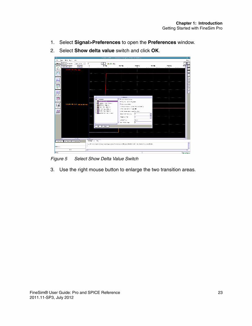
Chapter 1: IntroductionGetting Started with FineSim Pro
1. Select Signal>Preferences to open the Preferences window.
2. Select Show delta value switch and click OK.
Figure 5 Select Show Delta Value Switch
3. Use the right mouse button to enlarge the two transition areas.
FineSim® User Guide: Pro and SPICE Reference 232011.11-SP3, July 2012

Chapter 1: IntroductionGetting Started with FineSim Pro
4. Use the left mouse button to place the first cursor on v(in) and the middle mouse button to place the second cursor on v(out). The delay number is shown in the third field at the top of the waveform display area.
Figure 6 Viewing the Delay in FineWave
Display Results from Multiple SimulationsWith FineWave, you can compare waveforms from .fsdb files from multiple simulations.
1. Select File>Open DB from the menu or Open DB from the lower left corner to open the Select File window.
2. Select fast2.fsdb and spice2.fsdb and Shift-click OK.
3. Select the signals v(in) and v(out) from both fast2.fsdb and spice2.fsdb.
24 FineSim® User Guide: Pro and SPICE Reference2011.11-SP3, July 2012

Chapter 1: IntroductionGetting Started with FineSim Pro
4. Select Edit>Auto Group to group the same signal from three different simulations into one group:
Figure 7 Using Auto Group
5. Zoom in on the v(out) rising edge and you can measure the differences between the three modes.
Session FileFineWave allows you to save waveforms in a session file for future display. This is convenient when you want display the waveforms again without selecting individual signals again.
FineSim® User Guide: Pro and SPICE Reference 252011.11-SP3, July 2012

Chapter 1: IntroductionGetting Started with FineSim Pro
1. Select File>Save Session to open the Select File window;
2. Type tutorial in the Selection field and click OK;
Figure 8 Saving a Session File
3. Select File»Exit to quit FineWave.
To load the saved session file:
%finewave –s tutorial.fw
This will display the waveforms we just saved automatically.
Open the tutorial.fw session file to familiarize yourself with its content. You may change one or more .fsdb file names, such as spice3.fsdb to spice1.fsdb, to get your new simulation results displayed together with previous results you want to compare.
Dynamic Update of fsbd Signal Waveforms in FineWaveFineWave can now auto-update fsdb signals without the need for manual reloading. Use this feature by with the option -update.
Example 1finewave -update
26 FineSim® User Guide: Pro and SPICE Reference2011.11-SP3, July 2012

Chapter 1: IntroductionEnvironment Variables
will invoke FineWave and load the waveform file (from the FineWave menu) that has to be auto-updated.
Example 2finewave -update -f file.fsdb
will auto-update the waveform file file.fsdb.
Currently, only fsdb format waveform signals can be auto-updated.
Environment Variables
The following are a list of environment variables used by FineSim.
Table 3 Environmental Variables
Variable Description
FINESIM_HOME Installation directory for FineSim.
FINESIM_64 When set to 0, FineSim will run in 32 bit mode. Default is 1.
FINESIM_GCC When set to 0, FineSim will use the system gcc/ld path for verilog A and expression building.
FINESIM_VA2C_SO_DIR The directory to output the .so files for verilog A compilation.
FINESIM_PSF_LIMIT The maximum size for the PSF file output before it split into new file.
FINESIM_PROJ_CFG Secondary locations to look for the finesim.cfg file.
FINESIM_EXTEND_PROBE Triggers the addition of the finesim_prbport=1 option in the netlist, enhancing the output file by explicitly saving signals at the lower level of hierarchies.
FineSim® User Guide: Pro and SPICE Reference 272011.11-SP3, July 2012

Chapter 1: IntroductionInteractive Mode
Interactive Mode
You can start FineSim Pro in interactive mode from the command line using the -istop time option. You also can get the interactive prompt by using the Ctrl+C key during transient simulation.
For more information on the commands supported in interactive mode, refer to Chapter 9, TCL Interactive Mode & API Functions.
28 FineSim® User Guide: Pro and SPICE Reference2011.11-SP3, July 2012

2
2FineSim Multi-CPU
This chapter details the Multi-CPU features of FineSim.
Introduction to Multi-CPU
Both FineSim SPICE and FineSim Pro offer Multi-CPU technology to run simulations on multiple CPU and machines. This Multi-CPU feature gives you near-linear scalability in simulation performance and capacity with respect to the number of CPUs used versus a serial simulation with the same accuracy.
Please note that we strongly recommend you use the same CPU type/frequency and OS between your Multi-CPU simulations that span across multiple machines. You can get unexpected results or slowdown due to different machine configurations.
Why Multi-CPU SPICE?
For many large digital, analog and memory circuits, FineSim Pro’s modes can not only simulate circuits at different levels of accuracy and speed to meet different design requirements, but they also can handle a circuit capacity that traditional, serial SPICE simulators cannot. However, for some analog circuits of any size, such as ADC, PLL, and analog power rail analysis, the accuracy in FineSim Pro and FineSim Pro modes is insufficient. Those circuits require SPICE mode accuracy to get the expected circuit behavior. The only way to increase SPICE simulation performance dramatically is through parallel execution distributed among multiple CPUs.
FineSim Multi-CPU uses a proprietary technique to distribute the circuit over multiple CPUs and run the jobs on those CPUs synchronously to maintain the full accuracy of the SPICE algorithm. The FineSim SPICE algorithm minimizes
FineSim® User Guide: Pro and SPICE Reference 292011.11-SP3, July 2012

Chapter 2: FineSim Multi-CPUMulti-CPU Computers vs. Clusters of Computers
communication overhead so that the performance gain from parallel execution is maximized.
FineSim Multi-CPU can speed up the simulation of circuits with as few as several hundred transistors and nodes by more than 3 times on one single 4-way Symmetric Multi-Processing (SMP) machine. With circuits of hundreds of thousands of transistors and nodes, the improvement is more than 20 times on a cluster of 20 to 30 CPUs. Besides offering increased speed, Multi-CPU SPICE execution can handle circuits too large to simulate serially. This increased speed and capacity enables you to further verify the accuracy of FineSim Pro or FineSim Pro on a much larger scale than a traditional SPICE simulator can because of prohibitively long runtimes and/or excessive memory usage.
Multi-CPU Computers vs. Clusters of Computers
As CPU speed has leveled off, the computer industry has been putting multiple CPUs together to achieve higher performance through parallel execution. These CPUs can be on a single machine or on multiple machines connected by a high-speed network.
Computers with multiple CPUs in the Symmetric Multiprocessing (SMP) architecture are the most common multi-CPU computers. An SMP computer may have two or more identical processors connected to a shared main memory. The major benefit of SMP for Multi-CPU is that the inter-process communication is achieved through the shared main memory instead of the network, which can lead to communication overhead. For circuits of less than 1000 nodes, you should run Multi-CPU on a SMP machine because the communication overhead may be a significant portion of the total runtime.
For large circuits, one SMP machine can still be too slow or too small in capacity to make Multi-CPU a practical solution. In these cases, you can apply Multi-CPU to a cluster of single-CPU computers or SMPs. Because the communication overhead increases as the number of machines increases, the simulation performance gain of Multi-CPU eventually saturates. The saturation number of CPUs depends on the size of the circuit and the network. FineSim Multi-CPU automatically calculates and provides the optimal number of CPUs based on the circuit size in the log file. A rule of thumb is to assign approximately ten thousand transistors per CPU (for designs greater than a total count of 10K transistors), and one thousand transistors per CPU (for
30 FineSim® User Guide: Pro and SPICE Reference2011.11-SP3, July 2012

Chapter 2: FineSim Multi-CPUSystem Requirements
designs with a total count of 1K to 5K transistors) in order to gain scalability and performance.
System Requirements
The following are the minimum system requirements to run FineSim Multi-CPU.
Hardware■ A SMP machine, or ■ A cluster of single-CPU and/or SMP machines with identical CPUs that are
connected through Gigabit Ethernet
Software■ SMP capable operating system■ Python 2.2 or later■ LSF, LSF HPC v6.2, Secure Shell (SSH), or rsh■ Grid version 6.0
SMP servers and workstations with 2, 4, or 8 CPU’s are becoming more and more common in IT infrastructures. Multi-CPU is distributed in such a way that each CPU process gets the same amount of computing resources. If a process were to run slower than others due to either a slower machine or competing jobs on the machine, all the other processes would have to wait for its completion and the overall performance would be reduced. So, before you start Multi-CPU simulation, consult your IT team to arrange for dedicated machine(s) for you.
Running Multi-CPU Simulations
All options for serial (single CPU) simulations are still valid, and there are no additional options added for this feature. This means that you can use your input setup from a serial simulation to run a Multi-CPU simulation directly
FineSim® User Guide: Pro and SPICE Reference 312011.11-SP3, July 2012

Chapter 2: FineSim Multi-CPURunning Multi-CPU Simulations
without changing either your stimulus or netlist. it will create all of the same output files a serial SPICE run creates.
Running Multi-CPU simulation is easy. The shell script manages all of the execution details. To run it on a single SMP machine, you do not need to make any set-up changes. To run it on a cluster of computers, use either LSF or LSF-HPC to distribute jobs onto your LSF queue, or set up a password-less SSH or rsh login once for all the computers and set up a machine file that contains the machine names and number of the dedicated computers for use in your Multi-CPU simulation.
For Multi-CPU, the FineSim command line supports the following options (this list can also be obtained by typing finesim -p in the command line):
Table 4 Multi-CPU Command Line Options
Command Description
-p/-h Print help message.
-np X X is number of process.
-auto Automatic determine number of processes to use. X specified in -np becomes the maximum value.
-ip Independent sweeps.
-mf machinefile Using machine file for multiple machines.
-bsub "lsf options Using LSF for multiple machines.
-qsub "sge options Using sungrid for multiple machines.
-usub "finesim_manager_header options
User specified grid command for finesim_manager.
-lsf_hpc Use LSF HPC instead of LSF.
-np_per_m X X is the maximum number of processes for each LSF/SGE job.
-timeout X Maximum wait time to obtain LSF/SGE resources.
-wait Process will not exit until the Multi-CPU job is finished.
32 FineSim® User Guide: Pro and SPICE Reference2011.11-SP3, July 2012

Chapter 2: FineSim Multi-CPURunning FineSim Multi-CPU on a Single Machine
Running FineSim Multi-CPU on a Single Machine
Running FineSim SPICE or FineSim Pro in Multi-CPU on a single a machine is as simple as specifying the number of CPU required. In the command line, add –np X to specify the number of CPUs you want to use.
For FineSim Pro fast-spice modes, due to circuit partitioning, the Multi-CPU performances are not linearly scalable and the performance gain saturates around 4 CPU. Although there’s no limit on number of CPU you can run, it is recommended to keep it at 4 CPUs maximum for fast-spice modes.
Examples%> finesim –spice –np 8 input.sp%> finesim –np 4 input.sp
In the first example, it will run a 8-CPU FineSim SPICE simulation.
In the second example, it will run a 4-CPU FineSim Pro simulation.
Running FineSim Multi-CPU on Multiple Machines
FineSim supports three methods to run Multi-CPU simulations across multiple machines: using password-less SSH to tunnel the connection, LSF, and Sungrid. This section explains the setup requirements and commands for each of the methods.
.mpd.conf Configuration FileRunning Multi-CPU simulations requires a hidden configuration file: .mpd.conf. In most cases, this file is automatically created without any user effort. Only when you run into an error message regarding .mpd.conf do you need to read the following.
FineSim searches for .mpd.conf in the following sequence:
1. If the environment variable MPD_CONF_FILE is set, FineSim tries to read this file and create it if it does not exist. If all fails, it errors out.
2. If the environment variable MPD_CONF_FILE is not set, Finesim tries to read ~/.mpd.conf and create it if it does not exist. If all fails, it goes to step 3.
FineSim® User Guide: Pro and SPICE Reference 332011.11-SP3, July 2012

Chapter 2: FineSim Multi-CPURunning FineSim Multi-CPU on Multiple Machines
3. Finesim tries to read .mpd.conf in the current working directory and create it if it does not exist. If all fails, it errors out.
The error message normally suggests creating a .mpd.conf file in a directory you can access and setting MPD_CONF_FILE with its path.
To create a .mpd.conf file:
1. Add the following one line to this file:
secretword=finesim (echo "secretword=finesim" > .mpd.conf.
2. Change the file permission and make it accessible only to you (chmod 600 .mpd.conf).
How to Set Up Passwordless SSH LoginFineSim Multi-CPU can be started on any single machine, but it needs SSH to propagate processes onto other machines. By default, SSH to a network machine requires you to type a password. To avoid having to type in a password for each machine, use the following instructions to set up a passwordless SSH login.
Run ssh-keygen on your machine, and press <enter> when asked for a password.
Example% ssh-keygen –t(ype) rsa
where t(ype) is either rsa1 for protocol version 1 or rsa for protocol version 2.
This will generate both a private and a public key. In older SSH versions, they will be stored in ~/.ssh/identity and ~/.ssh/identity.pub. In newer versions, they will be stored in ~/.ssh/id_rsa and ~/.ssh/id_rsa.pub.
Next, add the contents of the public key file into ~/.ssh/authorized_keys on the remote site (The file should be mode 600.)
You should then be able to use SSH to log in to any computer on the network without being asked for a password. SSH to all the computers first as a test before you send any FineSim Multi-CPU job over the network.
34 FineSim® User Guide: Pro and SPICE Reference2011.11-SP3, July 2012
Chapter 2: FineSim Multi-CPURunning FineSim Multi-CPU on Multiple Machines
Machine FileTo run Multi-CPU on a cluster of computers using password-less SSH, you must know the name of the computers and the number of CPUs each computer has. A simple text file, called a machine file, is needed for the task. The format for a machine file is intuitive. Each line should contain the name of a machine along with the number of CPUs on that machine.
Exampleapple.synopsys.com:4peach.synopsys.com:2
Apple has 4 CPUs, while peach has 2 CPUs for the FineSim Multi-CPU run. The first line needs to contain the machine that is submitting the job.
For the above example, you can start 6 CPU job using:
apple.synopsys.com> finesim –np 6 –mf machine_file input.sp
LSF or LSF HPCIf you use LSF or LSF HPC, you do not need a machine file because LSF or LSF HPC will use whatever machine is available on the queue at the moment.
For running Multi-CPU on single machine, you don’t need to change the way you submit to LSF, other than adding –n X in the bsub command to specify how many CPUs to request for resources. The same command you use to explicitly select machines still applies.
For example, you can select 4 CPU with model X5355 that runs on RedHat 5.6 with the following command:
bsub –n 4 -q queue_name -R "select[(type==RHEL5)&&(model==X5355)] " finesim –np 4 input.sp
If you are using the HPC version of LSF, you must specify the –lsf_hpc option in the bsub command line.
In order to run Multi-CPU across multiple machines, you will need to use FineSim commands to submit the LSF jobs. The number of CPU requests -n X is now the number of CPUs to request per machine (LSF job), and not the total number of CPUs. Also, you will need to add span[hosts=1] in the resource requirement (-R).
FineSim® User Guide: Pro and SPICE Reference 352011.11-SP3, July 2012

Chapter 2: FineSim Multi-CPURunning FineSim Multi-CPU on Multiple Machines
Using the previous example, you can modify it to use 2 CPUs from 2 machines using the following:
finesim –np 4 –bsub ‘-n 2 –q queue_name –R “select[(type==RHEL5)&&(model==X5355)] span[hosts=1]”’ input.sp
SGE SungridFineSim Pro supports Sun Grid Environment (SGE) Version N1GE 6.0u9. You must have administrative privileges to configure SGE. Complete the following steps to set up SGE on your computer:
Note:Complete the initial SGE configuration. This must be done by an SGE manager or administrator.3.Add a Multi-CPU environment (PE) such as finesim. Enter qconf -ap finesim, and edit the file with the following options:
pe_name finesimslots 999user_lists NONExuser_lists NONEstart_proc_args /bin/truestop_proc_args /bin/trueallocation_rule $pe_slotscontrol_slaves FALSEjob_is_first_task TRUEurgency_slots min
4. Add the PE to the queue. The default queue is all.q. Enter qconf -mq all.q, and add “finesim” to the “pe_list.”
The following code exemplifies a FineSim command example:
finesim -np 4 -qsub '-q QUEUE -pe finesim NP_PER_M' -o test_sge_4 in.sp
Using *.bkill to Terminate LSF ProcessesAfter you submit your Multi-CPU through regular LSF, a .bkill file is generated. By executing this file, you can terminate all jobs automatically. It is not necessary to obtain the LSF process ID and manually terminate them all by using bkill one by one.
For example, the following command terminates all LSF processes for the Multi-CPU run with the prefix 3X4CPU_parallel_run.
% 3X4CPU_parallel_run.bkill
36 FineSim® User Guide: Pro and SPICE Reference2011.11-SP3, July 2012

Chapter 2: FineSim Multi-CPUIndependent Parallel
Time-Out MessagesParallel SPICE issues an informative message to standard output when a time-out occurs. For example, the reason for a time-out might be reported as follows:
Queued 40 finesim jobs via LSF.Network speed check will be logged to 'x40.nc_log'.LSF output will be logged to 'x40.lsf_log'.FineSim output will be logged to 'x40.log'.Trying to get 10 machines (40 CPU's)...ERROR: could not get any machine after 600 seconds.Please check the queue and your command.
In this instance, you might move to a larger LSF queue, or reduce the number of processes, or have a longer time-out wait time such as -timeout 3600.
Independent Parallel
Besides native Multi-CPU technology, FineSim also supports independent parallel simulation. Independent parallel can be used in the simulation that contains alter/MonteCarlo/Fast MonteCarlo/temp sweep/data sweep, or the mix of these operations. You can use “-ip” option in command line to invoke this feature.
When any above operation exists in the deck, and “-ip” is used in command line, FineSim will distribute all sweep simulations to different CPUs. The job on different CPUs will run parallel, while the job on same CPU will run serially.
Consider the following example with 5 temperature sweeps:....temp -10 0 25 75 100...
If you run the simulation with the following command:
% finesim –np 2 –ip –spice input.sp
The job will run on 2 CPU. The distribution is: “-10”, “25”, and “100” will run on the first CPU serially, “0”and “75” will run on the second CPU serially.
If run the simulation with the following command:
% finesim –np 4 –ip –spice input.sp
FineSim® User Guide: Pro and SPICE Reference 372011.11-SP3, July 2012

Chapter 2: FineSim Multi-CPUUsing .finesim_parallel.ini to Simplify Multi-CPU Calls
The job will run on 4 CPUs. The distribution is: “-10” and “100” will run on the first CPU serially, “0” will run on the second CPU, “25” will run on the third CPU, and “75” will run on the fourth CPU.
Using .finesim_parallel.ini to Simplify Multi-CPU Calls
For Multi-CPU runs, many common options can be stored in a .finesim_parallel.ini file so that you do not have to specify them from the command line every time. The FineSim Multi-CPU command searches for a .finesim_parallel.ini file. The directory names and their priorities in searching are as follows:
1. $FINESIM_HOME—the installation directory.
2. $FINESIM_PROJ_CFG—the project directory.
3. $HOME—the home directory.
4. The current working directory.
The search is performed in the order listed, with the current working directory being the highest priority. The highest priority .finesim_parallel.ini file can incrementally add the options not yet set and also override the options set in the lower priority .finesim_parallel.ini files. For example, if no $FINESIM_PROJ_CFG variable is defined, the search for finesim_parallel.ini is initiated in the order $FINESIM_HOME, $HOME and then the current working directory. If a .finesim_parallel.ini file exists in the current working directory and contains options already specified in a lower-level .finesim_parallel.ini file, the options in the current working directory’s .finesim_parallel.ini file take precedence over any .finesim_parallel.ini instances in $FINESIM_HOME or $HOME. Any unique options defined in $FINESIM_HOME or $HOME and not defined in the .finesim_parallel.ini file in the current working directory will be retained.
A sample .finesim_parallel.ini file is provided in the $FINESIM_HOME installation directory where all possible options are listed but commented out for your reference.
38 FineSim® User Guide: Pro and SPICE Reference2011.11-SP3, July 2012

Chapter 2: FineSim Multi-CPUAutomatic Determination of Optimal Number of Parallel Processes
Automatic Determination of Optimal Number of Parallel Processes
You can use the -auto option with finesim_parallel. When enabled, it tells FineSim Pro to calculate the ideal number of processes to use for a run. When -auto is specified, the N in option -np N then becomes the upper bound on the number of processes that can be used.
An optimal number of processes is calculated by FineSim Pro. When the specified number of processes differs from the optimal number, FineSim Pro reports a warning. You can use this functionality with the following modes:■ Dedicated machines (single or multiple)■ Regular LSF■ SGE
This functionality is not available for LSF_HPC.
FineSim® User Guide: Pro and SPICE Reference 392011.11-SP3, July 2012

Chapter 2: FineSim Multi-CPUAutomatic Determination of Optimal Number of Parallel Processes
40 FineSim® User Guide: Pro and SPICE Reference2011.11-SP3, July 2012

3
3Circuit Elements and Models
This chapter describes the circuit elements and models that FineSim supports.
Elements are categorized into four general classes:■ Passive elements■ Independent sources■ Dependent sources■ Active elements
An element statement defines the type of the device, its terminal nodes, the parameter values that describe the operating electrical characteristics of the device and references to model statements that define the electrical parameters of the element itself. A netlist is simply the element instances for all the devices in a circuit and their connections through nodes.
FineSim Pro Rules for Instance, Model, and Global Parameter Interaction
Before you learn about each element definition and usage, review the three rules FineSim Pro follows to determine the right value should instance parameters be in conflict with model or global parameters.
Rule 1The instance length L and width W are scaled by the global scale statement,
.OPTION SCALE=val
FineSim® User Guide: Pro and SPICE Reference 412011.11-SP3, July 2012

Chapter 3: Circuit Elements and ModelsFineSim Pro Rules for Instance, Model, and Global Parameter Interaction
However, the instance values (for example, resistance, capacitance) are scaled by the value in the instance statement. In the following discussion, SCALE(instance) represents instance scaling, and SCALE(option) represents the global dimensional scale declaration.
Example .OPTION SCALE=1uR1 rn1 rn2 R=5 SCALE=1k L=0.5 W=20
In this example, L and W are scaled in um by SCALE(option). That is, L=0.5um and W=20um, respectively. The resistance value of R1 is scaled to 1.0e3 by SCALE(instance). That is, R=5k ohm.
Rule 2If the model name of an instance is the same as that of a parameter, the model name takes precedence.
Example .PARAM name=1.5R1 in out1 name TC1=0.1.MODEL name R RSH=1k
In this example, name is the model name of R1, not the parameter 1.5.
Rule 3Some parameters can come from instance and .MODEL statements. If a parameter is in both the instance and the .MODEL statements, the value in the instance statement is used.
Example R1 in out1 Rmodel 4.7k TC1=0.08 TC2=0.04.MODEL Rmodel R DW=0.3u TNOM=27 TC1=0.4 TC2=0.18
In this example, the temperature coefficient of R1 is TC1=0.08, TC2=0.04, and not TC1=0.4, TC2=0.18 as defined in the .MODEL statement.
42 FineSim® User Guide: Pro and SPICE Reference2011.11-SP3, July 2012

Chapter 3: Circuit Elements and ModelsResistors
Note:Reserved node names for ground: 0, GND, GND!, GROUND. FineSim Pro treats those nodes as the absolute ground node. But if they are used in a sub-circuit’s port name, it will be treated as a normal node inside of that sub-circuit.
Resistors
SyntaxRxxx n1 n2 <mname> Rval <TC1 <TC2>> <SCALE=val> <M=val> + <AC=val> <DTEMP=val> <L=val> <W=val> <C=val>
or
Rxxx n1 n2 <mname> R=val <<TC1=>val> <<TC2=>val> <SCALE=val> <M=val> + <AC=val> <DTEMP=val> <L=val> <W=val> <C=val>
or
Rxxx n1 n2 <mname> R=’algebraic expression’ <TC1 <TC2>> <SCALE=val> <M=val> + <AC=val> <DTEMP=val> <L=val> <W=val> <C=val>
Table 5 Resistor Parameters
Parameter Description
AC Resistance for AC analysis. If not specified, the same value is used for AC analysis.
C Capacitance connected from N2 to bulk. The default value is 0.0 if C is not set in the model mname and Ceff=C x SCALE(instance) x M
DTEMP Temperature difference between the element and the circuit in Celsius. The default value is 0.0. DTEMP is available with TC1 and TC2. Equation:
R = R0 + TC1*?t + TC2*?t^2 ?t = temperature-TNOM+DTEMPwhere R0 is the user given resistance value.
FineSim® User Guide: Pro and SPICE Reference 432011.11-SP3, July 2012

Chapter 3: Circuit Elements and ModelsResistors
Example * Example of Resistor model *.option postR123 in out1 1kc1 out1 0 1pRw in out2 R=10 SCALE=1e3 M=3c2 out2 0 1pRtest in out3 R='2.345*1.4' SCALE=1e6c3 out3 0 1pRk1 in out4 R_model L=10u W=200uc4 out4 0 1pRCC in out5 R=100k
L Resistor length. The default value is 0.0 if L is not set in the model mname. Scaled length is Lscaled= L x SCALE(option)
M Multiplier used to simulate parallel connection of the resistors.
The default value is 1.0.
mname Model name for the resistor.
N1, N2 Two instance nodes.
Rxxxx Resistor instance name.
SCALE Instance scale factor for resistor. The default value is 1.0.
Rval should be set before SCALE(instance) is used.
TC1 First-order temperature coefficient for the resistor.
TC2 Second-order temperature coefficient for the resistor.
VALUE The resistance, either a value (in ohms) or an equation. (R=val or R=’expression’)
Reff=R x SCALE(instance) / M
W Resistor width. The default value is 1e-6 meters if W is not set in the model mname. Scaled width is
Wscaled= W x SCALE(option)
Table 5 Resistor Parameters (Continued)
Parameter Description
44 FineSim® User Guide: Pro and SPICE Reference2011.11-SP3, July 2012

Chapter 3: Circuit Elements and ModelsCapacitors
c5 out5 0 1pRk2 in out6 R_model L=10u W=200u DTEMP=90c6 out6 0 1p.model R_model R RSH=1k DW=0.3u TNOM=27 TC1=0.4 TC2=0.18vin in 0 pwl( 0 0 5n 0 5.5n 2.5 ).tran 0.1n 200n.end
Semiconductor Resistor Model:.MODEL mname R(RES) par1=val1 par2=val2 ….
where mname is the model name, R(or RES) is the keyword for the resistor model, and par1, par2, … lists the values of parameters.
Capacitors
SyntaxCxxx n+ n- <mname> VALUE <TC1 <TC2>> <SCALE=val><L=val><W=val> + <M=val><IC=val><DTEMP=val>
or
Cxxx n+ n- <mname> C=val <<TC1=>val> <<TC2=>val> <SCALE=val><L=val><W=val> + <M=val><IC=val><DTEMP=val>
or
Cxxx n+ n- <mname> C=’algebraic expression’ <<TC1=>val> <<TC2=>val> <SCALE=val><L=val><W=val> + <M=val><IC=val><DTEMP=val>
Table 6 Capacitor Parameters
Parameter Description
Cxxxx Capacitor instance name.
FineSim® User Guide: Pro and SPICE Reference 452011.11-SP3, July 2012

Chapter 3: Circuit Elements and ModelsCapacitors
DTEMP DTEMP Temperature difference between the element and the circuit in Celsius. The default value is 0.0. DTEMP is available with TC1 and TC2. Equation:
C = C0 + TC1*?t + TC2*?t^2 ?t = temperature-TNOM+DTEMP
where C0 is the user given capacitance value.
IC=val Sets the initial voltage across the capacitor in volts. If the input netlist contains an .IC statement, it overrides the initial assignment in the instance statement.
L Capacitor length. The default value is 0.0 if L is not set in the model mname. Scaled length is Lscaled= L x SCALE(option)
M Multiplier used to simulate parallel connection of the capacitors. The default value is 1.0.
mname Model name for the capacitor.
N- Negative instance node.
N+ Positive instance node.
SCALE Instance scale factor for the capacitor. The default value is 1.0.
VALUE should be set before SCALE(instance) is used. Ceff = C x SCALE(instance) x M
TC1 First-order temperature coefficient for the resistor.
TC2 Second-order temperature coefficient for the resistor.
VALUE Capacitance in Farads, or as (C=val or C=’expression’).
W Capacitor width. The default value is 1e-6 meters if W is not set in the model mname. Scaled width is Wscaled= W x SCALE(option)
Table 6 Capacitor Parameters (Continued)
Parameter Description
46 FineSim® User Guide: Pro and SPICE Reference2011.11-SP3, July 2012

Chapter 3: Circuit Elements and ModelsCapacitors
Example * Example of Capacitor model *.option post accurateC11 out1 0 1pFr1 in out1 1kCeq out2 0 c='22p + 11*4e-12'r2 in out2 1kCval out3 0 cmodel L=10u W=20u M=4r3 in out3 1kCtt out4 0 cmodel IC=1.5Vr4 in out4 1k.model cmodel C CAP=1p TC1=0.01 TC2=0.005vin in 0 pwl( 0 0 5n 0 5.5n 2.5 ).tran 0.1n 200n.end
Capacitance Model:.MODEL mname C par1=val1 par2=val2 ….
where mname is the model name, C is the keyword for capacitor model, and par1, par2, … list the values of the parameters.
Three Terminal Mosvar Model in Spectre and SPICE FormatFineSim supports a three terminal mosvar model, and this element will be recognized as a MOSVAR element in log file.
Example
# MOSVAR : 1
Charge-Based CapacitorsFineSim Pro supports charge-based capacitors, where the charge can be given by an expression which may depend on node voltages.
SyntaxCxxx n1 n2 q=exprexpr supports nodal voltages parameters.
ExampleC1 1 2 Q=’cosh(0.5*V(1,2))’
FineSim® User Guide: Pro and SPICE Reference 472011.11-SP3, July 2012

Chapter 3: Circuit Elements and ModelsInductors
Inductors
Linear Inductor (L-element)
SyntaxLxxx n+ n- VALUE <TC1 <TC2>> <SCALE=val><M=val><IC=val><DTEMP=val> or
Lxxx n+ n- L=val <<TC1=>val> <<TC2=>val> <SCALE=val><M=val><IC=val><DTEMP=val>
or
Lxxx n+ n- L=’algebraic expression’ <<TC1=>val> <<TC2=>val> <SCALE=val><M=val><IC=val><DTEMP=val>
Table 7 Linear Inductor Parameters
Parameter Description
DTEMP DTEMP Temperature difference between the element and the circuit in Celsius. The default value is 0.0. DTEMP is available with TC1 and TC2. Equation:
L = L0 + TC1*?t + TC2*?t^2 ?t = temperature-TNOM+DTEMP
where L0 is the user given inductance value.
IC=val Sets the initial current through the inductor in amperes.
Lxxxx Linear inductor instance name.
M Multiplier used to simulate parallel connection of the inductors. The default value is 1.0.
mname Model name for the inductor.
N- Negative instance node.
N+ Positive instance node.
48 FineSim® User Guide: Pro and SPICE Reference2011.11-SP3, July 2012

Chapter 3: Circuit Elements and ModelsInductors
Example* example of Inductor *.option post accurateLcouple l1 lout1 L=10uH M=3r1 in l1 100c1 lout1 0 0.5pLs l2 lout2 45 SCALE=1e-5r2 in l2 100c2 lout2 0 0.5pLIC l3 lout3 70uH IC=0.5mAr3 in l3 100c3 lout3 0 0.5pvin in 0 pwl( 0 0 5n 0 5.5n 2.5 ).tran 0.1n 200n.end
Mutual Inductors (K-element)
SyntaxKxxx Lyyy Lzzz VALUE
SCALE Instance scale factor for the inductor. The default is 1.0. VALUE should be set before SCALE(instance) is used. Leff = l x SCALE(instance) x M
TC1 First-order temperature coefficient for the resistor.
TC2 Second-order temperature coefficient for the resistor.
VALUE Inductance in henries (H), or as (L=val or L=’expression’)
Table 8 Mutual Inductor Parameters
Parameter Description
Kxxxx Mutual inductor instance name.
Lyyy, Lzzz Names of the two coupled inductors.
Table 7 Linear Inductor Parameters (Continued)
Parameter Description
FineSim® User Guide: Pro and SPICE Reference 492011.11-SP3, July 2012

Chapter 3: Circuit Elements and ModelsInductors
Example** K element example **.option accurate post rmax=.05Vin in 0 sin (0 5 60)Rin in rin 10Lin rin 0 L=20u Km Lin Lm K=0.8Rs 0 rs 10Lm rm rs L=50u Rm rm rmc 5Cm rmc 0 50p.tran 1m 25m.end
FineSim Pro allows the two inductors that are used to define a mutual inductor (K element) to be hierarchical. Consider the following example:
Kmutual X1.LA X1.LB 0.5Where LA and LB are defined under the hierarchical structure of X1 as follows:
.SUBCKT subinductorLA 1 0 1mLB 1 0 0.5m.ENDSX1 subinductor
Reluctor (L-element)
SyntaxLxxx n1+ n1– n2+ n2– … ni+ ni– … nj+ nj– … nN+ nN–
VALUE The coupling coefficient, which must be greater than 0 and less than 1, or it can be expressed as K=val or K=’expression’.
Table 8 Mutual Inductor Parameters (Continued)
Parameter Description
50 FineSim® User Guide: Pro and SPICE Reference2011.11-SP3, July 2012

Chapter 3: Circuit Elements and ModelsDiodes
RELUCTANCE=(1, 1, rluc11, 1, 2, rluc12, …, i, i, rlucii, i, j, rlucij, …, N, N, rlucNN)
Example .option post accurateL1 1 2 0 3 6 7 RELUCTANCE = (1, 1, 1.6e9, 1, 2, -8.5e8, 1, 3, -2.1e8, 2, 2, 1.8e9, 2, 3, -5.5e8, 3, 3, 1.4e9)R1 2 4 1.0R2 3 5 1.0R3 7 8 1.0C1 6 0 0.1pC2 4 5 0.1pC3 5 8 0.1pvin 1 0 pwl(0 0 0.1n 0 0.2n 2.5 1n 2.5).tran 1p 1n.end
Diodes
SyntaxDxxx N+ N- MNAME <OFF><DTEMP=val><M=val><IC=vd>+<AREA=val><PJ=val><L=val><W=val>+<WP = val><LP = val><WM= val><LM= val>
Table 9 Linear Reluctor Parameters
Parameter Description
Lxxxx N-port mutual reluctor instance name.
ni+ Positive instance node name of port i.
ni- Negative instance node name of port i.
RELUCTANCE Described in triplets (index of porti, index of portj, reluctance value in inverse Henries (1/H)). When i equals j, the third item of the triplet is self reluctance, otherwise it is mutual reluctance. Mutual reluctance is symmetric–the reluctance between port i and port j equals the reluctance between port j and port i, so you only need to specify one of the triplets, (i, j, rluc) or (j, i, rluc). Also, you only need to include non-zero reluctance in each triplet.
FineSim® User Guide: Pro and SPICE Reference 512011.11-SP3, July 2012

Chapter 3: Circuit Elements and ModelsDiodes
Examples
Diode pnode nnode diodemodel M=2
Table 10 Diode Parameters
Parameter Description
AREA Area multiplier factor. The default is 1.0.
DTEMP Temperature difference between the element and the circuit in Celsius. The default value is 0.0.
IC=vd Initial voltage across the diode. Intended for use with the UIC option on the .TRAN statement when starting transient analysis from a point other than the quiescent operating point.
L Length of diode in meters (for LEVEL = 3 only).
LM Length of metal capacitor in meters (for LEVEL = 3 only). Overrides WM in diode model. The default is 0.0.
LP Length of polysilicon capacitor in meters (for LEVEL = 3 only). Overrides LP in diode model. The default is 0.0.
M Multiplier for Diode.
mname Model name for the diode.
N+, N- Positive and negative nodes, respectively.
OFF Initial condition OFF for this instance in DC analysis.
Default is ON.
PJ Periphery of junction.
W Width of diode in meters (for LEVEL = 3 only).
WM Width of metal capacitor in meters (for LEVEL = 3 only). Overrides WM in diode model. The default is 0.0.
WP Width of polysilicon capacitor in meters (for LEVEL = 3 only). Overrides WP in diode model. The default is 0.0.
52 FineSim® User Guide: Pro and SPICE Reference2011.11-SP3, July 2012

Chapter 3: Circuit Elements and ModelsDiodes
Dclamp in out dmodel area=3 IC=0.4
Geometry Calculation Note■ Diode model LEVEL=1 is a non-geometric and scale-less junction diode
model. This means all settings of L, W, SCALE(option), SCALE(instance), in both the diode instance and the model are ignored;
■ Parameters (AREA, PJ, L, W) are common in instance and model parameters. If they appear in both instance and model lines, instance parameters take precedence.
■ For LEVEL=1
AREAeff = AREA • MPJeff = PJ • M
■ For LEVEL=3
Case 1: If AREA or PJ equations are given, and L, W are not given
AREAeff = AREA • M • SCALE(option)2
PJeff = PJ • M • SCALE(option)
Case 2: If L and W are given, AREA or PJ are ignored whether given or not, and
Leff = L • SCALE(option) + XWWeff = W • SCALE(option) + XW
and
PJeff = (2•Weff +2•Leff) • MAREAeff = Weff•Leff • M
Diode Model:.MODEL MNAME D <par1=val1 par2=val2 ….>
where MNAME is the model name, and D is the keyword to indicate the diode model. par1, par2, … list the value of the parameters. For specific details about which models FineSim Pro supports, see the Output Files section of Chapter 1, Introduction.
FineSim® User Guide: Pro and SPICE Reference 532011.11-SP3, July 2012

Chapter 3: Circuit Elements and ModelsBipolar Junction Transistors (BJTs)
Bipolar Junction Transistors (BJTs)
SyntaxQxxx NC NB NE <NS> mname <area><OFF><DTEMP=val>+ <M=val> <IC=VBE, VCE>
or
Qxxx NC NB NE <NS> mname <OFF><DTEMP=val>+ <M=val> <AREA=val><AREAB=val><AREAC=val>+ <VBE=val><VCE=val>
Table 11 BJT Parameters
Parameter Description
AREA Area multiplier factor. The default is 1.0.
AREAB Base Area multiplier factor. The default is AREA.
AREAC Collector Area multiplier factor. The default is AREA.
DTEMP Temperature difference between the element and the circuit in Celsius. The default value is 0.0.
IC=VBE,VCE Initial internal voltages, base-emitter and collector-emitter voltage, respectively. Intended for use with the UIC option in the .TRAN statement when starting a transient analysis from a point other than the quiescent operating point.
M Multiplier for BJT.
mname Model name for the BJT.
NC, NB, NE The collector, base and emitter nodes, respectively.
NS Optional substrate node. The default is ground node.
OFF Initial condition OFF for this instance in DC analysis.
Default is ON.
VBE=val Initial voltage drop between base and emitter.
VCE=val Initial voltage drop between collector and emitter
54 FineSim® User Guide: Pro and SPICE Reference2011.11-SP3, July 2012
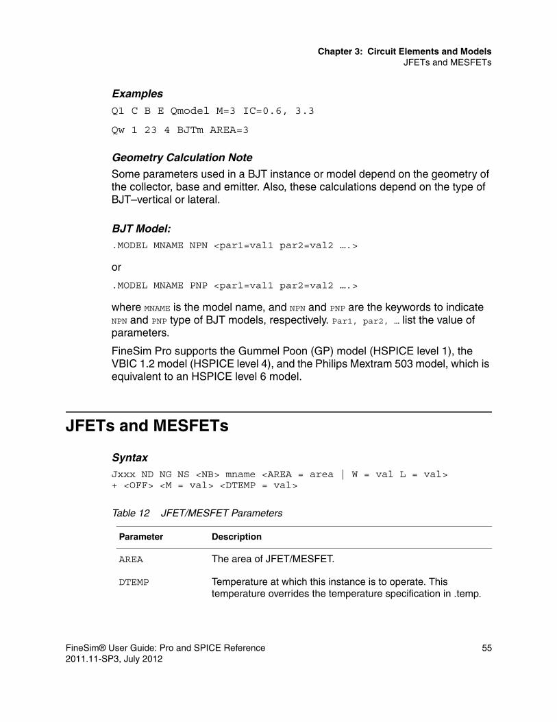
Chapter 3: Circuit Elements and ModelsJFETs and MESFETs
Examples
Q1 C B E Qmodel M=3 IC=0.6, 3.3
Qw 1 23 4 BJTm AREA=3
Geometry Calculation Note
Some parameters used in a BJT instance or model depend on the geometry of the collector, base and emitter. Also, these calculations depend on the type of BJT–vertical or lateral.
BJT Model:.MODEL MNAME NPN <par1=val1 par2=val2 ….>
or
.MODEL MNAME PNP <par1=val1 par2=val2 ….>
where MNAME is the model name, and NPN and PNP are the keywords to indicate NPN and PNP type of BJT models, respectively. Par1, par2, … list the value of parameters.
FineSim Pro supports the Gummel Poon (GP) model (HSPICE level 1), the VBIC 1.2 model (HSPICE level 4), and the Philips Mextram 503 model, which is equivalent to an HSPICE level 6 model.
JFETs and MESFETs
SyntaxJxxx ND NG NS <NB> mname <AREA = area | W = val L = val>+ <OFF> <M = val> <DTEMP = val>
Table 12 JFET/MESFET Parameters
Parameter Description
AREA The area of JFET/MESFET.
DTEMP Temperature at which this instance is to operate. This temperature overrides the temperature specification in .temp.
FineSim® User Guide: Pro and SPICE Reference 552011.11-SP3, July 2012

Chapter 3: Circuit Elements and ModelsJFETs and MESFETs
ExamplesJ1 d g s b njfet L=10u W=5u J2 2 4 0 0 njfet area=5p M=3 DTEMP=50
JFET/MESFET model:
.MODEL MNAME PJF LEVEL=val <par1=val par2=val …..>
or
.MODEL MNAME NJF LEVEL=val <par1=val par2=val…..>
where MNAME is the model name, and the PJF and NJF are keywords that indicate the P-channel and N-channel type of JFET/MESFET models, respectively. Par1, par2, … list the value of the parameters.
FineSim Pro supports HSPICE level 1 and 2.
L Gate length.
M Multiplier for the JFETs/MESFET
mname model name of JFET or MESFET instance
ND, NG, NS, NB The drain, gate, source, and bulk (subtrate) nodes, respectively.
OFF Initial condition for this instance in DC analysis
W Gate width.
Table 12 JFET/MESFET Parameters
Parameter Description
56 FineSim® User Guide: Pro and SPICE Reference2011.11-SP3, July 2012

Chapter 3: Circuit Elements and ModelsMOSFETs
MOSFETs
SyntaxMxxx ND NG NS NB mname <L=>val <W=>val+ <AS=val><AD=val><PS=val><PD=val><NRD=val><NRS=val>+ <OFF><IC=VDS, VGS, VBS><DELVTO=val><DTEMP=val>+ <GEO=val><M=val>
Table 13 MOSFET Parameters
Parameter Description
AS, AD The area of the drain and source diffusions. The units are m2. The default is DEFAS, DEFAD as defined in the .OPTION statement for AS and AD, respectively.
DELVTO Zero-bias threshold voltage shift. The default is 0.0.
DTEMP Temperature difference between the element and the circuit in Celsius. The default value is 0.0.
GEO Source/drain sharing selector for ACM=3. The default is 0.0 .
IC=VDS,VGS, VBS
Initial voltages across the external drain-source, gate-source, and bulk-source, respectively. Intended for use with the UIC option in the .TRAN statement when starting a transient analysis from a point other than the quiescent operating point.
L=val, W=val Channel length and width of MOSFET, respectively. If L= and W= are omitted, these two values assign length first and then width in defaults. Also, L and W are scaled by the SCALE(option). The default value is DEFL, DEFW in the .OPTION statement for length and width, respectively.
M Multiplier for the MOSFET.
mname Model name of MOSFET instance.
ND, NG, NS, NB The drain, gate, source, and bulk (substrate) nodes, respectively.
FineSim® User Guide: Pro and SPICE Reference 572011.11-SP3, July 2012

Chapter 3: Circuit Elements and ModelsMOSFETs
ExamplesM1 d g s b MOD1 L=10u W=5u AD=100p AS=100p+ PD=40u PS=40uM2 2 4 0 0 nch 0.5u 10u M=3 DTEMP=50M7 8 9 vdd vdd pch W=4u L=0.8u IC=-3, -1, 0
MOSFET model:.MODEL MNAME PMOS LEVEL=val <par1=val par2=val …..>
or
.MODEL MNAME NMOS LEVEL=val <par1=val par2=val…..>
where MNAME is the model name, and the PMOS and NMOS are keywords that indicate the PMOS and NMOS type of MOSFET models, respectively. Par1, par2, … list the value of the parameters.
A MOSFET is defined by the MOSFET model and element parameters. MOSFET models are either p-channel or n-channel models. They are classified according to level such as LEVEL 1 or LEVEL 50.
The detailed description of MOSFET model parameters can be found in the original UC Berkeley SPICE and Philips documents. For specific details about which models FineSim Pro supports, see the Output Files section of Chapter 1, Introduction.
NRD, NRS The equivalent number of squares of the drain and source diffusion for resistance calculation. The default is DEFNRD, DEFDRS as defined in the .OPTION statement for NRD and NRS, respectively.
OFF Initial condition OFF for this instance in DC analysis.
Default is ON.
PD, PS The perimeters of the drain and source diffusions. Units are m.
Table 13 MOSFET Parameters (Continued)
Parameter Description
58 FineSim® User Guide: Pro and SPICE Reference2011.11-SP3, July 2012

Chapter 3: Circuit Elements and ModelsIndependent Sources
Independent Sources
Voltage sourceVxxx N+ N- <<DC=>dcval> function <AC=acmag, <acphase>>
Current sourceIxxx N+ N- <<DC=>dcval> function <AC=acmag, <acphase>>+ <M=val>
ExamplesVdd vdd 0 2.5Vss Vss 0 gnd_valueVin in vss PULSE(0 2.5 1n 2n 2n 8n 20n)
Table 14 Independent Source Parameters
Parameter Description
AC AC source keyword, for use in AC small-signal analysis.
acmag Magnitude (RMS) of the AC source, in volts
acphase Phase of AC source in degrees. Default is 0.0.
DC=dcval DC source value. The default is 0.0.
function Time-dependent function for transient analysis. Eight functions are supported by FineSim Pro: pulse, piece-wise-linear (PWL), exponential (EXP), sinusoidal (SIN), single-frequency FM (SFFM), Amplitude Modulation (AM), Pseudo Random-Bit Generator Source(PRBS), and Pattern Source (PAT).
M Multiplier used to simulate parallel connection of current source. The default is 1.0
N+, N- Positive and negative nodes for the source, respectively.
Note that the voltage source, in addition to being used as power supply of the circuit, can also be used as current meter for the circuit. That is, a zero volt voltage source may be inserted into the circuit to measure the current. Positive current is defined to flow from the positive node, through the source, to the negative node.
FineSim® User Guide: Pro and SPICE Reference 592011.11-SP3, July 2012

Chapter 3: Circuit Elements and ModelsIndependent Sources
Vm Iin Iout 0IG vdd iin SIN(0 1e-3 10MEG)Iac vdd 3 SFFM( 0 1 10MEG 5 1MEG)
Functions
PULSE
SyntaxPULSE (V1 V2 TD TR TF PW PER)
A single pulse so specified is described by the following table:
Table 15 Pulse Parameters
Parameter Description
PER Period. The default value is the TSTOP value of the .TRAN statement.
PW Pulse width. The default value is TSTOP of the .TRAN statement. Note that if PW=0, this pulse function will generate a triangular wave.
TD Delay time. The default value is 0.
TF Fall time. The default value is TSTEP of the .TRAN statement.
TR Rise time. The default value is TSTEP of the .TRAN statement.
V1 Initial value before the pulse onset.
V2 Pulsed value.
Table 16 Pulse Pattern
Time (secs) Value (volt or amp)
0 V1
TD V1
TD+TR V2
60 FineSim® User Guide: Pro and SPICE Reference2011.11-SP3, July 2012

Chapter 3: Circuit Elements and ModelsIndependent Sources
ExamplesPULSE ( 0 2.5 1n 2n 2n 8n 20n )PULSE(0 2.5 10n 5n 5n 0 10n) $ triangular wavePULSE(0 2.5 10n 2n 2n 5n ) $ single pulseThese signals are shown below.
Figure 9 Example Pulse Signals
TD+TR+PW V2
TD+TR+PW+TF V1
TSTOP V1
Table 16 Pulse Pattern (Continued)
Time (secs) Value (volt or amp)
FineSim® User Guide: Pro and SPICE Reference 612011.11-SP3, July 2012

Chapter 3: Circuit Elements and ModelsIndependent Sources
Piece-Wise-Linear (PWL)
SyntaxPWL (T1 V1 <T2 V2 T3 V3 T4 V4 …> <R><TD=delay> )
Each pair (Ti, Vi) specifies that the value of the source is Vi at time=Ti. R causes the function to repeat until the TSTOP. TD is the delay time.
PL ( … ) is ASPEC style format. It changes time-value pairs to value-time pairs.
PL ( V1 T1 <V2 T2 V3 T3 ….> <R> <TD=delay> )
ExamplesPWL (0 0 3n 2.5 15n 2.5 18n 0 38n 2.5 59n 2.5 60n 0 R TD=2n)PWL ( 0 0 4n 0 4.5n vddval 9.5n vddval 10n 0 )PL ( 0 0n 0 4n vddval 4.5n vddval 9.5n 0 10n )
.data Driven PWL SourceFineSim supports a .data driven PWL source.
Syntax vxxx sigA gnd PWL(time, sigB).tran data=data_name.data data_nametime sigB0 01e-9 0.51.5e-0 1...2e-6 1.2.enddata
In .tran, FineSim is taking the second time in .data as tstep and the last time as tstop.
In the above .data example, the transient time step and stop time will be 1e-9 and 2e-6, respectively, as with .tran 1e-9 2e-6.
Pwlz Allows High ‘z’ StatePwlz is a pwl source that allows a high ‘z’ state.
62 FineSim® User Guide: Pro and SPICE Reference2011.11-SP3, July 2012
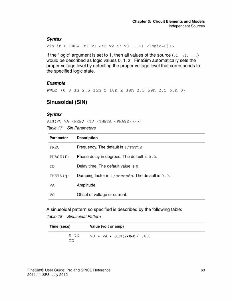
Chapter 3: Circuit Elements and ModelsIndependent Sources
SyntaxVin in 0 PWLZ (t1 v1 <t2 v2 t3 v3 ...>) <logic=0|1>
If the "logic" argument is set to 1, then all values of the source (v1, v2, ...) would be described as logic values 0, 1, z. FineSim automatically sets the proper voltage level by detecting the proper voltage level that corresponds to the specified logic state.
Example
PWLZ (0 0 3n 2.5 15n Z 18n Z 38n 2.5 59n 2.5 60n 0)
Sinusoidal (SIN)
SyntaxSIN(VO VA <FREQ <TD <THETA <PHASE>>>>)
A sinusoidal pattern so specified is described by the following table:
Table 17 Sin Parameters
Parameter Description
FREQ Frequency. The default is 1/TSTOP.
PHASE(f) Phase delay in degrees. The default is 0.0.
TD Delay time. The default value is 0.
THETA(q) Damping factor in 1/seconds. The default is 0.0.
VA Amplitude.
VO Offset of voltage or current.
Table 18 Sinusoidal Pattern
Time (secs) Value (volt or amp)
0 to TD
VO + VA • SIN(2•π•φ / 360)
FineSim® User Guide: Pro and SPICE Reference 632011.11-SP3, July 2012

Chapter 3: Circuit Elements and ModelsIndependent Sources
ExamplesSIN(1 3.3 10MEG 50n 4e6 180)SIN(1.5 0.5 10MEG 50n 0 90)
Exponential (EXP)The standard exponential source allows multiple time delay and time constant pairs without a limit. It is required that each successive delay time for multiple pairs be greater than the last, because the delay is measured from time zero.
SyntaxV1 out gnd EXP (V1 V2 TD1 TAU1 TD2 TAU2 TD3 TAU3 TD4 TAU4 ...)
A exponential function so specified is described by the following table:
TD to TSTOP
VO + VA • Exp[-(time-TD)•θ] •SIN{ 2•π• [FREQ•(time-TD) + φ/ 360] }
Table 19 EXP Parameters
Parameter Description
TAU1(τ1) Rise time constant. The default is TSTEP.
TAU2(τ2) Rise time constant. The default is TSTEP.
TD1 Rise delay time. The default is 0.0.
TD2 Fall delay time. The default is TD1+TSTEP.
V1 Initial value.
V2 Pulsed value.
Table 20 Exponential Pattern
Time (secs) Value (Volt or Amp.)
0 < t <= TD1 Vo=V1
Table 18 Sinusoidal Pattern (Continued)
Time (secs) Value (volt or amp)
64 FineSim® User Guide: Pro and SPICE Reference2011.11-SP3, July 2012

Chapter 3: Circuit Elements and ModelsIndependent Sources
Single-Frequency FM (SFFM)
SyntaxSFFM(VO VA FC MDI FS)
TD1<t<=TD2 Vo=V1+ (V2-V1)*(1-Exp(-(t-TD1)/TAU1)
TD2<t<=TD3 Vo=(Vo|t=TD2)+ (V1-V2)(1-Exp(-(t-TD2)/TAU2))
TD3<t<=TD4 Vo=(Vo|t=TD3)+(V2-V1)*(1-Exp(-(t-TD3)/TAU3)
TD4<t<=TD5 Vo=(Vo|t=TD4)+ (V1-V2)(1-Exp(-(t-TD4)/TAU4))
TDn<t<=TSTOP Vo=(Vo|t=TDn-1)+ (V1-V2)(1-Exp(-(t-TDn-1)/TAUn-1)) when n=even
Vo=(Vo|t=TDn-1)+ (V2-V1)(1-Exp(-(t-TDn-1)/TAUn-1)) when n=odd
Table 21 SFFM Parameters
Parameter Description
FC Carrier frequency in Hz. The default is 1/TSTOP.
FS Frequency in Hz. The default value is 1/TSTOP.
MDI Modulation index. The default is 0.0.
VA Amplitude.
VO Offset.
Table 20 Exponential Pattern (Continued)
Time (secs) Value (Volt or Amp.)
FineSim® User Guide: Pro and SPICE Reference 652011.11-SP3, July 2012

Chapter 3: Circuit Elements and ModelsIndependent Sources
A single-frequency FM function so specified is described by the following table:
ExampleSFFM(1 3.3 3MEG 18 3MEG)
Amplitude Modulation (AM)
SyntaxAM (SA OC FM FC <TD>)
An amplitude modulation function so specified is described by the following table:
Table 22 Single_Frequency FM Pattern
Time (sec.) Value (Volt or Amp.)
time VO+VA ∗ SIN[2∗π∗FC∗time + MDI * SIN(2∗π∗FS∗time)]
Table 23 AM Parameters
Parameter Description
FC Carrier frequency in Hz. The default value is 1/TSTOP.
FM Modulation frequency in Hz. The default value is 1/TSTOP.
OC Offset constant, a unitless constant that determines the absolute magnitude of the modulation. The default is 0.0.
SA Signal amplitude in volts or amps. The default is 0.0.
TD Delay time before start of signal in seconds. The default is 0.0.
Table 24 Amplitude Modulation Pattern
Time (sec.) Value (Volt or Amp.)
time SA ∗ {OS + SIN [2∗π∗FM∗(time – TD) ]} ∗SIN [2∗π∗FC∗(time – TD)]
66 FineSim® User Guide: Pro and SPICE Reference2011.11-SP3, July 2012

Chapter 3: Circuit Elements and ModelsIndependent Sources
ExampleAM(1 3.3 3MEG 18 3MEG)These functions’ waveforms are shown below.
Figure 10 Source Waveforms
Pseudo Random-Bit Generator SourceIn general, pseudo random-bit generator source (PRBS) uses a linear feedback shift register (LFSR) to generate a pseudo random bit sequence. The syntax is as follows:
Vxxx n+ n- LFSR <(> vlow vhigh tdelay trise tfall rate seed <[> taps <]> <)> Ixxx n+ n- LFSR <(> vlow vhigh tdelay trise tfall rate seed <[> taps <]> <)>
Table 25 PRBS Parameters
Parameter Description
rate The bit rate.
FineSim® User Guide: Pro and SPICE Reference 672011.11-SP3, July 2012

Chapter 3: Circuit Elements and ModelsIndependent Sources
Examplevin in gnd LFSR (0 1 1m 1n 1n 10meg 1 [5, 2] rout=10)
Pattern Source (PAT)FineSim Pro supports the time dependent bit pattern (PAT) function. This special function is used to describe some bit patterns in place of PWL in the independent voltage or current sources. FineSim Pro also supports nested structure and pattern-command (.PAT) driven structure for the pattern source function to construct complex bit patterns. The nested structure starts with an open square bracket (‘[‘] and ends with closing square bracket (‘]’).
To create complex bit patterns, the pattern source function can be written using either a nested structure notation or a pattern-command driven notation. (See the .PAT section of Chapter 5, SPICE Options, for more information).
SyntaxPAT ( vhi vlo td tr tf tsample data <RB=val> <R=val> )
or
PAT ( vhi vlo td tr tf tsample [component 1, ..., component n]
seed The initial value loaded into the shift register.
taps The bits used to generate feedback.
tdelay Initial time delay to the first transition.
tfall Duration of the recovery ramp, from the pulse plateau back to the initial value.
trise Duration of the onset ramp, from the initial value o the pulse plateau value.
vhigh The maximum level of voltage or current.
vlow The minimum level of voltage or current.
Table 25 PRBS Parameters
Parameter Description
68 FineSim® User Guide: Pro and SPICE Reference2011.11-SP3, July 2012

Chapter 3: Circuit Elements and ModelsIndependent Sources
+ <RB=val> <R=val> )
Example 1 (simple form)v1 n1 n2 PAT (5 0 1n 2n 5n b1010111 r=2 rb=2 b10m1z)
Example 2 (nested structure form)v1 n1 n2 PAT (5 0 1n 2n 5n [b1101 r=1 rb=2 [b10m1z r=2 rb=2]] r=2 rb=2)v1 n1 n2 PAT (5 0 1n 2n 5n [b1101 [b10m1z r=2 rb=2]] r=2 rb=2)
Table 26 PAT Parameters
Parameter Description
component 1… n
The components that make up nested structures. These structures can be a bit-pattern or a pattern-name defined in other “.pat” command. RB or R can be used in the component.
data Bit string of 1,0, m, or z starting with B, or a pattern-name defined in other .pat command.
PAT Keyword for a time-dependent pattern source.
R=val Keyword to specify the number of repeating operations. R must be an integer. It can be set to 0 or -1. When set to -1, the repeating operation continues forever. When this value is set to less than -1, FineSim Pro automatically resets it to 0.
RB=val Keyword to specify the starting bit when repeating. Default value is 1.
td Delay time from the beginning of the transient interval to the first onset ramp.
tf Duration of the recovery ramp from the high to the low value.
tr Duration of the onset ramp from the low to the high value.
tsample Time spent at 1, 0, m, or z pattern value.
vhi High voltage or current value.
vlo Low voltage or current value.
FineSim® User Guide: Pro and SPICE Reference 692011.11-SP3, July 2012

Chapter 3: Circuit Elements and ModelsDependent Sources/Instances
Dependent Sources/Instances
FineSim Pro support four types of dependent sources/instances:■ E-element: Voltage controlled voltage source (VCVS)■ F-element: Current controlled current source (CCCS)■ G-element: Voltage controlled current source or resistor or capacitor
(VCCS, VCR, VCCAP).■ H-element: Current controlled voltage source (CCVS)
The dependency between these elements and their control source can be expressed by linear, or piece-wise-linear (PWL) functions.
Linear FunctionUse a gain factor to describe the relationship between the controlling source and the controlled element (controlled)=gain×val(controlling). Also, the final value is clamped by MAX and MIN assigned in the instance line. MAX and MIN should be set simultaneously and MAX should be greater than MIN. Otherwise, the clamp assignment is ignored.
Piece-Wise-Linear (PWL) FunctionUse the pairs of data points (at least two) to describe the relationship between the controlling source and the controlled element. PWL(1) is the keyword to declare the PWL function. The pairs of data points (x1 y1 x2 y2 x3 y3 … xi yi) list the values of the controlling nodes (xi) and the corresponding value of the controlled node (yi). The x values must be in increasing order.
Polynomial FunctionUse a polynomial function to describe the relationship between the controlling source and the controlled element. POLY(k) is the keyword to declare the polynomial function and the coefficients P0, P1, …, make up the polynomial function. K is the dimension of the polynomial function, and can be 1, 2, or 3.
When the input value (current or voltage) I1, I2, I3 is given, the function value F is determined by the following expression:
70 FineSim® User Guide: Pro and SPICE Reference2011.11-SP3, July 2012

Chapter 3: Circuit Elements and ModelsDependent Sources/Instances
When k=1:
F = P0 + P1*I1 + P2*I12 + P3*I1
3 + P4*I14 + P5*I1
5 + …When k=2:
F = P0 + P1*I1 + P2*I2 + P3* I12 + P4* I1*I2 + P5* I2
2 + P6* I13 +
P7* I12*I2 + P8* I1*I2
2
+ P9* I23 + …
When k=3:
F = P0 + P1*I1 + P2*I2 + P3*I3 + P4*I12 + P5*I1*I2 + P6*I1*I3 +
P7*I22 + P8*I2*I3
+ P9*I32 + P10*I1
3 + P11*I12*I2 + P12*I1
2*I3 + P13*I1*I22 +
P14*I1*I2*I3+ P15*I1*I3
2 + …
Gate FunctionUse the gate function to describe the relationship between the controlling source and the controlled element. type(k) is the keyword to declare the gate function. type can be AND, NAND, OR, or NOR, and k is the number of inputs. The function is determined by the given PWL function and only one of inputs determines its output. For AND/NAND, the smallest value among the inputs is used as the input of the PWL function. For OR/NOR, the largest value among the inputs is used as the input of the PWL function.
Voltage Controlled Voltage Source-VCVS (E-element)FineSim Pro supports voltage-controlled voltage sources VCVS (E-elements). These sources are functions of the input voltages (linear, piece-wise-linear, polynomial, gates, delays, and behavioral).
Syntax
LinearExxx N+ N- <VCVS> in+ in- gainval <MAX=val> <MIN=val>+ <SCALE=val><TC1=val> <TC2=val><ABS=1> <IC=val>
PWLExxx N+ N- <VCVS> PWL(1) in+ in- <SCALE=val>+ <TC1=val><TC2=val> x1,y1 x2,y2 x3,y3 …. <IC=val>
FineSim® User Guide: Pro and SPICE Reference 712011.11-SP3, July 2012

Chapter 3: Circuit Elements and ModelsDependent Sources/Instances
PolynomialExxx N+ N- <VCVS> POLY(k) in1+ in1- ... ink+ ink- <SCALE=val>+ <TC1=val><TC2=val><MAX=val><MIN=val><ABS=1> P0 P1 … <IC=val>
GatesExxx N+ N- <VCVS> type(k) in1+ in1- ... ink+ ink- <SCALE=val><TC1=val><TC2=val> x1,y1 x2,y2 x3,y3 … <IC=val>
DelayExxx N+ N- <VCVS> DELAY in+ in- TD=val + <SCALE=val> <TC1=val> <TC2=val>
Ideal Transformer (Element)Exxx N+ N- TRANSFORMER in+ in- k
Behavioral Voltage Source
Exxx N+ N- VOL=”equation” <MAX=val> <MIN=val> <SCALE=val>
Conditional Equation in Behavioral VCVS (E-element)
FineSim Pro supports the behavior of VCVS statements that have a conditional expression for an OR gate, as shown in the following example, where conditional V(A) and V(B) are gated with an OR function:
Exxb Y VSS VOL='((V(A)>0.3) || (V(B)>0.3))?V(VDD):V(VSS)'
Table 27 VCVS Parameters
Parameter Description
ABS If ABS is 1, output is absolute value.
DELAY Keyword to indicate delayed instance.
gainval Value of voltage gain. The default is 1.
IC The initial estimate of the value(s) of the controlling voltage.
The default is 0.0.
in+, in- Positive and negative nodes. One pair for each dimension.
k Dimension of polynomial function or number of inputs to gate function.
72 FineSim® User Guide: Pro and SPICE Reference2011.11-SP3, July 2012

Chapter 3: Circuit Elements and ModelsDependent Sources/Instances
ExamplesE0 out0 Rvdd DELAY in0 Rvdd TD=20nsE1 n+ 0 in+ in- gain=5.5 max=3.3 min=0.05E77 np nn PWL(1) inp1 inp2 1 1.1 2 2.2 3 3.3 DELTA=0.5
The first example is a voltage source with the value of the voltage difference between in0 and Rvdd and delay a time constant of 20ns.
The second example is a VCVS instance 5.5 times the voltage difference between node in+ and in- and clamped in the region of 0.05 to 3.3V.
lin Optional keyword to indicate a linear function.
MAX Maximum output voltage value.
MIN Minimum output voltage value.
N+, N- Positive and negative nodes for the controlled instance, respectively.
P0, P1 … Polynomial coefficients.
POLY Keyword to indicate polynomial function.
PWL(1) Keyword to indicate a piece-wise-linear function.
SCALE Scale factor for element value.
TC1,TC2 First and second order temperature coefficients.
SCALEeff = SCALE ∗ (1 + TC1 ∗ dT + TC2 ∗ dT2 )
TD Delay time for delayed instance. The default is 0.0.
type Type of gates. Must be and, nand, or, or nor.
VCVS Optional keyword to indicate voltage controlled voltage source.
x1,x2, … Voltage of controlling nodes. You can specify up to 100 points.
y1,y2, … Corresponding voltage value of controlled instance.
Table 27 VCVS Parameters (Continued)
Parameter Description
FineSim® User Guide: Pro and SPICE Reference 732011.11-SP3, July 2012

Chapter 3: Circuit Elements and ModelsDependent Sources/Instances
The third example is a VCVS with a value equal to 1.1 when the voltage difference of inp1 and inp2 is 1, 2.2 when the voltage difference is 2 and so on. Furthermore, it uses DELTA=0.5 to round-off the corner for derivative continuity sake.
Laplace Function
FineSim Pro supports the Laplace function.
SyntaxGxxx n+ n- LAPLACE in+ in- k0, k1, ..., kn / d0, d1, ..., dm
H(s) is a rational function, in the following form:
H(s)=( k0 + k1s +&+ knsn)/(d0 + d1s + &+ dmsm)
The following parameters can be used to define the values of all coefficients (k0, k1, ..., d0, d1, ...).
Example G22 0 out LAPLACE in 0 1.0 / 1.0 2.0 2.0 1.0
The G22 element statement describes a third-order low-pass filter, with the transfer function:
H(s)=1/(1 + 2s + 2s2 + s3)
Current Controlled Current Source-CCCS (F-element)FineSim Pro supports current-controlled voltage sources. These sources are functions of the input voltages (linear, piece-wise-linear, polynomial, gates, delays, and behavioral).
LinearFxxx N+ N- <CCCS> vname <lin> gainval <MAX=val> <MIN=val>+ <SCALE=val> <TC1=val> <TC2=val> <M=val> <ABS=1> <IC=val>
PWLFxxx N+ N- <CCCS> PWL(1) vname <M=val> <SCALE=val>+ <TC1=val> <TC2=val><ABS=1> x1,y1 x2,y2 x3,y3 …. + <IC=val>
74 FineSim® User Guide: Pro and SPICE Reference2011.11-SP3, July 2012

Chapter 3: Circuit Elements and ModelsDependent Sources/Instances
PolynomialFxxx N+ N- <CCCS> POLY(k) vin1… vink <M=val> <SCALE=val>+ <TC1=val><TC2=val><MAX=val><MIN=val><ABS=1> P0 P1 …<IC=val>
GatesFxxx N+ N- <CCCS> type(k) vin1... vink <M=val> <SCALE=val><TC1=val><TC2=val> x1,y1 x2,y2 x3,y3 … <IC=val>
DelayFxxx N+ N- <CCCS> DELAY vname TD=val + <SCALE=val> <TC1=val> <TC2=val>
Table 28 CCCS Parameters
Parameter Description
ABS If ABS=1, output is absolute value.
CCCS Optional keyword to indicate the current controlled current source.
DELAY Keyword to indicate a delayed instance.
gainval Value of voltage gain. The default is 1.
IC The initial estimate of the value(s) of the controlling current.
The default is 0.0.
k Dimension of the polynomial function or number of inputs to the gate function.
lin Optional keyword to indicate a linear function.
M Multiplier for parallel connection of current source
MAX Maximum output current value.
MIN Minimum output current value.
N+, N- Positive and negative nodes for the controlled instance, respectively.
P0, P1 … Polynomial coefficients.
FineSim® User Guide: Pro and SPICE Reference 752011.11-SP3, July 2012

Chapter 3: Circuit Elements and ModelsDependent Sources/Instances
ExamplesFp in out CCCS Vzero 0.4 max=1m min=1u M=4Fil 0 out PWL(1) VSRC 1m 10m -2m 0.1m
The first example is a CCCS connected between in and out. The current that controls the value of Fp flows through the voltage source Vzero. The value is 0.4×I(Vzero)×4 and is clamped by (1m, 1u).
The second example is a CCCS connected between 0 and out. When the current through VSRC is 1mA, the current value is 10mA. When the current through VSRC is –2mA, the current value is 0.1mA.
POLY Keyword to indicate a polynomial function.
PWL(1) Keyword to indicate a piece-wise-linear function.
SCALE Scale factor for element value.
TC1,TC2 First and second order temperature coefficients.
SCALEeff = SCALE ∗ (1 + TC1 ∗ dT + TC2 ∗ dT2 )
TD Delay time for delayed instance. The default value is 0.0.
type Type of gates, which must be and, nand, or or nor.
vname, …. Names of voltage source through which the controlling current flows. At least one voltage source name should be defined.
x1,x2, … Current through controlling voltage source vname. You can specify up to 100 points.
y1,y2, … Corresponding current value of the controlled instance.
Table 28 CCCS Parameters (Continued)
Parameter Description
76 FineSim® User Guide: Pro and SPICE Reference2011.11-SP3, July 2012

Chapter 3: Circuit Elements and ModelsDependent Sources/Instances
Voltage Controlled Current Source- VCCS (G-element)Voltage Controlled Resistor - VCRVoltage Controlled Capacitor - VCCAP
LinearGxxx N+ N- <VCCS> in+ in- transconductance <M=val> <MAX=val><MIN=val>+ <SCALE=val> <TC1=val> <TC2=val> <ABS=1> <IC=val>
or
Gxxx N+ N- VCR in+ in- transfactor <M=val> <MAX=val> <MIN=val>+ <SCALE=val> <TC1=val> <TC2=val> <ABS=1> <IC=val>
PWLGxxx N+ N- <VCCS> PWL(1) in+ in- <M=val> <SCALE=val>+ <TC1=val> <TC2=val> x1,y1 x2,y2 x3,y3 …. <IC=val>
or
Gxxx N+ N- VCR PWL(1) in+ in- <M=val> <SCALE=val>+ <TC1=val> <TC2=val> x1,y1 x2,y2 x3,y3 …. <IC=val>
or
Gxxx N+ N- VCCAP PWL(1) in+ in- <M=val> <SCALE=val>+ <TC1=val> <TC2=val> x1,y1 x2,y2 x3,y3 …. <IC=val>
NPWL & PPWL Gxxx N+ N- <VCCS> NPWL(1) in+ in- <DELTA=val> <SCALE=val> <M=val>+ <TC1=val><TC2=val> x1,y1 x2,y2 ... x100,y100 <IC=val> Gxxx N+ N- <VCCS> PPWL(1) in+ in- <DELTA=val> <SCALE=val> <M=val>+ <TC1=val> <TC2=val> x1,y1 x2,y2 ... x100,y100 <IC=val>
PolynomialGxxx N+ N- <VCCS> POLY(k) vin1… vink <M=val> <SCALE=val>+ <TC1=val><TC2=val><MAX=val><MIN=val><ABS=1> P0 P1 …<IC=val>
GatesGxxx N+ N- <VCCS> type(k) vin1 ... vink <M=val> <SCALE=val><TC1=val><TC2=val> x1,y1 x2,y2 x3,y3 … <IC=val>
FineSim® User Guide: Pro and SPICE Reference 772011.11-SP3, July 2012

Chapter 3: Circuit Elements and ModelsDependent Sources/Instances
DelayGxxx N+ N- <VCCS> DELAY in+ in- TD=val + <SCALE=val> <TC1=val> <TC2=val>
Support for G-Element
FineSim supports G-element for foster pole-residue form. The form is:
Gxxx N+ N- FOSTER IN+ IN- k0 k1 +(Re{A1}, Im{A1}) / (Re{p1}, Im{p1})+(Re{A2}, Im{A2}) / (Re{p2}, Im{p2})+...
A pole-residue pair is represented by four numbers (real and imaginary part of the residue, then real and imaginary part of the pole).
Behavioral Current Sourcegxxx node1 node2 noise=’noise_expression’
The above syntax creates a simple two-terminal current noise source. The output noise is noise_expression*H, where H is the transfer function from the terminal pair (node1,node2) to the circuit output, where the output noise is measured.
Examplegnoise 1 2 noise='4*1.3806266e-23*(TEMPER+273.15)*0.001'
NPWL Function
If the node is connected, in- is connected to n-, as follows:
If v(N+, N-) > 0, the controlling voltage is v(in+,in-).
Otherwise, the controlling voltage is v(in+,N+).
If node in- is connected to n+, then if v(N+,N-) < 0, the controlling voltage is v(in+,in-). Otherwise, the controlling voltage is v(in+,N+).
PPWL Function
If the node is connected in- is connected to n-, as follows:
If v(N+,N-) < 0, the controlling voltage is v(in+,in-).
Otherwise, the controlling voltage is v(in+,N+).
78 FineSim® User Guide: Pro and SPICE Reference2011.11-SP3, July 2012

Chapter 3: Circuit Elements and ModelsDependent Sources/Instances
For node in- connected to N+, if v(N+,N-) > 0, the controlling voltage is v(in+,in-). Otherwise, the controlling voltage is v(in+,N+).
Laplace Function
FineSim Pro supports the Laplace function.
SyntaxGxxx n+ n- LAPLACE in+ in- k0, k1, ..., kn / d0, d1, ..., dm
H(s) is a rational function, in the following form:
H(s)=( k0 + k1s +&+ knsn)/(d0 + d1s + &+ dmsm)
The following parameters can be used to define the values of all coefficients (k0, k1, ..., d0, d1, ...).
Example G22 0 out LAPLACE in 0 1.0 / 1.0 2.0 2.0 1.0
The G22 element statement describes a third-order low-pass filter, with the transfer function:
H(s)=1/(1 + 2s + 2s2 + s3)
Table 29 VCCS, VCR,VCCAP Parameters
Parameter Description
ABS If ABS=1, output is absolute value.
DELAY Keyword to indicate a delayed current source.
IC The initial estimate of the value(s) of the controlling voltage.
The default is 0.0.
k Dimension of the polynomial function or number of inputs to the gate function.
M Multiplier for parallel connection of controlled instances
MAX Maximum current or resistance value.
MIN Minimum current or resistance value.
FineSim® User Guide: Pro and SPICE Reference 792011.11-SP3, July 2012

Chapter 3: Circuit Elements and ModelsDependent Sources/Instances
ExamplesG2 out 0 VCCS pnode nnode 1e-6 M=2Gswitch 1 2 VCR PWL(1) Vswitch 0 0, 10MEG 1, 1e-6Gcap 22 19 VCCAP PWL(1) V+ V-
N+, N- Positive and negative nodes for the controlled instance, respectively.
P0, P1 … Polynomial coefficients.
POLY Keyword to indicate a polynomial function.
PWL(1) Keyword to indicate a piece-wise-linear function.
SCALE Scale factor for element value.
TC1,TC2 First and second order temperature coefficients.
SCALEeff = SCALE ∗ (1 + TC1 ∗ dT + TC2 ∗ dT2 )
TD Delay time.
transconductance
Voltage to current conversion factor. The default is 1.
transfactor Voltage to resistance conversion factor. The default is 1.
type Type of gates, which must be and, nand, or, or nor.
VCCAP Keyword for voltage controlled capacitor
VCCS Optional keyword to indicate current controlled current source. This is the default mode for a G-element.
VCR Keyword for voltage controlled resistor.
x1,x2, … Value of controlling voltage between node in+ and in-. You can specify up to 100 points.
y1,y2, … Corresponding current/resistance/capacitance value of the controlled instance.
Table 29 VCCS, VCR,VCCAP Parameters (Continued)
Parameter Description
80 FineSim® User Guide: Pro and SPICE Reference2011.11-SP3, July 2012

Chapter 3: Circuit Elements and ModelsDependent Sources/Instances
+ 1 1e-12+ 2 2e-12+ 3 3e-12
The first example is a current source connected between out and 0. It depends on the voltage between pnode and nnode and the transconductance is 1e-6 with a multiplier of 2.
The second example is a way to describe the operation of the switch. That is, when the controlled voltage is 0, it is off (with high resistance 1e7) and when the voltage is 1Volt, it is on (with the low resistance 1e-6).
The third example is a voltage dependent capacitor with the capacitance value 1pF when the controlled voltage is 1v and 2pF when the controlled voltage is 2v and so on.
Current Controlled Voltage Source- CCVS (H-element)
LinearHxxx N+ N- <CCVS> vname <lin> transconductance <MAX=val> <MIN=val>+ <SCALE=val> <TC1=val> <TC2=val> <ABS=1> <IC=val>
PWLHxxx N+ N- <CCVS> PWL(1) vname <DELTA=val> <SCALE=val>+ <TC1=val> <TC2=val> x1,y1 x2,y2 x3,y3 ….x100,y100 <IC=val>
PolynomialHxxx N+ N- <CCVS> POLY(k) vin1… vink <SCALE=val>+ <TC1=val><TC2=val><MAX=val><MIN=val><ABS=1> P0 P1 …<IC=val>
GatesHxxx N+ N- <CCVS> type(k) vin1 ... vink <SCALE=val><TC1=val><TC2=val> x1,y1 x2,y2 x3,y3 … <IC=val>
FineSim® User Guide: Pro and SPICE Reference 812011.11-SP3, July 2012

Chapter 3: Circuit Elements and ModelsDependent Sources/Instances
DelayHxxx N+ N- <CCVS> DELAY vname TD=val + <SCALE=val> <TC1=val> <TC2=val>
Table 30 CCVS Parameters
Parameter Description
CCVS Optional keyword to indicate e current controlled voltage source.
DELAY Keyword to indicate delayed voltage source.
IC The initial estimate of the value(s) of the controlling current.
The default is 0.0.
k Dimension of polynomial function or the number of inputs to the gate function.
lin Optional keyword to indicate linear function.
MAX, MIN Clamp the value for a linear function.
N+, N- Positive and negative nodes for the controlled instance, respectively.
P0, P1 … Polynomial coefficients.
POLY Keyword to indicate a polynomial function.
PWL(1) Keyword to indicate piece-wise-linear function.
SCALE Scale factor for element value.
TC1,TC2 First and second order temperature coefficients.
SCALEeff = SCALE ∗ (1 + TC1 ∗ dT + TC2 ∗ dT2 )
TD Delay time.
transconductance
Current to voltage conversion factor.
type Type of gates, which must be and, nand, or, or nor.
82 FineSim® User Guide: Pro and SPICE Reference2011.11-SP3, July 2012

Chapter 3: Circuit Elements and ModelsS-Element
ExampleHqq 2 1 Vsuppply 1000
This example is a voltage source dependant on the current through Vsupply and the transconductance is 1000.
S-Element
FineSim Pro supports S-parameter models with the Touchstone file format (Revision 1.1), according to the following syntax:
Syntax.model smodel s tstonefile=s_par_sim.s2p s0 sin sout gnd mname=smodel fbase=val fmax =val highpass=val lowpass=val passive=[0|1] rational_fun_reuse=[1|0] tf_file = filename
where smodel is the name given to the model and s_par_sim.snp is the name of the Touchstone file. The Touchstone naming convention is followed, so the snp suffix indicates that this is an n-port model. The parameters specified in the element statement have a higher priority over the model statement.
Example
S2 in out inb outb MNAME=Scase_bp.MODEL Scase_bp S N=4 TSTONEFILE="Case1_bp.s4p" TYPE=s Z0=50 FBASE=10E6 FMAX=25E9
vname, ... Names of voltage sources through which the controlling current flows. At least one voltage name must be defined.
x1,x2, … Controlling current through vname. You can specify up to 100 points.
y1,y2, … Corresponding voltage values of the controlled instances.
Table 30 CCVS Parameters (Continued)
Parameter Description
FineSim® User Guide: Pro and SPICE Reference 832011.11-SP3, July 2012

Chapter 3: Circuit Elements and ModelsS-Element
Note:S-elements are only allowed with grounded reference nodes. Other choices of reference nodes will run, but can produce incorrect results.
Table 31 S-element Parameters
Parameter Description
causal Passivity enforcement:
Recursive convolution: passivity is enforced after vector fitting. It can be helpful to resolve a time step too small issue introduced from fitting.Direct convolution: passivity is enforced for non-passive models.
fbase Base frequency used for transient analysis (IFFT). If fbase is not specified, FineSim uses the reciprocal of the transient runtime as the base frequency.
fmax Maximum frequency for transient analysis. Default is maximal frequency in touchstone file.
highpass 0: Cut off.
1: Use highest frequency point.
2: Linear extrapolation using the highest 2 points.
3: Using window function.
4: Set to 0. This is the default value.
intdattyp Data type for interpolation of the complex data:
RI: real-imaginary based interpolation (default).MA: magnitude-angle based interpolation.
interpolation The interpolation method:
Only linear interpolation is supported now (default).
lowpass 0: Special model fitting. This is the default value.
1. Use magnitude of the lowest point.
2. Linear extrapoluation using magnitude of lowest 2 points.
mname Name of the S model.
84 FineSim® User Guide: Pro and SPICE Reference2011.11-SP3, July 2012

Chapter 3: Circuit Elements and ModelsS-Element
The following options are for use with S-elements.
finesim_selem_conv_method = [0|1|2|3]0—recursive convolution1—direct convolution
2—linear convolution
3—default option.
nd1 nd2 ... ndN <ndRef>
Nodes of an S-element. There are three definitions:
1. No reference node ndRef, GND node is the default reference node.2. With on reference node ndRef.3. Each port has its own reference node. Each pair of the nodes (nd1+ nd1- nd2+ nd2- ... ndN+ ndN-) constructs one of the N ports of the S-element.
passive 1: Enforce passivity to the transfer functions. Passivity is enforced after vector fitting. And it can be used to resolve a time step too small issue in S-Element circuits.
0: No enforce.
For recursive convolution mode only.
rational_func_reuse
1. Store the fitted rational function to the next run in .tf file.
0: No storation.
For recursive convolution mode only.
tf_file=filename
For recursive convolution only. tf_file specifies the rational function file to reuse.
type Parameter type:
S: (scattering) (default).Y: (admittance).Z: (impedance).
Z0 Characteristic impedance value for the reference line. Default =50?. Only 50? is supported now.
Table 31 S-element Parameters
Parameter Description
FineSim® User Guide: Pro and SPICE Reference 852011.11-SP3, July 2012

Chapter 3: Circuit Elements and ModelsTransmission Lines
FineSim Pro chooses the convolution method according to the circuit type.
finesim_selem_passive=[0|1]By default, there is no passivity enforcement during vector fitting and recursive convolution. By either setting fines_selem_passive=1 or passive=1 in S-element instance description, passivity is enforced after vector fitting.
finesim_selem_passive=1 can be used to resolve a time step too small issue in S-Element circuits.
Vector Fitting is a robust numerical method for rational approximation in the frequency domain. It permits to identify state space models directly from measured or computed frequency responses, both for single or multiple input/output systems. The resulting approximation has guaranteed stable poles that are real or come in complex conjugate pairs.
finesim_selem_order = n (n>=0)Used for recursive convolution only. The number of poles used in rational form. The default value is 10.
finesim_selem_max_rmserr = 1e-kThis option is for recursive convolution only. The max rms error allowed for vector fitting. If the max rms error is larger than this specified number, the FineSim Pro session stopped after the parsing/vector fitting stage. You can try to increase the order or reduce the max_rmserr specification. If rmserr does not reach the new max_rmserr specification after adding orders, report this to your Synopsys representative. The default value is 1e-3.
Transmission Lines
For transmission line, FineSim Pro supports both the ideal transmission line element and the lossy U element statement. The ideal transmission line only delays the difference between the signal and the reference. Like SPICE, FineSim Pro also uses a U element to model single and coupled lossy transmission lines for various line structures.
86 FineSim® User Guide: Pro and SPICE Reference2011.11-SP3, July 2012
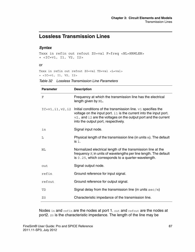
Chapter 3: Circuit Elements and ModelsTransmission Lines
Lossless Transmission Lines
SyntaxTxxx in refin out refout Z0=val F=freq <NL=NRMLEN>+ <IC=v1, I1, V2, I2>
or
Txxx in refin out refout Z0=val TD=val <L=val>
+ <IC=v1, I1, V2, I2>
Nodes in and refin are the nodes at port 1. out and refout are the nodes at port2. Z0 is the characteristic impedance. The length of the line may be
Table 32 Lossless Transmission Line Parameters
Parameter Description
F Frequency at which the transmission line has the electrical length given by NL.
IC=v1,i1,v2,i2 Initial conditions of the transmission line. v1 specifies the voltage on the input port. i1 is the current into the input port. v2, and i2 are the voltages on the output port and the current into the output port, respectively.
in Signal input node.
L Physical length of the transmission line (in units m). The default is 1.
NL Normalized electrical length of the transmission line at the frequency F, in units of wavelengths per line length. The default is 0.25, which corresponds to a quarter-wavelength.
out Signal output node.
refin Ground reference for input signal.
refout Ground reference for output signal.
TD Signal delay from the transmission line (in units sec/m)
Z0 Characteristic impedance of the transmission line.
FineSim® User Guide: Pro and SPICE Reference 872011.11-SP3, July 2012

Chapter 3: Circuit Elements and ModelsTransmission Lines
expressed in either of two forms. The transmission delay, TD, may be specified directly (as TD=10ns, for example). Or, a frequency F may be given, together with NL, the normalized electrical length of the transmission line with respect to the wavelength in the line at the frequency F. If a frequency is specified but NL is not, 0.25 is assumed. That is, the frequency is assumed to be the quarter-wave frequency. Although both forms for expressing the line length are indicated as optional, one of the two must be specified.
This instance models only one propagating mode. If all four nodes are distinct in the actual circuit, then two modes may be excited. To simulate such a situation, two transmission-line instances are required. The initial condition (IC) specification consists of the voltage and current at each of the transmission line ports. The initial conditions (if any) apply only if the UIC option is specified on the .TRAN statement.
A lossy transmission line with zero loss may be more accurate than the loss-less transmission line due to implementation details.
ExampleTd 1 0 2 0 Z0=55 TD=12ns
Circuit Examples*** Lossless Transmission Line (match) ***.global dd.subckt inv y ampa y a dd dd p l=0.5u w=100u ad=2.1p as=2.1p ps=1u pd=1umna y a 0 0 n l=0.5u w=50u as=2.1p ad=2.1p ps=1u pd=1u.ends inv.model n nmos level=49.model p pmos level=49.param dd=3.3vdd dd 0 ddvinp inp 0 pulse(0 dd 5n 0.1n 0.1n 5n 10n)x1 out1 inp inv
*** characteristic impedance of t1 matches rout2 ***t1 out1 0 out2 0 z0=50rout2 out2 vx 50vx vx 0 ‘dd/2’.tran 0.1n 30n.probe v(out1) v(out2) v(inp).end
This case is a loss-less transmission line with impedance match. The next case shows the results when impedance is mismatched.
88 FineSim® User Guide: Pro and SPICE Reference2011.11-SP3, July 2012

Chapter 3: Circuit Elements and ModelsTransmission Lines
*** Lossless Transmission Line (not matched) ***.global dd.subckt inv y ampa y a dd dd p l=0.5u w=100u ad=2.1p as=2.1p ps=1u pd=1umna y a 0 0 n l=0.5u w=50u as=2.1p ad=2.1p ps=1u pd=1u.ends inv.model n nmos level=49.model p pmos level=49.param dd=3.3vdd dd 0 ddvinp inp 0 pulse(0 dd 5n 0.1n 0.1n 5n 10n)x1 out1 inp inv
*** characteristic impedance of t1 does not match rout2 ***t1 out1 0 out2 0 z0=50 td=10nrout2 out2 vx 100vx vx 0 ‘dd/2’.tran 0.1n 30n.probe v(out1) v(out2) v(inp).end
Lossy Transmission Lines
SyntaxUxxx in1 <in2 <...in5>> refin out1 <out2 <...out5>> refout MNAME+ L=val <LUMPS=val>
Table 33 Lossy Transmission Line Parameters
Parameter Description
F Frequency at which the transmission line has the electrical length given by NL.
inn Signal input node for the nth transmission line (in1 is required.).
L Physical length of the transmission line (in meters).
LUMPS Number of lumped-parameter sections.
mname U-model lossy transmission-line model reference name.
FineSim® User Guide: Pro and SPICE Reference 892011.11-SP3, July 2012

Chapter 3: Circuit Elements and ModelsTransmission Lines
A lossy transmission line with zero loss may be more accurate than the lossless transmission line due to implementation details.
ExampleU12 1 0 2 0 model_loss
Circuit Example*** Lossy Transmission Line (U-element) *** .option post
vin 12 0 pwl (0 0v 250ps 0v 350ps 2v 10n 2v) RG 12 10 50 RLD1 1 0 50 C1 10 0 2p C2 1 0 2p Uelem1 3 10 2 0 5 1 4 0 example L=0.178 lumps=1 Uelem2 3 10 2 0 5 1 4 0 example L=1 lumps=100 R2 2 0 50 R3 3 0 50 R4 4 0 50 R5 5 0 50
.model example U Level=3 NL=3 Elev=2 Llev=0 Plev=1 Nlay=2 + L11=2.311uH L12=0.414uH L22=2.988uH L33=2.813uH + Cr1=17.43pF C12=5.41pF Cr2=10.1pF + C13=1.08pF C23=5.72pF Cr3=17.67pF + R1c=42.5 R2c=41.0 R3c=33.5 + Gr1=0.44387mS G12=0.1419mS Gr2=0.3671mS + G13=23.23uS G23=90uS Gr3=0.38877mS
NL Normalized electrical length of the transmission line at the frequency F, in units of wavelengths per line length. The default value is 0.25, which corresponds to a quarter-wavelength.
outn Signal output node for the nth transmission line (each input port must have a corresponding output port).
refin Ground reference for input signal.
refout Ground reference for output signal.
Table 33 Lossy Transmission Line Parameters (Continued)
Parameter Description
90 FineSim® User Guide: Pro and SPICE Reference2011.11-SP3, July 2012

Chapter 3: Circuit Elements and ModelsTransmission Lines
+ R1s=0.00135 R2s=0.001303 R3s=0.001064
.tran 10ps 20ns
.probe v(*)
.end
Transmission Line (W-element)FineSim supports Transmission Line (“W”) elements, according to the following syntax:
SyntaxWxxx in1 ... inN refin out1 ... outN refout N=val L=val+ <RLGCMODEL=name or RLGCFILE=name>
ExampleW2 1 2 3 0 4 5 6 0 N=3 L=0.6 RLGCFILE=example.rlgcW3 1 2 0 4 5 0 N=2 L=0.6 RLGCMODEL=rlgc_model
RLGCMODEL:* RLGCMODEL example matrices (N=2)
Table 34 Transmission Line (W-element) Parameters
Parameter Description
in1 ... inN Signal input nodes
L Length of a transmission line
N Number of signal conductors (excluding the reference conductor)
out1 ... outN Signal output nodes
refin Reference for input signal
refout Reference for output signal
RLGCFILE Name of the external file with RLGC parameter
RLGCMODEL Name of the RLGC model
FineSim® User Guide: Pro and SPICE Reference 912011.11-SP3, July 2012

Chapter 3: Circuit Elements and ModelsTransmission Lines
.MODEL rlgc_model W MODELTYPE=RLGC N=2+ Lo=+ 1.0e-6+ 5.0e-7 1.2e-6+ Co=+ 2.0e-11+ -4.0e-12 2.1e-11+ Ro= + 30+ 0 28+ Go=+ 5.0e-4+ -1.0e-4 4.5e-4.endRLGCFILE:* example.rlgc* N2* Lo1.0e-65.0e-7 1.2e-6* Co2.0e-11-4.0e-12 2.1e-11* Ro300 28* Go5.0e-4-1.0e-4 4.5e-4
Where the Lo, Co, Ro, Go are DC inductance matrix per unit length, DC capacitance matrix per unit length, DC resistance matrix per unit length, and DC shunt conductance matrix per unit length, respectively.
Skin-Effect in W-ElementsFineSim Pro supports skin effect resistance matrix Rs for a transmission line (W-element). This matrix can actually be a single line or large matrix. For example, in a RLGC model, you might have Rs defined as follows:
:+ Rs = 1.8066439e-03
Or you might have it defined as a matrix:
:
92 FineSim® User Guide: Pro and SPICE Reference2011.11-SP3, July 2012

Chapter 3: Circuit Elements and ModelsSub-Circuit Instances (X-elements)
+ Rs = 1.8247631e-03+_ 2.4873219e-06 1.8247631e-03
Sub-Circuit Instances (X-elements)
A sub-circuit instance is a call statement which instantiates a .SUBCKT or .MACRO definition. The sub-circuit definition,.SUBCKT, must be predefined for the creation of a reusable circuit (instance).
A simple method for naming the sub-circuit nodes and elements is to prefix them with the sub-circuit call name Xyyyy.
SyntaxXyyyy N1 <N2 N3 …..> subname <param=val …><M=val>
ExampleX1 2 4 17 31 MULTI WN = 100 LN = 5
This example calls a sub-circuit model named MULTI. It assigns the parameters WN=100 and LN=5 to the parameters WN and LN given in the .SUBCKT statement (not shown). The instance name is X1.
Table 35 Subcircuit Instance Parameters
Parameter Description
M Multiplier. Makes the sub-circuit appear as M sub-circuits in parallel.
N1,N2,N3,… The list of input/output signal names of the sub-circuit.
param A parameter name set to a value for use only in the sub-circuit.
subname Sub-circuit or macro model reference name.
Xyyy Sub-circuit or macro element name, which must begin with an X.
FineSim® User Guide: Pro and SPICE Reference 932011.11-SP3, July 2012

Chapter 3: Circuit Elements and ModelsSub-Circuit Instances (X-elements)
94 FineSim® User Guide: Pro and SPICE Reference2011.11-SP3, July 2012

4
4FineSim Pro Options
This chapter describes how to use the FineSim Pro simulation controls, and most importantly, its various simulation mode options.
FineSim is a unified simulation engine with PRO and SPICE modes. These modes can be applied to different design types based on accuracy, performance and capacity requirements. Each mode handles a design differently but all start by reading in a transistor level netlist and SPICE models.
FineSim Pro analyzes the sea of transistors and categorizes them into different Channel Connected Components (CCC) groups, called partitions, while SPICE mode puts all transistors into one partition. For each partition, FineSim Pro builds and solves a matrix as any other SPICE simulator does. The electrical communication from partition to partition is facilitated through an event-driven procedure that controls the simulation calculation process from primary inputs to primary outputs. If the event control signal at a partition boundary is not crossing the pre-defined threshold, the partition driven by this signal won’t be activated and no calculation is performed at all to save simulation time. By employing this event-driven technique for partitions, FineSim Pro can run up to 1000X faster than SPICE mode, which usually takes much longer to solve its single matrix.
Besides circuit partitioning, FineSim Pro provides a rich set of options to control simulation accuracy and performance. For example, a MOSFET transistor can be modeled at different levels of detail to represent its electrical characteristics. There are also various numerical integration methods and error tolerances that help you meet your simulation needs. For designs with repeated structures such as memories, FineSim Pro automatically applies its adaptive hierarchical database to speed up simulation and maintain high accuracy. This chapter presents basic options that control the accuracy, performance and capacity in a FineSim Pro simulation. If they conflict with options in the native SPICE deck from other SPICE simulators, FineSim Pro options take precedence. For
FineSim® User Guide: Pro and SPICE Reference 952011.11-SP3, July 2012

Chapter 4: FineSim Pro OptionsGeneral Control Options
example, the accurate option in other simulators is replaced by a combination of FineSim Pro options that address accuracy considerations differently.
General Control Options
FineSim Pro includes the following general control options. You can use wildcards for sub-circuit names that appear in any FineSim Pro option. For example, in the following command, all nand cells and aoi cells are in model=2 while the rest of the design is in model=4.
.option finesim_model=”4 nand*:2 aoi*:2”
You can specify all global default options in the finesim.cfg file. The configuration file is a collection of commonly used FineSim Pro options. This file serves as a central location for maintaining and managing default values. You can find the finesim.cfg file in the installation directory. Upon installation, it is an empty file. It is your responsibility to create and maintain this file. Because these options are used for any FineSim Pro simulation, please add options to this global configuration file with extreme care.
When the $FINESIM_HOME environment variable sets the directory (that is, the finesim.cfg file is properly located within the installation directory) FineSim Pro reads finesim.cfg and changes all FineSim Pro options as specified in this file.
You can use FineSim -h to get a list of the FineSim Pro controls and options that can be used on the command line.
Note:FineSim Pro supports user environment variables and the Unix home ‘~’ character. However, ‘$’ is also a comment character in the Spice netlist format. So, a single quotation mark is required when you use the ‘$’ character. Consider the following examples:
.inc ‘$process/model.inc’
.inc ~/device/process/model.inc
Note:FineSim SPICE and the FineSim Pro SPICE modes also rely on this file. You must use extreme care when adding FineSim Pro options to this file.
You can specify FineSim Pro options using the finesim.cfg file or in the input SPICE deck or in any one of the included files. Options specified locally always override any options in the finesim.cfg file.
The FineSim Pro .log file prints out all options in finesim.cfg but separates them from those options defined in the input SPICE deck or included files.
96 FineSim® User Guide: Pro and SPICE Reference2011.11-SP3, July 2012

Chapter 4: FineSim Pro OptionsFineSim Pro Commands
A sample configuration file might appear as follows:
.option finesim_fcapmin=0.1f
.option finesim_resmin=0.01
.option finesim_cutnode=1000
.option finesim_spred=2
Using finesim.cfg to Define Common FineSim Pro OptionsFineSim Pro has extended support for the finesim.cfg file. FineSim Pro searches within four directories to find this file. The directory names and their priorities in searching are as follows:
1. $FINESIM_HOME—the installation directory.
2. $FINESIM_PROJ_CFG—the project directory.
3. $HOME—the home directory.
4. The directory of the input file.
The search is performed in the order listed, with the input file directory being the highest priority. The highest priority finesim.cfg file can incrementally add the options not yet set and also override the options set in the lower priority finesim.cfg files. For example, if no $FINESIM_PROJ_CFG variable is defined, the search for finesim.cfg is initiated in the order $FINESIM_HOME, $HOME and then the input file directory. If a finesim.cfg file exists in the current working directory and contains options already specified in a lower-level finesim.cfg file, the options in the input file directory’s finesim.cfg file take precedence over any finesim.cfg instances in $FINESIM_HOME or $HOME. Any unique options defined in $FINESIM_HOME or $HOME and not defined in the finesim.cfg file in the input file directory will be retained.
Note:Any FineSim Pro option defined in the simulation deck always overrides the same option in any finesim.cfg file.
FineSim Pro Commands
FineSim Pro provides the following categories of configuration commands:■ General Commands■ DC Initialization Commands
FineSim® User Guide: Pro and SPICE Reference 972011.11-SP3, July 2012
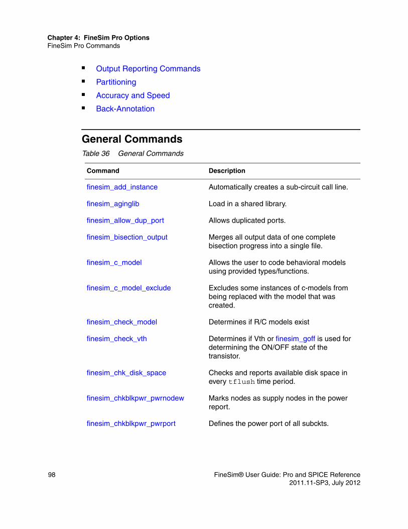
Chapter 4: FineSim Pro OptionsFineSim Pro Commands
■ Output Reporting Commands■ Partitioning■ Accuracy and Speed■ Back-Annotation
General CommandsTable 36 General Commands
Command Description
finesim_add_instance Automatically creates a sub-circuit call line.
finesim_aginglib Load in a shared library.
finesim_allow_dup_port Allows duplicated ports.
finesim_bisection_output Merges all output data of one complete bisection progress into a single file.
finesim_c_model Allows the user to code behavioral models using provided types/functions.
finesim_c_model_exclude Excludes some instances of c-models from being replaced with the model that was created.
finesim_check_model Determines if R/C models exist
finesim_check_vth Determines if Vth or finesim_goff is used for determining the ON/OFF state of the transistor.
finesim_chk_disk_space Checks and reports available disk space in every tflush time period.
finesim_chkblkpwr_pwrnodew Marks nodes as supply nodes in the power report.
finesim_chkblkpwr_pwrport Defines the power port of all subckts.
98 FineSim® User Guide: Pro and SPICE Reference2011.11-SP3, July 2012

Chapter 4: FineSim Pro OptionsFineSim Pro Commands
finesim_chkznode_vth Sets the Vth value in calculating the ON/OFF state of MOSFET.
finesim_clampVerilog Clamps stamped conductance value to finesim_gmax.
finesim_convlevel Determines how FineSim attempts to solve the "time step too small" error.
finesim_detect_lvdd_static Supports logic probing by a generated voltage source.
finesim_enhanced_tcl_mode Allows TCL to perform model name matching.
finesim_exit Causes FineSim to terminate after SPF annotation.
finesim_exitwarn Change a FineSim Pro warning to an error by defining the warning string.
finesim_fcapmodel Controls the modeling of floating capacitances.
finesim_fcapmodel Controls the modeling of floating capacitances.
finesim_floating_gate_gshunt Adds a conductance between floating gate node and ground.
finesim_fsc_auto_detect Voltage levels corresponding to logic levels or setting the VDD for a model will be handled automatically using this option.
finesim_fsc_vdd Specifies the supply voltage for the C-model interface.
finesim_goff Works with the .CHKZNODE statement to determine if a MOSFET is on or off.
finesim_ignore Ignores instances or sub-circuits in simulation for higher perfomance.
Table 36 General Commands (Continued)
Command Description
FineSim® User Guide: Pro and SPICE Reference 992011.11-SP3, July 2012

Chapter 4: FineSim Pro OptionsFineSim Pro Commands
finesim_ignore_float_isrc Ignores the floating current source and ouputs a warning message.
finesim_ignore_option_error This option ignores misinput for the finesim_hiersim and finesim_pwrblock options.
finesim_ignore_subblk_option_error
Prints a warning message if a sub-circuit name is not defined.
finesim_irem_rms Calculate RMS value of the current and report it as AC current.
finesim_keepzeroparms Use zero values for PS, PD, AS, and AD parameters for BSIM models.
finesim_lsf_format_chars Allows usage of Spectre Verilog-A special characters
finesim_max_width_tol Sets tolerance range for transistor width when it exceeds max. defined width.
finesim_model_verification_mode Use tighter simulation settings for simulations with model qualification.
finesim_negres Keeps negative resistors in the netlist.
finesim_no_swap Controls whether disk swap can be used with the simulation runs out of memory.
finesim_restore (.SNAPSHOT) Captures a snapshot of the dynamic state of the circuit in motion.
finesim_rpitft_mode Enables FineSim support for SmartSpice TFT Model correlation.
finesim_scale Applies the scale factor for sub-circuits.
finesim_set_cpu_time Sets the maximum elapse time for a simulation.
Table 36 General Commands (Continued)
Command Description
100 FineSim® User Guide: Pro and SPICE Reference2011.11-SP3, July 2012

Chapter 4: FineSim Pro OptionsFineSim Pro Commands
DC Initialization CommandsFineSim Pro provides the following options you can use to control DC initialization.
finesim_single_bin_model_check Apply a similar model binning check for non-binning models.
finesim_skip_unused_param Ignores HSIM-specific parameters to avoid ineffective warning messages
finesim_subckt_dup_rule Selects which sub-circuit definition to use in simulation.
finesim_tcl_init_file Specifies the TCL file for FineSim to source for the simulation.
finesim_tstop Modifies the tstop specified in the .tran command line, to shorten/extend simulation length.
finesim_vector Specifies a vector file for comparison with simulation results.
finesim_vector_mode Sets the I/O vector file format for bus signals.
finesim_warn_limit Sets the number of all warning messages to a specific number of lines.
finesim_write_instance_table Generates an instance file.
finesim_write_mcparam Saves the generated parameters in each run to a file.
Table 37 DC Initialization Commands
Command Description
finesim_dcalg Sets algorithm for DC convergence.
Table 36 General Commands (Continued)
Command Description
FineSim® User Guide: Pro and SPICE Reference 1012011.11-SP3, July 2012

Chapter 4: FineSim Pro OptionsFineSim Pro Commands
Output Reporting CommandsFineSim Pro provides the following options you can use to control output reporting.
finesim_dceffort Controls effort applied for DC convergence.
finesim_gen_ic_op Generates the .op file when it is not created by default.
finesim_gic Sets conductance value of the resistor in the Norton-type voltage source.
Table 38 Output Reporting Commands
Command Description
finesim_bisection_output Controls the measure file and waveform database output for each bisection sweep
finesim_bisection_summary Controls the bisection summary file .bisect_mt0.
finesim_chk_devport Checks device port name during wildcard matching of .probe statement.
finesim_double_precision_output Changes output file value from 4 bytes to 8 bytes.
finesim_fsdb_limit Specifies a size limit for fsdb files.
finesim_fsdb_split Allows splitting of fsdb files.
finesim_identical_mc_instance_file Generate the same random number sequence for the Monte Carlo simulation.
finesim_ignore_chkfunc_error Continues the simulation with a warning instead of an error and exiting.
Table 37 DC Initialization Commands (Continued)
Command Description
102 FineSim® User Guide: Pro and SPICE Reference2011.11-SP3, July 2012

Chapter 4: FineSim Pro OptionsFineSim Pro Commands
finesim_iovec_abs_value Treats all the time values in the vector file as absolute time.
finesim_iovec_vih Sets the logichv outside of a vector file.
finesim_iovec_vil Sets the logiclv outside of a vector file.
finesim_iprbtol Sets the current tolerance for the current print out.
finesim_maxicout Sets maximum number of node voltages included in the .ic file.
finesim_measout Controls the measurement file format.
finesim_mparcheck Determines if MOSFET model parameters will be checked.
finesim_num_meas_log Limits number of measurement results output to the screen and log file.
finesim_num_meas_per_line Outputs measurement values on multiple lines.
finesim_output Sets the output file format for saving transient analysis results.
finesim_output_fname_type Defines the naming convention for output files with the netlist has an .alter and/or .temp sweep parameter.
finesim_output_range Limits output of transient results of waveforms to the waveform file.
finesim_prbexprvar Determines whether to make any signals in the expression of .probe out.
finesim_prbport Determines whether port voltages wil be probed, depending on tolerance.
finesim_prbtol Obsolete. Aliased to finesim_vprbtol
Table 38 Output Reporting Commands (Continued)
Command Description
FineSim® User Guide: Pro and SPICE Reference 1032011.11-SP3, July 2012

Chapter 4: FineSim Pro OptionsFineSim Pro Commands
finesim_print_period Defines the fixed interval at which the .print command will print to the output file.
finesim_print_to_probe Converts all .print statements to .probe statements.
finesim_probe_passive_device Probes passive devices like R/C.
finesim_profile Generates profile data in a file after transient analysis.
finesim_pt0_format Changes into a list format where it prints the time point value for each node.
finesim_remove_probe_prefix Removes prefix from output signal.
finesim_set_special_char Appends a "\" before special characters during PSF output.
finesim_skipwarn Determines amount and type of information output to the log file.
finesim_tflush Flushes output files at time interval x.
finesim_use_old_trout Determines whether to use new or previous output file name extensions for .print and .measure.
finesim_utf_mode Ouputs compressed UTF for Veritools.
finesim_vprbtol Sets the voltage tolernace for voltage print out.
finesim_vpwltol Removes small changes in the voltage input waveform in PWL format.
finesim_wdf_limit Sets the number of warning messages to a number of specified lines.
finesim_wdf_mode Controls the amount of compression for wdf output file.
Table 38 Output Reporting Commands (Continued)
Command Description
104 FineSim® User Guide: Pro and SPICE Reference2011.11-SP3, July 2012

Chapter 4: FineSim Pro OptionsFineSim Pro Commands
PartitioningFineSim Pro provides the following options you can use to control partitioning.
Table 39 Partitioning Commands
Command Description Mode
finesim_cutnode Reduces partition size for signal nodes.
Fast SPICEOnly
finesim_flatsize Sets a threshold to flatten sub-circuits before partitioning starts.
Fast SPICEOnly
finesim_gmax Clamps the stamped conductance value to finesim_gmax.
Fast SPICEOnly
finesim_hiersim Selects hierarchical simulation mode.
Fast SPICEOnly
finesim_hstolscale Sets a multiplier applied to all internal tolerance values for sub-circuits that will be simulated with the hiersim method.
Fast SPICEOnly
finesim_partition Specifies how partitioning is done.
Fast SPICEOnly
finesim_print_max_con_node Identifies nodes with greatest number of connections for connectivity report.
Fast SPICEOnly
finesim_pwrblock Detects transitors that control or regulate power.
Fast SPICEOnly
finesim_pwrnet Specifies names of actual power supply nets that are connected to transistors.
Fast SPICEOnly
FineSim® User Guide: Pro and SPICE Reference 1052011.11-SP3, July 2012

Chapter 4: FineSim Pro OptionsFineSim Pro Commands
Accuracy and SpeedFineSim Pro provides the following options you can use for accuracy and speed.
finesim_pwrnode Specifies names of nets that are considered to be generated by designed voltage and power generators.
Fast SPICEOnly
finesim_pwrtol Specifies the voltage tolerance to control an event between a power block partition and the other partitions.
Fast SPICEOnly
Table 40 Accuracy and Speed Commands
Command Description
finesim_accelerate_rom Improves performance for the simulation of ROM circuits.
finesim_bytol Sets the voltage value to use in determining whether a MOS is latent.
finesim_chgtol Sets absolute charge tolerance during charge-based 1teq time step algorithm.
finesim_delmax Sets maximum value of internal time step in simulation.
finesim_dvmax Sets the maximum voltage change of a node in a single time step.
finesim_fcapmin Converts a small coupling capacitance into two grounded capacitance values.
finesim_flatsize Sets the ratio to determine whether a floating capacitance will be grounded.
Table 39 Partitioning Commands (Continued)
Command Description Mode
106 FineSim® User Guide: Pro and SPICE Reference2011.11-SP3, July 2012

Chapter 4: FineSim Pro OptionsFineSim Pro Commands
finesim_leakage_mode Uses more conservative leakage tolerances for better accuracy.
finesim_loadmodel Sets the capacitive load model that a partition output drives.
finesim_mcbrief Limits information written to the log file.
finesim_mcseed Provides a seed to produce the same sequence of random numbers in Monte Carlo simulation.
finesim_method Sets the numerical integration method used during a transient analysis.
finesim_mode Sets the simulation mode.
finesim_model Sets the modeling method of the MOSFETs.
finesim_montecarlo_mode Determines whether to enable or disable Fast Monte Carlo mode.
finesim_prelayout_models Sets which model FineSim should use.
finesim_qlevel Controls the tolerance of the signal level accuracy.
finesim_resmax Sets maximum value for a resistor to be considered in simulation.
finesim_resmin Sets minimum value for a resistor to be considered in simulation.
finesim_reuse_mos_model Reuses MOSFET models built in the previous iteration.
finesim_speed Sets the speed level of the simulation.
finesim_tolscale Sets a multiplier applied to all internal tolerance values.
Table 40 Accuracy and Speed Commands (Continued)
Command Description
FineSim® User Guide: Pro and SPICE Reference 1072011.11-SP3, July 2012

Chapter 4: FineSim Pro OptionsFineSim Pro Commands
Back-AnnotationFineSim Pro commands for back-annotation are divided into DSPF annotation, DPF annotation, and non-ideal power analysis. See Chapter 6, Back-Annotation, for more details about post-layout simulation with back-annotation.
finesim_tsc Sets the algorithm mode for time-step control during transient analysis.
finesim_tunit Defines the base time unit of the simulation.
finesim_vdd Sets the VDD value used for MOS table generation.
Table 41 DSPF Annotation Commands
Command Description
finesim_add_divider Defines a character to use as a hierarchy divider.
finesim_em_layer Used with finesim_spfred to reduce resistors not specified with this option.
finesim_repdot Replaces "." with another character.
finesim_simple_em_naming Avoid EM analysis being unable to find the signal nets.
finesim_spf Specifies the DSPF file that contains SPF data extracted from the layout interconnects.
finesim_spf_add_irem_window Specifies analysis time range for the IR/EM .em file.
finesim_spf_keep_hier Helps reduce the memory footprint.
finesim_spf_matcheffort Performs more rigorous naming matching for SPF net and devices.
Table 40 Accuracy and Speed Commands (Continued)
Command Description
108 FineSim® User Guide: Pro and SPICE Reference2011.11-SP3, July 2012

Chapter 4: FineSim Pro OptionsFineSim Pro Commands
finesim_spf_removetoprce Removes the top level parasitics in the finesim_spfinst=2 back-annotation flow.
finesim_spf_selective_backannotation
Supports back-annotation based on the activity of a prelayout file.
finesim_spf_sensitive Supports case sensitivity for Spectre netlist back-annotation flow.
finesim_spf_spice_names Specifies whether the instance names in the DSPF file include SPICE type prefix.
finesim_spfallowerror Continues simulation even when there is a parsing error of SPF.
finesim_spfallowmissinginstance Annotates the net to which the missing device was attached as an RC net.
finesim_spfcnet Specifies the net names to be annotated with lumped capacitance only.
finesim_spfeqr, finesim_spf2eqr, finesim_spfeqrfile, finesim_spfeqronly
Specifies the output file and net of a DSPF file.
finesim_spffcmin Sets the minimum floating capacitor value allowed for back-annotation.
finesim_spffcnet Keeps the floating capacitance for C-only back-annotation.
finesim_spfinst Controls whether the instance section of DSPF file is used for back-annotation.
finesim_spfmergeport Merges ports in a DSPF net.
finesim_spfnonet Specifies the nets that are not going to be back-annotated by DSPF data.
finesim_spfprb Sets the probe mode for DSPF nodes.
Table 41 DSPF Annotation Commands (Continued)
Command Description
FineSim® User Guide: Pro and SPICE Reference 1092011.11-SP3, July 2012

Chapter 4: FineSim Pro OptionsFineSim Pro Commands
finesim_spfprb_mode Flattens SPF-annotated node name.
finesim_spfprefix Lists the prefixes that should be removed from device names.
finesim_spfrcnet Specifies the net names that will be annotated with RC trees.
finesim_spfred Sets the RC reduction mode and whether DSPF RCs are reduced or not.
finesim_spfreplast Controls how the representative node is chosen when annotating DSPF.
finesim_spfrmax Sets the maximum resistor value allowed for back-annotation.
finesim_spfrmin Sets the minimum resistor value allowed for back-annotation.
finesim_spfrptrmax Sets the warning threshold number for SPF resistors.
finesim_spfscale Sets the scale for devices in the DSPF file.
finesim_spfsplitnet Splits nets into multiple nets after layout is complete.
finesim_spfsuffix Defines the suffix in an SPF file.
finesim_spftc Sets the time constant value used by the RC reduction algorithm.
finesim_spred Determines the type and level of RC reduction.
finesim_spredtc Sets the time constant value used by the RC reduction algorithm.
Table 41 DSPF Annotation Commands (Continued)
Command Description
110 FineSim® User Guide: Pro and SPICE Reference2011.11-SP3, July 2012

Chapter 4: FineSim Pro OptionsFineSim Pro Commands
Table 42 DPF Annotation Commands
Command Description
finesim_dpf Specifies the DPF file that contains the extracted device parameter data.
finesim_dpfadddev Controls whether DPF devices that are not in the netlist are added.
finesim_dpfhdiv Sets the divider character for hierarchical names in DPF files.
finesim_dpfprefix Lists the prefixes that should be removed from DPF device names.
finesim_dpfscale Sets the scale for devices in the DPF file.
finesim_dpfsuffix Defines the suffix in a DPF file.
Table 43 Non-Ideal Power Analysis Commands
Command Description
finesim_em_layer Used with finesim_spfred to reduce resistors not specified with this option.
finesim_spfeqr, finesim_spf2eqr, finesim_spfeqrfile, finesim_spfeqronly
Specifies the output file and net.
finesim_spfpost Sets the node names for post analysis of DSPF back-annotated simulation.
finesim_spfpost_end, finesim_spfpost_out, finesim_spfpost_start
Specifies the output file, start time, and end time of EM analysis.
finesim_spfpost_out_only Probes the internal nodes of power/ground during EM analysis.
finesim_spfpwr Sets the annotation mode for power supply nodes.
FineSim® User Guide: Pro and SPICE Reference 1112011.11-SP3, July 2012

Chapter 4: FineSim Pro OptionsFineSim Pro Command Reference
FineSim Pro Command Reference
finesim_accelerate_romImproves performance for the simulation of ROM circuits.
Example.option finesim_accelerate_rom
finesim_add_instanceAutomatically creates a sub-circuit call line.
Syntax.option finesim_add_instance=<[instance_name:]subckt_name>
If the user doesn't specify instance_name, FineSim will automatically name it ’x1’.
Example.option finesim_add_instance="x1:inv" or .option finesim_add_instance="inv"
In the above example, FineSim makes a top-level instance x1 which comes from sub-circuit inv.
finesim_add_dividerThis option defines a character to use as a hierarchy divider.
Example.option finesim_add_divider="/"
where FineSim Pro will consider the "/" character a hierachy divider.
112 FineSim® User Guide: Pro and SPICE Reference2011.11-SP3, July 2012
Chapter 4: FineSim Pro OptionsFineSim Pro Command Reference
finesim_aginglibUse to load aging model shared library into FineSim. See Chapter 18, FineSim Reliability Analysis Interface for more details.
Syntax.option finesim_aginglib=”filename”
finesim_allow_dup_portAllows duplicated ports. The default value is 1. When finesim_allow_dup_port=1, FineSim continues simulation regardless of duplicate ports. When you set this option to 0, FineSim stops the simulation when there is a duplicated port.
Example.option finesim_allow_dup_port=[0|1]
finesim_bisection_outputThis option controls the measure file and waveform database output for each bisection sweep. The default value is 1.
Syntaxfinesim_bisection_output = [0|1|2]
where:■ 0 — no bisection sweep measurement is output; only the final waveform is
saved.■ 1 — (default) each bisection sweep measurement is lumped into a single
mt0 file; only the final waveform is saved.■ 2 — each bisection sweep measurement is lumped into a single mt0 file;
each bisection sweep waveform is saved with the prefix extension _bsX.
FineSim® User Guide: Pro and SPICE Reference 1132011.11-SP3, July 2012

Chapter 4: FineSim Pro OptionsFineSim Pro Command Reference
finesim_bisection_summaryThis option controls the bisection summary file .bisect_mt0, which contains the final measurement data of the bisection sweep.
Syntax.option finesim_bisection_summary = [0|1|2]
where:■ 0 — bisection summary is not generated.■ 1 — (default) one bisec_mt0 file for the whole simulation (alter/temp/sweep).■ 2 — one summary bisec_mt0 file for each alter/temp.
finesim_bytolSets the voltage value to use in determining whether a MOS is latent. A MOS transistor is latent when its terminal voltages are stable within a defined limit. Model evaluation can be skipped for these transistors.
The default value of spicehd is 0.1mV. The default value of the other spice and pro modes is 1mV.
Model evaluation bypass is disabled for DC/AC analyses. It is enabled only during transient analysis.
Examples.option finesim_bytol=0.05mV.option finesim_bytol=0
In the first example, a MOS transistor is latent if its terminal voltages vary less than 0.05mV and no model evaluation will be performed under this voltage limit.
In the second example, no MOSFETs are latent because no voltage variation will be smaller than 0. This means that all models will be re-evaluated.
finesim_c_modelThe c-model code is a set of C-function APIs which allows a user to code-up behavioral models using provided types and functions. It allows you to define a
114 FineSim® User Guide: Pro and SPICE Reference2011.11-SP3, July 2012

Chapter 4: FineSim Pro OptionsFineSim Pro Command Reference
model with ports and assign/obtain analog voltages or digital values to those ports.
finesim_c_model_excludeThis option excludes some instances of C-models from being replaced with the model that was created.
Example.option finesim_c_model_exclude = "x1 x3"
This option is intended to be used where multiple instances of the same C-model would normally all be replaced with the model. Using the exclusion option allows some instances to remain as transistor level instances.
finesim_check_modelThis option determines if R/C models exist. The default value is 0, which means FineSim does nothing for "model not found RC" devices. If it is set to 1, then FineSim checks the proper model for RLC and terminates if it fails.
Syntax.option finesim_check_model=[0|1]
finesim_check_vthThis option is used for Check High Impedance State Node (.CHKZNODE) to determine if Vth or finesim_goff is used for determining the ON/OFF state of the transistor. The default value is 1, which uses the Vth method.
Syntax.option finesim_check_vth=[0/1]
where:
0 — finesim_goff ( Off : gm < finesim_goff ).
1 — Vth ( Off : Vgs < Vth @ NMOS).
FineSim® User Guide: Pro and SPICE Reference 1152011.11-SP3, July 2012

Chapter 4: FineSim Pro OptionsFineSim Pro Command Reference
finesim_chgtolSets the absolute charge tolerance for all capacitances during the charge-based lteq time step algorithm. Smaller value means more precise simulation.
The default value is 1e-15 coulombs.
Example.option finesim_chgtol=1e-14
The absolute charge tolerance on a capacitor is set to 1e-14 coulombs.
finesim_chk_devportThis option checks the device port name during wildcard matching in the .probe statement. When this option is set to 0 (which is the default), Finesim Pro will disable wildcard matching for device port name and will consider the port names which have been specifically named. When this option is set to 1, FineSim Pro will allow wildcard matching.
Syntax.option finesim_chk_devport=<0 | 1>
Example.option finesim_chk_devport=1.probe v(xi1.xg.xgperm_top.xpd38<0>.xpdlat<6>.xmm7.mtp:g)
Where ’g’ means the second terminal of the MOSFET, regardless of the actual pin name.
finesim_chk_fsdbThis option prevents overwriting fsdb files. The default value is 0. If set to 1, FineSim will generate a input_machineName_processID.fsdb file.
116 FineSim® User Guide: Pro and SPICE Reference2011.11-SP3, July 2012

Chapter 4: FineSim Pro OptionsFineSim Pro Command Reference
finesim_chk_disk_spaceSets this option to check and report available disk space in every tflush time period. (The default is every 10% of the transient window.) When set 0, FineSim Pro does not check disk space while set 1 it does. The default value is 0.
finesim_chkblkpwr_pwrnodeThis option will mark all specified nodes as supply nodes in the power report. This option supports wildcards.
Syntaxfinesim_chkblkpwr_pwrnode ="node1 node2..."
finesim_chkblkpwr_pwrportThis option defines the power port of all subckts. This is a global option that applies to all .chkblkpwr commands. The defined power port will be treated as a supply node. Wildcards are also supported for defining power ports.
Syntax.option finesim_chkblkpwr_pwrport="port1 port2 ..."
The above will mark all port name matching these patterns as supply nodes for all subckts.
finesim_chkznode_vthThis option is used for Check High Impedance State Node (.CHKZNODE) to set the Vth value in calculating the ON/OFF state of MOSFET. By default, FineSim will automatically determine this value by calculating the Vth of the device. When the user specifies this option, MOSFET is considered off when the gate voltage (Vg) is below the finesim_chkznode_vth value.
Example.option finesim_chkznode_vth=0.3
FineSim® User Guide: Pro and SPICE Reference 1172011.11-SP3, July 2012

Chapter 4: FineSim Pro OptionsFineSim Pro Command Reference
The above example will set the Vth value to 0.3.
finesim_clampVerilogWhen you enable conductance clamping by setting the option finesim_clampVerilog=1 or finesim_clampVerilog, FineSim Pro clamps the stamped conductance value (dI/dV) to finesim_gmax (which defaults to 100). FineSim Pro issues a warning message if the conductance value exceeds finesim_gmax. When this option is enabled, FineSim Pro always clamps g, even when it does not issue the warning message.
Given the flexibility provided by Verilog-A, it is possible to create models containing terms whose derivatives are singular (infinite), and used as conductance values. FineSim Pro detects this and may issue a warning, as follows:
WARNING! g(1.000000e+12) across nodes: (abc, GND) is larger than gmax(1.000000e+02), in instance 'x' of model ‘my_model’-------> Port #1= 0.000000e+00-------> Port #2= 6.605598e-08-------> Port #3= 6.605598e-08-------> Port #4= 1.981679e-07-------> Port #5= 1.981679e-07-------> Port #6= 1.981679e-07
Note:FineSim Pro only prints a few such warnings, to prevent unreasonable growth of the log file.
finesim_convlevelFor transient analysis as well as in DC analysis, you sometimes run into a time step too small error. This error indicates that the numerical iteration routines have failed and cannot reach convergence. To solve this problem, FineSim Pro includes an effort-level parameter, finesim_convlevel.
You cn use the finesim_convlevel parameter, as follows:
finesim_convlevel=x
This option determines how vigorously FineSim attempts to solve the time step too small error. Possible values are 0, 1, 2 and 3. The default value is 0.
118 FineSim® User Guide: Pro and SPICE Reference2011.11-SP3, July 2012

Chapter 4: FineSim Pro OptionsFineSim Pro Command Reference
Generally, you need not set this option unless FineSim Pro has reported the following error in your log file:
ERROR! time step too small (diverged). Setting theoption'finesim_convlevel=<1 or 2>' may help.
Note:Simulation speed is impacted by the value of this option, with finesim_convlevel=0 requiring no additional time and finesim_convlevel=2 being the most time–consuming.
This option accepts three values of x: 1, 2, 3, in addition to 0 which turns the option off and is the default value. finesim_convlevel helps with convergence in the case of circuits which give rise to “difficult” matrices. Said difficulties can arise from unusual circuit topology, model parameters or model behavior. The various levels of convlevel use different techniques to get around these difficulties and try to force convergence despite them.
While this option can sometimes very significantly reduce the runtime for runs that need it, it can also increase the runtime for circuits that don’t by as much as 50%. Also, the “effort” put into forcing convergence and the ensuing runtime overhead generally increases with the convlevel value. For these reasons, a blanket application of the finesim_convlevel option is not recommended. Instead, start with the lowest values of convlevel first. The techniques used by convlevel=2 are a superset of those used by convlevel=1. Convlevel=3 uses mostly different techniques relative to those of 1,2.
If a circuit is found to require convlevel to converge or run in reasonable time, the best option is to check the circuit topology and element values (that is, very small/large resistors, very large capacitors, FET instance parameters). Another option that can be useful in that circumstance is finesim_mparcheck which checks the parameter values passed down to BSIM models and flags any unusual model parameter values.
finesim_cutnodeUse this option to reduce partition size for signal nodes. The finesim_cutnode option can be given the number of connections that will serve as a threshold for determining which nodes will be cutnodes. For example, if 500 is given, any nodes having 500 or more device connections will be selected as a cutnode. The syntax is as follows:
.option finesim_cutnode=’vdda vpp’
.option finesim_cutnode=500
FineSim® User Guide: Pro and SPICE Reference 1192011.11-SP3, July 2012

Chapter 4: FineSim Pro OptionsFineSim Pro Command Reference
The default value is 0 (disabled) in all fast-spice modes. This option has no meaning for spice modes.
Example .option finesim_cutnode='dout x1.x2q'
finesim_dcalgUse this option to set the algorithm for DC convergence in FineSim Pro for SPICE modes only. Possible values for this parameter are 0, 1, 2, 3, 4 and 5. The default value is 0. When using the default value, FineSim Pro takes the following approach:■ In default mode, FineSim Pro in Spice mode runs through algorithms 1, 2,
3, 4 and 5 for DC convergence. If DC converges in algorithm 1, it will move to next analysis and if DC does not converge with algorithm 1, it will try algorithm 2.
■ If DC does not converge after going through all the algorithms sequentially then “DC not converged” will be reported in the log file and simulation will move to next phase.
■ If finesim_dcalg is set to [1-5], only the specific algorithm will be used for DC convergence.
■ If an invalid number is specified (such as finesim_dcalg=8), a warning will be issued in the log file and FineSim Pro will use the default value.
finesim_dceffortUse this option to control the effort applied in FineSim Pro fast-spice mode for DC convergence. The default value is 1.■ finesim_dceffort = 0 — equivalent to the previous setting, finesim_dcalg=1
in Pro mode. ■ finesim_dceffort = 1 — (default) uses the latest Pro mode DC algorithm.■ finesim_dceffort = 2|3 — increases number of convergence iteration for
DC analysis, 3 being the most iterations.
If an invalid number is given (such as finesim_dceffort=5) a warning will be issued and the tool will use the default behavior.
120 FineSim® User Guide: Pro and SPICE Reference2011.11-SP3, July 2012

Chapter 4: FineSim Pro OptionsFineSim Pro Command Reference
finesim_delmaxSets the maximum value of the internal time step in simulation. You can have different values for different simulation windows. Although a smaller maximum time step improves accuracy for some kinds of circuits (for example a source-less ring oscillator), it slows the simulation down.
If not specified, FineSim Pro will use dynamic delmax value, and there is no delmax information in the log file. However, if you still want to use the previous method to calculate delmax’s value based on the tstep and tstop values of the .TRAN statement as well as the input vectors, then set this option to 0, like:
.option finesim_delmax=0
Then, in your .log file, you can find the internally calculated delmax value, as shown in the following example:
Initializing ...delmax : 1e-08
Based on this value, you might need to manually define a different delmax with the finesim_delmax option to, for example, speed up your simulation. In the first simulation time slot (from t=0 to t=time1), finesim_delmax=default. In the second simulation time slot (from t=time1 to t=time2), finesim_delmax=value1. In the last simulation time slot (from t=time2 to t=end of simulation), finesim_delmax=value2.
.option finesim_delmax=’time1:value1 time2:value2’
Example.option finesim_delmax=’2.2e-6:1e-10 3.8e-06:1e-9’
In the previous example, FineSim Pro makes the following settings for finesim_delmax:
■ From 0 to 2.2us, finesim_delmax=default■ From 2.2us to 3.8us, finesim_delmax=100ps■ From 3.8us to the end of the .tran window, finesim_delmax=1ns
Note:The maximum possible value of delmax that FineSim Pro allows is 1 millisecond.
FineSim® User Guide: Pro and SPICE Reference 1212011.11-SP3, July 2012

Chapter 4: FineSim Pro OptionsFineSim Pro Command Reference
ExpressionsThe finesim_delmax parameter could also be used with an expression, but the usage for a space sign without a bracket is limited and an error message will be issued.
Example.param stoptime=1n .option finesim_delmax='1n+stoptime/10' .option finesim_delmax='1n + stoptime/10' .option finesim_delmax='1n+( stoptime/10 )'
In the above examples, both the first and the last can work well. However, the middle one will get a parser error due to the limited space sign.
finesim_detect_lvddFineSim Pro provides auto-detection of the VDD level for lprobe. The default value of this option is 0.
.option finesim_detect_lvdd=<0|1>
When set to 0, the user should specify low/high threshold voltage for lprobe. If not set, FineSim will stop parsing with an error message. If the option is set to 1, FineSim will automatically detect the VDD level of the lprobed node and use the 20-80 rule.
finesim_detect_lvdd_staticThis option supports logic probing by a generated voltage source.
Syntax.option finesim_detect_lvdd_static = '<nodename>:<value> ...'
Example.option finesim_detect_lvdd_static="VINT1:1.2 VINT2:1.5 VINT3:2.0"
122 FineSim® User Guide: Pro and SPICE Reference2011.11-SP3, July 2012

Chapter 4: FineSim Pro OptionsFineSim Pro Command Reference
finesim_double_precision_outputFor output files, FineSim uses 4bytes of memory for each output value. If this option is set to 1, then FineSim uses 8bytes of memory, which means it could give more precise results, though the filesize would be bigger. The default value is 0.
Syntax.option finesim_double_precision_output=<0|1>
finesim_dpfSpecifies the DPF file that contains the device parameter data extracted from the layout.
Examples.option finesim_dpf=”ddd.dpf”.option finesim_dpf=”eee.dpf”
The DPF files ddd.dpf and eee.dpf will be used for back-annotation.
finesim_dpfadddevControls whether DPF devices that are not in the netlist are added. By default, when FineSim Pro finds a device in a DPF file that was not in the original netlist, it issues a warning and skips the device. For example, if the DPF file contains xinv1/mn1 and xinv1/mn1@2, but there is no xinv1.mn1 in the design, these devices would normally be skipped. Setting finesim_dpfadddev to 1 causes these devices to be added.
Example .option finesim_dpf=”file1.dpf”.option finesim_dpfadddev=1 $ add new dpf devices
FineSim® User Guide: Pro and SPICE Reference 1232011.11-SP3, July 2012

Chapter 4: FineSim Pro OptionsFineSim Pro Command Reference
finesim_dpfhdivSets the divider character for hierarchical names in DPF files. The default value is /.
Example .option finesim_dpf=”file1.dpf”.option finesim_dpfhdiv=”.” $ handle names like xiv1.m32
finesim_dpfprefixLists the prefixes that should be removed from DPF device names. Extraction tools sometimes add an additional type prefix on extracted devices in the DPF file.
Example.option finesim_dpfprefix="m r c q"
xinv1.mn2 might be listed in the DPF file as mxinv1/mn2. The option would remove the leading m in mxinv1/mn2.
finesim_dpfscaleSets the scale for devices in the DPF file. The default behavior is to use the same scale as in the netlist. This option only needs to be used when the DPF scale differs from the netlist scale.
Example .option finesim_dpf=”file1.dpf”.option finesim_dpfscale=1 $ DPF devices should not be scaled.
finesim_dpfsuffixDefines the suffix in a DPF file. In DPF files, when a device has been broken up into fingers, the extra devices and nodes have a suffix added to them. By default, FineSim Pro assumes the suffix is @<number>. But the suffix can be
124 FineSim® User Guide: Pro and SPICE Reference2011.11-SP3, July 2012

Chapter 4: FineSim Pro OptionsFineSim Pro Command Reference
other characters too. For example, consider the following excerpt from a DPF file:
M102 …M102#1 …M102#2 …M102#3 …
FineSim Pro includes this option to define the suffix in a DPF file:
.option finesim_dpfsuffix="string"
Example: .option finesim_dpfsuffix=’#’
FineSim Pro can handle the device with “”#” as suffix in a DPF file.
finesim_dvmaxSets the maximum voltage change of a node in a single time step. Its default value is set by finesim_mode.
The value of finesim_dvmax is used as an upper bound and the actual value is calculated from the VDD value, which is automatically detected or can be calculated according to finesim_vdd.
Example.option finesim_dvmax=0.05m
In this example, the maximum voltage change on any node is limited to 0.05mV.
finesim_em_layerEM analysis should be run with finesim_spfred=0 to avoid losing the resistor information due to RC reduction. However, one can use the option in conjunction with finesim_spfred=1|2 and reduce the resistors that are not specified with this option.
Syntax.option finesim_em_layer=’layer_number1 layer_number2 ….’
FineSim® User Guide: Pro and SPICE Reference 1252011.11-SP3, July 2012

Chapter 4: FineSim Pro OptionsFineSim Pro Command Reference
Example.option finesim_em_layer=’70 75’
The above option will retain the resistors in Layer Numbers 70, 75 and do RC reduction in other layers as per finesim_spfred option.
finesim_enhanced_tcl_modeThis option is required in order for TCL to perform model name matching. If interactive mode (-i –istop) is activated or finesim_tcl_init_file is specified, this option will automatically turn on (or set to 1). Please note that setting this option will increase memory usage for FineSim. The default value is 0.
finesim_exitAn option for equivalent resistor extraction that will cause FineSim to terminate after SPF annotation.
Example.option finesim_exit="spf"
finesim_exitwarnYou can change any FineSim Pro warning to an error by defining the specific warning string(s) with the finesim_exitwarn option. Only one string is supported per option instance.
Example.option finesim_exitwarn="Following MOS()’s operating voltages exceed cache range"
finesim_fcapminSets the minimum value of floating (cross coupling) capacitance. All floating capacitors smaller than this value will be split into grounded capacitors. This prevents unnecessarily large partitions due to small coupling capacitance
126 FineSim® User Guide: Pro and SPICE Reference2011.11-SP3, July 2012

Chapter 4: FineSim Pro OptionsFineSim Pro Command Reference
between signal nets and/or power. The current default value is determined by the finesim_spred setting: spred=1,2 is 1e-20 and spred=3 is 1e-15.
Example.option finesim_fcapmin=10fF
In the above example, all floating capacitors less than 10fF become grounded capacitors.
finesim_fcapmodelThis option controls the modeling of floating capacitances. The user can adjust the fcapmodel setting to gain speed-up for circuits with a large amount of floating capacitances. This option only applies to fast-spice mode. Setting to 1 will yield the best performance, while 3 will give the best accuracy.
Syntax.option finesim_fcapmodel=[1/2/3]
where:
1 — Optimized fcap model for all floating caps.
2 — Optimized fcap model for small floating caps, default for promd and proxd.
3 — Unoptimized fcap model, default for prohd and legacy fast-spice modes.
finesim_flatsizeSets a threshold such that any sub-circuit with a transistor count under it will be flattened before partitioning starts.
A small partition, due to its strong coupling, can increase runtime without any accuracy improvement. This option merges small sub-circuit partitions into a larger one to speed up the simulation run. Its default is 7.
Example.option finesim_flatsize=50
In this example, a sub-circuit with fewer than 50 transistors will be flattened before partitioning.
FineSim® User Guide: Pro and SPICE Reference 1272011.11-SP3, July 2012

Chapter 4: FineSim Pro OptionsFineSim Pro Command Reference
finesim_floating_gate_gshuntA conductance defined by this option is added between the floating gate node and ground. This option will include any floating gate that has R/Cs connected to it.
Example .option finesim_floating_gate_gshunt=1e-9
FineSim Pro will insert a 1e-9 conductance between any floating gate and ground.
The default value for finesim_floating_gate_gshunt is 0.
finesim_fsdb_limitYou can use the finesim_fsdb_limit option to specify a size limit for fsdb files, resulting in the generation of multiple fsdb files of a more manageable size. The finesim_fsdb_limit option accepts integer values representing megabytes. The default value for this option is 0, resulting in one fsdb file.
By default, FineSim Pro creates one single fsdb file without splitting it.
Example.option finesim_fsdb_limit=1500
In the previous example, the limit is set at an integer value of 1500 megabytes or 1.5 gigabytes. In the case of a 3GB file, FineSim Pro would create two 1.5GB .fsdb files.
The default hierarchy delimiter in fsdb output files is '.'. Take care as this can affect FineSim Pro users with custom fsdb readers.
finesim_fsdb_splitThis command allows splitting of FSDB files, based on a time value.
Syntax.option finesim_fsdb_split_time="time1 [time2 time3 ...]"
128 FineSim® User Guide: Pro and SPICE Reference2011.11-SP3, July 2012
Chapter 4: FineSim Pro OptionsFineSim Pro Command Reference
The above example is set to split FSDB at time1, time2, time3, etc.
finesim_fsc_auto_detectVoltage levels corresponding to logic levels or setting the VDD for a model will be handled automatically using this option. Specific unique voltage levels can still be set from within the model itself.
finesim_fsc_vddThis option specifies the supply voltage for the C-model interface. Alternatively, you can use finesim_fsc_auto_detect=1 for automatic detection of supply voltage.
finesim_fsdb_max_sizeTerminates the simulation when the waveform size reaches a specified limit.
Syntax.option finesim_fsdb_max_size=<value>
where the value is in MB. The default is unlimited. Once this option is set, all other size affective options (finesim_fsdb_limit, finesim_fsdb_split_time) will be ignored. Please note that the size of the fsdb can be slightly bit larger than the specified limit to complete writing the buffer in memory.
finesim_gen_ic_opWhen a .op card is included in a simulation deck, the DC operating point is calculated and an output file .op is created. But if the keyword UIC is specified for .tran analysis, this time=0 operation point calculation is not used in the simulation.
If an analysis such as small signal .ac or .net requires an operating point to begin with, the .op card does not have to be specified in the deck and FineSim Pro will always automatically run it. The .op file by default will not be created for such analysis. To generate this file, use the following option:
FineSim® User Guide: Pro and SPICE Reference 1292011.11-SP3, July 2012

Chapter 4: FineSim Pro OptionsFineSim Pro Command Reference
.option finesim_gen_ic_op=0|1
where 1 sets .op file generation.
The .op command also can be used at different time points along a .tran analysis. Consider the following example:
.OP 0n 10n 20n 30n
This creates four .OP files: .op0, .op1, .op2, and .op3.
Multi .op cards, however, are not allowed in a simulation deck.
finesim_gicSets the conductance value of the resistor in the Norton-type voltage source that is tied to a node. The recommended value range is from 1 to 1e10, with its default being 1e10.
A Norton voltage source, which has a resistor in parallel to a current source, is used to maintain a node voltage for .ic conditions. The larger this conductance, the stronger the node voltage it can maintain.
Use this option when you have set .ic conditions but final DC initialization does not converge. Some of the nodes in the .ic file might have inaccurate initial voltages. With a new gic value, usually smaller than its default, the final node voltage will drift to the correct value–for instance, from 0.8v to 0.65v.
Example.option finesim_gic=100
In this example, suppose you have a node .ic value of V(a)=1. This example sets the Norton voltage source to conductance=100mho and I=100A.
finesim_gmaxFineSim Pro clamps the stamped conductance value (dI/dV) to finesim_gmax (which defaults to 100).
130 FineSim® User Guide: Pro and SPICE Reference2011.11-SP3, July 2012
Chapter 4: FineSim Pro OptionsFineSim Pro Command Reference
finesim_goffWorks with the .CHKZNODE statement to determine whether a MOSFET is in the on state or off state. When the Gds of the device is greater than finesim_goff, it’s considered to be turned on.
finesim_hier_delimiterChanges the hierarchical delimiter from "." to another character.
Syntax.option finesim_hier_delimiter="char"
Example.option finesim_hier_delimiter="/"
In the above example, FineSim uses "/" as the hierarchical delimiter instead of "."
finesim_hiersimSelects hierarchical simulation mode. FineSim Pro automatically detects hierarchical structures, such as memory arrays, in a design. However, you can also selectively apply this adaptive hierarchical simulation approach to different portions of a design or disable it completely by using the option finesim_hiersim. It is defined as follows:■ finesim_hiersim = 0: Disables hierarchical detection algorithm.■ finesim_hiersim = 1: Enables hierarchical detection algorithm.
FineSim Pro automatically searches for the best candidate for hierarchical simulation.
Note that 1 can slow down non-memory simulations because this option works well with array structures but not random control logic.
Example.option finesim_hiersim = “subckt1 subckt2 ….”
FineSim® User Guide: Pro and SPICE Reference 1312011.11-SP3, July 2012

Chapter 4: FineSim Pro OptionsFineSim Pro Command Reference
In this example, FineSim Pro selectively applies hierarchical simulation to subckt1, subckt2, ..., and runs the rest of the circuit in flattened mode.
finesim_hstolscaleSets a multiplier applied to all internal tolerance values for sub-circuits that will be simulated with the hiersim method. The smaller is the value, the more accurate the simulation is for those circuit parts. This option is similar to finesim_tolscale, which sets the tolerance scale globally.
Example.option finesim_tolscale = 1.option finesim_hstolscale = 0.01
The sub-circuits that are simulated with hierarchy method have more strict tolerance with multiplier 0.01, while other parts will still use the default tolerance for that simulation mode.
The default value for finesim_hstolscale is 1. It only supports globally setting, and can’t be used for a specific sub-circuit.
finesim_ichierWhen multiple .ICs are given for a node through sub-circuit ports hierarchically, FineSim Pro selects the outermost .IC by default. The user can control the selection with finesim_ichier.
Syntax.option finesim_ichier=local .option finesim_ichier=global (default) ex)
Example.subckt sub1 a c1 a 0 1f .ic v(a)=2v .ends x1 a sub1 .ic v(a)=1v
132 FineSim® User Guide: Pro and SPICE Reference2011.11-SP3, July 2012

Chapter 4: FineSim Pro OptionsFineSim Pro Command Reference
In the example above, when finesim_ichier=global is set, 1v is selected. When finesim_ichier=local is set, 2v is selected.
finesim_identical_mc_instance_fileWhen the option is given with an imc_file as the described syntax, FineSim will generate the same random number sequence for the Monte Carlo simulation for those sub-circuit instances within a parenthesis.
Syntax.option finesim_identical_mc_instance_file=imc_file_nameimc_file( instance_0_1 instance_0_2 instance_0_3 ...)( instance_1_1 instance_1_2 instance_1_3 ...)...
where instance_x_x is a full hierarchical subckt instance name. In the above syntax, any random number generation within instance_0_x will have the same value sequence as instance_1_x.
Example.tran .1n 40n sweep monte=10
.subckt sss 1 2
.param rval=agauss(50,1,1)R1 1 2 R=rvalR2 1 2 R=rval.ends
x1 1 0 sssx2 2 0 sssx3 3 0 sssv1 1 0 1v2 2 0 1v3 3 0 1.print i(v1) i(v2) i(v3).option finesim_identical_mc_instance_file="a.imc".END-----------------------"a.imc"(x1 x3)-----------------------
FineSim® User Guide: Pro and SPICE Reference 1332011.11-SP3, July 2012
Chapter 4: FineSim Pro OptionsFineSim Pro Command Reference
In the above example, the result will show the same values for i(v1) and i(v3), but not for i(v2).
finesim_ignoreUse this option to get rid of instances or sub-circuits from simulation to achieve higher performance.
Example 1.option finesim_ignore=”x1 x2.xinv”
Example 2.option finesim_ignore=”nand”
In the first example, FineSim Pro ignores the x1 and x2.xinv instances in the SPICE netlist. In the second example, FineSim Pro ignores the nand subckt in the SPICE netlist.
FineSim Pro supports wildcards when using the ignore feature.
Example .option finesim_ignore= x101.xj*.xi1
finesim_ignore_chkfunc_errorBy default, FineSim Pro will error out if the circuit check is performed on a floating node, dangling node, and/or a node that doesn't exist in the netlist. When this option is set to 1, FineSim Pro will continue the simulation and bypass the error. The user will still see the error message in the log file.
Please note this option only ignores error messages related to Circuit Checks (.chkxxx) commands, it does not apply to other simulation errors.
finesim_ignore_float_isrcIf a current source, isrc, is connected to a floating node, FineSim Pro has two different default behaviors depending on netlist format. If it is in SPICE format, FineSim Pro exits and outputs an error message as follows:
134 FineSim® User Guide: Pro and SPICE Reference2011.11-SP3, July 2012

Chapter 4: FineSim Pro OptionsFineSim Pro Command Reference
ERROR! Node “:net1” has only 1 connection to a current source ‘:i1’
If it is in Spectre format, FineSim Pro adds a 1 ohm dummy resistor to ground this floating node and outputs a warning message as follows:
WARNING! node ‘:net1” has only 1 connection to a current source ‘:I1’. A grounded resistor inserted
This option allows you to ignore this floating current source and output a warning message.
Example.option finesim_ignore_floating_isrc=1
finesim_ignore_option_errorThis option ignores misinput for the finesim_hiersim and finesim_pwrblock options. The default is 0. When set to 1, FineSim will continue simulation even if those options contain an error.
finesim_ignore_subblk_option_errorFineSim Pro would normally terminate with an ERROR message if the user specified a block level option but the subckt did not exist in the design. When set to 1, FineSim Pro will not ERROR out. Instead, it will print a Warning message and continue the simulation. The default value is 0.
Currently, this option supports ignoring the incorrect block level option value for following options:■ finesim_mode■ finesim_model■ finesim_speed■ finesim_partition
Syntax.option finesim_ignore_subblk_option_error=<0|1>
FineSim® User Guide: Pro and SPICE Reference 1352011.11-SP3, July 2012

Chapter 4: FineSim Pro OptionsFineSim Pro Command Reference
finesim_iovec_abs_valueBy default (0), FineSim treats the time value in the vector file as incremental from the last time value. If set to 1, FineSim will treat all the time values in the vector file as absolute time.
Examplesignal a bradix 11io iilogichv LOGICHV_PARAMlogiclv LOGICLV_PARAMperiod '2*tCK'slope tt#0 00#10 10#30 01
By default, signal a will be high at 10ns and signal b will be high at 40ns ( 10n + 30n ). With this option, signal b will instead be high at 30ns.
finesim_iovec_vihSets the logichv outside of a vector file. FineSim supports setting the voltage threshold of vector files on individual pins using .option finesim_iovec_vih="signal_name:vih_level".
Examples■ .option finesim_iovec_vih="level" — set vih level.■ .option finesim_iovec_vih="signal:level" — set vih level for individual
signal.■ .option finesim_iovec_vih="level signal:level ..." — set level 1 for
global vih and set vih level 2 for signal vih.
finesim_iovec_vilSets the logiclv outside of a vector file. FineSim supports setting the voltage threshold of vector files on individual pins using .option finesim_iovec_vil="signal_name:vil_level". See above for syntax options.
136 FineSim® User Guide: Pro and SPICE Reference2011.11-SP3, July 2012

Chapter 4: FineSim Pro OptionsFineSim Pro Command Reference
finesim_iprbtolSets the current tolerance for the current print out. The default value is 1e-12amp. You can use this option to control the resolution of output waveforms in fsdb/wdf.
finesim_irem_rmsBy default (0), FineSim reports the AC current for EM analysis which has both positive and negative swing. Setting this option to 1 will calculate RMS value of the current and report it as AC current.
Syntax.option finesim_irem_rms=[0|1]
finesim_keepzeroparmsSometimes an instance call in a netlist passes zero values for PS, PD, AS, and AD parameters in BSIM MOSFETs. Since these parameters are not physical and can cause convergence problems, FineSim has an option to ignore these zero-specified values and substitute its own calculated values as it would normally do if these parameters were omitted from the netlist.
Syntax.option finesim_keepzeroparms=[0|1]
The default value is 1, where zero parameters are kept. 0 will substitute PS, PD , AS, AD with calculated value from BSIM equations.
ExampleMxxx D G S B l=length w=width as=0 ad=0 ps=0 pd=0.option finesim_keepzeroparms=0
The above example will ignore the as=0, ad=0, ps=0, pd=0 and recalculate from the BSIM equation.
FineSim® User Guide: Pro and SPICE Reference 1372011.11-SP3, July 2012

Chapter 4: FineSim Pro OptionsFineSim Pro Command Reference
finesim_leakage_modeThis option is used for better accuracy for leakage measurement .The default value is 0. When set to 1, FineSim Pro will use more conservative tolerances where accurate leakage currents are needed to be measured.
.option finesim_leakage_mode=1
finesim_loadmodelSets the capacitive load model that a partition output drives. Its values are defined as follows: ■ finesim_loadmodel=1: The average gate capacitance.■ finesim_loadmodel=2: Selectively either 1 or 3 for a load. ■ finesim_loadmodel=3: Efficiently calculated Miller effect and voltage
dependent capacitance load■ finesim_loadmodel=4: Accurate Miller effect and voltage dependent
capacitance load.
Its default value is determined by the finesim_mode setting.
Examples.option finesim_loadmodel=3.option finesim_mode=promode
In this example, loadmodel is set to 3 for promd mode.
finesim_lprobe_vhSets high threshold value for signals with “.lprobe” statement. The value that is larger than this threshold will be probed as “1”. This option is for global setting, the “high” definition in “.lprobe” will override it for corresponding signals. If there is no finesim_lprobe_vh definition, and no “high” definition in “.lprobe” statement also, FineSim Pro will issue an error message and stop the simulation.
Example.option finesim_lprobe_vh = 2.5
138 FineSim® User Guide: Pro and SPICE Reference2011.11-SP3, July 2012

Chapter 4: FineSim Pro OptionsFineSim Pro Command Reference
.lprobe v(a) high=2.3
.lprobe v(b)
The high threshold for signal “a” is 2.3v, while the high threshold for signal “b” is 2.5v.
finesim_lprobe_vlSets low threshold value for signals with “.lprobe” statement. The value that is less than this threshold will be probed as “0”. This option is for global setting, the “low” definition in “.lprobe” will override it for corresponding signals. If there is no finesim_lprobe_vl definition, and no “low” definition in “.lprobe” statement also, FineSim Pro will issue an error message and stop the simulation.
Example.option finesim_lprobe_vl = 0.5.lprobe v(a) low=0.3.lprobe v(b)
The low threshold for signal “a” is 0.3v, while the low threshold for signal “b” is 0.5v.
finesim_lsf_format_charsThis command allows usage of Spectre Verilog-A special characters, listed below:■ %P — LSF job process ID■ %T — LSF job starting time■ %D — LSF job starting date■ %H — LSF host name
Syntaxfinesim_lsf_format_chars=[0|1]
The default value is 0. Changing it to 1 will change the definition of %P, %T, %D, %H to LSF parameters.
FineSim® User Guide: Pro and SPICE Reference 1392011.11-SP3, July 2012

Chapter 4: FineSim Pro OptionsFineSim Pro Command Reference
finesim_max_width_tolFor the wmax binning check, using this option can allow FineSim to add a factor of wmax and using the new effective wmax [(1+finesim_max_width_tol)*wmax] to checking for model binning.
Examples.option finesim_max_width_tol = 0.1
The above example will extend the maximuim width allowed by an additional 10%.
finesim_maxicoutSets the maximum number of node voltages included in the .ic (Initial Condition) file. The default value is 1,000,000.
Examples.option finesim_maxicout=500,000.option finesim_maxicout=0
In the first example, 500,000 nodes are saved in the .ic file.
In the second example, no .ic file will be created. This is useful when you run a large simulation and you do not need your .ic file for future use.
finesim_mcbriefLimits the information written to the log file. By default (1), FineSim abbreviates the log file information for monte carlo after the first sweep. Set this option to 0 to enable printing all the monte carlo sweep information into the log file.
The log shows:
SWEEP #1.Ignore writing out the details for the rest of the sweep...
140 FineSim® User Guide: Pro and SPICE Reference2011.11-SP3, July 2012

Chapter 4: FineSim Pro OptionsFineSim Pro Command Reference
finesim_mcseedProvides a seed to the random number generator that will produce the same sequence of random numbers in Monte Carlo simulation. The default value is 0 while 1 corresponds to random seed capability.
Example.option finesim_mcseed=[1|2]
finesim_measout Controls the measurement file format. When the value is 0, all measurement values are concatenated together and output on one line, as with HSpice. When the value is 1, each measurement value is printed on a separate line, as with HSim.
When using bisection, if finesim_measout=1, FineSim Pro will generate one file for each alter loop. This is the same behavior as finesim_measout=0, but the file format is different. The final result is now in one separate file xxx.bisec_mt0.
finesim_methodSets the numerical integration method used during a transient analysis. The possible selections are:■ finesim_method=TRAP (Trapezoidal)
■ finesim_method=BE (backward Euler, (1st order of Gear))
■ finesim_method=GEAR
Examples.option finesim_method=BE.option finesim_method=GEAR
finesim_modeSets the simulation mode. This is the most important option in FineSim Pro because it automatically selects a subset of options that are crucial to simulation accuracy, performance and capacity.
FineSim® User Guide: Pro and SPICE Reference 1412011.11-SP3, July 2012

Chapter 4: FineSim Pro OptionsFineSim Pro Command Reference
The tool’s default value is promd in FineSim Pro and spicemd in FineSim SPICE.
The values for this option are shown below:
Spicehd is the most accurate mode, and proxd is the least accurate mode. All of the spice modes are single matrix solving without any partitioning being performed. If you want to run in spice mode, you must add finesim_mode=spice to your netlist before invoking FineSim Pro with the FineSim Pro script, or use the command line argument -spice.
Examples.option finesim_mode=spice (or spicemd).option finesim_mode=”PLL:spicehd ADC:spice,d CTRL:proxd”
In the first example, the simulation runs in spice3 mode.
In the second example, the simulation runs in different modes on different parts of the design. PLL is in spicehd. ADC is in spicemd and CTRL is in proxd. The rest of the design is in the default mode, promd.
Table 44 finesim_mode Options
model speed spred partition loadmodel tunit
spicehd 4 0.5 0 0 N/A 0.1p
spicemd 4 1 0 0 N/A 0.1p
spicexd 3 1 1 0 N/A 1p
prohd 3 1 1 1 4 1p
promd 2 2 2 1 2 1p
proxd 2 3 3 1 1 1p
142 FineSim® User Guide: Pro and SPICE Reference2011.11-SP3, July 2012

Chapter 4: FineSim Pro OptionsFineSim Pro Command Reference
finesim_mode Usage GuidelineEach of the FineSim modes has a targeted circuit type. The following is a guideline on when to utilize each mode.
Setting Local Options for Instance, Node, or DeviceFineSim provides an instance, node, or device-based local option setting for the finesim_mode option.
Syntax
Global finesim_mode option setting:
.option finesim_mode = <mode>
Local finesim_mode option setting:
.option finesim_mode = <"pattern:mode"[:subckt | :instance | :node | :device]>
In the second expression, FineSim applies mode with matched patterns for a given type (the default is subckt).
Example 1.option finesim_mode = "x1.*:spicemd":device
In this example, all devices under instance x1 are simulated with spicemd mode.
Table 45
Mode Target
spicehd Highly sensitive analog circuits.
spicemd General spice mode for all circuit types.
spicexd Mixed signal design/Extracted Post Layout.
prohd Large mixed signal design/leakage/power simulations.
promd Timing simulations.
proxd Functional verifications.
FineSim® User Guide: Pro and SPICE Reference 1432011.11-SP3, July 2012

Chapter 4: FineSim Pro OptionsFineSim Pro Command Reference
Example 2.option finesim_mode = "inv*:promd"
In this example, all subckts which begin with "inv" are simulated with promd mode, because the default type of pattern is subckt. The usage is identical to:
.option finesim_mode = "inv*:promd":subckt
Example 3.option finesim_mode="xpll.xj*:spicehd":instance
In this example, all instances under xpll which begin with "xj" are simulated with spicehd mode.
.opset OptionThis option applies specified option sets when the value of finesim_mode is matched. FineSim Pro also supports wildcards for the value of finesim_mode.
Syntax.opset (finesim_mode=<value>) <option_name>[=<option_value>] ....
Example.opset (finesim_mode = spicemd) finesim_method = gear.opset (finesim_mode = prohd) finesim_method = gear.opset (finesim_mode = default) finesim_method = be.opset (finesim_mode=pro*) finesim_model=3
When finesim_mode is set to spicemd mode, apply the finesim_method option to gear.
finesim_modelSets the modeling method of the MOSFETs. Its values are defined as follows:■ finesim_model=1: Reduced MOS model that includes efficient Ids,
capacitance and junction diodes■ finesim_model=2: 1 plus Miller feedback, and feedforward capacitance■ finesim_model=3: 2 plus accurate Ids, capacitance, and tunneling current
144 FineSim® User Guide: Pro and SPICE Reference2011.11-SP3, July 2012

Chapter 4: FineSim Pro OptionsFineSim Pro Command Reference
■ finesim_model=4: Exact MOS model that includes all components■ finesim_model=5: Direct equation evaluation
Each finesim_mode definition uses one of these model definitions by default.
Also, different models can be assigned to different sub-circuits in one simulation run.
Examples.option finesim_mode=fast2.option finesim_model=”PLL:4 CTRL:2”
In this example, the MOSFETs in PLL and CTRL will use model 4 and model 2, respectively, while all others will use model 3.
finesim_model_verification_modeThis option is for simulations involving model qualification. Setting the option to 1 will utilize one of the tightest simulation settings to generate the most accurate result. Please note this option is only recommended for qualification involving few devices, and not recommended for general use. The default value is 0.
Syntax.option finesim_model_verification_mode=[0/1]
finesim_montecarlo_modeDetermines whether to enable or disable Fast Monte Carlo mode. The default mode for Monte Carlo analysis is traditional.
This is set when no finesim_montecarlo_mode option is used in the simulation deck. When a run is in traditional mode, FineSim Pro disables any target statement and runs the simulation up to what is defined in sweep monte=MC_number.
See also Chapter 5, SPICE Options, and Chapter 11, Monte Carlo Analysis for more details about Fast Monte Carlo.
FineSim® User Guide: Pro and SPICE Reference 1452011.11-SP3, July 2012
Chapter 4: FineSim Pro OptionsFineSim Pro Command Reference
Syntax.option finesim_montecarlo_mode = traditional
finesim_mparcheckDetermines if MOSFET model parameters will be checked. Its values are defined as:■ finesim_mparcheck=0: no parameter checking;■ finesim_mparcheck=1: Check and print out warning/error messages.
The default value is 0.
Example.option finesim_mparcheck=1
finesim_negcapWhen set to 1, FineSim will allow negative capacitances. The default value is 0.
finesim_negresSome RC extraction tools will extract negative resistors for MOSFET devices. Such negative resistors, by default, will be ignored and shorted by FineSim Pro. But if you set the finesim_negres option, FineSim Pro will keep such negative resistors and also keep them from being reduced.
Example.option finesim_negres=1
This setting causes FineSim Pro to keep negative resistors in the netlist.
finesim_no_swapControls if disk swap can be used when the simulation runs out of physical memory. Please note, using disk swap will obviously make the performance slowdown.
146 FineSim® User Guide: Pro and SPICE Reference2011.11-SP3, July 2012

Chapter 4: FineSim Pro OptionsFineSim Pro Command Reference
■ .option finesim_no_swap=0: (default) allow to use disk swap■ .option finesim_no_swap=1: avoid using disk swap. So when the simulation
runs out of physical memory, the simulation errors out.
For example, with default finesim_no_swap=0, if the simulation runs out of physical memory, then the following warning message will be issued and the simulation will be continued:
WARNING! Out of Physical Memory. (Total Physical RAM: 16418900 kB; Free: 66024 kB)
The simulation may become very slow due to disk swapping.
But if set finesim_no_swap=1, then the simulation will be terminated with the following error message:
ERROR! Out of Physical Memory. (Total Physical RAM: 16418900 kB; Free: 43668 kB)
finesim_num_meas_logLimits the number of measurement results printed to the screen and written to the log file.
Example.option finesim_num_meas_log=NUMBER
finesim_num_meas_per_lineWhen a simulation has large number of .meas statements, FineSim Pro outputs all the measurement values into one single line in the .mt0 file by default. This very long line structure sometimes made the .mt0 file unreadable or difficult to post-process with scripts. Set this option to output measurement values to multiple lines.
.option finesim_num_meas_per_line = number
where number can be any integer larger than 0, which is the default value.
Example.option finesim_num_meas_per_line = 2
This will output two measurement values per line as follows:
FineSim® User Guide: Pro and SPICE Reference 1472011.11-SP3, July 2012

Chapter 4: FineSim Pro OptionsFineSim Pro Command Reference
rmvariable_i(x3.x2.r1) rmvariable_i(x3.x2.r2) rmvariable_i(x3.x1.r1) rmvariable_i(x3.x1.r2) rmvariable_i(x3.x6.r1) rmvariable_i(x3.x6.r2)
finesim_outputSets the output file format for saving transient analysis results, so waveform display tools, such as FineWave, can display the result. The supported formats are FSDB, WDF, TR0, UTF, OUT, and PSF.
finesim_output = [fsdb|wdf|psf|tr0|utf|none|out]
For finesim_output=none, it means FineSim Pro will just keep measuring data, while ignore all commands related with .probe and .post.
For PSF format, FineSim Pro limits the file size to 2GB, any simulation that creates file larger than 2Gb will be split into multiple PSF files. The 2GB size is the default value and represents the largest allowed size of a PSF file. If you prefer PSF files smaller than 2GB, you can use the the $FINESIM_PSF_LIMIT environment variable to define a new value.
Example.option finesim_output=psfsetenv FINESIM_PSF_LIMIT 1500000000
This limits the PSF file size to 1.5GB. the correct input for this variable is in bytes.
Multiple values can be given to finesim_output and FineSim will generate both output formats at the same time. Please note that multiple outputs is only supported for the following formats: FSDB, WDF, UTF. Currently, TR0 and PSF are not supported.
Example.option finesim_output="fsdb utf"
The above example will output both FSDB and UTF files during the simulation.
Note:Your waveform display tool may not be able to read in and display all the split data.
148 FineSim® User Guide: Pro and SPICE Reference2011.11-SP3, July 2012

Chapter 4: FineSim Pro OptionsFineSim Pro Command Reference
finesim_output_fname_typeDefines the naming convention for output files when the netlist has a .alter and/or .temp sweep parameter. The default value of this option is 0, which uses FineSim default output convention. When option is set to 1, FineSim uses HSPICE naming convention and 2 uses HSIM naming convention.
Syntax.option finesim_output_fname_type=<0|1|2>
Example.option finesim_output_fname_type=2
If the netlist has an alter statement and two temperature sweeps, the output files will be generated as follows:
<netlist_file_prefix>.a0.t0.fsdb<netlist_file_prefix>.a0.t1.fsdb<netlist_file_prefix>.a1.t0.fsdb<netlist_file_prefix>.a1.t1.fsdb
finesim_output_rangeThis option can limit output of transient results of waveforms to the waveform file.
Syntax.option finesim_output_range=”t1:t2 t3:t4 t5”
Example.option finesim_output_range=”2n:20n”
This will output waveforms to the waveform file from 2n to 20n.
.option finesim_output_range=”2n:20n 30n:40n”
This will output waveforms to the waveform file from 2n to 20n and again from 30n to 40n.
FineSim® User Guide: Pro and SPICE Reference 1492011.11-SP3, July 2012

Chapter 4: FineSim Pro OptionsFineSim Pro Command Reference
finesim_partitionSpecifies how partitioning is done. Its values are defined as follows:■ finesim_partition=0: No partition■ finesim_partition=1: Conservative partitioning■ finesim_partition=2: Moderate partitioning
The default value is determined by the finesim_mode option.
If a netlist is flat, 1 and 2 are equivalent because no hierarchy boundary exits.
In FineSim Pro’s non-ideal power analysis feature, the partition is further divided into power rail RC partitions and MOSFET partitions. Please refer to Chapter 6, Back-Annotation for details on non-ideal power analysis.
Examples.option finesim_partition=SUBCKT1:0.option finesim_partition=”1 SUBCKT1:0”.option finesim_partition=”1 SUBCKT1:0 SUBCKT2:0”.option finesim_partition=”0 SUBCKT1:1 SUBCKT2:2”
In the first example, SUBCKT1 has no partition but the rest of the circuit is partitioned by finesim_mode.
In the second example, SUBCKT1 has no partition while the rest of the circuit is partitioned by 1, which overrides the finesim_mode partition setting.
In the third example, SUBCKT1 and SUBCKT2 have no partitions while the rest of the circuit is partitioned by option 1.
In the last example, suppose SUBCKT2 is within SUBCKT1. SUBCKT2 is partitioned by 2 while the rest of SUBCKT1 in partitioned by 1. The rest of the circuit is partitioned by 0.
In SPICE modes, FineSim Pro does not partition the design. If you use finesim_partition=1/2 in SPICE modes, then FineSim Pro will partition the design and it will no longer remain a SPICE mode simulation. finesim_partition=1/2 requires a PRO license feature (CKTSIMPROFS or legacy CKTSIMPRO).
A partition request (i.e., finesim_partition=[1|2] will be ignored under any one or more of the following conditions:
150 FineSim® User Guide: Pro and SPICE Reference2011.11-SP3, July 2012

Chapter 4: FineSim Pro OptionsFineSim Pro Command Reference
1. If a CKTSIMPROFS or legacy CKTSIMPRO license is not available.
2. If -spice is specified on the FineSim command line.
3. If -mode spice[1-5] or -mode spice[hmx]d is specified on the FineSim command line.
finesim_prbexprvarDetermines whether to make any signals in the expression of probe statement out. Its values are defined as follows: ■ finesim_prbexprvar = 0—FineSim Pro does not save any expressed signals. ■ finesim_prbexprvar = 1—FineSim Pro saves all specified signals.
The default value is 1.
Example .probe prb_diff=par('v(n1)-v(n2)') .option finesim_prbexprvar = 0
In this case, FineSim Pro saves only the prb_diff signal into output file. But if the option is set to 1, FineSim Pro saves prb_diff and v(n1), v(n2) as well.
finesim_prbportDetermines whether the port voltages will be probed, provided the voltage change is larger than the tolerance in finesim_vprbtol. Its values are defined as follows:■ finesim_prbport=0: no print out of port voltages■ finesim_prbport=1: print out port voltage if its variation is larger than the
tolerance defined by finesim_vprbtol.
The default value is 1.
Example.option finesim_prbport=0
FineSim® User Guide: Pro and SPICE Reference 1512011.11-SP3, July 2012

Chapter 4: FineSim Pro OptionsFineSim Pro Command Reference
finesim_prbtolThis obsolete option is aliased to the finesim_vprbtol option.
finesim_prelayout_modelsSets which model FineSim Pro should use, the model in pre-layout netlist or in spf file. Usually, different models are used for pre-layout netlist and post-layout netlist. When running simulation with pre-layout netlist and back-annotation with spf extracted from layout, the value for this option can decide which model should be used.
Example schematic netlist: M1 a b c d NCH l=45e-9 w=180e-9
SPF: M1 a b c d NMOS l=45-9 w=90e-9 ... M1@2 a b c d NMOS l=45e-9 w=90e-9 ....
.option finesim_prelayout_models=1
FineSim Pro will back-annotate M1 and M1@2 with NCH instead of NMOS.
.option finesim_prelayout_models=0
FineSim Pro will back-annotate M1 and M1@2 with NMOS instead of NCH.
The default value for finesim_prelayout_models is 0.
finesim_print_max_con_nodeWith the finesim_print_max_con_node option, you can identify nodes with the greatest number of connections for which a connectivity report is desired. Then you can use this information with the finesim_cutnode option to reduce partition size for signal nodes. The finesim_pwrnode option provides the same level of control for low frequency signals such as power lines.
The value of finesim_print_max_con_node is an integer identifying the number of nodes that you want to report.
152 FineSim® User Guide: Pro and SPICE Reference2011.11-SP3, July 2012

Chapter 4: FineSim Pro OptionsFineSim Pro Command Reference
Example.option finesim_print_max_con_node=5
In this example, FineSim Pro prints out the top five nodes with maximum connections in the largest partition. The node names output by this option correspond to nodes that are connected to many devices. Reducing the size of the largest partition can reduce the maximum partition size and allow more efficient simulation.
The default value is 20 for multi-partition modes.
finesim_print_periodThis option defines the fixed interval at which the .print command will print to the output file. The default value is set to print per each time point. If you set this option to a small value, it can result in additional time points being created.
Example.option finesim_print_period=10p
In the above example, FineSim will output the .print file every 10p seconds.
finesim_print_to_probeConverts all .print statements to .probe statements automatically when this option is set to 1. The default value is 0, which means FineSim does not treat .print as .probe.
Example.option finesim_print_to_probe=[0|1]
When set to 1, all .print statements automatically convert into .probe statements. The default value is 0, which keeps all .print statements and outputs .pt# files.
finesim_probe_passive_deviceProbes passive devices like R/C automatically when set to 1. The default is 0.
FineSim® User Guide: Pro and SPICE Reference 1532011.11-SP3, July 2012

Chapter 4: FineSim Pro OptionsFineSim Pro Command Reference
finesim_profileThis option controls profiling analysis output for chip-level simulation. If .option finesim_profile=1|2 is given, profile data will be generated in the file <header>.prof after transient analysis.
.option finesim_profile=1
prints the summary of simulation cost for all devices in the subckt.
.option finesim_profile=2
prints simulation cost for each device.
The profile data will be formatted as follows:
.subckt subckt_name number_of_usage evaluation_cost solving_cost device_name number_of_evaluation evaluation_cost solving_cost instance_name subckt_name evaluation_cost solving_cost .ends
finesim_pt0_formatBy default, the .print will output a file in table format [time point\node]. This can be changed into a list format where it prints the time point value for each node.
Syntax.option finesim_pt0_format=[table|list] (default is table)
ExampleTable time v(out) v(in) 0.0000e+00 3.6729e-03 0.0000e+00 1.0000e-11 3.6735e-03 0.0000e+00
List TIME v(in) 0.0 0.0 5.0000n 0.0… TIME v(out) 0.0 3.6729m 10.0000p 3.6729m
154 FineSim® User Guide: Pro and SPICE Reference2011.11-SP3, July 2012

Chapter 4: FineSim Pro OptionsFineSim Pro Command Reference
…
finesim_pwrblockThis option is used to detect the parasitic in the power network, as well as the transistors that control or regulate the power domains. You can use this option when you have, for example, headers and footers that are used for power management in a design. The default value is 1. FineSim Pro will automatically trace ideal and non-ideal power supplies to determine if the network is a power candidate, and treat it accordingly. You can also manually specify the port of non-ideal voltage output or the net/node that should be treated as power.
Syntax.option finesim_pwrblock= “[0|1] <net/nodename[:0|1]> <subckt(port)[:0|1]>
When this option is set to 0, automatic power block detection is turned off. When set to 1, automatic detection is turned on. By default, a net name, node name, or subckt port specified without :0 is considered as :1. The user needs to add :0 to manually turn it off. When using the subckt(port) specification, the port should be the driving port from the voltage generation.
Example 1.option finesim_pwrblock=”1 subckt1(port1,port2)”
Example 2finesim_pwrblock=”1 subckt1(port1) subckt2(port2)”
In the first example, subckt1 is an internally-generating power supply sub-circuit, not an instance. In addition, port1,port2 are the driving ports of the sub-circuit.
In the second example, subckt1 and subckt2 are two internally-generating power blocks, and port1,port2 are their respective driving ports.
Note:When this option is used, both finesim_pwrnet and finesim_pwrnode in a simulation deck are disabled.
FineSim® User Guide: Pro and SPICE Reference 1552011.11-SP3, July 2012

Chapter 4: FineSim Pro OptionsFineSim Pro Command Reference
finesim_pwrnetSpecifies the names of the actual power supply nets that are connected directly to the transistors. These supply nets may typically be connected to ideal/non-ideal power sources via designed or parasitic resistors. This option helps create a partition for power rails separate from the MOSFET partition. This option is often used in conjunction with finesim_spfpwr=1 for non-ideal power analysis for power grid rails, but it can also be used in an ideal power case, provided its netlist has resistors between the power supply and the transistors. Hierarchical net names can be used.
Examples.option finesim_spfpwr=1.option finesim_pwrnet=”AVDD AVSS”
.options finesim_pwrnet=”vdd x1.x2.vdd1 nand:vss”
.option finesim_pwrnet=0|1
In the first example, AVDD and AVSS are back-annotated and used for power nets.
In the second example, vdd, x1.x2.vdd1, and all vss in the sub-circuit nand are back-annotated and used for power nets. The default value is 1.
In the third example, the default is 1, which means to enable pwrnet detection. 0 means detection is disabled. If the design has a power net and you set pwrnet=0, in FineSim Pro mode (pwrnet does not apply to SPICE modes) the power net will be merged into another partition. (It is possible to get very large partitions.)
finesim_pwrnodeSpecifies the names of the nets that are considered to be generated by designed voltage and power generators like voltage regulators. This enables circuits to be partitioned correctly for simulation, especially for non-ideal power analysis. The default value is 1.
Hierarchical name can be used for power nodes.
Example.options finesim_pwrnode=”vdd1 vdd2”
156 FineSim® User Guide: Pro and SPICE Reference2011.11-SP3, July 2012

Chapter 4: FineSim Pro OptionsFineSim Pro Command Reference
In this example, vdd1 and vdd2 are treated as power supply nodes.
One common mistake in using the non-ideal power analysis feature is to declare regular signal nodes that are connected through resistors to ideal voltage source as finesim_pwrnet. Also you should check for floating (cross coupling) capacitors between power and ground nets or power and signal nets since it will put all RCs into one partition. If you see such a warning in a .log file, you can split the floating capacitors into grounded ones, as in the example,
.option finesim_fcapmin=10fF
This option makes all floating capacitors less than 10fF grounded capacitors.
finesim_pwrtolSpecifies the voltage tolerance setting used to control an event between a power block partition and the other partitions. A smaller value generally makes the non-ideal power signal waveforms with more detail, sacrificing runtime. The default value is 3mv.
Syntax.option finesim_pwrtol=1mv
finesim_qlevelThis option only applies to FineSim spice modes (spicehd, spicemd, spicexd), and it is used to control the tolerance of the signal level accuracy. The default value is 1. Setting to 2 or 3 will apply tighter tolerance, 3 being the tightest setting. This option is recommended for charge sensitive circuits like PLL, ADC, DAC, etc.
Syntax.option finesim_qlevel=[1/2/3]
finesim_remove_hier_va_filesThis option will clean up hierarchical Verilog-A temporary files. The default value is 0, which keeps all _HIER.sp and _HIER.va files after simulation. When set to 1, FineSim will remove .sp and .va files related to hierarchical VA files.
FineSim® User Guide: Pro and SPICE Reference 1572011.11-SP3, July 2012
Chapter 4: FineSim Pro OptionsFineSim Pro Command Reference
Syntax.option finesim_remove_hier_va_files=0|1
finesim_remove_probe_prefixWhen this option is set to 1, output signal doesn't have prefix. This option would work on fsdb/wdf/utf formats only. The default value is 0.
finesim_remove_va_so_filesRemoves a generated .so file for Verilog-A models.
Syntax.option finesim_remove_va_so_files=0|1
The default value is 0, which keeps all .so files after the simulation. When set to 1, as shown in the following example, it removes the .so files generated from Verilog-A files after being loaded for further simulation.
.option finesim_remove_va_so_files=1
The use of this option forces the regeneration of the shared-object (.so) file for every run and thus incurs a time penalty.
finesim_repdotReplaces the "." with another character during back-annotation.
Example.option finesim_repdot=’_’
The FineSim parser will replace "." with "_" during SPF annotation.
finesim_resmaxSets the maximum value for a resistor to be considered in simulation. Resistors with a larger value are ignored and considered open nodes.
158 FineSim® User Guide: Pro and SPICE Reference2011.11-SP3, July 2012

Chapter 4: FineSim Pro OptionsFineSim Pro Command Reference
The default value is 1T ohm.
Example.option finesim_resmax=0.5T
In this example, resistors larger than 0.5T ohms are considered open nodes.
finesim_resminSets the minimum value for a resistor to be considered in simulation. Resistors with a smaller value are ignored and considered short nodes. The default is 0.1 ohm for fast-spice mode and 0.001 for all spice modes.
Example.option finesim_resmin=2e-3
finesim_restore (.SNAPSHOT)The .snapshot and finesim_restore options together provide a way to capture a snapshot of the dynamic state of the circuit in motion for later use with the finesim_restore option, which will resume simulations where the snapshot was taken. This allows you to fast-forward to an interesting portion of a simulation or record checkpoints to guard against machine crashes, power outages, or other unexpected termination of simulation in cases in which the runtime is very long.
Syntax.snapshot [file=aaa] time=(10ns,20ns,30ns).snapshot [file=aaa] [start=0ns] [stop=100ns] period=10ns
The default file name is the prefix of the input netlist file just like the other output files.
The default values of start and stop are 0 and tstop of .tran, respectively.
The finesim_restore option is an alternative option:
.option finesim_restore=aaa_10ns.snapshot
Currently finesim_restore is not implemented for hierarchical simulation, so if finesim_restore is given, hiersim will be automatically turned off with a warning message.
FineSim® User Guide: Pro and SPICE Reference 1592011.11-SP3, July 2012
Chapter 4: FineSim Pro OptionsFineSim Pro Command Reference
You can run without hierarchical simulation, although it can cause some degradation in speed and an increase in memory usage. This applies only to circuits to which hierarchical simulation can be applied.
finesim_reuse_mos_modelThis option is applied to simulation with sweep, such as DC sweep. When it is set to 1, FineSim Pro will reuse mosfet models built in previous iteration in order to save time; when it is set to 0, FineSim Pro will build mosfet model in each sweep, regardless of the result in previous iteration. Re-building mosfet models can result to a little longer runtime, while save memory usage.
The default value for finesim_reuse_mos_model is 1.
finesim_rpitft_modeThis option, set to 1, will enable FineSim support for SmartSpice TFT Model correlation. The default is 0. In a HSPICE format netlist and model, FineSim will match with the HSPICE result for RPI TFT model (level=62, version=2). In a Spectre format netlist and model, FineSim will match with the Spectre result.
Note:If temperature is not given in the input netlist, use .temp 27 to match with SmartSpice result.
finesim_scaleApplies the scale factor for sub-circuits.
Syntax.option finesim_scale="<subckt_name>:<scale_factor> ..."
The global scale factor is controlled by .option scale. This option applies to subckts only.
Example.option finesim_scale="inv:1u inv2:1.0"
160 FineSim® User Guide: Pro and SPICE Reference2011.11-SP3, July 2012

Chapter 4: FineSim Pro OptionsFineSim Pro Command Reference
finesim_set_cpu_timeWhen specified, FineSim will error out if the simulation time exceeds the specified threshold.
Syntax.option finesim_set_cpu_time=x
where x is time in minutes.
finesim_set_special_charThis option appends the "\" character before special characters specified during PSF output.
Syntax.option finesim_set_special_char=<char1 char2 ...>
Example
Netlist signal: a\<2\>
Previous PSF output name: a<2>
.option finesim_set_special_char=”< >”
New PSF output name: a\<2\>
finesim_simple_em_namingSome extraction tools will mix spice hierarchical delimiters "." and "/" as part of the name, which can result in EM net mismatches. Setting this option to 1 will force the output file to store everything using "." to avoid EM analysis being unable to find the signal nets.
FineSim® User Guide: Pro and SPICE Reference 1612011.11-SP3, July 2012
Chapter 4: FineSim Pro OptionsFineSim Pro Command Reference
finesim_single_bin_model_checkFor model card without binning, by default FineSim will not check the parameter value against the model card specified ranges. Setting this option to 1 will apply a similar model binning check for non-binning models.
Example
If wmax is defined as 900u in the model card and user defined w=901u:
.option finesim_single_bin_model_check=1
The above example will generate an error in FineSim:
ERROR! w+xw(0.000901) of mn is larger than wmax+xwref(0.0009)
finesim_skip_unused_paramThis option ignores HSIM-specific parameters to avoid ineffective warning messages when set to 1. The default value is 0.
Syntax.option finesim_skip_unused_param=<0|1>
finesim_skipwarnDetermines the amount and the type of information FineSim Pro outputs to the log file. By default, FineSim outputs all information to the log file. Use this option to limit the number and type of warnings FineSim Pro reports.
This option is based on matching an expression. Consider the following example:
.option finesim_skipwarn="smaller than FINESIM_RESMIN"
When you set this option, FineSim Pro skips all warnings related to FINESIM_RESMIN.
You also can use the following command:
.option finesim_skipwarn="smaller than FINESIM_RESMIN":10
When you set this option, FineSim Pro limits the number of warnings issued to 10 per log file.
162 FineSim® User Guide: Pro and SPICE Reference2011.11-SP3, July 2012

Chapter 4: FineSim Pro OptionsFineSim Pro Command Reference
finesim_soa_warnFineSim Pro supports TSMC SOA (version 0.4), which checks for devices’ safe operating areas (predefined in the model).
Syntaxfinesim_soa_warn=[1|0]
where 1 enables the SOA checking (the default), and 0 disables SOA checking.
finesim_soa_maxwarnsSets the maximum number of warnings for finesim_soa_warn. The default is n=5.
Syntaxfinesim_soa_maxwarns=n
finesim_speedSets the speed level of the simulation. Values are 0, 0.5, 1, 2, 3, 4, and 5.
FineSim Pro has a unique algorithm for controlling tolerances for time step, event signal, and Newton-Raphson procedures. This option sets the combination of the tolerance allowances internally from 0, the slowest and most accurate, to 5, the fastest but least accurate.
Each finesim_mode has a default speed. You can override that default by explicitly setting a value.
Examples.option finesim_mode=fast.option finesim_speed=0
In this example, the default speed (1) in FineSim mode fast is changed to 0.
FineSim® User Guide: Pro and SPICE Reference 1632011.11-SP3, July 2012

Chapter 4: FineSim Pro OptionsFineSim Pro Command Reference
finesim_spfSpecifies the DSPF file that contains Standard Parasitic Format data extracted from the layout interconnects. You can rename the subckt name with -rename.
Syntax.option finesim_spf= “spf_file <-renaming subckt_original subckt_rename>
Examples.option finesim_spf=”aaa.spf”.option finesim_spf=”bbb.spf”
In the above example, the DSPF files aaa.spf and bbb.spf are read in and back-annotated to the design.
.option finesim_spf = "inv.spf -renaming INV_POST INV_PRE"
In the above example, the DSPF file inv.spf is read in and back-annotated. The sub-circuit name INV_POST inside the SPF is rename to INV_PRE.
finesim_spf_add_irem_windowThis option specifies the analysis time range for the IR/EM .em file. This command will have higher precedence than finesim_spfpost_start and finesim_spfpost_end. If multiple instances of the finesim_spf_add_irem_window command are specified, multiple .em files will be created. However, multiple finesim_spf_add_irem_window instances cannot overlap. If overlap occurs, the latter defined finesim_spf_add_irem_window is ignored.
Syntax.option finesim_spf_add_irem_window="start_time end_time"
Example.option finesim_spf_add_irem_window="1e-9 2e-9".option finesim_spf_add_irem_window="3e-9 4e-9"
In the above example, FineSim will generate following .em files with time windows string embedded in the file names:
output.em.1e-9_2e-9
164 FineSim® User Guide: Pro and SPICE Reference2011.11-SP3, July 2012

Chapter 4: FineSim Pro OptionsFineSim Pro Command Reference
otuput.em.3e-9_4e-9
finesim_spf_keep_hierWhen set to 1, helps reduce the memory footprint. This option is a global option and should not be used for an individual SPF. It should be applied to C only annotation and not RC annotation. The default value is 0.
Example
.option finesim_spf_keep_hier=1
finesim_spf_matcheffortThis option is for SPF back-annotation. Sometimes the extraction tool will use the hierarchical divider for both the flattened portion of the netlist, as well as the hierarchical portion of the netlist. When setting this option to 1, FineSim will perform more rigorous naming matching for SPF net and devices to achieve higher % of match net/devices. The default value is 0, and setting to 1 will result in runtime penalties.
Syntax.option finesim_spf_matcheffort=[0/1]
finesim_spf_removetoprcRemove the top level parasitics in the finesim_spfinst=2 back-annotation flow. Setting this option to 1 will remove the RC. The default is 0 (disabled).
finesim_spf_selective_backannotationThis option supports SPF back-annotation based on the activity of a prelayout circuit. When set to auto, the first simulation will not back-annotate the SPF file to generate the activity file. Without modifying the simulation deck, running the second time will back-annotate the SPF base on the prelayout activity file. The default value is disabled. To enable the selective SPF back-annotation, set the following option:
FineSim® User Guide: Pro and SPICE Reference 1652011.11-SP3, July 2012

Chapter 4: FineSim Pro OptionsFineSim Pro Command Reference
.option finesim_spf_selective_backannotation= write | read | auto | disabled
where:■ write — run the simulation with back-annotation to generate the activity file.■ read — read the activity file to perform active net selective annotation.■ auto — FineSim will decide whether to write/read activity toggle file.
The default SPF activity toggle file name is: ${input.sp.name}.spftoggle. Users can change the file name with the following option:
.option finesim_spf_activity_file=${user_activity_file_name}
When this feature is enabled, Any SPF RC net that is not list in the activity file, will be automatically switched to C net for better performance.
finesim_spf_sensitiveThis option supports case sensitivity for Spectre netlist back-annotation flow: finesim_spf_sensitive. The default is 1. If the SPF file is case insensitive, the option needs to be set to 1.
Syntax.option finesim_spf_sensitive=[0|1]
finesim_spf_spice_namesSpecifies whether the instance names in the DSPF file include the SPICE type prefix. It is common for hierarchical DSPF files not to include the SPICE prefix. For example, a net in the DSPF file might be u0/u1/net10 instead of the standard SPICE format with prefix of x as in xu0/xu1/net10. This option restores the SPICE-like names to back-annotate the pre-layout netlist.■ finesim_spf_spice_names=0: names have no SPICE prefix;■ finesim_spf_spice_names=1: names have SPICE prefix.
The default value is 1.
Example.option finesim_spf_spice_names=0
166 FineSim® User Guide: Pro and SPICE Reference2011.11-SP3, July 2012

Chapter 4: FineSim Pro OptionsFineSim Pro Command Reference
finesim_spfallowerrorWhen this option is set to 1, user can continue simulation even though there is a parsing error of SPF. The default value is 0.
Example.option finesim_spfallowerror=1
finesim_spfallowmissinginstanceAnnotates the net to which the missing device was attached as an RC net. When cleared, it annotates the net as an FC-net. The default value is 1. This option is relevant when a DSPF file references devices that do not exist in the netlist.
finesim_spfcnetSpecifies the net names to be annotated with lumped capacitance only. The names must be quoted if wildcard characters or multiple net names are used. For other (unspecified) nets, by default, RC trees will be annotated.
Examples.option finesim_spfcnet=”a.* b.*”.option finesim_spfcnet=” ”
In the first example, all the nets that match a.* or b.* will be back-annotated with lumped capacitance. All other nets will use RC back-annotation.
In the second example, none of the nets are annotated even though the DSPF is read.
FineSim® User Guide: Pro and SPICE Reference 1672011.11-SP3, July 2012

Chapter 4: FineSim Pro OptionsFineSim Pro Command Reference
finesim_spfeqr,finesim_spf2eqr,finesim_spfeqrfile,finesim_spfeqronlyThe equivalent resistor of a DSPF file is calculated by extracting the equivalent resistors from the port (*|P) to pin (*|I) in the DSPF file. Using the option finesim_spf2eqr will extract equivalent from port-to-port in addition to port-to-pin.
If you want to run the equivalent resistor analysis without running back-annotation or full simulation, you can set the option finesim_spfeqr_only to 1. The default is 0.
Syntaxfinesim_spfeqr=”net1 <net2 …>” or finesim_spf2eqr=”net1 <net2 …>”finesim_spfeqrfile=”output_file_name”finesim_spfeqr_only=<0|1>
Example.option finesim_spfeqr = vdd vss .option finesim_spfeqrfile=test.eqr
In the above example, FineSim will extract equivalent resistor values for vdd and vss and dump the result to the test.eqr file.
finesim_spffcminSets the minimum floating (cross coupling) capacitor value allowed for back-annotation. All floating capacitors with a smaller value will be split into two grounded capacitors for back-annotation.
This option can be applied on a net by net basis, and applies only to the DSPF file in the preceding finesim_spf option.
The default value is 0.
Example.option finesim_spffcmin=2fF
168 FineSim® User Guide: Pro and SPICE Reference2011.11-SP3, July 2012
Chapter 4: FineSim Pro OptionsFineSim Pro Command Reference
If RC reduction is also requested, floating capacitors smaller than this value both before and after the reduction will be split into two grounded capacitors.
finesim_spffcnetThe finesim_spffcnet=”net names” option keeps the floating (coupling) capacitance for C-only back-annotation. The difference between this option and the finesim_spfcnet option is that the latter keeps only the grounded capacitance for annotation. The finesim_spffcnet option keeps both grounded and coupling capacitances.
Example .option finesim_spffcnet="A B”
Nets A and B are back-annotated with grounded capacitances as well as coupling capacitances.
finesim_spfinstControls whether the instance section of the DSPF file is used for annotation. FineSim Pro normally ignores the instance section of the DSPF file. The default value is 0.
If this option is set to 1, the devices in the instance section will be annotated. New devices will be added to the netlist and any device parameters given in the instance section will be used. This option causes the instance section to be annotated as if it were in a DPF file.
Example.option finesim_spfinst=1
If this option is set to 2, a new parsing flow is applied. This flow can only be applied when the SPF is self contained with complete netlist and connectivity information. The new flow uses the SPF netlist to replace the schematic netlist (as opposed to annotating the SPF netlist to the existing one). All the device’s instance and subckt instances are removed, except for the top-level parasitic and stimulus sources, and replaced with the SPF instance section. FineSim will back-annotate the SPF net section to run the simulation.
To enable the new flow, set the finesim_spfinst as shown below.
FineSim® User Guide: Pro and SPICE Reference 1692011.11-SP3, July 2012

Chapter 4: FineSim Pro OptionsFineSim Pro Command Reference
Example.option finesim_spfinst = 2
By default, this feature is disabled.
To remove the top level parasitic, please see option finesim_spf_removetoprc.
finesim_spfmergeportAllows you to merge ports in a DSPF net. In some cases, networks in the DSPF file will have more than one port for a net. For example, the VDD net in the ideal netlist, which is a single port, may be annotated as a network with ports VDD, VDD_1 and VDD_2, and so on, in the physical data of DSPF. It is sometimes convenient to merge these into a single port so that all ports will be driven by the same voltage source for simulation. ■ finesim_spfmergeport=0: no ports merged;■ finesim_spfmergeport =1: all ports in a DSPF net will be merged.
The default value is 0.
Example .option finesim_spfmergeport=1
finesim_spfnonetThe finesim_spfnonet=”net names” option specifies the nets that are not going to be back-annotated by DSPF data.
Example .option finesim_spfnonet=”vss1 vss2”
In this example, the ground nets vss1 and vss2 are not annotated with DSPF data.
finesim_spfpostSets the node names for post analysis of DSPF back-annotated simulation. Its purpose is to record the simulation results along with physical information
170 FineSim® User Guide: Pro and SPICE Reference2011.11-SP3, July 2012

Chapter 4: FineSim Pro OptionsFineSim Pro Command Reference
within the DSPF data for non-ideal power analysis for dynamic voltage drop and EM violations.
When the option is used, the DSPF information for the given nodes is saved into the file XXX_irdrop.db, and if the nodes are probed, the internal DSPF nodes are also probed for post analysis. This output data can be viewed or analyzed using PowerView which is the Synopsys SPF post analysis tool.
Example.option finesim_spfpost=”AVDD AVSS”
Wildcard SupportFineSim supports wildcard usage for finesim_spfpost. This can be used to find the worst resistor and net (in EM analysis, for example).
finesim_spfpost_end, finesim_spfpost_out, finesim_spfpost_startFineSim Pro supports electro-migration (EM) analysis with these options.
The finesim_spfpost_out option turns on the EM analysis and specifies the output file. If the input is 1, it will dump the output file with the simulation output prefix as defined using the -o option in the command line. If the input is a file name, it will write the output file with the name specified.
The finesim_spfpost_start option specifies the start time of the EM analysis window. The default value is 0.
The finesim_spfpost_end option specifies the end time of the EM window. The default value is the transient analysis end time.
Syntax.option finesim_spfpost_out = 1|<em_output_filename>.option finesim_spfpost_start = <start_time>.option finesim_spfpost_end = <end_time>
FineSim® User Guide: Pro and SPICE Reference 1712011.11-SP3, July 2012

Chapter 4: FineSim Pro OptionsFineSim Pro Command Reference
finesim_spfpost_out_onlyYou can use this option to probe the internal nodes of power/ground during EM simulation. Be default, FineSim Pro did not save those node’s waveforms into FSDB. This option lets the user save and see those waveforms. The default value is 1.
Syntax.option finesim_spfpost_out_only=0
finesim_spfprbSets the probe mode for DSPF nodes.
Once layout interconnect is extracted in DSPF format, new subnodes are usually generated to connect all resistors and capacitors, and the primary nodes defined in the pre-layout netlist. This option specifies whether these newly created nodes within the DSPF are probed. ■ finesim_spfprb=0: none of the new nodes are probed■ finesim_spfprb=1: only the new instance pin nodes are probed. These
nodes form the boundary of the annotated network■ finesim_spfprb=2: all new nodes, including internal nodes, are probed
The default value is 0.
Examples.option finesim_spfprb=1.option finesim_spfprb=2
finesim_spfprb_modeBasically, spf-annotated node name would be flattened as "v(netname#flattened_nodename)". When this option is set to 1, the node is put into the proper hierarchy. The default value is 0.
Example
Spf netname is net074 and spf file is annotated to instance xi0, and spf nodename is xi0/xi0/xgi1/mna:g.
172 FineSim® User Guide: Pro and SPICE Reference2011.11-SP3, July 2012

Chapter 4: FineSim Pro OptionsFineSim Pro Command Reference
.option finesim_spfprb_mode=0
Output nodename is v(net074#xi0/xi0/xgi1/mna:g) under hierarchy xi0.
.option finesim_spfprb_mode=1
Output nodename is v(mna:g) under hierarchy xi0/xi0/xi0/xgi1.
finesim_spfprefixThe finesim_spfprefix option lists the prefixes that should be removed from device names. Extraction tools sometimes add an additional type prefix on extracted devices in the DSPF file.
When finesim_spfinst=1, FineSim Pro annotates devices from the instance section of a DSPF file much like it annotates devices in a DSPF file. The finesim_spfprefix option is the equivalent of the finesim_dpfprefix option for these devices.
Example.option finesim_dpfprefix="m r c q"
xinv1.mn2 might be listed in the DSPF file as mxinv1/mn2. The option would remove the leading m in mxinv1/mn2.
finesim_spfpwrSets the annotation mode for power supply nodes:■ finesim_spfpwr=0—Disables DSPF back-annotation for power nets. ■ finesim_spfpwr=1—Enables DSPF back-annotation for power nets.
Once enabled, FineSim Pro can either automatically detect power nets or use finesim_pwrnet to manually define power nets and ground nets for back-annotation. For large power rail analysis, you should manually define power net names, especially when you have split power domains.
The default value is 1.
The equivalent resistor of DSPF Files is now calculated by extracting the equivalent resistors from the from “*|P” port to “*|I” in the SPF file. You can specify the output file and net as follows:
FineSim® User Guide: Pro and SPICE Reference 1732011.11-SP3, July 2012

Chapter 4: FineSim Pro OptionsFineSim Pro Command Reference
finesim_spfeqr = “netname” finesim_spfeqrfile=”filename” (default is output_prefix.eqr)
Examples.option finesim_spfpwr=1.option finesim_pwrnet=”AVDD AVSS”
In this example, power net AVDD and ground net AVSS are back-annotated with SPF.
finesim_spfrcnetSpecifies the net names that will be annotated with RC trees. The names must be quoted if wildcard characters or multiple net names are used. The default value is “*”, RC tree back-annotation for all nets.
This option is usually used in conjunction with the finesim_spfcnet option. If only finesim_spfrcnet is specified for specific nets, FineSim Pro will back-annotate these nets with RC trees and leave all the other nets untouched. So, normally, you should not use this option without finesim_spfcnet to cover the other nets unless it is intended for cases such as critical path timing analysis.
If finesim_spfrcnet and finesim_spfcnet are given the same nets, higher priority will be given to finesim_spfrcnet. If finesim_spfcnet is specified explicitly for a net, lumped capacitance annotation will be applied instead of the default.
The default value is “*”.
Examples .option finesim_spfrcnet=”c.* d.e.*” .option finesim_spfrcnet=a finesim_spfcnet=b .option finesim_spfrcnet=”aa bb” finesim_spfcnet=”bb cc”
In the first example, all nets that match c.* or d.e.* will be RC tree back-annotated. All other nets will not be annotated, which is the potential danger of using this option alone. A solution is to add finesim_spfcnet for all other nets:
.option finesim_spfrcnet=”c.* d.e.*” finesim_spfcnet=”*”This option applies lumped capacitance back-annotation to all nets not specified by finesim_spfrcnet.
In the second example, only net a and b will be annotated with RC tree and lumped capacitance, respectively. All other nets are not annotated.
174 FineSim® User Guide: Pro and SPICE Reference2011.11-SP3, July 2012

Chapter 4: FineSim Pro OptionsFineSim Pro Command Reference
In the third example, the nets aa and bb will be annotated in RC-tree, and net cc in lumped capacitance. All other nets are not annotated.
finesim_spfredSets whether to reduce RC reduction during the SPF back-annotation stage. The whole circuit RC reduction is controlled by finesim_spred, and executed after circuit elaboration stage. The default value is 0, which is no reduction. Setting to 1, 2, 3 will enable RC reduction in SPF. RC reduction is only performed on nets with time constant value smaller than finesim_spftc. RC reduction modes are as follows:■ 0 — No reduction.■ 1 — Keeps both port nodes and cross coupling capacitor nodes from
reduction.■ 2 — Includes port nodes in reduction but still keeps cross coupling capacitor
nodes from reduction.■ 3 — Includes both port nodes and cross coupling capacitor nodes in
reduction.
Syntax.option finesim_spfred=[0|1|2|3]
finesim_spfreplastControls how the representative node is chosen when annotating DSPF. When DSPF is back-annotated onto a design, what was one node in the original design is replaced with an RC network. When the annotation is done, FineSim Pro chooses one node in the RC network as the representative node. This node keeps the original node name, so any measurements involving the original node are actually made on the representative node.
If port (*|P) or a node of the same name is defined, the port definition will be the represented node, and this option will not be applied. However, if the port is floating, then this option’s setting will apply.
FineSim Pro uses the following algorithm to choose the representative node:■ finesim_spfreplast=0: (default) choose the first instance pin as the
representative node
FineSim® User Guide: Pro and SPICE Reference 1752011.11-SP3, July 2012

Chapter 4: FineSim Pro OptionsFineSim Pro Command Reference
■ finesim_spfreplast=1: choose the last instance pin as the representative node
■ finesim_spfreplast=2: choose the first instance pin as the representative node after sorting of (*|I)
■ finesim_spfreplast=3: choose the last instance pin as the representative node after sorting of (*|I)
For example, in spf file, there is NET21 as follows:
*|NET NET21 0.00419788PF
*|I (XND5/MXM0:DRN XND5/MXM0 DRN B 0 1.495 17.989)
*|I (XIV0/MXM1:GATE XIV0/MXM1 GATE I 7e-16 2.365 15.57)
*|I (XND5/MXM1:DRN XND5/MXM1 DRN B 0 1.36 5.33)
*|I (XND5/MXM4:DRN XND5/MXM4 DRN B 0 1.02 5.33)
*|I (XIV0/MXM2:GATE XIV0/MXM2 GATE I 2.6e-16 2.365 5.33)
By default, FineSim Pro will choose the first instance pin XND5/MXM0:DRN as representative node. When the finesim_spfreplast option is set to 1, then the last instance pin XIV0/MXM2:GATE will be chosen. When the finesim_spfreplast option is set to 2, then all names of *|I will be sorted first, and then the first instance pin XND5/MXM4:DRN will be chosen. Similarly, When the finesim_spfreplast option is set to 3, then the last instance pin XIV0/MXM1:GATE will be chosen after sorting.
finesim_spfrmaxSets the maximum resistor value allowed for back-annotation. All resistors with a greater value will be ignored as an open circuit.
This option can be applied on a net by net basis, and applies only to the DSPF file in the preceding finesim_spf option.
If RC reduction is also requested, resistors larger than this value both before and after the reduction will be eliminated.
The default value is 1.0e8 ohm.
Examples.option finesim_spf="a.spf".option finesim_spfrmax=”1e6 clk:10000 vdd:1000”.option finesim_spf="b.spf".option finesim_spfrmax=100k
176 FineSim® User Guide: Pro and SPICE Reference2011.11-SP3, July 2012

Chapter 4: FineSim Pro OptionsFineSim Pro Command Reference
In the first example, the maximum resistor value is 10000 for clk, 1000 for vdd, and 1e6 for all other nets in the a.spf file.
In the second example, the maximum resistor value is 100,000 for all nets in the b.spf file.
finesim_spfrminSets the minimum resistor value allowed for back-annotation. All resistors with a smaller value are treated as short circuits.
This option can be applied on a net by net basis, and applies only to the DSPF file given by the preceding finesim_spf option.
If RC reduction is also requested, resistors smaller than this value both before and after reduction will be eliminated.
The default value is 0.01 ohm.
Examples.option finesim_spf="a.spf".option finesim_spfrmin=”1e-5 clk:0.001 vdd:0.0001”.option finesim_spf="b.spf".option finesim_spfrmin=1e-4
In the first example, the minimum resistor value is 0.001 for clk, 0.0001 for vdd, and 1e-5 for all other nets in the a.spf file.
In the second example, the minimum resistor value is 1e-4 for all the nets in the b.spf file.
finesim_spfrptrmaxSets the warning threshold number (per net) for SPF resistors. The default value is 2000.
Example.option finesim_spfrptrmax=300
This will generate the following warnings in the log file:
FineSim® User Guide: Pro and SPICE Reference 1772011.11-SP3, July 2012

Chapter 4: FineSim Pro OptionsFineSim Pro Command Reference
WARNING! Net detected with unexpectedly big number of elements: Res#=323 FCap#=0 GCap#=1062 Pin#=262 <=== xiblock[7].xisubblock_left.bl3[9]
finesim_spfscaleSets the scale for devices in the DSPF file. The default behavior is to use the same scale as in the netlist. This option only needs to be used when the DSPF scale differs from the netlist scale.
This option supports macro models in the SPF file.
When finesim_spfinst=1, FineSim Pro annotates devices from the instance section of a DSPF file much like it annotates devices in a DPF file. The finesim_spfscale option is the equivalent of the finesim_dpfscale option for these devices.
Example .option finesim_spf=”file1.spf”.option finesim_spfscale=1 $ DSPF devices should not be scaled.
finesim_spfsplitnetFineSim Pro includes split nets in DSPF files. A single net in the schematic netlist can be split into multiple nets, or fingers, after layout is complete. These split nets are extracted into DSPF format in the form of nets, for example, A, A@1, and A@2, and so on, where net A is the original net in the schematic netlist and A@<number> is the newly added net bound for layout.
You can control this functionality with the finesim_spfsplitnet option, as shown in the following example:
finesim_spfsplitnet=x
Possible values for this parameter are 0 and 1. The default value is 1.
FineSim Pro treats any net in the format <net>@<number> as a split net. When finesim_spfsplitnet is set to 1, the default value, all nets for that split net are back-annotated. When finesim_spfsplitnet is set to 0, only the last net (for example, A@2 in the previous example) is back-annotated. For example, when you issue the following command, only the last net is back-annotated for the split nets.
.option finesim_spfsplitnet=0
178 FineSim® User Guide: Pro and SPICE Reference2011.11-SP3, July 2012

Chapter 4: FineSim Pro OptionsFineSim Pro Command Reference
finesim_spfsuffixDefines the suffix in an SPF file. In SPF files, when a device has been broken up into fingers, the extra devices and nodes have a suffix added to them. By default, FineSim Pro assumes the suffix is @<number>. But the suffix can be other characters too. For example, consider the following excerpt from an SPF file:
M102 …M102#1 …M102#2 …M102#3 …
FineSim Pro includes this option to define the suffix in a DSPF file:
.option finesim_spfsuffix="string"
Example .option finesim_spfsuffix=’#’
FineSim Pro can handle the device with “”#” as suffix in a DSPF file.
finesim_spftcSets the time constant value used by the FineSim Pro’s RC reduction algorithm. The RC reduction algorithm ignores frequencies higher than the given value.
This option can be applied on a net by net basis, and applies only to the DSPF file in the preceding finesim_spf option.
The default value is 0.1ps.
Example.option finesim_spftc=1.2ps
finesim_spredDetermines the level of RC reduction perform on the circuit. RC reduction is recommended for extracted netlists to reduce runtime penalty. You can also disable reduction for individual subckts. The default value is determined by the finesim_mode setting.
FineSim® User Guide: Pro and SPICE Reference 1792011.11-SP3, July 2012

Chapter 4: FineSim Pro OptionsFineSim Pro Command Reference
■ finesim_spred=0 — No reduction.■ finesim_spred=1 — Conservative reduction; can be used on most circuits
with minimal accuracy loss.■ finesim_spred=2 — Moderate reduction, recommended for timing or post-
layout simulations.■ finesim_spred=3 — Aggressive reduction, recommended for functional
verification or higher process technology nodes.■ Please note that RC reduction is only perform on net with time constant
value small than finesim_spredtc, however, it’s recommended to leave the default set by the FineSim tool.
Syntax.option finesim_spred=”[0|1|2|3] <subckt:0 subckt2:0 …>”
Example .option finesim_spred=“2 analog_top:0”
The above example will set reduction level 2 for the whole circuit, and disable reduction for analog_top subckt.
finesim_spredtcSets the time constant value used by the FineSim Pro’s RC reduction algorithm. The RC reduction algorithm ignores any parasitic network frequencies higher than the given value. The default value is preset by the finesim_spred option, ranging from 1e-15 to 1e-11.
Example .option finesim_spredtc=1.2ps
finesim_subckt_dup_ruleSelects which subckt definition to use in simulation, when a simulation deck has multiple subckt definitions. When a simulation deck has multiple subckt definitions, FineSim Pro provides the following option to select which subckt definition to use in simulation:
180 FineSim® User Guide: Pro and SPICE Reference2011.11-SP3, July 2012

Chapter 4: FineSim Pro OptionsFineSim Pro Command Reference
.option finesim_subckt_dup_rule=0|1|2
where:■ 0 selects the last subckt definition. This is the default value.■ 1 selects the first subckt definition. ■ 2 errors out for multiple subckt definitions.
finesim_tcl_init_fileThis command specifies the TCL file for FineSim to source for the simulation. For more information regarding support TCL commands, please refer to Chapter 9, TCL Interactive Mode & API Functions.
Syntaxfinesim_tcl_init_file = “file”
Example.option finesim_tcl_init_file=”check_voltage.tcl”
Finesim will source in check_voltage.tcl to execute the TCL function specified.
finesim_tflushSets FineSim Pro or FineSim SPICE to flush output files (log/fsdb/wdf) at time interval x. Its default is Ttran/10, where Ttran is the .tran analysis time window.
finesim_tolscaleSets a multiplier applied to all internal tolerance values. The recommended value range is from 1 to 1e-3, with 1 being the default. The smaller the value, the more accurate the simulation.
You determine FineSim Pro's internal tolerances (such as for event signal) when you select a simulation mode. This option gives you the flexibility of trading off between speed and accuracy.
The finesim_tolscale option is not only a global parameter, but can be extended to any hierarchy level sub-circuit you choose. You can control this
FineSim® User Guide: Pro and SPICE Reference 1812011.11-SP3, July 2012
Chapter 4: FineSim Pro OptionsFineSim Pro Command Reference
functionality as shown in the following example, where subckt1 equals value1, subckt2 equals value2 and so on:
finesim_tolscale=”value subckt1:value1 subckt2:value2 …”
For example, given the following command, the digital control block dig_cntl has the default of 1, PLL has a value of 0.01 and the rest of the design has a value of 0.1.
.option finesim_tolscale=”0.1 dig_cntl:1.0 PLL:0.01”
Example.option finesim_tolscale=1e-3
In this example, the simulation tolerance is tightened by a factor of 1e-3.
finesim_tscSets the algorithm mode to be used for time-step control during transient analysis. FineSim Pro dynamically selects this step based on stability of output. Its values are defined as follows:■ finesim_tsc=lte (voltage-based LTE)■ finesim_tsc=lteq (charge-based LTE)■ finesim_tsc=dvdt
where LTE means Local Truncation Error. The default value is LTE.
Voltage-based LTE uses node voltage as its integration variable. Charge-based LTE uses capacitor charge and inductor flux as its integration variables.
Examples.option finesim_method=gear.option finesim_tsc=lte
In this example, FineSim Pro uses voltage-based LTE time-step control with the GEAR numerical integration method for transient analysis.
182 FineSim® User Guide: Pro and SPICE Reference2011.11-SP3, July 2012
Chapter 4: FineSim Pro OptionsFineSim Pro Command Reference
finesim_tstopThis option will modify the tstop specified in the .tran command line, to shorten/extend simulation length. It has the same functionality as –tstop in the command line.
Example.option finesim_tstop=100u
The above example will change the simulation duration to 100u.
finesim_tunitDefines the base time unit of the simulation. Internal simulation time is always represented by an integer multiple of this value. The default values are 0.1ps for spice1, spice2, spice3, and spice4 modes and 1ps for spice5 and Pro modes.
Examples.option finesim_mode=proxd.option finesim_tunit=0.5ps
In this example, proxd simulation has a tunit of 0.5ps.
finesim_use_old_troutDetermines whether to use the previous output file name extensions (*.prt and *.msr) or the newer ones (*.pt0 and *.mt0) for .print and .measure during transient analysis. The default value is 0, which enables the newer extensions. If you want to use the previous extensions, set finesim_use_old_trout=1.
finesim_utf_modeFineSim Pro can output compressed UTF for Veritools. There are a total of three compression modes controlled by the option finesim_utf_mode. The modes are none, fast, and max, and they are defined as follows:■ none—no compression.■ fast—fastest compression (default).
FineSim® User Guide: Pro and SPICE Reference 1832011.11-SP3, July 2012

Chapter 4: FineSim Pro OptionsFineSim Pro Command Reference
■ max—maximum compression.
Note:The mode none runs at the slowest speed and outputs the largest .fast file.
Consider the following examples:
.option finesim_output=utf
.option finesim_utf_mode=max
In the previous example, FineSim Pro creates a .fast file in the maximum compressed mode.
finesim_vddSets the VDD value used for MOS table generation. This option is usually used in high voltage generation circuitry, such as charge pumping. For such circuit simulation, higher voltage than the primary power supply is generated. To cover the wider range of voltage values, MOSFETs need to be modeled to that generated voltage level.
The default value is the larger of the auto-detected voltage source value or 3V.
Example.option finesim_vdd=20
In this example, the MOS table is modeled to 20V.
finesim_vectorSpecifies a vector file that contains an input stimulus signal pattern and an expected output pattern for comparison with simulation results. The support vector data types are input, output and bi-directional.
See Chapter 12, Digital I/O Vectors for more details.
Example.option finesim_vector=’vector.io’
184 FineSim® User Guide: Pro and SPICE Reference2011.11-SP3, July 2012
Chapter 4: FineSim Pro OptionsFineSim Pro Command Reference
finesim_vector_modeSets the I/O vector file format for bus signals, 0 means it follows hspice rule, while 1 means it follows hsim rule. Both .vec and finesim_vector will process vector file with this definition. If this option is absent, .vec will process bus signals as hspice rule, while finesim_vector will process as hsim rule.
Example.option finesim_vector_mode=0
Then FineSim Pro expands a[1:0] in vector file to a0 and a1 for both .vec and finesim_vector commands.
.option finesim_vector_mode=1
Then FineSim Pro expands a[1:0] in vector file to a[0] and a[1] for both .vec and finesim_vector commands.
If this option is absent, then FineSim Pro expands a[1:0] in vector file to a0 and a1 for .vec command, and expands to a[0] and a[1] for finesim_vector command.
finesim_veriloga (.hdl)The finesim_veriloga (.hdl) option helps include Verilog-A file in the netlist.
Example.finesim_veriloga veriloga_file.va
finesim_veriloga_bypassThe finesim_veriloga_bypass enables the model bypass of entire Verilog A models in the design. The default value is 1. The use of this option can result in significant speed-up of Verilog-A simulations. However, you should not use this feature when a high level of accuracy is required.
Syntaxfinesim_veriloga_bypass=1|0
FineSim® User Guide: Pro and SPICE Reference 1852011.11-SP3, July 2012

Chapter 4: FineSim Pro OptionsFineSim Pro Command Reference
The finesim_veriloga_bypass command is flexible and easy to use. You can use the command with a selective list of model names, as in the following example:
.option finesim_veriloga_bypass=” 1 <model 1>:0 <model 2>:0”
The previous command disables model evaluation bypass for model 1 and model 2 but leaves bypass on for all other models. Another selective example is as follows:
.option finesim_veriloga_bypass=” 0 <model 1>:1 <model 2>:1”
The previous command disables model evaluation bypass for all models except model 1 and model 2.
finesim_vprbtolSets the voltage tolerance for voltage print out. The default value .1mV. You can use this option to control the resolution of output waveforms in fsdb/wdf.
finesim_vpwltolThis option removes small changes in the voltage input waveform in PWL format. If the voltage difference of two consecutive points of PWL waveform is less than the value given by this option, FineSim will remove one of the two points to smooth the waveform. The default value is 1e-4.
Example.option finesim_vpwltol=1m .option finesim_vpwltol=0 (all the points are kept)
finesim_warn_limitSets the number of all warning messages to a limited number of user-specified lines. If you set this option to a certain integer number, FineSim Pro prints warning messages by less than the number. After simulation, FineSim Pro reports how many warnings have been suppressed.
Example.option finesim_warn_limit=<value>
186 FineSim® User Guide: Pro and SPICE Reference2011.11-SP3, July 2012

Chapter 4: FineSim Pro OptionsFineSim Pro Command Reference
The default value is 0, which means not to suppress any warnings.
finesim_wdf_limitSplits wdf output files that exceed a user-specified value. The value specified places an upper limit on the file size before splitting. The units are in Mb.
Example.option finesim_wdf_limit=<value>
finesim_wdf_modeUsing this option can control the amount of compression for the wdf output file. The available options are none, loseless, fast, max. The default value is loseless.
Syntax.option finesim_wdf_mode=[none|loseless|fast|max]
finesim_write_instance_tableGenerates an instance list (.ins) file when this option is set to 1. The instance list has information about which instance corresponds to which sub-circuit.
Example.option finesim_write_instance_table=<0 | 1>
finesim_write_mcparamWhen finesim_write_mcparam=1 is set during Monte Carlo analysis, FineSim pro saves the local, global, and model parameters generated in each run to a file. This file will be located in the output directory with the following naming convention:
<inputprefix>.mcp<anlysis><N>
FineSim® User Guide: Pro and SPICE Reference 1872011.11-SP3, July 2012

Chapter 4: FineSim Pro OptionsFineSim Pro Command Reference
For example, input.mcpt0 would be the file name for a transient analysis MC without sweep.
The contents of this file is similar to a measure file in ASCII format and can be loaded into FineWave for plotting distributions and scatter plots.
188 FineSim® User Guide: Pro and SPICE Reference2011.11-SP3, July 2012

5
5SPICE Options
This chapter is a reference for commonly used SPICE controls and options.
SPICE Compatible Options
This section lists some commonly used SPICE-compatible options.
acoutSets the rule to calculate nodal voltage difference for AC output value, it works on vdb/vm/vp.
.option acout = [0 | 1]
0: calculate nodal voltage for AC output value with SPICE method.
1: calculate nodal voltage for AC output value with HSPICE method.
The following equations define AC analysis output variables for HSPICE and SPICE method.
SPICE Method (ACOUT=0):Real and imaginary: VR(N1,N2)= REAL [V(N1,0) - V(N2,0)] VI(N1,N2)= IMAG [V(N1,0) - V(N2,0)] Magnitude:
VM(N1,N2)= [VR(N1,N2)2+VI(N1,N2)2]0.5 Phase: VP(N1,N2)= ARCTAN[VI(N1,N2)/VR(N1,N2)] Decibel: VDB(N1,N2)= 20 × LOG10[VM(N1,N2)]
FineSim® User Guide: Pro and SPICE Reference 1912011.11-SP3, July 2012

Chapter 5: SPICE OptionsSPICE Compatible Options
HSPICE Method (ACOUT=1):
Real and imaginary: VR(N1,N2)= REAL [V(N1,0)] - REAL [V(N2,0)] VI(N1,N2)= IMAG [V(N1,0)] - IMAG [V(N2,0)] Magnitude:
VM(N1,0)= [VR(N1,0)2 + VI(N1,0)2]0.5
VM(N2,0)= [VR(N2,0)2 + VI(N2,0)2]0.5 VM(N1,N2)= VM(N1,0) - VM(N2,0) Phase: VP(N1,0)= ARCTAN[VI(N1,0)/VR(N1,0)] VP(N2,0)= ARCTAN[VI(N2,0)/VR(N2,0)] VP(N1,N2)= VP(N1,0) - VP(N2,0) Decibel: VDB(N1,0)=20 x LOG10[VM(N1,0)] VDB(N1,N2)= 20 x LOG10(VM(N1,0)/VM(N2,0))
aspecSets ASPEC compatibility mode for spice characterization. See SPICE documentation for details. The default value is 0.
Example.option aspec=1
autostopStops the transient analysis after calculating measure functions such as TRIG-TARG, FIND-WHEN, and FROM-TO. This option can dramatically reduce CPU usage. This option also can be used with any measure types. The result of the preceding measurement can be used as the next measured parameter. This is very useful option for testing corners. FineSim only supports the following format:
.OPTION AUTOSTOP
FineSim does not support the following format:
.OPTION AUTOSTOP=’expression’
Example.option autostop
192 FineSim® User Guide: Pro and SPICE Reference2011.11-SP3, July 2012

Chapter 5: SPICE OptionsSPICE Compatible Options
captab FineSim Pro supports SPICE option of captab:
.option captab
The default value is 1. The possible values are 1 and 2.
FineSim Pro will add up all the capacitances attached to a node and outputs a .cap file.
When set to 2, FineSim Pro calculates the total capacitance for a net defined in the SPF file as “|NET”. If a net is not SPF back-annotated, the capacitance value will be calculated by captab=1.
A .cap file has table format as follows:
Node-name Node-capacitance-value
Examplevdd! 109.6168 fFout 2.7955 fFx101.j1 4.3880 fFx101.j1.i14.2575 fFnet21 12.6542 fFxnd5.net34 43.1205 fF
cshuntHelps with circuit convergence. The default value is 0, which disables the option. When you specify a non-zero value for cshunt, it attaches a grounded capacitor with the specified value to every node in the circuit. For example, with the following command, there is a 1.23pf capacitor connecting all nodes to ground.
Example .option cshunt=1.23pf
dcapSelects the equations used in calculating the depletion capacitance for Level 1 and 3 diodes and BJTs. The three types of equations are:
FineSim® User Guide: Pro and SPICE Reference 1932011.11-SP3, July 2012

Chapter 5: SPICE OptionsSPICE Compatible Options
■ dcap=1: The junction bottom area and periphery capacitances■ dcap=2: The total depletion capacitance equations■ dcap=3: Limits peak depletion capacitance to FC*CGDeff or FC*CGSeff, with
proper fall-off when forward bias exceeds PB(FC >= 1)
See SPICE documentation for individual device model information concerning the equations used. The default value is 2.
Examples.option dcap=1.option dcap=2 (Default).option dcap=3
dcicControls whether or not .IC is used for .DC analysis. The default value is 1.
Syntax.option DCIC=0
ignores .IC for .DC analysis.
.option DCID=1
uses .IC for .DC analysis.
defadSets the default value for MOSFET drain diffusion area. The default value is 0.
Example.option defad=1e-7
defasSets the default value for MOSFET source diffusion area. The default value is 0.
194 FineSim® User Guide: Pro and SPICE Reference2011.11-SP3, July 2012

Chapter 5: SPICE OptionsSPICE Compatible Options
Example.option defas=1e-6
deflSets the default value for MOS channel length. The default value is 1e-4m.
Example.option defl=1e-6
defnrdSets the number of squares for the drain resistor on a MOSFET. The default is 0.
Example.option defnrd=5
defnrsSets the number of squares for the source resistor on a MOSFET. The default is 0.
Example.option defnrs=5
defpdSets the default value for the MOSFET drain diffusion perimeter. The default is 0.
Example.option defpd=1e-6
FineSim® User Guide: Pro and SPICE Reference 1952011.11-SP3, July 2012
Chapter 5: SPICE OptionsSPICE Compatible Options
defpsSets the default value for the MOSFET source diffusion perimeter. The default is 0.
Example.option defps=1e-8
defwSets default value for MOS channel width. The default value is 1e-4m.
Example
.option defw=1e-5
geoshrinkSome of the latest process models have a new scale factor called geoshrink to shrink device geometry. Consider the following example:
Example.option geoshrink=0.9
gminSets the minimum conductance allowed in a transient analysis time sweep. The default value is 1e-12.
Example.option gmin=1e-10
gmindcSets the minimum conductance placed in parallel with all PN junctions and all MOSFET nodes except the gate for DC analysis.
196 FineSim® User Guide: Pro and SPICE Reference2011.11-SP3, July 2012

Chapter 5: SPICE OptionsSPICE Compatible Options
The default value is 1e-12.
Example.option gmindc=1e-10
grampSets the conductance range over which GMINDC is to be swept during a DC operating point analysis. FineSim Pro substitutes values of GMINDC over this range and simulates at each value. The default value is 0. You can set gramp to any value, but the recommended range is between 0 and 12.
Example.option gramp=4
gshuntHelps DC/transient convergence for some kinds of circuits. Recommended values are 0 ~ 1e-9. The default value is 0.
Example.option gshunt=1e-10
hier_scaleSets a scale parameter with a value determined by the scale option. The hier_scale option can be set to 0 or 1. The default value is 0. When hier_scale=1, the sub-circuit parameter named s becomes a scale parameter and its value is multiplied by the scale option and used as a scale factor in the sub-circuit. If multiple s parameters are defined along the hierarchy path, the final scale parameter value is the product of all s parameter values just as with m parameters. When hier_scale=0, any parameter named s is treated as a normal parameter.
FineSim® User Guide: Pro and SPICE Reference 1972011.11-SP3, July 2012

Chapter 5: SPICE OptionsSPICE Compatible Options
interpIf 1, sets the simulation output to be in the increment defined by timestep in .tran analysis. The default is 0. This option is usually used for reducing the size of output waveform files when the detailed waveform shape is not important. But, be cautious when .measure is used because the reduced output file may lose some accuracy. It does not work with sweep.
Example.option interp=1
Sets the output to be updated on the time interval defined by .tran’s timestep.
itl1Sets the maximum number of DC iterations. The default value is 200.
Example.option itl1=300
imin (or itl3)Sets the lower limit of iterations in transient analysis. The default value is 3.0.
Examples.option imin=5.0.option itl3=5.0
imax (or itl4)Sets the upper limit of iterations at a time point in transient analysis. The default value is 8.0.
Examples.option imax=10.0.option itl4=10.0
198 FineSim® User Guide: Pro and SPICE Reference2011.11-SP3, July 2012

Chapter 5: SPICE OptionsSPICE Compatible Options
MACMODAllows the exchange of the element definition from "M", "R", "C", "D" and "Q" to subckt "X" for flexibility. Take "M", for example: Finesim Pro will search .subckt definitions for “M” when no MOSFET model name has been defined. In addition, Finesim Pro also allows "X" elements to be defined as a .model instead of a .subckt when MACMOD=1. If FineSim Pro cannot find a proper model/sub-circuit, a parsing error is reported.
Note:FineSim supports macmod for the following device types in DPF files: MOSFET, resistor, capacitor, diode, and BJT.
The MACMOD option can have the following values:■ .option MACMOD=1—searches the .subckt definition for "M", "R", "C", "D", and
"Q" elements.■ .option MACMOD=2—searches the .model definition for "X" instances.■ .option MACMOD=3—combination of 1 and 2.
The default is MACMOD=1.
Syntax .option MACMOD<=0|1|2|3>
Example 1.option MACMOD=1MXX a b c d nch_mac
.subckt nch_mac My a b c d nch .ends nch_mac
.model nch
...
Example 2.option MACMOD=2 XYY a b c d nch
.model nch
...
FineSim® User Guide: Pro and SPICE Reference 1992011.11-SP3, July 2012

Chapter 5: SPICE OptionsSPICE Compatible Options
In the first example, with .option MACMOD=1 FineSim Pro will search the subckt nch_mac definition for the MXX element. In the second example, with .option MACMOD=2 FineSim Pro will search the MOSFET model nch definition for the XYY instance.
measdgtSets the number of significant digits for results in the .measure file. The default is 4.
Example.option measdgt=6
numdgtSets the number of significant digits for output results in .ic, .prt, and .pd# files. The default is 4.
Example.option numdgt=5
parhierSets the parameter passing rules to control the evaluation order of sub-circuit parameters. They only apply to parameters with the same name at different levels of sub-circuit hierarchy. The options are:■ LOCAL: During analysis of a sub-circuit, a parameter name specified in the
sub-circuit prevails over the same parameter name specified at a higher hierarchical level.
■ GLOBAL: A parameter name specified at a higher hierarchical level prevails over the same parameter name specified at a lower level. The default value is GLOBAL.
Examples.option parhier=GLOBAL.option parhier=LOCAL
200 FineSim® User Guide: Pro and SPICE Reference2011.11-SP3, July 2012

Chapter 5: SPICE OptionsSPICE Compatible Options
post [probe]This option saves results in fsdb binary format. To save just the results you want, use POST PROBE in conjunction with the .PROBE statement to specify the data you want saved. The POST option without PROBE saves all nodes. It is the same as using POST PROBE in conjunction with the .PROBE V(*) I(v*) statement. The use of PROBE significantly decreases the size of the simulation output files.
This option can have the following values: ■ post=0—no simulation output file will be generated.■ post=1—print as binary format.■ post=2—print as ASCII format.
These are applied when the output format tr0, as in finesim_output=tr0.
Examples.option post.option post probe.probe v(*) I(*)
post_versionSelects the Spice 2001 output format during the generation of a .tr0 output file. To specify this output format, use the post_version option with an assigned value of 2001. The default value is 9601.
The Spice 2001 output format can be helpful when the number of probed nodes exceeds the spice9601 limitation (9999).
Example.option post_version=2001
risetimeSets the smallest rise time of the signal used only in transmission line models. In the U Element, the number of lumps is determined by:
MIN [20, 1 + (TDeff / RISETIME) * 20]
where TDeff is the total end-to-end delay in a transmission line.
FineSim® User Guide: Pro and SPICE Reference 2012011.11-SP3, July 2012
Chapter 5: SPICE OptionsSPICE Compatible Options
Example.option risetime=5n
searchFinds files in a simulation.
Example.option search=<netlist_dir>
scaleSets the element scaling factor for device geometries. This option scales parameters used in element statements by value. The default value is 1.
Example.option scale=1e-6
scalmSets the model scaling factor for device model parameters. SCALM is used in the .OPTION or .MODEL statement. For active devices such as MOSFET, BJT, and diode, the SCALM specified in the .MODEL statement overrides the SCALM of the .OPTION statement. The default value is 1.
Example.option scalm=1e-6
tnomSets the reference temperature for the simulation. The default value is 25 degrees Celsius.
Example.option tnom=27
202 FineSim® User Guide: Pro and SPICE Reference2011.11-SP3, July 2012

Chapter 5: SPICE OptionsSPICE Compatible Controls
unwrapSets all phase results in AC analysis to be calculated in an unwrapped form.
Example.option unwrap
SPICE Compatible Controls
This section lists some commonly used SPICE controls.
.AC (AC Analysis)The .AC statement is used in AC analysis to sweep source values. An AC analysis calculates the behavior of the circuit when AC voltage or current is applied.
Syntax.AC type np fstart fstop <SWEEP var start stop incr>.AC type np fstart fstop <SWEEP var type np start stop >.AC var1 START=start1 STOP=stop1 STEP=incr1 <SWEEP var2 start2 stop2 incr2>.AC type np fstart fstop <SWEEP data=dataname>.AC data=dataname
Table 46 .AC Parameters
Parameters Description
dataname Name for data driven name.
np Number of points per decade, per octave, or just number of points depending on the preceding keyword.
start, stop, incr Starting, final and increment value of var, respectively.
start1, stop1, incr1
Starting, final and increment value of var1, respectively.
FineSim® User Guide: Pro and SPICE Reference 2032011.11-SP3, July 2012

Chapter 5: SPICE OptionsSPICE Compatible Controls
Examples.AC dec 10 100k 10meghz.AC lin 2 10k 100k sweep pdcin 0.0 2.5 0.1.AC lin 2 10k 100k sweep data=op_point.AC data=Vds_point sweep monte=100
In the last example, FineSim Pro performs a Monte Carlo simulation. The AC analysis is run 100 times randomly varying the statistical parameters.
.ALTERThe .ALTER statement reruns a simulation using different parameters and data. In the case of multiple .ALTER statements, the simulation runs up to the first .ALTER statement, then performs another simulation using the input between the current .ALTER statement and the next .ALTER statement or the .END statement. If you want to omit the simulation up to the first .ALTER statement every time, put the statements preceding the first .ALTER statement in a library and use the .LIB statement in the main input file, and put a .DEL LIB statement in the .ALTER section to delete that library.
I/O statements such as .PROBE or .PRINT cannot be included in the .ALTER block, but analysis statements (.DC or .TRAN, and so on) can be included in only one
start2, stop2, incr2
Starting, final and increment value of var2, respectively.
type Sweeping type. One of the following: ■ DEC n fstart fstop: Decade variation starts at
fstart, stops at fstop, with total number of points n.■ LIN n fstart fstop: Linear variation starts at
fstart, stops at fstop,with total number of points n.■ OCT n fstart fstop: Octave variation starts at
fstart, stops at fstop, with total number of points n.■ POI n val1 val2 val3: List of n points with value
val1, val2, ….valn, respectively.
var1 Name of an independent source (voltage, current).
Table 46 .AC Parameters (Continued)
Parameters Description
204 FineSim® User Guide: Pro and SPICE Reference2011.11-SP3, July 2012

Chapter 5: SPICE OptionsSPICE Compatible Controls
.ALTER or in the main block. The output files are numbered as finesim.fsdb, finesim#1.fsdb, finesim#2.fsdb, and so on.
FineSim Pro supports .SUBCKT in the .ALTER statement structure.
Syntax
.ALTER <title_string>
Example.altermdut drain gate drain drain nch w=1.0000u l=0.0600u.altermdut drain gate drain drain nch w=0.6000u l=0.0600u
In this example, the transistor mdut sizes are changed twice to 1u/0.06u and 0.6u/0.06u pairs.
.CONNECT
Syntax .connect a b
FineSim Pro will connect nodes a and b.
.DATA (Data Driven Analysis)The .DATA statement collects the values for parameters you want to modify and use in .DC or .TRAN analysis. This statement is referred to by the dataname and should be ended by .ENDDATA.
The .DATA statement associates the parameters with the value array, and it replaces the settings made by the .PARAM statement.
Table 47 .ALTER Parameters
Parameters Description
title_string Any string up to 72 characters. The appropriate title string for each .ALTER run is printed in each section heading of the output files (finesim#n.fsdb).
FineSim® User Guide: Pro and SPICE Reference 2052011.11-SP3, July 2012
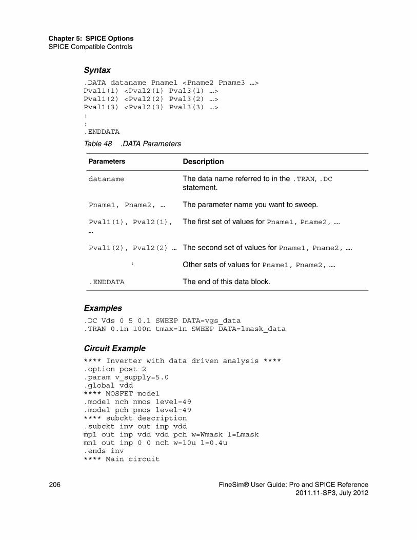
Chapter 5: SPICE OptionsSPICE Compatible Controls
Syntax.DATA dataname Pname1 <Pname2 Pname3 …>Pval1(1) <Pval2(1) Pval3(1) …>Pval1(2) <Pval2(2) Pval3(2) …>Pval1(3) <Pval2(3) Pval3(3) …>::.ENDDATA
Examples.DC Vds 0 5 0.1 SWEEP DATA=vgs_data.TRAN 0.1n 100n tmax=1n SWEEP DATA=lmask_data
Circuit Example**** Inverter with data driven analysis ****.option post=2.param v_supply=5.0.global vdd**** MOSFET model.model nch nmos level=49.model pch pmos level=49**** subckt description.subckt inv out inp vddmp1 out inp vdd vdd pch w=Wmask l=Lmaskmn1 out inp 0 0 nch w=10u l=0.4u.ends inv**** Main circuit
Table 48 .DATA Parameters
Parameters Description
dataname The data name referred to in the .TRAN, .DC statement.
Pname1, Pname2, … The parameter name you want to sweep.
Pval1(1), Pval2(1), …
The first set of values for Pname1, Pname2, ….
Pval1(2), Pval2(2) … The second set of values for Pname1, Pname2, ….
: Other sets of values for Pname1, Pname2, ….
.ENDDATA The end of this data block.
206 FineSim® User Guide: Pro and SPICE Reference2011.11-SP3, July 2012

Chapter 5: SPICE OptionsSPICE Compatible Controls
Vdd vdd 0 3.3Vin inp 0 pulse (0 v_supply 2n 1n 1n 30n 200n)X1 out inp vdd inv**** transient analysis with different conditions.tran 0.01n 2000n sweep DATA=condition.DATA condition+ Wmask Lmask v_supply temp+ 10u 0.5u 3.3 25+ 10u 1.0u 5.0 25+ 5u 0.5u 3.3 75+ 10u 0.35u 1.8 75.ENDDATA.end
In this example, the .PARAM setting is ignored for v_supply and transient analysis is performed with each set of parameters in the .DATA statement.
.DC (DC Analysis)The .DC statement is used in DC analysis to sweep source values. DC analysis calculates the behavior of the circuit when DC voltage or current is applied. In most cases, this simulation analysis is performed first. The result of this analysis is commonly referred to as the DC bias or operating point characteristic. Currently, FineSim Pro supports the sweeping of the independent voltage or current source.
Syntax.DC var1 START=val STOP=val STEP=val.DC var1 start1 stop1 step1 <var2 start2 stop2 step2>.DC var1 start1 stop1 step1 <SWEEP var2 TYPES np start2 stop2>.DC var1 types <SWEEP data=dataname>.DC data=dataname.DC var1 type np start1 stop1 <SWEEP MONTE=MCcommand>
Table 49 .DC Parameters
Parameters Description
dataname name for data driven name (see .DATA description).
np number of points per decade, per octave, or just number of points depending on the preceding keyword.
FineSim® User Guide: Pro and SPICE Reference 2072011.11-SP3, July 2012

Chapter 5: SPICE OptionsSPICE Compatible Controls
Examples.DC Vds 0 5 0.1 Vgs 1 5 1 .DC Vds 0 5 0.1 SWEEP Vgs POI 5 1 2 3 4 5 .DC Vds 0 5 0.1 SWEEP Vgs LIN 5 1 5 .DC Vds LIN 51 0 5 SWEEP Vgs POI 5 1 2 3 4 5 .DC data=Vds_point SWEEP Vgs 1 5 1 .DC data=bias_point .DC temp -40 80 10 .DC Vds 0 5 0.1 sweep MONTE=100 The first six examples are the same command with different syntax. These commands are usually used for MOSFET I-V characterization, which sweep drain voltage (Vds) from 0V to 5V with an increment of 0.1V using Vgs as parameters with values of 1, 2, 3, 4, and 5V.
The seventh example sweeps simulation temperature from -40ºC to 80ºC with increments of 10 ºC.
Circuit Examples**** DC analysis for MOSFET I-V ****.option post=2.model mn nmos level=3.param vd_val=5.0
start1, stop1, step1
starting, final and increment value of var1, respectively.
start2, stop2, step2
starting, final and increment value of var2, respectively.
type One of the following: ■ DEC n fstart fstop: Decade variation starts at
fstart, stops at fstop, with total number of points n.■ LIN n fstart fstop: Linear variation starts at
fstart, stops at fstop,with total number of points n.■ OCT n fstart fstop: Octave variation starts at
fstart, stops at fstop, with total number of points n.■ POI n val1 val2 val3: List of n points with value
val1, val2, ….valn..
var1 name of an independent source (voltage, current).
Table 49 .DC Parameters (Continued)
Parameters Description
208 FineSim® User Guide: Pro and SPICE Reference2011.11-SP3, July 2012
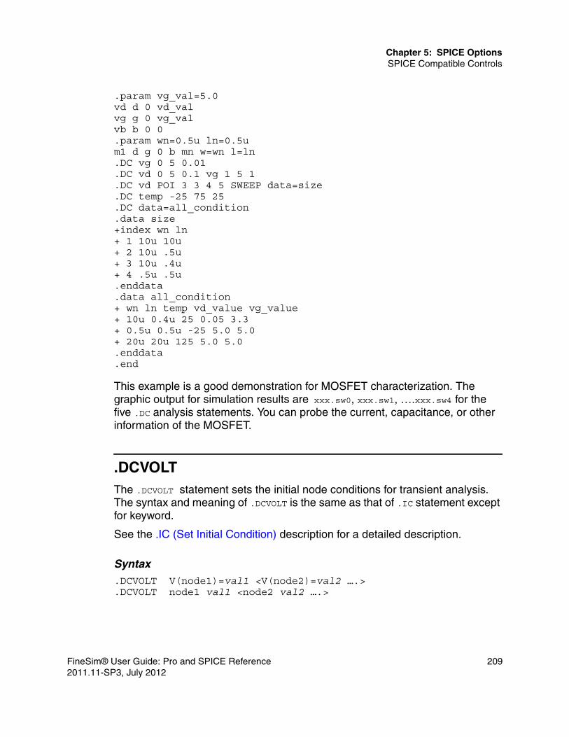
Chapter 5: SPICE OptionsSPICE Compatible Controls
.param vg_val=5.0vd d 0 vd_valvg g 0 vg_valvb b 0 0.param wn=0.5u ln=0.5um1 d g 0 b mn w=wn l=ln.DC vg 0 5 0.01.DC vd 0 5 0.1 vg 1 5 1.DC vd POI 3 3 4 5 SWEEP data=size.DC temp -25 75 25.DC data=all_condition.data size+index wn ln+ 1 10u 10u+ 2 10u .5u+ 3 10u .4u+ 4 .5u .5u.enddata.data all_condition+ wn ln temp vd_value vg_value+ 10u 0.4u 25 0.05 3.3+ 0.5u 0.5u -25 5.0 5.0+ 20u 20u 125 5.0 5.0.enddata.end
This example is a good demonstration for MOSFET characterization. The graphic output for simulation results are xxx.sw0, xxx.sw1, ….xxx.sw4 for the five .DC analysis statements. You can probe the current, capacitance, or other information of the MOSFET.
.DCVOLTThe .DCVOLT statement sets the initial node conditions for transient analysis. The syntax and meaning of .DCVOLT is the same as that of .IC statement except for keyword.
See the .IC (Set Initial Condition) description for a detailed description.
Syntax.DCVOLT V(node1)=val1 <V(node2)=val2 ….>.DCVOLT node1 val1 <node2 val2 ….>
FineSim® User Guide: Pro and SPICE Reference 2092011.11-SP3, July 2012

Chapter 5: SPICE OptionsSPICE Compatible Controls
Example.DCVOLT V(bias)=3.3 V(12)=-5
.DEL LIBThe .DEL LIB statement is used with the .ALTER statement to remove library data from memory. The .DEL LIB statement marks data for removal from memory with a .LIB call statement with the same library number and entry name the next time the simulation is run. A .LIB statement can be used to replace the deleted library.
See the .LIB description.
Syntax.DEL LIB ‘<filepath>filename’ entryname.DEL LIB libnumber entryname
Circuit Example*ALTER TEST FOR CMOS INVERTER.option post.temp 125.param wval=15U vdd=5*.dc vin 0 5 0.1.probe v(3) v(2)*vdd 1 0 vddvin 2 0*
Table 50 .DEL LIB Parameters
Parameters Description
entryname Entry name to be deleted.
filename Name of a file to be deleted from the data file. The filename must be enclosed in single or double quote marks, and can include directory path.
filepath Directory path to filename.
libnumber Library number to be deleted.
210 FineSim® User Guide: Pro and SPICE Reference2011.11-SP3, July 2012

Chapter 5: SPICE OptionsSPICE Compatible Controls
m1 3 2 1 1 P 6u 15um2 3 2 0 0 N 6u W=wval*.lib 'mos.lib' normal.ALTER.del lib 'mos.lib' normal $removes lib from memory.ALTER.param wval=100u vdd = 5.5 $change the parametersvdd 1 0 5.5 $using vdd 1 0 5.5 to change the$power supply vdd value doesn't workvin 2 0 PWL 0ns 0 2ns 5 4ns 0 5ns 5.tran 1ns 5ns m2 3 2 0 0 N 6u wval $change channel width.measure sw2 TRIG v(3) val=2.5 RISE=1 TARG v(3)+ val=vdd CROSS = 2 $measure output.end
.ENDThe .END statement is used to mark the end of a program run. Every input netlist must have at least one .END statement, which must be the last line in the netlist.
Syntax.END
Examples
See any circuit example in this chapter.
.ENDDATAThe .ENDDATA statement is used to signify the end of a .DATA statement.
Syntax.ENDDATA
Examples
See the .DATA (Data Driven Analysis) description.
FineSim® User Guide: Pro and SPICE Reference 2112011.11-SP3, July 2012
Chapter 5: SPICE OptionsSPICE Compatible Controls
.ENDLThe .ENDL statement is used to signify the end of the library macro .LIB.
Syntax.ENDL
Examples
See the .LIB description.
.ENDS
.ENDS must be the last statement for a sub-circuit definition. The sub-circuit name, if included, indicates which sub-circuit is being terminated. If no name is specified, all sub-circuits being defined are terminated. The name may be necessary in the case of nested sub-circuit definitions.
Syntax.ENDS <SUBNAME>
Examples**** Single sub-circuit ****.subckt inv out input vddmp1 out input vdd vdd pch W=10u L=1umn1 out input gnd out nch W=10u L=0.6u.ends inv
**** nested sub-circuit.subckt sub10 net1 net2 0 in out net3 vddx10 out input 0 two_cm0 net44 net1 vdd vdd pch W=10u L=0.5u M=2m1 input net2 net44 net44 pch W=12u L=0.8um2 input net3 net28 0 nch W=11u L=0.5um3 net28 in 0 0 nch W=30u L=0.6um4 net31 in 0 0 nch W=30u L=0.6um5 in net3 net31 0 nch W=13u L=0.6um6 in net2 net41 0 nch W=13u L=0.8um7 net41 net1 vdd vdd pch W=10u L=1u
.subckt two_c neg plus subc0 plus neg 25pF M=3
212 FineSim® User Guide: Pro and SPICE Reference2011.11-SP3, July 2012
Chapter 5: SPICE OptionsSPICE Compatible Controls
c1 neg sub 12pF M=3.ends two_c.ends sub10
.EOMThe .EOM statement must end a .MACRO definition. The macro name, if included, indicates which macro is being terminated. if no macro name is specified, all macros being defined are terminated. The name may be necessary is the case of nested macro definitions.
See the .MACRO description.
Syntax.EOM <MACRONAME>
ExampleX1 D Q Qbar CL CLBAR dlatch flip = 0.macro dlatch D Q Qbar CL CLBAR flip = vcc.nodeset v(din) = flipxinv1 din qbar invxinv2 Qbar Q invm1 q CLBAR din nch w = 5 l = 1m2 D CL din nch w = 5 l = 1.eom
.FOURYou can use this statement to perform a Fourier analysis as part of the transient analysis. A Fourier analysis is performed over the interval between tstop-period and tstop, where tstop is the end time specified for the transient analysis, and period is the period specified in the .four statement. Specified variables are sampled on the last 1/f time period, where f is the fundamental frequency. Sampled data is interpolated by first-order interpolation.
FineSim® User Guide: Pro and SPICE Reference 2132011.11-SP3, July 2012

Chapter 5: SPICE OptionsSPICE Compatible Controls
Syntax.four frequency out_var1 <out_var2 out_var3 …>
Example.four 10meg v(1)
Output for the Fourier analysis is shown in log file as follows.
****** Fourier analysis of v(1)
index freq(hz) Fourier phase(deg) component
1 1.000e+07 +1.249e+00 +89.64 2 2.000e+07 +3.331e-03 -90.72 3 3.000e+07 +1.874e-03 -91.22 4 4.000e+07 +1.332e-03 -91.47 5 5.000e+07 +1.044e-03 -92.05 6 6.000e+07 +8.576e-04 -92.14 7 7.000e+07 +7.327e-04 -92.76 8 8.000e+07 +6.354e-04 -92.72 9 9.000e+07 +5.660e-04 -93.48
dc component = 2.500 total harmonic distortion= 0.353 (%)
.FFTYou can use this statement to perform an FFT analysis as part of the transient analysis. The specified variable being sampled is interpolated by 1st-order interpolation. The resulting output file is named <prefix>_fft<num>.out. <prefix> is the FineSim Pro file prefix and <num> is a number corresponding to a particular .fft statement, as there can be many. For example, if the input file is in.sp, and there are three .fft statements in that input file, there will be three output files: in_fft00.out, in_fft01.out, and in_fft02.out.
Table 51 .four Options
Option Description
frequency Fundamental frequency.
out_var1 … Output variables for the desired analysis.
214 FineSim® User Guide: Pro and SPICE Reference2011.11-SP3, July 2012

Chapter 5: SPICE OptionsSPICE Compatible Controls
Syntax.fft out_var <[start|from]=value> <[stop|to]=value> <np=value>+ <format=keyword> <window=keyword> <alfa=value>+ <freq=value> <fmin=value> <fmax=value>
Table 52 .FFT Options
Option Description
alfa Specifies the alfa parameter used in Gaussian and Kaiser-Bessel window. This value should be between 1 and 20. The default value is 3.
fmax Specifies the maximum frequency of printing. The default value is 0.5*np*fmin.
fmin Specifies the minimum frequency of printing. The default value is 1/(stop-start).
format Specifies whether the output magnitudes are normalized, where norm indicates normalized and unorm indicates unnormalized.
freq Specifies a frequency. If this value is non-zero, the output is limited to a range that begins at fmin and ends at fmax. The default value is 0.
from An alias for start.
np The number of points used in FFT analysis. This value should be a power of 2. The default value is 1024.
out_var A valid output variable such as voltage, current, or power.
start The start time of the output variable to be analyzed. The default value is the start time specified in the .tran statement.
stop The end time of the output variable to be analyzed. The default value is the end time specified in the .tran statement.
to An alias for stop.
FineSim® User Guide: Pro and SPICE Reference 2152011.11-SP3, July 2012

Chapter 5: SPICE OptionsSPICE Compatible Controls
Example.fft v(1)
Output for the fft analysis is shown in log file as follows.
****** fft analysis of v(1)
index freq(hz) mag(db) phase(deg)
2 1.000e+07 -6.021e+00 +90.00 4 2.000e+07 -1.390e+02 +19.80 6 3.000e+07 -1.152e+02 -160.61 8 4.000e+07 -1.342e+02 -87.18 10 5.000e+07 -1.141e+02 -143.37 12 6.000e+07 -1.259e+02 -62.12 14 7.000e+07 -1.138e+02 -127.98 16 8.000e+07 -1.233e+02 -32.90 18 9.000e+07 -1.142e+02 -122.42
signal to noise ratio = +86.062(db) total harmonic distortion = -102.038(db)
.GLOBALThe .GLOBAL statement is used when sub-circuits are included in the netlist. This statement assigns a common node name to sub-circuit nodes. Ordinarily, in a sub-circuit the node name is given as the sub-circuit call number concatenated to the node name. When a .GLOBAL statement is used, the node name is not concatenated with the sub-circuit call number and is instead
window Specifies the data window to be used, where rect = rectangular window,bart = Bartlett (triangular) window,hann = Hanning window,hamm = Hamming window,black = Blackman window,harris = Blackman-Harris window,gauss = Gaussian window, and kaiser = Kaiser-Bessel window.
Table 52 .FFT Options (Continued)
Option Description
216 FineSim® User Guide: Pro and SPICE Reference2011.11-SP3, July 2012
Chapter 5: SPICE OptionsSPICE Compatible Controls
assigned the global name. The connection of power supply for all sub-circuits is often made through the .GLOBAL statement. For example, .GLOBAL VCC connects all sub-circuits with the internal node name VCC.
Syntax.GLOBAL node1 node2 node3 ….
Example.GLOBAL VDD input_sig
This example shows global definitions for the nodes VDD and input_sig.
.IC (Set Initial Condition)The .IC statement sets transient initial conditions. How it does this depends on whether the UIC parameter is included in the .TRAN analysis statement.
Syntax.IC V(node1)=val1 <V(node2)=val2 ….> [subckt=name]
or
.IC node1=val1 <node2=val2 ...> [subckt=name]
This statement sets the time-zero voltage at node1 to val1, that at node2 to val2, and so on. It also can load the simulation result file saved in the previous run as the initial solution (see .TRAN (Transient Analysis) description for more information). It has two different interpretations, depending on whether the UIC parameter is in the .TRAN statement. Also, you should not confuse this statement with the .NODESET statement. The .NODESET statement is only to help DC convergence, and does not affect final bias solution (refer to the examples in the description of .NODESET).
The two interpretations of this line are:
Table 53 .GLOBAL Parameters
Parameters Description
node1 Specifies global nodes, such as supply and clock names. Overrides local sub-circuit definitions.
FineSim® User Guide: Pro and SPICE Reference 2172011.11-SP3, July 2012

Chapter 5: SPICE OptionsSPICE Compatible Controls
■ When the UIC parameter is in the .TRAN statement, the node voltage specified on the .IC control statement is used as a device-based .IC statement to compute the capacitor, diode, BJT, and MOSFET initial conditions (for an inductor, branch current is used as initial condition). This is equivalent to specifying the IC= parameter on each device line. The IC= parameters can still be specified and take precedence over the .IC values. Since no DC bias (initial transient) solution is computed before the transient analysis, make sure you specify all DC source voltages on the .IC statement if they are to be used to compute device initial conditions.
■ When the UIC parameter is not in the .TRAN statement, the DC bias (initial transient) solution is computed before the transient analysis. In this case, the node voltage specified on the .IC statement is forced to the desired initial values during the bias solution. During transient analysis, the constraint on these node voltages is removed. This is the preferred method because it allows FineSim Pro to compute a consistent DC solution.
This statement sets transient initial conditions and handles wildcards. The level option is applied when there is wildcard character in an output variable. The following values are possible:■ -1 (the default value)—Finds matched variables in all levels.■ 0—Ignores wildcards in .ic or .probe statements.■ 1—Finds matched variables in the current level.■ 2—Finds matched variables in the current level and one level below.
Example.IC V(bias)=3.3 V(12)=-5
Circuit Example 1:**** Parallel RLC Circuit with UIC/IC command ***.option postL 1 gnd 1MH IC=1MR 1 gnd 10KC 1 gnd 1NIS gnd 1 PWL(0 0 1N 1M 1 1M).TRAN 0.1u 200u UIC.SAVE.END
Circuit Example 2:**** Parallel RLC Circuit with UIC/IC command ***
218 FineSim® User Guide: Pro and SPICE Reference2011.11-SP3, July 2012

Chapter 5: SPICE OptionsSPICE Compatible Controls
L 1 gnd 1MHR 1 gnd 10KC 1 gnd 1NIS gnd 1 PWL(0 0 1N 1M 1 1M).TRAN 0.1u 200u.SAVE.END
The omission of the keyword UIC from the .TRAN statement results in damped oscillations, because the device-based IC has no effect.
Sub-Circuit Example 1.ic A=0 subckt=CDL With this command, FineSim Pro will initialize node A as 0 in sub-circuit CDL.
Using WildcardsThe wildcard character "*" can be used in .IC statements.
Example.ic v(Xdut*Xirowx128_left*XI*XI*Xval*CC0:A)=PGND
will work fine on extracted flattened netlists, but the following will not:
.ic v(Xdut.Xirowx128_left.XI*.XI*.Xval*.CC0:A)=PGND
The subtle difference here is that the "." is recognized as a hierarchical delimiter in the .ic statement. There is no hierarchy in a flattened extracted netlist, although the format looks to be hierarchical.
.IF/.ELSEFineSim Pro supports the .if/.elseif/.else/.endif condition-controlled structure in a netlist. You can use this structure to control which parts of a netlist are used for simulation based on a condition that is evaluated as logically true. The syntax is as follows:
.if (condition-expression-1)Statements-1.elseif (condition-expression-2)Statements-2.elseStatements-3
FineSim® User Guide: Pro and SPICE Reference 2192011.11-SP3, July 2012

Chapter 5: SPICE OptionsSPICE Compatible Controls
.endif
When condition-expression-1 is logically true, FineSim Pro executes Statements-1. Otherwise FineSim Pro evaluates condition-expression-2, and if that is true, it executes Statement-2. If condition-expression-2 is false, FineSim Pro executes Statement-3. You can use more than one .elseif statement between the .if and .endif statements in the previous definition.
A single .if statement without the .elseif or .else statements is also allowed, such as that shown in the following example
.if (condition-expression-1) Statements-1.endif
In the previous example, FineSim Pro executes Statements-1 if condition-expression-1 is evaluated as logically true. Otherwise, FineSim Pro executes what follows the .endif statement.
A nested .if/.if/.elseif/.else/.endif/.elseif/.else/.endif structure is also supported in FineSim Pro, as follows:
.if (condition-expression-1)Statements-1 .if (condition-expression-a) Statements-a .elseif (condition-expression-b) Statements-b .else Statements-b .endif.elseif (condition-expression-2)Statements-2.elseStatements-3.endif
The following examples show how the if-else structure works.
Example 1.param dc=0::.if (dc==1)v1 1 0 1.elsev1 1 0 sin(0 0.1 5meg)
220 FineSim® User Guide: Pro and SPICE Reference2011.11-SP3, July 2012

Chapter 5: SPICE OptionsSPICE Compatible Controls
.endif
In this example, voltage source v1 will be at DC 1 volt if the dc parameter is valued at 1. Otherwise, v1 will be a sin wave source.
Example 2
The conditions for .if and .elseif can be complex logical expressions, as shown in the following example:
.if ((a>0) && (sin(b)>(pi/2.0)))X101 ck s0 in1 in2 pins out MUX1.elseif ((a<0) && (sin(b)<(pi/2.0)))X101 ck so in1 in2 pins out MUX2.elseX101 ck so in1 in2 pins out MUX0.endif
In this example, one of the three sub-circuits {MUX0 – MUX2} is selected based on the conditional expressions in the .if and .elseif statements.
Example 3
In addition to being used at the top level of a netlist, this if-else structure also can be used inside sub-circuits. When used inside a sub-circuit the condition chosen depends on the parameters of the instance of the sub-circuits. Consider the following example:
.subckt rc a b r=1 c=10f probe=0r1 a b r.if (c>0)c1 b 0 c.if (probe) .probe i(c1).endif.endif.ends
x1 1 2 rc c=0x2 3 4 rc c=100f x3 5 6 rc c=50f probe=1
In this example, x1 will not contain a capacitor since c==0. x2 will contain a capacitor, but the capacitor current will not be probed because probe==0. For x3, the capacitor current will be probed.
FineSim® User Guide: Pro and SPICE Reference 2212011.11-SP3, July 2012

Chapter 5: SPICE OptionsSPICE Compatible Controls
Example 4
The .if blocks can contain most statements in SPICE format. There are two exceptions, however. First, it cannot contain .alter statements. Second, .if blocks inside of sub-circuits cannot contain .subckt statements. Consider the following example:
.if (a==0)
.subckt a 1 0….ends.else.subckt a 1 0….ends.endif
At the top level, this excerpt is legal, but this cannot be used inside of another sub-circuit to control the value of a nested sub-circuit. Another similar situation is that an .if/.else statement cannot appear in an .alias card.
.INCLUDEThe .INCLUDE statement includes the named file in the input netlist during simulation. Frequently, portions of circuit descriptions or device models can be shared by several input netlists. The .INCLUDE statement is used so that it is as if the contents of the file in the .INCLUDE statement appeared in place of the .include line in the input netlist.
Syntax.INCLUDE <path name>filename
Example.INCLUDE ‘/mydir/infile’
.LIBThe .LIB call statement makes it possible to place commonly used commands, device models, sub-circuit analysis, and statements in a library. As each .LIB call name is encountered in the main data file, the corresponding entry is read in from the designated library file until an .ENDL statement is encountered.
222 FineSim® User Guide: Pro and SPICE Reference2011.11-SP3, July 2012

Chapter 5: SPICE OptionsSPICE Compatible Controls
A .LIB call statement can appear in an .ALTER block, but an .ALTER statement cannot be included in a library. A library can contain .LIB calls to itself or other libraries.
Library Call Statement
Syntax.LIB “<pathname> filename” entryname
Calls the library, in which pathname indicates the path of this file. The default path is the working directory. filename is the file name for this library and entryname is used for the section of the library file to be included. Library calls may call other libraries, provided they are different files.
Example.LIB “/mydir/myfile” MOS1
Library File Definition Statement
You can build libraries by using the .LIB statement in a library file. For each macro in a library, enter a library definition statement (.LIB entryname) and an .ENDL statement. The .LIB statement begins the library macro, and the .ENDL statement ends the library macro.
Library calls can be nested to any depth. This capability, along with the .ALTER statement, allows you to construct a sequence of model runs composed of similar components with different model parameters, without duplicating the entire FineSim Pro input file.
Syntax.LIB entryname1*Any valid set of FineSim Pro statements.ENDL entryname1.LIB entryname2*Any valid set of FineSim Pro statements.ENDL entryname2
Example.LIB CMOS1....LIB 'libfileA' CMOS2.LIB 'libfileB' CMOS3
FineSim® User Guide: Pro and SPICE Reference 2232011.11-SP3, July 2012

Chapter 5: SPICE OptionsSPICE Compatible Controls
.ENDL
.LOADThe .LOAD statement inputs the contents of a file stored with the .SAVE statement. Files stored with the .SAVE statement contain operating point information for the point in the analysis at which the .SAVE was executed.
Syntax.LOAD <FILE = load_file>
Example.LOAD FILE=”icfile.ic”
.LPROBEYou can use the .LPROBE statement to reduce your fsdb file size significantly. By default, FineSim Pro only adjusts the logic value of an lprobe statement when it writes out an analog simulation data point. Logic probes can be either logically zero (‘0’), logically one (‘1’) or undefined (‘x’).
Syntax.lprobe level=x v(*) high=x low=x
In case of conflicting probe and lprobe statements, the probe statement takes precedence and will be executed instead of the logic probe. For more details, see the Logic Probes (Digital Waveforms) section.
Table 54 .LOAD Parameters
Parameters Description
load_file Name of the file in which an operating point for the circuit under simulation was saved using .SAVE. The default is <design>.ic, where design is the root name of the design.
224 FineSim® User Guide: Pro and SPICE Reference2011.11-SP3, July 2012

Chapter 5: SPICE OptionsSPICE Compatible Controls
.MACROThe .MACRO statement is the same as the .SUBCKT except that the last line is .EOM instead of .ENDS. See the .SUBCKT description for more information.
Syntax
.MACRO subnam n1 < n2 n3 … > < parnam = val …>
Examples.option postv1 1 0 1.param p5 = 5 p2 = 10*.subckt sub1 1 2 p4 = 4r1 1 0 p4r2 2 0 p5x1 1 2 sub2 p6 = 7x2 1 2 sub2.ends*.macro sub2 1 2 p6 = 11r1 1 2 p6r2 2 0 p2.eom*
Table 55 .MACRO Parameters
Parameters Description
subnam Specifies reference name for the sub-circuit model call n1.... Node numbers are for external reference and cannot be ground node (zero). Element nodes appearing in the sub-circuit but not included
in this list are strictly local, with three exceptions:■ the ground node (zero)■ nodes assigned using BULK = node in the MOSFET or BJT
models■ nodes assigned using the .GLOBAL statement
parnam A parameter name set to a value. For use only in the sub-circuit, overridden by an assignment in the sub-circuit call or by a value set in a .PARAM statement.
FineSim® User Guide: Pro and SPICE Reference 2252011.11-SP3, July 2012

Chapter 5: SPICE OptionsSPICE Compatible Controls
x1 1 2 sub1 p4 = 6x2 3 4 sub1 p6 = 15x3 3 4 sub2.model DA D CJA=CAJA CJP=CAJP VRB=-20 IS=7.62E-18+ PHI = .5 EXA=.5 EXP=.33.param CAJA=2.535E-16 CAJP=2.53E-16.end
This example defines two sub-circuits, sub1 and sub2. These are resistor divider networks whose resistance values have been parameterized. They are called with the X1, X2, and X3 statements. Because the resistor value parameters are different in each call, these three calls produce different sub-circuits.
.MALIASThe .MALIAS statement defines an alias for a model name.
Syntax.malias model_name alias_name1 <alias_name2 …>
Example.malias nmos01 nm1 nm2
In the previous example, both nm1 and nm2 are aliased to nmos01.
.MEASUREThe .MEASURE statement is useful in a wide range of applications. You can analyze simulation results by adding .MEASURE statements in input files. FineSim Pro has additional data-measurement capability whose syntax is compatible with popular SPICE conventions. For more information on .MEASURE and its usage, refer to the .MEASURE section of Chapter 7, Probing and Measuring.
.MODELThe .MODEL statement takes the form of the key word followed by the model name used in the device element statement, and a list of the model parameter values enclosed in parentheses. Model parameters not specified are assigned default values. See Chapter 3, Circuit Elements and Models for description of
226 FineSim® User Guide: Pro and SPICE Reference2011.11-SP3, July 2012

Chapter 5: SPICE OptionsSPICE Compatible Controls
each device model, and see related SPICE documentation for model parameter details.
Syntax
.MODEL mname type <pname1 = val1 pname2 = val2 ...>
Table 56 .Model Parameters
Parameters Description
causal Passivity enforcement:
Recursive convolution: passivity is enforced after vector fitting. It can be helpful to resolve a time step too small issue introduced from fitting.Direct convolution: passivity is enforced for non-passive models.
highpass 0: Cut off.
1: Use highest frequency point.
2: Linear extrapolation using the highest 2 points.
3: Using window function.
4: Set to 0. This is the default value.
lowpass 0: Special model fitting. This is the default value.
1. Use magnitude of the lowest point.
2. Linear extrapoluation using magnitude of lowest 2 points.
mname Model name. Elements must refer to the model by this name.
passive 1: Enforce passivity to the transfer functions. Passivity is enforced after vector fitting. And it can be used to resolve a time step too small issue in S-Element circuits.
0: No enforce.
For recursive convolution mode only.
pname1 ... Parameter name. The model parameter name assignment list (pname1) must be from the list of parameter names for the appropriate model type. The default values are given in each model description. The parameter assignment list can be enclosed in parentheses and each assignment can be separated by blanks or commas for legibility. Continuation lines begin with a plus sign (+).
FineSim® User Guide: Pro and SPICE Reference 2272011.11-SP3, July 2012

Chapter 5: SPICE OptionsSPICE Compatible Controls
Example.MODEL MOD1 NPN (BF=50 IS=1E-13 VBF=50 AREA=2 PJ=3, N=1.05).MODEL D D (CO=2PF, RS=1, IS=1P)
.NET optionThe .net option computes the parameters of the impedance, admittance, scattering and hybrid matrices. This is done as part of the AC analysis. The syntax is (optional arguments in square brackets).
.net [output] input-source [ROUT=xxx] [RIN =yyy]
The input can be voltage or current source with AC input.
The output can be voltage (e.g.: V(N1)).
The input/output impedances default to 1 Ohm.
Parameters of the various matrices can be printed using the following syntax, where i and j are 1 or 2, indicating the element of the 2x2 matrix to be printed and <x> is one of: M (magnitude, default if <x> omitted), P (phase), R (real part, I (imaginary part), DB (decibel)
ZIN(<x>), ZOUT(<x>), YIN(<x>), YOUT(<x>), Sij(<x>), Zij(<x>), Hij(<x>), Yij(<x>)
type Selects the model type, which must be one of the following:
C capacitor model
D diode model
NMOS n-channel MOSFET model
NPN npn BJT model
PMOS p-channel MOSFET model
PNP pnp BJT model
R resistor model
U lossy transmission line model (lumped)
W lossy transmission line model
Table 56 .Model Parameters (Continued)
Parameters Description
228 FineSim® User Guide: Pro and SPICE Reference2011.11-SP3, July 2012

Chapter 5: SPICE OptionsSPICE Compatible Controls
Example.ac lin 100 100meg 200meg .net v(out) vin rout=50 rin=50 .print ac zin(m) yout(p) s11(m) s21(db) z11(r)
In this example, FineSim Pro performs a network analysis by using the .ac and .net analysis statements, and prints the magnitude of the input impedance, the phase of the output admittance and several S and Z parameters.
.NODESETThe .NODESET statement helps the simulator find the DC or initial transient solution by making a preliminary pass with the specified nodes held to the given voltages. With this statement, you can specify initial node voltage guesses. The initialization constraint is then removed and the iteration continues to the final solution. Therefore, the final solution may differ from the values specified by .NODESET. The .NODESET statement may be necessary for convergence on bistable or astable circuits.
Another approach to node voltage initialization is the .IC statement. The major difference between .NODESET and .IC statement is that node voltages are forced to the values you specify in the .IC statement and are not corrected after an initial pass (see .IC (Set Initial Condition) description).
Syntax.NODESET V(node1)=val1 V(node2)=val2 ….
or
.NODESET node1 val1 <node2 val2 ….>
This statement assigns val1 to the voltage of node1, val2 to node2, and so on, in the first few solution iterations. The Examples section demonstrates the usage of .NODESET. The difference between the .IC and .NODESET statements are also shown through the operating point analysis. From the operating point information, you can see that the .IC statement forced the node voltage V(1) and V(2) to the .IC setting. .NODESET did not.
Examples.NODESET V(17)=3.888 V(vpp_in)=4.5.NODESET 17 3.888 vpp_in 4.5.NODESET V(5:setx)=3.5V V(x1.x2.vint)=1V
FineSim® User Guide: Pro and SPICE Reference 2292011.11-SP3, July 2012

Chapter 5: SPICE OptionsSPICE Compatible Controls
Circuit Example 1:**** Flip-Flop with NODESET/IC ****.option postvdd 3 0 5Vml1 2 2 3 3 pch w=10u l=1uml2 1 1 3 3 pch w=10u l=1umi1 2 1 0 0 nch w=5u l=0.8umi2 1 2 0 0 nch w=5u l=0.8u.model nch nmos level=49.model pch pmos level=49**** set initial guess of V(1) , V(2) dc solution with .NODESET ****.nodeset V(1)=0.25 v(2)=5.tran 20ns 2us.save.end
Simulation result is:
Operating point information:NodeVoltageV(1) 1.0792 V(2) 3.6516 V(3) 5.0000 ::
Circuit Example 2:**** Flip-Flop with NODESET/IC ****.option postvdd 3 0 5Vml1 2 2 3 3 pch w=10u l=1uml2 1 1 3 3 pch w=10u l=1umi1 2 1 0 0 nch w=5u l=0.8umi2 1 2 0 0 nch w=5u l=0.8u.model nch nmos level=49.model pch pmos level=49**** set initial guess of V(1) , V(2) dc solution with .NODESET ****.ic V(1)=0.25 v(2)=5.tran 20ns 2us.save.op.end
Simulation result is:
Operating point information:NodeVoltageV(1) 2.500000e-01
230 FineSim® User Guide: Pro and SPICE Reference2011.11-SP3, July 2012

Chapter 5: SPICE OptionsSPICE Compatible Controls
V(2) 5.000000e+00V(3) 5.000000e+00::
.NOISEFineSim Pro supports noise analysis in conjunction with the AC analysis mode via the .NOISE statement. The syntax is as follows:
.NOISE <output variable> <current/voltage source> <interval><interval> is the interval of sweep steps at which to print results.
FineSim .NOISE analysis calculates small-signal AC response around the DC operating point to various noise sources. Each noise source is assumed to be independent from each other. The total output noise voltage is the root-mean-square sum of every individual noise contribution:
Where:■ |Onoise| is the total output noise,■ Ink is normal value of the thermal, shot, or flicker noise current source,■ Zk is the trans-impedance from each noise current source to the output, and■ N is the total number of noise sources in the circuit.
When more than one .NOISE statement is specified in the netlist, all but the last statement is ignored.
The .PRINT statement can be used to print the output noise and input-referred noise in the .pn0 file. The unit for output and input-referred noise will be V/hz^1/2. A .pn_c0 file is also generated with detailed noise contribution information including noise source density (Nd), output noise (Onoise), input-referred noise (Inoise), and trans-impedance (Tx) from every noise source of each device in the circuit. At every frequency point of noise analysis, FineSim will report all device noise and total inoise/onoise.
Example.NOISE V(1) VIN 1
Onoise Zk2
ink2
k 1=
N
∑=
FineSim® User Guide: Pro and SPICE Reference 2312011.11-SP3, July 2012

Chapter 5: SPICE OptionsSPICE Compatible Controls
.print noise onoise inoise
This example sums the output noise voltage at node 1 by using the voltage source VIN as the noise input reference and prints the total output noise and the equivalent input noise.
.OP When a .op (operating point) statement is included in an input file, the DC operating point of the circuit is calculated. You also can use the .op statement to produce an operating point during transient analysis. Only one .op statement can appear in a FineSim Pro simulation.
If an analysis is being used that requires an operating point to be calculated, the .op statement is not required; an operating point calculation will be performed. If a .op statement is specified and the keyword UIC exists in a .TRAN analysis statement, the time=0 operating point analysis will be omitted.
FineSim Pro supports multiple time points for operating point analysis. Consider the following example:
.OP 0n 10n 20n 30n
This will create four .OP files: .op0, .op1, .op2, and .op3.
If an analysis such as small signal .ac or .net requires an operating point to begin with, the .op card does not have to be specified in the deck and FineSim Pro will always automatically run it. The .op file by default will not be created for such analysis. To generate this file, use the following option:
.option finesim_gen_ic_op=1
.OPTIONSThe .OPTIONS statement controls a variety of simulation actions. An .OPTIONS statement can contain any number of options, and any number of .OPTIONS statements can be included in the netlist files. The various options are described in Chapter 4, FineSim Pro Options.
Syntax.OPTIONS opt1 opt2 opt=val …
232 FineSim® User Guide: Pro and SPICE Reference2011.11-SP3, July 2012

Chapter 5: SPICE OptionsSPICE Compatible Controls
Example.OPTIONS reltol=0.005 relq=1.0e-4
.PARAMThe .PARAM statement sets the values of parameters, which are names associated with numeric values. The value could be a number or an algebraic expression with quoted strings. The .PARAM statement is usually used in conjunction with the .DATA and .ALTER statements. It overrides other assignments of parameters in sub-circuit calls, device models or elements. You can assign a simple value, an algebraic expression, a sub-circuit default definition (see .SUBCKT), a distribution function (see Algebraic Expressions), or a measurement parameter (see the Measurement Analysis (.MEASURE) and its Modes section).
Syntax.PARAM par1=val1 <par2=val2 par3=val3 …. >.PARAM par1=’algebraic expression’.PARAM par1=func.PARAM parl=OptParFun (Initial, Lower, Upper)
Any parameter defined in the netlist can be replaced by an algebraic expression with quoted strings. These expressions may be used as output variables in the .PROBE (or .PRINT), and .MEASURE statements. The func is a predefined distribution function. UNIF or AUNIF are uniform distribution functions using relative or absolute variation, respectively. GAUSS and AGAUSS are Gaussian distribution functions using relative or absolute variation, respectively. LIMIT is a random limit distribution function using absolute variation.
Example.param a=1.4 b=5.5u.param wn=’a*0.5u’ ln=’5.5u-2.3*1e-6’.param fx=GAUSS(100, 0.2, 3)m1 d g s b mn w=wn l=ln::
FineSim® User Guide: Pro and SPICE Reference 2332011.11-SP3, July 2012

Chapter 5: SPICE OptionsSPICE Compatible Controls
.PATFineSim Pro provides a command driven pattern description for the time dependent bit pattern (PAT) function in the independent voltage or current sources. This command is used to simplify the description of the independent voltage or current sources. See Chapter 3, Circuit Elements and Models, for more information.
SyntaxVxxx n1 n2 PAT ( vhi vlo td tr tf tsample patname <RB=val> <R=val> )Ixxx n1 n2 PAT ( vhi vlo td tr tf tsample patname <RB=val> <R=val> )
.PAT patname=data <RB=val> <R=val>or
.PAT patname=[component 1, ..., component n] <RB=val> <R=val>
The below table lists and describes .PAT parameters.
Table 57 .PAT Parameters
Parameter Description
.PAT Keyword for a pattern command.
component 1… n The components that make up nested structures. These structures can be a bit-pattern or a pattern-name defined in other .pat command. RB or R can be used in the component.
data Bit string of 1,0,m, or z starting with B, or a pattern-name defined in other .pat command.
patname Pattern name which is referenced from a voltage or current source or other pattern commands.
R=val Keyword to specify the number of repeating operation.
R must be an integer, if it is less than 0, it will be set to 0.
Default value is 1.
RB=val Keyword to specify the starting bit when repeating. Default value is 1.
234 FineSim® User Guide: Pro and SPICE Reference2011.11-SP3, July 2012
Chapter 5: SPICE OptionsSPICE Compatible Controls
Example 1 (pattern-command-driven form)v1 n1 n2 PAT (5 0 1n 2n 5n 10n pat1 pat2 r=2 rb=2).PAT pat1=b1101 r=1 rb=2.PAT pat2=b1010 r=1 rb=1
This is equivalent to:
v1 n1 n2 PAT (5 0 1n 2n 5n 10n b1101 r=1 rb=2 b1010 r=2 rb=2)
Example 2 (mixed form)v1 n1 n2 PAT (5 0 1n 2n 5n 10n [b11001 pat1] r=2 rb=1).PAT pat1=b10m1z r=2 rb=2
FineSim Pro supports pattern source definitions (.PAT) in arithmetic expressions in repeating bit definitions.
Example ******** parameter statements ****** .param period= 200p .param trf= 10p .param delstartp=1n .param power=2 .param settle=11 *********** pattern source ********* VCLKlm clklm 0 PAT (power 0 'delstartp+2*period' trf trf '2*period' b1001 R="settle-1")
.PRINTThe .PRINT statement saves waveforms of output variables into data files. If you are only interested in tabular text format output, use the .PRINT statement. See Output Files for more information on output file name conventions.
When you use this statement, FineSim Pro can create additional nodes when DSPF is back-annotated onto a design. For more details see DSPF Annotation in Chapter 6, Back-Annotation.
Syntax.PRINT antype <name1=>V(NodeName) <name2=>I(DevName) …..PRINT antype <name3=>V(Node1,Node2) ….
FineSim® User Guide: Pro and SPICE Reference 2352011.11-SP3, July 2012

Chapter 5: SPICE OptionsSPICE Compatible Controls
.PRINT antype <name4=>PAR(‘algebraic expression’) ….
Examples.PRINT DC V(1) V(2) V(3) beta=PAR(`I1(Q1)/I2(Q1)').PRINT TRAN V(3,1) V(4) V(7) V(0,10).PRINT DC V(*) I(*.*).PRINT DC V(A*) I(BBB.*).PRINT TRAN V(?????)
In the third example, V(*) means all of the voltage variables in the design. I(*.*) means the current variables of all the devices in the second level hierarchy and below. In the fourth example, V(A*) means all of the voltage variables beginning with A in the top level, I(BBB.*) means all of the current variables under the BBB sub-circuit block. V(?????) in the fifth example is all the voltage variables whose length is 5 in the top level.
Printing Block Current
You can measure the current into a block through a port or global node by using x() with this statement, as shown in the following example:
x(instance.port) or x(instance.global)
where:■ instance is the name of an instance in the design, and can include
wildcards.
Table 58 .PRINT Parameters
Parameter Description
antype Type of analysis (DC or TRAN) for the specified plots.
DevName Device (element) name, which can contain wildcards * and/or ?. I(DevName) means the branch current through DevName.
name1,name2, ...
Optional user-defined output name.
Node1, Node2 Node names that don’t allow wildcard characters. V(Node1,Node2) means the difference of V(Node1)-V(Node2).
NodeName Node name, which can contain wildcard characters * and/or ?. V(NodeName) means the node voltage of NodeName.
236 FineSim® User Guide: Pro and SPICE Reference2011.11-SP3, July 2012

Chapter 5: SPICE OptionsSPICE Compatible Controls
■ port is the name of a port in the instance, and can include wildcards, and■ global is the name of a global node used by the instance, and can include
wildcards.
.print tran x(x1.*.vdd) $ print the current into all instances that match x1.* from vdd.
Note:Current is considered positive when it is flowing into a block and negative when it is flowing out, so vdd current will usually be positive while vss current will usually be negative.
.PROBEThe .PROBE statement saves waveforms of output variables into data files. FineSim Pro usually saves all of the voltages and supply currents without the .PROBE statement. For a detailed explanation of .PROBE and its usage, refer to the .PROBE section of Chapter 7, Probing and Measuring.
.PZ (Pole/Zero Analysis)The .PZ statement is used in Pole and Zero analysis. The PZ analysis calculates the poles and zeroes of linear, time-invariant networks. It can be used for analog circuits to determine the stability of the design, such as amplifiers, filters, etc.
Syntax
.PZ output input
Examples.PZ v(5) vin
Table 59 .PZ Parameters
Parameters Description
output Output variable, which can be any node voltage v(n), or branch current through a voltage source I(Vn).
input Input source, which may be any independent voltage or current source.
FineSim® User Guide: Pro and SPICE Reference 2372011.11-SP3, July 2012

Chapter 5: SPICE OptionsSPICE Compatible Controls
In the example, FineSim Pro performs a Pole/Zero simulation. The output is node voltage v(5), and the input is independent voltage source vin.
PZ Analysis Related Options■ pzmethod—the default value is 0, and QR algorithm will be used for all the
poles and zeroes. The algorithm is suitable for small-medium circuits. For very large circuit set pzmethod to 1, where a krylov subspace method will be used to calculate the dominant poles and zeros.
■ pznum—number of poles and zeroes the user wants to calculate. The option is only used when pzmethod is set to 1, otherwise all the poles and zeroes in the circuit are calculated.
■ pzkmult—controls the number of vectors used in forming Krylov subspace. The option is only used when pzmethod is set to 1. The amount of memory used is proportional to the pzkmult. The trade off is between runtime and memory. pzkmult is set to 2 by default, it can be between 1 and 2. However, if the user set pzkmult too small, Krylov subspace method may introduce divergence.
Output ResultsThe PZ analysis will dump out the *.pz0 file and poles and zeroes are in both rad/sec and hertz formats. For example:
Poles(rad\sec) Poles(hertz)-4.505616e+02 + i2.210450e+04 -7.170911e+01 + i3.518041e+03-4.505616e+02 + i-2.210450e+04 -7.170911e+01 + i-3.518041e+03-1.835284e+03 + i2.148369e+04 -2.920945e+02 + i3.419236e+03-1.835284e+03 + i-2.148369e+04 -2.920945e+02 + i-3.419236e+03 Zeros(rad\sec) Zeros(hertz)-3.221995e-02 + i2.516970e+04 -5.127965e-03 + i4.005882e+03-3.221995e-02 + i-2.516970e+04 -5.127965e-03 + i-4.005882e+032.524353e-01 + i2.383956e+04 4.017632e-02 + i3.794184e+032.524353e-01 + i-2.383956e+04 4.017632e-02 + i-3.794184e+03
238 FineSim® User Guide: Pro and SPICE Reference2011.11-SP3, July 2012

Chapter 5: SPICE OptionsSPICE Compatible Controls
.SAVEThe .SAVE statement stores the operating point of a circuit in a user-specified file. You can then use the .LOAD statement to input the contents of this file for subsequent simulations to obtain quick DC convergence. You can specify that the operating point data be saved as an .IC or a .NODESET statement.
Syntax.SAVE <TYPE = type_keyword> <FILE = save_file>+ <LEVEL = level_keyword> <TIME = save_time>
Table 60 .SAVE Parameters
Parameters Description
type_keyword
(Default is NODESET)
Type of operating point storage, which can be NODESET or IC. NODESET: Stores the operating point as a .NODESET statement. In subsequent simulations, all node voltages are initialized to these values if the .LOAD statement is used. Assuming incremental changes in circuit conditions, DC convergence should be achieved in a few iterations.
IC: Stores the operating point as an .IC statement. In subsequent simulations, node voltages are initialized to these values If .LOAD is included in the netlist file.
save_file Name of the file in which the DC operating point data is stored. The default is <design>.ic.
level_keyword
(Default is ALL)
Circuit level at which the operating point is saved. You can use three level keywords with the .save option: top, all, and none.
ALL: All nodes from the top to the lowest circuit level are saved. This option provides the greatest improvement in simulation time.
TOP: Only nodes in the top-level design are saved.
No sub-circuit nodes are saved.
NONE: The operating point is not saved.
save_time
(Default is 0)
Time during transient analysis at which the operating point is saved. A valid transient analysis statement is required to successfully save a DC operating point.
FineSim® User Guide: Pro and SPICE Reference 2392011.11-SP3, July 2012

Chapter 5: SPICE OptionsSPICE Compatible Controls
Examples.SAVE TYPE=IC FILE=’save.ic’ TIME=30n
See the finesim_maxicout option in Chapter 4, FineSim Pro Options.
Capacitance TablesCapacitance tables can be generated at any time during transient analysis.
Syntax.save type=captab|captab1|captab2 time=time_value file=file_name where type=captab is equivalent to type=captab1
Example.save type=captab time=100n file=captab_file
In the previous example, the capacitance table captab_file is generated at time 100ns. Note that .option captab is equivalent to .save type=captab and that .option captab=2 is equivalent to .save type=captab2.
.SUBCKTThe .SUBCKT definition is usually used to create a reusable circuit, and save design time. Names of the sub-circuit nodes and elements are prefixed with the sub-circuit call name. A circuit definition begins with a .SUBCKT statement, and the group of element statements which immediately follow define the sub-circuit. An .ENDS statement (see the .ENDS description) terminates the sub-circuit definition. Control statements may not appear within a sub-circuit definition. However, sub-circuit definitions may contain anything else, including other sub-circuit definitions, device models, and sub-circuit calls (see the nested sub-circuit call examples in .ENDS). Device models or sub-circuit definitions included as part of a sub-circuit are strictly local (that is, such models and definitions are not known outside the sub-circuit definition). Also, element nodes not included in the .SUBCKT statement are strictly local, with the exception of 0 (ground) which is always global. The circuit example uses .GLOBAL, .LIB, .INCLUDE, .SUBCKT, .ENDS, and .END.
240 FineSim® User Guide: Pro and SPICE Reference2011.11-SP3, July 2012

Chapter 5: SPICE OptionsSPICE Compatible Controls
Syntax.SUBCKT subname N1 <N2 N3 …> <P1=val1 P2=val2 …>
Example.SUBCKT OPAMP 1 2 3 4
Circuit Example**** Ring Oscillator ****.option post.global vdd**** MOSFET model.lib /mydir/mos/model_035 TT**** include subckt description.include inv_subckt**** Main circuit for 21-stages ring OSC.vdd vdd 0 3.3x1 o1 o5 vdd inv5x2 o2 o1 vdd inv5x3 o3 o2 vdd inv5x4 o4 o3 vdd inv5x5 o5 o4 vdd inv.ic v(o1)=3.3.save.tran 0.1n 200n.end
The sub-circuit include file inv_subckt is
**** cmos inverter ****.subckt inv out inp vddmp1 out inp vdd vdd pch w=20u l=0.5umn1 out inp 0 0 nch w=10u l=0.4u.ends inv
.subckt inv5 out inp vddx1 a1 inp vdd inv
Table 61 .SUBCKT Parameters
Parameters Description
subname The sub-circuit name
N1, N2, … The external nodes, which cannot be zero
P1, P2, … The parameter names.
FineSim® User Guide: Pro and SPICE Reference 2412011.11-SP3, July 2012

Chapter 5: SPICE OptionsSPICE Compatible Controls
x2 a2 a1 vdd invx3 a3 a2 vdd invx4 a4 a3 vdd invx5 out a4 vdd inv.ends inv5
.TEMP (Operating Temperature of Circuit)The .TEMP statement sets the operating temperature of circuit. The single-valued .TEMP statement is the same as .option temp=val. For a multi-valued .TEMP statement, output files for the second and subsequent temperatures have the additional suffix _t# where # is a number.
Syntax.TEMP val val1 val2 …
Examples.TEMP 85.TEMP -25 30 26
.TFCommand for DC small signal transfer functions.
Syntax.tf ov srcname
Where:■ ov is the small signal output variable, and■ srcname is the small signal input voltage or current.
Examples.tf v(5,3) vin.tf i(vout) vin
The output is as follows:
small-signal transfer function from srcname to ov small-signal input resistance
242 FineSim® User Guide: Pro and SPICE Reference2011.11-SP3, July 2012

Chapter 5: SPICE OptionsSPICE Compatible Controls
small-signal output resistance
.TRAN (Transient Analysis)Transient analysis, probably the most important analysis type, simulates the circuit as a function of time over a specified voltage range with the specified initial conditions. Because a transient analysis first performs a DC operating point analysis (unless the UIC option is specified in the .TRAN statement), most of the DC analysis algorithms, control options, and initialization and convergence issues apply to transient analysis.
Some circuits, such as oscillators or circuits with feedback, do not have stable operating point solutions. For these circuits, either the feedback loop must be broken so that a DC operating point can be calculated, or the initial conditions must be provided in the simulation input. The DC operating point analysis is bypassed if the UIC parameter is included in the .TRAN statement. If UIC is included in the .TRAN statement, a transient analysis is started using node voltages specified in an .IC statement. If a node is set to 5V in the .IC statement, the value at that node for the first time point (time 0) is 5V.
Syntax.TRAN tstep tstop <start=Tstart> <UIC >
or
.TRAN tstep1 tstop1 <tstep2 tstop2 ...tstepN tstopN> <start=Tstart> <UIC>
or
.TRAN tstep tstop <start=Tstart> <UIC> <SWEEP types>
or
.TRAN tstep tstop <start=Tstart> <UIC> <SWEEP data=”dataname”>
Here, Tstep and Tstop are the user-defined time step. Tstart is the starting time for the graphic output file, the default of which is 0 sec. Tstart can save memory in the graphic output file because it stores only the data of time >= start. The usage of UIC can be found in the .IC statement description. Sweep and the types of sweep can be found in .DC statement description. The sweep variable can be any one of the voltage or current sources (Vxxx or Ixxx), TEMP keyword, a variety of parameters, or data names referred to in .DATA statements. The sweep types are DEC, LIN, OCT, or POI (see the .DC (DC Analysis) description).
FineSim® User Guide: Pro and SPICE Reference 2432011.11-SP3, July 2012

Chapter 5: SPICE OptionsSPICE Compatible Controls
For each sweep condition, the simulation results are stored in the files xxx_s0.fsdb, xxx_s1.fsdb, and so on if the option finesim_output=fsdb was set, or xxx_s0.tr0, xxx_s1.tr1, and so on if the option finesim_output=tr0 was set.
Examples.TRAN 0.1n 100n.TRAN 1n 20n UIC.TRAN 0.1n 20m start=10m.TRAN 0.1n 100n sweep temp -40 80 20.TRAN 0.1n 100n sweep vcc LIN 3 3 5.TRAN 0.1n 100n sweep vcc POI 3 3 4 5.TRAN 0.1n 100n sweep vcc 3 5 1.TRAN 0.1n 100n sweep data=v_data .TRAN 0.1n 100n sweep monte=100
In the first example, the transient analysis starts with a 0.1ns time step for 100ns. In the second example, the transient analysis starts with a 1ns time step for 20ns with UIC. In the third example, the transient analysis starts with a time step of 0.1ns for 20ms. However, only the simulation results at time>10ms are stored in the graphic output file. In the fourth example, temperature is swept from –40ºC to 80ºC with a 20ºC increment. In the fifth through seventh examples, the transient analysis uses the parameter vcc=3, 4, and 5. The eighth example is a data-driven transient analysis with a .DATA statement named v_data.
In the last example, FineSim Pro performs a Monte Carlo simulation. The transient analysis is run 100 times randomly varying the statistical parameters.
Circuit Examples
Single time step transient analysis:
**** Inverter Chain ****.option post.global vdd**** MOSFET model.model nch nmos level=49.model pch pmos level=49
**** subckt description.subckt inv out inp vddmp1 out inp vdd vdd pch w=20u l=0.5umn1 out inp 0 0 nch w=10u l=0.4u.ends inv
.subckt inv5 out inp vddx1 a1 inp vdd inv
244 FineSim® User Guide: Pro and SPICE Reference2011.11-SP3, July 2012
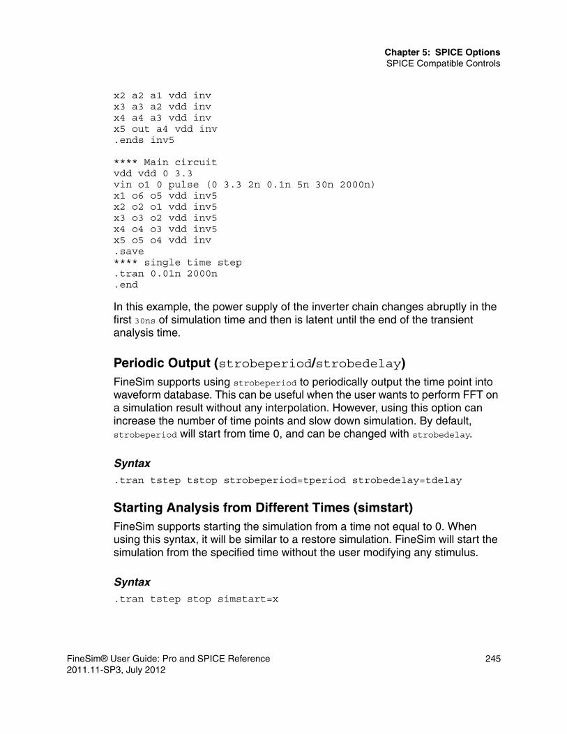
Chapter 5: SPICE OptionsSPICE Compatible Controls
x2 a2 a1 vdd invx3 a3 a2 vdd invx4 a4 a3 vdd invx5 out a4 vdd inv.ends inv5
**** Main circuitvdd vdd 0 3.3vin o1 0 pulse (0 3.3 2n 0.1n 5n 30n 2000n)x1 o6 o5 vdd inv5x2 o2 o1 vdd inv5x3 o3 o2 vdd inv5x4 o4 o3 vdd inv5x5 o5 o4 vdd inv.save**** single time step.tran 0.01n 2000n.end
In this example, the power supply of the inverter chain changes abruptly in the first 30ns of simulation time and then is latent until the end of the transient analysis time.
Periodic Output (strobeperiod/strobedelay)FineSim supports using strobeperiod to periodically output the time point into waveform database. This can be useful when the user wants to perform FFT on a simulation result without any interpolation. However, using this option can increase the number of time points and slow down simulation. By default, strobeperiod will start from time 0, and can be changed with strobedelay.
Syntax.tran tstep tstop strobeperiod=tperiod strobedelay=tdelay
Starting Analysis from Different Times (simstart)FineSim supports starting the simulation from a time not equal to 0. When using this syntax, it will be similar to a restore simulation. FineSim will start the simulation from the specified time without the user modifying any stimulus.
Syntax.tran tstep stop simstart=x
FineSim® User Guide: Pro and SPICE Reference 2452011.11-SP3, July 2012

Chapter 5: SPICE OptionsSPICE Compatible Controls
Transient Noise Analysis SupportTransient noise analysis is large signal noise analysis in time domain. This analysis is very useful for all kinds of noise sensitive circuits to determine the performance deterioration due to device noise. Both white and flicker noise can be supported.
Syntax.TRAN tstep tstop noisefmax=val1 <noisefmin=val2> <noisescale=val3> <noiseseed=val4>
where:■ noisefmax—parameter to invoke the transient noise analysis. Default is 0. A
nonzero value will turn on noise sources during transient analysis.■ noisefmin—If specified, the flicker noise will be included in transient
analysis. The default is noisefmax. The noise power density below noisefmin is constant.
■ noisescale—noise scale for all noise sources. The default is 1.■ noiseseed—seed for random number generator.
Examples.tran 0.5n 1m noisefmax=1e6 noisescale=1e2.tran 1ps 0.1u noisefmax=5e6 noisefmin=1e3
In the first example, transient noise analysis will only take white noise sources into account, and noise sources are scaled by 1e2 times.
In the second example, both white and flick noise sources are taken into account.
.VECFineSim Pro supports the .vec command similar to HSPICE.
Syntax.vec vector_file_name
Example.vec xyz.vec
246 FineSim® User Guide: Pro and SPICE Reference2011.11-SP3, July 2012

Chapter 5: SPICE OptionsSPICE Compatible Controls
where xyz.vec is a vector file and the expansion of busses will be HSPICE compatible. Either of the following formats can be used for vector files:
.vec vector_file
.option finesim_vector=vector_file
.XFCommand for AC small signal transfer functions.
Syntax .xf ov type np fstart fstop
where ov is the small signal output variable.
For type, np, fstart,or fstop, refer to .ac analysis.
Example.xf v(1,2) dec 10 1e2 1e9
FineSim® User Guide: Pro and SPICE Reference 2472011.11-SP3, July 2012

Chapter 5: SPICE OptionsSPICE Compatible Controls
248 FineSim® User Guide: Pro and SPICE Reference2011.11-SP3, July 2012

6
6Back-Annotation
This chapter describes how to use post-layout simulation with back-annotation in FineSim.
With process technologies advancing to 90 nanometers and below, parasitic effects become increasingly important and cannot be ignored in circuit simulation. A successful simulation for a pre-layout netlist does not necessarily mean you will get a successful simulation after layout and RC parasitics are taken into account. Full-chip transistor-level simulation considering the post-layout parasitics has therefore become an essential step for a successful design.
FineSim Pro supports post-layout simulation by allowing pre-layout netlists to be back-annotated with the extracted interconnect RC parasitics as well as extracted device parameters. FineSim Pro can read interconnect parasitics from Detailed Standard Parasitic Format (DSPF) files and extracted device parameters from Device Parameter Format (DPF) files or DSPF files.
No matter what back-annotation method you use in FineSim Pro, you can achieve the most accurate results for post-layout simulation, including dynamic voltage drop, and EM violations, to complete the design verification successfully at the transistor level.
Setting Defaults for DSPF and DPF Options
FineSim Pro supports setting default values for DSPF and DPF-related options. DSPF and DPF options apply to the DSPF or DPF file they follow. When multiple DSPF or DPF files are back-annotated, the options must be repeated for each file. Consider the following example:
.option finesim_spf=”file1.spf”
FineSim® User Guide: Pro and SPICE Reference 2492011.11-SP3, July 2012

Chapter 6: Back-AnnotationSetting Defaults for DSPF and DPF Options
.option finesim_spfred=0
.option finesim_spfrmin=0
.option finesim_spf=”file2.spf”
.option finesim_spfred=0
.option finesim_spfrmin=0
.option finesim_spf=”file3.spf”
.option finesim_spfred=0
.option finesim_spfrmin=.1
Because it is often the case that the same options should be applied to all DSPF or DPF files, the DSPF or DPF options that come before the first file change the default value for all of the files. This allows one to achieve the same effect as in the previous example with the following code excerpt:
* Set the defaults for DSPF.option finesim_spfred=0.option finesim_spfrmin=0
* DSPF files.option finesim_spf=”file1.spf”.option finesim_spf=”file2.spf”.option finesim_spf=”file3.spf”.option finesim_spfrmin=.1 $ Override rmin for file3.spf
FineSim Pro supports temperature-dependent DSPF resistors with the following options:■ finesim_spfrtc1—You can use this option to set the tc1 parameter for DSPF
resistors. The default value is 0.■ finesim_spfrtc2—You can use this option to set the tc2 parameter for SPF
resistors. The default value is 0.■ finesim_spftref—You can use this option to set the reference temperature
for DSPF resistors.
When these options are specified, the resistances in the DSPF file are scaled according to the following formula:
(1.0+(temp-tref)*tc1)
Consider the following example:
.option finesim_spf=”file1.spf”
.option finesim_spftref=”30”
.option finesim_spfrtc1=.0035
250 FineSim® User Guide: Pro and SPICE Reference2011.11-SP3, July 2012

Chapter 6: Back-AnnotationDSPF Annotation
or:
.option finesim_spfrtc2=5.34e-7
DSPF Annotation
To support post-layout simulation, FineSim Pro supports back-annotating interconnect parasitics contained in a DSPF file onto a pre-layout netlist.
A DSPF file contains networks of RC parasitics that correspond to nodes in the ideal netlist. Because annotating the full RC network for all of the nets in a DSPF file can significantly slow down a simulation, FineSim Pro is flexible on how the DSPF is read, annotated and reduced. Depending on the accuracy requirements, on a net-by-net basis, FineSim Pro can annotate a nodal network as full RC trees, a single lumped capacitance or with no back-annotation at all.
For RC tree parasitics, FineSim Pro can further reduce the RC tree with different levels of constraints, such as model order reduction. Some floating (cross coupling) capacitors and resistors that are either too small or too large can be eliminated from the back-annotation process to improve performance without compromising accuracy much. For power rail back-annotation, the challenge is the vast RC networks and their impact on voltage drops along the rail. FineSim Pro has a special separate-partitioning-synchronizing-event-control algorithm to analyze this non-ideal power scenario to achieve the most accurate results in the industry.
Parasitic extraction tools can generate a flat or hierarchical DSPF file. A flat DSPF is the result of a full extraction, and contains parasitic networks at the lowest level of the design connected directly to basic devices such as transistors. A hierarchical DSPF, on the other hand, comes from extracting only the higher-level, for instance, gate level, interconnect parasitics. This hierarchical approach is useful for simulation of a standard-cell based design where a cell library with pre-extracted parasitics at the transistor level for each cell is already available.
When FineSim Pro does back-annotation, either in a flat or hierarchical DSPF, onto a pre-layout netlist, it will automatically and intelligently flatten the design as necessary to add the parasitics at the appropriate level. In the case of a flat DSPF, back-annotation may end up completely flattening the design to transistors and hence disable FineSim Pro’s ability to take advantage of the
FineSim® User Guide: Pro and SPICE Reference 2512011.11-SP3, July 2012

Chapter 6: Back-AnnotationDSPF Annotation
adaptive hierarchy database (finesim_hiersim option) because no sub-circuit modules are identical anymore.
FineSim Pro supports the use of different MOS models between pre-layout netlists and SPF. The SPF model is used to perform simulation.
FineSim Pro provides the following options you can use for DSPF annotation:
Table 62 DSPF Annotation Commands
Command Description
finesim_add_divider Defines a character to use as a hierarchy divider.
finesim_em_layer Used with finesim_spfred to reduce resistors not specified with this option.
finesim_repdot Replaces "." with another character.
finesim_simple_em_naming Avoid EM analysis being unable to find the signal nets.
finesim_spf Specifies the DSPF file that contains SPF data extracted from the layout interconnects.
finesim_spf_add_irem_window Specifies analysis time range for the IR/EM .em file.
finesim_spf_keep_hier Helps reduce the memory footprint.
finesim_spf_matcheffort Performs more rigorous naming matching for SPF net and devices.
finesim_spf_selective_backannotation
Supports back-annotation based on the activity of a prelayout file.
finesim_spf_sensitive Supports case sensitivity for Spectre netlist back-annotation flow.
finesim_spf_spice_names Specifies whether the instance names in the DSPF file include SPICE type prefix.
finesim_spfallowerror Continues simulation even when there is a parsing error of SPF.
252 FineSim® User Guide: Pro and SPICE Reference2011.11-SP3, July 2012

Chapter 6: Back-AnnotationDSPF Annotation
finesim_spfallowmissinginstance Annotates the net to which the missing device was attached as an RC net.
finesim_spfcnet Specifies the net names to be annotated with lumped capacitance only.
finesim_spfeqr, finesim_spf2eqr, finesim_spfeqrfile, finesim_spfeqronly
Specifies the output file and net of a DSPF file.
finesim_spffcmin Sets the minimum floating capacitor value allowed for back-annotation.
finesim_spffcnet Keeps the floating capacitance for C-only back-annotation.
finesim_spfinst Controls whether the instance section of DSPF file is used for back-annotation.
finesim_spfmergeport Merges ports in a DSPF net.
finesim_spfnonet Specifies the nets that are not going to be back-annotated by DSPF data.
finesim_spfprb Sets the probe mode for DSPF nodes.
finesim_spfprb_mode Flattens SPF-annotated node name.
finesim_spfprefix Lists the prefixes that should be removed from device names.
finesim_spfrcnet Specifies the net names that will be annotated with RC trees.
finesim_spfred Sets the RC reduction mode and whether DSPF RCs are reduced or not.
finesim_spfreplast Controls how the representative node is chosen when annotating DSPF.
Table 62 DSPF Annotation Commands (Continued)
Command Description
FineSim® User Guide: Pro and SPICE Reference 2532011.11-SP3, July 2012

Chapter 6: Back-AnnotationDSPF Annotation
Option PrecedenceFineSim Pro adheres to the following rules in regard to the precedence of DSPF annotation-related options:
1. The precedence is defined as follows with finesim_spfnonet being at the highest level:
a. finesim_nonet
b. finesim_rcnet
c. finesim_fcnet
d. finesim_cnet
finesim_spfrmax Sets the maximum resistor value allowed for back-annotation.
finesim_spfrmin Sets the minimum resistor value allowed for back-annotation.
finesim_spfrptrmax Sets the warning threshold number for SPF resistors.
finesim_spfscale Sets the scale for devices in the DSPF file.
finesim_spfsplitnet Splits nets into multiple nets after layout is complete.
finesim_spfsuffix Defines the suffix in an SPF file.
finesim_spftc Sets the time constant value used by the RC reduction algorithm.
finesim_spred Determines the type and level of RC reduction.
finesim_spredtc Sets the time constant value used by the RC reduction algorithm.
Table 62 DSPF Annotation Commands (Continued)
Command Description
254 FineSim® User Guide: Pro and SPICE Reference2011.11-SP3, July 2012

Chapter 6: Back-AnnotationSPEF Annotation
2. The exact net name match without wildcards takes precedence over the match with wildcards. For example, with the following commands, net A is annotated with grounded C only while all the other nets are annotated with RC trees.
.option finesim_rcnet=’*’
.option finesim_cnet= ‘A’
Probing Internal NodesWhen DSPF is back-annotated onto a design, additional nodes are created. What was one node in the original design becomes an RC network with additional nodes. FineSim Pro supports .measure, .probe, and .print statements involving nodes from the DSPF file. For example, consider the following example where DSPF nets are annotated:
*|NET B 0.00269325PF*|I (XND5/MXM2:GATE XND5/MXM2 GATE I 3e-15 0 0)*|P (B B 0 0.565 9.685)*|I (XND5/MXM4:GATE XND5/MXM4 GATE I 2e-16 0 0)Cg1 XND5/MXM2:GATE GND 2e-16R1 XND5/MXM2:GATE B 100R2 XND5/MXM2:GATE XND5/MXM4:GATE 1000R3 B XND5/MXM4:GATE 200
*|NET XND5/NET2 0PF*|I (XND5/MXM2:DRN XND5/MXM2 DRN B 0 0 0)*|I (XND5/MXM0:SRC XND5/MXM0 SRC B 0 0 0)R4 XND5/MXM2:DRN XND5/MXM0:SRC 0.001
FineSim Pro supports statements such as the following examples:
.measure a avg v(xnd5.mxm2:gate)
.probe v(xnd5.mxm2:drn)
Notice that for hierarchical node names, the hierarchy separator must be changed to a period (.)
SPEF Annotation
FineSim Pro supports back-annotation for the SPEF file. The syntax and options are the same as DSPF Annotation.
FineSim® User Guide: Pro and SPICE Reference 2552011.11-SP3, July 2012

Chapter 6: Back-AnnotationDPF Annotation
DPF Annotation
In addition to interconnect parasitics, extraction tools can also extract the device parameters from layout and save these in a Device Parameter Format (DPF) file. FineSim Pro can annotate these device parameters onto the pre-layout netlist. If there are device parameters already in the pre-layout netlist, those in DPF file override pre-layout values for a correctly annotated simulation.
FineSim Pro provides the following options you can use for DPF annotation:
RC Reduction
In post layout simulations, efficient handling of RC parasitics can dramatically improve the performance of the simulator. FineSim Pro employs an advanced RC reduction algorithm that can minimize the accuracy loss when RC reduction is performed. The RC reduction level is controlled by the option finesim_spred and the default values are pre-determined by finesim_mode. RC reduction is performed after certain pre-prep steps, such as shorting very small resistors (finesim_resmin) and splitting very small cross coupling capacitors into grounded capacitors (finesim_fcapmin), is completed. Fundamentally speaking, the RC reduction algorithm reduces RC components that are smaller
Table 63 DPF Annotation Commands
Command Description
finesim_dpf Specifies the DPF file that contains the extracted device parameter data.
finesim_dpfadddev Controls whether DPF devices that are not in the netlist are added.
finesim_dpfhdiv Sets the divider character for hierarchical names in DPF files.
finesim_dpfprefix Lists the prefixes that should be removed from DPF device names.
finesim_dpfscale Sets the scale for devices in the DPF file.
finesim_dpfsuffix Defines the suffix in a DPF file.
256 FineSim® User Guide: Pro and SPICE Reference2011.11-SP3, July 2012

Chapter 6: Back-AnnotationRC Reduction
than a predefined time constant, or its corresponding cut-off frequency. The option finesim_spftc defines the frequency threshold for RC reduction. Any RC network time constant larger than this threshold can be reduced, while the lower ones will be preserved.
During SPF back-annotation, the user can elect different thresholds and settings for RC reduction of each individual SPF file. The following are list of equivalent options for the SPF file:■ finesim_spfrmin — shorting of small resistors.■ finesim_spffcmin — splitting of small coupling capacitors.■ finesim_spfred — RC reduction for SPF file.
The RC reduction for SPF is done during the back-annotation, and the fully annotated netlist will then go through RC reduction set by finesim_spfred.
FineSim® User Guide: Pro and SPICE Reference 2572011.11-SP3, July 2012

Chapter 6: Back-AnnotationRC Reduction
258 FineSim® User Guide: Pro and SPICE Reference2011.11-SP3, July 2012
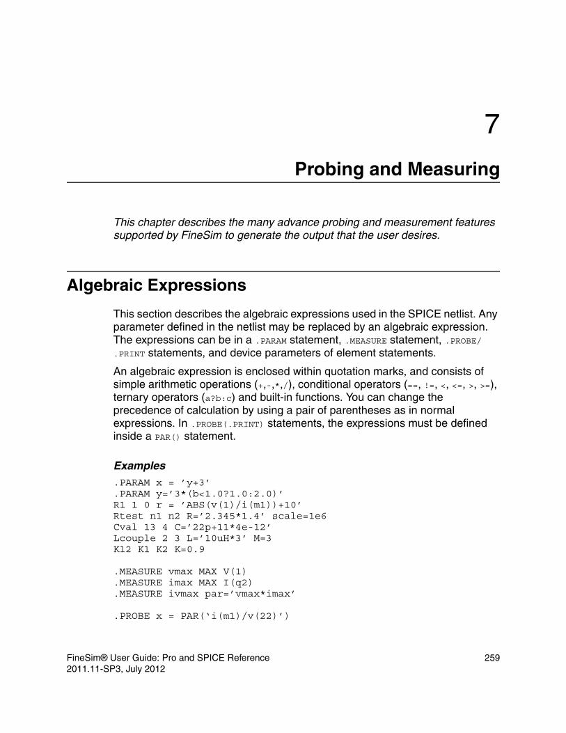
7
7Probing and Measuring
This chapter describes the many advance probing and measurement features supported by FineSim to generate the output that the user desires.
Algebraic Expressions
This section describes the algebraic expressions used in the SPICE netlist. Any parameter defined in the netlist may be replaced by an algebraic expression. The expressions can be in a .PARAM statement, .MEASURE statement, .PROBE/.PRINT statements, and device parameters of element statements.
An algebraic expression is enclosed within quotation marks, and consists of simple arithmetic operations (+,-,*,/), conditional operators (==, !=, <, <=, >, >=), ternary operators (a?b:c) and built-in functions. You can change the precedence of calculation by using a pair of parentheses as in normal expressions. In .PROBE(.PRINT) statements, the expressions must be defined inside a PAR() statement.
Examples.PARAM x = ’y+3’.PARAM y=’3*(b<1.0?1.0:2.0)’R1 1 0 r = ’ABS(v(1)/i(m1))+10’Rtest n1 n2 R=’2.345*1.4’ scale=1e6Cval 13 4 C=’22p+11*4e-12’Lcouple 2 3 L=’10uH*3’ M=3K12 K1 K2 K=0.9
.MEASURE vmax MAX V(1)
.MEASURE imax MAX I(q2)
.MEASURE ivmax par=’vmax*imax’
.PROBE x = PAR(‘i(m1)/v(22)’)
FineSim® User Guide: Pro and SPICE Reference 2592011.11-SP3, July 2012

Chapter 7: Probing and MeasuringAlgebraic Expressions
FineSim Pro also supports function parameter definition. For example:
.PARAM myfunc(a,b) = ’3*a + b’
.PARAM x = ... y = ...
.PARAM k = ’2*myfunc(x,y)’R10 2 0 r=’1+myfunc(10,100)’
Built-In FunctionsTable 64 Built in Function Descriptions
Function
Name (args)
Description
(Return value)
abs(x) absolute value of x: |x|
acos(x) inverse cosine of x (in radians)
asin(x) inverse sine of x (in radians)
atan(x) inverse tangent of x (in radians)
ceil(x) smallest integer >= x
cos(x) cosine of x (in radians)
cosh(x) hyperbolic cosine of x (in radians)
db(x) base 10 logarithm of the absolute value of x, multiplied by 20, with the sign of x: (sign of x)20log10(|x|)
exp(x) e raised to the power x: ex
floor(x) largest integer of <= x
fmod(x,y) floating-point remainder of x/y
int(x) largest integer less than or equal to x
log(x) natural logarithm of the absolute value of x, with the sign of x: (sign of x)log(|x|)
log10(x) base 10 logarithm of the absolute value of x, with the sign of x: (sign of x)log10(|x|)
260 FineSim® User Guide: Pro and SPICE Reference2011.11-SP3, July 2012

Chapter 7: Probing and Measuring.PROBE
.PROBE
The .PROBE statement saves waveforms of output variables into data files. FineSim Pro usually saves all of the voltages and supply currents without the .PROBE statement. If you are only interested in the output data file, use the .OPTION POST PROBE statement in conjunction with the .PROBE statement. Even when you only use .PROBE statement, FineSim Pro saves output variables only. See Output Files for detailed information about output file name conventions.
max(x,y) numeric maximum of x and y
min(x,y) numeric minimum of x and y
nint(x) round to nearest integer of x
pow(x,y) value of x raised to power of the integer part of y: x(integer part of y)
pwr(x,y) absolute value of x raised to the y power, with the sign of x: (sign of x)|x|y
round(x) round to nearest integer of x
sgn(x) -1 if x is less than 0, 0 if x is equal to 0, and 1 if x is greater than 0
sign(x,y) absolute value of x, with the sign of y: (sign of y)|x|
sin(x) sine of x (in radians)
sinh(x) hyperbolic sine of x (in radians)
sqrt(x) square root of the absolute value of x: sqrt(-x) = -sqrt(|x|)
tan(x) tangent of x (in radians)
tanh(x) hyperbolic tangent of x (in radians)
trunc(x) integer part of x
Table 64 Built in Function Descriptions (Continued)
Function
Name (args)
Description
(Return value)
FineSim® User Guide: Pro and SPICE Reference 2612011.11-SP3, July 2012

Chapter 7: Probing and Measuring.PROBE
This statement handles level identification for the use of wildcards across hierarchy. The level option is applied when there is wildcard character in an output variable. The following values are possible:■ -1 (the default value)—Finds matched variables in all levels.■ 0—Ignores wildcards in .ic or .probe statements.■ 1—Finds matched variables in the current level.■ 2—Finds matched variables in the current level and one level below.
When you use this statement, FineSim Pro can create additional nodes when DSPF is back-annotated onto a design. For more details see DSPF Annotation in Chapter 6, Back-Annotation.
Syntax.PROBE antype <name1=>V(NodeName) <name2=>I(DevName) … [subckt=name].PROBE antype <name3=>V(Node1,Node2) … [subckt=name].PROBE antype <name4=>PAR(‘algebraic expression’) … [subckt=name]
FineSim Pro can also probes nodes inside a subckt without having .probe inside the .subckt block.
Table 65 .PROBE Parameters
Parameters Description
antype Type of analysis (DC or TRAN) for the specified plots.
DevName Device (element) name, which can contain wildcards * and/or ?. I(DevName) means the branch current through DevName.
name1,name2, ...
Optional user-defined output name.
Node1, Node2 Node names that don’t allow wildcard characters. V(Node1,Node2) means the difference of V(Node1)-V(Node2).
NodeName Node name, which can contain wildcard characters * and/or ?. V(NodeName) means the node voltage of NodeName.
subckt=name Name of the sub-circuit.
262 FineSim® User Guide: Pro and SPICE Reference2011.11-SP3, July 2012

Chapter 7: Probing and Measuring.PROBE
Example{simulation deck} :.probe v(*) subckt=block1 :.subckt a b c d e block1 :.ends :
The previous example is equivalent to the following deck:
{simulation deck} :.subckt a b c d e block1.probe v(*) :.ends :
When adonly=1 is added, only the nodes that are connected to at least one active device will be probed, as in the following example:
.probe v(*) subckt=block1 adonly=1
Examples.PROBE DC V(1) V(2) V(3) beta=PAR(`I1(Q1)/I2(Q1)')
In this example, FineSim Pro probes the DC voltages at node 1, 2 and 3 as well as currents through devices Q1. The variable beta is calculated by I1(Q1)/I2(Q1).
.PROBE TRAN V(3,1) V(4) V(7) minus_ten=V(0,10)
In this example, FineSim Pro probes voltage differences between nodes 3 and 1 (3,1) and 0 and 10 (0,10) and calls the latter as variable minus_ten. It also probes voltages at nodes 4 and 7.
.PROBE V(*)
In this example, FineSim Pro probes voltages at all nodes in the entire design.
.PROBE V(*.*)
In this example, FineSim Pro probes voltages at nodes from the second level of hierarchy and below.
.PROBE V(*.*.*)
FineSim® User Guide: Pro and SPICE Reference 2632011.11-SP3, July 2012

Chapter 7: Probing and Measuring.PROBE
In this example, FineSim Pro probes voltages at nodes from the third level of hierarchy and below.
.PROBE V(*) LEVEL=1
In this example, FineSim Pro probes voltages at the top level nodes only, which is also where wildcard character first met.
.PROBE V(*) LEVEL=2
In this example, FineSim Pro probes voltages at nodes for the top level where is wildcard character first met and one level below.
.PROBE V(*) LEVEL=3
In this example, FineSim Pro probes voltages at nodes for the top level, where is wildcard character first met, and 2 levels down to make 3 levels of hierarchy.
.PROBE V(X101.*) LEVEL=3
In this example, FineSim Pro probes from instance X101.* as the first level and 2 levels of hierarchy down for a total of 3 levels of hierarchy.
.PROBE V(X*.*) LEVEL=3
In this example, FineSim Pro probes from instance X* as the first level and 2 level of hierarchy down for a total of 3 levels of hierarchy.
.PROBE V(X*.*) LEVEL=1
In this example, FineSim Pro won’t probe anything.
.PROBE DC V(*) I(*.*)
In this example, FineSim Pro probes DC voltages for all nodes in the entire design and also currents on all devices from the second level of hierarchy down.
.PROBE DC V(A*) I(x1.*)
In this example, FineSim Pro probes voltage on nodes started with letter A and currents in instance x1 for all the hierarchy levels in this instance.
.PROBE TRAN V(?????)
In this example, FineSim Pro probes all the voltage on nodes whose name is 5 characters in the top level.
.PROBE V(*EN*)
264 FineSim® User Guide: Pro and SPICE Reference2011.11-SP3, July 2012

Chapter 7: Probing and Measuring.PROBE
In this example, FineSim Pro probes all nodes in the entire design whose name has the string EN.
.PROBE TRAN V(*b?)
In this example, FineSim Pro probes all nodes in the entire design whose name ends with letter b followed by one more character, for example, b0, b1, enba.
Probing Block CurrentYou can measure the current into a block through a port or global node by using x() with this statement, as shown in the following example:
x(instance.port) or x(instance.global)
where:■ instance is the name of an instance in the design, and can include wildcards,■ port is the name of a port in the instance, and can include wildcards, and■ global is the name of a global node used by the instance, and can include
wildcards.
Example.probe tran x(x1.x2.a) .probe tran x(x1.vdd*)
In the first example, FineSim Pro probes the current into port x1.x2.a, in the second example, FineSim Pro probes the current into x1 through any global nodes matching vdd*.
FineSim supports syntax of ISUB(X****.****) to support current probing in spice netlist format. Internally, it will be mapped into x-probes.
Note:Current is considered positive when it is flowing into a block and negative when it is flowing out, so vdd current will usually be positive while vss current will usually be negative.
When you want to define the source or sink of a current explicitly, you can use the finesim_chk_devport option. For more details, see Chapter 4, FineSim Pro Options.
FineSim® User Guide: Pro and SPICE Reference 2652011.11-SP3, July 2012

Chapter 7: Probing and Measuring.PROBE
Probing and Exceptions to ProbingFineSim Pro supports regular expressions for probes and lprobes as well as exceptions to probes and lprobes. Exceptions can be given to any probe statement. Independent of whether you use glob-patterns or regular expressions for the node name, the exception is always a glob-pattern. You can further refine your probe statement with more constraints such as the level= statement.
FineSim Pro implements the Posix ERE (extended regular expressions).
Logic Probes (Digital Waveforms)In contrast to the normal analog waveform probing in which FineSim records every change in the waveform that exceeds finesim_vprbtol, digital waveforms or logic probes can be either logically zero (‘0’), logically one (‘1’) or undefined (‘x’). Using lprobes can reduce your fsdb file size significantly.
For logic probes you must define the threshold levels for logic-low and logic-high detection for the signals you probe, as in the following example:
.lprobe level=8 v(*) high=0.7 low=0.4
The previous example probes all signals in the top eight levels of hierarchy. All voltage levels up to 0.4V will be displayed as logically zero, all values above 0.7V will be displayed as logically one, and the values in between will be undefined.
In case of conflicting probe and lprobe statements, the probe statement takes precedence and will be executed instead of the logic probe.
By default, FineSim Pro only adjusts the logic value of an lprobe statement when it writes out an analog simulation data point.
No interpolation is performed to obtain the exact point in time when the given signal crosses the threshold value. You can enable interpolation using finesim_lprobe=1. The below figure illustrates this difference:
266 FineSim® User Guide: Pro and SPICE Reference2011.11-SP3, July 2012

Chapter 7: Probing and Measuring.PROBE
Figure 11 finesim_lprobe=1 vs. 0
Probing with Regular ExpressionsFineSim Pro supports regular expressions for probes and lprobes, as well as the Posix ERE (extended regular expressions). regexp=option can be used to match nodes you want to probe.
The below table lists and describes the special characters that FineSim Pro supports.
Table 66 Supported Characters for Regular Expressions
Character Description
^ Indicates the beginning of the string.
$ Indicates the end of the string.
. Matches anything, including spaces.
* Matches the prepended item zero times or more often. For example, X\d*$ matches ‘XXX’ as well as ‘X122321’ and ‘X3’.
+ Matches the prepended item once or more often. For example, X\d+$ does not match ‘XXX’ but it matches ‘X122321’ and ‘X3’.
FineSim® User Guide: Pro and SPICE Reference 2672011.11-SP3, July 2012

Chapter 7: Probing and Measuring.PROBE
Examples.probe regexp=v(^[a-z]+$)
The previous example probes all nodes that consist of characters only, no numbers or any special characters.
.probe regexp=v(^[a-z0-9]+$)
The previous example probes all nodes that consist of characters and digits only, no special characters such as underscore.
.probe regexp=v(net[0-4][0-9]*)
The previous example probes all nets that begin with either 0, 1, 2, 3 or 4, for example: net1 or net49 or net33423 but not net7 or net99.
Exceptions to ProbingWhen using patterns to match multiple signals such as ‘*’ or regular expressions, it often occurs that this pattern matches thousands of signals. Quite often you do not intend to probe them all, just for a few of them. That is especially true in post-layout simulations, where each node has several (sometimes as many as hundreds) derivatives.
To exclude certain nets from your probe statement, you can use the except= option. These exceptions are always interpreted as glob-patterns, not as regular expressions, even though your actual probe statement might be.
? Matches the prepended item zero times or only once. For example, X\d?$ matches ‘XXX’ and ‘X3’, but does not match ‘X122321’.
( ) Used to group certain characters. For example, (abac)+ matches ‘abac’ or ‘abacabac’ but not ‘abab’.
[ ] Used to define a set of characters, out of which either one can match. For example, h[aeo]llo matches ‘hallo’ or ‘hello’ or ‘hollo’ but not ‘hillo’.
\ Escape any of the above special characters.
Table 66 Supported Characters for Regular Expressions
Character Description
268 FineSim® User Guide: Pro and SPICE Reference2011.11-SP3, July 2012

Chapter 7: Probing and Measuring.PROBE
Exceptions can be given to any probe statement. Independent of whether you use glob-patterns or regular expressions for the node name, the exception is always a glob-pattern. You can further refine your probe statement with more constraints such as the level= statement.
Examples.probe v(*) except="v*" level=2.probe v(*) except="*$*".probe regexp=v(^[^o][a-z0-5]+$) except="s15" level=1
The first example probes all nets on the first two levels of hierarchy, except those that start with the letter ‘v’.
The second example probes all nets in all hierarchies except those that contain the dollar sign.
The third example probes all nets that do not begin with ‘o’ and after that only contain '0', '1', '2', '3', '4', and '5', with the exception of node ‘s15’.
Support for Power Reporting for Each DevicePower reporting for each device is supported.
Syntaxp(device_full_name)
Exampleprobe p(x1.x2.m1) p(vvdd)
where p(device_full_name) is the sum of terminal_voltage*terminal_current for all terminals of the device where terminal_current is the incoming direction.
Please note that: ■ pd() reports only dissipated power, but p() basically reports the sum of
dissipated power and stored power.■ HSpice has the same syntax but its definition is different for the devices
having both resistances and capacitances inside like MOSFET. In that case, FineSim's pd() corresponds to it.
FineSim® User Guide: Pro and SPICE Reference 2692011.11-SP3, July 2012

Chapter 7: Probing and Measuring.PROBE
Support for Measuring Power Dissipation: pd()FineSim Pro supports pd() for measuring the power dissipation of an individual device or total circuit. For capacitors/inductors/voltage sources/current sources, there is no power dissipation and the pd() value is 0.
Examples.probe pd(x1.m1) pd(x1.r1) pd(*) .probe pd(%top%).meas total_power INTEG pd(%top%)
In the first example, it will probe the power dissipation for an individual device. In the second example, it will probe the total power dissipation. In the third example, the total power dissipation can be used with .measure.
Probing Element ParametersFineSim Pro supports probing of the following element parameters, including resistor, diode, BJT and MOSFET.
Table 67 Supported Resistor Parameters for Probing
Parameters Description
LV1 Conductance at analysis temperature.
LV2 Resistance at analysis temperature.
Table 68 Supported Diode Parameters for Probing
Parameters Description
LV1 Diode area factor.
LX0 Voltage across diode (VD), excluding RS (series resistance).
LX1 DC current through diode (ID), excluding RS. Total diode current is the sum of IDC and ICAP.
LX2 Equivalent conductance (GD).
LX4 Current through the diode capacitor. Total diode current is the sum of IDC and ICAP.
270 FineSim® User Guide: Pro and SPICE Reference2011.11-SP3, July 2012

Chapter 7: Probing and Measuring.PROBE
LX5 Total diode capacitance.
LV23 Area after scaling
Table 69 Supported BJT Parameters for Probing
Parameters Description
LX19 cbe capacitance (C?).
LX20 cbc internal base-collector capacitance (Cµ).
Table 70 Supported MOS Parameters for Probing
Parameter Description
LV1 Channel length (L)
LV2 Channel width (W)
LV3 Area of the drain diode (AD)
LV4 Area of the source diode (AS)
LV9 Threshold voltage
LV10 Saturation voltage (VDSAT)
LV11 Drain diode periphery (PD)
LV12 Source diode periphery (PS)
LV13 Drain resistance (squares) (RDS)
LV14 Source resistance (squares) RSS
LV15 Charge sharing coefficient
LV16 Effective drain conductance (1/RDeff)
Table 68 Supported Diode Parameters for Probing
Parameters Description
FineSim® User Guide: Pro and SPICE Reference 2712011.11-SP3, July 2012

Chapter 7: Probing and Measuring.PROBE
LV17 Effective source conductance (1/RSeff)
LV36 Gate-source overlap capacitance
LV37 Gate-drain overlap capacitance
LV38 Gate-bulk overlap capacitance
LX1 Bulk-source voltage (VBS)
LX2 Gate-source voltage (VGS)
LX3 Drain-source voltage (VDS)
LX4 DC-drain current (CDO)
LX5 DC source-bulk diode current (IBS)
LX6 DC drain-bulk diode current (IBD)
LX7 DC-gate transconductance (GMO)
LX8 DC drain-source conductance (GDSO)
LX9 DC-substrate transconductance (GMBSO)
LX18 CGGBO=∂Qg/∂Vgb=CGS+CGD+CGB
LX19 CGDBO=∂Qg/∂Vdb
LX20 CGSBO=∂Qg/∂Vsb
LX21 CBGBO=∂Qb/∂Vgb
LX22 CBDBO=∂Qb/∂Vdb
LX23 CBSBO=∂Qb/∂Vsb
LX28 Bulk-source capacitance
LX29 Bulk-drain capacitance
Table 70 Supported MOS Parameters for Probing
Parameter Description
272 FineSim® User Guide: Pro and SPICE Reference2011.11-SP3, July 2012

Chapter 7: Probing and Measuring.PROBE
LX32 CDGBO=∂Qd/∂Vgb
LX33 CDDBO=∂Qd/∂Vdb
LX34 CDSBO=∂Qd/∂Vsb
LX62 Effective channel width (Weff)
LX63 Effective channel length (Leff)
LX70 Gate induced drain leakage current
LX82 Total gate capacitance (including intrinsic), and all overlap and fringing components
LX83 Total gate-to-drain capacitance (including intrinsic), and overlap and fringing components
LX84 Total gate-to-source capacitance (including intrinsic), and overlap and fringing components
LX85 Total drain capacitance (including intrinsic), overlap and fringing components, and junction capacitance
LX86 Total drain-to-source capacitance
LX87 Total drain-to-gate capacitance (including intrinsic), and overlap and fringing components
LX88 Total bulk-to-gate (floating body-to-gate) capacitance, including intrinsic and overlap components
LX89 Total bulk-to-drain (floating body-to-drain) capacitance, including intrinsic and junction capacitance
LX90 Total bulk-to-source (floating body-to-source) capacitance, including intrinsic and junction capacitance
LX110 Gate-induced source leakage current
Table 70 Supported MOS Parameters for Probing
Parameter Description
FineSim® User Guide: Pro and SPICE Reference 2732011.11-SP3, July 2012

Chapter 7: Probing and Measuring.MEASURE
Examples.probe LV9(Xab.Xcd.M1) .meas name1 avg lv9(Xab.Xcd.M1)
.MEASURE
The .MEASURE statement is useful in a wide range of applications. You can analyze simulation results by adding .MEASURE statements in input files. FineSim Pro has additional data-measurement capability whose syntax is compatible with popular SPICE conventions.
Support for EM in .MEASURE
FineSim supports the EM function in measure statements. The related option is finesim_em_factor and the default value of this option is 0.5.
Hierarchical Parameter Measurements
FineSim supports .meas hierarchical parameter measurements when the statement is in the top level of the hierarchy.
Measurement Analysis (.MEASURE) and its Modes
The .MEASURE statement prints user-defined electrical specifications of a circuit and is used extensively in optimization. The specifications include propagation, delay, rise time, fall time, peak-to-peak voltage, minimum and maximum voltage over the specified period, and a number of other user-defined variables.
The .MEASURE statement has several different formats, depending on the application. You can use it for either DC sweep or transient analysis. Fundamental measurement modes are rise-fall-delay, find-when, equation evaluation, functions (average, RMS, min, max, and peak-to-peak), integral evaluation, and derivative evaluation.
General expressions can be given in the when condition of a .MEASURE statement, as shown in the following examples:
.measure tran tm1 when ‘v(1)+v(2)’=‘v(3)+1’ rise=1
.measure tran tm2 when ‘v(4)*2’=2 fall=3
274 FineSim® User Guide: Pro and SPICE Reference2011.11-SP3, July 2012

Chapter 7: Probing and Measuring.MEASURE
Rise, Fall, and Delay
This format is used to measure independent-variable (time, or any parameter or temperature) differential measurements such as rise time, fall time, slew rate, and any measurement that requires the determination of independent variable values. The format has two sub-statements TRIG and TARG, which specify the beginning and ending of a voltage or current amplitude measurement.
The rise, fall, and delay measurement mode computes the time between a trigger value and a target value.
Syntax.MEASURE <DC | AC | TRAN> Result+ TRIG trig_var VAL=trig_val <TD = time_delay> + <CROSS = c> <RISE = r> <FALL = f> + TARG targ_var VAL=targ_val <TD = time_delay> + <CROSS= c | LAST> <RISE= r | LAST> <FALL=f | LAST>
or:
.MEASURE <DC | AC | TRAN> Result+ TRIG AT=val + TARG targ_var VAL=targ_val <TD = time_delay> + <CROSS= c | LAST> <RISE= r | LAST> <FALL=f | LAST>
Table 71 Rise, Fall and Delay Parameters
Parameters Description
<DC|AC|TRAN> Analysis type. If omitted, the last analysis mode used is assumed.
AT = val The val is the time for the TRAN analysis or the parameter for the DC analysis, at which the measurement is to start.
CROSS = c The measurement is performed when the designated signal has reached c crossing times, as a result of rising or falling.
FALL= f The measurement is performed when the designated signal has fallen f times.
FineSim® User Guide: Pro and SPICE Reference 2752011.11-SP3, July 2012

Chapter 7: Probing and Measuring.MEASURE
LAST The measurement is performed when the last CROSS, FALL, or RISE event occurs. For CROSS=LAST, measurement is performed the last time the WHEN condition is true for a rising or falling signal. For FALL=LAST or RISE=LAST, the measurement is performed the last time the WHEN condition is true for a falling or rising signal, respectively.
MEASURE Specifies measurements. Can be abbreviated as MEAS.
Result The name given the measured value in the FineSim Pro output. The item measured is the independent variable beginning at the trigger and ending at the target. For transient analysis it is time. For DC analysis it is the DC sweep variable. If the target is reached before the trigger is activated, the result is negative.
RISE = r The measurement is performed when the designated signal has risen r times.
TARG The beginning of the target signal specification.
targ_var The name of the output variable whose propagation delay is determined with respect to the trig_var.
TD=time_delay The amount of simulation time that must elapse before the measurement is enabled. The number of crossings, rises, or falls is counted only after the time_delay value. The default value is 0.
TRIG The beginning of the trigger signal specification.
trig_var The name of the output variable that determines the logical beginning of measurement.
VAL=targ_val The value of the targ_var at which the counter for crossing, rises, or falls is incremented by one.
VAL=trig_val The value of trig_var at which the counter for crossings, rises, or falls is incremented by one.
Table 71 Rise, Fall and Delay Parameters (Continued)
Parameters Description
276 FineSim® User Guide: Pro and SPICE Reference2011.11-SP3, July 2012

Chapter 7: Probing and Measuring.MEASURE
Examples.MEASURE TRAN tdelay TRIG V(1) VAL = 2.5 TD = 10n RISE = 2+ TARG V(2) VAL = 2.5 FALL = 2.MEASURE TRAN riset TRIG I(Q1) VAL = 0.5m RISE = 3+ TARG I(Q1) VAL = 4.5m RISE = 3.MEASURE pwidth TRIG AT = 10n TARG V(in) VAL = 2.5 CROSS = 3
In the first example, a propagation delay measurement is taken between nodes 1 and 2 for a transient analysis. The delay is measured from the second rising edge of the voltage at node 1 to the second falling edge of node 2. The measurement begins when the second rising voltage at node 1 is 2.5V and ends when the second falling voltage at node 2 reaches 2.5V. The TD=10ns parameter prevents the crossings from being counted until 10ns has elapsed. The results are printed as tdelay=<value>.
In the second example, the time measurement begins when the current through Q1 at the third rising edge is 0.5mA and ends when the current through Q1 at the third rising edge is 4.5mA. The variable riset is the printed output variable.
In the third example, the short form TRIG AT=10n specifies that the time measurement is to begin at time t=10ns in the transient analysis. The TARG parameters specify that the time measurement is to end when V(in)=2.5V on the third crossing. The variable pwidth is the printed output variable.
FIND and WHEN Functions
The FIND and WHEN functions allow you to measure any independent variable (time, parameter), any dependent variable, such as voltage or current, or the derivative of any dependent variables when some event occurs. These functions are useful for measuring the time or any parameter value when two signals cross each other, or when a signal crosses a constant value. The measurement starts after a specified time delay, TD. You can find a specific event by setting RISE, FALL, or CROSS to a value (or parameter) or LAST for the last event.
Syntax.MEASURE <DC|AC|TRAN> result WHEN outvar = val <TD = val>+ <RISE = r | LAST> <FALL = f | LAST> <CROSS = c | LAST>
or
.MEASURE <DC|AC|TRAN> result WHEN outvar1 = outvar2 <TD = val>+ <RISE = r | LAST> <FALL = f | LAST> <CROSS = c| LAST>
FineSim® User Guide: Pro and SPICE Reference 2772011.11-SP3, July 2012
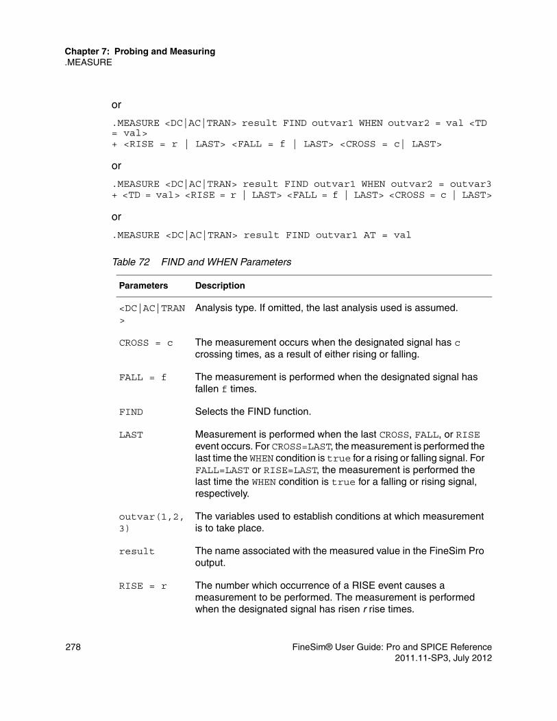
Chapter 7: Probing and Measuring.MEASURE
or
.MEASURE <DC|AC|TRAN> result FIND outvar1 WHEN outvar2 = val <TD = val>+ <RISE = r | LAST> <FALL = f | LAST> <CROSS = c| LAST>
or
.MEASURE <DC|AC|TRAN> result FIND outvar1 WHEN outvar2 = outvar3+ <TD = val> <RISE = r | LAST> <FALL = f | LAST> <CROSS = c | LAST>
or
.MEASURE <DC|AC|TRAN> result FIND outvar1 AT = val
Table 72 FIND and WHEN Parameters
Parameters Description
<DC|AC|TRAN>
Analysis type. If omitted, the last analysis used is assumed.
CROSS = c The measurement occurs when the designated signal has c crossing times, as a result of either rising or falling.
FALL = f The measurement is performed when the designated signal has fallen f times.
FIND Selects the FIND function.
LAST Measurement is performed when the last CROSS, FALL, or RISE event occurs. For CROSS=LAST, the measurement is performed the last time the WHEN condition is true for a rising or falling signal. For FALL=LAST or RISE=LAST, the measurement is performed the last time the WHEN condition is true for a falling or rising signal, respectively.
outvar(1,2,3)
The variables used to establish conditions at which measurement is to take place.
result The name associated with the measured value in the FineSim Pro output.
RISE = r The number which occurrence of a RISE event causes a measurement to be performed. The measurement is performed when the designated signal has risen r rise times.
278 FineSim® User Guide: Pro and SPICE Reference2011.11-SP3, July 2012

Chapter 7: Probing and Measuring.MEASURE
Examples.MEASURE TRAN result WHEN V(1) = 3.3.MEASURE TRAN result WHEN V(1)=V(2) TD=10ns.MEASURE TRAN result FIND V(3) WHEN V(1)=2.3 RISE=3.MEASURE TRAN result FIND V(3) WHEN V(1)=V(2) CROSS=LAST
In the first example the result is the time taken when the voltage at the node 1 is 3.3V.
In the second example, result is the time taken at 10ns after both node 1 and 2 have the same voltage value.
The third example finds the voltage at the node 3 when V(1)=2.3V on the third rising.
The fourth example finds the voltage at the node 3 when V(1)=V(2) on the last crossing.
Equation Evaluation
This statement is used to evaluate an equation that is a function of the results of previous .MEASURE statements. The equation must not be a function of node voltages or branch currents.
Syntax
.MEASURE <DC|AC|TRAN> result PARAM = ’equation’
TD=val The time at which measurement is to start.
WHEN Selects the WHEN function.
Table 73 Equation Evaluation Parameters
Parameters Description
<DC|AC|TRAN>
Analysis type. If omitted, the last analysis type uses is assumed.
PARAM=’equ’
Evaluations of any algebraic expression which may contain other measure outputs.
Table 72 FIND and WHEN Parameters (Continued)
Parameters Description
FineSim® User Guide: Pro and SPICE Reference 2792011.11-SP3, July 2012

Chapter 7: Probing and Measuring.MEASURE
Examples.MEASURE TRAN result1 TRIG V(1) VAL=3.3 FALL=2+TARG V(2) VAL=2.1 TD=40ns.MEASURE TRAN result2 TRIG AT=5ns+TARG V(4) VAL=3.0 RISE=LAST.MEASURE TRAN sum param=’result1+0.5*result2’
The first example finds the time measurement from the time V(1)=3.3V on the second fall to the time 40ns after V(2)=2.1V. The result is stored in result1 and output.
The second example finds the time measurement from 5ns to the time V(4)=3V on the last rise. The result is stored in result2 and output.
The third example calculates the expression result1+0.5*result2 and stores the result in sum and outputs sum as sum=<value>.
AVG, RMS, MIN, MAX, INTEG, and Peak-To-Peak
The average (AVG), RMS, MIN, MAX, and peak-to-peak (PP) measurement modes report statistical functions of the output variable rather than the analysis value. AVG calculates the area under the output variable divided by the periods of interest. RMS takes the square root of the area under the output variable square divided by the period of interest. MIN reports the minimum value of the output function over the specified interval. MAX reports the maximum value of the output function over the specified interval. PP (peak-to-peak) reports the maximum value minus the minimum value over the specified interval.
Syntax.MEASURE <DC|AC|TRAN> result func outvar <FROM = val> <TO = val>
Table 74 AVG,RMS, MIN, MAX, INTEG, PP Parameters
Parameters Description
<DC|AC|TRAN>
Analysis type. If omitted, the last analysis mode used is assumed.
FROM=val The beginning of the func calculation.
280 FineSim® User Guide: Pro and SPICE Reference2011.11-SP3, July 2012

Chapter 7: Probing and Measuring.MEASURE
Examples.MEASURE TRAN avgval AVG v(10) FROM = 10ns TO = 55ns.MEASURE TRAN maxval MAX v(1,2) FROM = 15ns TO = 100ns.MEASURE TRAN minval MIN v(1,2) FROM = 15ns TO = 100ns.MEASURE TRAN p2val PP I(M1) FROM = 10ns TO = 100ns
The first example calculates the average nodal voltage value for node 10 during the transient sweep from 10ns to 55ns and prints the result as avgval.
The second example finds the maximum voltage difference between nodes 1 and 2 from 15ns to 100ns and prints the result as maxval.
The third example finds the minimum voltage difference between nodes 1 and 2 from 15ns to 100ns and prints the result as minval.
The fourth example finds the peak-to-peak current through the element M1 from 10ns to 100ns and prints the result as p2val.
func The type of measure statement; one of the following:■ AVG (average): Calculates the area under outvar divided by
the periods of interest.■ MAX (maximum): Reports the maximum value of outvar over
the specified interval.■ MIN (minimum): Reports the minimum value of outvar over the
specified interval.■ PP (peak-to-peak): Reports the maximum value minus the
minimum value of outvar over the specified interval.■ RMS (root mean squared): Calculates the square root of the area
under outvar divided by the period of interest.
outvar The name of any output variable whose function func is to be measured in the simulation.
result The name associated with the measured value in the FineSim Pro output. The value is a function of the variable (outvar) and func.
TO=val The end of the func calculation.
Table 74 AVG,RMS, MIN, MAX, INTEG, PP Parameters (Continued)
Parameters Description
FineSim® User Guide: Pro and SPICE Reference 2812011.11-SP3, July 2012

Chapter 7: Probing and Measuring.MEASURE
INTEGRAL Function
The INTEGRAL function calculates the integral of an output variable over a specified period. It uses the same syntax used for the average (AVG), RMS, MIN, MAX, and peak-to-peak (PP) measurement modes with func defined as INTEGRAL.
Syntax.MEASURE <DC|AC|TRAN> result INTEGRAL outvar <FROM = val> <TO = val>
Example.MEASURE TRAN charge INTEGRAL I(cload) FROM=10ns TO=100ns
This example calculates the integral of I(cload) from 10ns to 100ns.
DERIVATIVE Function
The DERIVATIVE function calculates the derivative of an output variable at a given time or frequency or for any sweep variable, depending on the type of analysis. It also calculates the derivative of a specified output variable when some specific event occurs.
Syntax.MEASURE <DC|AC|TRAN> result DERIVATIVE outvar AT = val
or
.MEASURE <DC|AC|TRAN> result DERIVATIVE outvar WHEN var2 = val+ <RISE = r | LAST> <FALL = f | LAST> <CROSS = c | LAST> <TD = tdval>
or
.MEASURE <DC|AC|TRAN> result DERIVATIVE outvar WHEN var2 = var3+ <RISE = r | LAST> <FALL = f | LAST> <CROSS = c | LAST> <TD = tdval>
Table 75 Rise, Fall and Delay Parameters
Parameters Description
<DC|AC|TRAN> Analysis type. If omitted, the last analysis mode used is assumed.
AT = val Value of outvar at which the derivative is to calculated.
282 FineSim® User Guide: Pro and SPICE Reference2011.11-SP3, July 2012

Chapter 7: Probing and Measuring.MEASURE
Examples.MEASURE TRAN slew_rate DERIV v(out) AT = 25ns.MEASURE TRAN slew DERIV v(1) WHEN v(1) = ’0.90*vdd’
The first example calculates the derivative of v(out) at 25ns.
The second example calculates the derivative of v(1) when v(1) is equal to 0.9*vdd.
CROSS = c The measurement is performed when the designated signal has reached c crossing times, as a result of rising or falling.
DERIVATIVE Selects the derivative function. May be abbreviated to DERIV.
FALL= f The measurement is performed when the designated signal has fallen f times.
LAST The measurement is performed when the last CROSS, FALL, or RISE event occurs. For CROSS=LAST, measurement is performed the last time the WHEN condition is true for a rising or falling signal. For FALL=LAST or RISE=LAST, the measurement is performed the last time the WHEN condition is true for a falling or rising signal, respectively.
outvar The variable for which the derivative is to be found.
Result The name given the measured value in the FineSim Pro output.
RISE = r The measurement is performed when the designated signal has risen r times.
TD=val The time at which the measurement is to start.
var(2,3) The variables used to establish conditions at which the measurement is to take place.
WHEN Selects the WHEN function.
Table 75 Rise, Fall and Delay Parameters (Continued)
Parameters Description
FineSim® User Guide: Pro and SPICE Reference 2832011.11-SP3, July 2012

Chapter 7: Probing and Measuring.MEASURE
284 FineSim® User Guide: Pro and SPICE Reference2011.11-SP3, July 2012

8
8Circuit Checks
This chapter contains information on various circuit check commands.
The below circuit checks are detailed in this chapter:■ Check Active/Inactive Nodes (.CHKANODE)■ Check Block Power (.CHKBLKPWR)■ Check DC Path (.CHKDCPATH)■ Check Leakage Current Path (.CHKDCPATH, zgate=on)■ Check Device Current (.CHKDEVCUR)■ Check Device Operation Point (.CHKDEVOP)■ Check Expression (.CHKEXPR)■ Check Rise/Fall Transition Time (.CHKRFTIME)■ Check Signal Voltage Difference (.CHKSIGDIFF)■ Check Timing Setup/Hold/Delay/Width (.CHKTIMING)■ Check and Report Toggle Count (.CHKTOGGLE)■ Static Circuit Checks (.CHKSTATICERC)■ Check High Impedance State Node (.CHKZNODE)
Check Active/Inactive Nodes (.CHKANODE)
This command is used to check both the inactive and active nodes of the circuit.
FineSim® User Guide: Pro and SPICE Reference 2852011.11-SP3, July 2012
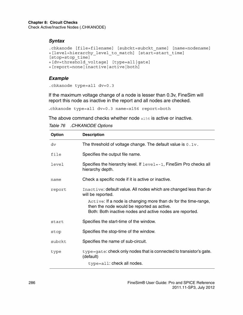
Chapter 8: Circuit ChecksCheck Active/Inactive Nodes (.CHKANODE)
Syntax.chkanode [file=filename] [subckt=subckt_name] [name=nodename]+[level=hierarchy_level_to_match] [start=start_time] [stop=stop_time]+[dv=threshold_voltage] [type=all|gate] +[report=none|inactive|active|both]
Example.chkanode type=all dv=0.3
If the maximum voltage change of a node is lesser than 0.3v, FineSim will report this node as inactive in the report and all nodes are checked.
.chkanode type=all dv=0.3 name=xl56 report=both
The above command checks whether node xl56 is active or inactive.
Table 76 .CHKANODE Options
Option Description
dv The threshold of voltage change. The default value is 0.1v.
file Specifies the output file name.
level Specifies the hierarchy level. If level=-1, FineSim Pro checks all hierarchy depth.
name Check a specific node if it is active or inactive.
report Inactive: default value. All nodes which are changed less than dv will be reported.
Active: If a node is changing more than dv for the time-range, then the node would be reported as active. Both: Both inactive nodes and active nodes are reported.
start Specifies the start-time of the window.
stop Specifies the stop-time of the window.
subckt Specifies the name of sub-circuit.
type type=gate: check only nodes that is connected to transistor’s gate. (default)
type=all: check all nodes.
286 FineSim® User Guide: Pro and SPICE Reference2011.11-SP3, July 2012
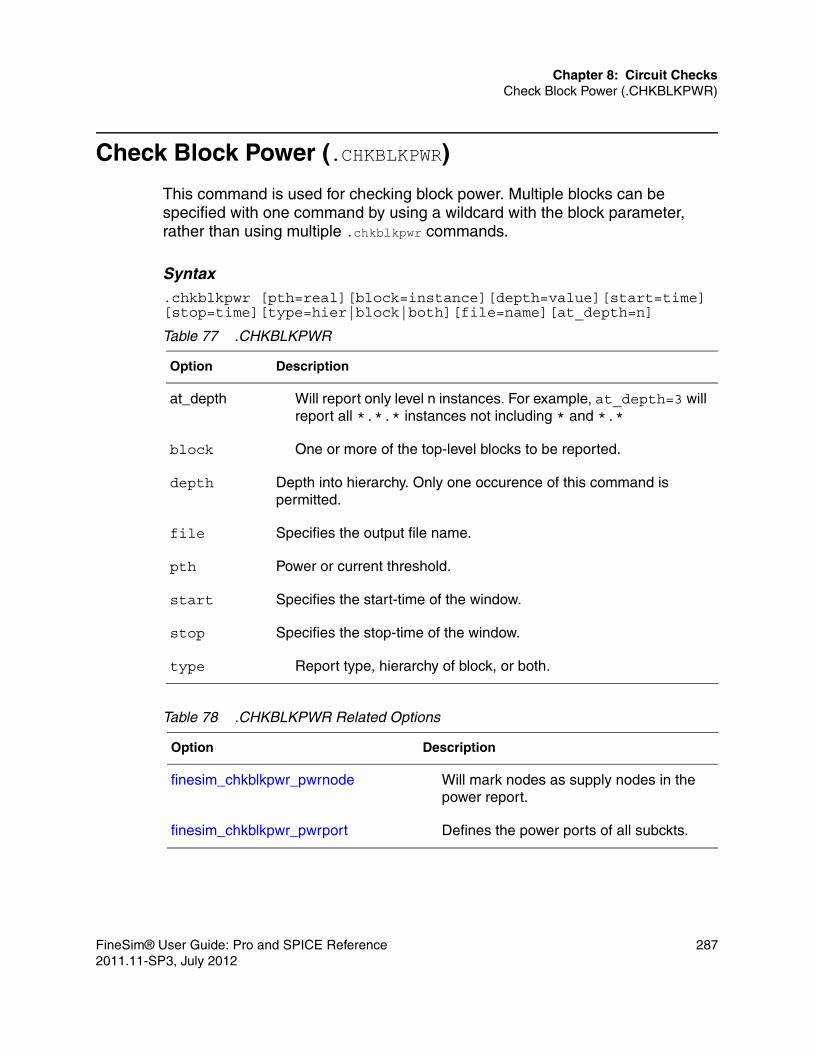
Chapter 8: Circuit ChecksCheck Block Power (.CHKBLKPWR)
Check Block Power (.CHKBLKPWR)
This command is used for checking block power. Multiple blocks can be specified with one command by using a wildcard with the block parameter, rather than using multiple .chkblkpwr commands.
Syntax.chkblkpwr [pth=real][block=instance][depth=value][start=time] [stop=time][type=hier|block|both][file=name][at_depth=n]
Table 77 .CHKBLKPWR
Option Description
at_depth Will report only level n instances. For example, at_depth=3 will report all *.*.* instances not including * and *.*
block One or more of the top-level blocks to be reported.
depth Depth into hierarchy. Only one occurence of this command is permitted.
file Specifies the output file name.
pth Power or current threshold.
start Specifies the start-time of the window.
stop Specifies the stop-time of the window.
type Report type, hierarchy of block, or both.
Table 78 .CHKBLKPWR Related Options
Option Description
finesim_chkblkpwr_pwrnode Will mark nodes as supply nodes in the power report.
finesim_chkblkpwr_pwrport Defines the power ports of all subckts.
FineSim® User Guide: Pro and SPICE Reference 2872011.11-SP3, July 2012

Chapter 8: Circuit ChecksCheck DC Path (.CHKDCPATH)
Check DC Path (.CHKDCPATH)
This command is used to check the DC current path among voltage sources in the circuit. The generated output will be prefix.filename.chkdcpath.
Syntax.chkdcpath <name=”sig_name1 sig_name2 sig_name3 …”> [ith=threshold_current]+[tag=tag_name] [file=filename][report=all]+[subckt=subckt_name<:0|1>][instance=instance_name<:0|1>]+[zgate=on][pwr_off=0][gnd_vth=xx]+[start=time_val][stop=time_val][include|exclude=name]+[period=time | interval=time | delay=time | at=<time[,time2, time3…]>]
Example .chkdcpath name="BATT G" ith=100n delay=0
The above command conducts DC path check from node “BATT” to “G”. If the current value of a path is larger than 100nA, FineSim Pro will regard this path as error and put it in the output file.
Table 79 .CHKDCPATH Options
Option Description
at When this parameter is used, the DC path check is performed at the specified time.
delay When this parameter is specified, the DC path is checked at each time defined as t+specified delay. t is the time at which an input voltage source changes to a new voltage level.
file Specifies the output file name.
gnd_vth The threshold used in pwr_off to determine power down state. Default is 0.
include|exclude=name
include=name — only checks the include device/node in the circuit check.exclude=name — excludes the device/node in the circuit check.
288 FineSim® User Guide: Pro and SPICE Reference2011.11-SP3, July 2012

Chapter 8: Circuit ChecksCheck DC Path (.CHKDCPATH)
instance Specifies the instance name to perform dcpath analysis. You can append [0|1] to indicate if it is an include or exclude. Wildcards are supported.
interval When this parameter is specified, the DC path is checked for every specified interval.
ith Defines threshold current. The default value is 50uA.
name Defines node names. This option needs two or more node names.
period Default is 1n if interval, at, and delay are not specified. When this parameter is specified, DC path will report any current path violation that exceeds period threshold. For a Hi-Z DC path, the period is set by the .chkznode command. If .chkznode is not specified, the default z-period is 1n.
pwr_off Default is 0. When set to 1, .CHKDCPATH will check if the nodes specified under name have paths to voltage sources. If not, these nodes will be skipped an a warning will be given. For all other nodes, if the voltage is less than the gnd_vth parameter, it will be treated as a ground and ignore all dcpath to ground (a warning will also be given).
report When set to all, reports all paths, even other branches. The default is to not report other branches.
start Specifies the start-time of the window. Default is 0.
stop Specifies the stop-time of the window. Default is the minimum of tstop of 1s.
subckt Specifies the subckt to perform dcpath analysis. You can append [0|1] to indicate if it is an include or exclude. Wildcards are supported.
tag Defines the tag name of the result.
Table 79 .CHKDCPATH Options
Option Description
FineSim® User Guide: Pro and SPICE Reference 2892011.11-SP3, July 2012

Chapter 8: Circuit ChecksCheck Leakage Current Path (.CHKDCPATH, zgate=on)
Check Leakage Current Path (.CHKDCPATH, zgate=on)
FineSim Pro includes a floating gate check for leakage paths. Use option zgate=on with .chkdcpath to support cckAnalogPDown in HSIM.
Syntax.chkdcpath zgate=on ...
All .chkdcpath options can be used.
ExamplecckAnalogPDown tag=chk_2 time=5n time=7n vsrc=vdd vsrc=gnd cckAnalogPDownIth 10u
The HSIM commands in the example above can be equivalently expressed in FineSim Pro as follows:
.chkdcpath zgate=on tag=chk_2 at=(5n,7n) name=”vdd gnd” ith=10u
This command conducts a power-down leakage-path check at both 5.0 ns and 7.0 ns. It then reports DC paths with leakage currents larger than the default 10uA current flowing from vdd to gnd, or the conducting paths with device(s) driven by a Hi-Z node.
Check Device Current (.CHKDEVCUR)
This command checks whether the current of a device is exceeding a given threshold and reports all violations in a log file.
Syntax.chkdevcur start=start_time stop=stop_time tag=tagname ith=threshold_current [avg=1] [rms=1] [model=modelpattern]
Note:The center log file’s name is *.chkdevcur. Log files for separate tags are named *.tagname.chkdevcur.
290 FineSim® User Guide: Pro and SPICE Reference2011.11-SP3, July 2012

Chapter 8: Circuit ChecksCheck Device Operation Point (.CHKDEVOP)
Example.chkdevcur start=0 stop=400n tag=avg_tag ith=200n avg=1
Check Device Operation Point (.CHKDEVOP)
This command checks the operating point of a device such as MOSFET, diode, and bipolar transistors and issues warnings if the operating point falls outside the user-specified values.
Syntax .chkdevop [type=m|q|j|d]c|r] [<model=modelpattern] + [subckt=subckt_name] [name=instance_name][level= none|warn|error]+ [lmin=min_length][lmax=max_length]+ [wmin=min_width][wmax=max_width]+ [period=period_time] [tag=tag_name]+ [start=start_time][stop=stop_time][file=filename]+ Vab=(min_value,max_value)… [when Vab=(min_value,max_value)…]
Table 80 .CHKDEVCUR
Option Description
avg Report the average current of the device if there are any violations. This is the default option.
lth Threshold current, device current (rms and/or avg) exceeding this number will be reported.
model Specify the model pattern filter. Only models matching the given pattern will be reported. Supports wildcard matching.
rms Report the rms current of the device if there are any violations.
start Specify start time of the check window.
stop Specify stop time of the check window.
tag Each violation will have a tag name when reported. Violations sharing the same tag will be summarized in a separate log file with that tag. If the user doesn’t supply a tag, the tag name will be ’default’ and a warning will be issued.
FineSim® User Guide: Pro and SPICE Reference 2912011.11-SP3, July 2012
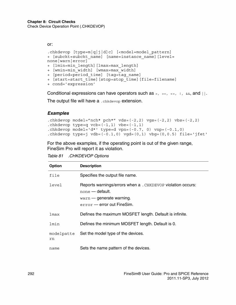
Chapter 8: Circuit ChecksCheck Device Operation Point (.CHKDEVOP)
or:
.chkdevop [type=m|q|j|d]c] [<model=model_pattern] + [subckt=subckt_name] [name=instance_name][level= none|warn|error]+ [lmin=min_length][lmax=max_length]+ [wmin=min_width] [wmax=max_width]+ [period=period_time] [tag=tag_name]+ [start=start_time][stop=stop_time][file=filename]+ cond=’expression’
Conditional expressions can have operators such as >, >=, <=, !, &&, and ||.
The output file will have a .chkdevop extension.
Examples.chkdevop model=”nch* pch*” vds=(-2,2) vgs=(-2,2) vbs=(-2,2).chkdevop type=q vcb=(-1,1) vbe=(-1,1).chkdevop model='d*' type=d vpn=(-0.7, 0) vnp=(-0.1,0).chkdevop type=j vdb=(-0.1,0) vgd=(0,1) vbg=(0,0.5) file='jfet'
For the above examples, if the operating point is out of the given range, FineSim Pro will report it as violation.
Table 81 .CHKDEVOP Options
Option Description
file Specifies the output file name.
level Reports warnings/errors when a .CHKDEVOP violation occurs:
none — default.
warn — generate warning.
error — error out FineSim.
lmax Defines the maximum MOSFET length. Default is infinite.
lmin Defines the minimum MOSFET length. Default is 0.
modelpattern
Set the model type of the devices.
name Sets the name pattern of the devices.
292 FineSim® User Guide: Pro and SPICE Reference2011.11-SP3, July 2012

Chapter 8: Circuit ChecksCheck Device Operation Point (.CHKDEVOP)
period If any device is staying in the violation state longer than period, it will be reported in the output file.
start Specifies the start-time of the window.
stop Specifies the stop-time of the window.
subckt Specifies subckt name to be checked.
tag Defines the tag name of the result.
type type=m MOSFET
type=q Bipolar transistor
type=d Diode
type=j Junction transistor
type=c Capacitortype=r Resistor
Vab Vab can be any of below:
Vd,Vg,Vs,Vb,Vds,Vgs … for MOSFETVe,Vb,Vc,Vs,Vec,Vbc … for BJTVp,Vn,Vpn,Vnp for Diode
wmax Defines the maximum MOSFET width. Default is infinite.
wmin Defines the minimum MOSFET width. Default is 0.
window Specifies the window limit.
Table 82 Terminals Supported for .CHKDEVOP
Devices Type Terminals
Capacitor c P: positive node
N: negative node
Diode d vpn: forward bias voltage threshold
vnp: reverse bias voltage threshold
Table 81 .CHKDEVOP Options
Option Description
FineSim® User Guide: Pro and SPICE Reference 2932011.11-SP3, July 2012

Chapter 8: Circuit ChecksCheck Device Operation Point (.CHKDEVOP)
Conditional Expressions.chkdevop type=m model=nch start=10n +cond=’((vds<0||vds>5)&&(vgs<0||vgs>5))’
In the previous example, .chkdevop is performed under the condition that vds and vgs are within the range of 0 to 5 volts. If the “cond” is true, FineSim Pro will report this as violation.
Keyword when UsageYou can specify conditions after the when keyword. If a condition is specified, the checking is done only when the conditions are met.
.chkdevop model="nch" vds=(-1,1) when vgs=(0,1) vbs=(0,2)
This means when vgs is within (0,1) and vbs is within (0,2), check if vds is within (-1,1).
Junction Transistor
j G: gate
D: drainS: sourceB: bulk
MOSFET m G: gate
D: drainS: sourceB: bulk
Resistor r P: positive node
N: negative node
Bipolar Transistor
q B: base
C: collectorE: emitterS: substrate
Table 82 Terminals Supported for .CHKDEVOP
Devices Type Terminals
294 FineSim® User Guide: Pro and SPICE Reference2011.11-SP3, July 2012

Chapter 8: Circuit ChecksCheck Device Operation Point (.CHKDEVOP)
Wildcard UsageFineSim Pro also supports the wildcard like “d*b” to match dnb,dpb,dnndmb, dpddnmb; besides, model="" can match the .malias model names.
Individual Voltage SupportFineSim Pro supports individual voltage conditions and parameters for the .chkdevop command. For example, FineSim Pro supports Vb and Vs voltage conditions separately.
.chkdevop cond='vg<2||vd<2' tag=amos period=1n
Specify MOSFET SizeYou can specify lmin, lmax, wmin, wmax for selecting MOSFET of lmin<=length<=lmax and wmin<=width<=wmax.
.chkdevop model="nch" lmin=1u lmax=10u wmin=1u wmax=5u vds=(-1,1)
Parameter UsageFineSim Pro supports parameters for condition in .chkdevop:
.param vbias10=1.0
.param vmerg=0.01
.chkdevop file='nmos_cond' model='nmos*' lmax=0.4 + cond='((vgd>='vbias10 - vmerg'))'
Negation OperatorYou can also specify the logic negation operator.
.chkdevop file='hndld_cond' model='HNDLD*' LMAX=2u+ cond='(((vgs>=20) && !((vds<3) && (vsb<1))) && (vdb>vsb)'
Multiple Time WindowsFineSim Pro can specify multiple time windows for .chkdevop. All operating point check commands use the same window sets that are specified by this command. When a window is not specified, the default window will be the whole simulation time.
Syntax.chkdevop window start_time1 stop_time1 start_time2 stop_time2 ...
FineSim® User Guide: Pro and SPICE Reference 2952011.11-SP3, July 2012

Chapter 8: Circuit ChecksCheck Expression (.CHKEXPR)
Example.chktiming window 2n 10n 20n 30n 40n
In the above example, the command specifies three sets of windows. The first window is from 2ns to 10ns, the second window is from 20ns to 30ns, and the last window is from 40ns to the end of simulation.
Option to Check Operation of CapacitorUse type=c to check the operation of the capacitor in .chkdevop.
Example.chkdevop type=c vpn=(-1.5,1.5)
If the operating voltage is out of the given range, FineSim will report it as a violation.
Check Expression (.CHKEXPR)
The .chkexpr can be used to check a custom script during the simulation. The usage model is very similar to .chkdevop and the expression syntax is similar to .measure/.probe. You can utilize .chkexpr to perform stress check on a subckt/instances. Please note that .chkexpr can dramatically slow down simulation if the check is performed on a large scale. The output file will have the .chkexpr extension.
Syntax.chkexpr expr=”expression_to_perform_checking” +[file=filename][tag=tagname][boolean=0|1][level=none|warn|error]+[subckt=subckt_name] [instance=instance_name]+ [period=period_time][start=start_time][stop=stop_time]+[window=”start1 stop1 start2 stop2…”]+[type=m|q|d|j|c|x] [model=model_name]
Example.chkexpr expr=”abs( V(A) - V(Z)) > 1” subckt=sub1
296 FineSim® User Guide: Pro and SPICE Reference2011.11-SP3, July 2012

Chapter 8: Circuit ChecksCheck Expression (.CHKEXPR)
The above example will report any time where the absolute value of V(A) – V(Z) is greater than 1 for the sub1 subckt.
Conditional StatementsThe usage of IF/ELSE keywords is not supported in .chkexpr. However, you can use the simplified form (?/:) for specifying if/else.
ExampleIf (cond) then (expr1) else (expr2) endif
Table 83 .CHKEXPR Options
Option Description
Boolean=0|1 Set to report a violation when the expression is true or false. The default is true.
expr Specifies the expression of the probing syntax. Algebraic functions and conditional statements are supported.
file Specifies the output file name.
level Reports warnings/errors when a .chkexpr violation occurs:■ none — default.■ warn — generate warning.■ error — error out FineSim.
period If the violation period exceeds this specified period, it will be reported. The default is 0.
start Specifies the start time for the violation check.
stop Specifies the stop time for the violation check.
tag Defines the tag name of the result.
type/model Please refer to Check Device Operation Point (.CHKDEVOP).
window="start1 stop1 start2 stop2..."
Specifies multiple start/stop windows.
FineSim® User Guide: Pro and SPICE Reference 2972011.11-SP3, July 2012

Chapter 8: Circuit ChecksCheck Expression (.CHKEXPR)
can be translated into cond?expr1:expr2.
Checking Device Current.chkexpr can be used to perform stress checks on device current. The usage model is very similar to .chkdevop, with some additional extensions.
Two functions are supported for .chkexpr:■ IN(expression, lower_bound, upper_bound) – returns true if the expression
falls between lower and upper bound.■ OUT(expression, lower_bound, upper_bound) – returns true if the expression
falls outside the lower and upper bound.
Supported Parameters
The following parameters are supported for .chkexpr:■ ID,IS,IB,IG — current through specific MOSFET terminals.■ IB,IC,IE — current through specific BJT terminals.
Example.chkexpr expr=”id(*) > 1n” type=m model=nch
The above will report any nch MOSFET device’s drain current exceeding 1n.
Checking Subckt Model Operating Point.chkexpr can be used to check device operating points for subckt models. Unlike .chkdevop, .chkexpr will check on the boundary of the subckt, and treat the subckt model as a single device. type=x has been added for subckt model checking: ■ When using type=x, the user can check the operating point of the subckt
model by using Vxy syntax, where x and y are the terminal of the equivalent device.
■ BJT is not supported for type=x. ■ Using the Vxy syntax will automatically convert to the corresponding port
based on the port order of the equivalent device. For instance, Vgs for MOSFET will be the 2nd and 3rd port of the subckt.
298 FineSim® User Guide: Pro and SPICE Reference2011.11-SP3, July 2012

Chapter 8: Circuit ChecksCheck Rise/Fall Transition Time (.CHKRFTIME)
Supported Parameters
MOSFET subckt model: Vd, Vg, Vs, Vb, Vds, Vdg, Vdb, Vgs, Vgd, Vgb, Vsb (and all reverse combinations)
Diode/Resistor/Capacitor subckt model: Vp, Vn, Vpn, Vnp
Example
If you want to check if Vgs of a subckt MOSFET nch_mac is outside of an operating range of -1~1V:
.chkexpr type=x subckt=nch_mac expr="OUT( vgs(*), -1, 1)" It is recommended for the user to explicitly specify the subckt model name instead of using a wildcard.
Check Rise/Fall Transition Time (.CHKRFTIME)
This command checks if the time of rising or falling transitions on a single node is bigger than a predefined threshold, then reports the violated results into an output file.
Syntax.chkrftime vl=low_threshold_voltage vh=high_threshold_voltage +[subckt=subckt_name] [name=nodename] [level=hierarchy_level_to_match]+[type=gate|all] [tr=rise_time_limit] [tf=fall_time_limit] +[tx=unknown_time_limit]+[start=start_time] [stop=stop_time] [file=filename]
The output file will have a .chkrftime extension.
Examples.chkrftime vl=0.5 vh=2.0 tr=1p tf=1p file=test.chkrftime type=gate
This command checks rising transitions and falling transitions of all the nodes that are connected to the transistor’s gate. If a node’s rise time is larger than 1p or its fall time larger than 1p, it will be reported. The rise time of a node is the time range that a node rises across vl to vh. The fall time of a node is the time range that a node falls across vh to vl.
FineSim® User Guide: Pro and SPICE Reference 2992011.11-SP3, July 2012

Chapter 8: Circuit ChecksCheck Rise/Fall Transition Time (.CHKRFTIME)
The result will be output in the file test.chkrftime.
Table 84 .CHKRFTIME Options
Option Description
file Specifies the output file name.
level Specify the hierarchy level. If level=-1, FineSim Pro checks all hierarchy depth.
name Check a specific node. If name is not given, all nodes which are matching type will be checked with the warning message.
start Specifies the start-time of the window.
stop Specifies the stop-time of the window.
subckt Specify the name of sub-circuit.
tf fall_time_limit. If any node’s fall time is larger than tf, it will be reported in the output file. Default value is 5ns.
tr rise_time_limit. If any node’s rise time is larger than tr, it will be reported in the output file. Default value is 5ns.
tx unknown_time_limit. Unknown state occurs when any node's voltage cross the same vl/vh threshold twice without reaching the other threshold. If any node's unknown time is larger than tx, it will be reported in the output file. Default value is 5ns.
type type=gate: check only nodes that is connected to transistor’s gate. (default)
type=all: check all nodes.
vh High voltage threshold to start fall time, or stop rise time measurement.
vl Low voltage threshold to start rise time, or stop fall time measurement.
300 FineSim® User Guide: Pro and SPICE Reference2011.11-SP3, July 2012

Chapter 8: Circuit ChecksCheck Signal Voltage Difference (.CHKSIGDIFF)
Check Signal Voltage Difference (.CHKSIGDIFF)
This option checks the voltage difference of two signals and issues a warning if the difference is maintained for longer than the specified period.
Syntax.chksigdiff <name=signal_name> <dv=threshold_voltage> <report=match|diff> <period=period_time> <start=start_time> <stop=stop_time> <tag=tag_name> <file=file_name>
Example
.chksigdiff name="a b" dv=0.2 period=10p
Table 85 .CHKSIGDIFF Options
Option Description
dv Defines the threshold of voltage difference. The default is 0.01v.
file Specifies the output file name.
name Defines the two signal names.
period Reports time-range if the voltage difference stays in the violation state longer than the specified period. The default is 0.
report Reports time-range.
If report=match, voltage difference is less than dv (default.If report=diff, voltage difference is more than dv.
start Specifies the start-time of the window.
stop Specifies the stop-time of the window.
tag Defines the tag name of the result.
FineSim® User Guide: Pro and SPICE Reference 3012011.11-SP3, July 2012

Chapter 8: Circuit ChecksCheck Timing Setup/Hold/Delay/Width (.CHKTIMING)
Check Timing Setup/Hold/Delay/Width (.CHKTIMING)
You can use this statement to perform checks for setup, hold, delay, and pulse_width. FineSim Pro supports chktiming wildcards for tag names. For example:
.chktiming type=width name=”a*”
where "a*” can be a bus of a[15:0].
FineSim Pro can specify windows for .chktiming. All timing check commands use the same window sets that are specified by this command. When a window is not specified, the default window will be the whole simulation time.
Syntax.chktiming window start_time1 stop_time1 start_time2 stop_time2 …
Example.chktiming window 0n 10n 40n 60n 80n
In this example, the command specifies three sets of windows. The first window is from 0ns to 10ns, the second window is from 40ns to 60ns, and the last window is from 80ns to the end of simulation.
Table 86 .CHKTIMING Options
Option Description
edge Defines the state transition type of the node, wherer indicates the check is performed with transition from 0 to 1,
f indicates the check is performed with transition from 1 to 0, and
x indicates the check is performed with any transition.
file Specifies the output file name.
hightime Defines minimum and maximum width values of the high state pulse.
lowtime Defines minimum and maximum width values of the low state pulse.
name Defines the node name. When using a subckt parameter, sig_name is the node name in the sub-circuit.
ref Defines the reference node name.
302 FineSim® User Guide: Pro and SPICE Reference2011.11-SP3, July 2012

Chapter 8: Circuit ChecksCheck Timing Setup/Hold/Delay/Width (.CHKTIMING)
Setup Time CheckChecks whether the time from the reference node transition to the signal node transition is less than the setup time.
Syntax.chktiming type=setup name=sig_name ref=ref_name
refedge Defines state transition type of the reference node.
refvhth Represents logic state 1 threshold voltage of the reference node.
refvlth Represents logic state 0 threshold voltage of the reference node.
subckt When defined, indicates that checking timing is performed on all instances of the sub-circuit.
tag Defines the tag name of the result.
time Defines time value to check. Delay type checking must have a time pair represented by minimum and maximum times.
trigger 0: Default. Any permissible state transition at either signal node or reference node triggers the timing edge check.
1: Only the permissible state transition at the signal node triggers the check.2: Only the permissible state transition at the reference node triggers the check.
vhigh Defines the high threshold voltage, above which the signal must travel during a transition in order to register as a pulse.
vhth Represents logic state 1 threshold voltage of the node.
vlow Defines the low threshold voltage, below which the signal must travel during a transition in order to register as a pulse.
vlth Represents logic state 0 threshold voltage of the node.
window Specifies the window limit.
Table 86 .CHKTIMING Options
Option Description
FineSim® User Guide: Pro and SPICE Reference 3032011.11-SP3, July 2012

Chapter 8: Circuit ChecksCheck Timing Setup/Hold/Delay/Width (.CHKTIMING)
+time=val [tag=tag_name]+vlth=low_threshold_voltage vhth=high_threshold_voltage+refvlth=ref_low_threshold_voltage+refvhth=ref_high_threshold_voltage+[edge=<r|f|x>] [refedge=<r|f|x>] [window=window_limit]+[subckt=ckt_name] [file=filename]
Example.chktiming type=setup name=n1 ref=clk time=1n vlth=0.2 vhth=2.0+ refvlth=0.2 refvhth=2.0
The example above checks whether the time from the reference node clk transition to the signal node n1 transition is less than the setup time 1ns. If the time is more than 1ns, FineSim Pro would report it as a violation. For both clk and n1, the low threshold voltage is 0.2v and high voltage threshold is 2.0v.
Hold Time CheckChecks whether the time from the signal node transition to the reference node transition is less than the hold time.
Syntax.chktiming type=hold name=sig_name ref=ref_name+ time=val tag=tag_name+ vlth=low_threshold_voltage vhth=high_threshold_voltage+ refvlth=ref_low_threshold_voltage refvhth=ref_high_threshold_voltage+ [edge=<r|f|x>] [refedge=<r|f|x>] [window=window_limit]+ [subckt=ckt_name] [file=filename]
Example.chktiming type=hold name=n1 ref=clk time=1n vlth=0.2 vhth=2.0+ refvlth=0.2 refvhth=2.0
The above example checks whether the time from the reference node clk transition to the signal node n1 transition is less than the hold time 1ns. If the time is more than 1ns,FineSim Pro would report it as a violation. For both clk and n1, the low threshold voltage is 0.2v and high voltage threshold is 2.0v.
Delay CheckChecks whether the time delay between the signal node and the reference falls outside the specified time window.
304 FineSim® User Guide: Pro and SPICE Reference2011.11-SP3, July 2012

Chapter 8: Circuit ChecksCheck and Report Toggle Count (.CHKTOGGLE)
Syntax.chktiming type=delay name=sig_name ref=ref_name+ time=(val1,val2) tag=tag_name+ vlth=low_threshold_voltage vhth=high_threshold_voltage+ refvlth=ref_low_threshold_voltage refvhth=ref_high_threshold_voltage+ [edge=<r|f|x>] [refedge=<r|f|x>] [window=window_limit]+ trigger=[0|1|2] [subckt=ckt_name] [file=filename]
Example.chktiming type=delay name=n1 ref=clk time=(1n,2n) vlth=0.2 vhth=2.0+ refvlth=0.2 refvhth=2.0
Pulse Width CheckChecks the time between the rise and fall transitions of the signal node.
Syntax.chktiming type=width name=sig_name tag=tag_name+ lowtime=(val1,val2) hightime=(val1,val2)+ vlth=low_threshold_voltage vhth=high_threshold_voltage+ vlow=low_min_voltage vhigh=high_max_voltage+ [edge=<r|f|x>] [subckt=ckt_name] [file=filename]
Example.chktiming type=width name=n1 lowtime=(1n,2n) hightime=(1n,2n)+ vlth=0.2 vhth=2.0
In the above example, if the high or low pulse width are less than 1ns or greater than 2ns, a pulse width violation would be reported. Node n1 has a logic 0 state if its node voltage is lower than 0.2v and has a logic 1 state if the node voltage is higher than 2v.
Check and Report Toggle Count (.CHKTOGGLE)
Toggle count is reported for every node at the end of the simulation. If any node rises across vh or declines across vl, the toggle count at this node is increased by 1. At the end of the simulation, the toggle count is reported for every node.
FineSim® User Guide: Pro and SPICE Reference 3052011.11-SP3, July 2012

Chapter 8: Circuit ChecksCheck and Report Toggle Count (.CHKTOGGLE)
Syntax.chktoggle vl=low_threshold_voltage vh=high_threshold_voltage +[subckt=subckt_name] [name=nodename] [level=hierarchy_level_to_match]+[type=gate|all] [report=(min,max)] [start=start_time]+[stop=stop_time][file=filename]The output file will have a .chktoggle extension.
Examples.chktoggle name=”2” vl=0.5 vh=2.0 start=0 stop=2n file=test.chktoggle+type=all report=(0,10000)
This command counts the toggle number of all nodes in the circuit between 0ns and 2ns.The low threshold voltage is 0.5v and the high threshold voltage is 2v.If the number of nodes that meet the condition is between 0 and 10000, FineSim Pro will report all of them.
The result will be put in the file test.chktoggle.
Table 87 .CHKTOGGLE Options
Option Description
file Specifies the output file name.
level Specify the hierarchy level. If level=-1, FineSim Pro checks all hierarchy depth.
name Sets the specific node name for toggle behavior check. If name is not given, all nodes matching type will be checked with the warning message.
report Sets the minimum number and the maximum number of nodes reported in the output file.
start Specifies the start-time of the window.
stop Specifies the stop-time of the window.
subckt Specify the name of sub-circuit.
type type=gate: check only nodes that is connected to transistor’s gate. (default)
type=all: check all nodes.
306 FineSim® User Guide: Pro and SPICE Reference2011.11-SP3, July 2012

Chapter 8: Circuit ChecksStatic Circuit Checks (.CHKSTATICERC)
Static Circuit Checks (.CHKSTATICERC)
FineSim Pro supports the static electrical checking (ERC) command. This command is used to check a variety of electrical rules. The following are currently supported:■ Voltage level checking: gate, drain, and source of MOS devices.■ Floating bulk node checking: bulk voltage checking less than drain/source
for pmos or greater than drain/source for nmos.■ Gate node checking: connected to power or ground.■ Path checking: connected to voltage source from the given nodes.■ Antenna diode checking: at top-level circuit or at given nodes.
Syntax.chkstaticerc type=<erc_cmd> [mode={0|1|2|3|4|5|9|L|H|F|P|N|Z|G|V|A}]+ [file=filetag] [tag=name] + [subckt=subname] [stop=1|0]+ [vt=vth][vsrcnode=”node1(min,max) node2(min,max) ....”]+ [node=”node1,node2,...”] [dest_node=”node5,node6,...”] + [digital_mode=1|0] [floating_gate=0|1] [grounded_gate=0|1] <erc_cmd> := levelchk | bulkchk | gatechk | pathchk | adiochk
Example*level check test .global vdd vcc vss v1 vdd 0 dc=2v v2 vcc 0 dc=3v v3 vss 0 dc=0 .subckt inv in out vdd vss
vh high_threshold_voltage. If any node rises across vh, the toggle count at this node is increased by 1.
vl low_threshold_voltage. If any node declines across vl, the toggle count at this node is increased by 1.
Table 87 .CHKTOGGLE Options
Option Description
FineSim® User Guide: Pro and SPICE Reference 3072011.11-SP3, July 2012

Chapter 8: Circuit ChecksStatic Circuit Checks (.CHKSTATICERC)
.param w=1u mp out in vdd vdd pmos w='w*0.1' l=0.3u mn out in vss vss nmos w=3u l=0.3u .ends inv .model pmos pmos level=53 .model nmos nmos level=53 x1 in n1 vdd vss inv x2 n1 n2 vdd vss inv x3 n1 n5 vcc vss inv x4 n5 out2 vcc vss inv x5 n4 out1 vcc vss inv mp1 n3 n4 vcc vcc pmos mn1 n3 n2 vss vss nmos mp2 n4 n3 vcc vcc pmos mn2 n4 n1 vss vss nmos .tran 0.1n 40n .probe v(*) (1) .chkstaticerc type=levelchk file=aaa (2) .chkstaticerc type=levelchk file=aaa_stop stop=1 (3) .chkstaticerc type=levelchk file=digital1 stop=1 digital_mode=1 (4) .chkstaticerc type=levelchk file=digital2 stop=1 digital_mode=2 (5) .chkstaticerc type=levelchk file=digital0 stop=1 digital_mode=0 (6) .chkstaticerc type=levelchk file=gndgate stop=1 digital_mode=0 + floating_gate=1 grounded_gate=1 (7) .chkstaticerc type=bulkchk mode=0 file=floating stop=1 (8) .chkstaticerc type=bulkchk mode=2 stop=1 (9) .chkstaticerc type=gatechk mode=0 file=floating stop=1 (10) .chkstaticerc type=gatechk mode=2 file=nmosvdd stop=1 (11) .chkstaticerc type=pathchk mode=1 file=vsrc node=”n1,n2” stop=1 (12) .chkstaticerc type=pathchk mode=2 file=node node=”n1,n2” dest_node=”n3” stop=1 (13) .chkstaticerc type=pathchk file=node node=”*” dest_node=”n3” stop=1 (14) .chkstaticerc type=adiochk mode=1 file=antenna stop=1 (15) .chkstaticerc type=adiochk mode=2 file=antnode node=”n1,n2,n3” stop=1 .end
When you run finesim test.sp, you can get the following results for each command used.■ (1) generates “test.aaa.levelchk” file for level check.
308 FineSim® User Guide: Pro and SPICE Reference2011.11-SP3, July 2012

Chapter 8: Circuit ChecksStatic Circuit Checks (.CHKSTATICERC)
■ (2) is the same as (1), but terminates simulation right after the levelchk command.
■ (3),(4),(5) generate “test.digital1.levelchk”, “test.digital2.levelchk”, and “test.digital0.levelchk” by using different algorithms, respectively, and stops.
■ (6) generates “test.gndgate.levelchk”, this does level checking for floating and grounded gates also.
■ (7) generates “test.floating.bulkchk”, this does check floating bulk node.■ (8) generates “test.bulkchk”, this checks if Vb is greater than Vd/Vs for
nmos.■ (9) generates “test.floating.gatechk”, this does check floating gate node.■ (10) generates “test.nmosvdd.gatechk”, this does check gate nodes
connected to vdd.■ (11) generates “test.vsrc.pathchk”, this checks if there is an path to voltage
sources from the node “n1” or “n2”.■ (12) generates “test.node.pathchk”, this checks if there is an path to
destination node “n3” from the node “n1” or “n2”.■ (13) generates “test.allnode.pathchk”, this checks if there is an path to
destination node “n3” from at least one node of all the nodes.■ (14) generates “test.antenna.adiochk”, this checks if an antenna node is
protected by diode, that is, the diode is connected backward to antenna node.
■ (15) generates “test.antnode.adiochk”, this checks if each of the given node (n1,n2,n3) is protected by diode.
Table 88 .CHKSTATICERC Options
Option Description
dest_node Specifies destination node names for pathchk type. Several node names can be given by using double quotation mark “ ”. Wild cards (* or ?) can be used in the part of dest_node names.
FineSim® User Guide: Pro and SPICE Reference 3092011.11-SP3, July 2012
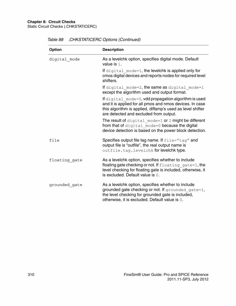
Chapter 8: Circuit ChecksStatic Circuit Checks (.CHKSTATICERC)
digital_mode As a levelchk option, specifies digital mode. Default value is 1.
If digital_mode=1, the levelchk is applied only for cmos digital devices and reports nodes for required level shifters.
If digital_mode=2, the same as digital_mode=1 except the algorithm used and output format.
If digital_mode=0, vdd propagation algorithm is used and it is applied for all pmos and nmos devices. In case this algorithm is applied, diffamp’s used as level shifter are detected and excluded from output.
The result of digital_mode=1 or 2 might be different from that of digital_mode=0 because the digital device detection is based on the power block detection.
file Specifies output file tag name. If file=”tag” and output file is “outfile”, the real output name is outfile.tag.levelchk for levelchk type.
floating_gate As a levelchk option, specifies whether to include floating gate checking or not. If floating_gate=1, the level checking for floating gate is included, otherwise, it is excluded. Default value is 0.
grounded_gate As a levelchk option, specifies whether to include grounded gate checking or not. If grounded_gate=1, the level checking for grounded gate is included, otherwise, it is excluded. Default value is 0.
Table 88 .CHKSTATICERC Options (Continued)
Option Description
310 FineSim® User Guide: Pro and SPICE Reference2011.11-SP3, July 2012
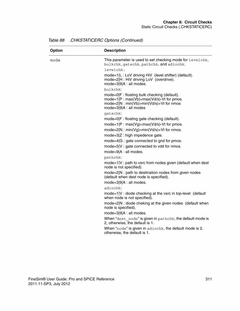
Chapter 8: Circuit ChecksStatic Circuit Checks (.CHKSTATICERC)
mode This parameter is used to set checking mode for levelchk, bulkchk, gatechk, pathchk, and adiochk. levelchk:
mode=1|L : LoV driving HiV (level shifter) (default).mode=2|H : HiV driving LoV (overdrive).mode=3|9|A : all modes.bulkchk: mode=0|F : floating bulk checking (default).mode=1|P : max(Vb)<max(Vd/s)-Vt for pmos mode=2|N : min(Vb)>min(Vd/s)+Vt for nmosmode=3|9|A : all modesgatechk: mode=0|F : floating gate checking (default).mode=1|P : max(Vg)<max(Vd/s)-Vt for pmos.mode=2|N : min(Vg)>min(Vd/s)+Vt for nmos.mode=3|Z : high impedence gate.mode=4|G : gate connected to gnd for pmos.mode=5|V : gate connected to vdd for nmos.mode=9|A : all modes.pathchk: mode=1|V : path to vsrc from nodes given (default when dest node is not specified).mode=2|N : path to destination nodes from given nodes (default when dest node is specified).mode=3|9|A : all modes.adiochk: mode=1|V : diode checking at the vsrc in top-level (default when node is not specified).mode=2|N : diode cheking at the given nodes (default when node is specified).mode=3|9|A : all modes.When “dest_node” is given in pathchk, the default mode is 2, otherwise, the default is 1.When “node” is given in adiochk, the default mode is 2, otherwise, the default is 1.
Table 88 .CHKSTATICERC Options (Continued)
Option Description
FineSim® User Guide: Pro and SPICE Reference 3112011.11-SP3, July 2012

Chapter 8: Circuit ChecksStatic Circuit Checks (.CHKSTATICERC)
node Specifies starting node names for pathchk type and the node names considered as antenna node and checks if each node is protected by diode for adiochk type.Several node names can be given by using double quotation mark “ ”. Wild cards (* or ?) can be used in the part of node names. If type=adiochk and the “node” parameter is not given, detects an antenna node to be protected by diode. It is defined as an input at top level, driven by ideal voltage sources, and directly connected or through resistor/inductor to transistor's gate.
stop Specify the stop mode. If stop=1, the simulation will be discontinued after checking staticerc (stop=0 is the default).
subckt Specifies a subckt for static ERC checking.
tag Specifies tag name. If tag=”label” is specified in a command, “[tag=label]” is appeared in each line of output file. This feature is usually used to classify the result output to the same file for the same kind commands.
type Specifies ERC command. Currently, level check, bulk check, gate check, path check, antenna diode check commands are supported:■ levelchk — Checks if level shifter is required on
gate node of mos devices. (Refer to digital_mode, floating_gate, grounded_gate parameters)
■ bulkchk — Checks if bulk node is floating, or its voltage level is less than or greater than drain/source voltage. (Refer to mode setting)
■ gatechk — Checks if gate node is floating, or pmos gate is connected to gnd, or nmos gate is connected to vdd. (Refer to mode setting)
■ pathchk — Checks if there is a path to voltage source or destination node from the given nodes.
■ adiochk — Checks if an antenna node is protected by diode at top-level circuit or a given sub-circut.
Table 88 .CHKSTATICERC Options (Continued)
Option Description
312 FineSim® User Guide: Pro and SPICE Reference2011.11-SP3, July 2012

Chapter 8: Circuit ChecksCheck High Impedance State Node (.CHKZNODE)
Check High Impedance State Node (.CHKZNODE)
The .CHKZNODE statement is used to check for the high impedance state in the circuit.
The option finesim_goff has been added for this feature and it is used to determine whether a MOSFET is in the on state or off state. However, if the finesim_check_vth option is given, the ON/OFF state of MOS is determined by operating region instead of finesim_goff.
Syntax.chkznode [file=filename] [type=gate|bulk|all] [start=time_val][stop=time_val] +[subckt=subckt_name<:0|1>][instance=instance_name<:0|1>]+[period=time_val][include|exclude=name]
Examples.chkznode file=output type=gate start=160u stop=240u
This command checks the high impedance state of nodes that are connected to transistors’ gates between 160us and 240us.The result will put be into file output.
Table 89 .CHKZNODE Options
Option Description
file Specifies the output file name.
include|exclude=name include=name — only checks the include device/node in the circuit check.exclude=name — excludes the device/node in the circuit check.
period If any node is staying in the high impedance state longer than period, it will be reported in the output file. The default is 1n.
start Specifies the start-time of the window.
stop Specifies the stop-time of the window.
FineSim® User Guide: Pro and SPICE Reference 3132011.11-SP3, July 2012

Chapter 8: Circuit ChecksCheck High Impedance State Node (.CHKZNODE)
type type=gate: check only nodes that is connected to transistor’s gate. (default) type=all: check all nodes.
type=bulk: check bulk nodes.
Table 90 .CHKZNODE Related Options
FineSim Option Description
finesim_check_vth Specifies whether to use finesim_goff (0) or vth (1) to determine the ON/OFF state. The default is 1.
finesim_chkznode_vth Specifies the Vth value for checking ON/OFF state.
finesim_goff Determines the ON/OFF state of a MOSFET.
Table 89 .CHKZNODE Options
Option Description
314 FineSim® User Guide: Pro and SPICE Reference2011.11-SP3, July 2012

9
9TCL Interactive Mode & API Functions
This chapter describes FineSim support for API functions with TCL Interactive mode.
With the need of complex and intensive simulations, there is an increasing need to get the most information out of each run. It extends beyond simple probing of signals and parameters; the status of certain devices or sub-circuits in a time period of the run can potentially reveal valuable methods for verification of the design. Such techniques are also useful in investigating problem areas in the circuit. FineSim supports a TCL interface to provide access to real-time simulation data in transient simulations.
There are two ways to access this data:■ Using the command line argument –istop.■ Starting the simulation with -i in the command line and pressing Ctrl-C
during a transient run.
With the finesim -i option, Finesim Pro will keep all nodal information so that the interactive mode can access them. At the FineSim > Interactive prompt, the commands for querying the simulation data can be entered. These commands are listed in the subsequent section titled Interactive Commands.
User-defined scripts in the TCL syntax can be passed into FineSim for running in batch mode using the option finesim_tcl_init_file. The APIs available to access FineSim simulation data are listed in the section below titled Scripting API Functions. It is possible to create control structures and mathematical expressions using the TCL language to evaluate information as desired. The pause command provides the capability to switch to Interactive Mode if necessary.
A tutorial for TCL Scripting is available in the 2011.04.01_00 install tree. Instructions for running through the examples are provided in the README file.
FineSim® User Guide: Pro and SPICE Reference 3152011.11-SP3, July 2012

Chapter 9: TCL Interactive Mode & API FunctionsInteractive Commands
Interactive Commands
Below is a table of the interactive commands. Click on a command name to jump to a more detailed description with examples.
Command Description
circheck TCL circuit check.
clearlog Clear the interactive command log.
cont Continue simulation.
dataflush Flush output logs and fsdb files.
exi Report devices with excessive current.
exit Terminate the simulation.
fn Force node, force voltage to nodes.
fset Configure TCL interactive mode parameters.
help Lists command usage.
help Print node current.
ni Print the current of nodes matching the given set of node_patterns.
now Report simulation progress.
pd Print device information.
pn Print node information.
quit Quit current sweep.
rn Release node, release const voltage set by fn.
snapshot save Take a snapshot.
stop Set stop point for the simulator.
316 FineSim® User Guide: Pro and SPICE Reference2011.11-SP3, July 2012

Chapter 9: TCL Interactive Mode & API FunctionsInteractive Commands
circheckThis command will add, list, and remove customized functions for checking nodes and devices.
Syntaxcircheck [node|device] add nodenamePattern checkFunccircheck [node|device] lscircheck [node|device] del -index index <index>
where:■ [node|device] — specifies either node level or device level.■ add nodenamePattern checkFunc — attaches the user-defined check function
checkFunc to nodes matched by nodenamePattern. checkFunc needs to take the node handle as the only argument. The return value of the function will be neglected.
■ ls — prints the current set of nodes and the check function name.■ del -index index <index> — removes set of nodes with checking functions
by specifying the index. Use the circheck node ls to get the indexes.
clearlogThis command clears and truncates the interactive command log (*.inter.log).
contThis command continues the interrupted simulation for time seconds oruntil a previously set stop point.
Syntaxcont <time>
tn Trace node, show devices connected to the node.
Command Description
FineSim® User Guide: Pro and SPICE Reference 3172011.11-SP3, July 2012

Chapter 9: TCL Interactive Mode & API FunctionsInteractive Commands
where <time> sets the running time of the simulation until it stops again.
dataflushThis command flushes all of FineSim’s output logs and fsdb files.
exiThis command identifies and reports the devices matching a given set of device_patterns. The patterns support wildcard matching.
Syntaxexi options device_pattern <device_pattern>where:■ -ith threshold_current — sets the threshold current; all devices with
current exceed threshold_current will be reported. The default value is 5e-5.■ -type device_type — sets the type of device; only devices matching
device_type will be reported. Supported device type are: Res, VarRes, RDiff, Cap, VarCap, ChgCap, Ind, Reluc, VarInd, MutInd, MutReluc, NMOS, PMOS, VSrc, ISrc, VCVS, VCVSD, VCCS, VCCSD, CCVS, CCVSD, CCCS, CCCSD, VCRes, VCCap, BVS, BCS, Diode, BJT, JFET, WElem, SElem, BElem, Norton, EMM, User, CModel.
■ -sort — if set, sort the devices by current, with larger coming first.
Note:Any of the above options can be used before device name patterns.
exitThis command stops the entire simulation process and exits FineSim.
fnThis command forces nodes matching a set of node_patterns to keep a constant voltage. To avoid abrupt change of voltages, the voltage of the forced nodes will be changing from their current voltage to the specified voltage at the given slope.
318 FineSim® User Guide: Pro and SPICE Reference2011.11-SP3, July 2012
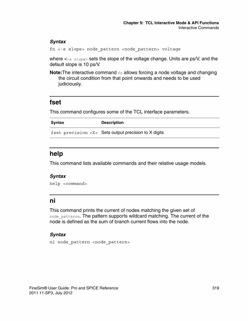
Chapter 9: TCL Interactive Mode & API FunctionsInteractive Commands
Syntaxfn <-s slope> node_pattern <node_pattern> voltage
where <-s slope> sets the slope of the voltage change. Units are ps/V, and the default slope is 10 ps/V.
Note:The interactive command fn allows forcing a node voltage and changing the circuit condition from that point onwards and needs to be used judiciously.
fsetThis command configures some of the TCL interface parameters.
helpThis command lists available commands and their relative usage models.
Syntaxhelp <command>
niThis command prints the current of nodes matching the given set of node_patterns. The pattern supports wildcard matching. The current of the node is defined as the sum of branch current flows into the node.
Syntaxni node_pattern <node_pattern>
Syntax Description
fset precision <X> Sets output precision to X digits
FineSim® User Guide: Pro and SPICE Reference 3192011.11-SP3, July 2012

Chapter 9: TCL Interactive Mode & API FunctionsInteractive Commands
nowThis command reports current simulation time and progress percentage of the whole simulation.
pdThis command prints the device name and related information of devices matching the given set of device_patterns. The pattern supports wildcard matching. Related information includes the type of the device, basic parameters, and all of the device terminal name with voltages and currents. There is extra information available for MOSFETs.
Syntaxpd device_pattern <device_pattern>
pnThis command prints the name and voltage of nodes matching the given set of node_patterns. The pattern supports wildcard matching.
Syntaxpn node_pattern <node_pattern>
quitThis command quits the current sweep and continues with the rest of the simulation.
rnThis command releases the const voltage set by fn for nodes matching the given set of node_patterns. The node voltages will therefore be determined by normal simulation result.
320 FineSim® User Guide: Pro and SPICE Reference2011.11-SP3, July 2012

Chapter 9: TCL Interactive Mode & API FunctionsInteractive Commands
Syntaxrn node_pattern <node_pattern>
snapshot saveThis command controls taking a snapshot in interactive mode.
Syntaxsnapshot save <file_name>
will take a snapshot and save it to file_name.
stopThis command sets a time point at which the simulator will schedule to stop at time, in terms of seconds.
Syntaxstop time
tnThis command prints information of devices connected to certain nodes matching a given set of node_patterns. The pattern supports wildcard matching. Each device will be printed with its terminal nodes. The one which directly connects to the given node will be marked with a '*'.
Syntaxtn options node_pattern <node_pattern>where -ith threshold_current sets the threshold current; only devices with connected port currents that exceed threshold_current will be reported.
FineSim® User Guide: Pro and SPICE Reference 3212011.11-SP3, July 2012

Chapter 9: TCL Interactive Mode & API FunctionsScripting API Functions
Scripting API Functions
Below is a table of scripting API functions. Click on a function name to jump to a more detailed description with examples.
Function Description
foreach_device Loop over devices.
get_current_time Get current simulation time.
get_device_current Get current of a device.
get_device_handle Get device handle by name.
get_device_handle_list Get list of device handles by name.
get_device_name Get name of a device.
get_device_param Get device parameters.
get_device_terminal_list Get node handle list of device.
get_device_terminal_name_list Get terminal name list of device.
get_device_type Get type of device.
get_node_device_list Get device handle list of nodes.
get_node_handle Get node handle by name.
get_node_handle_list Get list of node handles by name.
get_node_name Get node name.
get_node_voltage Get node voltage.
get_total_tr_time Get total simulation time.
log_inter Write to interactive command log.
log_main Write to main log.
pause Pause the simulation.
322 FineSim® User Guide: Pro and SPICE Reference2011.11-SP3, July 2012

Chapter 9: TCL Interactive Mode & API FunctionsScripting API Functions
foreach_deviceThis function loops over all or part of the devices in the circuit.
Syntaxforeach_device options dev script
where options can be any of the following:■ -type device_type — filters by the type of devices. device_type can be one
of following:
m: MOSFET q: BJT r: Resistor c: Capacitor l: Inductor all: Everything
■ -model model_name — filters by the model name. model_name supports wild card matching. Model matching only support certain kinds of devices, including MOSFET, BJT, Diode and JFET. All other kinds of devices won't be matching even if you specify a model_name.
Parameters■ Device handle dev (output): $dev will contain the device handle inside the
loop.■ Tcl script script (input): body of the script to be executed in the loop.
get_current_timeThis function gets the current simulation time in seconds.
get_device_currentThis function gets the instant current of a device during simulation.
Syntaxget_device_current deviceHandle
FineSim® User Guide: Pro and SPICE Reference 3232011.11-SP3, July 2012

Chapter 9: TCL Interactive Mode & API FunctionsScripting API Functions
Parameters■ Device handle deviceHandle (input): Device handle.
Return Value
Returns current of the device. Raises an error if the deviceHandle is not valid.
get_device_handleThis function gets the device handle by name.
Syntaxget_device_handle devicename
Parameters■ string devicename (input): Name of the device.
Return Value
Returns the device handle if found, otherwise returns 0.
get_device_handle_listThis function gets a list of device handles by matching name.
Syntaxget_device_handle_list devicenamePattern
Parameters■ string devicenamePattern (input): Device name, supports wild card pattern.
Return Value
Returns list of device handles if found, otherwise returns a empty list.
get_device_nameThis function gets the name of a device.
324 FineSim® User Guide: Pro and SPICE Reference2011.11-SP3, July 2012

Chapter 9: TCL Interactive Mode & API FunctionsScripting API Functions
Syntaxget_device_name deviceHandle
Parameters■ Device handle deviceHandle (input): Device handle.
Return Value
Returns name of the device. Raises an error if the deviceHandle is not valid.
get_device_paramThis function gets the various parameters of a device.
Syntaxget_device_param deviceHandle param
Parameters■ Device handle deviceHandle (input): Device handle.■ String param (input): For different kinds of devices, different set of
parameters are supported. param is not case sensitive:
MOSFET■ mos.l: Length■ mos.w: Width
Resistor■ res.r: Resistance
Capacitor■ cap.c: Capacitance
Inductor■ ind.l: Inductance
FineSim® User Guide: Pro and SPICE Reference 3252011.11-SP3, July 2012

Chapter 9: TCL Interactive Mode & API FunctionsScripting API Functions
Return Value
Returns parameters of the device. Raises an error if the deviceHandle is not valid or if the device doesn't have certain parameters.
get_device_terminal_listThis function returns the list of node handles for all terminals of a device.
Syntaxget_device_terminal_list deviceHandle
Parameters■ Device handle deviceHandle (input): Device handle.
Return Value
Returns a list of node handles. Raises an error if the deviceHandle is not valid.
get_device_terminal_name_listThis function returns the list of terminal names for all terminals of a device.
Syntaxget_device_terminal_name_list deviceHandle
Parameters■ Device handle deviceHandle (input): Device handle.
Return Value
Returns a list of terminal names. Raises an error if the deviceHandle is not valid.
get_device_typeThis function returns the type of device.
326 FineSim® User Guide: Pro and SPICE Reference2011.11-SP3, July 2012
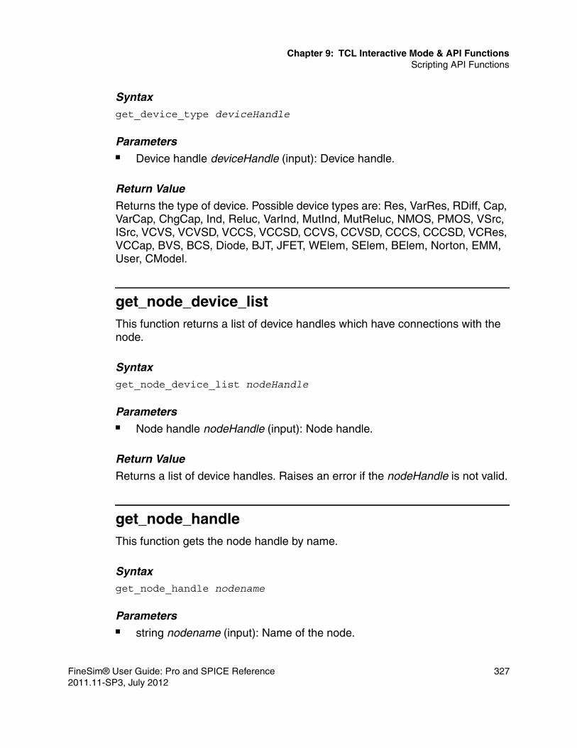
Chapter 9: TCL Interactive Mode & API FunctionsScripting API Functions
Syntaxget_device_type deviceHandle
Parameters■ Device handle deviceHandle (input): Device handle.
Return Value
Returns the type of device. Possible device types are: Res, VarRes, RDiff, Cap, VarCap, ChgCap, Ind, Reluc, VarInd, MutInd, MutReluc, NMOS, PMOS, VSrc, ISrc, VCVS, VCVSD, VCCS, VCCSD, CCVS, CCVSD, CCCS, CCCSD, VCRes, VCCap, BVS, BCS, Diode, BJT, JFET, WElem, SElem, BElem, Norton, EMM, User, CModel.
get_node_device_listThis function returns a list of device handles which have connections with the node.
Syntaxget_node_device_list nodeHandle
Parameters■ Node handle nodeHandle (input): Node handle.
Return Value
Returns a list of device handles. Raises an error if the nodeHandle is not valid.
get_node_handleThis function gets the node handle by name.
Syntaxget_node_handle nodename
Parameters■ string nodename (input): Name of the node.
FineSim® User Guide: Pro and SPICE Reference 3272011.11-SP3, July 2012

Chapter 9: TCL Interactive Mode & API FunctionsScripting API Functions
Return ValueReturns the node handle if found, otherwise returns 0.
get_node_handle_listThis function gets a list of node handles by matching name.
Syntaxget_node_handle_list nodenamePattern
Parameters■ string nodenamePattern (input): Node name, supports wildcard pattern.
Return Value
Returns list of node handles if found, otherwise returns a empty list.
get_node_nameThis function gets the name of a node.
Syntaxget_node_name nodeHandle
Parameters■ Node handle nodeHandle (input): Node handle.
Return Value
Returns name of the node. Raises an error if the nodeHandle is not valid.
get_node_voltageThis function gets the instant voltage of a node during simulation.
Syntaxget_node_voltage nodeHandle
328 FineSim® User Guide: Pro and SPICE Reference2011.11-SP3, July 2012

Chapter 9: TCL Interactive Mode & API FunctionsScripting API Functions
Parameters■ Node handle nodeHandle (input): Node handle.
Return Value
Returns voltage of the node in volts. Raises an error if the nodeHandle is not valid.
get_total_tr_timeThis function gets the time of the whole transient simulation, in seconds.
log_interThis function writes a message to the interactive command log (*.inter.log).
Syntaxlog_inter str
Parameters■ string str (input): The message to be logged.
log_mainThis function writes a message to the main log (*.log).
Syntaxlog_main str
Parameters■ string str (input): The message to be logged.
pauseThis function pauses the simulation at a given time.
FineSim® User Guide: Pro and SPICE Reference 3292011.11-SP3, July 2012

Chapter 9: TCL Interactive Mode & API FunctionsScripting API Functions
Syntaxpause t
Parameters■ float t (input): At which time to pause the simulation, in seconds.
Do not try to pause at current simulation time (return value of get_current_time. Add a very small delay to it, like 1ps (1e-12 s).
Exampleif {[get_node_voltage $node] > 2.0} { pause [expr [get_current_time] + 1e-12]}
This script will allow you to pause the simulation almost immediately after the node voltage passes 2 volt.
330 FineSim® User Guide: Pro and SPICE Reference2011.11-SP3, July 2012

10
10Bisection Optimization
This chapter describes FineSim support for Bisection Optimization.
Bisection automates the characterization of a design for setup, hold or minimum pulse width. FineSim pro provides two different methods for defining the exit criteria: BISECTION and PASSFAIL. Both methods use a binary search method varying the input parameters to optimize. The difference is in the definition of the goal:■ PASSFAIL exits the binary search when the difference between the two
latest test input values is within the error tolerance and one of the values passes the goal with the other failing.
■ BISECTION works in a similar fashion except that the last two test input values are within the error tolerance and the latest measured value exceeds the goal.
In general, setup and hold values are acquired using the BISECTION method. Minimum pulse width is typically acquired using the PASSFAIL method. All methods require that the input stimulus be properly defined with both inputs and output identified. The optimization automatically alters the input stimulus relationship to achieve the desired goal.
To perform Bisection optimization, the .TRAN, .PARAM, .MEASURE and .MODEL statements must be used.
Syntax.TRAN <TranStep> <TranTime> SWEEP + OPTIMIZE=<Optxxx>+ RESULTS=<MeasName> + MODEL=<ModName>.PARAM <ParName>=<Optxxx> (<Initial>, <Lower>, <Upper>).MEASURE TRAN <MeasName> <MeasureClause> GOAL=<val>
FineSim® User Guide: Pro and SPICE Reference 3312011.11-SP3, July 2012

Chapter 10: Bisection Optimization
.MODEL <ModName> OPT METHOD=BISECTION/PASSFAIL <Relin=val> <Itropt=val>
The OPTIMIZE keyword is followed by the Bisection optimization parameter.
The OPTxxx optimization parameter reference name must agree with the OPTxxx name given in the .TRAN statement associated with the keyword OPTIMIZE.
The measure results for <Lower> and <Upper> limits of <ParName> must be on opposite sides of the GOAL value in the .MEASURE statement. For the PASSFAIL method, the measure must pass for one limit and fail for the other limit. The process ignores the value of the <Initial> field.
Table 91 .PARAM Statement Keywords
Keyword Meaning
ParName Name of the Bisection optimization parameter.
Initial Initial value for Bisection optimization parameter.
Lower Left-bound for Bisection optimization parameter.
Upper Right-bound for bisection optimization parameter.
Table 92 .MEASURE TRAN Statement Keywords
Keyword Meaning
RESULT This keyword is followed by the target for optimization.
MeasName Name of the measure calculated by a .MEASURE statement.
GOAL=val GOAL value. If the associated goal measurement exceeds the GOAL value, it is a "pass"; otherwise it is a "fail".
332 FineSim® User Guide: Pro and SPICE Reference2011.11-SP3, July 2012

Chapter 10: Bisection Optimization
MODEL This keyword is followed by the optimization model.
ModName The model name, used by Bisection optimization to reference a particular model.
OPT This keyword indicates that optimization is to be performed.
METHOD This keyword indicates which optimization method to use.
Relin Error tolerance. This specifies the relative input parameter variation for convergence. The default value is 1e-3, which means the last two input parameter variations should be less than 1e-3*(Lower, Upper) before the bisection succeeds and ends.
Itropt Sets the maximum number of iterations. The default value is 20.
Table 92 .MEASURE TRAN Statement Keywords
Keyword Meaning
FineSim® User Guide: Pro and SPICE Reference 3332011.11-SP3, July 2012

Chapter 10: Bisection Optimization
Example for Setup Time Analysis with Bisection*include your model and netlist here .inc “modelfile” .inc “ dff.sp”
* apply clock/data stimulus vdata data gnd PWL + 0s 5v + 1n 5v + 2n 0v + 'Delay' 5v
vclock clock gnd PWL + 0s 0v + 3n 0v + 4n 5v
.TRAN 1n 10n Sweep Optimize = Opt1 Result = MaxVout Model = OptMod
.PARAM Delay= Opt1 ( 0n, 0n, 5.0n )
.MEASURE Tran MaxVout Max v(D_Output) Goal = 4.8
.MEASURE Tran SetupTime Trig v(Data) Val = 2.5 Rise = 1 Targ v(Clock) Val = 2.5 Rise = 1 .MODEL OptMod Opt Method = Bisection Relin=0.1.end
FineSim reports the calculation result for each sweep:
****************…….SWEEP #5bisec-opt iter = 4, delay = 1.56253218750000031045e-09, status: fail…….SWEEP #6bisec-opt iter = 5, delay = 1.40633218750000031045e-09, status: success*****************
The measure file (mt0) also shows how finesim calculates optimum value of ‘delay’ :
*****************
$DATA1 SOURCE='FineSimPro' VERSION='2010.08’.TITLE '' delay maxvout setuptime
334 FineSim® User Guide: Pro and SPICE Reference2011.11-SP3, July 2012
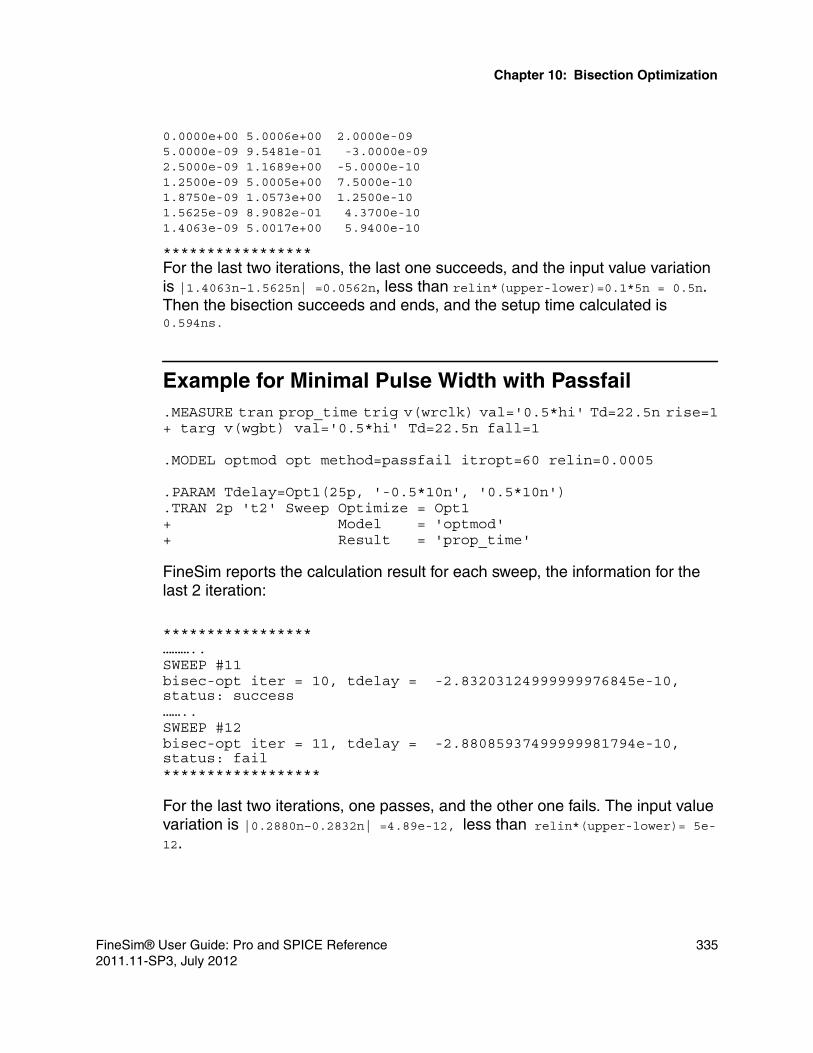
Chapter 10: Bisection Optimization
0.0000e+00 5.0006e+00 2.0000e-09 5.0000e-09 9.5481e-01 -3.0000e-09 2.5000e-09 1.1689e+00 -5.0000e-10 1.2500e-09 5.0005e+00 7.5000e-10 1.8750e-09 1.0573e+00 1.2500e-10 1.5625e-09 8.9082e-01 4.3700e-10 1.4063e-09 5.0017e+00 5.9400e-10
*****************For the last two iterations, the last one succeeds, and the input value variation is |1.4063n–1.5625n| =0.0562n, less than relin*(upper-lower)=0.1*5n = 0.5n. Then the bisection succeeds and ends, and the setup time calculated is 0.594ns.
Example for Minimal Pulse Width with Passfail.MEASURE tran prop_time trig v(wrclk) val='0.5*hi' Td=22.5n rise=1+ targ v(wgbt) val='0.5*hi' Td=22.5n fall=1
.MODEL optmod opt method=passfail itropt=60 relin=0.0005
.PARAM Tdelay=Opt1(25p, '-0.5*10n', '0.5*10n')
.TRAN 2p 't2' Sweep Optimize = Opt1+ Model = 'optmod'+ Result = 'prop_time'
FineSim reports the calculation result for each sweep, the information for the last 2 iteration:
*****************………..SWEEP #11bisec-opt iter = 10, tdelay = -2.83203124999999976845e-10, status: success……..SWEEP #12bisec-opt iter = 11, tdelay = -2.88085937499999981794e-10, status: fail******************
For the last two iterations, one passes, and the other one fails. The input value variation is |0.2880n–0.2832n| =4.89e-12, less than relin*(upper-lower)= 5e-12.
FineSim® User Guide: Pro and SPICE Reference 3352011.11-SP3, July 2012

Chapter 10: Bisection Optimization
Pushout BisectionThe pushout analysis is very similar to passfail methodology, the difference is that a maximum allowed pushout time will be added in the analysis. In pushout bisection analysis, the first successful bisection result will be considered as standard value. For the following analysis, the result must meet two criteria, then it can be looked as a success. Based on the bisection methodology, the standard value must be got from upper or lower boundary, since FineSim will first analyze these two input value, and one must result in success.
Note:meet the criteria of passfail3.meet the criteria of | meas_result – standard | < pushout
Example.MEASURE tran out_rise when v(wgbt)='hi/2' Td=22.5n fall=1 pushout=2e-12
.MODEL optmod opt method=passfail itropt=itrnum relin=0.0005
.PARAM Tdelay=Opt1(25p, '-0.5*10n', '0.5*10n')
.TRAN 2p 't2' Sweep Optimize = Opt1+ Model = 'optmod'+ Result = 'out_rise'
FineSim reports the calculation results for each sweep:
************************out_rise= 2.3074e-08bisec-opt upper boundary, tdelay = 5.000000000010461e-09, status: success………..SWEEP #11out_rise= 2.3078e-08bisec-opt iter = 10, tdelay = -2.83203124999976845e-10, status: fail………..SWEEP #12out_rise= 2.3074e-08bisec-opt iter = 11, tdelay = -2.78320312500003595e-10, status: success************************
For sweep #11, the measure for out_rise can get value, but the status is still fail, this is because it does not meet the criteria for pushout.
336 FineSim® User Guide: Pro and SPICE Reference2011.11-SP3, July 2012

Chapter 10: Bisection OptimizationBisection Analysis with Two Measurements
In this example, the standard is 2.3074e-08, which is got from upper boundary. Pushout is defined as 2e-12.
For sweep #11, |2.3078e-12 – 2.3074e-12| > 2e-12, so the status is fail.
For sweep 12, the out_rise can also get value, and it meets pushout criteria, then, the status is success.
Bisection Output ConventionThe standard file output convention for bisection analysis is as follows:
prefix#alter_temp_sweep.extensionWith the same procedure as the transient output, the first temp/alter does not have _t0 or #0 in the naming convention. For data sweeps, the mt0s are lumped into a single file, unless finesim_measout is set to 1, in which case the mt0 for each data sweep will be separated into an individual file with _sX appended in the prefix.
In addition, the following options control the bisection output:■ finesim_bisection_output■ finesim_bisection_summary
Bisection Analysis with Two Measurements
FineSim can support evaluating bisection criteria using multiple measure results. To use this function, a keyword "result1" needs to be added on .TRAN analysis.
Syntax.TRAN t1 tstop Sweep Optimize=op1 Model=ModName+ Result=MeasName1+ Result1=MeasName2
Concurrent Bisection for Independent Circuit Blocks
FineSim can support performing concurrent bisection analyses that sweep multiple bisection parameters and results at the same time. However, it will be
FineSim® User Guide: Pro and SPICE Reference 3372011.11-SP3, July 2012

Chapter 10: Bisection OptimizationConcurrent Bisection for Independent Circuit Blocks
up to the user to provide circuits where each set of bisection parameters/results is independent of each other. The number of results and parameters specified should be the same as the number of optimized parameters.
Syntax.TRAN t1 tstop Sweep Model=ModName+ Optimize =opt1 opt2 .... + Results = res1 res2 .....
338 FineSim® User Guide: Pro and SPICE Reference2011.11-SP3, July 2012

11
11Monte Carlo Analysis
This chapter describes FineSim support for Monte Carlo Analysis.
The Monte Carlo (MC) method is a well known technique for modeling manufacturing variations in a statistical manner. The simulations involve randomizing some process parameters and observing the impact on the desired outputs. Typically, it requires a very large number of simulations and measurements to ensure confidence in boundaries of variations. Speed-up can be further improved by the fact that FineSim Pro offers scalability at runtime by executing on multiple processors and by the inherent speed-up of FineSim Pro simulation. This can be achieved by using -ip -np N with the command.
Random variations can be defined by using functions such as unif, aunif, and the gauss and agauss functions. In the Spectre format input decks, FineSim Pro can parse the statistics section for process and mismatch variations.
You should use the following Spice analysis statements used to set MC analysis:
.dc … sweep monte=NMC [firstrun=N]
.tran … sweep monte=NMC [firstrun=N]
.ac … sweep monte=NMC [firstrun=N]
where NMC is the maximum number of Monte Carlo runs and firstrun defines the index from which to start using the random number sequence.
In Spectre syntax, the following syntax is acceptable:
name montecarlo parameter=value … {analysis statements …}
Supported Spectre parameters are numruns, firstrun, variations and seed. Supported analyses are DC, DCOP, TRAN, and AC frequency sweep.
FineSim® User Guide: Pro and SPICE Reference 3392011.11-SP3, July 2012

Chapter 11: Monte Carlo Analysis
Note:Currently, FineSim Pro does not support sweep of temperature or parameters in Spectre format input decks. Other unsupported Spectre options include, but are not limited to, donominal, savefamilyofplots, saveprocessparams, appendsd, and saveprocessvec. To save a family of plots, set finesim_output=tr0. To save process parameter values, set finesim_write_mcparam=1.
To set the seed for random generation to be the same across multiple runs, set finesim_mcseed to a positive integer value. See the finesim_mcseed section in Chapter 4, FineSim Pro Options, for details.
There needs to be at least one .measure statement in the input deck to output scalar values from each Monte Carlo run. FineSim Pro generates a .mt0/.ma0/.md0 file for the run that includes the list of evaluated values in each Monte Carlo run, followed by a summary of the distribution.
It is highly recommended that you set finesim_output=none to avoid generating several FSDB files that can cause a disk space issue. For debugging purposes, set finesim_output=tr0 to save the family of plots; set finesim_output=fsdb/tr0 when a single run is rerun (monte=1 firstrun=Nrerun).
Note:In Spectre format input decks, export statements are not supported. Hence, it is required to replace them with equivalent statements.
Bi-Section RunsFineSim also supports Monte Carlo analysis performed during bisection simulations.
Syntax.tran 10p 'tmax' sweep Optimize = Opt1 Result = GoalValue Model = optmod monte=1000
listFineSim Pro supports list for Monte Carlo Simulations.
Syntax .tran/.dc/.ac ... monte=list 3 .tran/.dc/.ac .. monte=list (a:b c d:e)
340 FineSim® User Guide: Pro and SPICE Reference2011.11-SP3, July 2012

Chapter 11: Monte Carlo Analysis
Example.tran ... monte=list 3 #runs 3rd iteration only .dc ... monte=list (1:2 10 18:20) #runs 1st, 2nd, 10th, 18th, 19th, and 20th iterations only
Random Number Generation SequenceFineSim can generate the same random number sequence for a different subckt. Please refer to finesim_identical_mc_instance_file for more information.
Plotting with FineWaveYou can use FineWave to plot histograms, scatter plots and families of plots based on files generated in the run directory, and view Monte Carlo output.
Exampleparameters RSHSP=200 SPDW=0 XRSP=1statistics {process {vary RSHSP dist=gauss std=1vary SPDW dist=gauss std=0.25}mismatch {vary XRSP dist=gauss std=1}correlate dev=[R1 R2] cc=0.75}m1 montecarlo numruns=3 variations=mismatch seed=10 {tran1 tran stop=300n export v1=oceanEval(“V(\”1\”)”)export v2=oceanEval(“V(\”2\”)”)}
The previous example is translated as follows:
.param rshsp_tmp = agauss(200,1,1)
.param RSHSP = rshsp_tmp
.param spdw_tmp = agauss(0,0.25,1)
.param SPDW = spdw_tmp
.param XRSP = agauss(1,1,1)
.tran ‘3e-7*0.001’ 3e-7 SWEEP MONTE=3
Note:PSF format is not supported.
FineSim® User Guide: Pro and SPICE Reference 3412011.11-SP3, July 2012

Chapter 11: Monte Carlo AnalysisFast Monte Carlo
Fast Monte Carlo
FineSim can perform statistical analysis with up to 10-100x speedup over traditional methods. In traditional Monte Carlo, it is not possible for the user to know how much error was incurred in the statistical analysis. However, with FineSim’s Fast Monte Carlo method, the user specifies the acceptance error in the statistical analysis. FineSim then uses the required error to determine the optimal number of statistical simulations.
As in the traditional method, the user specifies a pre-determined maximum number of statistical runs; FMC will automatically stop if convergence to specified tolerance level is reached earlier.
RequirementsYou must have at least one .measure statement in the input deck that will always evaluate to a finite scale or value in each MC run.
finesim_montecarlo_modeThe finesim_montecarlo_mode option determines whether to enable or disable Fast Monte Carlo mode. The option finesim_montecarlo_mode must be set to fast to enable this feature.
Syntax.option finesim_montecarlo_mode = fast | traditional
The default mode for Monte Carlo analysis is traditional.
Statistical TargetsFineSim Pro supports the following statistical targets:
.monte target = (prob, …)
.monte target = (mean, …)
.monte target = (median, …)
.monte target = (percentile, …)
.monte target = (sigma, …)
342 FineSim® User Guide: Pro and SPICE Reference2011.11-SP3, July 2012

Chapter 11: Monte Carlo AnalysisFast Monte Carlo
If you can identify the statistical analysis with required error tolerances, FineSim Pro can use the information to perform the Monte Carlo analysis with minimum runs. The command to define the boundaries can be as follows:
.monte target = (prob, <meas>, less|greater, <threshold>, relerr| abserr, <errtol>).monte target = (mean, <meas>, relerr|abserr, <errtol>).monte target = (median, <meas>, relerr|abserr, <errtol>).monte target = (percentile, <meas>, <between 0 - 1>, relerr|abserr, <errtol>).monte target = (sigma, <meas>, [1|2|3...], relerr|abserr, <errtol>)
The descriptions of statistical functions defined above are as follows: ■ prob returns the probability of a measurement; it ranges from 0 to 1. ■ mean returns the mean value of a measurement.■ median returns the median value of a measurement.■ percentile is the value of a variable below which a certain percent of
observations fall. It is defined by the argument that is between 0 to 1, i.e for 25th percentile, 0.25 should be set as percentile value.
■ sigma returns the standard deviation for the measurement data set.
The error boundary for each statistic is defined by the latter arguments—keyword relerr or abserr, followed by the tolerance value. FineSim Pro calculates internally for the optimum number of runs required to achieve 95% confidence level in the tracked outputs.
Suppose, there are i measurement statements and Ni is the internally calculated run numbers needed for each of the measurements, then the maximum of Ni will be decided as run count for execution. Of course, if the calculated number turns out to be higher than NMC then it is capped as defined by the input deck to NMC; thus, ensuring that NMC is the maximum possible runs for evaluating the statistics.
Statistical Observations The output of fast monte carlo can be observed using the .monte obs statement in FineSim Pro. By default, FineSim Pro outputs the mean and standard deviation of all measurements in the output measurement file and log file. Other statistical observations can be requested by the following syntax:
FineSim® User Guide: Pro and SPICE Reference 3432011.11-SP3, July 2012

Chapter 11: Monte Carlo AnalysisFast Monte Carlo
.monte obs = (prob, <meas>, less|greater, <threshold>);
.monte obs = (mean, <meas>);
.monte obs = (median, <meas>);
.monte obs = (percentile, <meas>, <double[0,1]>);
.monte obs = (sigma, <meas>, 1|2|3|4|5|6);
■ <meas> is the name of measurement, specified through the .measure statement.
■ prob returns the probability of a measurement, ranging 0-1. For example, .measure delay TRIG …. .monte obs = (prob, delay, greater, 1e-10) returns the probability that delay>=1e 10. .monte obs = (prob, delay, less, 1e-11) returns the probability that delay <= 1e-11.
■ mean returns the mean value of a measurement. ■ median returns the median value of a measurement. ■ percentile returns the percentile. A percentile is the value of a variable
below which a certain percent of observations fall. Here, it ranges [0,1]. So for the 25th percentile, “0.25” should be set as the percentile value. For example, “.monte obs = (percentile, delay, 0.9)” return the 90th percentile of delay, which means below which 90 percent of the observations may be found.
■ sigma is used to describe the standard deviation. If a data distribution is approximately normal then about 68% of values are within 1 sigma, about 95% of values are within 2 sigma and about 99.7% lie within 3 sigma. “.monte obs = (sigma, <int>)” returns the <int> sigma range. <int> here could only be 1, 2, 3, 4, 5, or 6.
Note:.monte obs is intended for specifying statistical observations and will not influence the number of monte carlo runs.
344 FineSim® User Guide: Pro and SPICE Reference2011.11-SP3, July 2012

12
12Digital I/O Vectors
This chapter describes FineSim’s support of digital I/O vector files.
FineSim usually reads a stimulus directly from a SPICE deck, such as PWL for input CLK. But for digital circuits, which generate and read vectors as stimuli, FineSim supports a tabular I/O-vector format to accommodate the digital simulation design environment. This vector format has time-varying input signal patterns and expected output patterns that are used for simulation result comparison.
To read the I/O vector file, you must set the vector file name as in the following example:
.option finesim_vector=’control.vec’
Direct VCD Input
FineSim can read in the VCD (Value Change Dump) file by converting the VCD file into a vector file automatically. You will need either an fscript command file or signal file in order to use this feature. Alternatively, you can use the fscript utility to first convert your VCD files to io_vector files and then input them into FineSim directly. For more details about this utility, see Appendix A, FineSim Pro Utilities. FineSim can read in VCD files directly by using the .vcdvec command, as follows:
.vcd2vec fscript_command_file
or:
.vcd2vec vcd_file signal_file
FineSim® User Guide: Pro and SPICE Reference 3452011.11-SP3, July 2012

Chapter 12: Digital I/O VectorsDirect VCD Input
FineSim has limited support for a signal_file that is commonly used by other simulators for converting VCD to VEC. The list of signal_file features includes:
#tunit — fset tunit#trise — fset rise#tfall — fset fall#slope — fset slope#vih — fset vih#vil — fset vil#voh — fset voh#vol — fset vol#scale — fset scale#idelay — fset tdelay#scope — fset scope#in — vsignal ... in bin#out — vsignal ... out bin#alias — valias*fset fscript_fset_command
A * usually dictates comments in a signal file. In order to avoid conflicting syntax, since fset is a script specific command, fscript fset commands can be set using *fset.
Examplefset vcd2vec bus_separator < >
The above will be converted into "fset vcd2vec bus_separator < >".
Consider the following example, where there is a vcd2vec statement in the netlist:
.vcd2vec “sample.sig”
The fscript command file sample.sig is as follows:
load vcd sample.vcdopen sample.vec
fset vih 2.5fset vil 0.0fset slope 1ns
vinitvsignal x1.a in binvsignal x1.z out binvrun
346 FineSim® User Guide: Pro and SPICE Reference2011.11-SP3, July 2012

Chapter 12: Digital I/O VectorsVector File Format
The output vector file sample.vec will be generated as follows and FineSim Pro reads this vector file automatically.
; input file : sample.vcd; vector pattern definitions
radix+ 1+ 1
vname+ x1.a+ x1.z
io+ i+ o
; waveform parameter settingtunit ns
slope 1 vil 0 vih 2.5
; tabular data (these values may differ in case) 0 0 0 10 1 0 12 1 1
Vector File Format
An I/O vector file has three sections in the following order:
1. Vector Pattern Definition
2. Waveform Parameter Settings
3. Tabular Data
The vector pattern definition declares signal (vector) names, vector sizes, and vector types. A vector type specifies whether the signal is an input or an expected output that should be used for comparison.
The waveform parameter settings define a variety of signal attributes. For example, they define the time unit, the rise and fall time, the driving strength, the thresholds for logic high or low, and so on.
FineSim® User Guide: Pro and SPICE Reference 3472011.11-SP3, July 2012

Chapter 12: Digital I/O VectorsVector File Format
The tabular data lists the values of input signals at specified times. The time may be listed in the first column, followed by signal values, in the order specified by the nodename statement of the vector pattern definition. To take the rise and fall time into consideration when the vector switches between 1 and 0 or vice versa, FineSim Pro provides the pwl_type definition you specify before the description of the tabular data but preceded by comment character ;.
The following is an example I/O vector file:
; Vector Pattern Definitionradix 1 1 4 4 4 4 1 4 4nodename clk out addr[15-0] R data[7:0]io i o i i i i x b b; Waveform Parameter SettingSlope 2.1VIH 5; Tabular Data; pwl_type 0 (or 1) ; Default is 01.0 L H 1 1 a e 1 0 02.5 1 0 z x 0 0 1 x 05.6 0 1 a b c d 0 1 2
In this example, the character ; always means that this line is a comment line.
Vector Pattern DefinitionVector patterns are defined by the following parameters:
RadixThe Radix statement must be included as a non-comment line in the I/O vector file. Its valid values are 1 to 4, as defined in the below table.
Table 93 Radix Values
Radix Number System Ranges
1 binary 0-1
2 quaternary 0-3
3 octal 0-7
4 hexadecimal 0-F
348 FineSim® User Guide: Pro and SPICE Reference2011.11-SP3, July 2012

Chapter 12: Digital I/O VectorsVector File Format
Exampleradix 1 1 4 4 4 4 1 4 4;
NodeNameThe nodeName, signal, sname, or vname defines the node name of each vector. Single-bit signals have one NodeName, and multiple-bit signals (bus signals) have bus notation with [i:j], [i-j], [i~j], <i:j>, <i-j>, or <i~j>.
When FineSim Pro converts bus signal to bit signal, both Hspice rule and Hsim rule can be supported according to the set of .vec, finesim_vector, and finesim_vector_mode options. Therefore, it could be a[1:2] -> a1, a2 (Hspice rule) or a[1:2] -> a[1], a[2] (Hsim rule). For more information, please refer to the description of the finesim_vector_mode option.
Examplenodename clk out addr[15-0] R data[7:0];
In this example, clk, out and R are single bit signals and addr and data are bus signals.
When using .vec or finesim_vector_mode=0, FineSim Pro always ignores the bus bracket for Hspice compatibility.
Example (.vec or finesim_vector_mode=0)a<1~2> -> a1, a2a<1:2> -> a1, a2a[1:2] -> a1, a2a<[1:2]> -> a<1>, a<2>a[[1:2]] -> a[1], a[2]a[<1:2>] -> a[1], a[2]a_[1:2]_ -> a_1_, a_2_a_[1:2] -> a_1, a_2
When using finesim_vector or finesim_vector_mode=1, FineSim Pro only ignores the bus bracket in the following two cases:■ The bus delimiter is a tilde (~).■ There is a string after the bus bracket.
Example (finesim_vector or finesim_vector_mode=1)a<1~2> -> a1, a2 (ignore angle bracket because of ‘~’)a<1:2> -> a<1>, a<2>
FineSim® User Guide: Pro and SPICE Reference 3492011.11-SP3, July 2012

Chapter 12: Digital I/O VectorsVector File Format
a[1:2] -> a[1], a[2]a<[1:2]> -> a<1>, a<2> (ignore square bracket because there is '>')a[[1:2]] -> a[1], a[2]a[<1:2>] -> a[1], a[2]a_[1:2]_ -> a_1_, a_2_a_[1:2] -> a_[1], a_[2] (FineSim keeps the square bracket because there is no character after bus description)
Hierarchical Node Names in Vector FilesFineSim Pro supports hierarchical names for input signals in a vector file. FineSim Pro checks voltage sources for internal nodes, copying sub-circuits when needed. For example, signal x1.x2.a can be an input or a bidirectional signal. FineSim Pro supports all level signals for value checking in vector files.
IO StatementsAn IO statement starts with a keyword io and is followed by a string of i, o, b,m or x(u). The io types are defined in the below table.
Exampleio i o i i i i x b b ;
In this example, the first signal is an input, the second an output, the third through sixth input, the seventh ignored, and the eighth and ninth bi-directional.
Waveform Parameter SettingWaveform parameters are defined as follows:
Table 94 IO Types
State Meaning
i An input stimulus signal.
o An expected output pattern.
b A bi-directional vector.
m The voltage range between vih and vil.
x, u Ignored.
350 FineSim® User Guide: Pro and SPICE Reference2011.11-SP3, July 2012

Chapter 12: Digital I/O VectorsVector File Format
TunitSets the time unit in the vector file. The default value is 1ns.
ExampleTunit 0.1n;
SlopeSets the rise and fall time slopes for an input signal. Slope is defined as 0-100% of a signal swing in FineSim Pro. This is overridden by the Trise/Tfall statement when used. The default value is 1ps.
ExampleSlope 1;
TfallSets the fall time slope of an input signal. If Tfall is not specified, Tfall=Slope.
ExampleTfall 1;
TriseSets the rise time slope of an input signal. If Trise is not specified, Trise=Slope.
ExampleTrise 0.5;
VH or VOH Sets the logic threshold of output 1 value. It is used for output pattern checking. The default value is VIH/2.
ExamplesVH 3.0; VOH 3.0;
FineSim® User Guide: Pro and SPICE Reference 3512011.11-SP3, July 2012

Chapter 12: Digital I/O VectorsVector File Format
VL or VOLSets the logic threshold of output 0 value. It is used for output pattern checking. The default value is VIH/2.
ExamplesVL 2.0;VOL 2.0;
VIH Sets the voltage level for input 1-state. VIH has no default value. If there is no description, FineSim Pro terminates with an error message.
ExampleVIH 3.3;
VILSets the voltage value for input 0-state. The default value is 0V.
ExampleVIL 0.8;
MaskSets a mask function for signals defined in the vector file. It works on all keywords such as vil/vih/trise/tfall/slope/tunit/delay. It is used when signals require special values other than the values defined globally. The signals used in check_window statement also can be defined with mask.
Syntaxmask mask_name signal1 [signal2 signal3 ……]
or:
mask mask_name mask_pattern
mask_name is the mask name referenced in the check_window statement or other parameter definitions.
352 FineSim® User Guide: Pro and SPICE Reference2011.11-SP3, July 2012

Chapter 12: Digital I/O VectorsVector File Format
Examplesignal in1 in2 in3 in4radix 1 1 1 1io i i i imask mask1 in1 in4mask mask2 0 1 0 1vil 1v mask1vil 0.75v mask2vil 0.5v……
In the previous example, the vil for signal in1 is 1v; It is enabled by the first vil definition. The vil for in2 is 0.75v; It is enabled by the second definition of vil. The vil for in3 is 0.5v, it is disabled by the first two vil statements, and will use the default value. The vil for signal in4 is 0.75v. Actually the first and second definitions have a conflict for in4; for such situations, the last one will be used.
Check_WindowSpecifies the time window of the vector strobe that is defined as an output of the io statement. The output comparison is done within the time window.
Syntaxcheck_window begin_offset end_offset steady [mask_name]
or:
check_window begin_offset end_offset steady period_time first_time [mask_name]
For the first syntax statement, the begin_offset and end_offset are the start and stop offset values, respectively. The default value and unit are 0 and ns. The time window is [t – begin_offset, t + end_offset], where “t” is the vector stop time. The steady can be defined as 1 or 0. If steady=1 and the unexpected output range or time exists in the check window, the result is an error. If steady=0 and the expected output range or time exists in the check window, the result is correct. If mask_name is specified, the check window is applied to the signals defined in the mask statement.
For the second syntax statement, the begin_offset and end_offset are the same with the first example. The time window is [t – begin_offset, t + end_offset], where “t” is first_time. The check will be repeated every period_time. The steady can be defined as 3 or 2. If steady=3 and the unexpected output range or time exists in the check window, the result is an
FineSim® User Guide: Pro and SPICE Reference 3532011.11-SP3, July 2012

Chapter 12: Digital I/O VectorsVector File Format
error. If steady=2 and the expected output range or time exists in the check window, the result is correct. If mask_name is specified, the check window is applied to the signals defined in the mask statement.
Example 1signal DQradix 1io ocheck_window -0.5 0.5 1 mn1mask mn1 DQtime0 xtime1 1………
Example 2signal Dout1 Dout2 Din1radix 1 1 1io o o icheck_window -1 1 3 20 5timen 0 0 1timen+1 1 0 0
Figure 12 check_window Example Output
check_window
begin_offsetend_offset
VOH
VOL
time
steady=0, Passsteady=1, Error
354 FineSim® User Guide: Pro and SPICE Reference2011.11-SP3, July 2012

Chapter 12: Digital I/O VectorsVector File Format
Support for logichv and logiclv in Vector FilesFineSim Pro supports logichv and logiclv, which are equivalent to the existing vih and vil commands, respectively. Consider the following usage example:
logichv|logiclv value
In vector files, you can use logichv for describing voltage values of logic 1 and you can use logiclv for describing voltage values of logic 0.
Example“logichv 1.2” -> logic ‘1’ will be replaced by 1.2v.“logiclv 0.0” -> logic ‘0’ will be replaced by 0.0v.
Delay Statements in Vector FilesFineSim Pro supports the delay parameter in vector files. The reserved keywords are delay or tdelay. The usage is as follows:
delay|tdelay value
The value is scaled by the tunit value. The default unit is ns scale.
Exampletunit 0.1ndelay 10
In the previous example, the actual delay will be 1ns because the time unit is 0.1n. If there is no tunit, the delay is 10ns.
Tabular DataTabular data has the following types:
Tabular data
arbitrary time stepT1 s1 s2 s3 …T2 s1 s2 s3 …T3 s1 s2 s3 …
FineSim® User Guide: Pro and SPICE Reference 3552011.11-SP3, July 2012

Chapter 12: Digital I/O VectorsVector File Format
uniform time stepperiod Tstep ;s1 s1 s3 …s1 s2 s3 …::
cascade time stepT1 s1 s2 s3 … T1 s1 s2 s3 …T2 s1 s2 s3 … T2 s1 s2 s3 …T3 s1 s2 s3 … T3 s1 s2 s3 …Cascade; CascadeT4 s1 s2 s3 … T3+T4 s1 s2 s3 …T5 s1 s2 s3 … T3+T5 s1 s2 s3 …T6 s1 s2 s3 … T3+T6 s1 s2 s3 …: :: :
The states are defined in the below table.
period
Defines the time interval of the tabular data. If a period statement is specified, the tabular data contains not only signal values but times.
Table 95 State Definitions
State Meaning
0 Drive to ground
1 Drive to one (VIH)
Z Floating high impedance
X, U Don’t Care, set to ground
L Currently, same as state 0
H Currently, same as state 1
M Meta-stability state defined as the voltage range in between vih and vil.
356 FineSim® User Guide: Pro and SPICE Reference2011.11-SP3, July 2012

Chapter 12: Digital I/O VectorsVector File Format
Exampleperiod 25 ;1000 0001 ;1110 0111 ;1100 0011 ;
This example is the same as:
0 1000 0001 ;25 1110 0111 ;50 1100 0011 ;
cascade
Forces the tabular data to be cascaded with the previous data.
pwl_type
Defines the slope as a PWL rise or fall around time=T. Its values are defined as:■ pwl_type 0 : The slope is the time interval between T and T+slope■ pwl_type 1 : The slope is the time interval between T-slope/2 and T+slope/2
The default value is 0. This statement comes before the first tabular data line. The pwl_type follows the line comment character (*), as shown in the following example:
* pwl_type 1
IO Vector Support for ’-’ ValuesIn the period during which an output variable has ‘-‘ values, output comparison is disabled during simulation time. The ‘-‘ character in an IO vector file implies a don’t care region of out comparison checking. In the following example, the ‘out’ signal will be checked during simulation because it is output while ‘clk’ is input.
If the value of signal is different from the expected value in an IO vector file, FineSim Pro reports that information. But the output comparison will be disabled for the period of ‘-‘, that is, 20ns ~ 30ns, as shown in the following example.
radix 11io ionodename clk out0.00 10
FineSim® User Guide: Pro and SPICE Reference 3572011.11-SP3, July 2012

Chapter 12: Digital I/O VectorsCircuit Examples
10.00 0020.00 1-30.00 0-40.00 1150.00 01
Circuit Examples
**** Test IO vector ****.option post probe.option finesim_vector=vec.in*** vec.in2 is a case for cascade io vector*.option finesim_vector=vec.in2*** vec.in3 is the same as vec.in2 without cascade io vector*.option finesim_vector=vec.in3.model nch nmos level=49.model pch pmos level=49.subckt inv out in dmp1 out in d d pch w=20u l=0.6umn1 out in 0 0 nch w=10u l=0.6u.ends invvcc vcc 0 5.0vin vin 0 pulse(0 4.3 2n 3n 3n 10n 20n)x0 d0 in0 vcc invx1 d1 in1 vcc invx2 d2 vin vcc invx3 d3 in3 vcc invx4 d4 in4 vcc inv.tran 0.1n 100n.save.end
This circuit has five inverters and has its input signal given by three IO vector files. The first case, vec.in, is the input signal and output check declaration via IO vector in print-on-change format. The second case, vec.in2, is the input signal using cascaded tabular data format, which is the same as the 3rd case, vec.in3.
The following examples show each case in the vector format.
Case 1 (vec.in):; input node:in1-4 output node:d0-d4 check node:d2, d3
358 FineSim® User Guide: Pro and SPICE Reference2011.11-SP3, July 2012

Chapter 12: Digital I/O VectorsCircuit Examples
radix 1111 1 1 1 1 1 1 1io bbbb b i i i i o onodename d[0~3] d4 in0 in1 in3 in4 d2 d3tunit 1n;slope 0.5;vih 2.5;vil 0.8;voh 3.8;vol 2.0;;tabular data;time d0 d1 d2 d3 d4 in0 in1 in3 in4 d2 d3; print on change5.0 z z z z z 1 0 0 1 x x10.0 z z z z z 1 0 1 0 x x13.0 z z z z z 0 1 0 1 x 115.0 1 1 0 0 z 0 1 1 1 0 x28.0 z z z z z 1 0 0 1 1 138.0 z z z z 1 1 1 1 1 0 045.0 z z 1 z 1 0 0 0 0 1 178.0 z z 1 z 1 0 1 0 0 0 x98.0 z z z 1 0 0 0 1 1 x x
Case 2 (vec.in2):; input node:in1-4radix 1111io iiiinodename in0 in1 in3 in4tunit 1n;slope 0.5;vih 2.5;vil 0.8;vh 3.8;vl 2.0;;tabular data;time in0 in1 in3 in40.0 0 0 0 05.0 1 0 0 110.0 1 0 1 0cascade1.0 0 1 0 13.0 0 1 1 18.0 1 0 0 1cascade0.0 1 1 1 15.0 0 0 0 011.0 0 1 0 0
FineSim® User Guide: Pro and SPICE Reference 3592011.11-SP3, July 2012

Chapter 12: Digital I/O VectorsCircuit Examples
cascade3.0 0 0 1 15.0 0 0 0 0
Case 3 (vec.in3):; input node:in1-4radix 1111io iiiinodename in0 in1 in3 in4tunit 1n;slope 0.5;vih 2.5;vil 0.8;vh 3.8;vl 2.0;;tabular data;time in0 in1 in3 in4; same time point as vec.in20.0 0 0 0 05.0 1 0 0 110.0 1 0 1 011.0 0 1 0 113.0 0 1 1 118.0 1 1 1 123.0 0 0 0 029.0 0 1 0 032.0 0 0 1 134.0 0 0 0 0
360 FineSim® User Guide: Pro and SPICE Reference2011.11-SP3, July 2012

13
13Co-Simulation
This chapter describes FineSim Pro support for mixed-mode simulation with Verilog simulators using the Verilog Programming Interface (VPI) API.
Mixed-Mode Simulation
Mixed mode simulation involves combining digital and analog simulators in various ways. However, it has been difficult to find efficient methods for synchronization between the two domains. This is due to the fact that the analog simulator uses dynamic time step control whereas the digital simulator uses an event driven paradigm. In FineSim Pro, efficient synchronization algorithms have been developed and applied to mixed-mode simulation. FineSim Pro supports mixed-mode simulation with Verilog simulators using the Verilog Programming Interface (VPI) API. Using this standard API allows FineSim Pro to be used with any vendor’s Verilog simulator.
Verilog Co-SimulationFineSim Pro supports mixed-mode simulation with Verilog simulators. This is referred to as Verilog co-simulation. FineSim Pro includes a dynamic library, finesim.so, which provides this support. When the Verilog simulator starts it loads finesim.so and interacts with FineSim Pro through the VPI API. The following figure shows the interaction of the digital and analog simulators.
FineSim® User Guide: Pro and SPICE Reference 3612011.11-SP3, July 2012

Chapter 13: Co-SimulationMixed-Mode Simulation
Figure 13 Verilog co-simulation Flow
Running Verilog Co-SimulationBecause FineSim Pro provides Verilog co-simulation through a VPI library, finesim.so, the Verilog simulator must load the VPI library. How this is done depends on the Verilog simulator, but generally the Verilog simulator needs to be advised of the location of the VPI library, the name of the library, and the name of the start-up function in the library.
Because finesim.so is a dynamic library that is loaded by the Verilog simulator, its location usually must be added to the LD_LIBRARY_PATH environment variable. This allows the Verilog simulator to find the library.
FineSim Pro provides the finesim.so file for both 32 bit and 64 bit versions on the Linux platform. You should choose the finesim.so file according to whether you are using the 32 bit or 64 bit version of the digital simulator. For example:
setenv LD_LIBRARY_PATH $INST_DIR/finesim/platform/Linux32:${LD_LIBRARY_PATH}
Once the location of the library is in the LD_LIBRARY_PATH, the name of the library, finesim.so, and the name of the startup function, finesim_startup, are generally passed as command line options to the Verilog simulator.
362 FineSim® User Guide: Pro and SPICE Reference2011.11-SP3, July 2012

Chapter 13: Co-SimulationMixed-Mode Simulation
Verilog Simulator CommandsFineSim VPI supports most of the common verilog simulator commands. Below is some example syntax needed to start verilog simulation:
ModelSIMvsim -c -pli finesim.so
NCSIMncverilog +access+rwc +loadvpi=finesim.so:finesim_startup ....
VCSvcs –R +vpi -load finesim.so:finesim_startup +cli+3 ....
VerilogXLverilog +access+rwc +loadvpi=finesim.so:finesim_startup
ExamplesIn general, analog/digital mixed circuits can be categorized into two kinds of circuit styles. One style has the analog netlist as a design top instance, and digital instances are instantiated from the analog netlist. The other style has the digital netlist as a design top instance, and analog instances are instantiated from the digital netlist.
In this section, simple examples with the analog (SPICE) netlist and digital (Verilog) netlist on top are given to show how the two circuit styles can be simulated with FineSim Pro.
FineSim® User Guide: Pro and SPICE Reference 3632011.11-SP3, July 2012

Chapter 13: Co-SimulationMixed-Mode Simulation
SPICE Top Example
Figure 14 Block Diagram of Lab1
In this example the main circuit is the SPICE netlist. The SPICE netlist includes both analog and digital sub-circuits. The first inverter is in SPICE, the second is in Verilog format. In SPICE, "sin" is the input of the first inverter. The output of the first inverter, "sinb" goes to the input of the second inverter, which is an instance of a Verilog module. The output of the second inverter then goes to "dout". Since we are mixing analog and digital signals, FineSim Pro automatically inserts A2D and D2A blocks to convert the signals form analog to digital and back again.
Circuit Example
This example can be found in Lab “1_Spice_Top.”
ms1.sp* Mixed Sim - SPICE Top Example.option postvvdd VDD 0 dc 2.5vvss VSS 0 dc 0.global VSS VDDvin sin 0 pulse (0 2.5 1.0n 1.0n 1.0n 4.0n 10n).inc ./model.inc
** Top Netlist **X1 sin sinb sinvX2 sinb dout vinv
.subckt sinv in outmp0 out in VDD VDD p l=0.25u w=3umn0 out in VSS VSS n l=0.25u w=1.5u
364 FineSim® User Guide: Pro and SPICE Reference2011.11-SP3, July 2012

Chapter 13: Co-SimulationMixed-Mode Simulation
.ends
.subckt vinv in out
.ends
.tran 1p 100ns
.end *******ms1.v`timescale 1ns/1psmodule top;vinv I1 (sinb,dout);initial begin$finesim_config( ,".option progress=0", // show the progress of FineSim Pro".finesim -o ms1 ms1.sp" // run commend of FineSim Pro);$finesim_instance(I1,"X2"); // mapping each instance$monitor(" %10.3f sinb= %b dout= %b", $realtime, sinb, dout);$dumpfile("ms1.vcd");$dumpvars(0, top);endendmodule
module vinv (i,o);input i;output o;not #1 (o,i);endmodule
Note that the SPICE netlist includes a sub-circuit wrapper for the digital block, vinv, which includes the port list. This digital block is defined and instantiated in the Verilog netlist file.
In addition, the Verilog netlist file contains tasks for configuring the FineSim Pro simulation, such as $finesim_config, $finesim_instance, in the top module. See “FineSim Pro Tasks” section for detailed information about the tasks used in the Verilog co-simulation.
Although in this example the top-level netlist is the SPICE netlist, it should be noted that the Verilog simulator reads the Verilog netlist, as can be seen in the examples below. The tasks in the Verilog netlist configure FineSim Pro and start the top-level SPICE simulation.
Run$ verilog +access+rwc +loadvpi=finesim.so:finesim_startup ms1.v$ ncverilog +access+rwc +loadvpi=finesim.so:finesim_startup ms1.v
FineSim® User Guide: Pro and SPICE Reference 3652011.11-SP3, July 2012

Chapter 13: Co-SimulationMixed-Mode Simulation
Result
Figure 15 The Result of Lab1
Verilog Top Example
Figure 16 Block Diagram of Lab2
In the example the main circuit is the Verilog netlist. The Verilog netlist includes both analog and digital sub-circuits. The first inverter is in Verilog, the second is in SPICE format. In Verilog, “din” is the input of the first inverter. The output of the first inverter, “dinb” goes to the input of the second inverter, which is an
366 FineSim® User Guide: Pro and SPICE Reference2011.11-SP3, July 2012

Chapter 13: Co-SimulationMixed-Mode Simulation
instance of a SPICE sub-circuit. The output of the second inverter then goes to “sout”. Since we are mixing analog and digital signals, FineSim Pro automatically inserts D2A and A2D blocks to convert the signals form digital to analog and back again.
Circuit Example
This example can be found in Lab “2_Verilog_Top”
ms2.v`timescale 1ns/1psmodule top;reg din;wire dinb, sout;vinv I1 (din,dinb);sinv I2 (dinb,sout);initial begin$finesim_config( , ".finesim -o ms2 ms2.sp" ); // to run FineSim$monitor(" %10.3f din=%b dinb=%b sout=%b",$realtime,din,dinb,sout);$dumpfile("ms2.vcd");$dumpvars(0);din=0;repeat(10) #10 din= ~din;$finish;endendmodulemodule vinv (i,o);input i;output o;not #1 (o,i);endmodulemodule sinv (in,out);input in;output out;reg out;initial $finesim_module;endmodule
ms2.sp* Mixed Sim - Verilog Top Examplevvdd VDD 0 dc 2.5vvss VSS 0 dc 0.global VSS VDD.inc ./model.inc.inc './finemix.sp' $ Automatically generated SPICE instance netlist
FineSim® User Guide: Pro and SPICE Reference 3672011.11-SP3, July 2012

Chapter 13: Co-SimulationMixed-Mode Simulation
.subckt sinv in outmp0 out in VDD VDD p l=0.5u w=1umn0 out in VSS VSS n l=0.5u w=1u.ends
.option post
.tran 1p 100ns
.end
In Verilog top netlist style, the analog block in the Verilog netlist file is defined as a module wrapper with port declarations and the $finesim_module task. The $finesim_module task causes FineSim Pro to generate a SPICE instance netlist and save it in the file named finemix.sp. These analog blocks are defined and instantiated in the SPICE netlist file. The finemix.sp should also be included in the SPICE netlist file.
See “FineSim Pro Tasks” section for detailed information about the tasks used in the Verilog co-simulation.
Run$ verilog +access+rwc +loadvpi=finesim.so:finesim_startup ms2.v$ ncverilog +access+rwc +loadvpi=finesim.so:finesim_startup ms2.v
Result
Figure 17 The Result of Lab2
368 FineSim® User Guide: Pro and SPICE Reference2011.11-SP3, July 2012

Chapter 13: Co-SimulationFineSim Pro Tasks
Verilog Top Example with (Gate Level Netlist + TR Level Cell)
This lab can be found in Lab "3_VT_Gate_TR"
Figure 18 Block Diagram of Lab3
This example has a more complicated hierarchy. The top-level netlist is in Verilog, but it contains eight instances of spice sub-circuits. The SPICE netlist for these instances is again automatically generated and will be found in “finemix_ms3.sp”. Note that all of the nets are connected in the Verilog domain, including the ones colored red in the diagram above that connect two analog blocks. Because these signals go through the Verilog domain, which is digital, they are converted from analog to digital and then back again.
FineSim Pro Tasks
Users can control FineSim Pro and Verilog co-simulation using tasks in the Verilog netlist, such as $finesim_config and $finesim_instance. This section describes the tasks supported by FineSim Pro.
$finesim_configWith this task, a variety of configuration commands can be defined. Configuration commands can directly be specified, and/or configuration file name containing those commands can be specified. This section describes the syntax of the task. The configuration commands are described in the section Configuration Commands below.
FineSim® User Guide: Pro and SPICE Reference 3692011.11-SP3, July 2012

Chapter 13: Co-SimulationFineSim Pro Tasks
Syntax$finesim_config( ["config_file_name"] [, "config_command"] ... );
Example$finesim_config( "test.cfg" );$finesim_config( , ".finesim test.sp");$finesim_config( , ".option progress=0 accurate=1",".a2d vdd25 vl=1.25 vh=1.25",".d2a vdd25 vl=0 vh=2.5 vx=1.25 tr=0.3n tf=0.3n",".finesim -out test test.sp );
In the first example, the configuration file name is specified. In the other example, configuration commands are given directly.
$finesim_inputWith this task, users can connect a Verilog input to a SPICE output through an A2D module. This task has the same meaning as the configuration command “.INPUT”.
Syntax$finesim_input( net_name, "spice_node_name" [, "a2d_model_name" ] );
Parameter Description
config_command The command.
config_file_name
File that contains the configuration commands.
Parameter Description
a2d_model_name Name of model used for A/D conversion.
net_name Input node name to the Verilog module.
spice_node_name Output node name from the SPICE module.
370 FineSim® User Guide: Pro and SPICE Reference2011.11-SP3, July 2012

Chapter 13: Co-SimulationFineSim Pro Tasks
Example$finesim_input( TOP.IN , "XI1.out" , "default" );
$finesim_outputWith this task, users can connect a Verilog output to a SPICE input through a D2A module. This task has the same meaning as the configuration command ".OUTPUT".
Syntax$finesim_output( net_name, "spice_node_name" [, "d2a_model_name" ] );
Example$finesim_output( TOP.OUT , "XI1.in" , "default" );
$finesim_inoutWith this task, users can connect a Verilog inout port to a SPICE port through D2A and/or A2D modules. This task has the same meaning as the configuration command ".INOUT".
Syntax$finesim_inout( net_name, "spice_node_name" \[, "D2A=d2a_model_name" ] [, “A2D=a2d_model_name”]);
Parameter Description
d2a_model_name Name of model used for D/A conversion.
net_name Output node name from the Verilog module.
spice_node_name Input node name to the SPICE module.
Parameter Description
a2d_model_name Name of model used for A/D conversion.
d2a_model_name Name of model used for D/A conversion.
FineSim® User Guide: Pro and SPICE Reference 3712011.11-SP3, July 2012

Chapter 13: Co-SimulationFineSim Pro Tasks
Example$finesim_inout( TOP.DATA , "XI1.data" , "D2A=default", “A2D=default” );
$finesim_moduleThis task enables users to define a module as a SPICE sub-circuit. If the sub-circuit name is not specified in the argument, the name of the Verilog module in which this task is defined will be used. If the sub-circuit name is different from the module name, users can specify the name. When this task is included in a Verilog module, FineSim Pro automatically generates a SPICE instance netlist which is saved in the file “finemix.sp” by default, and internal A/D and D/A conversion modules. The save file name can be changed by using “.OPTION” command within the “$finesim_config” task.
The generated SPICE file should be included in the SPICE netlist. The model used for the A/D and D/A conversion can be specified by using Verilog statement “defparam” or “parameter” with the key words of “finesim_a2d” and “finesim_d2a” within the module which “$finesim_module” task is included. If it is not specified, the DEFAULT model is used.
See the finesim_a2d / finesim_d2a parameter section for details.
Syntax
$finesim_module [( "spice_subckt_name" )];
Example$finesim_module;
net_name Bi-directional node name to/from the Verilog module.
spice_node_name Bi-directional node name from/to the SPICE module.
Parameter Description
spice_subckt_name
SPICE sub-circuit name to be used in the generation of the SPICE instance netlist.
Parameter Description
372 FineSim® User Guide: Pro and SPICE Reference2011.11-SP3, July 2012

Chapter 13: Co-SimulationConfiguration Commands
or:
$finesim_module(“inv”);
$finesim_instanceWith this task, users can map a Verilog instance to a SPICE instance. The SPICE instance should be an instance of a sub-circuit wrapper that just includes the port definitions. This task causes the Verilog instance to be simulated instead of the SPICE instance. Normally it is used when the top-level netlist is a SPICE netlist. The model used for the A/D and D/A conversion can be specified by using Verilog statement “defparam” or “parameter” with the key words of “finesim_a2d” and “finesim_d2a” within the instance module. If it is not specified, the “DEFAULT” model is used. See “finesim_a2d/finesim_d2a parameter” section for the details.
Syntax
$finesim_instance( instance_name, "spice_instance_name" );
Example$finesim_instance( I1 , "X1" );
Configuration Commands
As described in the $finesim_config section, a variety of configuration commands can be given using the task $finesim_config. These commands can either be put in a configuration file specified in the $finesim_config task or included directly in the $finesime_config task. In this section, each of those command statements is described in detail.
Parameter Description
instance_name Instance name in the Verilog netlist.
spice_instance_name
Instance name in the SPICE netlist.
FineSim® User Guide: Pro and SPICE Reference 3732011.11-SP3, July 2012

Chapter 13: Co-SimulationConfiguration Commands
.RESISTANCEThis command is used to define a model of signal strengths. In Verilog, net value is represented by logic and strength. Verilog defines these different signal strengths: supply, strong, pull, large, weak, medium, small, highz.
The .RESISTANCE command is used to specify the equivalent resistances that correspond to these signal strengths. A resistance model is part of the specification of an A2D or D2A converter.
Consider D2A, S being the signal strength■ if (S == supply) apply R7 as resistance of the thevenin equivalent circuit.■ if (S == strong) apply R6 as resistance of the thevenin equivalent circuit.■ if (S == pull) apply R5 as resistance of the thevenin equivalent circuit.■ if (S == large) apply R4 as resistance of the thevenin equivalent circuit.■ if (S == weak) apply R3 as resistance of the thevenin equivalent circuit.■ if (S == medium) apply R2 as resistance of the thevenin equivalent circuit.■ if (S == small) apply R1 as resistance of the thevenin equivalent circuit.■ if (S == highz) apply R0 as resistance of the thevenin equivalent circuit.
Consider A2D, R being the driven resistance of the spice net■ if (R <= R7) apply supply strength in the verilog net.■ else if (R <= R6) apply strong strength in the verilog net.■ else if (R <= R5) apply pull strength in the verilog net.■ else if (R <= R4) apply large strength in the verilog net.■ else if (R <= R3) apply weak strength in the verilog net.■ else if (R <= R2) apply medium strength in the verilog net.■ else if (R <= R1) apply small strength in the verilog net.■ else apply highz strength in the verilog net.
The default signal strengths for both a2d and d2a are "1 3k 4k 5k 50k 70k 90k 10g".
374 FineSim® User Guide: Pro and SPICE Reference2011.11-SP3, July 2012

Chapter 13: Co-SimulationConfiguration Commands
Syntax
.RESISTANCE res_model_name R7 R6 R5 R4 R3 R2 R1 R0
Example.resistance default 1 3k 4k 5k 50k 70k 90k 10g.resistance VDD33R 1 3k 5k 10k 50k 80k 100k 20g
.A2DThis command is used to define a model for A/D conversion. Different models can be defined for different input conditions.
Syntax.A2D a2d_model_name [VL=real_value] [VH=real_value] \ [TX=real_value] [R=res_model_name]
Example.A2D default VL=1.25 VH=1.25 TX=1n R=default
Parameter Description
R7 … R0 Signal strengths which is corresponding to Strength7 ~ Strength0.
res_model_name Resistance model name. The default is "DEFAULT".
Parameter Description
a2d_model_name The name of the model.
R=res_model_name The RESISTANCE model name for signal strengths. The default is “DEFAULT”.
TX=real_value Show unknown state("X") if the signal is between
VL and VH for longer than TX. The default is 1ns.
VH=real_value Logic "1" threshold voltage. The default is 1.25.
VL=real_valueLogic
"0" threshold voltage. The default is 1.25.
FineSim® User Guide: Pro and SPICE Reference 3752011.11-SP3, July 2012

Chapter 13: Co-SimulationConfiguration Commands
.A2D VDD33 VL=1.65 VH=1.65 TX=0n R=VDD33R
.D2AThis command is used to define a model for D/A conversion. Different models can be defined for different conditions.
Syntax.D2A d2a_model_name [VL=real_value] [VH=real_value] [VX=real_value] \[TR=real_value] [TF=real_value] [T0X=real_value] [TX1=real_value] \[T1X=real_value] [TX0=real_value] [R=res_model_name]
Example.D2A default VL=0 VH=2.5 VX=1.25 TR=1n TF=1n R=default.D2A VDD33 VL=0 VH=3.3 VX=1.65 TR=0.5n TF=0.5n R=VDD33R
Parameter Description
d2a_model_name The name of the model.
R=res_model_name
The RESISTANCE model name which is defined in the RESISTANCE command. The default is “DEFAULT”.
T0X=real_value 0 to X transition time. The default is rising time (TR).
T1X=real_value X to 1 transition time. The default is rising time (TR).
TF=real_value Falling time. The default is 1ns.
TR=real_value Rising time. The default is 1ns.
TX0=real_value X to 0 transition time. The default is falling time (TF).
TX1=real_value X to 1 transition time. The default is falling time (TF).
VH=real_value Logic "1" voltage. The default is 2.5.
VL=real_value Logic "0" voltage. The default is 0.
VX=real_value Logic "X" voltage. The default is 1.25.
376 FineSim® User Guide: Pro and SPICE Reference2011.11-SP3, July 2012
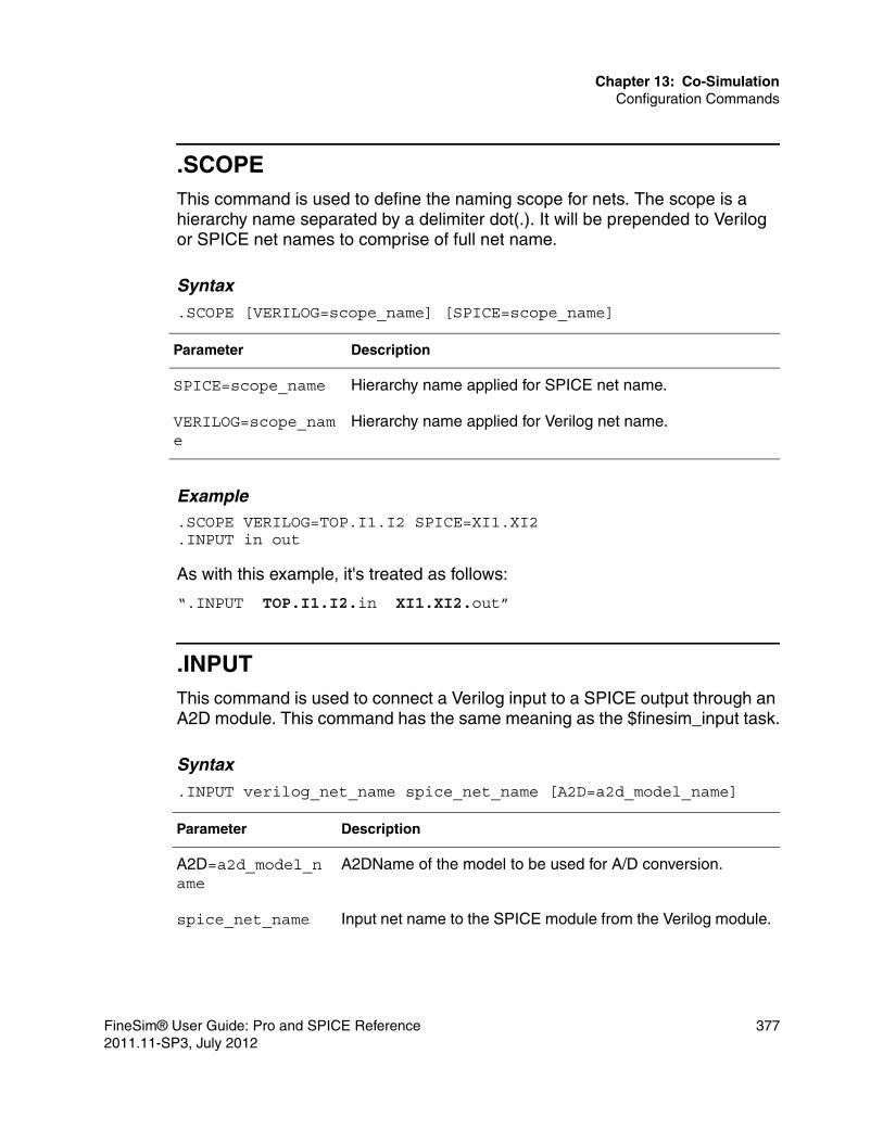
Chapter 13: Co-SimulationConfiguration Commands
.SCOPEThis command is used to define the naming scope for nets. The scope is a hierarchy name separated by a delimiter dot(.). It will be prepended to Verilog or SPICE net names to comprise of full net name.
Syntax
.SCOPE [VERILOG=scope_name] [SPICE=scope_name]
Example.SCOPE VERILOG=TOP.I1.I2 SPICE=XI1.XI2.INPUT in out
As with this example, it's treated as follows:
“.INPUT TOP.I1.I2.in XI1.XI2.out”
.INPUTThis command is used to connect a Verilog input to a SPICE output through an A2D module. This command has the same meaning as the $finesim_input task.
Syntax
.INPUT verilog_net_name spice_net_name [A2D=a2d_model_name]
Parameter Description
SPICE=scope_name Hierarchy name applied for SPICE net name.
VERILOG=scope_name
Hierarchy name applied for Verilog net name.
Parameter Description
A2D=a2d_model_name
A2DName of the model to be used for A/D conversion.
spice_net_name Input net name to the SPICE module from the Verilog module.
FineSim® User Guide: Pro and SPICE Reference 3772011.11-SP3, July 2012

Chapter 13: Co-SimulationConfiguration Commands
Example.INPUT TOP.IN XI1.out A2D=default
.OUTPUTThis command is used to connect a Verilog output to a SPICE input through a D2A module. This command has the same meaning as the $finesim_output task.
Syntax
.OUTPUT verilog_net_name spice_net_name [D2A=d2a_model_name]
Example.OUTPUT TOP.OUT XI1.in D2A=default
.INOUTThis command is used to connect a Verilog inout port to a SPICE port through A2D and/or D2A modules. This command has the same meaning as the $finesim_inout task.
verilog_net_name
Output net name from the Verilog module to the SPICE module.
Parameter Description
D2A=d2a_model_name
Name of the model to be used for D/A conversion.
spice_net_name Output net name from the SPICE module to the
Verilog module.
verilog_net_name Input net name to the Verilog module from the
SPICE module.
Parameter Description
378 FineSim® User Guide: Pro and SPICE Reference2011.11-SP3, July 2012

Chapter 13: Co-SimulationConfiguration Commands
Syntax.INOUT verilog_net_name spice_net_name [A2D=a2d_model_name][D2A=d2a_model_name]
Example.INOUT TOP.data XI1.data D2A=default A2D=default
.OPTIONBy using this OPTION command, users can specify various options.
Syntax.OPTION [INST_FILE=file_name] [PROGRESS=0|1] [IMAX=integer_value] \ [IMOD=0|1] [ACCURATE=0|1] [dump_ie=0|1] [minimize_ie=0|1|2]
Parameter Description
A2D=a2d_model_name
Name of the model to be used for A/D conversion.
D2A=d2a_model_name
Name of the model to be used for D/A conversion.
spice_net_name Bi-directional node name from/to the SPICE module.
verilog_net_name Bi-directional node name to/from the Verilog module.
Parameter Description
INST_FILE=file_name
Sets the file name for the SPICE instance netlist. If a Verilog module has $finesim_module task, A SPICE instance will be automatically generated in this file. The default file name is finemix.sp.
PROGRESS=0/1 Sets the mode for showing the status of the simulation progress. The default value is 1 (on mode).
IMAX=value Sets the maximum iteration count for DC solving in FineSim/Verilog co-simulation. The default value is 5.
FineSim® User Guide: Pro and SPICE Reference 3792011.11-SP3, July 2012

Chapter 13: Co-SimulationConfiguration Commands
.FINESIMWith this command users can define the FineSim Pro command and arguments. The command arguments and syntax are the same as those for standalone FineSim Pro.
Syntax
.FINESIM finesim_command_arguments
Example.FINESIM -out finesimout input.sp
IMODE=0/1 Sets the interrupt mode for FineSim Pro execution. When IMODE=1, a “Ctrl+C” will cause FineSim Pro to stop running. The default value is 0 (off mode).
ACCURATE=0/1 Sets the re-calculation mode for A/D conversion. A value of 1 will result in more accurate timing, but cause the simulation to run more slowly. The default value is 0 (off mode).
dump_ie=0|1 Sets to dump out A2D and D2A information into *.dumpie file. The default value is 0 (off mode).
minimize_ie=0|1|2 Sets to avoid unnecessary A2D and D2A conversion. If two nodes are connected within analog domain and it is not defined as a register type, then minimize_ie=1 will remove D2A but keep A2D for waveform probing; minimize_ie=2 will remove both A2D and D2A if digital signal of A2D does not drive primitive gate or continuous assignment. This option only applies to ports defined under $finesim_module task. The default value is 0 (off mode).
Parameter Description
finesim_command_arguments
See Running FineSim SPICE and Pro in Chapter 1, Introduction for details.
Parameter Description
380 FineSim® User Guide: Pro and SPICE Reference2011.11-SP3, July 2012

Chapter 13: Co-SimulationAutomatic Verilog Instance Generation
finesim_a2d / finesim_d2a parameterAs described in the “$finesim_module” and “$finesim_instance” sections, both finesim_a2d and finesim_d2a parameters can be used to change the model to be used for the A/D and D/A conversion. The “DEFAULT” model is used by default. The designation of specific signals is delimited by “$” character, like “finesim_d2a$signal”.
Examplesdefparam I2.finesim_a2d= "vdd_33_1";parameter finesim_a2d = "vdd_33";parameter finesim_d2a$A33 = "vdd33";parameter \finesim_a2d$DA[0] = "vdd_25";
The first example overrides the A/D conversion model name with “vdd_33_1” for instance I2. The second specifies the A/D model name of "vdd_33" for all signals used within the module. The third specifies the D/A model name of “vdd33” only for a signal A33. The fourth specifies the A/D model name of "vdd_25" only for the first signal of bus DA.
Automatic Verilog Instance Generation
FineSim Pro provides the support of automatic Verilog instance file generation when SPICE Top structure co-simulation is used. This flow introduces the –genv command option and some new options, such as finesim_verilog_file, finesim_verilog_module, and finesim_verilog_subckt_file. This section describes the flow supported by FineSim Pro.
-genvIf this command option is given, Verilog instance will be automatically generated according the sub-circuit definition in the deck file.
Syntaxfinesim –genv[=1|2] deck_file
FineSim® User Guide: Pro and SPICE Reference 3812011.11-SP3, July 2012

Chapter 13: Co-SimulationAutomatic Verilog Instance Generation
Examplefinesim -genv test.spfinesim -genv=1 test.spfinesim -genv=2 test.sp
The first example is the same as the second example, only the Verilog instance file is created. The third example will generate both a Verilog instance file and Spice sub-circuit definition file.
finesim_bus_formatSpecifies bus format, where %d is mandatory, representing the bits. "<" ">" indicates the bus characters, which can be modified to fit the bus characters.
Syntaxfinesim_bus_format=”<%d>”
finesim_port_map_by_nameThis option defines whether FineSim will use the port order or port name to map between the verilog module and spice subckt. The default is 0, which maps each co-simulation connection based on the order the ports are defined. When set to 1, FineSim will map the connection based on the name of the port, so the port order in Verilog versus spice can be different, but the name of the port has to be identical.
Syntaxfinesim_port_map_by_name=1
finesim_verilog_fileSets the file name for Verilog instance file. Default file name is "finemix.v".
Syntax.option finesim_verilog_file=<file_name>
382 FineSim® User Guide: Pro and SPICE Reference2011.11-SP3, July 2012

Chapter 13: Co-SimulationAutomatic Verilog Instance Generation
Example.option finesim_verilog_file=”inv.v”
finesim_verilog_instanceSpecifies a spice instance to be replaced by a Verilog module. Please note, this option can only work with the command option -genv. If the subckt name is the same as the module name, the module name can be omitted.
Syntax.option finesim_verilog_instance="<instance_name>:<module_name> ..."
Example.option finesim_verilog_instance="x1.x2.x3:inv x1.x2.x4:buf"
In this example, Spice instances x1.x2.x3 and x1.x2.x4 will be replaced by the Verilog module inv and buf, respectively.
finesim_verilog_moduleSpecifies spice sub-circuit to be replaced by Verilog module. If sub-circuit name is same with module name, module name can be omitted. This option can be specified multiple times.
Syntax.option finesim_verilog_module="<subckt_name>:<module_name> ... "
Example.option finesim_verilog_module="inv buf:BUF nand2:Nand2"
The example means the co-simulation will use inv, BUF, Nand2 Verilog modules in digital side, not inv, buf, nand2 sub-circuits in analog netlist.
FineSim® User Guide: Pro and SPICE Reference 3832011.11-SP3, July 2012

Chapter 13: Co-SimulationAutomatic Verilog Instance Generation
finesim_verilog_module_fileThis option specifies the verilog file containing the verilog module definitions. This option is used when the verilog instance file is generated by finesim -genv.
Syntaxfinesim_verilog_module_file=”filename”
finesim_verilog_subckt_fileSets the file name for new spice sub-circuit definition file. If command option -genv=2 is given, new spice sub-circuit definition file will be generated. This sub-circuit is empty because this sub-circuit will be replaced by Verilog module. Default file name is "finemix_subckt.sp".
Syntax.option finesim_verilog_subckt_file=<file_name>
Example.option finesim_verilog_subckt_file=”pll.sp”
Circuit Example: (test.sp).option post.global 0vvdd VDD 0 dc 2.5vvss VSS 0 dc 0.global VSS VDDvin sin 0 pulse (0 2.5 1.0n 1.0n 1.0n 4.0n 10n).inc ./model.inc
** Top Netlist **X1 sin sinb sinvX2 sinb dout vinv
.subckt sinv in outmp0 out in VDD VDD p l=0.25u w=3umn0 out in VSS VSS n l=0.25u w=1.5u.ends .subckt vinv in outmp0 out in VDD VDD p l=0.25u w=3u
384 FineSim® User Guide: Pro and SPICE Reference2011.11-SP3, July 2012

Chapter 13: Co-SimulationParallel Co-Simulation
mn0 out in VSS VSS n l=0.25u w=1.5u.ends
.tran 1p 100ns
.end
In this example, if the user wants to replace vinv sub-circuit by vinv module in Verilog side. Firstly, add the .option finesim_verilog_module="vinv" into test.sp deck file, and then execute finesim –genv=2 test.sp command in terminal. Then, the finemix.v and finemix_subckt.sp files can be automatically generated. Thirdly, include the finemix.v in Verilog file and include finemix_subckt.sp in test.sp deck file separately. Now, the automatic Verilog instance generation flow is done, the user can continue to run the co-simulation.
Parallel Co-Simulation
FineSim Pro has applied its parallel simulation technology to co-simulation. It solves the performance bottleneck of slower transistor level simulation in a co-simulation environment. To use this feature, modify the finesim command to run parallel FineSim Pro with the -np switch, as shown in the following example:
//You can change a 1CPU serial run of.finesim –spectre –spice –o 1CPU input.scs//to a 4CPU run of.finesim –np 4 –spectre –spice –o 4CPU input.scs
Currently, the maximum number of –np in parallel co-simulation is 4.
Common Co-Simulation Problems
Since every verilog simulator behaves a bit differently with VPI, sometimes unexpected problems are encountered. This section will go through some of these common co-simulation problems and the workarounds to for fixing them.
VCS Abort: ** glibc detected *** free(): invalid pointer: 0x0af34b58 ***
You can workaround the problem by setting:
setenv MALLOC_CHECK_ 0
FineSim® User Guide: Pro and SPICE Reference 3852011.11-SP3, July 2012

Chapter 13: Co-SimulationCommon Co-Simulation Problems
Error while reading shared library symbols, cannot find new threads: generic error
You can workaround the problem by setting:
setenv LD_ASSUME_KERNEL"
ERROR: VPI NOFORCB: vpi_put_value() cannot force a bit of an unexpanded vector net
Some of the verilog simulation will not expand out the output bus, so you cannot use .input/.output/.inout to drive the signal.
For the output [MSB:LSB] name that is causing the issue, add "wire scalared [MSB:LSB] name". Alternatively, you can set the signal as "output reg".
386 FineSim® User Guide: Pro and SPICE Reference2011.11-SP3, July 2012

14
14IR Drop and EM Analysis
This chapter explains how IR Drop and EM simulation and analysis is achieved using FineSim Pro and Titan IR/EM platforms. The Titan IR/EM platform is explained in the section Titan IR/EM Analysis.
FineSim SPICE and Pro support dynamic IR Drop and EM simulation and analysis, accelerated to deliver high accuracy and high performance by using:■ FineSim Back-Annotation Flow ■ FineSim Parallel Technology■ Titan IR/EM Platform
FineSim back-annotates the post-layout parasitic and device files with the prelayout design netlist, and speeds up the simulation with its unique parallel technology. Titan IR/EM uses a Graphical User Interface to analyze dynamic IR-Drop/Electro-Migration more comprehensively.
Non-Ideal Power Analysis (IR Drop)
For power rail networks, dynamic voltage drop analysis and its impact on transistor behavior demand a tremendous amount of simulation power. The vast RC tree network associated with power and ground grids, oftentimes in multiple domains, makes traditional CCC partition-based simulation algorithms impractical, if not impossible to use.
FineSim Pro’s non-ideal power analysis feature employs a partitioning algorithm that creates an extra, separate power rail partition from the traditional CCC partition and then synchronizes both partitions through a controlled event generation process to simulate the non-ideal power nodes along the power rail simultaneously with the transistors. By this method, FineSim Pro achieves the
FineSim® User Guide: Pro and SPICE Reference 3872011.11-SP3, July 2012

Chapter 14: IR Drop and EM AnalysisEM Analysis
most accurate voltage or current value at any time and at any place on a power rail wire. This accurate voltage value, in turn, is used to simulate the transistors that are tied to it and hence produces correct circuit behavior.
To run this non-ideal power analysis feature, you make the power rail RC in the DSPF file back-annotatable. FineSim Pro intelligently traces down to find the power net names.
IR Drop Analysis OptionsFineSim Supports IR Drop Analysis with the help of following essential options:■ finesim_spfpost ■ finesim_spf
For Power Net IR Drop analysis, the power net parasitic files are back-annotated using the finesim_spf command and the power nets to be analyzed are to be provided using the finesim_spfpost command.
To enable EM analysis on power nets, we can use the finesim_spfpost_out command, which will be covered in detail in the EM analysis Section followed.
IR Drop Analysis OuputsThe output files are as follows:■ <file>.fsdb — Contains Voltage waveforms for each node as well as each
resistor as identified in the DSPF file.■ <file>_irdrop.db — Contains layout information and resistor value. Also
contains width/length information for metal resistors, and area information for via resistor.
EM Analysis
FineSim Pro performs both Signal and Power EM analysis by using parasitic resistor information from the DSPF file to generate DC/AC/RMS current information of the Metal/Via layers and store it in EM file output. The user can choose to select dumping AC or RMS using the finesim_irem_rms option.
388 FineSim® User Guide: Pro and SPICE Reference2011.11-SP3, July 2012

Chapter 14: IR Drop and EM AnalysisEM Analysis
DC Current = AC Current =
FineSim has the capability to selectively analyse power nets/signal nets of interest using the finesim_spfpost option with the nets of interest.
DSPF File RequirementsEM analysis requires DSPF resistors to contain geometry and layer attributes to simulate, map, and position the resistor in the Titan EM view. ■ Geometry attributes: Length, width, position, co-ordinates of resistor node.■ Layer attributes: Layer level number.
The DSPF file should dump layer map information on the layer name that corresponds to the layer number. FineSim automatically reads this information and doesn’t require a separate layer map to identify.
EM Analysis OptionsFineSim Pro supports electro-migration (EM) analysis with the following options:■ finesim_spf■ finesim_spf_add_irem_window■ finesim_spfpost_end, finesim_spfpost_out, finesim_spfpost_start■ finesim_spfpost_out_only■ finesim_spfpwr■ finesim_spfeqr, finesim_spf2eqr, finesim_spfeqrfile, finesim_spfeqronly■ finesim_em_layer■ finesim_irem_rms
EM analysis cannot be run with DSPF RC-Reduction (finesim_spfred=0). However, the user can speed up simulation with selective net/layer analysis with the help of the above commands.
i t( ) td∫T
--------------------i t( ) td∫T
-----------------------
FineSim® User Guide: Pro and SPICE Reference 3892011.11-SP3, July 2012

Chapter 14: IR Drop and EM AnalysisTitan IR/EM Analysis
EM Analysis OutputsThe output files are as follows:■ <file>.em — Contains IR drop information for each node as well as AC/DC/
RMS current of each register as identified in the DSPF file.■ <file>_irdrop.db — Contains layout information and resistor value. Also
contains width/length information for metal resistors, and area information for via resistor.
These files are used as inputs to PowerView/Titan IR/EM.
Titan IR/EM Analysis
Titan’s IR/Electro-Migration (EM) flow allows you to perform non-ideal power net or signal net analysis. It addresses the FineSim PowerView flow in a comprehensive manner by providing layout capabilities and a faster turnaround. It also provides features such as stream-in and stream-out capabilities of GDS error markers, and Tcl interface. Through the IR/EM flow, you can analyze IR-drop, EM, and vias from FineSim Pro simulations.
When running non-ideal power analysis by executing the finesim_spfpost command, FineSim Pro writes SPF information into a file with the extension irdrop.db. For more information about the PowerView flow in FineSim, refer to Appendix D, Using PowerView.
The simulation output files generated by FineSim have the ‘.fsdb’ extension for IR-drop analysis and ‘.em’ extension for EM analysis. Titan IR/EM uses FineSim simulation output data from the output files, EM criteria, and the nets to be analyzed to provide a complete solution for IR-drop and EM test needs.
390 FineSim® User Guide: Pro and SPICE Reference2011.11-SP3, July 2012

Chapter 14: IR Drop and EM AnalysisTitan IR/EM Analysis
The figure below depicts Titan IR/EM's position in the dynamic IR/EM analysis flow with FineSim Pro:
Figure 19 Titan IR/EM in FineSim Pro IR/EM Flow
Titan IR/EM ModesTitan supports the following IR/EM analysis modes:
FineSim® User Guide: Pro and SPICE Reference 3912011.11-SP3, July 2012

Chapter 14: IR Drop and EM AnalysisTitan IR/EM Analysis
Non-Layout Based ModesYou can run the IR/EM analysis without the layout data information by using only simulation output data from FineSim Pro. To run IR/EM in this mode, choose Tools > IR/EM from the Titan menu bar as shown below.
Figure 20 Launching IR/EM Analysis through the Titan Window
392 FineSim® User Guide: Pro and SPICE Reference2011.11-SP3, July 2012

Chapter 14: IR Drop and EM AnalysisTitan IR/EM Analysis
Layout BasedYou can also analyze IR/EM data over the layout database for better understanding of the analyzing data. To run IR/EM in this mode, choose Verification > IR/EM in the Layout Editor as shown below.
Figure 21 Launching IR/EM Analysis through the Layout Editor
FineSim® User Guide: Pro and SPICE Reference 3932011.11-SP3, July 2012

Chapter 14: IR Drop and EM AnalysisTitan IR/EM Analysis
IR/EM Common Analysis FlowAfter you launch Titan IR/EM in a particular analysis mode by choosing the appropriate menu option, both the modes share a common flow. After the IR/EM command is executed, the New Analysis form appears as shown below.
Figure 22 New Analysis Form
In the New Analysis form, click Load to directly load a previously saved session, or do the following:■ Specify a simulation output filename in the Simulation Output File field.
You can also choose a simulation output file by clicking the Browse (...) button. The simulation files can have .fsdb or .em extensions.
■ Specify the starting and ending times in the duration of the entire simulation to be analyzed, in the Start Times and End Times field.
If unspecified, the command assumes the duration of the entire simulation.
394 FineSim® User Guide: Pro and SPICE Reference2011.11-SP3, July 2012

Chapter 14: IR Drop and EM AnalysisTitan IR/EM Analysis
■ Specify the duty in percentage.
Duty defines the activity percentile of each simulation file to the analyses. The default duty is 100 percent.
■ Click Add to add the simulation output file details.
You can also select a file and click Delete to delete it.
■ Specify the SPFDB filename in the SPFDB File field.
You can also choose an SPFDB file by clicking the Browse (...) button.
■ Specify the EM criterion filename in the EM Criterion File field.
An EM criterion file is defined by EM criteria rules. A rule can describe conditions by width/length/area and by layer. You can also choose an EM criterion file by clicking the Browse (...) button.
■ Specify the net name of the power or signal net to be analyzed in the Net Name field. Wildcard is supported, but must be used in conjunction with the regex radio button activated.
This net is defined with the finesim_spfpost=net_name option in FineSim Pro simulation.
■ Specify the voltage level of the power or signal net in the Level field.■ Click Add to add the net details. Similarly, you can add multiple nets.
You can also select a net and click Delete to delete its details.
■ Click Ok. The IR/EM information from the specified SPFDB and simulation files are displayed on the canvas as per the chosen IR/EM analysis mode.
FineSim® User Guide: Pro and SPICE Reference 3952011.11-SP3, July 2012

Chapter 14: IR Drop and EM AnalysisTitan IR/EM Analysis
The below figure displays the IR/EM analysis output in the non-layout mode:
Figure 23 Titan IR/EM Analysis: Non-Layout Mode
396 FineSim® User Guide: Pro and SPICE Reference2011.11-SP3, July 2012

Chapter 14: IR Drop and EM AnalysisTitan IR/EM Analysis
The below figure displays the IR/EM analysis output in the layout mode. You can easily analyze the IR/EM shapes over the existing layout information. You can also modify, hide, and view different layout layers over IR-Drop layers.
Figure 24 Titan IR/EM Analysis: Layout Mode
Note:You can also click Load to directly load information from a previously saved session.
FineSim® User Guide: Pro and SPICE Reference 3972011.11-SP3, July 2012

Chapter 14: IR Drop and EM AnalysisTitan IR/EM Analysis
IR/EM Analyzer
Simultaneously, the IR/EM Analyzer appears as shown below. Using this analyzer, you can control the visibility of nets and layers, voltage level and resolution, and highlighting of nodes.
Figure 25 IR/EM Analyzer
In the IR/EM Analyzer:
In the IR-drop tab, select Avg under Mode to generate the average IR-drop value during simulation. The default mode is Max. The max or peak mode signifies the maximum IR-drop value during simulation.
398 FineSim® User Guide: Pro and SPICE Reference2011.11-SP3, July 2012

Chapter 14: IR Drop and EM AnalysisTitan IR/EM Analysis
Click View Node to view the node details, highlight selected nodes on the canvas, and plot selected nodes. The View Node form appears as shown below.
View Node Form
In the View Node form:
Figure 26 The View Node Form
■ Specify the number of results to be displayed after the node information is filtered, in the # results field.
If the database has more than 100 results, only 100 results per net are displayed if you retain the default value in the # results field. The default value is “100”.
■ The default filter is by region coordinates. Specify values in the lower-left X, lower-left Y, upper-right X, and upper-right Y fields for creating a bounding box, and click Refresh.
The node details within the bounding box are displayed. You can generate a report of the filtered results in a text file by clicking Report.
■ Select by ir-drop value to filter node details according to specific IR-drop values.
Specify a range — the minimum and maximum IR-drop values —and click
FineSim® User Guide: Pro and SPICE Reference 3992011.11-SP3, July 2012

Chapter 14: IR Drop and EM AnalysisTitan IR/EM Analysis
Refresh. The node details according to the specified IR-drop range are displayed. You can generate a report of the filtered results in a text file by clicking Report.
■ Select the nodes from the filtered results, and click Highlight to view them in the design.
The letter “H” appears next to the highlighted nodes in the form, as shown below. The nodes are highlighted on the canvas as blinking dots, as shown below. By default, the command displays all nodes of the selected nets.
Figure 27 The Highlighted Nodes
400 FineSim® User Guide: Pro and SPICE Reference2011.11-SP3, July 2012

Chapter 14: IR Drop and EM AnalysisTitan IR/EM Analysis
■ Click Show Wave to plot the selected nodes in FineWave. The selected data, shown above, is plotted as shown in the figure below. This is enabled only when fsdb is used in analysis and not when the EM file is used to analyze IR Drop analysis.
Figure 28 Plotted Nodes
■ Select highlighted nodes, click Clear, and click the Redraw/Resync button to remove the node highlights from the canvas.
■ Click Clear All to clear all the highlighted nodes.
The report saves the analyzed output to the specified filename if selected.■ Click Edit Level to change the default criterion for the severity levels.
The default criterion divides the severity levels by 10% of the voltage or net level specified in the New Analysis form. For example, if the specified net level is 1.5v, the difference between severity levels 0 through 9 according to the default criterion is 10% of 1.5v, which is .15v. The value of each severity level, as shown in the IR-drop Level (V) field, is calculated as .15v / 10, which is .015.
■ The Edit IR-drop level form appears as shown below.
FineSim® User Guide: Pro and SPICE Reference 4012011.11-SP3, July 2012
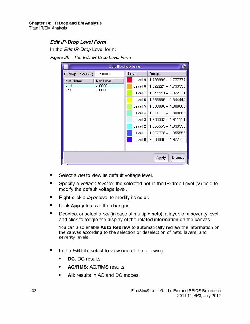
Chapter 14: IR Drop and EM AnalysisTitan IR/EM Analysis
Edit IR-Drop Level Form
In the Edit IR-Drop Level form:
Figure 29 The Edit IR-Drop Level Form
■ Select a net to view its default voltage level.■ Specify a voltage level for the selected net in the IR-drop Level (V) field to
modify the default voltage level.■ Right-click a layer level to modify its color.■ Click Apply to save the changes.■ Deselect or select a net (in case of multiple nets), a layer, or a severity level,
and click to toggle the display of the related information on the canvas.
You can also enable Auto Redraw to automatically redraw the information on the canvas according to the selection or deselection of nets, layers, and severity levels.
■ In the EM tab, select to view one of the following:
• DC: DC results.
• AC/RMS: AC/RMS results.
• All: results in AC and DC modes.
402 FineSim® User Guide: Pro and SPICE Reference2011.11-SP3, July 2012

Chapter 14: IR Drop and EM AnalysisTitan IR/EM Analysis
■ Click View Resistor to view EM results in the form, as shown below.
View Resistor Form
In the View Resistor form:
Figure 30 The View Resistor Form
■ Specify the number of results to be displayed after the node information is filtered, in the “# results” field.
If the database has more than 100 results, only 100 results per net are displayed if you retain the default value in the # results field. The default value is “100”.
■ Click Report to generate a report of the EM results in a text file.■ Select rows of EM information, click Highlight, and click the Redraw/
Resync button to highlight the selected information on the canvas.
You can click Clear to clear the selected highlights on the canvas.
■ Click Clear All to clear all highlighted EM information on the canvas.■ Click Refresh to rebuild the list of resistor information in the View Resistor
form.■ Click Stream Out to export the IR-drop and EM information on the canvas
in a GDSII file. The Stream Out form appears as shown in below.
FineSim® User Guide: Pro and SPICE Reference 4032011.11-SP3, July 2012
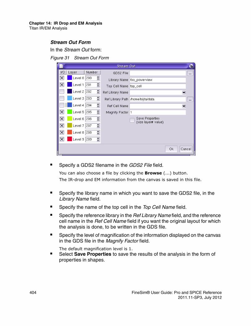
Chapter 14: IR Drop and EM AnalysisTitan IR/EM Analysis
Stream Out Form
In the Stream Out form:
Figure 31 Stream Out Form
■ Specify a GDS2 filename in the GDS2 File field.
You can also choose a file by clicking the Browse (...) button. The IR-drop and EM information from the canvas is saved in this file.
■ Specify the library name in which you want to save the GDS2 file, in the Library Name field.
■ Specify the name of the top cell in the Top Cell Name field.■ Specify the reference library in the Ref Library Name field, and the reference
cell name in the Ref Cell Name field if you want the original layout for which the analysis is done, to be written in the GDS file.
■ Specify the level of magnification of the information displayed on the canvas in the GDS file in the Magnify Factor field.
The default magnification level is 1.■ Select Save Properties to save the results of the analysis in the form of
properties in shapes.
404 FineSim® User Guide: Pro and SPICE Reference2011.11-SP3, July 2012

Chapter 14: IR Drop and EM AnalysisTitan IR/EM Analysis
• For IR analysis, properties such as severity level, layout layer, net name, node name, peakVolt@time (for peak), and avgVolt (for AVG analysis) are saved.
• For EM analysis, properties such as severity level, layout layer, net name, AC current, DC current, and width or area are saved.
■ Select the layers and corresponding severity levels to be included in the GDS2 file.
■ Click Ok.■ Click Save and assign a name to the current session to save the current
session information.
You can reload this session when required, instead of repeating the information in the New Analysis form.
■ Click Exit or Close to exit from the IR/EM Analyzer.
FineSim® User Guide: Pro and SPICE Reference 4052011.11-SP3, July 2012

Chapter 14: IR Drop and EM AnalysisTitan IR/EM Analysis
Multiple IR/EM AnalysesTitan IR/EM allows you to simultaneously perform layout and non-layout based IR-drop analysis. Titan allows multiple layout based IR/EM analysis as shown below.
Figure 32 Simultaneous Layout And Non-layout Based Analysis
IR Drop and EM Analysis in Titan IREM “NO-GUI” ModeIR Drop and EM analysis can also be run in command mode without the GUI item. This usually helps users in analyzing results of a batch of IR/EM outputs. Titan IR/EM command mode is powered by TCL mode, so TCL programming can be used to setup the analysis in batch mode.
Command to Run Titan in No GUI Modetitan -file <titan_irem_script> -noGUI
Exampletitan -file no_gui_em -noGUI
406 FineSim® User Guide: Pro and SPICE Reference2011.11-SP3, July 2012

Chapter 14: IR Drop and EM AnalysisTitan IR/EM Analysis
Titan IR/EM Script FileThis is a command file that has instructions to the tool on the input files, analysis type and outputs needed in “No GUI” mode. TCL programming can be done on top of these instructions to allow looping, using variables, and take advantage of the language.
This file can either be created manually following Titan IR/EM help (Please see the below section, Titan IR/EM Help for details) or can be automatically created if we try the same steps in graphical mode. Titan IR/EM stores a replay file with prefix “titanirem”.
For example: “titanirem.12.12.12.21.replay” for all the IR/EM instructions done in Graphical mode. This allows us to avoid learning Titan IR/EM commands.
Example Script Fileirem initirem add simdb finesim_rms.em 100 0 0irem set spfdb finesim_rms_irdrop.db -emCriterionFile em_cri.criirem add net {"*"} 1.1irem start analysisirem switch view EMirem switch analysis ALLirem export text -file em_rms_out.out -allirem close session 1exit
The above example takes the inputs finesim_rms.em, finesim_rms_irdrop.db (output from FineSim) and em_cri.cri (EM rule file from Designer).
EM analysis is done on all Nets “*” and EM output file is dumped to em_rms_out.out (text output).
Titan IR/EM HelpTitan IREM Help/Man Pages are available in both GUI and command prompt.
FineSim® User Guide: Pro and SPICE Reference 4072011.11-SP3, July 2012

Chapter 14: IR Drop and EM AnalysisTitan IR/EM Analysis
GUI Mode has a Document Browser in the left panel of the Main Titan window as show in the below image. All IR/EM commands are explained in the man pages under section “irem”.
Figure 33 Document Browser
408 FineSim® User Guide: Pro and SPICE Reference2011.11-SP3, July 2012

Chapter 14: IR Drop and EM AnalysisHandling EM Rule Specification
The Command Prompt below shows the same explanation of each command when we type the related command.
Figure 34 Command Prompt
Titan Tool Tips on IR/EM options are available when mousing over any button you would like to know about, as shown below, highlighting "Add simulation output file".
Figure 35 Mouseover Example
Handling EM Rule Specification
This section details EM rule and file specifications.
FineSim® User Guide: Pro and SPICE Reference 4092011.11-SP3, July 2012

Chapter 14: IR Drop and EM AnalysisHandling EM Rule Specification
EM Criteria File (New Criterion Format)Foundry EM specifications (rules) are in the form of equations. Leading edge technologies moved to length based equation rules, which Titan IR/EM handles through an EM Rule/Criteria file. The following describes the EM criteria file syntax for these newer rules.
EM Criteria File Syntax Description
EM_CRI_FORMAT 1
For backward compatibility, we need to maintain the earlier criterion format. As such, the new format criteria files require the parameter EM_CRI_FORMAT be set to 1.■ Deprecated parameters with EM_CRI_FORMAT 1: min_width, max_width,
min_area, max_area. ■ Newly added parameters with EM_CRI_FORMAT 1: curr_max_eqn,
shortlen_max_curr, shortlen_max_len. ■ Behavior changes for following parameters: level1, level2, ... level10, now
accepts % values, where previously these were absolute numbers.
EM_CURR_IS_RMS 1
Set when current_type is RMS
ExampleEM_CURR_IS_RMS 1, current_type=ac [ inside the condition statement ] The above settings will analyze RMS current instead of AC current.
AC scale: used when AC rules are turned on.
Comments: Any line which starts with * is a comment line.
Units ■ LENGTH_UNIT um — All length values in criteria file will be in unit referred from
this parameter. ■ WIDTH_UNIT um — All width values in criteria file will be in unit referred from
this parameter.
410 FineSim® User Guide: Pro and SPICE Reference2011.11-SP3, July 2012
Chapter 14: IR Drop and EM AnalysisHandling EM Rule Specification
■ AREA_UNIT um2 — All area values in criteria file will be in unit referred from this parameter. Please note that um2 means (um)*(um).
■ CURRENT_UNIT mA — Units for current.
Support for EquationsEquations are allowed with the following parameters only: ■ curr_max_eqn — Accepts the current-based equations. ■ shortlen_max_len — Identifies the maximum line length to which relaxed
rules can be applied. ■ shortlen_max_curr — Accepts the current-based equations and is used
instead of curr_max_eqn when the line length is less than shortlen_max_len.
The exhaustive list of operators and functions which can be used in equation are:
Operators
+ , - , * , / , ( , ), ! , <, > , <= , >=, ==, != , &&, ||
Functions
Single argument functions:
abs, acos, asin, atan, atanh, ceil, cos, cosh, exp, floor, floor, log, log10, sin, sinh, sqrt, tan, tanh
Two argument functions:
min, max, mod, pow
Three argument functions:
if
Syntax of 'if' is like the conditional operator:
if( (condition) , (expr1), (expr2) )
Via Criteria Format Add is_via = 1 to disable the need for using min/max area:
*min_area = 0.0024 *max_area = 0.0026
FineSim® User Guide: Pro and SPICE Reference 4112011.11-SP3, July 2012

Chapter 14: IR Drop and EM AnalysisHandling EM Rule Specification
Examples
Example 1: Short Length
Example usage of new keywords:
Maximum current value allowed in this metal layer calculated from this eqn:
curr_max_eqn = min((? + (?/W) + ?*W) ,( ? + ? * sqrt(W) + ? *W))
Maximum current value for short length resistors:
shortlen_max_curr = if( (W < 0.1), (((? + (?/W) + ?*W)*(10/L)),( ? + (?/W) + ?*W) )
Value below which a resistor is identified as short length:
shortlen_max_len = 10
Example 2: Mid Range/Short Range
For rules like: ■ for res L > 10u — rule with eqn1. ■ for res L < 10u && L > 5 u — rule with eqn2. ■ for res L < 5u — rule with eqn3. ■ shortlen_max_curr = if( (L <10 && L > 5 ), (eqn2), (eqn3) ) ■ shortlen_max_len = 10
For L > 10, width rules are already applied (eqn1).
Example 3: Equation Rule on Via
For a Via rule of: ■ Vx (1xvia) = 0.01mA for area 0.1X0.1 size
curr_max_eqn = 0.01 * A/((0.1)* (0.1)) (A is a reserved keyword)
Usage:
condition { current_type = dc curr_max_eqn = 0.01 * A/((0.1)* (0.1)) is_via = 1
412 FineSim® User Guide: Pro and SPICE Reference2011.11-SP3, July 2012

Chapter 14: IR Drop and EM AnalysisHandling EM Rule Specification
Sample EM Specification #1 (Equation-Based) ■ Layer Name — M1 ■ Layer Number — 201 ■ EM Criteria — DC specification.
General Rules
1. Standard Electromigration (Idc Maximum current limit):
? + (?/W) + ?*W (W = width of the line)
2. Local Heating Enhanced Electromigration (Irms Maximum Current limit):
? + ? * sqrt(W) + ? *W
3. If Idc Limit is greater than Irms Limit, Use Irms as Idc Limit.
Relaxation Rules
1. Short Length (Llimit) - € (um)
2. Wmin (Minimum Width) = ? (um)
3. For Length less than Llimit and Width less than N times Wmin:
Idc (short length ) = Idc (calculated ) X Llimit / Length
Sample EM Specification #2 (Equation-Based)■ Layer Name: Via1 ■ Layer Number: 101 ■ EM Criteria : DC specification
General Rules
1. Standard Electromigration (Idc Maximum current limit).
1 X Vias = ¥ (mA) Area = 0.1um X 0.1 um
EM criteria file for above sample EM specification is shown below
Sample EM Criterion File EM_CRI_FORMAT 1 LENGTH_UNIT um
FineSim® User Guide: Pro and SPICE Reference 4132011.11-SP3, July 2012

Chapter 14: IR Drop and EM AnalysisHandling EM Rule Specification
WIDTH_UNIT um AREA_UNIT um2 CURRENT_UNIT mA EM_CURR_IS_RMS 1 EM M1 (201) { criterion { condition { current_type = dc curr_max_eqn = min((? + (?/W) + ?*W) ,( ? + ? * sqrt(W) + ? *W)) shortlen_max_curr = if( (W <N*?) , (((? + (?/W) + ?*W)*(10/L)),( ? + (?/W) + ?*W) ) shortlen_max_len = € } current { level10 = 100% level9 = 90% level8 = 80% level7 = 70% level6 = 60% level5 = 50% level4 = 40% level3 = 30% level2 = 20% level1 = 10% } } } EM Via1 (101) { criterion { condition { current_type = dc curr_max_eqn = ¥ * A/((0.1)* (0.1)) is_via = 1 } current { level10 = 100% level9 = 90% level8 = 80% level7 = 70% level6 = 60% level5 = 50% level4 = 40% level3 = 30% level2 = 20%
414 FineSim® User Guide: Pro and SPICE Reference2011.11-SP3, July 2012

Chapter 14: IR Drop and EM AnalysisHandling EM Rule Specification
level1 = 10% } } }
FineSim® User Guide: Pro and SPICE Reference 4152011.11-SP3, July 2012

Chapter 14: IR Drop and EM AnalysisHandling EM Rule Specification
416 FineSim® User Guide: Pro and SPICE Reference2011.11-SP3, July 2012

15
15Verilog-A Support
This chapter describes support for Verilog-A models.
Including and Compiling Verilog-A Modules
Usually, a Verilog-A file name has a .va extension. It can be included in a FineSim Pro circuit netlist as follows:■ SPICE netlist—.hdl“veriloga_file.va”
■ SPECTRE netlist—ahdl_include “veriloga_file.va” (To read a Spectre netlist, use the -spectre option as in finesim –spectre circuit.scs. For more details about Spectre, see Appendix B, Spectre Support.)
FineSim Pro compiles all the Verilog-A modules defined and creates an object file to run those blocks. You can include multiple Verilog-A files or multiple modules in one Verilog-A file. When there is more than one module with same file name, the first definition is used and subsequent definitions are ignored.
FineSim Pro also supports Verilog-A include files within sub-circuit blocks.
Set the FINESIM_VA2C_SO_DIR environment variable to define the directory from which to read shared-object (*.so) files and in which to place said shared-object files when they are generated from a Verilog-A file. This directory must be readable by the user and writable if new *.so files are to be added there. The effective default value of this environment variable is the directory in which the circuit is run. Consider the following example:
setenv FINESIM_VA2C_SO_DIR <path_to_library>
FineSim® User Guide: Pro and SPICE Reference 4172011.11-SP3, July 2012

Chapter 15: Verilog-A SupportSupported Platforms
Supported Platforms
FineSim Pro supports both Linux 64-bit and 32-bit binaries for Verilog-A based designs. Use the following command to run 64-bit:
setenv FINESIM_64 1Use the following command to run 32-bit:
setenv FINESIM_64 0
Support for Encrypted Verilog-A Files as Input
FineSim supports reading encrypted Verilog-A files as input for the .hdl command. This allows the user to encrypt Verilog-A models using the fencrypt utility and use them in FineSim simulation. This feature is supported for both Spice and Spectre netlist formats.
Example Usage
Verilog-A file: cap.va
Unencrypted Flow
Input netlist: .hdl cap.va
Encrypted Flow
1. Using the fencrypt utility (please see the Using Fencrypt section:
%> fencrypt file cap.va cap_encrypted.va
2. Input netlist: .hdl cap_encrypted.va
418 FineSim® User Guide: Pro and SPICE Reference2011.11-SP3, July 2012

Chapter 15: Verilog-A SupportVerilog-A Related FineSim Options
Verilog-A Related FineSim Options
The table below describes Verilog-A related FineSim options:
Supported Verilog-A Language Features
Prior to the release of Verilog-AMS HDL, the OVI board approved an analog-only specification called Verilog-A v1.0. With the release of Verilog-AMS HDL, the official Verilog-A Language Reference Manual is no longer supported as it is included as part of the Verilog-AMS HDL specification. This document is based on this subset of Verilog-AMS HDL for analog-only products.
Note:FineSim Pro supports Verilog-A as described in the Verilog-AMS 2.2 Language Reference Manual. This version of FineSim Pro supports the Analog Language subset of the Verilog-AMS HDL specification. Although all of Verilog-A is not yet supported, FineSim Pro supports most of the key features of Verilog-A.
You can find the Complete Reference Manual at www.vhdl.org/verilog-ams/htmlpages/public-docs/lrm/2.2/AMS-LRM-2-2.pdf. Additionally, certain obsolete features of Verilog-A 1.0 are supported for backwards compatibility.
The Verilog-A subset provides access to a salient set of features within the full modeling language that allows analog designers the ability to model analog systems.
Option Description
finesim_lsf_format_chars Allows usage of Spectre Verilog-A special characters.
finesim_veriloga (.hdl) Includes veriloga file in netlist.
finesim_veriloga_bypass Bypass veriloga model evaluation.
finesim_remove_va_so_files Remove va/so temp files after compilation.
finesim_remove_hier_va_files Remove hierarchical temp files after simulation.
FineSim® User Guide: Pro and SPICE Reference 4192011.11-SP3, July 2012

Chapter 15: Verilog-A SupportSupported Verilog-A Language Features
The following tables list the features of Verilog-AMS 2.2 and show which features are supported by FineSim Pro.
Lexical ConventionsThe below table lists and describes supported lexical conventions.
Table 96 Lexical Conventions
Section Feature Description Supported
2.1 Lexical Tokens
2.2 Primitives Yes
2.2 White space Characters for spaces, tabs, new lines, and form feeds.
Yes
2.3 Comment Short comment - // ; Long Comment - /*{ASCII}*/
Yes
2.4 Operator Unary, Conditional, Binary Operators
Yes
2.5 Number
2.5.1 Integer Constants Integer type Yes
2.5.2 Real Constants Real type Yes
2.5.3 Scale factors for Real Constants
Micro, milli, nano Yes
2.6 String
2.6.1 String Variable Declaration
Variable of String type
No
2.6.2 String Manipulation String variable manipulation using operators
No
420 FineSim® User Guide: Pro and SPICE Reference2011.11-SP3, July 2012

Chapter 15: Verilog-A SupportSupported Verilog-A Language Features
Data TypesThe below table lists and describes supported data types.
2.6.3 Special characters in String
New line/tab etc Yes
2.7 Identifiers, Keywords and System names
2.7.1 Escaped identifier With a preceding back-slash
Yes
2.7.2 Keyword Non Escaped Identifiers
Yes
2.7.3 System tasks/functions
$ based lang construct for system functions
Yes
2.7.4 Compiler directives Language construct for compiler directives
Yes
2.8 Attributes Properties about objects
No
2.8.1 Standard Attributes Description/units No
Table 97 Data Types
Section Feature Description Supported
3.1 Integer/real data type One or more variable of Integer/real data
Yes
3.1.1 Output variables Variable with a standard attribute
No
Table 96 Lexical Conventions (Continued)
Section Feature Description Supported
FineSim® User Guide: Pro and SPICE Reference 4212011.11-SP3, July 2012

Chapter 15: Verilog-A SupportSupported Verilog-A Language Features
3.2.1 Type Specification Parameter real/integer
Yes
3.2.2 Value Range Specification
For example, parameter real neg_rail = -15 from[50:0)
Yes
3.2.3 Parameter Units and Descriptions
standard attributes No
3.2.4 Parameter Arrays For example, parameter real poles[0:3] = { 1.0, 3.198, 4.554, 2.00 }
Yes
3.2.5 Local Parameters localparam Yes
3.2.6 String Parameters Parameter string Yes
3.2.7 Parameter alias Alternate names for module parameters
Yes
3.3 Genvar Integer variable for use in for loop etc
Yes
3.4.1 Natures Collection of attributes
Yes
3.4.2 Disciplines For example, potential or flow
Yes
3.4.3 Net discipline declaration
For example, electrical [MSB:LSB] n1
Yes
3.4.4 Ground declaration Ground node declaration
Yes
Table 97 Data Types (Continued)
Section Feature Description Supported
422 FineSim® User Guide: Pro and SPICE Reference2011.11-SP3, July 2012

Chapter 15: Verilog-A SupportSupported Verilog-A Language Features
3.4.5 Implicit nets Nets without declaration for use in module instances
No
3.5 Real net declarations Not a Verilog-A feature
n/a
3.6 Default discipline Not a Verilog-A Feature
n/a
3.6.1 Disciplines of primitives
Not a Verilog-A Feature
n/a
3.7 Discipline precedence
Use of Disciplines in different ways
No
3.8.1 Discipline and Nature Net compatibility rules Compatibility
n/a
3.9 Branches Branch declaration Yes
3.10 Namespace
3.10.1 Nature and discipline Nature/discipline names
Yes
3.10.2 Access functions Access function names
Yes
3.10.3 Net Net names Yes
3.10.4 Branch Branch names Yes
Table 97 Data Types (Continued)
Section Feature Description Supported
FineSim® User Guide: Pro and SPICE Reference 4232011.11-SP3, July 2012

Chapter 15: Verilog-A SupportSupported Verilog-A Language Features
ExpressionsThe below table lists and describes supported Verilog-A expressions.
Table 98 Expressions
Section Feature Description Supported
4 Expressions
4.1 Operators Table 4.1 of the Verilog-A Language Reference Manual. All operators except Bitwise operators
Yes
4.1.1 Operators with real operands
Table 4.2 of the Verilog-A Language Reference Manual.
Yes
4.1.2 Binary operator precedence
Table 4.4 of the Verilog-A Language Reference Manual.
Yes
4.1.3 Expression evaluation order
Associativity rule in evaluating operators
Yes
4.1.4 Arithmetic operators Table 4.5, 4.6, 4.7 of the Verilog-A Language Reference Manual.
Yes
4.1.5 Relational operators Table 4.8 of the Verilog-A Language Reference Manual.
Yes
4.1.6 Case equality operators
Not a Verilog-A construct
N/A
4.1.7 Logical equality operators
Table 4.9 of the Verilog-A Language Reference Manual.
Yes
4.1.8 Logical operators && || Yes
424 FineSim® User Guide: Pro and SPICE Reference2011.11-SP3, July 2012

Chapter 15: Verilog-A SupportSupported Verilog-A Language Features
4.1.9 Bit-wise operators &, | ~ ^ (Table 4.10-4.16 of the Verilog-A Language Reference Manual)
Yes
4.1.10 Shift operators >> << Yes
4.1.11 Conditional operator ?: Yes
4.1.12 Event or OR of events Section 6.7.2 of the Verilog-A Language Reference Manual.
Yes
4.1.13 Concatenations Join Scalar elements n/a
4.2 Built-in mathematical functions
4.2.1 Standard mathematical functions
Table 4.17 of the Verilog-A Language Reference Manual.
Yes
4.2.2 Transcendental functions
Table 4.18 of the Verilog-A Language Reference Manual.
Yes
4.2.3 Error handling Error when outside the range of this Math functions
Yes
4.3 Signal access functions
V(b1) V(n1, n2) I(<n1>) – port access not supported
Yes
4.4 Analog operators Yes
4.4.1 Restrictions on analog operators
n/a
Table 98 Expressions (Continued)
Section Feature Description Supported
FineSim® User Guide: Pro and SPICE Reference 4252011.11-SP3, July 2012

Chapter 15: Verilog-A SupportSupported Verilog-A Language Features
4.4.2 Vector or array arguments to analog operators
No
4.4.3 Analog operators and equations
n/a
4.4.4 Time derivative operator
Table 4.20 of the Verilog-A Language Reference Manual ddt with more than one argument not supported
Yes
4.4.5 Time integral operator
Table 4.21 of the Verilog-A Language Reference Manual idt with more than one argument not supported
Yes
4.4.6 Circular integrator operator
Table 4.22 of the Verilog-A Language Reference Manual idtmod with more than one argument not supported
Yes
4.4.7 Derivative operator ddx Yes
4.4.8 Absolute delay operator
Absdelay Yes
4.4.9 Transition filter Smooths out piecewise constant waveform
Yes
4.4.10 Slew filter Bounds the rate of change of waveform
Yes
Table 98 Expressions (Continued)
Section Feature Description Supported
426 FineSim® User Guide: Pro and SPICE Reference2011.11-SP3, July 2012

Chapter 15: Verilog-A SupportSupported Verilog-A Language Features
4.4.11 last_crossing function
function returns a real value representing the simulation time when a signal expression last crossed zero
Yes
4.4.12 Laplace transform filters
Laplace filter Yes
4.4.13 Z-transform filters Z filter Yes
4.4.14 Limited exponential Exp() with improved convergence
Yes
4.4.15 Constant versus dynamic arguments
n/a
4.5 Analysis-dependent functions
To determine analysis being performed
Yes
4.5.1 Analysis Table 4.24, 4.25 of the Verilog-A Language Reference Manual.
Yes
4.5.2 DC analysis Analysis (“dc”) Yes
4.5.3 AC stimulus ac_stim() Yes
4.5.4 Noise Noise functions No
4.6 User-defined functions
Custom functions defined by users
Yes
4.6.1 Defining an analog function
Function definition statements
Yes
Table 98 Expressions (Continued)
Section Feature Description Supported
FineSim® User Guide: Pro and SPICE Reference 4272011.11-SP3, July 2012

Chapter 15: Verilog-A SupportSupported Verilog-A Language Features
Supported SignalsThe below table lists and describes supported signals.
4.6.2 Returning a value from an analog function
Return Value access Yes
4.6.3 Calling an analog function
Analog Function call Yes
4.7.1 Enhanced Parameter Definition Support
Yes
Table 99 Signals
Section Feature Description Supported
5 Signals
5.1 Analog signals
5.1.1 Access functions Same as Section 4.3 of the Verilog-A Language Reference Manual.
Yes
5.1.2 Probes and sources Support of probe/source model
Yes
5.1.3 Examples Methods to define controlled sources, resistors, RLCs
Yes
5.1.4 Port branches I(<a>) Yes
5.1.5 Switch branches Switch between potential and flow
Yes
Table 98 Expressions (Continued)
Section Feature Description Supported
428 FineSim® User Guide: Pro and SPICE Reference2011.11-SP3, July 2012
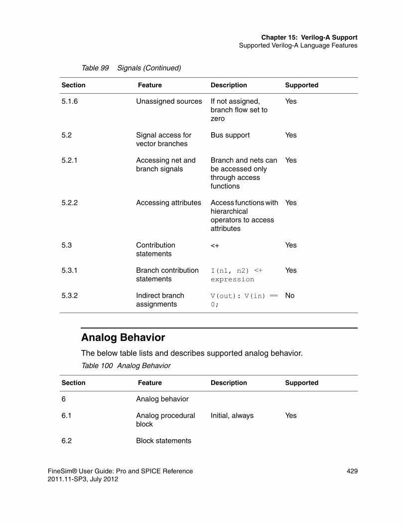
Chapter 15: Verilog-A SupportSupported Verilog-A Language Features
Analog BehaviorThe below table lists and describes supported analog behavior.
5.1.6 Unassigned sources If not assigned, branch flow set to zero
Yes
5.2 Signal access for vector branches
Bus support Yes
5.2.1 Accessing net and branch signals
Branch and nets can be accessed only through access functions
Yes
5.2.2 Accessing attributes Access functions with hierarchical operators to access attributes
Yes
5.3 Contribution statements
<+ Yes
5.3.1 Branch contribution statements
I(n1, n2) <+ expression
Yes
5.3.2 Indirect branch assignments
V(out): V(in) == 0;
No
Table 100 Analog Behavior
Section Feature Description Supported
6 Analog behavior
6.1 Analog procedural block
Initial, always Yes
6.2 Block statements
Table 99 Signals (Continued)
Section Feature Description Supported
FineSim® User Guide: Pro and SPICE Reference 4292011.11-SP3, July 2012

Chapter 15: Verilog-A SupportSupported Verilog-A Language Features
6.2.1 Sequential blocks begin, end Yes
6.2.2 Block names No
6.3 Procedural assignments
Assigning integer and real identifiers inside analog blocks
Yes
6.4 Conditional statement
Verilog-AMS construct
N/A
6.4.2 Analog conditional statements
If-else with analog Yes
6.5 Case statement Verilog-AMS construct
6.5.1 Analog case statements
Case expression support. casex, casez not supported
Yes
6.5.2 Constant expression in case statement
Constant expr can be used in case statement
Yes
6.6 Looping statements
6.6.1 Repeat and while statements
While() supported. Repeat() not supported
Yes
6.6.2 For statements For expression Yes
6.7 Events
6.7.1 Event detection @ Yes
6.7.2 Event OR operator Using OR on events Yes
Table 100 Analog Behavior (Continued)
Section Feature Description Supported
430 FineSim® User Guide: Pro and SPICE Reference2011.11-SP3, July 2012

Chapter 15: Verilog-A SupportSupported Verilog-A Language Features
Spectre OperatorsThe below table lists and describes supported Spectre operators.
6.7.3 Event triggered statements
Statements restrictions when event triggered block is executed
n/a
6.7.4 Global events Only intial_step in Table 6.1 supported
Yes
6.7.5 Monitored events Cross, above, timer events
Yes
Table 101 Miscellaneous Support
Section Feature Description Supported
7 Hierarchical structures
Module instance and related features
Yes
7.2.1 defparam defparam statement No
7.2.5 Detecting parameter overrides
$param_given No
7.2.6 Hierarchical system parameters
$xposition, $yposition, $angle, $hflip, $vflip
No
7.3 Paramset Paramset statements No
7.4.3 Real valued ports No
7.4.6 No
7.4.7 No
Table 100 Analog Behavior (Continued)
Section Feature Description Supported
FineSim® User Guide: Pro and SPICE Reference 4312011.11-SP3, July 2012

Chapter 15: Verilog-A SupportSupported Verilog-A Language Features
7.4.8 No
7.5 Hierarchical names No
7.6 No
9 Scheduling semantics
9.2 Analog simulation cycle
n/a
9.2.1 Nodal analysis n/a
9.2.2 Transient analysis n/a
9.2.3 Convergence n/a
10 System tasks and functions
10.1 Environment parameter functions
$temperature, $abstime, $realtime, $vt, and $simparam are supported.
Yes
10.2 $random function Random number generation
Yes
10.3 $dist_ functions Distribution function Yes
10.4 Simulation control system tasks
Yes
10.4.1 $finish Makes the simulator exit.
Yes
10.4.2 $stop Suspends simulation to a converged time point
Yes
Table 101 Miscellaneous Support (Continued)
Section Feature Description Supported
432 FineSim® User Guide: Pro and SPICE Reference2011.11-SP3, July 2012

Chapter 15: Verilog-A SupportSupported Verilog-A Language Features
10.5 File operation tasks
10.5.1 $fopen Opens the file specified as argument
Yes
10.5.2 $fclose Closes the file specified as argument
Yes
10.6 Display tasks $strobe, $display, $monitor, $write, $debug
Yes
10.6.1 Escape sequences for special characters
For special character printing
Yes
10.6.2 Format specifications Table 10.4, 10.5 of the Verilog-A Language Reference Manual.
Yes
10.6.3 Hierarchical name format
%m Yes
10.6.4 String format %s Yes
10.7 Announcing discontinuity
Gives simulator hints on discontinuity
No
10.8 Time related functions
$bound_step Yes
10.9 Limit functions $limit Yes
Table 101 Miscellaneous Support (Continued)
Section Feature Description Supported
FineSim® User Guide: Pro and SPICE Reference 4332011.11-SP3, July 2012

Chapter 15: Verilog-A SupportSupported Verilog-A Language Features
10.10 Hierarchical system parameter functions
Table 10.6 of the Verilog-A Language Reference Manual. $mfactor$xposition$yposition$angle$hflip$vflip
No
10.11 Hierarchy detection functions
$param_given $port_connected
No
10.12 Interpolation function $table_model Yes
10.12.1 Table model inputs table_inputs Yes
10.12.2 Table data source table_data_source
Yes
10.12.3 Extrapolation control string
Table 10.7 of the Verilog-A Language Reference Manual.
Yes
11 Compiler directives
11.1 `default_discipline
Not a Verilog-A Feature
N/A
11.2 `default_transition
Not a Verilog-A Feature
N/A
11.3 `define and `undef
11.3.1 `define Defines Text Macro Yes
11.3.2 `undef Undefines Text Macro
Yes
Table 101 Miscellaneous Support (Continued)
Section Feature Description Supported
434 FineSim® User Guide: Pro and SPICE Reference2011.11-SP3, July 2012

Chapter 15: Verilog-A SupportOther Supported Features
Other Supported Features
Probe Verilog-A TerminalThe Verilog-A component terminal current is supported. If a specific terminal name is given, its current will be saved.
Note:Wildcards are not supported for terminal names.
ExampleR001 (net0001 net0002) resistor r=1000 R002 (net0002 net0003) resvasave R002:1 R002:currents : module resva(vp, vn); inout vp, vn; electrical vp, vn; analog V(vp, vn) <+ 1000*I(vp, vn); endmodule“R002:1” is probed but “R002:currents” is not.
11.4 `ifdef, `else, `endif
Conditional Compilation directives
Yes
11.5 `include Includes compiler directive files
Yes
11.6 `resetall Resets all custom directives to default
No
11.7 Predefined macros Verilog-AMS N/A
12 Using VPI routines VPI routines support No
13 VPI routine definitions
Routine definition support
No
Table 101 Miscellaneous Support (Continued)
Section Feature Description Supported
FineSim® User Guide: Pro and SPICE Reference 4352011.11-SP3, July 2012

Chapter 15: Verilog-A SupportPartial Support Features
Verilog Model Aliasing for Spice and Spectre NetlistsIn the following examples, the model original_model_name defined in the verilog2.va file is aliased to alias_model_name, which is the model name to be referenced in the netlist.
Example 1 (Spectre)ahdl_include verilog2.va -master alias_model_name
Spectre implicitly allows only one model to be aliased per file.
Example 2 (SPICE)hdl verilog2.va original_model_name alias_model_name
In Spice (Example 2), there can be many original/alias pairs, consistent with the fact that there can be multiple model definitions in a single file.
Example(o: original_model_name, a: alias_model_name): .hdl verilog2.va o1 a1 o2 a2 03 a3
Partial Support Features
Hierarchical StructuresFineSim Pro supports hierarchical structures in Verilog-A. FineSim supports the features mentioned in Chapter 7 of the specifications of the Verilog A Reference Manual, Version 2.2.
The following enhancements are not yet supported:■ Defparam (7.2.1)■ Hierarchical system parameters (7.2.6)■ Paramsets (7.3)
$discontinuityThe $discontinuity command is only partially supported in that it is allowed by the parser. FineSim Pro reports a warning when it encounters this command, but continues.
436 FineSim® User Guide: Pro and SPICE Reference2011.11-SP3, July 2012

Chapter 15: Verilog-A SupportBackwards Compatibility to Verilog-A Version 1.0
$realtimeFineSim Pro supports several syntax variations.
Standard Syntax$realtime : units are seconds $realtime(1): unites are seconds $realtime("1ps") units are ps $realtime("10ns") units are 10ns (1e-8 s) $realtime("100ps") $realtime(1e-9) units are nanaseconds
In addition, some nonstandard extensions are supported:
$realtime("1.2ps") units are 1.2 ps $realtime (1.2345E-12) units are 1.2345 ps
Illegal Syntax
Please note that the syntax "$realtime(1ps)" (without double-quotes in the argument) is invalid and unsupported.
FineSim Pro does not presently support the scaling by the implicit time scale of the circuit, determined by the use of the "timescale" verilog-A directive.
Example `timescale 1ns/1ps
The scale defined by the statement timescale 1ns/1ps is intended to apply to a call of $realtime without arguments.
Backwards Compatibility to Verilog-A Version 1.0
The below table lists the supported obsolete features of Verilog-A 1.0.
Table 102 Supported Obsolete Features
Feature OVI Verilog-A version 1.0 OVI Verilog-AMS version 2.0
Timestep control (maximum step size)
bound_step(const_expression)
$bound_step(expr)
Continuous waveform delay delay() absdelay()
FineSim® User Guide: Pro and SPICE Reference 4372011.11-SP3, July 2012

Chapter 15: Verilog-A SupportBackwards Compatibility to Verilog-A Version 1.0
Generate statement generate N/A
Table 102 Supported Obsolete Features
438 FineSim® User Guide: Pro and SPICE Reference2011.11-SP3, July 2012

16
16C-Modeling
This chapter describes the C-modeling capabilities of FineSim Pro.
C-based models have the advantage of the flexibility of the C programming language, whereas dedicated modeling languages, such as Verilog or Verilog-A, are mostly restricted to dedicated functions defined within the boundaries of their associated IEEE standards. Each has their place in the design space.
However, C-models can be written to model both analog and digital behavior simultaneously, whereas digital HDL Verilog models cannot model analog behavior and Verilog-A models cannot model digital behavior in the pure digital domain. In some cases, performance can be greatly increased. In others, the C-model approach can allow simulation of regular array structures that are not possible with any other modeling approach.
This chapter will cover the basic C-model structure as well as provide tutorial examples and a list of the C-based functions available within FineSim Pro.
Required Steps to Use a C-Model
The following steps must be done before FineSim Pro can execute a simulation with a C-model:
1. Compile the model to create the shared object model.so file.
2. Reference the compiled model(s) file(s) in the netlist.
3. Set the supply voltage level for digital translation in the netlist.
4. Instantiate the model in the netlist.
5. Run the simulation.
FineSim® User Guide: Pro and SPICE Reference 4392011.11-SP3, July 2012

Chapter 16: C-ModelingRequired Steps to Use a C-Model
Compiling the model is usually done with the standard “gcc” compiler provided with all Linux OS installations. The build_c_model utility provided with FineSim Pro is used to do the compilation.
% build_c_model model.c
This creates a model.so file that FineSFineSimim Pro can then read in. To do so, a command needs to be provided in the netlist. Then the supply voltage for the model needs to be specified as in the example below. If a given instance of the same model were to be placed in a different supply voltage domain, then other C-functions are provided to change the voltage levels corresponding to the required digital values. This will be covered later in this chapter.
.option finesim_c_model = “model.so”
.option finesim_fsc_vdd = 1.8
The model must be instantiated in the netlist somewhere. When a model is provided and there is a transistor level sub-circuit with the same name, the instances with the same name as defined in the model C-code will be replaced with the C-model. It is assumed that if the finesim_c_model option is present in the netlist the intent is that instances with the model name are to be replaced with the C-model equivalent. An extra command to tell the simulator to do the substitution is not necessary.
Running the simulation then just requires executing the appropriate command line normally used to run FineSim Pro such as:
% finesim input.sp
Multiple C-model files can be compiled and included separately as needed. They do not need to be all placed in a single C-code file. It is only necessary to use additional netlist option lines to include the other compiled object files. This may be different than other C-model approaches used with other fast-SPICE simulation tools.
.option finesim_c_model = “model1.so”
.option finesim_c_model = “model2.so”
And etc.
It is also not necessary to have a dummy or empty sub-circuit definition as a placeholder in the netlist, though it might be a good idea so that the port order is guaranteed to match the real transistor level subciruit when it is eventually included. The empty sub-circuit should be generated from a schematic netlister to ensure consistency of port order matching later in the design process.
440 FineSim® User Guide: Pro and SPICE Reference2011.11-SP3, July 2012

Chapter 16: C-ModelingMain C-Model Structure
Main C-Model Structure
There are four main parts of a typical C-model file:
1. Header file includes.
2. Structure definition, if needed.
3. Evaluation function.
4. Model definition.
Below is a simple nand gate example of the basic C-model structure. First is the header file include statements, then the evaluation function followed by the model definition function where the model name and the port names are defined:
#include <stdio.h>#include "fsc.h"// Evaluation function; It will be called whenever there is an event on an input.static void nand_eval(){fsc_digital_value_t a, b, y;
a = fsc_get_port_value("A");b = fsc_get_port_value("B");y = !(a&&b);fsc_set_port_value("Y", y);fsc_mesg("DEBUG: Setting value to %d\n", y);}
void fsc_define_models(){// Define the modelfsc_model_t* m = fsc_define_model("nand", nand_eval);
// Define the ports. The port order is determined by the subckt definition.fsc_define_port(m, "A", FSC_DIGITAL, FSC_INPUT);fsc_define_port(m, "B", FSC_DIGITAL, FSC_INPUT);fsc_define_port(m, "Y", FSC_DIGITAL, FSC_OUTPUT);}
The above example consists of only three sections, since a structure for locally stored variables was not required. The next example shows a register model with all four sections:
FineSim® User Guide: Pro and SPICE Reference 4412011.11-SP3, July 2012

Chapter 16: C-ModelingMain C-Model Structure
#include <stdio.h>#include "fsc.h"typedef struct d_register_state_t {fsc_digital_value_t prev_clk;} d_register_state_t;
// Evaluation functionstatic void d_register_eval(){fsc_digital_value_t clk, d[8];d_register_state_t* state = fsc_get_state();clk = fsc_get_port_value("CLK");
// On a rising clock set the value of q to d.if (state->prev_clk == FSC_ZERO && clk == FSC_ONE) {fsc_get_vector_port_values("D", d);fsc_set_vector_port_values("Q", d);}// Save the previous clock valuestate->prev_clk = clk;}
void fsc_define_models(){// Define the modelfsc_model_t* m = fsc_define_model("d_register", d_register_eval);// Define the portsfsc_define_port(m, "CLK", FSC_DIGITAL, FSC_INPUT);fsc_define_vector_port(m, "D", 7, 0, FSC_DIGITAL, FSC_INPUT);fsc_define_vector_port(m, "Q", 7, 0, FSC_DIGITAL, FSC_OUTPUT);fsc_define_port(m, "PREV_CLK", FSC_DIGITAL, FSC_STATE);// Allocate memory for state structurefsc_alloc_state(m, sizeof(d_register_state_t));}
The extra structure definition is used to store local variables that will be unique to each instance of the model. This is necessary if there are multiple instances of the same model because each instance will likely have different values for those local variables. One instance cannot be allowed to overwrite the local stored variables of another instance. Memory for the structure is allocated in the model definition section as shown at the end of the above example.
An example of such a local stored variable is the last state of a clock signal that is used to determine if there is a rising edge or a falling edge on the clock to trigger evaluation of a section of the model code. To do this it is necessary to store a short history of the clock state for later recall to test for the desired condition. If the last clock state was low and the present clock state is high then
442 FineSim® User Guide: Pro and SPICE Reference2011.11-SP3, July 2012

Chapter 16: C-ModelingC-model Related FineSim Options
a rising edge has occurred. Such variables can be integer for digital checks or floating point types for analog voltage or time checks.
C-model Related FineSim Options
The following table describes related C-Model options.
FineSim Pro Common C-Functions for C-Models
All FineSim Pro C-functions begin with “fsc_” to identify them as specific and unique to FineSim Pro C-models. These functions are defined in a header file called “fsc.h” that must be put at the top of every C-model file. Other header files may be needed, such as “stdio.h” and “math.h”, which are standard C-code header files. Typically, the “stdio.h” header file will always be required. It is up to the user to determine if additional header files are needed.
Header Filesinclude “fsc.h”
This line must appear at the top of the file to define the core C-functions.
State Structure Definitionstypedef struct model_state_t {
Option Description
finesim_c_model Inputs the C-model .so files into FineSim.
finesim_fsc_auto_detect Automatically detects vdd instead of using finesim_vdd.
finesim_c_model_exclude Excludes some instances of C-models from being replaced with the model that was created.
finesim_fsc_vdd Specifies the supply voltage for the C-model interface.
FineSim® User Guide: Pro and SPICE Reference 4432011.11-SP3, July 2012

Chapter 16: C-ModelingFineSim Pro Common C-Functions for C-Models
}model_state_t;
Evaluation Functionsstatic void model_eval() { }
where “model_eval” name can be anything.
Model Definition Functionsvoid fsc_define_models () {fsc_model_t* m=fsc_define_model(“subckt_name”, eval_function_name);}
Port Definition Functionsfsc_define_port(m, “name”, type, direction);fsc_define_vector_port(m, “name”, msb, lsb, type, direction);
State Structure Memory Allocationfsc_alloc_state(m, sizeof(model_state_t) );
where ”model_state_t” must match previously defined structure name.
Simulation PhasesFSC_STARTFSC_DCFSC_TRANFSC_END
Usageif(fsc_get_phase()==FSC_TRAN) { //Then do this }
Hash Table Functions for Compact Memory or Array Storagefsc_define_table(fsc_model_t* model, const char* name, unsigned key_size, unsigned value_size);fsc_get_table_id(const char* name);fsc_set_table_value(const char* name, void* key, void* value);fsc_set_table_value_by_id(fsc_table_id_t* id, void* key, void* value);fsc_get_table_value(const char* name, void* key);
444 FineSim® User Guide: Pro and SPICE Reference2011.11-SP3, July 2012

Chapter 16: C-ModelingFineSim Pro Common C-Functions for C-Models
fsc_get_table_value_by_id(fsc_table_id_t* id, void* key);
See the 8_memory tutorial in the tutorial directory on the installation path for a simple example of how to use some of the above functions for memory models.
Port Access Functionsfsc_get_port_value(“name”);fsc_set_port_value(“name”, value);fsc_get_vector_port_values(“D”, array);fsc_set_vector_port_values(“Q”, array);fsc_get_port_voltage(“name”);fsc_set_port_voltage(“name”, value);fsc_get_vector_port_voltages(“name”, array.);
Self-Generated Eventsfsc_wakeup(time);
where time units are in seconds.
Simulation Timet = fsc_current_time();
where time units are in seconds.
Port TypesFSC_DIGITALFSC_ANALOG
Port DirectionsFSC_INPUT — input port.
FSC_OUTPUT — output port.
FSC_BIDI — bidirectional port.
FSC_STATE — “state” port for a local variable storage structure.
Digital ValuesFSC_ZERO — digital zero [0]
FSC_ONE — digital one [1]
FineSim® User Guide: Pro and SPICE Reference 4452011.11-SP3, July 2012

Chapter 16: C-ModelingFineSim Pro Common C-Functions for C-Models
FSC_X — digital unknown [2]
446 FineSim® User Guide: Pro and SPICE Reference2011.11-SP3, July 2012

Chapter 16: C-ModelingFineSim Pro Common C-Functions for C-Models
Port Properties
Usagefsc_set_port_property(“name”, FSC_DRIVE_RESISTANCE, 1.0e4);fsc_set_port_property(“name”, FSC_VOH, 2.2);fsc_set_port_property(“name”, FSC_VIH, 2.0);
Property Description Default
FSC_CAPACITANCE Port capacitance. Analog/BIDI: 100ff
Input/Dig Output: 0
FSC_DRIVE_RESISTANCE
Drive resistance to port. 1k ohm
FSC_ABSTOL Absolute tolerance (finesim_abstol). Controls analog event triggering.
FSC_RELTOL Relative tolerance (finesim_reltol). Controls analog event triggering.
FSC_VIL Digital logic zero threshold. VDD/2
FSC_VIH Digital logic one threshold. VDD/2
FSC_VOL Digital logic zero voltage. 0 volts
FSC_VOH Digital logic one voltage. VDD
FSC_DELAY Intrinsic delay from input to output. 0
FSC_RISE_DELAY Intrinsic delay for a rising output. 0
FSC_FALL_DELAY Intrinsic delay for a falling output. 0
FSC_TRANSITION_TIME
Transition time. finesim_tunit
FSC_RISE_TIME Rising transition time. finesim_tunit
FSC_FALL_TIME Falling transition time. finesim_tunit
FineSim® User Guide: Pro and SPICE Reference 4472011.11-SP3, July 2012

Chapter 16: C-ModelingFineSim Pro Common C-Functions for C-Models
fsc_set_port_property(“name”, FSC_VIL, 0.2);fsc_set_port_property(“name”, FSC_TRANSITION_TIME, 50e-12);
Error CodesIf there is an error found in a C-model during runtime after a clean compile of the model, FineSim Pro will report an error code. Below is a list of error codes:■ FSC_NOT_IMPLEMENTED — this function is not yet implemented.■ FSC_INVALID_DIRECTION — this operation is invalid due to its port direction.■ FSC_INVALID_TYPE — this operation is invalid due to its port type.■ FSC_INVALID_ARG — an argument is invalid, usually NULL.■ FSC_INTERNAL_ERROR — other errors in FineSim Pro.
Standard PracticesC-code functions that are pre-defined in the fsc.h header file all begin with the “fsc_” identifier. All of the “fsc_” function definitions can be found at the end of this chapter in the Appendix of FineSim Pro FSC C-Model Functions.
Temporary Local Variable StorageOne recommended approach in coding C-models is to use the state pointer method to access and save local state variables such as last clock states or any other variable that needs temporary storage.
Examplesif(state->prev_clk==0 && clk==1) {// rising edge of clk} or:
if(state->prev_clk==FSC_ZERO && clk==FSC_ONE ) {// rising edge of clk}
The state->prev_clk action checks the prev_clk stored state to see if it equals 0. This is a handy shorthand to simplify coding to check state variable values. When it is necessary to write a new value, such as the current clock state into the state variable, it would look like this:
state->prev_clk = clk;There may be times when it is desired to copy the state variable into another variable. In such a case it would look like this:
448 FineSim® User Guide: Pro and SPICE Reference2011.11-SP3, July 2012

Chapter 16: C-ModelingFineSim Pro Common C-Functions for C-Models
new_clk = state->prev_clk;
When defining port types, try to stick with defining FSC_INPUT and FSC_OUTPUT ports. Bi-directional FSC_BIDI ports are rarely needed. If true bi-directional ports are required, such as for a bi-directional data bus, the active direction must be set before using. The fsc_enable_port() function will activate output direction. The fsc_disable_port() function will change it to an input. An FSC_BIDI port will not function as an input unless disabled as an output. By default an FSC_BIDI port is enabled as an output.
Defining vector ports requires paying attention to the port order and the MSB and LSB definitions.
Examplesfsc_define_vector_port(m, "IN", 7, 0, FSC_DIGITAL, FSC_INPUT);fsc_define_vector_port(m, "IN", 0, 7, FSC_DIGITAL, FSC_INPUT);
Note that the MSB and LSB locations can be swapped, which would reverse the port order. The vector port description does not imply a specific port naming convention such as “IN[0], IN[1], etc”. It only defines the LSB to MSB port ordering whether it is left-to-right or right-to-left. The actual sub-circuit port names in the netlist can be anything.
Accessing Ports by Port IDThere are two ways to access ports in a model. One is by name, which makes for more readable code, and the other is by port ID. The “by_id” method permits faster access because the ID does not need to be looked up first. However, it requires extra programming steps to get the port ID and then use of the alternate “by_id” versions of the port access functions.
For models that are small or don’t see a lot of activity during simulation the access by name approach is fine. For high activity models or large footprint models the “by_id” method may be a good one to consider:
Examplefsc_id_t* A_id;
defines the pointer for A_id.
A_id = fsc_get_port_id(“A”);
gets the id for port A.
FineSim® User Guide: Pro and SPICE Reference 4492011.11-SP3, July 2012

Chapter 16: C-ModelingDebugging C-Models
A = fsc_get_port_value_by_id(A_id);
copies the port value using A_id into variable A.
Debugging C-Models
Debugging C-models is normally done by using embedded print commands to print out variable values or other information to determine if the code is performing the intended function. The standard C printf function can be used. FineSim also provides the fsc_mesg function that will print to the screen and the log file. The formatting syntax for the fsc_mesg function is the same as for the standard printf command. Below are some examples for printing floating point and integer variables.
Examplesfsc_mesg(“time=%f \n”, fsc_current_time()*1e9);fsc_mesg(“Q=%d \n”, fsc_get_port_value(“q”);printf(“time=%f \n”, fsc_current_time()*1e9);printf(“Q=%d \n”, fsc_get_port_value(“q”);
The above functions will print to the screen as well as the log file allowing inspection of the results after a simulation has completed.
Tutorials
There are several tutorials included in the FineSim Pro installation directory under the “tutorial” directory. The tutorials are short and give examples of many of the C-functions provided. Beyond the FSC based functions, standard C-code can be used to perform any function permitted and supported by the standard C language.
The tutorial directories are listed below:
1_nand_gate_properties
2_d_flop
3_dac
4_sine_gen
450 FineSim® User Guide: Pro and SPICE Reference2011.11-SP3, July 2012

Chapter 16: C-ModelingAppendix of FineSim Pro FSC C-Model Functions
5_nand_gate
6_nand_gate_id
7_d_register
8_memory
9_rom
10_exclude
The 8_memory tutorial shows how a RAM style memory is coded. It is a simple example using a “hash” function to store the memory data in a very compact and efficient manner.
The 9_rom tutorial shows how to read in a code initialization file to load the ROM contents into memory local to the model instance. If there is more than one instance of the same ROM model, different ROM code files can be loaded that are unique to each instance.
The 10_exclude tutorial demonstrates how to selectively exclude instances of the same sub-circuit from being replaced with a C-model.
Appendix of FineSim Pro FSC C-Model Functions
The header file defining all FSC C-modeling functions must be included at the top of all C-model files that are separately compiled.
fsc.h fsc_get_instance_name();
Example:
fsc_mesg(“Instance = %s\n”, fsc_get_instance_name());fsc_get_port_value(“name”);
Example:
fsc_get_port_value(“A”);fsc_get_port_value_by_id(id);fsc_set_port_value(“name”, value);
Example:
fsc_set_port_value(“A”, 0); fsc_set_port_value(“A”, 1);fsc_set_port_value_by_id(id);
FineSim® User Guide: Pro and SPICE Reference 4512011.11-SP3, July 2012

Chapter 16: C-ModelingAppendix of FineSim Pro FSC C-Model Functions
Example:
id_A = fsc_get_port_id(“A”); fsc_set_port_value_by_id(id_A, 1);fsc_get_vector_port_values(“D”, array);fsc_get_vector_port_values_by_id(id);fsc_set_vector_port_values(“Q”, array);fsc_set_vector_port_values_by_id(id);fsc_get_port_voltage(“name”);
Example:
in1 = fsc_get_port_voltage(“A”);fsc_get_port_voltage_by_id(id);fsc_set_port_voltage(“name”, value);
Example:
fsc_set_port_voltage(“A”, vdd); fsc_set_port_voltage(“A”, 1.2);fsc_set_port_voltage_by_id(id, value);
Example:
id_A = fsc_get_port_id(“A”);fsc_set_port_voltage_by_id(id_A,1.2);fsc_get_vector_port_voltages(“name”, array);fsc_get_vector_port_voltages_by_id(id);fsc_get_port_id(“name”);
Example:
IN_id = fsc_get_port_id(“IN”);fsc_define_port(m, "name", type, direction);
Example:
fsc_define_port(m, “IN”, FSC_DIGITAL, FSC_INPUT);fsc_define_vector_port(m, "name", lsb, msb, type, direction);
Example:
fsc_define_vector_port(m, “ADDR”, 0, 15, FSC_DIGITAL, FSC_INPUT );fsc_set_port_property(“name”, property, value);
Example:
fsc_set_port_property(“IN”, FSC_RISE_TIME, 0.1e-9 );fsc_enable_port(“name”);
452 FineSim® User Guide: Pro and SPICE Reference2011.11-SP3, July 2012

Chapter 16: C-ModelingAppendix of FineSim Pro FSC C-Model Functions
Example:
fsc_enable_port(“IN”);fsc_enable_port_by_id(id);
Example:
OUT_id = fsc_get_port_id(“OUT”);fsc_enable_port_by_id(OUT_id);fsc_disable_port(“name”);
Example:
fsc_disable_port(“IN”);fsc_disable_port_by_id(id);
Example:
OUT_id = fsc_get_port_id(“OUT”);fsc_disable_port_by_id(OUT_id);fsc_disable_all_ports(port_type, port_direction);
Example:
fsc_disable_all_ports(FSC_INPUT, FSC_DIGITAL);fsc_activate_port(“name”);
Example:
fsc_activate_port(“OUT”);fsc_activate_port_by_id(id);
Example:
OUT_id = fsc_get_port_id(“OUT”);fsc_activate_port_by_id(OUT_id);fsc_deactivate_port(“name”);
Example:
fsc_deactivate_port(“OUT”);fsc_deactivate_port_by_id(id);
Example:
OUT_id = fsc_get_port_id(“OUT”);fsc_deactivate_port_by_id(OUT_id);fsc_port_changed(“name”);
Example:
FineSim® User Guide: Pro and SPICE Reference 4532011.11-SP3, July 2012

Chapter 16: C-ModelingAppendix of FineSim Pro FSC C-Model Functions
fsc_port_changed(“IN”);fsc_port_changed_by_id(id);
Example:
IN_id = fsc_get_port_id(“IN”);fsc_port_changed_by_id(IN_id);fsc_vector_port_changed(“name”,start,end);
Example:
fsc_vector_port_changed(“IN”);fsc_vector_port_changed_by_id(id,start,end);
Example:
IN_id = fsc_get_port _id(“IN”);fsc_vector_port_changed_by_id(IN_id);fsc_mesg("Text %format\n", variable_name);
Example:
fsc_mesg(“IN = %d”, in);fsc_get_instance_name();
Example: fsc_mesg("Instance Name=%s \n", fsc_get_instance_name() );fsc_get_prefix_name();
Example:
fsc_mesg("prefix Name=%s \n", fsc_get_prefix_name() );fsc_define_models();
Example:
void fsc_define_models() {--Definitions--}fsc_define_model(“subckt_name”, eval_function_name);
Example:
fsc_model_t* m = fsc_define_model(“nand”, nand_eval );fsc_alloc_state(m, sizeof(structure_name));
Example:
fsc_alloc_state(m, sizeof(rom_state_t));fsc_get_phase();
454 FineSim® User Guide: Pro and SPICE Reference2011.11-SP3, July 2012

Chapter 16: C-ModelingAppendix of FineSim Pro FSC C-Model Functions
Example:
if(fsc_get_phase == FSC_TRAN){--execute transient code--}fsc_wakeup(time);
Example:
fsc_wakeup(fsc_current_time() + tstep);fsc_current_time();
Example:
time = fsc_current_time();fsc_get_state();
Example:
This function is typically replaced by this form: x = state->local_variable, or this: state->local_variable = y;fsc_get_string_param_value(“name”, value);
Example:
const char* file=fsc_get_string_param_value(“init_file”, NULL);fsc_get_vdd();
Example:
vdd = fsc_get_vdd();
The above example gets the VDD value specified by:
.option finesim_fsc_vdd = 1.20 in the netlist
FineSim® User Guide: Pro and SPICE Reference 4552011.11-SP3, July 2012

Chapter 16: C-ModelingAppendix of FineSim Pro FSC C-Model Functions
456 FineSim® User Guide: Pro and SPICE Reference2011.11-SP3, July 2012

17
17FineSim Pro Model Interface
This chapter describes the FineSim Pro Model Interface (FMI), which allows you to use proprietary SPICE process models.
To use FMI, set finesim_fmilib to the name of the dynamically-linked FMI library.
Making the Dynamic Library
1. Copy the FMI directory from the release directory to a new location.
% cp –r $(install directory)/fmi $(user_model_directory)
2. Add FMI_MOSDEF for the user MOSFET model.
FMI_MOSDEF structure type is declared in the include/fmi_def.h file. For each new user MOSFET model, use the FMI_MOSDEF type variable to define pointers to the model/instance parameter assignment and model evaluation functions.
The FMI_MOSDEF structure is as in the following example:
include/fmi_def.h:
typedef struct FMI_MOSDEF {char model_name[128];char instance_name[128];
char *pmodel;char *pinstance;
int model_size;int instance_size;
FineSim® User Guide: Pro and SPICE Reference 4572011.11-SP3, July 2012

Chapter 17: FineSim Pro Model InterfaceMaking the Dynamic Library
// interface functionsint (*FMI_ResetModel)(char*,int,int);int (*FMI_ResetInstance)(char*);int (*FMI_SetModelParam)(char*,char*,double);int (*FMI_SetInstanceParam)(char*,char*,double);int (*FMI_SetupModel)(char*);int (*FMI_SetupInstance)(char*,char*);int (*FMI_Evaluate)(FMI_VAR*,char*,char*);
// optional interface functionsint (*FMI_FreeModel)(char*);int (*FMI_FreeInstance)(char*,char*);
} FMI_MOSDEF;
The example of the FMI_MOSDEF variable is in the ExMOSModel/ExMOSModel.h and ExMOSModel/ExMOSModel.c files.
ExMOSModel/ExMOSModel.h:/****************************************************************/#ifndef _ex_mos_h#define _ex_mos_h
extern intexResetModel(char *,int,int);extern intexResetInstance(char*);extern intexSetModelParam(char*,char*,double);extern intexSetInstanceParam(char*,char*,double);extern intexSetupModel(char*);extern intexSetupInstance(char*,char*);extern intexEvaluate(FMI_VAR*,char*,char*);
typedef struct ExMOSInstance {char *name;double l;double w;double ad;double as;…
} ExMOSInstance;
typedef struct ExMOSModel {char *name;int level;int type;double vto;double tox;
458 FineSim® User Guide: Pro and SPICE Reference2011.11-SP3, July 2012

Chapter 17: FineSim Pro Model InterfaceMaking the Dynamic Library
int igbmod;int igcmod;int rgatemod;…
} ExMOSModel;
#endif
ExMOSModel/ExMOSModel.c:/****************************************************************/#include <stdio.h>#include <string.h>
#include "fmi_def.h"#include “ExMOSModel.h”
static ExMOSModel _ExMOSModel;static ExMOSInstance _ExMOSInstance;
static FMI_MOSDEF FMI_ExMOS = {"","",(char*)&_ExMOSModel,(char*)&_ExMOSInstance,sizeof(ExMOSModel),sizeof(ExMOSInstance),exResetModel,exResetInstance,exSetModelParam,exSetInstanceParam,exSetupModel,exSetupInstance,exEvaluate,0, /* FMI_FreeModel() */0 /* FMI_FreeInstance() */
};
FMI_MOSDEF *pFMI_ExMOS = &FMI_ExMOS;
3. Edit link/fmi_main.c to add your new model to FineSim Pro.
The level of the user MOSFET model must be between 100 and 199.
Example fmi_main.c file (edits shown in boldface):
FineSim® User Guide: Pro and SPICE Reference 4592011.11-SP3, July 2012

Chapter 17: FineSim Pro Model InterfaceMaking the Dynamic Library
link/fmi_main.c:/****************************************************************/
#include "fmi_def.h"
double CONSTvt0;double CONSTKoverQ;
static FMI_ENV FmiEnv;FMI_ENV *pFMIenv = &FmiEnv;
// declare FMI_MOSDEF structure pointer of model// begin editing SECTION
extern FMI_MOSDEF *pFMI_ExMOS;
// end editing SECTION
void fmi_initialize(double temp,double tnom,double scalm,double gmin) {
pFMIenv->temp = temp;pFMIenv->tnom = tnom;pFMIenv->scalm = scalm;pFMIenv->gmin = gmin;
}
char *fmi_init_model(int type,int level,char *name) {char *mosdef;int len;
switch (level) {// add mosfet level here and assign mosdef with
the FMI_MOSDEF of your model// begin editing SECTION
case 199:mosdef = (char*)pFMI_ExMOS;break;
// end editing SECTION default:
return 0;}
len = strlen(name);if (len<128) strcpy(((FMI_MOSDEF*)mosdef)-
>model_name,name);else {
460 FineSim® User Guide: Pro and SPICE Reference2011.11-SP3, July 2012

Chapter 17: FineSim Pro Model InterfaceMaking the Dynamic Library
strncpy(((FMI_MOSDEF*)mosdef)->model_name,name,128);
((FMI_MOSDEF*)mosdef)->model_name[128] = 0;}
((FMI_MOSDEF*)mosdef)->FMI_ResetModel(((FMI_MOSDEF*)mosdef)->pmodel,type,level);
return mosdef;}The contents should not otherwise be changed.
4. FMI_ResetModel
int FMI_ResetModel(char *model, int is_pmos, int level);This function is for model initialization. For example:
ExMOSModel/exMOSModel.c/****************************************************************/
int exResetModel(char *model,int is_pmos, int level) {ExMOSModel *pmodel = (ExMOSModel*)model;
memset(pmodel,0,sizeof(ExMOSModel));if (is_pmos) pmodel->type = -1;else pmodel->type = 1;pmodel->level = level;….return FMI_OK; }
5. FMI_ResetInstance
int FMI_ResetInstance(char *inst);This function initializes all parameters in an instance. For example:
ExMOSModel/ExMOSModel.c /****************************************************************/int exResetInstance (char *inst) {
ExMOSInstance *pinst = (ExMOSInstance*)inst;
memset(pinst, 0, sizeof(ExMOSInstance));
pinst->l = 1.0e-4;pinst->w = 1.0e-4;…return FMI_OK;
FineSim® User Guide: Pro and SPICE Reference 4612011.11-SP3, July 2012

Chapter 17: FineSim Pro Model InterfaceMaking the Dynamic Library
}
6. FMI_SetModelParam
int FMI_SetModelParam(char *model, char *name, double value);Sets the value of a model parameter. For example:
ExMOSModel/ExMOSModel.c/****************************************************************/
int exSetModelParam(char *model,char *name,double value) {int param;
exMOSGetMpar(name,¶m);exMOSSetMpar(name,value,(ExMOSModel*)model);return FMI_OK;
}
7. FMI_SetInstanceParam
int FMI_SetInstanceParam(char *inst,char *name,double value);Sets the value of an instance parameter. For example:
ExMOSModel/ExMOSModel.c/****************************************************************/
int exSetInstanceParam(char *inst,char *name,double value) {int param;
exMOSGetIpar(name,¶m);exMOSSetIpar(name,value,(ExMOSInstance*)inst);return FMI_OK;
}
8. FMI_SetupModel
After all model parameters are specified, call this function to setup a model.
ExMOSModel/ExMOSModel.c/****************************************************************/
int exSetupModel(char *model) {…return FMI_OK;
}
462 FineSim® User Guide: Pro and SPICE Reference2011.11-SP3, July 2012

Chapter 17: FineSim Pro Model InterfaceMaking the Dynamic Library
9. FMI_SetupInstance
After all instance parameters are specified, call this function to setup an instance.
ExMOSModel/ExMOSModel.c/****************************************************************/
int exSetupInstance(char *inst) {…return FMI_OK;
}
10. FMI_Evaluate
int FMI_Evaluate(FMI_VAR *var,char *model,char *inst);The interface variable FMI_VAR is declared in include/fmi_def.h.
// FineSim ProModel Interface variables typedef struct FMI_VAR {
// bias input value ----------------------------------------------------------
double vds;// vdsdouble vgs;// vgsdouble vbs;// vbs
// output parameters --------------------------------------------------------
double ids;// drain currentdouble gds;// output conductance double gm;// transconductance double gmbs;// substrate transconductance
// bias dependent source/drain conductance. Used when model parameter RDSMOD is non zero
double gd;double gs; // gate conductance. Used when model parameter RGATEMOD
is non-zerodouble gg;
double qbs;// substrate souce junction chargedouble qbd;// substrate drain junction charge
// charge based model terminal chargesdouble qg;// gate charge
FineSim® User Guide: Pro and SPICE Reference 4632011.11-SP3, July 2012

Chapter 17: FineSim Pro Model InterfaceMaking the Dynamic Library
double qd;// drain chargedouble qs;// source charge
// overlap capacitances double cgso;// gate-source overlap capacitancedouble cgdo;// gate-drain overlap capacitancedouble cgbo;// gate-substrate overlap capacitance
// charge based model intrinsic trans capacitancesdouble cggb;double cgdb;double cgsb;double cbgb;double cbdb;double cbsb;double cdgb;double cddb;double cdsb;
// substrate junction informationdouble ibd;// substrate drain leakage currentdouble gbd;// substrate drain conductancedouble ibs;// substrate source leakage currentdouble gbs;// substrate source conductancedouble capbs;// substrate source capacitancedouble capbd;// substrate drain capacitance
// substrate currentdouble isub;// transconductances for substrate currentdouble gbgs;double gbds;double gbbs;
// gate tunneling current between gate and substrate. model parameter // IGBMOD, IGCMOD controls this.
double igb;// gate tunneling current between gate and source/drain
channel.double igcs;double igcd;// gate tunneling current between gate and source/drain
diffusion region.double igs;double igd;
464 FineSim® User Guide: Pro and SPICE Reference2011.11-SP3, July 2012

Chapter 17: FineSim Pro Model InterfaceMaking the Dynamic Library
// transconductances for gate tunneling currentdouble gigss;double gigsg;
double gigcsg;double gigcsd; double gigcsb;double gigcss;
double gigdd;double gigdg;
double gigcdg;double gigcdd; double gigcdb;double gigcds;
double gigbg;double gigbd;double gigbb;double gigbs;
//substrate conductances. Used when model parameter RBODYMOD is//nonzero
double grbpb;double grbpd;double grbps;double grbdb;double grbsb;
} FMI_VAR;
FMI sets the vds, vgs, and vbs input bias value. With this value, the FMI_Evaluate function evaluates and sets various parameters in the FMI_VAR variable.
The circuit temperature and nominal model temperature are set in the FMI_ENV variable, which is also defined in include/fmi_def.h for MOSFET evaluation reference.
typedef struct FMI_ENV {double temp;double tnom;double gmin;double scalm;
} FMI_ENV;
extern FMI_ENV *pFMIEnv;
FineSim® User Guide: Pro and SPICE Reference 4652011.11-SP3, July 2012

Chapter 17: FineSim Pro Model InterfaceMaking the Dynamic Library
Here is the ExMOS example:
ExMOSModel/ExMOSModel.c/****************************************************************/#include <stdio.h>#include <stdlib.h>#include <math.h>
#include “fmi_def.h”
int exEvaluate(FMI_VAR *var, char *model, char *inst) {ExMOSModel *pmodel = (ExMOSModel*)model;ExMOSInstance *pinst = (ExMOSInstance*)inst;
….VdsExt = var->vds;VgsExt = var->vgs;VbsExt = var->vbs;
vds = pmodel->type * VdsExt;vgs = pmodel->type * VgsExt;vbs = pmodel->type * VbsExt;
vbd = vbs – vds;vgd = vgs – vds;vgb = vgs – vbs;
if (vds>=0.0) { // normal mode;Vds = vds;Vgs = vgs;Vbs = vbs;
} else {// reverse mode;Vds = -vds;Vgs = vgd;Vbs = vbd;
}…
// evaluate MOS parameters.pinst->BSIM4;
// set result in FMI_VARvar->ids = pinst->Idval;var->gm = pinst->gm;
466 FineSim® User Guide: Pro and SPICE Reference2011.11-SP3, July 2012

Chapter 17: FineSim Pro Model InterfaceMaking the Dynamic Library
….
return FMI_OK;}FineSim Pro does not perform any variable transformation (vds -> -vds, vgs -> vgd, vbs->vbd) in reverse mode (when vds<0 for n-channel, or vds>0 for p-channel).
11. FMI_FreeModel
After simulation is done, this function frees user MOSFET model related memory. This function is optional.
int FMI_FreeModel(char *model);
12. FMI_FreeInstance
After simulation is done, this function frees user MOSFET instance related memory. This function is optional.
int FMI_FreeInstance(char *inst);
13. Compile to make a dynamically linked library.
Prepare the Make file in your model directory. When using the gcc compiler, use the -fPIC flag during compile so you will be able to make a dynamic library.
The example Makefile for ExMOSModel is as follows:
ExMOSModel/Makefile
SHELL = /bin/shINCPATH = -I../includeLIBPATH = ../libOBJPATH = ../objLIB = libfinesim_fmi.soSRCS = ExMOSModel.cOBJS = ExMOSModel.o
CFLAGS = -O3SOFLAG = -fPICTARGET = $(LIBPATH)/$(LIB)FLAGS = $(CFLAGS) $(INCPATH) $(SOFLAG)
$(TARGET): $(OBJS)# @echo "making $(LIB) ...."
cp -p $(OBJS) $(OBJPATH).c.$(O):
$(CC) -c $(FLAGS) $<
FineSim® User Guide: Pro and SPICE Reference 4672011.11-SP3, July 2012

Chapter 17: FineSim Pro Model InterfaceMaking the Dynamic Library
all: $(TARGET)
clean:rm -f *.obj *.o *.a *.lib *.exe *.bak
Edit the Makefile in $(user_model_directory)/fmi to include your new MOS model directory in the MODEL_DIRS variable.
The example for the ExMOS is as follows:
$(user_model_directory)/fmi/Makefile
CC = gcc
MODEL_DIRS = ExMOSModelMAIN_DIR = linkORG_DIR = $(CWD)LIB_DIR = libOBJ_DIR = obj
LDFLAG = -shared CFLAG = -O
TARGET = libfinesim_fmi.so
all: $(MODEL_DIRS)@for i in $(MODEL_DIRS); do \
cd $$i; \$(MAKE) $(MAKE_FLAG) all; \cd $(ORG_DIR); \
done@for i in $(MAIN_DIR); do \
cd $$i; \$(MAKE) $(MAKE_FLAG) all; \cd $(ORG_DIR); \
done$(CC) $(LDFLAG) $(CFLAGS) -o $(LIB_DIR)/$(TARGET)
$(OBJ_DIR)/*.o
clean:@for i in $(MODEL_DIRS); do \
cd $$i; \$(MAKE) $(MAKE_FLAG) clean; \cd $(ORG_DIR); \
done@for i in $(MAIN_DIR); do \
cd $$i; \$(MAKE) $(MAKE_FLAG) clean; \
468 FineSim® User Guide: Pro and SPICE Reference2011.11-SP3, July 2012

Chapter 17: FineSim Pro Model InterfaceSimulation Using FMI
cd $(ORG_DIR); \done
14. In $(user_model_directory)/fmi, type make.
% make
The FMI dynamically linked library libfinesim_fmi.so will be created in $(user_model_directory)/fmi/lib.
Simulation Using FMI
Add the finesim_fmilib option to specify the dynamically linked library.
.option finesim_fmilib = $(user_model_directory)/fmi/lib/libfinesim_fmi.so
Here is the simple inverter example using level 199 user MOSFET model:
* Simple inverter with MOS model 199
.model pmos pmos level=199 tnom=27 version=3.10000e+00 tox=3.69000e-09 +xj=1.00000e-07 nch=1.70000e+17 lln=1.0 lwn=1.0 wln=1.00000e+00 +wwn=1.00000e+00 lint=2.58000e-08 ll=0.0 lw=0.00000e+00 lwl=0.0 +wint=3.43e-08 wl=0.00000e+00 ww=0.0 wwl=0.00000e+00 mobmod=1.00000e+00 +dwg=0. dwb=0.0 vth0=-4.81600e-01 k1=7.82564e-01 k2=-7.00000e-02 +k3=-1.40000e+01 dvt0=2.58312e+00 dvt1=1.00700e+00 dvt2=-2.48000e-02 +dvt0w=-3.20000e-01 dvt1w=5.00000e+05 dvt2w=0.00000e+00 nlx=1.79248e-08+wr=8.57636e-01 u0=8.39837e-03 a0=1.52120e+00 keta=1.12080e-02 +a1=2.24000e-08 a2=3.77890e-01 delta=1.00000e-02 alpha0=0.00000e+00 +beta0=3.00000e+01 kt1=-3.69800e-01 kt2=-1.31200e-01 at=1.00000e+02 +ute=-1.51348e+00 ua1=1.62000e-09 ub1=-4.49000e-18 uc1=-1.00000e-13+kt1l=-6.080e-21 prt=-3.56000e+02 cj=1.08000e-03 mj=4.00000e-01 +pb=5.60000e-01 cjsw=7.40000e-11 mjsw=3.70000e-01 pbsw=5.60000e-01 +cjswg=3.80000e-10 mjswg=2.30000e-01 pbswg=1.00000e-01 js=5.64000e-07 +nj=1.0 xti=3.00000e+00 cgdo=1.01000e-10 cgso=1.01000e-10 +cgbo=0.00000e+00 capmod=2.00000e+00 xpart=0.00000e+00 cgs1=0.00000e+00 +cgd1=0.00000e+00 ckappa=6.00000e-01 cf=6.16000e-11 clc=1.00000e-07 +cle=6.00000e-01 dlc=2.58000e-08 dwc=3.43723e-08
FineSim® User Guide: Pro and SPICE Reference 4692011.11-SP3, July 2012

Chapter 17: FineSim Pro Model InterfaceSimulation Using FMI
.model nmos nmos level=199 tnom=27 mobmod=1.00000e+00 tox=3.55000e-09 +xj=1.50000e-07 nch=6.65801e+17 u0=3.796e+02 vth0=3.28500e-01 +k1=5.41600e-01 k2=-1.60000e-02 k3=1.05100e+02 k3b=-8.04400e+01 +w0=1.22500e-05 nlx=1.71100e-07 dvt0=2.15100e+00 dvt1=3.39500e-01+vsat=9.80900e+04 a0=1.87700e+00 b0=0.00000e+00 b1=0.0 ags=5.76600e-01 +keta=-1.96800e-03 a1=4.44100e-17 a2=9.13800e-01 rdsw=9.61000e+01 +prwg=-4.44089e-19 prwb=-1.38800e-16 wr=1.00000e+00 voff=-8.20600e-02 +nfactor=7.98200e-01 cdsc=1.80000e-03 cdscd=3.00000e-04 ua1=-2.27400e-09 +ub1=1.00000e-18 uc1=1.98500e-10 at=5.43500e+04 prt=-5.25900e+02+cgso=5.19000e-11 cgdo=5.19000e-11 cgbo=0.00000e+00 cj=1.20000e-04 +cjsw=4.20000e-10 pb=6.70000e-01 pbsw=6.70000e-01 mj=4.20000e-01 +mjsw=3.10000e-01 xpart=0.00000e+00 js=2.04000e-06 wl=0.00000e+00 +ww=3.02200e-15 wwl=0.0 wln=1.00000e+00 wwn=1.04000e+00+ll=0.00000e+00 lw=0.00000e+00 lwl=0.00000e+00 lln=1.00000e+00 +lwn=1.00000e+00 nj=1.00000e+00 xti=3.00000e+00 capmod=2.00000e+00 +nqsmod=0.00000e+00 elm=5.00000e+00 cgs1=0.00000e+00 cgd1=0.00000e+00 +ckappa=6.00000e-01 cf=6.23000e-11 clc=1.00000e-07 cle=6.00000e-01+dlc=2.03323e-08 dwc=6.17270e-08 ngate=0.00000e+00 cjswg=5.10000e-10 +mjswg=2.70000e-01 pbswg=1.00000e-01 version=3.10000e+00
mp0 out in vdd vdd pmos l=1.6e-07 w=1.7e-06 ad=7.82e-13 as=7.82e-13 +pd=4.32e-06 ps=4.32e-06 mn0 out in 0 0 nmos l=1.6e-07 w=1.3e-06 ad=5.98e-13 as=5.98e-13 +pd=3.52e-06 ps=3.52e-06
vdd vdd 0 1.0vin in 0 pulse(0 5 2n 0.1n 0.1n 3n 5n)
.option finesim_fmilib = “/home/test/fmi/lib/libfinesim_fmi.so”
.option post
.tran 1p 10n
.end
470 FineSim® User Guide: Pro and SPICE Reference2011.11-SP3, July 2012

18
18FineSim Reliability Analysis Interface
This chapter describes the steps to implement a user-defined aging model with FineSim Reliability Analysis (FRI).
The FRI libraries can be found under $FINESIM_HOME/finesim/fri ($FRI) and contain all of the data required to compile your own aging model.
Data Structure
Core data structure for customizing aging models is defined using the AgingModelDef structure, as follows:
typedef struct AgingModelDef {char model_name[128];int model_size;int inst_size;int data_size;int svec_num;int level;int (*Aging_SetupModel)(void* model);int (*Aging_SetupInstance)(void* model, void* inst);int (*Aging_SetupDeviceData)(void* model, void* inst, void* data);int (*Aging_SetModelParameter)(void* model, char* name, double value);int (*Aging_Evaluate)(double* voltages, double* parameters, double* env, void* model, void* instance, void* data, double* svector);int (*Aging_UpdateDeviceModelParameter)(void* model, void* instance, void* data, double* svector, double* env);int (*Aging_FreeModel)(void* model);int (*Aging_FreeInstance)(void* instance);int (*Aging_FreeDeviceData)(void* data);} AgingModelDef;
FineSim® User Guide: Pro and SPICE Reference 4712011.11-SP3, July 2012

Chapter 18: FineSim Reliability Analysis InterfaceCreating a Shared Library
Each aging model should be created under a separate folder and must declare an AgingModelDef structure and initialize it with required function pointers, name, and sizes of different data structures. The structure is exported through a global pointer.
Example$FRI/NBTIstatic AgingModelDef NBTIAgingModelDef = {"NBTI",sizeof(NBTIModel),sizeof(NBTIModelInstance),sizeof(NBTIDeviceData),SVECTOR_SIZE,101,NBTI_setup_model,NBTI_setup_instance,NBTI_setup_device_data,NBTI_set_model_parameter,NBTI_evaluate,NBTI_update_device_model_parameter,NULL,NULL,NULL};
AgingModelDef* pNBTIAgingModelDef = &NBTIAgingModelDef;
Creating a Shared Library
MakefileYou can use the Makefile from $FRI/NBTI example as a template, modify the SRCS variable in the Makefile, and change it to your own source files.
ExampleSRCS = mysrc1.c mysrc2.c
472 FineSim® User Guide: Pro and SPICE Reference2011.11-SP3, July 2012

Chapter 18: FineSim Reliability Analysis InterfaceRunning FineSim Reliability Analysis
aging_main.cModify the aging_main.c under $FRI/lib:
In the function Aging_get_user_model_def, map a specific level for each of the custom aging models and return the pointer to the AgingModelDef data structure.
Exampleswitch (level) { case 101:
return pNBTIAgingModelDef; case 102:
return pSimpleNBTIAgingModelDef; case 103:
return pYourOwnAgingModelDef; default:
return NULL;}
Compiling the LibraryModify the MODELS variable in the Makefile under $FRI to include the directories that contains custom aging models.
ExampleMODELS = SimpleNBTI NBTI YourOwnAgingModel
The library will be in $FRI/lib/libfinesim_aging.so.
Running FineSim Reliability Analysis
To load in the shared library you created, use finesim_aginglib =”filename”.
Example.option finesim_aginglib=$FRI/lib/libfinesim_aging.so
An aging model is specified using the .age, .model, and .appendmodel commands.
FineSim® User Guide: Pro and SPICE Reference 4732011.11-SP3, July 2012

Chapter 18: FineSim Reliability Analysis InterfaceRunning FineSim Reliability Analysis
.modelDefines the aging model.
Syntax
.model model_name aging level=value [modelparam]
.appendmodelAppends the aging model to MOSFET models.
Syntax
.appendmodel src_model model_keyword1 des_model model_keyword2
.agingPerform reliability analysis with aging models.
Argument Description
model_name User-defined aging model name.
aging FineSim aging model type keyword.
level User-implemented aging model level start from 101.
modelparam User-defined model parameters in their implementation.
Argument Description
src_model Aging model to be bound.
model_keyword1 For aging simulations: aging
des_model Destination model (usually MOSFET models).
model_keyword2 Usually nmos or pmos.
474 FineSim® User Guide: Pro and SPICE Reference2011.11-SP3, July 2012

Chapter 18: FineSim Reliability Analysis InterfaceCallBack Functions
Syntax
.aging simmode=mode agetotaltime=time
Example.model NBTI aging level=101.appendmodel NBTI aging NCH nmos.aging simmode=1 agetotaltime=3.1536e7
The above example will add aging model NBTI to the NCH MOSFET and perform aging analysis with a degradation time of 1 year.
CallBack Functions
In order for FineSim to evaluate the reliability analysis, you must provide callback functions that are utilized by FineSim inside the AgingModelDef data structure. All of the interface variables and callback definitions are declared under $FRI/include/aging_api.h, which also includes all necessary documentation.
Aging_SetupModelCallback function to initialize the user-defined model structure.
Argument Description
simmode Supported as 1, which will perform a pre-stress transient simulation and output the result to *.stressvec.
agetotaltime Total degradation time of the devices, in seconds.
window Specifies the time window to perform aging analysis. User will need to update aging_api.h for this parameter to take effect. Syntax is below:
.aging... window=(tstart1:tend1 tstart2:tend2)
FineSim® User Guide: Pro and SPICE Reference 4752011.11-SP3, July 2012

Chapter 18: FineSim Reliability Analysis InterfaceCallBack Functions
Functionint (*Aging_SetupModel)(void* model);
Variables■ model — Pointer to user-defined model structure.
Return
FINESIM_AGING_OK if succeeded, FINSIM_AGING_ERROR if not.
Aging_SetupInstanceCallback function to initialize the user-defined instance structure.
Functionint (*Aging_SetupInstance)(void* model, void* inst);
Variables■ model — Pointer to user-defined model structure. ■ inst — Pointer to user-defined instance structure.
Return
FINESIM_AGING_OK if succeeded, FINSIM_AGING_ERROR if not.
Aging_SetupDeviceData (optional)Callback function to initialize the user-defined per device data structure.
Functionint (*Aging_SetupDeviceData)(void* model, void* inst, void* data);
Variables■ model — Pointer to user-defined model structure.■ inst — Pointer to user-defined instance structure.■ data — Pointer to user-defined per device data structure.
476 FineSim® User Guide: Pro and SPICE Reference2011.11-SP3, July 2012

Chapter 18: FineSim Reliability Analysis InterfaceCallBack Functions
Return
FINESIM_AGING_OK if succeeded, FINSIM_AGING_ERROR if not.
Aging_SetModelParameterCallback function to set parameter for user-defined model.
Functionint (*Aging_SetModelParameter)(void* model, char* name, double value);
Variables■ model — Pointer to user-defined model structure.■ name — Name of the model parameter.■ value — Value of the model parameter.
Return
FINESIM_AGING_OK if succeeded, FINSIM_AGING_ERROR if not.
Aging_EvaluateCallback function to calculate stress vectors during the pre-stress transient simulation.
Functionint (*Aging_Evaluate)(double* voltages, double* parameters, double* env, void* model, void* instance, void* data, double* svector);
Variables■ voltages — Array which holds runtime voltage of terminal D G S B of the
MOSFET.■ parameters — Array which holds runtime parameters of MOSFET as listed
in FRI_AgingRuntimeParameterType.■ env — Array holds various environment variables related to aging
simulation:
FineSim® User Guide: Pro and SPICE Reference 4772011.11-SP3, July 2012

Chapter 18: FineSim Reliability Analysis InterfaceCallBack Functions
■ model — Pointer to user-defined model structure.■ inst — Pointer to user-defined instance structure.■ data — Pointer to user-defined per device data structure.■ svector — Array holds the stress vector, to be filled by user, size of which is
def->svec_size.
Return
FINESIM_AGING_OK if succeeded, FINSIM_AGING_ERROR if not.
Aging_UpdateDeviceModelParameterCallback function to update device model parameter acording to calculated stress vectors. This function is called after pre-stress transient simulation.
Functionint (*Aging_UpdateDeviceModelParameter)(void* model, void* instance, void* data, double* svector, double* env);
env (enum) Description
FRI_ENV_TOTAL_AGE_TIME Total aging time.
FRI_ENV_STRESS_START_TIME Start time of the pre-stress simulation.
FRI_ENV_STRESS_STOP_TIME Stop time of the pre-stress simulation.
FRI_ENV_STRESS_CURRENT_TIME Current time.
FRI_ENV_TEMP Circuit temperature.
FRI_ENV_NUM Total env variable number.
FRI_ENV_STRESS_WINDOW_INDEX The current stress simulation window index, starting from 0.
FRI_ENV_STRESS_START_TIME Start time of the current stress window.
FRI_ENV_STREE_STOP_TIME End time of the current stress window.
478 FineSim® User Guide: Pro and SPICE Reference2011.11-SP3, July 2012

Chapter 18: FineSim Reliability Analysis InterfaceCallBack Functions
Variables■ model — Pointer to user defined model structure.■ inst — Pointer to user defined instance structure.■ data — Pointer to user defined per device data structure.■ svector — Array that holds the time integrated stress vector at the end of the
pre-stress transient simulation.■ env — Array that holds various environment variables related to aging
simulation, see FRI_AgingEnvParameterType for details.
Return
FINESIM_AGING_OK if succeeded, FINSIM_AGING_ERROR if not.
Aging_FreeModel (Optional)Callback function to destruct the user defined model structure.
Function int (*Aging_FreeModel)(void* model);
Variables■ model — Pointer to user defined model structure.
Return
FINESIM_AGING_OK if succeeded, FINSIM_AGING_ERROR if not.
Aging_FreeInstance (Optional)Callback function to destruct the user defined instance structure.
Functionint (*Aging_FreeInstance)(void* instance);
Variables■ inst — Pointer to user defined instance structure.
FineSim® User Guide: Pro and SPICE Reference 4792011.11-SP3, July 2012
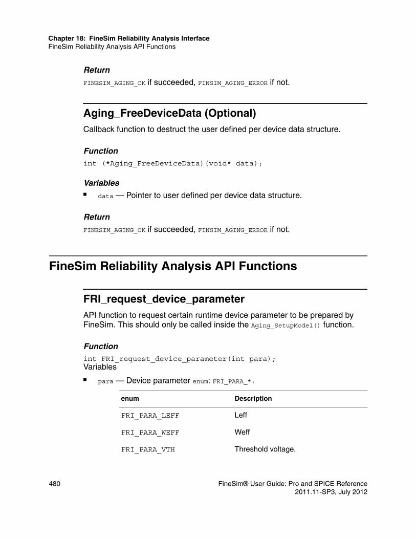
Chapter 18: FineSim Reliability Analysis InterfaceFineSim Reliability Analysis API Functions
Return
FINESIM_AGING_OK if succeeded, FINSIM_AGING_ERROR if not.
Aging_FreeDeviceData (Optional)Callback function to destruct the user defined per device data structure.
Functionint (*Aging_FreeDeviceData)(void* data);
Variables■ data — Pointer to user defined per device data structure.
Return
FINESIM_AGING_OK if succeeded, FINSIM_AGING_ERROR if not.
FineSim Reliability Analysis API Functions
FRI_request_device_parameterAPI function to request certain runtime device parameter to be prepared by FineSim. This should only be called inside the Aging_SetupModel() function.
Functionint FRI_request_device_parameter(int para);Variables■ para — Device parameter enum: FRI_PARA_*:
enum Description
FRI_PARA_LEFF Leff
FRI_PARA_WEFF Weff
FRI_PARA_VTH Threshold voltage.
480 FineSim® User Guide: Pro and SPICE Reference2011.11-SP3, July 2012

Chapter 18: FineSim Reliability Analysis InterfaceFineSim Reliability Analysis API Functions
Return
FINESIM_AGING_OK if succeeded, FINSIM_AGING_ERROR if not.
FRI_get_device_parameterAPI function to get parameter of the current device at model setup stage. This can only be called inside Aging_Setup* functions.
Functionint FRI_get_device_parameter(char* name, double* value);
Variables■ name — Name of the parameter.■ value — Value of the parameter, filled by engine.
Return
FINESIM_AGING_OK if succeeded, FINSIM_AGING_ERROR if not.
FRI_update_device_parameterAPI function to update device model parameters based on the stress vector result caculated from the pre-stress transient simulation. This can only be called inside the Aging_UpdateDeviceModelParameter function
Functionint FRI_update_device_parameter(char* name, double value);
FRI_PARA_VDSAT Saturation voltage.
FRI_PARA_IDS Ids
FRI_PARA_IB Isub
enum Description
FineSim® User Guide: Pro and SPICE Reference 4812011.11-SP3, July 2012

Chapter 18: FineSim Reliability Analysis InterfaceFineSim Reliability Analysis API Functions
Variables■ name — Name of the parameter.■ value — Value of the parameter, provided by user.
Return
FINESIM_AGING_OK if succeeded, FINSIM_AGING_ERROR if not.
482 FineSim® User Guide: Pro and SPICE Reference2011.11-SP3, July 2012

A
AFineSim Pro Utilities
This appendix describes various FineSim Pro utilities.
Using Fencrypt
This section describes the Fencrypt utility. FineSim Pro fencrypt supports two kinds of encryption. One is whole file encryption, and the other is a partial encryption of the netlist file.
Syntaxfencrypt <file|net> <input_file> <output>file: encrypt whole file by given namenet: encrypt protected block in spice netlist file and regenerate netlist file
Examplefencrypt file in.any new_in.enc
FineSim® User Guide: Pro and SPICE Reference 4832011.11-SP3, July 2012

Appendix A: FineSim Pro UtilitiesUsing Fscript
As shown in the following illustration, fencrypt reads all input data in the in.any file, encrypts the data, and generates the new_in.enc file.
As shown in the following illustration, fencrypt reads the input Spice netlist file “in.sp”, and encrypts the protected block if one exists. Then FineSim Pro regenerates the netlist file “new_in.sp” and the encrypted files “new_in_1.enc” and “new_in_2.enc” respectively.
Using Fscript
This section describes the fscript utility, which supports the conversion or export of signals from a data file.
484 FineSim® User Guide: Pro and SPICE Reference2011.11-SP3, July 2012

Appendix A: FineSim Pro UtilitiesUsing Fscript
You can use the fscript command as shown in the following example:
fscript
When you give a command list file as an argument of fscript, the utility runs with commands in batch mode.
fscript <command_list_file>
fscript CommandsThis section lists and describes the commands you can use with this utility.
calcCalculates numerical math for the signal.
Syntax
calc <type> <signal_name>
closeCloses the opened output file. It can be closed automatically when the application is terminated. So this command can be used in order to open another output file.
Syntaxclose
Table 103 Calc Variables
Parameter Description
AVG Average of the signal
YMIN Min value of the signal
YMAX Max value of the signal
YMINMAX Min/max value of the signal
FineSim® User Guide: Pro and SPICE Reference 4852011.11-SP3, July 2012

Appendix A: FineSim Pro UtilitiesUsing Fscript
cmdlistShows and/or saves the command history. When a file name is specified, this command saves all histories to the specified file.
Syntax cmdlist [cmd_filename]
dinitInitializes the dump signal table.
Syntaxdinit
dirReports a list of the directory contents.
Syntaxdir [args]
dlistShows all registered signals in dump table.
Syntaxdlist
dsignalAdds a signal to the dump signal table. This command supports wildcard descriptions in signal names. For more details see the fscript Commands section.
Syntaxdsignal <signal_name>
486 FineSim® User Guide: Pro and SPICE Reference2011.11-SP3, July 2012

Appendix A: FineSim Pro UtilitiesUsing Fscript
dumpDumps all signals in the given format. If you need to dump in IC format, you can add ic as a following argument. By default, Fscript will dump the signal in table format. Before you run this command, the output file must be opened by using the open command. You can also use this command to dump the desired signals into a new fsdb file using the dump fsdb command.
Syntaxdump [table|ic|fsdb]
Examplefset start 5nfset end 10nfset step 0.5ndsignal v(clk)open output.dumpdumpclose
TIME v(clk)5.000n 0.0005.500n 2.5006.000n 2.5006.500n 416.667m7.000n 0.0007.500n 0.0008.000n 2.5008.500n 2.5009.000n 416.667m9.500n 0.00010.000n 0.000
exit/quitTerminates the application.
Syntaxexitquit
FineSim® User Guide: Pro and SPICE Reference 4872011.11-SP3, July 2012

Appendix A: FineSim Pro UtilitiesUsing Fscript
fsdb2psfConverts an esdb file to a psf file. Supports additional arguments to translate signals selectively.
Examplefsdb2psf <input_fsdb_file> <output_psf_dir> [signal_file] [asc|bin]
where signal_file is an ASCII file that contains a list of desired signals, one per line. Wildcards are not supported.
fsdb2vcdConverts an fsdb file to a vcd file. All signals in the fsdb file will be converted in digital with vith and vhth variable.
Syntaxfsdb2vcd <input_fsdb_file> <output_vcd_file>
Support for Signal File
The fsdb2vcd function supports specifying a signal file to limit the number of signals to convert from fsdb to vcd.
Syntaxfsdb2vcd <infile> <outfile> [signal_file]
Signal File Format (One Signal per Line)v(x1.x2.node)
fsetSets the value of internal variables. These internal variables affect all other functions.
488 FineSim® User Guide: Pro and SPICE Reference2011.11-SP3, July 2012

Appendix A: FineSim Pro UtilitiesUsing Fscript
Syntaxfset <variable_name> <value>
Table 104 Internal Variables
Name Description Default Value
TUNIT Time unit 1n
SLOPE Slope time 1.0
RISE Rise time 0.5
FALL Fall time 0.5
VOL Output low voltage 0.5
VOH Output high voltage 2.0
VIL Input low voltage 0.5
VIH Input high voltage 2.0
VLTH Low threshold voltage 0.5
VHTH High threshold voltage 2.0
VDD Global supplied voltage 2.5
START Start time 0.0
END End time 0.0
STEP Time step 0.0
NDIGIT Significant number 6
SCALE Time scale factor 1.0
TOLERANCE Tolerance for output 10u
SCOPE Current hierarchy scope “”
NOTATION Value notation
(suffix/scientific/ exponent)
Suffix
FineSim® User Guide: Pro and SPICE Reference 4892011.11-SP3, July 2012

Appendix A: FineSim Pro UtilitiesUsing Fscript
fset VCD2VECThe following options are specific to converting VCD to vector files.
ascope
This option changes the output hierarchy of the vector file. It can be combined with fset scope (digital vcd hierarchy) to perform the mapping of hierarchy from digital to analog. If the converted vector file is at the top level of the spice netlist, you can leave the scope name as blank.
Syntaxfset vcd2vec ascope <analog_scope_name>
Examplesfset vcd2vec ascope ATOP
All the vector file output will be ATOP.signal_name.
fset vcd2vec ascope
All the vector file output will be signal_name.
bus_separator
In the VCD file, [] is standard bus notation. Use this option to change bus notation for the output vector file.
Syntaxfset vcd2vec bus_separator prefix <postfix>
Examplefset vcd2vec bus_separator _
VCD2VEC Settings specific to VCD2VEC.
ascope
bus_separatorcheck_window
Table 104 Internal Variables (Continued)
Name Description Default Value
490 FineSim® User Guide: Pro and SPICE Reference2011.11-SP3, July 2012

Appendix A: FineSim Pro UtilitiesUsing Fscript
this will map a[0] to a_0.
fset vcd2vec bus_separator \< \>
this will map a[0] to a\<0\>.
check_window
Using this command will allow the user to insert the check_window command into the vector file. Please note that it is the user’s responsibility to make sure the check_window command is valid for vector file. Fscript will not be performing a syntax check for check_window.
Syntaxfset vcd2vec check_window ....
Examplefset vcd2vec check_window 1e-12 10e-12 1
this will put the line "check_window 1e-12 10e-12 1" into the vector file.
listPrints out internal data of the recently-opened database. The default value is to show all hierarchy names only.
Syntax list [signal|scope|all]
Examplelist signal ========================================================SIGNALS========================================================v(clk)v(clkb)v(cntout<0>)v(cntout<1>)v(cntout<2>)v(cntout<3>)v(cntout<4>)v(dll_fail)v(down)
FineSim® User Guide: Pro and SPICE Reference 4912011.11-SP3, July 2012

Appendix A: FineSim Pro UtilitiesUsing Fscript
v(lock)v(reset)v(up)v(vdd)v(vss)v(x3<0>.x2<0>.x1<0>.cntout<0>)v(x3<0>.x2<0>.x1<0>.cntout<1>)v(x3<0>.x2<0>.x1<0>.cntout<2>)v(x3<0>.x2<0>.x1<0>.cntout<3>)v(x3<0>.x2<0>.x1<0>.cntout<4>)========================================================TOTAL SIGNAL : 19
loadLoads the simulation output file. It supports tr0/fsdb/vcd/extend vcd format. For vcd format, you can give a signal_info_file to generate the iovector file automatically.
Syntaxload <spice|fsdb|vcd> <filename> [signal_info_file]
meas/measureRuns the post simulation measurements. It can be run as standalone syntax or in conjunction with the load command. The fscript meas command also supports running .measure across multiple FSDB files that are split during FineSim simulation. You only need to perform .measure on the first FSDB file and fscript will automatically look for additional split files.
Currently the following simulation options are supported:■ param■ finesim_measout■ measdgt■ Algebraic functions
Syntaxmeas[sure]<measfile> [-i <dbfile>] [-o <outfile>] [-l <logfile>]
492 FineSim® User Guide: Pro and SPICE Reference2011.11-SP3, July 2012

Appendix A: FineSim Pro UtilitiesUsing Fscript
openSpecifies the output file name. Usually, it will be used in dump/vec/pwl commands and so on. If there is already an opened file, FineSim Pro closes the previous file automatically.
Syntax
open <filename>
phnmeasThis command extracts phase noise from the resulting waveforms of Transient Noise Analysis. The underlying algorithm uses the Delay Line Method (DLM). An output file must be open before phnmeas can be run, and you should name the extension as .pn0 so it can be read into FineWave automatically. If you want to use Custom Waveview, please see the command pn2tbl.
Syntaxphnmeas <SIGNAME> <FUND_FREQ> <TSTART> <TSTOP> <Fsample> <FminRatio> <NumClockCycle>
Table 105 phnmeas Variables
Parameter Description
signame Signal name in the waveform file that is being analyzed.
fund freq Fundamental oscillation frequency reference.
tstart, tstop Stable oscillation period used.
fsample Sampling frequency for data in fscript. Default is 128*fund
fminratio To determine minimum frequency to be considered for DLM (fmin=fminratio/ (tstop-tstart)). Default is 10.
numclockcycle Number of clock cycles for DLM. Default is 10.
FineSim® User Guide: Pro and SPICE Reference 4932011.11-SP3, July 2012

Appendix A: FineSim Pro UtilitiesUsing Fscript
pn2tblThis command converts the .pn0 file into .tbl format to load into custom Waveview
Syntaxpn2tbl <input_filename> <output_filename>
pwlConverts a signal to pwl. The result is written to the output file. So the output file must be opened using the open command. This command supports wildcard descriptions in signal names. For more details see the fscript Commands section.
Syntax
pwl <signal_name> [<nodename> <type>]
Examplefset start 5n fset end 10n fset step 0.1n open output.pwl pwl v(clk) close
vclk clk 0 pwl( + 5.0000e-09 0.0000e+00 5.1000e-09 8.3333e-01 5.3000e-09 2.5000e+00 + 6.2000e-09 2.5000e+00 6.3000e-09 2.0833e+00 6.4000e-09 1.2500e+00 + 6.5000e-09 4.1667e-01 6.6000e-09 0.0000e+00 7.5000e-09 0.0000e+00 + 7.6000e-09 8.3333e-01 7.8000e-09 2.5000e+00 8.7000e-09 2.5000e+00 + 8.8000e-09 2.0833e+00 8.9000e-09 1.2500e+00 9.0000e-09 4.1667e-01
Table 106 pwl Variables
Parameter Description
type Describes signal type <v(voltage)/i(current)>
494 FineSim® User Guide: Pro and SPICE Reference2011.11-SP3, July 2012

Appendix A: FineSim Pro UtilitiesUsing Fscript
+ 9.1000e-09 0.0000e+00 1.0000e-08 0.0000e+00 )
If a pwl signal is a digital signal, fscript automatically converts it to an analog signal with some global variables such as VDD/TRISE/TFALL/VIL/VIH, as shown in the following illustration.
Figure 36 Analog to Digital Conversion
runRuns commands in batch mode.
Syntaxrun <filename>
signalProvides a convenient method for obtaining a signal list from an output file.
Syntaxsignal <name_pattern> [depth(default=0)]
If you want to get all voltage nodes in toplevel, enter signal v(*).
Consider an enhanced "fsdb2psf" command such as the following:
fsdb2psf <input_fsdbfile> <output_psfdir> [signal_file] [asc|bin]
Example
Make a batch file such as...
FineSim® User Guide: Pro and SPICE Reference 4952011.11-SP3, July 2012

Appendix A: FineSim Pro UtilitiesUsing Fscript
load fsdb <output_fsdbfile> open <signal_list_file> signal v(*) close fsdb2psf <output_fsdbfile> <output_psfdir> <signal_list_file> asc
After simulation, run fscript with the batch file. This will result in an ASCII psf file containing all nodes in toplevel.
sp2fsdb Converts HSpice tr0 file to fsdb file. If the tr0 file is swept, then the created fsdb file is named by given_ prefix#sweepnum.fsdb automatically.
Syntaxsp2fsdb <input_spice_file> <output_fsdb_file>
valiasMaps the node name to a different name to match the design for the vector signal. Please note that this option is order dependent. If you alias a signal from A to B, you can perform another alias change from B to C.
Syntaxvalias <original_name> <aliased_name>
vinit Initializes the vector signal.
Syntaxvinit
vlist Shows all registered signals in vector table.
Syntaxvlist
496 FineSim® User Guide: Pro and SPICE Reference2011.11-SP3, July 2012

Appendix A: FineSim Pro UtilitiesUsing Fscript
vrun Dumps all signals in vector format file. So the output file must be opened by using the open command.
Syntaxvrun
Examplefset start 5nfset end 10nfset step 0.1nvsignal v(clk) in binopen output.vecvrunclose
; vector pattern definitionsradix+ 1
io + i
vname+ v(clk) ; waveform parameter settingtunit 1.0nslope 1.0vol 500.0mvoh 2.0 vil 500.0mvih 2.0
; tabular data0011203140
FineSim® User Guide: Pro and SPICE Reference 4972011.11-SP3, July 2012

Appendix A: FineSim Pro UtilitiesUsing Fscript
vsignal Adds a signal to the vector signal table. This command supports wildcard descriptions in signal names. For more details see the fscript Commands section.
Syntaxvsignal <signal_name> <type> <radix>
ExamplesThis section includes examples to demonstrate how you can use this utility.
Example 1 — convert fsdb to PWLConsider the following example when you want to get a PWL signal “v(clk)”:
fscript> load fsdb sample.fsdbfscript> fset start 5nfscript> fset end 10nfscript> fset step 0.5nfscript> open output.pwlfscript> pwl v(clk)fscript> close
If you do not specify start/end/step variables, all time step points are output. In this case, the output file “output.pwl” is as follows:
vclk clk 0 pwl(+ 5.0000e-09 0.0000e+00 5.1000e-09 8.3333e-01 5.3000e-09 2.5000e+00+ 6.2000e-09 2.5000e+00 6.3000e-09 2.0833e+00 6.4000e-09 1.2500e+00+ 6.5000e-09 4.1667e-01 6.6000e-09 0.0000e+00 7.5000e-09 0.0000e+00+ 7.6000e-09 8.3333e-01 7.8000e-09 2.5000e+00 8.7000e-09 2.5000e+00
Table 107 vsignal Variables
Parameter Description
type Describes signal type. (in/out/both)
radix Describes signal radix (bin/oct/hex)
498 FineSim® User Guide: Pro and SPICE Reference2011.11-SP3, July 2012

Appendix A: FineSim Pro UtilitiesUsing Fscript
+ 8.8000e-09 2.0833e+00 8.9000e-09 1.2500e+00 9.0000e-09 4.1667e-01+ 9.1000e-09 0.0000e+00 1.0000e-08 0.0000e+00 )
Example 2 — Convert vcd to vectorConsider the following example when you want vector out:
fscript> load vcd sample.vcdfscript> fset start 0fscript> fset end 100nfscript> fset step 0fscript> open output.vecfscript> vinitfscript> vsignal cont in binfscript> vrunfscript> close
If you do not specify start/end/step variables, all time step points are output. In this case, the output file "output.vec" is as follows:
; vector pattern definitionsradix+ 1nodename+ cont
Io+ i; waveform parameter settingtunit 1.0nslope 1.0vol 500.0mvoh 2.0vil 500.0mvih 2.0; tabular data0.000 110.000 020.000 1 30.000 0 40.000 150.000 060.000 170.000 080.000 190.000 0100.000 1
FineSim® User Guide: Pro and SPICE Reference 4992011.11-SP3, July 2012
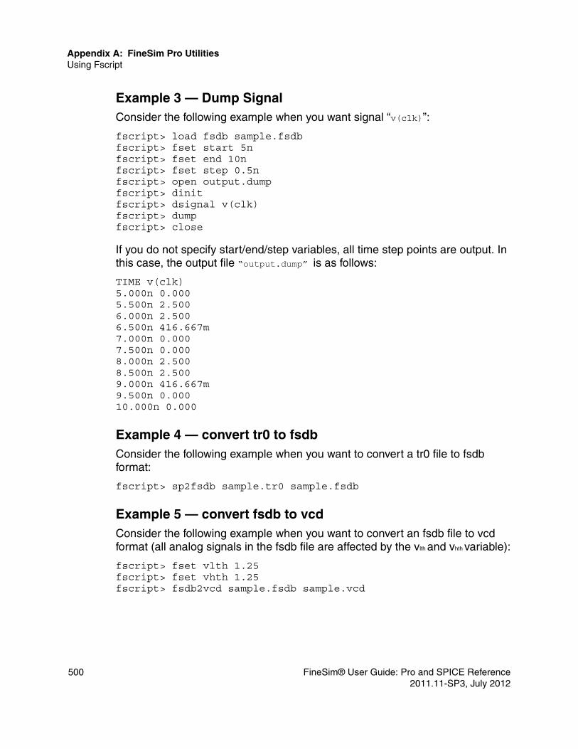
Appendix A: FineSim Pro UtilitiesUsing Fscript
Example 3 — Dump SignalConsider the following example when you want signal “v(clk)”:
fscript> load fsdb sample.fsdbfscript> fset start 5nfscript> fset end 10nfscript> fset step 0.5nfscript> open output.dumpfscript> dinitfscript> dsignal v(clk)fscript> dumpfscript> close
If you do not specify start/end/step variables, all time step points are output. In this case, the output file “output.dump” is as follows:
TIME v(clk) 5.000n 0.000 5.500n 2.500 6.000n 2.500 6.500n 416.667m 7.000n 0.000 7.500n 0.000 8.000n 2.500 8.500n 2.500 9.000n 416.667m 9.500n 0.000 10.000n 0.000
Example 4 — convert tr0 to fsdbConsider the following example when you want to convert a tr0 file to fsdb format:
fscript> sp2fsdb sample.tr0 sample.fsdb
Example 5 — convert fsdb to vcdConsider the following example when you want to convert an fsdb file to vcd format (all analog signals in the fsdb file are affected by the vlth and vhth variable):
fscript> fset vlth 1.25fscript> fset vhth 1.25fscript> fsdb2vcd sample.fsdb sample.vcd
500 FineSim® User Guide: Pro and SPICE Reference2011.11-SP3, July 2012

Appendix A: FineSim Pro UtilitiesUsing Fscript
Example 6 — create IC file from simulation output filesConsider the following example to create IC files from simulation output files, namely .fsdb:
fscript>load fsdb reference.fsdbfscript>open output.icfscript>dsignal *fscript>dump icfscript>exit
The output.ic file gets created uses the .ic statement. It can be modified to .nodeset if necessary.
Example 7 — post-measure with output data fileConsider the following example to load an output file output.fsdb using the original input deck input.sp and perform post measure to generate output.pmt:
fscript> meas input.sp –i output.fsdb –o output.pmt –l fscript.log
or:
fscript> load fsdb output.fsdbfscript> meas input.sp –o output.pmt –l fscript.log
Example 8 — phase noise analysisConsider the following example to perform phase noise analysis on the fsdb output:
fscript> load fsdb input.fsdbfscript> open output.pn0fscript> phnmeas pll_out 1e9 50e-9 80e-9fscript> close output.pn0fscript> exit
The command will load the input.fsdb into fscript and perform phase noise analysis. The result will be stored into output.pn0.
Wildcard Support for Signal NamesFscript supports wildcard descriptions in signal names for pwl/dsignal/vsignal commands. For example, using the following statements, you can convert all signals with names beginning with “n” to pwl:
FineSim® User Guide: Pro and SPICE Reference 5012011.11-SP3, July 2012

Appendix A: FineSim Pro UtilitiesUsing Fscript
pwl v(n1)pwl v(n2)pwl v(n3)
Or you can issue the following statement instead, using a wildcard.
pwl v(n*)
Using valias for Bus Notation MappingSince bus_separator is a globally applied bus notation mapping, you can also use valias to change the vector bus notation for individual signals. Any valias used for bus mapping will be performed at the very end.
Examplefscript> fset vcd2vec bus_separator < >fscript> valias a<*> a_*In the above example, all the bus signals will use <*> as bus notation, except for a, which will use _* as bus notation.
502 FineSim® User Guide: Pro and SPICE Reference2011.11-SP3, July 2012

B
BSpectre Support
This chapter describes support for Spectre format netlists.
Support for Monte Carlo analysis is supported with Spectre. For more details see Chapter 11, Monte Carlo Analysis.
Spectre Interface
To directly use a Spectre netlist as a FineSim Pro input, you must specify the -spectre or -spec2hsp options with the finesim command. The following command reads the Spectre netlist and performs a simulation:
$ finesim –spectre spectre_file
The following command reads the Spectre netlist and generates only a compatible HSpice netlist to the file named spectre_file.sp~:
$ finesim –spec2hsp spectre_file
You can use the previous command to check the supported device parameters and manually change the netlist before performing a simulation.
When using Spectre netlists for simulation, it is recommended that you take care of most control statements because there might be many different features between Spectre and HSpice. Therefore when converted to HSpice, compatible parameters are automatically translated to corresponding HSpice parameters and non-compatible parameters are passed in as is, and eventually skipped.
Consider the following tips for direct simulation of a Spectre netlist:■ Comment out any simple control statements from the Spectre netlist, such
as spectre_file.scs.
FineSim® User Guide: Pro and SPICE Reference 5032011.11-SP3, July 2012

Appendix B: Spectre SupportSpectre Interface
■ Add some HSpice control cards at the end of the spectre netlist (spectre_file.scs); HSpice control cards begin with simulator lang=spice.
The -spectre command line argument preserves instance names in the Spectre format, unchanged. ■ -spectre—Used for Spectre format.■ -spectrex—Used for SPICE format. Instance names are changed for SPICE
instance convention.
Consider the following example:
% finesim –np 2 –spectre input.scs
This preserves Spectre names so that they remain unchanged.
SPICE Compatibility with -spectreFineSim Pro supports Spectre netlists mixed with SPICE netlists and control statements. The SPICE syntax should be started with simulator lang=spice. FineSim Pro accepts a control statement that starts with . (such as .param, .ic, .include) without the simulator lang=spice statement, but you must comply with Spectre's case sensitivity mode.
If the control command has some case-sensitive names, such as a signal name or device name, it is strongly recommended that it be used without the simulator lang=spice statement. Specially, .ic should be used without simulator lang=spice, otherwise, some signal or device names will be ignored.
When including files under –spectre, all files that do not end in .scs signify SPICE format, while files ending with .scs are Spectre format. It is recommended that simulator lang=spectre | spice be specified in the first line of the netlist file, regardless of the file extension. Please note that .include automatically assumes the whole file is in SPICE format.
FineSim Option Automatically Set by –spectreWhen simulation is evoked with –spectre, certain options are set in FineSim automatically. The purpose of these options is to maintain spectre compatibility in terms of waveform output and display:
.option finesim_remove_probe_prefix=1
.option finesim_prbport=0
.option finesim_set_special_char='< >'
.option parhier=local
504 FineSim® User Guide: Pro and SPICE Reference2011.11-SP3, July 2012

Appendix B: Spectre SupportSpectre Interface
Map Spectre SettingsYou can also use –map_spectre_setting in the command line to translate some of the control statements and option settings into FineSim specific settings. Currently, FineSim will map spectre errpreset, maxstep, and reltol settings into FineSim equivalent options (finesim_mode, finesim_delmax, finesim_qlevel). To achieve the optimal accuracy and performance trade off, we recommend you set FineSim options manually.
Supported FeaturesThis section includes information about supported Spectre features that differ from HSpice.
Title LineIn Spectre netlists, the first line is usually a title line that begins with a comment (* or //).
Comments (*, ;, #, //, blank, /* */)FineSim Pro supports the following kinds of comments: ■ Line comments that begins with an asterisk (*), semicolon (;), or pound (#). ■ Line comments that begins with a double slash (//). These comments can
be added in any position of a line. Anything after a double slash (//) is recognized as a comment.
■ Blank lines are recognized as comments.■ Block comments begin with /* and end with */. Anything between block
comment delimiters are treated as comments.
Continuation Characters (\,+)FineSim Pro supports two kinds of continuation characters: ■ Back slash (\) when used at the end of a line to be continued on the next
line. ■ Plus sign (+) when used at the beginning of the next continuation line.
FineSim® User Guide: Pro and SPICE Reference 5052011.11-SP3, July 2012

Appendix B: Spectre SupportSpectre Interface
Simulation Language ModeFineSim Pro supports both the Spectre and Spice language modes. Each netlist should begin with simulator lang=spectre or simulator lang=spice, respectively.
Mathematical ExpressionsFineSim Pro supports any mathematical expressions that is used where numeric values are expected on the right-hand side of an equals sign (=) or within the vector, where the vector itself is on the right-hand side of an equals sign.
Examplespar=(0.5*rgate*finger_width/L)/fingersr2 1 0 resistor r=p1+p2
Support for Limited Model Sets for Spectre NetlistsFineSim supports limited model sets for Spectre netlists using compatible=hspice. The supported model will be converted to equivalent hspice model parameters, and unsupported models will generate a warning and be simulated as Spectre model parameters.
The below table lists and describes supported Spectre operators.
Table 108 Operators
Operator Symbol(s) Supported
Binary +, - +,- Yes
Bitwise AND & Yes
Bitwise OR | Yes
Bitwise XNOR ~^ (^~) Yes
Equality ==, != Yes
Logical AND && Yes
Logical OR || Yes
Multiply, Divide *, / Yes
506 FineSim® User Guide: Pro and SPICE Reference2011.11-SP3, July 2012

Appendix B: Spectre SupportSpectre Interface
The below table lists and describes supported arithmetic and trigonometric functions.
Power **, ^ Yes
Relational <,<=,>,>= Yes
Shift left, right <<, >> Yes
Ternary (cond) ? x : y Yes
Unary +, -, ! +,-, ! Yes
Table 109 Arithmetic and Trigonometric Functions
Function Description Supported
abs(x) absolute value of x Yes
acos(x) arc-cosine of x Yes
acosh(x) arc-hyperbolic cosine of x No
asin(x) arc-sine of x Yes
asinh(x) arc-hyperbolic sine of x No
atan(x) arc-tangent of x Yes
atan2(x,y) arc-tangent of x/y Yes
atanh(x) arc-hyperbolic tangent of x No
ceil(x) smallest integer >= x Yes
cos(x) cosine of x Yes
cosh(x) hyperbolic cosine of x Yes
exp(x) exponential x<80 Yes
Table 108 Operators (Continued)
Operator Symbol(s) Supported
FineSim® User Guide: Pro and SPICE Reference 5072011.11-SP3, July 2012

Appendix B: Spectre SupportSpectre Interface
The below table lists and describes supported component statements.
floor(x) largest integer <= x Yes
fmod(x,y) floating-point remainder of x/y
Yes
hypot(x,y) sqrt (x*x, y*y) for x,y Yes
int(x) integer part of x Yes
log(x) natural logarithm x>0 Yes
log10(x) decimal logarithm x>0 Yes
max(x,y) maximum value of x, y Yes
min(x,y) minimum value of x, y Yes
pow(x,y) x to the power of y Yes
sin(x) sine of x Yes
sinh(x) hyperbolic sine of x Yes
sqrt(x) square root x>0 Yes
tan(x) tangent of x Yes
tanh(x) hyperbolic tangent of x Yes
Table 110 Component Statements (Device)
Spectre Description FineSim Pro Supported
a2d Analog-to-digital Yes
Table 109 Arithmetic and Trigonometric Functions (Continued)
Function Description Supported
508 FineSim® User Guide: Pro and SPICE Reference2011.11-SP3, July 2012

Appendix B: Spectre SupportSpectre Interface
bjtbjt301bjt503bjt504bjt504thbtvbic
Bipolar junction transistorLateral PNP transistorVertical NPN/PNP transistorVertical NPN/PNP transistorVertical NPN/PNP transistorHetero-junction bipolar tran.VBIC bipolar transistor
Q (1)
Q (6)version=503Q (6)version=504Q (6)version=504
Q (4)
GPNoMextramYesYesNovbic
bsource Behavioral sources (r, g, c, l, i, v, q)
R,G,C,Q, L,E(V),G(I)
Yes
capacitorjuncapintcapnodcap
Two terminal capacitorJunction capacitorInterconnect capacitorNode capacitor
CDCC
YesYesYesYes
Table 110 Component Statements (Device) (Continued)
Spectre Description FineSim Pro Supported
FineSim® User Guide: Pro and SPICE Reference 5092011.11-SP3, July 2012

Appendix B: Spectre SupportSpectre Interface
cccsccvsvccsvcvspcccspccvspvccspvcvsscccssccvssvccssvcvszcccszccvszvccssvcvs
Current controlled current sourceCurrent controlled voltage sourceVoltage controlled current sourcevoltage controlled voltage sourcepolynomial CCCSpolynomial CCVSpolynomial VCCSpolynomial VCVSs-Domain CCCSs-Domain CCVSs-Domain VCCSs-Domain VCVSz-Domain CCCSz-Domain CCVSz-Domain VCCSz-Domain VCVS
FHGEF polyH polyG polyE poly
YesYesYesYes YesYesYesYesNoNoNoNoNoNoNoNo
cktrom Circuit reduced order model
No
d2a Digital-to-analog Yes
diode
dio500
Junction diode (1)Fowler-Nordheim (2)Modified-Berkeley (3)Diode level 500
D(1)D(2)D(3)D(5)
YesYesYesYes
inductormutual-inductor
Two terminal inductor Mutual inductor
LK
YesYes
iprobe Current probe V dc=0 Yes
Table 110 Component Statements (Device) (Continued)
Spectre Description FineSim Pro Supported
510 FineSim® User Guide: Pro and SPICE Reference2011.11-SP3, July 2012

Appendix B: Spectre SupportSpectre Interface
isourcevsourceport
Independent current sourceIndependent voltage sourceIndependent resistive source
IVR,V
YesYesYes
jfetgaastom2tom3
Junction field effect transistorGaAs MESFETGaAs MESFETGaAs MESFET
J jfetNoNoNo
Table 110 Component Statements (Device) (Continued)
Spectre Description FineSim Pro Supported
FineSim® User Guide: Pro and SPICE Reference 5112011.11-SP3, July 2012

Appendix B: Spectre SupportSpectre Interface
mos0mos1mos1000mos1100mos11010mos11011mos15mos2mos3mos30mos3002mos3100mos40mos705mos902mos903bsim1bsim2bsim3bsim3v3bsim4bsimsoibtasoib3soipdhvmosekvhisimmisnanpsitft
psp1020 (1021)
MOS level-0 MOS level-1Compact MOS distortion modelCompact MOS distortion modelCompact MOS distortion modelCompact MOS distortion modelMOS level-15 MOS level-2MOS level-3 Long-channel JFET/MOS modelLong-channel JFET/MOS modelLong-channel JFET/MOS modelSilicon on insulator JFETCompact MOS transistorCompact MOS transistorCompact MOS transistorBSIM1 FETBSIM2 FETBSIM3 MOSBSIM3v3 MOSBSIM4 MOSBSIMSOI-PD/FDBTA SOIB3SOI-PDHV MOSEKV MOSHiSIM1 FETMISN FETPoly-Si TFTPenState Phillips Model
M (3)
M (50)
M (13)M (39)M (47)M (53)M (54)M (57)
M (55)M (64)
M (62)M (69)
NoNoNoNoNoNoNoNomos3NoNoNoNoNomm9Nobsim1bsim2bsim3bsim3v3~bsim4~bsim3soi2NoNoNoekvhisimNoNo
YesYes
node Set node quantity No
nport Linear N port s Yes
Table 110 Component Statements (Device) (Continued)
Spectre Description FineSim Pro Supported
512 FineSim® User Guide: Pro and SPICE Reference2011.11-SP3, July 2012

Appendix B: Spectre SupportSpectre Interface
The table below lists and describes supported analysis statements.
paramtest Parameter value tester
No
quantity Quantity information No
relay Four terminal relay G VCR RELAY Yes
resistorrdiffphy_res
Two terminal resistorDiffusion resistor modelPhysical resistor
R YesYesYes
switch Ideal switch Yes
transformer Linear two winding idealtransformer
E transformer Yes
windingcoretlinemslinemtlinedelay
Winding for magnetic coreMagnetic core with hysteresisTransmission lineMicrostrip lineMulti-conductor transmission lineDelay line
T
WE delay
NoNoYesNoYesYes
Table 111 Analysis Statements
Spectre Description FineSim Pro Supported
acnoisexfsp
AC analysisNoise analysisTransfer function analysisS-parameter analysis
.ac
.noise
.xf
YesYesYesNo
dc DC analysis .dc Yes
Table 110 Component Statements (Device) (Continued)
Spectre Description FineSim Pro Supported
FineSim® User Guide: Pro and SPICE Reference 5132011.11-SP3, July 2012

Appendix B: Spectre SupportSpectre Interface
montecarlo Monte Carlo analysis supported in device
pz Pole zero analysis Yes
RF analysisenvppacpdapnoisepsppsspxfqpacqpnoiseqpspqpssqpxf
Envelope following analysisPeriodic AC analysisPeriodic distortion analysisPeriodic noise analysisPeriodic S-parameter analysisPeriodic steady-state analysisPeriodic transfer function analysisQuasi-periodic AC analysisQuasi-periodic noise analysisQuasi-periodic S-parameter analysisQuasi-periodic steady-state analysisQuasi-periodic transfer function
No
sensfourierdcmatchstb
Sensitivity analysisFourier analysisDC device matching analysisStability analysis
.fourNoYesNoNo
Table 111 Analysis Statements (Continued)
Spectre Description FineSim Pro Supported
514 FineSim® User Guide: Pro and SPICE Reference2011.11-SP3, July 2012

Appendix B: Spectre SupportSpectre Interface
The table below lists and describes supported control statements.
sweep Sweep analysis
General ParameterVoltage Source DC ParameterTemperature ParameterModel parameterDevice parameterSubckt instance parameterNested Sweep
sweep data=xxx
sweep dc=.temp
.temp
Limited
YesYes
Yes
NoNoNo
No
trantbr
Transient analysisTime-domain reflectometer analysis
.tran YesNo
Table 112 Control Statements
Spectre Description FineSim Pro Supported
alter Alter a circuit, component,Netlist parameter
.alter Yes
altergroup Alter group .alter Yes
assert Device checker No
check Check parameter No
checklimit Check limit analysis No
ic Initial condition .ic Yes
nodeset Node sets .nodeset Yes
Table 111 Analysis Statements (Continued)
Spectre Description FineSim Pro Supported
FineSim® User Guide: Pro and SPICE Reference 5152011.11-SP3, July 2012

Appendix B: Spectre SupportDevice Parameter Compatibility
Device Parameter Compatibility
This section describes device parameter compatibility.
info Circuit information No
options Immediate set options
.option Yes
paramset Parameter set – block of data
.data Yes
save Output selections .probe Yes
set Deferred set options No
shell Shell command No
statistics Statistics Specification (process, mismatch)
gauss, agauss, unif, aunif
Yes
simulator Language switching (spectre, spice)
lang. mode information
Yes
if-then-else Conditional .if .elseif.else .endif
Yes
include File include .inc .lib Yes
parameters Netlist parameter .param Yes
subckt .subckt Yes
Inline subckt Inline sub-circuits .macro Yes
Table 112 Control Statements (Continued)
Spectre Description FineSim Pro Supported
516 FineSim® User Guide: Pro and SPICE Reference2011.11-SP3, July 2012
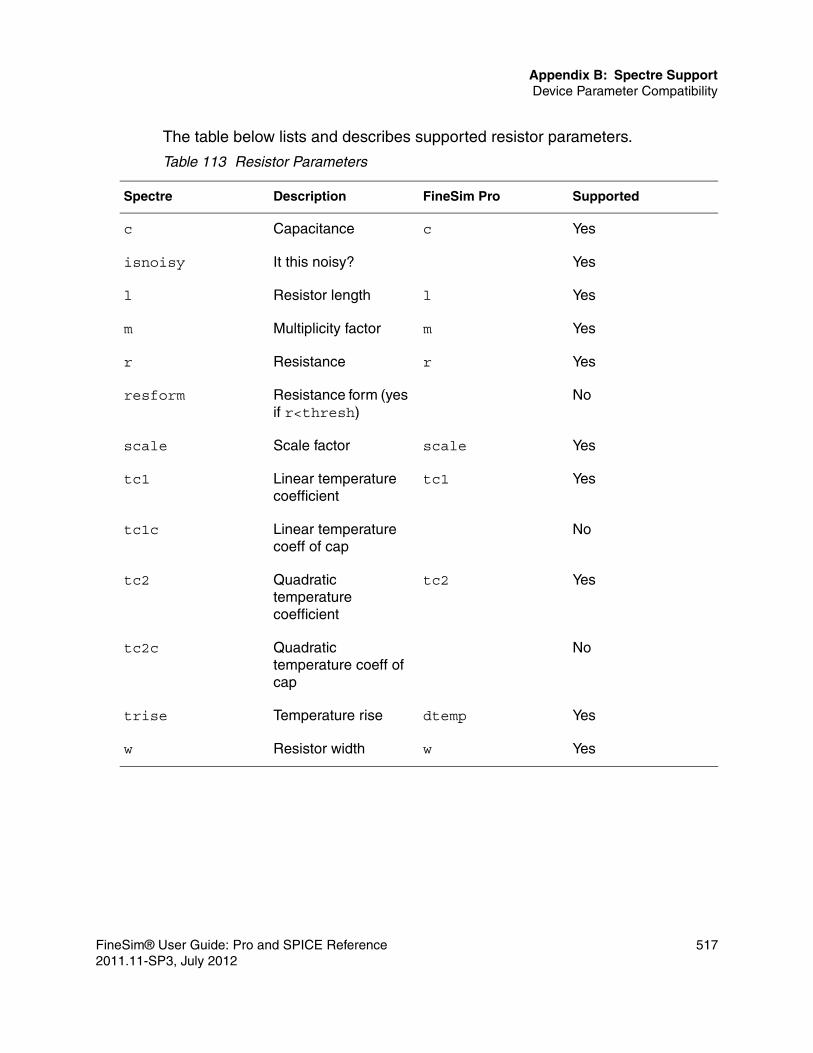
Appendix B: Spectre SupportDevice Parameter Compatibility
The table below lists and describes supported resistor parameters.
Table 113 Resistor Parameters
Spectre Description FineSim Pro Supported
c Capacitance c Yes
isnoisy It this noisy? Yes
l Resistor length l Yes
m Multiplicity factor m Yes
r Resistance r Yes
resform Resistance form (yes if r<thresh)
No
scale Scale factor scale Yes
tc1 Linear temperature coefficient
tc1 Yes
tc1c Linear temperature coeff of cap
No
tc2 Quadratic temperature coefficient
tc2 Yes
tc2c Quadratic temperature coeff of cap
No
trise Temperature rise dtemp Yes
w Resistor width w Yes
FineSim® User Guide: Pro and SPICE Reference 5172011.11-SP3, July 2012

Appendix B: Spectre SupportDevice Parameter Compatibility
The table below lists and describes supported capacitor parameters.
The table below lists and describes supported inductor parameters.
Table 114 Capacitor Parameters
Spectre Description FineSim Pro Supported
area Capacitor area Yes
c capacitance c Yes
ic Initial condition ic Yes
l Capacitor length l Yes
m Multiplicity factor m Yes
perim Capacitor perimeter Yes
scale Scale factor scale Yes
tc1 Linear temperature coefficient
tc1 Yes
tc2 Quadratic temperature coefficient
tc2 Yes
trise Temperature rise dtemp Yes
w Capacitor width w Yes
Table 115 Inductor Parameters
Spectre Description FineSim Pro Supported
ic Initial condition ic Yes
isnoisy It this noisy? Yes
l Inductance l Yes
m Multiplicity factor m Yes
518 FineSim® User Guide: Pro and SPICE Reference2011.11-SP3, July 2012

Appendix B: Spectre SupportDevice Parameter Compatibility
The table below lists and describes supported mutual inductor parameters.
The table below lists and describes supported independent source parameters.
r Resistance r Yes
trise Temperature rise dtemp Yes
Table 116 Mutual Inductor Parameters
Spectre Description FineSim Pro Supported
coupling Coupling coefficient k Yes
ind1 Inductor to be coupled
<ind1> Yes
ind2 Inductor to be coupled
<ind2> Yes
Table 117 Independent Source Parameters
Spectre Description FineSim Pro Supported
dc DC value dc Yes
delay Waveform delay time td Yes
EXP params EXP parameters exp Yes
fundname Fundamental frequency name
No
magphase
Small signal voltage and value
ac=mag,phase
Yes
noisefile Excess spot noise file No
noisevec Excess spot noise data
No
Table 115 Inductor Parameters (Continued)
Spectre Description FineSim Pro Supported
FineSim® User Guide: Pro and SPICE Reference 5192011.11-SP3, July 2012

Appendix B: Spectre SupportDevice Parameter Compatibility
The table below lists and describes supported diode parameters.
PULSE params PULSE parameters pulse Yes
PWL params PWL parameters pwl Yes
SIN params SIN parameters sin Yes
type Waveform type pulse, pwl, sin, exp
Yes
xfmagpacphase
No
Table 118 Diode Parameters
Spectre Description FineSim Pro Supported
area Junction area area Yes
l Drawn length of junction
l Yes
lm Length of metal capacitor
lm Yes
lp Length of poly capacitance
lp Yes
m Multiplicity factor m Yes
perim Junction perimeter Pj, perim Yes
region Estimated operating region
No
scale Scale factor scale Yes
trise Temperature rise dtemp Yes
Table 117 Independent Source Parameters (Continued)
Spectre Description FineSim Pro Supported
520 FineSim® User Guide: Pro and SPICE Reference2011.11-SP3, July 2012

Appendix B: Spectre SupportDevice Parameter Compatibility
The table below lists and describes supported BJT parameters.
The table below lists and describes supported JFET parameters.
w Drawn width of junction
w Yes
Table 119 BJT Parameters
Spectre Description FineSim Pro Supported
area Transistor area area Yes
areab Transistor areab areab Yes
areac Transistor areac areac Yes
m Multiplicity factor m Yes
rbmod
region Estimated operating region
No
trise Temperature rise dtemp Yes
Table 120 JFET Parameters
Spectre Description FineSim Pro Supported
area Transistor area area Yes
m Multiplicity factor m Yes
region Estimated operating region
No
Table 118 Diode Parameters (Continued)
Spectre Description FineSim Pro Supported
FineSim® User Guide: Pro and SPICE Reference 5212011.11-SP3, July 2012
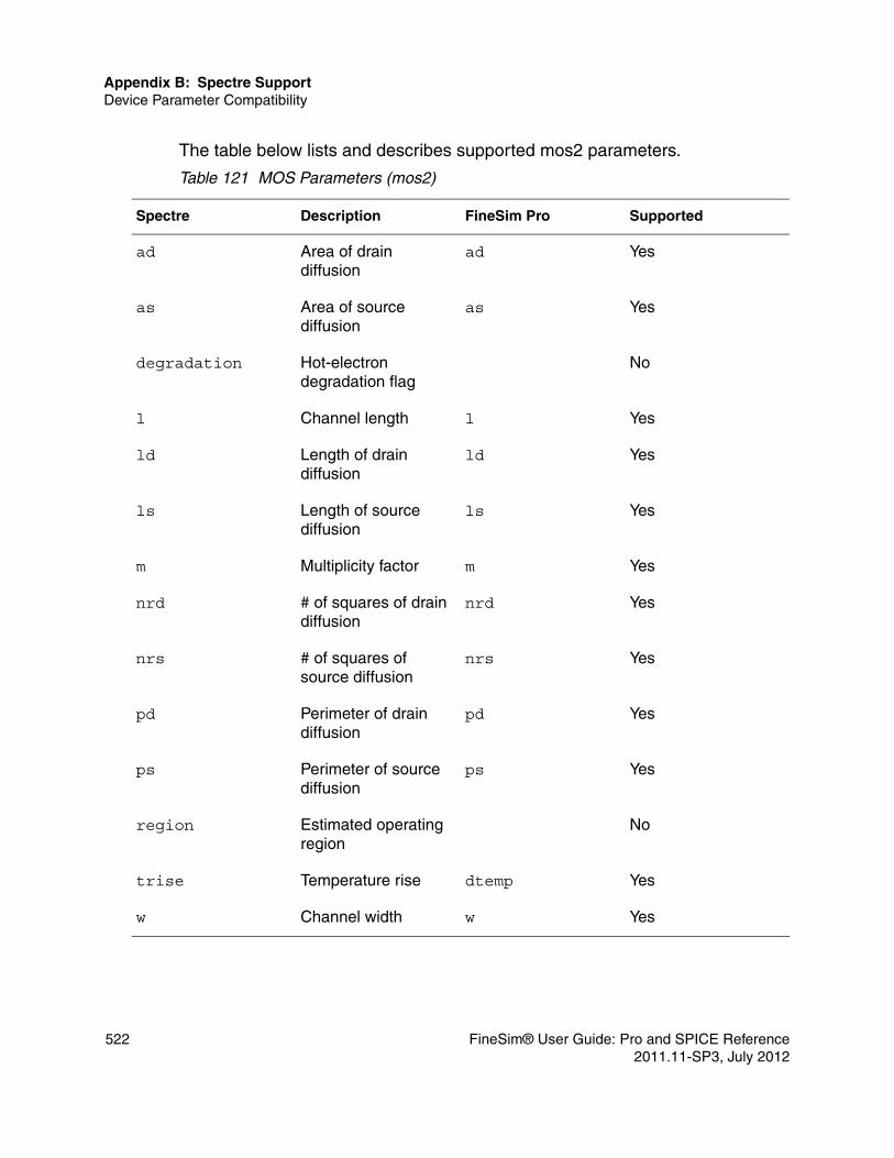
Appendix B: Spectre SupportDevice Parameter Compatibility
The table below lists and describes supported mos2 parameters.
Table 121 MOS Parameters (mos2)
Spectre Description FineSim Pro Supported
ad Area of drain diffusion
ad Yes
as Area of source diffusion
as Yes
degradation Hot-electron degradation flag
No
l Channel length l Yes
ld Length of drain diffusion
ld Yes
ls Length of source diffusion
ls Yes
m Multiplicity factor m Yes
nrd # of squares of drain diffusion
nrd Yes
nrs # of squares of source diffusion
nrs Yes
pd Perimeter of drain diffusion
pd Yes
ps Perimeter of source diffusion
ps Yes
region Estimated operating region
No
trise Temperature rise dtemp Yes
w Channel width w Yes
522 FineSim® User Guide: Pro and SPICE Reference2011.11-SP3, July 2012

Appendix B: Spectre SupportDevice Parameter Compatibility
The table below lists and describes supported bsim3v3 MOS parameters.
Table 122 MOS Parameters (bsim3v3)
Spectre Description FineSim Pro Supported
ad Area of drain diffusion
ad Yes
aforward Forward gate leakage current coeff
No
areverse Reverse gate leakage current coeff
No
as Area of source diffusion
as Yes
delk1 Shift in body-bias threshold
No
delnfct Shift in sub-threshold swing factor
No
delvto Shift in zero-bias threshold
delvto Yes
geo Geometry selector geo Yes
l Channel length l Yes
ld Length of drain diffusion
ld Yes
ls Length of source diffusion
ls Yes
m Multiplicity factor m Yes
mulmu0 Mobility multiplier No
nqsmod NQS flag No
nrd # of squares of drain diffusion
nrd Yes
FineSim® User Guide: Pro and SPICE Reference 5232011.11-SP3, July 2012

Appendix B: Spectre SupportDevice Parameter Compatibility
The table below lists and describes supported bsim4 MOS parameters.
nrs # of squares of source diffusion
nrs Yes
pd Perimeter of drain diffusion
pd Yes
ps Perimeter of source diffusion
ps Yes
rdc Drain contact resistance
rdc Yes
region Estimated operating region
No
rsc Source contact resistance
rsc Yes
sa Distance between OD edge to polyof one side
No
sb Distance between OD edge to polyof the other side
No
trise Temperature rise dtemp Yes
w Channel width w Yes
Table 123 MOS Parameters (bsim4)
Spectre Description FineSim Pro Supported
acnqsmod AC NQS flag acnqsmod Yes
ad Area of drain diffusion
ad Yes
Table 122 MOS Parameters (bsim3v3) (Continued)
Spectre Description FineSim Pro Supported
524 FineSim® User Guide: Pro and SPICE Reference2011.11-SP3, July 2012

Appendix B: Spectre SupportDevice Parameter Compatibility
as Area of source diffusion
as Yes
delk1 Shift in body-bias threshold
No
delnfct Shift in sub-threshold swing factor
No
delvto Shift in zero-bias threshold
delvto Yes
geo Geometry selector geo Yes
geomode Geo flag geomode Yes
l Channel length l Yes
ld Length of drain diffusion
ld Yes
ls Length of source diffusion
ls Yes
m Multiplicity factor m Yes
min Minimum # of device fingers
min Yes
mulmu0 Mobility multiplier No
nf Number of device fingers
nf Yes
nrd # of squares of drain diffusion
nrd Yes
nrs # of squares of source diffusion
nrs Yes
Table 123 MOS Parameters (bsim4) (Continued)
Spectre Description FineSim Pro Supported
FineSim® User Guide: Pro and SPICE Reference 5252011.11-SP3, July 2012

Appendix B: Spectre SupportDevice Parameter Compatibility
pd Perimeter of drain diffusion
pd Yes
ps Perimeter of source diffusion
ps Yes
rbdb Resistance between dbnode, bnode
rbdb Yes
rbodymod Rbody flag rbodymod Yes
rbpb Resistance between bnode, bnode
rbpb Yes
rbpd Resistance between bnode, dbnode
rbpd Yes
rbps Resistance between bnode, sbnode
rbps Yes
rbsb Resistance between sbnode, bnode
rbsb Yes
rdc Drain contact resistance
rdc Yes
region Estimated operating region
No
rgatemode Rgate flag rgatemode Yes
rgeomode Diffusion resistance and contact model flag
rgeomode Yes
rsc Source contact resistance
rsc Yes
sa Distance between OD edge to polyof one side
sa Yes
Table 123 MOS Parameters (bsim4) (Continued)
Spectre Description FineSim Pro Supported
526 FineSim® User Guide: Pro and SPICE Reference2011.11-SP3, July 2012

Appendix B: Spectre SupportDevice Parameter Compatibility
The table below lists and describes supported voltage-controlled source parameters.
sb Distance between OD edge to polyof the other side
sb Yes
sc Distance between neighbor fingers
sc Yes
trise Temperature rise dtemp Yes
trnqsmod Transient NQS flag trnqsmod Yes
w Channel width w Yes
Table 124 Voltage Controlled Source Parameters (VCVS,VCCS)
Spectre Description FineSim Pro Supported
abs Absolute output voltage flag
abs Yes
delta Smoothing parameter
delta Yes
file File for PWL data pwl Yes
gain Voltage gain gain value Yes
m Multiplicity factor m Yes
max Maximum output voltage
max Yes
min Minimum output voltage
min Yes
pwl Vector of voltage/voltage pairs
pwl Yes
Table 123 MOS Parameters (bsim4) (Continued)
Spectre Description FineSim Pro Supported
FineSim® User Guide: Pro and SPICE Reference 5272011.11-SP3, July 2012

Appendix B: Spectre SupportDevice Parameter Compatibility
The table below lists and describes supported current-controlled source parameters.
scale Scale for PWL output voltage
scale Yes
stretch Scale for PWL controlling voltage
stretch No
tc1 Linear temperature coefficient
tc1 Yes
tc2 Quadratic temperature coefficient
tc2 Yes
type Source type(vcvs/vccs, and, nand, or, nor)
vcvs,vccs, and,nand, or,nor
Yes
Table 125 Current Controlled Source Parameters (CCVS,CCCS)
Spectre Description FineSim Pro Supported
abs Absolute output voltage flag
abs Yes
delta Smoothing parameter
delta Yes
file File for PWL data pwl Yes
gain Voltage gain gain value Yes
m Multiplicity factor m Yes
max Maximum output voltage
max Yes
min Minimum output voltage
min Yes
Table 124 Voltage Controlled Source Parameters (VCVS,VCCS) (Continued)
Spectre Description FineSim Pro Supported
528 FineSim® User Guide: Pro and SPICE Reference2011.11-SP3, July 2012

Appendix B: Spectre SupportDevice Parameter Compatibility
The table below lists and describes supported transition line parameters.
port Index for probe port No
ports Indices for probes No
probe Device through which controllingCurrent flows
source name Yes
probes Probe for multi-input digital gates
multi-input gates
Yes
pwl Vector of voltage/voltage pairs
pwl Yes
scale Scale for PWL output voltage
scale Yes
stretch Scale for PWL controlling voltage
No
tc1 Linear temperature coefficient
tc1 Yes
tc2 Quadratic temperature coefficient
tc2 Yes
type Source type (ccvs/cccs, and, nand, or, nor)
ccvs, cccs, and, nand, or, nor
Yes
Table 126 Transmission Line Parameters (tline)
Spectre Description FineSim Pro Supported
alphac Conductor loss at fc No
alphad Dielectric loss No
Table 125 Current Controlled Source Parameters (CCVS,CCCS) (Continued)
Spectre Description FineSim Pro Supported
FineSim® User Guide: Pro and SPICE Reference 5292011.11-SP3, July 2012

Appendix B: Spectre SupportDevice Parameter Compatibility
corner Corner frequency for skin effect
No
dcr DC series resistance per unit length
No
f Reference frequency f Yes
fc Conductor loss measurement freq.
No
fd Dielectric measurement freq.
No
g Dielectric (shunt) conductance
No
len Physical length l Yes
m Multiplicity factor m No
nl Normalized electrical length
nl Yes
qc Conductor loss quality factor at fc
No
qd Conductor loss quality factor at fd
No
r Conductor resistance No
td Transmission delay td Yes
vel Propagation velocity No
z0 Characteristic impedance
z0 Yes
Table 126 Transmission Line Parameters (tline) (Continued)
Spectre Description FineSim Pro Supported
530 FineSim® User Guide: Pro and SPICE Reference2011.11-SP3, July 2012

Appendix B: Spectre SupportDevice Parameter Compatibility
The table below lists and describes supported multi-conductor transmission line parameters.
Table 127 Multi-Conductor Transmission Line Parameters (mtline)
Spectre Description FineSim Pro Supported
c Capacitance matrix No
file RLGC file RLGC file Yes
fmax Maximum signal frequency
No
freqscale Frequency scale for RLGC file
No
g Conductor matrix No
gdloss Dielectric loss conductance matrix
No
l Inductance matrix No
len Physical length l Yes
m Multiplicity factor n Yes
r Resistance matrix No
rskin Skin effect resistance matrix
No
FineSim® User Guide: Pro and SPICE Reference 5312011.11-SP3, July 2012

Appendix B: Spectre SupportAnalysis and Control Parameter Compatibility
Analysis and Control Parameter Compatibility
This section describes analysis and control parameter compatibility. The table below lists and describes supported AC analysis parameters.
Table 128 AC Analysis Parameters (ac)
Spectre Description FineSim Supported
Annotation Parameters
annotate, stats, title No
center Center of sweep. Yes
Convergence Parameters
restart No
dec Points per decade. DEC Yes
dev Device instance whose parameter value is to be swept.
Yes
freq Frequency when parameter other than frequency is being swept.
freq Yes
lin Number of sweep, linear sweep.
LIN Yes
log Number of sweep, log sweep.
LOG Yes
mod Model whose parameter value is to be swept.
Yes
Output Parameters
save, nestlvl, oppoint
No
param Name of parameter to be swept.
Yes
532 FineSim® User Guide: Pro and SPICE Reference2011.11-SP3, July 2012

Appendix B: Spectre SupportAnalysis and Control Parameter Compatibility
The table below lists and describes supported DC analysis parameters.
span Sweep limit span. Yes
start Start sweep limit. start Yes
State-file Parameters
readns No
step Step size, linear sweep.
step Yes
stop Stop sweep limit. stop Yes
values Array of sweep values.
.data Yes
Table 129 DC Analysis Parameters (dc)
Spectre Description FineSim Supported
Annotation Parameters
annotate, title No
center Center of sweep. Yes
Convergence Parameters
Restart, homotopy, maxiters, maxsteps
No
dec Points per decade. DEC Yes
dev Device instance whose parameter value is to be swept.
Yes
lin Number of sweep, linear sweep.
LIN Yes
Table 128 AC Analysis Parameters (ac)
Spectre Description FineSim Supported
FineSim® User Guide: Pro and SPICE Reference 5332011.11-SP3, July 2012

Appendix B: Spectre SupportAnalysis and Control Parameter Compatibility
log Number of sweep, log sweep.
LOG Yes
mod Model whose parameter value is to be swept.
Yes
Output Parameters
save, nestlvl, oppoint, print, check
No
param Name of parameter to be swept.
Yes
span Sweep limit span. Yes
start Start sweep limit. start Yes
State-file Parameters
readns, readforce, force
No
step Step size, linear sweep.
step Yes
stop Stop sweep limit. stop Yes
values Array of sweep values.
.data Yes
write The file for the solution at the first step to be written.
.save Yes
writefinal The file for the solution at the final step to be written.
.save Yes
Table 129 DC Analysis Parameters (dc)
Spectre Description FineSim Supported
534 FineSim® User Guide: Pro and SPICE Reference2011.11-SP3, July 2012

Appendix B: Spectre SupportAnalysis and Control Parameter Compatibility
The table below lists and describes supported TRAN analysis parameters.
Table 130 TRAN Analysis Parameters (tran)
Spectre Description FineSim Supported
Accuracy Parameters
errpreset, relref, lteratio, stats
Limited
Annotation Parameters
stats, annotate, title
No
Circuitage Parameters
circuitage No
ckptperiod Check point the analysis periodically using the specified period.
No
ic What should be set upon initial condition: dc, node, dev, or all.
No
maxstep Maximum time step used in simulator.
Yes
method Integration methods: euler, trap, traponly, gear2, gear2only, or trapgear2.
be, trap, gear Yes
Newton Parameters
maxiters, restart
No
Noise Parameters noisefmax, noisescale, noiseseed, noisefmin, noisetmin
Yes
Output Parameters
A variety of output related parameters.
No
FineSim® User Guide: Pro and SPICE Reference 5352011.11-SP3, July 2012

Appendix B: Spectre SupportAnalysis and Control Parameter Compatibility
outputstart Output is saved only after this time is reached (default=start).
Yes
readic The file that contains initial condition.
Yes
skipdc DC analysis for transient: no, yes, waveless, rampup, autodc, or sigrampup.
yes: uic Yes
skipstart When to start strobing.
skipstart Yes
skipstop When to stop strobing.
skipstop Yes
start Start time (default=0).
start Yes
step Minimum time step used in simulator (default=0.001).
step Yes
stop Stop time. stop Yes
strobedelay The delay to the first strobe point.
strobedelay Yes
strobeperiode The output strobe interval.
strobeperiode Yes
write The file for initial transition solution to be written.
.save Yes
Table 130 TRAN Analysis Parameters (tran)
Spectre Description FineSim Supported
536 FineSim® User Guide: Pro and SPICE Reference2011.11-SP3, July 2012
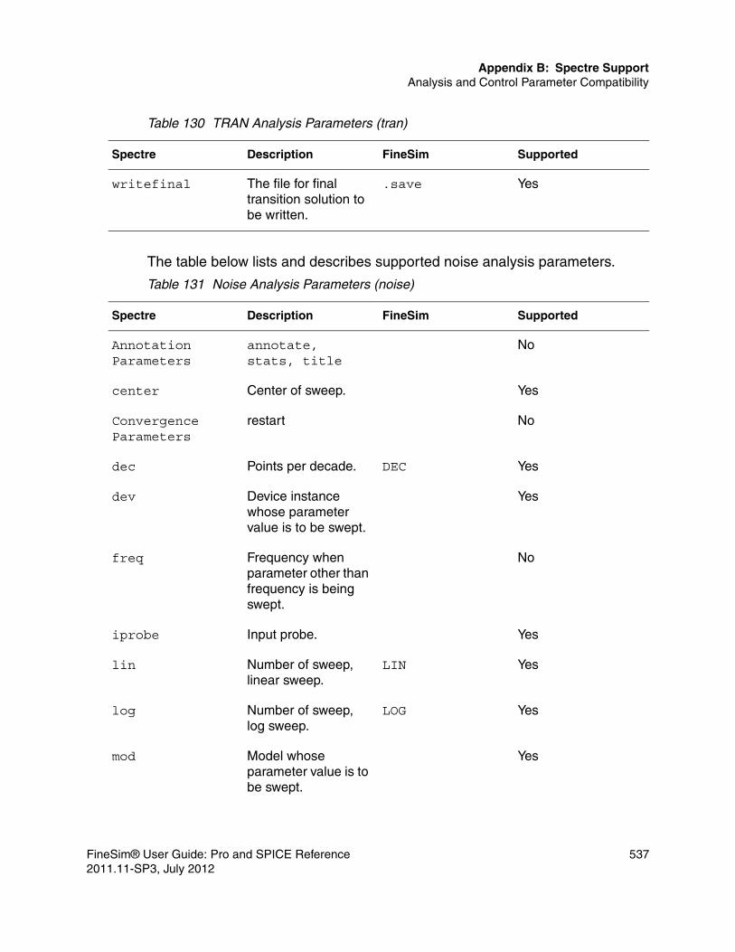
Appendix B: Spectre SupportAnalysis and Control Parameter Compatibility
The table below lists and describes supported noise analysis parameters.
writefinal The file for final transition solution to be written.
.save Yes
Table 131 Noise Analysis Parameters (noise)
Spectre Description FineSim Supported
Annotation Parameters
annotate, stats, title
No
center Center of sweep. Yes
Convergence Parameters
restart No
dec Points per decade. DEC Yes
dev Device instance whose parameter value is to be swept.
Yes
freq Frequency when parameter other than frequency is being swept.
No
iprobe Input probe. Yes
lin Number of sweep, linear sweep.
LIN Yes
log Number of sweep, log sweep.
LOG Yes
mod Model whose parameter value is to be swept.
Yes
Table 130 TRAN Analysis Parameters (tran)
Spectre Description FineSim Supported
FineSim® User Guide: Pro and SPICE Reference 5372011.11-SP3, July 2012

Appendix B: Spectre SupportAnalysis and Control Parameter Compatibility
The table below lists and describes supported options control parameters.
oprobe Compute the total noise at the out defined by this component.
Yes
Output Parameters
save, nestlvl, oppoint
No
param Name of parameter to be swept.
Yes
prevoppoint Use operating point computed previous analysis.
No
span Sweep limit span. Yes
start Start sweep limit. start Yes
State-file Parameters
readns No
step Step size, linear sweep.
step Yes
stop Stop sweep limit. stop Yes
values Array of sweep values.
No
Table 132 Options Control Parameters (options)
Spectre Description FineSim Supported
Annotation Parameters
A variety of annotation related parameters
No
Table 131 Noise Analysis Parameters (noise)
Spectre Description FineSim Supported
538 FineSim® User Guide: Pro and SPICE Reference2011.11-SP3, July 2012

Appendix B: Spectre SupportAnalysis and Control Parameter Compatibility
currents Terminal currents to output: all, nonlinear, selected.
save i(*) Yes
gmin Minimum conductance across each nonlinear device.
gmin Yes
Matrix Parameters
A variety of matrix related parameters
No
nestlvl Levels of sub-circuits to output.
.probe level=x Yes
Quantity Parameters
A variety of quantity related parameters
No
reltol Relative convergence criterion.
finesim_tolscale
Yes
save Signals to output: all, lvl, allpub, lvlpub, selected, or none.
save v(*)
save v(*) level=n
Yes
scale Device instance scaling factor.
scale Yes
scalem Model scaling factor. scalm Yes
Sensitivity Parameters
A variety of sensitivity related parameters
No
subckrprobetlvl Level up to which sub-circuit terminal current probes are to be set up.
No
Table 132 Options Control Parameters (options)
Spectre Description FineSim Supported
FineSim® User Guide: Pro and SPICE Reference 5392011.11-SP3, July 2012

Appendix B: Spectre SupportAnalysis and Control Parameter Compatibility
The table below lists and describes supported save control parameters.
temp Temperature. .param temp=temper
Yes
tnom=x Default component parameter measurement temperature.
tnom.param tnom=x
Yes
Table 133 Save Control Parameters (save)
Spectre Description FineSim Supported
inst:all Saves all the signals for the component.
I1(inst),
I2(inst), …
Yes
inst:cap Saves the junction capacitance for the component.
No
inst:currents Saves all terminal currents associated with the component.
I1(inst),I2(inst), …
Yes
inst:n Saves terminal currents associated with the instance, where n is terminal number 1, 2, 3, …
In(inst) Yes
inst:oppoint Saves operating point information for the component.
No
inst:pwr Saves the power dissipated in the instance.
No
Table 132 Options Control Parameters (options)
Spectre Description FineSim Supported
540 FineSim® User Guide: Pro and SPICE Reference2011.11-SP3, July 2012

Appendix B: Spectre SupportOther Supported Features
Other Supported Features
This section describes useful features that FineSim Pro supports.
File EncryptionFineSim Pro provides file encryption support for Spectre format netlists. Both file and net types are supported. For net type, use the protect and unprotect commands to encrypt partial encryption of Spectre format with fencrypt.
Parameter Support for scaler/scalec/scaleiFineSim Pro supports Spectre scaling factors for individual models of resistor (scaler), capacitor (scalec) and inductor (scalei).
inst:static Saves resistive terminal currents associated with the component.
No
inst:t Saves terminal currents associated with the instance, where t is terminal name D, G, S, or B for MOS, C, B, E, or S for BJT, and P or N for other devices with two pins. These names are numbered 1,2,3,4,...
In(inst) Yes
node Saves voltage for a node named.
V(node) Yes
Table 133 Save Control Parameters (save)
Spectre Description FineSim Supported
FineSim® User Guide: Pro and SPICE Reference 5412011.11-SP3, July 2012

Appendix B: Spectre SupportOther Supported Features
Example R0 (P1 N1) resmod r=10kC0 (N1 0) capmod c=5pmodel remod resistor + scaler=0.8 model capmod capacitor +scalec=1.2
This example will scale R0 to 8K ohms and C0 to 6 pF.
Spectre Support for scalefactorFineSim Pro supports Spectre model scaling factor, as follows:
setscale options scalefactor=0.9
Once your model file (such as those from TSMC 45nm processes) has this scaling factor, you should not use the scaling factor again at the netlist level. This is because you will scale your device models twice.
User-Defined FunctionsFineSim Pro supports user-defined functions.
Examplereal userfunc(real a, real b) {return sqrt(a+b)*sin(b);}
Example function userfunc(a,b)= sqrt(a+b)*sin(b)
VBIC Self-Heating ModelFineSim Pro supports the self-heating model parameter RTH. When RTH > 0, the self-heating effect is enabled. In Spectre, there is an additional model parameter selft. In the case that RTH > 0 and selft = 1, the self-heating effect will be considered in the Spectre netlist.
542 FineSim® User Guide: Pro and SPICE Reference2011.11-SP3, July 2012

Appendix B: Spectre SupportOther Supported Features
Support for Spectre analogmodelFineSim Pro supports Spectre analogmodel, which is a reserved keyword used for model name passing. The value of a special instance parameter called modelname is used to bind an instance to different masters. Consider the following example: the value “NCH_1P2V_HVG” of the parameter “mod” in the instance MN1 is bound to the model of the instance MN9999 in the sub-circuit nch, as follows:
subckt nch B D G S parameters mod="NCH_1P2V_HVG" l=0.18 wFinger=0.8 miX=1 mi=1 MN9999 (D G S B) analogmodel modelname=mod l=l w=wFinger m=miX*mi .................................. ends nch MN1 (VSS_DCO WELL OSCP_VAR WELL) nch m=1 mod="NCH_1P2V_HVG" l=0.12 + wFinger=0.4 miX=1 mi=1 The previous code is translated to HSpice format as follows: .subckt nch B D G S mod=str('NCH_1P2V_HVG') l=0.18 wFinger=0.8 miX=1 mi=1 MN9999 D G S B str(mod) l=l w=wFinger m='(miX*mi)' ........................................ .ends nch XMN1 VSS_DCO WELL OSCP_VAR WELL nch m=1 mod=str('NCH_1P2V_HVG') l=0.12 + wFinger=0.4 miX=1 mi=1"
VSWITCH StatementFineSim Pro supports voltage controlled switches (vswitch). This device is compatible with voltage controlled resistor (VCR). The syntax is as follows:
Syntax 1S1 np nm cp cn vsmodmodel vsmod vswitch ron=0.1m roff=100Meg von=1.19 voff=1.21
or:
S1 np nm cp cn vswitch ron=0.1m roff=100Meg von=1.19 voff=1.21
Syntax 2S1 np nm cp cn vsmodmodel vsmod vswitch ron=0.1m roff=100Meg vt=1.2 vh=0.01
FineSim® User Guide: Pro and SPICE Reference 5432011.11-SP3, July 2012

Appendix B: Spectre SupportOther Supported Features
or:
S1 np nm cp cn vswitch ron=0.1m roff=100Meg vt=1.2 vh=0.01
RELAY ModelFineSim Pro supports the four terminal relay model of Spectre that is a voltage controlled relay. The voltage between terminals ps and ns controls the relay resistance. The relay resistance varies nonlinearly between ropen and rclosed, the open relay resistance and closed relay resistance, respectively. The syntax is as follows:
SyntaxName 1 2 ps ns relay vt1=value vt2=value ropen=value rclosed=value
or:
Name 1 2 ps ns ModelName vt1=value vt2=value ropen=value rclosed=valuemodel modelName relay vt1=value vt2=value ropen=value rclosed=value
ExampleW0 (V1_PLUS R0_PLUS W0_NC\+ 0) relay vt1=300m vt2=100m ropen=1T rclosed=1.0
Hot Carrier Injection StatementFineSim Pro supports hot carrier injection statements in the Spectre format. It has the current expression in a G-element definition. Consider the following example:
ghc rg sub cur='equal(smode,1)*hcieff*min(1,exp(-pow((v(s,sub)-v(fg,sub))/(hcidis+hcivss*(v(s,sub)-hcicrt)),hciexp)))*i3(mp)*gt(v(s,d),hcimin)'
544 FineSim® User Guide: Pro and SPICE Reference2011.11-SP3, July 2012

C
CEldo Support
This appendix details FineSim support for Eldo.
Using Eldo
To directly use an Eldo netlist as a FineSim Pro input, you must specify -eldo, -eldost, -eldo2hsp or -eldost2hsp options with the finesim command. The following command reads the Eldo netlist and performs a simulation:
$ finesim –eldo eldo_file$ finesim –eldost eldo_file
Note:The second command example is compatible to -stver for Eldo netlist using ST models.
The following command reads the Eldo netlist and generates only a compatible HSpice netlist to the file named eldo_file.sp~:
$ finesim –eldo2hsp eldo_file$ finesim –eldost2hsp eldo_file
Note:The second command example is compatible to -stver for Eldo netlist using ST models.
You can use the previous command to check the supported device parameters and manually change the netlist before performing a simulation.
RecommendationsWhen using Eldo netlists for simulation, it is recommended that you take care of most control statements because there might be many different features between Eldo and Hspice. Therefore, when converted to Hspice, compatible
FineSim® User Guide: Pro and SPICE Reference 5452011.11-SP3, July 2012

Appendix C: Eldo SupportSupported Features
parameters are automatically translated to corresponding HSpice parameters and non-compatible parameters are passed in as is, and eventually skipped.
Consider the following tips for direct simulation of an Eldo netlist:
1. Comment out any simple control statements from the Eldo netlist, such as eldo_file.sp.
2. Make sure the control file is in HSpice syntax, including any corresponding control statements commented out of Eldo netlist (such as eldo_file.ctrl)
3. Add a line into the Eldo netlist (eldo_file.sp) to include the control file (for example, .incspc eldo_file.ctrl).
Supported Features
This section includes information about supported features that differ from HSpice.
Title LineIn Eldo netlists, the first line must be a title line. If part of the circuit description is found on the first line, it will be ignored. If the first line is blank, it will be recognized as the title line.
CommentsFineSim Pro supports four kinds of comments (*, !, $) (#com / #endcom):
1. Line comments that begin with asterisk (*).
2. Line comments that begin with a bang (!) or a dollar ($). These comments can be added to any position in a line. Anything after a bang mark (!) or a dollar ($) is recognized as a comment.
3. Block comments which begin with “#com” line and end with “#endcom” line.
Continuation CharactersFineSim Pro supports a plus sign (+) when used at the beginning of the next continuation line.
546 FineSim® User Guide: Pro and SPICE Reference2011.11-SP3, July 2012

Appendix C: Eldo SupportSupported Features
Mathematical ExpressionsFineSim Pro supports any mathematical expressions enclosed in left and right braces ({ }) or single quotes (‘ ’). Consider the following examples:
Examples{(0.5*rgate*finger_width/L)/fingers}‘(0.5*rgate*finger_width/L)/fingers’
Parser DirectivesFineSim Pro supports the following simple pre-processor Eldo commands:
#if#define <name>#ifdef <name>#ifndef <name>#else#endif#include
Examples#define NO_RESISTOR------#ifndef NO_RESISTOR------#endif
IF/ELSE StatementsThe eldo parser supports IF/ELSE/ENDIF eldo syntax.
Syntaxif (A == 1)M1 d g s b w=20uelseM1 d g s b w=10uendif
FineSim® User Guide: Pro and SPICE Reference 5472011.11-SP3, July 2012

Appendix C: Eldo SupportSupported Features
Operators
Arithmetic & Trigonometric Functions
Operator Symbol(s) Supported
Unary +, -, ! +,-, ! Yes
Power **, ^ Yes
Multiply, Divide *, / Yes
Binary +, - +, - Yes
Shift left, right <<, >> Yes
Relational <,<=,>,>= Yes
Equality ==, != Yes
Bitwise AND & Yes
Bitwise OR | Yes
Logical AND && Yes
Logical OR || Yes
Ternary (cond) ? x : y
eval(cond ? x : y)
valif(cond, x, y)
Yes
Function Description Supported
log(x) natural logarithm x>0 Yes
log10(x) decimal logarithm x>0 Yes
db(x) value in dBs (20*log10(x)) Yes
exp(x) exponential x<80 Yes
548 FineSim® User Guide: Pro and SPICE Reference2011.11-SP3, July 2012

Appendix C: Eldo SupportSupported Features
sqrt(x) square root x>0 Yes
sin(x) sine of x Yes
cos(x) cosine of x Yes
tan(x) tangent of x Yes
asin(x) arc-sine of x Yes
acos(x) arc-cosine of x Yes
atan(x) arc-tangent of x Yes
sinh(x) hyperbolic sine of x Yes
cosh(x) hyperbolic cosine of x Yes
tanh(x) hyperbolic tangent of x Yes
min(x,y,…,n)
dmin(x,y,...,n)
minimum value of x, y, …, n Yes
max(x,y,…,n)
dmax(x,y,...,n)
maximum value of x, y, …, n Yes
abs(x) absolute value of x Yes
pwr(x,y) sign(x)*pow(x,y) Yes
pow(x,y) x to the power of y Yes
sgn(x) x>0:-1, x=0:0, x<0:-1 Yes
sign(x) x>=0; +1, otherwise, -1 Yes
sign(x,y) abs(x)*sgn(y) Yes
int(x) integer part of x Yes
trunc(x) integer part of x Yes
round(x) round to nearest integer of x Yes
Function Description Supported
FineSim® User Guide: Pro and SPICE Reference 5492011.11-SP3, July 2012

Appendix C: Eldo SupportSupported Features
ceil(x) smallest integer >= x Yes
floor(x) largest integer <= x Yes
fmod(x,y) floating-point remainder of x/y Yes
deriv(x) derivative of x No
real(x) real part of complex number No
imag(x) imaginary part of complex number No
magnitude(x) magnitude of complex number No
conj(x) conjugate of complex number No
complex(x,y) complex number w/ real x, imag y No
stosmith(x) normalized value of the complex number No
ddt(x) derivative of x No
idt(x) integral of x No
limit(x,y,z) x<y:y, x>z: z, a otherwise No
bitof(x,y) yth bit value of x No
pwl(xval,interp,
x1,y1,…,xn,yn )
Equivalent value at the input xval,
interp=1|0 specifies if y value is
interpolated linearly(1) or not (0).
No
smabs(val,eps) Returns the absolute value of val, with smoothing coefficient eps.
Yes
smmax(a,b,eps) Returns the maximum of a and b, with smoothing coefficient eps.
Yes
smmin(a,b,eps) Returns the minimum of a and b, with smoothing coefficient eps.
Yes
Function Description Supported
550 FineSim® User Guide: Pro and SPICE Reference2011.11-SP3, July 2012

Appendix C: Eldo SupportSupported Features
smsgn(val,eps) Returns the signum of val, with smoothing coefficient eps.
Yes
smsign(val,eps) Returns the signum of val, with smoothing coefficient eps.
Yes
Function Description Supported
FineSim® User Guide: Pro and SPICE Reference 5512011.11-SP3, July 2012

Appendix C: Eldo SupportSupported Features
Component Statements (Device)Table 134 Eldo Component Statements
Eldo Description FineSim Supported
R resistor R Yes
C capacitor C Yes
L Two terminal inductor L Yes
K Mutual inductor K Yes
P Semiconductor resistor R Yes
T Transmission line T Yes
U Lossy transmission line (U-model) U Yes
W Lossy transmission line (W-model) W Yes
D Junction diode D Yes
Q Bipolar junction transistor Q Yes
J Junction field effect transistor J Yes
M MOSFET M Yes
V Independent voltage source V Yes
I Independent current source I Yes
E (VCVS) Voltage controlled voltage source E Yes
G (VCCS) Voltage controlled current source G Yes
F (CCCS) Current controlled current source F Yes
H (CCVS) Current controlled voltage source H Yes
S Switch No
552 FineSim® User Guide: Pro and SPICE Reference2011.11-SP3, July 2012
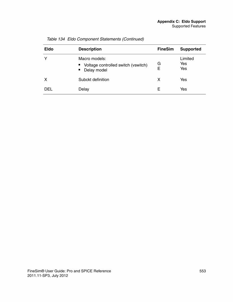
Appendix C: Eldo SupportSupported Features
Y Macro models:■ Voltage controlled switch (vswitch)■ Delay model
GE
LimitedYesYes
X Subckt definition X Yes
DEL Delay E Yes
Table 134 Eldo Component Statements (Continued)
Eldo Description FineSim Supported
FineSim® User Guide: Pro and SPICE Reference 5532011.11-SP3, July 2012

Appendix C: Eldo SupportSupported Features
Control Statements (Commands)Table 135 Eldo Control Statements
Eldo Description FineSim Supported
.a2d Analog-to-digital converter No
.ac AC analysis .ac Yes
.addlib Insert a model or sub-circuit file No
.age Age analysis No
.agemodel Reliability model param declaration No
.alter Generalized rerun facility .alter Yes
.call_tcl Call TCL function No
.checkbus Check bus value No
.checksoa Check safe operating area limits .chkdevop
.chkexpr
Limited
.chrent Piece wise linear source (PWL) Vxx pwl()
Yes
.chrsim Input from a prior simulation .load Yes
.comchar Change comment character No
.connect Connect two nodes .connect
Yes
.conso Current used by circuit No
.correl Correlation between parameters No
.d2a Digital-to-analog converter No
.data Parameter sweep .data Yes
554 FineSim® User Guide: Pro and SPICE Reference2011.11-SP3, July 2012
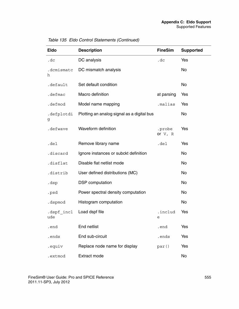
Appendix C: Eldo SupportSupported Features
.dc DC analysis .dc Yes
.dcmismatch
DC mismatch analysis No
.default Set default condition No
.defmac Macro definition at parsing Yes
.defmod Model name mapping .malias Yes
.defplotdig
Plotting an analog signal as a digital bus No
.defwave Waveform definition .probe or V, R
Yes
.del Remove library name .del Yes
.discard Ignore instances or subckt definition No
.disflat Disable flat netlist mode No
.distrib User defined distributions (MC) No
.dsp DSP computation No
.psd Power spectral density computation No
.dspmod Histogram computation No
.dspf_include
Load dspf file .include
Yes
.end End netlist .end Yes
.ends End sub-circuit .ends Yes
.equiv Replace node name for display par() Yes
.extmod Extract mode No
Table 135 Eldo Control Statements (Continued)
Eldo Description FineSim Supported
FineSim® User Guide: Pro and SPICE Reference 5552011.11-SP3, July 2012
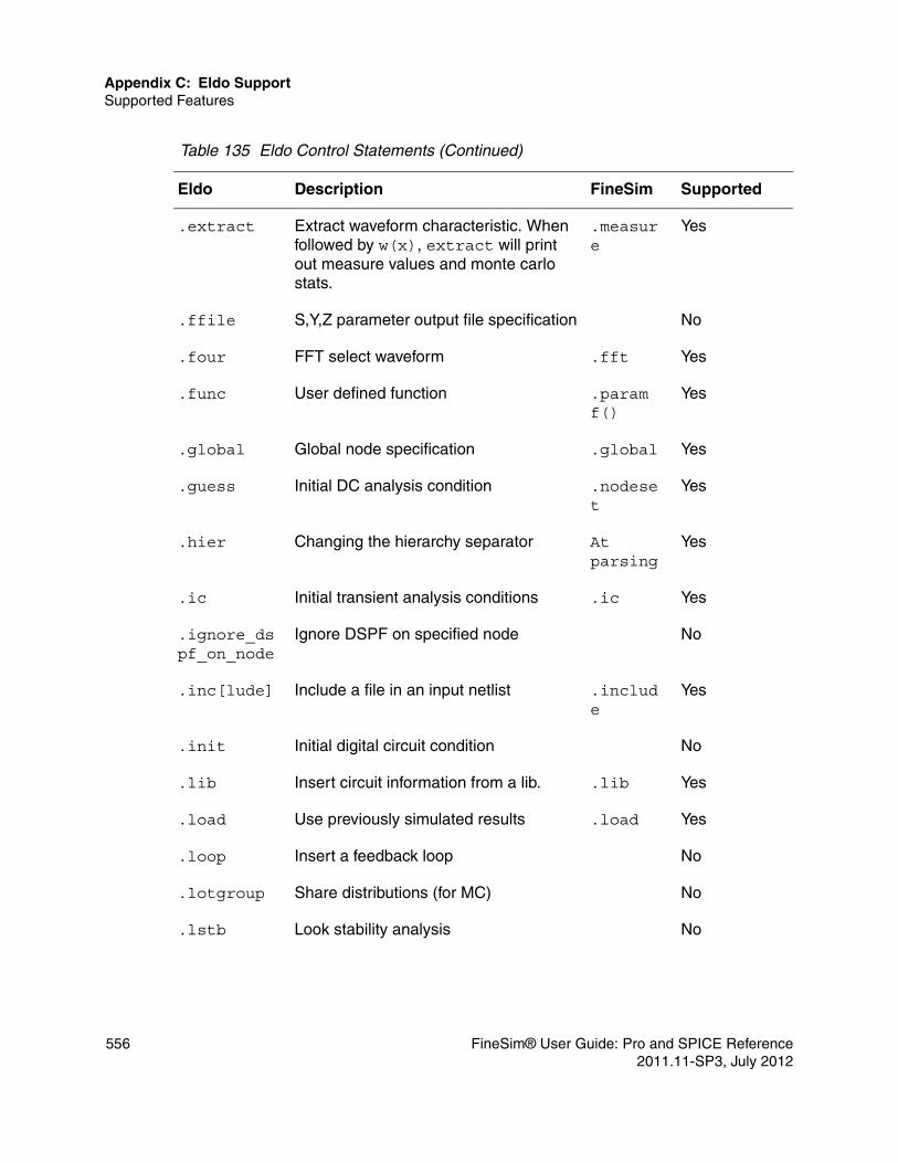
Appendix C: Eldo SupportSupported Features
.extract Extract waveform characteristic. When followed by w(x), extract will print out measure values and monte carlo stats.
.measure
Yes
.ffile S,Y,Z parameter output file specification No
.four FFT select waveform .fft Yes
.func User defined function .param f()
Yes
.global Global node specification .global Yes
.guess Initial DC analysis condition .nodeset
Yes
.hier Changing the hierarchy separator At parsing
Yes
.ic Initial transient analysis conditions .ic Yes
.ignore_dspf_on_node
Ignore DSPF on specified node No
.inc[lude] Include a file in an input netlist .include
Yes
.init Initial digital circuit condition No
.lib Insert circuit information from a lib. .lib Yes
.load Use previously simulated results .load Yes
.loop Insert a feedback loop No
.lotgroup Share distributions (for MC) No
.lstb Look stability analysis No
Table 135 Eldo Control Statements (Continued)
Eldo Description FineSim Supported
556 FineSim® User Guide: Pro and SPICE Reference2011.11-SP3, July 2012

Appendix C: Eldo SupportSupported Features
.map_dspf_node_name
Map Eldo node to DSPF node No
.mc Monte Carlo analysis Limited
.mcmod LOT/DEV variation specification on model parameters (MC)
No
.meas Measure waveform characteristic .meas Yes
.moddup Aspire/SimPilot command No
.model Device model description .model Yes
.modlogic Digital model definition No
.monitor Monitor simulation step ctrl-C Yes
.mprun Multi-processor simulation Yes
.net Network analysis .net Yes
.newpage Control page layout No
.nocom Suppress comment lines from output file No
.nodeset DC analysis condition .nodeset
Yes
.noise Noise analysis .noise Yes
.noisetran Transient noise analysis Yes
.notrc Suppress netlist from an output file No
.nwblock Partition netlist into Newton block No
.op DC operating point calculation .op Yes
.optfour FFT postprocessor option No
.optimize Optimization No
Table 135 Eldo Control Statements (Continued)
Eldo Description FineSim Supported
FineSim® User Guide: Pro and SPICE Reference 5572011.11-SP3, July 2012

Appendix C: Eldo SupportSupported Features
.option Simulation options .option Yes
.optnoise AC noise analysis No
.optpwl Accuracy by time window No
.optwind Accuracy by time window No
.param Parameter definition .param Yes
.plot Plotting of simulation results .probe Yes
.plotbus Plotting of bus signal .lprobe Yes
.print Printing of results .print Yes
.printfile Print tabular output file No
.probe Output shortform .probe Yes
.probebus Printing of bus signal .lprobe Yes
.protect Netlist protection .protect
Yes
.pz Pole-zero analysis .pz Yes
.ramp Automatic ramping No
.restart Restart simulation No
.save Save simulation run .save Yes
.scale Automatic scaling of active devices No
.sens DC sensitivity analysis .sens Yes
.sensparam Sensitivity analysis No
.setbus Create bus .vec Yes
.setkey Set reliability model key No
Table 135 Eldo Control Statements (Continued)
Eldo Description FineSim Supported
558 FineSim® User Guide: Pro and SPICE Reference2011.11-SP3, July 2012

Appendix C: Eldo SupportSupported Features
.setsoa Set safe operating area .chkdevop
.chkexpr
Limited
.sigbus Set bus signal Yes
.sinus Sinusoidal voltage sources Vxx sin()
Yes
.snf Spot noise figure No
.solve Sizing facility No
.step Parameter sweep .tran, .dc,.ac sweep
Limited
.subckt Subcircuit definition .subckt Yes
.ends Subcircuit ends .ends Yes
.subckt lib
No
.subdup Subcircuit duplicate parameters No
.table Value table No
.temp Set circuit temperature .temp Yes
.tf Transfer function .tf Yes
.title Set the title of output file .title Yes
.topcell Select top cell No
.tran Transient analysis .tran Yes
.tvinclude Test vector file No
Table 135 Eldo Control Statements (Continued)
Eldo Description FineSim Supported
FineSim® User Guide: Pro and SPICE Reference 5592011.11-SP3, July 2012

Appendix C: Eldo SupportDevice Parameter Compatibility
Device Parameter Compatibility
This section describes parameter compatibility:■ Resistor Parameters■ Semiconductor Resistor Parameters (R)■ RC-Wire Resistor Parameters (R)■ Capacitor Parameters (C)■ Inductor Parameters (L)■ Mutual Inductor Parameters (K)■ Independent Source Parameters (V/I)■ Diode Parameters (D)■ BJT Parameters (Q)■ JFET Parameters (J)■ MOS Parameters (M)■ Voltage Controlled Sources (VCVS, VCCS)■ Current Controlled Sources (CCCS, CCVS)
.unprotect Netlist protection .unprotect
Yes
.use Use previously simulate results .load Yes
.usekey Use reliability model key No
.use_tcl Use TCL file No
.verilog Verilog-A .hdl Yes
.wcase Worst case analysis No
.width Set printer paper width .width Yes
Table 135 Eldo Control Statements (Continued)
Eldo Description FineSim Supported
560 FineSim® User Guide: Pro and SPICE Reference2011.11-SP3, July 2012

Appendix C: Eldo SupportDevice Parameter Compatibility
■ Transmission Line Parameters (T)■ Lossy Transmission Line Parameters (W)
FineSim® User Guide: Pro and SPICE Reference 5612011.11-SP3, July 2012

Appendix C: Eldo SupportDevice Parameter Compatibility
Resistor ParametersTable 136 Eldo Resistor Parameters
Eldo Description FineSim Supported
r Resistance r Yes
model Model name mname Yes
tc1 Linear temperature coefficient tc1 Yes
tc2 Second order temperature coeff tc2 Yes
tc3 Third order temperature coeff No
poly Non-linear polynomial No
ac Resistance for AC analysis ac Yes
value for freq dependent analysis r Yes
temp Device temperature dtemp=temp-temper
Yes
dtemp Temperature difference dtemp Yes
m Multiplicity factor m Yes
keeprmin No
nonoise Nonoise model used No
table Resistance by table description No
kf Flicker noise coefficient No
af Flicker noise exponent No
weexp Flicker noise exponent No
leexp Flicker noise exponent No
fexp Flicker noise exponent No
562 FineSim® User Guide: Pro and SPICE Reference2011.11-SP3, July 2012

Appendix C: Eldo SupportDevice Parameter Compatibility
fmin Lower limit of noise freq. band No
fmax Upper limit of noise freq. band No
nbf Linear temperature coeff of cap No
fit Transient analysis method No
Table 136 Eldo Resistor Parameters (Continued)
Eldo Description FineSim Supported
FineSim® User Guide: Pro and SPICE Reference 5632011.11-SP3, July 2012

Appendix C: Eldo SupportDevice Parameter Compatibility
Semiconductor Resistor Parameters (R)
RC-Wire Resistor Parameters (R)
Table 137 Eldo Semiconductor Resistor Parameters
Eldo Description FineSim Supported
r Resistance r Yes
mname Model name mname Yes
l Resistor length l Yes
w Resistor width w Yes
cl Resistor offset length No
wl Resistor offset width No
area Resistor area area Yes
Table 138 Eldo RC-Wire Resistor Parameters
Eldo Description FineSim Supported
r Resistance r Yes
mname Model name mname Yes
tc1 Linear temperature coefficient tc1 Yes
tc2 Second order temperature coeff tc2 Yes
c Node to bulk capacitance c Yes
cratio Control splitting of C value No
l Resistor length l Yes
w Resistor width w Yes
m Multiplicity factor m Yes
564 FineSim® User Guide: Pro and SPICE Reference2011.11-SP3, July 2012

Appendix C: Eldo SupportDevice Parameter Compatibility
temp Device temperature dtemp=temp-temper
Yes
dtemp Temperature difference dtemp Yes
scale Scale factor scale Yes
Table 138 Eldo RC-Wire Resistor Parameters (Continued)
Eldo Description FineSim Supported
FineSim® User Guide: Pro and SPICE Reference 5652011.11-SP3, July 2012

Appendix C: Eldo SupportDevice Parameter Compatibility
Capacitor Parameters (C)Table 139 Eldo Capacitor Parameters
Eldo Description FineSim Supported
c Capacitance c Yes
poly Non-linear polynomial poly Yes
value for freq dependent analysis c Yes
mname Model name mname Yes
dccut For dc,ac,tran, modsst analysis No
l Capacitor length l Yes
w Capacitor width w Yes
m Multiplicity factor m Yes
temp Device temperature dtemp=temp-temper
Yes
dtemp Temperature difference dtemp Yes
tc1 Linear temperature coefficient tc1 Yes
tc2 Second order temperature coeff tc2 Yes
tc3 Third order temperature coeff No
ic Initial condition ic Yes
ctype For C devices defined by poly, or expression
No
566 FineSim® User Guide: Pro and SPICE Reference2011.11-SP3, July 2012

Appendix C: Eldo SupportDevice Parameter Compatibility
Inductor Parameters (L)
Mutual Inductor Parameters (K)
Table 140 Eldo Inductor Parameters
Eldo Description FineSim Supported
l Inductance l Yes
poly Non-linear polynomial poly Yes
value for freq dependent analysis l Yes
mname Model name mname Yes
dcfeed For dc,ac,tran, modsst analysis No
m Multiplicity factor m Yes
ic Initial condition ic Yes
temp Device temperature dtemp=temp-temper
Yes
dtemp Temperature difference dtemp Yes
tc1 Linear temperature coefficient tc1 Yes
tc2 Second order temperature coeff tc2 Yes
tc3 Third order temperature coeff No
Table 141 Eldo Mutual Inductor Parameters (K)
Eldo Description FineSim Supported
kval Coupling coefficient k Yes
ind1 Inductor1 to be coupled <ind1> Yes
ind2 Inductor2 to be coupled <ind2> Yes
FineSim® User Guide: Pro and SPICE Reference 5672011.11-SP3, July 2012

Appendix C: Eldo SupportDevice Parameter Compatibility
Independent Source Parameters (V/I)Table 142 Eldo Independent Source Parameters
Eldo Description FineSim Supported
dc DC value dc Yes
acmag AC magnitude acmag Yes
acphase AC phase acphase Yes
PULSE Pulse waveform pulse Yes
PWL Pwl waveform pwl Yes
EXP Exp waveform exp Yes
SIN Sine waveform sine Yes
SFFM Single freq FM waveform sffm Yes
PATTERN Pattern waveform pat Yes
tc1 Linear temperature coefficient tc1 Yes
tc2 Second order temperature coeff tc2 Yes
noise Generate noise source No
thn White noise level No
fln Flicker noise level (1/f) No
alpha Frequency exponent of 1/f No
fc Cutoff freq of low pass noise filter No
n Filter order No
fmin Lower limit of noise freq. band No
fmax Upper limit of noise freq. band No
nbf # of sine sources No
568 FineSim® User Guide: Pro and SPICE Reference2011.11-SP3, July 2012

Appendix C: Eldo SupportDevice Parameter Compatibility
table Tabular form source No
interp Interpolation type (lin,log,oct,dec) No
four Multitone source No
rport Port resistance No
zport_file File for complex port impedence No
nonoise No noise model used for rport No
rpost_tc1,rport_tc2
Temperature coefficients for rports No
iport Number for naming output No
cport Capacitor in series with rport No
lport Inductor in series with rport No
mode Mixed s-parameter selection No
noisetemp Temp used for noise calculation No
Table 142 Eldo Independent Source Parameters (Continued)
Eldo Description FineSim Supported
FineSim® User Guide: Pro and SPICE Reference 5692011.11-SP3, July 2012

Appendix C: Eldo SupportDevice Parameter Compatibility
Diode Parameters (D)
BJT Parameters (Q)
Table 143 Eldo Diode Parameters
Eldo Descrition FineSim Supported
area Junction area area Yes
peri Junction perimeter peri Yes
pj Junction perimeter pj Yes
pgate Length of the diode gate-edge No
m Multiplicity factor m Yes
temp Device temperature dtemp=temp-temper
Yes
dtemp Temperature difference dtemp Yes
off Initial operating point flag off Yes
nonoise Nonoise model flag for this device No
noise Noise model flag for this device No
fmin Lower limit of noise freq. band No
fmax Upper limit of noise freq. band No
nbf # of sinusoidal sources No
ox Yes
Table 144 Eldo BJT Parameters
Eldo Description FineSim Supported
area Transistor area area Yes
570 FineSim® User Guide: Pro and SPICE Reference2011.11-SP3, July 2012

Appendix C: Eldo SupportDevice Parameter Compatibility
areab Transistor areab areab Yes
areac Transistor areac areac Yes
m Multiplicity factor m Yes
temp Device temperature dtemp=temp-temper
Yes
dtemp Temperature difference dtemp Yes
off Initial operating point flag off Yes
nonoise Nonoise model flag for this device No
noise Noise model flag for this device No
fmin Lower limit of noise freq. band No
fmax Upper limit of noise freq. band No
nbf # of sinusoidal sources No
Table 144 Eldo BJT Parameters (Continued)
Eldo Description FineSim Supported
FineSim® User Guide: Pro and SPICE Reference 5712011.11-SP3, July 2012

Appendix C: Eldo SupportDevice Parameter Compatibility
JFET Parameters (J)
MOS Parameters (M)
Table 145 Eldo JFET Parameters
Eldo Description FineSim Supported
area Transistor area area Yes
l Channel length l Yes
w Channel width w Yes
temp Device temperature dtemp=temp-temper
Yes
dtemp Temperature difference dtemp Yes
m Multiplicity factor m Yes
off Initial operating point flag off Yes
nonoise Nonoise model flag for this device No
fmin Lower limit of noise freq. band No
fmax Upper limit of noise freq. band No
nbf # of sinusoidal sources No
Table 146 Eldo MOS Parameters
Eldo Description FineSim Supported
l Channel length l Yes
w Channel width w Yes
ad Area of drain diffusion ad Yes
as Area of source diffusion as Yes
572 FineSim® User Guide: Pro and SPICE Reference2011.11-SP3, July 2012

Appendix C: Eldo SupportDevice Parameter Compatibility
pd Perimeter of drain diffusion pd Yes
ps Perimeter of source diffusion ps Yes
geo Geometry selector geo Yes
nrd # of squares of drain diffusion nrd Yes
nrs # of squares of source diffusion nrs Yes
m Multiplicity factor m Yes
rdc Drain contact resistance rdc Yes
rsc Source contact resistance rsc Yes
temp Device temperature dtemp=temp-temper
Yes
dtemp Temperature difference dtemp Yes
off Initial operating point flag off Yes
nonoise Nonoise model flag for this device No
fmin Lower limit of noise freq. band No
fmax Upper limit of noise freq. band No
nbf # of sinusoidal sources No
delvto delvto Yes
mulu0 mulu0 Yes
Table 146 Eldo MOS Parameters (Continued)
Eldo Description FineSim Supported
FineSim® User Guide: Pro and SPICE Reference 5732011.11-SP3, July 2012

Appendix C: Eldo SupportDevice Parameter Compatibility
Voltage Controlled Sources (VCVS, VCCS)Table 147 Eldo Voltage Controlled Sources
Eldo Description FineSim Supported
min Minimum output voltage min Yes
max Maximum output voltage max Yes
tc1 Linear temperature coefficient tc1 Yes
tc2 Quadratic temperature coefficient tc2 Yes
scale Element scale factor scale Yes
abs Absolute output voltage flag abs Yes
poly Non-linear polynomial poly Yes
and Muli-input AND gate and Yes
nand Muli-input NAND gate nand Yes
or Muli-input OR gate or Yes
nor Muli-input NOR gate nor Yes
VCCAP (vccs)
Voltage controlled capacitor VCCAP Yes
VCR (vccs)
Voltage controlled resistor VCR Yes
pwl(1) Simple interpolation for output pwl(1) Yes
npwl(1) (vccs)
npwl(1) Yes
ppwl(1) (vccs)
ppwl(1) Yes
delta Smoothing parameter (0~0.5) delta Yes
delay Value of p+ and n- control nodes delay Yes
574 FineSim® User Guide: Pro and SPICE Reference2011.11-SP3, July 2012

Appendix C: Eldo SupportDevice Parameter Compatibility
td Delay value td Yes
value Value for functional description vol, cur Yes
table Tabular description No
integration Integral of (v(ncp)-v(ncn) )*val No
derivation derivative of (v(ncp)-v(ncn) )*val No
fns s-domain function No
pz (vccs) pole and zeros for transfer function No
freq Frequency domain description No
transformer Ideal transformer No
Table 147 Eldo Voltage Controlled Sources (Continued)
Eldo Description FineSim Supported
FineSim® User Guide: Pro and SPICE Reference 5752011.11-SP3, July 2012

Appendix C: Eldo SupportDevice Parameter Compatibility
Current Controlled Sources (CCCS, CCVS)Table 148 Eldo Current Controlled Sources
Eldo Description FineSim Supported
min Minimum output voltage min Yes
max Maximum output voltage max Yes
tc1 Linear temperature coefficient tc1 Yes
tc2 Quadratic temperature coefficient tc2 Yes
scale Element scale factor scale Yes
abs Absolute output voltage flag abs Yes
poly Non-linear polynomial poly Yes
and Multi-input AND gate and Yes
nand Multi-input NAND gate nand Yes
or Multi-input OR gate or Yes
nor Multi-input NOR gate nor Yes
pwl(1) Simple interpolation for output pwl(1) Yes
delta Smoothing parameter (0~0.5) delta Yes
delay Value of p+ and n- control nodes delay Yes
td Delay value td Yes
integration Integral of (v(ncp)-v(ncn) )*val No
derivation derivative of (v(ncp)-v(ncn) )*val No
576 FineSim® User Guide: Pro and SPICE Reference2011.11-SP3, July 2012

Appendix C: Eldo SupportDevice Model Compatibility
Transmission Line Parameters (T)
Lossy Transmission Line Parameters (W)
Device Model Compatibility
Table 149 Eldo Transmission Line Parameters
Eldo Description FineSim Supported
z0 Characteristic impedance z0 Yes
td Transmission delay td Yes
f Reference frequency f Yes
nl Normalized electrical length nl Yes
len Physical length l Yes
Table 150 Eldo Lossy Transmission Line Parameters
Eldo Description FineSim Supported
n Number of lines n Yes
l Geometiric of the system l Yes
rlgcfile Name of the file containing R, L, C, G, Rs and Gd matrices
rlgcfile Yes
rlgcmodel rlgcmodel
Yes
Umodel Name of the transmission line model. This entry allows the use of the U model
Umodel Yes
tablemodel Name of the model containing R, L, C and G tabular matrices description
tablemodel
Yes
FineSim® User Guide: Pro and SPICE Reference 5772011.11-SP3, July 2012

Appendix C: Eldo SupportDevice Model Compatibility
This section describes device model compatibility.
MOSFET Model (M)
Diode Model (D)
BJT Model (Q)
ST-MOSFET Model (M)
ST-Diode Model (D)
ST-BJT model (Q)
578 FineSim® User Guide: Pro and SPICE Reference2011.11-SP3, July 2012

Appendix C: Eldo SupportDevice Model Compatibility
MOSFET Model (M)
Diode Model (D)
Table 151 Compatibility for MOSFET Model
Eldo Description FineSim Supported
Level 3 mos3 3 Yes
Level 8 bsim1 13 No
Level 11 bsim2 39 No
Level 47 bsim3 47 Yes
Level 53 bsim3v3 53 Yes
Level 60 bsim4 54 Yes
Level 56 bsim3soi2 57 Yes
Level 55 bsim3soi1 57 Yes
Level 66 hisim 68 Yes
Level 44 ekv 55 Yes
Level 59 mm9 50 Yes
Level 63 mm11 63 Yes
Level 70 Psp102 69 Yes
Level 75 Psp103 69 Yes
Table 152 Compatibility for Diode Model
Eldo Description FineSim Supported
Level 1 Berkely level 1 1 Yes
Level 2 Modified berkely level 2 3 Yes
FineSim® User Guide: Pro and SPICE Reference 5792011.11-SP3, July 2012

Appendix C: Eldo SupportDevice Model Compatibility
Level 3 Fowler-Nordheim 2 Yes
Level 4 STMicro 1 - Yes
Level 8 Phillipse mm9 w/ diolev=9 4 Yes
Level 8 Phillipse mm11 w/ diolev=11 6 Yes
Level 9 Phillipse diode500 5 Yes
Table 152 Compatibility for Diode Model (Continued)
Eldo Description FineSim Supported
580 FineSim® User Guide: Pro and SPICE Reference2011.11-SP3, July 2012

Appendix C: Eldo SupportDevice Model Compatibility
BJT Model (Q)
ST-MOSFET Model (M)
ST-Diode Model (D)
Table 153 Compatibility for BJT Model
Eldo Description FineSim Supported
Level 1 Gummel-Poon (GP) 1 Yes
Level 2 Gummel-Poon (GP) Lateral 3 Yes
Level 3 Gummel-Poon (GP) (ST-BJT) - Yes
Level 4 Phillipse Mextram503 6 Yes
Level 22 Phillipse Mextram504 6 Yes
Level 8 VBIC 4 Yes
Level 9 hicum 8 Yes
Table 154 Compatibility for ST-MOSFET Model
ST-MOS Description FineSim Supported
Level 1 Eldo Level=18 18 No
Level 3 Eldo Level=19 19 No
Table 155 Compatibility for ST-Diode Model
ST-Diode Description FineSim Supported
Level 1 Eldo Level=4 STMicro1 Yes
Level 2 Eldo Level=5 STMicro2 No
Level 3 Eldo Level=6 STMicro3 No
FineSim® User Guide: Pro and SPICE Reference 5812011.11-SP3, July 2012

Appendix C: Eldo SupportControl Parameter Compatibility
ST-BJT Model (Q)
Control Parameter Compatibility
This section describes control parameter compability.
.extract CommandFineSim Pro partially supports the Eldo .extract command, which is mapped to the .measure command.
Table 156 Compatibility for ST-BJT Model
ST-BJT Description FineSim Supported
Level 1 Eldo Level=2 (GP-Lateral) 3 Yes
Table 157 .extract Compatibility
Parameters Description FineSim Supported
extract_info Extract info is one of the following parameters:
ACDCDCTRANDCACDCSWEEPTRANNOISETRANFOURDSPSWEEPOPT
ACDC
TRAN
YesYesNoNoNoYesNoNoNoNoNo
LABEL=name Label name of the extraction result. name Yes
FILE=name File name to be dumped into. No
582 FineSim® User Guide: Pro and SPICE Reference2011.11-SP3, July 2012

Appendix C: Eldo SupportControl Parameter Compatibility
UNIT=uname The unit of the extract. No
VECT The vector of returned values (by default, the first one).
No
CATVECT The combined vector of all vectors of analysis.
No
LBOUND=lower_min
Lower bound for the extracted value. No
UBOUND=upper_max
Upper bound for the extracted value. No
$MACRO Instantiation of a macro previously defined using .DEFMAC
Expanded at parser
Yes
Table 157 .extract Compatibility (Continued)
Parameters Description FineSim Supported
FineSim® User Guide: Pro and SPICE Reference 5832011.11-SP3, July 2012

Appendix C: Eldo SupportControl Parameter Compatibility
function Transient Extraction Language Functions:D_WADTCSLEWRATESLOPETCROSSTINTEGTPDTPDUUTPDUDTPDDUTPDDDTRISETFALLVALAT
CROSSCROSSINTEGtrig...targtrig...targtrig...targtrig...targtrig...targtrig...targtrig...targFIND AT
NoNoNoYesYesYesYesYesYesYesYesYesYesYes
Table 157 .extract Compatibility (Continued)
Parameters Description FineSim Supported
584 FineSim® User Guide: Pro and SPICE Reference2011.11-SP3, July 2012

Appendix C: Eldo SupportControl Parameter Compatibility
Examples.extract tran label=period abs(xup(v(a),2.5,2)-xup(v(a),2.5,1)).extract tran label=cycle abs(xdown(v(a),2.5,1)-xup(v(a),2.5,1)).extract tran label=duty_cycle {extract(cycle)/extract(period)}The previous codes are translated as follows:
.measure tran @xup10 WHEN v(a)=2.5 RISE=2
.measure tran @xup11 WHEN v(a)=2.5 RISE=1
.measure tran period PARAM='abs((@xup10-@xup11))'
.measure tran @xdown12 WHEN v(a)=2.5 FALL=1
.measure tran cycle PARAM='abs((@xdown12-@xup11))'
function General Extraction Language functions:AVERAGECOMPRESSDCMDISTOEVALINTEGKFACTORMAXMINMODPAROPMODEPOWPOWERPVAL (param)RMSWFREQWINTEGXCOMPRESSXDOWNXMAXXMINXTHRESXUPXYCONDYVAL
AVG
INTEG
MAXMIN
paramRMS
INTEG
FALLXMAXXMINCROSSRISE
FIND AT
YesNoNoNoNoYesNoYesYesNoNoNoNoYesYesNoYesNoYesYesYesYesYesNoYes
Table 157 .extract Compatibility (Continued)
Parameters Description FineSim Supported
FineSim® User Guide: Pro and SPICE Reference 5852011.11-SP3, July 2012

Appendix C: Eldo SupportControl Parameter Compatibility
.measure tran duty_cycle PARAM='(cycle/period)'
.defwave Command and Wave FunctionFineSim Pro partially supports the Eldo .defwave functions. These functions are mapped to the .probe commands or independent voltage sources for parameter definition and PWL function, respectively. All defwaves are referred to by a wave function W(x).
Table 158 .defwave Compatibility
Parameters Description FineSim Supported
SWEEP Sweep keyword. No
analysis One of the following types:
ACDCTRANFOURDSPFSSTMODSSTNOISESSASSTSSTACSSTNOISESSTXFTSST
ACDCTRAN
YesYesYesNoNoNoNoNoNoNoNoNoNoNo
wave_name New waveform name. wave_name Yes
wave_expr Arithmetic expression for relating the previously defined waveforms and nodes.
The following function types are available:PWLPWL_CTEPWL_LIN
’expr’
Vxx PWL
Yes
YesNoNo
586 FineSim® User Guide: Pro and SPICE Reference2011.11-SP3, July 2012

Appendix C: Eldo SupportControl Parameter Compatibility
Example 1.defwave power_vdd=i(v1)*v(v1).probe tran W(power_vdd)
The previous codes are translated as follows:
.probe power_vdd=par(‘i(v1)*v(v1)’)
Example 2.defwave tran f1=pwl(5n,0,7n,5,8n,5,9n,1).extract tran label=pwl_wave w(f1)
The previous codes are translated as follows:
V@f1 @f1 0 pwl(5e-09,0,7e-09,5,8e-09,5,9e-09,1).measure pwl_wave PARAM=V(@f1)
Note:The : character will function as a hierarchy separator in .defwave statements.
.setbus CommandThe .setbus command creates a bus with bits defined from most to least significant.
Syntax .SETBUS bus_name Pn {Pn}
Example.SETBUS A_bus A5 A4 A3 A2 A1 A0
The above example creates a 6-bit bus called A_bus with bits A5-A0.
.sigbus CommandThe .sigbus command sets the values of the bus.
Syntax .SIGBUS bus_name VHI = Val1 VLO = Val2 TFALL = Val3 TRISE = Val4 BASE = OCTAL | DEC | BIN | HEXA Tn Val {Tn Val}
FineSim® User Guide: Pro and SPICE Reference 5872011.11-SP3, July 2012

Appendix C: Eldo SupportControl Parameter Compatibility
Example .SIGBUS A_bus VHI = 1.8 VLO = 0 TRISE=0.2n TFALL=0.2n BASE=HEXA 0 0000 10n FFFF 15n 1234
The above example sets the value of bus A to hex 0 at 0, hex FFFF at 10n, etc., with a high voltage of 1.8V. The VHI, VLO, TRISE, TFALL parameters are optional.
.step CommandFineSim Pro partially supports the Eldo .step command. Currently, only one level of the .step command is applied to the .tran, .ac, and .dc analysis whose statement does not contain sweep parameters.
Table 159 .step Compatibility
Parameters Description FineSim Supported
TEMP Keyword specifying that temperature is to be swept.
TEMP Yes
incr_spec Increment step:<start><stop>[DEC|OCT|LIN|INCR] <incr>
(LIN, INCR)
Yes
rlc_name Name of R, C, or L whose value is to be swept.
rlc name Yes
mos_name MOS instance name whose L or W parameter is to be swept.
mos name
Yes
model_name Model name, of which a parameter is to be swept.
name Yes
PARAM Keyword specifying that a global parameter is to be swept.
PARAM Yes
param_name Global parameter name to be swept. param name
Yes
588 FineSim® User Guide: Pro and SPICE Reference2011.11-SP3, July 2012
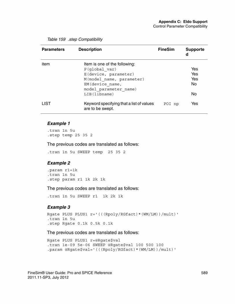
Appendix C: Eldo SupportControl Parameter Compatibility
Example 1.tran 1n 5u.step temp 25 35 2
The previous codes are translated as follows:
.tran 1n 5u SWEEP temp 25 35 2
Example 2.param r1=1k.tran 1n 5u.step param r1 1k 2k 1k
The previous codes are translated as follows:
.tran 1n 5u SWEEP r1 1k 2k 1k
Example 3Rgate PLUS PLUS1 r='(((Rpoly/RGfact)*(WM/LM))/mult)'.tran 1n 5u.step Rgate 0.1k 0.5k 0.1k
The previous codes are translated as follows:
Rgate PLUS PLUS1 r=@Rgate$val.tran 1e-09 5e-06 SWEEP @Rgate$val 100 500 100.param @Rgate$val='(((Rpoly/RGfact)*(WM/LM))/mult)'
item Item is one of the following:P(global_var)E(device, parameter)M(model_name, parameter)EM(device_name, model_parameter_name)LIB(libname)
YesYesYesNo
No
LIST Keyword specifying that a list of values are to be swept.
POI np Yes
Table 159 .step Compatibility
Parameters Description FineSim Supported
FineSim® User Guide: Pro and SPICE Reference 5892011.11-SP3, July 2012

Appendix C: Eldo SupportControl Parameter Compatibility
.hier CommandFineSim Pro supports the .hier command for hierarchical separator. By default, the hierarchical separator in Eldo is the '.' character. If .hier is specified in the Eldo netlist, all the hierarchical characters in the instance and node names are changed to ‘.’, and all the previous ‘.’s are changed to ‘_’.
Example* Purpose: Eldo format. To change the hierarchical separator to / from ..HIER / .subckt my_res in1 in2R1 in1 2 1kR2 2 in2 1kR3 2 3 1kR4 3 in2 1k.ends my_res V1 1 0 pwl (0 0 1n 0 2n 5v 4n 5v 5n 0v 6n 0v 8n 10v)X1 1 0 my_res .tran 1n 20n.probe aaa='V(X1/2)+V(X1/3)' .END
The previous codes are translated to as follows:
* Purpose: Eldo format. To change the hierarchical separator to / from ..subckt my_res in1 in2R1 in1 2 1000R2 2 in2 1000R3 2 3 1000R4 3 in2 1000.ends my_res V1 1 0 pwl(0 0 1e-09 0 2e-09 5 4e-09 5 5e-09 0 6e-09 0 8e-09 10)X1 1 0 my_res.tran 1e-09 2e-08.probe aaa='(v(X1.2)+v(X1.3))'.end
590 FineSim® User Guide: Pro and SPICE Reference2011.11-SP3, July 2012

Appendix C: Eldo SupportControl Parameter Compatibility
Other Eldo Compatibility Features
Voltage Controlled Switch (VSWITCH)FineSim Pro supports voltage controlled switch (VSWITCH) macro model that is equivalent to voltage controlled resistor (VCR) in FineSim Pro. In Eldo, the resistance change can be defined to be linear or exponential using the LEVEL parameter. If level=1, the model is working in the linear mode. It is working in the exponential mode for level=2.
Currently, FineSim Pro supports only linear model. If .OPTION YMFACT is specified in the model, ‘M’ factor is mapped to the ‘M’ parameter G element.
SyntaxYxx VSWITCH [PIN:] NP NN CP CN [PARAM: PAR=VAL {PAR=VAL}] [MODEL: MNAME]
ExampleY1 VSWITCH 2 0 1 0 PARAM: LEVEL=1 VON=4v VOFF=1v RON=1e-6 ROFF=2K M=2
or:
Y2 VSWITCH 2 0 1 0 MODEL: my_vswitch.MODEL my_vswitch MODFAS+ LEVEL=1 + VON=4v+ VOFF=1v+ RON=1e-6+ ROFF=2K+ M=2
or:
Y3 VSWITCH 2 0 1 0 J PARAM: VON=4v ROFF=2K M=2+ MODEL: my_vswitchThe previous codes are translated to as follows:
GY1 2 0 VCR PWL(1) 1 0 1 2K 4 1e-06GY2 2 0 VCR PWL(1) 1 0 1 2K 4 1e-06GY3 2 0 VCR PWL(1) 1 0 1 2K 4 1e-06
File-Driven PWL Voltage SourceFineSim supports the file-driven PWL voltage source in Eldo format.
FineSim® User Guide: Pro and SPICE Reference 5912011.11-SP3, July 2012

Appendix C: Eldo SupportControl Parameter Compatibility
SyntaxVxxx Pos Neg PWL file=pwl_file scale=0.5 stretch=1
The pwl_file file contains pairs of time vs. voltage. scale and stretch parameters are also supported.
KWSCALE / NOKWSCALE OptionsFineSim supports KWSCALE or NOKWSCALE being used in Eldo option statement. When KWSCALE (default) is specified, SCALE can be considered as a keyword and can appear in expressions, and its value is set through option statement like SCALE=val. When SCALE is not considered as a keyword, that is, NOKWSCALE is specified, the SCALE can appear in expressions, but its value must be defined via a .PARAM statement.
Example 1.option SCALE=3 [KWSCALE].param par=’10*scale’
The previous codes are translated to as follows:
.param scale=3
.param par=’10*scale’
Example 2.option NOKWSCALE.param SCALE=3.param par=’10*scale’
The previous codes are translated to as follows:
.param SCALE=3
.param par=’10*scale’
YMFACT OptionFineSim Pro supports YMFACT in Eldo option statement. When YMFACT is specified in option statement, it is allowed to use the device multiplier ‘M’ in Yxxxx instantiations.
STVER OptionFineSim Pro supports STVER option in addition to the command option -eldost. When STVER is specified in the .OPTION statement, the model being used in Eldo
592 FineSim® User Guide: Pro and SPICE Reference2011.11-SP3, July 2012

Appendix C: Eldo SupportControl Parameter Compatibility
netlist are considered as an ST model, not Eldo model. If MODTYPE=ELDO is given in any .MODEL statement, the model is considered as an Eldo model, that is, mapped to Eldo compatible SPICE model.
Refer to the ST-MOSFET, ST-Diode, and ST-BJT model mapping tables in the previous section for the ST models supported by Finesim.
Verilog-A ElementFineSim Pro supports the macro model for the instantiation of the Verilog-A modules that is extended to include Verilog-A modules. The declaration of a Verilog-A module in the netlist is done through the Eldo .model card.
Syntax<instantiation>
Y <inst_name> module_name + [PORT:] node_name {node_name}+ [GENERIC: param=val {param=val}] + [PARAM: param=val {param=val}]
<model definition>.MODEL <module_name> MACRO LANG=VERILOGA
where:■ <inst_name> is the name of the instance.■ module_name is the name of the Verilog-A module in the Verilog-A source file.■ node_name corresponds the terminals or ports of the Verilog-A modules.■ .param=val overrides the values of parameters in the module.
ExampleYr2 resistor 0 1 GENERIC: p1=10K=k p2=2.MODEL resistor MACRO lang=veriloga
The above example defines an instance, yr2, of the module resistor. Node 0 connects to the first terminal of the module and node 1 the second. Parameters p1 and p2 in the module are assigned the values of 10k and 1, respectively.
FineSim® User Guide: Pro and SPICE Reference 5932011.11-SP3, July 2012

Appendix C: Eldo SupportControl Parameter Compatibility
594 FineSim® User Guide: Pro and SPICE Reference2011.11-SP3, July 2012

D
DUsing PowerView
This appendix explains how to use PowerView, a GUI display tool that reads and analyzes voltage drop results from FineSim Pro simulations.
PowerView is especially useful for non-ideal power analysis on power rails. It shows the simulation results on a physical database of a design, which is based on the DSPF layer definitions and coordinates that an extraction generates.
When running non-ideal power analysis with finesim_spfpost, FineSim Pro writes DSPF information into finesim_irdrop.db and, when nodes are probed, internal DSPF nodes are also probed for post analysis.
Navigating PowerView
To invoke PowerView, use the following command:
$ powerview
The main window appears as in the below figure.
The main window is composed of menus and sub-windows, such as pull-down and icon menus, the drawing canvas, message window, and status window.
FineSim® User Guide: Pro and SPICE Reference 5952011.11-SP3, July 2012

Appendix D: Using PowerViewNavigating PowerView
Figure 37 PowerView Main Window
MenusThe menu bar in PowerView contains a File, View, and Tools menu, each of which has its own submenus.
File>New AnalysisWith the new analysis option, you select the net name and voltage level of the power net to be analyzed, and add those to the window with net_name and vdd_level fields by clicking the Add button. Several nets can be added through
596 FineSim® User Guide: Pro and SPICE Reference2011.11-SP3, July 2012

Appendix D: Using PowerViewNavigating PowerView
the same procedure. You also can select the SPFDB and simulation output files created by the FineSim Pro DSPF-annotated simulation to load geometry and power information for the nets. The below figure shows the tabs and fields within the New Analysis dialog box.
Figure 38 New Analysis Dialog Box
The below table lists and describes the options you can use with the PowerView New Analysis dialog box.
Table 160 New Analysis Menu Options
Option Description
Net Name Specifies the net name of the power net to be analyzed. This net is defined with option finesim_spfpost=xxx in the FineSim Pro simulation.
Voltage Level Specifies the voltage level of the power net.
SPFDB File Specifies the SPFDB file. This file has layer and geometry information for nets that are set with the option finesim_spfpost. It can be obtained from a DSPF-annotated simulation with the option finesim_spf=xxx. The SPFDB file name will be xxx_irdrop.db.
FineSim® User Guide: Pro and SPICE Reference 5972011.11-SP3, July 2012

Appendix D: Using PowerViewNavigating PowerView
After setting all the fields within the New Analysis dialog box, click OK. PowerView begins by loading geometry and power information from the SPFDB and simulation files specified, and that displays the analyzed geometry data in the canvas window.
Simulation Output File
Specifies the simulation output file that is obtained from a DSPF-annotated simulation.
Duty Defines the efficiency of analysis about each simulation file.
Start/End Time Specifies the range of time to analyze. The default value is the whole range.
EM Criterion File Specifies a file that is defined by EM criterion rules. Its rule can describe by width and by layer.
Table 160 New Analysis Menu Options (Continued)
Option Description
598 FineSim® User Guide: Pro and SPICE Reference2011.11-SP3, July 2012

Appendix D: Using PowerViewNavigating PowerView
You also can control the visibility of nets and layers, voltage level and resolution, and highlighting of nodes through the control window on the left side of the main window. PowerView displays analysis results, as shown below.
Figure 39 Analysis Results
FineSim® User Guide: Pro and SPICE Reference 5992011.11-SP3, July 2012

Appendix D: Using PowerViewNavigating PowerView
File>Load CellYou can use this option to view geometry data translated from a GDSII format file. As shown below, libraries found in search paths are shown at the left side of the dialog box. Then you can select a library and cell and click OK.
Figure 40 Load Cell Dialog Box
600 FineSim® User Guide: Pro and SPICE Reference2011.11-SP3, July 2012

Appendix D: Using PowerViewNavigating PowerView
The results are displayed as shown below.
Figure 41 Load Cell Results
File>Load SessionUse this option to load a previously saved session from a file.
File>Save SessionUse this option to save analyzed data to a file.
FineSim® User Guide: Pro and SPICE Reference 6012011.11-SP3, July 2012

Appendix D: Using PowerViewNavigating PowerView
File>Stream InThe Stream In option translates a GDSII format file to internal data. As shown below, you must provide information for three fields in the GDSII Stream In dialog box: ■ GDSII file name■ Run directory (or the working directory) ■ Library name
After the file is translated, PowerView generates a log file named stream_ libraryname.out in the specified directory.
Figure 42 GDSII Stream In Dialog Box
File>Stream OutThe Stream Out option translates current analyzed data to a GDSII format file. Because the analyzed data is a collection of line shapes that were transformed
602 FineSim® User Guide: Pro and SPICE Reference2011.11-SP3, July 2012

Appendix D: Using PowerViewNavigating PowerView
into path shapes, you must input an additional minimum width value. The below figure shows the GDSII Stream Out dialog box.
Figure 43 GDSII Stream Out Dialog Box
File>ExitExits PowerView.
View>RedrawRedraws the canvas window.
View>FitAutomatically fits the data into the canvas window.
View>Zoom InZooms in.
View>Zoom OutZooms out.
FineSim® User Guide: Pro and SPICE Reference 6032011.11-SP3, July 2012

Appendix D: Using PowerViewNavigating PowerView
Tools>Edit Cell Layer AttributesYou use this option to change layer properties. As shown below, you can change and save display properties of a layer.
Figure 44 Edit Layer Attribute Dialog Box
604 FineSim® User Guide: Pro and SPICE Reference2011.11-SP3, July 2012

Appendix D: Using PowerViewNavigating PowerView
Tools>Edit EM Rules You can use this option to build EM criterion rules. as shown below, you can add and/or remove rules and load from or save to a file.
Figure 45 Edit EM Rules Dialog Box
Icon MenuThe below figure lists and describes the icons you can select for frequently-used functions. The show node on/off icon displays the two nodes of resisters in analyzed data as small box shapes. This icon is useful for distinguishing nodes. The display cell in color/gray icon displays geometry data from GDSII in gray-scale or full color. When analysis data overlaps geometries, the gray-scale display is easier to view. The display cell in hierarchy/flat icon displays geometry data at the top level only or at flattened levels. The display
FineSim® User Guide: Pro and SPICE Reference 6052011.11-SP3, July 2012

Appendix D: Using PowerViewNavigating PowerView
via in line/box icon displays all via resistors in the analyzed data as box or line shapes, respectively.
Figure 46 Icon Menu
Mouse and Key ActionsYou can use the following mouse and/or key actions in PowerView:■ Use the right mouse button to zoom in on the display by using a press-drag-
release technique. ■ Use the arrow keys to pan in each direction by a half screen.
606 FineSim® User Guide: Pro and SPICE Reference2011.11-SP3, July 2012

Appendix D: Using PowerViewNavigating PowerView
■ Use the left mouse button to display the coordinates on a view when any data is displayed, as shown below.
Figure 47 Displaying Coordinates on a View
View Node in IR-Drop ModeAfter the analysis of IR-drop or EM, you can use the view node button to view critical nodes. Selected nodes can be highlighted and cleared at their position, as shown below. All nodes are arranged on the dialog box in order of IR-drop
FineSim® User Guide: Pro and SPICE Reference 6072011.11-SP3, July 2012

Appendix D: Using PowerViewNavigating PowerView
value. Also, you can select nodes by pressing, dragging, and releasing the mouse middle button.
Figure 48 View Node Dialog Box
Edit Level in IR-Drop ModeYou can use the Edit level button in IR-Drop mode to control the IR-drop voltage criterion of the power net. It can control individual nets or all nets within a
608 FineSim® User Guide: Pro and SPICE Reference2011.11-SP3, July 2012

Appendix D: Using PowerViewView Resistor in EM mode
range. This value is expressed as an absolute value on the Edit IR-drop level dialog box, as shown below, in IR-Drop display mode.
Figure 49 Edit IR-Drop Level Dialog Box
The IR-drop level must be specified as an absolute value. The default value of IR-drop level is 10% in the case of VDD and 0.5V in the case of VSS. When you select the toggle button in the upper-left side of the dialog box, the IR-drop voltage specified in the IR-drop level (v) field is applied to all nets.
View Resistor in EM mode
After the analysis of EM, you can use the view resistor button to view critical resistors as shown below. Selected resistors can be highlighted and cleared at their position. All resistors are arranged on the dialog box in order of current
FineSim® User Guide: Pro and SPICE Reference 6092011.11-SP3, July 2012

Appendix D: Using PowerViewView Resistor in EM mode
value. Also, you can select resistors by pressing, dragging, and releasing the mouse middle button.
Figure 50 View Resistor Dialog Box
610 FineSim® User Guide: Pro and SPICE Reference2011.11-SP3, July 2012

Appendix D: Using PowerViewAnalyze Via
Analyze Via
After the analysis of EM, you can use the analyze via button to analyze critical vias, as shown below. PowerView calculates resistor current one via at a time.
Figure 51 Via Analysis for EM Dialog Box
You can use the VC utility to generate via count files. It makes groups of via from GDSII files and saves via counts and positions. A simple rule for via counts is as follows:
file { path= . libname= sample cellname= topcell outfile= vc.dat}
layer { via_layer = 45 47}
The via_layer keyword requires two layer numbers to match the data. As shown in the previous example (via_layer = 45 47), the first number is the DSPF layer number and the second number is the GDSII layer number.
FineSim® User Guide: Pro and SPICE Reference 6112011.11-SP3, July 2012

Appendix D: Using PowerViewAnalyze Via
612 FineSim® User Guide: Pro and SPICE Reference2011.11-SP3, July 2012

E
EObsolete Options
This appendix covers options and commands that are no longer supported or required.
.option finesim_modeThe modes spice1, spice2, spice3, spice4, spice5, fast1, fast2, fast3, hyper1, hyper2, and hyper3 have been replaced by newer spice/pro modes. See the finesim_mode section for more details.
Previous UsageSets the simulation mode. This is the most important option in FineSim Pro because it automatically selects a subset of options that are crucial to simulation accuracy, performance and capacity.
The tool’s default value is hyper2 (hyper) in FineSim Pro. When FineSim Pro runs in SPICE mode or when running FineSim SPICE, the default value is spicemd.
The values for this option are shown below:
mode model speed dvmax partition loadmodel tunit
spice1 4 0 0.1 0 NA 0.1p
spice2 4 0 0.3* 0 NA 0.1p
spice/spice3 4 0.5 0.3* 0 NA 0.1p
spice4 4 1 0.3* 0 NA 0.1p
spice5 3 1 0.3* 0 NA 1p
FineSim® User Guide: Pro and SPICE Reference 6132011.11-SP3, July 2012

Appendix E: Obsolete Options
*The value of dvmax (0.3) is used as an upper bound and the actual value is calculated from the VDD value, which is automatically detected or can be given by the finesim_vdd option.
If you want to run in spice mode, you must add finesim_mode=spice to your netlist before invoking FineSim Pro with the FineSim Pro script or use the command line argument -spice.
Examples.option finesim_mode=spice (or spicemd).option finesim_mode=”PLL:spice1 ADC:fast1 CTRL:hyper3”
In the first example, the simulation runs in spice3 mode.
In the second example, the simulation runs in different modes on different parts of the design. PLL is in spice1. ADC is in fast1 and CTRL is in hyper3. The rest of the design is in the default mode, hyper.
.option finesim_lprobeFineSim now always performs as if finesim_lprobe=1.
Previous UsageUsed to get a more accurate logic value. By default, FineSim Pro only adjusts the logic value of an lprobe statement when it writes out an analog simulation data point. It does not calculate internal time points for the threshold. When set
fast1 4 1 0.3* 1 3 1p
fast/fast2 3 1 0.3* 1 3 1p
fast3 2 2 0.3* 1 3 1p
hyper1 2 2 0.3* 2 2 1p
hyper/hyper2 2 2 0.3* 2 1 1p
hyper3 1 3 0.3* 2 1 1p
mode model speed dvmax partition loadmodel tunit
614 FineSim® User Guide: Pro and SPICE Reference2011.11-SP3, July 2012

Appendix E: Obsolete Options
to 1, it calculates time points by linear interpolation to obtain the exact point in time when the given signal crosses the threshold value.
If finesim_lprobe is set to 1, the output will not be flushed until the end of simulation, and the setting for finesim_tflush will be ignored. The default value is 0.
Example.option finesim_lprobe=1
.option finesim_enprefixPlease use finesim_spfprefix and finesim_dpfprefix.
Previous UsageSpecifies instance name prefixes to be eliminated from netlists generated by extraction tools. This option restores instance names with one, and only one, leading x.
Example.option finesim_enprefix=”x m”
Suppose we have the following netlist generated by an extraction tool:
XxU6 up net181 clki Reset CntOut<6> c7 c6 dUDcellAXxU7 up net181 clki Reset CntOut<7> c8 c7 dUDcellAMxU9\mxN10 vssA net282 CEn vssA nmos ad=1.188p + as=0.858p l=0.3u pd=4.4u ps=2.462u w=1.25u MxU9\mxP13 vddA net282 CEn vddA pmos ad=1.938p + as=1.729p l=0.3u pd=5.067u ps=4.222u w=2.5u
The leading X and M will be eliminated. For example, XxU6 will become xU6.
.option finesim_spredalgFineSim now uses an intelligent method to handle RC network and this option is no longer required.
FineSim® User Guide: Pro and SPICE Reference 6152011.11-SP3, July 2012

Appendix E: Obsolete Options
Previous UsageThis option is for SPICE RC networks. When this option is set to 0, FineSim Pro uses the previous reduction functionality. When this option is set to 1, FineSim Pro treats cross-coupling capacitors more conservatively by not allowing capacitor spitted to ground, and includes capacitive loads from any active device that an RC net is connected to in the calculation of adaptive time constant Tc. This option should be used in combination of finesim_spred=1|2|3. It gives a lower reduction ratio but more accurate results. The default value is 0.
Example.option finesim_spredalg=0.option finesim_spredalg=1
.option finesim_chgaccThis option should only be used with legacy spice modes. The user should consider using finesim_qlevel for the consolidated spice modes.
Previous UsageThis option is only applied to transient analysis in spice modes. When it is set to 1, it will use more accurate charge calculation. This option should be used for high accuracy analog circuits such as PLL, ADC and Oscillator, etc.
Example
.option finesim_chgacc=1
.option finesim_rawoutThis option has been replaced by finesim_vprbtol and finesim_iprbtol.
.option finesim_fast_sweepWhen this option was set to 1, it would force FineSim to skip elaboration for spice modes. FineSim Pro now handles this behavior automatically.
616 FineSim® User Guide: Pro and SPICE Reference2011.11-SP3, July 2012

Appendix E: Obsolete Options
.option finesim_fcapandThis option is obsolete and is no longer in use.
Previous UsageWhen set to 1, this option reverts the FineSim Pro partitioning algorithm to that of versions 2007.03.05 and earlier. You can use this option for backward compatibility.
The default value is 0.
Examples
.option finesim_fcapand=1
.option finesim_fcapratioThis option is obsolete. finesim_fcapmin is now the only adjustable option for controlling coupling capacitance splitting.
Previous UsageSets the ratio that is used to determine whether a floating capacitance will be grounded. This ratio is applied to floating capacitors that have a value greater than fcapmin. The default value is 0.
FineSim Pro converts a small coupling capacitance into two grounded capacitance values to get better partitioning. If the capacitance value is smaller than fcapmin or smaller than 1% of the total node capacitance, FineSim Pro grounds it.
Examples.option finesim_fcapratio=.1
In this example, the ratio of .1 is used to determine whether a floating capacitance is grounded. Every floating capacitance value is compared to the value of the lumped capacitance value at that node and when the ratio is
FineSim® User Guide: Pro and SPICE Reference 6172011.11-SP3, July 2012
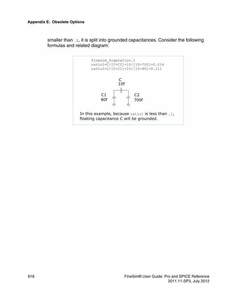
Appendix E: Obsolete Options
smaller than .1, it is split into grounded capacitances. Consider the following formulas and related diagram:
C
C1 C2700f80f
10f
finesim_fcapratio=.1ratio1=C/[C+C2]=10/[10+700]=0.014ratio2=C/[C+C1]=10/[10+80]=0.111
In this example, because ratio1 is less than .1, floating capacitance C will be grounded.
618 FineSim® User Guide: Pro and SPICE Reference2011.11-SP3, July 2012

Index
Symbols.A2D 375.AC 203.ALTER 204.CHKANODE 285.CHKBLKPWR) 287.CHKDCPATH 288
zgate=on 290.CHKDEVCUR 290.CHKDEVOP 291.CHKEXPR 296.CHKRFTIME 299.CHKSIGDIFF 301.CHKSTATICERC 307
Antenna diode checking 307Floating bulk node checking 307Gate node checking 307Path checking 307Voltage level checking 307
.CHKTIMING 302Delay Check 304Hold Time Check 304Pulse Width Check 305Setup Time Check 303
.CHKTOGGLE 305
.CHKZNODE 313
.CONNECT 205
.D2A 376
.DATA 205
.data 62
.DC 207
.DCVOLT 209
.defwave 586
.DEL LIB 210
.ELSE 219
.END 211
.ENDDATA 211
.ENDL 212
.ENDS 212
.EOM 213
.extract 582
.FFT 214
.FINESIM 380
.finesim_parallel.ini 38
.FLEXLMRC 10
.FOUR 213
.hdl 186
.hier 590
.IC 217
.IF 219
.INCLUDE 222
.INOUT 378
.INPUT 377
.LIB 222
.LOAD 224
.LPROBE 224
.MACRO 225
.MALIAS 226
.MEASURE 226, 274AVG 280DERIVATIVE 282EM 274Equation Evaluation 279FIND 277INTEG 280INTEGRAL 281MAX 280MIN 280peak to peak 280Rise, Fall, and Delay 274RMS 280WHEN 277
.MODEL 226
.mpd.conf 33
.NET 228
.NODESET 229
.NOISE 231
.OP 232
.opset 145
.OPTION 379
.optionfinesim_accelerate_rom 113finesim_add_divider 113finesim_add_instance 113
FineSim® User Guide: Pro and SPICE Reference 6192011.11-SP3, July 2012

IndexSymbols
finesim_allow_dup_port 114finesim_bisection_output 114finesim_bisection_summary 115finesim_bytol 115finesim_chgtol 117finesim_chk_devport 117finesim_chk_disk_space 118finesim_chk_fsdb 117finesim_clampVerilog 119finesim_c_model 115finesim_convlevel 119finesim_cutnode 120finesim_dcalg 121finesim_dceffort 121finesim_delmax 122finesim_detect_lvdd 123finesim_detect_lvdd_static 123finesim_double_precision_output 124finesim_dpf 124finesim_dpfadddev 124finesim_dpfhdiv 125finesim_dpfprefix 125finesim_dpfscale 125finesim_dpfsuffix 125finesim_dvmax 126finesim_em_layer 126finesim_enhanced_tcl_mode 127finesim_exit 127finesim_exitwarn 127finesim_fcapand 617finesim_fcapmin 127finesim_fcapmodel 128finesim_fcapratio 128finesim_flatsize 618finesim_floating_gate_gshunt 129finesim_fmilib 457finesim_fsc_auto_detect 130finesim_fsc_vdd 130finesim_fsdb_limit 129finesim_gen_ic_op 130finesim_gic 131finesim_gmax 131finesim_goff 132finesim_hiersim 132finesim_hstolscale 133finesim_ichier 133finesim_ignore 135finesim_ignore_chkfunc_error 135
finesim_ignore_float_isrc 135finesim_ignore_subblk_option_error 136finesim_iovec_abs_value 137finesim_iovec_vih 137finesim_iovec_vil 137finesim_iprbtol 138finesim_irem_rms 138finesim_keepzeroparms 138finesim_leakage_mode 139finesim_loadmodel 139finesim_lprobe_vh 139finesim_lprobe_vl 140finesim_maxicout 141finesim_max_width_tol 141finesim_mcbrief 141finesim_mcseed 142finesim_measout 142finesim_method 142finesim_mode 142finesim_model 145finesim_model_verification_mode 146finesim_montecarlo_mode 146finesim_mparcheck 147finesim_negcap 147finesim_negres 147finesim_no_swap 147finesim_num_meas_log 148finesim_num_meas_per_line 148finesim_output 149finesim_output_fname_type 150finesim_output_range 150finesim_partition 151finesim_prbexprvar 152, 153finesim_prbport 152finesim_prelayout_models 153finesim_print_max_con_node 153finesim_print_period 154finesim_print_to_probe 154finesim_probe_passive_device 154finesim_profile 155finesim_pt0_format 155finesim_pwrblock 156finesim_pwrnet 157finesim_pwrnode 157finesim_pwrtol 158finesim_qlevel 158finesim_remove_hier_va_files 158finesim_remove_probe_prefix 159
620 FineSim® User Guide: Pro and SPICE Reference2011.11-SP3, July 2012

IndexSymbols
finesim_remove_va_so_files 159finesim_repdot 159finesim_resmax 159finesim_resmin 160finesim_restore 160finesim_reuse_mos_model 161finesim_rpitft_mode 161finesim_scale 161finesim_selem_conv_method 85finesim_selem_max_rmserr 86finesim_selem_order 86finesim_selem_passive 86finesim_skip_unused_param 163finesim_skipwarn 13, 163finesim_soa_maxwarns 164finesim_soa_warn 164finesim_speed 164finesim_spf 165finesim_spf_add_irem_window 165finesim_spfallowerror 168finesim_spfallowmissinginstance 168finesim_spfcnet 168finesim_spfeqr 169finesim_spfeqrfile 169finesim_spffcmin 169finesim_spffcnet 170finesim_spfinst 170finesim_spf_keep_hier 166finesim_spf_matcheffort 166finesim_spfmergeport 171finesim_spfnonet 171finesim_spfpost 171finesim_spfpost_end 172finesim_spfpost_out 172finesim_spfpost_out_only 173finesim_spfpost_start 172finesim_spfprb 173finesim_spfprb_mode 173finesim_spfprefix 174finesim_spfpwr 174finesim_spfrcnet 175finesim_spfred 176finesim_spfreplast 176finesim_spfrmax 177finesim_spfrmin 178finesim_spfrptrmax 178finesim_spfscale 179finesim_spf_selective_backannotation 166
finesim_spf_sensitive 167finesim_spf_spice_names 167finesim_spfsplitnet 179finesim_spfsuffix 180finesim_spftc 180finesim_spred 180finesim_spredtc 181finesim_subckt_dup_rule 181finesim_tcl_init_file 182finesim_tflush 182finesim_tolscale 182finesim_tsc 183finesim_tstop 184finesim_tunit 184finesim_use_old_trout 184finesim_utf_mode 184finesim_vdd 185finesim_vector 185finesim_vector_mode 186finesim_veriloga_bypass 186finesim_verilog_file 382finesim_verilog_instance 383finesim_verilog_module 383finesim_verilog_subckt_file 384finesim_vprbtol 187finesim_vpwltol 187finesim_warn_limit 187finesim_wdf_limit 188finesim_wdf_mode 188finesim_write_instance_table 188finesim_write_mcparam 188
.OPTIONS 232
.OUTPUT 378
.PARAM 233
.PAT 234
.PRINT 235Printing Block Current 236
.PROBE 237, 261Exceptions to Probing 268Logic Probes (Digital Waveforms) 266pd() 270Probing and Exceptions to Probing 266Probing Block Current 265Probing Element Parameters 270Probing with Regular Expressions 267
.PZ 237Output Results 238pzkmult 238
FineSim® User Guide: Pro and SPICE Reference 6212011.11-SP3, July 2012

IndexA
pzmethod 238pznum 238
.RESISTANCE 374
.SAVE 239Capacitance Tables 240
.SCOPE 377
.SNAPSHOT 160
.step 588
.TEMP 242
.TF 242
.TRAN 243
.VEC 246
.XF 247*.bkill 36$ powerview 595$discontinuity 436$finesim_config 365, 369
.A2D 375
.D2A 376
.FINESIM 380
.INOUT 378
.INPUT 377
.OPTION 379
.OUTPUT 378
.RESISTANCE 374
.SCOPE 377finesim_a2d 381finesim_d2a 381
$finesim_inout 371$finesim_input 370$finesim_instance 365, 373$finesim_module 372$finesim_output 371$realtime 437
AAC Analysis 203ACAD_LICENSE_FILE 9Algebraic Expressions 259AM 66Analyze Via
EM analysisAnalyze Via 611
Automatic Verilog Instance Generation 381finesim_verilog_file 382finesim_verilog_instance 383finesim_verilog_module 383finesim_verilog_subckt_file 384
-genv 381
BBack-Annotation
DPF 249DPF Annotation 256DPF Commands 112, 256DSPF 249DSPF Annotation 251DSPF Commands 109, 252Non-Ideal Power 112Non-Ideal Power Analysis 257Options 109RC Reduction 256
Command-Line Syntax-method 12
BISECTION 331Bi-Section
monte carlo 340Bisection
Concurrent Bisection 337Bisection Optimization
BISECTION 331Fast Sweep 332Minimal Pulse Width 335PASSFAIL 331Pushout Bisection 336Setup Time Analysis 334
BJT 54
Ccalc 485capacitors 45CCCS 74CCVS 81C-Function Appendix 451C-Functions 443
Digital Values 445Error Codes 448Evaluation Functions 444Header Files 443Model Definition Functions 444Port Access Functions 445Port Definition Functions 444Port Directions 445Port Properties 447
622 FineSim® User Guide: Pro and SPICE Reference2011.11-SP3, July 2012

IndexC
Port Types 445Self-Generated Events 445Simulation Phases 444Simulation Time 445State Structure Definitions 443State Structure Memory Allocation 444
Check Active/Inactive Nodes 285Check and Report Toggle Count 305Check DC Path 288Check Device Current 290CHeck Device Operation Point 291Check High Impedance State Node 313Check Leakage Current Path 290Check Rise/Fall Transition Time 299Check Signal Voltage Difference 301Check Timing Setup/Hold/Delay/Width 302check_window 353circheck 317Circuit Checks
.CHKANODE 285
.CHKDCPATH 288
.CHKDEVCUR 290
.CHKDEVOP 291
.CHKRFTIME 299
.CHKSIGDIFF 301
.CHKSTATICERC 307
.CHKTIMING 302
.CHKTOGGLE 305
.CHKZNODE 313circuit elements 41
active elements 41BJT 54capacitors 45Charge-Based Capacitors 47dependent sources 41diodes 51independent sources 41, 59Inductors 48inductors 48JFET 55Lossless Transmission Lines 87Lossy Transmission Lines 89MESFET 55MOSFETs 57passive elements 41Resistors 43Rules 41Semiconductor Resistor 45
Transmission Lines 86W-element 91X-elements 93
clearlog 317close 485cmdlist 486C-Model
C-Function Appendix 451C-Functions 443Debugging 450Ports by Port ID 449Requirements 439Standard Practices 448Structure 441Temporary Local Variable Storage 448Tutorials 450
Command-Line Syntax 11-4pk 12-afile FILE_NAME 12-format 12-h 11-i 12-ifile FILE_NAME 12-inc PATH 12-istop TIME 12-log FILE_NAME 12–map_spectre_setting 12-mode 12-model 12-np 11-out 12-skipdc 12-spectre 12-speed VALUE 12-spice 11-stop TIME 12-syntax check 12-top SUBCKT 12-w 12
Command-Line Syntax-8pk 12Command-Line Syntax-h 11Command-Line Syntax-spice 11Compressed Input Files 3Configuration Commands 373cont 317Co-Simulation
Automatic Verilog Instance Generation 381configuration commands 373
FineSim® User Guide: Pro and SPICE Reference 6232011.11-SP3, July 2012

IndexD
Mixed-Mode Simulation 361Parallel Co-Simulation 385
Co-Simulation tasks$finesim_config 369$finesim_inout 371$finesim_input 370$finesim_instance 373$finesim_module 372$finesim_output 371
DData driven analysis 205dataflush 318DC analysis 207delay 355Dependent Sources 70dinit 486diodes 51dir 486Direct VCD 345dlist 486DPF Annotation 256dsignal 486DSPF Annotation 251
Option Precedence 254Probing Internal Nodes 255
dump 487Dynamic Library 457
EE-element 71ELdo
YMFACT 592Eldo 545
.defwave 586
.extract 582
.hier 590
.step 588commands 554comments 546continuation characters 546KWSCALE 592mathematical expressions 547NOKWSCALE 592operators 548parser directives 547STVER 592
title line 546VSWITCH 591
–eldo 545Eldo compatibility
BJT model 581diode model 579MOSFET 579ST-BJT model 582ST-diode model 581ST-MOSFET model 581
Eldo parametersBJT 570capacitor parameters 566CCCS 576CCVS 576diode parameters 570independent source parameters 568inductor parameters 567JFET parameters 572lossy transmission line parameters 577MOS parameters 572mutual inductor parameters 567RC-wire resistor parameters 564resistor parameters 562semiconductor resistor parameters 564transmission line parameters 577VCCS 574VCVS 574
–eldo2hsp 545–eldost 545–eldost2hsp 545EM Analysis 388EM Criteria File 410Environment Variables 27et_node_voltage 328exi 318exit 318, 487EXP 64
FFast Monte Carlo 342Fast Sweep 332F-element 74Fencrypt 483finesim_a2d 381finesim_aginglib 114finesim_chgacc 616finesim_d2a 381
624 FineSim® User Guide: Pro and SPICE Reference2011.11-SP3, July 2012

IndexG
finesim_enprefix 615finesim_fmilib 457finesim_fsc_vdd 130FINESIM_LICENSE_WAIT_TIMEOUT 9finesim_lprobe 614finesim_mode 613finesim_spf2eqr 169finesim_spfeqronly 169finesim_spredalg 615finesim_verilog_file 382finesim_verilog_instance 383finesim_verilog_module 383finesim_verilog_subckt_file 384FMI 457
Simulation 469fn 318foreach_device 323Fscript 484
Convert fsdb to PWL 498convert fsdb to vcd 500Convert vcd to vector 499Dump Signal 500onvert tr0 to fsdb 500Wildcards 485
Fscript commands 485calc 485close 485cmdlist 486dinit 486dir 486dlist 486dsignal 486dump 487exit 487fsdb2psf 488fsdb2vcd 488fset 488list 491load 492open 493pwl 494quit 487run 495signal 495sp2fsdb 496valias 496vinit 496vlist 496
vrun 497vsignal 498
fsdb2psf 488fsdb2vcd 488fset 488Functions 60
.data 62AM 66E-element 71EXP 64Exponential Pattern 64F-element 74Gate 71G-element 77H-element 81Laplace 74, 79Linear 70NPWL 78PAT 68Polynomial 70PPWL 78PRBS 67Pulse 60PWL 62, 70PWLZ 62S-Element 83SFFM 65SIN 63
GGate 71G-element 77-genv 381get_current_time 323get_device_current 323get_device_handle 324get_device_handle_list 324get_device_name 324get_device_param 325get_device_terminal_list 326get_device_terminal_name_list 326get_device_type 326get_node_device_list 327get_node_handle 327get_node_handle_list 328get_node_name 328get_total_tr_time 329
FineSim® User Guide: Pro and SPICE Reference 6252011.11-SP3, July 2012

IndexH
HH-element 81help 319Hierarchical Node Names 350
IIndependent Parallel 37independent sources 41, 59Inductor
K-element 49L-element 48, 50
Inductors 48Initial Condition 217Installation 7Interactive Commands 316Interactive Mode 28Introduction 1IO Statements 350IO Vectors
- values 357circuit examples 358vec.in 358vec.in2 359vec.in3 360
IR Drop 387IR/EM Analyzer 398-iskipdc 12-istop time 28
JJFET 55
KK-element 49KWSCALE 592
LL-element 48, 50Library Call Statement 223Library File Definition Statement 223License
Resume Job 10Suspend Job 10
list 340, 491load 492
Log Filesfilename.log 13
log files 13Logic Probes 266Logic Probes (Digital Waveforms) 266logichv 355logiclv 355log_inter 329log_main 329LSF 35LSF HPC 35
MMachine File 35MACMOD 199mask 352Measurement Analysis 274Measuring Power Dissipation 270MESFET 55Mixed-Mode Simulation 361
Verilog Co-Simulation 361Model Interface 457ModelSIM 363Monte Carlo 339
Bi-section runs 340Fast Monte Carlo 342finesim_montecarlo_mode 146FineWave 341list 340
MOSFETs 57Multi-CPU 30Multi-CPU Command Line Options
-auto 32-bsub "lsf options 32-h 32-ip 32-lsf_hpc 32-mf machinefile 32-np X 32-np_per_m 32-p 32-qsub "sge options 32-timeout 32-usub 32-wait 32
Multiple IR/EM Analyses 406Mutual Inductor 49
626 FineSim® User Guide: Pro and SPICE Reference2011.11-SP3, July 2012

IndexN
NNCSIM 363Netlist Formats 3ni 319NodeName 349NOKWSCALE 592Non-Ideal Power Analysis 257, 387now 320
Oobsolete options
finesim_chgacc 616finesim_enprefix 615finesim_lprobe 614finesim_mode 613finesim_spredalg 615
open 493Options 96
Accuracy/Speed 107Back-Annotation 109
DPF Commands 112, 256DSPF Commands 109, 252Non-Ideal Power 112
DC Initialization 102finesim.cfg 97General Commands 99Output Reporting 103Partitioning 106
Output Formats.ac# 14.fast 14.fsdb 14.ic 14.ins 14.log 14.ma# 14.md# 14.mt# 14.op# 14.pa# 14.pd# 14.pt# 14.sw# 14.tr# 14.wdf 14DC Analysis 15Output Control Statements 15
Transient Analysis 15
PParallel Co-Simulation 385Parallel SPICE 29PASSFAIL 331passive elements 41PAT 68pause 329pd 320pd() 270pn 320Pole/Zero Analysis 237Polynomial 70PowerView 595PRBS 67Probing and Exceptions to Probing 266Probing Block Current 265Probing Element Parameters 270Probing with Regular Expressions 267Pushout Bisection 336PWL 62, 70pwl 494pwlperiod 544pwlperiodstart 544PWLZ 62
Qquit 320, 487
RRadix 348RC Reduction 256Reluctor 50Rise, Fall, and Delay 274rn 320run 495
Sscalefactor 542Scripting API Functions 322S-Element 83
finesim_selem_conv_method 85finesim_selem_order 86finesim_selem_passive 86
SFFM 65
FineSim® User Guide: Pro and SPICE Reference 6272011.11-SP3, July 2012

IndexS
SGE Sungrid 36signal 495Simulation Using FMI 469SIN 63slope 351sp2fsdb 496Spectre
analogmodel 543Block Comments 543Comments 505Continuation Characters 505File Encryption 541Four Terminal Resistor Model Support 541Hot Carrier Injection 544Mathematical Expressions 506pwlperiod 544pwlperiodstart 544RELAY Model 544scalefactor 542scaler/scalec/scalei 541Simulation Language Mode 506Title Line 505twidth 544User-Defined Functions 542VBIC 542VSWITCH 543
Spectre Interface 503SPICE
System Requirements 31Time-Out 37
SPICE Controls.MEASURE 274.PROBE 261
SPICE controls.AC 203.ALTER 204.CONNECT 205.DATA 205.DC 207.DCVOLT 209.DEL LIB 210.ELSE 219.END 211.ENDDATA 211.ENDL 212.ENDS 212.EOM 213.FFT 214
.FOUR 213
.GLOBAL.GLOBAL 216
.IC 217
.IF 219
.INCLUDE 222
.LIB 222
.LOAD 224
.LPROBE 224
.MACRO 225
.MALIAS 226
.MEASURE 226, 274
.MODEL 226
.NET 228
.NODESET 229
.NOISE 231
.OP 232
.OPTIONS 232
.PARAM 233
.PAT 234
.PRINT 235
.PROBE 237, 261
.PZ 237
.SAVE 239
.SUBCKT 240
.TEMP 242
.TF 242
.TRAN 243
.VEC 246
.XF 247SPICE options
itl1 198acout 191aspec 192autostop 192captab 193cshunt 193dcap 193dcic 194defad 194defas 194defnrd 195defnrs 195defpd 195defps 196defw 196delf 195geoshrink 196
628 FineSim® User Guide: Pro and SPICE Reference2011.11-SP3, July 2012

IndexT
gmin 196gmindc 196gramp 197gshunt 197hier_scale 197imax 198imin 198interp 198itl3 198itl4 198MACMOD 199measdgt 200numdgt 200parhier 200post 201post_version 201risetime 201scale 202scalm 202search 202tnom 202unwrap 203
SSH Login 34stop 321STVER 592Supported Models 3, 14
Flash Cell 6NBTI 5STI 5TSMC 5
Supported Platforms 2
Ttabular data 355tfall 351Titan IR/EM Analysis 390Titan IR/EM analysis 390Titan IR/EM Modes 391
IR/EM analyzer 398IR/EM Common Analysis Flow 394Layout Based 393Non-Layout Based Modes 392
Titan IR/EM Script File 407tn 321Transient Analysis 15, 243Transient Noise Analysis Support 246Transmission Lines 86trise 351
tunit 351tutorials 16
Backannotation 16Basic 16Circuit_check 17Cosim 16Elements 16Fencrypt 17FineWave 17Fscript 17Modes 16MonteCarlo 17Parallel 16TCLcheck 17Vector_File 17Verilog-A 17
twidth 544
Vvalias 496VCCAP 77VCCS 77VCD 345VCR 77VCS 363VCVS 71vec.in 358vec.in2 359vec.in3 360Vector File Format 347Vector Pattern Definition 348
Hierarchical Node Names 350IO Statements 350NodeName 349Radix 348
VectorsTabular Data 355
Verilog Co-Simulation 361Verilog-A 417
$discontinuity 436$realtime 437Aliasing for Spice and Spectre Netlists 436Analog Behavior 429Data Types 421Expressions 424Language Features 419Lexical Conventions 420Miscellaneous Support 431
FineSim® User Guide: Pro and SPICE Reference 6292011.11-SP3, July 2012

IndexW
Signals 428Supported Platforms 418
Verilog-A options.hdl 186finesim_remove_va_so_files 159finesim_veriloga_bypass 186
VerilogXL 363VH 351VIH 352VIL 352vinit 496VL 352vlist 496VOH 351VOL 352vrun 497vsignal 498VSWITCH 543, 591
WWaveform Parameters 350
check_window 353Delay 355
logichv 355logiclv 355mask 352slope 351tfall 351trise 351tunit 351VH 351VIH 352VIL 352VL 352VOH 351VOL 352
W-element 91Skin Effect 92
XX-elements 93
YYMFACT 592
630 FineSim® User Guide: Pro and SPICE Reference2011.11-SP3, July 2012