Application of Modified Derived Equations of Motion of ...
17
International Journal of Clinical Chemistry and Laboratory Medicine (IJCCLM) Volume 7, Issue 1, 2021, PP 20-36 ISSN No. (Online) 2455-7153 DOI: http://dx.doi.org/10.20431/2455-7153.0701003 www.arcjournals.org International Journal of Clinical Chemistry and Laboratory Medicine (IJCCLM) Page 20 Application of Modified Derived Equations of Motion of Respiratory Mechanics in the Interpretation of Ventilator Graphics Dr.T.Rajini Samuel M.D* Associate Professor of Biochemistry, Shri Sathya Sai Medical College and Research institute, Sri Balaji Vidyapeeth Deemed to be University, Guduvancherry-thiruporur main road, Ammapettai, kancheepuram district, India 1. INTRODUCTION Ventilator Graphics is an indispensable tool at the bedside for monitoring of the mechanical ventilation. Amid the COVID-19 critical situation, the Ventilators play a major role in the management of these patients. Although continuous advancement in Mechanical Ventilator technology takes place, understanding and interpretation of Ventilator Graphics at the bedside is considered the most important in management of intensive care unit( ICU) patients.[I]The basic mathematical model of breathing mechanics consider the respiratory system as a single compartment model relating the pressure, volume and flow during Ventilation. This is known as the Equation of Motion for the respiratory system or the force balance equation.[II,III]The movement of air takes place between atmosphere and the alveoli inside the lungs during breathing. This movement is driven by the pressure gradient between these two sites and hindered by the presence of airway resistance. The amount of air flow through an airway in a given period of time depends on this pressure gradient and the airway resistance.[III] Inhalation is an active process that requires resistive work of breathing to overcome the frictional resistance to flow and elastic work of breathing to overcome the elastance (reciprocal of compliance) of the respiratory system. This can be compared to the pressure needed to inflate a balloon through a straw where the pressure is needed to overcome both the resistance of the straw and elasticity of the balloon.[III] The energy required for inspiration is more than that required for expiration under physiological conditions because only resistive work of breathing is required for expiration. Tidal breathing during exhalation is a passive process that does not require active energy. The elastic energy stored during inspiration is partly utilized as resistive work of breathing for expiration and partly dissipated as heat energy.[IV]The pressure required for expiratory flow to exhale the necessary tidal Abstract: Ventilator Graphics is an indispensable tool at the bedside for monitoring of the mechanical ventilation. The basic mathematical models of breathing mechanics consider the respiratory system as a single compartment model relating the pressure, volume and flow during Ventilation. This is known as the Equation of Motion for the respiratory system or the force balance equation. The understanding and application of these concepts plays a vital role in the intensive care unit patients. Amid the COVID-19 critical situation, the Ventilators play a major role in the management of these patients. Although continuous advancement in Mechanical Ventilator technology takes place, understanding and interpretation of Ventilator Graphics at the bedside is considered the most important part in management of critically ill patients. In the current study, newer equations are derived by modifying the equations of motion of the respiratory mechanics and the application of these research finding are summarized. The study concludes that the application of these novel equations which are to be considered as differential equations may help in better understanding of the mechanical ventilation that helps in the interpretation of invaluable ventilator graphics. Keywords: Respiratory Mechanics, Mathematical Model, Modified Derived Equation of Motion *Corresponding Author: Dr.T.Rajini Samuel M.D*, Associate Professor of Biochemistry, Shri Sathya Sai Medical College and Research institute, Sri Balaji Vidyapeeth Deemed to be University, Guduvancherry-thiruporur main road, Ammapettai, kancheepuram district, India
-
Upload
khangminh22 -
Category
Documents
-
view
0 -
download
0
Transcript of Application of Modified Derived Equations of Motion of ...
International Journal of Clinical Chemistry and Laboratory Medicine (IJCCLM)
Volume 7, Issue 1, 2021, PP 20-36
ISSN No. (Online) 2455-7153
DOI: http://dx.doi.org/10.20431/2455-7153.0701003
www.arcjournals.org
International Journal of Clinical Chemistry and Laboratory Medicine (IJCCLM) Page 20
Application of Modified Derived Equations of Motion of
Respiratory Mechanics in the Interpretation of Ventilator
Graphics
Dr.T.Rajini Samuel M.D*
Associate Professor of Biochemistry, Shri Sathya Sai Medical College and Research institute, Sri Balaji
Vidyapeeth Deemed to be University, Guduvancherry-thiruporur main road, Ammapettai, kancheepuram
district, India
1. INTRODUCTION
Ventilator Graphics is an indispensable tool at the bedside for monitoring of the mechanical
ventilation. Amid the COVID-19 critical situation, the Ventilators play a major role in the
management of these patients. Although continuous advancement in Mechanical Ventilator
technology takes place, understanding and interpretation of Ventilator Graphics at the bedside is
considered the most important in management of intensive care unit( ICU) patients.[I]The basic
mathematical model of breathing mechanics consider the respiratory system as a single compartment
model relating the pressure, volume and flow during Ventilation. This is known as the Equation of
Motion for the respiratory system or the force balance equation.[II,III]The movement of air takes
place between atmosphere and the alveoli inside the lungs during breathing. This movement is driven
by the pressure gradient between these two sites and hindered by the presence of airway resistance.
The amount of air flow through an airway in a given period of time depends on this pressure gradient
and the airway resistance.[III]
Inhalation is an active process that requires resistive work of breathing to overcome the frictional
resistance to flow and elastic work of breathing to overcome the elastance (reciprocal of compliance)
of the respiratory system. This can be compared to the pressure needed to inflate a balloon through a
straw where the pressure is needed to overcome both the resistance of the straw and elasticity of the
balloon.[III] The energy required for inspiration is more than that required for expiration under
physiological conditions because only resistive work of breathing is required for expiration. Tidal
breathing during exhalation is a passive process that does not require active energy. The elastic energy
stored during inspiration is partly utilized as resistive work of breathing for expiration and partly
dissipated as heat energy.[IV]The pressure required for expiratory flow to exhale the necessary tidal
Abstract: Ventilator Graphics is an indispensable tool at the bedside for monitoring of the mechanical
ventilation. The basic mathematical models of breathing mechanics consider the respiratory system as a
single compartment model relating the pressure, volume and flow during Ventilation. This is known as the
Equation of Motion for the respiratory system or the force balance equation. The understanding and
application of these concepts plays a vital role in the intensive care unit patients. Amid the COVID-19 critical
situation, the Ventilators play a major role in the management of these patients. Although continuous
advancement in Mechanical Ventilator technology takes place, understanding and interpretation of Ventilator
Graphics at the bedside is considered the most important part in management of critically ill patients. In the
current study, newer equations are derived by modifying the equations of motion of the respiratory mechanics
and the application of these research finding are summarized. The study concludes that the application of
these novel equations which are to be considered as differential equations may help in better understanding
of the mechanical ventilation that helps in the interpretation of invaluable ventilator graphics.
Keywords: Respiratory Mechanics, Mathematical Model, Modified Derived Equation of Motion
*Corresponding Author: Dr.T.Rajini Samuel M.D*, Associate Professor of Biochemistry, Shri Sathya
Sai Medical College and Research institute, Sri Balaji Vidyapeeth Deemed to be University,
Guduvancherry-thiruporur main road, Ammapettai, kancheepuram district, India
Application of Modified Derived Equations of Motion of Respiratory Mechanics in the Interpretation of
Ventilator Graphics
International Journal of Clinical Chemistry and Laboratory Medicine (IJCCLM) Page 21
volume from the lungs is supplied by the potential energy in the lungs due to elastic
recoil[II,III,IV].The pressure associated with the delivery of a tidal breath is defined by the simplified
equation of motion of the respiratory system(Lungs and Chest Wall) and the parameters like pressure,
volume and flow are all continuous functions of time.[II]
A ventilator mode refers to the set of operating characteristics that control how the ventilator
functions. It indicates the pattern of breath delivery and how the breaths are triggered, cycled and
limited.[V] If the inspiration is both triggered(started) and cycled(stopped) by the patient, then it is
called as spontaneous breath. If the inspiration is either ventilator triggered or ventilator cycled or
both, then it is called as mandatory breath. The spontaneous breaths may be assisted or unassisted. An
assisted breath is a breath during which all or part of inspiratory (or expiratory) flow is generated by
the ventilator doing work on the patient.[II] The total cycle time (TCT) or Ventilator period denotes
the sum of both inspiratory time and expiratory time and it is inversely related to frequency. Minute
ventilation is the tidal volume times the respiratory rate (frequency).[II]
The change in volume is due to the variation in pressure but the process is a time consuming process.
The time constant describes the speed of this process and it specifies how much time is required to
inhale adequate tidal volume during inhalation and to exhale the required tidal volume during
expiration. The time constant is usually defined as the time required for inflation upto 63% of the final
volume or deflation by 63 %.This is very useful to assess whether the respiratory system fills and
empties slowly or quickly. The high resistance leads to a long time constant, so the lung unit fills and
empties slowly. Low compliance will result in short time constant, so the lung unit fills and empties
quickly.[VI - IX]
During expiration a baseline or expiratory pressure is always measured and set relative to atmospheric
pressure. In zero setting, the baseline pressure is set equal to the atmospheric pressure and a positive
value is called as the positive end-expiratory pressure (PEEP). This is referred to as the baseline
variable.[II] An increased minute ventilation or obstruction (airway resistance) may cause an
incomplete expiration due to inability in fully exhaling the tidal volume before the next breath. A
large tidal volume requires a longer expiratory time to exhale and an increased respiratory rate will
decrease the total cycle time that may shorten the expiratory time. If inspiration starts before the end
of the previous expiration, some air will remain trapped inside the lungs. If allowed to equilibrate by
preventing the next breath to happen, the trapped gas volume will generate a positive
pressure.[X,XI,XII] This pressure is auto PEEP or intrinsic PEEP because it is not set directly by the
clinician.
In the Ventilator Graphic display, curve or scalar waveforms and Ventilator loops or plots are used to
analyze the respiratory system mechanics to provide the information about the patient-ventilator
interaction.[I] The aim of the current study is to derive and apply the newly modified equations of
motion of the respiratory mechanics for better understanding in the interpretation of ventilator
graphics.
2. MATERIALS AND METHODS
Compliance denotes the amount of air in ml the lungs can hold for every 1 cm H2O change in
pressure. Elastance is the reciprocal of compliance. [VI,XIII,XIV,XV]
Compliance = Change in Volume in ml(Δ V)/Change in Pressure in cm H2O(Δ P)
Compliance = Δ V/ Δ P ; Elastance = Δ P/Δ V
The time constant characterizes the rate of variation of the function over a period of time. Time
constant is relevant when modelling a process using exponential functions and it does not apply for
constant functions. During inspiration, the time constant can only be evaluated in the pressure
controlled ventilations because the inspiratory flow time waveform will be in the exponential form.
During exhalation, the time constant can be evaluated regardless of the ventilation mode because the
expiratory flow time waveform is an exponential function for passive expiration. So, the Expiratory
time constant is very useful for assessing the overall respiratory mechanics.[II,XVI]

Application of Modified Derived Equations of Motion of Respiratory Mechanics in the Interpretation of
Ventilator Graphics
International Journal of Clinical Chemistry and Laboratory Medicine (IJCCLM) Page 22
The inspiratory time (TI) is to be represented in terms of inspiratory time constant(τi or RC ins) and
similarly expiratory time(TE) is to be represented in units of expiratory time constant(τe or RC
exp).Their calculated ratios namely TI/RC ins and TE/RC exp are used to assess the completion of the
process of inspiration and expiration. A ratio of 5, 4, 3, 2 and 1 denotes a completion of the process of
99.3 %, 98.2%, 95.1 %, 86.5 % and 63.3%respectively.The inspiration process will increase by these
percentages and the expiration process will decrease by these percentages (clearly shown in figure
1).[VI,XIV]
Figure1. Time Constant for Exponential Functions
The time constant measured in seconds is calculated using the product of resistance(R) and
compliance(C). Inspiratory time constant(RC ins) and expiratory time constant(RC exp) are not equal
because of lower airway resistance during inspiration. Thus inspiratory time constant is shorter than
the expiratory time constant.[II,VI,XVI]
Time constant (in seconds) = Resistance x Compliance
RC ins = Cstat x Rins & RC exp = Cstat x Rexp
3. EQUATION OF MOTION OF RESPIRATORY SYSTEM
The Equation of motion of Respiratory system of respiratory mechanics or Force balance equation
which is given below is also a differential equation.[II]Pressure as a function of time P(t) is related to
the volume and flow with constant coefficients (elastance and resistance).
P(t) = R.[dv/dt] + E.v(t)
The volume as a function of time represented by v(t) is equal to the constant (or average) flow
multiplied by time. The flow is calculated using the derivative of volumev(t) with respect to time t
which is denoted by dv/dt.[2]Volume curve is usually not measured directly but it is derived from the
flow measurement as the area under the flow time curve using integral calculus.[II,XVI]The Equation
of motion of respiratory mechanics in simplified form is given below.
PAW = Flow X Resistance + Elastance X Tidal Volume
PAW = F X R + E X TV
PAW = PRES+ PEL
PRES= F X R ; PEL= E X TV
Where PAW is the pressure generated either by the ventilator or the muscle.
4. DERIVATIONS OF EQUATIONS OF MOTION
At any moment during inspiration, the airway pressure must exactly balance the forces opposing lung
and chest wall expansion. The opposing pressures are the sum of flow resistive pressure (PRES), elastic
recoil pressure(PEL) and inertance pressure(Pinertance) of the respiratory system.[III, XIII,XIV]
Application of Modified Derived Equations of Motion of Respiratory Mechanics in the Interpretation of
Ventilator Graphics
International Journal of Clinical Chemistry and Laboratory Medicine (IJCCLM) Page 23
PAW = PRES+ PEL+ Pinertance
The inertial forces are usually negligible during conventional ventilation. The inertance
pressure(Pinertance) of the respiratory system can be omitted from the equation and the equation of
motion is simplified as given below.
PAW = PRES+ PEL
In the presence of positive end expiratory pressure(PEEP), the equation of motion of the respiratory
system is written as follows.
PAW =PRES + PEL + PEEP
The ventilator will generate a positive pressure and the gas will flow from higher to lower pressure.
The muscle will generate a negative pressure at the other end so the gas will flow through the pressure
gradient.[XVII] So the above equation can be written as follows using the pressure generated by the
ventilator and the muscle.
PVENT=PRES+ PEL - PMUS + PEEP
The equation contains PMUS with negative sign because it acts by creating a negative pressure at the
other end. The equation can be re-written in the following form.
PVENT + PMUS= PRES + PEL +PEEP
PAW= PRES + PEL +PEEP
PAW- PEEP = PRES + PEL
Δ P = PRES + PEL where Δ P = PAW- PEEP
PAW is the pressure generated either by the ventilator or the muscle. From this equation it is very clear
that the pressure generated by the ventilator and/or muscle has to increase above the PEEP level for
the pressure gradient to develop that helps in flow of gas across the respiratory system.[II]
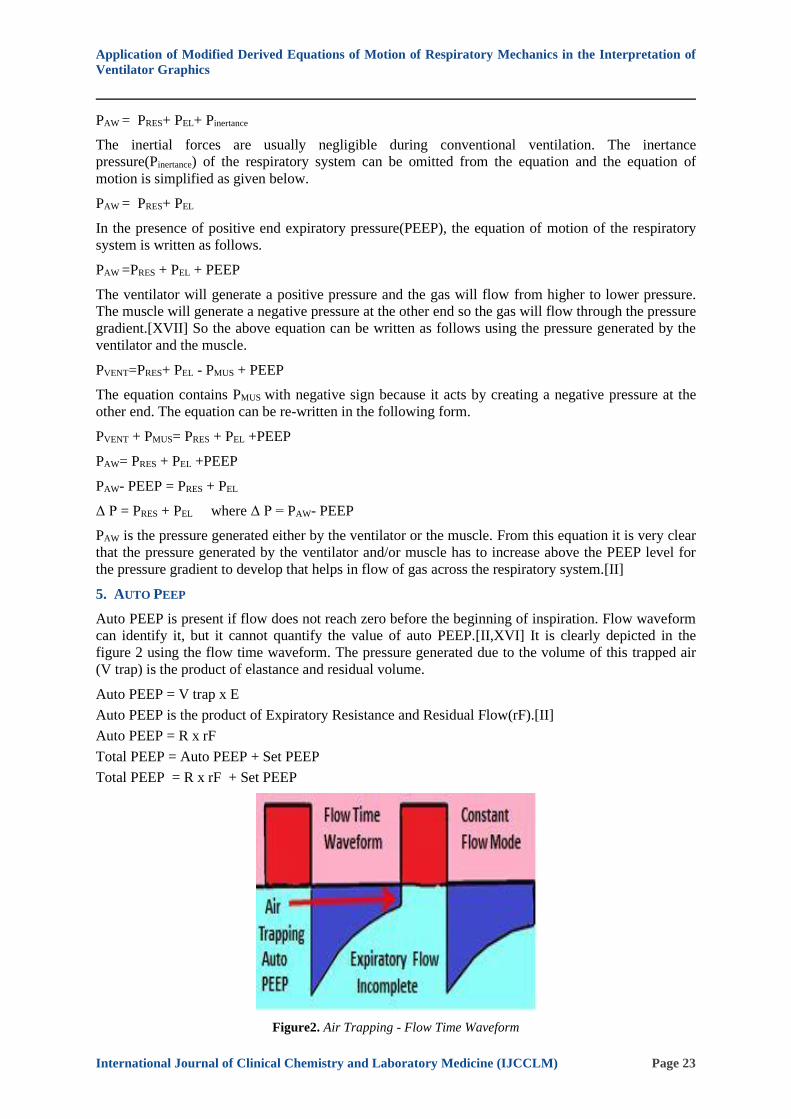
5. AUTO PEEP
Auto PEEP is present if flow does not reach zero before the beginning of inspiration. Flow waveform
can identify it, but it cannot quantify the value of auto PEEP.[II,XVI] It is clearly depicted in the
figure 2 using the flow time waveform. The pressure generated due to the volume of this trapped air
(V trap) is the product of elastance and residual volume.
Auto PEEP = V trap x E
Auto PEEP is the product of Expiratory Resistance and Residual Flow(rF).[II]
Auto PEEP = R x rF
Total PEEP = Auto PEEP + Set PEEP
Total PEEP = R x rF + Set PEEP
Figure2. Air Trapping - Flow Time Waveform

Application of Modified Derived Equations of Motion of Respiratory Mechanics in the Interpretation of
Ventilator Graphics
International Journal of Clinical Chemistry and Laboratory Medicine (IJCCLM) Page 24
6. NEWLY MODIFIED DERIVED EQUATIONS OF MOTION
Let the End expiratory alveolar volume be denoted by V and the amount of tidal volume inspired
during inhalation be denoted by Δ V. Then [V + Δ V] denote End inspiratory alveolar volume. Let the
amount of tidal volume expired during exhalation be denoted by dV. If the amount of tidal volume
inhaled(Δ V) and the amount of tidal volume exhaled(dV) are equal then the difference between these
values will be zero. But under certain conditions, these volumes may differ and their difference will
increase. Decreased expiratory flow increases the residual volume that results in air trapping which
may lead to a decreased exhaled tidal volume. If there is leakage then exhaled tidal volume will be
grossly lower than the amount of inhaled tidal volume. [II,XVI]
7. DERIVATION OF INSPIRATORY FLOW WITH PRESSURE GRADIENT, ELASTANCE AND
RESISTANCE
PAW - PEEP = PRES + PEL
Inspiration is an active process that needs energy for both resistive and elastic work. The resistive
pressure gradient depends on the product of flow and resistance(R) and the elastic pressure gradient
depends on the product of elastance(E) and the amount of tidal volume (TV) inhaled.[II,III,IV]
PAW - PEEP= iF X R + E X TV
For constant flow, Tidal Volume is the product of Inspiratory Flow (iF) and Inspiratory Time(Ti).
Auto PEEP is the product of Resistance and Residual Flow(rF).[II]
PAW - PEEP= iF X R + E X (iF X Ti) ; Where TV = iF X Ti
PAW - PEEP =iF(R + EXTi)
PAW - Set PEEP - Auto PEEP =iF(R +EXTi) ;
Where Total PEEP = R x rF + Set PEEP
PAW - Set PEEP - R x rF=iF(R + EXTi)
Δ P =iF(R +EXTi) + R x rF
In the absence of Auto PEEP,
Δ P = iF(R + EXTi) ; Where Δ P = PAW - Set PEEP
8. DERIVATION OF INSPIRATORY FLOW WITH COMPLIANCE(C) AND TIME CONSTANT
Δ P = iF(R + EXTi) + R x rF
Δ P - R x rF=iF(R +Ti/C) Where E = 1/C
Δ P - R x rF = [iF/C ] X (RC +Ti)
Δ P - R x rF = [iF/C ] X (τi +Ti)
iF = {[Δ P - R x rF] X C} / (τi +Ti)
In the absence of Auto PEEP, residual flow is zero. So, the above equation becomes,
iF = [Δ P X C] / (τi +Ti)
9. DERIVATION OF INSPIRATORY FLOW WITH RESISTANCE AND PRESSURE GRADIENT
PAW - PEEP = iF X R + E X TV
iF X R + E X TV = PAW - PEEP
iF X R + E X TV = PAW - Set PEEP - R x rF
iF X R = PAW - Set PEEP - R x rF - E X TV
iF X R = PAW - Set PEEP - (R x rF + E X TV)
Application of Modified Derived Equations of Motion of Respiratory Mechanics in the Interpretation of
Ventilator Graphics
International Journal of Clinical Chemistry and Laboratory Medicine (IJCCLM) Page 25
Let the amount of tidal volume inspired during inhalation be denoted by Δ V. The above equation can
written as follows.
iF = [1/R] X { Δ P - (R x rF + E X Δ V) } ; Where Δ P= PAW- Set PEEP
In the absence of Auto PEEP, residual flow is zero. So, the above equation is reduced to the following
equation.
iF = [1/R] X {Δ P - E X Δ V}
10. DERIVATION OF EXPIRATORY FLOW WITH RESISTANCE AND PRESSURE GRADIENT
Expiration is a process that needs energy only for the resistive work which is provided by the elastic
energy stored during inspiration.[IV]End expiratory alveolar pressure is the product of End expiratory
alveolar volume(V) and elastance(E). End inspiratory alveolar pressure is the product of End
inspiratory alveolar volume [V + Δ V] and elastance(E). The required passive elastic recoil pressure
(PEL) is calculated as the difference between End inspiratory alveolar pressure and End expiratory
alveolar pressure.
PEL= [V + Δ V] X E – [V X E]
PEL= E {V + Δ V – V}
PEL=E X Δ V
PEL=E X Δ V
Δ V -denote the amount of inhaled tidal volume
The Equation of Motion of the Respiratory System for Expiration is as follows.[II]
PVENT + PMUS = PRES + PEL
For Expiration: PVENT &PMUS are zero.
PEL = - (PRES)
E X Δ V = - R x F
The energy for the expiratory resistive work is provided by the elastic energy stored during the
inspired tidal volume.[IV]The Equation of Motion of the Respiratory System for Expiration with
PEEP is as follows.[II]
PVENT + PMUS = PRES + PEL +PEEP
For Expiration: PVENT & PMUS are zero.
PEL = - (PRES + PEEP)
At each moment in time, the pressure necessary to cause expiratory flow is equal to the pressure
stored in the lungs due to elastic recoil. The negative sign indicates flow during expiration is in the
opposite direction of inspiration.[II]Negative sign can be omitted to compare only the magnitude of
the pressure.
E X Δ V = (R x eF + PEEP)
R x eF = E X Δ V - PEEP
R x eF = E X Δ V - Auto PEEP - Set PEEP
R x eF = E X Δ V - R x rF - Set PEEP
R x eF + R x rF = E X Δ V - Set PEEP
R X [eF+ rF ] = E X Δ V - Set PEEP
[eF + rF ] =[1/R] X { E X Δ V – Set PEEP }
Application of Modified Derived Equations of Motion of Respiratory Mechanics in the Interpretation of
Ventilator Graphics
International Journal of Clinical Chemistry and Laboratory Medicine (IJCCLM) Page 26
In the absence of Auto PEEP, residual flow is zero. So, the above equation becomes the following.
eF =[1/R] X {E X Δ V – Set PEEP}
It is very clear from the above relation that the expiratory flow is driven by the gradient between
alveolar pressure and set PEEP and decreased by resistance.
11. DERIVATION OF END EXPIRATORY ALVEOLAR PRESSURE, PEEP & AUTO PEEP
The pressure necessary to cause expiratory flow is equal to the pressure stored in the lungs due to
elastic recoil.[II,IV]
E X Δ V = (R x eF + PEEP)
E X Δ V = (R x eF + Auto PEEP + Set PEEP)
The expiratory hold pause the breath in expiration. The expiratory flow is interrupted by preventing
the next breath to happen. With the flow stopped, the flow goes to zero the alveolar pressure
equilibrates with the ventilator circuit. If some air remains trapped then the residual pressure in the
lungs equilibrates with the patient circuit.[II,XIV,XVI,XVIII]
E X Δ V = (R x eF + Auto PEEP + Set PEEP)
E X Δ V - R x eF= Auto PEEP + Set PEEP
At the end of expiration, expiratory flow(eF)is zero and Volume will be the resting volume because
the tidal volume is exhaled, so Δ V changes to V.
Δ V: Tidal Volume inhaled
V: End expiratory alveolar volume
So, the above equation is changed to the following equation.
E X V = (Auto PEEP + Set PEEP)
Auto PEEP = E X V - Set PEEP
AUTO PEEP (also known as intrinsic or occult PEEP) is the positive difference between end
expiratory alveolar pressure and the end expiratory airway pressure (PEEP set by the clinician).Total
end expiratory pressure is the sum of the auto-PEEP and the extrinsically applied PEEP in the
mechanically ventilated patient.[ II,XIV,XVI,XVIII]
Auto PEEP = E X V - Set PEEP
In the absence of auto PEEP, the above equation changes to the following.
E X V = Set PEEP ; V = C X Set PEEP
E X V = (Auto PEEP + Set PEEP)
From the above relation it is very clear that end expiratory alveolar pressure and volume depends on
set PEEP and Auto PEEP. The set PEEP increases the volume by both distension of previously open
alveoli and recruitment of alveoli. [XIX,XX]
12. DERIVATION OF EXPIRATORY TIME CONSTANT (τe)
The pressure necessary to cause expiratory flow in the presence of auto PEEP is as follows.
E X Δ V = (R x eF + Auto PEEP + Set PEEP)
E X Δ V = (R x eF + E X V) ; Where E X V = (Auto PEEP + Set PEEP)
E X (Δ V- V) = R X eF
(Δ V- V) = R C X eF ; Where E = 1/C and τe = RC
τe = [ΔV - V]/eF
OR
Application of Modified Derived Equations of Motion of Respiratory Mechanics in the Interpretation of
Ventilator Graphics
International Journal of Clinical Chemistry and Laboratory Medicine (IJCCLM) Page 27
E X Δ V = (R x eF + Auto PEEP + E X V); Where E X V = Set PEEP
E X Δ V = (R x eF + R X rF + E X V)
E X (Δ V- V) = R X (eF +rF)
(Δ V- V) = R C X (eF +rF)
(Δ V - V) = τeX [eF+ rF ]
τe =[ΔV - V]/ (eF + rF)
If the residual flow is zero,
τe =[ΔV - V]/eF
In the absence of auto PEEP, expiratory time constant is the ratio between the exhaled tidal volume
and the peak expiratory flow.
V: End expiratory alveolar volume
Δ V - Amount of tidal volume inspired
[V + Δ V]:End inspiratory alveolar volume
[ΔV - V]: Exhaled Tidal Volume
During inspiration the lung volume increases by the amount of inhaled tidal volume(Δ V) and then
during expiration the lung volume decreases, reaching the resting volume by the exhaled tidal
volume(dV) at the end of expiration.
Δ V– dV = V OR Δ V– V = dV
The difference between the Inhaled Tidal Volume and the Exhaled Tidal Volume will be the normal
resting lung volume. It is very clear that Increased Resting Lung Volume results if the exhaled tidal
volume is lower than the inhaled tidal volume.
13. TOTAL WORK DONE DURING INSPIRATION
Total pressure required to inflate the lung is the sum of the pressure required to overcome the airway
resistance and the elastance of the respiratory system.[II,III,IV]
PAW- Set PEEP = iF(R + EXTi) + R x rF
The above relation shows that the pressure gradient increased above set PEEP, is necessary for the
inspiratory flow. The work required to deliver a tidal breath during inspiration is the product of tidal
volume(TV) and airway Pressure.[II,XIV]
Work done = pressure X Change in volume
WTOT = { iF(R + EXTi) + R x rF } X TV
The above equation represents the total work done to overcome the resistive and elastic elements of
the respiratory system.[VIII]Also the work done is increased in the presence of auto PEEP generated
by the product of residual flow and resistance.
14. WORK DONE DURING EXPIRATION BY PASSIVE ELASTIC RECOIL PRESSURE
Work done during inhalation is stored as potential energy which is recovered during exhalation.
Elastic energy due to the elastic recoil of the lung is stored as potential energy which provides the
necessary pressure required for exhaling the tidal volume.[IV] The pressure necessary to cause
expiratory flow in the presence of auto PEEP is as follows.
{E X Δ V – Set PEEP} = R X [eF + rF]
PEL- Set PEEP = R x (eF +rF)
Work done = pressure X Change in volume
WEL = R x (eF+ rF) x dV
Application of Modified Derived Equations of Motion of Respiratory Mechanics in the Interpretation of
Ventilator Graphics
International Journal of Clinical Chemistry and Laboratory Medicine (IJCCLM) Page 28
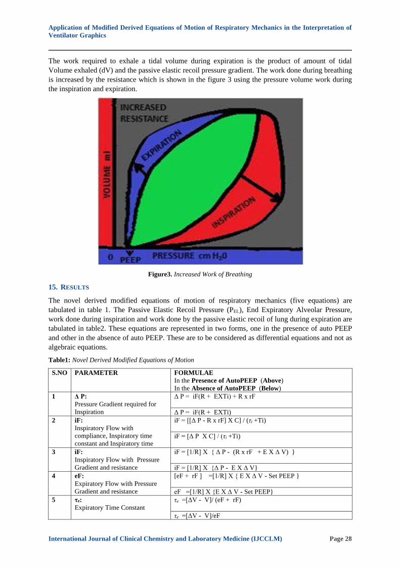
The work required to exhale a tidal volume during expiration is the product of amount of tidal
Volume exhaled (dV) and the passive elastic recoil pressure gradient. The work done during breathing
is increased by the resistance which is shown in the figure 3 using the pressure volume work during
the inspiration and expiration.
Figure3. Increased Work of Breathing
15. RESULTS
The novel derived modified equations of motion of respiratory mechanics (five equations) are
tabulated in table 1. The Passive Elastic Recoil Pressure (PEL), End Expiratory Alveolar Pressure,
work done during inspiration and work done by the passive elastic recoil of lung during expiration are
tabulated in table2. These equations are represented in two forms, one in the presence of auto PEEP
and other in the absence of auto PEEP. These are to be considered as differential equations and not as
algebraic equations.
Table1: Novel Derived Modified Equations of Motion
S.NO PARAMETER FORMULAE
In the Presence of AutoPEEP (Above)
In the Absence of AutoPEEP (Below)
1 Δ P:
Pressure Gradient required for
Inspiration
Δ P = iF(R + EXTi) + R x rF
Δ P = iF(R + EXTi)
2 iF:
Inspiratory Flow with
compliance, Inspiratory time
constant and Inspiratory time
iF = [[Δ P - R x rF] X C] / (τi +Ti)
iF = [Δ P X C] / (τi +Ti)
3 iF:
Inspiratory Flow with Pressure
Gradient and resistance
iF = [1/R] X { Δ P - (R x rF + E X Δ V) }
iF = [1/R] X {Δ P - E X Δ V}
4 eF:
Expiratory Flow with Pressure
Gradient and resistance
[eF + rF ] =[1/R] X { E X Δ V - Set PEEP }
eF =[1/R] X {E X Δ V - Set PEEP}
5 τe:
Expiratory Time Constant
τe =[ΔV - V]/ (eF + rF)
τe =[ΔV - V]/eF

Application of Modified Derived Equations of Motion of Respiratory Mechanics in the Interpretation of
Ventilator Graphics
International Journal of Clinical Chemistry and Laboratory Medicine (IJCCLM) Page 29
Table2. Passive Elastic Recoil Pressure & Work Done
S.NO PARAMETER FORMULAE
In the Presence of AutoPEEP (Above)
In the Absence of AutoPEEP (Below)
6 E X Δ V :
Passive Elastic Recoil Pressure
(PEL)
E X Δ V = (R x eF + Auto PEEP + Set PEEP)
E X Δ V = (R x eF + Set PEEP)
7 E X V :
End Expiratory Alveolar Pressure
E X V = Auto PEEP + Set PEEP
E X V = Set PEEP
8 WTOT: Total Work done During Active Inspiration
WTOT = { iF(R + EXTi) + R x rF } X Δ V
9 WEL:Work done During Passive Expiration by the Elastic Recoil Pressure
WEL = R x (eF+ rF) x dV
16. DISCUSSION
Ventilators play a major role in the management of intensive care unit patients. Ventilator Graphical
tool helps in monitoring the mechanical ventilation at the bedside. A lot of advancement in
Mechanical Ventilator technology has taken place yet the understanding and interpretation of
Ventilator Graphics at the bedside seems to be a challenging one.[I] The Equation of Motion for the
respiratory system is the basic mathematical model of breathing mechanics.[II] The understanding and
application of the various physical concepts involved in it plays a vital role in the management of
these patients.
17. APPLICATION OF THE NEWLY DERIVED MODIFIED EQUATIONS
The application of the derived modified equations of motion of the respiratory system of the
respiratory mechanics is to be discussed in detail. Total Work done during the inspiration includes
both resistive and elastic work. It is decreased by the compliance, increased by the inspiratory
resistance, elastance and the auto PEEP generated due to the residual flow. The pressure gradient
required for the inspiratory flow is decreased by the set PEEP and increased by the resistance at the
start of inspiration.
Δ P =iF(R + EXTi) + R x rF ; Where Δ P = PAW - set PEEP
In the presence of auto PEEP, the pressure gradient required for causing the flow will be higher. But
in the absence of Auto PEEP, residual flow is zero and so the above equation is reduced to the
following form.
Δ P = iF(R + EXTi)
Δ P = iF(R + EX0) ; At time Ti = zero
Δ P =iF X R OR iF= Δ P/R
If the resistance is increased then the Peak inspiratory flow will decrease. In constant flow mode of
ventilation, peak inspiratory flow rate is seen at the beginning of the inspiratory cycle depending on
the set inspiratory rise time (normal, too fast and too slow) in the ventilator, then the inspiratory flow
is constant throughout the inspiratory cycle and it ceases once the preset or target value is achieved.
The inspiratory rise time determines the amount of time it takes to reach the desired airway pressure
or peak flow rate (shown in figure 4). [XV]It determines the rate at which the ventilator achieves a
target pressure in pressure control and pressure support modes or flow rate in volume control modes.

Application of Modified Derived Equations of Motion of Respiratory Mechanics in the Interpretation of
Ventilator Graphics
International Journal of Clinical Chemistry and Laboratory Medicine (IJCCLM) Page 30
Figure4. Normal Inspiratory Rise Time
During the initial portion of inspiration, the pressure gradient is a function of flow and resistance.
Thus the pressure time waveform in the constant flow mode of ventilation begins with an exponential
rise to a first step. If the resistance is higher, then the rise in step will be much higher (figure 5 A).
The second portion of the pressure time waveform is a linear increase to peak inspiratory
pressure(PIP) representing the peak dynamic pressure that includes both the resistive and elastic
components.[XIV,XVI,XVIII] As the inspiratory timeTi increases, the term {R + Ex Ti}will increase.
The second portion of the pressure time waveform depends mainly on the elastance which is the
reciprocal of compliance. If the compliance is decreased, then the elastance is increased and so the
slope of the second portion is increased(figure 5 B).
Figure5A. Increased Resistance Figure5B. Decreased Compliance
If the compliance is increased, then the elastance is decreased and so the slope of the second portion is
decreased. The increased resistance and decreased compliance seen in the pressure and volume time
waveform in both the constant flow and constant pressure mode of ventilation are compared with their
normal in the figure 5A and 5 B respectively.
iF = [[Δ P - R x rF] X C] / (τi +Ti)
Higher pressure gradient is required for causing the inspiratory flow in the presence of auto PEEP.
The residual flow is zero in the absence of Auto PEEP and so, the above equation is reduced to
become the following equation.
iF = [Δ P X C] / (τi +Ti)

Application of Modified Derived Equations of Motion of Respiratory Mechanics in the Interpretation of
Ventilator Graphics
International Journal of Clinical Chemistry and Laboratory Medicine (IJCCLM) Page 31
In constant pressure mode of ventilation, the Inspiratory flow is directly proportional to the pressure
gradient (driving force) and the compliance and inversely proportional to the Inspiratory Time
Constant. The peak inspiratory flow is seen at the start of inspiration (depending on the set inspiratory
rise time) due to maximum pressure gradient and as the Inspiratory time increases, the pressure
gradient is decreased due to the inspired tidal volume, so the inspiratory flow decreases till it reaches
the baseline. The inspiratory flow will be higher if the patient has increased compliance(decreased
elastance) and the inspiratory flow will be lower If the patient has decreased compliance (increased
elastance)as depicted in the figure 6.If the inspiratory time constant is shorter, the tidal volume is
inhaled quickly or short inspiratory time is sufficient to inhale the tidal volume. If the inspiratory
time constant is longer, the tidal volume is inhaled slowly or long inspiratory time is needed to inhale
the required tidal volume. As the inspiratory time constant (τi) increases, the inspiratory flow will
decrease and vice versa.
Figure6. Decreased Compliance - Flow Time Waveform
iF = [1/R] X { Δ P - (R x rF + E X Δ V) }
The inspiratory flow requires higher pressure gradient in the presence of auto PEEP. If the residual
flow is zero(absence of Auto PEEP), the above equation is reduced to become the following equation.
iF = [1/R] X {Δ P - E XΔ V}
In constant pressure mode of ventilation, the Inspiratory flow is directly proportional to the pressure
gradient (driving force) and inversely proportional to the resistance. The inspiration starts at the end
expiratory alveolar volume denoted by V. The pressure gradient at the start of inspiration is denoted
by {Δ P - E X V}and the pressure gradient is maximum at this starting point and so the peak
inspiratory flow is always seen at the beginning of the inspiration. The pressure gradient at the end of
inspiration will be denoted by {Δ P - E X Δ V} and as the tidal volume(Δ V) is inhaled during
inspiration, the pressure gradient{Δ P - E XΔ V} decreases and the flow ceases if the pressure
gradient is zero{Δ P = E XΔ V}. The inspiratory flow will decrease with increase in resistance, so
more inspiratory time is needed to deliver the required volume otherwise the inspired tidal volume
will be decreased as compared with normal resistance patients which is clearly depicted in the figure
7.[XIV]
Application of Modified Derived Equations of Motion of Respiratory Mechanics in the Interpretation of
Ventilator Graphics
International Journal of Clinical Chemistry and Laboratory Medicine (IJCCLM) Page 32
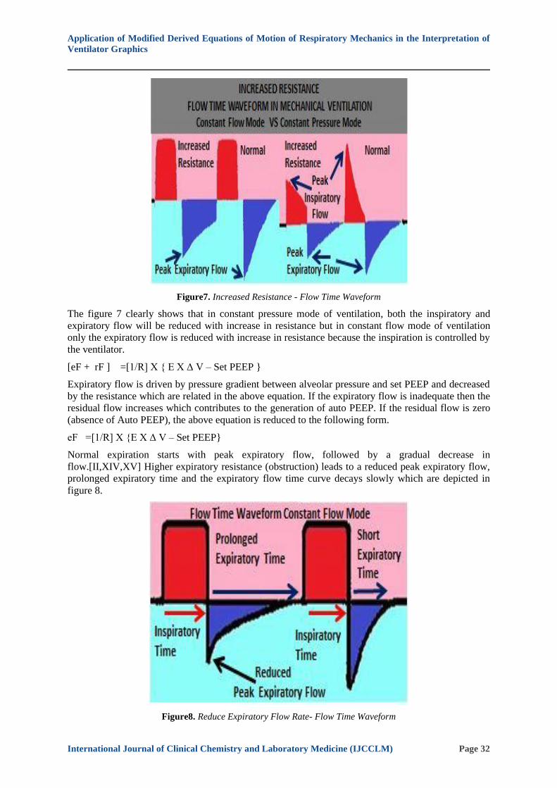
Figure7. Increased Resistance - Flow Time Waveform
The figure 7 clearly shows that in constant pressure mode of ventilation, both the inspiratory and
expiratory flow will be reduced with increase in resistance but in constant flow mode of ventilation
only the expiratory flow is reduced with increase in resistance because the inspiration is controlled by
the ventilator.
[eF + rF ] =[1/R] X { E X Δ V – Set PEEP }
Expiratory flow is driven by pressure gradient between alveolar pressure and set PEEP and decreased
by the resistance which are related in the above equation. If the expiratory flow is inadequate then the
residual flow increases which contributes to the generation of auto PEEP. If the residual flow is zero
(absence of Auto PEEP), the above equation is reduced to the following form.
eF =[1/R] X {E X Δ V – Set PEEP}
Normal expiration starts with peak expiratory flow, followed by a gradual decrease in
flow.[II,XIV,XV] Higher expiratory resistance (obstruction) leads to a reduced peak expiratory flow,
prolonged expiratory time and the expiratory flow time curve decays slowly which are depicted in
figure 8.
Figure8. Reduce Expiratory Flow Rate- Flow Time Waveform

Application of Modified Derived Equations of Motion of Respiratory Mechanics in the Interpretation of
Ventilator Graphics
International Journal of Clinical Chemistry and Laboratory Medicine (IJCCLM) Page 33
Let the inspired tidal volume be denoted by ΔV. If the End expiratory alveolar volume is denoted by
V,then[V+Δ V] denote the End inspiratory alveolar volume. The pressure gradient is maximum at
beginning of expiration (end of inspiration) and then as the tidal volume is exhaled the pressure
gradient decreases gradually. The peak expiratory flow will be seen at the beginning of the expiration
and then the lung volume decreases towards the resting volume in the end of
expiration.[II,XIV,XV,XVI] If airway obstruction is present, then the peak expiratory flow will be
reduced and then it decreases very slowly towards the resting volume which is clearly noticed as
scooping in the flow volume loop shown in the figure 9.
Figure9. Reduce Expiratory Flow Rate- Flow volume Loop
The passive elastic recoil pressure (PEL) required for causing flow during expiration is calculated as
the difference between End inspiratory alveolar pressure and End expiratory alveolar pressure (PEL= E
X Δ V). The resistive work of expiration is provided by the elastic energy stored during
inspiration.[IV] The pressure necessary to cause expiratory flow in the presence of auto PEEP is
shown in the below equation.
E X Δ V = (R x eF + Auto PEEP + Set PEEP)
If the required tidal volume inhaled during inspiration is exhaled by the expiratory flow then there is
no residual flow. The pressure necessary to cause expiratory flow in the absence of auto PEEP is
given in the below equation.
E X Δ V = (R x eF+ Set PEEP)
At the end of expiration, the expiratory flow (eF) is zero and Volume will be the resting volume
because the tidal volume is exhaled. Functional Residual Capacity (FRC)is the volume of gas that
remains in the lungs at the end of expiration which is the resting state and in the presence of
positive end expiration pressure (PEEP) it is called the end-expiratory lung volume (EELV).FRC is a
lung volume measured without PEEP (at atmospheric pressure). PEEP contributes to increased end-
expiratory lung volume (EELV) by recruitment of previously non-aerated alveolar units and
distension of previously open alveolar units. If no recruitment occurs then the volume increased by
the set PEEP will be the result of product of compliance and set PEEP(i.e. C X set PEEP). When there
is a larger change in volume, then that volume gain will be due to the recruitment.[XIX-XXII]
E X V = (Auto PEEP + Set PEEP)
The end expiratory alveolar pressure and volume depends on both the externally set PEEP and auto-
generated PEEP. The set PEEP increases the volume by recruitment of alveoli as well as distension of
previously open alveoli. If there is no auto PEEP and the set PEEP is zero, then the end expiratory
alveolar pressure will be at the atmospheric pressure level.
Application of Modified Derived Equations of Motion of Respiratory Mechanics in the Interpretation of
Ventilator Graphics
International Journal of Clinical Chemistry and Laboratory Medicine (IJCCLM) Page 34
The relationship between the expiratory time constant, expiratory flow, residual flow and the alveolar
volume at the end of inspiration and expiration is given in the below equation.
τe =[ΔV - V]/ (eF + rF)
If the residual flow (rF) is zero (absence of auto PEEP), then the above equation is reduced to the
following relation.
τe = [ΔV - V]/eF
[ΔV]: Inhaled Tidal Volume
[V+ Δ V]: End inspiratory alveolar volume
V: End Expiratory Alveolar Volume
Expiratory time constant = exhaled tidal volume / peak expiratory flow
The above simple formula is already used to calculate the expiratory time constant which is the ratio
between the exhaled tidal volume and the peak expiratory flow. It treats the lung as single
compartment and does not account for time constant heterogeneity of lungs.[IX]In the presence of
auto PEEP, the above formula is inaccurate and so it cannot be used to calculate the expiratory time
constant. During inspiration the lung volume increases by the amount of inhaled tidal volume (Δ
V).Then the lung volume decreases during expiration and it reaches the resting volume at the end of
expiration by the exhaled tidal volume (dV)
Δ V– dV= V OR Δ V– V = dV
If the inhaled tidal volume is completely expelled by the exhaled tidal volume then the resting lung
volume is normal. If the Inhaled Tidal Volume is not completely expelled by the exhaled Tidal
Volume due to incomplete expiration, then the resting lung volume is increased. When the expiration
time is insufficient, the expiratory flow will decrease and consequently the residual flow will increase
leading to an increase in end expiratory lung volume that result in dynamic hyperinflation. This
prevents the respiratory system from returning to its resting end expiratory equilibrium volume
between breath cycles.[X,XI,XII]
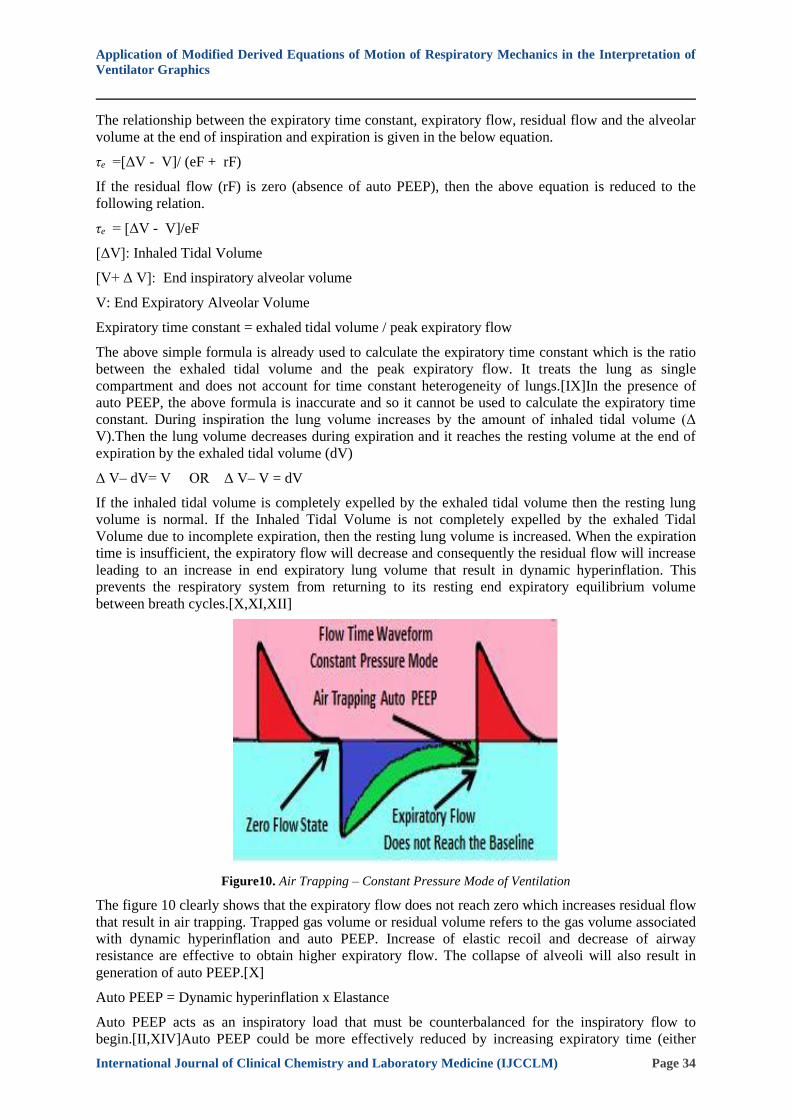
Figure10. Air Trapping – Constant Pressure Mode of Ventilation
The figure 10 clearly shows that the expiratory flow does not reach zero which increases residual flow
that result in air trapping. Trapped gas volume or residual volume refers to the gas volume associated
with dynamic hyperinflation and auto PEEP. Increase of elastic recoil and decrease of airway
resistance are effective to obtain higher expiratory flow. The collapse of alveoli will also result in
generation of auto PEEP.[X]
Auto PEEP = Dynamic hyperinflation x Elastance
Auto PEEP acts as an inspiratory load that must be counterbalanced for the inspiratory flow to
begin.[II,XIV]Auto PEEP could be more effectively reduced by increasing expiratory time (either

Application of Modified Derived Equations of Motion of Respiratory Mechanics in the Interpretation of
Ventilator Graphics
International Journal of Clinical Chemistry and Laboratory Medicine (IJCCLM) Page 35
increasing inspiratory flow or reducing breathing frequency) to increase the ratio between expiratory
time and time constant rather than by decreasing the inspired tidal volume.[X,XI,XII,XV]The
expiratory flow is a passive process so the ratio between expiratory time and expiratory time constant
is very important in assessing the respiratory mechanics. After one time constant (or ratio of one
between the expiratory time and expiratory time constant), the expiratory flow will decrease by 63.3%
to reach a value of 36.7 %.The expiratory flow will decrease by 99.3% to reach a value of 0.7% after
five time constant (ratio of 5).[VI,XIV]The expiratory flow will not reach the zero reference baseline
if the ratio decreases. If the expiratory time is not sufficient then the amount of tidal volume exhaled
will be incomplete resulting in trapping of air which is clearly shown in the figure 10. The inhaled
tidal volume is the product of constant or average inspiratory flow and inspiratory time. If the
inspiratory flow is increased then the required tidal volume is inhaled with a short inspiratory time
that will help in increasing the expiratory time. The frequency and total cycle time duration are
inversely related. So decreasing the frequency will increase the total cycle time (TCT) duration that
may help in increasing the expiratory time depending on I: E ratio. The inspiratory time and
expiratory time can be adjusted to maintain a required I: E ratio.
The current research study clearly discussed the derivation and the application of these newly derived
modified equations of motion of the respiratory mechanics which are considered as differential
equations and not algebraic equations. Some of the parameters in these equations are held constant
while others are a variable quantity that changes with changes in other parameters. These novel
equations may help in better understanding of the ventilator graphics that play a significant role in
management of critically ill patients.
18. CONCLUSION
The ventilator graphics is an indispensable tool that plays a significant role in saving the life of the
mechanically ventilated patients. The study concludes that understanding of the various physical
concepts involved in mechanical ventilation and the application of these derived modified equations
of motion of the respiratory mechanics at the bed side for monitoring these patients may help in better
understanding required for the interpretation of invaluable ventilator graphics.
REFERENCES
[1] Amanda M Dexter and Kimberly Clark. Ventilator Graphics: Scalars, Loops, & Secondary Measures
RESPIRATORY CARE , 2020; 65(6): 739 – 759
[2] Robert L chatburn. Fundamentals of Mechanical Ventilation A short course on the theory and application
of mechanical ventilators. Mandu Press Ltd 2003 , pages: 1-282.
[3] Alysson Roncally Carvalho and Walter Araujo Zin. Respiratory system dynamical mechanical properties:
modeling in time and frequency domain Biophys Rev. 2011 Jun; 3(2): 71. doi: 10.1007/s12551-011-0048-
5
[4] Lutfi, M.F. The physiological basis and clinical significance of lung volume measurements. Multidiscip
Respir Med 12, 3 (2017). https://doi.org/10.1186/s40248-017-0084-5
[5] Yuan Lei. Chapter Mechanical Ventilation Mode, Book Medical Ventilator system Basics: A clinical
guide. DOI:10.1093/med/9780198784975.003.0008
[6] Iotti GA, Braschi A. Measurements of respiratory mechanics during mechanical ventilation. Rhäzüns,
Switzerland: Hamilton Medical AG; 2001
[7] Shevade MS. Time constant: What do we need to know to use it? Indian J Respir Care 2019;8:4-7.
[8] UgurKoca, Mehmet Yildiz ,Ugur YL and Demirdoven BT Mechanical Ventilation Journal of Respiratory
Medicine and Lung Disease ,2020 ; 5 ( 2 ): 2020; 5 (2) Article 1054: 1-11.
[9] Dean R Hess Respiratory Mechanics in Mechanically Ventilated Patients RESPIRATORY CARE 2014;
59(11): 1773- 1794.
[10] Lluı´s Blanch , Francesca Bernabe and Umberto Lucangelo Measurement of Air Trapping, Intrinsic
Positive EndExpiratory Pressure, and Dynamic Hyperinflation in Mechanically Ventilated Patients Respir
Care 2005;50(1):110 –123.
[11] Natalini G., Tuzzo D., Rosano A. et all Assessment of factors related to auto-PEEP. Respir Care.
2016;61(2):134–141. doi: 10.4187/respcare.04063
Application of Modified Derived Equations of Motion of Respiratory Mechanics in the Interpretation of
Ventilator Graphics
International Journal of Clinical Chemistry and Laboratory Medicine (IJCCLM) Page 36
[12] Stephen E. LapinskyAuto-PEEP Encyclopedia of Trauma Care 2015 DOI: https://doi.org/10.1007/978-3-
642-29613-0_234
[13] Ricardo LuizCordioli and Laurent Brochard Respiratory system compliance and resistance in the critically
ill Oxford Textbook of critical care 2nd Edition DOI: 10.1093/med/9780199600830.003.0074
[14] Paul Ouellet Waveform and loop analysis in Mechanical Ventilation SIEMENS 1997, Pages 7-84
[15] Charles S. Williams RRT, AE-C VENTILATOR GRAPHICS ver.2.0
[16] Jean-Michel Arnal Monitoring Mechanical Ventilation Using Ventilator Waveforms Springer 2018 pages:
1-177
[17] Umberto Lucangelo , Francesca Bernabe and Lluis Blanch Lung mechanics at the bedside: make it simple
Current Opinion in Critical Care 2007, 13:64–72
[18] Frank Rittner Martin Doring Drager Technology for life Curves and Loops in Mechanical Ventilation
Pages 6-43.
[19] Dean R Hess RECRUITMENT MANEUVERS AND PEEP TITRATION RESPIRATORY CARE
2015;60(11):1688-1704
[20] Dellamonica N. Lerolle C. Sargentini G. Beduneau F. Di Marco A. Mercat J. C. M. Richard J. L. Diehl J.
Mancebo J. J. Rouby Q. Lu G. Bernardin L. Brochard. PEEP-induced changes in lung volume in acute
respiratory distress syndrome. Two methods to estimate alveolar recruitment Intensive Care Med (2011)
37:1595–1604 DOI 10.1007/s00134-011-2333-y
[21] Bellani G, Patroniti N, Pesenti A Chapter Measurement of Functional Residual Capacity during
Mechanical Ventilation Book Yearbook of Intensive Care and Emergency Medicine, 2010 pp 143-153
[22] Ido G Bikker, Jasper van Bommel, Dinis Reis Miranda, Jan Bakker, DiederikGommers End-expiratory
lung volume during mechanical ventilation: a comparison with reference values and the effect of positive
end-expiratory pressure in intensive care unit patients with different lung conditionsCrit Care. 2008; 12(6):
R145. 2008. doi: 10.1186/cc7125
Citation: Dr.T.Rajini Samuel." Application of Modified Derived Equations of Motion of Respiratory
Mechanics in the Interpretation of Ventilator Graphics", International Journal of Clinical Chemistry and
Laboratory Medicine (IJCCLM), vol. 7, no.1, pp. 20-36, 2021. http://dx.doi.org/10.20431/ 2455-
7153.0701003
Copyright: © 2021 Authors. This is an open-access article distributed under the terms of the Creative
Commons Attribution License, which permits unrestricted use, distribution, and reproduction in any
medium, provided the original author and source are credited.