Patch Testing for Contact Allergy and Allergic Contact Dermatitis
Upload
independentCategory
view
0download
0
ARTICLE IN PRESS
0734-743X/$ - s
doi:10.1016/j.iji
�CorrespondE-mail addr
minokey@yons
International Journal of Impact Engineering 35 (2008) 578–588
www.elsevier.com/locate/ijimpeng
Application of an improved contact algorithm for penetrationanalysis in SPH
Songwon Seoa,�, Oakkey Minb, Jaehoon Leea
aDepartment of Mechanical Engineering, Graduate School, Yonsei University, 134 Shinchon-dong, Seodaemun-gu, Seoul 120-749, Republic of KoreabSchool of Mechanical Engineering, Yonsei University, 134 Shinchon-dong, Seodaemun-gu, Seoul 120-749, Republic of Korea
Received 22 April 2005; received in revised form 24 April 2007; accepted 25 April 2007
Available online 14 September 2007
Abstract
A numerical algorithm to analyze an elasto-plastic contact problem using the smoothed particle hydrodynamics (SPH) method is
proposed. In order to solve the contact problem with SPH when both bodies are deformable, a variational equation based on the virtual
work principle is derived and its solution is obtained by the penalty method. Methods to find the boundary particles and to determine the
boundary normal vector are reviewed to apply to the contact algorithm. In calculating the actual penetration and penetration rate, a
method that can determine the actual normal boundary vector through the contact relationship with a contact surface is proposed. A
numerical simulation is conducted to validate the proposed method in cylindrical coordinates. A steel ball 10mm in diameter impacting a
thin steel plate of 1mm thickness at a high velocity such as 200m/s is chosen to verify that the contact algorithm can be applied to the
penetration problem. The final shape results obtained by the proposed contact algorithm are more similar to the experimental results
than the conventional SPH analysis results.
r 2007 Elsevier Ltd. All rights reserved.
Keywords: Contact algorithm; Penetration; Boundary vector; High velocity
1. Introduction
Smoothed particle hydrodynamics (SPH), though origin-ally developed for astrophysical applications, have alsobeen successfully applied to the problems of solid and fluidmechanics. This method was proposed as an alternative tomesh-based hydrocodes, which have drawbacks such asmesh tangling, severe distortion at large deformations, andincreasing computational costs. Since SPH has no spatialmesh to be distorted, it has the ability to handle largedeformations in solid mechanics [1–4]. However, when SPHis extended to elasto-plastic problems with small deforma-tions at lower velocities, we should consider the contactproperties because several problems still remain: ghoststress and numerical instability (which result from uncon-ditionally referring the information of particles within a
ee front matter r 2007 Elsevier Ltd. All rights reserved.
mpeng.2007.04.009
ing author. Tel.: +822 2123 2817; fax: +82 2 362 2736.
esses: [email protected] (S. Seo),
ei.ac.kr (O. Min), [email protected] (J. Lee).
smoothing length though two colliding bodies do notcontact [5]), numerical fracture, and a separation of contactparticles due to an imaginary tensile force that resistsseparation after impact between bodies.
There have been some efforts to resolve the deficiency ofparticle behavior on the boundary and the study of a simplecontact problem. Randies et al. [1] reviewed the kernel sumdeficiency at boundaries and treated boundary conditions.They proposed a more general treatment of the free surfaceboundary condition based on an extension of the ghostparticles. Monaghan [6] handled the effects that a degree ofpenetration and mixing of materials can cause at thecontact surface because SPH does not require the velocityfield to be single valued. Campbell et al. [5] checked whetheror not particles penetrate each other, and then judgedwhether the contact force could be applied to each particleby the penetration rate, which uses the concept of thepinball algorithm proposed by Belytschko et al. [7].Parshikov et al. [2] obtained the velocity and stress on aninterface using Riemann solutions instead of the mean
ARTICLE IN PRESSS. Seo et al. / International Journal of Impact Engineering 35 (2008) 578–588 579
value for velocity and stress between each particle, assum-ing that contacts occur independently as with fluid particles.
Contact problems are inherently non-linear and have avariational inequality because the actual surface on whichthese bodies meet is generally unknown a priori and has to bedetermined as part of the solution [8,9]. The penalty methodused as the solution technique in this study is used to convertthe inequality constraint into a variational equality on theboundary. In this method, both a penetration and apenetration rate are introduced and a method to determinetheir parameters is proposed. It is also described how todetermine normal vectors on the boundary, especially incylindrical coordinates, how to judge whether the actualcontact occurs or not, and how to reconstruct the actualboundary normal vector that is required to compute a realpenetration. A penetration problem is studied to validatewhether the algorithm can be applied to a problem withfracture in cylindrical coordinates. Body forces and thetraction enforced on bodies are ignored.
2. The method
2.1. Review of SPH theory
SPH is a Lagrangian method which uses particles insteadof a background mesh to compute the spatial derivative.Physical quantities of each particle are calculated from therelation of neighbor particles using the kernel function forinterpolation. Both the kernel approximation to estimate thephysical quantities of a particle and the particle approxima-tion to convert an integral of a continuous system into thediscrete form are used for numerical calculation [4].
Using the concept of unitary volume and kernelapproximation to represent the form of particle approx-imation, expressions for a function at any point X0, u(X0),and its derivative are
uðxiÞ ¼Xn
j¼1
uðxjÞW ðxi � xj ; hÞVj, (1)
ruðxiÞ ¼Xn
j¼1
uðxjÞrW ðxi � xj ; hÞV j, (2)
where W(x0�x,h) is a kernel or smoothing function, h is asmoothing length, and Vj represents the particle volume j.
The smoothing length controls the size of the compactsupport domain O. In order to analyze axisymmetricproblems, the method proposed by Petschk et al. [10] isadopted. We can obtain the governing equations for the r
and z directions using tensor transformation and thesymmetry of cylindrical coordinates:
dri
dt¼ � ri
2
h2
Xj
mj
rj
W c Uri ri � rj
I1
I0
� ��
þUzijzij �Ur
j ri
I1
I0� rj
� ��, ð3Þ
dUri
dt¼
2
h2
Xj
mjW csrr
i
r2iri � rj
I1
I0
� ��
þsrr
j
r2jri
I0 þ I2
2I0
� �� rj
I1
I0
� �� �
þsyyj
r2jri
I0 � I2
2I0
� �þ
srzi
r2iþ
srrj
r2j
I1
I0
!zij þPij
),
ð4Þ
dUzi
dt¼
2
h2
Xj
mjW csrz
i
r2iri � rj
I1
I0
� ��
þsrz
j
r2jri
I1
I0� rj
� �þ
szzi
r2iþ
szzj
r2j
!zij þPij
),
ð5Þ
dEi
dt¼ �
2
h2
Xj
mjW csrr
i
r2iUr
i ri � rj
I1
I0
� ���
þUrj ri
I1
I0�
1
2rj 1þ
I2
I0
� �� ��
þsrz
i
r2izij Ur
i �Urj
I1
I0
� �þUz
ij ri � rj
I1
I0
� �� �
þszz
i
r2iUz
ijzij �syyi
r2iUr
j rj
I0 � I2
2I0þ
Pij
2
�, ð6Þ
where Wc is the 2D cylindrical kernel function, Ik
(k ¼ 0,1,2,y) is the modified Bessel function, zij ¼ zj�zj,Uij
z¼ Ui
z�Uj
z, and Pij is an artificial viscosity, which isintroduced to reduce numerical oscillation occurring whentwo particles approach each other, suggested by Monaghanand Gingold [11]. Libersky and Petschek [3] have for-mulated the elasto-plastic model in SPH in order toconsider the strength of materials impacting under avelocity of about 2 km/s. Total stress sab, in whichcompressive stress is taken to be positive, is expressed interms of a deviatoric stress tensor Sab and hydrostaticpressure P as follows:
sab ¼ Pdab � Sab, (7)
where dab is Kronecker’s delta.The equation of state (EOS) describes the relation-
ship between pressure, density, and internal energy of amaterial in a physical system. When the pressure is not toohigh, the Mie–Gruneisen equation [4] can be successfullyused to represent the deformation property of metallicmaterials.
2.2. Elasto-plastic model
The stress in a material during elastic deformation hasthe relationship of linear proportion to the strain, which iscalled Hooke’s law. A unique strain can thus be determinedwhen a stress is given. However, once a material reaches the
ARTICLE IN PRESSS. Seo et al. / International Journal of Impact Engineering 35 (2008) 578–588580
yield state exceeding the elastic state, the plastic deformationprocess represents history or a path-dependent phenomenon.A material being deformed plastically under a multi-axialstress condition transitions from elasticity to plasticity at thelimitation of combined stress. The von Mises yield criterion isused to check the limitation and the exponential workhardening model as the elasto-plastic constitutive model isapplied. Because a stress state computed during any loadinstant by an explicit method, for instance SPH, may notstrictly satisfy the yield condition, it is necessary to conductiterations to be able to satisfy the yield condition at a giveninstant. The radial return method [12] regarded as a simpleand efficient algorithm is adopted as the time integration ofthe constitutive equation.
The Prandtl–Reuss equation, called plastic flow theory andknown as the representative constitutive equation, is alsoused and is written as the following Eq. (8). This equationassumes that the plastic strain increment is in proportion tothe deviatoric stress for an elasto-plastic material.
d�pab ¼ Sab dl, (8)
where dep denotes the plastic strain increment and dlis a parameter that can be determined using the yieldcriterion.
2.3. Contact theory
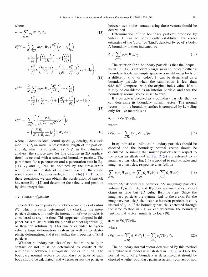
An interaction between contact bodies can be handled bya particular algorithm called the slideline algorithm [13] innumerical analysis. The main concept of this algorithm is toimpose the restriction that two bodies cannot occupy thesame space at the same time. FEM or FDM imposes thecondition of whether a penetration between finite elementlattices whose consecutiveness is given on the contactsurface occurs or not. However, SPH requires new contactconditions and consideration because the contact surface ismodeled by discontinuous particles. These characteristicsare illustrated schematically in Fig. 1.
The variational equation based on the virtual workprinciple can be derived to obtain the numerical formu-lation for SPH [14]. In order to obtain the weak form forthe contact problem, we can multiply the equation ofmotion and the boundary constraint equation by dva, which
Fig. 1. Comparison of contact concept between FEM and SPH: (
is the variation of admissible velocity satisfying both thevelocity condition and the strain rate–velocity relation.Integrating over the domain O and the boundary G, it isgiven asZ
Osab;bdva dV þ
ZOrbadva dV
þ
ZOrvadva dV þ
ZGðta � t̄aÞdva dA ¼ 0. ð9Þ
Applying Gauss’ divergence theorem for the first term onthe left-hand side, we can obtain the equation of virtualwork. The penalty method is used to convert the inequalityconstraint, which is caused by the kinematic constraintcondition imposed on the contact problem, to an equalityconstraint on the boundary. Therefore, the general varia-tion form can be written as the following equation, ignoringthe body force ba:
dW ¼
ZOsabdva;b dV þ
ZOrvadva dV
þ
ZGc
ðl1pn þ l2pnÞnadvdG; ð10Þ
where p is the penetration, p is the penetration rate, and l1and l2 are the parameters for penetration and penetrationrate, respectively. Transforming the weak form of Eq. (10),which is derived from the virtual work principle, into theSPH formulation using the approximations in Eqs. (1) and(2), we can represent it as
XN
i
vai
Xj2Mi
rjW ijVjV i þXj2Mi
sabj rW ijVjV i
"
þX
j2MBci
ðl1pn þ l1pnÞniW ijAiV j
35dvai ¼ 0, ð11Þ
where Mi and MBc
i denote the neighbor particles andneighbor boundary particles within a 2-h distance ofparticle i, respectively, and na is the boundary normalvector. Therefore, the momentum equation acting betweentwo bodies in contact can be written as the following:
mivi ¼ �Finti � Fcon
i , (12)
a) slideline contact algorithm in FEM and (b) contact in SPH.
ARTICLE IN PRESSS. Seo et al. / International Journal of Impact Engineering 35 (2008) 578–588 581
where
mi ¼Xj2Mi
rjW cV jV i, (13)
F int;ri ¼
2
h2
Xj2Mc
mimjW csrr
i
r2iri � rj
I1
I0
� ��
þsrr
j
r2jri
I0 þ I2
2I0
� �� rj
I1
I0
� �� �
þsyyj
r2jri
I0 � I2
2I0
� �þ
srzi
r2iþ
srrj
r2j
I1
I0
!zij þPij
),
ð14Þ
F int;zi ¼
2
h2
Xj2Mc
mimjW csrz
i
r2iri � rj
I1
I0
� ��
þsrz
j
r2jri
I1
I0� rj
� �þ
szzi
r2iþ
szzj
r2j
!zij þPij
),
ð15Þ
F coni ¼
Xj2MBc
i
rjCj
rjCj þ riCi
riCi
!p
(
þEiEj
Ei þ Ej
1
d0
� �p
�niW cAiV j, ð16Þ
where C denotes local sound speed, ri density, Ei elasticmodulus, d0 an initial representative length of the particle,and Ai, which is computed as 2prihi in the cylindricalanalysis, the surface area (or line distance in 2D applica-tions) associated with a contacted boundary particle. Theparameters for a penetration and a penetration rate in Eq.(11), l1 and l2, can be obtained by the stress–strainrelationship in the state of uniaxial stress and the elasticwave theory in ID, respectively, as in Eq. (16) [14]. Throughthese equations, we can obtain the acceleration of particlei,vi, using Eq. (12) and determine the velocity and positionby time integration.
2.4. Contact algorithm
Contact between particles is between two circles of radiusd/2, which is easily determined by checking the inter-particle distance, and only the interaction of two particles isconsidered at any one time. This approach adopted in thispaper has similarities with the pinball contact algorithm [7]or Reimann solution [2]. This can be extended to hyper-velocity large deformation analysis as well as to elasto-plastic deformation, and it can utilize the properties of SPHparticles.
Whether boundary particles of two bodies are really incontact or not must be determined to construct therelationship between elasto-plastic bodies in SPH. Theboundary normal vectors for boundary particles of eachbody should be calculated, and whether or not the particles
between two bodies contact using those vectors should bedetermined.Determination of the boundary particles proposed by
Sulsky [1] can be conveniently established by kernelestimates of the ‘color’ or ‘kind’, denoted by c, of a body.A boundary is then indicated by
ciaXj2Mi
cjmjW ij=rj : (17)
The criterion for a boundary particle is that the inequal-ity in Eq. (17) is sufficiently large so as to indicate either aboundary bordering empty space or a neighboring body ofa different ‘kind’ or ‘color’. It can be designated as aboundary particle when the summation is less than0.85–0.90 compared with the original index value. If not,it may be considered as an interior particle, and then theboundary normal vector is set to zero.If a particle is checked as a boundary particle, then we
can determine its boundary normal vector. The normalvector onto the boundary surface is computed by kernelingonly for like materials as
ni ¼ �ðrc=jrcjÞi,
where
ðrcÞi ¼ �Xj2Mi
cjmjrW ij=rj : (18)
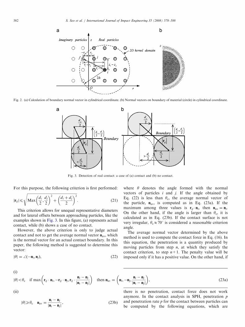
In cylindrical coordinates, boundary particles should bechecked and the boundary normal vector should becalculated. Assuming that mirror particles with respect tothe z-axis as illustrated in Fig. 2 (a) are referred to asimaginary particles, Eq. (17) is applied to real particles andimaginary particles, respectively, as follows:Xj2Mi
cjmjW ij=rj ¼X
j2MRi
cjW ijV j þXj2MI
i
cjW ijV j, (19)
where MiR denotes real particles, Mi
I imaginary particles,volume Vj is dr� dz, and Wij does not use the cylindricalGaussian type but 2D cubic B-spline type. Since theimaginary particles are symmetrical to the z-axis, for theimaginary particle j, the distance between particles is ri+rj
instead of ri�rj. If the boundary particle is detected throughthe same method in 2D, we can determine the boundaryunit normal vector, similarly to Eq. (18).
ni ¼ �ðrc=jrcjÞi,
where
ðrcÞi ¼ �X
j2MRi
cjrW ijVj �Xj2MI
i
cjrW ijVj. (20)
The boundary normal vector determined by this methodin a cylindrical model is illustrated in Fig. 2(b). Once thenormal vector of a boundary is determined, it should bechecked whether boundary particles actually contact or not.
ARTICLE IN PRESS
Fig. 3. Detection of real contact: a case of (a) contact and (b) no contact.
Fig. 2. (a) Calculation of boundary normal vector in cylindrical coordinate. (b) Normal vectors on boundary of material (circle) in cylindrical coordinate.
S. Seo et al. / International Journal of Impact Engineering 35 (2008) 578–588582
For this purpose, the following criterion is first performed:
jrijjp
ffiffiffiffiffiffiffiffiffiffiffiffiffiffiffiffiffiffiffiffiffiffiffiffiffiffiffiffiffiffiffiffiffiffiffiffiffiffiffiffiffiffiffiffiffiffiffiffiffiffiffiffiffiffiffiffiffiffiMax
di
2;dj
2
� �2
þdi þ dj
2
� �2s
. (21)
This criterion allows for unequal representative diametersand for lateral offsets between approaching particles, like theexamples shown in Fig. 3. In this figure, (a) represents actualcontact, while (b) shows a case of no contact.
However, the above criterion is only to judge actualcontact and not to get the average normal vector nav, whichis the normal vector for an actual contact boundary. In thispaper, the following method is suggested to determine thisvector:
jyj ¼ ffð�ni; njÞ, (22)
(i)
jyjoyc if max rij � ni;�rij � nj ; rij �ni � nj
jni � njj
� �then nav ¼ ni;�nj ;
ni � nj
jni � njj
� �, (23a)
(ii)
jyjXyc nav ¼ni � nj
jni � njj, (23b)
re y denotes the angle formed with the normal
whevectors of particles i and j. If the angle obtained byEq. (22) is less than yc, the average normal vector ofthe particle, nav, is computed as in Eq. (23a). If themaximum among three values is rij � ni, then nav ¼ ni.On the other hand, if the angle is larger than yc, it iscalculated as in Eq. (23b). If the contact surface is notvery irregular, ycE701 is considered a reasonable criterionangle.The average normal vector determined by the abovemethod is used to compute the contact force in Eq. (16). Inthis equation, the penetration is a quantity produced bymoving particles from step n, at which they satisfy thecontact criterion, to step n+1. The penalty value will beimposed only if it has a positive value. On the other hand, if
there is no penetration, contact force does not workanymore. In the contact analysis in SPH, penetration p
and penetration rate p for the contact between particles canbe computed by the following equations, which are

ARTICLE IN PRESS
Fig. 5. Schematic of the experimental setup for a rod impact test.
Fig. 6. Velocity–time histories at mid-particles for a rest rod in cylindrical
analysis.
Table 1
Analysis conditions for cylinder impact test by SPH
Analysis coordinate Cylindrical coordinate
Constitutive relation Elastic
Equation of state Mie–Gruneisen EOS
Initial smoothing length (h) 0.1mm
NPH (number of particles per
smoothing length)
1.65
Artificial viscosity coefficients
(a,b)1.0, 1.0
Total number of particles on each
rod
200EA
Time increment (dt) 1.0 ns
Table 2
Material properties and constants for Mie–Gruneisen EOS of iron and
steel
r0(kg/m3)
C0
(m/s)
S G0 v E0
(GPa)
m0(GPa)
Y0
(MPa)
7850.0 3574.0 1.92 1.69 0.185 189.6 80.0 593.0
Fig. 4. Actual contact normal vector and penetration when contact
between particle and particle occurs.
S. Seo et al. / International Journal of Impact Engineering 35 (2008) 578–588 583
illustrated in Fig. 4:
pnav¼ ðRi þ Rj � jrij � navjÞ, (24)
pnav¼ ðvi � vjÞ � nav, (25)
where | | designates the absolute value, rij is the posi-tion vector between particles i and j, and Ri and Rj
denote the radii of particles i and j, respectively. The normalvector nj in Eq. (16) and the average normal vector navdetermined in Eq. (23) can be substituted for the normalvector nj.
3. Simulation and experiment
3.1. Experimental equipment
The experimental devices for a ball impact test arecomposed of five main parts. The schematic of the ballimpact test used in this paper is shown in Fig. 5. Theaccelerator part creates the propulsive power at the ball andthe acceleration tube, which receives the propulsive power,induces straight line flight of the ball. The speed measure-ment part measures the collision speed of the ball when itimpacts the specimen. The alignment base part ensures avertical front collision between the ball and the specimen.And, the last part is a specimen and its fixed part.
The expansive power of nitrogen gas which is compressedto high pressure is used as the propulsive power for flight.Nitrogen gas is stored in an accelerator throughout a valveconnected to the nitrogen gas container and exhaustsinstantaneously when the solenoid valve is opened. In
this moment, a launching valve is automatically movedto the back side by exhausting nitrogen gas with pressurelower than the pressure of the inner vessel at the rearof the launching valve. Finally, the propulsive powerthat accelerates the ball is provided by a launching valvethat moves to the back side with the high-pressure nitro-gen gas induced into the entrance of the accelerator tube,where the ball is fixed. The accelerating ball receives theexpansive power of the high-pressure nitrogen gas, and theball flies in a direction of the specimen. The rigid wall isplaced in the rear of the specimen to receive the ball passingthrough it.
3.2. Simulation and experiment
The impact of two identical cylindrical rods is firstsimulated to see the contact accuracy of the algorithm in
ARTICLE IN PRESS
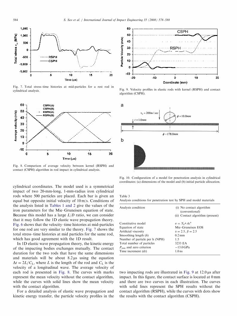
Fig. 7. Total stress–time histories at mid-particles for a rest rod in
cylindrical analysis.
Fig. 8. Comparison of average velocity between kernel (RSPH) and
contact (CSPH) algorithm in rod impact in cylindrical analysis.
Fig. 9. Velocity profiles in elastic rods with kernel (RSPH) and contact
algorithm (CSPH).
Fig. 10. Configuration of a model for penetration analysis in cylindrical
coordinates: (a) dimensions of the model and (b) initial particle allocation.
Table 3
Analysis conditions for penetration test by SPH and model materials
Analysis condition (i) No contact algorithm
(conventional)
(ii) Contact algorithm (present)
Constitutive model s ¼ Y0+Aen
Equation of state Mie–Gruneisen EOS
Artificial viscosity a ¼ 2.5, b ¼ 2.5
Smoothing length (h) 0.2mm
Number of particle per h (NPH) 1.5
Total number of particles 3233 EA
Pmin and zero criterion �13.0GPa
Time increment (dt) 1.0 ns
S. Seo et al. / International Journal of Impact Engineering 35 (2008) 578–588584
cylindrical coordinates. The model used is a symmetricalimpact of two 20-mm-long, 1-mm-radius iron cylindricalrods where 500 particles are placed. Each bar is given anequal but opposite initial velocity of 10m/s. Conditions ofthe analysis listed in Tables 1 and 2 give the values of theiron parameters for the Mie–Gruneisen equation of state.Because this model has a large L/D ratio, we can considerthat it may follow the 1D elastic wave propagation theory.Fig. 6 shows that the velocity–time histories at mid-particlesfor one rod are very similar to the theory. Fig. 7 shows thetotal stress–time histories at mid particles for the same rod,which has good agreement with the 1D result.
In 1D elastic wave propagation theory, the kinetic energyof the impacting bodies exchanges mutually. The contactduration for the two rods that have the same dimensionsand materials will be about 8.2 ms using the equationDt ¼ 2L/CL, where L is the length of the rod and CL is thevelocity of a longitudinal wave. The average velocity ofeach rod is presented in Fig. 8. The curves with marksrepresent the mean velocity without the contact algorithm,while the curves with solid lines show the mean velocitywith the contact algorithm.
For a detailed analysis of elastic wave propagation andkinetic energy transfer, the particle velocity profiles in the
two impacting rods are illustrated in Fig. 9 at 12.0 ms afterimpact. In this figure, the contact surface is located at 0mmand there are two curves in each illustration. The curveswith solid lines represent the SPH results without thecontact algorithm (RSPH), while the curves with dots showthe results with the contact algorithm (CSPH).
ARTICLE IN PRESS
Table 4
Material properties and constants for Mie–Gruneisen EOS of steel
r0 (kg/m3) C0 (m/s) S G0 v E0 (GPa) m0 (GPa) Y0 (MPa) A (MPa) n
7850.0 3600.0 1.90 1.70 0.30 200.0 77.0 600.0 275.0 0.36
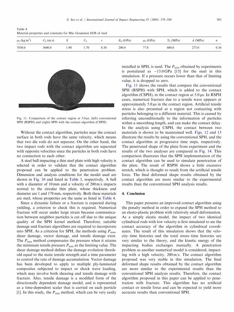
Fig. 11. Comparison of the contact region at 5.0 ms: (left) conventional
SPH (RSPH) and (right) SPH with the contact algorithm (CSPH).
S. Seo et al. / International Journal of Impact Engineering 35 (2008) 578–588 585
Without the contact algorithm, particles near the contactsurface in both rods have the same velocity, which meansthat two die rods do not separate. On the other hand, thetwo impact rods with the contact algorithm are separatedwith opposite velocities since the particles in both rods haveno connection to each other.
A steel ball impacting a thin steel plate with high velocity isselected in order to validate that the contact algorithmproposed can be applied to the penetration problem.Dimension and analysis conditions for the model used areshown in Fig. 10 and listed in Table 3, respectively. A ballwith a diameter of 10mm and a velocity of 200m/s impactsnormal to the circular thin plate, whose thickness anddiameter are 1 and 178mm, respectively. Both these materialsare steel, whose properties are the same as listed in Table 4.
Since a dynamic failure or a fracture is expected duringyielding, a criterion to check this is required. Numericalfracture will occur under large strain because communica-tion between neighbor particles is cut off due to the uniquequality of the SPH kernel method. Therefore, suitabledamage and fracture algorithms are required to incorporateinto SPH. As a criterion for SPH, the methods using Pmin,shear damage, vector damage, and tensile damage exist.The Pmin method compensates the pressure when it attainsthe minimum tensile pressure Pmin as the limiting value. Theshear damage method defines the damage evolution thresh-old equal to the static tensile strength and a time parameterto control the rate of damage accumulation. Vector damagehas been developed to apply to multiple ply-laminatedcomposites subjected to impact or shock wave loading,which may involve both shearing and tensile damage withfracture. Also, tensile damage is a modified form of thedirectionally dependent damage model, and is representedas a time-dependent scalar that is carried on each particle[1]. In this study, the Pmin method, which can be very easily
installed in SPH, is used. The Pmin obtained by experimentsis postulated as �13.0GPa [15] for the steel in thissimulation. If a pressure occurs lower than that of limitingvalue, it is dropped to zero.Fig. 11 shows the results that compare the conventional
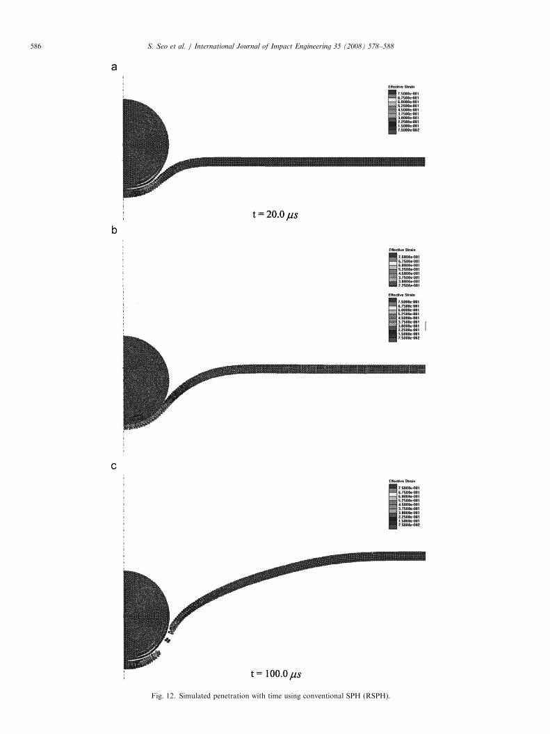
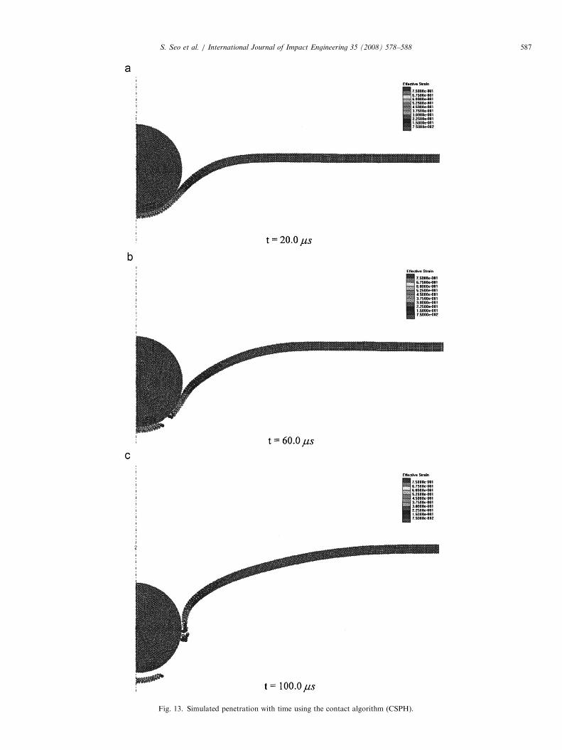
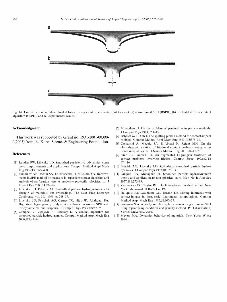
SPH (RSPH) with SPH, which is added to the contactalgorithm (CSPH), in the contact region at 5.0 ms. In RSPHcases, numerical fracture due to a tensile wave appears atapproximately 5.0 ms in the contact region. Artificial tensilestress is also presented at a region not contacting withparticles belonging to a different material. This is caused byreferring unconditionally to the information of particleswithin a smoothing length, and can make the contact delay.In the analysis using CSPH, the contact between twomaterials is shown to be maintained well. Figs. 12 and 13illustrate the results by using the conventional SPH, and thecontact algorithm at progressive time steps, respectively.The penetrated shape of the plate from experiment and theresults of the two analyses are compared in Fig. 14. Thiscomparison illustrates that the SPH implementation of thecontact algorithm can be used to simulate penetration ofthe plate. The result of RSPH shows a little excessivestretch, which is thought to result from the artificial tensileforce. The final deformed shape results obtained by thecontact algorithm are more similar to the experimentalresults than the conventional SPH analysis results.
4. Conclusion
This paper presents an improved contact algorithm usingthe penalty method in order to expand the SPH method toan elasto-plastic problem with relatively small deformation.As a simply elastic model, the impact of two identicalcylindrical rods with low velocity is first simulated to see thecontact accuracy of the algorithm in cylindrical coordi-nates. The result of this simulation shows that the velo-city–time histories and the total stress–time histories arevery similar to the theory, and the kinetic energy of theimpacting bodies exchanges mutually. A penetrationproblem as another numerical model is considered, impact-ing with a high velocity, 200m/s. The contact algorithmproposed was very stable in this simulation. The finaldeformed shape results obtained by the contact algorithmare more similar to the experimental results than theconventional SPH analysis results. Therefore, the contactalgorithm proposed in this paper can be applied to pene-tration with fracture. This algorithm has no artificialcontact or tensile force and can be expected to yield moreaccurate results than conventional SPH.
ARTICLE IN PRESS
Fig. 12. Simulated penetration with time using conventional SPH (RSPH).
S. Seo et al. / International Journal of Impact Engineering 35 (2008) 578–588586
ARTICLE IN PRESS
Fig. 13. Simulated penetration with time using the contact algorithm (CSPH).
S. Seo et al. / International Journal of Impact Engineering 35 (2008) 578–588 587
ARTICLE IN PRESS
Fig. 14. Comparison of simulated final deformed shapes and experimental (not to scale): (a) conventional SPH (RSPH), (b) SPH added to the contact
algorithm (CSPH), and (c) experimental results.
S. Seo et al. / International Journal of Impact Engineering 35 (2008) 578–588588
Acknowledgment
This work was supported by Grant no. RO1-2001-00390-0(2003) from the Korea Science & Engineering Foundation.
References
[1] Randies PW, Libersky LD. Smoothed particle hydrodynamics: some
recent improvements and applications. Comput Method Appl Mech
Eng 1996;139:375–408.
[2] Parshikov AN, Medin SA, Loukashenko II, Milekhin VA. Improve-
ments in SPH method by means of interparticle contact algorithm and
analysis of perforation tests at moderate projectile velocities. Int J
Impact Eng 2000;24:779–96.
[3] Libersky LD, Petschk AG. Smoothed particle hydrodynamics with
strength of materials. In: Proceedings, The Next Free Lagrange
Conference, vol. 395, 1991. p. 248–57.
[4] Libersky LD, Petschek AG, Carney TC, Hipp JR, Allahdadi FA.
High strain lagrangian hydrodynamics; a three-dimensional SPH code
for dynamic material response. J Comput Phys 1993;109:67–75.
[5] Campbell J, Vignjevic R, Libersky L. A contact algorithm for
smoothed particle hydrodynamics. Comput Method Appl Mech Eng
2000;184:49–64.
[6] Monaghan JJ. On the problem of penetration in particle methods.
J Comput Phys 1989;82:1–15.
[7] Belytschko T, Yeh I. The splitting pinball method for contact-impact
problem. Comput Method Appl Mech Eng 1993;105:375–93.
[8] Czekanski A, Meguid SA, El-Abbasi N, Refaat MH. On the
elastodynamic solution of frictional contact problems using varia-
tional inequalities. Int J Numer Method Eng 2001;50:611–27.
[9] Simo JC, Laursen TA. An augmented Lagrangian treatment of
contact problems involving friction. Comput Struct 1992;42(1):
97–116.
[10] Petschk AG, Libersky LD. Cylindrical smoothed particle hydro-
dynamics. J Comput Phys 1993;109:76–83.
[11] Gingold RA, Monaghan JJ. Smoothed particle hydrodynamics:
theory and application to non-spherical stars. Mon No R Astr Soc
1977;181:375–89.
[12] Zienkiewicz OC, Taylor RL. The finite element method. 4th ed. New
York: McGraw-Hill Book Co; 1991.
[13] Hallquist JO, Goudreau GL, Benson DJ. Sliding interfaces with
contact-impact in large-scale Lagrangian computations. Comput
Method Appl Mech Eng 1985;51:107–37.
[14] Songwon Seo. A study on elasto-plastic contact algorithm in SPH
using reproducing condition and penalty method. PhD dissertation,
Yonsei University, 2004.
[15] Meyers MA. Dynamics behavior of materials. New York: Wiley;
1994.
Copyright © 2022 FDOKUMEN