Application notes for TeleMatrix 3302IP SIP Telephones with ...
Upload
khangminh22Category
view
1download
0
Avaya Solution & Interoperability Test Lab
Application Notes for the Allot NetEnforcer with Avaya Communication Manager - Issue 1.0
Abstract
These Application Notes describe the procedure for configuring the Allot NetEnforcer to guarantee WAN link bandwidth to Voice over IP (VoIP) traffic generated by Avaya Media Servers, Avaya Media Gateways, and Avaya IP Telephones. During compliance testing, telephone calls going across the WAN link were successfully established with good voice quality regardless of the amount of non-VoIP traffic sharing the WAN link. Information in these notes has been obtained through compliance testing and additional technical discussions. Testing was conducted via the DeveloperConnection Program at the Avaya Solution and Interoperability Test Lab.
BS; Reviewed: SPOC 1/31/2005
Solution & Interoperability Test Lab Application Notes ©2005 Avaya Inc. All Rights Reserved.
1 of 25 NetEnforcer.doc
BS; Reviewed: SPOC 1/31/2005
Solution & Interoperability Test Lab Application Notes ©2005 Avaya Inc. All Rights Reserved.
2 of 25 NetEnforcer.doc
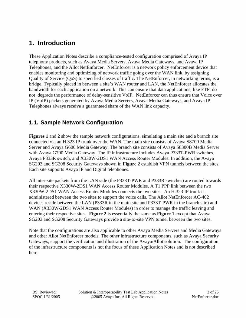
1. Introduction These Application Notes describe a compliance-tested configuration comprised of Avaya IP telephony products, such as Avaya Media Servers, Avaya Media Gateways, and Avaya IP Telephones, and the Allot NetEnforcer. NetEnforcer is a network policy enforcement device that enables monitoring and optimizing of network traffic going over the WAN link, by assigning Quality of Service (QoS) to specified classes of traffic. The NetEnforcer, in networking terms, is a bridge. Typically placed in between a site’s WAN router and LAN, the NetEnforcer allocates the bandwidth for each application on a network. This can ensure that data applications, like FTP, do not degrade the performance of delay-sensitive VoIP. NetEnforcer can thus ensure that Voice over IP (VoIP) packets generated by Avaya Media Servers, Avaya Media Gateways, and Avaya IP Telephones always receive a guaranteed share of the WAN link capacity.
1.1. Sample Network Configuration Figures 1 and 2 show the sample network configurations, simulating a main site and a branch site connected via an H.323 IP trunk over the WAN. The main site consists of Avaya S8700 Media Server and Avaya G600 Media Gateway. The branch site consists of Avaya S8300B Media Server with Avaya G700 Media Gateway. The IP infrastructure includes Avaya P333T-PWR switches, Avaya P333R switch, and X330W-2DS1 WAN Access Router Modules. In addition, the Avaya SG203 and SG208 Security Gateways shown in Figure 2 establish VPN tunnels between the sites. Each site supports Avaya IP and Digital telephones. All inter-site packets from the LAN side (the P333T-PWR and P333R switches) are routed towards their respective X330W-2DS1 WAN Access Router Modules. A T1 PPP link between the two X330W-2DS1 WAN Access Router Modules connects the two sites. An H.323 IP trunk is administered between the two sites to support the voice calls. The Allot NetEnforcer AC-402 devices reside between the LAN (P333R in the main site and P333T-PWR in the branch site) and WAN (X330W-2DS1 WAN Access Router Modules) in order to manage the traffic leaving and entering their respective sites. Figure 2 is essentially the same as Figure 1 except that Avaya SG203 and SG208 Security Gateways provide a site-to-site VPN tunnel between the two sites. Note that the configurations are also applicable to other Avaya Media Servers and Media Gateways and other Allot NetEnforcer models. The other infrastructure components, such as Avaya Security Gateways, support the verification and illustration of the Avaya/Allot solution. The configuration of the infrastructure components is not the focus of these Application Notes and is not described here.

Avaya 6408D+Digital Phone
Ext. 30004
Avaya S8700 Media ServerIP Addr: 192.45.100.10
VLAN 100
Avaya G600 Media GatewayIPSI IP Addr: 192.45.100.13
C-LAN IP Addr: 192.45.100.17MEDPRO IP Addr: 192.45.100.19
VLAN 100
Avaya 4612 IPPhone
Ext.30001VLAN 100
Avaya 4612 IPPhone
Ext. 30002VLAN 100
192.168.100.1
T1 PPP
Avaya 4612 IPPhone
Ext. 50000VLAN 10
Avaya 4612 IPPhone
Ext. 50001VLAN 10
Avaya 6424D+Digital Phone
Ext. 50002
Main Site
Branch Site
VLAN 100, 101
Main Site VLANsVLAN 100: 192.45.100.0/24VLAN 101: 192.45.101.0/24 VLAN 102: 192.45.102.0/24
Branch Site VLANsVLAN 10: 10.1.1.0/24VLAN 11: 11.1.1.0/24
VLAN 102
DHCP/FTP ServerIP Addr:
192.45.101.170VLAN 101
PCVLAN 101
PCVLAN 11
192.168.100.0
10.1.1.254
11.1.1.254
192.45.102.1 192.45.102.2
192.45.101.254
Allot NetEnforcer AC-402
192.168.100.2
Allot NetEnforcer AC-402
Avaya P333T-PWRPower Over Ethernet
Stackable SwitchAvaya P333R Stackable Switch withX330W-2DS1 WAN Access Router Module
Avaya P333T-PWRPower Over Ethernet Stackable Switch with
X330W-2DS1 WAN Access Router Module
Avaya S8300B Media Server withG700 Media Gateway
Serv er IP Addr: 10.1.1.1P330 Stack: 10.1.1.2
MGP IP Addr: 10.1.1.3VoIP Addr: 10.1.1.4
VLAN 10
Figure 1: Sample Network Configuration
BS; Reviewed: SPOC 1/31/2005
Solution & Interoperability Test Lab Application Notes ©2005 Avaya Inc. All Rights Reserved.
3 of 25 NetEnforcer.doc

Avaya 6408D+Digital Phone
Ext. 30004
Avaya S8700 Media ServerIP Addr: 192.45.100.10
VLAN 100
Avaya G600 Media GatewayIPSI IP Addr: 192.45.100.13
C-LAN IP Addr: 192.45.100.17MEDPRO IP Addr: 192.45.100.19
VLAN 100
Avaya 4612 IPPhone
Ext.30001VLAN 100
Avaya 4612IPPhone
Ext. 30002VLAN 100
192.168.100.1
T1 PPP
Avaya 4612 IP PhoneExt. 50000VLAN 10
Avaya 4612 IPPhone
Ext. 50001VLAN 10
Avaya 6424D+Digital Phone
Ext. 50002
Avaya P333T-PWRPower Over Ethernet
Stackable Switch
Main Site
Branch Site
Avaya P333R Stackable Switch withX330W-2DS1 WAN Access Router Module
VLAN 100, 101
Main Site VLANsVLAN 100: 192.45.100.0/24VLAN 101: 192.45.101.0/24VLAN 102: 192.45.102.0/24
Branch Site VLANsVLAN 10: 10.1.1.0/24VLAN 11: 11.1.1.0/24
Avaya S8300B Media Server withG700 Media Gateway
Serv er IP Addr: 10.1.1.1P330 Stack: 10.1.1.2
MGP IP Addr: 10.1.1.3VoIP Addr: 10.1.1.4
VLAN 10
DHCP/FTP ServerIP Addr:
192.45.101.170VLAN 101
PCVLAN 101
PCVLAN 10
192.168.100.0
10.1.1.254
192.45.102.1
192.45.102.2
192.45.101.254
Allot NetEnforcer AC-402
Avaya SG203 Security Gateway
Avaya SG208 SecurityGateway
192.168.100.2
Allot NetEnforcer AC-402
192.168.101.2
192.168.101.1
192.168.102.2
192.168.102.1
Avaya P333T-PWRPower Over Ethernet Stackable Switch with
X330W-2DS1 WAN Access Router Module
Figure 2: Sample Network Configuration with Site-to-Site VPN Tunnel Between Sites
BS; Reviewed: SPOC 1/31/2005
Solution & Interoperability Test Lab Application Notes ©2005 Avaya Inc. All Rights Reserved.
4 of 25 NetEnforcer.doc
BS; Reviewed: SPOC 1/31/2005
Solution & Interoperability Test Lab Application Notes ©2005 Avaya Inc. All Rights Reserved.
5 of 25 NetEnforcer.doc
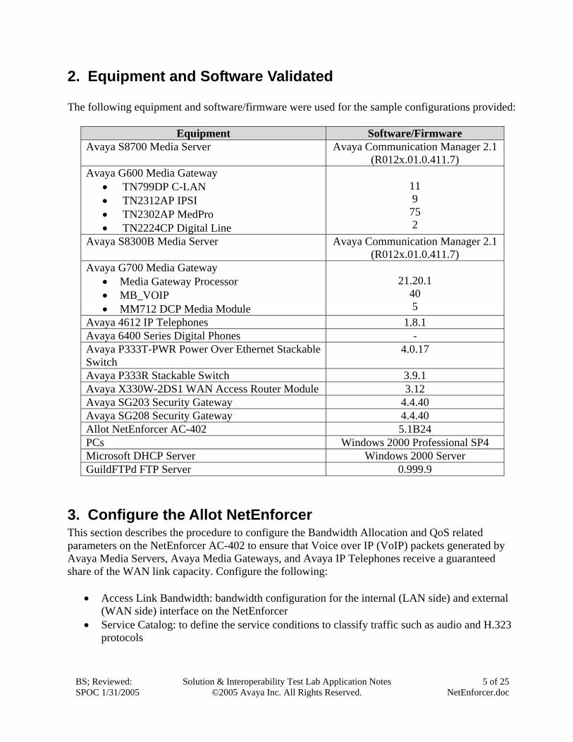
2. Equipment and Software Validated The following equipment and software/firmware were used for the sample configurations provided:
Equipment Software/Firmware Avaya S8700 Media Server Avaya Communication Manager 2.1
(R012x.01.0.411.7) Avaya G600 Media Gateway
• TN799DP C-LAN • TN2312AP IPSI • TN2302AP MedPro • TN2224CP Digital Line
11 9 75 2
Avaya S8300B Media Server Avaya Communication Manager 2.1 (R012x.01.0.411.7)
Avaya G700 Media Gateway • Media Gateway Processor • MB_VOIP • MM712 DCP Media Module
21.20.1
40 5
Avaya 4612 IP Telephones 1.8.1 Avaya 6400 Series Digital Phones - Avaya P333T-PWR Power Over Ethernet Stackable Switch
4.0.17
Avaya P333R Stackable Switch 3.9.1 Avaya X330W-2DS1 WAN Access Router Module 3.12 Avaya SG203 Security Gateway 4.4.40 Avaya SG208 Security Gateway 4.4.40 Allot NetEnforcer AC-402 5.1B24 PCs Windows 2000 Professional SP4 Microsoft DHCP Server Windows 2000 Server GuildFTPd FTP Server 0.999.9
3. Configure the Allot NetEnforcer This section describes the procedure to configure the Bandwidth Allocation and QoS related parameters on the NetEnforcer AC-402 to ensure that Voice over IP (VoIP) packets generated by Avaya Media Servers, Avaya Media Gateways, and Avaya IP Telephones receive a guaranteed share of the WAN link capacity. Configure the following:
• Access Link Bandwidth: bandwidth configuration for the internal (LAN side) and external (WAN side) interface on the NetEnforcer
• Service Catalog: to define the service conditions to classify traffic such as audio and H.323 protocols

• Quality of Service (QoS) Catalog: to define actions for the classified traffic such as bandwidth allocation
• Policies: to associate a set of actions (from the QoS Catalog) to conditions (from the Service Catalog) such as bandwidth allocation for H.323 Audio. A grouping of traffic defined by conditions (rules) and actions is called a Pipe. A Pipe owns sub-groupings called Virtual Channels.
• DSCP Marking (Optional): re-marking of the bits in the DSCP byte.
This section describes the steps for creating catalog entries that define conditions (rules) and actions (Quality of Service) that are subsequently applied to the Pipes and Virtual Channels for the VoIP traffic.
3.1. Configure Access Link Bandwidth This section covers the bandwidth configuration for the internal and external interfaces on the NetEnforcer, which refer to the LAN side and WAN side respectively. Step Description
1. Open a browser, enter NetEnforcer’s IP address as the URL and log in with the appropriate password.
2. Click Log On. The NetEnforcer Control Panel is displayed.
BS; Reviewed: SPOC 1/31/2005
Solution & Interoperability Test Lab Application Notes ©2005 Avaya Inc. All Rights Reserved.
6 of 25 NetEnforcer.doc

BS; Reviewed: SPOC 1/31/2005
Solution & Interoperability Test Lab Application Notes ©2005 Avaya Inc. All Rights Reserved.
7 of 25 NetEnforcer.doc
Step Description 3. From the NetEnforcer Control Panel click on the Configuration tab, and then the Access
Links tab. Set the following parameters: • Bandwidth for External interface: Enter the capacity of the WAN link in the
Inbound Bandwidth and Outbound Bandwidth textboxes for the External interface and click on Save to NetEnforcer under the File menu. In the example below, a rate of 1.5Mbps is used to approximate the T1 link rate.
• Bandwidth for Internal interface: Enter the capacity of the LAN link in the Inbound Bandwidth and Outbound Bandwidth textboxes for the External interface and click on Save to NetEnforcer under the File menu. In the example below, a rate of 45Mbps is used on the LAN side.
Note: For VPN configurations, the effective inbound/outbound rates may be significantly lower depending on the encryption algorithm used and processing power of the VPN devices. The calculation of the effective rates is beyond the scope of this document. Use the effective rates if they can be determined.
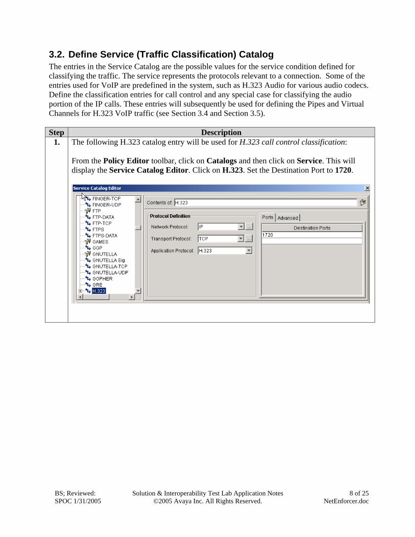
3.2. Define Service (Traffic Classification) Catalog The entries in the Service Catalog are the possible values for the service condition defined for classifying the traffic. The service represents the protocols relevant to a connection. Some of the entries used for VoIP are predefined in the system, such as H.323 Audio for various audio codecs. Define the classification entries for call control and any special case for classifying the audio portion of the IP calls. These entries will subsequently be used for defining the Pipes and Virtual Channels for H.323 VoIP traffic (see Section 3.4 and Section 3.5). Step Description
1. The following H.323 catalog entry will be used for H.323 call control classification: From the Policy Editor toolbar, click on Catalogs and then click on Service. This will display the Service Catalog Editor. Click on H.323. Set the Destination Port to 1720.
BS; Reviewed: SPOC 1/31/2005
Solution & Interoperability Test Lab Application Notes ©2005 Avaya Inc. All Rights Reserved.
8 of 25 NetEnforcer.doc

BS; Reviewed: SPOC 1/31/2005
Solution & Interoperability Test Lab Application Notes ©2005 Avaya Inc. All Rights Reserved.
9 of 25 NetEnforcer.doc
Step Description 2. The following H.323 catalog entry will be used for H.323 Audio classification:
Note: This catalog entry must be used for the audio classification if the Direct IP-IP Audio Connections in the Signaling Group form in Avaya Communication Manager is set to yes (i.e., shuffling of audio paths is enabled). See Section 4.2.1. From the Service Catalog Editor, Click on New and then click on Application. Enter the name, in the Contents of textbox. Select IP for Network Protocol, UDP for Transport Protocol and Other UDP for Application Protocol. Enter the UDP port range in the Destination Ports textbox that matches the port range administered in the IP Network Region form in Avaya Communication Manager (see Section 4.1.2). In the following example, the UDP port range is 2048-3049.
BS; Reviewed: SPOC 1/31/2005
Solution & Interoperability Test Lab Application Notes ©2005 Avaya Inc. All Rights Reserved.
10 of 25 NetEnforcer.doc
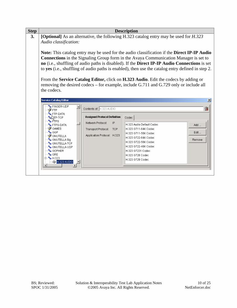
Step Description 3. [Optional] As an alternative, the following H.323 catalog entry may be used for H.323
Audio classification: Note: This catalog entry may be used for the audio classification if the Direct IP-IP Audio Connections in the Signaling Group form in the Avaya Communication Manager is set to no (i.e., shuffling of audio paths is disabled). If the Direct IP-IP Audio Connections is set to yes (i.e., shuffling of audio paths is enabled), then use the catalog entry defined in step 2. From the Service Catalog Editor, click on H.323 Audio. Edit the codecs by adding or removing the desired codecs – for example, include G.711 and G.729 only or include all the codecs.

3.3. Define QoS (Quality of Service) Catalog The entries in the QoS catalog are the possible values for the Quality of Service action defined for a connection. The Quality of Service entry allocates bandwidth and specifies traffic priority. These entries will subsequently be used for defining the Pipes and Virtual Channels for H.323 VoIP traffic (see Section 3.4 and Section 3.5). Step Description
1. The following H.323 catalog entry will later be used for setting priority for call control in the Policy Editor. From the Policy Editor toolbar, click on the Catalogs and then click on Service. This will display the Quality of Service Catalog Editor. Click on New and select Virtual Channel Allocation. Enter the name for this entry in the Contents of textbox, and enter the Priority. In the following example, the priority is set to the highest priority of 10.
BS; Reviewed: SPOC 1/31/2005
Solution & Interoperability Test Lab Application Notes ©2005 Avaya Inc. All Rights Reserved.
11 of 25 NetEnforcer.doc

BS; Reviewed: SPOC 1/31/2005
Solution & Interoperability Test Lab Application Notes ©2005 Avaya Inc. All Rights Reserved.
12 of 25 NetEnforcer.doc
Step Description 2. The following H.323 catalog entry will later be used for bandwidth allocation for H.323
Audio in the Policy Editor. From the Quality of Service Catalog Editor, click on New and select Virtual Channel Allocation. Enter the name for this entry in the Contents of text box, and enter the Minimum and Maximum Bandwidth for the Virtual Channel Allocation. For per call connection allocation within a virtual channel, enter the Minimum Bandwidth per connection. In the following example, the bandwidth is reserved for five H.323 VOIP call connections. Assuming that each G.711 call will require about 90Kbps, includes the packet overhead, the minimum and maximum bandwidth for the Virtual Channel is set to 450 Kbps. The minimum bandwidth for each voice call connection is set to 90 Kbps. .
Note: When the bandwidth is reserved for N voice calls on the NetEnforcer, it allocates the bandwidth for N calls. The N+1th call should be blocked to ensure that N calls are reliable and the quality of the calls remain acceptable. The NetEnforcer does not block the N+1th call. The Avaya Communication Manager Server must be configured to block the N+1th call by making sure that the number of calls originating from the Avaya Media Gateway is set to N calls. See Section 4.2.3

BS; Reviewed: SPOC 1/31/2005
Solution & Interoperability Test Lab Application Notes ©2005 Avaya Inc. All Rights Reserved.
13 of 25 NetEnforcer.doc
Step Description 3. Now click on General in the Quality of Service Catalog Editor. Select Admit by
Priority under the Conditional Admission section of the screen.
3.4. Define Policies for Bandwidth Allocation NetEnforcer allows you to classify and enforce Quality of Service. QoS Policy consists of a set of conditions (rules) and a set of actions that apply as a consequence of conditions being satisfied. A Pipe or a Virtual Channel is defined by one or more rules and a set of actions. A Pipe includes one or more virtual channels. NetEnforcer supports several conditions and the sets of actions. The most relevant for the VoIP bandwidth optimization is the Service condition (defines protocols relevant to a connection), and the actions defined for Quality of Service.

BS; Reviewed: SPOC 1/31/2005
Solution & Interoperability Test Lab Application Notes ©2005 Avaya Inc. All Rights Reserved.
14 of 25 NetEnforcer.doc
Step Description 1. The default Pipe configured in the NetEnforcer is called the Fallback Pipe. Create a new
Pipe or use the default Pipe for configuring the virtual channels for the H.323 VoIP traffic. In the following example, the two Virtual Channels are defined within the Fallback Pipe – one for the H.323 audio portion of the call and the other for the H.323 call control. H.323 Audio Virtual Channel From the Policy Editor, click on Insert on the toolbar to create the Virtual Channel and define the parameters in the following columns:
• Name: Enter the name, e.g. H.323 Audio, for the H.323 Audio virtual channel.
• Service: From the drop down menu, select the catalog entry defined in the Section 3.2. That is, select the H.323 Audio Service catalog entry. Note that if the Direct IP-IP Audio Connections is set to yes (i.e., shuffling of audio paths is enabled) in the Avaya Communication Manager, ensure that the catalog entry based on the UDP port range is selected, as defined in Step 2 of Section 3.2.
• Quality of Service: From the drop down menu, select the QoS catalog entry defined for the bandwidth allocation in Step 2 of Section 3.3. That is, select the MinMax450 connections entry that reserves and allocates the bandwidth for five G.711 call at 90Kbps each.

BS; Reviewed: SPOC 1/31/2005
Solution & Interoperability Test Lab Application Notes ©2005 Avaya Inc. All Rights Reserved.
15 of 25 NetEnforcer.doc
Step Description 2. H.323 Call Control Virtual Channel
From the Policy Editor, click Insert on the toolbar to create the Virtual Channel and define the parameters in the following columns:
• Name: Enter the name, e.g. H.323 Control, for the H.323 call control virtual channel.
• Service: From the drop down menu, select the H.323 Service catalog entry, defined in Step 1 of Section 3.2. The H.323 catalog entry covers all the relevant H.323 call control protocols.
• Quality of Service: From the drop down menu, select the High Priority QoS catalog entry, defined in Step 1 of Section 3.3. Setting High Priority gives the highest priority to the H.323 call control packets in the NetEnforcer.
3. FTP and other Virtual Channels Create a new Pipe or use the default Fallback Pipe for configuring other virtual channels such as FTP. The Quality of Service of these Virtual Channels can be configured in the same manner as the H.323 VoIP virtual channels as described above.

3.5. DSCP Marking (Optional) NetEnforcer supports the re-marking of the Differentiated Services Code Point (DSCP) value. In order to remark DSCP for the H.323 call control and H.323 audio, add entries for the DSCP markings in the TOS Catalog Editor and then assign them in the Policy Editor Step Description
1. From the Policy Editor toolbar, click on Catalogs and then click on TOS. This will display the TOS Catalog Editor. Click on New. Enter the name 34 (or any name of your choice) for this entry in the Contents of text box, and enter the TOS Byte Bit Settings for the value 34. Similarly, add an entry in the TOS catalog for DSCP 46.
BS; Reviewed: SPOC 1/31/2005
Solution & Interoperability Test Lab Application Notes ©2005 Avaya Inc. All Rights Reserved.
16 of 25 NetEnforcer.doc

BS; Reviewed: SPOC 1/31/2005
Solution & Interoperability Test Lab Application Notes ©2005 Avaya Inc. All Rights Reserved.
17 of 25 NetEnforcer.doc
Step Description 2. From the Policy Editor,
• Select the H.323 Audio virtual channel entry. In the Quality of Service for this virtual channel entry, select Mark 46 from the drop down menu.
• Select the H.323 Control virtual channel entry. In the Quality of Service for this virtual channel entry, select Mark 34 from the drop down menu.

BS; Reviewed: SPOC 1/31/2005
Solution & Interoperability Test Lab Application Notes ©2005 Avaya Inc. All Rights Reserved.
18 of 25 NetEnforcer.doc
4. Configure the Avaya Communication Manager
4.1. Configure VoIP Attributes and QoS
4.1.1. IP Audio Codec Set Administer the desired audio codec – G.711 or G.729 – using the ip-codec-set form. To specify the codecs, enter change ip-codec-set p using the System Access Terminal (SAT), where p is the number of a codec set, and modify the ip-codec-set form accordingly. The default settings are shown below:
change ip-codec-set 1 Page 1 of 2 IP Codec Set Codec Set: 1 Audio Silence Frames Packet Codec Suppression Per Pkt Size(ms) 1: G.711MU n 2 20 2:
4.1.2. VoIP Attributes and QOS In the sample configurations described in these Application Notes, the main site and the branch site is assigned an IP network region. To configure the VoIP attributes for each IP network region, enter change ip-network-region m using the SAT, where m is the number of the region. On Page 1 of the change ip-network-region form, configure the following:
1. Codec Set – Enter the number of the codec set that will be used in this region. 2. UDP Ports: Enter the range of the UDP ports for the audio portion of the calls. 3. DiffServ/ToS Parameters and 802.1P/Q Parameters – Enter DSCP and 802.1p values for
call control and audio RTP packets originating from the region. 4. Intra-region IP-IP Direct Audio – if set to yes, RTP audio paths may be established
directly between IP telephones within the region. These are also called the shuffled paths. 5. Inter-region IP-IP Direct Audio – if set to yes, RTP audio paths may be established
directly between an IP telephone within this region and another IP telephone in another region that also has this parameter set to yes. These are also called the shuffled paths.

BS; Reviewed: SPOC 1/31/2005
Solution & Interoperability Test Lab Application Notes ©2005 Avaya Inc. All Rights Reserved.
19 of 25 NetEnforcer.doc
change ip-network-region 2 Page 1 of 19 IP NETWORK REGION Region: 2 Location: Home Domain: Name: Intra-region IP-IP Direct Audio: yes AUDIO PARAMETERS Inter-region IP-IP Direct Audio: yes Codec Set: 1 IP Audio Hairpinning? y UDP Port Min: 2048 UDP Port Max: 3049 RTCP Reporting Enabled? n DIFFSERV/TOS PARAMETERS Call Control PHB Value: 34 Audio PHB Value: 46 802.1P/Q PARAMETERS Call Control 802.1p Priority: 7 Audio 802.1p Priority: 6 AUDIO RESOURCE RESERVATION PARAMETERS H.323 IP ENDPOINTS RSVP Enabled? n H.323 Link Bounce Recovery? y Idle Traffic Interval (sec): 20 Keep-Alive Interval (sec): 5 Keep-Alive Count: 5
4.1.3. Assign IP Addresses to IP Network Regions To assign a range of IP addresses to an IP Network Region, enter change ip-network-map using the SAT. On Page 1 of the change ip-network-map form, enter one or more IP address ranges and the IP network regions to which they belong. In the example below, IP endpoints (i.e., IP telephones) in the 192.45.100.0/24 subnet are assigned to IP Network Region 2. change ip-network-map Page 1 of 32 IP ADDRESS MAPPING Emergency Subnet Location From IP Address (To IP Address or Mask) Region VLAN Extension 192.45 .100.0 192.45 .100.255 24 2 100 . . . . . . n . . . . . . n

BS; Reviewed: SPOC 1/31/2005
Solution & Interoperability Test Lab Application Notes ©2005 Avaya Inc. All Rights Reserved.
20 of 25 NetEnforcer.doc
4.2. Configure H.323 IP trunk between the two sites
4.2.1. Signaling Group Administer a signaling group on each S8700 and S8300 by entering change signaling-group n, where n is the number of the signaling group number.
• Group Type and trunk group: Enter h.323 for Group Type and associate this signaling group with an H.323 trunk group by entering the value of trunk group number in the Trunk Group for Channel Selection field.
• Node names and the listen ports: Enter the near-end and far-end node names and the listen ports. Enter the Far-End network-region.
• Direct IP-IP Audio Connections – if set to yes, RTP audio paths may be established directly between IP telephones that use the IP trunk. These are also called the shuffled paths.
change signaling-group 60 Page 1 of 5 SIGNALING GROUP Group Number: 60 Group Type: h.323 Remote Office? n Max number of NCA TSC: 0 SBS? n Max number of CA TSC: 0 Trunk Group for NCA TSC: Trunk Group for Channel Selection: 60 Supplementary Service Protocol: a Near-end Node Name: clan-02a03 Far-end Node Name: S8300-procr Near-end Listen Port: 1720 Far-end Listen Port: 1720 Far-end Network Region: 2 LRQ Required? n Calls Share IP Signaling Connection? n RRQ Required? n Bypass If IP Threshold Exceeded? n DTMF over IP: in-band Direct IP-IP Audio Connections? y IP Audio Hairpinning? y Interworking Message: PROGress Note: If the Direct IP-IP Audio Connections is set to no (i.e., no shuffling of audio paths), the NetEnforcer can classify the audio portion of the calls by using the predefined H.323 Audio content setting. However, if the Direct IP-IP Audio Connections is set to yes (i.e., shuffling of audio paths is enabled), then NetEnforcer classifies the H.323 audio portion of the calls based on the UDP port range. In this case, make sure the UDP port range on the NetEnforcer matches the UDP port range administered on the Avaya Communication Manager ip-network-region form (see Section 4.1.2 for the ip-network-region form)

BS; Reviewed: SPOC 1/31/2005
Solution & Interoperability Test Lab Application Notes ©2005 Avaya Inc. All Rights Reserved.
21 of 25 NetEnforcer.doc
4.2.2. Trunk Group Configure an H.323 IP trunk by adding or changing a trunk group. Enter add trunk-group n, where n is the trunk group number. Administer the trunk group parameters, with the following settings
• Group Type: Enter isdn. • Carrier Medium: Enter IP. • Service Type: Enter tie to set this as an IP tie trunk between the two servers.
add trunk-group 60 Page 1 of 22 TRUNK GROUP Group Number: 60 Group Type: isdn CDR Reports: y Group Name: H.323 Calls to S8300 COR: 1 TN: 1 TAC: 160 Direction: two-way Outgoing Display? n Carrier Medium: IP Dial Access? y Busy Threshold: 255 Night Service: Queue Length: 0 Service Type: tie Auth Code? n TestCall ITC: rest Far End Test Line No: TestCall BCC: 4 TRUNK PARAMETERS Codeset to Send Display: 6 Codeset to Send National IEs: 6 Max Message Size to Send: 260 Charge Advice: none Supplementary Service Protocol: a Digit Handling (in/out): enbloc/enbloc Trunk Hunt: ascend Digital Loss Group: 18 Incoming Calling Number - Delete: Insert: Format: Bit Rate: 1200 Synchronization: async Duplex: full Disconnect Supervision - In? y Out? n Answer Supervision Timeout: 0
4.2.3. Trunk Group Members Configure the trunk group members on Page 6 of the trunk-group form, by setting the port to IP and the previously configured signaling group. After submitting the form, the port field values are changed to Txxxxx. display trunk-group 60 Page 6 of 22 TRUNK GROUP Administered Members (min/max): 1/5 GROUP MEMBER ASSIGNMENTS Total Administered Members: 5 Port Code Sfx Name Night Sig Grp 1: T00207 60 2: T00185 60 3: T00186 60 4: T00187 60 5: T00188 60
Note: When the bandwidth is reserved for N voice calls on the NetEnforcer, it allocates the bandwidth for N calls. The N+1th call should be blocked to make sure the N calls are reliable and the quality of the call remains acceptable. The NetEnforcer does not block the N+1th call. The

BS; Reviewed: SPOC 1/31/2005
Solution & Interoperability Test Lab Application Notes ©2005 Avaya Inc. All Rights Reserved.
22 of 25 NetEnforcer.doc
Avaya Communication Manager Server must be configured to block the N+1th call as follows - making sure that the number of calls originating from the Avaya Media Gateway is set to N calls:
1. Set the number of calls on the IP trunk to N calls by limiting the number of trunk members in the trunk-group form, i.e. one trunk member for each call. For example, in Page 6 of the trunk group form as shown above, the number of trunk members is set to 5, and this corresponds to the bandwidth reserved for 5 calls in NetEnforcer. Not doing so can degrade the quality and reliability of the existing calls.
2. For configurations where two sites are served by only one Avaya Media Server, then limit the number of calls by setting WAN-BW-limits on Page 3 of the ip-network-region form, i.e. set this parameter to the desired number of calls for which the bandwidth is reserved. In the following example, the number of calls between the region 1 and region 2 is limited to 5.
change ip-network-region 1 Page 3 of 19 Inter Network Region Connection Management src dst rgn rgn codec-set direct-WAN WAN-BW-limits Intervening-regions 1 1 1 1 2 1 y 5:Calls 1 3
5. Interoperability Compliance Testing The interoperability compliance testing focused on assessing the impact that NetEnforcer has on VoIP performance in a converged voice/data IP network comprising of Avaya Media Servers, Avaya Media Gateways, Avaya IP phones, Avaya Digital phones, PCs, and file servers. The test network was divided into two simulated sites connected by a T1 PPP WAN link, and NetEnforcer devices were employed at each site to manage the bandwidth utilization on the WAN link. Bandwidth reservations were configured on NetEnforcer device for each H.323 audio flow and for all H.323 audio traffic. For H.323 call control traffic, a higher priority policy was applied, and the bandwidth reservation was optional.
5.1. General Test Approach The general approach was to attempt calls between the two sites with varying levels of competing data traffic on the WAN link. The main objectives were to verify that:
• Calls between pairs of Avaya telephones (IP-IP, Digital-Digital and IP-Digital) can be established across the WAN link.
• Multiple calls between the two sites, up to the guaranteed (reserved) number, can be established and maintained with good voice quality, even with the presence of competing data traffic (including aggressive applications such as FTP and over subscription of the WAN link).

BS; Reviewed: SPOC 1/31/2005
Solution & Interoperability Test Lab Application Notes ©2005 Avaya Inc. All Rights Reserved.
23 of 25 NetEnforcer.doc
• Additional calls between the two sites over the guaranteed number cannot be completed. • Non-VoIP traffic does not encroach upon the bandwidth guaranteed to VoIP traffic. • VoIP traffic does not encroach upon the bandwidth reserved for other traffic. • NetEnforcer is able to insert or overwrite DSCP values in the VoIP packets. • The joint solution is valid for different voice codecs (G.711 and G.729) as well as VPN and
non-VPN configurations.
5.2. Test Results All test cases completed successfully. With the appropriate bandwidth reservations, NetEnforcer was able to guarantee bandwidth for all calls up to the amount allowed on the WAN link, regardless of the amount of competing traffic sharing the WAN link. For a congested or oversubscribed WAN link with competing traffic, the call completion rate was noticeably higher with NetEnforcer in place than without it. In addition, the solution was successfully tested with G.711 and G.729 codecs in VPN and non-VPN configurations.
1. The additional calls over the guaranteed bandwidth may still complete, and this degrades
the quality and reliability of the existing calls. To ensure that such additional calls do not complete, limit the number of inter-site calls in Avaya Communication Manager (see Section 4.2.3) to the same number of calls that the bandwidth reservations made in NetEnforcer can guarantee.
2. If the H.323 audio calls are enabled to be “shuffled” over the WAN link in the Avaya Communication Manager (see Section 3.2 and Section 4.2.1) the NetEnforcer does not classify the audio portion of the calls by it’s predefined H.323 Audio Content setting. As an alternative, the NetEnforcer classifies the H.323 audio portion of the calls based on the UDP port range that matches the UDP port range administered on the Avaya Communication Manager ip-network-region form (see Section 4.1.2)
6. Verification Steps The following steps may be used to verify the configuration:
• On NetEnforcer, verify that the Pipes, Virtual Channel, Catalog entries for Service, QoS and other conditions, and the policies for each Pipe/Virtual Channel are configured correctly.
• If VPN is used, verify that the tunnel is up and configured properly. Verify the Access Rate (inbound/outbound) is not higher than the effective rate of the VPN tunnel (i.e., the bandwidth of the actual payload without the VPN overhead)
• From each side of the WAN link, ping IP endpoints (Avaya Media Servers, Avaya Media Gateways, Avaya IP phones, PCs, servers, etc.) on the other side of the link.
• Verify that basic calls can be completed across the WAN link with acceptable voice quality. • Establish a call that goes across the WAN link, then FTP a large file across the WAN link
and verify that the call is maintained and voice quality is unaffected.

BS; Reviewed: SPOC 1/31/2005
Solution & Interoperability Test Lab Application Notes ©2005 Avaya Inc. All Rights Reserved.
24 of 25 NetEnforcer.doc
7. Support For technical support on the NetEnforcer productse, consult www.allot.com/support or contact Allot Technical Support: From U.S.: 1-800-204-1364 From Outside the U.S. : 650-401-2266
8. Conclusion These Application Notes illustrate the procedure for configuring the Allot NetEnforcer to guarantee WAN link bandwidth to VoIP traffic generated by Avaya Media Servers, Avaya Media Gateways, and Avaya IP telephones. With the appropriate bandwidth reservations and priority policies applied to VoIP traffic classes, telephone calls going across the WAN link were always provided with the configured guaranteed bandwidth, regardless of the amount of non-VoIP traffic sharing the WAN link.
9. Additional References The following documents are relevant to these Application Notes:
1) Administrator’s Guide for Avaya Communication Manager, Issue 8, June 2004, Document Number 555-233-506.
2) Allot NetEnforcer User Guide Version 5.1 Additional product documentation for Avaya products may be found at http://support.avaya.com and for Allot products at http://www.allot.com.

BS; Reviewed: SPOC 1/31/2005
Solution & Interoperability Test Lab Application Notes ©2005 Avaya Inc. All Rights Reserved.
25 of 25 NetEnforcer.doc
©2005 Avaya Inc. All Rights Reserved. Avaya and the Avaya Logo are trademarks of Avaya Inc. All trademarks identified by ® and ™ are registered trademarks or trademarks, respectively, of Avaya Inc. All other trademarks are the property of their respective owners. The information provided in these Application Notes is subject to change without notice. The configurations, technical data, and recommendations provided in these Application Notes are believed to be accurate and dependable, but are presented without express or implied warranty. Users are responsible for their application of any products specified in these Application Notes. Please e-mail any questions or comments pertaining to these Application Notes along with the full title name and filename, located in the lower right corner, directly to the Avaya DeveloperConnection Program at [email protected].
Copyright © 2022 FDOKUMEN