Application Notes for Configuring Bright House Networks SIP ...
76
ALW; Reviewed: SPOC 4/15/2013 Solution & Interoperability Test Lab Application Notes ©2013 Avaya Inc. All Rights Reserved. 1 of 76 BHN-CM-SM-ASBCE Avaya Solution & Interoperability Test Lab Application Notes for Configuring Bright House Networks SIP Trunking with Avaya Aura® Communication Manager R6.2, Avaya Aura® Session Manager R6.2, and Avaya Session Border Controller for Enterprise R4.0.5Q19 – Issue 1.0 Abstract These Application Notes describe the steps to configure Session Initiation Protocol (SIP) Trunking between Bright House Networks SIP Trunking and an Avaya SIP-enabled enterprise solution. The Avaya solution consists of Avaya Aura® Session Manager R6.2, Avaya Aura® Communication Manager R6.2, Avaya Session Border Controller for Enterprise R4.0.5-Q19 and various Avaya endpoints. Bright House Networks is a member of the Avaya DevConnect Service Provider program. Information in these Application Notes has been obtained through DevConnect compliance testing and additional technical discussions. Testing was conducted via the DevConnect Program at the Avaya Solution and Interoperability Test Lab.
-
Upload
khangminh22 -
Category
Documents
-
view
4 -
download
0
Transcript of Application Notes for Configuring Bright House Networks SIP ...

ALW; Reviewed:
SPOC 4/15/2013
Solution & Interoperability Test Lab Application Notes
©2013 Avaya Inc. All Rights Reserved.
1 of 76
BHN-CM-SM-ASBCE
Avaya Solution & Interoperability Test Lab
Application Notes for Configuring Bright House Networks
SIP Trunking with Avaya Aura® Communication Manager
R6.2, Avaya Aura® Session Manager R6.2, and Avaya
Session Border Controller for Enterprise R4.0.5Q19 – Issue
1.0
Abstract
These Application Notes describe the steps to configure Session Initiation Protocol (SIP)
Trunking between Bright House Networks SIP Trunking and an Avaya SIP-enabled enterprise
solution. The Avaya solution consists of Avaya Aura® Session Manager R6.2, Avaya Aura®
Communication Manager R6.2, Avaya Session Border Controller for Enterprise R4.0.5-Q19
and various Avaya endpoints.
Bright House Networks is a member of the Avaya DevConnect Service Provider program.
Information in these Application Notes has been obtained through DevConnect compliance
testing and additional technical discussions. Testing was conducted via the DevConnect
Program at the Avaya Solution and Interoperability Test Lab.

ALW; Reviewed:
SPOC 4/15/2013
Solution & Interoperability Test Lab Application Notes
©2013 Avaya Inc. All Rights Reserved.
2 of 76
BHN-CM-SM-ASBCE
TABLE OF CONTENTS
1. INTRODUCTION .............................................................................................................................................. 4
2. GENERAL TEST APPROACH AND TEST RESULTS ............................................................................... 4
2.1. INTEROPERABILITY COMPLIANCE TESTING ................................................................................................. 4 2.2. TEST RESULTS ............................................................................................................................................. 5 2.3. SUPPORT...................................................................................................................................................... 5
3. REFERENCE CONFIGURATION ................................................................................................................. 5
4. EQUIPMENT AND SOFTWARE VALIDATED ........................................................................................... 8
5. CONFIGURE AVAYA AURA® COMMUNICATION MANAGER ........................................................... 9
5.1. LICENSING AND CAPACITY .......................................................................................................................... 9 5.2. SYSTEM FEATURES .................................................................................................................................... 10 5.3. IP NODE NAMES ........................................................................................................................................ 11 5.4. CODECS ..................................................................................................................................................... 11 5.5. IP NETWORK REGION ................................................................................................................................ 12 5.6. SIGNALING GROUP .................................................................................................................................... 13 5.7. TRUNK GROUP .......................................................................................................................................... 15 5.8. CALLING PARTY INFORMATION................................................................................................................. 18 5.9. INCOMING CALL HANDLING TREATMENT ................................................................................................. 19 5.10. OUTBOUND ROUTING ................................................................................................................................ 19
6. CONFIGURE AVAYA AURA® SESSION MANAGER ............................................................................. 23
6.1. SYSTEM MANAGER LOGIN AND NAVIGATION ........................................................................................... 23 6.2. SPECIFY SIP DOMAIN ................................................................................................................................ 25 6.3. ADD LOCATION ......................................................................................................................................... 25 6.4. ADD ADAPTATION MODULE ...................................................................................................................... 26 6.5. ADD SIP ENTITIES ..................................................................................................................................... 27 6.6. ADD ENTITY LINKS ................................................................................................................................... 31 6.7. ADD ROUTING POLICIES ............................................................................................................................ 33 6.8. ADD DIAL PATTERNS ................................................................................................................................ 35 6.9. REGULAR EXPRESSIONS ............................................................................................................................ 38 6.10. ADD/VIEW SESSION MANAGER ................................................................................................................. 39
7. CONFIGURE AVAYA SESSION BORDER CONTROLLER FOR ENTERPRISE ............................... 41
7.1. ACCESS MANAGEMENT INTERFACE .......................................................................................................... 41 7.2. SYSTEM STATUS ........................................................................................................................................ 42 7.3. GLOBAL PROFILES – SERVER INTERWORKING ........................................................................................... 43
7.3.1. Server Interworking: Avaya-SM ............................................................................................................... 43 7.3.2. Server Interworking: ServiceProvider ..................................................................................................... 45
7.4. GLOBAL PROFILES – SERVER CONFIGURATION ......................................................................................... 48 7.4.1. Server Configuration for Session Manager .............................................................................................. 48 7.4.2. Server Configuration for Bright House Networks SIP Trunking ............................................................. 51
7.5. GLOBAL PROFILES – ROUTING .................................................................................................................. 53 7.5.1. Routing Configuration for Session Manager ........................................................................................... 53 7.5.2. Routing Configuration for Bright House Networks SIP Trunking ........................................................... 55
7.6. GLOBAL PROFILES – TOPOLOGY HIDING ................................................................................................... 56 7.6.1. Topology Hiding for Session Manager .................................................................................................... 56 7.6.2. Topology Hiding for Bright House Networks SIP Trunking .................................................................... 58
7.7. DOMAIN POLICIES – MEDIA RULES ........................................................................................................... 58 7.8. DOMAIN POLICIES – SIGNALING RULES .................................................................................................... 59 7.9. DOMAIN POLICIES – END POINT POLICY GROUPS ..................................................................................... 62 7.10. DEVICE SPECIFIC SETTINGS – NETWORK MANAGEMENT .......................................................................... 64 7.11. DEVICE SPECIFIC SETTINGS – MEDIA INTERFACE ..................................................................................... 65 7.12. DEVICE SPECIFIC SETTINGS – SIGNALING INTERFACE ............................................................................... 66

ALW; Reviewed:
SPOC 4/15/2013
Solution & Interoperability Test Lab Application Notes
©2013 Avaya Inc. All Rights Reserved.
3 of 76
BHN-CM-SM-ASBCE
7.13. DEVICE SPECIFIC SETTINGS – END POINT SERVER FLOWS ........................................................................ 67 7.14. SIGNALING MANIPULATIONS ..................................................................................................................... 70
8. BRIGHT HOUSE NETWORKS SIP TRUNKING CONFIGURATION ................................................... 72
9. VERIFICATION AND TROUBLESHOOTING .......................................................................................... 73
10. CONCLUSION ............................................................................................................................................ 75
11. REFERENCES ............................................................................................................................................ 75

ALW; Reviewed:
SPOC 4/15/2013
Solution & Interoperability Test Lab Application Notes
©2013 Avaya Inc. All Rights Reserved.
4 of 76
BHN-CM-SM-ASBCE
1. Introduction These Application Notes describe the steps to configure Session Initiation Protocol (SIP)
Trunking between Bright House Networks SIP Trunking and an Avaya SIP-enabled enterprise
solution. Bright House Networks SIP Trunking is a business trunking product supported by the
BroadWorks platform. The Avaya solution consists of Avaya Aura® Session Manager R6.2,
Avaya Aura® Communication Manager R6.2, Avaya Session Border Controller for Enterprise
(Avaya SBCE) R4.0.5-Q19 and various Avaya endpoints.
Avaya Aura® Session Manager is a core SIP routing and integration engine that connects
disparate SIP devices and applications within an enterprise. Avaya Aura® Communication
Manager is a telephony application server and is the point of connection between the enterprise
endpoints and Avaya Aura® Session Manager. The Avaya Session Border Controller for
Enterprise is the point of connection between Avaya Aura® Session Manager and the Bright
House Networks SIP trunking service and is used to not only secure the SIP trunk, but also to
make adjustments to SIP signaling for interoperability.
Customers using this Avaya SIP-enabled enterprise solution with Bright House Networks SIP
Trunking are able to place and receive PSTN calls via a broadband WAN connection and the SIP
protocol. This converged network solution is an alternative to traditional PSTN trunks such as
analog and/or ISDN-PRI.
2. General Test Approach and Test Results A simulated enterprise site using Communication Manager, Session Manager and the Avaya
SBCE was connected to the Bright House Networks test network via an open Internet
connection. The enterprise site was configured to connect to Bright House Networks SIP
trunking service through this Internet connection.
DevConnect Compliance Testing is conducted jointly by Avaya and DevConnect members. The
test plan focuses on exercising APIs and/or standards-based interfaces pertinent to the
interoperability of the tested products and their functionalities. DevConnect Compliance Testing
is not intended to substitute full product performance or feature testing performed by
DevConnect members, nor is it to be construed as an endorsement by Avaya of the suitability or
completeness of a DevConnect member’s solution.
2.1. Interoperability Compliance Testing
To verify SIP trunking interoperability, the following features and functionality were covered
during the interoperability compliance test:
Response to SIP OPTIONS queries.
Incoming PSTN calls to various phone types.
Phone types included H.323, SIP, digital, and analog telephones at the enterprise. All
inbound PSTN calls were routed to the enterprise across the SIP trunk from the service
provider.
Outgoing PSTN calls from various phone types.
Phone types included H.323, SIP, digital, and analog telephones at the enterprise. All
outbound PSTN calls were routed from the enterprise across the SIP trunk to the service
provider.

ALW; Reviewed:
SPOC 4/15/2013
Solution & Interoperability Test Lab Application Notes
©2013 Avaya Inc. All Rights Reserved.
5 of 76
BHN-CM-SM-ASBCE
Inbound and outbound PSTN calls to/from Avaya one-X® Communicator (soft client).
Avaya one-X® Communicator supports two modes (Road Warrior and Telecommuter).
Each supported mode was tested. Avaya one-X® Communicator also supports two
Voice Over IP (VoIP) protocols: H.323 and SIP. Only the H.323 protocol version was
tested.
Various call types including: local, long distance, international, outbound toll-free,
operator, local directory assistance (411), and 911 emergency.
G.729A and G.711MU codecs.
Voicemail navigation for inbound and outbound calls using DTMF transmission per RFC
2833.
Caller ID presentation and Caller ID restriction.
Response to incomplete call attempts and trunk errors.
User features such as hold and resume, internal call forwarding, transfer, and conference.
Off-net call forwarding, transfer, conference and mobility (extension to cellular).
Inbound and outbound T.38 faxing.
Items not supported or not tested included the following:
Operator Assisted calling is only available by dialing “0” and then selecting the button
press choice for Operator Assisted dialing. 0+10 digit dialing is not supported.
2.2. Test Results
Interoperability testing of Bright House Networks SIP Trunking was completed with successful
results for all test cases with the exception of the observations/limitations noted below.
Operator Assisted dialing is not directly supported. A user can place Operator Assisted
calls by first dialing the Operator and then choosing the corresponding button press entry
for Operator Assisted calling.
Directory Assistance is only available by dialing 411. 1411 is not supported.
2.3. Support
For technical support on Bright House Networks SIP Trunking, contact Bright House Networks
at http://www.brighthouse.com.
3. Reference Configuration Figure 1 illustrates a sample Avaya SIP-enabled enterprise solution connected to Bright House
Networks SIP Trunking service (using a lab test circuit) through an open public Internet
connection.
For security purposes, any actual public IP addresses and PSTN routable phone numbers used in
the compliance test are masked in these Application Notes.

ALW; Reviewed:
SPOC 4/15/2013
Solution & Interoperability Test Lab Application Notes
©2013 Avaya Inc. All Rights Reserved.
6 of 76
BHN-CM-SM-ASBCE
The Avaya components used to create the simulated customer site included:
Avaya S8800 Server running Communication Manager
Avaya G430 Media Gateway
Avaya S8800 Server running Session Manager
Avaya S8800 Server running System Manager
Avaya SBCE
Avaya 9600-Series IP Telephones (H.323 and SIP)
Avaya 96x1-Series IP Telephone (H.323)
Avaya one-X® Communicator soft phones (H.323 and SIP)
Avaya digital and analog telephones
Located at the edge of the enterprise is the Avaya SBC for Enterprise. It has a public interface
that connects to the external network and a private interface that connects to the enterprise
network. All SIP and RTP traffic entering or leaving the enterprise flows through this enterprise
SBC. In this way, the SBC can protect the enterprise against any SIP-based attacks. The
transport protocol between the enterprise SBC and Bright House Networks across the public IP
network is UDP; the transport protocol between the enterprise SBC and Session Manager across
the enterprise IP network is TCP.
Figure 1: Avaya SIP Enterprise Solution with Bright House Networks SIP Trunking

ALW; Reviewed:
SPOC 4/15/2013
Solution & Interoperability Test Lab Application Notes
©2013 Avaya Inc. All Rights Reserved.
7 of 76
BHN-CM-SM-ASBCE
A dedicated SIP trunk was created between Communication Manager and Session Manager to
carry the service provider traffic. This was done so that any trunk or codec setting required by
the service provider could be applied only to this trunk and would not affect other enterprise SIP
traffic. This trunk carried both inbound and outbound traffic.
For inbound calls, the calls flow from the service provider to the Avaya SBCE and then to
Session Manager. Session Manager uses the configured dial patterns (or regular expressions)
and routing policies to determine the recipient, in this case Communication Manager, and to
which trunk to send the call. Once the call arrives at Communication Manager, further incoming
call treatment such as incoming digit translations and class of service restrictions, may be
performed.
Outbound calls to the PSTN are first processed by Communication Manager and may be subject
to outbound feature treatment such as automatic route selection, digit manipulation and class of
service restrictions. Once Communication Manager selects the proper SIP trunk group, the call
is routed to Session Manager. Session Manager once again uses the configured dial patterns (or
regular expressions) to determine the route to the Avaya SBCE. From the Avaya SBCE, the call
is sent to Bright House Networks SIP Trunking service through the public Internet connection.
The administration of Modular Messaging and Communication Manager extensions are standard
for the enterprise. Since the configuration tasks for Modular Messaging and enterprise endpoints
are not directly related to the interoperability with the Bright House Networks SIP Trunking
service, they are not included in these Application Notes.

ALW; Reviewed:
SPOC 4/15/2013
Solution & Interoperability Test Lab Application Notes
©2013 Avaya Inc. All Rights Reserved.
8 of 76
BHN-CM-SM-ASBCE
4. Equipment and Software Validated
Avaya IP Telephony Solution Components
Equipment/Software Release/Version
Avaya Aura® Communication Manager
running on Avaya S8800 Server
6.2
(R016x.02.0.823.0-20001)
Avaya G430 Media Gateway
ANA MM711AP
DCP MM712AP
31.22.0
HW33 FW091
HW07 FW007
Avaya Aura® Session Manager
running on Avaya S8800 Server
6.2.3.0.623006
Avaya Aura® System Manager
running on Avaya S8800 Server
6.2
Build 6.2.0.0.15669 Patch-6.2.12.408
Software Update Revision No: 6.2.16.1.1993
Avaya 96x0 Series IP Telephone (H.323) Avaya one-X® Deskphone Edition 3.1.1
Avaya 96x0 Series IP Telephone (SIP) Avaya one-X® Deskphone SIP Edition 2.6.6
Avaya 96x1 Series IP Telephone (H.323) Avaya one-X® Deskphone Release S6.2119
Avaya one-X Communicator (H.323 & SIP) 6.1.5.07-SP5-37495
Avaya 8410D Digital Telephone n/a
Avaya 6210 Analog Telephone n/a
Fax device Ventafax Home Version 6.2.80.203
Avaya Session Border Controller for Enterprise 4.0.5.Q19
Avaya Modular Messaging V5.2 (9.2.350.5019)
Bright House Networks SIP Trunking Components
Equipment/Software Release/Version
Acme Packet SBC SC6.2.0 MR-6
NSN HiQ-8000 Soft Switch Release 14
The specific hardware and software listed in the table above were used for the compliance
testing. Note that this solution will be compatible with other Avaya Server and Media Gateway
platforms running similar versions of Communication Manager and Session Manager.

ALW; Reviewed:
SPOC 4/15/2013
Solution & Interoperability Test Lab Application Notes
©2013 Avaya Inc. All Rights Reserved.
9 of 76
BHN-CM-SM-ASBCE
5. Configure Avaya Aura® Communication Manager This section describes the procedures for configuring Communication Manager for Bright House
Networks SIP Trunking. A SIP trunk is established between Communication Manager and
Session Manager for use by signaling traffic to and from Bright House Networks. It is assumed
the general installation of Communication Manager, the Avaya G430 Media Gateway and
Session Manager has been previously completed and is not discussed here.
The Communication Manager configuration was performed using the System Access Terminal
(SAT). Some screens in this section have been abridged and highlighted for brevity and clarity
in presentation. Note that the public IP addresses and PSTN routable phone numbers shown
throughout these Application Notes have been edited so that the actual public IP addresses of the
network elements and public PSTN numbers are not revealed.
5.1. Licensing and Capacity
Use the display system-parameters customer-options command to verify that the Maximum
Administered SIP Trunks value on Page 2 is sufficient to support the desired number of
simultaneous SIP calls across all SIP trunks at the enterprise including any trunks to the service
provider. The example shows that 24000 licenses are available and 42 are in use. The license file
installed on the system controls the maximum values for these attributes. If a required feature is
not enabled or there is insufficient capacity, contact an authorized Avaya sales representative to
add additional capacity.
display system-parameters customer-options Page 2 of 11
OPTIONAL FEATURES
IP PORT CAPACITIES USED
Maximum Administered H.323 Trunks: 12000 0
Maximum Concurrently Registered IP Stations: 18000 3
Maximum Administered Remote Office Trunks: 12000 0
Maximum Concurrently Registered Remote Office Stations: 18000 0
Maximum Concurrently Registered IP eCons: 414 0
Max Concur Registered Unauthenticated H.323 Stations: 100 0
Maximum Video Capable Stations: 41000 0
Maximum Video Capable IP Softphones: 18000 0
Maximum Administered SIP Trunks: 24000 42
Maximum Administered Ad-hoc Video Conferencing Ports: 24000 0
Maximum Number of DS1 Boards with Echo Cancellation: 522 0
Maximum TN2501 VAL Boards: 128 0
Maximum Media Gateway VAL Sources: 250 1
Maximum TN2602 Boards with 80 VoIP Channels: 128 0
Maximum TN2602 Boards with 320 VoIP Channels: 128 0
Maximum Number of Expanded Meet-me Conference Ports: 300 0
(NOTE: You must logoff & login to effect the permission changes.)

ALW; Reviewed:
SPOC 4/15/2013
Solution & Interoperability Test Lab Application Notes
©2013 Avaya Inc. All Rights Reserved.
10 of 76
BHN-CM-SM-ASBCE
5.2. System Features
Use the change system-parameters feature command to set the Trunk-to-Trunk Transfer
field to all to allow incoming calls from the PSTN to be transferred to another PSTN endpoint.
If for security reasons, incoming calls should not be allowed to transfer back to the PSTN then
leave the field set to none.
On Page 9 verify that a text string has been defined to replace the Calling Party Number (CPN)
for restricted or unavailable calls. This text string is entered in the two fields highlighted below.
The compliance test used the values of Restricted for restricted calls and Unavailable for
unavailable calls.
change system-parameters features Page 9 of 19
FEATURE-RELATED SYSTEM PARAMETERS
CPN/ANI/ICLID PARAMETERS
CPN/ANI/ICLID Replacement for Restricted Calls: Restricted
CPN/ANI/ICLID Replacement for Unavailable Calls: Unavailable
DISPLAY TEXT
Identity When Bridging: principal
User Guidance Display? n
Extension only label for Team button on 96xx H.323 terminals? n
INTERNATIONAL CALL ROUTING PARAMETERS
Local Country Code:
International Access Code:
ENBLOC DIALING PARAMETERS
Enable Enbloc Dialing without ARS FAC? n
CALLER ID ON CALL WAITING PARAMETERS
Caller ID on Call Waiting Delay Timer (msec): 200
change system-parameters features Page 1 of 19
FEATURE-RELATED SYSTEM PARAMETERS
Self Station Display Enabled? y
Trunk-to-Trunk Transfer: all
Automatic Callback with Called Party Queuing? n
Automatic Callback - No Answer Timeout Interval (rings): 3
Call Park Timeout Interval (minutes): 10
Off-Premises Tone Detect Timeout Interval (seconds): 20
AAR/ARS Dial Tone Required? y

ALW; Reviewed:
SPOC 4/15/2013
Solution & Interoperability Test Lab Application Notes
©2013 Avaya Inc. All Rights Reserved.
11 of 76
BHN-CM-SM-ASBCE
5.3. IP Node Names
Use the change node-names ip command to verify that node names have been previously
defined for the IP addresses of the Avaya S8800 Servers running Communication Manager
(procr) and Session Manager (asm). These node names will be needed for defining the service
provider signaling group in Section 5.6. Note that even though it is not strictly necessary for the
compliance test configuration, the IP Node Name for the Avaya SBCE (ASBCE) has been
populated as well.
5.4. Codecs
Use the change ip-codec-set command to define a list of codecs to use for calls between the
enterprise and the service provider. For the compliance test, ip-codec-set 2 was used for this
purpose. Bright House Networks officially supports G.729A and G.711MU. Thus, these codecs
were included in the set. Enter G.729A first and then G.711MU in the Audio Codec column of
the table. By listing the G.729A codec first, this tells the Bright House Networks network that
G.729A is preferred. Default values can be used for all other fields.
On Page 2, set the Fax Mode to t.38-standard. This setting was used to test both inbound and
outbound T.38 faxing.
change node-names ip Page 1 of 2
IP NODE NAMES
Name IP Address
ASBCE 205.3.3.250
Acme 205.3.3.3
MM 205.3.3.56
asm 205.3.3.209
default 0.0.0.0
procr 205.3.3.200
procr6 ::
change ip-codec-set 2 Page 1 of 2
IP Codec Set
Codec Set: 2
Audio Silence Frames Packet
Codec Suppression Per Pkt Size(ms)
1: G.729A n 2 20
2: G.711MU n 2 20
3:
change ip-codec-set 2 Page 2 of 2
IP Codec Set
Allow Direct-IP Multimedia? n
Mode Redundancy
FAX t.38-standard 0
Modem off 0
TDD/TTY US 3
Clear-channel n 0

ALW; Reviewed:
SPOC 4/15/2013
Solution & Interoperability Test Lab Application Notes
©2013 Avaya Inc. All Rights Reserved.
12 of 76
BHN-CM-SM-ASBCE
For the enterprise, ip-codec-set 1 was used and was configured with the exact same settings as
above except that the codec set contained G.711MU as the first codec and G.729A as the second,
so that G.711MU was the preferred codec for calls made within the enterprise.
5.5. IP Network Region
Create a separate IP network region for the service provider trunk. This allows for separate
codec or quality of service settings to be used (if necessary) for calls between the enterprise and
the service provider versus calls within the enterprise or elsewhere. For the compliance test, IP-
network-region 2was chosen for the service provider trunk. Use the change ip-network-region
3 command to configure region 3 with the following parameters:
Set the Authoritative Domain field to match the IP address of the Bright House
Networks SIP trunking SBC. In this configuration, the IP address was set to 72.1.1.35.
This IP address appears in the “From” header of SIP messages originating from this IP
region, namely the PSTN.
Enter a descriptive name in the Name field.
Enable IP-IP Direct Audio (shuffling) to allow audio to be sent directly between IP
endpoints without using media resources in the Avaya Media Gateway. Set both Intra-
region and Inter-region IP-IP Direct Audio to yes. This is the default setting.
Shuffling can be further restricted at the trunk level on the Signaling Group form.
Set the Codec Set field to the IP codec set defined in Section 5.4.
Default values can be used for all other fields.
change ip-network-region 2 Page 1 of 20
IP NETWORK REGION
Region: 2
Location: Authoritative Domain: 72.1.1.35
Name: Brighthouse-SIPT
MEDIA PARAMETERS Intra-region IP-IP Direct Audio: yes
Codec Set: 2 Inter-region IP-IP Direct Audio: yes
UDP Port Min: 2048 IP Audio Hairpinning? n
UDP Port Max: 3329
DIFFSERV/TOS PARAMETERS
Call Control PHB Value: 46
Audio PHB Value: 46
Video PHB Value: 26
802.1P/Q PARAMETERS
Call Control 802.1p Priority: 6
Audio 802.1p Priority: 6
Video 802.1p Priority: 5 AUDIO RESOURCE RESERVATION PARAMETERS
H.323 IP ENDPOINTS RSVP Enabled? n
H.323 Link Bounce Recovery? y
Idle Traffic Interval (sec): 20
Keep-Alive Interval (sec): 5
Keep-Alive Count: 5

ALW; Reviewed:
SPOC 4/15/2013
Solution & Interoperability Test Lab Application Notes
©2013 Avaya Inc. All Rights Reserved.
13 of 76
BHN-CM-SM-ASBCE
On Page 4, define the IP codec set to be used for traffic between region 2 and region 1. Enter the
desired IP codec set in the codec set column of the row with destination region (dst rgn) 1.
Default values may be used for all other fields. The example below shows the settings used for
the compliance test. It indicates that codec set 2 will be used for calls between region 2 (the
service provider region) and region 1 (the rest of the enterprise). Also, it is necessary to set the
direct WAN field to y in order to connect Region 1 to Region 2.
5.6. Signaling Group
Use the add signaling-group command to create a signaling group between Communication
Manager and Session Manager for use by the service provider trunk. This signaling group is
used for inbound and outbound calls between the service provider and the enterprise. For the
compliance test, signaling group 4 was used for this purpose and was configured using the
parameters highlighted below.
Set the Group Type field to sip.
Set the IMS Enabled field to n. This specifies the Communication Manager will serve
as an Evolution Server for the Session Manager.
Set the Transport Method to the value of tcp. For ease of troubleshooting during
testing, the compliance test was conducted with the Transport Method set to tcp. The
transport method specified here is used between Communication Manager and Session
Manager. For security purposes, the default Transport Method value of TLS is
recommended for production environments.
Set the Near-end Listen Port and Far-end Listen Port to a valid unused port. This is
necessary for Session Manager to distinguish this trunk from the trunk used for other
enterprise SIP traffic. The default well-known port value for SIP over TCP is 5060. The
compliance test was conducted with the Near-end Listen Port and Far-end Listen Port
set to 5060.
Set the Peer Detection Enabled field to y. The Peer-Server field will initially be set to
Others and cannot be changed via administration. Later, the Peer-Server field will
automatically change to SM once Communication Manager detects its peer as a Session
Manager.
Set the Near-end Node Name to procr. This node name maps to the IP address of the
Avaya S8800 Server running Communication Manager as defined in Section 5.3.
Set the Far-end Node Name to asm. This node name maps to the IP address of the
S8800 Server running Session Manager as defined in Section 5.3.
Set the Far-end Network Region to the IP network region defined for the service
provider in Section 5.5.
Leave the Far-end Domain field blank.
change ip-network-region 2 Page 4 of 20
Source Region: 2 Inter Network Region Connection Management I M
G A t
dst codec direct WAN-BW-limits Video Intervening Dyn A G c
rgn set WAN Units Total Norm Prio Shr Regions CAC R L e
1 2 y NoLimit n t
2 2 all
3

ALW; Reviewed:
SPOC 4/15/2013
Solution & Interoperability Test Lab Application Notes
©2013 Avaya Inc. All Rights Reserved.
14 of 76
BHN-CM-SM-ASBCE
Set Direct IP-IP Audio Connections to y. This field will enable media shuffling on the
SIP trunk allowing Communication Manager to redirect media traffic directly between
the SIP trunk and the enterprise endpoint. If this value is set to n, the Avaya Media
Gateway will remain in the media path of all calls between the SIP trunk and the
endpoint. Depending on the number of media resources available in the Avaya Media
Gateway, these resources may be depleted during high call volume preventing additional
calls from completing.
Set the DTMF over IP field to rtp-payload. This value enables Communication
Manager to send DTMF transmissions using RFC 2833.
Default values may be used for all other fields.
Note that the Initial IP-IP Direct Media setting must be consistent with the setting in the
signaling group used for general internal SIP traffic; otherwise unintended side effects could
occur. The default setting is not to enable this feature.
add signaling-group 4
SIGNALING GROUP
Group Number: 4 Group Type: sip
IMS Enabled? n Transport Method: tcp
Q-SIP? n
IP Video? n Enforce SIPS URI for SRTP? y
Peer Detection Enabled? y Peer Server: SM
Near-end Node Name: procr Far-end Node Name: asm
Near-end Listen Port: 5060 Far-end Listen Port: 5060
Far-end Network Region: 2
Far-end Domain:
Bypass If IP Threshold Exceeded? n
Incoming Dialog Loopbacks: eliminate RFC 3389 Comfort Noise? n
DTMF over IP: rtp-payload Direct IP-IP Audio Connections? y
Session Establishment Timer(min): 3 IP Audio Hairpinning? n
Enable Layer 3 Test? y Initial IP-IP Direct Media? n
H.323 Station Outgoing Direct Media? n Alternate Route Timer(sec): 6

ALW; Reviewed:
SPOC 4/15/2013
Solution & Interoperability Test Lab Application Notes
©2013 Avaya Inc. All Rights Reserved.
15 of 76
BHN-CM-SM-ASBCE
5.7. Trunk Group
Use the add trunk-group command to create a trunk group for the signaling group created in
Section 5.6. For the compliance test, trunk group 4 was configured using the parameters
highlighted below.
Set the Group Type field to sip.
Enter a descriptive name for the Group Name.
Enter an available trunk access code (TAC) that is consistent with the existing dial plan
in the TAC field.
Set the Service Type field to public-ntwrk.
Set Member Assignment Method to auto.
Set the Signaling Group to the signaling group created in Section 5.6.
Set the Number of Members field to the number of trunk members in the SIP trunk
group. This value determines how many simultaneous SIP calls can be supported by this
trunk.
Default values were used for all other fields.
On Page 2, leave the Redirect On OPTIM Failure timer set to the default value of 5000. Note
that the Redirect On OPTIM Failure timer is defined in milliseconds. Verify that the
Preferred Minimum Session Refresh Interval is set to a value acceptable to the service
provider. This value defines the interval that re-INVITEs must be sent to keep the active session
alive. For the compliance test, a value of 900 seconds was used.
On Page 3, set the Numbering Format field to public. This field specifies the format of the
calling party number (CPN) sent to the far-end. Beginning with Communication Manager 6.0,
add trunk-group 4 Page 1 of 21
TRUNK GROUP
Group Number: 4 Group Type: sip CDR Reports: y
Group Name: SIPT-asm COR: 1 TN: 1 TAC: 104
Direction: two-way Outgoing Display? n
Dial Access? n Night Service:
Queue Length: 0
Service Type: public-ntwrk Auth Code? n
Member Assignment Method: auto
Signaling Group: 4
Number of Members: 14
add trunk-group 4 Page 2 of 21
Group Type: sip
TRUNK PARAMETERS
Unicode Name: auto
Redirect On OPTIM Failure: 5000
SCCAN? n Digital Loss Group: 18
Preferred Minimum Session Refresh Interval(sec): 900
Disconnect Supervision - In? y Out? y
XOIP Treatment: auto Delay Call Setup When Accessed Via IGAR? n

ALW; Reviewed:
SPOC 4/15/2013
Solution & Interoperability Test Lab Application Notes
©2013 Avaya Inc. All Rights Reserved.
16 of 76
BHN-CM-SM-ASBCE
public numbers are automatically preceded with a + sign (E.164 numbering format) when passed
in the SIP From, Contact and P-Asserted Identity headers. The compliance test used 10 digit
numbering format.
Set the Replace Restricted Numbers and Replace Unavailable Numbers fields to y. This will
allow the CPN displayed on enterprise endpoints to be replaced with the value set in Section 5.2,
if the inbound call enabled CPN block. For outbound calls, these same settings request that CPN
block be activated on the far-end destination if an enterprise user requests CPN block on a
particular call routed out this trunk. Default values were used for all other fields.
add trunk-group 4 Page 3 of 21
TRUNK FEATURES
ACA Assignment? n Measured: none
Maintenance Tests? y
Numbering Format: public
UUI Treatment: service-provider
Replace Restricted Numbers? y
Replace Unavailable Numbers? y
Modify Tandem Calling Number: no
Show ANSWERED BY on Display? y
DSN Term? n
ALW; Reviewed:
SPOC 4/15/2013
Solution & Interoperability Test Lab Application Notes
©2013 Avaya Inc. All Rights Reserved.
17 of 76
BHN-CM-SM-ASBCE
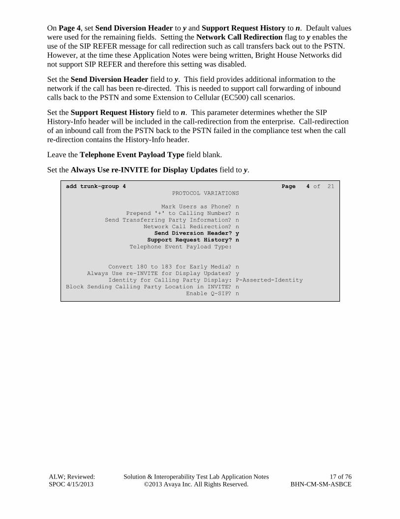
On Page 4, set Send Diversion Header to y and Support Request History to n. Default values
were used for the remaining fields. Setting the Network Call Redirection flag to y enables the
use of the SIP REFER message for call redirection such as call transfers back out to the PSTN.
However, at the time these Application Notes were being written, Bright House Networks did
not support SIP REFER and therefore this setting was disabled.
Set the Send Diversion Header field to y. This field provides additional information to the
network if the call has been re-directed. This is needed to support call forwarding of inbound
calls back to the PSTN and some Extension to Cellular (EC500) call scenarios.
Set the Support Request History field to n. This parameter determines whether the SIP
History-Info header will be included in the call-redirection from the enterprise. Call-redirection
of an inbound call from the PSTN back to the PSTN failed in the compliance test when the call
re-direction contains the History-Info header.
Leave the Telephone Event Payload Type field blank.
Set the Always Use re-INVITE for Display Updates field to y.
add trunk-group 4 Page 4 of 21
PROTOCOL VARIATIONS
Mark Users as Phone? n
Prepend '+' to Calling Number? n
Send Transferring Party Information? n
Network Call Redirection? n
Send Diversion Header? y
Support Request History? n
Telephone Event Payload Type:
Convert 180 to 183 for Early Media? n
Always Use re-INVITE for Display Updates? y
Identity for Calling Party Display: P-Asserted-Identity
Block Sending Calling Party Location in INVITE? n
Enable Q-SIP? n

ALW; Reviewed:
SPOC 4/15/2013
Solution & Interoperability Test Lab Application Notes
©2013 Avaya Inc. All Rights Reserved.
18 of 76
BHN-CM-SM-ASBCE
5.8. Calling Party Information
The calling party number is sent in the SIP “From”, “Contact” and “PAI” headers. Since public
numbering was selected to define the format of this number (Section 5.7), use the change
public-unknown-numbering command to create an entry for each extension which has a DID
assigned. The DID numbers are provided by the SIP service provider. Each DID number is
assigned to an enterprise internal extension or Vector Directory Numbers (VDNs). It is also used
to authenticate the caller.
The screen below shows the DID numbers assigned for testing by Bright House Networks.
These DIDs were mapped to extensions 5001, 5002, 5055, 5057, 5525, and 5526. These same
10-digit numbers were used for the outbound calling party identification on the service provider
trunk when calls were originated from these 6 extensions.
In the example above, the top entry is necessary for Modular Messaging to receive the local
extension number and properly identify the called party extension. With this entry, all stations
with a 4-digit extension beginning with 5 will send the calling party number across trunk 4 to
Modular Messaging, as the extension number.
change public-unknown-numbering 0 Page 1 of 2
NUMBERING - PUBLIC/UNKNOWN FORMAT
Total
Ext Ext Trk CPN CPN
Len Code Grp(s) Prefix Len
Total Administered: 7
4 5 4 4 Maximum Entries: 9999
4 5001 4 3525559911 10
4 5002 4 3525559912 10 Note: If an entry applies to
4 5055 4 3525559913 10 a SIP connection to Avaya
4 5057 4 3525559910 10 Aura(R) Session Manager,
4 5525 4 3525559914 10 the resulting number must
4 5526 4 3525559915 10 be a complete E.164 number.

ALW; Reviewed:
SPOC 4/15/2013
Solution & Interoperability Test Lab Application Notes
©2013 Avaya Inc. All Rights Reserved.
19 of 76
BHN-CM-SM-ASBCE
5.9. Incoming Call Handling Treatment
Use the change incoming-call-handling-trmt trunk group x command, where x is the SIP
trunk configured for the service provider, to map inbound DIDs to extensions.
5.10. Outbound Routing
In these Application Notes, the Automatic Route Selection (ARS) feature is used to route
outbound calls via the SIP trunk to the service provider. In the sample configuration, the single
digit 9 is used as the ARS access code. Enterprise callers will dial 9 to reach an “outside line”.
This common configuration is illustrated below with little elaboration. Use the change dialplan
analysis command to define a dialed string beginning with 9 of length 1 as a feature access code
(fac).
change dialplan analysis Page 1 of 12
DIAL PLAN ANALYSIS TABLE
Location: all Percent Full: 1
Dialed Total Call Dialed Total Call Dialed Total Call
String Length Type String Length Type String Length Type
1 3 dac
5 4 ext
7 4 ext
8 1 fac
9 1 fac
* 3 fac
# 3 fac
change inc-call-handling-trmt trunk-group 4 Page 1 of 30
INCOMING CALL HANDLING TREATMENT
Service/ Number Number Del Insert
Feature Len Digits
public-ntwrk 10 3524999910 10 5057
public-ntwrk 10 3524999911 10 5001
public-ntwrk 10 3524999912 10 5002
public-ntwrk 10 3524999913 10 5055
public-ntwrk 10 3524999914 10 5525
public-ntwrk 10 3524999915 10 5526

ALW; Reviewed:
SPOC 4/15/2013
Solution & Interoperability Test Lab Application Notes
©2013 Avaya Inc. All Rights Reserved.
20 of 76
BHN-CM-SM-ASBCE
Use the change feature-access-codes command to configure 9 as the Auto Route Selection
(ARS) – Access Code 1.
change feature-access-codes Page 1 of 10
FEATURE ACCESS CODE (FAC)
Abbreviated Dialing List1 Access Code: 137
Abbreviated Dialing List2 Access Code:
Abbreviated Dialing List3 Access Code: 160
Abbreviated Dial - Prgm Group List Access Code:
Announcement Access Code: 115
Answer Back Access Code: 116
Attendant Access Code:
Auto Alternate Routing (AAR) Access Code: *88
Auto Route Selection (ARS) - Access Code 1: 9 Access Code 2:
Automatic Callback Activation: 120 Deactivation: 121
Call Forwarding Activation Busy/DA: 122 All: 123 Deactivation: 124
Call Forwarding Enhanced Status: Act: Deactivation:
Call Park Access Code: 125
Call Pickup Access Code: 126
CAS Remote Hold/Answer Hold-Unhold Access Code:
CDR Account Code Access Code:
Change COR Access Code:
Change Coverage Access Code:
Conditional Call Extend Activation: Deactivation:
Contact Closure Open Code: Close Code:
ALW; Reviewed:
SPOC 4/15/2013
Solution & Interoperability Test Lab Application Notes
©2013 Avaya Inc. All Rights Reserved.
21 of 76
BHN-CM-SM-ASBCE
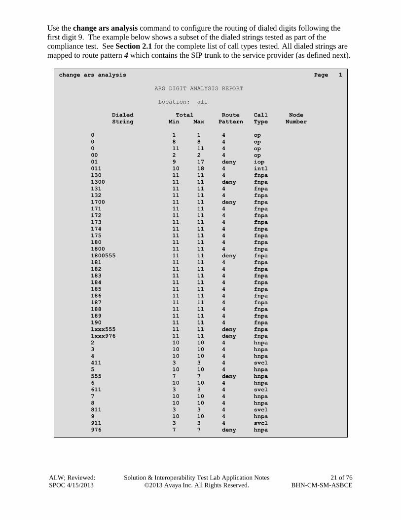
Use the change ars analysis command to configure the routing of dialed digits following the
first digit 9. The example below shows a subset of the dialed strings tested as part of the
compliance test. See Section 2.1 for the complete list of call types tested. All dialed strings are
mapped to route pattern 4 which contains the SIP trunk to the service provider (as defined next).
change ars analysis Page 1
ARS DIGIT ANALYSIS REPORT
Location: all
Dialed Total Route Call Node
String Min Max Pattern Type Number
0 1 1 4 op
0 8 8 4 op
0 11 11 4 op
00 2 2 4 op
01 9 17 deny iop
011 10 18 4 intl
130 11 11 4 fnpa
1300 11 11 deny fnpa
131 11 11 4 fnpa
132 11 11 4 fnpa
1700 11 11 deny fnpa
171 11 11 4 fnpa
172 11 11 4 fnpa
173 11 11 4 fnpa
174 11 11 4 fnpa
175 11 11 4 fnpa
180 11 11 4 fnpa
1800 11 11 4 fnpa
1800555 11 11 deny fnpa
181 11 11 4 fnpa
182 11 11 4 fnpa
183 11 11 4 fnpa
184 11 11 4 fnpa
185 11 11 4 fnpa
186 11 11 4 fnpa
187 11 11 4 fnpa
188 11 11 4 fnpa
189 11 11 4 fnpa
190 11 11 4 fnpa
1xxx555 11 11 deny fnpa
1xxx976 11 11 deny fnpa
2 10 10 4 hnpa
3 10 10 4 hnpa
4 10 10 4 hnpa
411 3 3 4 svcl
5 10 10 4 hnpa
555 7 7 deny hnpa
6 10 10 4 hnpa
611 3 3 4 svcl
7 10 10 4 hnpa
8 10 10 4 hnpa
811 3 3 4 svcl
9 10 10 4 hnpa
911 3 3 4 svcl
976 7 7 deny hnpa

ALW; Reviewed:
SPOC 4/15/2013
Solution & Interoperability Test Lab Application Notes
©2013 Avaya Inc. All Rights Reserved.
22 of 76
BHN-CM-SM-ASBCE
The route pattern defines which trunk group will be used for the call and performs any necessary
digit manipulation. Use the change route-pattern command to configure the parameters for the
service provider trunk route pattern in the following manner. The example below shows the
values used for route pattern 4 during the compliance test.
Pattern Name: Enter a descriptive name.
Grp No: Enter the outbound trunk group for the SIP service provider. For the compliance
test, trunk group 4 was used.
FRL: Set the Facility Restriction Level (FRL) field to a level that allows access to this
trunk for all users that require it. The value of 0 is the least restrictive level.
LAR: next.
change route-pattern 4 Page 1 of 3
Pattern Number: 4 Pattern Name: asm-sipt
SCCAN? n Secure SIP? n
Grp FRL NPA Pfx Hop Toll No. Inserted DCS/ IXC
No Mrk Lmt List Del Digits QSIG
Dgts Intw
1: 4 0 n user
2: n user
3: n user
4: n user
5: n user
6: n user
BCC VALUE TSC CA-TSC ITC BCIE Service/Feature PARM No. Numbering LAR
0 1 2 M 4 W Request Dgts Format
Subaddress
1: y y y y y n n rest next
2: y y y y y n n rest none
3: y y y y y n n rest none
4: y y y y y n n rest none
5: y y y y y n n rest none
6: y y y y y n n rest none
6: y y y y y n n rest none

ALW; Reviewed:
SPOC 4/15/2013
Solution & Interoperability Test Lab Application Notes
©2013 Avaya Inc. All Rights Reserved.
23 of 76
BHN-CM-SM-ASBCE
6. Configure Avaya Aura® Session Manager This section provides the procedures for configuring Session Manager. The procedures include
the following items:
Specify SIP domain
Add Logical/physical Location that can be occupied by SIP Entities
Add Adaptation module to perform dial plan manipulation
Add SIP Entities corresponding to Communication Manager, Avaya SBCE and Session
Manager
Add Entity Links, which define the SIP trunk parameters used by Session Manager when
routing calls to/from SIP Entities
Add Routing Policies, which define route destinations and control call routing between the
SIP Entities
Add Dial Patterns and Regular Expressions, which specify dialed digits and govern to which
SIP Entity a call is routed
Add/View Session Manager, corresponding to the Session Manager to be managed by
System Manager.
It may not be necessary to create all the items above when configuring for connection to the
service provider since some of these items would have already been defined as part of the initial
Session Manager installation. This includes items such as certain SIP domains, locations, SIP
entities, and Session Manager itself. However, each item should be reviewed to verify the
configuration.
6.1. System Manager Login and Navigation
Session Manager configuration is accomplished by accessing the browser-based GUI of System
Manager, using the URL “https://<ip-address>/SMGR”, where “<ip-address>” is the IP address
of System Manager. At the System Manager Log On screen, provide the appropriate
credentials and click on Login (not shown). The initial screen shown below is then displayed.
Most of the configuration items are performed in the Routing Element. Click on Routing in the
Elements column to bring up the Introduction to Network Routing Policy screen.

ALW; Reviewed:
SPOC 4/15/2013
Solution & Interoperability Test Lab Application Notes
©2013 Avaya Inc. All Rights Reserved.
24 of 76
BHN-CM-SM-ASBCE
The navigation tree displayed in the left pane will be referenced in subsequent sections to
navigate to items requiring configuration.

ALW; Reviewed:
SPOC 4/15/2013
Solution & Interoperability Test Lab Application Notes
©2013 Avaya Inc. All Rights Reserved.
25 of 76
BHN-CM-SM-ASBCE
6.2. Specify SIP Domain
Create a SIP domain for each domain that Session Manager will need to be aware in order to
route calls. For the compliance test, this includes the enterprise domain avayalab2.com.
Navigate to Routing Domains in the left-hand navigation pane and click the New button in
the right pane (not shown). In the new right pane that appears (shown below), fill in the
following:
Name: Enter the domain name.
Type: Select sip from the pull-down menu.
Notes: Add a brief description (optional).
Click Commit. The screen below shows the entry for the enterprise domain.
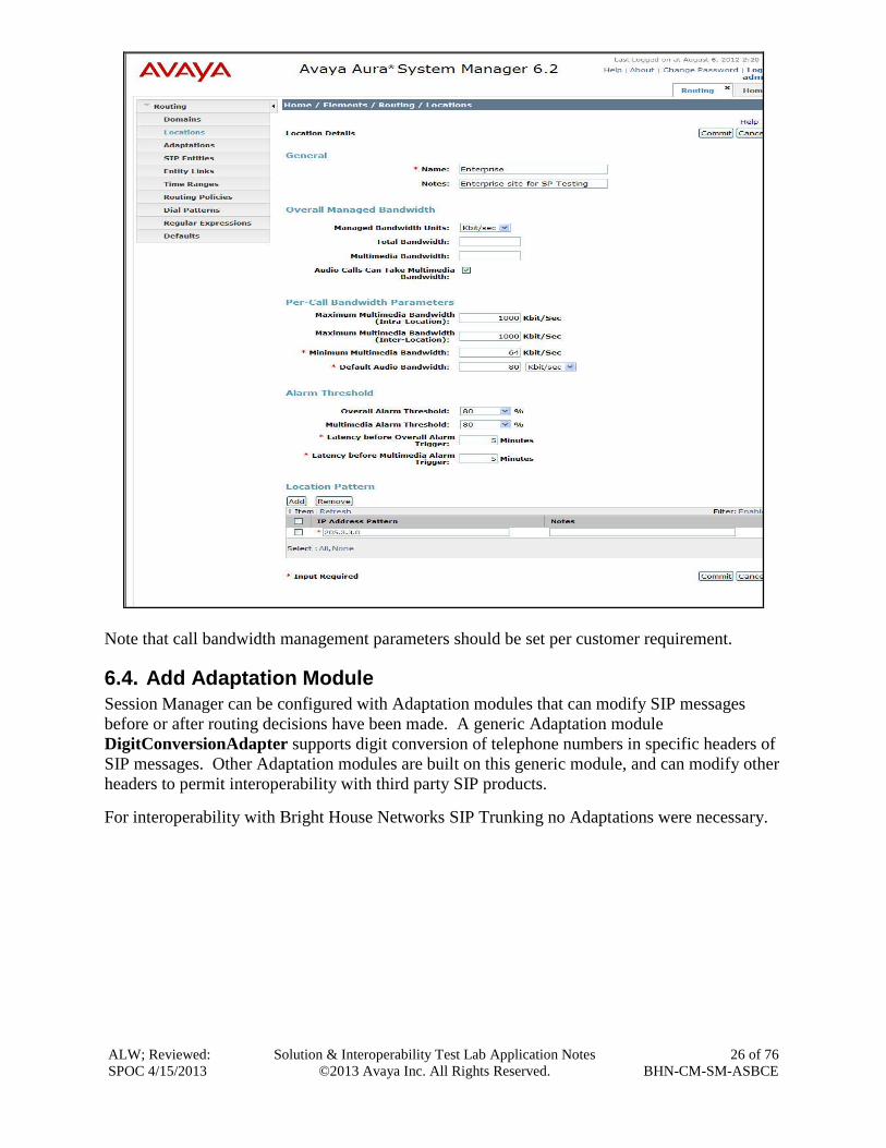
6.3. Add Location
Locations can be used to identify logical and/or physical locations where SIP Entities reside for
purposes of bandwidth management and call admission control. To add a Location, navigate to
Routing Locations in the left-hand navigation pane and click the New button in the right pane
(not shown).
In the General section, enter the following values:
Name: Enter a descriptive name for the Location.
Notes: Add a brief description (optional).
In the Location Pattern section (see screen below), click Add and enter the following values:
IP Address Pattern: An IP address pattern used to identify the Location.
Notes: Add a brief description (optional).
Displayed below is the screen for the addition of the Enterprise Location, which includes all
equipment on the enterprise network including Communication Manager and Session Manager
itself. Click Commit to save.
ALW; Reviewed:
SPOC 4/15/2013
Solution & Interoperability Test Lab Application Notes
©2013 Avaya Inc. All Rights Reserved.
26 of 76
BHN-CM-SM-ASBCE
Note that call bandwidth management parameters should be set per customer requirement.
6.4. Add Adaptation Module
Session Manager can be configured with Adaptation modules that can modify SIP messages
before or after routing decisions have been made. A generic Adaptation module
DigitConversionAdapter supports digit conversion of telephone numbers in specific headers of
SIP messages. Other Adaptation modules are built on this generic module, and can modify other
headers to permit interoperability with third party SIP products.
For interoperability with Bright House Networks SIP Trunking no Adaptations were necessary.

ALW; Reviewed:
SPOC 4/15/2013
Solution & Interoperability Test Lab Application Notes
©2013 Avaya Inc. All Rights Reserved.
27 of 76
BHN-CM-SM-ASBCE
6.5. Add SIP Entities
A SIP Entity must be added for Session Manager and for each SIP telephony system connected
to it, which includes Communication Manager and the Avaya SBCE. Navigate to Routing
SIP Entities in the left navigation pane and click on the New button in the right pane (not
shown).
In the General section, enter the following values. Use default values for all remaining fields:
Name: Enter a descriptive name.
FQDN or IP Address: Enter the FQDN or IP address of the SIP Entity.
Type: Select Session Manager for Session Manager, CM for
Communication Manager and Other for Avaya SBCE.
Adaptation: This field is only present if Type is not set to Session Manager.
If applicable, select the Adaptation name created in Section 6.4
that will be applied to this entity.
Location: Select one of the locations defined previously.
Time Zone: Select the time zone for the location above.
The following screen shows the addition of the Session Manager SIP Entity. The IP address of
the Session Manager SIP signaling interface is entered for FQDN or IP Address.

ALW; Reviewed:
SPOC 4/15/2013
Solution & Interoperability Test Lab Application Notes
©2013 Avaya Inc. All Rights Reserved.
28 of 76
BHN-CM-SM-ASBCE
To define the ports used by Session Manager, scroll down to the Port section of the SIP Entity
Details screen. This section is only present for the Session Manager SIP Entity.
In the Port section, click Add and enter the following values. Use default values for all
remaining fields:
Port: Port number on which Session Manager listens for SIP requests.
Protocol: Transport protocol to be used to send and receive SIP requests.
Default Domain: The domain used for the enterprise.
Defaults can be used for the remaining fields. Click Commit to save.
Although the default port values for SIP over UDP and TLS were configured, they were not used
in this compliance test. One Port entry was used for three SIP Entities:
5060 with TCP for connecting to Avaya SBCE
5060 with TCP for connecting to Communication Manager
5060 with TCP for connecting to Modular Messaging
In addition, port 5060 with TCP was also used between Session Manager and Communication
Manager for Avaya SIP telephones and SIP soft clients. This SIP Link was part of the standard
configuration on Session Manager and was not directly relevant to the inter-operability with
Bright House Networks SIP Trunking.

ALW; Reviewed:
SPOC 4/15/2013
Solution & Interoperability Test Lab Application Notes
©2013 Avaya Inc. All Rights Reserved.
29 of 76
BHN-CM-SM-ASBCE
The following screen shows the addition of the Communication Manager SIP Entity.

ALW; Reviewed:
SPOC 4/15/2013
Solution & Interoperability Test Lab Application Notes
©2013 Avaya Inc. All Rights Reserved.
30 of 76
BHN-CM-SM-ASBCE
The following screen shows the addition of the SIP Entity for the Avaya SBCE.

ALW; Reviewed:
SPOC 4/15/2013
Solution & Interoperability Test Lab Application Notes
©2013 Avaya Inc. All Rights Reserved.
31 of 76
BHN-CM-SM-ASBCE
6.6. Add Entity Links
A SIP trunk between Session Manager and a telephony system is described by an Entity Link.
For the compliance test, three Entity Links were created; one to Communication Manager, one to
the Avaya SBCE and one to Avaya Modular Messaging. To add an Entity Link, navigate to
Routing Entity Links in the left-hand navigation pane and click on the New button in the
right pane (not shown). Fill in the following fields in the new row that is displayed:
Name: Enter a descriptive name.
SIP Entity 1: Select the Session Manager SIP Entity.
Protocol: Select the transport protocol used for this link.
Port: Port number on which Session Manager will receive SIP requests from
the far-end. For Communication Manager, this must match the
Far-end Listen Port defined for the Communication Manager signaling
group in Section 5.6.
SIP Entity 2: Select the name of the other system. For Communication Manager,
select the Communication Manager SIP Entity defined in Section 6.5.
Port: Port number on which the other system receives SIP requests from
Session Manager. For Communication Manager, this must match the
Near-end Listen Port defined for the Communication Manager signaling
group in Section 5.6.
Trusted: Select Trusted from the drop down menu. Note: If trusted is not
selected, calls from the associated SIP Entity specified in Section 6.5 will
be challenged / denied.
Click Commit to save.
The following screens illustrate the Entity Links to Communication Manager and the Avaya
SBCE. It should be noted that in a customer environment the Entity Link to Communication
Manager would normally use TLS. For the compliance test, TCP was used to aid in
troubleshooting since the signaling traffic would not be encrypted. The protocol and ports
defined here must match the values used for the Communication Manager signaling group form
in Section 5.6.

ALW; Reviewed:
SPOC 4/15/2013
Solution & Interoperability Test Lab Application Notes
©2013 Avaya Inc. All Rights Reserved.
32 of 76
BHN-CM-SM-ASBCE
Entity Link to Communication Manager:
Entity Link to Avaya SBCE:

ALW; Reviewed:
SPOC 4/15/2013
Solution & Interoperability Test Lab Application Notes
©2013 Avaya Inc. All Rights Reserved.
33 of 76
BHN-CM-SM-ASBCE
6.7. Add Routing Policies
Routing Policies describe the conditions under which calls will be routed to the SIP Entities
specified in Section 6.5. Two Routing Policies must be added: one for Communication Manager
and one for the Avaya SBCE. To add a routing policy, navigate to Routing Routing Policies
in the left-hand navigation pane and click on the New button in the right pane (not shown). The
following screen is displayed. Fill in the following:
In the General section, enter the following values. Use default values for all remaining fields:
Name: Enter a descriptive name.
Notes: Add a brief description (optional).
In the SIP Entity as Destination section, click Select. The SIP Entity List page opens (not
shown). Select the appropriate SIP Entity to which this routing policy applies and click Select.
The selected SIP Entity displays on the Routing Policy Details page as shown below. Use
default values for remaining fields. Click Commit to save.
The following screens show the Routing Policies for Communication Manager and the Avaya
SBCE, respectively.
Routing Policy for Communication Manager:

ALW; Reviewed:
SPOC 4/15/2013
Solution & Interoperability Test Lab Application Notes
©2013 Avaya Inc. All Rights Reserved.
34 of 76
BHN-CM-SM-ASBCE
Routing Policy for Avaya SBCE:

ALW; Reviewed:
SPOC 4/15/2013
Solution & Interoperability Test Lab Application Notes
©2013 Avaya Inc. All Rights Reserved.
35 of 76
BHN-CM-SM-ASBCE
6.8. Add Dial Patterns
Dial Patterns are needed to route calls through Session Manager. For the compliance test, Dial
Patterns were needed to route calls from Communication Manager to Bright House Networks
and vice versa. Dial Patterns define which Routing Policy will be selected for a particular call
based on the dialed digits, destination Domain and originating Location. To add a Dial Pattern,
navigate to Routing Dial Patterns in the left-hand navigation pane and click on the New
button in the right pane (not shown). Fill in the following, as shown in the screens below:
In the General section, enter the following values. Use default values for all remaining fields:
Pattern: Enter a dial string that will be matched against the Request-URI of the
call.
Min: Enter a minimum length used in the match criteria.
Max: Enter a maximum length used in the match criteria.
SIP Domain: Enter the destination SIP Domain used in the match criteria.
Notes: Add a brief description (optional).
In the Originating Locations and Routing Policies section, click Add. From the Originating
Locations and Routing Policy List that appears (not shown), select the appropriate originating
Location for use in the match criteria. Note that for the compliance test, the Originating
Location of –ALL- was used. Lastly, select the Routing Policy from the list that will be used to
route all calls that match the specified criteria. Click Select.
Default values can be used for the remaining fields. Click Commit to save.

ALW; Reviewed:
SPOC 4/15/2013
Solution & Interoperability Test Lab Application Notes
©2013 Avaya Inc. All Rights Reserved.
36 of 76
BHN-CM-SM-ASBCE
Examples of Dial Patterns used for the compliance test are shown below. The first example
shows the Dial Patterns for outbound calls that belong to the Routing Policy To_ASBCE as
defined in Section 6.7. These Dial Patterns cover Operator and Operator Assisted calls,
International calls, and any 1x11 and x11 services, respectively. There is the option to define a
Dial Pattern of x here to cover any and all possible Dial Patterns for outbound calls; however, for
the compliance test a Regular Expression was used for this purpose which will be covered in the
Regular Expression section that follows. The SIP domain was set to -ALL- since this Session
Manager was not being shared in this environment, but could have been set specifically to
avayalab2.com if necessary.
Note that the above Dial Pattern configuration did not restrict outbound calls to specific US area
codes. In real deployments, appropriate restriction can be exercised (e.g., use Pattern 1908,
1303, etc. with 11 digits) per customer business policies.
Also note that –ALL- was selected for Originating Location. This selection was to
accommodate certain off-net call forward scenarios where the inbound call was re-directed
outbound back to the PSTN. For straight outbound calls, like 411 local directory, the enterprise
Location Enterprise could have been selected.

ALW; Reviewed:
SPOC 4/15/2013
Solution & Interoperability Test Lab Application Notes
©2013 Avaya Inc. All Rights Reserved.
37 of 76
BHN-CM-SM-ASBCE
The screen below shows the Dial Patterns for inbound calls that belong to the Routing Policy
To_CM62 as defined in Section 6.7. These Dial Patterns cover any e.164 numbering that carries
the preceding + sign, the 4 digit extension range of 5xxx, and the DIDs assigned to the enterprise
by Bright House Networks which all begin with 352555991. The SIP domain was set to -ALL-
since this Session Manager was not being shared in this environment, but could have been set
specifically to avayalab2.com if necessary. Originating location was also set to -ALL- but
could have been set to a more specific location, had one been defined for the Bright House
Networks network.
Below shows an example of the Dial Pattern Details for the DIDs that were assigned by Bright
House Networks. Inbound 10-digit numbers that start with 352555991 will use Routing Policy
To_CM62 as defined in Section 6.7. This Dial Pattern matches the DID numbers assigned to the
enterprise by Bright House Networks.

ALW; Reviewed:
SPOC 4/15/2013
Solution & Interoperability Test Lab Application Notes
©2013 Avaya Inc. All Rights Reserved.
38 of 76
BHN-CM-SM-ASBCE
6.9. Regular Expressions
A Regular Expression was created to route any possible combination of outbound dialed digits
to the Bright House Networks SIP trunk service via the Avaya SBCE. This regular expression
covers all possible 10 digit dialed strings starting with any digit except 0 or 1.
The screen below shows the Regular Expression Details screen and the values that were used to
create the Regular Expression:
Pattern: Enter a regular expression that covers the requirements.
Rank Order: Priority of the pattern. Lower numbers mean higher priority. For
the compliance test, 0 was used as it is the highest priority
possible.
Routing Policy: Enter the routing policy that should be associated with the regular
expression. For the compliance test, the To_ASBCE Routing
Policy was chosen since this regular expression covers outbound
calls.
Click on Commit when finished.

ALW; Reviewed:
SPOC 4/15/2013
Solution & Interoperability Test Lab Application Notes
©2013 Avaya Inc. All Rights Reserved.
39 of 76
BHN-CM-SM-ASBCE
6.10. Add/View Session Manager
The creation of a Session Manager element provides the linkage between System Manager and
Session Manager. This was most likely done as part of the initial Session Manager installation
and is shown for informational purposes only.
To add a Session Manager, navigate to Home Elements Session Manager Session
Manager Administration in the left navigation pane and click on the New button in the right
pane (not shown). If the Session Manager already exists, click View (not shown) to view the
configuration. Enter/verify the data as described below and shown in the following screen:
In the General section, enter the following values:
SIP Entity Name: Select the SIP Entity created for Session
Manager.
Description: Add a brief description (optional).
Management Access Point Host Name/IP: Enter the IP address of the Session Manager
management interface.
The screen below shows the Session Manager values used for the compliance test.
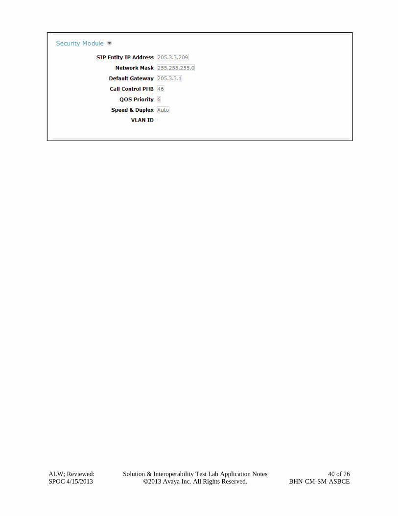
In the Security Module section, the following values should be filled in automatically since
these parameters are generally setup at the time of installation. If not, use the values below:
SIP Entity IP Address: Enter the IP address of the Session Manager signaling
interface.
Network Mask: Enter the network mask corresponding to the IP address of
Session Manager.
Default Gateway: Enter the IP address of the default gateway for Session
Manager.
Use default values, or values appropriate for the specific customer, for the remaining fields.
Click Save (not shown) to add this Session Manager. The screen below shows the Session
Manager values used for the compliance test.
ALW; Reviewed:
SPOC 4/15/2013
Solution & Interoperability Test Lab Application Notes
©2013 Avaya Inc. All Rights Reserved.
40 of 76
BHN-CM-SM-ASBCE
ALW; Reviewed:
SPOC 4/15/2013
Solution & Interoperability Test Lab Application Notes
©2013 Avaya Inc. All Rights Reserved.
41 of 76
BHN-CM-SM-ASBCE
7. Configure Avaya Session Border Controller for Enterprise In the sample configuration, an Avaya SBCE is used as the edge device between the Avaya CPE
and the Bright House Networks SIP Trunking service.
These Application Notes assume that the installation of the SBC and the assignment of a
management IP Address have already been completed.
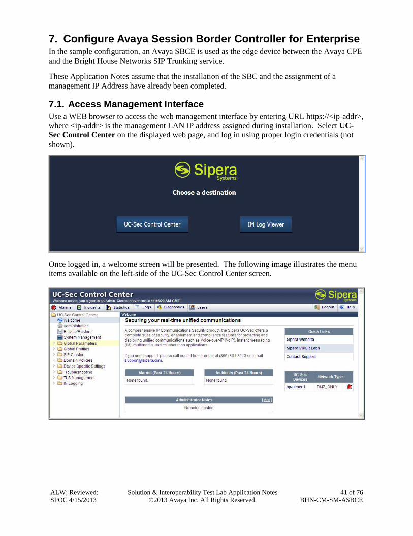
7.1. Access Management Interface
Use a WEB browser to access the web management interface by entering URL https://<ip-addr>,
where <ip-addr> is the management LAN IP address assigned during installation. Select UC-
Sec Control Center on the displayed web page, and log in using proper login credentials (not
shown).
Once logged in, a welcome screen will be presented. The following image illustrates the menu
items available on the left-side of the UC-Sec Control Center screen.
ALW; Reviewed:
SPOC 4/15/2013
Solution & Interoperability Test Lab Application Notes
©2013 Avaya Inc. All Rights Reserved.
42 of 76
BHN-CM-SM-ASBCE
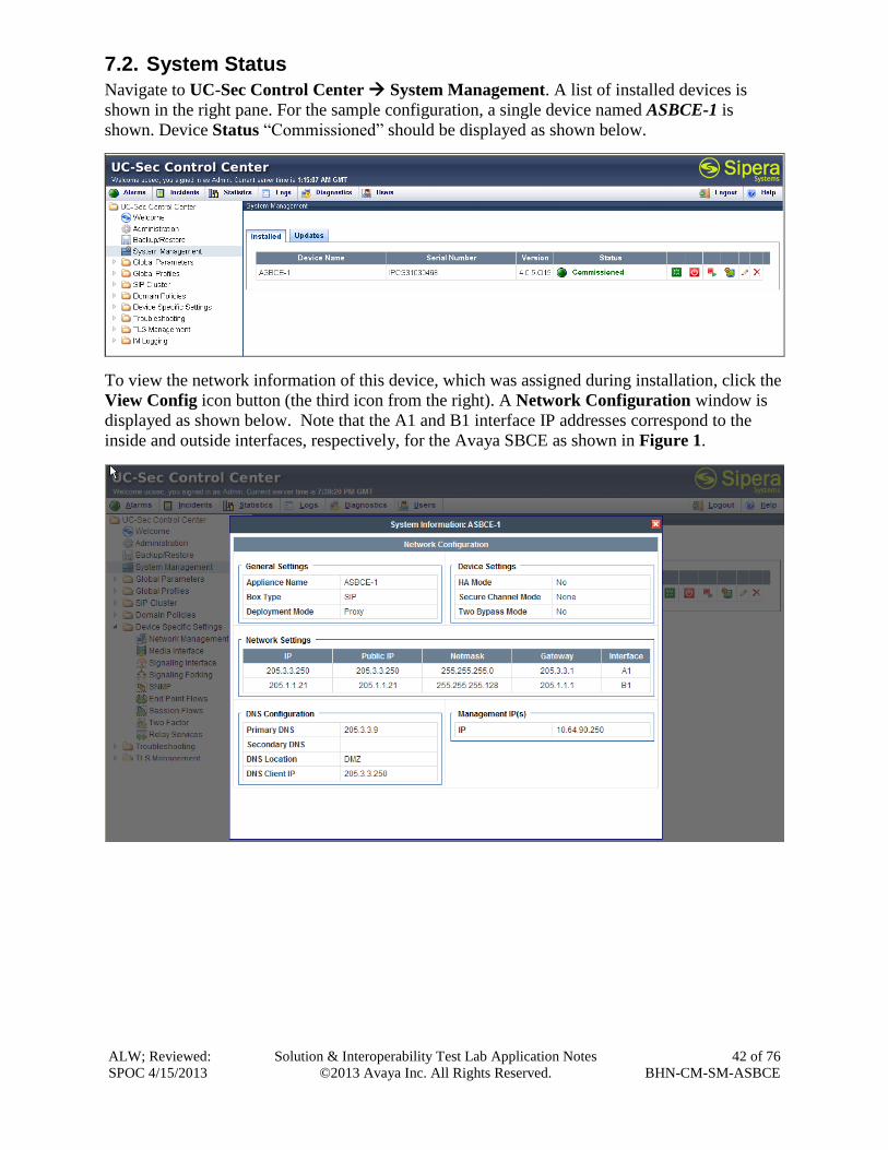
7.2. System Status
Navigate to UC-Sec Control Center System Management. A list of installed devices is
shown in the right pane. For the sample configuration, a single device named ASBCE-1 is
shown. Device Status “Commissioned” should be displayed as shown below.
To view the network information of this device, which was assigned during installation, click the
View Config icon button (the third icon from the right). A Network Configuration window is
displayed as shown below. Note that the A1 and B1 interface IP addresses correspond to the
inside and outside interfaces, respectively, for the Avaya SBCE as shown in Figure 1.

ALW; Reviewed:
SPOC 4/15/2013
Solution & Interoperability Test Lab Application Notes
©2013 Avaya Inc. All Rights Reserved.
43 of 76
BHN-CM-SM-ASBCE
7.3. Global Profiles – Server Interworking
Server interworking is defined for each server connected to the Avaya SBCE. For the
compliance test, the Bright House Networks SIP trunk network-edge SBC serves as the Trunk
Server and Session Manager serves as the Call Server.
Navigate to Global Profiles Server Interworking from the left-side menu (not shown) to
configure Server Interworking profiles.
7.3.1. Server Interworking: Avaya-SM
Click the Add Profile button (not shown) to add a new profile or select an existing Server
Interworking profile to edit. If adding a profile, a screen such as the following is displayed.
Enter an appropriate Profile Name such as Avaya-SM shown below. Click Next.
The following screens illustrate the General parameters used in the sample configuration for the
Interworking Profile named Avaya-SM. Most parameters retain default values. In the sample
configuration, T.38 Support was checked to enable T.38 faxing, and Hold Support was set for
RFC3264.

ALW; Reviewed:
SPOC 4/15/2013
Solution & Interoperability Test Lab Application Notes
©2013 Avaya Inc. All Rights Reserved.
44 of 76
BHN-CM-SM-ASBCE
Click Next (not shown) to advance to configure Privacy and DTMF general parameters, which
can retain default values. The following screen shows the complete General tab used in the
sample configuration for the interworking profile named Avaya-SM.
The parameters in all other tabs may retain default settings.
ALW; Reviewed:
SPOC 4/15/2013
Solution & Interoperability Test Lab Application Notes
©2013 Avaya Inc. All Rights Reserved.
45 of 76
BHN-CM-SM-ASBCE
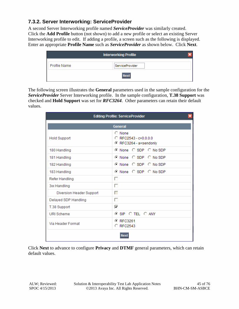
7.3.2. Server Interworking: ServiceProvider
A second Server Interworking profile named ServiceProvider was similarly created.
Click the Add Profile button (not shown) to add a new profile or select an existing Server
Interworking profile to edit. If adding a profile, a screen such as the following is displayed.
Enter an appropriate Profile Name such as ServiceProvider as shown below. Click Next.
The following screen illustrates the General parameters used in the sample configuration for the
ServiceProvider Server Interworking profile. In the sample configuration, T.38 Support was
checked and Hold Support was set for RFC3264. Other parameters can retain their default
values.
Click Next to advance to configure Privacy and DTMF general parameters, which can retain
default values.

ALW; Reviewed:
SPOC 4/15/2013
Solution & Interoperability Test Lab Application Notes
©2013 Avaya Inc. All Rights Reserved.
46 of 76
BHN-CM-SM-ASBCE
The following screen shows the complete General tab used in the sample configuration for the
interworking profile named ServiceProvider.
Next go to the URI Manipulation tab and click on Add Regex. The screen below shows the
regex values used for the compliance test. These entries were necessary to strip the preceding
e.164 “+” sign from SIP messaging being sent to the service provider. Enter the following:
User Regex: Enter \+.*
User Action Select Remove prefix [value] from the drop-down menu.
User Values Enter +

ALW; Reviewed:
SPOC 4/15/2013
Solution & Interoperability Test Lab Application Notes
©2013 Avaya Inc. All Rights Reserved.
47 of 76
BHN-CM-SM-ASBCE
Default values may be retained for all other fields. Click Finish when completed.
The parameters in all other tabs may retain their default settings.

ALW; Reviewed:
SPOC 4/15/2013
Solution & Interoperability Test Lab Application Notes
©2013 Avaya Inc. All Rights Reserved.
48 of 76
BHN-CM-SM-ASBCE
7.4. Global Profiles – Server Configuration
In the compliance test, the Bright House Networks SIP trunk network-edge SBC is connected as
the Trunk Server and the enterprise Session Manager is connected as the Call Server.
Navigate to Global Profiles Server Configuration from the left-side menu to configure the
two servers.
7.4.1. Server Configuration for Session Manager
Click the Add Profile button (not shown) to add a new profile, or select an existing profile to
edit. If adding a profile, a screen such as the following is displayed. Enter an appropriate Profile
Name such as asm shown below. Click Next.
The following screens illustrate the Server Configuration with Profile name asm. Select Call
Server from the Server Type drop-down menu. In the IP Addresses / Supported FQDNs area,
the IP Address of the Session Manager SIP signaling interface should be entered. In the
Supported Transports area, TCP is selected and the TCP Port is set to 5060. This
configuration corresponds with the Session Manager Entity Link configuration for the Entity
Link connecting to the Avaya SBCE. If adding a new profile, click Next (not shown). If editing
an existing profile, click Finish.

ALW; Reviewed:
SPOC 4/15/2013
Solution & Interoperability Test Lab Application Notes
©2013 Avaya Inc. All Rights Reserved.
49 of 76
BHN-CM-SM-ASBCE
Once configuration is completed, the General tab for the configured asm call server will appear
as shown below:
If adding the profile, click Next to accept default parameters for the Authentication tab, and
advance to the Heartbeat area (not shown). If editing an existing profile, select the Heartbeat
tab and click Edit.
The Avaya SBCE can be configured to source “heartbeats” in the form of SIP OPTIONS. In the
sample configuration, with one connected Session Manager, this configuration is optional.
If SBC-sourced OPTIONS messages are desired, check the Enable Heartbeat box. Select
OPTIONS from the Method drop-down menu. Select the desired frequency (in seconds) that
the SBC will source OPTIONS to this server. The From URI and To URI may be filled in to
configure easily identifiable URIs to appear in SIP OPTIONS sourced by the SBC toward
Session Manager. If adding a new profile, click Next (not shown). If editing an existing profile,
click Finish.

ALW; Reviewed:
SPOC 4/15/2013
Solution & Interoperability Test Lab Application Notes
©2013 Avaya Inc. All Rights Reserved.
50 of 76
BHN-CM-SM-ASBCE
If SBC sourced OPTIONS are configured, the Heartbeat tab for the asm server profile will
appear as shown below:
If adding a profile, click Next to continue to Advanced settings. If editing an existing profile,
select the Advanced tab and click Edit. In the resultant screen, select the Interworking Profile
Avaya-SM created in Section 7.3.1. Click Finish.
Once configuration is completed, the Advanced tab for the call server asm will appear as shown
below.

ALW; Reviewed:
SPOC 4/15/2013
Solution & Interoperability Test Lab Application Notes
©2013 Avaya Inc. All Rights Reserved.
51 of 76
BHN-CM-SM-ASBCE
7.4.2. Server Configuration for Bright House Networks SIP Trunking
A second Server Configuration profile named SP-SIP-Trunk was similarly created. The
following screens illustrate the SP-SIP-Trunk Server Configuration profile. In the General
parameters, select Trunk Server from the Server Type drop-down menu. In the IP Addresses /
Supported FQDNs area, the Bright House Networks-provided SIP Trunking SBC IP Address is
entered. In the Supported Transports area, UDP is selected and the UDP Port is set to 5060 as
specified by Bright House Networks.
If adding the profile, click Next to accept default parameters for the Authentication tab, and
advance to the Heartbeat area (not shown). If editing an existing profile, select the Heartbeat
tab and click edit.
The Avaya SBCE can be configured to source “heartbeats” in the form of SIP OPTIONS
towards Bright House Networks. This configuration is optional. Independent of whether the
SBC is configured to source SIP OPTIONS towards Bright House Networks, Bright House
Networks will receive OPTIONS from the enterprise site as a result of the SIP Entity Monitoring
configured for Session Manager. When Session Manager sends SIP OPTIONS to the inside
private IP Address of the Avaya SBCE, the Avaya SBCE will forward those SIP OPTIONS to
Bright House Networks. When Bright House Networks responds, the SBC will pass the
response back to Session Manager.
If SBC-sourced OPTIONS are desired, select OPTIONS from the Method drop-down menu.
Select the desired frequency that the SBC will source OPTIONS. The From URI and To URI
may be filled in to configure easily identifiable URIs to appear in SIP OPTIONS sourced by the
SBC. If adding a new profile, click Next (not shown). If editing an existing profile, click
Finish.

ALW; Reviewed:
SPOC 4/15/2013
Solution & Interoperability Test Lab Application Notes
©2013 Avaya Inc. All Rights Reserved.
52 of 76
BHN-CM-SM-ASBCE
If the optional SBC sourced OPTIONS configuration is completed, the Heartbeat tab for the
SP-SIP-Trunk server profile will appear as shown below.
If adding a profile, click Next to continue to Advanced settings (not shown). If editing an
existing profile, select the Advanced tab and click Edit. In the resultant screen, select the
Interworking Profile ServiceProvider created in Section 7.3.2. Click Finish.

ALW; Reviewed:
SPOC 4/15/2013
Solution & Interoperability Test Lab Application Notes
©2013 Avaya Inc. All Rights Reserved.
53 of 76
BHN-CM-SM-ASBCE
Once configuration is completed, the Advanced tab for ServiceProvider will appear as shown
below.
7.5. Global Profiles – Routing
Routing information is required for traffic to be routed to Session Manager on the internal side,
and to the Bright House Network’s network on the external side. The IP addresses and ports
defined here will be used as the destination addresses for signaling. If no port is specified, the
default SIP port of 5060 is used.
Navigate to Global Profiles Routing from the left-side menu to configure Routing profiles.
7.5.1. Routing Configuration for Session Manager
Click the Add Profile button (not shown) to add a new profile, or select an existing routing
profile to edit. If adding a profile, a screen such as the following is displayed. Enter a Profile
Name such as To_Avaya-SM shown below. Click Next.

ALW; Reviewed:
SPOC 4/15/2013
Solution & Interoperability Test Lab Application Notes
©2013 Avaya Inc. All Rights Reserved.
54 of 76
BHN-CM-SM-ASBCE
In the Next Hop Routing configuration, enter the IP Address of the Session Manager SIP
signaling interface with port number (optional if port number is 5060) as Next Hop Server 1, as
shown below. Check Routing Priority based on Next Hop Server. Choose TCP for Outgoing
Transport.
Once configuration is completed, the Routing Profile for To_Avaya-SM will appear as follows:

ALW; Reviewed:
SPOC 4/15/2013
Solution & Interoperability Test Lab Application Notes
©2013 Avaya Inc. All Rights Reserved.
55 of 76
BHN-CM-SM-ASBCE
7.5.2. Routing Configuration for Bright House Networks SIP Trunking
A Routing Profile named To_ServiceProvider for the trunk server was similarly configured as
shown below.
Click the Add Profile button (not shown) to add a new profile, or select an existing routing
profile to edit. If adding a profile, a screen such as the following is displayed. Enter a Profile
Name such as To_ServiceProvider shown below. Click Next.
In the Next Hop Routing configuration, enter the IP Address of the Bright House Networks SIP
trunking SBC signaling interface with port number (again, optional if port number is 5060) as
Next Hop Server 1, as shown below. Check Routing Priority based on Next Hop Server.
Choose UDP for Outgoing Transport as Bright House Networks accepts SIP traffic over UDP.
Once configuration is completed, the Routing Profile for To_ServiceProvider will appear as
follows:

ALW; Reviewed:
SPOC 4/15/2013
Solution & Interoperability Test Lab Application Notes
©2013 Avaya Inc. All Rights Reserved.
56 of 76
BHN-CM-SM-ASBCE
7.6. Global Profiles – Topology Hiding
Topology Hiding is a security feature which allows the changing of several parameters within
SIP packets, preventing the private enterprise network information from being propagated to the
un-trusted public network.
Topology Hiding can also be used as an interoperability tool to adapt certain parameters in
selected SIP headers to meet expectations by Session Manager and the SIP trunk service
provider, allowing the call to be accepted in each case.
For the compliance test, only the minimum configuration required to achieve interoperability
was performed.
Navigate to Global Profiles Topology Hiding from the left-side menu for configuring
Topology Hiding profiles.
7.6.1. Topology Hiding for Session Manager
Click the Add Profile button (not shown) to add a new profile, or select an existing topology
hiding profile to edit. If adding a profile, a screen such as the following is displayed. Enter a
Profile Name such as Avaya-SM shown below. Click Next.
In the resultant screen, click the Add Header button to reveal additional headers.

ALW; Reviewed:
SPOC 4/15/2013
Solution & Interoperability Test Lab Application Notes
©2013 Avaya Inc. All Rights Reserved.
57 of 76
BHN-CM-SM-ASBCE
To ensure that the domain received by Session Manager from the SBC is the expected enterprise
domain, select Overwrite from the drop-down menu as the Replace Action for the To and
Request-Line headers. Enter the enterprise domain in the Overwrite Value column as shown
below. In the example below, the domain received by Session Manager has been changed by the
Avaya SBCE to avayalab2.com. Click Finish.
After configuration is completed, the Topology Hiding for profile Avaya-SM will appear as
follows.

ALW; Reviewed:
SPOC 4/15/2013
Solution & Interoperability Test Lab Application Notes
©2013 Avaya Inc. All Rights Reserved.
58 of 76
BHN-CM-SM-ASBCE
7.6.2. Topology Hiding for Bright House Networks SIP Trunking
A Topology Hiding profile named ServiceProvider for Bright House Networks was similarly
configured as shown below. Note that it was not necessary to configure any Topology Hiding
for SIP signaling that was forwarded to the Service Provider. Default values were used for all
fields.
7.7. Domain Policies – Media Rules
Domain Policies allow configuring, managing and applying various sets of rules designed to
control and normalize the behavior of call flows based upon various criteria of communication
sessions originating from or terminating to the enterprise.
Navigate to Domain Policies Media Rules from the left-side menu to configure Media Rules.
In the sample configuration, a single media rule was used. This media rule was cloned from the
default rule default-low-med by selecting the default rule default-low-med then clicking the
Clone Rule button in the upper right corner as shown below:

ALW; Reviewed:
SPOC 4/15/2013
Solution & Interoperability Test Lab Application Notes
©2013 Avaya Inc. All Rights Reserved.
59 of 76
BHN-CM-SM-ASBCE
Enter a descriptive Clone Name, and then click Finish. The cloned media rule will be displayed
in the Media Rules list on the left. Select this cloned rule from the list, then select Media
Anomaly tab and click Edit. In the displayed Media Anomaly edit window, uncheck Media
Anomaly Detection as shown below.
Click Finish. The rule named modified-dft-low-med is shown below with the Media Anomaly
tab selected. This rule is sufficient for the compliance test.
7.8. Domain Policies – Signaling Rules
Signaling Rules define the actions to be taken (Allow, Block, Block with Response, etc.) on
signaling request and response messages. They also allow the setting of Quality of Service
markings for the signaling packets.
The P-Location and P-Charging-Vector headers are sent in SIP messages from Session Manager
to the service provider network via the Avaya SBCE. These headers should not be exposed
outside the enterprise. For simplicity, these headers were simply removed (blocked) from both
request and response messages that originated from Session Manager.
Navigate to Domain Policies Signaling Rules from the left-side menu to configure Signaling
Rules.
Click the Add Rule button (not shown) to add a new signaling rule. In the Rule Name field,
enter an appropriate name, such as SM_SigRules. Click Next.

ALW; Reviewed:
SPOC 4/15/2013
Solution & Interoperability Test Lab Application Notes
©2013 Avaya Inc. All Rights Reserved.
60 of 76
BHN-CM-SM-ASBCE
In the subsequent screen (not shown), click Next to accept defaults. In the Signaling QoS
screen, click Finish (not shown).
After this configuration, the new SM_SigRules rule will appear as follows.
Select the Request Headers tab, and select the Add In Header Control button. Check the
Proprietary Request Header? checkbox. In the Header Name field, type P-Location. Select
INVITE as the Method Name from the drop-down menu. In the Header Criteria, select
Forbidden. Retain Presence Action Remove header. The intent is to remove the P-Location
header which is inserted by Session Manager but not needed by the Bright House Networks SIP
trunking service. This configuration is optional in that the P-Location and P-Charging-Vector
headers do not cause any user-perceivable problem if presented to Bright House Networks.

ALW; Reviewed:
SPOC 4/15/2013
Solution & Interoperability Test Lab Application Notes
©2013 Avaya Inc. All Rights Reserved.
61 of 76
BHN-CM-SM-ASBCE
Similarly, configure additional header control rules to:
Remove the P-Charging-Vector header in the outbound INVITE
Remove the P-Charging-Vector header in the outbound UPDATE
Once complete, the Request Headers tab appears as follows.
Select the Response Headers tab and repeat the above configuration steps to:
Remove the P-Charging-Vector header in the 200 OK response to INVITEs
Remove the P-Charging-Vector header in the 200 OK response to UPDATEs
Remove the P-Location header in the 200 OK response to INVITEs
Once configuration is complete, the Response Headers tab for the SM_SigRules signaling rule
will appear as follows.
Again, this configuration is optional in that the P-Location and P-Charging-Vector headers do
not cause any user-perceivable problem if presented to Bright House Networks.

ALW; Reviewed:
SPOC 4/15/2013
Solution & Interoperability Test Lab Application Notes
©2013 Avaya Inc. All Rights Reserved.
62 of 76
BHN-CM-SM-ASBCE
7.9. Domain Policies – End Point Policy Groups
End Point Policy Groups are associations of different sets of rules (Media, Signaling, Security,
etc…) to be applied to specific SIP messages traversing the Avaya SBCE.
Navigate to Domain Policies End Point Policy Groups from the left-side menu to configure
End Point Policy Groups.
Select the Add Group button (not shown). Enter a name in the Group Name field, such as
Avaya as shown below. Click Next.
In the sample configuration, defaults were selected for all fields, with the exception of:
Media Rule, which was set to the modified-dft-low-med media rule as defined in Section
7.7
Signaling Rule, which was set to the SM_SigRules signaling rule as defined in Section
7.8
Click Finish.

ALW; Reviewed:
SPOC 4/15/2013
Solution & Interoperability Test Lab Application Notes
©2013 Avaya Inc. All Rights Reserved.
63 of 76
BHN-CM-SM-ASBCE
Once configuration is completed, the Avaya End Point Policy Group will appear as follows.
Repeat the configuration steps above to create a second End Point Policy Group named
ServiceProvider for the network side as shown below.
Note that this End Point Policy Group uses the same Media Rule (modified-dft-low-med) for
disabling Media Anomaly Detection and the default Signaling Rule since no header
manipulations are required for messages to and from the outside interface of the Avaya SBCE.
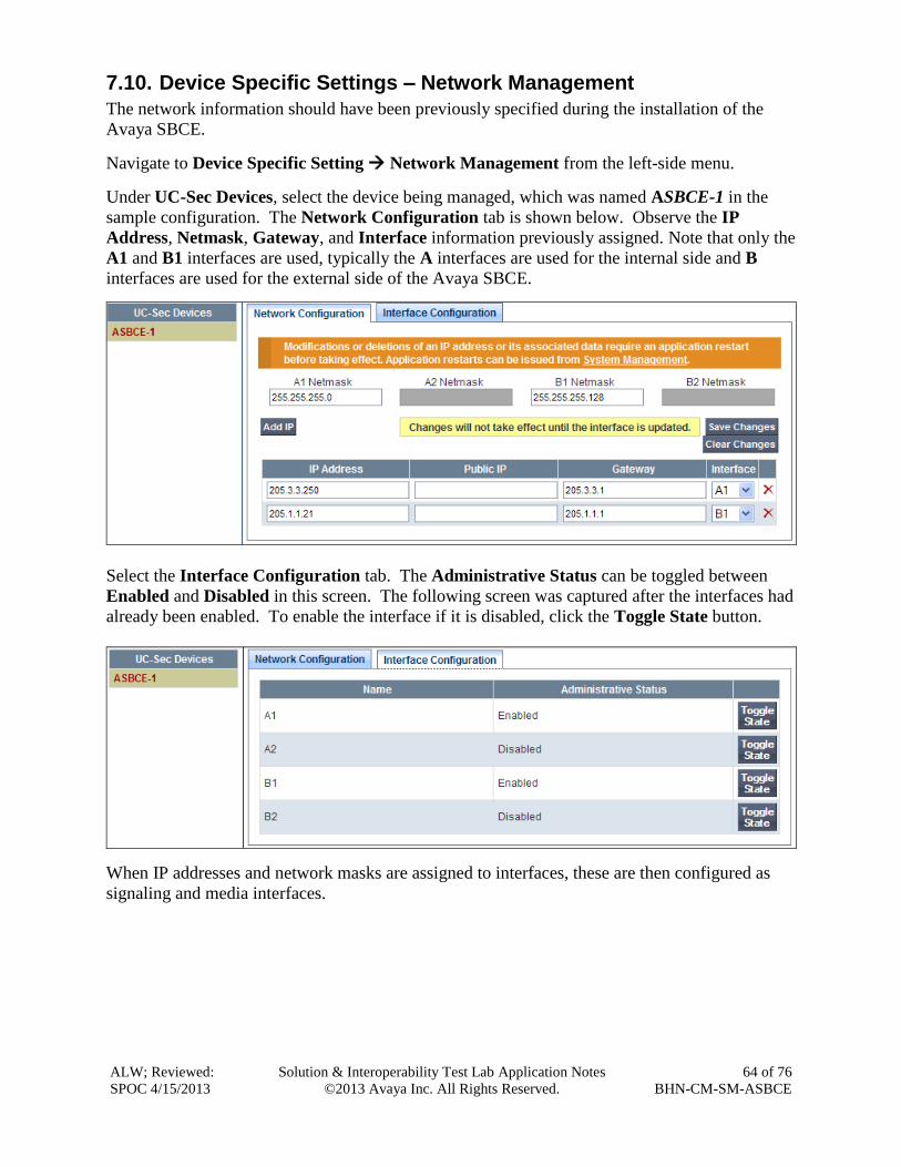
ALW; Reviewed:
SPOC 4/15/2013
Solution & Interoperability Test Lab Application Notes
©2013 Avaya Inc. All Rights Reserved.
64 of 76
BHN-CM-SM-ASBCE
7.10. Device Specific Settings – Network Management
The network information should have been previously specified during the installation of the
Avaya SBCE.
Navigate to Device Specific Setting Network Management from the left-side menu.
Under UC-Sec Devices, select the device being managed, which was named ASBCE-1 in the
sample configuration. The Network Configuration tab is shown below. Observe the IP
Address, Netmask, Gateway, and Interface information previously assigned. Note that only the
A1 and B1 interfaces are used, typically the A interfaces are used for the internal side and B
interfaces are used for the external side of the Avaya SBCE.
Select the Interface Configuration tab. The Administrative Status can be toggled between
Enabled and Disabled in this screen. The following screen was captured after the interfaces had
already been enabled. To enable the interface if it is disabled, click the Toggle State button.
When IP addresses and network masks are assigned to interfaces, these are then configured as
signaling and media interfaces.

ALW; Reviewed:
SPOC 4/15/2013
Solution & Interoperability Test Lab Application Notes
©2013 Avaya Inc. All Rights Reserved.
65 of 76
BHN-CM-SM-ASBCE
7.11. Device Specific Settings – Media Interface
Media Interfaces are created to adjust the port range assigned to media streams leaving the
interfaces of the SBC. The compliance test used the port range 2048 to 3329 for the inside,
private interface to match the default media port range for Communication Manger. The public
interface was set to use the Avaya SBCE default media port range of 35000 to 40000.
Navigate to Device Specific Setting Media Interface from the left-side menu to configure
Media Interfaces; one for internal and one for external.
Under UC-Sec Devices, select the device being managed, which was named ASBCE-1 in the
sample configuration (not shown). Select Add Media Interface.
Enter an appropriate Name for the Media Interface facing the enterprise and select the inside,
private IP Address for the Avaya SBCE from the IP Address drop-down menu. In the sample
configuration, Media_Inside was chosen as the name, and the inside IP Address of the SBC is
205.3.3.250. For the Port Range the default Communication Manager media port range of 2048
to 3329 are shown. Click Finish.
An external Media Interface facing the network was similarly created with the name
Media_Outside. The outside IP Address of the SBC (205.1.1.21) was selected from the drop-
down menu and the Port Range setting was left at the Avaya SBCE default value of 35000 to
40000.

ALW; Reviewed:
SPOC 4/15/2013
Solution & Interoperability Test Lab Application Notes
©2013 Avaya Inc. All Rights Reserved.
66 of 76
BHN-CM-SM-ASBCE
The resultant Media Interface configuration used in the sample configuration is shown below.
7.12. Device Specific Settings – Signaling Interface
Navigate to Device Specific Setting Signaling Interface from the left-side menu to configure
Signaling Interfaces; one for internal and one for external.
Under UC-Sec Devices, select the device being managed, which was named ASBCE-1 in the
sample configuration (not shown). Select Add Signaling Interface.
In the Add Signaling Interface screen, enter an appropriate Name (e.g., Sig_Inside) for the
inside interface, and choose the private, inside IP Address of the Avaya SBCE from the IP
Address drop-down menu. Enter 5060 for TCP Port since TCP port 5060 is used between
Session Manager and the Avaya SBCE in the sample configuration. Click Finish.

ALW; Reviewed:
SPOC 4/15/2013
Solution & Interoperability Test Lab Application Notes
©2013 Avaya Inc. All Rights Reserved.
67 of 76
BHN-CM-SM-ASBCE
An external Signaling Interface facing the network was similarly created with the name
Sig_Outside. Select the outside, public IP Address of the Avaya SBCE (205.1.1.21) from the
drop-down menu. Note that 5060 was specified as the UDP Port since UDP was used between
the Avaya SBCE and the Bright House Networks network.
The following screen shows the Signaling Interfaces defined for the sample configuration.
7.13. Device Specific Settings – End Point Server Flows
End Point Server Flows combine the previously defined profiles into an outgoing flow from the
Call Server (Session Manager) to the Trunk Server (service provider network) and an incoming
flow from the Trunk Server to the Call Server. This configuration ties all the previously entered
information together so that calls can be routed from Session Manager to the service provider
network and vice versa.
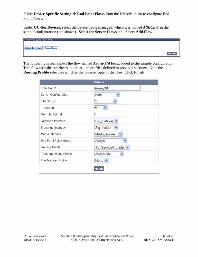
ALW; Reviewed:
SPOC 4/15/2013
Solution & Interoperability Test Lab Application Notes
©2013 Avaya Inc. All Rights Reserved.
68 of 76
BHN-CM-SM-ASBCE
Select Device Specific Setting End Point Flows from the left-side menu to configure End
Point Flows.
Under UC-Sec Devices, select the device being managed, which was named ASBCE-1 in the
sample configuration (not shown). Select the Server Flows tab. Select Add Flow.
The following screen shows the flow named Avaya-SM being added to the sample configuration.
This flow uses the interfaces, policies, and profiles defined in previous sections. Note the
Routing Profile selection which is the reverse route of the flow. Click Finish.

ALW; Reviewed:
SPOC 4/15/2013
Solution & Interoperability Test Lab Application Notes
©2013 Avaya Inc. All Rights Reserved.
69 of 76
BHN-CM-SM-ASBCE
Once again, select the Server Flows tab. Select Add Flow.
The following screen shows the flow named ServiceProvider being added to the sample
configuration. This flow uses the interfaces, policies, and profiles defined in previous sections.
Note the Routing Profile selection which is the reverse route of the flow. Click Finish.

ALW; Reviewed:
SPOC 4/15/2013
Solution & Interoperability Test Lab Application Notes
©2013 Avaya Inc. All Rights Reserved.
70 of 76
BHN-CM-SM-ASBCE
The following screen summarizes the Server Flows configured in the sample configuration.
7.14. Signaling Manipulations
The Signaling Manipulation feature allows the ability to add, change and delete any of the
headers in a SIP message. This feature allows configuration of such manipulations in a highly
flexible manner using a proprietary scripting language called SigMa.
The SigMa scripting language is designed to express any of the SIP header manipulation
operations to be done by the Avaya SBCE. Using this language, a script can be written and tied
to a given flow through the EMS GUI. The Avaya SBCE appliance then interprets this script at
the given entry point or “hook point” of the call flow.
To create a new Signaling Manipulation, navigate to UC-Sec Control Center Global Profiles
Signaling Manipulation and click on Add Script (not shown). A new blank SigMa Editor
window will pop up. For more information on Signaling Manipulation see Reference [8].
There was a SigMa script created during the compliance test to remove any “+” signs from SIP
messaging that is not removed with the Topology Hiding configuration shown in Section 7.6.
The script is broken down as follows:
within session “All” Manipulations are applied to all SIP
sessions.
act on message Manipulations will be applied to all SIP
messages.
%DIRECTION=“OUTBOUND” Applied to messages leaving the Avaya
SBCE towards the service provider, in this
case.
%ENTRY_POINT=“POST_ROUTING” The “hook point” to apply the script after the
SIP message has routed through the Avaya
SBCE.
In the body of the Signaling Manipulation script, the From, Contact, and P-Asserted Identity
(PAI) headers (first three %HEADERS lines) will be examined to see if they contain an e.164

ALW; Reviewed:
SPOC 4/15/2013
Solution & Interoperability Test Lab Application Notes
©2013 Avaya Inc. All Rights Reserved.
71 of 76
BHN-CM-SM-ASBCE
“+” sign. If a “+” sign is found then it is removed and replaced with a SIP URI that does not
contain a “+” sign.
The last line in the SigMa script will look for any SIP Contact header containing a parameter of
“epv” (or end point view), and if the parameter is present in the Contact header, it will be
removed. While the “epv” parameter did not cause any noticeable issues during the compliance
test, it was still removed before being sent to the service provider network since the service
provider does not require or need the “epv” parameter.
The following screen shows the finished Signaling Manipulation Script Remove-Plus.

ALW; Reviewed:
SPOC 4/15/2013
Solution & Interoperability Test Lab Application Notes
©2013 Avaya Inc. All Rights Reserved.
72 of 76
BHN-CM-SM-ASBCE
After the SigMa script has been created it needs to be applied to the Server Configuration.
Navigate to Global ProfilesServer Configuration (not shown). Click on the Advanced tab
for the service provider, in this case SP-SIP-Trunk, and then click Edit as shown below:
Next, select the appropriate SigMa script from the drop-down menu. For the compliance test, the
SigMa script Remove-Plus was used as shown below:
Note, the script is applied to the service provider Server Configuration so that manipulations
can occur as the SIP messages leave the Avaya SBCE, and after any routing decisions have been
made.
8. Bright House Networks SIP Trunking Configuration To use Bright House Networks SIP Trunking, a customer must request the service from Bright
House Networks using the established sales and provisioning processes.
During the signup process, Bright House Networks will require that the customer provide the
public IP address used to reach the Avaya SBCE at the edge of the enterprise and information
related to SIP configuration supported by the enterprise. Bright House Networks will provide
the IP address of the Bright House Network’s SIP trunk proxy/SBC, transport protocol and
listening port for the SIP connection to the enterprise, and Direct Inward Dialed (DID) numbers
assigned to the enterprise. This information is used to complete the configurations of
Communication Manager, Session Manager, and the Avaya SBCE discussed in the previous
sections.
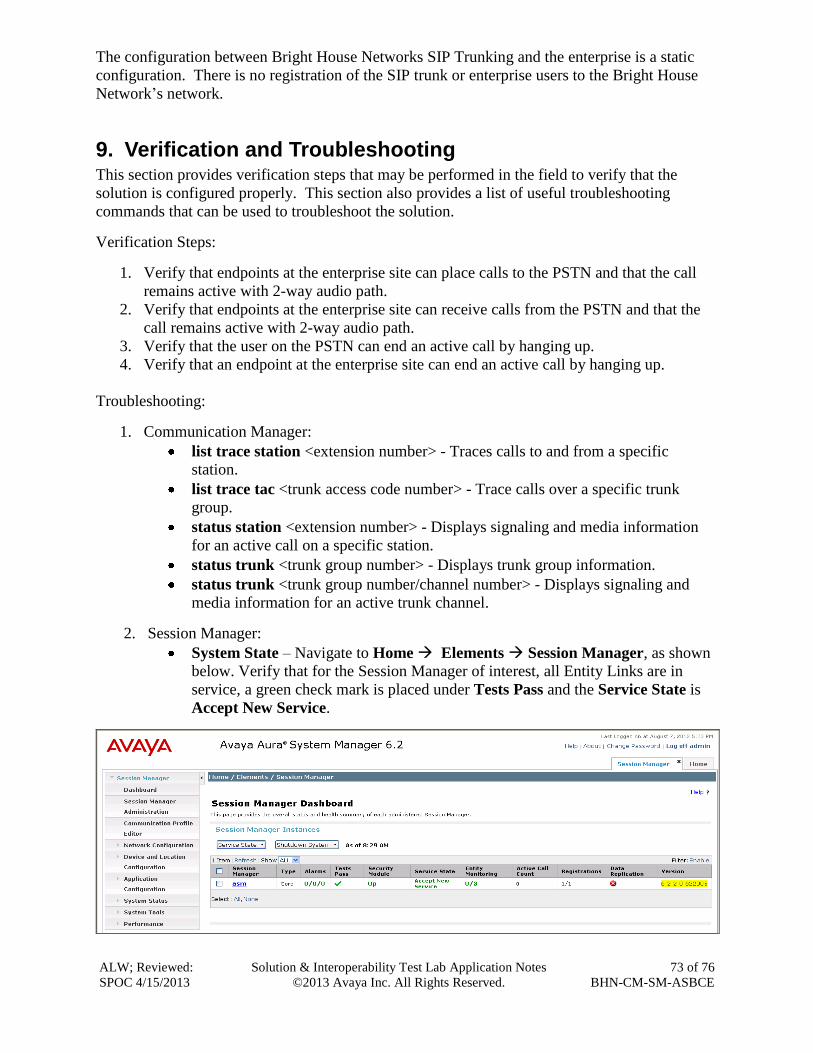
ALW; Reviewed:
SPOC 4/15/2013
Solution & Interoperability Test Lab Application Notes
©2013 Avaya Inc. All Rights Reserved.
73 of 76
BHN-CM-SM-ASBCE
The configuration between Bright House Networks SIP Trunking and the enterprise is a static
configuration. There is no registration of the SIP trunk or enterprise users to the Bright House
Network’s network.
9. Verification and Troubleshooting This section provides verification steps that may be performed in the field to verify that the
solution is configured properly. This section also provides a list of useful troubleshooting
commands that can be used to troubleshoot the solution.
Verification Steps:
1. Verify that endpoints at the enterprise site can place calls to the PSTN and that the call
remains active with 2-way audio path.
2. Verify that endpoints at the enterprise site can receive calls from the PSTN and that the
call remains active with 2-way audio path.
3. Verify that the user on the PSTN can end an active call by hanging up.
4. Verify that an endpoint at the enterprise site can end an active call by hanging up.
Troubleshooting:
1. Communication Manager:
list trace station <extension number> - Traces calls to and from a specific
station.
list trace tac <trunk access code number> - Trace calls over a specific trunk
group.
status station <extension number> - Displays signaling and media information
for an active call on a specific station.
status trunk <trunk group number> - Displays trunk group information.
status trunk <trunk group number/channel number> - Displays signaling and
media information for an active trunk channel.
2. Session Manager:
System State – Navigate to Home Elements Session Manager, as shown
below. Verify that for the Session Manager of interest, all Entity Links are in
service, a green check mark is placed under Tests Pass and the Service State is
Accept New Service.

ALW; Reviewed:
SPOC 4/15/2013
Solution & Interoperability Test Lab Application Notes
©2013 Avaya Inc. All Rights Reserved.
74 of 76
BHN-CM-SM-ASBCE
traceSM -x – Session Manager command line tool for traffic analysis. Log in via
SSH to the Session Manager management interface and become the root user.
Run the command traceSM –x to start the Session Manager traceSM tool.
Call Routing Test - The Call Routing Test verifies routing for a particular source
and destination. To run the routing test, navigate to Home Elements
Session Manager System Tools Call Routing Test. Enter the requested
data to run tests.
3. Avaya SBC for Enterprise
OPTIONS – Disable the SBC-sourced OPTIONS to the trunk server (see Section
7.4.2) and use a network sniffer like Wireshark to verify that the service provider
network will receive OPTIONS forwarded by the SBC from the enterprise site as
a result of the SIP Entity Monitoring configured for Session Manager. Reversely,
when the service provider network responds to the OPTIONS from Session
Manager, the SBC will pass the response to Session Manager.
Incidents – From the admin web interface of the Avaya SBCE, open the Incidents
report by clicking the Incidents button on the menu bar. Look for any errors.

ALW; Reviewed:
SPOC 4/15/2013
Solution & Interoperability Test Lab Application Notes
©2013 Avaya Inc. All Rights Reserved.
75 of 76
BHN-CM-SM-ASBCE
10. Conclusion These Application Notes describe the configuration necessary to connect Avaya Aura®
Communication Manager R6.2, Avaya Aura® Session Manager R6.2 and Avaya Session Border
Controller for Enterprise R4.0.5-Q19 to Bright House Networks SIP Trunking. Bright House
Networks SIP Trunking is a SIP-based Voice over IP service for customers ranging from small
businesses to large enterprises providing businesses a flexible, cost-saving alternative to
traditional hardwired telephony trunks.
11. References The Avaya product documentation is available at http://support.avaya.com unless otherwise
noted.
Avaya Aura® Session Manager/System Manager
[1] Administering Avaya Aura® Session Manager, Document ID 03-603324, Release 6.2, July
2012
[2] Implementing Avaya Aura® Session Manager, Doc ID 03-603473 Release 6.2, July 2012
[3] Maintaining and Troubleshooting Avaya Aura® Session Manager, Doc ID 03-603325, Issue
4.1, March 2012
[4] Administering Avaya Aura® System Manager, Document Number 03-603324, Release 6.2,
July 2012
Avaya Aura® Communication Manager
[5] Administering Avaya Aura® Communication Manager, Document ID 03-300509, Issue 7.0,
Release 6.2, July 2012
[6] Programming Call Vectors in Avaya Aura® Call Center, 6.0, June 2010
Avaya Session Border Controller for Enterprise
Product documentation for UC-Sec can be obtained from Sipera using the link at
http://www.sipera.com.
[7] E-SBC 1U Installation Guide, Release 4.0.5, Part Number: 101-5225-405v1.00, Release
Date: November 2011
[8] E-SBC Administration Guide, Release 4.0.5, Part Number: 010-5424-405v1.00, Release
Date: November 2011
ALW; Reviewed:
SPOC 4/15/2013
Solution & Interoperability Test Lab Application Notes
©2013 Avaya Inc. All Rights Reserved.
76 of 76
BHN-CM-SM-ASBCE
©2013 Avaya Inc. All Rights Reserved.
Avaya and the Avaya Logo are trademarks of Avaya Inc. All trademarks identified by ® and
™ are registered trademarks or trademarks, respectively, of Avaya Inc. All other trademarks
are the property of their respective owners. The information provided in these Application
Notes is subject to change without notice. The configurations, technical data, and
recommendations provided in these Application Notes are believed to be accurate and
dependable, but are presented without express or implied warranty. Users are responsible for
their application of any products specified in these Application Notes.
Please e-mail any questions or comments pertaining to these Application Notes along with the
full title name and filename, located in the lower right corner, directly to the Avaya
DevConnect Program at [email protected].