
Opolo Vineyards SIP Certification Analysis - Cal Poly Digital ...
Upload
khangminh22Category
view
3download
0
RS; Reviewed:
SPOC 10/14/2010
Solution & Interoperability Test Lab Application Notes
©2010 Avaya Inc. All Rights Reserved.
1 of 35
TeleMatrix3302
Avaya Solution & Interoperability Test Lab
Application notes for TeleMatrix 3302IP SIP Telephones
with Avaya Communication Server 1000 Release 6.0
– Issue 1.0
Abstract
These Application Notes describe a solution comprised of Avaya Communication Server 1000
SIP Line Release 6.0 and TeleMatrix 3302IP SIP telephones. During the compliance testing,
the TeleMatrix 3302IP was able to register as a SIP client endpoint with the Communication
Server 1000. The TeleMatrix 3302IP SIP telephones were able to place and receive calls from
Communication Server 1000 Release 6.0 non-SIP and SIP Line clients. The compliance tests
focused on basic telephone features.
Information in these Application Notes has been obtained through DevConnect compliance
testing and additional technical discussions. Testing was conducted via the DevConnect
Program at the Avaya Solution and Interoperability Test Lab.

RS; Reviewed:
SPOC 10/14/2010
Solution & Interoperability Test Lab Application Notes
©2010 Avaya Inc. All Rights Reserved.
2 of 35
TeleMatrix3302
1. Introduction
These application notes provide detail configurations of Avaya Communication Server 1000 SIP
Line release 6.0 (hereafter referred to as CS1000) and the TeleMatrix 3302IP SIP telephone
release V1.8.3-781 (aka SC2-1.8.3-781) used during the compliance testing. The TeleMatrix
3302IP was tested with the non-SIP and SIP clients of the CS1000 SIP line release 6.0. All the
applicable telephony feature test cases of release 6.0 SIP line were executed on the TeleMatrix
3302IP, where applicable, to ensure the interoperability with CS 1000.
1.1. Interoperability Compliance Testing
The focus of this testing was to verify that the TeleMatrix 3302IP SIP telephone was able to
interoperate with the CS1000 SIP line system. The following areas were tested:
The TeleMatrix 3302IP must be able to be installed in the same local VLAN network as
the CS1000 successfully.
Registration of the TeleMatrix 3302IP SIP telephone to the CS1000 SIP Line Gateway.
Calls establishment of TeleMatrix 3302IP with CS1000 SIP and non-SIP telephones.
Telephony features: Basic calls, conference, DTMF (dual tone multi frequency)
transmission, voicemail with Message Waiting Indication (MWI) notification, busy, hold,
speed dial, group call pickup, call waiting, ring again busy/no answer, multiple
appearances Directory Number.
Codec negotiation – G.711 and G.729.
1.2. Support
For technical support on TeleMatrix 3302IP SIP endpoints, please contact TeleMatrix, Inc
technical support at website www.TeleMatrix.net or telephone: +1 719 638 8821 or email
2. Reference Configuration Figure 1 illustrates the test configuration used during the compliance testing between the Avaya
CS1000 and the TeleMatrix 3302IP.

RS; Reviewed:
SPOC 10/14/2010
Solution & Interoperability Test Lab Application Notes
©2010 Avaya Inc. All Rights Reserved.
3 of 35
TeleMatrix3302
Figure 1: Test Bed Configuration
3. Equipment and Software Validated
System Software Version
Avaya CS1000 Call Server (CPPM): 6.00RJ
Signaling Server (CPPM): 6.00.18
SIP Line Gateway (HP DL320)
Avaya voicemail system CallPilot 5.0 system
Avaya 11xx SIP client (Sigma)
Avaya SIP soft-phones
Avaya IP phones
02.02.16.00
SMC3456: v2.6 Build 53715
2050PC: 3.02.0045
TeleMatrix 3302IP 3302IP V1.8.3-781 (aka SC2-1.8.3-781)
4. Configure Avaya CS 1000 - SIP LINE This section describes the steps to configure the Avaya CS1000 SIP Line using CS 1000 Element
Manager. A command line interface (CLI) option is available to provision the SIP Line
application on CS 1000 system. For detailed information see [1] in section 9.
4.1. Prerequisite
- A CS1000 server which has been:
o Installed with CS 1000 Release 6.0 Linux Base.
o Joined CS 1000 Release 6.0 Security Domain.
o Deployed with SIP Line Application.
For more information, see [6] in section 9.
RS; Reviewed:
SPOC 10/14/2010
Solution & Interoperability Test Lab Application Notes
©2010 Avaya Inc. All Rights Reserved.
4 of 35
TeleMatrix3302
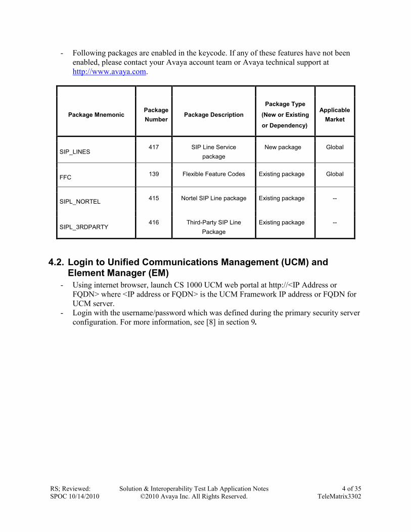
- Following packages are enabled in the keycode. If any of these features have not been
enabled, please contact your Avaya account team or Avaya technical support at
http://www.avaya.com.
Package Mnemonic Package
Number Package Description
Package Type
(New or Existing
or Dependency)
Applicable
Market
SIP_LINES 417 SIP Line Service
package
New package Global
FFC 139 Flexible Feature Codes Existing package Global
SIPL_NORTEL 415 Nortel SIP Line package Existing package --
SIPL_3RDPARTY 416 Third-Party SIP Line
Package
Existing package --
4.2. Login to Unified Communications Management (UCM) and Element Manager (EM)
- Using internet browser, launch CS 1000 UCM web portal at http://<IP Address or
FQDN> where <IP address or FQDN> is the UCM Framework IP address or FQDN for
UCM server.
- Login with the username/password which was defined during the primary security server
configuration. For more information, see [8] in section 9.

RS; Reviewed:
SPOC 10/14/2010
Solution & Interoperability Test Lab Application Notes
©2010 Avaya Inc. All Rights Reserved.
5 of 35
TeleMatrix3302
Figure 2: UCM Home Page

RS; Reviewed:
SPOC 10/14/2010
Solution & Interoperability Test Lab Application Notes
©2010 Avaya Inc. All Rights Reserved.
6 of 35
TeleMatrix3302
- On the Unified Communications Management page, under the Element Name column,
click on the server name to navigate to Element Manager for that server. The CS 1000
Element Manager page appears as show in Figure 3 below.
Figure 3: CS 1000 EM Home Page
4.3. Enable SIP Line Service and Configure the Root Domain in Customer Data Block (CDB)
- On the EM page, navigate to Customers on the left column menu, select the customer
number to be enabled with SIP Line Service (not shown).
- Enable SIP Line Service by clicking on the SIP Line Service check box.

RS; Reviewed:
SPOC 10/14/2010
Solution & Interoperability Test Lab Application Notes
©2010 Avaya Inc. All Rights Reserved.
7 of 35
TeleMatrix3302
- Enter the SIP Line Root Domain name in the Root Domain text box as shown in Figure
4.
Figure 4: SIP Line Service in Customers Data Block
4.4. SIP Line Telephony Node Configuration
- On the EM page, navigate to System IP Network Nodes: Servers, Media Cards.
- Click Add to add a new SIP Line Node to IP Telephony Nodes. To see the SIP Line node
details, click on the SIP Line Node ID (not shown).
- Enter the following as show in Figure 5:
- Enter Node ID in the Node ID text box.
- Enter Call Server IP Address in the Call Server IP Address text box.
- Enter Node IP Address in the Node IP Address text box.
- Enter TLAN Subnet Mask in the Subnet Mask text box.
- Enter ELAN Gateway IP Address in the Gateway IP Address text box.
- Enter ELAN Subnet Mask in the Subnet Mask text box.
- Check SIP Line check box to enable SIP Line for this Node.

RS; Reviewed:
SPOC 10/14/2010
Solution & Interoperability Test Lab Application Notes
©2010 Avaya Inc. All Rights Reserved.
8 of 35
TeleMatrix3302
Figure 5 – IP Telephony Node
- Click Next. The page, New IP Telephony Note with Node ID, will appear as shown in
Figure 6.
- On Add Server page, from the drop down menu list, select the desired server to add to
the node.
- Click Add (Do not click the Next button).
- Select the check box next to the newly added server, and click Make Leader.
Figure 6 – IP Telephony Node – Add Server

RS; Reviewed:
SPOC 10/14/2010
Solution & Interoperability Test Lab Application Notes
©2010 Avaya Inc. All Rights Reserved.
9 of 35
TeleMatrix3302
- Click Next. The SIP Line Configuration Detail page appears as shown in Figure 7.
- Enter SIP Line domain name in SIP Domain name text box. This must be the same as
the domain name configured in Customers.
Figure 7 – SIP Line Node Details
- Under the SIP Line Gateway Services section, select MO from the SLG Role list.
- From the SLG Mode list, select S1/S2 (SIP Proxy Server 1 and Server 2), see Figure 8.
Figure 8 – SIP Line Node Details (cont.)

RS; Reviewed:
SPOC 10/14/2010
Solution & Interoperability Test Lab Application Notes
©2010 Avaya Inc. All Rights Reserved.
10 of 35
TeleMatrix3302
- Click Next. The Confirm new Node details page appears (not shown).
- Click Finish and wait for the configuration being saved. The Node Saved page appears,
see Figure 9.
Figure 9 – Transfer Configuration
- Click Transfer Now. The Synchronize Configuration Files (Node ID 556) page appears.
- Select some or all of the node elements and then click Start Sync to transfer the
configuration files to the selected servers, see Figure 10.
Figure 10 – Synchronize Configuration Files
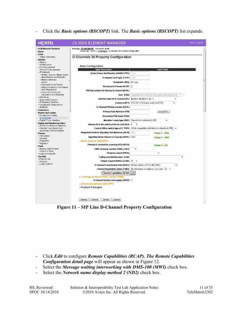
4.5. D-Channel over IP Configuration
- On the EM page, on the left column menu navigate to Routes and Trunks D-
Channels. - Under the Configuration section, from the Choose a D-Channel Number list, select a D-
Channel number, channel 30 in this configuration.
- Under the Configuration section, from the Type list, select DCH.
- Click Add.
- From the D channel Card Type (CTYP) list, select D-Channels is over IP (DCIP).
- Click Add.
- The D-Channels xx Property Configuration page appears as shown in Figure 11.
- From the Interface type for D-channel (IFC) list, select Meridian Meridian1 (SL1).
- Others are at default values.
RS; Reviewed:
SPOC 10/14/2010
Solution & Interoperability Test Lab Application Notes
©2010 Avaya Inc. All Rights Reserved.
11 of 35
TeleMatrix3302
- Click the Basic options (BSCOPT) link. The Basic options (BSCOPT) list expands.
Figure 11 – SIP Line D-Channel Property Configuration
- Click Edit to configure Remote Capabilities (RCAP). The Remote Capabilities
Configuration detail page will appear as shown in Figure 12.
- Select the Message waiting interworking with DMS-100 (MWI) check box.
- Select the Network name display method 2 (ND2) check box.

RS; Reviewed:
SPOC 10/14/2010
Solution & Interoperability Test Lab Application Notes
©2010 Avaya Inc. All Rights Reserved.
12 of 35
TeleMatrix3302
- At the bottom of the Remote Capabilities Configuration page, click Return - Remote
Capabilities.
- The D-Channel xx Property Configuration page reappears.
Figure 12 – SIP Line D-Channel RCAP Configuration Details
Message Waiting Interworking with DMS-100 (MWI) must be enabled to support voice mail
notification on SIP Line endpoints.
Network Name Display Method 2 (ND2) must be enabled to support name display between SIP
Line endpoints.
Others check boxes are left unchecked.

RS; Reviewed:
SPOC 10/14/2010
Solution & Interoperability Test Lab Application Notes
©2010 Avaya Inc. All Rights Reserved.
13 of 35
TeleMatrix3302
4.6. Application Module Link (AML) over Embedded LAN (ELAN) Configuration
- On the EM page, navigate to System Interfaces Application Module Link.
- Click Add to add an Application Module Link. New Application Module Link page
appears as shown in Figure 13.
- Enter AML port in the Port number text box. The SIP Line Service can use port 32 to
port 127. In this case, SIP Line Service is configured to use port 32.
- Click Save to save the configuration.
Figure 13 – Application Module Link Configuration
4.7. Value Added Server (VAS) Configuration
- On the EM page, navigate to System Interfaces Value Added Server.
- Click Add to add new Value Added Server. The Add Value Added Server page appears.
- Click on the Ethernet LAN Link as shown in Figure 14.
- Enter the Ethernet LAN Link number in the Ethernet LAN Link text box.
- Ensure that the Application Security check box is unchecked.

RS; Reviewed:
SPOC 10/14/2010
Solution & Interoperability Test Lab Application Notes
©2010 Avaya Inc. All Rights Reserved.
14 of 35
TeleMatrix3302
Figure 14 – Value Added Service for Application Module Link
4.8. Virtual Trunk Zone Configuration
- On the EM page, navigate to System IP Network Zones.
- On the Zones page, select Bandwidth Zones.
- On the Bandwidth Zones page, select a Bandwidth Zone number from the list, and click
to Add (not shown).
- On the Zone Basic Property and Bandwidth Management page, set the zone properties
based on bandwidth availability. It is recommended to set the Zone Strategy to
BestQuality (BQ) as shown in Figure 15.
- From the Zone Intent (ZBRN) list, select VTRK (VTRK).
- Click Submit button at the bottom of the page to save and commit the changes.
Figure 15 – Virtual Trunk Zone Configuration

RS; Reviewed:
SPOC 10/14/2010
Solution & Interoperability Test Lab Application Notes
©2010 Avaya Inc. All Rights Reserved.
15 of 35
TeleMatrix3302
4.9. SIP Line Route Data Block (RDB) Configuration
- On the EM page, navigate to Routes and Trunks Routes and Trunks.
- Click Add for the customer number.
- On the Customer xx, New Route Configuration page as shown in Figure 16.
- From the Route number (ROUT) list, select a route number.
- From the Trunk type (TKTP) list, select TIE trunk data block (TIE).
- When Trunk Type (TKTP) is selected, the following options appear:
Trunk type M911P (M911P).
The route is for a virtual trunk route (VTRK).
Digital trunk route (DTRK).
Integrated services digital network option (ISDN).
- From the Incoming and outgoing trunk (ICOG) field, select Incoming and Outgoing
(IAO).
- In the Access code for the trunk route (ACOD) field, enter the access code.
- Select The route is for virtual trunk route (VTRK) check box.
- In the Zone for codec selection and bandwidth management (ZONE) field, enter the
zone number. (Use the same zone as configured in 4.8 “Virtual Trunk Zone
Configuration”).
- In the Node ID of signaling server of this route (NODE) field, enter the node ID of the
SIP Line Gateway.
- From the Protocol ID for the route (PCID) list, select SIP Line (SIPL).
- Select the Integrated services digital network option (ISDN) check box.
- From the Mode of operation (MODE) list, select Route uses ISDN Signaling Link
(ISLD).
- In the D channel number (DCH) field, enter the D-channel number.
- From the Interface type for route (IFC) list, select Meridian M1 (SL1).
- Ensure the Network calling name allowed (NCNA) check box is selected.
- Select the Trunk route optimization (TRO) check box. (Optional)
- Basic Route Options, Network Options, General Options, and Advanced
Configurations sections set as default.
- Click Submit button to save the configuration changes.

RS; Reviewed:
SPOC 10/14/2010
Solution & Interoperability Test Lab Application Notes
©2010 Avaya Inc. All Rights Reserved.
16 of 35
TeleMatrix3302
Figure 16 –SIP Line Route Configuration
Note: There is an outstanding issue with the CS 1000 Call Waiting feature which occurs when
Network Call Redirection is enabled. If the Network Call Redirection feature is not required,
uncheck the feature to make the Call Waiting work.
4.10. SIP Line Virtual Trunk Configuration
- On the EM page, navigate to Routes and Trunks Routes and Trunks.
- Select the customer for which you are configuring Virtual Trunks.
- Click Add trunk associated with the route listing to add new trunk members.
- The Customer xx, Route yy, New Trunk Configuration Web page appears as show in
Figure 17.
- Choose Multiple trunk input number (MTINPUT) if you are using more than one trunk.
- From the Trunk data block (TYPE) list, select IP Trunk (IPTI).
- In the Terminal Number (TN) field, enter a TN.
- Enter a Route number, Member number (RTMB).
- Enter a Trunk Group Access Restriction (TGAR) value.

RS; Reviewed:
SPOC 10/14/2010
Solution & Interoperability Test Lab Application Notes
©2010 Avaya Inc. All Rights Reserved.
17 of 35
TeleMatrix3302
- In the Channel ID for this trunk (CHID) field, enter a channel ID (where the range is 1
to 382).
- To specify a Class of Service (CLS) for the trunk, click Edit. The Class of Service
Configuration Web page appears (not shown).
- Select a Class of Service.
- Click Return Class of Service to return to the New Trunk Configuration Web page.
- Select Basic Configuration. The Basic Configuration list expands.
- From the Start arrangement Incoming (STRI) list, select a value for the start
arrangement for incoming calls.
- From the Start arrangement Outgoing (STRO) list, select a value for the start
arrangement for outgoing calls.
- Select Advanced Trunk Configurations. The Advanced Trunk Configurations list
expands (not shown).
- Configure Network Class of Service group (NCOS). Please select the value between 0 -
99. The default value is 0.
- Click Save.
Figure 17 –SIP Line Trunk Configuration
4.11. SIP Line Phones Configuration
Following is a sample configuration for a Third Party SIP Line endpoint. Depending on
supported features and service access level of the user, this configuration can be adjusted
accordingly. The sample is using Command Line Interface of CS1000. This can be done by
login to Call Server of CS1000 and using overlay 11 as shown below. The bold text values are
the changes required where others are at default values.

RS; Reviewed:
SPOC 10/14/2010
Solution & Interoperability Test Lab Application Notes
©2010 Avaya Inc. All Rights Reserved.
18 of 35
TeleMatrix3302
>LD 11
REQ: prt
TYPE: tnb
TN 96 0 1 27
DATE
PAGE
DES
DES TELE
TN 096 0 01 27 VIRTUAL
TYPE UEXT
CDEN 8D
CTYP XDLC
CUST 0
UXTY SIPL
MCCL YES
SIPN 0 Set this to 1 and set SIP3 to 0 if this TN is reserved for Avaya SIP Phones
SIP3 1 Set this to 1 and set SIPN to 0 if this TN is reserved for third party SIP Phones
FMCL 0
TLSV 0
SIPU 55573
NDID 556
SUPR NO
SUBR DFLT MWI RGA CWI MSB
UXID
NUID
NHTN
CFG_ZONE 001
CUR_ZONE 001
ERL
ECL 0
FDN 55576 If CLS FNA is equipped, call will be forwarded no answer to this number
TGAR 0
LDN NO
NCOS 0
SGRP 0
RNPG 2 This field must be set first if call pickup is equipped (CLS PUA)
SCI 0
SSU
XLST
SCPW 1234
SFLT NO
CAC_MFC 0
CLS UNR FBA WTA LPR PUA MTD FNA HTA TDD HFA CRPD
MWA LMPN RMMD SMWD AAD IMD XHD IRD NID OLD VCE DRG1

RS; Reviewed:
SPOC 10/14/2010
Solution & Interoperability Test Lab Application Notes
©2010 Avaya Inc. All Rights Reserved.
19 of 35
TeleMatrix3302
POD DSX VMD SLKD CCSD SWD LND CNDA
CFTD SFD MRD DDV CNIA CDCA MSID DAPA BFED RCBD
ICDD CDMD LLCN MCTD CLBD AUTU
GPUA DPUA DNDA CFXA ARHD CLTD ASCD
CPFA CPTA ABDD CFHD FICD NAID BUZZ AGRD MOAD
UDI RCC HBTD AHA IPND DDGA NAMA MIND PRSD NRWD NRCD NROD
DRDD EXR0
USMD USRD ULAD CCBD RTDD RBDD RBHD PGND FLXD FTTC DNDY DNO3
MCBN
FDSD NOVD VOLA VOUD CDMR ICRD MCDD T87D MSNV FRA PKCH
CPND_LANG ENG
RCO 0
HUNT 55576 If CLS HTA/FBA is equipped, call will be forwarded busy to this number
LHK 0
PLEV 02
DANI NO
AST
IAPG 0
AACS NO
ITNA NO
DGRP
MLWU_LANG 0
MLNG ENG
DNDR 0
KEY 00 SCR 55573 0 MARP
CPND
CPND_LANG ROMAN
NAME TELEMATRIX 55573
XPLN 13
DISPLAY_FMT FIRST, LAST
01 HOT U 2655573 MARP 0
02 SCU 0004 Speed Call User
03
04 MSB This key can be different than key 04 to enable Make Set Busy (MBS) feature
05
.
.
16
17 TRN
18 AO6
19 CFW 16 55574
20 RGA
21 PRK
22 RNP
23
24 PRS

RS; Reviewed:
SPOC 10/14/2010
Solution & Interoperability Test Lab Application Notes
©2010 Avaya Inc. All Rights Reserved.
20 of 35
TeleMatrix3302
25 CHG
26 CPN
4.12. PSTN Outside Trunk Configuration
Following is a sample configuration which was used during compliance testing. For more
information about PRI Trunk Configuration, see [3] in section 9.
4.12.1. Procedure summary
This procedure was applied for the CS 1000 system under test as per Figure 1. The provisioning
is done using the Command Line Interface by logging in to the Call Server of the CS1000.
No. Overlay Action
1 LD 17 Adding a PRI card
2 LD 17 Adding a PRI D-Channel
3 LD 15 Defining a PRI customer
4 LD 16 Defining a PRI service route
5 LD 14 Defining service channels and PRI
trunks
6 LD 73 Defining system timers and clock
controller
7 LD 48 Enable TMDI or PRI MSDL card
8 LD 60 Enable Clock Controller
9 LD 60 Enable Digital trunk loop
10 LD 96 Enable D-channel
4.12.2. Adding a PRI card
The programming example below shows how to add a PRI card using LD 17. For all other fields
not listed in the example press RETURN to use default values.
Prompt Response Description
REQ CHG Change data.
TYPE CFN Configuration data block.

RS; Reviewed:
SPOC 10/14/2010
Solution & Interoperability Test Lab Application Notes
©2010 Avaya Inc. All Rights Reserved.
21 of 35
TeleMatrix3302
CEQU YES Changes to common equipment.
DLOP 10 Digital Trunk Interface Loop
MG_CARD 4 0 1 MG card assigned to superloop
MODE PRI Mode of operation
TMDI YES Card is TMDI card
TRSH 0 Threshold
4.12.3. Adding a PRI D-channel
The programming example below shows how to add a PRI D-channel using LD 17. For all other
fields not listed in the example press RETURN to use default values.
Prompt Response Description
REQ CHG Change existing data
TYPE CFN Configuration data block.
ADAN NEW DCH
10
Add a primary D-channel (any unused SDI port.)
xx = 1-9 for Option 11C main cabinet, 11-19 for IP
expansion
cabinet 1, 21-29 for IP expansion cabinet 2, 31-39 for IP
expansion cabinet 3, and 41-49 for IP expansion cabinet 4.
Xx = 11-14, 21-24, 31-34, 41-44 of the first, second, third
and
fourth Media Gateway, respectively.
CTYP TMDI Card type where:
MSDL = The NTBK51BA Downloadable D-Channel
Daughterboard.
TMDI = TMDI (NTRB21) card.
DES T1_QSIG Designator field.
USR PRI D-channel is for ISDN PRI only.
Note: 2.0 Mb only supports PRI or SHA user
IFC ISGF Interface type.

RS; Reviewed:
SPOC 10/14/2010
Solution & Interoperability Test Lab Application Notes
©2010 Avaya Inc. All Rights Reserved.
22 of 35
TeleMatrix3302
DCHL 10 PRI card number carries the D-channel. Must match entry
made for the "CDNO" associated with the "DCHI" prompt
above.
Where: xx = 1-9 for Option 11C main cabinet, 11-19 for IP
expansion cabinet 1, 21-29 for IP expansion cabinet 2, 31-
39 for
IP expansion cabinet 3, and 41-49 for IP expansion cabinet
4.
xx = 11-14, 21-24, 31-34, 41-44 of the first, second, third
and fourth Media Gateway, respectively.
SIDE NET NET = network, the controlling switch (applied for CS 1000
PSTN simulator
USR = slave to the controller (applied for CS 1000 system
under test)
RLS 6 Software release of far-end. This is the current software
release of the far-end. If the far-end has an incompatible
release of software, it prevents the sending of application
messages, for example, ‟Network Ring Again.
RCAP CCBI CCNI
PRI DV3I
CTI QMWI
Remote Capabilities.
PR_TRIGS
PR_TRIGS
PR_TRIGS
PR_TRIGS
DIV 2 3
CNG 2 3
CON 2 3
CTR2 2 3
Path Replacement Triggers
4.12.4. Defining a PRI customer
The programming example below shows how to define a PRI customer using LD 15. For all
other fields not listed in the example press RETURN to use default values.
Prompt Response Description
REQ CHG Change existing data.
TYPE CDB Customer data block.
CUST 0 Customer number.
ISDN YES Customer is equipped with ISDN.

RS; Reviewed:
SPOC 10/14/2010
Solution & Interoperability Test Lab Application Notes
©2010 Avaya Inc. All Rights Reserved.
23 of 35
TeleMatrix3302
4.12.5. Defining a PRI service route
The programming example below shows how to add a PRI service route using LD 16. For all
other fields not listed in the example press RETURN to use default values.
Prompt Response Description
REQ NEW Create new data
TYPE RDB Route data block
CUST 0 Customer number
ROUT 10 Route number
DES T1_QSIG Designator field for trunk
TKTP TIE Trunk type
DTRK YES Digital trunk route
ISDN YES ISDN option
MODE PRI Route used for PRI only
PNI 1 Customer private network identifier. Is the same as the CDB
PNI at far-end.
IFC ISGF Interface type.
ICOG IAO Incoming and outgoing
ACOD 8010 Trunk access code
4.12.6. Defining service channels and PRI trunks
The programming example below shows how to create service channels and PRI trunks using
LD 14. For all other fields not listed in the example press RETURN to use default values.
Prompt Response Description
REQ NEW 23 Create 23 new trunks
TYPE Tie Trunk type
TN 10 1 Loop (card) and channel number for digital trunks
PCML MU System PCM law.

RS; Reviewed:
SPOC 10/14/2010
Solution & Interoperability Test Lab Application Notes
©2010 Avaya Inc. All Rights Reserved.
24 of 35
TeleMatrix3302
DES T1_QSIG Designator field for trunk
CUST 0 Customer number
RTMB 10 1 Service route number and trunk member number
CLS UNR DTN Trunk Class Of Service

RS; Reviewed:
SPOC 10/14/2010
Solution & Interoperability Test Lab Application Notes
©2010 Avaya Inc. All Rights Reserved.
25 of 35
TeleMatrix3302
5. Configure TeleMatrix 3302IP This section describes how to access the TeleMatrix 3302IP SIP endpoint web interface and
configure the TeleMatrix 3302IP for testing.
5.1. SIP Registration
This section shows how to login to the main SIP telephone registration.
In the web browser address field, enter the TeleMatrix 3302IP IP address. The TeleMatrix
3302IP login page will appear as shown in Figure 18. Enter the username and password.
Figure 18 – Login Screen
Click the Login button, the main configuration screen appears as in Figure 19 below.
Figure 19: Main Configuration Screen

RS; Reviewed:
SPOC 10/14/2010
Solution & Interoperability Test Lab Application Notes
©2010 Avaya Inc. All Rights Reserved.
26 of 35
TeleMatrix3302
5.2. Configure the SIP Port
This section shows how to configure the SIP telephone to register with the CS1000 SIP Line.
In the main configuration screen (see Figure 19), click to the VOIP menu on the left menu bar.
Provide the SIP information as shown in Figure 20 below. Click on the APPLY button.
Figure 20: SIP Configuration Screen
5.3. Local Call Forward Settings
This section shows how to set “Local Call Forward” on the SIP telephone.
On the Figure 20 above, click on “Advanced Set” button to go Advanced SIP setting. Set “Local
Call Forward” as shown in Figure 21 below.
The “Call Forward No Answer” ringing timeout settings established here should be less than the
timeout setting on the CS 1000 Call Server in order to make the “Local Call Forward No
Answer” take affect.
The “Call Forward Always” settings on the CS 1000 Call Server must be OFF in order to make
the “Local Call Forward Always” take effect.

RS; Reviewed:
SPOC 10/14/2010
Solution & Interoperability Test Lab Application Notes
©2010 Avaya Inc. All Rights Reserved.
27 of 35
TeleMatrix3302
Figure 21: Local Call Forward Settings
5.4. DTMF and Codec settings
This section describes how to configure DTMF and Codec settings in the TeleMatrix 3302IP SIP
telephone.
5.4.1. DTMF Settings
This section shows how to set DTMF on the SIP telephone.

RS; Reviewed:
SPOC 10/14/2010
Solution & Interoperability Test Lab Application Notes
©2010 Avaya Inc. All Rights Reserved.
28 of 35
TeleMatrix3302
In the main configuration screen (see Figure 20), click on the “Advanced Set” button, and then
click on DTMF mode from the list box as Figure 22.
Figure 22 DTMF setting
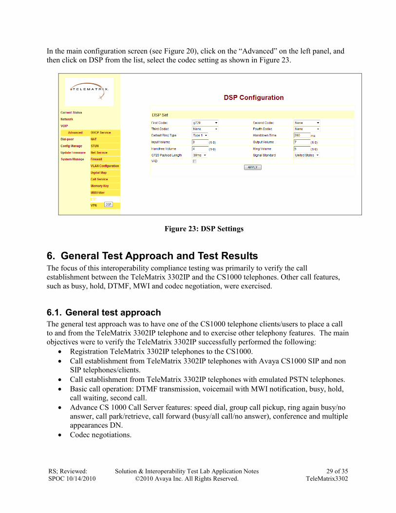
5.4.2. Codec Settings
This section shows how to set Codec on the SIP telephone. Testing has been done on both
codecs; G711 and G729. Bellow example only shows how to set them for testing G729, but it
can be done the same way for G711.
RS; Reviewed:
SPOC 10/14/2010
Solution & Interoperability Test Lab Application Notes
©2010 Avaya Inc. All Rights Reserved.
29 of 35
TeleMatrix3302
In the main configuration screen (see Figure 20), click on the “Advanced” on the left panel, and
then click on DSP from the list, select the codec setting as shown in Figure 23.
Figure 23: DSP Settings
6. General Test Approach and Test Results The focus of this interoperability compliance testing was primarily to verify the call
establishment between the TeleMatrix 3302IP and the CS1000 telephones. Other call features,
such as busy, hold, DTMF, MWI and codec negotiation, were exercised.
6.1. General test approach
The general test approach was to have one of the CS1000 telephone clients/users to place a call
to and from the TeleMatrix 3302IP telephone and to exercise other telephony features. The main
objectives were to verify the TeleMatrix 3302IP successfully performed the following:
Registration TeleMatrix 3302IP telephones to the CS1000.
Call establishment from TeleMatrix 3302IP telephones with Avaya CS1000 SIP and non
SIP telephones/clients.
Call establishment from TeleMatrix 3302IP telephones with emulated PSTN telephones.
Basic call operation: DTMF transmission, voicemail with MWI notification, busy, hold,
call waiting, second call.
Advance CS 1000 Call Server features: speed dial, group call pickup, ring again busy/no
answer, call park/retrieve, call forward (busy/all call/no answer), conference and multiple
appearances DN.
Codec negotiations.

RS; Reviewed:
SPOC 10/14/2010
Solution & Interoperability Test Lab Application Notes
©2010 Avaya Inc. All Rights Reserved.
30 of 35
TeleMatrix3302
6.2. Test Results
The objectives outlined in section 6.1 were verified. The following observations were made
during the compliance testing:
Enable Network Call Redirection (NCRD) in CS1000 Call Server SIP Line Route will
cause an issue with Call Waiting. This issue has been raised against CS 1000 SIP Line
system.
The transfer scenario is not supported on the TeleMatrix 3302IP telephone. This feature
was not tested during compliance testing, as transfer is not a hospitality guestroom
function.
The TeleMatrix 3302IP telephone does not support call forward as described below:
Pre-condition: UA_02 which is configured CFNA to UA_01 on CS1000. Place a call
from UA_02 to UA_02, i.e. dial its own telephone number. You will hear the dial tone.
This is by design intent on the TeleMatrix telephone.
In order to register SIP Line 2 on the TeleMatrix 3302IP telephone, the user needs to
modify the Config File as follows:
- Go to „Config Manage‟ on the left hand menu.
- On 'Backup Configuration', choose “Right Click here to Save as Config File (.txt)”
- Edit 'Config File' as following:
+ Replace version 2.0002 by version 2.0025.
+ Delete 'tt@1' on SIP1 Sip Name field.
+ Delete 'tt@2' on SIP2 Sip Name field.
- Save Config File and upload it back into the telephone in 'Update Configuration'
- SIP Line 2 can then be answered when called, but only SIP 1 will perform outbound
calls.
Bridge Line Appearance (BLA) has not been tested and therefore not supported.
The TeleMatrix 3302IP sets does not support client busy forward when two 3302IP sets
are in conversation mode. However if CS1K is programmed for busy forward then the
3302IP sets will follow the CS1K configuration. The 3302IP sets will support client busy
forward only when the set is off hook and not in conversation mode.
Avaya has not performed audio performance testing or reviewed the SIP phones compliance
to required industry standards.
7. Verification Steps This section includes some steps that can be followed to verify the configuration.
Verify that the SIP telephone registers successfully with the CS 1000 SIP Line Gateway
server and Call Server by using CS 1000 Linux command line and CS 1000 Call Server
overlay LD 32.
- Login to the sipline server using Avaya account.
- Issue command “slgSetShowByUID [userID]” where userID is SIP Line user‟s ID
being checked. [nortel@sipl ~]$ slgSetShowByUID 55524
=== VTRK ===

RS; Reviewed:
SPOC 10/14/2010
Solution & Interoperability Test Lab Application Notes
©2010 Avaya Inc. All Rights Reserved.
31 of 35
TeleMatrix3302
UserID TN Clients Calls SetHandle
--------------- --------------- ------- ----- ---------
55524 096-00-02-24 1 0 0xb7c25e10
StatusFlags = Registered Controlled KeyMapDwld SSD
FeatureMask =
CallProcStatus = 0
Current Client = 0, Total Clients = 1
== Client 0 ==
IP:Port:Trans = 47.248.100.56:5060:udp
Type = SIP3
UserAgent = PolycomVVX-VVX_1500-UA/3.2.2.0481
x-nt-guid = 9ad7a4871842718a35aeadf070608745
RegDescrip =
RegStatus = 1
PbxReason = OK
SipCode = 200
Expire = 300
Contact = sip:[email protected]:5060
Nonce = cad64489bbd9bca62aa9a1f833052da4
NonceCount = 3
hTimer = 0x9c659d0
TimeRemain = 183
Stale = 0
Outbound = 0
ClientGUID = 0
Key Func Lamp Label
0 3 0 55524
1 126 0 2655524
2 3 0 55097
3 9 0
4 29 0
17 16 0
18 18 0
19 27 0
20 19 0
21 52 0
22 25 0
24 11 0
25 30 0
26 31 0
- Login to the call server using admin account.
- Load overlay 32 and then issue command “stat [TN]” where TN is the SIP Line
user‟s TN being checked >ld 32
NPR000
.stat 96 0 2 24
IDLE REGISTERED 00
Place a call from and to TeleMatrix 3302IP telephone and verify that the call is
established with 2 way speech path.

RS; Reviewed:
SPOC 10/14/2010
Solution & Interoperability Test Lab Application Notes
©2010 Avaya Inc. All Rights Reserved.
32 of 35
TeleMatrix3302
During the call, use pcap tool (ethereal/wireshark) at the SIPLine Gateway and clients to
make sure that all SIP request/response messages are correct.
8. Conclusion All of the executed test cases have passed and met the objectives outlined in Section 6.1, with
some exceptions outlined in Section 6.2. The outstanding issues are being investigated by
TeleMatrix and Avaya design teams. Some of these issues are considered as exceptions. The
TeleMatrix 3302IP version 3302TRMSIP V1.8.3-781 is considered in compliance with Avaya
CS1000 SIP Line System Release 6.0.
9. Additional References Product documentation for Avaya products may be found at:
http://support.nortel.com/go/main.jsp
[1] Communication Server 1000 SIP Line Fundamental, Release 6.0, Revision 01.08, February
2010, Document Number NN43001-508
[2] Communication Server 1000E Maintenance, Release 6.0, Revision 03.16, January 2010,
Document Number NN43041-700
[3] Communication Server 1000 ISDN Primary Rate Interface Installation and Commissioning,
Revision 01.03, August 2007, Document Number NN43001-301
[4] Troubleshooting Guide for Distributors, Release 6.0, Revision 02.02, December 2009,
Document Number NN43001-730
[5] Communication Server 1000E Installation and Commissioning, Release 6.0, Revision 03.06,
February 2010, Document Number NN43041-310
[6] Communication Server 1000E Software Upgrades, Revision 03.12, February 2010,
Document Number NN43041-458
[7] Communication Server 1000E Linux Platform Base and Applications Installation and
Commissioning, Revision 03.10, February 09, 2009, Document Number NN43001-315
[8] Communication Server 1000 Unified Communications Management Common Services
Fundamentals, Revision: 03.04, September 28, 2009, Document Number NN43001-116
Product information for TeleMatrix 3302IP products can be found at
www.TeleMatrix.net

RS; Reviewed:
SPOC 10/14/2010
Solution & Interoperability Test Lab Application Notes
©2010 Avaya Inc. All Rights Reserved.
33 of 35
TeleMatrix3302
10. Appendix This section is to help user provisioning the clock synchronization of a network of CS1000
systems used under test. This will create the PRI trunk synchronization between 2 CS1000 under
test in Figure 1; Main and Emulated PSTN systems. In this example, the emulated PSTN will
have clock controller card. Therefore, these provisioning steps below will only apply to the
emulated PSTN CS1000 system only. The steps below can be accomplished by login to the Call
Server and using command line interface on overlay 73.
Defining system timers and clock controller parameters
The programming example below shows how to define system timers and clock controller
parameters using LD 73. For all other fields not listed in the example press RETURN to use
default values.
Prompt Response Description
REQ CHG Change data.
TYPE DDB Digital Data Block
MGCLK 4 0 1 Card slot number for Media Gateway 4 0
PREF 1 Card number of PRI/DTI/SILC or DTI2/PRI2/SILC
containing the primary clock reference.
SREF 1 Card number of PRI/DTI/SILC or DTI2/PRI2/SILC
containing the primary clock reference.
Enabling T1 QSIG Service
Enable TMDI card
The example below shows how to enable TMDI card using LD 48.
>ld 48
LNK000
.enl tmdi 4 0 1
OK
Enable Clock Controller
The example below shows how to enable clock controller using LD 60.
>ld 60
DTI000
.enl cc 4 0

RS; Reviewed:
SPOC 10/14/2010
Solution & Interoperability Test Lab Application Notes
©2010 Avaya Inc. All Rights Reserved.
34 of 35
TeleMatrix3302
.OK
Enable PRI loop
The example below shows how to enable PRI loop using LD 60.
>ld 60
DTI000
.enll 10
OK
.
Enable D-Channel
The D-Channel may not automatically come up. The example below shows how to enable PRI D-
channel using LD 96.
>ld 96
DCH000
.enl dch 10
.
DCH: 10 EST CONFIRM TIME: 19:38:44 30/09/2009
DCH 10 UIPE_OMSG CC_RESTART_REQ REF 00000000 CH 0 TOD 19:38:44 CK
E0DAF978
TYPE: ALL CHANNEL
DCH 10 UIPE_IMSG CC_RESTART_CONF REF 00008000 TOD 19:38:44 CK E0DAF9C2
TYPE: ALL CHANNEL

RS; Reviewed:
SPOC 10/14/2010
Solution & Interoperability Test Lab Application Notes
©2010 Avaya Inc. All Rights Reserved.
35 of 35
TeleMatrix3302
©2010 Avaya Inc. All Rights Reserved.
Avaya and the Avaya Logo are trademarks of Avaya Inc. All trademarks identified by ® and
™ are registered trademarks or trademarks, respectively, of Avaya Inc. All other trademarks
are the property of their respective owners. The information provided in these Application
Notes is subject to change without notice. The configurations, technical data, and
recommendations provided in these Application Notes are believed to be accurate and
dependable, but are presented without express or implied warranty. Users are responsible for
their application of any products specified in these Application Notes.
Please e-mail any questions or comments pertaining to these Application Notes along with the
full title name and filename, located in the lower right corner, directly to the Avaya
DevConnect Program at [email protected].
Copyright © 2022 FDOKUMEN