Appendix F: Excluded studies - F.1 Classification - NICE ...
Upload
khangminh22Category
view
2download
0
Appendix A: Tolerance Classification
© Springer International Publishing Switzerland 2016
D. Um, Solid Modeling and Applications, DOI 10.1007/978-3-319-21822-9287

Tolerance
classification(m
etricvalues)
Basic
size
b
Loose
running
Freerunning
Close
running
Sliding
Locational
clearance
Hole
Shaft
Hole
Shaft
Hole
Shaft
Hole
Shaft
Hole
Shaft
H11
c11
Fitb
H9
d9
Fitb
H8
f7Fitb
H7
g6
Fitb
H7
h6
Fitb
1Max
1.060
0.940
0.180
1.025
0.980
0.070
1.014
0.994
0.030
1.010
0.998
0.018
1.010
1.000
0.016
Min
1.000
0.880
0.060
1.000
0.995
0.020
1.000
0.984
0.006
1.000
0.992
0.002
1.000
0.994
0.000
1.2
Max
1.260
1.140
0.180
1.225
1.180
0.070
1.214
1.194
0.030
1.210
1.198
0.018
1.210
1.200
0.016
Min
1.200
1.080
0.060
1.200
1.155
0.020
1.200
1.184
0.006
1.200
1.192
0.002
1.200
1.194
0.000
1.6
Max
1.660
1.540
0.180
1.625
1.580
0.070
1.614
1.594
0.030
1.610
1.598
0.018
1.610
1.600
0.016
Min
1.600
1.480
0.060
1.600
1.555
0.020
1.600
1.584
0.006
1.600
1.592
0.002
1.600
1.594
0.000
2Max
2.060
1.940
0.180
2.025
1.980
0.070
2.014
1.994
0.030
2.010
1.998
0.018
2.010
2.000
0.016
Min
2.000
1.880
0.060
2.000
1.955
0.020
2.000
1.984
0.006
2.000
1.992
0.002
2.000
1.994
0.000
2.5
Max
2.560
2.440
0.180
2.525
2.480
0.070
2.514
2.494
0.030
2.510
2.498
0.018
2.510
2.500
0.016
Min
2.500
2.380
0.060
2.500
2.455
0.020
2.500
2.484
0.006
2.500
2.484
0.002
2.500
2.494
0.000
3Max
3.060
2.940
0.180
3.025
2.980
0.070
3.014
2.994
0.030
3.010
2.998
0.018
3.010
3.000
0.016
Min
3.000
2.880
0.060
3.000
2.955
0.020
3.000
2.984
0.006
3.000
2.992
0.002
3.000
2.994
0.000
4Max
4.075
3.930
0.220
4.030
3.970
0.090
4.018
3.990
0.040
4.012
3.996
0.024
4.012
4.000
0.020
Min
4.000
3.855
0.070
4.000
3.940
0.030
4.000
3.978
0.010
4.000
3.988
0.004
4.000
3.992
0.000
5Max
5.075
4.930
0.220
5.030
4.970
0.090
5.018
4.990
0.040
5.012
4.996
0.024
5.012
5.000
0.020
Min
5.000
4.855
0.070
5.000
4.940
0.030
5.000
4.978
0.010
5.000
4.988
0.004
5.000
4.992
0.000
6Max
6.075
5.930
0.220
6.030
5.970
0.090
6.018
5.990
0.040
6.012
5.996
0.024
6.012
6.000
0.020
Min
6.000
5.855
0.070
6.000
5.940
0.030
6.000
5.978
0.010
6.000
5.988
0.004
6.000
5.992
0.000
8Max
8.090
7.920
0.260
8.036
7.960
0.112
8.022
7.987
0.050
8.015
7.995
0.029
8.015
8.000
0.024
Min
8.000
7.830
0.080
8.000
7.924
0.040
8.000
7.972
0.013
8.000
7.986
0.005
8.000
7.991
0.000
10
Max
10.090
9.920
0.260
10.036
9.960
0.112
10.022
9.987
0.050
10.015
9.995
0.029
10.015
10.000
0.024
Min
10.000
9.830
0.080
10.000
9.924
0.040
10.000
9.972
0.013
10.000
9.986
0.005
10.000
9.991
0.000
12
Max
12.110
11.905
0.315
12.043
11.956
0.136
12.027
11.984
0.061
12.018
11.994
0.035
12.018
12.000
0.029
Min
12.000
11.795
0.095
12.000
11.907
0.050
12.000
11.966
0.016
12.000
11.983
0.006
12.000
11.989
0.000
288 Appendix A: Tolerance Classification
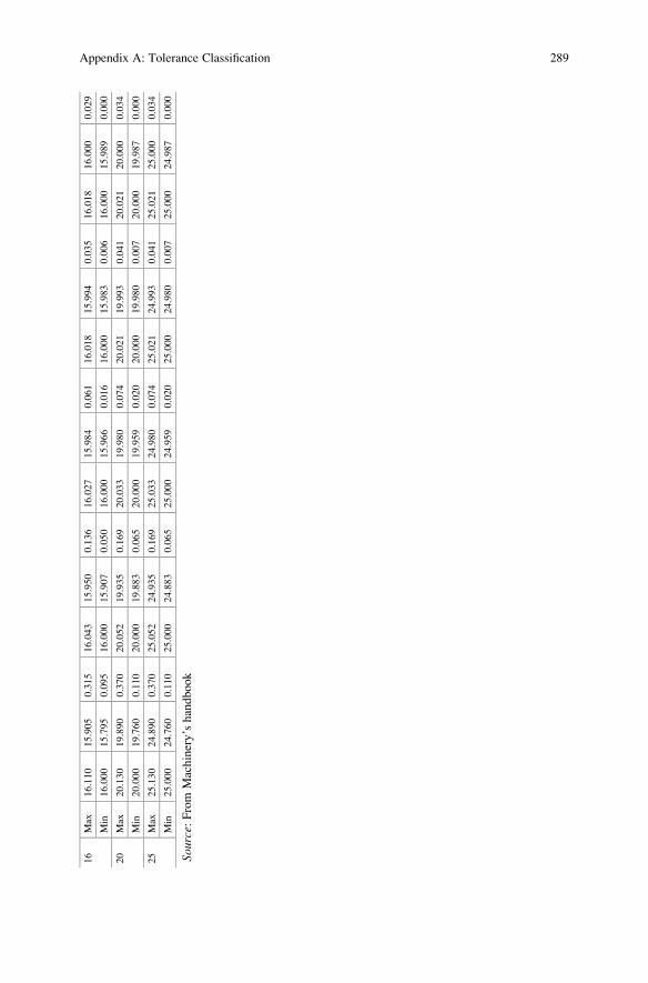
16
Max
16.110
15.905
0.315
16.043
15.950
0.136
16.027
15.984
0.061
16.018
15.994
0.035
16.018
16.000
0.029
Min
16.000
15.795
0.095
16.000
15.907
0.050
16.000
15.966
0.016
16.000
15.983
0.006
16.000
15.989
0.000
20
Max
20.130
19.890
0.370
20.052
19.935
0.169
20.033
19.980
0.074
20.021
19.993
0.041
20.021
20.000
0.034
Min
20.000
19.760
0.110
20.000
19.883
0.065
20.000
19.959
0.020
20.000
19.980
0.007
20.000
19.987
0.000
25
Max
25.130
24.890
0.370
25.052
24.935
0.169
25.033
24.980
0.074
25.021
24.993
0.041
25.021
25.000
0.034
Min
25.000
24.760
0.110
25.000
24.883
0.065
25.000
24.959
0.020
25.000
24.980
0.007
25.000
24.987
0.000
Source:From
Machinery’shandbook
Appendix A: Tolerance Classification 289

Tolerance classification (inch values)
Nominal
size range
(in.)
Class LN 1 Class LN 2 Class LN 3
Limits of
interference
Standard limits
Limits of
interference
Standard limits
Limits of
interference
Standard limits
Hole
H6
Shaft
n5
Hole
H7
Shaft
p6
Hole
H7
Shaft
r6
Over To Values shown below are given in thousandths of an inch
0–0.12 0 +0.25 +0.45 0 +0.4 +0.65 0.1 +0.4 +0.75
0.45 0 +0.25 0.65 0 +0.4 0.75 0 +0.5
0.12–0.24 0 +0.3 +0.5 0 +0.5 +0.8 0.1 +0.5 +0.9
0.5 0 +0.3 0.8 0 +0.5 0.9 0 +0.6
0.24–0.40 0 +0.4 +0.65 0 +0.6 +1.0 0.2 +0.6 +1.2
0.65 0 +0.4 1.0 0 +0.6 1.2 0 +0.8
0.40–0.71 0 +0.4 +0.8 0 +0.7 +1.1 0.3 +0.7 +1.4
0.8 0 +0.4 1.1 0 +0.7 1.4 0 +1.0
0.71–1.19 0 +0.5 +1.0 0 +0.8 +1.3 0.4 +0.8 +1.7
1.0 0 +0.5 1.3 0 +0.8 1.7 0 +1.2
1.19–1.97 0 +0.6 +1.1 0 +1.0 +1.6 0.4 +1.0 +2.0
1.1 0 +0.6 1.6 0 +1.0 2.0 0 +1.4
1.97–3.15 0.1 +0.7 +1.3 0.2 +1.2 +2.1 0.4 +1.2 +2.3
1.3 0 +0.8 2.1 0 +1.4 2.3 0 +1.6
3.15–4.73 0.1 +0.9 +1.6 0.2 +1.4 +2.5 0.6 +1.4 +2.9
1.6 0 +1.0 2.5 0 +1.6 2.9 0 +2.0
4.73–7.09 0.2 +1.0 +1.9 0.2 +1.6 +2.8 0.9 +1.6 +3.5
1.9 0 +1.2 2.8 0 +1.8 3.5 0 +2.5
7.09–9.85 0.2 +1.2 +2.2 0.2 +1.8 +3.2 1.2 +1.8 +4.2
2.2 0 +1.4 3.2 0 +2.0 4.2 0 +3.0
9.85–12.41 0.2 +1.2 +2.3 0.2 +2.0 +3.4 1.5 +2.0 +4.7
2.3 0 +1.4 3.4 0 +2.2 4.7 0 +3.5
12.41–
15.75
0.2 +1.4 +2.6 0.3 +2.2 +3.9 2.3 +2.2 +5.9
2.6 0 +1.6 3.9 0 +2.5 5.9 0 +4.5
15.75–
19.69
0.2 +1.6 +2.8 0.3 +2.5 +4.4 2.5 +2.5 +6.6
2.8 0 +1.8 4.4 0 +2.8 6.6 0 +5.0
Source: From Machinery’s handbook
290 Appendix A: Tolerance Classification

Appendix B: Surface Finish Symbols
�.� Roughness average rating (maximum) in microinches or micrometers
�.��.� Roughness average rating (maximum and minimum) in microinches or
micrometers
�.���-� Maximum waviness height (first number) in mm or in. Maximum
waviness spacing (second number) specified in millimeters or inches
�.�
Amount of stock provided for material removal in millimeters or inches
�.� Removal of material is prohibited
�.� Lay direction is perpendicular to this edge of the surface
�.�.
Roughness length or cutoff rating in mm or inches below the horizontal.
When no value is shown. Use 0.8 mm (0.03 in.)
�.�.�
Roughness spacing (maximum) in mm or inches is placed to the right of
the lay symbol
A. Basic surface texture symbol: surface may be produced by any
method
B. Material removal by machining: indicated by horizontal bar
�.�C. Material removal allowance: the amount of stock (mm or in.) to be
removed by machining
(continued)
© Springer International Publishing Switzerland 2016
D. Um, Solid Modeling and Applications, DOI 10.1007/978-3-319-21822-9291

D. Material removal prohibited: surface to be produced by hot
finishing, casting, die casting, etc. without removing material
.��� E. Surface texture symbol: used when values for surface characteristics
are added above the horizontal or to the right
F. Maching symbols: the symbols below are used to recommend
maching operations
MILL GRIND LAP
292 Appendix B: Surface Finish Symbols
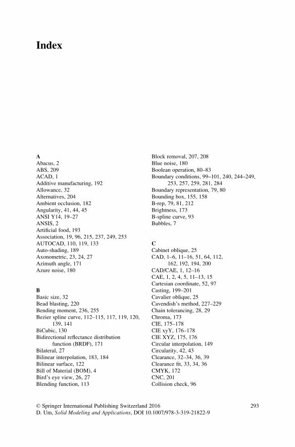
Index
AAbacus, 2
ABS, 209
ACAD, 1
Additive manufacturing, 192
Allowance, 32
Alternatives, 204
Ambient occlusion, 182
Angularity, 41, 44, 45
ANSI Y14, 19–27
ANSIS, 2
Artificial food, 193
Association, 19, 96, 215, 237, 249, 253
AUTOCAD, 110, 119, 133
Auto-shading, 189
Axonometric, 23, 24, 27
Azimuth angle, 171
Azure noise, 180
BBasic size, 32
Bead blasting, 220
Bending moment, 236, 255
Bezier spline curve, 112–115, 117, 119, 120,
139, 141
BiCubic, 130
Bidirectional reflectance distribution
function (BRDF), 171
Bilateral, 27
Bilinear interpolation, 183, 184
Bilinear surface, 122
Bill of Material (BOM), 4
Bird’s eye view, 26, 27
Blending function, 113
Block removal, 207, 208
Blue noise, 180
Boolean operation, 80–83
Boundary conditions, 99–101, 240, 244–249,
253, 257, 259, 281, 284
Boundary representation, 79, 80
Bounding box, 155, 158
B-rep, 79, 81, 212
Brightness, 173
B-spline curve, 93
Bubbles, 7
CCabinet oblique, 25
CAD, 1–6, 11–16, 51, 64, 112,
162, 192, 194, 200
CAD/CAE, 1, 12–16
CAE, 1, 2, 4, 5, 11–13, 15
Cartesian coordinate, 52, 97
Casting, 199–201
Cavalier oblique, 25
Cavendish’s method, 227–229
Chain tolerancing, 28, 29
Chroma, 173
CIE, 175–178
CIE xyY, 176–178
CIE XYZ, 175, 176
Circular interpolation, 149
Circularity, 42, 43
Clearance, 32–34, 36, 39
Clearance fit, 33, 34, 36
CMYK, 172
CNC, 201
Collision check, 96
© Springer International Publishing Switzerland 2016
D. Um, Solid Modeling and Applications, DOI 10.1007/978-3-319-21822-9293

Collision detection, 81
Colorfulness, 173
Colorimetry, 175, 176
Color quantization, 174, 180
Communication, 3
Compatibility, 243, 247
Compound transformation, 61
Computer Aided Design (CAD), 1–6
Computer Aided Engineering (CAE), 1
Computer graphics, 51, 93, 95, 143–168, 171,
172, 180, 182, 185, 191, 233
Concentricity, 40
Cones, 80, 174
Connecting rod, 229, 232
Connectivity, 79, 215, 219
Constructive solid geometry (CSG), 79–91
Contact area, 45
Continuity, 243
Continuum, 223
Contour crafting (CC), 194
Control net, 112
Control points, 97, 98, 101–105, 111–115, 117,
120, 130, 132, 133, 135, 138–141
Conventional method, 4
Cook-Torrance, 183
Coon’s patch, 131–133
Coordinate, 52–55
Coordinate transformation, 55
Cousin color space, 176–177
Cubic polynomial coefficient, 99–101, 106,
107, 136, 138, 141
Cubic polynomial equation, 97, 98
Cubic spline curve, 97, 98, 107
Cure depth, 217, 219
Curvature, 101
Curve mesh surface, 77
Cylindricity, 42
DDatum lines, 28
Datum plane, 28, 29, 31
Datum targets, 31, 32
DDA interpolation, 150, 167
Definitive layout, 9
Degree of twist, 133
Delaunay triangulation, 8
Descriptive geometry, 17, 18
Design cycle, 198
Design evaluation, 196–197, 199, 201
Design intent, 225
Design process, 73, 225
Design prototypes, 191, 192, 194–197
Design validation, 191
Deviation, 32
Diagrams, 4
Die casting, 199–201
Diffusivity, 185
Digital differential analyzer (DDA),
145, 147–152, 167
Dimensionality, 226, 227
Dimetric, 24
Direct stiffness method, 27–31
Dirichlet tessellation, 8
Distributed mass, 2
Dithering, 179–182
Documentation, 9
Drafting errors, 225
Dynamic analysis, 198
Dynamic models, 198
EEDM, 201
Elastic curve, 97, 112
Elastic modulus, 224
Electromagnetic spectrum, 218
Electrostatic deposition, 192
Element type, 226, 227, 240, 255
Equidistance, 229, 230
Euler angle rotation, 63, 64
Evaluated form, 79
Exterior view, 21
FFatigue strength, 198
Feature control frames, 28
Fillet lines, 77, 81, 83
Finite element method (FEM), 1–4, 7, 8, 11,
14, 15–16, 21, 64
First-angle projection, 21–23
Fixed angle rotation, 62, 63
Flat face representation, 79
Flat shading, 182
Flatness, 42
Flaws, 45
Floating point, 144, 145
Floor, 145
Force equilibrium, 229, 239, 247, 248, 251,
254, 257, 271, 272
Form tolerance, 42
Fortus, 209–211
Frame rate control (FRC), 178, 179
Free body diagram, 17, 22, 27
Full sectional view, 21
294 Index
Function verification, 196–199, 201
Functional verification, 197
Functional models, 196
Fundamental deviation, 33
Fused deposition modeling (FDM), 209
GGaspard Monge, 17
General curved surface, 121, 122, 130–142
General oblique, 25
Geometric constraints, 98, 99, 114, 133
Geometric model, 3, 6, 17
Geometric specifications, 17
Geometric tolerances, 40
Geometry decomposition, 8
Global coordinate, 54, 55, 67, 68, 90,
157, 242, 251, 261
Global stiffness matrix, 250, 252, 258,
260–264, 267, 268,
272, 275, 281
Gouraud, 171, 183–184, 188
Gouraud shading, 183, 184, 188
Gouraud’s illumination, 171, 183
Green strength, 202
Grid-Based approach, 8, 10
Ground’s eye view, 26, 27
Gusset, 204
HHalf sectional view, 21, 22
Hand sanding, 220
Heat transfer, 217
Hermite spline curve, 97, 105, 110, 112, 114,
131, 135, 138, 140, 141
Hidden line removal, 74, 152, 161
Hidden surfaces removal, 78
Hole & shaft tolerancing, 32–40
Homogeneity, 198
Homogeneous boundary
condition, 23
Homogeneous transformation, 59
Hook’s law, 224, 237,
254–256
Horseshoe, 177
HSL, 172
HSV, 172
Hue, 172, 173, 183
Hue-Intensity-Saturation, 183
Human’s eye view, 25, 26
Hybrid modeling, 81, 82
IIdeate, 6, 7
Illumination model, 171, 172, 182–188
Imaginary object, 18
Imaginary plane, 18
Inclusion test, 153, 162
Indeterministic, 245
Index, 112, 239, 243
Infiltration, 202
Influence, 112–114, 186, 225, 238
Ink-jet printing, 205
Inspection, 29, 31, 179, 192, 200
Interchangeability, 27
Interface, 217
Interference, 32, 34, 37, 39, 46
Interference fit, 34, 37, 39, 46
Internal view, 21
International Commission on Illumination, 175
International tolerance (IT) grade, 33
Interpretation, 17, 74, 75
Inverse transformation, 61
Investment casting, 220
Irradiance, 171
Isometric, 24
KKinematic model, 197, 198
LLambert, 183
Lambertian mode, 186
Laminated object manufacturing
(LOM), 202, 207–208, 212
Laminating, 199, 202, 207
Language of designer, 3
Laplacian smoothing, 13, 14
Laser-curing, 215–217
Laser-trimming, 207
Lay, 45, 195
Layer connectivity, 219
Layered manufacturing, 195
Layer thickness, 203, 205, 206, 217, 219
Least Material Condition, 29, 30
Lee’s methodm, 230
Light illumination, 182
Lightness, 172, 173
Limit forms, 27
Limits of tolerance, 32
Line fits, 32, 34
Liquid binder, 205
Index 295

Local control, 104, 105, 112, 114
Local coordinate, 52, 54, 55,
95, 260
Local stiffness matrix, 240, 242, 247,
250, 252, 258
Location tolerance, 40, 41
LOM, 202, 207, 208
Loop feedback, 150
Loose pattern molding, 199
Lower deviation, 33
Luminance, 173
Luminance-chrominance, 177
Lumped mass, 223, 224
MMagnetostatic deposition, 192
Manifold modeling, 81
Manual drawing, 23, 208, 227, 235
Manufacturing cell, 192
Manufacturing process, 45, 192, 194–196,
199–202, 217, 219
Mapped element approach, 8
Mapping, 59–61
Material handling, 192, 195, 198, 209
Matrix approach, 237–238
Maximum Material Condition (MMC), 28
Mesh, 1, 4–14
Mesh density, 227, 229, 235
Mesh generation, 1, 4, 8, 13
Metal laminates, 202, 207
Minnaert, 183
Mold tooling, 199
Mongian projection, 4, 18
Monochromatic, 175
Monomeric styrene, 218
Monomers, 218
Multi-Sim, 2
NNodal displacements, 255, 257, 260,
276, 277
Node generation, 226–229, 232
Nominal size, 32, 35
Non-homogeneous approach, 81,
245, 248–249
Nonhomogeneous boundary
condition, 26
Nonspectral purples, 177
Nowhere negative, 175
NURBS, 130
Nylon, 209
OOBJET, 209
Oblique projections, 23–25, 27
Oligomeric acrylates, 218
Oligomers, 218
Ordered dithering, 180
Oren-Nayar, 183
Orthogonal matrix, 54, 95, 262
Orthographic projection, 18, 19, 21–23,
25, 26
Orthographic views, 21
Orthonormal, 262
Overlapping, 74, 80, 159–162, 230, 233
PPahl and Beitz’s proposal, 7
Parametric design, 51
Parametric equation, 93, 98, 162
Parametric line, 95
Part orientation, 217
Patterns, 3, 196
Perpendicularity, 44
Perspective projection, 26, 27, 70
Perspective sketches, 23
Phong, 171, 183–188
Phong shading, 183, 184, 188
Phong’s illumination, 171, 183–188
Photo-curing, 218
Photodetectors, 174
Photoinitiators, 218
Photopolymer, 191, 192, 203, 205, 216–219
Photosculpture, 191
Pictorial drawing, 19
Pictorial projection, 19, 20, 23–27, 45, 74, 75
Pierre Bezier, 112
Planar geometric projections, 17
Planar truss, 236
Polygon clipping, 143, 159
Polygon filling, 143
Polyhedron, 230
PolyJet, 209
Polymerization, 192, 201, 203, 216, 218–220
Polynomial spline curve, 97
Poorman’s algorithm, 155
Potency, 174
Post-cure, 202, 220
Postprocessing, 3
Preferred sizes, 37
Preliminary layouts, 8, 9
Preprocessing, 3
Primaries, 25, 26, 35, 99, 172, 174–177, 237
Primitives, 80, 81, 83, 144
296 Index

Process planning, 195
Production planning, 192
Productivity, 226
Pro-E, 1
Profile tolerance, 43
QQuadrilateral, 4
Quality control, 179, 192
Quad-tree, 11, 12
Quaternion interpolation, 188
RRadiance, 171, 173, 185
Rapid die casting, 200
Rapid plaster, 199
Rapid prototyping, 5, 194
Rapid Prototyping & Manufacturing, 192
Raster graphics, 144
Raster grid, 144
Reaction moment, 236
Redundancy, 215
Reflectability, 171, 172, 182, 183, 185,
186, 188
Rendering, 188–189
Repetitive drawing, 20
Representation, 3, 75–80
Resolidification, 202
Retina, 174, 180
Rigid body, 224, 226, 236
Room temperature vulcanization, 199
Rotational matrix, 53, 54, 56, 57,
60, 63, 64
Roughness, 45
Roughness height, 45
Roughness width, 45
Roughness width cutoff, 45, 46
RP&M, 192, 193, 195–199, 201–208,
212–215, 219, 220
RTV mold, 200
Ruled surface, 127
Runout tolerance, 44
SSaturation, 172, 173
Scaling factor, 94, 95
Scan-conversion, 144
Scanning method, 153, 154
Sectional view, 21, 22
Selective curing, 215
Selective laser sintering, 202, 212
Selective solidification, 202
Set-theoretic mode, 80, 83
SFF, 192, 215–219
Sense of realism, 27
SGC, 204
Shear force, 254, 255, 262
Shimada’s method, 227, 229
Singularity, 94, 226, 244
SLA, 199–201
Smooth shading, 183
Soft tooling, 220
Solid freeform fabrication, 192
Solid ground curing, 204–205
Solid modeling, 79
Solidworks, 1
Space truss, 236
Spatial distribution, 187
Spatial dithering, 179, 187
Specification, 8, 9
Spectral response, 174
Spectrum, 172, 174, 176, 177, 218
Specularity, 187
Spherical linear interpolation, 188
Spring assemblage, 21
Standard sizes, 35
Standardization, 17, 19, 27, 32, 35, 39, 201,
213–215, 249
Static equilibrium, 239, 240
Stereolithography, 203–204, 216
Stiffness, 18–19, 27–42
Stiffness matrix, 225, 237–245,
249–264, 267, 268, 270, 272,
275, 279, 281, 283
Stimuli, 176
STL, 212–216
STL file format, 212–215
Straightness, 27, 42, 45, 93, 94, 112, 122, 126,
144, 236
STRATASYS, 209
Stress, 42–44
Stress models, 257, 264–267
Stress/strain analysis, 198, 225, 232, 236,
243, 254, 256
Subject polygon, 159
Sum of angle, 153
Superposition, 27–31
Support structures, 203, 204
Surface conditions, 20
Surface finish, 27, 199
Surface modeling, 51, 73, 75–78, 82,
212, 214
Surface normal, 155, 171, 185, 213
Index 297

Surface representation, 76
Surface of revolution, 42, 122
Surface texture, 19, 45, 46
Surface theory, 120–142
Swept surface, 77
Symmetry tolerance, 42
Symbols, 19, 20, 28, 29, 31, 37, 38, 40,
41, 53, 64, 237
System engineering, 19, 32, 224
TTangent vector, 77, 98, 99, 101, 102,
104, 106, 114, 117, 130, 132,
133, 136, 138, 148
Tangential line, 98, 99, 101, 102,
104, 106, 114, 117, 130, 132,
133, 136, 138, 148
Temporal dithering, 178, 179
Tensile stress, 255
Tetrahedral, 226, 227, 230
Thermal models, 200, 207, 209
Thermo plastic, 209
Third-angle projection, 20–23
3-D digitizer, 193
3-D model, 18, 51–52, 62, 73, 79–81,
93–94, 112, 143, 212, 214
3D Printing, 192, 205–206
T-Junctions, 184
Tolerance, 7, 27–45, 32–40, 34–39, 39–40,
40–41, 44–45
Tolerance methods, 28
Tolerance specification, 27, 29,
30, 33, 34, 43
Tolerance verification, 45
Tolerance zone, 33
Tool-less process 195
Topography 191, 192
Topology decomposition, 8
Transform equation, 62
Transformation arithmetic, 61–62
Transformation matrix, 157
Transition, 32, 34, 36
Transition fit, 34, 36
Triangular elements, 226, 227, 230
Trimetric projection, 24
Tristimulus, 174
Truss, 2, 14–19, 31–64
TurboCAD, 1
Type of fits, 33–35, 37, 38
UUltem, 209
Undercut, 203, 204
Unevaluated form, 80, 83
Unilateral, 27
UNISURF, 112
Upper deviation, 32
VVanishing points, 26, 27, 69
Variation diminishing, 114, 117
Verbosity, 215
Virtual assembly, 51, 103
Virtual scene, 172, 179
Visible surface, 143, 155, 156
Visual aids, 196
Voronoi diagram, 8–10
WWavelengths, 172–177, 219, 220
Waviness, 45
Waviness height, 45
Waviness width, 45
Weiler-Atherton, 159
Wireframe, 73–75, 78
Wireframe geometry, 51, 73–76, 78,
81, 82, 135, 152, 212
Woodwark, 79
Worm’s eye view, 26, 27
YYoung’s modulus, 257
ZZ-buffering, 143, 156
Z-buffering algorithm, 143, 156
Z-clipping, 143, 162
Zenith angle, 171–172
298 Index
Copyright © 2022 FDOKUMEN