Antenna and system design for controlled delivery of ... - CORE
203
Antenna and system design for controlled delivery of microwave thermal ablation by Hojjatollah Fallahi B.S., Shiraz University of Technology, 2010 M.S., Tarbiat Modares University, 2013 AN ABSTRACT OF A DISSERTATION submitted in partial fulfillment of the requirements for the degree DOCTOR OF PHILOSOPHY Department of Electrical and Computer Engineering Carl R. Ice College of Engineering KANSAS STATE UNIVERSITY Manhattan, Kansas 2020
-
Upload
khangminh22 -
Category
Documents
-
view
3 -
download
0
Transcript of Antenna and system design for controlled delivery of ... - CORE
Antenna and system design for controlled delivery of microwave thermal ablation
by
Hojjatollah Fallahi
B.S., Shiraz University of Technology, 2010
M.S., Tarbiat Modares University, 2013
AN ABSTRACT OF A DISSERTATION
submitted in partial fulfillment of the requirements for the degree
DOCTOR OF PHILOSOPHY
Department of Electrical and Computer Engineering
Carl R. Ice College of Engineering
KANSAS STATE UNIVERSITY
Manhattan, Kansas
2020

Abstract
Microwave ablation is an established minimally invasive modality for thermal
ablation of unresectable tumors and other diseases. The goal of a microwave ablation
procedure is to deliver microwave power in a manner localized to the targeted tissue, with
the objective of raising the target tissue to ablative temperatures (~60 °C). Engineering
efforts in microwave applicator design have largely been focused on the design of
microwave antennas that yield large, near-spherical ablation zones, and can fit within
rigid needles or flexible catheters. These efforts have led to significant progress in the
development and clinical application of microwave ablation systems, particularly for
treating tumors in the liver and other highly vascular organs. However, currently available
applicator designs are ill-suited to treating targets of diverse shapes and sizes.
Furthermore, there are a lack of non-imaging-based techniques for monitoring the
transient progression of the ablation zone as a means for providing feedback to the
physician. This dissertation presents the design, implementation, and experimental
evaluation of microwave ablation antennas for site-specific therapeutic applications with
these issues in mind.
A deployable 915 MHz loop antenna is presented, providing a minimally-invasive
approach for thermal ablation of the endometrial lining of the uterus for treatment of
heavy menstrual bleeding. The antenna incorporates a radiating loop, which can be
deployed to adjustable shapes within the uterine cavity, and a passive element, to enable
thermal ablation, to 5.7–9.6 mm depth, of uterine cavities ranging in size from 4–6.5 cm
in length and 2.5–4.5 cm in width. Electromagnetic–bioheat transfer simulations were
employed for design optimization of the antennas, and proof-of-concept applicators were
fabricated and extensively evaluated in ex vivo tissue. Finally, feasibility of using the
broadband antenna reflection coefficient for monitoring the ablation progress during the
course of ablation was evaluated. Experimental studies demonstrated a shift in antenna
resonant frequency of 50 MHz correlated with complete ablation.
For treatment of 1–2 cm spherical targets, water-cooled monopole antennas
operating at 2.45 and 5.8 GHz were designed and experimentally evaluated in ex vivo
tissue. The technical feasibility of using these applicators for treating 1–2 cm diameter
benign adrenal adenomas was demonstrated. These studies demonstrated the potential of
using minimally-invasive microwave ablation applicators for treatment of hypertension
caused by benign aldosterone producing adenomas.
Since tissue dielectric properties have been observed to change substantially at
elevated temperatures, knowledge of the temperature-dependence of tissue dielectric
properties may provide a means for estimating treatment state from changes in antenna
reflection coefficient during a procedure. The broadband dielectric properties of bovine
liver, an established tissue for experimental characterization of microwave ablation
applicators, were measured from room temperature to ablative temperatures. The
measured dielectric data were fit to a parametric model using piecewise linear functions,
providing a means for readily incorporating these data into computational models. These
data represent the first report of changes in broadband dielectric properties of liver tissue
at ablative temperatures and should help enable additional studies in ablation system
development.
Antenna and system design for controlled delivery of microwave thermal ablation
by
Hojjatollah Fallahi
B.S., Shiraz University of Technology, 2010
M.S., Tarbiat Modares University, 2013
A DISSERTATION
submitted in partial fulfillment of the requirements for the degree
DOCTOR OF PHILOSOPHY
Department of Electrical and Computer Engineering
Carl R. Ice College of Engineering
KANSAS STATE UNIVERSITY
Manhattan, Kansas
2020
Approved by:
Major Professor
Dr. Punit Prakash

Copyright
© Hojjatollah Fallahi 2020.
Abstract
Microwave ablation is an established minimally invasive modality for thermal
ablation of unresectable tumors and other diseases. The goal of a microwave ablation
procedure is to deliver microwave power in a manner localized to the targeted tissue, with
the objective of raising the target tissue to ablative temperatures (~60 °C). Engineering
efforts in microwave applicator design have largely been focused on the design of
microwave antennas that yield large, near-spherical ablation zones, and can fit within
rigid needles or flexible catheters. These efforts have led to significant progress in the
development and clinical application of microwave ablation systems, particularly for
treating tumors in the liver and other highly vascular organs. However, currently available
applicator designs are ill-suited to treating targets of diverse shapes and sizes.
Furthermore, there are a lack of non-imaging-based techniques for monitoring the
transient progression of the ablation zone as a means for providing feedback to the
physician. This dissertation presents the design, implementation, and experimental
evaluation of microwave ablation antennas for site-specific therapeutic applications with
these issues in mind.
A deployable 915 MHz loop antenna is presented, providing a minimally-invasive
approach for thermal ablation of the endometrial lining of the uterus for treatment of
heavy menstrual bleeding. The antenna incorporates a radiating loop, which can be
deployed to adjustable shapes within the uterine cavity, and a passive element, to enable

thermal ablation, to 5.7–9.6 mm depth, of uterine cavities ranging in size from 4–6.5 cm
in length and 2.5–4.5 cm in width. Electromagnetic–bioheat transfer simulations were
employed for design optimization of the antennas, and proof-of-concept applicators were
fabricated and extensively evaluated in ex vivo tissue. Finally, feasibility of using the
broadband antenna reflection coefficient for monitoring the ablation progress during the
course of ablation was evaluated. Experimental studies demonstrated a shift in antenna
resonant frequency of 50 MHz correlated with complete ablation.
For treatment of 1–2 cm spherical targets, water-cooled monopole antennas
operating at 2.45 and 5.8 GHz were designed and experimentally evaluated in ex vivo
tissue. The technical feasibility of using these applicators for treating 1–2 cm diameter
benign adrenal adenomas was demonstrated. These studies demonstrated the potential of
using minimally-invasive microwave ablation applicators for treatment of hypertension
caused by benign aldosterone producing adenomas.
Since tissue dielectric properties have been observed to change substantially at
elevated temperatures, knowledge of the temperature-dependence of tissue dielectric
properties may provide a means for estimating treatment state from changes in antenna
reflection coefficient during a procedure. The broadband dielectric properties of bovine
liver, an established tissue for experimental characterization of microwave ablation
applicators, were measured from room temperature to ablative temperatures. The
measured dielectric data were fit to a parametric model using piecewise linear functions,

providing a means for readily incorporating these data into computational models. These
data represent the first report of changes in broadband dielectric properties of liver tissue
at ablative temperatures and should help enable additional studies in ablation system
development.
x
Table of Contents
List of Figures ............................................................................................... xiii
List of Tables ..................................................................................................xx
Acknowledgements ...................................................................................... xxii
Dedication ................................................................................................... xxiii
1 Introduction ................................................................................................1
1.1 Overview ............................................................................................................... 1
1.2 Overview of microwave ablation systems ............................................................. 5
1.3 Research approach ................................................................................................ 6
1.4 Contributions ........................................................................................................ 9
1.5 Dissertation outline ............................................................................................. 13
2 Background ............................................................................................... 14
2.1 Thermal ablation................................................................................................. 14
2.2 Overview of microwave ablation......................................................................... 18
2.2.1 Biophysics of microwave tissue heating .......................................................... 18
2.2.2 Microwave ablation systems ........................................................................... 20
2.3 Microwave ablation applicators .......................................................................... 23
2.3.1 Early microwave ablation applicators............................................................. 26
2.3.2 Reduced diameter microwave ablation antennas ........................................... 32
2.3.3 Directional applicators .................................................................................... 34
2.3.4 Helix and spiral antennas ................................................................................ 39
2.3.5 Transmission line based devices ...................................................................... 41
2.3.6 Printed planar applicators .............................................................................. 44
2.3.7 Additional designs ........................................................................................... 48
2.3.8 Alternative ablation pattern control techniques............................................. 52
2.4 Summary ............................................................................................................. 54
xi
3 Design of a Microwave Global Endometrial Ablation Device .................. 55
3.1 Introduction ........................................................................................................ 55
3.2 Material & Methods ............................................................................................ 59
3.2.1 Microwave loop antenna design ...................................................................... 59
3.2.2 Simulation-based antenna optimization and evaluation ................................ 62
3.2.3 Device fabrication and experimental evaluation............................................. 66
3.3 Results & Discussion ........................................................................................... 68
3.3.1 SAR and impedance matching ........................................................................ 68
3.3.2 Experimental verification of thermal ablation patterns ................................. 72
3.3.3 Radiating and passive loop profiles for ablating cavities of varying size ....... 75
3.4 Conclusion ........................................................................................................... 78
4 Monitoring Transient Evolution of Planar Ablation Zones Using the
Broadband Antenna Reflection Coefficient .............................................. 80
4.1 Introduction ........................................................................................................ 80
4.2 Methods ............................................................................................................... 82
4.3 Results ................................................................................................................. 83
4.4 Discussion ............................................................................................................ 85
4.5 Conclusion ........................................................................................................... 87
5 Microwave Antennas for Ablation of Benign Adrenal Adenomas ........... 88
5.1 Introduction ........................................................................................................ 88
5.2 Methods ............................................................................................................... 93
5.2.1 Water-cooled antenna designs ......................................................................... 94
5.2.2 Computational models – SAR and thermal ablation zone analysis ............... 94
5.2.3 Experimental platform – hardware for evaluating ablation zones ................. 99
5.2.4 Experimental protocol ................................................................................... 100
5.3 Results ............................................................................................................... 102
5.4 Discussion .......................................................................................................... 109
xii
5.5 Conclusion ......................................................................................................... 114
6 Broadband Dielectric Properties of Ex Vivo Bovine Liver Tissue
Characterized at Ablative Temperatures ............................................... 116
6.1 Introduction ...................................................................................................... 116
6.2 Methods ............................................................................................................. 119
6.2.1 Dielectric property measurements ................................................................ 119
6.2.2 Parametric model for temperature and thermal isoeffective dose dependent
broadband dielectric properties ................................................................................ 123
6.2.3 Experimental assessment of temperature and thermal isoeffective dose
dependent dielectric property models ...................................................................... 124
6.3 Results ............................................................................................................... 126
6.4 Discussion .......................................................................................................... 131
6.5 Conclusion ......................................................................................................... 135
7 Conclusion and Future Work ................................................................. 137
References ..................................................................................................... 142
Appendix A: Supplemental Data for Chapter 6 ........................................... 158
A.1 Piecewise linear function for measured dielectric data .................................... 158
A.2 Fitting errors ..................................................................................................... 162
A.3 Details of the computational model for simulating microwave ablation ......... 165
A.4 Change of effective conductivity slope at low temperatures ............................ 168
A.5 Max/Min envelopes vs. mean ± 2×STD envelopes .......................................... 169
Appendix B: Applicator Fabrication Example ............................................. 170
B.1 Fabrication steps ............................................................................................... 173
xiii
List of Figures
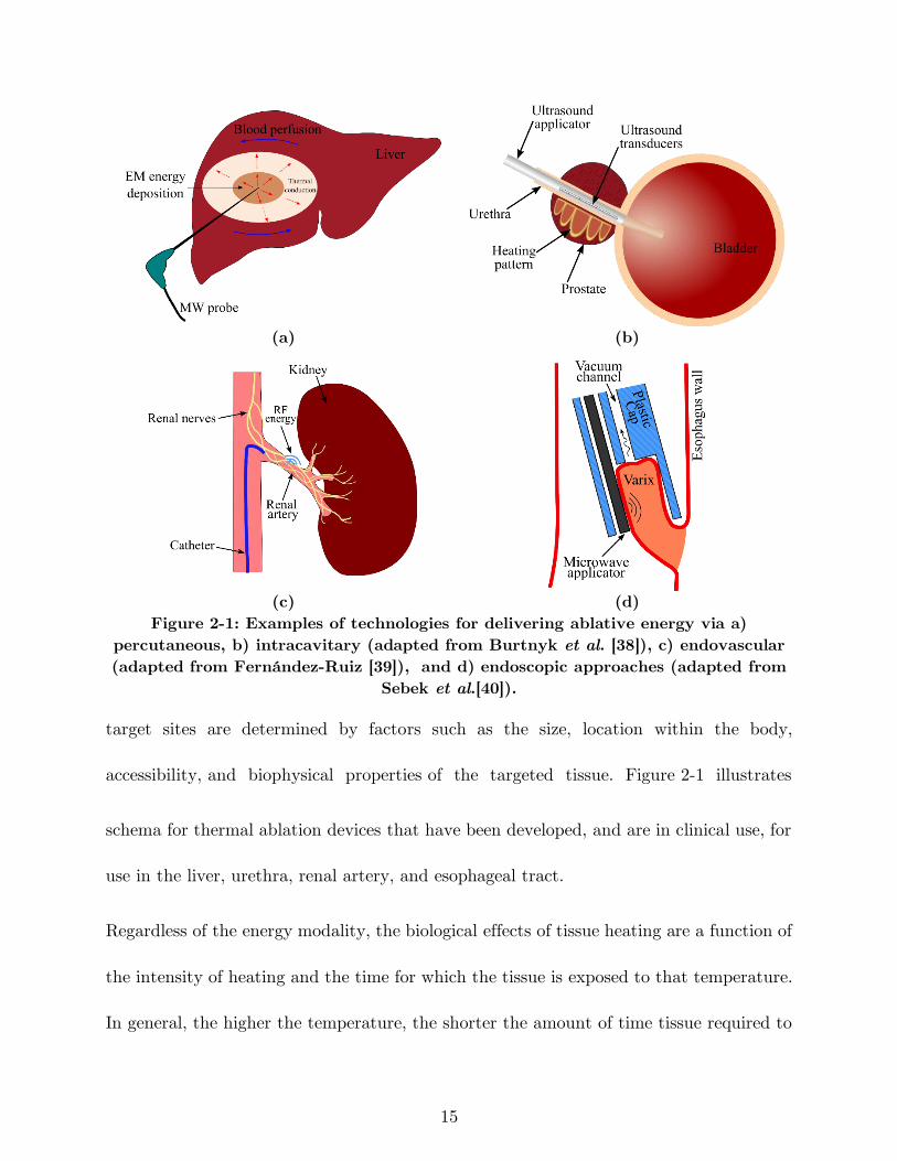
Figure 2-1: Examples of technologies for delivering ablative energy via a) percutaneous,
b) intracavitary (adapted from Burtnyk et al. [38]), c) endovascular (adapted from
Fernández-Ruiz [39]), and d) endoscopic approaches (adapted from Sebek et al.[40]).
................................................................................................................................... 15
Figure 2-2: Dependence of liver dielectric properties on frequency based on technology
described by Gabriel et al. [58]. ................................................................................ 20
Figure 2-3: Electromagnetic wavelength in liver tissue vs. frequency. ......................... 20
Figure 2-4: Components of an image-guided microwave ablation system. ................... 21
Figure 2-5: Integration of a cooling system to a coaxial dipole antenna. ..................... 25
Figure 2-6: Original antennas: dipole, monopole, and slot ........................................... 27
Figure 2-7: Examples of coaxial antennas with sleeve, choke, and cap and a monopole
in a triaixal configuration (black metal, grey: dielectric). ........................................ 29
Figure 2-8: Fabrication steps of a dipole antenna with sleeve: a) simple dipole, b)
addition of an insulation layer (polyimide), c) addition of the metal sleeve, and d)
covering of the dipole with heat shrink. ................................................................... 30
Figure 2-9: Measured reflection coefficient (S11) of dipoles antennas with and without
sleeve. ......................................................................................................................... 31
Figure 2-10: Simulated a) power absorption profile and b) temperature profiles of dipole
antennas with (left) and without (right) sleeve. Estimated extent of the ablation zone
is overlaid in black (Pin = 60 W, duration = 2 minutes). ....................................... 31
Figure 2-11: Example ablation patterns of dipole antennas a) with and b) without sleeve
in ex vivo porcine muscle (Pin = 60 W, duration = 2 minutes). ............................. 32
Figure 2-12: Techniques for reducing applicator diameter: a) Matching network [adapted
from Luyen et al. [47]], b) reduced diameter by using a different dielectric material
xiv
[adapted from Luyen et al. [48]], c) tapered balun [adapted from Luyen et al. [49]]
(black metal, grey: dielectric, white: air). ................................................................. 33
Figure 2-13: a) Proof of concept [adapted from McWilliams et al. [50]], and b)
slot/monopole [adapted from Mohtashami et al. [51]] directional antennas (black
metal, grey: dielectric, white: air, patterned: water). ............................................... 36
Figure 2-14: Example of a fabricated directional monopole antenna without the outflow
polyimide tube [courtesy of Pegah Faridi]. ............................................................... 38
Figure 2-15: Example power absorption profiles of a) a conventional and b) a directional
antennas. .................................................................................................................... 38
Figure 2-16: Comparison of directional and conventional monopole antenna ablation
patterns in the liver tissue. ....................................................................................... 38
Figure 2-17: variations of helical antenna [adapted from Satoh et al. [92]] ................ 39
Figure 2-18: Microwave bone drill [adapted from Eshet et al. [98]]. ............................ 42
Figure 2-19: a) 9.2 GHz circular waveguide applicator for endometrial ablation in egg
white b) before and c) after ablation [[Reprinted with permission from Hodgson et al.
[9] Copyright 1999, Wiley]. ....................................................................................... 43
Figure 2-20: dual-mode applicators consisting of oval split ring resonator (SRR) on the
back side of a coplanar waveguide (CPW) [Reprinted from Reimann et al. [101] under
a Creative Commons Attribution 4.0 International license ..................................... 46
Figure 2-21: Performance of the dual mode SRR sensor. Frequency shift in a) assessment
mode, b) simulated ablation zone, and c), d) and e) experimental ablation zone in
liver tissue in treatment mode [Reprinted from Reimann et al. [101] under a Creative
Commons Attribution 4.0 International license ....................................................... 46
Figure 2-22: a) array of two planar dipoles loaded with capacitors [reprinted with
permission from AIP Publishing, Copyright 2017, [102]] and b) a travelling wave
antenna [adapted from Hancock et al. [61]]. ............................................................. 47
xv
Figure 2-23: a) two prong fork device for treatment of snoring [adapted from Cresson et
al. [104]], b) double loop applicator [reprinted with permission from Springer Nature,
Copyright 2005, [105]] c) Drooped ground monopole antenna [reprinted with
permission from John Wiley and Sons, Copyright 2015, [106]], and d) loop antenna
for global endometrial ablation [adapted from Fallahi et al. [23]]. .......................... 49
Figure 2-24: Simulated and experimental ablation pattern of a loop antenna with planar
heating. Estimated extent of the ablation zone (60 °C isotherm) are overlaid on the
simulated temperature profiles. ................................................................................. 52
Figure 3-1: Illustration of the uterine cavity geometry and clinically relevant endometrial
ablation profiles shown in orange along axial (A—B, C—D, and E—F) and sagittal
sections through the uterus (G—H). ........................................................................ 56
Figure 3-2: Proposed loop antennas for microwave GEA a) simple loop antenna, b) delta
loop antenna, and c) loop antenna with a passive element. ..................................... 60
Figure 3-3: a) Illustration of the geometry employed in computational models and b)
solver flow diagram. .................................................................................................. 63
Figure 3-4: Experimental setup for evaluating the ablation profile of the proposed
antennas. .................................................................................................................... 67
Figure 3-5: Illustration of the axes along which tissue was sectioned following ablations
for measuring experimental ablation zone depths: (left) bottom piece and (right) top
piece. .......................................................................................................................... 67
Figure 3-6: Electromagnetic power loss density (𝑄𝑒) of a) simple loop, b) delta loop at
915 MHz, and c) delta loop at 650 MHz in coronal (top row) and sagittal planes. 68
Figure 3-7: Simulated and measured return loss (RL = -|S11|) of the simple loop antenna,
delta loop antenna, and loop antenna with a passive element. ................................ 70
Figure 3-8: Simulated a) 𝑄𝑒 and b) temperature profile in coronal (top row) and sagittal
planes overlaid by thermal damage contour (Ω = 1, black solid line: without perfusion,
xvi
red dotted line: with perfusion) of the loop antenna with passive element for input
power of 60 W and ablation duration of 180 s. ........................................................ 71
Figure 3-9: Ablation profile of a) simple loop antenna, b) delta loop antenna at 915
MHz, c) delta loop antenna at 650 MHz, and d) loop antenna with a passive element
(The inset images show the position of each antenna relative to the ablation profile).
................................................................................................................................... 73
Figure 3-10: Experimental ablation zones created by the loop antenna with passive
element in the horizontal and vertical planes illustrated in Figure 3-5. .................. 74
Figure 3-11: a) Reshaped simple loop antenna (l5 = 40 mm, w5 = 10 mm, h1 = 10 mm,
b1 = 5 mm) conformal to the smallest cavity size, b) reshaped loop antenna with
passive element (l4 = 42 mm, w4 = 25 mm, l6 = 39 mm, w6 = 17 mm, h2 = 5 mm,
b2 = 3 mm, d = 25) conformal to the medium size cavity. Simulated temperature
profiles and overlaid thermal damage contour without blood perfusion (black solid
line, Ω = 1) of the (c) reshaped simple loop antenna, and d) reshaped loop antenna
with passive element, for input power of 60 W and ablation duration of 150 s. ..... 76
Figure 4-1: Water-cooled antenna with a fiber optic temperature sensor for global
endometrial ablation. ................................................................................................. 83
Figure 4-2: Block diagram of the setup for S11 measurement during the ablation....... 83
Figure 4-3: Tissue temperature change during the ablation experiment. ..................... 84
Figure 4-4: Example photos of the ablations for fixed input power of 60 s and duration
of a) 70 s, b) 150 s, and c) 240 s. .............................................................................. 84
Figure 4-5: Comparison of the antenna S11 before and after ablation for fixed power of
60 W and different durations. ................................................................................... 85
Figure 5-1: Illustration of the a) water-loaded monopole antenna and b) geometry of the
multi-layered tissue model used in simulations. ....................................................... 95
Figure 5-2: Comparison of simulated electromagnetic power absorption profiles in liver
tissue for monopole antennas operating at a) 2.45 GHz and b) 5.8 GHz. ............. 102
xvii
Figure 5-3: Comparison of simulated temperature profiles in adrenal and liver tissue
following 40 W, 60 s microwave heating at 2.45 GHz with coolant water temperature
of 10 °C. The Ω = 1 thermal damage contours estimating extent of the ablation zone
are overlaid (black solid line). ................................................................................. 102
Figure 5-4: Comparison of the simulated temperature profile in liver tissue at frequencies
of 2.45 and 5.8 GHz for different ablation time of 30, 60, and 90 s and input power
of 40 W, with overlaid Ω = 1 thermal damage contour (black solid line). ............ 104
Figure 5-5: Example ablation patterns following 60 s microwave ablation in ex vivo liver
tissue: (a) 30 W, 2.45 GHz; (b) 30 W, 5.8 GHz; (c) 40 W, 2.45 GHz; and (d) 40 W,
5.8 GHz. ................................................................................................................... 105
Figure 5-6: Example ablation patterns following 40 W microwave ablation in ex vivo
liver tissue for 30, 60 and 90 s at 2.45 and 5.8 GHz. ............................................. 106
Figure 5-7: Experimentally observed ablation zone in ex vivo liver tissue following 30 W,
90 s microwave ablation at 5.8 GHz with coolant temperature of a) 10, b) 20 and c)
30 °C. ....................................................................................................................... 107
Figure 5-8: Comparison of the observed ablation zones in bovine adrenal gland at
different frequencies with a non-ablated gland: a) control sample f = 2.45 GHz, Pin
= 0 W, t = 180 s, Tcoolant = 10 °C, b) ablated sample at f = 2.45 GHz, Pin = 50 W,
t = 180 s, Tcoolant = 10 °C and c) ablated sample at f = 5.8 GHz, Pin = 40 W, t =
90 s, Tcoolant = 30 °C. The dashed line illustrates the antenna insertion track into the
adrenal tissue sample............................................................................................... 108
Figure 6-1: a) Experimental setup for measurement of dielectric properties of liver tissue
during heating and b) photo of the custom copper box. ........................................ 122
Figure 6-2: Measured temperature-dependent dielectric properties of bovine liver (n =15
samples) at 915 MHz and 2.45 GHz. Estimated non-parametric mean, upper and
lower envelopes of the measured data are shown in black dashed lines. ............... 122
xviii
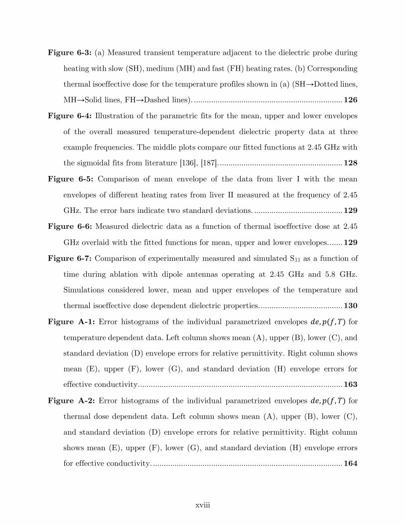
Figure 6-3: (a) Measured transient temperature adjacent to the dielectric probe during
heating with slow (SH), medium (MH) and fast (FH) heating rates. (b) Corresponding
thermal isoeffective dose for the temperature profiles shown in (a) (SH→Dotted lines,
MH→Solid lines, FH→Dashed lines). ..................................................................... 126
Figure 6-4: Illustration of the parametric fits for the mean, upper and lower envelopes
of the overall measured temperature-dependent dielectric property data at three
example frequencies. The middle plots compare our fitted functions at 2.45 GHz with
the sigmoidal fits from literature [136], [187]. ......................................................... 128
Figure 6-5: Comparison of mean envelope of the data from liver I with the mean
envelopes of different heating rates from liver II measured at the frequency of 2.45
GHz. The error bars indicate two standard deviations. ......................................... 129
Figure 6-6: Measured dielectric data as a function of thermal isoeffective dose at 2.45
GHz overlaid with the fitted functions for mean, upper and lower envelopes. ...... 129
Figure 6-7: Comparison of experimentally measured and simulated S11 as a function of
time during ablation with dipole antennas operating at 2.45 GHz and 5.8 GHz.
Simulations considered lower, mean and upper envelopes of the temperature and
thermal isoeffective dose dependent dielectric properties. ...................................... 130
Figure A-1: Error histograms of the individual parametrized envelopes 𝑑𝑒, 𝑝(𝑓, 𝑇) for
temperature dependent data. Left column shows mean (A), upper (B), lower (C), and
standard deviation (D) envelope errors for relative permittivity. Right column shows
mean (E), upper (F), lower (G), and standard deviation (H) envelope errors for
effective conductivity............................................................................................... 163
Figure A-2: Error histograms of the individual parametrized envelopes 𝑑𝑒, 𝑝(𝑓, 𝑇) for
thermal dose dependent data. Left column shows mean (A), upper (B), lower (C),
and standard deviation (D) envelope errors for relative permittivity. Right column
shows mean (E), upper (F), lower (G), and standard deviation (H) envelope errors
for effective conductivity. ........................................................................................ 164
xix
Figure A-3: Illustration of the geometry employed in computational models. ........... 167
Figure A-4: Change of effective conductivity slope at low temperatures as a function of
frequency .................................................................................................................. 168
Figure A-5: Comparison of maximum/minimum envelopes with mean ± 2×STD of the
measured data at 2.45 GHz. .................................................................................... 169
Figure B-1: Parts used in the fabrication of the example water-cooled microwave
ablation applicator................................................................................................... 171
Figure B-2: Dimension and structure of the water-cooled microwave ablation applicator.
................................................................................................................................. 172
Figure B-3: Fabricated examples of the microwave ablation applicator. ................... 172
Figure B-4: Different parts of SMA connector 21_SMA-50-1-1/111_NE ................. 173
Figure B-5: Steps in soldering the SMA connector to the coaxial cable. ................... 175
Figure B-6: Mounting of the valve onto the coaxial cable. Red indicates where epoxy
glue should be applied. ............................................................................................ 176
Figure B-7: Positioning of the inflow polyimide tube. The location where epoxy glue
should be applied is shown in red. .......................................................................... 177
Figure B-8: Addition of the Y-connector to the applicator and its orientation with
respect to the valve. ................................................................................................ 178
Figure B-9: Addition of the outflow polyimide tube. Red indicates where epoxy glue
should be applied. .................................................................................................... 179
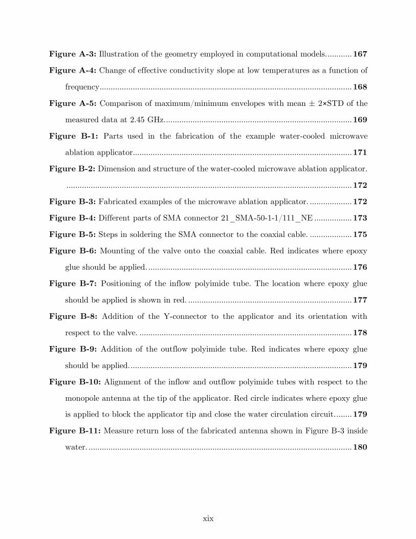
Figure B-10: Alignment of the inflow and outflow polyimide tubes with respect to the
monopole antenna at the tip of the applicator. Red circle indicates where epoxy glue
is applied to block the applicator tip and close the water circulation circuit. ....... 179
Figure B-11: Measure return loss of the fabricated antenna shown in Figure B-3 inside
water. ....................................................................................................................... 180
xx
List of Tables
Table 3-1: Tissue physical properties used in the simulations. ..................................... 64
Table 3-2: Ablation depth measured (n = 3) for the proposed loop antennas at points
defined in Figure 3-5. ................................................................................................ 74
Table 4-1: Resonant frequency of the antenna before and after ablation..................... 85
Table 5-1: Nominal thermal properties of tissue. .......................................................... 97
Table 5-2: Dielectric properties of tissue at 2.45 GHz and 5.8 GHz employed in
simulations. ................................................................................................................ 98
Table 5-3: Simulated ablation zone dimensions for different power and time combinations
in liver tissue. .......................................................................................................... 104
Table 5-4: Experimentally measured ablation zone dimensions ex vivo in liver tissue with
water-cooled 2.45 GHz and 5.8 GHz antennas. Data are presented as mean ±
standard deviation (n = 5 for each combination). ................................................. 106
Table 5-5: Ablation zone dimensions in ex vivo liver tissue at 5.8 GHz for power of 30
W and 90 s duration with coolant temperatures of 10, 20 and 30 °C (n = 3). ..... 107
Table 5-6: p-values of main effects and their interaction for length and width of ablation
zone in ex vivo liver tissue following 3-way ANOVA analysis. .............................. 108
Table 6-1: Correlation between the experimentally measured S11 and those simulated by
the temperature and thermal isoeffective dose dependent dielectric properties of
bovine liver at 2.45 and 5.8 GHz (shown in Figure 6-7). ....................................... 134
Table A-1: Overall data coefficients for the piecewise functions for the temperature
dependent dielectric properties of ex vivo bovine liver. .......................................... 159
Table A-2: Slow heating rate Coefficients for the piecewise functions for the temperature
dependent dielectric properties of ex vivo bovine liver. .......................................... 160
Table A-3: Medium heating rate coefficients for the piecewise functions for the
temperature dependent dielectric properties of ex vivo bovine liver. ..................... 160
xxi
Table A-4: Fast heating rate coefficients for the piecewise functions for the temperature
dependent dielectric properties of ex vivo bovine liver. .......................................... 161
Table A-5: Overall data coefficients for the piecewise functions for the thermal dose
dependent dielectric properties of ex vivo bovine liver ........................................... 161
Table A-6: Tissue physical properties used in the simulations. .................................. 166
Table B-1: Example dimensions of hypodermic tubes and catheters in gauge, millimeter
and inch. .................................................................................................................. 171
xxii
Acknowledgements
I am grateful to my Advisor Dr. Punit Prakash for his continuous support,
encouragement and mentorship during my PhD years. He has guided me in research and
inspired me to love and enjoy research. It was a great pleasure to work with him and I
learnt a lot from countless discussions I had with him.
I would like to express my appreciation to my dissertation committee: Dr. Steven
Warren, Dr. Bill Kuhn and Dr. Warren Beard for their insightful comments and feedback
that helped me to improve my dissertation.
Special thanks goes to my friends and fellow labmates at Biomedical Computing
and Devices Laboratory: Pegah Faridi, Jan Sebek, Austin Pfannenstiel, Faraz Chamani
and Ghina Zia. I really enjoyed working and collaborating with them.
It is my fortune to gratefully acknowledge the support of my dearest friends at K-
State: Heman Shakeri, Behnaz Moradi, Mahboobe Jassas, Hamid Rashidi, and Hazhar
Sufi Karimi. They were always beside me during the happy and sad moments to encourage
and motivate me.
I would like to thank my parents and my siblings who have provided me through
moral and emotional support in my life.
Words cannot express how grateful I am to my beloved wife, Sahar Lashkarbolooki,
who always supports me with her unconditional love through thick and thin.

xxiii
Dedication
To Sahar, love of my life.
1
1 Introduction
1.1 Overview
Thermal ablation is a minimally invasive technique clinically used to destroy
diseased tissues by localized heating or freezing for treatment of cancer and other disease.
An ideal thermal ablation system may have the following features:
• Quantifiable: it should be able to deliver a quantifiable treatment in a localized
manner. For example, in heat-based ablations, it is necessary to raise the target tissue
temperature to approximately 60 °C while limiting unintended heating of surrounding
non-targeted tissue.
• Controllable: the system would provide a means for the clinician to adjust the
treatment profile, so it can be tailored to targets of varying size and shape.
• Predictable: it should be possible to predict the treatment outcome based on the
input parameters of the ablation system such as input power and ablation duration as
well as the target tissue’s physical and physiological properties.
• Monitoring: The system should provide a means for monitoring the transient
evolution of the treatment.
2
Ablation procedures are usually performed in an out-patient setting by making a
small incision on the body to guide the ablation device toward the target percutaneously
or inserting the device into the body through a catheter endoscopically, intravenously, or
via body cavities. While ablation has been applied in oncology for destruction of tumors
in liver [1], lung [2], kidney [3], bone [4], prostate [5], and brain [6], a variety of ablative
systems have been developed for treatment of cardiac arrhythmia [7], Barrett’s esophagus
[8], menorrhagia [9], and other benign conditions. Ablation may be delivered by a variety
of energy modalities, such as radiofrequency, microwaves, ultrasound, laser, freezing
(cryoablation), irreversible electroporation, and toxic chemicals.
Radiofrequency devices create ablation zones based on resistive heating (the Joule
effect). When the radiofrequency applicator in inserted into the target tissue, high
frequency currents (typically at ~460 kHz) from the applicator flow through the
surrounding tissue and return to the applicator via another electrode in contact with the
body. Direct radiofrequency heating occurs within several millimeters of the electrodes,
and the ablation zone grows passively to encompass distant tissue regions via thermal
conduction [1].
During a microwave ablation (MWA) procedure (e. g. at 915 MHz or 2.45 GHz),
heat is generated by dielectric heating, where the dielectric media is the target tissue.
When microwaves travel through tissue, heating occurs because the electromagnetic fields
force the polar molecules (e.g. water) in the tissue to oscillate. More heat is generated in
3
the tissues with higher water content (e.g. solid tumors) while less heat is created in
tissues with less water (e.g. fat). Direct microwave heating occurs within the vicinity of
the microwave applicator and the rest of the ablation zone is created by thermal
conduction [10].
Ultrasound is generated by applying an alternating voltage with a frequency in the
range of 6-10 MHz across a piezoelectric material. The resulting ultrasound wave
propagates through tissues, causing alternating cycles of increased and reduced pressure
(compression and rarefaction, respectively). The pressure fluctuations induced lead to
vibration of tissue at a microscopic level, which results in frictional heating. In high
intensity focused ultrasound, an array of transducers with input voltages alternating at
0.8-3.5 MHz are employed to focus the ultrasound wave at a given point similar to the
focusing of light. During a high intensity focused ultrasound ablation procedure, a high
power beam is swept over the target tissue while sparing the surrounding tissues [11], [12].
Destruction of tissue during laser ablation is caused by thermal conversion of
focused electromagnetic energy, most commonly at a wavelength of 1064 nm, which raises
tissue temperature to lethal levels. The extent of the tissue destruction is dependent on
the level of the delivered heat energy and the depth of penetration. Small (800–980 nm)
diode lasers are gaining popularity due to their portability, power, and cost effectiveness
and water-cooled laser application sheaths are being employed to allow for higher laser
power output (50 W) [13], [14].
4
Cryoablation is the destruction of the target tissue by decreasing the tissue
temperature to lower than –40 °C. In modern cryoablation procedures, a high-pressure
cryogenic fluid such as argon or nitrogen is circulated through the lumen of thin probes
because of its low viscosity. Low pressure within the lumen of the probe results in rapid
expansion of the cryogen, which creates a very low temperature (Joule-Thompson effect).
This low temperature (<–100 °C) creates an ice ball around the tip of the probe. Clinical
cryoablation protocols incorporate multiple freeze – thaw cycles leading to tissue necrosis
by a variety of direct and indirect mechanisms. Usually, the freezing interval is rapid and
thawing interval is slow in order to maximize the ablation zone. The freeze-thaw cycle is
repeated multiple times until achieving the required temperature in the target along with
a margin of normal tissue around the tumor [15], [16].
Irreversible electroporation is a novel non-thermal focal ablation technique that
uses paired electrodes to deliver a series of short high power electric pulses into a targeted
region of tissue, killing the cells by irreversibly disrupting cellular membrane integrity.
Currently, 70–90 pulses with pulse width of 70–90 μs and voltage level of 1500 V/cm are
used for tumor ablation [17]. The IRE effect is not uniform and depends on the intrinsic
conductivity of the tissue, the number of pulses delivered, the current flow achieved, and
the total time for the treatment [18].
Chemoablation techniques employ toxic substances, such as ethanol and acetic
acid, which are directly injected into the target tissue. Toxicity of the chemical destroys
5
the target tissue by immediate dehydration of the cytoplasm and protein denaturation.
Compared to thermal ablation therapy, devices for chemical ablation therapy are less
complicated and are easy to use. However, the challenges in using chemoablation are the
toxicity of ablation reagents and inability to control the ablation pattern [19]. A new
modality under development is thermochemical ablation where two chemical substances
such as alcohol, acid or alkali are injected by syringes to the target site. Upon injection,
chemicals mix and generate enough heat to destroy the target [20].
Microwave ablation is distinct from other modalities for thermal therapy
application in a number of ways. Microwaves are capable of propagating through tissue
of varying biophysical state, including water vapor and charred tissue created during an
ablation procedure. Microwave ablation also does not require direct electrical contact of
the applicator with the tissue under treatment. Ablation using microwave power can heat
tissue to higher temperatures than when using other ablation modalities, enabling the
creation of large ablation zones in highly perfused tissues such liver. For these reasons,
microwave has become an attractive choice for large volume thermal ablation.
1.2 Overview of microwave ablation systems
MWA systems operating at frequencies of 915 MHz and 2.45 GHz have been
developed and are in clinical use for select indications. Applicators have largely been
optimized to create large near spherical heating patterns, and are suitable for treating
6
large tumor volumes in vascular tissue. Physicians have relied on the ex vivo ablation size
data provided by MWA system manufacturers and preoperative imaging for determining
how to set the ablation parameters - input power and duration. There are few methods
for monitoring the growth of the ablation zone during the procedure. Therefore, success
of the ablation has been heavily dependent on the clinician experience and skill. Although
it has been possible to develop these applicators and systems without complete
understanding of the microwaves and tissue interaction, development of MWA applicators
for applicators other than tumor ablation demands an improved knowledge of microwaves
and tissue interaction. Characterization of tissue properties at microwave frequencies also
opens an avenue for developing feedback signals from the ablation growth during the
course of ablation. Addition of feedback signals from the ablation status to MWA systems
could assist clinicians in devising more effective treatment plans.
1.3 Research approach
To address the above-mentioned limitations and gaps in the MWA area, this
dissertation describes the development of MWA applicators with non-spherical ablation
zones for site-specific applications. Antennas with a planar heating pattern were designed
for ablation of the endometrial lining of the uterine cavity, with application to treatment
of menstrual heavy bleeding. Antennas operating at 5.8 GHz, a higher frequency band
7
compared to the 915 MHz and 2.45 GHz typically investigated in other studies, were
designed and evaluated for creation of small, spherical ablation patterns.
We also investigated the potential use of antenna reflection coefficient as a feedback
signal for monitoring the evolution of the treatment zone. The dielectric properties of
bovine liver tissue were measured and modeled at ablative temperatures across a wide
range of frequencies. The final data will provide the foundation for further model-based
design and development of next-generation minimally invasive MWA systems as well as
wideband techniques for real-time monitoring of MWA. Finally, with the insight obtained
from the tissue characterization experiments, the potential use of antenna reflection
coefficient as a feedback signal for monitoring the ablation status during the course of
ablation was investigated.
In this regard, this dissertation addressed the following research questions:
Question 1: Menorrhagia, a condition when menstrual periods have abnormally
heavy or prolonged bleeding, significantly affects quality of life, and affects ~20% of
women of reproductive age. Global endometrial ablation (GEA) is a minimally invasive
alternative to surgical options such as hysterectomy. Is it feasible to design a MW antenna
for GEA with near triangular shaped ablation pattern with ablation depth of 3–9 mm,
conformal to the anatomy of diverse range of uterine cavities?
Question 2: In a GEA procedure, there is no imaging or non-imaging based
mechanism for monitoring the ablation zone growth. A real-time feedback signal during
8
the ablation would provide the clinician with an extra source of information. What
parameters of an ablation system could be used as a feedback signal to monitor the
transient evolution of the ablation zone?
Question 3: Primary aldosteronism is characterized by the excessive secretion of
aldosterone from the adrenal gland, and is responsible for up to 11.2% of all cases of
hypertension. This excess of aldosterone is attributable to an adenoma (a benign adrenal
gland tumor). The average adrenal adenoma is around 5–20 mm wide, which is much
smaller than the majority of the malignant tumors in the liver, kidney, and lungs. One of
the advantages of MWA is its ability to create large ablation zones when operating at
frequencies of 915 MHz and 2.45 GHz. Is it feasible to create small ablation zones with
MWA for destruction of adrenal adenomas? What is the effect of frequency on the ablation
zone size and shape?
Question 4: There is a lack knowledge of tissue dielectric properties at ablative
temperatures. In order to investigate ablation systems at different operating frequencies,
and wideband approaches for monitoring treatment progress, characterization of tissue
dielectric properties across a broad range of frequencies in the ablative temperature range
is critical. What is the broadband temperature dependence of tissue dielectric properties?
9
1.4 Contributions
In order to address the aforementioned questions, this dissertation contributes to
the state of the art of MWA as follows:
Contribution 1: In early years of MWA introduction, many efforts were focused
on designing needle form MWA applicators with omnidirectional heating patterns [21].
We performed a comprehensive search on the MWA applicator designs, with a focus on
applicators developed after 2006. These studies introduced applicators designs capable of
creating directional and planar heating patterns, and ablation length control with
integrated matching networks, chokes, and sleeves, as well as mechanisms for active
cooling of applicators. This contribution is discussed in detail in chapter 2 and in the
following review article:
[22] H. Fallahi and P. Prakash, “Antenna designs for microwave tissue ablation,”
Crit. Rev. Biomed. Eng., vol. 46, no. 6, 2018.
Contribution 2: Endometrial ablation is a minimally invasive treatment option
for menorrhagia. Radiofrequency as the most commonly used endometrial ablation
modality has two disadvantages: large applicator diameter and the need for direct contact
of the applicator with the target tissue. The former requires dilation of the cervix that
causes discomfort for the patient, and the latter requires integrating a suction mechanism
into the applicator. As microwave applicators may not need direct contact with the target
tissue, and thus allow for compact small-diameter applicators, we investigated the
10
feasibility of a microwave global endometrial ablation applicator. The specific anatomy of
the uterine cavity led to design of a MWA applicator with a planar heating pattern,
allowing ablation of the entire target with a single positioning of the applicator and
capability of ablating a range of different uterine cavity sizes. Details of this study are
discussed in chapter 3 and the following publications:
[23] H. Fallahi, J. Šebek, E. Frattura, J. Schenck, and P. Prakash, “Global
microwave endometrial ablation for menorrhagia treatment,” in Proc. of SPIE Vol, 2017,
vol. 10066, pp. 100660K–1.
[24] H. Fallahi and P. Prakash, “Design of a Microwave Global Endometrial
Ablation Device,” IEEE J. Electromagn. RF Microw. Med. Biol., 2019.
[25] P. Faridi, H. Fallahi, and P. Prakash, “Evaluation of the effect of uterine
fibroids on microwave endometrial ablation profiles,” in 2018 40th Annual International
Conference of the IEEE Engineering in Medicine and Biology Society (EMBC), 2018, pp.
3236–3239.
Contribution 3: Broadband reflection coefficient of the MWA loop antenna was
measured and monitored during the course of ablation for the application of endometrial
ablation. The shift of resonant frequency in the reflection coefficient and drop of
transmission coefficient values were related to the ablation state of the target tissue.
Details of this investigation are summarized in chapter 4 and the following patent
application:
11
[26] P. Prakash, H. Fallahi, J. T. Schenck, E. A., Frattura, “Microwave global
endometrial ablation systems and methods of use,” WO2019241439A1, PCT/US20
19/036845 Filed: 06/12/2019.
Contribution 4: We investigated the effect of frequency of operation on the
ablation size. A MWA antenna was fabricated to operate at 5.8 GHz and its performance
was compared with an antenna operating at 2.45 GHz, one of the common operation
frequencies of commercial MWA systems. The ability of the antennas to create small,
spherical ablation zones (< 10 mm) was assessed for the application of destroying benign
adrenal adenomas. The antennas were experimentally evaluated in ex vivo and in vivo
settings. Findings of this study are presented in chapter 5 and the following papers.
[27] H. Fallahi, A. Shahzad, D. Clausing, M. O’Halloran, M. C. Dennedy, and P.
Prakash, “Technological requirements for microwave ablation of adrenal masses,” in
Antennas and Propagation (EUCAP), 2017 11th European Conference on, 2017, pp.
3713–3716.
[28] H. Fallahi, D. Clausing, A. Shahzad, M. O’Halloran, M. C. Dennedy, and P.
Prakash, “Microwave antennas for thermal ablation of benign adrenal adenomas,” Biomed.
Phys. Eng. Express, vol. 5, no. 2, p. 025044, 2019.
[29] P. T. Donlon, H. Fallahi, W. L. Beard, A. Shahzad, L. Heflin, W. Cox, B.
Bloomberg, J. D. Lillich, C. K. Ganta, G. J. O’Sullivan, G. Ruvio, P. M. O’Shea, M.
O’Halloran, P. Prakash, M. C. Dennedy, “Using microwave thermal ablation to develop a
12
subtotal, cortical-sparing approach to the management of primary aldosteronism,” Int. J.
Hyperthermia, vol. 36, no. 1, pp. 905–914, 2019.
Contribution 5: Ex vivo bovine liver tissue is the most widely used tissue model
for benchtop characterization of ablation technology. While it is well established that the
dielectric properties of tissue change dynamically during the course of an ablation, the
temperature dependency of liver tissue dielectric properties at ablative temperatures has
not been reported at frequencies other than 2.45 GHz. Broadband temperature-dependent
dielectric measurements were conducted on ex vivo bovine liver in the frequency range of
0.5 to 6 GHz. Different heating rates were tested and temperatures as high as 130 °C were
recorded. The measured data were processed in order to parameterize the data to linear
piecewise functions. The derived dielectric properties functions were incorporated within
computational models of microwave ablation and applied to study transient changes in
MWA antenna return loss during ablation. The contributions of this study are discussed
in chapter 6 and the following papers:
[30] H. Fallahi and P. Prakash, “Measurement of Broadband Temperature-
Dependent Dielectric Properties of Liver Tissue,” in 2018 IEEE International Microwave
Biomedical Conference (IMBioC), 2018, pp. 91–93.
[31] H. Fallahi, J. Šebek, and P. Prakash, “Broadband Dielectric Properties of Ex
Vivo Bovine Liver Tissue Characterized at Ablative Temperatures,” IEEE Trans. Biomed.
Eng., 2020.
13
1.5 Dissertation outline
This dissertation is organized as follows. A brief background of thermal ablation
followed by an extensive review of MWA antenna designs is presented in chapter 2.
Development of a MWA antenna for global endometrial ablation is illustrated in chapter
3. A technique for monitoring ablation zone growth in real-time for microwave endometrial
ablation is discussed in chapter 4. Feasibility of using a 5.8 GHz antenna for creation of
small size ablation zones is demonstrated in chapter 5. In chapter 6, Measurement results
of broadband temperature-dependent dielectric properties are presented. Finally,
concluding remarks and directions for future work are provided in chapter 7.
14
2 Background1
2.1 Thermal ablation
Thermal ablation is destruction of tissue by localized heating to elevated
temperatures, typically in excess of 50 °C. Its medical applications includes tumor
destruction in the liver, lung, kidney, and other organs, disrupting conduction pathways
for treatment of cardiac arrhythmias, neuromodulation by destroying nerves (e.g. renal
denervation), and tissue reshaping. Heating can be achieved through a variety of energy
sources, including: microwave (MW), laser, radiofrequency (RF) current, and ultrasound
(US) [32]–[36]. Ablative effects can also be obtained by freezing, termed cryoablation, and
irreversible electroporation (IRE), which is a non-thermal ablative modality using high
voltage pulsed electric fields [16], [37]. Technologies have been developed for delivering
ablative energy via percutaneous, intracavitary, endovascular, endoscopic, laparoscopic,
and open surgical approaches to a range of tissue targets. Suitable approaches for specific
1 This chapter has been published as: H. Fallahi and P. Prakash, “Antenna designs for microwave tissue
ablation,” Crit. Rev. Biomed. Eng., vol. 46, no. 6, 2018. (DOI: 10.1615/CritRevBiomedEng.2018028554)
0278-940X/18/$35.00 © 2018 by Begell House, Inc. www.begellhouse.com
15
(a) (b)
(c) (d)
Figure 2-1: Examples of technologies for delivering ablative energy via a)
percutaneous, b) intracavitary (adapted from Burtnyk et al. [38]), c) endovascular
(adapted from Fernández-Ruiz [39]), and d) endoscopic approaches (adapted from
Sebek et al.[40]).
target sites are determined by factors such as the size, location within the body,
accessibility, and biophysical properties of the targeted tissue. Figure 2-1 illustrates
schema for thermal ablation devices that have been developed, and are in clinical use, for
use in the liver, urethra, renal artery, and esophageal tract.
Regardless of the energy modality, the biological effects of tissue heating are a function of
the intensity of heating and the time for which the tissue is exposed to that temperature.
In general, the higher the temperature, the shorter the amount of time tissue required to
16
be exposed to heating in order to deliver ablative treatment. A review of mathematical
models of thermal damage following heating is provided in [41].
Of the various ablation technologies in clinical use, RF ablation devices have been
most widely used, with major applications including treatment of cardiac arrhythmias and
tumor ablation. The use of microwave energy for thermal tissue ablation was first reported
in the late 1970s, where several studies described monopolar microwave antennas for
surgical coagulation in soft tissues [42]. To date, the vast majority of development of
microwave ablation technology has been focused on thermal ablation of large unresectable
tumors in vascular organs such as the liver. In contrast to RF ablation, radiative MW
ablation devices enable heating of larger tissue volumes. Researchers focused on optimizing
needle-based microwave applicators such as dipole, monopole and coaxial slot antennas
to provide large spherical ablation pattern. As reviewed in Bertram et al. and O’Rourke
et al. [21], [43], efforts were focused on suppressing the backward current on the surface
of the coaxial cable outer conductor by adding chokes and sleeves as well as keeping the
electric fields concentrated around the antenna tip antenna [44], [45]. Another technique
was to create a better coupling between the antenna and the surrounding tissue by loading
the antenna with a dielectric material with electrical permittivity closer to that of the
tissue [46]. While these modifications improved the ablation pattern, there was still room
to make the applicators thinner and less invasive. Thinner applicators were introduced by
integrating a matching network into the coaxial cable, using an air-filled coax section to
17
at the end of a Teflon-filled coaxial line, and integrating a balun on the coaxial cable outer
conductor itself [47]–[49]. Medical applications other than hepatic cancer has led to some
newer designs that offer directional heating pattern, making it possible to ablate diseased
tissues safely next to critical structures [50], [51]. While the goal in design of coaxial-
feedline-based antennas has been treatment of tumors, helix and spiral antennas have
been primarily developed for intracavitary applications such as cardiac ablation and
Barrett’s esophagus [7], [8]. Microwave energy is usually delivered to the tissue through a
coupling solution or gel kept around the antenna inside a balloon. Small and localized
ablation patterns have been achieved by using transmission line based applicators for
collagen reshaping on the cornea, endometrial ablation, and bone drilling [9], [52], [53].
Coaxial cable and circular waveguides can create a hotspot at their tip. One of the main
requirements in minimally invasive ablation is the small diameter of the device. This has
limited the design to coaxial applicators. However, applicability of printed circuit board
technology in microwave ablation has been investigated by choosing a higher operation
frequency aiming for small ablation zone and designing dual-mode devices for dielectric
measurement and ablation [54], [55].
The antenna is an integral element of a MW ablation device and has a significant
impact on the ablation pattern. This chapter reviews antenna designs that have been
developed to address clinical needs for a diverse set of applications.
18
2.2 Overview of microwave ablation
2.2.1 Biophysics of microwave tissue heating
Propagation of electromagnetic energy is determined by the dielectric permittivity
and magnetic permeability of the media within which the waves are induced and travel.
Like many other materials, the relative magnetic permeability of most biological tissues
is approximately equal to one. However, the dielectric permittivity varies widely amongst
tissue types, and is generally complex valued. The complex permittivity of tissue, 𝜖𝑟∗, is
often expressed in terms of relative permittivity, 𝜖𝑟′ , and effective electrical conductivity,
𝜎, which are defined as in Eq. (1):
𝜖𝑟∗ = 𝜖𝑟
′ − 𝑗𝜖𝑟′′ = 𝜖𝑟
′ − 𝑗𝜎
𝜔𝜖0, (1)
where 𝜔 [rad/s] is the angular frequency and 𝜖0 is vacuum permittivity. The Poynting
theorem, Eq. (2), describes the conservation of electromagnetic energy:
∇ ∙ 𝐏 = −𝜕
𝜕𝑡(1
2𝜖0𝜖𝑟
∗𝐄 ∙ 𝐄) −𝜕
𝜕𝑡(1
2𝜇0𝜇𝑟
∗𝐇 ∙ 𝐇), (2)
where 𝐏 is the Poynting vector, and E and H are electric and magnetic fields, respectively.
Poynting vector represents the directional energy flux of an electromagnetic field and is
given by 𝐏 = 𝐄 × 𝐇. The real component of ∇ ∙ 𝐏 in Eq. (2) quantifies the ability of a
material to support electrical and magnetic energy whereas the imaginary component of
∇ ∙ 𝐏 determines how well electromagnetic energy is absorbed by a material. It is noted
that effective conductivity (computed from imaginary part of 𝜖𝑟∗ in Eq. (1)) captures the
19
contribution from time-varying electric fields (displacement current), specifically rotation
of dipoles in polar materials as they constantly realign themselves with an alternating
electric field. In most biological tissues, the main contribution to losses at microwave
frequencies is the displacement current. The rotation of dipoles generates heat inside
biological tissues which is known as dielectric heating [56], [57].
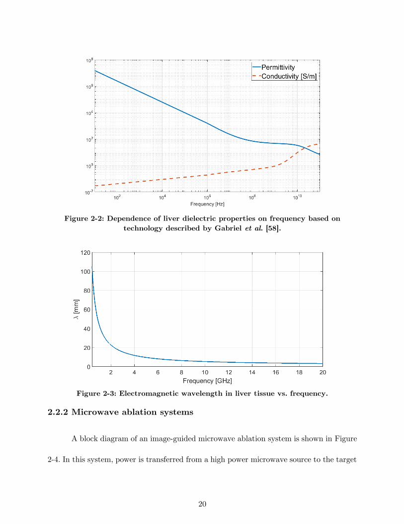
Both relative permittivity and effective conductivity are dependent on frequency,
temperature, and other factors in biological tissues such as water content. As an example,
Figure 2-2 shows the relative permittivity and effective conductivity of liver tissue as
function of frequency in the range of 10 Hz to 100 GHz.
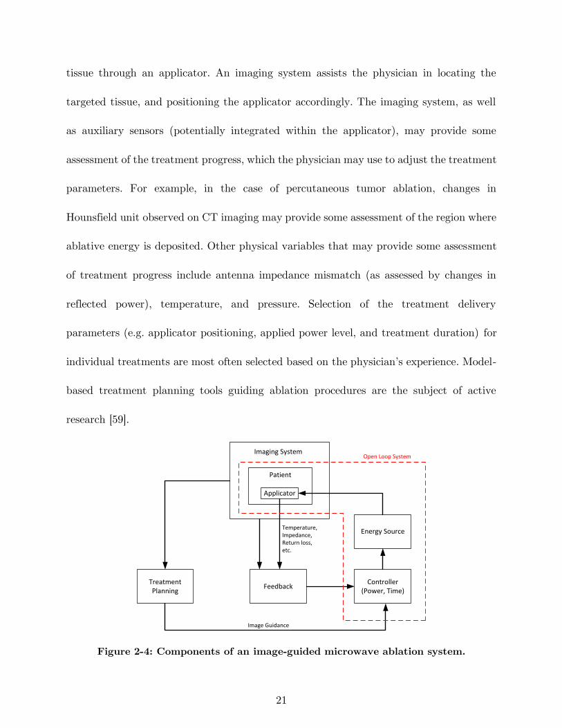
The electromagnetic wavelength in tissue can be calculated from the relative
permittivity using the relationship (𝜆 =𝑐0
𝑓√𝜖𝑟, 𝑐0 is light velocity in free space). The
wavelength is a particularly important parameter for antenna design; antennas are often
efficient when their critical dimension is of the order of wavelength. The relatively long
wavelength (on the order of centimeters) in biological tissue places constraints on the
minimum antenna size that can be employed for practical ablation applications.
Electromagnetic wavelength in liver tissue as a function of frequency is shown in Figure
2-3.
20
Figure 2-2: Dependence of liver dielectric properties on frequency based on
technology described by Gabriel et al. [58].
Figure 2-3: Electromagnetic wavelength in liver tissue vs. frequency.
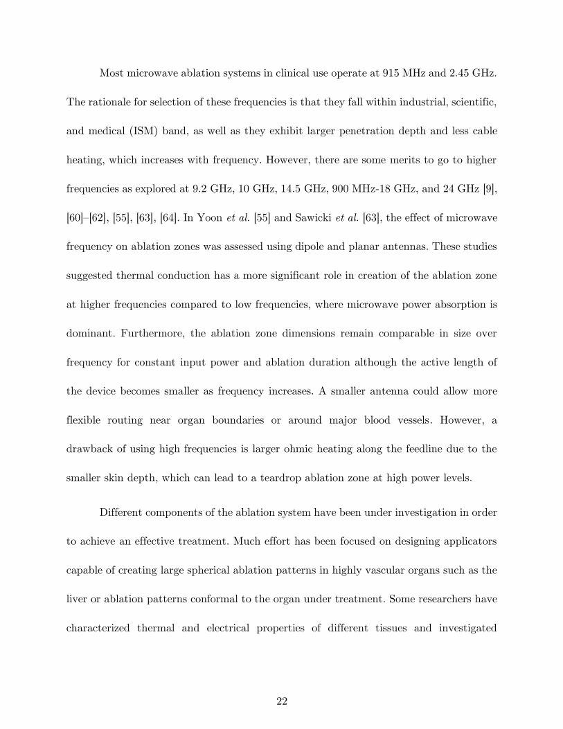
2.2.2 Microwave ablation systems
A block diagram of an image-guided microwave ablation system is shown in Figure
2-4. In this system, power is transferred from a high power microwave source to the target
21
tissue through an applicator. An imaging system assists the physician in locating the
targeted tissue, and positioning the applicator accordingly. The imaging system, as well
as auxiliary sensors (potentially integrated within the applicator), may provide some
assessment of the treatment progress, which the physician may use to adjust the treatment
parameters. For example, in the case of percutaneous tumor ablation, changes in
Hounsfield unit observed on CT imaging may provide some assessment of the region where
ablative energy is deposited. Other physical variables that may provide some assessment
of treatment progress include antenna impedance mismatch (as assessed by changes in
reflected power), temperature, and pressure. Selection of the treatment delivery
parameters (e.g. applicator positioning, applied power level, and treatment duration) for
individual treatments are most often selected based on the physician’s experience. Model-
based treatment planning tools guiding ablation procedures are the subject of active
research [59].
Controller(Power, Time)
Energy Source
Imaging System
Applicator
FeedbackTreatment Planning
Patient
Temperature,Impedance,Return loss,etc.
Image Guidance
Open Loop System
Figure 2-4: Components of an image-guided microwave ablation system.
22
Most microwave ablation systems in clinical use operate at 915 MHz and 2.45 GHz.
The rationale for selection of these frequencies is that they fall within industrial, scientific,
and medical (ISM) band, as well as they exhibit larger penetration depth and less cable
heating, which increases with frequency. However, there are some merits to go to higher
frequencies as explored at 9.2 GHz, 10 GHz, 14.5 GHz, 900 MHz-18 GHz, and 24 GHz [9],
[60]–[62], [55], [63], [64]. In Yoon et al. [55] and Sawicki et al. [63], the effect of microwave
frequency on ablation zones was assessed using dipole and planar antennas. These studies
suggested thermal conduction has a more significant role in creation of the ablation zone
at higher frequencies compared to low frequencies, where microwave power absorption is
dominant. Furthermore, the ablation zone dimensions remain comparable in size over
frequency for constant input power and ablation duration although the active length of
the device becomes smaller as frequency increases. A smaller antenna could allow more
flexible routing near organ boundaries or around major blood vessels. However, a
drawback of using high frequencies is larger ohmic heating along the feedline due to the
smaller skin depth, which can lead to a teardrop ablation zone at high power levels.
Different components of the ablation system have been under investigation in order
to achieve an effective treatment. Much effort has been focused on designing applicators
capable of creating large spherical ablation patterns in highly vascular organs such as the
liver or ablation patterns conformal to the organ under treatment. Some researchers have
characterized thermal and electrical properties of different tissues and investigated
23
biological effect of different energy modalities in order to improve the simulation models
for device design. This would reduce the cost and number of iterations in the device design
process. Incorporation of an imaging system capable of real-time monitoring of the
ablation progress would be a significant step towards enabling delivery of adequate
thermal doses to targeted tissues. Finding a parameter to estimate the growth of the
ablation zone instead of an imaging system is another option to be employed as a feedback.
One example of a feedback parameter is tissue impedance change relative to its desiccation
rate, as commonly employed in RF ablation systems. Novasure is an impedance controlled
global endometrial ablation system that monitors the tissue impedance to control the
ablation depth [65]. All the feedback parameters would be used to adjust the power and
time of the energy source.
2.3 Microwave ablation applicators
The goal of thermal ablation procedures is to heat targeted tissue regions to
ablative temperatures, while minimizing damage to non-targeted tissue regions.
Applicators for microwave ablation consist of a feeding transmission line terminated by a
radiating antenna; the electric field radiated by the antenna is absorbed in surrounding
tissue regions leading to heating.
Since practical transmission lines are made of conductors and dielectrics with non-
negligible attenuation, the transmission line heats up when microwave power supplied
24
from the generator passes through. The geometry of the radiating antenna, frequency of
operation, and the electromagnetic properties of the surrounding media, determine the
spatial profile of the radiated electric field into tissue, as well as the applicator’s efficiency
at transferring power from the feeding transmission line to the radiating antenna.
Antenna return loss (𝑅𝐿) represents the ratio of power delivered to the antenna to
the power reflected back to the source due to impedance mismatch between the
transmission line and antenna:
𝑅𝐿𝑑𝐵 = 10 log10𝑃𝑖
𝑃𝑟 (3)
While it is desirable to maximize 𝑅𝐿, in practice 𝑅𝐿 > 10 𝑑𝐵 provides an
approximate design goal, representing 90% power transferred to the antenna. Inefficient
applicators will require larger applied power levels at the transmission line input terminal
to achieve the same ablation size, as an efficient applicator. Attenuation within the feeding
transmission line leads to heating of the applicator, which often requires the use of active
cooling strategies to maintain applicator integrity and minimize passive heating of tissue
that may be in contact with the applicator. Thus, highly efficient applicators are desirable
as they reduce the burden on cooling of the feeding transmission line.
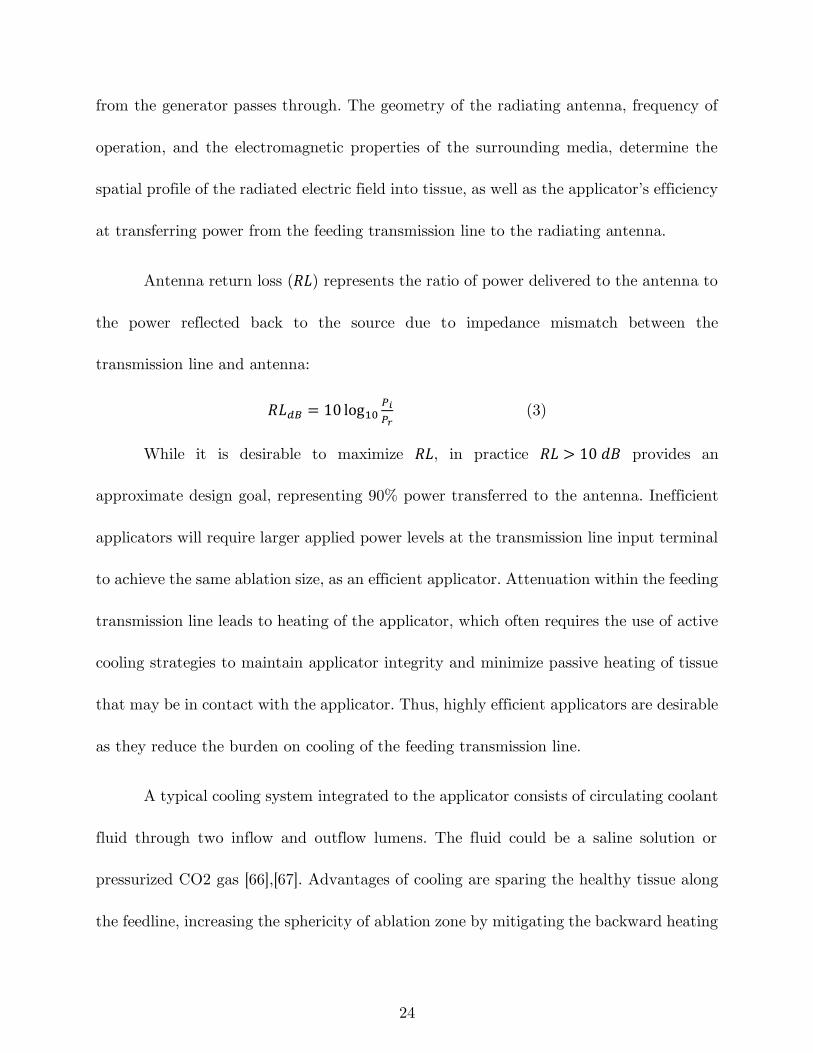
A typical cooling system integrated to the applicator consists of circulating coolant
fluid through two inflow and outflow lumens. The fluid could be a saline solution or
pressurized CO2 gas [66],[67]. Advantages of cooling are sparing the healthy tissue along
the feedline, increasing the sphericity of ablation zone by mitigating the backward heating
25
Figure 2-5: Integration of a cooling system to a coaxial dipole antenna.
and higher power delivery. Figure 2-5 shows a cooling strategy on a dipole antenna.
Cooling may be implemented using an arrangement of concentric tubes for coolant
inflow/outflow. If the coolant used is electromagnetically lossy, circulating the coolant to
the distal tip of the radiating antenna will result in microwave absorption within the fluid,
coupling less power to the tissue, and potentially reducing the efficacy of the cooling.
The antenna geometry, relative to the electromagnetic wavelength at the operating
frequency, also determines the pattern of the radiated electric fields. It is desirable to
select antenna geometries that yield electric field radiation patterns that are well matched
to the tissue regions targeted for ablation. While the electromagnetic power absorbed is
proportional to |𝐄|2, thermal profiles in tissue are also affected by passive conduction of
heat and cooling due to blood flow, and these effects should be considered during antenna
design optimization [68].
The efficiency and ablation pattern of candidate microwave applicator designs can
be evaluated under a variety of experimental conditions. Antenna RL can be measured
26
by immersing the antenna in a tissue mimicking load. A variety of tissue-mimicking
phantoms with tunable dielectric properties have been reported in the literature [69], [70].
Measurement of the antenna’s SAR pattern may be helpful for assessing the radiation
pattern of an antenna, but neglects the effects of thermal conduction on ablation zone
profiles [71]. Furthermore, SAR measurements typically do not account for the changes
in antenna radiation pattern due to temperature dependent changes in tissue dielectric
properties. Ablation devices are often characterized on the benchtop in ex vivo tissue. The
size and shape of the ablation is defined by tissue discoloration at elevated temperatures
[72]. To account for effects of blood perfusion, which acts as a heat sink, ablation zones
must be evaluated in an in vivo animal model or by emulating the perfusion using a
perfusion chamber [73], [74]. Ablated tissue is resected after in vivo ablations for
histopathologic analysis; viability stains may assist in accurate determination of the
ablation zone boundary.
2.3.1 Early microwave ablation applicators
Semi-rigid coaxial cables have been widely used as feeding transmission lines within
microwave ablation applicators. This is because their cylindrical geometry facilitates
insertion within rigid catheters, and antennas can be readily integrated by modifying the
geometry of the distal tip of the cable. Ablation applicators are designed to fit within an
insulating material (e.g. a rigid catheter) to facilitate insertion, prevent the device from
adhering to the ablated tissue, provide protection and mechanical stability, and improve
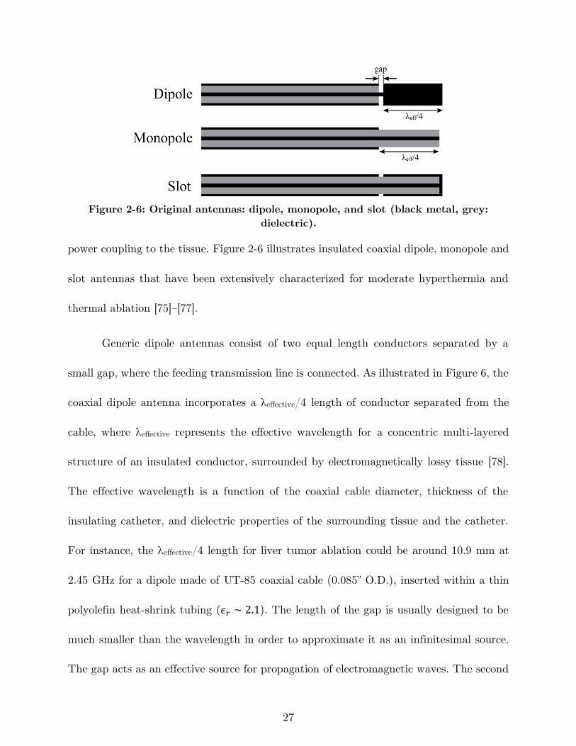
27
Figure 2-6: Original antennas: dipole, monopole, and slot (black metal, grey:
dielectric).
power coupling to the tissue. Figure 2-6 illustrates insulated coaxial dipole, monopole and
slot antennas that have been extensively characterized for moderate hyperthermia and
thermal ablation [75]–[77].
Generic dipole antennas consist of two equal length conductors separated by a
small gap, where the feeding transmission line is connected. As illustrated in Figure 6, the
coaxial dipole antenna incorporates a λeffective/4 length of conductor separated from the
cable, where λeffective represents the effective wavelength for a concentric multi-layered
structure of an insulated conductor, surrounded by electromagnetically lossy tissue [78].
The effective wavelength is a function of the coaxial cable diameter, thickness of the
insulating catheter, and dielectric properties of the surrounding tissue and the catheter.
For instance, the λeffective/4 length for liver tumor ablation could be around 10.9 mm at
2.45 GHz for a dipole made of UT-85 coaxial cable (0.085” O.D.), inserted within a thin
polyolefin heat-shrink tubing (𝜖𝑟 ∼ 2.1). The length of the gap is usually designed to be
much smaller than the wavelength in order to approximate it as an infinitesimal source.
The gap acts as an effective source for propagation of electromagnetic waves. The second
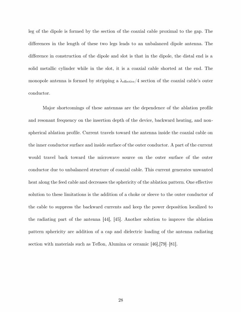
28
leg of the dipole is formed by the section of the coaxial cable proximal to the gap. The
differences in the length of these two legs leads to an unbalanced dipole antenna. The
difference in construction of the dipole and slot is that in the dipole, the distal end is a
solid metallic cylinder while in the slot, it is a coaxial cable shorted at the end. The
monopole antenna is formed by stripping a λeffective/4 section of the coaxial cable’s outer
conductor.
Major shortcomings of these antennas are the dependence of the ablation profile
and resonant frequency on the insertion depth of the device, backward heating, and non-
spherical ablation profile. Current travels toward the antenna inside the coaxial cable on
the inner conductor surface and inside surface of the outer conductor. A part of the current
would travel back toward the microwave source on the outer surface of the outer
conductor due to unbalanced structure of coaxial cable. This current generates unwanted
heat along the feed cable and decreases the sphericity of the ablation pattern. One effective
solution to these limitations is the addition of a choke or sleeve to the outer conductor of
the cable to suppress the backward currents and keep the power deposition localized to
the radiating part of the antenna [44], [45]. Another solution to improve the ablation
pattern sphericity are addition of a cap and dielectric loading of the antenna radiating
section with materials such as Teflon, Alumina or ceramic [46],[79]–[81].
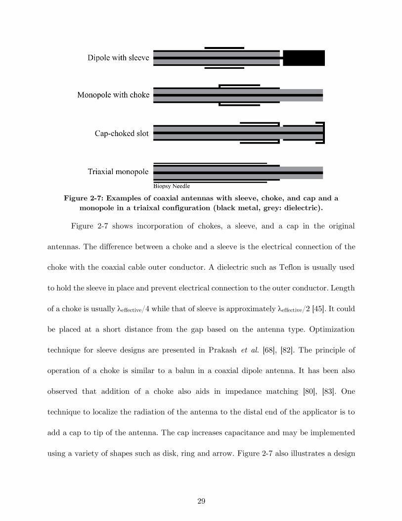
29
Figure 2-7: Examples of coaxial antennas with sleeve, choke, and cap and a
monopole in a triaixal configuration (black metal, grey: dielectric).
Figure 2-7 shows incorporation of chokes, a sleeve, and a cap in the original
antennas. The difference between a choke and a sleeve is the electrical connection of the
choke with the coaxial cable outer conductor. A dielectric such as Teflon is usually used
to hold the sleeve in place and prevent electrical connection to the outer conductor. Length
of a choke is usually λeffective/4 while that of sleeve is approximately λeffective/2 [45]. It could
be placed at a short distance from the gap based on the antenna type. Optimization
technique for sleeve designs are presented in Prakash et al. [68], [82]. The principle of
operation of a choke is similar to a balun in a coaxial dipole antenna. It has been also
observed that addition of a choke also aids in impedance matching [80], [83]. One
technique to localize the radiation of the antenna to the distal end of the applicator is to
add a cap to tip of the antenna. The cap increases capacitance and may be implemented
using a variety of shapes such as disk, ring and arrow. Figure 2-7 also illustrates a design
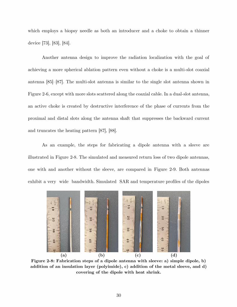
30
which employs a biopsy needle as both an introducer and a choke to obtain a thinner
device [73], [83], [84].
Another antenna design to improve the radiation localization with the goal of
achieving a more spherical ablation pattern even without a choke is a multi-slot coaxial
antenna [85]–[87]. The multi-slot antenna is similar to the single slot antenna shown in
Figure 2-6, except with more slots scattered along the coaxial cable. In a dual-slot antenna,
an active choke is created by destructive interference of the phase of currents from the
proximal and distal slots along the antenna shaft that suppresses the backward current
and truncates the heating pattern [87], [88].
As an example, the steps for fabricating a dipole antenna with a sleeve are
illustrated in Figure 2-8. The simulated and measured return loss of two dipole antennas,
one with and another without the sleeve, are compared in Figure 2-9. Both antennas
exhibit a very wide bandwidth. Simulated SAR and temperature profiles of the dipoles
(a) (b) (c) (d)
Figure 2-8: Fabrication steps of a dipole antenna with sleeve: a) simple dipole, b)
addition of an insulation layer (polyimide), c) addition of the metal sleeve, and d)
covering of the dipole with heat shrink.
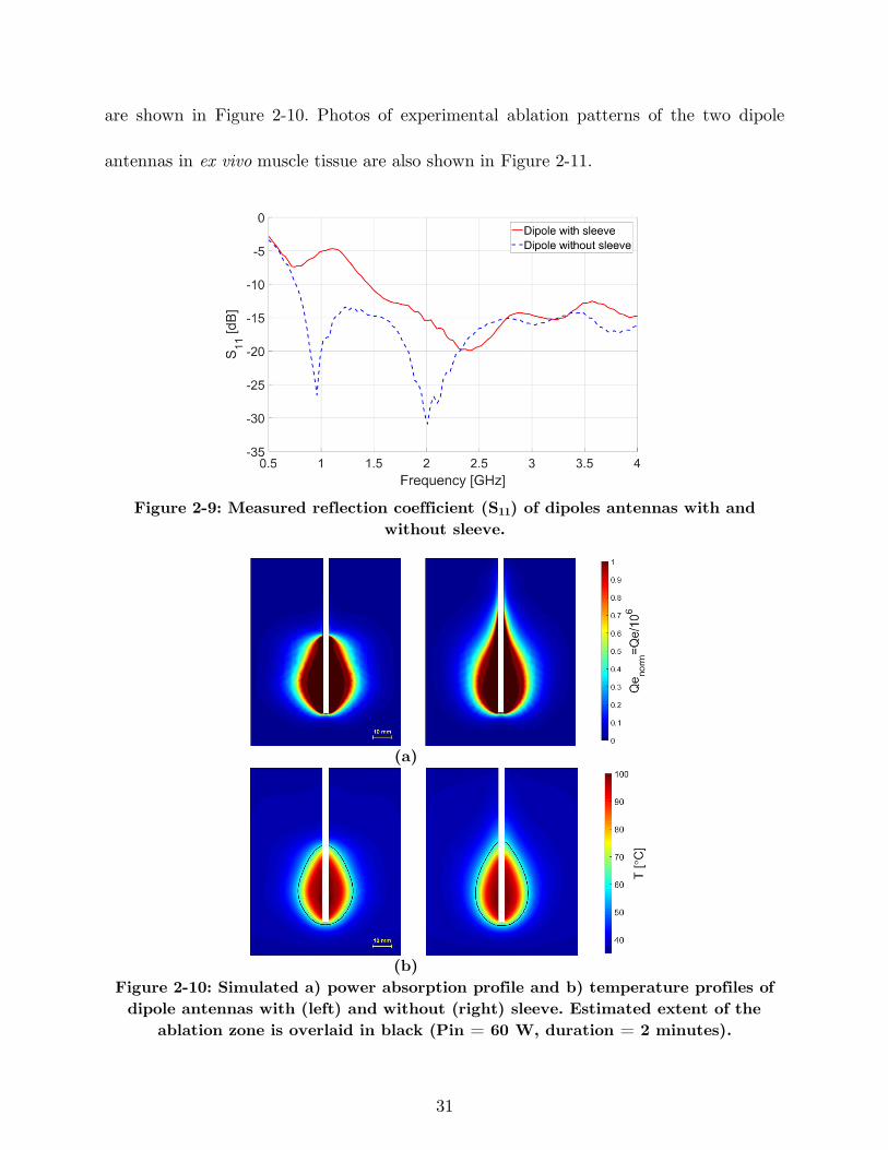
31
are shown in Figure 2-10. Photos of experimental ablation patterns of the two dipole
antennas in ex vivo muscle tissue are also shown in Figure 2-11.
Figure 2-9: Measured reflection coefficient (S11) of dipoles antennas with and
without sleeve.
(a)
(b)
Figure 2-10: Simulated a) power absorption profile and b) temperature profiles of
dipole antennas with (left) and without (right) sleeve. Estimated extent of the
ablation zone is overlaid in black (Pin = 60 W, duration = 2 minutes).
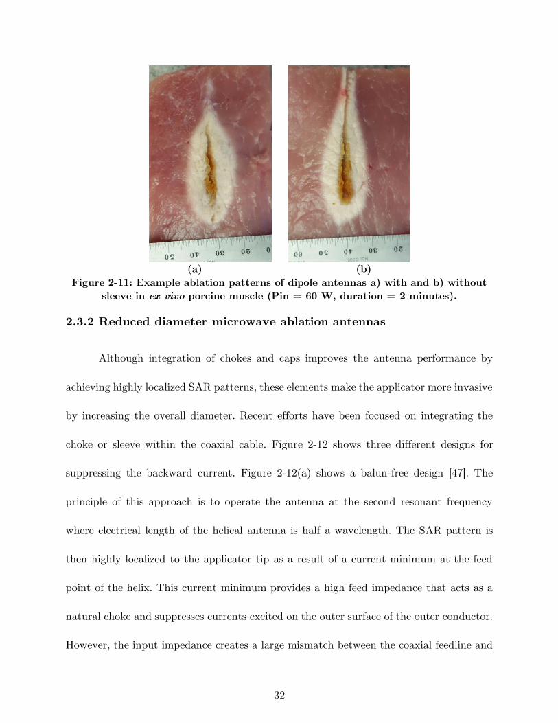
32
(a) (b)
Figure 2-11: Example ablation patterns of dipole antennas a) with and b) without
sleeve in ex vivo porcine muscle (Pin = 60 W, duration = 2 minutes).
2.3.2 Reduced diameter microwave ablation antennas
Although integration of chokes and caps improves the antenna performance by
achieving highly localized SAR patterns, these elements make the applicator more invasive
by increasing the overall diameter. Recent efforts have been focused on integrating the
choke or sleeve within the coaxial cable. Figure 2-12 shows three different designs for
suppressing the backward current. Figure 2-12(a) shows a balun-free design [47]. The
principle of this approach is to operate the antenna at the second resonant frequency
where electrical length of the helical antenna is half a wavelength. The SAR pattern is
then highly localized to the applicator tip as a result of a current minimum at the feed
point of the helix. This current minimum provides a high feed impedance that acts as a
natural choke and suppresses currents excited on the outer surface of the outer conductor.
However, the input impedance creates a large mismatch between the coaxial feedline and
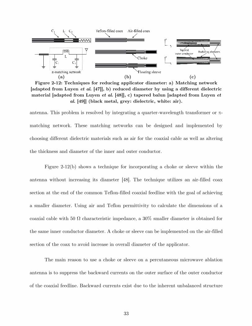
33
(a) (b) (c)
Figure 2-12: Techniques for reducing applicator diameter: a) Matching network
[adapted from Luyen et al. [47]], b) reduced diameter by using a different dielectric
material [adapted from Luyen et al. [48]], c) tapered balun [adapted from Luyen et
al. [49]] (black metal, grey: dielectric, white: air).
antenna. This problem is resolved by integrating a quarter-wavelength transformer or π-
matching network. These matching networks can be designed and implemented by
choosing different dielectric materials such as air for the coaxial cable as well as altering
the thickness and diameter of the inner and outer conductor.
Figure 2-12(b) shows a technique for incorporating a choke or sleeve within the
antenna without increasing its diameter [48]. The technique utilizes an air-filled coax
section at the end of the common Teflon-filled coaxial feedline with the goal of achieving
a smaller diameter. Using air and Teflon permittivity to calculate the dimensions of a
coaxial cable with 50 Ω characteristic impedance, a 30% smaller diameter is obtained for
the same inner conductor diameter. A choke or sleeve can be implemented on the air-filled
section of the coax to avoid increase in overall diameter of the applicator.
The main reason to use a choke or sleeve on a percutaneous microwave ablation
antenna is to suppress the backward currents on the outer surface of the outer conductor
of the coaxial feedline. Backward currents exist due to the inherent unbalanced structure
34
of the coax cable. By gradually changing the shape of the outer conductor to create a
balanced transmission line, the backward current problem may be addressed. Figure
2-12(c) shows a dipole antenna design with a tapered balun [49]. The outer conductor has
been gradually tapered into two parallel strips that act as the second arm of the dipole.
The first arm of the dipole is the extension of the inner conductor. Besides achieving a
highly localized SAR without using an external choke or sleeve, the tapered balun
improves the antenna return loss by acting as a matching network. Further, the gradual
taper of the balun increases the antenna bandwidth.
2.3.3 Directional applicators
Most microwave ablation applicators employ a needle-based design and yield ovoid
ablation pattern. In practice, the applicator is usually placed in the center of the targeted
tissue and the ablation zone progresses radially outward. In cases when the target is next
to critical structures, caution must be taken to prevent any damage to non-targeted
tissues. One technique to overcome this adverse effect is fluid instillation between the
target and adjacent tissue (hydrodisplacement) to protect vulnerable organs. The fluid
such as dextrose 5% in water (D5W) or saline increases the distance between the
microwave source and the target structure, and further acts as a heat sink. In other words,
this technique directs the energy only to sites where no fluid is surrounding them [89].
Recently, a few antenna designs restricting microwave radiation in a preferred
direction, approximately one half of the angular expanse, have been reported. Such
35
applicators may be used for ablation of targets in proximity of critical structures, without
requiring any space for fluid displacement. Figure 2-13 shows two antenna designs with
directional radiation patterns suitable for integration within rigid catheters/needles. A
proof of concept device is shown in Figure 2-13(a) [50]. This design consists of a monopole
antenna with water-cooling incorporated through its shaft. The coaxial feedline is
concentrically placed within two inner (water inflow) and outer (water outflow) tubes.
The inner tube, made of metal, is cut into a semicylinder from the base of the monopole
and extended beyond the tip of the monopole. This semicylinder would act as a reflector
in order the direct the microwaves to one side of the monopole antenna. The outer tube,
made of dielectric (polyimide or PEEK), extends beyond the reflector and allows water
to circulate back to the reservoir. The circulating water provides active cooling which
mitigates heating along the feedline. It makes the device less invasive by eliminating the
need for choke or sleeve for backward heating. Additionally, water high electrical
permittivity (ϵr = 78 @ 2.45 GHz) reduces the wavelength, thereby limiting overall
antenna radiating length.
A thinner (2.5 mm diameter) with deeper radial ablation depth was obtained by
modifying the monopole shape and reflector of Figure 2-13(a) in Sebek et al. [90]. The
monopole antenna of Sebek et al. [90] is pushed toward the outer tube wall. The placement
of the monopole antenna in close proximity to the outer tube wall and closer to the tissue
would allow a larger portion of near field microwave energy to be coupled to the tissue
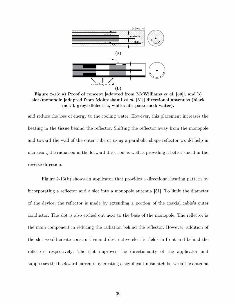
36
(a)
(b)
Figure 2-13: a) Proof of concept [adapted from McWilliams et al. [50]], and b)
slot/monopole [adapted from Mohtashami et al. [51]] directional antennas (black
metal, grey: dielectric, white: air, patterned: water).
and reduce the loss of energy to the cooling water. However, this placement increases the
heating in the tissue behind the reflector. Shifting the reflector away from the monopole
and toward the wall of the outer tube or using a parabolic shape reflector would help in
increasing the radiation in the forward direction as well as providing a better shield in the
reverse direction.
Figure 2-13(b) shows an applicator that provides a directional heating pattern by
incorporating a reflector and a slot into a monopole antenna [51]. To limit the diameter
of the device, the reflector is made by extending a portion of the coaxial cable’s outer
conductor. The slot is also etched out next to the base of the monopole. The reflector is
the main component in reducing the radiation behind the reflector. However, addition of
the slot would create constructive and destructive electric fields in front and behind the
reflector, respectively. The slot improves the directionality of the applicator and
suppresses the backward currents by creating a significant mismatch between the antenna
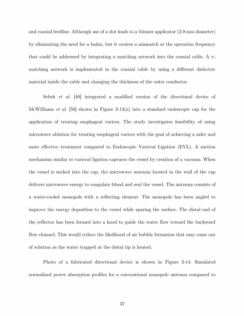
37
and coaxial feedline. Although use of a slot leads to a thinner applicator (2.9 mm diameter)
by eliminating the need for a balun, but it creates a mismatch at the operation frequency
that could be addressed by integrating a matching network into the coaxial cable. A π-
matching network is implemented in the coaxial cable by using a different dielectric
material inside the cable and changing the thickness of the outer conductor.
Sebek et al. [40] integrated a modified version of the directional device of
McWilliams et al. [50] shown in Figure 2-13(a) into a standard endoscopic cap for the
application of treating esophageal varices. The study investigates feasibility of using
microwave ablation for treating esophageal varices with the goal of achieving a safer and
more effective treatment compared to Endoscopic Variceal Ligation (EVL). A suction
mechanism similar to variceal ligation captures the vessel by creation of a vacuum. When
the vessel is sucked into the cap, the microwave antenna located in the wall of the cap
delivers microwave energy to coagulate blood and seal the vessel. The antenna consists of
a water-cooled monopole with a reflecting element. The monopole has been angled to
improve the energy deposition to the vessel while sparing the surface. The distal end of
the reflector has been formed into a hood to guide the water flow toward the backward
flow channel. This would reduce the likelihood of air bubble formation that may come out
of solution as the water trapped at the distal tip is heated.
Photo of a fabricated directional device is shown in Figure 2-14. Simulated
normalized power absorption profiles for a conventional monopole antenna compared to
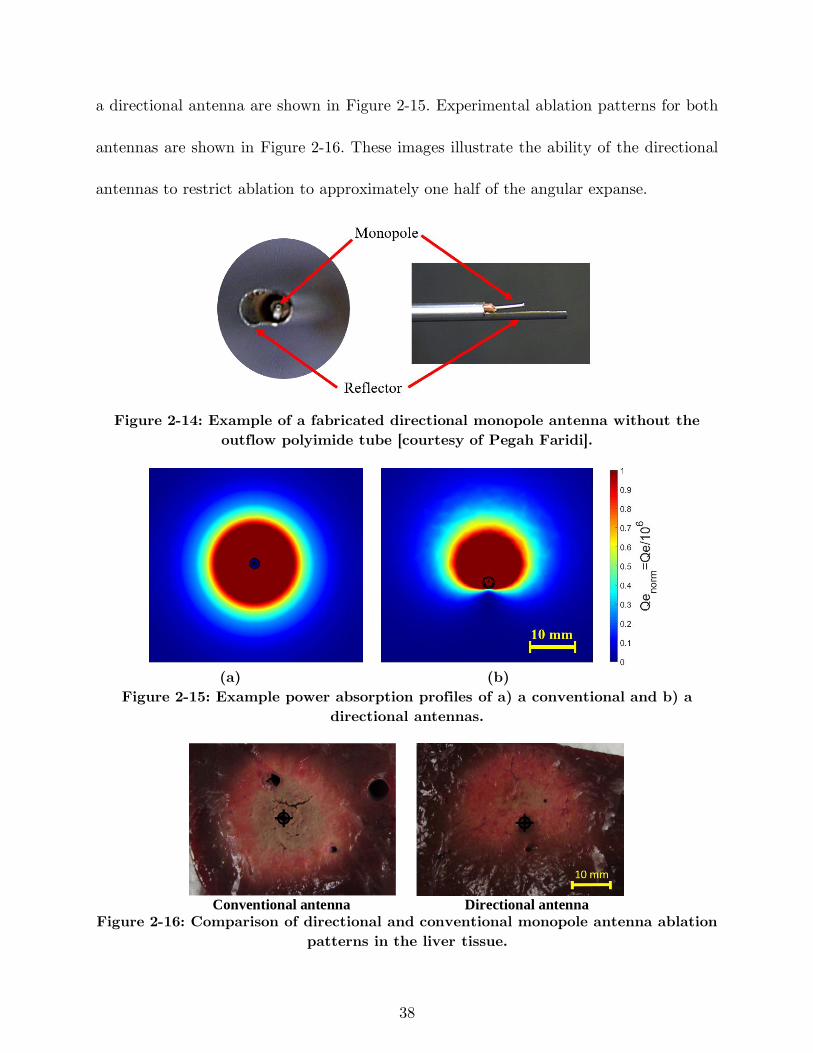
38
a directional antenna are shown in Figure 2-15. Experimental ablation patterns for both
antennas are shown in Figure 2-16. These images illustrate the ability of the directional
antennas to restrict ablation to approximately one half of the angular expanse.
Figure 2-14: Example of a fabricated directional monopole antenna without the
outflow polyimide tube [courtesy of Pegah Faridi].
(a) (b)
Figure 2-15: Example power absorption profiles of a) a conventional and b) a
directional antennas.
Conventional antenna Directional antenna
Figure 2-16: Comparison of directional and conventional monopole antenna ablation
patterns in the liver tissue.
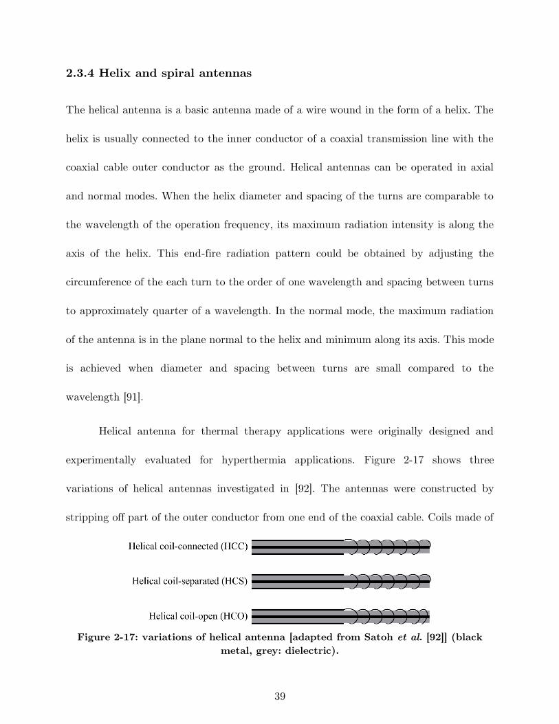
39
2.3.4 Helix and spiral antennas
The helical antenna is a basic antenna made of a wire wound in the form of a helix. The
helix is usually connected to the inner conductor of a coaxial transmission line with the
coaxial cable outer conductor as the ground. Helical antennas can be operated in axial
and normal modes. When the helix diameter and spacing of the turns are comparable to
the wavelength of the operation frequency, its maximum radiation intensity is along the
axis of the helix. This end-fire radiation pattern could be obtained by adjusting the
circumference of the each turn to the order of one wavelength and spacing between turns
to approximately quarter of a wavelength. In the normal mode, the maximum radiation
of the antenna is in the plane normal to the helix and minimum along its axis. This mode
is achieved when diameter and spacing between turns are small compared to the
wavelength [91].
Helical antenna for thermal therapy applications were originally designed and
experimentally evaluated for hyperthermia applications. Figure 2-17 shows three
variations of helical antennas investigated in [92]. The antennas were constructed by
stripping off part of the outer conductor from one end of the coaxial cable. Coils made of
Figure 2-17: variations of helical antenna [adapted from Satoh et al. [92]] (black
metal, grey: dielectric).
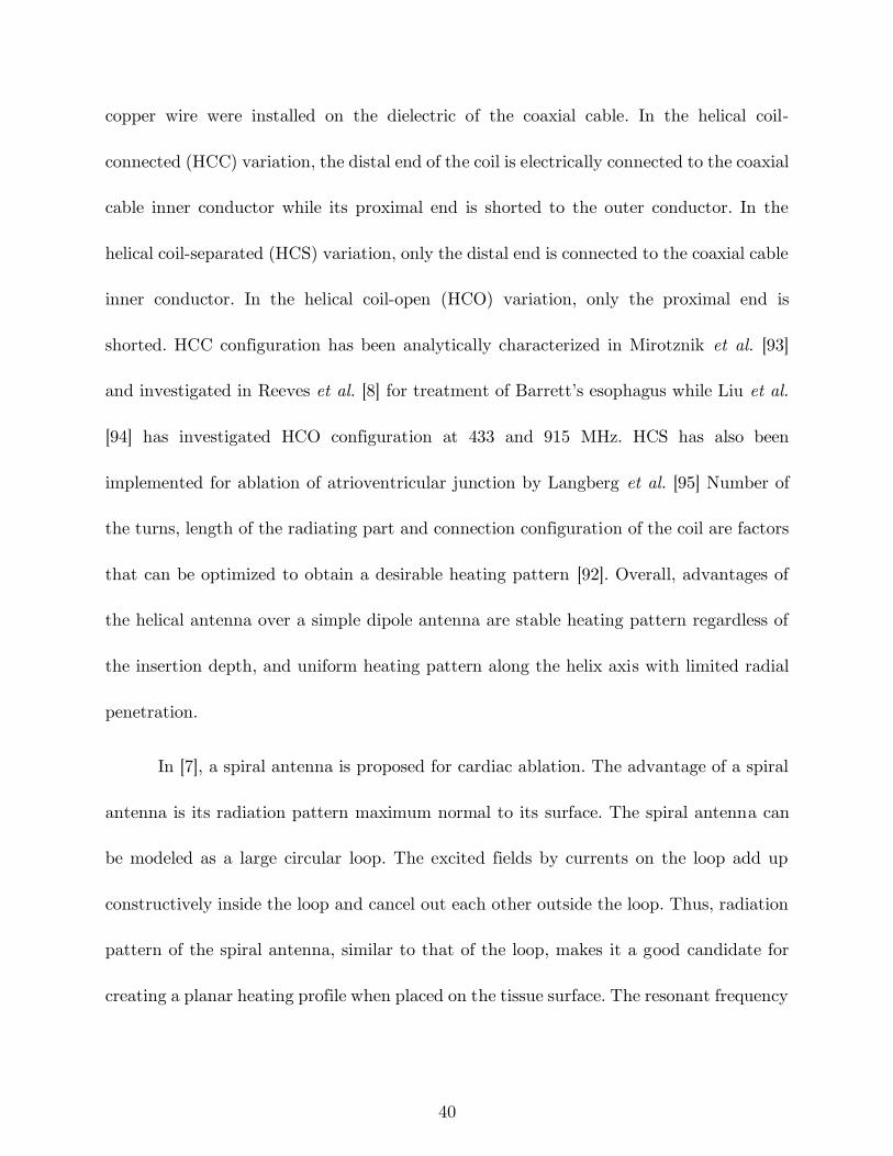
40
copper wire were installed on the dielectric of the coaxial cable. In the helical coil-
connected (HCC) variation, the distal end of the coil is electrically connected to the coaxial
cable inner conductor while its proximal end is shorted to the outer conductor. In the
helical coil-separated (HCS) variation, only the distal end is connected to the coaxial cable
inner conductor. In the helical coil-open (HCO) variation, only the proximal end is
shorted. HCC configuration has been analytically characterized in Mirotznik et al. [93]
and investigated in Reeves et al. [8] for treatment of Barrett’s esophagus while Liu et al.
[94] has investigated HCO configuration at 433 and 915 MHz. HCS has also been
implemented for ablation of atrioventricular junction by Langberg et al. [95] Number of
the turns, length of the radiating part and connection configuration of the coil are factors
that can be optimized to obtain a desirable heating pattern [92]. Overall, advantages of
the helical antenna over a simple dipole antenna are stable heating pattern regardless of
the insertion depth, and uniform heating pattern along the helix axis with limited radial
penetration.
In [7], a spiral antenna is proposed for cardiac ablation. The advantage of a spiral
antenna is its radiation pattern maximum normal to its surface. The spiral antenna can
be modeled as a large circular loop. The excited fields by currents on the loop add up
constructively inside the loop and cancel out each other outside the loop. Thus, radiation
pattern of the spiral antenna, similar to that of the loop, makes it a good candidate for
creating a planar heating profile when placed on the tissue surface. The resonant frequency
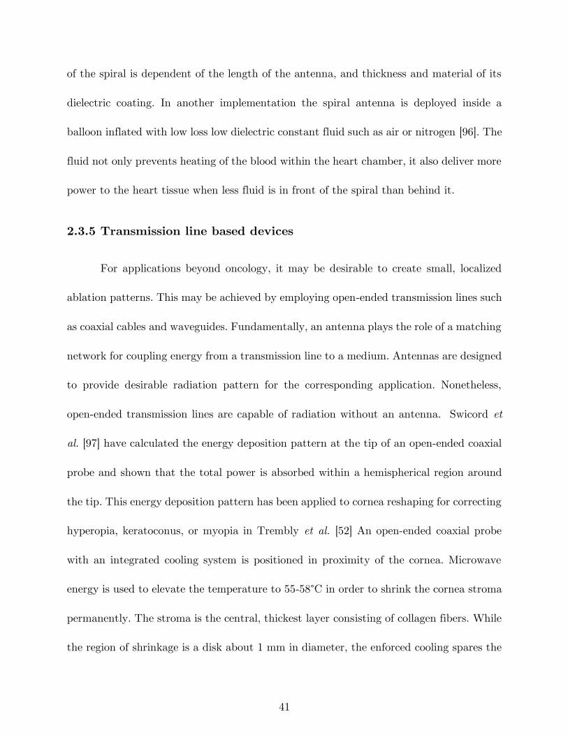
41
of the spiral is dependent of the length of the antenna, and thickness and material of its
dielectric coating. In another implementation the spiral antenna is deployed inside a
balloon inflated with low loss low dielectric constant fluid such as air or nitrogen [96]. The
fluid not only prevents heating of the blood within the heart chamber, it also deliver more
power to the heart tissue when less fluid is in front of the spiral than behind it.
2.3.5 Transmission line based devices
For applications beyond oncology, it may be desirable to create small, localized
ablation patterns. This may be achieved by employing open-ended transmission lines such
as coaxial cables and waveguides. Fundamentally, an antenna plays the role of a matching
network for coupling energy from a transmission line to a medium. Antennas are designed
to provide desirable radiation pattern for the corresponding application. Nonetheless,
open-ended transmission lines are capable of radiation without an antenna. Swicord et
al. [97] have calculated the energy deposition pattern at the tip of an open-ended coaxial
probe and shown that the total power is absorbed within a hemispherical region around
the tip. This energy deposition pattern has been applied to cornea reshaping for correcting
hyperopia, keratoconus, or myopia in Trembly et al. [52] An open-ended coaxial probe
with an integrated cooling system is positioned in proximity of the cornea. Microwave
energy is used to elevate the temperature to 55-58°C in order to shrink the cornea stroma
permanently. The stroma is the central, thickest layer consisting of collagen fibers. While
the region of shrinkage is a disk about 1 mm in diameter, the enforced cooling spares the
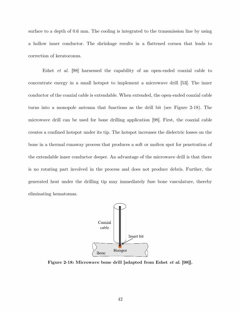
42
surface to a depth of 0.6 mm. The cooling is integrated to the transmission line by using
a hollow inner conductor. The shrinkage results in a flattened cornea that leads to
correction of keratoconus.
Eshet et al. [98] harnessed the capability of an open-ended coaxial cable to
concentrate energy in a small hotspot to implement a microwave drill [53]. The inner
conductor of the coaxial cable is extendable. When extended, the open-ended coaxial cable
turns into a monopole antenna that functions as the drill bit (see Figure 2-18). The
microwave drill can be used for bone drilling application [98]. First, the coaxial cable
creates a confined hotspot under its tip. The hotspot increases the dielectric losses on the
bone in a thermal runaway process that produces a soft or molten spot for penetration of
the extendable inner conductor deeper. An advantage of the microwave drill is that there
is no rotating part involved in the process and does not produce debris. Further, the
generated heat under the drilling tip may immediately fuse bone vasculature, thereby
eliminating hematomas.
Figure 2-18: Microwave bone drill [adapted from Eshet et al. [98]].
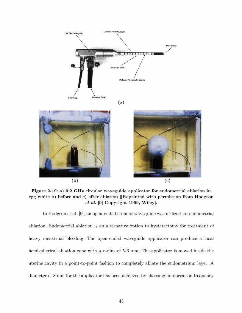
43
(a)
(b) (c)
Figure 2-19: a) 9.2 GHz circular waveguide applicator for endometrial ablation in
egg white b) before and c) after ablation [[Reprinted with permission from Hodgson
et al. [9] Copyright 1999, Wiley].
In Hodgson et al. [9], an open-ended circular waveguide was utilized for endometrial
ablation. Endometrial ablation is an alternative option to hysterectomy for treatment of
heavy menstrual bleeding. The open-ended waveguide applicator can produce a local
hemispherical ablation zone with a radius of 5-6 mm. The applicator is moved inside the
uterine cavity in a point-to-point fashion to completely ablate the endometrium layer. A
diameter of 8 mm for the applicator has been achieved by choosing an operation frequency
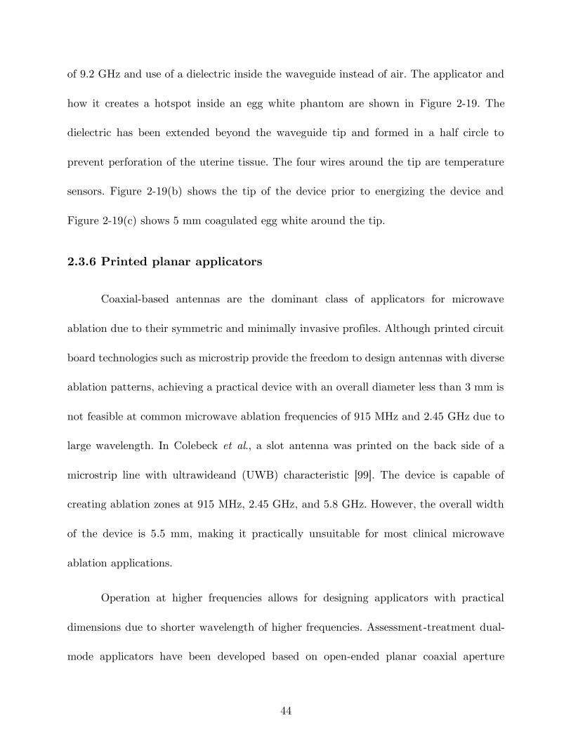
44
of 9.2 GHz and use of a dielectric inside the waveguide instead of air. The applicator and
how it creates a hotspot inside an egg white phantom are shown in Figure 2-19. The
dielectric has been extended beyond the waveguide tip and formed in a half circle to
prevent perforation of the uterine tissue. The four wires around the tip are temperature
sensors. Figure 2-19(b) shows the tip of the device prior to energizing the device and
Figure 2-19(c) shows 5 mm coagulated egg white around the tip.
2.3.6 Printed planar applicators
Coaxial-based antennas are the dominant class of applicators for microwave
ablation due to their symmetric and minimally invasive profiles. Although printed circuit
board technologies such as microstrip provide the freedom to design antennas with diverse
ablation patterns, achieving a practical device with an overall diameter less than 3 mm is
not feasible at common microwave ablation frequencies of 915 MHz and 2.45 GHz due to
large wavelength. In Colebeck et al., a slot antenna was printed on the back side of a
microstrip line with ultrawideand (UWB) characteristic [99]. The device is capable of
creating ablation zones at 915 MHz, 2.45 GHz, and 5.8 GHz. However, the overall width
of the device is 5.5 mm, making it practically unsuitable for most clinical microwave
ablation applications.
Operation at higher frequencies allows for designing applicators with practical
dimensions due to shorter wavelength of higher frequencies. Assessment-treatment dual-
mode applicators have been developed based on open-ended planar coaxial aperture
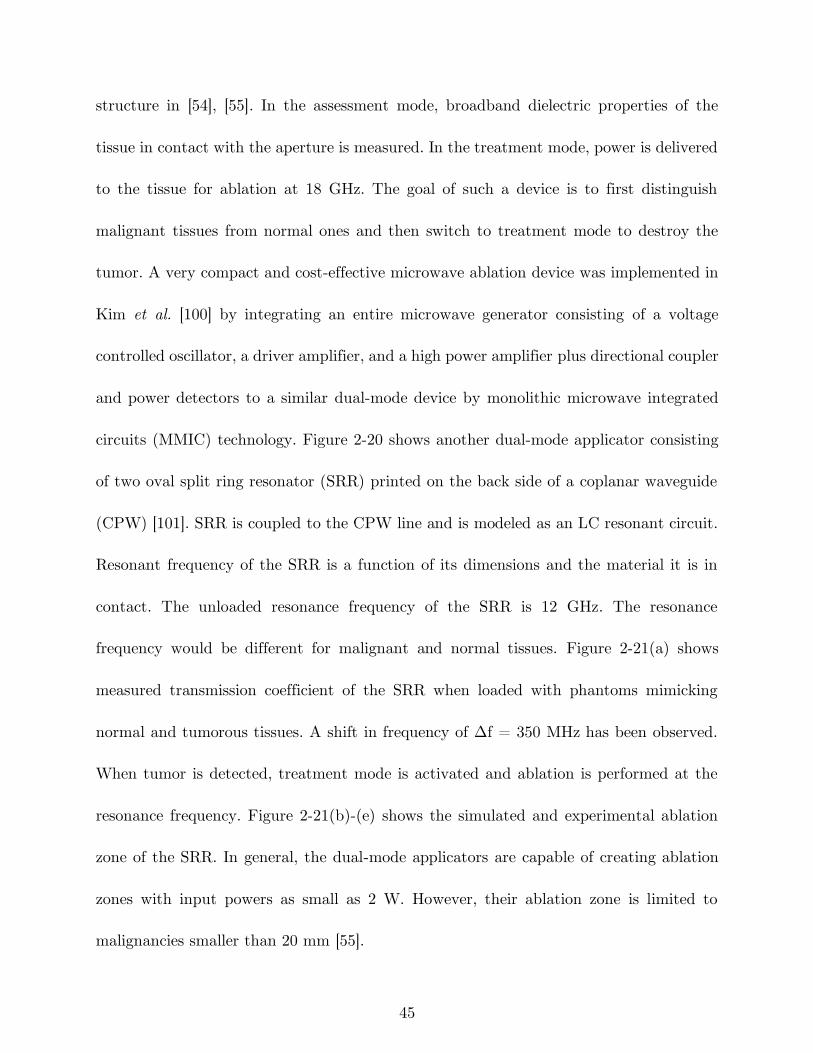
45
structure in [54], [55]. In the assessment mode, broadband dielectric properties of the
tissue in contact with the aperture is measured. In the treatment mode, power is delivered
to the tissue for ablation at 18 GHz. The goal of such a device is to first distinguish
malignant tissues from normal ones and then switch to treatment mode to destroy the
tumor. A very compact and cost-effective microwave ablation device was implemented in
Kim et al. [100] by integrating an entire microwave generator consisting of a voltage
controlled oscillator, a driver amplifier, and a high power amplifier plus directional coupler
and power detectors to a similar dual-mode device by monolithic microwave integrated
circuits (MMIC) technology. Figure 2-20 shows another dual-mode applicator consisting
of two oval split ring resonator (SRR) printed on the back side of a coplanar waveguide
(CPW) [101]. SRR is coupled to the CPW line and is modeled as an LC resonant circuit.
Resonant frequency of the SRR is a function of its dimensions and the material it is in
contact. The unloaded resonance frequency of the SRR is 12 GHz. The resonance
frequency would be different for malignant and normal tissues. Figure 2-21(a) shows
measured transmission coefficient of the SRR when loaded with phantoms mimicking
normal and tumorous tissues. A shift in frequency of Δf = 350 MHz has been observed.
When tumor is detected, treatment mode is activated and ablation is performed at the
resonance frequency. Figure 2-21(b)-(e) shows the simulated and experimental ablation
zone of the SRR. In general, the dual-mode applicators are capable of creating ablation
zones with input powers as small as 2 W. However, their ablation zone is limited to
malignancies smaller than 20 mm [55].
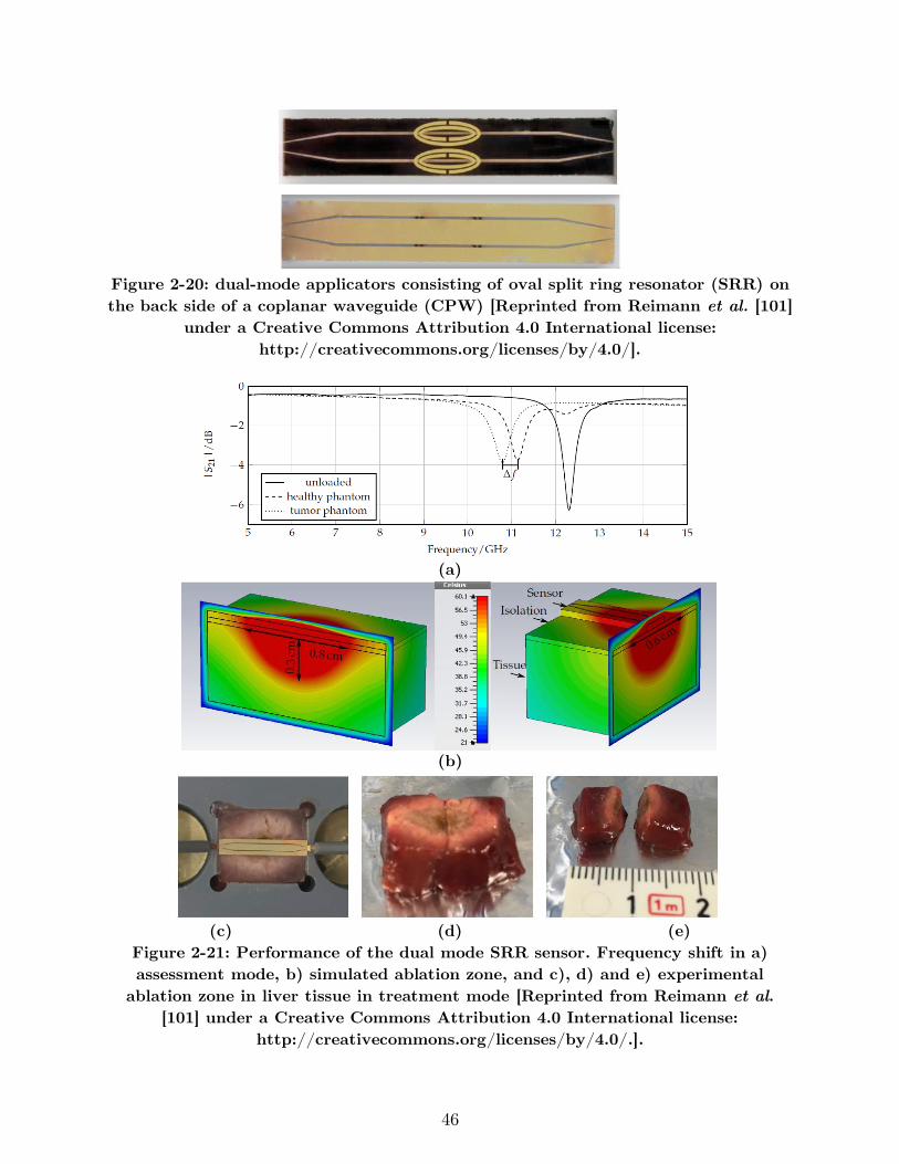
46
Figure 2-20: dual-mode applicators consisting of oval split ring resonator (SRR) on
the back side of a coplanar waveguide (CPW) [Reprinted from Reimann et al. [101]
under a Creative Commons Attribution 4.0 International license:
http://creativecommons.org/licenses/by/4.0/].
(a)
(b)
(c) (d) (e)
Figure 2-21: Performance of the dual mode SRR sensor. Frequency shift in a)
assessment mode, b) simulated ablation zone, and c), d) and e) experimental
ablation zone in liver tissue in treatment mode [Reprinted from Reimann et al.
[101] under a Creative Commons Attribution 4.0 International license:
http://creativecommons.org/licenses/by/4.0/.].
47
(a) (b)
Figure 2-22: a) array of two planar dipoles loaded with capacitors [reprinted with
permission from AIP Publishing, Copyright 2017, [102]] and b) a travelling wave
antenna [adapted from Hancock et al. [61]].
Figure 2-22(a) shows a conceptual design of an array of two planar dipoles loaded
with two surface-mount capacitor on each arm [102]. The dipoles are printed back-to-back
and fed by stripline. The idea is to obtain the desired ablation pattern by controlling the
current distribution on each dipole through optimizing parameters such as the capacitance
values, capacitor positions along the arms, and the feed point along the length of the
dipole.
Applicability of a travelling wave antenna structure for Barrett’s esophagus has
been investigated in Hancock et al. [61] The goal is to create a band of controlled heating
around the sphincter of esophagus to give controlled tightening. As shown in Figure
2-22(b), a series of slots are created on the ground plane of a microstrip line on a flexible
substrate. By adjusting the size of each slot, uniform power coupling from the microstrip
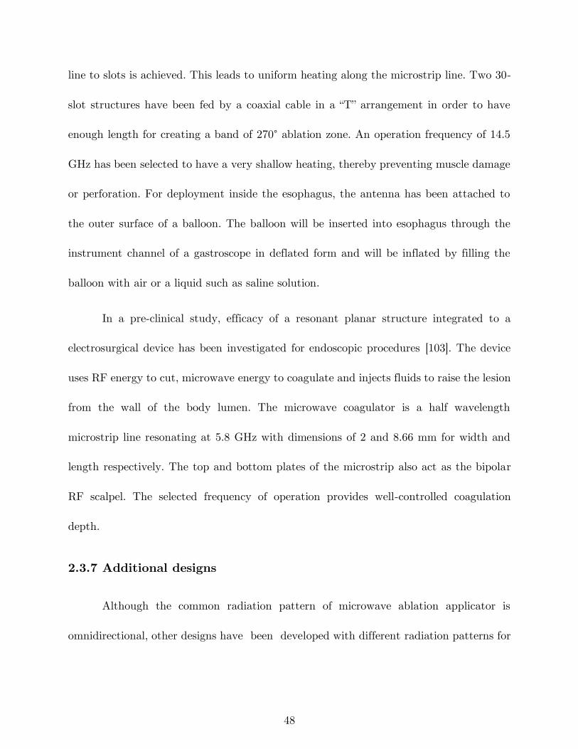
48
line to slots is achieved. This leads to uniform heating along the microstrip line. Two 30-
slot structures have been fed by a coaxial cable in a “T” arrangement in order to have
enough length for creating a band of 270° ablation zone. An operation frequency of 14.5
GHz has been selected to have a very shallow heating, thereby preventing muscle damage
or perforation. For deployment inside the esophagus, the antenna has been attached to
the outer surface of a balloon. The balloon will be inserted into esophagus through the
instrument channel of a gastroscope in deflated form and will be inflated by filling the
balloon with air or a liquid such as saline solution.
In a pre-clinical study, efficacy of a resonant planar structure integrated to a
electrosurgical device has been investigated for endoscopic procedures [103]. The device
uses RF energy to cut, microwave energy to coagulate and injects fluids to raise the lesion
from the wall of the body lumen. The microwave coagulator is a half wavelength
microstrip line resonating at 5.8 GHz with dimensions of 2 and 8.66 mm for width and
length respectively. The top and bottom plates of the microstrip also act as the bipolar
RF scalpel. The selected frequency of operation provides well-controlled coagulation
depth.
2.3.7 Additional designs
Although the common radiation pattern of microwave ablation applicator is
omnidirectional, other designs have been developed with different radiation patterns for
49
(a) (b)
(c) (d)
Figure 2-23: a) two prong fork device for treatment of snoring [adapted from
Cresson et al. [104]], b) double loop applicator [reprinted with permission from
Springer Nature, Copyright 2005, [105]] c) Drooped ground monopole antenna
[reprinted with permission from John Wiley and Sons, Copyright 2015, [106]], and
d) loop antenna for global endometrial ablation [adapted from Fallahi et al. [23]].
applications such as snoring treatment, tumor ablation, noncontact circumferential
endocardial ablation, and global endometrial ablation (see Figure 2-23).
In Cresson et al. [104], a two-prong fork made of coaxial cable has been developed
for snoring treatment. Figure 2-23(a) shows that one prong of the applicator is the
extension of the coaxial cable inner conductor and the other one is a needle electrically
50
connected to the coaxial cable outer conductor. This configuration would create a hotspot
at the tip of the prongs while less heat is generated on the proximal end. The treatment
goal of the device is to create a deep-seated fibrous scar in the soft palate tissue while
sparing its surface by constraining the temperature. Ablation would change the soft palate
to fibrous scar that reduces vibratory capacity of the soft palate, thereby decreasing the
snoring.
Most of the implemented applicators for microwave ablation of tumors are inserted
into the center of the tumor and create an outward growing ablation zone to cover the
whole tumor. In Shock et al. [107], a monopole antenna was suggested that takes a loop
form when deployed (see Figure 2-23(b)). With this design, the tumor is encircled by the
loop and is heated from the outside in. This may help in rapid truncation of the blood
supply to minimize the blood heat sink effect. Further, the loop configuration would
decrease tumor recurrence due to malignant cell proceeding during placement of needle
form applicators since it is positioned next to the tumor. It is noted that for a complete
coverage of the tumor, more than one applicator would be required due to less symmetric
ablation pattern of the loop. Some disadvantages of the loop design is the more
complicated targeting procedure of the tumors. Moreover, the loop is energized during
deployment for easier placement that can cause complications if it hits surrounding critical
organs [107].
51
A monopole with drooping ground radial wires has been implemented for
noncontact circumferential endocardial ablation in [106]. As shown in Figure 2-23(c), the
design target is to create a circumferential ablation pattern in the antrum of the
pulmonary vein for isolation of the source of atrial fibrillation. Theoretically, addition of
four 45° drooped radial wires electrically connected to the outer conductor provides a pure
resistive 50 Ω input impedance. Radial wires usually have a length of λeffective/4 and play
the role of a ground plane. The radiation pattern of this antenna is above its ground plane.
In other words, the radiation pattern is tilted toward the monopole arm and is slightly
directional. This design takes advantage of the pulmonary vein flow for keeping the surface
of the myocardial tissue.
Figure 2-23(d) shows a loop antenna inserted to the uterine cavity for globally
ablating its inner lining, endometrium layer, as a treatment for heavy menstrual bleeding
[23]. The loop consists of an extension of the inner conductor of a coaxial cable that is
electrically connected to the coaxial cable outer conductor at its tip. The large loop
antenna is resonant at a perimeter of one wavelength and changing its shape does not
appreciably change the loop resonant frequency. The loop is inserted into the uterine
cavity in an endocervical approach and deployed inside the cavity. Small diameter of the
device does not require any dilation of cervix. The loop conforms to the anatomy of the
uterine cavity and create a planar ablation pattern. Microwave energy is majorly delivered
along the loop wire whereas center of the loop is ablated through thermal conduction.
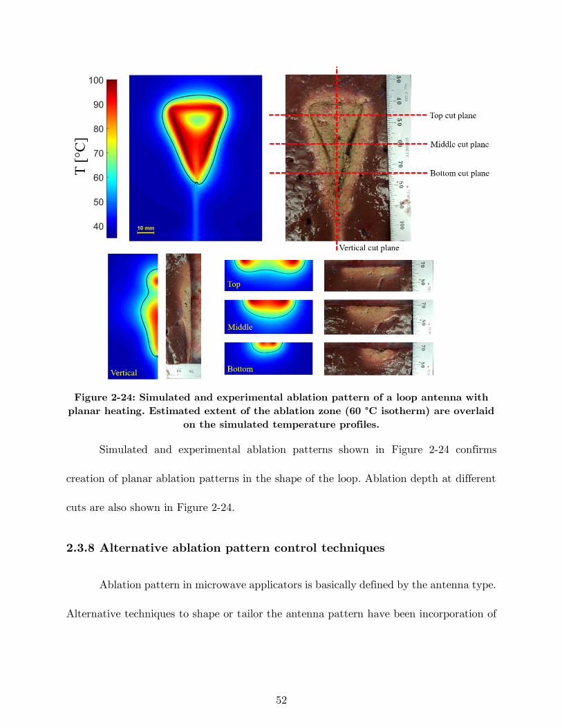
52
Figure 2-24: Simulated and experimental ablation pattern of a loop antenna with
planar heating. Estimated extent of the ablation zone (60 °C isotherm) are overlaid
on the simulated temperature profiles.
Simulated and experimental ablation patterns shown in Figure 2-24 confirms
creation of planar ablation patterns in the shape of the loop. Ablation depth at different
cuts are also shown in Figure 2-24.
2.3.8 Alternative ablation pattern control techniques
Ablation pattern in microwave applicators is basically defined by the antenna type.
Alternative techniques to shape or tailor the antenna pattern have been incorporation of
53
cooling, use of balloon, shifting to higher frequencies, and employing multiple devices in
an array configuration.
Use of a balloon is an effective technique in intracavitary applications such as
Barrett’s esophagus, renal denervation, benign prostate hyperplasia (BPH) and cardiac
ablation [96], [108]–[110]. While the microwave antenna is held in the center of the balloon,
the balloon is inflated and filled with a coupling material such as saline or gel. These
materials provide more efficient coupling of power from the antenna to the tissue
compared to air since their electrical properties are similar to body tissues. In Qian et al.
[109], deep circumferential heating is reported while sparing transmural arterial wall in
renal denervation application.
Microwave ablation has shown that it is capable of creating larger ablation zones
compared to RF ablation. However, a single microwave applicator with optimal spherical
ablation zone may not be large enough to cover a large tumor (3 cm in diameter) plus a
healthy margin [111]. Heat sink effect of local blood flow is the main reason of this
limitation that can increase the chance of incomplete ablation and risk of tumor
recurrence. Thus, the use of multiple applicators has been proposed to achieve larger
ablation volume. SAR pattern of arrays of four antennas in square configuration has been
investigated for different antenna types in Ryan et al. [71]. Helical antenna in square and
crescent array form has been investigated in Sherar et al. [112] for prostate cancer thermal
therapy. Feasibility of using triple microwave antennas simultaneously in the treatment
54
of liver tumors intraoperatively has been shown in [113]. Array of multiple antennas may
not create a spherical ablation zone but the final ablation pattern can adequately cover
the tumor by precise placement of the antenna elements.
2.4 Summary
There has been considerable interest in development of microwave ablation
technology for a range of clinical indications. A critical component of microwave ablation
systems is the applicator, which includes an antenna for coupling applied microwave power
from a generator to the targeted tissue. Here, we have reviewed microwave antennas
designed for site-specific thermal ablation of tissue. The use of active cooling strategies
for minimizing unintended heating along the feeding transmission line, and antenna
chokes/sleeves and cooling for adjusting the length of ablation zones were discussed.
Ongoing developments incorporating sensors for assessing treatment progress may yield
improved control of microwave thermal ablation zones.
55
3 Design of a Microwave Global Endometrial
Ablation Device2
3.1 Introduction
Menorrhagia, a condition when menstrual periods have abnormally heavy or prolonged
bleeding, significantly affects quality of life, and affects ~20% of women of reproductive
age [114]. Surgical interventions have been the standard treatment when medical therapy
fails to mitigate the symptoms. Surgical options include hysterectomy or resectoscopic
techniques such as transcervical resection of the endometrium (TCRE), roller-ball, and
endometrial laser ablation [115]. The main goal of endometrial ablation is to stop or reduce
the heavy menstrual bleeding by thermal coagulation of the endometrium (i.e., the inner
lining of the uterus). In a thermal ablation procedure, an energy delivery applicator is
2 This chapter has been published as: H. Fallahi and P. Prakash, “Design of a Microwave Global Endometrial
Ablation Device,” IEEE J. Electromagn. RF Microw. Med. Biol., 2019. (DOI: 10.1109/JERM.2019.2893280)
© 2020 IEEE. Personal use of this material is permitted. Permission from IEEE must be obtained for all
other uses, in any current or future media, including reprinting/republishing this material for advertising
or promotional purposes, creating new collective works, for resale or redistribution to servers or lists, or
reuse of any copyrighted component of this work in other works.
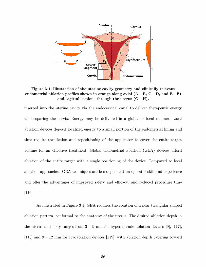
56
Figure 3-1: Illustration of the uterine cavity geometry and clinically relevant
endometrial ablation profiles shown in orange along axial (A—B, C—D, and E—F)
and sagittal sections through the uterus (G—H).
inserted into the uterine cavity via the endocervical canal to deliver therapeutic energy
while sparing the cervix. Energy may be delivered in a global or local manner. Local
ablation devices deposit localized energy to a small portion of the endometrial lining and
thus require translation and repositioning of the applicator to cover the entire target
volume for an effective treatment. Global endometrial ablation (GEA) devices afford
ablation of the entire target with a single positioning of the device. Compared to local
ablation approaches, GEA techniques are less dependent on operator skill and experience
and offer the advantages of improved safety and efficacy, and reduced procedure time
[116].
As illustrated in Figure 3-1, GEA requires the creation of a near triangular shaped
ablation pattern, conformal to the anatomy of the uterus. The desired ablation depth in
the uterus mid-body ranges from 3 – 9 mm for hyperthermic ablation devices [9], [117],
[118] and 9 – 12 mm for cryoablation devices [119], with ablation depth tapering toward
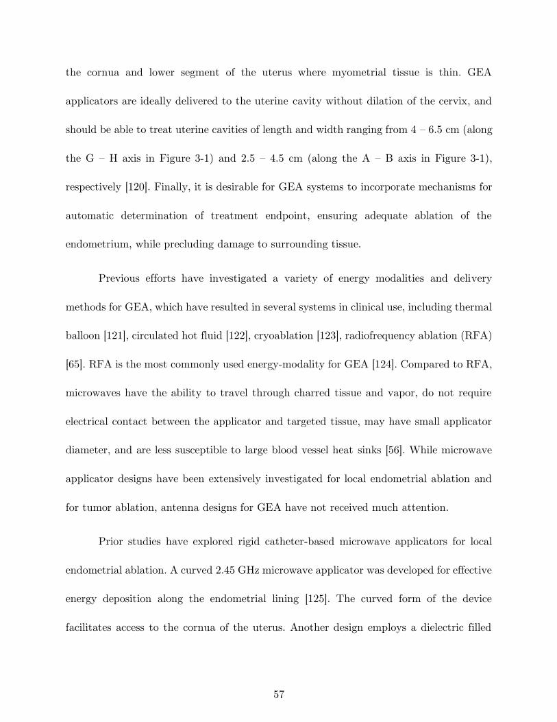
57
the cornua and lower segment of the uterus where myometrial tissue is thin. GEA
applicators are ideally delivered to the uterine cavity without dilation of the cervix, and
should be able to treat uterine cavities of length and width ranging from 4 – 6.5 cm (along
the G – H axis in Figure 3-1) and 2.5 – 4.5 cm (along the A – B axis in Figure 3-1),
respectively [120]. Finally, it is desirable for GEA systems to incorporate mechanisms for
automatic determination of treatment endpoint, ensuring adequate ablation of the
endometrium, while precluding damage to surrounding tissue.
Previous efforts have investigated a variety of energy modalities and delivery
methods for GEA, which have resulted in several systems in clinical use, including thermal
balloon [121], circulated hot fluid [122], cryoablation [123], radiofrequency ablation (RFA)
[65]. RFA is the most commonly used energy-modality for GEA [124]. Compared to RFA,
microwaves have the ability to travel through charred tissue and vapor, do not require
electrical contact between the applicator and targeted tissue, may have small applicator
diameter, and are less susceptible to large blood vessel heat sinks [56]. While microwave
applicator designs have been extensively investigated for local endometrial ablation and
for tumor ablation, antenna designs for GEA have not received much attention.
Prior studies have explored rigid catheter-based microwave applicators for local
endometrial ablation. A curved 2.45 GHz microwave applicator was developed for effective
energy deposition along the endometrial lining [125]. The curved form of the device
facilitates access to the cornua of the uterus. Another design employs a dielectric filled
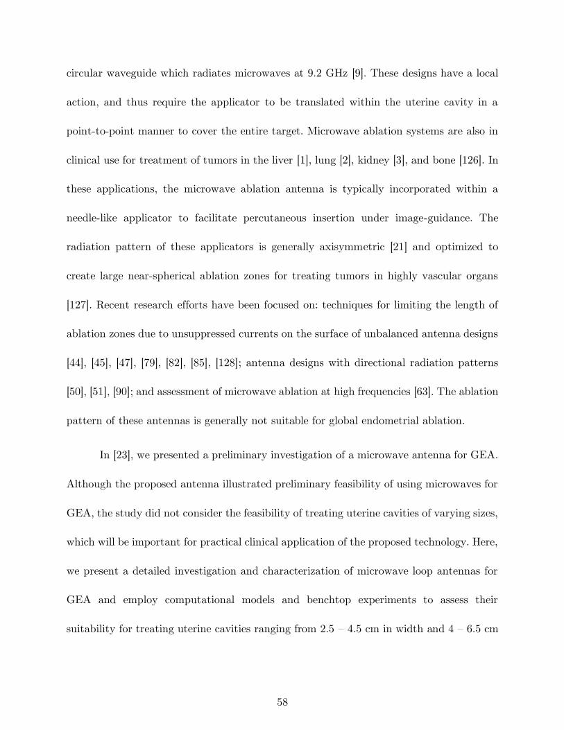
58
circular waveguide which radiates microwaves at 9.2 GHz [9]. These designs have a local
action, and thus require the applicator to be translated within the uterine cavity in a
point-to-point manner to cover the entire target. Microwave ablation systems are also in
clinical use for treatment of tumors in the liver [1], lung [2], kidney [3], and bone [126]. In
these applications, the microwave ablation antenna is typically incorporated within a
needle-like applicator to facilitate percutaneous insertion under image-guidance. The
radiation pattern of these applicators is generally axisymmetric [21] and optimized to
create large near-spherical ablation zones for treating tumors in highly vascular organs
[127]. Recent research efforts have been focused on: techniques for limiting the length of
ablation zones due to unsuppressed currents on the surface of unbalanced antenna designs
[44], [45], [47], [79], [82], [85], [128]; antenna designs with directional radiation patterns
[50], [51], [90]; and assessment of microwave ablation at high frequencies [63]. The ablation
pattern of these antennas is generally not suitable for global endometrial ablation.
In [23], we presented a preliminary investigation of a microwave antenna for GEA.
Although the proposed antenna illustrated preliminary feasibility of using microwaves for
GEA, the study did not consider the feasibility of treating uterine cavities of varying sizes,
which will be important for practical clinical application of the proposed technology. Here,
we present a detailed investigation and characterization of microwave loop antennas for
GEA and employ computational models and benchtop experiments to assess their
suitability for treating uterine cavities ranging from 2.5 – 4.5 cm in width and 4 – 6.5 cm
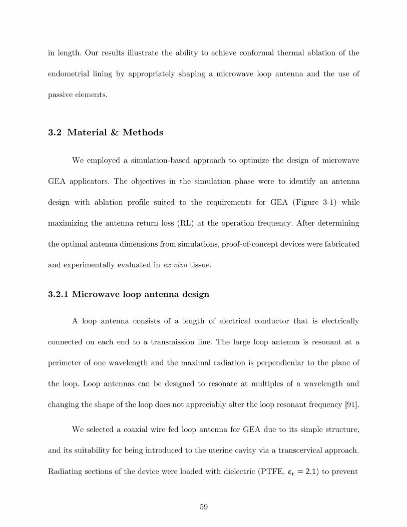
59
in length. Our results illustrate the ability to achieve conformal thermal ablation of the
endometrial lining by appropriately shaping a microwave loop antenna and the use of
passive elements.
3.2 Material & Methods
We employed a simulation-based approach to optimize the design of microwave
GEA applicators. The objectives in the simulation phase were to identify an antenna
design with ablation profile suited to the requirements for GEA (Figure 3-1) while
maximizing the antenna return loss (RL) at the operation frequency. After determining
the optimal antenna dimensions from simulations, proof-of-concept devices were fabricated
and experimentally evaluated in ex vivo tissue.
3.2.1 Microwave loop antenna design
A loop antenna consists of a length of electrical conductor that is electrically
connected on each end to a transmission line. The large loop antenna is resonant at a
perimeter of one wavelength and the maximal radiation is perpendicular to the plane of
the loop. Loop antennas can be designed to resonate at multiples of a wavelength and
changing the shape of the loop does not appreciably alter the loop resonant frequency [91].
We selected a coaxial wire fed loop antenna for GEA due to its simple structure,
and its suitability for being introduced to the uterine cavity via a transcervical approach.
Radiating sections of the device were loaded with dielectric (PTFE, 𝜖𝑟 = 2.1) to prevent
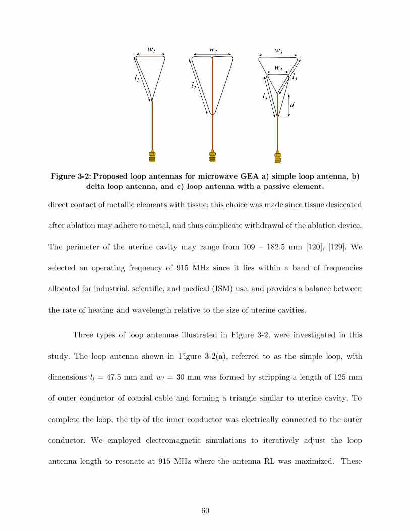
60
Figure 3-2: Proposed loop antennas for microwave GEA a) simple loop antenna, b)
delta loop antenna, and c) loop antenna with a passive element.
direct contact of metallic elements with tissue; this choice was made since tissue desiccated
after ablation may adhere to metal, and thus complicate withdrawal of the ablation device.
The perimeter of the uterine cavity may range from 109 – 182.5 mm [120], [129]. We
selected an operating frequency of 915 MHz since it lies within a band of frequencies
allocated for industrial, scientific, and medical (ISM) use, and provides a balance between
the rate of heating and wavelength relative to the size of uterine cavities.
Three types of loop antennas illustrated in Figure 3-2, were investigated in this
study. The loop antenna shown in Figure 3-2(a), referred to as the simple loop, with
dimensions l1 = 47.5 mm and w1 = 30 mm was formed by stripping a length of 125 mm
of outer conductor of coaxial cable and forming a triangle similar to uterine cavity. To
complete the loop, the tip of the inner conductor was electrically connected to the outer
conductor. We employed electromagnetic simulations to iteratively adjust the loop
antenna length to resonate at 915 MHz where the antenna RL was maximized. These
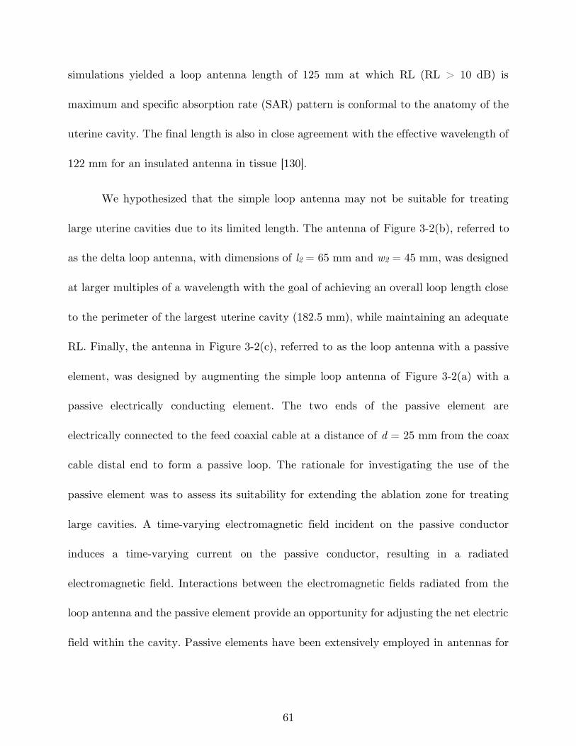
61
simulations yielded a loop antenna length of 125 mm at which RL (RL > 10 dB) is
maximum and specific absorption rate (SAR) pattern is conformal to the anatomy of the
uterine cavity. The final length is also in close agreement with the effective wavelength of
122 mm for an insulated antenna in tissue [130].
We hypothesized that the simple loop antenna may not be suitable for treating
large uterine cavities due to its limited length. The antenna of Figure 3-2(b), referred to
as the delta loop antenna, with dimensions of l2 = 65 mm and w2 = 45 mm, was designed
at larger multiples of a wavelength with the goal of achieving an overall loop length close
to the perimeter of the largest uterine cavity (182.5 mm), while maintaining an adequate
RL. Finally, the antenna in Figure 3-2(c), referred to as the loop antenna with a passive
element, was designed by augmenting the simple loop antenna of Figure 3-2(a) with a
passive electrically conducting element. The two ends of the passive element are
electrically connected to the feed coaxial cable at a distance of d = 25 mm from the coax
cable distal end to form a passive loop. The rationale for investigating the use of the
passive element was to assess its suitability for extending the ablation zone for treating
large cavities. A time-varying electromagnetic field incident on the passive conductor
induces a time-varying current on the passive conductor, resulting in a radiated
electromagnetic field. Interactions between the electromagnetic fields radiated from the
loop antenna and the passive element provide an opportunity for adjusting the net electric
field within the cavity. Passive elements have been extensively employed in antennas for

62
gain, directivity, and bandwidth improvement [91], [131]–[133] for applications in
communications. We hypothesized that the passive element would redistribute
electromagnetic power within the uterine cavity, and thus provide a means for extending
the ablation profile. The length and shape of the active loop (l3 = 40 mm and w3 = 45
mm) and passive element (l4 = 42 mm and w4 = 25 mm) were selected to conform to the
lower body of the uterine cavity.
3.2.2 Simulation-based antenna optimization and evaluation
We employed a coupled 3D electromagnetic-heat transfer finite element method
(FEM) model, implemented with COMSOL Multiphysics, v5.3, for design optimization of
the loop antenna for GEA. The device was modeled as being centrally positioned within
a cylindrical block of tissue as shown in Figure 3-3(a).
The model initially solves the time-harmonic Helmholtz wave equation to
determine the electric field profile in tissue:
∇2𝐄− 𝑘02 (𝜖𝑟 −
𝑗𝜎
𝜔𝜖0)𝐄 = 0 (1)
where 𝐄 [V/m] is the electric field, 𝑘0 [m-1] is the free space wavenumber, 𝜖𝑟 is the relative
real permittivity, 𝜎 [S/m] is the effective electrical conductivity, 𝜔 [rads/s] is the angular
frequency, and 𝜖0 [F/m] is the permittivity of free space. In (1), 𝜖𝑟 and 𝜎 of tissue are
both temperature-dependent. In the second step, the solver uses the wave equation
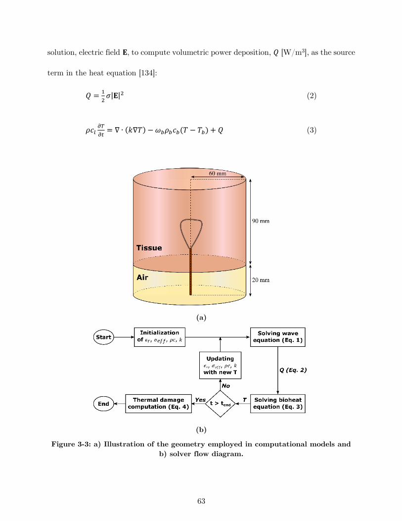
63
solution, electric field 𝐄, to compute volumetric power deposition, 𝑄 [W/m3], as the source
term in the heat equation [134]:
𝑄 =1
2𝜎|𝐄|2 (2)
𝜌𝑐𝑙𝜕𝑇
𝜕𝑡= ∇ ∙ (𝑘∇𝑇) − 𝜔𝑏𝜌𝑏𝑐𝑏(𝑇 − 𝑇𝑏) + 𝑄 (3)
(a)
(b)
Figure 3-3: a) Illustration of the geometry employed in computational models and
b) solver flow diagram.
64
where 𝑇 [K] is temperature of the tissue, 𝜌 is the density of tissue (1050 kg/m3), 𝑐𝑙
[J/(kg·K)] is the heat capacity of tissue at constant pressure, 𝑘 [W/(m·K)] is the thermal
conductivity of liver, 𝜔𝑏 is rate of blood perfusion (0.0028 mb3/(mt
3·s)[135]), 𝜌𝑏 is blood
density (1080 kg/m3 [135]), 𝑐𝑏 is blood specific heat capacity (3500 J/(kg·K) [135]) and 𝑇𝑏
is the physiological blood temperature (i.e. 37 °C). The heat capacity 𝑐𝑙 and thermal
conductivity 𝑘 are other temperature-dependent tissue parameters. Solution of the heat
equation, 𝑇, is used to update the four temperature dependent parameters of the tissue
using the functions summarized in Table 3-1.
Table 3-1: Tissue physical properties used in the simulations.
Parameter Unit Value @
37 °C Temperature-dependent formula
Relative real permittivity, 𝜖𝑟
[136] — 46 𝜖𝑟(𝑇) = 46 (1 −
1
1 + exp [0.0764(82.271 − 𝑇)]) + 1
Effective conductivity, 𝜎𝑒𝑓𝑓
[136] S/m 0.86 𝜎(𝑇) = 0.86(1 −
1
1 + exp [0.0697(85.375 − 𝑇)])
Volumetric heat capacity, 𝜌𝑐
[137] J/(m3·K) 4,000,000 𝜌𝑐(𝑇) =
{
𝜌𝑐0 𝑓𝑜𝑟 𝑇 < (100 −
Δ𝑇
2)
𝜌𝑐0 + 𝜌𝑐𝑣2
+𝜌𝑤 ∙ 𝐿 ∙ 𝐶
Δ𝑇 𝑓𝑜𝑟 (100 −
Δ𝑇
2) < 𝑇 < (100 +
Δ𝑇
2)
𝜌𝑐𝑣 𝑓𝑜𝑟 𝑇 > (100 +Δ𝑇
2)
Thermal conductivity, 𝑘 [137] W/(m·K) 0.5 𝑘(𝑇) = {𝑘0 + Δ𝑘[𝑇 − 𝑇0] 𝑇 ≤ 373 𝐾
𝑘0 + Δ𝑘[373 − 𝑇0] 𝑇 > 373 𝐾
Uterus Blood perfusion,
𝜔𝑏𝜌𝑏𝑐𝑏 [135] W/(m3·K) 10584
𝑤(𝑇) = {𝜔𝑏𝜌𝑏𝑐𝑏 0 < 𝑇 < 325.15 𝐾
0 325.15 𝐾 < 𝑇 < 1000 𝐾
Since no measured temperature-dependent data is available in the literature for
permittivity and conductivity at 915 MHz at ablative temperatures (i.e. 50 – 120 °C), we
approximated temperature-dependent changes at 915 MHz using the sigmoid temperature
dependence of dielectric properties reported at 2.45 GHz, while scaled appropriately for
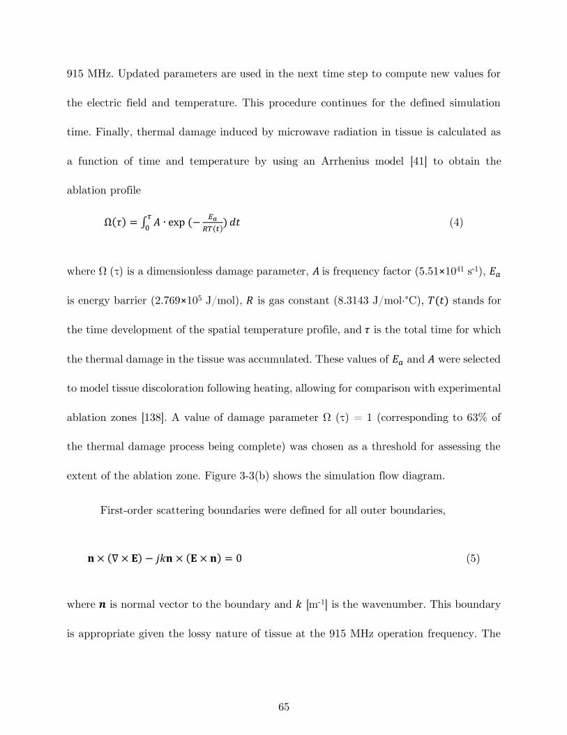
65
915 MHz. Updated parameters are used in the next time step to compute new values for
the electric field and temperature. This procedure continues for the defined simulation
time. Finally, thermal damage induced by microwave radiation in tissue is calculated as
a function of time and temperature by using an Arrhenius model [41] to obtain the
ablation profile
Ω(𝜏) = ∫ 𝐴 ∙ exp (−𝐸𝑎
𝑅𝑇(𝑡))
𝜏
0𝑑𝑡 (4)
where Ω (τ) is a dimensionless damage parameter, 𝐴 is frequency factor (5.51×1041 s˗1), 𝐸𝑎
is energy barrier (2.769×10⁵ J/mol), 𝑅 is gas constant (8.3143 J/mol·°C), 𝑇(𝑡) stands for
the time development of the spatial temperature profile, and 𝜏 is the total time for which
the thermal damage in the tissue was accumulated. These values of 𝐸𝑎 and 𝐴 were selected
to model tissue discoloration following heating, allowing for comparison with experimental
ablation zones [138]. A value of damage parameter Ω (τ) = 1 (corresponding to 63% of
the thermal damage process being complete) was chosen as a threshold for assessing the
extent of the ablation zone. Figure 3-3(b) shows the simulation flow diagram.
First-order scattering boundaries were defined for all outer boundaries,
𝐧 × (∇ × 𝐄) − 𝑗𝑘𝐧 × (𝐄 × 𝐧) = 0 (5)
where 𝒏 is normal vector to the boundary and 𝑘 [m-1] is the wavenumber. This boundary
is appropriate given the lossy nature of tissue at the 915 MHz operation frequency. The
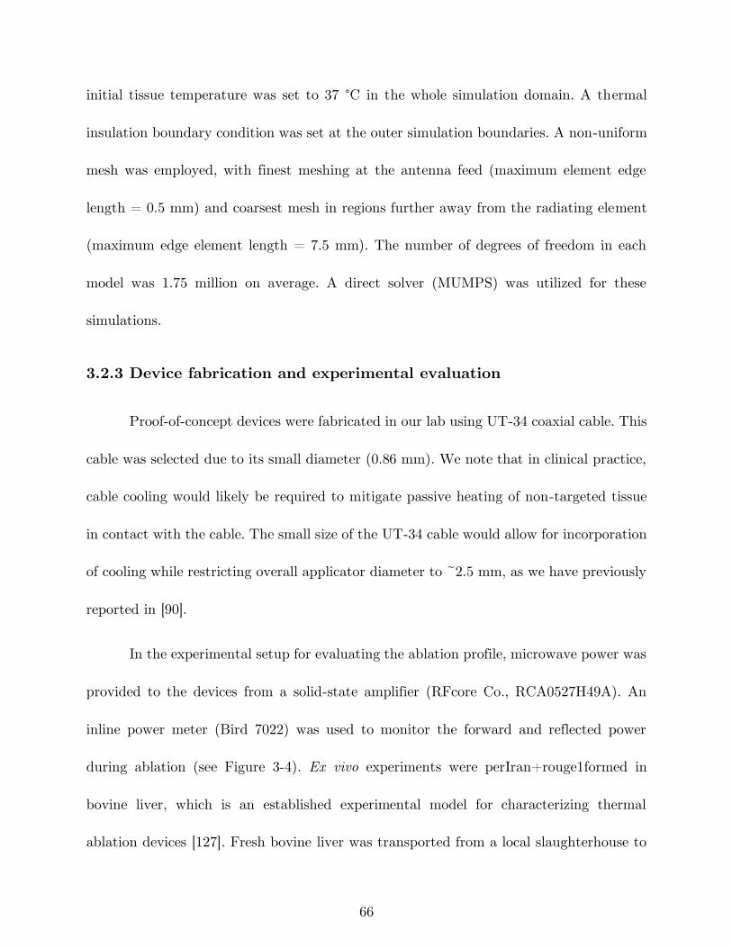
66
initial tissue temperature was set to 37 °C in the whole simulation domain. A thermal
insulation boundary condition was set at the outer simulation boundaries. A non-uniform
mesh was employed, with finest meshing at the antenna feed (maximum element edge
length = 0.5 mm) and coarsest mesh in regions further away from the radiating element
(maximum edge element length = 7.5 mm). The number of degrees of freedom in each
model was 1.75 million on average. A direct solver (MUMPS) was utilized for these
simulations.
3.2.3 Device fabrication and experimental evaluation
Proof-of-concept devices were fabricated in our lab using UT-34 coaxial cable. This
cable was selected due to its small diameter (0.86 mm). We note that in clinical practice,
cable cooling would likely be required to mitigate passive heating of non-targeted tissue
in contact with the cable. The small size of the UT-34 cable would allow for incorporation
of cooling while restricting overall applicator diameter to ~2.5 mm, as we have previously
reported in [90].
In the experimental setup for evaluating the ablation profile, microwave power was
provided to the devices from a solid-state amplifier (RFcore Co., RCA0527H49A). An
inline power meter (Bird 7022) was used to monitor the forward and reflected power
during ablation (see Figure 3-4). Ex vivo experiments were perIran+rouge1formed in
bovine liver, which is an established experimental model for characterizing thermal
ablation devices [127]. Fresh bovine liver was transported from a local slaughterhouse to
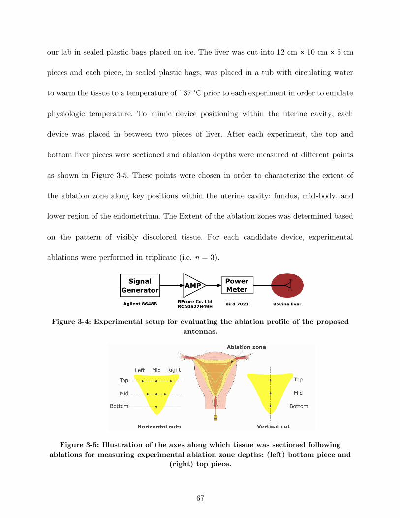
67
our lab in sealed plastic bags placed on ice. The liver was cut into 12 cm × 10 cm × 5 cm
pieces and each piece, in sealed plastic bags, was placed in a tub with circulating water
to warm the tissue to a temperature of ~37 °C prior to each experiment in order to emulate
physiologic temperature. To mimic device positioning within the uterine cavity, each
device was placed in between two pieces of liver. After each experiment, the top and
bottom liver pieces were sectioned and ablation depths were measured at different points
as shown in Figure 3-5. These points were chosen in order to characterize the extent of
the ablation zone along key positions within the uterine cavity: fundus, mid-body, and
lower region of the endometrium. The Extent of the ablation zones was determined based
on the pattern of visibly discolored tissue. For each candidate device, experimental
ablations were performed in triplicate (i.e. n = 3).
Figure 3-4: Experimental setup for evaluating the ablation profile of the proposed
antennas.
Figure 3-5: Illustration of the axes along which tissue was sectioned following
ablations for measuring experimental ablation zone depths: (left) bottom piece and
(right) top piece.
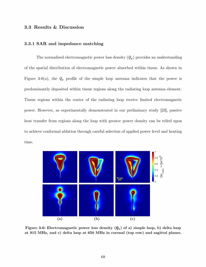
68
3.3 Results & Discussion
3.3.1 SAR and impedance matching
The normalized electromagnetic power loss density (𝑄𝑒) provides an understanding
of the spatial distribution of electromagnetic power absorbed within tissue. As shown in
Figure 3-6(a), the 𝑄𝑒 profile of the simple loop antenna indicates that the power is
predominantly deposited within tissue regions along the radiating loop antenna element.
Tissue regions within the center of the radiating loop receive limited electromagnetic
power. However, as experimentally demonstrated in our preliminary study [23], passive
heat transfer from regions along the loop with greater power density can be relied upon
to achieve conformal ablation through careful selection of applied power level and heating
time.
(a) (b) (c)
Figure 3-6: Electromagnetic power loss density (𝑸𝒆) of a) simple loop, b) delta loop
at 915 MHz, and c) delta loop at 650 MHz in coronal (top row) and sagittal planes.
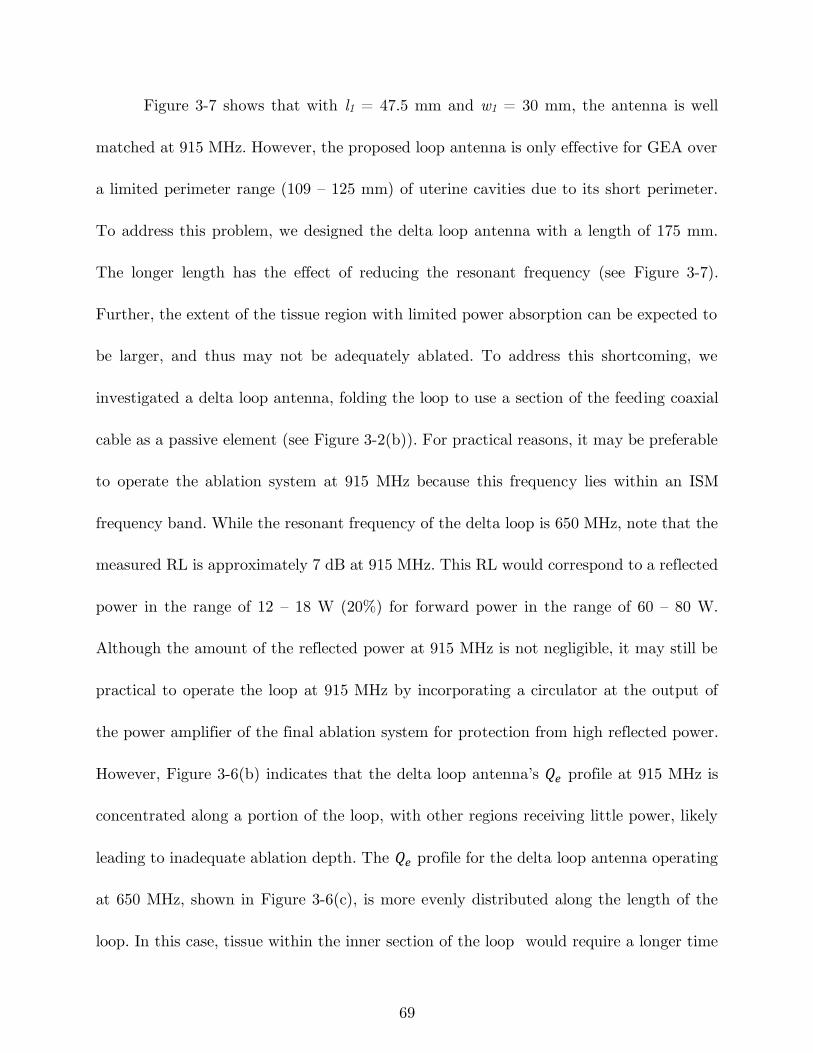
69
Figure 3-7 shows that with l1 = 47.5 mm and w1 = 30 mm, the antenna is well
matched at 915 MHz. However, the proposed loop antenna is only effective for GEA over
a limited perimeter range (109 – 125 mm) of uterine cavities due to its short perimeter.
To address this problem, we designed the delta loop antenna with a length of 175 mm.
The longer length has the effect of reducing the resonant frequency (see Figure 3-7).
Further, the extent of the tissue region with limited power absorption can be expected to
be larger, and thus may not be adequately ablated. To address this shortcoming, we
investigated a delta loop antenna, folding the loop to use a section of the feeding coaxial
cable as a passive element (see Figure 3-2(b)). For practical reasons, it may be preferable
to operate the ablation system at 915 MHz because this frequency lies within an ISM
frequency band. While the resonant frequency of the delta loop is 650 MHz, note that the
measured RL is approximately 7 dB at 915 MHz. This RL would correspond to a reflected
power in the range of 12 – 18 W (20%) for forward power in the range of 60 – 80 W.
Although the amount of the reflected power at 915 MHz is not negligible, it may still be
practical to operate the loop at 915 MHz by incorporating a circulator at the output of
the power amplifier of the final ablation system for protection from high reflected power.
However, Figure 3-6(b) indicates that the delta loop antenna’s 𝑄𝑒 profile at 915 MHz is
concentrated along a portion of the loop, with other regions receiving little power, likely
leading to inadequate ablation depth. The 𝑄𝑒 profile for the delta loop antenna operating
at 650 MHz, shown in Figure 3-6(c), is more evenly distributed along the length of the
loop. In this case, tissue within the inner section of the loop would require a longer time
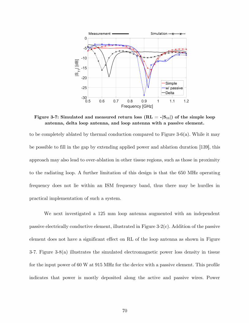
70
Figure 3-7: Simulated and measured return loss (RL = -|S11|) of the simple loop
antenna, delta loop antenna, and loop antenna with a passive element.
to be completely ablated by thermal conduction compared to Figure 3-6(a). While it may
be possible to fill in the gap by extending applied power and ablation duration [139], this
approach may also lead to over-ablation in other tissue regions, such as those in proximity
to the radiating loop. A further limitation of this design is that the 650 MHz operating
frequency does not lie within an ISM frequency band, thus there may be hurdles in
practical implementation of such a system.
We next investigated a 125 mm loop antenna augmented with an independent
passive electrically conductive element, illustrated in Figure 3-2(c). Addition of the passive
element does not have a significant effect on RL of the loop antenna as shown in Figure
3-7. Figure 3-8(a) illustrates the simulated electromagnetic power loss density in tissue
for the input power of 60 W at 915 MHz for the device with a passive element. This profile
indicates that power is mostly deposited along the active and passive wires. Power
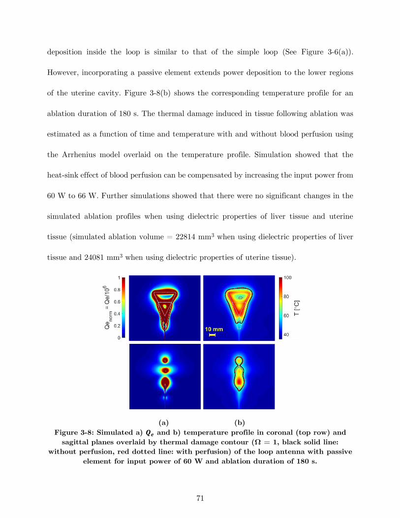
71
deposition inside the loop is similar to that of the simple loop (See Figure 3-6(a)).
However, incorporating a passive element extends power deposition to the lower regions
of the uterine cavity. Figure 3-8(b) shows the corresponding temperature profile for an
ablation duration of 180 s. The thermal damage induced in tissue following ablation was
estimated as a function of time and temperature with and without blood perfusion using
the Arrhenius model overlaid on the temperature profile. Simulation showed that the
heat-sink effect of blood perfusion can be compensated by increasing the input power from
60 W to 66 W. Further simulations showed that there were no significant changes in the
simulated ablation profiles when using dielectric properties of liver tissue and uterine
tissue (simulated ablation volume = 22814 mm3 when using dielectric properties of liver
tissue and 24081 mm3 when using dielectric properties of uterine tissue).
(a) (b)
Figure 3-8: Simulated a) 𝑸𝒆 and b) temperature profile in coronal (top row) and
sagittal planes overlaid by thermal damage contour (Ω = 1, black solid line:
without perfusion, red dotted line: with perfusion) of the loop antenna with passive
element for input power of 60 W and ablation duration of 180 s.
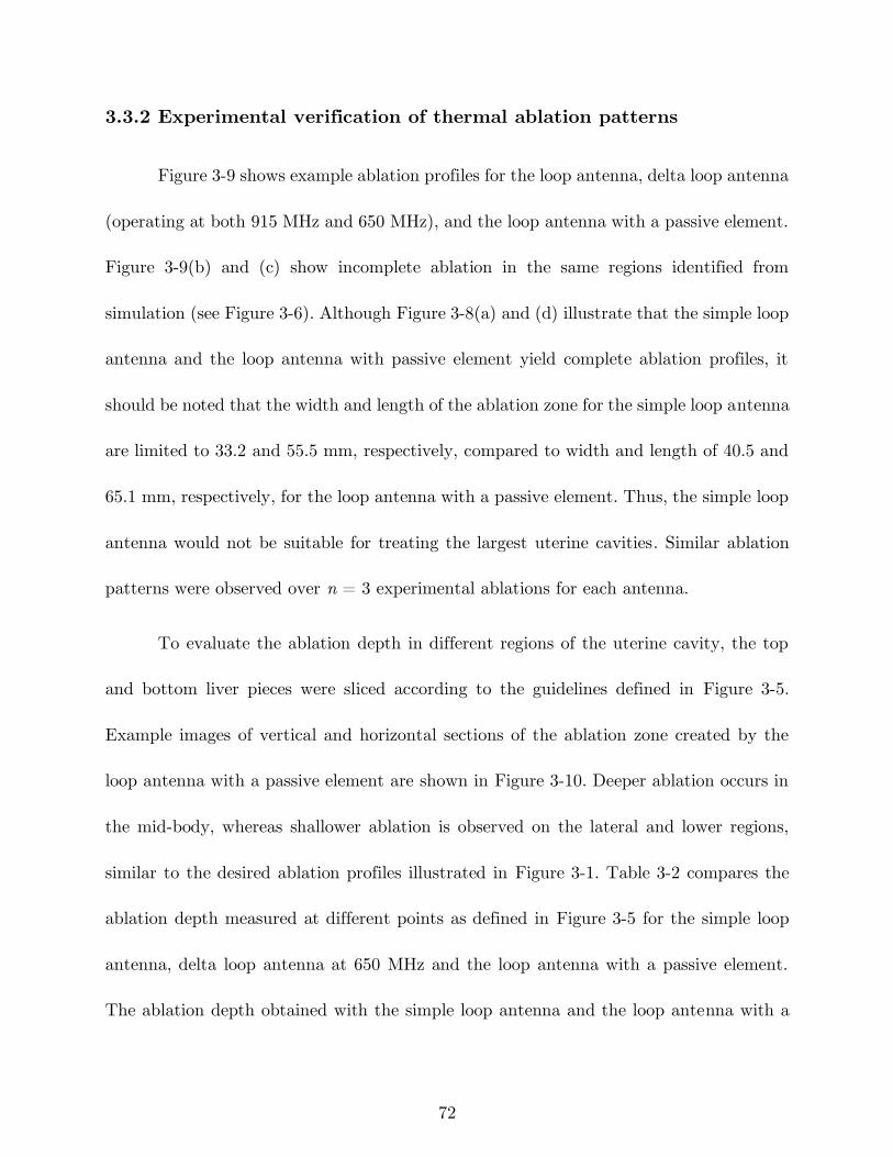
72
3.3.2 Experimental verification of thermal ablation patterns
Figure 3-9 shows example ablation profiles for the loop antenna, delta loop antenna
(operating at both 915 MHz and 650 MHz), and the loop antenna with a passive element.
Figure 3-9(b) and (c) show incomplete ablation in the same regions identified from
simulation (see Figure 3-6). Although Figure 3-8(a) and (d) illustrate that the simple loop
antenna and the loop antenna with passive element yield complete ablation profiles, it
should be noted that the width and length of the ablation zone for the simple loop antenna
are limited to 33.2 and 55.5 mm, respectively, compared to width and length of 40.5 and
65.1 mm, respectively, for the loop antenna with a passive element. Thus, the simple loop
antenna would not be suitable for treating the largest uterine cavities. Similar ablation
patterns were observed over n = 3 experimental ablations for each antenna.
To evaluate the ablation depth in different regions of the uterine cavity, the top
and bottom liver pieces were sliced according to the guidelines defined in Figure 3-5.
Example images of vertical and horizontal sections of the ablation zone created by the
loop antenna with a passive element are shown in Figure 3-10. Deeper ablation occurs in
the mid-body, whereas shallower ablation is observed on the lateral and lower regions,
similar to the desired ablation profiles illustrated in Figure 3-1. Table 3-2 compares the
ablation depth measured at different points as defined in Figure 3-5 for the simple loop
antenna, delta loop antenna at 650 MHz and the loop antenna with a passive element.
The ablation depth obtained with the simple loop antenna and the loop antenna with a
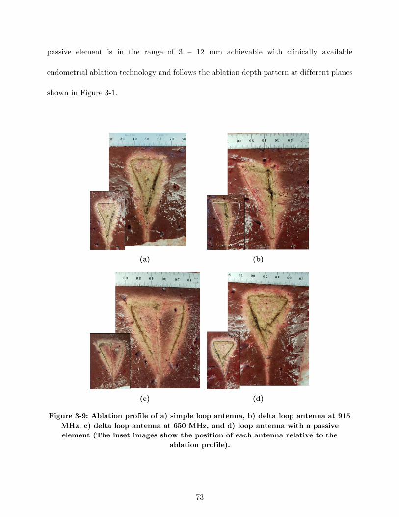
73
passive element is in the range of 3 – 12 mm achievable with clinically available
endometrial ablation technology and follows the ablation depth pattern at different planes
shown in Figure 3-1.
(a) (b)
(c) (d)
Figure 3-9: Ablation profile of a) simple loop antenna, b) delta loop antenna at 915
MHz, c) delta loop antenna at 650 MHz, and d) loop antenna with a passive
element (The inset images show the position of each antenna relative to the
ablation profile).
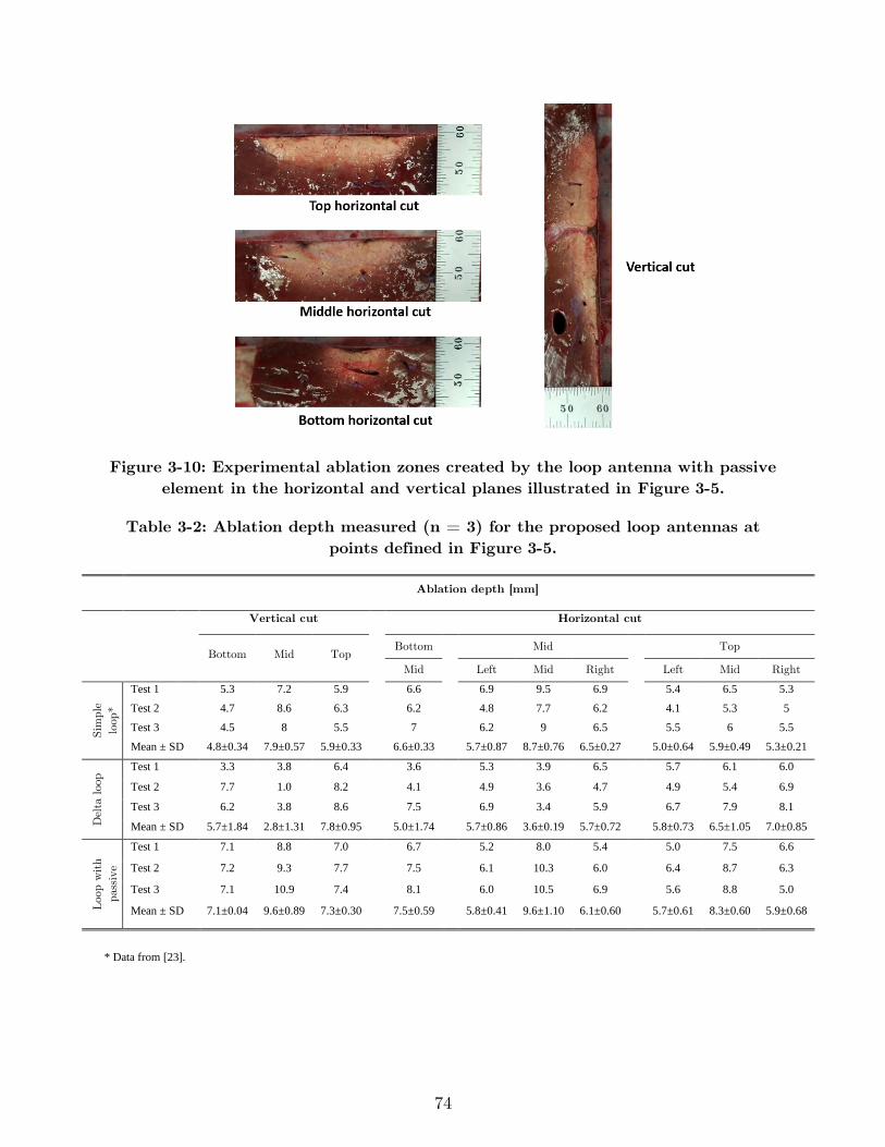
74
Figure 3-10: Experimental ablation zones created by the loop antenna with passive
element in the horizontal and vertical planes illustrated in Figure 3-5.
Table 3-2: Ablation depth measured (n = 3) for the proposed loop antennas at
points defined in Figure 3-5.
* Data from [23].
Ablation depth [mm]
Vertical cut Horizontal cut
Loop Bottom Mid Top
Bottom Mid Top
Mid Left Mid Right Left Mid Right
Sim
ple
loop
*
Test 1 5.3 7.2 5.9 6.6 6.9 9.5 6.9 5.4 6.5 5.3
Test 2 4.7 8.6 6.3 6.2 4.8 7.7 6.2 4.1 5.3 5
Test 3 4.5 8 5.5 7 6.2 9 6.5 5.5 6 5.5
Mean ± SD 4.8±0.34 7.9±0.57 5.9±0.33 6.6±0.33 5.7±0.87 8.7±0.76 6.5±0.27 5.0±0.64 5.9±0.49 5.3±0.21
Del
ta loo
p Test 1 3.3 3.8 6.4 3.6 5.3 3.9 6.5 5.7 6.1 6.0
Test 2 7.7 1.0 8.2 4.1 4.9 3.6 4.7 4.9 5.4 6.9
Test 3 6.2 3.8 8.6 7.5 6.9 3.4 5.9 6.7 7.9 8.1
Mean ± SD 5.7±1.84 2.8±1.31 7.8±0.95 5.0±1.74 5.7±0.86 3.6±0.19 5.7±0.72 5.8±0.73 6.5±1.05 7.0±0.85
Loo
p w
ith
pas
sive
Test 1 7.1 8.8 7.0 6.7 5.2 8.0 5.4 5.0 7.5 6.6
Test 2 7.2 9.3 7.7 7.5 6.1 10.3 6.0 6.4 8.7 6.3
Test 3 7.1 10.9 7.4 8.1 6.0 10.5 6.9 5.6 8.8 5.0
Mean ± SD 7.1±0.04 9.6±0.89 7.3±0.30 7.5±0.59 5.8±0.41 9.6±1.10 6.1±0.60 5.7±0.61 8.3±0.60 5.9±0.68
75
3.3.3 Radiating and passive loop profiles for ablating cavities of
varying size
Combination of the proposed radiating loop antenna with a passive element
provides a degree of freedom to shape the ablation zone for varying cavity sizes by
appropriately sizing, shaping, and positioning the passive element and radiating loop.
Figure 3-8 illustrates the suitability of using the loop antenna coupled with a passive
element for ablating large uterine cavities. In order to assess the versatility of the proposed
loop antenna coupled with a passive element for global ablation of cavities of small cavity
sizes, we investigated applicators with the geometries shown in Figure 3-11(a) and (b).
For a small cavity (perimeter = 109 mm), we investigated a loop antenna with
shape modified to fit within the cavity, and without a passive element (see Figure 3-11(a)).
For an intermediate-sized cavity (perimeter = 155 mm), we investigated a simple loop
antenna with a passive element shaped as in Figure 3-11(b). Simulated temperature
profiles for both applicators indicate conformal ablation over the corresponding uterine
cavity. These simulations suggest that the combination of the radiating loop antenna with
the passive element will enable adequate ablation of uterine targets of perimeter 109 –
182.5 mm. In [140], a passive loop element was employed to shape the electric field pattern
radiated by a monopole antenna. Compared to the approach in [140], the use of a passive
element with a loop antenna presented in this study offers the advantage of the loop
antenna’s return loss being minimally affected by the presence and positioning of the
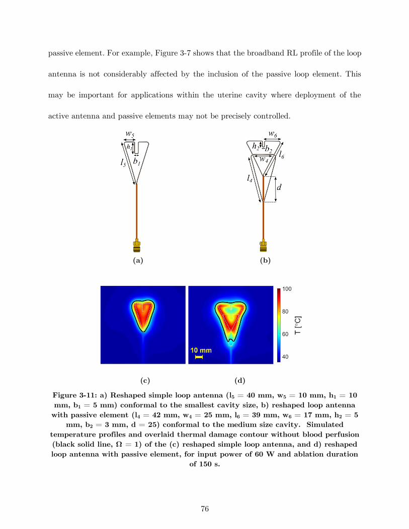
76
passive element. For example, Figure 3-7 shows that the broadband RL profile of the loop
antenna is not considerably affected by the inclusion of the passive loop element. This
may be important for applications within the uterine cavity where deployment of the
active antenna and passive elements may not be precisely controlled.
(a) (b)
(c) (d)
Figure 3-11: a) Reshaped simple loop antenna (l5 = 40 mm, w5 = 10 mm, h1 = 10
mm, b1 = 5 mm) conformal to the smallest cavity size, b) reshaped loop antenna
with passive element (l4 = 42 mm, w4 = 25 mm, l6 = 39 mm, w6 = 17 mm, h2 = 5
mm, b2 = 3 mm, d = 25) conformal to the medium size cavity. Simulated
temperature profiles and overlaid thermal damage contour without blood perfusion
(black solid line, Ω = 1) of the (c) reshaped simple loop antenna, and d) reshaped
loop antenna with passive element, for input power of 60 W and ablation duration
of 150 s.
77
A limitation of this study is that experiments considered ex vivo tissue and did not
account for the impact of blood perfusion. We note that heat sink due to blood flow may
be compensated by adjusting applied power levels and duration of ablation. The proposed
design is capable of creating shallow depth ablation zone in which the depth is tapered
and not uniform in the sagittal plane, as is desired for the endometrial ablation
application. However, for applications requiring uniform ablation depth, the shape of the
loop may need to be modified. Furthermore, clinical use of the proposed design in practice
will require a deployable device inserted to the uterine cavity in a retracted state with
minimal dilation of the cervix. In this study, we employed coaxial cables formed into the
desired loop shapes. Nitinol, a shape memory alloy that has been widely used in medical
devices [141], including RF ablation technology [142], may be suitable for implementing
deployable designs. Other studies have also demonstrated the suitability of using Nitinol
for creating deployable/configurable antennas [107]. Other approaches to realize a
deployable applicator include the use of compression spring properties. Further studies
investigating practical approaches for realizing deployable antenna designs are warranted.
This study illustrates the technical feasibility of performing microwave global
endometrial ablation, similar to other energy modalities such as thermal balloon,
circulated hot water and RF ablation. The microwave applicator’s overall diameter, which
includes components for circulating cooling water along the feeding coaxial line, is 2.5 mm
while the reported range for cervical dilation used for other endometrial techniques is 5-8
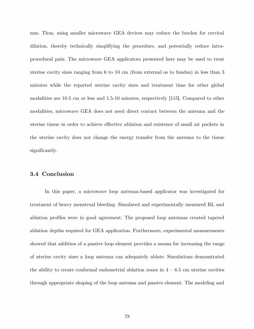
78
mm. Thus, using smaller microwave GEA devices may reduce the burden for cervical
dilation, thereby technically simplifying the procedure, and potentially reduce intra-
procedural pain. The microwave GEA applicators presented here may be used to treat
uterine cavity sizes ranging from 6 to 10 cm (from external os to fundus) in less than 3
minutes while the reported uterine cavity sizes and treatment time for other global
modalities are 10.5 cm or less and 1.5-10 minutes, respectively [115]. Compared to other
modalities, microwave GEA does not need direct contact between the antenna and the
uterine tissue in order to achieve effective ablation and existence of small air pockets in
the uterine cavity does not change the energy transfer from the antenna to the tissue
significantly.
3.4 Conclusion
In this paper, a microwave loop antenna-based applicator was investigated for
treatment of heavy menstrual bleeding. Simulated and experimentally measured RL and
ablation profiles were in good agreement. The proposed loop antennas created tapered
ablation depths required for GEA application. Furthermore, experimental measurements
showed that addition of a passive loop element provides a means for increasing the range
of uterine cavity sizes a loop antenna can adequately ablate. Simulations demonstrated
the ability to create conformal endometrial ablation zones in 4 – 6.5 cm uterine cavities
through appropriate shaping of the loop antenna and passive element. The modeling and

79
design procedures described in this paper can be utilized to design microwave ablation
antennas for targets with a wide planar profile but requiring limited ablation depth.
80
4 Monitoring Transient Evolution of Planar
Ablation Zones Using the Broadband
Antenna Reflection Coefficient
4.1 Introduction
The most common approach for characterization of MWA applicators is to
determine the ablation size as a function of input power and ablation duration in ex vivo
bovine liver tissue. The tissue sample is sectioned after the ablation and the ablation zone
dimensions are measured from the visible extent of discolored tissue. The measured
dimensions would be tabulated as part of regulatory submissions and in the applicator
guide manual for physicians’ reference. During a clinical procedure, the physician has to
choose the applied input power and ablation duration based on the anatomy of the patient
being treated. However, the ablation size charts provided by the applicator manufacturers
have some limitations. The target tissue being treated may have considerably different
biophysical properties when compared to bovine liver, may have heterogeneous texture
and blood perfusion is present in vivo. Consequently, selection of applied energy delivery
parameters that result in complete destruction of the target is challenging. Imaging
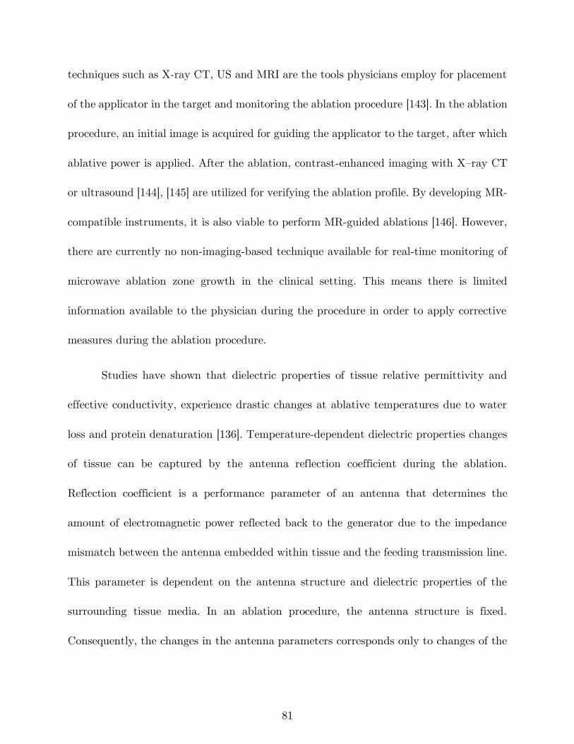
81
techniques such as X-ray CT, US and MRI are the tools physicians employ for placement
of the applicator in the target and monitoring the ablation procedure [143]. In the ablation
procedure, an initial image is acquired for guiding the applicator to the target, after which
ablative power is applied. After the ablation, contrast-enhanced imaging with X–ray CT
or ultrasound [144], [145] are utilized for verifying the ablation profile. By developing MR-
compatible instruments, it is also viable to perform MR-guided ablations [146]. However,
there are currently no non-imaging-based technique available for real-time monitoring of
microwave ablation zone growth in the clinical setting. This means there is limited
information available to the physician during the procedure in order to apply corrective
measures during the ablation procedure.
Studies have shown that dielectric properties of tissue relative permittivity and
effective conductivity, experience drastic changes at ablative temperatures due to water
loss and protein denaturation [136]. Temperature-dependent dielectric properties changes
of tissue can be captured by the antenna reflection coefficient during the ablation.
Reflection coefficient is a performance parameter of an antenna that determines the
amount of electromagnetic power reflected back to the generator due to the impedance
mismatch between the antenna embedded within tissue and the feeding transmission line.
This parameter is dependent on the antenna structure and dielectric properties of the
surrounding tissue media. In an ablation procedure, the antenna structure is fixed.
Consequently, the changes in the antenna parameters corresponds only to changes of the
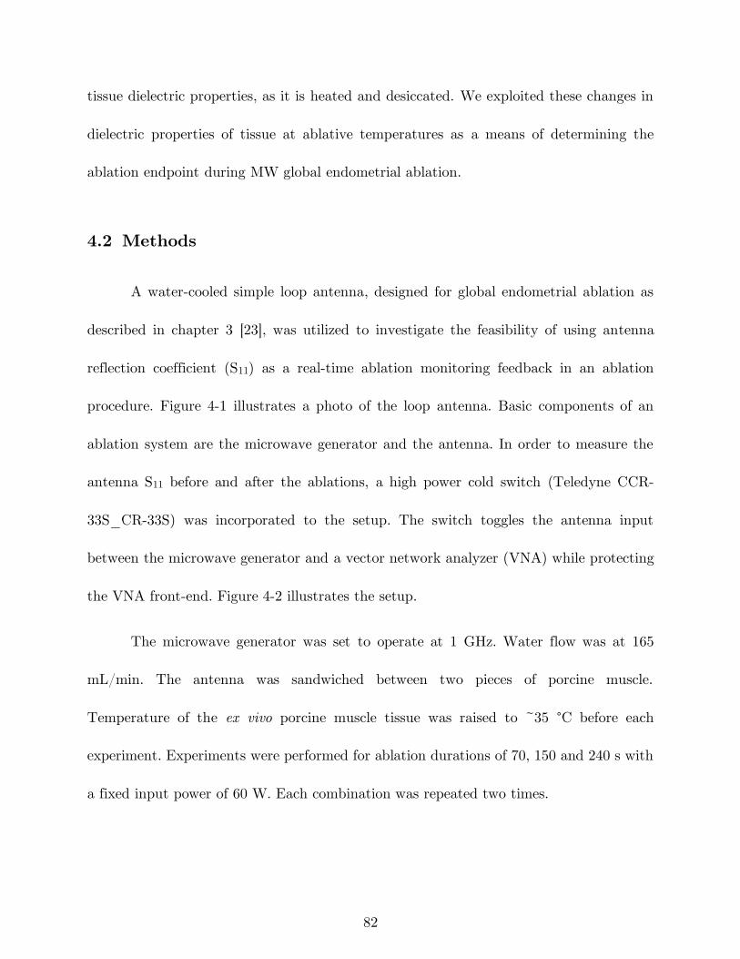
82
tissue dielectric properties, as it is heated and desiccated. We exploited these changes in
dielectric properties of tissue at ablative temperatures as a means of determining the
ablation endpoint during MW global endometrial ablation.
4.2 Methods
A water-cooled simple loop antenna, designed for global endometrial ablation as
described in chapter 3 [23], was utilized to investigate the feasibility of using antenna
reflection coefficient (S11) as a real-time ablation monitoring feedback in an ablation
procedure. Figure 4-1 illustrates a photo of the loop antenna. Basic components of an
ablation system are the microwave generator and the antenna. In order to measure the
antenna S11 before and after the ablations, a high power cold switch (Teledyne CCR-
33S_CR-33S) was incorporated to the setup. The switch toggles the antenna input
between the microwave generator and a vector network analyzer (VNA) while protecting
the VNA front-end. Figure 4-2 illustrates the setup.
The microwave generator was set to operate at 1 GHz. Water flow was at 165
mL/min. The antenna was sandwiched between two pieces of porcine muscle.
Temperature of the ex vivo porcine muscle tissue was raised to ~35 °C before each
experiment. Experiments were performed for ablation durations of 70, 150 and 240 s with
a fixed input power of 60 W. Each combination was repeated two times.
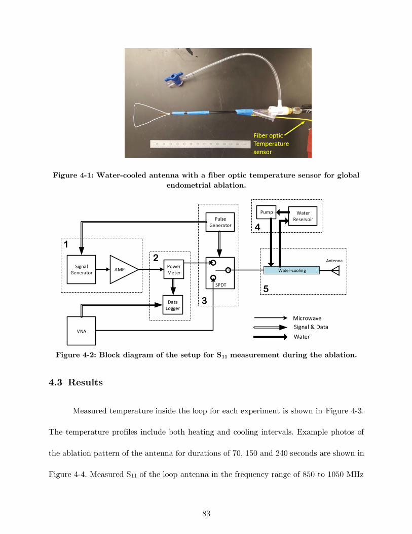
83
Figure 4-1: Water-cooled antenna with a fiber optic temperature sensor for global
endometrial ablation.
Signal Generator
Power Meter
AMP
Pulse Generator
Data Logger
SPDT
VNA
Water Reservoir
Water-cooling
Pump
1
2
3
4
5
Antenna
Microwave
Signal & Data
Water
Figure 4-2: Block diagram of the setup for S11 measurement during the ablation.
4.3 Results
Measured temperature inside the loop for each experiment is shown in Figure 4-3.
The temperature profiles include both heating and cooling intervals. Example photos of
the ablation pattern of the antenna for durations of 70, 150 and 240 seconds are shown in
Figure 4-4. Measured S11 of the loop antenna in the frequency range of 850 to 1050 MHz
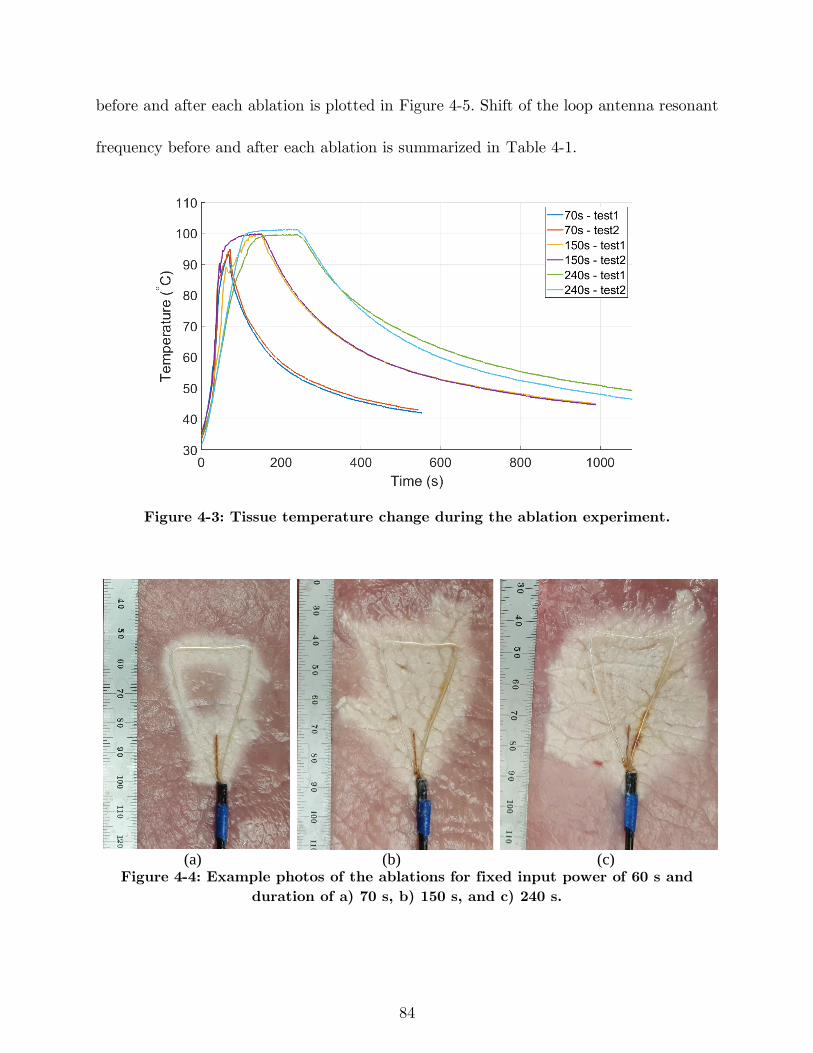
84
before and after each ablation is plotted in Figure 4-5. Shift of the loop antenna resonant
frequency before and after each ablation is summarized in Table 4-1.
Figure 4-3: Tissue temperature change during the ablation experiment.
(a) (b) (c)
Figure 4-4: Example photos of the ablations for fixed input power of 60 s and
duration of a) 70 s, b) 150 s, and c) 240 s.
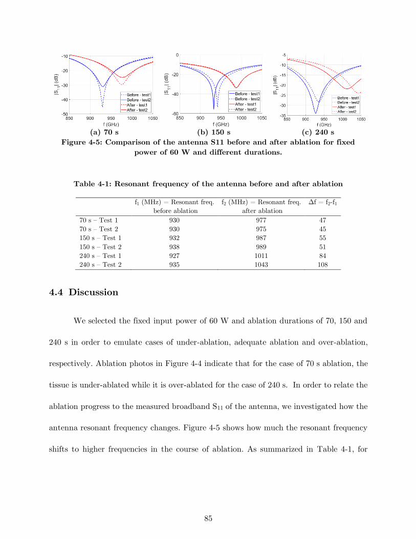
85
(a) 70 s (b) 150 s (c) 240 s
Figure 4-5: Comparison of the antenna S11 before and after ablation for fixed
power of 60 W and different durations.
Table 4-1: Resonant frequency of the antenna before and after ablation
f1 (MHz) = Resonant freq.
before ablation
f2 (MHz) = Resonant freq.
after ablation
Δf = f2-f1
70 s – Test 1 930 977 47
70 s – Test 2 930 975 45
150 s – Test 1 932 987 55
150 s – Test 2 938 989 51
240 s – Test 1 927 1011 84
240 s – Test 2 935 1043 108
4.4 Discussion
We selected the fixed input power of 60 W and ablation durations of 70, 150 and
240 s in order to emulate cases of under-ablation, adequate ablation and over-ablation,
respectively. Ablation photos in Figure 4-4 indicate that for the case of 70 s ablation, the
tissue is under-ablated while it is over-ablated for the case of 240 s. In order to relate the
ablation progress to the measured broadband S11 of the antenna, we investigated how the
antenna resonant frequency changes. Figure 4-5 shows how much the resonant frequency
shifts to higher frequencies in the course of ablation. As summarized in Table 4-1, for
86
longer ablations the difference between the antenna resonant frequency before ablation
and that of after ablation is larger.
In order to make use of the resonant frequency shift as an ablation-monitoring
signal, two modes are defined for the ablation setup shown in Figure 4-2: treatment and
assessment modes. In the treatment mode, the switch connects the antenna to the
microwave generator. The generator energizes the antenna at the operation frequency to
deliver power to the tissue and heat it to lethal temperatures. In the assessment mode,
the switch connects the antenna to the VNA. The VNA transmits a range of frequencies
at low power and measures the reflected power in order to calculate the antenna S11. The
measurement interval (as short as 5 seconds) is not comparable to treatment intervals
and does not compromise the ablation.
In an ablation procedure, when the antenna is positioned in the target site, the
switch puts the antenna in assessment mode to measure the antenna S11 and finds the
resonant frequency. This would be used as a reference for the subsequent measurements.
During the course of the ablation, the antenna is set to assessment mode to measure S11.
The measured signal is compared to the reference signal and determines when to stop the
ablation.
One of the limitations of this feedback signal is that it may only provide a
complementary means for monitoring the ablation progress. The physician may not be
able to definitely determine when to stop the ablation solely based this signal since there
87
are many other variables involved that may impact the antenna reflection coefficient and
the ablation zone extent, such as tissue variability.
4.5 Conclusion
This study investigated the feasibility of using broadband reflection coefficient of
ablation antennas as a feedback signal for monitoring the ablation progress over the
ablation procedure. As heat changes the tissue state from unablated to mildly ablated and
completely ablated, the tissue dielectric properties change. Experimental ablations using
a loop antenna indicated that dielectric properties change translate to change of resonant
frequency of the antenna. This parameter may provide physicians with an extra layer of
information in addition to post-procedural imaging.
88
5 Microwave Antennas for Thermal Ablation
of Benign Adrenal Adenomas3
5.1 Introduction
Primary aldosteronism involves the excessive secretion of aldosterone from the
adrenal gland, and is responsible for up to 11.2% of all cases of hypertension [147]. When
this excess of aldosterone is attributable to an adenoma (a benign adrenal gland tumor),
the condition is referred to as Conn’s syndrome. The negative effects of chronic
hypertension are widely known and include coronary artery disease, congestive heart
failure and cardiac arrhythmias [148], [149]. Currently, a patient with Conn’s syndrome
must undergo adrenalectomy or receive intensive medical management with significant
side-effects [149]. While adrenalectomy is an effective means of definitive therapy, it is
only indicated for unilateral disease. Bilateral cases are typically treated with
3 This chapter has been published as: H. Fallahi, D. Clausing, A. Shahzad, M. O’Halloran, M. C. Dennedy,
and P. Prakash, “Microwave antennas for thermal ablation of benign adrenal adenomas,” Biomed. Phys.
Eng. Express, vol. 5, no. 2, p. 025044, 2019. (DOI: 10.1088/2057-1976/ab068b)
Original content from this work may be used under the terms of the Creative Commons Attribution 3.0
license. ©2019 IOP Publishing Ltd
89
mineralcorticoid receptor antagonists (MRA), which are associated with side effects like
gynaccomastia and sexual dysfunction in men, while causing menstrual irregularities and
conferring risks for teratogenicity in women of reproductive age [150].
Recently, there has been growing interest in the potential of image-guided thermal
blation for minimally-invasive treatment of adrenal adenomas. Thermal ablation is an
established treatment modality that uses high temperatures (> ~55 °C) to destroy
malignant tumors in the liver, kidney, prostate, and the lungs. Systems employing a
variety of energy modalities have been developed for thermal ablation, including
radiofrequency current, laser, microwave, and ultrasound [151], [152]. As a result, ablation
research and clinical applications have been primarily focused on achieving large ablation
zones that destroy the tumor, as well as a healthy margin around the tumor to reduce the
risk of recurrence. The difference between using ablation for cancerous lesions and a
Conn’s adenoma is twofold: Firstly, in Conn’s syndrome, a primary goal is to preserve as
much healthy functional tissue as possible rather than continuing ablation until marginal
ablation of healthy tissue is established. While, complete ablation of the adenoma is
necessary for clinical success, large volume marginal ablation is unnecessary because these
tumors are benign. Secondly, several studies indicate that the average adrenal adenoma
causing Conn’s syndrome is around 5 – 20 mm wide, which is much smaller than the
majority of the malignant tumors in the liver, kidney, and lungs [153]. These two major
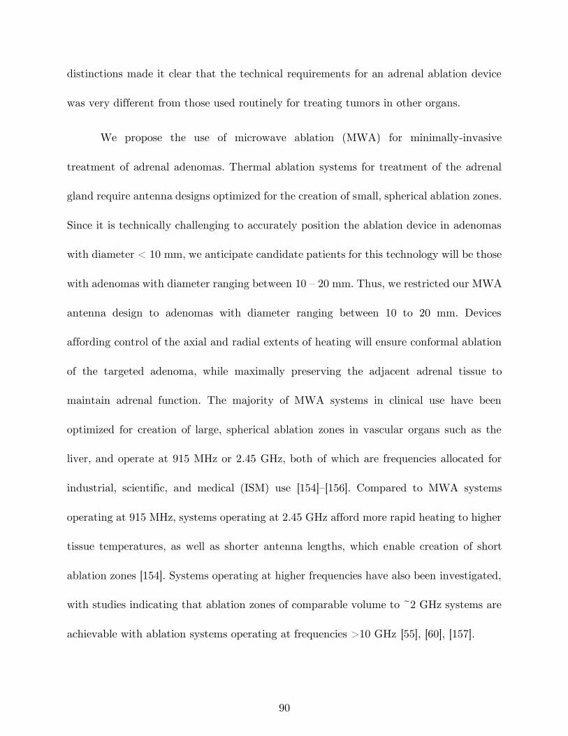
90
distinctions made it clear that the technical requirements for an adrenal ablation device
was very different from those used routinely for treating tumors in other organs.
We propose the use of microwave ablation (MWA) for minimally-invasive
treatment of adrenal adenomas. Thermal ablation systems for treatment of the adrenal
gland require antenna designs optimized for the creation of small, spherical ablation zones.
Since it is technically challenging to accurately position the ablation device in adenomas
with diameter < 10 mm, we anticipate candidate patients for this technology will be those
with adenomas with diameter ranging between 10 – 20 mm. Thus, we restricted our MWA
antenna design to adenomas with diameter ranging between 10 to 20 mm. Devices
affording control of the axial and radial extents of heating will ensure conformal ablation
of the targeted adenoma, while maximally preserving the adjacent adrenal tissue to
maintain adrenal function. The majority of MWA systems in clinical use have been
optimized for creation of large, spherical ablation zones in vascular organs such as the
liver, and operate at 915 MHz or 2.45 GHz, both of which are frequencies allocated for
industrial, scientific, and medical (ISM) use [154]–[156]. Compared to MWA systems
operating at 915 MHz, systems operating at 2.45 GHz afford more rapid heating to higher
tissue temperatures, as well as shorter antenna lengths, which enable creation of short
ablation zones [154]. Systems operating at higher frequencies have also been investigated,
with studies indicating that ablation zones of comparable volume to ~2 GHz systems are
achievable with ablation systems operating at frequencies >10 GHz [55], [60], [157].
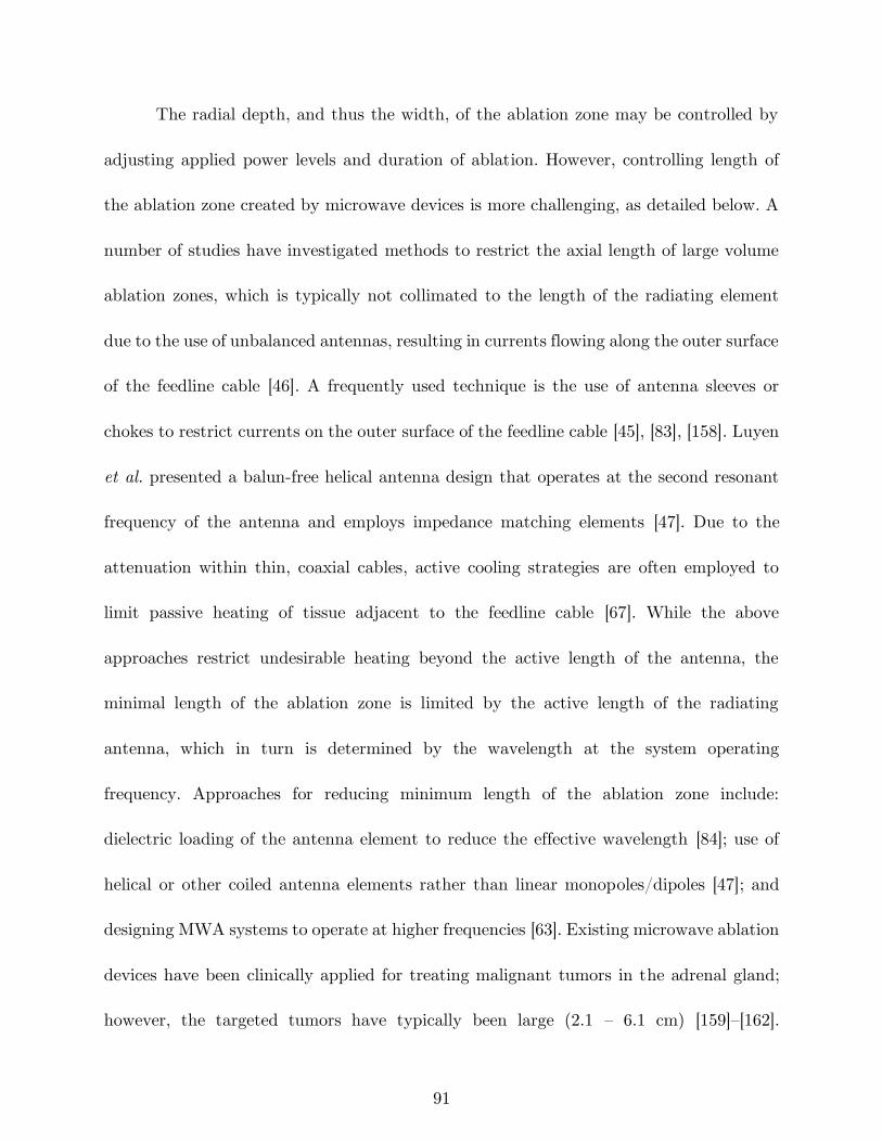
91
The radial depth, and thus the width, of the ablation zone may be controlled by
adjusting applied power levels and duration of ablation. However, controlling length of
the ablation zone created by microwave devices is more challenging, as detailed below. A
number of studies have investigated methods to restrict the axial length of large volume
ablation zones, which is typically not collimated to the length of the radiating element
due to the use of unbalanced antennas, resulting in currents flowing along the outer surface
of the feedline cable [46]. A frequently used technique is the use of antenna sleeves or
chokes to restrict currents on the outer surface of the feedline cable [45], [83], [158]. Luyen
et al. presented a balun-free helical antenna design that operates at the second resonant
frequency of the antenna and employs impedance matching elements [47]. Due to the
attenuation within thin, coaxial cables, active cooling strategies are often employed to
limit passive heating of tissue adjacent to the feedline cable [67]. While the above
approaches restrict undesirable heating beyond the active length of the antenna, the
minimal length of the ablation zone is limited by the active length of the radiating
antenna, which in turn is determined by the wavelength at the system operating
frequency. Approaches for reducing minimum length of the ablation zone include:
dielectric loading of the antenna element to reduce the effective wavelength [84]; use of
helical or other coiled antenna elements rather than linear monopoles/dipoles [47]; and
designing MWA systems to operate at higher frequencies [63]. Existing microwave ablation
devices have been clinically applied for treating malignant tumors in the adrenal gland;
however, the targeted tumors have typically been large (2.1 – 6.1 cm) [159]–[162].
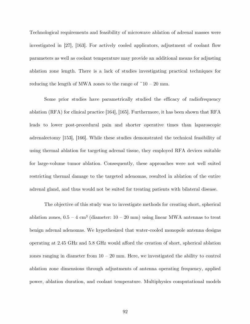
92
Technological requirements and feasibility of microwave ablation of adrenal masses were
investigated in [27], [163]. For actively cooled applicators, adjustment of coolant flow
parameters as well as coolant temperature may provide an additional means for adjusting
ablation zone length. There is a lack of studies investigating practical techniques for
reducing the length of MWA zones to the range of ~10 – 20 mm.
Some prior studies have parametrically studied the efficacy of radiofrequency
ablation (RFA) for clinical practice [164], [165]. Furthermore, it has been shown that RFA
leads to lower post-procedural pain and shorter operative times than laparoscopic
adrenalectomy [153], [166]. While these studies demonstrated the technical feasibility of
using thermal ablation for targeting adrenal tissue, they employed RFA devices suitable
for large-volume tumor ablation. Consequently, these approaches were not well suited
restricting thermal damage to the targeted adenomas, resulted in ablation of the entire
adrenal gland, and thus would not be suited for treating patients with bilateral disease.
The objective of this study was to investigate methods for creating short, spherical
ablation zones, 0.5 – 4 cm3 (diameter: 10 – 20 mm) using linear MWA antennas to treat
benign adrenal adenomas. We hypothesized that water-cooled monopole antenna designs
operating at 2.45 GHz and 5.8 GHz would afford the creation of short, spherical ablation
zones ranging in diameter from 10 – 20 mm. Here, we investigated the ability to control
ablation zone dimensions through adjustments of antenna operating frequency, applied
power, ablation duration, and coolant temperature. Multiphysics computational models
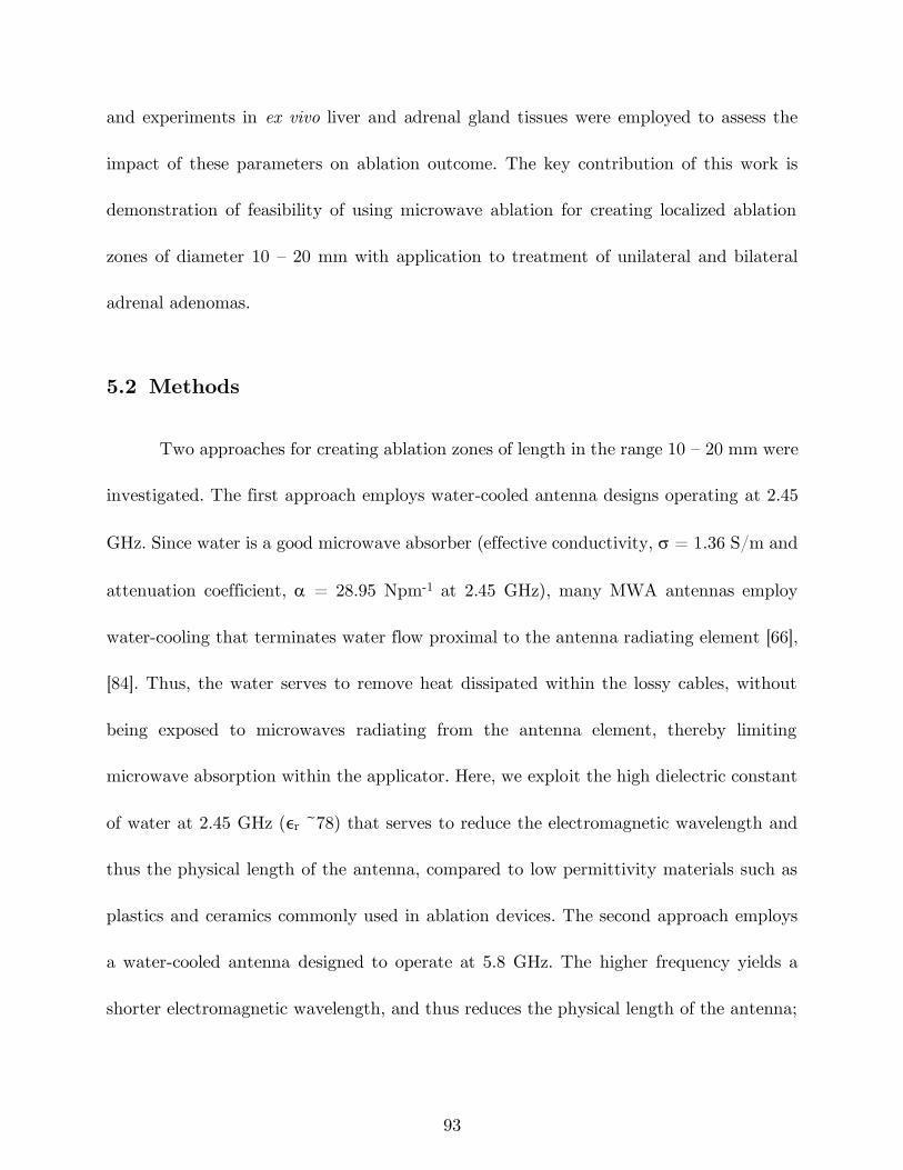
93
and experiments in ex vivo liver and adrenal gland tissues were employed to assess the
impact of these parameters on ablation outcome. The key contribution of this work is
demonstration of feasibility of using microwave ablation for creating localized ablation
zones of diameter 10 – 20 mm with application to treatment of unilateral and bilateral
adrenal adenomas.
5.2 Methods
Two approaches for creating ablation zones of length in the range 10 – 20 mm were
investigated. The first approach employs water-cooled antenna designs operating at 2.45
GHz. Since water is a good microwave absorber (effective conductivity, = 1.36 S/m and
attenuation coefficient, = 28.95 Npm-1 at 2.45 GHz), many MWA antennas employ
water-cooling that terminates water flow proximal to the antenna radiating element [66],
[84]. Thus, the water serves to remove heat dissipated within the lossy cables, without
being exposed to microwaves radiating from the antenna element, thereby limiting
microwave absorption within the applicator. Here, we exploit the high dielectric constant
of water at 2.45 GHz (ϵr ~78) that serves to reduce the electromagnetic wavelength and
thus the physical length of the antenna, compared to low permittivity materials such as
plastics and ceramics commonly used in ablation devices. The second approach employs
a water-cooled antenna designed to operate at 5.8 GHz. The higher frequency yields a
shorter electromagnetic wavelength, and thus reduces the physical length of the antenna;
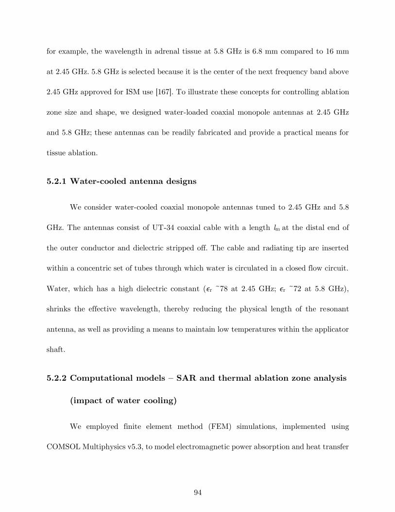
94
for example, the wavelength in adrenal tissue at 5.8 GHz is 6.8 mm compared to 16 mm
at 2.45 GHz. 5.8 GHz is selected because it is the center of the next frequency band above
2.45 GHz approved for ISM use [167]. To illustrate these concepts for controlling ablation
zone size and shape, we designed water-loaded coaxial monopole antennas at 2.45 GHz
and 5.8 GHz; these antennas can be readily fabricated and provide a practical means for
tissue ablation.
5.2.1 Water-cooled antenna designs
We consider water-cooled coaxial monopole antennas tuned to 2.45 GHz and 5.8
GHz. The antennas consist of UT-34 coaxial cable with a length lm at the distal end of
the outer conductor and dielectric stripped off. The cable and radiating tip are inserted
within a concentric set of tubes through which water is circulated in a closed flow circuit.
Water, which has a high dielectric constant (ϵr ~78 at 2.45 GHz; ϵr ~72 at 5.8 GHz),
shrinks the effective wavelength, thereby reducing the physical length of the resonant
antenna, as well as providing a means to maintain low temperatures within the applicator
shaft.
5.2.2 Computational models – SAR and thermal ablation zone analysis
(impact of water cooling)
We employed finite element method (FEM) simulations, implemented using
COMSOL Multiphysics v5.3, to model electromagnetic power absorption and heat transfer
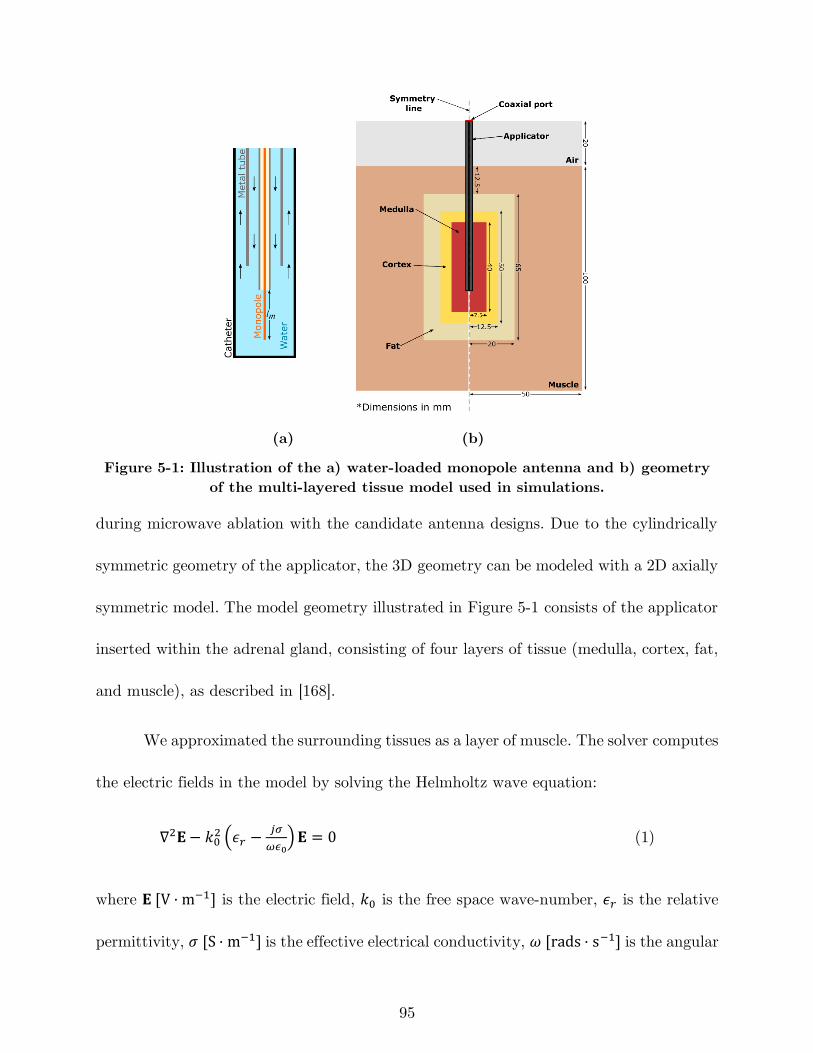
95
(a) (b)
Figure 5-1: Illustration of the a) water-loaded monopole antenna and b) geometry
of the multi-layered tissue model used in simulations.
during microwave ablation with the candidate antenna designs. Due to the cylindrically
symmetric geometry of the applicator, the 3D geometry can be modeled with a 2D axially
symmetric model. The model geometry illustrated in Figure 5-1 consists of the applicator
inserted within the adrenal gland, consisting of four layers of tissue (medulla, cortex, fat,
and muscle), as described in [168].
We approximated the surrounding tissues as a layer of muscle. The solver computes
the electric fields in the model by solving the Helmholtz wave equation:
∇2𝐄− 𝑘02 (𝜖𝑟 −
𝑗𝜎
𝜔𝜖0)𝐄 = 0 (1)
where 𝐄 [V · m−1] is the electric field, 𝑘0 is the free space wave-number, 𝜖𝑟 is the relative
permittivity, 𝜎 [S · m−1] is the effective electrical conductivity, 𝜔 [rads · s−1] is the angular
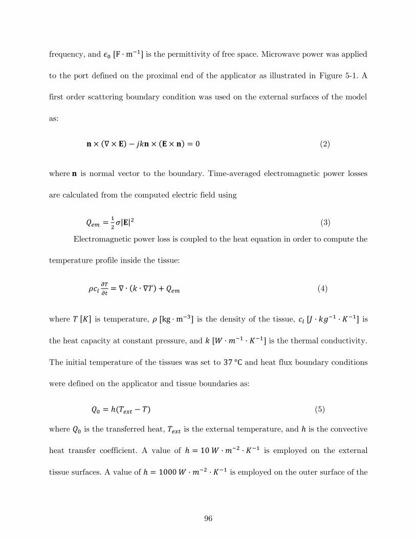
96
frequency, and 𝜖0 [F · m−1] is the permittivity of free space. Microwave power was applied
to the port defined on the proximal end of the applicator as illustrated in Figure 5-1. A
first order scattering boundary condition was used on the external surfaces of the model
as:
𝐧 × (∇ × 𝐄) − 𝑗𝑘𝐧 × (𝐄 × 𝐧) = 0 (2)
where 𝐧 is normal vector to the boundary. Time-averaged electromagnetic power losses
are calculated from the computed electric field using
𝑄𝑒𝑚 =1
2𝜎|𝐄|2 (3)
Electromagnetic power loss is coupled to the heat equation in order to compute the
temperature profile inside the tissue:
𝜌𝑐𝑙𝜕𝑇
𝜕𝑡= ∇ ∙ (𝑘 ∙ ∇𝑇) + 𝑄𝑒𝑚 (4)
where 𝑇 [𝐾] is temperature, 𝜌 [kg · m−3] is the density of the tissue, 𝑐𝑙 [𝐽 · 𝑘𝑔−1 · 𝐾−1] is
the heat capacity at constant pressure, and 𝑘 [𝑊 · 𝑚−1 · 𝐾−1] is the thermal conductivity.
The initial temperature of the tissues was set to 37 °C and heat flux boundary conditions
were defined on the applicator and tissue boundaries as:
𝑄0 = ℎ(𝑇𝑒𝑥𝑡 − 𝑇) (5)
where 𝑄0 is the transferred heat, 𝑇𝑒𝑥𝑡 is the external temperature, and ℎ is the convective
heat transfer coefficient. A value of ℎ = 10 𝑊 · 𝑚−2 · 𝐾−1 is employed on the external
tissue surfaces. A value of ℎ = 1000 𝑊 · 𝑚−2 · 𝐾−1 is employed on the outer surface of the
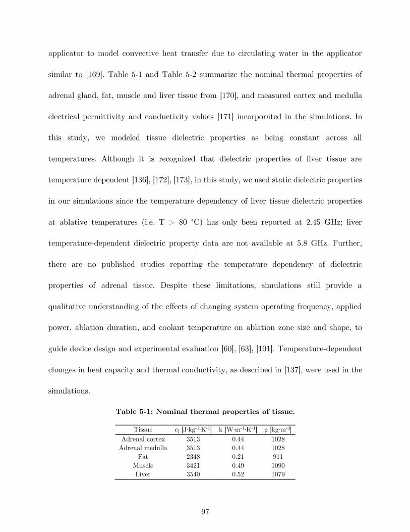
97
applicator to model convective heat transfer due to circulating water in the applicator
similar to [169]. Table 5-1 and Table 5-2 summarize the nominal thermal properties of
adrenal gland, fat, muscle and liver tissue from [170], and measured cortex and medulla
electrical permittivity and conductivity values [171] incorporated in the simulations. In
this study, we modeled tissue dielectric properties as being constant across all
temperatures. Although it is recognized that dielectric properties of liver tissue are
temperature dependent [136], [172], [173], in this study, we used static dielectric properties
in our simulations since the temperature dependency of liver tissue dielectric properties
at ablative temperatures (i.e. T > 80 °C) has only been reported at 2.45 GHz; liver
temperature-dependent dielectric property data are not available at 5.8 GHz. Further,
there are no published studies reporting the temperature dependency of dielectric
properties of adrenal tissue. Despite these limitations, simulations still provide a
qualitative understanding of the effects of changing system operating frequency, applied
power, ablation duration, and coolant temperature on ablation zone size and shape, to
guide device design and experimental evaluation [60], [63], [101]. Temperature-dependent
changes in heat capacity and thermal conductivity, as described in [137], were used in the
simulations.
Table 5-1: Nominal thermal properties of tissue.
Tissue cl [J∙kg-1∙K-1] k [W∙m-1∙K-1] ρ [kg∙m-3]
Adrenal cortex 3513 0.44 1028
Adrenal medulla 3513 0.44 1028
Fat 2348 0.21 911
Muscle 3421 0.49 1090
Liver 3540 0.52 1079
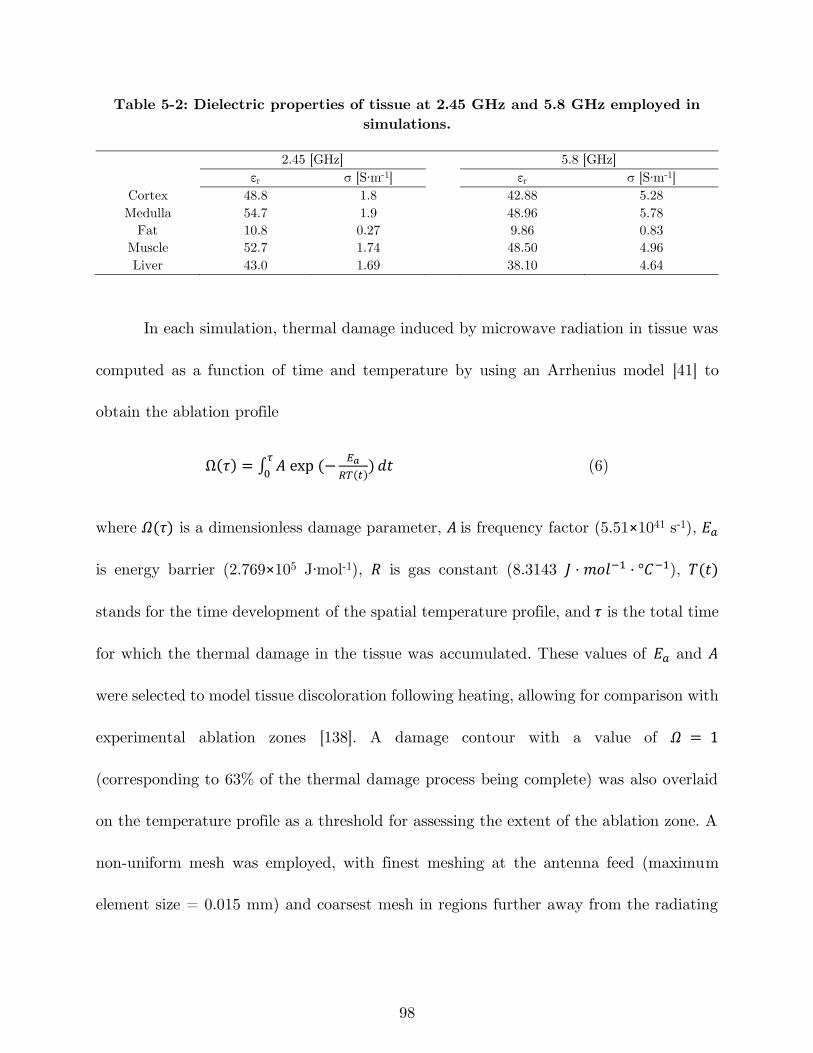
98
Table 5-2: Dielectric properties of tissue at 2.45 GHz and 5.8 GHz employed in
simulations.
2.45 [GHz] 5.8 [GHz]
εr σ [S∙m-1] εr σ [S∙m-1]
Cortex 48.8 1.8 42.88 5.28
Medulla 54.7 1.9 48.96 5.78
Fat 10.8 0.27 9.86 0.83
Muscle 52.7 1.74 48.50 4.96
Liver 43.0 1.69 38.10 4.64
In each simulation, thermal damage induced by microwave radiation in tissue was
computed as a function of time and temperature by using an Arrhenius model [41] to
obtain the ablation profile
Ω(𝜏) = ∫ 𝐴 exp (−𝐸𝑎
𝑅𝑇(𝑡))
𝜏
0𝑑𝑡 (6)
where 𝛺(𝜏) is a dimensionless damage parameter, 𝐴 is frequency factor (5.51×1041 s˗1), 𝐸𝑎
is energy barrier (2.769×10⁵ J∙mol-1), 𝑅 is gas constant (8.3143 𝐽 · 𝑚𝑜𝑙−1 · °𝐶−1), 𝑇(𝑡)
stands for the time development of the spatial temperature profile, and 𝜏 is the total time
for which the thermal damage in the tissue was accumulated. These values of 𝐸𝑎 and 𝐴
were selected to model tissue discoloration following heating, allowing for comparison with
experimental ablation zones [138]. A damage contour with a value of 𝛺 = 1
(corresponding to 63% of the thermal damage process being complete) was also overlaid
on the temperature profile as a threshold for assessing the extent of the ablation zone. A
non-uniform mesh was employed, with finest meshing at the antenna feed (maximum
element size = 0.015 mm) and coarsest mesh in regions further away from the radiating
99
element (maximum element size = 4.45 mm). The number of degrees of freedom in each
model was 212,000 on average.
The computational models were used to determine the monopole length, lm, that
yielded the lowest antenna reflection coefficient at the desired operating frequency.
Nominally, the length is expected to be lm = ~/4 at the operating frequency for a
monopole antenna. At each frequency of interest, we iteratively adjusted lm in simulations
to identify the frequency at which reflected power is minimized, indicating the best
impedance match to the feeding transmission line.
5.2.3 Experimental platform – hardware for evaluating ablation zones
Antennas were fabricated from UT-34 semi-rigid coaxial cable inserted within a
stainless-steel tube (1.82 mm O.D. and 1.37 mm I.D.), and the entire assembly
subsequently inserted within a thin-walled PEEK tube (2.46 mm O.D.). The broadband
reflection coefficients of the fabricated antennas were measured with a vector network
analyzer (HP 8753D) to confirm adequate impedance matching at the desired operating
frequency.
Following confirmation of impedance match (S11 < -10 dB), ablation experiments
were then performed in freshly excised ex vivo bovine liver and adrenal gland tissues. We
selected fresh ex vivo bovine liver tissue for experimental evaluations since it is a well-
established tissue model for benchtop evaluation of novel thermal ablation technologies
[127]; unlike the adrenal gland, it would not require embedding within a larger lossy
100
medium to simulate the body [27]; and the contrast in color of ablated tissue vs. unablated
tissue is readily observed in liver, but not clear in adrenal gland tissue.
Freshly excised bovine liver and adrenal gland tissues were obtained from a local
meat locker and transported to the lab within sealed plastic bags placed on ice. At the
lab, the liver was sectioned into ~8 cm × 8 cm × 6 cm blocks, placed within thin-walled
plastic bags that were sealed and immersed within a ~35-37 °C water bath. Once samples
were warmed to ~37 °C, they were removed from the bath. The applicator was introduced
into the liver and positioned such that the applicator tip was 60 mm below the liver
surface. For adrenal gland ablations, the glands were similarly warmed up and they were
sandwiched between porcine muscle with temperature of ~35-37 °C during ablation.
Insertion depth of the microwave applicator in the adrenal gland case was from 20 to 25
mm. An HP 83752B signal generator provided a continuous wave sinusoidal signal at the
frequency of interest. Solid-state microwave amplifiers were then used to amplify the signal
to 30 and 50 W. During ablations, a microwave power meter (Bird 7022, statistical power
sensor) was connected in line with the applicator to monitor forward and reflected power
for all applications. Chilled water (~10 °C) was circulated through the applicator via a
peristaltic pump (Cole Parmer 7554–90, Vernon Hills, IL, USA) at a rate of 80 ml/min.
5.2.4 Experimental protocol
We employed experiments to assess ablation zone size/shape when delivering
ablation with the following parameters:
101
- Input power: 30 and 40 W
- Frequency: 2.45 GHz and 5.8 GHz
- Ablation duration: 30, 60 and 90 s
- Coolant water temperature: 10 °C
Each (power, frequency, duration) combination was repeated five times (n = 5).
In a second set of experiments, the effect of coolant water temperatures was investigated
(Tcoolant = 20 and 30 °C) when frequency = 5.8 GHz considering Pin = 30 W, and ablation
duration of 90 s (n = 3). Following each experimental ablation, the tissue sample was
sliced along the applicator axis, and the ablation zone length and width were measured
using a ruler. The sphericity of the ablation zone shape was assessed using the axial ratio,
defined as the ratio of the ablation zone width to the ablation zone length. Finally, we
analyzed the measured length and width of ablations by using multi-way ANOVA. In a
3-way ANOVA, the main effects (frequency, power, time) and interaction terms
(frequency*power, power*time, time*frequency) were studied.
After ensuring that it is feasible to use microwave ablation for creation of small
ablation zones, two sets of ablation experiments (f = 2.45 GHz, Pin = 50 W, t = 180 s,
Tcoolant = 10°C) and (f = 5.8 GHz, Pin = 40 W, t = 90 s, Tcoolant = 30 °C) were
performed three times (n = 3) for each combination in bovine adrenal gland.
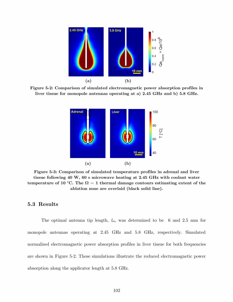
102
(a) (b)
Figure 5-2: Comparison of simulated electromagnetic power absorption profiles in
liver tissue for monopole antennas operating at a) 2.45 GHz and b) 5.8 GHz.
(a) (b)
Figure 5-3: Comparison of simulated temperature profiles in adrenal and liver
tissue following 40 W, 60 s microwave heating at 2.45 GHz with coolant water
temperature of 10 °C. The Ω = 1 thermal damage contours estimating extent of the
ablation zone are overlaid (black solid line).
5.3 Results
The optimal antenna tip length, lm, was determined to be 6 and 2.5 mm for
monopole antennas operating at 2.45 GHz and 5.8 GHz, respectively. Simulated
normalized electromagnetic power absorption profiles in liver tissue for both frequencies
are shown in Figure 5-2. These simulations illustrate the reduced electromagnetic power
absorption along the applicator length at 5.8 GHz.
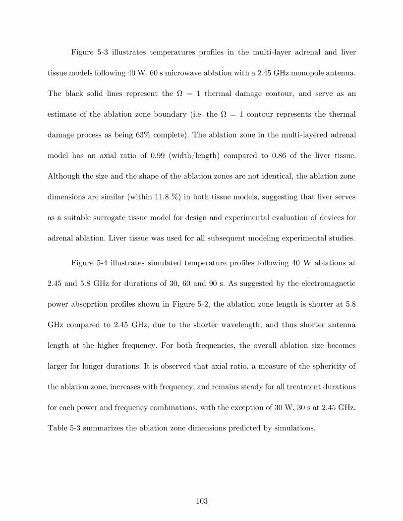
103
Figure 5-3 illustrates temperatures profiles in the multi-layer adrenal and liver
tissue models following 40 W, 60 s microwave ablation with a 2.45 GHz monopole antenna.
The black solid lines represent the Ω = 1 thermal damage contour, and serve as an
estimate of the ablation zone boundary (i.e. the Ω = 1 contour represents the thermal
damage process as being 63% complete). The ablation zone in the multi-layered adrenal
model has an axial ratio of 0.99 (width/length) compared to 0.86 of the liver tissue.
Although the size and the shape of the ablation zones are not identical, the ablation zone
dimensions are similar (within 11.8 %) in both tissue models, suggesting that liver serves
as a suitable surrogate tissue model for design and experimental evaluation of devices for
adrenal ablation. Liver tissue was used for all subsequent modeling experimental studies.
Figure 5-4 illustrates simulated temperature profiles following 40 W ablations at
2.45 and 5.8 GHz for durations of 30, 60 and 90 s. As suggested by the electromagnetic
power absoprtion profiles shown in Figure 5-2, the ablation zone length is shorter at 5.8
GHz compared to 2.45 GHz, due to the shorter wavelength, and thus shorter antenna
length at the higher frequency. For both frequencies, the overall ablation size becomes
larger for longer durations. It is observed that axial ratio, a measure of the sphericity of
the ablation zone, increases with frequency, and remains steady for all treatment durations
for each power and frequency combinations, with the exception of 30 W, 30 s at 2.45 GHz.
Table 5-3 summarizes the ablation zone dimensions predicted by simulations.
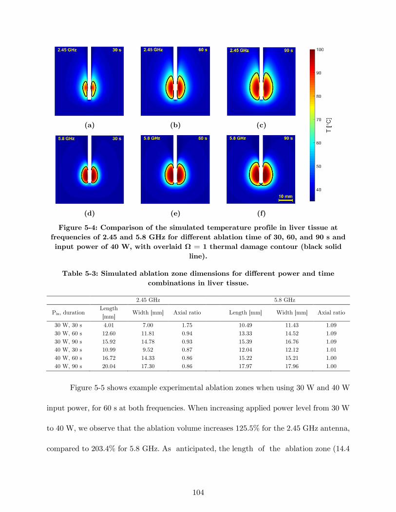
104
(a) (b) (c)
(d) (e) (f)
Figure 5-4: Comparison of the simulated temperature profile in liver tissue at
frequencies of 2.45 and 5.8 GHz for different ablation time of 30, 60, and 90 s and
input power of 40 W, with overlaid Ω = 1 thermal damage contour (black solid
line).
Table 5-3: Simulated ablation zone dimensions for different power and time
combinations in liver tissue.
2.45 GHz 5.8 GHz
Pin, duration Length
[mm] Width [mm] Axial ratio
Length [mm] Width [mm] Axial ratio
30 W, 30 s 4.01 7.00 1.75 10.49 11.43 1.09
30 W, 60 s 12.60 11.81 0.94 13.33 14.52 1.09
30 W, 90 s 15.92 14.78 0.93 15.39 16.76 1.09
40 W, 30 s 10.99 9.52 0.87 12.04 12.12 1.01
40 W, 60 s 16.72 14.33 0.86 15.22 15.21 1.00
40 W, 90 s 20.04 17.30 0.86 17.97 17.96 1.00
Figure 5-5 shows example experimental ablation zones when using 30 W and 40 W
input power, for 60 s at both frequencies. When increasing applied power level from 30 W
to 40 W, we observe that the ablation volume increases 125.5% for the 2.45 GHz antenna,
compared to 203.4% for 5.8 GHz. As anticipated, the length of the ablation zone (14.4
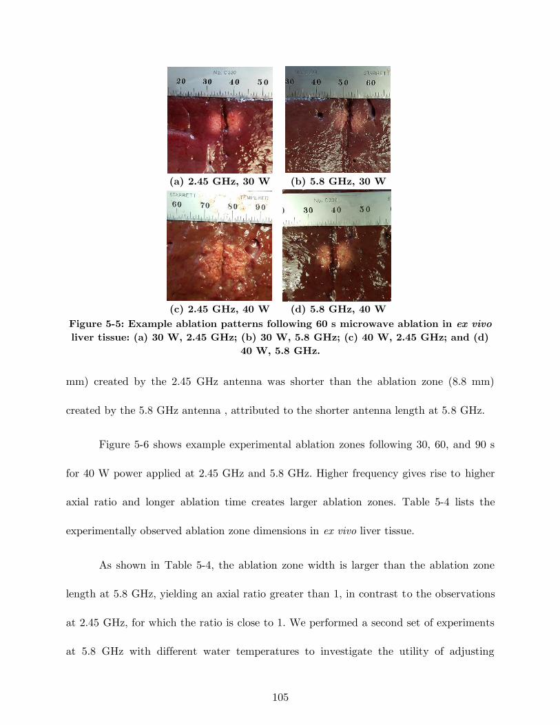
105
(a) 2.45 GHz, 30 W (b) 5.8 GHz, 30 W
(c) 2.45 GHz, 40 W (d) 5.8 GHz, 40 W
Figure 5-5: Example ablation patterns following 60 s microwave ablation in ex vivo
liver tissue: (a) 30 W, 2.45 GHz; (b) 30 W, 5.8 GHz; (c) 40 W, 2.45 GHz; and (d)
40 W, 5.8 GHz.
mm) created by the 2.45 GHz antenna was shorter than the ablation zone (8.8 mm)
created by the 5.8 GHz antenna , attributed to the shorter antenna length at 5.8 GHz.
Figure 5-6 shows example experimental ablation zones following 30, 60, and 90 s
for 40 W power applied at 2.45 GHz and 5.8 GHz. Higher frequency gives rise to higher
axial ratio and longer ablation time creates larger ablation zones. Table 5-4 lists the
experimentally observed ablation zone dimensions in ex vivo liver tissue.
As shown in Table 5-4, the ablation zone width is larger than the ablation zone
length at 5.8 GHz, yielding an axial ratio greater than 1, in contrast to the observations
at 2.45 GHz, for which the ratio is close to 1. We performed a second set of experiments
at 5.8 GHz with different water temperatures to investigate the utility of adjusting
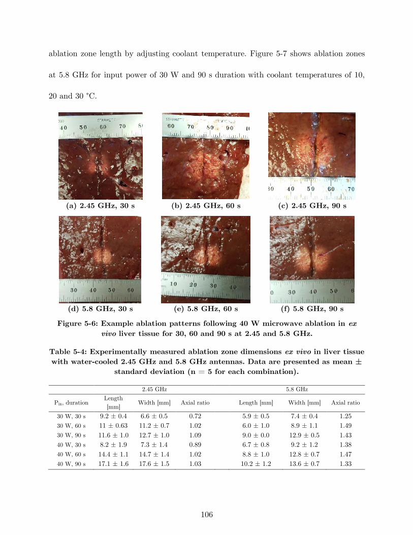
106
ablation zone length by adjusting coolant temperature. Figure 5-7 shows ablation zones
at 5.8 GHz for input power of 30 W and 90 s duration with coolant temperatures of 10,
20 and 30 °C.
(a) 2.45 GHz, 30 s (b) 2.45 GHz, 60 s (c) 2.45 GHz, 90 s
(d) 5.8 GHz, 30 s (e) 5.8 GHz, 60 s (f) 5.8 GHz, 90 s
Figure 5-6: Example ablation patterns following 40 W microwave ablation in ex
vivo liver tissue for 30, 60 and 90 s at 2.45 and 5.8 GHz.
Table 5-4: Experimentally measured ablation zone dimensions ex vivo in liver tissue
with water-cooled 2.45 GHz and 5.8 GHz antennas. Data are presented as mean ±
standard deviation (n = 5 for each combination).
2.45 GHz 5.8 GHz
Pin, duration Length
[mm] Width [mm] Axial ratio
Length [mm] Width [mm] Axial ratio
30 W, 30 s 9.2 ± 0.4 6.6 ± 0.5 0.72 5.9 ± 0.5 7.4 ± 0.4 1.25
30 W, 60 s 11 ± 0.63 11.2 ± 0.7 1.02 6.0 ± 1.0 8.9 ± 1.1 1.49
30 W, 90 s 11.6 ± 1.0 12.7 ± 1.0 1.09 9.0 ± 0.0 12.9 ± 0.5 1.43
40 W, 30 s 8.2 ± 1.9 7.3 ± 1.4 0.89 6.7 ± 0.8 9.2 ± 1.2 1.38
40 W, 60 s 14.4 ± 1.1 14.7 ± 1.4 1.02 8.8 ± 1.0 12.8 ± 0.7 1.47
40 W, 90 s 17.1 ± 1.6 17.6 ± 1.5 1.03 10.2 ± 1.2 13.6 ± 0.7 1.33
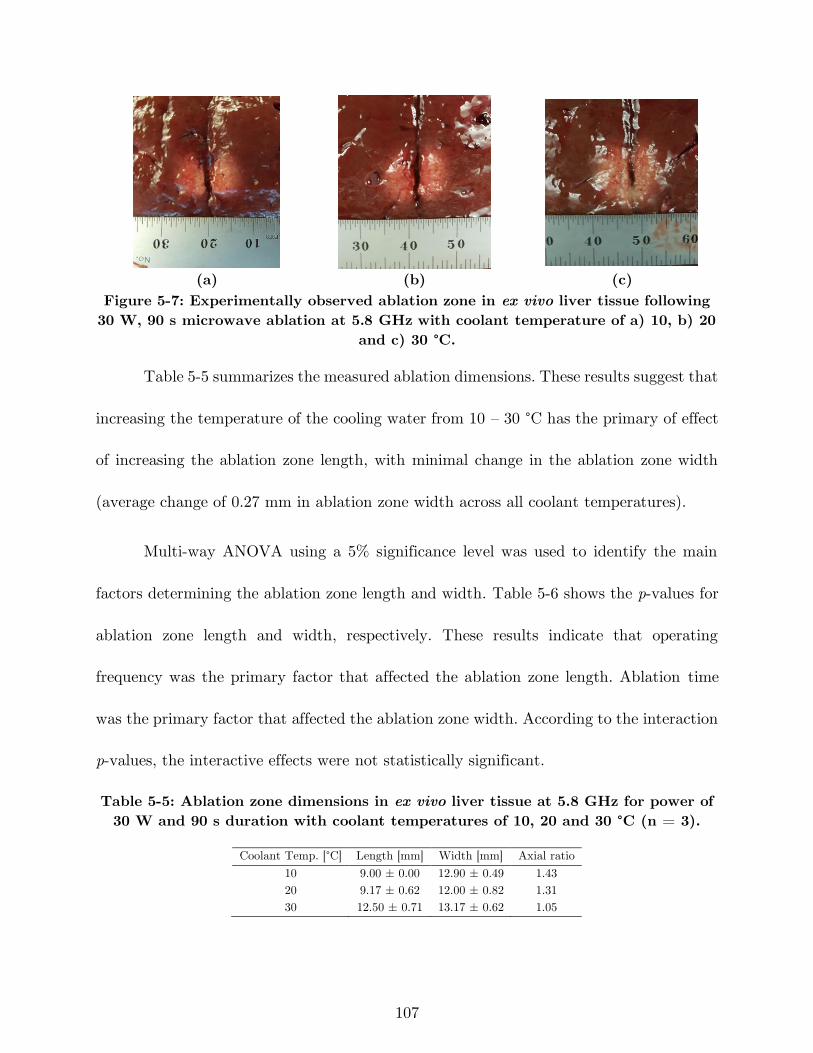
107
(a) (b) (c)
Figure 5-7: Experimentally observed ablation zone in ex vivo liver tissue following
30 W, 90 s microwave ablation at 5.8 GHz with coolant temperature of a) 10, b) 20
and c) 30 °C.
Table 5-5 summarizes the measured ablation dimensions. These results suggest that
increasing the temperature of the cooling water from 10 – 30 °C has the primary of effect
of increasing the ablation zone length, with minimal change in the ablation zone width
(average change of 0.27 mm in ablation zone width across all coolant temperatures).
Multi-way ANOVA using a 5% significance level was used to identify the main
factors determining the ablation zone length and width. Table 5-6 shows the p-values for
ablation zone length and width, respectively. These results indicate that operating
frequency was the primary factor that affected the ablation zone length. Ablation time
was the primary factor that affected the ablation zone width. According to the interaction
p-values, the interactive effects were not statistically significant.
Table 5-5: Ablation zone dimensions in ex vivo liver tissue at 5.8 GHz for power of
30 W and 90 s duration with coolant temperatures of 10, 20 and 30 °C (n = 3).
Coolant Temp. [°C] Length [mm] Width [mm] Axial ratio
10 9.00 ± 0.00 12.90 ± 0.49 1.43
20 9.17 ± 0.62 12.00 ± 0.82 1.31
30 12.50 ± 0.71 13.17 ± 0.62 1.05
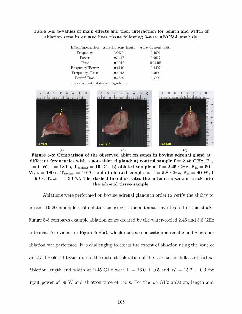
108
Table 5-6: p-values of main effects and their interaction for length and width of
ablation zone in ex vivo liver tissue following 3-way ANOVA analysis.
Effect/interaction Ablation zone length Ablation zone width
Frequency 0.0426† 0.4091
Power 0.1417 0.0917
Time 0.1042 0.0446†
Frequency*Power 0.6140 0.6497
Frequency*Time 0.4943 0.3600
Power*Time 0.3859 0.5709 † p-values with statistical significance
(a) (b) (c)
Figure 5-8: Comparison of the observed ablation zones in bovine adrenal gland at
different frequencies with a non-ablated gland: a) control sample f = 2.45 GHz, Pin
= 0 W, t = 180 s, Tcoolant = 10 °C, b) ablated sample at f = 2.45 GHz, Pin = 50
W, t = 180 s, Tcoolant = 10 °C and c) ablated sample at f = 5.8 GHz, Pin = 40 W, t
= 90 s, Tcoolant = 30 °C. The dashed line illustrates the antenna insertion track into
the adrenal tissue sample.
Ablations were performed on bovine adrenal glands in order to verify the ability to
create ~10-20 mm spherical ablation zones with the antennas investigated in this study.
Figure 5-8 compares example ablation zones created by the water-cooled 2.45 and 5.8 GHz
antennas. As evident in Figure 5-8(a), which ilustrates a section adrenal gland where no
ablation was performed, it is challenging to assess the extent of ablation using the zone of
visibly discolored tissue due to the distinct coloration of the adrenal medulla and cortex.
Ablation length and width at 2.45 GHz were L = 16.0 ± 0.5 and W = 15.2 ± 0.3 for
input power of 50 W and ablation time of 180 s. For the 5.8 GHz ablation, length and
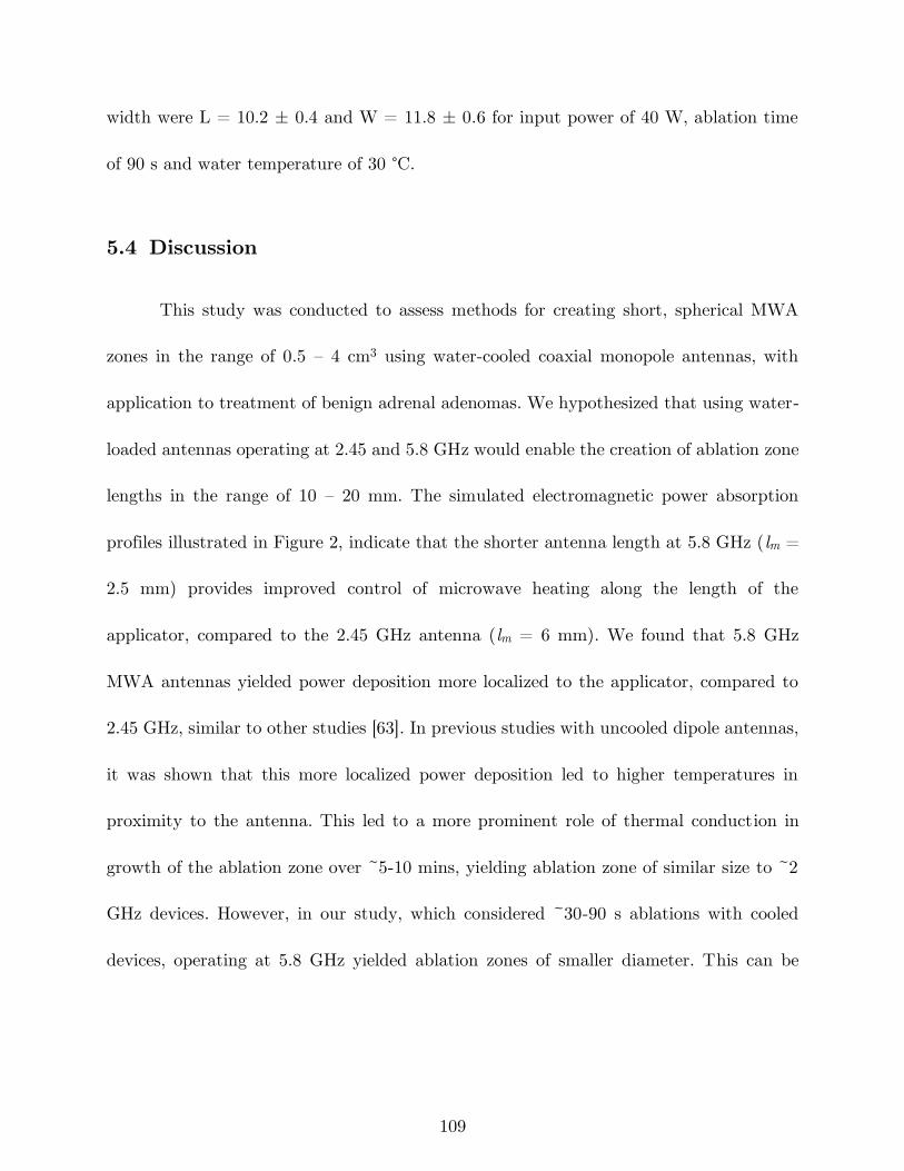
109
width were L = 10.2 ± 0.4 and W = 11.8 ± 0.6 for input power of 40 W, ablation time
of 90 s and water temperature of 30 °C.
5.4 Discussion
This study was conducted to assess methods for creating short, spherical MWA
zones in the range of 0.5 – 4 cm3 using water-cooled coaxial monopole antennas, with
application to treatment of benign adrenal adenomas. We hypothesized that using water-
loaded antennas operating at 2.45 and 5.8 GHz would enable the creation of ablation zone
lengths in the range of 10 – 20 mm. The simulated electromagnetic power absorption
profiles illustrated in Figure 2, indicate that the shorter antenna length at 5.8 GHz (lm =
2.5 mm) provides improved control of microwave heating along the length of the
applicator, compared to the 2.45 GHz antenna (lm = 6 mm). We found that 5.8 GHz
MWA antennas yielded power deposition more localized to the applicator, compared to
2.45 GHz, similar to other studies [63]. In previous studies with uncooled dipole antennas,
it was shown that this more localized power deposition led to higher temperatures in
proximity to the antenna. This led to a more prominent role of thermal conduction in
growth of the ablation zone over ~5-10 mins, yielding ablation zone of similar size to ~2
GHz devices. However, in our study, which considered ~30-90 s ablations with cooled
devices, operating at 5.8 GHz yielded ablation zones of smaller diameter. This can be
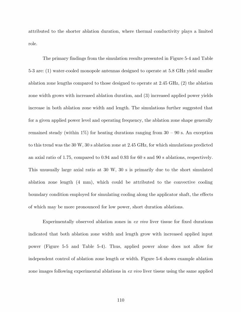
110
attributed to the shorter ablation duration, where thermal conductivity plays a limited
role.
The primary findings from the simulation results presented in Figure 5-4 and Table
5-3 are: (1) water-cooled monopole antennas designed to operate at 5.8 GHz yield smaller
ablation zone lengths compared to those designed to operate at 2.45 GHz, (2) the ablation
zone width grows with increased ablation duration, and (3) increased applied power yields
increase in both ablation zone width and length. The simulations further suggested that
for a given applied power level and operating frequency, the ablation zone shape generally
remained steady (within 1%) for heating durations ranging from 30 – 90 s. An exception
to this trend was the 30 W, 30 s ablation zone at 2.45 GHz, for which simulations predicted
an axial ratio of 1.75, compared to 0.94 and 0.93 for 60 s and 90 s ablations, respectively.
This unusually large axial ratio at 30 W, 30 s is primarily due to the short simulated
ablation zone length (4 mm), which could be attributed to the convective cooling
boundary condition employed for simulating cooling along the applicator shaft, the effects
of which may be more pronounced for low power, short duration ablations.
Experimentally observed ablation zones in ex vivo liver tissue for fixed durations
indicated that both ablation zone width and length grow with increased applied input
power (Figure 5-5 and Table 5-4). Thus, applied power alone does not allow for
independent control of ablation zone length or width. Figure 5-6 shows example ablation
zone images following experimental ablations in ex vivo liver tissue using the same applied
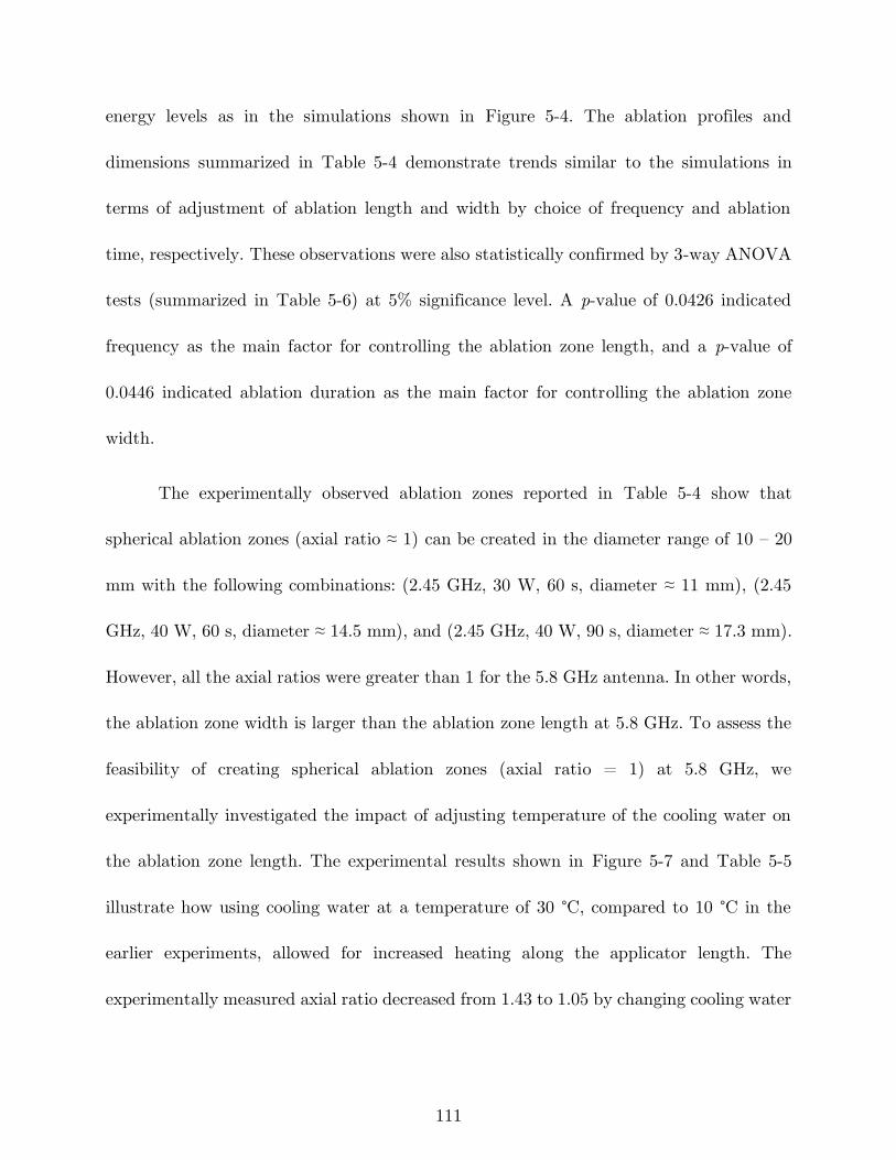
111
energy levels as in the simulations shown in Figure 5-4. The ablation profiles and
dimensions summarized in Table 5-4 demonstrate trends similar to the simulations in
terms of adjustment of ablation length and width by choice of frequency and ablation
time, respectively. These observations were also statistically confirmed by 3-way ANOVA
tests (summarized in Table 5-6) at 5% significance level. A p-value of 0.0426 indicated
frequency as the main factor for controlling the ablation zone length, and a p-value of
0.0446 indicated ablation duration as the main factor for controlling the ablation zone
width.
The experimentally observed ablation zones reported in Table 5-4 show that
spherical ablation zones (axial ratio ≈ 1) can be created in the diameter range of 10 – 20
mm with the following combinations: (2.45 GHz, 30 W, 60 s, diameter ≈ 11 mm), (2.45
GHz, 40 W, 60 s, diameter ≈ 14.5 mm), and (2.45 GHz, 40 W, 90 s, diameter ≈ 17.3 mm).
However, all the axial ratios were greater than 1 for the 5.8 GHz antenna. In other words,
the ablation zone width is larger than the ablation zone length at 5.8 GHz. To assess the
feasibility of creating spherical ablation zones (axial ratio = 1) at 5.8 GHz, we
experimentally investigated the impact of adjusting temperature of the cooling water on
the ablation zone length. The experimental results shown in Figure 5-7 and Table 5-5
illustrate how using cooling water at a temperature of 30 °C, compared to 10 °C in the
earlier experiments, allowed for increased heating along the applicator length. The
experimentally measured axial ratio decreased from 1.43 to 1.05 by changing cooling water
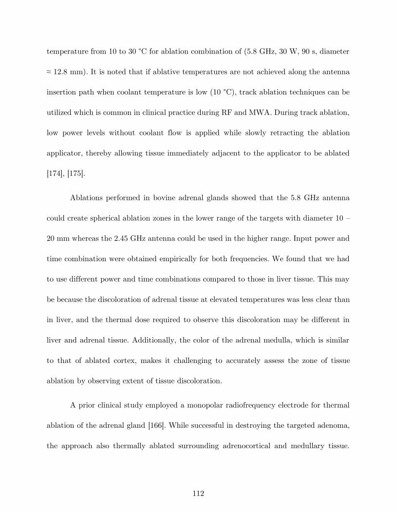
112
temperature from 10 to 30 °C for ablation combination of (5.8 GHz, 30 W, 90 s, diameter
≈ 12.8 mm). It is noted that if ablative temperatures are not achieved along the antenna
insertion path when coolant temperature is low (10 °C), track ablation techniques can be
utilized which is common in clinical practice during RF and MWA. During track ablation,
low power levels without coolant flow is applied while slowly retracting the ablation
applicator, thereby allowing tissue immediately adjacent to the applicator to be ablated
[174], [175].
Ablations performed in bovine adrenal glands showed that the 5.8 GHz antenna
could create spherical ablation zones in the lower range of the targets with diameter 10 –
20 mm whereas the 2.45 GHz antenna could be used in the higher range. Input power and
time combination were obtained empirically for both frequencies. We found that we had
to use different power and time combinations compared to those in liver tissue. This may
be because the discoloration of adrenal tissue at elevated temperatures was less clear than
in liver, and the thermal dose required to observe this discoloration may be different in
liver and adrenal tissue. Additionally, the color of the adrenal medulla, which is similar
to that of ablated cortex, makes it challenging to accurately assess the zone of tissue
ablation by observing extent of tissue discoloration.
A prior clinical study employed a monopolar radiofrequency electrode for thermal
ablation of the adrenal gland [166]. While successful in destroying the targeted adenoma,
the approach also thermally ablated surrounding adrenocortical and medullary tissue.
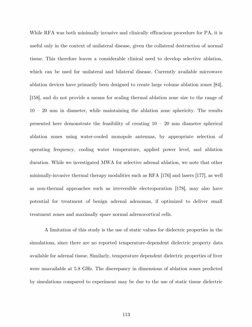
113
While RFA was both minimally invasive and clinically efficacious procedure for PA, it is
useful only in the context of unilateral disease, given the collateral destruction of normal
tissue. This therefore leaves a considerable clinical need to develop selective ablation,
which can be used for unilateral and bilateral disease. Currently available microwave
ablation devices have primarily been designed to create large volume ablation zones [84],
[158], and do not provide a means for scaling thermal ablation zone size to the range of
10 – 20 mm in diameter, while maintaining the ablation zone sphericity. The results
presented here demonstrate the feasibility of creating 10 – 20 mm diameter spherical
ablation zones using water-cooled monopole antennas, by appropriate selection of
operating frequency, cooling water temperature, applied power level, and ablation
duration. While we investigated MWA for selective adrenal ablation, we note that other
minimally-invasive thermal therapy modalities such as RFA [176] and lasers [177], as well
as non-thermal approaches such as irreversible electroporation [178], may also have
potential for treatment of benign adrenal adenomas, if optimized to deliver small
treatment zones and maximally spare normal adrenocortical cells.
A limitation of this study is the use of static values for dielectric properties in the
simulations, since there are no reported temperature-dependent dielectric property data
available for adrenal tissue. Similarly, temperature dependent dielectric properties of liver
were unavailable at 5.8 GHz. The discrepancy in dimensions of ablation zones predicted
by simulations compared to experiment may be due to the use of static tissue dielectric
114
properties in the simulations. Ongoing efforts in our lab are geared towards assessing the
relationship between residual adrenal function following selective thermal ablation of
targeted regions within the adrenal medulla and cortex. Similar to other reports on design
of devices for microwave ablation employing computational models and experiments in ex
vivo tissue [45], [137], [165], perfusion effects were not considered in our simulations and
experiments. Compared to longer treatment durations used for creation of large ablation
zones (e.g. in the liver), it is likely that perfusion will have a reduced impact for short
duration ablations and can be compensated by increasing the applied input power.
5.5 Conclusion
We evaluated water-cooled monopole antennas, designed to operated 2.45 GHz and
5.8 GHz, for creating short spherical ablation zones with application to thermal ablation
of benign adrenal adenomas. Computational models and experiments in ex vivo tissue
were used to analyze the effect of frequency, applied power, ablation duration, and coolant
temperature on the ablation length and width. Both simulation and measured results
demonstrated the ability to create spherical ablation zones with a diameter in the range
of 10 – 20 mm through appropriate selection of applied power, ablation duration, and
coolant temperature. Statistical analysis of the experimentally measured ablation zones
showed that ablation length is primarily controlled by the operating frequency, while
115
ablation width is primarily controlled by the ablation duration and temperature of the
cooling water.
116
6 Broadband Dielectric Properties of Ex Vivo
Bovine Liver Tissue Characterized at
Ablative Temperatures4
6.1 Introduction
Microwave ablation (MWA) is a minimally invasive treatment for destruction of
tissue by localized heating to cytotoxic temperatures. MWA has been clinically applied
for treatment of tumors in the liver, kidney, lung, and bone [56], as well as benign targets,
such as the endometrial lining of the uterine cavity for treating menorrhagia [24] and
cardiac arrhythmias [179]. The majority of MWA systems in current clinical use deliver
4 This chapter has been published as: H. Fallahi, J. Sebek, and P. Prakash, “Broadband Dielectric Properties
of Ex Vivo Bovine Liver Tissue Characterized at Ablative Temperatures,” IEEE Trans. Biomed. Eng., 2020.
© 2020 IEEE. Personal use of this material is permitted. Permission from IEEE must be obtained for all
other uses, in any current or future media, including reprinting/republishing this material for advertising
or promotional purposes, creating new collective works, for resale or redistribution to servers or lists, or
reuse of any copyrighted component of this work in other works.
117
microwave power at a frequency of 915 MHz or 2.45 GHz; systems operating at other
frequencies are under investigation [63]. Microwave propagation and absorption within
tissue is a function of the dielectric properties – relative permittivity and effective
conductivity – which are known to vary widely across tissue type, and as a function of
frequency, water content, and temperature. The dielectric properties of target tissue are
key inputs for computational models of MWA, which are widely used for device design
and optimization, device characterization and as part of regulatory studies, and are under
development for planning, guiding delivery, and assessing clinical ablation procedures
[180].
Gabriel et al. [58] reported the dielectric properties of different tissues across a
broad range of frequencies, at temperatures close to the physiologic temperature range
(~37 °C). These data have been invaluable for driving simulation-based design of
microwave thermal therapy systems. During MWA, tissue temperatures may rise from
baseline to ~150 °C [1]. At these elevated temperatures, tissue structural changes and
water loss [181], [182] lead to reversible and irreversible changes in tissue dielectric
properties [183], [184]. Therefore, models employing static tissue dielectric properties at
elevated temperatures may not accurately capture the ablation outcome [136].
Furthermore, some recent studies have proposed exploiting changes in tissue dielectric
properties at ablative temperatures to monitor transient growth of the ablation zone [185].
118
Further development of these techniques will require characterization of broadband tissue
dielectric properties at ablative temperatures.
While several studies have investigated the dielectric properties of tissue as a
function of temperature, few have extended these measurements to temperatures
exceeding 90 °C, which are commonly observed during tissue ablation [69], [186]. In recent
years, some studies have reported temperature-dependent dielectric properties of liver
tissue [136], [172], [187], which include the dynamic change of properties at temperatures
as high as 100 °C. However, these data have predominantly been limited to the single
frequency of 2.45 GHz; the lack of knowledge of dielectric properties at ablative
temperatures at other microwave frequencies has hampered the development of ablative
technologies operating at frequencies other than 2.45 GHz [24], [28], [63]. As researchers
investigate ablation systems at other operating frequencies, and wideband approaches for
monitoring treatment progress, characterization of tissue dielectric properties across a
broad range of frequencies in the ablative temperature range will be critical. Furthermore,
the bulk of prior studies of temperature-dependent tissue dielectric properties at 2.45 GHz
have not investigated the impact of the rate of heating on the measured dielectric
properties [188]. This is of importance since the heating rate during MWA varies
considerably within tissue as a function of spatial position relative to the radiating
antenna. Broadband temperature-dependent measurement of dielectric properties of
bovine liver will provide the foundation for further model-based design and development
119
of next-generation minimally invasive MWA systems as well as wideband techniques for
real-time monitoring of MWA [189], [190].
In this work, we experimentally measured the changes in broadband dielectric
properties of fresh ex vivo bovine liver tissue (frequencies between 0.5 to 6 GHz) over the
temperature range of 20 to 130 °C. The measurements were performed at slow heating
(SH) rate, medium heating (MH) and fast heating (FH) rate, of approximately 6.4 °C/min,
11.3 °C/min and 16.9 °C/min, respectively. Then, the measured data were fitted to a
parametric model describing tissue dielectric properties as function of frequency and
temperature or thermal dose, suitable for application in computational models of MWA.
Finally, the parametric models were evaluated by comparing simulated return loss of
MWA antennas operating at 2.45 and 5.8 GHz with experimentally measured return loss
during MWA experiments.
6.2 Methods
6.2.1 Dielectric property measurements
Among the different methods for dielectric measurement [191]–[194], the open-
ended coaxial probe technique has been widely used for dielectric characterization of
tissue. This method utilizes a coaxial probe connected to a vector network analyzer
(VNA). The VNA measures the signals reflected at the tip of the coaxial probe, at the
interface with the tissue sample. Tissue relative permittivity, 𝜖𝑟, and effective
120
conductivity, 𝜎𝑒𝑓𝑓, are computed from the measured complex reflection coefficients. We
used an HP 8753D VNA with the frequency range of 0.5 to 6 GHz and the slim form
open-ended dielectric probe kit (Keysight 85070E). Dielectric properties of the samples
were recorded at 401 points logarithmically distributed across the frequency range [195].
The standard calibration (air, short, distilled water) procedure was performed before each
test. The performance of the probe was validated by measuring the dielectric properties
of ethanol at 25 °C. The maximum difference between our measurement and published
data [196] was approximately 0.88 unit for relative permittivity and 0.16 S/m for effective
conductivity, similar to [186].
A fiber optic temperature sensor (Qualitrol OptiLinkTM, T1C-02-PP10 with
Neoptix Reflex signal conditioner) was positioned flush with the dielectric probe in order
to co-register the tissue sample temperature at all times when dielectric properties were
recorded. A piece of polyimide tube was employed to keep the temperature sensor in place.
The sensor measured the temperature with an acquisition rate of 1 sample/s.
The tissue sample was placed in a custom-made copper box on top of a hot plate
(ThermoScientific), similar to the approach we previously reported for measuring
dielectric properties of lung tissue [197]. Briefly, the tissue sample within the copper
sample holder is heated by thermal conduction from the hot plate. A set of thin copper
fins affixed to the top of the copper sample holder provided a heat transfer path from the
hot plate surface to the upper edges of the sample holder, with a goal of minimizing the
121
temperature gradient over the sample. We found this approach of heating the tissue
sample to be more repeatable than previous efforts using a microwave antenna to heat
the tissue [30]. The coaxial probe was positioned approximately above the center of the
sample using a lab jack. We pushed the tip of the probe at least 5 mm onto the sample.
The values of dielectric properties were automatically captured every 5 s during the course
of heating. Figure 6-1 shows the experimental setup.
The tissue samples were excised from fresh bovine liver purchased from a local
slaughterhouse, and transported to our lab in a plastic bag placed on ice. Tissue was cut
into 2×2×2 cm3 samples and kept on ice in a cooler. Dielectric data were measured within
~12-24 hours post-mortem. Measurements were performed on 15 samples obtained from
two bovine livers (6 samples from liver I and 9 from liver II). Slow, medium and fast
heating rates were achieved by setting the hot plate temperature to 200 °C, 300 °C and
400 °C, respectively (n = 3 measurements at each heating rate). When the sample
temperature reached ~90 °C, the hot plate temperature was set to max (540 °C) in order
to provide adequate heat to overcome the latent heat of water vaporization and raise the
tissue temperature above 100 °C. Dielectric properties of samples from liver I were
measured using the slow heating rate while those of samples from liver II were measured
using different heating rates. When changes of dielectric properties due to different heating
rates were compared with each other, only the data from liver II were used in order to
exclude the data variability due to the tissue itself.
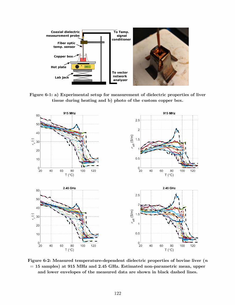
122
Figure 6-1: a) Experimental setup for measurement of dielectric properties of liver
tissue during heating and b) photo of the custom copper box.
Figure 6-2: Measured temperature-dependent dielectric properties of bovine liver (n
= 15 samples) at 915 MHz and 2.45 GHz. Estimated non-parametric mean, upper
and lower envelopes of the measured data are shown in black dashed lines.
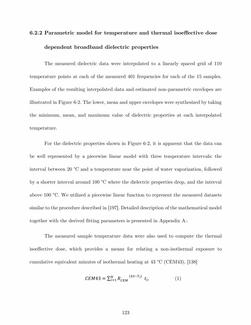
123
6.2.2 Parametric model for temperature and thermal isoeffective dose
dependent broadband dielectric properties
The measured dielectric data were interpolated to a linearly spaced grid of 110
temperature points at each of the measured 401 frequencies for each of the 15 samples.
Examples of the resulting interpolated data and estimated non-parametric envelopes are
illustrated in Figure 6-2. The lower, mean and upper envelopes were synthesized by taking
the minimum, mean, and maximum value of dielectric properties at each interpolated
temperature.
For the dielectric properties shown in Figure 6-2, it is apparent that the data can
be well represented by a piecewise linear model with three temperature intervals: the
interval between 20 °C and a temperature near the point of water vaporization, followed
by a shorter interval around 100 °C where the dielectric properties drop, and the interval
above 100 °C. We utilized a piecewise linear function to represent the measured datasets
similar to the procedure described in [197]. Detailed description of the mathematical model
together with the derived fitting parameters is presented in Appendix A:.
The measured sample temperature data were also used to compute the thermal
isoeffective dose, which provides a means for relating a non-isothermal exposure to
cumulative equivalent minutes of isothermal heating at 43 °C (CEM43), [138]
𝐶𝐸𝑀43 = ∑ 𝑅𝐶𝐸𝑀 (43−𝑇𝑖) 𝑡𝑖 ,
𝑁𝑖=1 (1)
124
where 𝑅𝐶𝐸𝑀 is the constant for proportionality for the process modeled, 𝑇𝑖 is the
temperature of time interval 𝑖 (°C), and 𝑡𝑖 is the time at 𝑇𝑖 (minutes). The values used
for 𝑅𝐶𝐸𝑀 at temperatures below and above the breakpoint, 43 °C, were 0.25 and 0.5,
respectively [198]. Presenting dielectric properties as a function of thermal dose provides
a means for capturing changes in dielectric properties based on the time-temperature
history during heating, rather than temperature alone. A similar parametric model and
optimization approach was employed to find the best parametrized piecewise fits for
dielectric properties as a function of the logarithm of CEM43.
6.2.3 Experimental assessment of temperature and thermal isoeffective
dose dependent dielectric property models
We conducted experiments to assess the ability of the temperature and thermal
dose dependent dielectric property parameterizations to capture dielectric property
changes in liver tissue during MWA. The return loss of an antenna is a parameter that
captures the impedance mismatch between the ablation antenna and the feeding
transmission line. The antenna impedance is primarily a function of the dielectric
properties of the tissue within which the antenna is inserted, as well as the antenna
dimensions. As tissue dielectric properties change at elevated temperatures during the
course of an ablation, return loss also changes. Thus, we sought to compare experimentally
measured changes in antenna return loss against simulated return loss during the course
of an ablation, when using simulations employing the temperature or thermal dose
125
dependent dielectric properties described in Section 6.2.2. Ablations were performed with
interstitial dipole antennas tuned to operate at 2.45 and 5.8 GHz, following the method
described in [199]. Briefly, finite element method computational models were used to solve
the steady-state Helmholtz equation to determine the electric field and power loss density
profiles in tissue, which served as the heat source for a transient heat transfer model. A
coupled model in COMSOL Multiphysics v5.3 was implemented such that the tissue
physical properties were updated, and the electromagnetic model solved again, after each
time step taken by the transient solver (more details are provided in Appendix A:). The
antenna gap length was 1 for both frequencies and the dipole arm length was 10.9 and 5
mm respectively. Ablations were performed at 2.45 GHz and 5.8 GHz in fresh bovine liver
(sample dimensions: L = 80 mm, W = 70 mm, H = 70 mm), using the following applied
energy levels: (f = 2.45 GHz, Pin = 25 W, t = 10 min), (f = 2.45 GHz, Pin = 40 W, t =
4 min), (f = 5.8 GHz, Pin = 25 W, t = 10 min), and (f = 5.8 GHz, Pin = 40 W, t = 4
min). At each experimental group, ablation experiments were performed in triplicate (i.e.,
n = 3). During the course of ablation, return loss was measured with a statistical RF
power meter (Bird 7022). We applied the temperature-dependent and thermal dose-
dependent functions into computational models of MWA, previously described in [199].
Antenna return loss was simulated when using dielectric property parameterizations
capturing the lower, mean and upper envelopes of each dielectric property.
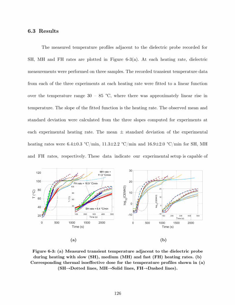
126
6.3 Results
The measured temperature profiles adjacent to the dielectric probe recorded for
SH, MH and FH rates are plotted in Figure 6-3(a). At each heating rate, dielectric
measurements were performed on three samples. The recorded transient temperature data
from each of the three experiments at each heating rate were fitted to a linear function
over the temperature range 30 – 85 °C, where there was approximately linear rise in
temperature. The slope of the fitted function is the heating rate. The observed mean and
standard deviation were calculated from the three slopes computed for experiments at
each experimental heating rate. The mean ± standard deviation of the experimental
heating rates were 6.4±0.3 °C/min, 11.3±2.2 °C/min and 16.9±2.0 °C/min for SH, MH
and FH rates, respectively. These data indicate our experimental setup is capable of
(a) (b)
Figure 6-3: (a) Measured transient temperature adjacent to the dielectric probe
during heating with slow (SH), medium (MH) and fast (FH) heating rates. (b)
Corresponding thermal isoeffective dose for the temperature profiles shown in (a)
(SH→Dotted lines, MH→Solid lines, FH→Dashed lines).
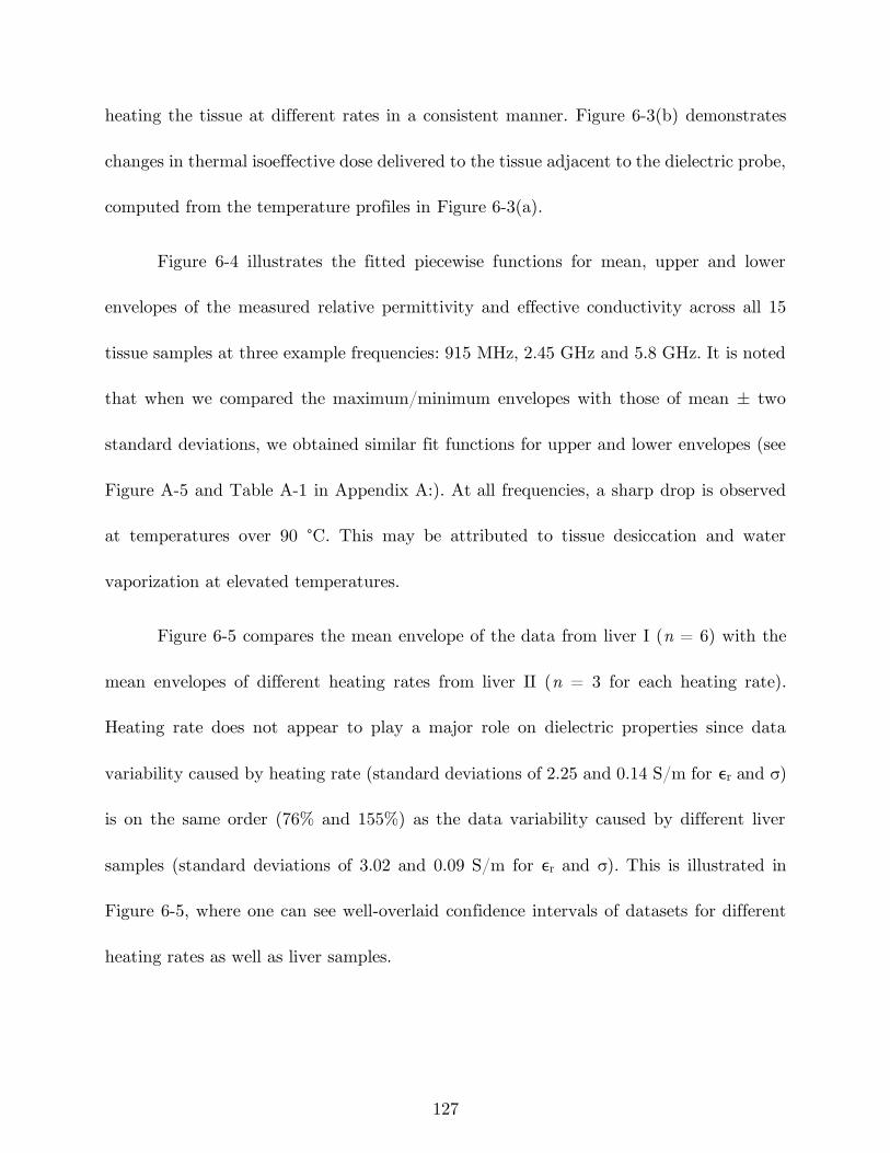
127
heating the tissue at different rates in a consistent manner. Figure 6-3(b) demonstrates
changes in thermal isoeffective dose delivered to the tissue adjacent to the dielectric probe,
computed from the temperature profiles in Figure 6-3(a).
Figure 6-4 illustrates the fitted piecewise functions for mean, upper and lower
envelopes of the measured relative permittivity and effective conductivity across all 15
tissue samples at three example frequencies: 915 MHz, 2.45 GHz and 5.8 GHz. It is noted
that when we compared the maximum/minimum envelopes with those of mean ± two
standard deviations, we obtained similar fit functions for upper and lower envelopes (see
Figure A-5 and Table A-1 in Appendix A:). At all frequencies, a sharp drop is observed
at temperatures over 90 °C. This may be attributed to tissue desiccation and water
vaporization at elevated temperatures.
Figure 6-5 compares the mean envelope of the data from liver I (n = 6) with the
mean envelopes of different heating rates from liver II (n = 3 for each heating rate).
Heating rate does not appear to play a major role on dielectric properties since data
variability caused by heating rate (standard deviations of 2.25 and 0.14 S/m for ϵr and σ)
is on the same order (76% and 155%) as the data variability caused by different liver
samples (standard deviations of 3.02 and 0.09 S/m for ϵr and σ). This is illustrated in
Figure 6-5, where one can see well-overlaid confidence intervals of datasets for different
heating rates as well as liver samples.
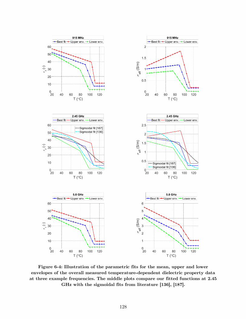
128
Figure 6-4: Illustration of the parametric fits for the mean, upper and lower
envelopes of the overall measured temperature-dependent dielectric property data
at three example frequencies. The middle plots compare our fitted functions at 2.45
GHz with the sigmoidal fits from literature [136], [187].
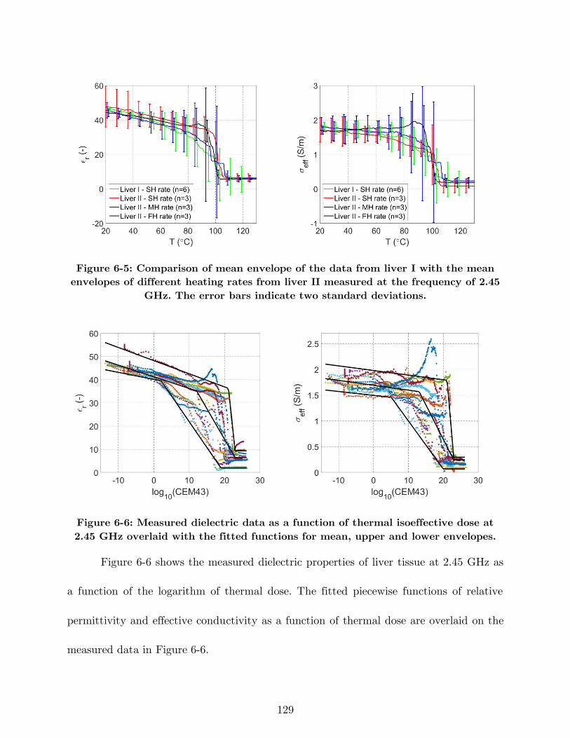
129
Figure 6-5: Comparison of mean envelope of the data from liver I with the mean
envelopes of different heating rates from liver II measured at the frequency of 2.45
GHz. The error bars indicate two standard deviations.
Figure 6-6: Measured dielectric data as a function of thermal isoeffective dose at
2.45 GHz overlaid with the fitted functions for mean, upper and lower envelopes.
Figure 6-6 shows the measured dielectric properties of liver tissue at 2.45 GHz as
a function of the logarithm of thermal dose. The fitted piecewise functions of relative
permittivity and effective conductivity as a function of thermal dose are overlaid on the
measured data in Figure 6-6.
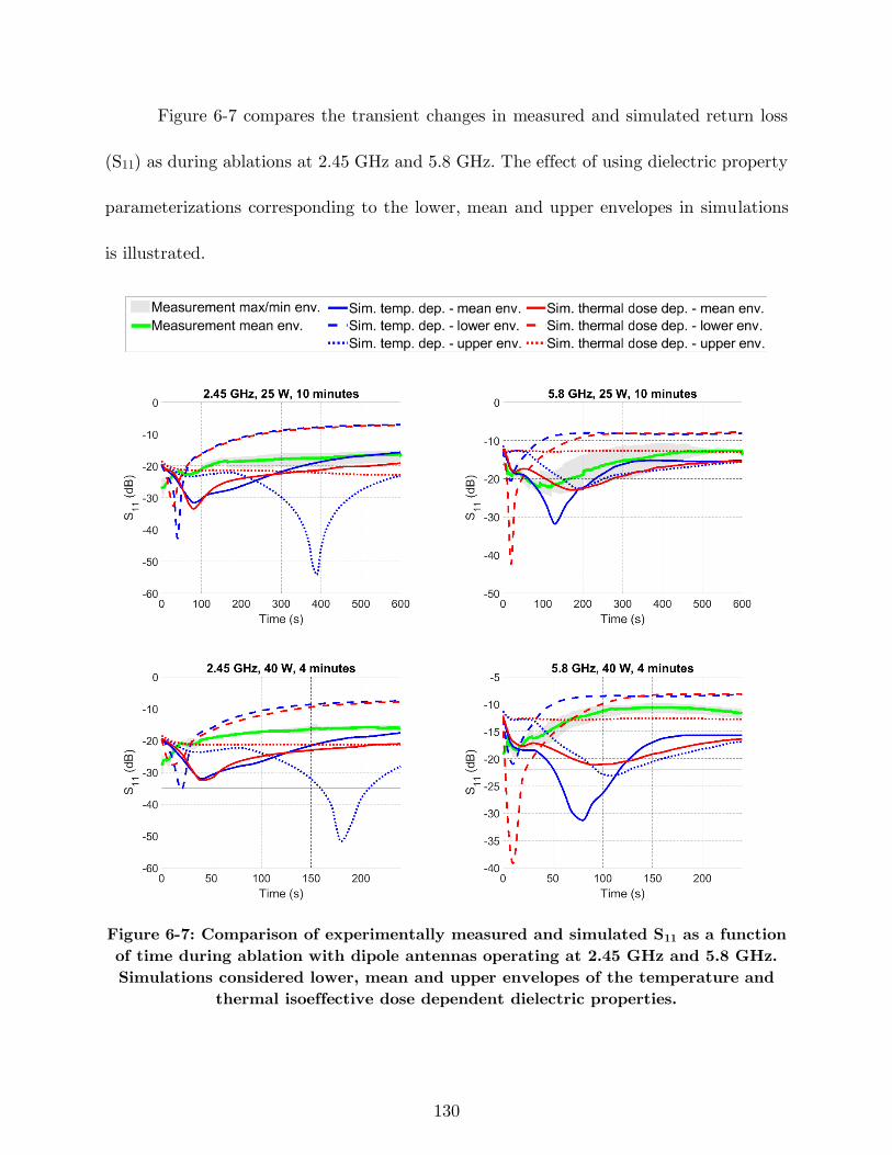
130
Figure 6-7 compares the transient changes in measured and simulated return loss
(S11) as during ablations at 2.45 GHz and 5.8 GHz. The effect of using dielectric property
parameterizations corresponding to the lower, mean and upper envelopes in simulations
is illustrated.
Figure 6-7: Comparison of experimentally measured and simulated S11 as a function
of time during ablation with dipole antennas operating at 2.45 GHz and 5.8 GHz.
Simulations considered lower, mean and upper envelopes of the temperature and
thermal isoeffective dose dependent dielectric properties.
131
6.4 Discussion
The goal of this study was to measure the broadband dielectric properties of ex
vivo bovine liver tissue starting at room temperature and continuing over the ablative
temperature range. These data have application to the development of computational
models for microwave ablation applicator and system design, as well as validation of
computational models used for simulating clinical procedures. Moreover, we derived a
piecewise linear function characterizing frequency and temperature dependence of tissue
dielectric properties, suitable for use with computational models.
Among the prior studies on temperature-dependent dielectric properties of tissue,
there are only a few with data reported at ablative temperatures (i.e. T > 90 °C) [136],
[187]. The measured dielectric properties reported in these studies have been limited to a
single frequency (2.45 GHz), and only a single heating rate was used. The broadband
dielectric properties and parametric models presented in this study may contribute to the
continued development of ablation technology operating at frequencies other than 2.45
GHz, as well as broadband techniques for monitoring growth of the ablation zone, the
presented dielectric properties.
The dielectric property parameterizations plotted in Figure 6-4 illustrate dielectric
property changes can be grouped over three temperature intervals: gradual changes in
dielectric properties at temperatures in the range 20 to ~90 °C; a sharp drop in dielectric
properties over the temperature range ~90 to ~110 °C; and relatively constant dielectric
132
properties beyond ~110 °C. The average error for the piecewise linear parametrization was
low (e. g. 1.06 and 0.0051 in case of mean ϵr and σeff envelopes), indicating they are a
suitable parametrization for these data (see Appendix A:). While relative permittivity at
different frequencies changes similarly as a function of temperature, effective conductivity
changes during heating vary across frequency ranges. An important observation is the
change of the effective conductivity slope in the first temperature region from positive
values at lower frequencies (0.5–1.64 GHz) to negative values at higher frequencies (1.64–
6 GHz). The positive slope of effective conductivity at low temperatures is in agreement
with the measurements in [186], where broadband dielectric properties were presented up
to temperatures of ~65 °C (see Figure A-4 in Appendix A:).
The recommended settings for use of the open-ended coaxial dielectric
measurement probe employed in the presented study suggest a homogeneous material
within 5 mm radially from the probe surface. For this reason, we selected the sample size
for tissue to be 2×2×2 cm3, exceeding the minimal recommend sample size. However, given
the relatively large sample size, and the source of heating, undoubtedly there existed a
temperature gradient within the sample. It is noteworthy that several studies have
identified that the open-ended dielectric probe measurement method is most sensitive to
tissue within 0.3 mm of the probe surface, for the ~2.2 mm dielectric probe used in the
present study [200], [201]. While there may be some thermal heterogeneity within this
133
small volume, it is likely to be considerably small, and may have a relatively small impact
on the dielectric measurements, compared to probes that have greater sensing depths.
The presented fitted piecewise function for dielectric properties at 2.45 GHz follows
a trend similar to the sigmoidal models reported in the literature (see Figure 6-4).
Changing the heating rate did not yield appreciable changes in the measured relative
permittivity. However, varying the heating rate did give rise to different temperature
dependencies for the effective conductivity in the range of 40 to 100 °C. When heating the
sample using a lower heating rate (6.4 °C/min), a more rapid drop in effective conductivity
was observed as a function of temperature, compared to higher heating rates. Overall, the
dielectric data sensitivity due to different heating rates is within the same range as that
of the tissue variability. The dielectric property parameterizations as a function of thermal
dose provide a means for capturing changes in dielectric properties of tissue at varying
heating rates.
During a MWA procedure, the antenna’s return loss (S11) may provide an
indication of the changes in tissue dielectric properties. We used the temperature and
thermal dose dependent dielectric property parameterizations presented in this paper in
computational models of microwave ablation with dipole antennas operating at 2.45 GHz
and 5.8 GHz and compared the simulated changes in S11 with measured changes in return
loss during experimental ablations. The correlation coefficients listed in Table 6-1 provide
a means for assessing the similarity between the measured and simulated S11 during
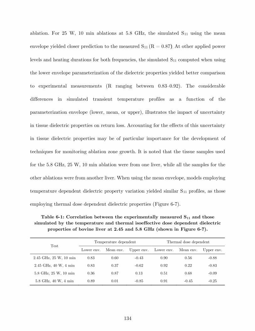
134
ablation. For 25 W, 10 min ablations at 5.8 GHz, the simulated S11 using the mean
envelope yielded closer prediction to the measured S11 (R = 0.87). At other applied power
levels and heating durations for both frequencies, the simulated S11 computed when using
the lower envelope parameterization of the dielectric properties yielded better comparison
to experimental measurements (R ranging between 0.83–0.92). The considerable
differences in simulated transient temperature profiles as a function of the
parameterization envelope (lower, mean, or upper), illustrates the impact of uncertainty
in tissue dielectric properties on return loss. Accounting for the effects of this uncertainty
in tissue dielectric properties may be of particular importance for the development of
techniques for monitoring ablation zone growth. It is noted that the tissue samples used
for the 5.8 GHz, 25 W, 10 min ablation were from one liver, while all the samples for the
other ablations were from another liver. When using the mean envelope, models employing
temperature dependent dielectric property variation yielded similar S11 profiles, as those
employing thermal dose dependent dielectric properties (Figure 6-7).
Table 6-1: Correlation between the experimentally measured S11 and those
simulated by the temperature and thermal isoeffective dose dependent dielectric
properties of bovine liver at 2.45 and 5.8 GHz (shown in Figure 6-7).
Test Temperature dependent Thermal dose dependent
Lower env. Mean env. Upper env. Lower env. Mean env. Upper env.
2.45 GHz, 25 W, 10 min 0.83 0.60 -0.43 0.90 0.56 -0.88
2.45 GHz, 40 W, 4 min 0.83 0.37 -0.62 0.92 0.22 -0.83
5.8 GHz, 25 W, 10 min 0.36 0.87 0.13 0.51 0.68 -0.09
5.8 GHz, 40 W, 4 min 0.89 0.01 -0.85 0.91 -0.45 -0.25
135
A limitation of this study is that the dielectric property measurements were
conducted on ex vivo tissue. While it is ideal to characterize tissue properties in vivo,
measuring tissue dielectric properties in vivo with invasive probes is a challenging task
[202], [203], due to the additional uncertainties associated with blood in proximity to the
dielectric probe. In our experiments, we pushed the probe ~5 mm onto the tissue. Recent
studies demonstrate that the pressure applied by dielectric measurement probes on the
tissue surface may alter the tissue water content, potentially contributing to variability
of measured dielectric properties [204]. Further investigation of the probe-to-tissue contact
pressure on dielectric properties of tissue during heating to ablative temperatures is
warranted. Our ex vivo data is a step toward better understanding the broadband tissue
dielectric properties over the ablative temperature range. Our study was further limited
to measurements on normal liver tissue, which is a widely used benchtop experimental
model for evaluating microwave ablation devices. Future studies investigating the
dielectric properties of normal and malignant human liver would provide enhanced
understanding of microwave energy interactions with tissue during clinical ablation
procedures.
6.5 Conclusion
We have reported measurements of the broadband dielectric properties of ex vivo
bovine liver over the frequency range 500 MHz to 6 GHz and temperature range 20 to 130
136
°C. We observed a sharp drop in both relative permittivity and effective conductivity in
the temperature range of 89 to 107 °C similar to prior reports of dielectric properties at
2.45 GHz reported in the literature. The observed temperature-dependence of dielectric
properties varied a function of temperature for each frequency. Dielectric properties did
not vary appreciably when experiments were conducted at different heating rates (6.4 –
16.9 °C/min). Finally, piecewise functions modeling the measured dielectric properties of
liver tissue were provided, and may serve as a foundation for more accurate modeling of
microwave ablation applicators and systems.
137
7 Conclusion and Future Work
In this chapter, concluding remarks of this dissertation are provided as well as a
summary of the results and suggestion for future research directions.
There has been considerable interest in the development of MW ablation
technology for a range of clinical indications. In chapter 2, it was demonstrated that a
critical component of MW ablation systems is the applicator, which includes an antenna
for coupling applied MW power from a generator to the targeted tissue. We reviewed MW
antennas designed for site-specific thermal ablation of tissue. Then, the use of active
cooling strategies for minimizing unintended heating along the feeding transmission line
and antenna chokes/sleeves and cooling for adjusting the length of ablation zones were
discussed.
In chapter 3, we presented an applicator for treatment of menstrual heavy bleeding.
The applicator employs a microwave loop antenna for global endometrial ablation
enabling conformal ablation of uterine cavities of varying size in the range 4–6.5 cm in
length and 2.5–4.5 cm in width, with a single positioning of the device. For treating large
cavities, conformal microwave radiation was achieved by coupling the loop antenna with
a passive element. A 3-D-coupled finite element method electromagnetic and heat transfer
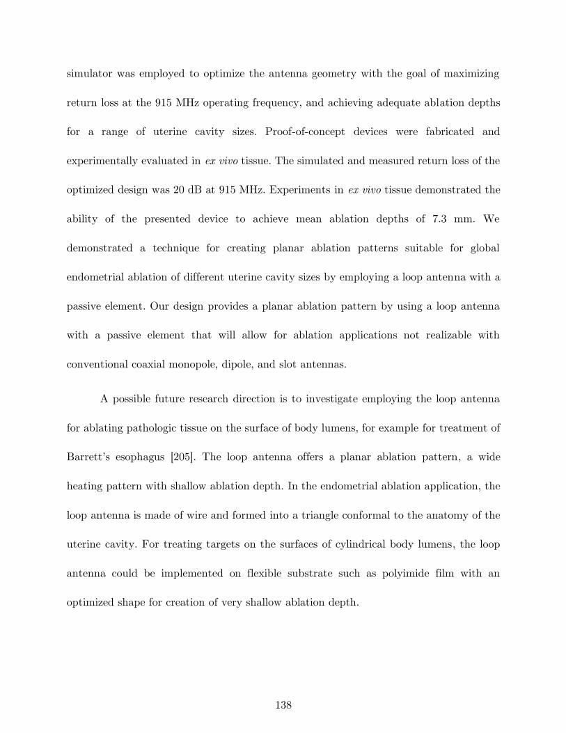
138
simulator was employed to optimize the antenna geometry with the goal of maximizing
return loss at the 915 MHz operating frequency, and achieving adequate ablation depths
for a range of uterine cavity sizes. Proof-of-concept devices were fabricated and
experimentally evaluated in ex vivo tissue. The simulated and measured return loss of the
optimized design was 20 dB at 915 MHz. Experiments in ex vivo tissue demonstrated the
ability of the presented device to achieve mean ablation depths of 7.3 mm. We
demonstrated a technique for creating planar ablation patterns suitable for global
endometrial ablation of different uterine cavity sizes by employing a loop antenna with a
passive element. Our design provides a planar ablation pattern by using a loop antenna
with a passive element that will allow for ablation applications not realizable with
conventional coaxial monopole, dipole, and slot antennas.
A possible future research direction is to investigate employing the loop antenna
for ablating pathologic tissue on the surface of body lumens, for example for treatment of
Barrett’s esophagus [205]. The loop antenna offers a planar ablation pattern, a wide
heating pattern with shallow ablation depth. In the endometrial ablation application, the
loop antenna is made of wire and formed into a triangle conformal to the anatomy of the
uterine cavity. For treating targets on the surfaces of cylindrical body lumens, the loop
antenna could be implemented on flexible substrate such as polyimide film with an
optimized shape for creation of very shallow ablation depth.
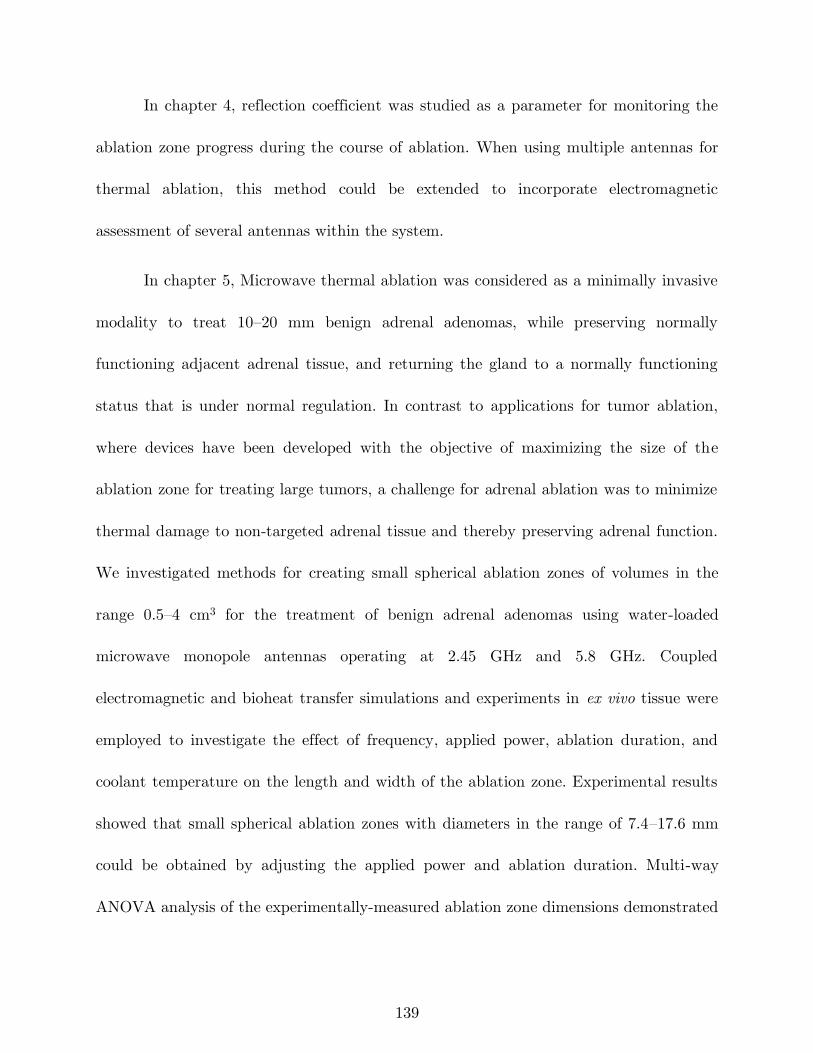
139
In chapter 4, reflection coefficient was studied as a parameter for monitoring the
ablation zone progress during the course of ablation. When using multiple antennas for
thermal ablation, this method could be extended to incorporate electromagnetic
assessment of several antennas within the system.
In chapter 5, Microwave thermal ablation was considered as a minimally invasive
modality to treat 10–20 mm benign adrenal adenomas, while preserving normally
functioning adjacent adrenal tissue, and returning the gland to a normally functioning
status that is under normal regulation. In contrast to applications for tumor ablation,
where devices have been developed with the objective of maximizing the size of the
ablation zone for treating large tumors, a challenge for adrenal ablation was to minimize
thermal damage to non-targeted adrenal tissue and thereby preserving adrenal function.
We investigated methods for creating small spherical ablation zones of volumes in the
range 0.5–4 cm3 for the treatment of benign adrenal adenomas using water-loaded
microwave monopole antennas operating at 2.45 GHz and 5.8 GHz. Coupled
electromagnetic and bioheat transfer simulations and experiments in ex vivo tissue were
employed to investigate the effect of frequency, applied power, ablation duration, and
coolant temperature on the length and width of the ablation zone. Experimental results
showed that small spherical ablation zones with diameters in the range of 7.4–17.6 mm
could be obtained by adjusting the applied power and ablation duration. Multi-way
ANOVA analysis of the experimentally-measured ablation zone dimensions demonstrated
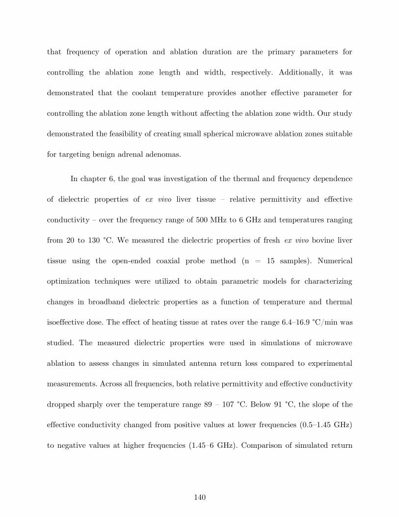
140
that frequency of operation and ablation duration are the primary parameters for
controlling the ablation zone length and width, respectively. Additionally, it was
demonstrated that the coolant temperature provides another effective parameter for
controlling the ablation zone length without affecting the ablation zone width. Our study
demonstrated the feasibility of creating small spherical microwave ablation zones suitable
for targeting benign adrenal adenomas.
In chapter 6, the goal was investigation of the thermal and frequency dependence
of dielectric properties of ex vivo liver tissue – relative permittivity and effective
conductivity – over the frequency range of 500 MHz to 6 GHz and temperatures ranging
from 20 to 130 °C. We measured the dielectric properties of fresh ex vivo bovine liver
tissue using the open-ended coaxial probe method (n = 15 samples). Numerical
optimization techniques were utilized to obtain parametric models for characterizing
changes in broadband dielectric properties as a function of temperature and thermal
isoeffective dose. The effect of heating tissue at rates over the range 6.4–16.9 °C/min was
studied. The measured dielectric properties were used in simulations of microwave
ablation to assess changes in simulated antenna return loss compared to experimental
measurements. Across all frequencies, both relative permittivity and effective conductivity
dropped sharply over the temperature range 89 – 107 °C. Below 91 °C, the slope of the
effective conductivity changed from positive values at lower frequencies (0.5–1.45 GHz)
to negative values at higher frequencies (1.45–6 GHz). Comparison of simulated return
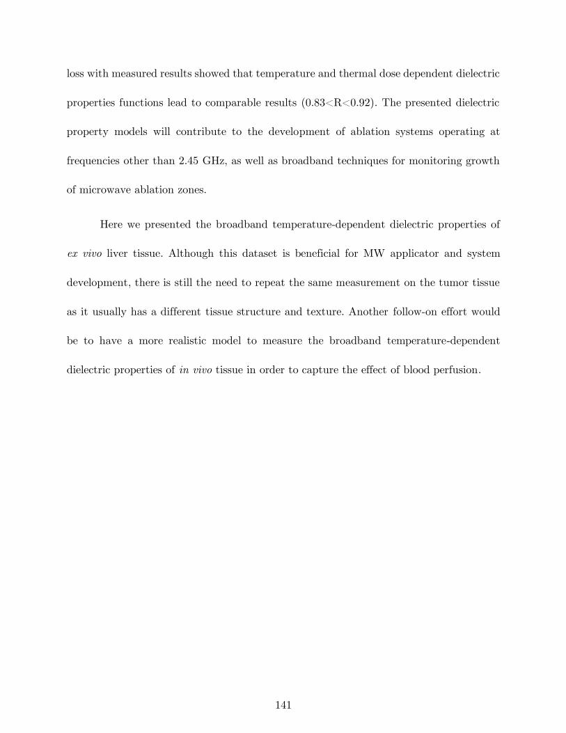
141
loss with measured results showed that temperature and thermal dose dependent dielectric
properties functions lead to comparable results (0.83<R<0.92). The presented dielectric
property models will contribute to the development of ablation systems operating at
frequencies other than 2.45 GHz, as well as broadband techniques for monitoring growth
of microwave ablation zones.
Here we presented the broadband temperature-dependent dielectric properties of
ex vivo liver tissue. Although this dataset is beneficial for MW applicator and system
development, there is still the need to repeat the same measurement on the tumor tissue
as it usually has a different tissue structure and texture. Another follow-on effort would
be to have a more realistic model to measure the broadband temperature-dependent
dielectric properties of in vivo tissue in order to capture the effect of blood perfusion.
142
References
[1] C. L. Brace, “Radiofrequency and microwave ablation of the liver, lung, kidney, and
bone: what are the differences?,” Curr. Probl. Diagn. Radiol., vol. 38, no. 3, pp. 135–
143, 2009.
[2] E. S. Alexander and D. E. Dupuy, “Lung cancer ablation: technologies and
techniques,” in Seminars in interventional radiology, 2013, vol. 30, pp. 141–150.
[3] Y. Lin et al., “Percutaneous microwave ablation of renal cell carcinoma is safe in
patients with a solitary kidney,” Urology, vol. 83, no. 2, pp. 357–363, 2014.
[4] A. Kelekis, F. H. Cornelis, S. Tutton, and D. Filippiadis, “Metastatic osseous pain
control: bone ablation and cementoplasty,” in Seminars in interventional radiology,
2017, vol. 34, pp. 328–336.
[5] O. Lodeizen et al., “Ablation energies for focal treatment of prostate cancer,” World
J. Urol., vol. 37, no. 3, pp. 409–418, 2019.
[6] A. H. Kim et al., “Laser Ablation of Abnormal Neurological Tissue Using Robotic
NeuroBlate System (LAANTERN): 12-Month Outcomes and Quality of Life After
Brain Tumor Ablation,” Neurosurgery, 2020.
[7] Z. Gu, C. M. Rappaport, P. J. Wang, and B. A. VanderBrink, “A 2 1/4-turn spiral
antenna for catheter cardiac ablation,” IEEE Trans. Biomed. Eng., vol. 46, no. 12,
pp. 1480–1482, 1999.
[8] J. Reeves, M. Birch, K. Munro, and R. Collier, “Investigation into the thermal
distribution of microwave helical antennas designed for the treatment of Barrett’s
oesophagus,” Phys. Med. Biol., vol. 47, no. 19, p. 3557, 2002.
[9] D. A. Hodgson, I. B. Feldberg, N. Sharp, N. Cronin, M. Evans, and L. Hirschowitz,
“Microwave endometrial ablation: development, clinical trials and outcomes at three
years,” BJOG Int. J. Obstet. Gynaecol., vol. 106, no. 7, pp. 684–694, 1999.
[10] A. Andreano and C. L. Brace, “A comparison of direct heating during radiofrequency
and microwave ablation in ex vivo liver,” Cardiovasc. Intervent. Radiol., vol. 36, no.
2, pp. 505–511, 2013.
[11] > Gail ter Haar and C. Coussios, “High intensity focused ultrasound: physical
principles and devices,” Int. J. Hyperthermia, vol. 23, no. 2, pp. 89–104, 2007.
[12] J. E. Kennedy, “High-intensity focused ultrasound in the treatment of solid
tumours,” Nat. Rev. Cancer, vol. 5, no. 4, p. 321, 2005.
[13] T. Lee, N. Mendhiratta, D. Sperling, and H. Lepor, “Focal laser ablation for localized
prostate cancer: principles, clinical trials, and our initial experience,” Rev. Urol., vol.
16, no. 2, p. 55, 2014.
143
[14] U. Lindner, N. Lawrentschuk, and J. Trachtenberg, “Focal laser ablation for
localized prostate cancer,” J. Endourol., vol. 24, no. 5, pp. 791–797, 2010.
[15] S. Tatli, M. Acar, K. Tuncali, P. R. Morrison, and S. Silverman, “Percutaneous
cryoablation techniques and clinical applications,” Diagn. Interv. Radiol., vol. 16, no.
1, pp. 90–95, Mar. 2010, doi: http://dx.doi.org/10.4261/1305-3825.DIR.1922-08.0.
[16] J. G. Baust, A. A. Gage, and J. M. Baust, “Principles of cryoablation,” in
Dermatological Cryosurgery and Cryotherapy, Springer, 2016, pp. 9–16.
[17] P. G. Wagstaff et al., “Irreversible electroporation: state of the art,” OncoTargets
Ther., vol. 9, p. 2437, 2016.
[18] K. R. Thomson, H. Kavnoudias, and R. E. Neal II, “Introduction to irreversible
electroporation—principles and techniques,” Tech. Vasc. Interv. Radiol., vol. 18, no.
3, pp. 128–134, 2015.
[19] J. Rehman, J. Landman, C. Sundaram, and R. V. Clayman, “Tissue chemoablation,”
J. Endourol., vol. 17, no. 8, pp. 647–657, 2003.
[20] E. N. Cressman et al., “Concentration and volume effects in thermochemical ablation
in vivo: Results in a porcine model,” Int. J. Hyperthermia, vol. 28, no. 2, pp. 113–
121, 2012.
[21] J. M. Bertram, D. Yang, M. C. Converse, J. G. Webster, and D. M. Mahvi, “A
review of coaxial-based interstitial antennas for hepatic microwave ablation,” Crit.
Rev. Biomed. Eng., vol. 34, no. 3, 2006.
[22] H. Fallahi and P. Prakash, “Antenna designs for microwave tissue ablation,” Crit.
Rev. Biomed. Eng., vol. 46, no. 6, 2018.
[23] H. Fallahi, J. Šebek, E. Frattura, J. Schenck, and P. Prakash, “Global microwave
endometrial ablation for menorrhagia treatment,” in Proc. of SPIE Vol, 2017, vol.
10066, pp. 100660K–1.
[24] H. Fallahi and P. Prakash, “Design of a Microwave Global Endometrial Ablation
Device,” IEEE J. Electromagn. RF Microw. Med. Biol., 2019.
[25] P. Faridi, H. Fallahi, and P. Prakash, “Evaluation of the effect of uterine fibroids on
microwave endometrial ablation profiles,” in 2018 40th Annual International
Conference of the IEEE Engineering in Medicine and Biology Society (EMBC),
2018, pp. 3236–3239.
[26] P. Prakash, “Microwave system for global endometrial ablation,” WO2019241439A1,
Dec. 19, 2019.
[27] H. Fallahi, A. Shahzad, D. Clausing, M. O’Halloran, M. C. Dennedy, and P.
Prakash, “Technological requirements for microwave ablation of adrenal masses,” in
Antennas and Propagation (EUCAP), 2017 11th European Conference on, 2017, pp.
144
3713–3716, Accessed: Aug. 30, 2017. [Online]. Available:
http://ieeexplore.ieee.org/abstract/document/7928268/.
[28] H. Fallahi, D. Clausing, A. Shahzad, M. O’Halloran, M. C. Dennedy, and P.
Prakash, “Microwave antennas for thermal ablation of benign adrenal adenomas,”
Biomed. Phys. Eng. Express, vol. 5, no. 2, p. 025044, 2019.
[29] P. T. Donlon et al., “Using microwave thermal ablation to develop a subtotal,
cortical-sparing approach to the management of primary aldosteronism,” Int. J.
Hyperthermia, vol. 36, no. 1, pp. 905–914, 2019.
[30] H. Fallahi and P. Prakash, “Measurement of Broadband Temperature-Dependent
Dielectric Properties of Liver Tissue,” in 2018 IEEE International Microwave
Biomedical Conference (IMBioC), 2018, pp. 91–93.
[31] H. Fallahi, J. Sebek, and P. Prakash, “Broadband Dielectric Properties of Ex Vivo
Bovine Liver Tissue Characterized at Ablative Temperatures,” IEEE Trans. Biomed.
Eng., Under review.
[32] K. F. Chu and D. E. Dupuy, “Thermal ablation of tumours: biological mechanisms
and advances in therapy,” Nat. Rev. Cancer, vol. 14, no. 3, p. 199, 2014.
[33] S. Rey and S. Levine, “An Overview of Cardiac Ablation,” J. Clin. Exerc. Physiol.,
vol. 6, no. 2, pp. 29–35, 2017.
[34] W. Verloop, M. Voskuil, and P. Doevendans, “Renal denervation: a new treatment
option in resistant arterial hypertension,” Neth. Heart J., vol. 21, no. 2, pp. 95–98,
2013.
[35] G. W. Choby and P. H. Hwang, “Emerging roles of coblation in rhinology and skull
base surgery,” Otolaryngol. Clin. North Am., vol. 50, no. 3, pp. 599–606, 2017.
[36] M. Ahmed, C. L. Brace, F. T. Lee Jr, and S. N. Goldberg, “Principles of and
advances in percutaneous ablation,” Radiology, vol. 258, no. 2, pp. 351–369, 2011.
[37] C. Jiang, R. V. Davalos, and J. C. Bischof, “A review of basic to clinical studies of
irreversible electroporation therapy,” IEEE Trans. Biomed. Eng., vol. 62, no. 1, pp.
4–20, 2015.
[38] M. Burtnyk, T. Hill, H. Cadieux-Pitre, and I. Welch, “Magnetic resonance image
guided transurethral ultrasound prostate ablation: a preclinical safety and feasibility
study with 28-day followup,” J. Urol., vol. 193, no. 5, pp. 1669–1675, 2015.
[39] I. Fernández-Ruiz, “Renewed hopes for renal denervation in hypertension,” Nat. Rev.
Cardiol., p. 1, 2018.
[40] J. Sebek et al., “Feasibility Assessment of Microwave Ablation for Treating
Esophageal Varices,” J. Med. Devices, vol. 11, no. 3, p. 031013, 2017.
[41] J. A. Pearce, “Models for thermal damage in tissues: processes and applications,”
Crit. Rev. Biomed. Eng., vol. 38, no. 1, 2010.
145
[42] A. Osaka, “Use of microwave radiation in surgery and cancer therapy,” J. Microw.
Power, vol. 13, no. 2, pp. 155–161, 1978.
[43] A. P. O’Rourke, D. Haemmerich, P. Prakash, M. C. Converse, D. M. Mahvi, and J.
G. Webster, “Current status of liver tumor ablation devices,” Expert Rev. Med.
Devices, vol. 4, no. 4, pp. 523–537, 2007.
[44] K. Saito, S. Hosaka, S. Okabe, H. Yoshimura, and K. Ito, “A proposition on
improvement of a heating pattern of an antenna for microwave coagulation therapy:
Introduction of a coaxial-dipole antenna,” Electron. Commun. Jpn. Part Commun.,
vol. 86, no. 1, pp. 16–23, 2003.
[45] D. Yang et al., “A floating sleeve antenna yields localized hepatic microwave
ablation,” IEEE Trans. Biomed. Eng., vol. 53, no. 3, pp. 533–537, 2006.
[46] R. D. Nevels, G. D. Arndt, G. W. Raffoul, J. R. Carl, and A. Pacifico, “Microwave
catheter design,” IEEE Trans. Biomed. Eng., vol. 45, no. 7, pp. 885–890, 1998.
[47] H. Luyen, S. C. Hagness, and N. Behdad, “A balun-free helical antenna for
minimally invasive microwave ablation,” IEEE Trans. Antennas Propag., vol. 63,
no. 3, pp. 959–965, 2015.
[48] H. Luyen, S. C. Hagness, and N. Behdad, “Reduced-Diameter Designs of Coax-Fed
Microwave Ablation Antennas Equipped With Baluns,” IEEE Antennas Wirel.
Propag. Lett., vol. 16, pp. 1385–1388, 2017.
[49] H. Luyen, S. C. Hagness, and N. Behdad, “A Minimally Invasive Coax-Fed
Microwave Ablation Antenna With a Tapered Balun,” IEEE Trans. Antennas
Propag., vol. 65, no. 12, pp. 7280–7287, 2017.
[50] B. T. McWilliams, E. E. Schnell, S. Curto, T. M. Fahrbach, and P. Prakash, “A
directional interstitial antenna for microwave tissue ablation: Theoretical and
experimental investigation,” IEEE Trans. Biomed. Eng., vol. 62, no. 9, pp. 2144–
2150, 2015.
[51] Y. Mohtashami, S. C. Hagness, and N. Behdad, “A Hybrid Slot/Monopole Antenna
With Directional Heating Patterns for Microwave Ablation,” IEEE Trans. Antennas
Propag., vol. 65, no. 8, pp. 3889–3896, 2017.
[52] B. S. Trembly and R. H. Keates, “Combined microwave heating and surface cooling
of the cornea,” IEEE Trans. Biomed. Eng., vol. 38, no. 1, pp. 85–91, 1991.
[53] E. Jerby, V. Dikhtyar, O. Aktushev, and U. Grosglick, “The microwave drill,”
Science, vol. 298, no. 5593, pp. 587–589, 2002.
[54] K. Kwon et al., “Planar type probe with multiple-polarization response for in-vivo
permittivity measurements of heterogeneous biological tissues,” IEEE Microw. Wirel.
Compon. Lett., vol. 16, no. 1, pp. 1–3, 2006.
146
[55] J. Yoon et al., “High-frequency microwave ablation method for enhanced cancer
treatment with minimized collateral damage,” Int. J. Cancer, vol. 129, no. 8, pp.
1970–1978, 2011.
[56] C. L. Brace, “Microwave tissue ablation: biophysics, technology, and applications,”
Crit. Rev. Biomed. Eng., vol. 38, no. 1, 2010, Accessed: Dec. 18, 2016. [Online].
Available:
http://www.dl.begellhouse.com/journals/4b27cbfc562e21b8,41996af914259394,6941e0
586b165112.html.
[57] P. Prakash, “Theoretical modeling for hepatic microwave ablation,” Open Biomed.
Eng. J., vol. 4, p. 27, 2010.
[58] S. Gabriel, R. W. Lau, and C. Gabriel, “The dielectric properties of biological
tissues: II. Measurements in the frequency range 10 Hz to 20 GHz,” Phys. Med.
Biol., vol. 41, no. 11, p. 2251, 1996.
[59] G. Deshazer, M. Hagmann, D. Merck, J. Sebek, K. B. Moore, and P. Prakash,
“Computational modeling of 915 MHz microwave ablation: comparative assessment
of temperature-dependent tissue dielectric models,” Med. Phys., 2017.
[60] H. Luyen, F. Gao, S. C. Hagness, and N. Behdad, “Microwave ablation at 10.0 GHz
achieves comparable ablation zones to 1.9 GHz in ex vivo bovine liver,” IEEE Trans.
Biomed. Eng., vol. 61, no. 6, pp. 1702–1710, 2014.
[61] C. Hancock, N. Dharmasiri, C. I. Duff, and M. White, “New microwave antenna
structures for treating gastro-oesophageal reflux disease (GERD),” IEEE Trans.
Microw. Theory Tech., vol. 61, no. 5, pp. 2242–2252, 2013.
[62] C. P. Hancock, N. Dharmasiri, M. White, and A. M. Goodman, “The design and
development of an integrated multi-functional microwave antenna structure for
biological applications,” IEEE Trans. Microw. Theory Tech., vol. 61, no. 5, pp.
2230–2241, 2013.
[63] J. F. Sawicki, J. D. Shea, N. Behdad, and S. C. Hagness, “The impact of frequency
on the performance of microwave ablation,” Int. J. Hyperthermia, vol. 33, no. 1, pp.
61–68, 2017.
[64] V. V. Komarov, “Numerical study and optimization of interstitial antennas for
microwave ablation therapy,” Eur. Phys. J.-Appl. Phys., vol. 68, no. 1, 2014.
[65] M. Y. Bongers, “Second-generation endometrial ablation treatment: Novasure,” Best
Pract. Res. Clin. Obstet. Gynaecol., vol. 21, no. 6, pp. 989–994, 2007.
[66] M. Kuang et al., “Liver cancer: increased microwave delivery to ablation zone with
cooled-shaft antenna--experimental and clinical studies,” Radiology, vol. 242, no. 3,
pp. 914–924, Mar. 2007, doi: 10.1148/radiol.2423052028.
147
[67] E. M. Knavel et al., “High-powered gas-cooled microwave ablation: shaft cooling
creates an effective stick function without altering the ablation zone,” Am. J.
Roentgenol., vol. 198, no. 3, pp. W260–W265, 2012.
[68] P. Prakash, G. Deng, M. C. Converse, J. G. Webster, D. M. Mahvi, and M. C.
Ferris, “Design optimization of a robust sleeve antenna for hepatic microwave
ablation,” Phys. Med. Biol., vol. 53, no. 4, p. 1057, 2008.
[69] P. R. Stauffer, F. Rossetto, M. Prakash, D. G. Neuman, and T. Lee, “Phantom and
animal tissues for modelling the electrical properties of human liver,” Int. J.
Hyperthermia, vol. 19, no. 1, pp. 89–101, 2003.
[70] A. Dabbagh, B. J. J. Abdullah, C. Ramasindarum, and N. H. Abu Kasim, “Tissue-
mimicking gel phantoms for thermal therapy studies,” Ultrason. Imaging, vol. 36, no.
4, pp. 291–316, 2014.
[71] T. P. Ryan, “Comparison of six microwave antennas for hyperthermia treatment of
cancer: SAR results for single antennas and arrays,” Int. J. Radiat. Oncol. Biol.
Phys., vol. 21, no. 2, pp. 403–413, 1991.
[72] G. Deshazer, P. Prakash, D. Merck, and D. Haemmerich, “Experimental
measurement of microwave ablation heating pattern and comparison to computer
simulations,” Int. J. Hyperthermia, vol. 33, no. 1, pp. 74–82, 2017.
[73] C. L. Brace, P. F. Laeseke, D. W. van der Weide, and F. T. Lee, “Microwave
ablation with a triaxial antenna: results in ex vivo bovine liver,” IEEE Trans.
Microw. Theory Tech., vol. 53, no. 1, pp. 215–220, 2005.
[74] J. F. Sawicki, H. Luyen, Y. Mohtashami, J. D. Shea, N. Behdad, and S. C. Hagness,
“The Performance of Higher-Frequency Microwave Ablation in the Presence of
Perfusion,” IEEE Trans. Biomed. Eng., 2018.
[75] W. Hurter, F. Reinbold, and W. J. Lorenz, “A dipole antenna for interstitial
microwave hyperthermia,” IEEE Trans. Microw. Theory Tech., vol. 39, no. 6, pp.
1048–1054, 1991.
[76] S. Labonte, A. Blais, S. R. Legault, H. O. Ali, and L. Roy, “Monopole antennas for
microwave catheter ablation,” IEEE Trans. Microw. Theory Tech., vol. 44, no. 10,
pp. 1832–1840, 1996.
[77] L. Hamada, K. Saito, H. Yoshimura, and K. Ito, “Dielectric-loaded coaxial-slot
antenna for interstitial microwave hyperthermia: longitudinal control of heating
patterns,” Int. J. Hyperthermia, vol. 16, no. 3, pp. 219–229, 2000.
[78] R. W. King, B. Trembly, and J. Strohbehn, “The electromagnetic field of an
insulated antenna in a conducting or dielectric medium,” IEEE Trans. Microw.
Theory Tech., vol. 31, no. 7, pp. 574–583, 1983.
[79] J. C. Lin and Y.-J. Wang, “The cap-choke catheter antenna for microwave ablation
treatment,” IEEE Trans. Biomed. Eng., vol. 43, no. 6, pp. 657–660, 1996.
148
[80] S. Pisa, M. Cavagnaro, P. Bernardi, and J. C. Lin, “A 915-MHz antenna for
microwave thermal ablation treatment: physical design, computer modeling and
experimental measurement,” IEEE Trans. Biomed. Eng., vol. 48, no. 5, pp. 599–601,
2001.
[81] H.-M. Chiu, A. S. Mohan, A. R. Weily, D. J. Guy, and D. L. Ross, “Analysis of a
novel expanded tip wire (ETW) antenna for microwave ablation of cardiac
arrhythmias,” IEEE Trans. Biomed. Eng., vol. 50, no. 7, pp. 890–899, 2003.
[82] P. Prakash, M. C. Converse, J. G. Webster, and D. M. Mahvi, “An optimal sliding
choke antenna for hepatic microwave ablation,” IEEE Trans. Biomed. Eng., vol. 56,
no. 10, pp. 2470–2476, 2009.
[83] I. Longo, G. B. Gentili, M. Cerretelli, and N. Tosoratti, “A coaxial antenna with
miniaturized choke for minimally invasive interstitial heating,” IEEE Trans.
Biomed. Eng., vol. 50, no. 1, pp. 82–88, 2003.
[84] M. Cavagnaro, C. Amabile, P. Bernardi, S. Pisa, and N. Tosoratti, “A minimally
invasive antenna for microwave ablation therapies: design, performances, and
experimental assessment,” IEEE Trans. Biomed. Eng., vol. 58, no. 4, pp. 949–959,
2011.
[85] K. Ito, M. Hyodo, M. Shimura, and H. Kasai, “Thin applicator having coaxial ring
slots for interstitial microwave hyperthermia,” in Antennas and Propagation Society
International Symposium, 1990. AP-S. Merging Technologies for the 90’s. Digest.,
1990, pp. 1233–1236.
[86] K. Saito, H. Yoshimura, K. Ito, Y. Aoyagi, and H. Horita, “Clinical trials of
interstitial microwave hyperthermia by use of coaxial-slot antenna with two slots,”
IEEE Trans. Microw. Theory Tech., vol. 52, no. 8, pp. 1987–1991, 2004.
[87] C. L. Brace, “Dual-slot antennas for microwave tissue heating: Parametric design
analysis and experimental validation,” Med. Phys., vol. 38, no. 7, pp. 4232–4240,
2011.
[88] J. Chiang, K. A. Hynes, M. Bedoya, and C. L. Brace, “A dual-slot microwave
antenna for more spherical ablation zones: ex vivo and in vivo validation,”
Radiology, vol. 268, no. 2, pp. 382–389, 2013.
[89] D. Kitchin et al., “Microwave ablation of malignant hepatic tumours: intraperitoneal
fluid instillation prevents collateral damage and allows more aggressive case
selection,” Int. J. Hyperthermia, vol. 30, no. 5, pp. 299–305, 2014.
[90] J. Sebek, S. Curto, R. Bortel, and P. Prakash, “Analysis of minimally invasive
directional antennas for microwave tissue ablation,” Int. J. Hyperthermia, vol. 33,
no. 1, pp. 51–60, 2017.
[91] C. A. Balanis, “Antenna theory: A review,” Proc. IEEE, vol. 80, no. 1, pp. 7–23,
1992.
149
[92] T. Satoh and P. R. Stauffer, “Implantable helical coil microwave antenna for
interstitial hyperthermia,” Int. J. Hyperthermia, vol. 4, no. 5, pp. 497–512, 1988.
[93] M. S. Mirotznik, N. Engheta, and K. R. Foster, “Heating characteristics of thin
helical antennas with conducting cores in a lossy medium. I. Noninsulated antennas,”
IEEE Trans. Microw. Theory Tech., vol. 41, no. 11, pp. 1878–1886, 1993.
[94] R. L. Liu, E. Y. Zhang, E. J. Gross, and T. C. Cetas, “Heating pattern of helical
microwave intracavitary oesophageal applicator,” Int. J. Hyperthermia, vol. 7, no. 4,
pp. 577–586, 1991.
[95] J. J. LANGBERG, T. WONNELL, M. C. CHIN, W. FINKBEINER, M.
SCHEINMAN, and P. STAUFFER, “Catheter ablation of the atrioventricular
junction using a helical microwave antenna: A novel means of coupling energy to the
endocardium,” Pacing Clin. Electrophysiol., vol. 14, no. 12, pp. 2105–2113, 1991.
[96] Z. Gu, M. Rappaport, P. J. Wang, and B. A. VanderBrink, “Development and
experimental verification of the wide-aperture catheter-based microwave cardiac
ablation antenna,” IEEE Trans. Microw. Theory Tech., vol. 48, no. 11, pp. 1892–
1900, 2000.
[97] M. L. Swicord and C. C. Davis, “Energy absorption from small radiating coaxial
probes in lossy media,” IEEE Trans. Microw. Theory Tech., vol. 29, no. 11, pp.
1202–1209, 1981.
[98] Y. Eshet, R. R. Mann, A. Anaton, T. Yacoby, A. Gefen, and E. Jerby, “Microwave
drilling of bones,” IEEE Trans. Biomed. Eng., vol. 53, no. 6, pp. 1174–1182, 2006.
[99] E. Colebeck and E. Topsakal, “Ultra-wideband Microwave Ablation Therapy
(UMAT),” in Microwave Symposium Digest (IMS), 2013 IEEE MTT-S
International, 2013, pp. 1–3.
[100] K. Kim et al., “A Ku-band miniaturized microwave ablation system integrated on
a micromachined silicon applicator,” in Microwave Symposium Digest (IMS), 2013
IEEE MTT-S International, 2013, pp. 1–4.
[101] C. Reimann et al., “Planar microwave sensor for theranostic therapy of organic
tissue based on oval split ring resonators,” Sensors, vol. 16, no. 9, p. 1450, 2016.
[102] S. Sharma and C. D. Sarris, “Inversely-designed printed microwave ablation
antenna for controlled temperature profile synthesis,” J. Appl. Phys., vol. 121, no. 7,
p. 074701, 2017.
[103] C. P. Hancock et al., “A new wave in electrosurgery: A review of existing and
introduction to new radio-frequency and microwave therapeutic systems,” IEEE
Microw. Mag., vol. 16, no. 2, pp. 14–30, 2015.
[104] P.-Y. Cresson, C. Ricard, N. Bernardin, L. Dubois, and J. Pribetich, “Design and
modeling of a specific microwave applicator for the treatment of snoring,” IEEE
Trans. Microw. Theory Tech., vol. 54, no. 1, pp. 302–308, 2006.
150
[105] K. Meredith, F. Lee, M. B. Henry, T. Warner, and D. Mahvi, “Microwave
ablation of hepatic tumors using dual-loop probes: results of a phase I clinical trial,”
J. Gastrointest. Surg., vol. 9, no. 9, pp. 1354–1360, 2005.
[106] P. Qian et al., “A novel microwave catheter can perform noncontact
circumferential endocardial ablation in a model of pulmonary vein isolation,” J.
Cardiovasc. Electrophysiol., vol. 26, no. 7, pp. 799–804, 2015.
[107] S. A. Shock et al., “Microwave ablation with loop antenna: in vivo porcine liver
model,” Radiology, vol. 231, no. 1, pp. 143–149, 2004.
[108] S. Meeson, J. Reeves, M. Birch, C. Swain, K. Ikeda, and R. Feakins, “Preliminary
findings from tests of a microwave applicator designed to treat Barrett’s
oesophagus,” Phys. Med. Biol., vol. 50, no. 19, p. 4553, 2005.
[109] P. C. Qian et al., “Transcatheter non-contact microwave ablation may enable
circumferential renal artery denervation while sparing the vessel intima and media.,”
EuroIntervention J. Eur. Collab. Work. Group Interv. Cardiol. Eur. Soc. Cardiol.,
vol. 12, no. 15, pp. e1907–e1915, 2017.
[110] H. Rosen, A. Rosen, and P. Walinsky, “Microwave balloon systems in medicine,”
IEEE Pulse, vol. 1, no. 2, pp. 8–15, 2010.
[111] T. Livraghi et al., “Hepatocellular carcinoma: radio-frequency ablation of medium
and large lesions,” Radiology, vol. 214, no. 3, pp. 761–768, 2000.
[112] M. D. Sherar, A. S. Gladman, S. R. Davidson, J. Trachtenberg, and M. R.
Gertner, “Helical antenna arrays for interstitial microwave thermal therapy for
prostate cancer: tissue phantom testing and simulations for treatment,” Phys. Med.
Biol., vol. 46, no. 7, p. 1905, 2001.
[113] C. J. Simon et al., “Intraoperative triple antenna hepatic microwave ablation,”
Am. J. Roentgenol., vol. 187, no. 4, pp. W333–W340, 2006.
[114] V. Kumar, R. Chodankar, and J. K. Gupta, “Endometrial Ablation for Heavy
Menstrual Bleeding,” Womens Health, vol. 12, no. 1, pp. 45–52, Jan. 2016, doi:
10.2217/whe.15.86.
[115] H. T. Sharp, “Assessment of new technology in the treatment of idiopathic
menorrhagia and uterine leiomyomata,” Obstet. Gynecol., vol. 108, no. 4, pp. 990–
1003, 2006.
[116] S. J. Leathersich and P. M. McGurgan, “Endometrial resection and global
ablation in the normal uterus,” Best Pract. Res. Clin. Obstet. Gynaecol., vol. 46, pp.
84–98, Jan. 2018, doi: 10.1016/j.bpobgyn.2017.09.006.
[117] J. Garza-Leal, I. Hernandez, L. Castillo, M. L. Jessop, N. Chill, and J. E. Coad,
“Successful vapor-based endometrial ablation: in vivo peri-hysterectomy study,” J.
Minim. Invasive Gynecol., vol. 18, no. 4, pp. 445–448, 2011.
151
[118] “NovaSure Impedance Controlled Endometrial Ablation System -- P010013,” p.
21.
[119] G. H. Lipscomb, “Endometrial Ablation,” Glob. Libr. Womentextquotesingles
Med., 2009, doi: 10.3843/glowm.10024.
[120] N. Goldstuck, “Assessment of uterine cavity size and shape: a systematic review
addressing relevance to intrauterine procedures and events,” Afr. J. Reprod. Health,
vol. 16, no. 3, pp. 129–138, 2012.
[121] V. Saadat, Heated balloon having a reciprocating fluid agitator. Google Patents,
1998.
[122] S. L. Corson, “A multicenter evaluation of endometrial ablation by Hydro
ThermAblator and rollerball for treatment of menorrhagia,” J. Am. Assoc. Gynecol.
Laparosc., vol. 8, no. 3, pp. 359–367, 2001.
[123] N. R. van der Walt, J. H. Xiao, and D. W. Vancelette, Cryosurgical devices for
endometrial ablation. Google Patents, 2008.
[124] M. Wortman, A. Cholkeri, A. M. McCausland, and V. M. McCausland, “Late-
onset Endometrial Ablation Failure—Etiology, Treatment, and Prevention,” J.
Minim. Invasive Gynecol., vol. 22, no. 3, pp. 323–331, 2015.
[125] Y. Kanaoka, K. Hirai, and O. Ishiko, “Microwave endometrial ablation for an
enlarged uterus,” Arch. Gynecol. Obstet., vol. 269, no. 1, pp. 30–32, 2003.
[126] C. Pusceddu, B. Sotgia, R. M. Fele, and L. Melis, “Treatment of bone metastases
with microwave thermal ablation,” J. Vasc. Interv. Radiol., vol. 24, no. 2, pp. 229–
233, 2013.
[127] T. P. Ryan and C. L. Brace, “Interstitial microwave treatment for cancer:
historical basis and current techniques in antenna design and performance,” Int. J.
Hyperthermia, vol. 33, no. 1, pp. 3–14, 2017.
[128] G. Schaller, J. Erb, and R. Engelbrecht, “Field simulation of dipole antennas for
interstitial microwave hyperthermia,” IEEE Trans. Microw. Theory Tech., vol. 44,
no. 6, pp. 887–895, 1996.
[129] F. H. Martini and E. F. Bartholomew, Essentials of Anatomy & Physiology, 6th
edition. Boston: Pearson, 2012.
[130] R. W. King, B. S. Trembly, and J. W. Strohbehn, “The electromagnetic field of
an insulated antenna in a conducting or dielectric medium,” IEEE Trans. Microw.
Theory Tech., vol. 31, no. 7, pp. 574–583, 1983.
[131] H. Kawakami and T. Ohira, “Electrically steerable passive array radiator
(ESPAR) antennas,” IEEE Antennas Propag. Mag., vol. 47, no. 2, pp. 43–50, 2005.
152
[132] K. Q. Da Costa, V. Dmitriev, D. C. Nascimento, and J. da S. Lacava,
“Broadband L-probe fed patch antenna combined with passive loop elements,” IEEE
Antennas Wirel. Propag. Lett., vol. 6, pp. 100–102, 2007.
[133] R. H. Phillion and M. Okoniewski, “Lenses for circular polarization using planar
arrays of rotated passive elements,” IEEE Trans. Antennas Propag., vol. 59, no. 4,
pp. 1217–1227, 2011.
[134] H. H. Pennes, “Analysis of tissue and arterial blood temperatures in the resting
human forearm,” J. Appl. Physiol., vol. 1, no. 2, pp. 93–122, 1948.
[135] S. A. Baldwin, A. Pelman, and J. L. Bert, “A heat transfer model of thermal
balloon endometrial ablation,” Ann. Biomed. Eng., vol. 29, no. 11, pp. 1009–1018,
2001.
[136] Z. Ji and C. L. Brace, “Expanded modeling of temperature-dependent dielectric
properties for microwave thermal ablation,” Phys. Med. Biol., vol. 56, no. 16, p.
5249, 2011.
[137] S. K. Hall, E. H. Ooi, and S. J. Payne, “Cell death, perfusion and electrical
parameters are critical in models of hepatic radiofrequency ablation,” Int. J.
Hyperthermia, vol. 31, no. 5, pp. 538–550, 2015.
[138] J. A. Pearce, “Relationship between Arrhenius models of thermal damage and the
CEM 43 thermal dose,” in Energy-based Treatment of Tissue and Assessment V,
2009, vol. 7181, p. 718104.
[139] H. Fallahi, J. Šebek, E. Frattura, J. Schenck, and P. Prakash, “Global microwave
endometrial ablation for menorrhagia treatment,” in Proc. of SPIE Vol, 2017, vol.
10066, pp. 100660K–1, Accessed: Aug. 30, 2017. [Online]. Available:
http://proceedings.spiedigitallibrary.org/pdfaccess.ashx?url=/data/conferences/spiep
/91624/100660k.pdf.
[140] K. Shroff, C. Y. Chu, D. I. Mody, C. Emmons, and A. J. Walke, Methods and
devices for applying energy to bodily tissues. Google Patents, 2015.
[141] T. W. Duerig, A. Pelton, and D. Stöckel, “An overview of nitinol medical
applications,” Mater. Sci. Eng. A, vol. 273, pp. 149–160, 1999.
[142] R. Pearson, S. A. Daniel, D. J. Balbierz, K. S. Lee, J. Liang, and M. Getaneh,
“Tissue ablation apparatus and method,” Jan. 2007.
[143] X. Yu et al., “Comparison of contrast enhanced ultrasound and contrast
enhanced CT or MRI in monitoring percutaneous thermal ablation procedure in
patients with hepatocellular carcinoma: a multi-center study in China,” Ultrasound
Med. Biol., vol. 33, no. 11, pp. 1736–1749, 2007.
[144] S. Garrean et al., “Ultrasound monitoring of a novel microwave ablation (MWA)
device in porcine liver: lessons learned and phenomena observed on ablative effects
153
near major intrahepatic vessels,” J. Gastrointest. Surg., vol. 13, no. 2, pp. 334–340,
2009.
[145] P. Liang et al., “Practice guidelines for ultrasound-guided percutaneous
microwave ablation for hepatic malignancy,” World J. Gastroenterol. WJG, vol. 19,
no. 33, p. 5430, 2013.
[146] Y. Kurumi et al., “MR-guided microwave ablation for malignancies,” Int. J. Clin.
Oncol., vol. 12, no. 2, pp. 85–93, 2007.
[147] G. P. Rossi et al., “A Prospective Study of the Prevalence of Primary
Aldosteronism in 1,125 Hypertensive Patients,” J. Am. Coll. Cardiol., vol. 48, no. 11,
pp. 2293–2300, Dec. 2006, doi: 10.1016/j.jacc.2006.07.059.
[148] P. Milliez, X. Girerd, P.-F. Plouin, J. Blacher, M. E. Safar, and J.-J. Mourad,
“Evidence for an increased rate of cardiovascular events in patients with primary
aldosteronism,” J. Am. Coll. Cardiol., vol. 45, no. 8, pp. 1243–1248, 2005.
[149] W. F. Young, “Primary aldosteronism: renaissance of a syndrome,” Clin.
Endocrinol. (Oxf.), vol. 66, no. 5, pp. 607–618, May 2007, doi: 10.1111/j.1365-
2265.2007.02775.x.
[150] M. Boscaro, V. Ronconi, F. Turchi, and G. Giacchetti, “Diagnosis and
management of primary aldosteronism,” Curr. Opin. Endocrinol. Diabetes Obes.,
vol. 15, no. 4, pp. 332–338, Aug. 2008, doi: 10.1097/MED.0b013e3283060a40.
[151] P. R. Stauffer, “Evolving technology for thermal therapy of cancer,” Int. J.
Hyperthermia, vol. 21, no. 8, pp. 731–744, 2005.
[152] C. J. Diederich, “Thermal ablation and high-temperature thermal therapy:
overview of technology and clinical implementation,” Int. J. Hyperthermia, vol. 21,
no. 8, pp. 745–753, 2005.
[153] M.-H. Yang, Y.-S. Tyan, Y.-H. Huang, S.-C. Wang, and S.-L. Chen, “Comparison
of radiofrequency ablation versus laparoscopic adrenalectomy for benign aldosterone-
producing adenoma,” Radiol. Med. (Torino), vol. 121, no. 10, pp. 811–819, Oct.
2016, doi: 10.1007/s11547-016-0662-1.
[154] S. Curto, M. Taj-Eldin, D. Fairchild, and P. Prakash, “Microwave ablation at 915
MHz vs 2.45 GHz: A theoretical and experimental investigation,” Med. Phys., vol.
42, no. 11, pp. 6152–6161, Nov. 2015, doi: 10.1118/1.4931959.
[155] R. Hoffmann et al., “Comparison of four microwave ablation devices: an
experimental study in ex vivo bovine liver,” Radiology, vol. 268, no. 1, pp. 89–97,
Jul. 2013, doi: 10.1148/radiol.13121127.
[156] R. C. Ward, T. T. Healey, and D. E. Dupuy, “Microwave ablation devices for
interventional oncology,” Expert Rev. Med. Devices, vol. 10, no. 2, pp. 225–238, Mar.
2013, doi: 10.1586/erd.12.77.
154
[157] I. B. Feldberg and N. J. Cronin, “A 9.2 GHz microwave applicator for the
treatment of menorrhagia,” in 1998 IEEE MTT-S International Microwave
Symposium Digest (Cat. No.98CH36192), Jun. 1998, vol. 2, pp. 755–758 vol.2, doi:
10.1109/MWSYM.1998.705100.
[158] C. L. Brace et al., “Microwave Ablation with a Single Small-Gauge Triaxial
Antenna: In Vivo Porcine Liver Model 1,” Radiology, vol. 242, no. 2, 2007.
[159] F. J. Wolf, D. E. Dupuy, J. T. Machan, and W. W. Mayo-Smith, “Adrenal
neoplasms: effectiveness and safety of CT-guided ablation of 23 tumors in 22
patients,” Eur. J. Radiol., vol. 81, no. 8, pp. 1717–1723, 2012.
[160] X. Li et al., “CT-guided percutaneous microwave ablation of adrenal malignant
carcinoma: Preliminary results,” Cancer, vol. 117, no. 22, pp. 5182–5188, 2011.
[161] Y. Wang, P. Liang, X. Yu, Z. Cheng, J. Yu, and J. Dong, “Ultrasound-guided
percutaneous microwave ablation of adrenal metastasis: preliminary results,” Int. J.
Hyperthermia, vol. 25, no. 6, pp. 455–461, 2009.
[162] T. Kigure, T. Harada, Y. Satoh, N. Fujieda, and Y. Wakayama, “Microwave
ablation of the adrenal gland: experimental study and clinical application,” Br. J.
Urol., vol. 77, no. 2, pp. 215–220, 1996.
[163] P. T. Donlon et al., “Tackling hypertension via adrenal ablation-the development
of novel immunohistochemical ablation biomarkers.”
[164] G. Zorbas and T. Samaras, “Parametric study of radiofrequency ablation in the
clinical practice with the use of two-compartment numerical models,” Electromagn.
Biol. Med., vol. 32, no. 2, pp. 236–243, 2013.
[165] E. Y. K. Ng and M. Jamil, “Parametric sensitivity analysis of radiofrequency
ablation with efficient experimental design,” Int. J. Therm. Sci., vol. 80, pp. 41–47,
2014.
[166] A. Sarwar et al., “Clinical outcomes following percutaneous radiofrequency
ablation of unilateral aldosterone-producing adenoma: comparison with
adrenalectomy,” J. Vasc. Interv. Radiol., vol. 27, no. 7, pp. 961–967, 2016.
[167] “ITU Radio Regulations, CHAPTER II – Frequencies, ARTICLE 5 Frequency
allocations, Section IV – Table of Frequency Allocations.” .
[168] G. Ruvio, J. Eaton-Evans, A. Shahzad, and M. O’Halloran, “Numerical
evaluation of microwave thermal ablation to treat small adrenocortical masses,” Int.
J. RF Microw. Comput.-Aided Eng., vol. 28, no. 3, p. e21236, 2018.
[169] M. Cavagnaro, R. Pinto, and V. Lopresto, “Numerical models to evaluate the
temperature increase induced by ex vivo microwave thermal ablation,” Phys. Med.
Biol., vol. 60, no. 8, p. 3287, 2015.
155
[170] P. A. Hasgall et al., IT’IS Database for thermal and electromagnetic parameters
of biological tissues. Version 3.0, September 1st. 2015. .
[171] A. Shahzad, D. Clausing, P. Prakash, M. C. Dennedy, and M. O’halloran,
“Broadband dielectric properties of adrenal gland for accurate anatomical modelling
in medical applications,” in Electromagnetics in Advanced Applications (ICEAA),
2017 International Conference on, 2017, pp. 1465–1468.
[172] V. Lopresto, R. Pinto, G. A. Lovisolo, and M. Cavagnaro, “Changes in the
dielectric properties of ex vivo bovine liver during microwave thermal ablation at
2.45 GHz,” Phys. Med. Biol., vol. 57, no. 8, p. 2309, 2012.
[173] C. Rossmann and D. Haemmerich, “Review of temperature dependence of
thermal properties, dielectric properties, and perfusion of biological tissues at
hyperthermic and ablation temperatures,” Crit. Rev. Biomed. Eng., vol. 42, no. 6,
2014.
[174] T. Herbold, R. Wahba, C. Bangard, M. Demir, U. Drebber, and D. L. Stippel,
“The laparoscopic approach for radiofrequency ablation of hepatocellular
carcinoma—indication, technique and results,” Langenbecks Arch. Surg., vol. 398,
no. 1, pp. 47–53, 2013.
[175] J. Yu, P. Liang, X. Yu, Z. Cheng, Z. Han, and B. Dong, “Needle track seeding
after percutaneous microwave ablation of malignant liver tumors under ultrasound
guidance: analysis of 14-year experience with 1462 patients at a single center,” Eur.
J. Radiol., vol. 81, no. 10, pp. 2495–2499, 2012.
[176] T. Nguyen, E. Hattery, and V. P. Khatri, “Radiofrequency ablation and breast
cancer: a review,” Gland Surg., vol. 3, no. 2, p. 128, 2014.
[177] M. F. Marqa, S. Mordon, and N. Betrouni, “Laser interstitial thermotherapy of
small breast fibroadenomas: Numerical simulations,” Lasers Surg. Med., vol. 44, no.
10, pp. 832–839, 2012.
[178] O. Adeyanju, H. Al-Angari, and A. Sahakian, “The optimization of needle
electrode number and placement for irreversible electroporation of hepatocellular
carcinoma,” Radiol. Oncol., vol. 46, no. 2, pp. 126–135, 2012.
[179] C. Rappaport, “Cardiac tissue ablation with catheter-based microwave heating,”
Int. J. Hyperthermia, vol. 20, no. 7, pp. 769–780, 2004.
[180] J. Sebek, N. Albin, R. Bortel, B. Natarajan, and P. Prakash, “Sensitivity of
microwave ablation models to tissue biophysical properties: A first step toward
probabilistic modeling and treatment planning,” Med. Phys., vol. 43, no. 5, p. 2649,
May 2016, doi: 10.1118/1.4947482.
[181] J. L. Schepps and K. R. Foster, “The UHF and microwave dielectric properties of
normal and tumour tissues: variation in dielectric properties with tissue water
content,” Phys. Med. Biol., vol. 25, no. 6, p. 1149, 1980.
156
[182] D. Yang, M. C. Converse, D. M. Mahvi, and J. G. Webster, “Measurement and
analysis of tissue temperature during microwave liver ablation,” IEEE Trans.
Biomed. Eng., vol. 54, no. 1, pp. 150–155, 2006.
[183] S. A. Sapareto and W. C. Dewey, “Thermal dose determination in cancer
therapy,” Int. J. Radiat. Oncol. Biol. Phys., vol. 10, no. 6, pp. 787–800, 1984.
[184] C. Bircan and S. A. Barringer, “Determination of protein denaturation of muscle
foods using the dielectric properties,” J. Food Sci., vol. 67, no. 1, pp. 202–205, 2002.
[185] R. Scapaticci, V. Lopresto, R. Pinto, M. Cavagnaro, and L. Crocco, “Monitoring
thermal ablation via microwave tomography: An ex vivo experimental assessment,”
Diagnostics, vol. 8, no. 4, p. 81, 2018.
[186] M. Lazebnik, M. C. Converse, J. H. Booske, and S. C. Hagness, “Ultrawideband
temperature-dependent dielectric properties of animal liver tissue in the microwave
frequency range,” Phys. Med. Biol., vol. 51, no. 7, p. 1941, 2006.
[187] V. Lopresto, R. Pinto, and M. Cavagnaro, “Experimental characterisation of the
thermal lesion induced by microwave ablation,” Int. J. Hyperthermia, vol. 30, no. 2,
pp. 110–118, 2014.
[188] D. D. Yero, F. G. González, D. Van Troyen, and G. A. Vandenbosch, “Dielectric
Properties ofEx VivoPorcine Liver Tissue Characterized at Frequencies Between 5
and 500 kHz When Heated at Different Rates,” IEEE Trans. Biomed. Eng., vol. 65,
no. 11, pp. 2560–2568, 2018.
[189] R. Scapaticci, G. G. Bellizzi, M. Cavagnaro, V. Lopresto, and L. Crocco,
“Exploiting microwave imaging methods for real-time monitoring of thermal
ablation,” Int. J. Antennas Propag., vol. 2017, 2017.
[190] S. Kidera, L. M. Neira, B. D. Van Veen, and S. C. Hagness, “TDOA-based
microwave imaging algorithm for real-time microwave ablation monitoring,” Int. J.
Microw. Wirel. Technol., vol. 10, no. 2, pp. 169–178, 2018.
[191] T. S. England and N. A. Sharples, “Dielectric properties of the human body in
the microwave region of the spectrum,” Nature, vol. 163, no. 4143, p. 487, 1949.
[192] S. S. Chaudhary, “Dielectric properties of normal and malignant human breast
tissues at radiowave and microwave frequencies,” Indian J Biochem Biophs, vol. 21,
pp. 76–79, 1984.
[193] A. J. Surowiec, S. S. Stuchly, J. R. Barr, and A. Swarup, “Dielectric properties of
breast carcinoma and the surrounding tissues,” IEEE Trans. Biomed. Eng., vol. 35,
no. 4, pp. 257–263, 1988.
[194] A. M. Campbell and D. V. Land, “Dielectric properties of female human breast
tissue measured in vitro at 3.2 GHz,” Phys. Med. Biol., vol. 37, no. 1, p. 193, 1992.
157
[195] S. Salahuddin, E. Porter, P. M. Meaney, and M. O’Halloran, “Effect of
logarithmic and linear frequency scales on parametric modelling of tissue dielectric
data,” Biomed. Phys. Eng. Express, vol. 3, no. 1, p. 015020, 2017.
[196] J. Barthel, K. Bachhuber, R. Buchner, and H. Hetzenauer, “Dielectric spectra of
some common solvents in the microwave region. Water and lower alcohols,” Chem.
Phys. Lett., vol. 165, no. 4, pp. 369–373, 1990.
[197] J. Sebek, R. Bortel, and P. Prakash, “Broadband lung dielectric properties over
the ablative temperature range: Experimental measurements and parametric
models,” Med. Phys., vol. 46, no. 10, pp. 4291–4303, 2019, doi: 10.1002/mp.13704.
[198] W. C. Dewey, “Arrhenius relationships from the molecule and cell to the clinic,”
Int. J. Hyperthermia, vol. 10, no. 4, pp. 457–483, 1994.
[199] S. Curto, M. Taj-Eldin, D. Fairchild, and P. Prakash, “Microwave ablation at 915
MHz vs 2.45 GHz: A theoretical and experimental investigation,” Med. Phys., vol.
42, no. 11, pp. 6152–6161, 2015.
[200] E. Alanen, T. Lahtinen, and J. Nuutinen, “Variational formulation of open-ended
coaxial line in contact with layered biological medium,” IEEE Trans. Biomed. Eng.,
vol. 45, no. 10, pp. 1241–1248, 1998.
[201] P. M. Meaney, A. P. Gregory, J. Seppälä, and T. Lahtinen, “Open-ended coaxial
dielectric probe effective penetration depth determination,” IEEE Trans. Microw.
Theory Tech., vol. 64, no. 3, pp. 915–923, 2016.
[202] A. P. O’rourke et al., “Dielectric properties of human normal, malignant and
cirrhotic liver tissue: in vivo and ex vivo measurements from 0.5 to 20 GHz using a
precision open-ended coaxial probe,” Phys. Med. Biol., vol. 52, no. 15, p. 4707, 2007.
[203] E. Porter et al., “Minimum information for dielectric measurements of biological
tissues (MINDER): A framework for repeatable and reusable data,” Int. J. RF
Microw. Comput.-Aided Eng., vol. 28, no. 3, p. e21201, 2018.
[204] G. Maenhout, T. Markovic, I. Ocket, and B. Nauwelaers, “Effect of Open-Ended
Coaxial Probe-to-Tissue Contact Pressure on Dielectric Measurements,” Sensors, vol.
20, no. 7, p. 2060, 2020.
[205] G. Galloro, Revisiting Barrett’s Esophagus. Springer, 2019.
158
Appendix A: Supplemental Data for chapter
Chapter 6
A.1 Piecewise linear function for measured dielectric data
The piecewise linear functions used to model the measured dielectric datasets in
chapter 6 follows the below form:
�̂�𝑒,𝑝 [𝑓, 𝑇] =
{
𝑏0(𝑓)∙(𝑇1−𝑇)+𝑏1(𝑓)∙(𝑇−20)
𝑇1−20, 20 °𝐶 < 𝑇 < 𝑇1,
𝑏1(𝑓)∙(𝑇2−𝑇)+𝑏2(𝑓)∙(𝑇−𝑇1)
𝑇2−𝑇1, 𝑇1 < 𝑇 < 𝑇2,
𝑏2(𝑓), 𝑇2 < 𝑇 < 130 °𝐶,
(1)
where �̂�𝑒,𝑝 [𝑓, 𝑇] is the parametrized envelope of the measured values, 𝑇1 and 𝑇2 are the
transition temperatures between the above mentioned temperature intervals, and 𝑏0(𝑓),
𝑏1(𝑓) and 𝑏2(𝑓) are frequency-dependent fitting coefficients. Quadratic functions were
chosen to model each frequency dependent fitting coefficient based on the shape of the
data along the frequency axis:
𝑏0(𝑓) = 𝑏01 ∙ 𝑓2 + 𝑏02 ∙ 𝑓 + 𝑏03, (2)
𝑏1(𝑓) = 𝑏11 ∙ 𝑓2 + 𝑏12 ∙ 𝑓 + 𝑏13, (3)
𝑏2(𝑓) = 𝑏21 ∙ 𝑓2 + 𝑏22 ∙ 𝑓 + 𝑏23, (4)
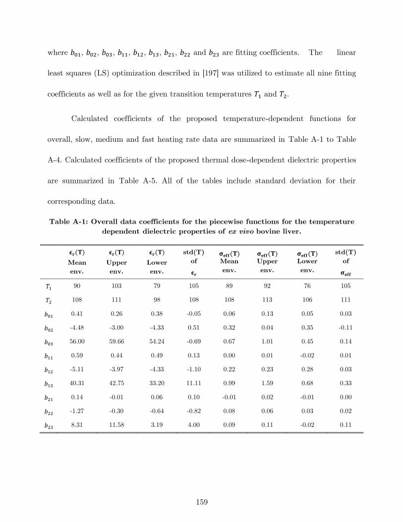
159
where 𝑏01, 𝑏02, 𝑏03, 𝑏11, 𝑏12, 𝑏13, 𝑏21, 𝑏22 and 𝑏23 are fitting coefficients. The linear
least squares (LS) optimization described in [197] was utilized to estimate all nine fitting
coefficients as well as for the given transition temperatures 𝑇1 and 𝑇2.
Calculated coefficients of the proposed temperature-dependent functions for
overall, slow, medium and fast heating rate data are summarized in Table A-1 to Table
A-4. Calculated coefficients of the proposed thermal dose-dependent dielectric properties
are summarized in Table A-5. All of the tables include standard deviation for their
corresponding data.
Table A-1: Overall data coefficients for the piecewise functions for the temperature
dependent dielectric properties of ex vivo bovine liver.
𝛜𝐫(𝐓)
Mean
env.
𝛜𝐫(𝐓)
Upper
env.
𝛜𝐫(𝐓)
Lower
env.
std(T)
of
𝛜𝐫
𝛔𝐞𝐟𝐟(𝐓) Mean
env.
𝛔𝐞𝐟𝐟(𝐓) Upper
env.
𝛔𝐞𝐟𝐟(𝐓) Lower
env.
std(T)
of
𝛔𝐞𝐟𝐟
𝑇1 90 103 79 105 89 92 76 105
𝑇2 108 111 98 108 108 113 106 111
𝑏01 0.41 0.26 0.38 -0.05 0.06 0.13 0.05 0.03
𝑏02 -4.48 -3.00 -4.33 0.51 0.32 0.04 0.35 -0.11
𝑏03 56.00 59.66 54.24 -0.69 0.67 1.01 0.45 0.14
𝑏11 0.59 0.44 0.49 0.13 0.00 0.01 -0.02 0.01
𝑏12 -5.11 -3.97 -4.33 -1.10 0.22 0.23 0.28 0.03
𝑏13 40.31 42.75 33.20 11.11 0.99 1.59 0.68 0.33
𝑏21 0.14 -0.01 0.06 0.10 -0.01 0.02 -0.01 0.00
𝑏22 -1.27 -0.30 -0.64 -0.82 0.08 0.06 0.03 0.02
𝑏23 8.31 11.58 3.19 4.00 0.09 0.11 -0.02 0.11
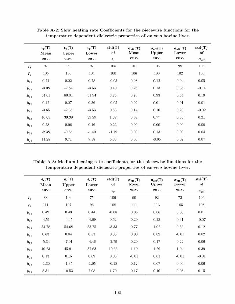
160
Table A-2: Slow heating rate Coefficients for the piecewise functions for the
temperature dependent dielectric properties of ex vivo bovine liver.
𝛜𝐫(𝐓)
Mean
env.
𝛜𝐫(𝐓)
Upper
env.
𝛜𝐫(𝐓)
Lower
env.
std(T)
of
𝛜𝐫
𝛔𝐞𝐟𝐟(𝐓) Mean
env.
𝛔𝐞𝐟𝐟(𝐓) Upper
env.
𝛔𝐞𝐟𝐟(𝐓) Lower
env.
std(T)
of
𝛔𝐞𝐟𝐟
𝑇1 97 99 97 105 101 105 98 105
𝑇2 105 106 104 100 106 100 102 100
𝑏01 0.24 0.22 0.28 -0.03 0.08 0.12 0.04 0.05
𝑏02 -3.08 -2.84 -3.53 0.40 0.25 0.13 0.36 -0.14
𝑏03 54.61 60.01 51.94 3.75 0.70 0.93 0.54 0.19
𝑏11 0.42 0.27 0.36 -0.05 0.02 0.01 0.01 0.01
𝑏12 -3.65 -2.35 -3.53 0.53 0.14 0.16 0.23 -0.02
𝑏13 40.65 39.39 39.29 1.32 0.69 0.77 0.53 0.21
𝑏21 0.28 0.06 0.16 0.22 0.00 0.00 0.00 0.00
𝑏22 -2.38 -0.65 -1.40 -1.79 0.03 0.13 0.00 0.04
𝑏23 11.28 9.71 7.58 5.33 0.03 -0.05 0.02 0.07
Table A-3: Medium heating rate coefficients for the piecewise functions for the
temperature dependent dielectric properties of ex vivo bovine liver.
𝛜𝐫(𝐓)
Mean
env.
𝛜𝐫(𝐓)
Upper
env.
𝛜𝐫(𝐓)
Lower
env.
std(T)
of
𝛜𝐫
𝛔𝐞𝐟𝐟(𝐓) Mean
env.
𝛔𝐞𝐟𝐟(𝐓) Upper
env.
𝛔𝐞𝐟𝐟(𝐓) Lower
env.
std(T)
of
𝛔𝐞𝐟𝐟
𝑇1 88 106 75 106 90 92 72 106
𝑇2 111 107 96 108 111 113 105 108
𝑏01 0.42 0.43 0.44 -0.08 0.06 0.06 0.06 0.01
𝑏02 -4.51 -4.45 -4.69 0.62 0.29 0.23 0.31 -0.07
𝑏03 54.78 54.68 53.75 -3.33 0.77 1.02 0.53 0.12
𝑏11 0.63 0.84 0.53 0.33 0.00 0.02 -0.01 0.02
𝑏12 -5.34 -7.01 -4.46 -2.79 0.20 0.17 0.22 0.06
𝑏13 40.23 45.91 37.63 19.66 1.10 1.29 1.04 0.39
𝑏21 0.13 0.15 0.09 0.03 -0.01 0.01 -0.01 -0.01
𝑏22 -1.30 -1.35 -1.05 -0.18 0.12 0.07 0.06 0.06
𝑏23 8.31 10.53 7.08 1.70 0.17 0.10 0.08 0.15
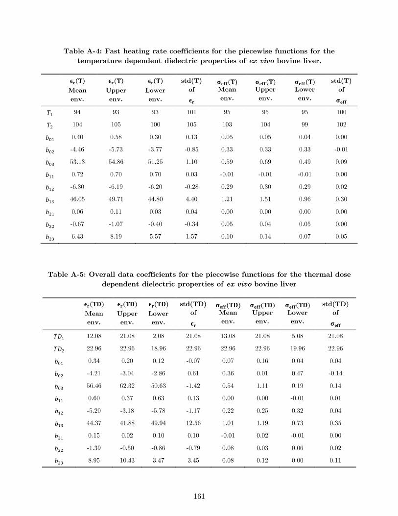
161
Table A-4: Fast heating rate coefficients for the piecewise functions for the
temperature dependent dielectric properties of ex vivo bovine liver.
𝛜𝐫(𝐓)
Mean
env.
𝛜𝐫(𝐓)
Upper
env.
𝛜𝐫(𝐓)
Lower
env.
std(T)
of
𝛜𝐫
𝛔𝐞𝐟𝐟(𝐓) Mean
env.
𝛔𝐞𝐟𝐟(𝐓) Upper
env.
𝛔𝐞𝐟𝐟(𝐓) Lower
env.
std(T)
of
𝛔𝐞𝐟𝐟
𝑇1 94 93 93 101 95 95 95 100
𝑇2 104 105 100 105 103 104 99 102
𝑏01 0.40 0.58 0.30 0.13 0.05 0.05 0.04 0.00
𝑏02 -4.46 -5.73 -3.77 -0.85 0.33 0.33 0.33 -0.01
𝑏03 53.13 54.86 51.25 1.10 0.59 0.69 0.49 0.09
𝑏11 0.72 0.70 0.70 0.03 -0.01 -0.01 -0.01 0.00
𝑏12 -6.30 -6.19 -6.20 -0.28 0.29 0.30 0.29 0.02
𝑏13 46.05 49.71 44.80 4.40 1.21 1.51 0.96 0.30
𝑏21 0.06 0.11 0.03 0.04 0.00 0.00 0.00 0.00
𝑏22 -0.67 -1.07 -0.40 -0.34 0.05 0.04 0.05 0.00
𝑏23 6.43 8.19 5.57 1.57 0.10 0.14 0.07 0.05
Table A-5: Overall data coefficients for the piecewise functions for the thermal dose
dependent dielectric properties of ex vivo bovine liver
𝛜𝐫(𝐓𝐃)
Mean
env.
𝛜𝐫(𝐓𝐃)
Upper
env.
𝛜𝐫(𝐓𝐃)
Lower
env.
std(TD)
of
𝛜𝐫
𝛔𝐞𝐟𝐟(𝐓𝐃) Mean
env.
𝛔𝐞𝐟𝐟(𝐓𝐃) Upper
env.
𝛔𝐞𝐟𝐟(𝐓𝐃) Lower
env.
std(TD)
of
𝛔𝐞𝐟𝐟
𝑇𝐷1 12.08 21.08 2.08 21.08 13.08 21.08 5.08 21.08
𝑇𝐷2 22.96 22.96 18.96 22.96 22.96 22.96 19.96 22.96
𝑏01 0.34 0.20 0.12 -0.07 0.07 0.16 0.04 0.04
𝑏02 -4.21 -3.04 -2.86 0.61 0.36 0.01 0.47 -0.14
𝑏03 56.46 62.32 50.63 -1.42 0.54 1.11 0.19 0.14
𝑏11 0.60 0.37 0.63 0.13 0.00 0.00 -0.01 0.01
𝑏12 -5.20 -3.18 -5.78 -1.17 0.22 0.25 0.32 0.04
𝑏13 44.37 41.88 49.94 12.56 1.01 1.19 0.73 0.35
𝑏21 0.15 0.02 0.10 0.10 -0.01 0.02 -0.01 0.00
𝑏22 -1.39 -0.50 -0.86 -0.79 0.08 0.03 0.06 0.02
𝑏23 8.95 10.43 3.47 3.45 0.08 0.12 0.00 0.11
162
A.2 Fitting errors
To assess the goodness of the fit, �̂�𝑒,𝑝(𝑓, 𝑇), a histogram of RMSE values across
all 401 frequencies was computed for each envelope and dielectric property type as a
function of temperature (similar to [197]), and is shown in Figure A-1. In the shown
histograms, one can observe low average values of error for each envelope, which are
specifically 1.06 for average, 6.92 for upper, 2.52 for lower and 1.84 for standard deviation
in case of relative permittivity. In case of effective conductivity, the respective errors are
0.0051, 0.0505, 0.0083 and 0.0051 S/m.
Figure A-2 illustrates the error for each envelope computed as a function of thermal
isoeffective dose. One can observe low average values of error for each envelope, which
are specifically 1.96 for average, 6.71 for upper, 3.49 for lower and 3.89 for standard
deviation in case of relative permittivity. In case of effective conductivity, the respective
errors are 0.0055, 0.0716, 0.0081 and 0.0097 S/m.
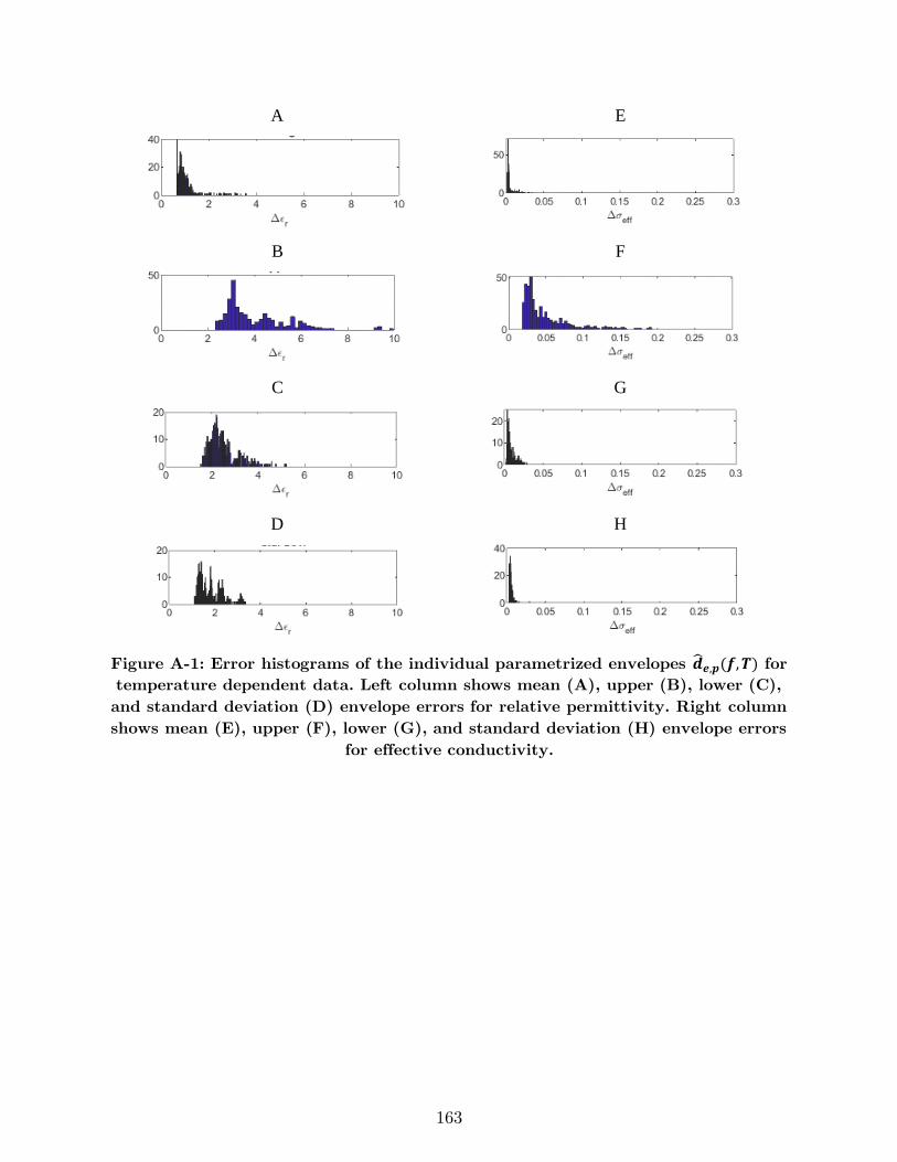
163
A E
B F
C G
D H
Figure A-1: Error histograms of the individual parametrized envelopes �̂�𝒆,𝒑(𝒇,𝑻) for
temperature dependent data. Left column shows mean (A), upper (B), lower (C),
and standard deviation (D) envelope errors for relative permittivity. Right column
shows mean (E), upper (F), lower (G), and standard deviation (H) envelope errors
for effective conductivity.
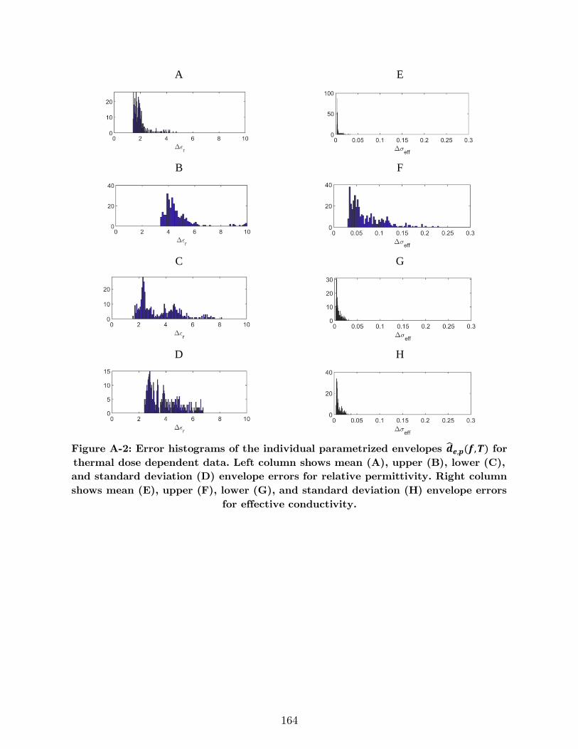
164
A E
B F
C G
D H
Figure A-2: Error histograms of the individual parametrized envelopes �̂�𝒆,𝒑(𝒇,𝑻) for
thermal dose dependent data. Left column shows mean (A), upper (B), lower (C),
and standard deviation (D) envelope errors for relative permittivity. Right column
shows mean (E), upper (F), lower (G), and standard deviation (H) envelope errors
for effective conductivity.
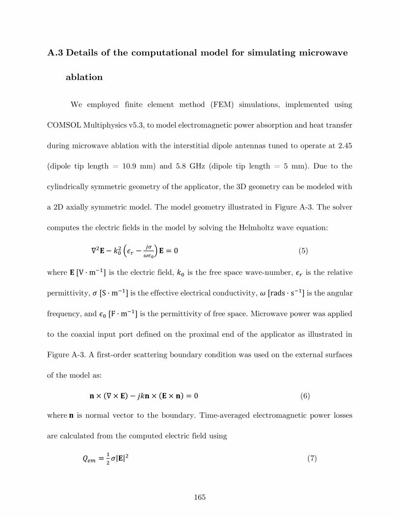
165
A.3 Details of the computational model for simulating microwave
ablation
We employed finite element method (FEM) simulations, implemented using
COMSOL Multiphysics v5.3, to model electromagnetic power absorption and heat transfer
during microwave ablation with the interstitial dipole antennas tuned to operate at 2.45
(dipole tip length = 10.9 mm) and 5.8 GHz (dipole tip length = 5 mm). Due to the
cylindrically symmetric geometry of the applicator, the 3D geometry can be modeled with
a 2D axially symmetric model. The model geometry illustrated in Figure A-3. The solver
computes the electric fields in the model by solving the Helmholtz wave equation:
∇2𝐄− 𝑘02 (𝜖𝑟 −
𝑗𝜎
𝜔𝜖0)𝐄 = 0 (5)
where 𝐄 [V · m−1] is the electric field, 𝑘0 is the free space wave-number, 𝜖𝑟 is the relative
permittivity, 𝜎 [S · m−1] is the effective electrical conductivity, 𝜔 [rads · s−1] is the angular
frequency, and 𝜖0 [F · m−1] is the permittivity of free space. Microwave power was applied
to the coaxial input port defined on the proximal end of the applicator as illustrated in
Figure A-3. A first-order scattering boundary condition was used on the external surfaces
of the model as:
𝐧 × (∇ × 𝐄) − 𝑗𝑘𝐧 × (𝐄 × 𝐧) = 0 (6)
where 𝐧 is normal vector to the boundary. Time-averaged electromagnetic power losses
are calculated from the computed electric field using
𝑄𝑒𝑚 =1
2𝜎|𝐄|2 (7)
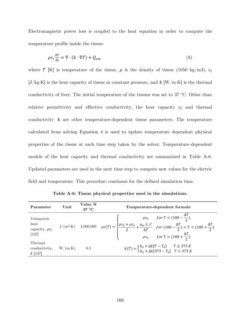
166
Electromagnetic power loss is coupled to the heat equation in order to compute the
temperature profile inside the tissue:
𝜌𝑐𝑙𝜕𝑇
𝜕𝑡= ∇ ∙ (𝑘 ∙ ∇𝑇) + 𝑄𝑒𝑚 (8)
where 𝑇 [K] is temperature of the tissue, 𝜌 is the density of tissue (1050 kg/m3), 𝑐𝑙
[J/kg·K] is the heat capacity of tissue at constant pressure, and 𝑘 [W/m·K] is the thermal
conductivity of liver. The initial temperature of the tissues was set to 37 °C. Other than
relative permittivity and effective conductivity, the heat capacity 𝑐𝑙 and thermal
conductivity 𝑘 are other temperature-dependent tissue parameters. The temperature
calculated from solving Equation 4 is used to update temperature dependent physical
properties of the tissue at each time step taken by the solver. Temperature-dependent
models of the heat capacity and thermal conductivity are summarized in Table A-6.
Updated parameters are used in the next time step to compute new values for the electric
field and temperature. This procedure continues for the defined simulation time.
Table A-6: Tissue physical properties used in the simulations.
Parameter Unit Value @
37 °C Temperature-dependent formula
Volumetric
heat
capacity, 𝜌𝑐𝑙
[137]
J/(m3·K) 4,000,000 𝜌𝑐(𝑇) =
{
𝜌𝑐0 𝑓𝑜𝑟 𝑇 < (100 −
Δ𝑇
2)
𝜌𝑐0 + 𝜌𝑐𝑣2
+𝜌𝑤 . 𝐿. 𝐶
Δ𝑇 𝑓𝑜𝑟 (100 −
Δ𝑇
2) < 𝑇 < (100 +
Δ𝑇
2)
𝜌𝑐𝑣 𝑓𝑜𝑟 𝑇 > (100 +Δ𝑇
2)
Thermal
conductivity,
𝑘 [137]
W/(m·K) 0.5 𝑘(𝑇) = {𝑘0 + Δ𝑘[𝑇 − 𝑇0] 𝑇 ≤ 373 𝐾
𝑘0 + Δ𝑘[373 − 𝑇0] 𝑇 > 373 𝐾
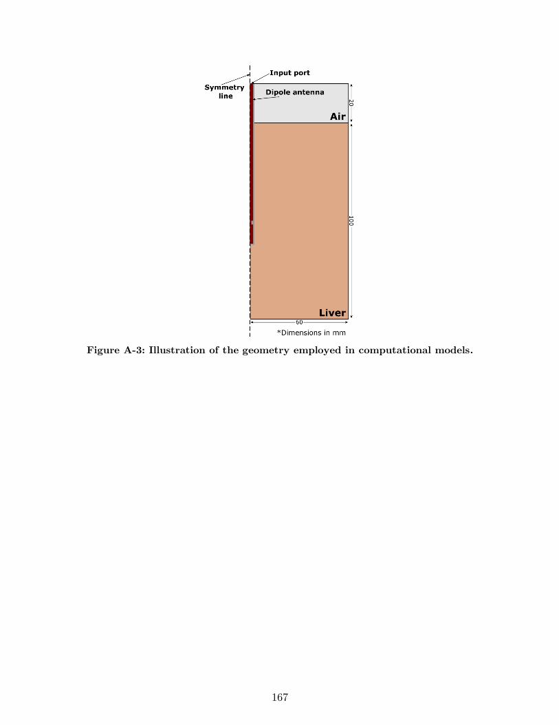
167
Figure A-3: Illustration of the geometry employed in computational models.
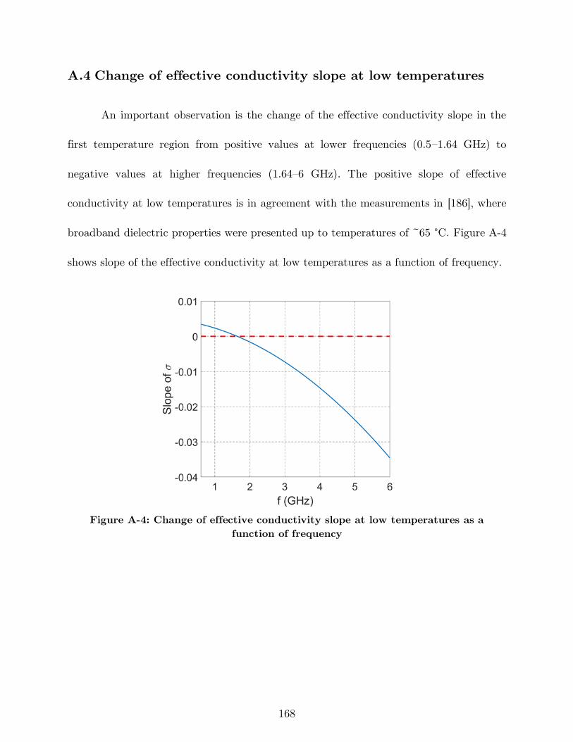
168
A.4 Change of effective conductivity slope at low temperatures
An important observation is the change of the effective conductivity slope in the
first temperature region from positive values at lower frequencies (0.5–1.64 GHz) to
negative values at higher frequencies (1.64–6 GHz). The positive slope of effective
conductivity at low temperatures is in agreement with the measurements in [186], where
broadband dielectric properties were presented up to temperatures of ~65 °C. Figure A-4
shows slope of the effective conductivity at low temperatures as a function of frequency.
Figure A-4: Change of effective conductivity slope at low temperatures as a
function of frequency
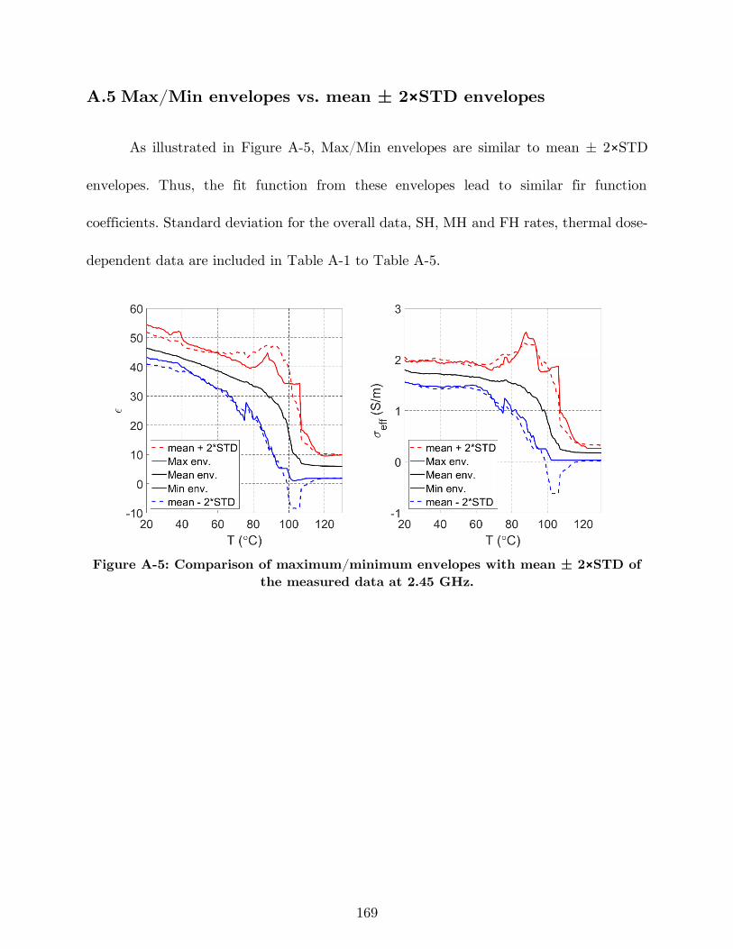
169
A.5 Max/Min envelopes vs. mean ± 2×STD envelopes
As illustrated in Figure A-5, Max/Min envelopes are similar to mean ± 2×STD
envelopes. Thus, the fit function from these envelopes lead to similar fir function
coefficients. Standard deviation for the overall data, SH, MH and FH rates, thermal dose-
dependent data are included in Table A-1 to Table A-5.
Figure A-5: Comparison of maximum/minimum envelopes with mean ± 2×STD of
the measured data at 2.45 GHz.
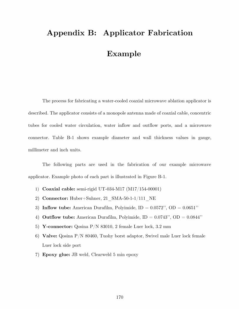
170
Appendix B: Applicator Fabrication
Example
The process for fabricating a water-cooled coaxial microwave ablation applicator is
described. The applicator consists of a monopole antenna made of coaxial cable, concentric
tubes for cooled water circulation, water inflow and outflow ports, and a microwave
connector. Table B-1 shows example diameter and wall thickness values in gauge,
millimeter and inch units.
The following parts are used in the fabrication of our example microwave
applicator. Example photo of each part is illustrated in Figure B-1.
1) Coaxial cable: semi-rigid UT-034-M17 (M17/154-00001)
2) Connector: Huber+Suhner, 21_SMA-50-1-1/111_NE
3) Inflow tube: American Durafilm, Polyimide, ID = 0.0572’’, OD = 0.0651’’
4) Outflow tube: American Durafilm, Polyimide, ID = 0.0743’’, OD = 0.0844’’
5) Y-connector: Qosina P/N 83010, 2 female Luer lock, 3.2 mm
6) Valve: Qosina P/N 80460, Tuohy borst adaptor, Swivel male Luer lock female
Luer lock side port
7) Epoxy glue: JB weld, Clearweld 5 min epoxy
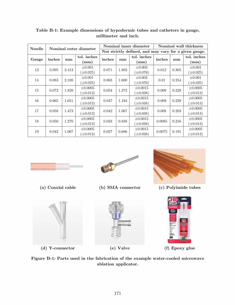
171
Table B-1: Example dimensions of hypodermic tubes and catheters in gauge,
millimeter and inch.
Needle Nominal outer diameter Nominal inner diameter Nominal wall thickness
Not strictly defined, and may vary for a given gauge.
Gauge inches mm tol. inches
(mm) inches mm
tol. inches
(mm) inches mm
tol. inches
(mm)
13 0.095 2.413 ±0.001
(±0.025) 0.071 1.803
±0.003
(±0.076) 0.012 0.305
±0.001
(±0.025)
14 0.083 2.108 ±0.001
(±0.025) 0.063 1.600
±0.003
(±0.076) 0.01 0.254
±0.001
(±0.025)
15 0.072 1.829 ±0.0005
(±0.013) 0.054 1.372
±0.0015
(±0.038) 0.009 0.229
±0.0005
(±0.013)
16 0.065 1.651 ±0.0005
(±0.013) 0.047 1.194
±0.0015
(±0.038) 0.009 0.229
±0.0005
(±0.013)
17 0.058 1.473 ±0.0005
(±0.013) 0.042 1.067
±0.0015
(±0.038) 0.008 0.203
±0.0005
(±0.013)
18 0.050 1.270 ±0.0005
(±0.013) 0.033 0.838
±0.0015
(±0.038) 0.0085 0.216
±0.0005
(±0.013)
19 0.042 1.067 ±0.0005
(±0.013) 0.027 0.686
±0.0015
(±0.038) 0.0075 0.191
±0.0005
(±0.013)
(a) Coaxial cable (b) SMA connector (c) Polyimide tubes
(d) Y-connector (e) Valve (f) Epoxy glue
Figure B-1: Parts used in the fabrication of the example water-cooled microwave
ablation applicator.
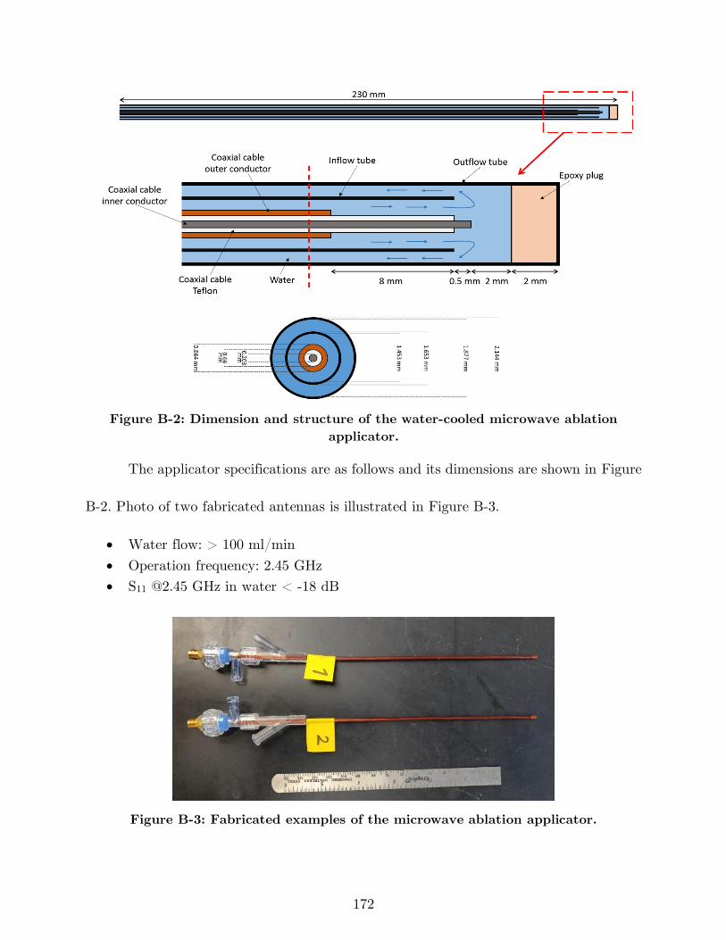
172
Figure B-2: Dimension and structure of the water-cooled microwave ablation
applicator.
The applicator specifications are as follows and its dimensions are shown in Figure
B-2. Photo of two fabricated antennas is illustrated in Figure B-3.
• Water flow: > 100 ml/min
• Operation frequency: 2.45 GHz
• S11 @2.45 GHz in water < -18 dB
Figure B-3: Fabricated examples of the microwave ablation applicator.
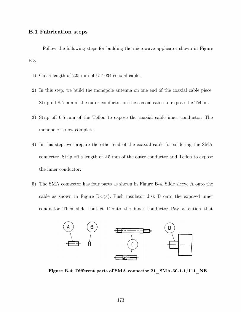
173
B.1 Fabrication steps
Follow the following steps for building the microwave applicator shown in Figure
B-3.
1) Cut a length of 225 mm of UT-034 coaxial cable.
2) In this step, we build the monopole antenna on one end of the coaxial cable piece.
Strip off 8.5 mm of the outer conductor on the coaxial cable to expose the Teflon.
3) Strip off 0.5 mm of the Teflon to expose the coaxial cable inner conductor. The
monopole is now complete.
4) In this step, we prepare the other end of the coaxial cable for soldering the SMA
connector. Strip off a length of 2.5 mm of the outer conductor and Teflon to expose
the inner conductor.
5) The SMA connector has four parts as shown in Figure B-4. Slide sleeve A onto the
cable as shown in Figure B-5(a). Push insulator disk B onto the exposed inner
conductor. Then, slide contact C onto the inner conductor. Pay attention that
Figure B-4: Different parts of SMA connector 21_SMA-50-1-1/111_NE
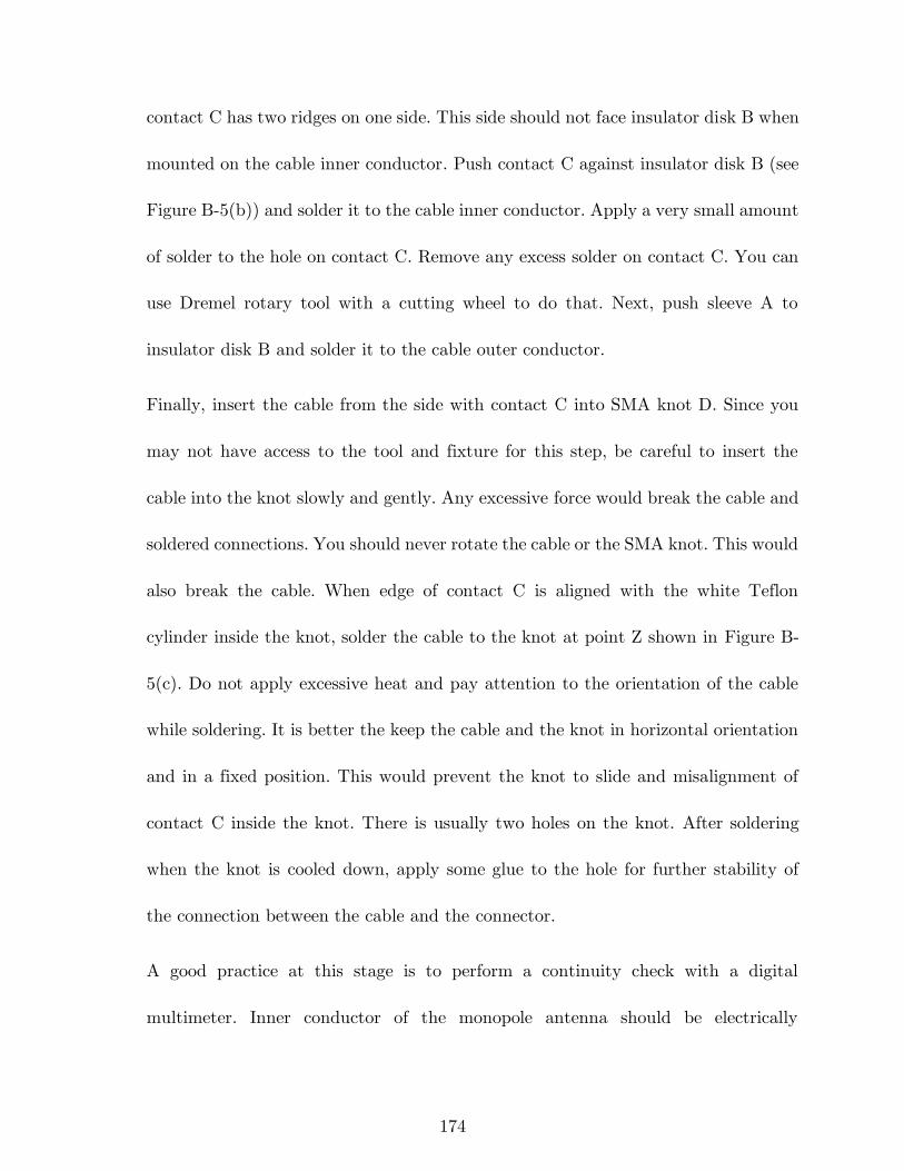
174
contact C has two ridges on one side. This side should not face insulator disk B when
mounted on the cable inner conductor. Push contact C against insulator disk B (see
Figure B-5(b)) and solder it to the cable inner conductor. Apply a very small amount
of solder to the hole on contact C. Remove any excess solder on contact C. You can
use Dremel rotary tool with a cutting wheel to do that. Next, push sleeve A to
insulator disk B and solder it to the cable outer conductor.
Finally, insert the cable from the side with contact C into SMA knot D. Since you
may not have access to the tool and fixture for this step, be careful to insert the
cable into the knot slowly and gently. Any excessive force would break the cable and
soldered connections. You should never rotate the cable or the SMA knot. This would
also break the cable. When edge of contact C is aligned with the white Teflon
cylinder inside the knot, solder the cable to the knot at point Z shown in Figure B-
5(c). Do not apply excessive heat and pay attention to the orientation of the cable
while soldering. It is better the keep the cable and the knot in horizontal orientation
and in a fixed position. This would prevent the knot to slide and misalignment of
contact C inside the knot. There is usually two holes on the knot. After soldering
when the knot is cooled down, apply some glue to the hole for further stability of
the connection between the cable and the connector.
A good practice at this stage is to perform a continuity check with a digital
multimeter. Inner conductor of the monopole antenna should be electrically
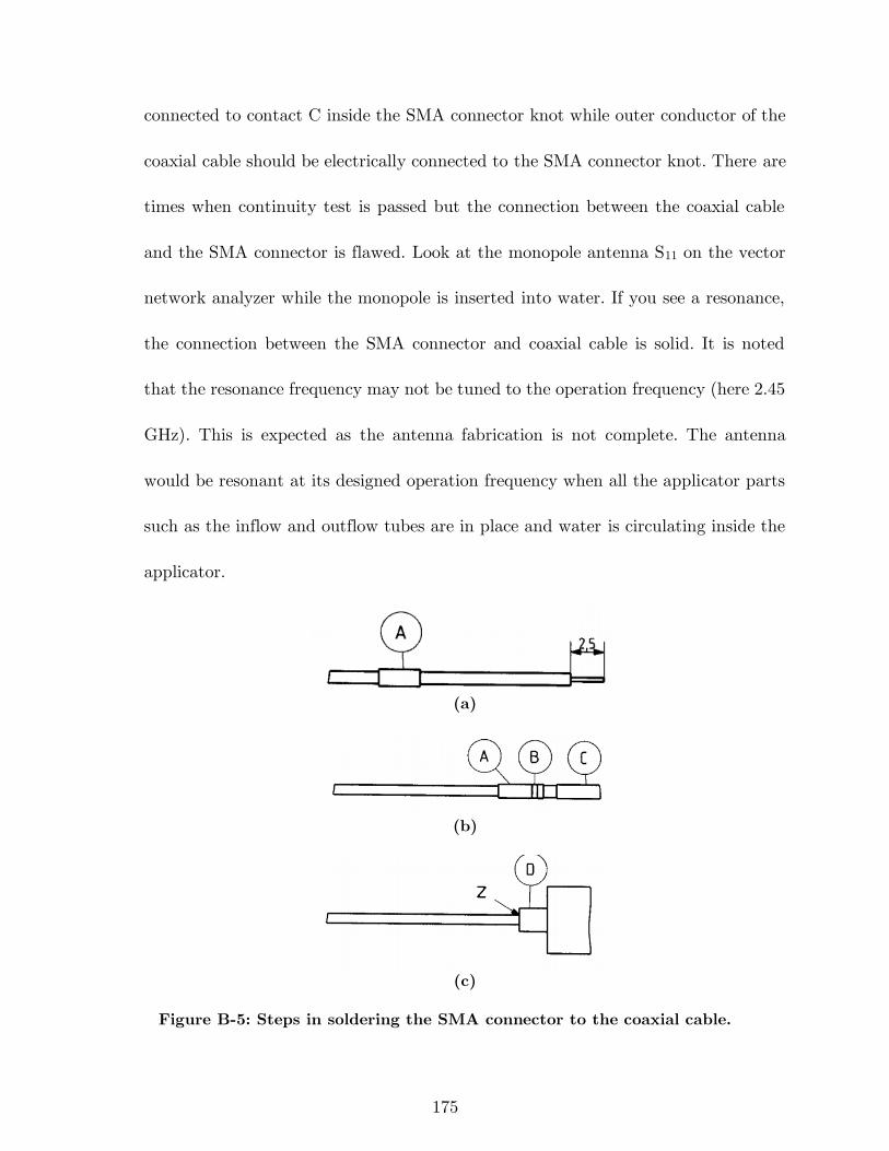
175
connected to contact C inside the SMA connector knot while outer conductor of the
coaxial cable should be electrically connected to the SMA connector knot. There are
times when continuity test is passed but the connection between the coaxial cable
and the SMA connector is flawed. Look at the monopole antenna S11 on the vector
network analyzer while the monopole is inserted into water. If you see a resonance,
the connection between the SMA connector and coaxial cable is solid. It is noted
that the resonance frequency may not be tuned to the operation frequency (here 2.45
GHz). This is expected as the antenna fabrication is not complete. The antenna
would be resonant at its designed operation frequency when all the applicator parts
such as the inflow and outflow tubes are in place and water is circulating inside the
applicator.
(a)
(b)
(c)
Figure B-5: Steps in soldering the SMA connector to the coaxial cable.
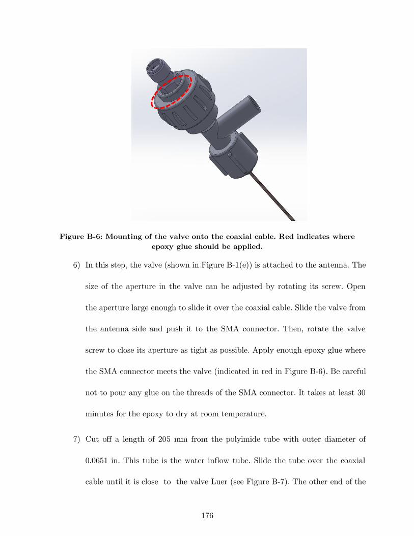
176
Figure B-6: Mounting of the valve onto the coaxial cable. Red indicates where
epoxy glue should be applied.
6) In this step, the valve (shown in Figure B-1(e)) is attached to the antenna. The
size of the aperture in the valve can be adjusted by rotating its screw. Open
the aperture large enough to slide it over the coaxial cable. Slide the valve from
the antenna side and push it to the SMA connector. Then, rotate the valve
screw to close its aperture as tight as possible. Apply enough epoxy glue where
the SMA connector meets the valve (indicated in red in Figure B-6). Be careful
not to pour any glue on the threads of the SMA connector. It takes at least 30
minutes for the epoxy to dry at room temperature.
7) Cut off a length of 205 mm from the polyimide tube with outer diameter of
0.0651 in. This tube is the water inflow tube. Slide the tube over the coaxial
cable until it is close to the valve Luer (see Figure B-7). The other end of the
177
Figure B-7: Positioning of the inflow polyimide tube. The location where
epoxy glue should be applied is shown in red.
tube should be aligned with the monopole antenna tip as illustrated in Figure
B-2. Pour some epoxy glue onto the tube where it is inserted to the valve
(indicated in red in Figure B-7). By keeping the valve in vertical orientation,
the glue will move down because of gravity. It is very important not to pour
excess glue because it may pass the tube opening in the valve and clog it.
8) When the epoxy glue completely dried, slide the Y-connector onto the coaxial
cable and fasten it to the valve. Pay attention to align the Y-connector output
Luer in the opposite direction of the valve input Luer. With this arrangement,
connection to the water circulation tubing will be easier. Figure B-8 shows the
applicator with the Y-connector fastened to the valve.
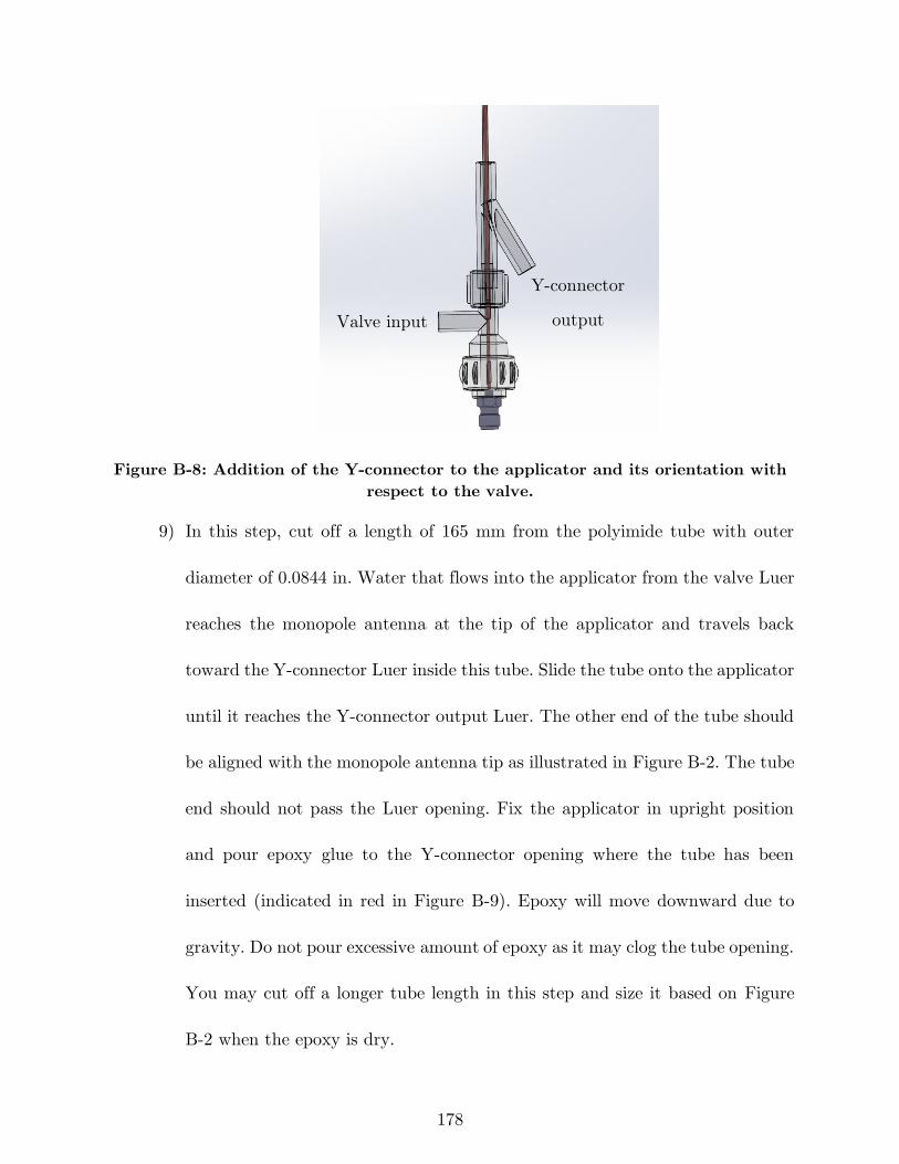
178
Figure B-8: Addition of the Y-connector to the applicator and its orientation with
respect to the valve.
9) In this step, cut off a length of 165 mm from the polyimide tube with outer
diameter of 0.0844 in. Water that flows into the applicator from the valve Luer
reaches the monopole antenna at the tip of the applicator and travels back
toward the Y-connector Luer inside this tube. Slide the tube onto the applicator
until it reaches the Y-connector output Luer. The other end of the tube should
be aligned with the monopole antenna tip as illustrated in Figure B-2. The tube
end should not pass the Luer opening. Fix the applicator in upright position
and pour epoxy glue to the Y-connector opening where the tube has been
inserted (indicated in red in Figure B-9). Epoxy will move downward due to
gravity. Do not pour excessive amount of epoxy as it may clog the tube opening.
You may cut off a longer tube length in this step and size it based on Figure
B-2 when the epoxy is dry.
Valve input
Y-connector
output
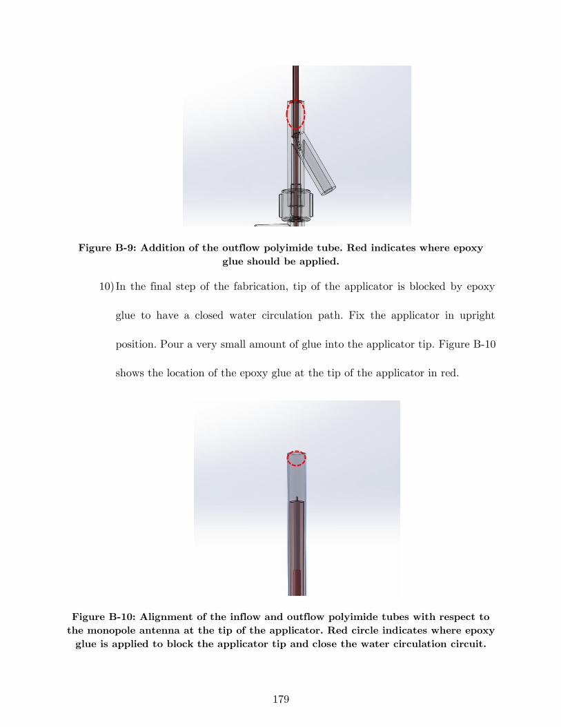
179
Figure B-9: Addition of the outflow polyimide tube. Red indicates where epoxy
glue should be applied.
10) In the final step of the fabrication, tip of the applicator is blocked by epoxy
glue to have a closed water circulation path. Fix the applicator in upright
position. Pour a very small amount of glue into the applicator tip. Figure B-10
shows the location of the epoxy glue at the tip of the applicator in red.
Figure B-10: Alignment of the inflow and outflow polyimide tubes with respect to
the monopole antenna at the tip of the applicator. Red circle indicates where epoxy
glue is applied to block the applicator tip and close the water circulation circuit.
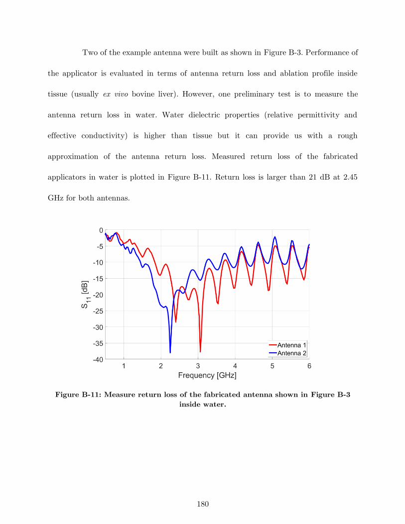
180
Two of the example antenna were built as shown in Figure B-3. Performance of
the applicator is evaluated in terms of antenna return loss and ablation profile inside
tissue (usually ex vivo bovine liver). However, one preliminary test is to measure the
antenna return loss in water. Water dielectric properties (relative permittivity and
effective conductivity) is higher than tissue but it can provide us with a rough
approximation of the antenna return loss. Measured return loss of the fabricated
applicators in water is plotted in Figure B-11. Return loss is larger than 21 dB at 2.45
GHz for both antennas.
Figure B-11: Measure return loss of the fabricated antenna shown in Figure B-3
inside water.


![Patch Antenna[1]](https://static.fdokumen.com/doc/165x107/63158e4cc32ab5e46f0d5c89/patch-antenna1.jpg)