Stress and fault parameters affecting fault slip magnitude and ...
Upload
khangminh22Category
view
5download
0
�����������������
Citation: Kołodziejek, P.; Wachowiak,
D. Fast Real-Time RDFT- and
GDFT-Based Direct Fault Diagnosis
of Induction Motor Drive. Energies
2022, 15, 1244. https://doi.org/
10.3390/en15031244
Academic Editor: Cristina MOREL
Received: 8 November 2021
Accepted: 3 February 2022
Published: 8 February 2022
Publisher’s Note: MDPI stays neutral
with regard to jurisdictional claims in
published maps and institutional affil-
iations.
Copyright: © 2022 by the authors.
Licensee MDPI, Basel, Switzerland.
This article is an open access article
distributed under the terms and
conditions of the Creative Commons
Attribution (CC BY) license (https://
creativecommons.org/licenses/by/
4.0/).
energies
Article
Fast Real-Time RDFT- and GDFT-Based Direct Fault Diagnosisof Induction Motor DrivePiotr Kołodziejek * and Daniel Wachowiak
Department of Electrical and Control Engineering, Gdansk University of Technology, 80-398 Gdansk, Poland;[email protected]* Correspondence: [email protected]; Tel.: +48-58-348-60-76
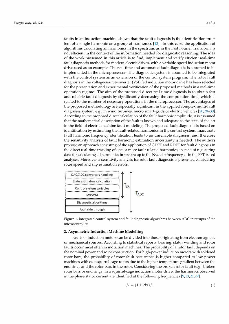
Abstract: This paper presents the theoretical analysis and experimental verification of a direct faultharmonic identification approach in a converter-fed electric drive for automated diagnosis purposes.On the basis of the analytical model of the proposed real-time direct fault diagnosis, the fault-relatedharmonic component is calculated using recursive DFT (RDFT) and Goertzel DFT (GDFT), appliedinstead of the full spectrum calculations required in the most popular FFT algorithm. The simulationmodel of an inverter sensorlessly controlled induction motor drive is linked with the inductionmachine rotor fault model for testing the sensitivity of the GDFT- and RDFT-based fault diagnosis tostate variable estimation errors. According to the presented simulation results, the accuracy of thedirect identification of a fault-related harmonic is sensitive to the quality of fault harmonic frequencyestimation. The sensitivity analysis with respect to RDFT and GDFT algorithms is included. Basedon the experimental setup with a sensorlessly controlled induction motor drive with the investigatedrotor fault, fault diagnosis algorithms were implemented in the microprocessor by integration withthe control system in one microcontroller and experimentally verified. The RDFT and GDFT approachhas shown accurate and fast direct automated fault identification at a significantly decreased numberof arithmetical operations in the microcontroller, which is convenient for the frequency-domain faultdiagnosis in electric drives and supports fault-tolerant control system implementation.
Keywords: fault diagnosis; automated diagnosis; real-time diagnosis; recursive DFT; Goertzel DFT;induction motor; rotor fault; estimation; sensitivity analysis
1. Introduction
Increasing requirements are formulated for converter-fed variable-speed drives withrespect to their control quality, reliability and safety. These requirements are intendedto provide safe and reliable machine operation, including early fault detection and fault-tolerant control to avoid critical faults and their consequences. In electrical machines, themost convenient diagnosis methods in industrial applications are based on the frequencydomain analysis utilizing known analytical models of faults and their frequency depen-dencies [1–12]. Due to measurement simplicity, the most popular method in recent yearsfor diagnosing induction motor drives was the Motor Current Signature Analysis (MCSA),with reasoning based on the harmonic analysis using the Fast Fourier Transform (FFT) [1–5].The induction motor diagnosis usually requires external current measurements and humanexpert knowledge. According to the cited articles, the MCSA approach is convenient fordiagnosing stator and rotor faults, as well as eccentricity and bearing damages. The faultdiagnosis in the frequency domain is usually based on a known mathematical model ap-plied for specified harmonic frequencies of the fault-related symptom and their amplitudeidentification and analysis [13–19]. The bearing fault is the most common in inductionmachines. However, rotor faults are also among the top three faults most often recorded ininduction motors [10,11,13]. Statistically, a stator fault is more probable [5]. Moreover, therotor fault occurrence probability is different for low- and high-power induction machines
Energies 2022, 15, 1244. https://doi.org/10.3390/en15031244 https://www.mdpi.com/journal/energies

Energies 2022, 15, 1244 2 of 14
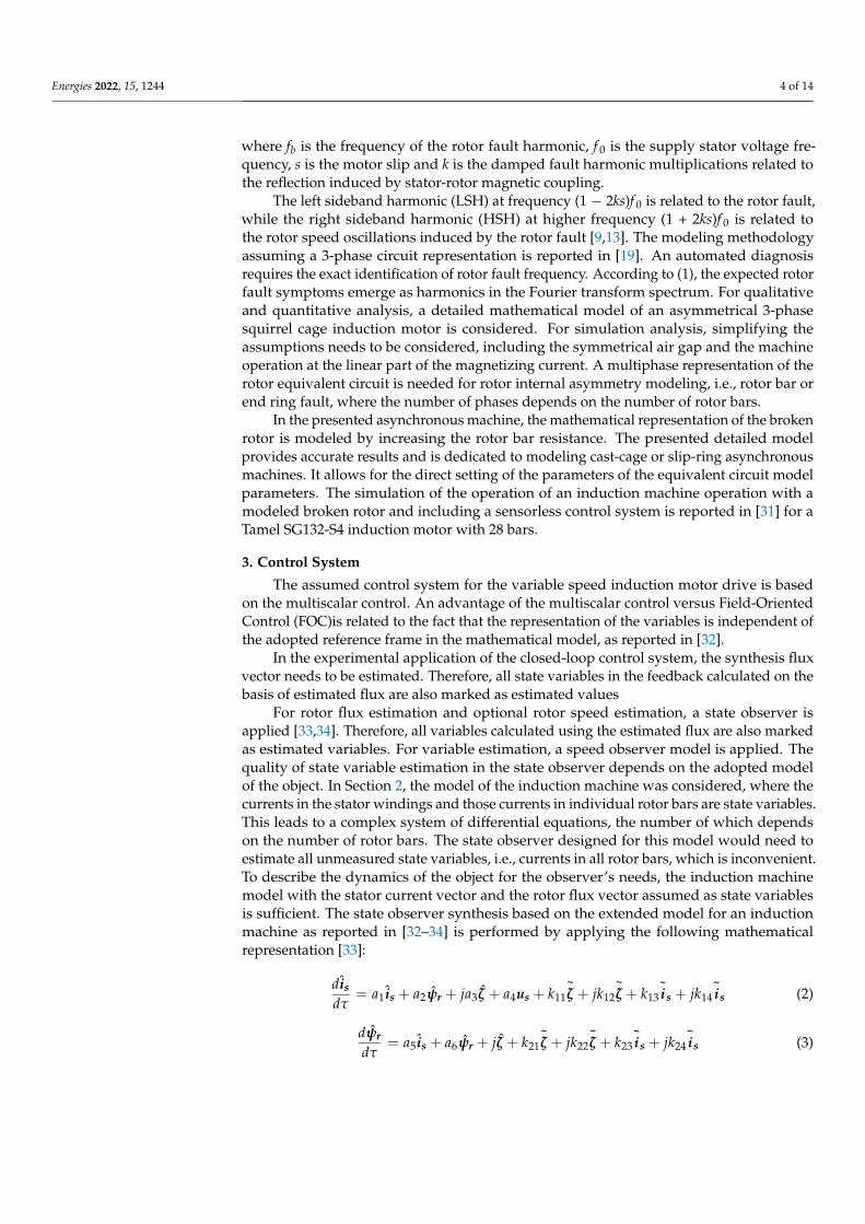
due to different manufacturing technology, i.e., cast alloy cage or soldered copper cage.The nominal power of the induction motor is related to the specified size of the rotor andits temperature gradient during operation, hence its vulnerability to the rotor fault is alsodifferent [11]. A great deal of scientific interest has been focused on the rotor faults ofinduction motors [6,8,10–20]. The computing speed of current microcontrollers makesit possible to integrate the control, monitoring and automated diagnosis system in onemicroprocessor, which can be further developed to the fault ride-through and fault-tolerantcontrol systems. When a rotor fault of the induction motor is slowly emerging, its com-pensation or even elimination of its impact is possible by proper fault-tolerant controlapplication; therefore, the exact detection, identification and extraction of the fault is re-quired [21]. Reported methods for the IM diagnosis are focused on early-stage detectionand fault range accuracy identification. Some diagnosis methods require a determinedoperational state of the machine. For transient state operation diagnosis, the waveletmethod is proposed in [20] and based on stray flux observation in [21]. The automateddetection method for the rotor fault diagnosis is reported in [6], but it is dedicated only tothe standstill operation condition. In Methodology, the diagnosis is based on a registeringsignal, e.g., motor current, offline or online frequency domain analysis by calculation allharmonics in the spectra up to the Nyquist frequency, which is necessary in FFT due to thebutterfly algorithm principle [2,3,9,22–25]. The proposed diagnosis methodology is basedon direct fault-related harmonic calculation using GDFT and RDFT, therefore, calculationsare limited to the amplitude determination of the fault-related harmonics, significantlyincreasing diagnosis time by decreasing the number of arithmetical operations. Motor slipis estimated using the speed observer implemented for the sensorless operation of the drive.The proposed approach is beneficial, assuming an online diagnosis in the microprocessorwith the implemented control system of the IM drive. In [9], a sliding window DFT isproposed for online rotor fault diagnosis; however, in this report, the calculation of theslip is based on the sidelobes leakage phenomenon observed from rotor slot harmonics,and issues of amplitude errors compared to the FFT analysis and slip estimation error arenot addressed. In comparison to the method reported in [9], the proposed method doesnot require identification of the number of rotor bars and the number of pairs of poles.Moreover, the proposed method is verified in the vector control system. The vector controlsystem in the fault diagnosis, which affects the amplitudes of the identified fault symptoms,is assumed in a few reports [13,21,22,26]. The inverter-fed electric drive control systemoften uses FPGA and a microprocessor, along with the supply voltage vector generationmethod, for ADC/DAC converter handling, state variable estimation and control systemvariable calculation. Increasing the MIPS (Million Instructions per Second) of microproces-sors increases the number of available instructions for the microprocessor in a specifiedtime between interrupts for ADC converter handling, which creates new possibilities forreal-time automated diagnostic algorithm applications. The available time Tdiag for of thediagnosis, see Figure 1, depends on the processing time or the control system algorithmsand the assumed time between ADC interruptions Tdiag = TADC − TCS, where Tdiag isthe time between ADC handling interrupts for diagnosis purposes, TADC is the programexecution period between interrupts for ADC handling and TCS is the time of the controlsystem variable calculation.
Considering the high computational load of the control unit in modern electricaldrives, the integrated real-time diagnostic methods need to be optimized due to the increas-ing switching frequency of inverter transistors in many applications, e.g., in SIC MOSFETtransistors, which implies decreased TADC, and the feasibility of additional diagnosis al-gorithms [27]. Moreover, a simultaneous real-time diagnosis implementation for differentfaults with additional functionalities, as shown in Figure 1, requires optimized and efficientdiagnostic algorithms. The application of Fast Fourier Transform is not efficient in thiscase because it requires computing the full spectra of the harmonics, which is unnecessaryassuming that the mathematical equations for specified fault-related symptom harmonicsare known. The analysis of the mathematical description of the most common types of
Energies 2022, 15, 1244 3 of 14
faults in an induction machine shows that the fault diagnosis is the identification prob-lem of a single harmonic or a group of harmonics [13]. In this case, the application ofalgorithms calculating all harmonics in the spectrum, as in the Fast Fourier Transform, isnot efficient in the context of the information needed for diagnostic reasoning. The ideaof the work presented in this article is to find, implement and verify efficient real-timefault diagnosis methods for modern electric drives, with a variable-speed induction motordrive used as an example. The real-time and automated fault diagnosis is assumed to beimplemented in the microprocessor. The diagnostic system is assumed to be integratedwith the control system as an extension of the control system program. The rotor faultdiagnosis in the voltage-source-inverter (VSI) fed induction motor drive has been selectedfor the presentation and experimental verification of the proposed methods in a real-timeoperation regime. The aim of the proposed direct real-time diagnosis is to obtain fastand reliable fault diagnosis by significantly decreasing the computation time, which isrelated to the number of necessary operations in the microprocessor. The advantages ofthe proposed methodology are especially significant in the applied complex multi-faultdiagnosis system, e.g., in wind turbines, micro smart-grids or electric vehicles [20,28–30].According to the proposed direct calculation of the fault harmonic amplitude, it is assumedthat the mathematical description of the fault is known and adequate to the state-of-the-artin the field of electric machine fault modeling. The proposed fault diagnosis is based onidentification by estimating the fault-related harmonics in the control system. Inaccuratefault harmonic frequency identification leads to an unreliable diagnosis, and thereforethe sensitivity analysis of fault harmonic estimation uncertainty is needed. The authorspropose an approach consisting of the application of GDFT and RDFT for fault diagnosis inthe direct real-time tracking of one or more fault-related harmonics, instead of registeringdata for calculating all harmonics in spectra up to the Nyquist frequency as in the FFT-basedanalyses. Moreover, a sensitivity analysis for rotor fault diagnosis is presented consideringrotor speed and slip estimation errors.
Energies 2022, 15, x FOR PEER REVIEW 3 of 15
unnecessary assuming that the mathematical equations for specified fault-related symp-
tom harmonics are known. The analysis of the mathematical description of the most com-
mon types of faults in an induction machine shows that the fault diagnosis is the identifi-
cation problem of a single harmonic or a group of harmonics [13]. In this case, the appli-
cation of algorithms calculating all harmonics in the spectrum, as in the Fast Fourier
Transform, is not efficient in the context of the information needed for diagnostic reason-
ing. The idea of the work presented in this article is to find, implement and verify efficient
real-time fault diagnosis methods for modern electric drives, with a variable-speed induc-
tion motor drive used as an example. The real-time and automated fault diagnosis is as-
sumed to be implemented in the microprocessor. The diagnostic system is assumed to be
integrated with the control system as an extension of the control system program. The
rotor fault diagnosis in the voltage-source-inverter (VSI) fed induction motor drive has
been selected for the presentation and experimental verification of the proposed methods
in a real-time operation regime. The aim of the proposed direct real-time diagnosis is to
obtain fast and reliable fault diagnosis by significantly decreasing the computation time,
which is related to the number of necessary operations in the microprocessor. The ad-
vantages of the proposed methodology are especially significant in the applied complex
multi-fault diagnosis system, e.g., in wind turbines, micro smart-grids or electric vehicles
[20,28–30]. According to the proposed direct calculation of the fault harmonic amplitude,
it is assumed that the mathematical description of the fault is known and adequate to the
state-of-the-art in the field of electric machine fault modeling. The proposed fault diagno-
sis is based on identification by estimating the fault-related harmonics in the control sys-
tem. Inaccurate fault harmonic frequency identification leads to an unreliable diagnosis,
and therefore the sensitivity analysis of fault harmonic estimation uncertainty is needed.
The authors propose an approach consisting of the application of GDFT and RDFT for
fault diagnosis in the direct real-time tracking of one or more fault-related harmonics, in-
stead of registering data for calculating all harmonics in spectra up to the Nyquist fre-
quency as in the FFT-based analyses. Moreover, a sensitivity analysis for rotor fault diag-
nosis is presented considering rotor speed and slip estimation errors.
Figure 1. Integrated control system and fault diagnostic algorithms between ADC interrupts of the
microcontroller.
2. Asymmetric Induction Machine Modelling
Faults of induction motors can be divided into those originating from electromag-
netic or mechanical sources. According to statistical reports, bearing, stator winding and
rotor faults occur most often in induction machines. The probability of a rotor fault de-
pends on the nominal power and rotor construction. For high-power induction motors
with soldered rotor bars, the probability of rotor fault occurrence is higher compared to
low-power machines with cast squirrel-cage rotors due to the higher temperature gradient
between the end rings and the rotor bars in the rotor. Considering the broken rotor fault
(e.g., broken rotor bars or end rings) in a squirrel-cage induction motor drive, the harmon-
ics observed in the phase stator current are identified at the following frequencies
[9,13,21,29]:
Figure 1. Integrated control system and fault diagnostic algorithms between ADC interrupts of themicrocontroller.
2. Asymmetric Induction Machine Modelling
Faults of induction motors can be divided into those originating from electromagneticor mechanical sources. According to statistical reports, bearing, stator winding and rotorfaults occur most often in induction machines. The probability of a rotor fault depends onthe nominal power and rotor construction. For high-power induction motors with solderedrotor bars, the probability of rotor fault occurrence is higher compared to low-powermachines with cast squirrel-cage rotors due to the higher temperature gradient between theend rings and the rotor bars in the rotor. Considering the broken rotor fault (e.g., brokenrotor bars or end rings) in a squirrel-cage induction motor drive, the harmonics observedin the phase stator current are identified at the following frequencies [9,13,21,29]:
fb = (1 ± 2ks) f0 (1)
Energies 2022, 15, 1244 4 of 14
where fb is the frequency of the rotor fault harmonic, f 0 is the supply stator voltage fre-quency, s is the motor slip and k is the damped fault harmonic multiplications related tothe reflection induced by stator-rotor magnetic coupling.
The left sideband harmonic (LSH) at frequency (1 − 2ks)f 0 is related to the rotor fault,while the right sideband harmonic (HSH) at higher frequency (1 + 2ks)f 0 is related tothe rotor speed oscillations induced by the rotor fault [9,13]. The modeling methodologyassuming a 3-phase circuit representation is reported in [19]. An automated diagnosisrequires the exact identification of rotor fault frequency. According to (1), the expected rotorfault symptoms emerge as harmonics in the Fourier transform spectrum. For qualitativeand quantitative analysis, a detailed mathematical model of an asymmetrical 3-phasesquirrel cage induction motor is considered. For simulation analysis, simplifying theassumptions needs to be considered, including the symmetrical air gap and the machineoperation at the linear part of the magnetizing current. A multiphase representation of therotor equivalent circuit is needed for rotor internal asymmetry modeling, i.e., rotor bar orend ring fault, where the number of phases depends on the number of rotor bars.
In the presented asynchronous machine, the mathematical representation of the brokenrotor is modeled by increasing the rotor bar resistance. The presented detailed modelprovides accurate results and is dedicated to modeling cast-cage or slip-ring asynchronousmachines. It allows for the direct setting of the parameters of the equivalent circuit modelparameters. The simulation of the operation of an induction machine operation with amodeled broken rotor and including a sensorless control system is reported in [31] for aTamel SG132-S4 induction motor with 28 bars.
3. Control System
The assumed control system for the variable speed induction motor drive is basedon the multiscalar control. An advantage of the multiscalar control versus Field-OrientedControl (FOC)is related to the fact that the representation of the variables is independent ofthe adopted reference frame in the mathematical model, as reported in [32].
In the experimental application of the closed-loop control system, the synthesis fluxvector needs to be estimated. Therefore, all state variables in the feedback calculated on thebasis of estimated flux are also marked as estimated values
For rotor flux estimation and optional rotor speed estimation, a state observer isapplied [33,34]. Therefore, all variables calculated using the estimated flux are also markedas estimated variables. For variable estimation, a speed observer model is applied. Thequality of state variable estimation in the state observer depends on the adopted modelof the object. In Section 2, the model of the induction machine was considered, where thecurrents in the stator windings and those currents in individual rotor bars are state variables.This leads to a complex system of differential equations, the number of which dependson the number of rotor bars. The state observer designed for this model would need toestimate all unmeasured state variables, i.e., currents in all rotor bars, which is inconvenient.To describe the dynamics of the object for the observer’s needs, the induction machinemodel with the stator current vector and the rotor flux vector assumed as state variablesis sufficient. The state observer synthesis based on the extended model for an inductionmachine as reported in [32–34] is performed by applying the following mathematicalrepresentation [33]:
dis
dτ= a1 is + a2ψr + ja3ζ + a4us + k11
~ζ + jk12
~ζ + k13
~is + jk14
~is (2)
dψr
dτ= a5 is + a6ψr + jζ + k21
~ζ + jk22
~ζ + k23
~is + jk24
~is (3)

Energies 2022, 15, 1244 5 of 14
where ˆ means the estimated values, k11 − k34 are the gain values of the speed observer and~is,
~ζ are the stator current and EMF estimation error vectors, respectively, defined as:
~is = is − is (4)
~ζ = ωrψr − ζ (5)
The estimated rotor speed is then determined as:
ωr =ψrα ζα + ψrβ ζβ
ψ2r
(6)
where ψrα,ψrβ are the estimated orthogonal components of the rotor flux vector, ψr is theestimated rotor flux module and ζα, ζβ are the estimated orthogonal components of theEMF vector.
For 12 gain values k11 − k34 of the state observer, evolutionary optimization algo-rithms are applied to provide stability of speed observer operation by properly placing theeigenvalues according to the control system theory. The application of a genetic algorithmfor searching an optimized set of parameters is reported in [33,34]. An extended analysisof the sensorless control system based on the proposed modeling approach is reportedin [13,21,29].
4. Direct DFT-Based Fault Diagnosis Approach
Considering the fault diagnosis approach in frequency domain, a discrete Fouriertransformation is applied to the registered stator current signal to convert a given samplesequence window into a sequence of harmonics [34]:
Xk =N−1
∑n=0
xne−i2πN kn =
N−1
∑n=0
xn[cos(2πkn/N)− i sin(2πkn/N)], (7)
where xn is the sequence of registered samples, and k/N is the frequency of the sinusoidalwave-k cycles per N samples. DFT is usually calculated using the butterfly algorithmfor the Fast Fourier Transform invented by Cooley and Tukey [34], which provides theincreased efficiency of calculations by decreasing the computational complexity from O(N2)to O(Nlog(N)). Most faults in AC machines can be identified on the basis of one or a groupof fault-related harmonics, thus it is more efficient to perform a diagnosis using algorithmsproviding direct calculation of the fault harmonic, unless all harmonics in the spectrum areneeded. Efficient fault diagnosis algorithms are highly desired considering a limited timebetween microprocessor interrupts, as presented in Figure 1, and the high computationalcomplexity resulting from the need to calculate state variable estimators required for bothsensor-based and sensorless control system topologies. The rotor fault diagnosis of theinduction motor can be identified by analyzing a selected state variable, e.g., phase statorcurrent, Park’s vector modulus of the stator current, estimated rotor flux, electromagnetictorque or rotor speed during the steady-state operation of the machine [21,29]. The calcu-lation of all harmonics in the spectrum using the FFT algorithm increases the number ofarithmetical operations, which, consequently, increases the overall time of calculations andinvolves more memory resources in the microprocessor. Considering a known fault-relatedharmonic frequency (2), the amplitude of the harmonic at the fault frequency is directlycalculated from the current stator phase measurement results using the recursive algorithm:
Ak =N−1
∑n=0
anwN−kn, (8)
Energies 2022, 15, 1244 6 of 14
where: N—number of samples, n—sample number, an—value of the n-th sample andwN = ei 2π
N .The output values of the DFT are updated using the recursive algorithm as follows:
Xk(n) = Xk(n − 1) + (x(n)− x(n − N))wN−kn (9)
As a result of the application of the recursive direct Fourier transform, the amplitudesof the fault-related harmonic are updated every sample of the acquired signal in the slidingwindow. A significant drawback of this approach is the cumulation of numerical errorsrelated to the finite precision of numerical data representation in the microcontroller. Dif-ferent approaches to compensate for this drawback can be named. Resetting the diagnosticalgorithm can be performed without disturbing its operation. According to the assump-tion of continuous operation of the diagnostic algorithm, the recursive DFT algorithm isperiodically reset to reduce the cumulation of numerical errors. The application of therecursive algorithm for DFT calculation decreases the number of arithmetical operationsfrom 2N multiplication and adding operations to four adding and two multiplicationoperations for a single harmonic amplitude calculation. The computational complexity isdecreased from O(N) to O(1). Another considered approach for direct amplitude calculationof a single harmonic is the Goertzel algorithm, which is known from application in thedual-tone multi-frequency (DTMF) tone detection in telecommunication and in magneticcoupling simulation [35]. According to the Goerzel algorithm, the DFT amplitude of asingle harmonic is obtained as follows [35]:
uk(n) = x(n) + 2 cos(
2πkN
)uk(n − 1)− uk(n − 2) (10)
y(n) = uk(n)− wN−kuk(n − 1) (11)
The application of the Goertzel algorithm decreases the computational complexitybecause sample Equation (10) are only calculated, while Equation (11) is determined at theend of full window acquisition. In Equation (10), the term: 2 cos(2πk/N) has a fixed value,unlike the recursive DFT algorithm where the trigonometric functions converting wN
−kn
to real and imaginary values in Equation (9) require the information about the samplenumber. It is possible to overcome this problem in the recursive DFT algorithm via thetabularization of trigonometric values from 1 to N, however, it requires the allocation ofadditional memory resources in the microprocessor.
5. Simulation Analysis
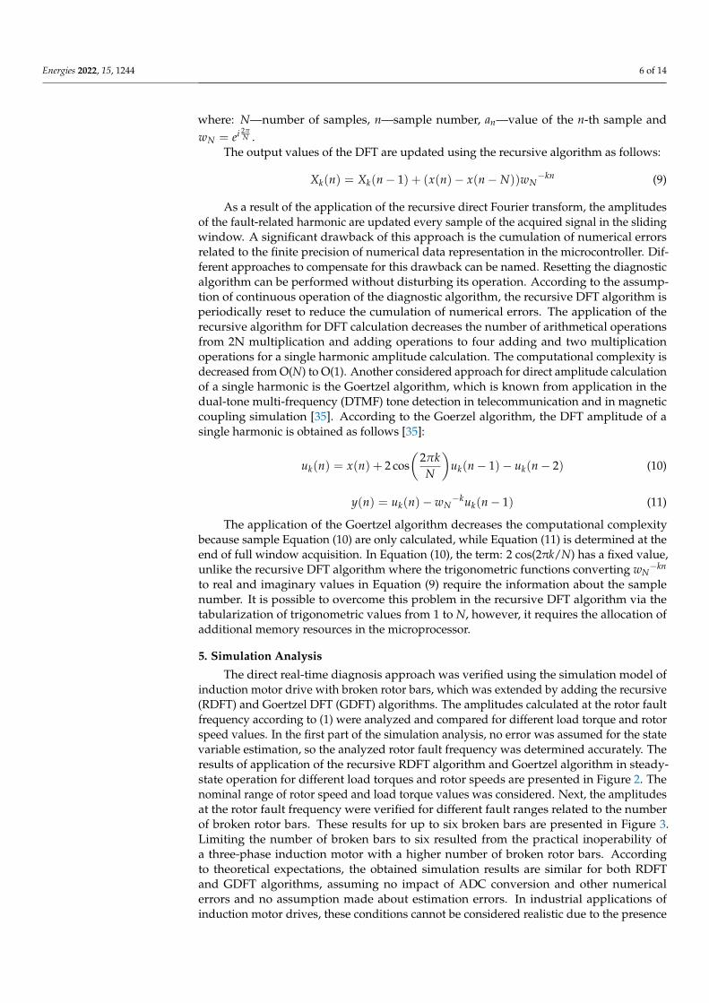
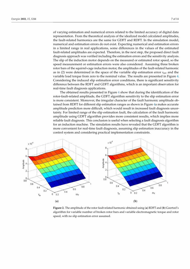
The direct real-time diagnosis approach was verified using the simulation model ofinduction motor drive with broken rotor bars, which was extended by adding the recursive(RDFT) and Goertzel DFT (GDFT) algorithms. The amplitudes calculated at the rotor faultfrequency according to (1) were analyzed and compared for different load torque and rotorspeed values. In the first part of the simulation analysis, no error was assumed for the statevariable estimation, so the analyzed rotor fault frequency was determined accurately. Theresults of application of the recursive RDFT algorithm and Goertzel algorithm in steady-state operation for different load torques and rotor speeds are presented in Figure 2. Thenominal range of rotor speed and load torque values was considered. Next, the amplitudesat the rotor fault frequency were verified for different fault ranges related to the numberof broken rotor bars. These results for up to six broken bars are presented in Figure 3.Limiting the number of broken bars to six resulted from the practical inoperability ofa three-phase induction motor with a higher number of broken rotor bars. Accordingto theoretical expectations, the obtained simulation results are similar for both RDFTand GDFT algorithms, assuming no impact of ADC conversion and other numericalerrors and no assumption made about estimation errors. In industrial applications ofinduction motor drives, these conditions cannot be considered realistic due to the presence
Energies 2022, 15, 1244 7 of 14
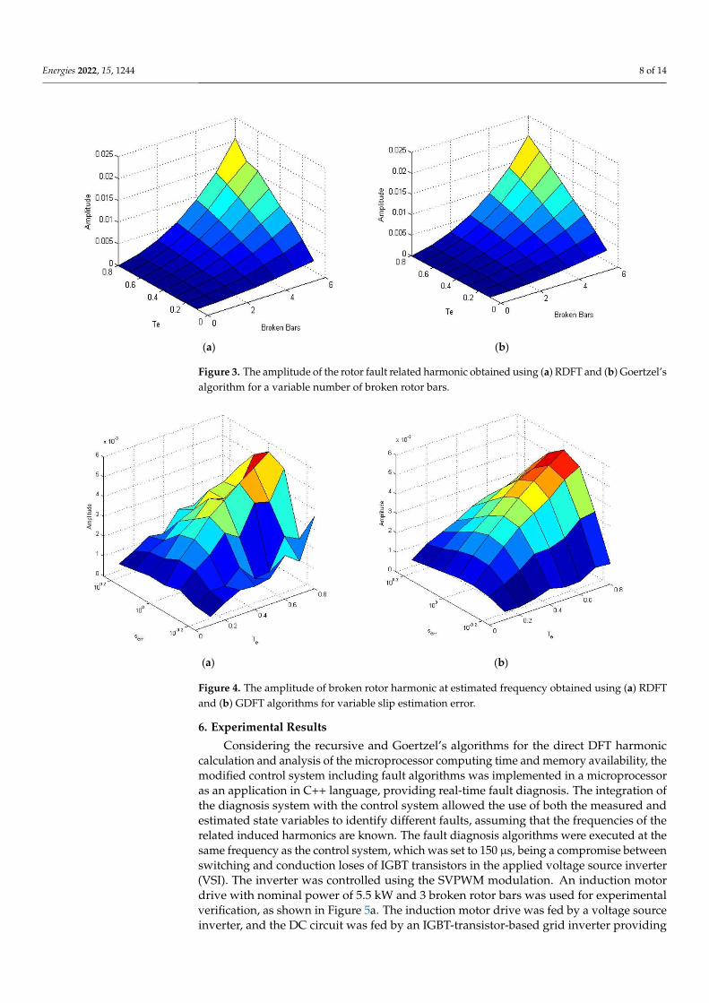
of varying estimation and numerical errors related to the limited accuracy of digital datarepresentation. From the theoretical analysis of the idealized model calculated amplitudes,the fault-related harmonics are the same for GDFT and RDFT. In the simulation model,numerical and estimation errors do not exist. Expecting numerical and estimation errorsin a limited range in real applications, some differences in the values of the estimatedfault-related amplitudes are expected. Therefore, in the next step, the proposed direct faultdiagnosis approach was verified including the estimation errors and the sensitivity analysis.The slip of the induction motor depends on the measured or estimated rotor speed, so thespeed measurement or estimation errors were also considered. Assuming three brokenrotor bars of the squirrel-cage induction motor, the amplitudes of the fault-related harmonicas in (2) were determined in the space of the variable slip estimation error serr and thevariable load torque from zero to the nominal value. The results are presented in Figure 4.Considering the induced slip estimation error conditions, there is significant sensitivitydifference between the RDFT and GDFT algorithms, which is an important observation forreal-time fault diagnosis applications.
The obtained results presented in Figure 4 show that during the identification of therotor-fault-related amplitude, the GDFT algorithm sensitivity to the slip estimation erroris more consistent. Moreover, the irregular character of the fault harmonic amplitude ob-tained from RDFT for different slip estimation ranges as shown in Figure 4a makes accurateamplitude prediction more difficult, which would result in increased fault diagnosis uncer-tainty. For limited range of the slip estimation fault, the calculation of the fault harmonicamplitude using GDFT algorithm provides more consistent results, which implies morereliable fault diagnosis. This conclusion is useful when selecting a fault diagnosis algorithmfor an induction machine. The simulation results have revealed that the GDFT algorithm ismore convenient for real-time fault diagnosis, assuming slip estimation inaccuracy in thecontrol system and considering practical implementation constraints.
Energies 2022, 15, x FOR PEER REVIEW 7 of 15
presence of varying estimation and numerical errors related to the limited accuracy of
digital data representation. From the theoretical analysis of the idealized model calculated
amplitudes, the fault-related harmonics are the same for GDFT and RDFT. In the simula-
tion model, numerical and estimation errors do not exist. Expecting numerical and esti-
mation errors in a limited range in real applications, some differences in the values of the
estimated fault-related amplitudes are expected. Therefore, in the next step, the proposed
direct fault diagnosis approach was verified including the estimation errors and the sen-
sitivity analysis. The slip of the induction motor depends on the measured or estimated
rotor speed, so the speed measurement or estimation errors were also considered. Assum-
ing three broken rotor bars of the squirrel-cage induction motor, the amplitudes of the
fault-related harmonic as in (2) were determined in the space of the variable slip estima-
tion error serr and the variable load torque from zero to the nominal value. The results are
presented in Figure 4. Considering the induced slip estimation error conditions, there is
significant sensitivity difference between the RDFT and GDFT algorithms, which is an
important observation for real-time fault diagnosis applications.
The obtained results presented in Figure 4 show that during the identification of the
rotor-fault-related amplitude, the GDFT algorithm sensitivity to the slip estimation error
is more consistent. Moreover, the irregular character of the fault harmonic amplitude ob-
tained from RDFT for different slip estimation ranges as shown in Figure 4a makes accu-
rate amplitude prediction more difficult, which would result in increased fault diagnosis
uncertainty. For limited range of the slip estimation fault, the calculation of the fault har-
monic amplitude using GDFT algorithm provides more consistent results, which implies
more reliable fault diagnosis. This conclusion is useful when selecting a fault diagnosis
algorithm for an induction machine. The simulation results have revealed that the GDFT
algorithm is more convenient for real-time fault diagnosis, assuming slip estimation inac-
curacy in the control system and considering practical implementation constraints.
(a) (b)
Figure 2. The amplitude of the rotor fault related harmonic obtained using (a) RDFT and (b) Goert-
zel’s algorithm for variable number of broken rotor bars and variable electromagnetic torque and
rotor speed, with no slip estimation error assumed.
Figure 2. The amplitude of the rotor fault related harmonic obtained using (a) RDFT and (b) Goertzel’salgorithm for variable number of broken rotor bars and variable electromagnetic torque and rotorspeed, with no slip estimation error assumed.
Energies 2022, 15, 1244 8 of 14Energies 2022, 15, x FOR PEER REVIEW 8 of 15
(a) (b)
Figure 3. The amplitude of the rotor fault related harmonic obtained using (a) RDFT and (b) Goert-
zel’s algorithm for a variable number of broken rotor bars.
(a) (b)
Figure 4. The amplitude of broken rotor harmonic at estimated frequency obtained using (a) RDFT
and (b) GDFT algorithms for variable slip estimation error.
6. Experimental Results
Considering the recursive and Goertzel’s algorithms for the direct DFT harmonic cal-
culation and analysis of the microprocessor computing time and memory availability, the
modified control system including fault algorithms was implemented in a microprocessor
as an application in C++ language, providing real-time fault diagnosis. The integration of
the diagnosis system with the control system allowed the use of both the measured and
estimated state variables to identify different faults, assuming that the frequencies of the
related induced harmonics are known. The fault diagnosis algorithms were executed at
the same frequency as the control system, which was set to 150 µs, being a compromise
between switching and conduction loses of IGBT transistors in the applied voltage source
inverter (VSI). The inverter was controlled using the SVPWM modulation. An induction
Figure 3. The amplitude of the rotor fault related harmonic obtained using (a) RDFT and (b) Goertzel’salgorithm for a variable number of broken rotor bars.
Energies 2022, 15, x FOR PEER REVIEW 8 of 15
(a) (b)
Figure 3. The amplitude of the rotor fault related harmonic obtained using (a) RDFT and (b) Goert-
zel’s algorithm for a variable number of broken rotor bars.
(a) (b)
Figure 4. The amplitude of broken rotor harmonic at estimated frequency obtained using (a) RDFT
and (b) GDFT algorithms for variable slip estimation error.
6. Experimental Results
Considering the recursive and Goertzel’s algorithms for the direct DFT harmonic cal-
culation and analysis of the microprocessor computing time and memory availability, the
modified control system including fault algorithms was implemented in a microprocessor
as an application in C++ language, providing real-time fault diagnosis. The integration of
the diagnosis system with the control system allowed the use of both the measured and
estimated state variables to identify different faults, assuming that the frequencies of the
related induced harmonics are known. The fault diagnosis algorithms were executed at
the same frequency as the control system, which was set to 150 µs, being a compromise
between switching and conduction loses of IGBT transistors in the applied voltage source
inverter (VSI). The inverter was controlled using the SVPWM modulation. An induction
Figure 4. The amplitude of broken rotor harmonic at estimated frequency obtained using (a) RDFTand (b) GDFT algorithms for variable slip estimation error.
6. Experimental Results
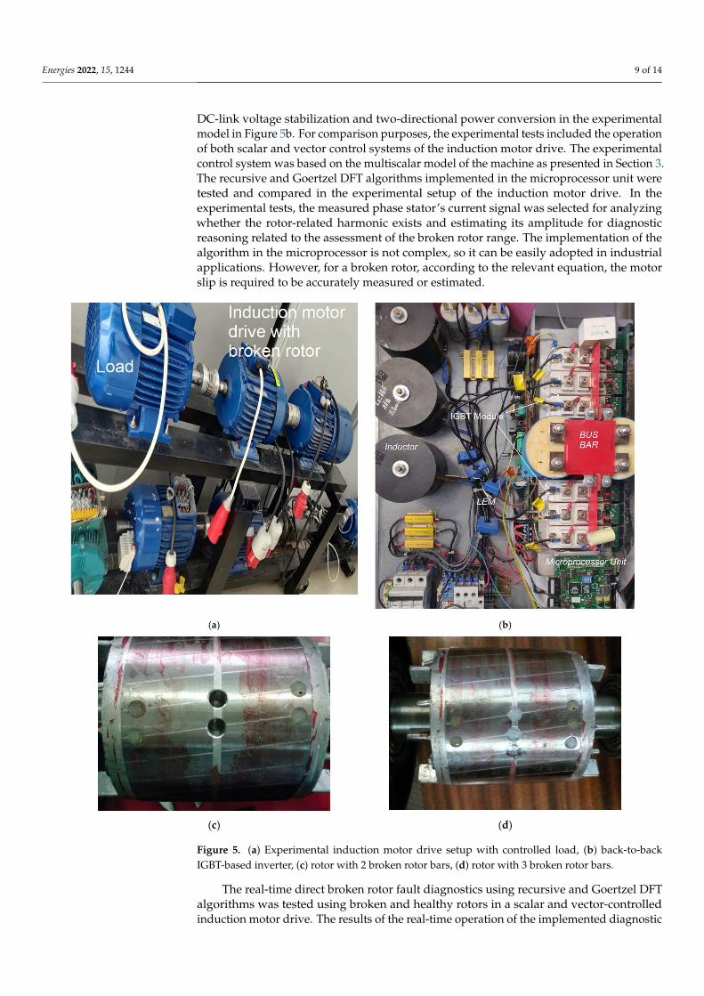
Considering the recursive and Goertzel’s algorithms for the direct DFT harmoniccalculation and analysis of the microprocessor computing time and memory availability, themodified control system including fault algorithms was implemented in a microprocessoras an application in C++ language, providing real-time fault diagnosis. The integration ofthe diagnosis system with the control system allowed the use of both the measured andestimated state variables to identify different faults, assuming that the frequencies of therelated induced harmonics are known. The fault diagnosis algorithms were executed at thesame frequency as the control system, which was set to 150 µs, being a compromise betweenswitching and conduction loses of IGBT transistors in the applied voltage source inverter(VSI). The inverter was controlled using the SVPWM modulation. An induction motordrive with nominal power of 5.5 kW and 3 broken rotor bars was used for experimentalverification, as shown in Figure 5a. The induction motor drive was fed by a voltage sourceinverter, and the DC circuit was fed by an IGBT-transistor-based grid inverter providing
Energies 2022, 15, 1244 9 of 14
DC-link voltage stabilization and two-directional power conversion in the experimentalmodel in Figure 5b. For comparison purposes, the experimental tests included the operationof both scalar and vector control systems of the induction motor drive. The experimentalcontrol system was based on the multiscalar model of the machine as presented in Section 3.The recursive and Goertzel DFT algorithms implemented in the microprocessor unit weretested and compared in the experimental setup of the induction motor drive. In theexperimental tests, the measured phase stator’s current signal was selected for analyzingwhether the rotor-related harmonic exists and estimating its amplitude for diagnosticreasoning related to the assessment of the broken rotor range. The implementation of thealgorithm in the microprocessor is not complex, so it can be easily adopted in industrialapplications. However, for a broken rotor, according to the relevant equation, the motorslip is required to be accurately measured or estimated.
Energies 2022, 15, x FOR PEER REVIEW 9 of 15
motor drive with nominal power of 5.5 kW and 3 broken rotor bars was used for experi-
mental verification, as shown in Figure 5a. The induction motor drive was fed by a voltage
source inverter, and the DC circuit was fed by an IGBT-transistor-based grid inverter
providing DC-link voltage stabilization and two-directional power conversion in the ex-
perimental model in Figure 5b. For comparison purposes, the experimental tests included
the operation of both scalar and vector control systems of the induction motor drive. The
experimental control system was based on the multiscalar model of the machine as pre-
sented in Section 3. The recursive and Goertzel DFT algorithms implemented in the mi-
croprocessor unit were tested and compared in the experimental setup of the induction
motor drive. In the experimental tests, the measured phase stator’s current signal was
selected for analyzing whether the rotor-related harmonic exists and estimating its ampli-
tude for diagnostic reasoning related to the assessment of the broken rotor range. The
implementation of the algorithm in the microprocessor is not complex, so it can be easily
adopted in industrial applications. However, for a broken rotor, according to the relevant
equation, the motor slip is required to be accurately measured or estimated.
(a) (b)
(c) (d)
Figure 5. (a) Experimental induction motor drive setup with controlled load, (b) back-to-backIGBT-based inverter, (c) rotor with 2 broken rotor bars, (d) rotor with 3 broken rotor bars.
The real-time direct broken rotor fault diagnostics using recursive and Goertzel DFTalgorithms was tested using broken and healthy rotors in a scalar and vector-controlledinduction motor drive. The results of the real-time operation of the implemented diagnostic
Energies 2022, 15, 1244 10 of 14
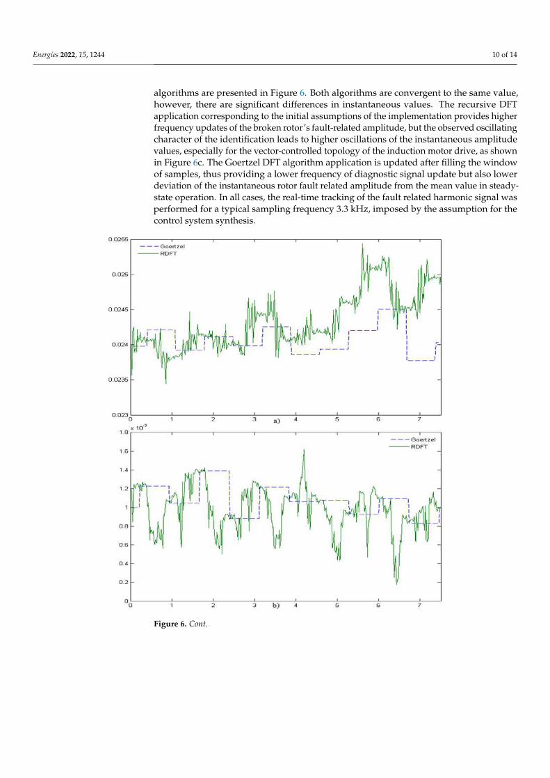
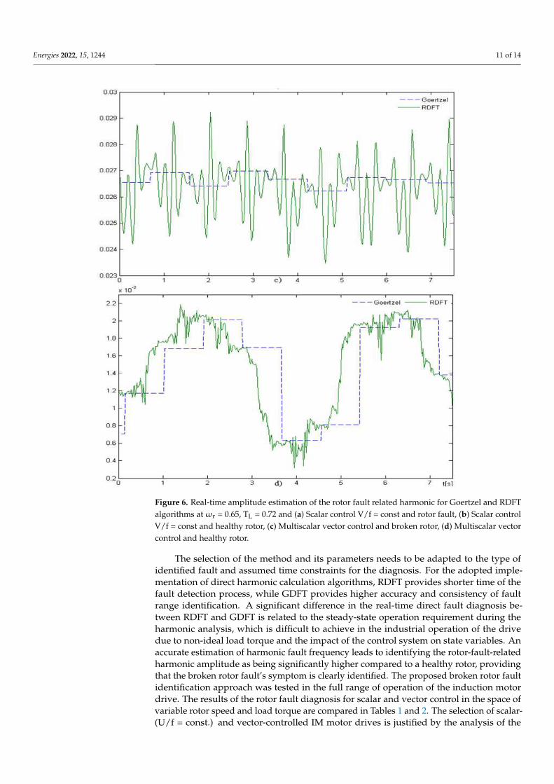
algorithms are presented in Figure 6. Both algorithms are convergent to the same value,however, there are significant differences in instantaneous values. The recursive DFTapplication corresponding to the initial assumptions of the implementation provides higherfrequency updates of the broken rotor’s fault-related amplitude, but the observed oscillatingcharacter of the identification leads to higher oscillations of the instantaneous amplitudevalues, especially for the vector-controlled topology of the induction motor drive, as shownin Figure 6c. The Goertzel DFT algorithm application is updated after filling the windowof samples, thus providing a lower frequency of diagnostic signal update but also lowerdeviation of the instantaneous rotor fault related amplitude from the mean value in steady-state operation. In all cases, the real-time tracking of the fault related harmonic signal wasperformed for a typical sampling frequency 3.3 kHz, imposed by the assumption for thecontrol system synthesis.
Energies 2022, 15, x FOR PEER REVIEW 10 of 15
Figure 5. (a) Experimental induction motor drive setup with controlled load, (b) back-to-back IGBT-
based inverter, (c) rotor with 2 broken rotor bars, (d) rotor with 3 broken rotor bars.
The real-time direct broken rotor fault diagnostics using recursive and Goertzel DFT
algorithms was tested using broken and healthy rotors in a scalar and vector-controlled
induction motor drive. The results of the real-time operation of the implemented diagnos-
tic algorithms are presented in Figure 6. Both algorithms are convergent to the same value,
however, there are significant differences in instantaneous values. The recursive DFT ap-
plication corresponding to the initial assumptions of the implementation provides higher
frequency updates of the broken rotor’s fault-related amplitude, but the observed oscil-
lating character of the identification leads to higher oscillations of the instantaneous am-
plitude values, especially for the vector-controlled topology of the induction motor drive,
as shown in Figure 6c. The Goertzel DFT algorithm application is updated after filling the
window of samples, thus providing a lower frequency of diagnostic signal update but also
lower deviation of the instantaneous rotor fault related amplitude from the mean value in
steady-state operation. In all cases, the real-time tracking of the fault related harmonic
signal was performed for a typical sampling frequency 3.3 kHz, imposed by the assump-
tion for the control system synthesis.
Figure 6. Cont.
Energies 2022, 15, 1244 11 of 14Energies 2022, 15, x FOR PEER REVIEW 11 of 15
Figure 6. Real-time amplitude estimation of the rotor fault related harmonic for Goertzel and RDFT
algorithms at ωr = 0.65, TL = 0.72 and (a) Scalar control V/f = const and rotor fault, (b) Scalar control
V/f = const and healthy rotor, (c) Multiscalar vector control and broken rotor, (d) Multiscalar vector
control and healthy rotor.
The selection of the method and its parameters needs to be adapted to the type of
identified fault and assumed time constraints for the diagnosis. For the adopted imple-
mentation of direct harmonic calculation algorithms, RDFT provides shorter time of the
fault detection process, while GDFT provides higher accuracy and consistency of fault
range identification. A significant difference in the real-time direct fault diagnosis be-
tween RDFT and GDFT is related to the steady-state operation requirement during the
harmonic analysis, which is difficult to achieve in the industrial operation of the drive due
to non-ideal load torque and the impact of the control system on state variables. An accu-
rate estimation of harmonic fault frequency leads to identifying the rotor-fault-related har-
monic amplitude as being significantly higher compared to a healthy rotor, providing that
the broken rotor fault’s symptom is clearly identified. The proposed broken rotor fault
identification approach was tested in the full range of operation of the induction motor
Figure 6. Real-time amplitude estimation of the rotor fault related harmonic for Goertzel and RDFTalgorithms at ωr = 0.65, TL = 0.72 and (a) Scalar control V/f = const and rotor fault, (b) Scalar controlV/f = const and healthy rotor, (c) Multiscalar vector control and broken rotor, (d) Multiscalar vectorcontrol and healthy rotor.
The selection of the method and its parameters needs to be adapted to the type ofidentified fault and assumed time constraints for the diagnosis. For the adopted imple-mentation of direct harmonic calculation algorithms, RDFT provides shorter time of thefault detection process, while GDFT provides higher accuracy and consistency of faultrange identification. A significant difference in the real-time direct fault diagnosis be-tween RDFT and GDFT is related to the steady-state operation requirement during theharmonic analysis, which is difficult to achieve in the industrial operation of the drivedue to non-ideal load torque and the impact of the control system on state variables. Anaccurate estimation of harmonic fault frequency leads to identifying the rotor-fault-relatedharmonic amplitude as being significantly higher compared to a healthy rotor, providingthat the broken rotor fault’s symptom is clearly identified. The proposed broken rotor faultidentification approach was tested in the full range of operation of the induction motordrive. The results of the rotor fault diagnosis for scalar and vector control in the space ofvariable rotor speed and load torque are compared in Tables 1 and 2. The selection of scalar-(U/f = const.) and vector-controlled IM motor drives is justified by the analysis of the
Energies 2022, 15, 1244 12 of 14
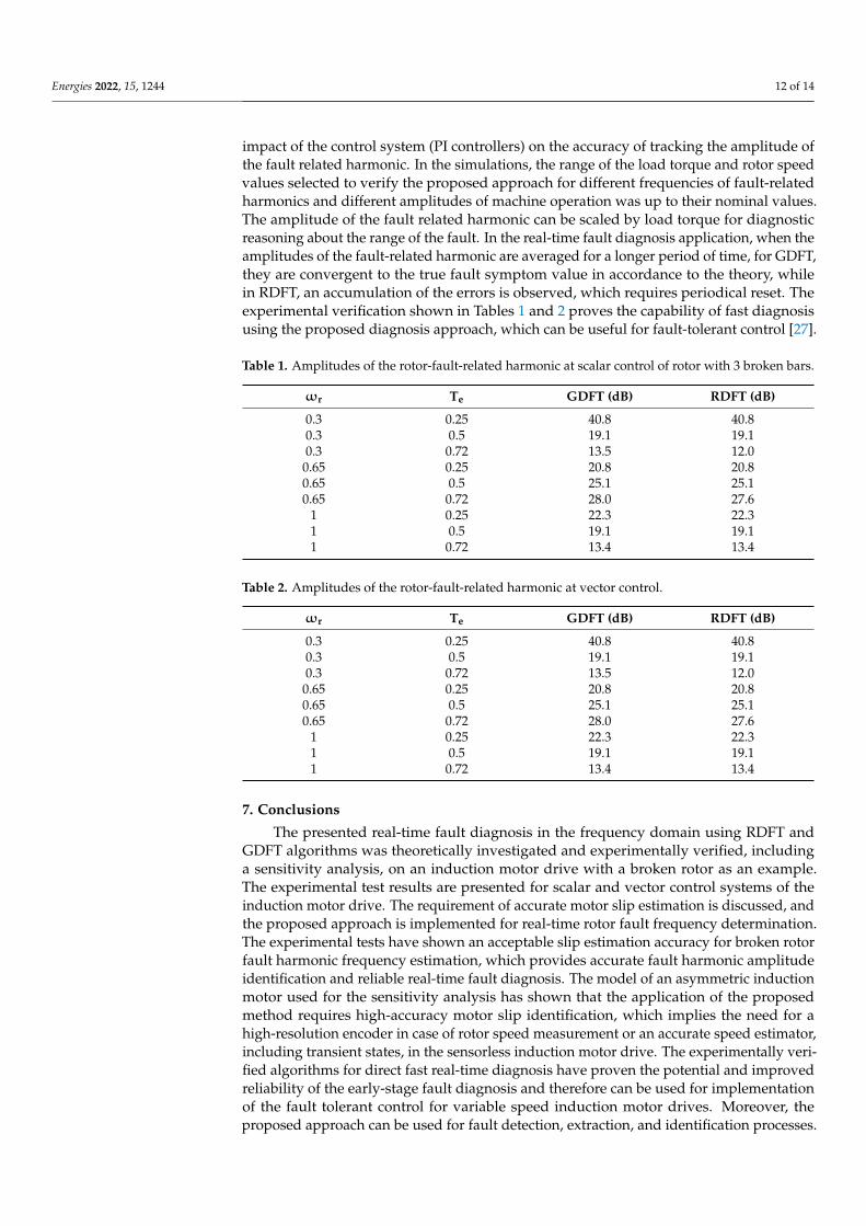
impact of the control system (PI controllers) on the accuracy of tracking the amplitude ofthe fault related harmonic. In the simulations, the range of the load torque and rotor speedvalues selected to verify the proposed approach for different frequencies of fault-relatedharmonics and different amplitudes of machine operation was up to their nominal values.The amplitude of the fault related harmonic can be scaled by load torque for diagnosticreasoning about the range of the fault. In the real-time fault diagnosis application, when theamplitudes of the fault-related harmonic are averaged for a longer period of time, for GDFT,they are convergent to the true fault symptom value in accordance to the theory, whilein RDFT, an accumulation of the errors is observed, which requires periodical reset. Theexperimental verification shown in Tables 1 and 2 proves the capability of fast diagnosisusing the proposed diagnosis approach, which can be useful for fault-tolerant control [27].
Table 1. Amplitudes of the rotor-fault-related harmonic at scalar control of rotor with 3 broken bars.
ωr Te GDFT (dB) RDFT (dB)
0.3 0.25 40.8 40.80.3 0.5 19.1 19.10.3 0.72 13.5 12.0
0.65 0.25 20.8 20.80.65 0.5 25.1 25.10.65 0.72 28.0 27.6
1 0.25 22.3 22.31 0.5 19.1 19.11 0.72 13.4 13.4
Table 2. Amplitudes of the rotor-fault-related harmonic at vector control.
ωr Te GDFT (dB) RDFT (dB)
0.3 0.25 40.8 40.80.3 0.5 19.1 19.10.3 0.72 13.5 12.0
0.65 0.25 20.8 20.80.65 0.5 25.1 25.10.65 0.72 28.0 27.6
1 0.25 22.3 22.31 0.5 19.1 19.11 0.72 13.4 13.4
7. Conclusions
The presented real-time fault diagnosis in the frequency domain using RDFT andGDFT algorithms was theoretically investigated and experimentally verified, includinga sensitivity analysis, on an induction motor drive with a broken rotor as an example.The experimental test results are presented for scalar and vector control systems of theinduction motor drive. The requirement of accurate motor slip estimation is discussed, andthe proposed approach is implemented for real-time rotor fault frequency determination.The experimental tests have shown an acceptable slip estimation accuracy for broken rotorfault harmonic frequency estimation, which provides accurate fault harmonic amplitudeidentification and reliable real-time fault diagnosis. The model of an asymmetric inductionmotor used for the sensitivity analysis has shown that the application of the proposedmethod requires high-accuracy motor slip identification, which implies the need for ahigh-resolution encoder in case of rotor speed measurement or an accurate speed estimator,including transient states, in the sensorless induction motor drive. The experimentally veri-fied algorithms for direct fast real-time diagnosis have proven the potential and improvedreliability of the early-stage fault diagnosis and therefore can be used for implementationof the fault tolerant control for variable speed induction motor drives. Moreover, theproposed approach can be used for fault detection, extraction, and identification processes.
Energies 2022, 15, 1244 13 of 14
The presented frequency-domain direct fault diagnosis is not limited to induction motordrives. Regarding the electric machine fault theory, it is also applicable for different electricdrives and different faults. By relying it on the mathematical model of fault, the complexityof the real-time fault diagnosis has been decreased, which supports its capability of real-time identification of other faults by the microprocessor. In the proposed approach, theapplication of GDRFT and RDFT for fault diagnosis via direct real-time tracking of one ormore fault-related harmonics significantly improves the efficiency of the diagnosis becauseregistering the data for calculating all harmonics in the spectra up to the Nyquist frequency,as in FFT, and further analysis of the spectra is omitted. The proposed approach has beenproven to be efficient and convenient for real-time automated diagnostics in a broad rangeof applications.
Author Contributions: Conceptualization, P.K. and D.W.; methodology, D.W.; software, P.K.; valida-tion, D.W.; formal analysis, P.K.; investigation, D.W.; resources, P.K.; data curation, D.W.; writing—original draft preparation, P.K.; writing—review and editing, P.K. and D.W.; visualization, P.K.;supervision, D.W.; project administration, P.K.; funding acquisition, P.K. All authors have read andagreed to the published version of the manuscript.
Funding: This research was funded by The National Centre of Science grant 7158/B/T02/2011/40.
Institutional Review Board Statement: Not applicable.
Informed Consent Statement: Not applicable.
Conflicts of Interest: The authors declare no conflict of interest.
References1. Riera-Guasp, M.; Antonino-Daviu, J.A.; Capolino, G.-A. Advances in Electrical Machine, Power Electronic, and Drive Condition
Monitoring and Fault Detection: State of the Art. IEEE Trans. Ind. Electron. 2014, 62, 1746–1759. [CrossRef]2. Merizalde, Y.; Hernández-Callejo, L.; Duque-Perez, O. State of the Art and Trends in the Monitoring, Detection and Diagnosis of
Failures in Electric Induction Motors. Energies 2017, 10, 1056. [CrossRef]3. Terron-Santiago, C.; Martinez-Roman, J.; Puche-Panadero, R.; Sapena-Bano, A. A Review of Techniques Used for Induction
Machine Fault Modelling. Sensors 2021, 21, 4855. [CrossRef] [PubMed]4. Tian, Y.; Guo, D.; Zhang, K.; Jia, L.; Qiao, H.; Tang, H. A Review of Fault Diagnosis for Traction Induction Motor. In Proceedings
of the 2018 37th Chinese Control Conference (CCC), Wuhan, China, 25–27 July 2018; pp. 5763–5768.5. Chen, H.; Jiang, B. A Review of Fault Detection and Diagnosis for the Traction System in High-Speed Trains. IEEE Trans. Intell.
Transp. Syst. 2019, 21, 450–465. [CrossRef]6. Kim, B.; Lee, K.; Yang, J.; Bin Lee, S.; Wiedenbrug, E.J.; Shah, M.R. Automated Detection of Rotor Faults for Inverter-Fed Induction
Machines Under Standstill Conditions. IEEE Trans. Ind. Appl. 2010, 47, 55–64. [CrossRef]7. Li, L.; Lu, W.; Wang, X.; Li, Z. A frequency domain feature based cascade classifier and its application to fault diagnosis. In
Proceedings of the 28th Chinese Control and Decision Conference, CCDC 2016, Yinchuan, China, 28–30 May 2016; Volume 2, pp.5957–5961. [CrossRef]
8. Wang, Z.; Yang, J.; Li, H.; Zhen, D.; Xu, Y.; Gu, F. Fault Identification of Broken Rotor Bars in Induction Motors Using an ImprovedCyclic Modulation Spectral Analysis. Energies 2019, 12, 3279. [CrossRef]
9. Moussa, M.A.; Boucherma, M.; Khezzar, A. A Detection Method for Induction Motor Bar Fault Using Sidelobes LeakagePhenomenon of the Sliding Discrete Fourier Transform. IEEE Trans. Power Electron. 2016, 32, 5560–5572. [CrossRef]
10. Sahraoui, M.; Cardoso, A.J.M.; Ghoggal, A. The Use of a Modified Prony Method to Track the Broken Rotor Bar CharacteristicFrequencies and Amplitudes in Three-Phase Induction Motors. IEEE Trans. Ind. Appl. 2014, 51, 2136–2147. [CrossRef]
11. Skowron, M.; Orlowska-Kowalska, T.; Wolkiewicz, M.; Kowalski, C.T. Convolutional Neural Network-Based Stator CurrentData-Driven Incipient Stator Fault Diagnosis of Inverter-Fed Induction Motor. Energies 2020, 13, 1475. [CrossRef]
12. Rinanto, N.; Adhitya, R.Y.; Sarena, S.T.; Kautsar, S.; Munadhif, I.; Setyoko, A.S.; Syai’In, M.; Soeprijanto, A. Rotor bars faultdetection by DFT spectral analysis and Extreme Learning Machine. In Proceedings of the 2016 International Symposium onElectronics and Smart Devices, ISESD 2016, Bandung, Indonesia, 29–30 November 2016; pp. 103–108. [CrossRef]
13. Kolodziejek, P.; Bogalecka, E. Broken rotor bar impact on sensorless control of induction machine. COMPEL Int. J. Comput. Math.Electr. Electron. Eng. 2009, 28, 540–555. [CrossRef]
14. Puche-Panadero, C.R.; Pineda-Sanchez, M.; Riera-Guasp, M.; Roger-Folch, J.; Hurtado-Perez, E.; Perez-Cruz, J. ImprovedResolution of the MCSA Method Via Hilbert Transform, Enabling the Diagnosis of Rotor Asymmetries at Very Low Slip. IEEETrans. Energy Convers. 2013, 24, 52–59. [CrossRef]
Energies 2022, 15, 1244 14 of 14
15. Kral, C.; Pirker, F.; Pascoli, G. The impact of inertia on rotor faults effects theoretical aspects of the Vienna Monitoring Method.In Proceedings of the 2007 IEEE International Symposium on Diagnostics for Electric Machines, Power Electronics and Drives,SDEMPED, Cracow, Poland, 6–7 September 2007; pp. 77–82. [CrossRef]
16. Luo, M.; Liu, Z.; Zhou, H.; Zhang, X.; Gao, F. Diagnosis simulation of broken rotor bars in squirrel cage induction motor fed withvariable frequency power. In Proceedings of the 27th Chinese Control Conference CCC, Kunming, China, 16–18 July 2008; pp.88–92. [CrossRef]
17. Gritli, Y.; Bellini, A.; Rossi, C.; Casadei, D.; Filippetti, F.; Capolino, G.A. Condition monitoring of mechanical faults in inductionmachines from electrical signatures: Review of different techniques. In Proceedings of the 2017 IEEE 11th International Symposiumon Diagnostics for Electric Machines, Power Electronics and Drives, SDEMPED 2017, Tinos, Greece, 29 August–1 September 2017;Volume 2017, pp. 77–84. [CrossRef]
18. Nemec, M.; Ambrožic, V.; Fišer, R.; Nedeljkovic, D.; Drobnic, K. Induction motor broken rotor bar detection based on rotor fluxangle monitoring. Energies 2019, 12, 794. [CrossRef]
19. Ayhan, B.; Chow, M.-Y.; Song, M.-H. Multiple Signature Processing-Based Fault Detection Schemes for Broken Rotor Bar inInduction Motors. IEEE Trans. Energy Convers. 2005, 20, 336–343. [CrossRef]
20. Lu, B.; Paghda, M. Induction motor rotor fault diagnosis using wavelet analysis of one-cycle average power. In Proceedings of theIEEE Applied Power Electronics Conference and Exposition APEC 2018, San Antonio, TX, USA, 4–8 March 2018; pp. 1113–1118.[CrossRef]
21. Kołodziejek, P.; Bogalecka, E. Broken rotor symptoms in the sensorless control of induction machine. COMPEL Int. J. Comput.Math. Electr. Electron. Eng. 2011, 31, 237–247. [CrossRef]
22. Kia, S.H.; Henao, H.; Capolino, G.A.; Martis, C. Induction machine broken bars fault detection using stray flux after supplydisconnection. IECON Proc. 2006, 2006, 1498–1503. [CrossRef]
23. Jornet, A.; Espinosa, A.G.; Romeral, L.; Cusidó, J.; Ortega, J.A. Double frequency test for detecting faults in induction machines.IECON Proc. 2005, 2005, 1516–1521. [CrossRef]
24. Drif, M.; Cardoso, A.J.M. The Use of the Instantaneous-Reactive-Power Signature Analysis for Rotor-Cage-Fault Diagnostics inThree-Phase Induction Motors. IEEE Trans. Ind. Electron. 2009, 56, 4606–4614. [CrossRef]
25. Touhami, O.; Fadel, M. Detection of Broken Rotor Bars and Stator Faults in Squirrel-Cage Induction Machine by Spectral Analysis.In Proceedings of the 2007 Thirty-Ninth Southeastern Symposium on System Theory, Macon, GA, USA, 4−7 March 2007; pp.274–278. [CrossRef]
26. Pakhaliuk, B.; Shevchenko, V.; Mucko, J.; Husev, O.; Lukianov, M.; Kołodziejek, P.; Strzelecka, N.; Strzelecki, R. Optimal RotatingReceiver Angles Estimation for Multicoil Dynamic Wireless Power Transfer. Energies 2021, 14, 6144. [CrossRef]
27. Adamowicz, M.; Szewczyk, J. SiC-Based Power Electronic Traction Transformer (PETT) for 3 kV DC Rail Traction. Energies 2020,13, 5573. [CrossRef]
28. Kołodziejek, P. State and control system variables sensitivity to rotor asymmetry in the induction motor drive. COMPEL Int. J.Comput. Math. Electr. Electron. Eng. 2012, 32, 142–152. [CrossRef]
29. Wlas, M.; Galla, S.; Kouzou, A.; Kolodziejek, P. Analysis of an Energy Management System of a Small Plant Connected to theRural Power System. Energies 2022, 15, 719. [CrossRef]
30. Wu, Y.; Liu, Z.X.; Li, R.Y. Fault diagnosis way based on subsection spectrum zoom analysis by CZT for squirrel cage inductionmotors. In Proceedings of the 2008 International Conference on Condition Monitoring and Diagnosis, Beijing, China, 21–24 April2008; pp. 208–211. [CrossRef]
31. Krzeminski, Z. Cyfrowe Sterowanie Maszynami Asynchronicznymi; Gdansk University of Technology: Gdansk, Poland, 2000.(In Polish)
32. Wachowiak, D. A Universal Gains Selection Method for Speed Observers of Induction Machine. Energies 2021, 14, 6790. [CrossRef]33. Wachowiak, D. Genetic Algorithm Approach for Gains Selection of Induction Machine Extended Speed Observer. Energies 2020,
13, 4632. [CrossRef]34. Cooley, J.W.; Tukey, J.W. An Algorithm for the Machine Calculation of Complex Fourier Series. Math. Comput. 1965, 19, 297–301.
[CrossRef]35. Gerard, G. An Algorithm for the Evaluation of Finite Trigonometric Series. Am. Math. Mon. 1958, 65, 34–35.
Copyright © 2022 FDOKUMEN