Anchorage of tower foundations in rock - SINTEF
25
Anchorage of tower foundations in rock Classification of rock ground and design rules Jessica Ka Yi Chiu, [email protected] ROCARC-webinar 2020-11-18
-
Upload
khangminh22 -
Category
Documents
-
view
4 -
download
0
Transcript of Anchorage of tower foundations in rock - SINTEF

Anchorage of tower foundations in rockClassification of rock ground and design rules
Jessica Ka Yi Chiu, [email protected] 2020-11-18

Agenda
1. Background2. Classification of rock ground3. Design rules
chimney
tendon2

Foundation of tower chimneys on rockAfter a power line foundation failure in Sauda – Liastøl, NGI was employed by Statnett to develop a better procedure for rock ground investigation and designing of anchorage of power line tower foundation on rock.
This resulted in two contract documents: «Classification of rock ground», which presents a procedure for classification of rock ground. «Design rules», which presents a procedure for determining bearing capacity of rock ground and required embedment depth of tendons in the tower chimneys based on rock class.
3
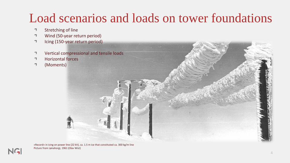
Load scenarios and loads on tower foundationsStretching of lineWind (50-year return period)Icing (150-year return period)
Vertical compressional and tensile loadsHorizontal forces(Moments)
«Record» in icing on power line (22 kV), ca. 1.5 m ice that constituted ca. 300 kg/m linePicture from Lønahorgi, 1961 (Olav Wist)
4

What is the purpose of these specification?To establish a safe practise for design of the tower foundations on rock ground, with focus on:
A. Bearing capacity on rock groundB. Pull-out resistance of the rock ground
Tower 42 Sauda - Liastøl 5

General information about the specificationsGeneral rules for design of overhead electric lines are given in NEK-EN 50341-1, and -3-16:2001 «Overhead electric lines exceeding AC 45 kV», however, this does not cover tower foundations in rock.
Therefore the rules are based on Eurocode 7, NS-EN 1997-1:2004+A1:2013+NA:2016
The main focus is on anchorage of the chimney founda-tions against pull-out forces, which is usually controlling the design.
To be applied by consultants and contractors responsible for design and construction of power lines for Statnett.
Based on a classification of the rock ground at the site.
6

Classification of rock ground
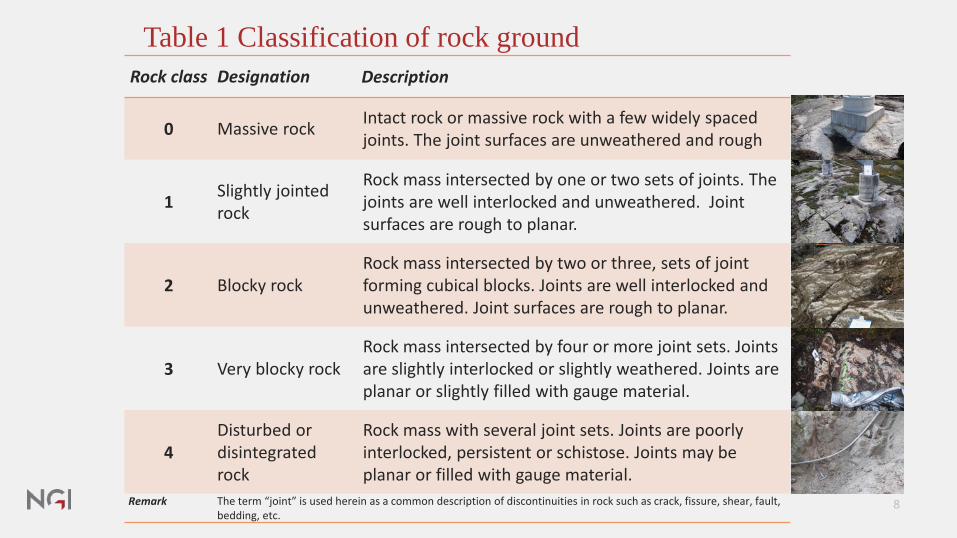
Table 1 Classification of rock groundRock class Designation Description
0 Massive rock Intact rock or massive rock with a few widely spaced joints. The joint surfaces are unweathered and rough
1 Slightly jointedrock
Rock mass intersected by one or two sets of joints. The joints are well interlocked and unweathered. Joint surfaces are rough to planar.
2 Blocky rockRock mass intersected by two or three, sets of joint forming cubical blocks. Joints are well interlocked and unweathered. Joint surfaces are rough to planar.
3 Very blocky rockRock mass intersected by four or more joint sets. Joints are slightly interlocked or slightly weathered. Joints are planar or slightly filled with gauge material.
4Disturbed or disintegratedrock
Rock mass with several joint sets. Joints are poorly interlocked, persistent or schistose. Joints may be planar or filled with gauge material.
Remark The term “joint” is used herein as a common description of discontinuities in rock such as crack, fissure, shear, fault, bedding, etc.
8

Table 1 Classification of rock groundRock class Designation Description
0 Massive rock Intact rock or massive rock with a few widely spaced joints. The joint surfaces are unweathered and rough
1 Slightly jointedrock
Rock mass intersected by one or two sets of joints. The joints are well interlocked and unweathered. Joint surfaces are rough to planar.
2 Blocky rockRock mass intersected by two or three, sets of joint forming cubical blocks. Joints are well interlocked and unweathered. Joint surfaces are rough to planar.
3 Very blocky rockRock mass intersected by four or more joint sets. Joints are slightly interlocked or slightly weathered. Joints are planar or slightly filled with gauge material.
4Disturbed or disintegratedrock
Rock mass with several joint sets. Joints are poorly interlocked, persistent or schistose. Joints may be planar or filled with gauge material.
Class 4A concrete foundation in a blasted or excavated pit is cheaper than to reinforce the rock mass with tendons.
Class 0 & Class 1Sufficient tensile strength to withstand uplifting forces.
Class 2 & Class 3So low tensile strength that the uplifting forces can only be countered by shear resistance of joints and the weight of the rock lump between the embedded tendons.
9
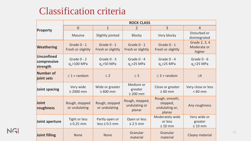
Classification criteria
Property
ROCK CLASS0 1 2 3 4
Massive Slightly jointed Blocky Very blocky Disturbed or disintegrated
Weathering Grade 0 - 1Fresh or slightly
Grade 0 - 1Fresh or slightly
Grade 0 - 1Fresh or slightly
Grade 0 - 1Fresh or slightly
Grade 2, 3, 4Moderate or
higherUnconfined compressive strength
Grade 0 - 2qu>100 MPa
Grade 0 - 3qu>50 MPa
Grade 0 - 4qu>25 MPa
Grade 0 - 4qu>25 MPa
Grade 0 - 6qu<25 MPa
Number of joint sets ≤ 1 + random ≤ 2 ≤ 3 ≤ 3 + random ≥4
Joint spacing Very wide≥ 2000 mm
Wide or greater≥ 600 mm
Medium or greater
≥ 200 mm
Close or greater≥ 60 mm
Very close or less< 60 mm
Joint roughness
Rough, stepped or undulating
Rough, stepped or undulating
Rough, stepped, undulating or
planar
Rough, smooth, stepped,
undulating or, planar
Any roughness
Joint aperture Tight or less≤ 0.25 mm
Partly open or less ≤ 0.5 mm
Open or less≤ 2.5 mm
Moderately wide or less
≤ 10 mm
Very wide or greater
≥ 10 mm
Joint filling None None Granularmaterial
Granularmaterial Clayey material
10

Example from Inner Oslofjord –reporting
Results of classification (for each tower leg)Property
ROCK CLASS0 1 2 3 4
MassiveSlightjointed
Blocky Very blockyDisturbed or disintegrated
WeatheringGrade 0 - 1 Grade 0 - 1 Grade 0 - 1 Grade 0 - 1 Grade 2, 3, 4
Fresh or slightly
Fresh or slightly
Fresh or slightly
Fresh or slightly
Moderate or higher
Unconfined compressive strength
Grade 0 - 2 Grade 0 - 3 Grade 0 - 4 Grade 0 - 4 Grade 0 - 6
qu>100 MPa qu>50 MPa qu>25 MPa qu>25 MPa qu<25 MPa
Number of joint sets
≤ 1 + random ≤ 2 ≤ 3 ≤ 3 + random ≥4
Joint spacing Very wideWide or greater
Medium or greater
Close or greater
Very close or less
≥ 2000 mm ≥ 600 mm ≥ 200 mm ≥ 60 mm < 60 mm
Joint roughness
Rough, stepped or undulating
Rough, stepped or undulating
Rough, stepped,
undulating or planar
Rough, smooth, stepped,
undulating or, planar
Any roughnss
Joint aperture Tight or less≤ 0.25 mm
Partly open or less ≤ 0.5
mm
Open or less≤ 2.5 mm
Moderat wide or less
≤ 10 mm
Very wide or greater
≥ 10 mm
Joint filling None None Granular material
Granular material
clayey material
11
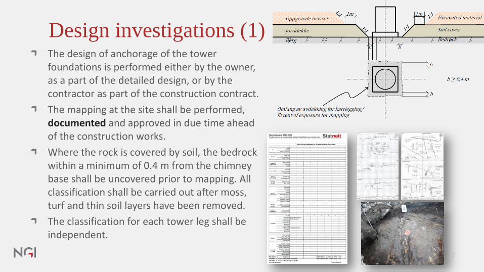
The design of anchorage of the tower foundations is performed either by the owner, as a part of the detailed design, or by the contractor as part of the construction contract.The mapping at the site shall be performed, documented and approved in due time ahead of the construction works.Where the rock is covered by soil, the bedrock within a minimum of 0.4 m from the chimney base shall be uncovered prior to mapping. All classification shall be carried out after moss, turf and thin soil layers have been removed.The classification for each tower leg shall be independent.
Design investigations (1)
12

Design investigations (2)
For Class 2 & Class 3:Fractured and weathered surface rock may be removed, then undertake new classification.Hydraulic hammer are well suited in removal of surface rock.Blasting of surface rock will seldom be appropriate. The base charge often tears up the rock and create new joints.
13

Design rules

Chimney foundation design - general requirementsDesign of chimney foundations comprise two main tasks:
1. Check that bearing capacity of the rock ground are adequate against design compressional loads from the chimney.
Possible modes of failure at ultimate bearing capacity of foundation rock(Goodman 1989)
15

Chimney foundation design - general requirementsDesign of chimney foundations comprise two main tasks:
2. Check that the anchorage in rock has adequate resistance (capacity) against design tensile forces from chimney.
Principal modes of failure of grouted rock anchors under applied axial tension(Pease & Kulhawy, 1984)
16

Strength parameters of rock mass
How to determine bearing capacity of the rock ground?
Characteristic values for bearing capacity of rock class (0-3)Bearing capacity based on the UCCS of intact rock, joint spacing, joint aperture.Characteristic strength values of rock ground estimated based on classification criteria, using the Hoek & Brown failure criterion.Boundary limits between the rock classes and engineering judgements
17

Bearing capacity of foundation rockPresumptions:I. Only effective area of the chimney can transfer compressive
force to bedrock (= inner diameter of hoop reinforcement)II. Design commpression capacity of tendons, fyd = 400 Mpa.III. Design compressive strength of concrete, fcd = 19,8 MpaIV. Concrete cover = 50 mm. V. Diameter hoop reinforcement 10 mm. Eff.
areal
18

Bearing capacity offoundation rock
For rock class 0 and 1, the bearing capacity is limited by the reinforced chimney, i.esteel and concrete. For rock class 2 and 3 the bearing capacity is limited by capacity of rock mass and steel tendons.
19

Computational models for pull-out resistance in rock
For long embedded tendons
1. Tensile strength model (rock class 0-1) 2. Pull-out cylinder shaft (rock class 1-2)
3. Weight of cone (rock class 2-3) 4. Combined weight of cone andbond strength (rock class 2-3) 20

Required embedment depth of tendons
21

Ground improvement
For Class 2 & Class 3:As an alternative to long tendons, the rock may be reinforced around the chimney to engage lateral rock mass instead of at depth.
22

23
Measurement once a year by StatnettCondition control and assess the needfor future tensioningR&D: to gain more knowledge on the long-term behavior and hopefully improve the current design methodology for anchors in strong rock types.At least 10 years’ monitoring (post-tensioning 13 September, 2017)
Design pylon, Lysefjorden (read more)

Thank you!

NORGES GEOTEKNISKE INSTITUTTNGI.NO
#påsikkergrunn