Analysis of equilibrium shift in isothermal reactors with a permselective wall
11
Analysis of Equilibrium Shift in Isothermal Reactors with a Permselective Wall The objective of this study is to obtain a fundamental understanding of the behavior of reactors with a permselective wall (membrane reac- tors) in terms of: design parameters (reactor length, membrane thick- ness); operating variables (pressure ratio, feed flow rate): physical properties (rate constant, permeability of fast gas, permselectivity, equilibrium constant): and flow patterns (recycle, cocurrent, countercur- rent). Pure feed reacts on the high-pressure side of the membrane, and the product(s) formed are continuously removed to the low-pressure side so that thermodynamic equilibrium is never reached. It is shown by simulation that equilibrium shift can be enhanced by: recycling uncon- verted reactant; shifting feed location to separate products; and main- taining high permeation rates to reduce backreaction. It is also shown that the choice between cocurrent flow and countercurrent flow depends on the system parameters. Krishna Mohan and Rakesh Govind Department of Chemical Engineering University of Cincinnati Cincinnati, OH 4522 1 Introduction In recent years, the use of membranes in reaction engineering has been recognized. By selectively separating the products from the reaction mixture, it is possible to achieve significant enhancement over equilibrium conversion. Shifting the thermo- dynamic equilibrium in this manner has obvious industrial inter- est. It allows for reduced reaction temperatures, thereby mini- mizing side reactions and heating costs. Also, both reaction and separation may be achieved in a single unit, making the mem- brane reactor a very cost-effective unit operation. The term “membrane reactor” has been used in the literature to describe a number of reactor configurations. In some instances, the role of the membrane is merely to confine the catalyst to the reactor. In other cases, the membrane prevents certain compo- nents (e.g., particulates) of the reactant feed stream from con- tacting the catalyst. In certain applications, the membrane sup- ports the catalyst and may or may not be permselective. In this study, the membrane is a permselective barrier that separates certain components from the reaction mixture, Figure 1. This study analyzes the effects of design parameters (mem- brane characteristics and dimensions, and reactor dimensions); operating variables (reaction and permeation side pressure, and feed and inert flow rate); physical properties (reaction rate Correspondence concerning this article should be addressed to R. Govind. constant, equilibrium constant, and permeabilities); and flow patterns (cocurrent, countercurrent, and recycle) on the perfor- mance of reactors with a permselective wall. The model equa- tions represent reactors, in which the flow stream on one side of the membrane reacts. However, many of the results obtained in this study can be extended to reactors, in which the permeating stream reacts, since the model neglects radial effects. Background Study The majority of the published literature on membrane reac- tors involve biological systems. This is due to the fact that enzyme immobilization techniques are highly developed and because membranes are the natural environment for many enzymes. Membranes not only serve as a support for the cata- lytic enzymes but provide a cost-effective means of separating the products. In typical usage, the membrane is a composite of a permselective layer (for separation) and a catalytic layer (for reaction). Membranes are popular enzyme supports, largely because they are experimentally convenient and the mathemat- ics involved in their description is simple (Porter et al., 1972; Vieth et al., 1972; Madgavkar et al., 1977; Matson, 1979). Using membranes to upset the equilibrium in a reversible reaction has been recognized since the late 60s (Wood, 1968; Shah et al., 1970; Barker and Burns, 1973; Gryaznov et al., 1973; Hwang and Kammermeyer, 1975). Practical application has been limited to inorganic membranes, due to the lack of suit- AIChE Journal September 1988 Vol. 34, No. 9 1493
-
Upload
independent -
Category
Documents
-
view
0 -
download
0
Transcript of Analysis of equilibrium shift in isothermal reactors with a permselective wall
Analysis of Equilibrium Shift in Isothermal Reactors with a Permselective Wall
The objective of this study is to obtain a fundamental understanding of the behavior of reactors with a permselective wall (membrane reac- tors) in terms of: design parameters (reactor length, membrane thick- ness); operating variables (pressure ratio, feed flow rate): physical properties (rate constant, permeability of fast gas, permselectivity, equilibrium constant): and flow patterns (recycle, cocurrent, countercur- rent). Pure feed reacts on the high-pressure side of the membrane, and the product(s) formed are continuously removed to the low-pressure side so that thermodynamic equilibrium is never reached. It is shown by simulation that equilibrium shift can be enhanced by: recycling uncon- verted reactant; shifting feed location to separate products; and main- taining high permeation rates to reduce backreaction. It is also shown that the choice between cocurrent flow and countercurrent flow depends on the system parameters.
Krishna Mohan and Rakesh Govind Department of Chemical Engineering
University of Cincinnati Cincinnati, OH 4522 1
Introduction In recent years, the use of membranes in reaction engineering
has been recognized. By selectively separating the products from the reaction mixture, it is possible to achieve significant enhancement over equilibrium conversion. Shifting the thermo- dynamic equilibrium in this manner has obvious industrial inter- est. It allows for reduced reaction temperatures, thereby mini- mizing side reactions and heating costs. Also, both reaction and separation may be achieved in a single unit, making the mem- brane reactor a very cost-effective unit operation.
The term “membrane reactor” has been used in the literature to describe a number of reactor configurations. In some instances, the role of the membrane is merely to confine the catalyst to the reactor. In other cases, the membrane prevents certain compo- nents (e.g., particulates) of the reactant feed stream from con- tacting the catalyst. In certain applications, the membrane sup- ports the catalyst and may or may not be permselective. In this study, the membrane is a permselective barrier that separates certain components from the reaction mixture, Figure 1.
This study analyzes the effects of design parameters (mem- brane characteristics and dimensions, and reactor dimensions); operating variables (reaction and permeation side pressure, and feed and inert flow rate); physical properties (reaction rate
Correspondence concerning this article should be addressed to R. Govind.
constant, equilibrium constant, and permeabilities); and flow patterns (cocurrent, countercurrent, and recycle) on the perfor- mance of reactors with a permselective wall. The model equa- tions represent reactors, in which the flow stream on one side of the membrane reacts. However, many of the results obtained in this study can be extended to reactors, in which the permeating stream reacts, since the model neglects radial effects.
Background Study The majority of the published literature on membrane reac-
tors involve biological systems. This is due to the fact that enzyme immobilization techniques are highly developed and because membranes are the natural environment for many enzymes. Membranes not only serve as a support for the cata- lytic enzymes but provide a cost-effective means of separating the products. In typical usage, the membrane is a composite of a permselective layer (for separation) and a catalytic layer (for reaction). Membranes are popular enzyme supports, largely because they are experimentally convenient and the mathemat- ics involved in their description is simple (Porter et al., 1972; Vieth et al., 1972; Madgavkar et al., 1977; Matson, 1979).
Using membranes to upset the equilibrium in a reversible reaction has been recognized since the late 60s (Wood, 1968; Shah et al., 1970; Barker and Burns, 1973; Gryaznov et al., 1973; Hwang and Kammermeyer, 1975). Practical application has been limited to inorganic membranes, due to the lack of suit-
AIChE Journal September 1988 Vol. 34, No. 9 1493

purge gas - feed -
Z=O closed end
+
9 ..!J ..... .) ...... J..!... p r o d u c t s XI FI -
b) countercurrent membrane reactor
z = o enricher stripper
c) membrane reactor with recycle and intermediate feed location
(CMC configuration)
Figure 1. Flow patterns in membrane reactors.
able membranes that can withstand high temperatures and pro- vide good permselectivities.
In recent years, many researchers have studied the feasibility of producing hydrogen by enhancing the conversion of dehydro- genation/decomposition reactions. Dokiya et al. (1977), Fu- kuda et al. (1978), and Kameyama et al. (1981) employed por- ous Vycor glass to selectively separate the hydrogen produced in the decomposition of hydrogen sulfide. In a separate study using the same reaction, Kameyama et al. (1983) showed the possibil- ity of using porous alumina membranes. Shindo et al. (1981) conducted similar studies for the hydrogen iodide reaction using porous Vycor glass. This last study has important significance to the thermochemical production of hydrogen, since many of the water splitting cycles use the decomposition of hydrogen halo- genide. Ito et al. (1984), in a theoretical study of the decomposi- tion of hydrogen iodide, showed that significant equilibrium shift is possible when porous Vycor glass is used to separate the hydrogen. They also indicated the need for manufacturing very thin membranes ( m) and/or membranes with large surface area per unit volume (hollow fiber type) to obtain high perme- ation fluxes.
Shinji et al. (1982) and Ito (1987), using porous Vycor glass and palladium respectively, enhanced the dehydrogenation of cyclohexane. Palladium being permeable only to the hydrogen, high conversions could be achieved by increasing residence time: i.e., decreasing the feed flow rate. Ito et al. (1985) simulated the membrane reactor with the above reaction and showed that, for given rates of permeation and reaction, there is an optimum thickness of membrane a t which maximum conversion is ob- tained. In a separate parametric study (Mohan and Govind, 1986), it is shown that for a membrane, which is permeable to both products and reactants, the maximum equilibrium shift possible is limited by the loss of reactant from the reaction zone.
A literature classification based on reaction is presented in Table 1.
Table 1. Literature Classification
Reaction Membrane Authors
H2S=H2 + S
2HI -- H, + I,
C6H12 === C6HI0 + H2
Dehydrogenation + Hydrogenation
2C3H6 == C2H4 + C4H8
Porous Vycor glass
Porous alumina
Porous Vycor glass
Porous Vycor glass
Palladium
Palladium alloy
Palladium alloy
Porous Vycor glass
Raymont (1975) Fukuda et al., Dokiya
et al. (1977, 1978) Kameyama et al.
(1981, 1983) Kameyama et al.
(1983)
Shindo et al. (1981) It0 et al. (1984) Mohan and Govind
Shinji et al. (1982) Ito et al. (1985) Mohan and Govind
(1986,1988) Ito (1987)
Wood (1968)
Gryaznov et al. (1973)
Chang and Hwang (1987)
Mohan and Govind (1988)
(1988)
Model Development
ure 1. A reversible reaction of the type Consider the reactors with a permselective wall shown in Fig-
is taking place on one side of the membrane, referred to as the reaction side. Though the reaction would otherwise stop at equi- librium, it will proceed in the forward direction due to selective removal of products to the other side of the membrane: the per- meation side.
The dimensionless differential equations governing the mem- brane reactor are shown in Table 2. These equations are essen-
Table 2. Model Equations
Forward integration from the feed end Reaction side, Z > 0
1 dFi Da dZ _-= 2 A - 6Ui (Xi - y;P,)
+ for products - for reactants
Permeation side. Z > 0
* 6a,(x, - yip,) 1 dQi _-=
Da dZ
+ cocurrent flow - countercurrent flow
i = 1,2, . . . , N where N is the total number of components
(3)
1494 September 1988 Vol. 34, No. 9 AIChE Journal

tially material balances over a differential length, for the reac- tants and products on either side of the membrane.
The model uses these assumptions: 1. Homogeneous membrane 2. Isothermal operation 3. Plug flow on both sides of the membrane 4. No axial or radial diffusion 5. Reaction takes place only in one side of membrane 6. Reaction mechanism is elementary 7. Permeability coefficients for components of a permeating
8. Negligible pressure drop on either side of membrane Plug flow conditions exist a t high Reynolds numbers typically
found in flow through packing or flow in hollow fibers, where the small radius makes the velocity profile inconsequential. Typical Peclet numbers (radial and axial) found in permeators (Thor- man, 1976; Antonson et al., 1977) show the dominance of con- vective flow over diffusive flow. As a consequence, high Peclet numbers can also be expected for reactors with a permselective wall. Reactions that are catalytic or functions of operating con- ditions (such as pressure) may be assumed to occur only on one side of the membrane. To provide results applicable to different types of reactions, this study deals only with elementary reaction mechanisms. Coupling effects of permeabilities in gas mixtures and axial pressure drop on either side of the membrane are fac- tors that need to be considered in simulating the behavior of membrane reactors (Fang, 1975; Antonson et al., 1977). How- ever, it would then be necessary to define the configuration of the membrane reactor and to specify the gas mixture. Moreover, the pressure drop in packed beds and/or hollow fibers is usually a small fraction of the total pressure and can be neglected with- out significant error (Thorman, 1976).
gas mixture are same as those for the pure components
used for simulating membrane separators (without reaction) by Antonson et al. (1977), Teslik (1983), and Teslik and Sirkar (1985).
Numerical instability caused by no flow condition is avoided by starting integration from the closed end. In situations of large backpermeation, the iterative technique fails to improve on the initial guesses, and random search has to be used to achieve the convergence.
Adaptive Random Search. This procedure, suggested by Gall (1966), is a widely used algorithm for the solution of complex optimization problems. The basic equation for finding new val- ues of the independent variable (unknown initial conditions in our case) is:
Qi = Qf + Xi(2G - 1)" (4)
The search is conducted by determining new values of the unknown initial conditions, Qi, from Eq. 4 and by evaluating the objective function, "err," i.e., sum of the squares of the deviation in calculated variables from known boundary conditions. When there is an improvement in "err," the Qt is replaced in Eq. 4 with the improved values and the search continued.
Equation 4 corresponds to a stochastic (Monte Carlo) sam- pling from a probability distribution of Qi. The distribution (sampling region) is centered about Qr, is determined by the quantity Xi(2G - I)"', and has a variance dependent on m (vari- ance decreases with increasing m; uniform distribution results a t m = 1). Thus, the sampling region is controlled by varying the value of m and the range Xi. More details on the method can be found in studies by Gall (1966), Luus and Jaakola (1973a), and Heuckroth et al. (1976).
- Note that this study aims at providing a fundamental under-
standing into the behavior of reactors with a permselective wall. The above assumptions are necessary to preserve generality of the conc~usions. Future publications will focus on incorporating these assumDtions in a detailed model.
Recycle and intermediatefeed The method of successive substitution (Carnahan et al., 1969)
is used in these situations. The technique, widely used in solving process flowsheets, involves the tearing of one or more streams
systems
(one for recycle systems; two for intermediate feed location sys-
Solution Methodology Figure 1 shows that a closed end is formed by the absence of a
purge gas in the permeation zone. The gas composition here is calculated by assuming cross flow-i.e., plug flow--on the reac- tion side and well mixed on the permeation side (Weller and Steiner, 1950).
Cocurrent and countercurrent flow For cocurrent flow, the model equations are solved as an ini-
tial value problem. The necessary conditions to start the solution are the compositions (flow rates) of the feed and of the purge gas (or well mixed closed end).
For countercurrent flow, since the directions of flow on either side of the membrane are opposite to each other, a split boun- dary value problem is created. The two methods that are used to solve the countercurrent equations are as follows.
Iterative Convergence Method. The scheme used in this study was developed by Goodman and Lance (1956). Use of their result was described first by Denn and Aris (1965). Fan (1966) outlined a step-by-step procedure to solve two point boundary value problems. The iterative technique has previously been
tems) and iterating on their unknown composition.
Results and Discussion The design parameters, operating variables, and physical
properties affecting the performance of a reactor with a perm- selective wall are combined into the dimensionless groups 6, Da, P,, K E , and cyi. The ratio of maximum permeation rate of the fastest gas to maximum forward reaction rate, 6, is termed rate ratio and is inversely proportional to the membrane thickness. The Damkohler number, Da, is a measure of the maximum forward reaction rate that can be achieved in the membrane reactor. For fixed kinetic constants and feed flow rate, it is also proportional to the membrane area and reaction volume. The permselectivity, ai, denotes the permeation rate of component i with respect to the permeation rate of the fastest gas. The princi- pal measures of membrane reactor performance are conversion, X , and conversion ratio, X , (conversion obtained in membrane reactor/equilibrium conversion).
Table 3 shows the design parameters, operating conditions, and physical properties for three reactions that have been exper- imentally studied by other researchers (Shindo et al., 1981; Shinji et al., 1982; Chang and Hwang, 1987). I t should be noted
AiCbE Journal September 1988 Vol. 34, No. 9 1495

Table 3. Typical Design and Operating Conditions in Experimental Membrane Reactor Systems
A = E + C Membrane Operating Conditions
Cyclohexane dehydrogenation*
catalyst: Pt/alumina C&12 L C& + 3H2
Hydrogen iodide decomposition** 2HI == It + H2 Pt/alumina
Propylene disproportionationt
Re,O,/alumma 2C3H6 + C2H4 + C4H8
Vycor glass CYA = 0.274, OC, = 0.45 1 qncrt = 0.224
Vycor glass aA = 0.125, (YE = 0.089 aincrt = 0.333
a) Vycor glass CU, = 0.43, LYE = 0.247
b) Silicone rubber a A = 0.4, CUE = 0.1
To = 477 K, KE = 0.0004
Fine* = 5.0, Qi,, = 50.0 6 = 1.0, Da = 20, Pr = 1.0
To = 700 K, KE = 0.133 6 = 0.2 - 1.0, Da = 10 Pr = 0.0, Fino* = 1.0 - 3.5
To = 298 K, KE = 0.065 6 = 0.5, Da = 10 Pr = 0.0
6 = 3.0, Da = 10 Pr = 0.0 - 0.5
To = 298 K, KE = 0.065
Data taken from: 'Shinji et al. (1982). **Shindoet al. (1981). tChang and Hwang (1987).
that the propylene disproportionation reaction, being reversible a t room temperatures, can use polymeric membranes in hollow fiber form to provide high permeation rates. The ranges of parameters used in this study are based on the experimental sys- tems and encompass both the.tubular Vycor glass reactor and the hollow fiber reactor.
Effect of Design and Operating Parameters In Figure 2, the conversion ratio, X,, obtained in the mem-
brane reactor has been plotted as a function of the rate ratio, 6, for different reactions. Conversion decreases above an optimum rate ratio for all the cases shown. The initial increase is due to equilibrium shift resulting from permeation of product; the decrease is due to the loss of reactant a t higher values of 6. It should be noted that for reactions, in which PEreaCunt cc PEpducts,
I .a
1.6
x" 6 2
r
.- c 5 1.4
a > C
.-
s 1 .z
1
Da# = 3.0 KE = 0.5 Pr = 0.0
0 1 2 3
rate ratio.6
Figure 2. Effect of rate ratio on equilibrium shift.
the optimum rate ratio coincides with the depletion of all the gases on the reaction side. However, for situations in which
onset of backreaction in the membrane reactor. The performance of a membrane reactor without recycle has
been summarized in Mohan and Govind (1986). Results from the previous study have shown that an infinite reactor (to con- sume all reactant) operating a t a pressure ratio of zero and an infinitesimally small (but not zero) rate ratio (to reduce reac- tant loss) will give the largest amount of equilibrium shift. Thus, without backpermeation or recycle, there is a maximum conver- sion (A',,,,,, X,,,) that can be attained in a membrane reactor. This maximum is governed solely by the loss of reactant from the reaction side to the permeation side.
In Table 4, the maximum conversion is shown as a function of the reactant permselectivity for different reactions. When reac- tant permeability is high, membrane reactors need some form of modification in operation or design to reduce reactant loss. The possibility of using backpermeation and permeate recycle to enhance conversion will be discussed in later sections.
PEproduct(2) < PEraCtant < PEproduct(l), the optimum denotes the
Effect of inerts The need to study the effect of inerts is twofold. In reactions,
in which there is an increase in volume, inerts are needed to
Table 4. Maximum Conversion in Membrane Reactors
Conversion
Reaction XE Xm,, xu,, 0.333 0.70 2.1
0.333 0.50 1.52
0.333 0.40 1.2
A = B u A = 0.25 A = B aA = 0.5 A = B
Cyclohexane 0.25 0.60 2.39 Hydrogen iodide 0.21 0.45 2.15 Propylene Vycor glass 0.34 0.42 1.235
= 0.75
Propylene hollow fiber 0.34 0.40 1.12
September 1988 Vol. 34, No. 9 AIChE Journal 1496

decrease the partial pressure of products. Moreover, since most reactions either absorb or release heat, inerts may be needed to control temperature. On the permeation side, a t finite pressure ratios inerts can be used to maintain high permeation rates by decreasing partial pressure of permeate gases.
On the reaction side, the presence of inerts decreases the par- tial pressure of the reactant causing a reduction in the reaction rate. With increase in the rate ratio, more unconverted reactant permeates through the membrane. Thus, the optimum rate ratio, 6, will not coincide with the depletion of reactant, Figure 2.
In Figure 3 the conversion difference, AX*, between mem- brane reactors and impermeable wall plug flow reactors is plot- ted as a function of reaction side inert flow rate, Fine*. For reac- tions with an increase in volume, there is an optimum inert flow rate, beyond which low permeation rates negate any enhance- ment in conversion.
On the permeation side, aside from the obvious advantage of decreasing permeate partial pressure, inerts can be used to cre- ate conditions whereby reactant permeates back to the reaction side. Hence, this is a way of reducing reactant loss and obtaining conversions beyond the maximum, X,,,,,. Shinji et al. (1982), using high flow rates on the permeation side (i.e., large amount of inerts) and low flow rates (i.e., large residence times) on the reaction side, were able to achieve conversions of 80% for the cyclohexane dehydrogenation reaction. This is significantly higher than the maximum of 60% possible in Vycor glass mem- brane reactors, Table 4.
In operating the membrane reactor in this mode, it is obvious that the pressure ratio should be unity, and the flow on either side of membrane should be cocurrent. Since it is necessary to maintain negative flux (backpermeation) of reactant while maintaining positive flux of product(s), this mode of operation is beneficial mainly for those systems in which reactant permeabil- ity is high and/or there is an increase in volume with reaction. The extent of shift that can be achieved depends on a number of parameters. In Figure 4, the conversion, X , is plotted as a func-
aA = 0.27 Da# = 10.0
4 ---------- 0 1 I I I I I
0 1 2 3 4 5
inert flow rate, Finert
Figure3. Effect of reaction side inerts on membrane reactor performance.
AIChE Journal September 1988
.8
Xmax
.6 X
0
al > C
c' 2 .-
8 .b
Xmax
Figure 4.
- aA=1.5, Xmax=0.35 t-Qineri = 5
. . . . . . . aA 0.5, Xmax = 0.675
.2
0 1 2 3 4
rate ratio, 6
Effect of permeation side inerts on membrane reactor performance.
tion of the rate ratio for two different permselectivities of reac- tant. It should be noted that there is an optimum inert flow rate, Qinert, beyond which backpermeation of reactant decreases due to low partial pressures. At small inert flow rates, there is signif- icant backpermeation of product and no enhancement of conver- sion is possible.
For the reactions in Table 3, backpermeation is useful only for cyclohexane dehydrogenation (Mohan and Govind, 1988).
Effect of Flow Patterns Recycle
Using some form of recycle, it is possible to enhance the equi- librium shift obtained in a membrane reactor. The two useful modes of recycle are shown in Figure 5.
In the bottom product recycle, recycling of unreacted mate- rial (Type 1) makes it possible to shift equilibrium up to a maxi-
top product . . . . .3. .J.. ..3.. . .
feed 5 bottom product
Type 1 : bottom product recycle
top product
feed
Type 2: top product recycle
Figure5 Types of useful recycle in a membrane reac- tor.
Vol. 34, No. 9 1497
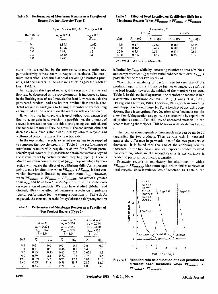
Table 5. Performance of Membrane Reactor as a Function of Bottom Product Recycle (Type 1)
6X1.0 - w =0.5
Table 7. Effect of Feed Location on Equilibrium Shift for a Membrane Reactor When PEproducqg < PE,,,, < PEm4,)
K E = 0.5, Pr = 0.0, A B, DA# = 1.0
Rate Ratio aA = 0.274 a" = 0.5 6 XR,,,
0.1 1.895 1.462 0.5 1.776 1.33 1 .o 1.641 1.2 1.5 1.530 1.1 2.0 1.477
mum limit as specified by the rate ratio, pressure ratio, and permselectivity of reactant with respect to products. The maxi- mum conversion is obtained a t total recycle (no bottoms prod- uct), and decreases with increase in rate ratio (greater reactant loss), Table 5.
In instituting this type of recycle, it is necessary that the feed flow rate be decreased as the recycle amount is increased so that, in the limiting case of total recycle the feed flow rate equals the permeated product, and the bottom product flow rate is zero. Total recycle is analogous to having a membrane reactor long enough that all the reactant on the reaction side is consumed.
If, on the other hand, recycle is used without decreasing feed flow rate, no gain in conversion is possible. As the amount of recycle increases, the reaction side starts getting well mixed, and the net reaction rate suffers. As a result, the conversion obtained decreases to a fixed value established by infinite recycle and well-mixed concentration on the reaction side.
In the top product recycle, external energy has to be supplied to compress the recycle stream. In Table 6, the performance of membrane reactors with recycle are shown for different perm- selectivity of reactant. It is possible to obtain conversions beyond the maximum set by bottom product recycle (Type 1). There is also an optimum compressor load (qsOpt), beyond which backre- action will negate the effect of equilibrium shift. An important point to note for situations when PE,,,,, < PEpducu is that con- version increase is limited by the maximum X,,,,,. However, when PEpduct(Z) < PE,,,, < PEprduct(,), conversions greater than X,, can be achieved, since equilibrium shift also depends on separation of products. We also have studied (Mohan and Govind, 1988) the effect of permeate recycle on membrane reactor performance for the example reactions in Table 3. As expected, the conversion ratio for cyclohexane dehydrogenation
Table 6. Performance of Membrane Reactor as a Function of Top Product Recycle (Type 2)
Da#
A = B CU, = 0.274 X,, = 0.63
6 = 1.0
X q:p*
A = = B + C = 0.274
01c = 0.451 X,, = 0.78
6 = 3.0
0.0 1 .o 3 .O 6.0
12.0 25.0
m
0.0 0.0 0.37 0.0 0.55 0.45 0.59 2.1 0.624 5.1 0.630 11.8 0.63 co
0.0 0.0 0.46 0.0 0.65 2.9 0.72 7.6 0.75 17.3 0.78 38.5 0.78 m
A = = B + C o.A = 0.274 ffc = 0.100 X,,, = 0.7
d = 3.0 -
x s& 0.0 0.0 0.43 1 .O 0.622 3.5 0.74 8.5 0.821 21.0 0.89 52.0 1 .o m
~ ~~~
Conversion, X 6 = 1.0 6 = 3.0
Du# FL = 0.0 FL = opt FL = 0.0 FL =opt
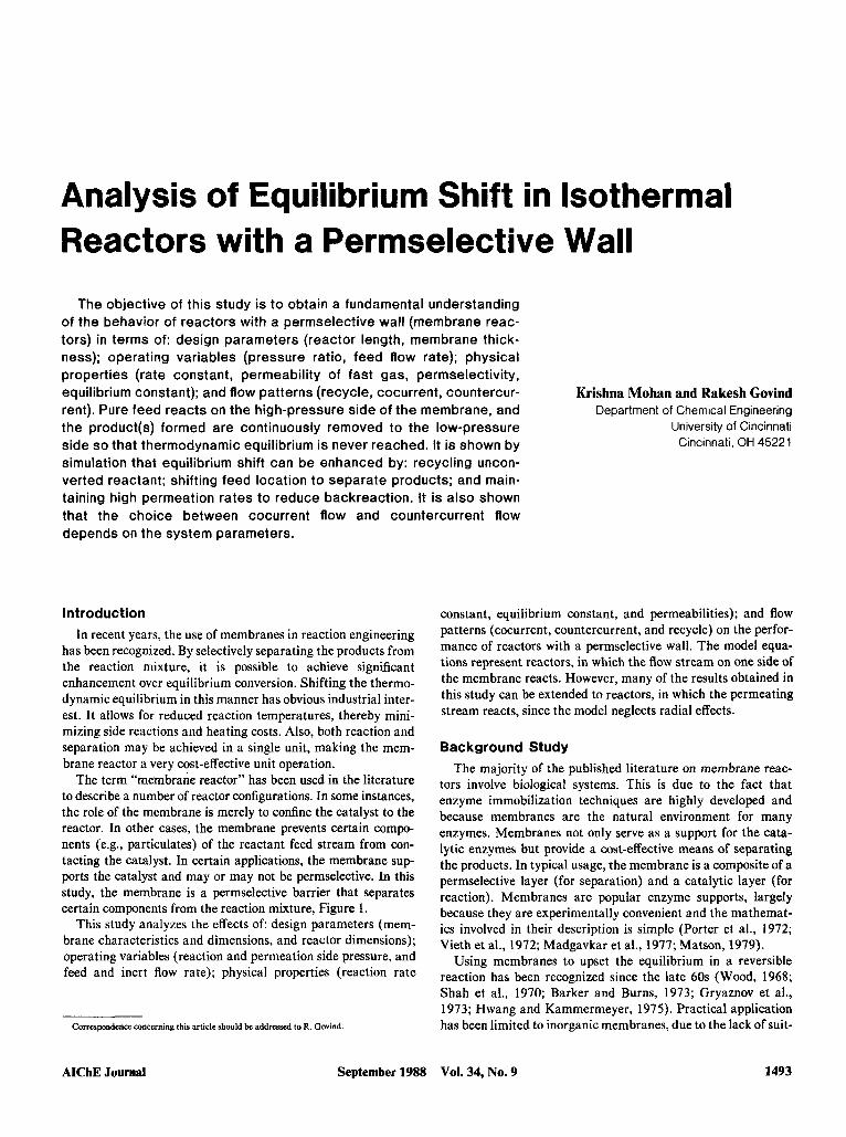
4.0 0.37 0.385 0.463 0.475 10.0 0.465 0.485 0.585 0.60 20.0 0.55 0.57 0.674 0.69 40.0 0.637 0.655 0.75 0.76
Pr - 0.0, A i=it B + C, aA - 0.4, ac - 0.1
is limited by X,,, while by increasing membrane area (Da No.) and compressor load ( q s ) substantial enhancement over X,,, is possible for the other two reactions.
When the permeability of reactant is in between that of the products, equilibrium shift can be further enhanced by shifting the feed location towards the middle of the membrane reactor, Table 7. In this mode of operation, the membrane reactor is like a continuous membrane column (CMC) (Hwang et al., 1980; Hwang and Thorman, 1980; Thorman, 1979), with an enriching and stripping section, Figure Ic. For a fixed set of operating con- ditions, there is an optimal feed location, since beyond a certain size of enriching section any gains in reaction rate by separation of products cannot offset the loss of unreacted material in the stream leaving the stripper. This behavior is illustrated in Figure 6 .
The feed location depends on how much gain can be made by separating the two products. Thus, as rate ratio is increased and/or the difference in permeabilities of the two products is decreased, it is found that the size of the enriching section increases. In the first case a smaller stripper is needed to avoid backreaction, while in the second case a larger enricher is needed to perform the difficult separation.
Permeate recycle is mandatory for situations in which PE,,,, > PEpdudua(s). Maximum equilibrium shift is achieved a t total recycle, since it reduces loss of reactant. In Table 8, the
1498 September 1988 Vol. 34, No. 9 AIChE Journal

Table 8. Effect of Rate Ratio and Damkohler Number on the Performance of a Membrane Reactor
When PE-c,, ’ PEprodUet(s,
K E = 0.5,aA = 3.65, P,= 0.0, A d B
Rate Ratio 6
0.1 0.5 1 .O 5.0
10.0 20.0 30.0
m
Da# = 1.5
XR sh., 1.04 0.45 1.19 2.25 1.34 4.55 1.94 23.6 2.25 48.1 2.55 97.9 2.70 148.1 3.00 m
Da# = 3.0
X R 4:m..
1.05 0.84 1.29 4.35 1.52 8.74 2.35 45.91 2.65 91.85 2.84 183.8 2.90 275.7 3.00 m
performance of a membrane reactor has been shown as a func- tion of rate ratio and Damkohler number. As expected, with an increase in rate ratio and Damkohler number, the amount of equilibrium shift is enhanced, though at a cost in terms of com- pressor load and/or membrane area. For a fixed length of reac- tor, in the limit of infinite rate ratio and compressor duty (qs) , complete conversions can be achieved.
Cocurrent vs. countercurrentflow At finite pressure ratios, the effect of the direction of flow on
either side of the membrane will play a major part in deter- mining the performance of the membrane reactor. In separation systems design, countercurrent has always been preferred due to its larger average concentration gradient. In membrane reactor design, however, an important consideration is the maintenance of high forward reaction rates. Since most of the reaction occurs near the feed end, product, and reactant, permeation fluxes in that region govern the choice between cocurrent and counter- current.
The countercurrent membrane reactor has high product con- centration on the permeation side towards the feed end, the driv- ing force for product permeation is low [even negative for a feed of pure reactant(s)], and as a result “equilibrium shift” suffers. The cocurrent membrane reactor, on the other hand,.has low concentration of gases on the permeation side towards the feed end, the driving force for permeation is high, and as a result “reactant loss” can be significant.
In Table 9, the difference in conversion between cocurrent and countercurrent, AX, is shown as a function of rate ratio, 6. Though the results in this table were obtained using the rate expression for propylene disproportionation, the following anal- ysis is valid for other reaction mechanisms. For details on the kinetic rate equation, refer to Mohan and Govind (1988).
When PE,,,,, < PEproducts (ac = l.O), cocurrent is better than countercurrent since equilibrium shift controls. On the other hand, when PEprodun(2) < PEreacmnt < PEproduct(i) (ac = 0.11, a t low equilibrium constants (low reaction rates; high 6,,,,), there is a critical rate ratio above which reactant loss controls.
Permeation fluxes being controlled by partial pressure, reac- tion-side inert flow rate, Fin:,,,, is an important parameter in determining choice of flow mode. Thus, for the case aC = 0.1 in Table 9, when Fine,, = 0.0, reactant loss controls and countercur- rent flow mode is better irrespective of equilibrium constant and rate ratio. On the other hand, for ac = 1.0, there are regions depending on rate ratio and equilibrium constant where one flow mode outperforms the other.
The choice of flow mode for the example reactions in Table 3 follows directly from our analysis. Equilibrium shift controls the cyclohexane reaction and reactant loss controls the propylene reaction, while for the hydrogen iodide reaction the choice of flow mode depends on the design and operating conditions (Mo- han and Govind, 1988).
The effect of recycle on flow mode is studied for a situation where PEproduct(2) < PE,,,,, < PEprduct(,) and reactant loss con- trols. In Figure 7, the conversion ratio is plotted as a function of recycle ratio for cocurrent and countercurrent flow modes. It should be noted that, as recycle is increased, the difference between the two modes goes through a maximum. At low values of recycle, the countercurrent performs better due to lower reac- tant loss and greater separation of the products. At high values of recycle, concentration profiles set up in the permeation side are similar for both flow modes, and the difference in perfor- mance decreases so that eventually, a t total recycle, both flow modes have identical behavior.
In Figure 8, the reaction rate,f,, has been plotted against the axial position for a membrane reactor operating with inter- mediate feed location. Countercurrent flow provides larger separation of the products in the enricher, since the average con- centration gradient for separation is better. In the stripper, countercurrent flow inhibits the loss of reactant and, as a result reduces backreaction. Thus, the average forward reaction rate in the column is greater for the countercurrent membrane reac-
Table 9. Comparison of Performance of Cocurrent and Countercurrent Membrane Reactors
Rate Ratio
6
aA = 0.274,2Ai. B + C, Da# = 10.0, P, = 0.3 Flnen = 3.0, QWn = 1.0
Conversion Difference, AX x 100 (Cocurrent - Countercurrent)
a= = 1.0 ac = 0.1
KE = 0.06 KE = 0.15 KE = 0.5 KE = 0.06 KE = 0.15 K E = 0.5
0.0 0.1 0.5 1 .O 1.5 2.0
0.0 0.0 0.0 0.0 0.0 0.0 0.1 0.21 0.21 0.1 0.09 0.06 1.2 1.62 1.8 0.3 0.626 0.6 1.3 2.28 3.1 -0.4 0.505 1 .o 1.2 2.42 3.9 -2.0 -0.16 1.4 0.8 2.52 4.7 -2.7 -0.6 1.7
AIChE Journal September 1988 Vol. 34, No. 9 1499
1.25
1.2
x c‘ 1.15 0 r 0)
.-
1.1 s
1.05 1 .
-
$, 6 = 1.0 at, = 0.5 aC=O.l Pr = 0.5 Da# = 6.0 KE = 0.1 A=B+ C
- \ i \ countercurrent
-
-
cocurrent \ : Ropt
0 10 20 30 40 50
recycle ratio, R
Figure7. Effect of recycle on flow mode when pEproduct(l~ < pEr..cbnt < PEprOduct(l).
tor. It should be noted that the optimum size of the enriching section is larger for countercurrent flow since greater advantage can be obtained from separation of products.
Separation An important application of the membrane reactor is in
achieving separation of the components of a reaction mixture, while enhancing conversion. The separation goals possible in a reaction system of three components are separation of products ( B from C), and separation of reactant from either product ( A from B and A from C).
To measure the separation efficiency of the membrane reac- tor, the “extent of separation” index proposed by Rony (1968, 1972) and applied subsequently to membrane separations by Sirkar (1977), McCandless (1984,1985), and Teslik and Sirkar (1986) was used. In applying the index between two compo-
Figure 8.
1500
6 = 2.0 OA = 0.5
- -
nents, it is assumed that there is no difficulty in separating the third, and consequently the segregation fractions, K,, are calcu- lated on the basis of a two component top and bottom product streams. The extent of separation is defined as the absolute value of the determinant of a binary separation matrix that is written in terms of the four segregation factors:
,$ = abs det
where Kj = Qitop/(Fibat + Qitop) w h e n j = 1; Ftht/(Fttmt + Qitop)
when j = 2. The commonly used separation factor defined as
$ = x,*y?*/x,*yT
where xi*= Fikt/(F~bt + F z ~ o ~ ) , and Y?= Qitop/(Qltop + Q2top) is not a useful index in this case due to the presence of a third com- ponent in the product streams. As previously indicated by Sirkar (1977), the separation factor Ic/ merely indicates the composi- tional differences between the two streams while ignoring the total flows in them.
In the case of PErcaetant < PEpdUcb, Figure 9, the extent of sep- aration index, t , and conversion, X , has been plotted as a func- tion of rate ratio, 6. For all the separation goals mentioned above, there is an optimum rate ratio. Although the goals of high separation and high conversion are contradictory, by proper design and operation of membrane reactor, it may be possible to achieve significant separation while maintaining a high conver- sion. Thus, for the case shown in Figure 9, it may be economi- cally advantageous to design and operate the membrane reactor for maximum separation of A from B.
In the case of PEpdun(2, < PE,,, < PEproduct(l,, since conver- I
sion is enhanced by the separation of products, in operating the membrane reactor as a continuous membrane column (CMC), output streams can be obtained which have high concentrations
.7
.6
Id
x .5 a, 0 .- Q .4 % ti x .3 c‘
?! 0
a, .2 > E
.-
s .1 . . . . . ’ . . ’ I. . . .
\ . . . . ‘ . . 0 , i i , + I I I
0 .25 .5 .75 1. 0 .1 .2 .3 .4 .5 -.15
axial position, Z rate ratio, 6
Effect of flow mode on the optimum perfor- mance of a membrane reactor when PEproduct~4 <
Figure9. Separation efficiency of a membrane reactor as a function of rate ratio when P€r..et.nt <
PErucl.nt < PEprOdUCt(l)’ PEproduct(.)’
AIChJ3 Journal September 1988 Vol. 34, No. 9

a;, = 0.5, C Y ~ = 0.1 0.5 0.3511.2 1.0 0.4012.4 2.0 0.4615.5 4.0 0.53112.8
0.5 0.3111.6 1.0 0.3213.5 2.0 0.3317.7 4.0 0.34116.7
a;, = 0.7, (YC = 0.5
- 3
0.6 8 10.9 0.8112.3 0.88l5.7 0.921 13.5
0.3311.5 0.4013.8 0.4718.2 0.54117.2
aa
0.410.8 0.641 1.7 0.7514.5 0.831 1 1 .O
0.1911.4 0.2413.5 0.2817.7 0.32116.5
0.3511.3 0.4213.2 0.5J7.5 0.55/16.6
0.161 1.7 0.2013.8 0.2418.4 0.29117.8
Pr - 0.0, A - E + C, Da# - -6.0, K, - 0.1
of products, i.e., the top stream would be enriched with the most permeable product, B, while the bottom stream would be enriched with the least permeable product, C. In Table 10, sepa- ration efficiency of a membrane reactor is shown as a function of rate ratio, 6.
Conversion X , extent of separation index +, and their asso- ciated optimum compressor load qsOpt, all increase with perme- ation rate. Table 10 shows that there can be a significant differ- ence in the optimum compressor loads for the different goals. If downstream separation costs are high, it may be economically advantageous to design and operate the membrane reactor to maximize separation rather than conversion.
Design Considerations The extent of equilibrium shift in a reactor with a permselec-
tive wall, depends on the design parameters, operating variables, and physical properties:
X , = func(6, Da#, KE, ai, Pr, Fin,,,, Qincrt, flow patterns) ( 5 )
The membrane-dependent parameters are 6 (a l/thickness, a
permeability, a permeation area), Da No. (a permeation area), and a, (permselectivity). The reaction specific parameters are 6 (a l/kinetic rate constant, a l/reaction volume), Da No. (a
reaction volume), and KE (equilibrium constant). Typical values of the various parameters likely to be encoun-
tered in practice are: 1. Rate ratio, 6,0.1 to 5.0 2. Damkohler number, Da, 5.0 to 50.0 3. Pressure, P,, 0.0 to 1.0 4. Equilibrium constant, K E , 0.0001 to 0.5 5. Permselectivity, a, 0.0 to 1 .O. The ranges specified are based on previous experimental
work, Table 3. Since 6 is proportional to permeation arealreac- tion volume, by increasing the packing density of hollow fiber reactors, very high rate ratio’s may be achieved (50 or 100). Conversion being dependent on residence time (i.e., time spent by reactant in reaction zone), large amounts of recycle would then be necessary to achieve significant equilibrium shift, Fig- ure 2, and Tables 6 and 8. The upper limit for rate ratio sug- gested above is an estimate based on results obtained in this study.
The choice of membrane and membrane type depends on reaction temperatures. Under mild conditions, polymeric mem- branes in hollow fiber form can be used to provide high perme-
ation rates. Inorganic membranes like porous Vycor glass can- not be manufactured in the thin hollow fiber form; and to offset the low permeation rates it will be necessary to have larger membrane areas, i.e., longer membrane reactors (Ito et al., 1985).
The importance of membrane selectivity, ai, and permeability (rate ratio, 6) in determining the performance of a membrane reactor is presented in Figure 10. The maximum conversion ratio, X,,,,, and maximum Damkohler number, Dams,, is plot- ted as a function of permeation rate, 6, for a reversible A + B reaction. Dam,,, is defined as the Damkohler number (or resi- dence time) necessary to achieve XRm. When the membrane is permeable only to product complete conversions can be achieved in the membrane reactor. Thus, palladium, which allows only hydrogen to permeate through it, is an attractive membrane for dehydrogenation reactions (Ito, 1987). However, to achieve sig- nificant conversions very long reactors would be needed (high Damax) as permeation fluxes attainable are very low (corre- sponds to 6 << 1 for the case in Figure 10).
When the membrane, as in most cases, is permeable also to the reactant, the maximum conversion decreases with increase in permeation rate. Thus, as shown in Figure 10, for membranes with high permselectivity for reactant there may be no advan- tage over the impermeable wall reactor. It is important to note that there is an optimum value of rate ratio, 6, above which there is no significant change in reactor size (Da,,). For the case shown in Figure 10, doptimum is approximately 1 .O. Considerable economic advantage may be realized, if membranes are avail- able that not only provide low reactant permselectivity but also the permeation fluxes needed to attain the optimum rate ratio, 6.
An economic analysis is necessary to fix the actual design parameters and operating conditions. To achieve a given conver- sion with fixed membrane thickness, packing density, and prod- uct throughput, there is a choice between a long membrane reactor (high Da No., high fixed costs) with low recycle (low qs, low operating costs) or short membrane reactor (low Da No.,
.- X m E
.5
0 + o 1 2 3 a 5
rate ratio, 6
Figure 10. influence of permeability and permselectivity on membrane reactor performance.
AICbE Journal September 1988 Vol. 34, NO. 9 1501

PEprd(2) < PErearcant < PEprod(1)
high 6, low Pr, high Da# intermediate feed location optimum permeate recycle flow mode separation of products
T2 = 1.0
PEreactant < PEproduct(s)
high a, low Pr, high Da# feedlocationatZ=O optimum permeate recycle bottom product recycle flow mode
T i = PE reactant IPEprod(1)
4 Weactant > PEproduct(s)
high 6. low Pr, high Da# feed location at 2 = 0 total permeate recycle independent of flow mode
* T2 =1.0
PEprod(1) < Weactant < PEprod(2)
high 6, low Pr. high Da# intermediate feed location optimum permeate recycle flow mode separation of products
Figure 11. Summary of factors enhancing equilibrium shift in membrane reactors.
low fixed costs) with high recycle (high qs, high operating costs). For fixed Da No., a similar relationship exists between rate ratio (packing density and membrane thickness) and recy- cle.
The choice of flow mode (cocurrent or countercurrent) depends on the system parameters. Typically, cocurrent flow is favored for low permeation rates at the feed end (PI?,,,, < PI?pmduetr, high Fbmr and low 6 ) while countercurrent flow is favored for high permeation rates at the feed end (PI?pducts(z) < P&stant < f‘I?pdua(~)* low Finer,, high 6).
Summary It is shown that conversions exceeding equilibrium can be
achieved by using a permselective wall to maintain high concen- trations of feed in the reaction zone. Figure 11 summarizes the important factors that enhance equilibrium shift in membrane reactors. The performance of reactors with a permselective wall can be improved by recycling or backpermeating unconverted reactant, separating products by shifting feed location and maintaining high product permeation rates to reduce backreac- tion.
Acknowledgment This work was supported by a grant from Standard Oil Co. of Ohio,
Cleveland.
Notation A = reactant B = fast permeating product b - stoichiometric coefficient corresponding to B C = slow permeating product c = stoichiometric coefficient corresponding to C
Da - Damkohler number, ~ P & V , / F : ~ err = material balance error, objective function in random search Fi = dimensionless flow of gas on reaction side, molar flow rate of
gas/molar feed flow rate
F: = flow rate of gas on reaction side, mol/s F,= = feed location, enricher length/total length
= dimensionless rate expression for reaction, xA - (x”, - X;.)/KE C = random number between zero and one k = forward rate constant, mol/m3 s Pa
KE = equilibrium constant L = length of membrane reactor, m N - total number of components, reactants + products + inerts m - distribution coefficient (odd integer 1, 3, 5..)
Pn - reaction side pressure, Pa P, = permeation side pressure, Pa
qs = compressor load, flow rate of recycle stream/feed flow rate Qi = dimensionless flow of gas on permeation side, molar flow rate of
Q:= improved guesses for Q, in adaptive random search algorithm R = recycle ratio, molar flow of recycle stream/molar flow of output
PE = permeability of fast gas, mol/m . Pa - s
pr = Pdph
gas/molar feed flow rate
stream S, = area of membrane per unit length of membrane reactor, m2/m t, = thickness of membrane, m v, = reaction side volume per unit length of membrane reactor, m3/
xi = mole fraction of gas on the reaction side x:= modified fraction in the bottom product stream X = conversion
m
XE = equilibrium conversion X , = conversion ratio, membrane reactor conversion/equilibrium
AX* = difference in conversion between membrane reactor and imper-
AX - difference in conversion between cocurrent and countercurrent
conversion
meable wall plug flow reactor
membrane reactors y, - mole fraction of gas on the permeation side y?= modified mole fraction in the top product stream Y , = segregation factor for component i in stream j Z = axial position/length of membrane reactor
Subscripts A = reactant
B = fast permeating product, product(1) C = slow permeating product, product(2) i = reactant, product or inert 0 = membrane reactor inlet; feed conditions
bot = bottom product stream
top = top product stream opt = optimum
max = maximum
Greek letters ai = permselectivity of gas 6 = ratio of permeation rate to reaction rate, PE . S,/(t, . k . v,)
X i = allowable search region about Q: f = extent of separation index $ = separation factor
Literature Cited Antonson, C. R., R. J. Gardner, C. F. King, and D. Y. KO, “Analysis of
Gas Separation by Permeation in Hollow Fibers,” Ind. Eng. Chem. Proc. Des. Dev., 16,473 (1977).
Barker, S. A., and R. F. Burns, “Reactor Separators Incorporating Membrane Bound Enzymes,” Chemist. and Ind., London, 16, 801 (1973).
Carnahan, B., H. A. Luther, and J. 0. Wilkes, Applied Numerical Methods. Wiley, New York (1969).
Chang, M. N., and S. T. Hwang, “The Continuous Membrane Reac- tor,” Ph.D. Thesis, Univ. of Cincinnati (1987).
Denn, M. M., and R. Aris, “Green’s Functions and Optimal Systems: I. Necessary Conditions and an Iterative Technique,” Ind. Eng. Chem. Fund.. 4,213 (1965).
1502 September 1988 Vol. 34, No. 9 AIChE Journal

Dokiya, M., T. Kameyama, and K. Fukuda, “The Application of the EKusion on the Thermochemically Limited Reaction,” Denki Kaga- ku, 45,701 (1977).
Fan, L-T., The Continuous Muximum Principle, Wiley, New York (1966).
Fang, S. M., S. A. Stern, and H. L. Frisch, “A ‘Free Volume’ Model of Permeation of Gas and Liquid Mixtures through Polymeric Mem- branes,” Chem. Eng. Sci., 30,773 (1975).
Fukuda, K., M. Dokiya, T. Kameyama, and Y. Kotera, “Catalytic Decomposition of Hydrogen Sulfide,” Ind. Eng. Chem. Fund., 17,243 (1978).
Gall, D. A., “A Practical Multifactor Optimization Criterion,” Recent Advances in Optimization Techniques, A. Lavi and T. P. Vogl, ed., Wiley, New York (1966).
Goodman, T. R., and G. M. Lance, “The Numerical Integration of Two-Point Boundary Value Problems,” Math. Tables and Other Aids lo Computation, 10,82 (1956).
Gryaznov, V. M., V. S. Smirnov, and G. Slinko, “Heterogeneous Catal- ysis with Reagent Transfer through the Selectively Permeable Cata- lysts,” Catalysis, J. W. Hightower, ed., American Elsevier, New York (1973).
Heuckroth, M. W., J. L. Gaddy, and L. D. Gaines, “An Examination of the Adaptive Random Search Technique,” AIChE J., 22, 745 (1976).
Hwang, S. T., and K. Kammermeyer, Membranes in Separations, Wiley-Interscience, New York (1975).
Hwang, S. T., and J. M. Thorman, “The Continuous Membrane Col- umn,” AIChE J., 26,558 (1980).
Hwang, S. T., J. M. Thorman, and K. H. Yuen, “Gas Separation by a Continuous Membrane Column,” Sep. Sci. Techno!.. 15, 1069 (1980).
Ito, N., Y. Shindo, T. Hakuta, and Y. Yoshitome, “Enhanced Catalytic Decomposition of HI by Using a Microporous Membrane,” Int. J . Hydrogen Energy, 9,835 (1984).
Ito, N., Y. Shindo, K. Haraya, K. Obata, T. Hakuta, and H. Yoshitome, “Simulation of a Reaction Accompanied by Separation,” Int. Chem. Eng.. 25, 138 (1985).
Ito, N., “A Membrane Reactor Using Palladium,” AIChE J , 33, 1576 (1987).
Kameyama, T., M. Dokiya, M. Fujishige, and H. Yokokawa, “Possibil- ity for Effective Production of Hydrogen from Hydrogen Sulfide by means of a Porous Vycor Glass Membrane,” Ind. Eng. Chem. Fund., 20,97 (1981).
Kameyama, T., M. Dokiya, M. Fujishige, H. Yokokawa, and K. Fuku- da, “Production of Hydrogen from Hydrogen Sulfide by means of Selective Diffusion Membranes,” Znt. 1. Hydrogen Energy, 8, 5 (1983).
Luus, R., and T. H. I. Jaakola, “Optimization by Direct Search and Sys- tematic Reduction of the Size of Search Region,” AIChE J. . 19,760 (1973a).
McCandless, F. P., “The Extent of Separation in Single Permeation Stages,” J. Membrane Sci., 17,323 (1984).
McCandless, F. P., “A Comparison of Some Recycle Permeators for Gas Separations,” J. Membrane Sci.. 24,15 (1985).
Madgavkar, A. M., Y. T. Shah, and J. T. Cobb, “Hydrolysis of Starch in a Membrane Reactor,” Biotech. Bioeng.. 19, 1719 (1977).
Matson, S. L., “Membrane Reactors,” Ph.D. Thesis, Univ. of Pennsyl- vania (1979).
Mohan, K., and R. Govind, “Analysis of a Cocurrent Membrane Reac- tor,” AIChE J.. 32,2083 (1986).
Mohan, K., and R. Govind, “Studies on a Membrane Reactor,” accepted by Sep. Sci. Technol. (1988).
Porter, M. C., “Applications of Membranes to Enzyme Isolation and Purification,” Enzyme Engineering, L. B. Wingard, ed., 3, 115, Inter- science, New York (1 972).
Raymont, M. E. D., “Make Hydrogen from Hydrogen Sulfide,” Hydroc. Process., 54,139 (1975).
Rony, P. R., “The Extent of Separation: A Universal Separation Index,” Sep. Sci., 3,239 (1968).
Rony, P. R., “Multiphase Catalysis: 11. Hollow-Fiber Catalysis,” Bic- iech. Bioeng., 13,431 (1971).
Rony, P. R., “The Extent of Separation: On the Unification of the Field of Chemical Separations,” AIChE Symp. Ser., 68 (120), 89 (1972).
Shah, Y. T., T. Rammen, and S. H. Chiang, “A Note on Isothermal Permeable Wall Plug Flow Reactor,” Chem. Eng. Sci., 25, 1947 ( 1970).
Shindo, Y., K. Haraya, K. Obata, T. Hakuta and H. Yoshitome, Japa- nese Soc. Chem. Eng. Meeting, Kanazawa (1981), as referred to by Ito et al. (1984, 1985).
Shinji, O., M. Misonou, and Y. Oneda, “The Dehydrogenation of Cyclo- hexane by the Use of a Porous-Glass Reactor,”&dL Chem. SOC. Jpn., 55,2760 (1982).
Sirkar, K. K., “On the Composite Nature of the Extent of Separation,” Sep. Sci.. 12,211 (1977).
Teslik, S., and K. K. Sirkar, “A Comparative Analysis of the Role of Recycle or Reflux in Permeators Separating a Binary Gas Mixture,” Recent Developments in Separation Science, N. N. Li and J. M. Calo, eds., 9,245, CRC, Boca Raton, FL (1986).
Teslik, S., “Analysis of a Light Fraction Recycle Permeator and Oxygen Enrichment Separation Schemes,” MS Thesis, Stevens Inst. of Tech- nol., Hoboken, NJ (1983).
Thorman, J. M., “Engineering Aspects of Capillary Gas Permeators, and the Continuous Membrane Column,” PhD Thesis, Univ. of Iowa (1979).
Vieth, W. R., S. S. Wang, F. R. Bernath, and A. 0. Mogensen, “En- zyme Polymer Membrane Systems,” Recent Developments in Sepu- ration Science, N. N. Li, and J. M. Calo, eds., 1, 175, CRC, Boca Raton, FL (1972).
Weller, S., and W. A. Steiner, “Separation of Gases by Fractional Per- meation through Membranes,” J. Appl. Phys., 21,279 (1950).
Wood, B. J., “Dehydrogenation of Cyclohexane on a Hydrogen-Porous Membrane,” J. Cut., l l , 3 0 (1968).
Manuscript Dec. 7, 1987. and revision received Apr. 22, I988
AIChE Journal September 1988 Vol. 34, No. 9 1503