Analysis of Compositional Conflicts in Component ... - TU Berlin
194
Analysis of Compositional Conflicts in Component-Based Systems vorgelegt von Diplom - Informatiker Andreas Leicher von der Fakult¨ at IV - Elektrotechnik und Informatik der Technischen Universit¨ at Berlin zu Erlangung des akademischen Grades Doktor der Ingenieurwissenschaften - Dr.-Ing. - genehmigte Dissertation Promotionsausschuss: Vorsitzender: Prof. Dr. Hartmut Ehrig Berichter: Prof. Dr. Herbert Weber Berichter: Prof. Dr. Frantisek Plasil Tag der wissenschaftlichen Aussprache: 21. September 2005 Berlin, 11. November 2005 D83
-
Upload
khangminh22 -
Category
Documents
-
view
5 -
download
0
Transcript of Analysis of Compositional Conflicts in Component ... - TU Berlin
Analysis of Compositional Conflicts inComponent-Based Systems
vorgelegt vonDiplom - Informatiker
Andreas Leicher
von der Fakultat IV - Elektrotechnik und Informatikder Technischen Universitat Berlin
zu Erlangung des akademischen Grades
Doktor der Ingenieurwissenschaften- Dr.-Ing. -
genehmigte Dissertation
Promotionsausschuss:
Vorsitzender: Prof. Dr. Hartmut EhrigBerichter: Prof. Dr. Herbert WeberBerichter: Prof. Dr. Frantisek Plasil
Tag der wissenschaftlichen Aussprache: 21. September 2005
Berlin, 11. November 2005D83


Zusammenfassung
Ein Ziel der komponentenbasierten Softwareentwicklung besteht in der Wiederverwendung be-reits entwickelter Komponenten zur Verbesserung der Qualitat und zur Verminderung derKosten des Softwareentwicklungsprozesses. Die Wiederverwendung von bestehenden Kompo-nenten erfordert jedoch die sorgfaltige Integration in das zu entwickelnde System und wirderschwert durch unterschiedliche Middlewaretechnologien, unterschiedliche Kommunikations-und Interoperationsmechanismen dieser Technologien sowie durch unterschiedliche und zumTeil unvollstandige Komponentenspezifikationen.
Das grundlegende Ziel dieser Arbeit ist die Unterstutzung der Komponentenintegration durcheine ausfuhrliche Konfliktanalyse, welche bestehende Inkompatibilitaten von zu integrierendenKomponenten aufzeigt. Dazu wird ein Framework bereitgestellt, welches es erlaubt, Kompo-nenten unterschiedlicher Technologien im Rahmen eines UML-basierten Entwicklungsprozesseszu prufen und die (teil-) automatische Generierung von Konnektoren vorzubereiten.
Im Gegensatz zu bisherigen Ansatzen ermoglicht dieses Framework die Prufung von Kompo-nenten unterschiedlicher Middlewaretechnologien in Hinblick auf strukturelle, semantische undkommunikative Differenzen. Insbesondere die Einbeziehung von Kommunikationseigenschaften,welche die von den beteiligten Komponenten verwendeten Kommunikationsmechanismen derzugrundeliegenden Middlewaretechnologien beschreiben, wird zur Zeit von keinem anderen In-tegrationsframework angeboten.
Das vorgestellte Framework basiert auf einem modellzentrierten Ansatz im Rahmen der ModelDriven Architecture (MDA). Dies bedeutet, dass sowohl Komponentenspezifikationen auf ver-schiedenen Ebenen verwaltet werden konnen als auch dass Modelltransformationen unterstutztwerden. Die Konfliktanalyse basiert auf einem kanonischen plattformunabhangigen Kompo-nentenmodell, welches von Plattformspezifika abstrahiert. Komponenten, die auf Grundlageeiner speziellen Middlewaretechnologie definiert wurden, werden durch Modelltransformationenin das kanonische Modell abstrahiert. Umgekehrt konnen jedoch auch plattformunabhangigeKomponentenspezifikationen in Spezifikationen spezieller Middlewaretechnologien spezialisiertwerden. Als Besonderheit unterstutzt das Framework dabei parametrisierbare Modelltrans-formationen, so dass sich je nach Nutzervorstellungen optimale Transformationen durchfuhrenlassen.
Um die Verwendung des Frameworks in unterschiedlichen Anwendungsszenarien und -domanenzu ermoglichen, wurde es moglichst flexibel definiert. Somit konnen sowohl unterschiedlicheMiddlewaretechnologien und Typsysteme als auch unterschiedliche Spezifikationssprachen indas Framework integriert werden. Zudem konnen zusatzliche Daten als RDF Statements anbeliebige Elemente von Komponenten notiert und uber zusatzliche Analyseverfahren ausge-wertet werden.


Abstract
Component Based Software Engineering is an emerging discipline that aims at improving soft-ware development by means of artifact reuse within a systematically applied construction pro-cess. The idea of reuse involves integrating components rather than reinventing and reimple-menting existing artifacts. Unfortunately, reuse of existing components is a complex undertak-ing because of different technologies, different communication forms, and incomplete componentspecifications.
The objective of this work concerns the improvement of component integration by providingextended conflict analysis capabilities, which help to identify mismatches between componentsthat hinder a direct integration. The work defines a Framework for Component Conflict Analysisand Composition that serves as a basis of component integration. The framework is able tohandle components of different technologies and it is compatible with a UML-based developmentprocess. As a result, it provides the inevitable preparatory work that is required for a semi-automatic connector generation.
Contrary to existing approaches, the framework allows analyzing components of different mid-dleware technologies by checking compatibility between their type, behavior, and communica-tion related property specifications. Especially, analysis of required and provided communica-tion properties, which takes the middleware context of components into account is not availablein comparable integration frameworks.
Components of different technologies cannot be directly compared as they are defined relativeto different programming languages, type systems, and middleware technologies. Therefore, theframework is based on a model centric approach within the scope of the Model-Driven Archi-tecture (MDA). Consequently, the framework distinguishes platform independent and platformdependent component specifications. Conflict analysis is based on a platform independentcanonical model that represents the least common denominator of components in middlewaretechnologies. Furthermore, the framework provides model transformations that allow abstrac-tion and refinement of components between different abstraction levels. Thereby, the frameworksupports parametric model transformations as a special feature, which take user requirementsinto account and result in optimal translations.
In order to gain a solution, which is adaptable to different situations and application domains,the framework offers a highly flexible architecture. Consequently, we can integrate new mid-dleware technologies, their type systems as well as additional specification languages into theframework.


Acknowledgments
First of all, I’d like to thank my family. Without their support and especially without the helpof Silke I hadn’t been able to finish this work.
Special thanks goes to Susanne Busse, Uli Kriegel, Ralf Kutsche, Martin Große-Rhode, JornGuy Suß, and Prof. Weber for their support, critique, and suggestions as well as for all thediscussions regarding my approach. With Uli Kriegel, I mainly discussed platform related issues,whereas Martin Große-Rhode and Ralf Kutsche helped me with the theoretical aspects. WithSusanne Busse and Jorn Guy Suß, I mainly discussed issues in the areas of UML and MDA.
Further, I thank Andreas Billig, who convinced me to use an object-oriented reasoning languageand who provided me with the ODIS environment that I used throughout the work for modeltransformations and for conflict analysis.
The members of the Distributed Systems Research Group from Charles University also of-fered me a lot of helpful critique related to aspects of the core model and behavioral analysis.Especially, I thank Prof. Plasil, Tomas Bures, Jiri Adamek and Vladimir Mencl.
I also want to mention the fruitful discussions with Jan Gadicke, Felix Schmid, and Yong Liaowho helped me to discover how to formalize the communication taxonomy.
Furthermore, I thank Thomas Brehm and Cedavis Inc. for their support regarding a case studyof their system.
At last, I’d like to thank the members of the CIS group, especially Claudia Gantzer and LutzFriedel for their help and the working atmosphere.

VIII

Contents
Contents IX
I Foundations of Conflict Analysis 1
1 Introduction 3
1.1 Motivation . . . . . . . . . . . . . . . . . . . . . . . . . . . . . . . . . . . . . . . 3
1.2 Prerequisites . . . . . . . . . . . . . . . . . . . . . . . . . . . . . . . . . . . . . . 4
1.3 Objectives . . . . . . . . . . . . . . . . . . . . . . . . . . . . . . . . . . . . . . . . 6
1.4 Approach . . . . . . . . . . . . . . . . . . . . . . . . . . . . . . . . . . . . . . . . 7
1.5 Contributions . . . . . . . . . . . . . . . . . . . . . . . . . . . . . . . . . . . . . . 8
1.6 Outline . . . . . . . . . . . . . . . . . . . . . . . . . . . . . . . . . . . . . . . . . 9
2 Communication and Integration 11
2.1 Communication . . . . . . . . . . . . . . . . . . . . . . . . . . . . . . . . . . . . . 11
2.1.1 Inter-Process Communication . . . . . . . . . . . . . . . . . . . . . . . . . 14
2.1.2 Middleware Communication Mechanisms and Services . . . . . . . . . . . 16
2.2 Integration . . . . . . . . . . . . . . . . . . . . . . . . . . . . . . . . . . . . . . . 17
2.2.1 Compatibility and Substitutability . . . . . . . . . . . . . . . . . . . . . . 19
2.2.2 Characterization of Integration . . . . . . . . . . . . . . . . . . . . . . . . 22
2.2.3 Approaches for Connector Generation . . . . . . . . . . . . . . . . . . . . 22
2.3 Scenarios for Integration . . . . . . . . . . . . . . . . . . . . . . . . . . . . . . . . 27
2.3.1 Legacy System Migration . . . . . . . . . . . . . . . . . . . . . . . . . . . 27
2.3.2 Commercials Off-The-Shelf . . . . . . . . . . . . . . . . . . . . . . . . . . 28
2.3.3 Analyzing Existing Software . . . . . . . . . . . . . . . . . . . . . . . . . 30
2.4 Foundations for Component Specification . . . . . . . . . . . . . . . . . . . . . . 31
2.4.1 Software Architecture . . . . . . . . . . . . . . . . . . . . . . . . . . . . . 31
2.4.2 A Type System for Components . . . . . . . . . . . . . . . . . . . . . . . 36
2.4.3 Formal Languages for Behavior Specification . . . . . . . . . . . . . . . . 38
II Framework for Component Conflict Analysis 41
3 Approach for Conflict Analysis 43
3.1 Technologies for the Conflict Analysis Framework . . . . . . . . . . . . . . . . . . 43
IX
X CONTENTS
3.1.1 Architecture Description Languages . . . . . . . . . . . . . . . . . . . . . 44
3.1.2 Model-Driven Development . . . . . . . . . . . . . . . . . . . . . . . . . . 45
3.1.3 Feature Models . . . . . . . . . . . . . . . . . . . . . . . . . . . . . . . . . 45
3.1.4 Resource Description Framework . . . . . . . . . . . . . . . . . . . . . . . 47
3.1.5 TRIPLE . . . . . . . . . . . . . . . . . . . . . . . . . . . . . . . . . . . . . 47
3.2 Architecture of the Conflict Analysis Framework . . . . . . . . . . . . . . . . . . 48
3.2.1 UML Modeling Tools . . . . . . . . . . . . . . . . . . . . . . . . . . . . . 49
3.2.2 The Evolution and Validation Environment . . . . . . . . . . . . . . . . . 50
3.2.3 Analytical-Data-on-Artifacts-and-Models . . . . . . . . . . . . . . . . . . 51
3.2.4 Ontology-Based Framework and External Tools . . . . . . . . . . . . . . . 52
3.3 Processes for Conflict Analysis and Model Transformation . . . . . . . . . . . . . 52
3.3.1 Conflict Analysis Process . . . . . . . . . . . . . . . . . . . . . . . . . . . 52
3.3.2 Model Transformation Process . . . . . . . . . . . . . . . . . . . . . . . . 54
3.4 Related Work . . . . . . . . . . . . . . . . . . . . . . . . . . . . . . . . . . . . . . 55
3.4.1 Architectural Frameworks . . . . . . . . . . . . . . . . . . . . . . . . . . . 55
3.4.2 Technology-Related Frameworks for Integration . . . . . . . . . . . . . . . 56
3.4.3 Model-Driven Development . . . . . . . . . . . . . . . . . . . . . . . . . . 57
4 Communication Taxonomy 59
4.1 Motivation . . . . . . . . . . . . . . . . . . . . . . . . . . . . . . . . . . . . . . . 59
4.2 Classification of Communication Mechanisms . . . . . . . . . . . . . . . . . . . . 61
4.2.1 Property-Based Classification . . . . . . . . . . . . . . . . . . . . . . . . . 61
4.2.2 Definition of a Communication Taxonomy . . . . . . . . . . . . . . . . . . 63
4.3 Applications of the Communication Taxonomy . . . . . . . . . . . . . . . . . . . 74
4.3.1 Feature Annotations . . . . . . . . . . . . . . . . . . . . . . . . . . . . . . 75
4.3.2 Conflict Analysis . . . . . . . . . . . . . . . . . . . . . . . . . . . . . . . . 75
4.3.3 Model Transformation . . . . . . . . . . . . . . . . . . . . . . . . . . . . 76
4.3.4 Discussion . . . . . . . . . . . . . . . . . . . . . . . . . . . . . . . . . . . . 77
4.4 Related Work . . . . . . . . . . . . . . . . . . . . . . . . . . . . . . . . . . . . . . 77
4.4.1 Architectural Styles . . . . . . . . . . . . . . . . . . . . . . . . . . . . . . 77
4.4.2 Connector Taxonomy . . . . . . . . . . . . . . . . . . . . . . . . . . . . . 78
4.4.3 Other Approaches . . . . . . . . . . . . . . . . . . . . . . . . . . . . . . . 80
5 Conflict Analysis Framework 81
5.1 The Ontology-Based Framework . . . . . . . . . . . . . . . . . . . . . . . . . . . 81
5.1.1 Structural Model . . . . . . . . . . . . . . . . . . . . . . . . . . . . . . . . 81
5.1.2 Type Model . . . . . . . . . . . . . . . . . . . . . . . . . . . . . . . . . . . 83
5.1.3 Behavioral Model . . . . . . . . . . . . . . . . . . . . . . . . . . . . . . . . 84
5.1.4 Property Model . . . . . . . . . . . . . . . . . . . . . . . . . . . . . . . . . 85
5.1.5 Conflict Model . . . . . . . . . . . . . . . . . . . . . . . . . . . . . . . . . 85
5.2 UML Representation of the Framework’s Components . . . . . . . . . . . . . . . 87
5.2.1 Representation of the Framework’s Components in UML . . . . . . . . . . 88
CONTENTS XI
5.2.2 Transformation between UML and RDF . . . . . . . . . . . . . . . . . . . 89
5.2.3 Integrity Conflicts . . . . . . . . . . . . . . . . . . . . . . . . . . . . . . . 92
5.3 Examples . . . . . . . . . . . . . . . . . . . . . . . . . . . . . . . . . . . . . . . . 92
5.3.1 Dining Philosopher Example . . . . . . . . . . . . . . . . . . . . . . . . . 92
5.3.2 Mortgage Bank Example . . . . . . . . . . . . . . . . . . . . . . . . . . . 92
6 Conflict Analysis 95
6.1 Type Analysis . . . . . . . . . . . . . . . . . . . . . . . . . . . . . . . . . . . . . . 95
6.1.1 Nominal and Structural Subtyping . . . . . . . . . . . . . . . . . . . . . . 96
6.1.2 Subtyping Rules . . . . . . . . . . . . . . . . . . . . . . . . . . . . . . . . 96
6.1.3 Compatibility and Substitutability . . . . . . . . . . . . . . . . . . . . . . 98
6.1.4 Constructors, Overloading and Recursion . . . . . . . . . . . . . . . . . . 98
6.2 Behavior Analysis . . . . . . . . . . . . . . . . . . . . . . . . . . . . . . . . . . . 99
6.2.1 Equivalence Relationships . . . . . . . . . . . . . . . . . . . . . . . . . . . 99
6.2.2 Compatibility and Substitutability . . . . . . . . . . . . . . . . . . . . . . 100
6.3 Analysis of Communication Properties . . . . . . . . . . . . . . . . . . . . . . . . 100
6.3.1 Requirements . . . . . . . . . . . . . . . . . . . . . . . . . . . . . . . . . . 103
6.3.2 Compatibility and Substitutability . . . . . . . . . . . . . . . . . . . . . . 103
6.4 Conflict Generation . . . . . . . . . . . . . . . . . . . . . . . . . . . . . . . . . . . 106
III Applications of Conflict Analysis and Transformation 109
7 Examples for Conflict Analysis 111
7.1 Analysis Process and Scenario Setup . . . . . . . . . . . . . . . . . . . . . . . . . 111
7.2 Basic Applications . . . . . . . . . . . . . . . . . . . . . . . . . . . . . . . . . . . 112
7.2.1 Type Analysis . . . . . . . . . . . . . . . . . . . . . . . . . . . . . . . . . 112
7.2.2 Protocol Analysis . . . . . . . . . . . . . . . . . . . . . . . . . . . . . . . . 115
7.2.3 Property Analysis . . . . . . . . . . . . . . . . . . . . . . . . . . . . . . . 116
7.3 Federated Information System Example . . . . . . . . . . . . . . . . . . . . . . . 116
7.3.1 Type Compatibility . . . . . . . . . . . . . . . . . . . . . . . . . . . . . . 117
7.3.2 Behavioral Compatibility . . . . . . . . . . . . . . . . . . . . . . . . . . . 118
7.3.3 Communication Compatibility . . . . . . . . . . . . . . . . . . . . . . . . 118
7.4 Analysing the Cedavis Data Warehouse Tool . . . . . . . . . . . . . . . . . . . . 119
7.4.1 Example Application: Cedavis Health . . . . . . . . . . . . . . . . . . . . 119
7.4.2 Architecture . . . . . . . . . . . . . . . . . . . . . . . . . . . . . . . . . . 120
7.4.3 Integration Scenario . . . . . . . . . . . . . . . . . . . . . . . . . . . . . . 121
7.4.4 Analysis Process . . . . . . . . . . . . . . . . . . . . . . . . . . . . . . . . 122
7.5 Summary of Conflict Analysis . . . . . . . . . . . . . . . . . . . . . . . . . . . . . 128
8 Parameterized Transformations 131
8.1 Motivation . . . . . . . . . . . . . . . . . . . . . . . . . . . . . . . . . . . . . . . 131
8.2 Parameterized Model Transformation . . . . . . . . . . . . . . . . . . . . . . . . . 132

XII CONTENTS
8.3 Example . . . . . . . . . . . . . . . . . . . . . . . . . . . . . . . . . . . . . . . . . 132
8.3.1 Platform Independent Model . . . . . . . . . . . . . . . . . . . . . . . . . 132
8.3.2 A Feature Model for Optimization of EJB Transformations . . . . . . . . 133
8.3.3 A Platform Specific Model for EJB . . . . . . . . . . . . . . . . . . . . . . 134
8.4 PIM-PSM Transformation . . . . . . . . . . . . . . . . . . . . . . . . . . . . . . 135
8.5 Related Work . . . . . . . . . . . . . . . . . . . . . . . . . . . . . . . . . . . . . . 138
IV Conclusion and Outlook 141
9 Conclusion 143
9.1 Objectives for Component Integration . . . . . . . . . . . . . . . . . . . . . . . . 143
9.2 Architecture of the Framework . . . . . . . . . . . . . . . . . . . . . . . . . . . . 144
9.3 Summary of Contributions . . . . . . . . . . . . . . . . . . . . . . . . . . . . . . . 145
9.4 Connector Generation . . . . . . . . . . . . . . . . . . . . . . . . . . . . . . . . . 145
9.5 Future Work . . . . . . . . . . . . . . . . . . . . . . . . . . . . . . . . . . . . . . 146
V Appendix 149
A Acronyms 151
B UML Profile for the Ontology-Based Framework 153
B.1 Stereotype Summary . . . . . . . . . . . . . . . . . . . . . . . . . . . . . . . . . . 153
B.2 Elements of the Component Type Diagram . . . . . . . . . . . . . . . . . . . . . 155
B.3 Elements of the Configuration Diagram . . . . . . . . . . . . . . . . . . . . . . . 159
B.4 Elements of the Behavior State Diagram . . . . . . . . . . . . . . . . . . . . . . . 161
B.5 Elements of the Property Diagram . . . . . . . . . . . . . . . . . . . . . . . . . . 162
B.6 Well-Formedness Rules . . . . . . . . . . . . . . . . . . . . . . . . . . . . . . . . . 163
C Taxonomies 165
C.1 Remote Method Invocation Taxonomy . . . . . . . . . . . . . . . . . . . . . . . . 165
C.2 EntityBean Taxonomy . . . . . . . . . . . . . . . . . . . . . . . . . . . . . . . . . 166
C.3 Message Taxonomy . . . . . . . . . . . . . . . . . . . . . . . . . . . . . . . . . . . 166
C.4 Net Remoting Taxonomy . . . . . . . . . . . . . . . . . . . . . . . . . . . . . . . 167
C.5 Serviced Component Taxonomy . . . . . . . . . . . . . . . . . . . . . . . . . . . . 167
D Published Papers 169
List of Figures 171
List of Tables 173
References 175
Index 181
Part I
Foundations of Conflict Analysis
1


Chapter 1
Introduction
1.1 Motivation
Component Based Software Engineering is an emerging discipline that aims at improving soft-ware development by means of artifact reuse within a systematically applied construction pro-cess. The idea of reuse involves integrating components rather than reinventing and reimple-mening existing artifacts.
We restrict the focus of this work to the technical aspects of component integration. Precisely,we consider the question whether two components are compatible by analyzing several relation-ships between their specifications. Two components are compatible if they can communicatewithout encountering any mismatches regarding types, behavior and semantics. The relation-ships we use for analysis originate in syntactic and semantic categories. Thereby, syntacticaspects are defined via type systems and subtype relationships, whereas semantic specificationsare further distinguished into pre- and post-conditions, behavioral protocols and property-baseddescriptions of the semantics (functionality) and the communication requirements of compo-nents.
We further distinguish component integration by two steps: conflict analysis and connectorgeneration. Conflict analysis identifies mismatches between components. Conflicts are differ-ences between component descriptions that hinder a direct integration. A connector resolvesthe identified mismatches and therefore integrates the components. This work concentrateson the first integration step. The second step is considered insofar as connector generation isprepared and the approaches of conflict resolution that result in the specification of connectorparts are discussed.
Unfortunately, conflict analysis as needed for component integration is difficult to achieve forseveral reasons:
Different interpretations of the term component. Similar to computer literature, whereseveral definitions of the term component have been proposed, technologies also diverge intheir handling of components. For example, entities such as programs, COM components,Java classes, or Enterprise JavaBeans can be interpreted as components. Each of theseentities provides different structures and features as well as imposes different require-ments on the environment. Therefore, features defined for a component in a particulartechnology are not necessarily present in a component specification of another technol-ogy. Therefore, we can neither directly compare components of different technologies nordecide if a composition will fail.
Different technologies hinder direct comparison. Components of different technologiescannot be directly compared, as they are defined relative to different programming lan-guages, type systems, and middleware technologies. Furthermore, constraints are oftendefined in different specification languages, which disallow direct checks.
4 Introduction
Different communication forms. Middleware technologies define similar but slightly differ-ent communication mechanisms. Application components depend on the given mecha-nisms of their underlying technology. A seamless interoperation requires the same com-munication mechanism used by the involved application components. Consequently, anintegration of components of different technologies requires the analysis of communicationmechanisms. However, respective descriptions are often not available.
Incomplete component specifications. A sound integration requires the identification ofall conflicts between two or more components. Unfortunately, this is often a problembecause of under-specification of components, lack of formal methods, and unknown com-munication properties of the components and the underlying technology.
Lack of support for software development. The natural environment to compare the ca-pabilities and requirements of components is provided by modeling tools. Unfortunately,most tools do not support modeling of components of different technologies. Therefore, acomparison cannot directly be integrated in such tools, but must be manually performedby the developer.
1.2 Prerequisites
A prerequisite for compositional analysis consists of defining an appropriate communicationmodel. This model needs to exactly specify the way components communicate.
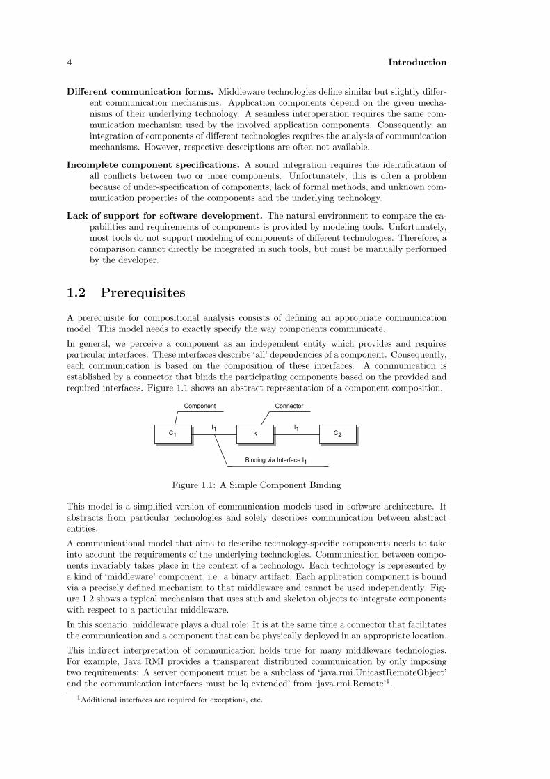
In general, we perceive a component as an independent entity which provides and requiresparticular interfaces. These interfaces describe ‘all’ dependencies of a component. Consequently,each communication is based on the composition of these interfaces. A communication isestablished by a connector that binds the participating components based on the provided andrequired interfaces. Figure 1.1 shows an abstract representation of a component composition.
C1 C2KI1 I1
Component
Binding via Interface I1
Connector
Figure 1.1: A Simple Component Binding
This model is a simplified version of communication models used in software architecture. Itabstracts from particular technologies and solely describes communication between abstractentities.
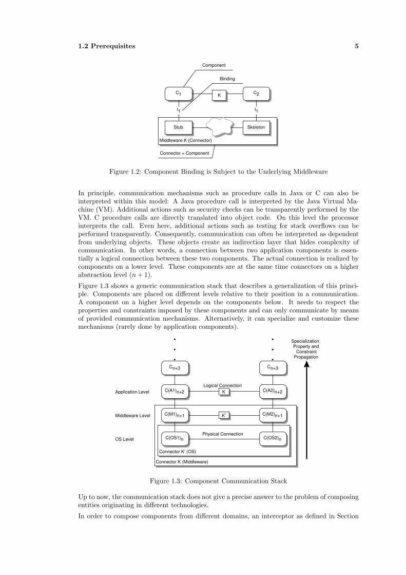
A communicational model that aims to describe technology-specific components needs to takeinto account the requirements of the underlying technologies. Communication between compo-nents invariably takes place in the context of a technology. Each technology is represented bya kind of ‘middleware’ component, i.e. a binary artifact. Each application component is boundvia a precisely defined mechanism to that middleware and cannot be used independently. Fig-ure 1.2 shows a typical mechanism that uses stub and skeleton objects to integrate componentswith respect to a particular middleware.
In this scenario, middleware plays a dual role: It is at the same time a connector that facilitatesthe communication and a component that can be physically deployed in an appropriate location.
This indirect interpretation of communication holds true for many middleware technologies.For example, Java RMI provides a transparent distributed communication by only imposingtwo requirements: A server component must be a subclass of ‘java.rmi.UnicastRemoteObject’and the communication interfaces must be lq extended’ from ‘java.rmi.Remote’1.
1Additional interfaces are required for exceptions, etc.
1.2 Prerequisites 5
Middleware K (Connector)
C1 C2
Stub Skeleton
I1 I1
Component
Connector = Component
Binding
K
Figure 1.2: Component Binding is Subject to the Underlying Middleware
In principle, communication mechanisms such as procedure calls in Java or C can also beinterpreted within this model: A Java procedure call is interpreted by the Java Virtual Ma-chine (VM). Additional actions such as security checks can be transparently performed by theVM. C procedure calls are directly translated into object code. On this level the processorinterprets the call. Even here, additional actions such as testing for stack overflows can beperformed transparently. Consequently, communication can often be interpreted as dependentfrom underlying objects. These objects create an indirection layer that hides complexity ofcommunication. In other words, a connection between two application components is essen-tially a logical connection between these two components. The actual connection is realized bycomponents on a lower level. These components are at the same time connectors on a higherabstraction level (n + 1).
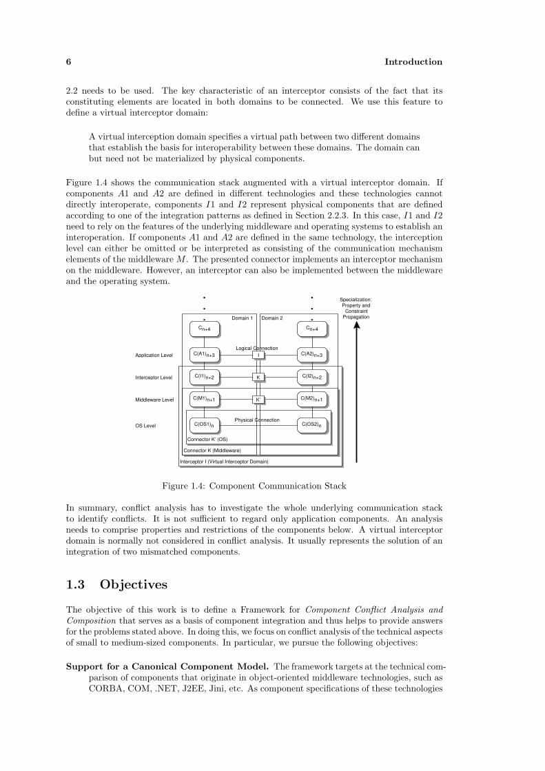
Figure 1.3 shows a generic communication stack that describes a generalization of this princi-ple. Components are placed on different levels relative to their position in a communication.A component on a higher level depends on the components below. It needs to respect theproperties and constraints imposed by these components and can only communicate by meansof provided communication mechanisms. Alternatively, it can specialize and customize thesemechanisms (rarely done by application components).
Connector K (Middleware)
Connector K’ (OS)
Cn+3
C(A1)n+2
C(M1)n+1
C(OS1)n
Cn+3
C(A2)n+2
C(M2)n+1
C(OS2)nPhysical Connection
Logical ConnectionApplication Level
Middleware Level
OS Level
K
K’
.
.
.
.
.
.
Specialization: Property and
Constraint Propagation
Figure 1.3: Component Communication Stack
Up to now, the communication stack does not give a precise answer to the problem of composingentities originating in different technologies.
In order to compose components from different domains, an interceptor as defined in Section
6 Introduction
2.2 needs to be used. The key characteristic of an interceptor consists of the fact that itsconstituting elements are located in both domains to be connected. We use this feature todefine a virtual interceptor domain:
A virtual interception domain specifies a virtual path between two different domainsthat establish the basis for interoperability between these domains. The domain canbut need not be materialized by physical components.
Figure 1.4 shows the communication stack augmented with a virtual interceptor domain. Ifcomponents A1 and A2 are defined in different technologies and these technologies cannotdirectly interoperate, components I1 and I2 represent physical components that are definedaccording to one of the integration patterns as defined in Section 2.2.3. In this case, I1 and I2need to rely on the features of the underlying middleware and operating systems to establish aninteroperation. If components A1 and A2 are defined in the same technology, the interceptionlevel can either be omitted or be interpreted as consisting of the communication mechanismelements of the middleware M . The presented connector implements an interceptor mechanismon the middleware. However, an interceptor can also be implemented between the middlewareand the operating system.
Interceptor I (Virtual Interceptor Domain)
Connector K (Middleware)
Connector K’ (OS)
Cn+4
C(A1)n+3
C(M1)n+1
C(OS1)n
Cn+4
C(A2)n+3
C(M2)n+1
C(OS2)nPhysical Connection
Logical ConnectionApplication Level
Middleware Level
OS Level
.
.
.
.
.
.
Specialization: Property and
Constraint Propagation
C(I1)n+2 C(I2)n+2Interceptor Level K
I
K’
Domain 1 Domain 2
Figure 1.4: Component Communication Stack
In summary, conflict analysis has to investigate the whole underlying communication stackto identify conflicts. It is not sufficient to regard only application components. An analysisneeds to comprise properties and restrictions of the components below. A virtual interceptordomain is normally not considered in conflict analysis. It usually represents the solution of anintegration of two mismatched components.
1.3 Objectives
The objective of this work is to define a Framework for Component Conflict Analysis andComposition that serves as a basis of component integration and thus helps to provide answersfor the problems stated above. In doing this, we focus on conflict analysis of the technical aspectsof small to medium-sized components. In particular, we pursue the following objectives:
Support for a Canonical Component Model. The framework targets at the technical com-parison of components that originate in object-oriented middleware technologies, such asCORBA, COM, .NET, J2EE, Jini, etc. As component specifications of these technologies
1.4 Approach 7
differ in form and content, a canonical representation is required that represents the leastcommon denominator of components in these technologies.
Support for Component Abstraction. As existing artifacts are specified in terms of con-crete technologies, the framework has to provide transformation functionality to demergeplatform specific details of components such as type systems and to create a canonicalrepresentation of those in order to create a basis for conflict analysis.
Conflict Analysis identifies mismatches between the technical specifications of two compo-nents. The more kinds of conflicts are identified, the more accurate a cost assessment ofan integration effort will be. A solution can be generated in the form of a connector whichmediates the identified incompatibilities between a number of components. However, theaccuracy of a generated connector depends on the precision of conflict identification.
We therefore aim to check for as many conflict categories as possible and additionallyto create a highly customizable conflict analysis framework that is adaptable to differentrequirements and for different technologies. At present, we support compatibility andsubstitutability analysis of types, behavior and communication properties.
Support for Model Refinement. We aim to support model refinement because it is requiredin order to generate platform specific connectors. Furthermore, it also realizes a proposedadvantage of Model-Driven Development: Reuse of Platform Independent Models (PIMs)by providing transformations into arbitrary technologies.
Integration into Software Development. We believe that a framework for conflict analysisand composition will only be useful in the context of CBSE if it seamlessly integrates withdesign tools that are used in software development. As UML is the de facto modelinglanguage, we aim to support conflict identification from within UML tools.
A possible application scenario for the framework concerns integration and reuse of existing ar-tifacts. In this sense, components are often termed as Commercials Off-the-Shelf (COTS) thatcan be obtained from a component market, as it was first proposed by McIlroy [91] in 1968.Unfortunately, reuse of COTS is not easily realized. There are two major problems of COTSintegration: The first problem concerns selection and identification of COTS that offer requiredfunctionality and quality. The second problem concerns incompatibilities among current tech-nologies that make it difficult to compose COTS. For these reasons, integration approachesnormally only consider COTS based on the same technology. Integration of components thatoriginate in different technologies is avoided, as it is a difficult and time-consuming task. Theproposed framework targets at the second problem as it mainly provides conflict analysis forCOTS integration.
1.4 Approach
We engage component integration and conflict analysis in particular by defining a frameworkthat provides the necessary functionality to satisfy each of the five objectives stated above.The central aspect of the framework consists of a platform independent component model onwhich conflict analysis is based. The components to be analysed and integrated, however, arespecified relative to a platform. The connector that integrates these components also has to bespecified according to particular technologies.
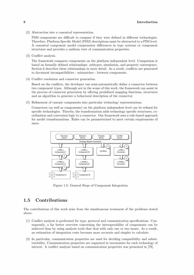
Therefore, an integration process as shown in Figure 1.5 consists of several sequential steps:
(1) Extraction of component specifications from artifacts.
In the first step, for each artifact a corresponding model is created. In terms of the MDA,this model is a platform specific model (PSM), as it represents a direct mapping of atechnology’s relevant properties into a formal (model-based) representation. The OMGalready provides UML profiles for several technologies such as a CORBA profile or aprofile for entity relationship models.
8 Introduction
(2) Abstraction into a canonical representation.
PSM components are difficult to compare if they were defined in different technologies.Therefore, Platform Specific Model (PSM) descriptions must be abstracted to a PIM level.A canonical component model compensates differences in type systems or componentstructures and provides a uniform view of communication properties.
(3) Conflict analysis.
The framework compares components on the platform independent level. Comparison isbased on formally defined relationships: subtypes, simulation, and property convergence.Section 6 describes these relationships in more detail. As a result, conflicts are generatedto document incompatibilities - mismatches - between components.
(4) Conflict resolution and connector generation.
Based on the conflicts, the developer can semi-automatically define a connector betweentwo component types. Although not in the scope of this work, the framework can assist inthe process of connector generation by offering predefined mapping functions, structuresand an algorithm to generate a behavioral description of the connector.
(5) Refinement of canonic components into particular technology representations.
Connectors (as well as components) on the platform independent level can be refined forspecific technologies. Thereby, the transformation adds technology specific structures, co-ordination and conversion logic to a connector. Our framework uses a rule-based approachfor model transformations. Rules can be parameterized to meet certain requirements ofusers.
Component A Component B
<<PSM>> Component A
<<PSM>> Component B
<<PIM>> Component A
<<PIM>> Component B
Ontology-Based Framework
Structure Model
Behavior Model
Property Model
Conflict Model
Conflicts <<PIM>> Connector
<<PSM>> Connector
1
2
3 4
5
Figure 1.5: General Steps of Component Integration
1.5 Contributions
The contributions of this work arise from the simultaneous treatment of the problems statedabove.
(1) Conflict analysis is performed for type, protocol and communication specifications. Con-sequently, a far better overview concerning the interoperability of components can beachieved than by using analysis tools that deal with only one or two issues. As a result,an estimation of integration costs becomes more accurate and simpler to calculate.
(2) In particular, communication properties are used for deciding compatibility and substi-tutability. Communication properties are organized in taxonomies for each technology ofinterest. A conflict analysis based on communication properties was presented in [79].

1.6 Outline 9
(3) The framework is extensible for additional analysis methods such as ontology-based checksand pre- and post-conditions. Moreover the language for protocol specifications is ex-changeable and the type system customizable. The framework is described in [77], whereasconflict analysis was presented in [78].
(4) The framework can be seen as a ‘minimal’ model-driven development system, as it sup-ports models - especially component models - on different abstraction levels and furtherprovides transformation functionality between the models. It further provides function-ality to store model descriptions and transformation in a component repository.
(5) The framework can be used in a UML-based development process, as UML models canbe transformed into the framework’s internal representation (RDF) and vice versa. Theframework’s models (platform independent and specific component models) are expressedby UML profiles in order to describe the necessary transformations. Thus, each UMLtool can be used as a front-end if it supports stereotypes and tagged values. This isachieved on the basis of the Evolution and Validation Framework [131], which we haveextended by a transformation service. Consequently, we are able to attach arbitrarybackground information on UML elements and to interpret the background informationas RDF statements. This has been demonstrated for communication properties in [79].
We also support a tight integration of the framework and UML tools, as commands can beencoded into UML diagrams. The framework’s services analyse the models and executethe appropriate services.
(6) UML does not directly support reasoning. The framework however uses TRIPLE, whichis a deductive language based on RDF. As we are able to transform between UML andRDF, we practically realize reasoning on UML.
(7) The framework further introduces flexible refinement operations on components. There-fore, a transformation is adaptable to the requirements of the developer. This is contraryto one-to-one transformations as defined in many software tools. In [25], we demonstratedparameterized refinement transformations for Enterprise JavaBeans. Thereby, the trans-formation can be optimized for certain situations based on existing J2EE patterns.
1.6 Outline
This work is divided into four parts. The first part describes communication and integration incomponent-based systems. Chapter 2 describes communication from two perspectives: It firstdiscusses the technical aspects of communication followed by a survey of communication from anarchitectural viewpoint. The first part also introduces the two operations of interest in this work:checking compatibility and substitutability. Compatibility validates if two components areinteroperable, whereas substitutability checks if components are exchangeable. Finally, methodsfor component integration are introduced. Component integration is realized by connectors thatsolve the conflicts between otherwise incompatible components.
The second part describes the framework for conflict analysis. Chapter 3 introduces the twoprocesses of interest: component analysis and transformation. Chapter 4 further introduces acommunication taxonomy that augments type and behavior checks. Chapter 5 describes theframework. It includes an architectural overview as well as a description of the core models ofthe framework. Chapter 5 further describes the interaction with UML, which is achieved viaprofiles, and informally describes a morphism between UML and RDF. Chapter 6 introducesconflict analysis as performed by the framework. This part includes segments of previouslypublished papers: [77–79; 131].
The third part exemplifies the usage scenarios of the framework. Therefore, Chapter 7 describesexamples for conflict analysis and Chapter 8 describes parameterized model transformation aspresented in [25].

10 Introduction
The last part concludes the work and provides visions for future work as well as cooperations.
The appendices mainly include a UML Profile for the core models of the Ontology-Based Frame-work (OBF) as well as taxonomies describing relevant communication properties of J2EE andMicrosoft .Net. A list of previously published papers that were integrated in this work is alsoincluded as an appendix.

Chapter 2
Communication and Integration
This chapter first describes the technical foundations of communication and integration andsecond introduces communication and interoperation from an architectural viewpoint. Commu-nication or more precisely interprocess communication enables the composition of componentsto complex systems, which in turn results in advantages such as higher reliability, concur-rent and distributed computations, reuse and integration of preexisting components, or higherthroughput of client requests. Sophisticated architectures of distributed systems such as theclient-server architecture and its variations provide the basis for these advantages.
Section 2.1 consequently starts with an overview of the foundations of communication. Thisincludes a basic model of communication, communication protocols, basic interprocess commu-nication (Section 2.1.1) as well as middleware communication mechanisms and services (Section2.1.2).
Distributed applications are generally composed of several components. If some of the compo-nents are pre-fabricated, reused or incompatible because of mismatched specifications, the issueof component integration arises. We base the decision if two components are compatible onformally defined relationships that identify mismatches in different areas of component specifi-cations: subtype relationships, simulation of behavioral specification and relationships betweencommunication requirements. Section 2.2 describes component integration and interoperation.This includes an overview of the important relationships deciding component compatibility andsubstitutability. The section also includes some hints regarding the question of how to integratemismatched components.
Section 2.3 describes integration scenarios used throughout this work. This includes a shortdescription of legacy components (Section 2.3.1) and COTS (Section 2.3.2) as well as somenotes regarding program understanding. These aspects form potential application scenariosof the framework developed in this work. As we assume that the components to be analysedfor compatibility and substitutability are specified in UML, we include a short description ofprogram understanding (Section 2.3.3). Program understanding is required in order to extractthe necessary information for a UML specification from legacy components and COTS.
Section 2.4 provides an overview of software architecture, type systems and behavioral specifica-tion languages. These are the foundations specifying communication and interoperation at thearchitectural level and are critical in deciding compatibility and substitutability of components.
2.1 Communication
According to the Reference Model of Open Distributed Processing (RM-ODP), we define com-munication as
Definition 1 (Communication) “The conveyance of information between two or more ob-jects as a result of one or more interactions, possibly involving some intermediate objects.

12 Communication and Integration
[Thereby] an interaction takes place with the participation of the environment of the object”[67, pp. 4-5].
Considering the definition of communication proposed by the RM-ODP, we can identify threeelementary parts out of which a communication is composed:
Communication EndPoint
Communication EndPointData Data
Control
Process A Process B
Protocol
Figure 2.1: Communication Model
Communication Endpoints. Communication requires at least two participants. Both par-ticipants must agree upon the protocols used and the data to be submitted in order tosuccessfully initiate a communication.
Data. Communication involves the conveyance of information between participants. This in-cludes the exchange of data in a well-defined format which is understood by both par-ticipants. The format describes the types of data that can be exchanged as well as theencoding of the data. For example, object-oriented systems such as CORBA use proto-cols that describe data exchange encoded as binary data. On the contrary, Web Servicesdescribe data exchange on the basis of XML (SOAP), which is based on text encodedmessages. This introduces overhead, as data encodings require more space and process-ing time, but also allows for a simpler integration of different systems and middlewaretechnologies.
Control. Communication can be described by a protocol that the participants must respect inorder to interact with each other. In this respect control describes the kinds of messagesthat can be exchanged and prescribes the order of the messages to be exchanged.
Figure 2.1 shows a respective model that exemplifies communication in terms of the describedelements.
Our view of a communication stem from software architecture, which distinguishes explicitlybetween data and control issues. Shaw and Garlan [124] use, for example, a categorization ofarchitectural styles, which mainly consists of control and data-related criteria.
Focusing on distributed systems, both issues are mingled together in the definition of protocols.According to Coulouris et. al. [40] a protocol is defined as follows:
Definition 2 (Protocol) “The term protocol is used to refer to a well-known set of rules andformats to be used for communication between processes in order to perform a given task” [40,p.76].
The definition mainly covers two aspects of communication - the exchange of messages betweencommunication endpoints that are described (ordered) by certain rules and the specification offormats of exchanged data. Both issues correspond exactly to control and data as describedabove.
Establishing communication between distributed processes is a difficult concern. It involves forexample the physical conveyance of information, marshaling of information to the formats sup-ported by different processes in different environments, verification of correctness of submitteddata, ordering of transmitted data packets, resubmission of lost data and messages, etc.
As a response to these complex and difficult to handle problems, protocols are normally dividedinto several layers from which each handles a particular problem. The OSI reference model [45]defines seven layers that describe the most fundamental problems of communication. Each layeruses the functionality provided by the next lower level to realize its functionality. The sevenlayers of the OSI reference model can be described as follows:

2.1 Communication 13
Physical Layer. The physical layer describes data exchange as electrical signals between phys-ical communication endpoints. ISDN is an example of a protocol that is located on thislayer.
Data Link Layer. The data link layer mainly provides functionality to check the correctnessof the exchanged data between directly connected communication nodes (endpoints). Anexample protocol for this layer is PPP.
Network Layer. The network layer specifies the routing of information packages in a network.The de facto protocol on this layer is the IP protocol.
Transport Layer. The transport layer describes certain constraints between two or more com-munication partners. It describes, for example, if a communication is reliable or not. Areliable communication prescribes that communication packages are received in the cor-rect order and that no package can be lost. The de facto protocols on this layer areTCP for a reliable communication and UDP for an unreliable communication. This layeralso distinguishes between connection-oriented (TCP) and connection-less (UDP) formsof communication.
Session Layer. The session layer extends the transport layer as it supports process synchro-nization in communication sessions.
Presentation Layer. The presentation layer defines platform-independent data formats thatcan be used to exchange information between communication endpoints in different envi-ronments such as Windows and UNIX. This level can also be used to introduce encryptionin a communication. An example protocol on this level is SSL.
Application Layer. Protocols on this layer resolve the needs of particular applications. Thisincludes protocols such as FTP and SMTP.
Existing protocols do not exactly follow this reference model as they were often developed beforethe model was released (e.g. TCP/IP) or they structure the levels slightly different accordingto the requirements of a particular situation. Consequently, it is difficult to identify protocolsdesigned for the session layer or the representation layer. Therefore, we introduce a five layermodel as defined by Tannenbaum [135]. His model introduces a middleware layer instead ofthe representation and the session layers. The middleware layer provides the communicationservices used by application components to communicate with each other.
Physical Layer
Data Link Layer
Protocol Layer
Transport Layer
Middleware Layer
IPC & Marshalling
Communication Mechanisms (RMI, RPC,...)
Application Layer
Figure 2.2: Adapted Protocol Stack
Figure 2.2 shows the resulting model. This view also corresponds to the view of Coulouriset. al. They also recognize the gap in the upper layers of the reference model. According toCoulouris, “ the application, presentation and session layers are not clearly distinguished inthe Internet protocol stack” [40, p.78]. Consequently, they amalgamate the application and
14 Communication and Integration
the presentation layers as a middleware layer1 and further the session and the transportationlayers, as existing protocols support this partitioning.
The middleware layer is further divided into two subsequent layers: Communication mechanismsare defined in the upper middleware layer. These mechanisms are directly used by applicationcomponents to communicate with each other. The mechanisms are built upon an IPC protocollayer that provides messages to exchange data and that also introduce services to transformdata according to the needs of each communication endpoint.
The positioning of middleware within the Open Systems Interconnection Reference Model reflectthe higher level of abstraction that is offered. Middleware hides the primitive IPC mechanisms asprovided by operating systems by supporting more sophisticated communication mechanismsthat can be used by application components. These mechanisms alleviate the developmentof distributed applications by introducing transparencies and services such as transactions orsecurity.
In this respect, Coulouris et.al. [40] define Middleware as follows:
“The term middleware applies to a software layer that provides a programming ab-straction as well as masking the heterogeneity of the underlying networks, hardware,operating systems and programming languages” [40, p.16].
This definition does not clearly characterize middleware, as it does not describe the way inwhich middleware overcomes heterogeneity and the different kinds of middleware available.
In this respect, Bernstein [23] proposes the following characteristics to describe middlewaremore precisely:
• Middleware must support a wide range of applications. Middleware is a standardized andgeneral approach. An approach that aims at a specific scenario should not be consideredmiddleware.
• Middleware should be available on a wide range of platforms and further allow for com-munication between components defined on these platforms.
• Middleware should support distributed communication.
• Middleware should support standard protocols, allowing the exchange of a middlewareproduct.
• Middleware services should perform its services transparently and via standard APIs toallow for simplified development.
In summary, the middleware layer consists of two subsequent layers: A layer that provides basicservices for interprocess communication as well as the necessary functionality to transform datafor the communication endpoints and a layer that introduces the more sophisticated commu-nication mechanisms of the middleware including services. The following two sections describeboth layers, as they will provide the focus for conflict identification.
2.1.1 Inter-Process Communication
Inter-Process communication can be categorized by the number of hosts involved: communica-tion is either local to a single host or distributed between different hosts. Classic interprocessmechanisms are shared memory, pipes, messages, and RPC. Thereby, shared memory forms anexception as it is based on data exchange on the heap. Therefore, it is a very efficient formof interprocess communication but is only applicable for communication on a single host. Theother forms of communication can either be used for local or distributed communication.
1Precisely, according to Coulouris, they can also be implemented separately for each application. However,we do not consider this case in the following.
2.1 Communication 15
IPC mechanisms define protocols to exchange messages between communication endpoints. Arespective message passing mechanism can be based on two operations: send and receive. Twoor more processes initiate communication with only these two operations by adhering to certainrestrictions and properties on these operations that are obliged by a particular IPC protocol. Ingeneral, protocols rely either on Request or Request/Reply semantics2. A request correspondsto a single message, whereas a request/reply protocol consists of two messages: A request issent from process A and received by process B. B computes the request and sends a reply backto process A. This semantics corresponds in general to a remote method/function call.
Communication protocols as well as messages on which they are defined are normally providedby operating systems with network capabilities. Thereby, the exact primitives, the supportedIPC mechanisms, and the available protocol stacks they provide are variable. Operating systemsare free to choose the granularity and the form of these factors. This can lead to optimizationsfor particular communication mechanisms, as is often the case in experimental research systems.However, most common operating systems such as Windows NT or UNIX derivates providemechanisms that use ‘Sockets’ as abstractions for communication endpoints and define IPCmechanisms between them. Sockets refer to an IP number and a respective port.
A remote communication differs from a local communication in several aspects. In particular,call semantics must be considered carefully, as in contrast with a local call several additionalsources of errors are introduced. For example, an operation can fail because the remote nodeis offline or the remote node takes too much time to compute a request. Therefore, differentwarranties regarding distributed calls are introduced, which yield the following semantics:
Maybe semantics initiates an operation exactly once but do not provide any reliability war-ranties. It is therefore not guaranteed that the operation is successfully executed on theserver or even reaches the server.
At-least-once semantics repeats an operation if no reply is received in a given time. Thiscan be the case if the request is lost due to a network failure or that the server has notcompleted the computations of the request in the given time. Consequently, this semanticsshould only be used with idempotent operations.
At-most-once semantics repeats an operation until it is executed once. This semantics re-quires a complex design of the server if operations are not idempotent. A solution concernsthe introduction of a history that caches already performed operations. For more detailssee, for example, Coulouris [40].
Exactly-once semantics executes a remote operation exactly once. This semantic is difficultto achieve and requires a sophisticated design of the involved processes.
Communication mechanisms can further be characterized by properties. The following proper-ties are proposed by Coulouris [40]:
Synchronized Communication. Communication between participating processes can be char-acterized as synchronous or asynchronous. A synchronous communication requires theblocking of the message initiating process until a response of the addressed processes isreceived. Thereby, blocking can be classified into several distinct forms. Table 2.1providesan overview of different forms of blocking as defined by Tannenbaum [135].3
Message Destinations. Messages are normally targeted at only one receiver. In this case acommunication requires an initial step that constitutes a connection between two end-points. Alternatively, a message can be broadcast to a group of processes. This kind ofcommunication does not require an established connection.
2Coulouris also introduces a Request/Reply/Acknowledge protocol that adds certain warranties on the reli-ability of operations.
3Tai and Rouvellou also describe a similar matrix in [134].

16 Communication and Integration
Persistent Transientsynchronous (b) Process A sends a message and
waits for an acknowledgment. Theacknowledgment is given by themiddleware. The called process Breceives the message the next timeit is started.
(d) The calling process A waits fora receipt that the message were re-ceived. The receipt is given fromB, even if the receiving process Bdoes not process the message imme-diately.(e) The calling process A waits forthe delivery of the message, whichmeans that the receiving process Bhas received the message and startedprocessing of it.(f) The calling process A awaits theresponse for a message. The re-sponse includes the results of themessage’s computation.
asynchronous (a) Process A sends a message andresumes its computations. The mes-sage is delivered by a middleware tothe called process B, even if the pro-cess is not running at the moment.
(c) Process A sends a message to areceiving process B. B needs to berunning in order to get the message.
Table 2.1: Six Forms of Message Passing Accoring to Tannenbaum [135]
Reliability and Ordering. Reliability describes whether a communication preserves data in-tegrity and message ordering. A reliable communication provides guarantees about theseissues whereas in the case of an unreliable communication it is not guaranteed that allmessages are received. A protocol designed for unreliable communication is given withUDP.
It should be noticed that each property can be related to the basic elements of communication:synchronization corresponds to control, message destinations to communication endpoints, dataintegrity to data, and message ordering to control.
2.1.2 Middleware Communication Mechanisms and Services
The second middleware layer (Figure 2.2) defines sophisticated communication mechanisms foruse with application components. The mechanisms are augmented with services such as trans-action and security that provide valuable supplements of communication. The most commonmechanisms are defined on procedure call semantics and message passing.
Remote Procedure Call
A remote procedure call can be characterized as a synchronous communication mechanism be-tween a client and a server which is based on a Request/Reply protocol. Important propertiesof a procedure call include parameter passing and call semantics. Parameter passing can bedescribed, similar to a local call, as by-value and by-reference passing. By-value passing de-scribes the transmission of a data value to a callee. The process involves the marshaling andde-marshaling of the value. By-reference calls also concern the transmission of data structures.Contrary to local calls, a reference, which corresponds to a pointer to a local object, cannot beinterpreted in a distributed environment. Therefore, the referenced structure must be copiedto the remote location.
2.2 Integration 17
Remote Method Invocation
The advent of object-oriented programming languages also introduced object-oriented dis-tributed communication. Thereby, communication depends on an object model with all itsfeatures from which the most important for distributed communication are object referencesand interfaces. Object references need to be unique in time and space to identify the correctobject. This can be achieved, for example, by constructing an object reference from an Internetaddress, a timestamp, an object counter and an interface identifier.
Interfaces define the methods that can be called remotely. They provide the usual abstractionfrom the implementation. There are two approaches to define interfaces for a remote invocation.The first and more general approach uses an Interface Description Language (IDL) to definea remote interface. The advantage of this approach is language independence. CORBA andCOM use IDLs to define interoperation between objects written in different languages. Thesecond form is used by Java RMI. The interface is defined like a normal Java interface. Thisresults in a more transparent integration of remote invocations.
In principal, a remote method invocation can be performed almost transparently. From aprogrammer’s perspective it should be indistinguishable from a local call. However, additionalfailure semantics and the higher latency of remote calls should not be defined transparently. JavaRMI resolves these requirements, for example, by the restriction that remote communicationmust be defined via a special remote interface. Furthermore, remote method declarations mustcontain remote exceptions that are used to express failure semantics in a distributed system.
Message Passing
Message passing cannot be characterized as easily as the former communication mechanismsbecause several variations are used in middleware systems. Direct message passing, messagequeues and publisher/subscriber form the most common mechanisms. Whereas direct messagepassing is often used in a single application, message passing and publisher/subscriber decoupleapplications in time and space. Both provide services to store messages in case a recipient isnot available. Respective products are, for example, Message Brokers and Event Services.
Important characteristics of message passing mechanisms are the degree of coupling betweenprocesses, call semantics as introduced above, and the number of participants of a communi-cation. Message passing mechanisms distinguish a variety of asynchronous and synchronousmessage passing semantics. Table 2.1 shows a respective overview as defined by Tannenbaum[135]. Contrary to procedure calls, message passing mechanisms support one-to-many commu-nication. For example, in the publisher/subscriber model, several subscribers can register forparticular events of a single publisher.
Classification of Middleware Communication Mechanisms
Middleware communication mechanisms can be classified by a number of properties, similar tothe classification of communication in general. Thompson [137] provides a classification whichoriginally was taken from a report of the Gartner group. Table 2.2 shows the slightly adaptedclassification consisting of properties describing the communication mechanism, the protocol,the number of participants, and the synchronicity of the communication. It is obvious thatmost mechanisms can be divided into two groups: asynchronous one-to-many communicationand synchronous one-to-one communication.
2.2 Integration
Component integration itself refers to the process of composing two or more components toa more complex system. According to the IEEE glossary of software engineering terms [62],integration is defined as follows:

18 Communication and Integration
Communication Mechanism Protocol Participants SynchronicityRemote Procedure Calls Request/Reply 1:1 synchronousRemote Method Invocation Request/Reply 1:1 synchronousDirect Messaging Request(Message) 1:1 asynchronousMessage Queues Request 1:n asynchronousPublish/Subscribe Request 1:n asynchronousProcedure Call Request/Reply 1:1 synchronousDatabase Gateways (e.g. JDBC) Request/Reply 1:1 synchronous
Table 2.2: Properties of Middleware Communication Mechanisms (adapted from [137])
Definition 3 (Integration) “[Integration is ] the process of combining software components,hardware components, or both into an overall system” [62, p.41].
The composed system forms another, more abstract kind of a component. This abstract com-ponent can be composed of a number of interoperating distributed (primitive) components thatare coordinated in order to solve a complex problem. The abstract component can itself be fur-ther integrated resulting in more complex systems. Consequently, components form a hierarchyas proposed by several researchers such as Weber and Ehrig [144], Plasil [18], Kramer [85], etc.
The term interoperation refers to the exchange of data and control between components. Adefinition of the term interoperation, which emphasizes the exchange of information, is alsogiven in the IEEE standard glossary.
“The ability of two or more systems or components to exchange information and touse the information that has been exchanged” [62, p.42].
Another definition of interoperation, which is provided by Peter Wegner, also adds conflictresolution to the meaning of the term:
“Interoperability is the ability of two or more entities to cooperate despite differencesin language, interface, and execution platform” [145, p.1].
This definition of interoperability comes close to our understanding of the term. In our view,a proper component integration consists of two steps: in ‘the’ first step, a conflict analysisprocess identifies conflicts between two components, whereas in ‘the’ second step a connector isgenerated that compensates the conflicts to provide a seamless interoperation between compo-nents. Consequently, we define the term interoperability as the amalgamation of both formerdefinitions:
Definition 4 (Interoperability) Interoperability refers to the ability of two components toexchange information and to cooperate despite differences in language, interface, and executionplatform.4
Conflicts are incompatibilities in either the required and provided types, in the behavior ofcomponents or in the communication requirements. A conflict is defined as follows:
Definition 5 (Conflict) A conflict is any mismatch between interfaces or behavior of twocomponents or any mismatch between their domains that impedes a seamless interoperationbetween them.
The definition of interoperability as defined by Wegner [145] emphasizes an important pointof cooperation: Not only the component specifications need to correspond to each other, but
4The definition is based on [145] and [62].
2.2 Integration 19
also the technological context must match. The context5 can be, for example, a middlewaretechnology such as CORBA or an operating system such as Unix. As the entities that representthe context of a component can vary depending on the viewpoint of the observer, we use themore appropriate term of a ‘domain’. A domain describes the relationship between componentsand their context or environment. The term is defined by the RM-ODP as follows:
Definition 6 (Domain) “A set of objects, each of which is related by a characterizing rela-tionship X to a controlling object” [67, p.9].
Thereby X can be interpreted as a ‘depends’ or ‘use’ relationship between application compo-nents and their context, e.g. middleware such as CORBA or operating systems such as UNIXform a technical domain.
Interoperability between mismatched components can be realized by providing a connector thatcompensates the conflicts between components. A connector is a special kind of componentthat does not contain application logic but only provides transformation and coordination logic.The connector is often not directly visible to application developers.6
The RM-ODP uses the term ‘interceptor’ to refer to a connector that mediates conflicts betweendifferent domains. An interceptor emphasizes the relevance of the context of components - thedomains - for composition.7
Definition 7 (Interceptor) “[An Interceptor is] placed at a boundary between . . . [two] do-mains. An . . . interceptor
• performs checks to enforce or monitor policies on permitted interactions between basicengineering objects in different domains;
• performs transformations to mask differences in interpretation of data by basic engineeringobjects in different domains” [68, p.32].
2.2.1 Compatibility and Substitutability
Establishing interoperability concerns the process of composing components to realize a seamlesscommunication between them. The major question regarding this process pertains to thedecision of whether two components are compatible or not.
We regard compatibility between two components. Both components require and provide ser-vices that are defined by interfaces. The interfaces consist of method declarations and behavioralspecifications. Further, both components are placed in a technological context that describestheir communication abilities.
We decide component compatibility by proving type, behavior, and property relationships.Type and behavior relationships are based on well-known theoretical approaches. Propertyrelationships describe the required and provided abilities of the components regarding commu-nication. They are described in a taxonomy that covers important aspects for communication.Contrary to type and behavior specification, communication properties do not provide a ‘com-plete’ description of a component. We propose that if a classification is based on carefullychosen properties, communication mechanisms can be differentiated and the root causes of in-compatibility can be determined. This augments type and behavior specifications, especially ifthey are incompletely specified by providing an approximation of compatibility.
We believe that from a pragmatic perspective, a compatibility check of these relationships issufficient to guarantee a technical interoperability of components. In this respect, we definecompatibility as
5In this work, we perceive the context of a component as either the underlying middleware or operatingsystem. We further use the term ‘domain’ instead of the term ‘context’.
6The terms component and connector are discussed in Section 2.4.1.7We use the term interceptor to emphasize this circumstance. Otherwise, we use the more general term of a
connector.
20 Communication and Integration
Definition 8 (Compatibility) Two components are compatible if they can interact with re-gard to type, behavior and property relationships.
For component exchange, similar relationships can be used to verify the equivalence betweenthe legacy and the substituent component. We refer to the term substitutability to check forcomponent exchange:
Definition 9 (Substitutability) Two components are substitutable if they can be exchangedwithout interfering with the functionality of particular components in any system configura-tion. Substitutability can be decided by proving equivalence relationships. These include at leastsubtyping of component interfaces and bisimulation of components’ behavior.
In the remainder of this section, we introduce a classification of relationships to determinecompatibility and substitutability. In general, we distinguish two categories of relationshipsregarding syntactic and semantic interoperability between two components:
Type Interoperability defines relationships on the exposed and required interface types ofcomponents. Two relationships can be distinguished: type equality, which verifies theexchangeability of two components and subtype compatibility, which checks if two com-ponents can be composed.
Both relationships are determinable and are ‘commonly’ used in typed programming lan-guages and in middleware systems.
Semantic Interoperability covers different aspects of component specification. Unfortu-nately, these aspects are not clearly denoted and consequently different terms are used forthe same aspects throughout the community. In the following, we employ the terms andthe categorization of Vallecillo et. al. [138]. They use the term ‘Semantic Interoperabil-ity’ as a top level concept to further distinguish into: behavioral semantics and protocolsemantics.
Behavioral Semantics refers to the principle of ‘design by contract’ as introduced byMeyer [97] to check for compatibility. Consequently, the caller needs to establish thepreconditions of the callee before a request and presumes valid post-conditions after aresponse.
Vallecillo further introduces the term behavioral subtyping to prove if components are ex-changeable. Several authors propose their own definitions of behavioral subtyping to checkfor substitution.8 According to Zaremski and Wing [152, p.14] most of the approachesare similar as they are based on
“pre-/post-condition specifications (1) to describe the behavior of types and (2)to determine whether one type is a subtype of another.”
Consequently, behavioral specifications are mainly based on the analysis of pre- and postconditions. These conditions can be annotated to components in several specificationlanguages such as Z [129], OCL [107], OCLPrime [133], Larch [59].
A disadvantage of behavioral specifications relates to difficulties in proving matchingspecifications as “behavior-preserving subtyping is in general undecidable” [138, p.6].
Protocol semantics prescribes the order of operations within a communication. For-malisms to express protocols often rests on a transition system to prove the validity of acommunication. Protocol semantics can also be specified in a number of formal languages.Examples are Process Algebras such as CSP [61], ACP [17], or FSP [86], Petri Nets [116],or Message Sequence Charts [64].
Protocol semantics allows checking several relationships: substitutability and compati-bility of components as well as protocol properties. Substitutability can be decided by
8For an overview see [138] or [152].

2.2 Integration 21
checking for bisimulation between components. In literature, several slightly differentdefinitions of bisimulation are proposed. An overview is given in Section 6.2. Compati-bility can be decided by simulation relationships. Most research aims at proving processequivalence. However, simulation can be defined by substracting the relationship thatestablishes equivalent behavior between the callee to the caller from the respective bisim-ulation definitions. An overview of simulation is also provided in Section 6.2. Based ontransition systems, properties such as deadlock or progress can also be checked.
Process algebra expressions and relationships are often checked by model checkers. Forseveral of the languages above, tools were developed that provide the necessary function-ality for proofs and property checks. We use these tools for compatibility and substi-tutability checks.
We call the former relationships formal, as we can prove their validity based on sophisticatedconcepts, languages and tools. In practice, they are not sufficient: Firstly, they do not al-low proving the ‘meaning’ of operations when composing components of different sources andsecondly, semantical specifications are complicated and therefore often omitted for ‘common’application components. For both issues, approaches are proposed that aim to alleviate theseproblems:
(1) Ontologies can be used to provide meaning to operations of different sources. In a re-spective scenario, operations and components are augmented with meta information thatstate their purpose and their intended semantics. Consequently, similar components canbe searched for in a repository and matches can be performed based on ‘matching’. Anontology specifies a graph of related terms of a particular area. The meta informationthat is attached to a component needs to originate from the same ontology to performsemantic matches.
At present, research aims to augment component descriptions of web services with re-spective meta information. Several matching algorithms based on annotated information(see for example [111]) have been proposed to select similar components and to initiaterespective compatibility matches. Some early ontologies can be used to specify meta in-formation in certain fields.9 However, a major problem of this approach concerns creatingan ontology so that a ‘common’ agreement can be found. Consequently, at present usefulontologies are rare.
The framework proposed in this work can be easily extended to augment components withmeta information that stems from a particular ontology as it is based on RDF. However,we do not exemplify a match on meta information that stems from a predefined ontology.Instead, we present almost the same concept for communication taxonomies introducedbelow.
(2) A description of the communication mechanism required by components to communi-cate can, in principle, replace the information provided by semantic relationships. Someapproaches already exist that describe the communication as well as architectural re-quirements of components [44; 93; 123; 124]. However, these approaches are restrictedto the architectural level and do not investigate the properties of existing middlewaretechnologies.
This work expands existing approaches, in particular the approach of Mehta [93] to definecommunication mechanisms of middleware technologies. The resulting taxonomies canbe used to reason the compatibility and substitutability of application components of theinvestigated middleware technologies. This can be used to first provide a quick estimationof the compatibility of two components, which can be used, for example, to decide betweencandidates for composition and second to partially substitute for semantic relationshipsif these are not defined for the components of interest. Although a taxonomy basedreasoning cannot ‘exactly’ ensure the compatibility of components, it can describe the
9For a selection of ontologies refer to [9].

22 Communication and Integration
requirements for communication which arises from the underlying technologies and cantherefore be used to estimate the costs of an integration. This work provides taxonomiesthat describe communication mechanisms of .Net and J2EE.
The framework principally supports all kinds of compatibility checks between components be-cause of the structure of the chosen framework. However, in this work, we restrict ourselves toa configuration that proves type compatibility (subtype relationships), protocol compatibility(simulation relationships) and communication compatibility.
2.2.2 Characterization of Integration
We distinguish integration based on two criteria: the number of processes in the integratedsystem and the number of domains from which the involved components stem.
As a first criterion, we distinguish integration by the number of processes:
In-Process Integration describes a form of composition, in which the components are definedin the form of shared libraries. Procedure calls are the usual kind of communicationin this scenario. Consequently many problems of a distributed communication such astransactions and security are simplified.
Inter-Process Integration. Components are composed via a connector that realizes a form ofinter-process communication (IPC). Thereby, the connector mediates between componentsthat are possibly physically distributed and written for different contexts (e.g. differentmiddleware, programming languages, or operating systems).
Establishing a connection requires finding a communication mechanism that either candirectly be handled by both components or that can be mediated via the connector.
We can further classify integration by the number of domains that are involved in the resultingsystem:
Single Domain Integration. Component composition takes place in a single context. Onlya single technology is involved in a composition. Consequently, we can interpret a com-position as an integration of application components within a single technology.
Multiple Domain Integration. In this case, an integration combines two or more technolo-gies. Consequently, an integration depends on a communication mechanism that is un-derstood and supported by both technologies.
Table 2.3 provides some examples of integrated components in the two dimensional space thatis spanned by both classification dimensions.
2.2.3 Approaches for Connector Generation
This section provides an overview of general techniques for component integration. Thesetechniques can be used to approach connector generation.
Integration approaches can be classified by two dimensions: the level of abstraction from aparticular technology and the kinds of interoperability considered by an integration approach.In particular, most integration approaches either target at a specific integration scenario forparticular technologies or they propose a general solution for a particular problem.
For the first class of integration approaches, software products are available that target atcomponent integration between particular technologies. For example, the COM/CAS Bridgefrom Sun10 provides a COM view of Enterprise JavaBeans running in an Application Server.
10The COM/CAS Bridge as well as the ActiveX-Bridge are no longer supported by Sun.
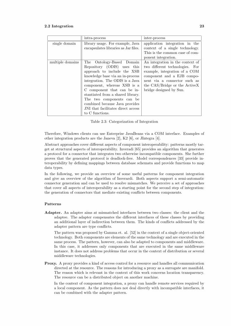
2.2 Integration 23
intra-process inter-processsingle domain library usage. For example, Java
encapsulates libraries as Jar files.application integration in thecontext of a single technology.This is the common case of com-ponent integration.
multiple domains The Ontology-Based DomainRepository (ODIS) uses thisapproach to include the XSBknowledge base via an in-processintegration. The ODIS is a Javacomponent, whereas XSB is aC component that can be in-stantiated from a shared library.The two components can becombined because Java providesJNI that facilitates direct accessto C functions.
An integration in the context oftwo different technologies. Forexample, integration of a COMcomponent and a EJB compo-nent via a connector such asthe CAS/Bridge or the ActiveXbridge designed by Sun.
Table 2.3: Categorization of Integration
Therefore, Windows clients can use Enterprise JavaBeans via a COM interface. Examples ofother integration products are the Janeva [2], K2 [6], or JIntegra [4].
Abstract approaches cover different aspects of component interoperability: patterns mostly tar-get at structural aspects of interoperability. Inveradi [65] provides an algorithm that generatesa protocol for a connector that integrates two otherwise incompatible components. She furtherproves that the generated protocol is deadlock-free. Model correspondences [33] provide in-teroperability by defining mappings between database schemata and provide functions to mapdata types.
In the following, we provide an overview of some useful patterns for component integrationand give an overview of the algorithm of Inverardi. Both aspects support a semi-automaticconnector generation and can be used to resolve mismatches. We perceive a set of approachesthat cover all aspects of interoperability as a starting point for the second step of integration:the generation of connectors that mediate existing conflicts between components.
Patterns
Adapter. An adapter aims at mismatched interfaces between two classes: the client and theadaptee. The adapter compensates the different interfaces of these classes by providingan additional layer of indirection between them. The kinds of conflicts addressed by theadapter pattern are type conflicts.
The pattern was proposed by Gamma et. al. [52] in the context of a single object-orientedtechnology. Both components are elements of the same technology and are executed in thesame process. The pattern, however, can also be adapted to components and middleware.In this case, it addresses only components that are executed in the same middlewareinstance. It does not address problems that occur in the context of distribution or severalmiddleware technologies.
Proxy. A proxy provides a kind of access control for a resource and handles all communicationdirected at the resource. The reasons for introducing a proxy as a surrogate are manifold.The reason which is relevant in the context of this work concerns location transparency.The resource can be a distributed object on another machine.
In the context of component integration, a proxy can handle remote services required bya local component. As the pattern does not deal directly with incompatible interfaces, itcan be combined with the adapter pattern.

24 Communication and Integration
Broker. The broker pattern [32] addresses the problem of managing a remote client-servercommunication. The complexity of remote communication is almost completely hiddenfrom application objects. It introduces a layer of indirection to organize the necessarymanaging tasks which handle issues such as remote object identifiers, transactions, secu-rity, location transparency, etc. The broker pattern is used in middleware systems suchas J2EE, .Net, and CORBA.
The broker introduces a proxy and a skeleton to provide local surrogates for the remoteobject. Several brokers communicate via bridges that externalize object identifiers basedon standard protocols such as IIOP.
The pattern provides a kind of standard architecture of a connector for handling commu-nication between distributed and incompatible components. It can be augmented withseveral other patterns and idioms to handle certain mismatches between client and server.
Interceptor. An interceptor11 pattern is a refinement of the proxy and the broker pattern.It mainly aims at transparently introducing additional services in a framework withoutchanging the framework. The pattern is of special interest as it is used in middlewaresystems to handle client requests for component instances. The patterns introduce inter-ceptors as well as dispatchers. A client can install custom interceptors in a frameworkinstance. The framework calls the interceptors via a dispatcher object whenever it reachesa particular state. The dispatcher calls every installed interceptor object passing a specialcontext object which encapsulates state information of the framework.
The pattern also handles the problem of mismatched services between the client and theserver object.
Different integration approaches such as Keshav and Gamble [73] or Plasil and Bures [31] usethese and additional patterns for connector specification and generation.
Protocol Integration
The algorithm of Inverardi [65] generates the protocol of a connector that provides behavioralinteroperability between otherwise incompatible components. The algorithm has the followingproperties:
• It it based on an architectural style, called ‘Connector Based Architecture’, which issimilar to the C2 style.
• It distinguishes between input and output actions, which are called requests and notifi-cations.
• It uses communication channels to denote the link between the components and theconnector that integrates them.
Regarding the integration of components from different technologies, the algorithm suffers twoproblems: First, methods are often named differently in components originating from differentsources. Consequently, correspondences must be defined between method names. Second, the‘semantics’ of methods often do not exactly match. Therefore, a complex matching betweenthe operations is necessary, which is also not covered by the algorithm.
In the following, we give a short example of the algorithm based on the Mortgage Bank exampleintroducted in Section 5.3.2. The example consists of two components, ‘BLContractMgmt’ and‘BLCalc’, which have the following process algebra expressions annotated:
11The interceptor pattern was introduced by Douglas et. al. [119]

2.2 Integration 25
ContractMgmt:R = (newContract→R1),R1= (newContract→R1
|simulate→R1).
BLCalc:Q = (getNewContract→Q1),Q1= (getNewContract→Q1
|setRate→Q2),Q2= (getNewContract→Q2
|setRate→Q2|simulation→Q2).
As the Inverardi algorithm expects input and output actions, we split the action, which rep-resents synchronous operations into an input and an output action. The input actions areannotated by α whereas the output actions are annotated as α. Both extended expressions aredefined as follows:
ContractMgmt:
R = (newContract→ newContract → R1),R1= (newContract→ newContract → R1
|simulate→ simulate → R1).
BLCalc:Q = (getNewContract→ getNewContract → Q1),Q1= (getNewContract→ getNewContract → Q1
|setRate→ setRate → Q2),Q2= (getNewContract→ getNewContract →Q2
|setRate→ setRate → Q2|simulation→ simulation → Q2).
The first step of the algorithm reverses the action labels to represent both expressions fromthe viewpoint of a connector between both components. Inverardi calls the resulting transitionsystem an AS graph.12 In the second step, each action is exchanged by a sequence of an inputaction followed by an output action. The exact rule is defined as follows:
• Each input action α is exchanged by an input action αc followed by an output action α?.Thereby ‘c’ and ‘?’ denote communication channels which are associated with components:‘c’ refers to a particular communication channel, whereas ‘?’ refers to any channel whichprovides action α. This information is used in the last step of the algorithm, which unifiesaction pairs of the form α? = αc, where ‘?’ is substituted by ‘c’.
• Each output action α is exchanged by an input action α? and an output action αc.
The resulting process descriptions are called EX graphs and are defined as follows for theexample expressions:
12We omitted the presentation of this step for this example.

26 Communication and Integration
ContractMgmt:
EXR = (newContract1 → newContract? → newContract? →newContract1 → EXR1),
EXR1 = (newContract→newContract? → newContract? →newContract1 → EXR1| simulate1 → simulate? → simulate? → simulate1 → EXR1).
BLCalc:EXQ = (getNewContract? → getNewContract2 →
getNewContract2 → getNewContract? → EXQ1),EXQ1 = (getNewContract? → getNewContrac2 →
getNewContract2 → getNewContract? → EXQ1| setRate? → setRate2 →setRate2 → setRate? → EXQ2),
EXQ2 = (getNewContract? → getNewContract2 →getNewContract2 → getNewContract? → EXQ2| setRate? → setRate2 →setRate2 → setRate? → EXQ2| simulation? → simulation? →simulation2 → simulation? → EXQ2).
The last step of the algorithm generates a connector that mediates between both processes.The step consists of a unification of the same actions from different components. Thereby, ineach step the action αc is matched with α? to yield a transition in the connector.
As mentioned above, the algorithm assumes the same action labels and does not cope withcomplex relationship between actions. However, both issues are needed to generate a connectorfor the example. The correspondences have to be defined by a developer. In the example, thefollowing two correspondences are defined:
(1) newContract ∼ getNewContract,
(2) simulate ∼ setRate → simulation.
The first correspondence fits easily in the unification algorithm proposed by Inverardi. Un-fortunately the second correspondence is not as simple to integrate in the unification processbecause the algorithm is based on the principle that a connector firstly receives an operationfrom component A and forwards another operation to component B. Therefore all action areorganized as sequences of input action that are followed by output actions and we cannot sub-stitute the correspondence for each simulated action because the connector would not supportan incoming simulated action from the ‘ContractMgmt’ component.
However, we can define another expression which represents the correspondence. This expres-sion could, for example, represent a thread in the connector. For the example, the secondcorrespondence can be defined as:
ContractMgmt:
C2 = (simulate → setRate → setRate →simulation → simulation → simulate → C2).
// the process that represents an EX-GraphCREX = (simulate? → simulate3 →
setRate3 → setRate? →setRate? → setRate3 →simulation3 → simulation? →simulation? → simulation3 →simulate3 → simulate? → CREX).

2.3 Scenarios for Integration 27
The resulting connector definition can be generated by unification of the respective action pairsas follows:
Connector:K = (newContract1 → getNewContract2 → getNewContract2 →
newContract1 → K1),K1 = (newContract1 → getNewContract2 → getNewContract2 →
newContract1 → K1| simulate1 → simulate3 → setRate3 →setRate2 → setRate2 → setRate3 →simulation3 → simulation2 → simulation2 →simulation3 → simulate3 → simulate1 → K1).
2.3 Scenarios for Integration
As the complexity of the integration scenario directly influences the intricacy of the analysisprocess, we define the simplest but still useful scenario possible: two components that arearranged in a classical client-server architecture. Figure 2.3 provides the conceptual model ofa client-server integration. The model supports all forms of integration mentioned in Section2.2.2.
Thereby, we do not restrict the forms of communication to a particular mechanism. Bothcomponents can rely on any form of communication supported by their context (see Figure2.3). The context is either given by a middleware or an operating system that hosts thecomponents.
To integrate components, a suitable third domain needs to be found which is compatible withboth component domains. A connector mediates communication between the client and theserver component on the basis of the third domain. Therefore, the connector must be virtuallyor physically part of all three domains.
TextClient ServerConnector
Domain A Domain BDomain C
Figure 2.3: Overview on the Integration Scenario
We can further imagine that the server is an existing artifact, which is either a legacy componentor a COTS, whereas the client can be either an artifact that needs to be composed with theserver or it is the specification of a component defined in a software development process.
The framework requires a UML description of both components for the analysis process. Inthe following, we give an overview on the properties of both Legacy Systems and CommercialsOff-the-Shelf and summarize techniques to create the UML specifications from these artifacts.
2.3.1 Legacy System Migration
There are several definitions of the term ‘Legacy System’ proposed in literature. For exampleBrodie&Stonebraker [29, p.3] define a legacy system as follows:
“A legacy information system is any information system that significantly resistsmodification and evolution.”
Another definition was proposed by Bennett [22, p.1]. He defines a legacy system as

28 Communication and Integration
“large software systems that we don’t know how to cope with but that are vital toour organization.”
Both definitions do not directly describe which properties render a system as a ‘legacy’. Theyalso do not directly define the meaning of ‘significantly resists modification’ or ‘to cope with’.However, summarizing their articles as well as descriptions from [27; 121] we can extract thefollowing characteristics of a legacy system:
• A legacy system is a ‘mission critical’ system of a company,
• It causes high maintenance costs as it runs on obsolete hardware and is written in anearly programming language or has no acceptable internal structure,
• It is difficult to create interfaces to communicate with external systems.
According to continuously changing business needs and the introduction of new technologies,the maintenance costs of each system tend to increase over time. Consequently, legacy systemsneed to be constantly maintained. In literature, several levels of maintenance are distinguished.According to Seacord [27; 121] maintenance can be classified into three categories: Maintenance,which refers to bug fixes and small functional improvements, modernization, which describesall kinds of system restructuring and component exchange, and system replacement.
Several methods were proposed to modernize (reengineer) a legacy system into a new sys-tem. These methods can mainly be classified into ‘redevelopment’ and incremental approaches:Redevelopment, also known as ‘Big Bang’ or ‘Cold Turkey’ approaches create a new system.Thereby, they completely exchange both systems. Redevelopment has a high risk of failure, asthe behavior of both the new and old system need to be identical to the context in which they areexecuted. Incremental approach such as ‘Little Chicken’ [29], ‘Butterfly’ [27] or ‘Risk-ManagedModernization (Horseshoe Model)’ [121] exchange or reengineer systems in small steps, whichresult in lower risks for the stakeholders.
Modernization can be realized by using a number of techniques such as the ones described bySeacord et. al. [121, pp.10-17]:
Retargeting refers to an exchange of the hardware of a system. The approach aims at costreduction as old hardware often implies expensive maintenance costs and at the sametime limited capabilities in comparison with newer systems. The application is portedunchanged to the new hardware. The advantages depend on the enhanced capabilities ofthe new hardware.
Revamping exchanges the User Interface (UI) of an application. The advantage of the ap-proach relates to newer front-ends that have enhanced capabilities in comparison withthe original UI. Additionally, the modern UIs propose cheaper maintenance costs as theyoften use common approaches such as web browsers or standard APIs.
Screen scraping is a particular approach of revamping, which wraps the old functionalityin modern UIs. Unfortunately, this does not change user guidance.
Integration of Commercials Off-the-Shelf replace system parts. Thereby, COTS are ob-tained from the market to improve quality and reliability. A limitation of COTS relatesto their standardization, which becomes necessary to address a broader market. At it isnot always possible to customize COTS for a company’s needs, using them often requirespartial changes of the architecture or of the existing system environment. Therefore, theirusage benefits and their introduced costs need to be exactly calculated.
2.3.2 Commercials Off-The-Shelf
The idea of reuse involves composing components rather than reinventing and reimplementingexisting artifacts. In this sense, components are often termed as COTS that can be obtained

2.3 Scenarios for Integration 29
from a component market, as was first proposed by McIlroy [91] in 1968. Unfortunately, thereis not yet a common understanding of what exactly constitutes COTS. An overview of populardefinitions is provided by the Data and Analysis Center for Software, which defines a classi-fication matrix [101] for COTS. According to that classification, we can define a commercialoff-the-shelf as
“a reusable black-box unit with explicit context dependencies that originates froman external source and allows only little or no modification.”
Unfortunately, COTS reuse is not as easy to be realized as reuse of ICs. Therefore, a marketplacegenerally does not exist yet. The Software Engineering Institute (SEI) points out some reasonsfor its non-existence [35]. It describes a marketplace as
“characterized by a vast array of products and product claims, extreme quality andcapability differences between products, and many product incompatibilities, evenwhen they purport to adhere to the same standards.”
Concerning this statement, there are two major problems of COTS integration: The first prob-lem concerns selection and identification of COTS that offer required functionality and quality.The second problem concerns incompatibilities among current technologies that make it difficultto compose COTS.
Component Selection
How do we find a suitable component? This question is a prerequisite for integration. Itinvolves identification of components that are likely to correspond with the stated require-ments. Today, this is difficult to achieve because of several problems: First, most existingcomponents are not registered in a repository. Second, there are only a few repositoriesavailable. Third, there is no standard format of component description. However, thereare several approaches that aim to provide solutions to these problems. A promising ap-proach is the Web Service [36] standard. It provides a format to describe services as wellas a standard for repositories.
How do we select the best-suited COTS for integration? Component selection refers tothe process of choosing the most adequate COTS for a stakeholder’s requirements. Theseoften refer to quality attributes such as performance, maintainability, conformance, etc. Itis possible that several COTS are appropriate for system integration, but are differentlywell suited for different requirements. Today, there is practically no support to selectCOTS based on quality attributes.13
Component Integration
How do we integrate COTS and the software development process? COTS are exist-ing artifacts, whereas software development is concerned with the design of a system. Adesign often represents a platform independent model of a system that is not bound toa specific technology. Alternatively, it aims for a particular technology, but is placed onan abstraction level that does not cover implementation details. COTS are specified in atechnology-specific format. Thus, there is a mismatch in the abstraction levels betweenCOTS and the objects regarded in software development.
How do we compare components? Comparison is an operation that identifies the similar-ities and differences between components. Comparison between COTS of different tech-nologies proves difficult, as considerable differences exist in their specifications. Anotherproblem concerns the degree of detail of those specifications. Components are rarely fullyspecified in current technologies. Some facts are stated implicitly or not at all.
13Refer, for example, to [142].

30 Communication and Integration
For both reasons, integration approaches normally only consider COTS based on the sametechnology. Integration of components that originate in heterogeneous systems is avoided, as itis a difficult and time-consuming task.
2.3.3 Analyzing Existing Software
Reconstruction of legacy systems is an important concern in system reengineering. It is alsoimportant for COTS that are not fully specified. Reconstruction of a system’s architecture isa complex task which is outside the scope of this work. However, as it is a precondition for aUML specification of a system, we briefly summarize common analysis methods as defined bySeacord [121, pp.61-64] that aim at source code analysis:
Static Program Analysis includes techniques to generate reports of the structure of ele-ments and the relationships between elements. Reports include for example function callhierarchies, type hierarchies and usage/dependency relationships. The information ex-tracted via static program analysis is valuable to extract architectural descriptions of asystem. Unfortunately, static analysis cannot cover all necessary aspects for architecturaldescriptions, as some issues of a program are only fixed at program execution. This in-cludes late binding, function parameters as well as dynamic configuration of components,which are often used in middleware systems.
Dynamic Analysis generates reports of elements and their relationships, but from a dynamic(runtime) perspective. Therefore, techniques such as profiling are used to recover thenecessary information. Profiling analyses the control flow of a running system. It providesinformation regarding the order of operation calls.
Slicing. Program slicing works on a component’s source code. It investigates programs bymarking or extracting statements that directly concern the properties of interest.
Redocumentation is a manual approach to code analysis. A developer analyses the func-tionality of a program and creates appropriate documentation. However, the amount ofcode that a developer can handle is limited. According to Seacord [121] a developer canhandle code up to a size of 50,000 lines.
Refactoring is a popular technique to improve code quality and functionality by methodicallymodifying the internal structure of code. Fowler [49] provides a catalog of refactoringtechniques - similar to the pattern catalog of Gamma et. al. - that describes a number ofuseful code transformations.
The presented methods aim at an analysis of a system’s source code. They provide statistics,reports, or descriptions on the source. An architectural reconstruction, however, requires thecreation of higher level abstractions from these basic results. This mainly includes extraction ofarchitectural views, which describes the system from different perspectives such as configurationof the system’s components or the used component types and their dependencies. As describedin [121] the extraction of architectural views is a highly iterative process that involves interactionof the analysts and the stakeholder.
For a more complete description of system renovation and transformation, Seacord et. al. pro-posed the Horseshoe model [121]. The model distinguishes three main processes: reconstruction,transformation and refinement. All processes are required for legacy system migration. Recon-struction aims at system analysis and is therefore a prerequisite for component analysis. Theprocess itself is outside the scope of this work. The transformation process covers program andstructure transformation and is supported by the framework. The refinement process is par-tially supported. The framework supports parameterized model transformation,whereas codegeneration is unsupported.

2.4 Foundations for Component Specification 31
2.4 Foundations for Component Specification
This section gives an overview of software architecture as well as on type and behavior descrip-tions. Software architecture provides the basis for a canonical component description, whereastypes and behavior provide the basis for the ‘traditional’ conflict analysis. Types are used inmost middleware technologies. In contrast, behavior descriptions are often not supported bythese technologies as they are more difficult to handle. However, for both techniques a consid-erable amount of knowledge exists, so that they provide the basis for deciding structural andsemantical interoperability. In the next chapter, we augment both concepts with reasoning oncommunication properties.
2.4.1 Software Architecture
The term ‘Software Architecture’ is used in several fields of software engineering with slightlydifferent meanings. This led to numerous definitions of this term (see [3]). In the context ofthis paper, we define Software Architecture as proposed by Bass et. al.:
Definition 10 (Software Architecture) “The software architecture of a program or com-puting system is the structure or structures of the system, which comprise software elements,the externally visible properties of those elements, and the relationships among them” [20, p.21].
This definition precisely defines the basic elements of software architecture: components, theirrelationships, systems of these elements as well as properties. On the other hand, it is anabstract definition as it does not exactly state the nature of components and their relationships.Thus, we are free to interpret these terms, which we will do in the following subsections.
Software architecture focuses on a high-level viewpoint of software systems. This captures earlydesign decisions, but leaves implementation details undefined. This, in turn, provides severaladvantages: a high-level description can be easily understood, it can be used in negotiationswith stakeholders, it documents early design decisions, it can be reused like a design pattern,etc.
A general problem of software architecture is linked to the informal description of systems asimprecise box and line diagrams. These frequently used representations often provide no se-mantics of the meanings of the constructs used. This impedes a system’s analysis, rendering theproposed advantages useless. To enable formal analysis, Architectural Description Languages(ADL) as semi formal languages were proposed. Besides ADLs, other efforts for formalizationand standardization such as the IEEE 1471-2000 [63] or proposals for documentations such as[38] exist, but are not in the focus of this work.
Software architecture also aims to classify systems based on certain characteristics. This isdone by defining a set of (functional) properties such as synchronicity of communication flows,topology of a system, continuity of data flows, binding time of components, delivery policy ofmessages, modes of data transfer, transactional secured interactions and many more. For amore complete overview refer to [44; 95; 123]. A set of these properties restricted to particularvalues constitutes an architectural style:
Definition 11 (Architectural Style) “An architectural style is a description of componenttypes and a pattern of their runtime control and/or data transfer. A style can be thought of asa set of constraints on the component types and their pattern of interaction” [19, p.25].
In this definition the term ‘type’ is interpreted as a set of property/value pairs independentfrom a component’s interface. Similar to types, properties constrain architectural elements.Thus, they need to be taken into account during any composition effort. A conflict analysistherefore requires a classification of relevant properties and property values. We describe thisissue in Chapter 4.
32 Communication and Integration
In the following, we introduce the standard elements that are of interest for the framework.Thereby, we first present commonly used definitions of each term and discuss these in the lightof component composition and conflict identification.
Component
Components are generally perceived as elements that perform the actual calculations in a sys-tem, whereas connectors specify the communication that takes place between components. Acommon definition that emphasizes the functional viewpoint of a component was proposed byShaw [124, p.165]:
“Component are the loci of computation and state.”
Unfortunately, this very abstract definition does not mention any technology dependencies, nordoes it clarify the constituting parts of a component. Moreover, in the context of componentintegration, computation and state as mentioned in this definition are not directly of interest.Both are hidden in the component body (black box view) and are interpreted no further. Solelythe interconnection points of a component as well as its associated properties are of interest.
A better suited definition of the term ‘component’ focuses on the actual configuration of com-ponents at runtime. Here, the term ‘component’ denotes binary artifacts, i.e. executables thatare instantiated on a particular node. Thus, each component represents an instance such as aweb browser running on a computer. A system configuration then consists of several relatedand communicating component instances. The OMG proposes this kind of view in UML 1.x.They define
“A component represents a modular, deployable, and replaceable part of a systemthat encapsulates implementation and exposes a set of interfaces. [...]
A component may be implemented by one or more artifacts, such as binary, exe-cutable, or script files” [108, p.36].
Software architecture also chooses this view if particular properties of runtime systems suchas security or performance are of interest. Here, a runtime system describes the layout ofparticipating components, the allowed types of components and their properties of interest.Furthermore, software architecture investigates components in a module view to describe thestructure of a component type as well as in an allocation view to describe the physical instan-tiation of a system [38].
The former definition indicates that the interaction points are determined by interfaces. How-ever, it does not define the exact requirements of these interfaces. A more exact definition, inthis respect, was proposed by Szyperski [132, p.34]:
“A component is a unit of composition with contractually specified interfaces andexplicit context dependencies only. A software component can be deployed inde-pendently and is subject to composition by third parties. ”
This definition interprets interconnection points as contracts and ‘context dependencies’. Con-tracts are attached to interface definitions and place additional constraints on the usage of acomponent. They are stated between components on the same level of abstraction. We in-terpret ‘context dependencies’ as implicit relations to components located at another level ofabstraction. For example, a context dependency relates application components to componentssuch as containers, which host these components, required databases, or the underlying OS.
A properly defined component composition, however, requires resolving these ‘context depen-dencies’. Every interaction needs to be explicitly expressed via interfaces. A communicationbetween two Enterprise JavaBeans, for example, needs to take into account the underlying
2.4 Foundations for Component Specification 33
container. Consequently, the container needs to be modeled as a ‘canonic’ component14, too.Furthermore, the container cannot be instantiated without an underlying operating system andso on. For a more detailed discussion refer to Section 1.2.
OMG’s UML 2.0 proposal more precisely describes ‘context dependencies’. It also distinguishesbetween a component type and a component instance:
“A component represents a modular part of a system that encapsulates its contentsand whose manifestations is replaceable within its environment. A component de-fines its behavior in terms of provided and required interfaces. As such, a componentserves as a type, whose conformance is defined by these provided and required inter-faces (encompassing both their static as well as dynamic semantics)” [104, p.110].
This definition is closely related to our definition but does not distinguish different abstractionlayers as used for model-driven development. In the light of the above remarks, we define acomponent as follows:
Definition 12 (Component) A platform independent (canonic) component (PIC) is an ab-stract entity of a particular type that consists of a body and ‘requires’ and ‘provides’ interfaces,which are defined as contracts and properties associated with these parts. Properties define thecontext of a component as defined in Definition 6. A component is independent as it has nohidden dependencies besides the ones stated by the interfaces.
A platform specific component (PSC) has the same structure as a PIC. Different from a PIC,it is specified in terms of its associated platform: A PSC’s interfaces are defined in the typesystem of the platform and its properties - the context of the component - must correspond tothe abilities and requirements of its platform (domain).
‘Provides’ interfaces determine the exposed services of a component. ‘Requires’ interfaces iden-tify demands of a component that are used in the body to realize a component’s services.Thereby, the body represents a black box. Properties describe the context of a component. Inthis work, a component’s context describes the communication mechanism15 the componentdepends on. Interactions between components are defined exclusively via connectors, whichrepresent the ‘relationships’ within a system configuration.
Component types are defined in the metamodel of the Ontology-Based Framework for compo-nent analysis and transformation, which is defined in Section 5.1. Component types describesthe vocabulary from which system configurations consisting of instances from these types canbe built. A system configuration describes the physical layout and the properties of a system.
Connector
The word ‘connector’ originates in the Latin word ‘connectere’ [Merriam-Webster], which ba-sically means ‘to bind’. Following that definition, the term refers to a relation between com-ponents. In software architecture, that relation is represented by a first-class architecturalelement, the connector. A connector manages the control flow as well as the data flow betweencomponents. Thereby, it takes into account all dependencies that are relevant for an interaction.In other words, communication is exclusively conducted via connectors.
A popular definition of the term ‘connector’ was proposed by Shaw [124, p.165]:
“Connectors are the loci of relations among components.”
This definition expresses the above-mentioned role of a connector. However, it leaves manyunanswered questions:
14At the same time the container is a connector between these Enterprise JavaBeans.15Communication mechanisms are described by a taxonomy, which is defined in Chapter 4.
34 Communication and Integration
• What is the internal structure of a connector, if any?
• Which parts of a connector are mandatory?
• Which properties are relevant to classify communication?
• How are these properties attached to connectors?
• How do these properties characterize an architectural style?
• Which kinds of connectors exist in software systems?
We do not want to discuss all of these questions in this section. However, we want to point outtwo different viewpoints of how connectors are perceived: from software architecture and fromtechnology specific settings.
Software Architecture View. Software architecture focuses on the properties of connectors,which are used for analysis purposes. Thus, at an architectural level, a connector is treatedas a structured element that describes a link between components. This link is associatedwith particular property values. These determine which kind of communication can take placebetween components in a system bound by a particular connector. Properties are classifiedinto taxonomies such as the one by Medvidovic and Mehta [93–95], who try to identify existingconnector types. Furthermore, connectors need to explicitly provide and require interfaces, inorder to associate types and behavior. This information is needed for a formal description of asystem. It is, however, of no importance how a connector is realized in a particular technology.
Besides simply providing communication resources, a connector is also able to handle severalextra tasks. It can be used to modify the behavior as well as the data structure of passedinformation. It also allows adding services such as transaction, security, or replication. Thesetasks can be provided transparently.
Connectors are often used to overcome mismatches between components. In this regard, severalpatterns were developed in order to describe the role of connectors in a composition on thearchitectural level [73]. These patterns include proxies, bridges, mediators, links, etc.
Middleware View. Middleware aims for simplified development of large complex systems.Therefore, each middleware technology provides a high-level framework as well as a number ofservices that can be used to easily access the underlying communication and interaction mech-anism. At a minimum, middleware supports a particular application domain and connectorsthat reflect the needs of that domain. These connectors are well integrated into the technologiesand can be handled almost transparently. For example, a complex connector such as a remoteprocedure call can almost be treated like a simple local call. A developer does not need towrite complex code to use remote calls. Thus, connectors are often not explicitly handled intechnology dependent component descriptions, but hidden within middleware. In summary,middleware focuses only on a small subset of connectors, which is often not explicitly modeledbut can be customized to a certain degree.
Several middleware systems allow customizing the behavior of connections between components.This mainly includes, specifying additional services such as logging and load balancing. Sometechnologies provide a kind of ‘interceptor’ to attach arbitrary user defined services. As moreconcrete examples, the JBoss Server [1] supports a call-back interface to intercept method callsto Enterprise JavaBeans. The BEA WebLogic Server [21] provides a call-back interface in orderto specify customized load balancing. Microsoft offers integration techniques, so-called hooks,which easily and transparently allow addition of interception code into existing software [71; 80].However, customization is restricted to prefabricated connector types.
Definition 13 (Connector) A connector at a platform-independent level is a first-class entitythat links components based on their provided and required interfaces. It consists of interfaces

2.4 Foundations for Component Specification 35
that exactly match the component interfaces, a body that establishes the communication, andassociated properties that describe the kind of communication that the connector facilitates. Aplatform specific connector links platform specific components.
Interface
As discussed above, interfaces define the interaction points of a component with its environment.Accordingly, they are often defined as entities
“. . . for specifying a service. An interface gives a name to a collection of operationsthat work together to carry out some logically interesting behavior of a system or apart of a system” [76, p.2].
However, this definition does not mention which functionality an interface exactly has to de-scribe. As mentioned previously, Szyperski exactly defines the role of an interface as a kind ofcontract between a ‘supplier’ and a ‘consumer’. He defines a contract as
“. . . a specification attached to an interface that mutually binds the clients andproviders of that interface” [132, p.370].
We take up his position and interpret an interface similar to an ’Abstract Data Type’ (ADT)16.An ADT consists of a set of operations, invariants and pre- and post-conditions. Operationsconsist of a number of arguments, a return type and a set of possible exceptions. Argumentsconsist of a name, a type, a direction, and an optional default value. Constraints define statesthat have to be valid immediately before or after the end of the execution of an operation.These constraints can be expressed in different languages such as Z [28] or Larch [59].
Almost all current middleware technologies use or support interfaces for component specifica-tions. They either offer an Interface Description Language (IDL) or define interfaces directlyin an associated programming language. IDLs are trimmed according to the requirements ofeach middleware. However, most IDLs offer elements such as operations or attributes that weperceive as ‘canonic’elements of every technology.
Unfortunately, middleware technologies often only specify structural aspects - types - of in-terfaces. They leave out behavior and properties. Thus almost all interface specifications areincomplete as they cannot be used to identify behavioral conflicts or mismatched assumptionson the environment.
Ports and Roles
Regarding system configurations, interfaces are not directly associated with components andconnectors. In fact, components are related via ports with interfaces, whereas connectors arerelated via roles with interfaces. The main reason behind this indirection concerns multiplicitiesof interfaces. Ports and roles allow defining how many interfaces can be bound by a component.Another reason concerns binding of behavioral specifications. In principle, a component or aconnector can simultaneously execute a protocol in each port or role. Additionally, ports can beused to describe communication requirements of connectors and components. In this respect,a connector can be described with different communication requirements on each port. This isthe basis to describe connections between different middleware technologies.
In the framework, ports and port types are used to define behavior (protocols) as well asproperties (see Sections 5.1.3 and 4). We do not distinguish roles and ports in this workbecause of the relativity of components and connectors.
16Contrary to an ADT, an interface provides no implementation.

36 Communication and Integration
System
A system describes a graph of interconnected components and connectors. These elementsare bound via ports and roles. A composition requires a match between ports and roles andtherefore between the interfaces associated with these elements
2.4.2 A Type System for Components
Type systems are well known in the context of programming languages, where they are used tostatically ensure the correctness of statements and whole programs. A typed language providesconsiderable advantages compared to untyped languages, as it can be automatically checkedwhether a statement such as ’if x+1 then ’a’ else 1 ’ is correct or not. This is achieved byalgorithms, which exploit a predefined typing relation to deduce the type for a statement. Inthis respect, it is important to notice that types can only be used to prove the absence of certainkinds of ‘bad behavior’. They cannot ensure ‘correctness’.
In our context, we use types to check if two components can be composed or not. More precisely,we are interested in the question of whether there are type conflicts between components selectedfor composition. In the following, we will trace back this question to the determination ofwhether the interfaces of both components are in a subtype relationship. According to ourdefinition of a component, this is sufficient to guarantee structural compliance.
In the remainder of this section, we will briefly define the terms ‘type’ and ‘type system’. Basedon these, we will explain the properties of a subtype relationship between types. Furthermore,we will investigate the problem of mapping type systems of several middleware systems into asingle system.
Type Systems
In order to clarify the term ‘type system’, we first precisely define the meaning of a type. In thefollowing, we will perceive a type as a set of values, where each value needs to satisfy particularproperties. For example, a 16 bit unsigned integer type is a set of natural numbers that isconstrained by a maximal (65535) boundary and a minimal (0) boundary. In the following, wedefine a type by a quotation from Carelli/Wegner:
Definition 14 (Type) “There is a universe V of all values, containing simple values likeintegers, data structures like pairs, records and variants, and functions. . . .A type is a set ofelements of V ” [34, p.14].
They use this definition to introduce type systems. Please note that this is a simplified view ontypes. Cardelli/Wegner describe a far more complex theory of types, which is based on ‘Ideals’,polymorphic types, etc. However, we do not address these advanced properties as they are notrequired to describe most object-oriented middleware and therefore choose to use the abovedefinition.
Based on this definition, a type system consists of a set of types and a number of rules thatexpress relationships between types. Each type of a type system is either a basic type, whichhas no internal structure (as far as the type system is concerned) or a composite type, such asa record or a list. A type system assigns a single type to each well-formed term if a derivationtree exists, or fails if there is no deduction for a term. In this respect, we define a type systemaccording to Pierce as follows:
Definition 15 (Type System) “A type system is a tractable syntactic method for provingthe absence of certain program behaviors by classifying phrases according to the kinds of valuesthey compute” [112, p.1].
2.4 Foundations for Component Specification 37
As an example of a simple type system, we present the three typing rules of the pure simplytyped λ-calculus as defined by Pierce [112]:
x : T ∈ ΓΓ ` x : T
(2.1)
Γ, x : T1 ` t2 : T2
Γ ` λx : T1.t2 : T1 → T2(2.2)
Γ ` t1 : T11 → T12 Γ ` t2 : T11
Γ ` t1 t2 : T12(2.3)
In the simply typed λ-calculus a single function type exists T ::= T → T . The syntax of theλ-calculus is described by only three kinds of valid terms:
(1) Variables: x,
(2) Abstractions: λx : T.t, where x : T represent a typed variable,
(3) Applications: t t, the application of two terms.
The ‘typing context (Γ)’ as defined in the typing rules from Pierce, is basically a set of mappingsfrom free variable names to their associated types. Thus, the rule ‘Γ ` t : T ’ states that termt has type T , if all free variables in t are substituted by the Types assumed under the actualtyping context Γ. This technique of annotations is used in explicitly typed languages.
Subtype Relationship
A type system deduces the type of a term according to a set of given inference rules. However,these rules often are stated too strictly. For example, the following expression is not well typed(without subtyping),
void foo() {long x;int y = 1;
x = y;}
because the types ‘long’ and ‘int’ are not identical. Nevertheless, it is obvious that it is safe toassign the value of y to x.
In order to construct more flexible type systems, which allow type deductions of ‘safe’ terms, thesubtype relationship was introduced. Informally, a subtype corresponds to a subset relationship.Thus, we can substitute the value of y for x because the set of integers is a subset of the set oflong integers.
We define a subtype as follows:
Definition 16 (Subtype) A subtype is a binary relationship between types, written S � T thatindicates that S can be substituted for T . It consists of a set of direct relations between basictypes and inference rules for complex types. A subtype relationship is reflexive and transitive.
According to this definition, separate inference rules need to be specified for each complex type.Additionally, there are two basic rules: a reflexive and a transitive rule. The first rule statesthat every type is a subtype of its self:
38 Communication and Integration
T � T
The second defines a transitive relationship between types: if S is a subtype of U and U is asubtype of T then S is also a subtype of T.
S � U U � T
S � T
Both rules are standard assumptions used for subtyping and were taken from Pierce [112].Pierce additionally introduces rules for common complex data types such as records, tuples,variants, lists, references, etc. In Section 5.1.2, we use his definitions for functions and records.These rules constitute the foundation for the subtype relationships of components, connectors,and interfaces.
A subtype relationship can be defined with several semantics and can have more sophisticatedproperties as indicated here. A more complete introduction is given, for example, by [34; 112].
Type Conversion Between Different Type Systems
A major problem for the framework concerns different type systems of middleware technologies.These differ in properties of basic types as well as in supported complex types. For example:a Java ‘int’ is defined as a 32 bit type whereas a C ‘int’ can also be defined as a 16 bit type.Furthermore, C supports pointers whereas Java does not, etc.
In general, there are two approaches to map types between different technologies. We canprovide one-to-one mapping rules that map between every technology or we can introduce asingle type system that participates in each mapping. We refer to the latter approach as a ‘star’schema, because a single type system is in the center of each mapping. We use this approachand provide a ‘minimal’ type system for Ontology-Based Framework for component analysisand transformation (OBF), which we use for conflict analysis and model transformation. Itconsists of only these types that are needed to decide for conflicts between components. Theother alternative would introduce additional costs as there are more connections to maintain.
Furthermore, the proposed approach fits well into a model-driven development that supportsabstractions and refinements between PIM and PSM level entities (see Figure 3.1). A PIM isrelated to several PSMs. Correspondingly, a platform independent component model is relatedto several platform specific component models.
2.4.3 Formal Languages for Behavior Specification
According to Lamsweerde [141, p.149], a formal specification
“is the expression in some formal language and at some level of abstraction, of acollection of properties some system should satisfy.”
This definition neither prescribes the kind of system that is being specified nor the kinds ofproperties of interest. This leaves room to interpret the meaning of a system: it can range froma single component to a complex configuration of components within a system and its envi-ronment. Properties of interest can be summarized as functional properties and non-functionalproperties such as security and performance.
According to Wing [148], a formal specification language can be informally defined as a languagethat
“provides a notation (its syntactic domain), a universe of objects (its semanticdomain), and a precise rule, defining which objects satisfy each specification. Aspecification is [then] a sentence written in terms of the elements of the syntacticdomain” [148, p.10].
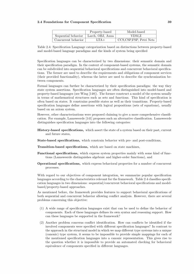
2.4 Foundations for Component Specification 39
Property-based Model-basedSequential behavior Larch, OBJ, Anna VDM,ZConcurrent behavior LTA+ CCS,CSP,FSP, Petri Nets
Table 2.4: Specification Language categorization based on distinctions between property-basedand model-based language paradigms and the kinds of system being specified
Specification languages can be characterized by two dimensions: their semantic domain andtheir specification paradigm. In the context of component-based systems, the semantic domaincan be subdivided into sequential behavioral specifications and concurrent behavioral specifica-tions. The former are used to describe the requirements and obligations of component services(their provided functionality), whereas the latter are used to describe the synchronization be-tween components.
Formal languages can further be characterized by their specification paradigm: the way theystate system assertions. Specification languages are often distinguished into model-based andproperty-based languages (see Wing [148]). The former construct a model of the system usuallyin terms of mathematical structures such as sets and functions. This kind of specification isoften based on states. It constrains possible states as well as their transitions. Property-basedspecification languages define assertions with logical propositions (sets of equations), usuallybased on an axiom system.
However, other characterizations were proposed claiming to give a more comprehensive classifi-cation. For example, Lamsweerde [141] proposes such an alternative classification. Lamsweerdedistinguishes specification languages into the following categories:
History-based specifications, which assert the state of a system based on their past, currentand future states,
State-based specifications, which constrain behavior with pre- and post-conditions,
Transition-based specifications, which are based on state machines,
Functional specifications, which express system properties mainly with some kind of func-tions (Lamsweerde distinguishes algebraic and higher-order functions), and
Operational specifications, which express behavioral properties for a number of concurrentprocesses.
With regard to our objectives of component integration, we summarize popular specificationlanguages according to the characteristics relevant for the framework. Table 2.4 classifies specifi-cation languages in two dimensions: sequential/concurrent behavioral specifications and model-based/property-based approaches.
As mentioned before, the framework provides features to support behavioral specifications ofboth sequential and concurrent behavior allowing conflict analysis. However, there are severalproblems concerning this objective:
(1) A wide range of specification languages exist that can be used to define the behavior ofcomponents. Each of these languages defines its own syntax and reasoning support. Howcan these languages be supported in the framework?
(2) Another problem concerns conflict identification. How can conflicts be identified if theinvolved components were specified with different specification languages? In contrast tothe approach in the structural model in which we map different type systems into a unique(canonic) type system, it seems to be impossible to provide simple mappings for each ofthe mentioned specification languages into a canonic representation. This gives rise tothe question whether it is impossible to provide an automated checking for behavioralequivalence of components specified in different languages.

40 Communication and Integration
In response to the first question, we equipped the framework with elements to handle sequentialand concurrent behavioral specifications. As we perceive the framework as a customizable tool,we do not enforce a fixed specification language. It is up to the user to instantiate the frameworkwith appropriate specification languages and to provide mappings between different languages.Thus, it is possible to use any of the languages mentioned above if the constraints can beascribed to components and connectors using the given framework classes.
Regarding the second question, we do not believe that an ultimate solution exists. However, wedesigned the framework to at least partially solve this challenge for concurrent specifications.As can be seen from Table 2.4, most popular specification languages for concurrent behaviorare model-based approaches. More precisely, they are often based on automata theory. If theseautomata are interpreted as process graphs, they can be checked for simulation and bisimu-lation equivalence. These equivalence relations compare the behavior of concurrent executingprocesses.

Part II
Framework for ComponentConflict Analysis
41


Chapter 3
Approach for Conflict Analysis
This chapter describes our approach to conflict analysis of software components, which alwayscompares two components for compatibility. Section 3.1 starts with a definition of requirementsfor a conflict integration framework and presents the chosen technologies that satisfy theserequirements. Section 3.2 provides an overview of the framework’s architecture that fuses onthe presented technologies and meets the objectives stated in the introduction. Based on theframework architecture and the technologies presented in Section 3.1, Section 3.3 introducestwo processes for component analysis, and transformations are presented. These describe themajor activities supported by the framework.
3.1 Technologies for the Conflict Analysis Framework
In order to achieve our objective of component analysis, we impose the following five require-ments that must be provided by a conflict analysis framework:
• Definition of a canonical component model that allows describing important aspects ofcomponents of different technologies. The model constitutes the basis for conflict analysis.
• Creation of an abstraction function that translates platform specific component descrip-tions into the canonical component model.
• Proposition of conflict analysis functionality that identifies the most relevant conflictsregarding an integration of two components.
• Creation of refinement functionality to create platform specfic component and connectorspecifications from an abstract model.
• Integration in a UML-based software development process.
As mentioned before, each requirement alone can be satisfied by using a standard technologyor language. For example, UML is the de facto modeling language, whereas ADLs providecanonic representations of components and connectors. However, neither UML nor ADLs di-rectly support reasoning, which instead is provided for by deductive programming languages.Furthermore, ADLs are often defined in proprietary formats and are not supported by a widerange of tools. Model-Driven Development (MDD) supports models on several abstraction lay-ers. It also supports model transformations. However, the MDA, which is the standard MDDarchitecture, currently lacks a model transformation language. Furthermore, it is not compat-ible with ADLs. Nevertheless, we believe that combinations of these technologies are able tofulfil all these prerequisites together. We propose the following technology combination:
(1) UML as a front-end modeling language for the end-user.
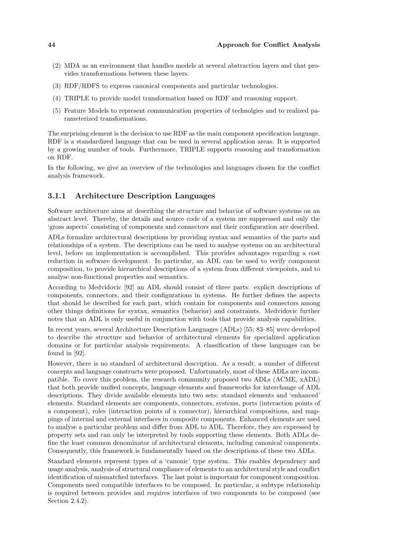
44 Approach for Conflict Analysis
(2) MDA as an environment that handles models at several abstraction layers and that pro-vides transformations between these layers.
(3) RDF/RDFS to express canonical components and particular technologies.
(4) TRIPLE to provide model transformation based on RDF and reasoning support.
(5) Feature Models to represent communication properties of technolgies and to realized pa-rameterized transformations.
The surprising element is the decision to use RDF as the main component specification language.RDF is a standardized language that can be used in several application areas. It is supportedby a growing number of tools. Furthermore, TRIPLE supports reasoning and transformationon RDF.
In the following, we give an overview of the technologies and languages chosen for the conflictanalysis framework.
3.1.1 Architecture Description Languages
Software architecture aims at describing the structure and behavior of software systems on anabstract level. Thereby, the details and source code of a system are suppressed and only the‘gross aspects’ consisting of components and connectors and their configuration are described.
ADLs formalize architectural descriptions by providing syntax and semantics of the parts andrelationships of a system. The descriptions can be used to analyse systems on an architecturallevel, before an implementation is accomplished. This provides advantages regarding a costreduction in software development. In particular, an ADL can be used to verify componentcomposition, to provide hierarchical descriptions of a system from different viewpoints, and toanalyse non-functional properties and semantics.
According to Medvidovic [92] an ADL should consist of three parts: explicit descriptions ofcomponents, connectors, and their configurations in systems. He further defines the aspectsthat should be described for each part, which contain for components and connectors amongother things definitions for syntax, semantics (behavior) and constraints. Medvidovic furthernotes that an ADL is only useful in conjunction with tools that provide analysis capabilities.
In recent years, several Architecture Description Languages (ADLs) [55; 83–85] were developedto describe the structure and behavior of architectural elements for specialized applicationdomains or for particular analysis requirements. A classification of these languages can befound in [92].
However, there is no standard of architectural description. As a result, a number of differentconcepts and language constructs were proposed. Unfortunately, most of these ADLs are incom-patible. To cover this problem, the research community proposed two ADLs (ACME, xADL)that both provide unified concepts, language elements and frameworks for interchange of ADLdescriptions. They divide available elements into two sets: standard elements and ‘enhanced’elements. Standard elements are components, connectors, systems, ports (interaction points ofa component), roles (interaction points of a connector), hierarchical compositions, and map-pings of internal and external interfaces in composite components. Enhanced elements are usedto analyse a particular problem and differ from ADL to ADL. Therefore, they are expressed byproperty sets and can only be interpreted by tools supporting these elements. Both ADLs de-fine the least common denominator of architectural elements, including canonical components.Consequently, this framework is fundamentally based on the descriptions of these two ADLs.
Standard elements represent types of a ‘canonic’ type system. This enables dependency andusage analysis, analysis of structural compliance of elements to an architectural style and conflictidentification of mismatched interfaces. The last point is important for component composition.Components need compatible interfaces to be composed. In particular, a subtype relationshipis required between provides and requires interfaces of two components to be composed (seeSection 2.4.2).
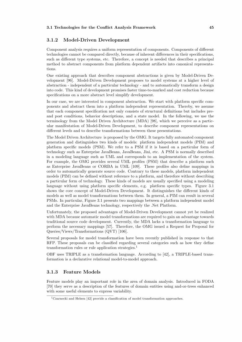
3.1 Technologies for the Conflict Analysis Framework 45
3.1.2 Model-Driven Development
Component analysis requires a uniform representation of components. Components of differenttechnologies cannot be compared directly, because of inherent differences in their specifications,such as different type systems, etc. Therefore, a concept is needed that describes a principalmethod to abstract components from platform dependent artifacts into canonical representa-tions.
One existing approach that describes component abstractions is given by Model-Driven De-velopment [96]. Model-Driven Development proposes to model systems at a higher level ofabstraction - independent of a particular technology - and to automatically transform a designinto code. This kind of development promises faster time-to-marked and cost reduction becausespecifications on a more abstract level simplify development.
In our case, we are interested in component abstraction. We start with platform specific com-ponents and abstract them into a platform independent representation. Thereby, we assumethat each component specification not only consists of structural definitions but includes pre-and post conditions, behavior descriptions, and a state model. In the following, we use theterminology from the Model Driven Architecture (MDA) [98], which we perceive as a partic-ular manifestation of Model-Driven Development, to describe component representations ondifferent levels and to describe transformations between these presentations.
The Model Driven Architecture is proposed by the OMG. It targets fully automated componentgeneration and distinguishes two kinds of models: platform independent models (PIM) andplatform specific models (PSM). We refer to a PSM if it is based on a particular form oftechnology such as Enterprise JavaBeans, JavaBeans, Jini, etc. A PSM is normally describedin a modeling language such as UML and corresponds to an implementation of the system.For example, the OMG provides several UML profiles (PSM) that describe a platform suchas Enterprise JavaBeans or CORBA in UML [109]. These profiles also define mappings inorder to automatically generate source code. Contrary to these models, platform independentmodels (PIM) can be defined without reference to a platform, and therefore without describinga particular form of technology. These kinds of models are usually specified using a modelinglanguage without using platform specific elements, e.g. platform specific types. Figure 3.1shows the core concept of Model-Driven Development. It distinguishes the different kinds ofmodels as well as model transformations between them. In general, a PIM can result in severalPSMs. In particular, Figure 3.1 presents two mappings between a platform independent modeland the Enterprise JavaBeans technology, respectively the .Net Platform.
Unfortunately, the proposed advantages of Model-Driven Development cannot yet be realizedwith MDA because automatic model transformations are required to gain an advantage towardstraditional source code development. Currently, the MDA lacks a transformation language toperform the necessary mappings [57]. Therefore, the OMG issued a Request for Proposal forQueries/Views/Transformations (QVT) [106].
Several proposals for model transformation have been recently published in response to thatRFP. These proposals can be classified regarding several categories such as how they definetransformation rules or rule application strategies.1
OBF uses TRIPLE as a transformation language. According to [42], a TRIPLE-based trans-formation is a declarative relational model-to-model approach.
3.1.3 Feature Models
Feature models play an important role in the area of domain analysis. Introduced in FODA[70] they serve as a description of the features of domain entities using and-or-trees enhancedwith some useful elements to express variability.
1Czarnecki and Helsen [42] provide a classification of model transformation approaches.

46 Approach for Conflict Analysis
PICMPIM
PSM
Implementation
PSCMEJB PSCM.Net
Artifacts
PICMUMLProfile
PSCMEJBUML Profile
Artifacts
Alternative RepresentationComponent Models
Key: Mapping with Cardinality 1 or many(*) Model
1 1
1 1
111
* * *
1
*
1
*
A:EJB
<<CompSpec>> A
<<SessionBean>> A
1
*
1
Example Component Transformation
* **
Figure 3.1: Component-Based Models and Their Abstraction Levels
The root of a feature model is called a concept.2 It describes the ‘object’ of interest regardingparticular stakeholders. Features characterize the relevant properties of the concept:
“Features allow us to express the commonalities and differences between conceptinstances. They are fundamental to formulating concise descriptions of conceptswith large degrees of variations among their instances” (Czarnecki & Eisenecker[41, p.83]).
Thereby, they span a design space of possible instances. For example, our focus concernsthe description of communication - the concept - between several middleware technologies.The subsequent features characterize communication variability by describing possible kinds ofcommunication. A feature instance is a feature model that does not contain any variabilityelements. For all variability points in the original model, a choice has been made.
In the following, we do not use the original definition of feature models as introduced in FODA,but refer to the representation as proposed by Czarnecki and Eisenecker [70]. Accordingly, afeature model mainly consists of a diagram, and for each included feature of a description, arationale, an example, a number of stakeholders that the feature is of interest, and a numberof constraints.3
The diagram consists of several node types that differ in the degree of variability that theyallow. Figure 3.2 shows each of the node types, which are described as follows:
Mandatory Features. Mandatory features have to be included in a feature instance iff theirparent node is included in the instance. Mandatory features describe the invariant partsof a concept or a parent feature. In a diagram they are represented by a filled circle.
Optional Features. Optional features may be included in a feature instance iff their parentis included in the instance. They are represented by a blank circle.
Alternative Features. An alternative describes a set of features. If the parent feature isincluded in a feature instance, exactly one feature of the set also needs to be included inthe instance. A group of alternative features is represented by a blank arc that spans aset of mandatory features. In the following, we often refer to alternative features as ‘xor’features.
2We regard concepts and features as synonyms. A concept is the root of a feature diagram. It defines thecontext of analysis. However, the context is relative. If we aggregate feature models, the former context nodesbecome normal features in a larger feature model.
3It furthermore contains some other aspects that are of no interest in the context of this work. The interestedreader may refer to Czarnecki and Eisenecker, [70], Chapter 4.

3.1 Technologies for the Conflict Analysis Framework 47
Or Features. Or features also form a group. If the parent feature is included in a featureinstance, one or more of the features in the set also needs to be included in the instance.The group is represented by a filled arc that spans the set of mandatory features.
Optional Alternative Features. This node type is similar to alternative features. In con-trast to an alternative feature set, the included features are all defined optional. Conse-quently, if the parent feature is included in a feature instance, at most one feature can beselected for the instance.
Figure 4.1 shows an example of a feature model, which describes the communication featuresof a SessionBean.
f_1 f_2
f_0f_0
f_1
f_0
f_1
f_0
f_1 f_2
Text
f_1 f_2
f_0
Mandatory Feature
Optional Feature
Atlernative Features
’or’ Features
Optional Alternative Features
Figure 3.2: Feature Model Node Types
3.1.4 Resource Description Framework
Resource Description Framework (RDF) is a standardized language of the W3C [149]. The goalof RDF is to express information (metadata) about resources on the World Wide Web. Thereby,a resource can refer to individuals, things, properties, or property values. Each resource isidentified by a Uniform Resource Identificator (URI). RDF can express properties of resourcesas well as relations between resources.
Information about resources expressed by statements that consist of a subject, a predicateand an object. The subject is a resource, for which information is attached by predicates.Predicates refer to objects, which are either resources or constant values (literals). A RDFmodel is consequently constituted by a set of those statements.
In order to exchange information, RDF models should conform to a schema that was definedin RDF Schema (RDFS) [150]. RDFS schema can be compared to a type system in object-oriented programming languages. It defines classes and properties of the classes for a domainof interest. Based on a RDFS instance, applications are able to exchange RDF models. Animportant difference between a type system and RDFS, however, consists of the treatment ofproperties. In RDFS, properties are defined independent of a specific class. Another importantaspect of RDF concerns data types. RDF and RDFS do not define specific data types. Instead,they define data types as special URIs that refer to a specific type system. As an example, datatypes are often defined by referring to the types of XML Schema [26].
In this work, we use RDFS to define models for component types, behavior, and properties.The structural model is based on ADL elements, which are important for conflict analysis.Furthermore, several platform specific models that describe components of several middlewaretechnologies are also defined in RDFS. These models are used for model transformations.
3.1.5 TRIPLE
TRIPLE was proposed by Decker et. al. in [126]. TRIPLE is a language designed to providea reasoning service for the semantic web. TRIPLE facts are very similar to RDF statements.

48 Approach for Conflict Analysis
TRIPLE is based on F-Logic [74], which supports object-oriented features and distinguishesbetween instance data and schema information (types/classes). TRIPLE states facts as tuples(S,P,O,C): S for subject, the entity to be described; P is a predicate that states the relationof interest; O stands for an Object, which is either a Literal or another tuple; C describes thecontext within which the tuple is valid. The ‘context’ is a new construct that allows specifyingviews of an object in different contexts. This feature is extremely helpful because it divides factbases into chunks that can be used as separate units.
An RDF statement can be formalized in TRIPLE as
subject[predicate->object]@context.
Constraints for building such statements are formulated with the special schema-vocabularyRDFS, which essentially enables the definition of binary relation signatures [150]. For examplethe statements
class1 [ rdfs:subClassOf -> class2 ].prop [ rdfs:domain -> class2; rdfs:range -> class1 ].
express the following constraints: The statement s[prop → o] is valid if s is an instance of class1or class2 and o is an instance of class1. Therefore
x [ rdf:type -> class1; prop -> y [ rdf:type -> class1 ]].
is a valid statement with regard to the schema statements above.
For the sake of readability, TRIPLE has been extended syntactically in [24]: Similar to F-Logicthe form p → {A,B} stands for {p → A; p → B}.A TRIPLE-mapping is defined through a parameterized context. For example, the clause
forall X @inv(X) {forall U,V V[requiredBy->U] <- U[requires->V]@X.
}
simply defines a mapping ‘inv’ which filters and inverts the association ‘requires’. The sourcemodel of the mapping is the set of all statements in context X. For each instantiation of therule body with a statement of the source model a statement according to the rule head will beproduced. The target model contains these statements which are in the context inv(X). Forexample, the query
forall s,p,o s[p->o]@inv(ctxExample).
transforms the source model with context ‘ctxExample’ to the target model with context‘inv(ctxExample)’.
3.2 Architecture of the Conflict Analysis Framework
The architecture of the framework for ‘Component Conflict Analysis’ (Figure 3.3) is dividedup into five logical parts: part one consists of a UML modeling tool that is able to importand export XMI.4 Part two is responsible for transformations between models formalized inXML Metadata Interchange (XMI) and RDF. This transformation is realized as a service of
4XML Metadata Interchange (XMI)
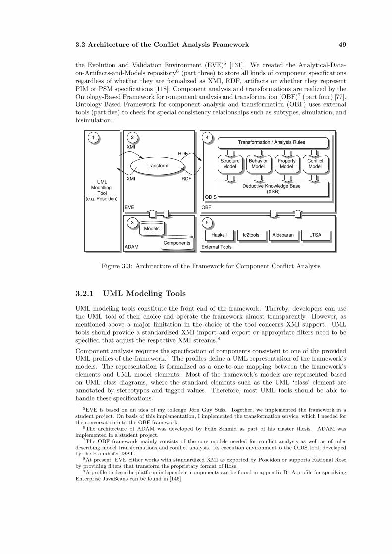
3.2 Architecture of the Conflict Analysis Framework 49
the Evolution and Validation Environment (EVE)5 [131]. We created the Analytical-Data-on-Artifacts-and-Models repository6 (part three) to store all kinds of component specificationsregardless of whether they are formalized as XMI, RDF, artifacts or whether they representPIM or PSM specifications [118]. Component analysis and transformations are realized by theOntology-Based Framework for component analysis and transformation (OBF)7 (part four) [77].Ontology-Based Framework for component analysis and transformation (OBF) uses externaltools (part five) to check for special consistency relationships such as subtypes, simulation, andbisimulation.
OBFEVE
ODIS
Deductive Knowledge Base (XSB)
Structure Model
BehaviorModel
Conflict Model
Transformation / Analysis Rules
Property Model
External Tools
Haskell fc2tools LTSA
ADAM
Models
UML Modelling
Tool (e.g. Poseidon)
Transform
XMI
RDFXMI
RDF
21
3
4
5
Aldebaran
Components
Figure 3.3: Architecture of the Framework for Component Conflict Analysis
3.2.1 UML Modeling Tools
UML modeling tools constitute the front end of the framework. Thereby, developers can usethe UML tool of their choice and operate the framework almost transparently. However, asmentioned above a major limitation in the choice of the tool concerns XMI support. UMLtools should provide a standardized XMI import and export or appropriate filters need to bespecified that adjust the respective XMI streams.8
Component analysis requires the specification of components consistent to one of the providedUML profiles of the framework.9 The profiles define a UML representation of the framework’smodels. The representation is formalized as a one-to-one mapping between the framework’selements and UML model elements. Most of the framework’s models are represented basedon UML class diagrams, where the standard elements such as the UML ‘class’ element areannotated by stereotypes and tagged values. Therefore, most UML tools should be able tohandle these specifications.
5EVE is based on an idea of my colleage Jorn Guy Suss. Together, we implemented the framework in astudent project. On basis of this implementation, I implemented the transformation service, which I needed forthe conversation into the OBF framework.
6The architecture of ADAM was developed by Felix Schmid as part of his master thesis. ADAM wasimplemented in a student project.
7The OBF framework mainly consists of the core models needed for conflict analysis as well as of rulesdescribing model transformations and conflict analysis. Its execution environment is the ODIS tool, developedby the Fraunhofer ISST.
8At present, EVE either works with standardized XMI as exported by Poseidon or supports Rational Roseby providing filters that transform the proprietary format of Rose.
9A profile to describe platform independent components can be found in appendix B. A profile for specifyingEnterprise JavaBeans can be found in [146].

50 Approach for Conflict Analysis
3.2.2 The Evolution and Validation Environment
The Evolution and Validation Environment (EVE) [131] allows executing arbitrary services onUML models. Thereby, the architecture of EVE is centered around serialized and standardizedmodels, creating a tool independent environment. EVE is based on a Meta-Object Facility(MOF) repository and uses XMI to operate on models. In the context of this thesis, we definea transformation service that converts models between XMI and RDF representations.
Figure 3.4 shows the basic concepts of EVE: Models specified in an arbitrary modeling tool areextracted. Services are applied on these models in a sequential order. The results can either bedisplayed or handed back to the modeling tool environment. Alternatively, a service can createartifacts such as source code. EVE consists of the following basic components:
EVE
UML Modelling
Tool (e.g. Poseidon)
Service
XMI
XMI
RDF
Plug
Plug
View
Artifact e.g. RDF files source code
Figure 3.4: Basic Concepts of the Evolution and Validation Environment
Models. The EVE framework is able to handle model instances that are based on a MOFcompliant metamodel, as it is based on the Netbeans MDR metadata repository.
Plugs. Modeling tools handle and store model instances in different proprietary formats. Inorder to use these model instances, they have to be translated into proper XMI.10 Plugsperform this translation and therefore provide the connection between modeling tools andthe framework.
Services. Services define functionality that can be applied to model instances. Typical exam-ples of services are model validation, model evolution and model transformation.
Views. Views are components for immediate visual presentation of models and system orservice feedback. A view can be a HTML page, a RDF feedback, or an error report.Views are also used to monitor the status of the EVE platform, as users must be able todetermine which services are available.
Artifacts. The term artifact refers to all data that does not represent a (UML) model instance.Services may produce or consume arbitrary artifacts such as source code, reports, etc.However, artifacts cannot be passed around in the primary framework. If services intend tocooperate on the content of the artifact, then the artifact must be modeled, i.e. expressedas a model instance and embedded into the model that is passed around. Otherwise theservices must define a private, proprietary communication channel.
We constructed the EVE framework on the basis of two architectural styles: The ‘pipe-and-filter’ style [32; 124] was used to provide sequential operations on services. A strict ‘layeredsystems’ style was applied to arrange the invocation capabilities of the framework (local access,LAN access, WAN access) in different layers.
10Most modeling tools support an XMI dialect that more or less complies with the XMI Specification. Thus,model instances have to be cleansed in order to become usable.

3.2 Architecture of the Conflict Analysis Framework 51
We used the pipe-and-filter style to gain a transactionally secured composition of services.Services represent particular functionality that can be composed in subsequent service calls.Figure 3.5 shows an example instantiation of the EVE framework expressed in a pipe-and-filterstyle. In the figure, two functionally independent services are composed. The transformationis started by a plug component. A plug is an abstraction for model input or output: E.g. acommand line operation or plug-in for a tool such as Rational Rose or ArgoUML. It suppliesa model instance to the first or retrieves one from the last service. Each service performsa particular operation on its source model and outputs a modified target model as well asfeedback and optional artifacts. Feedback refers to details of the services operation, e.g. errormessages or derivation traces. Artifacts are objects like generated code, etc. Each operation ofthe framework ends either in a viewer or in a plug component.
<<plug>> <<model>><<model>>
<<artifact>>
<<model>>
Key:
Component types: plug: actor, tool service: Eve service performing model operations viewer: device to represent all kinds of generated artifacts
Relations: direct acyclic attachment conveys models or artifacts
<<service>> <<service>>
<<viewer>>
<<plug>> <<artifact>>
Figure 3.5: Main Architecture of EVE
EVE has been developed over the last two years at the TU Berlin and is mainly part of thedissertation of Jorn Guy Suß.
3.2.3 Analytical-Data-on-Artifacts-and-Models
The Analytical-Data-on-Artifacts-and-Models (ADAM) repository [118] represents a genericfacility to store resources of arbitrary format and to handle meta information on these resources.In the context of this work, ADAM is customized to handle component descriptions specified inXMI and RDF, component transformations specified in TRIPLE, communication taxonomiesand component binaries. ADAM provides RDF Schema (RDFS) to handle relationships betweeninstances of these resources.
Transformation
ComponentA
[XMI]
ComponentA
[RDF]
ComponentEJB_A [RDF]
PIM
PIM
PSM
Component A
[BINARY]
Taxonomy EJB
[RDF]
XMI RDF
Artifacts
Figure 3.6: The Analytical Data on Artifacts and Models (ADAM) Repository

52 Approach for Conflict Analysis
Figure 3.6 provides an overview of ADAM. The figure shows a single component A that is storedin several representations: It is stored as a PIM both in an RDF and an XMI representation,and also as a specialized EJB PSM component. The relationship between the PIM and the EJBPSM component is described by a transformation. The EJB PSM component is associated witha corresponding communication taxonomy that describes the communication requirements ofA. Furthermore, A is stored as a binary artifact in the repository. The relationships betweenthese component elements are managed by ADAM via a customized RDFS, which describesthe components on different abstraction layers as well as their relationships. Besides the EJBtechnology, the ADAM repository can be customized to supports additional component models.
ADAM is implemented as a Java component. It is based on Jena, the Semantic Web Frameworkfor Java [89], and can be customized for the requirements in different application areas. Therepository provides an open design which allows saving resources in different kinds of storagesystems. At present, it uses the file system and the Tamino XML database to store models andartifacts. The metadata is stored in MySQL.
ADAM was developed in the scope of a student project at the TU Berlin. It was designedwithin a master thesis [118].
3.2.4 Ontology-Based Framework and External Tools
The Ontology-Based Framework (OBF) for component conflict analysis consists of several RDFschemata describing structure, behavior, communication properties, and conflicts as well as ofTRIPLE rules for component transformation and conflict analysis. OBF is implemented on topof the Ontology-Based Domain Repository (ODIS) [24]. ODIS provides an environment for theinterpretation of TRIPLE rules and uses XSB, a deductive knowledge basis for rule evaluation.OBF extends ODIS by adding several specialized tools for component conflict analysis.
At present, it uses a prototype implementation, which is written in Haskell to check for typeconflicts. Further, it uses the existing model checkers Aldebaran and fc2tools to check forsimulation and bisimulation conflicts and LTSA to identify deadlocks and progress violations.OBF models are explained in Section 5.1, whereas conflict analysis is explained in Chapter 6.We decided to use external tools instead of an implementation directly based on TRIPLE, asthese tools are already functional or are simpler to implement.
3.3 Processes for Conflict Analysis and Model Transfor-mation
This section gives an overview of the process of conflict analysis as well as of the associatedprocess of component transformation. The second process is a necessary side effect of conflictanalysis.
3.3.1 Conflict Analysis Process
The conflict analysis process that is shown in figure 3.7 can be divided up into three parts:The specification part covers the creation of component descriptions, the transformation parttransposes these descriptions into a canonical representation and the analysis part identifiesmismatches that hinder integration.
Specification
If a developer creates a new component, he is free to describe the structure and behavior aswell as to select appropriate communication properties and the technology of this component.However, often binary artifacts are to be integrated. In this case, it can be extremely difficult

3.3 Processes for Conflict Analysis and Model Transformation 53
to obtain the information necessary to create a UML specification. The first activity of figure3.7 covers the creation of UML specifications from COTS and legacy systems. This usuallyrequires the application of reengineering techniques such as static or dynamic code analysisto obtain information necessary to create component descriptions. Often tools are used toreengineer artifacts in order to create a documentation and an architectural description. Thereare a number of techniques, some of which are described in Section 2.3.3, that can be used forreverse engineering.
Analyse Components
Create Structural Specification
Create Behavioral Specification
Create Property Specification
Annotate Components
Submit to EVE
Transform to PICM
Conflict Analysis
Convert Conflicts to XMI
Specification
Transformation
Analysis
UML Tool
UML Tool
EVE
EVE
OBF
Figure 3.7: Conflict Analysis Process
Most of these analysis techniques are complex and their applicability depends on the particularsituation. Therefore, we do not investigate these activities in this work. We assume thatreengineering activities have already been applied to extract the information necessary to gaina more or less complete specification of an artifact. We further assume that the structuralspecification, e.g. the interfaces and types, are completely specified, whereas the behavior andthe property descriptions may be incomplete.
Transformation
If all required components are specified in UML, a developer can choose two components forconflict analysis. He can further annotate information that is required for component analysis.Useful annotations span among other directives such as property restrictions, which prescribecommunication and the component technology.
Conflict analysis is based on a platform independent canonical component model. This modelis represented by an RDFS component model, which we call the Platform Independent Com-ponent Model (PICM). Therefore, the transformation activities involve the reinterpretations ofcomponents specified in UML in terms of the PICM metamodel.
The transformation involves several steps, depending on the exact format of the UML compo-nent descriptions. The steps are described in the transformation process (Section 3.3.2).
Analysis
Conflict analysis evaluates several essential criteria for component integration. Among others,the following criteria are checked: type conformance, behavioral compatibility, existence orabsence of certain protocol properties, and compatibility of communication requirements.
The framework checks the actual specifications of two components for conflicts. We do notimpose any order or a sequence of the conflict categories in this process. A developer can

54 Approach for Conflict Analysis
analyse the conflict categories he is most interested in. However, we suggest to start eitherwith a structural analysis or with an analysis of the communication properties of components.Checking of communication properties is especially useful, if the amount of integration workbetween components of different technologies should be estimated, whereas type analysis is mostuseful, if two components are already selected for integration. Identified mismatches betweencertain parts and features of these components result in conflicts which are represented as RDFstatements. These results are presented to a developer, who then can decide how to proceed.
3.3.2 Model Transformation Process
The analysis process includes an activity for component abstraction. Figure 3.8 shows this activ-ity as part of a general transformation service, which covers not only component abstraction butalso parameterized refinements. Thus, component descriptions can either be abstracted or re-fined to more general or more specific descriptions. Consequently, the framework partly presentsa solution to the OMG’s Request for Proposal for Query/View/Transformations (QVT).
Submit to EVE
Select Components
Annotate Roles
Annotate Source & Target Technology
Select Features
Extract external Data
UML(XMI) to UML(RDF)
Target Transformation
Target(RDF) to UML(RDF)
UML(RDF) to UML(XMI)
UML(RDF) to Source(RDF)
ADAM
EVE
OBF
UML Tool
Abstraction?
External Data?
[YES]
[NO]
Profiled?
[YES]
[YES]
[NO]
[NO]
Figure 3.8: Transformation Process
The first activity of transformation involves the selection of UML component descriptions ofinterest. The descriptions must be annotated with information specifying the intended sourceand target technologies. This determines the direction of the transformation, which is either anabstraction or a refinement. For a refinement additional information for a transformation canbe given: If a transformation is targeted at several components that are composed in a system,the roles of the components in that system can be specified. The roles are used to trigger specificmappings of the components under consideration of user requirements. User requirements arespecified by special features that are selected from an overall feature model. This results in aparameterized and therefore flexible mapping of components. We have proposed this kind ofmapping in [25].11
We propose two approaches to select components for transformation and analysis: First, theycan be connected by dependency relationships which are annotated with a note, which gives the
11We give an overview of parameterized transformations in Section 8.1.
3.4 Related Work 55
framework a command to transform or compare these components. This method of encodingcommands directly in UML models and is completely tool independent. We proposed thisapproach in [79]. The approach requires that annotated UML models be exported manually.Alternatively, commands can be specified by issuing commands on a plug which has beenintegrated into a UML modeling tool. This approach requires a kind of Plug-In support in themodeling tool (see [131]).
The next activity serializes the components as XMI streams and transmits them to our XMI toRDF transformation service. The service has been embedded in the Evolution and ValidationEnvironment. The service extracts the components as well as their attached annotations andgenerates a RDF representation.12
At this point, the components are encoded as RDF statements relative to a UML metamodel.Thereby, the RDF representation is an instance of a RDFS model, which conforms to theUML metamodel that has been used by the UML tool in which the original UML componentdescription has been given. The framework contains several RDFS models that cover the majorversions of UML 1.x.
The next step of the transformation identifies external references in the attached information ofthe components and tries to include external references into the RDF model. At present, thisactivity concerns communication properties that can be referenced in the UML description.Information concerning communication properties is stored in the ADAM repository. Theactivity copies the respective definitions into the RDF model.
The UML(RDF) representation is treated differently, regarding the targeted transformationoperation. An abstraction transforms platform specific models into a platform independentrepresentation. At present, the only choice of abstraction results in the PICM componentrepresentation, which is used for component analysis. A refinement operation transforms thesource model under consideration of specified features into the target technology. Both opera-tions depend on the existence of appropriate transformation rules.
If the UML components are specified according to a framework’s profile, the former step ispreceded by a transformation of the component’s RDF(UML) representation to a representationcorresponding to the metamodel, which is described by the profile. Thus, the components arereinterpreted (transformed) in terms of their metamodel. However, this operation depends onthe conformance of the UML components to a profile of the framework.
After a successful transformation the process is reversed: the components are reinterpreted interms of UML and are handed back to the UML tool.
3.4 Related Work
In the following, we will describe related work that aims at component integration. We will focusthe discussion on approaches which target integration from a software architecture’s perspectiveand from a middleware context. Furthermore, we will look at approaches targeting the model-driven perspective of integration. We will not discuss conflict identification. This issue will bediscussed in Section 4.4.
3.4.1 Architectural Frameworks
A yet unresolved problem of Software Architecture concerns component composition. A com-position requires checking for compliance of structural and behavioral specifications as well asof architectural properties.
In recent years, several Architecture Description Languages (ADLs) [55; 83–85] were proposedto handle the structure and behavior of architectural elements. They define type systems to
12For a detailed description of this process see Section 5.2.2.

56 Approach for Conflict Analysis
handle structural aspects of composition and use formalisms such as Process Algebra [61; 86]to identify and overcome interaction mismatches.
However, despite these formalisms, ‘architectural mismatches’ [53] still exist. According to Gar-lan, they are caused by divergent architectural properties. The software architecture communitydeveloped several frameworks to cope with component integration. The tools can be distin-guished into two categories: Tools that only specify component compositions and componentinteractions and tools that also enforce the architecture in an implementation.
AcmeStudio is an architectural modeling environment which is based on the Eclipse Platform.AcmeStudio is based on Acme [54; 55]. AcmeStudio supports modeling with architecturalstyles (Acme Families). Furthermore, it allows the definition of new styles and is able togenerate Acme descriptions from graphical representations. Acme is a second generation ADL.It supports seven basic architectural elements: components, connectors, ports, roles, systems,representations and rep-maps. Acme associates property definition with component descriptionsto support for a translation of definitions specified in other ADLs.
Archstudio from the University of California, Irvine, is another architectural framework. It isbased on the C2 architectural style [136]. C2 uses an asynchronous communication mechanism,which is especially useful for development of GUI software. Archstudio is able to generateJava programs. It thereby provides a link between architectural specifications and a particularimplementation technology.
ArchJava [10] also links abstract Architecture Description Languages and frameworks for thedesign and integration of middleware systems. Contrary to most ADLs it includes new languageconstructs into the Java Language. Therefore, the architecture and the implementation ofa system coincide with each other. ArchJava aims at ensuring the communication integrityof an architecture: Communication between components is only allowed via explicit definedconnections. Recently ArchJava was integrated with AcmeStudio.
Similar to ArchJava are approaches such as ComponentJ [122] or ACOEL [130], which alsointroduce components into the Java language or other mainstream languages. Both approachesintroduce type systems and subtyping for components. Further approaches in this area are, forexample, Gestalt [120] or Jiazzi [90].
3.4.2 Technology-Related Frameworks for Integration
Approaches such as SOFA/DCUP [113], Fractal [30], or OSGi [5] define component models andstandard services on a platform independent level and provide language mappings for severaltechnologies. This concept is similar to the middleware concept. However, the approachesprovide advanced concepts in comparison to currently used middleware such as CORBA, COMetc. Components from different technologies are integrated by providing plugs that map thesecomponents into the component model.Currently, all approaches provide language bindings forat last the Java programming language. From the three approaches, the OSGi Service Platformis developed by an industrial consortium which includes companies such as Nokia, Motorola orBMW. The highlights of this platform include a standardized specification, flexible applicationdeployment and respective life-cycle management, which also includes remote management, anda number of implemented service components from which can be chosen.
The Vienna Component Framework (VCF) [103] provides a meta-component model to describecomponents of different middleware technologies. This metamodel supports the addition ofconcrete middleware technologies via a standardized interface. A technology can be added to theframework by implementing the interface. The framework supports integration of JavaBeans,Enterprise JavaBeans, CORBA and COM components. Contrary to our framework, the VCFdoes not guide component integration by providing conflict identification. It further does notsupport a model-centered development process.
UniFrame [115] is similar framework, which targets at composing distributed ‘heterogeneous’components. In our terminology, it generates an additional domain which uses adapters toattach components of other technologies. Contrary to ArchJava, UniFrame does not support

3.4 Related Work 57
component generation. It provides a simple meta-data based model to describe components,their functionality, and their service attributes. Uniframe does also not support conflict identifi-cation. Instead, connector generation is based on the Prototype System Description Language,which needs to be created manually. An interesting aspect of UniFrame is related to systemcomposition, which is based on Quality of Service attributes and calculations thereof. Eachcomponent is required to provide information about Quality of Service attributes. The frame-work calculates the optimal system from these attributes. Uniframe also provides a servicediscovery service [127], which is used to discover optimal components from user queries. Thisapproach is similar to service discovery in the area of web services, but is based on the unifiedmeta-component model from UniFrame.
Other approaches aim at connector generation in the context of different technologies and dif-ferent communication mechanisms. Bures and Plasil [31] provide an approach for connectorgeneration that takes four communication styles into account and creates a connector by as-sembling several units, from which each unit provides a distinct functionality such as logging,marshaling, encryption, etc. The approach further takes into account non-functional propertieswhich are considered in connector generation. A prototype is available for the SOFA/DCUPcomponent model [113]. Another approach from Spitznagel and Garlan [128] focuses on con-nector generation based on protocol transformations. Although, this work is better placed inthe area of process algebra research, it aims at protocol generation to connect COTS products.The paper uses FSP to specify the protocols and uses an ADL similar to Wright [11].
As mentioned before industrial solutions do not support a wide range of technologies but focuson the integration of two particular technologies. Examples of products are Janeva [2], K2 [6],or JIntegra [4].
3.4.3 Model-Driven Development
The framework is also related to the principles of Model-Driven Development [96]. It is con-cerned with the transformation of components between different levels of abstraction. In par-ticular, it can be seen as an application of the Model Driven Architecture [99] as defined by theOMG. Model transformations are defined in TRIPLE. According to the classification of modeltransformation approach provided by Czarnecki and Helsen [42] TRIPLE is a declarative re-lational model-to-model approach. The framework supports several platform specific RDFschemata that allow transformation of components specified relative to one of these schematainto the platform independent schemata of OBF.

58 Approach for Conflict Analysis

Chapter 4
Communication Taxonomy
In this section, we propose to augment structural and behavioral component specifications withan additional form of specification that describes the communication requirements of compo-nents. This form of specification consists of a property-based description of communicationmechanisms of interest. As explained in Section 1.2, application components use one of theprovided communication mechanisms of their context for communication. A comparison ofthe communication mechanisms required by components identifies mismatched properties thathinder interoperation.
Communication mechanisms correspond to architectural connectors as they implement commu-nication between components. In this respect, a property-based description of communicationidentifies key constraints of connectors. These constraints partly correspond to type and be-havior descriptions of components. However, the description is incomplete with regard to aprotocol specification and a structural specification as only key properties are included. Theseproperties consist of general restrictions that are implied by the underlying middleware.
Property descriptions of several communication mechanisms are composed into a taxonomy,which describes key constraints of the mechanisms. We call this taxonomy a ‘communica-tion taxonomy’, because it contains properties that describe the communicationm mechanismused. These properties need to be compatible in order to allow ‘communication’ between twocomponents.
A communication taxonomy can further be used to support model refinement in MDA. It can beused as a parameter to provide flexible mappings that are adapted regarding user requirements.
Section 4.1 starts with a motivation, which explains why comparison of communication prop-erties is important. Section 4.2 introduces communication properties and the communicationtaxonomy. We further explain our approach of defining a communication taxonomy based onfeature models (Section 4.3) and conclude the chapter with related work.
4.1 Motivation
We propose to augment component specifications with property-based specifications that de-scribe the abilities and requirements of a component regarding communication. Such a spec-ification provides an answer to two common interdependent problems: incomplete componentspecifications and as a special case implicit assumptions of communication properties:
Incomplete Specifications. Incomplete specifications concern the degree of detail of compo-nent specifications. Components are rarely fully specified in current technologies. Somefacts are stated implicitly or not at all. For example, a major problem of present middle-ware technologies is that they ignore the need for a behavioral specification of components.Most popular technologies do not associate this kind of information with their component

60 Communication Taxonomy
definitions. Thus, it is unlikely that there will be a considerable amount of componentreuse based on these technologies, at least not without a time-consuming and cumbersomeintegration process.
Implicit Assumptions. Another problem is implicit assumptions of component developers.Within one technology, aspects regarding communication are often implicitly defined bythe structural and behavioral parts of a component specification but not named explicitly.This is sufficient because in the context of one technology communication must be basedon predefined mechanisms which the technology transparently takes care of.
However, when dealing with more than one technology, with different communicationparadigms, or with adaptable communication mechanisms, it is likely that the require-ments of components regarding communication will vary. This is especially a problem ifthe technology of the component is unknown to the integrator. For example, componentsof a distributed system often require an initialization of their communication. This ofteninvolves contacting a name service. However, if the required initialization procedure isnot explicitly specified and the technology is unknown or not standardized, an integratorneeds to analyse a component to find out whether it needs initialization and to identifythe required order of procedure calls.
Regarding our discussion on the communication model (section 1.2), each component must beseen in a technological context. The context provides abilities to a component but also im-poses requirements that must be obeyed. Features describe the abilities and requirements givento a component from its context. Thus, even without regarding the interfaces of a compo-nent, certain assumptions on its communication abilities can be deduced solely by knowing itstechnology context. For example, a Java1 component (a JavaBean), which uses no additionalservices such as distributed communication, normally communicates via synchronous procedurecalls.2 It further cannot deal with default parameters nor handle pointers, as these features arenot defined in Java.
Inherited features are relevant in conflict analysis. A comparison of a Java SessionBean anda C++ DCOM component will eventually result in mismatches, even if the canonical repre-sentation of these components match in their structural and behavioral specifications, as both‘technologies’ provide different features. For example, a mismatch between a Java and a C++component will result because of different mechanisms for name resolution. Java uses, for ex-ample, a hierarchical naming scheme whereas DCOM uses an attribute-based naming scheme.A connector must mediate between both concepts.
An important property of a component’s feature description relates to the inherent variabilityof some features. An EJB component, for example, can principally be based on asynchronouscommunication (MessageBean) or on synchronous communication (SessionBean and Entity-Bean). Furthermore, transaction handling can be enabled or disabled for an EJB by choosingone of several transaction attributes in the deployment descriptor. Consequently, the knowledgethat a component is contained in the EJB technology does not fix all exposed features. Certainfeatures are still variable.
Our goal is to explicitly describe properties required for component composition in order toreason about the compatibility of components. We therefore propose a taxonomy to describethe communication mechanisms of several technologies. We believe that a communicationtaxonomy allows a quick estimation of the compatibility of two components without relying ona costly analysis from scratch. The taxonomy should also include technology-related metadata.Technology-related information such as the language in which a component is written, platformavailability, or resulting costs provides additional information regarding the complexity of aconnector.
We argue to express the abilities of a component via features. Features are members of a generalcommunication taxonomy. They provide an overview of the abilities of components in the
1We define the abilities of Java as defined by the Java Language Specification [69] including the definitionsof the classes packaged in ’java.lang.’.
2Asynchronous communication is defined in JMS.
4.2 Classification of Communication Mechanisms 61
context of certain technologies, which cannot be directly gained from investigating the interfacesof a component. A consistent taxonomy can be defined containing all relevant properties for thetechnology of interest. From this taxonomy specialized instances can be extracted that describeconcrete communication mechanisms of the technologies. The taxonomy can be reused for theanalysis of components of the particular technology. Considering the above discussion, weimpose two requirements on a communication taxonomy:
(1) A communication taxonomy must include relevant features of components that can causeintegration conflicts. The features should describe the abilities and requirements impliedby the surrounding technologies from which a component depends.
(2) A taxonomy must be able to express variability, as certain features can be customized.
4.2 Classification of Communication Mechanisms
Each communication mechanism establishes a particular kind of message exchange betweencomponents by determining the exact conditions for a valid interaction in terms of messageexchange, protocols, data format, services, etc. Thereby, we interpret each mechanism as aninstance of the communication model as defined in section 1.2. As our communication modeldefines three key elements: endpoints, control and data, each mechanism must include exactspecifications regarding these elements. In this work, we aim for a high-level classification ofcommunication mechanisms used in .Net and J2EE. We base the classification on a number ofkey properties that characterize the constraints of each mechanism regarding the key elementsof the communication model.
4.2.1 Property-Based Classification
As mentioned above, a property-based classification of communication mechanisms comprisesa high-level characterization of certain key constraints of each mechanism. Therefore, theclassification is not as accurate as a type specification or a behavioral protocol specification.Contrary to these specifications, it cannot be used in an interpretation that generates a ‘com-plete’ representation of a mechanism in terms of a more specific model (e.g. source code). Theclassification describes only important aspects and can therefore at most be used to generatepartial models (e.g. code templates). However, a ‘complete’ interpretation is not our intendedgoal. We propose that if a classification is based on carefully chosen properties, mechanismscan be differentiated and the root causes of incompatibility can be determined. This augmentstype and behavior specifications, especially if they are incompletely specified, by providing anapproximation of compatibility.
Regarding these statements, the question arises: Which properties are needed for a usefulclassification? Unfortunately, this question cannot be exactly answered as we cannot generallystate a criterion that determines whether the correct properties are chosen which describethe key constraints of the mechanisms at hand and whether the mechanisms are described insufficient detail. The level of detail that appropriately describes mechanisms depends on thetask at hand. A simple selection of a communication category (e.g. messages or procedure calls)can be based on a small set of properties, whereas a conflict analysis should include a large set ofproperties. According to these reasons, we can only indicate criteria for significant properties.In general, properties should be related to the key elements of the communication model andfurther form a single taxonomy which consistently describes the mechanisms of interest. Onlya single taxonomy allows a meaningful comparison of explored mechanisms regardless of thelevel of detail chosen. Properties should be selected if they are relevant for a communicationmechanism of one technology of interest. This can result in properties defined on a platformspecific level. In the context of this work, we restrict properties by choosing two middlewaretechnologies: J2EE and .Net.

62 Communication Taxonomy
Persistencytransient persistent
CommunicationCoordination connection-
lessconnection-oriented
connection-less
connection-oriented
synchronous RPC, RMI,Java RMI,.Net Re-moting,COM
asynchronous Messages MessageQueues
Table 4.1: A Classification of Communication Mechanisms
A communication taxonomy should at least contain two independent dimensions that are chosenfrom the three elements of the communication model. As an example, we define a simpletaxonomy consisting of three dimensions, from which each corresponds to one of the threeelements of the model and define two values for each property:
Communication can be related to the communication endpoints. A communication can eitherbe connection-less or connection-oriented.
Persistency describes the storage of data for a deferred communication. Data exchange be-tween two endpoints can either be transient or persistent.
Coordination describes an aspect of message exchange. Message exchange between the end-points can either be synchronous or asynchronous.
Using these dimensions, Table 4.1 shows the classification of common communication mech-anisms, including mechanisms used by the middleware technologies of interest. However, theexpressiveness of this simple classification is limited as it can only distinguish between majorcategories.
Consequently, the taxonomy has to be refined to express the differences between mechanismssuch as Java RMI and .Net Remoting more clearly. This can be done by adding appropriateproperties to the basic classification. Candidate properties for a refinement are for example,parameter passing mode, error handling, cardinality, etc.
Besides properties that directly describe the key elements of the communication model, an-other category of properties that can be commonly found in middleware needs to be described.Middleware technologies often aggregate services such as transactions, security, monitoring,cryptography with communication mechanisms to further simplify application development.
We can further distinguish properties in two categories: Explicit visible properties and trans-parent properties. A transparent property is not directly visible in an analysis of a componentspecified in a technology. At least eight transparencies [66] are defined in order to simplifydevelopment and to provide other advantages. In the case that a communication mechanismimplements a transparency, some properties become transparent with regard to the specificationand the source code of a component. The identification of the exact values of these propertiesrequires the analysis of the specification or the source code of the mechanism.
On the contrary, explicit properties can be identified from the specification and the sourcecode of components. They either relate to the programming language and describe the proper-ties of a language regarding communication or they directly relate to a special communicationmechanism. In particular, all customizable features are allocated in this category. Besides com-patibility checks, customizable features are also useful for parameterized model transformations,as they can be used to generate special platform specific component descriptions regarding thevariants chosen.
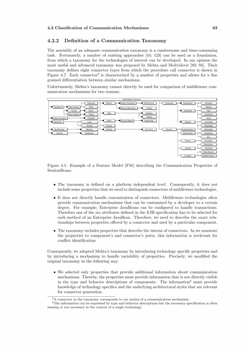
4.2 Classification of Communication Mechanisms 63
4.2.2 Definition of a Communication Taxonomy
The assembly of an adequate communication taxonomy is a cumbersome and time-consumingtask. Fortunately, a number of existing approaches [44; 123] can be used as a foundation,from which a taxonomy for the technologies of interest can be developed. In our opinion themost useful and advanced taxonomy was proposed by Mehta and Medvidovic [93; 94]. Theirtaxonomy defines eight connector types from which the procedure call connector is shown inFigure 4.7. Each connector3 is characterized by a number of properties and allows for a finegrained differentiation between similar mechanisms.
Unfortunately, Mehta’s taxonomy cannot directly be used for comparison of middleware com-munication mechanisms for two reasons:
SessionBean Taxonomy
Parameter Data Transfer
Reference
Value
Format
Return Values
Binary
Result
Implicit Invocation Exception
Local
Remote
Distribution
BlockingSynchronicity
Delivery Delivery Semantics At-Most-Once
Delivery Mechanism UnicastT
State Stateless
Stateful
HierarchicalStructure-BasedName
Automatic
Manual
New
Supported
None
Committed
Repeatable
Serializable
Demarcation
Awareness
Isolation
Transaction
Redundancy
T
T
T
Capabilities
ACL
Encryption
Certificate
Single Session
Multiple Session
Authentification
Authorization
Privacy
Integrity
Durability
Security
Pooling
Binding Run-TimeT
T
T
T
T
T
T
T T
TT
T
T T
T
T
T
T
T T T
T
InitializationLifecycleT T
Figure 4.1: Example of a Feature Model (FM) describing the Communication Properties ofSessionBeans.
• The taxonomy is defined on a platform independent level. Consequently, it does notinclude some properties that we need to distinguish connectors of middleware technologies.
• It does not directly handle customization of connectors. Middleware technologies oftenprovide communication mechanisms that can be customized by a developer to a certaindegree. For example, Enterprise JavaBeans can be configured to handle transactions.Therefore one of the six attributes defined in the EJB specification has to be selected foreach method of an Enterprise JavaBean. Therefore, we need to describe the exact rela-tionships between properties offered by a connector and used by a particular component.
• The taxonomy includes properties that describe the interns of connectors. As we annotatethe properties to component’s and connector’s ports, this information is irrelevant forconflict identification.
Consequently, we adapted Mehta’s taxonomy by introducing technology specific properties andby introducing a mechanism to handle variability of properties. Precisely, we modified theoriginal taxonomy in the following way:
• We selected only properties that provide additional information about communicationmechanisms. Thereby, the properties must provide information that is not directly visiblein the type and behavior descriptions of components. The information4 must provideknowledge of technology specifics and the underlying architectural styles that are relevantfor connector generation.
3A connector in the taxonomy corresponds to our notion of a communication mechanism.4The information can be expressed by type and behavior descriptions but the necessary specification is often
missing or not necessary in the context of a single technology.

64 Communication Taxonomy
• We omitted properties that are not relevant in the context of our proposed communica-tion model. This particularly includes properties that deal with hardware issues, n-aryrelationships, or that describe properties for adapter functionality.
• Platform specific properties that describe communication in Java, J2EE and .Net wereanalysed [51; 81] and added to the taxonomy. Figure 4.1 shows for example a part ofa feature model consisting of communication properties relevant for EJB Session Beans,whereas Figure 4.2 shows a feature model describing Java procedure calls.
• Mandatory and optional properties are distinguished. Mandatory properties refer to struc-tures and behavior that must be present, whereas for optional properties there is a choicefor implementation. Optional properties are interpreted differently regarding the type ofelement they are attached to (see Section 4.3.2).
• The original Connector Taxonomy of Medvidovic/Mehta consists of eight connector types,which as they claim, are sufficient to express most of the connectors which can be foundin present systems. These connector types were removed from the taxonomy. Instead,properties are directly annotated to connector types5 (‘ConnectorType’) from the definedplatform independent ADL (see Section 4.3.1).
• Each property is precisely defined by a description.
• Properties with equal names are renamed to resolve ambiguities in handling componentdescriptions.
A second taxonomy covers the aforementioned technological properties such as platforms (OSs),programming languages, etc. As we have not found any existing taxonomy that covers theseproperties, we have defined them from scratch. This taxonomy provides additional informa-tion for a quick estimation of compatibility. The taxonomy is described in [102] and used forcomponent search, in the ADAM repository [118]. The approach can be compared to similarapproaches in the area of the semantic web for semantic matching6 such as the one proposed byPaolucci [111]. However, the taxonomy is mostly limited to describing implementation aspectsand the purpose of components.
Java Procedure Call Taxonomy
Parameter Data Transfer
Reference
Value
Format
Return Values
Binary
Result
Implicit Invocation Exception
LocalDistribution
BlockingSynchronicity
Delivery Delivery Mechanism UnicastT
State Stateless
Stateful
Binding Run-TimeT
T
T
T
T
T T
T
T
T
T
T
LifecycleT Initialization
T
T
T
T
Compile-Time
Figure 4.2: Example of a Feature Model (FM) describing a Java Procedure Call: filled circlesrepresent mandatory features, empty circles represent optional features.
The communication taxonomy forms a consistent set of terms that describe the technologiesof interest with the same properties and on the same level of abstraction. This results in ameaningful comparison of components written in these technologies. As we are mainly inter-ested in Middleware technologies, we omit several properties and dimensions from the originaltaxonomy, which are of no interest for the chosen mechanisms.
5Properties are more precisely annotated to the ports of connectors and components.6Matching based on ontologies.

4.2 Classification of Communication Mechanisms 65
Communication Taxonomy
In the following, we describe properties of the overall taxonomy augmented with platformspecific properties. Figure 4.3 provides an overview of the feature model of the taxonomy. Inthe general taxonomy, most properties are optional properties that can be specialized for aparticular communication mechanism. The taxonomy is composed based on the works of Liao[81] and Gadicke [51], who researched J2EE, Jini and .Net technologies. We use a simple tableconsisting of two columns: property name and description. We mark top level properties withbold font and properties that represent values with italic font. We further introduce a specialsection in the description called ‘Interpretation’, which explaines the meaning of a property inthe taxonomy.
Communication Taxonomy
Parameter Data Transfer
Reference
Value
Name
Format
Return Values
Binary
SOAP
Error
Result
Implicit Invocation Exception
Callback
Delegation
Local
Remote
Distribution
Non-Blocking
Blocking
Time-Out Blocking
Synchronicity
Delivery Delivery Semantics Best-Effort
Exactly-Once
At-Most-Once
At-Least-Once
Delivery Mechanism Unicast
Multicast
Broadcast
Polled
T
Publish/Subscr
Central-Update
Point-to-Point
Event Patterns
Direct
Technique
Selection
Notification T
T
State Stateless
Stateful
Flat
Hierarchical
Structure-Based
Attribute-Based
NameInitialization
Termination
Lifecycle
Raw Access
File Access
Database Access
Semaphore
Rendezvous
Monitor
Lock
Automatic
Manual
New
Supported
None
Committed
Repeatable
Serializable
Demarcation
Awareness
Isolation
Transaction
Redundancy
Persistency
Concurrency
T
T
T
Capabilities
ACL
Encryption
Certificate
Single Session
Multiple Session
Authentification
Authorization
Privacy
Integrity
Durability
Security
Pooling
Binding Compile-Time
Run-Time
T
T
T
T
T
T
Figure 4.3: The Communication Taxonomy
Property Name Description
Parameter Parameters denote the arguments that can be passed alongwith a call to another routine, process or component. Theydescribe the abilities of a language or technology to handlearguments, data transfer, exceptions, data types, etc. Pa-rameters are visible in the interface declarations of compo-nents and connectors.

66 Communication Taxonomy
Data Transfer Data transfer denotes the way data is passed to the receivingroutine. In general, there are two calling conventions: call byvalue and call by reference. A subroutine call that uses a ‘byvalue’ call first evaluates the argument and passes the valueto the receiving routine. A call ‘by reference’ submits theaddress of the argument (indirect addressing) to the callee.Consequently, the callee can modify the original argument.In addition to these main variants, some derivations are de-fined. For example, call by reference can be distinguishedinto two cases: automatic and manual dereferencing of thepointer. For example, C++ provides both modes by spec-ifying a pointer (X *) or a reference (X &). A referenceautomatically dereferences the argument.Call by name is another calling convention proposed by someprogramming languages such as ALGOL. It differs from the‘normal’ cases as it passes the argument unevaluated. Eachtime the callee references an argument provided ‘by-name’the argument is re-evaluated.The classification of Java regarding data transfer yields aninteresting case: Can Java handle by-reference parameterpassing? Java distinguishes two kinds of types: primitivetypes and reference types (see [69] Chapter 4). For eachmethod invocation, a new activation frame is created forthe callee and the parameters are copied by value to thisframe. The callee works on the copies of the ‘original’ values.However, if the callee accesses a variable of a reference type,it can ‘globaly modify’ the referenced object. This effect canbe compared with that of reference types in C++. A C++reference type encapsulates a pointer that is automaticallydereferenced, if accessed.In summary, Java provides no concept to handle pointersexplicitly. This is a simplification to allow writing programsmore easily. Behind the scenes, however, Java handles ref-erences. As this can effect globally defined objects, we con-sider Java to also have ‘by-reference’ data transfer, even ifthe official documentation only mentions parameter passingby value.Interpretation: The parameter describes the supportedmodes of data transfer that must be compensated by a con-nector. Thereby, reference parameters often require morecomplex type mappings and bookkeeping capabilities in-cluded into a connector. Konstantas [75] describes theseissues in detail. The property is mandatory if a technol-ogy supports method arguments in general. The parametermodes reflect the actual usage of parameters in a component.For the taxonomy of the mechanism, they must be declaredoptional if they are supported.
Reference Parameter passing by-reference.
Value Parameter passing by-value.
Name Parameter passing by-name.
Format The data format in which data is exchanged. The propertyhas to be delcared mandatory if parameters are supported bya mechanism. For example, .Net supports binary and SOAPdata passing.Interpretation: Different data formats must be handled andtransformed by a connector.
Binary Data is communicated in a binary format.
SOAP Data is communicated in a XML-based data format.
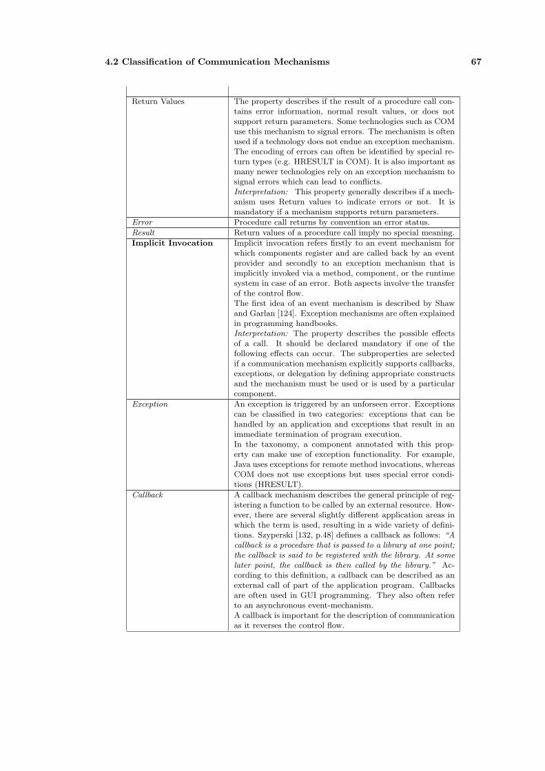
4.2 Classification of Communication Mechanisms 67
Return Values The property describes if the result of a procedure call con-tains error information, normal result values, or does notsupport return parameters. Some technologies such as COMuse this mechanism to signal errors. The mechanism is oftenused if a technology does not endue an exception mechanism.The encoding of errors can often be identified by special re-turn types (e.g. HRESULT in COM). It is also important asmany newer technologies rely on an exception mechanism tosignal errors which can lead to conflicts.Interpretation: This property generally describes if a mech-anism uses Return values to indicate errors or not. It ismandatory if a mechanism supports return parameters.
Error Procedure call returns by convention an error status.
Result Return values of a procedure call imply no special meaning.
Implicit Invocation Implicit invocation refers firstly to an event mechanism forwhich components register and are called back by an eventprovider and secondly to an exception mechanism that isimplicitly invoked via a method, component, or the runtimesystem in case of an error. Both aspects involve the transferof the control flow.The first idea of an event mechanism is described by Shawand Garlan [124]. Exception mechanisms are often explainedin programming handbooks.Interpretation: The property describes the possible effectsof a call. It should be declared mandatory if one of thefollowing effects can occur. The subproperties are selectedif a communication mechanism explicitly supports callbacks,exceptions, or delegation by defining appropriate constructsand the mechanism must be used or is used by a particularcomponent.
Exception An exception is triggered by an unforseen error. Exceptionscan be classified in two categories: exceptions that can behandled by an application and exceptions that result in animmediate termination of program execution.In the taxonomy, a component annotated with this prop-erty can make use of exception functionality. For example,Java uses exceptions for remote method invocations, whereasCOM does not use exceptions but uses special error condi-tions (HRESULT).
Callback A callback mechanism describes the general principle of reg-istering a function to be called by an external resource. How-ever, there are several slightly different application areas inwhich the term is used, resulting in a wide variety of defini-tions. Szyperski [132, p.48] defines a callback as follows: “Acallback is a procedure that is passed to a library at one point;the callback is said to be registered with the library. At somelater point, the callback is then called by the library.” Ac-cording to this definition, a callback can be described as anexternal call of part of the application program. Callbacksare often used in GUI programming. They also often referto an asynchronous event-mechanism.A callback is important for the description of communicationas it reverses the control flow.
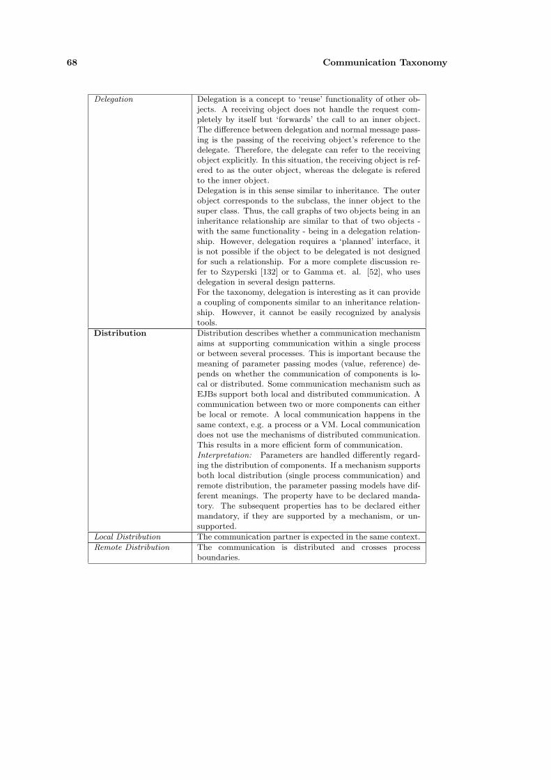
68 Communication Taxonomy
Delegation Delegation is a concept to ‘reuse’ functionality of other ob-jects. A receiving object does not handle the request com-pletely by itself but ‘forwards’ the call to an inner object.The difference between delegation and normal message pass-ing is the passing of the receiving object’s reference to thedelegate. Therefore, the delegate can refer to the receivingobject explicitly. In this situation, the receiving object is ref-ered to as the outer object, whereas the delegate is referedto the inner object.Delegation is in this sense similar to inheritance. The outerobject corresponds to the subclass, the inner object to thesuper class. Thus, the call graphs of two objects being in aninheritance relationship are similar to that of two objects -with the same functionality - being in a delegation relation-ship. However, delegation requires a ‘planned’ interface, itis not possible if the object to be delegated is not designedfor such a relationship. For a more complete discussion re-fer to Szyperski [132] or to Gamma et. al. [52], who usesdelegation in several design patterns.For the taxonomy, delegation is interesting as it can providea coupling of components similar to an inheritance relation-ship. However, it cannot be easily recognized by analysistools.
Distribution Distribution describes whether a communication mechanismaims at supporting communication within a single processor between several processes. This is important because themeaning of parameter passing modes (value, reference) de-pends on whether the communication of components is lo-cal or distributed. Some communication mechanism such asEJBs support both local and distributed communication. Acommunication between two or more components can eitherbe local or remote. A local communication happens in thesame context, e.g. a process or a VM. Local communicationdoes not use the mechanisms of distributed communication.This results in a more efficient form of communication.Interpretation: Parameters are handled differently regard-ing the distribution of components. If a mechanism supportsboth local distribution (single process communication) andremote distribution, the parameter passing models have dif-ferent meanings. The property have to be declared manda-tory. The subsequent properties has to be declared eithermandatory, if they are supported by a mechanism, or un-supported.
Local Distribution The communication partner is expected in the same context.
Remote Distribution The communication is distributed and crosses processboundaries.
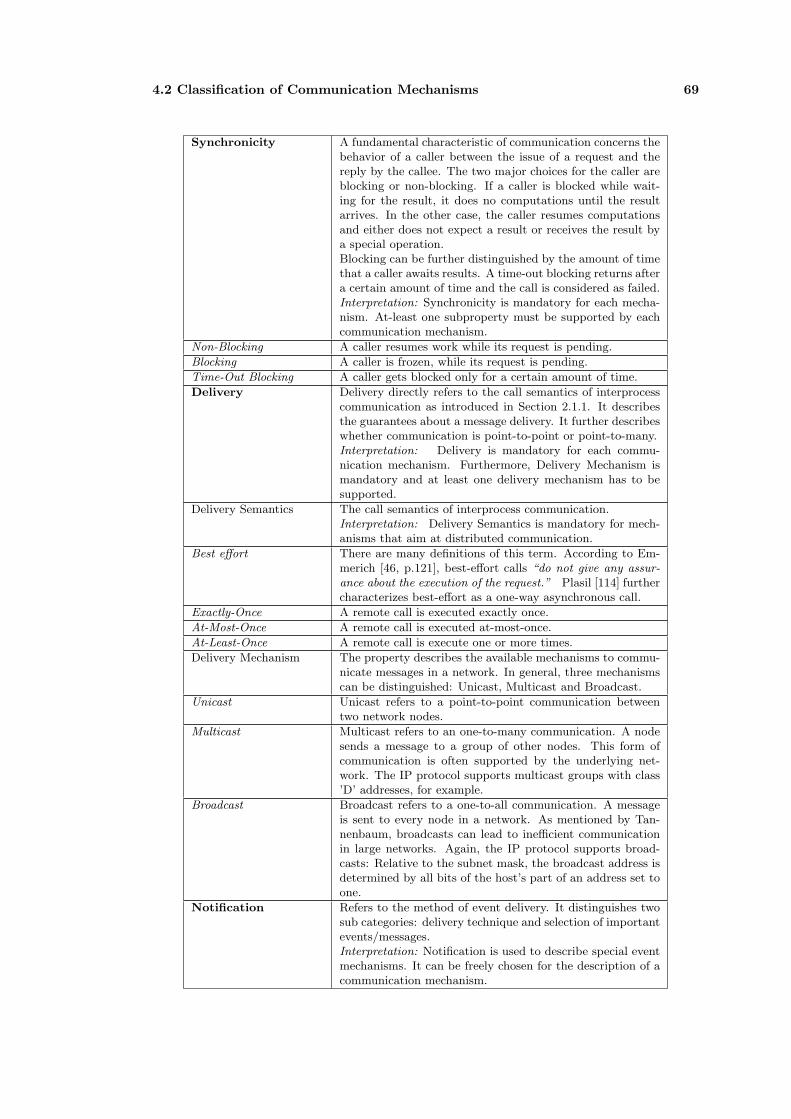
4.2 Classification of Communication Mechanisms 69
Synchronicity A fundamental characteristic of communication concerns thebehavior of a caller between the issue of a request and thereply by the callee. The two major choices for the caller areblocking or non-blocking. If a caller is blocked while wait-ing for the result, it does no computations until the resultarrives. In the other case, the caller resumes computationsand either does not expect a result or receives the result bya special operation.Blocking can be further distinguished by the amount of timethat a caller awaits results. A time-out blocking returns aftera certain amount of time and the call is considered as failed.Interpretation: Synchronicity is mandatory for each mecha-nism. At-least one subproperty must be supported by eachcommunication mechanism.
Non-Blocking A caller resumes work while its request is pending.
Blocking A caller is frozen, while its request is pending.
Time-Out Blocking A caller gets blocked only for a certain amount of time.
Delivery Delivery directly refers to the call semantics of interprocesscommunication as introduced in Section 2.1.1. It describesthe guarantees about a message delivery. It further describeswhether communication is point-to-point or point-to-many.Interpretation: Delivery is mandatory for each commu-nication mechanism. Furthermore, Delivery Mechanism ismandatory and at least one delivery mechanism has to besupported.
Delivery Semantics The call semantics of interprocess communication.Interpretation: Delivery Semantics is mandatory for mech-anisms that aim at distributed communication.
Best effort There are many definitions of this term. According to Em-merich [46, p.121], best-effort calls “do not give any assur-ance about the execution of the request.” Plasil [114] furthercharacterizes best-effort as a one-way asynchronous call.
Exactly-Once A remote call is executed exactly once.
At-Most-Once A remote call is executed at-most-once.
At-Least-Once A remote call is execute one or more times.
Delivery Mechanism The property describes the available mechanisms to commu-nicate messages in a network. In general, three mechanismscan be distinguished: Unicast, Multicast and Broadcast.
Unicast Unicast refers to a point-to-point communication betweentwo network nodes.
Multicast Multicast refers to an one-to-many communication. A nodesends a message to a group of other nodes. This form ofcommunication is often supported by the underlying net-work. The IP protocol supports multicast groups with class’D’ addresses, for example.
Broadcast Broadcast refers to a one-to-all communication. A messageis sent to every node in a network. As mentioned by Tan-nenbaum, broadcasts can lead to inefficient communicationin large networks. Again, the IP protocol supports broad-casts: Relative to the subnet mask, the broadcast address isdetermined by all bits of the host’s part of an address set toone.
Notification Refers to the method of event delivery. It distinguishes twosub categories: delivery technique and selection of importantevents/messages.Interpretation: Notification is used to describe special eventmechanisms. It can be freely chosen for the description of acommunication mechanism.

70 Communication Taxonomy
Technique A message can be exchanged in a number of differnt ways.On the one end, an interested component can poll messagesfrom a source, or on the contrary, events can be distributedvia a central update that is uniformly delivered to all com-ponents. In between, the publisher/subscriber technique canbe used, in which events are only delivered to subscribed (in-terested) parties.Interpretation: We define technique as a mandatory feature,as we interpret the property as based on a standard notifi-cation technique.
Polled A client polls an event source (busy waiting).
Publish/Subscribe An event source delivers message to all registered parties.
Central Update Events are distributed to all parties.
Point-To-Point Events are communicated between exactly two components.
Selection This property determines if event reception can be con-strained by a client or not.
Event Patterns A receiver can select events by specifying some kind of filters.
Direct A receiver receives all events from a chanel and has to providea mechanism to handle the events.
State The property describes whether communication is able toexpress a conversation between components, which is char-acterized by handling of a state.Interpretation: The property is mandatory for each commu-nication mechanism. It describes whether a conversationalstate can be maintained between communication partners ornot.
Stateless A communication only transfers data between components,without being able to create a conversation between the com-munication endpoints.
Stateful A communication can be controlled by a state describingrelevant properties of a communication. In this case, a statecan be changed in the callee and be accessed or modified insubsequent communication calls.
Naming Mehta considers two subproperties of naming: structure-based naming and attribute-based naming. Unfortunately,he does not exactly describe the intended meaning of theseproperties, so we interpret them as defined by Coulouris [40]:The property structure-based naming refers to the generalstructure of name, which can be either flat or hierarchical.The property attribute-based naming refers to the fact thatthe names also include attributes.Interpretation: Naming is required if the communicationpartners are not statically linked to each other.
Structure-Based Naming Structure-based describes names in a flat or in a hierarchicalnamespace. A flat namespace uses simple identifiers to mapnames to objects and is a finite space (provided that theidentifier of the name is of fixed size). On the contrary, ahierarchical namespace is able to generate an infinite numberof names. Examples of services with structured namespacesare Domain Name Service (DNS) and most file systems.
Hierarchical Hierarchical composeable names.
Flat A flat namespace.
Attribute-Based Naming A discovery service stores not only names but also attributesto these names. Consequently, we can also search for nameswith a number of known attributes. This property can beaugmented with particular properties of the technologies ofinterest.
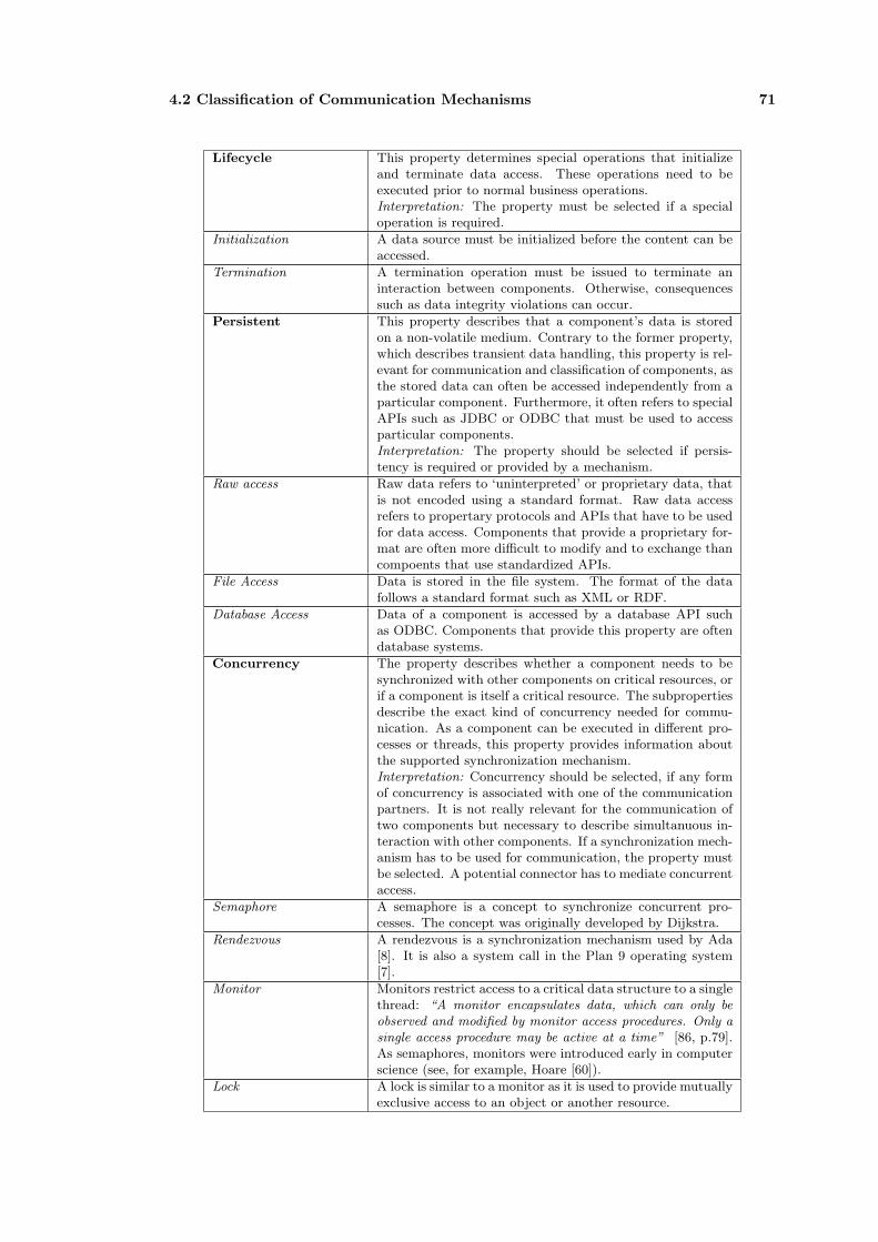
4.2 Classification of Communication Mechanisms 71
Lifecycle This property determines special operations that initializeand terminate data access. These operations need to beexecuted prior to normal business operations.Interpretation: The property must be selected if a specialoperation is required.
Initialization A data source must be initialized before the content can beaccessed.
Termination A termination operation must be issued to terminate aninteraction between components. Otherwise, consequencessuch as data integrity violations can occur.
Persistent This property describes that a component’s data is storedon a non-volatile medium. Contrary to the former property,which describes transient data handling, this property is rel-evant for communication and classification of components, asthe stored data can often be accessed independently from aparticular component. Furthermore, it often refers to specialAPIs such as JDBC or ODBC that must be used to accessparticular components.Interpretation: The property should be selected if persis-tency is required or provided by a mechanism.
Raw access Raw data refers to ‘uninterpreted’ or proprietary data, thatis not encoded using a standard format. Raw data accessrefers to propertary protocols and APIs that have to be usedfor data access. Components that provide a proprietary for-mat are often more difficult to modify and to exchange thancompoents that use standardized APIs.
File Access Data is stored in the file system. The format of the datafollows a standard format such as XML or RDF.
Database Access Data of a component is accessed by a database API suchas ODBC. Components that provide this property are oftendatabase systems.
Concurrency The property describes whether a component needs to besynchronized with other components on critical resources, orif a component is itself a critical resource. The subpropertiesdescribe the exact kind of concurrency needed for commu-nication. As a component can be executed in different pro-cesses or threads, this property provides information aboutthe supported synchronization mechanism.Interpretation: Concurrency should be selected, if any formof concurrency is associated with one of the communicationpartners. It is not really relevant for the communication oftwo components but necessary to describe simultanuous in-teraction with other components. If a synchronization mech-anism has to be used for communication, the property mustbe selected. A potential connector has to mediate concurrentaccess.
Semaphore A semaphore is a concept to synchronize concurrent pro-cesses. The concept was originally developed by Dijkstra.
Rendezvous A rendezvous is a synchronization mechanism used by Ada[8]. It is also a system call in the Plan 9 operating system[7].
Monitor Monitors restrict access to a critical data structure to a singlethread: “A monitor encapsulates data, which can only beobserved and modified by monitor access procedures. Only asingle access procedure may be active at a time” [86, p.79].As semaphores, monitors were introduced early in computerscience (see, for example, Hoare [60]).
Lock A lock is similar to a monitor as it is used to provide mutuallyexclusive access to an object or another resource.
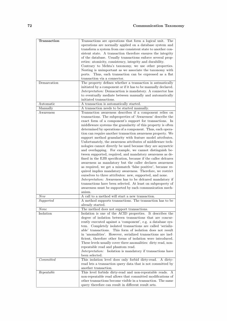
72 Communication Taxonomy
Transaction Transactions are operations that form a logical unit. Theoperations are normally applied on a database system andtransform a system from one consistent state to another con-sistent state. A transaction therefore ensures the integrityof the database. Usually transactions enforce several prop-erties: atomicity, consistency, integrity and durability.Contrary to Mehta’s taxonomy, we use other properties.Nesting is unimportant as we associate the taxonomy withports. Thus, each transaction can be expressed as a flattransaction via a connector.
Demarcation The property defines whether a transaction is autmaticallyinitiated by a component or if it has to be manually declared.Interpretation: Demacartion is mandatory. A connector hasto eventually mediate between manually and automaticallyinitiated transactions.
Automatic A transaction is automatically started.
Manually A transaction needs to be started manually.
Awareness Transaction awareness describes if a component relies ontransactions. The subproperties of ‘Awareness’ describe theexact form of a component’s support for transactions. Inmiddleware systems the granularity of this property is oftendetermined by operations of a component. Thus, each opera-tion can require another transaction awareness property. Wesupport method granularity with feature model attributes.Unfortunately, the awareness attributes of middleware tech-nologies cannot directly be used because they are asymetricand overlapping. For example, we cannot distinguish be-tween supported, required, and mandatory awareness as de-fined in the EJB specification, because if the callee delcaresawareness as mandatory but the caller declares awarenessas required, we get a mismatch ‘false positive’, because re-quired implies mandatory awareness. Therefore, we restrictourselves to three attributes: new, supported, and none.Interpretation: Awareness has to be delcared mandatory iftransactions have been selected. At least on subproperty ofawareness must be supported by each communication mech-anism.
New A call to a method will start a new transaction.
Supported A method supports transactions. The transaction has to bealready started.
None The method does not support transactions.
Isolation Isolation is one of the ACID properties. It describes thedegree of isolation between transactions that are concur-rently executed against a ‘component’, e.g. a database sys-tem. Completely isolated transactions are called ‘serializ-able’ transactions. This form of isolation does not resultin ‘anomalities’. However, serialized transactions are inef-ficient, therefore other forms of isolation were introduced.These levels usually cover three anomalities: dirty read, non-repeatable read and phantom read.Interpretation: Isolation is mandatory if transactions havebeen selected.
Committed This isolation level does only forbid dirty-read. A dirty-read lets a transaction query data that is not committed byanother transaction.
Repeatable This level forbids dirty-read and non-repeatable reads. Anon-repeatable read allows that committed modifications ofother transactions become visible in a transaction. The samequery therefore can result in different result sets.

4.2 Classification of Communication Mechanisms 73
Serializable This level describes serializable transactions. No anomalityoccurs in this transaction level.
Security This property represents the root property for security-related properties.Interpretation: Security is an optional service, which can besupported or required. Each subproperty of security is alsooptional and depends on the actual communication mecha-nism.
Authentification Authentification refers to the identification of a user by thesystem: ‘Authentication is the mechanism by which callersand service providers prove to one another that they are act-ing on behalf of specific users or systems’ [125].
Authorization Authorization checks if a particular resource can be accessedby a user: “Authorization mechanisms limit interactions withresources to collections of users or systems for the purposeof enforcing integrity, confidentiality, or availability con-straints” [125, p.293]. Authorization is usually enforcedwith Access Control Lists (ACL). However, a second concept,Capability Lists, exists that resolves authorization more effi-ciently. For a differentiation between the two see Miller, Yeand Shapiro [100].
Capabilities Authorization via capability lists.
Access Control Lists Authorization via ACLs.
Privacy The property describes how information is secured.
Encryption Communicated data is encrypted and third parties cannotread the exchanged information. An encryption is imple-mented by an appropriate cypher algorithm.
Integrity Integrity concerns the correctness of submitted data: “In-tegrity mechanisms ensure that communication between en-tities is not being tampered with by another party, especiallyone that can intercept and modify their communications”[125, p.304].
Redundancy We define ‘Redundancy’ as a form hash code that is attachedto a message and ensures the correctness of this message.This form of protection is, for exmaple, used in J2EE and inIPSec.
Certificates A certificate ensures that the data sent by a person/com-ponent belongs to the right identity. Certificates are oftencreated by a Certificate Authority (CA).
Durability This property restrictes the validity of security settings toeither a single session or to multiple sessions. This propertydetermines if authorization is required before each commu-nication.
Single session Security settings are valid for a single communication session.
Multi session Security settings are valid for several communication ses-sions.
Pooling This property describes the ability of a component to storeconnections and objects in a pool. This provides a fasteraccess to these objects or connections. In general, this prop-erty is not necessary to describe communication as it doesnot influence the behavior but only the performance of acommunication.Interpretation: This property is an optional service that canbe used by a connector to optimize communication.
Binding This property describes the time of allocation of a compo-nent.Interpretation: The property is mandatory for each com-munication mechanism.
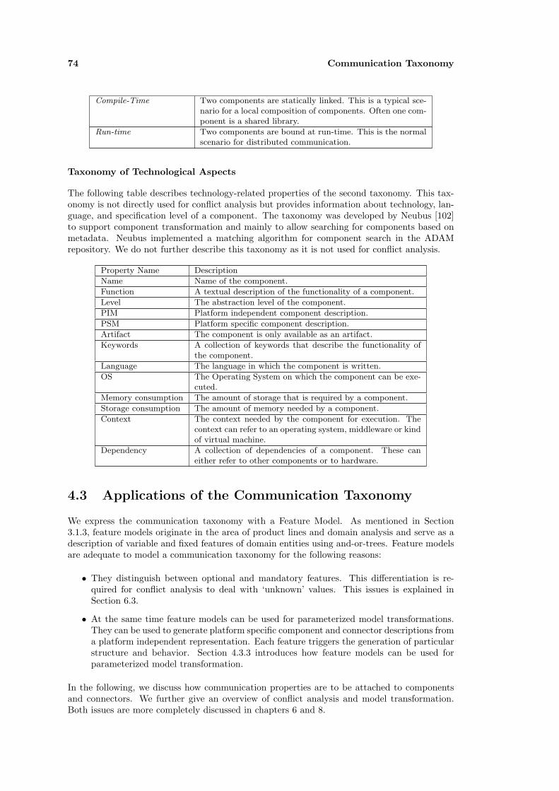
74 Communication Taxonomy
Compile-Time Two components are statically linked. This is a typical sce-nario for a local composition of components. Often one com-ponent is a shared library.
Run-time Two components are bound at run-time. This is the normalscenario for distributed communication.
Taxonomy of Technological Aspects
The following table describes technology-related properties of the second taxonomy. This tax-onomy is not directly used for conflict analysis but provides information about technology, lan-guage, and specification level of a component. The taxonomy was developed by Neubus [102]to support component transformation and mainly to allow searching for components based onmetadata. Neubus implemented a matching algorithm for component search in the ADAMrepository. We do not further describe this taxonomy as it is not used for conflict analysis.
Property Name Description
Name Name of the component.
Function A textual description of the functionality of a component.
Level The abstraction level of the component.
PIM Platform independent component description.
PSM Platform specific component description.
Artifact The component is only available as an artifact.
Keywords A collection of keywords that describe the functionality ofthe component.
Language The language in which the component is written.
OS The Operating System on which the component can be exe-cuted.
Memory consumption The amount of storage that is required by a component.
Storage consumption The amount of memory needed by a component.
Context The context needed by the component for execution. Thecontext can refer to an operating system, middleware or kindof virtual machine.
Dependency A collection of dependencies of a component. These caneither refer to other components or to hardware.
4.3 Applications of the Communication Taxonomy
We express the communication taxonomy with a Feature Model. As mentioned in Section3.1.3, feature models originate in the area of product lines and domain analysis and serve as adescription of variable and fixed features of domain entities using and-or-trees. Feature modelsare adequate to model a communication taxonomy for the following reasons:
• They distinguish between optional and mandatory features. This differentiation is re-quired for conflict analysis to deal with ‘unknown’ values. This issues is explained inSection 6.3.
• At the same time feature models can be used for parameterized model transformations.They can be used to generate platform specific component and connector descriptions froma platform independent representation. Each feature triggers the generation of particularstructure and behavior. Section 4.3.3 introduces how feature models can be used forparameterized model transformation.
In the following, we discuss how communication properties are to be attached to componentsand connectors. We further give an overview of conflict analysis and model transformation.Both issues are more completely discussed in chapters 6 and 8.

4.3 Applications of the Communication Taxonomy 75
4.3.1 Feature Annotations
We propose to annotate properties to components and connectors to describe their requirementsand abilities regarding communication. However, properties cannot be associated directly tothese elements but must be related to their exposed interfaces.
For example, imagine a configuration as shown in Figure 4.4. The components C1, C2, andC3 are directly annotated with features7 expressing their abilities and requirements regardingcommunication.
The connectors K1 and K2 have to mediate the differences between the communication featuresexposed by the three components. Thus, they need to comply with two sets of communicationfeatures imposed by the linked components. Consequently, we cannot attach the propertiesdirectly, but must consider the relationships of the connectors K1 and K2 to their linked com-ponents. The same holds true for components, because of the relativity of components andconnectors.
<<Component>> C2
<<Component>> C3
K2<<Component>> C1
K1
<<Feature>> RPC
<<Feature>> TX
<<Feature>> RPC
<<Feature>> PC
Figure 4.4: Direct Property Annotations to Components
Therefore, we bind communication features to the ports of components and connectors. Con-sequently, a component/connector can expose different communication requirements on eachinterface. Evolving our example from Figure 4.4 to an extended version, shown in Figure 4.5,K2 and C2 handle two feature models for their connections.
<<Component>> C2
<<Component>> C3
<<Connector>> K2
<<Port>> P2
<<Port>> P1
<<requiredPort>>
<<binds>>
<<providedPort>>
<<binds>>
<<Feature>> RPC
<<Feature>> TX
<<Feature>> RPC
<<Component>> C1
<<Connector>> K2
<<Port>> P3
<<Port>> P4
<<requiredPort>>
<<binds>><<binds>>
<<Feature>> PC
<<Feature>> PC
<<providedPort>>
Figure 4.5: Property Annotations to Component Ports
4.3.2 Conflict Analysis
Concrete communication mechanisms are described via a subset of the properties included inthe communication taxonomy. A comparison of two mechanisms checks if the properties of bothmechanisms correspond to each other. Thereby, two interleaving aspects must be considered:the role of the element, for which the instance is defined and the variability of the features inthe concrete taxonomies, which describe a particular communication mechanism.
7They are annotated with features describing a communication mechanism. The features are likely to containvariable elements that allow customization of certain aspects of the mechanism such as support for transactions.
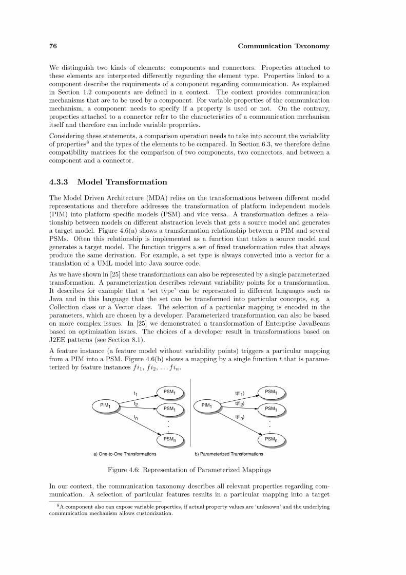
76 Communication Taxonomy
We distinguish two kinds of elements: components and connectors. Properties attached tothese elements are interpreted differently regarding the element type. Properties linked to acomponent describe the requirements of a component regarding communication. As explainedin Section 1.2 components are defined in a context. The context provides communicationmechanisms that are to be used by a component. For variable properties of the communicationmechanism, a component needs to specify if a property is used or not. On the contrary,properties attached to a connector refer to the characteristics of a communication mechanismitself and therefore can include variable properties.
Considering these statements, a comparison operation needs to take into account the variabilityof properties8 and the types of the elements to be compared. In Section 6.3, we therefore definecompatibility matrices for the comparison of two components, two connectors, and between acomponent and a connector.
4.3.3 Model Transformation
The Model Driven Architecture (MDA) relies on the transformations between different modelrepresentations and therefore addresses the transformation of platform independent models(PIM) into platform specific models (PSM) and vice versa. A transformation defines a rela-tionship between models on different abstraction levels that gets a source model and generatesa target model. Figure 4.6(a) shows a transformation relationship between a PIM and severalPSMs. Often this relationship is implemented as a function that takes a source model andgenerates a target model. The function triggers a set of fixed transformation rules that alwaysproduce the same derivation. For example, a set type is always converted into a vector for atranslation of a UML model into Java source code.
As we have shown in [25] these transformations can also be represented by a single parameterizedtransformation. A parameterization describes relevant variability points for a transformation.It describes for example that a ‘set type’ can be represented in different languages such asJava and in this language that the set can be transformed into particular concepts, e.g. aCollection class or a Vector class. The selection of a particular mapping is encoded in theparameters, which are chosen by a developer. Parameterized transformation can also be basedon more complex issues. In [25] we demonstrated a transformation of Enterprise JavaBeansbased on optimization issues. The choices of a developer result in transformations based onJ2EE patterns (see Section 8.1).
A feature instance (a feature model without variability points) triggers a particular mappingfrom a PIM into a PSM. Figure 4.6(b) shows a mapping by a single function t that is parame-terized by feature instances fi1, fi2, . . . fin.
PIM1
PSM1
PSM1
PSMn
t1
t2
tn . . .
PIM1
PSM1
PSM1
PSMn
t(fi1)
t(fi2)
t(fin)
a) One-to-One Transformations b) Parameterized Transformations
.
.
.
Figure 4.6: Representation of Parameterized Mappings
In our context, the communication taxonomy describes all relevant properties regarding com-munication. A selection of particular features results in a particular mapping into a target
8A component also can expose variable properties, if actual property values are ‘unknown’ and the underlyingcommunication mechanism allows customization.

4.4 Related Work 77
model, for example into a model with stubs and skeletons and a protocol description specifyingsynchronous communication.
4.3.4 Discussion
As mentioned above, we cannot generally state a criteria that determines if the correct propertieswhere chosen. Accordingly, we cannot be sure that the taxonomy covers each relevant conflictin the actual form with the properties defined above. This is by no means our intention. Werather claim that a communication taxonomy is valuable because it supports a quick analysisof the communication capabilities of two components. Developers should be able to estimatethe necessary integration effort to connect to components. The advantage of the approachrelates to the concept of property-based conflict analysis in the context of our communicationmodel. Furthermore, the taxonomy can be augmented and adapted to further technologies. Anymissing property can be added to the taxonomy to complete conflict analysis. The downsideof the approach concerns the effort to create a taxonomy instance for a concrete technology.However, a taxonomy has to be developed only once.
Another problem of the approach concerns the requirements that only symmetric and non-overlapping properties can be chosen for the taxonomy. For example, the EJB technologydefines six transaction awareness attributes, including ‘requires’ and ‘mandatory’. The proper-ties overlap as both require a transaction for their operation. However, a ‘requires’ method ofa callee component will create a transactional context if none is specified by a caller, whereasa ‘mandatory’ method will throw an exception. The problem refers to the specification of theattributes in the communication taxonomy. The conflict analysis algorithm will result in aconflict if a ‘requires’ method is annotated with ‘requires’ and a ‘provides’ method is annotatedwith ‘mandatory’.
This issue conflicts with our goal of model transformation. A transformation which is based onthe properties of the communication taxonomy will be less effective if we cannot include everyproperty of a technology in the taxonomy.
A further problem of classifying communication mechanisms relates to supported but optionalfeatures that differ from implementation to implementation. The EJB standard for exampledefines several transaction features and security features as optional. A vendor can chooseif he supports these features and in which way he supports them. We model these featuresas optional properties of a technology. A component that requires or provides these specialoptional features has to be executed on a suitable application server.
4.4 Related Work
In the following, we briefly describe related approaches that aim at a property-based charac-terization of components and connectors: We consider Architectural Styles, Mehta’s ConnectorTaxonomy as well as related approaches that also aim at conflict identification or at property-based reasoning.
4.4.1 Architectural Styles
Architectural Styles were one of the early approaches in software architecture to classify systems.A style specifies the parts of a system as well as properties that need to be satisfied in a systemconfiguration. Shaw and Garlan define an architectural style as follows:
“An architectural style defines a vocabulary of components and connector types,and a set of constraints on how they can be combined” [124, p.20].
One possible application area of styles is the classification of systems regarding the compositionof their constituting parts. Shaw [123; 124] provides such a classification. A style is represented
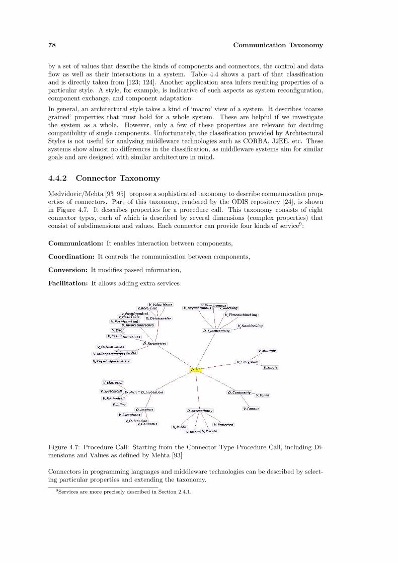
78 Communication Taxonomy
by a set of values that describe the kinds of components and connectors, the control and dataflow as well as their interactions in a system. Table 4.4 shows a part of that classificationand is directly taken from [123; 124]. Another application area infers resulting properties of aparticular style. A style, for example, is indicative of such aspects as system reconfiguration,component exchange, and component adaptation.
In general, an architectural style takes a kind of ‘macro’ view of a system. It describes ‘coarsegrained’ properties that must hold for a whole system. These are helpful if we investigatethe system as a whole. However, only a few of these properties are relevant for decidingcompatibility of single components. Unfortunately, the classification provided by ArchitecturalStyles is not useful for analysing middleware technologies such as CORBA, J2EE, etc. Thesesystems show almost no differences in the classification, as middleware systems aim for similargoals and are designed with similar architecture in mind.
4.4.2 Connector Taxonomy
Medvidovic/Mehta [93–95] propose a sophisticated taxonomy to describe communication prop-erties of connectors. Part of this taxonomy, rendered by the ODIS repository [24], is shownin Figure 4.7. It describes properties for a procedure call. This taxonomy consists of eightconnector types, each of which is described by several dimensions (complex properties) thatconsist of subdimensions and values. Each connector can provide four kinds of service9:
Communication: It enables interaction between components,
Coordination: It controls the communication between components,
Conversion: It modifies passed information,
Facilitation: It allows adding extra services.
Figure 4.7: Procedure Call: Starting from the Connector Type Procedure Call, including Di-mensions and Values as defined by Mehta [93]
Connectors in programming languages and middleware technologies can be described by select-ing particular properties and extending the taxonomy.
9Services are more precisely described in Section 2.4.1.

4.4 Related Work 79
Sty
leC
onst
ituen
tpart
sC
ontr
olIs
sues
Data
Issu
esC
ontr
ol/
data
Inte
ract
ion
Com
ponen
tsC
onnec
tors
Topo-
logy
Synch
-ro
nic
ity
Bin
din
gT
ime
Topo-
logy
Conti
n-
uity
Mode
Bin
din
gT
ime
Isom
orp
hic
Shapes
Flo
wdir
ecti
on
Naiv
eC
lien
t/-
Ser
ver
pro
gra
ms
pro
cedure
calls
/R
PC
star
synch
w,c
,rst
ar
spor,
lvol
pass
edw
,c,r
yes
opposi
te
Dis
trib
ute
dO
b-
ject
sm
anager
sre
mote
pro
ce-
dure
calls
arb
ls/par,
synch
w,c
,rarb
spor,
lvol
pass
edw
,c,r
no
n/a
Pro
cess
-base
dC
lien
t/Ser
ver
pro
cess
esre
ques
t/re
ply
mes
sages
star
synch
w,c
,rst
ar
spor,
lvol
pass
edw
,c,r
yes
opposi
te
Even
tSyst
ems
pro
cess
esim
plici
tin
vo-
cati
on
arb
asy
nch
,opp
i,r
arb
spor,
lvol
bdca
sti,r
no
n/a
Data
Cen
tere
dC
lien
t/Ser
ver
manager
s,co
mputa
tions
transa
ctio
ns
opns
wit
hhis
tory
star
asy
nch
w,c
,rst
ar
spor,
lvol
pass
edw
,c,r
yes
opposi
te
Key
Topolo
gy
hie
r(hie
rarc
hic
al)
,arb
(arb
itra
ry),
star,
linea
r(o
ne-
way
),fixed
(det
erm
ined
by
style
)Synch
ronic
ity
seq(s
equen
tial,
one
thre
ad
ofco
ntr
ol)
,ls
/par(
lock
step
para
llel
),sy
nch
(synch
ronous)
,asy
nch
(asy
nch
ronous)
,opp
(opport
unis
tic)
Bin
din
gT
ime
w(w
rite
-tim
e),c(
com
pile-
tim
e),i(
invoca
tion-t
ime)
,r(
runti
me)
Conti
nuity
spor(
spora
dic
),co
nt(
conti
nuous)
,hvol(
hig
h-v
olu
me)
,lv
ol(
low
-volu
me)
Mode
share
d,pass
ed,bdca
st(b
roadca
st),
mca
st(m
ult
icast
),ci
/co
(copy-in/co
py-o
ut)
Table 4.4: Example of Architectural Styles as defined by Allan and Shaw [123].

80 Communication Taxonomy
The taxonomy is platform independent as it does not contain platform specific values anddimensions. Therefore, it needs to be extended to introduce technology dependent values aswell as new services (Jini Leases [14], Tupelspaces [50; 56]).
The analysis of middleware technologies in the context of Mehta’s connector taxonomy alsoreveals several problems: The terms used in the taxonomy are not explicitly defined. For anumber of terms, a lot of different definitions are available. Some terms are ambiguous asdifferent interpretations in the taxonomy can be chosen. For example the property ‘Exceptions’can refer to a method that throws an exception or one that is activated because of an exception.The taxonomy describes connector types as part of the taxonomy. We feel that these typesshould not be included in the taxonomy because connector types are the entities that aredescribed by properties, but they themselves are not properties.
4.4.3 Other Approaches
Other approaches aim to automatically discover mismatches based on conflicting characteristics.Today, several approaches use taxonomies [44; 93; 95; 123] to categorize architectural propertiesand further aim to automatically discover mismatches based on conflicting characteristics [11;43; 72; 94; 151]. Most of these approaches concentrate on architectural mismatches and do nothandle structural and behavioral specifications.
Davis et. al. [44] propose an interesting approach to deal with unknown architectural properties.They define twelve properties on three levels of abstraction and define rules between them.Based on the rules, it becomes possible to deduce unknown system properties from knownproperties. However, their properties are too abstract to be used for an exact estimation ofcommunication properties of a ‘system’. Furthermore, their rules are difficult to implement interms of a deductive programming language.
Pahl [110] also considers behavior. He encodes behavior directly in description logic. Thisresults in a more elegant language, but also does not allow a customization of specificationlanguages.
However, most of these approaches concentrate on architectural mismatches. They do nothandle technologies directly nor do they identify conflicts in structural and behavioral specifi-cations. They can be classified into approaches using only a structure such as a table to describeproperties [11; 94] and in approaches which additionally provide reasoning support [43; 44; 72].Approaches providing reasoning support often only support a subset of properties available inthe former category.
We propose to combine structural, behavioral and property specifications with a single ontology-based framework. We check structural and behavioral specifications with the help of thesetools.10 Therefore, it becomes possible for a developer to customize the framework with differentkinds of formalisms. This is in particular interesting as a wide range of incompatible approachesfor behavioral specifications exist that differ in their languages and in their analysis capabilities.Thus, specification languages such as Z [129], OCL [107; 133; 143], CSP [61], ACP [17], etc.can be integrated in the system, if appropriate checker tools are available as external tools.Furthermore, different type systems can also be defined for use in the framework. However,possible type systems are restricted to features of object-oriented systems, which are found incontemporary middleware systems.
10As we base compatibility checks on model checkers (see Section 3.2.4), we are restricted by the abilities ofthese tools to solve the given protocols.

Chapter 5
Conflict Analysis Framework
The objective of this thesis concerns component conflict analysis in the context of a UMLbased software development process. In Section 3.2 we provided an overview of a framework’sarchitecture for conflict analysis and component transformation. The central component ofthis architecture regarding conflict analysis and model transformation is the Ontology-BasedFramework for component analysis and transformation (OBF) component. OBF provides thenecessary platform independent component models to facilitate both analysis and transforma-tion.
Section 5.1 describes the main models of OBF that we use for component descriptions, conflictanalysis and model transformation. Section 5.2 relates these models to a UML-based notation,which uses profiles to create compatible component descriptions. Section 5.2.2 describes themapping between XMI and RDF that we defined for component exchange between the front-endand the framework. Section 5.3 exemplifies specification of platform independent componentsin UML. The last section discusses related work.
5.1 The Ontology-Based Framework
The framework provides models that cover the previously mentioned aspects of componentspecification. The models are formulated in RDFS [150]. Unfortunately, RDFS only supportsa single level of metamodels. The representation of the structural model, however, requires twolevels: descriptions of types and instances. Therefore, both of these levels have been folded intoone model.
5.1.1 Structural Model
The structural model is divided into two parts: a vocabulary part (shown in Figure 5.1 and aconfiguration part (shown in Figure 5.2). The vocabulary describes element types, on whichtype checks are performed. It defines the set of valid elements to be used in the design of asystem. The main elements are component types, connector types, interface types, and porttypes.
A system configuration consists of component and connector instances as well as of bindingsbetween them. The instances can be derived from previously defined component and connec-tor types. A configuration composes components and connectors via the ‘binds’ relationship.Furthermore, it provides ports to specify the multiplicity of interfaces.
Vocabulary Part. The elements of the structural model are combined by several relation-ships. Two of these relationships indirectly describe the dependencies between interface typesand component respective connector types. Provide relations identify the services that are
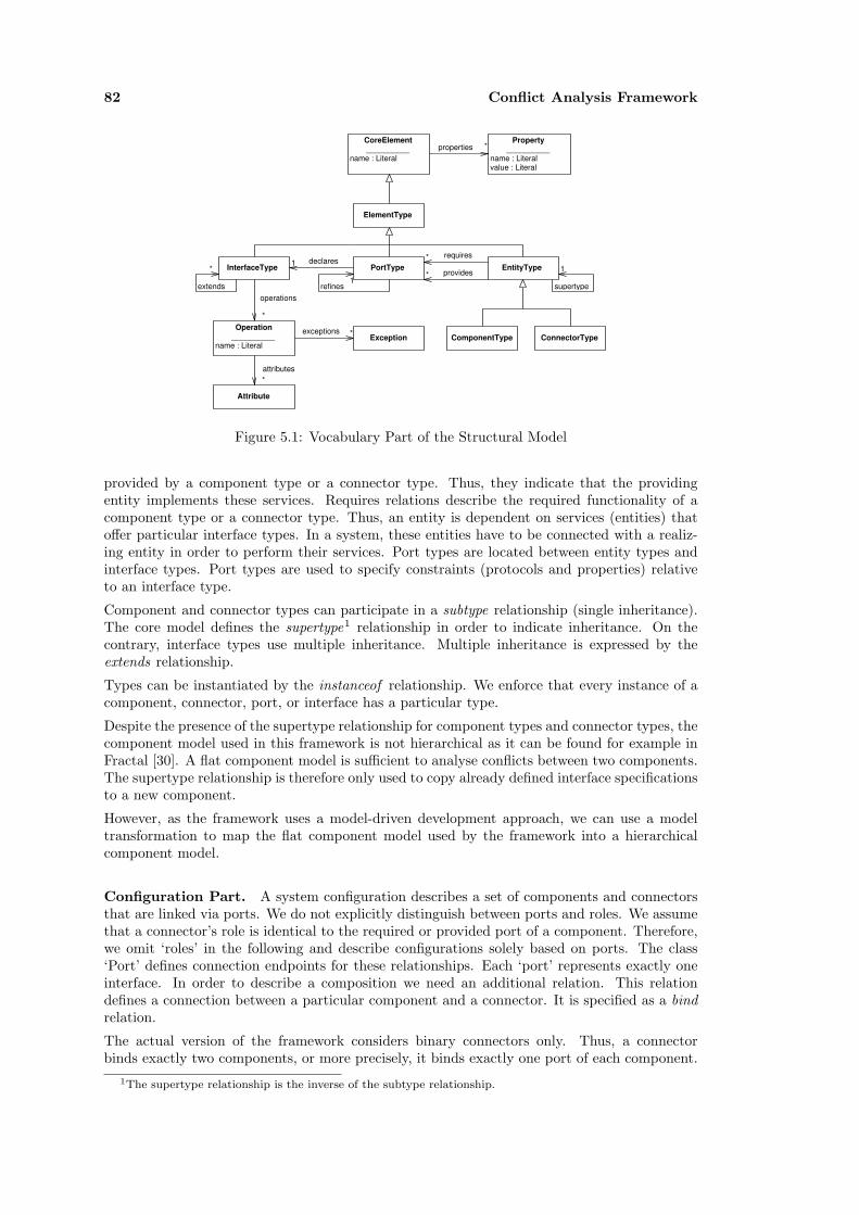
82 Conflict Analysis Framework
CoreElement __________
name : Literal
ElementType
PortType EntityTypeInterfaceType
ComponentType ConnectorType
requires
providesdeclares
refinesextendsoperations
Operation __________
name : Literal
Attribute
attributes
supertype
exceptionsException
11
1
*
*
*
**
*
Property __________
name : Literal value : Literal
properties *
Figure 5.1: Vocabulary Part of the Structural Model
provided by a component type or a connector type. Thus, they indicate that the providingentity implements these services. Requires relations describe the required functionality of acomponent type or a connector type. Thus, an entity is dependent on services (entities) thatoffer particular interface types. In a system, these entities have to be connected with a realiz-ing entity in order to perform their services. Port types are located between entity types andinterface types. Port types are used to specify constraints (protocols and properties) relativeto an interface type.
Component and connector types can participate in a subtype relationship (single inheritance).The core model defines the supertype1 relationship in order to indicate inheritance. On thecontrary, interface types use multiple inheritance. Multiple inheritance is expressed by theextends relationship.
Types can be instantiated by the instanceof relationship. We enforce that every instance of acomponent, connector, port, or interface has a particular type.
Despite the presence of the supertype relationship for component types and connector types, thecomponent model used in this framework is not hierarchical as it can be found for example inFractal [30]. A flat component model is sufficient to analyse conflicts between two components.The supertype relationship is therefore only used to copy already defined interface specificationsto a new component.
However, as the framework uses a model-driven development approach, we can use a modeltransformation to map the flat component model used by the framework into a hierarchicalcomponent model.
Configuration Part. A system configuration describes a set of components and connectorsthat are linked via ports. We do not explicitly distinguish between ports and roles. We assumethat a connector’s role is identical to the required or provided port of a component. Therefore,we omit ‘roles’ in the following and describe configurations solely based on ports. The class‘Port’ defines connection endpoints for these relationships. Each ‘port’ represents exactly oneinterface. In order to describe a composition we need an additional relation. This relationdefines a connection between a particular component and a connector. It is specified as a bindrelation.
The actual version of the framework considers binary connectors only. Thus, a connectorbinds exactly two components, or more precisely, it binds exactly one port of each component.
1The supertype relationship is the inverse of the subtype relationship.
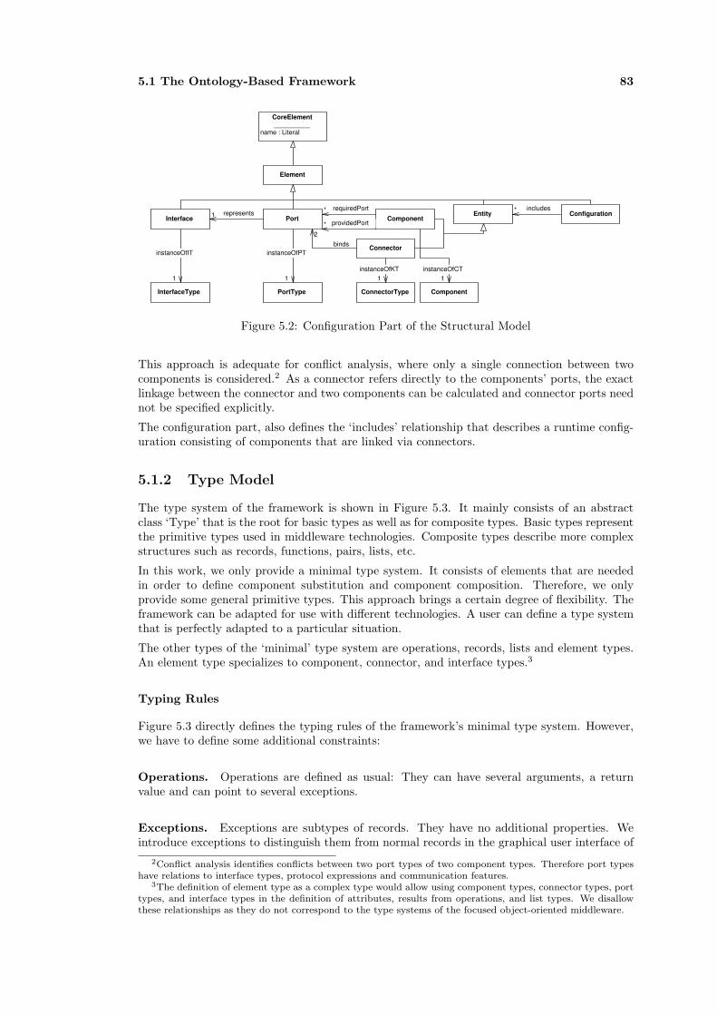
5.1 The Ontology-Based Framework 83
CoreElement __________
name : Literal
Element
PortEntity
Interface Component
Connector
requiredPort
providedPortrepresents
binds
Configurationincludes
InterfaceType
instanceOfIT
PortType
instanceOfPT
ConnectorType
instanceOfKT
Component
instanceOfCT1
1
1 1 1
*
*2
*
Figure 5.2: Configuration Part of the Structural Model
This approach is adequate for conflict analysis, where only a single connection between twocomponents is considered.2 As a connector refers directly to the components’ ports, the exactlinkage between the connector and two components can be calculated and connector ports neednot be specified explicitly.
The configuration part, also defines the ‘includes’ relationship that describes a runtime config-uration consisting of components that are linked via connectors.
5.1.2 Type Model
The type system of the framework is shown in Figure 5.3. It mainly consists of an abstractclass ‘Type’ that is the root for basic types as well as for composite types. Basic types representthe primitive types used in middleware technologies. Composite types describe more complexstructures such as records, functions, pairs, lists, etc.
In this work, we only provide a minimal type system. It consists of elements that are neededin order to define component substitution and component composition. Therefore, we onlyprovide some general primitive types. This approach brings a certain degree of flexibility. Theframework can be adapted for use with different technologies. A user can define a type systemthat is perfectly adapted to a particular situation.
The other types of the ‘minimal’ type system are operations, records, lists and element types.An element type specializes to component, connector, and interface types.3
Typing Rules
Figure 5.3 directly defines the typing rules of the framework’s minimal type system. However,we have to define some additional constraints:
Operations. Operations are defined as usual: They can have several arguments, a returnvalue and can point to several exceptions.
Exceptions. Exceptions are subtypes of records. They have no additional properties. Weintroduce exceptions to distinguish them from normal records in the graphical user interface of
2Conflict analysis identifies conflicts between two port types of two component types. Therefore port typeshave relations to interface types, protocol expressions and communication features.
3The definition of element type as a complex type would allow using component types, connector types, porttypes, and interface types in the definition of attributes, results from operations, and list types. We disallowthese relationships as they do not correspond to the type systems of the focused object-oriented middleware.
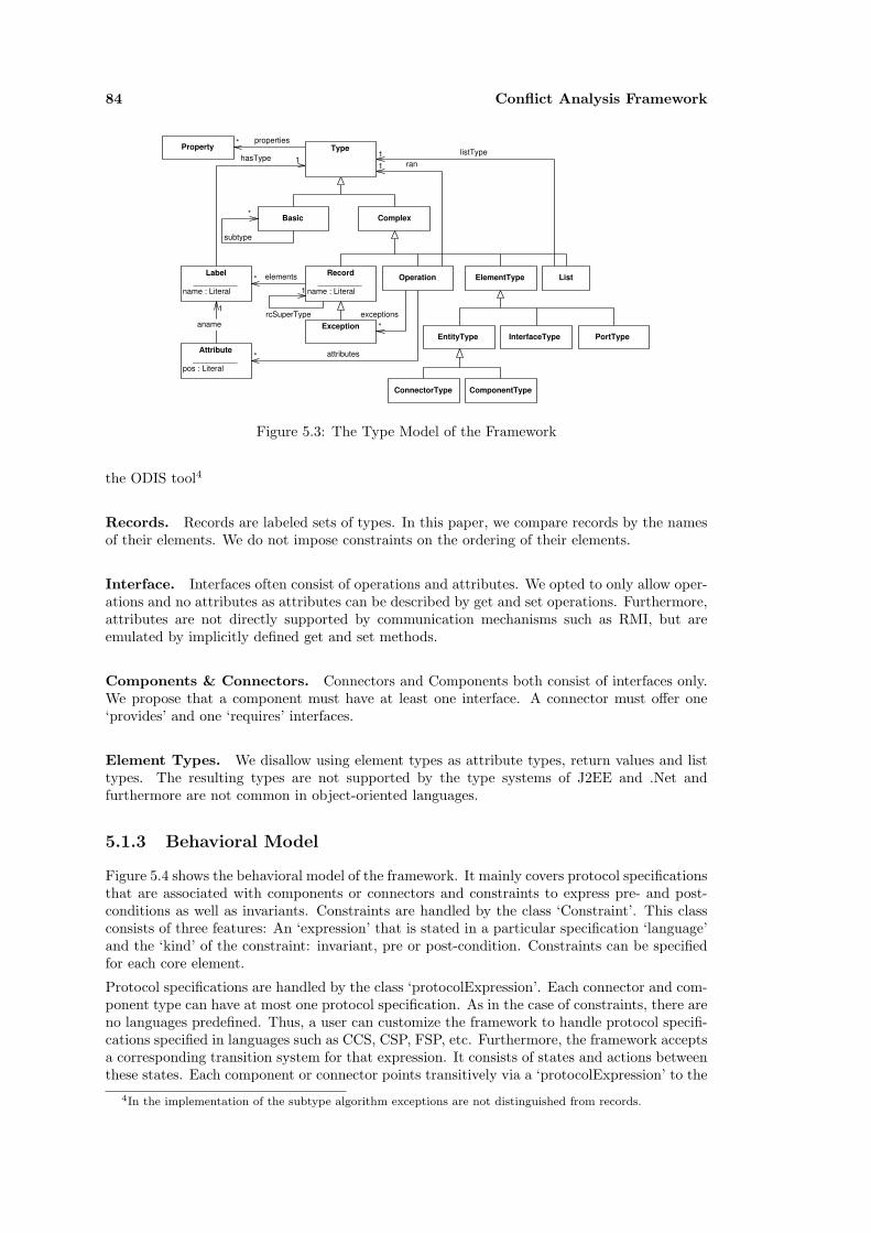
84 Conflict Analysis Framework
Basic Complex
ElementType
Exception
Operation ListRecord __________
name : Literal
subtype
Attribute __________
pos : Literal
Label __________
name : Literal
aname
attributes
elements
EntityType InterfaceType PortType
ComponentTypeConnectorType
hasTyperan
listType
exceptions
1
1
11
*
*
*
*rcSuperType
1
TypePropertyproperties*
Figure 5.3: The Type Model of the Framework
the ODIS tool4
Records. Records are labeled sets of types. In this paper, we compare records by the namesof their elements. We do not impose constraints on the ordering of their elements.
Interface. Interfaces often consist of operations and attributes. We opted to only allow oper-ations and no attributes as attributes can be described by get and set operations. Furthermore,attributes are not directly supported by communication mechanisms such as RMI, but areemulated by implicitly defined get and set methods.
Components & Connectors. Connectors and Components both consist of interfaces only.We propose that a component must have at least one interface. A connector must offer one‘provides’ and one ‘requires’ interfaces.
Element Types. We disallow using element types as attribute types, return values and listtypes. The resulting types are not supported by the type systems of J2EE and .Net andfurthermore are not common in object-oriented languages.
5.1.3 Behavioral Model
Figure 5.4 shows the behavioral model of the framework. It mainly covers protocol specificationsthat are associated with components or connectors and constraints to express pre- and post-conditions as well as invariants. Constraints are handled by the class ‘Constraint’. This classconsists of three features: An ‘expression’ that is stated in a particular specification ‘language’and the ‘kind’ of the constraint: invariant, pre or post-condition. Constraints can be specifiedfor each core element.
Protocol specifications are handled by the class ‘protocolExpression’. Each connector and com-ponent type can have at most one protocol specification. As in the case of constraints, there areno languages predefined. Thus, a user can customize the framework to handle protocol specifi-cations specified in languages such as CCS, CSP, FSP, etc. Furthermore, the framework acceptsa corresponding transition system for that expression. It consists of states and actions betweenthese states. Each component or connector points transitively via a ‘protocolExpression’ to the
4In the implementation of the subtype algorithm exceptions are not distinguished from records.
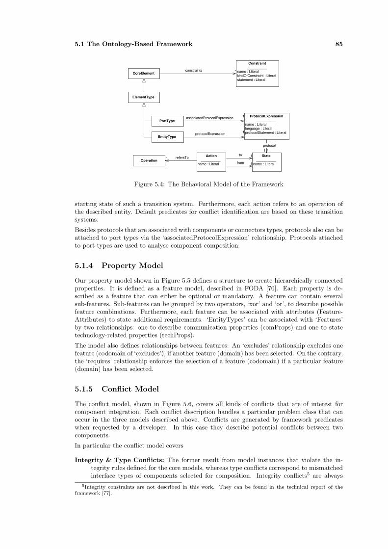
5.1 The Ontology-Based Framework 85
CoreElement
ElementType
EntityType
PortType
Constraint __________
name : Literal kindOfConstraint : Literal statement : Literal
constraints
ProtocolExpression __________
name : Literal language : Literal protocolStatement : LiteralprotocolExpression
associatedProtocolExpression
State __________
name : Literal
protocol
to
from
Action __________
name : Literal Operation
refersTo
*
1
1
11
11
Figure 5.4: The Behavioral Model of the Framework
starting state of such a transition system. Furthermore, each action refers to an operation ofthe described entity. Default predicates for conflict identification are based on these transitionsystems.
Besides protocols that are associated with components or connectors types, protocols also can beattached to port types via the ‘associatedProtocolExpression’ relationship. Protocols attachedto port types are used to analyse component composition.
5.1.4 Property Model
Our property model shown in Figure 5.5 defines a structure to create hierarchically connectedproperties. It is defined as a feature model, described in FODA [70]. Each property is de-scribed as a feature that can either be optional or mandatory. A feature can contain severalsub-features. Sub-features can be grouped by two operators, ‘xor’ and ‘or’, to describe possiblefeature combinations. Furthermore, each feature can be associated with attributes (Feature-Attributes) to state additional requirements. ‘EntityTypes’ can be associated with ‘Features’by two relationships: one to describe communication properties (comProps) and one to statetechnology-related properties (techProps).
The model also defines relationships between features: An ‘excludes’ relationship excludes onefeature (codomain of ‘excludes’), if another feature (domain) has been selected. On the contrary,the ‘requires’ relationship enforces the selection of a feature (codomain) if a particular feature(domain) has been selected.
5.1.5 Conflict Model
The conflict model, shown in Figure 5.6, covers all kinds of conflicts that are of interest forcomponent integration. Each conflict description handles a particular problem class that canoccur in the three models described above. Conflicts are generated by framework predicateswhen requested by a developer. In this case they describe potential conflicts between twocomponents.
In particular the conflict model covers
Integrity & Type Conflicts: The former result from model instances that violate the in-tegrity rules defined for the core models, whereas type conflicts correspond to mismatchedinterface types of components selected for composition. Integrity conflicts5 are always
5Integrity constraints are not described in this work. They can be found in the technical report of theframework [77].

86 Conflict Analysis Framework
Feature __________
fname : Literal fdescription : Literal
MandatoryFeatureOptionalFeature
VarElement
VarXOR VarOR
subFeature
excludesrequires
comPropstechProps
comPropstechProps
FeatureAttribute __________
faname : Literal favalue : Literal
feAttributesPortType
Port
*
FeatureElement *
****
**
Figure 5.5: The Property Model of the Framework
Conflict __________
cause : Literal
BinaryConflict
FeatureConflict TypeConflict
ProtocolConflict
BehavioralPropertyConflict
SimulationConflict __________
failureTrace : Literal
NameConflictConstraintConflict __________
kindOfConstraint : Literal
CoreElementconcerns
relates
FeatureElement
concernsFeature
Action
mismatchedName
Configuration
conflictConfiguration
1
1
111
contains*
Figure 5.6: The Conflict Model of the Framework

5.2 UML Representation of the Framework’s Components 87
caused by instances of model elements that violate constraints of the framework andtherefore cannot be processed any further nor checked for compositional conflicts.
Type conflicts result from mismatched subtype relationships between two componenttypes. A ‘TypeConflict’ is defined as a kind of ‘BinaryConflict’ between two componenttypes. It is further specified by a pointer to the interface type for which no subtyperelationship can be calculated.
Behavior Conflicts: In general, three kinds of behavioral conflicts are covered: constraintviolations, protocol violations, and property violations (e.g. deadlocks). Protocol viola-tions are either name conflicts, simulation or bisimulation conflicts. The former occurs ifthe actions of one process do not have a counterpart in the compared process and no cor-respondence exists that identifies different labeled actions. A prerequisite for simulationand bisimulation are identical action labels of the compared process graphs. Simulationand bisimulation conflicts are proven based on the chosen equivalence relationships.6 Aswe aim to check these relationships with external tools, such as Aldebaran, FC2Tools,LTSA, the set of algorithms may be customized. However, for each algorithm a checkpredicate as well as a conflict generation predicate has to be defined.
Constraint violations refer to one or more constraints that are violated within the com-parison of two components. This kind of conflict occurs if the pre- and post-conditions oftwo components are incompatible.
Besides checking for equivalence relationships between components and/or connectors,we can also verify certain properties of a composed system, consisting of a connector andseveral components. System properties that can be checked include progress properties aswell as deadlocks. In terms of process algebra, these properties can be tested by existingtools such as LTSA [82]. These tools allow testing properties based on parallelly-composedprocess expressions (bound to components and a connector). A property conflict consistsof a field stating the kind of property violation, a reference to a ‘Configuration’ andpointers to the elements (components and connectors) of a parallelly-composed system.
Property Conflicts: Property conflicts are described by the ProperyConflict class. Propertyconflicts refine binary conflicts by a new relationship pointing to the property (FeatureEle-ment) that caused the conflict.
5.2 UML Representation of the Framework’s Components
In order to integrate the conflict analysis framework in common software development processesthat use UML for the design stage, a mapping between the framework models and UML needsto be defined. A prerequisite for the mapping concerns the identification of the framework’scomponents in UML. We solve this requirement with UML profiles. These mainly use stereo-typed UML classes to represent the framework’s entities (on the platform independent level andon the platform specific level) in a one-to-one relationship. The mapping itself consists of twoparts: a transformation of XMI into RDF based on the UML metamodel and the reinterpreta-tion of component instances, specified relative to the UML metamodel against the framework’smetamodels.
In this section, we describe how the framework components are principally represented in UMLbased on the defined PICM UML profile. The examples provided in Section 5.3 augmentthis introduction by a complete overview of UML representations of all main models definedby OBF. Furthermore, this section describes the mappings necessary to exchange componentdescriptions between UML models and the framework.
6Section 6.2 introduces several relationships such as strong bisimulation or branching bisimulation that canbe used for conflict analysis provided that the used model checker supports the relationships.
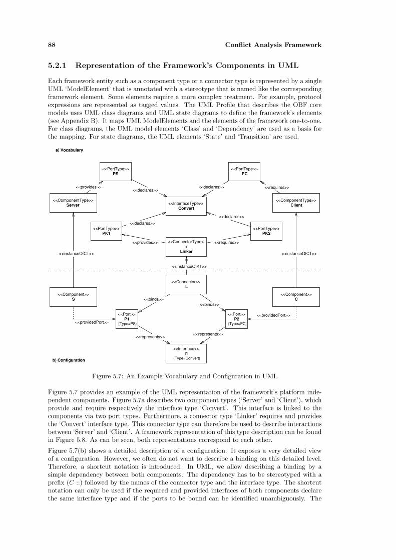
88 Conflict Analysis Framework
5.2.1 Representation of the Framework’s Components in UML
Each framework entity such as a component type or a connector type is represented by a singleUML ‘ModelElement’ that is annotated with a stereotype that is named like the correspondingframework element. Some elements require a more complex treatment. For example, protocolexpressions are represented as tagged values. The UML Profile that describes the OBF coremodels uses UML class diagrams and UML state diagrams to define the framework’s elements(see Appendix B). It maps UML ModelElements and the elements of the framework one-to-one.For class diagrams, the UML model elements ‘Class’ and ‘Dependency’ are used as a basis forthe mapping. For state diagrams, the UML elements ‘State’ and ‘Transition’ are used.
<<InterfaceType>> Convert
<<ConnectorType>>
Linker
<<ComponentType>> Server
<<ComponentType>> Client
<<provides>> <<requires>>
<<provides>> <<requires>>
<<Component>> S
<<Component>> C
<<Connector>> L
<<instanceOfKT>>
<<instanceOfCT>><<instanceOfCT>>
<<Port>> P1
{Type=PS}
<<Port>> P2
{Type=PC}
<<Interface>> I1
{Type=Convert}
<<providedPort>>
<<providedPort>>
<<represents>><<represents>>
<<binds>><<binds>>
a) Vocabulary
b) Configuration
<<PortType>> PC
<<PortType>> PS
<<PortType>> PK1
<<PortType>> PK2
<<declares>><<declares>>
<<declares>>
<<declares>>
Figure 5.7: An Example Vocabulary and Configuration in UML
Figure 5.7 provides an example of the UML representation of the framework’s platform inde-pendent components. Figure 5.7a describes two component types (‘Server’ and ‘Client’), whichprovide and require respectively the interface type ‘Convert’. This interface is linked to thecomponents via two port types. Furthermore, a connector type ‘Linker’ requires and providesthe ‘Convert’ interface type. This connector type can therefore be used to describe interactionsbetween ‘Server’ and ‘Client’. A framework representation of this type description can be foundin Figure 5.8. As can be seen, both representations correspond to each other.
Figure 5.7(b) shows a detailed description of a configuration. It exposes a very detailed viewof a configuration. However, we often do not want to describe a binding on this detailed level.Therefore, a shortcut notation is introduced. In UML, we allow describing a binding by asimple dependency between both components. The dependency has to be stereotyped with aprefix (C ::) followed by the names of the connector type and the interface type. The shortcutnotation can only be used if the required and provided interfaces of both components declarethe same interface type and if the ports to be bound can be identified unambiguously. The

5.2 UML Representation of the Framework’s Components 89
Figure 5.8: Example Vocabulary Rendered by ODIS
dependency has to point to the component that provides the interface. Figure 5.9 shows theshortcut notation for a part of example 5.7.
<<Component>> S
<<Component>> C
<<C::Linker,Convert>>
Figure 5.9: The Shortcut Representation of a Binding
5.2.2 Transformation between UML and RDF
The transformation of a UML model, which is specified according to one of the supplied UMLprofiles, is realized in two steps: In the first step a generic UML-to-RDF transformation isapplied, which results in the representation of UML models as RDF instances of the UMLmetamodel. This step is a generic transformation of a UML model into an RDF representation.Thereby, both versions of the model are instances of a UML metamodel, which is expressedin MOF and in RDFS. The second step converts models that are defined relative to a UMLmetamodel into a representation which is an instance of one of the OBF metamodels.
Creating an RDF Representation of a UML model
The first step of model transformation converts UML models, which are encoded as XMI datastreams, into a RDF representation. The resulting RDF model is consistent to a RDFS model,which represents the UML metamodel of the UML source model in RDFS. Figure 5.10 denotesthis transformation as a ‘1:1 mapping’ between a UML metamodel and the corresponding RDFSmodel on the MOF M2 layer. Based on these two metamodels, arbitrary UML models (M1layer) can be translated into RDF.
Metamodel Transformation
The second step requires a model transformation between two different metamodels. Thetransformation converts models that are instances of a UML 1.4 metamodel into models relativeto one of the available PICM or PSCM metamodels of OBF. This step only covers UML modelsthat are specified according to one of the provided UML profiles. As the profiles provide analmost one-to-one representation of the framework’s metamodels in UML, transformation rulesorientate on stereotypes and tagged values to perform the mapping.
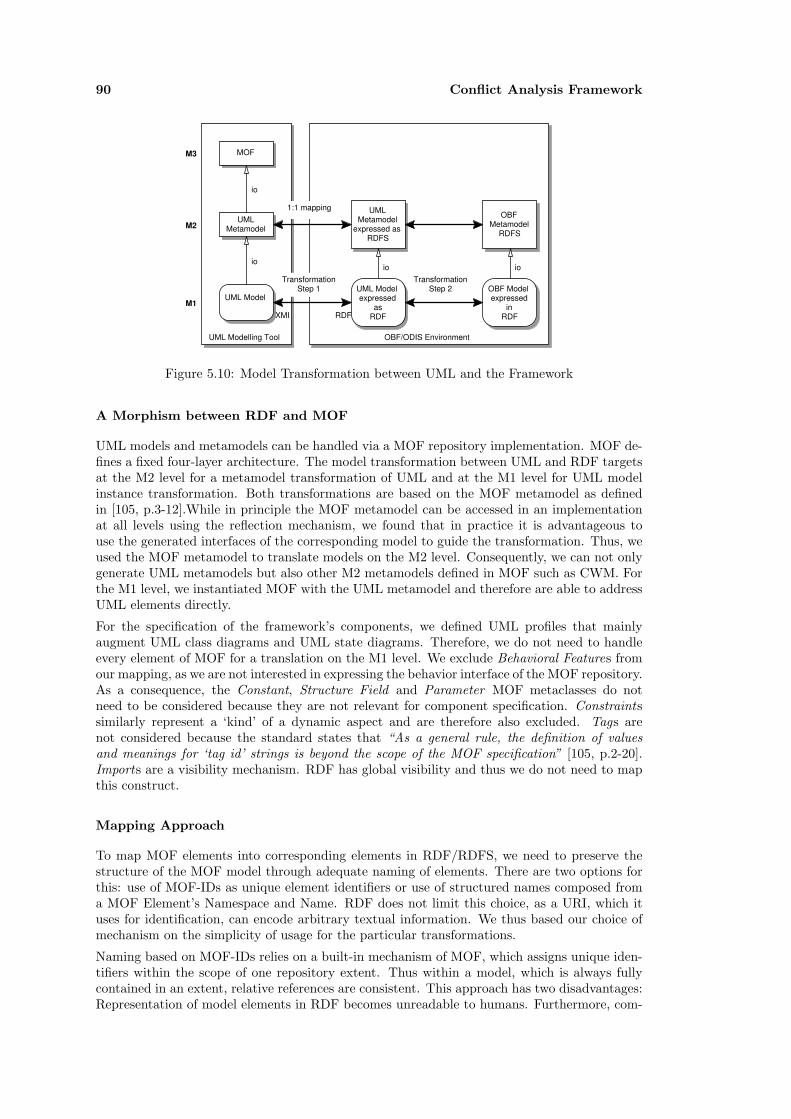
90 Conflict Analysis Framework
OBF/ODIS EnvironmentUML Modelling Tool
UML Metamodel
UML Model
MOFM3
M2
M1
io
io
UML Metamodel
expressed as RDFS
UML Model expressed
as RDF
io
OBF Metamodel
RDFS
OBF Model expressed
in RDF
ioTransformation
Step 1Transformation
Step 2
XMI RDF
1:1 mapping
Figure 5.10: Model Transformation between UML and the Framework
A Morphism between RDF and MOF
UML models and metamodels can be handled via a MOF repository implementation. MOF de-fines a fixed four-layer architecture. The model transformation between UML and RDF targetsat the M2 level for a metamodel transformation of UML and at the M1 level for UML modelinstance transformation. Both transformations are based on the MOF metamodel as definedin [105, p.3-12].While in principle the MOF metamodel can be accessed in an implementationat all levels using the reflection mechanism, we found that in practice it is advantageous touse the generated interfaces of the corresponding model to guide the transformation. Thus, weused the MOF metamodel to translate models on the M2 level. Consequently, we can not onlygenerate UML metamodels but also other M2 metamodels defined in MOF such as CWM. Forthe M1 level, we instantiated MOF with the UML metamodel and therefore are able to addressUML elements directly.
For the specification of the framework’s components, we defined UML profiles that mainlyaugment UML class diagrams and UML state diagrams. Therefore, we do not need to handleevery element of MOF for a translation on the M1 level. We exclude Behavioral Features fromour mapping, as we are not interested in expressing the behavior interface of the MOF repository.As a consequence, the Constant, Structure Field and Parameter MOF metaclasses do notneed to be considered because they are not relevant for component specification. Constraintssimilarly represent a ‘kind’ of a dynamic aspect and are therefore also excluded. Tags arenot considered because the standard states that “As a general rule, the definition of valuesand meanings for ‘tag id’ strings is beyond the scope of the MOF specification” [105, p.2-20].Imports are a visibility mechanism. RDF has global visibility and thus we do not need to mapthis construct.
Mapping Approach
To map MOF elements into corresponding elements in RDF/RDFS, we need to preserve thestructure of the MOF model through adequate naming of elements. There are two options forthis: use of MOF-IDs as unique element identifiers or use of structured names composed froma MOF Element’s Namespace and Name. RDF does not limit this choice, as a URI, which ituses for identification, can encode arbitrary textual information. We thus based our choice ofmechanism on the simplicity of usage for the particular transformations.
Naming based on MOF-IDs relies on a built-in mechanism of MOF, which assigns unique iden-tifiers within the scope of one repository extent. Thus within a model, which is always fullycontained in an extent, relative references are consistent. This approach has two disadvantages:Representation of model elements in RDF becomes unreadable to humans. Furthermore, com-
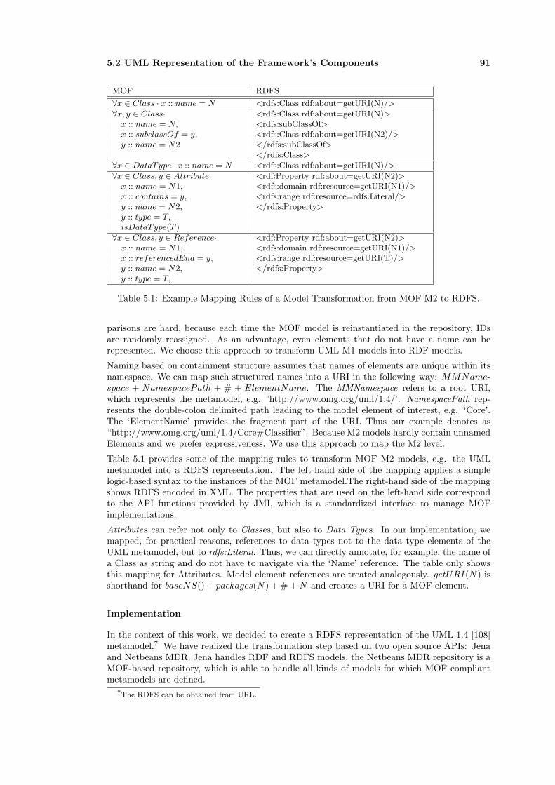
5.2 UML Representation of the Framework’s Components 91
MOF RDFS
∀x ∈ Class · x :: name = N <rdfs:Class rdf:about=getURI(N)/>
∀x, y ∈ Class· <rdfs:Class rdf:about=getURI(N)>x :: name = N, <rdfs:subClassOf>x :: subclassOf = y, <rdfs:Class rdf:about=getURI(N2)/>y :: name = N2 </rdfs:subClassOf>
</rdfs:Class>
∀x ∈ DataType · x :: name = N <rdfs:Class rdf:about=getURI(N)/>
∀x ∈ Class, y ∈ Attribute· <rdf:Property rdf:about=getURI(N2)>x :: name = N1, <rdfs:domain rdf:resource=getURI(N1)/>x :: contains = y, <rdfs:range rdf:resource=rdfs:Literal/>y :: name = N2, </rdfs:Property>y :: type = T,isDataType(T )
∀x ∈ Class, y ∈ Reference· <rdf:Property rdf:about=getURI(N2)>x :: name = N1, <rdfs:domain rdf:resource=getURI(N1)/>x :: referencedEnd = y, <rdfs:range rdf:resource=getURI(T)/>y :: name = N2, </rdfs:Property>y :: type = T,
Table 5.1: Example Mapping Rules of a Model Transformation from MOF M2 to RDFS.
parisons are hard, because each time the MOF model is reinstantiated in the repository, IDsare randomly reassigned. As an advantage, even elements that do not have a name can berepresented. We choose this approach to transform UML M1 models into RDF models.
Naming based on containment structure assumes that names of elements are unique within itsnamespace. We can map such structured names into a URI in the following way: MMName-space + NamespacePath + # + ElementName. The MMNamespace refers to a root URI,which represents the metamodel, e.g. ’http://www.omg.org/uml/1.4/’. NamespacePath rep-resents the double-colon delimited path leading to the model element of interest, e.g. ‘Core’.The ‘ElementName’ provides the fragment part of the URI. Thus our example denotes as“http://www.omg.org/uml/1.4/Core#Classifier”. Because M2 models hardly contain unnamedElements and we prefer expressiveness. We use this approach to map the M2 level.
Table 5.1 provides some of the mapping rules to transform MOF M2 models, e.g. the UMLmetamodel into a RDFS representation. The left-hand side of the mapping applies a simplelogic-based syntax to the instances of the MOF metamodel.The right-hand side of the mappingshows RDFS encoded in XML. The properties that are used on the left-hand side correspondto the API functions provided by JMI, which is a standardized interface to manage MOFimplementations.
Attributes can refer not only to Classes, but also to Data Types. In our implementation, wemapped, for practical reasons, references to data types not to the data type elements of theUML metamodel, but to rdfs:Literal. Thus, we can directly annotate, for example, the name ofa Class as string and do not have to navigate via the ‘Name’ reference. The table only showsthis mapping for Attributes. Model element references are treated analogously. getURI(N) isshorthand for baseNS() + packages(N) + # + N and creates a URI for a MOF element.
Implementation
In the context of this work, we decided to create a RDFS representation of the UML 1.4 [108]metamodel.7 We have realized the transformation step based on two open source APIs: Jenaand Netbeans MDR. Jena handles RDF and RDFS models, the Netbeans MDR repository is aMOF-based repository, which is able to handle all kinds of models for which MOF compliantmetamodels are defined.
7The RDFS can be obtained from URL.

92 Conflict Analysis Framework
In principle, all kinds of models for which a MOF compliant metamodel exist can be translated inthe same way. The Netbeans MDR repository provides a reflection mechanism on metamodelsthat can be used to generate RDF schemata. We have implemented an EVE service thatgenerates for arbitrary MOF 1.4 M2 metamodels a corresponding RDFS metamodel. 8
5.2.3 Integrity Conflicts
Integrity conflicts identify component specifications that are not compliant to the rules of thecore models.
These conflicts can occur in the translation of component specifications from UML into RDF,as the transformation does not prevent invalid specifications.
We do not consider the integrity rules of the framework in this work. Please refer to [77] for anexact definition of the imposed rules.
5.3 Examples
This section provides two examples to demonstrate component specification in the framework.All examples present different aspects of component specification and are shown in a UMLrepresentation and a framework representation: The dining philosophers example demonstratescomponent type specifications as well as a system configuration. The mortage bank exampleillustrates behavioral attachements and property annotations.
5.3.1 Dining Philosopher Example
Figure 5.11 shows a representation of the well known philosophers problem. The problemis characterized by five philosophers that compete against limited resources (forks).9 Theexample demonstrates properties and problems of concurrent programs. Figure 5.11 describesphilosophers and forks as component types, which are linked by the ‘PhilConnect’ connectortype. The upper part shows the simple vocabulary of the two involved component types, whichare linked via the IFork interface type.
The lower part of figure 5.11 shows a configuration of five philosophers and five forks. Thebindings between the philosophers are expressed by the shortcut notation introduced in Section5.2.1.
Figure 5.12 shows a screenshot from the vocabulary part of the philosopher example: The UMLmodel was converted into RDF and the Metamodel transformed from UML into PICM.
5.3.2 Mortgage Bank Example
The second example (see Figure 5.13) shows two components that are part of a fictive customerinformation system. They describe part of a possible simulation of financial development fordifferent forms of mortgage contracts. The BLContractMgmt component acts as a customerfacade. It uses calculations from a set of worker components described by the BLCalc componenttype. Both component types are annotated with process descriptions expressed in FSP, a processalgebra proposed by Kramer and Magee [86].
In the UML profile, which can be found in appendix B, protocol expressions and languageattributes are defined as tagged values of a UML Class which is annotated with the PortTypestereotype. In Figure 5.13, however, we use a note to describe this information, because ofbetter readability.
8The UML2RDF metamodel translator is available for download from URL.9For a brief explanation see [61].

5.3 Examples 93
<<C
ompo
nent
Type
>>
Phi
loso
pher
<<C
ompo
nent
Type
>>
Fork
<<P
ortT
ype>
> F
<<P
ortT
ype>
> P
<<In
terfa
ceTy
pe>>
IF
ork
<<C
onne
ctor
Type
>>
Phi
lCon
nect
<<P
ortT
ype>
> B
F<<
Por
tTyp
e>>
BP
<<re
quire
s>>
<<de
clar
es>>
<<
decl
ares
>>
<<pr
ovid
es>>
<<re
quire
s>>
<<pr
ovid
es>>
<<de
clar
es>>
<<de
clar
es>>
<<C
ompo
nent
>>
F1
{type
=For
k}
<<C
ompo
nent
>>
P1
{type
=Phi
loso
pher
}
<<C
ompo
nent
>>
P2
{type
=Phi
loso
pher
}
<<C
ompo
nent
>>
P4
{type
=Phi
loso
pher
}
<<C
ompo
nent
>>
P3
{type
=Phi
loso
pher
}
<<C
ompo
nent
>>
P5
{type
=Phi
loso
pher
}
<<C
ompo
nent
>>
F2
{type
=For
k}
<<C
ompo
nent
>>
F3
{type
=For
k}
<<C
ompo
nent
>>
F5
{type
=For
k}
<<C
ompo
nent
>>
F4
{type
=For
k}
<<C
::Phi
lCon
nect
,IFor
k>>
<<C
::Phi
lCon
nect
,IFor
k>>
<<C
::Phi
lCon
nect
,IFor
k>> <<
C::P
hilC
onne
ct,IF
ork>
> <<
C::P
hilC
onne
ct,IF
ork>
> <<C
::Phi
lCon
nect
,IFor
k>>
<<C
::Phi
lCon
nect
,IFor
k>>
<<C
::Phi
lCon
nect
,IFor
k>>
<<C
::Phi
lCon
nect
,IFor
k>>
<<C
::Phi
lCon
nect
,IFor
k>>
Con
figur
atio
n V
iew
Type
Vie
w
Figure 5.11: The Philosopher’s Problem Described by the UML Profile
Figure 5.12: Screenshot of the Philosopher Vocabulary

94 Conflict Analysis Framework
<< ComponentType >>BLContractMgmt
<< ComponentType >>BLCalc
<< PortType >>P1
<< requires >>
<< InterfaceType >>ContractSimulation
+ newBLContract ():BLContract+ simulate (c:BLContract ):SimulationResult
<< Record >>BLContract
<< Record >>SimulationResult
<< declares >>
<< PortType >>P2
<< provides >>
<< InterfaceType >>ISimulate
+ getNewContract ():Contract+ simulate (c:Contract ):Simulation+ setRate(i:int ):void
<< Record >>Contract
<< Record >>Simulation
<< declares >>
PAE(FSP):=R=(newContract −> R1),R1=(newContract −>R1 | simulate −> R1).
PAE(FS):=Q = (getNewContract−>Q1),Q1=(getNewContract−>Q1 |setRate−>Q2),Q2=(getNewContract−>Q2 |setRate−>Q2 |simulation−>Q2).
<< Mandatory >>fmSessionBean
<< comProps >>
<< Mandatory >>fmManagedComponent
<< comProps >>
Created with Poseidon for UML Community Edition. Not for Commercial Use.
Figure 5.13: Mortgage Bank Example
Figure 5.14 shows the BLContractMgmt component rendered by ODIS. As can be seen, theprotocol expression has been automatically translated into the required structure of the frame-work. Furthermore, the roots of the attached communication properties are shown. Bothcommunication taxonomies are represented in figures 4.1 and 4.2.
Figure 5.14: Part of the Mortgage Bank Example Rendered By ODIS

Chapter 6
Conflict Analysis
Conflict analysis is the last step in the conflict analysis process described in Section 3.3.1.It requires that components comply to several requirements: At first, components must bespecified in the Platform Independent Component Model. Consequently, their types must beexpressed in terms of the type system introduced in Section 5.1.2. The type system musteventually be extended by basic (primitive) types that represent primitive types of the tech-nologies from which the components originate. Furthermore, behavior descriptions attached tothe components must be stated in the same language and a tool must exist and be included inthe framework that can handle the language. At present, we use FSP [86] to specify protocolsas process algebra expressions and use the tools fc2tools [117], Aldebaran [47] and LTSA [86]for conflict analysis. Finally, communication requirements of components must be described byproperties of the communication taxonomy defined in Section 4.2.
The framework provides two operations for conflict analysis between two components withregard to type, behavior and communication specifications:
A Compatibility operation checks if two components can interact.
A Substitutability operation checks if two components can be exchanged.
Conflict analysis is checked between two port types. Therefore, the core model associates eachport type with type information (interface type), a behavior description and a communicationcontext. For compatibility analysis of two component types, a developer has to select two com-ponent types and for each component type either a single requires or a provides port type (seeFigure 6.1 for an example of a compatibility check). As mentioned above, the component modelof the framework is flat. Consequently, we do not look at component dependencies betweensubcomponents. For conflict analysis, we consider components as black-box specifications. Thedeveloper has to choose the granularity level he is interested in.
Compatibility analysis for connectors is not defined. Substitutability is checked for all requiresand provides port types of both component types or connector types. Contrary to compatibilitychecks, port types with the same relationship to a component type (either requires or provides)are compared to decide substitutability.
The first three sections of this chapter describe conflict analysis in the respective areas anddefine both operations for each area. The last section describes the implementation of theoperations.
6.1 Type Analysis
Type analysis is based on subtype relationships between components. In this section, we firstdiscuss the difference between nominal and structural subtyping, then we introduce the struc-
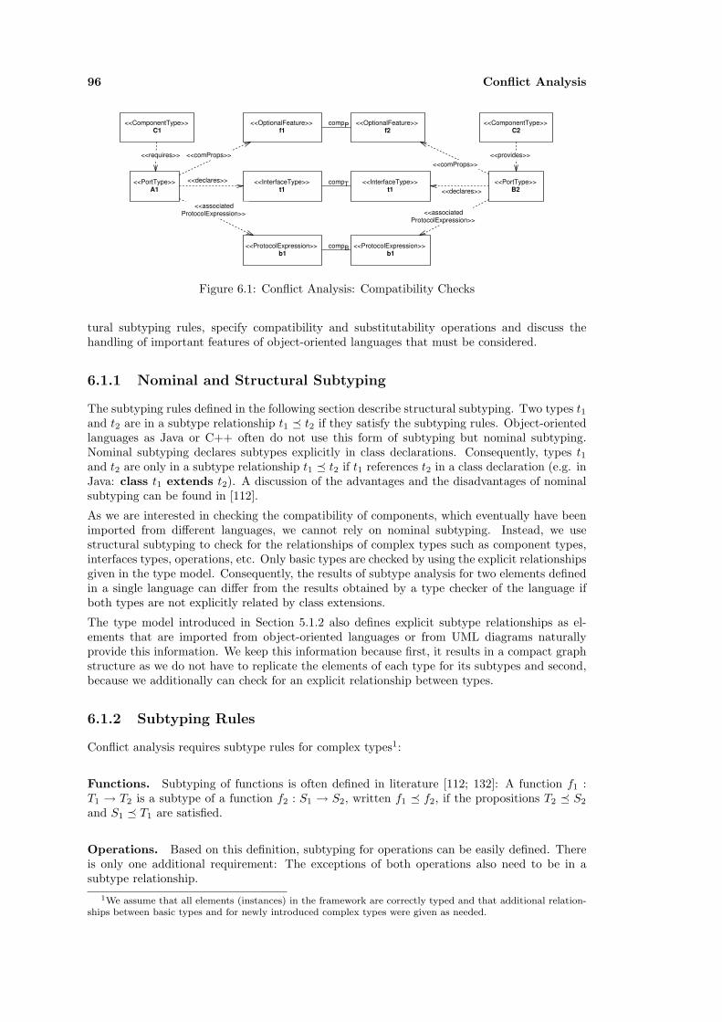
96 Conflict Analysis
<<ComponentType>> C1
<<ComponentType>> C2
<<PortType>> A1
<<PortType>> B2
<<provides>>
<<OptionalFeature>> f1
<<OptionalFeature>> f2
<<requires>> <<comProps>> <<comProps>>
<<InterfaceType>> t1
<<declares>>
<<ProtocolExpression>> b1
<<associated ProtocolExpression>>
<<InterfaceType>> t1
<<ProtocolExpression>> b1
<<declares>>
<<associated ProtocolExpression>>
compB
compT
compP
Figure 6.1: Conflict Analysis: Compatibility Checks
tural subtyping rules, specify compatibility and substitutability operations and discuss thehandling of important features of object-oriented languages that must be considered.
6.1.1 Nominal and Structural Subtyping
The subtyping rules defined in the following section describe structural subtyping. Two types t1and t2 are in a subtype relationship t1 � t2 if they satisfy the subtyping rules. Object-orientedlanguages as Java or C++ often do not use this form of subtyping but nominal subtyping.Nominal subtyping declares subtypes explicitly in class declarations. Consequently, types t1and t2 are only in a subtype relationship t1 � t2 if t1 references t2 in a class declaration (e.g. inJava: class t1 extends t2). A discussion of the advantages and the disadvantages of nominalsubtyping can be found in [112].
As we are interested in checking the compatibility of components, which eventually have beenimported from different languages, we cannot rely on nominal subtyping. Instead, we usestructural subtyping to check for the relationships of complex types such as component types,interfaces types, operations, etc. Only basic types are checked by using the explicit relationshipsgiven in the type model. Consequently, the results of subtype analysis for two elements definedin a single language can differ from the results obtained by a type checker of the language ifboth types are not explicitly related by class extensions.
The type model introduced in Section 5.1.2 also defines explicit subtype relationships as el-ements that are imported from object-oriented languages or from UML diagrams naturallyprovide this information. We keep this information because first, it results in a compact graphstructure as we do not have to replicate the elements of each type for its subtypes and second,because we additionally can check for an explicit relationship between types.
6.1.2 Subtyping Rules
Conflict analysis requires subtype rules for complex types1:
Functions. Subtyping of functions is often defined in literature [112; 132]: A function f1 :T1 → T2 is a subtype of a function f2 : S1 → S2, written f1 � f2, if the propositions T2 � S2
and S1 � T1 are satisfied.
Operations. Based on this definition, subtyping for operations can be easily defined. Thereis only one additional requirement: The exceptions of both operations also need to be in asubtype relationship.
1We assume that all elements (instances) in the framework are correctly typed and that additional relation-ships between basic types and for newly introduced complex types were given as needed.

6.1 Type Analysis 97
s = [1..o 1.attribute] = [1..o2.attribute]o1.range � o2.range
∀e1 ∈ o1.exceptions∃e2 ∈ o2.exceptions · e1 � e2
∀i ∈ s · o2.attributei.aname.hasType � o1.dom.attributei.aname.hasType
o1 � o2
The first line of the rule defines a list s containing the number of arguments of both operations.Thereby, both operations must have the same number of arguments. The second line demandsa covariant relationship of the return types. The third line requires a covariant relationshipbetween the declared exceptions of the subtype o1 and the supertype o2 for each exception ofthe subtype. Thus, a subtyped operation is not allowed to throw more exceptions or exceptionsthat are not subtypes of the exceptions thrown by the supertype operation. The fourth lineof the rule may be read as follows: Each attribute type at position i of the subtype o1 mustby in a contravariant relationship to the attribute type at the same position of the supertypeo2. Thereby, the reference ‘o2.attributei.aname.hasType’ represents the navigation in the typemodel shown in Figure 5.3.
Exceptions. We treat exceptions as a special kind of record. Therefore, they are checked bythe record subtyping rule.
Records. We define the usual rules for record subtyping. The following rule represents acombination of the ‘width’ rule and the ‘depth’ rule found in [112]. Thereby, record elementsare compared by name. Thus, a record A is a subtype of another record B, if all elements of Bare also available in A and the element types are in a covariant relationship.
∀f ∈ r1.elements∃g ∈ r2.elements · f.name = g.name ∧ g.hasType � f.hasType
r2 � r1
Records are used to represent classes of object-oriented languages. We restrict the elementsof records, which are used for subtype checks to operations and disallow direct manipulationof instance variables, which would demand stronger subtyping rules. We furthermore do notconsider other advanced features of classes such as constructors or access attributes. For adetailed discussion of class properties refer for example to Fisher and Mitchell [48].
Interfaces. A subtyping relationship between interfaces can be defined as follows:
∀o2 ∈ it2.operations∃o1 ∈ it1.operations · o1 � o2 ∧ o1.name = o2.name
it1 � it2
Thus, interface subtyping is defined in the same way as record subtyping. However, in our typemodel the navigation uses different paths and constraints interface type elements to operationtypes.
Lists. We treat lists as simple collections of objects of a particular type. The subtyping rulecorresponds to array subtyping as defined in [112]. As arrays can be accessed and manipulatedthey are neither covariant nor contravariant.
l1.listType � l2.listType l2.listType � l1.listType
l1 � l2

98 Conflict Analysis
Components & Connectors. Components and Connectors consist of two sets of interfaces:a ‘provides’ set and a ‘requires’ set. We define the following subset rules:
∀p2 ∈ ct2.provides.declares∃p1 ∈ ct1.provides.declares · p1 � p2
∀r1 ∈ ct1.requires.declares∃r2 ∈ ct2.requires.declares · r2 � r1
ct1 � ct2
Thus component ct1 needs to provide at least the services of ct2 but can have additional in-terfaces. Furthermore, ct1 must have at most the requirements of ct2. Connectors are definedanalogous.
6.1.3 Compatibility and Substitutability
Compatibility Two components C1 and C2 are compatible - written C1 ‘compS’ C2 if thereexist two interfaces i1 ∈ C1.provides.delcares and i2.provides.delcares, which are in the sub-type relationship: i2 � i1.
Component C1 uses the services or part of the services of C2. It cannot require more servicesin i1 as there are available in i2. Therefore, they are compatible if i2 is a subtype of i1. Inthis case, component instances of C1 and C2 can be related via a connector that binds theport instances i1 and i2. We define this form of connection - a single connection involving asingle pair requires and provides ports - as the standard composition mechanism in distributedsystems.2
A binding of two components C1 and C2 via a connector KT is valid if there exist two interfacetypes ki ∈ KT.provides.delcares and k2 ∈ KT.requires.declares that are in the followingsubtype relationships to the interface types i1 and i2 as defined above: k1 � i1 and i2 � k2.
Substitutability. Two element types E1 and E2, which are either ‘ComponentTypes’ or‘ConnectorTypes’, can be exchanged - written E1
′exchangeS′ E2 - if the following predicateevaluates to true:
∀i2 ∈ X2.provides.declares,∃i1 ∈ X1.provides.declares · i2 � i1∧∀i3 ∈ X1.requires.declares,∃i4 ∈ X2.requires.declares · i4 � i3
where X1 and X2 are either of type ′ComponentType′ or of type ′ConnectorType′.
Consequently, a component C1 can be exchanged by a new component C2 if the new componentprovides the same or more services to the environment and requires the same or less servicesfrom the environment. The same holds true for the exchange of connectors. The predicateis equivalent to the subtyping rule of component and connector types. Again, the expression‘provides.declares’ refers to the interfaces that are attached to an element E via a provides port.
Both definitions are based on a flat component model. We therefore does not consider theinternal structure of two component types but only the external visible properties.
6.1.4 Constructors, Overloading and Recursion
Object-oriented languages often provide additional features that must be considered for subtypechecking. Object classes are usually initialized via constructors. Constructors, are usuallydescribed in class definitions as well as in UML diagrams and therefore appear as class features
2This definition of a connection only considers a single connection between two ports. Other requires interfacesof a component must be connected via additional ‘bindings’.
6.2 Behavior Analysis 99
in the platform independent component model. However, they are not considered as regularmembers of classes [48; 69] and we therefore filter constructors so that they do not appear insubtype checking.
Another problem is method overloading. Most object-oriented languages allow defining severaloperations with the same name but different signatures. Therefore, names are not necessarilyunique. We treat this issue with the subtyping rules as stated above. We check that for eachoperation o1 of the superclass an operation o2 of the same name exists such that o2 � o1.
Object-oriented languages also allow class types as return and argument parameter of opera-tions. This can result in cyclic type structures. We treat this issue by defining a subtypingalgorithm that uses ‘Trails’ to remember the states already visited. A trail stores states of theform t1 � t2 in a list. An algorithm for subtype checking (called by ‘check st t’) stores a tupleof the actually checked types ((st, t)) in the trail and proceeds with recursive checks for thecomponents of st and t. Two recursive types t1 and t2 are in a subtype relationship t1 � t2 ifthe checking algorithm reaches a state that has already been visited and no contradiction wasfound. Trails as well as a subtyping algorithm for recursive types were defined by Cardelli andAmadio in [13] for example.
6.2 Behavior Analysis
Conflict analysis in the behavioral model is based on either the annotated labeled transitionsystems or on a particular process algebra, which has been provided by a user. Constraints arenot compared, as these require to instantiate the framework with a particular language suchas OCL or Z to define conflict predicates. Furthermore, constraints often cannot be comparedautomatically and are checked via theorem provers. A theorem prover often requires a skilleduser to find a proof.
According to Glabbeek [140, p.559], “a process graph is a connected, rooted, edge-labeled and di-rected graph” (a transition system). Each component can be interpreted as an entity that, whendeployed on a node (host system) can be associated with a process. To decide compatibility,we identify the action names of two components and compare their process graphs (transitionsystems). We distinguish two cases: Component composition and component substitution. Inthe first case, a simulation of the two process graphs needs to be proven, i.e. can the serviceprovider handle each action of the client component. In the second case, bisimulation of theold and new component needs to be proven, i.e. can they be exchanged transparently.
Process expressions can be annotated to component, connector types or to port types. Theformer are used to identify conflicts for component substitution, whereas the latter are used todecide component composition.
6.2.1 Equivalence Relationships
Informally, a simulation is an asymmetric relationship between two transition systems P andQ - written P ⊆ Q. The relationship requires that for all transitions of P , Q offers respectivetransitions. Thus, each action taken by P can be simulated by Q. More formally, we derive thedefinition of a simulation from the definition of bisimulation as proposed by Glabbeek [140]:
Definition 17 (Simulation) As simulation is defined as a relation R on the nodes of graphsg and h satisfying:
the roots of g and h are related by R,
if R(r, s) and ra−→ r′, then there exists a node s′ such that s
a−→ s′ and R(r′, s′).
This definition is exactly the definition of ‘Bisimulation Equivalence’ (see next definition) as de-fined by Glabbeek, except that the third condition is removed. In the following, we distinguish
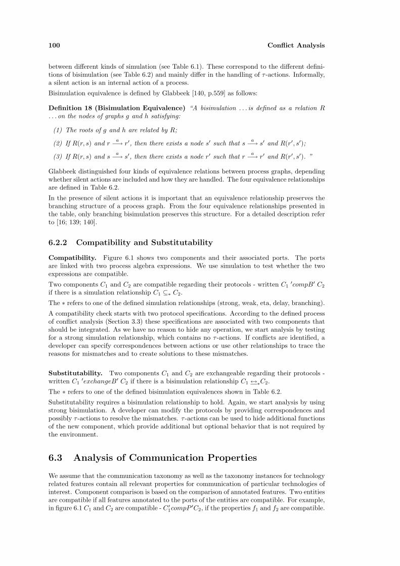
100 Conflict Analysis
between different kinds of simulation (see Table 6.1). These correspond to the different defini-tions of bisimulation (see Table 6.2) and mainly differ in the handling of τ -actions. Informally,a silent action is an internal action of a process.
Bisimulation equivalence is defined by Glabbeek [140, p.559] as follows:
Definition 18 (Bisimulation Equivalence) “A bisimulation . . . is defined as a relation R. . . on the nodes of graphs g and h satisfying:
(1) The roots of g and h are related by R;
(2) If R(r, s) and ra−→ r′, then there exists a node s′ such that s
a−→ s′ and R(r′, s′);
(3) If R(r, s) and sa−→ s′, then there exists a node r′ such that r
a−→ r′ and R(r′, s′). ”
Glabbeek distinguished four kinds of equivalence relations between process graphs, dependingwhether silent actions are included and how they are handled. The four equivalence relationshipsare defined in Table 6.2.
In the presence of silent actions it is important that an equivalence relationship preserves thebranching structure of a process graph. From the four equivalence relationships presented inthe table, only branching bisimulation preserves this structure. For a detailed description referto [16; 139; 140].
6.2.2 Compatibility and Substitutability
Compatibility. Figure 6.1 shows two components and their associated ports. The portsare linked with two process algebra expressions. We use simulation to test whether the twoexpressions are compatible.
Two components C1 and C2 are compatible regarding their protocols - written C1′compB′ C2
if there is a simulation relationship C1 ⊆∗ C2.
The ∗ refers to one of the defined simulation relationships (strong, weak, eta, delay, branching).
A compatibility check starts with two protocol specifications. According to the defined processof conflict analysis (Section 3.3) these specifications are associated with two components thatshould be integrated. As we have no reason to hide any operation, we start analysis by testingfor a strong simulation relationship, which contains no τ -actions. If conflicts are identified, adeveloper can specify correspondences between actions or use other relationships to trace thereasons for mismatches and to create solutions to these mismatches.
Substitutability. Two components C1 and C2 are exchangeable regarding their protocols -written C1
′exchangeB′ C2 if there is a bisimulation relationship C1 ↔∗C2.
The ∗ refers to one of the defined bisimulation equivalences shown in Table 6.2.
Substitutability requires a bisimulation relationship to hold. Again, we start analysis by usingstrong bisimulation. A developer can modify the protocols by providing correspondences andpossibly τ -actions to resolve the mismatches. τ -actions can be used to hide additional functionsof the new component, which provide additional but optional behavior that is not required bythe environment.
6.3 Analysis of Communication Properties
We assume that the communication taxonomy as well as the taxonomy instances for technologyrelated features contain all relevant properties for communication of particular technologies ofinterest. Component comparison is based on the comparison of annotated features. Two entitiesare compatible if all features annotated to the ports of the entities are compatible. For example,in figure 6.1 C1 and C2 are compatible - C ′
1compP ′C2, if the properties f1 and f2 are compatible.

6.3 Analysis of Communication Properties 101
Equivalence Definition SilentRelationship Actions
Strong Simulationa Two graphs g and h in Gb are (strongly) similar -notation - g ⊆h h - if there exists a relation R betweenthe nodes of g and h (called a simulation) such that:
(1) The roots of g and h are related by R;
(2) If R(r, s) and ra−→ r′, then there exists a node
s′ such that sa−→ s′ and R(r′, s′).
no
Weak Simulation Two graphs g and h in G are (weakly) similar -notation: g ⊆w h - if there exists an asymmetricrelation R between the nodes of g and h (called aweak simulation) such that:
(1) The roots are related by R;
(2) If R(r, s) and ra−→ r′, then either a = τ and
R(r′, s), or there exists a pathc s =⇒ s1a−→
s2 =⇒ s′ such that R(r′, s′).
yes
Eta Simulation Two graphs g and h in G are η-similar - notation g ⊆η
h, if there exists an asymmetric relation R betweenthe nodes of g and h (called a η-simulation) such that:
(1) The roots are related by R;
(2) If R(r, s) and ra−→ r′, then either a = τ
and R(r′, s), or there exists a path =⇒ s1a−→
s2 =⇒ s′ such that R(r, s1) and R(r′, s′).
yes
Delayed Simulation Two graphs g and h in G are delay similar - notationg ⊆d h - if there exists an asymmetric relation R be-tween the nodes of g and h (called a delay simulation)such that:
(1) The roots are related by R;
(2) If R(r, s) and ra−→ r′, then either a = τ and
R(r′, s), or there exists a path s =⇒ s1a−→
s2 =⇒ s′ such that R(r′, s2) and R(r′, s′).
yes
Branching Simulation Two graphs g and h in G are branching similar - no-tation: g ⊆b h - if there exists an asymmetric relationR between the nodes of g and h (called a branchingsimulation) such that:
(1) The roots are related by R;
(2) If R(r, s) and ra−→ r′, then either a = τ and
R(r′, s), or there exists a path s =⇒ s1a−→
s2 =⇒ s′ such that R(r, s1), R(r′, s2) andR(r′, s′).
yes
aThe following definitions are equivalent to the definitions of bisimulation shown in Table 6.2. They areonly changed to handle an asymmetric relationship between the graphs g and h. Consequently, the followingdefinitions correspond closely - almost one-to-one - to the definition of Glabbeeck [140]
bDomain of process graphscp ⇒ s ⇒ q is a sequence of actions with an arbitrary number of τ actions that is reduced to a after removing
the τ actions.
Table 6.1: Definitions of Simulation Relationships Based on the Definitions of Glabbeek [140,pp.559-564].
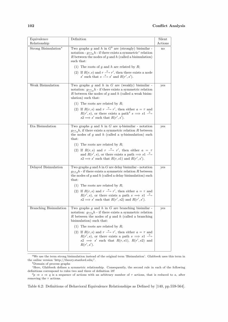
102 Conflict Analysis
Equivalence Definition SilentRelationship Actions
Strong Bisimulationa Two graphs g and h in Gb are (strongly) bisimilar -notation - g↔hh - if there exists a symmetricc relationR between the nodes of g and h (called a bisimulation)such that:
(1) The roots of g and h are related by R;
(2) If R(r, s) and ra−→ r′, then there exists a node
s′ such that sa−→ s′ and R(r′, s′).
no
Weak Bisimulation Two graphs g and h in G are (weakly) bisimilar -notation: g↔wh - if there exists a symmetric relationR between the nodes of g and h (called a weak bisim-ulation) such that:
(1) The roots are related by R;
(2) If R(r, s) and ra−→ r′, then either a = τ and
R(r′, s), or there exists a pathd s =⇒ s1a−→
s2 =⇒ s′ such that R(r′, s′).
yes
Eta Bisimulation Two graphs g and h in G are η-bisimilar - notationg↔ηh, if there exists a symmetric relation R betweenthe nodes of g and h (called a η-bisimulation) suchthat:
(1) The roots are related by R;
(2) If R(r, s) and ra−→ r′, then either a = τ
and R(r′, s), or there exists a path =⇒ s1a−→
s2 =⇒ s′ such that R(r, s1) and R(r′, s′).
yes
Delayed Bisimulation Two graphs g and h in G are delay bisimilar - notationg↔dh - if there exists a symmetric relation R betweenthe nodes of g and h (called a delay bisimulation) suchthat:
(1) The roots are related by R;
(2) If R(r, s) and ra−→ r′, then either a = τ and
R(r′, s), or there exists a path s =⇒ s1a−→
s2 =⇒ s′ such that R(r′, s2) and R(r′, s′).
yes
Branching Bisimulation Two graphs g and h in G are branching bisimilar -notation: g↔bh - if there exists a symmetric relationR between the nodes of g and h (called a branchingbisimulation) such that:
(1) The roots are related by R;
(2) If R(r, s) and ra−→ r′, then either a = τ and
R(r′, s), or there exists a path s =⇒ s1a−→
s2 =⇒ s′ such that R(r, s1), R(r′, s2) andR(r′, s′).
yes
aWe use the term strong bisimulation instead of the original term ‘Bisimulation’. Glabbeek uses this term inthe online version ‘http://theory.stanford.edu/’.
bDomain of process graphscHere, Glabbeek defines a symmetric relationship. Consequently, the second rule in each of the following
definitions correspond to rules two and three of definition 18!dp ⇒ s ⇒ q is a sequence of actions with an arbitrary number of τ actions, that is reduced to a, after
removing the τ actions.
Table 6.2: Definitions of Behavioral Equivalence Relationships as Defined by [140, pp.559-564].

6.3 Analysis of Communication Properties 103
6.3.1 Requirements
We distinguish three types of properties that can be associated with components to describetheir communication capabilities and requirements: mandatory properties, optional propertiesand unsupported properties. We further interpret the meaning of optional features differentlyfor components and connectors.
We need to deal with optional or ‘unknown’ values, because
(1) technologies support several properties of communication mechanisms that may be usedby application components, but are not compulsory. Consequently, we must distinguishbetween a property that is supported as an option or that is required (mandatory).
(2) often, it is difficult to decide if a property is required by a component or not supported.Middleware specifications describe communication protocols coarse grained only. Lowerlevel properties are often either partially described or omitted.
Therefore, if a property is optional in a communication mechanism assigned to a component andevidence whether the property is required or not supported by a component cannot be found,we must deal with ‘unknown’ values. We therefore distinguish between mandatory properties,which are required for a communication, unsupported properties, which are not required, and‘unknown’ properties, for which no evidence for or against their usage can be found. We model‘unknown’ properties as optional properties in feature models. In a feature model, an optionalproperty can be selected for communication but it is not required. For components, we interpretoptional properties as ‘unknown’ values and generate warnings in an analysis process.
A component composition demands that all required features have been identified. We cannotcompose components for which we are not sure if particular properties such as transactionsare required or not. Furthermore, a composition of two components results in a connectorgeneration that fits the requirements of involved components. Such a connector generation isnot possible if the features are not clearly defined, i.e. there must not be any free variationpoints (optional features) annotated to the components. Therefore, a warning indicates that adeveloper must manually investigate the components and identify whether the properties areused or are unsupported.
If optional features are attached to connectors, they are interpreted as supported features. Ifa component requires a feature (mandatory) and a connector supports that feature, we can besure that the connector can actually communicate with the component, because it provides therequired functionality.
6.3.2 Compatibility and Substitutability
Compatibility. Regarding this discussion, we describe compatibility relationships ‘compP’between elements E1 and E2 by comparing the feature models (taxonomy instances describinga particular communication mechanism) that are attached to the ports of the elements E1 andE2. The ports are connected to E1 and E2 via a requires and a provides relationship.3 Wedefine the compatibility operation for the following element combinations:
(1) Component ‘compP’ Component
This relationship needs to be true in order to compose two components. Two compo-nents are only compatible if they are annotated with the same mandatory features andthe attributes of each feature are also compatible. The relationship ‘compP’ yields true
3We only consider a component composition by a single link between a requires and a provides interface.

104 Conflict Analysis
Component vs.Component
mandatory optional unsupported
mandatory√
w foptional w w wunsupported f w
√
w = warningf = failure
Table 6.3: Compatibility Matrix between two Components
between two components C1 and C2 if the following proposition holds:
∀n ∈C1.r.comProps·isMandatoryFeature(n) →∃m ∈ C2.q.comProps·n.fname = m.fname∧isMandatoryFeature(m)
(6.1)
The symbols ‘r’ and ‘q’ refer to provides and requires ports of components. The follow-ing two combinations are allowed (r = requires, q = provides) or (r = provides, q =requires). The predicate requires for each mandatory (required) feature of component C1
a mandatory (supported) feature of the same name exists in C2. The predicate ‘isManda-toryFeature’ iterates the feature model instance annotated to a component and identifiesmandatory features. Therefore, it selects features that are themselves mandatory and forwhich all parent features are also mandatory.
Mismatches are generated for all other cases. The matrix shown in Table 6.3 shows thegenerated mismatches for all value combinations.
(2) Component ‘compP’ Connector
This relationship indicates compatibility between components and connectors. A compo-nent is compatible to a connector if the connector provides the properties required by thecomponent. Here, optional features are interpreted differently for the component and theconnector. The relationship yields true between a component C and a connector K if thefollowing propositions hold:
∀n ∈C.r.comProps·isMandatoryFeature(n) →∃m ∈ K.q.comProps·n.fname = m.fname∧(isMandatoryFeature(m)∨isOptionalFeature(m))
(6.2)
∀n ∈C.r.comProps·isOptionalFeature(n) →∃m ∈ K.q.comProps·n.fname = m.fname∧isOptionalFeature(m)
(6.3)
The first predicate can be read as follows: for each mandatory feature of the componentmust exist a corresponding property in the connector that is either mandatory or optional.

6.3 Analysis of Communication Properties 105
Component vs.Connector
mandatory optional unsupported
mandatory√ √
foptional w
√w
unsupported f√ √
w = warningf = failure
Table 6.4: Compatibility Matrix between a Component and a Connector
We interpret optional values of a connector as features supported by the connector if theyare requested by a client component. The second predicate matches properties even ifthey are defined optional by the component - it is unknown whether they are requiredor not - because the connector supports the properties regardless of whether they arerequired by the component or not. Generated mismatches are shown in Table 6.4.
Substitutability. We define substitutability similar to compatibility between the featuremodels attached to two elements E1 and E2. Contrary to the compatibility relationships, themodels to be compared are attached via the same relationship to the ports of both elements.Two components are exchangeable with regard to their communication - written E1 ‘exchangeP’E2 - if for each feature model attached to a port of E1 a compatible model for a port E2 exists.This is another difference from the compatibility check. For substitution, all feature modelsattached to the ports of E1 must have compatible models in E2.
We define substitutability between two element combinations:
• Component ‘exchangeP’ Component. Two components C1 and C2 can be exchanged -written C1 ‘exchange’ C2, if ∀r ∈ C2.X∃p ∈ C1.X, where X refers either to a ‘requires’or an ‘provides’ relationship, the following predicates evaluate to true:
∀n ∈C2.X.comProps·isMandatoryFeature(n) →∃m ∈ C1.X.comProps·n.fname = m.fname∧isMandatoryFeature(m)
(6.4)
∀n ∈C1.X.comProps·isMandatoryFeature(n) →∃m ∈ C2.X.comProps·n.fname = m.fname∧isMandatoryFeature(m)
(6.5)
The predicates are almost identical to the predicate defined for component compatibility.However, they perform the check from both sides. The number of mandatory featuresmust be invariant: The component must use the same context as the old component. Anew component cannot use a slightly changed environment with different properties.
• Connector ‘exchangeP’ Connector. Two connectors K1 and K2 can be exchanged - K1‘exchange’ K2, if ∀r ∈ K1.X∃p ∈ K2.X, where X refers either to a ‘requires’ or an‘provides’ relationship, the following predicate evaluates to true:
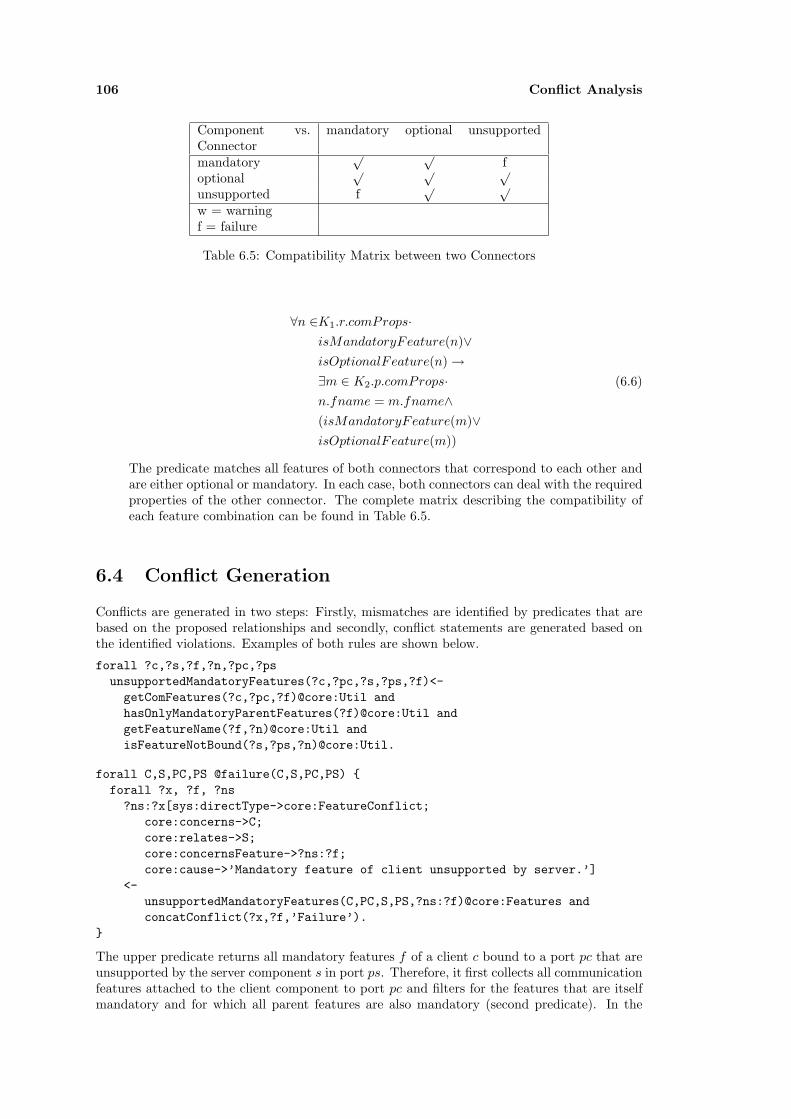
106 Conflict Analysis
Component vs.Connector
mandatory optional unsupported
mandatory√ √
foptional
√ √ √
unsupported f√ √
w = warningf = failure
Table 6.5: Compatibility Matrix between two Connectors
∀n ∈K1.r.comProps·isMandatoryFeature(n)∨isOptionalFeature(n) →∃m ∈ K2.p.comProps·n.fname = m.fname∧(isMandatoryFeature(m)∨isOptionalFeature(m))
(6.6)
The predicate matches all features of both connectors that correspond to each other andare either optional or mandatory. In each case, both connectors can deal with the requiredproperties of the other connector. The complete matrix describing the compatibility ofeach feature combination can be found in Table 6.5.
6.4 Conflict Generation
Conflicts are generated in two steps: Firstly, mismatches are identified by predicates that arebased on the proposed relationships and secondly, conflict statements are generated based onthe identified violations. Examples of both rules are shown below.
forall ?c,?s,?f,?n,?pc,?psunsupportedMandatoryFeatures(?c,?pc,?s,?ps,?f)<-getComFeatures(?c,?pc,?f)@core:Util andhasOnlyMandatoryParentFeatures(?f)@core:Util andgetFeatureName(?f,?n)@core:Util andisFeatureNotBound(?s,?ps,?n)@core:Util.
forall C,S,PC,PS @failure(C,S,PC,PS) {forall ?x, ?f, ?ns?ns:?x[sys:directType->core:FeatureConflict;
core:concerns->C;core:relates->S;core:concernsFeature->?ns:?f;core:cause->’Mandatory feature of client unsupported by server.’]
<-unsupportedMandatoryFeatures(C,PC,S,PS,?ns:?f)@core:Features andconcatConflict(?x,?f,’Failure’).
}
The upper predicate returns all mandatory features f of a client c bound to a port pc that areunsupported by the server component s in port ps. Therefore, it first collects all communicationfeatures attached to the client component to port pc and filters for the features that are itselfmandatory and for which all parent features are also mandatory (second predicate). In the

6.4 Conflict Generation 107
third line, it looks up the name of the feature and tests if the feature is unsupported by theserver (line four).
The second rule generates conflict statements. The rule is included in a parameterized mappingwith parameters C,PC, S and PS. C and S refer to component types, whereas PC and PSrefer to two interfaces of the components. The body of the rule identifies conflicts, which resultin new conflict statements in the head of the rule. The head generates conflict statements ofthe form described by the conflict model in Section 5.1.5. In the framework, a complete set ofrules for each case shown in Table 6.3 are implemented.

108 Conflict Analysis

Part III
Applications of Conflict Analysisand Transformation
109


Chapter 7
Examples for Conflict Analysis
The previous sections discussed the idea and theory of conflict analysis. Conflict analysiswas embedded into a tool suite that supports different technologies, customization of conflictanalysis capabilities and model transformation.
In this section, we provide examples of conflict analysis. We describe the analysis process, giveexamples for each conflict category, discuss two complex examples as well as the problems andadvantages of conflict analysis.
7.1 Analysis Process and Scenario Setup
This chapter covers the ‘Conflict Analysis’ step of the conflict analysis process described inSection 3.3.1. Consequently, it identifies conflicts between platform independent componentdescriptions, which have already been transformed from UML models and from platform specificcomponent descriptions.
Conflict analysis is an iterative process: Conflicts between two descriptions are identified usingthe conflict predicates introduced before. Then, a user, who reviews the produced conflicts, canspecify correspondences between mismatched elements and reapply conflict analysis.
Correspondences supported by the framework include name matching and matching of operationsequences used for behavioral analysis. The correspondences have to be specified by a user, asthe framework does not try to automatically identify matching operations. This would require akind of semantic matching as proposed, for example, by Paolucci et. al. [111] in the area of webservices. However, a user can augment the framework to support also semantic matching forparticular application areas as the framework is technically able to handle semantic matching.A respective master thesis explores a kind of semantic matching in the context of the ADAMrepository [102].
The following examples are specified in UML and checked either in the Ontology-Based DomainRepository (ODIS) framework or with respective tools such as Aldebaran and Haskell. We usethe following configuration of the conflict analysis and transformation framework:
• Type conflicts are identified based on a simple subtype algorithm that implements thesubtype rules as introduced in Section 6. The algorithm is implemented in Haskell. Thesubtype rules are based on the rules described by Pierce [112] and Amadio [13].
For the purpose of the analysis, the framework’s type system has been initialized withcommon primitive types and their subtype relations. The primitive type ‘void’1 is treatedas the ‘bottom’ type of the system. It is therefore a subtype of each type. The bottomtype can only appear as a return parameter of an operation.
1The ‘void’ type is exported as a primitive type from the used UML tool (Poseidon).

112 Examples for Conflict Analysis
The example algorithm supports recursive types and includes only public operations ofrecords for conflict analysis.
• Behavior conflicts are analysed with two external model checkers: LTSA and Aldebaran[47]. We use LTSA to check for progress and deadlock properties of a component con-figuration (not shown in the following examples) and Aldebaran to check for simulationand bisimulation relationships. Therefore, the examples are annotated in the respectiveprocess algebra language: FSP [86].
• Property conflicts are analysed based on the communication taxonomy introduced inSection 4.2.2. The taxonomies for particular technologies were created by Gaedicke [51]and Liao [81].
In the following, Section 7.2 exemplifies simple cases of conflict analysis, separated for eachof the three categories. The following two sections then describe more complex examples ofconflict analysis. Section 7.4 describes a data warehouse solution of Cedavis Ltd. that is writtenin Java and should be integrated with .Net technology. The chapter concludes with a summaryof conflict analysis and a discussion of connector generation.
7.2 Basic Applications
In this section, we give three simple examples of conflict analysis. Thereby, we aim to createan idea of the framework’s capabilities and do not aim at exhaustive examples that cover mostconflict categories. The first example discusses subtype analysis, the second simulation, andthe third communication conflicts. For each example, we first show the UML model, which iscompatible with the UML profile of the framework, then we describe the expected and foundconflicts.
7.2.1 Type Analysis
Figure 7.1 shows a simple UML component model that is defined according to the specified UMLprofile. The model consists of two component types, their interface types, and some additionalelements describing the involved types. Thereby, UML classes without any stereotype aretreated as ‘Record’ types of the framework’s type system.
R1 __________
attr1 : int attr2 : String
__________ getAttr2() : String setAttr2(param1 : String):void
R2 __________ attr3 : int
R3 __________ attr3 : int
Class_4 __________
walk(param_1:R3):void
Class_5 __________
go(param_1:R3):int
<<InterfaceType>> IT1
__________ foo1(param_1:long):Class_4
<<InterfaceType>> IT2
__________ foo2(param_1:int):Class_5
<<PortType>> PT1
<<PortType>> PT2
<<ComponentType>> CT1
<<ComponentType>> CT2
<<declares>>
<<provides>><<requires>>
<<declares>>
Figure 7.1: Type Example UML Model
From the UML model, the framework generates the type expressions shown in Table 7.1. Theexample CT1 and CT2 are defined on lines 18 and 19. The type expressions can directly be

7.2 Basic Applications 113
No. Type Expression
1. ref int=B ”int”
2. ref long=B ”long”
3. ref void=B ”void”
4. ref string=Rc ”String”NoST []
5. ref r2=Rc ”R2”NoST [(”attr3”,BT ref int),(”R1”,RT ref r1)]
6. ref class 4=Rc ”Class 4”(SubT (RT ref r1)) [(”walk”,OT ref walk)]
7. ref r1=Rc ”R1”NoST [(”attr2”,RT ref string),(”setAttr2”,OTref setattr2),(”attr1”,BT ref int),(”getAttr2”,OT ref getattr2)]
8. ref class 5=Rc ”Class 5”(SubT (RT ref r1)) [(”go”,OT ref go)]
9. ref r3=Rc ”R3”NoST [(”attr3”,BT ref int)]
10. ref setattr2=Op ”setAttr2”[(”param1”,RT ref string)] (BT (ref void)) []
11. ref go=Op ”go”[(”param 1”,RT ref r3)] (BT (ref int)) []
12. ref walk=Op ”walk”[(”param 1”,RT ref r3)] (BT (ref void)) []
13. ref foo1=Op ”foo1”[(”param 1”,BT ref long)] (RT (ref class 4)) []
14. ref getattr2=Op ”getAttr2”[] (RT (ref string)) []
15. ref foo2=Op ”foo2”[(”param 1”,BT ref int)] (RT (ref class 5)) []
16. ref it2=In ”IT2”[] [(OT ref foo2)]
17. ref it1=In ”IT1”[] [(OT ref foo1)]
18. ref ct1=Co ”CT1”[] [(IT (ref it1))]
19. ref ct2=Co ”CT2”[(IT (ref it2))] []
Table 7.1: Generated Types for Type Example
used with the Haskell subtype checker. The type expressions correspond to Haskell types shownin Figure 7.2.
Given Figure 7.1, we expect the following subtype relationships - written <: - to hold:
• Record R2 (line 5) is a subtype (<:) of R3 (line 9).
• Record R3 is a subtype (<:) of R22.
• Record R1 (line 7) is an subtype (<:) of R1 and R2
• Record Class 4 (line 6), Class 5 (line 8) <: R1.
A comparison of Class 4 <: Class 5 or R1 <: Class 4 does not succeed as we define recordsubtyping via the names of the included elements. Consequently, the type checker produces thefollowing conflict message (for R1 <: Class 4):
“ Mismatch between record types (R1 <: Class 4). Designated Subtype Record (R1)has too few elements. Feature mismatch in Record. For walk exists no correspondingelement in the subtype term.”
Another conflict results from a comparison of the two operations from Class 4 and Class 5:go (line 11) <: walk (line 12):
“ Mismatch between operation types (go <: walk). Mismatch between return types:Basic types are not in a subtype relation. (BT (B ”int”)) (BT (B ”void”))”
Finally IT1 and IT2 are also not in a subtype relationship (IT2 <: IT1), because of namingconflicts:
2As we check the subtype relationship only on the operations of classes (records) both records are empty andtherefore equivalent regarding the subtype relationship.

114 Examples for Conflict Analysis
1. Type definitions> type Name = String> data Basic = B Name> deriving (Show,Eq)
Void is the bottom type rendered assimple data type from UML:
> void = B ”void”
2. Complex TypesThe following complex types are defined:
2a. Operations> type Arg = (Name,Type)> data Operation = Op Name [Arg] Type> [TException]> deriving (Show, Eq)
> type TException = Type
2c. Interfaces> data Interface = In Name> [Supertype]> [TOperation]> deriving (Show, Eq)
> type TOperation = Type
2d. Components> data Component = Co Name> [Interface]> [Interface]> deriving (Show, Eq)
2e. Connectors> data Connector = Ko Name> [Interface]> [Interface]> deriving (Show, Eq)
2f. Records> data Record = Rc Name Supertype> [Arg]> deriving (Show, Eq)
> data Supertype = NoST | SubT Type> deriving (Show, Eq)
2g. Lists> data List = Lt Type> deriving (Show, Eq)
2h. Root type definition> data Type = BT Basic> | OT Operation> | IT Interface> | CT Component> | KT Connector> | RT Record> | LS List> deriving (Show,Eq)
Figure 7.2: Haskell Type Constructors for Subtype Relationships.
“ Mismatch between interface types (IT2 <: IT1). For foo1 exists no correspondingelement in the subtype term.”
At this point, a developer can specify correspondences between names and then reapply conflictanalysis. If he defines the two correspondences: walk ∼ go for the operations of Class 4 andClass 5, and foo1 ∼ foo2 for the operations in both interface types, the type check deducesadditional subtype relationships:
• Operation walk (line 12) <: go (line 11).
• Record Class 4 <: Class 5.
• Operation foo1 (line 13) <: foo2 (line 15).
• Interface Type IT1 (line 17) <: IT2 (line 16).
Compatibility Checks
According to Section 6 compatibility between two components C1 and C2 - written C1 ‘compS’C2 is checked for a single pair of port types and their associated interface types. The componentsC1 and C2 are compatible - written C1 ‘compS’ C2 if these interfaces i1 ∈ C1.provides.delcaresand i2.provides.delcares are in the subtype relationship: i2 � i1.
Consequently, CT1 and CT2 of the example are not directly compatible. Even if we compareboth components CT1 ‘compS’ CT2 under consideration of both correspondences defined above,the predicate fails because no subtype relation between IT2 <: IT1 can be inferred:

7.2 Basic Applications 115
“Test compatibility (IT2<:IT1):“Mismatch between interface types (IT2 <: IT1):
Mismatch between operation types (foo2 <: foo2):Mismatch between return types:Mismatch between record types (Class 5 <: Class 4):Feature mismatch in Record:Mismatch between operation types (go <: go):Mismatch between return types:Basic types are not in a subtype relation.(BT (B ”int”)) (BT (B ”void”))
Mismatch between arguments:Basic types are not in a subtype relation.(BT (B ”long”)) (BT (B ”int”))”...
The conflict depends on a mismatch between the return types of the operations go and walk(go)and on mismatched argument types of foo2 and foo2(foo1). Consequently, a connector isrequired, which maps the differently named operations between both components and resolvestheir subtype incompatibilities.
7.2.2 Protocol Analysis
We use the protocol descriptions of the Mortgage Bank example from section 5.3.2 to pro-vide an example of protocol analysis. Both components in the example describe part of apossible simulation of financial development for different forms of mortgage contracts. The‘BLContractMgmt’ component acts as a customer facade. It uses calculations from a set ofworker components described by the ‘BLCalc’ component type. Both example components areannotated with the following FSP protocol expressions:
ContractMgmt:R = (newContract→R1),R1= (newContract→R1
|simulate→R1).
BLCalc:Q = (getNewContract→Q1),Q1= (getNewContract→Q1
|setRate→Q2),Q2= (getNewContract→Q2
|setRate→Q2|simulation→Q2).
The expressions describe behavior of both components. ‘BLContractMgmt’ queries the ‘BLCalc’component for an contract object, which is then used to simulate the terms of a mortgage underconsideration of a given rate. The corresponding transition system is shown in Figure 7.3.
For conflict analysis, we analyse the compatibility of ’BLContractMgmt’ ’compB’ ’BLCalc’. Weuse the Aldebaran model checker to check for a simulation relationship between both processexpressions. The analysis results in a conflict for the first transition: ’BLContractMgmt’ cando a ’getNewContract’ transition that is not available for ’BLCalc’. The mismatch results fromthe different alphabets of both expressions Q and R.
Thus, a developer needs to specify correspondences between the action names. In the exam-ple, the following two correspondences can be defined: getNewContract ∼ newContract andsimulation ∼ simulate.3 As a result, we obtain the following conflict from Aldebaran:
“ In the states (S1 = 1, S2 = 1) Only BLContractMgmt can do a ”simulate”-transition from these states.”(where S1 refers to BLContractMgmt and S2 to BLContract.)
3The ‘setRate’ operation has no direct counterpart in the process description of ‘BLContractMgmt’.

116 Examples for Conflict Analysis
This mismatch occurs because of a difference in specifying the rate for calculation. BLCalcfirst needs a ‘setRate’ call before it can ‘simulate’ a contract. BLContractMgmt provides arespective value as a parameter of ‘simulate’ and does not support an explicit operation to setthe rate. In summary, both expressions would correspond if we define another correspondence:simulate ∼ setRate → simulation.
Figure 7.3: Transition system for the Mortgage Bank example.
7.2.3 Property Analysis
Figure 7.4 shows two components that we use to demonstrate the analysis of communicationproperties. Both components expose and require their services via a Java EntityBean commu-nication mechanism. They are connected to a feature model instance describing the communi-cation properties of EntityBeans. The only difference in the components concerns transactionsupport for their operations, which is specified by the awareness property. ‘QueryControl’ doesnot support transactions, whereas ‘ComponentRepository’ requires transactions. Consequently,the only conflict that should occur the both components should refer to this difference.
The annotation of an EntityBean communication model results in the addition of all commu-nication properties of the respective communication mechanism to the component. The directannotations to the component override the respective features of the mechanism. In the ex-ample, we get two EntityBean communication models annotated to both components. Theonly difference is the properties annotated to ‘Transaction Awareness’. QueryControl has theproperty ‘FeatureNone’ attached to the Transaction Awareness property, whereas Componen-tRepository has the property ‘FeatureRequired’ associated with its instance of the awarenessproperty.
Different from the prior analysis example, property conflicts are checked directly in the frame-work, without external tool support. The analysis predicates can be found in Section 6.3. Theyare implemented in [77]. Communication properties are differentiated in two categories: failuresand warnings.
A computation of the failures between the communication properties of both example compo-nents - ‘QueryControl’ ‘compP’ ‘ComponentRepository’ yields two conflicts:
“ 1. Feature53Required4 - Mandatory feature of server unsupported by client.2. Feature52Never - Mandatory feature of client unsupported by server.”
Both conflicts describe the difference in the transaction awareness properties from the perspec-tives of both components.
7.3 Federated Information System Example
The example shown in Figure 7.5 describes part of a mediator of a federated information system.A mediator is a kind of middleware that performs queries against heterogeneous distributed datasources (see for example [147]). If a client queries a mediator, the mediator first calculates which
4Features are enumerated in the implementation.
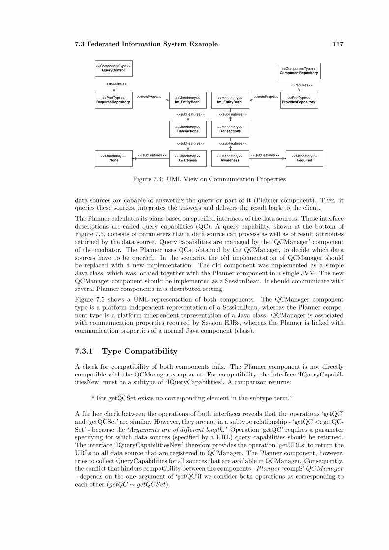
7.3 Federated Information System Example 117
<<ComponentType>> QueryControl <<ComponentType>>
ComponentRepository
<<PortType>> RequiresRepository
<<Mandatory>> fm_EntityBean
<<PortType>> ProvidesRepository
<<Mandatory>> Transactions
<<Mandatory>> Transactions
<<Mandatory>> Awareness
<<Mandatory>> Awareness
<<Mandatory>> None
<<Mandatory>> Required
<<requires>> <<requires>>
<<comProps>> <<Mandatory>> fm_EntityBean
<<comProps>>
<<subFeatures>>
<<subFeatures>>
<<subFeatures>>
<<subFeatures>>
<<subFeatures>>
<<subFeatures>>
Figure 7.4: UML View on Communication Properties
data sources are capable of answering the query or part of it (Planner component). Then, itqueries these sources, integrates the answers and delivers the result back to the client.
The Planner calculates its plans based on specified interfaces of the data sources. These interfacedescriptions are called query capabilities (QC). A query capability, shown at the bottom ofFigure 7.5, consists of parameters that a data source can process as well as of result attributesreturned by the data source. Query capabilities are managed by the ‘QCManager’ componentof the mediator. The Planner uses QCs, obtained by the QCManager, to decide which datasources have to be queried. In the scenario, the old implementation of QCManager shouldbe replaced with a new implementation. The old component was implemented as a simpleJava class, which was located together with the Planner component in a single JVM. The newQCManager component should be implemented as a SessionBean. It should communicate withseveral Planner components in a distributed setting.
Figure 7.5 shows a UML representation of both components. The QCManager componenttype is a platform independent representation of a SessionBean, whereas the Planner compo-nent type is a platform independent representation of a Java class. QCManager is associatedwith communication properties required by Session EJBs, whereas the Planner is linked withcommunication properties of a normal Java component (class).
7.3.1 Type Compatibility
A check for compatibility of both components fails. The Planner component is not directlycompatible with the QCManager component. For compatibility, the interface ‘IQueryCapabil-itiesNew’ must be a subtype of ‘IQueryCapabilities’. A comparison returns:
“ For getQCSet exists no corresponding element in the subtype term.”
A further check between the operations of both interfaces reveals that the operations ‘getQC’and ‘getQCSet’ are similar. However, they are not in a subtype relationship - ‘getQC <: getQC-Set’ - because the ‘Arguments are of different length.’ Operation ‘getQC’ requires a parameterspecifying for which data sources (specified by a URL) query capabilities should be returned.The interface ‘IQueryCapabilitiesNew’ therefore provides the operation ‘getURLs’ to return theURLs to all data source that are registered in QCManager. The Planner component, however,tries to collect QueryCapabilities for all sources that are available in QCManager. Consequently,the conflict that hinders compatibility between the components - Planner ‘compS’ QCManager- depends on the one argument of ‘getQC’if we consider both operations as corresponding toeach other (getQC ∼ getQCSet).
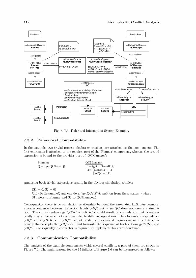
118 Examples for Conflict Analysis
<<ComponentType>> Planner
<<InterfaceType>> IQueryCapabilities
_____________________ getQCSet() : QCSet
<<ComponentType>> QCManager
<<requires>><<provides>>
<<Interface>> QC
_____________________________________ getParameter(name: String) : Parameter getResultAttribute(name: String) : ResultAttribute getParameters() : Param getResultAttributes() : Result
<<PortType>> Planner
PortType
<<declares>> <<PortType>> QCManager PortType1
<<InterfaceType>> IQueryCapabilitiesNew
_____________________ getURLs():ListURL getQC(URL url) :QCSet throws NotExistsException
<<declares>>
<<Mandatory>> fmSessionBean
<<Mandatory>> fmJavaPC
<<comProps>><<comProps>>
JavaBean SessionBean
PAE(FSP):= Q=getQCSet->Q).
PAE(FSP):= R=(getURLs->R1), R1=(getURLs->R1 | getQC->R1).
<<List>> ListURL
URL _____________________ location:String _____________________
<<Set>> Param
<<Set>> Result
ResultAttribute
Parameter <<Set>> QCSet
<<Mandatory>> Transaction
<<Mandatory>> Security
<<subFeatures>> <<subFeatures>>
Figure 7.5: Federated Information System Example.
7.3.2 Behavioral Compatibility
In the example, two trivial process algebra expressions are attached to the components. Thefirst expression is attached to the requires port of the ‘Planner’ component, whereas the secondexpression is bound to the provides port of ‘QCManager’:
Planner:Q = (getQCSet→Q).
QCManager:R = (getURLs→R1),R1= (getURLs→R1
|getQC→R1).
Analysing both trivial expressions results in the obvious simulation conflict:
(S1 = 0, S2 = 0)Only FedExampleQ.aut can do a ”getQCSet”-transition from these states. (whereS1 refers to Planner and S2 to QCManager.)
Consequently, there is no simulation relationship between the associated LTS. Furthermore,a correspondence between the action labels getQCSet ∼ getQC does not create a simula-tion. The correspondence getQCSet ∼ getURLs would result in a simulation, but is seman-tically invalid, because both actions refer to different operations. The obvious correspondencegetQCset ∼ getURLs → getQC cannot be defined because it requires an intermediate com-ponent that accepts the getQC call and forwards the sequence of both actions getURLs andgetQC. Consequently, a connector is required to implement this correspondence.
7.3.3 Communication Compatibility
The analysis of the example components yields several conflicts, a part of them are shown inFigure 7.6. The main reasons for the 15 failures of Figure 7.6 can be interpreted as follows:

7.4 Analysing the Cedavis Data Warehouse Tool 119
• Transactions are unsupported by the Planner component but required by the QCMan-agerComponent.
• The Planner component requires a static binding, whereas the QCManagerComponent asa distributed component requires a dynamic binding and furthermore requires a initial-ization based on a Naming service (JNDI).
• The QCManager requires an environment that provides security handling.
Figure 7.6: Property Conflicts - failures
7.4 Analysing the Cedavis Data Warehouse Tool
Cedavis Ltd. provides Business Intelligence (BI) solutions that aim at supporting a company’sdecision-making process. From a technical perspective Cedavis analyses and optimizes infor-mation important to a company by providing data warehouse tools.
A data warehouse [88] is a large database, often containing data used for a company’s decisionsupport. Cedavis Ltd. aims to improve decisions by providing an Online Analytical Processing(OLAP) tool that allows browsing and aggregating data via ad hoc queries. Thereby, data isrepresented as a n dimensional data cube. A company decides, which dimensions as well aswhich kind of statistics are of interest. This information constitutes the content of the datacube. The OLAP tool aggregates this information and presents it to a user. The user canexplore the database by selecting dimensions of interest and defining filters on the data.
A major contribution of the Cedavis OLAP tool relates to performant calculations on issuedqueries. This feature is technically realized by managing the data entirely on the heap of anappropriate number of servers.
7.4.1 Example Application: Cedavis Health
The OLAP tool has been applied by customers of several business lines. Figure 7.7 shows ascreenshot of the Cedavis Web Analyzer customized for business information in a hospital.
The upper part of the Analyzer displays the categories of the underlying data cube inclusiveof the subdimension for each category. A user can drill down or refine the analysis by settingfilters on subdimensions. The lower left part shows information relevant to calculate the resultsof queries. For a query a user has to select two dimensions and at least one value type.Furthermore, he can select filters as mentioned above. The result of a query is displayed on thelower right side.

120 Examples for Conflict Analysis
Figure 7.7: Cedavis Web Analyzer
7.4.2 Architecture
The Architecture of the Cedavis OLAP tool, shown in Figure 7.8, can be described as a fourtier architecture. The client tier consists of web clients that communicate with the applicationserver. At present, web clients are the only choice for accessing the Cedavis tool. The appli-cation tier manages user-related activities such as queries, security, job control, and reports.The persistency tier processes user queries based on the data actually stored on the heap. Fur-thermore, it actualizes data from a data warehouse. The lowest tier consists of life databasescontaining a company’s business data and a data warehouse which aggregates and manages thisdata.
From a technical perspective, the Cedavis OLAP tool is written entirely in Java. It does nottake advantage of a middleware to implement its services, but only uses socket communicationbetween its distributed components. The main components in each tier are described as follows:
Web Analyzer. The Cedavis Web Analyzer component mainly provides a web representationto the users. It further manages connections of clients and checks for security violations.Data queried by the clients is stored in a cache to economize network transfer with thequery manager. The Web Analyzer is implemented as a Java web application using Servletand JSP technologies. Therefore, it is executed in an adequate Web Server such as theApache Server.
Query Manager. The Query Manager is realized as a ‘daemon’ that listens on a given portfor user requests. It processes queries and communicates with the data dispatcher to exe-cute the queries. The Query Manager mainly implements a role-based security subsystemincluding fine grained access rights for dimensions and subdimensions on any level. Fur-ther, it manages job execution. Jobs are predefined queries that can be executed at agiven point in time.
Processing Server. Processing servers manage the data to be analysed on the heap. They are

7.4 Analysing the Cedavis Data Warehouse Tool 121
responsible for calculating the results of user queries. If the amount of data to be analysedexceeds the captivity that can be handled by a single Java VM, processing servers canbe deployed on different servers. In this case, the data is split by means of a hashingalgorithms into several data sets that are managed by different servers. Consequently,calculations are performed concurrently, which also results in a higher speed of calculation.
Query Dispatcher. The Query Dispatcher is a helper component that distributes queries andcollects responses from the processing servers.
Data Warehouse. In general, a company’s operating data cannot be used for analysis withoutconverting it into a suitable representation. Data conversion results in cleansed data thatis stored in the Cedavis Data Warehouse. Data conversion is performed based on rulesthat need to be manually configured. Cedavis uses an external Extraction Transformationand Loading (ETL) tool for data conversion.
Operational DB
DWH
Backend
Processing Server
Processing Server
Processing Server
Data Dispatcher
Query Manager
Web Analyzer
Persistency Tier
Application Tier
Client Client ClientClient Tier
Operational DB
Operational DB
Figure 7.8: Architecture of the Cedavis OLAP Tool
7.4.3 Integration Scenario
As mentioned above, Cedavis presently provides solely a web interface to interact with itsanalysis tool. The Web interface is appropriate for viewing and analysing data. However, it isdifficult to integrate the tool with other components to perform advanced operations, becausea tight coupling with applications such as Excel is not available.
Consequently, Cedavis decided to augment its tool with a .Net client based on .Net Remotingtechnology. The client should be designed as a single component that allows querying thedatabase.
Figure 7.9 shows the intended .Net component. It is designed to request queries from thedatabase via the ‘ICedavisOLAP’ interface. The interface supports five operations: The ‘con-nect’ and ‘close’ operations perform the connection with Cedavis ‘QueryManager’ components.The ‘getDimensions’ and ‘getValueType’ operations query the connected processing server foravailable dimensions such as, for example, cost unit or time frame as shown in Figure 7.7 as wellas for value types, which describe financial ratios of interest. The final operation ‘olapQuery’performs queries against the connected Cedavis server. The operation requires arguments thatspecify two dimensions as well as a list of value types that should be extracted from the database.
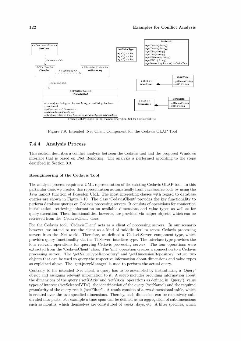
122 Examples for Conflict Analysis
Figure 7.9: Intended .Net Client Component for the Cedavis OLAP Tool
7.4.4 Analysis Process
This section describes a conflict analysis between the Cedavis tool and the proposed Windowsinterface that is based on .Net Remoting. The analysis is performed according to the stepsdescribed in Section 3.3.
Reengineering of the Cedavis Tool
The analysis process requires a UML representation of the existing Cedavis OLAP tool. In thisparticular case, we created this representation automatically from Java source code by using theJava import function of Poseidon UML. The most interesting classes with regard to databasequeries are shown in Figure 7.10. The class ‘CedavisClient’ provides the key functionality toperform database queries on Cedavis processing servers. It consists of operations for connectioninitialization, retrieving information on available dimensions and value types as well as forquery execution. These functionalities, however, are provided via helper objects, which can beretrieved from the ‘CedavisClient’ class.
For the Cedavis tool, ‘CedavisClient’ acts as a client of processing servers. In our scenariohowever, we intend to use the client as a kind of ‘middle tier’ to access Cedavis processingservers from the .Net world. Therefore, we defined a ‘CedavisServer’ component type, whichprovides query functionality via the ‘ITServer’ interface type. The interface type provides thefour relevant operations for querying Cedavis processing servers. The four operations wereextracted from the ‘CedavisClient’ class: The ‘init’ operation creates a connection to a Cedavisprocessing server. The ‘getValueTypeRepository’ and ‘getDimensionRepository’ return twoobjects that can be used to query the respective information about dimensions and value typesas explained above. The ‘getQueryManager’ is used to perform the actual query.
Contrary to the intended .Net client, a query has to be assembled by instantiating a ‘Query’object and assigning relevant information to it. A setup includes providing information aboutthe dimensions of the query (‘setXAxis’ and ‘setYAxis’ operations as defined in ‘Query’), valuetypes of interest (‘setSelectedVTs’), the identification of the query (‘setName’) and the requiredgranularity of the query result (‘setFilter’). A result consists of a two-dimensional table, whichis created over the two specified dimensions. Thereby, each dimension can be recursively sub-divided into parts. For example a time span can be defined as an aggregation of subdimensionssuch as months, which themselves are constituted of weeks, days, etc. A filter specifies, which
7.4 Analysing the Cedavis Data Warehouse Tool 123
subdimensions should be summarized and which should be made available as columns and rowsin the result.
In summary, a query consists of the following steps: Firstly, a connection to a Cedavis processingserver has to be established. Secondly, dimensions and value types have to be queried from theserver. Thirdly, a query has to be created and to be executed via the ‘ClientQueryManager’class. This involves executing the ‘addQuery’ and ‘getQueryResult’ operations of that class. Adetailed process description, which has been created with the help of Cedavis developers, canbe found below.
Extraction Process
From the UML representation of the Cedavis tool including both component type specifications,a XMI file was exported and translated into a RDF model based on the UML metamodel. Themodel was directly transformed into the PICM as defined by the framework’s core models (seeSection 5.1).
Subtype Analysis
To check subtype compatibility between the client and the server component type, the sub-type relationship between both component types is calculated based on the predicate ’compS’as defined in Section 6.1. A check (ITServer <: ICedavisOLAP ) results in the followingmismatch:
“ Mismatch between interface types (ITServer <: ICedavisOLAP):For getValueType exists no corresponding element in the subtype term.For close exists no corresponding element in the subtype term.For connect exists no corresponding element in the subtype term.For olapQuery exists no corresponding element in the subtype term.For getDimensions exists no corresponding element in the subtype term.”
This is an obvious result, as we defined a subtype relationship of interface types based on nameequivalence. Therefore, we needed to define correspondences between semantically equivalentoperations. We decided to use the following correspondences: close ∼ init, connect ∼ init,olapquery ∼ getQueryManager, getDimension ∼ getDimensionRepository. This results inthe following slightly condensed conflict between ITServer <: ICedavisOLAP :
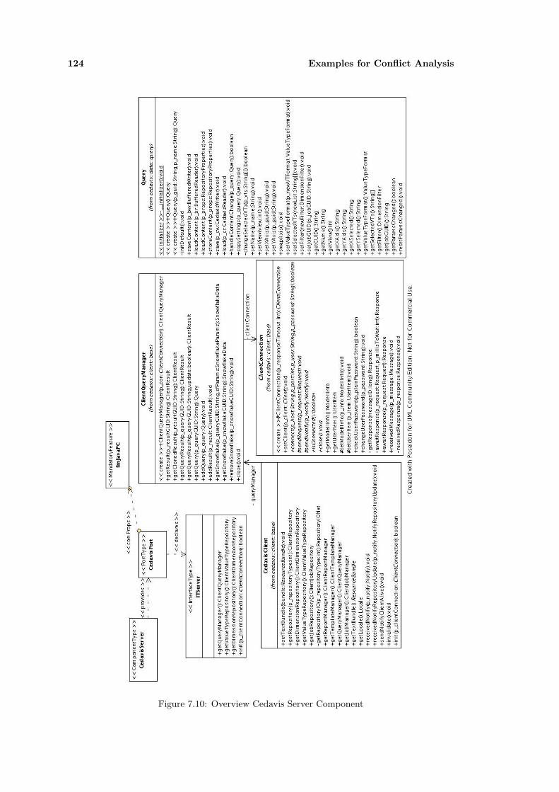
124 Examples for Conflict Analysis
Figure 7.10: Overview Cedavis Server Component

7.4 Analysing the Cedavis Data Warehouse Tool 125
“ Mismatch between interface types (ITServer <: ICedavisOLAP):Mismatch between operation types (getValueTypeRepository <: getValueTypeReposi-
tory):Mismatch between return types: Structural mismatch!
Mismatch between operation types (init <: init):Arguments are of different length.Mismatch between return types:Basic types are not in a subtype relation. (BT (B ”boolean”)) (BT (B ”void”))
Mismatch between operation types (init <: init):Arguments are of different length.Mismatch between arguments:Mismatch between record types (String <: ClientConnection):Designated Subtype Record (String) has too few elements:Feature mismatch in Record:For changeUserPassword exists no corresponding element in the subtype term.For setUserItem exists no corresponding element in the subtype term.”For setModellInfo exists no corresponding element in the subtype termFor getModellInfo exists no corresponding element in the subtype term. . . .
Mismatch between operation types (getQueryManager <: getQueryManager)Arguments are of different length.Mismatch between return types.Mismatch between record types (ClientQueryManager <: NetValueType):Feature mismatch in Record:For getX exists no corresponding element in the subtype term.. . .
Mismatch between operation types (getDimensionRepository <: getDimensionReposi-tory):
Mismatch between return types: Structural mismatch!”
Both interface types are incompatible because of a different design. In ‘ICedavisOLAP’ inter-face, we directly retrieve a list of dimensions, a list of value types, and assemble a query in asingle operation. In the ‘ITServer’ interface, we first retrieve manager objects on which we canperform the operations. Consequently, the specified correspondences are semantically invalidand a connector is needed to resolve the indirection layer required by the ‘ITServer’ interfacetype.
However, we can check if the operations in ‘ICedavisOLAP’ are supported in the managerobjects by searching for corresponding functions in the utility objects:
connect. The corresponding operation for connect can be found by the ‘connect’ operation inthe ClientConnection class. A type check between both operations (ClientConnection-.connect <: ICedavisOLAP.connect) succeeds.
close. Again the corresponding operation is the ‘close’ operation of the ‘ClientConnection’class. A type check between both operations succeeds.
getDimension. The corresponding operation is ‘getDimensionRootGUIDs’ (not shown in thefigure) defined in the ‘ClientDimensionRepository’. A subtype check between both oper-ations (‘ClientDimensionRepository.getDimensionRootGUIDs <: ICedavisOLAP.getDim-ension’) fails because the return types of both operations are different. getDimensionRoot-GUIDs has a string array as return value, whereas getDimension has a list of ‘Dimension’as return value.
getValueType. The corresponding operation is ‘getValueTypeGUIDs’ (not shown in the fig-ure) defined in the class ‘ClientValueTypeRepository’. Again the return types are in-compatible. Operation ‘getValueType’returns a list of ValueType as shown in Figure7.9, whereas ‘getValueTypeGUIDs’ returns a list of ValueTypeItem. However, this con-flict is again a name mismatch between the ‘getID’ operation in ‘ValueType’ and thecorresponding operation ‘getGUID’ in ‘ValueTypeItem’.
olapQuery. For this operation no corresponding operation can be found in ‘ClientQueryMan-ager’because a query is split into two operations ‘addQuery’ and ‘getQueryResult’.

126 Examples for Conflict Analysis
Behavioral Analysis
A check for behavioral compatibility between the ‘CedavisClient’ component type and the‘CedavisServer’ component type involves testing for a simulation if the behavior of the ‘Ce-davisClient’ component type can be simulated by the ‘CedavisServer’ component type. We useFSP to specify the valid operation orders of both components. These result in two transitionsystems that are checked for a simulation relationship. We use the Aldebaran model checkerfor the test.
The behavior descriptions are annotated to the components ports (‘CedavisPort’ and ‘Client-Port’). We omitted the description in the diagrams because of the size of the expressions.
The behavioral description associated with the ‘CedavisServer’ component type is very sim-ple. It consists of an initial ‘init’ transition and subsequent transitions of the remaining threeactions: Q = (init → Q1), Q1 = (getQueryManager → Q1 | getV alueTypeRepository →Q1 | getDimensionRepository → Q1). As the operations of both interface types do not corre-spond to each other, it would not make sense to choose this process for compatibility analysis.Therefore, we decided to model a process description involving not only the behavior of thefour operations defined in ‘ITServer’ but also of the relevant operations of the manager objectsassociated with the operations of the interface type. Furthermore, we simplified the processdescription to provide an impression of a ‘direct’ interface without intermediate manager ob-jects. For example, a query for the dimensions of a Cedavis processing server would requiretwo calls: The first, ‘getDimensionRepository’, returns a ‘ClientDimensionRepository’ and thesecond ‘getDimensionRootGUIDs’ on this object to retrieve the information. We modeled bothoperations as a single transition (‘dim’). We also modeled the five operations on the ‘Query’class that are necessary to pose a query.
We expressed the transition system of the CedavisServer component by a parallel composition,which describes the valid operation sequences for a communication. The resulting transitionsystem, which we use for conflict analysis, consists of 38 states and 280 transitions:
// Definition of the CedavisServer Component/Server=(init→R0),R0= (ready1→R2 | close→Server),R2 = (ready → R3| close→Server),R3 = (query→R3 | close→Server).
// Abstraction for Dimensions// getDimension = dimDIM=(init→D1),D1 =(dim→D2 | close→DIM),D2 =(dim→D2 | ready1 → D3 | close→DIM),D3 =(dim→D3 | close → DIM).
// Abstraction for Value Types// getValueTypes = valVAL=(init→V1),V1 =(val→V2 | close→VAL),V2 =(val→V2 | ready1 → V3 | close→VAL),V3 =(val→V3 | close → VAL).
// The following five expressions represent the// operations of the Query class.// They can be called in any order.
// Abstraction for setName in a Query ObjectName=(ready1→N1|close→Name),N1=(setN→N2 | close → Name),N2=(ready → N3 | setN → N2 | close → Name),N3=(setN → N3 | close → Name).
// Abstraction for the setXAxis operation// in a Query objectSetX=(ready1→SetX1|close→SetX),SetX1=(setX→SetX2 | close → SetX),SetX2=(ready → SetX3 | setX → SetX2
| close → SetX),SetX3=(setX → SetX3 | close → SetX).
// Abstraction for the setYAxis operation// in a Query objectSetY=(ready1→SetY1|close→SetY),SetY1=(setY→SetY2 | close → SetY),SetY2=(ready → SetY3 | setY → SetY2
| close → SetY),SetY3=(setY → SetY3 | close → SetY).
// Abstraction for the setFilter operation// in a Query objectFil=(ready1→Fil1|close→Fil),Fil1=(setFil→Fil2 | close → Fil),Fil2=(ready → Fil3 | setFil → Fil2
| close → Fil),Fil3=(setFil → Fil3 | close → Fil).
// Abstraction for the setSelectedVTs oper-ation// in a Query objectVT=(ready1→VT1|close→VT),VT1=(selVTs→VT2 | close → VT),VT2=(ready → VT3 | selVTs → VT2
| close → VT),VT3=(selVTs → VT3 | close → VT).
// Definition of the transition system for the Cedavis Server Component‖CedavisServer=(Server‖DIM‖Name‖SetX‖VAL‖SetY‖Fil‖VT).
The protocol expression of the Client involves the operations of the ’ICedavisOLAP’ interfacetype:
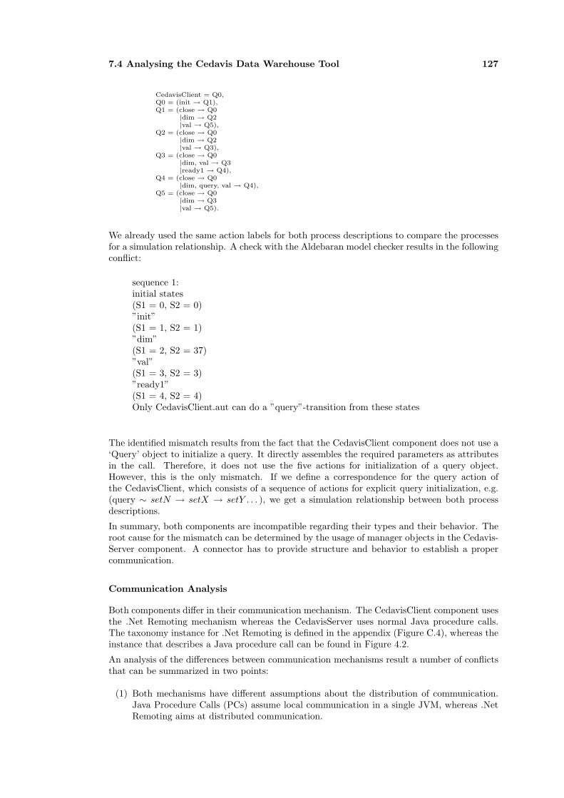
7.4 Analysing the Cedavis Data Warehouse Tool 127
CedavisClient = Q0,Q0 = (init → Q1),Q1 = (close → Q0
|dim → Q2|val → Q5),
Q2 = (close → Q0|dim → Q2|val → Q3),
Q3 = (close → Q0|dim, val → Q3|ready1 → Q4),
Q4 = (close → Q0|dim, query, val → Q4),
Q5 = (close → Q0|dim → Q3|val → Q5).
We already used the same action labels for both process descriptions to compare the processesfor a simulation relationship. A check with the Aldebaran model checker results in the followingconflict:
sequence 1:initial states(S1 = 0, S2 = 0)”init”(S1 = 1, S2 = 1)”dim”(S1 = 2, S2 = 37)”val”(S1 = 3, S2 = 3)”ready1”(S1 = 4, S2 = 4)Only CedavisClient.aut can do a ”query”-transition from these states
The identified mismatch results from the fact that the CedavisClient component does not use a‘Query’ object to initialize a query. It directly assembles the required parameters as attributesin the call. Therefore, it does not use the five actions for initialization of a query object.However, this is the only mismatch. If we define a correspondence for the query action ofthe CedavisClient, which consists of a sequence of actions for explicit query initialization, e.g.(query ∼ setN → setX → setY . . . ), we get a simulation relationship between both processdescriptions.
In summary, both components are incompatible regarding their types and their behavior. Theroot cause for the mismatch can be determined by the usage of manager objects in the Cedavis-Server component. A connector has to provide structure and behavior to establish a propercommunication.
Communication Analysis
Both components differ in their communication mechanism. The CedavisClient component usesthe .Net Remoting mechanism whereas the CedavisServer uses normal Java procedure calls.The taxonomy instance for .Net Remoting is defined in the appendix (Figure C.4), whereas theinstance that describes a Java procedure call can be found in Figure 4.2.
An analysis of the differences between communication mechanisms result a number of conflictsthat can be summarized in two points:
(1) Both mechanisms have different assumptions about the distribution of communication.Java Procedure Calls (PCs) assume local communication in a single JVM, whereas .NetRemoting aims at distributed communication.
128 Examples for Conflict Analysis
(2) Consequently, Java PCs do not support name lookup and do not support the ‘At-Most-Once’ delivery semantics for distributed calls.
7.5 Summary of Conflict Analysis
This chapter provided several examples for conflict analysis of small and medium-sized integra-tion problems. The examples were discussed by directly using the framework (ODIS/OBF) forconflict analysis. A front-end UML tool was only used to generate the UML models. In thiscase, a developer directly use the framework to investigate compatibility and substitutability ofcomponents. She can enter the respective analysis predicates, can further investigate the causesof mismatches and can specify correspondences between names to modify analysis results.
The main point of this chapter was to demonstrate that conflict analysis is an iterative process.A simple query for deciding the compatibility of two components does not provide enoughinformation to understand the causes of a conflict. A developer needs to interpret the results.Iterative queries against particular types and the definition of correspondences provide a betterunderstanding on conflicts. Furthermore, conflict analysis locates the areas of mismatch so thatthe user can concentrate on the right points. Thus, an experienced user would probably usethe ODIS/OBF framework directly instead of interacting via a UML tool with the framework.It is cumbersome to further analyse compatibility directly from a UML tool as this meansto explicitly select elements for analysis and correspondences to consider in analysis. Eachiteration requires converting the UML model into the framework’s representation, to performthe analysis and to deliver the results back to UML.
The conflict analysis framework should be customized for a particular application domain toprovide the best possible conflict analysis. Specialized languages and additional rules, whichcover the constraints of a domain provide a higher potential regarding conflict analysis ofthat domain. Furthermore, the framework includes at the same time the capability of modeltransformation. This can be used for automatic model abstraction, which is necessary toperform analysis as well as for model generation. In particular domains, it should be possibleto generate parts of connectors, which bridge identified mismatches automatically.
A major problem of conflict analysis concerns UML tools and source code import. If a systemneeds to be analysed for which source code is available (which was the case in the examples),the source code first needs to be imported into a UML tool. The imported elements can then beused for analysis. However, the way the source code is imported into UML is not standardizedand therefore tool dependent. For this work, we used Poseidon UML to import Java sourcecode. The tool includes some stereotypes and notes in the integration process that are - inour opinion - tool dependent. These additional elements require special treatment in the RDFtransformation. It is likely that another tool introduces other elements or uses different mappingrules.
Regarding connector generation, the identified conflicts are useful because they illuminate in-tegration mismatches from a platform independent level. A direct comparison of the platformspecific types of two components does not easily show which types are easy and which aremore complicated to integrate. A platform independent view, however, shows the differencesin the light of an independent type system. Furthermore, communication properties describecommunication from a platform independent viewpoint. It is easier to identify conflicts fromthe provided taxonomies than from searching in the source code. Consequently, it is simplerto define connectors based on the platform independent conflicts. We will discuss connectorgeneration further in the last part of the work.
The examples provided in this section do not give an exhaustive overview of the conflicts thatcan be identified by the framework. Further conflict categories concern substitutability of com-ponents and property checking of component configurations. Substitutability of components issimilar to compatibility checking. However, other predicates are used which often impose furtherconstraints in comparison to compatibility predicates. In particular, deciding substitutabilitydemands equivalence checking to decide if a component can be replaced by another. Property

7.5 Summary of Conflict Analysis 129
conflicts describe deadlock and progress properties of a system (component configuration) andare checked with LTSA.

130 Examples for Conflict Analysis
Chapter 8
Parameterized Transformations
This chapter gives an example of parameterized model transformation. The text is mainlytaken from a publication on the Middlware Conference [25], which was a joint work with mycolleagues Susanne Busse, Andreas Billig, and Jorn Guy Suß.
8.1 Motivation
The OMG proposes the Model Driven Architecture (MDA) [98] to target fully automatedcomponent generation. Therefore, it distinguishes two kinds of models: platform independentmodels (PIM) and platform specific models (PSM). A PSM is normally described in a modelinglanguage such as UML and corresponds in a one-to-one fashion to an implementation of thesystem. A platform independent models (PIM) can be defined without reference to a platform,and therefore without describing a particular form of technology.
A problem of many approaches for model transformation concerns the lack of customizationof refinement transformations. A transformation should be applied according to specific userrequirements. For example, a platform independent component should be transformed intoan EntityBean or a SessionBean according to particular requirements. Unfortunately, existingsoftware development tools (such as Rose, ArgoUML, etc.) do not support platform independentmodels. They often provide source code mappings only for one or a small number of technologies:These mappings are defined as one-to-one relationships between UML classes and source codeclasses. As a consequence, it is rarely possible to customize these mappings according to userrequirements.
As a solution to the problem, we propose to realize PIM-to-PSM refinements with TRIPLErules. The concentration of PIM-to-PSM refinements allows handling transformations aimedfor several platforms such as Enterprise JavaBeans, CORBA, .Net, COM, etc. Furthermore,TRIPLE rules are customizable, which allows parameterization of PIM-to-PSM transforma-tions. We parameterize the rules with features to describe the situation when the rule shouldbe applied. Thus, a particular transformation is selected based on the requirements of a specificsituation.
This chapter first introduces the requirements for parameterized model transformation (Section8.2). Then, Section 8.3 describes the different parts of an example, consisting of a platformindependent model, a feature model describing customization of EJB mappings, and a platformspecific EJB model. Section 8.4 describes two customized transformations of the PIM into EJBPSMs. Section 8.5 discusses related work.

132 Parameterized Transformations
8.2 Parameterized Model Transformation
Different from common practice we do not map a PIM directly into source code. Instead, wemap the PIM into a PSM expressed in UML. The appropriate mapping is chosen according toselected requirements. A PIM-PSM transformation is based on three elements:
• the platform independent model that should be mapped. In our context this will be aPIM represented as an instance of the framework’s metamodel. In particular, elementslike components are annotated with further properties that can be used to customize amodel transformation to the specific situation.
• a feature model instance describing requirements that should be considered in the trans-formation. It is used to choosing an appropriate mapping. Thus, feature models allowthe customization of a model transformation.
• mappings that define rules for possible transformations. Mappings formally specify designknowledge that is used when realizing a system with a specific middleware technology.They enable the automatization of the transformation process.
A PIM-PSM transformation consists of three steps: First, the developer designs a systemindependent from a platform technology. Second, he specifies his requirements for a specificPIM-to-PSM transformation by choosing features from the feature model. This selection resultsin a Feature Model Instance (FI), which does not contain any variation points. Third, theframework transforms the PIM according to the specified requirements.
Formally, the basis for a parameterized model transformation is a set of Triple transformationrules (see Section 3.1.5). Each rule takes the PIM and a Feature Model Instance model as inputarguments and creates a PSM which corresponds to the given requirements. In our frameworkall participating models are defined as RDF models: A platform independent component modelis defined in Section 5.1, a feature model is defined in Section 3.1.3, and a platform specificmodel to describe Enterprise JavaBeans is described in this section. On this basis, a mappingcan be defined as a TRIPLE-mapping with parameterized contexts:
∀PIM, FI @pim2psmMapping(PIM,FI){//Transformation rule1∀ < . . . necessaryV ariables . . . >
< . . . elements . . . > @PIM ∧< . . . constraint . . . > @FI
−→< . . . PSMelements . . . >
//Transformation rule2. . .
8.3 Example
Our running example comes from federated information systems and was already describedin Section 7.3. We describe two possible PIM-to-PSM transformations from the platform in-dependent model to EJB specific models regarding specific requirements on distribution andoptimization.
8.3.1 Platform Independent Model
Figure 8.1 shows the two components that are part of a mediator. Althought the exampleis described in Section 7.3, we repeat the description for an overview: If a client queries amediator, the mediator first calculates which data sources are capable of answering the query
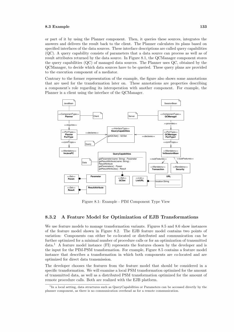
8.3 Example 133
or part of it by using the Planner component. Then, it queries these sources, integrates theanswers and delivers the result back to the client. The Planner calculates its plans based onspecified interfaces of the data sources. These interface descriptions are called query capabilities(QC). A query capability consists of parameters that a data source can process as well as ofresult attributes returned by the data source. In Figure 8.1, the QCManager component storesthe query capabilities (QC) of managed data sources. The Planner uses QC, obtained by theQCManager, to decide which data sources have to be queried. These query plans are providedto the execution component of a mediator.
Contrary to the former representation of the example, the figure also shows some annotationsthat are used for the transformation later on. These annotations are properties describinga component’s role regarding its interoperation with another component. For example, thePlanner is a client using the interface of the QCManager.
<<ComponentType>> Planner
<<InterfaceType>> IQueryCapabilities
_____________________ getQCSet() : QCSet
<<ComponentType>> QCManager
<<requires>><<provides>>
QueryCapabilities _____________________________________ getParameter(name: String) : Parameter getResultAttribute(name: String) : ResultAttribute getParameters() : Param getResultAttributes() : Result
<<PortType>> Planner
PortType
<<declares>> <<PortType>> QCManager PortType1<<declares>>
<<Mandatory>> fmSessionBean
<<Mandatory>> fmJavaPC
<<comProps>><<comProps>>
JavaBean SessionBean
Client Server
<<List>> ListURL
URL _____________________ location:String _____________________
<<Set>> Param
<<Set>> Result
ResultAttribute
Parameter <<Set>> QCSet
<<Mandatory>> Transaction
<<Mandatory>> Security
<<subFeatures>> <<subFeatures>>
Data
Query
Figure 8.1: Example - PIM Component Type View
8.3.2 A Feature Model for Optimization of EJB Transformations
We use feature models to manage transformation variants. Figures 8.5 and 8.6 show instancesof the feature model shown in Figure 8.2. The EJB feature model contains two points ofvariation: Components can either be co-located or distributed and communication can befurther optimized for a minimal number of procedure calls or for an optimization of transmitteddata.1 A feature model instance (FI) represents the features chosen by the developer and isthe input for the PIM-PSM transformation. For example, Figure 8.5 contains a feature modelinstance that describes a transformation in which both components are co-located and areoptimized for direct data transmission.
The developer chooses the features from the feature model that should be considered in aspecific transformation. We will examine a local PSM transformation optimized for the amountof transmitted data, as well as a distributed PSM transformation optimized for the amount ofremote procedure calls. Both are realized with the EJB platform.
1In a local setting, data structures such as QueryCapabilities or Parameters can be accessed directly by theplanner component, as there is no communication overhead as for a remote communication.
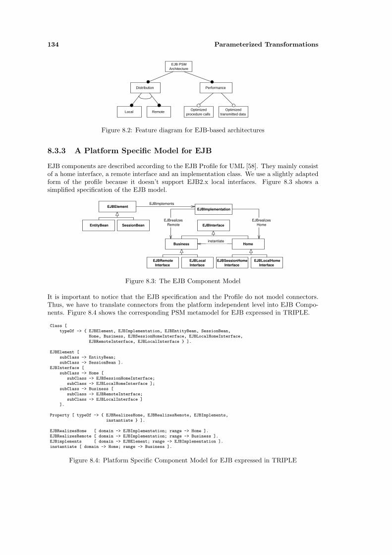
134 Parameterized Transformations
EJB PSM Architecture
Distribution Performance
Local RemoteOptimized
procedure callsOptimized
transmitted data
Figure 8.2: Feature diagram for EJB-based architectures
8.3.3 A Platform Specific Model for EJB
EJB components are described according to the EJB Profile for UML [58]. They mainly consistof a home interface, a remote interface and an implementation class. We use a slightly adaptedform of the profile because it doesn’t support EJB2.x local interfaces. Figure 8.3 shows asimplified specification of the EJB model.
EJBElement
EntityBean SessionBean EJBInterface
Home
EJBSessionHomeInterface
EJBLocalHome Interface
Business
EJBRemote Interface
EJBLocal Interface
EJBImplementation
EJBrealizesHome
EJBrealizesRemote
EJBimplements
instantiate
Figure 8.3: The EJB Component Model
It is important to notice that the EJB specification and the Profile do not model connectors.Thus, we have to translate connectors from the platform independent level into EJB Compo-nents. Figure 8.4 shows the corresponding PSM metamodel for EJB expressed in TRIPLE.
Class [typeOf -> { EJBElement, EJBImplementation, EJBEntityBean, SessionBean,
Home, Business, EJBSessionHomeInterface, EJBLocalHomeInterface,EJBRemoteInterface, EJBLocalInterface } ].
EJBElement [subClass -> EntityBean;subClass -> SessionBean ].
EJBInterface [subClass -> Home [
subClass -> EJBSessionHomeInterface;subClass -> EJBLocalHomeInterface ];
subClass -> Business [subClass -> EJBRemoteInterface;subClass -> EJBLocalInterface ]
].
Property [ typeOf -> { EJBRealizesHome, EJBRealizesRemote, EJBImplements,instantiate } ].
EJBRealizesHome [ domain -> EJBImplementation; range -> Home ].EJBRealizesRemote [ domain -> EJBImplementation; range -> Business ].EJBimplements [ domain -> EJBElement; range -> EJBImplementation ].instantiate [ domain -> Home; range -> Business ].
Figure 8.4: Platform Specific Component Model for EJB expressed in TRIPLE

8.4 PIM-PSM Transformation 135
<<EJBSessionBean>> Planner
<<EJBRemoteInterface>> PlannerRemote
__________ <<EJBRemoteMethod>> execute() <<EJBRemoteMethod>> plan()
<<EJBSessionHomeInterface>> PlannerHome __________
<<EJBCreateMethod>> create()
<<instantiate>>
<<EJBImplementation>> PlannerBean
<<EJBRealizeRemote>>
<<EJBRealizeHome>>
<<EJBEntityBean>> QueryCapabilities
<<EJBLocalEntityHomeInterface>> QueryCapabilitesHome
__________ <<EJBCreateMethod>> create() <<EJBFinderMethod>>findQCSet():Enumeration
<<EJBEntityBean>> Parameter
<<EJBEntityBean>> ResultAttribute
<<EJBLocalInterface>> QueryCapabilitiesRemote
__________ <<EJBLocalMethod>> getResultAttribute()
<<EJBLocalMethod>>getParameter() . . .
EJB PSM Architecture
Distribution Performance
LocalOptimized
transmitted data
a) Platform Independent Component Model b) Feature Model Instance
<<ComponentType>> Planner
<<Interface>> IQueryCapabilities
_____________________ _____________________ getQCSet() : Set(QC)
<<ComponentType>> QCManager
Query Capabilities
Parameter ResultAttribute
* 1..*Client
Server
Data
Query
c) Platform Specific Component Model
Figure 8.5: Example - PIM-PSM Transformation for a Local Configuration
8.4 PIM-PSM Transformation
Starting from the PIM of a mediator and the feature model for EJB architectures we showtwo possible transformations to the EJB PSM. In our example the transformation is based onpatterns [12; 87] that were developed to optimize EJB communication and performance. Wewill discuss a local and a distributed configuration of the mediator components.
Local Configuration Scenario
This transformation is done according to the features that were chosen by the developer: bothcomponents are co-located and optimized for the amount of transmitted data. Using the pat-terns in [12; 87] the transformation results in the PSCM shown in Figure 8.5. The Plannercomponent as a client in this example is mapped into a Session Bean because it is used as abusiness logic component, e.g. it provides computations. The QCManager, which includes theQC data structure (determined by the relationship to an element with a Data annotation), ismapped into three EntityBeans, as it presents persistent data. We don’t need an extra QC-Manager Bean as this component would introduce another layer of indirection. Instead, wedirectly access the persistence layer. This leads to optimized data transfer, as we don’t have tocollect all data of the persistence layer and send it to the Planner component. Instead, data isreturned in the form of a set of references to locally available QC EntityBeans. The operationto obtain all QC is renamed to findQCSet as described in the profile. If the Planner needsparameters, it issues calls to obtain the required information.
In order to save space, only the Planner component in Figure 8.5 shows all parts of an EJBaccording to the profile. Otherwise, we only show interesting parts of a bean and representother elements as small boxes.

136 Parameterized Transformations
EJB PSM Architecture
Distribution Performance
Remote Optimized procedure calls
a) Platform Independent Component Model b) Feature Model Instance
<<ComponentType>> Planner
<<Interface>> IQueryCapabilities
<<ComponentType>> QCManager
Query Capabilities
Parameter ResultAttribute
* 1..*Client
Server
Data
c) Platform Specific Component Model
<<EJBSessionBean>> QCManager
<<EJBSessionHomeInterface>> QCManagerHome
__________ <<EJBCreateMethod>> create()
<<EJBRemoteInterface>> QCManagerRemote
__________ <<EJBRemoteMethod>>getQCSet(): Enumerate
<<EJBEntityBean>> Parameter
<<EJBEntityBean>> ResultAttribute
<<EJBEntityBean>> QueryCapabilities
<<EJBSessionBean>> Planner
Figure 8.6: Example - PIM-PSM Transformation for a Distributed Configuration
Distributed Configuration Scenario
The distributed transformation optimizes remote procedure calls between distributed Plan-ner components and a single QCManager component. Again, the transformation is based onthe chosen features from the feature model. Regarding the EJB platform, several patternsfor performance optimization were developed. We will use the Data Transfer Object pattern(DTO)[12; 87] and the Data Transfer Object Factory pattern (DTOF)[87] for the PIM-to-PSMtransformation in this example.
Figure 8.6 shows the mapping result. The QCManager component is mapped into a statelessSessionBean following the DTOF pattern that provides a facade to the persistence layer con-sisting of three EntityBeans. The QCManager locally assembles Data Transfer Objects for eachquery by calling the Entity Beans. Different from the local mapping these objects are copies ofpersistent data. Thus, a query of the Planner component results in a single remote procedurecall.
Parameterized Transformations with TRIPLE
The specification of the mappings for our transformation2 described before consists of two parts:the first one defines the general mapping from PIM elements to EJB, the second one definesthe mapping depending on the possible features.
Figure 8.7 shows part of the general mapping definition from PIM models to SessionBeansor EntityBeans. The arguments of the bean mapping are the resource variables X, PIM, and
2The following rules, shown in figures 8.7 and 8.8, precisely cover the available choices of the feature modelshown in Figure 8.2.
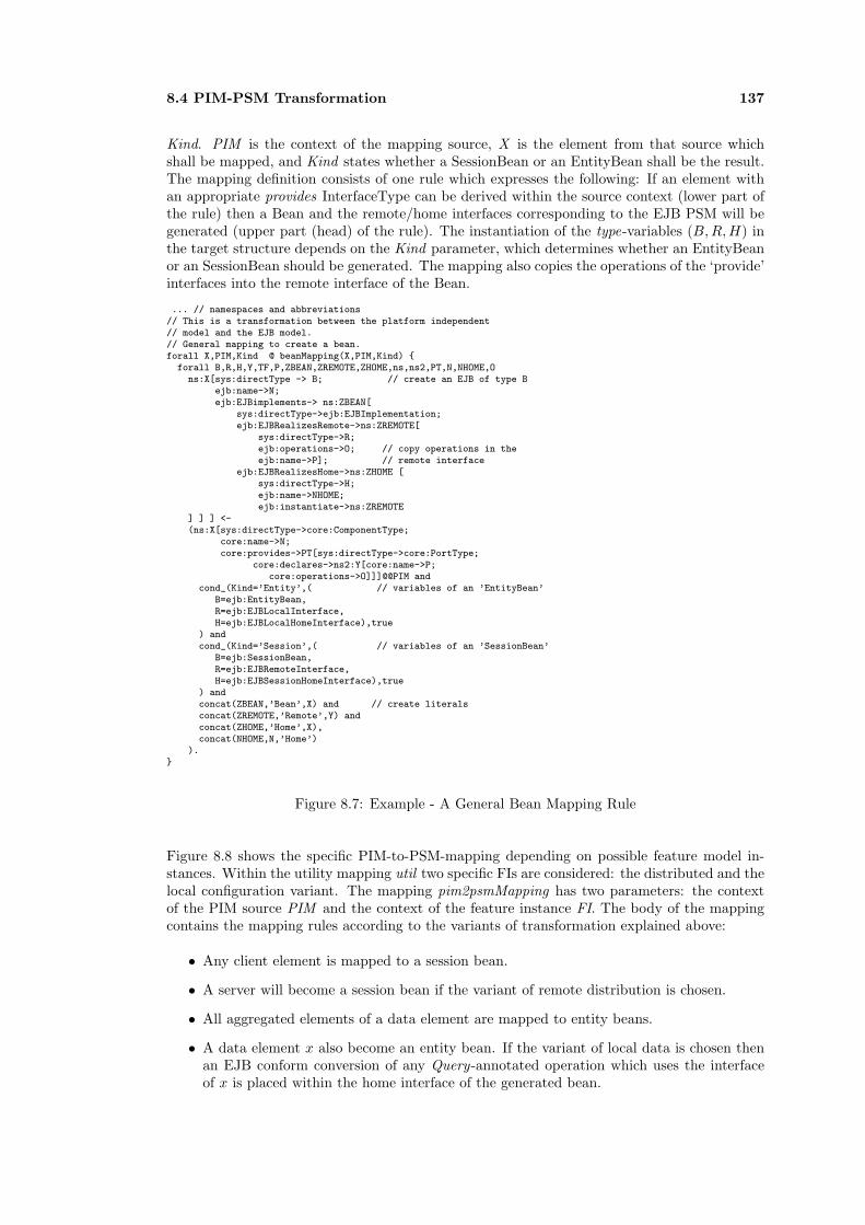
8.4 PIM-PSM Transformation 137
Kind. PIM is the context of the mapping source, X is the element from that source whichshall be mapped, and Kind states whether a SessionBean or an EntityBean shall be the result.The mapping definition consists of one rule which expresses the following: If an element withan appropriate provides InterfaceType can be derived within the source context (lower part ofthe rule) then a Bean and the remote/home interfaces corresponding to the EJB PSM will begenerated (upper part (head) of the rule). The instantiation of the type-variables (B,R, H) inthe target structure depends on the Kind parameter, which determines whether an EntityBeanor an SessionBean should be generated. The mapping also copies the operations of the ‘provide’interfaces into the remote interface of the Bean.
... // namespaces and abbreviations// This is a transformation between the platform independent// model and the EJB model.// General mapping to create a bean.forall X,PIM,Kind @ beanMapping(X,PIM,Kind) {
forall B,R,H,Y,TF,P,ZBEAN,ZREMOTE,ZHOME,ns,ns2,PT,N,NHOME,Ons:X[sys:directType -> B; // create an EJB of type B
ejb:name->N;ejb:EJBimplements-> ns:ZBEAN[
sys:directType->ejb:EJBImplementation;ejb:EJBRealizesRemote->ns:ZREMOTE[
sys:directType->R;ejb:operations->O; // copy operations in theejb:name->P]; // remote interface
ejb:EJBRealizesHome->ns:ZHOME [sys:directType->H;ejb:name->NHOME;ejb:instantiate->ns:ZREMOTE
] ] ] <-(ns:X[sys:directType->core:ComponentType;
core:name->N;core:provides->PT[sys:directType->core:PortType;
core:declares->ns2:Y[core:name->P;core:operations->O]]]@@PIM and
cond_(Kind=’Entity’,( // variables of an ’EntityBean’B=ejb:EntityBean,R=ejb:EJBLocalInterface,H=ejb:EJBLocalHomeInterface),true
) andcond_(Kind=’Session’,( // variables of an ’SessionBean’
B=ejb:SessionBean,R=ejb:EJBRemoteInterface,H=ejb:EJBSessionHomeInterface),true
) andconcat(ZBEAN,’Bean’,X) and // create literalsconcat(ZREMOTE,’Remote’,Y) andconcat(ZHOME,’Home’,X),concat(NHOME,N,’Home’)
).}
Figure 8.7: Example - A General Bean Mapping Rule
Figure 8.8 shows the specific PIM-to-PSM-mapping depending on possible feature model in-stances. Within the utility mapping util two specific FIs are considered: the distributed and thelocal configuration variant. The mapping pim2psmMapping has two parameters: the contextof the PIM source PIM and the context of the feature instance FI. The body of the mappingcontains the mapping rules according to the variants of transformation explained above:
• Any client element is mapped to a session bean.
• A server will become a session bean if the variant of remote distribution is chosen.
• All aggregated elements of a data element are mapped to entity beans.
• A data element x also become an entity bean. If the variant of local data is chosen thenan EJB conform conversion of any Query-annotated operation which uses the interfaceof x is placed within the home interface of the generated bean.
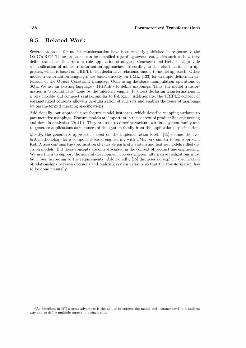
138 Parameterized Transformations
8.5 Related Work
Several proposals for model transformation have been recently published in response to theOMG’s RFP. These proposals can be classified regarding several categories such as how theydefine transformation rules or rule application strategies. Czarnecki and Helsen [42] providea classification of model transformation approaches. According to this classification, our ap-proach, which is based on TRIPLE, is a declarative relational model-to-model approach. Othermodel transformation languages are based directly on UML. [133] for example defines an ex-tension of the Object Constraint Language OCL using database manipulation operations ofSQL. We use an existing language - TRIPLE - to define mappings. Thus, the model transfor-mation is ‘automatically’ done by the inference engine. It allows declaring transformations ina very flexible and compact syntax, similar to F-Logic.3 Additionally, the TRIPLE concept ofparameterized contexts allows a modularization of rule sets and enables the reuse of mappingsby parameterized mapping specifications.
Additionally, our approach uses feature model instances, which describe mapping variants toparameterize mappings. Feature models are important in the context of product line engineeringand domain analysis ([39; 41]). They are used to describe variants within a system family andto generate applications as instances of this system family from the application’s specification.
Mostly, the generative approach is used on the implementation level. [15] defines the Ko-brA methodology for a component-based engineering with UML very similar to our approach.KobrA also contains the specification of variable parts of a system and feature models called de-cision models. But these concepts are only discussed in the context of product line engineering.We use them to support the general development process wherein alternative realizations mustbe chosen according to the requirements. Additionally, [15] discusses no explicit specificationof relationships between decisions and realizing system variants so that the transformation hasto be done manually.
3As described in [57] a great advantage is the ability to express the model and instance level in a uniformway and to define multiple targets in a single rule.
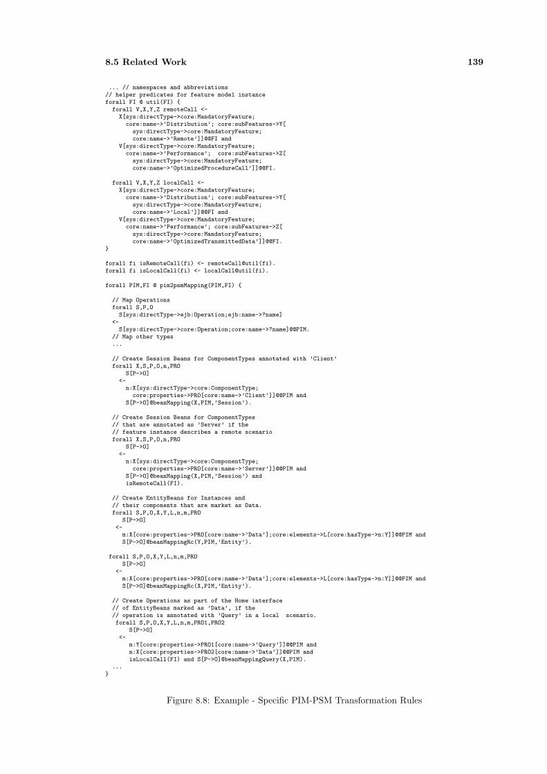
8.5 Related Work 139
... // namespaces and abbreviations// helper predicates for feature model instanceforall FI @ util(FI) {
forall V,X,Y,Z remoteCall <-X[sys:directType->core:MandatoryFeature;
core:name->’Distribution’; core:subFeatures->Y[sys:directType->core:MandatoryFeature;core:name->’Remote’]]@@FI and
V[sys:directType->core:MandatoryFeature;core:name->’Performance’; core:subFeatures->Z[
sys:directType->core:MandatoryFeature;core:name->’OptimizedProcedureCall’]]@@FI.
forall V,X,Y,Z localCall <-X[sys:directType->core:MandatoryFeature;
core:name->’Distribution’; core:subFeatures->Y[sys:directType->core:MandatoryFeature;core:name->’Local’]]@@FI and
V[sys:directType->core:MandatoryFeature;core:name->’Performance’; core:subFeatures->Z[
sys:directType->core:MandatoryFeature;core:name->’OptimizedTransmittedData’]]@@FI.
}
forall fi isRemoteCall(fi) <- remoteCall@util(fi).forall fi isLocalCall(fi) <- localCall@util(fi).
forall PIM,FI @ pim2psmMapping(PIM,FI) {
// Map Operationsforall S,P,O
S[sys:directType->ejb:Operation;ejb:name->?name]<-
S[sys:directType->core:Operation;core:name->?name]@@PIM.// Map other types...
// Create Session Beans for ComponentTypes annotated with ’Client’forall X,S,P,O,n,PRO
S[P->O]<-
n:X[sys:directType->core:ComponentType;core:properties->PRO[core:name->’Client’]]@@PIM and
S[P->O]@beanMapping(X,PIM,’Session’).
// Create Session Beans for ComponentTypes// that are annotated as ’Server’ if the// feature instance describes a remote scenarioforall X,S,P,O,n,PRO
S[P->O]<-
n:X[sys:directType->core:ComponentType;core:properties->PRO[core:name->’Server’]]@@PIM and
S[P->O]@beanMapping(X,PIM,’Session’) andisRemoteCall(FI).
// Create EntityBeans for Instances and// their components that are market as Data.forall S,P,O,X,Y,L,n,m,PRO
S[P->O]<-
m:X[core:properties->PRO[core:name->’Data’];core:elements->L[core:hasType->n:Y]]@@PIM andS[P->O]@beanMappingRc(Y,PIM,’Entity’).
forall S,P,O,X,Y,L,n,m,PROS[P->O]
<-m:X[core:properties->PRO[core:name->’Data’];core:elements->L[core:hasType->n:Y]]@@PIM andS[P->O]@beanMappingRc(X,PIM,’Entity’).
// Create Operations as part of the Home interface// of EntityBeans marked as ’Data’, if the// operation is annotated with ’Query’ in a local scenario.forall S,P,O,X,Y,L,n,m,PRO1,PRO2
S[P->O]<-
m:Y[core:properties->PRO1[core:name->’Query’]]@@PIM andn:X[core:properties->PRO2[core:name->’Data’]]@@PIM andisLocalCall(FI) and S[P->O]@beanMappingQuery(X,PIM).
...}
Figure 8.8: Example - Specific PIM-PSM Transformation Rules

140 Parameterized Transformations

Part IV
Conclusion and Outlook
141

Chapter 9
Conclusion
This thesis presented a Framework for Component Conflict Analysis and Composition thatserves as a basis for component integration. The framework fulfils the required objectives forcomponent integration and is placed in a technological context that provides several advan-tages compared to other approaches: It allows analysing components with type, behavior andcommunication properties, it is adaptable for application domains and for additional kinds ofanalysis and it integrates model transformation capabilities. In this section, we will summa-rize the main objectives for component integration, the architecture of the framework and theresulting advantages. Finally, we give an outlook for future research.
9.1 Objectives for Component Integration
In the work we divided component integration into two steps: Conflict Analysis and ConnectorGeneration. The work primarily aimed at the first step and focused on relationships to decidecompatibility and substitutability of components.
The work focused on the integration of small to medium-sized components that originate inobject-oriented middleware technologies such as CORBA, COM, .NET, Jini, etc. As componentspecifications of these technologies differ in form, complexity and content, a canonical repre-sentation was required that represented the least common denominator of components in thesetechnologies. The presented framework supports such a platform independent representationby defining several models that represent the core concepts of components: structure, behaviorand communication properties.
As components are normally specified in terms of concrete technologies, they cannot be di-rectly compared unless they are translated into the platform independent component modelsprovided by the framework. The framework principally supports model abstractions, whichdemerge platform specific details from component descriptions and create a canonical represen-tation of those components. In this thesis, however, we have concentrated the more complexrefinement transformation that transforms platform independent models into platform specificmodels based on parameters which modify the results according to user requirements.
Based on the platform independent component model, we provided conflict analysis. We aimedto check for as many conflict categories as possible, because the more conflicts the analysisidentifies, the more accurate the cost assessment of an integration effort will be. We proposedtwo complex relationships for conflict analysis: A compatibility relationship checks if two com-ponents can interact, whereas a substitutability relationship decides if two components canbe exchanged. Both relationships are composed of several other relationships that cover thespecification categories of components. These include subtype, simulation and bisimulationrelationships to cover essential conflict categories. It further introduced a new relationship thatevaluates the compliance of communication requirements based on the exposed features of twocomponents.

144 Conclusion
We proposed two taxonomies to describe communication requirements as well as technology-related metadata. The first taxonomy is a modified version of the connector taxonomy pro-posed by Medvidovic/Mehta. We used this taxonomy, because it provides the most fine grainedproperties available today. We modified the original taxonomy to describe communication incurrently available middleware systems and to express customizable properties of those com-munication mechanisms. The second taxonomy covers technology-related properties.
A Property-based conflict analysis of components’ communication requirements is often under-estimated at present. Only a few approaches cover property-based description and analysis.Examples are the connector taxonomy of Mehta/Medvidovic or architectural styles proposedby Allan/Shaw. However, a property-based analysis provides several advantages: Propertiescan be used to transform conceptual models into specific representation covering particularcommunication requirements and they allow gaining more information regarding incompletelyspecified components.
Components are rarely fully specified in current technologies. Some facts are stated implicitlyor not at all. For example, a major problem of present middleware technologies is that theyignore the need for a behavioral specification. Most popular technologies cannot associate thiskind of information with their component definitions. Furthermore, communication require-ments are often not explicitly stated in middleware technologies. This is sufficient as in thecontext of one technology communication must be based on predefined mechanisms for whichthe technology transparently takes care of. However, when dealing with more than one technol-ogy, with different communication paradigms, or with adaptable communication paradigms, itis likely that the requirements of components regarding communication will vary. Consequently,explicit knowledge about communication properties is required.
We further aimed to support model refinement. Model refinement covers component transfor-mation from a platform independent level to a platform specific level. It is required to supportthe second step of integration: connector generation. We proposed to use a property-basedtransformation that is based on feature models to describe user requirements.
A parameterized transformation paves the way for design reuse. It becomes possible to reuse aconceptual model for different technologies. One can create a EJB model or a CORBA model ora model for another language from a single conceptual model. Regarding communication prop-erties, different kinds of communication can be generated for a conceptual model. For example,one can create an EJB component accepting synchronous communication (e.g. a SessionBean)or a component accepting asynchronous communication (e.g. a MessageBean) from a singleconceptual component. Based on properties in a feature model, model transformation can alsobe parameterized in a more flexible way. In [25], we demonstrated that model transformationscan be parameterized based on J2EE patterns.
As a last objective, we aimed to support a seamless integration with design tools used in softwaredevelopment. As UML is the de facto modeling language, we support conflict analysis fromwithin UML tools.
9.2 Architecture of the Framework
The objective of this thesis concerns component conflict analysis in the context of a UML-based software development process. As no technology is able to cover all objectives by itself,we propose a technology combination to satisfy the objectives: We use UML as a front-endmodeling language for the end-user. We use concepts of Architecture Description Languagesto compose the platform independent component models on which conflict analysis is based.As a formalization of those models, we chose RDF, as it is a standardized language that canbe easily used in several application domains. To cope with models on different abstractionlevels, we orientated on the Model-Driven Architecture of the OMG and implemented modeltransformation on TRIPLE. TRIPLE, which is a ‘RDF-aware’ extension of F-Logic providesreasoning support and at the same time allows describing parameterized mappings.
9.3 Summary of Contributions 145
The architecture of the framework was divided into five parts: The first part consists of aUML modeling tool that is able to import and export XMI. The second part transforms modelsbetween XMI and RDF. The third part, the Ontology-Based Framework, realizes componentanalysis and transformations between platform independent and platform specific models. Thefourth part consists of several external tools that provide conflict analysis capabilities such astype checking and model checking. The framework is augmented with a component repository,which stores all kinds of component specification regardless of whether they are formalized asXMI, RDF, artifacts or represent PIMs or PSMs.
Technically the framework is based on the ODIS repository, which itself is based on a deductiveknowledge base (XSB). The models and their associated rules that are used within the frame-work are realized based on TRIPLE. Type and behavioral conflicts are checked with externaltools such as Haskell, LTSA, FDR, fc2tools, or Aldebaran. We used these tools because theyprovide more sophisticated analysis than was possible with a deductive knowledge base.
9.3 Summary of Contributions
The framework explicitly aims at conflict analysis in several areas. It supports type and behav-ior checks and additionally communication requirements of components. Consequently, a farbetter overview concerning the interoperability of components can be achieved than by usinganalysis tools that deal with only one or two issues. As a result, an estimation of integrationcosts becomes more accurate and simpler to calculate. Furthermore, a user can customize theframework with additional analysis methods or with different specification languages.
At the same time, the framework represents a ‘minimal’ model-driven development system.It supports abstraction and refinement operations on models and handles models on differentabstraction levels. As mentioned above the refinement of models can be parameterized andtherefore adapted to satisfy user requirements. This is contrary to one-to-one transformationsthat are usually provided by development tools.
The framework further supports a UML-based model driven development and integrates rea-soning and transformation capabilities to ‘existing’ modeling tools. The framework uses RDFto represent component specifications. UML models can be transformed into this internal rep-resentation (RDF) and vice versa. Consequently, we are able to reason on UML models, whichis not directly supported by UML, and further to attach arbitrary background information onUML elements and to interpret the background information as RDF statements.
9.4 Connector Generation
The framework provides the foundation for the second step of integration: connector generation.Connector generation depends on the results of the analysis process. We propose to startconnector generation on the platform independent level and then to refine the connector forparticular technologies. This process is briefly described in the following steps. The first two ofthese steps require user interaction. The fourth step can be customized for certain requirements.
(1) For each structural conflict a correspondence relationship needs to be specified manuallyif possible. If correspondences cannot bridge identified incompatibilities in a reasonableway, connector generation stops at this or at the next step. We distinguish betweenmismatched operation and parameter names and mismatched types. A correspondenceis a relationship between operations of the client’s required interface and the server’sprovided interface. In case of a type mismatch an additional conversion function needs tobe defined manually (and implemented).
(2) For behavioral conflicts (protocol conflicts), a simulation conflict results if a server can-not react on the issued operations of a client. A common cause relates to mismatched
146 Conclusion
operation granularity. For example, the client issues an operation co1, but the serverrequires an explicit initialization so1 before the request of the client can be handled byanother operation so2. In this case the connector needs to implement the correspondenceco1 ∼ (so1 → so2).
(3) Based on this information a platform independent connector can be automatically speci-fied. We propose to use two kinds of diagrams to define a connector: a structural diagramand a state diagram. The structural diagram consists of the internal operation needed tomap diverging types as well as of the required operations of the client. The behavioraldiagram specifies the mediation of the required operation orders of both components. Wecan derive information for a connector’s behavior by utilizing the algorithm proposed byInverardi [65]. She defines an algorithm that handles behavioral mismatches between sev-eral components by defining a connector that resolves these mismatches. The resultingstate diagram consists of transitions where the events correspond to the operations issuedby the client and the actions are either internal type transformations or called operationsof the server component.
(4) Based on the platform independent description, we transform the connector into platformspecific representations. The specified communication properties are important in thisstep as they determine the structure and additional behavior of the resulting platformspecific connector. For example, if the property description requires a distributed con-nector and a name server lookup, the connector can be mapped according to the proxypattern with an additional operation call to a name server.
9.5 Future Work
We plan to augment the framework with additional analysis capabilities and to enhance theconcept of parameterized transformation.
At present, matching algorithms for web services are developed that use ‘semantic’ matchingto improve the identification of suitable services. These algorithms are used to search forcomponents that are the most suitable compared to a given query. The ‘semantic’ matchingis often based on ontologies that are used for calculations. At present, a semantic matchingservice is developed for the ADAM repository. This enables framework users to query forsuitable components that are stored in the ADAM repository based on metadata attached tothe components. The prototype of the searching algorithm uses a taxonomy, which describesthe technological requirements of a component. Further, the functionality of a component isdescribed. These metadata can be used for a ranking of suitable components. An advantage ofthe framework compared to solutions for web services concerns the additional checking of types,behavior and communication properties that can be calculated at the same time. Furthermore,the framework supports different technologies, from which the web service technology is onlyone possible incarnation. Consequently, we can search the database for components origin indifferent technologies, which are specified on different abstraction levels.
We further plan to enhance parameterized transformation. We first exploit the defined com-munication taxonomies for parameterized transformation. The customizable properties of acommunication mechanisms can naturally be used to describe mapping variations of platformindependent component descriptions for a particular technology. At the moment, parameterizedtransformations for the Enterprise JavaBeans technology, which are based on the customizableproperties of the communication mechanisms defined for that technology, are being researched.
At the same time, we plan to provide mappings for J2EE patterns defined in the EJB com-munity. The patterns represent optimized solutions for particular use cases. We exploit theexisting patterns in transformations so that a platform independent model can be optimized fora particular use case. Contrary to the approach we already proposed at the Middleware 2004conference, we encode the patterns and the available variations of the patterns as feature modelsand do not create a feature model, which describes the applicability and the the consequences

9.5 Future Work 147
for a number of patterns. This solution, which was presented at the middleware conference, ismore complicated to extend than the new concept. However, we encode information regardingthe applicability and the consequences as feature attributes of the feature models describingthe patterns. This allows for an efficient search for suitable patterns.

148 Conclusion

Part V
Appendix
149

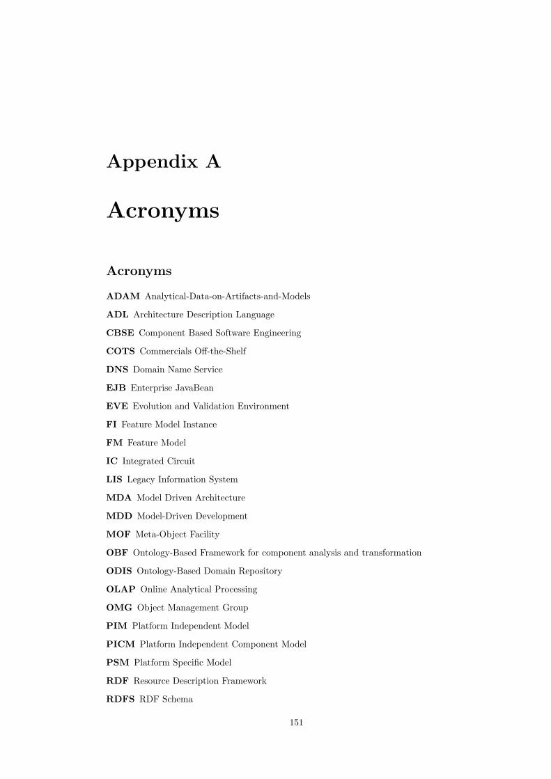
Appendix A
Acronyms
Acronyms
ADAM Analytical-Data-on-Artifacts-and-Models
ADL Architecture Description Language
CBSE Component Based Software Engineering
COTS Commercials Off-the-Shelf
DNS Domain Name Service
EJB Enterprise JavaBean
EVE Evolution and Validation Environment
FI Feature Model Instance
FM Feature Model
IC Integrated Circuit
LIS Legacy Information System
MDA Model Driven Architecture
MDD Model-Driven Development
MOF Meta-Object Facility
OBF Ontology-Based Framework for component analysis and transformation
ODIS Ontology-Based Domain Repository
OLAP Online Analytical Processing
OMG Object Management Group
PIM Platform Independent Model
PICM Platform Independent Component Model
PSM Platform Specific Model
RDF Resource Description Framework
RDFS RDF Schema
151

152 Acronyms
RM-ODP Reference Model of Open Distributed Processing
UI User Interface
UML The Unified Modeling Language
URI Uniform Resource Identificator
W3C World Wide Web Consortium
XMI XML Metadata Interchange

Appendix B
UML Profile for theOntology-Based Framework
This section defines a UML representation of the framework’s models. The representation isformalized as a profile that basically provides an one-to-one mapping between the framework’selements and UML model elements. Most of the framework models are represented based onUML class diagrams, where the standard elements are annotated by stereotypes. The onlyexception is the framework’s definition of state diagrams which is based on UML elementsdefined for use within state diagrams.
The profile definition orientates on UML 1.4.21. However, it should be valid within most UML1.x versions. The profile does not define a stereotype hierarchy. It differs from the OMGrecommendation as it provides no well-formedness rules expressed in OCL as we perceive theprofile as a representation of the framework’s models, we check validity by integrity rules definedon the framework’s models.
In this section, we first give an overview of the diagram types together with a listing of thedefined stereotypes and then provide a description of each stereotype.
B.1 Stereotype Summary
The following profile defines four diagram types: a component type diagram, a run-time configuration
diagram, a behavior diagram, and a property diagram:
Component Type Diagram
1formal/04-07-02
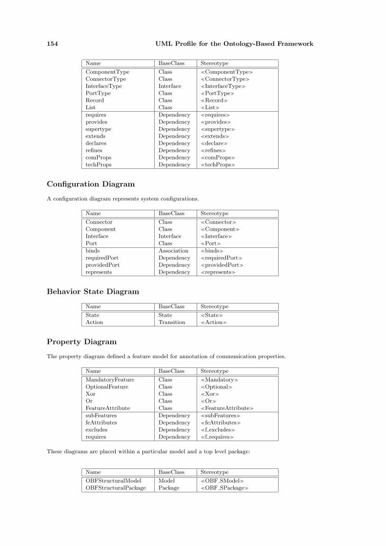
154 UML Profile for the Ontology-Based Framework
Name BaseClass Stereotype
ComponentType Class �ComponentType�
ConnectorType Class �ConnectorType�
InterfaceType Interface �InterfaceType�
PortType Class �PortType�
Record Class �Record�
List Class �List�
requires Dependency �requires�
provides Dependency �provides�
supertype Dependency �supertype�
extends Dependency �extends�
declares Dependency �declare�
refines Dependency �refines�
comProps Dependency �comProps�
techProps Dependency �techProps�
Configuration Diagram
A configuration diagram represents system configurations.
Name BaseClass Stereotype
Connector Class �Connector�
Component Class �Component�
Interface Interface �Interface�
Port Class �Port�
binds Association �binds�
requiredPort Dependency �requiredPort�
providedPort Dependency �providedPort�
represents Dependency �represents�
Behavior State Diagram
Name BaseClass Stereotype
State State �State�
Action Transition �Action�
Property Diagram
The property diagram defined a feature model for annotation of communication properties.
Name BaseClass Stereotype
MandatoryFeature Class �Mandatory�
OptionalFeature Class �Optional�
Xor Class �Xor�
Or Class �Or�
FeatureAttribute Class �FeatureAttribute�
subFeatures Dependency �subFeatures�
feAttributes Dependency �feAttributes�
excludes Dependency �f excludes�
requires Dependency �f requires�
These diagrams are placed within a particular model and a top level package:
Name BaseClass Stereotype
OBFStructuralModel Model �OBF SModel�
OBFStructuralPackage Package �OBF SPackage�
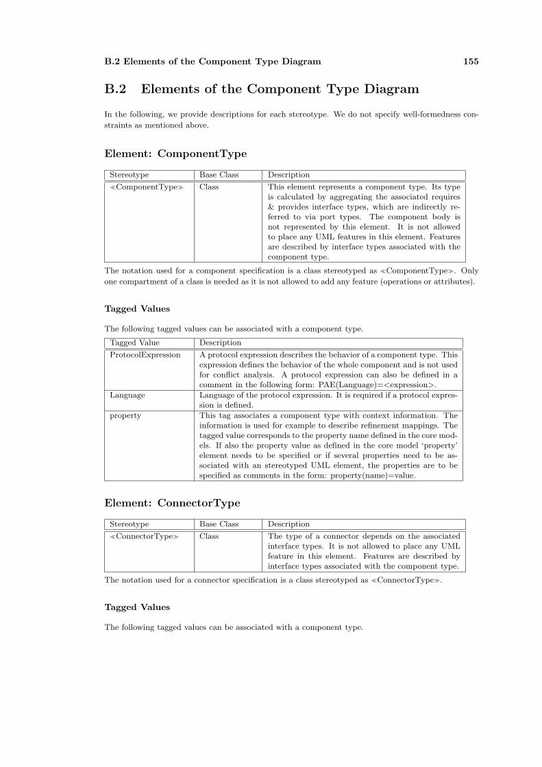
B.2 Elements of the Component Type Diagram 155
B.2 Elements of the Component Type Diagram
In the following, we provide descriptions for each stereotype. We do not specify well-formedness con-
straints as mentioned above.
Element: ComponentType
Stereotype Base Class Description
�ComponentType� Class This element represents a component type. Its typeis calculated by aggregating the associated requires& provides interface types, which are indirectly re-ferred to via port types. The component body isnot represented by this element. It is not allowedto place any UML features in this element. Featuresare described by interface types associated with thecomponent type.
The notation used for a component specification is a class stereotyped as �ComponentType�. Only
one compartment of a class is needed as it is not allowed to add any feature (operations or attributes).
Tagged Values
The following tagged values can be associated with a component type.
Tagged Value Description
ProtocolExpression A protocol expression describes the behavior of a component type. Thisexpression defines the behavior of the whole component and is not usedfor conflict analysis. A protocol expression can also be defined in acomment in the following form: PAE(Language)=<expression>.
Language Language of the protocol expression. It is required if a protocol expres-sion is defined.
property This tag associates a component type with context information. Theinformation is used for example to describe refinement mappings. Thetagged value corresponds to the property name defined in the core mod-els. If also the property value as defined in the core model ‘property’element needs to be specified or if several properties need to be as-sociated with an stereotyped UML element, the properties are to bespecified as comments in the form: property(name)=value.
Element: ConnectorType
Stereotype Base Class Description
�ConnectorType� Class The type of a connector depends on the associatedinterface types. It is not allowed to place any UMLfeature in this element. Features are described byinterface types associated with the component type.
The notation used for a connector specification is a class stereotyped as �ConnectorType�.
Tagged Values
The following tagged values can be associated with a component type.

156 UML Profile for the Ontology-Based Framework
Tagged Value Description
ProtocolExpression A protocol expression describes the behavior of a component type interms of a process algebra expression. The expression is no used forconflict analysis.
Language Language of the protocol expression. It is required if a protocol expres-sion is specified.
property This tag associates a component type with context information. Theinformation is used for example to describe refinement mappings.
Element: InterfaceType
Stereotype Base Class Description
�InterfaceType� Interface An interface type describes component interactions interms of operations. It consists of a set of operations.Attributes have to be encapsulated as operations.
The notation used for an interface type is a UML interface stereotyped as �InterfaceType�. Alter-
natively, a UML class with the same stereotype can be used. Both elements are mapped into the
framework’s interface types.
Tagged Values
The following tagged value can be associated with an interface type.
Tagged Value Description
property This tag associates a component type with context information. Theinformation is used for example to describe refinement mappings.
Element: PortType
Stereotype Base Class Description
�PortType� Class A port type defines a point of interaction. The in-teraction is expressed by an interface type and a pro-tocol expression. Port types are referenced by com-ponent types and connector types to declare requiredand provided interface types. It is illegal to place anyfeature in this element.
The notation used for a port type is a UML class stereotyped as �PortType�.
Tagged Values
The following tagged values can be associated with a component type.
Tagged Value Description
ProtocolExpression A protocol expression describes the behavior of a component type interms of a process algebra expression.
Language Language of the protocol expression.
property This tag associates a component type with context information. Theinformation is used for example to describe refinement mappings.
Element: Record
Stereotype Base Class Description
�Record� Class A record refers to a normal UML class. Each classthat has no stereotype or is stereotyped with ‘Record’is translated into a Record in the framework.
The notation used for a port type is a UML class stereotyped as �Record�.

B.2 Elements of the Component Type Diagram 157
Tagged Values
The following tagged values can be associated with a record type.
Tagged Value Description
property This tag associates a component type with context information. Theinformation is used for example to describe refinement mappings.
Element: List
Stereotype Base Class Description
�List� Class A list type represents any kind of array or collection.
The notation used for a port type is a UML class stereotyped as �List�.
Tagged Values
The following tagged values can be associated with a list type.
Tagged Value Description
property This tag associates a component type with context information. Theinformation is used for example to describe refinement mappings.
Relationship: Requires
Stereotype Base Class Description
�requires� Dependency A requires relationship defines services of a compo-nent type or a connector type that are needed by thiselement. The services are expressed via a port type.
The notation used for a requires relationship is a dependency stereotyped as �requires�.
Relationship: Provides
Stereotype Base Class Description
�provides� Dependency A provides relation identifies the services that are of-fered by a component type or mediated by a connec-tor type. This functionality is expressed via a porttype.
The notation used for a provides relationship is a dependency stereotyped as �provides�.
Relationship: Supertype
Stereotype Base Class Description
�supertype� Generalization The supertype relationship describes single inheri-tance between component types or connector types.It restricts the UML generalization to component andconnector types. The generalization hierarchy has tobe a tree.
Several modeling tools do not allow specifying a stereotype for a generalization. Therefore, we use a
dependency to visualize this relationship. Thus, the notation used for a supertype relationship is a
dependency stereotyped as �supertype�.

158 UML Profile for the Ontology-Based Framework
Relationship: Extends
Stereotype Base Class Description
�extends� Generalization The extends relationship describes multiple inheri-tance between interfaces. It restricts the UML gen-eralization to interface types. The generalization hi-erarchy can be a graph.
We use a dependency to visualize this relationship. Thus, the notation used for a extends relationship
is a dependency stereotyped as �extends�.
Relationship: Declares
Stereotype Base Class Description
�declares� Dependency This relationship links an interface type to a porttype.
The notation used for a declares relationship is a dependency stereotyped as �declares�.
Relationship: Refines
Stereotype Base Class Description
�refines� Generalization The refines relationship describes single inheritancebetween port types. The generalization hierarchy hasto be a tree. The refines relationship is mainly usedto inherit the properties associated with a propertytype.
We use a dependency to visualize this relationship. Thus, the notation used for a refines relationship
is a dependency stereotyped as �refines�.
Relationship: ComProps
Stereotype Base Class Description
�comProps� Dependency This relationship links a single feature to a port type.The feature should correspond to a feature that ispredefined in a communication taxonomy or in a tech-nology taxonomy.If the port type extends another port type whichis also associated with features, the compProps re-lationship overrides previously defined and equallynamed features.The property can be associated with componenttypes, connector types as well as with port types.
The notation used for a comProps relationship is a dependency stereotyped as �comProps�.
Relationship: TechProps
Stereotype Base Class Description
�comProps� Dependency This relationship corresponds to the ‘comProps’ re-lationship. Instead of targeting on communicationproperties it describes technology-related properties.
The notation used for a techProps relationship is a dependency stereotyped as �techProps�.
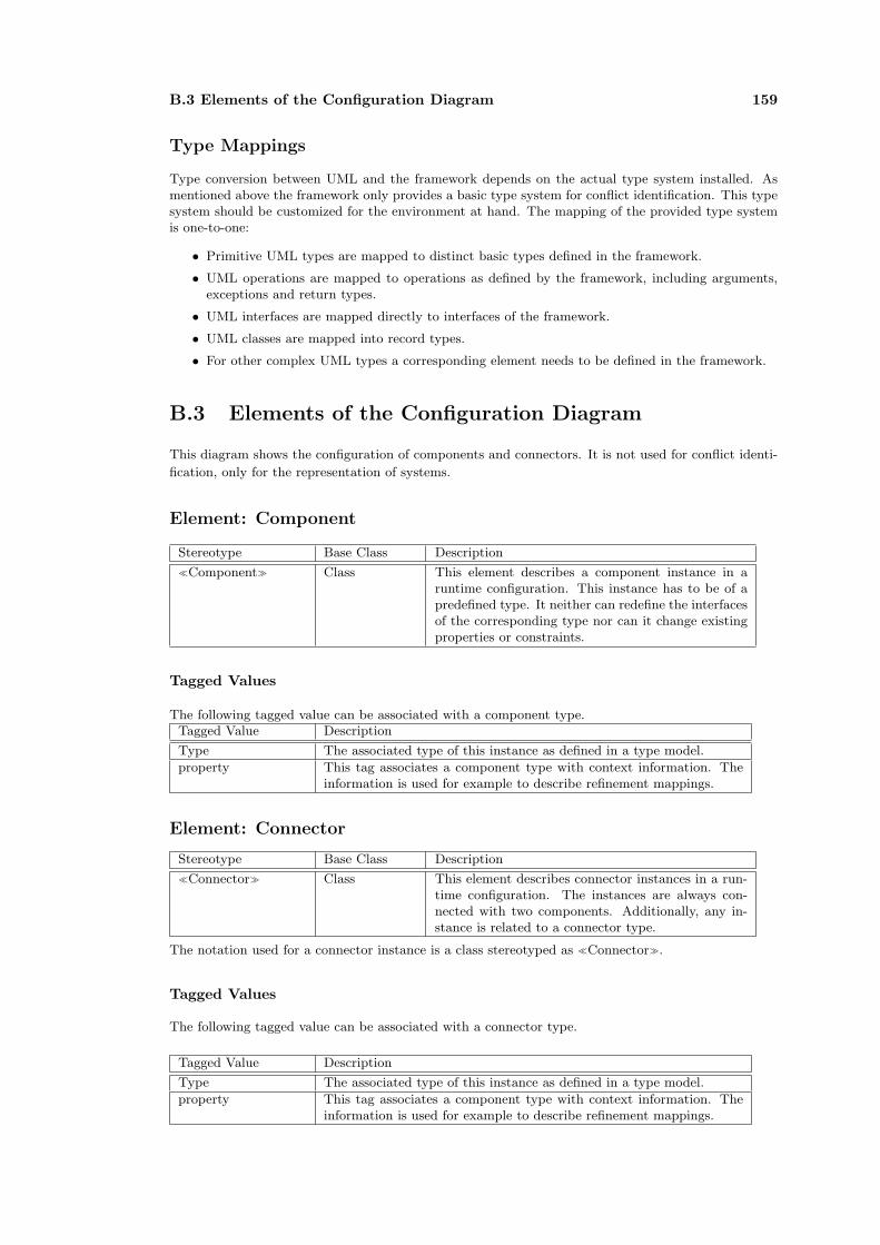
B.3 Elements of the Configuration Diagram 159
Type Mappings
Type conversion between UML and the framework depends on the actual type system installed. Asmentioned above the framework only provides a basic type system for conflict identification. This typesystem should be customized for the environment at hand. The mapping of the provided type systemis one-to-one:
• Primitive UML types are mapped to distinct basic types defined in the framework.
• UML operations are mapped to operations as defined by the framework, including arguments,exceptions and return types.
• UML interfaces are mapped directly to interfaces of the framework.
• UML classes are mapped into record types.
• For other complex UML types a corresponding element needs to be defined in the framework.
B.3 Elements of the Configuration Diagram
This diagram shows the configuration of components and connectors. It is not used for conflict identi-
fication, only for the representation of systems.
Element: Component
Stereotype Base Class Description
�Component� Class This element describes a component instance in aruntime configuration. This instance has to be of apredefined type. It neither can redefine the interfacesof the corresponding type nor can it change existingproperties or constraints.
Tagged Values
The following tagged value can be associated with a component type.Tagged Value Description
Type The associated type of this instance as defined in a type model.
property This tag associates a component type with context information. Theinformation is used for example to describe refinement mappings.
Element: Connector
Stereotype Base Class Description
�Connector� Class This element describes connector instances in a run-time configuration. The instances are always con-nected with two components. Additionally, any in-stance is related to a connector type.
The notation used for a connector instance is a class stereotyped as �Connector�.
Tagged Values
The following tagged value can be associated with a connector type.
Tagged Value Description
Type The associated type of this instance as defined in a type model.
property This tag associates a component type with context information. Theinformation is used for example to describe refinement mappings.

160 UML Profile for the Ontology-Based Framework
Element: Interface
Stereotype Base Class Description
�Interface� Class An interface describes the services required or pro-vided by a component or mediated by a connector.The services are attached to a port, which defines aninteraction point. An interface inherits every oper-ation from it associated type. It is not allowed tochange the signature of this type.
The notation used for an interface instance is a class stereotyped as �Interface�. It can also be defined
as a UML class stereotyped as an interface.
Tagged Values
The following tagged value can be associated with an interface type.
Tagged Value Description
Type The associated type of this instance as defined in a type model.
property This tag associates a component type with context information. Theinformation is used for example to describe refinement mappings.
Element: Port
Stereotype Base Class Description
�Port� Class A port binds the interfaces of a component. It spec-ifies the connection end points of a component. Foroutgoing connections the port must be bound by a‘requiredPort’ dependency to a component. An in-coming connection is represented by a ‘providedPort’dependency.
The notation used for a port is a class stereotyped as �Port�.
Tagged Values
The following tagged value can be associated with a port type.
Tagged Value Description
Type The associated type of this instance as defined in a type model.
property This tag associates a component type with context information. Theinformation is used for example to describe refinement mappings.
Relationship: Binds
Stereotype Base Class Description
�binds� Dependency The binds relationship defines a connection betweencomponents via a connector. It links a connector witha a port of a component. The connector needs toprovide a compatible port to that of the component.
The notation used for the bind relationship is a dependency stereotyped as �binds�.

B.4 Elements of the Behavior State Diagram 161
Relationship: RequiredPort
Stereotype Base Class Description
�requiredPort� Dependency The relationship binds a port to a component or aconnector. It corresponds to the ‘requires’ relation-ship of the type model. It therefore describes the linkbetween components (connectors) and their requiredinteraction points. Interaction points are expressedby a port and an interface.
The notation used for the relationship is a dependency stereotyped as �requiredPort�.
Relationship: ProvidedPort
Stereotype Base Class Description
�providedPort� Dependency The relationship corresponds to the ‘provides’ rela-tionship of the type model. The semantics of therelationship is analogue to that of the ‘requiredPort’relationship described above.
The notation used for the relationship is a dependency stereotyped as �requiredPort�.
Relationship: Represents
Stereotype Base Class Description
�represents� Dependency The relationship corresponds to the ‘declares’ rela-tionship of the type model. It associates a port toexactly one interface.
The notation used for the relationship is a dependency stereotyped as �represents�.
B.4 Elements of the Behavior State Diagram
A state diagram can be used to describe the behavior of components in form of labeled transition
systems (LTS). Conflict analysis is based on the comparison of two LTS.
Element: State
Stereotype Base Class Description
�State� State This element represents a state as defined in UML. AsUML already defines state machines a normal statediagram as defined by the UML can be used to de-scribe a behavioral model of a component. A statedoes not contain any features.
The notation used for a state is a UML state stereotyped as �State�.
Tagged Values
The following tagged value can be associated with a component type.
Tagged Value Description
property This tag associates a component type with context information. Theinformation is used for example to describe refinement mappings.
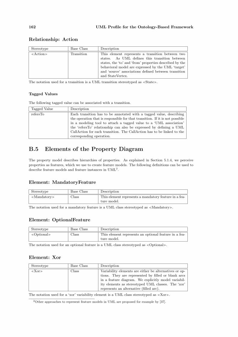
162 UML Profile for the Ontology-Based Framework
Relationship: Action
Stereotype Base Class Description
�Action� Transition This element represents a transition between twostates. As UML defines this transition betweenstates, the ‘to’ and ‘from’ properties described by thebehavioral model are expressed by the UML ‘target’and ‘source’ associations defined between transitionand StateVertex.
The notation used for a transition is a UML transition stereotyped as �State�.
Tagged Values
The following tagged value can be associated with a transition.
Tagged Value Description
refersTo Each transition has to be annotated with a tagged value, describingthe operation that is responsible for that transition. If it is not possiblein a modeling tool to attach a tagged value to a ‘UML association’the ‘refersTo’ relationship can also be expressed by defining a UMLCallAction for each transition. The CallAction has to be linked to thecorresponding operation.
B.5 Elements of the Property Diagram
The property model describes hierarchies of properties. As explained in Section 5.1.4, we perceive
properties as features, which we use to create feature models. The following definitions can be used to
describe feature models and feature instances in UML2.
Element: MandatoryFeature
Stereotype Base Class Description
�Mandatory� Class This element represents a mandatory feature in a fea-ture model.
The notation used for a mandatory feature is a UML class stereotyped as �Mandatory�.
Element: OptionalFeature
Stereotype Base Class Description
�Optional� Class This element represents an optional feature in a fea-ture model.
The notation used for an optional feature is a UML class stereotyped as �Optional�.
Element: Xor
Stereotype Base Class Description
�Xor� Class Variability elements are either be alternatives or op-tions. They are represented by filled or blank arcsin a feature diagram. We explicitly model variabil-ity elements as stereotyped UML classes. The ‘xor’represents an alternative (filled arc).
The notation used for a ‘xor’ variability element is a UML class stereotyped as �Xor�.
2Other approaches to represent feature models in UML are proposed for example by [37].

B.6 Well-Formedness Rules 163
Element: Or
Stereotype Base Class Description
�Or� Class The ‘or’ represents an option group(blank arc).
The notation used for a ‘or’ variability element is a UML class stereotyped as �Or�.
Element: FeatureAttribute
Stereotype Base Class Description
�FAttribute� Class A common extension to feature models are attributesthat are attached to features. They are often used todescribe issues such as cardinality etc.
The notation used for a feature element is a UML class stereotyped as �FAttribute�.
Relationship: SubFeatures
Stereotype Base Class Description
�subFeatures� Dependency The relationship is used to organize features into a hi-erarchy and variability elements. In a feature model,a ‘subFeature’ represents an arc to a dependent fea-ture.
The notation used for the relationship is a dependency stereotyped as �subFeatures�.
Relationship: feAttributes
Stereotype Base Class Description
�feAttributes� Dependency The relationship associates feature attributes to fea-tures.
The notation used for the relationship is a dependency stereotyped as �feAttributes�.
Relationship: Excludes
Stereotype Base Class Description
�f excludes� Dependency Selection of the source feature prohibits a selectionof the target feature.
The notation used for the relationship is a dependency stereotyped as �f excludes�.
Relationship: Requires
Stereotype Base Class Description
�f requires� Dependency Selection of the source feature requires the selectionof the target feature.
The notation used for the relationship is a dependency stereotyped as �f requires�.
B.6 Well-Formedness Rules
We define no well-formedness rules for OCL as constraints normally are not checked in current modeling
tools. Instead, the constraints are formulated in Triple. At present, our group works on a service
that enables checking of OCL constraints based on metamodels. This service will allow checking the
described diagrams in UML tools such as Poseidon.

164 UML Profile for the Ontology-Based Framework

Appendix C
Taxonomies
The appendix summaries the taxonomies of .Net and J2EE. The taxonomies are composed basedon the works of Liao [81] and Gadicke [51], who researched J2EE, Jini and .Net technologies.Properties that describe the interna of a communication mechanism - the - implementationhave been removed.
C.1 Remote Method Invocation Taxonomy
RMI Taxonomy
Parameter Data Transfer
Reference
Value
Format
Return Values
Binary
Result
Implicit Invocation Exception
RemoteDistribution
BlockingSynchronicity
Delivery Delivery Semantics At-Most-Once
Delivery Mechanism UnicastT
State Stateless
Stateful
HierarchicalStructure-BasedName
Binding Run-TimeT
T
T
T
T
T T
T
T T
T
T
T
LifecycleT InitializationT
T
T
T
T T
T
TT T
T
Figure C.1: Remote Method Invocation Taxonomy
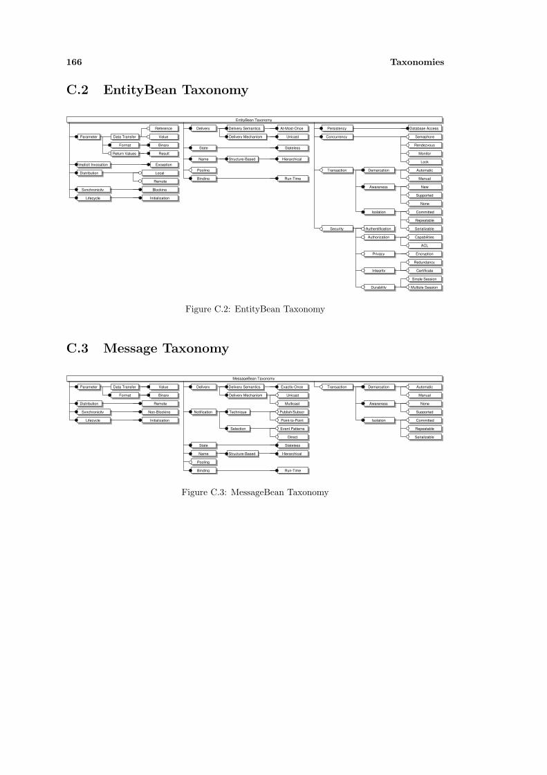
166 Taxonomies
C.2 EntityBean Taxonomy
EntityBean Taxonomy
Parameter Data Transfer
Reference
Value
Format
Return Values
Binary
Result
Implicit Invocation Exception
Local
Remote
Distribution
BlockingSynchronicity
Delivery Delivery Semantics At-Most-Once
Delivery Mechanism UnicastT
State Stateless
HierarchicalStructure-BasedName
InitializationLifecycle
Database Access
Semaphore
Rendezvous
Monitor
Lock
Automatic
Manual
New
Supported
None
Committed
Repeatable
Serializable
Demarcation
Awareness
Isolation
Transaction
Redundancy
Persistency
Concurrency
T
T
T
Capabilities
ACL
Encryption
Certificate
Single Session
Multiple Session
Authentification
Authorization
Privacy
Integrity
Durability
Security
Pooling
Binding Run-TimeT
T
T
T
T
T T
T
T
T
TT
TT T T
T
T
T
TT TT
TT
Figure C.2: EntityBean Taxonomy
C.3 Message Taxonomy
MessageBean Taxonomy
Parameter Data Transfer Value
Format Binary
RemoteDistribution
Non-BlockingSynchronicity
Delivery Delivery Semantics Exactly-Once
Delivery Mechanism Unicast
Multicast
T
Publish/Subscr
Point-to-Point
Event Patterns
Direct
Technique
Selection
Notification T
T
State Stateless
HierarchicalStructure-BasedName
InitializationLifecycle
Automatic
Manual
Supported
None
Committed
Repeatable
Serializable
Demarcation
Awareness
Isolation
Transaction T
T
T
Pooling
Binding Run-TimeT
T
T
T
T
T
TT
T
T
T
TT
T T
T
T
TTT
T
Figure C.3: MessageBean Taxonomy
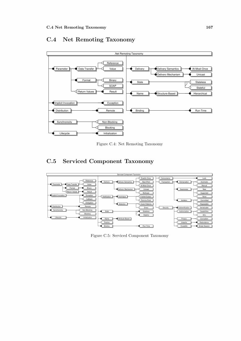
C.4 Net Remoting Taxonomy 167
C.4 Net Remoting Taxonomy
.Net Remoting Taxonomy
Parameter Data Transfer
Reference
Value
Format
Return Values
Binary
SOAP
Result
Implicit Invocation Exception
RemoteDistribution
Non-Blocking
Blocking
Synchronicity
Delivery Delivery Semantics At-Most-Once
Delivery Mechanism UnicastT
State Stateless
Stateful
HierarchicalStructure-BasedName
Binding Run-TimeT
T
T
T
T
T
TT
T
T T
T
T T T
T
T T
T
InitializationLifecycleT T
Figure C.4: Net Remoting Taxonomy
C.5 Serviced Component Taxonomy
Serviced Component Taxonomy
Parameter Data Transfer
Reference
Value
Format
Return Values
Binary
Result
Implicit Invocation Exception
Callback
Delegation
RemoteDistribution
Non-Blocking
Blocking
Synchronicity
Delivery Delivery Semantics Best-Effort
Exactly-Once
At-Most-Once
Delivery Mechanism Unicast
Multicast
T
Publish/Subscr
Point-to-Point
Event Patterns
Direct
Technique
Selection
Notification T
T
State Stateless
Stateful
Attribute-BasedNameInitializationLifecycle
Lock
Automatic
Manual
New
Supported
None
Committed
Repeatable
Serializable
Demarcation
Awareness
Isolation
Transaction
Redundancy
Concurrency
T
T
T
Capabilities
ACL
Encryption
Single Session
Authentification
Authorization
Privacy
Integrity
Durability
Security
Pooling
Binding Run-TimeT
T
T
T
T
T
T T
T T
T
TT
T
T
T
T
T
TT
T
T
T
T
T
Figure C.5: Serviced Component Taxonomy

168 Taxonomies
Appendix D
Published Papers
The appendix summaries previously published papers from which segments were integrated inthis work:
- Leicher, A. A framework for identifying compositional conflicts in component-based sys-tems. Tech. Rep. 2004-23, TU Berlin, 2004.
- Leicher, A., Busse, S., and Suß, J. G. Analysis of compositional conflicts in component-based systems. In Software Composition: 4th International Workshop, SC 2005 (2005),no. 3628 in Lecture Notes in Computer Science (LNCS).
- Leicher, A., and Suß, J. G. Augmenting uml models for composition conflict analysis. InFundamental Approaches to Software Engineering (FASE) (2005).
- Billig, A., Busse, S., Leicher, A., and Suß, J. G. Platform independent model trans-formation based on TRIPLE. In Proceedings of Middleware 04, ACM/IFIP/USENIXInternational Middleware Conference (2004), H.-A. Jacobsen, Ed., no. 3231 in LectureNotes in Computer Science (LNCS).
- Suß, J. G., Leicher, A., Weber, H., and Kutsche, R.-D. Model-centric engineering with theevolution and validation en vironment. In UML 2003 - The Unified Modeling Language:Modeling Lan guages and Applications, 6th International Conference, San Francisco, CA,USA (2003), P. Stevens, J. Whittle, and G. Booch, Eds., vol. 2863 of Lecture Notes inComputer Science (LNCS), Springer, pp. 31 43.

170 Published Papers
List of Figures
1.1 A Simple Component Binding . . . . . . . . . . . . . . . . . . . . . . . . . . . . . 4
1.2 Component Binding is Subject to the Underlying Middleware . . . . . . . . . . . 5
1.3 Component Communication Stack . . . . . . . . . . . . . . . . . . . . . . . . . . 5
1.4 Component Communication Stack . . . . . . . . . . . . . . . . . . . . . . . . . . 6
1.5 General Steps of Component Integration . . . . . . . . . . . . . . . . . . . . . . . 8
2.1 Communication Model . . . . . . . . . . . . . . . . . . . . . . . . . . . . . . . . . 12
2.2 Adapted Protocol Stack . . . . . . . . . . . . . . . . . . . . . . . . . . . . . . . . 13
2.3 Overview on the Integration Scenario . . . . . . . . . . . . . . . . . . . . . . . . . 27
3.1 Component-Based Models and Their Abstraction Levels . . . . . . . . . . . . . . 46
3.2 Feature Model Node Types . . . . . . . . . . . . . . . . . . . . . . . . . . . . . . 47
3.3 Architecture of the Framework for Component Conflict Analysis . . . . . . . . . 49
3.4 Basic Concepts of the Evolution and Validation Environment . . . . . . . . . . . 50
3.5 Main Architecture of EVE . . . . . . . . . . . . . . . . . . . . . . . . . . . . . . . 51
3.6 The Analytical Data on Artifacts and Models (ADAM) Repository . . . . . . . . 51
3.7 Conflict Analysis Process . . . . . . . . . . . . . . . . . . . . . . . . . . . . . . . 53
3.8 Transformation Process . . . . . . . . . . . . . . . . . . . . . . . . . . . . . . . . 54
4.1 Example of a Feature Model (FM) describing the Communication Properties ofSessionBeans. . . . . . . . . . . . . . . . . . . . . . . . . . . . . . . . . . . . . . . 63
4.2 Example of a Feature Model (FM) describing a Java Procedure Call: filled circlesrepresent mandatory features, empty circles represent optional features. . . . . . 64
4.3 The Communication Taxonomy . . . . . . . . . . . . . . . . . . . . . . . . . . . . 65
4.4 Direct Property Annotations to Components . . . . . . . . . . . . . . . . . . . . 75
4.5 Property Annotations to Component Ports . . . . . . . . . . . . . . . . . . . . . 75
4.6 Representation of Parameterized Mappings . . . . . . . . . . . . . . . . . . . . . 76
4.7 Procedure Call: Starting from the Connector Type Procedure Call, includingDimensions and Values as defined by Mehta [93] . . . . . . . . . . . . . . . . . . 78
5.1 Vocabulary Part of the Structural Model . . . . . . . . . . . . . . . . . . . . . . . 82
5.2 Configuration Part of the Structural Model . . . . . . . . . . . . . . . . . . . . . 83
5.3 The Type Model of the Framework . . . . . . . . . . . . . . . . . . . . . . . . . . 84
5.4 The Behavioral Model of the Framework . . . . . . . . . . . . . . . . . . . . . . . 85
171
172 LIST OF FIGURES
5.5 The Property Model of the Framework . . . . . . . . . . . . . . . . . . . . . . . . 86
5.6 The Conflict Model of the Framework . . . . . . . . . . . . . . . . . . . . . . . . 86
5.7 An Example Vocabulary and Configuration in UML . . . . . . . . . . . . . . . . 88
5.8 Example Vocabulary Rendered by ODIS . . . . . . . . . . . . . . . . . . . . . . . 89
5.9 The Shortcut Representation of a Binding . . . . . . . . . . . . . . . . . . . . . . 89
5.10 Model Transformation between UML and the Framework . . . . . . . . . . . . . 90
5.11 The Philosopher’s Problem Described by the UML Profile . . . . . . . . . . . . . 93
5.12 Screenshot of the Philosopher Vocabulary . . . . . . . . . . . . . . . . . . . . . . 93
5.13 Mortgage Bank Example . . . . . . . . . . . . . . . . . . . . . . . . . . . . . . . . 94
5.14 Part of the Mortgage Bank Example Rendered By ODIS . . . . . . . . . . . . . . 94
6.1 Conflict Analysis: Compatibility Checks . . . . . . . . . . . . . . . . . . . . . . . 96
7.1 Type Example UML Model . . . . . . . . . . . . . . . . . . . . . . . . . . . . . . 112
7.2 Haskell Type Constructors for Subtype Relationships. . . . . . . . . . . . . . . . 114
7.3 Transition system for the Mortgage Bank example. . . . . . . . . . . . . . . . . . 116
7.4 UML View on Communication Properties . . . . . . . . . . . . . . . . . . . . . . 117
7.5 Federated Information System Example. . . . . . . . . . . . . . . . . . . . . . . . 118
7.6 Property Conflicts - failures . . . . . . . . . . . . . . . . . . . . . . . . . . . . . . 119
7.7 Cedavis Web Analyzer . . . . . . . . . . . . . . . . . . . . . . . . . . . . . . . . . 120
7.8 Architecture of the Cedavis OLAP Tool . . . . . . . . . . . . . . . . . . . . . . . 121
7.9 Intended .Net Client Component for the Cedavis OLAP Tool . . . . . . . . . . . 122
7.10 Overview Cedavis Server Component . . . . . . . . . . . . . . . . . . . . . . . . . 124
8.1 Example - PIM Component Type View . . . . . . . . . . . . . . . . . . . . . . . 133
8.2 Feature diagram for EJB-based architectures . . . . . . . . . . . . . . . . . . . . 134
8.3 The EJB Component Model . . . . . . . . . . . . . . . . . . . . . . . . . . . . . . 134
8.4 Platform Specific Component Model for EJB expressed in TRIPLE . . . . . . . . 134
8.5 Example - PIM-PSM Transformation for a Local Configuration . . . . . . . . . . 135
8.6 Example - PIM-PSM Transformation for a Distributed Configuration . . . . . . . 136
8.7 Example - A General Bean Mapping Rule . . . . . . . . . . . . . . . . . . . . . . 137
8.8 Example - Specific PIM-PSM Transformation Rules . . . . . . . . . . . . . . . . 139
C.1 Remote Method Invocation Taxonomy . . . . . . . . . . . . . . . . . . . . . . . . 165
C.2 EntityBean Taxonomy . . . . . . . . . . . . . . . . . . . . . . . . . . . . . . . . . 166
C.3 MessageBean Taxonomy . . . . . . . . . . . . . . . . . . . . . . . . . . . . . . . . 166
C.4 Net Remoting Taxonomy . . . . . . . . . . . . . . . . . . . . . . . . . . . . . . . 167
C.5 Serviced Component Taxonomy . . . . . . . . . . . . . . . . . . . . . . . . . . . . 167
List of Tables
2.1 Six Forms of Message Passing Accoring to Tannenbaum [135] . . . . . . . . . . . 16
2.2 Properties of Middleware Communication Mechanisms (adapted from [137]) . . . 18
2.3 Categorization of Integration . . . . . . . . . . . . . . . . . . . . . . . . . . . . . 23
2.4 Specification Language categorization based on distinctions between property-based and model-based language paradigms and the kinds of system being specified 39
4.1 A Classification of Communication Mechanisms . . . . . . . . . . . . . . . . . . . 62
4.4 Example of Architectural Styles as defined by Allan and Shaw [123]. . . . . . . . 79
5.1 Example Mapping Rules of a Model Transformation from MOF M2 to RDFS. . . 91
6.1 Definitions of Simulation Relationships Based on the Definitions of Glabbeek[140, pp.559-564]. . . . . . . . . . . . . . . . . . . . . . . . . . . . . . . . . . . . . 101
6.2 Definitions of Behavioral Equivalence Relationships as Defined by [140, pp.559-564]. . . . . . . . . . . . . . . . . . . . . . . . . . . . . . . . . . . . . . . . . . . . 102
6.3 Compatibility Matrix between two Components . . . . . . . . . . . . . . . . . . . 104
6.4 Compatibility Matrix between a Component and a Connector . . . . . . . . . . . 105
6.5 Compatibility Matrix between two Connectors . . . . . . . . . . . . . . . . . . . 106
7.1 Generated Types for Type Example . . . . . . . . . . . . . . . . . . . . . . . . . 113
173

174 LIST OF TABLES

References
[1] JBoss enterprise middleware system (JEMS). http://www.jboss.org/products/index, 2002. 21 June 2005.
[2] Borland Janeva. http://www.borland.com/janeva, 2005. Borland, 21 June 2005.
[3] How do you define software architecture? http://www.sei.cmu.edu/architecture/definitions.html, 2005. CarnegieMellon University, Software Engineering Institute (SEI), 24 June 2005.
[4] J-Integra interoperability suite: Bridging java to microsoft (com, .net, exchange). http://j-integra.intrinsyc.com/,2005. Intrinsyc Software International, Inc., 21 June 2005.
[5] Osgi technology. http://www.osgi.org/osgi technology/index.asp?section=2, 2005. OSGi, 6 October 2005.
[6] Overview - k2 - icmg: K2 component server. http://www.icmgworld.com/corp/k2/k2.overview.asp, 2005. iCMG,21 June 2005.
[7] Plan 9 (operating system). http://en.wikipedia.org/, 2005. Wikimedia Foundation Inc., 21 June 2005.
[8] Programming:ada:tasking. http://en.wikibooks.org/wiki/Programming:Ada:Tasking, 2005. Wikimedia Founda-tion Inc., 21 June 2005.
[9] The protege ontology editor and knowledge acquisition system. http://protege.stanford.edu/, 2005. StanfordMedical Informatics, 21 June 2005.
[10] Aldrich, J., Chambers, C., and Notkin, D. Archjava: Connecting software architecture to implementation. InProceedings of the 22rd International Conference on Software Engineering, ICSE (2002).
[11] Allen, R., and Garlan, D. A formal basis for architectural connection. ACM Transactions on Software Engi-neering and Methodology (TOSEM) 6, 3 (1997), 213–249.
[12] Alur, D., Crupi, J., and Malks, D. Core J2EE Patterns: Best Practices and Design Strategies. Prentice Hall/ Sun Microsystems Press, 2001.
[13] Amadio, R. M., and Cardelli, L. Subtyping recursive types. ACM Transactions on Programming Languagesand Systems (TOPLAS) 15, 4 (1993), 575–631.
[14] Arnold, K., O’Sullivan, B., Scheifler, R. W., Waldo, J., and Wollrath, A. The Jini Specification. Addison-Wesley, 1999.
[15] Atkinson, C., Bayer, J., Bunse, C., Kamsties, E., Laitenberger, O., Laqua, R., Muthig, D., Paech, B., Wust, J.,and Zettel, J. Component-based Product Line Engineering with UML. Component Software Series. Addison-Weseley, 2002.
[16] Baeten, J. A brief history of process algebra. Tech. Rep. CSR 04-02, TU Eindhoven, 2004.
[17] Baeten, J., and Weijland, W. Process Algebra. Cambridge Tracts in Theoretical Computer Science. CambridgeUniversity Press, 1990.
[18] Balek, D., and Plasil, F. Software connectors: A hierarchical model. Tech. Rep. 2000/2, Dep. of SW Engineering,Charles University, Prague, November 2000.
[19] Bass, L., Clements, P., and Kazman, R. Software Architecture in Practice. Software Engineering Institute.Addison-Wesley, 1998.
[20] Bass, L., Clements, P., and Kazman, R. Software Architecture in Practice - Second Edition. Addison-Wesley,2003.
[21] BEA Systems, Inc. BEA WebLogic Server, Using WebLogic Server Clusters, March 2001.
[22] Bennett, K. Legacy systems: Coping with success. IEEE Software 12, 1 (1995), 19 – 23.
[23] Bernstein, P. A. Middleware: A model for distributed system services. Communications of the ACM 39, 2(1996).
[24] Billig, A. ODIS - Ein Domanenrepository auf der Basis von Semantic Web Technologien. InTagungsband der Berliner XML Tage (2003), XML-Clearinghouse. english version: http://www-berlin.isst.fhg.de/~abillig/Odis/xsw2003.
175

176 REFERENCES
[25] Billig, A., Busse, S., Leicher, A., and Suß, J. G. Platform independent model transformation based on TRIPLE.In Proceedings of Middleware 04, ACM/IFIP/USENIX International Middleware Conference (2004), H.-A.Jacobsen, Ed., no. 3231 in Lecture Notes in Computer Science (LNCS).
[26] Biron, P. V., and Malhotra, A. XML Schema Part 2: Datatypes. World Wide Web Consortium (W3C), 2001.
[27] Bisbal, J., Lawless, D., Wu, B., and Grimeson, J. Legacy information systems: Issues and directives. IEEESoftware 16, 5 (1999), 103 – 111.
[28] Brien, S., and Nicholls, J. Z Base Standard. Oxford University, 1991.
[29] Brodie, M. L., and Stonebraker, M. Migrating Legacy Systems, Gateways, Interfaces & The IncrementalApproach. Morgan Kaufmann Publishers, Inc., 1995.
[30] Bruneton, E., Coupaye, T., and Stefani, J. The Fractal Component Model. The ObjectWeb Consortium,February 2004. http://fractal.objectweb.org/.
[31] Bures, T., and Plasil, F. Communication style driven connector configurations. In Software EngineeringResearch and Applications: First International Conference, SERA 2003, San Francisco (2004), C. V. Ra-mamoorthy, R. Lee, and K. W. Lee, Eds., vol. 3026 of Lecture Notes in Computer Science (LNCS).
[32] Buschmann, F., Meunier, R., Rohnert, H., Sommerlad, P., and Stal, M. Pattern-Oriented Software Architec-ture: A System of Pattern. John Wiley & Sons, 1996.
[33] Busse, S. A specification language for model correspondence assertions, part i: Overlap correspondences.Forschungsberichte des Fachbereichs Informatik Nr. 99-8, Technische Universitat Berlin, 1999.
[34] Cardelli, L., and Wegner, P. On understanding types, data abstraction, and polymorphism. ACM ComputingSurveys (CSUR) 17, 4 (1985), 471–523.
[35] Carnegie Mellon University, Software Engineering Institute. CBS Overview, 2004.http://www.sei.cmu.edu/cbs/overview2.htm,27. June 2004.
[36] Chinnici, R., Gudgin, M., Moreau, J.-J., Schlimmer, J., and Weerawarana, S. Web services description language(wsdl) version 2.0 part 1: Core language. Tech. rep., World Wide Web Consortium (W3C), 2004. W3C WorkingDraft.
[37] Clauß, M. Modeling variability with uml. In Proc. 3rd Int. Conference Generative and Component-BasedSoftware Engineering (GCSE) (2001), vol. 2186 of Lecture Notes in Computer Science (LNCS), Springer.
[38] Clements, P., Bachmann, F., Bass, L., Garlan, D., Ivers, J., Little, R., Nord, R., and Stafford, J. DocumentingSoftware Architecture: views and beyond. Software Engineering Institute (SEI). Addison-Wesley, Boston, 2003.
[39] Clements, P., and Northrop, L. Software Product Lines: Practices and Patterns. Kluwer, 2001.
[40] Coulouris, G., Dollimore, J., and Kindberg, T. Distributed Systems, Concepts and Design, Third Edition.Addison-Wesley, 2001.
[41] Czarnecki, K., and Eisenecker, U. Generative Programming - Methods, Tools, and Applications. Addison-Wesley, 2000.
[42] Czarnecki, K., and Helsen, S. Classification of model transformation approaches. In Proceedings of the 2ndOOPSLA Workshop on Generative Techniques in the Context of the Model Driven Architecture (Anaheim,October 2003).
[43] Davis, L., Flagg, D., Gamble, R., and Karatas, C. Classifying interoperability conflicts. In COTS-Based Soft-ware Systems: Second International Conference, ICCBSS 2003 Ottawa, Canada (2003), T. W. H. Erdogmus,Ed., no. 2580 in Lecture Notes in Computer Science (LNCS), Springer, pp. 62–71.
[44] Davis, L., Gamble, R., and Payton, J. The impact of component architectures on interoperability. Journal ofSystems and Software 61, 1 (2002), 31–45. based on the Technical Report UTULSA-MCS-99-30.
[45] Day, J., and Zimmerman, H. The OSI Reference Model. Proceedings of the IEEE 71, 12 (1983).
[46] Emmerich, W. Software engineering and middleware: a roadmap. In Proceedings of the conference on Thefuture of Software engineering (2000), ACM Press, pp. 117–129.
[47] Fernandez, J.-C. Aldebaran: A tool for verification of communicating processes. Tech. rep., Laboratoire deGenie Informatique - Institut IMAG, 1989.
[48] Fisher, K., and Mitchell, J. C. On the relationship between classes, objects, and data abstraction. Theory andPractice of Object Systems 4, 1 (1998), 3–25.
[49] Fowler, M. Refactoring: Improving the Design of Existing Code. Addison-Wesley, 2000.
[50] Freeman, E., Hupfer, S., and Arnold, K. Java Spaces - Principles, Patterns, and Practice. Addison-Wesley,1999.
[51] Gadicke, J. Metadatengestutzte Analyse Der Kommunikationsfahigkeit Von Enterprise Java Beans und .Net.Master’s thesis, TU Berlin, 2004. german.
[52] Gamma, E., Helm, R., Johnson, R., and Vlissides, J. Design Patterns, Elements of Reusable Object-OrientedSoftware. Addison-Wesley, 1995.

REFERENCES 177
[53] Garlan, D., Allen, R., and Ockerbloom, J. Architectural mismatch, or, why it’s hard to build systems outof existing parts. In Proceedings of the 17th International Conference on Software Engineering (Seattle,Washington, April 1995), pp. 179–185.
[54] Garlan, D., Monroe, R. T., and Wile, D. Acme: An architecture description interchange language. In Proceed-ings of CASCON’97 (Toronto, Ontario, November 1997), pp. 169–183.
[55] Garlan, D., Monroe, R. T., and Wile, D. Acme: Architectural description of component-based systems. InFoundations of Component-Based Systems, G. T. Leavens and M. Sitaraman, Eds. Cambridge University Press,2000, pp. 47–68.
[56] Gelernter, D. Generative communication in linda. ACM Transactions on Programming Languages and Sys-tems 7, 1 (Januar 1985), 80–112.
[57] Gerber, A., Lawley, M., Raymond, K., Steel, J., and Wood, A. Transformation: The missing link of mda. InICGT ’02: Proceedings of the First International Conference on Graph Transformation (London, UK, 2002),Springer, pp. 90–105.
[58] Greenfield, J. UML Profile For EJB. Tech. rep., Rational Software Corporation, May 2001.http://www.jcp.org/jsr/detail/26.jsp, Java Community Process (JCP).
[59] Guttag, J. V., and Horning, J. J., Eds. Larch: Languages and Tools for Formal Specification. Texts andMonographs in Computer Science. Springer, 1993. With Stephen J. Garland, Kevin D. Jones, Andres Modet,and Jeannette M. Wing.
[60] Hoare, C. Monitors: An operating system structuring concept. Journal of the ACM 17, 10 (1974).
[61] Hoare, C. Communicating Sequential Processes. Prentice Hall PTR, 1985.
[62] IEEE. IEEE Standard Glossary of Software Engineering Terminology, 1990. IEEE Std 610.12-1990.
[63] IEEE Computer Society. IEEE Recommended Practice for Architectural Description of Software-IntensiveSystems, 2000. IEEE Std 1471-2000.
[64] International Telecommunications Union (ITU). Message Sequence Charts, 2004. Recommendation Z.120.
[65] Inverardi, P., and Tivoli, M. Software architecture for correct components assembly. In Formal Methods forSoftware Architectures, Third International School on Formal Methods for the Design of Computer, Com-munication and Software Systems: Software Architectures, SFM 2003, Bertinoro, Italy (September 2003),M. Bernardo and P. Inverardi, Eds., vol. 2804 of LNCS Tutorial, Springer.
[66] ISO/IEC. Reference Model of Open Distributed Processing: Part I: Overview, 1995. International Standard10746-1.
[67] ISO/IEC. Reference Model of Open Distributed Processing: Part II: Foundations, 1995. International Standard10746-2.
[68] ISO/IEC. Reference Model of Open Distributed Processing: Part III: Architecture, 1995. International Standard10746-3.
[69] Joy, B., Stelle, G., Gosling, J., and Bracha, G. The Java Language Specification. Addison-Wesley, 2000.
[70] Kang, K., Cohen, S., Hess, J., Novak, W., and Peterson, A. Feature-Oriented Domain Analysis (FODA) Feasi-bility Study. Tech. Rep. CMU/SEI-90-TR-21, Software Engineering Institute, Carnegie Mellon University, nov1990.
[71] Kaplan, Y. API spying techniques for windows 9x, NT and 2000.http://www.internals.com/articles/apispy/apispy.htm, 2001. 21 June 2005.
[72] Kelkar, A., and Gamble, R. Understanding the architectural characteristics behind middleware choices. In 1stInternational Conference in Information Reuse and Integration (1999).
[73] Keshav, R., Gamble, R., Payton, J., and Frasier, K. Architecture integration elements. Tech. Rep. UTULSA-MCS-16-99, University of Tulsa, May 1999.
[74] Kifer, M., Lausen, G., and Wu, J. Logical foundations of object-oriented and frame-based languages. Journalof the ACM 42 (Juli 1995), 741–843.
[75] Konstantas, D. Interoperation of object-oriented applications. In Object-Oriented Software Composition,O. Nierstrasz and D. Tsichritzis, Eds. Prentice Hall PTR, 1995.
[76] Kruchten, P. Modeling component systems with the unified modeling language - a position paper for icse’98workshop, 1998. Int. Workshop on Component-Based Software Engineering.
[77] Leicher, A. A framework for identifying compositional conflicts in component-based systems. Tech. Rep. 2004-23,TU Berlin, 2004.
[78] Leicher, A., Busse, S., and Suß, J. G. Analysis of compositional conflicts in component-based systems. InSoftware Composition: 4th International Workshop, SC 2005 (2005), vol. 3628 of Lecture Notes in ComputerScience (LNCS), Springer.
[79] Leicher, A., and Suß, J. G. Augmenting uml models for composition conflict analysis. In Fundamental Ap-proaches to Software Engineering (FASE) (2005).
178 REFERENCES
[80] Leman, D. Spying on com objects. Windows Developer’s Journal 10, 7 (July 1999).
[81] Liao, Y. Metadatengestutzte Analyse der Kommunikationsfahigkeit zweier ausgewahlter Komponententechnolo-gien. Master’s thesis, TU Berlin, 2004. german.
[82] Labelled transition system analyser (ltsa). http://www.doc.ic.ac.uk/ jnm/book/ltsa/LTSA.html, 21 June 2005,1999.
[83] Luckham, D. C., Kenney, J. L., Augustin, L. M., Vera, J., Bryan, D., and Mann, W. Specification and analysisof system architecture using Rapide. IEEE Transactions on Software Engineering 21, 4 (1995), 336–355.
[84] Magee, J., Dulay, N., Eisenbach, S., and Kramer, J. Specifying Distributed Software Architectures. In Proc.5th European Software Engineering Conf. (ESEC 95) (Sitges, Spain, 1995), W. Schafer and P. Botella, Eds.,vol. 989, Springer-Verlag, Berlin, pp. 137–153.
[85] Magee, J., Dulay, N., and Kramer, J. Regis: A constructive development environment for distributed programs.Distributed Systems Engineering 1, 5 (1994), 304–312.
[86] Magee, J., and Kramer, J. Concurrency, State Models & Java Programs. John Wiley & Sons, 1999.
[87] Marinescu, F. EJB Design Patterns: Advanced Patterns, Processes, and Idioms. John Wiley & Sons, Inc.,2002.
[88] Mattison, R. Data Worehousing: Stratgies, Technologies, and Techniques. McGraw-Hill, 1996.
[89] McBride, B. Jena: Implementing the rdf model and syntax specification. Semantic Web Workshop, WWW,2001.
[90] McDirmid, S., Flatt, M., and Hsieh, W. C. Jiazzi: new-age components for old-fasioned java. In OOPSLA ’01:Proceedings of the 16th ACM SIGPLAN conference on Object oriented programming, systems, languages, andapplications (New York, NY, USA, 2001), ACM Press, pp. 211–222.
[91] McIlroy, M. Mass produced software components. In NATO Conference on Software Engineering (Oktober1968), P.Naur and B. Randel, Eds., NATO Science Commitee.
[92] Medvidovic, N. A classification and comparison framework for software architecture description languages. Tech.rep., Department of Information and Computer Science, University of California, Irvine, 1996.
[93] Mehta, N. R. Software connectors: A taxonomy approach. In Workshop on Evaluating SoftwareArchitectural Solutions 2000 (2000), Institute for Software Research University of California, Irvine.http://www.isr.uci.edu/events/wesas2000/position-papers/mehta.pdf.
[94] Mehta, N. R., and Medvidovic, N. Understanding software connector compatibilites using a connector taxon-omy. In In Proceedings of First Workshop on Software Design and Architecture (SoDA02), Bangalore, India(December 2002).
[95] Mehta, N. R., Medvidovic, N., and Phadke, S. Towards a taxonomy of software connectors. In Proceedings ofthe 22nd international conference on Software engineering (2000), ACM Press, pp. 178–187.
[96] Mellor, S. J., Clark, A. N., and Futagami, T. Model-driven development. IEEE Software 20, 5 (2003), 14–18.
[97] Meyer, B. Object-Oriented Software Construction, Second Edition. Prentice Hall PTR, 1997.
[98] Miller, J., and Mukerji, J. Model Driven Architecture(MDA). Tech. Rep. ormsc/2001-07-01, Object Manage-ment Group(OMG), Architecture Board ORMSC, July 2001.
[99] Miller, J., and Mukerji, J. MDA Guide Version 1.0. Web (www.omg.org), May 2003. Document Numberomg/2003-05-01.
[100] Miller, M., Yee, K.-P., and Shapiro, J. S. Capability myths demolished. Tech. Rep. SRL2003-02, Johns HopkinsUniversity, Systems Research Laboratory, 2003.
[101] Morisio, M., and Sunderhaft, N. Commercial-off-the-shelf (cots): A survey. Tech. rep., Data & and Anal-ysis Center for Software (DACS), December 2000. Prepared for: Ari Force Research Laboratory - Inforationdirectorate (AFRL/IFED), http://iac.dtic.mil/dacs.
[102] Neubus, N. Entwicklung eines Matching-Algorithmus fu ein Komponenten-Repository . Master’s thesis, TUBerlin, 2005. german.
[103] Oberleitner, J., Gschwind, T., and Jazayeri, M. Vienna component framework enabling composition acrosscomponent models. Tech. rep., Technische Universitat Wien, 2002.
[104] Object Management Group. UML 2.0 Superstructure Specification, 2003. http://www.omg.org/cgi-bin/doc?ptc/03-08-02.
[105] Object Management Group (OMG). Meta Object Facility (MOF) Specification, April 2002. Version 1.4.
[106] Object Management Group (OMG). Request for Proposal: MOF 2.0 Query / Views / Transformations RFP,April 2002. http://www.omg.org/cgi-bin/apps/do doc?ad/2002-04-10.pdf.
[107] Object Management Group (OMG). OCL 2.0 Specification, 2003. Final Adopted Specification.
[108] Object Management Group (OMG). Unified Modeling Language Specification Version 1.4.2, Juli 2004.formal/04-07-02.
REFERENCES 179
[109] OMG. UML Profile for CORBA Specification V1.0, 2000.
[110] Pahl, C. An ontology for software component matching. In 6th International Conference, FASE 2003, Held asPart of the Joint European Conferences on Theory and Practice of Software, ETAPS 2003, Warsaw, Poland(April 2003), M. Pezze, Ed., no. 2621 in Lecture Notes in Computer Science (LNCS).
[111] Paolucci, M., Kawmura, T., Payne, T., and Sycara, K. Semantic matching of web services capabilities. In FirstInt. Semantic Web Conf. (2002).
[112] Pierce, B. C. Types and programming languages. MIT Press, 2002.
[113] Plasil, F., Balek, D., and Janecek, R. SOFA/DCUP: Architecture for component trading and dynamic updating.In CDS ’98: Proceedings of the International Conference on Configurable Distributed Systems (Washington,DC, USA, 1998), IEEE Computer Society, p. 43.
[114] Plasil, F., and Stal, M. An architectural view of distributed objects and components in CORBA, java RMI andCOM/DCOM. Software - Concepts and Tools 19, 1 (1998), 14–28.
[115] Raje, R. R., Auguston, M., Bryant, B. R., Olson, A. M., and Burt, C. A unified approach for the integrationof distributed heterogeneous software components. In Proceedings of the Monterey Workshop on EngineeringAutomation for Soware Intensive System Integration (2001).
[116] Reisig, W. Petri Nets: An Introduction. EATCS Monographs on Theoretical Computer Science. Springer,Berlin, Germany, 1985.
[117] Ressouche, A., de Simone, R., Bouali, A., and Roy, V. The FCTools User Manual. INRIA and Ecole desMines/CMA. http://www.iist.unu.edu/ alumni/software/other/inria/www/fc2tools/index.html.
[118] Schmid, F. Erstellung eines Repositories fur die Verwaltung und Transformation von Komponentenmodellen.Master’s thesis, TU Berlin, 2004. german.
[119] Schmidt, D., Stal, M., Rohnert, H., and Buschmann, F. Pattern-Oriented Software Architecture: Patterns forConcurrent and Distributed Objects. John Wiley & Sons, 2000.
[120] Schwanke, R. W., Strack, V. A., and Werthmann-Auzinger, T. Industrial software architecture with gestalt. InIWSSD ’96: Proceedings of the 8th International Workshop on Software Specification and Design (Washing-ton, DC, USA, 1996), IEEE Computer Society, p. 176.
[121] Seacord, R. C., Plakosh, D., and Lewis, G. A. Moderinizing Legacy Systems: Software Technologies, Engi-neering Processes, and Business Practices. SEI Series in Software Engineering. Addison-Wesley, 2003.
[122] Seco, J. C., and Caires, L. A basic model of typed components. In ECOOP 2000 - Object-Oriented Programming(2000), E. Bertino, Ed., Lecture Notes in Computer Science (LNCS).
[123] Shaw, M., and Clements, P. C. A field guide to boxology: Preliminary classification of architectural styles forsoftware systems. In Proceedings of the 21st International Computer Software and Applications Conference(1997), IEEE Computer Society, pp. 6–13.
[124] Shaw, M., and Garlan, D. Software Architecture: Perspectives on an Emerging Discipline. Prentice Hall PTR,April 1996.
[125] Singh, I., Stearns, B., Johnson, M., and Team, E. Designing Enterprise Applications with the J2EE Platform.Addison-Wesley, 2002.
[126] Sintek, M., and Decker, S. TRIPLE - A Query, Inference, and Transformation Language for the Semantic Web.In Proceedings of International Semantic Web Conference ISWC 2002 (2002), vol. 2342 of Lecture Notes inComputer Science (LNCS), Springer.
[127] Siram, N. N., Raje, R. R., and Olson, A. M. An architecture for the uniframe resource discovery service. InProceedings of the 3rd International Workshop on Software Engineering and Middleware (SEM) (2002).
[128] Spitznagel, B., and Garlan, D. A compositional formalization of connector wrappers. In Proccedings of the2003 International Conference on Software Engineering (ICSE’03) (2003).
[129] Spivey, J. M. Understanding Z: A Specification Language and its Formal Semantics, vol. 3 of CambridgeTracts in Theoretical Computer Science. Cambridge University Press, Jan. 1988.
[130] Sreedhar, V. C. Mixin’up components. In ICSE ’02: Proceedings of the 24th International Conference onSoftware Engineering (New York, NY, USA, 2002), ACM Press, pp. 198–207.
[131] Suß, J. G., Leicher, A., Weber, H., and Kutsche, R.-D. Model-centric engineering with the evolution and vali-dation en vironment. In UML 2003 - The Unified Modeling Language: Modeling Lan guages and Applications,6th International Conference, San Francisco, CA, USA (2003), P. Stevens, J. Whittle, and G. Booch, Eds.,vol. 2863 of Lecture Notes in Computer Science (LNCS), Springer, pp. 31 – 43.
[132] Szyperski, C. Component Software: Beyond Object-Oriented Programming. Addison-Wesley, 1999.
[133] Suß, J., Leicher, A., and Busse, S. OCLPrime - Environment and Language for Model Query, Views, andTransformations. In OCL 2.0 - Industry standard or scientific playground?, Workshop on the 6th Int. Conf.UML 2003 (2003).
[134] Tai, S., and Rouvellou, I. Strategies for integrating messaging and distributed object transactions. In Mid-dleware 2000, IFIP/ACM International Conference on Distributed Systems Platforms and Open DistributedProcessing (2000), J. Sventek and G. Coulson, Eds., no. 1795 in Lecture Notes in Computer Science (LNCS),Springer.
180 REFERENCES
[135] Tannenbaum, A., and Van Steen, M. Distributed Systems: Principles and Paradigms. Pearson, 2002.
[136] Taylor, R. N., Medvidovic, N., Anderson, K. M., Jr., E. J. W., Robbins, J. E., Nies, K. A., Oreizy, P., andDubrow, D. L. A component- and message-based architectural style for gui software. IEEE Transactions onSoftware Engineering 22, 6 (1996).
[137] Thompson, J. Avoiding a middleware muddle. IEEE Software 14, 6 (November/December 1997).
[138] Vallecillo, A., Hernandez, J., and Troya, J. Component interoperability. Tech. Rep. ITI-2000-37, Dept.Lenguajes y Ciencias de la Computacion, University of Malaga, July 2000.
[139] van Glabbeek, R. J. What is branching time semantics and why to use it? In The Concurrency Column,M. Nielsen, Ed. Bulletin of the EATCS 53, 1994, pp. 190–198. Also available as Report STAN-CS-93-1486,Stanford University, 1993, at http://theory.stanford.edu/branching/, and in G. Paun, G. Rozenberg & A. Salo-maa, editors: Current Trends in Theoretical Computer Science; Entering the 21st Century, World Scientific,2001.
[140] van Glabbeek, R. J., and Weijland, W. P. Branching time and abstraction in bisimulation semantics. Journalof the ACM 43, 3 (1996), 555–600.
[141] van Lamsweerde, A. Formal specification: a roadmap. In Proceedings of the conference on The future ofSoftware engineering (2000), ACM Press, pp. 147–159.
[142] Vitharana, P., Zahedi, F., and Jain, H. Design, retrieval, and assembly in component-based software develop-ment. Communications of the ACM 46, 11 (2003).
[143] Warmer, J. B., and Kleppe, A. G. The object constraint language: precise modeling with UML. Addison-Wesley,1999.
[144] Weber, H., and Ehrig, H. Specification of concurrently executable modules and distributed modular systems,September 1988. Workshop on the Future Trends of Distributed Computing Systems in the 1990s.
[145] Wegner, P. Interoperability. ACM Computing Surveys (CSUR) 28, 1 (1996), 285–287.
[146] Weißbach, M. Analyzing user requirements for customizable pim-to-psm transformations. Master’s thesis, TUBerlin, 2005.
[147] Wiederhold, G. Mediators in the Architecture of Future Information Systems. In Readings in Agents, M. N.Huhns and M. P. Singh, Eds. Morgan Kaufmann, San Francisco, CA, USA, 1997, pp. 185 – 196.
[148] Wing, J. M. A specifier’s introduction to formal methods. IEEE Computer 23, 9 (September 1990), 8 – 23.
[149] World Wide Web Consortium (W3C). RDF Primer: W3C Recommendation 10 February 2004, 2004.http://www.w3.org/TR/rdf-primer/,21 June 2005.
[150] World Wide Web Consortium (W3C). RDF Vocabulary Description Language 1.0: RDF Schema: W3CRecommendation 10 February 2004, 2004. http://www.w3.org/TR/2004/REC-rdf-schema-20040210/,21 June2005.
[151] Yakimovich, D., Bieman, J. M., and Basili, V. R. Software architecture classification for estimating the cost ofcots integration. In Proceedings of the 21st international conference on Software engineering (1999), IEEEComputer Society Press, pp. 296–302.
[152] Zaremski, A. M., and Wing, J. M. Specification matching of software components. In SIGSOFT ’95: Proceedingsof the 3rd ACM SIGSOFT symposium on Foundations of software engineering (New York, NY, USA, 1995),ACM Press, pp. 6–17.

Index
ADAM, 51adapter, 23ADL, 44architectural style, 31, 77Architecture Description Language, 44
behavioral analysis, 99bisimulation equivalence, 100compatibility, 100equivalence, 99simulation, 99substitutability, 100
binding, 73bisimulation, 100broker, 24
callback, 67Cedavis, 119Commercials Off-The-Shelf, 28communication, 11communication analysis, 100
compatibility, 103substitutability, 105
communication mechanism, 16classification, 17message passing, 17remote mthod invocation, 17remote procedure call, 16
communication taxonomy, 65attribute-based naming, 70binding, 73callback, 67concurrency, 71delegation, 68delivery, 69delivery mechanism, 69delivery semantics, 69distribution, 68exception, 67implicit invocation, 67lifecycle, 71lock, 71monitor, 71naming, 70notification, 69
parameter, 65persistent, 71pooling, 73rendevous, 71security, 73
authentification, 73authorization, 73durability, 73integrity, 73
semaphore, 71state, 70structure-based naming, 70synchronicity, 69transaction, 72
awareness, 72demarcation, 72isolation, 72
compatibility, 20, 95component, 32component subtyping, 82concurrency, 71Conflict, 18conflict analysis, 75, 95conflict analysis process, 52connector, 33connector generation, 145connector taxonomy, 78context, 19COTS integration, 28
data transfer, 66delegation, 68delivery, 69
delivery mechanism, 69delivery semantics, 69
distribution, 68domain, 19dynamic analysis, 30
EVE, 50exception, 67
feature model, 45, 74formal language, 38
functional specification, 39history-based specification, 39
181
182 INDEX
operational specification, 39state-based specification, 39transition-based specification, 39
implicit invocation, 67integration, 18
in-process, 22inter-process, 22multiple domain, 22protocol, 24single domain, 22
inter-process communication, 14interceptor, 19, 24interface, 35interoperability, 18
type, 20Inverardi, 24
legacy system migration, 27lifecycle, 71lock, 71
MDA, 45Medvidovic, 78Mehta, 78metamodel transformation, 89middleware, 14Model-Driven Development, 45Model Driven Architecture, 45model transformation process, 54monitor, 71
naming, 70attribute-based, 70structure-based, 70
notification, 69
OBF, 52, 81ontology-based framework, 81
behavioral model, 84conflict model, 85property model, 85structural model, 81type model, 83
OSI reference model, 12
parameter, 65parameterized model transformation, 131pooling, 73port, 35property-based classification, 61protocol, 12proxy, 23
RDF, 47redocumentation, 30refactoring, 30
rendevous, 71Resource Description Framework, 47retargeting, 28return value, 67revamping, 28role, 35
security, 73authentification, 73authorization, 73
semantics, 20behavior, 20protocol, 20
semaphore, 71simulation, 99slicing, 30software architecture, 31state, 70static program analysis, 30substitutability, 20, 95subtype, 37subtyping, 96
compatibility, 98nominal, 96overloading, 98recursion, 98structural, 96substitutability, 98
synchronicity, 69system, 36
transaction, 72awareness, 72isolation, 72
TRIPLE, 47type, 36type system, 36