
"Analysis of Capsule OCIII-D Duke Power Company Oconee ...
107
_ _ . . __ i . 4 , " BAW-2128. Rev. I 1 May 1992 ; | i 1 4 ) ' ; ANALYSIS OF CAPSULE OCIll-D ; DUKE POWER COMPANY OCONEE NUCLEAR STATION UNIT-3 , 4 j -- Reactor Vessel Material Surveillance Program -- . I i J ! 4 i , i i : : . < - . 951HB&WNUCLEAR |BS''so2a2g2ososnoocaowo?8R' IDWSERVICE COMPANY > P , -. .-. . - -- ,
-
Upload
khangminh22 -
Category
Documents
-
view
3 -
download
0
Transcript of "Analysis of Capsule OCIII-D Duke Power Company Oconee ...

_ _ . . __
i .
4,
"
BAW-2128. Rev. I1 May 1992
;
|
i1
4
)
'
; ANALYSIS OF CAPSULE OCIll-D; DUKE POWER COMPANY
OCONEE NUCLEAR STATION UNIT-3,
4
j -- Reactor Vessel Material Surveillance Program --.
I
iJ
!
4
i
,
i
i
:
:
.
<
-
.
951HB&WNUCLEAR|BS''so2a2g2ososnoocaowo?8R' IDWSERVICE COMPANY>
P
, -. .-. . - -- ,

. __ _ ____ _
, ..
''
EAW:1118. Rev. 1-
May 1992
ANALYSIS Of CAPSULE 0C111 DDUKE POWER COMPANY
OCONEE NUCLEAR STATION UNIT-3
-- Reactor Vessel Material Surveillance Program --
by
A. L. Lowe, Jr., PEJ. D. Aadland
A. D. NanaH. A. Rutherford
W. R. Stagg
B&W Document No. 77-2128 01(See Section 11 for document signatures)
B&W Nuclear Service CompanyEngineering and Plant Services Division
P. O. Box 10935Lynchburg, Virginia 24506-0935
B W i|?v M i % r
o
.- - . . _ _ - . - - . -. - . . - - - - . . - . . _ - - .
i;. .
i
i i
.
-!
SUMMARY'
Ii
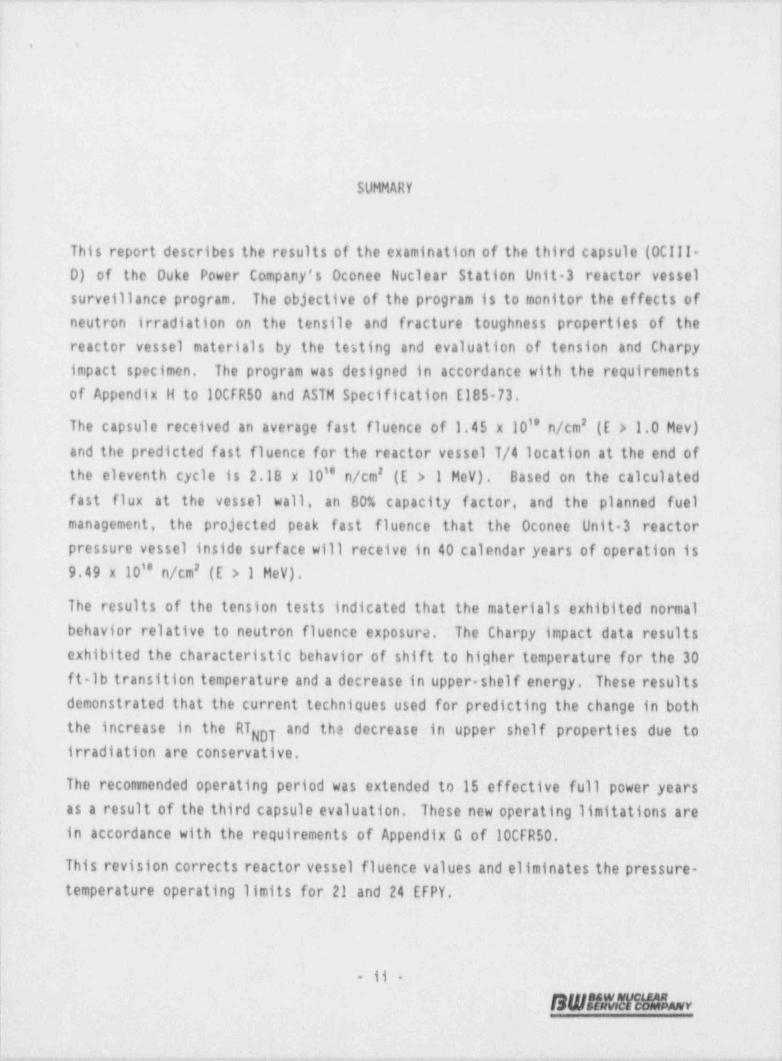
This report describes the results of the examination of the third capsule (OCll!- [D) of the Duke Power Company's Oconee Nuclear Station Unit 3 reactor vessel fsurveillance program. The objective of the program is to monitor the effects of i
neutron irradiation on the- tensile and fracture toughness properties of thereactor vessel materials by the testing and evaluation of tension and Charpyimpact specimen. The program was designed in accordance with the requirements ;
of Appendix H to 10CFR50 and ASTM Specification E185 73. !
The capsule received an average fast fluence of 1.45 x 10'' n/cm' (E > 1.0 Mev);and the predicted fast fluence for the reactor vessel T/4 location at the end of
the eleventh cycle is 2.18 x 10'' n/cm' (E > 1 MeV). Based on the calculated !fast flux at the vessel wall, an 80% capacity factor, and the planned fuel {management, the projected peak fast fluence that the Oconee Unit 3 reactor- f
pressure vessel inside surface will receive in 40 calendar years of operation is
9.49 x 10'' n/cm' (E > 1 MeV). [
The results of the tension tests indicated that the materials exhibited normalbehavior relative to neutron fluence exposure. The Charpy impact data results - >
exhibited the characteristic behavior of shift to higher temperature for the 30-ft lb transition temperature and a decrease in upper-shelf energy. These resultsdemonstrated that.the current techniques used for predicting the ' change in both
Ithe increase in the RT and the decrease in upper shelf properties due toNDT _
irradiation are conservative.
The recommended operating period was ' extended to 15 effective full power years i-
as a result of the third capsule evaluation. These new operating limitations are ,
in accordance with the requirements of Appendix G of 10CFR50.-,
This revision corrects reactor vessel fluence values and eliminates the pressure-temperature operating limits for 21 and 24' EFPY.
- 11 -
SW51131M00 v j
;
y . _ _ , -_ _ _ _ - _ - . _ - . . , _ _ . . . _ _ _ _ , _. . . _ , . , , . . . _ _ . , , , . . . , - - - .

- _ _ _ _ _ _ _ _ - _ _ - _ - . . .
.
. .
RECORD OF REVISIONS
Date Revision Number Descriotion
May 1991 0 Original Issue
May 1992 1 Summary - Revision _ statement added, fluencevalue revised
Table 6 3 Correct 21, 24, 32 EFPY fluence
Table 7-5 Corrected 32 EFPY data
Table 7-6 Corrected 32 EFPY data
Section 8 Deleted 21 and 24 EFPY pressure-temperature operating limit curves
Section 9 Fluence at EOL revised-
Section 11 - Revision signatures.added-
Appendix D'- Table D-2 fluence valuescorrected
: :-
.
- iii -
SW5Mml05.w
-
-
____ d-

__ _-.
,
1 . .
i
):
i
I,
!
l3
CONTENTS'
i
Page
j 1. INTRODUCTION ...........................11.
| 2. BACKGROUND . . . . . . . . . . . . . . . . . . . . . . . . . . . . 2-1 {| 3. SURVEILLANCE PROGRAM DESCRIPTION . . . . . . . . . . . . . . . . . 3-1 '
|4. PRE-IRRADIATION TESTS . . . . . . . . . . . . . . . . . . . . . . . 4 1
.-
.
'.
4.1. Tensinn Tests . . . . . . . . . . . . . . . . -. 4 1......
! 4.2. Impact Tests . . . . . .. . . . . . . . . . . . . . . . . . . 4 1-
| S. POST-!RRADIATION TESTS ................._.....515.1. Thermal Monitors ......................51-5.2. Tension Test Results .................... 51 '
j 5.3. Chaipy V-Notch impar.t Test Results . . . . . . . . . . . . . 5-2
| 6. NEUTRON FLUENCE . . . .-. .-. . . . . . . . . . . . . . . . . . . . 6-1l
6 .1 '. Introduction . . . . . . . . . . . .-. . . . . . . . . . . . .- 6-16.2. Vessel Fluence . . . . . . . . . . . . . . ... 64.. ... . .
6.3. Capsul e Fl uence . . . . . . . . . . .. . . . . . . . . . . . . . 6 56.4. Fluence Uncertainties . . . . . . . ... . . .=. . . . . . . ._. 6 5.
7. DISCUSSION OF CAPSULE RESULTS . . ... . . . . . .-. . . . . . . . 7-1 [7,1. Pre Irradiation. Property Data-. . . . . . . . . .:. . . . ._... 7-17.2. Irradiated Property Data . , . . . . . . . . . . . . .... . . . 7-1
7;2.1. Tensile Properties .. . ... . . . . . .....'. ... . . . 7-1 +
7.2.2._ Impact Properties . . . . . . .:. , . . . . . . . . . .L7-2,
7.3. Reactor Vessel Fracture Toughness . . . . . . . . . . . .. '. 7-4..
| 8. DETERMINA110N OF REACTOR: COOLANT' PRESSURE BOUNDARY PRESSURE -j. TEMPERATURE LIMITS ......-...-...._,,....-....-..-..-81-
9. SUMARY:0F RESULTS ..-.......-._._.....-.._.-..-9-1- ,
-10. SURVEILLANCE CAPSULE: REMOVAL SCHEDULE ~. . .:. . 7. . . . . . .-. . 10 1--
11 ;CERTIFICATIONi... . . . ... . . . . .,. . .'._. . . .c. .7. . . . 111-1- .
.
- iv -
SWABMMMAL y "
_. - _ _ _ _ - _ -__ _ _ . _ _ _ _ _ - .- - -. _ _ -

-- _ _. __ . _ . _ _ _ _ _ _ _ - _. _ _ _ _ - . - _ _ _ _ _ _ . __ _ _
; t
. .
;'
Contents (Cont'd)
APPENDIXLi Page
A. Reactor Vessel Surveillance Program Backgrour.d Dataa n d I n f o rm a t i o n . . . . . . . . . . . . . . . . . . . . . . . . . . . A 1 i
B. Pre Irradiation Tensile Data ....................B1C. Pre lrradiation Char)y !mpact Data .................C1D. Fluence Analysis Met 1odology ....................D1 iE. Capsule Dosimetry Data .....................E1 *
. . .
F. References . . . . . . . . . . . . . . . . . . . . . . . . . . . . F-1.,
:
List of Tables
Table
3 1. Specimens in Surveillance Capsule 0C111 D . . . . . . . . . . . . 3-33-2. Chemical Composition and Heat Treatment of
.
.
Surveillance Materials ......................-3-4 '.
5 1. Tensile Properties of Cppsule OCill D Base Metal and Weld MetalIrradiated to 1.45 x 10 n/cm' (E > 1 MeV) . 53 '
. . . . . . . . . .
5 2. Charpy impact Data From Capsule 0C111-0 Base Metal,ANK-191, Transverse Orientation, Irradiated to145 x 10" n/cm' (E > 1 MeV; . . . . . . . . . . . . . . . . . . 5-3
5-3. Charpy Impact Data from Capsule 0Cill-D, Base Metal,AWS-192, Transverse Orientation, Irradiated to1.45 x 10'' n/cm' (E > 1 MeV) . . . . . . . . . . . . . . . . . . 5-4
5 4. Charpy impact Data From Capsule 00111-0 HAZ Metal,ANK 191, Longitudinal Orientation, Irradiated to1.45 x 10'' n/cm' (E > 1 MeV) . . . . . . . . . . . . . . . . . . 5-4-
5 5. Charpy impact-Data from Capsule 0C111-D HAZ Metal,.
AWS 192, Longitudinal Orientation, Irradiated to1.45 x 10'' n/cm' (E > 1 HeV)- .................. 55
5 6. Charpy Impact Data From Capsule 00111-D Weld Metal WF-209-1Irradiated to 1.45 x 10'' n/cm' (E > 1- MeV) .:. . . . . . 5-5. . . . .
5-7. Charpy impact Data From Capsule 00111 D Correlation MonitorMaterial,'* Heat No. A 1195 1 Irradiated to1.45 x 10- n/cm' (E > 1 MeV) . . . . . .-.-... . . , . . . . . . .-5-6
. .
6-1. Surveillance Capsule Dosimeters.. . . ... . . . . . . . . . . . . 6 6~.
6-2. Oconee Unit-3 Reactor Vessel Fast Flux ........-......6-7.6-3. Calculated Oconee Unit-3 Reactor Vessel Fluence . .. . . . . . . . 6 86-4. Surveillance Capsule 00111-0 Fluence, Flux,-and DPA . . . . . . . 6-96-5. Estimated Fluence Uncertainty . . . . . . . .- . .-.. . . . .'. . . . 6-97-1. Comparison of Capsule tilli-D Tensile Test Results . . . . . . . 7-6
.
7-2.. Summary of Oconee Unit 3 Reactor Vessel Surveillance Capsules.
- '
Tensile Test Results . . . . . . . . . . . . . . . . . . ...-. . . -7-77-3. Observed Vs.. Predicted Changes for Capsule OClll-0' Irradiated -
Charpy impact Properties - 1.45 x 10' n/cm' '(E -> 1 MeV) - . .- . s. -7-8-.
-v-
SWMt31HAL.o.
93,-g g -g -y- 9.- w--,y,=,y-.- e n-. % -ei.g-s-w9 W- W'' r,w - tr ' n ~ 9 g *-*--r- Ne--''- ''F- 4-'b %i' y+* NeWteeie4T'- =v

,_ _ _ _ _ . . _ _ - - -_ . _ _ _ _ _ _ _ _ __ _ _ _
ij
. .
<
I
i lables (Cont'dlij Table Page1
7-4. Summary of Oconee Unit 3 Reactor Vessel Surveillance Capsules| Charpy impact Test Results . . . . . . . . . . . . . . . . . . . 7-9j 7-5. Evaluation of Reactor Vessel End of-Life Fracture. Toughness
and Pressurize. Thermal Shock Criterion - Duke Power Company,{ Oconee Unit-3 02 EFPY) . . . . . . . . . . . . . . . . . . . . . 7-10
7 6. Evaluation of Duke Power Company Oconee Unit-3 Reactor Vessel.
| End of Life, Upper Shelf Energy (32 EFPY) . . . . . . . . . . . . 711j 8 1. Data for Preparation of Pressure-Temperature Limit Curves for
-
j Oconee Unit-3 -- Applicable Through 15' EFPY . . . . . . . . . . . 8 4i
i A-1. Surveillance Program Material Selection Data for Oconee 3 . . . . . A 3 |
j. A 2. Materials and Specimens in Upper Surveillance Capsules IOCill- A, 0C111-C, and OCIll-E . . . . . . . . . . - . . . . . . . . . A-4'
A 3. Materials and Specimens in Lower Surveillance Capsules.
! OClli-B, 00111-D, and OCIll-F . . . . . . . . . . ._. . . . . .-. . A-4
i B 1. Pre-trradiation Tensile Properties of Shell Plate Material,j Heat ANK-191 . . . . . . . . . . . . . . . . . . . . . B-2. . . . . . .
j B 2. Pre-!rradiation Tensile Properties of Weld Metal -i Longitudinal, WF-209 1 . . . . . . . . . . . . ... . . . . . . . B-2.
.
C-1. Pre-Irradiation Charpy impact Data for Shell forging;
Material - Transverse Orientation, Heat ANK-191_. . ._. ._. . . . . C-2i
i- C-2. Pre-Irradiation Charpy impact Data for Shell Forgingj Haterial - Transverse Orientation, Heat AWS-192 . . . . . -. . . . . C-3 jC 3. Pre-Irradiation Charpy impact Data-for Shell Forging;
| Material - HAZ, Transverse Orientation. Heat ANK 191 ..._....C4 l
; C 4. Pre Irradiation Charpy impact Data for Shell Forgingj Haterial - HAZ, Transverse Orientation, Heat AWS-192 .......C51 C-5 Pre-Irradiation Charpy impact Data for Weld Metal, WF-209-1 . . . . C 6{ D 1. Flux Normalization Factor . . . . ... . . . . . . . . . . . . .-. . D-7j D-2. Oconee Unit 3 Reactor Vessel Fluence by Cycle . . . . . . . . . . . D 8j E-1. Detector Composition and Shielding . . . . . . . E-2. . . . . . . . .
E-2. Measured Specific Activities (Unadjusted) for Dosimeters in4
Capsule 00111 0 . . . . . . . . ... . . . . . . . . . . . . . . . . E-2E-3. Dosimeter Activation. Cross Sections, b/ atom . . . . . . . . . . . . E-3:
; ._
4-
!
| List of Fioures
,i Figure
; 3-1. Reactor Vessel Cross Section Showing Location of Capsule-OCill D Duke Power Company Oconee Unit-3 . . . . . . ._. ... . . _ 3-5
,
'
'-2. Reactor Vessel Cross Section Showing Location of Oconee.
? Unit.3 Capsule 0Clli-D in Crystal River Unit.3 Reactor - - , . .- 3-6. . .
3-3. Loading Diagram for Test Specimens in Capsule OClli-D . . . . . 3-7'
5-1. Charpy-Impact-Data for Irradiated Base Material,.-
Transverse Orientation, Heat'No.- ANK-191 . . . . . .-.=. . . . , . 5 7-
4
s
| - vi -
SWBM1|Hof-i
3 - ,,..m. ._ m- m . _._ . - -,, _. ~ _ , , - . _ . e , - ,_, , , . m,,, , , , , . - . -_.,,,,,v..,.,.,m , . _ - , .y,-,

. _ _ _ - _ _ _ - _ _ _ -_ _ _ _ _ .
.. _. .. ..
. .
Fioures (Coatish
Figure Page
5 2. Charpy Impact Data for Irradiated Base Material, TransverseOrientation, Heat No. AW5-192 . . . . . . . . . . . . . . , . . . 5-8
5 3. Charpy impact Data for Irradiated Base Material Heat-AffectedZone. Heat No. ANK-191 . . . . . . . . . . . . . . . . . . . 5-9..
5 4. Charpy impact Data for Irradiated Base Material. Heat AffectedZone. Heat No. AWS-192 . . . . . . . . . . . . . . .-. . . . . 5 10.
5 5. Charpy impact Data for Irradiated Weld Metal, WF-209-1- . . . . 5-11.
5 6. Charpy impact Data for Irradiated Correlation Material,Correlation Material, HSST PL-02, Heat No. A-11951. . . . . . . 5-12
6 1. General Fluence Determination Methodology . . . . . . . . . . . . 6-26-2. Fast Flux, Fluence and DPA Distribution Throu
Vessel Wall . . . . . . . . . . . . . . . . .gh Reactor. . . . . . . . . . 6 10
6 3. Azimuthal Flux and Fluence Distributions at Reactor VesselInside Surface . . . . . . . . . . . . . . . . . . . . 6-11. . . . .
8-1. Predicted _ Fast Neutron Fluence at Various Locations ThroughReactor Vessel Wall for 32 EFPY - Oconee Unit 3 . . . . . . . .- - . 8-5
8 2. Reactor Vessel Pressure-Temperature Limit Curves.
for Normal Operation - Heatup, Applicable forFirst 15 EFPY - Oconee Unit-3 .-. . . . . . . . . . . . . . . . . . B 6
8 3. Reactor Vessel Pressure Temperature limit-Curvesfor Normal Operation - Cooldown, Applicable forFirst 15 EFPY - Oconee Unit-3-. . . . . . . . . . . . . . . . . . 8-7
8-4. Reactor Vessel Pressure-Temperature-Limit Curves.
for Inservice Leak and Hydrostatic Tests -Apfor First 15 EFPY - Oconee Unit-3 . . . . plicable
.....-...... 88A-1. Location and Identification of Materials Used in Fabrication
of Reactor Pressure Vessel . . . . . . . . . . . . . . . . . . . . A-5C 1. Charpy Impact Data from Unirradiated Shell Forging Material
( ANK 191) Transverse Orientation . . . . . . . . . , . . . . . . . C-7C-2. .Charpy Impact Data from Unirradiated Shell Forging Material
( AWS-192), Transverse Orientation . .- , . . . . . . . . . . . . . . C-8C 3. Charpy impact Data from Unirradiated Shell Forging Material
(ANK-191), Heat-Affected Zone, Longitudinal Orientation . . . . . . C-9C-4. Charpy impact Data from Unirradiated.Shell Forging Material .
.
(AWS-192), Heat-Affected Zone, Longitudinal Orientation . . . . . . C-10C-5. Charpy Impact Data from Unirradiated Weld Metal WF 209-1- . . . . . C-IlD-1. Rationale for the Calculation of Dosimeter Activities-
and Neutron Flux in the Capsule . . ... . . . . . . . . . . . . . . D-9D 2. Rationale for the Calculation of Neutron Flux-
in the Reactor Ves sel . . . .- . . . . . . . . . . . . . . . . . . . . D-10D 3. Plan View Through Reactor Core Midplane
(Reference R-e calculation Model) . , . . . . . . . -. . . . . . . . D- 1 1.
- vii -
BWRM!MQLe:
_ ---____----__ - - - - -

_ - _ _.. ..
. .
1. INTRODUCTION
This report describes the results of the examination of the third capsule (0C111-D) of the Duke Power Company, Oconee Nuclear Station Unit 3 (Oconee Unit-3)reactor vessel material surveillance program (RVSP). The capsule was removed andevaluated after being irradiated in the Crystal River Unit 3 reactor as pr t ofthe Integrated keactor Vessel Materials Surveillance Program (BAW 1543A). Thisirradiation in Crystal River Unit 3 plus the previous irradiation in Oconee Unit-3 is the equivalent of 22.22 years of exposure in the Oconee Unit 3 reactor *
I8 8vessel. The capsule experienced a fluence of 1.45 x,10 n/cm (E > 1 HeV).-which is the equivalent to approximately 57-effective full power years' (EFPY)operation of the Oconee Unit-3 reactor vessel. The first capsule (OClli A) fromthis program was . removed and examined after the first' year of nperation; theresults are reported in BAW-1438.8 The second capsule (0C111-B) was removed and
examined after irradiation in Florida Power Corporation Crystal River Unit-3 aspart of the Integrated Reactor Vessel Materials Surveillance Program; the resultsare reported in BAW 1697.8
The objective of the program is to monitor the effects of neutron irradiation onthe tensile and impact properties of reactor pressure vessel materials underactual operating conditions. The surveillance program for Oconee Unit-3 wasdesigned and furnished by Babcock &~Wilcox (B&W) as described in BAW 10006A andd
conducted in accordance with BAW-1543A.' The program was planned to monitor the
effects of neutron irradiation on the reactor vessel materials for the 40-yeardesign life of the reactor pressure vessel.
The surveillance program for Oconee Unit-3 ' was designed in accordance withE185 66''and thus is ~not in compliance with:10CFR50, Appendixes G' and H' since
the requirements did not exist at'the time the program was design. .Because ofthe difference, additional tests and evaluations were required to ensure meeting
1-1
SWARNIHbvi
_ _ _ _ _ _

i S
the requirements of 10 CFR 50, Appendixes G and H. The recommendations for thefuture operation of Oconee Unit-3 included in this report do comply with theserequirements.
;
1
:
1-2
SWf!#vM'E*o=!=v
.

-. .. . . . . . -
. . . .- _- . - _ . .- -.-
!
. .
Lj l
j 2. BACKGROUND;
Ii,
1 The ability of the reactor pressure vessel to res.st fracture is the primary i
j factor in ensuring the safety of the primary system in light water cooled |
| reactors. The beltline region of the reactor vessel is the most critical region !I of the vessel because it is exposed to neutron irradiation. The general effects *
of fast neutron irradiation on the mechanical properties of such low. alloy- |j ferritic steels as SA508 Class 2, modified by ASME Code case 1332 4, used in the [! fabrication of the Oconee Unit-3 reactor vessel, are well characterized and docu-
; mented in the literature. The low alloy ferritic steels used in the beltline| region of reactor vessels exhibit an increase in ultimate and yield strength :
! properties with a corresponding decrease in ductility after irradiation. 'The ,
Imost significant mechanical property change in reactor pressure vessel steelsa
i is the increase in temperature. for the transition from brittle to ductile
fracture accorapanied by a reduction in the Charpy upper shelf energy value.e
I Appendix G to 10CFR50, " Fracture Toughness kequirements,'" specifies minimu'm '
$ fracture toughness requirements for the ferritic materials of the pressure-; retaining components of the reactor coolant pressure boundary (RCPB) of |
water-cooled power reactors,.and provides specific guidelines for determining the,
; pressure temperature limitations on operation of the RCPB -The toughness and ;
operational requirements are specified to provide adequate safety margins during!
j any condition of normal operation, including anticipated operational occurrences-
; and system hydrostatic tests. to which the pressure boundary may be subjected-over its service lifetime. Although the requirements of Appendix G-to 10CFR50#
~ became effective on August 13, 1973, the requirements are applicable to all'boiling and pressurized water-cooled-nuclear power reactors, including those
,
under construction or in' operation on the-effective date. '
e
+
5
!
2-1-,
SWmMt1 MAL r-

--
. .
Appendix H to 10CFR$0, " Reactor Vessel Materials Surveillance Program
Requirements,'" defines the material surveillahce program required to monitorchanges in the fracture toughness properties of ferritic materials in the reactorvessel beltline region of water cooled reactors resulting from exposure toneutron irradiation and the thermal environment. Fracture toughness test dataare obtained from material specimens withdrawn periodically from the reactorvessel. These data will permit determination of the conditions under which thevessel can be operated with adequate safety margins against fracture throughoutits service life.
A method for guarding against brittle fracture in reactor pressure vessels isdescribed in Appendix G to the ASME Boiler and Pressure Vessel Code Section 111" Nuclear Power Plant Components." This method utilizes fracture mechanics
concepts and the reference nil-ductility temperature, RINDT, which is defined asthe greater of the drop weight nil ductility transition temperature (per ASlH
(E-208) or the temperature that 'is 60f below that at which the material exhibit50 ft-lbs and 35 mils lateral expansion. The RT of a given material is used
NDT
to index that material to a reference stress intensity factor curve (k curve),gp
which appears in Appendix G of ASME Section !!!. The K curve is a lower boundIRof dynamic, static, and crack arrest fracture toughness results obtained fromseveral heats of pressure vessel steel. When a given material is indexed to theK curve, allowable stress intensity factors can be obtained for this materialip
as a function of temperature. Allowable operating limits can then be determinedusing these allowable stress intensity factors.
The RT and, in turn, the operating limits of a ruclear power plant, can beNDT
adjusted to account for the effects of radiation on tne properties of the reactorvessel materials. The radiation embrittlement and the resultant changes inmechanical properties of a given pressure vessel steel can be monitored by asurveillance program in which a surveillance capsule containing preparedspecimens of the reactor vessel materials is periodically removed from theoperating nuclear reactor and the specimens are tested. The increase in theCharpy V-notch 30 ft lb temperature is added to the original RT to adjust it
NOTfor radiation embrittlement. This adjusted RT is used to index the material
NDTto the K curve which, in turn, is used to set operating limits for the nuclearIR
2-2
13 W ita M i E n
-_ ___

._ _ _ . . _ . - . . . _ _ _ _ . _ - . _ . _ _ __ _ _ _. _ __ _ _ __.- _ - _ _ _ _,'l
i
|: . *
c :
!power plant. These new limits take into account the effects of irradiation on j
the reactor vessel materials, j
Appendix G,10CFR50, also requires a minimum Charpy V notch upper shelf energy f'
of 75 ft lbs for all beltline region materials unless it is demonstrated that |;
lower values of upper-shelf fracture energy will provide an adequate margin forJ,
deterioration as the result of neutron radiation. No action is required for a |.
material that does not meet the 75 ft lb requirement provided the irradiationdeterioration does not cause the upper-shelf energy to drop below 50 f t lbs. The -i
regulations specify that if the upper-shelf energy drops below 50 ft lbs it must .
be demonstrated in a manner approved by the Office of Nuclear Regulation that the :
lower values will provide adequate margins of safety.'
Wher a reactor vessel fails to meet the 50 ft-lb requirement, a program must be !
submitted for review and approval at least three years prior 'to the time the- !
predicted fracture toughness will no longer satisfy the regulatory requirements, jThe program must address the following: |
A. A volumetric examination of 100 percent of the beltline materials that ;
do not meet the requirement.,
B. Supplemental fracture _ toughness data as evidence of the fracturetoughness of the irradiated beltline materials.
C. Fracture toughness analysis to demonstrate the existence of equivalent .
!margins of safety for continued operation.
If these procedures do not indicate the existence of an_ adequate margin of*
safety, the reactor vessel-beltline may be given a thermal annealing treatment'
to recover the fracture toughness properties of the materials. -|
i
,
2-3 ;
SWBN!FlH & w Il
aj

_ _ _ _ _ _ . . . - . _ ~ _ _ _ - - _ _ . . _____ _ _ __
. .
;
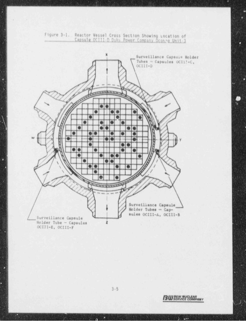
3. SURVEILLANCE PROGRAM DESCRIPTION
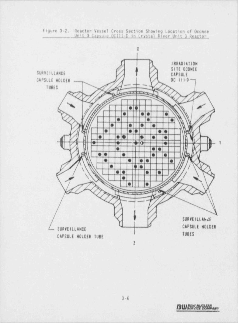
The surveiilanco program for Oconee Unit 3 comprises six surveillance capsulesdesignei to monitor 1.he effects of neutron and thermal environment on thematerials of Use reactor pressure vessel core region. The capsules, which wereinserted into the reactor vessel before initial plant startup, were positionedinside the reactor voss41 between the thermal shleid and the vessel wall at thelocatiens shGe in figurc 34. . Tie -six capsules, originally designed to beplaced two N cach holder tube, are positioned near the peak exial and aziinuthalneutron flux. WW-10006A int |)udes a-full description of the capsule locationsand design. AftJr'thR Capuits were removed from Oconee Unit 3 in 1976 and -included in the integrated RVSP, they were scheduled and feradiated in. theCrystal River Unit 3 reactor as described in BAW-1543A. During this period ofirradiation, tapsule OCIII D was irradiated in the bottom location in holder tubeYX as shown in Figure 3-2.
Capsule OCII) D was removed during the seventh refueling shutdown of CrystalRiver Unit 3. This capsule contained Charpy V notch impact test-. specimensfabricated from one base metal (SA508, Class 2), one heat affected o one, a weldmetal and correlation material Tension test specimens were fabricated from thebase metal and the weld metal only. .The specimens contained in the capsule aredescribed in Table 31, and the location of the individual specimens within thecapsule are described in Figure 3-3. The chemical composition and heattreatment of ths surveillance material in capsule 00111 0 are described in Table3-2.
All test specimens were machined from the 1/4-thickness (1/4T) location of the-plate material. Charpy V notch and tension test specimens were cut- from thesurveillance material such that they were oriented with their longitudinal axes-either parallel or. perpendicular to the principal working direction.
.
3-1
SWBMHbr
i'
.._ . ---. _ . - , -..; .. .- -. . -

__ _ _ _ _ _ _ _ _ _ _ _ _ _ _ _ _ _ _ _ _ _ _ _ _ _ _ _ _ _ _ _ . _ _ _ _ - _ _ _ _ _ _ _ _ _ _ _ _ _ _ _ _ _ _ _ _ - . _ _ _ _ _ _ _ - _ _ _ _ _ _ _ _ _ _ _ _ - _ _ _ _ _ _ _ - _ _
. .
Capsule 0C111-D contained dosimeter wires, described as follows:
Dosimeter Wire ShielditLq.
U Al alloy Cd Ag alloy
Np Al alloy Cd Ag alloy
Nickel Cd-Ag alloy
0.66% Co Al alloy Cd
0.66% Co-Al alloy None
fe None
Thermal monitors of low melting alloys .nd metals were included in the capsule.The alloys and metals and their melting points were as follows:
Allov Meltina Point,_[
90% Pb, 5% Ag, 5% Sn 558
97.5% Pb. 2.5% Ag 580
97.5% Pb, 1.5% Ag, 1.0% Sn 588
Cadmium, 99.99+% 610
lead. 99.994% 621
.
|
!
1
3-2
S W !! E W a h r
._

- - - - -- -. . . _ _ .
.
Table 3-1. Soetimens in Surveillange Capsule 00111-0-
No. of SpecimensMaterial Description Ign}tig [hnp_y
Weld metal. WF-209, longitudinal 2 12
Weld, HAZ
Heat A ANK-191, longitudinal 0 12Heat B - AWS-192, longitudinal 0 6
Baseline material
Heat A - ANK-191. transverse 2 12Heat 8 - AWS-192, transverse 0 6
Correlation, HSST plate 02 9 _1
Total per capsule 4 54
<
.
3-3
BWHrvEYii%w
_.
- _ _ - _ - _
__
'
i
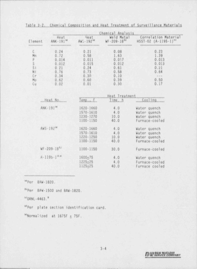
Table 3 2. Chemical Composition and Heat Treatment of Surveillance Materials
Chemical _ AnalysisHeat Ileat Weld Metal Correlation Material
Element ANK- 191''' AW5- 192''' WF-209-1B" HSST-02 (A-1195-1)'*'!
C 0.24 0.21 0.08 0.23 -lMn 0.72 0.58 1.63 1.39 i
P 0.014 0.011 0.017 0.013 !
S 0.012 0.015 0.012 0.013 |
Si 0.21 0.24 0.61 0.21 !Ni 0.76 0.73 0.58 0.64 !Cr 0.34 0.30 0.10 --
Ho 0.62 0.60 0.39 0.50,
Cu 0.02 0.01 0.30 0.17 i
:i'
Heat 1reatmentHeat No. Temo.. F Time h Coolina
ANK- 191''' 1620 1660 4.0 Water quench. !
1570 1610 4.0 - Water quench1230-1270 10.0 Water' quench - ,
1100 1150 40.0 Furnace-cooled
AWS-192''' 1620 1660 -4.0 Water quench !1570 1610 4' 0 Water quench !
1220 1250 10.0 Water quench3
1100 1150 40.0 Furnace-cooled'
:.
WF-209-1B" 1100-1150 30.0 furnace-cooled .
A-119S l**' 1600175 4.0 Water quench1225125 4.0 Furnace-cooled1125 25 40.0 -Furnace cooled ,
,
'''Pe r BAW-1820.
"Per 'BAW-1500 and BAW-1820. f'*'ORNL 4463.*
'*Per plate section identification card.
''' Normal ized at 1675F i 75F.
| 3-4 '
L SWANt31Mby
1L ,..m.. - , _ u. _ _... ,_ . _ _ _ _ _ _ ._ ._. _ __ _ -._. _ _
_ _ _ _ _ _ _ _ . _ _ - -
.
Figure 3-1. Reactor Vessel Cross Section Showing tocation ofCapsule 00111-D Dub, Poyer Cp2Pln.Y_0cluee Unit-3
* Surveillance Capsule lloiderTubes - Capsules DC117-C.OC111-D
t/ /
,f. .
..,J,
,
/\ #/ . o \'
. . . . s-y--
. . . .. .
y. . . .,. . . . . ,c4 . . . . . .m_s .
,. / ,. = . _ . . . _. .- - . -
s1 . . . V,
v' _7 . . . . .. . . . ..
e G . / 'y ,s . . . . / '
\ . /y g. e-
3 . ..
, ~ ~ . -,
' 'Surveillance Capsule
h lloider Tubes - Cap-'
sules OCIII-A, OCIII-BSurveillance Capsulelloider Tube - Capsules 2OCIII-E, OCIII-F
3-5
S W,Y#Xc h y.
!|
, .._._-___.__.__.....__.._J
- .
Figure 3-2. Reactor Vessel Cross Section Showing Location of OconeeUnit 3 Caosule 0C111 D in Crystal River Unit 3 Scactor--
x
IRRADIAil0N& SITE OCONEE
SURVEILLANCE I CAPSUL E
CAPSULE HOLDER - . OC | | |-0'~~'
TUBES.. .,
f% . o x /
/,# N, i
e o e ee o e 1
i e e e e_
e e o . . ,i
N . e e . . . n -,
f ,, e s - +. c : -
- Y,,
,- /) e e e ,
q e e e e .. . . . .
e n o /\ e e o e\ j
* N/e .
, ,
_ -
//9 g SURVEILLANCE
CAPSULE HOLDERSURVElLLANCE
TUBESCAPSULE HOLDER TUBE
Z
3-6
S W f/4 M % v

- ... --_ -__, ~,~. n ~ ann.-...~..u- - - , a_.. .a--us.--,n ..-~.~.x_.---. . --. -~- - , . , - - - - - - . . . - .--..
1
. .
UEz.
U .*3*C Cr g
% O*OI @ s .i g* )
e:.
e N ,/ eM # b ~
/,.' N m|i/wz ., :., g # )
sw -,-
c m2, ),,- s gs . t r 1d # ;/ #O r s I t
[f*
1*m"' / / / i,
p p p ,oe ( '
\ @|-. '
. , '\._v ' !,
8 m s c
c e ih', s . . . .
!N,
,
3. .s '. u)/ # 1m ,
,' s /$ / ',
v r s -.
M )/ ,' N /'
f. >- Z -
Q. w /t ,
-
# ; ;%- : ;E WE, -___- , , ,
g u - s ' I 1=k,
/U / '* , s k' #
'L'
f# '
$ o s mi
_
m a - : a. se s w,
y W!e
&,||//) ,A
_
z-;N - Oy a /N*
mE |N //\g o =
Ni o /N wa>
.C gs'
/s -y N / E ce2 /g d 1 | 5-__ ,
N ' m w-/s%.- I I| 85s i ,,
T'* m /5 ' $ 1 | :S @@N
[yE Z /N s 'Nm /s ,E Ng 5' /\ . s
D /'dt' ,
m /g 1., - 3s? /
s\'
s g 2 II m/ y
M / ===
/s s /
s - ; gie, s-
h -sa , k [ -[ @~ -
N / 1 j
. [ /N. w ,
fh / \/
Q-',
v
, 1 -. >.
.L j ;,r
|'
% ,' ,5'
L,
i
;
!
3-7SWhy
.- ,_ ._ . _ . . _ ._.. . , _ ._ _ _ . _ .-. . __ ._

. .
4. PRE-IRRADIATION TESTS
Unirradiated material was evaluated for two purposes: (1) to establish abaseline of dat5 to which irradiated properties data could be referenced, and (2) |
to detsrmine those materials properties to the exter.'. practical from availablecaterial, as required for compliance with 10CfR50, Appendixes G and H.
4.1. Tension Tests
Tension test specimens were fabricated from the reactor vessel shell courseforging and weld matal. The specimens were 4.25 inches long with a reducedsection 1.750 inches long by 0.357 inch in diameter. They were tested on a55,0001b load capacity universal test machine at a crosshead speed of 0.050 inchper minute. A 4 pole extension device with a strain gaged extensometer was usedto determine the 0.2% yield point. Test conditions were in accordance with theapplicable requirements of ACTH A370-77.10 for each material type and/or condi-
tion, six specimens in groups of three were tested at both room temperature and580F, Yhe tension compression load cell used had a certified accuracy of betterthan 40.5% of full scah (25,000 lb). All test data for the pre irradiationtensile specimens are given in Appendix B.
L2. Imoact Tests
Charpy V notch impact tests were conducted in accordance with the requirements10 IIof ASTM Standard Methods A370 77 and E23-82 on an impact tester certified to
meet Watertown standards. Test specimens were of the Charpy V notch type, whichwere nominally 0.394 inch square and 2.165 inches long.
Prior to testing, specimens were temperature-controlled in liquid immersionbaths, capable of covering the temperature range from 50 to 4550F. Specimens-were removed from the baths and positioned in the test frame anvil with tongsspecifically designed for the purpose. The pendulum was released manually,
4-1
S W l/ M a h r
_ _ - _ _ _ _ _ _ _ _ _ _ _ _ _ _ _ _ _ _ _ _ _ _ _ _ _ _ _ _ _ _ _ _ _ _ _ _ _ _ - _ _ _ _ _ _ _ _ _ _ _ _ _ _ _ _ _ _ _ _ _ _ _ _ _ _ _ _ _ _ _ _ _ _ _ - _ _ _ _ _ _ _ _ _ _ _ _ _ _ _ _ _ _ _ _ _ _ _ _ _ _ _ _ _ _ _ _ __ ________ - __-_. _
. .
I
allowing the specimens to be broken within 5 seconds from their removal from thetemperature baths.
Impact test data for the unirradiated baselin a reference inaterials are presentedin Appendix C. Tables C-1 through C 5 contain the basis data that are plottedin Figures C-1 through C-5.
I
;
||
i
1
4-2 I
BWifMVSt%v

-_ _ --
. .
5. POST-IRRADIATION TESTS
5.1. Thermal Monitors
Capsule OCIII-D contained two temperature monitor holder tubes, each containingfive fusible alloy wires with melting points ranging from 558 to 621F. Four ofthe five wires in F.h set had the appearance of being melted. All the thermalmonitors at 558, 580, and 588F had melted while those at '.he 610F location showed
no signs of melting or slumping; the monitor at the 621F: location appeared to bemelted in both holder tubes. Heretofore it was assumed that the 610F and 621Fmonitors were placed in the wrong locations i_n the holder tubes, and based onthese observations, it was concluded that the capsule had been exposed to a peRtemperature in the range of 610 to 621F during the reactor operating-period.
In the case of OCIII-D the original loading diagram was consulted. This drawinglists the five materials-used in the monitors, and showed the position in which
-
each wire was loaded. Both show the lead wire (621F melting poir.t) to be in thefourth position, with the cadmium wi_re (610F melting point) in the fifth-position. This means that the 610F monitor did not melt while the 621F- monitorappeared to melt. It is believed that the; lead wire softened and slumped andthereby presented the appearance of melting due tc long- exposure _- to elevated -temperatures, which were not' sufficient to melt the cadmium wire. . Therefore, itis probable that the capsule was_ exposed to-temperatures in excess of 588F:butnot as high as 610F, and that this was. sufficient to cause the-lead wires to Oslump and appear to have melte3.
L2. Tension Test Results
The results of_ the postirraaiation tension tests are presented in Table 5-1.#
-Tests were performed on specimens at both room temperature and at the temperatureof 500f using similar test _ procedures and techniques used to test the unirradiat -ed specimens (Section 4.1). In general, the ultimate strength and yield.-
]
5-1~
SWADM!raiGL=v
i- _ - . _ _ -- - a

- .._ _ _ _ _ _ _-___ - __ __-___ _ _ _ _ _ _ _
,
.. .
strength of the material increased with a corresponding slight decrease Jin-ductility as compared to the unirradiated values; both-effects were the result-of neutron radiation damage. The type of behavior observed and the degr<e towhich the material properties changed is within the range of changes to beexpected for the radiation environment to-which the specimens were-exposed.
The results of the pre-irradiation tension tests are presented in Appendix B,
5.3. Charov V-Notch 1moact Test Results-
The test results from the irradiated Charpy V-notch specimens of the reactorvessel beltline material are presented in Tables 5-2 through 5-7 and Figures 51through 5-6. The test procedures and techniques were similar to those used totest the unirradiated specimens (Section 4.2). The data show that the materialsexhibited a sensitivity to -irradiation within the v'alues to be expected fromtheir chemical composition and the fluence to which they were exposed,
i
The results of the pre-irradiation Charpy V-notch -impact tests are given inAppendix C.
.
t
5-2
SWB!M!mhv D
1,
._ ____-___._i. ____i________ _.___._____o

__ _-
... .,
Table 5-1. TensilePropertiesofCapsuleOC!lhDBaseMetaland'Weld Metal Irradiated to 1.45 x 10 n/cm' (E > 1 MeV)
Red'n.Specimen Test Temp, Strenath. osi Elonaaticp. % in 1rea,. No. F Yield Ultimate Uniform Total %
Ease Metal. Transverse. Heat ANK-191
JJ 602 70 66,900 _91,500 9.9 26.6 65.1
JJ 618 550 60,300 87,200 9.9 23.3 62,0
)[qld Metal . WF-209-1
JJ 017 70. 98,000 111,300-- 10.7 24.2 56.7JJ 016 550 86,600 102,900- 9.0 17.7 -49.4
Table 5-2. Charpy impact Data From Capsule 0C111-D,' Base g al, ANK 191,Transverse Orientation, Irradiated to 1.45 x-10 n/cm' (E > 1 MeV)
Absorbed Lateral Shear-Specimen Test Temp., Energy, Expagsion. Fracture,-
No. F ft-lb 10 in. -%-
JJ 634 0 9,0 02 10
JJ 693 25 23.0 23 10'
JJ 646 30 39.0 30 10
JJ 683 30 63.0 50 20
JJ 659 40 58.0 -51 20
JJ 669 70 71.5 57 30
JJ 624 125 107.0 76 70
JJ 677 200 123.0*~ 83 100
JJ 627 250 124.0* 99 100- I
JJ 615 350 128.5* 89- 100
JJ 628. 450 123.0 86 100-
JJ 662 550 123.5 91 100-
* Values used to determine upper-shelf energy-value per ASTM E185.
5-3
SWB&TIMLv
b.. . . . . . . __ ____ _ _ __ _ _ __i

- - . - . _ _ _
. .
Table 5-3. Charpy Impact Data From Capsule OCIII-D, Base Mgpal, AWS 192Transverse Orientation, Irradiated to-1.45 x 10 n/cm' (E > 1 MeV) -
-Absorbed' Lateral- ShearSpecimen Test Temp., _ Energy, .Expagsson, Fracture,-
:No. F ft-lb 10 in. %_
KK 668 0 5.0 03 0'
KK 615 40' 37.0 29 10-
KK 649 70 50.5 43 20
KK 660 125 84.0 64 603
KK 617 200 90.0 67 90
KK 638 300 93.0* 77- 100
*Value used to determine upper-shelf energy value per ASTM E185.
Table 5-4.Charpy Impact Data -From Capsule OClll-D'HAI Metg 'n/cm' (E >:1 MeV)ANK 191Longitudinal Orientation, Irradiated to l' 45 x 10*
.
Absorbed Lateral ShearSpecimen Test Temp., Energy, Expagston, Fracture,
No. F ft-lb 10 in. %,
JJ 366 -50 23.5 13: l'0
JJ 349 0 25.0 16 20
JJ 329 15 31.5 20 30
JJ 326 70 136.5- 90 90-
JJ 361 70 26.5 30- 20-JJ 378 70 138.0 97 100
JJ 367 100 63.0 40- 50
JJ 360 125- 62.0 46 .85'JJ 307 200 75.0* 51 100
JJ 368 250-- 64.0* '51 100
JJ 356- 350 66.0* 48 100
JJ 352 550 J73.5 59 100
* Values .used to determine upper-shelf energy value-per ASTM E185.'
,
!-!
5-4
- S W 5 fwiM H h r-,
, .. -.. ... . , _ . . . . . .. . . . _ _ _ '
i
'. .
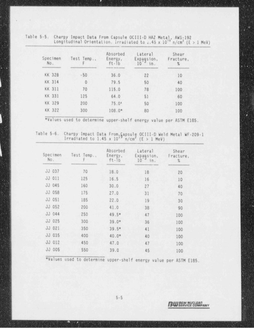
Table 5 5. Charpy impact Data From Capsule 0C111-0 HAZ Metal,' AWS-192Longitudinal Orientation, Irradiated to 2.45 x 10'' n/cm' (E > 1 MeV)
Absorbed Lateral ' Shear.Specimen Test Temp., Energy, _Expagsion, Fracture,
No. F _ lb 10 in. %ft
KK 328 50 36.0 22- 10
KK 314 0 79.5 50 40
KK 311 70 115.0 78 100
KK 331 125 64.0 51 60
KK 329 200 75.0* 50 100
KK 322 300 108.0* 80 100
* Values used to determine upper shelf energy value per ASTM E185.,
Table 5-6. Charpy impact Data From gapsulp OCIII-D Weld _Hetal WF-209-1.gIrradiated to 1.45 x 10 n/cm (E > l MeV)
Absorbed Lateral ShearSpecimen Test Temp., Energy, Expagsion, LFracture,
No. F ft-lb 10 in. %__
JJ 037 70 18.0- 18 20-
JJ 011 125 16.5 16 10-JJ 045 160 30.0 27 40
JJ 058 175 27.0 31 70
JJ 051 185 22.0 19 30
JJ 052 200 41.0 38 90=
JJ 044 250 49.5* -47- 100
JJ 025 300 39.0* 36 100
JJ 021 350 :39.5* 41 100
JJ 035 400 40.0* 40 100
JJ 012 450 47.0 47- 100
JJ 005 -550 39.0 45~- 100
* Values used to determine upper-shelf energy- value per ASTM E185.
..
i
5-5
SW#n51iid&w
. . . . . . .. . . _ _ . ,..g ,.i,
- _ _ _ _ _ _ _ _ - _ _ _ _ _ _ - _ _ _ _ _ - - _ _ _ _ _ _ -.. .. .. . .
. .
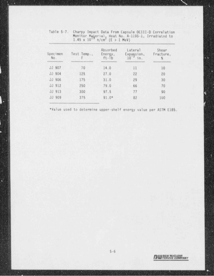
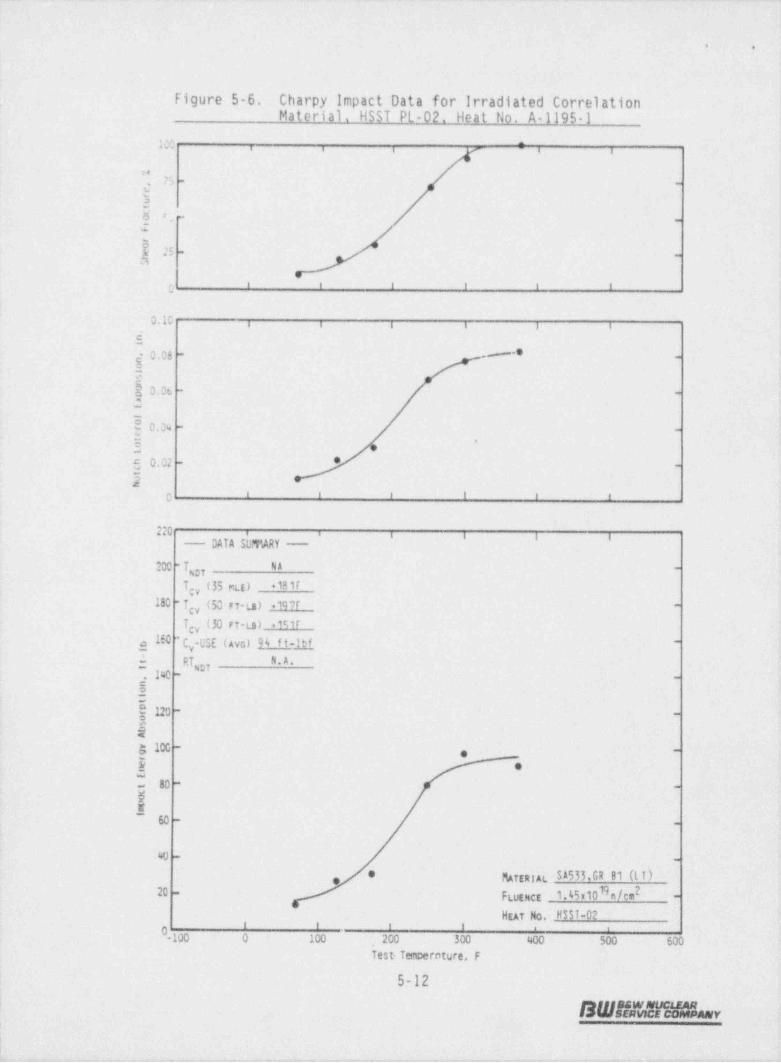
Table 5-7.- Charpy- Impact Data-From Capsule:0CIII-D' CorrelationMonitor Mgerial - Heat No.< A-11951,- Irradiated to-gl'.45 x 10. n/cm - (E -> 1 MeV)-
Absorbed' l.ateral Shear-Specimen- Test-Temp., Energy, Expagston, Fracture,,
No. F ft-lb 10 in. -%
JJ'907 70 '14.0 11- 10-
JJ 904 125 27.0 22 20
JJ 906 175 31.0 29- 30
JJ 912 250 79.0 66 -70
JJ 913 300 97.5 77 90 .
JJ 909 375 91.0* 82 100
!- d
*Value used to determine upper-shelf- energy- value per ASTM- E185.
L
l
.-
u _
-5-6
SWANMt1 MAR-r
. . .
. . :__ __

. _ _ _ _ . ._ _ . .. _ . ...
.
t . .
.
4
Figure 5-1. Charpy' Impact Data for Irradiated: Base Material,Transverse Orientation. Heat No. ANK 191.
-
: : : :100 , , , , ,
ne -
75 -, ,
v, .
3~
yg .' -
.
- 25 --
,
a
i i e i i e
e 4
e
| 0.10 i , , , , ,
g - - _e,,- ,
-
e1
[ g 0.08 -
it., ,.
k0,06 -'-
T =1 -
: { 0.3 *-
5aw
) -
: S 0,02 -
i 5.
a' ' ' ' '
0
:
|' 22C' i i i i , ,; - DATA SumARY -,
tk 200 "i No$* *
9
Tcy (35 MLE) +"r|
180 -icy (50 rr La) .wr-
:
| Tey (30 rt-La) 99r
IEC c .USE (avr.) 125 ft-lbf-
'
e vi -j RT N "-
, 140 - uor -
8!-
-5 120-* 4
.
|-
! 5!
R,
1; 100--
1 EO.
80--
,x , _ _
,a
40 - -
MATERI AL.1A508,CL.2 (IL)
Fwtuct 1. H 1019n/cm2*~ 20
--*
HEAT No. A Nx.1914 ' ' ' ' ' '
0-100 0 100 , 200 300 400 500 600
,
Test Temperature, F
5-7
B WfistrMIL-r;
ir t y -

a a3 , 4 A 4 a h+ai a M .A ie.1r.m.. A .eA- S 5-+s_s. .s 1 - ---
. .
Figure 5 2. Charpy impact Data-for Irradiated Base Material,Transverse Orientation. Heat No. AWS-192
1 30 i. . . i
* " , 75#
- -
o
5 *
y 50 - -
-,
I25 - -
a
f ~ f f 3 I
0 10 i e i i i a
$g 0.08 --
,
5 e50.06 - -
:
j0.04 - -
Ea
-5 0.02 - --
.
2'' ' ' ' '0
220 i .i i i i iDATA SU.TARY --
200 -T N.A. -
g,
Tcy (35 met) +5?r
180 - T , (L rt-a) -61r -
ICV (30 ri-ts) +%F
160g C -USE (Avo) 43 ft-lbf-
y
$ RT,g7-
N.A.140 -
.
8:$120
- -
$a; 100 - -
.E ~' -: -
80 - -
Ur- 60 -- -
40 _ . . .
MTERut $A508.CL.2 (IL)10 9n/cm2 _FEutnct 1.45 120 -
HEAT No. AW5 102' ' ' ' '
!-0-100 0 100- 200 300 400 - 500 600
Test Temperature, F
5-8
BW11:4!nMLr
. . - ..

.. - .- -. . .. . .- -.
.
,'
e 4
4
I
Figure 5-3. Charpy impact Data for Irradiated Base Material.Heat-Affected Zone. Heat No. ANK-191
1100 ; ; ; ; ;
, ,_
, , ,
eo Hj 75 - -,
, e6 ,
.
en
@ 50* e-
, .. -
'! f 25 -
m -e
5 1 t t t t tg
0.10 , , , , , , ,
1~i e
g 0.08 - -
| 3i -
! !0.06 - -,! O _
- ,_
-4
_y0.0( - - |'
$=
s y .
a
3, 0.02 - -
2*
' ' ' ' ' 1- 04
d.
3 4 , g g g
- DATA SGTARY -
200 - T,;, N.A. -
Tcy (35 mtt) .a t r
180 -T (50 FT-W *B 3r -
ICV (30 FT-LS) +4kIo 160 C -USE (avs) M f t-lbf -
y
S RT,37 h,A,
1860 -
g 8-,
:
$ 120- -
o
E3 100 -
-
EO ;
'
80 --.
-g - .-e .o _
_
40 - .
* MAttatAL SA508.Ct.2(HAl),
FLuencg 1.4510Hn/cm2. _20 -
HEAT No. A N X-191' ' ' '
0 ' '-100 0- 100 , 200 300 400 500 600
Test-Temperature, F-
5-9
BWMAV!M%r |4

.- _ _ _ - -_ - _ _____ __
. .-
Figure 5 4. Charpy Impact Data for--Irradiated Base Material.Heat-Affected 70ne. Heat No. AWS-192
100 : 7 i.- . , ,
w75 - _,.
] e
g_ sc_-
f2 -
' ' ' ' ' '0
'
O.10 , , , , , ,
-$g _0.06 : -- -
.
550.06 - -
M
e e -e-
-.$0.04-- .
' .E
5 0.02 - * .
~,s
' ' ' ' ' '0
20 i , ,
- DATA SumARY -_
, , ,
200 -T,3, N.A. -
-23f'Tcy (35 not)180 -Tg (50 rT-a) -28 t* -
-Tgy (30 FT-ts) -55F'160g C -USE (avo) 108 f t-lbf' -
y _
RT,37 N.A.-
. 140 - .
8 All data is suspect .
; due to scatter !
$120- -
-
eM 0
g 100 - .
sC-- 80 - o -
*t .
w . _
40 - _ .
MAftRIAL'' SA508 CL2(H AI)3
20 :FLuenct 1.45:1019n/cm2 .-
' '. ' . ' .' HEAT No. AWS-192
' '0-100 0 100 - , 200- 300 400 500 600 !
Test.Temperaturei F
5-10
S W E N!Fi!M & .y.
_-. _ . _ - _ _
- _ _ _ - _ - _ _ _ _ _ . . . . . ..
..
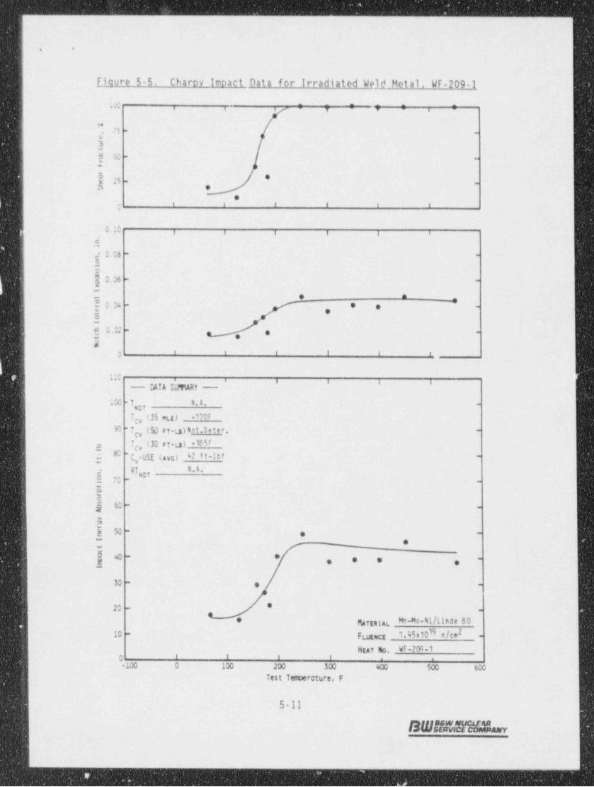
Fioure 5-5. Charov impact Data- for irradiated Weld Metal. WF-2091|
l'Xi . ; :i i , ,
75 -
,. -
3
! 50 -
*
I 25 *-
a oe
I t i i 1 tg
0.10 , , , , , ,>
5,
g 0.08 --
2e$0.06 - -
OIo a .g
'- 0.34 e e-
t e-
3m 0.02 - , . i
- e2
' ' ' I i i0
110 r, , , , , ,
- DATA S' fMRY -J
100 -T 4.A. -g7
I;y (35 mut) +170r
M Tcy (50 FT-ts)het. Deter. -
Igy (30 FT-L3) +18 5Ig80 "t .USE (AVG) b2 II"IDI "'
y
g Ri R.A. |g,2 70 -
-
EEy so -
-
ay% - , -
e
j e e -
-.- , -, ,
30 - , -
20 - '-
MAftniat Mn-Mo-N1/Linde 80 1*
FLutact 1.45x10¹⁹ n/cm210 -.
HEAT No. WF-200-10 ' ' ' ' . .
-100 0 100 200 300 400 500 600Test Tencerature, F
5-11
SWALYe%Lv
. _. .
.
_ _ - - _ - - _ - _ -
__ - _.
. , ,
1
Figure 5-6. Charpy Impact Data for Irradiated Correlation !Material. HSST PL-02. Heat No. A-1195-1 -'
1
100 . : '
, , , , ,
B4
75 - -,,
t3y.- -
.
f5 --
, , , , , ,c
0,10 i i i i i i
$-'0.03 -
8-
?2 0.06 - -
_{0.04--
5 *
-,
5 0.02 - *-
5x
' ' ' ' ' '0
2:0 . . , , i- DATA SUMMARY -
200 - T,37 NA -
Tey (35 mtt) +181T
180 -Tcy (50 n-La) +1m -
Tcy (30 ri-La) + 1r,1 r1603 " C -USE ( Ava) 94 f t-lbf -
y
f RT R.A. '
ug, -, 140 -
--
-
g120 -.-
5<
a 100 --...
E *-
80 -- -
W-r
, 60 --
w - -
, MATEntAL SA533,9 B16 I)*
FLugner 1.45:1019n/cm220 - ..-
HEAT No.. H33T-02i f f I e ,
-100 0 100 200 300 400 500: -600Test- Temperriture, F
5-12'
S W ff a !! m h v;
i.- - . .. . , . - - --
_ _ _ . - _ _ _ _ _ . .. .__ . . . . _ _ . - . _ _ . .
4
. .
:
!
|
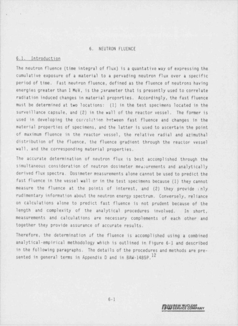
6. NEUTRON FLUENCE
j 6.1. Introductionij The neutron fluence (time integral of flux) is a quantative way of expressing thej cumulative exposure of'a material to a pervading neutron flux over a specific
j period of time. Fast neutron fluence, defined as the fluence of neutrons having
| energies greater than 1 MeV, is the parameter that is presently used to correlate
| radiation induced changes 'in material properties. Accordingly, the fast fluence
j must be determined at two locations: (1) in the test specimens located in the-
[ surveillance capsule,- and (2) in the wall of the reactor vessel. The former is; used in developing - the correlation; between fasti fluence- and changes. in - the: material properties of specimens, and the latter is used to ascertain the point-
of maximum fluence in the reactor vessel, the relative radial and azimuthaldistribution of the fluence, the fluence gradient through the reactor vesselwall, and the corresponding mater _ial properties. -
,
| The accurate determination of neutron flux is best accomplished through- thej simultaneous consideration of neutron dosimeter measurements _ and analyticallyL derived flux spectra. Dosimeter measurements alone cannot be used to' predict the -
fast fluence in the vessel wall or in the test. specimens because (1) they cannot-e
| measure the fluence at the points. of interest, and. (2) they' provide (nlyrudimentary information about the neutron energy spectrum. Conversely, reliance
4
on calculations alone to predict fast fluence i ts not prudent ' because of the; length and complexity of the analytical procedures involved. LIn short,
measurements and . calculations are necessary complements of: each other and; -together they_ provide assurance of accurate results.
Therefore, the determination of the fluence is- accomplished using. a combined-analytical-empirical methodology which is outlined in Figure 6-1 and describedin the following paragraphs. The details of the procedures and methods are pre-sented in general terms in Appendix D and in BAW-1485P.12
F
4
e
i - 6-1
OWMMy-
.
- , - + - . , , ,- r

- _ _ - _ _ - _ _ _ _ _ _ - _ _ _ _ _ _ _ _ _ _ _ _ _ _ _ _ _ _ _ _ _ _ -
..
Fiaure 6-1, General Fluence Determination Methodoloav
MEASlRENENTS OF NEUTRON ANALYTICAL DETERMI)MTION OF00SIMETER ACTIVITIES DOSIMETER ACTIVITIES APO
NEUTRON FLUX
||
ADJUSTED ENERGYDEPE}0ENT NEUIRONFLUX
REACTOR OPERATINGNEUIRON HISTORY N o PRE-FLUENCE DICTED FUTlRE
OPERATION
^
Analytical Determination of Dosimeter Activities and Neutron Flux
The analytical calculation of the space and energy dependent neutron flux in thetest specimens and in the reactor vessel is performed with the two dimensionaldiscrete ordinates transport code, 00TIV.13 The calculations employ an angular
quadrature of 48 sectors (S8), a third order LeGendre polynomial scatteringI4approximation (P3), the CASK 23E cross section set with 22 neutron energy groups
and a fixed distributed source corresponding to the time weighted average powerdistribution for the applicable irradiation period.
In addition to the flux in the test specimens, the 00TIV calculation determinesthe saturated specific activity of the various neutron dosimeters located .in thesurveillance capsule using the ENDF/B5 dosimeter reaction cross sections.15 The
saturated activity of each dosimeter is then adjusted by a factor which correctsfor the fraction of saturation attained during the dosimeter's actual (finite)
6-2
SWHEv'2a%r
-- - _ - _ _ - - - _ _ - - - - - _ _ - _ - _ - - - - - - - - -_-- _ --

_ -___- _ - _ _ _ - - _-
. .
1
irradiation history. Additional corrections are made to account for the'
following effects:
* Photon induced fissions in V and Np dosimeters (without this correctionthe results underestimate the measured activity).
* Fissile impurities in U dosimeters (without this correction the resultsunderestimate the measured activity).
* Short half-life of isotopes produced in iron and nickel dosimeters (303- !
day Mn-54 and 71-day C0-58, respectively). (Withoutthiscorrection,theresults could be biased high or low depending on the long term versusshort term power histories.)
Measurement of Neutron Dosimeter Activities
The accuracy of neutron fluence predictions is improved if the calculated neutronflux is compared with neutton dosimeter measurements adjusted for the effectsnoted above. The neutron dosimeters located in the surveillance capsules arelisted in Table 6-1. Both activation type and fission type dosimeters were used.
The ratio of measured dosimeter activity to calculated dosimeter activity (M/C)is determined for each dosimeter, as discussed in Appendix D. These M/C ratiosare evaluated on a case-by-case basis to assess the dependability or veracity ofeach individual dosimeter response. After carefully evaluating all factors knownto affect the calculations or the measurements, an average M/C ratio iscalculated and defined as the " normalization factor." The normalization factoris applied as an adjustment factor to the D0i-calculated flux at all points ofinterest.
Neutron Fluence
The determination of the neutron fluence from the time averaged flux requiresonly a simple multiplication by the time in EFPS (effective full-power seconds)over which the flux was averaged, i.e.
f ( AT) - E &% aT9
where~
fjj (AT) - Fluence' ~at (i,j) accumulated over time aT (n/cm'),
6-3
BWUunsLa
- ___ _ -- _ _ _- -_

..- - . -- .. . -- -.
!
:i. .
g - Energy group index,
gjg - Time-average flux at (i,j) in energy group g, (n/cm'-sec),d
ai - Irradiation time, EFPS. '
Neutron fluence was calculated in this analysis fo'r the following components overthe indicated operating time:
'
-5Test Specimens: Capsule irradiation tims in EFPS
Reactor Vessel: Vessel irradiation. time-in EFPS
Reactor Vessel: Maximum point on inside surface extrapolated to 32effective full-power years *
The neutron exposure to the reactor vessel and the material surveillance'
specimens was also determined in terms of the iron atom displacements per atom
of iron (DPA). The iron DPA is an exposure index giving the-fraction of ironatoms in an iron' specimen which would be displaced during an irradiation. It is
considered to be an appropriate damage exposure index since displacements of-atoms from their normal lattice sites _is a primary source' of neut'ron- radiation -damage. DPA was calculated based on the ASTM Standard E693-79 (reapproved1985).16 A DPA cross section for iron is given in the ASTM Standard in '641energy groups. DPA per second is determined by multiplying the cross section ata given energy by the neutron flux at that energy and' integrating over energy.DPA is then the integral of DPA per second over the time of the irradiation. Inthe DPA calculations reported herein, the ASTM DPA cross _ sections -were firstcollapsed to the 22 neutron group structure of CASK-23E; .the DPA-was -thendetermined by summing the group flux times the DPA cross section over the 22energy groups and multiplying by the time of the' irradiation.
6.2. Vessel Fluence
The maximnm fluence (E > 1 MeV) exposure of the Oconee Unit '3. reactor vesselIOduring Cycles-6-11 was determined to be 1.96.x 10 n/cm* based on a maximum
neutron flux of 9.49 x 10' n/cm'-s (Tables 6-2 and 6-3) . The maximum fluence-
occurs at the cladding / vessel interface at an azimuthal location of approximately-11 degrees' from a major-_ horizontal , axis 'of the- core.
||
6-4
SWBM1|h -14

4e
Fluence data were extrapolated to 32 EFPY of operation based on two assumptions:
(1) the future fuel cycle operations do not differ significantly from their
current designs, and (2) the latest calculated (or extrapolated) flux remainsconstant from that time through 32 EFPY, The extrapolation was carried out intwo stages. (1) from EOC 11 to EOC 13, an0 (2) from EOC 13 to 32 EFPY In thefirst stage, cycle averaged fluxes are calculated based on the current designsfor cycle 12 and 13, using DOT ajoint factors for assembly-averaged powerdistributions, in the second stage, the 32 EFPY fluence was calculated byassuming a constant flux over the period which was equal to the average flux forcycles 12 and 13.
Relative fluence and DPA (displacement per atom) as a function of radial locationin the reactor vessel wall is shown in Figure 6-2. Reactor vessel neutronfluence lead factors, which are the ratio of the neutron flux at the clad inter-
f ace to that in the vessel wall at the T/4, T/2 and 3T/4 locations, are 1.78,3.53, and 7.25, respectively. DPA lead factors at the same locations are 1.59,2.64, and 4.55, respectively. The relative fluence as a function of azimuthalangle is shown in Figure 6-3. A peak occurs in the fast flux (E > 1 MeV) atabout 11 degrees with a corresponding value of 9.49 x 10' n/cm'-s.
6.3. Caosule Fluence
The capsule wts irradiated for 2373.9 EFPD in the top holder tube position duringcycles IB-7 of Crystal River Unit 3 located 11 degrees off the major horizontalexis at about 202 cm from the vertical axis of the core. The capsule was alsoirradiated for 477.9 EFPD in Oconee Unit 3, during cycle 1, located at the 11degree position about 211 cm from the vertical axis of the core. The cumulativefast fluence at the center of the surveillance capsule was calculated to be 1.45x 10'' n/cm' of which 5.1% was accumulated during the Oconee cycle 1 irradiation,
and 94.9% was accumulated during the Crystal River cycles IB-7 irradiation (Table6-4), This fluence value represents an average value for the various locationsin the capsule.
6.4. - Fluence Uncertainties
Uncertainties were estimated for the fluence values reported herein. The resultsare shown in Table 6-5 and are based on comparisons to benchmark experiments,
6-5
B W s* ? s' ? a fe Lu w
_ _

_. _ _ _ _ __ .______ _ __ ______________ _ ___ _ _ _ _ - - __
. .
when available; estimated and measured variations in input data; and onengineering judgement. The values in Table 6-5 represent best estimate valuesbased on past experience with reactor vessel fluence coulysas.
Table 6-1. Surveillance Capsule Dosimeters
Lower EnergyLimit for Isotope
Dosimeter Reactions (a) Reaction, HeV Half-Life .
_
54 ,(n,p)54Hn 2.5 312.5 days -7
58Ni(n,p)58Co 2.3 70.85 days
238 (n,f)l370s 1.1 30.03 yearsU
237Np(n f)I37Cs 0.5 30.03 years
(8) Reaction activities measured for capsule flux evaluation.
6-6
B Ws* TEE?a % r;
-- - _ _ _ _ _ _ - _ _ _ _ _ _ _ _ _ _ _ _ _ _ _ _ _ _ _ .
s
..
.
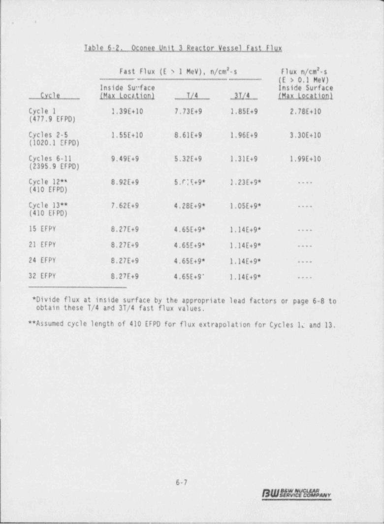
Table-6-2. Oconee Unit'3 Reactor Vessel Fast Flux.,
Fast Flux (E > 1 MeV),7 n/cm'-s1 Fl ux ' n/cm'- s(E > O'1 MeV)
-.
Inside Surface . Inside Surface- -
Cycle (Max locr. tion) T/4- 3T/4 -(Maxlocationl- 1
Cycle 1 1.39E+10 7.73E+9 -1.85E+9 2.78E+10;(477.9 EFPD) .
Cycles 2-5 1.55E+10 8.61E+9 1.96E+9- 3.30E+10 ,
(1020.1 EFPD)
Cycles 6-11 9.49E+9 5.32E+9- 1,31E+9 1.99E+10 3
(2395.9 EFPD) g.S
Cycle 12** 8.92E+9 5.C'E+9* 1.23E+9* ----
(410 EFPD)
Cycle 13** 7.62E+9 4.28E+9* -1.05E+9*- ----
(410 EFPD)
15 EFPY 8.27E+9 4.65E+9* 1.14E+9*'
----
21 EFPY 8.27E+9 :4.65E+9* 1.14E+9* ----
24 EFPY 8.27E+9 4.65E+9*- :1.14E+9* ------
32 EFPY 8.27E+9 4.65E+9^ 1.14E+9* ----
i
* Divide flux at inside surface by the appropriate. lead # factors or. page 6-8 toobtain these T/4 and 3T/4 fast flux values.:
o* Assumed cycle length of 410 EFPD-for _ flux extrapolation for Cycles'lc and 13,
3 .-
-
6
-
6-7-
SW8MMLov .
1

,
-,
s .
Table 6-3. Calculated Oconee Unit 3 Reactor Vessel Fiv3nce
Fast Fluence, n/cm' (E > 1 MeV)Cumulative Inside Surface . ,
Irradiation Time (Max location) T/4 T/2 3T/4 _End of Cycle 1 0.58E+18 3.19E+17 7.73E+16 7.65E+16-(477.9 EFPD)
End of Cycle 5 1.94E+18 1.nSE+18 0.16E+17 2.50E+171(1498 EFPD)
End of Cycle 11 3.91E+18 2.18E+18 1.17E+18 5.21E+17 ,
(3893.9 EFPD)
IEnd of Cycle 12 4.23E+18 2.38E+18* 1.20E+18* 5.83E+17*(4303.9 EFPD)
End of Cycle 13 4.50E+18 2.53E+18*- - 1.27E+18* I6.21E+17*(4713.9-EFFD)--
,
15 EFPY 5.05E+18 2.84E+18* 1.43E+18*- 16.97E+17*
21 EFPY 6.62E+18 3.72E+18* - 1.88E+18* 9.'13 E+ 17 *
24 EFPY 7.40E+18 4.16E+18* - 2.10E+18* - 1.02E+18*
32 EFPY :9.49E+18 5.33E+18* 2.69E+18* '1.31E+18*
* Calculated using these 1.0 1.78 3.53 7.25lead factors
Conversion Factors-
Fluence (E > 1 MeV) 1 45E-21** :1.63E-21** -1.94E-21** 2.31E-21** -.
to DPA
* Multiply fast fluence values (E > 1 MeV) in' units of n/cm' by. these' factors:*
to obtain the corresponding DPA values.
,
|
6-8
. SWAIN!MHbv-
p,
'y-w r er D-g 4 r e- a- tw 'w- +- = ht ---f' ar --'- a w w- '- r *
. . . . . - . . - ..- - . .. - - - --. .. . . - - , . -. . . .... -- . -
.
}. . -.
;.
l
s
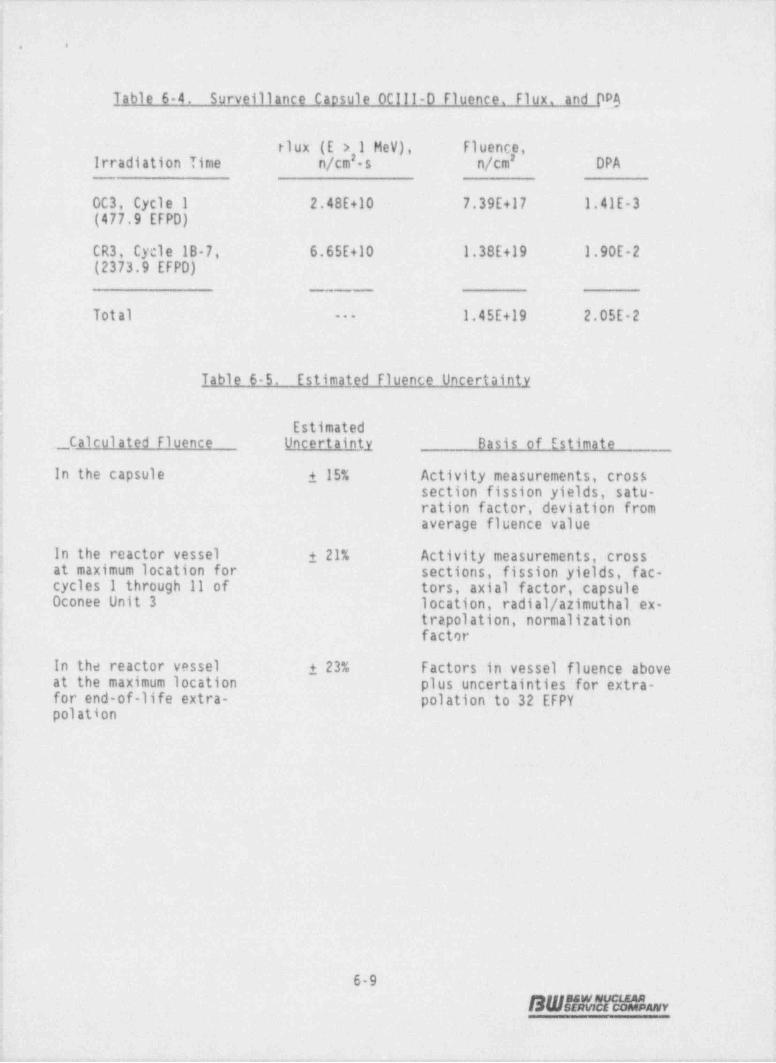
j Table 6 4. Surveillance Caosule 0C111-0 Fluence. Flux. and DPJj-1 - flux'(E > 1 MeV), Fluence,
-
j -- Irradiation-Time - n/cm'- s ; n/cm' DPA<
j OC3, Cycle 1 2.48E+10 7.39E+17 1.41E-3| (477.9 EFPD)
| CR3, Cycle 18_7, 6.65E+10 1.38E+19 1.90E-2j (2373.9 EFPD)
[ Total 1.45E+19 2.05E-2--
i-a
! Table 6-5. Estimated Fluence Uncertainty
: -
! Estimated . .
. , Calculated Fluence Uncertainty Basis of Estimate
i In the capsule 15%
]
. Activity measurements, crosssection fission yields, satu-
;- ration factor,-deviation from!- average fluence value
: In_the reactor vessel 21% Activity measurements,' crossI at maximum location for . sections, fission _ yields, fac -|- cycles 1 through 11:of tors, axial: factor,' capsulej Oconee Unit-3 -location, . radial / azimuthal. ex-j- - trapolation,- normalization
.
,
factor-;
!
j In the reactor vessel- 23% ' Factors-in vessel fluence above'
; at the maximum location plus uncertainties for extra-j - for-end-of-life extra- polation to 32;EFPYi , polation..
3
--
jnj3.
.
!'-.
b-4
i
. 6-9-r - aggst!Mgg, -
.
.r- v - -.y . --- + .-eer - w c-a irre, +---w---+& w y v%w -r---

,
. .
Figure 6-2. Fast Flux, Fluence and DPA DistributionThrouah Reactor Vessel Vall
1.00 ^
- L.F. = 1.585@
-_y g L.F. = 2.639,,'go :
- s @, L.F. = 4.545
0.50 ". S 'g,
, s-'
S T/48 li L.F. = 1.783 |s'sx O 3O 2 A3 : '
,
5 $ % m~
- @) L; O.20 'm ,
e e T/2 'qv i ,1 E* L.F. = 3.534 's oo 4 su -
C.
'S C'3m $-C<L -
b,0.10 -
oO 3T/4 5-
e - L.F. = 7.248 5O Gr) -~N
5 0.05 $-
5 - 5.o O
Z- 223.01 cm. 228.37 cm 233.72 cm_
0.02 -
Flux o-.-DPA - - + --
'I''''I''''I''''!''''!''''0.01 '' '
215 220 225 23C 235 240 245
Radius from Core Center (cm)
6-10
SW#saihr- i
. ____-

_ _ _ _ _ _ _ _ _ _ _ _ _ _ _
..
Fiqure 6-3. Azimuthal Flux and Fluence Distributions at Reactor Vessel Inside Surface ..
1.086 3 3 3 y 4 , ,
1 06 -_
l.04 -
_
>
' t .02 -_
'l.00 -
a>
E 0.98 -
E-
c7 0.96 -
-
en n.'. C~
' E 0.94 -_
vi' T,m f
0.92 --
|
0.90 - -
0.88 - -
0.86 - -
>
0.84 - -
.
0.82 i '' ' ' ' i i ,
,
0* 5' 10* 15* '20* 25* 30* 35' 40* 45*Degrees from Mapr Axis
5t. ._ ._._:.- . . . _ ._ - . ._.. _ . _ . _ .
_ . . _ _ _ . ..

_ . _ _ _ _ - - - - .. .. ..
... . .
,
7. DISCUSSION OF CAPSULE RESULTS
7.1. Pre-Irradiation Property Data
A review of the unirradiated properties of the reactor vessel core ' beltlineregion materials indicated no significant deviation from expected propertiesexcept in the case of the upper-shelf properties of.the weld metal. Based on thepredicted end-of-service peak neutron fluence value at the 1/4T vessel walllocation and the copper content of the weld metal, it was predicted that the
1 end-of-service Charpy upper shelf energy (USE) would be below 50 ft-lb.- - Weld -metal representative of the controlling weld metal was selected for inclusion inthe surveillance program in accordance with the criteria in effect at the time-the program was designed for Oconee Unit-3. . The applicable selection criterion -tsas based on the unirradiated properties only.
7.2. Irradiated Property Data.
7.2.1. Tensile Procerties
Table 7-1 compares irradiated and unirradiated tensile properties. At both roomtemperature and elevated temperature, the ultimate and yield strength changesin the base metal as a result of irradiation and the corresponding.: changes -in-ductility are within the limits observed for similar materials. - - There is somestrengthening, as indicated by ' increases -in ultimate and yield strengths. and
Idecreases in_ ductility properties. All changes observed in the base metal aresuch as- to be considered within acceptable limits. The ' changes at both roomtemperature-and 580F in the properties of the weld metal are larger than thoseobserved for the base metal, indicating a greater--sensitivity of the weld metal-to irradiation damage. In either case, the changes:in tensile properties areinsignificant relative to the analysis of the reactor vessel materials at this
i periodLin service life.;
7-1
SW21Mll1Hhr
_ _ - - _ _ _ - _ __ a

. .
A comparison of the tensile data from previously evaluated capsules (Capsules0CIII-A and 0C111-B) with the corresponding data from the capsule reported inthis report is shown in Table 7-2. The currently reported capsule experienceda fluence that is twelve times greater than the first capsule.
The general behavior of the tensile properties as a function of neutron
irradiation is an increase in both ultimate and yield strength and a decrease inductility as measured by both total elongation and reduction of area. The mostsignificant observation from these data is that the weld metal exhibited greatersensitivity to neutron radiation than the base metal.
7.2.2. Impact Propertiel
The behavior of the Charpy V-notch impact data is more significant to thecalculation of the reactor system's operating limitations. Table 7-3 compares
the observed changes in irradiated Charpy impact properties with the predictedchanges.
The 30 ft-lb transition temperature shift for the base metal is not in good17agreement with the value predicted using either Regulatory Guide 1.99, Rev. 2
even without applying the margin which is required. It would be expected that.these values would exhibit better agreement when it is considered that the dataused to develop Regulatory Guide 1.99, Rev. 2, was taken at the 30 ft-lb
temperature.
The transition temperature measurements at 30 ft-lbs for the weld metal is notin good agreement with the results using Regulatory Guide 1.99, Revision 2without the margin applied. With the addition of the margin the procedure isvery conservative in predicting the irradiated values. The estimating curves ofRegulatory Guide 1.99, Rev. 2, are conservative for predicting the 30 ft-lbtransition temperature shifts since the procedure requires that a margin be addedto the calculated value to provide a conservative value.
ihe data for the decrease in Charpy USE with irradiation showed good agreementwith predicted values for the base metal and only fair agreement for the weldmetal. However, a good comparison of the measured data with the predicted valueis not expected in view of the lack of data for low , medium , or high-
7-2
SW##enH3-

- _ - . - - . - - . - - - - . - .- . - - - - ~ . .- .-. . -
|1
'
|. .
copper-content materials _ at the fluence values that were used- to develop theestimating curves.
A comparison of the Charpy impact data from the previously evaluated capsu'es-(Capsules 0Clll-A and 0C111-B) with the corresponding data from the ' capsulereported in this report is shown in Table 7-4. The currently reported data
-
experienced a fluence that is _ eighteen times greater _than the first capsule.
The base metal exhibited shifts at the -30 ft-lb level for the latest capsulethat were similar to those of the previous capsules. The corresponding data forthe weld metal showed a further increase at the 30 ft-lb level. This may be due )to a further decrease in the upper shelf energy with a corresponding ' increasedshift at the 30 ft-lb level.
Both the base metal and the weld metal exhibited a decrease in the upper shelfvalues similar to the previous capsule. The weld metal in this capsule exhibiteda slightly greater-decrease than the held metal-in the previous capsule. Thesedata confirm that the upper. shelf drop for this weld metal did not reach satura-tion as observed in the results of capsules evaluated by others. This behaviorof Charpy USE drop for this weld metal should not-be considered indicative of asimilar behavior of upper shelf region fracture toughness properties. This
'
behavior indicates that other reactions may be taking place within' the materialbesides simple neutron damage. Verification of this relationship must await thetesting and evaluation of the data from compact fracture- toughness testspecimens.
Results from other surveillance capsules .also indicate that RT estimatingNDT
curves _have greater inaccuracies than originally thought. These _ inaccuracies area function of a number of parameters related to.the basic data-available at thetime the estimating curves are established. These parameters may ' includeinaccurate fluence. values, poor chemical composition values, and:: variations-indata interpretation. ' The change in the regulations requiring the shift
measurement to be based on -the 30 -ft-lb- value has minimized the errors thatresult from using the 50 ft-lb data- base to predict the shift' behavior at 30
_ft-lbs._
7-3-
SWEEYah<
u
. .- - -
_.
. .
An evaluation of the reactor vessel end-of-life upper-shelf enethe materials used in the fabrication was made and the result
rgy for each ofTable 7-6.
the reactor vessel are Linde 80 flux, low-upper-shelf energThis evaluation was made because the weld metals used to fabric ts are presented in
ae
copper and are expected to be highly sensitive to neutron radiation danrelative high- y,
methods were used to evaluate the radiation 5duced decrease inage. Two
energy.The method of Regulatory Guide 1.99, Revision 2, which is the
upper shelf
procedure as used in Revision 1, and the method presented in BAW 1803"same
developed specifically to address the need of an estimating meth d fwhich was-
of weld metals. o or this class
The methods of Regulatory Guide 1.99, Revision 2, indicate that tmay be expected to decrease below 50 f t-lb level prior to EOLwo of the welds
shows that none of the. materials used in the fabrication of the reactHowever, BAW-1803.
will have an upper-shelf energy below 50 ft-lbs through 32 EFPY dor vesselon the T/4 wall location. esign life based
below 50 ft-lbs for the controlling weld metal at the vessel iRegulatory Guide 1.99 method also predicts a decreasenside wall.
;
1
i
7-5
(SW??5NEEYN5m

_
..
~
copper-content materials 3t the ficc..ce values that were used to develop theestimating curves. |
i A comparison of the Charpy impact data from the preitously evaiuated capsules(Capsules Otlll-A and OC111-B) with the corresponding data from the capsulereported in this report is shown in Table 7-4. The currently reported dataexperienced a fluence that is eighteen times greater than the first capsule.
The base metal exhibited shifts at the 30 ft-lb level for the latest capsule
that were similar to those of the previous capsules. The corresponding data for,
the weld metal showed a further increase at the 30 ft-lb level. This may be due
j to a further decrease in the upper shelf energy with a corresponding increasedshift at the 30 ft-lb level.
Both the base metal and the weld metal exhibited a decrease in the upper shelfvalues similar to the previous capsule. The weld metal in this capsule exhibiteda slightly greater decrease than the weld metal in the previous capsule, Thesedata confirm that the upper-shelf drop for this weld metal did not reach satura-
,
| tion as observed in the results of capsules evaluated by others. This behaviorof Charpy USE drop for this weld metal should not be considered indicative of asimilar behavior of upper shelf region fracture toughness properties. This,
behavior indicates that other reactions may be taking place within the materialbesides simple neutron damage. Verification of this relationship must await the
'
testing and evaluation of the data from compact fracture toughness testspecimens.
Results from other surveillance capsules also indicate that RT estimatingNDT
curves have greater inaccuracies than originally thought. These inaccuracies are; a function of a number of parameters related to the basic data available at the
time the estimating curves are established. These parameters may includeinaccurate fluence values, poor chemical composition values, and variations in,
data interpretation. The change in the regulations requiring the shift,
measurement to be based on the 30 ft-lb value has minimized the errors thatresult from using the 50 ft-lb data base to predict the shift behavior at 30ft-lbs,
f
7-3
BWitnEYk_.-

. _ _ _ _ _ _ _ _ . _ . _ _ _ . _ _ _ _ _ _ _ _ . _ . _ . _ . . _
|.
.
I
l The design curves for predicting the shif t will continue to be modified as more !data become available until thet time, the design curves for predicting the !
RTNDT shift as given in Regulatory Guide 1.99. Revision 2, are consideredadequate for predicting the RTNDT shift of those materials for which data are not |available. These curves will be used to establish the pressure temperature i
operational limitations for the irradiated portions of the reactor vessel until |the time that new prediction curves are developed and approved.
|;
The lack of good agreement of the change in Charpy USE is further support of the !
inaccuracy of the prediction curves. Although the prediction curves are i
conservative in thst they generally predict a larger drop in upper shelf than is '
observed for a given fluence and copper content, the conservatism can unduly. [restrict the operational limitations. These data support the contention that the |USE drop curves will have to be' revised as more reliable data become available; I
until that time the design curves used to predict the decrease in USE of the i
contmiling materials'are considered conservative.J
7.3. Reactor Versel fracture Touchness'
i
An evaluation of the reactor vessel end-of life fracture toughness and the,
pressurized thermal shock criterion was made and the results are presented in,
Table 7 5. ,
|-
The fracture toughness evaluation shows that the controlling weld metal may have,
| an end-of life Riuor of 228F based on Regulatory Guide -1.99, Revision 2. This :;
-
;
( predicted shift is excessive since the latest capsule _(Capsule 00111-0) exhibited! a measured shift of 140F for a fluence of 1.45 x 10" n/cm'. Ratioing this |
measured shift to the T/4 wall location fluence, it is estimated that the end of-life RTc shift will be significantly less. than the value .erdirNd using-
a
Renulatory Guide 1.99, Revision 2. This reduced shift permD e the cahulationL of iess restrictive pressure temperature operating limitations tun if Regulatory.. |'
Guide 1.99, Revision 2, was used.
The pressurized thermal shock evaluation: demonstrates that the Oconee Unit 3'
reactor pressure vessel is well below the screening criterion limits and,therefore, need not take any additional ~ corrective _ action 'as required by the-
regulation.-
!
L :
9'7-4
S W 51121H & - ,
c . -.- - - - -..a - -..- . .- .a u - :

_
. .
An evaluation of the reactor vessel end of i,r'e upper shelf energy for each ofthe materials used in the fabrication was made and the results are presented inTable 7 6. This evaluation was made because the weld metals used to fabricatethe reactor vessel are Linde 80 flux, low upper shelf energy, relative highcopper and are expected to be highly sensitive to neutron radiation damage. Twouethods were used to evaluate the radiation induced decrease in upper shelfenergy. The method of Regulatory Guide 1.99, Revision 2, which is the sameprocedure as used in Revision 1, and the method presented in BAW 1803"' which was
developed specifically to address the need of an estimating method for this classof weld metals.
The methods of Regulatory Guide 1.99, Revision 2, iridicate that two of the weldsmay be expected to decrease below 50 f t lb level prior to [0L. However, BAW 1803shows that none of the, materials used in the fabrication of the reactor vesseletil have an upper-shelf energy below 50 ft-lbs through 32 ErpY design life based
"
on the T/4 wall location. Regulatory Guide 1.99 method also predicts a decreasebelow 50 ft L s for the controlling weld metal at the vessel inside wall.
7-5
B W!!?aY% % r
. .- _-

..
litbl e 7 - 1. Comn rison of Cansule 0C11_l:D lension Test Results
Clevated Temp.Room Temn. Test- _lest (580f)Unirr Iraj Unin JrQL
i
Base Metal -- Ati!LLtl. TransverseI9fluence, 10 n/cm' (> 1 MeV) 0 1.45 0 1.45
Ultimate tensile strength, Asi 85.4 91.5 35.0 87.2
0.2% yield strength, ksi 63.1 (6.9 55.7 60.3
Uniform elongation, % 13.8 9.9 11.9 9.9
Total elongation, % 30.4 26.6 28.6 23.3
Reduction of area, % 66.8 65.1 66.5 62.0
Weld Metal Wi-209-1
I8Fluence, 10 n/cm' (> 1 MeV) 0 1.45 0 1.45
Ultimate tensile strength, ksi 90.5 111.3 87.9 102.9
0.2% yield strength, ksi 75.0 98.0 67.4 86.6
Uniform elongation, % 12.5 10.7 10,9 9.0
Tott' elongation, % 28.1 24.2 21.4 17.7
Reduction of area, % 62.9 56.7 52.1 49.4
i
l
|
|
7-6
B W !!K E?i %
.

.
Table 7-2.- Suseary of Oconee Unit 3 Reactor Vessel Surveillanca capsules Tensile Test Results .
Strenoth. ksi Ductility. %
F Test Total Reduction-10]gence-2 I.I Yield %g.) Elon. %g.) of Area %g.)
n/cm Temp, F Ultimate %Material
63.1 30 - 67 -Base Metal 0 70 85.4 -
67 -'55.7 - 29-(ANK-191) 580 85.0 --
0.81 70 87.5 + 2.5 63.0 - 0.2 30 00 68 + 1.5580 86.4 + 1.6 57.2 + 2.7 29 00 67 0.0
3.12 69 105.6 +23.7 91.3 +44.7 25 -16.7 56 -16.4585 86.9 + 2.2 56.0 + 0.1 37 +27.6 64 - 4.5
14.50 70 91.5 + 7.1 66.9 + 6.0 27 -10.0 65 - 3.0
550 87.2 + 2.6 60.3 + 8.3 23 -20.7 62 - 7.5
28 - 63 -~ Weld Metal 0- 70 90.5 - 75.0 -
4 -(WF-209-1) 580 87.9 - 67.4 - 21 - 52 -
.
0.81 70 93.9- + 3.8 79.3 '+ 5.7 27 - 3.6 63 0.0580 93.7 +-6.6 72.6 '+ 7.7 23 + 9.5 60 +15.4
3.12~ 69 105.0 +16.G' 90.6 +20.8 25 -10.7 57 - 4.8
585 85.6 - 2.6 57.8 -14.2= 26 +23.8 ~56 + 7.7
. 30.7 24 -14.3 57 - 9.514.50 70' 111.3 +23.0 98.0 +
550 102.9 +17.1 86.6 +28.5 18 -16.7 49 - 5.8
9-e(.)chan9e r.1 tive to unirradiated.

_.__ _.. _ _ _ . _ . - _ _ _ _ _ . _ . _ . _ . - _ . - _. _ _
. .
1
Table 7-3. Observed Ys. Predicted Changes for Cggsule 9C111 D Irradiated ,
Charpy impact Properties - 1.45 x 10 n/cm (E > 1 MeV) i
|
PredictefPredicted iIbIRG 1.99/2 ,I RG 1.99/2+M
,
Material Observed '
. _ _ .
.
Increase in 30 ft 'b Trans. Temo.. r |
Base material (ANK-lh')i
Transverse 31 22 33 ;
Heat affected zone 74 22 33- |
Base material (AWS-192)
Transverse 45 22 33Heat affected zone. .1 22 33 |
Weld metal (WF 209 1) 140 196 252'
Correlation material (HSST plate 02) 119- 141 197
Decrease in Charov USE. ft-lb -
Base material (ANK-191)-;
Transverse 19 17 N.A.Heat affected zone 22 11 N.A. .I
i
Base material (AWS-192)
Transverse 19 12 N.A.Heat affected zone 6 13 N.A.
Weld metal (WF 209 1) 24 30 N.A.
Correlation material (HSST plate 02) 36 36 N.A.
i
(*)PerR.G.-1.99, Revision 2,May1988. .)(b)PerR.G.1.99, Revision 2,May1988,'plus2xmargin. l
;
, .,
j
7-8 )13 sana 1 MAL- 1
'
t1_ _ . . _ .___,,,.u.,__,_.__._.__. _ . _
-
- -- J

--
.
Table 7-4. Sumary of Oconee Unit 3 Reactor Vessel Surveillance Capsules Charpy Irpact Test Results .
Transition Temperature Increase. F Upper-SheliPredicte Enercy. ft-lb30ft-lbgy Predicte4) Predicted'4Fgence,r 30 ft-lb ,
30 ft-lbi- ObservedMaterial 10 n/cm Observed-
Base material (ANK-191)Transverse 0.81 9 8 12 130 136
3.12 32 14 ZI 123 131
14.50 31 22 33 125 127
Heat-affected zone 0.81 0 8 12 145 853.12 Ind. 14 21 67 82
14.50 74 22 33 68 79
Base material (AWS-192)Transverse 0.81 63 8 12 100 108
3.12 19 14 21 99 103
14.50 45 22 33 93 100 i
$ Heat-affected zone 3.12 Ind. 14 21 123 105
14.50 1 22 33 108 101
Weld metal (WF-209-1) 0.81 48 70 I05 54 " 50
3.12 64 121 177 49" 44
14.50 140 196 252 42" 36|
Correlation material 3.12 39 87 131 96 104'
(HSST plate 02) 14.50 119 141 197 94 94
g (a)Per R.G. 1.99, Revision 2, May 1988.
(b)Per R.G. 1.99, evision 2, plus margin.R
"Per 8AW-1803, Revision 1, dated March 1991, plus margin.''on
h " Upper-shelf energy value re-defined per ASTM E185.
I<
u.__ . . _ _ . .

_ _ _ _ _ _ . _ _ _ _ _ . _ _ _ . _ _ _ _ _ _ _
F4 * s
_f g 64-
3{[.$' R R R 8 8 * 8-
"* N N N m m E mY
{}^--M L *.
I h v@4W W W m mA W''" wH m N t. N N
sg .= N N E {Nw .
Yv t -l
q
" " ".E- .
W e- 2 R, O o n"~ m - + . E a.e- m y ,k -3 3 o
>3ea ,
m >- - .W CL w c L.NL La. M & W
b k. k. k. N P k h UAW *
e (n) ng, L .,e
%N E = E E E - - E+ V d go.,
* A fuCM Se
n- u a"a +-O e
M 3%,m w ** LWu
. s. $C- *- -.e. e .
D'D t. N,.M N, C, M. r' #.-e get
.mc.m3 s . n n = .
- N ~ E E 7O W sufH 68 *
C g a-WO h eL U P-
UD N3- c. e m m. m m @- s>- e . . -e+ + e + + + . * b 31V . 3g w 4
at.s w w w w wq >to Cg g en m m kn mg g
t.8 .h., E . .
cW M
c. -Qy W D
. e sn .n .n N ***.em
.T s.*E*o 1~ m m m m .m .e.-v - . . , . - - .-J wt J TJ w (" 4 + * + + . +
hVd.heJ Cs * V hJ w w w kJL,. t* 4.9. N
6,g
t J = m th Ch &*.y g
O. 5 $ . m ~ m .ns'vKo m ~ m
. ,
vA 3eO a. ES-
-b.W & O m W m .C;P
o o o o.
.m m. 6mE4 .- ~, m. ~. ~. w.o o o se,
n. . m,, o., --
c;me . -- ,,
tt,, eW -.>c 6 .c
- N W w .h CD (C EW @ o .m. - -s. - as. o. o. ~. ~. m. m W N
.
3 .O O O o O O o % J.
v- g_-
2 *C uuu b &:xcr u m v v ,,
,. v gmwu a . . .
s m m m w .
- e +oU > o y , y v g f.,, po .o .on .n n .- - - -w w w w v * msc .c N N N 2 a a > oJ"'om .
- N m - *e-- e ~ .
.2, 2,8em u w w e o n3 e, . . A.
- o o - s.-. .N. ~. . u-- g hm y v.
T Cb~
si 3 a 5 sW 9 gE4.4J W gg a b o
v .tg M M dG. 5
-. - e
- o ~ N e -m.
* .o ,C4 *
8-- - . . ne. . o. a. e. -
w eso - o 3 2 8,v w-
8 7-" - ~ = *= , a w.o sc - - m m - yWq ;s. o - ar - -m I< b agw-
.- .a 2 g- 1'-
.ur o m .i. o , .
e m .,o .,.-.a g.
t- sg.e .w a -- - - _
. .m .,.. . .
.. ~ . .. ~m
-- o .c e -- - ,.
8r = 8v-- - -
k 2 g- c - - u v; z -- .
I t. [. t e M t t t-m, a s a z - 1- -
a uc .
r , a a f
7-10
SW#ssih

-!
-. _l./.
lin_3
.
A. A. 2 2 A. 20n8 . . .
l1 A.e3 3 3
-N m M > > W >dttWef uAt 6a0 e
im 5 L_2t o4 /stl1Tj9 .
E
Ft 2 2 2 1 6 A. 21 3 3 3 2 1 3
a_ RT
> > > R >E G
nE l oS* li
.
A.U. *l a .
A. A.. 4 4. .
t
A. A.W a/ 5 5t 3 c4 2 M N N m0 0 /eE 8 tT1d -
ee WtaA e c
amB d .
A. A..
f. .
3 2 A. A..r r A.i i
r so t 5 5e wt p a$ N m M M ns
E lca n
W"le ol
.R iU a .
A.t
A.v - 2 W 9 9 l 8 7at/ 0 e l 4 43 a 09 4 1 I M Mcor E9 / tt e T
d1in enE t C e
cU aF .a.
A.mi r tdf f 6 7 0 A.s 0 8 1
5 4rcl sMt e 4un 1 1 M mee sE i
nhoSc - l
Or a t* *
* " *st *) * "e iE ) } )itS 3 7 3 0 0 Cyp iU - 3 9 2 7 7
.
7A.tn r, e 1 1f
f ( ( ( M (aUg) n 8 8 8 8 8 6l
o'l
aia * + *1 1 11 1 1oY + + .
E+
CP Wt E E E E E A.cF e a 5 3 3 5 3 8
rE dM/oc/ 0 3 3 0 3 N 94 nee t tIL 4 5 5 4 5 2w2 au
elo3 tF 8 8 8 8 8 6P( t ee 1 1 1 1 1 1
E % i a'ss d< + + + + + . +E E E E E A. 1
Eee E sf c 1 9 9 1 9kf nr/ 2 4 4 2 a. N 3
I unui S 1 9 9 7 9 5DL-
n_lff e 1 3 6 3 0 3 3oo h o 9 7 7 6 6 5 6
- ll pc/aa]i w 0 0 0 0 0 0 0nd c1Mon iri1
iE e m 1_r .
meot e
3 1 2 4 4 5 8 8 .t ah 8 1al MC p/ 1 0 0 2 2 3 1 9 9pwue 1 9o 0 0 0 0 0 0 0l s Jt 1
yas a hve Z 2 2 M crEV I 1 l
C C C d ae e M .
t 6p . . ,a d 7
. y 3 8 86 T 0 0 0 d d d d d e 9
t 15 5 5 l l l l , a- A A A o e e e7 S S 5 k W W W 2 d . h
s cn , t r
e 0 2 1 o I r ai o P.l r 8 9 9 0 9 s n pt e 5 1 1 0 7 0 6b o e diab 4 - - 2 6 7 1 v i R ea em M S K - - - - e s tT Hu D W N F F T T
N R A A W W W W R i t av s d
. e ee 9 R T .e ) )t n % % 9 P
, s 6t o 5 51 3 l 4r i 7 2 0 a 0j t
r a D D e 8 i 0O d 1 r 15l c I
- e -eo ( ( iu W t WJ* s L d d G A a AD.e n B M B.s t l d d l
l e l l elV o e w e e w y
i r r d ra i t . w w.
t p i pL_ o erg o e e e
r e m .
m. us a fttR 1 i l u m l d i dlc : l l t u u c u e t eaae r e e e rMen o h h l
c c
icr r g t r te a e aRt n s s c i i R m t
im1 c C it r r r r r r t r ti e e e e . . a
h o tp o p id w e s e sw p w p di c P E P E
t t t L' M M t * * " "_
NEFE4n .S o .N,
__
____
_

. .
8. DETERMINATION OF P.EACTOR COOLANT-PRESSUREBOUNDARY PRES $URE . TEMPERATURE LIMITS
The pressure-temperature limits of the reactor coolant pressure boundary (RCPB)of Oconee Unit-3 are established in accordance with the requirements of 10CFR50,Appendix G. The methods and criteria employed to establish operating pressureand temperature limits are ' described in topical- report BAW 10046A." The
objective of these limits is to prevent nonductile failure during any normaloperating condition, including anticipated- operation' occurresnces and systemhydrostatic tests. The loading conditions of-_ interest include-the following:
1. Normal operations, including heatup and cooldown.
2. Inservice leak and hydrostatic tests.
3. Reactor core operation..
The major components of the RCPB have been analyzed in accordance with 10CFR50,Appendix G. The closure head region, the reactor vessel outlet nozzle, and thebeltline region have been identified as the only regions of the reactor vessel(and consequently of the RCPB)~ that regulate the pressuretemperature limits.Since the closure head region is 'significantly stressed at relatively : lowtemperatures (due to mechanical loads resulting from bolt preload),'this regionlargely-controls the pressure temperature limits of the first several service-periods. The reactor vessel outlet no:zle also affects the pressure-temperaturelimit curves of the first several service periods. This is due to the high localstresses at the inside corner of the nozzle, which can be two to three times themembrane stresses of the shell. --After the ' first several years of neutronradiation exposure, the RT of the ' beltline region materials will be high
NDTenough that= the_ belt 1.ine region of the reactor ve'ssel will start to control the
-pressure-temperature-limits.of the RCPB. For'the service period for which the-limit curves are established. the maximum allowable' pressure as a function offluid temperature:is obtained through' a point-by point comparison of the.llmits
8-1
BWRR8NQLa

_ _ _ . _ . . _ . . _ _ . . - - ~ . . _ _ _ _ _ _ . - _._-_.._..m _ _ _
i
. .
imposed by the closure head region the outlet nozzle, and the beltline region..| The maximum allowable pressure is taken to be the lowest of the three calculated
pressures.
| The limit curves for Oconee Unit-3 are based on the predicted values of the t
adjusted reference temperatures of all the beltline region materials at the end :
of fifteenth EFPY. The fifteenth EFPY was selected as the last time periodbecause it represents a logical sequence from the previous analysis and the ;,
survelliance capsule was scheduled to be withdrawn at the end of the refueling |cycle wher the estimated capsule fluence corresponded to approximately the inside [surface end of-life value. However, the use of low leakage fuel cycles caused 1
the capsult fluence to exceed the reactor vessel inside st'rface end of-lifefluence. The time difference between the withdrawal of this surveillance capsule iand future operating requirements provides adequate time for re establishing theoperating pressure and temperature limits for subsequent periods of operation-_ '
beyond the current surveillance capsule withdrawt.1.
The unirradiated impact properties were determined for the surveillance beltlineregion materials in accordance with 10CFR50, Appendixes G and H. For the otherseltline region and RCPB materials for.which the measured properties are notavailable, the unirradiated impact properties and residual.. elements, as
originally established for the beltline region materials, are listed in-TabicA-1. The adjusted reference temperatures are calculated by adding the predicted
_
radiation induced RT and the unirradiated RT The predicted RT ISNDT NDT. NDTcalculated using the respective neutron fluence and copper and nickel contents.Figure 8-1 illustrates-the_ calculated _ peak neutron' fluence at several locations
, -
through'the reactor vessel beltline region wall. The' supporting information forFigure 8-1 is described in Section 6. The neutron fluence-values of Fire 8-l'are the predicted fluences that- have been demonstrated (Section 6) w beconservative. The design curves of Regulatory Guide 1.99, Rev. 2, were used topredict the radiation-induced RTNDT values as a function of the material's:
-
copper and nickel content and neutron fluence.
The neutron fluences and adjusted RTNDT values of the beltline region materials :
at the end of the _ fifteenth full-power year are listed.in Table 8-1. -The neutron -fluences and adjusted RT values are given for the:1/4T_ and 3/4T vessel wall
NDT
|
8-2
S W B MIFIM & nr
. _. ._ .._, . _ . _ _ _ . . __. _ __._a_. u,.,_ 2 n _ ;_ -
_ _ _ _ _ _ _ _ _ _ - _ _ _
. .
locations (T wall thickness). The assumed RT f the closure head region andNDT
the outlet nozzle steel forgings is 60F, in accordance with BAW-10046. The
RTuo, values selected for calculation of the pressure temperature limit curvesare those values which exhibit the highest values at the T/4 and 3T/4 locations.In the case of the 3T/4 location, one weld metal made up the outside 25% of theweldment and another made up the remainder. It was assumed that the theoretical
T/4 thickness flaw used to calculate the pressure-temperature curves layed suchthat its forward most crack front was posed to enter the material composing themajor portion at the weldment and, therefore, that material is controlling.
I
Figure 8-2 shows the reactor vessel's pressure-temperature limit curves- fornormal heatup. This figure also shows the the core criticality limits asrequired by 10CFR50, Appendix G. Figure 8-3 shows the vessel's pressure-tempera-ture limit curves for normal cooldown. Figure 8-4 shows the vessel's heatup andcooldown limitations during inservice leak and hydrostatic tests. All pres-sure-temperature limit curves are applicable up to the fifteenth EFPY asindicated. Protection against nonductile failure is ensured by maintaining thecoolant pressure below the upper limits of the pressure temperature limitcurves. The acceptable pressure and temperature combinations for reactor vesseloperation are below and to the right of the limit curve. The reactor is notpermitted to go critical until the pressure temperature combinations are to the '
right of the criticality limit curve. To establish the pressure-temperaturelimits for protection against nonductile' failure of the RCPB, the limitspresented in figures 8-2 through 8-4 must be adjusted by the pressuredifferential between the point of system pressure measurement and the pressureon the reactor vessel controlling the limit curves. This is necessary becausethe reactor vessel is the most limiting component of the RCPB. !
8-3
S W B l M!PlH L w ,
. 1-

-
I 3, - -II q
.
)9 9 9 2 9
fg l
I
e 3 3 3 38d f 1 I ge f (
o MEY It
s r If I
Jy ]dpI 4 0 7 T 2 C , .A 5f 3 4 4 7
1.4 _
tJ1 1 1a (
.n 9 0 0 9 9 ,
6 1 1 6 6 ,69i / / / / / j .r 9 4 s 9 9 , .a 6 1 I 6 6M
n fFe d, e
.
A.
ey(Me7 9 9 8 5 7t
bt 3 6 T , n6agrY aI t1/ 5 1 1 o 3
,
.
dm 8 3 3 s 6 A.,
oP R a13 l 1 , afF
-
I IE W ()I
lt C I I D b Dslt y
a ( 9 9 I I, ) I I ) ) ) )e5 3 0 0 5 5 5 5
v1 t g 2 2 -
e ( ( ( ( (r li
uh RCc yu rt o t ri r tse 6 0 0 8 3 8 9
t 1 2 2 7 7 1 5mh ac 3 1 2 1eaiT bf .l (
eel o
) /.rb dua (
n . 1 3 6 3 0 9 3t c e l 9 7 7 6 6 5 6
t eai t t 0 0 c c 0 0 0rl t ts .ep o ni F
pp p 0m 2mA o o -e C /
wT - l no .
'
- - a , 3 1 2 4 4 5 8 i )c r 1 0 0 2 2 3 3e t t6 e a xr3 m p 0 0 0 0 0 0 0 i ee p v tu- h e est t C D esi e
den e 13 8
81 1 1 1y 8 8 8 6 1 s
2 (1 1
rU e- * + 4 * + + + a
P 4dr # f t t I f f t d 3 s,f e 4 5 5 4 5 5 3 n 8 ta 9 t
- sr c 8 0 0 8 D 0 0 t 1 eauI/f fSF n 3 5 5 3 5 5 3 5 ty Ion e l
n u eo 4 nni /o O J r
1i u; . tot t - - - s s s8- e e o e 9 ada -
~i a - f t N F 9 9 rl c - 9 T ett eon Wl . 1 I paS e 8 - m
l 3 h W ert s 9 c A tar j n '- r B -i 1 a . epa go ssgi mAe - - - - - - - y M 6 d ree .L_ t - - - - a 7 n uo e - - .- - - M 9 a sarrr -rl 11(f o9 1 s
'Pc 0o je d 4 eet aD e n h 8 r
rN ld a ieu m M t c 9 p .
r 1 ssd a f to e e s et M r o t
efe h nd . e . b m leal 3 3 3 9 2 R P u o i2 6 6 4_e rl em - 4 - 1 2 n 6 e tan opWc .e 3 a c t eCd - - - - - -t 0 e a rt o io 0
Mt 8 O D u
DOisac v -
I. u t1
Y.t a
e W W ra eA) ) D 4
6 B 0 c p) 1 t )t 5 5 1 . 2 m
. o 7 t 0 9 r r 8 n en o 0 9 e e 1 i t
l e l
1 O ( 1 W e e0 D p p - -1
.
t (t t ( ( s s A s r
8 ea l d d e l 8 u ulnc e l d d l d a a s .
i o b e l l e t t r r s se lt m e e w lo e e e o e t
t e m m G m m p f r rl t n i l l . . p ob eo r l l c . . c y d e s s p
s n e e eSi r e e r c c r r la g o h h i r r i o e e t l aa e u t R
T e n s s c ic ci c t w la t a l tR r f f i v u sr r r gd, d u g 'e o s c e .. e lue e e o T l i 3w p w o e y y p O a -o p o
A" iM iM t R g gm N c l 6t it t o T ar i T c R o i e
0 0 0 0 e R R t r l
8 8 8 8 p l d e b2 2 2 l l a e d t a1 l l e e e e d a a c t e a T
n e ( C C d d d d e it t a s Mo p a a n n t t t a l u ,
i y . . . t l i i a i i e u d 6ttT 6 8 8 t L L L l n a h c s le/ u i l c l e n
WS Wsa 0 0 0 /A c a u f ot c 5 5 5 A
l d d s c l t irt A A A Sef S 5 5 A A A A a e e l a t t
c t t a l v r c -tt- a a i a e eat
Ma. 0 1 1 m e r i T C sEr eto 8 2 1 - 0 i l e t
dM 6 9 9 0 9 M t t t i
l 4, 1 1 0 7 0 6 Y s s a n T e et - - 2 6 7 1 R )( E M I R P 5a M S 5 - - - - I ) I I I
NI I* b C d I'te W t W W W W W I ( I ( I IM I A A
p s
.
'.
'
f ll|{l ||tlL|| ,1
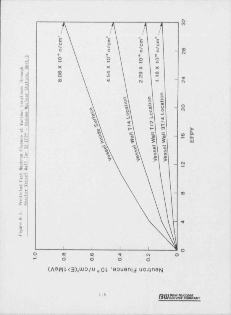
|' | |[ 'I t
_
_
___
.__
-.
23
N_.
._
'm 'm 'm 'mc c c c _
/ / / /_..
8n n n n f
2* ' ' '
'o '0 '0 '03
-t t 1 1 1i
nhU X X X Xg
8 4 9 8u .0 5 2 1on
ro'hi 8 4 2 _
_
Tta .
.
st _
-nSoi r n _
t aae " n o .
icl 0 o toc il u 6 at
e a a cl ,f
ue c c c osoe a o o Lin t L L #
4ro t
ac o 4 2 /VO 6 f / T
e T T 3 Yt -a P -Y' d l l l
6l l l
$ a a a F-
eP \ t
1cF * W W W EnEeu2 \e g e s
g l !
l 3m
F 5 5 s sr 5 5 s snoof e e e er g V V Vtl 2ul 'ea 1NW e
tlseasF s
edVet rco 8,
itdceare
PR
.
1-8
4o
erugi
f
- - - - O0 8 6 4 2 0 -
<
0 O 0 D1
n>e2w AW .EoNc O .$8 2* cohgZ2
=& l'=
; , i. ;| !', f . I i
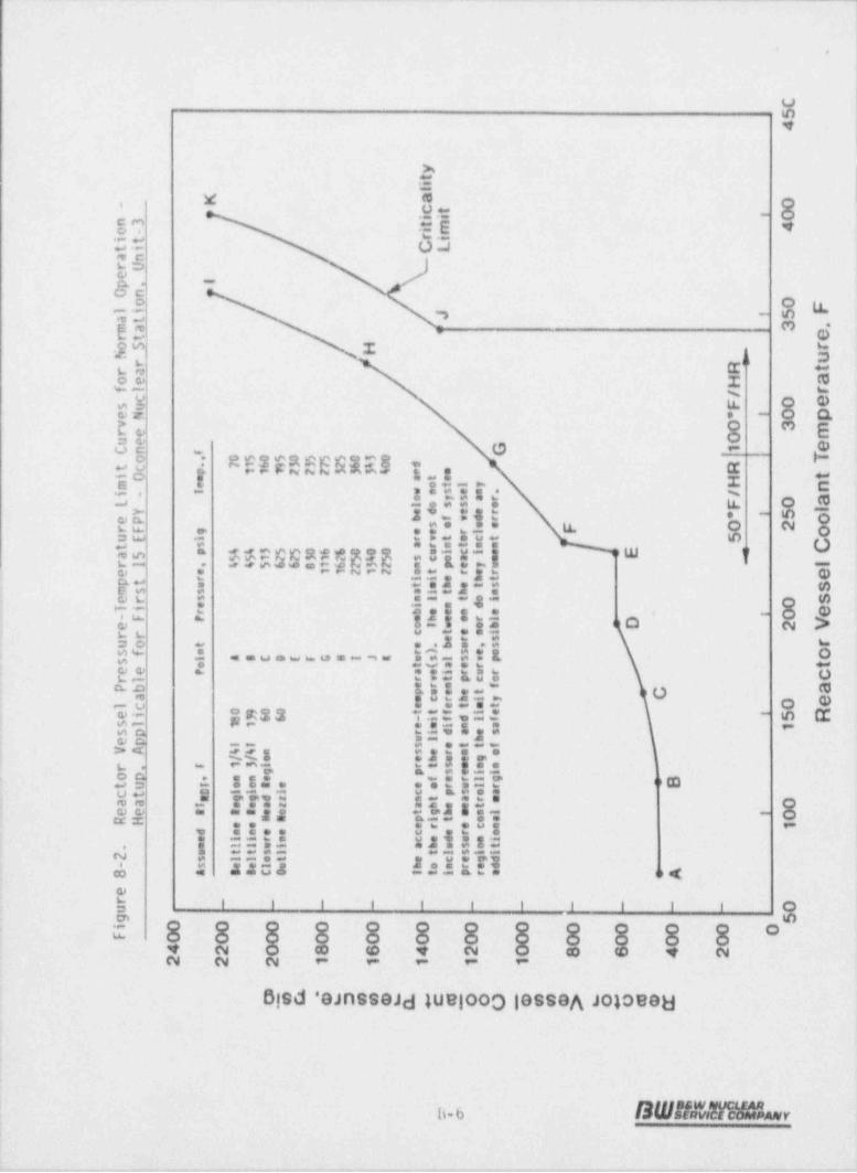
~ .
C54
yti
l
K a 0- Ct 0'iin3 im 4to -
rii t CLtianrUe
Ip .On
o 0 Fl i 5J 'at
rt'
3 .ma eoS H rN urra R t
oe H afl r/csu F 0 e
0 peN * '_
v 0 3 mre 0ue1 eF, GCn
05c50555030 To71633 7264 0 d
p 1172723334 e . R.t ciO m mt e tH nm e et I yi - T wss ' n . /l l os5 e F 0 ao y5 ar
lY ed " er 5 o* 'd reP b f
so ee F O 2rF g ee ' l oSuE i r rt ' ct Ct s at n'n n
%4355W66000 si 'i epa5 $5122 1 254 5 seo"yu er1 , %4566B 6232 n p l
e e 11212 ot e'ht eerr ilpt su t eh ' t s
_ ms s ait " an'd 0 ser s nl ol_ e i
Ti 0 e __ r b ee* e . 'F P mb e*rl_ e oi w eb 2 Vrr c t ' si_
se " e,s ruo t e . b_
' o o_ sf a r)l A8t9EFcNI JE usl 5 v ps t"ra t( a. ee P a ei er crl r vt Pco aPb er n f. p ue'ta ecr"i y
l c e e'mt 0 e.
_ ei 0900 t tf i e ' 5 R8 366 - if *l fsl 1 1 emi* a 1
_sp rid *esep ul h
e r ''e t f1 1 sVA 44 n s o//o eh u'g
.
f 13i rt s ' na. r . g p s 'li i. op , sne f_ge'l _ Bt u I oes e eor ' r
ct C l i l c p' eee '' t sn g gd z nt r 0. aa i eeez ahee R tR eo t gh " sl ' 0RH nn pit oa
ee e r 'cn 1d nn.e e e'sio. n C ed 5'e ii
r. i. e l l 'tlh e ot5l im t t sl2 s ll et ' c'edgd- s eel e * oa "ra8 A BBcD 3 tl __
er - _ - - - - - - - - 0 -ug 50 0 0 0 0 0 0 0 0 0 0 Oi
_
F 0 0 0 0 0 0 0 0 0 0 04 2 0 8 6 4 2 0 8 4 2_
2 2 2 1 1 1 1 1_
3C gg .GyeeS $g3OQ 3ee $ uO E.
.
_._T # DO '_
_
_
, i ;| :{i ,!' - , i- ; ii i ,'

.
Figure 8-3. Reactor Vessel Pressure-Temperature Limit Curves for Normal Operation - -
Cooldown. Applicable for First 15 EFPY - Oconee Nuclear Station. Unit-3
2400Assomed ITRDg,I Foint Pressere, psig feep., f
F2200 seitti.e aegie. 1/51 is0 a 435 70Beltline Beglen 3/5T 139 3 W) 150Closure need Regles 60 C 75 5 725o.tline sente 60 e 1555 rso Eg 2000
E 2040 320#
I 7250 370g1800-
g Ibe acceptable pressure-teeperature coebinations are below and is theright of the llelt curve (s). The lielt cerves da set laclude sheb
U pressere differential between the peint of system pressereg 1600 ee.s.reseet e.d the pressere e. the reacter eesset re,ien co.tretti.,g the llelt curve, ser da they laclade any ad(Itional margin of safety'r for possible instrosent errar.1 1400 -4,g DW3 1200 -
oO
1000 -_
eMee 800 -
> Cu
3 600 -O
N W Cool-down Design Basiseg 400 - j B 570 to 280F - SOF steps /3On in. hold
I 280 to 150F - 25F steps /30 min. hold150 to 70F - 10F steps /60 min. hold
_
' ' ' ' ' 'O5 50 100 150 200 250 300 350 400
Reactor Vessel Coolant Temperature. F
L---__... . . . _ . . . . . .- - - - .
-- ... - -.---- - - -- . - - - -- - - .- -. -
- -

__ -._- -- .
:
1
1~
{'
.
i !
Figure 8-4. Reactor Vessel Pressure-Temperature Limit Curves for Inservice leak and i
Hydrostatic Tests. Applicable for First 15 EFPY - Oconee Nuclear Station. Unit-3r
;
2600Assomed Eigg, I Penst - Pressure, psig f rep., f
_
O Beltline Region 1/41 18 0 A 577 70 I
e_ 2200 - settline aegies 3/41 1 39 597 150-
,
a Closure need Beglee 60 C 625 160 ',
'''II" '''''' '' ' '25 #"5!d 2000
E 910 210 ;u"3 T 1221 250 :
# 1800 - G 1751 500 I". R 2500 J43 G,
!CL 1600 The acceptance pressure-teeperature combientions are helev and-- to the'right of the limit curve (s). The lieit curves de est ,
c7 1400 - teclude the pressure differesties netween the point er syste. -
.3 pressere seasureseet and the pressere on the reactor vessel ;c3- O regles controlling the lleit curve, nor de they lectede any
O 1200 - addities 1 argie of safety for possible lestr=eeat errer. F- ,
O.
'i5 1000 -
em- E
800 --
.$,
I E 600 -; H - Design Basis Rates
: 'o A B C D % , _, c,,, ,
! 8 400 - 70 to 280F - SOF/ Hour! ei E 280 to 570F - 100F/ Hour
n;) 200 -:i
E| %.
' ' ' ' ' 'O50 100 150 200 .250 300 350 400
|Reactor Vessel Coolant Temperature. F
.
; ,t
| i*
.
*
, , , . -__. _. . -

_.---.- - - .. -.. . __ _ - . - . - - - - - _ _ . - - - . .
i.
'
.,
,
t
i
e
9. SUMMARY OF RESULTS
The analysis of the reactor vessel material contained in the third surveillancecapsule, OCill-D, removed for evaluation as part of the Duke Power Company,Oconee Nuclear Station Unit 3, Reactor Vessel Surveillance Program, led to thefollowing cnnelusions:
1. The capsule received an average fast fluence of 1.45 x 10"' n/cm' (E >
location at the end of the eleventh fuel cycle is '2.18 x 10'' n/cm' /4(E1.0 MeV) . The predicted fast fluence for the reactor vessel'T
> 1 MeV).
2. The fast fluence of 1.45 x 10'' n/cm2 (E > 1 MeV) increased the RTof the capsule reactor vessel core region shell materials a maximum Of-N
140F,
3. Based on the calculated fast flux at the vessel wall, an 80% capacityfactor and the planned fuel management, the projected fast fluence thatthe Oconee Unit-3 reactor pressure vessel inside surface will receive
2in 32 EFPY operation is 9.49 x -10'' n/cm (E > 1 MeV).
4. The increase in the RT for the shell forging material was~ not ingood agreement with thakDfredicted by the currently used design curvesof RT versus fluence .(i.e., R.G.1.99/Rev. 2).-
NDT
5. The increase in the RT for the weld metal was significantly _lessthan that predicted by tNeurrently used design curves of RT versusfluence (i.e., R.G.1.99/Rev. 2), however, the prediction Mhniquesare conservative.
The RT[N E0L fluence values and are below the PTS screening criteria.values decreased for 32 EFPY because of a decrease in the6.
estima
7. The current techniques (i.e., Regulatory Guide 1.99, Revision 2) used 6
to predict ~ the change in weld metal Charpy upper-shelf properties-dueto irradiation are conservative.
8, The analysis of the neutron dosimeters demonstrated'that the analyticaltechniques used to predict the neutron flux and f_luence were- accurate..
,
9-1
SW5iMMAL,

.
9. The capsule design operating temperature may have been exceeded duringoperating transients but not 'qr times and temperatures that would makethe capsule data unusable. ihe response of the surveillance capsulewas representative of the conditions to which the reactor vesselexperienced.
9-2
SW!/44faf4 =r

_..._..m_.- . . _ _ _ _ _ _ . _ _ _.__ _ . _.__ __._ _ . -. _ _
,
!
| ..
;
I
!
!
|1
!10. SURVEILLANCE CAPSULE REMOVAL SCHEDULE !
!
!
| Based on the postirradiation test results of capsule OCl!! 0, the following ;
schedule is recommended for examination of the remaining capsules in the Oconee !'
Unit 3 RVSP:
Evaluation Schedule ("I
Estimated Vessel t
Estimated ca EOL Fluence, n/cm'Estimated Datt )
'
CapsuleFluence, 10"' psulen/cm''Surfece 1/4T
0Data Available\ iID
|
OCIII C"' O.86- 8.lE18 4.5E18 St'andby'
OC l l i - E"' -1.60 8.lE18 4.5E18 Standby
OC l l l- F"' l.60 8.lE18 4.5E18 Standby |
.!
(a)ln accordance with BAW-10006A and ASTM E185 82 as modified by BAWil543A, fRev. 3. t
(b) Estimated date based on 0.8 plant capacity factor.
(c) Capsules designated as standbys and wil'l not be evaluated when removed.,
.
'
,
,
t
.
10-1-
BY M
1

i
I4
|
11. CERTiflCAT1014!|
The specimens were tested, and the data obtained from Duke Power Company OconeeNuclear Station Unit 3 reactor vessel surveillance Capsule 0Cill-D wereevaluated using accepted techniques and established standard methods andprocedures in accordance with the requirements of 10CFR50, Appendixes G and H.
f .. 3 P6 8/fr|W/~
'A. L. Lowe, Jr., P(E. / DateProject Technical Manager
This report has been reviewed for technical content and accuracy.
-D.O , i[ d/d/Y/ -
H. J. Devan.(Material Properties) DateM&SA Unit
t ) .h. kAhd k/d|'ilN. L. Snidow (fluence Analysis) DatePerformance Analysis Unit'
/,$.D W S//fo/ffK. R. Yoon, N.E. (Fracture Analysis) DateH&SA Unit
Verification of independent review.
' / ;)C ;/$f C64./ &'
'K. E. Moore, Manager -Si/s,,/
DateM&SA Unit-
This report has been approved-for release.
?/ A& P/T. L. Baldwin DateProgram Manager
.11 1
DWit481 MAR =v

_ _ _ _ _ _ _ _ _ - _ _ _ _ _ _ _ _ _ _ --
0 4
Revision 1
The revisions to this report were made as stated in accordance with the standardmethods and procedures for the original report.
1 f)) 1
e ,% N ,5 |ArYWY|NZA~. 'L Lowe, Jr. /- ' DateProjectTechnicalMana(ger
.
Revisions have been reviewed for technical content and accuracy.
I !/2 '92NM /M. J. Dedn (Material Properties DateM&SA Unit-
# r.3!9JLt/H nL. Petrusha (fluence Analysis) I ~/- Date
. Performance Analysis Unit)
Y WI2/92-K. K. Y n P.E. (Fracture Analysis) DateM&SA Un
Verification of independent review.
$$bD ' 642-Q%K. E. Moore, Manager DiteM&SA Unit
This report approved for release.
W 6"b.9 .L1..L. Baldwin DateProgram Manager
11-2
SWBNNhv
. . ...
. - _ _ _ - - _ _ _
_ _ _ . _ _ . _ _ . .
U
.,
APPDlDIX A
Reactor Vessel Survei_llance ProgramBackground Data and information
,
A-1
SW!!bnFe%
_x........ .- - - - - -a
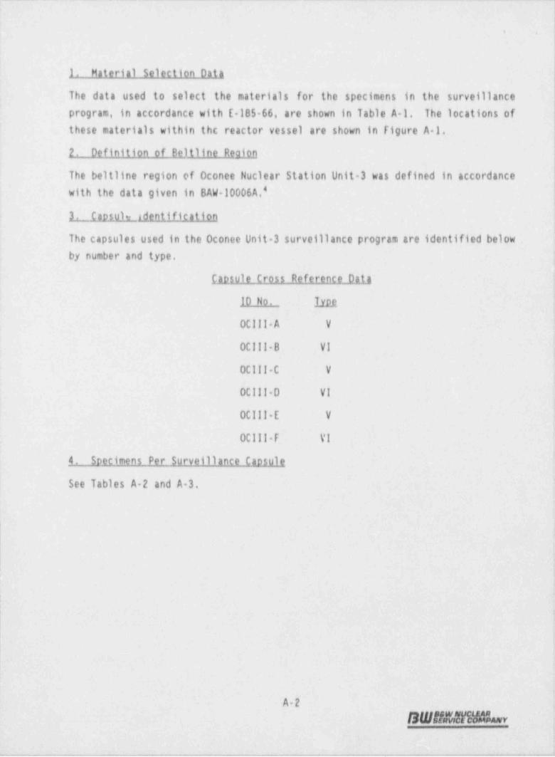
-. ..-. - -. ..-.. - _ .-. - - - . - . - . - . ~ - - . . - . - - - . ... . . .-.
|
. .
1. Material Selection Data
The data used to select the materials for the specimens in the surveillance'
program, in accordance with E-185 66, are shown in Table A 1. The locations of"
these materials within the reactor vessel are shown in figure A 1.I
2. Definition of Beltline Reaion i
l
The beltline region of Oconee Nuclear Station Unit 3 was defined in accordance !
with the data given in BAW-10006A.'
3. Caosule identification .
,
'
The capsules used in the Oconee Unit +3 surveillance program are identified below,
by number and type.
Caosule Cross- Reference Data
10 No. lyM '
OClll- A : V
00111 8 VI q
OCIII C V.
>
0C111-0 VI-
OClli-E V
;OCill-F VI-
4. Specimens Per Surveillance Caosule.
See Tables- A 2 and A-3.
,
8
!
>
A-2 ,
S W 5 M rli h r1.
'
, .+a.n,--- ,vae,,,-- ,,,,,,,-,.,,n., ,. ,. - ,, ,.,,,,.-J,,-m.,.,..n,._., ..,.-,,,-,._,,.,,,,.gA--, .,,,,.,.,,.,.,-+,,-,,,>y.
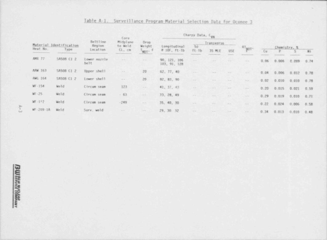
. _ _ _ _ _ _ _ _ -_
l.
Table A-1. Surveillance Program Material Selection Data for Oconee 3 -
Charry Data, Cp
Beltilne Midplane Drop TranJverseMaleria_1_id nt_tf_igal_f_qr! Region to Weld Weight longitudinal ._50 ET Ch p istry. %t iHeat No. Type location CL, cm TET, F 9 10F, ft-lb ft-lb 35 MtE USE bT. Cu P 5 Ni
AMX 77 5A508 C1 2 Lowr nortle -- -- 90, 121, 106 - -- -- -- 0.06 0.006 C.009 0.74belt 103, 91, 128
AAW 163 SA508 C1 2 Upper shell -- 20 62, 77, 40 - - - -- -- -- 0.04 0.006 0.012 0.78AWG 164 5A503 C1 2 Lower shell -- 20 82, 83, 90 -- -- -- -- 0.02 0.010 0.010 0.78WF-154 Weld Circum seam 123 -- 41, 37, 43 -- -- -- -- 0.20 0.015 0.021 0.59WF-25 Weld Circum seam - 63 -- 33, 28, 49 -- -- -- -- 0.29 0.019 0.010 0.71
WF-182 Weld Clrtum seam -249 -- 35. 40, 30 -- -- -- -- 0.22 0.024 0.006 0.58>L Wr-209-1A Weld Surv. weld -- -- 29, 30. 32 -- -- -- -- 0.34 0.013 0.010 0.48
.,
GBsER*
4-

. .
Table A 2. Materials and Specimens in Upper SurveillanceCaosules OClll A. 00111-C. and OClli-E
Number of SoecimensMaterial Description Tension Charov
Weld metal, WF 209-1 2 12
Heat affected zone (HAZ)
Heat A ANK 191, longitudinal 0 12(
Baseline material
Heat A - ANK-191, longitudinal 0 9Heat A - ANK 191, transverse 2 12Heat B - AWS 192, transverse Q t
Total per capsule 4 54
Table A 3. Materials and Specimens in Lower SurveillanceCaosules 0C111 B. 0C111 0. and OClli-F
Nismber of SpecimensMaterial-Descriotion Tension [hnny
Weld metal,- WF 209-1 -2 12.
'd, HAZ
Heat A - ANK-191, longitudinal 0 12Heat B - AWS-192, longitudinal 0 6
Baseline material - -
Heat A - ANK 191, transverse 2 12Heat B - AWS-192, transverse 0- 6
Correlation HSST plate 02- Q 1
Total per capsule 4 54
A-4
SWhy
O__ -_ - - - - = = - - - - - -
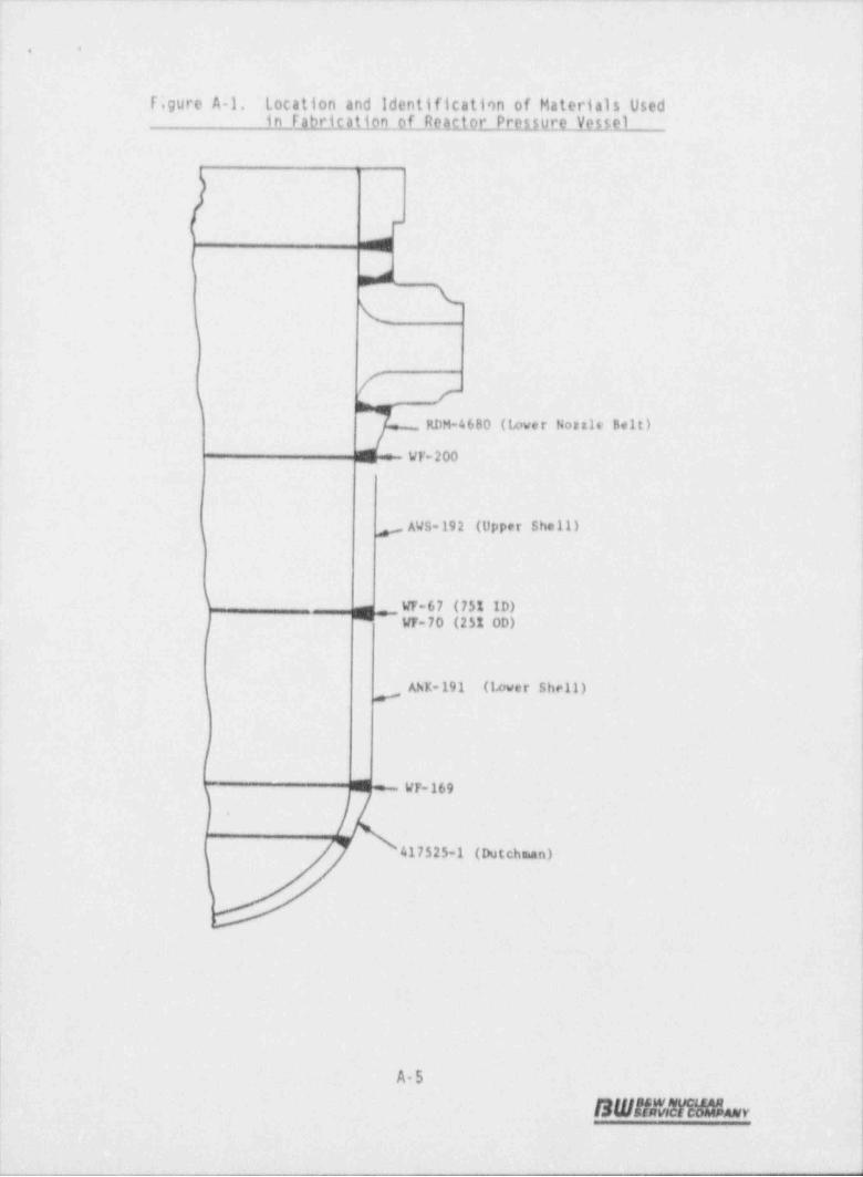
__ . _ _ . . _ _ . . . . __ ._ . -- _ , _ . .-_ . . . . _ .
..
f;gure A-1. Location and identification of Materials Usedin Fabrication of Reactor Pressure Vessel
1- I
m
|'
&\(
t .,
ry
RDH-4680 (Lower Nortle Belt)
_ : WF- 200
AVS-192 (Upper Shell)g
g_ W-67 (75% ID)-
_| W 70 (25% OD)
AhK-191 (lever Shell)
I
4WF-169
i )1. 417525-1 (Dutchman)
)
>
A5
SWAWN9 h r.|!

1.,
b
;
APPENDIX B<
Pre-Irradiation Tensile Data
B.1
BW!!K We % r
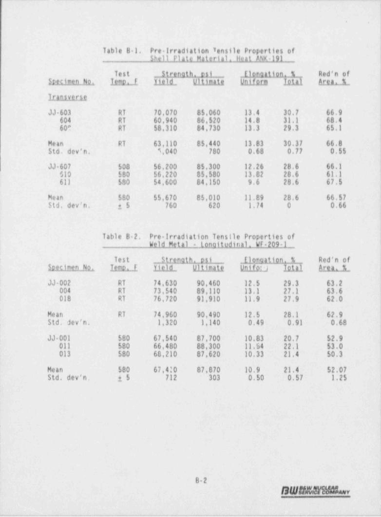
. .
Table B 1. Pre trradiation Tensile Properties ofShell Plate Material llent ANK-191
Test Strenath. osi Elonaation. % Red'n ofSpecimen No. Temo. F Yield. Ultimate Uniform lotal attam_1_
Transverse
JJ 603 RT 70,070 85,060 13.4 30.7 66.9604 RT 60,940 86.520 14.8 31.1 68.4600 RT 58,310 84,730 13.3 29.3 65.1
Hean RT 63,110 85,440 13.83 30.37 66.8Std. dev'n. 5,040 780 0.68 0.77 0.55
JJ 607 508 56.200 85,300 12.26 28.6 66.1S10 580 56,220 85,580 13.82 28.6 61.1611 580 54,600 84,150 9.6 28.6 67.5
Hean 580 55,670 85,010 11.89 28.6 66.57Std. dev'n. 5 700 620 1.74 0 0.66
Table B 2. Pre-trradiation Tensile Properties ofWeld Metal .Lonoitudinal . WF-209-1
Test Strenath, osi Elonaation. % Red'n of-
Specimen _th Temo. F Yield Ultimate 1)ltilplJ 191]t1 Area. %
JJ-002 RT 74,630 90,460 12.5 29.3 63.2004 RT 73,540 89,110 13.1 27.1 63.6018 R1 76,720 91,910 11.9 27.9 62.0
Mean RT 74,960 90,490 12.5 28.1 62.9Std. dev'n. 1,320 1,140 0.49 0.91 0.68
JJ 001 580 67,540 87,700 10.83 20.7 52.9011 580 66,480 88,300 11.54 22.1 53.0013 580 68,210 87,620 10.33 21.4 50.3
Mean 580 67,410 87,870 10.9 21.4 52.07Std. dev'n. 15 712 303 0.50 0.57 1.25
i
B-2
BWltKMW

_ _ _ _ _ _ _ - _ _ _ _ _-
..
1
.
APPENDIX C
Pre-Irradiation Charpy Impact Data
,
.
C-1
BW!! nan"o Lur
. ...
.
. . . . . .. . .
___m____.___ __.J

_ _ __-___ ___ __ ._ _ -_ - _ _ _ _ - _ _ _ _ - _ - _ .
_
-__
. . -,
Table C-1. Pre-Irradiation Charpy Impact Data forLShell Forging-
Material - Transverse Orientation. Heat ANK-191
-Asborbed Lateral;. ShearSpecimen: Test Temp., Energy, Expagsion, Fracture,
No, - F ft-lb 10 in, %
JJ-651 362 172 -75- 100-640 361 144= 66- 100621: 357 128- 72 100
JJ-701 284 136 73 100705 283 140 73 100700 277 135 71 100
JJ-635- 200- 150 - 71 - 100625 200 153 .67 100637 200 141 73. 100.
JJ-704 140 130 74 88-703 140. 126- 74 85702 140 118 71 70
JJ-676 80 123- 71 55611 79 130 78 65-
657 79 :129 74- 60
JJ-670 41 77 62 5685 41- 71- 58 4-612 41 86 66 10 .,--
JJ-708 25 68 55 5706 24 -74: 62 -- 10707 ~28 57 46 8-
75 21- 58: 48- 6>
43 20- 47 41- 4
JJ 22 0.9 35 26 1 --
'2 - 0.9 56 44-- - 2. 1
580 0.5 18 15- 0;
JJ-698 -39 3 2 -0697- -40 8 8 0-699 -41- :14 12 0
C-2 ,
S W BlW!l11ML y: U
a- _ _ - - - - -
-
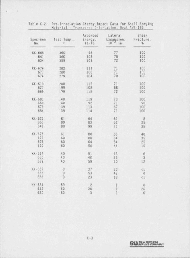
.. _- _ _. . . - . _ _ _ . _ _ _ . _ . . . _ _ . . _ _ _
i
,. .
- . |
Table C-2. Pre Irradiation Charpy Impact Data forIShell forging ,
Material - Transverse Orientation. Heat AWS-192
Asborbed lateral Shear .
Specimen Test Temp.,- Energy, Expagsion, fracture, '
No. F ft-lb _10 in. %-
KK-665 360- 98 77 .100=641 360 103 70 100634 359 109 72 100-
111 71 100KK-676 282 +
677 280 106 71- 100674 279 104 70 100- r
KK-619 200 115 71 100627 199 108 68 100669 199 115- 72 100
KK-683 140 119 73 100659 140 92 -71 - 90
'
679 139 113 67 -100684 139 114 71 100
KK-622 81- 64 51 ;8651 80 83 62 -- 2 5
648 80 99 71 35
KK-675 61 80 65 40*
673 60 80 64 35'
678 60 64 54 25610 60 50 44 15.
KK 614 40 51 43 6-630 40 40 36 3-639 40- 59 50' 12~
KK-657 0 37 30 <1633 0 53 42 4666 0 23 18 <1
KK-681 -59 2- - 1- 0-682 -60 30 1 -26 J680 -60 3 2' O
C-3
S W J E M M H & n y-.
-
_ _ . . _ _ . . . . . . _ .

...
. .
. . _ . _
.
.. .
Table C-3, Pre-Irradiation Charpy Impact Datt for Shell Forging-Material - HAZ Transverse Orientation. Heat ANK-191
-Asborbed . Lateral ShearSpecimen Test' Temp.,- Energy. Expagston, Fracture,
No.= F -ft-lb 10 in. %-. ..
JJ-313 360 86 53 100315- 359 -106 63 100335 358 73 54 100
JJ-328 201- 102 54: 100323 201 92 59 100308 -200- 83- 49 100
JJ-322 80 76' 42 -85-319 80- 98 51 100344 80 74 45 80-
JJ-357 40. 66- 44 85-332 40- 57 33 45
'
339 40 55' 30- 55
JJ-301- 20 46 29 70:304 .20 36 127- 30
JJ-331 0 35 29- 35324- 0 33 -26 23337- 0 47 ~33 13 5
JJ-424 -59 27 20 2420 -60 56 44 4-421 -61 67 35 ;6.
!
. . _
C+4 j- SW2f4171HORany j

. - .. .. -. - . . - - --- - . - - _ . . - . , . .. . -- ,.-
4 ;-!. . .
:;
' . Table C 4.- Pre-Irradiation Charpy_ Impact Data-for Shell Forging-,
i Material HA7. Transverse Orientation. Heat AWS-192 -|-
|.
i- Asborbed Lateral- Shear I
i Specimen Test Temp., Energy, Expagsion, Fracture, !
No.- F~
ft-lb 10 in. _% u'
~ |
} KK'-325 361 135- 65. 100 :336 -360 153: 77 100:
| 318 358 128- 63 - 100'
l
KK-343 278. .118 76- -100-339 278 125 76. 100-.
-
i 344 277 132 76 100;
! KK-333 199 65 37 -100
|; 310 190 122 66 100313 197 78 53 100
3,
i KK-346 139 131 77 100-337 139 132 671 100.
'
348 139 121 71 100
! KK-312 80 91 46 943 307 79 76 41- '85| 335 79 63- 36 98 '
KK-308 40 141 67- 100-! 316 40 72 42 35
'
; 327 40 ~66. 40 45
3_ KK-341 20 93 70 40i- 340 20 104 77- ' 65-e 345 19 82 64 30-1
l' KK-317 0.5 106: 64 45-! 324 0.1 43 31 18-
326 0.1 ~43 32 40
KK-309 -40- 30 22 20j 330 -39 80 51 28-
>.
KK-342 -39 27 21 :2-
347 -40 52- 35 5--
338 -40- 38- 28 3-
:4
4
b '|
< u1
'
[ C-5
L SWB*amidbr ,
;
'|
, .. ,. - - . . - . , . . . - - - - -. ._ - , , ,..,..-.,-..a,

_ _ _ _ __ _- _ _ _
. .
I?ble C-5. Pre-Irradiation Charov Imonet Data for Weld Metal WF-209-11
Asborbed lateral . Shear.Specimen Test Temp., Energy, Expayston, Fracture,
No.-
F .ft-lb 10 in. .%
JJ-063 359 -57 49 100-083~ 357 58: 48 100-089- 357- 65 53 100
JJ 091 201 57 46- 100053 201 '63 50 100084 199 78 57 100
JJ-093. 140 60. 46 100060 2140- 69 52- 1100065 140 61 49 100
JJ-092 110 64- 46 30'
038 110 58 46. 100-077 109 47 37 96-
JJ-064 80 61- 40 98-095 80 38 32 95081 79 48 35 85
JJ-090 40 28 28 10069 40 33 -29 15=07 5- 40 21 20 12
JJ 061 -40- 17 16 5-050. -40 16 14 -2057 -39 19 18 6
i
|
C-6
S W B N!r M L ev
.. ..
.. _ _ _ - -_ -

- , . =. . ..
:.
..
5
1
Figure C-1. Charpy impact Data _From Unitradiated Shell Forgingj Material (ANK-1911. Transverse Orientation
E ;i :. i . i;
n4 75 - -, ,
5,4
@ 50- -
!
; ,{ 25 - -
a e e e e en
0.10 i i i i , i
$4 g 0.05 - -
- o e e .1i e s e-
f0.06* --,
1 ~
i 5 0.04 *e-
t-
-
34
'
c 0.02 - -
2 e
{ g - e i t I e e
i 220 i i i i i i--- DATA SumARY --
200 -T +20r -g,
Tgy (35 met) +st
180 -Tcy (50 rt-La) +1?F -
Tgy (30 FT-ta) -9F '<
'
o lE0 ~C -USE (Avr,) ikk ft-lbf -
y
RT +20r I
. 140 - ot,
.- -
Is 8; ; I $ e5 120 - -
,
Q4
g 100 - .
| Cz
% - --,
E o"
. sc -
1 e'
e40 -- -
MATERI AL ' S A500,tt.2(IL) -
20 -
e Ftuence NONE -
oHEAT No, ' ANK-191
a 1 i t t , ,
100 0 100 200 300 400 500 600Test Temperature, F
C-7
SW#N&v -
, _ . - . .

. .
Figure C-2. Charpy Impact' Data from Unirradiated Shell ForgingMaterial (AWS-192). Transverse Orientation
10c :- ; :, :, , , ,o
"75 - -
Jw
.f 50- -
e/om
~z 2se e- -
d, , , , ,0 ;
,
0,10 , , , , , i
$
5060 - -,
* * * 0 ieR 0.06 -
g e e-
: e* *
0.04 -
,-
2= 0.01 -
, -
;a:
0 -
' ' ' ' ''
220 . i i , i i- DATA SUMMARY -
+20r -200 -T,37
Tgy (35 mug) 19 r
180 -T (50 ri- a) +37r -
T,y (30 FT ts) 4f160e C -USE (Avo) 112 ft-lbf -
ya
140 -RT" '+?0i~
8-
:
|M - e -,
'S e ,*
a 100 e ;--
E *-
80 - e- -
@u
| ~ 60 - e -
*
* e40 - e -
e MAign AL. $A508.Cl.2 (IL)20 *
Ftuencg NONE-
-
HEAT No. AWS-192' ' ' '0 ' '
-100 0 100 , 200 300 400 500 600Test Temperature, F
C-8
B Wit &5"cW h y
. .- .

. _ - - _ __
'.
..
J
'i
i Figure C-3. Charpy Impact Data from Unirradiated Shell Forging Material(ANK-191) Heat-Affected Zone. Lonoitudinal Orientation
| * i i i i:_.
*4
75 -
,g -
E*
sM' - -,~
1
~ eE 25 *
- -
:| M
' ' ' ' ' '0l9
1 0.10i e i i i i
, d.
g 0.08 - -
Oi
k0.06 *- o -
* *0.04' - - t,
e_e,'
5 0.02 - -
!
]' ' ' ' ' ' 'O --
220 . . i e i i- DATA SumARY -
j 200 - T,3, -+20f
Tcy (35 m.t) .t?r
180 -T (50 FT-ts) + 32r -
y
; icy (30 ri-La) -torIE0g g.USE (Avn) 90 f t-hf -
,
i_ RT,7 +20F, 10 - -
| 8:,
gm -a -
$4 ,g 100 -e-
, -.
se :>
I g --se,g -.
| I e* *- g _
_
e
-i. e% - .
eMatta:AL S A508,Cl.2 (HAl)
20 FLugnet NONE --
HEAT No. A N K-191' ' ' '0 ' '
-100 0 100- , 200 300. 400 500 600,
Test- Temperature, F
C-9
BWs*tamv
.

- -. _.
. .
Figure C-4. Charpy impact Data from Unirradiated Shell Forg'ing Material( AWS-192) Heat-Affected Zone. Lonoitudinal Orientation
100 :-
: i ;, ;, , , ,
*w:s - -;
*.t.iy 50 - -
2,
-*-
. .E 75 - -
5 e e
i I e i t 1g
0.10 , , , , , ,
$g0.08
- -, , , ,. e
-k0.06 ** I --
O e ee
I *{0,04 -
, , -
3 ec 0.02 - 8 -
4=
' ' ' ' '' '0
220 . . i i i- DATA SumARY -
+20r200 - T,37 .
-WICV ( 5 met)
180 -T m pr. W -W -
Cy
Tcy (30 FT-La) '%f-
160g C -USE (ava) 114 ft-lbf -
y*
~, 140 -RT" *+20Fa* -
8 g- . *= *
120 o *~ -,
Eg 100 - e'
-
y e e
2 80 e *- -, ,
-g .. . ._ , _ _
o'W . .
g $7:niat S AS06,Ct.2 (HAl)-20 FLUENct NONE- -
HEAT No. ._Ayt-19 2-
' ' ' ' ' '0-100 0 100 , 200- 300 400 500 600
Test Temperature, F
C-10
SW#Ahv

. _ _ _ _ - _ , _ _ _ _ _ _ ___
..
Fiaure C-5. Charov Impact Data From Unirradiated Weld Metal. WF-209-1
2 3 2 2100 - , ,
- , ,,
w15 - -,
t3y 50 - -
mt.
S 25 - -a
i t t t t tg
0.10 i i i , , i
$g 0.08 - -
2m
kD.06 -, -
a 2e L
3 e-
0.04 - e -,
,3
s 0.02 - p. -.Ea
' ' ' ' ' '0
IM , , , , , ,- DATA SumARY -
100 -T -
oy -
+81ITey (35 nt.t)90 T G n-ts) 6 -
ey
Tey (30 FT-ts) +45rg80s ~C -USE (avo) 66 ft-lbs -
y .
g lit -
o 70 -e,
, -
*o e eE % - $ -
!. e 5o
E . 50 --
w e,
| ' 40 --
.?. *e
30 --
20 - e -
MATERIAL Veld Metal-llnde 8010 -
FLutset None -
HEAT No. VF-209-10 ' ' ' I - '-100 0 100 - 200 300 400 500 600
Test Temperature, F
C-11
SW.'ts,1!mhv
_ - _ _ _ _ _ . .
..
APPENDIX D
Fluence Analysis Methodology
D-1
S Ws?sifauiimv
_

.
. .
1. Analytical Method
A semiempirical method .is used to calculate the capsule and vessel flux. The
method employs explicit modeling of the reactor vessel and internals.and uses anaverage core power distribution in the discrete ordinates transport code DOTIV,.
_
version 4.3. 00TIV calculates-the energy-and space dependent neutron flux''forthe specific _ reactor under consideration. This semiempirical method is conven-iently outlined in Figures D-1 (capsule ' flux)- and D 2 (vessel flux).
The two-dimensional transport code DOTIV was used to calculate the erergy- andspace-dependent neutron flux at all points of interest in the reactor system.DOTIV uses the discrete ordinates method of solution of the Boltzmann transpor.tequation and has multi-group and asymmetric-scattering capability. The referencecalculational model is an R-e geometric representation of a plan view through the
reactor core midplane which includes the core, core liner, coolant, core barrel,~
thermal shield, pressure vessel, and concrete. The material _ and geometry model',represented in Figure D-3, uses one-eight core symmetry. In order to includereasonable geometrie detail within the computer memory limitations, the codeparameters are specified as P order of sr.attering, Se quadrature, and 22 energy _3 -
groups. The P order of scattering adequately describes .the predominately3
forward scattering of neutrons observed-in the deep penetration of steel and !
water media, as demonstrated by the close agreement between measured andcalculated dosimeter activities. The Se symmetric quadrature has generally
produced accurate 'results in discrete ordinates solutions for similar problems,;-
and is used routinely in the B&W R-e DOT analyses.
Flux generation 'in the core was represented by a fixed; distributed source which235the -code derives based on a 0-fission spectrum, the input relative power
distribution, and a normalization _ factor to adjust : flux level- to the desired 1
power density.
Geometrical Confiouration
- For modeling purposes, the actual geometrical configuration is divided into three-_ parts, as shown in Figure D-3. The first -part, Model "A," is used to generate-.'the energy-dependent - angular flux. at the inner boundary 'of Model "B," whichbegins at the- outer surface of the core barrel, Model A includes a detailed
|
|!
|' D-2
SW."fMiMLvv
., . . . . - , , . - , , .- - .-_-s - _. , . . _ _ -.
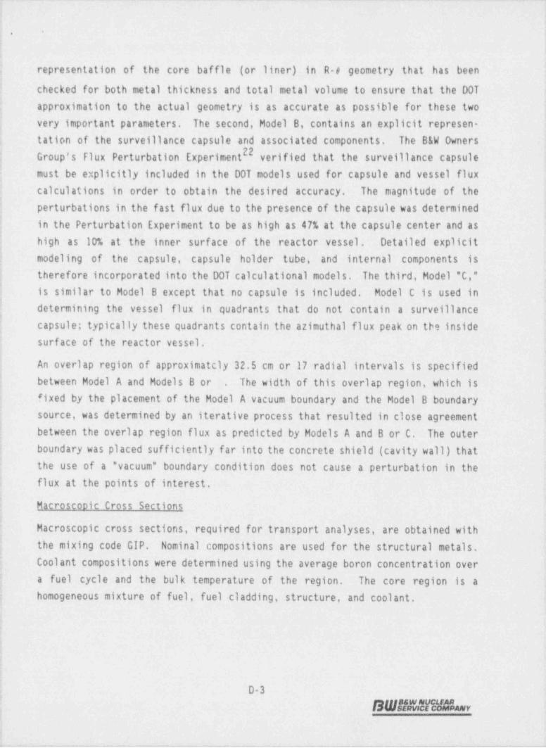
..
; representation of the core baffle (or liner) in R-e geometry that has been! checked for both metal thickness and total metal volume to ensure that the DOT
approximation to the actual geometry is as accurate as possible for these twovery important parameters. The second, Model B, contains an explicit represen-tation of the surveillance capsule and associated components. The B&W Owners
22; Group's Flux Perturbation Experiment verified that the surveillance capsule>
must be explicitly included in the DOT models used for capsule and vessel fluxcalculations in order to obtain the desired accuracy. The magnitude of theperturbations in the fast flux due to the presence of the capsule was determinedin the Perturbation Experiment to be as high as 47% at the capsule center and ashigh as 10% at the inner surface of the reactor vessel. Detailed explicit
modeling of the capsule, capsule holder tube, and internal components istherefore incorporated into the DOT calculational models. The third, Model "C,"is similar to Model B except that no capsule is included. Model C is used indetermining the vessel flux in quadrants that do not contain a surveillancecapsule; typically these quadrants contain the azimuthal flux peak on the insidesurface of the reactor vessel.
An overlap region of approximatcly 32.5 cm or 17 radial intervals is specifiedbetween Model A and Models B or The width of this overlap region, which is.
fixed by the placement of the Model A vacuum boundary and the Model B boundary
source, was determined by an iterative process that resulted in close agreement'
between the overlap region flux as predicted by Models A and B or C. The outerboundary was placed sufficiently far into the concrete shield (cavity wall) thatthe use of a " vacuum" boundary condition does not cause a perturbation in theflux at the points of interest.
Macroscopic Cross Sections
Macroscopic cross sections, required for transport analyses, are obtained withthe mixing code GIP. Nominal compositions are used for the structural . metals.Coolant compositions were determined using the average boron concentration overa fuel cycle and the bulk temperature of the region. The core region is a-homogeneous mixture of fuel, fuel cladding, structure, and coolant.
D3B W i|E M ale % r

- _ - - _ _ _ _ _ _ _ _ _ - _ __
..
The cross-section library presently used is the (22-neutron group and 18-gammagroup) CASK 23E coupled set.- The dosimeter reaction cross sections are based onthe ENDF/B5 library, and are listed in Table E-3. The measured and calculateddosimeters activities are compared in' Table D-1.
Distribute'd Source
The neutron population in the core during full | power operation is a function ofneutron energy, space, and time. The time dependence is accounted for in the-analysis by calculating' the - time-weighted average _ neutron source, i.e. the
neutron source corresponding'to the_ time-weighted average power distribution.The. effects of -the other two independent variables, energy and- space, areaccounted- for by usir.g a finite but appropriately large number of discreteintervals in energy and space. In each of these intervals the neutron source isassumed to be invariant and independent of all other variables.: lhe space andenergy dependent source function can be considered as the product of a discretelyexpressed " spatial function" and a magnitude coefficient, i.e.
Svg3g = [v/K Po] (RPDgX,]~ (D1)- - jx
magnitude spatial
where:
Svg3g Energy-and space-dependent neutron source, n/cc-sec,=
v/K Fissic neutron production rate, n/w-sec,-
Po Average power density in core, w/cc,-
RPDjj Relative power density at interval (i,j), unitiess,=
X, = . Fission spectrum,-- fraction of fission neutrons having energyin group "g,"
i Radial coordinate index,-
j Azimuthal coordinate index,=
- Energy _. group -_ i ndex.-g =;
The spatial dependence of the flux-is directly related to the RPD distrib'ution. I
Even though the entire-(eighth-core symmetric) RPD distribution is modeled in the
D-4
BWHLW18%

. _.- __ _ - . _ _ ~._ _ __ .- _. _
!
-;.
i
| analysis, only the peripheral fuel assemblies contribute significantly to the ex-_
| core flux. The axial average pin by-pin RPD distribution is calculated on a
; quarter-core symmetric basis for 8 to- 12 times -during each core -cycle for the4 entire capsule irradiation period. The time-weighted average RPD distribution
j is used to_ generate the normalized space and energy dependency of the neutronj source. Calculations for the energy and space dependent, time-averaged flux were-! performed for the midpoint of each DOT interval throughout the model.- Since the
; reference model calculation produced fluxes in the R-o plane that are averaged
; over the core height, an axial correction factor of 1.17 was required to adjustj these fluxes to the capsule elevation.:i 1.1. Capsule Flux and Fluence Calculation
ij As dist.issed above, the- DOTIV code was used to explicitly model the capsule
| assembly and to calculate the neutron flux as a function of energy within'the ..
| capsule. The calculated- fluxes were used in the following equation to' obtain-
calculated activities for comparison with the measured data. The calculated
| activity for reaction product 0,, in (pCi/gm) is:1
D, = Ea (E) 4(E)j EF, (1-e'*03) e W (T - ri) (0-2)'
o
| (3.7 x 10') An E -j,
where:
N - Avogadro's number,*
4 An - Atomic weight of target material n,
! f - Either weight fraction of target _ isotope in n-th material or thei
j fission yield of the desired-isotope,-
Io,(E) - Group-averaged cross sections for material n-(listed in Table;
; E-3)-
4(E) - Group averaged fluxes calculated by D0TIV analysis,,
;
| F -- Fraction-.of full power during j-th time interval, t,i_F; Ai = Decay constant of the ith isotope,1
.T - Sum of total. irradiation time, i.e., residual time in reactor,
i
e
i
D-5
BWifMin3 v,
.- - _. - -- - . . . - . -

. . ._ . - .- - . . . . . -
. .
and the wait time between reactor shutdown and counting-times',,
rj - Cumulative time.from reactor startup to end of j-th time period.-7
t - Length of the j-th time period3
Adjustments were made to the calculated dosimeter activities to correct for theeffects listed below:
'
Short half life adjustments to Ni and Fe dosimeter activities238 237Photofission adjustments to 0 and Np dosimeter act'ivities
238 ' dosimeter activitiesFissile impurity adjustments toL 0
After making these adjustments the calculated dosimeter activities were used withthe corresponding measured activities to obtain the flux normalization factors:
D, (measured)|C, = ,
D, (calculated).
These normalization factors were evaluated, averaged, and then used to adjust thecalculated _ test specimen flux,and fluence to be consistent with the dosimeter-measurements. Additionally, the norma'lization factor was used to--update the:average normalization factor which had been derived from previous analyses. Theupdated normalization factor was then used-to adjust the calculated vessel' fluxand fluence. The flux normalization -factors are given in Table. D-1. L
2. Vessel Fluence Extrapolation
For past core cycles, fluence: values in the pressure vessel are calculated asL described above. Extrapolation- to future cycles is . required to predict the
useful vessel life. Three time periods-are considered inithe extrapolation: 1)operation to date for which vessel fluence has been calculated, 2) future fuelcycles for which PDQ calculations have been performed, and 3) future cycles for
_
which_no analyses exist.
For the Oconee Unit 3. analysis, time period 1 is through cycle 11, time peri 6d2 covers cycles 12 and 13, and time period 3Jcovers from the end of cycle 13
_
through 32' EFPY. The flux and fluence 'for time period 2 was estimated- b;calculating the vessel flux using an adjoint-DOT calculational procedure with the'-appropriate assembly-average power distributions and _ integrating these values
D-6
SWMJtthy
L'
, _ .. _ ~, __ _ _ _ _
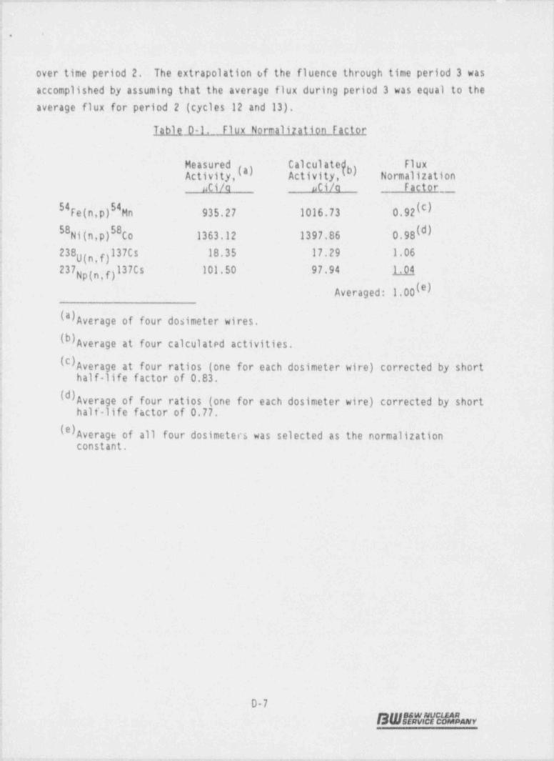
..
over time period 2. The extrapolation of the fluence through time period 3 wasaccomplished by assuming that the average flux during period 3 was equal to the'
average flux for period 2 (cycles 12 and 13), il
Table 0-1. Flux Normalization Factor,
Measured Calculated FluxActivity,I") Activity,(b) Normalization
*
uti/a uCi/a factor,
1
54Fe(n,p)S4Hn 935.27 1016.73 0.92(C)
: Ni(n,p)58Co 1363.12 1397.86 0.98(d)58
238 (n,f)l37Cs 18.35 17.29 1.06U
237Np(n,f)137Cs 101.50 97.94 1 14
Averaged: 1.00 ')I#
(8) Average of four dosimeter wires.<
(b) Average at four calculated activities.
(c) Average at four ratios (one for each dosimeter wire) corrected by short' half-life factor of 0.83.
(d) Average of four ratios (one for each dosimeter wire) corrected by shorthalf-life factor of 0.77.
.
(*) Average of all four dosimeters was selected as the normalization' constant.
D-7
BWs*t? vent %%m

i
|..
Table D-2. Oconee Unit 3 Reactor Vessel Fluence by Cycle
= ;
Vessel Fluence, n/cm Jc)incremental Cumulative Vessel lux, ,
Cycles Time, EFPY Time, EFPY ti/cm s : Incremental Cumulative
1 1.31 1.31 1.39E+10 '0,58E+18: 0.58E+18
2-5 2.79 4.10 1.55E+10 1.37E+18 1.94E+18,
6-11 6.56 10.66 9.49E+9 1.96E+18J 3.91E+18
12 1.12 11.78 8.92E+9 3.16E+17 4.23E+18
:12.91 -7.62E+9(*) 2.70E+17(b) 4.50E+18(b). ,13 1- -
2.09 15.00 8.27E+9(") 5. 47 E+ 1'7 ( b)-5.05E+18(b).
- ,
6.00 21.00 8.27E+9(a) 1.57E+18(b) 6.62E+18(b)_ ,
3.00 24.00 8.27E+9(a) 7.83E+17(b) 7.40E+18(b)f
8.00 32.00- 8.27E+9(a) 2.09E+18(b)- 9.49E+18(b)
(*)The fuel cycle designs for future cycles-12 and-13.were used to estimate themaximum neutron flux at the inside surface of reactor vessel.
(b) Extrapolated values. -'
(c) Peak fluence at inside surface of reactor vessel.
J
D8 ,
BWWJ!NLv.
, r - y <, g 9- ,- # r w 4 -.e-- , - ,- - - - -. - . - - ~-

.- .-
Figure D 1. Rationale for the Calculation of DosimeterActivities and Neutron Flux in the Capsule
-- -|DEF/84 0055 SECTIONS _ GEDETRY &'GMDRATUtE PGet DISTRI- 1DEF/85 00$DETUt RfAC- FUt KEE. A DDT OLffEN5 SDG 1
TUR 0055 SECTIONS .CAPSIAE INSER-TEN -(P00),
EIP y*
SGutEL +0105$ SECTIONS QEE
3 r
" TDE AVE DISTRI-GEDETRY &. DDT 4-- BUTED SOL 81CE SvmW3tATt5tE --+ KEEL A (E R, e )KDEL 8-
ir ir ir
DDT 4 #G1AR FIBKMDEL B c AT 845tEL
IPGet HIS15tyDOSDETER -(F CAPStLE
5 ACTIVITIES (PIDEST (IEE):
i
i: ir
'FINAL <
tCALOLATEDACTWITIES.
L a 1
EASWtED !>
(- 00SDETER iACTIVITIES !
AXIAL 1QIIRECTEM
FACTUt
u'
ir- ri
CAPS 11E FIDX | IGMALIZATEN FACTGt: M/C RATID
;
.'. |
|_ D-9
; SWEIMIPMLv
_. . _ . . . _. __ _. . _ _ . _ _ . . _ . . _ _
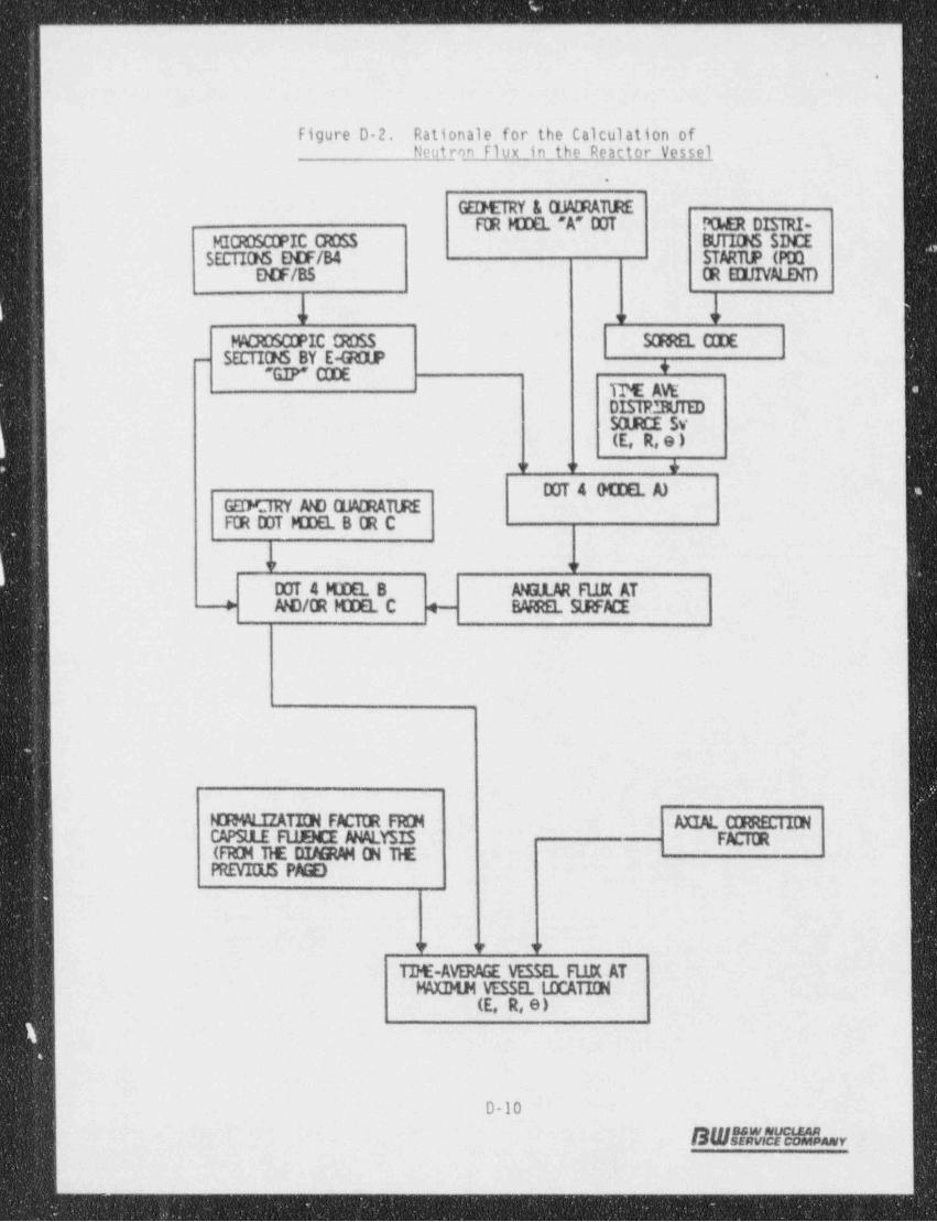
. .- - - _ _ _ _ _ _ _ - _ _ - _ _ _ _ _ _ _ _ _ _ ____- __. - - . . ___ __ ___ _
..
Figure D-2. Rationale for the Calculation of' Neutron flux in the Reactor Vessel
.
GEDETRY & a%DRATlREFIR M] DEL 'A' DOT POER DISTRI-
MICROSCDPIC CROSS BlfTIONS SINCESECTIONS E!0F/B4 STARTUP (PDQ
DOF/B5 (R EIU1VALEND
3r 3r ir
MACROSCDPIC CROSS 53REL CIDESECTIONS BY E-G OLP- *" GIP" CIDE
TM AVEDISTR.3UTEDSOLRCE SV(E, R,e )
ir y +DOT 4 GCOEL A)
GEDORY NO EMDRATIREFCR DDT KDEL B CR C
ir u
DOT 4 KDEL B ANGLAR Ft1R AT4 #0/0R MIEL C 4- BARREL SLRFACE
PCRMALIZATIIN FACTER FRM AXIAL CIRRECTIONCAPSlLE FilBCE ANALYSIS FACitR(FRCH 11E DIMRAM (N llEPREVIOUS PAGE)
<r <r v
TI)E-AVERAGE VESSEL FUK ATMXIMN VESSEL LDCATICH
(E, R,e)
D-10
BWUna M ar
- _ _ - _ _ _ - _ _ - _ _ _ - - _ _ _ _ _ _ _ _ - _ _ _. -_ ___ _ -_ _ -_ _ ___ _

- - -
. . ._ _ _ _-- - .
|i
Figure D-3. Plan View Through Reactor Core Midplane - |(Reference R-0 Calculation Model) t
Y~ " 'a
.-6'
J i
85,' p.
. .. os%k- @ *
a o
'o, }.L. <
o : "c.. . .
' ?, $E 4.---
c8 I core _. g ,,
i}. 28 3 L8" % - 2 .
, 7>p*o J-I I $ 3 ;
. ,?, 3 g-
j _ _ _ , _ _ _ _ , . _ _ _ .-
b { $I I I
/ s i I % $;> s 3._ _ _1_ _ _ 1_ _ _i _ _ _ ...,- 4, ' capsule- "f','<,i i
I I CORE l- t13 I tit L15 (Mo.ei = v. .i, , , , "'d E~~
'
_ _ _ ,_ _ _ 4 _ _ _ i. _ _ _4 _ _ _ 8r---, , i i ,
,
, I I K13 i Kit i K15I I
E i i I f s .r:..+___ ___n___g___.,.__-,-__- Mia _
' * 8
R ! 'nerlect e souna ry n 3 wie nis$us o . - e- M.jor A.iso Model A
; _
Models 5/C
x
_ _ . _ _ _ _ _ _ _ _ _ _ _ _ _ . _,

_ _
..
.
s
.
APPENDIX E
Capsule Dosimetry Data
E-1
SW!!s!F5hr,
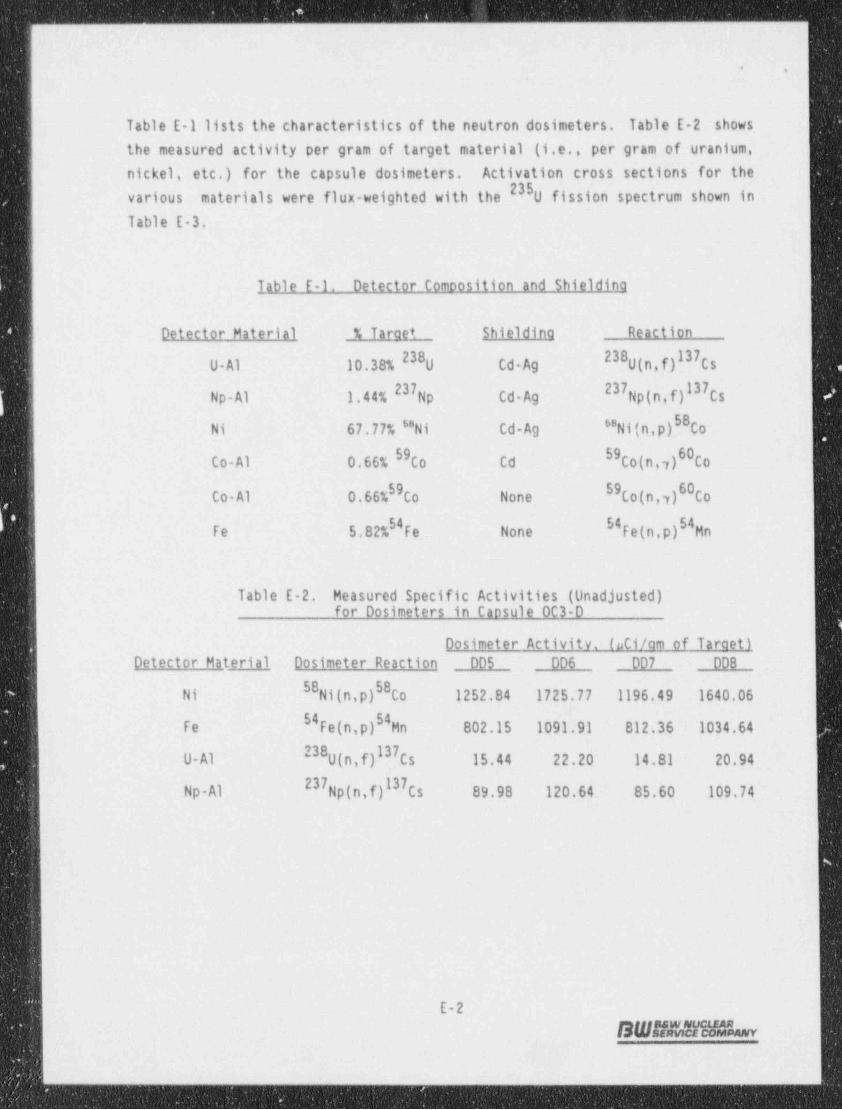
_ _ _ - _ _ _ - _ _ - _ _ _ _ . _ _ .
. .,
Table E 1 lists the characteristics of the neutron-dosimeters. Table E-2 shows-the measured activity per--gram of target material (i.e., per gram of uranium,nickel, etc.) for the capsule dosimeters. Activation cross sections-for the
235various materials were flux-weighted with the 0 fission spectrum shown in
Table E-3.
Table E-1. Detector Comoosition and Shieldino
Detector Material - % Taraet Shieldina Reaction
238 (n,f)I37Cs238U Al 10.38% 0 Cd Ag U_
Np-Al 1.44% Np Cd Ag Np(n,f)l37Cs23 237
Ni(n p)58Co'68Ni 67.77% ''Ni Cd-Ag
Co-Al 0.66% 00 Cd Co(n, y)60Co59 59
59 59Co(n,y)60CoCo-Al 0.66% 00 None
Fe 5.82% Fe None Fe(n.p)S4Mn-54- 54
,
Table E-2. Measured Specific Activities (Unadjusted)for Dosimeters in Caosule OC3-D '
Dosimeter Activity. (uti/am of Taraet)
Detector Material Dosimeter-Reaction DD5 DD6 DD7 DDB
58Ni(n,p)SBCo 1252.84 1725.77 1196.49 1640.06:Ni
54Fe(n,p)S4Mn '802.15 1091,91 812.36 1034.64-Fe
238 (n,f)137Cs 15.44_ 22.20- 14.81 20.94U-Al U
Np-Al Np(n,f)l37Cs 89.98- -120.64 85.60- 109.74237
1
|
E-2
BWhiMNW
. _ _

.. - .----- . -- . . - . - - - . - - - ._- - .
..
Table E 3. Dosinster Activation Cross Sections, b/ atom (a)
|
1
238 (n,f) 58 54237U Ni(n p)- Fe(n p) - |G Energy Range, MeV Np(n.f)
1 12.2 - 15 2.323 1.051E+0 4.830E-1: 4.133E-1
2 10.0 - 12.2 2.341 9.851E-1 5.735E-1 4.728E-1
3 8.18 - 10.0 2.309 9.935E-1- 5.981E-1- 4.772E-1
8.18 2.093. 9.110E-1 5.921E-1 4.714E-14 6.36 -
5 4.96 6.36 1.542 5.777E-1 5.223E-1 4.321E-1-
6 4.06 4.96 1.532 5.454E-1 4.146E-1 3.275E-1-
7 3.01 4.06 1.614 5.340E-1 2.701E-1 2.193E-1-
3.01 1.689 5.325E-1 1.445E-1 1;080E-1-8 2.46 -
9 2.35 2.46 1.695 5.399E-1 -9.154E-2 5.613E-2-
| 10 1.83 2.35 1.676 5.323E-1 4.856E-2 2.940E-2-
11 1.11 1.83 .l.594 2.608E-1 1.180E-2 2.948E-3--
.
12 0.55 1.11 1.241 9.845E-3' l.336E-3 . 6.999E-5-
13 0.111 - -0.55 2.352E-1 2.436E-4. 5.013E-4 6.419E-81.l 14 0.0033 0.111 1.200E-2 6.818E-5. -1.512E-5 0i -
-(*)ENDF/85 valygg that have been fluv weighted -(over CASK energy: groups).based on a U fission spectruo in the fast energy range plus a 1/E shapein the intermediate energy range.
.
E-3
SWAfA31WLv.
d d, = W D e W ++ e w, 9 -w s g 4''W-*=-w +- F h*: 1*"-rT 1 -t'' '

E
1
l
APPENDIX F
References
|,
i
|
l
t
1
F-1nureswsuctzanEdwSERVICE COMPANY
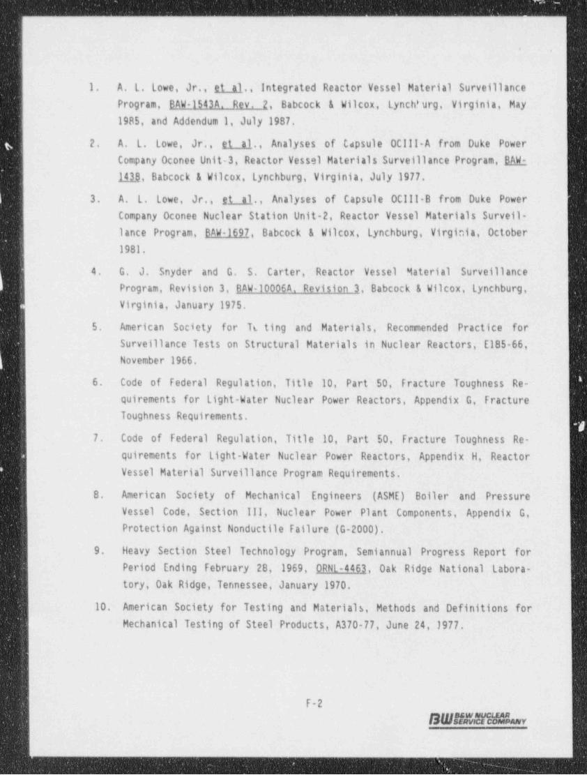
a
. ,
1. . A. L. Lowe, Jr.. et_ al., Integrated Reactor Vessel Material Surveillance.
Program, BAW-1543A. Rev. 2, Babcock - & Wilcox, - Lynch' urg, Virginia, May1985, and Addendum 1, July 1987. -
- 2. A.- L. Lowe, Jr., et al., Analyses of- Capsule OCIII-A from- Duke PowerCompany Oconee Unit-3, Reactor Vessel Materials Surveillance Program, SAR-
lila, Babcock & Wilcox, Lynchburg, Virginia, July 1977.
3. A. L. Lowe, Jr., s.t_al., Analyses of Capsule OCIll-B from Duke PowerCompany Oconee Nuclear Station Unit-2, Reactor Vessel Materials Surveil-lance Program, BAW 1697, Babcock & Wilcox,- Lynchburg, Virginia, October
_
1981.
4. G. J. Snyder and G. S. Carter, Reactor Vessel Material SurveillanceProgram, Revision 3, BAW-10006A. Revision 3, Babcock & Wilcox Lynchburg,_
t- Virginia, January 1975.
5. American Society- for To ting and Materials, Recommended Practice forSurveillance Tests on Structural Materials in Nuclear-Reactors. - E185 66,November 1966.
6. Code of Federal Regulation, Title 10, Part 50 Fracture Toughness Re-quirements for Light-Water Nuclear Power Reactors, Appendix -G, Fracture-
'
Toughness Requirements.
7. Code of Federal Regulation, Title 10, Part'-50, Fracture Toughness Re- '
quirements for Light-Water Nuclear -Power Reactors, Appendix _ H Reactor-
Vessel Material Surveillance Program Requirements.
8. American Society of Mechanical Engineers (ASME) . Boiler and PressureVessel Code Section III, _- Nuclear Power- P1 ant L Components, ' Appendix G,
Protection Against Nonductile Failure-(G-2000).
9. Heavy .Section Steel Technology: Program, Semiannual - Progress Report for~
Period Ending February 28,.1969, ORNL-4461, Oak Ridge National Labora-tory,'0ak Ridge, Tennessee, January 1970.-
10. American Society for Testing and Materials, . Methods and Definitions for-q
Mechanical Testing of Steel Products, A370-77, June:24,1977. l
.
-
F-2
B W NA W1M L w
_
_ _ _ _ _ _ _ _ _ _ . . _ _ _ _
, m ..
-11. American Society for Testing and Materials, Methods for Notched Barimpact Testing of Metal' c ttaterials, E23-82, March 5,1982.
;
12. S. . Q. King, Pressure Vessel Fluence Analysis for 177-FA Reactors, BAW-1485P. Revision 1, Babcock & Wilcox, Lynchburg, Va., April.1988.
13. B&W's Version of DOTIV Version 4.3, One. and Two-Dimensional TransportCode System," Oak Ridge National Laboratory, Distributed by the RadiationShielding Information Center as CC-429, November 1, 1983,
14. " CASK-40 Group Coupled Neutron and Gamma-Ray Cross Section Data," Radia-
tion Shielding Information Center, DLC-23E.-
15. Dosimeter File ENDF/B5 Tape 531, distributed March 1984, National NeutronData Center, Brookhaven National Laboratory, Upton, Long Island,-NY.
16. American Society of Testing Materials, Characterizing Neutron Exposuresin Ferritic Steels in Terms of Displacements Fer Atom (DPA), E693-79(Reapproved 1985).
17. U.S. Nuclear Regulatory Commission, Radiation Damage to Reactor VesselMaterial, Reaulatory Guide 1.99. Revision 2, May 1988.
18. A. L. Lowe, Jr. and J. W. Pegram, Correlations for Predicting the Effectsof Neutron Radiation on Linde 50 Submerged-Arc Welds, BAW-1803. Revision1, B&W Nuclear Service Company, Lynchburg, Virginia, March 1991.
19. H. W. Behnke, et al., Methods of Compliance With Fracture Toughness andOperational Requirements _ of Appendix G to 10CFR50, BAW-10046A. Rev. 2,
Babcock & Wilcox, Lynchburg, Virginia, June 1986,
20. J. D._ Aadland, Babcock & Wilcox Owner's Group 177-Fuel- Assembly ReactorVessel and Surveillance Program Materials Information, BAW-1820, Babcock& Wil::ox, Lynchburg, Virginia, December 1984.
21. K. E. Moore and A. S, - Heller, B&W 177-FA Reactor Vessel Beltline Weld -Chemistry Study, BAW-1799, Babcock & Wilcox, -Lynchburg, Virginia, July1983.
F-3
SW#EWiHLv
.- .- . - .. _ - -
___-. . - - _ - -
..
22. N. L. Snider and L. A. Hassler, B&WOG flux Perturbation Experiment atORNL, Heasured and Calculatt.1 Dosimeter Results, DAW 1816, Dabcock &Wilcox, Lynchburg, Virginia September 1985.
3
.
.
F-4
S W ff 4 &"Si h r.
- _ _ _ . _ _ _ _ _ - . . . - . _ - - , - - -.