Jones_duke_0066D_12809.pdf - Duke University Dissertation ...
Upload
khangminh22Category
view
1download
0
OWNER'S MANUAL 2022
790 DUKE
Art. no. 3214405en

DEAR KTM CUSTOMER
*3214405en*3214405en
03/2022
DEAR KTM CUSTOMER
Congratulations on your decision to purchase a KTM motorcycle. You are now the owner of a state-of-the-artsports vehicle which, with appropriate care, will bring you pleasure for a long time to come.
We wish you good and safe riding at all times!
Enter the serial numbers of your vehicle below.
Vehicle identification number ( p. 12) Dealer's stamp
Engine number ( p. 12)
Key number ( p. 12)
The Owner's Manual contained the latest information for this model series at the time of publication. However,minor differences due to further developments in design cannot be ruled out completely.
All specifications contained herein are non-binding. KTM Sportmotorcycle GmbH specifically reserves the rightto modify or delete technical specifications, prices, colors, forms, materials, services, designs, equipment, etc.,without prior notice and without specifying reasons, to adapt these to local conditions, as well as to stop produc-tion of a particular model without prior notice. KTM accepts no liability for delivery options, deviations from fig-ures and descriptions, misprints, and other errors. The models portrayed partly contain special equipment thatdoes not belong to the regular scope of supply.
© 2022 KTM Sportmotorcycle GmbH, Mattighofen Austria
All rights reservedReproduction, even in part, as well as copying of all kinds, is permitted only with the express written permissionof the copyright owner.
ISO 9001(12 100 6061)KTM applies quality assurance processes that lead to the highest possible product quality asdefined in the ISO 9001 international quality management standard.Issued by: TÜV Management Service
KTM Sportmotorcycle GmbHStallhofnerstraße 35230 Mattighofen, Austria
This document is valid for the following models:
790 DUKE EU (F9603VM, F9603VN)
790 DUKE L EU (F9603VO, F9603VP)
790 DUKE D. D. EU (F9603VQ, F9603VR)

TABLE OF CONTENTS
2
TABLE OF CONTENTS
1 MEANS OF REPRESENTATION ...................... 5
1.1 Symbols used .................................... 51.2 Formats used..................................... 5
2 SAFETY ADVICE............................................ 6
2.1 Use definition – intended use.............. 62.2 Misuse.............................................. 62.3 Safety advice..................................... 62.4 Degrees of risk and symbols ................ 62.5 Tampering warning............................. 72.6 Safe operation ................................... 72.7 Protective clothing ............................. 72.8 Work rules......................................... 82.9 Environment...................................... 82.10 Owner's Manual ................................. 8
3 IMPORTANT NOTES...................................... 9
3.1 Manufacturer warranty, impliedwarranty............................................ 9
3.2 Fuel, auxiliary substances ................... 93.3 Spare parts, technical accessories ....... 93.4 Service ............................................. 93.5 Figures ............................................. 93.6 Customer service................................ 9
4 VIEW OF VEHICLE ...................................... 10
4.1 View of vehicle, front left (example) ... 104.2 View of vehicle, rear right
(example)........................................ 11
5 SERIAL NUMBERS ..................................... 12
5.1 Vehicle identification number............ 125.2 Type label ....................................... 125.3 Key number..................................... 125.4 Engine number ................................ 125.5 Fork part number ............................. 135.6 Shock absorber article number .......... 135.7 Steering damper article number ........ 13
6 CONTROLS................................................. 14
6.1 Clutch lever..................................... 146.2 Hand brake lever.............................. 146.3 Throttle grip .................................... 146.4 Switches on the left side of the
handlebar........................................ 146.4.1 Combination switch...................... 146.4.2 Light switch ................................ 156.4.3 Menu buttons .............................. 156.4.4 Turn signal switch........................ 156.4.5 Horn button ................................ 156.5 Switches on the right side of the
handlebar........................................ 166.5.1 Start button/emergency OFF
switch......................................... 16
6.6 Ignition and steering lock.................. 166.7 Opening fuel tank filler cap............... 166.8 Closing the fuel tank filler cap........... 176.9 Seat lock......................................... 186.10 Tool set........................................... 186.11 Grab handle .................................... 186.12 Passenger foot pegs ......................... 186.13 Shift lever ....................................... 196.14 Foot brake lever ............................... 196.15 Side stand....................................... 19
7 COMBINATION INSTRUMENT ..................... 20
7.1 Combination instrument ................... 207.2 Activation and test ........................... 207.3 Day-Night mode............................... 207.4 Warnings......................................... 217.5 Indicator lamps................................ 217.6 Display ........................................... 237.7 TRACK Display (optional).................. 247.8 Shift warning light ........................... 247.9 Fuel level display ............................. 257.10 Time............................................... 257.11 Coolant temperature indicator ........... 257.12 Trip odometer .................................. 267.13 Menu.............................................. 267.13.1 Favorites ..................................... 267.13.2 Trip 1 ......................................... 267.13.3 Trip 2 ......................................... 277.13.4 General Info ................................ 277.13.5 Settings ...................................... 287.13.6 Bluetooth® (optional).................... 287.13.7 Distance ..................................... 287.13.8 Temperature................................ 297.13.9 Pressure ..................................... 297.13.10 Consumption ............................... 297.13.11 Language .................................... 307.13.12 Clock/Date .................................. 307.13.13 DRL ........................................... 307.13.14 TPMS warning ............................. 317.13.15 Quick Selector 1.......................... 327.13.16 Quick Selector 2.......................... 327.13.17 Set Favorites ............................... 337.13.18 Service ....................................... 337.13.19 Extra functions ............................ 337.13.20 Warnings..................................... 347.13.21 Ride Mode .................................. 347.13.22 Track (optional) ........................... 347.13.23 Anti‑wheelie mode (optional)......... 357.13.24 Launch control (optional).............. 357.13.25 MTC ........................................... 357.13.26 MTC + MSR (optional).................. 367.13.27 ABS Mode................................... 367.13.28 Quickshifter + (optional)............... 367.13.29 Shift Light .................................. 37
TABLE OF CONTENTS
3
7.13.30 KTM MY RIDE (optional) .............. 377.13.31 Pairing (optional) ......................... 377.13.32 Audio player (optional) ................. 387.13.33 Telephony (optional) .................... 39
8 ERGONOMICS ............................................ 40
8.1 Handlebar position........................... 408.2 Adjusting the handlebar position .... 408.3 Adjusting the basic position of the
clutch lever ..................................... 418.4 Adjusting the basic position of the
hand brake lever .............................. 418.5 Adjusting the basic position of the
foot brake lever ............................ 418.6 Checking the basic position of the
shift lever........................................ 428.7 Adjusting the basic position of the
shift lever .................................... 43
9 PREPARING FOR USE................................. 44
9.1 Advice on preparing for first use ........ 449.2 Running in the engine ...................... 459.3 Loading the vehicle .......................... 45
10 RIDING INSTRUCTIONS.............................. 47
10.1 Checks and maintenance measureswhen preparing for use ..................... 47
10.2 Starting the vehicle .......................... 4710.3 Starting off...................................... 4810.4 Launch‑Control (optional) ................. 4810.5 Starting off with launch control
(optional) ........................................ 4910.6 Quickshifter + (optional) ................... 4910.7 Shifting, riding ................................ 5010.8 Engine traction torque control (
MSR)............................................... 5310.9 Applying the brakes.......................... 5310.10 Stopping, parking............................. 5410.11 Transporting .................................... 5510.12 Towing in the event of a breakdown ... 5510.13 Refueling ........................................ 56
11 SERVICE SCHEDULE .................................. 57
11.1 Additional information...................... 5711.2 Required work ................................. 5711.3 Recommended work ......................... 58
12 TUNING THE CHASSIS ............................... 59
12.1 Adjusting the spring preload of theshock absorber ............................. 59
13 SERVICE WORK ON THE CHASSIS............... 60
13.1 Raising the motorcycle with the rearlifting gear ...................................... 60
13.2 Removing the rear of the motorcyclefrom the lifting gear ......................... 60
13.3 Lifting the motorcycle with the frontlifting gear ...................................... 60
13.4 Taking the motorcycle off the frontlifting gear ...................................... 61
13.5 Cleaning the dust boots of the forklegs ............................................. 61
13.6 Removing the passenger seat ............ 6213.7 Mounting the passenger seat............. 6213.8 Removing the front rider's seat .......... 6313.9 Mounting the front rider's seat........... 6313.10 Checking the chain for dirt................ 6413.11 Cleaning the chain ........................... 6413.12 Checking the chain tension ............... 6513.13 Adjusting the chain tension............... 6513.14 Checking the chain, rear sprocket,
engine sprocket, and chain guide ...... 66
14 BRAKE SYSTEM ......................................... 69
14.1 Anti-lock braking system (ABS) ......... 6914.2 Checking the brake discs .................. 7014.3 Checking the front brake fluid level ... 7014.4 Adding front brake fluid ................ 7114.5 Checking the front brake linings ........ 7214.6 Checking the free travel of the foot
brake lever ...................................... 7214.7 Checking the rear brake fluid level..... 7314.8 Adding rear brake fluid ................. 7314.9 Checking the rear brake linings ......... 75
15 WHEELS, TIRES ......................................... 76
15.1 Removing the front wheel .............. 7615.2 Installing the front wheel .............. 7715.3 Removing the rear wheel ............... 7815.4 Installing the rear wheel ................ 7915.5 Checking the rear hub damping
rubber pieces ............................... 8115.6 Checking the tire condition ............... 8215.7 Checking tire pressure ...................... 8315.8 Using tire repair spray ...................... 83
16 ELECTRICAL SYSTEM ................................. 85
16.1 Daytime running light (DRL)............... 8516.2 Removing the 12-V battery ............ 8516.3 Installing the 12-V battery ............. 8616.4 Charging the 12-V battery ............. 8716.5 Changing the main fuse.................... 8916.6 Changing the ABS fuses ................... 9016.7 Changing the fuses of individual
electrical power consumers ............... 9116.8 Loosening the headlight mask with
the headlight ................................... 9216.9 Mounting the headlight mask with
the headlight ................................... 9216.10 Removing the cover of the headlight
mask rack ....................................... 93

TABLE OF CONTENTS
4
16.11 Installing the cover of the headlightmask rack ....................................... 94
16.12 Checking the headlight setting .......... 9416.13 Adjusting the headlight range............ 9516.14 Diagnostics connector ...................... 9516.15 Front ACC1 and ACC2 ...................... 9616.16 ACC1 and ACC2 rear ........................ 96
17 COOLING SYSTEM...................................... 97
17.1 Cooling system ................................ 9717.2 Checking the antifreeze and coolant
level ............................................... 9717.3 Checking the coolant level in the
compensating tank........................... 9817.4 Draining the coolant ..................... 9917.5 Filling/bleeding the cooling
system ...................................... 10017.6 Changing the coolant...................... 101
18 TUNING THE ENGINE............................... 103
18.1 Ride Mode .................................... 10318.2 Motorcycle traction control (MTC).... 10318.3 Slip adjustment (optional)............... 10418.4 Throttle response (optional)............. 104
19 SERVICE WORK ON THE ENGINE .............. 105
19.1 Checking the engine oil level........... 10519.2 Changing the engine oil and oil
filter, cleaning the oil screens ...... 10519.3 Adding engine oil ........................... 10719.4 Checking the free travel of the
clutch lever ................................... 10819.5 Setting the free travel of the clutch
lever .......................................... 108
20 CLEANING, CARE ..................................... 109
20.1 Cleaning the motorcycle ................. 10920.2 Checks and maintenance steps for
winter operation............................. 110
21 STORAGE................................................. 111
21.1 Storage ......................................... 11121.2 Preparing for use after storage......... 112
22 TROUBLESHOOTING ................................ 113
23 TECHNICAL DATA..................................... 115
23.1 engine .......................................... 11523.2 Engine tightening torques ............... 11623.3 Capacities ..................................... 11823.3.1 Engine oil ................................. 11823.3.2 Coolant ..................................... 11823.3.3 Fuel ......................................... 11923.4 Chassis ......................................... 11923.5 Electrical system............................ 12023.6 Tires ............................................. 120
23.7 Fork.............................................. 12023.8 Shock absorber .............................. 12123.9 Chassis tightening torques .............. 121
24 DECLARATIONS OF CONFORMITY ............. 125
24.1 Declarations of conformity .............. 12524.2 Country-specific declarations of
conformity..................................... 125
25 SUBSTANCES .......................................... 126
26 AUXILIARY SUBSTANCES ......................... 128
27 STANDARDS ............................................ 129
28 INDEX OF SPECIAL TERMS ....................... 130
29 LIST OF ABBREVIATIONS.......................... 131
30 LIST OF SYMBOLS.................................... 132
30.1 Red symbols.................................. 13230.2 Yellow and orange symbols.............. 13230.3 Green and blue symbols.................. 132
INDEX ............................................................. 133

MEANS OF REPRESENTATION 1
5
1.1 Symbols used
The meaning of specific symbols is described below.
Indicates an expected reaction (e.g. of a work step or a function).
Indicates an unexpected reaction (e.g. of a work step or a function).
Indicates work that requires expert knowledge and technical understanding. In the interest ofyour own safety, have these jobs performed by an authorized KTM workshop! Your motorcyclewill be cared for there to the highest degree by specially trained experts using the special toolsrequired.
Indicates a page reference (more information is provided on the specified page).
Indicates information with more details or tips.
Indicates the result of a testing step.
Indicates a voltage measurement.
Indicates a current measurement.
Indicates the end of an activity, including potential rework.
1.2 Formats used
The typographical formats used in this document are explained below.
Proprietary name Indicates a proprietary name.
Name® Indicates a protected name.
Brand™ Indicates a brand available on the open market.
Underlined terms Refer to technical details of the vehicle or indicate technical terms, whichare explained in the glossary.
2 SAFETY ADVICE
6
2.1 Use definition – intended use
The vehicle is designed and constructed to withstand the usual demands of regular traffic and use on racecourses.This vehicle is not suitable for offroad use.
InfoThis vehicle is only authorized for operation on public roads in its homologated version.
2.2 Misuse
The vehicle must only be used as intended.Dangers can arise for people, property and the environment through use not as intended.Any use of the vehicle beyond the intended and defined use constitutes misuse.Misuse also includes the use of operating and auxiliary fluids which do not meet the required specification for therespective use.
2.3 Safety advice
A number of safety instructions need to be followed to operate the product described safely. Therefore read thisinstruction and all further instructions included carefully. The safety instructions are highlighted in the text andare referred to at the relevant passages.
InfoVarious information and warning labels are attached in prominent locations on the product described. Donot remove any information or warning labels. If they are missing, you or others may not recognize dangersand may therefore be injured.
2.4 Degrees of risk and symbols
DangerIdentifies a danger that will immediately and invariably lead to fatal or serious permanent injury if theappropriate measures are not taken.
WarningIdentifies a danger that is likely to lead to fatal or serious injury if the appropriate measures are nottaken.
CautionIdentifies a danger that may lead to minor injuries if the appropriate measures are not taken.
NoteIdentifies a danger that will lead to considerable machine and material damage if the appropriate measures arenot taken.
NoteIndicates a danger that will lead to environmental damage if the appropriate measures are not taken.
SAFETY ADVICE 2
7
2.5 Tampering warning
Tampering with the noise control system is prohibited. Federal law prohibits the following acts or the causingthereof:
1 The removal or rendering inoperative by any person other than for purposes of servicing, repair, or replace-ment, of any device or element of design incorporated into any new vehicle for the purpose of noise controlprior to its sale or delivery to the ultimate purchaser or while it is in use, or
2 the use of the vehicle after such device or element of design has been removed or rendered inoperative by anyperson.
Among those acts presumed to constitute tampering are the acts listed below:
1 Removal or puncturing of the main silencers, baffles, header pipes or any other components which conductexhaust gases.
2 Removal or puncturing of parts of the intake system.
3 Lack of proper maintenance.
4 Replacing moving parts of the vehicle, or parts of the exhaust system or intake system, with parts other thanthose specified by the manufacturer.
2.6 Safe operation
DangerDanger of accidents A rider who is not fit to ride poses a danger to him or herself and others.
– Do not operate the vehicle if you are not fit to ride due to alcohol, drugs or medication.
– Do not operate the vehicle if you are physically or mentally impaired.
DangerDanger of poisoning Exhaust gases are toxic and inhaling them may result in unconsciousness and death.
– Always make sure there is sufficient ventilation when running the engine.
– Use effective exhaust extraction when starting or running the engine in an enclosed space.
WarningDanger of burns Some vehicle components become very hot when the vehicle is operated.
– Do not touch any parts such as the exhaust system, radiator, engine, shock absorber, or brake systembefore the vehicle parts have cooled down.
– Let the vehicle parts cool down before you perform any work on the vehicle.
Only operate the vehicle when it is in perfect technical condition, in accordance with its intended use, and in asafe and environmentally compatible manner.An appropriate driver's license is needed to drive the vehicle on public roads.Have malfunctions that impair safety promptly eliminated by an authorized KTM workshop.Adhere to the information and warning labels on the vehicle.
2.7 Protective clothing
WarningRisk of injury Missing or poor protective clothing presents an increased safety risk.
– Wear appropriate protective clothing such as helmet, boots, gloves as well as trousers and a jacketwith protectors on all rides.
– Always wear protective clothing that is in good condition and meets the legal regulations.
In the interest of your own safety, KTM recommends that you only operate the vehicle while wearing protectiveclothing.
2 SAFETY ADVICE
8
2.8 Work rules
Unless specified otherwise, the ignition must be turned off during all work (models with ignition lock, modelswith remote key) or the engine must be at a standstill (models without ignition lock or remote key).Special tools are necessary for certain tasks. The tools are not a component of the vehicle, but can be orderedusing the number in parentheses. Example: bearing puller (15112017000)Unless otherwise noted, normal conditions apply to all tasks and descriptions.
Ambient temperature 20 °C (68 °F)
Ambient air pressure 1,013 mbar (14.69 psi)
Relative air humidity 60 ± 5 %
During assembly, use new parts to replace parts which cannot be reused (e.g. self-locking screws and nuts,expansion screws, seals, sealing rings, O-rings, pins, and lock washers).In the case of certain screws, a screw adhesive (e.g. Loctite®) is required. Observe the manufacturer's instruc-tions.If thread locker (e.g., Precote®) has already been applied to a new part, do not apply any additional thread locker.After disassembly, clean the parts that are to be reused and check them for damage and wear. Change damagedor worn parts.After completing a repair or service work, check the operating safety of the vehicle.
2.9 Environment
If you use your motorcycle responsibly, you can ensure that problems and conflicts do not occur. To protect thefuture of the motorcycle sport, make sure that you use your motorcycle legally, display environmental conscious-ness, and respect the rights of others.When disposing of used oil, other operating and auxiliary fluids, and used components, comply with the laws andregulations of the respective country.Because motorcycles are not subject to the EU regulations governing the disposal of used vehicles, there are nolegal regulations that pertain to the disposal of an end-of-life motorcycle. Your authorized KTM dealer will be gladto advise you.
2.10 Owner's Manual
Read this owner's manual carefully and completely before making your first trip. The Owner's Manual containsuseful information and many tips on how to operate, handle, and service your motorcycle. This is the only way tofind out how best to customize the vehicle for your own use and how you can protect yourself from injury.
TipStore the Owner's Manual on your terminal device, for example, so that you can read it whenever you needto.
If you would like to know more about the vehicle or have questions on the material you read, please contact anauthorized KTM dealer.The Owner's Manual is an important component of the vehicle. If the vehicle is sold, the Owner's Manual must bedownloaded again by the new owner.The Owner's Manual can be downloaded several times using the QR code or the link on the delivery certificate.
The Owner's Manual is also available for download from your authorized KTM dealer and on the KTM website. Aprinted copy can also be ordered from your authorized KTM dealer.International KTM Website: KTM.COM
IMPORTANT NOTES 3
9
3.1 Manufacturer warranty, implied warranty
The work prescribed in the service schedule must only be carried out in an authorized KTM workshop and con-firmed in the KTM Dealer.net, as otherwise all warranty claims will be void. Damage or secondary damage causedby tampering with and/or conversions on the vehicle are not covered by the manufacturer warranty.
3.2 Fuel, auxiliary substances
NoteEnvironmental hazard Improper handling of fuel is a danger to the environment.
– Do not allow fuel to enter the groundwater, the soil, or the sewage system.
Use fuels and auxiliary substances in accordance with the Owner's Manual and specification.
3.3 Spare parts, technical accessories
For your own safety, only use spare parts and accessory products that are approved and/or recommended by KTMand have them installed by an authorized KTM workshop. KTM accepts no liability for other products and anyresulting damage or loss.Certain spare parts and accessory products are specified in parentheses in the descriptions. Your authorized KTMdealer will be glad to advise you.
The latest news KTM PowerParts on your vehicle can be found on the KTM website.International KTM Website: KTM.COM
3.4 Service
A prerequisite for perfect operation and prevention of premature wear is that the service, care, and tuning workon the engine and chassis is properly carried out as described in the Owner's Manual. An incorrect suspensionsetting can lead to damage and breakage of chassis components.Use of the vehicle under difficult conditions, such as dusty environments, heavy rain, high heat or with a heavyload, can lead to considerably more rapid wear of components such as the air filter, drive train, brake system, orsuspension components. For this reason, it may be necessary to inspect or replace parts before the next sched-uled service.It is imperative that you adhere to the stipulated run-in times and service intervals. If you observe these exactly,you will ensure a much longer service life for your motorcycle.The relevant mileage or time interval is whichever occurs first.
3.5 Figures
The figures contained in the manual may depict special equipment.In the interest of clarity, some components may be shown disassembled or may not be shown at all. It is notalways necessary to disassemble the component to perform the activity in question. Please follow the instructionsin the text.
3.6 Customer service
Your authorized KTM dealer will be happy to answer any questions you may have on your vehicle and KTM.
A list of authorized KTM dealers can be found on the KTM website.International KTM Website: KTM.COM

4 VIEW OF VEHICLE
10
4.1 View of vehicle, front left (example)
A01134-10
1 Combination instrument ( p. 20)
2 Ignition and steering lock ( p. 16)
3 Clutch lever ( p. 14)
4 Seat lock ( p. 18)
5 Side stand ( p. 19)
6 Shift lever ( p. 19)
7 Engine number ( p. 12)
VIEW OF VEHICLE 4
11
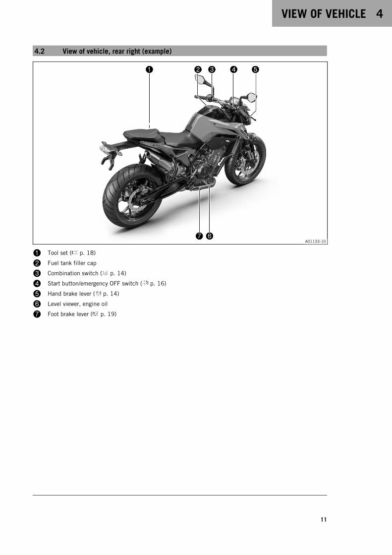
4.2 View of vehicle, rear right (example)
A01133-10
1 Tool set ( p. 18)
2 Fuel tank filler cap
3 Combination switch ( p. 14)
4 Start button/emergency OFF switch ( p. 16)
5 Hand brake lever ( p. 14)
6 Level viewer, engine oil
7 Foot brake lever ( p. 19)

5 SERIAL NUMBERS
12
5.1 Vehicle identification number
402324-10
The vehicle identification number1 is stamped on the right sideof the steering head.
5.2 Type label
V01213-10
The type label1 is located on the steering head on the left.
The type label Australia2 is located on the frame behind thesteering head at the top left.
5.3 Key number
V01200-10
The key number1 can be found on the KEYCODECARD.
InfoYou need the key number to order a spare key. Keepthe KEYCODECARD in a safe place.
5.4 Engine number
H01047-10
The engine number1 is stamped onto the engine case at thetop.
SERIAL NUMBERS 5
13
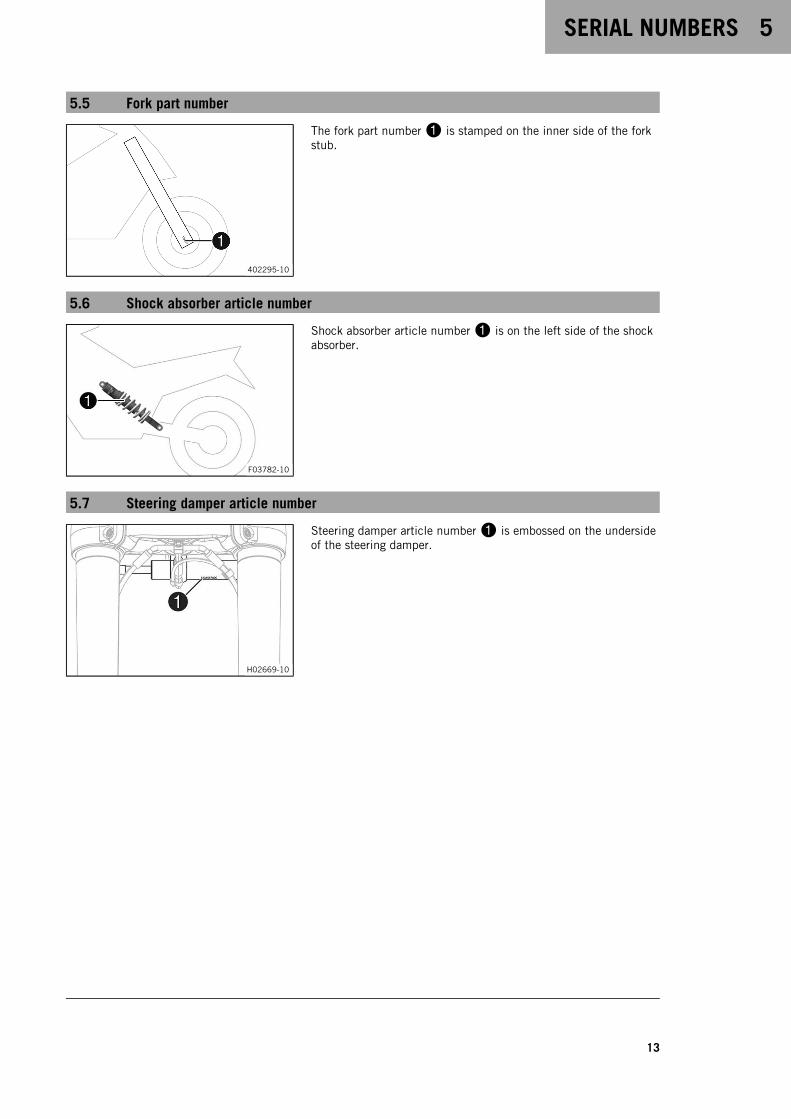
5.5 Fork part number
402295-10
The fork part number1 is stamped on the inner side of the forkstub.
5.6 Shock absorber article number
F03782-10
Shock absorber article number1 is on the left side of the shockabsorber.
5.7 Steering damper article number
H02669-10
Steering damper article number1 is embossed on the undersideof the steering damper.
6 CONTROLS
14
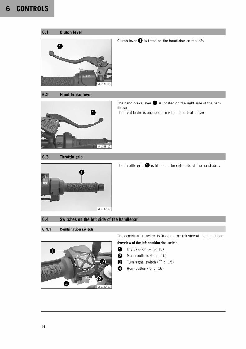
6.1 Clutch lever
V01187-10
Clutch lever1 is fitted on the handlebar on the left.
6.2 Hand brake lever
V01188-10
The hand brake lever1 is located on the right side of the han-dlebar.The front brake is engaged using the hand brake lever.
6.3 Throttle grip
V01189-10
The throttle grip1 is fitted on the right side of the handlebar.
6.4 Switches on the left side of the handlebar
6.4.1 Combination switch
The combination switch is fitted on the left side of the handlebar.
V01190-10
Overview of the left combination switch
1 Light switch ( p. 15)
2 Menu buttons ( p. 15)
3 Turn signal switch ( p. 15)
4 Horn button ( p. 15)
CONTROLS 6
15
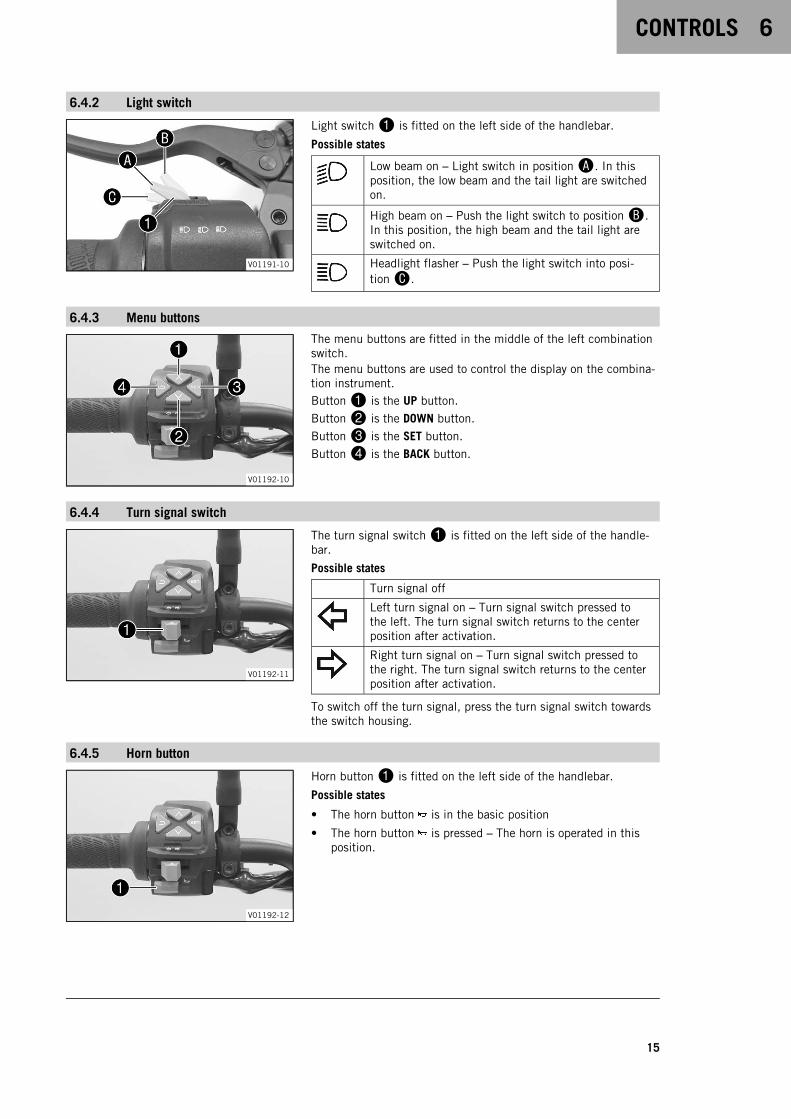
6.4.2 Light switch
V01191-10
Light switch1 is fitted on the left side of the handlebar.
Possible states
Low beam on – Light switch in positionA. In thisposition, the low beam and the tail light are switchedon.
High beam on – Push the light switch to positionB.In this position, the high beam and the tail light areswitched on.
Headlight flasher – Push the light switch into posi-tionC.
6.4.3 Menu buttons
V01192-10
The menu buttons are fitted in the middle of the left combinationswitch.The menu buttons are used to control the display on the combina-tion instrument.Button1 is the UP button.
Button2 is the DOWN button.
Button3 is the SET button.
Button4 is the BACK button.
6.4.4 Turn signal switch
V01192-11
The turn signal switch1 is fitted on the left side of the handle-bar.
Possible states
Turn signal off
Left turn signal on – Turn signal switch pressed tothe left. The turn signal switch returns to the centerposition after activation.
Right turn signal on – Turn signal switch pressed tothe right. The turn signal switch returns to the centerposition after activation.
To switch off the turn signal, press the turn signal switch towardsthe switch housing.
6.4.5 Horn button
V01192-12
Horn button1 is fitted on the left side of the handlebar.
Possible states
• The horn button is in the basic position
• The horn button is pressed – The horn is operated in thisposition.
6 CONTROLS
16
6.5 Switches on the right side of the handlebar
6.5.1 Start button/emergency OFF switch
V01194-10
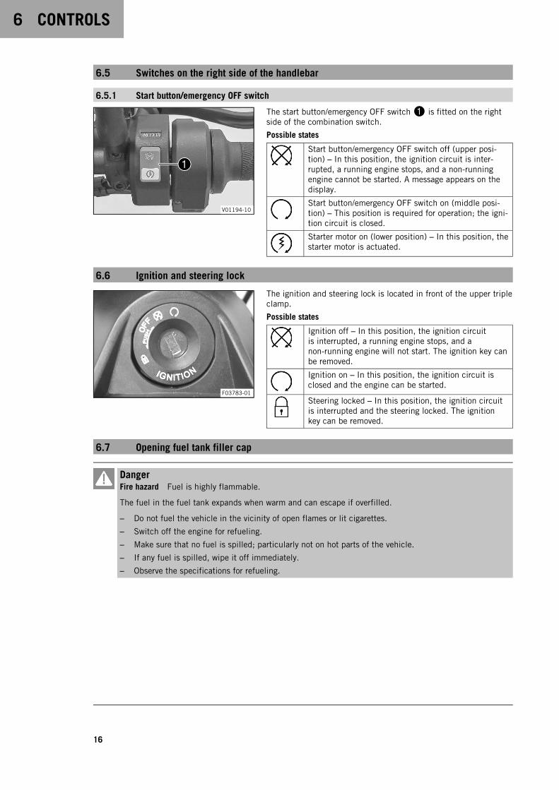
The start button/emergency OFF switch1 is fitted on the rightside of the combination switch.
Possible states
Start button/emergency OFF switch off (upper posi-tion) – In this position, the ignition circuit is inter-rupted, a running engine stops, and a non-runningengine cannot be started. A message appears on thedisplay.
Start button/emergency OFF switch on (middle posi-tion) – This position is required for operation; the igni-tion circuit is closed.
Starter motor on (lower position) – In this position, thestarter motor is actuated.
6.6 Ignition and steering lock
F03783-01
The ignition and steering lock is located in front of the upper tripleclamp.
Possible states
Ignition off – In this position, the ignition circuitis interrupted, a running engine stops, and anon-running engine will not start. The ignition key canbe removed.
Ignition on – In this position, the ignition circuit isclosed and the engine can be started.
Steering locked – In this position, the ignition circuitis interrupted and the steering locked. The ignitionkey can be removed.
6.7 Opening fuel tank filler cap
DangerFire hazard Fuel is highly flammable.
The fuel in the fuel tank expands when warm and can escape if overfilled.
– Do not fuel the vehicle in the vicinity of open flames or lit cigarettes.
– Switch off the engine for refueling.
– Make sure that no fuel is spilled; particularly not on hot parts of the vehicle.
– If any fuel is spilled, wipe it off immediately.
– Observe the specifications for refueling.
CONTROLS 6
17
WarningDanger of poisoning Fuel is poisonous and a health hazard.
– Avoid skin, eye and clothing contact with fuel.
– Immediately consult a doctor if you swallow fuel.
– Do not inhale fuel vapors.
– In case of skin contact, rinse the affected area with plenty of water.
– Rinse the eyes thoroughly with water, and consult a doctor in case of fuel contact with the eyes.
– Change your clothing in case of fuel spills on them.
– Keep fuels correctly in a suitable canister, and out of the reach of children.
NoteEnvironmental hazard Improper handling of fuel is a danger to the environment.
– Do not allow fuel to enter the groundwater, the soil, or the sewage system.
V01196-10
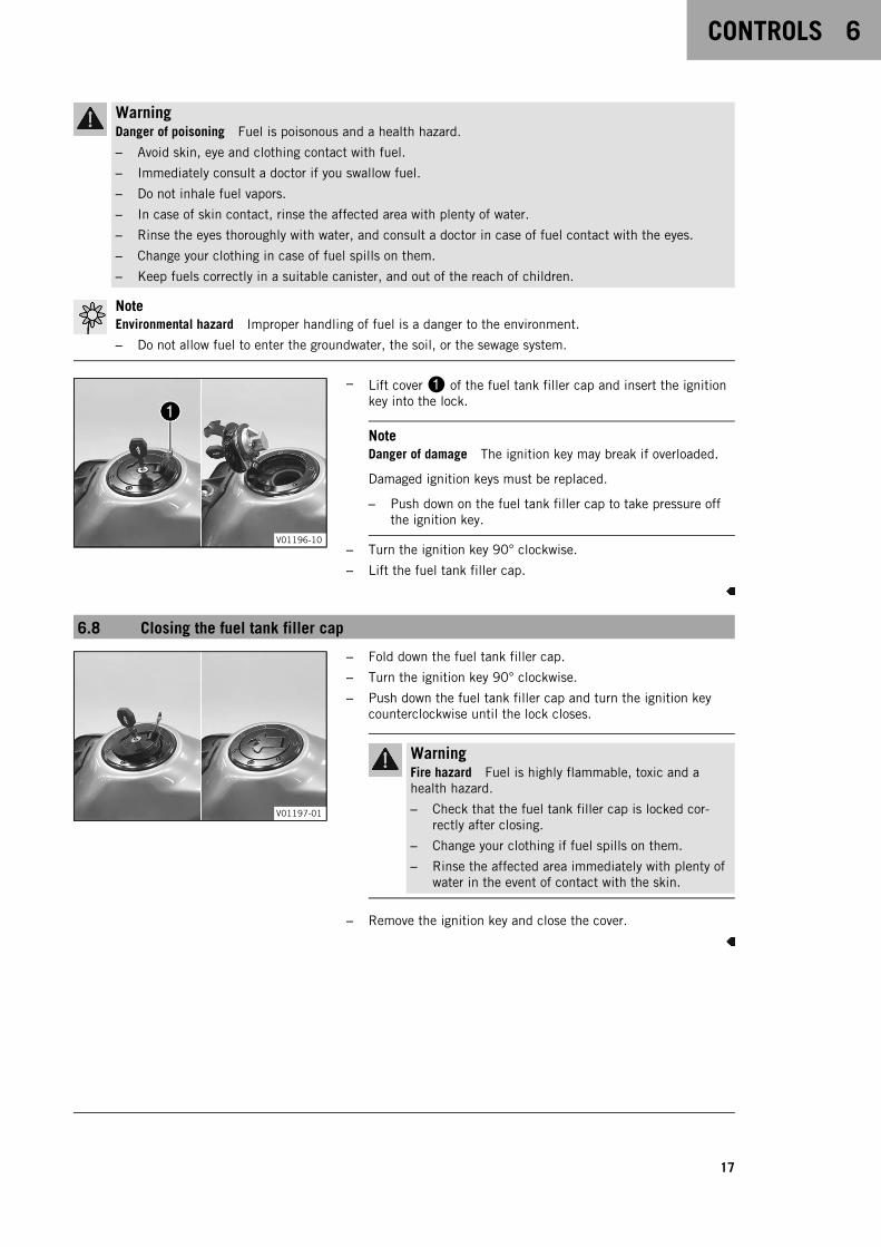
– Lift cover1 of the fuel tank filler cap and insert the ignitionkey into the lock.
NoteDanger of damage The ignition key may break if overloaded.
Damaged ignition keys must be replaced.
– Push down on the fuel tank filler cap to take pressure offthe ignition key.
– Turn the ignition key 90° clockwise.
– Lift the fuel tank filler cap.
6.8 Closing the fuel tank filler cap
V01197-01
– Fold down the fuel tank filler cap.
– Turn the ignition key 90° clockwise.
– Push down the fuel tank filler cap and turn the ignition keycounterclockwise until the lock closes.
WarningFire hazard Fuel is highly flammable, toxic and ahealth hazard.
– Check that the fuel tank filler cap is locked cor-rectly after closing.
– Change your clothing if fuel spills on them.
– Rinse the affected area immediately with plenty ofwater in the event of contact with the skin.
– Remove the ignition key and close the cover.
6 CONTROLS
18
6.9 Seat lock
V01198-10
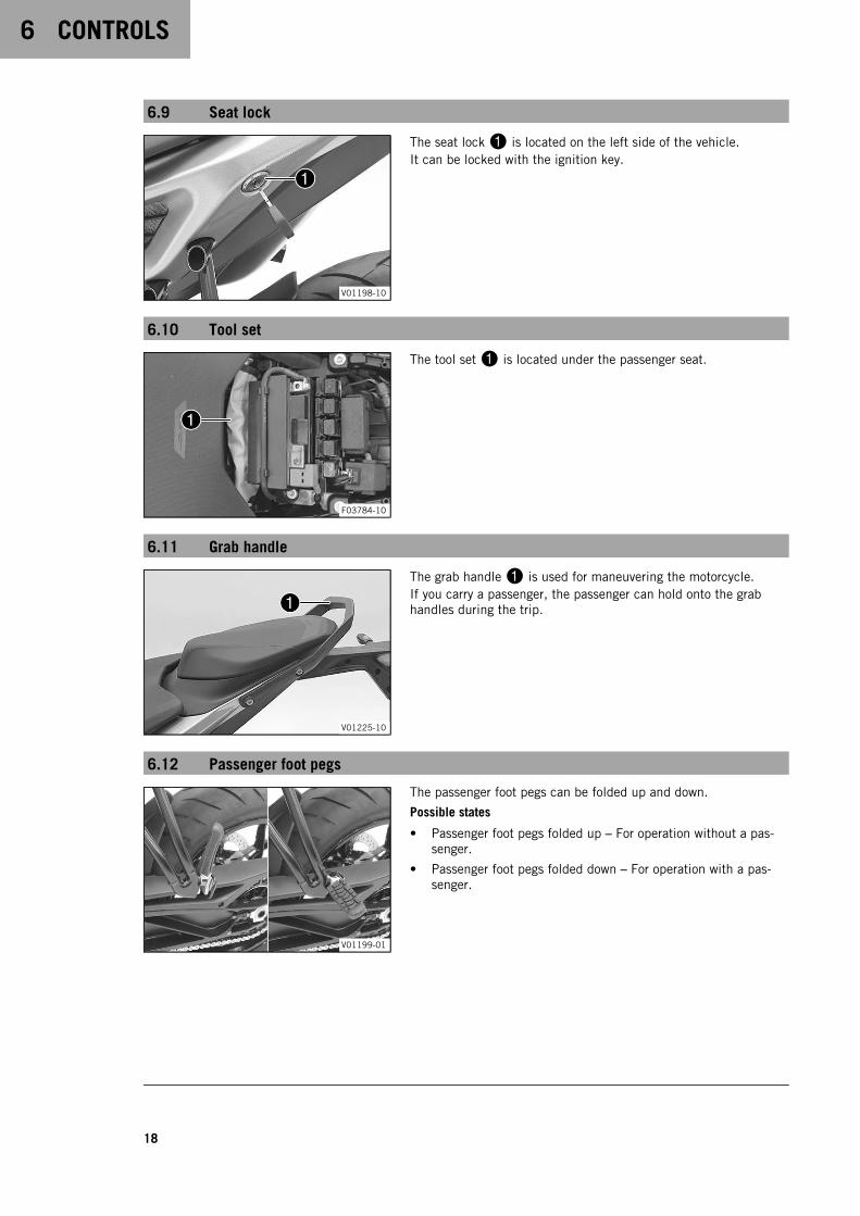
The seat lock1 is located on the left side of the vehicle.It can be locked with the ignition key.
6.10 Tool set
F03784-10
The tool set1 is located under the passenger seat.
6.11 Grab handle
V01225-10
The grab handle1 is used for maneuvering the motorcycle.If you carry a passenger, the passenger can hold onto the grabhandles during the trip.
6.12 Passenger foot pegs
V01199-01
The passenger foot pegs can be folded up and down.
Possible states
• Passenger foot pegs folded up – For operation without a pas-senger.
• Passenger foot pegs folded down – For operation with a pas-senger.

CONTROLS 6
19
6.13 Shift lever
V01271-11
The shift lever1 is mounted on the left side of the engine.
V01271-10
The gear positions can be seen in the photograph.The neutral or idle position is between the first and second gears.
6.14 Foot brake lever
402177-10
Foot brake lever1 is located in front of the right footrest.The rear brake is engaged with the foot brake lever.
6.15 Side stand
402029-10
The side stand1 is located on the left of the vehicle.The side stand is used for parking the motorcycle.
InfoThe side stand must be folded up during motorcycle use.The side stand is coupled with the safety starting system;follow the riding instructions.
Possible states
• Side stand folded out – The vehicle can be supported on theside stand. The safety starting system is active.
• Side stand folded in – This position is mandatory when ridingthe motorcycle. The safety starting system is inactive.

7 COMBINATION INSTRUMENT
20
7.1 Combination instrument
A01135-10
The combination instrument is attached in front of the handlebar.The combination instrument is divided into two function areas.
1 indicator lamps ( p. 21)
Display2
7.2 Activation and test
A01136-10
ActivationThe combination instrument is activated when the ignition isswitched on.
InfoThe brightness of the displays is controlled by an ambientlight sensor in the combination instrument.
TestThe welcome text appears on the display and the indicator lampsare briefly activated for a function check.
InfoThe malfunction indicator lamp always lights up as long asthe engine is not running. If the engine is running and themalfunction indicator lamp lights up, stop (taking care notto endanger yourself or other road users in the process) andcontact an authorized KTM workshop.The oil pressure warning lamp always lights up as long asthe engine is not running. If the engine is running and theoil pressure warning lamp lights up, stop immediately (tak-ing care not to endanger yourself or other road users in theprocess) and switch off the engine.The ABS warning lamp and TC indicator lamp light up untila speed of approx. 6 km/h (approx. 4 mph) or more hasbeen reached.
7.3 Day-Night mode
A01137-10
Day mode is shown in a bright color.
COMBINATION INSTRUMENT 7
21
A01138-10
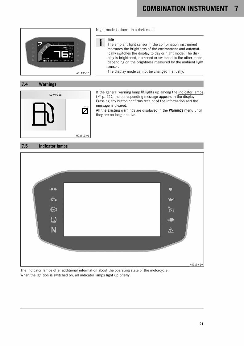
Night mode is shown in a dark color.
InfoThe ambient light sensor in the combination instrumentmeasures the brightness of the environment and automat-ically switches the display to day or night mode. The dis-play is brightened, darkened or switched to the other modedepending on the brightness measured by the ambient lightsensor.The display mode cannot be changed manually.
7.4 Warnings
H02619-01
If the general warning lamp lights up among the indicator lamps( p. 21), the corresponding message appears in the display.Pressing any button confirms receipt of the information and themessage is cleared.All the existing warnings are displayed in the Warnings menu untilthey are no longer active.
7.5 Indicator lamps
A01139-10
The indicator lamps offer additional information about the operating state of the motorcycle.When the ignition is switched on, all indicator lamps light up briefly.

7 COMBINATION INSTRUMENT
22
InfoThe malfunction indicator lamp always lights up as long as the engine is not running. If the engine is run-ning and the malfunction indicator lamp lights up, stop (taking care not to endanger yourself or other roadusers in the process) and contact an authorized KTM workshop.The oil pressure warning lamp always lights up as long as the engine is not running. If the engine is run-ning and the oil pressure warning lamp lights up, stop immediately (taking care not to endanger yourself orother road users in the process) and switch off the engine.The ABS warning lamp and TC indicator lamp light up until a speed of approx. 6 km/h (approx. 4 mph) ormore has been reached.
Possible states
The turn signal indicator lamp flashes green simultaneously with the turn signal – The turnsignal is switched on.
Malfunction indicator lamp lights up yellow – The OBD has detected a malfunction in thevehicle electronics. Come safely to a halt, and contact an authorized KTM workshop.
ABS warning lamp lights up yellow – Status or error messages relating to ABS.
TC indicator lamp lights up yellow – MTC ( p. 103) is not enabled or is currently interven-ing. The TC indicator lamp also lights up if a malfunction is detected. Contact an authorizedKTM workshop. The TC indicator lamp flashes if MTC actively engages or if the Launch Control( p. 48) is activated.
The idle indicator lamp lights up green – The transmission is in the neutral position.
The immobilizer indicator lamp lights up or flashes red – Status or error message of the alarmsystem.
The oil pressure warning lamp lights up red – The oil pressure is too low. Stop immediately,taking care not to endanger yourself or other road users in the process, and switch off theengine.
The cruise control system indicator lamp (optional) lights up yellow – The cruise control sys-tem function is switched on, but cruise control is not activated.
The cruise control system indicator lamp (optional) lights up green – The cruise control sys-tem function is switched on and cruise control is activated.
The high beam indicator lamp lights up blue – The high beam is switched on.
The general warning lamp lights up yellow – A note/warning on operating safety has beendetected. This is also shown in the display.
COMBINATION INSTRUMENT 7
23
7.6 Display
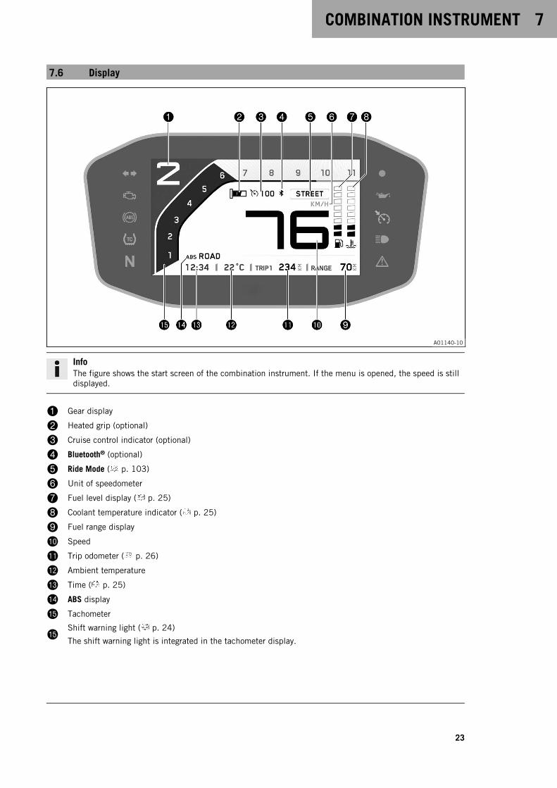
A01140-10
InfoThe figure shows the start screen of the combination instrument. If the menu is opened, the speed is stilldisplayed.
1 Gear display
2 Heated grip (optional)
3 Cruise control indicator (optional)
4 Bluetooth® (optional)
5 Ride Mode ( p. 103)
6 Unit of speedometer
7 Fuel level display ( p. 25)
8 Coolant temperature indicator ( p. 25)
9 Fuel range display
bk Speed
bl Trip odometer ( p. 26)
bm Ambient temperature
bn Time ( p. 25)
bo ABS display
bp Tachometer
bpShift warning light ( p. 24)
The shift warning light is integrated in the tachometer display.
7 COMBINATION INSTRUMENT
24
7.7 TRACK Display (optional)
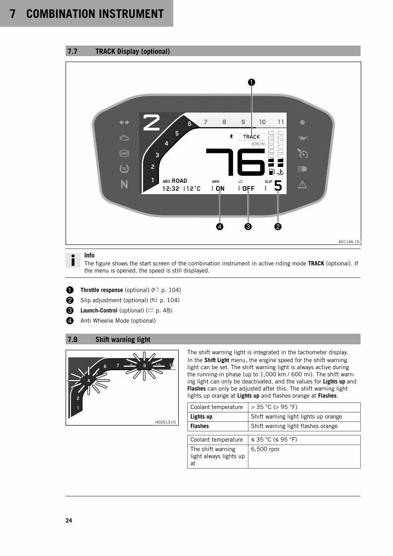
A01146-10
InfoThe figure shows the start screen of the combination instrument in active riding mode TRACK (optional). Ifthe menu is opened, the speed is still displayed.
1 Throttle response (optional) ( p. 104)
2 Slip adjustment (optional) ( p. 104)
3 Launch‑Control (optional) ( p. 48)
4 Anti Wheelie Mode (optional)
7.8 Shift warning light
H02613-01
The shift warning light is integrated in the tachometer display.In the Shift Light menu, the engine speed for the shift warninglight can be set. The shift warning light is always active duringthe running-in phase (up to 1,000 km / 600 mi). The shift warn-ing light can only be deactivated, and the values for Lights up andFlashes can only be adjusted after this. The shift warning lightlights up orange at Lights up and flashes orange at Flashes.
Coolant temperature > 35 °C (> 95 °F)
Lights up Shift warning light lights up orange
Flashes Shift warning light flashes orange
Coolant temperature ≤ 35 °C (≤ 95 °F)
The shift warninglight always lights upat
6,500 rpm

COMBINATION INSTRUMENT 7
25
7.9 Fuel level display
F02749-10
The fuel level indicator1 consists of bars. The more bars are lit,the more fuel is in the fuel tank.
InfoIf the fuel level is getting low, the last bar flashes orangeand the LOW FUEL warning also appears.The fuel level is displayed with a slight delay to prevent theindicator from constantly moving while riding.The fuel level display is not updated while the side stand isfolded out or the emergency off switch is switched off.Once the side stand is folded up and the emergency OFFswitch is switched on, the fuel level display is next updatedafter 2 minutes.The fuel level display flashes if the combination instrumentdoes not receive a signal from the fuel level sensor.
7.10 Time
F02750-10
The time1 is displayed in 24 hour format in all languagesexcept for EN-US. The time1 is displayed in 12 hour format ifthe language is set to EN-US.The time can be configured in the Clock/Date menu.
InfoThe time must be reset if the 12-V battery was discon-nected from the vehicle or the fuse was removed.
7.11 Coolant temperature indicator
H02616-01
NoteEngine failure Overheating damages the engine.
– If the coolant temperature warning is displayed, stop imme-diately and take care not to endanger yourself or other trafficparticipants in the process.
– Allow the engine and cooling system to cool down.
– Check and, if necessary, correct the coolant level on the cool-ing system while it is in a cooled state.
The temperature indicator consists of eight bars. The more barsthat light up, the hotter the coolant.Emergency mode operation is automatically activated at a coolanttemperature of 120 °C.
InfoWhen all the bars light up, the ENGINE TEMP HIGH warningalso appears.
Possible states
• The engine is cold – Up to three bars light up.
• Engine warm – Four to five bars light up.
• Engine hot – Six to eight bars light up.

7 COMBINATION INSTRUMENT
26
• Engine very hot – All eight bars flash orange.
7.12 Trip odometer
H02617-01
Trip 1 is displayed in the start screen as a trip odometer. This can-not be changed.Information about the total riding distance covered can beaccessed in the General Info menu under menu item Odometer.The trip odometer can be configured in the Trip 1 menu.Information about other distances traveled can be accessed andconfigured in the Trip 2 menu.
7.13 Menu
V01145-10
InfoPress the SET button1 to open the menu.
Navigate through the menu using the UP button2 orthe DOWN button3.
Press the BACK button4 to close the current menu or themenu overview.
7.13.1 Favorites
H02858-01
– Press the SET button when the menu is closed.
– Pressing the SET button again opens the menu.
– Press the UP or DOWN button to activate the menu item andselect it with the SET button.
You can directly open five freely configurable menus inthe Favorites menu.The Favorites menu is configured in the Set Favorites menu.
7.13.2 Trip 1
H02859-01
– Press the SET button when the menu is closed.
– Press the UP or DOWN button until the Trips/Data menu ismarked on the display. Press the SET button to open the menu.
– Press the UP or DOWN button until the Trip 1 menu is markedon the display. Press the SET button to open the menu.
Trip 1 shows the distance since the last reset, such as between tworefueling stops. Trip 1 is running and counts up to 9999.ØConsumption1 indicates the average fuel consumption based onTrip 1 and Trip time 1.ØSpeed1 indicates the average speed based on Trip 1 andTrip time 1.Trip time 1 shows the journey time on the basis of Trip 1 and runsas soon as a speed signal is received.

COMBINATION INSTRUMENT 7
27
Fuel range indicates the possible distance you can cover with thefuel reserve.
Press andhold the but-ton for 3–5seconds.
In the Trip 1 menu all entries apart fromFuel range are deleted.
7.13.3 Trip 2
H02857-01
– Press the SET button when the menu is closed.
– Press the UP or DOWN button until the Trips/Data menu ismarked on the display. Press the SET button to open the menu.
– Press the UP or DOWN button until the Trip 2 menu is markedon the display. Press the SET button to open the menu.
Trip 2 shows the distance since the last reset, such as between tworefueling stops. Trip 2 is running and counts up to 9999.ØConsumption2 indicates the average consumption based on Trip 2and Trip time 2.ØSpeed2 indicates the average speed based on Trip 2 andTrip time 2.Trip time 2 shows the journey time on the basis of Trip 2 and runsas soon as a speed signal is received.Fuel range indicates the possible distance you can cover with thefuel reserve.
Press andhold the but-ton for 3–5seconds.
In the Trip 2 menu all entries apart fromFuel range are deleted.
7.13.4 General Info
V01111-01
WarningDanger of accidents The tire pressure monitoring sys-tem does not eliminate the necessity to check the tiresbefore going on a ride.
To avoid false alarms, the tire pressure values areevaluated over a period of several minutes.
– Check the tire pressure before every ride.
– Correct the tire pressure if the tire pressure devi-ates from the specified value.
– Even if the tire pressure values are correct, stopthe vehicle immediately if its behavior indicates aloss of pressure in the tires.
– Press the SET button when the menu is closed.
– Press the UP or DOWN button until the Trips/Data menu ismarked on the display. Press the SET button to open the menu.
– Press the UP or DOWN button until the General Info menu ismarked on the display. Press the SET button to open the menu.
Date shows the date.Odometer shows the total distance covered.Battery indicates the battery voltage.Tire press fron (optional) indicates the tire pressure at the front.Tire press rear (optional) indicates the tire pressure at the rear.
7 COMBINATION INSTRUMENT
28
7.13.5 Settings
V01139-01
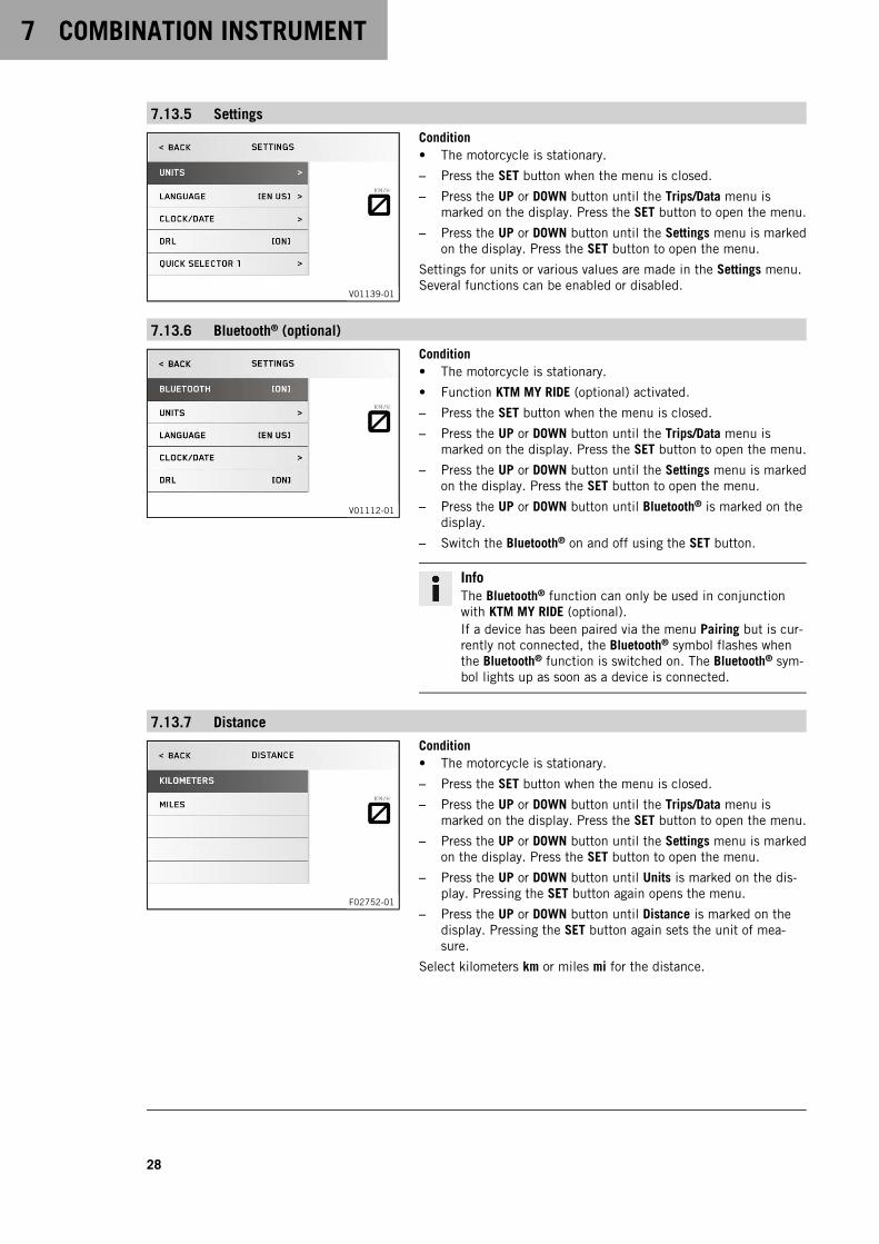
Condition• The motorcycle is stationary.
– Press the SET button when the menu is closed.
– Press the UP or DOWN button until the Trips/Data menu ismarked on the display. Press the SET button to open the menu.
– Press the UP or DOWN button until the Settings menu is markedon the display. Press the SET button to open the menu.
Settings for units or various values are made in the Settings menu.Several functions can be enabled or disabled.
7.13.6 Bluetooth® (optional)
V01112-01
Condition• The motorcycle is stationary.
• Function KTM MY RIDE (optional) activated.
– Press the SET button when the menu is closed.
– Press the UP or DOWN button until the Trips/Data menu ismarked on the display. Press the SET button to open the menu.
– Press the UP or DOWN button until the Settings menu is markedon the display. Press the SET button to open the menu.
– Press the UP or DOWN button until Bluetooth® is marked on thedisplay.
– Switch the Bluetooth® on and off using the SET button.
InfoThe Bluetooth® function can only be used in conjunctionwith KTM MY RIDE (optional).If a device has been paired via the menu Pairing but is cur-rently not connected, the Bluetooth® symbol flashes whenthe Bluetooth® function is switched on. The Bluetooth® sym-bol lights up as soon as a device is connected.
7.13.7 Distance
F02752-01
Condition• The motorcycle is stationary.
– Press the SET button when the menu is closed.
– Press the UP or DOWN button until the Trips/Data menu ismarked on the display. Press the SET button to open the menu.
– Press the UP or DOWN button until the Settings menu is markedon the display. Press the SET button to open the menu.
– Press the UP or DOWN button until Units is marked on the dis-play. Pressing the SET button again opens the menu.
– Press the UP or DOWN button until Distance is marked on thedisplay. Pressing the SET button again sets the unit of mea-sure.
Select kilometers km or miles mi for the distance.
COMBINATION INSTRUMENT 7
29
7.13.8 Temperature
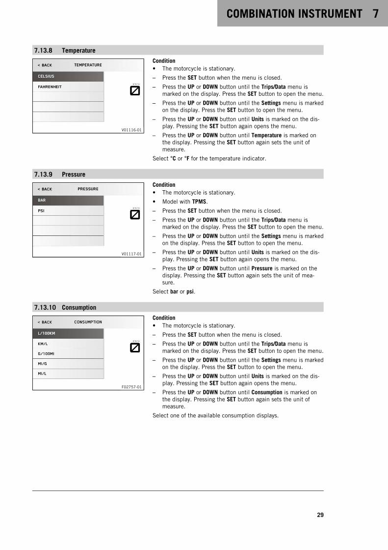
V01116-01
Condition• The motorcycle is stationary.
– Press the SET button when the menu is closed.
– Press the UP or DOWN button until the Trips/Data menu ismarked on the display. Press the SET button to open the menu.
– Press the UP or DOWN button until the Settings menu is markedon the display. Press the SET button to open the menu.
– Press the UP or DOWN button until Units is marked on the dis-play. Pressing the SET button again opens the menu.
– Press the UP or DOWN button until Temperature is marked onthe display. Pressing the SET button again sets the unit ofmeasure.
Select °C or °F for the temperature indicator.
7.13.9 Pressure
V01117-01
Condition• The motorcycle is stationary.
• Model with TPMS.
– Press the SET button when the menu is closed.
– Press the UP or DOWN button until the Trips/Data menu ismarked on the display. Press the SET button to open the menu.
– Press the UP or DOWN button until the Settings menu is markedon the display. Press the SET button to open the menu.
– Press the UP or DOWN button until Units is marked on the dis-play. Pressing the SET button again opens the menu.
– Press the UP or DOWN button until Pressure is marked on thedisplay. Pressing the SET button again sets the unit of mea-sure.
Select bar or psi.
7.13.10 Consumption
F02757-01
Condition• The motorcycle is stationary.
– Press the SET button when the menu is closed.
– Press the UP or DOWN button until the Trips/Data menu ismarked on the display. Press the SET button to open the menu.
– Press the UP or DOWN button until the Settings menu is markedon the display. Press the SET button to open the menu.
– Press the UP or DOWN button until Units is marked on the dis-play. Pressing the SET button again opens the menu.
– Press the UP or DOWN button until Consumption is marked onthe display. Pressing the SET button again sets the unit ofmeasure.
Select one of the available consumption displays.
7 COMBINATION INSTRUMENT
30
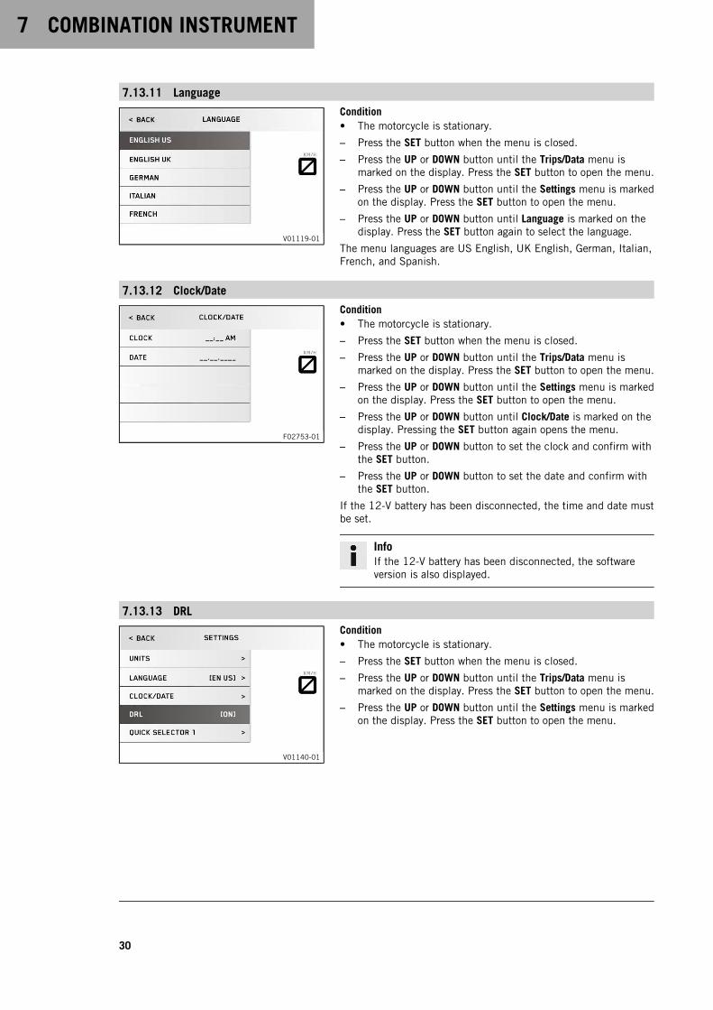
7.13.11 Language
V01119-01
Condition• The motorcycle is stationary.
– Press the SET button when the menu is closed.
– Press the UP or DOWN button until the Trips/Data menu ismarked on the display. Press the SET button to open the menu.
– Press the UP or DOWN button until the Settings menu is markedon the display. Press the SET button to open the menu.
– Press the UP or DOWN button until Language is marked on thedisplay. Press the SET button again to select the language.
The menu languages are US English, UK English, German, Italian,French, and Spanish.
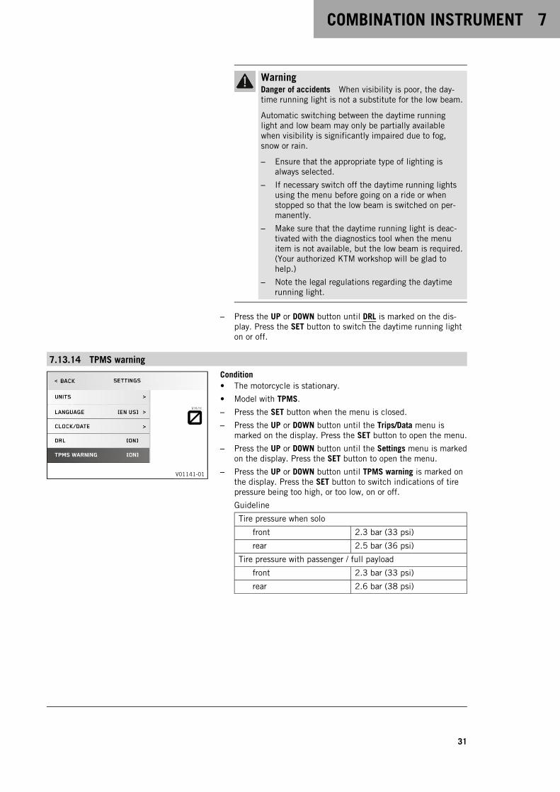
7.13.12 Clock/Date
F02753-01
Condition• The motorcycle is stationary.
– Press the SET button when the menu is closed.
– Press the UP or DOWN button until the Trips/Data menu ismarked on the display. Press the SET button to open the menu.
– Press the UP or DOWN button until the Settings menu is markedon the display. Press the SET button to open the menu.
– Press the UP or DOWN button until Clock/Date is marked on thedisplay. Pressing the SET button again opens the menu.
– Press the UP or DOWN button to set the clock and confirm withthe SET button.
– Press the UP or DOWN button to set the date and confirm withthe SET button.
If the 12-V battery has been disconnected, the time and date mustbe set.
InfoIf the 12-V battery has been disconnected, the softwareversion is also displayed.
7.13.13 DRL
V01140-01
Condition• The motorcycle is stationary.
– Press the SET button when the menu is closed.
– Press the UP or DOWN button until the Trips/Data menu ismarked on the display. Press the SET button to open the menu.
– Press the UP or DOWN button until the Settings menu is markedon the display. Press the SET button to open the menu.
COMBINATION INSTRUMENT 7
31
WarningDanger of accidents When visibility is poor, the day-time running light is not a substitute for the low beam.
Automatic switching between the daytime runninglight and low beam may only be partially availablewhen visibility is significantly impaired due to fog,snow or rain.
– Ensure that the appropriate type of lighting isalways selected.
– If necessary switch off the daytime running lightsusing the menu before going on a ride or whenstopped so that the low beam is switched on per-manently.
– Make sure that the daytime running light is deac-tivated with the diagnostics tool when the menuitem is not available, but the low beam is required.(Your authorized KTM workshop will be glad tohelp.)
– Note the legal regulations regarding the daytimerunning light.
– Press the UP or DOWN button until DRL is marked on the dis-play. Press the SET button to switch the daytime running lighton or off.
7.13.14 TPMS warning
V01141-01
Condition• The motorcycle is stationary.
• Model with TPMS.
– Press the SET button when the menu is closed.
– Press the UP or DOWN button until the Trips/Data menu ismarked on the display. Press the SET button to open the menu.
– Press the UP or DOWN button until the Settings menu is markedon the display. Press the SET button to open the menu.
– Press the UP or DOWN button until TPMS warning is marked onthe display. Press the SET button to switch indications of tirepressure being too high, or too low, on or off.
Guideline
Tire pressure when solo
front 2.3 bar (33 psi)
rear 2.5 bar (36 psi)
Tire pressure with passenger / full payload
front 2.3 bar (33 psi)
rear 2.6 bar (38 psi)
7 COMBINATION INSTRUMENT
32
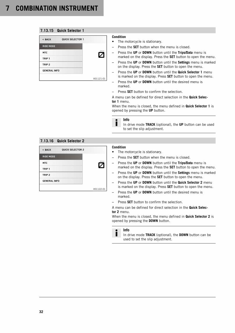
7.13.15 Quick Selector 1
V01121-01
Condition• The motorcycle is stationary.
– Press the SET button when the menu is closed.
– Press the UP or DOWN button until the Trips/Data menu ismarked on the display. Press the SET button to open the menu.
– Press the UP or DOWN button until the Settings menu is markedon the display. Press the SET button to open the menu.
– Press the UP or DOWN button until the Quick Selector 1 menuis marked on the display. Press SET button to open the menu.
– Press the UP or DOWN button until the desired menu ismarked.
– Press SET button to confirm the selection.
A menu can be defined for direct selection in the Quick Selec-tor 1 menu.When the menu is closed, the menu defined in Quick Selector 1 isopened by pressing the UP button.
InfoIn drive mode TRACK (optional), the UP button can be usedto set the slip adjustment.
7.13.16 Quick Selector 2
V01122-01
Condition• The motorcycle is stationary.
– Press the SET button when the menu is closed.
– Press the UP or DOWN button until the Trips/Data menu ismarked on the display. Press the SET button to open the menu.
– Press the UP or DOWN button until the Settings menu is markedon the display. Press the SET button to open the menu.
– Press the UP or DOWN button until the Quick Selector 2 menuis marked on the display. Press SET button to open the menu.
– Press the UP or DOWN button until the desired menu ismarked.
– Press SET button to confirm the selection.
A menu can be defined for direct selection in the Quick Selec-tor 2 menu.When the menu is closed, the menu defined in Quick Selector 2 isopened by pressing the DOWN button.
InfoIn drive mode TRACK (optional), the DOWN button can beused to set the slip adjustment.
COMBINATION INSTRUMENT 7
33
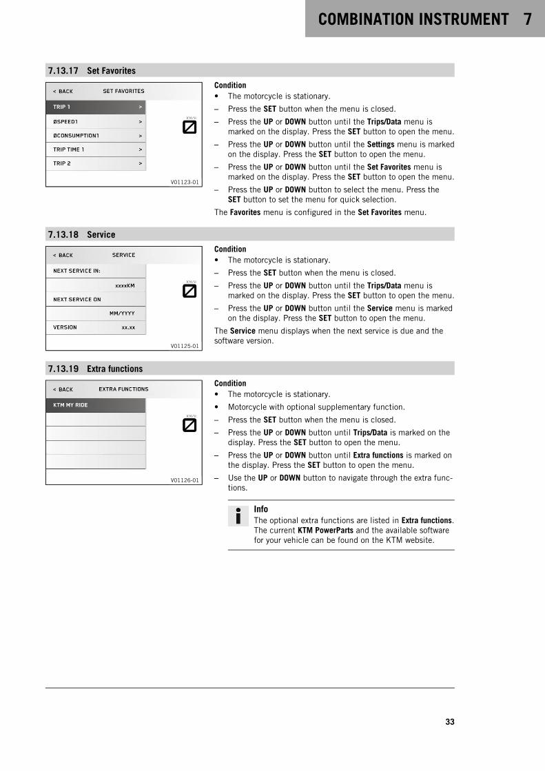
7.13.17 Set Favorites
V01123-01
Condition• The motorcycle is stationary.
– Press the SET button when the menu is closed.
– Press the UP or DOWN button until the Trips/Data menu ismarked on the display. Press the SET button to open the menu.
– Press the UP or DOWN button until the Settings menu is markedon the display. Press the SET button to open the menu.
– Press the UP or DOWN button until the Set Favorites menu ismarked on the display. Press the SET button to open the menu.
– Press the UP or DOWN button to select the menu. Press theSET button to set the menu for quick selection.
The Favorites menu is configured in the Set Favorites menu.
7.13.18 Service
V01125-01
Condition• The motorcycle is stationary.
– Press the SET button when the menu is closed.
– Press the UP or DOWN button until the Trips/Data menu ismarked on the display. Press the SET button to open the menu.
– Press the UP or DOWN button until the Service menu is markedon the display. Press the SET button to open the menu.
The Service menu displays when the next service is due and thesoftware version.
7.13.19 Extra functions
V01126-01
Condition• The motorcycle is stationary.
• Motorcycle with optional supplementary function.
– Press the SET button when the menu is closed.
– Press the UP or DOWN button until Trips/Data is marked on thedisplay. Press the SET button to open the menu.
– Press the UP or DOWN button until Extra functions is marked onthe display. Press the SET button to open the menu.
– Use the UP or DOWN button to navigate through the extra func-tions.
InfoThe optional extra functions are listed in Extra functions.The current KTM PowerParts and the available softwarefor your vehicle can be found on the KTM website.
7 COMBINATION INSTRUMENT
34
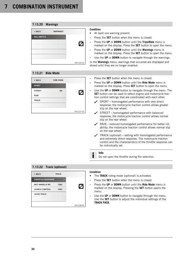
7.13.20 Warnings
V01124-01
Condition• At least one warning present.
– Press the SET button when the menu is closed.
– Press the UP or DOWN button until the Trips/Data menu ismarked on the display. Press the SET button to open the menu.
– Press the UP or DOWN button until the Warnings menu ismarked on the display. Press the SET button to open the menu.
– Use the UP or DOWN button to navigate through the warnings.
In the Warnings menu, warnings that occurred are displayed andstored until they are no longer enabled.
7.13.21 Ride Mode
V01127-01
– Press the SET button when the menu is closed.
– Press the UP or DOWN button until the Ride Mode menu ismarked on the display. Press SET button to open the menu.
– Use the UP or DOWN button to navigate through the menu. TheSET button can be used to select engine and motorcycle trac-tion control settings that are coordinated with each other.
SPORT – homologated performance with very directresponse; the motorcycle traction control allows greaterslip on the rear wheel.
STREET – homologated performance with balancedresponse; the motorcycle traction control allows normalslip on the rear wheel.
RAIN – reduced homologated performance for better rid-ability; the motorcycle traction control allows normal slipon the rear wheel.
TRACK (optional) – setting with homologated performanceand extremely direct response. The motorcycle tractioncontrol and the characteristics of the throttle response canbe individually set.
InfoDo not open the throttle during the selection.
7.13.22 Track (optional)
V01128-01
Condition• The TRACK riding mode (optional) is activated.
– Press the SET button when the menu is closed.
– Press the UP or DOWN button until the Ride Mode menu ismarked on the display. Pressing the SET button opens themenu.
– Use the UP or DOWN button to navigate through the menu.Use the SET button to adjust the individual settings of theTRACK PACK.
COMBINATION INSTRUMENT 7
35
InfoDo not open the throttle when setting the throttleresponse.The TRACK riding mode is ended via Leave Track andautomatically switches to the STREET riding mode. Donot open the throttle when doing so.
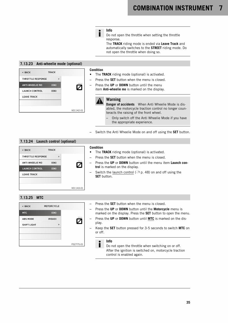
7.13.23 Anti‑wheelie mode (optional)
V01142-01
Condition• The TRACK riding mode (optional) is activated.
– Press the SET button when the menu is closed.
– Press the UP or DOWN button until the menuitem Anti‑wheelie mo is marked on the display.
WarningDanger of accidents When Anti Wheelie Mode is dis-abled, the motorcycle traction control no longer coun-teracts the raising of the front wheel.
– Only switch off the Anti Wheelie Mode if you havethe appropriate experience.
– Switch the Anti Wheelie Mode on and off using the SET button.
7.13.24 Launch control (optional)
V01143-01
Condition• The TRACK riding mode (optional) is activated.
– Press the SET button when the menu is closed.
– Press the UP or DOWN button until the menu item Launch con-trol is marked on the display.
– Switch the launch control ( p. 48) on and off using theSET button.
7.13.25 MTC
F02775-01
– Press the SET button when the menu is closed.
– Press the UP or DOWN button until the Motorcycle menu ismarked on the display. Press the SET button to open the menu.
– Press the UP or DOWN button until MTC is marked on the dis-play.
– Keep the SET button pressed for 3-5 seconds to switch MTC onor off.
InfoDo not open the throttle when switching on or off.After the ignition is switched on, motorcycle tractioncontrol is enabled again.
7 COMBINATION INSTRUMENT
36
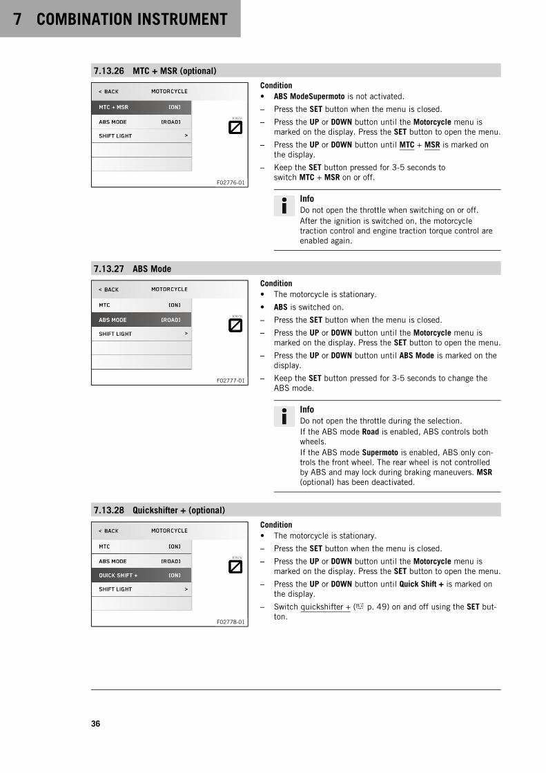
7.13.26 MTC + MSR (optional)
F02776-01
Condition• ABS ModeSupermoto is not activated.
– Press the SET button when the menu is closed.
– Press the UP or DOWN button until the Motorcycle menu ismarked on the display. Press the SET button to open the menu.
– Press the UP or DOWN button until MTC + MSR is marked onthe display.
– Keep the SET button pressed for 3-5 seconds toswitch MTC + MSR on or off.
InfoDo not open the throttle when switching on or off.After the ignition is switched on, the motorcycletraction control and engine traction torque control areenabled again.
7.13.27 ABS Mode
F02777-01
Condition• The motorcycle is stationary.
• ABS is switched on.
– Press the SET button when the menu is closed.
– Press the UP or DOWN button until the Motorcycle menu ismarked on the display. Press the SET button to open the menu.
– Press the UP or DOWN button until ABS Mode is marked on thedisplay.
– Keep the SET button pressed for 3-5 seconds to change theABS mode.
InfoDo not open the throttle during the selection.If the ABS mode Road is enabled, ABS controls bothwheels.If the ABS mode Supermoto is enabled, ABS only con-trols the front wheel. The rear wheel is not controlledby ABS and may lock during braking maneuvers. MSR(optional) has been deactivated.
7.13.28 Quickshifter + (optional)
F02778-01
Condition• The motorcycle is stationary.
– Press the SET button when the menu is closed.
– Press the UP or DOWN button until the Motorcycle menu ismarked on the display. Press the SET button to open the menu.
– Press the UP or DOWN button until Quick Shift + is marked onthe display.
– Switch quickshifter + ( p. 49) on and off using the SET but-ton.

COMBINATION INSTRUMENT 7
37
7.13.29 Shift Light
V01134-01
Condition• The motorcycle is stationary.
• ODO > 1,000 km (600 mi).
– Press the SET button when the menu is closed.
– Press the UP or DOWN button until the Motorcycle menu ismarked on the display. Press the SET button to open the menu.
– Press the UP or DOWN button until the Shift Light menu ismarked on the display. Press the SET button to open the menu.
– Press the UP or DOWN button to select the function. Use theSET button to set the engine speed for the gear shift recom-mendation.
Once the engine speed reaches the engine speed specified atLights up, the speed display lights up orange.Once the engine speed reaches the engine speed specified atFlashes, the speed display flashes orange.The gear shift recommendation can be switched on or off with thefunction Shift Light.
7.13.30 KTM MY RIDE (optional)
V01135-01
Condition• Function KTM MY RIDE (optional) activated.
• Function Bluetooth® (optional) activated.
– Press the SET button when the menu is closed.
– Press the UP or DOWN button until the KTM MY RIDE menu ismarked on the display. Press the SET button to open the menu.
In KTM MY RIDE, an appropriate cellphone or headset can bepaired via Bluetooth® with the KTM MY RIDE control unit.
InfoNot every cellphone and headset is suitable for pairing withthe KTM MY RIDE control unit.The standard Bluetooth® 2.1 must be supported.
7.13.31 Pairing (optional)
V01137-01
Condition• The motorcycle is stationary.
• Function KTM MY RIDE (optional) activated.
• Bluetooth® (optional) is switched on.
• The Bluetooth® should also be switched on in the device to bepaired.
• The Bluetooth®visibility must be activated on the device that isto be paired.
– Press the SET button when the menu is closed.
– Press the UP or DOWN button until the KTM MY RIDE menu ismarked on the display. Press the SET button to open the menu.
– Press the UP or DOWN button until Setup is marked on the dis-play. Press the SET button to open the menu.
– Press the UP or the DOWN button until the menu item Phone orHeadset is marked.
7 COMBINATION INSTRUMENT
38
InfoTwo cellphones or headsets can never be pairedsimultaneously with the KTM MY RIDE control unit. Onlyone cellphone and one headset can be paired with theKTM MY RIDE control unit at the same time.
– In the submenu Phone, a suitable cellphone can be paired withthe KTM MY RIDE control unit.
– In the submenu Headset, a suitable headset can be paired withthe KTM MY RIDE control unit.
– Press the SET button to open the menu.
– When pairing the device for the first time, press the UPor DOWN button until Pairing is marked. Press the SET buttonto open the menu.
– Navigate to the device required using the UP or DOWN button.Confirm the selection using the SET button.
InfoThe headset pairing is now finished.
– Confirmation of the Passkey successfully completes the cell-phone pairing.
InfoWhen a suitable device has been successfully paired,the name of the paired cellphone or headset appears ineach case in the Phone or Headset menu.Press the UP or DOWN button until the paired device ismarked. The paired device can be deleted by pressingthe SET button.The device most recently linked is automatically pairedwith the KTM MY RIDE control unit when Bluetooth® isswitched on and as soon as this device is in range andhas not been previously deleted.Not every cellphone or headset is suitable for pairingwith the KTM MY RIDE control unit.Make sure that the end device is in the correct pairingmode for call administration. If the end device is onlypaired for media playback, the call function may notwork.
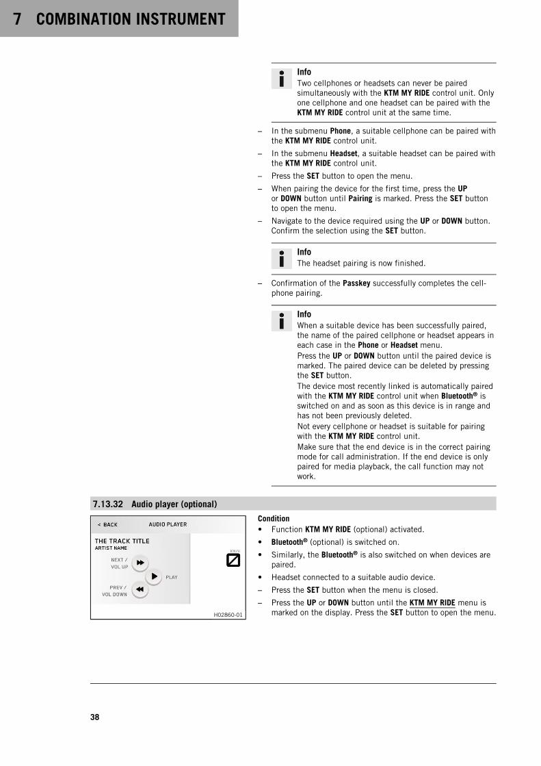
7.13.32 Audio player (optional)
H02860-01
Condition• Function KTM MY RIDE (optional) activated.
• Bluetooth® (optional) is switched on.
• Similarly, the Bluetooth® is also switched on when devices arepaired.
• Headset connected to a suitable audio device.
– Press the SET button when the menu is closed.
– Press the UP or DOWN button until the KTM MY RIDE menu ismarked on the display. Press the SET button to open the menu.
COMBINATION INSTRUMENT 7
39
WarningDanger of accidents Headphone volume which is toohigh distracts attention from traffic activity.
– Always select headphone volume which is lowenough for you to still clearly hear acoustic signals.
– Press the UP or DOWN button until Audio player is marked onthe display. Press the SET button to open the menu.
– Press and hold the UP button to increase the audio volume.
– Press and hold DOWN button to reduce the audio volume.
– Press the UP button briefly to change to the next audio track.
– Press the DOWN button briefly to play the audio track from thebeginning.
– Press the DOWN button twice to change to the previous audiotrack.
– Press the SET button to play or pause the audio track.
TipWith some cellphones, the cellphone audio playerneeds to be started before a playback is possible.The audio function can be added to Quick Selector 1 orQuick Selector 2 for easier operation.
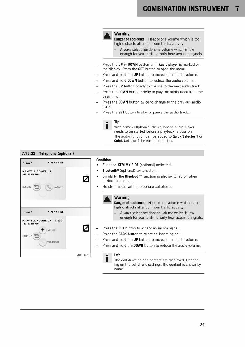
7.13.33 Telephony (optional)
V01138-01
Condition• Function KTM MY RIDE (optional) activated.
• Bluetooth® (optional) switched on.
• Similarly, the Bluetooth® function is also switched on whendevices are paired.
• Headset linked with appropriate cellphone.
WarningDanger of accidents Headphone volume which is toohigh distracts attention from traffic activity.
– Always select headphone volume which is lowenough for you to still clearly hear acoustic signals.
– Press the SET button to accept an incoming call.
– Press the BACK button to reject an incoming call.
– Press and hold the UP button to increase the audio volume.
– Press and hold the DOWN button to reduce the audio volume.
InfoThe call duration and contact are displayed. Depend-ing on the cellphone settings, the contact is shown byname.
8 ERGONOMICS
40
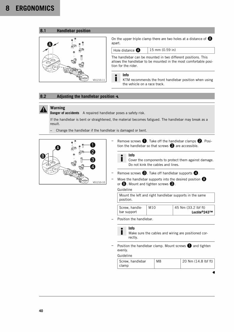
8.1 Handlebar position
V01210-11
On the upper triple clamp there are two holes at a distance ofAapart.
Hole distanceA 15 mm (0.59 in)
The handlebar can be mounted in two different positions. Thisallows the handlebar to be mounted in the most comfortable posi-tion for the rider.
InfoKTM recommends the front handlebar position when usingthe vehicle on a race track.
8.2 Adjusting the handlebar position
WarningDanger of accidents A repaired handlebar poses a safety risk.
If the handlebar is bent or straightened, the material becomes fatigued. The handlebar may break as aresult.
– Change the handlebar if the handlebar is damaged or bent.
V01210-10
– Remove screws1. Take off the handlebar clamps2. Posi-tion the handlebar so that screws3 are accessible.
InfoCover the components to protect them against damage.Do not kink the cables and lines.
– Remove screws3. Take off handlebar supports4.
– Move the handlebar supports into the desired positionAorB. Mount and tighten screws3.
Guideline
Mount the left and right handlebar supports in the sameposition.
Screw, handle-bar support
M10 45 Nm (33.2 lbf ft)Loctite®243™
– Position the handlebar.
InfoMake sure the cables and wiring are positioned cor-rectly.
– Position the handlebar clamp. Mount screws1 and tightenevenly.
Guideline
Screw, handlebarclamp
M8 20 Nm (14.8 lbf ft)
ERGONOMICS 8
41
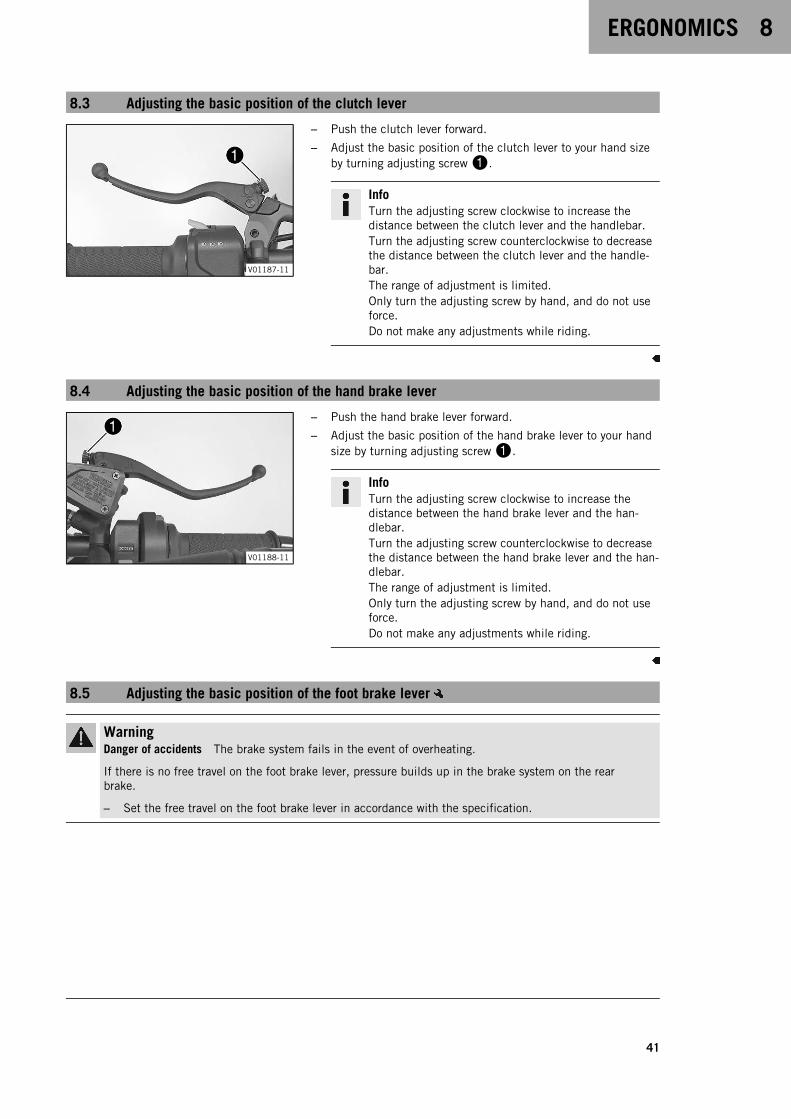
8.3 Adjusting the basic position of the clutch lever
V01187-11
– Push the clutch lever forward.
– Adjust the basic position of the clutch lever to your hand sizeby turning adjusting screw1.
InfoTurn the adjusting screw clockwise to increase thedistance between the clutch lever and the handlebar.Turn the adjusting screw counterclockwise to decreasethe distance between the clutch lever and the handle-bar.The range of adjustment is limited.Only turn the adjusting screw by hand, and do not useforce.Do not make any adjustments while riding.
8.4 Adjusting the basic position of the hand brake lever
V01188-11
– Push the hand brake lever forward.
– Adjust the basic position of the hand brake lever to your handsize by turning adjusting screw1.
InfoTurn the adjusting screw clockwise to increase thedistance between the hand brake lever and the han-dlebar.Turn the adjusting screw counterclockwise to decreasethe distance between the hand brake lever and the han-dlebar.The range of adjustment is limited.Only turn the adjusting screw by hand, and do not useforce.Do not make any adjustments while riding.
8.5 Adjusting the basic position of the foot brake lever
WarningDanger of accidents The brake system fails in the event of overheating.
If there is no free travel on the foot brake lever, pressure builds up in the brake system on the rearbrake.
– Set the free travel on the foot brake lever in accordance with the specification.
8 ERGONOMICS
42
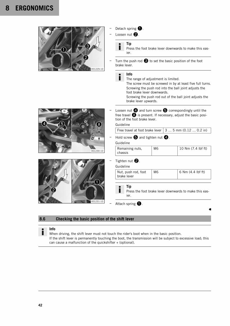
V01229-10
– Detach spring1.
– Loosen nut2.
TipPress the foot brake lever downwards to make this eas-ier.
– Turn the push rod3 to set the basic position of the footbrake lever.
InfoThe range of adjustment is limited.The screw must be screwed in by at least five full turns.Screwing the push rod into the ball joint adjusts thefoot brake lever downwards.Screwing the push rod out of the ball joint adjusts thebrake lever upwards.
V01230-10
– Loosen nut4 and turn screw5 correspondingly until thefree travelA is present. If necessary, adjust the basic posi-tion of the foot brake lever.
Guideline
Free travel at foot brake lever 3 … 5 mm (0.12 … 0.2 in)
– Hold screw5 and tighten nut4.
Guideline
Remaining nuts,chassis
M6 10 Nm (7.4 lbf ft)
V01231-10
– Tighten nut2.
Guideline
Nut, push rod, footbrake lever
M6 6 Nm (4.4 lbf ft)
TipPress the foot brake lever downwards to make this eas-ier.
– Attach spring1.
8.6 Checking the basic position of the shift lever
InfoWhen driving, the shift lever must not touch the rider's boot when in the basic position.If the shift lever is permanently touching the boot, the transmission will be subject to excessive load; thiscan cause a malfunction of the quickshifter + (optional).
ERGONOMICS 8
43
400692-10
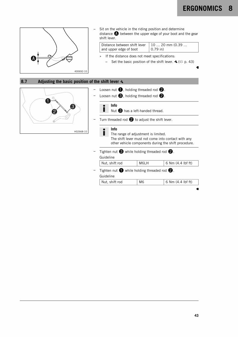
– Sit on the vehicle in the riding position and determinedistanceA between the upper edge of your boot and the gearshift lever.
Distance between shift leverand upper edge of boot
10 … 20 mm (0.39 …0.79 in)
» If the distance does not meet specifications:
– Set the basic position of the shift lever. ( p. 43)
8.7 Adjusting the basic position of the shift lever
H02668-10
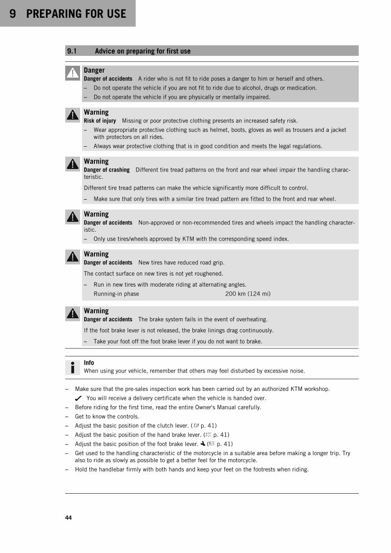
– Loosen nut1, holding threaded rod2.
– Loosen nut3, holding threaded rod2.
InfoNut3 has a left-handed thread.
– Turn threaded rod2 to adjust the shift lever.
InfoThe range of adjustment is limited.The shift lever must not come into contact with anyother vehicle components during the shift procedure.
– Tighten nut3 while holding threaded rod2.
Guideline
Nut, shift rod M6LH 6 Nm (4.4 lbf ft)
– Tighten nut1 while holding threaded rod2.
Guideline
Nut, shift rod M6 6 Nm (4.4 lbf ft)
9 PREPARING FOR USE
44
9.1 Advice on preparing for first use
DangerDanger of accidents A rider who is not fit to ride poses a danger to him or herself and others.
– Do not operate the vehicle if you are not fit to ride due to alcohol, drugs or medication.
– Do not operate the vehicle if you are physically or mentally impaired.
WarningRisk of injury Missing or poor protective clothing presents an increased safety risk.
– Wear appropriate protective clothing such as helmet, boots, gloves as well as trousers and a jacketwith protectors on all rides.
– Always wear protective clothing that is in good condition and meets the legal regulations.
WarningDanger of crashing Different tire tread patterns on the front and rear wheel impair the handling charac-teristic.
Different tire tread patterns can make the vehicle significantly more difficult to control.
– Make sure that only tires with a similar tire tread pattern are fitted to the front and rear wheel.
WarningDanger of accidents Non-approved or non-recommended tires and wheels impact the handling character-istic.
– Only use tires/wheels approved by KTM with the corresponding speed index.
WarningDanger of accidents New tires have reduced road grip.
The contact surface on new tires is not yet roughened.
– Run in new tires with moderate riding at alternating angles.
Running-in phase 200 km (124 mi)
WarningDanger of accidents The brake system fails in the event of overheating.
If the foot brake lever is not released, the brake linings drag continuously.
– Take your foot off the foot brake lever if you do not want to brake.
InfoWhen using your vehicle, remember that others may feel disturbed by excessive noise.
– Make sure that the pre-sales inspection work has been carried out by an authorized KTM workshop.
You will receive a delivery certificate when the vehicle is handed over.
– Before riding for the first time, read the entire Owner's Manual carefully.
– Get to know the controls.
– Adjust the basic position of the clutch lever. ( p. 41)
– Adjust the basic position of the hand brake lever. ( p. 41)
– Adjust the basic position of the foot brake lever. ( p. 41)
– Get used to the handling characteristic of the motorcycle in a suitable area before making a longer trip. Tryalso to ride as slowly as possible to get a better feel for the motorcycle.
– Hold the handlebar firmly with both hands and keep your feet on the footrests when riding.
PREPARING FOR USE 9
45
– Run the engine in. ( p. 45)
9.2 Running in the engine
– During the running-in phase, do not exceed the specified engine speed.
Guideline
Maximum engine speed
During the first: 1,000 km (620 mi) 6,500 rpm
After the first: 1,000 km (620 mi) 9,800 rpm
– Avoid fully opening the throttle!
9.3 Loading the vehicle
WarningDanger of accidents Total weight and axle loads influence the handling characteristic.
The total weight consists of: operational motorcycle with a full tank, rider and, if necessary, a passengerwith protective clothing and helmet, and, if necessary, mounted luggage.
– Do not exceed the maximum permissible overall weight or the axle loads.
WarningDanger of accidents Improper mounting of cases, tank rucksacks or other luggage impairs the handlingcharacteristics.
Luggage mounted incorrectly can slip while the vehicle is in motion.
– Mount and secure all luggage according to the manufacturer's instructions.
– Check that your luggage is fixed properly at regular intervals.
WarningDanger of accidents Carrying luggage alters handling characteristics at high speed.
– Adapt your speed to your payload.
– Ride more slowly if your motorcycle is loaded with cases or other luggage.
Maximum speed with baggage 130 km/h (80.8 mph)
WarningDanger of accidents The luggage system will be damaged if it is overloaded.
– Read the manufacturer information on maximum payload when mounting cases.
WarningDanger of accidents Luggage which has slipped impairs visibility.
If the tail light is covered, you are less visible to traffic behind you, especially when it is dark.
– Check that your luggage is fixed properly at regular intervals.
WarningDanger of accidents A high payload alters the handling characteristic and increases the stoppingdistance.
– Adapt your speed to your payload.
9 PREPARING FOR USE
46
WarningFire hazard The hot exhaust system may burn luggage.
– Fasten your luggage in such a way that it cannot be burned or singed by the hot exhaust system.
– If you carry luggage, make sure you secure it firmly as close as possible to the center of the vehicle andensure even weight distribution between the front and rear wheels.
– Do not exceed the maximum permissible weight and the maximum permissible axle loads.
Guideline
Maximum permissible overall weight 430 kg (948 lb.)
Maximum permissible front axle load 160 kg (353 lb.)
Maximum permissible rear axle load 270 kg (595 lb.)

RIDING INSTRUCTIONS 10
47
10.1 Checks and maintenance measures when preparing for use
InfoBefore every trip, check the condition of the vehicle and ensure that it is roadworthy.The vehicle must be in perfect technical condition when it is being operated.
H02217-01
– Check the engine oil level. ( p. 105)
– Check the front brake fluid level. ( p. 70)
– Check the rear brake fluid level. ( p. 73)
– Check the front brake linings. ( p. 72)
– Check the rear brake linings. ( p. 75)
– Check that the brake system is functioning properly.
– Check coolant level in the compensating tank. ( p. 98)
– Check the chain for dirt. ( p. 64)
– Check the chain tension. ( p. 65)
– Check the tire condition. ( p. 82)
– Check tire pressure. ( p. 83)
– Check the settings of all controls and ensure that they can beoperated smoothly.
– Check that the electrical system is functioning properly.
– Check that luggage is properly secured.
– Sit on the motorcycle and check the rear mirror setting.
– Check the fuel level.
10.2 Starting the vehicle
DangerDanger of poisoning Exhaust gases are toxic and inhaling them may result in unconsciousness and death.
– Always make sure there is sufficient ventilation when running the engine.
– Use effective exhaust extraction when starting or running the engine in an enclosed space.
CautionDanger of accidents Electronic components and safety devices will be damaged if the 12-V battery is dis-charged or missing.
If the 12-V battery is discharged or defective, malfunctions in the vehicle electronics can occur, espe-cially when starting.
– Never operate the vehicle with a discharged 12-V battery or without a 12-V battery.
NoteEngine damage High revving speed with a cold engine negatively impacts the lifespan of the engine.
– Always run the engine warm at a low speed.
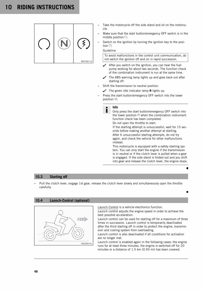
10 RIDING INSTRUCTIONS
48
B00782-10
– Take the motorcycle off the side stand and sit on the motorcy-cle.
– Make sure that the start button/emergency OFF switch is in themiddle position .
– Switch on the ignition by turning the ignition key to the posi-tion .
Guideline
To avoid malfunctions in the control unit communication, donot switch the ignition off and on in rapid succession.
After you switch on the ignition, you can hear the fuelpump working for about two seconds. The function checkof the combination instrument is run at the same time.
The ABS warning lamp lights up and goes back out afterstarting off.
– Shift the transmission to neutral position.
The green idle indicator lamp N lights up.
– Press the start button/emergency OFF switch into the lowerposition .
InfoOnly press the start button/emergency OFF switch intothe lower position when the combination instrumentfunction check has been completed.Do not open the throttle to start.If the starting attempt is unsuccessful, wait for 15 sec-onds before making another attempt at starting.After 6 unsuccessful starting attempts, do not tryagain, and check the vehicle for other malfunctionsinstead.This motorcycle is equipped with a safety starting sys-tem. You can only start the engine if the transmissionis in neutral or if the clutch lever is pulled when a gearis engaged. If the side stand is folded out and you shiftinto gear and release the clutch lever, the engine stops.
10.3 Starting off
– Pull the clutch lever, engage 1st gear, release the clutch lever slowly and simultaneously open the throttlecarefully.
10.4 Launch‑Control (optional)
H02000-01
Launch Control is a vehicle electronics function.Launch control adjusts the engine speed in order to achieve thebest possible acceleration.Launch control can be used for starting off for a maximum of threetimes in succession. Launch control is temporarily deactivatedafter the third starting off in order to protect the engine, transmis-sion and cooling system from overloading.Launch control is also deactivated if all conditions for activationare no longer met.Launch control is enabled again in the following cases: the engineruns for at least three minutes, the engine is switched off for 20minutes or a distance of 1.5 km (0.93 mi) has been covered.

RIDING INSTRUCTIONS 10
49
10.5 Starting off with launch control (optional)
WarningDanger of accidents Launch control enables very powerful acceleration which may ask too much of anovice rider.
– Only use the launch control if you have the appropriate experience.
– Do not use launch control on public roads.
H02000-01
ConditionThe TRACK riding mode (optional) is activated.First gear is engaged.The TC indicator lamp does not light up.Coolant temperature: > 60 °C (> 140 °F)Total riding distance covered: > 1,000 km (> 620 mi)
– Activate launch control in the combination instrument.
The number of available starts is indicated on the startscreen.
– Apply full throttle with the clutch lever pulled.
The engine speed is adjusted.
9,000 rpm
The TC indicator lamp flashes quickly.
– Release clutch lever quickly but in a controlled manner.
10.6 Quickshifter + (optional)
V01270-10
If the quickshifter + is activated, you can shift up and down with-out actuating the clutch.Because there is no need to close the throttle grip, uninterruptedgear shifts are possible.The quickshifter + uses the shifter shaft position to check whetheror not a shift should be initiated, and sends a corresponding signalto the engine control.If the quickshifter + is disabled in the combination instrument,the clutch needs to be actuated in the normal way for each shift.
10 RIDING INSTRUCTIONS
50
10.7 Shifting, riding
WarningDanger of accidents Abrupt load alterations can cause the vehicle to get out of control.
– Avoid abrupt load alterations and sudden braking actions.
– Adapt your speed to the road conditions.
WarningDanger of accidents If you change down at high engine speed, the rear wheel blocks and the engineraces.
– Do not change into a low gear at high engine speed.
WarningDanger of accidents An incorrect ignition key position causes malfunctions.
– Do not change the ignition key position while driving.
WarningDanger of accidents Adjustments to the vehicle distract attention from traffic activity.
– Make all adjustments when the vehicle is at a standstill.
WarningRisk of injury The passenger may fall from the motorcycle if they conduct themselves incorrectly.
– Ensure that the passenger sits correctly on the passenger seat, places his or her feet on the passengerfoot pegs and holds on to the rider or the grab handles.
– Note the regulations governing the minimum age of passengers in your country.
WarningDanger of accidents A risky riding style constitutes a major risk.
– Comply with traffic regulations and ride defensively and with foresight to detect sources of danger asearly as possible.
WarningDanger of accidents Cold tires have reduced road grip.
– Ride the first miles carefully on every journey at moderate speed until the tires reach operating tem-perature.
WarningDanger of accidents New tires have reduced road grip.
The contact surface on new tires is not yet roughened.
– Run in new tires with moderate riding at alternating angles.
Running-in phase 200 km (124 mi)
WarningDanger of accidents Total weight and axle loads influence the handling characteristic.
The total weight consists of: operational motorcycle with a full tank, rider and, if necessary, a passengerwith protective clothing and helmet, and, if necessary, mounted luggage.
– Do not exceed the maximum permissible overall weight or the axle loads.
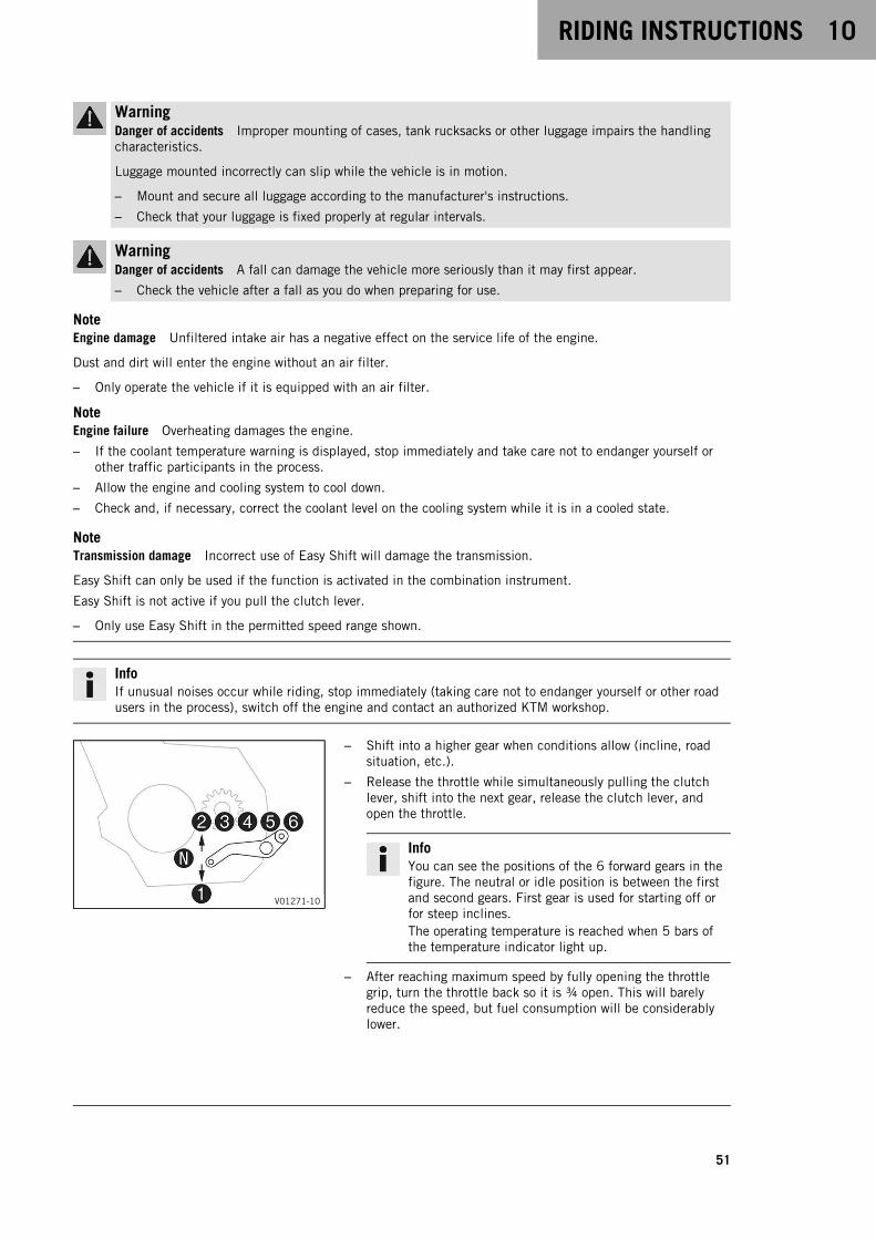
RIDING INSTRUCTIONS 10
51
WarningDanger of accidents Improper mounting of cases, tank rucksacks or other luggage impairs the handlingcharacteristics.
Luggage mounted incorrectly can slip while the vehicle is in motion.
– Mount and secure all luggage according to the manufacturer's instructions.
– Check that your luggage is fixed properly at regular intervals.
WarningDanger of accidents A fall can damage the vehicle more seriously than it may first appear.
– Check the vehicle after a fall as you do when preparing for use.
NoteEngine damage Unfiltered intake air has a negative effect on the service life of the engine.
Dust and dirt will enter the engine without an air filter.
– Only operate the vehicle if it is equipped with an air filter.
NoteEngine failure Overheating damages the engine.
– If the coolant temperature warning is displayed, stop immediately and take care not to endanger yourself orother traffic participants in the process.
– Allow the engine and cooling system to cool down.
– Check and, if necessary, correct the coolant level on the cooling system while it is in a cooled state.
NoteTransmission damage Incorrect use of Easy Shift will damage the transmission.
Easy Shift can only be used if the function is activated in the combination instrument.
Easy Shift is not active if you pull the clutch lever.
– Only use Easy Shift in the permitted speed range shown.
InfoIf unusual noises occur while riding, stop immediately (taking care not to endanger yourself or other roadusers in the process), switch off the engine and contact an authorized KTM workshop.
V01271-10
– Shift into a higher gear when conditions allow (incline, roadsituation, etc.).
– Release the throttle while simultaneously pulling the clutchlever, shift into the next gear, release the clutch lever, andopen the throttle.
InfoYou can see the positions of the 6 forward gears in thefigure. The neutral or idle position is between the firstand second gears. First gear is used for starting off orfor steep inclines.The operating temperature is reached when 5 bars ofthe temperature indicator light up.
– After reaching maximum speed by fully opening the throttlegrip, turn the throttle back so it is ¾ open. This will barelyreduce the speed, but fuel consumption will be considerablylower.
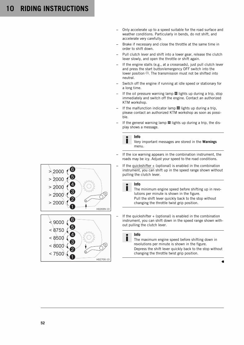
10 RIDING INSTRUCTIONS
52
– Only accelerate up to a speed suitable for the road surface andweather conditions. Particularly in bends, do not shift, andaccelerate very carefully.
– Brake if necessary and close the throttle at the same time inorder to shift down.
– Pull clutch lever and shift into a lower gear, release the clutchlever slowly, and open the throttle or shift again.
– If the engine stalls (e.g., at a crossroads), just pull clutch leverand press the start button/emergency OFF switch into thelower position . The transmission must not be shifted intoneutral.
– Switch off the engine if running at idle speed or stationary fora long time.
– If the oil pressure warning lamp lights up during a trip, stopimmediately and switch off the engine. Contact an authorizedKTM workshop.
– If the malfunction indicator lamp lights up during a trip,please contact an authorized KTM workshop as soon as possi-ble.
– If the general warning lamp lights up during a trip, the dis-play shows a message.
InfoVery important messages are stored in the Warningsmenu.
– If the ice warning appears in the combination instrument, theroads may be icy. Adjust your speed to the road conditions.
H02699-10
– If the quickshifter + (optional) is enabled in the combinationinstrument, you can shift up in the speed range shown withoutpulling the clutch lever.
InfoThe minimum engine speed before shifting up in revo-lutions per minute is shown in the figure.Pull the shift lever quickly back to the stop withoutchanging the throttle twist grip position.
H02700-10
– If the quickshifter + (optional) is enabled in the combinationinstrument, you can shift down in the speed range shown with-out pulling the clutch lever.
InfoThe maximum engine speed before shifting down inrevolutions per minute is shown in the figure.Depress the shift lever quickly back to the stop withoutchanging the throttle twist grip position.
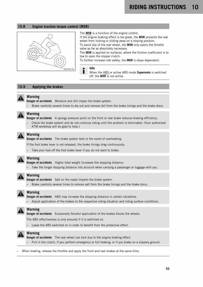
RIDING INSTRUCTIONS 10
53
10.8 Engine traction torque control (MSR)
402423-01
The MSR is a function of the engine control.If the engine braking effect is too great, the MSR prevents the rearwheel from locking or sliding away on a sloping position.To avoid slip of the rear wheel, the MSR only opens the throttlevalve as far as absolutely necessary.The MSR is applied on surfaces, where the friction coefficient is tolow to open the slipper clutch.To further increase ride safety, the MSR is slope dependent.
InfoWhen the ABS or active ABS mode Supermoto is switchedoff, the MSR is not active.
10.9 Applying the brakes
WarningDanger of accidents Moisture and dirt impair the brake system.
– Brake carefully several times to dry out and remove dirt from the brake linings and the brake discs.
WarningDanger of accidents A spongy pressure point on the front or rear brake reduces braking efficiency.
– Check the brake system and do not continue riding until the problem is eliminated. (Your authorizedKTM workshop will be glad to help.)
WarningDanger of accidents The brake system fails in the event of overheating.
If the foot brake lever is not released, the brake linings drag continuously.
– Take your foot off the foot brake lever if you do not want to brake.
WarningDanger of accidents Higher total weight increases the stopping distance.
– Take the longer stopping distance into account when carrying a passenger or luggage with you.
WarningDanger of accidents Salt on the roads impairs the brake system.
– Brake carefully several times to remove salt from the brake linings and the brake discs.
WarningDanger of accidents ABS may increase the stopping distance in certain situations.
– Adjust application of the brakes to the respective riding situation and riding surface conditions.
WarningDanger of accidents Excessively forceful application of the brakes blocks the wheels.
The ABS effectiveness is only ensured if it is switched on.
– Leave the ABS switched on in order to benefit from the protective effect.
WarningDanger of accidents The rear wheel can lock due to the engine braking effect.
– Pull in the clutch, if you perform emergency or full braking, or if you brake on a slippery ground.
– When braking, release the throttle and apply the front and rear brakes at the same time.
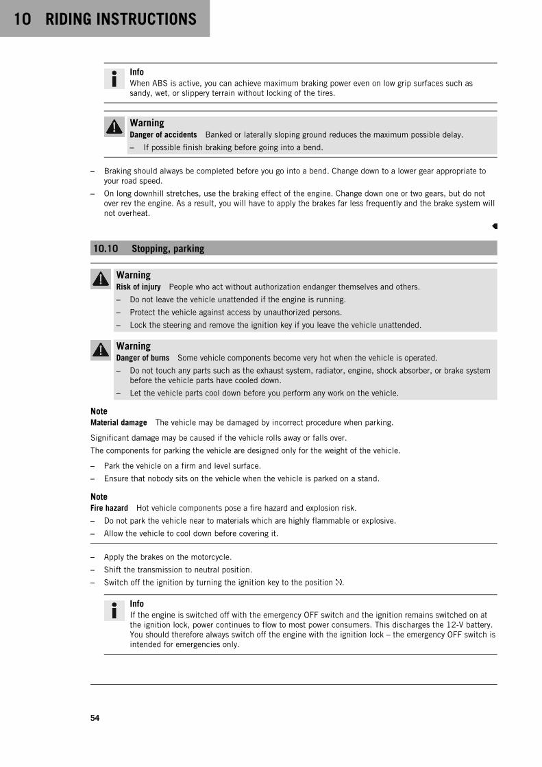
10 RIDING INSTRUCTIONS
54
InfoWhen ABS is active, you can achieve maximum braking power even on low grip surfaces such assandy, wet, or slippery terrain without locking of the tires.
WarningDanger of accidents Banked or laterally sloping ground reduces the maximum possible delay.
– If possible finish braking before going into a bend.
– Braking should always be completed before you go into a bend. Change down to a lower gear appropriate toyour road speed.
– On long downhill stretches, use the braking effect of the engine. Change down one or two gears, but do notover rev the engine. As a result, you will have to apply the brakes far less frequently and the brake system willnot overheat.
10.10 Stopping, parking
WarningRisk of injury People who act without authorization endanger themselves and others.
– Do not leave the vehicle unattended if the engine is running.
– Protect the vehicle against access by unauthorized persons.
– Lock the steering and remove the ignition key if you leave the vehicle unattended.
WarningDanger of burns Some vehicle components become very hot when the vehicle is operated.
– Do not touch any parts such as the exhaust system, radiator, engine, shock absorber, or brake systembefore the vehicle parts have cooled down.
– Let the vehicle parts cool down before you perform any work on the vehicle.
NoteMaterial damage The vehicle may be damaged by incorrect procedure when parking.
Significant damage may be caused if the vehicle rolls away or falls over.
The components for parking the vehicle are designed only for the weight of the vehicle.
– Park the vehicle on a firm and level surface.
– Ensure that nobody sits on the vehicle when the vehicle is parked on a stand.
NoteFire hazard Hot vehicle components pose a fire hazard and explosion risk.
– Do not park the vehicle near to materials which are highly flammable or explosive.
– Allow the vehicle to cool down before covering it.
– Apply the brakes on the motorcycle.
– Shift the transmission to neutral position.
– Switch off the ignition by turning the ignition key to the position .
InfoIf the engine is switched off with the emergency OFF switch and the ignition remains switched on atthe ignition lock, power continues to flow to most power consumers. This discharges the 12-V battery.You should therefore always switch off the engine with the ignition lock – the emergency OFF switch isintended for emergencies only.
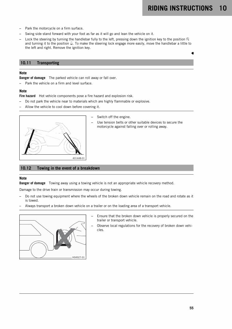
RIDING INSTRUCTIONS 10
55
– Park the motorcycle on a firm surface.
– Swing side stand forward with your foot as far as it will go and lean the vehicle on it.
– Lock the steering by turning the handlebar fully to the left, pressing down the ignition key to the positionand turning it to the position . To make the steering lock engage more easily, move the handlebar a little tothe left and right. Remove the ignition key.
10.11 Transporting
NoteDanger of damage The parked vehicle can roll away or fall over.
– Park the vehicle on a firm and level surface.
NoteFire hazard Hot vehicle components pose a fire hazard and explosion risk.
– Do not park the vehicle near to materials which are highly flammable or explosive.
– Allow the vehicle to cool down before covering it.
401448-01
– Switch off the engine.
– Use tension belts or other suitable devices to secure themotorcycle against falling over or rolling away.
10.12 Towing in the event of a breakdown
NoteDanger of damage Towing away using a towing vehicle is not an appropriate vehicle recovery method.
Damage to the drive train or transmission may occur during towing.
– Do not use towing equipment where the wheels of the broken down vehicle remain on the road and rotate as itis towed.
– Always transport a broken down vehicle on a trailer or on the loading area of a transport vehicle.
H04927-01
– Ensure that the broken down vehicle is properly secured on thetrailer or transport vehicle.
– Observe local regulations for the recovery of broken down vehi-cles.
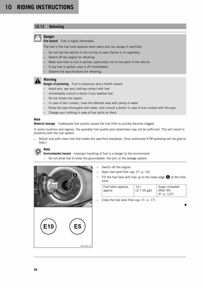
10 RIDING INSTRUCTIONS
56
10.13 Refueling
DangerFire hazard Fuel is highly flammable.
The fuel in the fuel tank expands when warm and can escape if overfilled.
– Do not fuel the vehicle in the vicinity of open flames or lit cigarettes.
– Switch off the engine for refueling.
– Make sure that no fuel is spilled; particularly not on hot parts of the vehicle.
– If any fuel is spilled, wipe it off immediately.
– Observe the specifications for refueling.
WarningDanger of poisoning Fuel is poisonous and a health hazard.
– Avoid skin, eye and clothing contact with fuel.
– Immediately consult a doctor if you swallow fuel.
– Do not inhale fuel vapors.
– In case of skin contact, rinse the affected area with plenty of water.
– Rinse the eyes thoroughly with water, and consult a doctor in case of fuel contact with the eyes.
– Change your clothing in case of fuel spills on them.
NoteMaterial damage Inadequate fuel quality causes the fuel filter to quickly become clogged.
In some countries and regions, the available fuel quality and cleanliness may not be sufficient. This will result inproblems with the fuel system.
– Refuel only with clean fuel that meets the specified standards. (Your authorized KTM workshop will be glad tohelp.)
NoteEnvironmental hazard Improper handling of fuel is a danger to the environment.
– Do not allow fuel to enter the groundwater, the soil, or the sewage system.
V01463-10
– Switch off the engine.
– Open fuel tank filler cap. ( p. 16)
– Fill the fuel tank with fuel up to the lower edgeA of the fillerneck.
Fuel tank capacity,approx.
14 l(3.7 US gal)
Super unleaded(ROZ 95)( p. 127)
– Close the fuel tank filler cap. ( p. 17)

SERVICE SCHEDULE 11
57
11.1 Additional information
Any further work that results from the compulsory work or from the recommended work must be ordered sepa-rately and invoiced separately.Different service intervals may apply in your country, depending on the local operating conditions.Individual service intervals and scopes may change in the course of technical developments. The most up-to-dateservice schedule can always be found on KTM Dealer.net. Your authorized KTM dealer will be happy to adviseyou.
11.2 Required work
every 24 months
every 12 months
every 30,000 km (18,600 mi)
every 15,000 km (9,300 mi)
after 1,000 km (620 mi)
Read out the fault memory using the KTM diagnostics tool. ○ ● ● ● ●
Program the shift shaft sensor. ○ ● ● ● ●
Check that the electrical system is functioning properly. ○ ● ● ● ●
Change the engine oil and the oil filter, clean the oil screens. ( p. 105) ○ ● ● ● ●
Check the front brake linings. ( p. 72) ○ ● ● ● ●
Check the rear brake linings. ( p. 75) ○ ● ● ● ●
Check the brake discs. ( p. 70) ○ ● ● ● ●
Check the brake lines for damage and leakage. ○ ● ● ● ●
Check the front brake fluid level. ( p. 70) ○ ● ● ●
Check the rear brake fluid level. ( p. 73) ○ ● ● ●
Change the front brake fluid. ●
Change the rear brake fluid. ●
Check the free travel of the clutch lever. ( p. 108) ○ ● ● ● ●
Check the free travel of the foot brake lever. ( p. 72) ○ ● ● ● ●
Check the shock absorber and fork for leaks. Perform fork service as needed anddepending on how the vehicle is used.
○ ● ● ● ●
Clean the dust boots of the fork legs. ( p. 61) ● ●
Check the steering head bearing for play. ○ ● ● ● ●
Check the tire condition. ( p. 82) ○ ● ● ● ●
Check tire pressure. ( p. 83) ○ ● ● ● ●
Check the chain, rear sprocket, engine sprocket, and chain guide. ( p. 66) ● ● ● ●
Check the chain tension. ( p. 65) ○ ● ● ● ●
Change the spark plugs. ●
Check the valve clearance. ●
Check the antifreeze and coolant level. ( p. 97) ○ ● ● ● ●
Check the cables for damage and for routing without kinks. ● ● ● ●
Change the air filter, clean the air filter box. ● ●
Check the fuel pressure and the absorbing elements of the fuel tank bracket. ● ● ● ●
Check the headlight setting. ( p. 94) ○ ● ●
Check that the radiator fan is functioning properly. ○ ● ● ● ●
Final check: Check the vehicle is roadworthy and take a test ride. ○ ● ● ● ●
Read out the fault memory using the KTM diagnostics tool after a test ride. ○ ● ● ● ●

11 SERVICE SCHEDULE
58
every 24 months
every 12 months
every 30,000 km (18,600 mi)
every 15,000 km (9,300 mi)
after 1,000 km (620 mi)
Set the service interval display with the combination instrument. ○ ● ● ● ●
Make a service entry in KTM Dealer.net. ○ ● ● ● ●
○ One-time interval
● Periodic interval
11.3 Recommended work
every 48 months
every 12 months
every 30,000 km (18,600 mi)
every 15,000 km (9,300 mi)
after 1,000 km (620 mi)
Check the frame. ●
Check the link fork. ●
Check/clean the oil nozzle for clutch lubrication. ○ ● ●
Check the fork bearing for play. ● ●
Check the wheel bearing for play. ● ●
Change the coolant. ( p. 101) ●
Empty the drainage hoses. ○ ● ● ● ●
Check all hoses (e.g. fuel, cooling, bleeder, drainage hoses, etc.) and sleeves for crack-ing, tightness, and correct routing.
● ● ● ●
Grease all moving parts (e.g. side stand, hand lever, chain, etc.) and check for smoothoperation.
○ ● ● ● ●
Check the tightness of the safety-relevant screws and nuts which are easily accessi-ble.
○ ● ● ● ●
○ One-time interval
● Periodic interval
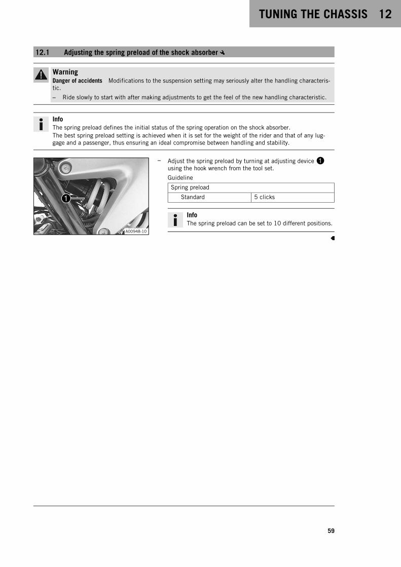
TUNING THE CHASSIS 12
59
12.1 Adjusting the spring preload of the shock absorber
WarningDanger of accidents Modifications to the suspension setting may seriously alter the handling characteris-tic.
– Ride slowly to start with after making adjustments to get the feel of the new handling characteristic.
InfoThe spring preload defines the initial status of the spring operation on the shock absorber.The best spring preload setting is achieved when it is set for the weight of the rider and that of any lug-gage and a passenger, thus ensuring an ideal compromise between handling and stability.
A00948-10
– Adjust the spring preload by turning at adjusting device1using the hook wrench from the tool set.
Guideline
Spring preload
Standard 5 clicks
InfoThe spring preload can be set to 10 different positions.
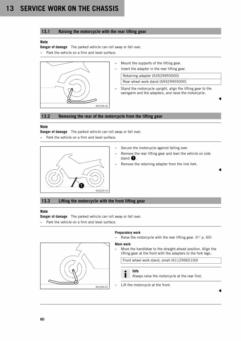
13 SERVICE WORK ON THE CHASSIS
60
13.1 Raising the motorcycle with the rear lifting gear
NoteDanger of damage The parked vehicle can roll away or fall over.
– Park the vehicle on a firm and level surface.
402346-01
– Mount the supports of the lifting gear.
– Insert the adapter in the rear lifting gear.
Retaining adapter (63529955000)
Rear wheel work stand (69329955000)
– Stand the motorcycle upright, align the lifting gear to theswingarm and the adapters, and raise the motorcycle.
13.2 Removing the rear of the motorcycle from the lifting gear
NoteDanger of damage The parked vehicle can roll away or fall over.
– Park the vehicle on a firm and level surface.
402029-10
– Secure the motorcycle against falling over.
– Remove the rear lifting gear and lean the vehicle on sidestand1.
– Remove the retaining adapter from the link fork.
13.3 Lifting the motorcycle with the front lifting gear
NoteDanger of damage The parked vehicle can roll away or fall over.
– Park the vehicle on a firm and level surface.
Preparatory work– Raise the motorcycle with the rear lifting gear. ( p. 60)
402344-01
Main work– Move the handlebar to the straight-ahead position. Align the
lifting gear at the front with the adapters to the fork legs.
Front wheel work stand, small (61129965100)
InfoAlways raise the motorcycle at the rear first.
– Lift the motorcycle at the front.
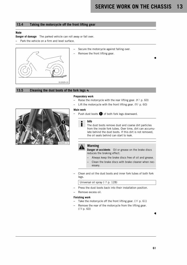
SERVICE WORK ON THE CHASSIS 13
61
13.4 Taking the motorcycle off the front lifting gear
NoteDanger of damage The parked vehicle can roll away or fall over.
– Park the vehicle on a firm and level surface.
312029-10
– Secure the motorcycle against falling over.
– Remove the front lifting gear.
13.5 Cleaning the dust boots of the fork legs
Preparatory work– Raise the motorcycle with the rear lifting gear. ( p. 60)
– Lift the motorcycle with the front lifting gear. ( p. 60)
A00949-10
Main work– Push dust boots1 of both fork legs downward.
InfoThe dust boots remove dust and coarse dirt particlesfrom the inside fork tubes. Over time, dirt can accumu-late behind the dust boots. If this dirt is not removed,the oil seals behind can start to leak.
WarningDanger of accidents Oil or grease on the brake discsreduces the braking effect.
– Always keep the brake discs free of oil and grease.
– Clean the brake discs with brake cleaner when nec-essary.
– Clean and oil the dust boots and inner fork tubes of both forklegs.
Universal oil spray ( p. 128)
– Press the dust boots back into their installation position.
– Remove excess oil.
Finishing work– Take the motorcycle off the front lifting gear. ( p. 61)
– Remove the rear of the motorcycle from the lifting gear.( p. 60)

13 SERVICE WORK ON THE CHASSIS
62
13.6 Removing the passenger seat
InfoThe passenger seat cover is also included for the special model.If it is not required to carry a passenger, the passenger seat cover can be used instead of the passengerseat.The passenger seat cover can be removed in the same way as the passenger seat.
V01232-10
– Insert the ignition key in seat lock1 and turn it clockwise.
– Raise the rear of the passenger seat cover, push it toward therear, and remove it upward.
– Remove the ignition key from the seat lock.
13.7 Mounting the passenger seat
InfoThe passenger seat cover is also included for the special model.If it is not required to carry a passenger, the passenger seat cover can be used instead of the passengerseat.The passenger seat cover can be fitted in the same way as the passenger seat.
V01233-10
– Hook holding lugs1 of the passenger seat onto the storagecompartment, lower the rear and push forward.
– Press the passenger seat downward until it clicks into place.
WarningDanger of accidents The seat can come loose from theanchoring if it is not mounted correctly.
– After assembly, check whether the seat is correctlylocked and cannot be pulled up.
– Finally, check that the passenger seat is correctly mounted.

SERVICE WORK ON THE CHASSIS 13
63
13.8 Removing the front rider's seat
Preparatory work– Remove the passenger seat. ( p. 62)
V01239-10
Main work– Remove screws1.
– Raise the rear of the front rider's seat, pull the seat back, andlift it off.
13.9 Mounting the front rider's seat
V01240-10
Main work– Push the front rider's seat forward and lower at the rear.
The holding lugs1 engage in the loopsA on the tank.
The holding lugs2 engage in the loopsB on theframe.
V01239-11
– Mount and tighten screws3.
Guideline
Remaining screws,chassis
M6 10 Nm (7.4 lbf ft)
– Finally, check that the front rider's seat is correctly mounted.
Finishing work– Mount the passenger seat. ( p. 62)
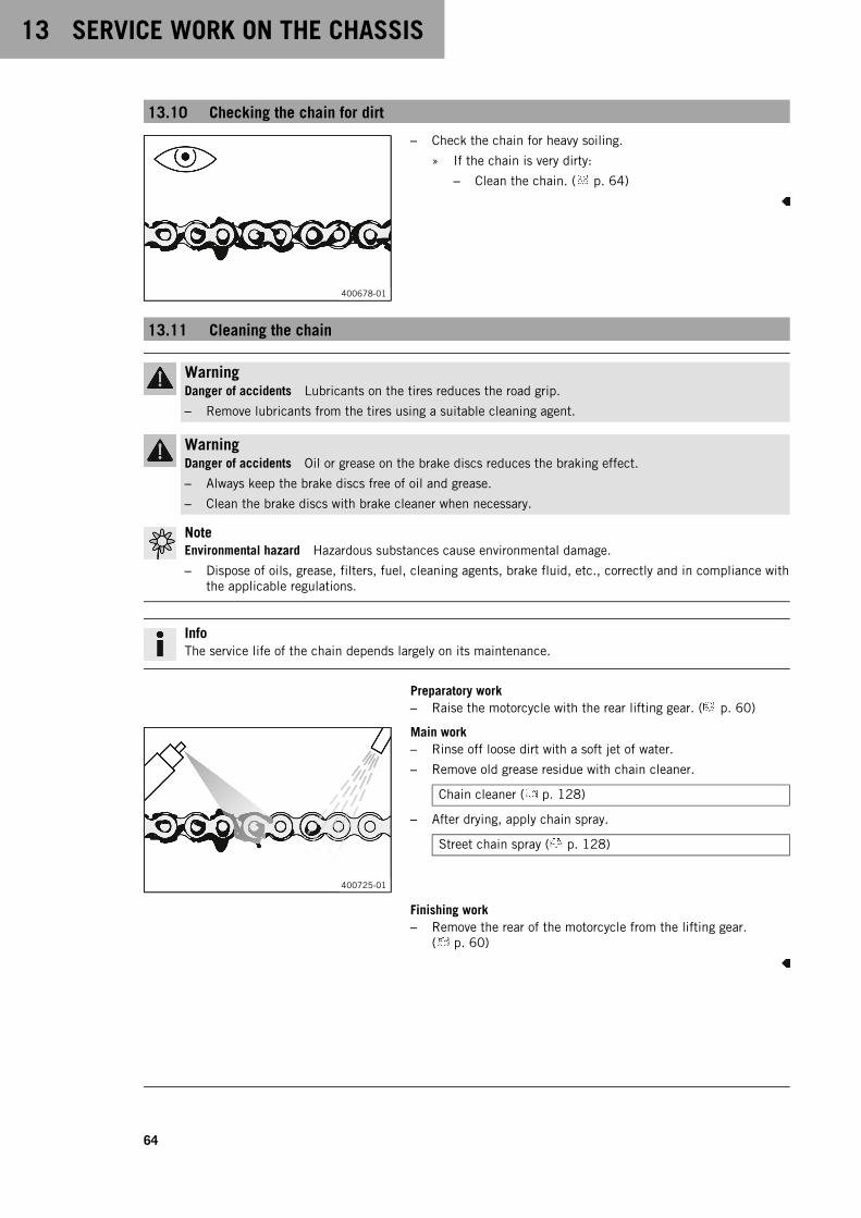
13 SERVICE WORK ON THE CHASSIS
64
13.10 Checking the chain for dirt
400678-01
– Check the chain for heavy soiling.
» If the chain is very dirty:
– Clean the chain. ( p. 64)
13.11 Cleaning the chain
WarningDanger of accidents Lubricants on the tires reduces the road grip.
– Remove lubricants from the tires using a suitable cleaning agent.
WarningDanger of accidents Oil or grease on the brake discs reduces the braking effect.
– Always keep the brake discs free of oil and grease.
– Clean the brake discs with brake cleaner when necessary.
NoteEnvironmental hazard Hazardous substances cause environmental damage.
– Dispose of oils, grease, filters, fuel, cleaning agents, brake fluid, etc., correctly and in compliance withthe applicable regulations.
InfoThe service life of the chain depends largely on its maintenance.
Preparatory work– Raise the motorcycle with the rear lifting gear. ( p. 60)
400725-01
Main work– Rinse off loose dirt with a soft jet of water.
– Remove old grease residue with chain cleaner.
Chain cleaner ( p. 128)
– After drying, apply chain spray.
Street chain spray ( p. 128)
Finishing work– Remove the rear of the motorcycle from the lifting gear.
( p. 60)

SERVICE WORK ON THE CHASSIS 13
65
13.12 Checking the chain tension
WarningDanger of accidents Incorrect chain tension damages components and results in accidents.
If the chain is tensioned too much, the chain, engine sprocket, rear sprocket, transmission and rearwheel bearings wear more quickly. Some components may break if overloaded.
If the chain is too loose, the chain may fall off the engine sprocket or the rear sprocket. As a result, therear wheel locks or the engine will be damaged.
– Check the chain tension regularly.
– Set the chain tension in accordance with the specification.
Preparatory work– Raise the motorcycle with the rear lifting gear. ( p. 60)
M01569-10
Main work– Shift the transmission to neutral position.
– Push the chain behind the chain sliding piece up and deter-mine the chain tensionA between the swingarm and theupper edge of the chain.
Guideline
DistanceB from the chainsliding piece
2.5 cm (0.98 in)
Measure the distance from the flat part of the swingarmdirectly above the chain, not from the edge of the swingarm.
InfoTop chain sectionC must be taut.Chain wear is not always even. Repeat this measure-ment at different chain positions.
Chain tension 2 … 5 mm (0.08 … 0.2 in)
» If the chain tension does not meet the specification:
– Adjust the chain tension. ( p. 65)
Finishing work– Remove the rear of the motorcycle from the lifting gear.
( p. 60)
13.13 Adjusting the chain tension
WarningDanger of accidents Incorrect chain tension damages components and results in accidents.
If the chain is tensioned too much, the chain, engine sprocket, rear sprocket, transmission and rearwheel bearings wear more quickly. Some components may break if overloaded.
If the chain is too loose, the chain may fall off the engine sprocket or the rear sprocket. As a result, therear wheel locks or the engine will be damaged.
– Check the chain tension regularly.
– Set the chain tension in accordance with the specification.
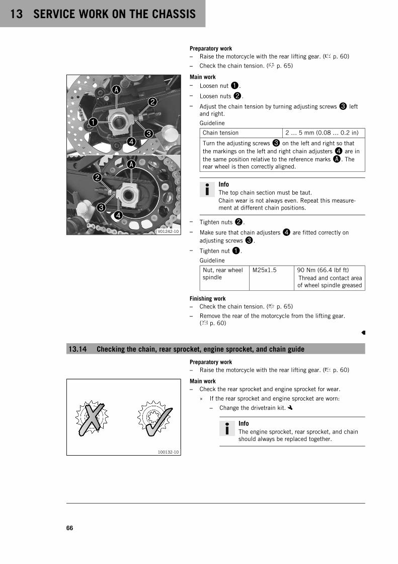
13 SERVICE WORK ON THE CHASSIS
66
Preparatory work– Raise the motorcycle with the rear lifting gear. ( p. 60)
– Check the chain tension. ( p. 65)
V01242-10
Main work– Loosen nut1.
– Loosen nuts2.
– Adjust the chain tension by turning adjusting screws3 leftand right.
Guideline
Chain tension 2 … 5 mm (0.08 … 0.2 in)
Turn the adjusting screws3 on the left and right so thatthe markings on the left and right chain adjusters4 are inthe same position relative to the reference marksA. Therear wheel is then correctly aligned.
InfoThe top chain section must be taut.Chain wear is not always even. Repeat this measure-ment at different chain positions.
– Tighten nuts2.
– Make sure that chain adjusters4 are fitted correctly onadjusting screws3.
– Tighten nut1.
Guideline
Nut, rear wheelspindle
M25x1.5 90 Nm (66.4 lbf ft)Thread and contact areaof wheel spindle greased
Finishing work– Check the chain tension. ( p. 65)
– Remove the rear of the motorcycle from the lifting gear.( p. 60)
13.14 Checking the chain, rear sprocket, engine sprocket, and chain guide
Preparatory work– Raise the motorcycle with the rear lifting gear. ( p. 60)
100132-10
Main work– Check the rear sprocket and engine sprocket for wear.
» If the rear sprocket and engine sprocket are worn:
– Change the drivetrain kit.
InfoThe engine sprocket, rear sprocket, and chainshould always be replaced together.
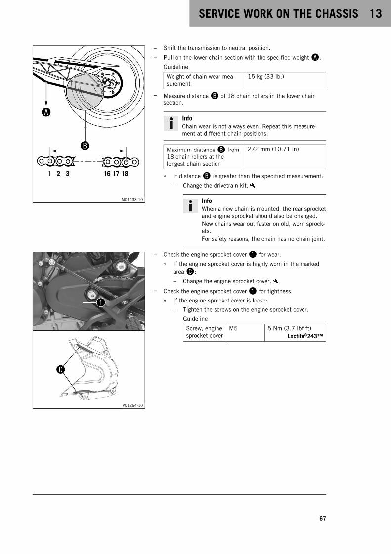
SERVICE WORK ON THE CHASSIS 13
67
M01433-10
– Shift the transmission to neutral position.
– Pull on the lower chain section with the specified weightA.
Guideline
Weight of chain wear mea-surement
15 kg (33 lb.)
– Measure distanceB of 18 chain rollers in the lower chainsection.
InfoChain wear is not always even. Repeat this measure-ment at different chain positions.
Maximum distanceB from18 chain rollers at thelongest chain section
272 mm (10.71 in)
» If distanceB is greater than the specified measurement:
– Change the drivetrain kit.
InfoWhen a new chain is mounted, the rear sprocketand engine sprocket should also be changed.New chains wear out faster on old, worn sprock-ets.For safety reasons, the chain has no chain joint.
V01264-10
– Check the engine sprocket cover1 for wear.
» If the engine sprocket cover is highly worn in the markedareaC:
– Change the engine sprocket cover.
– Check the engine sprocket cover1 for tightness.
» If the engine sprocket cover is loose:
– Tighten the screws on the engine sprocket cover.
Guideline
Screw, enginesprocket cover
M5 5 Nm (3.7 lbf ft)Loctite®243™
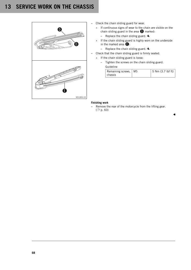
13 SERVICE WORK ON THE CHASSIS
68
V01265-10
– Check the chain sliding guard for wear.
» If continuous signs of wear to the chain are visible on thechain sliding guard in the areaD marked:
– Replace the chain sliding guard.
» If the chain sliding guard is highly worn on the undersidein the marked areaE:
– Replace the chain sliding guard.
– Check that the chain sliding guard is firmly seated.
» If the chain sliding guard is loose:
– Tighten the screws on the chain sliding guard.
Guideline
Remaining screws,chassis
M5 5 Nm (3.7 lbf ft)
Finishing work– Remove the rear of the motorcycle from the lifting gear.
( p. 60)

BRAKE SYSTEM 14
69
14.1 Anti-lock braking system (ABS)
H02670-10
ABS module1, which consists of a hydraulic unit, ABS controlunit, and return pump, is installed under the fuel tank. One wheelspeed sensor2 is located in each case on the front and the rearwheel.
WarningDanger of accidents Changes to the vehicle impair thefunction of the ABS.
– Do not make any changes to the suspension travel.
– Only use spare parts on the brake system which havebeen approved and recommended by KTM.
– Only use tires/wheels approved by KTM with the corre-sponding speed index.
– Maintain the specified tire pressure.
– Ensure that service work and repairs are performedprofessionally. (Your authorized KTM workshop will beglad to help.)
The ABS is a safety system that prevents locking of the wheelswhen driving straight ahead without the influence of lateral forces.
WarningDanger of accidents Driving aids can reduce the probabil-ity of a fall only within physical limits.
It is not always possible to compensate for extreme ridingsituations, for example with luggage loaded with a highcenter of gravity, varying road surfaces, steep descents orfull braking without disengaging the gear.
– Adapt your riding style to the road conditions and yourdriving ability.
The ABS operates with two independent brake circuits (front andrear brakes). During normal operation, the brake system operateslike a conventional brake system without ABS. When the ABS con-trol unit detects a locking tendency in a wheel, ABS begins reg-ulating the brake pressure. The control function causes a slightpulsing of the hand and foot brake levers.The ABS warning lamp3 must light up after the ignition isswitched on and go out after starting off. If it does not go outafter starting off or if it lights up while riding, this indicates amalfunction in the ABS. In this case, the ABS is no longer enabledand the wheels may lock during braking. The brake system itselfstays functional; only ABS control is not available.The ABS warning lamp may also light up if the rotating speeds ofthe front and rear wheels differ greatly under extreme riding con-ditions, for example when making "wheelies" or if the rear wheelspins. This causes the ABS to switch off.To reactivate the ABS, stop the vehicle and switch off the ignition.The ABS is reactivated when the vehicle is switched on again. TheABS warning lamp goes out after starting off.

14 BRAKE SYSTEM
70
14.2 Checking the brake discs
WarningDanger of accidents Worn-out brake discs reduce the braking effect.
– Make sure that worn-out brake discs are replaced immediately. (Your authorized KTM workshop willbe glad to help.)
100135-10
– Check the front and rear brake disc thickness at multiplepoints for the dimensionA.
InfoWear will reduce the thickness of the brake disc at con-tact surface1 of the brake linings.
Brake discs - wear limit
front 4.5 mm (0.177 in)
rear 4.5 mm (0.177 in)
» If the brake disc thickness is less than the specified value.
– Change the front brake discs.
– Change the rear brake disc.
– Check the front and rear brake discs for damage, cracking, anddeformation.
» If the brake disc exhibits damage, cracking, or deforma-tion:
– Change the front brake discs.
– Change the rear brake disc.
14.3 Checking the front brake fluid level
WarningDanger of accidents An insufficient brake fluid level will cause the brake system to fail.
If the brake fluid level drops below the specified marking or the specified value, the brake system isleaking or the brake linings are worn down.
– Check the brake system and do not continue riding until the problem is eliminated. (Your authorizedKTM workshop will be glad to help.)
WarningDanger of accidents Old brake fluid reduces the braking effect.
– Make sure that brake fluid for the front and rear brake is changed in accordance with the serviceschedule. (Your authorized KTM workshop will be glad to help.)
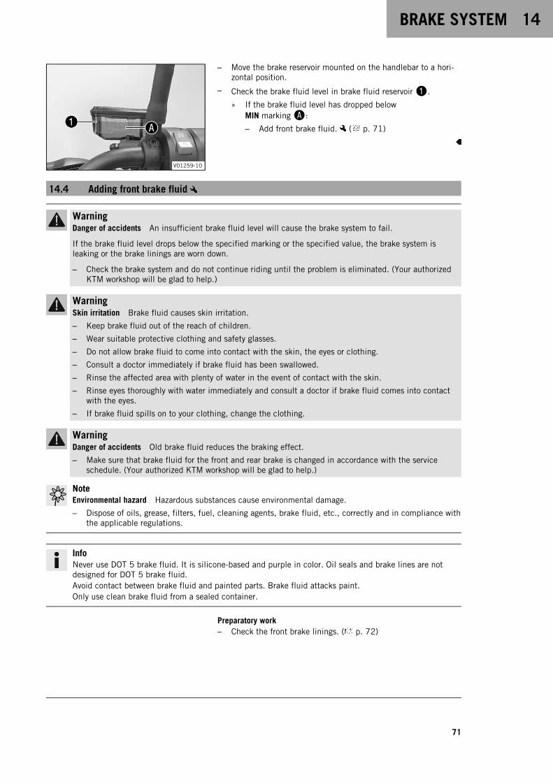
BRAKE SYSTEM 14
71
V01259-10
– Move the brake reservoir mounted on the handlebar to a hori-zontal position.
– Check the brake fluid level in brake fluid reservoir1.
» If the brake fluid level has dropped belowMIN markingA:
– Add front brake fluid. ( p. 71)
14.4 Adding front brake fluid
WarningDanger of accidents An insufficient brake fluid level will cause the brake system to fail.
If the brake fluid level drops below the specified marking or the specified value, the brake system isleaking or the brake linings are worn down.
– Check the brake system and do not continue riding until the problem is eliminated. (Your authorizedKTM workshop will be glad to help.)
WarningSkin irritation Brake fluid causes skin irritation.
– Keep brake fluid out of the reach of children.
– Wear suitable protective clothing and safety glasses.
– Do not allow brake fluid to come into contact with the skin, the eyes or clothing.
– Consult a doctor immediately if brake fluid has been swallowed.
– Rinse the affected area with plenty of water in the event of contact with the skin.
– Rinse eyes thoroughly with water immediately and consult a doctor if brake fluid comes into contactwith the eyes.
– If brake fluid spills on to your clothing, change the clothing.
WarningDanger of accidents Old brake fluid reduces the braking effect.
– Make sure that brake fluid for the front and rear brake is changed in accordance with the serviceschedule. (Your authorized KTM workshop will be glad to help.)
NoteEnvironmental hazard Hazardous substances cause environmental damage.
– Dispose of oils, grease, filters, fuel, cleaning agents, brake fluid, etc., correctly and in compliance withthe applicable regulations.
InfoNever use DOT 5 brake fluid. It is silicone-based and purple in color. Oil seals and brake lines are notdesigned for DOT 5 brake fluid.Avoid contact between brake fluid and painted parts. Brake fluid attacks paint.Only use clean brake fluid from a sealed container.
Preparatory work– Check the front brake linings. ( p. 72)

14 BRAKE SYSTEM
72
V01263-10
Main work– Move the brake reservoir mounted on the handlebar to a hori-
zontal position.
– Remove screws1.
– Take off cover2 with membrane3.
– Add brake fluid up to MAX markingA.
Brake fluid DOT 4 / DOT 5.1 ( p. 126)
– Position cover2 with membrane3.
– Mount and tighten screws1.
InfoClean up overflowed or spilled brake fluid immediatelywith water.
14.5 Checking the front brake linings
WarningDanger of accidents Worn-out brake linings reduce the braking effect.
– Ensure that worn-out brake linings are replaced immediately. (Your authorized KTM workshop will beglad to help.)
WarningDanger of accidents Damaged brake discs reduce the braking effect.
If the brake linings are not changed in time, the brake lining carriers grind against the brake disc. As aconsequence, the braking effect is greatly reduced and the brake discs are destroyed.
– Check the brake linings regularly.
A00950-10
– Check the brake linings for minimum thicknessA.
Minimum thicknessA ≥ 1 mm (≥ 0.04 in)
» If the minimum thickness is less than specified:
– Change the brake linings of the front brake.
– Check the brake linings for damage and cracking.
» If there is damage or cracking:
– Change the brake linings of the front brake.
14.6 Checking the free travel of the foot brake lever
WarningDanger of accidents The brake system fails in the event of overheating.
If there is no free travel on the foot brake lever, pressure builds up in the brake system on the rearbrake.
– Set the free travel on the foot brake lever in accordance with the specification.

BRAKE SYSTEM 14
73
V01223-10
– Detach spring1.
– Move the foot brake lever back and forth between the end stopand the contact to the foot brake cylinder piston and checkfree travelA.
Guideline
Free travel at foot brake lever 3 … 5 mm (0.12 … 0.2 in)
» If the free travel does not match the specification:
– Adjust the basic position of the foot brake lever.( p. 41)
– Attach spring1.
14.7 Checking the rear brake fluid level
WarningDanger of accidents An insufficient brake fluid level will cause the brake system to fail.
If the brake fluid level drops below the MIN marking, the brake system is leaking or the brake linings areworn down.
– Check the brake system and do not continue riding until the problem is eliminated. (Your authorizedKTM workshop will be glad to help.)
WarningDanger of accidents Old brake fluid reduces the braking effect.
– Make sure that brake fluid for the front and rear brake is changed in accordance with the serviceschedule. (Your authorized KTM workshop will be glad to help.)
G03319-10
– Stand the vehicle upright.
– Check the brake fluid level in the brake fluid reservoir.
» If the fluid level reaches the MIN marking1:
– Add rear brake fluid. ( p. 73)
14.8 Adding rear brake fluid
WarningDanger of accidents An insufficient brake fluid level will cause the brake system to fail.
If the brake fluid level drops below the MIN marking, the brake system is leaking or the brake linings areworn down.
– Check the brake system and do not continue riding until the problem is eliminated. (Your authorizedKTM workshop will be glad to help.)
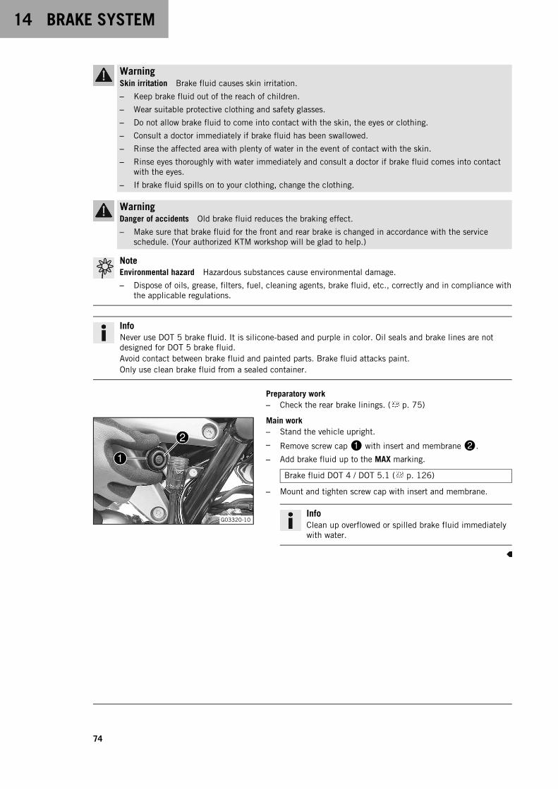
14 BRAKE SYSTEM
74
WarningSkin irritation Brake fluid causes skin irritation.
– Keep brake fluid out of the reach of children.
– Wear suitable protective clothing and safety glasses.
– Do not allow brake fluid to come into contact with the skin, the eyes or clothing.
– Consult a doctor immediately if brake fluid has been swallowed.
– Rinse the affected area with plenty of water in the event of contact with the skin.
– Rinse eyes thoroughly with water immediately and consult a doctor if brake fluid comes into contactwith the eyes.
– If brake fluid spills on to your clothing, change the clothing.
WarningDanger of accidents Old brake fluid reduces the braking effect.
– Make sure that brake fluid for the front and rear brake is changed in accordance with the serviceschedule. (Your authorized KTM workshop will be glad to help.)
NoteEnvironmental hazard Hazardous substances cause environmental damage.
– Dispose of oils, grease, filters, fuel, cleaning agents, brake fluid, etc., correctly and in compliance withthe applicable regulations.
InfoNever use DOT 5 brake fluid. It is silicone-based and purple in color. Oil seals and brake lines are notdesigned for DOT 5 brake fluid.Avoid contact between brake fluid and painted parts. Brake fluid attacks paint.Only use clean brake fluid from a sealed container.
Preparatory work– Check the rear brake linings. ( p. 75)
G03320-10
Main work– Stand the vehicle upright.
– Remove screw cap1 with insert and membrane2.
– Add brake fluid up to the MAX marking.
Brake fluid DOT 4 / DOT 5.1 ( p. 126)
– Mount and tighten screw cap with insert and membrane.
InfoClean up overflowed or spilled brake fluid immediatelywith water.

BRAKE SYSTEM 14
75
14.9 Checking the rear brake linings
WarningDanger of accidents Worn-out brake linings reduce the braking effect.
– Ensure that worn-out brake linings are replaced immediately. (Your authorized KTM workshop will beglad to help.)
WarningDanger of accidents Damaged brake discs reduce the braking effect.
If the brake linings are not changed in time, the brake lining carriers grind against the brake disc. As aconsequence, the braking effect is greatly reduced and the brake discs are destroyed.
– Check the brake linings regularly.
V01221-10
– Check the brake linings for minimum thicknessA.
Minimum thicknessA ≥ 1 mm (≥ 0.04 in)
» If the minimum thickness is less than specified:
– Change the rear brake linings.
– Check the brake linings for damage and cracking.
» If there is wear or tearing:
– Change the rear brake linings.
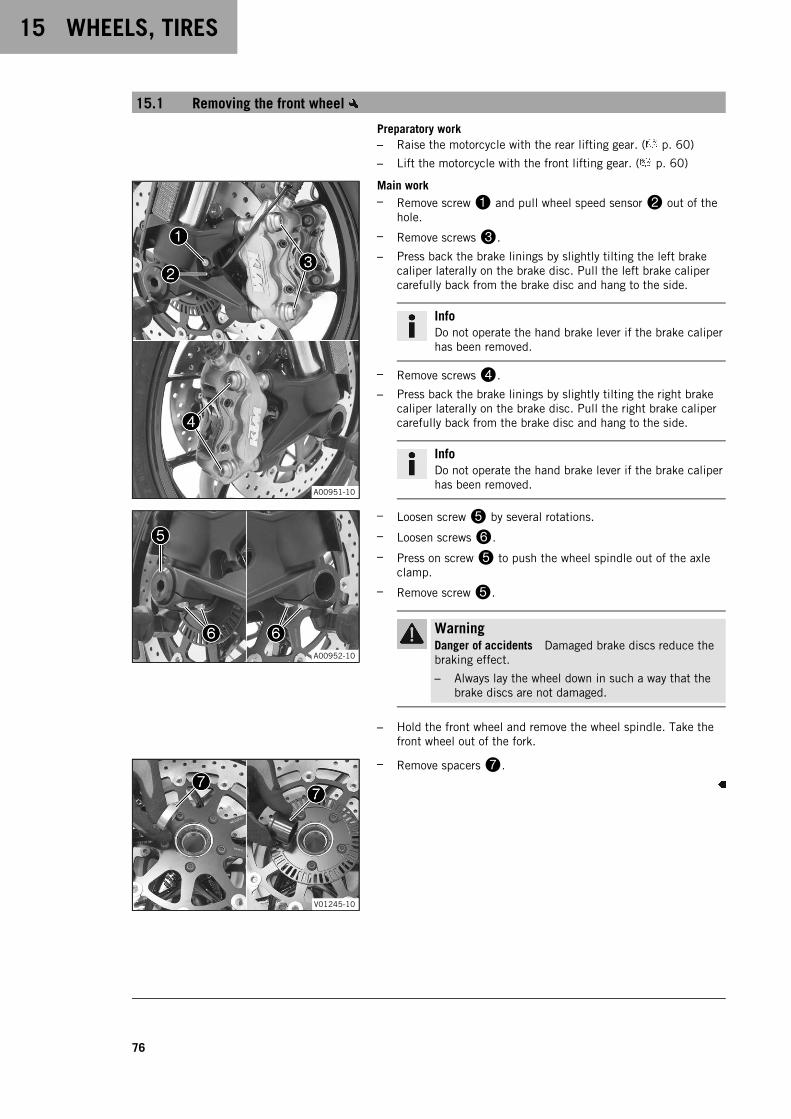
15 WHEELS, TIRES
76
15.1 Removing the front wheel
Preparatory work– Raise the motorcycle with the rear lifting gear. ( p. 60)
– Lift the motorcycle with the front lifting gear. ( p. 60)
A00951-10
Main work– Remove screw1 and pull wheel speed sensor2 out of the
hole.
– Remove screws3.
– Press back the brake linings by slightly tilting the left brakecaliper laterally on the brake disc. Pull the left brake calipercarefully back from the brake disc and hang to the side.
InfoDo not operate the hand brake lever if the brake caliperhas been removed.
– Remove screws4.
– Press back the brake linings by slightly tilting the right brakecaliper laterally on the brake disc. Pull the right brake calipercarefully back from the brake disc and hang to the side.
InfoDo not operate the hand brake lever if the brake caliperhas been removed.
A00952-10
– Loosen screw5 by several rotations.
– Loosen screws6.
– Press on screw5 to push the wheel spindle out of the axleclamp.
– Remove screw5.
WarningDanger of accidents Damaged brake discs reduce thebraking effect.
– Always lay the wheel down in such a way that thebrake discs are not damaged.
– Hold the front wheel and remove the wheel spindle. Take thefront wheel out of the fork.
V01245-10
– Remove spacers7.
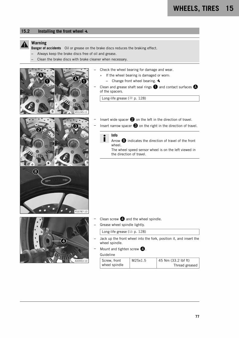
WHEELS, TIRES 15
77
15.2 Installing the front wheel
WarningDanger of accidents Oil or grease on the brake discs reduces the braking effect.
– Always keep the brake discs free of oil and grease.
– Clean the brake discs with brake cleaner when necessary.
V01245-11
– Check the wheel bearing for damage and wear.
» If the wheel bearing is damaged or worn:
– Change front wheel bearing.
– Clean and grease shaft seal rings1 and contact surfacesAof the spacers.
Long-life grease ( p. 128)
F03787-10
– Insert wide spacer2 on the left in the direction of travel.
– Insert narrow spacer3 on the right in the direction of travel.
InfoArrowB indicates the direction of travel of the frontwheel.The wheel speed sensor wheel is on the left viewed inthe direction of travel.
A00953-10
– Clean screw4 and the wheel spindle.
– Grease wheel spindle lightly.
Long-life grease ( p. 128)
– Jack up the front wheel into the fork, position it, and insert thewheel spindle.
– Mount and tighten screw4.
Guideline
Screw, frontwheel spindle
M25x1.5 45 Nm (33.2 lbf ft)Thread greased
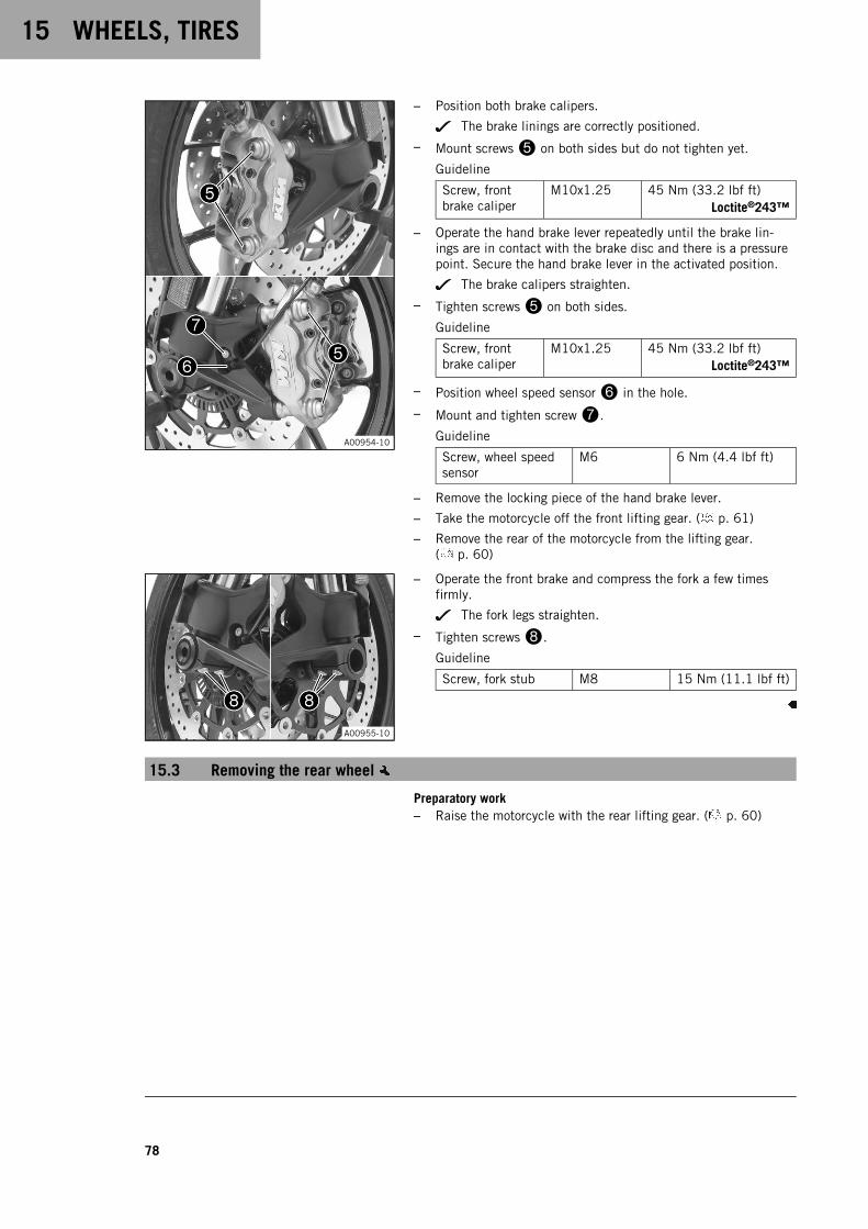
15 WHEELS, TIRES
78
A00954-10
– Position both brake calipers.
The brake linings are correctly positioned.
– Mount screws5 on both sides but do not tighten yet.
Guideline
Screw, frontbrake caliper
M10x1.25 45 Nm (33.2 lbf ft)Loctite®243™
– Operate the hand brake lever repeatedly until the brake lin-ings are in contact with the brake disc and there is a pressurepoint. Secure the hand brake lever in the activated position.
The brake calipers straighten.
– Tighten screws5 on both sides.
Guideline
Screw, frontbrake caliper
M10x1.25 45 Nm (33.2 lbf ft)Loctite®243™
– Position wheel speed sensor6 in the hole.
– Mount and tighten screw7.
Guideline
Screw, wheel speedsensor
M6 6 Nm (4.4 lbf ft)
– Remove the locking piece of the hand brake lever.
– Take the motorcycle off the front lifting gear. ( p. 61)
– Remove the rear of the motorcycle from the lifting gear.( p. 60)
A00955-10
– Operate the front brake and compress the fork a few timesfirmly.
The fork legs straighten.
– Tighten screws8.
Guideline
Screw, fork stub M8 15 Nm (11.1 lbf ft)
15.3 Removing the rear wheel
Preparatory work– Raise the motorcycle with the rear lifting gear. ( p. 60)
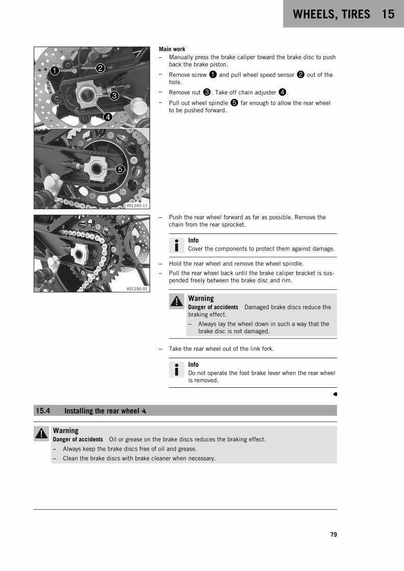
WHEELS, TIRES 15
79
V01242-11
Main work– Manually press the brake caliper toward the brake disc to push
back the brake piston.
– Remove screw1 and pull wheel speed sensor2 out of thehole.
– Remove nut3. Take off chain adjuster4.
– Pull out wheel spindle5 far enough to allow the rear wheelto be pushed forward.
V01250-01
– Push the rear wheel forward as far as possible. Remove thechain from the rear sprocket.
InfoCover the components to protect them against damage.
– Hold the rear wheel and remove the wheel spindle.
– Pull the rear wheel back until the brake caliper bracket is sus-pended freely between the brake disc and rim.
WarningDanger of accidents Damaged brake discs reduce thebraking effect.
– Always lay the wheel down in such a way that thebrake disc is not damaged.
– Take the rear wheel out of the link fork.
InfoDo not operate the foot brake lever when the rear wheelis removed.
15.4 Installing the rear wheel
WarningDanger of accidents Oil or grease on the brake discs reduces the braking effect.
– Always keep the brake discs free of oil and grease.
– Clean the brake discs with brake cleaner when necessary.

15 WHEELS, TIRES
80
WarningDanger of accidents There is no braking effect to start with at the rear brake after installing the rearwheel.
– Actuate the foot brake several times before going on a ride until you can feel a firm pressure point.
Main work– Check the rear hub damping rubber pieces. ( p. 81)
V01251-10
– Check the wheel bearing for damage and wear.
» If the wheel bearing is damaged or worn:
– Change the rear wheel bearing.
– Remove spacer.
– Clean and grease shaft seal ring1 and contact surfaceA ofthe spacer.
Long-life grease ( p. 128)
– Insert a spacer.
– Clean and grease the thread of the wheel spindle and nut.
Long-life grease ( p. 128)
– Clean and grease the wheel spindle.
Long-life grease ( p. 128)
– Clean the contact areas on the brake caliper bracket and linkfork.
V01242-12
– Engage the thrust bearing of brake caliper bracketB and thelink fork.
– Jack up the rear wheel into the link fork, position it, and insertthe wheel spindle.
The brake linings are correctly positioned.
– Place the chain on the sprocket.
– Position chain adjuster2. Mount nut3, but do not tightenit yet.
InfoMount the left and right chain adjusters in the sameposition.
– Make sure that chain adjusters2 are fitted correctly on theadjusting screws. Tighten nut3.
Guideline
In order for the rear wheel to be correctly aligned, the mark-ings on the left and right chain adjusters must be in thesame position relative to reference markingsC.
Nut, rear wheelspindle
M25x1.5 90 Nm (66.4 lbf ft)Thread and contact areaof wheel spindle greased
– Position wheel speed sensor4 in the hole.
– Mount and tighten screw5.
Guideline
Screw, wheel speedsensor
M6 6 Nm (4.4 lbf ft)
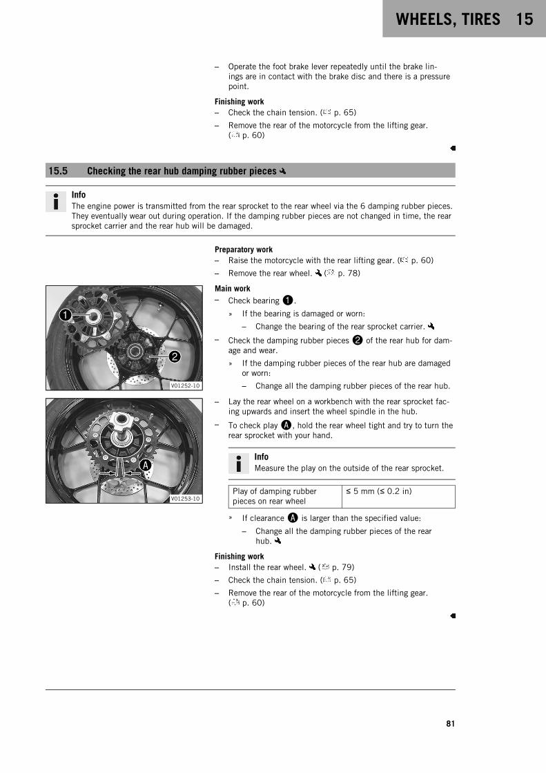
WHEELS, TIRES 15
81
– Operate the foot brake lever repeatedly until the brake lin-ings are in contact with the brake disc and there is a pressurepoint.
Finishing work– Check the chain tension. ( p. 65)
– Remove the rear of the motorcycle from the lifting gear.( p. 60)
15.5 Checking the rear hub damping rubber pieces
InfoThe engine power is transmitted from the rear sprocket to the rear wheel via the 6 damping rubber pieces.They eventually wear out during operation. If the damping rubber pieces are not changed in time, the rearsprocket carrier and the rear hub will be damaged.
Preparatory work– Raise the motorcycle with the rear lifting gear. ( p. 60)
– Remove the rear wheel. ( p. 78)
V01252-10
Main work– Check bearing1.
» If the bearing is damaged or worn:
– Change the bearing of the rear sprocket carrier.
– Check the damping rubber pieces2 of the rear hub for dam-age and wear.
» If the damping rubber pieces of the rear hub are damagedor worn:
– Change all the damping rubber pieces of the rear hub.
V01253-10
– Lay the rear wheel on a workbench with the rear sprocket fac-ing upwards and insert the wheel spindle in the hub.
– To check playA, hold the rear wheel tight and try to turn therear sprocket with your hand.
InfoMeasure the play on the outside of the rear sprocket.
Play of damping rubberpieces on rear wheel
≤ 5 mm (≤ 0.2 in)
» If clearanceA is larger than the specified value:
– Change all the damping rubber pieces of the rearhub.
Finishing work– Install the rear wheel. ( p. 79)
– Check the chain tension. ( p. 65)
– Remove the rear of the motorcycle from the lifting gear.( p. 60)

15 WHEELS, TIRES
82
15.6 Checking the tire condition
WarningDanger of accidents If a tire bursts while riding, the vehicle becomes uncontrollable.
– Ensure that damaged or worn tires are replaced immediately. (Your authorized KTM workshop will beglad to help.)
WarningDanger of crashing Different tire tread patterns on the front and rear wheel impair the handling charac-teristic.
Different tire tread patterns can make the vehicle significantly more difficult to control.
– Make sure that only tires with a similar tire tread pattern are fitted to the front and rear wheel.
WarningDanger of accidents Non-approved or non-recommended tires and wheels impact the handling character-istic.
– Only use tires/wheels approved by KTM with the corresponding speed index.
WarningDanger of accidents New tires have reduced road grip.
The contact surface on new tires is not yet roughened.
– Run in new tires with moderate riding at alternating angles.
Running-in phase 200 km (124 mi)
InfoThe type, condition, and pressure of the tires all have a major impact on the handling characteristic of themotorcycle.Worn tires have a negative effect on handling characteristics, especially on wet surfaces.
400602-10
– Check the front and rear tires for cuts, run-in objects, andother damage.
» If the tires have cuts, run-in objects, or other damage:
– Change the tires.
– Check the tread depth.
InfoAdhere to the legally required minimum tread depth.
Minimum tread depth ≥ 2 mm (≥ 0.08 in)
» If the tread depth is less than the minimum tread depth:
– Change the tires.

WHEELS, TIRES 15
83
H01144-10
– Check the tire age.
InfoThe tire date of manufacture is usually contained in thetire label and is indicated by the last four digits of theDOT number. The first two digits indicate the week ofmanufacture and the last two digits the year of manu-facture.KTM recommends that the tires be changed after 5years at the latest, regardless of the actual state ofwear.
» If the tires are more than 5 years old:
– Change the tires.
15.7 Checking tire pressure
InfoLow tire pressure leads to abnormal wear and overheating of the tire.Correct tire pressure ensures optimal riding comfort and maximum tire service life.
400695-01
– Remove the protection cap.
– Check the tire pressure when the tires are cold.
Tire pressure when solo
front 2.3 bar (33 psi)
rear 2.5 bar (36 psi)
Tire pressure with passenger / full payload
front 2.3 bar (33 psi)
rear 2.6 bar (38 psi)
» If the tire pressure does not meet specifications:
– Correct the tire pressure.
– Mount the protection cap.
15.8 Using tire repair spray
H03319-01
WarningDanger of accidents Incorrect use of tire repair spray willresult in the repaired tire losing pressure.
Tire repair spray cannot be used for all types of damage.
– Observe the instructions and specifications of themanufacturer of the tire repair spray.
– After repairing a tire with tire repair spray, ride slowlyand carefully.
– Ride no further than to the nearest workshop and havethe tire changed.
Tire repair spray should only be used in an emergency.We recommend transporting the broken down vehicle to the near-est workshop instead of using tire repair spray.
15 WHEELS, TIRES
84
(Option: With TPMS)
NoteMaterial damage Tire repair spray damages the tire pressuresensor.
– Note that after using tire repair spray, the tire pressuresensor may need to be replaced.
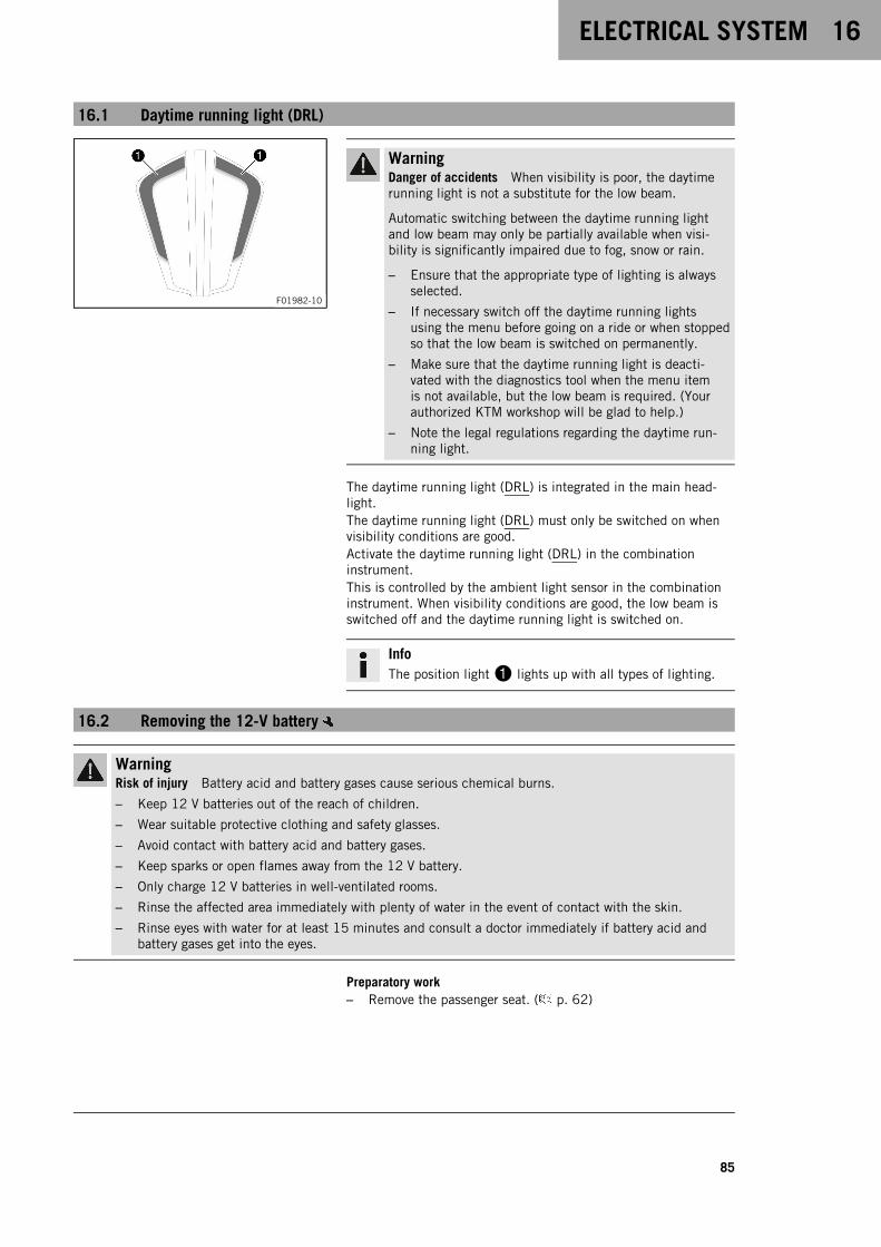
ELECTRICAL SYSTEM 16
85
16.1 Daytime running light (DRL)
F01982-10
WarningDanger of accidents When visibility is poor, the daytimerunning light is not a substitute for the low beam.
Automatic switching between the daytime running lightand low beam may only be partially available when visi-bility is significantly impaired due to fog, snow or rain.
– Ensure that the appropriate type of lighting is alwaysselected.
– If necessary switch off the daytime running lightsusing the menu before going on a ride or when stoppedso that the low beam is switched on permanently.
– Make sure that the daytime running light is deacti-vated with the diagnostics tool when the menu itemis not available, but the low beam is required. (Yourauthorized KTM workshop will be glad to help.)
– Note the legal regulations regarding the daytime run-ning light.
The daytime running light (DRL) is integrated in the main head-light.The daytime running light (DRL) must only be switched on whenvisibility conditions are good.Activate the daytime running light (DRL) in the combinationinstrument.This is controlled by the ambient light sensor in the combinationinstrument. When visibility conditions are good, the low beam isswitched off and the daytime running light is switched on.
InfoThe position light1 lights up with all types of lighting.
16.2 Removing the 12-V battery
WarningRisk of injury Battery acid and battery gases cause serious chemical burns.
– Keep 12 V batteries out of the reach of children.
– Wear suitable protective clothing and safety glasses.
– Avoid contact with battery acid and battery gases.
– Keep sparks or open flames away from the 12 V battery.
– Only charge 12 V batteries in well-ventilated rooms.
– Rinse the affected area immediately with plenty of water in the event of contact with the skin.
– Rinse eyes with water for at least 15 minutes and consult a doctor immediately if battery acid andbattery gases get into the eyes.
Preparatory work– Remove the passenger seat. ( p. 62)
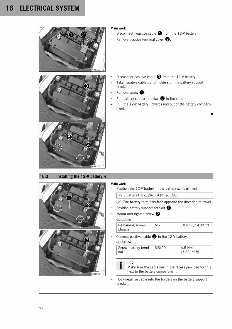
16 ELECTRICAL SYSTEM
86
V01203-11
Main work– Disconnect negative cable1 from the 12-V battery.
– Remove positive terminal cover2.
V01204-10
– Disconnect positive cable3 from the 12-V battery.
– Take negative cable out of holders on the battery supportbracket.
– Remove screw4.
– Pull battery support bracket5 to the side.
– Pull the 12-V battery upwards and out of the battery compart-ment.
16.3 Installing the 12-V battery
V01202-10
Main work– Position the 12-V battery in the battery compartment.
12 V battery (HTZ12A-BS) ( p. 120)
The battery terminals face opposite the direction of travel.
– Position battery support bracket1.
– Mount and tighten screw2.
Guideline
Remaining screws,chassis
M6 10 Nm (7.4 lbf ft)
– Connect positive cable3 to the 12 V battery.
Guideline
Screw, battery termi-nal
M6x20 4.5 Nm(3.32 lbf ft)
InfoMake sure the cable lies in the recess provided for thisnext to the battery compartment.
– Hook negative cable into the holders on the battery supportbracket.
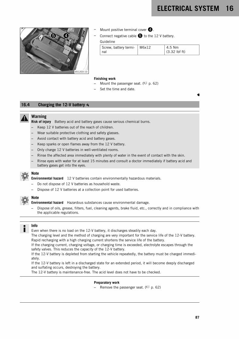
ELECTRICAL SYSTEM 16
87
V01203-10
– Mount positive terminal cover4.
– Connect negative cable5 to the 12 V battery.
Guideline
Screw, battery termi-nal
M6x12 4.5 Nm(3.32 lbf ft)
Finishing work– Mount the passenger seat. ( p. 62)
– Set the time and date.
16.4 Charging the 12-V battery
WarningRisk of injury Battery acid and battery gases cause serious chemical burns.
– Keep 12 V batteries out of the reach of children.
– Wear suitable protective clothing and safety glasses.
– Avoid contact with battery acid and battery gases.
– Keep sparks or open flames away from the 12 V battery.
– Only charge 12 V batteries in well-ventilated rooms.
– Rinse the affected area immediately with plenty of water in the event of contact with the skin.
– Rinse eyes with water for at least 15 minutes and consult a doctor immediately if battery acid andbattery gases get into the eyes.
NoteEnvironmental hazard 12 V batteries contain environmentally hazardous materials.
– Do not dispose of 12 V batteries as household waste.
– Dispose of 12 V batteries at a collection point for used batteries.
NoteEnvironmental hazard Hazardous substances cause environmental damage.
– Dispose of oils, grease, filters, fuel, cleaning agents, brake fluid, etc., correctly and in compliance withthe applicable regulations.
InfoEven when there is no load on the 12-V battery, it discharges steadily each day.The charging level and the method of charging are very important for the service life of the 12-V battery.Rapid recharging with a high charging current shortens the service life of the battery.If the charging current, charging voltage, or charging time is exceeded, electrolyte escapes through thesafety valves. This reduces the capacity of the 12-V battery.If the 12-V battery is depleted from starting the vehicle repeatedly, the battery must be charged immedi-ately.If the 12-V battery is left in a discharged state for an extended period, it will become deeply dischargedand sulfating occurs, destroying the battery.The 12-V battery is maintenance-free. The acid level does not have to be checked.
Preparatory work– Remove the passenger seat. ( p. 62)
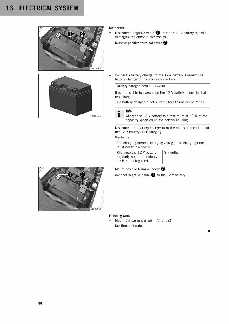
16 ELECTRICAL SYSTEM
88
V01203-11
Main work– Disconnect negative cable1 from the 12 V battery to avoid
damaging the onboard electronics.
– Remove positive terminal cover2.
F03612-01
– Connect a battery charger to the 12-V battery. Connect thebattery charger to the mains connection.
Battery charger (58429074200)
It is impossible to overcharge the 12‑V battery using this bat-tery charger.
This battery charger is not suitable for lithium-ion batteries.
InfoCharge the 12-V battery to a maximum of 10 % of thecapacity specified on the battery housing.
– Disconnect the battery charger from the mains connection andthe 12-V battery after charging.
Guideline
The charging current, charging voltage, and charging timemust not be exceeded.
Recharge the 12-V batteryregularly when the motorcy-cle is not being used
3 months
V01203-11
– Mount positive terminal cover2.
– Connect negative cable1 to the 12 V battery.
Finishing work– Mount the passenger seat. ( p. 62)
– Set time and date.

ELECTRICAL SYSTEM 16
89
16.5 Changing the main fuse
WarningFire hazard Incorrect fuses overload the electrical system.
– Only use fuses with the required ampere value.
– Do not bypass or repair fuses.
InfoThe main fuse protects all electrical power consumers of the vehicle. The main fuse is under the passen-ger seat.
Preparatory work– Remove the passenger seat. ( p. 62)
F02767-10
Main work– Remove protection cap1.
F02766-10
– Remove faulty main fuse2.
InfoA faulty fuse has a burned-out fuse wireA.
A spare fuse3 is located in the starter relay.
– Insert a new main fuse.
Fuse (58011109130) ( p. 120)
TipInsert a new spare fuse into the starter relay to have itavailable when needed.
F02767-10
– Mount protection cap1.
Finishing work– Mount the passenger seat. ( p. 62)
– Set time and date.
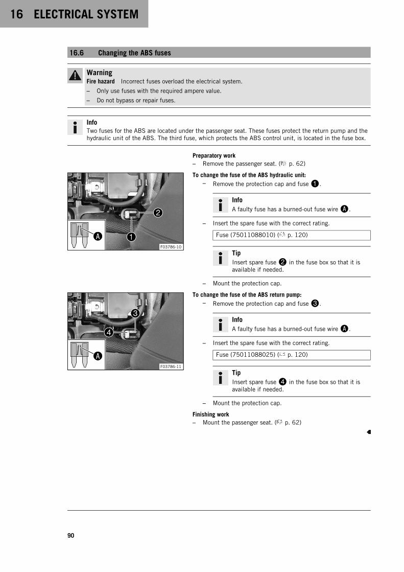
16 ELECTRICAL SYSTEM
90
16.6 Changing the ABS fuses
WarningFire hazard Incorrect fuses overload the electrical system.
– Only use fuses with the required ampere value.
– Do not bypass or repair fuses.
InfoTwo fuses for the ABS are located under the passenger seat. These fuses protect the return pump and thehydraulic unit of the ABS. The third fuse, which protects the ABS control unit, is located in the fuse box.
Preparatory work– Remove the passenger seat. ( p. 62)
F03786-10
To change the fuse of the ABS hydraulic unit:– Remove the protection cap and fuse1.
InfoA faulty fuse has a burned-out fuse wireA.
– Insert the spare fuse with the correct rating.
Fuse (75011088010) ( p. 120)
TipInsert spare fuse2 in the fuse box so that it isavailable if needed.
– Mount the protection cap.
F03786-11
To change the fuse of the ABS return pump:– Remove the protection cap and fuse3.
InfoA faulty fuse has a burned-out fuse wireA.
– Insert the spare fuse with the correct rating.
Fuse (75011088025) ( p. 120)
TipInsert spare fuse4 in the fuse box so that it isavailable if needed.
– Mount the protection cap.
Finishing work– Mount the passenger seat. ( p. 62)
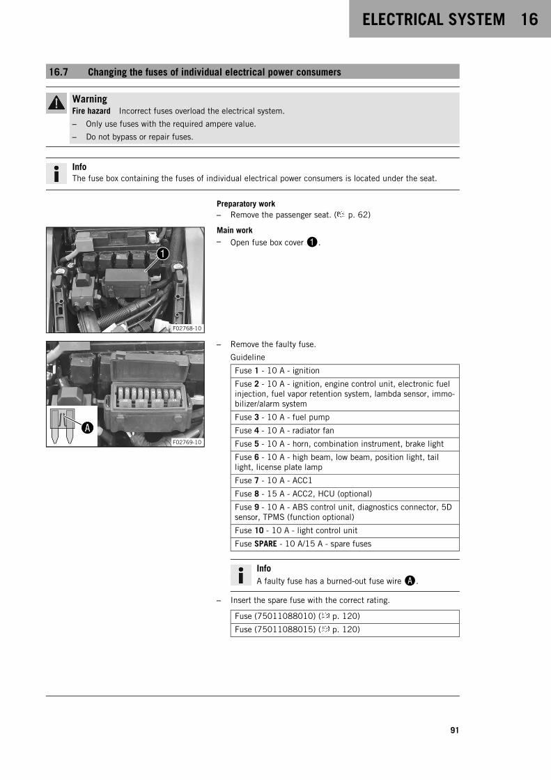
ELECTRICAL SYSTEM 16
91
16.7 Changing the fuses of individual electrical power consumers
WarningFire hazard Incorrect fuses overload the electrical system.
– Only use fuses with the required ampere value.
– Do not bypass or repair fuses.
InfoThe fuse box containing the fuses of individual electrical power consumers is located under the seat.
Preparatory work– Remove the passenger seat. ( p. 62)
F02768-10
Main work– Open fuse box cover1.
F02769-10
– Remove the faulty fuse.
Guideline
Fuse 1 - 10 A - ignition
Fuse 2 - 10 A - ignition, engine control unit, electronic fuelinjection, fuel vapor retention system, lambda sensor, immo-bilizer/alarm system
Fuse 3 - 10 A - fuel pump
Fuse 4 - 10 A - radiator fan
Fuse 5 - 10 A - horn, combination instrument, brake light
Fuse 6 - 10 A - high beam, low beam, position light, taillight, license plate lamp
Fuse 7 - 10 A - ACC1
Fuse 8 - 15 A - ACC2, HCU (optional)
Fuse 9 - 10 A - ABS control unit, diagnostics connector, 5Dsensor, TPMS (function optional)
Fuse 10 - 10 A - light control unit
Fuse SPARE - 10 A/15 A - spare fuses
InfoA faulty fuse has a burned-out fuse wireA.
– Insert the spare fuse with the correct rating.
Fuse (75011088010) ( p. 120)
Fuse (75011088015) ( p. 120)
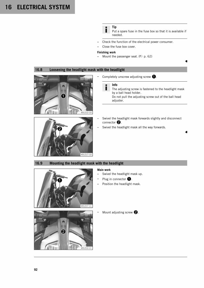
16 ELECTRICAL SYSTEM
92
TipPut a spare fuse in the fuse box so that it is available ifneeded.
– Check the function of the electrical power consumer.
– Close the fuse box cover.
Finishing work– Mount the passenger seat. ( p. 62)
16.8 Loosening the headlight mask with the headlight
V01212-10
– Completely unscrew adjusting screw1.
InfoThe adjusting screw is fastened to the headlight maskby a ball head holder.Do not pull the adjusting screw out of the ball headadjuster.
V01217-10
– Swivel the headlight mask forwards slightly and disconnectconnector2.
– Swivel the headlight mask all the way forwards.
16.9 Mounting the headlight mask with the headlight
V01217-11
Main work– Swivel the headlight mask up.
– Plug in connector1.
– Position the headlight mask.
V01212-11
– Mount adjusting screw2.
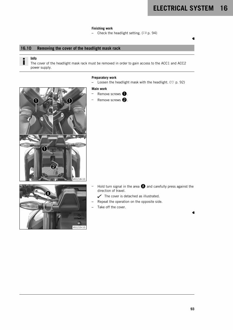
ELECTRICAL SYSTEM 16
93
Finishing work– Check the headlight setting. ( p. 94)
16.10 Removing the cover of the headlight mask rack
InfoThe cover of the headlight mask rack must be removed in order to gain access to the ACC1 and ACC2power supply.
Preparatory work– Loosen the headlight mask with the headlight. ( p. 92)
V01218-10
Main work– Remove screws1.
– Remove screws2.
V01219-10
– Hold turn signal in the areaA and carefully press against thedirection of travel.
The cover is detached as illustrated.
– Repeat the operation on the opposite side.
– Take off the cover.
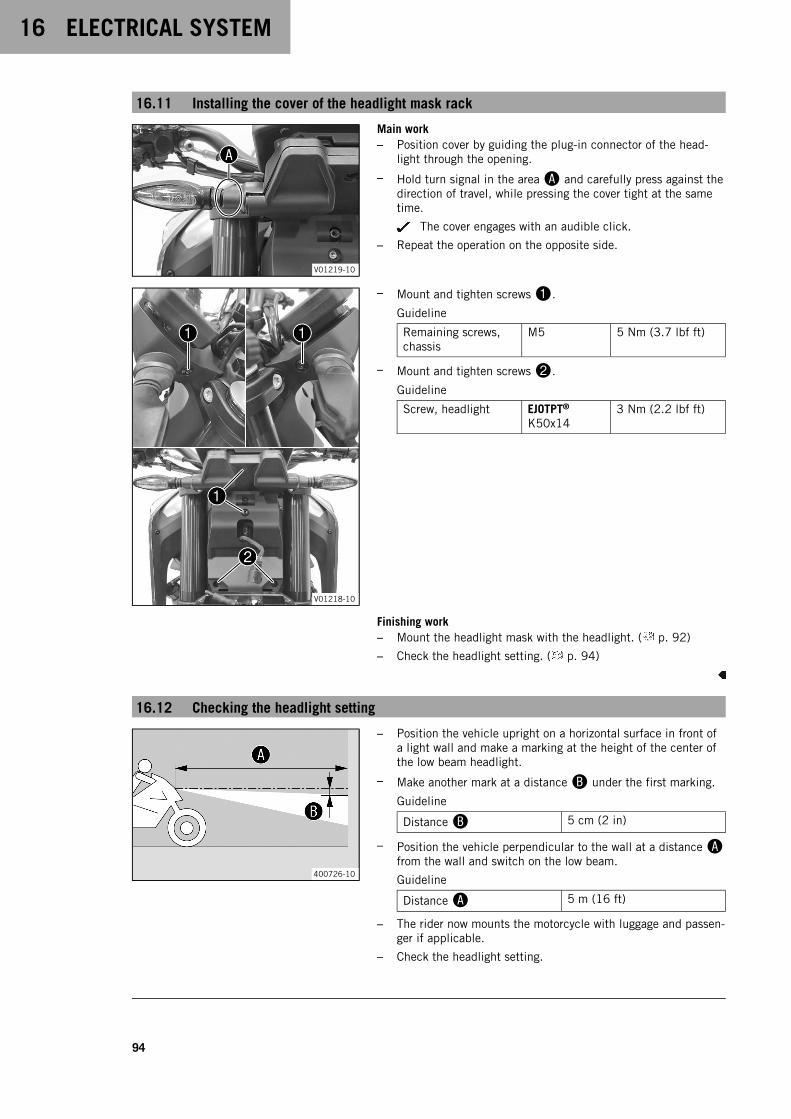
16 ELECTRICAL SYSTEM
94
16.11 Installing the cover of the headlight mask rack
V01219-10
Main work– Position cover by guiding the plug-in connector of the head-
light through the opening.
– Hold turn signal in the areaA and carefully press against thedirection of travel, while pressing the cover tight at the sametime.
The cover engages with an audible click.
– Repeat the operation on the opposite side.
V01218-10
– Mount and tighten screws1.
Guideline
Remaining screws,chassis
M5 5 Nm (3.7 lbf ft)
– Mount and tighten screws2.
Guideline
Screw, headlight EJOTPT®
K50x143 Nm (2.2 lbf ft)
Finishing work– Mount the headlight mask with the headlight. ( p. 92)
– Check the headlight setting. ( p. 94)
16.12 Checking the headlight setting
400726-10
– Position the vehicle upright on a horizontal surface in front ofa light wall and make a marking at the height of the center ofthe low beam headlight.
– Make another mark at a distanceB under the first marking.
Guideline
DistanceB 5 cm (2 in)
– Position the vehicle perpendicular to the wall at a distanceAfrom the wall and switch on the low beam.
Guideline
DistanceA 5 m (16 ft)
– The rider now mounts the motorcycle with luggage and passen-ger if applicable.
– Check the headlight setting.
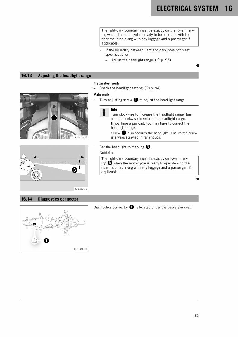
ELECTRICAL SYSTEM 16
95
The light-dark boundary must be exactly on the lower mark-ing when the motorcycle is ready to be operated with therider mounted along with any luggage and a passenger ifapplicable.
» If the boundary between light and dark does not meetspecifications:
– Adjust the headlight range. ( p. 95)
16.13 Adjusting the headlight range
Preparatory work– Check the headlight setting. ( p. 94)
V01212-10
Main work– Turn adjusting screw1 to adjust the headlight range.
InfoTurn clockwise to increase the headlight range; turncounterclockwise to reduce the headlight range.If you have a payload, you may have to correct theheadlight range.Screw1 also secures the headlight. Ensure the screwis always screwed in far enough.
400726-11
– Set the headlight to markingB.
Guideline
The light-dark boundary must lie exactly on lower mark-ingB when the motorcycle is ready to operate with therider mounted along with any luggage and a passenger, ifapplicable.
16.14 Diagnostics connector
H02681-10
Diagnostics connector1 is located under the passenger seat.
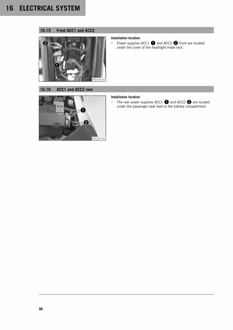
16 ELECTRICAL SYSTEM
96
16.15 Front ACC1 and ACC2
V01216-10
Installation location– Power supplies ACC11 and ACC22 front are located
under the cover of the headlight mask rack.
16.16 ACC1 and ACC2 rear
V01215-10
Installation location– The rear power supplies ACC11 and ACC22 are located
under the passenger seat next to the battery compartment.
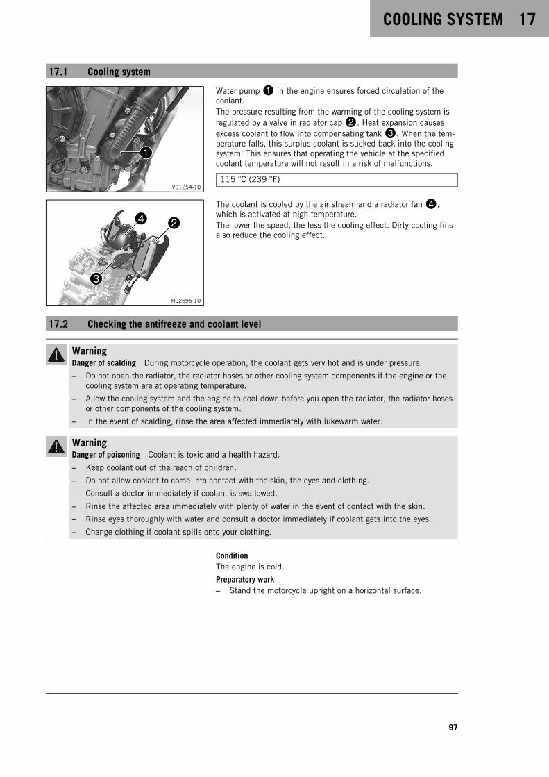
COOLING SYSTEM 17
97
17.1 Cooling system
V01254-10
Water pump1 in the engine ensures forced circulation of thecoolant.The pressure resulting from the warming of the cooling system isregulated by a valve in radiator cap2. Heat expansion causesexcess coolant to flow into compensating tank3. When the tem-perature falls, this surplus coolant is sucked back into the coolingsystem. This ensures that operating the vehicle at the specifiedcoolant temperature will not result in a risk of malfunctions.
115 °C (239 °F)
H02695-10
The coolant is cooled by the air stream and a radiator fan4,which is activated at high temperature.The lower the speed, the less the cooling effect. Dirty cooling finsalso reduce the cooling effect.
17.2 Checking the antifreeze and coolant level
WarningDanger of scalding During motorcycle operation, the coolant gets very hot and is under pressure.
– Do not open the radiator, the radiator hoses or other cooling system components if the engine or thecooling system are at operating temperature.
– Allow the cooling system and the engine to cool down before you open the radiator, the radiator hosesor other components of the cooling system.
– In the event of scalding, rinse the area affected immediately with lukewarm water.
WarningDanger of poisoning Coolant is toxic and a health hazard.
– Keep coolant out of the reach of children.
– Do not allow coolant to come into contact with the skin, the eyes and clothing.
– Consult a doctor immediately if coolant is swallowed.
– Rinse the affected area immediately with plenty of water in the event of contact with the skin.
– Rinse eyes thoroughly with water and consult a doctor immediately if coolant gets into the eyes.
– Change clothing if coolant spills onto your clothing.
ConditionThe engine is cold.
Preparatory work– Stand the motorcycle upright on a horizontal surface.
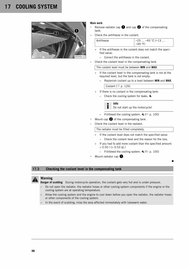
17 COOLING SYSTEM
98
A00956-10
Main work– Remove radiator cap1 and cap2 of the compensating
tank.
– Check the antifreeze in the coolant.
Antifreeze −25 … −45 °C (−13 …−49 °F)
» If the antifreeze in the coolant does not match the speci-fied value:
– Correct the antifreeze in the coolant.
– Check the coolant level in the compensating tank.
The coolant level must be between MIN and MAX.
» If the coolant level in the compensating tank is not at therequired level, but the tank is not empty:
– Replenish coolant up to a level between MIN and MAX.
Coolant ( p. 126)
» If there is no coolant in the compensating tank:
– Check the cooling system for leaks.
InfoDo not start up the motorcycle!
– Fill/bleed the cooling system. ( p. 100)
– Mount cap2 of the compensating tank.
– Check the coolant level in the radiator.
The radiator must be filled completely.
» If the coolant level does not match the specified value:
– Check the coolant level and the reason for the loss.
» If you had to add more coolant than the specified amount:> 0.50 l (> 0.53 qt.)
– Fill/bleed the cooling system. ( p. 100)
– Mount radiator cap1.
17.3 Checking the coolant level in the compensating tank
WarningDanger of scalding During motorcycle operation, the coolant gets very hot and is under pressure.
– Do not open the radiator, the radiator hoses or other cooling system components if the engine or thecooling system are at operating temperature.
– Allow the cooling system and the engine to cool down before you open the radiator, the radiator hosesor other components of the cooling system.
– In the event of scalding, rinse the area affected immediately with lukewarm water.
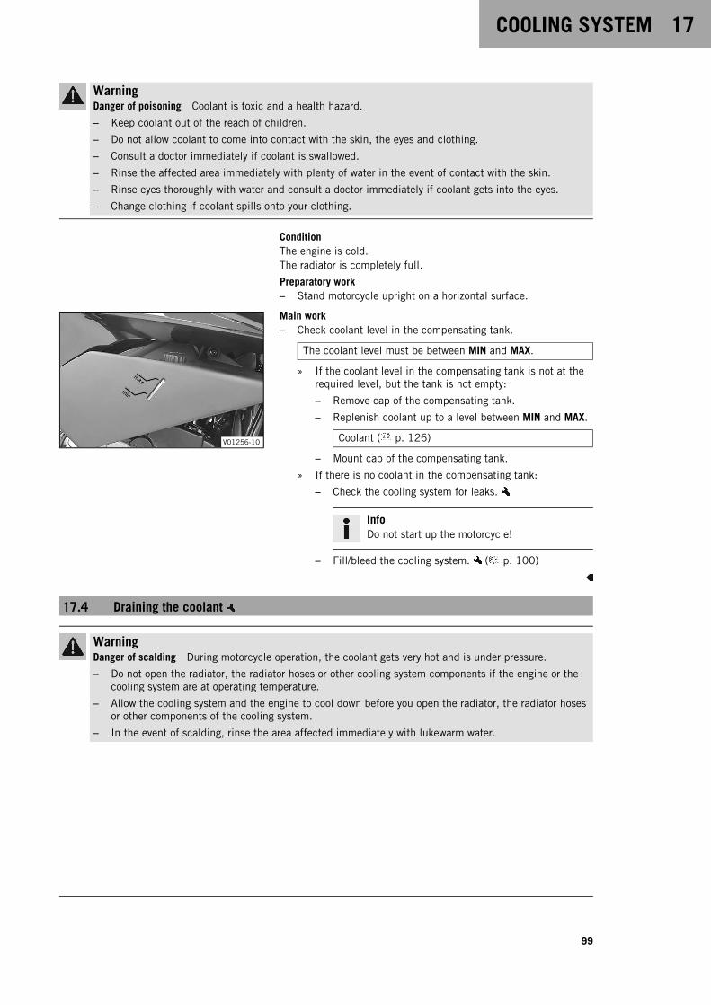
COOLING SYSTEM 17
99
WarningDanger of poisoning Coolant is toxic and a health hazard.
– Keep coolant out of the reach of children.
– Do not allow coolant to come into contact with the skin, the eyes and clothing.
– Consult a doctor immediately if coolant is swallowed.
– Rinse the affected area immediately with plenty of water in the event of contact with the skin.
– Rinse eyes thoroughly with water and consult a doctor immediately if coolant gets into the eyes.
– Change clothing if coolant spills onto your clothing.
ConditionThe engine is cold.The radiator is completely full.
Preparatory work– Stand motorcycle upright on a horizontal surface.
V01256-10
Main work– Check coolant level in the compensating tank.
The coolant level must be between MIN and MAX.
» If the coolant level in the compensating tank is not at therequired level, but the tank is not empty:
– Remove cap of the compensating tank.
– Replenish coolant up to a level between MIN and MAX.
Coolant ( p. 126)
– Mount cap of the compensating tank.
» If there is no coolant in the compensating tank:
– Check the cooling system for leaks.
InfoDo not start up the motorcycle!
– Fill/bleed the cooling system. ( p. 100)
17.4 Draining the coolant
WarningDanger of scalding During motorcycle operation, the coolant gets very hot and is under pressure.
– Do not open the radiator, the radiator hoses or other cooling system components if the engine or thecooling system are at operating temperature.
– Allow the cooling system and the engine to cool down before you open the radiator, the radiator hosesor other components of the cooling system.
– In the event of scalding, rinse the area affected immediately with lukewarm water.

17 COOLING SYSTEM
100
WarningDanger of poisoning Coolant is toxic and a health hazard.
– Keep coolant out of the reach of children.
– Do not allow coolant to come into contact with the skin, the eyes and clothing.
– Consult a doctor immediately if coolant is swallowed.
– Rinse the affected area immediately with plenty of water in the event of contact with the skin.
– Rinse eyes thoroughly with water and consult a doctor immediately if coolant gets into the eyes.
– Change clothing if coolant spills onto your clothing.
ConditionThe engine is cold.
V01254-11
– Position the motorcycle upright.
– Position an appropriate container under the engine.
– Remove screw1 with the seal ring.
– Remove the radiator cap.
– Completely drain the coolant.
– Mount and tighten screw1 with a new seal ring.
Guideline
Screw plug,water pumpdrain hole
EJOTALtracs®
Plus 60x148 Nm (5.9 lbf ft)
Loctite®243™
– Mount the radiator cap.
17.5 Filling/bleeding the cooling system
WarningDanger of poisoning Coolant is toxic and a health hazard.
– Keep coolant out of the reach of children.
– Do not allow coolant to come into contact with the skin, the eyes and clothing.
– Consult a doctor immediately if coolant is swallowed.
– Rinse the affected area immediately with plenty of water in the event of contact with the skin.
– Rinse eyes thoroughly with water and consult a doctor immediately if coolant gets into the eyes.
– Change clothing if coolant spills onto your clothing.
A00957-10
– Remove radiator cap1.
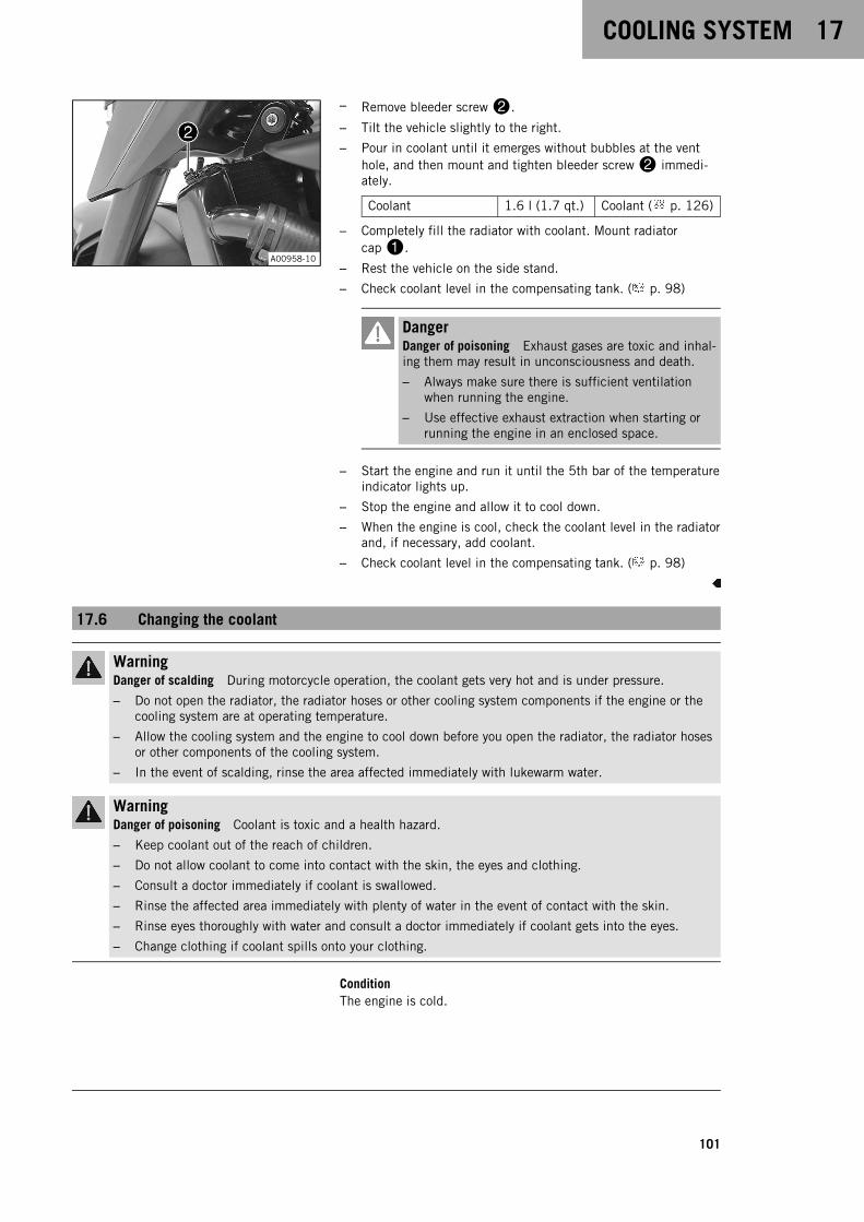
COOLING SYSTEM 17
101
A00958-10
– Remove bleeder screw2.
– Tilt the vehicle slightly to the right.
– Pour in coolant until it emerges without bubbles at the venthole, and then mount and tighten bleeder screw2 immedi-ately.
Coolant 1.6 l (1.7 qt.) Coolant ( p. 126)
– Completely fill the radiator with coolant. Mount radiatorcap1.
– Rest the vehicle on the side stand.
– Check coolant level in the compensating tank. ( p. 98)
DangerDanger of poisoning Exhaust gases are toxic and inhal-ing them may result in unconsciousness and death.
– Always make sure there is sufficient ventilationwhen running the engine.
– Use effective exhaust extraction when starting orrunning the engine in an enclosed space.
– Start the engine and run it until the 5th bar of the temperatureindicator lights up.
– Stop the engine and allow it to cool down.
– When the engine is cool, check the coolant level in the radiatorand, if necessary, add coolant.
– Check coolant level in the compensating tank. ( p. 98)
17.6 Changing the coolant
WarningDanger of scalding During motorcycle operation, the coolant gets very hot and is under pressure.
– Do not open the radiator, the radiator hoses or other cooling system components if the engine or thecooling system are at operating temperature.
– Allow the cooling system and the engine to cool down before you open the radiator, the radiator hosesor other components of the cooling system.
– In the event of scalding, rinse the area affected immediately with lukewarm water.
WarningDanger of poisoning Coolant is toxic and a health hazard.
– Keep coolant out of the reach of children.
– Do not allow coolant to come into contact with the skin, the eyes and clothing.
– Consult a doctor immediately if coolant is swallowed.
– Rinse the affected area immediately with plenty of water in the event of contact with the skin.
– Rinse eyes thoroughly with water and consult a doctor immediately if coolant gets into the eyes.
– Change clothing if coolant spills onto your clothing.
ConditionThe engine is cold.

17 COOLING SYSTEM
102
V01254-11
– Position the motorcycle upright.
– Position an appropriate container under the engine.
– Remove screw1 with the seal ring.
A00957-11
– Remove radiator cap2.
– Completely drain the coolant.
– Mount and tighten screw1 with a new seal ring.
Guideline
Screw plug,water pumpdrain hole
EJOTALtracs®
Plus 60x148 Nm (5.9 lbf ft)
Loctite®243™
A00958-11
– Remove bleeder screw3.
– Tilt the vehicle slightly to the right.
– Pour in coolant until it emerges without bubbles at the venthole, and then mount and tighten bleeder screw3 immedi-ately.
Coolant 1.6 l (1.7 qt.) Coolant ( p. 126)
– Completely fill the radiator with coolant. Mount radiatorcap2.
– Rest the vehicle on the side stand.
DangerDanger of poisoning Exhaust gases are toxic and inhal-ing them may result in unconsciousness and death.
– Always make sure there is sufficient ventilationwhen running the engine.
– Use effective exhaust extraction when starting orrunning the engine in an enclosed space.
– Start the engine and run it until the 5th bar of the temperatureindicator lights up.
– Stop the engine and allow it to cool down.
– After the engine has cooled down, check the coolant level inthe radiator and in the compensating tank again and add morecoolant if necessary.
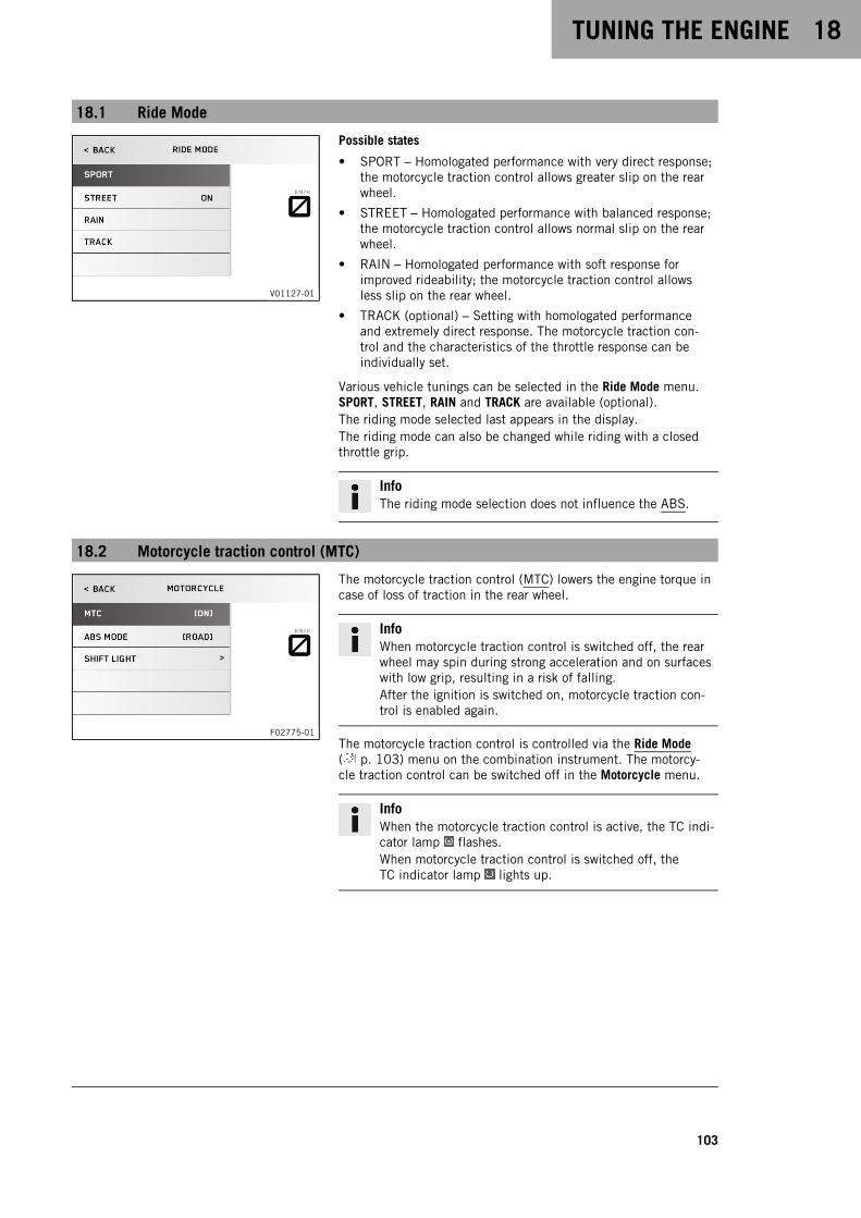
TUNING THE ENGINE 18
103
18.1 Ride Mode
V01127-01
Possible states
• SPORT – Homologated performance with very direct response;the motorcycle traction control allows greater slip on the rearwheel.
• STREET – Homologated performance with balanced response;the motorcycle traction control allows normal slip on the rearwheel.
• RAIN – Homologated performance with soft response forimproved rideability; the motorcycle traction control allowsless slip on the rear wheel.
• TRACK (optional) – Setting with homologated performanceand extremely direct response. The motorcycle traction con-trol and the characteristics of the throttle response can beindividually set.
Various vehicle tunings can be selected in the Ride Mode menu.SPORT, STREET, RAIN and TRACK are available (optional).The riding mode selected last appears in the display.The riding mode can also be changed while riding with a closedthrottle grip.
InfoThe riding mode selection does not influence the ABS.
18.2 Motorcycle traction control (MTC)
F02775-01
The motorcycle traction control (MTC) lowers the engine torque incase of loss of traction in the rear wheel.
InfoWhen motorcycle traction control is switched off, the rearwheel may spin during strong acceleration and on surfaceswith low grip, resulting in a risk of falling.After the ignition is switched on, motorcycle traction con-trol is enabled again.
The motorcycle traction control is controlled via the Ride Mode( p. 103) menu on the combination instrument. The motorcy-cle traction control can be switched off in the Motorcycle menu.
InfoWhen the motorcycle traction control is active, the TC indi-cator lamp flashes.When motorcycle traction control is switched off, theTC indicator lamp lights up.
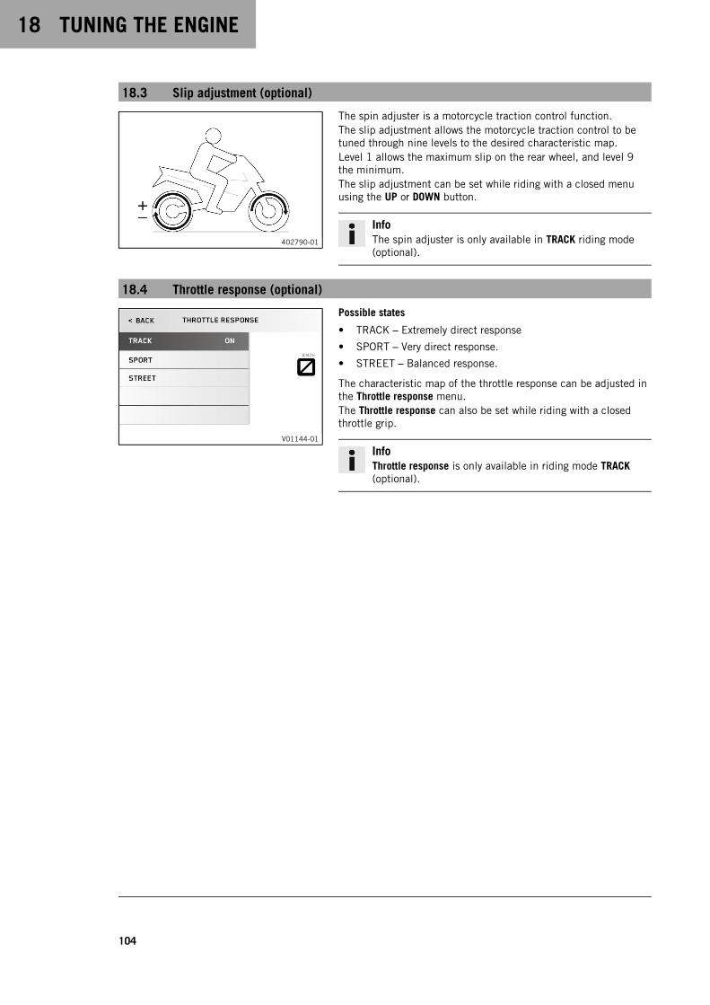
18 TUNING THE ENGINE
104
18.3 Slip adjustment (optional)
402790-01
The spin adjuster is a motorcycle traction control function.The slip adjustment allows the motorcycle traction control to betuned through nine levels to the desired characteristic map.Level 1 allows the maximum slip on the rear wheel, and level 9the minimum.The slip adjustment can be set while riding with a closed menuusing the UP or DOWN button.
InfoThe spin adjuster is only available in TRACK riding mode(optional).
18.4 Throttle response (optional)
V01144-01
Possible states
• TRACK – Extremely direct response
• SPORT – Very direct response.
• STREET – Balanced response.
The characteristic map of the throttle response can be adjusted inthe Throttle response menu.The Throttle response can also be set while riding with a closedthrottle grip.
InfoThrottle response is only available in riding mode TRACK(optional).
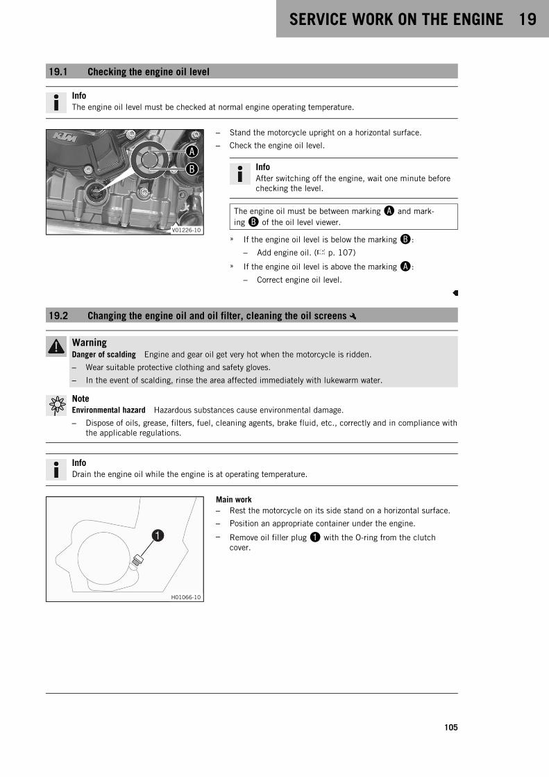
SERVICE WORK ON THE ENGINE 19
105
19.1 Checking the engine oil level
InfoThe engine oil level must be checked at normal engine operating temperature.
V01226-10
– Stand the motorcycle upright on a horizontal surface.
– Check the engine oil level.
InfoAfter switching off the engine, wait one minute beforechecking the level.
The engine oil must be between markingA and mark-ingB of the oil level viewer.
» If the engine oil level is below the markingB:
– Add engine oil. ( p. 107)
» If the engine oil level is above the markingA:
– Correct engine oil level.
19.2 Changing the engine oil and oil filter, cleaning the oil screens
WarningDanger of scalding Engine and gear oil get very hot when the motorcycle is ridden.
– Wear suitable protective clothing and safety gloves.
– In the event of scalding, rinse the area affected immediately with lukewarm water.
NoteEnvironmental hazard Hazardous substances cause environmental damage.
– Dispose of oils, grease, filters, fuel, cleaning agents, brake fluid, etc., correctly and in compliance withthe applicable regulations.
InfoDrain the engine oil while the engine is at operating temperature.
H01066-10
Main work– Rest the motorcycle on its side stand on a horizontal surface.
– Position an appropriate container under the engine.
– Remove oil filler plug1 with the O-ring from the clutchcover.

19 SERVICE WORK ON THE ENGINE
106
V01235-10
– Remove oil drain plugs2 along with the magnets, the O-rings, and the oil screens.
V01236-10
– Remove screws3. Take off oil filter cover4 with the O-ring.
– Pull oil filter5 out of the oil filter housing.
Lock ring plier (51012011000)
– Allow the engine oil to drain completely.
– Thoroughly clean the parts and the sealing surfaces.
V01237-10
– Insert new oil filter5.
InfoOnly insert the oil filter by hand.
– Oil the O-ring of the oil filter cover. Position oil filter cover4.
– Mount and tighten screws3.
Guideline
Screw, oil filter cover M5 6 Nm (4.4 lbf ft)
V01238-10
– Thoroughly clean magnetsA and oil screensB of the oildrain plugs.
V01235-10
– Mount the oil drain plugs2 with magnets and new seal rings,and tighten.
Guideline
Plug, oil screen M20x1.5 20 Nm (14.8 lbf ft)
– Fill up with engine oil at the clutch cover.
Engine oil 2.9 l (3.1 qt.) Engine oil(SAE 10W/50)( p. 126)
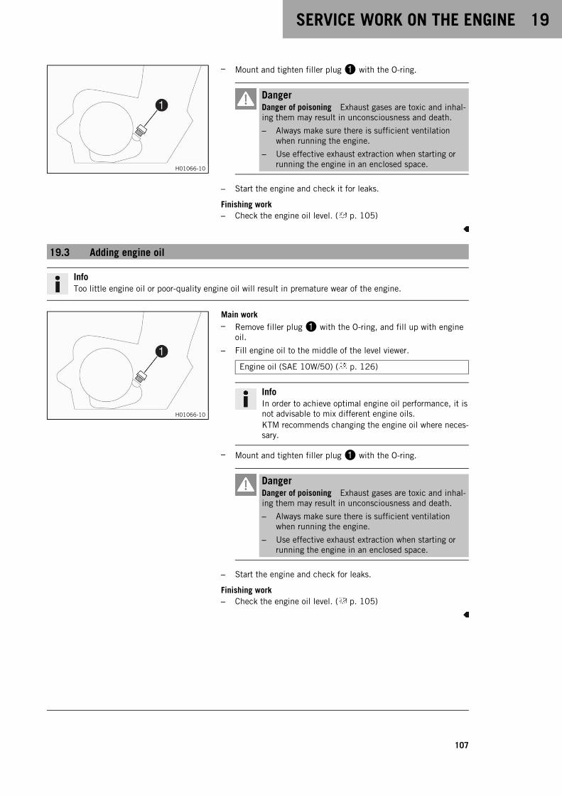
SERVICE WORK ON THE ENGINE 19
107
H01066-10
– Mount and tighten filler plug1 with the O-ring.
DangerDanger of poisoning Exhaust gases are toxic and inhal-ing them may result in unconsciousness and death.
– Always make sure there is sufficient ventilationwhen running the engine.
– Use effective exhaust extraction when starting orrunning the engine in an enclosed space.
– Start the engine and check it for leaks.
Finishing work– Check the engine oil level. ( p. 105)
19.3 Adding engine oil
InfoToo little engine oil or poor-quality engine oil will result in premature wear of the engine.
H01066-10
Main work– Remove filler plug1 with the O-ring, and fill up with engine
oil.
– Fill engine oil to the middle of the level viewer.
Engine oil (SAE 10W/50) ( p. 126)
InfoIn order to achieve optimal engine oil performance, it isnot advisable to mix different engine oils.KTM recommends changing the engine oil where neces-sary.
– Mount and tighten filler plug1 with the O-ring.
DangerDanger of poisoning Exhaust gases are toxic and inhal-ing them may result in unconsciousness and death.
– Always make sure there is sufficient ventilationwhen running the engine.
– Use effective exhaust extraction when starting orrunning the engine in an enclosed space.
– Start the engine and check for leaks.
Finishing work– Check the engine oil level. ( p. 105)

19 SERVICE WORK ON THE ENGINE
108
19.4 Checking the free travel of the clutch lever
NoteClutch damage If there is no free travel by the clutch lever, the clutch will begin to slip.
– Check the free travel of the clutch lever each time before using the motorcycle.
– Adjust the free travel of the clutch lever when necessary in accordance with the specification.
V01187-12
– Check the clutch lever for smooth operation.
– Move the handlebar to the straight-ahead position.
– Pull the clutch lever until resistance is perceptible, and deter-mine the free travelA.
Free travel of clutchleverA
5 mm (0.2 in)
» If the free travel of the clutch lever does not meet specifi-cations:
– Set the free travel of the clutch lever. ( p. 108)
– Move the handlebar to and fro over the entire steering range.
The free travel of the clutch lever must not change.
» If the free travel of the clutch lever changes:
– Check the routing of the clutch cable.
19.5 Setting the free travel of the clutch lever
V01234-10
– Move the handlebar to the straight-ahead position.
– Loosen lock nut1.
– Adjust the free travelA by turning adjusting screw2.
Guideline
Free travel of clutchleverA
5 mm (0.2 in)
– Tighten lock nut1.
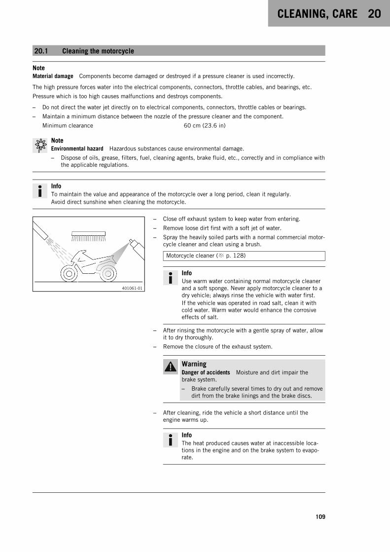
CLEANING, CARE 20
109
20.1 Cleaning the motorcycle
NoteMaterial damage Components become damaged or destroyed if a pressure cleaner is used incorrectly.
The high pressure forces water into the electrical components, connectors, throttle cables, and bearings, etc.
Pressure which is too high causes malfunctions and destroys components.
– Do not direct the water jet directly on to electrical components, connectors, throttle cables or bearings.
– Maintain a minimum distance between the nozzle of the pressure cleaner and the component.
Minimum clearance 60 cm (23.6 in)
NoteEnvironmental hazard Hazardous substances cause environmental damage.
– Dispose of oils, grease, filters, fuel, cleaning agents, brake fluid, etc., correctly and in compliance withthe applicable regulations.
InfoTo maintain the value and appearance of the motorcycle over a long period, clean it regularly.Avoid direct sunshine when cleaning the motorcycle.
401061-01
– Close off exhaust system to keep water from entering.
– Remove loose dirt first with a soft jet of water.
– Spray the heavily soiled parts with a normal commercial motor-cycle cleaner and clean using a brush.
Motorcycle cleaner ( p. 128)
InfoUse warm water containing normal motorcycle cleanerand a soft sponge. Never apply motorcycle cleaner to adry vehicle; always rinse the vehicle with water first.If the vehicle was operated in road salt, clean it withcold water. Warm water would enhance the corrosiveeffects of salt.
– After rinsing the motorcycle with a gentle spray of water, allowit to dry thoroughly.
– Remove the closure of the exhaust system.
WarningDanger of accidents Moisture and dirt impair thebrake system.
– Brake carefully several times to dry out and removedirt from the brake linings and the brake discs.
– After cleaning, ride the vehicle a short distance until theengine warms up.
InfoThe heat produced causes water at inaccessible loca-tions in the engine and on the brake system to evapo-rate.

20 CLEANING, CARE
110
– After the motorcycle has cooled down, lubricate all movingparts and pivot points.
– Clean the chain. ( p. 64)
– Treat bare metal (except for brake discs and the exhaust sys-tem) with a corrosion inhibitor.
Preserving materials for paints, metal and rubber( p. 128)
– Treat all painted parts with a mild paint care product.
Perfect finish and high gloss polish for paints ( p. 128)
InfoDo not polish parts that were matte when delivered asthis would strongly impair the material quality.
– Treat all plastic parts and powder-coated parts with a mildcleaning and care product.
Special cleaner for glossy and matte paint finishes, metaland plastic surfaces ( p. 128)
– Lubricate the ignition/steering lock.
Universal oil spray ( p. 128)
20.2 Checks and maintenance steps for winter operation
InfoIf you use the motorcycle in winter, salt can be expected on the roads. You should therefore take precau-tions against aggressive road salt.After riding on salted roads, thoroughly clean the vehicle with cold water and dry it well. Warm waterenhances the corrosive effects of salt.
401060-01
– Clean the motorcycle. ( p. 109)
– Clean the brake system.
InfoAfter EVERY trip on salted roads, thoroughly clean thebrake calipers and brake linings, after they have cooleddown and without removing them, with cold water anddry them carefully.After riding on salted roads, thoroughly clean themotorcycle with cold water and dry it well.
– Treat the engine, the swingarm, and all other bare or zinc-plated parts (except the brake discs) with a wax-based corro-sion inhibitor.
InfoCorrosion inhibitor must not come in contact with thebrake discs as this would greatly reduce the brakingforce.
– Clean the chain. ( p. 64)

STORAGE 21
111
21.1 Storage
InfoIf you plan to garage the motorcycle for a longer period, perform the following steps or have them per-formed.Before storing the motorcycle, check all parts for function and wear. If service, repairs, or replacementsare necessary, you should do this during the storage period (less workshop overload). In this way, you canavoid long workshop waiting times at the start of the new season.
401058-01
– When refueling for the last time before taking the motorcycleout of service, add fuel additive.
Fuel additive ( p. 128)
– Refuel. ( p. 56)
– Clean the motorcycle. ( p. 109)
– Change the engine oil and the oil filter, clean the oilscreens. ( p. 105)
– Check the antifreeze and coolant level. ( p. 97)
– Check tire pressure. ( p. 83)
– Remove the 12-V battery. ( p. 85)
– Charge the 12-V battery. ( p. 87)
Guideline
Storage temperature of the12-V battery without directsunlight
0 … 35 °C (32 … 95 °F)
– Store the vehicle in a dry location that is not subject to largefluctuations in temperature.
InfoKTM recommends jacking up the motorcycle.
– Raise the motorcycle with the rear lifting gear. ( p. 60)
– Lift the motorcycle with the front lifting gear. ( p. 60)
– Cover the vehicle with a tarp or similar cover that is permeableto air.
InfoDo not use non-porous materials since they preventhumidity from escaping, thus causing corrosion.Avoid running the engine for a short time only. Sincethe engine cannot warm up properly, the water vaporproduced during combustion condenses and causesvalves and the exhaust system to rust.
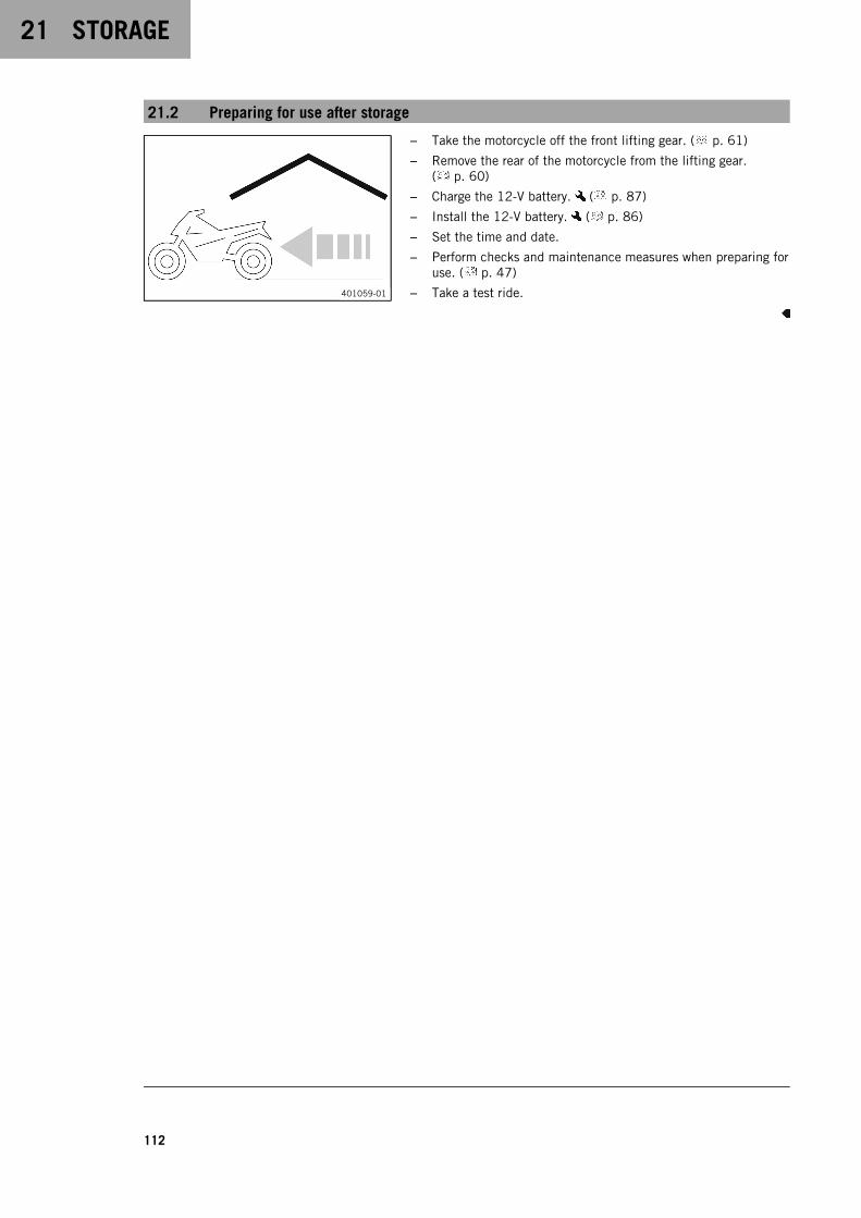
21 STORAGE
112
21.2 Preparing for use after storage
401059-01
– Take the motorcycle off the front lifting gear. ( p. 61)
– Remove the rear of the motorcycle from the lifting gear.( p. 60)
– Charge the 12-V battery. ( p. 87)
– Install the 12-V battery. ( p. 86)
– Set the time and date.
– Perform checks and maintenance measures when preparing foruse. ( p. 47)
– Take a test ride.
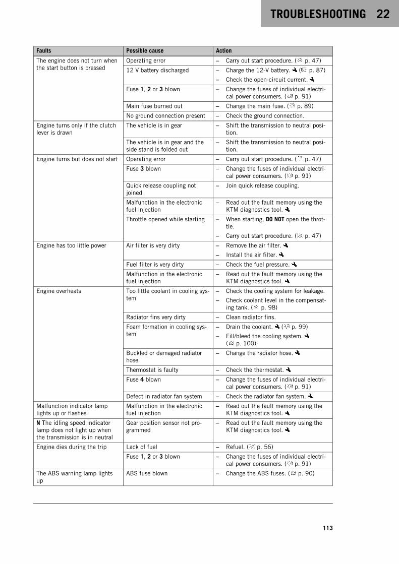
TROUBLESHOOTING 22
113
Faults Possible cause Action
The engine does not turn whenthe start button is pressed
Operating error – Carry out start procedure. ( p. 47)
12 V battery discharged – Charge the 12-V battery. ( p. 87)
– Check the open-circuit current.
Fuse 1, 2 or 3 blown – Change the fuses of individual electri-cal power consumers. ( p. 91)
Main fuse burned out – Change the main fuse. ( p. 89)
No ground connection present – Check the ground connection.
Engine turns only if the clutchlever is drawn
The vehicle is in gear – Shift the transmission to neutral posi-tion.
The vehicle is in gear and theside stand is folded out
– Shift the transmission to neutral posi-tion.
Engine turns but does not start Operating error – Carry out start procedure. ( p. 47)
Fuse 3 blown – Change the fuses of individual electri-cal power consumers. ( p. 91)
Quick release coupling notjoined
– Join quick release coupling.
Malfunction in the electronicfuel injection
– Read out the fault memory using theKTM diagnostics tool.
Throttle opened while starting – When starting, DO NOT open the throt-tle.
– Carry out start procedure. ( p. 47)
Engine has too little power Air filter is very dirty – Remove the air filter.
– Install the air filter.
Fuel filter is very dirty – Check the fuel pressure.
Malfunction in the electronicfuel injection
– Read out the fault memory using theKTM diagnostics tool.
Engine overheats Too little coolant in cooling sys-tem
– Check the cooling system for leakage.
– Check coolant level in the compensat-ing tank. ( p. 98)
Radiator fins very dirty – Clean radiator fins.
Foam formation in cooling sys-tem
– Drain the coolant. ( p. 99)
– Fill/bleed the cooling system.( p. 100)
Buckled or damaged radiatorhose
– Change the radiator hose.
Thermostat is faulty – Check the thermostat.
Fuse 4 blown – Change the fuses of individual electri-cal power consumers. ( p. 91)
Defect in radiator fan system – Check the radiator fan system.
Malfunction indicator lamplights up or flashes
Malfunction in the electronicfuel injection
– Read out the fault memory using theKTM diagnostics tool.
N The idling speed indicatorlamp does not light up whenthe transmission is in neutral
Gear position sensor not pro-grammed
– Read out the fault memory using theKTM diagnostics tool.
Engine dies during the trip Lack of fuel – Refuel. ( p. 56)
Fuse 1, 2 or 3 blown – Change the fuses of individual electri-cal power consumers. ( p. 91)
The ABS warning lamp lightsup
ABS fuse blown – Change the ABS fuses. ( p. 90)
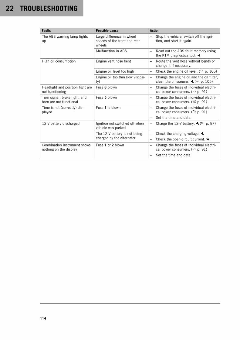
22 TROUBLESHOOTING
114
Faults Possible cause Action
The ABS warning lamp lightsup
Large difference in wheelspeeds of the front and rearwheels
– Stop the vehicle, switch off the igni-tion, and start it again.
Malfunction in ABS – Read out the ABS fault memory usingthe KTM diagnostics tool.
High oil consumption Engine vent hose bent – Route the vent hose without bends orchange it if necessary.
Engine oil level too high – Check the engine oil level. ( p. 105)
Engine oil too thin (low viscosi-ty)
– Change the engine oil and the oil filter,clean the oil screens. ( p. 105)
Headlight and position light arenot functioning
Fuse 6 blown – Change the fuses of individual electri-cal power consumers. ( p. 91)
Turn signal, brake light, andhorn are not functional
Fuse 5 blown – Change the fuses of individual electri-cal power consumers. ( p. 91)
Time is not (correctly) dis-played
Fuse 1 is blown – Change the fuses of individual electri-cal power consumers. ( p. 91)
– Set the time and date.
12 V battery discharged Ignition not switched off whenvehicle was parked
– Charge the 12-V battery. ( p. 87)
The 12-V battery is not beingcharged by the alternator
– Check the charging voltage.
– Check the open-circuit current.
Combination instrument showsnothing on the display
Fuse 1 or 2 blown – Change the fuses of individual electri-cal power consumers. ( p. 91)
– Set the time and date.
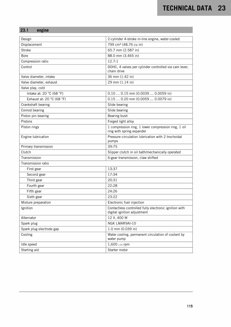
TECHNICAL DATA 23
115
23.1 engine
Design 2-cylinder 4-stroke in-line engine, water-cooled
Displacement 799 cm³ (48.76 cu in)
Stroke 65.7 mm (2.587 in)
Bore 88.0 mm (3.465 in)
Compression ratio 12.7:1
Control DOHC, 4 valves per cylinder controlled via cam lever,chain drive
Valve diameter, intake 36 mm (1.42 in)
Valve diameter, exhaust 29 mm (1.14 in)
Valve play, cold
Intake at: 20 °C (68 °F) 0.10 … 0.15 mm (0.0039 … 0.0059 in)
Exhaust at: 20 °C (68 °F) 0.15 … 0.20 mm (0.0059 … 0.0079 in)
Crankshaft bearing Slide bearing
Conrod bearing Slide bearing
Piston pin bearing Bearing bush
Pistons Forged light alloy
Piston rings 1 compression ring, 1 lower compression ring, 1 oilring with spring expander
Engine lubrication Pressure circulation lubrication with 2 trochoidalpumps
Primary transmission 39:75
Clutch Slipper clutch in oil bath/mechanically operated
Transmission 6-gear transmission, claw shifted
Transmission ratio
First gear 13:37
Second gear 17:34
Third gear 20:31
Fourth gear 22:28
Fifth gear 24:26
Sixth gear 23:22
Mixture preparation Electronic fuel injection
Ignition Contactless controlled fully electronic ignition withdigital ignition adjustment
Alternator 12 V, 400 W
Spark plug NGK LMAR9AI‑10
Spark plug electrode gap 1.0 mm (0.039 in)
Cooling Water cooling, permanent circulation of coolant bywater pump
Idle speed 1,600 ± 50 rpm
Starting aid Starter motor

23 TECHNICAL DATA
116
23.2 Engine tightening torques
Screw plug, water pump drain hole EJOTALtracs®Plus 60x14 8 Nm (5.9 lbf ft)Loctite®243™
Screw, bleeder flange EJOTALtracs® M6x12 8 Nm (5.9 lbf ft)Loctite®243™
Hose clamp, intake flange M4 2.5 Nm (1.84 lbf ft)
Nozzle, engine vent M5 2 Nm (1.5 lbf ft)
Oil nozzle for piston cooling M5 2 Nm (1.5 lbf ft)
Oil nozzle in cylinder head M5 2 Nm (1.5 lbf ft)
Remaining screws, engine M5 6 Nm (4.4 lbf ft)
Screw, cam lever axial lock M5 6 Nm (4.4 lbf ft)Loctite®243™
Screw, crankshaft speed sensor M5 6 Nm (4.4 lbf ft)Loctite®243™
Screw, gear position sensor M5 6 Nm (4.4 lbf ft)Loctite®243™
Screw, oil filter cover M5 6 Nm (4.4 lbf ft)
Screw, pressure plate M5 3 Nm (2.2 lbf ft)Loctite®243™
Screw, shift drum retaining bracket M5 6 Nm (4.4 lbf ft)Loctite®243™
Screw, shift shaft sensor M5 6 Nm (4.4 lbf ft)Loctite®243™
Screw, thermostat case M5 6 Nm (4.4 lbf ft)Loctite®243™
Securing screw, balancer shaft M5 5 Nm (3.7 lbf ft)Loctite®243™
Swing angle sensor screw M5 6 Nm (4.4 lbf ft)Loctite®243™
Nut, starter motor cable M6 5 Nm (3.7 lbf ft)
Remaining screws, engine M6 10 Nm (7.4 lbf ft)
Screw, alternator cover M6x30 10 Nm (7.4 lbf ft)
Screw, alternator cover M6x35 10 Nm (7.4 lbf ft)
Screw, camshaft bearing bridge M6 10 Nm (7.4 lbf ft)
Screw, clutch cable retainingbracket
M6 10 Nm (7.4 lbf ft)Loctite®243™
Screw, clutch cover M6 10 Nm (7.4 lbf ft)
Screw, clutch release lever M6 10 Nm (7.4 lbf ft)Loctite®243™
Screw, clutch spring M6 10 Nm (7.4 lbf ft)
Screw, cylinder head M6 10 Nm (7.4 lbf ft)
Screw, engine case M6x30 12 Nm (8.9 lbf ft)
Screw, engine case M6x60 12 Nm (8.9 lbf ft)
Screw, freewheel ring M6 14 Nm (10.3 lbf ft)Loctite®243™
Screw, ignition coil M6 8 Nm (5.9 lbf ft)

TECHNICAL DATA 23
117
Screw, locking lever M6 10 Nm (7.4 lbf ft)Loctite®243™
Screw, main shaft bearing support M6 10 Nm (7.4 lbf ft)Loctite®243™
Screw, oil pan M6x30 10 Nm (7.4 lbf ft)
Screw, oil pan M6x35 10 Nm (7.4 lbf ft)
Screw, oil pump cover M6 10 Nm (7.4 lbf ft)Loctite®243™
Screw, oil pump unit M6 10 Nm (7.4 lbf ft)
Screw, oil/water heat exchanger M6 10 Nm (7.4 lbf ft)Loctite®243™
Screw, shift drum locating M6 10 Nm (7.4 lbf ft)Loctite®243™
Screw, shift lever M6 14 Nm (10.3 lbf ft)Loctite®243™
Screw, shift shaft retaining bracket M6 10 Nm (7.4 lbf ft)Loctite®243™
Screw, starter motor M6 10 Nm (7.4 lbf ft)
Screw, stator M6 10 Nm (7.4 lbf ft)Loctite®243™
Screw, timing chain shaft M6 10 Nm (7.4 lbf ft)
Screw, upper guide rail M6 8 Nm (5.9 lbf ft)Loctite®243™
Screw, valve cover M6 10 Nm (7.4 lbf ft)
Screw, water pump cover M6 10 Nm (7.4 lbf ft)Loctite®243™
Screw, water pump wheel M6 10 Nm (7.4 lbf ft)Loctite®243™
Nut, exhaust flange M8 15 Nm (11.1 lbf ft)Copper paste
Oil nozzle for clutch lubrication M8 5 Nm (3.7 lbf ft)Loctite®243™
Remaining screws for engine M8 20 Nm (14.8 lbf ft)
Screw plug, locking screw M8 15 Nm (11.1 lbf ft)
Screw, engine case M8x45 25 Nm (18.4 lbf ft)Screw support greased
Screw, engine case M8x55 25 Nm (18.4 lbf ft)Screw support greased
Screw, engine case M8x65 25 Nm (18.4 lbf ft)Screw support greased
Screw, engine case M8x90 25 Nm (18.4 lbf ft)Screw support greased
Screw, knock sensor M8 20 Nm (14.8 lbf ft)
Screw, oil pump idler gear M8 15 Nm (11.1 lbf ft)Loctite®243™
Screw, tensioning rail M8 15 Nm (11.1 lbf ft)Loctite®243™
Stud, exhaust flange M8 15 Nm (11.1 lbf ft)Loctite®243™
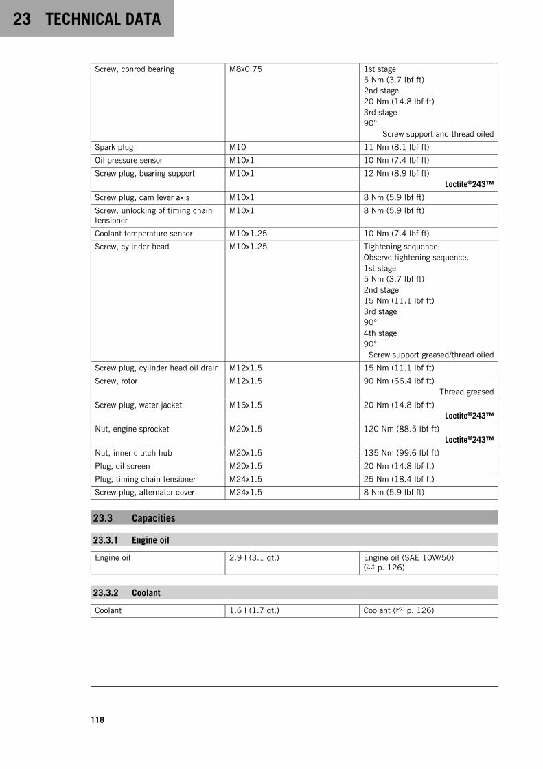
23 TECHNICAL DATA
118
Screw, conrod bearing M8x0.75 1st stage5 Nm (3.7 lbf ft)2nd stage20 Nm (14.8 lbf ft)3rd stage90°
Screw support and thread oiled
Spark plug M10 11 Nm (8.1 lbf ft)
Oil pressure sensor M10x1 10 Nm (7.4 lbf ft)
Screw plug, bearing support M10x1 12 Nm (8.9 lbf ft)Loctite®243™
Screw plug, cam lever axis M10x1 8 Nm (5.9 lbf ft)
Screw, unlocking of timing chaintensioner
M10x1 8 Nm (5.9 lbf ft)
Coolant temperature sensor M10x1.25 10 Nm (7.4 lbf ft)
Screw, cylinder head M10x1.25 Tightening sequence:Observe tightening sequence.1st stage5 Nm (3.7 lbf ft)2nd stage15 Nm (11.1 lbf ft)3rd stage90°4th stage90°Screw support greased/thread oiled
Screw plug, cylinder head oil drain M12x1.5 15 Nm (11.1 lbf ft)
Screw, rotor M12x1.5 90 Nm (66.4 lbf ft)Thread greased
Screw plug, water jacket M16x1.5 20 Nm (14.8 lbf ft)Loctite®243™
Nut, engine sprocket M20x1.5 120 Nm (88.5 lbf ft)Loctite®243™
Nut, inner clutch hub M20x1.5 135 Nm (99.6 lbf ft)
Plug, oil screen M20x1.5 20 Nm (14.8 lbf ft)
Plug, timing chain tensioner M24x1.5 25 Nm (18.4 lbf ft)
Screw plug, alternator cover M24x1.5 8 Nm (5.9 lbf ft)
23.3 Capacities
23.3.1 Engine oil
Engine oil 2.9 l (3.1 qt.) Engine oil (SAE 10W/50)( p. 126)
23.3.2 Coolant
Coolant 1.6 l (1.7 qt.) Coolant ( p. 126)
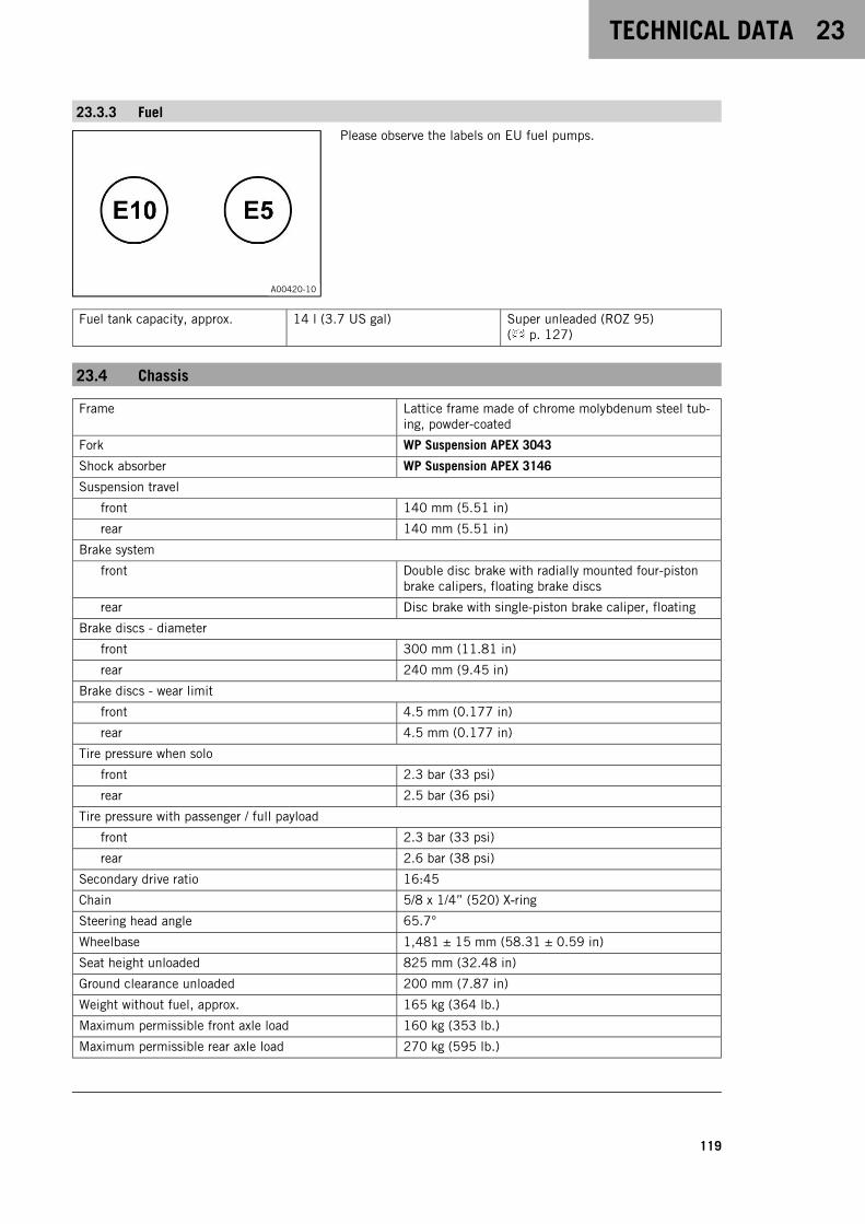
TECHNICAL DATA 23
119
23.3.3 Fuel
A00420-10
Please observe the labels on EU fuel pumps.
Fuel tank capacity, approx. 14 l (3.7 US gal) Super unleaded (ROZ 95)( p. 127)
23.4 Chassis
Frame Lattice frame made of chrome molybdenum steel tub-ing, powder-coated
Fork WP Suspension APEX 3043
Shock absorber WP Suspension APEX 3146
Suspension travel
front 140 mm (5.51 in)
rear 140 mm (5.51 in)
Brake system
front Double disc brake with radially mounted four-pistonbrake calipers, floating brake discs
rear Disc brake with single-piston brake caliper, floating
Brake discs - diameter
front 300 mm (11.81 in)
rear 240 mm (9.45 in)
Brake discs - wear limit
front 4.5 mm (0.177 in)
rear 4.5 mm (0.177 in)
Tire pressure when solo
front 2.3 bar (33 psi)
rear 2.5 bar (36 psi)
Tire pressure with passenger / full payload
front 2.3 bar (33 psi)
rear 2.6 bar (38 psi)
Secondary drive ratio 16:45
Chain 5/8 x 1/4” (520) X‑ring
Steering head angle 65.7°
Wheelbase 1,481 ± 15 mm (58.31 ± 0.59 in)
Seat height unloaded 825 mm (32.48 in)
Ground clearance unloaded 200 mm (7.87 in)
Weight without fuel, approx. 165 kg (364 lb.)
Maximum permissible front axle load 160 kg (353 lb.)
Maximum permissible rear axle load 270 kg (595 lb.)

23 TECHNICAL DATA
120
Maximum permissible overall weight 430 kg (948 lb.)
23.5 Electrical system
12 V battery HTZ12A-BS Battery voltage: 12 VNominal capacity: 10 AhMaintenance-free
Fuse 75011088010 10 A
Fuse 75011088015 15 A
Fuse 75011088025 25 A
Fuse 58011109130 30 A
Low beam/high beam LED
Daytime running light/position light LED
Combination instrument lighting and indicator lamps LED
Turn signal LED
Brake/tail light LED
License plate lamp LED
23.6 Tires
Front tire Rear tire
120/70 ZR 17 M/C (58W) TL (J)MAXXIS Supermaxx ST
180/55 ZR 17 M/C (73W) TL (G)MAXXIS Supermaxx ST
The tires specified represent one of the possible series production tires. For alternative manufacturers, if any,contact an authorized dealer or qualified tire dealership. If local road approval regulations apply, these and therespective technical specifications must be observed. Additional information is available in the Service sectionunder:KTM.COM
23.7 Fork
Fork article number 05.58.6R.26
Fork WP Suspension APEX 3043
Spring rate
Medium (standard) 6.0 … 9.0 N/mm (34.3 … 51.4 lb/in)
Fork length 765 mm (30.12 in)
Spring length with preload spacer(s) 367 mm (14.45 in)
Fork oil per fork leg 470 ± 5 ml (15.89 ± 0.17 fl. oz.) Fork oil (SAE 4) (48601166S1)( p. 127)

TECHNICAL DATA 23
121
23.8 Shock absorber
Shock absorber article number 01.58.4R.26
Shock absorber WP Suspension APEX 3146
Spring preload
Standard 5 clicks
Inbuilt length 387 mm (15.24 in)
Spring length 185 mm (7.28 in)
Spring rate
Medium (standard) 130 … 160 N/mm (742 … 914 lb/in)
Shock absorber oil Shock absorber fluid (SAE 2.5)(50180751S1) ( p. 127)
23.9 Chassis tightening torques
Radiator hose hose clamp - 2.2 Nm (1.62 lbf ft)
Remaining screws, chassis EJOTPT® K45x12 1 Nm (0.7 lbf ft)
Remaining screws, chassis EJOTPT® K50x12 1 Nm (0.7 lbf ft)
Remaining screws, chassis EJOTPT® K50x14 1 Nm (0.7 lbf ft)
Remaining screws, chassis EJOTPT® K50x16 2 Nm (1.5 lbf ft)
Remaining screws, chassis EJOTPT® K50x18 2 Nm (1.5 lbf ft)
Screw, headlight EJOTPT® K50x14 3 Nm (2.2 lbf ft)
Throttle valve body hose clamp - 2.8 Nm (2.07 lbf ft)
Remaining nuts, chassis M4 3 Nm (2.2 lbf ft)
Remaining screws, chassis M4 3 Nm (2.2 lbf ft)
Screw, fixed grip, left M4 3 Nm (2.2 lbf ft)
Remaining nuts, chassis M5 5 Nm (3.7 lbf ft)
Remaining screws, chassis M5 5 Nm (3.7 lbf ft)
Screw, air filter box M5 3 Nm (2.2 lbf ft)
Screw, brake fluid reservoir for rearbrake
M5 5 Nm (3.7 lbf ft)Loctite®243™
Screw, combination instrument M5 4 Nm (3 lbf ft)
Screw, combination switch, left M5 2 Nm (1.5 lbf ft)
Screw, combination switch, right M5 5 Nm (3.7 lbf ft)
Screw, engine sprocket cover M5 5 Nm (3.7 lbf ft)Loctite®243™
Screw, fuel level sensor M5 3 Nm (2.2 lbf ft)
Screw, fuel tank cover M5 3 Nm (2.2 lbf ft)
Screw, headlight mask M5 5 Nm (3.7 lbf ft)Loctite®243™
Screw, heat guard M5 5 Nm (3.7 lbf ft)Loctite®243™
Screw, license plate holder M5 3 Nm (2.2 lbf ft)
Screw, lower rear panel M5 3 Nm (2.2 lbf ft)
Screw, mask support M5 3 Nm (2.2 lbf ft)
Screw, side stand sensor M5 2 Nm (1.5 lbf ft)Loctite®243™

23 TECHNICAL DATA
122
Screw, support roller M5 4 Nm (3 lbf ft)Loctite®243™
Screw, throttle grip M5 3.5 Nm (2.58 lbf ft)
Screw, trim M5 3 Nm (2.2 lbf ft)
Nut, cable on starter motor M6 5 Nm (3.7 lbf ft)
Nut, hand brake lever M6 Attach torque to nut.10 Nm (7.4 lbf ft)
Nut, push rod, foot brake lever M6 6 Nm (4.4 lbf ft)
Nut, shift rod M6 6 Nm (4.4 lbf ft)
Nut, shift rod M6LH 6 Nm (4.4 lbf ft)
Remaining nuts, chassis M6 10 Nm (7.4 lbf ft)
Remaining screws, chassis M6 10 Nm (7.4 lbf ft)
Screw, activated carbon filterholder
M6 6 Nm (4.4 lbf ft)
Screw, angle sensor M6 5 Nm (3.7 lbf ft)
Screw, ball joint of push rod onfoot brake cylinder
M6 10 Nm (7.4 lbf ft)Loctite®243™
Screw, battery support bracket M6 4.5 Nm (3.32 lbf ft)
Screw, battery terminal M6x12 4.5 Nm (3.32 lbf ft)
Screw, battery terminal M6x20 4.5 Nm (3.32 lbf ft)
Screw, brake assembly M6 5 Nm (3.7 lbf ft)
Screw, clutch assembly M6 5 Nm (3.7 lbf ft)
Screw, foot brake cylinder M6 10 Nm (7.4 lbf ft)Loctite®243™
Screw, foot brake lever stub M6 10 Nm (7.4 lbf ft)Loctite®243™
Screw, front rider's seat M6 10 Nm (7.4 lbf ft)Loctite®243™
Screw, fuel tank rollers M6 10 Nm (7.4 lbf ft)Loctite®243™
Screw, fuel tank spoiler M6 3 Nm (2.2 lbf ft)
Screw, ground wire on frame M6 6 Nm (4.4 lbf ft)
Screw, ground wire to starter motor M6 10 Nm (7.4 lbf ft)
Screw, ignition lock (tamper-proofscrew)
M6 Tighten until the head tears off.
Loctite®243™
Screw, license plate holder M6 10 Nm (7.4 lbf ft)Loctite®243™
Screw, magnetic holder on sidestand
M6 2 Nm (1.5 lbf ft)Loctite®243™
Screw, main silencer clamp M6 8 Nm (5.9 lbf ft)
Screw, manifold clamp M6 8 Nm (5.9 lbf ft)
Screw, radiator bracket, bottom M6 5 Nm (3.7 lbf ft)
Screw, seat lock M6 8 Nm (5.9 lbf ft)Loctite® 222™
Screw, shift lever stub M6 10 Nm (7.4 lbf ft)Loctite®243™
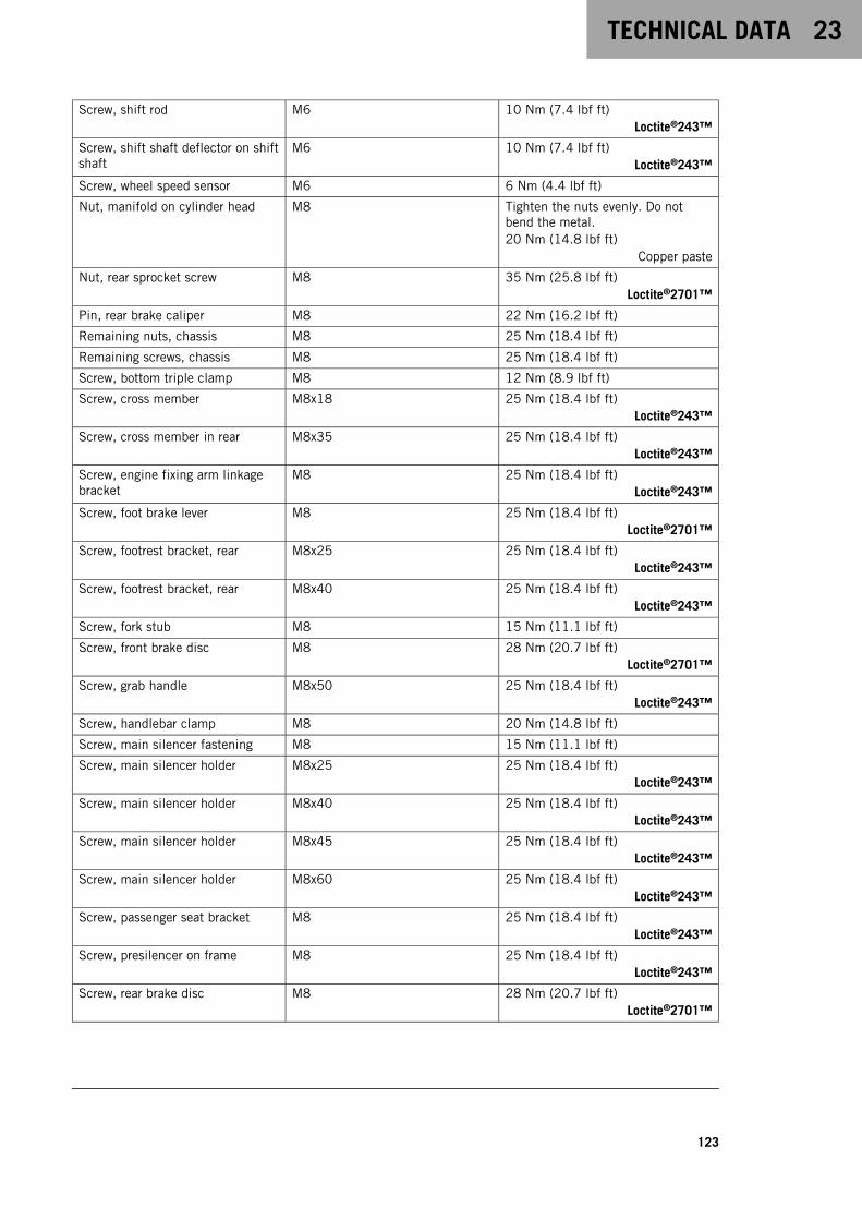
TECHNICAL DATA 23
123
Screw, shift rod M6 10 Nm (7.4 lbf ft)Loctite®243™
Screw, shift shaft deflector on shiftshaft
M6 10 Nm (7.4 lbf ft)Loctite®243™
Screw, wheel speed sensor M6 6 Nm (4.4 lbf ft)
Nut, manifold on cylinder head M8 Tighten the nuts evenly. Do notbend the metal.20 Nm (14.8 lbf ft)
Copper paste
Nut, rear sprocket screw M8 35 Nm (25.8 lbf ft)Loctite®2701™
Pin, rear brake caliper M8 22 Nm (16.2 lbf ft)
Remaining nuts, chassis M8 25 Nm (18.4 lbf ft)
Remaining screws, chassis M8 25 Nm (18.4 lbf ft)
Screw, bottom triple clamp M8 12 Nm (8.9 lbf ft)
Screw, cross member M8x18 25 Nm (18.4 lbf ft)Loctite®243™
Screw, cross member in rear M8x35 25 Nm (18.4 lbf ft)Loctite®243™
Screw, engine fixing arm linkagebracket
M8 25 Nm (18.4 lbf ft)Loctite®243™
Screw, foot brake lever M8 25 Nm (18.4 lbf ft)Loctite®2701™
Screw, footrest bracket, rear M8x25 25 Nm (18.4 lbf ft)Loctite®243™
Screw, footrest bracket, rear M8x40 25 Nm (18.4 lbf ft)Loctite®243™
Screw, fork stub M8 15 Nm (11.1 lbf ft)
Screw, front brake disc M8 28 Nm (20.7 lbf ft)Loctite®2701™
Screw, grab handle M8x50 25 Nm (18.4 lbf ft)Loctite®243™
Screw, handlebar clamp M8 20 Nm (14.8 lbf ft)
Screw, main silencer fastening M8 15 Nm (11.1 lbf ft)
Screw, main silencer holder M8x25 25 Nm (18.4 lbf ft)Loctite®243™
Screw, main silencer holder M8x40 25 Nm (18.4 lbf ft)Loctite®243™
Screw, main silencer holder M8x45 25 Nm (18.4 lbf ft)Loctite®243™
Screw, main silencer holder M8x60 25 Nm (18.4 lbf ft)Loctite®243™
Screw, passenger seat bracket M8 25 Nm (18.4 lbf ft)Loctite®243™
Screw, presilencer on frame M8 25 Nm (18.4 lbf ft)Loctite®243™
Screw, rear brake disc M8 28 Nm (20.7 lbf ft)Loctite®2701™

23 TECHNICAL DATA
124
Screw, shift lever M8 25 Nm (18.4 lbf ft)Loctite®2701™
Screw, spring holder plate on sidestand bracket
M8 15 Nm (11.1 lbf ft)Loctite®2701™
Screw, steering damper on holder M8 8 Nm (5.9 lbf ft)Loctite®243™
Screw, steering damper on tripleclamp
M8 8 Nm (5.9 lbf ft)Loctite®243™
Screw, steering stem M8 20 Nm (14.8 lbf ft)Loctite®243™
Screw, subframe brace M8 25 Nm (18.4 lbf ft)Loctite®243™
Screw, top triple clamp M8 15 Nm (11.1 lbf ft)
Engine carrying screw M10 45 Nm (33.2 lbf ft)Loctite®243™
Remaining nuts, chassis M10 45 Nm (33.2 lbf ft)
Remaining screws, chassis M10 45 Nm (33.2 lbf ft)
Screw, front footrest bracket M10x65 45 Nm (33.2 lbf ft)Loctite®243™
Screw, front footrest bracket M10x80 45 Nm (33.2 lbf ft)Loctite®243™
Screw, handlebar support M10 45 Nm (33.2 lbf ft)Loctite®243™
Screw, side stand M10 35 Nm (25.8 lbf ft)Loctite®243™
Screw, side stand bracket M10 45 Nm (33.2 lbf ft)Loctite®243™
Screw, subframe M10 50 Nm (36.9 lbf ft)Loctite®243™
Banjo bolt, brake line M10x1 25 Nm (18.4 lbf ft)
Screw, front brake caliper M10x1.25 45 Nm (33.2 lbf ft)Loctite®243™
Screw, bottom shock absorber M12 80 Nm (59 lbf ft)Loctite®2701™
Screw, swingarm pivot M12 100 Nm (73.8 lbf ft)
Screw, top shock absorber M12 80 Nm (59 lbf ft)Loctite®2701™
Lambda sensor M18x1.5 50 Nm (36.9 lbf ft)
Adjusting screw, swingarm M20LHx1.5 10 Nm (7.4 lbf ft)
Screw, steering head M20x1.5 18 Nm (13.3 lbf ft)
Nut, rear wheel spindle M25x1.5 90 Nm (66.4 lbf ft)Thread and contact area of wheel
spindle greased
Screw, front wheel spindle M25x1.5 45 Nm (33.2 lbf ft)Thread greased

DECLARATIONS OF CONFORMITY 24
125
24.1 Declarations of conformity
InfoThe functional and equipment scope is model-dependent and may not include all wireless systems andapplication areas referred to.
COBO SpA hereby declares that the BT‑ROUTER wireless system conforms with the relevant guidelines. The full textof the Declaration of Conformity is available at the following Internet address.Certification website: http://www.ktm.com/btrouter
KTM AG hereby declares that the Immo641 wireless system conforms with the relevant guidelines. The full text ofthe Declaration of Conformity is available at the following Internet address.Certification website: http://www.ktm.com/immo641
Schrader Electronics Ltd hereby declares that the Tyre Pressure Monitoring System wireless system conforms withthe relevant guidelines. The full text of the Declaration of Conformity is available at the following Internetaddress.Certification website: http://www.ktm.com/tpms
24.2 Country-specific declarations of conformity
F03629-01
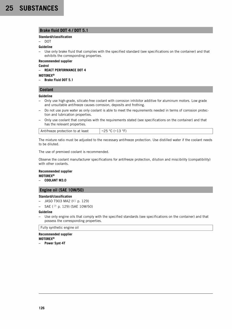
25 SUBSTANCES
126
Brake fluid DOT 4 / DOT 5.1Standard/classification– DOT
Guideline– Use only brake fluid that complies with the specified standard (see specifications on the container) and that
exhibits the corresponding properties.
Recommended supplierCastrol– REACT PERFORMANCE DOT 4
MOTOREX®
– Brake Fluid DOT 5.1
CoolantGuideline– Only use high-grade, silicate-free coolant with corrosion inhibitor additive for aluminum motors. Low grade
and unsuitable antifreeze causes corrosion, deposits and frothing.
– Do not use pure water as only coolant is able to meet the requirements needed in terms of corrosion protec-tion and lubrication properties.
– Only use coolant that complies with the requirements stated (see specifications on the container) and thathas the relevant properties.
Antifreeze protection to at least −25 °C (−13 °F)
The mixture ratio must be adjusted to the necessary antifreeze protection. Use distilled water if the coolant needsto be diluted.
The use of premixed coolant is recommended.
Observe the coolant manufacturer specifications for antifreeze protection, dilution and miscibility (compatibility)with other coolants.
Recommended supplierMOTOREX®
– COOLANT M3.0
Engine oil (SAE 10W/50)Standard/classification– JASO T903 MA2 ( p. 129)
– SAE ( p. 129) (SAE 10W/50)
Guideline– Use only engine oils that comply with the specified standards (see specifications on the container) and that
possess the corresponding properties.
Fully synthetic engine oil
Recommended supplierMOTOREX®
– Power Synt 4T

SUBSTANCES 25
127
Fork oil (SAE 4) (48601166S1)Standard/classification– SAE ( p. 129) (SAE 4)
Guideline– Use only oils that comply with the specified standards (see specifications on the container) and that exhibit
the corresponding properties.
Shock absorber fluid (SAE 2.5) (50180751S1)Standard/classification– SAE ( p. 129) (SAE 2.5)
Guideline– Use only oils that comply with the specified standards (see specifications on the container) and that exhibit
the corresponding properties.
Super unleaded (ROZ 95)Standard/classification– DIN EN 228 (ROZ 95)
Guideline– Only use super unleaded fuel that matches or is equivalent to the specified standard.
– Fuel with an ethanol content of up to 10% (E10 fuel) is safe to use.
InfoDo not use fuel containing methanol (e.g., M15, M85, M100) or more than 10% ethanol (e.g., E15,E25, E85, E100).

26 AUXILIARY SUBSTANCES
128
Chain cleanerRecommended supplierMOTOREX®
– Chain Clean
Fuel additiveRecommended supplierMOTOREX®
– Fuel Stabilizer
Long-life greaseRecommended supplierMOTOREX®
– Bike Grease 2000
Motorcycle cleanerRecommended supplierMOTOREX®
– Moto Clean
Perfect finish and high gloss polish for paintsRecommended supplierMOTOREX®
– Moto Shine
Preserving materials for paints, metal and rubberRecommended supplierMOTOREX®
– Moto Protect
Special cleaner for glossy and matte paint finishes, metal and plastic surfacesRecommended supplierMOTOREX®
– Quick Cleaner
Street chain sprayGuideline
Recommended supplierMOTOREX®
– Chainlube Road Strong
Universal oil sprayRecommended supplierMOTOREX®
– Joker 440 Synthetic

STANDARDS 27
129
JASO T903 MA2Different technical development directions required a separate specification for motorcycles – the JASO T903 MA2standard.Earlier, engine oils from the automobile industry were used for motorcycles because there was no separate motor-cycle specification.Whereas long service intervals are demanded for automobile engines, the focus for motorcycle engines is on highperformance at high engine speeds.In most motorcycle engines, the transmission and clutch are lubricated with the same oil.The JASO T903 MA2 standard meets these special requirements.
SAEThe SAE viscosity classes were defined by the Society of Automotive Engineers and are used for classifying oilsaccording to their viscosity. The viscosity describes only one property of oil and says nothing about quality.
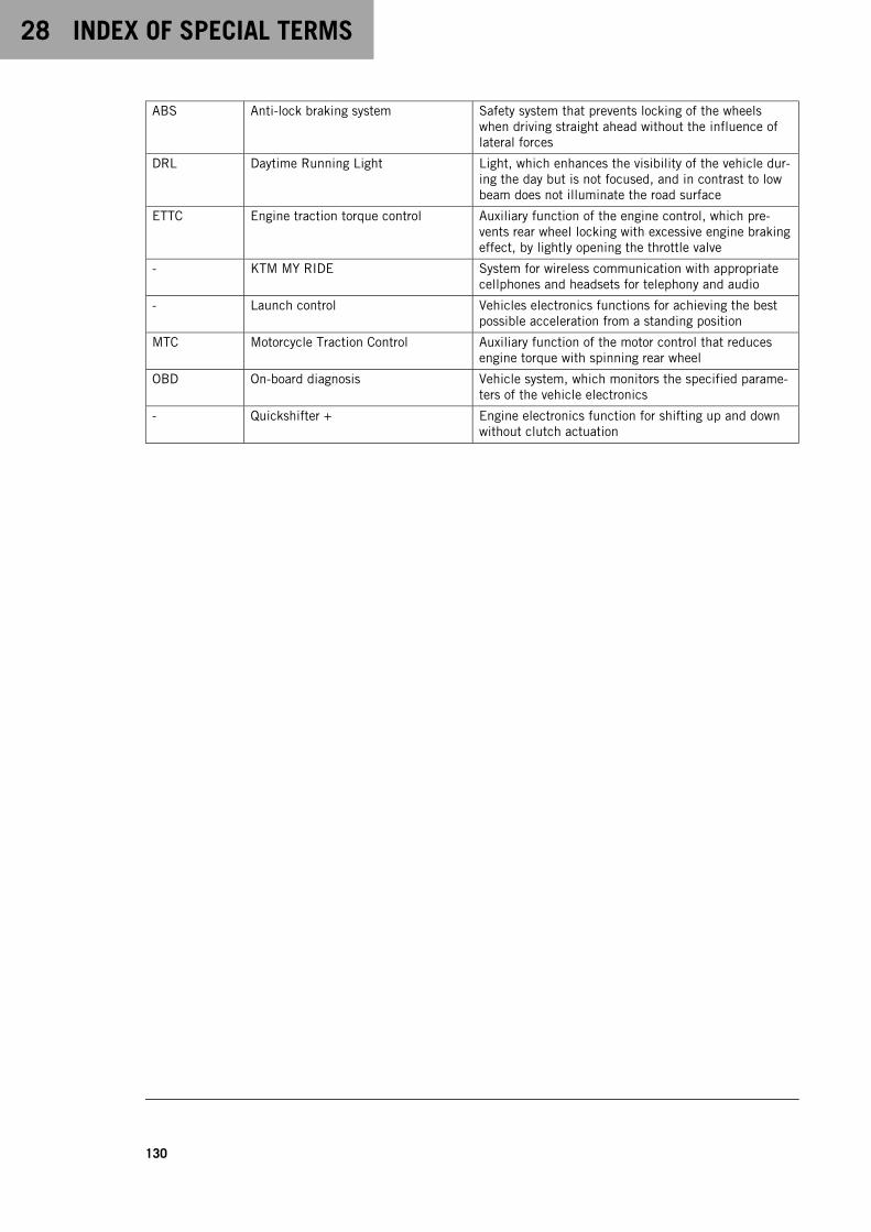
28 INDEX OF SPECIAL TERMS
130
ABS Anti-lock braking system Safety system that prevents locking of the wheelswhen driving straight ahead without the influence oflateral forces
DRL Daytime Running Light Light, which enhances the visibility of the vehicle dur-ing the day but is not focused, and in contrast to lowbeam does not illuminate the road surface
ETTC Engine traction torque control Auxiliary function of the engine control, which pre-vents rear wheel locking with excessive engine brakingeffect, by lightly opening the throttle valve
- KTM MY RIDE System for wireless communication with appropriatecellphones and headsets for telephony and audio
- Launch control Vehicles electronics functions for achieving the bestpossible acceleration from a standing position
MTC Motorcycle Traction Control Auxiliary function of the motor control that reducesengine torque with spinning rear wheel
OBD On-board diagnosis Vehicle system, which monitors the specified parame-ters of the vehicle electronics
- Quickshifter + Engine electronics function for shifting up and downwithout clutch actuation

LIST OF ABBREVIATIONS 29
131
Art. no. Article number
ca. circa
cf. compare
e.g. for example
etc. et cetera
i.a. inter alia
no. number
poss. possibly

30 LIST OF SYMBOLS
132
30.1 Red symbols
Red symbols indicate an error condition that requires immediate intervention.
The immobilizer indicator lamp lights up or flashes red – Status or error message of the alarmsystem.
The oil pressure warning lamp lights up red – The oil pressure is too low. Stop immediately,taking care not to endanger yourself or other road users in the process, and switch off theengine.
30.2 Yellow and orange symbols
Yellow and orange symbols indicate an error condition that requires prompt intervention. Active driving aids arealso represented by yellow or orange symbols.
Malfunction indicator lamp lights up yellow – The OBD has detected a malfunction in thevehicle electronics. Come safely to a halt, and contact an authorized KTM workshop.
ABS warning lamp lights up yellow – Status or error messages relating to ABS.
TC indicator lamp lights up yellow – MTC ( p. 103) is not enabled or is currently interven-ing. The TC indicator lamp also lights up if a malfunction is detected. Contact an authorizedKTM workshop. The TC indicator lamp flashes if MTC actively engages or if the Launch Control( p. 48) is activated.
The cruise control system indicator lamp (optional) lights up yellow – The cruise control sys-tem function is switched on, but cruise control is not activated.
The general warning lamp lights up yellow – A note/warning on operating safety has beendetected. This is also shown in the display.
30.3 Green and blue symbols
Green and blue symbols reflect information.
The turn signal indicator lamp flashes green simultaneously with the turn signal – The turnsignal is switched on.
The idle indicator lamp lights up green – The transmission is in the neutral position.
The cruise control system indicator lamp (optional) lights up green – The cruise control sys-tem function is switched on and cruise control is activated.
The high beam indicator lamp lights up blue – The high beam is switched on.
INDEX
133
INDEX
1
12-V batterycharging . . . . . . . . . . . . . . . . . . . . . . . . . . 87installing . . . . . . . . . . . . . . . . . . . . . . . . . . 86removing . . . . . . . . . . . . . . . . . . . . . . . . . . 85
A
ABS . . . . . . . . . . . . . . . . . . . . . . . . . . . . . . . . 69
ABS fuseschanging . . . . . . . . . . . . . . . . . . . . . . . . . . 90
ACC1front . . . . . . . . . . . . . . . . . . . . . . . . . . . . . 96rear . . . . . . . . . . . . . . . . . . . . . . . . . . . . . 96
ACC2front . . . . . . . . . . . . . . . . . . . . . . . . . . . . . 96rear . . . . . . . . . . . . . . . . . . . . . . . . . . . . . 96
Antifreezechecking . . . . . . . . . . . . . . . . . . . . . . . . . . 97
Anti-lock braking system . . . . . . . . . . . . . . . . . . 69Auxiliary substances . . . . . . . . . . . . . . . . . . . . . . 9
B
Brake discschecking . . . . . . . . . . . . . . . . . . . . . . . . . . 70
Brake fluidfront brake, adding . . . . . . . . . . . . . . . . . . . 71of rear brake, adding . . . . . . . . . . . . . . . . . . 73
Brake fluid levelfront brake, checking . . . . . . . . . . . . . . . . . 70rear brake, checking . . . . . . . . . . . . . . . . . . 73
Brake liningsfront brake, checking . . . . . . . . . . . . . . . . . 72rear brake, checking . . . . . . . . . . . . . . . . . . 75
Brake system . . . . . . . . . . . . . . . . . . . . . . . . 69-75Brakes . . . . . . . . . . . . . . . . . . . . . . . . . . . . . . 53Brakes, applying . . . . . . . . . . . . . . . . . . . . . . . . 53
Breakdowntowing . . . . . . . . . . . . . . . . . . . . . . . . . . . . 55
C
Capacitycoolant . . . . . . . . . . . . . . . . . . . 101-102, 118Engine oil . . . . . . . . . . . . . . . . . . . . 106, 118fuel . . . . . . . . . . . . . . . . . . . . . . . . . 56, 119
Chainchecking . . . . . . . . . . . . . . . . . . . . . . . . . . 66cleaning . . . . . . . . . . . . . . . . . . . . . . . . . . 64dirt, checking for . . . . . . . . . . . . . . . . . . . . 64
Chain tensionadjusting . . . . . . . . . . . . . . . . . . . . . . . . . . 65
checking . . . . . . . . . . . . . . . . . . . . . . . . . . 65
Clutch lever . . . . . . . . . . . . . . . . . . . . . . . . . . . 14basic position, adjusting . . . . . . . . . . . . . . . 41
Combination instrument . . . . . . . . . . . . . . . . 20-39ABS Mode . . . . . . . . . . . . . . . . . . . . . . . . . 36activation and test . . . . . . . . . . . . . . . . . . . 20Anti‑wheelie mode (optional) . . . . . . . . . . . . . 35Audio player . . . . . . . . . . . . . . . . . . . . . . . . 38Bluetooth® . . . . . . . . . . . . . . . . . . . . . . . . . 28Clock/Date . . . . . . . . . . . . . . . . . . . . . . . . . 30Consumption . . . . . . . . . . . . . . . . . . . . . . . . 29coolant temperature indicator . . . . . . . . . . . . 25day-night mode . . . . . . . . . . . . . . . . . . . . . 20display . . . . . . . . . . . . . . . . . . . . . . . . . . . 23Distance . . . . . . . . . . . . . . . . . . . . . . . . . . 28DRL . . . . . . . . . . . . . . . . . . . . . . . . . . . . . . 30Extra functions . . . . . . . . . . . . . . . . . . . . . . 33Favorites . . . . . . . . . . . . . . . . . . . . . . . . . . 26fuel level display . . . . . . . . . . . . . . . . . . . . 25General Info . . . . . . . . . . . . . . . . . . . . . . . . 27indicator lamps . . . . . . . . . . . . . . . . . . . . . 21KTM MY RIDE . . . . . . . . . . . . . . . . . . . . . . . 37Language . . . . . . . . . . . . . . . . . . . . . . . . . . 30Launch control (optional) . . . . . . . . . . . . . . . 35menu . . . . . . . . . . . . . . . . . . . . . . . . . . . . 26MTC . . . . . . . . . . . . . . . . . . . . . . . . . . . . . 35MTC + MSR (optional) . . . . . . . . . . . . . . . . . 36overview . . . . . . . . . . . . . . . . . . . . . . . . . . 20Pairing . . . . . . . . . . . . . . . . . . . . . . . . . . . 37Pressure . . . . . . . . . . . . . . . . . . . . . . . . . . 29Quick Selector 1 . . . . . . . . . . . . . . . . . . . . . 32Quick Selector 2 . . . . . . . . . . . . . . . . . . . . . 32quickshifter + (optional) . . . . . . . . . . . . . . . 36Ride Mode . . . . . . . . . . . . . . . . . . . . . 34, 103Service . . . . . . . . . . . . . . . . . . . . . . . . . . . 33Set Favorites . . . . . . . . . . . . . . . . . . . . . . . . 33Settings . . . . . . . . . . . . . . . . . . . . . . . . . . . 28shift warning light . . . . . . . . . . . . . . . . . . . . 24Shift Light . . . . . . . . . . . . . . . . . . . . . . . . . 37slip adjustment (optional) . . . . . . . . . . . . . 104telephony . . . . . . . . . . . . . . . . . . . . . . . . . 39Temp . . . . . . . . . . . . . . . . . . . . . . . . . . . . 29Throttle response (optional) . . . . . . . . . . . . . 104time . . . . . . . . . . . . . . . . . . . . . . . . . . . . . 25TPMS warning . . . . . . . . . . . . . . . . . . . . . . . 31Track (optional) . . . . . . . . . . . . . . . . . . . . . 34TRACK Display (optional) . . . . . . . . . . . . . . . 24Trip odometer . . . . . . . . . . . . . . . . . . . . . . 26Trip 1 . . . . . . . . . . . . . . . . . . . . . . . . . . . . 26Trip 2 . . . . . . . . . . . . . . . . . . . . . . . . . . . . 27warnings . . . . . . . . . . . . . . . . . . . . . . . 21, 34
Combination switch . . . . . . . . . . . . . . . . . . . . . . 14overview . . . . . . . . . . . . . . . . . . . . . . . . . . 14

INDEX
134
Coolantdraining . . . . . . . . . . . . . . . . . . . . . . . . . . 99
Coolant levelchecking . . . . . . . . . . . . . . . . . . . . . . . . . . 97checking in the compensating tank . . . . . . . . 98
Cooling system . . . . . . . . . . . . . . . . . . . . . . . . . 97filling/bleeding . . . . . . . . . . . . . . . . . . . . . 100
Cover of the headlight mask rackinstalling . . . . . . . . . . . . . . . . . . . . . . . . . . 94removing . . . . . . . . . . . . . . . . . . . . . . . . . . 93
Customer service . . . . . . . . . . . . . . . . . . . . . . . . 9
D
Declarations of conformity . . . . . . . . . . . . . . . . 125country-specific . . . . . . . . . . . . . . . . . . . . 125
Diagnostics connector . . . . . . . . . . . . . . . . . . . . 95
E
Emergency OFF switch . . . . . . . . . . . . . . . . . . . . 16
Enginerunning in . . . . . . . . . . . . . . . . . . . . . . . . . 45
Engine number . . . . . . . . . . . . . . . . . . . . . . . . . 12
Engine oiladding . . . . . . . . . . . . . . . . . . . . . . . . . . 107changing . . . . . . . . . . . . . . . . . . . . . . . . . 105
Engine oil levelchecking . . . . . . . . . . . . . . . . . . . . . . . . . 105
Engine sprocketchecking . . . . . . . . . . . . . . . . . . . . . . . . . . 66
Engine traction torque control . . . . . . . . . . . . . . . 53Environment . . . . . . . . . . . . . . . . . . . . . . . . . . . . 8
F
Figures . . . . . . . . . . . . . . . . . . . . . . . . . . . . . . . 9
Foot brake lever . . . . . . . . . . . . . . . . . . . . . . . . 19basic position, adjusting . . . . . . . . . . . . . . . 41free travel, checking . . . . . . . . . . . . . . . . . . 72
Fork legsdust boots, cleaning . . . . . . . . . . . . . . . . . . 61
Fork part number . . . . . . . . . . . . . . . . . . . . . . . 13
Free travel of clutch leverchecking . . . . . . . . . . . . . . . . . . . . . . . . . 108setting . . . . . . . . . . . . . . . . . . . . . . . . . . 108
Front rider’s seatmounting . . . . . . . . . . . . . . . . . . . . . . . . . 63
Front rider's seatremoving . . . . . . . . . . . . . . . . . . . . . . . . . . 63
Front wheelinstalling . . . . . . . . . . . . . . . . . . . . . . . . . . 77removing . . . . . . . . . . . . . . . . . . . . . . . . . . 76
Fuel tank filler capclosing . . . . . . . . . . . . . . . . . . . . . . . . . . . 17opening . . . . . . . . . . . . . . . . . . . . . . . . . . . 16
Fuel, oils, etc. . . . . . . . . . . . . . . . . . . . . . . . . . . 9
Fuseof individual electrical power consumers,changing . . . . . . . . . . . . . . . . . . . . . . . . . . 91
G
Grab handle . . . . . . . . . . . . . . . . . . . . . . . . . . . 18
H
Hand brake lever . . . . . . . . . . . . . . . . . . . . . . . 14basic position, adjusting . . . . . . . . . . . . . . . 41
Handlebar position . . . . . . . . . . . . . . . . . . . . . . 40adjusting . . . . . . . . . . . . . . . . . . . . . . . . . . 40
Headlightdaytime running light . . . . . . . . . . . . . . . . . 85range, adjusting . . . . . . . . . . . . . . . . . . . . . 95setting, checking . . . . . . . . . . . . . . . . . . . . 94
Headlight mask with headlightmounting . . . . . . . . . . . . . . . . . . . . . . . . . 92releasing . . . . . . . . . . . . . . . . . . . . . . . . . . 92
Horn button . . . . . . . . . . . . . . . . . . . . . . . . . . . 15
I
Ignition lock . . . . . . . . . . . . . . . . . . . . . . . . . . 16Implied warranty . . . . . . . . . . . . . . . . . . . . . . . . . 9Indicator lamps . . . . . . . . . . . . . . . . . . . . . . . . 21Intended use . . . . . . . . . . . . . . . . . . . . . . . . . . . 6
K
Key number . . . . . . . . . . . . . . . . . . . . . . . . . . . 12
L
Launch Control (optional) . . . . . . . . . . . . . . . . . . 48Light switch . . . . . . . . . . . . . . . . . . . . . . . . . . . 15Loading the vehicle . . . . . . . . . . . . . . . . . . . . . . 45Luggage . . . . . . . . . . . . . . . . . . . . . . . . . . . . . 45
M
Main fusechanging . . . . . . . . . . . . . . . . . . . . . . . . . . 89
Manufacturer warranty . . . . . . . . . . . . . . . . . . . . . 9Misuse . . . . . . . . . . . . . . . . . . . . . . . . . . . . . . . 6
Motorcyclecleaning . . . . . . . . . . . . . . . . . . . . . . . . . 109lifting with front lifting gear . . . . . . . . . . . . . 60raising with the rear lifting gear . . . . . . . . . . 60rear from the lifting gear, removing . . . . . . . . 60taking off front lifting gear . . . . . . . . . . . . . . 61
Motorcycle traction control . . . . . . . . . . . . . . . . 103MSR . . . . . . . . . . . . . . . . . . . . . . . . . . . . . . . . 53MTC . . . . . . . . . . . . . . . . . . . . . . . . . . . . . . . 103

INDEX
135
O
Oil filterchanging . . . . . . . . . . . . . . . . . . . . . . . . . 105
Oil screenscleaning . . . . . . . . . . . . . . . . . . . . . . . . . 105
Owner's Manual . . . . . . . . . . . . . . . . . . . . . . . . . 8
P
Parking . . . . . . . . . . . . . . . . . . . . . . . . . . . . . 54Passenger foot pegs . . . . . . . . . . . . . . . . . . . . . 18
Passenger seatmounting . . . . . . . . . . . . . . . . . . . . . . . . . 62removing . . . . . . . . . . . . . . . . . . . . . . . . . . 62
Preparing for useadvice on preparing for first use . . . . . . . . . . 44after storage . . . . . . . . . . . . . . . . . . . . . . 112checks and maintenance measures whenpreparing for use . . . . . . . . . . . . . . . . . . . . 47
Protective clothing . . . . . . . . . . . . . . . . . . . . . . . 7
Q
Quickshifter + (optional) . . . . . . . . . . . . . . . . . . . 49
R
Rear hub damping rubber pieceschecking . . . . . . . . . . . . . . . . . . . . . . . . . . 81
Rear sprocketchecking . . . . . . . . . . . . . . . . . . . . . . . . . . 66
Rear wheelinstalling . . . . . . . . . . . . . . . . . . . . . . . . . . 79removing . . . . . . . . . . . . . . . . . . . . . . . . . . 78
Refuelingfuel . . . . . . . . . . . . . . . . . . . . . . . . . . . . . 56
Riding . . . . . . . . . . . . . . . . . . . . . . . . . . . . . . 50starting off . . . . . . . . . . . . . . . . . . . . . . . . 48starting off with launch control (optional) . . . . 49
S
Safe operation . . . . . . . . . . . . . . . . . . . . . . . . . . 7Seat lock . . . . . . . . . . . . . . . . . . . . . . . . . . . . 18Service . . . . . . . . . . . . . . . . . . . . . . . . . . . . . . . 9Service schedule . . . . . . . . . . . . . . . . . . . . . 57-58
Shift lever . . . . . . . . . . . . . . . . . . . . . . . . . . . . 19basic position, adjusting . . . . . . . . . . . . . . . 43basic position, checking . . . . . . . . . . . . . . . 42
Shifting . . . . . . . . . . . . . . . . . . . . . . . . . . . . . 50
Shock absorberspring preload, adjusting . . . . . . . . . . . . . . . 59
Shock absorber article number . . . . . . . . . . . . . . 13Side stand . . . . . . . . . . . . . . . . . . . . . . . . . . . . 19Slip adjustment (optional) . . . . . . . . . . . . . . . . . 104Spare parts . . . . . . . . . . . . . . . . . . . . . . . . . . . . 9
Start button . . . . . . . . . . . . . . . . . . . . . . . . . . . 16Starting . . . . . . . . . . . . . . . . . . . . . . . . . . . . . 47Steering damper article number . . . . . . . . . . . . . . 13Steering lock . . . . . . . . . . . . . . . . . . . . . . . . . . 16Stopping . . . . . . . . . . . . . . . . . . . . . . . . . . . . . 54Storage . . . . . . . . . . . . . . . . . . . . . . . . . 111-112
Switchon the left side of the handlebar . . . . . . . . . . 14on the right side of the handlebar . . . . . . . . . 16
T
Technical accessories . . . . . . . . . . . . . . . . . . . . . 9
Technical datacapacities . . . . . . . . . . . . . . . . . . . . . . . . 118chassis . . . . . . . . . . . . . . . . . . . . . . . . . . 119chassis tightening torques . . . . . . . . . . . . . 121electrical system . . . . . . . . . . . . . . . . . . . 120engine . . . . . . . . . . . . . . . . . . . . . . . 115-124engine tightening torques . . . . . . . . . . . . . 116fork . . . . . . . . . . . . . . . . . . . . . . . . . . . . 120shock absorber . . . . . . . . . . . . . . . . . . . . . 121tires . . . . . . . . . . . . . . . . . . . . . . . . . . . . 120
Throttle grip . . . . . . . . . . . . . . . . . . . . . . . . . . . 14
Tire conditionchecking . . . . . . . . . . . . . . . . . . . . . . . . . . 82
Tire pressurechecking . . . . . . . . . . . . . . . . . . . . . . . . . . 83
Tire repair sprayusing . . . . . . . . . . . . . . . . . . . . . . . . . . . . 83
Tool set . . . . . . . . . . . . . . . . . . . . . . . . . . . . . 18Towing . . . . . . . . . . . . . . . . . . . . . . . . . . . . . . 55Transporting . . . . . . . . . . . . . . . . . . . . . . . . . . 55Troubleshooting . . . . . . . . . . . . . . . . . . . . 113-114Turn signal switch . . . . . . . . . . . . . . . . . . . . . . . 15Type label . . . . . . . . . . . . . . . . . . . . . . . . . . . . 12
U
Use definition . . . . . . . . . . . . . . . . . . . . . . . . . . 6
V
Vehicle identification number . . . . . . . . . . . . . . . 12
View of vehiclefront left . . . . . . . . . . . . . . . . . . . . . . . . . . 10rear right . . . . . . . . . . . . . . . . . . . . . . . . . . 11
W
Winter operationchecks and maintenance steps . . . . . . . . . . 110
Work rules . . . . . . . . . . . . . . . . . . . . . . . . . . . . 8
*3214405en*3214405en
03/2022
KTM Sportmotorcycle GmbH5230 Mattighofen/AustriaKTM.COM
Photo: Mitterbauer/KISKA/KTM
Copyright © 2022 FDOKUMEN