Oconee Nuclear Station, Unit 1, Fourth Ten-Year Inservice ...
221
Duke T. PRESTON GILLESPIE, JR. Duke Vice President PoEnergy® Oconee Nuclear Station Duke Energy ONO0 VP / 7800 Rochester Hwy. January 31, 2013 Seneca, SC 29672 U.S. Nuclear Regulatory Commission 864-873-4478 Document Control Desk 864-873-4208 fax T. Gillespie@duke-energy. corn Washington, DC 20555 Subject: Duke Energy Carolinas, LLC Oconee Nuclear Station Unit 1 Docket No. 50-269 Fourth Ten-Year Inservice Inspection Plan Request for Relief No. 12-ON-001 Pursuant to 10 CFR 50.55a(g)(5)(iii), attached is a Request for Relief from the requirement to examine 100% of the volume specified by the American Society of Mechanical Engineers Boiler and Pressure Vessel Code (ASME Code), Section Xl, Rules for Inservice Inspection of Nuclear Power Plant Components, 1998 Edition with 2000 Addenda (as modified by Code Case N-460). The attached Request for Relief 127ON-001 is to allow Duke Energy to take credit for the enclosed Table 1 list of limited ultrasonic examinations on welds associated with various systems and components during Unit 1 EOC26 refueling outage. The ultrasonic examination coverage of the subject Unit 1 welds did not meet the 90% examination requirements of Code Case N-460. The obtainable volume coverage for weld examination is indicated on Attachment A of the relief request. Achievement of greater examination coverage for these welds is impractical due to piping/valve geometry and interferences. Therefore, Duke Energy requests that the NRC grant relief as authorized under 10 CFR 50.55(g)(6)(i). This submittal document contains no regulatory commitments. If there are any questions or further information is needed you may contact Corey Gray at (864)-873-6325. Sincerely, T. Preston Gillespie Jr., Site Vice President Enclosure: Oconee Nuclear Station - Unit 1 Relief Request 12-ON-001 www.duke-energy. corn
-
Upload
khangminh22 -
Category
Documents
-
view
0 -
download
0
Transcript of Oconee Nuclear Station, Unit 1, Fourth Ten-Year Inservice ...

Duke T. PRESTON GILLESPIE, JR.Duke Vice President
PoEnergy® Oconee Nuclear Station
Duke EnergyONO0 VP / 7800 Rochester Hwy.
January 31, 2013 Seneca, SC 29672
U.S. Nuclear Regulatory Commission 864-873-4478Document Control Desk 864-873-4208 fax
T. Gillespie@duke-energy. cornWashington, DC 20555
Subject: Duke Energy Carolinas, LLCOconee Nuclear Station Unit 1Docket No. 50-269Fourth Ten-Year Inservice Inspection PlanRequest for Relief No. 12-ON-001
Pursuant to 10 CFR 50.55a(g)(5)(iii), attached is a Request for Relief from the requirement toexamine 100% of the volume specified by the American Society of Mechanical Engineers Boilerand Pressure Vessel Code (ASME Code), Section Xl, Rules for Inservice Inspection of NuclearPower Plant Components, 1998 Edition with 2000 Addenda (as modified by Code Case N-460).
The attached Request for Relief 127ON-001 is to allow Duke Energy to take credit for theenclosed Table 1 list of limited ultrasonic examinations on welds associated with varioussystems and components during Unit 1 EOC26 refueling outage. The ultrasonic examinationcoverage of the subject Unit 1 welds did not meet the 90% examination requirements of CodeCase N-460. The obtainable volume coverage for weld examination is indicated on AttachmentA of the relief request. Achievement of greater examination coverage for these welds isimpractical due to piping/valve geometry and interferences. Therefore, Duke Energy requeststhat the NRC grant relief as authorized under 10 CFR 50.55(g)(6)(i).
This submittal document contains no regulatory commitments.
If there are any questions or further information is needed you may contact Corey Gray at(864)-873-6325.
Sincerely,
T. Preston Gillespie Jr.,Site Vice President
Enclosure: Oconee Nuclear Station - Unit 1 Relief Request 12-ON-001
www.duke-energy. corn

U. S. Nuclear Regulatory CommissionJanuary 31, 2013Page 2
Xc w/att: Victor McreeRegion II AdministratorU. S. Nuclear Regulatory CommissionMarquis One Tower245 Peachtree Center Ave., NE, Suite 1200Atlanta, GA 30303-1257
John BoskaProject Manager(by electronic mail only)U. S. Nuclear Regulatory CommissionOffice of Nuclear Reactor Regulation11555 Rockville PikeMail Stop O-8G9ARockville, MD 20852-2746
Xc w/o attachment
NRC Senior Resident InspectorOconee Nuclear Station
Susan JenkinsSection ManagerDivision of Waste ManagementBureau of Land and Waste ManagementSC Dept. of Health & Environment Control2600 Bull St.Columbia, SC 29201
Enclosure
Oconee Nuclear Station - Unit 1Relief Request 12-ON-001

Oconee Relief Request 12-ON-001
1.0 Scope of Relief Request
Relief is requested pursuant to 10 CFR 50.55a(g)(5)(iii) for welds listed in Table 1.These welds were required to be examined in accordance with Inservice InspectionPlans for the following Units.
Oconee Nuclear Station - Unit 1Fourth 10-Year Inservice Inspection IntervalInterval Start Date: January 01, 2004
Table 1
Relief Oconee Examinati Weld ID Item/Summary ExaminationRequest Unit on Number Number DataSection Number PerformedNumber (Refueling
Outa qe)
2.0 1 1EOC26 1-PZR-WP26-3 O1.B3.110.0011 See AttachmentA Pages 1-10
3.0 1 1EOC26 1-PZR-WP26-7 O1.B3.110.0012 See AttachmentA Pages 11-20
4.0 1 1 EOC26 1-PIB1-9 O1..B9.11.0029 See AttachmentA Pages 21-32
5.0 1 1 EOC26 1-PDBl-1 O1..B9.11.0072 See AttachmentA Pages 33-44
6.0 1 1EOC26 lLP-128-80 O1.C5.11.0029 See AttachmentA Pages 45-51
7.0 1 1EOC26 1LP-209-17 O1.C5.11.0084 See AttachmentA Pages 52-57
8.0 1 1 EOC26 1 LP-209-18 O1.C5.11.0085 See AttachmentA Pages 58-63
9.0 1 1 EOC26 1HP-192-15 O1.C5.21.0006 See AttachmentA Pages 64-72
10.0 1 1 EOC26 1-51A-01-91A O1.C5.21.0024 See AttachmentA Pages 73-78
Page 1 of 55

Oconee Relief Request 12-ON-001
11.0 1 1 EOC26 1 HP-324-118B 01.C5.21.0041 See AttachmentA Pages 79-84
12.0 1 1 EOC26 1-51A-02-34B 01.C5.21.0053 See AttachmentA Pages 85-91
13.0 1 1EOC26 1HP-193-12 O1.C5.21.0057 See AttachmentA Pages 92-98
14.0 1 1 EOC26 1-51A-01-103A O1.C5.21.0066 See AttachmentA Pages 99-106
15.0 1 1 EOC26 1 LPS-563-14 O1.C5.51.0050 See AttachmentA Pages 107-115
16.0 1 1 EOC26 1 LPS-702-50 O1.C5.51.0053 See AttachmentA Pages 116-124
17.0 1 1 EOC26 WJ-32 PSI See AttachmentA Pages 125-133
18.0 1 1EOC26 WJ-33 PSI See AttachmentA Pages 134-144
19.0 1 1 EOC26 WJ-35 PSI See AttachmentA Pages 145-153
20.0 1 1 EOC26 WJ-36 PSI See AttachmentA Pages 154-162
Duke Energy procedures require ASME Code, Section XI examinations that do not meet therequirements of Code Case N-460 to be marked "reject" for tracking purposes, regardless ofwhether indications were noted. Therefore, the limited exams in 12-ON-001 without indicationswere marked "reject".
Page 2 of 55

Oconee Relief Request 12-ON-001
2.0 Weld #1-PZR-WP26-3
2.1. ASME Code Component(s) Affected
Unit 1 Pressurizer Heater Belt Shell to Sampling Nozzle Weld #1-PZR-WP26-3,Summary Number 01 .B3.110.0011 and ASME Code Class 1.
2.2. Applicable Code Edition and Addenda
ASME Boiler and Pressure Vessel Code, Section XI, 1998 Edition through the2000 Addenda.
2.3. Applicable Code Requirement
IWB-2500, Table IWB-2500-1, Examination Category B-D, Item Number B3.1 10Fig. IWB-2500-7 (a), 100% Volume Coverage of Examination VolumeA-B-C-D-E-F-G-H-I.
2.4. Impracticality of Compliance
Component configuration:
* Surface 1: Shell - Carbon steel* Surface 2: Sampling nozzle - Carbon steel* Diameter: 5.750 in.* Thickness: 6.187 in.
This component was scanned manually with conventional methods. Scanningrequirements are described in ASME Section V, Article 4, T-441.1.2(a),T-441.1.3,T-441.1.4, T-441.1.5 and T-441.1.6. These requirements describe and arespecific to scanning components in two axial and two circumferential directions.This component was scanned to the extent possible to meet these requirements.The aggregate coverage that was obtained is described and calculated from thefollowing:
* Weld coverage using 450& 600 shear waves for axial scans (S1, S2), and
450 & 600 shear waves for circumferential scans (CW, CCW) obtained
15.4% coverage.* Base material coverage using 450& 600 shear wave for axial scans (51)
and 450& 600 shear waves for circumferential scans (CW, CCW) obtained54.8% coverage.
* 00 scan coverage obtained 33.8% coverage.* The aggregate coverage was calculated to be
(15.4% + 54.8% + 33.8%)/3 = 34.7%.
The impracticality was caused by the weld taper configuration of the samplingnozzle to the shell that does not allow meaningful interrogation from Surface 2,the sampling nozzle side. In order to scan all of the required volume for this weld,the shell to sampling nozzle weld would have to be redesigned or replaced toallow scanning from both sides of the weld, which is impractical.
Page 3 of 55

Oconee Relief Request 12-ON-001
The Oconee Inservice Inspection Plan allows the use of Code Case N-460,which requires greater than 90% volumetric coverage. The achieved coveragedid not meet the acceptance criteria of this Code Case.This relief request is specific to examination volume coverage limitations only. Allother Code requirements were satisfied.
No indications were recorded during this examination. The reject box on the UTCalibration/Examination sheet is marked for internal tracking of the coveragelimitation only.
2.5. Proposed Alternative and Basis for Use
No substitution alternative for this weld is available which would provide bettercoverage. Radiography (RT) is not a desired option because RT is limited in theability to detect service induced flaws. Use of other manual or automated UTtechniques, whether conventional or phased array, were considered, but wouldnot increase coverage due to the limitation created by the componentconfiguration. The use of any other UT technique available would incur the samephysical scanning limitations.
2.6. Duration of Proposed Alternative
This request is for the duration of the fourth inservice inspection interval,currently scheduled to end on July 15, 2014.
2.7. Justification for Granting Relief
Ultrasonic examination of the weld for the item number 01 .B3.110.0011 wasconducted using personnel, equipment, and procedures qualified in accordancewith ASME Section XI, 1998 Edition with the 2000 Addenda.
The system leakage test performed each refueling outage in accordance withTable IWB-2500-1, Examination Category B-P requires a VT-2 visualexamination to detect evidence of leakage. This test and VT-2 examinationprovides additional assurance of pressure boundary integrity.
In addition to the above Code required examinations (volumetric and pressuretest), Reactor Building Normal Sump monitoring and other leakage detectionsystems provide additional assurance that, in the event that leakage did occurthrough this weld, it would be detected and proper action taken.
Duke Energy has examined the weld to the maximum extent possible utilizingapproved examination techniques and equipment. Based on the acceptableresults for the coverage completed by the volumetric examination, the pressuretesting (VT-2) examinations required by Section XI, and the leakage monitoring,it is Duke Energy's position that the combination of examinations provides areasonable assurance of quality and safety.
Page 4 of 55

Oconee Relief Request 12-ON-001
2.8. References
Duke Energy Relief Request 04-ON-005 was approved by the NRC during thelast inspection interval. The previous approved SE is documented in AccessionNumber ML050340377, TAC No.MC4527 dated March 8, 2005.
Page 5 of 55

Oconee Relief Request 12-ON-001
3.0 Weld #1-PZR-WP26-7
3.1. ASME Code Component(s) Affected
Unit 1 Pressurizer Heater Belt Shell to Sampling Nozzle Weld #1-PZR-WP26-7,Summary Number 01 .B3.110.0012, and ASME Code Class 1.
3.2. Applicable Code Edition and Addenda
ASME Boiler and Pressure Vessel Code, Section XI, 1998 Edition through the2000 Addenda.
3.3. Applicable Code Requirement
IWB-2500, Table IWB-2500-1, Examination Category B-D, Item Number B3.110Fig. IWB-2500-7 (a), 100% Volume Coverage of Examination VolumeA-B-C-D-E-F-G-H-I.
3.4. Impracticality of Compliance
Component configuration:
* Surface 1: Shell - Carbon steel* Surface 2: Sampling nozzle - Carbon steel* Diameter: 5.750 in.* Thickness: 6.187 in.
This component was scanned manually with conventional methods. Scanningrequirements are described in ASME Section V, Article 4, T-441.1.2(a),T-441.1.3, T-441.1.4, T-441.1.5 and T-441.1.6. These requirements describe andare specific to scanning components in two axial and two circumferentialdirections. This component was scanned to the extent possible to meet theserequirements. The aggregate coverage that was obtained is described andcalculated from the following:
Weld coverage using 450& 600 shear waves for axial scans (S1, S2), and
450 & 600 shear waves for circumferential scans (CW, CCW) obtained
15.4% coverage.Base material coverage using 450& 600 shear wave for axial scans (S1)
and 450& 600 shear waves for circumferential scans (CW, CCW) obtained54.8% coverage.
* 00 scan coverage obtained 33.8% coverage.* The aggregate coverage was calculated to be
(15.4% + 54.8% + 33.8%)/3 = 34.7%.
The impracticality was caused by the weld taper configuration of the samplingnozzle to the shell that does not allow meaningful interrogation from Surface 2,the sampling nozzle side. In order to scan all of the required volume for this weld,the shell to sampling nozzle weld would have to be redesigned or replaced toallow scanning from both sides of the weld, which is impractical.
Page 6 of 55

Oconee Relief Request 12-ON-001
The Oconee Inservice Inspection Plan allows the use of Code Case N-460,which requires greater than 90% volumetric coverage. The achieved coveragedid not meet the acceptance criteria of this Code Case.
This relief request is specific to examination volume coverage limitations only. Allother Code requirements were satisfied.
No indications were recorded during this examination. The reject box on the UTCalibration/Examination sheet is marked for internal tracking of the coveragelimitation only.
3.5. Proposed Alternative and Basis for Use
No substitution alternative for this weld is available which would provide bettercoverage. Radiography (RT) is not a desired option because RT is limited in theability to detect service induced flaws. Use of other manual or automated UTtechniques, whether conventional or phased array, were considered, but wouldnot increase coverage due to the limitation created by the componentconfiguration. The use of any other UT technique available would incur the samephysical scanning limitations.
3.6. Duration of Proposed Alternative
This request is for the duration of the fourth inservice inspection interval,currently scheduled to end on July 15, 2014.
3.7. Justification for Granting Relief
Ultrasonic examination of the weld for the item number 01 .B3.110.00012 wasconducted using personnel, equipment, and procedures qualified in accordancewith ASME Section XI, 1998 Edition with the 2000 Addenda.
The system leakage test performed each refueling outage in accordance withTable IWB-2500-1, Examination Category B-P requires a VT-2 visualexamination to detect evidence of leakage. This test and VT-2 examinationprovides additional assurance of pressure boundary integrity.
In addition to the above Code required examinations (volumetric and pressuretest), Reactor Building Normal Sump monitoring and other leakage detectionsystems provide additional assurance that, in the event that leakage did occurthrough this weld, it would be detected and proper action taken.
Duke Energy has examined the weld to the maximum extent possible utilizingapproved examination techniques and equipment. Based on the acceptableresults for the coverage completed by the volumetric examination, the pressuretesting (VT-2) examinations required by Section XI, and the leakage monitoring,it is Duke Energy's position that the combination of examinations provides areasonable assurance of quality and safety.
Page 7 of 55

Oconee Relief Request 12-ON-001
3.8. References
Duke Energy Relief Request 04-ON-005 was approved by the NRC during thelast inspection interval. The previous approved SE is documented in AccessionNumber ML050340377, TAC No.MC4527 dated March 8, 2005.
Page 8 of 55

Oconee Relief Request 12-ON-001
4.0 Weld #1-PIB1-9
4.1. ASME Code Component(s) Affected
Unit 1 Reactor Coolant Pump 1 B1 Casing Nozzle to Safe-End Piping Weld,Weld #1-PIB1-9, Summary Number 01 .B9.11.0029 and ASME Code Class 1.
4.2. Applicable Code Edition and Addenda
ASME Boiler and Pressure Vessel Code, Section XI, 1998 Edition through the2000 Addenda.
4.3. Applicable Code Requirement
IWB-2500, Table IWB-2500-1, Examination Category B-J, Item Number B9.11Figure IWB-2500-8 (c), 100% Volume Coverage of Examination VolumeC-D-E-F.
4.4. Impracticality of Compliance
Component configuration:
* Surface 1: Cast Stainless Steel Nozzle" Surface 2: Forged Stainless Steel Safe End* NPS: 36.5 in.* Thickness: 2.330 in.
This component was scanned manually with conventional methods. Scanningrequirements are described in 10 CFR 50.55a(b)(2)(xv)(A)(1). Theserequirements describe and are specific to scanning components in two axial andtwo circumferential directions. This component was scanned to the extentpossible to meet these requirements. The aggregate coverage that was obtainedis described and calculated from the following:
* 600 shear waves obtained 0% coverage in one axial direction (S1 - nozzle)* 600 shear waves obtained 50% coverage in one axial direction (S2 - safe
end)* 450 shear waves obtained 50% coverage in one circumferential direction
(CW).* 450 shear waves obtained 50% coverage in one circumferential direction
(CCW).* The aggregate coverage was calculated to be
(0% + 50% + 50% + 50%)/4 = 37.5%.
In addition, best effort supplemental scanning was performed using 600 and 700refracted longitudinal waves from the S2 pump casing side for interrogation of theupper 2/3 area within the cast material.
Page 9 of 55

Oconee Relief Request 12-ON-001
Best effort supplemental scanning was also performed using 600 refractedlongitudinal waves for interrogation of the lower 1/3 nozzle far side of the weldfrom the S1 safe-end side, but is not qualified to be calculated into the aboveclaimed coverage. The supplemental refracted longitudinal scan was only usedfor interrogation in the axial direction per procedural direction. Supplementalscanning is not performed in the circumferential direction.
The impracticality was caused by the nozzle taper configuration and caststainless steel material which cannot be effectively interrogated by ultrasound.There are currently no examination techniques that have been qualified for caststainless steel through Appendix VIII for cast stainless steel. Therefore, coveragecould not be obtained by scanning from the nozzle side. In order to scan all of therequired volume for this weld, the nozzle would have to be redesigned andreplaced, which is impractical.
The Oconee Inservice Inspection Plan allows the use of Code Case N-460,which requires greater than 90% volumetric coverage. Therefore, the availablecoverage will not meet the acceptance criteria of this Code Case.
This relief request is specific to examination volume coverage limitations only. Allother Code requirements were satisfied.
No indications were recorded during this examination. The reject box on each UTCalibration/Examination sheet is marked for internal tracking of the coveragelimitation only.
4.5 Proposed Alternative and Basis for Use
This weld was examined using procedures, equipment and personnel qualifiedin accordance with ASME Section XI, Appendix VIII. Radiography (RT) is not adesired option because RT is limited in the ability to detect service induced flawsand has not been qualified through performance demonstration. Use of othermanual or automated UT techniques, whether conventional or phased array,qualified under ASME Section XI, Appendix VIII would not increase coveragedue to the limitation created by the cast stainless material. The use of any otherUT technique available would incur the same physical scanning limitations.
4.6. Duration of Proposed Alternative
This request is for the duration of the fourth inservice inspection interval,currently scheduled to end on July 15, 2014.
4.7. Justification for Granting Relief
Ultrasonic examination of the weld for the item number O1.B9.11.0029 wasconducted using personnel, equipment, and procedures qualified in accordancewith ASME Section XI, 1998 Edition with the 2000 Addenda.
The system leakage test performed each refueling outage in accordance withTable IWB-2500-1, Examination Category B-P requires a VT-2 visualexamination to detect evidence of leakage. This test and VT-2 examinationprovides additional assurance of pressure boundary integrity.
Page 10 of 55

Oconee Relief Request 12-ON-001
In addition to the above Code required examinations (volumetric and pressuretest), Reactor Building Normal Sump monitoring and other leakage detectionsystems provide additional assurance that, in the event that leakage did occurthrough this weld, it would be detected and proper action taken.
Duke Energy has examined the weld to the maximum extent possible utilizingapproved examination techniques and equipment. Based on the acceptableresults for the coverage completed by the volumetric examination, the pressuretesting (VT-2) examinations required by Section XI, and the leakage monitoring,it is Duke Energy's position that the combination of examinations provides areasonable assurance of quality and safety.
4.8 References
None
Page 11 of 55

Oconee Relief Request 12-ON-001
5.0 Weld #1-PDBI-1
5.1. ASME Code Component(s) Affected
Unit 1 Reactor Coolant Pump 1 B1 Casing Nozzle to Safe-End Weld,Weld #1-PDBI-1, Summary Number O1..B9.11.0072 and ASME Code Class 1.
5.2. Applicable Code Edition and Addenda
ASME Boiler and Pressure Vessel Code, Section XI, 1998 Edition through the2000 Addenda.
5.3. Applicable Code Requirement
IWB-2500, Table IWB-2500-1, Examination Category B-J, Item Number B9.11Figure IWB-2500-8 (c), 100% Volume Coverage of Examination VolumeC-D-E-F.
5.4. Impracticality of Compliance
Component configuration:
* Surface 1: Forged Stainless Steel Safe End* Surface 2: Cast Stainless Steel Nozzle* NPS: 33.5 in.* Thickness: 2.330 in.
This component was scanned manually with conventional methods. Scanningrequirements are described in 10 CFR 50.55a(b)(2)(xv)(A)(1). Theserequirements describe and are specific to scanning components in two axial andtwo circumferential directions. This component was scanned to the extentpossible to meet these requirements. The aggregate coverage that was obtainedis described and calculated from the following:
600 shear waves obtained 50% coverage in one axial direction(51 - safe end)
* 600 shear waves obtained 0% coverage in one axial direction(S2 - nozzle)
* 450 shear waves obtained 50% coverage in one circumferential direction(CW).
* 450 shear waves obtained 50% coverage in one circumferential direction(CCW).
* The aggregate coverage was calculated to be(50% + 0% + 50% + 50%)/4 = 37.5%.
In addition, best effort supplemental scanning was performed using 600 and 700refracted longitudinal waves from the S2 pump casing side for interrogation of theupper 2/3 area within the cast material.
Page 12 of 55

Oconee Relief Request 12-ON-001
Best effort supplemental scanning was also performed using 600 refractedlongitudinal waves for interrogation of the lower 1/3 nozzle on the far side of theweld from the S1 safe-end side, but is not qualified to be calculated into theabove claimed coverage. The supplemental refracted longitudinal scan was onlyused for interrogation in the axial direction per procedural direction.Supplemental scanning is not performed in the circumferential direction.
The impracticality was caused by the nozzle taper configuration due to caststainless steel material which cannot be effectively interrogated by ultrasound.There are currently no examination techniques that have been qualified throughAppendix VIII for cast stainless steels. Therefore, coverage could not be obtainedby scanning from the nozzle side. In order to scan all of the required volume forthis weld, the nozzle would have to be redesigned and replaced, which isimpractical.
The Oconee Inservice Inspection Plan allows the use of Code Case N-460,which requires greater than 90% volumetric coverage. Therefore, the availablecoverage will not meet the acceptance criteria of this Code Case.
This relief request is specific to examination volume coverage limitations only. Allother Code requirements were satisfied.
No indications were recorded during this examination. The reject box on each UTCalibration/Examination sheet is marked for internal tracking of the coveragelimitation only.
5.5. Proposed Alternative and Basis for Use
This weld was examined using procedures, equipment and personnel qualifiedin accordance with ASME Section XI, Appendix VIII. Radiography (RT) is not adesired option because RT is limited in the ability to detect service induced flawsand has not been qualified through performance demonstration. Use of othermanual or automated UT techniques, whether conventional or phased array,qualified under ASME Section XI, Appendix VIII would not increase coveragedue to the limitation created by the cast stainless material. The use of any otherUT technique available would incur the same physical scanning limitations.
5.6. Duration of Proposed AlternativeThis request is for the duration of the fourth inservice inspection interval,currently scheduled to end on July 15, 2014.
5.7. Justification for Granting Relief
Ultrasonic examination of the weld for the item number 01 .B9.111.0072 wasconducted using personnel, equipment, and procedures qualified in accordancewith ASME Section XI, 1998 Edition with the 2000 Addenda.
The system leakage test performed each refueling outage in accordance withTable IWB-2500-1, Examination Category B-P requires a VT-2 visualexamination to detect evidence of leakage. This test and VT-2 examinationprovides additional assurance of pressure boundary integrity.
Page 13 of 55
Oconee Relief Request 12-ON-001
In addition to the above Code required examinations (volumetric and pressuretest), Reactor Building Normal Sump monitoring and other leakage detectionsystems provide additional assurance that, in the event that leakage did occurthrough this weld, it would be detected and proper action taken.Duke Energy has examined the weld to the maximum extent possible utilizingapproved examination techniques and equipment. Based on the acceptableresults for the coverage completed by the volumetric examination, the pressuretesting (VT-2) examinations required by Section XI, and the leakage monitoring,it is Duke Energy's position that the combination of examinations provides areasonable assurance of quality and safety.
5.8 ReferencesNone
Page 14 of 55

Oconee Relief Request 12-ON-001
6.0 Weld #1LP-128-80
6.1. ASME Code Component(s) Affected
Unit 1 Reducer to Valve 1 LP-1 8 Weld, Weld #1 LP-1 28-80, Summary NumberO1.C5.11.0029 and ASME Code Class 2.
6.2. Applicable Code Edition and Addenda
ASME Boiler and Pressure Vessel Code, Section XI, 1998 Edition through the2000 Addenda.
6.3. Applicable Code Requirement
IWC-2500, Table IWC-2500-1, Examination Category C-F-I, Item Number C5.11Figure IWC-2500-7(a), 100% Volume Coverage of Examination Volume C-D-E-F.
6.4. Impracticality of Compliance
Component configuration:
• Surface 1: Forged Stainless Steel Reducer* Surface 2: Cast Stainless Steel Valve* Diameter: 12.0 in.* Thickness: 1.168 in.
This component was scanned manually with conventional methods. Scanningrequirements are described in 10 CFR 50.55a(b)(2)(xv)(A)(1). Theserequirements describe and are specific to scanning components in two axial andtwo circumferential directions. This component was scanned to the extentpossible to meet these requirements. The aggregate coverage that was obtainedis described and calculated from the following:
0 600 shear waves obtained 50% coverage in one axial direction (51 - reducer)• 600 shear waves obtained 0% coverage in one axial direction (S2 - valve)* 450 shear waves obtained 50% coverage in one axial direction (S3 - CW)
* 450 shear waves obtained 50% coverage in one axial direction (S4 - CCW)a The aggregate coverage was calculated to be
(50% + 0 + 50% + 50%)/4 = 37.5%.
Best effort supplemental scanning was also performed using 600 refractedlongitudinal waves for interrogation of the lower 1/3 valve far side of the weldfrom the S1 reducer side, but is not qualified to be calculated into the aboveclaimed coverage. The supplemental refracted longitudinal scan was only usedfor interrogation in the axial direction per procedural direction. Supplementalscanning is not performed in the circumferential direction.
Page 15 of 55

Oconee Relief Request 12-ON-001
The impracticality was caused by the cast stainless steel material which cannotbe effectively interrogated by ultrasound. There are currently no examinationtechniques that have been qualified through Appendix VIII for cast stainlesssteels. Therefore, coverage could not be obtained by scanning from the valveside. In order to scan all of the required volume for this weld, the valve wouldhave to be redesigned and replaced, which is impractical.
The Oconee Inservice Inspection Plan allows the use of Code Case N-460,which requires greater than 90% volumetric coverage. Therefore, the availablecoverage will not meet the acceptance criteria of this Code Case.
This relief request is specific to examination volume coverage limitations only. Allother Code requirements were satisfied.
No indications were recorded during this examination. The reject box on each UTCalibration/Examination sheet is marked for internal tracking of the coveragelimitation only.
6.5. Proposed Alternative and Basis for Use
This weld was examined using procedures, equipment and personnel qualifiedin accordance with ASME Section XI, Appendix VIII. Radiography (RT) is not adesired option because RT is limited in the ability to detect service induced flawsand has not been qualified through performance demonstration. Use of othermanual or automated UT techniques, whether conventional or phased array,qualified under ASME Section XI, Appendix VIII would not increase coveragedue to the limitation created by the cast stainless material. The use of any otherUT technique available would incur the same physical scanning limitations.
6.6. Duration of Proposed Alternative
This request is for the duration of the fourth inservice inspection interval,currently scheduled to end on July 15, 2014.
6.7. Justification for Granting Relief
Ultrasonic examination of the weld for the item number O1 .C5.11.0029 wasconducted using personnel, equipment, and procedures qualified in accordancewith ASME Section XI, 1998 Edition with the 2000 Addenda.
The system leakage test performed each inspection period in accordance withTable IWC-2500-1, Examination Category C-H requires a VT-2 visualexamination to detect evidence of leakage. This test and VT-2 examinationprovides additional assurance of pressure boundary integrity.In addition to the above Code required examinations (volumetric and pressuretest), visual observations performed during operator rounds provide additionalassurance that in the event leakage did occur through this weld, it would bedetected and proper action taken.Duke Energy has examined the weld to the maximum extent possible utilizingapproved examination techniques and equipment. Based on the acceptable
Page 16 of 55

Oconee Relief Request 12-ON-001
results for the coverage completed by the volumetric examination, the pressuretesting (VT-2) examinations required by Section XI, and the continuing periodicleakage inspections, it is Duke Energy's position that the combination ofexaminations provides a reasonable assurance of quality and safety.
6.8 References
None
Page 17 of 55

Oconee Relief Request 12-ON-001
7.0 Weld #1 LP-209-17
7.1. ASME Code Component(s) Affected
Unit 1 Pipe to Flow Restrictor Weld, Weld #1 LP-209-17, Summary NumberO1 .C5.11.0084 and ASME Code Class 2.
7.2. Applicable Code Edition and Addenda
ASME Boiler and Pressure Vessel Code, Section XI, 1998 Edition through the2000 Addenda.
7.3. Applicable Code Requirement
IWC-2500, Table IWC-2500-1, Examination Category C-F-i, Item Number C5.11Figure IWC-2500-7(a), 100% Volume Coverage of Examination Volume C-D-E-F.
7.4. Impracticality of Compliance
Component configuration:
* Surface 1: Forged Stainless Pipe* Surface 2: Cast Stainless Flow Restrictor* Diameter: 10.0 in.* Thickness: 1.0 in.
This component was scanned manually with conventional methods. Scanningrequirements are described in 10 CFR 50.55a(b)(2)(xv)(A)(1). Theserequirements describe and are specific to scanning components in two axial andtwo circumferential directions. This component was scanned to the extentpossible to meet these requirements. The aggregate coverage that was obtainedis described and calculated from the following:
* 600 shear waves obtained 50% coverage in one axial direction (S1 - pipe)* 600 shear waves obtained 0% coverage in one axial direction
(S2 - flow restrictor)* 450 shear waves obtained 50% coverage in one axial direction (S3 - CW)* 450 shear waves obtained 50% coverage in one axial direction
(S4 - CCW)The aggregate coverage was calculated to be(50% + 0 + 50% + 50%)/4 = 37.5%.
Best effort supplemental scanning was also performed using 600 refractedlongitudinal waves for interrogation of the lower 1/3 flow restrictor far side of theweld from the S1 pipe side, but is not qualified to be calculated into the aboveclaimed coverage. The supplemental refracted longitudinal scan was only usedfor interrogation in the axial direction per procedural direction. Supplementalscanning is not performed in the circumferential direction.
Page 18 of 55

Oconee Relief Request 12-ON-001
The impracticality was caused by the cast stainless steel material which cannotbe effectively interrogated by ultrasound. There are currently no examinationtechniques that have been qualified through Appendix VIII for cast stainlesssteel. Therefore, coverage could not be obtained by scanning from the flowrestrictor side. In order to scan all of the required volume for this weld, the valvewould have to be redesigned and replaced, which is impractical.
The Oconee Inservice Inspection Plan allows the use of Code Case N-460,which requires greater than 90% volumetric coverage. Therefore, the availablecoverage will not meet the acceptance criteria of this Code Case.
This relief request is specific to examination volume coverage limitations only. Allother Code requirements were satisfied.
No indications were recorded during this examination. The reject box on each UTCalibration/Examination sheet is marked for internal tracking of the coveragelimitation only.
7.5. Proposed Alternative and Basis for UseThis weld was examined using procedures, equipment and personnel qualifiedin accordance with ASME Section Xl, Appendix VIII. Radiography (RT) is not adesired option because RT is limited in the ability to detect service induced flawsand has not been qualified through performance demonstration. Use of othermanual or automated UT techniques, whether conventional or phased array,qualified under ASME Section XI, Appendix VIII would not increase coveragedue to the limitation created by the cast stainless material. The use of any otherUT technique available would incur the same physical scanning limitations.
7.6. Duration of Proposed Alternative
This request is for the duration of the fourth inservice inspection interval,currently scheduled to end on July 15, 2014.
7.7. Justification for Granting Relief
Ultrasonic examination of the weld for the item number O1.C5.11.0084 wasconducted using personnel, equipment, and procedures qualified in accordancewith ASME Section XI, 1998 Edition with the 2000 Addenda.
The system leakage test performed each inspection period in accordance withTable IWC-2500-1, Examination Category C-H requires a VT-2 visualexamination to detect evidence of leakage. This test and VT-2 examinationprovides additional assurance of pressure boundary integrity.In addition to the above Code required examinations (volumetric and pressuretest), Reactor Building Normal Sump monitoring and other leakage detectionsystems provide additional assurance that, in the event that leakage did occurthrough this weld, it would be detected and proper action taken.Duke Energy has examined the weld to the maximum extent possible utilizingapproved examination techniques and equipment. Based on the acceptable
Page 19 of 55

Oconee Relief Request 12-ON-001
results for the coverage completed by the volumetric examination, the pressuretesting (VT-2) examinations required by Section XI, and the leakage monitoring,it is Duke Energy's position that the combination of examinations provides areasonable assurance of quality and safety.
7.8 References
None
Page 20 of 55

Oconee Relief Request 12-ON-001
8.0 Weld #1LP-209-18
8.1. ASME Code Component(s) Affected
Unit 1 Pipe to Flow Restrictor Piping Weld, Weld #1 LP-209-18, SummaryNumber 01 .C5.11.0085 and ASME Code Class 2.
8.2. Applicable Code Edition and Addenda
ASME Boiler and Pressure Vessel Code, Section Xl, 1998 Edition through the2000 Addenda.
8.3. Applicable Code Requirement
IWC-2500, Table IWC-2500-1, Examination Category C-F-i, Item Number C5.11Figure IWC-2500-7(a), 100% Volume Coverage of Examination Volume C-D-E-F.
8.4. Impracticality of Compliance
Component configuration:
* Surface 1: Cast Stainless Flow Restrictor* Surface 2: Forged Stainless Pipe* Diameter: 10.0 in.* Thickness: 1.0 in.
This component was scanned manually with conventional methods. Scanningrequirements are described in 10 CFR 50.55a(b)(2)(xv)(A)(1). Theserequirements describe and are specific to scanning components in two axial andtwo circumferential directions. This component was scanned to the extentpossible to meet these requirements. The aggregate coverage that was obtainedis described and calculated from the following:
600 shear waves obtained 0% coverage in one axial direction(S 1 - flow restrictor)
* 600 shear waves obtained 50% coverage in one axial direction (S2 - pipe)* 450 shear waves obtained 50% coverage in one axial direction (S3 - CW)* 450 shear waves obtained 50% coverage in one axial direction
(S4 - CCW)The aggregate coverage was calculated to be(0% + 50 + 50% + 50%)/4 = 37.5%.
Best effort supplemental scanning was also performed using 600 refractedlongitudinal waves for interrogation of the lower 1/3 flow restrictor far side of theweld from the 51 pipe side, but is not qualified to be calculated into the aboveclaimed coverage. The supplemental refracted longitudinal scan was only usedfor interrogation in the axial direction per procedural direction. Supplementalscanning is not performed in the circumferential direction.
Page 21 of 55

Oconee Relief Request 12-ON-001
The impracticality was caused by the cast stainless steel material which cannotbe effectively interrogated by ultrasound. There are currently no examinationtechniques that have been qualified through Appendix VIII for cast stainlesssteel. Therefore, coverage could not be obtained by scanning from the flowrestrictor side. In order to scan all of the required volume for this weld, the valvewould have to be redesigned and replaced, which is impractical.
The Oconee Inservice Inspection Plan allows the use of Code Case N-460,which requires greater than 90% volumetric coverage. Therefore, the availablecoverage will not meet the acceptance criteria of this Code Case.
This relief request is specific to examination volume coverage limitations only. Allother Code requirements were satisfied.
No indications were recorded during this examination. The reject box on each UTCalibration/Examination sheet is marked for internal tracking of the coveragelimitation only.
8.5. Proposed Alternative and Basis for Use
This weld was examined using procedures, equipment and personnel qualifiedin accordance with ASME Section XI, Appendix VIII. Radiography (RT) is not adesired option because RT is limited in the ability to detect service induced flawsand has not been qualified through performance demonstration. Use of othermanual or automated UT techniques, whether conventional or phased array,qualified under ASME Section XI, Appendix VIII would not increase coveragedue to the limitation created by the cast stainless material. The use of any otherUT technique available would incur the same physical scanning limitations.
8.6. Duration of Proposed Alternative
This request is for the duration of the fourth inservice inspection interval,currently scheduled to end on July 15, 2014.
8.7. Justification for Granting Relief
Ultrasonic examination of the weld for the item number O1 .C5.11.0085 wasconducted using personnel, equipment, and procedures qualified in accordancewith ASME Section XI, 1998 Edition with the 2000 Addenda.
The system leakage test performed each inspection period in accordance withTable IWC-2500-1, Examination Category C-H requires a VT-2 visualexamination to detect evidence of leakage. This test and VT-2 examinationprovides additional assurance of pressure boundary integrity.In addition to the above Code required examinations (volumetric and pressuretest), Reactor Building Normal Sump monitoring and other leakage detectionsystems provide additional assurance that, in the event that leakage did occurthrough this weld, it would be detected and proper action taken.
Duke Energy has examined the weld to the maximum extent possible utilizingapproved examination techniques and equipment. Based on the acceptableresults for the coverage completed by the volumetric examination, the pressure
Page 22 of 55

Oconee Relief Request 12-ON-001
testing (VT-2) examinations required by Section XI, and the leakage monitoring,it is Duke Energy's position that the combination of examinations provides areasonable assurance of quality and safety.
8.8 ReferencesNone
Page 23 of 55

Oconee Relief Request 12-ON-001
9.0 Weld #1 HP-192-15
9.1. ASME Code Component(s) Affected
Unit 1 Flange Orifice to Pipe Weld, Weld #1 HP-1 92-15, Summary NumberO1 .C5.21.0006 and ASME Code Class 2.
9.2. Applicable Code Edition and Addenda
ASME Boiler and Pressure Vessel Code, Section XI, 1998 Edition through the2000 Addenda.
9.3. Applicable Code Requirement
IWC-2500, Table IWC-2500-1, Examination Category C-F-i, Item Number C5.21Figure IWC-2500-7(a), 100% Volume Coverage of Examination Volume C-D-E-F.
9.4. Impracticality of Compliance
Component configuration:
* Surface 1: Forged Stainless Steel Flange* Surface 2: Forged Stainless Steel Pipe* Diameter: 4.0 in.* Thickness: 0.531 in.
This component was scanned manually with conventional methods. Scanningrequirements are described in 10 CFR 50.55a(b)(2)(xv)(A)(1). Theserequirements describe and are specific to scanning components in two axial andtwo circumferential directions. This component was scanned to the extentpossible to meet these requirements. The aggregate coverage that was obtainedis described and calculated from the following:
600 shear waves obtained 0% coverage in one axial direction(S1 -flange)
* 600 shear waves obtained 50% coverage in one axial direction (S2 - pipe)* 450 shear waves obtained 50% coverage in one axial direction (S3 - CW)* 450 shear waves obtained 50% coverage in one axial direction
(S4 - CCW)The aggregate coverage was calculated to be(0% + 50 + 50% + 50%)/4 = 37.5%.
Best effort supplemental scanning was also performed using 700 refractedlongitudinal waves for interrogation of the lower 1/3 flange far side of the weldfrom the S1 pipe side, but is not qualified to be calculated into the above claimedcoverage. The supplemental refracted longitudinal scan was only used forinterrogation in the axial direction per procedural direction. Supplementalscanning is not performed in the circumferential direction.
Page 24 of 55

Oconee Relief Request 12-ON-001
The impracticality was caused by the tapered configuration of the flange, whichdid not allow access to the full volume of the weld. Therefore coverage could notbe obtained by scanning from the flange side. In order to scan all of the requiredvolume for this weld, the flange would have to be redesigned and replaced,which is impractical.
The Oconee Inservice Inspection Plan allows the use of Code Case N-460,which requires greater than 90% volumetric coverage. Therefore, the availablecoverage will not meet the acceptance criteria of this Code Case.
This relief request is specific to examination volume coverage limitations only. Allother Code requirements were satisfied.
The indication detected during the examination was the result of componentgeometry and was not associated with flaws in the component weld. Theindication was acceptable without further evaluation. The indication wasdispositioned using procedure guidance on probe skewing, use of higher anglesand indication plotting. The reject box on each UT Calibration/Examination sheetis marked for internal tracking of the coverage limitation only.
9.5. Proposed Alternative and Basis for Use
This weld was examined using procedures, equipment and personnel qualifiedin accordance with ASME Section XI, Appendix VIII. Radiography (RT) is not adesired option because RT is limited in the ability to detect service induced flawsand has not been qualified through performance demonstration. Use of othermanual or automated UT techniques, whether conventional or phased array,qualified under ASME Section Xl, Appendix VIII would not increase coveragedue to the limitation created by the component configuration. The use of anyother UT technique available would incur the same physical scanning limitations.
9.6. Duration of Proposed Alternative
This request is for the duration of the fourth inservice inspection interval,currently scheduled to end on July 15, 2014.
9.7. Justification for Granting Relief
Ultrasonic examination of the weld for the item number O1 .C5.21.0006 wasconducted using personnel, equipment, and procedures qualified in accordancewith ASME Section Xl, 1998 Edition with the 2000 Addenda.
The system leakage test performed each inspection period in accordance withTable IWC-2500-1, Examination Category C-H requires a VT-2 visualexamination to detect evidence of leakage. This test and VT-2 examinationprovides additional assurance of pressure boundary integrity.
In addition to the above Code required examinations (volumetric and pressuretest), visual observations performed during operator rounds provide additionalassurance that in the event leakage did occur through this weld, it would bedetected and proper action taken.
Page 25 of 55

Oconee Relief Request 12-ON-001
Duke Energy has examined the weld to the maximum extent possible utilizingapproved examination techniques and equipment. Based on the acceptableresults for the coverage completed by the volumetric examination, the pressuretesting (VT-2) examinations required by Section XI, and the continuing periodicleakage inspections, it is Duke Energy's position that the combination ofexaminations provides a reasonable assurance of quality and safety.
9.8. References
Duke Energy Relief Requests 02-ON-005 and 02-ON-004 were approved by theNRC during the last inspection interval. The previous approved SE's aredocumented in Accession Number ML32721404, TAC No.MB5815 and MC5830dated September 29, 2003.
Page 26 of 55

Oconee Relief Request 12-ON-001
10.0 Weld #1-51A-01-91A
10.1. ASME Code Component(s) Affected
Unit 1 Pipe to Valve 1HP-128 Weld, Weld #1-51A-01-91A, Summary Number01 .C5.21.0024 and ASME Code Class 2.
10.2. Applicable Code Edition and Addenda
ASME Boiler and Pressure Vessel Code, Section XI, 1998 Edition through the2000 Addenda.
10.3. Applicable Code Requirement
IWC-2500, Table IWC-2500-1, Examination Category C-F-i, Item Number C5.21Figure IWC-2500-7(a), 100% Volume Coverage of Examination Volume C-D-E-F.
10.4. Impracticality of Compliance
Component configuration:
* Surface 1: Forged Stainless Steel Pipe0 Surface 2: Forged Stainless Steel Valve0 Diameter: 4.0 in.* Thickness: 0.531 in.
This component was scanned manually with conventional methods. Scanningrequirements are described in 10 CFR 50.55a(b)(2)(xv)(A)(1). Theserequirements describe and are specific to scanning components in two axial andtwo circumferential directions. This component was scanned to the extentpossible to meet these requirements. The aggregate coverage that was obtainedis described and calculated from the following:
* 600 shear waves obtained 100% coverage in one axial direction(S1 - pipe)
0 600 shear waves obtained 100% coverage in one axial direction(S2 - valve)
* 450 shear waves obtained 50% coverage in one axial direction (S3 - CW)* 450 shear waves obtained 50% coverage in one axial direction
(S4 - CCW)0 The aggregate coverage was calculated to be
(100% + 100 + 50% + 50%)/4 = 75.0%.
Best effort supplemental scanning was not applied since the requirements of theASME Code, Section XI, Supplement 2 pertaining to refracted longitudinal waveor 70 degree shear wave methods are to be applied during single sided examswhen axial scanning can only be performed from one side of the weld. 100%coverage was obtained in each axial scan direction.
Page 27 of 55

Oconee Relief Request 12-ON-001
The impracticality was caused by the tapered configuration of the valve, whichdid not allow access to the full volume of the weld in the circumferential direction.Therefore coverage could not be obtained by scanning from the valve side. Inorder to scan all of the required volume for this weld, the valve would have to beredesigned and replaced, which is impractical.
The Oconee Inservice Inspection Plan allows the use of Code Case N-460,which requires greater than 90% volumetric coverage. Therefore, the availablecoverage will not meet the acceptance criteria of this Code Case.
This relief request is specific to examination volume coverage limitations only. Allother Code requirements were satisfied.
No indications were recorded during this examination. The reject box on each UTCalibration/Examination sheet is marked for internal tracking of the coveragelimitation only.
10.5, Proposed Alternative and Basis for UseThis weld was examined using procedures, equipment and personnel qualifiedin accordance with ASME Section XI, Appendix VIII. Radiography (RT) is not adesired option because RT is limited in the ability to detect service induced flawsand has not been qualified through performance demonstration. Use of othermanual or automated UT techniques, whether conventional or phased array,qualified under ASME Section XI, Appendix VIII would not increase coveragedue to the limitation created by the component configuration. The use of anyother UT technique available would incur the same physical scanning limitations.
10.6, Duration of Proposed AlternativeThis request is for the duration of the fourth inservice inspection interval,currently scheduled to end on July 15, 2014.
10.7. Justification for Granting Relief
Ultrasonic examination of the weld for the item number O1 .C5.21.0024 wasconducted using personnel, equipment, and procedures qualified in accordancewith ASME Section XI, 1998 Edition with the 2000 Addenda.
The system leakage test performed each inspection period in accordance withTable IWC-2500-1, Examination Category C-H requires a VT-2 visualexamination to detect evidence of leakage. This test and VT-2 examinationprovides additional assurance of pressure boundary integrity.In addition to the above Code required examinations (volumetric and pressuretest), visual observations performed during operator rounds provide additionalassurance that in the event leakage did occur through this weld, it would bedetected and proper action taken.
Duke Energy has examined the weld to the maximum extent possible utilizingapproved examination techniques and equipment. Based on the acceptableresults for the coverage completed by the volumetric examination, the pressure
Page 28 of 55
Oconee Relief Request 12-ON-001
testing (VT-2) examinations required by Section Xl, and the continuing periodicleakage inspections, it is Duke Energy's position that the combination ofexaminations provides a reasonable assurance of quality and safety.
10.8. References
Duke Energy Relief Requests 02-ON-005 and 02-ON-004 were approved by theNRC during the last inspection interval. The previous approved SE's aredocumented in Accession Number ML32721404, TAC No.MB5815 and MC5830dated September 29, 2003.
Page 29 of 55

Oconee Relief Request 12-ON-001
11.0 Weld #1HP-324-118B
11.1. ASME Code Component(s) Affected
Unit 1 Tee to Valve 1 HP-1 19 Weld, Weld #1 HP-324-118B, Summary NumberO1.C5.21.0041 and ASME Code Class 2.
11.2. Applicable Code Edition and Addenda
ASME Boiler and Pressure Vessel Code, Section XI, 1998 Edition through the2000 Addenda.
11.3. Applicable Code Requirement
IWC-2500, Table IWC-2500-1, Examination Category C-F-i, Item Number C5.21Figure IWC-2500-7(a), 100% Volume Coverage of Examination Volume C-D-E-F.
11.4. Impracticality of Compliance
Component configuration:
* Surface 1: Forged Stainless Steel Valve* Surface 2: Forged Stainless Steel Tee* Diameter: 2.5 in.• Thickness: 0.375 in.
This component was scanned manually with conventional methods. Scanningrequirements are described in 10 CFR 50.55a(b)(2)(xv)(A)(1). Theserequirements describe and are specific to scanning components in two axial andtwo circumferential directions. This component was scanned to the extentpossible to meet these requirements. The aggregate coverage that was obtainedis described and calculated from the following:
600 shear waves obtained 77.850% coverage in one axial direction(S1 -valve)600 shear waves obtained 88.925% coverage in one axial direction(S2 - tee)
* 450 shear waves obtained 50% coverage in one axial direction (S3 - CW)* 450 shear waves obtained 50% coverage in one axial direction
(S4 - CCW)The aggregate coverage was calculated to be(77.850% + 88.925 + 50% + 50%)/4 = 66.694%.
Best effort supplemental scanning was performed using 700 shear waves forinterrogation of the lower 1/3 valve far side of the weld from the S2 tee side, butis not qualified to be calculated into the above claimed coverage. Thesupplemental shear was only used for interrogation in the axial direction perprocedural direction. Supplemental scanning is not performed in thecircumferential direction. The 700 shear wave was selected to supplement the600 shear waves as the component is less than 0.500" in thickness.
Page 30 of 55

Oconee Relief Request 12-ON-001
The impracticality was caused by the tapered configuration of the valve, whichdid not allow access to the full volume of the weld in the circumferential direction.Welded attachments prevented complete scanning from the valve side in theaxial direction. Therefore coverage could not be obtained by scanning from thevalve side. In order to scan all of the required volume for this weld, the valvewould have to be redesigned and replaced, which is impractical.
The Oconee Inservice Inspection Plan allows the use of Code Case N-460,which requires greater than 90% volumetric coverage. Therefore, the availablecoverage will not meet the acceptance criteria of this Code Case.
This relief request is specific to examination volume coverage limitations only. Allother Code requirements were satisfied.
No indications were recorded during this examination. The reject box on each UTCalibration/Examination sheet is marked for internal tracking of the coveragelimitation only.
11.5. Proposed Alternative and Basis for Use
This weld was examined using procedures, equipment and personnel qualifiedin accordance with ASME Section XI, Appendix VIII. Radiography (RT) is not adesired option because RT is limited in the ability to detect service induced flawsand has not been qualified through performance demonstration. Use of othermanual or automated UT techniques, whether conventional or phased array,qualified under ASME Section XI, Appendix VIII would not increase coveragedue to the limitation created by the component configuration. The use of anyother UT technique available would incur the same physical scanning limitations.
11.6. Duration of Proposed AlternativeThis request is for the duration of the fourth inservice inspection interval,currently scheduled to end on July 15, 2014.
11 .7. Justification for Granting ReliefUltrasonic examination of the weld for the item number O1 .C5.21.0041 wasconducted using personnel, equipment, and procedures qualified in accordancewith ASME Section XI, 1998 Edition with the 2000 Addenda.
The system leakage test performed each inspection period in accordance withTable IWC-2500-1, Examination Category C-H requires a VT-2 visualexamination to detect evidence of leakage. This test and VT-2 examinationprovides additional assurance of pressure boundary integrity.In addition to the above Code required examinations (volumetric and pressuretest), visual observations performed during operator rounds provide additionalassurance that in the event leakage did occur through this weld, it would bedetected and proper action taken.Duke Energy has examined the weld to the maximum extent possible utilizingapproved examination techniques and equipment. Based on the acceptable
Page 31 of 55

Oconee Relief Request 12-ON-001
results for the coverage completed by the volumetric examination, the pressuretesting (VT-2) examinations required by Section XI, and the continuing periodicleakage inspections, it is Duke Energy's position that the combination ofexaminations provides a reasonable assurance of quality and safety.
S1.8. References
Duke Energy Relief Requests 02-ON-005 and 02-ON-004 were approved by theNRC during the last inspection interval. The previous approved SE's aredocumented in Accession Number ML32721404, TAC No.MB5815 and MC5830dated September 29, 2003.
Page 32 of 55
Oconee Relief Request 12-ON-001
12.0 Weld #1-51A-02-34B
12.1. ASME Code Component(s) Affected
Unit 1 Elbow to Valve 1 HP-1 34, Weld #1-51A-02-34B, Summary NumberO1.C5.21.0053 and ASME Code Class 2.
12.2. Applicable Code Edition and Addenda
ASME Boiler and Pressure Vessel Code, Section Xl, 1998 Edition through the2000 Addenda.
12.3. Applicable Code Requirement
IWC-2500, Table IWC-2500-1, Examination Category C-F-I, Item Number C5.21Figure IWC-2500-7(a), 100% Volume Coverage of Examination Volume C-D-E-F.
12.4. Impracticality of Compliance
Component configuration:
* Surface 1: Forged Stainless Steel Elbow* Surface 2: Forged Stainless Steel Valve* Diameter: 4.0 in.* Thickness: 0.531 in.
This component was scanned manually with conventional methods. Scanningrequirements are described in 10 CFR 50.55a(b)(2)(xv)(A)(1). Theserequirements describe and are specific to scanning components in two axial andtwo circumferential directions. This component was scanned to the extentpossible to meet these requirements. The aggregate coverage that was obtainedis described and calculated from the following:
600 shear waves obtained 100% coverage in one axial direction(S1 -elbow)450 shear waves obtained 46.1 % coverage in one axial direction
(S2 - valve)* 450 shear waves obtained 50% coverage in one axial direction (S3 - CW)* 450 shear waves obtained 50% coverage in one axial direction
(S4 - CCW)The aggregate coverage was calculated to be(100% + 46.1 + 50% + 50%)/4 = 61.525%.
Best effort supplemental scanning was also performed using 600 refractedlongitudinal waves for interrogation of the lower 1/3 valve far side of the weldfrom the S1 elbow side, but is not qualified to be calculated into the aboveclaimed coverage. The supplemental refracted longitudinal scan was only usedfor interrogation in the axial direction per procedural direction. Supplementalscanning is not performed in the circumferential direction.
Page 33 of 55

Oconee Relief Request 12-ON-001
The impracticality was caused by the tapered configuration of the valve, whichdid not allow access to the full volume of the weld. Therefore coverage could notbe obtained by scanning from the valve side. In order to scan all of the requiredvolume for this weld, the valve would have to be redesigned and replaced, whichis impractical.
The Oconee Inservice Inspection Plan allows the use of Code Case N-460,which requires greater than 90% volumetric coverage. Therefore, the availablecoverage will not meet the acceptance criteria of this Code Case.
This relief request is specific to examination volume coverage limitations only. Allother Code requirements were satisfied.
No indications were recorded during this examination. The reject box on each UTCalibration/Examination sheet is marked for internal tracking of the coveragelimitation only.
12.5. Proposed Alternative and Basis for UseThis weld was examined using procedures, equipment and personnel qualifiedin accordance with ASME Section XI, Appendix VIII. Radiography (RT) is not adesired option because RT is limited in the ability to detect service induced flawsand has not been qualified through performance demonstration. Use of othermanual or automated UT techniques, whether conventional or phased array,qualified under ASME Section XI, Appendix VIII would not increase coveragedue to the limitation created by the component configuration. The use of anyother UT technique available would incur the same physical scanning limitations.
12.6. Duration of Proposed AlternativeThis request is for the duration of the fourth inservice inspection interval,currently scheduled to end on July 15, 2014.
12.7. Justification for Granting Relief
Ultrasonic examination of the weld for the item number O1 .C5.21.0053 wasconducted using personnel, equipment, and procedures qualified in accordancewith ASME Section XI, 1998 Edition with the 2000 Addenda.
In addition to the volumetric examination with limited coverage, Duke Energyperformed a surface examination (code required) on this C5.21 item. The resultfrom the surface examination was acceptable.
The system leakage test performed each inspection period in accordance withTable IWC-2500-1, Examination Category C-H requires a VT-2 visualexamination to detect evidence of leakage. This test and VT-2 examinationprovides additional assurance of pressure boundary integrity.
In addition to the above Code required examinations (volumetric, surface, andpressure test), visual observations performed during operator rounds provideadditional assurance that in the event leakage did occur through this weld, itwould be detected and proper action taken.
Page 34 of 55

Oconee Relief Request 12-ON-001
Duke Energy has examined the weld to the maximum extent possible utilizingapproved examination techniques and equipment. Based on the acceptableresults for the coverage completed by the volumetric examination, the acceptableresults of the surface examinations performed during this outage, the pressuretesting (VT-2) examinations required by Section XI, and the continuing periodicleakage inspections, it is Duke Energy's position that the combination ofexaminations provides a reasonable' assurance of quality and safety.
12.8. References
Duke Energy Relief Requests 02-ON-005 and 02-ON-004 were approved by theNRC during the last inspection interval. The previous approved SE's aredocumented in Accession Number ML32721404, TAC No.MB5815 and MC5830dated September 29, 2003.
Page 35 of 55

Oconee Relief Request 12-ON-001
13.0 Weld #1HP-193-12
13.1. ASME Code Component(s) Affected
Unit I Tee to Valve 1HP-26 Weld, Weld #1HP-193-12, Summary NumberO1 .C5.21.0057 and ASME Code Class 2.
13.2. Applicable Code Edition and Addenda
ASME Boiler and Pressure Vessel Code, Section XI, 1998 Edition through the2000 Addenda.
13.3. Applicable Code Requirement
IWC-2500, Table IWC-2500-1, Examination Category C-F-i, Item Number C5.21Figure IWC-2500-7(a), 100% Volume Coverage of Examination Volume C-D-E-F.
13.4. Impracticality of Compliance
Component configuration:
* Surface 1: Cast Stainless Steel Valve* Surface 2: Forged Stainless Steel Tee* Diameter: 4.0 in.* Thickness: 0.531 in.
This component was scanned manually with conventional methods. Scanningrequirements are described in 10 CFR 50.55a(b)(2)(xv)(A)(1). Theserequirements describe and are specific to scanning components in two axial andtwo circumferential directions. This component was scanned to the extentpossible to meet these requirements. The aggregate coverage that was obtainedis described and calculated from the following:
* 600 shear waves obtained 0% coverage in one axial direction (S1 - valve)* 600 shear waves obtained 50% coverage in one axial direction (S2 - tee)* 450 shear waves obtained 50% coverage in one axial direction (S3 - CW)* 450 shear waves obtained 50% coverage in one axial direction
(S4 - CCW)The aggregate coverage was calculated to be(0% + 50% + 50% + 50%)/4 = 37.5%.
Best effort supplemental scanning was also performed using 700 refractedlongitudinal waves for interrogation of the lower 1/3 valve far side of the weldfrom the S1 tee side, but is not qualified to be calculated into the above claimedcoverage. The supplemental refracted longitudinal scan was only used forinterrogation in the axial direction per procedural direction. Supplementalscanning is not performed in the circumferential direction.The impracticality was caused by the cast stainless steel material which cannotbe effectively interrogated by ultrasound. There are currently no examination
Page 36 of 55

Oconee Relief Request 12-ON-001
techniques that have been qualified through Appendix VIII for cast stainlesssteel. Therefore, coverage could not be obtained by scanning from the valveside. In order to scan all of the required volume for this weld, the valve wouldhave to be redesigned and replaced, which is impractical.
The Oconee Inservice Inspection Plan allows the use of Code Case N-460,which requires greater than 90% volumetric coverage. Therefore, the availablecoverage will not meet the acceptance criteria of this Code Case.
This relief request is specific to examination volume coverage limitations only. Allother Code requirements were satisfied.
No indications were recorded during this examination. The reject box on each UTCalibration/Examination sheet is marked for internal tracking of the coveragelimitation only.
13.5. Proposed Alternative and Basis for Use
This weld was examined using procedures, equipment and personnel qualifiedin accordance with ASME Section XI, Appendix VIII. Radiography (RT) is not adesired option because RT is limited in the ability to detect service induced flawsand has not been qualified through performance demonstration. Use of othermanual or automated UT techniques, whether conventional or phased array,qualified under ASME Section XI, Appendix VIII would not increase coveragedue to the limitation created by the cast stainless material. The use of any otherUT technique available would incur the same physical scanning limitations.
13.6. Duration of Proposed AlternativeThis request is for the duration of the fourth inservice inspection interval,currently scheduled to end on July 15, 2014.
13.7. Justification for Granting ReliefUltrasonic examination of the weld for the item number O1 .C5.21.0057 wasconducted using personnel, equipment, and procedures qualified in accordancewith ASME Section Xl, 1998 Edition with the 2000 Addenda.
The system leakage test performed each inspection period in accordance withTable IWC-2500-1, Examination Category C-H requires a VT-2 visualexamination to detect evidence of leakage. This test and VT-2 examinationprovides additional assurance of pressure boundary integrity.
In addition to the above Code required examinations (volumetric and pressuretest), visual observations performed during operator rounds provide additionalassurance that in the event leakage did occur through this weld, it would bedetected and proper action taken.
Duke Energy has examined the weld to the maximum extent possible utilizingapproved examination techniques and equipment. Based on the acceptableresults for the coverage completed by the volumetric examination, the pressuretesting (VT-2) examinations required by Section XI, and the continuing periodic
Page 37 of 55

Oconee Relief Request 12-ON-001
leakage inspections, it is Duke Energy's position that the combination ofexaminations provides a reasonable assurance of quality and safety.
13.8. References
Duke Energy Relief Requests 02-ON-005 and 02-ON-004 were approved by theNRC during the last inspection interval. The previous approved SE's aredocumented in Accession Number ML32721404, TAC No.MB5815 and MC5830dated September 29, 2003.
Page 38 of 55

Oconee Relief Request 12-ON-001
14.0 Weld #1-51A-01-103A
14.1. ASME Code Component(s) Affected
Unit 1 Pipe to Valve 1HP-109 Weld, Weld #1-51A-01-103A, Summary NumberO1.C5.21.0066 and ASME Code Class 2.
14.2. Applicable Code Edition and Addenda
ASME Boiler and Pressure Vessel Code, Section XI, 1998 Edition through the2000 Addenda.
14.3. Applicable Code Requirement
IWC-2500, Table IWC-2500-1, Examination Category C-F-i, Item Number C5.21Figure IWC-2500-7(a), 100% Volume Coverage of Examination Volume C-D-E-F.
14.4. Impracticality of Compliance
Component configuration:
* Surface 1: Forged Stainless Steel Valve* Surface 2: Forged Stainless Steel Pipe* Diameter: 3.0 in.* Thickness: 0.438 in.
This component was scanned manually with conventional methods. Scanningrequirements are described in 10 CFR.50.55a(b)(2)(xv)(A)(1). Theserequirements describe and are specific to scanning components in two axial andtwo circumferential directions. This component was scanned to the extentpossible to meet these requirements. The aggregate coverage that was obtainedis described and calculated from the following:
600 shear waves obtained 100% coverage in one axial direction(S1 -valve)600 shear waves obtained 100% coverage in one axial direction(S2 - pipe)
* 450 shear waves obtained 50% coverage in one axial direction (S3 - CW)* 450 shear waves obtained 50% coverage in one axial direction
(S4 - CCW)The aggregate coverage was calculated to be(100% + 100% + 50% + 50%)/4 = 75.0%.
Best effort supplemental scanning was not applied since the requirements of theASME Code, Section XI, Supplement 2 pertaining to refracted longitudinal waveor 70 degree shear wave methods are to be applied during single sided examswhen axial scanning. can only be performed from one side of the weld. 100%coverage was obtained in each axial scan direction.
Page 39 of 55
Oconee Relief Request 12-ON-001
The impracticality was caused by the tapered configuration of the valve, whichdid not allow access to the full volume of the weld in the circumferential direction.Therefore coverage could not be obtained by scanning from the valve side. Inorder to scan all of the required volume for this weld, the valve would have to beredesigned and replaced, which is impractical.
The Oconee Inservice Inspection Plan allows the use of Code Case N-460,which requires greater than 90% volumetric coverage. Therefore, the availablecoverage will not meet the acceptance criteria of this Code Case.
This relief request is specific to examination volume coverage limitations only. Allother Code requirements were satisfied.
No indications were recorded during this examination. The reject box on each UTCalibration/Examination sheet is marked for internal tracking of the coveragelimitation only.
14.5. Proposed Alternative and Basis for Use
This weld was examined using procedures, equipment and personnel qualifiedin accordance with ASME Section XI, Appendix VIII. Radiography (RT) is not adesired option because RT is limited in the ability to detect service induced flawsand has not been qualified through performance demonstration. Use of othermanual or automated UT techniques, whether conventional or phased array,qualified under ASME Section XI, Appendix VIII would not increase coveragedue to the limitation created by the component configuration. The use of anyother UT technique available would incur the same physical scanning limitations.
14.6. Duration of Proposed Alternative
This request is for the duration of the fourth inservice inspection interval,currently scheduled to end on July 15, 2014.
14.7. Justification for Granting Relief
Ultrasonic examination of the weld for the item number O1 .C5.21.0066 wasconducted using personnel, equipment, and procedures qualified in accordancewith ASME Section XI, 1998 Edition with the 2000 Addenda.
The system leakage test performed each inspection period in accordance withTable IWC-2500-1, Examination Category C-H requires a VT-2 visualexamination to detect evidence of leakage. This test and VT-2 examinationprovides additional assurance of pressure boundary integrity.In addition to the above Code required examinations (volumetric and pressuretest), visual observations performed during operator rounds provide additionalassurance that in the event leakage did occur through this weld, it would bedetected and proper action taken.
Duke Energy has examined the weld to the maximum extent possible utilizingapproved examination techniques and equipment. Based on the acceptableresults for the coverage completed by the volumetric examination, the pressure
Page 40 of 55
Oconee Relief Request 12-ON-001
testing (VT-2) examinations required by Section XI, and the continuing periodicleakage inspections, it is Duke Energy's position that the combination ofexaminations provides a reasonable assurance of quality and safety.
14.8. References
Duke Energy Relief Requests 02-ON-005 and 02-ON-004 were approved by theNRC during the last inspection interval. The previous approved SE's aredocumented in Accession Number ML32721404, TAC No.MB5815 and MC5830dated September 29, 2003.
Page 41 of 55

Oconee Relief Request 12-ON-001
15.0 Weld #1LPS-563-14
15.1. ASME Code Component(s) Affected
Unit 1 Valve 1 LPS-022 to Pipe Weld, Weld #1 LPS-563-14, Summary Number01 .C5.51.0050, Low Pressure Service Water System, and ASME Code Class 2.
15.2. Applicable Code Edition and Addenda
ASME Boiler and Pressure Vessel Code, Section XI, 1998 Edition through the2000 Addenda.
15.3. Applicable Code Requirement
IWC-2500, Table IWC-2500-1, Examination Category C-F-2, Item Number C5.51Figure IWC-2500-7(a), 100% Volume Coverage of Examination Volume C-D-E-F.
15.4. Impracticality of Compliance
Component configuration:
* Surface 1: Carbon Steel Pipe* Surface 2: Cast Stainless Steel Valve* Diameter: 8.0 in.* Thickness: 0.50 in.
This component was scanned manually with conventional methods. Scanningrequirements are described in I OCFR.50.55a(b)(2)(xv)(A)(1). Theserequirements describe and are specific to scanning components in two axial andtwo circumferential directions. This component was scanned to the extentpossible to meet these requirements. The aggregate coverage that was obtainedis described and calculated from the following:
* 600 shear waves obtained 50% coverage in one axial direction (S1 - pipe)* 600 shear waves obtained 0% coverage in one axial direction (S2 - valve)* 450 shear waves obtained 50% coverage in one axial direction (S3 - CW)* 450 shear waves obtained 50% coverage in one axial direction
(S4 - CCW)The aggregate coverage was calculated to be(50% + 0% + 50% + 50%)/4 = 37.5%.
The impracticality was caused by the cast stainless steel material which cannotbe effectively interrogated by ultrasound. There are currently no examinationtechniques that have been qualified through Appendix VIII for cast stainlesssteel. Therefore, coverage could not be obtained by scanning from the valveside. In order to scan all of the required volume for this weld, the valve wouldhave to be redesigned and replaced, which is impractical.
Page 42 of 55

Oconee Relief Request 12-ON-001
The Oconee Inservice Inspection Plan allows the use of Code Case N-460,which requires greater than 90% volumetric coverage. Therefore, the availablecoverage will not meet the acceptance criteria of this Code Case.
This relief request is specific to examination volume coverage limitations only. Allother Code requirements were satisfied.
No indications were recorded during this examination. The reject box on each UTCalibration/Examination sheet is marked for internal tracking of the coveragelimitation only.
15.5. Proposed Alternative and Basis for Use
This weld was examined using procedures, equipment and personnel qualifiedin accordance with ASME Section XI, Appendix VIII. Radiography (RT) is not adesired option because RT is limited in the ability to detect service induced flawsand has not been qualified through performance demonstration. Use of othermanual or automated UT techniques, whether conventional or phased array,qualified under ASME Section XI, Appendix VIII would not increase coveragedue to the limitation created by the cast stainless material. The use of any otherUT technique available would incur the same physical scanning limitations.
15.6. Duration of Proposed Alternative
This request is for the duration of the fourth inservice inspection interval,currently scheduled to end on July 15, 2014.
15.7. Justification for Granting Relief
Ultrasonic examination of the weld for the item number O1 .C5.51.0050 wasconducted using personnel, equipment, and procedures qualified in accordancewith ASME Section XI, 1998 Edition with the 2000 Addenda.
The system leakage test performed each inspection period in accordance withTable IWC-2500-1, Examination Category C-H requires a VT-2 visualexamination to detect evidence of leakage. This test and VT-2 examinationprovides additional assurance of pressure boundary integrity.
In addition to the above Code required examinations (volumetric and pressuretest), visual observations performed during operator rounds provide additionalassurance that in the event leakage did occur through this weld, it would bedetected and proper action taken.
Duke Energy has examined the weld to the maximum extent possible utilizingapproved examination techniques and equipment. Based on the acceptableresults for the coverage completed by the volumetric examination, the pressuretesting (VT-2) examinations required by Section XI, and the continuing periodicleakage inspections, it is Duke Energy's position that the combination ofexaminations provides a reasonable assurance of quality and safety.
15.8 References
None
Page 43 of 55

Oconee Relief Request 12-ON-001
16.0 Weld #1 LPS-702-50
16.1. ASME Code Component(s) Affected
Unit 1 Valve 1LPSW-016 to Pipe Weld, Weld #1 LPS-702-50, Summary Number01 .C5.51.0053, Low Pressure Service Water System, and ASME Code Class 2.
16.2. Applicable Code Edition and Addenda
ASME Boiler and Pressure Vessel Code, Section XI, 1998 Edition through the2000 Addenda.
16.3. Applicable Code Requirement
IWC-2500, Table IWC-2500-1, Examination Category C-F-2, Item Number C5.51Figure IWC-2500-7(a), 100% Volume Coverage of Examination Volume C-D-E-F.
16.4. Impracticality of Compliance
Component configuration:
* Surface 1: Carbon Steel Pipe* Surface 2: Cast Stainless Steel Valve* Diameter: 8.0 in.* Thickness: 0.50 in.
This component was scanned manually with conventional methods. Scanningrequirements are described in 10CFR.50.55a(b)(2)(xv)(A)(1). Theserequirements describe and are specific to scanning components in two axial andtwo circumferential directions. This component was scanned to the extentpossible to meet these requirements. The aggregate coverage that was obtainedis described and calculated from the following:
* 600 shear waves obtained 50% coverage in one axial direction (S1 - pipe)* 600 shear waves obtained 0% coverage in one axial direction (S2 - valve)• 450 shear waves obtained 50% coverage in one axial direction (S3 - CW)* 450 shear waves obtained 50% coverage in one axial direction
(S4 - CCW)The aggregate coverage was calculated to be(50% + 0% + 50% + 50%)/4 = 37.5%.
The impracticality was caused by the cast stainless steel material which cannotbe effectively interrogated by ultrasound. There are currently no examinationtechniques that have been qualified through Appendix VIII for cast stainlesssteel. Therefore, coverage could not be obtained by scanning from the valveside. In order to scan all of the required volume for this weld, the valve wouldhave to be redesigned and replaced, which is impractical.
Page 44 of 55

Oconee Relief Request 12-ON-001
The Oconee Inservice Inspection Plan allows the use of Code Case N-460,which requires greater than 90% volumetric coverage. Therefore, the availablecoverage will not meet the acceptance criteria of this Code Case.
This relief request is specific to examination volume coverage limitations only. Allother Code requirements were satisfied.
No indications were recorded during this examination. The reject box on each UTCalibration/Examination sheet is marked for internal tracking of the coveragelimitation only.
16.5. Proposed Alternative and Basis for Use
This weld was examined using procedures, equipment and personnel qualifiedin accordance with ASME Section XI, Appendix VIII. Radiography (RT) is not adesired option because RT is limited in the ability to detect service induced flawsand has not been qualified through performance demonstration. Use of othermanual or automated UT techniques, whether conventional or phased array,qualified under ASME Section XI, Appendix VIII would not increase coveragedue to the limitation created by the cast stainless material. The use of any otherUT technique available would incur the same physical scanning limitations.
16.6. Duration of Proposed Alternative
This request is for the duration of the fourth inservice inspection interval,currently scheduled to end on July 15, 2014.
16.7. Justification for Granting Relief
Ultrasonic examination of the weld for the item number O1 .C5.51.0053 wasconducted using personnel, equipment, and procedures qualified in accordancewith ASME Section XI, 1998 Edition with the 2000 Addenda.
The system leakage test performed each inspection period in accordance withTable IWC-2500-1, Examination Category C-H requires a VT-2 visualexamination to detect evidence of leakage. This test and VT-2 examinationprovides additional assurance of pressure boundary integrity.In addition to the above Code required examinations (volumetric and pressuretest), visual observations performed during operator rounds provide additionalassurance that in the event leakage did occur through this weld, it would bedetected and proper action taken.
Duke Energy has examined the weld to the maximum extent possible utilizingapproved examination techniques and equipment. Based on the acceptableresults for the coverage completed by the volumetric examination, the pressuretesting (VT-2) examinations required by Section XI, and the continuing periodicleakage inspections, it is Duke Energy's position that the combination ofexaminations provides a reasonable assurance of quality and safety.
16.8 References
None
Page 45 of 55

Oconee Relief Request 12-ON-001
17.0 Weld WJ32 (Serial #N-32389-1)
17.1. ASME Code Component(s) Affected
Unit 1 Letdown Cooler SN# N-32389-1 Inlet Channel Body to ChemicalConnector Weld # WJ32, Summary Number PSI and ASME Code Class 1.
17.2. Applicable Code Edition and Addenda
ASME Boiler and Pressure Vessel Code, Section XI, 1998 Edition through the2000 Addenda.
17.3. Applicable Code Requirement
IWB-2500, Table IWB-2500-1, Examination Category B-B, Item Number B2.51Figure IWB-2500-1, 100% Volume Coverage of Examination Volume A-B-C-D.
17.4. Impracticality of Compliance
Component configuration:
* Surface 1: Stainless Steel Inlet Channel Body* Surface 2: Stainless Steel Chemical Connector* Diameter: 8.620 in.* Thickness: 0.875 in.
This component was scanned manually using conventional methods. Scanningrequirements are described in ASME Section XI, Appendix III, 111-4420 and III-4430. These requirements describe and are specific to scanning components intwo axial and two circumferential directions. This component was scanned to theextent possible to meet these requirements. The aggregate coverage that wasobtained is described and calculated from the following.
Axial scan coverage: 450 shear waves and 450, 600 and 700 longitudinalwaves in the S1 and S2 direction obtained an aggregate coverage of97.2%Circumferential scan coverage: 450 shear waves obtained an aggregatecoverage of 78.1%The total aggregate coverage was calculated to be(97.2% + 78.1% )/2 = 87.7%In addition, a best effort examination was performed using 600 and 700longitudinal waves to the extent possible in the upper 2/3 area of interest.
The impracticality was caused by the taper configuration of the chemicalconnector and the proximity of a nozzle within the scan area from the inletchannel body. In order to scan all of the volume for this weld, the chemicalconnector and location of the adjacent nozzle would have to be redesigned andreplaced, which is impractical.
Page 46 of 55

Oconee Relief Request 12-ON-001
The Oconee Inservice Inspection Plan allows the use of Code Case N-460,which requires greater than 90% volumetric coverage. Therefore, the availablecoverage will not meet the acceptance criteria of this Code Case.
This relief request is specific to examination volume coverage limitations only. Allother Code requirements were satisfied.
Four indications were detected during the examinations that were determined tobe all from component geometry. The indications were not associated with flawsin the component weld. The indications were acceptable without furtherevaluation. The dispositions for the indications were by procedure guidance onthe use of probe skewing, use of higher angles and indication plotting. The rejectbox on each UT Calibration/Examination sheet is marked for internal tracking ofthe coverage limitation only.
17.5. Proposed Alternative and Basis for Use
No substitution alternative for this weld is available which would provide bettercoverage. Radiography (RT) is not a desired option because RT is limited in theability to detect service induced flaws. Use of other manual or automated UTtechniques, whether conventional or phased array, were considered, but wouldnot increase coverage due to the limitation created by the componentconfiguration. The use of any other UT technique available would incur the samephysical scanning limitations.
17.6. Duration of Proposed Alternative
This request is for the duration of the fourth inservice inspection interval,currently scheduled to end on July 15, 2014.
17.7. Justification for Granting Relief
Ultrasonic examination of the weld for the item number PSI was conducted usingpersonnel, equipment, and procedures qualified in accordance with ASMESection Xl, 1998 Edition with the 2000 Addenda.
The system leakage test performed each refueling outage in accordance withTable IWB-2500-1, Examination Category B-P requires a VT-2 visualexamination to detect evidence of leakage. This test and VT-2 examinationprovides additional assurance of pressure boundary integrity.In addition to the above Code required examinations (volumetric and pressuretest), Reactor Building Normal Sump monitoring and other leakage detectionsystems provide additional assurance that, in the event that leakage did occurthrough this weld, it would be detected and proper action taken.
Duke Energy has examined the weld to the maximum extent possible utilizingapproved examination techniques and equipment. Based on the acceptableresults for the coverage completed by the volumetric examination, the pressuretesting (VT-2) examinations required by Section XI, and the leakage monitoring,it is Duke Energy's position that the combination of examinations provides areasonable assurance of quality and safety.
Page 47 of 55

Oconee Relief Request 12-ON-001
17.8 References
None
Page 48 of 55

Oconee Relief Request 12-ON-001
18.0 Weld WJ33 (Serial #N-32389-1)
18.1. ASME Code Component(s) Affected
Unit 1 Letdown Cooler SN# N-32389-1 Inlet Nozzle to Channel Body WeldWJ33, Summary Number PSI and ASME Code Class 1.
18.2. Applicable Code Edition and Addenda
ASME Boiler and Pressure Vessel Code, Section XI, 1998 Edition through the2000 Addenda.
18.3. Applicable Code Requirement
IWB-2500, Table IWB-2500-1, Examination Category B-D, Item Number B3.150Figure IWB-2500-7(a), 100% Volume Coverage of Examination VolumeA-B-C-D-E-F-G-H-I.
18.4. Impracticality of Compliance
Component configuration:
a Surface 1: Stainless Steel Channel Body* Surface 2: Stainless Steel Inlet Nozzle* Diameter: 3.0 in.* Thickness: 0.875 in.
This component was scanned manually using conventional methods. Scanningrequirements are described in ASME Section XI, Appendix III, 111-4420 and III-4430. These requirements describe and are specific to scanning components intwo axial and two circumferential directions. This component was scanned to theextent possible to meet these requirements. The aggregate coverage that wasobtained is described and calculated from the following.
Base metal coverage using circumferential and axial scan coverage: 450shear waves and 45', 60' and 70' longitudinal waves in the S1 and S2direction obtained an aggregate coverage of 60.1%Weld Material coverage using axial and circumferential scan coverage:450 shear waves obtained an aggregate coverage of 49.1 %The total aggregate coverage was calculated to be(60.1% + 49.1%)/2 = 54.6%In addition, a best effort examination was performed using 600 and 700longitudinal waves to the extent possible in the upper 2/3 area of interest.
The impracticality was caused by the weld taper configuration of the inlet nozzleto channel body that does not allow meaningful interrogation from Surface 2 theinlet nozzle side. In order to scan the required volume for this weld, the channelbody to inlet nozzle weld would have to be redesigned and replaced, which isimpractical.
Page 49 of 55

Oconee Relief Request 12-ON-001
The Oconee Inservice Inspection Plan allows the use of Code Case N-460,which requires greater than 90% volumetric coverage. Therefore, the availablecoverage will not meet the acceptance criteria of this Code Case.
This relief request is specific to examination volume coverage limitations only. Allother Code requirements were satisfied.
No indications were detected during this examination. The reject box on each UTCalibration/Examination sheet is marked for internal tracking of the coveragelimitation only.
18.5. Proposed Alternative and Basis for Use
No substitution alternative for this weld is available which would provide bettercoverage. Radiography (RT) is not a desired option because RT is limited in theability to detect service induced flaws. Use of other manual or automated UTtechniques, whether conventional or phased array, were considered, but wouldnot increase coverage due to the limitation created by the componentconfiguration. The use of any other UT technique available would incur the samephysical scanning limitations.
18.6. Duration of Proposed Alternative
This request is for the duration of the fourth inservice inspection interval,currently scheduled to end on July 15, 2014.
18.7. Justification for Granting Relief
Ultrasonic examination of the weld for the item number PSI was conducted usingpersonnel, equipment, and procedures qualified in accordance with ASMESection XI, 1998 Edition with the 2000 Addenda.
The system leakage test performed each refueling outage in accordance withTable IWB-2500-1, Examination Category B-P requires a VT-2 visualexamination to detect evidence of leakage. This test and VT-2 examinationprovides additional assurance of pressure boundary integrity.In addition to the above Code required examinations (volumetric and pressuretest), Reactor Building Normal Sump monitoring and other leakage detectionsystems provide additional assurance that, in the event that leakage did occurthrough this weld, it would be detected and proper action taken.Duke Energy has examined the weld to the maximum extent possible utilizingapproved examination techniques and equipment. Based on the acceptableresults for the coverage completed by the volumetric examination, the pressuretesting (VT-2) examinations required by Section XI, and the leakage monitoring,it is Duke Energy's position that the combination of examinations provides areasonable assurance of quality and safety.
18.8 References
None
Page 50 of 55

Oconee Relief Request 12-ON-001
19.0 Weld WJ35 (Serial #N-32389-1)
19.1. ASME Code Component(s) Affected
Unit 1 Letdown Cooler SN# N-32389-1 Outlet Channel Body to ChemicalConnector Weld # WJ35, Summary Number PSI and ASME Code Class 1.
19.2. Applicable Code Edition and Addenda
ASME Boiler and Pressure Vessel Code, Section XI, 1998 Edition through the2000 Addenda.
19.3. Applicable Code Requirement
IWB-2500, Table IWB-2500-1, Examination Category B-B, Item Number B2.51Figure IWB-2500-1, 100% Volume Coverage of Examination Volume A-B-C-D.
19.4. Impracticality of Compliance
Component configuration:
* Surface 1: Stainless Steel Outlet Channel Body* Surface 2: Stainless Steel Chemical Connector* Diameter: 8.620 in.* Thickness: 0.875 in.
This component was scanned manually using conventional methods. Scanningrequirements are described in ASME Section Xl, Appendix III, 111-4420 and III-4430. These requirements describe and are specific to scanning components intwo axial and two circumferential directions. This component was scanned to theextent possible to meet these requirements. The aggregate coverage that wasobtained is described and calculated from the following.
* Axial scan coverage: 450 shear waves and 450, 600 and 700 longitudinalwaves in the S1 and S2 direction obtained an aggregate coverage of97.2%
* Circumferential scan coverage: 450 shear waves obtained an aggregatecoverage of 78.1%
* The total aggregate coverage was calculated to be(97.2% + 78.1%)/2 = 87.7%
* In addition, a best effort examination was performed using 600 and 700longitudinal waves to the extent possible in the upper 2/3 area of interest.
The impracticality was caused by the taper configuration of the chemicalconnector and the proximity of a nozzle within the scan area from the outletchannel body. In order to scan all of the volume for this weld, the chemicalconnector and location of the adjacent nozzle would have to be redesigned andreplaced, which is impractical.
Page 51 of 55
Oconee Relief Request 12-ON-001
The Oconee Inservice Inspection Plan allows the use of Code Case N-460,which requires greater than 90% volumetric coverage. Therefore, the availablecoverage will not meet the acceptance criteria of this Code Case.
This relief request is specific to examination volume coverage limitations only. Allother Code requirements were satisfied.
Three indications were detected during the examinations that were determined tobe all from component geometry. The indications were not associated with flawsin the component weld. All were acceptable without further evaluation. Thedispositions of all indications were by procedure guidance on the use of probeskewing, use of higher angles and indication plotting. The reject box on each UTCalibration/Examination sheet is marked for internal tracking of the coveragelimitation only.
19.5. Proposed Alternative and Basis for Use
No substitution alternative for this weld is available which would provide bettercoverage. Radiography (RT) is not a desired option because RT is limited in theability to detect service induced flaws. Use of other manual or automated UTtechniques, whether conventional or phased array, were considered, but wouldnot increase coverage due to the limitation created by the componentconfiguration. The use of any other UT technique available would incur the samephysical scanning limitations,
19.6. Duration of Proposed Alternative
This request is for the duration of the fourth inservice inspection interval,currently scheduled to end on July 15, 2014.
19.7. Justification for Granting Relief
Ultrasonic examination of the weld for the item number PSI was conducted usingpersonnel, equipment, and procedures qualified in accordance with ASMESection XI, 1998 Edition with the 2000 Addenda.
The system leakage test performed each refueling outage in accordance withTable IWB-2500-1, Examination Category B-P requires a VT-2 visualexamination to detect evidence of leakage. This test and VT-2 examinationprovides additional assurance of pressure boundary integrity.
In addition to the above Code required examinations (volumetric and pressuretest), Reactor Building Normal Sump monitoring and other leakage detectionsystems provide additional assurance that, in the event that leakage did occurthrough this weld, it would be detected and proper action taken.
Duke Energy has examined the weld to the maximum extent possible utilizingapproved examination techniques and equipment. Based on the acceptableresults for the coverage completed by the volumetric examination, the pressuretesting (VT-2) examinations required by Section XI, and the leakage monitoring,it is Duke Energy's position that the combination of examinations provides areasonable assurance of quality and safety.
Page 52 of 55

Oconee Relief Request 12-ON-001
19.8 References
None
Page 53 of 55

Oconee Relief Request 12-ON-001
20.0 Weld WJ36 (Serial #N-32389-1)
20.1. ASME Code Component(s) Affected
Unit 1 Letdown Cooler SN# N-32389-1 Outlet Nozzle to Channel Body Weld#WJ36, Summary Number PSI and ASME Code Class 1.
20.2. Applicable Code Edition and Addenda
ASME Boiler and Pressure Vessel Code, Section XI, 1998 Edition through the2000 Addenda.
20.3. Applicable Code Requirement
IWB-2500, Table IWB-2500-1, Examination Category B-D, Item Number B3.150Figure IWB-2500-7(a), 100% Volume Coverage of Examination VolumeA-B-C-D-E-F-G-H-I.
20.4. Impracticality of Compliance
Component configuration:
* Surface 1: Stainless Steel Channel Body* Surface 2: Stainless Steel Outlet Nozzle* Diameter: 3.0 in.* Thickness: 0.875 in.
This component was scanned manually using conventional methods. Scanningrequirements are described in ASME Section XI, Appendix III, 111-4420 and111-4430. These requirements describe and are specific to scanning componentsin two axial and two circumferential directions. This component was scanned tothe extent possible to meet these requirements. The aggregate coverage thatwas obtained is described and calculated from the following.
0 Base metal coverage using circumferential and axial scan coverage: 450shear waves and 450, 600 and 700 longitudinal waves in the S1 and S2direction obtained an aggregate coverage of 60.1%
* Weld Material coverage using axial and circumferential scan coverage:450 shear waves obtained an aggregate coverage of 49.1 %
* The total aggregate coverage was calculated to be(49.1% + 60.1%)/2 = 54.6%
* In addition, a best effort examination was performed using 600 and 700longitudinal waves to the extent possible in the upper 2/3 area of interest.
The impracticality was caused by the weld taper configuration of the outlet nozzleto channel body that does not allow meaningful interrogation from Surface 2, theoutlet nozzle side. In order to scan the required volume for this weld, the channelbody to outlet nozzle weld would have to be redesigned and replaced, which isimpractical.
Page 54 of 55

Oconee Relief Request 12-ON-001
The Oconee Inservice Inspection Plan allows the use of Code Case N-460,which requires greater than 90% volumetric coverage. Therefore, the availablecoverage will not meet the acceptance criteria of this Code Case.
This relief request is specific to examination volume coverage limitations only. Allother Code requirements were satisfied.
No indications were detected during this examination. The reject box on each UTCalibration/Examination sheet is marked for internal tracking of the coveragelimitation only.
20.5. Proposed Alternative and Basis for UseNo substitution alternative for this weld is available which would provide bettercoverage. Radiography (RT) is not a desired option because RT is limited in theability to detect service induced flaws. Use of other manual or automated UTtechniques, whether conventional or phased array, were considered, but wouldnot increase coverage due to the limitation created by the componentconfiguration. The use of any other UT technique available would incur the samephysical scanning limitations.
20.6. Duration of Proposed Alternative
This request is for the duration of the fourth inservice inspection interval,currently scheduled to end on July 15, 2014.
20.7. Justification for Granting Relief
Ultrasonic examination of the weld for the item number PSI was conducted usingpersonnel, equipment, and procedures qualified in accordance with ASMESection XI, 1998 Edition with the 2000 Addenda.
The system leakage test performed each refueling outage in accordance withTable IWB-2500-1, Examination Category B-P requires a VT-2 visualexamination to detect evidence of leakage. This test and VT-2 examinationprovides additional assurance of pressure boundary integrity.In addition to the above Code required examinations (volumetric and pressuretest), Reactor Building Normal Sump monitoring and other leakage detectionsystems provide additional assurance that, in the event that leakage did occurthrough this weld, it would be detected and proper action taken.Duke Energy has examined the weld to the maximum extent possible utilizingapproved examination techniques and equipment. Based on the acceptableresults for the coverage completed by the volumetric examination, the pressuretesting (VT-2) examinations required by Section XI, and the leakage monitoring,it is Duke Energy's position that the combination of examinations provides areasonable assurance of quality and safety.
20.8 References
None
Page 55 of 55
Attachment Ato Relief Request
12-ON-001
UT Detail Data sheets from1EOC-26
Limited Exam Coverage

Swunmary No.:
Wo~scopw.
Octnse I
01.83.110.0011
UT Calibratfor - *nationProcedure:
Pmcedure Rev.
Work Order No.:. 01597677
Outage No.: 0146
Repit No.: UT-1".1770
Page: I of 1
Code: 1806120W CMaL/m: 9.0 /5"110 Locatlw:
DrawN No.: lSS-OC1-2 DsAlpuon: Noai to Shelf
Syawm ID: 0
Component ID: ITZR-wP24 SIUMAeng: ilThkblmsa kmet C/8.187163 5
UmitRatons: 8a. atthd shta m•rt T"no: 1200 Fhns Time: 1207
Instrument se,,ing. search Unl, Cal-eulI No.: MOAT"T sedreal No..: C1204•P C"c. jh out
Manufacturer. KRAUTKRAMER Manabjien K13A [rillia CII 1050 .4111120
Mod•et:U Six IA shape: Rdound IlFe 1y00 I 112i 1
DesaD: 1.0I"" rp. 10n Freq. U 8 Miz StPit: Ter-1 _ fEr. Cal,
Mu Ca'e in Pww fth E Angle: .0 Sof SJ&Mmes: Skw ingl caAMem
Oampbng: 1K' Me&et 0% Mode: -olo -ad 1306
Rep. Rate: Au Fmq4l an2 #An& aum~n~~ Coupwantpuler bLed Mode: PE Wedge OWyl: Intagra CO. Baltch 0DowVobtge: flied Oither. FiWkvs Type: ULTRAGS-LAx Gain (dB) 31.3 Chu. Gaini (dB) WA fearch Unf1 Cable Mt: SOMOTCH
Sscewaa Div. - 1.0 in of Bound Path Type: RG -174 Exam Batchi 320
Unerity R•ew• No.: L-r1-13 _ Lengift v No. Cons. 0 Type: ULTRAGEL U
maiuawn Block Scan Coverage Mig.: SONOTICH
C&L Bok" No. 40338 Upabsown Dwmnem a Scan dB: 37.3 Rabic. slock
Thickne L.187 Din.: a.7o0 CW Q CCW Sca d: N/A M
Cal. SaL Temp. 71 Temp. To•o1 MCNDE40127 Exa Surface: OD. Tyie: ROMPAS
Comp. Temp. 768 Temp. T*o. MUCU4O12 Surbaoe Condilfn: As Ground •' -ROM"-
Recordable Indcat.ion(s): Yes 0 No E (If Yes, Ref AMehed UlM slo Indicadcn Repcui)
F -
Axia Orientatd Search UnaCalbadn sowa - VO Bwep S path.Ralior AM0&bde % ______ 1
fie 70 3.3 1 .3
- - -. -
CivuM nW . ..letated Search U114
Cetheilen ~at IPapthRaleetar Amplihud % ..a
.. on I _l.r•]~r• m ami, soundm PA
do ___Iw
ý'Il sw, so 1' 1.
/
Resufts: AcceptQ0 Reoct4 info 0
Percent Of Coverage Obtained 2P W0%: No.. Reviwead Previous Date:
Comet. N/A
AIIACHENTPASE / f

mmaoy No.;Wodmoopo:
UT Calibratlor' natlonOonuee .1 1
Procedure Rev.:
rn Wo*order No.:
NDH-og6~
01872
Outage No.: Ol.-ZO
Report No.: UT-11-771
Pag 1 I f of
Qod; •109IO0oA CAL/Kom: n.. i@ Lmaon:__,
Dlru~rQ No.: .C 2Desc•g.wi Norh. 'i Shel'Syte 1: 60
Comporwnt 1D: 1-PzR-WP264 SheI th: HIA Thmomeaslmato' CwSI.17P1•7.
Lkltin:~ so - See atlashed she*%s SWU TM. 1210 Finfsh Thu.: 122• ... ... .. .. . . . m • - .
-Insbment GSlinmg Search Unit
Serw No.: 0T.JXr S.i.. l No.: _t4_48_.__.
Manukaswwv ICRAUTKRAAIER maluactuor KRAModel UBN-6N0 ohm* WxA ,Mape: Ree."Dowar 11.31 Range; ILO Froq.. 2.25MHx "ll: .GammanMiCUwI: .12141 PUhIW High Exam Angle: 4 #of Elements: Single
DampIng: 1K Reject 0% Mode: showMap. Rate: A• W- Fr-q. ' .UMHz . I d Angle: 45.FUtlar. Fixd Mode: . p. Wedge Style; , WVotage: - Fixed Odbar Fulwma ,
Ax. Gah (d): 441J2.1 CIt. Gain (dB) tWA S ch Undt Cable
I Semen Dtv. v 1- UL of.t 8@uiwPam~ 1y',p RQ-I74
Uneafty Report No.: -14-38 ggtt V No. Cow,: 0
CaUbmallon Block Sowin Coverag
cal. Block No. ... 3. Upstem @ Omown Sa : Sn .1
Thlols I Die.: , 376 CW0 C1W• S do: SL1
Cal. s i. Temp. 71 Temp. Toot MC*.ND0127 E sSi: 0.... Co
Comp. Temp. 76 Temp. Toot MCNDE401IM Surface Cocnhi: As Ground
ecordable Indlca• on): Y"a Q No 0 (U Yes, Ret. Atached Ulaw&nhlcaton Report.)
Rsaull. Acept Q Reject fi ink QPercent Of C~overvigo Obtaine , o0t: Him ROatwed P Wftouu W* De; yow.
-~ I - I -' I
01 Tim.s DateCheuka
Ini"a Cal AGO NMIo1finter. CaL 1210 4118M161Irter. C&L _
Inter. CaL. 4K13201PQinal pi 300 4114=211
Coapbant
CaL. Batats: 09M2lype: ULTRAGELIM40.: soNclECH
Exam a", 00=6.Tp: ULTPAGELU0
Mfg.: BONOTECII
BeMW No.: 904622Type: ROMPAS
Axial Oslentated Search Unif•-Cammion 815111; S9weep
In. so IA 2.24218 25 3.0 4.70vs8 M0o 4.6 6.19
Notch so 64.6 1 91
• , .'- •.- .,:, -, -.,I um r no I Ori w' 4..rif
* Clromfe/rentia Out~stled Search Unit
Ca,12Ra1m slonwf SwepRiefiector Ampliud S Ollsoii mwO~uldP
Rderaiunenftiutator Block
I'~ ~ ~ ~ ~~~~0 IalnnnmlneIlhs1udpath
2,""12'• 1t,.-l an I 1.2 I 2.0I. _____________ --- --
1 -1 1 I_" - I;. 1 "
I " I I *_I-I
A11ACiIMENT A\PAGE ? OF 112
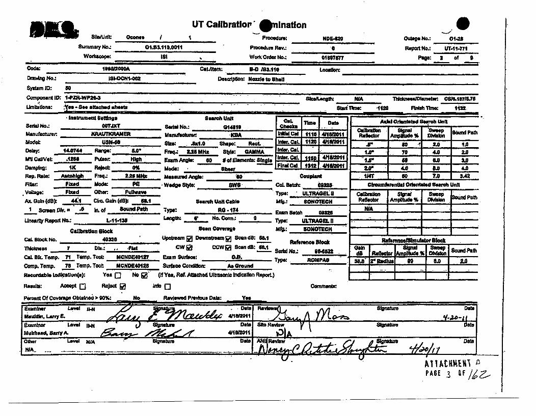
MSwmanoy
8rnmdy No-:WNU*:
UT Callbratior, @ linatlonocaee I ¶ Prooodure: NDE,420
Outae No.: o0-__
Report No.: UT,41-771
POP: 2 of 9
01.83&110.O011 Porcedure Rev.:
Woc' Order No.. ai1m7s77IS'
Code ~ 1Ir1o80000A Cmtem: 3.110 Locaon:
Dmwkilg No0.: I-ONO2D~es eptin: Houzle to UheU.
System ID: so
Component ID; 1-PZR-WP20,3 N" " ' "' 'A* .. .... " ..... .
uhbdons: •'.a-See attaceshe•e_ ._ gtdt'1e: d120 FIsh Time: 1122Lim____ _____________Finish______
- Instrumern Seattns Serc Unit - -im -otSail.] No.: oo"JxTr Saw No.: , , 141. ,.Manufacturer ~ KRAUUTKRAMER Ma'jcg idlCt111041121
Mode' USM-" Size: .".0 Ihit5L CAw. 1120 411l12l"106ay. 14.0744 Rien: .0 Freq.: 2U Mlz 8toe: GAMMA .__' C -.
hillCaWOI: .1166 P*uutter Examu AI'gWK so soElementds: Single. I~t Cal. 411121-FIn• •al: 1112l 41182011Dampbng: I- Rejoet 0% Mode: -. S "he _ -
Rep. Rat.: Autchl Freq.: 26 MHx Meaued An&.: 40 coo t
Flif.:r Fi,-d Mode: P Wedge Sly: ,CaL Beatch: 093M.vokai : . Fixed OQ. Puflwave Type: ULTuEo.'u
Ax Gain (dB) 44:1 CQm. Gain (dB) 53.1 Searh Unit Cable Mtg.: SONOTBCH1 3mw DJV. , 0 L iof 8ound Paith Type: RO -.174 E09m Batch as5
Unarl R t o.: ft; L-11-138 I .g L ... No. Conn" 0 T ype: ULTRAOEL I;Callbrs•on 8ck .oen w•ege M4.: SONOT.CH
CA Ilk" No. 40&U Upetrewm Dnstream Ea Scan di; L R56r1on kThkckneos 7 Dli.: .. AFid. CWi0 CCW Fa Son dD: 68.1 SNW No- 9,M
Ci.BDl.T*mp, 71 rtmp.Too: MCNDSO402 Exam Su, oe: Ty.p: RO e -Comp. Temp. 7R. Tomp. Tool MCNDM4128 surface Condtion: As Ground
Rec-ordabl Itnd .eation(.): Yea N No " (If Yes. Ref. Attaied Ubmlo hIdication Report.)
Raeiis AcceptQ Reject ~ lnfoQ 0o'mn
Axial Orlentated Searoh Unit
Rde~or • %DlvSoun 0md PathRetd Amsuo .o'" oo
ra' So 2, ,,.0I•• a8 L.o .0
2.V ILO 4.0-1wr 60 7.0 3A2J•
Clbumferontlei Ofontate earch Uni
t - -tRsefasiwallsftulator BlockG L I Olpu _I&"I &
6 d ftIM
dB Refhco~r MIoLtd ID-Ld --SI3 lias"rma ul 80 1. . 1 2A.• .- .- i I-.I .. . .--
I 't~ I . I..'
PACE 3 uF/&..
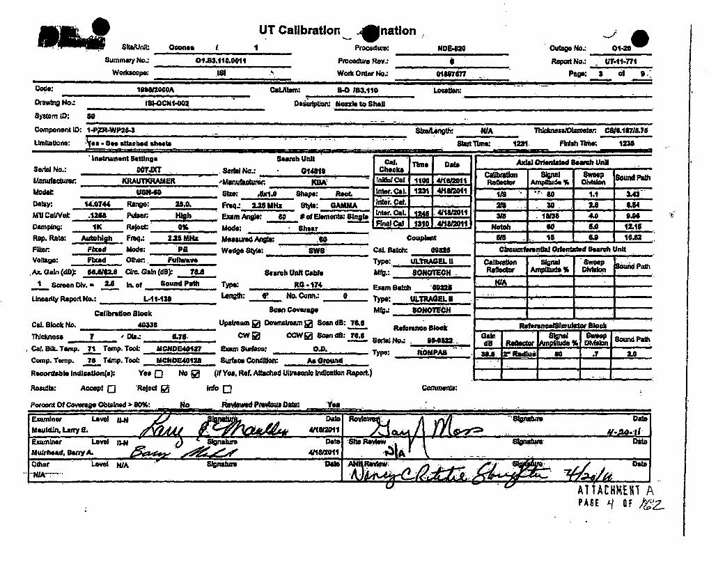
Nleln
SUMMiY NO.:
Wockwtopa:
UT Calibration .,-*nationOconee I 1 Procedure:
O193.1.oL 0, P ,ooedWu, Rev.:
181 Work Order No.:
NDH.820
601367477
Ouage No.: Oll-nSRapo No.: _ 0.61-471
Pago: a Wi S,
Cowe; ISSAIMOOA CaLJftwtn: B-0 163.110 Location:
Drawing No. 18404102Dmmption: am]$ to shell
system 11: so
Component 1 ID:1-P9R4M8-3 -Sbwe ': "WA -h-m-/Oh. •eer t I1 7"L75
Lbalstaona: cc -Se aftusbed SheetS Skit Tbw. 1231. Findsh Tbiw ¶235
", - i L n n I I " n l I I -u i .- + •. I ll I - -inl
Ins'maNetu etuing Iearan uirt !Seri No.: OOTJXT . Serlal No.: 0144"0Manufadture KRAUTKRAMER 'auaw ~ IAMolet 1... 40 aIre; ,Ix.. Shape: ROOtDelay: =4.74 RaNW: ZIA0 Freq., 2Z2 MHz 8"$: GAMMAMI Cal/Val: .123, Par.i Hjb Exem Angle: 60 is01 Elemnets' iLeOamplng 1K Ruojct 0% Mode; - shearRep. Rate. Aiftohh Fraq. 2.25 MHz Measaured Angle If0Sit= Ffed Mode: PID Wocg 8 : 0". .voltage: Fixed Othen, FialwaveAx Gain (d) 6C.62.. Cit. Ga (dS) 78. 8eih Unit Cable
I ScreenW. ,., 2j i. of Bound P..th Typo: RI. -174
LUInty Report No.: L,4_-433 LeAth: ft No.Corm.: o
Callbraton Slock law Oemage
Cml. Block No. 40. 3, Upstream 1 Downstream 0 Scan dB: 7
T1ile" I ODb-.: L76,. CWO CCW2i Scand8: 71.6Cal. Sik. Temp. 71 Temp. Tool: CANIDE4,1,7 ,, Sfmf: OD..- . -Comp. Tomp. 76 Tqimp. Tool: MCNE,40128 Surface Condlilon' Ae Ground
Reordtble lndicauiona.): Yes Q No [ (it Yes,. Rat Atae•d Ultraic ikwdiaon Repod)
Reults: Accept Q 'Reject 0 Ino [)
Percent Of Coveraget Obtained -P 90%, ______ Noa~ Aeevd____Dat;
Cal. echecks .Tm a
aio.al C 1100 41oo1er
InwCal. -I =lFinlti Cal.11 1621
:WS. Batoix Gem2rype: - .TRAOEL qAft.: SONOTEN.
%)aM "tCh am2rype: UL.TRAMEUMfg.: SOWoTC-.h
01191nc 9eAn
Isls•.: . ,554522x ,-
rmy: ,, OMPAS
COMM :
Axle Ofienlated BeArb IUnk
CaI stm mom I nal Sam"eeReeOBSON Amp~ltude % OeladnL :.Y;- - -.I... ,IN8 3O 1.1 31.4
2830 U. 6.54318 10136 4.0 0."
Natob go 50 12.15511 1 I ,l 6.9 1 IO,,.2
Cloauntehnlik Oden4taed earch Unit
Callbration Slgna 8Sweep dPaRalleodr Ampilld. D~vdsio
Gem- I %I - P
WA I
- - .I -,
ii
i.,
rmandigibl so a . 2AI:8. : !-,- hi 2.01.... f I i_
AOTACHME.I APASE q- OF t:?

0 0DUKE POWER COMPANY
ISI LIMITATION REPORT
ComponentlWold iD: 1-PZR-WP26-3 Item No: 01B3.110.0011 remarks:
NO SCAN SURFACE BEAM DIRECTION Due to nozze Configuration.
[LIMITED SCAN 01 02 1l] cW ecw 2 _@ __ __
FROM L N/A to L N/A INCHES FROM WO 1.0" to Beyond
ANGLE: IZ 0 0 45 0 60 other FROM 0 DEGto 360 DEG -
O NO SCAN SURFACE BEAM DIRECTION
C] LIMITED SCAN 0 1 "] 2 E] 1 C 2 E] cw E- ccw
FROM L to L INCHES FROM WO ..... toW .....
ANGLE: -0 045 Q60- other. FRO._M DEG to DEG
E" NO SCAN SURFACE BEAM DIRECTION
Q LIMITED SCAN C1 02 01 E2 ] cw ccw
FROM L .toL__ ,, INCHES FROM WO to . ....
ANGLE: 000 45 060 other FROM; DEG to - DEG
[J NO SCAN SURFACE BEAM DIRECTION
0 LIMITED SCAN 0 1 El 2 1r 1 E] 2 El cw El cw UT-11-7n7
FROM L to. L INCHES FROM WO to Sketch(s) attached
ANGLE: 0 0 00 5 0 other. FROM DEG to DEG I y NPrepared B.y. Mauldi' 1 L44 : Date: 04/1&11 Sheet 4.- Of 9
ew y. D1a"" //: . . A. tidzed Inspeotft; V . .... . ....- , . 1A. HkL~ i 1F P A
I ýý WE -S 0 F

0Item No. .I.B3.110.0011
Weld No.: WP26-3
0Pm~sudwzr Sa -41ing Nozile to Shell
Inspector/Date: Barr' Muirhead 411/11Noz7le
Surfiace 2Base and Weld Metal Examined with 00 angle.
% Examined 0* = 19.03 / 56.283 x 100 = 33.8%.
o
19.03 sq. in.
'r
I
N
ShellSurface 1 I
IPAGE (6 gF /,-
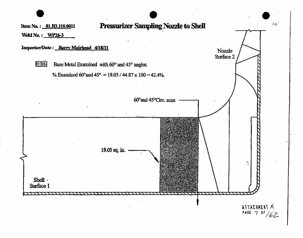
Item N66 Oi.LIX_.110.00
WeIdNo.: WP26-3
Inspector/Date: BArr Muirhead 4/18/U
utrizer Sampling Nozzle to Shell
Base Metal &mined widi 60 ad 450 angles.
% E1amýe 600 and 45* = 19.03 / 44.87 x 100 = 42.4%.
60Wand 450Circ. scan m
.19.03 sq. in".
Sheu -SurfacelI
IAi tmtAi APASI -7OF/ _

Item No. O1.B3.110.0011
Weld No. : WPl&3
PPressurizer Samlin Noz71e to Shell
1 .0
Impector/Date: Bar& Muirhead 04/18&Nozzle
Surface 2m Total Weld Metal Examined with at least 2 angles from one direction.
A combination of 45' and 600 angles vere used to obtain coverage.% Examined from Surfce 1 =7.015/ 11.413 x 100=61.46%.% Examined fom Surface Z CW, and 0GW= 0%.
Shell
SSurfiice I
7.015 sq. i , AST , G

0Item No.; -01B.UO.oo11 Pres
Weld No.:
Inspector/Date : ]k hited41L
surizer Sampling Nozzle to Shell0
Total Bas Metal nined with at least 2 angles from one drction.
A combination of 450 and 600 angles were used to obtain coverg.
% Examined = (24.45 + 5.705) / 44.87 x 100 67.2%/
600-- •
24.45 sq. in.
Shell
x N. x x ..X .-- -- - - - x x N11%-1 - I- - - - - - at.. ý , ý - - - - . . --
..5.705 sq. PAGE C oF/ .M

PZR Samplinf Nozzle to Shell % ofCoveral~ eb" C=
4 v- .
Item No.: 01,B3.110.0011 Weld No. : P26-3
Weld Coverage
ScanStS2
CwCCw
450 & 600450 & 600450 & 600450 & 600
Total
61.46 +4-
% CoveraaeObttied
614000
6.1.46
15.4 % Coverage
Bae aterialCoverage
Sicw & ccw
450 & 600450 & 600
Total
67.2424109.6
109.6 + 2
00 Scan Coveraee
% Coverage
% Coverage33.8
Aggregate Coverage = Weld + Base Material + 0P + 3
34.7 % oeale
Inspector / Date: Page _I of __q

01111 MOM_
Summary No.:
Workcope:
UT Calibratlor - Onlnatlon
Outago No.: 01-26Report No.: UT-11-72
Paea: 1 of .1:.
Oconee I Procedure:
Prooeduro Rev.:
Work Order No-.
NDE4140
61897577
code: .i. ... 19- - Ca..lt. .: 90 3.1114 L•cation-
Drawtin No.: 181.OCNI-002 - oeafpdom Nlzzl, td Shell
System ID: g0
Component ID: .-PZWP2.-7 -SheLongti: 1A Th.ck n ator CS 1 _7M.75Umltations: See T1 report StWar Time: 1208 Finish Time: 1215
---- . E I n n _ _ _ I _. i n .. . . ... .. .... i " ._ _ _ _ _ _ _ _ _ _". ,i .-_ _
Inlrmn etig erhUhCol. Tmes ot Axial orientated Search UnitS.a. No.: jXT SeW, N o.: C I200 SP C h ocks : S s we. p -n P g . - -
Manu.c..er KRAUTKRAMER .KRA I Sol 0 4 = .Reflectio Amlitde% Dwpon .
mom: UBN.,0 -11d* _1i.. Shap:. Round Inter. Col. 1200 .4112016 2` 1. 14 ..Dely. 1.039 Range: 1 Freq.; 2.26 MHz Ste: Gamma -.t 2e 70 -3. 3.3
M'k CalVit .233 Putn.'L . H10 Exam Angle: 0 #of Elements: Single r CO '1 4n.c . a 6A I...• - '---'- "--1:, Ifna Co 1-13.5,L41O I •.s .Dampno 11K Aelp 0% . ,Mode: Log.-Rep. Rate: Autohlgh Freq.: 2.28 MHz Measured Ange: W/A. CouplontFilter , Fixed Mode: P • Wedge Style: ... i. h l Col. Batch: 05 CrumfentaI Orientted Search UnitVoltage: Fixed Other. FuIlwave Type: ULTRAOEL N Calibraon Signal Sweep BoLu-dPath
Ax. Gain (dB . 31.3 Cim Gain (dB): ..... N/A Search Unit Cable Mft: SONOTECH Reflector Ampitude #A Dlvtslon
Screen Dlv, 1,0 Ib. Kof pound Patm Type: RG -174 Exam Batch'. 09... N•A
Lineaity Report No.: -11-t38 No. Conn., -. 0 Type: ULTRAGEL -
Callraton Blook SoonCoverage Mfg.: 8ONOTECH
Cal. Block No. 40338 Upstream D Downstream oo San dB: 37.3 Refe ulock Refarencel8knulstot BlockThIckmoas 8.1e7 oDi.: 5.r74 CW- CCW-IScan dSo: N/A Gaff, Ser nal I Svweopn d Path
______ ________ - Serial No.: 96622-e dB Reflector', Ampfttudo %S I M SondPCal. SIX. Temp. 71 Temp. Tool. MCN0240127 Exam Sur•.o OD ...... pe,: ROMPAS 14.I BW I 0 1.0 1.0Comp. Temp. 78 Temp. Tool: _MCNDC..40128 Surae Ccrond : Am I lcund l
Recordable lndlcstleo4): Yes 0 No 0 (if Yes. Ref. Attached UltrasonIcndication R0PcrL)-
Resufts: Ace pl Reject E Info 0 Comments: WA
Percent Of Coverage Obtained 3 90%: No Redeiived Previous Data: 'Yafs
Examiner Levelk-
Mulrtr Barry A. A
Other Lavel WA Data..ab
NIA -IJ'
PASE /I Of ~

summary No.:
UT Calibration A. ation SOconee J I
01.83 Al0.0012
IS'
Procedure:
Procedure Rev-,
Work Oid~r No.:
NDE-820
0
Oit No.: 01-2
Repit No.: UT-11-773
Peag: I a f *Code: 199000A CatJtem: 9.0 /B3,tt0 Location:
Drawig No.: l81-OCN.-002 DeascripticuNk.xe to Shelf
System ID: 80
Componei ii: 1iimR.WP264 Seftu..i i MIA ThlcIm[s/Diarnten CSMI$71575
Umitatlons: Yes - See affached athe•ets St Time: 1223 Fb*hTbme: 1230
Instrument BSo. _ S earch Unk -a. I -s, Cdor•atot Goo ,ntSeul No.: ,1 7 Seia N.-o.: 014818 Chieckw -.r•, CADIa ld sea Sc.. Pa.thManufn•cc, :RAUTKRAMER .Manctur•e• K1A Intial Cod, ion4H lv've.r Amplittde'llfcl' . .en .Ptlodel, USN48 Shm: LA.. Shape: Rect Inter. Col. 1216 ..1 81 80 IA 2.24
Delay: 11.81 RAng: I". PFuq.- Z.5Mlx Style: GaMA -ner Col - 218__ 38 3.0 4.70Mill CaIwel: .1268 Pulow High Ezmn Angle: 46' #of EIawnents$Sw nter. I SiB 1 20140 4.8 .09Damping: W, , Reject 0% Mcd,: st,, . F l Cal 1300 4Show11 N 35 8'6Rep. Raste: Autshi Fr"q.: 2. MHz Measured An&: 4 , C1U5et 182.1
Filter Fixed Mode: PE Wedge 84* .we Cal. Batch: 0M925 Wroussv....l•-!Orlentatod Search UnitVoltae: Fixed Olthw Pullwava Type: ULTRAGEL II Callraiona Sipne Sweep swmptAx. Gain (df) 46.1•t. Cuo Gahi (dB) I/A seh Un"t Cable Mfg.: SONOTUCH Refler Amplitde %, Wskin
I Sreen Div. a CS tn. of Bound Path Type: R0174 Exam Batch , 9m25
Linn*dl Report No.,: 1.4I1-1138 Le.w9th: 6' .No. Con.n _ Type: ULTRAGEL 1Callbrathm lca k -Scan Cweream M.: SONOTECO .. ...__ - .-
Cal. Block No. 40W !.Uipstrm 20 Downtsmn Ea Scands:--8"1 Reference Block "RdeRmnllimuld BlockThIct"ese 7 Dt. . £8 W CCWO Scan dS: 661 eIo Gain J ps $w Sondaat
____________ No.:a __0___$22 d8 Refetdor Amno WelonCaL a&k Temp. _71 Temp. Tool. MCM0E40127 Exwn Surface 00 Tym: ROMPA8 322_ r Ridu so 1. 0Comp. Temp. 7T8 rmp. Took: MC..2NDI6I Surfe CDofldton: As . r.oud -IRecordable Indlcetlon(s): Ye C] No 0 (If Yes, Ref. AMcled. Ulftaonlc lndWaton ReOPx) . ,
Resuls: Accept [] Reject Info E) Cornmenta:
PercoM Of Coroege Obtaise l 90W%: No. Reviwed Pffvlos Date: Y,,
Examiner La/ IM. DaftDMauldvin, Luffy L
-Examnerw Le iI-N 7 0 PAha". at
Muirliand, Barry A.1Other Leve W/A Strnatum I
NIA ___________________________________AE-
PAGE 12 oF142

0Summary No.:
Worfkoope:
UT Calibration - 9JinationOconwe I ..
01.3.I1t0.0012,
'!81
Procedure.
Procedure Rev.:
Work Order No.:
Outage No.: 01-nReport No.: UT4 l- .
NDE.8206Ie.I001577
Codev: 1 20 . Cat.,twm: - 1. 10 -SO Location:i il l il+ " "I~~ ~ ~ ~~i" " + .I ... .. .4 .i •j i + + •.. . i
Drvwtnig No.: IS-CNI-OZ " Drption: Noimd tc 8hell
System ID: s0
Componert ID: I-PZR-iP21.7 S... .1znglh: " ^ Th" Me"'" -ameter. CSI.19.7J5.,
LUmitatfo: Ye - S4e attached heets Stardtme: "a112 FIbfh 7lme: 1150Cal. ...e ,ate
Ser•al No.: ofTfXTManuboturer ..... ATRAME "Model: USH-40 - .
Delayr 14.07" R"g. ax0MV CoiNe: .1268 . b . HigeDamplng: IK Reject: 0%Rep. Rate: 4qfth_ Freq.: 2.25 MHz.Fiter FIX Mods: PEVoltage: Fixed Other iulwave
A& Gain (do) 4,,4. cOr. Gabi (d):' 5m.I Some.n ON. = J In. of Sound Pfl
iLhneady Report No.: . L-41-138 .
Cailbraon BIoBok
aoware, UMi
Sedal No.: 01481.Mwufaour KR
aim:_ J11.0 shape:Fe.q.. .L251 MR&a _• :EX&M Anle: 160 #of lMode: S. hearMeared APOW: .Wedge • 4•.: Owl
Search Unit Cable
Type: R t- 174Lstoh: "' NoCn..
scn Coverage
9 Checcs __
Ro. Artder. CL. 1120 4I1. 11. I
Inte, Inr Owei ,al111 211-Cal 131 F21.I I 1
CouaptantCal. Bab*t 09388Type: uumAeLuv
Mfg. SONOlICH
' Sam.c 0535_____ Type. U! RAl L I I
Mfg.: SONOTECH
, Axial Oiterasted Search Unit
Car •,•aion Sial 'SA"we ,ReflectOr Amplitude 9% Divis U Pat
" " 80 's 2.0 1.0I ... .-40 0 " .o
of8 451A. 3.02.w" 4Ao a.o ..019T__ .0 7.0 3A42
cmlmentUa Orkentated Search Unit- .. - "
Cadibratlt Sipal Sweep f~WPtReflector Apide% Dvso
lteftraa.Sncflrnulator Block- -~-da-A909 . isin- un~
Cal. Block No. 403388 Up-a r• Downseamf i Scan dS: 5161 ' Refno" BlackThkness r Die..: .. Flat CW l CCW 0 scan dis: .1 SerialNo.: isCl. 5Temp. 71 Tomp.Tool: MCN0o40 •.2 Eemu Surtae: O. .. ... Type: IOMI_
Camp. Temp. 70 Temp. Tool: MCNDE401IZ8 srfa• e Conlon: . As Ground
Recordable indlaion(,): Y'e D No R (If Yes, Re. Af.ached Uftwt indloatton Report.)
Reaubte: Accept [] Reject @ Ifo 0 Comments:
Perent Of Covae Obt•ined ,'0,: INo _W_- , R*wd PreviousD O•,: .. Y".
e -n3s-. ~lr vtodt.l so 1 &0 1 2.0
I

Sumntry No.:
Wodfscaps.
UT Callbration 9 ninationOcanas I
01E3.110.0012
181
Outag No.: .0148l
Report No.: uIT-114m-MPage: 3 of I
Procedure:
Pwcedum Rev.:
Work Onier No.:
N0E4120
01897577
:Code: 11lh2004A Catmltom; 1-0 13.110 Loca1t:
Drawing No.: I81d.0CN1,02 Deddton: Nozzle t6 ah,'
System ID: 50
Component ID: 1-PZR-WP26-7 S NwLeng: WA ThIclumeDlameteor C81&.87175
i-mitations: Yes - 8De attached shests start Tane 1239 Finsh Time: 1246- " '" ' " Il l it . Il 1 • . ri n . Eii ' II I I .II I
Inwumntu uetwig searcn unit0141etoSeria No.: OGTJXT SeOWa Ift
Malutsaoww: KRAUTKRAMIERModel: 1Us"0 SIZe.* .UDoiaer 14.0744 Run.: -211.0. Pmeq- 2.251411Cal/Ve .1288 Putaer High~* Exam Anigle:Dampkng: tIx Reject. 0% . We:Rep. Rate: Autithigh Fuq.: 2.28 Mtm Measured Ang
MBA1.0 SMPe: Re, .MHz Style: GAMMA
60 111ofElenments:lnlShear
is:S
Cal.Checks
In"ta CalInter. Ca.Inter. Cal.ITZ cal
Time Do"10o I, lmoii
L 1231 411/82011-I -
1U31 41MM1
Couplard
Cdbmtimal Si W Swee S Pauh.
218 30 2. 6.543m 1I 4AI 0.96
No.th I so U I 115N* 1 s " I I1M.8
Axial Orientated Search Unit
Flaner Fixed Mode: P9 Wedge Style: .. Cal. Batch: 09325Voltage: Fixed 0h.,r Putlmie Type:, ULTRAGEL U
Ax. GCan (dB): 56.616 Cbro. GaIn (dl) 7. Search Unit Cable Mfg.: SONOTMCH1 Saon Dwv. - 2.5 in. of sound Path Type: RG -174 F1 Ih ._______
Unea zly Repor l No.: L -1-14 38 IV. . No. Coa n. 0 Type: ULTRA GUL - I
SeanCovraTepeg: SONTRAECH1Callbndlon Block 80an coe" : .NOTECH
Cal. Block No. 40338 Upetren R Downstream &I Scan dB: 76.6 Raftrencs Blok
Thk a. O we.: 5.78 CW o CCWll Scan dB: 7&6 Serial No.: 984822CUl. Bk. Temp. _71 TOMw. Took MCNDO4W127 Exam Su•fdam C.D. Type: ROMPA ,
Comp. Temp. 78 Tamp. Toot MCNDMtC128 Ureface Condhlo. As Ground
Recordable Indloeuton(s) Yes Q No ja (it Yes, Ref. Aftched Ultr1aslonicaton Report.)
Porents: Accept "] Reject 0 Info Q Commenta .
Pemrce Of Coverage Obtained > go%: A0N Reviewed Pravloua Date: .Yea
Clcwufewnthd iOrletated Searoh Unit"."- iii - I
I I

.0 0K- DUKE POWER COMPANY
ISI LIMITATION REPORT IComponent/Weld ID: 1-PZR-WP26-7 Item No: 0LB3.110.0012 remarks:
Z NO SCAN SURFACE BEAM DIRECTION Due to nozzle configuratlon.
JLIMITED SCAN ED 1 0 2 0 1 02 0 cw 0 ccw
FROM L N/A to L N/A INCHES FROM WO 1.0. to Beynd -
ANGLE: 0 0 ED 45 [0 60 other. FROM 0 DEGto 360 DEG
El NO SCAN SURFACE BEAM DIRECTION
Cl LIMITED SCAN C] I [1 2 j 1 I0 2 [1 Cw C3 ccw
FROM L to L INCHES FROM WO to
ANGLE: 0 0 0145 [] 60 other FROM DEG to DEG
- NO SCAN SURFACE BEAM DIRECTION
QLIMITED SCAN 0 1 E2 Eli 2 [D1 cw __1__ _ _
FROM L to L INCHES FROM WO to
ANGLE: 00 [0 45 0 60 other FROM DEG to DEG
o NO SCAN
Ml LIMITED SCAN
SURFACE BEAM DIRECTION
011 02 C]l02Clcw 0ccwUT-11-773 I
Sketch(s) attachedFROM L to L4
INCHES FROM WO to
ANGLE: 0 00 5 other FROM DEG 0 yes El No
I1'
A11ACHMENT P.FASE/ 15 F/g
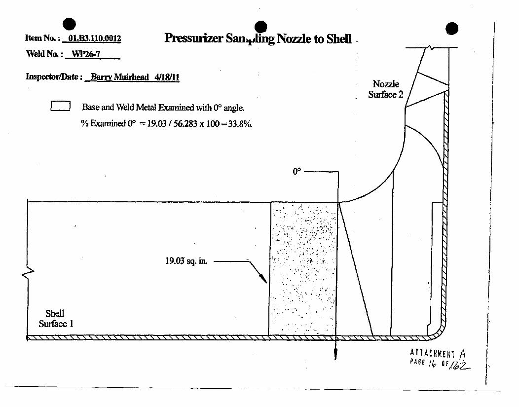
0 0Itemn No; O1.B3.110.0012 Pr suri•r San~ ing No.zzle to ShellWeld No.: WP26-7
Inspector/Date: Barry Muirhead 4/18/11
-- ] Base and Weld Metal Examined with 00 angle.
% Examined 0* = 19.03 / 56.283 x 100 = 33.8%.
0
NozzleSurface 2
Go
A
19.03 sq. in.
ShellSurface I
I.I1. 1. 1. 11 11
I WTACHREN, A
[
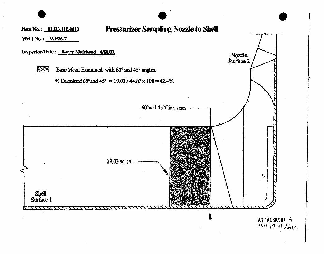
0 0Item No.: 01.B3.llO.0012
Wdd No.: WP26-7
Inspector/ate: ar Muirbmd 41811
%Muwr Sampling Nonle to Shell
Ba= MeWa Examined withi 60* an 450 angles
% Examined 600and 451 = 19.03 /44.87 x 100 =42.40/o
60JOnd 450 ~irc. scan
19.03sq, in. .N
Shell
e- r. t- t- W.. W. -L- e. el v C, CM cm em v. V Ir IV rr el V Rr Rr r V V V, Ir T T Ir -N
.f AIIA~UIw A

0Item No.: 01M3.110.0012 Ii'flWdd No. : Wp26-7
hupector/Date: Barr Muiziead 04/1/MU
Ussurizer Sampling Nozzle to Shell
SNztl2M Total Weld Metal Examined with at least 2 angles from one direction.
A combination of 450 and 60' angles were used to obtain coverage.
% Examined from Surface 1 =7.015 / 11.413 x 10 = 61.46%.% Examined from Surface 2, CW, and CCW = 0%.
ShellSurface I
----------X IX X % " X , 1ý 1. X ý% Xý- . .
7.015 sq. PAE/6Q.;O

0Item No.;: o1.B3.uo 0012 PreseWeld No.: 27 .
Inspector/Date: Barry Muirhead 4/18/11
w* ,-0surizer Sampling Nozzle to Shell
.. 0
M Total Base Metal Examined with at least 2 angles from one direction.
A combfnation of 450 and 600 anges were used to obtain coverage.
% Examined = (24.45 + 5.705) / 44.87 x 100 = 67.2%o
60,
'24.454s. in.
ShellSur1~ce1
I11 - - - - - - - - - - - - . T.. V. C. . IV, C, Ir,R
5.lO5sq."'I- PAS6 ; QF//,2.

PZR Sampling Nozzle to Shell % of Coverage'-Nb.aJc~
0U
--Item No.: 01JUI,1M.0012 Weld No. :
Weld Coverage
SamnSI
S2Cw
cCw
450 & 600450 & 600450 & 600450 & 600
Total
O/1 Coverae Obtained
0
061.46
61.46 +4= 154 % Coverage
Base Material Coveraue
S&CW &CCW
450 & 600450 & 600
Total
67.242.4
109.6
54.8
33.8
109.6 +2 =
00 Scan Coverafe
% Coverage
% Coverage
Aggregate Coverage = Weld + Base Material + 00 + 3
- 34.7
-n --c-o,,,Date - /
% Coxerag-e
Page -YOf --I
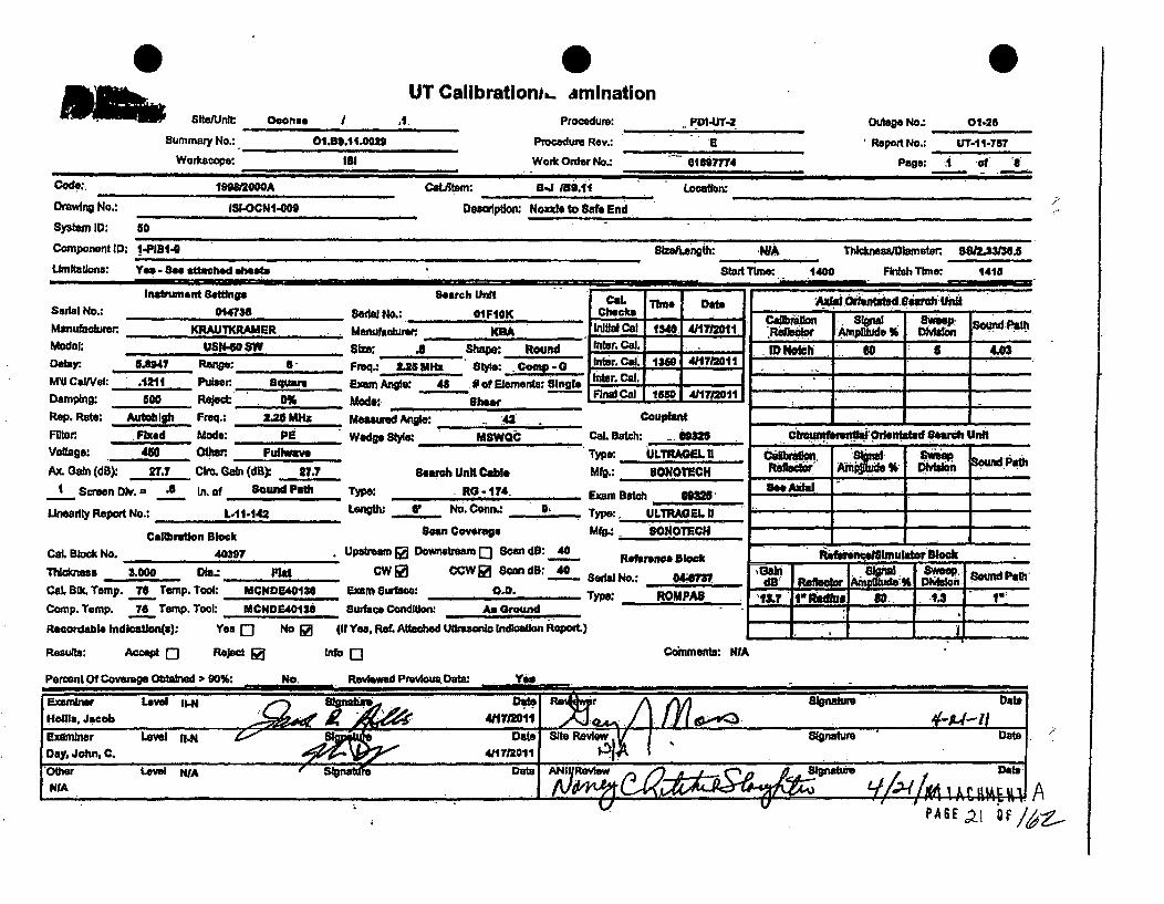
0makt SIUnlt:
Summary No.:
Worksoope:
0UT Calibratloni.- amination
0m
°
Ocorl..
O99lei02
,11. Procedure:
Procedure Rev.:
Work Order No.:
. PDIUT-2
018977741
Outage No-. 01-25
Report No.: , T-11-757
page: A1 d., I
Code:.
Drawing No.:
Syt=em ID: s0
Component ID; t-F
Limitations: Ye4
119=W200A
ISI-OCNI-009I
I ICwaLtem: 3-J 153.11
Deeaplo Nozzea to Safe End
Locaton:
I - See attached sheets-WA
start Trme 1400
Thicknewf~aretor~ SSIL333.5
FkIIh Time: 1418
Instrument Settng* search-CWL Time DebeSeial No.: 014738 Serial No.:. 01FIOK Check-
Manufacturer KRAUTKRAMER Manufaolune:. KA nitial Cal 1340 411712011Modal: USN4-0 8aW 81e: .. Shape: Round nter. .alDefaer 5.847 Range: _____ ____ . M 8qt .2 .ye:-_Compe.0 . r.Ca.u 1359 711MV CaIN: .1211 Pulsar Squa" Exam Angle: 48 of Elements: Single -r. Cal I
Damping: 600 ReJec 0% Modr.•: Fihee"al Cal 1550 411713l91Rep. Rate: .Autoblg Freq.: 2.26 MHz Meamsur Angle: __ .___.4,1"_ _. CouplentF~br Fixed Mode: Pe " Wedge St ..e. MsWoC Cal. Batch: 6.0=1Voltage: 4d0 Other. FuWwvo Type ULTRAGEL U
Ax. Gain (dB) 27.7 Cb'. Gain (d0) 27.7 Seafrh Unit cwbl Mfg.: 60NOTECH
t Screen Div. c .8 In. of SOu"d PaH Type: RO - 174. Exam Batch 9"M
Uneadfy Report No.: L-11-142 I".* IL No. Conn.: 0__ ..... _Type:. ULTRAGEL a '
Cal W lon S~e osan Coverage MfW•: . ONOTECH
CaL. elok No. 40397 Upstream wonstream Q Scan d8: 40 Refernc SbakThickness &000 i-, Rd CW • CW fSan dB: 40 Swa No.: 044CaL Bic. Tamp. 7_.0 Temp. Tool: MCMDE40136 Exam Surface: O.D. Type: ROM PASComp. Temp. 76 Tamp. Tool: MCNDE401$i Surface Conditon An Ground
Reoordable Indication(s): Yea Q No [a (if Ye. Ref. Attached Ulrasoft ,ndkcaton Report.)
Results: Ac•e - Reject 2 Info I- Conments: NIA
P AS E a I Of

summary N.
Weeksoope:
UT Calibrationm..aminationOconoe I I
01.59.11.0029
181
Pxmcdum:
Prceadure Rev..,
Work Order No.:
P0I-UT-2
01897774
Outage No.: 01-211
Report No.: UT-111-757
Peag: 2 of 8
Code: CatJltem: 9-1J 19.11 Locaion:
Orawng No.: 1I8-OCNI-.009 Dea1pono Nozzle to Safe End
System ID: so
Component I1: 1-P1314 eeenth: WA ThlnesOamlehater. 85/23.6.5
Urnltatlona: Yea -See attched sheets Star Time: 1417 FinIsh Tlmec 1421
Insat ment GoUings Search Unit Col. STim e D atesouft No.: 014738 Seqala No.: 380708 Cheocks ____da - . r. - wi -at
Manfacturer ~ KRAUT1CRAMER Manuhactuter KM "RANual Cal 1L345 41171201 Aeleolar %Model: USN-GO SW Sb Shape: Round Iner -O W4 581)" '1111).8Derlay. 5.293 Range: 10 - req.: .. 2.2 MW Style: COMP- Ines C& 1416 4A17/211--M111 CaV: .1225 Per Square Exam Anq. so # Elements: Iingl"- - ... , -.-
Damping: n00 ReJoo. 0% MIdw. Shear _ hal Cal 1
Rep. Ro,: _Aut Fq.: 2. 25 MHz Meaurd Ar: _______.._. Coupla•,,t _ -
FI'r Fk.•d Mom PBE Wedge Stye: M8WQC Cal. Batch: wie,.o, cht orlsetedarets Unit
Voltage: 450 Ol0W. FuliWave Type; ULThAGEL U Cmtiwo Sige sweepAx. Gain (dB): 45.3 CIM, Gain (d0) NIA Search Unit Cable Mfg.:. SONOTECH , I
.Screan .. 1.0 11-_ .Of Sound Pah Type: RG -.1174 Exam sat 0" W', A "
Linearity Report W.: L. 1-142. Length .,, No. Conn.: "ryp: .ULTRAGEL "11- - -
Calibration Block scan Coverage Mf. sONOTECH ,Cal. Block No. 40307 UpaireUm E DOawwfl Q 8w dB: 61.3 R.fere.•h. , ., r Block
Thlimee 3000 D~e: FatCW C CCWQ] Scan dB: MIA 0.77d IRe aterI fid d Osww Bound PathCal. 81k. Temp. -L reTep. Tool- MCNO94ISO EXar SWOac0. Type: ROMPAP -15.0 1•Radim 8 -Camp, Temp. ye Temp. Tool. MCH013401131 Surface Condillor As round- II IRecordable Indkcafen): Yes E] No O (f Yes. Ref. Attachd Ultrasonic Indication Report.)
Results: Accept Q Rejed Info Comments: WA
Pecent Of Covem Obtalned D 90%: No Reviewed Pmrvm DOat: Yes
Examiner Level IIN S -Ignatur Date ReV~wL intr Date
Exasniner Level gI.N Date Site Review VSintrDay.ý Joh. C. . A M 2:. 4/1712011 01A
Other Level WA fdae A.NI Review ,a...(lj .... ..
X r/A ) '''W J~Vi
V.
PASEJL

UT Calibration ,.,amination__St_/Un_ __ o ____._. I 1 Procedure: PDI4.JT-2 Outage No.: 01-26
Summary No.: 01.BS.11.001 Procedure Rev.: E. Report No.: UT-l-.TI5
Workdcope: - 8i Wo n Order No.: 01897774, Page: 3 of a
Code. 199812000A CatJItem: B-J IB9.11 Location:
DrMaIng No.: 1S-OCNI40W Deesipton: Nozzle to Safe End - " '
System ID: d0
Component ID: 1-P111-51- SIle ,.ngth: NIA Thilc•neslDlalret, 5S,,, .3J5
Umrntntona: Yes - See attached aheats Stait Time: 14V7 Finish Time: 1435
Inabn.mnt Setngs SONrh Unit C L Tit" Date .A 0 1 a U.S ariul No.: 014736 Serai No.: SE035S Checks -- .S.n.. S-_
Manufactawec KRAUTKRAMER Marudiacturen - Initia Cod 1350 411712011 -Model: USN-0 8W Stze: Shape. ha . Round Iner. Cal. V1 4so. S0 J -. 9D.lr.y 9.5. 3 Ranp e: In Preq.: 2.25. 5 ,I ' Style: comp - g . - .1421 411 712011 - '_ " - -
M10 CaIVel: . .1226 Pulon. Squar Exam Angle: To 0 of ElementS•. Sgle1- - ____20 1 __"
amping: 500 Rej 0%.. .il 5 ,Sheer . . ...-Rep. Rate: Fmq., 2.25 Mltz Mesured Angle: 70. Couplant ,,,_-_, _
Fiter Fixed Mode: .P..9.- Wedge Style: MeWQC CaL Batch: 00325. Unit-.uVoltage: 480 Othier Fuulwants Type: ULTRAGELO 619 8mVate SiPalatheAx. Gain (d6) so Cbv. Gain (dB) IVA search Unit Cable MIl.: SONOTECH , e Amp.iuft .... S
SemenDV. a 1.5 I .Of SoundPath Typew- RG -174 . . Exam Batch 00325. NA-
U:.uri.y Report No. L-11-142. Length: V No. Conn.: 0 Type: ULTRADEL II •-
Calibrtion Black scan Cowerae Mfg.: . ,ONOTECHCaL Block No. 40397 .. ..Upstream 5a Downsvtram Q Scan d8: e e nce Black bhiU5p0l8thl5.tar Bleak
Thoua ro l.:_______ O COW QScan dB: IVA Gain Signal SapSufdPtThickness U00 DID.: -" Serial No.: ..- 04•47 -" IOI Aiipetcre Div n aCaL. k. Temp. 756 rmnp. Tool: MCNDE40138 ExD Surface:., O.. Type: ROMPA8 17.. illI So I.7 I "COmp. Temp. 76 Termp. Tool: MCND41IS6 SuWUaoe Conlon".. As Ground IRecordablelndication(, Yea s No f (IfYes, Ref.Ataod"Ultawot IndlcationReport) 7
Results: Accept C] Reject & Info Q Comments: NIA
Peroet Of Coverage Obtaind , 90%: Na Reviewed Previous Da: Y . -_.
Uxmnr Lvel IlNOt eiwrSgaueDataNIelle, Jacob I11m N ]I I l
Exaniner Level , D-te St. Reiew S.i.ture Date'bay, John.,C. 4117201 P 1..
other Level NIA .ANII Review DatWA /1e~~cYw(4~
PAGE z; QE/Li..

m~ - SawUnIISummary No.:
Worltscope:
UT Caflbration),.aminationOconee. .
01.89.111.0029
lei
Procedurow
Procedure Rev.:
Work Order No.:
P0140.T2 Outag No.: O0-46
Report No.: UT.I1-757
Page: 4 of a01807774
Code. 19981=0AM Cat.Rtem: 8.4 A39.1 1 Location:Drawing No.: IS1OCNI.00 Deaalption: Nozzle to Sae. EndSystem 10: so
Component ID: 1.PI81.0 Slzelnungth: IVA Thikess/Diaineter, 8512.3=18.Limitations: Yes - See attached sheets Start Time: 1437 Fhdali Time: 1443
Instru.. .. Settngs Search Unit -- DateSewial No.; 014738 Serdal No.: . 98-298 I I -1 ! . - I
Manufar•,k.r KRAUTKRAMER m'nukubw. RTSD In,,8• i C -l 113B5 4712,'Jmode: us"o SW . SIM: 2(Zx4 'Shpe: .,c. Inte. 'Cal.Delay, 11I.61 Range: 1req.: 2.0 MHz .si. *: I nter. Col. 1436 4M1T12011Moal. UeSe 4,, 0 S . _ .. . . .. . . . e ..... . ... . r. C, al. -
MW C•aVWa .234 Pulser: Square Erm Angte: . s # of Elements: Dual Inter. Cal..
Damping: S00 Reject 0% Mods: Long.i I .. 18
Rep. Rate: Autehigh Freq- 2 MHz Measured Angle: pCouplantFlIer Fixed Mode: Pa., Wedge Style: .. nt , Cal. Batch: 00325Voltage: 480 Ot•."r Fulim Type: ULTRAGEL II,
Ax. Gain (dB) 82.4 Cho. Gain (dB): PUA Search Unit Cable Mfg.:. " ONOTECH
Scren Div. - .1 K of Sound Path Type: RG -.14 Exam Batch 0325
Linearity Report No.: LP11-142 ...... 6!L No. Con. 0___ Type:. ULT. RAdfL ff
Cellbrut)en Block Scan Coverage Mfg.: SONOTECH
CaL Block No. 40317 IJp*eam 5 Downstream 1 Scan dB: 62.4 Reerence block
Thickness "DO Dla.: Flat CW0 CCW W Soon dB: W41 Serial No.; 04-8711
Cal, Blk. Temp. TO Temp. Took MCNDPAO13 . Exam SwubM O.D; _Type: ROMPAS
Comp. Temp. 7s Temp. Too: MCNDH4O136 Surace Condition: As Ground
Recordable IndlrAteon(t) Yes f' No R (If Yes, Rea. Aathed Ultrasonlc Indloation Repwt.)
Results: Accept f Reject [] Info " Q Comments: NWA
Percent Of Coverage Obtained ; 90%: No Reviewed Previous Data: Yes
efetrAmoitide S. DMalo Pam
Cft=%Nnbretl Orknentatd~eareh Un
:Calibraton: SW.na GWeeP .ftf~t~ Aniptld YbDcio
ZLfto Iiitd4t2 Radiuslc 60pis 11o
A11AtUMEN1 P,PAGE 2q OF,!ý

) I*I' -0
IDUKE POWER COMPANY
ISI LIMITATION REPORT
Component/Weld ID: 1-PIB1-9 Item No: O.B9.11.0029 remarks:
9 NO SCAN SURFACE BEAM DIRECTION Due to cawt material on pump
0 LIMITED SCAN 1 0J2 0 1 D 2 [D w ccw side.
FROM L N/A to L N/A INCHES FROM WO CL to Be"rd .,
ANGLE: 00 0 45 0 60 othef'r._ FROM 0 DEG to 360 DEG
- NO SCAN SURFACE BEAM DIRECTION
E0 LIMITED SCAN 01 02 [0 1 -1 2 0 cw ccw _ _ _ _ _
FROM L __ Ito L INCHES FROM WO to _
ANGLE: [3 0 45 060 other. FROM. DEG to. DEG
El NO SCAN. SURFACE BEAM DIRECTION
0 LIMITEDSCAN 01 02 J-1 J2 -cw ccwm
FROM L tol1 INCHES FROM WD 1to
ANGLE: 0 0 45 0"1 60 other FROM - DEG to DEG
0 NO SCAN SURFACE BEAM DIRECTION
El LIMITED SCAN 0 1 01 2 0 1 0 2 cw [I ccw UT-11-757
FROM L NfA to L- N/A INCHES FROM WO 2.2' to Beýnd Sketch(s) attached
4ANGLE: 0 00 5 060- ofter 80RL FROM: 0 DEG~to 360 DEG 0 yes 0 No
'Prepared By: Ja:cob R.H ols L'.e I: . Date: 0411711 She .t .5 of 8
R.v.. .y Data: s. ... D.
yI
AlU~thMENT1 APAGE,2S Of

V 0~Supplemeh,., Report 0Report No.:
Page:
Summary No.: 01.59.11.0029Examiner. Ho*ls,.Jlcob
Examiner. Day, Johm. C.Olher: 1A
im i I
Levet U.N.Level: N/Level: M/A
Ravlower.Site Review.
ANDI Review.
~'AA
IJT-I1-757
Odae: .I(
I I Ill. m I I IF
Comments:
Sketch or Photo:
6o
52-.
Si, 0
I°.
T
AIIACAMENT fý

me.16 Supplement-i Report Report No.:
Pope:
Summary No.: O1.89.11.0o2
Exwnlner HollI, Jacob
Examnerw. Day J oht C.Othu. WA w Levl: "M44
Levet M
Site Review.
ANII Review:
UT-11-787UT. i.6
7 of 8
DOte: -.M.LL.Date:
Comments:
Sketch or Photo:
5',, II
. 0
I. i*
ATTACHMENT APAGE 27 OF;ý,Z
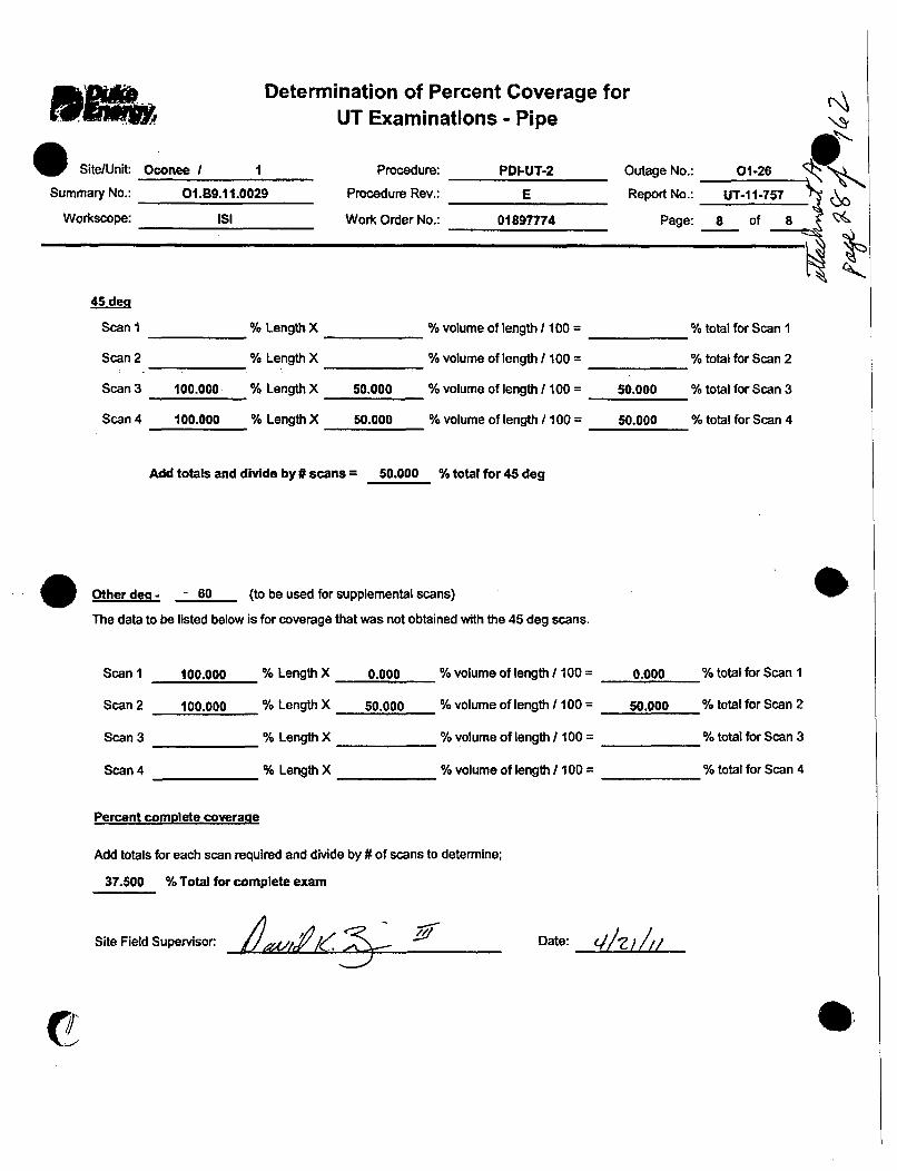
kDeten
O Site/Unit: Oconee / 1
Summary No.: 01.B9.11.0029
Workscope: ISI
mination of Percent Coverage fcUT Examinations - Pipe
Procedure:
Procedure Rev.:
Work Order No.:
PDI-UT-2
E
01897774
Outage No.: O1-26
Report No.: UT-11-757 &
Page: 8 of 8 A
45Sden
Scan I
Scan 2
Scan 3
Scan 4
100.000
100.000
% Length X
% Length X
% Length X
% Length X
50.000
50.000
% volume of length 1100 =
% volume of length /100 =
% volume of length /100 =
% volume of length /100 =
50.000
50.000
% total for Scan I
% total for Scan 2
% total for Scan 3
% total for Scan 4
Add totals and divide by # scans = 50.000 % total for 45 deg
Other deg - 60 (to be used for supplemental scans)
The data to be listed below is for coverage that was not obtained with the 45 deg scans.
Scan 1
Scan 2
Scan 3
Scan 4
100.000 % Length X
100.000 % Length X
% Length X
% Length X
0.000 % volume of length / 100 =
50.000 % volume of length / 100 =
% volume of length/ 100 =
% volume of length / 100 =
0.000 % total for Scan 1
50.000 % total for Scan 2
% total for Scan 3
% total for Scan 4
Percent complete coverame
Add totals for each scan required and divide by # of scans to determine;
37.500 % Total for complete exam
Site Field Supervisor: Z ., L.'I-,
Date: 41_e / ///_
CT

Summary No.:
w o
UT Calibration.. amination i.Oconee I01.89.11.0023
'SI
Procedure:
Procedure Rev.:
Woi Order No.:
NDS-8.i H|
Olm
Outage No.: 014n
Repoi No.: Ur-I11.7830-6.. 4 ..1 A
Code: 1I09000A Catlterm:. 5. ,9.11 Location.
DrwIrg No.: ISI-OCNI.0b9 DftWP : Nozle to Sale End
system ID: 5
Component W0: 1-PI131- . SzSIeurgil; WA Thlckneaa/Diameter 9912.33138.Linmitalins: Ye" - See attached sheets Stat Tlmr. 1034 Fnish Tihw. 1044
Ifatswnen setwn Search UnitSeilt No.: 1IILWG Seda No.: 01-1,Time IDat
M&AMufacuter ICRAIITICRMER Manuftobren R= I Inil Cal 1010 4Modok. Uel-m 200•1"t :w wri Iner Cal...
-;te-U-.dInter. CaL.
Damping: I1K Rejech. 8% Mod& 1.-WAVE - -
Rep. Ret,,: _ .ft h Feq:- 2 MRS Mea-aed Angle: 78 CuplantFlter Fixed Mode: Dual Wedge 8s : Interal CaL Batch: ' 0326vofag: Flied Odwr Fulwave Type: ULTRAGOL UAx Gain (d): 74 Chro Gstn (dB): 74 earch Unit Cale Mfg.: SONOTECH
I Seen O. a .6 IM.of Sound O Type. R - 174 ExamSatoh 0932O
Unoaity Report No.: Length. 6 No. Conn., Type: &lTRAGE. 11
Cad , Sokan CBoOVeg Mfg.: SoOTECH
CaL. Sklck No. SMf4 upagaQ Dowmrnpammo SandB: 74,T' wes 2A.,4 Die.: Mtd. OW• CCOW0 Scan dB: 74 SrfNo.: .MM
CaL BSO. Temp. G9 Temp. Took MCNDE4M130 Exam SWIaMe: ,O.. Type: ROMPAB
Comp. Temp. 67 Temp. Toot MCNDE40130 Bur. Cend tIon: As Ground
Recordable lndlestien~s) Yes Q No 0 (if Yes. Ref. Afttahe ULimnor Indication Report.)
I •Adl Olerdatd searh Uni t
I4T Ho 80 3.7 114
16- . - sund-a
Refetder An=.de DfW~
See' "da ___ I
dSfstwmo Id se uvo w II II •
Axplfmo ONf
40As
#&
PejenOf -COW Q Reoed E
Percent Of Coverage, Obtained r 50D%:-
tnfaQ Comments: NWF'
P A2
.,=~q "F/6,.

Sfte/Unll;
Sumnmary No.:
Woftcope:
UT Calibration.. aminatlon I'01,81.11.0029
Procedumr:
Procedure Rev.:
Work Order No.:
NOE.5S0
.1
Outage No.: 01-26
Report No.: UT-11-783
Page: 2 of 4;018197774
Code: 199812000A CaJItei: a-J 18.11 Location:
Omv.ng No.: ISI.OCNI-009 Descrption: Nczli to Safs End
System ID: 50
Component ID: 14P1B1-9 s~zlsLonoth: NIA ThldweaWDnumtt 88&3=.5321
Urntautlons: Ye. - See attched *hoets _Stant Te: 148 Finish Time: 1402
instrument Settings a.urch Unit ISeuial No.: OIILW6 Seoal No.: 03-738 -
Manulkhc r KRAUTKRAMER , u Manuid mWer .RI"D
Model: USH-CO 81w 2pi" shape: SquareD .lay: 14.U ano.: 7.0 Freq.: 1.0 M•z Style: 'RLIMv CaINeI: .2438 Put•. Hih Exsam Anigk 60 " - ofElemments: Dual;
Oamping: 1K Reject: 0% Mode: Longs
Rep. Rate: A Freq.: I MHz Meaaured Angb 0
Ffft. Fxed Mode: Dtd Wede 81: IntqlreVoltage.: Fixed Other: Futtwave
Ax. Gain (d8)l 751 Crc. GaIn (d): 63.6 Search Unit Cable
I Screen Dv. a .7 In. of Sound Path TWO: RG - 174
Linearity Report No.: L-11-143 Length I. - No. Conn._ , 0
Calibration BIlc Scan Coveape
Cal. Block No. 5M4 UpsieamnQ Downstream R) Scan dB: 75.1
Thcnss RA64 Die.. Flat CW CCW E Sa• dB: 76.1
Cal. 8k Temp. III Temp. Toolk MCNDB401I0 Exam 8iafaýc: O.D.
Camp. Temp. 67 Temp. Tool: MCNDE40130 Surface Condidt: As Ground
Recordab-e Indation(a): Yes Q No Z (it Yes, Ref. Atdesehd Ulmsonic Indication Report.)
Results: Accept 9j Re@ect 0 lno 13
Col. Thu. DateChecks . -
HOW~a Cal 1013 41181011.Inter. Cal,Inte. Cal. 1044 41181201Inter. Cal. _Final Cal 11230,41/21
Couplant
CaL Batch- 00325
rype: ULTMtAGEL I
Mfg.: SONOTECH
Exam Batch 0935
rype: ULTRAGE1. It
Mfg.: SONOTECH
Reference Block
nrial No.: AM=
rype: ROMPAS
Commenas: NIA
AXa Orientated search Unit
_6,rr1n ._en -. ,W, -,•e _
.. .. I - i
CiraufmfwntlialOrtentated Search Unit_______________________ I - I I -
Cadefltio n= o S A, S&weepDIVIeion SourW.d Pet
so0 3A89!
,RefewWIuelhlultor BlockGain Slowa Suap BM Ptdb! Reflecto AID116 b
46.8F ?lbdlu so 3
PAGE_30 QF/ý2

0DUKE POWER COMPANY
ISI LIMITATION REPOkT
GomponentlWeld ID: 1-PI81-9 Item No: 01.B9.JL0029 remarks:
0 NO SCAN SURFACE BEAM DIRECTION Procedure allows scanning from
0 LIMITED SCAN 01 0 2 0 [1- 2 C cw 0cCw castsfdeonly.
FROM L N/A to L N/A. INCHES FROM WO -2 "to CL __ _ __ __
ANGLE: 0 [1 45 060 other "6ORL FROM 0 DEGto 360. DEG
O NO SCAN SURFACE BEAM DIRECTION Proce.duros sc0nnlng from'
OLIMITED SCAN 1 2 0 1 02 0 cw 0 ccw 'cast side only.
FROM L N/A to L N/A INCHES FROM WO -1.60 to CL .
ANGLE: D 0 0l 45 0 60 other 70R. FROM 0 DEG to 360 DEG
NO SCAN SURFACE BEAMDIRECTION
0 LIMITED SCAN 0l 1 0] 2 [0 1 2 0 cw 0 ccw
FROM L N/A to L N/A INCHES FROM WO CL to Beyond
ANGLE: 0 0 0 45 060 other 6ORL FROM N/A. DEG to N/A DEG
0 NO SCAN
0 LIMITED SCAN
SURFACE
1102
BEAM DIRECTION
z01 2 0 w EDcew UT-Iii83-"
Sketch(s) attachedFROM L NIA toL N/A4
INCHES FROM WO CL to Beyond
r 7ORL FROM DEG to DEGANGLE: 0 0 0 5 0 60 0 yes 0:] Nootheim L i
Shet3' --of 4
01tADate:.
tAmumm A.

. .0
Supplemental ReportReport No.: UT.11-763
Page: 4 of
Summary No.: 0129.1.1020
Exalmlnenr koft Jacob
Examiner Day, John, C.
Other WA
LW.!: 11-H Roewern
LeveL: IM4 Site Review.Lovek NWA AN!! Review:
I a I I I Ill
Comments:
."
Sketch or Photo:
"6',O
a,
•r
.,.v
AH1ACRMER APAGE 3X% OF/3.

UT Calibration,. .amination
summary No.:
Wodcacpe:
Oaooe. .1 '1
01 "91.07
Pmaodum:
Pmoedure Rev.:
Wo,* Ordler No.:
Pol-UT-2
0180742.5
Outage No.: 0914.
Repot No.: UT11-765
Page: I of 8D
.7mat'wn No.:
Systsm ID: 5
ýoinponsnt ID: "081D-1
.knbatons: yes -e8.
S1998/2000AD.esiim: B-J Pm9.11Deelttt RC Pump 151 to Sofa end
Location:
atta "d shosts
SlzeiAMOlh WA
staft Time: 42302
Thicknecu/Dlaietan 9/2.33/23.S
Finish Time: 1312
Instrument Settlngs Boarch Unit
Sertal No.: . 011aT Seatml No.: O.O5LJ .. 1, - .•Maufactuw ... X MR . Man k . n'alCal 10 4"Ipmodel: USN-40 .8 0.5 Shape: Round kE Ž
Dway 7.5947 Range: 8.00 Freq.. 2 MNa style: Comp - Inter. Cal. -302 ART011
I.V0C oe l.I .1268 Pulst Hig E zauAngta: 45 #of Elemn tsd : ! M ing C l - -
Rep. Rate: AutoabLah Fmq.: 2.2 MHz . Aw. A..le: As Coup.nt
Filter: Roxd Mods: PE Wedge 81)4., M$WQC Cal. Botch: CBS"___
Voltage: Fixed Oth. Putihve Type: ULTRAGEL II
Ax. Gain (d): 58,s Clro. Galn (B)f S. Search Unit Cable Mra.: BONOTIECH
I S D$a m .8 In. of Bound Path Type: RO - 174 Exam Batch -SU
Liamday Report No.. L-11-139 Lengt: V No. Con.: 0 Type: ULTRRAGL U
Cl Brat look 1Scan Coverage MID.: 8ONOTsCH-
cut. Block NO. 4o03r Upseem 0 Dowmatram @ o SBn dB: 58_8 R nos Block
ThIcknea 3.000 DID.: Fist CW E CCWZ Scan dB: 658 Social No- 044r40
Cal. SOL Temp. 67 Temp. Took M.CN 4I30 Em wos ... , Type: . ROMPAS
Camp. Temp. 705j Temp. ToM MCNDE4MI30 + Uree Condio: , As Ground
Recordable indicatlon(s): Yea 0 No [ (If Yea, Ref. Attached ltrwao Indcatlton Repot.)
Result: Accept Q Reject [] Intej Comments: Inll
Percent Of Coverage Obtand , eo1 : OMo .edwed Po, D . N.
S e a d A x l e S A_ __n
Gain 1 Saalwsew.......
11. P s 90 2A4 LO0
f-J
e l I I I I I I I I II I i
tlmm"Ine: La IA..N Didainan cob
Other Leval WA signature Date 11.. , M, Dab
W1A ______________________________.......___i ____Ir#; • +
PA6E3;3 OF/' 14ý

,Summary No.
Wormonopo:
'0UT Calibration. .aminatlon
Oconem I
O1.B9.11.0071
IS'
Procadurw.
Prooedure Rev.:Work Onrer No.:
POI.UT.2
B
Outage No.: 01-26
ROpWt No.: UTo11*-765
Page: 2 of .804, 7425.. • • .
COdW 200A C9tAtm: 9.4 189.11 Locato:
Drnwng No.: 84I-OCN-013 Description: RC Pump 191 tiSale end
System ID: s0
Compone it ID: iI-P B II-I - SIe,- inI , ?" T e "iS,.
Lknlfttona: Yes. 9e aftmlised sheets SltanTbn: . .1320 Fk1be: ,123. A... . t • - '±- . . I",',, - I
f~nxumom m~nPSwi No.: 01IMT"
Manufa•turer KRAmUKRMERModel.: UsN"0
eaky•* 11. 02 Range: 1 0A0Mit Cawok, .121 PWW.Dwmping: IIC Rajoc 0%Rep. aW.: !et" Fmq.- 2.0 Mhzf
Ffr Fke~d Mod.: DualVolage: ' Fixed OtW - =Fulave'
Ax. Gain (dý 80.3 Cke. Gain (dB WlA
wertn un it
Seils No,: 10-1204
Maiufactaue. RTD'Slam: 2 fl1L -Shape:. e.Freq.: 2.0 Mf t: mtL*Eanm Ango: 60 #of emonents: DvalMode: .L.ng: ..
Measured Angle 6Wedge SW40 Integral
Searth UMi Cable
TWO Date,IChooksInW aCol.l 10121.411720117IInter. Cal.
Inter. Cal. 13225 41171211AInter. CaLFnal Cal 1550 4ISO 2
CaL Batch: .06
Type: ULTRGRI AMfg.: SONMTCH
Exam Batch .A9325
Type: ULTRAG-L a
Mlg.: SONOTECH
Reftmnce BlockSedal No. 044740
Type: ROPAS
:Axs orete eUnit
'Co &,ibrati ft igafnal SweeP Son m
WOM -4. I8 -4J
A Td ______ . - fRdefereAosimulatew Mick
I 8mme Dova 1.0 in. of 8ound Pth Two: ARG- 174
Lhrwlty Report.: -1.1:o Length: 6 No. Conn.: 0
CalirUtlon Bloack Sen CoverageCal. Blook No,. 40397 Up*"mC] Dowm mrnli SandD: 71.3
rrdckoua 3.000 V~a.: PW CW Q CCW[Q ScandB: MIACal. B&lL Temp. 67 Temp. Took MCNDE401 . Exam Surfaoe: O.D...Comp. Temp. 70.6 Temp. Took MCNDO4MItO Surflbe Condlion: As Ground
dS IR~fri*; p"9kde. .Cl~alon
sir r-_'-'m - so F .Recordable Indklcet ): Yeo - No 10 (If Ye, RaL Afttched Ultnm 1c; bidloation RopLol.).
Results: - E3 Rejec oninf EJ Conimordez ITAII&I Section Fimm

. .. ... .. .6ta/fi Qeonte
Workscope:-
0UT Calibration. .amination
*0I 1_
01.8241.0072
IS,
Procedure:
Procedure Rev.:
WoA Order No.:
Prn-ur4
01897425
Outage No.: .01-M8.
Report No.: . UT-11.765
Pane: 3 of. k
xda.209 Cet~bBm: 5-5 iso5.1 Location:)rawlng No.: 18.OH.OSOswlptlo RC Pump iBi to Safe end
SyetatoinI: 50
ýOmpwwnfn 10: 14:19?0.1 SkwuI~ngth Ell Thlcinosaalameter.. SSI.32=3..Imitat!"n: Yes See attached aiwesta SUartTime: .1314 Fninsh Time; 1224
Inbuet 5 i~tCOL Timed Data AxiW Onleldfid 8 0 ni UntilSwlaI No.; 01110" smaw fot: _____________ Checks, -atit -O vy
lModek US"-S WOW:.6 Sh : , Rosind !b&Ltb- -Cal ON8 53 7.DeaIay GAIN0 Rang.: 12m80 Fr"q.: 2.25 MHz Style: CotoPI-0 InW Cl 1313 4M - -
WitCawI:e IZU3 Pwor. "to . Exam Ange: 70 0of Elements: ;7.xl bftfb -c-l-
Dam, 19q: IK uP^%G 4% Mode: Shear -EMlj - -"0 - -m
Rep. PAte: Autoii~oh Fraq. 2.25 MNf Meuajud Angle: 70Couplazit- ---
Mr.eu Ftxed Mode: PIN_____ Wedge Stwa MeWO.C Cal. Satoh 003M C&CMUMfaMntICu1ratutd Beamh UrdEVoltage: Fkei O~wr. Fuliwave . YPer ULTRAOEL II amli Sga wJAxL Qain (dS)X =J. Ckc. GafIn (dB): NL4 search Unit cawl Mk.- SONOTECH' Ral -f? Ainpbtf % Oblaln CudP
I screun Lw.- I- 1.5 of Sound Pinfit Type: RO -174 5jmBih 025WA -1~ ~ .~ ~ L~ll: ~ ______Type:. ULYRAGEOL U
Colrto Boksoan Cowiag, Mfg.: -SOtfOTECIO___________
Cal. Blocic No. 40597 - Upatrem C3 Do~wnstetam iSee : Z Referenice BlockReMft Dl kThlolawa. LOOP Ola.: Ret Cw 0 CCWQ Scan dB: NI Seila Io: 0-70SudPu
Cat. Bli Temp. 07 Ternp. Tool: MCMDUMOIS Ewrn Siafane: dB!. Ad~~
Camrp. Temp. 70.0 Temp. Toot MCNOE4@130 Sudboo Condlilca As Orowud
Recordable aindlcaitonfe): Yes Q No 0 (if Yea, Red. Aboheld Mamieaol WnICatOM Report.)
Results: Aacept 0] Reject 2 Into ( Conimefta Initlal Section XI Exam
Percent Of Covearge Obtained 90%: ND Reviewed Pre~uiOnueDta: No
Examinor Love, 11-1 Db'D.8 a~uffr, Lester, E. 4 17 :
Otier Lavel ElIA Signature Dab at
EllA
PARr i '2n cf./

UT Calibrat. ._,Examination8Iwurft
Summary No.:Workccope:
.- 0Outage No.: O1-6
Report No.: UT, t.765
Page: 4 of B
O 1.BU.11.0072ivocedur.
Pmcedure Rev.:
Work Order No.:
NDE.-640
01897425
eowe: louriooA CeLAtei: U.J iDS.11I Location:
Drwiwng No., 1 lS. CNI.413 Daacdpttoe: RC Pumrp 151 to Safe end
Systemi ID: so
Comnponent ID: I-PIDBI-11 SkA.J vkth NIA T~lcneaofflamoten 88/2.3/335
LUmbtaons: None Start TIM1: .1210 Fhinis Thime: 1300
mnalumem Geaonga Search UinSerial No.: 011MBT Se.. aW No., 6668BManufecwuge KRAIJIKRAMER Manuftoluvrw PamemeblcsMod;k USM4O s: . 1.0 Sha: toundDolor. 0.557 Range: 0 1..26 MHz Style: GAMMMil Caloel: .2250 Puber. 4lh ., Exmm Angle: 0 0 of Elements: Single
Damping: K RJeim* 0% Mode: i Long.
Rep. Rate: Autohigh Fq-: 2.25 iNMsi l ead A ..... 0,Flfter. Fixed Mode: PH Wedge Wtyle: Integralvolage: Fbod Other Fufweave
Ax. Gain (dB)f 31.2 CGe6 Gain (dB): N/A Saroh Unit Cable
$ Maren Dlv.; . . of SoIed Pah Type: RO - 474
Cl. Tire* DateChecks
l,,a Cal 1250 411712011Int•r. Cal.Inter. Cal.Inter. Cal.Final rA 1 1300 41721
Couplut
Cal. Batch: 00325
Type: ULTRAGEL AMfg.: thONOTECH
Exam Batch on"'5
.MWi Orentate bgach un/t
-cON6 S nat pathR dr Aan. ... ..e
-omonods so. 5.5 2.700
Cfrowuftnflalr Orientated Search Unit]
o_ Mon vowISwe I
NIA
'I-.. ,nfprua.tlm,.up/atef loc
Uneary Report No.: .-11-139 Langth: • No.Conn.: 0 Type: ULTRAGEL II
Caelbratc block soon CoveraI Mfg.: BOROOTECH
C.a. Block No. Component Upstream 0 Downstream 0 Scan M 33 Reference BMockTh~c a 2.330 CALe: _CW 10 -CW- Scan dB: 33 Seral No.: 04-6740
CaL Bk. Temp. 70.0 Temp. Tool: . MCNDI4I30 , Exam 8urBae: 01) Type: ROMPAS
Camp. Temp. 70.5 Temp. Tool: MCNOIS0 , mSurfac Condition: As Ground
Recordable Indloation(a): .Yea No [ (if Yes, Ref. Attached Uiltrsonlo Indication Report)
Resulas: Acc•I •, Reect fl n_ Q. Cornmment.: Intl
Percent OfCoverageOobtainedsm ~ 0: yes Re¶Am~d Previous Datw.___
sound PamTH, V.I.= I ". . ,
:VA. BWý 18 LP -S
Uaa X, Exam
P A A

0 u0DUKE POWER COMPANY
ISI LIMITATION REPORT
Component/Weld ID: I-PDBI-1 Item No: O1B9.11.0072 remars:
0 NO SCAN SURFACE BEAM biRECTION Due to 11B RCP nozze
E] LIMITED SCAN 1 0 2 03 1 02 9 cw N ccw confguration.
FROM L N/A to L NIA INCHES FROM WO CL to Beyond ___
ANGLE: 0 0 0 45 0g60 other 70 FROM 0 DEG to 360 DEG
0 NO SCAN SURFACE BEAM DIRECTION*
D LIMITED SCAN [03 1 0 2 ["- 1 0 2 0 cw [I ccw
FROM L __ ._to L INCHES FROM WO to ....
ANGLE: 0-0 0 45 060 other- FROM DEG to DEG
0 NO SCAN SURFACE BEAM DIRECTION
E- LIMITED SCAN 01 02. 1 E]QI[1 2 [1 CW E"_ cw
FROM L to L INCHES FROM WO to ........
ANGLE: [10 0 45 0 60 other FROM DEGto - DEG
- NO SCAN
ED LIMITED SCAN
FROM L to'L4.
SURFACE
]1 02BEAM DIRECTION.
0,' ] Q2 0cW ccw.Sketch(s) attachedINCHES'FROM WO to _
IANGLE: 000 5 0 60 other I
PAGE,3 QF/1,gI
I I

Supplemental ReportReport No.:
Page:
Summary No.:
Examiner:
Examiner:
Other.
O1.B9.1 1.0072
Ste ufferf Leste;! --L S i
HAPsel MatheW, 8.NIA.
Level: U-N
Level: MINLevel: NIA
Site Review;
UT-1t-765
6 of 8
Date: 9.
Comments: .
Sketch or Photo:-. SCAt-I
Q -5ciAPJ
IIiI
1**/
I
AI1uW¶ APAGE3jg OF14 3

AN06 Supplemental ReportReport No.:
Page:
Summary No.: 01.B9.11.0072
Examiner Stauffer, Lestmr L.~9 '~ ''-- evel: OW.
Examiner: H82686 Matthew a Level: Nother. WA Level: MIA
Reviewer -)ed'ueA
ANDI Relew
UT-I 1-765
7" of 8
Date: Cf. .. i
Date:
/'
Comments:
Sketch or Photo:
0'
-,r Pumn'p
Ii3l -'?, PC~
ft-c-.oLi-
PAS3~OF// 1

Determination of PiUT Examine
Procedure:
2 Procedure Rev.:
Work Order No.:
ercent Coverage forMtlons- Pipe
PDi-UT-2 ...- Outage No.: 01-20. ,-
"i Report No.: UT-11-765
01807425 Page: 8 of 8
SiteWUnMt Ocrnee I I
Summary No.: 012.9.11n007
Wofaowpe: Ist
Scan1. % Length X .%volumoeoflength' 100w % totawfornScan 1
Scan 2 % Length X " %_ %voune of lngth/ I _Go % totaforScan 2
Scan3 100.000 % Length X 50.000 % volume of length 100= 50.000. % total for Scan 3
Scan4 100.000 % LengthX 50.000 %voumeoflengthI100 50000 % total forScan 4
Add totals and dIvIde by# scansa 50.000 %total for45 dog
OhdA - 70 (to be used for supplemental scans)
The data to be Hated below Is for coverage that was not obtained wth the 45 dog scans.
0
Scan I
Scan 2
Scan 3
Scan 4
100.000
0.000
"%Length X 50.000 % volurie of length 1100O
"%Length X 0.00 % oun ftegh10
,%LantX % volnaof length I10Da
,%LengthX ____% volumeof Wnglhl1100
50.000 % total forScan I
0.000 % ttal for Scan 2
%totl forScan 3
% tota for Scan 4
Add totals for each scan required and divide by # of scans to dtemllne;
37.500 % Total for compee exam
Site Fleld Supervbsr A:r Date:- 14,-A,
0

UT Calibration. aminationmaw, swued
Slmmaiy*,Wwtso"Op
Outage No.: 01-26
Repod NO.: UT-11-774Pace: 1 of 4
Oconee Procedure
Procedure Rev.:
Work Order No.:
NOE-=S
•.odae: 181200l Caelmma: B- 1911 Location:
)rwkn NO.: _ISl-0CN1413 Desvription: RC Pump 5l1'to Safe end
;yteam ID: so
'omponern ID: 1-P01-1 Slzizenngtl: WiA Thiosnetlarmster. 52.3301
Imltators: Yes. - Beeteched *heat S"nt Tim.: .1041 Fbfth Tine. 108w
Cear. Timtej~ Date MO Oplentalted Siambt Unit.Beti N, : No. ,W- Se.al NO.: 03-789 i Cha.ke -w"
___u___.,__________, _ MKR.nT ..... RTO I Initial • al 1W0 -41181•01M 1 c * "M Sa
MdkUSN.S0 sure; &NSape: Reel. 4" cal 41181201 so______
Delay. 18.7506 en 7.0 Freq., 4.0 MHx StWl: TIKLI War. 1 1040 - - -
mit Caleh .2600 PelU, High Exam Angle: 601. # of Elemenfts ua, -I-ter.7w._Final Cald100.
Dampw 1K 19 ,R,. 0% Mnds: Lang, - i O ___ __-__
Rep. Rate: Autohlgh Freq- i Mitz Mujed Agle: to Coupleat _.
Ffter FUd Mode: Dual Wedg. 814e•1 IntIMlI Cal. Batc 09"25 Cl nfaal Orlentated rqbUVoltlas: Fixed OMten Fultwav Type: ULTRAGEL 1 Sial -Sweep
Gain (') 70 Uo Galn (dB) 71.6 Saiearh Unit Cable M 4 SONO:ECH __,.__ __ .• - .- *.
ineait Report No.: L4. 14-1S , 6V No. Conn.: _ Tpe:. ULTRAGEL II -,
CtibraUon Block Saen Cowrag Mfg.: SONOTECH -
Cal. Block No. . 02. . Up*S"iml ja O•w 0 $can d8: 3 Reference Block. Rdeftn 1esfwl oinkThlaimesa 24ft Dl.: Flat CW 62 CCW~a soon dE: 73 i iwN. 474 %W'aCol. 11k. Temp. 67 Temp. Too. MCNOE4@130 Exam swic.e .. 0. Type: ROMPAS P?. ' R EI-, I I0 S .D Iv0'i
Compý. Temp. S? Temp. TooL' MCMDEA0430 Surface Condifti -- As Groumd - IRecordable Indlalet,(.): Ya Q No 0 (If Yes, Re. Altached Ultrenno Irdicalon Repor..)Re'll: Av• D Rejed• R1 I D Commeff, HL•,.
Percet of Coverag Obtained: ' 90% No Realsied fNevio"r Dami He,
Examiner Level Dab~ RS~aueo vk wem wluu D"Mo. l9 Meive. IL 4116*01
AtaM44r "atr , -~ . - A1621 I& . il 6.Z4
Other Level NIA Signature Date1 ANII - Sognerjm Daeb... . .. i.
,,.•MIA n&,z•1 o;
A111"tMEOt A
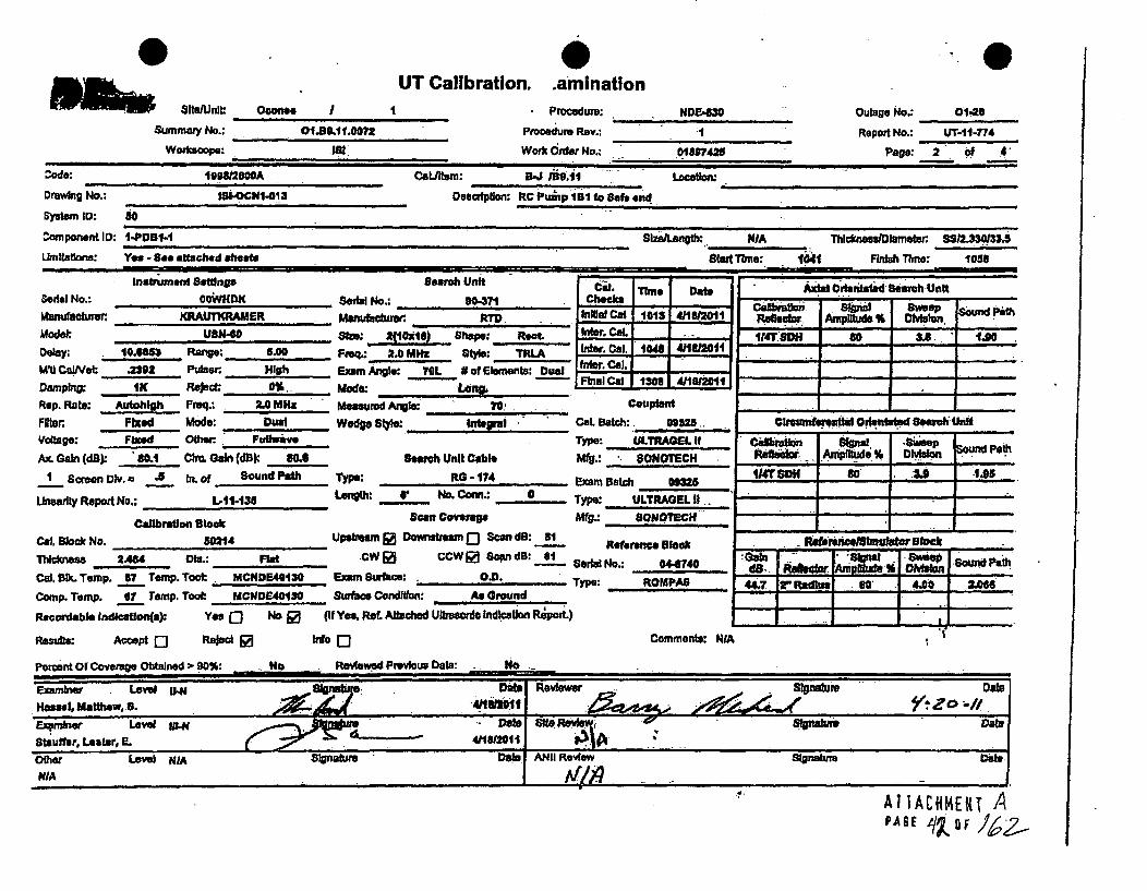
L nowtswUnit:
Summa•yNo.:
Wowkoope:
UT Calibration. aminationOconee I I
01.J3.11.0072
Procedure:
Pmoedura Rev.:
Work Order No.:
N0E430 Outage No.: 0140
Report No.: UT-11-774
Page: 2 of 4018974.25
:,Awe: 99/0BOOA Cat.lta: B 9.1 -Locatl
Drawkig No.: ISI-OCN1-013 Doslepitlo: RC Puep iB1 to 8Saf end
System ID: to
Conponent 10: I-P DB-1 SlzsLA ngb:,. NIA Thtckes.i lametw 8S J033i
Umflatl. as: Yes -.8 attached ah6 S4 Fkfth Tkme: 1058. .. . .- . . .. - " : ,, , II I
I natrtument Beffings, search UniASerial No.: COWiNHK ~ o:CFl. Time Datb
___ _ __.e ChoksIktanutoture -KRAUTKRAMER ... aneM& _____. _____In___ _ G 1012e 411821121
Mod&.: uBN4o 8zo: URN-"16) Shape: Root. CalDelay: 10.6m Ra,.: .5.00 F'" 2.0 Mmz • '1.": Th•InterCal.io 4.1 11-IMt0 Calwet .22 -Pulsor Hieh Exam Angle: 70L 2 of Elements: Duel 5E Ca.-
D.rng:. 1K R* .- o,. Mo-e: FM al -I I
Rep. Rate: Auohigh Freq.: 2.0 MHz Mesurd Angle: 70' Couptant
Fn Fixed Mode: Dual Wedge SW1$: Int.rfl CaL Botch:. 09325..Voltage: Fted Othw. Fuihwarve Type: ULTRAGEL ItAx. Gain (dB) 80.1 Chu Gain (dB) 80.G S atach Unit Cable Mfg.: SONOTECH
I Sceen Div.= -5 hi. of Sound P•dh Type: RG -174 Exam Batch 0125
Linealty Rpopd No.: L.11413 LOngth: v No. CoMr.: __,,_0, Type: ULTRAGEL If..
Calradon Block Sao Coverage WO.: sONOTECl
Cal. lmoc No. 50f14 Upstram ] Downstream 0 Scan do: al et...c. , k
lclumas 2404 Mie.: Flat CW 0 CCW j Scan. dB: 81 Serhd No.: 0441740
Cal. 9lk. Temp. _7 Temp. Toot: MCNDE40130 Exam 8urhci: O.D. Type: ROMPAB
Comp. Temp. 67! Temp. Took: MCNDE40130 Surfla Condi•.on: As Ground
Recordable Indication(s): Yes Q No [ (if Yes, ReL. Attached Ultrasonic IndIcaltlon Rýpol)
Resuls: Accept 0 "Aed S no [3 Comments: NIA
+ • , ,, + J .
Axial CrtaritatsdSearoh Unit
RbtrAmpl~tude ' I= DivisionIIT O to 88 1.00
Clreumfersuttul Orlutitatad SeaeI~ UnItV . V - Y -
CwbrctwnResebbxd Am~DI n Sound Pelth
t .. -
it" DMH 'an I. .U -1.25
- , .
I If0 M44.__ IZmml IZ, ZIZ=.o
.4.
AIIACHMEKT APAGE 41~ oF

0 ... 0DUKE POWER COMPANY
ISI LIMITATION REPORT
Component/Weld ID: 1-PDBI-1 item No: =9.oI1.:L0072: remAri:
[ NO SCAN sURFACE BEAM DIRECTION P•dealows scanningdfrot
QLIMITED SCAN 01 ] 2 0 1 0 2-[D cw S ccw castsdeonly.
FROM L N/A to L N/A INCHES FROM WO CL to Beyond
ANGLE: 0 0 0 45 0'60' o ther. 70L FROM 0 DEG to 360 DEG
0 NO SCAN SURFACE BEAM DIRECTION
0] UMITEDSCAN 0 1 0 2 0 1 [1 2 0-' cw 0_ ccw
FROM L to L INCHES FROM WO _ _ to -_ _
ANGLE: 0 03 45 ( 60 other FROM DEG to DEG
NO SCAN SURFACE BEAM DIRECTION
rl LIMITED SCAN 0 1 0 2 nI -0 2 0 cw f c cw
FROM L to L INCHES FROM WO ,to
ANGLE: 0 0 0 45 0 60 other FROM DEG to DEG
0l NO SCAN
0 LIMITED SCAN
*. SURF
01
ACE BEAM DIRECTION
0 2 0 1 -J 2 [' cw F ccw OT-11-774 A
FROM L to L'4
INCHES FROM WO to
DEG to DEG
Sketch(s) attached
0 yes O No
Sheet 3 of 4 I
olix. Date:.1
A11AtC4E.NTAPACE

Supplemental Report
'.0Report No.:
Page:
Summary No.: O1.B9.t1.0072
Examiner. Hiss ,,,Matw S. .. ._44 -
Examiner Stauffer, Lestr,.Offher: WMA
Level: WI-N
Level: Hi-NLevel: NIA
Reviewer.
:Ste Revew:"
.ANIIJReOWeO.ii
UT-11-774 .
4 of 4.
Date:
Date:
Comments.,
Sketch or Photo:
? /
s2.
?b2- tjr - LS~.
1
~slq,- ~
e0
A11ACHM~iL~PAGEq

0Wo,, Staunt
Summary No,:
Workscope:
0UT Calibratlojr aminatlon
O oconfee I ,
O1.C4.11.0029
iS8
Procedure:
Procedure Rev.:
Work Order No,:
PDI-t1T4 l-
01909569
Outage No.: 01-28
Report No-* UT-.11476pace: I of 7Page. 1 9!
Code:
Drawling No.:
System ID: 63A
Component ID: ILP-12640
Umiltatons: Yes - see at
19"842000A
ILP-P128
CatJltem: C-F-41/C5.11
Description: Reducer to Valve ILP.18 (Cast)
)aon:o
tached shoot
Sfzef,1ength NIA ThickneBa/Diameter: 1.16.1 12,000
Start Tbme: 1517 FInBh Time: 1543=
Instrument SetWng. Search Unit
Sertal No.: DOXI4L Seofal No.: 8E0708Mianufacturer: KRAUTKRA..R Manufacturer. , ,KModel: U8N4, Size: .5 Shape: RoundDelay; 5.4644 Range-. 3.. Freq.: .2 IAMl- style: .-Como .0MUI CaIeI: .1199 Pulser High Exm Angle: 45 #of E16FROMW SingleDamping: 1K Reolm* 01- Mode: ShearRep. Rate: Autohlo , Freq.: 2.25 MHz Measured Angle: 45 Couplarl
FIl.er Fixed Mode: PE Wedge Sl)fe: MSWQC Cal. Batch: DornVoltage: Fixed Other: Fulhvave Type: ULTRAGEL If
Ax. Gain (dB) 27.3 Circ. Gain (dS) 27.3 Search Unit Cable MIg.: SONOTECHI Scroen Div. a .3 in. of Sound Path Type: RG - 174 Exam Batch: 09326-
LUnearity Report No.: , L11-13t Length: 6 No. Conn.: .0 TYPO: ULTRAGEL iI
Calibration Blockt Scan Covmge Mfg.: SONOTECH
Cal. Blak No. 40413 Upstream 0 O0awbum Scan dB: 4.9 Reference Block
Thickness 1.125 0SD.a. 12 CW [ CCW @ Scan dB: 49 Serial No.: , .
Cal. BIk. Temp. 72 Tamp, Tool: MCNDE40I29 Exam Surface: 0.0. Type: Rompas
CoMp. rmIp. 8` Temp. Tool: MCt4DE4.,29. Surface Condition: As Ground
Recordable Indlcalon(s): Yea 0 NO [ (It Yea, Pea. Att•hed Ultrasonic Indication Report)
Results: Accept Q Reject [ Info 0 Comments: N/A
Percent Of Coverage Obtained > g0%: No Revlewed Previous Data: Yoa
Ch~mwam~flshIbI Oerfeetotea nrh Unit
R*11e6tor Akptitude #A Omaon
IDN6"c so 6.3 1.59
Raersrca)Slm=dtr BlackGobi Il~~ Swepim on Pt48 Refflfctor A~mpd *A Divison25.1 11"Radlus '80 3IA~ F
I'.
Examninar Level m Date Reviewer ~at rR On*oi Greg J. 21112011
Examirwnr Letve I1-M n Dat Side Review jASignature DateDa.John C. 271-12011 0____________A,_________
Other Level NIA ~ Slonsfrve" DaeANI" Date ý
PAGE q Q 1
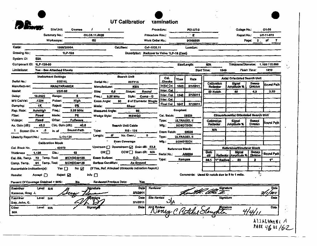
UUT Callbratior vamination
Slts/Unll: Oconee
Summary No.Workscope:
/ t
01I.C5.1110029
Procedure:
Procedure Rev.:
Work Order No.;
PDI-UT-2
S 010'09589
Outage No.: . 01-26
Report No. UT-11-875
Page: 2 . of 7tiS
Code: 1U9I0=00A CatAtem: C-F.ilC.1i Locatlon:
Drawing No.: ILP-128 Dasctlpion: Reducer to Valve ILP-1S (Cast)
System ID: 83A.
Component ID: 1LP-128-80 Size1enght: WfA- TckneassDlamwter. 1.165112.000
Lmlitations: Yes - See Attached Sheet Start Time: 1548 Finish Time: 1610Iii *. .. .. . --.
Inaftment Settlngs Search Unit Cal. Time Date Axial Orientated Search UnitS.. al l No.: 0OXI4L Seoral No.: 007Y13 Cho ciks - P .INManufacturer KRAUTKRAMER Manufacture KBA Iniltal C0 1503 211/2011t P1. Am d%. Dion
Model: USN-80 Sife: 0.5 Shape: Round -IIntero Cal.h. . .,... .. , Sie: O. .Sap: -'ID Noib.h. 60 4.3
Delay: 10.0522 Range: 6 Freq.: 2.25 MI~z Style: Comp - a Inter. Cal. 1545 2111'201
M'Ut Ca/Vel: .12i4 Purser: High Exam Angle: 60 aof Ereman gl Inter. Cal .
Damping: 1K Reject: 0%, Mode: Shear RFinl CaE 1647 21201
Rep. Rate; Aulohl Frnq.: 2.3 MHz Measured Ange: 60 Couplont -,-.-
Filter: Fixed Mode: PE Wedge Style: MSWQC Cal. Batch: 09325 CIrcumMerentIal Orlentatrd Search Unit'
Voltage: Fixed Other. Futhweve Type: ULTRAGEL II Cablj .fi Signal Sweep o P
Ax. Gain (dB) 45.5 Cio. G ain (dB)f 4i.5 Search Unit C able M ig.: .. ONOTE CH " . % DIvIsion . .... .
1 Screen Div. - .8 In. of Sound Path Type: RG - 174 EWN/A__ • . .. ~~Exam Batch: 03S,
Lewaty Report No.: L-11-1 31 Lenglh: -V No. Conn.: a Type: ULTRAGEL II
CibratJon Block " Scan Covervnge Mig.: . ONOTECH
Cal. okck No. -40413 Upstream 0 Downvebam 0 Scan dB: 53.8 Reference Block lbflt ul.or Bloack
Thlcknes 1.125 DIe.: 12 CW.] CCW Q Sc•n d: NIA Serwal No.: . m da" *5wj-- ' Pah
Cal. _Lk. Temp. 72 Temp. Tool: MCNDE4012B.. -ExamSu ac.,O.D. Type: RompaM 2,L1 1?.Raltus 80 2 -1-i
Comp. Temp. _81 Temp. Took: MCNDE4012O Surfaeo Condition:. As Ground.
Recordable Indication(s): Yea Q No & (if Yea, Reo. Attached Ultrsonic Indication Report.)
Results: Accept [J Reject 9 Info Q Comment.: Uoed ID notch due to 5 to I rWto.
Percent Of Coverage Obtaned 90%: No Reviewed Previous Oata: Yee.
Elx~inbwr Level g4N Anature Date Revikrv intrRansom, Greg J. 2".P20t.
ExamIner Level II-N o"eats ie Row Signature .
Day, John, C. 211/2011 AOther Level N/A SignN ove DlNIA
PASE q6 16-

Workscope:
UT Calibration~ xaftationOconee I*
01I.c6.1111ozg
Procedure:Procedure Rev.:
Work Order No.:
PDIJUT-2 Outage No.: 01-28
Report No.: UT-11-S7T
Page: 3 Of, T7818
Code: 119M/000A CaLl./am: C-F-ItC5.1t.1 Location:
Drawing No.: ILP-120 Description: Roducer to Valve lLP-18 (Cast)
System 10: .3A.
Component ID: ILP-128-80 .lz Lenglho llA, Thiclkees/Diameter . 1.1681 12.000
LmItatolanr: Yes - See Attached Shoots Start To.e: 1013 Fish Time: 6316
Insttument Settings Search Unit cal. Time Date Axial Orientated Search Unit
Serial No.: oOX 14L Serial No.: 93 C hek s I Ca l o - ' Op- SSo und Pat
Manufcturer.. KRAUTKRAMER Manufacturer ,RID rrdllJ Cal 1504 V112011 Reflector Amplitude % Division
Model: USN-60 Stre: 2 (10xi8) Shape: Rectangle ,Inter.L Cl. - 314 SdH 8 6.5 2A73
Delay:, 9.6303 Range: ." Freq-.. 2.0 Ml Stylae: TRL2 n Cal. 1812 21112011...•' ~ ~~Inter. C al.'- '"M 'i C a t i e ld : . 23 0 2 P u l v er : H i g h E xa-• m A n g le : 00 0 o f E m le r e t s: ; 1 1 F ina l .C, a l.
-... •-- FFinal Col 1648- 2/112011"Damping; IK Reject. 0% Made: Lon.. -_4 2
Rep. Rate: Auohigh Frq.: 2 MHz Measured Angle: 6' - Cp. co______
Filter. Fixed Mode: oail Wedge Style: Integral Cal. eatch: 09325 C.Ircuuftrsnital Orlentated Search Unit
Voltage: Fixed Othe. Fulfwave Type: ULTRAGEL II Catibatlon Signal Sweep Sound Path
Ax. Gain (dB) 76.5 Circ. Gain (dB) 76.5 Searoh Unit Cable Mfg.: SONOTECH RefIoI .r Am plide. % Division .
I scren Div.= .5 In. of Sound Path Type: RG -. 74 Exam Bc: ' .A 4....
Unesrtly Report No.: L-SI-131 . Length: 11 No. Conn.: 0 Type:, ULTRAGELU . ..-
Calibration B1lack scan Coverage Mfg.: BSONO•,ECH -..-
Cal. Block No, 40413 Upstream 0 Downreiam R) Scan d8: 76.5 Referenen Block Refoenowellmulator BlockTh,,,,es 1.125 De..: 12 ow 0 CCWO Scan dB: WiA an fignal SwepO Sound PathCaL BIk. Temp. 7.2 Temp. Tool; MCNDE40i29 Exam Surface: OeJ). Tr Romp.:, 53.1.. V Radefue - d0 2 st"
Comp. Temp. 81_ Temp, Tool: MCNDE4012e Surface Condw : As Ground
Recordable .ndleaton(a): yes Q No (if Yes, Rot. Attached Ultrasonic Indication Repor.)
Results: Accept [J Reject 0 Info Q Comments: Used ID not.h due to S to I ratio.
Percent Of Coverage Obtained > 90%. N.o. Re.iwd Previous Date: Y.,
Examiner Level lI-N Signature Date R"w . S.gnatureate
Ransom, Greg,' J. . --
Examiner Level U-N' Dýt .. s.. Review Signature Date
D'-6 John. C. 2•112011 4A
Other Lavel NIA- 0ate ANqP Aw , c jk F s reDateNIA 6!h(K( ~ /~
VI.# AIIAýHMEHI APAGE OF

DUKE POWER COMPANY
ISI LIMITATION REPORT
Component/Weld ID: ILP-128-80 Item No: O1.C5.11.0029 remarks:
NO SCAN SURFACE BEAM DIRECTION Due to valve configuration
i LIMITED SCAN [j 1 0 2 0 1 [1 2 El cW Z CCW (Cast material)
FROM L N/A to L N/A INCHES FROM WO CL to Beyond 1-LP-18 Valve
ANGLE: El 0 0 45 9 60 other FROM 0 DEG to 360 DEG
El NO SCAN SURFACE BEAM DIRECTION
-]LIMITED SCAN El- 1 2 l1 [ 2 i- cw ]ccw
FROM L to L INCHES FROM WO to
ANGLE: E] 0 Ei 45 El 60 other FROM DEG to DEG
-' NO SCAN SURFACE BEAM DIRECTION
-iLIMITED SCANý EL 1 [3 2 -] 1 E] 2 [] cw n ccw
FROM L to L INCHES FROM WO to
ANGLE: E] 0 [] 45 Ci 60 other FROM DEG to DEG
Li NO SCAN SURFACE BEAM DIRECTION
Li LIMITED SCAN El 1 El 2 Li1 -IL 2 Li cw i ccw UT-11-675
FROM L to. L INCHES FROM WO to Sketch(s) attached
ANGLE: L] 0 L] 45 Li 60 other FROM DEG to DEG DE yes i No
Prepared By: Gregor Ransom . , gje I: 11 Date: 02/01/11 Sheet 4 of 7
Reviewed By: ý72 Dale:sp~o~
VLv
a;

0SportSupplemer
Report No.: UT-s .- 75
Page: 5 of 7)
Summary No.: O1.CS.11.0029
Examiner Ransom. Greg J. A
ExamIner: Dn Jahii C. (Other: WA A,
Level: 1144
Level: I1-M
Level: N/A
Raviewer
Site Review:
ANII Review,
-A I
U
Date:
Date:
Date:Ii 2
Comments: I LP-12-8.0Scale I to I
Sketch or Photo: CtS-t Valve-. (51.)IL?-O31
?i~?E (:5 )
.... i
1*.,|
AITACHMENTPAGE qj fF 4

wfflupSupplemernt.. Report
Report No.: UT-11-675
Page: 6 of 7
Summary No.: Ot.C5.11.0029
Examiner: Ransom, Greg. J
Examiner: Day, John. C.
Other: MIA.
Level: Il-N
Level. U-NLevel: WA
Reviewer:
Site Review:
ANII Review:Ih7JA A
Date:
Dale:
Comments: ILP-128-80
Sketch or Photo:
f/socxJ1-elpf'-st 1
I
I+'I+
AtTACKK~ER APAGE OF
~ /gZ3

0 MIhMMM
Determination of PI UT Examinl
ercent Coverage forations - Pipe
PDI-UT-2 Outage No.- 01-28 6 a
E Report No.: UT-11475
01909569 Page: 7 of 7
11Site/Unit Oconee I
Summary No.: O1.C5.11.0029
Worksoope: 11
Procedure:
Procedure Rev.:
Work Order No.:
Scan 1
Scan 2
Scan 3
Scan 4
% Length X
% Length X
100.000 % Length X 50.000
100.000 % Length X 50.000
% volume of length• 100 d
% volume of length 1100 =
% volume of length 1100 =
% volume of length 1100
_____ _..%totalforScan I
% total for Scan 2
50.000 % total for Scan 3
60.000 % total for Scan 4
Add totals and divide by # scans.P 50.000 % total for 45 dog
Other dog - 60 (to be used for supplemental scans)
The data to be Usted below Is for coverage that was not obtained with the 45 dog scans.
t.,
Scan 1
Scan 2
Scan 3
Scan 4
100.000 % Length X 50.000 % volume of length 1100a 50,000 %total for Scan I
100.000 % Length X 0.000 % Volume of length 1100= 0,000 % total for Scan 2
% Length X % volume of length 1100 _ _ % total for Scan 3
_ _ _ % Length X % volue of Wngth100= I. ... % total for Scan 4
-Percent~cormv~ste goyerage
Add totals for each scan required and divide by # of scars to deterrnne;
37.500 % Total for complete exam
Site Field Supervisor S~teFiel Suprvist 1a TjZR I-Zott

0
Swnmmay No.-
Woarscope:
UT Calibration.,•aminationDoon.. J Procedure:
Pmeedure Rev.:
Work Ontf No--
view"r.
Outage No-* 01-26
Report No.: Lrrf.1.60
Page: 1 of aCode: IIIa/IOOOA :, CaL/Iem•: C..P.1fC8.11 L.nuauou___________________
ODaWng No.: IP0400 Descdptlon: Flow Resi1oor to Pipe
System ID: 33A
Component ID: ILP-201-17 WSe : WA Thiclesamefet 88/1.0110.0
UmItatlona: Ya -See aotached aheata Sta Time: 1232 Fb*h Thie: 1401
Insrumen Settings Search Unit Cal Tl* Oa Aidt Otr.ntad 8b Un*, ,Se•u•al f.: POX14L. so,,ia " ".Pj2 al Ca.ahrw. BWi -wee -Manufacturer. KRAUTKCRAMUR Manufacturer: KSA -Wv -95 414__ -d~ n~tbS Dao owPt
Delay. 495 Raa: - "req.: 2 -- " MlX awe. Ca Ina, C0L 1230 4M612011 -
Ml! CaIVaI: .111 Putter~ High Exmi Ardis: 46 Dof Elements: Il~ngli Inter. -i q
Damping: 1K Reject 0,. Mode: shut lo]4--1-
Rap. Ratw Aual Frsq. 2.201Mft Mezawuredlge; 48 Couplant ____ ___
Filter. Fixied Made: PE Wedge SW MSWQC Cal. Batch own Cr•_umbrfentla Orleintatsd Samh Unit
Voltage: Fblxd Other FtdIvm Type: ULTRA. UL U Caftreow ! gt " Swe e Path
Ax. Gain (dB)ý MIA CW& Gain (ft) 27.7 Search Unit Cable Mg: SONOTOECH Re~eoio Anipfltd. 1A. DMain
Isorean 01Y. h 2 i.ot Sound Path -Type: RO -.174 illt No1 tch so.... ... iL. I!L,ineafty Repor No.: L41.137 Langthv., N@, on. .Cn- --0 Type, ULTRAE.L Ii
Sclibrain Bo an Covereg. Mt., SON.OECH - -i -
CaL lOC co PNOUT.Q Upstram 0 Downstream Q Scan dB: WA Reference Sl.r9
Thickness .00.2.2 . Fla dw@ CCW1 8ndB: 34.8 Gab "1" PC aL BIk. Temp. 72 Temp. Toot. MCNDE40I30 Exam Surfaoe: . . O.. "y.: 04P74 2*7 IV. 8 4 .
comp. Temp. 7. Temp. Tool: U•CMQD4180 Swti CondWon: As Ground
Recordable lndloatlon(s): Ye Q No ( (if Y• Fl.a Attached Ul•,mr , Indjcan Re,.)
Reocm.: Acoept Q Raject. ino 3 Commenta. WA
PeFrent of Fo= . a•hwO.. . o,-.: .... 00:_ No ...ed'P.ul.. Yei
E,,ie LOW . . _, D•ate.Mul. ,W. Keldh. .. ' • .. : .r,) ... 4/.1612011 ~ •.. / /• • " ,/ •.•. i
, " iMathw.U
,WA- .a

8ftm/unl
Summary N.
Woriccacpe.
UT Calibration,- amlnationOconee I I
01.CS.1l.0014
is;
Procedure:
Ppxedwr Rev--
Work Order No0.:
P~l-Ul.-.
018077$4
Outage No.: 01•26
Report No.: UT-I 1.780
Pas: 2 of a
Code: 19twm200 Catiltem: C-F-1/C.II 1
'ravhig Ho.: ILP-209 De"Drdptlitlo Flow Re.Uitctor to Pipe
System ;O: OMA
ComponentlD ILP4-W-7 8b*Aeigt: ,IA Twmassolumeter S810.0fl
Lkmflatiom- Yes - See attached shoets._______ Startmfme: .123* Flnluh Tbne: 1401
.t...ment sett i ng Search unit_______Cal TIims DtebII4~fh
BMWial No.: 0OXt4L Ser'al No.: IFlJ0 Checks - Ibr_ m .. .. '.4 Sweepat.menufadtUner KRAUTKRANElt Ausoturenr- KIA lml 0 Cal 0013 41161201 ___________ ____________ ____ MelonModel: UaN-O ________gap&. Inter. COL __ - ImNth 8 *DIIIy? Round Weg Fe.2.5M..S) Cal. 1311 - - -14.._ C am p -. , 2 O_ _ _ 4I J1 Inter. _ _ _M. CaW*l: .,A1u Pu. n Ih .Em, Anlo!. 6o #of Elements: S ingl, D,..S- _.- l_ __ _.t'__, -
Damping: 1K Reject 0% MoeShear 16AAi~.____Rp. t* p A u~tft Fmeq-1 2.25 MHz - Measurd Angle:. Il6 _______ -
Feat, Fbtd mode: PS Wefts 8I4,.: mSWQC Cal•.Batch: .00=1 .10et0m•ffia1 o+4dOala Search UnitVollege: FbK.d OtWr Fuilwave TYWo: ULTRAQEL 9 cam"Gasion. :Sigh'l SteepAx. Gain (d0) 41.9 Chu. Gain ( 'dB) NIA Search U'ft Cable Mig.: SONOTECH R"I"e+." A pibade • , 04- P •I PlSou at
Scree Dly. = J3 In. of Sound Pafh Type:~ RO. .174 Exa Bac 0=8g -WA ___
Linearity Repod No... Lo-11.137 Laegth: -1 No. CoWL.: 9_ Type: ULTWAGL II . -•-
Calibration Block so ovrg MWg. SONOTECH _ _ _ _ _ _ _ _ _ _ _Cal. Bluk No. __ Upelr Qo wnstram D e Scan, oB" 51.1
ThIckness .50.2. De.: Flat OWO CCWQ Scan B: MIA Qf lw.......- Sal No.: 0...141 Soud PCaL+.V Tw.,'p.--73 Tam', To'* MCMDE401. .., n S,,., w.+, o.D. f, ot•• +bi,, % . ,f" rl
Comp. T•mp. 76 Temp. Tool: MCNDBE4OIZO Surface ondWon: As dround -
Recordable fIdlcetion(s: Yes Q No 0 (tf Yes. Rat. Attached utrasonc Indleulion Report.) 1.Results AcceptQ e &aJe Int 0o Comments: NIA
Peret, O f CoverggoObained 3. go%: No Reviewed Previos Datl: Yea
Uwnb"Aw Level 114i Signaturs aeeBasal. Matthew. S. mlOthe Letvl WdA 13;. IT 10h*1'sDaWlA
i i i I l i Ii• l _ _ i Ii ii iiii i I .A h 4 l
A IPAGE,ý

IUT Calibratlor1 . -.AaIMlnatlon
Surnmary No.:Wottcacpe.:
Ocoeen I Procedure
Procdure Rev.:
Work Order No.:
PVI4IT4 -.
a@1907784
Outage No.: 0125i
Report No-, U~T-1-780
Pap; 3 of .6
Drawbn No.: 11.11209 o~sscdption: Flow RelrMator to PipeSystam ID: 63A
Componient I0: 1LP400-1W7 stwu~nglh IVA: Thomlne~fas tar~ 6811.C010*
Limitations: Yes - Sea attached aheata Start TIMe: 42123* PFrileTlmnw 1401
Ins.buwht Sat .4 tsearch Uncat. ISeial No.: 1OXl4L Seral No.: ,3-s , Checks -i ode
Mauwue RUKAE Y Jinida Cal 1000 d'lM81011
Modek USN.8O Sie: g(1@a lh Shape: Ral. _ Inter. Cal. -
Dley. G.456 Range: 3 Freq. to MHz a" 't* 7KL2 lft*CL1141121MU CIveI: .11 PuLsa. Hig Apgl: 0 o Elements: Due] -
Darnptng I K Reject 0% Modez Lon~g. LLU 164 111120
Rep. Rawe Lath. 2 MHZ Measured Anale: ________Cul
Fl~tor. Pied Mode: Dual. Wedge St.a: gteg!md CaL Baitch: .- 2 ,Vetting: Moxd Ofliet Fuliweve .Type: ULLTRAGEL II.Ax. Gean (di): 66.1 Clo. Gain (dO):. H/A seach Unit Cable Mfg.: SONiOTECH
I Sceen DIv. = .3 In. of Sound Pai Type: RG - 174. Exam BatSh 09)25
Lineadly Report No.: L-11 1a? Length 6' fot COan- 0 Type:. ULTRAGEI U
CUbr#•n Sloek Scan Coverae Mf SONOTECH
CaL Block No. PDM-IT. Upstream 0 Downstream 0 am do: 72.5Thcnu .L0 Diu.: 0101___ CWQ( CCWQ0Sam dg:VA
_________ lat - Serfia -N.: 044741Cal. 81k. Temp. 73M Temp. Took. MCN0E40130 Exam Su•toe; , O.D. Tywe ROMPAS
Comp. Temp. 71 Temp. Too: MCNDR40130. Surfne Oondllow As Ground
Recordable Indliatlon(s): Yes Q No R (If Yesa Reo. Afsa11ed Ultrasonlo Irndonal Report.)
Resulle: Accept Q Rejec 0 Info Q Comments: NiA
Percent of Coverage Obtained 2- 00%: No -Reiewud Preious Deba: y
Ob Ation l Oretae Soweep U rd
r Ifftsb so 7.1 .2m3:
C==.fWeuhuAW ffhja0le~Wd Stiirh Unit
Cabrfalsm slw 'l-Re Artr ofAm lsld 5 do D tundfceh
WA _____
ReftitareeJlft ijtst Stock-
L80fb I` s lmh
I III I I • I I
1 .443 In h"S".004
4
PASE <bjaf~z

DUKE POWER COMPANYISI LIMITATION REPORT
ComponentlWeld ID: ILP-209-17 ?tm No-, 0145AL0084 remarks:
0 NO $CAN SURFACE BEAM DIRECTION Due to valve conflguraton
*0 LIMITED SCAN 011 02 0 1 02 (3 ew 0 =w cu tra F wRsMIvm
FROM L NIA to L N/A INCHES FROM WO CL to Beyond._....___,_,-,
ANGLE: 0 0 0 45 0•0 other FROM 0 DEGto 360 DEG
C NO SCAN SURFACE BEAM DIRECTION
]LIMITED SCAN 01 0 2 0 1 0 2O0 cw ___ tow
FROM L to L INCHES FROM WO .... _. to*
ANGLF- [00 o Q45 ]60 other FROM DEG to DEG
O NO SCAN SURFACE BEAM DIRECTION .....
-LIMITED SCAN 01 0 [12 0 1 2 cw0 cow ca
FROM L to L_____ INCHES FROM WO to o ...__
ANGLE: [ 0 0 45 [3 60 other FROM DEG to DEG
u?
0 NO SCAN
0 LIMITED SCAN
SURFACE
010 2
BEAM DIRECTION
03 02 O cwEow ~u'r-i 1-700
Sketch(s) attachedFROM L toL INCHES FROM WO to -
4ANGLE: 000 _6 60
VATIACHMENT APASE S T F) .

0 0Supplemental Report
Report No.:
Page:
Summary No,: O1.CS.11.0084
Examiw: Bugl, W. Kelth eval U.
Examlner .1a aIltrnw S Level:O0W. NA Level., VA
Reviewer. .
ANII Review.
UT-11.780
6 of 6
Date: .
Comments:
Sketch or Photo.
(ALOYRNJrkao.'S.i.t
.9
B• -" •
i
.9j. i1 .
VACOAtME~FASE.5's OF,

IDetermination of Percent Coverage foIeM .UT Examinations - Pipe
OLRZ:: 6 Of6* SItoUnfit OconeelI I
Summrnay No.: 01.C5.11.0094
Worikscope: t51
Procedure:
Procedure Rev.:
Work Order No.:
PDWT-2
E4`189T/64
Scan I % LengthX, % volume of leripgt 100 = % total for Scan 1
Scan 2 % Length X % vokune of length 100 _ % total for Scan 2
Scan 3 100.000 % Length X 50.000 % volume of length! 100 D 50.000 % total for Scan 3
Scan 4 100.000 % LengthX 50.000 %volume of length 1100 50.000 % tot1 for Scan 4
Add totals and divide by S scans = 50.000 % total for 45 deg
other-den - 60 (to be used for supplemental scans)
The data to be listed below is for coverage that was not obtained with the 45 deg scans.
Scant
Scan 2
Scan 3
Scan 4
100.000 % Length X 50.000 % volume of length 1100 = .50.000 % total for Scan I
100.000 % Lengh X 0.000 % volume of lejh 1l100 = 0.000 %totalforScan2
% Length X % volume oftength 1100 = % total for Scan 3
% Length X % volume oflength 1100 = % total for Scan 4
Poent coniolete, coverage
Add totals for each scan required and dMde by # of scans to determine;
37.500 % Total for complete exam
SAtD Field Supwviscr __________________ Date:

E.--A
n, '!k ; . . * 3. .& I1h.dU M . : . % .' ..;' . . :. s . iZ*. 17 77
-," -.-k -
.-~ I -~,Y __u bum ~
Ho.. :OOIX~U.. - Cii
WON .. .L__itT
.La
I~bad ~ ________IT.
4. A404 ZS ~ ~ .4 -. f -7
- - ~ -
I pa~.
-~5--~ -c- -
I -
I I .. .w..* --I.C,.
€..
.. . . . ... ..... .. .. .. ... . -&
11 ~ 6 -Haso 11I3
i
. . .. ..1 _ _ Li -•,;'• •" •
... j~
Cii~ .. .- ~rn4r4.o'~L - ' a~G am~~ da w"
T___ ca~a.___~7'~~ ~.Te~'T~b~'UCID~O38. ~jj'* _______PAS_
t!AL____ ___ ___ ~ IJ~Iawcon~R;.7
"a Yh Taa~. ta- MCOE IS & Aada'~POMM 5 '~Ua~ a r
:YM.
PtnOc~9u~~%~. H.~ -.-. , ~ ... >~ '~..~ ~.-'
A.3.
4 - .. , * -. I
.~~3 9
M/62-

...SýI * .-.- *;SOL
UI W, . u-&-v A 10 91
-FS-
s~t~u~..........ox14L. ...........~
~a~in . ~ ____ - q* Lin,
_______________...up' ..
Vql~~~~p~WW S jfthuv~:& ~ -N W CPf _
-'gg-S WezýU A 7,
~~A2 -P.___ ___ __
y~q~. *W ~ f~SQ I4a~ ! . -i.hi.,
WAvau *O~4YC~L Bh~ -. .. -I-
, p.- 2.~ - 9.~f2.-.*j 4 DO#IN. ~t______ t__ V..1b~PaI .. :O .2JL ~. - - - - ~ p ~p aa ~ . .It~gamIAw.Fa~ r.Uyp mo7j
-~i
..'
...
p- __
W.71 srKs 4t
41.. .
, W7_
/A Z

*im*M5y I'"
41i~ * '4P.L9-u , - - - , ..- . ~~5.*~ bd ~ -, - - * .A .a- ~ -.--- ~ .~.j. -~ M E .
* . ~- IS~ h ~~AM*3__ _ _ __ _ _ _ 5 O154k
~ ~~!a .. 1K . 6,)~L ..~.~,~
ex. y.-- .. --- , . * -.- _ _ __
Fl~d .. Ott 7.i-ttal-
-~ . . ~fr4ii5~*4~JII B5poa~~ (9~ .~J Ck I~t $1A 6~u~aIJ~~I~ -~~ ONO W4d-V~-
LJOWIy R~p)4aJL4143 :r., - . -. L% t T .~ i~..
- *..~~ ... U b a 1 D 0qd~f. - 0 -. . A ýfn~lria
t nF;ara~. tsp vw "..Gram" $ OaT f.Y aacuCvomraa~*Toak~ .bCNV~40t3A ~ . _i443 w~j 3 *101
~~!Q#AZ rNmproa -7N4IO ~ M~ud ~ ' T.~
. ~ ~ ,. ~7* 4W. : * A%
£4WSI5.W ~gn~~~7z~-*,-o-!7viwiu~~i~.th -- ~. .' .~',.Nu
9WL=VoI 0
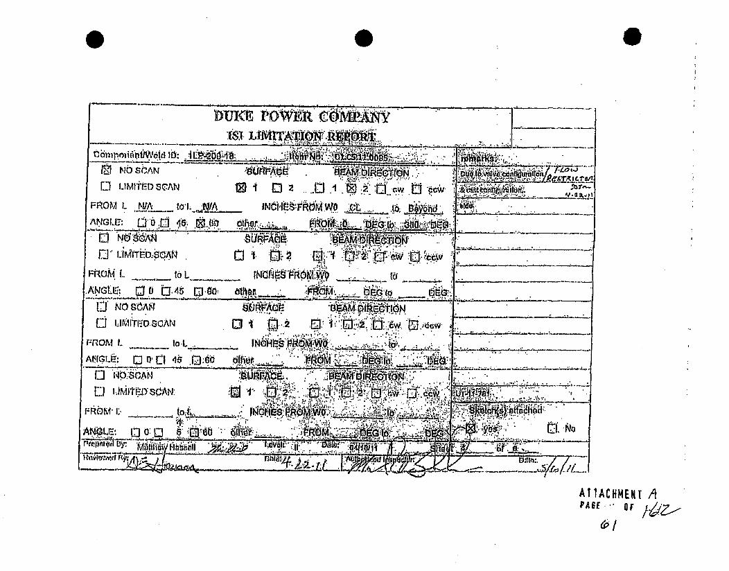
0
PANY _
":I --..---
1G1~tbN *.. ~ -' I
Z~. *t~ DM~bnd ~
~
__________ I3~ _______
~ -
~I~hoN2 U cv~ tJ
to'* ~ 4...~..Lv......
-.. ,r-r-..~ .~
* I .I..~ ~
* ~,*, *.. .~-~. ,*.
oar r Dflt~:.- - ~
AI1ACHMEKT APA6E * ~

9. I 0'
S~nZ4z;aLPti~
i Ai
1; KI-101i;r
4?e24~2~Zf /~'2~

4I>
so
'V.
¶ .i ft¼7~
S. 2
!.
.rbU~ :j'~"
q

SummaryNo.:
Worscopa
UT Calibratior OInationOconee I
O1405.21,0004
Procedre:
Procedure Rev.:
Wor" Order No.:
PDI.4T-2 -utg No.: 01-VIReport No.: UT-11-874
Page: I of a
Co.o: 1998/2000A CanlJltm: 1f-1/C5.21 Lowaion;
Drawing No.: 1HP-192 Deacdplqn: Pipe to Flange Orifice
System ID: 61A
Component iD: 1HP-192-t5 SleAength: W/A, ThiCCknOss/DaIunter 0.63114.0188
LlmllalJor: :Yes - e8e attched shoot StartTim•.:, 121 Finish l1me: 1233Settingsoeo.a U-i- - - . - -- - -- Inusnnt *Wng Swb Uit Cl. IM ateAxial Odritod Search Unit
Seral No.: .00X14L Scial No.: 8B0253 Choks .. Cai on SignalManutachoor KRAUTKRAMER ManuR cl-_..z 1 09 VeA01f Apn % Seone S___ath
Relco Amltd Diixo
Modal: USN-OG 45w Shape: Round Iner Cal 10otach so 4-___ M64
Delwy: 4.1701 Range: 1.00 Freq.: 2.20 MHz style; Comp O-G Cai. 1214 2/l-2011 -
MV CaJvel:- .1220 Pubser~ ______ in !Ahe j,4ý Io~eols Intler _____I
Damping: 1K ExJeca: Agd4 # 0heer ii J430 %2o1=1 '
Rep. Rate: Awtahigh Freq.: 2.26 MHz Measured Angle: 45 Couplant
FIJI: FiXed Mode: Re Wege SOW.: mBWQC Cal. Ba"ch: 00325 Clr"cumreaoal Oilentated Searcb Unit
Vollage: Fkied Owhe. Fullwarve Type: ULTRAGSL II Callbratol l Sig Sweep PlA. Gain (dB) 33.0 Ci ai (rB): 44.6 $iarth Urnt Cable Mt.: SONOTEC1H Reflector Amioltude lb DiMaon
_ sce_ Div. a .15 UL of sond PQ* Type: RG - 174 Exam Batch:; 09M - -
Unearity Report No.: .L-1-131 Laireh: V . No. CZo-. , 0, Type: ULTRAEL U -.-
Calibration Block Bean Coverage Mfg., SONOTECH -.-.
CaL BIock No. 4040 Up•lw a@l Downstream [] San dB: 49.9 Refreeonk lleaISl Black
T'hcknesa .531 Ula- 4 OW 0 CCW• ,Sanob: 4,. a. • o-- A09= GaS I Signal weep So•n Path
Camp.G Ter.a6Tmp. Tool: 14CM024412a Surface Condition: As GroundCal. 81k. Temp. 72.. Te~mp. Toad: M0ND840128 Exam Surface: .. .. Type: Romps. 21.5 diu 59 "5
R&cordable lndIaUonQPs): Yes Q No 0 (if Yea, Rot. Attached Ultrasonic Indication, Papout)
Reautts: Accept ) ReJect 2 info - Comment- IWA
Percont Of Coverago Obtained > 90%: No RPAvved PreIots DimI Y"
Examiner LI in n=--'bs D,4 Revie oe rCA-tog. . u
Ransom. Greg J.. V2=U2011
ExAminer Level Ont. Si Reew .Da.te • • D•Day, John, C. 2M11PP
Other Level NIA DabW ANI Date/k
V•APTACHENq yA I

OALZ Sita/Urdt:
Summary No.:
Wodscope:
UT Calibratior' 'iinationOconee "I
01.C5.211.0006
Procedure:
Procedure Rev.:
Work Order No.:
.- PD1-UT-2 Outage No.: 01-26
Report No.: UT-11474
Page: 2. of 901909573ISI
oo:192000A . .. cateltm: - C-F-11C5.21 Locaton
Dra~ng o.:IHP-192 Description: Pipe to Flange gOr~ce
system ID: I. ..
iComponen IM. IHP-192-15S SizelLength: WA Thlcknesalolameter: 0.63114.0IS8
Lmitations:. as - Soe Attached Sheets Stairt Time: 1308 Finsh Time. 1344
Instrument Settings Search Unit Ae- -
SeralNo: 0X11. Seia N.:cal. Time~ Date Axial Orientated Search UnithCaibration Signal Sweep Sound Path
Manufacturer: KRAUTKRAMER Manufacturer: GS Mal Cal 0933 2M1I2011 Reflector Ampikide % DivisionMoel .SI6 Inter.cCatModel: ., USH- . Sze: .26 Shape: Round ntr.Notch Tip 80 4 ,.85Delay. 7A500 Rae:: V _ Freq.: 226 MHz Stye: 2 -p . 6 Inter. Cal. 1304 2" , h_.. 'M'U CavelN . .1229 Puiser.. High - - Exam Angie: 60 #of Elements: Single Inter. Cal. -437___1/201 - -
Damping: 11K Rqect: 0% od:her- FalCl1437. 2111201111 1___
Rep. Rate: Autohigh Freq.: 2.25.MHz Measured Angle: 60 Couilant iJ-.Filter ..Fixed Mode: PE Wedge Style:, MWQC Cal. Batch: 09325 Circumferential Orientated Search UnitVoltage; Fixed Ote: Fullwave.. Type: ULTRAGEL II Caitxuiorn Signal Sweep
Ax. Gain (di) "8A4 Ckc. Gain (dB): MNA Search Unit Cable Mfg.: SONOTECH Redied" Amplikude % Division
1 Scemen Dlv. = .2 in. of Sound Path Type: RG - 174 .aNBA• ~Exam Batch: 09325 ..
ULneauty Report No.: L-11-131 Length: 61 No. Conr.: 0 Type: ULTkARAEL U
Calibralon Bloc-k 8Oe Coverage Mfg.:. SONOTECH
Cal. Block No. 40408 Upstram [a Downstream-n fJ Scan dB: 58A Reference Block Refrene/Slnutator Block
Thilcknoss .631 Dla.: 4 CW 0 CCW Q ftan d.: WA Sera No.: A0WA326 GB I Signal Ivý-P S. Path-al Seria Tamp.032 dB Relco AmpUlude Yo. Division
C_.01.Tep 2 Temp. Tool: MCMDE40129 Exam Surboo O2.D . Type: Rompa. ".3 1 80 5aii soComp. Temp. 70 Temp. Tool: MCHDE40129 Swuface Condition: As Oround
Recordable Indicat on(a): Yes [a No [ (If Yes. Re. Attached Ultrasonic Indication Report.)
Results: Accept Q Reject 0 Info 0 Comments MIA
Percent Of Coverage Obtalned > 90%: No Reviewed Previous Date: Yea
Examiner Level Il-N Signature Date ReviewerRansom, Greg J. 2/1V2011
Examiner Level U-.N Sinture Dat SkiteRivieW Sn DateDay, John. C. 21/2011
.... Leval WA S.atur. Data I .. . _ w ..... ..
'*1
PAGE(,

UT Calibratiom.-atnati on
PI ~Summary No.: oo.
Workaoope:
I IlOl.C621t.0000
Procedure:
Procedure Rev.:
Work Order No.:
PC[IUT-2, Outage No.: 01-26
Report No.: UT-11-674
Pap: :3 of 9m
0190i9573181 I
Code: .8$2000A Cat.Jtor: C..'.IJCO.21 Locatio:
Drawing No.: .HP-192 DescriptIon: Pipe to Fbinng O-rifice
System 10: G1A
Component ID: 18P-192-15 Sizetengft NIA ThacknosDiamter: 0.6j3114.0188
Limitations: " Yom - S50 Aitachod Sheets start Time: 1236: Finish Time: 1302
Instrumnt onISeaus seach UnitSoda! No.: DOX14L Sedal No.: 1042"8 .
Manufacturer.' CRAUTKRAMER -Manufacturer RTOModei USN-00 Sbwe !E71011144. Shape: Reot.Delay. 0.4031 RDng: 3 Fre.: 2.0 MHx Warle TPL 2MIU Cael~e: .2302 Pulve "Hi11 Exam Angle: 70 # of Bomnita: DulaDwnpbng: ix Reject~ 0%. Mde ogitop. Rate: Autohlgh FMQ.: a wha Meoasured Angi: To
FWrFbixd Mode: Dual Wedge 51$.: InteoralVoltag: Fixed COW.o Fuflwnvo
AjL Gain (d8): 50.6 CIro Gain (8): NIA searo UnIt Cable4 3. Sou... lnd Path Q-.,-A
Cho
Iimero'inter,
Intf..
Fnal
Cal. B
gype:
al. Tim.I Daleoak ka .
ICal 10141 2MIMI1.CaL
CaL ___
ICal 1435 I 21112o11
Gouplant
letch: 09328
ULTRAGEL If
SONOTECH
-- AxI*I Orientated Baarei Unltca to Sis SweepIBound Pathi
Reflecto Ampttuda % Divison
31450 80 s 3.9 1.174
cdkbmsoa siowa sweep W PahReflatdr' A04ilitude % Division
Rafnceffilmul~r lock
dR Aeflotor Amalie % ODvilonI -~r
Screen Div.~ a . 01. UI __________ Ir.-. - Exam Batch 90326
Unarity Repot No.: L-11-131 Lengdv " No. Conn.: 0 Type: ULTRAGEL ,
Cafbrator Black scan Coverage MfgJ. SONOTSCH .
Cal. Block No. 40406 Upstream D ownstream Q Scan dB: 59.8 t.n blckTnWidaw .631 Din. 4! CW- CCWC] ScandB: WA sarial No.: AG2
al. IL Tamp. 72 Tem•.o Tool: MCNDE40I29 Exam SurfAme: O.D Type: ROm~Sa.
Comp. Temp. 70 Temp. Tool: MCNDE40129- Surace Condrl on: As Ground
Reor.dable Indication(s): Yes Q No 2; (11 Yes, Reo. Attached Ultrasaoda Indication Repb.L)
Results: Accept Q Reject 2 Inf0 Q Commenta: NSA
Percent Of Coverage Obtained , 90%: *9 Revieoied PMWAvl Dowm Ye,--
46.6 II RadluL so 3A 1.
'AT 1ACIIMEH APAGEýýOF/
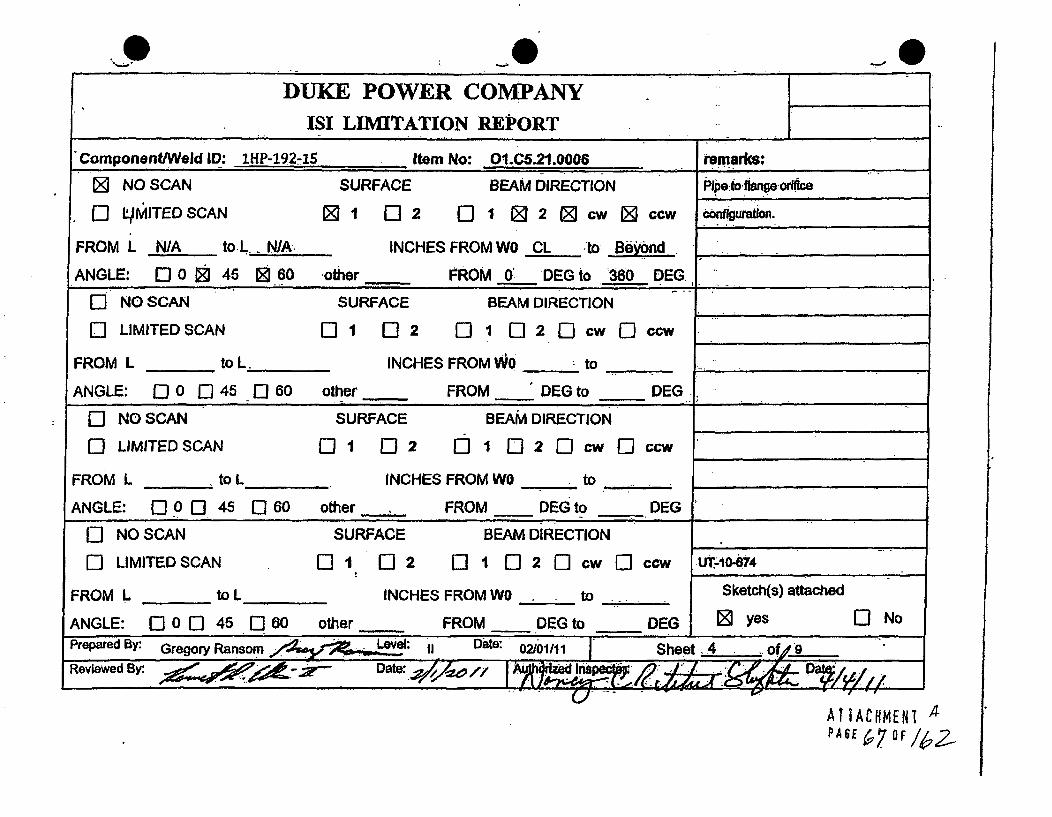
DUKE POWER COMPANY
ISI LIMITATION REPORT
Component/Weld ID: IHP-192-15 ,Item No: OI.C5.21.0006 remarks:
[ NO SCAN SURFACE BEAM DIRECTION Pipe to.flange orice
OL;MITEDSCAN 0 -1 2 01 2 cw 3 ccw C0rfiguratIon.
FROM L N/A to.L , N/A. INCHES FROM WO CL ,to Beyond -
ANGLE: [ 0 0 45 1060 other FROM 0' DEG to ý360 DEG. __
[O NO SCAN SURFACE BEAM DIRECTION
"LIMITED SCAN i 1 E] 2 0 1 - 2 0 c ccw E_ _ _ _ _
FROM L _ to L. INCHES FROM WO _ to __
ANGLE: 0j 0 0 45 0] 60 other FROM DEG to D__ EG.'
0] NO SCAN SURFACE BEAM DIRECTION
ULIMITED SCAN 0 1 E] 2 ] 1 El 2 EIl cw E3 ccw _
FROM L to L INCHES FROM WO to
ANGLE: 0 0 0 45 C] 60 other FROM DEG to DEG
I- NO SCAN SURFACE BEAM DIRECTION
-ILIMITED SCAN l 02 ] 1 EI 2 l cw - ccw UT-10-674
FROM L to L INCHES FROM WO to .... Sketch(s) attached
ANGLE: 0 0 45 0 60 other FROM __DEG to DEG 0 yes 0] No
Prepared By: Gregory Ransom L: . Date: 02101/11 Sheet 4 of 9.."
Reviewed By: DI &_
u- I -I
ATIACOMENI 4•PAE7 OF /62-

aL.AweI Supplemk-'aaportReport No.: __
Page: 6 of 9
SUMMaiy NO.: O1.C5.217Jw4
Examiiner "ansm. OraExaminer: Day Jhn, C.
Other NJA V,Ill
I I I I
LeveJ: IM-N
Level: 11-4.
Level: WA
Reviewer.
Site Review:
ANII Review:
balk
AU
Date:Date:
Comments: (Scale I to 1) Weld 1HP-192-15
Sketch or Photo:
SUA.AcE 2- I FLAA/6--E
,l/0 StLA4/;
ATTACtkth, APAGE69 rlg

9
sh.2I!_ _,rqMFAP_
SuppJeme.-A Rport Report No.: UT;-'4
Page: 6 of 0
Summary No.: O1.C5.21.0006
Examiner: RPsnom, G1eg J.
Examiner: Day, John, C.
Other WA
Level: Wi-N
Level:
Level:, NIA-
Reviewer:
Site Review'.
ANII Review:
-Date.
Date.oat ,
Comments:
Sketch or Photo:
B[F s i)
/VO ELC"AN
AIIACHMENT APA61 6c1 OFI&I2,

SupploniL.., ..aseport Repod No.: _U 4-11
Page: 7 of 9
Summary No.: O1,C5.21.0o06
Examiner Ransom, Grog J.
Examner.: Day, Jn, C.Other:, NA ....
Level: l.-N
Level: 014Level: WA
Reviewer
Site Review; 1 ) ' ~ '/ANDI Review"..u
Date:
Date:
DOWe
Comments: Weld I MP-192-15indication #1 was determined to be a geometric reflector due to I.D. weld root goorn•. "his was determined using higher angles and plotifg.
T-Iý Zý IJt ii &.r=-sl.)Setch ar Photo:
61f 0-SR
I.. Adddm~ - 8~ - ~Rom ~
*1
A1IACHMEKt A

Gut- Determination of Percent Coverage foUT Examinations - Pipe
r •Lq.
Outage No.: 01-28
Report No.: UT-111-874 '
Page: a of 9
Site/Unit Oconee I 1
Summa,y No*: 01.1.0.2110006
Workscope: ISI
Procedure:
Procedure Rev.:
Work Order No.:
PDI-UT-2
E
01909573
Scan I
Scan 2
Scan 3
Scan 4
% Length X % volume oflength I00 I DO % total for Scan 1
% Length X % volume oflenlgth I0 I . .. % total for Scan 2
100.000 % Length X 50.000 % volume of length / 100 - 50.000 % total for Scan 3
100.000 %Length X 50.000 % volume of length /100 = 50.000 % total for Scan 4
Add totals and divide by 9 scans: 50.000 % toted for 45 dog
0Other deo - 60 (to be used for supplemental scans)
The data to be listed below Is for coverage that was not obtained with the 45 deg scans.
Scan 1 100.000 % Length X 0.000 % volume of length/ 100 =
Scan 2 100.000 % Length X 50.000 % volume of length 1100 =
Scan 3 % Length X % volume of length 1100 =
Scan4_ % Length X % volume of length 1100 =
Percent complete coverage
Add totals-for each scan required and divide by# of scans to determine;
37.500 % Total for coinplete exam
0.000 % total for Scan 1
50.000 % total for Scan 2
% total for Scan 3
% total for Scan 4
Site Field Supervisor: Date:
0)
L • ._... . .. .............. ,S . .... ., . .- "--"'.,•,.i_• ;;€ _

Ultrasonic Imlaication Report" ~Sita/UnIL:
Summary No.:
Workscope:
- I.1
O1-C5.21.0006Procedure: PQI-UT-2
Procedure Rev.- _,
Work Order No.: 01909573
Outage.No.: 01-26 .
Report No.: UT-I 1-674
Page: 9 of 9
*,Il W2
Examinor' Level IINSignatureDaeRvwrSinte' Ransom, Greg J. 2/112011
Examiner Level rDNd Sie Review Signature DateDay, John, C. W11201 SAeRveOther LeVel N/A hIM. . . ANIRfvew e
-A11A*MEm A.te
PAGEo OF

I..
I..,.
* 1'
.1
I:,
F
UT Callbratiork.--,xaminationlww-Sgt$iUi~Oat.
Summary No.:
Worksocopo.:
/
01 .CS,2l .0024
'SI
Procediue: PVI-UT-2
Procedure Rev.: 5.
Wa•t Order No.: 01i0,579 -
Outage No.: 01-25
Rep•rt No.: UT-11476
Pag: 0 of S
Code; 19 ....... i C-F-k... 21 Location:
Drawing tNo.: . .S1A-01(3) Desordllon: Pipe to Vave t1HP.12.8
System 1I: SlA
Component ID: '1.61 A-0141A -SizalLength. WA Thickcasss/tsmeieýs 0.631,14Ai 88
LUmIwtaons: Yes - See attached sheot Slart Time: 101 Finish Tinme: 1021
Instrument B,,ahs Gearc Unit - -Cal. |Time iDab1 AiIJ D.,entaod Searchl-i, U ____
Sefla No-, 00X14L. Serial No.: B80203 Chocks :- ....Initial________ Chuck. oja ... . Ctlbiation Signa SM"eep at
Manufacturer KRAUTKRAfMER Mauatumn. KRA'- __ Reflector Ampiltade % Daivsoo
Model: USN.60 Sime: .25 Shape: Round t H1atch so SA .57-
Delay. 4.0688 Rango: 2 Fr. .2 ,s ,MHz Style: Camp - Inter.c Ca, 100 "21812011
M'T CaWal: .A224 Pulaor ~ Himh Earn Angle: 4. a of Elements: Sigal~-Damnping: 1K Reject: 0% Mode:10 2111_ _
Rep. Rate: Autaobigh Freq:. 2.25 MHZ M easured Anglel. 46, Couplant _- __ ._
Fater. Flixed Mode: Pa. Wedge Sty*:, MSWQC Cal. Batch: 00325 CkcnnfMndal aientated Seach UnitVoltage: Fixad Other Puliwave Type: ULTRAGL u ýCatb"e*o Signal Swee"Ax. Gain (4B): 34.5 CIr. Gain (d0 , 4V.7 Search Unit Cable Mig.: SONOTECH. RloleOd Ampladle % Division ound Path
i Scren Div. - .2 In. of !" Sound Path Type: R. 174 Exam Batch: o,232 W Notch j 50 4.3 54
LInkaar.y Repotrt No.: L-11-13 . Length: •.... No. Corin. m 0 Type: ULTRAaEL I-
Calibration Block Scan Coverage Mfg.: SONOTECH ._. -
Cal. Bloc. No. 40408 Upstream .,Downem @ Scn d8: 40.6 : l t blackRmn oulaier Block
Thickness .531 Ia,; 4. CW E CCW Scan dB: 51.7__.. ij•5 No.: G7-i00 n Signal 8w ,ow__.Pali- _________ dB. Refleclor Ampltud Souid Paon
Cal. Rik. Temp. 7_2 Temp. Tool:k MCNDe40 . Exwf Suwrtw OO.) Type: ROMriaP 27.1 9 8uls| 50 D isi 1o
Comp. Temp. T8 Temp. Tool: MCND.4O120 Surtoe Condition: As Ground , - I .- 5
Recordable Indcation(s): Yes C] No 0j (If Ysu Ref. Attached Ultraaonl Indiceatin Report)
Results: Accept 0 Reject RjInfo 0 Comments; NIA
Peroeni Of Covenae Obtained 00%: No, Reviewed Previous Data: . . .
arer Lee 1. M SRO e Signature
Oiner DaeO
A,1ACHMENI . .
PAS OE9 93
I

L
,~ ;
I
I,V.,
S I
I..
&
•t
0UT Callbrationk;zamination
Summry o.o:
Outage No.: 01-25
Report No- UT-11t-70
Page: '2 of a
Oconree Pocadure:
Procedure Rev.:
Work Order No,:.
PDW-T-2
01909679Code: 1198J2000A CalItem: C-F-11C6.21 L
Drawing No.: V-51A41 (3) Pe iJwo: Pipe to ýaljv I.NP-12'
System ID. 61A
Component ID: -1A-01491A Jz : /A Thlcknesasemetor, 0.53114.01SS
LimltaUons: Yes -S. a Ataschad Sheets Start Tire: 1093 FtlishTine: 1043&ument setting" oar-b Unit-. ..
SCali Time Date AxIal.d Orientated Search UnitSerial No.: 0OX14L Set'de No.: Sa043 . Cheak a . w nd ava Swee Son Path
manul'aoturer KRAiJTKRAMER Mio- iiCal 0805 11 Refletor A~npllUsde % DivisonModel:. U6N-.0 Size: .26 S hape: Round Intr, Cal. 3/4 SDH 8* 337 .735
Deaoy: .. 54262 Range: .2 Freq.: 2.28 MHz Style: Camp- 0 iafr, Cal. 1022 2-9A0 2_t_
MIIj CailVel: .1229 Pillow High Exa Anle 4 #of monto, Sl~inaiSInter. __ -
Da)mpbn: 1K Rect 0% Made. Show - Cal] 1205 205 1201o1 -
Rep. Rate: Autchlgh Foq.: 2.26 MHz Measured Angle: 60 Couplmnt_ __ -
Filter fixed Mode; PE Wedge Style: MSWQC Cal. Batch: 00326 Ckrumf•e._ntlal Orlentalad Bearch Unit
Voltage: Fixed Other. Fuliwave Type: ULTRAGRELIi - Cealbrallon Signal Swep Sound
Ax. Gain (dil): 47.9 Cbm Gain (dB): /IA Search Unit Cable M1g6: GONOTECH Roantor Ai•Ide Divislon
Screen Div. - .2 n. of Bound Path Type: RG - 174, Exam Batc: 08321 WiNA
Lineity, Report No.: L-11-131 Lurwa 6!4 NO, Conn., v - Type. ULTRAGEL.Calrton Black Scan Coverage Mfg.; ,, ONOTECH
Cal, Block No. 404.Ob .. Upseam Fa Downstranm @ Soan dB: 47. Refelrenco ai1oo, Reforancelimnulate Black
Thlckunae .5O1 Ole.: 4ý OW CCWQ San dB: HIA soda No.: 27.4590 Gai , Rgnl S1w•eepv Son Path_______ __________ - 0111 ________ Refllctor Ampfdo % Divslon
Cat. alk. Temp. 72 Temp. Tool: MCNOE40129 Exam Swee rODye: "9Radlua 80 C 01).
Camp. Temp. 78 Temp. Tool. MCNDE44129 Stufec Conidilflc As Ground
Racordable lndlcationts): Yes 0 No &a (If Yes. Ref. Allacited Ulirosonlc Indication Raxwi.)
PRosuat AceptQ Ra~ct 2 lob 0 Comments: W/A
Percent Of Covereae Obtained >90%: .No Reiewed Piviud Dew.. . Yoe
ýdk LvlON bw Sigature Date
Ra,.n .. "om are ... O . ,O.r;••. .c.Z
ftr L•evel NA Signate. .- DataMIA" " " l"b.../• A ,,• ; .. , / ., . ,,,
V.
Al TACHMENT1APAGE 7jD/ 4_

b
j
a.,
vV
a *
VI.
if.II
4
fi~.1'
r
0 0DUKE -POWER COMPANY "I..
ISI LINITATION REPORT i
ComponentlWetd ID: 1-51A-O1-91A Item No: O1.CS.21.o24. remarks:
ED NO SCAN SURFACE. BEAM DIRECTION .Dus4t-cponent
f'] LIMITED SCAN 01 1. 02 E0 1 Ej 2 N cw J@ ccw canfratim
FROM L N/A to. L N/A INCHES FROM WO CL to .Beyond_
ANGLE: 0 0 23 45 1- 60 other FROM 0 DEG to 360 DEG
-O NO SCAN SURFACE BEAM DIRECTION
Q LIMITED SCAN E01 0 2 2 l 1 02[Dcw D ccw _-.__.___
FROM L to L INCHES FROM WO .._:toANGLE: 00 0-) 45 0 60 other. FROM DEG to DEG
O NO SCAN SURFACE BEAM DIRECTION
O LIMITED SCAN 1i I E0 2 I' 1 []2 [: cw El ccw
FROM L to L iNCHES FROM WO _ to.0 ......
ANGLE: E) 0 0 45 E0 60 other FROM DEG to DEG
0l NO SCAN
I-I LIMITED SCAN
SURFACE
01:: 1 012 0~
BEAM DIRECTION
1 1] 2 1 cw [I ccw UT-11-676
FROM L .__L__. , INCHES FROM WO4
ANGLE: 0] 0 [D5 0 80 other - FROI
Sketch(s) attached
0D yes1. DEG'to DEG.
03 No
AIIACHMENT-4
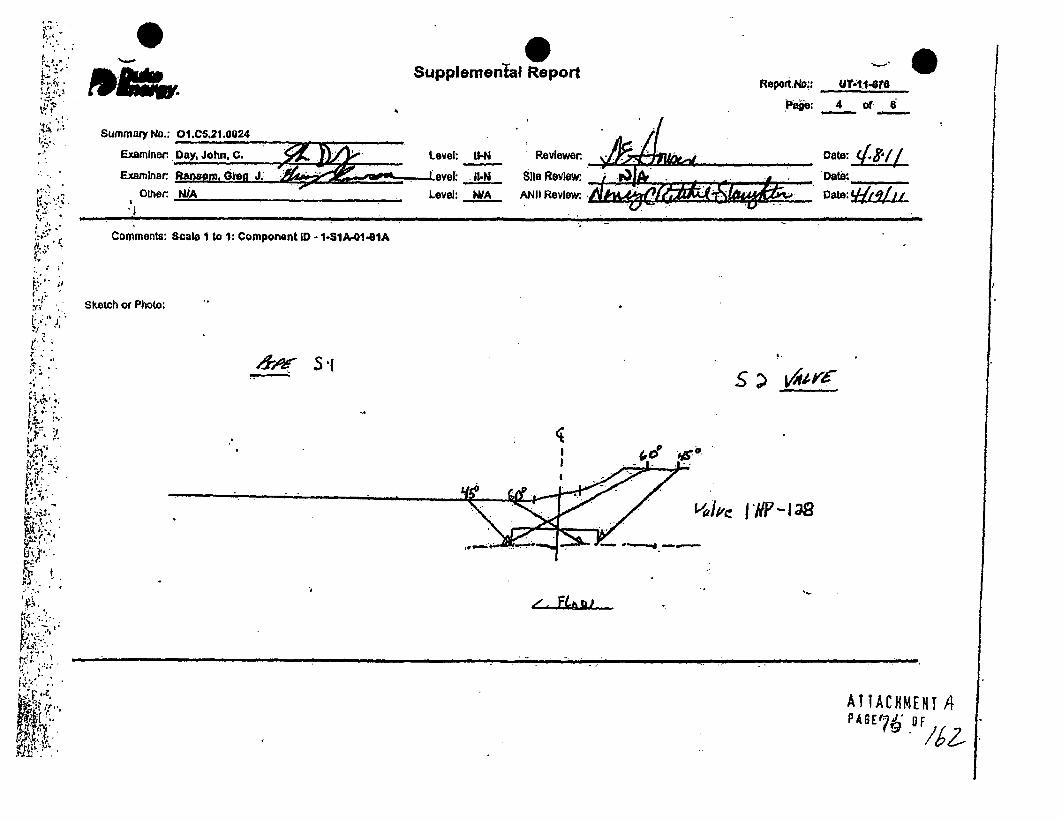
7;
-0SuDDlemenftal RooortS. -
II •
Summary No.: O1.C5.21.00:
Examiner. Day, John, C
Examiner. Ra!m.ja. G
OLher WA
Reviewer.
$Its Revimw ,Lrak
ANII Review, AM;C I bf&i,
4 of
Date:
Cat.: •, /J la,' J.
Level: U-N
Level: NIA
Comments: Scale 1 to 1: Component ID - 1-SlA-0141A
Sketch or Photo:
6 r5.15~
!.0
v0/1,~ fNP138
ATTACHMENTA.P45~70 UF/

0Supplemental Report Report No.:
Page: 5 Of 6
Date:
Date:
Summary No.: Dt.C5.21.002
Examiner: Day, John, C.
Examiner Rane~m, Ore
Oiher. NIA
If - A -&-ý
',J.
Level: II-N
Level: I1-N
Level: N/A
Reviewe
Site Review:
ANHI Review:!*1
Comments: Scale i to 1: Component ID - I-81A-01,91A
Sketch or Photo:
6* S1s:~
CT-u~:. SA~A
vaifi'e 1 #p -I as
Al TACHMENT APAGE 7 OF

Dotsi
Site/Urht: Oconee I ISUgurray No.: O1.CS.21.0024
Wwoeacope.1S
ninatlon of Percent Coverage foUT Examinations - Pipe
r tJ-,
Outage No.: 01-26
Rpoit No-: UT-11-678
page: A of 6
Procedure-Procedure Rev.:
Wok Order No.:
P01-UT72
E10?
Scani% ____ Lenigth X % valurneof length / 100 _ ___%totitwfr ScanlI
Scan 2 __ __% Longlh X % volume of length I100 ~ _ ___% totlfor Sca2
Scan 3 190.000 % LenigthX 50"00 % volume of ength /100- 50.000 % totalfor Scan 3
Scan 4 100.000 % LengthX 50000 % volume of lengib )100 a 50.000 % btalfor SM 4
Add totals and dMde by #somar A~000 % total for 43 dog
Other~~ 60 - s (to be used for supplainantall Sans)
The dab to be listed below Is for coverage that was not obtablnd wita the 45 deg sowns.
1:
Scan i 100.00 % LesgthX 100O.000 %volume of WO i1C00= 100.000 % total for Scan I
Scan2 100.000 % LengtX ioo~ooo % volume of lengo I1I0o - 100.000 % total forSoon 2
Scan 3 _____% Leonhx % vdinieoflengtiII0O= Yo____ totedfor Scan 3
Scan 4 % Lengft X % Volumeof langth /100~ ____ total korScan 4
Add totals for each scan require and divide by # of scans to daetet
M.000 % Total for complete exam
Sab f d Super~fow Ouw /__;__&/
I . .. It.

UT Calibratior LinationSit*/UnIL: Oconee" 'I Outage No.: 01-26
Report No.:.. UT11.707 .
Page: 1 of 6
I
Summary No.:
Workscope:
O1.CS.21.0041
'SI
Procedure:
Procedure Rev.:
Work Older No.:
PDIUT-2
04093
114=..000A Cat.m: CF .21 Location:... ..
Srawn'g No.: IHP-324 Description: Tee to Vilve IHP-119Ss; 'R 10.; 51A"
* I . .i , .. . . .. . ' "L' • , i * g WE.A
.,,nKCponent ID: 1P-324-1185 s.. .. ngth: W.A ThIclmsaelDlameter 8810.37512.5
1fi Jktitlons: .•os- See attached seets Stat Time: -134 Firdsh Tim: 1405,
Instrument Settias* Search Unit -
~S~taI No.: o~wHDK Call Time Dat a&OU~dwhUiSi6. .o.: oowHoK Serial No.: oo03vw Checks,
I'Dola: 3.7/$?056 Rang.o: 1. 40", Fmq. 6MHZ- Style: comnp".Gi "Iter CaL 14_/3 l!|." .i. I -I0I01apn: 1 Rec% e:inital Cal 1625 3=1111
Range:t: 11.6K F.: Is Mea401 A 4,.20111
AhFUter:., Fixed Mode: pM Wedge Styye: M:WQC Cal Batut,. 03nee
ge. ____ _ ____.122_ __ _High Exam A : ,4 #f .Fixed Cthel ul25 . - ... T4
tDamicialn(B: 26. CRejct Gai Mode, 47 erhUit ablR ~ OOEI
4,ý.ýcller Fixed . Mnode 0.1dPah Wyedg M0¶4 Cal Batch: -3 circumerentia " ao d Serc Unit
p..L-11-130 ' • Length: Fx' .d O.Coe.: -__,0 _ . Type: ULTRAGELIUjý,,-l (0) 3--.h-Gin(~, -.--A Serc Uni Cal g, S N TE HA
.,LUnearty Report No.: L-1__ 14_3___Type: __ULTMEL___,
Calbraio Bl~kscan Coverage Mfg.: SOROTECII-
BlockNo.40378 Upstream ~Downstream Scan dB: O R ioceI Block'ileck"a 0-7 Ol- ..6C2 CW S dB:, 47A Gaown SWap SudPt
All s 0.176 ole.: A"' CW COw s - Serial No.: 044737 S Path3 Cal.91k. Temp. 74 Temp. Toot: MCNDM4128 Exam Surface. . 0 " Type: ROMPAS ..- .0 *o - •0.. ,..+ ,, ... ... . .• o . •. Type: . ROMl PAI 0 I ISibCým'ipTemnp. 84 Temp. Tool: MCNO4i28 Surface Condition: AMGround
.--"R'" toIndication(s): Yea s No (If Yes, Rot. Attached Ultrasonic Indication Report.)
, Reeuits: Aop 0 ReJet 21 "i Infot, Comments,: PRF= 2550 Hz
r'PcOmni Ot Coveraga Obtalnod 0 80%: N.. Reviewed Previous Data: !Yea
Examiner Levl u.N . .~.Signature ~Review S~ei ~2 ~ Dtp Eimlo-r Level , I-N "' igrmti Date Re " Signature Data
, .. 313012011 •4 1"a-.ro ,..,,,°,l .,. -n. . N ). .Level . Signature Date I iaiul i
V. -. ' -- ý
1'. -
... Ft I Ufl iii, rI 5.51 I~A~E7~ CFf-6~.

4ummai)' No..
Woricacope:
UT Calibration Ani ation J1Ocnone I1
O11.CS.21.0"ll
Procedure;
Procedure Rev.:
Work Order No.:
- PDI-UT4Z
01901930
Outage No.: 0146
Report No.: UT-111-707Page: 2 of
'1I1
199C20JZDA Cat.tosm: C-F-1/Gi.2t1 Locaton:
C" : -aw i" No.: •IHP-324 Oeatscptlon: tm. to V9lve tIP.-110
I ",,System ID: G1A! .-Compionent ID: 1HP-324-18nB6-Siko/Length: • iZA Th =."Ohowdero 881o.202.5
k m_0a : . 1 Tahe.: .12 Fkndh Time: 1405
Instrument Settings 8earch UnitTime Dar ,xial OltntafdSouch Unt* ' .Serisl ,o.: GOWHOK Seilal No.: 0IJPCD Cheooks -e ..... , ..... "
| 1 -.•ModleI: uSNi.4O .... Size: .. 6 Shape: Round Inter. Cl. -1) N .,h " 04A"K'Delay..'mn 4.895 , Range: " 1.5 ... 1000 313012011 " M0 ,,. 4 O'ilon
Frq. 4a9 MD tye C.- Inter. Cal. 1409 313012011C ei .re250 P5MW. Higlh Inter. -Cal.___ __
•: Cae: - .1260 Pidser. Hligh Exam Angle: 60 #of Elements: Singier C-L-
6.ompIng: 1K Reject 0% Mod: he Final Cal 122
. p, Rate: A•,tohlgh Feq. 6 MHs Measured Angle. e0 Couplant
; r"e Fixed Mode: PE Wedge Style: MSWQC Cal. Batch: .00326 Cko l qlM Orbnbted Searc. UnIt
Voltage:. Fixed Otr Fuliwava Typo: ULTRAGEL 11,'-,x. (dB): 41.6 C .M Gain (dB): NIA Search Unit Cable Mfg.: SONOTECH .... Am..I....% DivisionS dP
4" semen olv. - .15 in. of Sound Path. Type R.. - 174 .. Exam Botch * 093.. NIA. ___J
~1 #!Salty Report No,: L-11-136 Length. W- No. Conn-- ye: UTAILi
. nScan Coverage Myg.: SO NOT BCHL -
C allbratfon Block _ _ _ _ _ _ _ _ _ _ _ _ _ _ _"Cal. Slock No. 40378 Upstram 2DOoa 0 Scan d9: 4 Refurenoe Slock •04I8kDodltoc 13Wek
C sl..Bllk.-Temp. 74 Tomp. TooL : MC NDE4. 28)I2 Exam Surface: O.D. S er : R .M .. " a 59 o .Pa
.;mp. . em.Temp. •m.Tol"rNE4o,2I.. Surface Condition: As Ground -
ý* ttal Indlo~atin(s): yes Q Nq~o*' (If Yes, Ref. Attached Ultrasonic Indication Report.)-
~osii,, Accept Road TA Info Comments: PRF 2532 Hz
',j peCnt Of Coverago Obtalned > 90%,: No Reviewed Previous Data: YVa
.Examiner Level Sl-N sIgnature D0t6 Revfew'
t Foss,,qtovan33021
S'Txnie Level DasilLPW ae
TQoftr; Stephen D. wrh
-4.004lhr:, Level MIA do Ignamiwr, Dt, IR
4~ Z4.

* 4 F J'"• Site/Unlit:
Summary No.:
Workscope:
Oconee I I
O1.C5.21.0041
UT Calibratioe.aminaProcedure:
Procedure Rev.:
Work Order No.:
PDI-UT.2
0Outage No 01-26
Report No.: LFT-11.707
Page: 3 of 6
E
019096301Si
Code: 1998/2000A CatLtem: C-F-11C6.21 Location:
Drawing No- IHP-324 Descrlption Toe to Valve IHP-119
Syatein ID: 51A
Component ID: IHP-324-118B Siz/Length: NIA Thlcknese/Dtameter 8S10.375&2.6
Limitaions: !Yen - See attached Shoots Start Time: 1428 Finish Time: 1440• I i l I II • I. ii. ll m i I ; i | • l.I JI1. I
Instrument Settings Search Unit
Serial No.: 00WHOK Serial No.: 580253
,.. Manufacturer KRAUTKRAMER Manufacturer KBA
-Modek . ........ iUSN40. -- S1ze: .25 Shape: Round.
y ,Oelay 6.449 - Range: -.2 .- Freq.: 21MHz Style: Comp-M
MU Cal/Vet: 1226 Putser High Exam Angie: .. 70 - of Elements: Single.Damping: 1K Reject: 0% Mode: Shear
Rep. Rate: Autohlgh Freq.: 2.25 MHz Measured Angle: 68
Filter: Fixed Mode: PE Wedge Style: MSWQCVoltage: Fixed Other: Fuliwave
Ax. Gain (dB): 57.9 Circ. Gain (dB): N/A Search Unit Cable
I Screen Div. = .2 in. of Sound Path Type: RG - 174
Linearity Report No.: L-11-136 Length: ir No. Conn.: 0
Cal. Time DataChecks J
intUal Cal 1150 3/3012011
Inter. Cal,___ ____
Inter. Cal. 1427 3°3012011Inter. Cal. i '
Final Cal 1619 13M0/2011
Couplant
Cal. Batch: 09325
Type: ULTRAGEL ii
Mfg.: SONOTECH
Exam Batch 09325
Type: ULTRAGEL I]
Mfg.: SONOTECH
Reference Block
Axial Orientated Search Unit
Calibration Signal Sweep Sound PathReflector Amplitude % OMDion
i1 Notch so S.9 .771
Circumferential Orientated Search Unit
Calibration Signali Sweep SonL PtRefleecor Amplitude % Division d Path
N/A
Reference/Simulator BlockGain .... Signal S e Sound •othd8 I fnactor Amplitude Diviion.
52.71 SOI 80o 3.7 .72F __t!
Calibration Block
40378Cal. Block No.
Thickness
Scan Coverage
Upstream R Downsteam a Scan dB: 57.9
CW[ CCW Q Scan dB: NIA0.375 DID.: 2.5 Serial No.: 04-0737Cal. B1k. Temp. 74 remp. Tool: MCNDE4012 " Exam Surface: OJ). Type: ROMPAS
Camp. Temp. 84 Temp. Tool: MCNDE-4012 Surface Condition: As Ground
Recordable Indication(s): Yes j] No 2 (If Yes, Ref. Attached Ultrasonic Indication Report.)
Results: Accept C] Reject 1] Info 0 Comments: PRJ
Percent Of Coverage Obtained > 90%: No Reviewed Previous Data: Yea
F= 1080 Hz
Eaie Lee -NSgaueDate Revieweril Signature DataFos. Steve W3i2 1 ' 2III IIiJlI:I
DExaminer Lavel IlLt"er- De Site Re Signature Datae
Tucker, SDtephen . X39/2011 MatJ
othe Lee NI 00" Sinaur DaeI 0 igaueDt

14J.
LIT
'4~ DUKE: POWER COMPANY
ISI LIMITATION ,REPORTI :' . .. . . . ,! . , ,- ,
' ,Component/Weld ID: 1HP-324-118B Item No: 01 .C5.21.0041 remlrks:
NO SCAN SURFACE*' BEAM DIRECTION Limited due to welded
S. 4IMITED SCAN 0 00 2 0 1 j• 2 - cw I] cew attachments.
FROM L 1.75" to L 2.716 INCHES FROM WO CL to Beyond
•A NGLE: r-0 0 [ 45 0; 6 other 70 FROM N/A DEG to N/A DEG
• NO SCAN -SURFACE BEAM DIRECTION Umitbd due to.welded
LIMITED SCAN I C1 02 0 1 Z 2 [ cw C cw attachments.
:FROM L 6.25 toL -7.25,. INCHES FROM WO cr_ to Beyond
ANGLE 0 0045 0 60 61the.,: 70: FROM "N/A DEG to N/A -DEG
NO SCAN • SURFACE -,BEAM DIRECTION No scan due to valve
..LIMITEDSCAN 1.i-- Q02 01 • D 21ED w 0 ccw onfiguratio.
iFROM L N/A toL 'WNA - INCHES FROM WO CL to Beyond.•:.I •l• ,h ' 4,," I' i -4 t -.. ,. .. .'AN•GLE'. 000 45 [00 other" • FROM 0 DEG to 360 DEG
1,:': . ,, •.. .7 ... .• , .. . .. " " , : -".. .
0 NO.SCAN SURFACE BE.AM DIRECTION
' LIMITED SCAN 0] 10.1 "] 2 0 cw [C cow UT-11-70!;FROM L to L "" ." INCHES FROMWO to . Ket, ns) attached "
jA, GLE" C1 0 0] 45 C] 60 'other- FROM DEG to )DEG :Y E. NoPM.re d'1ed Steve Fos Lev.el.. Date"
.F..dv.IBy: I .. 1 x zo <7 Date.,.. •X ,A."__M• 4 26,/t I _,jfd •":z/
#ýT -,I,0,; 7ý-
'C4
I *)
~ Cs.'
* * .77 14
q44 ) p% t*
rAE / " g
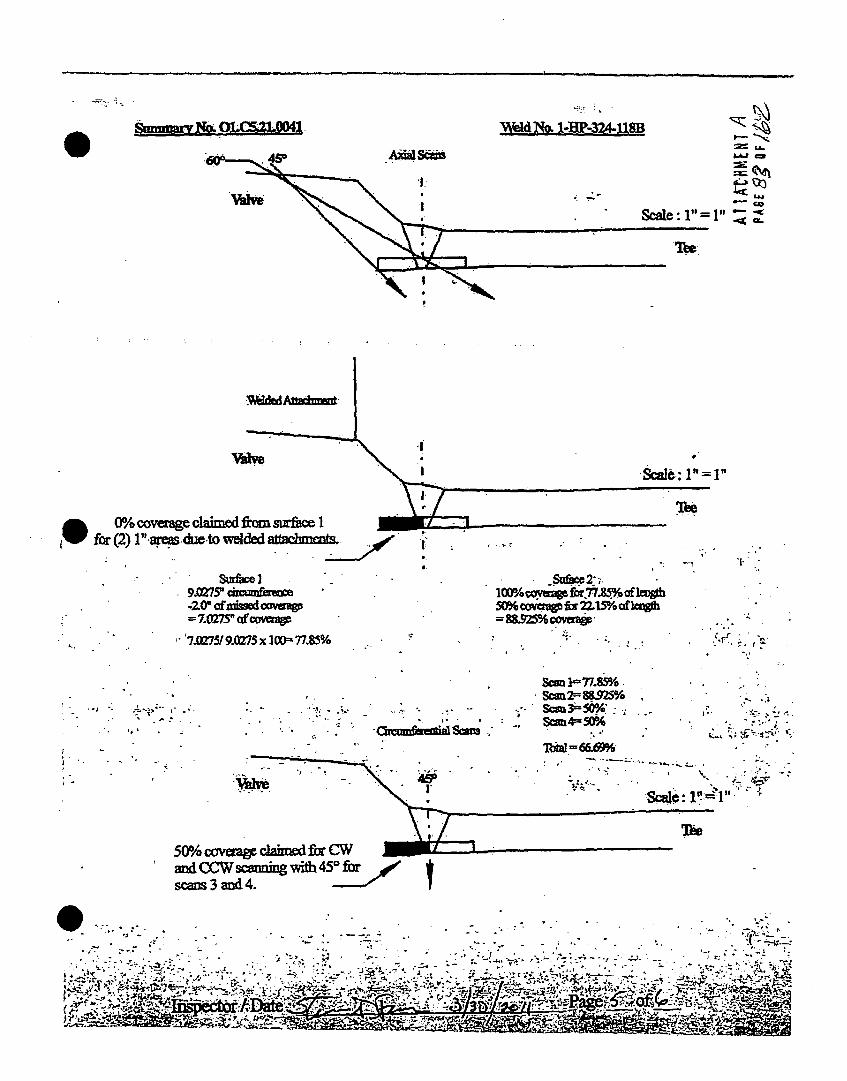
Val"1:
Scgle: V=P I
Tbee
TO
Vvsk
0% cvera clamedfrom surhce 1fr()1 " aresdue~to welded fahut.
!I
SC
7M075/ 9.MZ75 x I1OD" 77.W/.
. Sufie2-..
1OMcwavV o 22.85%ofk&o5092%C1S'ofwwg
f
5001o C(vadW clahmed fir CWUandiCCW Sunirng wit~h4IscanLs 3 and 4.
nfuedWS=m
SMn I- 77AWD%
*S=4350%
= 66.69% S~ 2~ 8 S 2 S r
1ne
S . . --7

Determination of Percent Coverage forUT Examinations -Vessels '-
SitmtUnIt Oconee I I Procedure: PDI-UT-2 Outage No.: 01-28
Summary No.: OC01.C5.21.0041 Procedure Rev.: E Report No.: UT-1l-T07
Worscope: 15l Work Order No.: 0196309 . Page: 6 of 6
0 deM PhMar
Sca. % LengthX X ,_ % voklme of length i 100 m % total for 0 deg
Scan1 77.850 % LengthX 100.000 % volume oflength 100 = 77.850 % otal forScan I
Scan 2 U8.925 % Length X 100.000 % volume oflength I 10= 88.925 % total for Scan 2
Scan3 100.000 % Length X 50.000 % volume of length 1100 = 50.000 % total for Scan 3
Scan 4 100.000 % Length X 50.000 % volume of length 100 = 50.000 % tota for Scan 4
Add totals and dMde by# scans 66.694 % total for 45 deg
<(Ohe d V4,
- * . :
* .. Scanl 2 %LengtX % %volumeoflength/100 ... 1-100%totalforScanl 2
Scan23 __ _ % Length X %vlmeofiMnjdj1G00= .%ttlorc
,Scan2 %_Ler•thX % volume oflen th I I= .. %totalforScan4 2.- s~a Ls.. :- vom) •=••o -. -:.-•:. *tor -s=•.*.4• 0.sc1., - %LengttX ." . %,hif~gel..1 jjg00 -. ,, .'%afttroscan4"
Add totals and divide by# scans % total for . •. ,. . .
Pement comalete coverage
Add totals for each angle and scan required and divide by # of angles to determine;
66.694 % Total for conplete exam
Note:
Supplemental coverage may be achieved by use of other angles J methods. When used, the .ierage for volume not
examinatlon.-~
............: . . .. . ... . . - . .-:+ . ,. ; .• • . . ". . ,; -., - , :,. " ;. • .J%
' •.. . -. Z
,, , - ...• .. . . . .. ., . •. _ + •,,• : • '• ;• - • . • ,•,,- •,-L• ,

~ Summary No.:
~ - K Workscope:
UT Calibration 'atationOconee 1 .1
O1.C5.21.0053
Procedure:
Procedure Roy.:
- Work Oider No.:
PDI-JT.2
010380
Outage No.: 01426
Report No.: UT-11-795
Pogw 1 of 7I • 11 II liB/ It I IlL. m :.
1998M2oooA
9 No.:. 1
~yat~rn ID: . @1k.~ ~ ~.
*~Component ID: 141A.0244B
*LimftaUouia: ' Valve configuration
-61A-02 ""
Ce tm: " C-F-IIC5.21
_________ V~acpfon: Ellbow to* Valve 1IHP.134
Lontlon:
SfweLength: MIA TnicknasJfaerneW 352.33114.0
Gtrt Tlwo 1350 Finish Thnw. 1403. " , ,m , .. ." " . . .. . ; .. _ .-. .... . , .I I
instnamant set-ings Search U• ht Col. DateP.aI~: ktS Ieia No. .. 'I - Checks
014LC(4..08.L
•Manufactursr.- KRAUTKRAMER Manufactrer: Initial Cal .103 411t72011
U S'-. .. W. Size:, 0.25 Shap; Round Inter. Cal. 411712Delay. ... 701 Range: 1.80 Freq... -.;2.26 MHw SC M: inter. C Al. -13941711
SM.d Co ,: .12=. P•i e.. Swuar. ExamAdgfe: 4j; .o ouElements:e .,l - -
Final Cal 1635 41l7120fl4 ,a p •d,.. 500 Reject• 0%. Mod*: ___- __ _ . - -
Atep . Autohlqh Freq: 2.25 MHz -. Meaewed Anglo: .. .._ 44__.... .. Coup4.nt;;Fgted.. .Fixd. Mode: Pi Wedge Sft:e: MSWQC Cal. Batchl 0&322
-,oYofleg•:. * 450 Other: Fullwavo " .. •. . ". ". Type: ULTRAGEL IIr.: G i,(a 31.0 Cire. Gain (dB) 3.2, Search UnitCe Mtg.: CONOTECI
In. of SOund Path, Type: .' RG-174 Exam Batch 093M5.... No" "• ' Itt to ":• •'.,• L~ngt: 'P Z . Conn.*: 0•Le~tReport . - .... . .!...... Typo: ULTRAGEL II
f.• ;" •,ft. ' .... .an Coverage - . Mfg.: SONOTECH
"CoI.'BloTco. 50275 UpTtream, DMND4tree"m [. San'-d. : 43-____________No.___.50275 Reference Block
Th 'sa 0.631. Cie.: 48C CWO~ S!2andB: 49 Sws No- A0111=2'IitaL~kL~mp~ Tep. Tool: MCNDE401ii. Exam Surfaoo .0I'CslýDlkTimp 74'ToniType: ROMPAII. T 4i S-, " Temp. Tool: MCNDEP0128. ,da.o•Condltw-,t - As Ground
'Reecrdbblndhmaon(v): Yes Q No & -;(Ir.Yes, Rot. Atlached Ultesonl IndICalon Report) -
',e:R fu : ,* • Accpt' Reject [ -- " info ¶ ' . -" - "- Comments: Pul
ýa ,pe tCaverage Obtained > 90%: __No _ _ Revwywd Previous Data: .Y_ s
Ax.W Oienhtled Be,•,Unitt
RAfleot6F. AnUtwtde % DWaln
Chtinmhtenbl Oftiabtted Scaych Unit'
CA~alfbei Signa 8"Op, sol PeRutlactr Ampltiudo DMWMioID Ndfte go U M
Rwferno./lznhmtor Block
Gab:~ I~ Now Souixd Path30.0 i .... I .20 . 1 7.0 1 1.44
I I I II I I :1
tos Width u 220 HS !r

-" UT Calibratior 'amination
.A#~ sitefunhit Oconee 1 1Procedure: PDI.UJT.2 Outage No0.: 01-28s" :.a Summary No.: O1.C,21I.0053 Proceduil Rev.; 8 Repor No.: UT-.1-785
Woks :,op': II" Work Order No.: ouoseav Page: 2 of 7
Coe .199IV2000A Cailtem: 'C.,.IJCS.21 Location:
Drawing No.: 1-51A-02 Desc~ption: Elbow to Valve IHP-134
. ID 51A
g,.!9olponet m 1A2-4/Lnt A Thiclme w/Dlameter. 9S9.53114.0, LlmbItaflo: Volvo conflguratnon Stat Time: 1405 Finish Time: 14`17
Insrlnaiimnt 8ettings SerhUhCol. TIM@ Date Axila sidentiaftd Sea-1 Unit,,. seu No ,o14BL.C Serial No.: 00O0cC Checki sn atl a'OnaJ Sweep Un dPtca I 1m 4 7 o, I cm aft to Jaw0 8, " .... pat
Mauatror KRAUTKRAMER I'inBehrr .'CA * Initial Cal 1133 417MI etli Apfltde FA DIaha
USN- ',00'" SW Size: cu. Ihk: ' ' hT Cal. WIN go &7 .8.4 S802 Range: 2.00 Froq. IMB MHz Sysl: Cemnp -a Inter. Cal. '1404 417211
7!•I.CaoLN .1230 Pulseir. . ,' Exam Angle: 60 # of Elements: Singlegr. Cal.~DsIWOn 500 Reet %M~ H iCal* 16401 411712011 d
I Rep. Rate: Autoahgh Freq.: 2.25 MHz Measured Angle: so Couplant _ _'"
F.Fter: .' Fixed "Mode: PS Wedge Style: MSWQC Cal. Batoh: 0OalCniI ,v -ga-, "a 4. Other. Fullwve I Type.: ULTRAGELIT C Iga sweep -I
Ax. GAM'(d):' 35.7 dC.m Gain (dB) MIA Search Unit Cable Mfg.: SONOTEC Ralco AmPlItUde % Divsin ifl P
•ia Sen D-. -.2 In. of Sound Path , .Typ.: ,. . 174 Ex'am Batch o. . WA '___"__
:" "tesit Report No.: '"a L-11-140 t :•s No. ... m,, _. .__. Type: ULTRAGELi
0i%ý soon~i Doa. 40" CW C( Sad:14A RfrNOE 6 1,.: ,j,.. .,.- . . . . . . . ., ' .. . .. .. . . .R. l.f"" ' '._ i I"L•,. 'ai•,'.• ' ,..._,. ,.• . ' ... ScanCoverage __,____,,,___.:______C,-. .. .Caflbration -Block. .. _
C ', ,. -, 'N0, 5275 Upattrm r- Oowsream 10 Scan 0: -41.7 .
CahL~ck -o6 - 1"a;CW"'cnd NI-Gi o 8" on t,. l,.•emp.., 74, lTamp. Tool: MCNOR40128 Exo Surface: O.0 ...... IIIZeIIIIIIa y,- Tp..e ROMPAS .1 IPD. 4. ?A 11A4.fTemp. as Temp. Tool: MCNDE4OIS,-i4-- Suface Conditlon: A.s o.und ,"'""-" '"" " , ___""__'__-'-____"______"'"_"__"_.. .. ._'_"_"
Recorabletndlatlo~s~ 9~ ~Noff" (*If Yes. Ret. Attachd Ultrasonio Indication ReOWt.)a, Results: "Accept 0J Reject 10 •Inf 17" -li 'ft Comments: Pulse Width -w NS
oPart e6t'.q!ovoraqg Obtained >- 90%: No ReowVd Prevloue Data.,,' .-
'U
PBI A f 0''A 1 ,,lE• / : -...

MW .,.AsiteUnit;1~ Summary No.:
Workaeope:
-0.UT Calibrationr 'amination -0.: ,
Oconee 1 1
01.CS.21.0053
tot
Procedure:
Procedure Rev.:
Work Order No.:
PE14UT-I
901003607
Outage No.: O0126
Repot No.: UT-11-785
Page: 3 of 7
Cd:19=82000A CaLAtem: C-P-11C5.21 Location;,Dre&lri No. -S1A-02 Deaalptlon: Elboew "t" Vale IP.134
10moejtI: l1A-6k02.348 . Sie/Length: WA ThIclumasalanieter~ 69,.531 14A.
?1'duoa Valve cofculoation Start Time: 1410 Firdsh Time: .1430.-. ~'r% -.
" Instrument Settinan searih unitCalDSwNul o.:' , 014OLC . sea No.: 10-1205 Checks ,
:MAnutt -r.- KRAUTKRAMER . Manufaoturer RTC -rdURi -al 1216 4
.Mo. - USMN4o Sw Size: 2(7XI0) Sh*: Ret. Inter. Cal.D ' ' .762•5 Range: 2.O0 Freq.: 2,0Mz atwe: TRL2" Inter.CaI. 1418 417120111
:MVs dalIoi: .2273.. Pulort Squ"* Exam Angle: 00 #of Elements;: d Inter.DCal. ,1__, ____. "_, Reject % Final Cal 1645 -1712011
Rape Rt,.e: u.""AtohIh Freq.: 2 MHz . Measured Angle: " ' 0 CouplantF.Uper ,. Flixed .lode: Dual Wedos Syle: Integral Cal. Batch: 09325.
VoS•:' - 450 Other Fullwave Type: ULTRAOEL 11
Ax. GaX n ( .B)- 43,0 C4. Gain (dB): NIA Search Unit Cable Mfg.-. 8ONOTECH
F" Swa8oen '- .2 in. of Sound Path Typ.- . - - -`174 Exam Satch 09325
Ulnemlt•i• Repo•tN 16.• . .-140 . 1• - 91h*• , ,. 4o. C n .0 - Type: ULTRAGEL IIC. • "at.. Stoc '., . Been Coverage , Mfg.: SONOTECH
Cl Block No, 80275 Uptream r-Q Dowtom I Seen dE: 46.0 .... ...Cl. -996 1 , 8-T oi*t"- i "o '8, - Reference Block____.__1 ola.: 4, .5 CWQ CCWOLSaal. dB: !5'S.tNo. " A"--
,~al.B~k Temp, i4 remp. Tool: MCNDE40121 Exam Surface: 0.0. Type: ____u_._
Comp Ternp. 68 : Te81.,,ool: MCNDE4012• Surfa•e CondItion: " As Ground -
" Reccii(S619ndl1nde): Yea Q No L - (If Yes-Rif. Atlched Ultrasonle Indication Reapnt.)
Reaul.1a: ' 'Aocapt Q 0 Reject I .'lnoj -'. Cornments: Wic
.P.peMIOf, Covae0btlained:90%: No Revlewe.Prvlouaat.. , Y ..
Axial Othmubed Search Unit.Cdlbralhn Signal Swcep .POR.al.ote A 'hpftfde % 11 O nto
3 S4O'H to 3.9 .768.
Celswallon 8IVAI s sAounp ptRfeor AMPIltift O~vMMl.___
.ftereeilm~,,uldw atemr a2• " "'
Gaincm Am
30.0 1 I.AdlU•L
huUotJB
lignl I~~epISoud Path.Bnat % 8Ise• .i •on~~ ~~,..:.83 L "D1
It,250 NS
F
LsatarRdbG4 M.-.
10wNbe 0.cLvlI--;sIgnIftute
+wwlr .......
rLsveI MIA
, I ....... _ _ + .... . .-. 4
,1' * j
''a.
A.., PACE O1~ Ff

DUKE POWER COMPANYISI LIMITATION REPORT
-0 1
Corfponent/Weld ID: 1-51A-02-34B Item No: 01.C5.21.0053 remarks:
El NO SCAN SURFACE BEAM DIRECTION Upstream scan limited due to
[ LIMITED SCAN [I 1 0 2 Z 1 [:] 2 E Cw (0 CCW valve configuration
FROM L 0.0" to L 14.13 INCHES FROMWO ' CL to .85"
ANGLE: El 0 N 45 E] 60 other FROM N/A DEG to N/A DEG
Z NO SCAN SURFACE BEAM DIRECTION Upstream scan limited due to
-- LIMITED SCAN El I 2 Z 1 r: 2 [1 cw E[ ccw valve configuration
FROM L 0.0" to L 14.13" INCHES FROM WO 1.15" to Beyond .
ANGLE: [ 0 Z 45 -0 60 other FROM N/A DEG to N/A DEG
[ NO SCAN SURFACE BEAM DIRECTION Upstream scan limited due to
El LIMITED SCAN El 1 I 2 1 1 El 2 R cw 91 ccw valve configuration
FROM L 0.0" to L 14.13" INCHES FROM WO CL to Beyond
ANGLE: [j 0 Eg 45 Z 60 other FROM NIA DEG to N/A DEG
E-l NO SCAN
r-- LIMITED SCAN
SURFACE BEAM DIRECTION
Eli I n2 nEILý[12[1CwE0CCw UT-1 1-785
FROM L
ANGLE:
to L4
EO0 -l 5 Q160 0o
INCHES FROM WO
,r__ FROM
to Sketch(s) attached
0 yes [INothe DEG to DEG
Prepared By: Robert Lester Date: 04/17/11 7
By:
M1,

0I11 Suppleme.pA Report9
Report No.: UT-11-785
Page: 5 of 7
Summary No.:
Examiner:
Examiner:
Other:
01.C5.21.0053
Lester, Robert M.
Foss, Steven .NIA
Level: Il-N
Level: li-N
Level: NIA
Reviewer:
Site Review:
ANII Review:
'baoa01kV
U -
Date: 22-I1
Date:
Date:
Comments: See pages 4 & 7 for limitations and coverage calculations.
Sketch or Photo: o) t, c., 21i, oo S31-51A-02-3q8
flpr&nr~tm.p Sc6AR ARF-A ON VAtVIE SIDE6
F.LaW V A Lv~
I-- - - - -
SI~
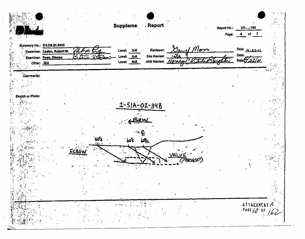
7.
Supplemes- Report Repor NO,: UT-..-78'.. Page: 6 of 7
Summary No.: 01'_._.211.00_3_.._________ • DarExamlfer Lostr Robart M. s , A 'l Date. P
Iwn Vor Level: JIM Site Review: IvD'
.. ..Other WA Level: NIA ANII R ~ . _el DIIIIa .
Comments:
Sketch or Photo:
0-.3
,- r. ±,.;....A _ -' ,.
S. ,.•
4OF
4. . I
""4
.... 4.,4 ,. I. 4"
.... ... -- AtT"M~V•q ;, ,•. :. ... A., O .
4 .. ..4 ,4,. . .. . . . . .

SMMUM-P
* S
''1
Weld N~o. : --AA4MY-310: OU.5,21,0053,ZE
dCE
MlowSI
ElbowSi
4
Scale.: 1"= 1"
% Coveirage Calculations '4. ***j~. *,~ -
- ... - , . - - ,sr.r... V.
S1I=Elbow=
S2 Valve
100%
46.1%
S3 = CW = 50%
(100% of the length x 100%.of the volueý)
(100% of the length x 46.1% of the volume)
(100% of thelength. x-50%" of the volume)
(100% of the length x 50% of the volume)
=61.525 % Aggregate Coverage
* ~..'r.<-
S4 =CCW = 20%
Total = 246.1 / 4 - I
JnspAeAoA T:~:Z r~. Rage'-----~ -
- ..-.. '"-t-
Wt-..

Stle/Unit:
!V summovy No.:', ,, Worksacpe:,
'Code:~ 19981
Drawing No..SystemlO ,,: 61A
SComnpomnontlD -1; rr193-12
.~., amitahed a
UT Calibratior %ination
Oconee. II Procedure:
Procedure Rev.:
Work Order No.:
PDI-UT-2
01909633
Outsg
Repe
IsNo.: 01-28
wit No.: UT-11-677
Page: I of ,. ISl 4.
I I I II
.
r .
.:
C eLl:tem: O-F-tlCe.21 P2
Desaription. Toe to Valve I HP-216
Locaton:
. , % " ,,,,
SitatTimeih: NIA Th~cknaegsllamoter~ SSI63`11 4.0
Firfth Time: 1345
*+ - In,,rument Settings Search Unit Cal. Time e
*"i SealNo.: . . 0140LC Serial No.: 0QVD?2 Checks ____ -
". KRAUTKRAMER Muaurn " .. Initial Cal 0900 3130o/2 1
' del. . ... ... Si . 05 Shape: Round n .
Deli, 4.7600 Range: 1.i00b' Fro. 2.2'e MHz Style: Camp - o t. or Calm I 133 31301W2011.
• li CaI l: .'.1230 P -.ser Square Exam Angle: 45 # of Elements, ,in.le-. . F0nal Cal 1 5303130120111
.Damplng: • 0- 0 Mode: ,SHEAR
, Rep.:Rate:, Autohlqh Freq.: 2.25 MHE Measured Angle: Couplanit
l,, ar F'i," Mode: PEe te:, Cal. Batch: 0932.tA.;vVO'IggO: ~.430 6ther. Fuliwavo Typo: .ULTRAO.L It
JV 'Ax. Gal n (dB)l u 2.1 Clrc. Gain (dB): 27.1 BSearc Unlt dable- Mfg'.'. SQNOTEC'4
v'csr i.' 8l~t OfdPt Type: *R R-.174 Exa Bac 09325
, "" Unarl.-Repo itNo.:,. . . - L-11.140 ... L 6' C __ "_-_ Type: ULTRAGEL II... .. , ' . Scan Coveage • M.,c Mfg.: SONOTECH
WY' . ~Calibration Block ________
l,' " C .a i B toc kN o +. "4 ii02n"" 'foe l D o ti~atrea mrn [] S o& ndB P. ,1 . ..-" , Cal' lo- ,No ___________________ . -- -',.--,:I M- Reference Block
___________W ci, . 40cGw@-ScondB. 33.11c ..knes..s. .£26 ........ c .w . . , " - Soi•al No.: 04.0741
Cal.•.•'Temp; 73 Temp. Tool: MCNDE4013" Exam Surface: O.Ty'"- ....___ __________~Typer ROMPAS
.-m P Te 1i8. Temp. Tool: MCNDE40135 -~ Sufface.CondloZon: - As ground
Reaotdenbloludlestlon(s): Yes Q No2- (if Yea, Ref. Attached Ultrasonic Indication Report.)*+• ... .. ;, , . .. + :,.t , -
Reult: Accept - Reject *"nfo- . - .2., . Comments: NIA'U•/ , :"j• t:• ,•'-,, : .. , ,
r.ot P I€.ovemg. Obtained > 90%: h: N•qo. , vI.w• d reou, Dta:, *-._Ye. .. D o w-nnr- ~ ~ o~ ni II I I " .. "I.at eveeSIt,
.'. I ' -'. • - " l-", . " . . ..". --.IJ.q"3-30/"2011 _____' ______' , -' - v. ... ___
I~sLevl .144- . **~ ?~ ý.A-Ns 'Daba SiteRev4ew,, _lr_ i e •i i ... , / *, .. .. - . • .. ...D 1 I S P+ l w ..'' " r. U ••.:" " . " :.. . %- +rm" Alm. l.l .,m .• . +. . . .•, .,•:, + . . . m 1, + ,: e * , -
U-
CAllratioriAp0lleari
Gl~ial SweepOwjslson SourýPd P " ; -
_________________ - - ~
SeOAxII -
R.hmne.ISlmutator Bloak
- Shngl' 8wuePSoundPithd8 'Refledbor A-,=e Divtslon20.2, 1' Radlus 80 8.7 .707
.4.:I~eVeI HIM'.4.,.
i1t -O;-W i* -. ,.* ., At AC liME Hl'
+ JF'14Po,.

UT Calibrat~iort v ntoSite/UNit Oconee I I Procedure: PDI-UT-2 Outage No.: 0--48
Summary No,: O1.C5.21.0051 Procedure Rev.: " Report No.. UT-14-077
. - ' Wofteope: lei Work Order No.: 01900833 Page* 2 of 7I" * :e -- +I,' t ' , ,,;, p. . r1 - --- ---
* C~do: 199812000A CaUltom: C-F.-1C5.21 Locaton:• iI.'".' .. . .,- .+ +
+.,Drawln,'qNo.:,. I HP-193 Descripton: Tee to Valve IHP-26
System.i1:' 1A
Component ID." 1HP-193-12 SlzeiLength: N/A Thiclnoss)Diameter SSJ.5311 4.0
Lmittiaone: Yes- See Attached Sheets Start'Time: 0824. Finlh Time: 1057
Search Unit Cal. TimeL Date Axial Oriontated Search Unit01-Serial o: . 4BLC Serial No.: 01F UJS Cheolk CGwSIIO I 8
Maniufacturer~ KRAUTKRAMER Manufacturer ~ KBA Ina a 34 4912011 Relet Aptds iisoMode:'" . USN-0 SW Ske.:. . Shape: Round" Inter. Cal. •- -"
-ela.•Y: , 4 .4"37 Range: 1.$ Freq.: 2.25 M•z Style: " -0 -latr. Ce 1001 4912....
M', • CaVI: .123 Pulver Squore Exam Angle: Go #of Elements: Single inr,+Cal. " IJ_•_-
D.smplng:. 500 ReJect 0%.. Modse: Sher - .FnalCal 1157 4,,,,,,___,20111 -
Rep. Rate: Auto,,gh Feq.: 2.25 MHz Measured Angle: so Coupant.- "_ _ _.
Filter" Fixed Mode: PE Wedge Style: MSWQC " Cal. Batch: 09216 Clrcumferentia Orientated Search UnitWHOaepr .Wo. Other Fu•twave Type: ULTRAGEL 1e , PaAx. q ,(db):' '41." Cro. Gain (d8): "MIA Searohi Unit Cab .. Mfg.: SONOTECH ______ _________ Division
I- S'ren Dl.ý -15 In. o Sound Palth Type: RG -174 NZAEamBth 92* .4 . *. . ~length. r Wo. Conn.: ..0...Tp: ULRGLI
Llneir tRepoit No.:.....L-11-140 -Type: __________I
i . ;,. . . Seen Coverage Mfg.: SONOTECHCalibratlon Stack ____._• -I'Upstrea [a.m ScandB: 47.3* "Cal Block , - •027 Uc Reference Block RIIaa lea
____2 _ 4.0_____ C8 CW carOB: N/A Gai SweepThcne, ; Dig. Cw ... . . ... .74 Path. , i + . ,I serial No. .044d741lolo moht 1* Diiii cn
al Temp' .73 Temp. Tool:k MCN0E40135' Exam Surface: Typ ROMPA8 41, NSI 45 4. .-8 ..
, omp.;le '. -07 Temp. Tool: - MCOE401S3 Surac Condition: Asorid Gr
, ec" ordablel tion~o} - Yes E NO E&, (if Yes, Ref. Attached Ultrasnlo • adcaUon Report.)
R... : ,-" R. 1.0 Comments: NIA
Accept Of Co g , > 0 . P...eougl-a.* . Y, .', PeonlOfCovereoOgle l 90%: _ o_ ,. _____P__o____. Yi +
I
i"i
'IExambier *Laverf il-t
MjUirtisad. BfrryAý.7t Other
Date
Date
AIIACHMENI APASE. 5OF/>
*.'fr. , .. 4-, * :.* .:.i. t1.
I. .. . '4 -
- 4.-' -
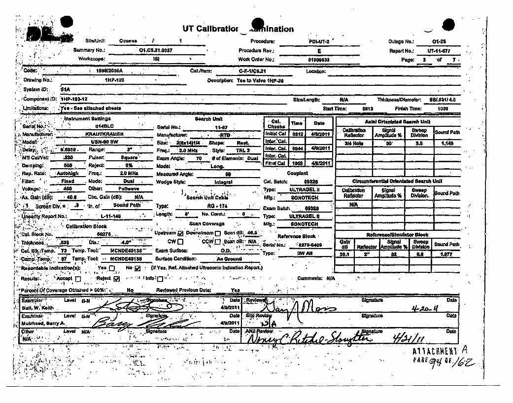
UT Calbratlor AinationU ' W: SitelUnit. Oconee . I Procedure: PDI.T-2 Outage No.: 01.20
Summary No.: 014.5.21.0087 Procedure Rev.: B Report No.: UT-1t-i477; Worklcopo: 181 Work Order No.: OIe633 Page: 3 'of 7
4. . .- . ___"___________IIIIlll II__liI ilil__i_______ iiiI__I__
I -19982000A . CatJftom: C-FiiC8g.21 Location:
D"raing No.: IHP-493 Descriptlon: Tee to Valve IHP-26
Syslem ID:, SI
,,Co.nonent ID: '1HP.1B3542 S1zalLwe&: WA Thickneea/Dlameter 8851.5114.0
',LtUIk:uu . em 'Y See " atahed ahoata StaIt Time: 0812 Finrsh Time: 1059
'.. - Col.uen Titmeg DCate Axial C~fated Search Unit* Seial NO.:'.,. 01413LC . Serial No.: 11-7 , Cheeks'" if " "*'' ... "t4 - Codl-.•,,. Sw SW'0- "bid PathSM "KRAKRFAER Manufacturer iitial Cal 0812 4.'2011'
USNMod SI UStd-.- 2(4*14)1/4 .Shpep Reot. fnter.'Cal. 3_ R o _80 0.149Mom" Range: Frq.: 2.0 MHz - : TRL 2 Inter. Cal. '0944 41"1 -
* ~~ae: 3 Plar gus Exam Angle., 70 #of Elements: Dual n Co
DampIng: 0o0. 'Reject 0% . Mode: .. o. . 1059 -•ong
Rep. Rate: Aut~hllh. Freq.: 2.0 MHz Measured Angle: S0 COUpldnt_
Filter. ; Fixed Mode: Dual Wedge Stl4: Intelrol Cal. Batch: 09320 Cflsmfna•ntlal Odmatated SBeob UntlVoltage' 450 00w, Fufiwave * yp: IJTRAOEL 11 Oslbaloj path See
i" ,Ax. GajnW(09): 40.6 Chr. Gain (de) NIA -Searth UnItCabli Mfg.: 9ONOTECH Rfectol .P•ift*d% D"WI=n.. .. in Dt" -1 In of"oa U' -Type.WA
", Sc vno:- *) ,,.of- 5nd~h' " pe: -R. 14 Exam Batch•. 09326 A.-
, rityReport ' 1 No. Lor ____140, Type: ULTRA0ELi-
S'..Cal.l.rai"on,• . iock Scan Coverage ,, ', Mfg.: SONOTECH_'. } dcNo. " •• Upstream Qi Goad dS:. 48.8' ..... _o - Stock__',__.___.____-___'____.. ... .......... _______ ' , ,. [ .,- -- ' ' Refermne oo -o r,= lm d • • k
Thickdos,, .520 1a.: , .4.0,' -. Ow E c Scan d,: . lA - , ,e,. Son a.~~ ~. el!No.: 627094409 ow dPt
ik Cal. BkirTemp. 73 'Temp. TooLt MCNDE4013-- Exam Sulsoe: O.D. .... W A "0.1 1 U IM!:oinpp.Tem 87 'r-Tomp..Took . MCN"E45 Surface CandUilo:, 'As Ground
ft!" ordabI*InvdIcadon(s):; Yes 0 N..2 (if-Ye, Ref. Attached Ulkasorio Indiction Report)-
ý,:- s, 0 Ro, d.0 _-. -. 4nf-o'•*-,... .. .Commerts: NIA .;
,Results.. Accept Q +ee"" ""." "-" ... .. "•""4'.Pdro~tbf Coverage Obtained 2, Go%:!. No ReviewedPrevious Data:' Yes== .
,x14nah:m", Law, d. 's D 4, Signature Date
.. ,m,-,~ ,:R eve .. "!r Date slid S:' ,atur cab..
t MuIi'h ad, Sony A.. 4A191201 *( ther LeVOl NWA' *,Sgltr Date.I~~, i ~ , asWA I ""'-'~-519 a ., IuMr4afd4 5
V .. ±1. J*,..'. * ~ 4~ 4 . .. .,.. . - 1~t1~-TI *AR in,
41.. .,

DUKE POWER COMPANYISI LIMITATION REPORT
Component/Weld ID: IHP-193-12 Item No: O1.C5.21.0057 remarks:
. NO'SCAN SURFACE BEAM DIRECTION Due to cast stainless valve
SMITEDSCAN 1 03 2 C 1 (g 2 0 cw 0ccw conwftgration.
F.ROM .. 0 to L 360: INCHES FROM WO CL to Beond
-ANGLE' 000 45 060 other 70RL FROM 0.; 360 DEG
' NO SCAN SURFACE: BEAM DIRECTION
S..LIMITED SCAN E] 1 0 2 C] 1 L] 2 El cw 0 cow
FROM L to L INCHES FROM WO to
!ANGLE:, 0 045 060 other FROM DEG to DEG
• 0 NoSCAN ,, .sUFC. ... " , :D IR IO N
(2LIMiTEDSCAN 0 0 01.020 2w 0 cow".F'FROQM10 L-____._ to L INCHES FROM WO to
ANG(LE: 0E,,Q ] 45 CQ -60 other - FROMe 'DEG to-- DEG!il osm' SURFA=• BEAM DJi€riog _____________
(40 NSCAN . 1ACE BADIETION
0 LLMITED SCAN 21 0, - 1,0 2 E-_ cw _-__cw' UT__-_
FROM L to L INCHES. FROM WO to Sketch(s) attached
ANGLE: .000 45 0 60i other- . FROM DEGto.. DEG 0 yes - No
fPreuBy-' MtthewHessel " lWoei: Date: b31•o/1" Sheet 4. of 7LF• m~~evl- ."-Byi';:' D ; • e,:. • ... ;Ins .. "-i:v.o
'!
(I
AJ
itt . LOA
T'I* .. *~* . ' .'-I.PAGE7

S upplamernaul Report
~8umnar~tfý4 1MC.21.0057
EXhrfi ullaW..Kelth -~Level: 111'Reviewer:
j if ~1Eaniher; .HassalWthwLeeI.it elw
i-%/ A'. Level; Wk AN11 Review.
4;!%,-,' Cdmment8: Weld I HP-193-12 Cover~age .
1 7.
(. .. iq
4'.
k' 4A.
Report No.: UT- 1-477
Page: 5 of 7
- A AI .
Date: (/. iiDate:
b
• m " ,Ill • • • "
_ L •. I i
./i
I~ -. 3
.A
bj. 'I A PAGE 7X OFtf1Z

* .Supplemen-taIReport
N..
nei~~BuJ, . Kith Leel:* I-N' 'RevIewer:
h&er.-.MsselMatew8 ' LeveL lN IM Site Review:
h-r NIA' ;' 'Level: WA *ANII Review':
Report No.: UT-11-677
Page: 6 of 7
V
Date:___
oats.Date, ~
6A, Vients.-Weid 1HP.193.12 Coverg
4 -. . -
'4 6ktoor-Phdto:
~ ~4A>3&. h '~ r
-- iI~J.I-V p.
.4 I 'I
r
4.- '.t
* 4 c
ji.
Y , . ... ' * -
-4 . 4*
A
It
.4.4
L. &I t~~yALY ýAýPA 9E V a QF/4 Zg
* * -1 -I. .' **
N '.ji.* p .

Determination of Percent Coverage forUT ExaminatiOns - Pipe
Site/Unit Oconee I I Procedure: PDIlJT-2 Outage No.: 01-26 .,. "-
Summary No.: 01.C5.21.0057 Procedure Rev.: E Report No.: UT-11-6"T
Workscope: iSI Work Order No.: 01009633 Page: 7 of 7
Scan I 100.000 % Length X 0.000 %volume oflength 1100 = 0.000 % total fbr Scan 1
Scan 2 100.000 % Length X 50.000 % volume of lengtho 1100 = 60.000 % total for Scan 2
Scan 3 100.000 % Length X 50.000 % volume of length 1100 - 50.000 % total for Scan 3
Scan 4 100.000 % Length X 50.000 % volume of teongth 1100= 50.000 % total for Scan 4
Add totals and divide by # scans 37.500 *% total.for 45 deg . . .... j-
. . .. ."" . t .- ": "" " :" " " • .. (.-". " .-- .- . . . - ". ' : .. .
.4.- ..
.Otherdea-.. . (tobeusedforeuppleýmentlsca )
Then data to be DiW d*6 b s for cveethat was not.obtaki w--tfte '4SC,.. ",
Scan- . .L... . : -,, is o • u.eofon, ..-..... -• %to.-f.r n : M..Do,:-. ;--" ;_ ,• : . -•, . ,. .:.* 4;.': p.• , : -... -.- ' .' tt,.-:o . .• ,.:'?;.•'..:.% . ..4JZ:.••v-.*
Sc$.an2 %Lntj--' . vtmofngt/0 ____%eaIrcn2- 24'Scan3 % _ .% t. ' . -.- %volu eof.• .l,100-,- -.. fr 3..q-i..p-
-. . ______-_ .:__ ._ ;.__ . -_..__._._.,__. .__ ..__ .... . . .. . ...; ..- -.....t• .t_.. o.... ..va !-- -,-V
'co .eetcmet Ora- .IRP'J-,. 44d-; '""r:'c - " "•..• • • ''•-""•"... " '" '-."4.: '" " • •
_ ". ...... ."' scan reqred ad dvideby 6U f scans to deter' .ne,
37.00•. %:Total forcompleta n .-. -: - ". . .
•2 .. . . . -... • w . . l. . • .. . . "o .-. . ... . .. A . . .*.. .. :.. .4*• ;*4 .. ; ..- . o
- . .. .. . --.
...- , . . -.. .. . . . . . , . ; . . . ..
- •, . . " - . . . - .
•.;::•-• • . .-•... - - -" " ' ' .• -... " ... - _. :•: . . . --.'-.: .• •F . .:• .;.;.- :,.-.• -- ' ., .: -=. ;.- :.. ,: . . .. ':.• : ,..:;"M.

¢1U +C , & • ' a , n, UT Calibratioi Wninatlonj •pI -,o1 - - Predure: PI,-UT-2
C. Procdýure Rev.: E•- .;: "181 b.. '.+'., +,' • .. vv0 Order rNo.: • 019091587
q•+-;+ .'Kt. +, Ca,0tom '.•+c+-F ,ICS.2 ,+ . Loca,,on:
... _77 ,-._, ' Descripio: Valve 1P.-t03 to Pipe.
'4 Stu
+10Outage No.: 01-26
Report No.: UT-11-670
Page: 1 of 8I
W/A Th~neas/Diameter 0A38 I3.W SS
j;lT?.T~
Exe Ii -6TInt
~~I* I~lde: *. ~.: .~ ' JFinalICal 2M21201
__________________CouplezitMealsurodAgi. 4
-~.wedge Style;11 ±'o~ MUWQC. *: 'CW. Batch: . 09329
4" T ype. UL1RAGE 11
* 8.brcinlabe Mfg. ONIOTECII
-'Exam Batch:- 09328
.*.Lgi S'J N. Cnn. ~Type: ULTRAGEL 11
~ -'Mfg. G ONOlECH
~.ypafeam q7 OomtaV9eam0' dB:' 384
~ Refereace Block
-.0, , Ut Se. . 0.0 04-874
'~ I ype: ROMPAS
Report.)
'.-+,.,-. . _, . Comments: HIA
I
Data
Date
AJ1ACHIME~iAPAS E 9

UTi calibr
'SitaUnIlt Oo. C
* V~orkscopo. ~11
atlor -ASnafion.Pi66odure:
SPs'ocedureltev.:aJ ,
Work'OrderNo.:
PDI-UT-2 Outage No.: 01.28
Report No.: UT-11?0
Page: 2 of 8U
019g58?I
II Ig l I I
2 1-51A-014, :.1
.. taIV,- DascrIpton 'ValvvA1HpO to9 Pip
Location:
103A a-.
SlzeJLength:
{i.i :• i l•, in n : i , I.II
r T1AStart Tie 1442
Thlclcneassjq~aeter 0.4381&.0189
Finlish Time:
_ _a R- - -
4efa oDat
(Axial Orientated Search Unit
Cambratelon Siga Sweoop So,Reflector AMPl•tudo % DOvlon
10 Notch 80 4.9
Circumferential Odentetad Search Unit
alibraUon Signal Swoop LReflector Amplitude %I DMAslon
Me"aWed An l.'__________ COtiptant
- Wedge Stile: msWOC ý ' Cal. Batch: 092
* ~ Type:o ULTRAGELDI C
-~ each ni CaleMIg. $6NOTEC14
- f.pe "R17 Exam Batch. 09335
who.U 0 No. Conn.: ,. ,-4 Type LLTRAGELU -
*~~~ ~~ trqjramd541 SONOtECH -
~AJ it'~ Reference Block -
'Ecmm Wftoe' ' 0.0. d
Type: ROMPAS _
aSwfdow Conditon. As Groujnd'4
(if Yea, Ret.;AUGMcIed Ultrasonic lIndication Rooo4)
A'ora......ments:
NIA
Ph '.
>90%:.:':-'I i I
ia':,Leve~l a-IiNp.-a.-. C.
7-2Izo11 IYeV!~wsr j~~~~SfgrwWeI. ,.~tI a-
~j~jj7 ~j~V4'7 . -~ a
4*0WI
a .. 7.a' >
Sl!8 ýDvl, wW"
Signature Date
_ , ,s" ,,,. ,,•, ,'.' ° " Ill • i irl i i m " i i " . i
'% ~LOVS N/ ~. *. ~?4J~~giatim77 S,1~. ~ ~ ~ ~ ~ a
i '..ANII viteow DsL~
i i I m I I I m II I I • ill - •. i• 1
|
j!. V.~
A. -
aw
41 U
'V~~~1
PACE' A ' - .. a
a-, .a at a a IV~OF

U TCalibration WI ination' ' ,Procedure: PDI-UT-2
I I I
0Outage No.: 01-26
Report No.: UT-11-70"
Page: 3 of 5
9
.01609587
K~'I;~~ 198j2q0A *I~1~& *~ y'4 ~'t ~Ctiltm -~ ) ~P-l1C.21Location:
~.; ~11-9i4) 3ý4. ,2;.J:.. : :'c' i ip~ 4Dscd2lo¶~Va~v.1I~- pe
SlzelANgth: WA
Start Tlime: 1130
ThlcknessDlametei. 0oA38/2.0/Ss
Finish Time: 1200- s...
.. *1. *. ICal. Time' Date
Initial Cal, 0828 2/820111
Inter. Cal.Inter. Cal. 1008 2181W2011
Inter. Ce
•ia Cal 1' 3 2J812o11
Axial Orientated S6arch Unit
e -MSWQC : Cal. Satoht: .09328
Type: .ULTRAGELIIchUttal Mfg.: SONOTECHl
~RO14~T, ' Exam Batch: 92
No.Con. ~ i~~*Type. ULTRAGELUIl
0.*oerag M~g.: ____________
4;.~.*~j- Reference Block
Seria W.: 04740- , TYPO: , ROMPAS
Ai Gound,.~- .-
Calration signal Sweep sound PathReflector Amplitude % Division f
.375 Notch go 2.1 me2
.750 Natch 8o 4.1 1.03
1.250 Notch 80 6.8 1.701
Circumferantdal Orientated Search Unit
Calibralion T signal Sweep LRaledor Amplitude % Division Sound Path
See Axila
RafeancelSimulat" BSlock
Gain ISignal Sweep Pat..dB Refector ljtupide %I DI)s~weoan1.* _v270 14" IIe~4hj.I go I 4.0 1 1.027 .... -R......
I I 1 I• .
- Comments: N/A
?RivIgwa~- Signature .eA .stsA*(ew I
Signature Datasignatur Date
. :Le l NIA-. '" • ;.•' '." gnaturi - RAIM ~ ~ 7~~t '/i, Date
f.
~ 01
4-.
P A GE. 5 OF / .1

°!'"i " SlllUnlLi..•,- ;O ,oal•:(:i;
• ..' Sn,'1 ry No.: , '..,01C•:
'o.: " Workscope: ", •
_.i.UT.Calibratlor Idel•n•
0066 ,,. .. • " .•Procedure Rev.:
., .:.. + -. •+,+ "Work OmerNo.:
Wton
P0iý-UT-2
9
Outage No.: ""ioge
Reoirt NO.' UTo11-610
Page,: 4 -of .
-24
• . :. . •r.at":';••f'~ ~ ~ ~ ~ ~~ wi .... 09,••{): to. Pipe'•"" •::;-- 'Location:
SIze/Lengl•: NIAStart Time: lini
ThicknesulDlemeten 0C4381 3.0/SSFinish Time: t122
, . • !..... +_
nsbum nt6et~ g# • . . . . :, .. . 1 S ear ch Unit Date...1..0',; •"." eilH • : "• "8 05 . . . " Checks ,
•,"' " " . . ; J., '.ap-"e-. . . .,' -- Inter. Cal.
'• I K ""R k~: "'F*0• ; :•+ ... -L -,2:25*M z ..:- W :. Inter-.Cal .n 12oi;] 213)20t~
• ". xa d ' Mo e ,E .1 . .'"? .. O' :• ,. "
7 Flxed, oute• ".r . Fulwvaoix., 0.• , . . , " "' TyM•: ULlrRAGEL 11"- -- -- ,cUn. t Cable.. .f..: + 'k"T" "
Olv.~ ~ ~ ~ ~ ~ ~ ~~~Ea -. : S. a"lp: -..... ch,14 , •':- 09326•:,,_•~~~~ ~~~~ .... WW::,,,.:+. :•+.,+,, m : r . No. Conn.; 114.: d;;i.': ~ •,_ _... ... + -o.1-43, •Ys UL RA E ,1,,-...-. . ... . . ye
•:,..m•,.•, ~ ~ ~ ~ ~ ~ ~ ~ ~ ~ ~ ~ ~ M~. ::. ,;. ..: ... +.,,+ O...T.EC..4,.-----•,. .:_ .,;:•:,JP DWT2& ""ihý 1 "d~a a ""1 Scan 'S . .. .. . 8. a:!,"s ~~c
'e p. lr-,- T'601:E"xa. pinim Surace •mO... P"•'t;", Z. -.':. . Too -,;j ,. , ",a.. na,,:luc ',id •-.,,• +- --. .
Mj, ,. --mnt . W
Fel s :R7 Pieep T•l.•':M • B 0:•. S r ~ ~ lln.": ; - sO o n -. '+•.ta .6ý.. l i-,:'•,; W ,% ...... ,ow pataz••-"' . ,
AilOrientated Search Unit
Reflectr Amplitude % Division
375 Nath• 00 1A .67175 a tch.,,m Tip . '8 2.4 1.3511
1l.25 Notch so 5.0 ,,2.606 .•
Ctrourmferentai Orientated Search Unit
1
I
Love . .1, .",-, -07. , .?.,;•-, ,.,:•-'.; '.,.•:-,. .. •'• .. .;•:+;I••I". il~l'.."i ',:: ".i ~ l i~i .,,+ ..... • .•<' ... ++• .I • ." :.' • +, ,,,.+, • l~n•7.. ,- +
'._~~~~sgatr Date: ... r,. •.....
Level u• NIA: 1- "+Si+g+:'.: natu'b, .-.+'" '" ' .' , +' • "• ' : % j', • " . • +" t I''• 110.""-
.... o t•NiF + . .. . ,://, ,, .040. ...... .o. • ., . ,... - , .1 . ... ,, + . . ..-. ;..,,. := ,;; +• ++. ; • . _
e I• v lJ w
A11ACHMENT A,

7.1I I) J 0
..... J m • == lJ I I I==
~DUKE 1514LMTAI
ioritlWeld ID: ý. 1-5: Nd':iNO SCAN ,, 4,-. BEAM DIRECTION
'E2 5 "2 ff cw' ccw
ICHES FROM WOj. CL to Beyond
DEGto 360 DEG
~4OSCA" , ~'~ s~fFAq,. E )a.BPMIREC IO
LIMITED SCAN;4 0 ' 0 Icw____*oL~. : INCHES FROM WO'. to
00~ 54 i'604 ot~r__ FROM ~'DEGt W
,"'0--ccw
DEGiii m ii i
I ISEAM DIRECTION
D 0. V2 5 cw [3 ccw
" HES FO & 'o .
|
Iaf I,,,,v
Y*P
51 -i-ý l 00 Elw El ccw
rIES FROM WO.".._ to ___
+ F~p~*' 'Et - DEG
.U"-1 1-"70I
Sketch(s) attached
%A@ yes El.No
.:-* ..*'**.~Jz;~*~., Sheet 5 . of-_ ~
K, + ~ 1.
* .,
~ I',~,".
~ ~'r
ICO'" - jy ATIACHMENIeAGE1,0 2 O
'S

,•-i :i•,• • * V S J. g..
Supp~m~JRpo~-I";
I., Lej: lN Reviewer:Level 7. $1-N
WW L r,; n .C. vel: toA ,A Rewiew:'
a , rý;NI
iwi
or4YI
c1- I.
A (i-rl
Report No.: UT-I11870'
~~ Date:Date.,
A t1" ~
V .,
.4,, 77,
t I
~jL
~-f A~v'I
d
** .7""
-'I
I -'V
4.7¶.*7;*
4.
a
41 .
ATIMAITH~PAGE o.

- ~~upplemqixb~df Report
-a, i- LG; fyevel 11-N Sit Reviewe:
)trWA -fLexvel: MIA ANli Review:
Report No.:
Page:
UT-11-670
7 of 8
Date:
Date:Date: •
'*
h ~ *~* )aj;j 'j~',- a
'/ e4~Ya
- :..~. p,.~-, I~a(f It
C-. 4*~. 4 *- c.~-~ *~*~
V
a j -a.~- ...
I,
J.
if~ I .3*' ~
J.,a ,~- . I4 ~ ?~
al .4 qa ,
/.~t.44 i~ ~ a------ I~
4 O
.00ý4:ýez)I.
V. -~
J"- .
, I I III
41
-'4'T AT TAt

Determination of Percent Coverage for
UT Examinations- Pipe
Site/Unrc Oconee I I Procedure: POI-UT-2 Outage No.: 01-26
Summary No.: 01 C5.21 ,006 Procedure Rev.: E Report No.: UT-L11-670
Woftscope: IS Work Order No.: 01909587 Page: 8' of 8
Scan 1_% Length X % volume of length 100 = % total forScan I
Scan 2 %LengthX % volume of lengthlIO10 - % total for Scan 2
Scan3 100.000 % LengthX 50.000 %volumeofiengib/100= $0.000 % total for Scan 3
Scan 4 100.000 % Length X 50.000 % volume of length 1100 = 50.000, % total for Scan 4
Add totals and divide by # s6ans,= 50.000 %total for 45 deg.M, :
- . .- ".x . . • . .-. ,-.."•. • ,.° . o-
.Other deog 6 (to beused forsupp emental scaqs) 'q p.-j .,r .-.
. . The datamtote.lHsted.beis fo- cove-ag tha Ut was not obtainedwih... te.45 deg scans.. . 7
_Scan21 100.o00 0bo- .,-,- ,0n.,om, ••1 a .•,,
-Scan 3-.. ...... % Lengthx; %volume-of~lei~1'l1O-...,.p%•totforcmn3 0,
7'"'
ýScan4 3, % %LsnthX--,--.; ,-r~do-Ptotal. fr Scan4 3 -
.. . •- - _._._._°. ___._:. .___ .-__ -___. . ____. __. ___ . . , ," . "_.._ , .- ,.. . .... -. .. - .' , .- ___,-______"__"____..._ .- ; = • ''
-:dd'. totasca 4.reac-h-, sc.n mqul;:•,•red'a :i .... ~ by -,~n t. deter. mnea= -, _• m:.;o = A,- : -. ,••_; Sc -. . .a'4:•- •-. , -
~~~~~~~~~~~~~~~~~. . . . .. . . ." . - .. . . . .. . .. : .. ,. ... ". . .. ..-- ". .. . " ' , " .
7,' 7- 'E
~~~~~~~~~~~~~~~~~~~. .... • s .p o... . . ..... • : • • . .. •, ,,. .•.•/...... .. . .. •..:•.,:•.•
, '..-. •
.: k .. 4r x • %.''0_ _ .-i'e KY .
;4. ,4 - __ • ... • • • •-- " . -:•- , ..,,A!
•,:...,•,ea is a .. .. req.u••- '....::.. :.. . ... t ...... "ftV' zx:• .-.'- ".. , . ... ., .,.: : . ., = .~~~ ~~. i .* . .• , : • , , • ,. , . J . - , : -
....... %-Tta fo-c"•et ax ?• w r4" -• • •';
I~ ~ ~ St F.le. d S... u. m. w ..-s .
..- •.•, .!-,j ' ,.•, -. :•... .. - -::••3 ,• ';• -. .:"•- ;• -• "•-%-n:

.. *, apinationSital~~~n~tiU CalibrrlaOtaeto..onf
,. Smmay No b"C~51050jPfoqedure e'_ _ _ _ _ _ _ _ _ Report No.: tJT-11-079
W Proo. ,* ., ' ' rk Order No. 01913780 Page: 1 l
9 9 L1g820 ODA .. 1 FT CA__tam:__Location:
.~ ~ lPS503 ThPti IýD1tir PptVevilft!PS-022
'843-1 -- '.~t~*'~ '4~ - ~ -~' J . * -~Size/Length: NIA Thlclczess/Dlameter. CS-SSJON81.0
~8e.mtah~dhet A~;'<..~i: ~: *'** -StartTtmne: 0910 Fnirsh Tlmo: 0048
C(l I-m Date: Axial Orientated Search UnitfVW1hwI I".. ' Chocks.
____________________Col-o T -3 3131120111 Calibraen Signal Swep SOWmd Paic'.KRATKR~iE~Wr. A M
9 . - . *J -. In~al~l 7333131301' RefosAir AnlP~Ude% D~isim
* .~''.SNO4 . 4~~;Sz: .,038 'Shp: Rud " *SO80-6.2 .789
;0".. r, Fraq . intitr.Cal. 0114 3131112011
W I. .~ w
g_.___..4_ CouptmntM~d~P'~wedesad : MaQ... -0.Stc:~ 9325 Cfromtaftntluiffentatad Bombl Unit.
..___________-:,1,____ !.I --IT.Signal
0. e'fGat dS -. Mg: SN 'C Reflector- AI1P1IISdO% DIVISlan P.11p..,!Sund G - IT4 e* Axial
4. .-.. 9'
D1 ~ ~ ~ imr 7' iIt~ ' C ~ CW Scan dB-" 40*0:_________ *. ý , , 9'0 Serial rwr-Boc
tj~PTot1 CNFiat 2 E m~rsc: 9, 4pý __ _ __ _ Ia~ III s a Sweep
t qqhI M.CN1415jM _ am ,.,*ce. . .~*, ~ ?,, 1 -1 SiJtr - Dat
p -
10 1.% N AW

j - .4. . -
~~'. . ~UT Cairto 5 amfinaflor
B7i5te/Un~iti Oc~on~gjA?;~ - Pioadure:
Summry~o ' ~.~i~ii.@@0h~Prcedumi,Rey,:Woilccope ha Work 0rder No.
C~si)~ '* , 19981200QA 0:/Iem C. 5.5C1,
I. OiqacdpUon: PIPe to V6,1ve ILPS-022-1LPS-563 ý:. ..
ti>4:
'4z's.:':~~~' ~ B~ At~1flt~tii3Ir. sftq&Wýnt I
i. PDI.UT-10
01913790
0Outage No.: 01.26
Report No,: UT-I1-676
Page: 2 of, 9
I I II I
10~~~ a, -~e .375 '. hape: Ij Rotwud IlfI' ýI* ~ ~ ~ ~ ~ A t~t;rq: 45M:- Sye'Cnp :inter. Cad. 0920 3/112011
1~4Ih'tJ~.Eam Ang~e:ý 1 890W U ' Emsit:ngle
__ -~ od. 4 * Sea Couplant
(dB: < 4 1:1~,r Type: ULTRAGEL 11
065Ia Jni 869 :* BNOTECI4~ Tye:~ ;,~"~HR174 ~ !Exm Batch '09325-
I*T-' J~ Leg :Sh$.4 INCcnnl. ...'ye4.., k t ULTRAGEL 1N
t. Son'B:43 - -
__________ 2~ ,-- Iteforencs Block
ikCvdN35kE4-,25 Exem'surface: 0.. Ic,!Tpe:. ROMPAD
Aftce.lbtiiioi Indication Report.)'-
P -~ Comments: Ini
*u" .- . *''. "D to, SIgnature
E5 I t.' I'
in eirA *-2 ~Sgauv . .- 'Date WRaisw Signature
W- J. (U,** .~
*~~~~~ V4 J'I. ~,'m.. . . '.K'
'. I

%~44 .
* mm * *
Atiil cne
r*
UT.Calibration,..amination• •'!"•i':i•"i" , ProcedUre•si"''!• " "
'I, mOil;O r o.: -
P01-UT-IO
01913700
Outage No.: 01-26
Report No.: UT-11-878
Page: 3 of 9
FinalCap 1148 3l3112011
45 Couplant-Intev ral!* Cal. Batch' 09)20 Circumferential Orientated Search Unit
& .~ ~~ ~Type: 'ULTRAGEL It Cawraft"U 1' na Sweepad4 Untiis t a I Mfg..+ SdNOTECII RaftftV Amnp"*dS Dvso PU1h.
MG iO.74 *- 'Eiim,8atch~ ej~T +yWe UIfTRELII.
in Ca-varipe '.','Mf.: S0N0.TECH--
tReference Block Isrne~tuwBc4CCWWScawdb: *Gdln I SWOO Pt
-*dB- Rellee 4% OMBM~' ype: ROMPAS A? Radlust ft 0 +. 1A.
'eQ.s round--4 .- -.
;Uftas6,Md Indloatidn Report.)::. -.
I,
Co m ns ntal.cl nX ~
Ii.
*17A11~~aI'bE A
.h . .'"

~ X 1LJT Callbr tio. am ntion
~ i ~ DR9. .Procedure Rev.:
*y 5~r~ ~ 4 i v ~ 1 ' W iOdrN.
-- 0SPD-UT-IO
E
Outage No.: O1-26
Report No.: UT.11-678
Page: 4 of 9
... 0-
~.aijm
I. . I.,
1.-'
* . Sei
Serial No
j -:1110 1
* .. Couplant
;Inegal Batc~h. - 0326 Cfrcumtmrei
ULTRAGEL 11 Callbraittm
arot~ltab. ~ d$f.:~1 SONoTEcH Refetior At
~:.'R174 :: ''09326' /A _
";1Exsm Batch _____
'i~Jo.C~flf ~ T : ~ ype: 'ULTRAGEL If
CarlPVB¶U ' ~Mfg.- 'SONOTECH -
fl'Iype * OMA 29. 1Radius
*~-~.*~ ~Commente: InItlia SOntlonX(I Exam
I.....................................
~- I
Da Ste RvsI
Date
Owte
Data
P A 6 F po F /4 Z,

, . ~ UT Callbration.) .minatlon____________________ ~ Prcure: NDE-040 Outage No.: 01-26
PrIde e. Report No.: UT-11-678
Mi~ ~Wrk Order N'. 01913780 Pg:5o
~fV ~,*.~ ta.V- rncI.1c.5, Location:
wDa4g~ .r ' - ILPST563 -Description: Pipe to Va~vlLP-022
f~op~fontO~ LP-5~.l4"' b'' *.~ i,4'SixelLenuth: NIA ThIckness/Olamoter. CS-SSIO.515.0;Y' ~ .. .. .. >4 * ... Start Time: 00 Finish Time: 0910
Camltetns~ .~j. *,'~:*. 5. Ti aeAxicalOrlientated Search UnitNo.: 0 IMBT.' ' 7'v SadalaNo.: 1:87402%08724 ~~ ýf'Checks -.
F..- Callbiatimu sowa wo SudPt,.anfatuar ~ KAUKRME" l-'..Menu1ooturar: "> KMA -~ . "Iftea 0730 313`112011 Soundm Path% M~l
.Model: 'I 41:w:0 , Iz 3.GX10mm 'SFee: Rund' Inter ClBW 5 .5sta.Ia . 9.1350 Ra01e: 1 1.0 .. Froq.:' 4.0 Mix --t-Stl: W.EB -ne C 0905 313112011
.44" I.,. C .- T..,-Final Cal 1.135. 31112011~Dap~n:L~..1K .Jot . %:~~Moe:... ~ -ong, 77SIRep~ae th f~req. 4.0 fyHj~34e- M;easured Ar~gei. o Cou plant
' b~~d 'IMods' 'OiI< ) Wedge 8 W'4 : -' ltga ~ ClBth 025Circumferential Orientated Search Unit
~~aeLj ~ be! .______.-~J: K't~ I I ' Type ULTRAGEL If Ceirio, Signal Swesepx.~1l~B).~8:~ CftO Gain (der~ Stir"-44 * Mg~SpOT Reflcto Ampl ude% olvislon S~dPt
.1 ~ ~ ~ ~ ~ c Unit~o Cable G :.R.N7 ,- -ExrBtc 535
7i 1.1 1-3.' -oh.. ~ *~ _________
Cai.tl-TRlc Z, w -1- ft nCiiii ,
Cocanfk' alvag ok go SONOTECNI ~,~Upfrea flDownslltdrna
~'aI 500 o. .2'~ .. cun ~ ~ '- '4~'d i-,~Reference block. Rfiacfimlo lo
- CNE415 Ui.*Ew'ulme .Serial No';:- .~, a 04-83 O Seo untiSiAsTr?. .?4.5jcnsp _____________ E,. Typo ST.EP WEDGE 3f* stop 90 .5.0 .5
Tap-Ta: * :MCNDrzO1il 4 Oufc cd~¶--.A round. Type. .
* ;"o U, 7.- nUJ V o1s, Ref.-Altacli Ultrasonic Indtcaton Report.
R~,I~s7 ~,.,, 'poet 'i~R~ad'$ ~ ~ ~ "'.~v~i 1.~1 ~. .~..,.-Comments: InitialISectlon'XlExam
~y~1~!~9abtan 90% 74
E~imkiV%- DatLe~ .,.... eiwr * int Date
Ye "A .. Sit* Re Signature
4ý4,
'~''"lntm oe Alfeiw ''SgaueDate
e*'~.* " 17
j". .~ 4
.~ 4 4~4 4 4,.. ~I~IdII'I Il%
-P ý / q,_

.tI
.1,,
.4 •
DUIKIE rQWR COMPANY.t"... 4.
'J ' Jl LIMITtO R EPORT
.q...n5 1 Item No: ,01...5.51,.0050NOS'N SURFAC' 'BE
S SURFA E- BEAMDIRECTION
LIMT.ED SCAN,. ."j4Ž ' E 0 i 0 1 E;V2 El cw n- ccw
.! -' . , O,,_ .| . INCHES FROMWO L, to Beyond
,. , 45 ,Q 'er . FRO, N/AI:EEG to N/A DEG
NOSCAN. SURFACE-,.*. BEAM DIRECTION
LIMITEC SCAN Eli 1 2 1 , Q02 cw, 0 ccw
.; , . , " I:: " , t ., •/ ,t -. , . . . .. : : .•,, • - .
..
0
VI
.p"j.
"tFL;, • oi>L.: .L , INCHES, FROM;WOa. CL to BV•0d.
Mo Elt, ,0'. ; 4- ,Q6.04;,the. . FROM NIA4 DEG to .N/A DEG
LIMTEEDSCAN- ;24 ( E. 14.-O2. 1 ow 0 cew
M - .to.L, .. . : ".INCHES FROMW0, , - to _ _ _
-,*other:;' W2 E.E: 00' .E] O.[]45.,.016 . ,ote:,•'. .... "'FROM -'- "-';- DEG to, " DEG
. .,I ; ',SURFACE BEAM DIRECTION
E] y0 w~ccw
AINCHE FROM-WO to_ ___~~~~~~~~~~~~~~~.. . . ....... ,•.. ..........-- . ,. .•... .. ,-,("/
00 5other, Wto
_ DE
Q- Re o~t Sh eG
od•.m , - , By.' ••.B ".',_..:: :., .. .... • .' , ' ,' 2, • , .; .' . .. ii .' [:P -O3 31 1 I .. h
st6
- I WAC1tU APAGEIfVF.14ý

4,
1~.
+
, I :, . , ; . . . ,, -• + ' .- 3 ... , 0 • " ' ', I '
, Supplemental RPport•' . ,: •;.''" -•.• - •, , .,. .:; '.',Report No.: UT-11I-OBT
,. . .. Page: 7 of 9
;k..Dm.1,: ,..•Mtic d B ui- . u• , L + . N +. . ,. s ,' R eview er . , m .: _ _ _
-. ,.. , .C.-• . , . .Da.e,
siet OL.,e1 S•ate Review. . , Revie w..L Date:
7414
' '' "~ + ." ,•+ •t ,
",.
. , , .- . , ' .. t 4. .
.+ ' ; -• .•.+.'+ -. . .. '* ,: "". : ,. , '.5 "
~tqfli34
'3
41* .. 3.
"4j4* :~' *'
4' -
'I "
*~~~: 0. c'. *wt - i ~ , = * 3
,4. +
*' A
I~~~ '. -. 4 .
'x;4
~; -~4 ,, E ~ JI
* 333 . *~. *~
* *.J .*1
33 33 , ~I.I I p'-I ~
3 V I
* ,* 3.~':.'~. 3,.*.4.
.4
I. -i
.4
I II- . 1. -
3-. 3 3 3 4 . .. .~ *. r~j4~i 3 ,
44$,. ~~r * ** * ,'. ~ , ~.'- :*.
~ ~,, .3, I,..
AIIACHMEEIA A-.PA6Ef,
3 OF

Supplemei ReportReport No.: UT-11-678
Page: 8 of 9
Date:I~S~f~sDate:
- Date:
Summary No.: O1.CE.51.0050Examiner. Murhtad, ".nyA. _ , Level: l1-N
Examiner. Dean, Steven Level: 11-
Other: NIA Level: NIA
Reviewer:
Site Revlew:ANI Review.
Comments: Weld 1LP8S-63-14 Coverage
0
Sketch or Photo:
s,-
V'dvC - s1.
Io'L qts G,0 .e4dJt.Aju 4 c.actr('sd
q
/ 77

0 D296.Determination of Percent Coverage f
UT Examinations- Pipe
Site/Unit: Oconee i I
Summary No.: O1.C5.51.0050
Workscope: ISI
Procedure:
Procedure Rev.:
Work Order No.:
P0I-UT-10
E
01913780
or
Outage No.: 01-26
Report No.: UT-1t-678
Page: 9 of 9
Scan 1
" Scan 2
Scan 3
Scan 4
% Length X % volume of length 1 100 %,total for Scan 1
% Length X %volumeof length/ 100 = % total for Scan 2100.000, % Length X;:Ž- -~.00.0 % volume of length 1100 = 50.000 % total for Scan 3
100.000 % Length X 50.000 % volume of length / 100 = 50.000 % total for Scan 4
Add totals and divide by # scans = 50.000 % total for 45 deg
6 Other dea - 60 (to be used for supplemental scant)
The data to be listed below is for coverage that was not obtained with the 45 deg scans.
Scan I
Scan 2
Scan 3
Scan 4
100.000 % Length X 50.000 % volume of length / 100 =
100.000 % Lengoh X 0.000 % volume of length 1 100 =
% Length X % volume of length 1100 =
% Length X % volume of length I 100 =
50.000 % total for Scan 1
0.000 % total for Scan 2
% total for Scan 3
% total for Scan 4
Percent comnplete coverage
Add totals for each scan required and divde by # of scans to determine;
37.500 % Total for complete exam
She Field SupervisorSite~~~~ Fil9uprior7 aeDate: Y/_I Z& Of/

0M a• Site/Unit:
Summary No.:
Workscope:
UT Calibration, .aminationOconee I I
Oi.C5.51.0053
IS'
Procedure:
Procedure Rev.:
Work Order No.:
PDI-UT-10
E011213756
Outage No.: 01-28
Report No.: UT-11.-TO
page: I of 9
Code: 1998/2000A Catjltem: C-F-21C5.51 Location:
Drawing No.: iLPS-702 Description: Pipe to Valve ILPSW-16 (Cast SS)
System ID: 14B
Component ID: ILP8-702-50 Size/Length: NIA ThicknesslDlameter 8S-CSIO.S/8.0
Umlatoiona: Yea - See attached sheet Start Time: 0057 Finish Time: 1035
instrument Settings, Search Unit ; : - .: . ...Cal. Time Date Axial Orlontatod Search Unit
Serial No.: 0 11M BT Serial No.: 011CXD Checks Il a naSo d
Manufacturer. KRAUTKRAMER Manufacturer KBA Initial Cal 0735 3131r2011 Reilector Amplitude % Divi Sound ath
Model: USN-60 Size: 0.375 Shape: Round Inter. Cal. SDH s0 5.2 .788
Oelay, 5.7450 Range: 1.5 Freq.: 1.8 MHz Style: Comp. G inter. Cal. 0957 313112011
MV Ca/al: .1288 Pulsen High Exam Angle: 45 # of Elements: Single Inter. Cal. - --
Damping: 1K RaJect 0% Mode: Shear FnalCml 1140 3n1I2011
Rap. Rate: Autohlgh Freq.: 2.0 MHz Measured Angle; 45 Couplant _
Filter . Fixed Mode: PE Wedge Style: MSWQC Cal. Batch: 09325 Circumferential Orientated Search Unit
Voltage. Fixed Other- Fullwave Type: ULTRAGEL It Calibration Signal Swoop Sound Path
Ax. GaIn (dB): 39.0 Ciro. Gain (dB): 39.0 Search Unit Cable Mfg.: SONOTECH Reflector Amplitude V6 Division
I Screen Div. n '15 In. of Sound Path Type: RG - 174 Exam Batch 09323 Seo Axial
Linearity ReWoo No.: L-111-139 Length: 6' No. Conn.: 0 Type: ULTRAGEL It
Calibration Block Scan Coverage Mfg.: SOROTECH
Cal. Block No. 89-4287 Upstream C3 Downstream R Scan dB: 40 Reference Block Reference/Simulator Block
Thickness 4" Di.: Flat CW @ CCW W1 Scan dB: 40 Serial No.: 89.3259 Gain i Sgnal SWO Sound Path- _____________ dB Rellootor lAmplitude %/ DMivson SudPt
Cal. BIt. Temp. 74.5 Temp. Tool: MCNOE40135 Exam Surfeae: O.D. Type: ROMPAS 21.7 1" Radius 80 6.6 1.0
Camp. Temp. 68 Temp. Tool: MCNO040135 Surface Condition: As Ground
Recordabla IndIcation(a): Yes C] No j] (If Yes, Ref. Attached Ultrasonic Indication Report)
Reault: Accept Q Reject 0 info 0 Comments: Initial Section Xl Exam
Perocnt Of Coverage Obtained > 90%: No Reviewed Previous Data: No-
Examiner Level f- Signature Date Ravi /I F Signature Date
Mulred, Barry. 3/31/2011 /.12.exermnier Level 11- Signature Data Site Review Signature Dt
Dean, stavan : ýOther Level NIA Signature Date AiSIl wna e ture Data
NIA C
1AMWI APAGE] 6 0 Of Z

4i1~3 IJ~.
~i.J
'aII',. ~
.. ,UT Callbratloi -...amninatlon'
SH~lurf Pcocedure:
____ ____ ____ __No,:_ ProcedUTRevRo.:
PD~I-UT-10 Outage No.: 01-28
Reporl No.: UT-11-870
Page: 2 of 901 913756
P*l.I • IIII i
ysytem I
~ ~ "1998J009Acat~ftem: "CF2JS5 Location:
rjo.:4.4 ? , LPS-02 *'. DescrIptlon:; Pipe to Valve 1LPSW.16 (Cast 3S)D* 413 * *4, .~
j. 3*SlzAeLength: NIA *
Start flme: O987
ThicknessJD~ameter~ SS.CSIO.518.0
Finish Time: 1015-"'Y asi.ttched 8 heests:.w~I
* inst Irament.Betting.' . "iSac Ui Cal. rs af-1MT' Whit SlaNo. 1-: :10M1V. Checks
le~ KRqAUTKRAAIBRt` M"andtutwer, ' L -JA Initial Ca 1 0740 313112011
~~~~b Iu - '-f hl84~,."~i-~sr .3@ 3 isape. 'Round, Inlter. Cal.- __
~ ~ .506 Friti.:72~2, 51 AZ 3.am"t 'Q.. ~COMO. v! -Inter. Cal. 1005 =1112011
________ Fulser. .- Hih 9 *! Exam Angie: Od 4I ~of. Elenments: Sinai:. Cal'.~
11K____ ___________ Moe, ! Sh ar431 3173112011
:Auoih Freq.: . 2.0O MHz, 73J Manumed-Anals: * ~ 4 4Couplalt
121164'ed Mode:,- pt, I~ Wedge WONleJ. MSWQC . Cal. Batch: 09325F~xe' otie. puw~&~~:, '- .'...Type: ULTRAGEL 11
442. C.r.4. Gain (dB) 'LIjA1 . sach-4nit eible Mfg.: . SONOTECH
art Div. 16 ~2~itof. -S*GUfid P8Mth`. Types I P!1 %~..RG.-i74 I >~.EwB 92
4.., 4.. 3. No.onn: '.0... 'TYPO: ULTRAGELI1I
__________________________________:~~ '-36325. ~ Uptiwm 0. ~Reference Block_____ IZ'Q7A' ~2W.~A t'i~. .~ Scan dB: 'NIA -etio:.,~845
emp.7. V epTo _ __ _ .' ROMPAS~Temp; Toui .
4MNEO3\ Surface-Condltlomrh ,:- As Ground
~ m onsJ -~. v.:~.N ~ (it-Yest;L~shdUluoi In~dkiaion Repa:
';4. ,4Commrenrts: mIt~
*Ra a ra vt 0 , . ..Coverage'Obtahud~9OI WN~' ,1 ewed P a iois, ORt:.
Axial Orientated Search Unit,
Cebrion §inal. 8we.p Sound Path-Re~hctot Amplitue 0I1 08$aon
mrSeD," "8o 3.4 - .16"-,,,+.. T -
I. . 1
Circumfarantlal Orientated Searot Unft
caflb~ftr 1i9e Sw o pi nd Patth
WIA ,
kftefran.lmlatorU19 Block
"6,4 1l.adhs 80 1.0
/.
ast Sect~on XI Examn
-* .~ :tsmgntue ~ Dal'
'I. .~.. 4 A11AMERAfl A.
PA&E/i72F/.0

,0350Wh ..U T & ý ib zi j o . -.a m 'In a tio n .j ~ Pmcedut: PDl-UT.10
31:510033_ j J., $ ,Proosdula F.av.:
18 '*0' Order o.: 01913750
' ~~COUtdtin" C-F7;1*q5.;1 Locailon:Des *~o,!Pipe'toi~altv ILPBW-l6.(Caat 88)
J SeLzal~ngth:
Sa ~hUn t s 'Cl
i*m Date
0Outage No.: 01-26Report No.: UT-t 1479
Page: 3 of I
*NIA Thlckness$Dlameter~ 38-C8IO.51i.0
rxfo)-4-., -3hv*. RioL.I iir oI I Phiar. Col. 401S 313112011i
~' 48 *ofiltmonbCal.-7 ) .nl l 1,148 313112011
'~ ~ A Intgral i Col. satchi: I 0932,, :, ~ uLTRAGEL If
L4arh".4411 Casl to Mfg.- SONOTECH
4R17 Examm atch .02325:ocnn. * :.Type, U6LTRAckLi.1
0o~ntm~i~ ~Sn~B: ~ " eferance Block
0.0~~ -.~!IROMPAi
inche Ukibsonio lndiUalln Repokr)
* comments: mnit
1 rasRvaiI..IK4 hJ~lall ~ -'- '~J~f..I
Acoapt R *' C.5 -
ýJ Mpo Obtane N,0: .___
fal Section X1 Exam
!M
AIA~APAGE/f/QVF,/ 2

mu TCal ibratlor1 .. amnto
-... ve Nj'iii1 ' rcdure: PVI.UT-10.,Sum7vryAl ¶~1 .51 Proedre Rkev.:
Outage No.: .01-26
Report No.: UT.11.679
Page: 4 of 0
*. ... L, P.OscStln P7 toIil'Viv LPSW'-16 (Cast 5S)
* ~ M .. e/Lengtt:
I Sheets' *;Jj~;~*~ji ! :j~ ~ ~ ~ .7' semz~q.tinit
j. Inter Cal.
4-1 ; 60 Cuplant
3r LX1 Batchi: 09325 CircumfawoifTye: ULTRAGELII
MntCal j ý'.-: PSONOTECH RAfte~tw Al
ROITA ItVExim Batch *025it9nn ~ T)e ULTRAGEL II
~ov~age ~ .i, Mg.:. 'SONOTECH:
. t , l- -f. Roferenea block,No,. '~. 86289 dB Raftleotr
.....__._.__ ._._ T ROMPS
.~~~~~~I .j
K'Comments: initial Section XI Exam
pt.I; ho
dtial Qrlentated Search Unit
S~flfi Swep I04~nd oath
rnieGAmulMm Blook-, ,, I
. . 812M. 191"apAi,4 IW.A. 2L MA.Vým
go j I
.11 - - - Signature Date
.9.Signature Date
'-' Dat,
tý&4w 0-wo
Dft
" , I • ,I •
'j.9
-~ ~
F ~4., 1*
. . Al I A E-RER IPASEff q fi

.~. ~UT Calibrait
siteIUnit: Oconee
Wol*poope' ..* :
Ion, aamipationProcedOur:
0NDE-640
Piocedtm IRe v.:
WorkcOrdei No.:
S
Outage No.: 01-26
Report No.: UT411-679
Page: 5 of I01913756
tý *1 C -;tie Jiilf-P 5 Location.-
.4 IP.02 ~ ocp~u:Pipoto Yatve iLPSW-16(as
~ .. . ,*Size/ength: WEA ThidcknessDiarneter SS-CSIOVISA
Inhirwitent~rm Detnate.Src ni m Axial Orientatod Search UnIt
U. II, ~,a No. 8462-09724 . Cek - - Sl--'rKR U IC A ER '~"P M nuaIu r K A ~'70 5I27 iaReflet "r slo S W Bound Path
'A'5 Ur' KR40MU,' ..SyAe MID Initer. Cal 0736 313112011. j- SHGO ~ ~ ~ lz 5X1m Mt~a.. Rud 1i-littr. CaL DUT 831 R-ng. - -
~V9 )&~hg~f Fuq ~ H iExr~ ngo:, j ,#ofl mna.Da Inter. Cal.'-., rh iT h 1 ' Reec.....0 s&-,N-Mdg 'Lng Final Cal 111351 313`1120111.
~¶Ti. 5 oe~ M~~~~jL~a~d nl .I7~2 Couplant _____ ____
-v Ti :ntegre......a 7ad: 092 ClrOumferential Orientated Search Unit_____________Typo ULTRAGEL" Soun Pathe, ~ nl Sw~ *' b - - j: Reflctor' Aqpfltuds Othtlon uF'I
Gan(dB) 38 - io an(B.38.0 3&0 C- Stmifh Lni Cpýe Mg SONOTECH ;-
In. 8ound at r 4T . -, ,:'Exam Batch: 09325
.8c San, Caveage ,~ 't SONOTECI4, ______
______________ amm~~~n SdB'0 3'~ tf ne.1slsmtditor Stock.
* ! 'maT '. cnReferance Block- ". -s
86d.. ;-'.Sral No. ':. 04.763 ýathom A~ie ~vsJ~~snps~5ep, Toolý P MCND)U40I i ji epeTontldSTEP-WEDO
.1A7 i,- ___:*___e*V"') s "ufce 97 . i o60.
~~e~~~o~~4sbI~~~~ 16~ains) Y efAtce Indice teo.Rp'Or--
~ ~' Rejct ~. t ~ . .~ .~ ;: ~ . ,'iComments: Initial SectinXI Exam
N, 1 : tTýnDataSigntur Dale
. .5 -. S' 3
Eiwmkn ff! .O~ i . Dat -`''l/3I Z1.i q,4, Sla5Ir Date311.q
~OteN IA 0...,. ~ gaueReiw~~~ ivi_0.1. AlI Date
4'.fA f .~ ¼
V,5 .. . .47 Al I A~W~ A

ýj ''2'4.
:,''~:;~ I a,
,~ ~h ilta
0 . 0
I ~* '~p1'-~.
4, .,' 0'-IPO.AWECOMPOANYN EPR
¶I§X LIIAT-TON RIEPORTý
I *n "U J&b,. 1LS .O25, Lte -. ' '_ No
•.-. .-': . ,
0 F 004 :40'"" 4 . .- i• " ;FROM'w
S"CAN '' "
ýTEdSC
EAM~ DIRECTION
, cw [ cew
N/IA':',EG to 'N/A DEG
t
I m . +
-..'NO-SCAN"
vlA- L t161 -
•M IgIRECTIO.N' +
cwý ccw
,,DEG to DEG
EAWID20 TINCQc
NjO4 . *w .0~
DEG ~DEG'.
LT-11479+ :- m
•Sketch(s) attached
E yes+;,4
I -Fats: C ~ jj- *~' a-i-
Sheet 6 of
M1AtM ER'1
I

:"'$uplemina ReortReport N~o.: UT-114679
' . , i :> V.*. Page: 7 of 9
* ~ " -. jU, . f-,-
Muiriwad Barny-A. ~V~- ~ Lvl I- etwr______________ Date:SL/1 /
an E. vo ". " Levef• . 7N Site Review Date:p
.. I A : ."' , .: n A • ; : 't . " . - ' ,Lv . I J I • l . " i e _ _ _ _ _, R e p o rt .N o ,: U T -t t ..6 7 9 D a t e
.., .A -"" ; • "0
'Profile of Weldl lPS-T0,240 ~
4x _';• • ";.., ......t I" ": A• . ,I•.. • , • "t , .J . . •' ; . . - -P g : 7 o
.4 5,.9 -.. .. .. ,. .. •A '.: , ." A, ." *4.• • , .i,.tl¥ t:r ' • • ' ''- ÷ •• .'''•.' ,•
' , •;,. .7 4 " '. -'A
.44
nr
ýn~
S4n H T
s-I. . L I , L ;
f
'V! ,e. t 1 . . ..
A .i .t• . • ' , : :, .
"t"i - :,4"" * 4 • " ' I""i " " - "* 5--. S,.S :. ; . '•'" " . . :'
•,•. ,:,
"..,* ... . )4 ',., ,I¶. •"i : ' r I:
U.; .-i • " I'' ..',•." .r.i •.i: ,:•..- J -r.I .... ... , .. . . .. :.• - " • '• . . .•.
.. ,... .. .. ;. 4 ,'- 4' • PAG. .E"
"• -• :'•i• ; .. ' '.'• , •.,.u, 0%,/i..,
II
I',.. i--SI '<'

Supplemlea ReportRepori No.: UT..i1679
Page: B of 9
Sumry No.: OI.Cs.5.0053cL.l.- R
: -/Examin-- Mu-rhead. ByA. Nm She Leview
Date:E~~fllf~f' Dean Steven Level: ~ St ~VS oeExaner D Level: NIA ANSI Review,.
Comments: Weld 1LPS-702-50 Coverage
Sketch or Photo
/4.1ve - '
t. "Ow &,de*.k
06.L I .
d"
/,/7 fL

Determination of Percent Coverage for eUT Examinatons*- Pipe
SiteInIt Oconee I I Procedure: PlD17UT-10 Outage No-. 01-26
Summary No.: O1.CS.5.0053 Procedure Rev.: EReport No.: UT-11-879
Woftwccpa 181 Work Order No.: 01913758 Page: 9 of 9
Scani I iLength X % . volume of lengthl1100 % total for San I
Sca2 ______%Length X %__ _ %volumzeof lengthllIa= - .. %total forScan 2
Scan 3 `100.000 % Length X 50.000 % volume of langth1100 50.000 % totalfr Scan 3
Scan 4 100.000 % Length X 50.000 % volume of jangthI100 50.000.. % total fr-Scan 4
.#Addtotals and"lleysvs 50.00 ODD -
diileigscnm %toalfor45d
C -
7 7
Th 6 dat to be* Mad__ paof.. isWt&vsii c--f he4- c
Scr4 -.100.0 e%_____..tnarvan~i~___________~temff MOD,=_~"- _~ .~-
r Wt %An.
z~ ~ .Lt,,-,
sc-a.n, - Ad by t
jt..j,
w?wt.. T*4..-.1- -_- 1 ".
-'-I.ý --i_4

• , a
* . .UT Vessel Examinatio~n
S)MIlft., 0"con0 1 0.Procedure: AIDEJOIC Outage No.: W/ASummary No.:,W3 ~ . Procedure Rev. Report No.: BOP-UT-09-112
* * . Workacoom.U......... Wok Ordor No.: @168357 Page: 1 Of 4
Cod*- 19s*JIOSOA Catittom:., 844JS36 Location: WAq DinViMo. Na UO114e.. * scriplon Chemiclo connector to chanrwef bodySystem ID: WA*
60Cmoonen't I0 W.3 SlZO/LeeIGt MIA Thlckneaa/Olamteta .6Tf/8.0SS
LkvitalonSI Yea, -.3 #00 eai"I~stnnlJ hot statn~tme: 1035 FWnis Time: 1105
*UAWudt~: Inside (J s diiad swttfe~ConcidLio As GO
Lo Lociatin: ~ * WO Lýýouoeo: Ccuth fW Couplant: ULMAGEL II Batch No.: Q2
Temp. Tool Mfg.:. PISH!R Serial No... MON" 02M7 Surface Temp.: TO
Cal, Report No.: al nA ý
AngloUsed 0 .,46' 45T,. 6;;9.' t~ 1scatnnin do 43.0 StY *01 IS 46.0
Indication(O) yet 18 'Moo ;cwi Coiterage: Uipstream D ownstream 0 CWGJ COW fi
Cormmonis:* Scanning db lowered Orom.*14dbi bonanai 2:1 aligmtna led to
Results: Accopi (Jl RuedXwlneaon SIN N-32300. FC W9-0. MO0
*Percent Of Cover~ag Obtained i SM0%:7TY RevAewtd Pevious Data, No
Ii
.1I
4
.1
I . -ATTIACHMENTI fPA4G E),
1

p
0f4 9
811e/Untt son.
4.
oDufm Ultrasonic Indication Report
. , Procedure: N0546 00WJ44 Procedure Rev.: +
op6C., . . - Work OderNo.: o015357
/ ISumnary No.:
Workscope:
Outage No.: NIAReport No.: BOP.UT.09-1112
-Page, 2 of 4.1
IeqSearch Unit Angle:. 457 CIA
We Location: Cenau0n 122 WeldLo Location: 1..
o Piping Welds
o Feniic Veessls x' 2T
@ Other Vessels < 2" 1
•'Wo W 2
....11 .o•/MP .Mtel Patm Wm" .. • istamnce From Wo ToL8.U. Maximum Response
RBR Remaining Back Retlectl,- Wi ji ,.ance From We At L 01 Max (Forward)
. 2mFromDatum,... ,..W Ditwhee From Wo. Of Max(Forward)
l",9nmnfle W"lt WA.A1 - i. / Al-' ? i
i" l-am
-. 4--affmLa
if
13
El W WrAw vi
.1
Ind"oatbi % '"WI . 50CSWI ,I L 1. RBR RemarksAngie No. Of Max ' Of Maxi o OiM Max of Amp.
DAC W, ,U-MP WI' MP 'W2 UP Max Max
'1 1-4•r 1o 21.14 WA WA WA WAL 3W I -i0_" IN. WA ItootOwn,*,,-,-'- .- . .+ . • . " ... .
82 2.5W T 70 0. 1.20 WkA' WA M-WA VA 4W '0.' IN? MIA Reet Coomety
82 3.70' 50 iig ' 2.30 1 W It/A WA. N;A2 30 04 II, WA LD G•eo niw- -.. W . W; W
92 441.69777 A 3O +"ITMARo eir
-, -t o -
• : . '" 9 . , ". I +
Examiner Level t1u14 Date Re ir.w 'Signature Date
. .. . ,A,"I + .,e,.DateSiteReviw Sinatue Date
_ r_._-_ _l~_ _ _ _ _ _V_ _"_-_s_ _, u teI
Wk.,mdM ,= W ¢] +•; i?*+; ':•.. • ;i
92$• . ,. 4:...
.1
.' ,.
Al 't NW.¶ A?

*0
DUKE POWER COMPANYISI, LIMITATION REPORT
Component/Weld ID: WJ-32 Item No: BOP-UT-09-112 remarks:
0 NO SCAN SURFACE BEAM DIRECTION Due to nozzle.
C LIMITED SCAN 01 02 01 2 0 cw 9 ccw
FROM L 0+3" to L C03" INCHES FROM WO CL+1.1 to Beyond
ANGLE: 0 0 0 45 []60 other 70 FROM 0 ' DEG to 360 DEG
O NO SCAN SURFACE BEAM DIRECTION Taper on chemical connector
LIMITED SCAN , 1 02 21 c2 w Cw ow
FROM L N/A to L, N/A INCHES FROM WO +0.6 to +1.5
ANGLE: ,0 N045 0o60 other 70 FROM 0, DEGto 360 DEG
O NO SCAN SURFACE BEAM DIRECTION
UMITEDSCAN [ 1. 0 2 [02 1 Q 2 E- cw 0 ccw
FROM L to L. INCHES FROM WO _ to
ANGLE: 0 0 0 45 '60 other: FROM DEGto - DEG
0 NO SCAN SURFACE BEAM DIRECTION
QLIMITED SCAN 1 0 2 0 1 Q 2 O cw [I ccw
FROM L to L 'INCHES FROM WO to Sketch(s) attached4
ANGLE: [10 [0 5 r 0,60 other FROM -DEG to DEG yes No
R. Vl.wO d By: ,.Autho I"Date. 1 d In•'8tveea • ,.•....:P-22 o
u
T
411AtLIjj AP AG E/ Fr6Z !

w5 kanoval- '' '. uplm fW flower.Re
" ~ ~~ ~ ~ . 4 :- .. , I, *: ,` N - 6
rii' *fi onth L-.Srae
2.~ VV W &.4~~owf a :?temlctl
~j j
41 .U v: tL j t? t5
'Lv.. ~~~~S' g,, 'Z ~~. .~ - ' -.. , :':;.. ~ ,~ ~~.~~ ~ 4 *' ,~ h
1A~
4- 4 4.
oft No.: BOP-UT4.-112Page: 4 of 4
Date:
Di :Ir.
.4.

Let DOwn Cooler - Chei necrto Channl..B.dy
% Coverage Calculations
Weld No.: WJ- 32
O= 8.62r"
t O=.87"
WeldLewgth 27.1w
TotaW Inhped Area- 223 sq. I..
% Leong% Umited due h ton n 27.1" x i00 =22.1%
Acareat Conaao CalMcton
.7 # Ki". -b. volum
.A7 ..... ._ . ... -+ 7 .!x
c*rh 78 a %-3 -4'w.
Ax.! ...... . . ....., .. •.. - 2.% feg x 6S • h~ lm olnt/0 ,2 ,% +i+' .;,+.,• +. .'-.,~ --...•. ... ÷ ,
-77
-C.'
~~~. . . . . . . . ... . . . -. .... .. . .. .. ... . ... . . . . .. . . ...... • . . .• . .. .....- ,+... ... +,;o.. . • . ..
1 071
*npector I Daft
'6 ,"
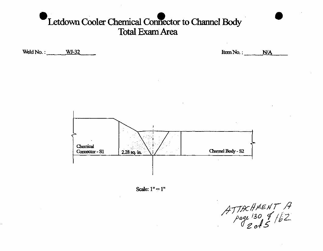
*Letdown Cooler Chemical Cornnector to Channel BodyTotal Exan Area
0
Weld No.: WJ-32 ItemNo.: N/A
ChemicalConictur - Si
I
aomel Body -S2I
Scale: I"=III
&4f•

*Letdown Cooler Chemical Connector to Channel BodyArea e Axial Scans
Weld No.: WJ-32 Item No. : N/A
=AreaNot Examined = 0.05 +0.01 =0.06 sq.in
=Area Eamined= 2.28 - 0.06/2.28x 100=97.4%
Chemical Conector -SI chanl Body -S2
45*600
Scale: 1" = 1"
O# ,

OLetdown Cooler Chemical Co•ctor to Chanel'BodyArea E amie @ Nozzle - Axial Scans
Weld No.: WJ-32 ItemNo. : N/A
= Area Not Examined = 0.05 + 0.01 + 0.02 = 0.08 sq. in.
LIII =Area Examined = 2.28 - 0.08 / 2.28 x 100 = 96.5%
I -• 0.05 sq.in.
0.02 sq. in
700
Chemical Conntor - SI
450 60 4 - 701450
cQannl Body -s2
Scale: 1" = 1" 177ý#Y•L AýlwlfE / 1 Z

Letdown Cooler Chemical Connfector to Channel BodyArea Examined - Circ. Scan
Weld No.: WJ-32 Item No. : N/A
=Area Not Examined = 0.5 sq. in.
=AreaExamnined= 2.28-0.5/2.28x100=78.1%LIZ
I
450 450
Scale: 1" = 1V
A -rl#c4''' .
: I gr 15_

UT Base Met amination
SitelUnit: Oconee / 0 Procedure: NDE-640 Outage No.: N/A
Summary No.: WJ.33 Procedure Rev.: 5 Report No.: BOP-UT-094113Workscope: PSI Work Order No,: 01889357 Page: 1 of 2
Code: NIA Cat./ltem: NA Location: N/A
Drawing No.: NIA Description: N/A
System ID: N/A
Component ID: WJ-33 Size/Length: NIA Thickness/Diameter: .875/3.OISS
Limitations: None Start Time: 0825 Finish Time: 0829
Examination Surface: inside [ Outside W/ Surface Condition: AS GROUNDLo Location: 9.1.1.1 Wo Location: Centertlne of Weld Couplant: ULTRAGEL II Batch No.: 09125Temp. Tool Mfg.: FISHER Serial No.: MCNDE32770 Surface Temp.: 70 OF Scanning dB: 47.0Cal. Report No.: CAL-09-457
% Amplitude Position One Position Max Position Two "mnd.Loss --. --.-. Remarks
No.Back Wall Full Screen Li W1 W2 MIP LM W1 W2 MP 12 W1 W2 MP
NRI
Comments: N/A
Results: Accept [ Reject C] Info PSI exam •_9/I ./ -2 Z3 ;'9- (Percent Of Coverage Obtained > 90%: Yes Reviewed Previous Data: No

96..SSupplemental Report
Report No.: BOP.UT-09-113
Page: 2 of 2
Summary No.: WJ-33
Examiner: Dean, Steven
Examiner: Griebe,, David M.
Other: N/A
Level: Il-N
Level: Il-N
Level: N/A
Reviewer:
Site Review:
ANII Review:.
Date:
Date:
Date:_,,-
Comments: WJ-33
52.
9A/iV~c•.J6~D5-'
A/ozaLZ7
ro 9-

0Site/Unit: Oconee / 0
Summary No.: WJ-33
Workscope: PSI
UUT Vessel Examination
0
Procedure:
Procedure Rev.:
Work Order No.:
NDE-3630
101889357
Outage No.: N/A
Report No.: BOP-UT-09-117
Page: 1 of 2
Code: 199812000A CaL/Item: B-DiB3.150 Location: WA
Drawing No.: NU.D-1149-1 Rev. A Description: Nozzle to channel body
System ID: N/A
Component ID: WJ-33 SizelLength: NIA ThicknesslDiameter- .87513.OISS
Limitations. Yes - See supplemental sheet Start Time: 0952 Finish Time: 1010
Examination Surface: Inside [ Outside [] Surface Condition: AS GROUND
Lo Location: 9.1.1.1 Wo Location: Centerline of Weld Couplant: ULTRAGEL II Batch No.: 09125
Temp. Tool Mfg.: FISHER Serial No,: MCNDE32770 Surface Temp.: 70 F
Cal. Report No.: ow 6 " //-'Y-'0 CAL-09-458, 459, 460, 461& 462
AngieUsed 0 4 4 45T I -ft -4H- 70L
Scanning dB 43.0 61i.1 50.2 55.0 46.0
Indication(s): Yes C] No [] Scan Coverage: Upstream to Downstream [] CW W CCW 66
Comments:
Scanning db lowered from +14db to maintain 2:1 signal to noise ratio
Results: Accept F) Reject 21 Info E) PSI examination .. 3/,/ A, -. Z ... :-/ s-.., c1i .c'-
Percent Of Coverage Obtained > 90%: No 54.6% Reviewed Previous Data: No C'AkV7J¶L%
Examiner Level II.N Signature Date Reviewer Signature DateDean, Steven 1114/2009 ,
Examiner Level II.JNin Date Site Review VSignature DateGrIebel, David M. 111412009 1IOther Level N/A " Signature Date AN?4iI4eview Signature DateNIA f~t~c tlgeT~9M
V/ - a 11

DUKE POWER COMPANYISI LIMITATION REPORT
ComponentlWeld ID: WJ-33 Item No: BOP-UT-09-117 remarks:
J NO SCAN SURFACE BEAM DIRECTION Due to nozzle.
E" LIMITED SCAN F" 1 • 2 1 Z 2 E- cw E' ccw
FROM L N/A to L N/A INCHES FROM WO Toe to Beyond
ANGLE: [3 0 0 45 0 60 other 70 FROM 0 DEG to 360 DEG
l NO SCAN SURFACE BEAM DIRECTION
E- LIMITED SCAN EC1 5] 2 l1 2 l cw E- ccw
FROM L to L INCHES FROM WO to
ANGLE: 53 0 [] 45 5] 60 other FROM DEG to DEG
El- NO SCAN SURFACE BEAM DIRECTION
n LIMITED SCAN l1 5 2 1 -] 2Elcw 0 ccw
FROM L to L INCHES FROM WO to
ANGLE: 5 0 F5 45 [] 60 other FROM DEG to DEG
El NO SCAN SURFACE BEAM DIRECTION
r- LIMITED SCAN 51 52 E [] 2[cw ccw
FROM L to L INCHES FROM WO to Sketch(s) attached4 [R yes E-] No
ANGLE: []00[ 5 0]60 other __ FROM DEG to DEG
Prpae B:Steve Dean • /ee:I ae 1041097 Sheet 2 of 2Reviewed By:i•m• A / Date: "oie A• nsnct -5S2ý.
. .. .i m & 2 2,A .- • ' a t .. _ ..,,,
wlwliýýlf13 ?,ýre 14ý Z,

i
Letdown Cooler Nozzle to Channel BodyWeld No. WJ-33
Base Material CoverageScan Radius View NonmRadius ViewAxial 68.2% 52.7%Circ 652% 54.4%
Aggregate @ 68.2 + 52.7 + 65.2 + 54.4 = 240.5/4 = 60.1%
"_Weld Material Coverage
Scan Radius View Non-Radcius ViewAxial-Si 45.9% .. 26.0MAxial-S2 0.0% .0.00%Circ-S2 94.1% 66.3%Circ-S2 94.1% 66.3%
Aggregate @ 45.9 + 26.0 + 0.0 + 0.0 + 94.1 + 66.3 + 94.1 + 66.3 392.7/8"= 49.1%Total Aggregate @ 6.0.1 + 49.1 = 109.2/2 = 54.6%
Level Ill T Af4Date /1I V- o'
14

0.Letdown Cooler Nozzic to Channel Body
Weld No.: W3-•-35;Item No. : oJIA
sAA1~JAL 1EUjff.AFI
2~-
~~JtI T) A(~AEA or- TJ~LLL~ -S~E~L. 7- .77F~~
~
=
Channel Body -Si
C
Scaic: "= 1"
,~ /37/~1 2s-T
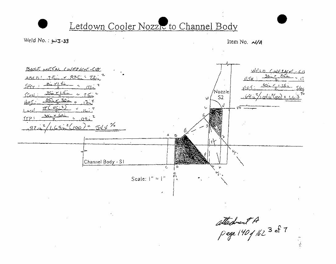
Letdown Cooler Nozzf to Channel Body
Weld No. w-5-33Item No. .JI,
z
/
Jfr-In -- Y7,,1
go-I
\WE5L I ,/z
J
I
IChannel .Body - S I
Scale: I"
9
l
•- i0
7, Vr4'

0Letdown Cooler Nozzt- to Channel Body
Weld No.: - -:3.:Item No. : A/,A
ilfiiA~2~coR
r~~~!f: (-, .L NozzleSS2
C:
4- 4 A
Sy~ ~ t(,,ý 7 ( z'. '
V Z 1Z
I
I Channel Body - S I
COScale: I" 1"
e
Xlý OZ q cf.

Letdown CooJ r.Nozzle to Channel Body,( Radius
0View')
.I
Weld No. • YZ-33 Item No. :,,,I/
-a ". ~gk .~,, - . q,z
-r, .
ItoIL
4? -. . . .. . ... .... .. . _ _ .
' 0 "uL.S•2 7 • .
7-
Lý, C', 14f-z
0 6~C-
Vo
,40-fA "& L3•L$
Q
Scale: 1'"= 1"
/'bZ <Ilol

0 0Lefdown CooL•r Nozzle to Cha~ihel Body ( Radius View')0
t/I!ld No.: W3AJ-33 Item No. : ,Vl/
7~&< &A~('f~l~ (C~ZA-T f-Oi /~I A %J/) CaO\/ýACrfý AVI/L
izLqsý) n
if . -A _ E . ,zI djA-
- ~ ~ .6 74. -' -74
C
-ttl
AC, 0 7z,
Ln3ýL
/. z
•,o°
Scale: I"= I"
/ r374z-~ 6 0F 7

*-tuown Coo1or Nozzle to ChaA-,ei Body ( Radius View c0
Weld No. " -_33 Item No. : AM/AI
BA CcxIt3C* ('c C
*q..
~ 2O~ "--7-
U, 0/.7
C-,c r R?5 Tx,'~
.1~/ *\-. -
_________
kJ
Yý
0
Scale: V''= I"///
-'~Te/9'7'/t 76
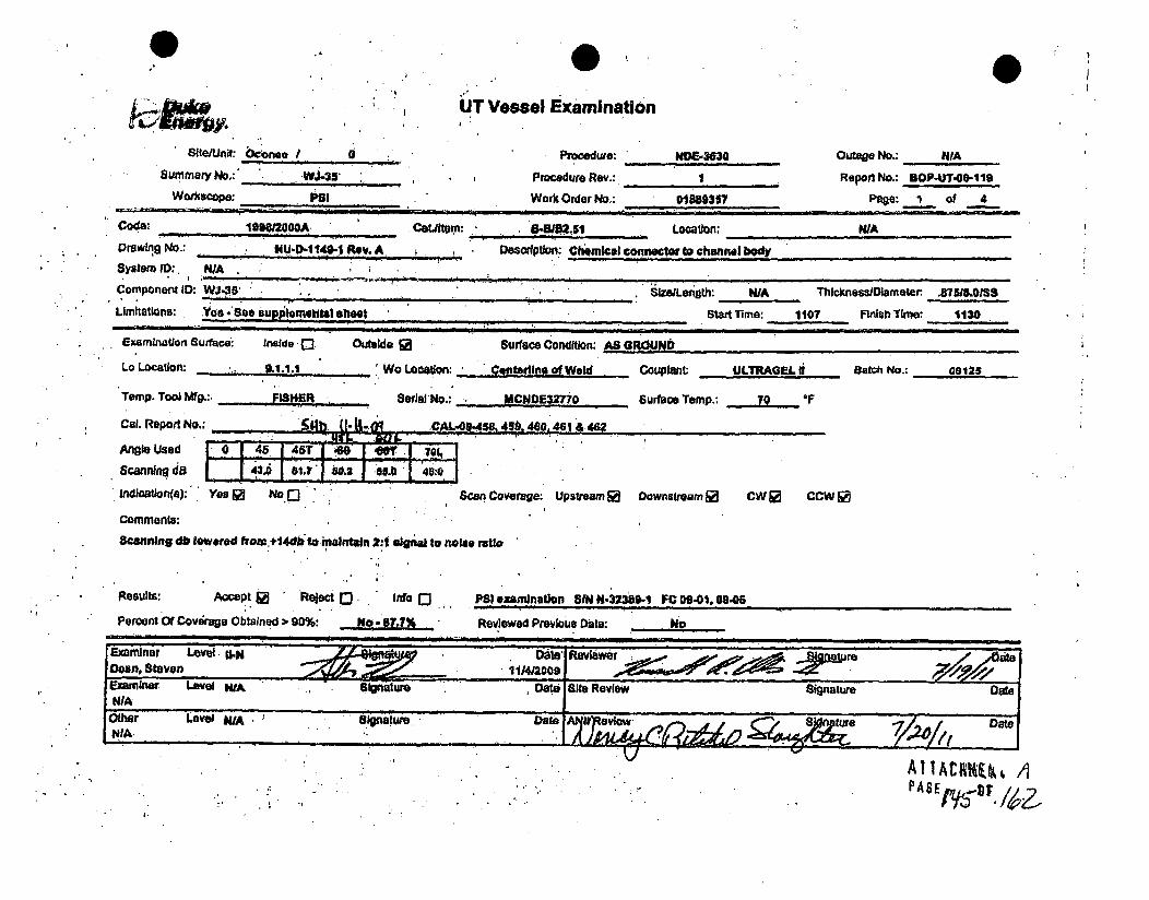
Vessel Examination
I1
ul
Summary No,:' *Wj 4s
Workscope: S
Proedwe: NOFE-3630
Procedure Roy' I
Work Order No, 011393117
Outgge No.: NIA
Report No.: BOP-UT.00-t19
Page. I of 4
Coda, leen o Cetiftem: .D8.1Locatn".l WA
Drawing No.: NU-0-I 140.1 ROV. A Description: Chemical co . wcWo to channelI body
system ID:, NIAC~omponanr ID: Wj3 ieLfgh AThlcknessiDiameter AMA=8.10
Limitations: ,Yoe -'Sao suppoinem tsl shteet Start Time: 1107 FMsIh Time: 1130
Examination Surface: Inside 0 Outside
Lo Location: I.,.. 'Wo Location:
Temp. Too) Mfg. FS .R ,.-eraNo.:
Col. Report No.:
Angle Used 45 46T
* Scanning dB 8J1-~.'?W. e .50..,a0Indioation(e): Yea s No Q
Comments:Scanning db lowered from:,÷4dblto inaIntahn 2:1 algn tonc
Resuls: Accept • Reject , Info (jPerent Of Covdraqu Obtained > 90%: No.-087.7%
Surface Condition: M A1
Ctaulldine of Weld
143u00
IICNBE32770
&_45.40c . 460, 461 & 402
Couptant; ULTRAGEI. I
Surface Tamp.: 70 O
Batch No.: 03126
m II B
Scan Coverage: Upsteam • Downstream 1 CW @ CCW [
la* ratio
Pal exanmnatgon SIN NM-23i -1 IC 09-01.0 940o
Revlewed Pravious Dala: .No
AT1Acrnk, A

44..
.44
Wo ocw;..Vs "m
AP. Me. Po
bA7 74~~~~~ -.55~1 nA~
- ~..W~Loc.~ Af
Ulson ic In~kaibain Rqport
.~on~f'~~..t0 -':'ed~: NDE-3830
-, ;., !;:~~11 ~ Work*OdrfrNo.: I0195*~~' 889357.'. 1
Outage No.: WAReport No.: BOP-U,-W9119
1Page: 2 of 4I I I I .. I. _ I | I
Fen ti -es l r' T ,
clva -W
.4 1
' r.
* 4.1
DW
1,,..ri
7. A", .
mvsnir
2 ~' 4
-2'
f4 ATTACI!MEN1 AP A 6 /1%4 F, 14Z_.4

4.
N
14
.1-
.5 . . I.
.5 4[*. .4'
r
4S4j~4.q~
5.44
.4
~ 'd~
'~55'
4
4 45 )45.
~54~
.5 - S
4 I
0S 0:;
4~:~D~4I~PWER.4:cQMPAN181~~ L11FA1INPRIORT'-
Cornpqnont1Wejd'IDij WJ,-35 41 _- ; . Item No:: BOP-IJT-09 119 remarks:
-NO SCAN . !'SURE BEAM DIRECTION Du.tonozze.EJ LIMITEDSCAN • .. 1 .2 01. 2 0cw ccwm
" ':-'• • " .. .~. 54' " *I*.I' t 'Ji •: '• " :' •
FROM L .0+3P toL: .3. ,jNCHESFROMWo,, CLO 1 toI 'Beyond..ANGLE:,* 0.0145 i-"1-1 Gt 60 DEG
-; [] NO SCAN .Uf _F A , . BE .DJR CTION .Taperonchemical
; -"LIM ITrD SCAN , -.; ' .- , -. . ' . 2 -' , -1 . e 2 , cw r@ caw , connetor.
FROM L'. NlA to . .N/A I .C.' FROMWO. +0.6 to +1.5
ANGLE:' '0 q 6, 0 9hr7O ROM; DEG to 38 DEG;;Jz "r,
I
i i
0,5 MC;: - EMDIETO
LIMIT ED ECAN -t• -. . .
'FOM L , ... ,' ' : ".INTCHES FROMWO . to
ANGLE:- 00 0. 450'.0 .othDr.FROM DEGto - DEt
'I
oNO'SCAN~i, LIMITED SCAN:";
FROML. .L4o
ANGLE:, " 0 5,
~E.j: 2~
j.. ~1
6tAm DIRECTION
E3 DJ2'';cw 0 ccw
F~O Iý DEG to 'DEC-
'4 i 4 .
I,7i.7 Sketch(s) attached
!.yes .- ENo
Pri'eii'wd By: Sheiet 3 of 4'[A41o.i.e
ftwl f
V( .::~ W
, rp
C,
i i4. f
A I IAt 1IHE11 /j i
!i

.wumrAt No.; W4
I. ., I
P,ar A .,
~i 2
RepodNo.: UNp.Ur-W,-liP~op: 4 of 4
DOC.
• .|.:

# . . .. - _
Lot flni Ccb - Cheical Conak • Cha~uwal fl
-to'k- ca
% Coverane Calculatons
a
Weld No..: WJ- 35
0= 8.62r"
S.= 0.87rr
27.1-" .Weld Leig =
Totd al pectlo Ame t2.Usq. hi.
%LengthLhbvddstminozzi-6'127.l~x 100.22.%-
-ni-
a' 7-
*u o lo - . ..- 3c¶.q
Aegnbcveqq~abcee:21475- 72 . ..-.* ~ ~ ~ ~ ~ ~ ~ ~ ý 7".* -. J'C. ''t~.t , ~
-. . ±3. -.... 4. .
- . J. -~ -
17-
Aq- '..... -, F.. .
a .-• . ... . • . - . -.• ' . .• .e
-.. . -• ..'" . . . , ., ' r• .•
.; ,4**
/,'%'o9 Pag.jof.1 ~
V
- -~- r-*- '-t. . .-'4$~-'t.'r4 *',.-
..• .... -. . . • .
-Ut.

Letdown Cooler Chemical Confector to Channel BodyTotal Exam Area
0
Weld No.: WJ-35 ItemNo.: N/A
Scale: 1" = 1"

Letdown Cooler Chemical Conffector to Channel BodyArea Examined- Axial Scans
0
Wed No.: W WJ-35 Item No.: , N/A
=AmaNot Exauhied= .05 +O0.01 =0.06 sq. in.
LII=Area Exatnined - 2.28-O0.06 /2.28 x100 =97.4%
Chemnical Connecto - SI chamnnl Body - S2
60'
Scale: I1IT= It ad~~~~/ 1± )ý6 ~
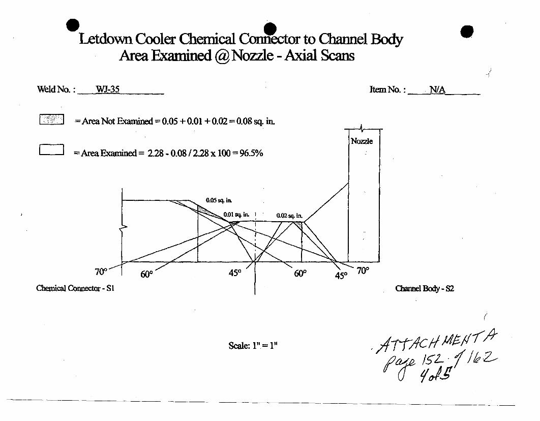
p ILetdown Cooler Chemical Connector to Channel Body
Area Examined @ Nozzle - Axial Scans
Weld No.: WJ.-35 Item No. : ,,N/A
IZ3
=Area Not Examined= 0.05 + 0.01 + 0.02 = 0.08 sq. in.
=Area Exained = 2.28 - 0.08/2.28 x 100 = 96.5%
0.05 s,. in.
I 0.01 sqi. I 0.02 sq. in
450 60P 450 70"
Chemical Connector - SI cinel Body -S2
Scale: 1", = 1"

Letdown Cooler Chemical Contector to Channel BodyArea Examined-UCirc. Scan
0
Weld No.: WJ-35 Item No. : N/A
-=Area Not Examnined = 0.5 sq. in.
Ei'- Area Examined= 2.28 - 0.5 / 2.28 x 100 = 78.1%
I
450 450
Scale: 1" = 1I
/A

0
SIteJUnit Oconee / 0
Summary No.: WJ-38
Wofkscope: PSI
UT Vessel Examination
Procedure:
Procedure Rev.:
Work Order No.:
NDE-3630
1
01889357
Outage No.: NIA
Report No.: BOP-UT-f9-1120
Page: 1 of 2
Code: 1198W2000A Cat.ltem: B.DIBS.160 Location: N/A
Drawing No.: NU-O-1 149-1 Rev. A Description: Nozzle to channel body
System ID: N/A
Component ID: WJ-4 SizefLength: NIA Thickneas/Dlameter. .87513.0138
Limitations: Yes - See supplemfntal sheet Start Time: 1012 Finish Time: 1034
Examination Sur#oce: inside Outside v Surface Condition: AS GROUND
Lo Location: 9.1.1.1 Wo Location: Centerine of Weld Couplant: ULTRAGEL II Batch No.: 09126
Temp. Tool Mfg.: PISHER Serial No.: MCNDE32770 Surface Temp.: 70 OF
Cal. Report No.: ;,"h 4'-. 09' CAL-09,458, 459,4e046,1& 482ev. eýcL-
Ang&eUsed 0 0 I 45 I 45T -•- .40- I 701.
Scanning dB 43.0 01. 50.2i 515.0 140.0
Indication(s): Yes No a: Scan Coverage: Upstream ý# Downstream v CW V CCW
Comments:
Scanning db lowered from 414db to maintain 2:1 signal to noise ratio
Reuulta Accept ý. Reject he Info
Percent Of Coverage Obtainedt > 90%: No -*W-
PSI examination S-4/A -32--8?-/ vc- OLI-01 CA-0s;Reviewed Previous Date: 0ý- 'i (-t-1 i's t
IExaminer Level U-N- Oats Reviev,. Signature DateDean, Steven : 1114/2009Examiner Level U.N .4igne Date Site Review Signature Date
Odebel, David bL. 11/4/2009 r
Other Level NIA Signature Date A - 1lnatu / . Date
A'%. ATI JA C~~ 00

-1N .4 .1ý A Al V
Component/Weld 1':, ._W-3 04" tm o BP-TO-20 .. marks:
NOMTE SCAN '6149 IP~~ .~".ý
. q pDN*
-FROM L! WA-- toW ý,N/A 4 ; - .NS -FROM.~Te",o
ANGLE: ~ ~ r~Z F~~OM~O~'.ýDEGto;360 -DEG________________
NO SCAN SRAE7BEAM DIRECTION __________
* 0 LIJM1TEDSCA C1 A. -.02 0 0,2 0o oFROML __ tL'tIN E"S'FROMWO, 't _ _
jR$~t., :DEG_______
0 LIMIED~qANV ; 4- 414 - 0"2%QMjt 1 2 0ow¼ 'M'.
UM.I&ITED SQ. N.~ __ _ _ _
A4 47
o o ~ ~ROM'~DE~t DEG 0ysE~
* ~~ .4f
AN.GLE' M. DEG t DEG
1/7 T R44 -'AK'

r
i2L
Letdown Cooler Nozzle to Channel BodyWeld No. WI-36
Base Material Coverage
3~)
"Sca n .",'Radius View .. .Non-R~adius V)iew. . .Axial ... 60.% ... 52.7%Circ , 65.2% 54.4%
Aggregate @ 68.2 + 52.7 + 65.2 + 54.4 '= 240.5/4 = 60.1%
... .. .... . . .. Weld Material Coverage
Scan Radius View Non-Radius ViewAxial-Si 45.9% 26.0%Axial-S2 0.0% 0.0%Circ-S2 94.1% 66.3%..Circ-S2 94.1% 66.3%
Aggregate @ 45.9 + 26.0 + 0.0 + 0.0 + 94,1 + 66.3 + 94A. + 66.3 392.7/8 =-49.1%Total Aggregate @ 60.1 + 49.1 = 109.2/2 .= 54:6%
Level III ___
Date (-109
41:j
14Q7

1. I W I4.
.44.. :.j 04IV
.
Le*w Chf.1e B
I a~o.: ____
... 4,.
'~~1 * ~.I
:J ~. L¶ ~ *'*l 4
~4.) 4'
4 4
I (4
' Total Exar
2' ~ I.41 4
4.. V 4.. . . I,
.4.4,.. 4 ~4
:4.".. *~~*
4 J,.,.,. ~ j4
2,
*,'~*,*-,<*j *s* *~
~ 4'~4 ~
d
*~'2.
I.4
.1
i,4444.*a .-. ,.*.*
'S
*1' '~~' * 44* 'V... i ,.
"I
.2"4
4'1 ~' . 1.
$44 ~4 4~4i
.1-'... 1444 (~ 4. 44'4
a i I I ,
'4
.4,,. 4..4...'.
'. . (4".i
p!4u
14 "I4
4.4 2.~I~? ,)> *4.,4>.~4~4~4 A? 4'.. F' -.
*r.4*** 41 - * ~ ,.' 1~
-. *.~.***~~'*'4.~*'4
S~~1e.- 1 ~4 ii V 4~ 2-'. V
'V 4
'p. .4
* " 'f4 14.4F,.4 * 4
444~ ~ .4
'4-, 4
I,*I4~
~ ,' A
P A 4 F
7, S 7

W d No.:., ." ,, . . • I,.
* I .
1 '
47 -71
T
N6e Nt Channel Box i d . 2• Ci•., c.:Scan.s.
• , I, . . .. .4.
.40 2lsqn,.
".21 1..72' x 100.= 55.5%• *o * | ... *j . 4, I. :
2, . ,44'. * ' ;, "" .' ' " ' '
.I7
a,.. ..: .• . • • •, . -' • . ,, .P,. ...
0 ... ,;
dy
n No.: _ __
-'4
-4
450
41*
- 444
I.
P
lI,
• , ". .
t~4..J
-. .4,4 ~4441. ... ~!,"~ ~,1 ~
14.
F\iN\I: 'S...
I.;...
, ' •. 7
450A11ACHME~P A E/58"DIsF
u~4- h
V1 ~ 4 1II, .., 450450
I`45-0
ts AIW ,im 3 *4:z

Id o
Letd• . ...; , , ,
...... :r ''., i ': ' ' ' .
1! Body
- -,,- I
*1
"IR
*1..
Ar a-nodt
Item Nc
II
W • A
II.
Lre~ Exaid 49 42- 7ýO '45.Zu/o
ozzle
K SS2
~~1C.
I,.It
-lr~
lei .450
. . . .. .
700
6500 A) 1ACNM1)4I AI.'A
"I(A
A -
* /4

Letdown Cooler Noz;ze to Cha'nnel Body (Radius View)
WeIdNo.: ,Item No.: _ jA
4
Total Exam Area 2.30 sq. in.
.Scale: V': P"AtCH~l
PAB/~ ~/ZA
t.

~etd'own C,.C
IlA are
(Radius View,
it4em No.:
4 Ii
4.f1
Oi.....30...I;X,
•...
.t
Ii-
700
6.00.I I'I 1*
450
q i °
~ .~> -
~I. ~.. .,.
.. L~< , ~pnnoJ
BodySI,
1. I.
Scale: 1" = V"
151"
*1
AITA HKEN I '.

%.0tCdown'CopQerý•Nozzet C 1anne1 Body Radius VieAeaExamined- Cir Scans• ., . T:,. A- ,,
Weld No,.: ¢ Item iV. ;
* I
*1
LII
4n
Are , not Exm'i'.ed • 0;.-42 sq. in
Area Examine4 • 3,03 - 0.42 /2.30 x 100= 81.7%450
**I
4 1
I.
4,
g
i 450
-, 41').
.4 ~VAAt1P1~r ~ £. .i 'a-- -
i~f.,. t~ * .1 a I* *-*- *, ..* a* ., *. 'a-.- .. I ~I-~:, ~**~ 1VL-~ *
I * 1'
Chann~elBody'
SI
I'I.
Scale: V =It
• ' ..
PAGF/6Z OF ' Z.i,
i