Inservice training program in mathematics education ... - CORE
Upload
khangminh22Category
view
1download
0
Florida Power & Light Company, 6501 South Ocean Drive, Jensen Beach, FL 34957
0 October 18, 2000 FPL
L-2000-211 10 CFR 50.4 10 CFR 50.55a
U. S. Nuclear Regulatory Commission Attn: Document Control Desk Washington, DC 20555
Re: St. Lucie Unit I Docket No. 50-335 Inservice Inspection Plan Unit 1 Revised Relief Request 7A
The purpose of this letter is to request NRC approval of St. Lucie Unit 1 third interval inservice inspection (ISI) revised Relief Request (R/R) 7A. R/R 7A revises the schedule for augmented refueling water tank (RWT) liner inspections and provides the justification for the new schedule. The revised R/R and the justifications are enclosed. Paragraphs that include changes are marked with a revision bar at the right margin.
The third ten-year ISI interval for St. Lucie Unit 1 began on February 11, 1998. Florida Power & Light Company (FPL) submitted the planned ISI program including the third interval R/Rs by letter L-98-14 on February 2, 1998. Revision 0 of Relief Request 7 was approved by NRC Safety Evaluation dated June 18, 1999.
NRC review and approval is requested by February 28, 2001, to support planning for the St. Lucie Unit 1 spring 2001 refueling outage (SL1-17). Please contact us should you require any additional clarifications.
Very truly yours,
Rajiv S. Kundalkar Vice President St. Lucie Plant
RSK/GRM
Enclosure
cc: Regional Administrator, Region II, USNRC Senior Resident Inspector, USNRC, St. Lucie Plant
pqDl
an FPL Group company
St. Lucie Unit 1 Docket No. 50-335 L-2000-211 Enclosure Page 1
St. Lucie Unit 1 THIRD INSPECTION INTERVAL
RELIEF REQUEST NUMBER 7A (Revised 9/2000)
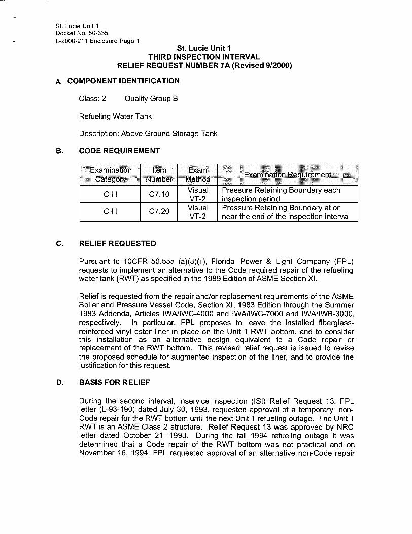
A. COMPONENT IDENTIFICATION
Class: 2 Quality Group B
Refueling Water Tank
Description: Above Ground Storage Tank
B. CODE REQUIREMENT
Examination Item ExamExmntoReuret Category Number MethodExmntoReuret
Visual Pressure Retaining Boundary each VT-2 inspection period
C-H C7.20 Visual Pressure Retaining Boundary at or VT-2 near the end of the inspection interval
C. RELIEF REQUESTED
Pursuant to 10CFR 50.55a (a)(3)(ii), Florida Power & Light Company (FPL) requests to implement an alternative to the Code required repair of the refueling water tank (RWT) as specified in the 1989 Edition of ASME Section XI.
Relief is requested from the repair and/or replacement requirements of the ASME Boiler and Pressure Vessel Code, Section XI, 1983 Edition through the Summer 1983 Addenda, Articles IWA/IWC-4000 and IWA/IWC-7000 and IWA/IWB-3000, respectively. In particular, FPL proposes to leave the installed fiberglassreinforced vinyl ester liner in place on the Unit 1 RWT bottom, and to consider this installation as an alternative design equivalent to a Code repair or replacement of the RWT bottom. This revised relief request is issued to revise the proposed schedule for augmented inspection of the liner, and to provide the justification for this request.
D. BASIS FOR RELIEF
During the second interval, inservice inspection (ISI) Relief Request 13, FPL letter (L-93-190) dated July 30, 1993, requested approval of a temporary nonCode repair for the RWT bottom until the next Unit 1 refueling outage. The Unit 1 RWT is an ASME Class 2 structure. Relief Request 13 was approved by NRC letter dated October 21, 1993. During the fall 1994 refueling outage it was determined that a Code repair of the RWT bottom was not practical and on November 16, 1994, FPL requested approval of an alternative non-Code repair

St. Lucie Unit 1 Docket No. 50-335 L-2000-211 Enclosure Page 2
St. Lucie Unit 1 THIRD INSPECTION INTERVAL
RELIEF REQUEST NUMBER 7A (Revised 912000)
to correct through wall leakage and corrosion of the Unit 1 RWT bottom. On November 25, 1994, NRC approved the addition of a reinforced vinyl ester liner to the bottom of the RWT until the St. Lucie Unit I steam generator replacement outage. As part of the approval, the NRC requested FPL to complete ongoing laboratory testing and in-situ inspections to confirm the ultimate capabilities of the lining.
FPL completed the evaluation of the reinforced vinyl ester liner and requested its approval as a permanent replacement of the RWT bottom. In NRC letter dated May, 27, 1997, the NRC authorized FPL's use of the tank lining along with the proposed inspections, in lieu of a Code repair or replacement, for the remainder of the second ten-year interval.
In NRC letter dated June 18, 1999, the NRC approved R/R 07, which had been submitted by FPL requesting authorization for use of the tank lining in lieu of a Code repair or replacement for the third ten-year interval.
The augmented inspection program for the tank liner requires that the RWT be drained and a hands-on inspection of the liner performed every third refueling outage, beginning with outage SLI-17. Based on the results of the inspections performed to date on the liner, it is proposed that the augmented inspection schedule be revised to require a hands-on inspection every sixth outage, beginning with outage SL1-20.
E. PROPOSED ALTERNATIVE
Florida Power and Light proposes to use the installed fiberglass-reinforced vinyl ester liner (Dudick Protecto-Line 800 system) in place on the Unit 1 RWT bottom as a permanent alternative design, and also proposes to continue to use the RWT to meet its required Technical Specification functions.
1. Beginning with the SL1-20 refueling outage (the fifth outage following the steam generator replacement outage, and the sixth outage following the last hands-on inspection performed), and during every sixth subsequent refueling outage (i.e., approximately every nine years), a full inspection of the RWT liner will be performed. For these inspections, the RWT will be completely drained; inspectors will enter the tank to perform a hands-on inspection. These inspections will be similar to the inspection performed during the spring 1996 refueling outage (SLI-14). The liner will be inspected for acceptability of the following properties:
- hardness - delamination - adhesion

St. Lucie Unit 1 Docket No. 50-335 L-2000-211 Enclosure Page 3
St. Lucie Unit 1 THIRD INSPECTION INTERVAL
RELIEF REQUEST NUMBER 7A (Revised 912000)
- peeling - flaking - undercutting - blistering - cracking - checking - discoloration - holidays - pinholes
2. Beginning with the SL1-15 outage (the steam generator replacement outage), and during every refueling outage for which a full, hands-on inspection is not scheduled, a remote visual inspection of the RWT liner will be performed. These remote inspections may be performed with the use of a diver or a remotely operated submersible vehicle equipped with a camera. During these inspections, following liner visual examinations will be performed:
- peeling - flaking - undercutting - blistering - cracking
Should any RWT liner inspections indicate unacceptable results, or if there are any documented occurrences of leakage through the RWT bottom, the inspection schedule (and types of inspections required) shall be revised as follows: a full hands-on inspection shall be performed during the first refueling outage following the unacceptable inspection results or documented leakage, and during every third refueling outage thereafter (through the end of the third ten-year ISI interval).
See Table 1 for a summary of proposed augmented inspections.
3. Inspection of Caulking Material
The conditions at the bottom of the RWT shall be inspected on an annual basis to verify that the corrective measures implemented (i.e., the caulking material between the RWT bottom and the concrete ring wall) continue to prevent ingress of standing or rain water beneath the RWT.

St. Lucie Unit 1 Docket No. 50-335 L-2000-211 Enclosure Page 4
St. Lucie Unit I THIRD INSPECTION INTERVAL
RELIEF REQUEST NUMBER 7A (Revised 9/2000)
F. IMPLEMENTATION SCHEDULE
This alternative repair will remain in place through the St. Lucie Unit 1 third inservice inspection interval.
G. ATTACHMENTS TO THE RELIEF
St. Lucie Unit 1, Refueling Water Tank, Request for Alternative Tank Bottom Design Justification.

St. Lucie Unit 1 Docket No. 50-335 L-2000-211 Enclosure Page 5
St. Lucie Unit I THIRD INSPECTION INTERVAL
RELIEF REQUEST NUMBER 7A (Revised 912000)
TABLE I
ST. LUCIE UNIT I -REFUELING WATER TANK PROPOSED SCHEDULE FOR INSPECTIONS FOR THE THIRD 10-year INSERVICE INSPECTION INTERVALS
OUTAGE REMOTE VISUAL INSPECTION (SEE SECTION 8.2.1.B)
FULL HANDS-ON INSPECTION (SEE SECTION 8.2.1.A)
THIRD TEN-YEAR ISI INTERVAL (February 11.
SL1-16
SL1-17
SL1-18
SLI-19
SL1-20
SL1-21
1998 - February 10. 2008)
x
x x x
x
x
NOTES: (1) The proposed inspection schedule outlined in Section 8.2.1 is only applicable
through the end of the third ten-year ISI interval. A separate submittal will be made to the NRC regarding a proposed inspection schedule for the period beginning with the fourth ten-year ISI interval (which begins on February 11, 2008). The proposed inspection schedule will be based on the results of inspections performed up to the time of submittal, along with the documented performance of the RWT liner.
(2) If any inspections indicate unacceptable results, or if there are any documented occurrences of leakage through the RWT bottom, the inspection schedule shall be revised as follows: a full hands-on inspection shall be performed during the first refueling outage following the unacceptable inspection results or documented leakage, and during every third refueling outage thereafter (through the end of the third ten-year ISI interval).

St. Lucie Unit 1 Docket No. 50-335 L-2000-211 Enclosure Page 6
Relief Request 7A Attachment
1.0 PURPOSE
The purpose of this submittal is:
a. To demonstrate that the liner material presently installed on the St. Lucie Unit I RWT bottom reflects an alternative design which provides acceptable levels of quality and safety which are equivalent to those provided by the original code of record.
b. To request approval of the installed liner material as an alternative design to be used on the tank bottom for the remaining duration of the tank life.
c. To establish the revised augmented inspection schedule (and types of inspections) proposed for verification that the RWT liner would continue to perform its required functions.
2.0 COMPONENT IDENTIFICATION
The RWT is an above ground storage tank which provides a source of primary grade water for refueling, reactor coolant makeup, reactivity control during plant operations, and accident conditions (Reference 9.1, Sections 3.1.2.2, 3.1.2.8, and 3.5.4). The RWT is a Quality Group B, ASME Class 2 structure, and was designed and erected in accordance with ANSI B96.1-1967 (Reference 9.2). The RWT provides the Technical Specification required minimum volume of 401,800 gallons of borated water, which ensures that 371,800 gallons are available for injection during emergency core cooling. The RWT boron concentration is maintained at a minimum value of 1720 ppm to ensure an adequate shutdown margin with the reactor in cold shutdown with all control element assemblies withdrawn (Reference 9.1, Section 3.1.2.8, and Reference 9.3, Section 6.3.2.2.1)
3.0 RELIEF REQUESTED
Relief is requested from the repair and/or replacement requirements of the ASME Boiler and Pressure Vessel Code, Section XI, 1983 Edition through the Summer 1983 Addenda, Articles IWAIIWC-4000 and IWAIIWC-7000 and IWNIWB-3000, respectively. In particular, Florida Power and Light proposes to leave the installed fiberglass-reinforced vinyl ester liner in place on the Unit 1 refueling water tank (RWT) bottom, and to consider this installation as an alternative design equivalent to a Code repair or replacement of the RWT bottom. In support of this request, FPL proposes an augmented inspection program for the bottom liner installation.

St. Lucie Unit 1 Docket No. 50-335 L-2000-211 Enclosure Page 7
Relief Request 7A Attachment
Revision to Relief Request
Via Reference 9.35, the NRC authorized FPL's use of the RWT lining along with the proposed inspections, in lieu of a Code repair or replacement, for the remainder of the second ten-year interval. Via Reference 9.36, the NRC approved R/R-07, which had been submitted by FPL requesting authorization for use of the tank lining in lieu of a Code repair or replacement for the third ten-year interval.
The augmented inspection program for the tank liner requires that the RWT be drained and a hands-on inspection of the liner performed every third refueling outage, beginning with outage SL1-17. During refueling outages for which a hands-on inspection is not performed, a remote visual inspection is required. Based on the results of the inspections performed to date on the liner, it is proposed that the augmented inspection schedule be revised to require a handson inspection every sixth outage, beginning with outage SL1-20. This revised relief request is issued to revise the proposed schedule for augmented inspection of the liner, and to provide the justification for this request.
4.0 BACKGROUND
4.1 Discovery of Leak in RWT Bottom
A steady loss of RWT inventory was observed for several weeks in June and July of 1993. The rate of the loss measured at that time was approximately 2 gpm. In July 1993, an acoustic emissions (AE) analysis was performed using externally mounted equipment and a transducer mounted on a mini-rover submarine. From this analysis, a single leak approximately 3/16 inch in diameter was located in an area on the RWT bottom near the east side of the tank.
4.2 Temporary Non-Code Repair (Epoxy Patch)
A review of Generic Letter 90-05 (Reference 9.4) was performed to determine the basis for allowing non-code repairs to code class components. It was determined that any non-code repair to Class 1 or 2 piping must be performed in accordance with an engineered specification which would provide a boundary that would be of equal structural strength as the original design basis of the component. Code R/R 13 was prepared and submitted to the NRC (Reference 9.5) requesting NRC approval for a non-code repair involving the use of an epoxy coating to adhere an aluminum plate to the tank bottom. In the relief request, FPL committed to providing a code acceptable repair during the fall 1994 refueling outage. The NRC, in accordance with 10 CFR 50.55a(g)(6)(i), granted the requested relief and accepted the temporary repair until the

St. Lucie Unit 1 Docket No. 50-335 L-2000-211 Enclosure Page 8
Relief Request 7A Attachment
fall 1994 refueling outage, at which time the RWT bottom plate was required to be repaired or replaced in accordance with the provisions of the ASME Code (Reference 9.6). The non-code repair was implemented using a 1/8 inch thick, 3 inch diameter piece of aluminum plate and Duromar SAR-UW epoxy. Additional AE testing confirmed that there was no further leakage from the identified location (Reference 9.7).
4.3 Proposed Permanent Code Repair
Engineering documents were prepared to support the implementation of a permanent code repair during the fall 1994 Unit I refueling outage. This repair, as designed, involved:
a. Removal of the section of the bottom plate which contained the identified leak, and which had been temporarily repaired in 1993 using aluminum plate and Duromar SAR-UW epoxy.
b. Addition of a new 1/4-inch aluminum filler plate, with bearing material as necessary to provide uniform support for the new plate section.
c. Sealing of the filler plate to the existing bottom plate by the use of Belzona 1111 epoxy sealant.
d. Welding of a new 1/4-inch aluminum plate section to the existing bottom plate to cover the opening left by the removal of the temporarily repaired plate.
When the bottom plate section was removed from the RWT bottom during the fall 1994 outage, visual inspection revealed corrosion on the exterior surface; scattered pitting (hemispherical in shape) and patches of a loosely adherent white corrosion product (likely aluminum oxide) were found. The depths of the ten deepest pits ranged from 0.065 inches to 0.225 inches, with an average depth of 0.107 inches. Most of the surface displayed a dark gray color, indicating a passive state prior to removal; however, several of the pits were shiny and silver in color, indicating a state of active corrosion prior to removal. Portions of the surface were free of any evidence of corrosive attack. The previously repaired hole was seen to have originated from the plate's exterior surface; this was deduced from the sloping profile of the hole. These findings are documented in the root cause analysis performed by FPL's component support and inspection (CSI) group (Reference 9.8).
During the installation of the new plate section, difficulties were experienced in completing the code repair. The wall thinning of the base

St. Lucie Unit 1 Docket No. 50-335 L-2000-211 Enclosure Page 9
Relief Request 7A Attachment
material, coupled with conditions associated with welding inside the contaminated environment, led to localized defects. This resulted in an inability to qualify the welds; for this reason, the code repair could not be implemented.
4.4 Alternative Non-Code Repair (Vinyl Ester Liner)
As an alternative to the code repair, a fiberglass reinforced vinyl ester liner (Protecto-Line 800 system, manufactured by Dudick, Inc.) was applied to the inside surface of the RWT bottom. The liner system is a 1/8-inch (approximate) thick coating consisting of a prime coat, a trowelled base coat with a layer of fiberglass roving, and a top coat. Prior to application, the aluminum surfaces to receive the liner were sandblasted to obtain the specified surface profile. The surface was inspected to ensure proper preparation for the application of the coating. The liner was applied over the entire tank bottom and extended approximately 24 inches up the tank wall. The liner was visually inspected to verify proper installation. The installation of this liner system was performed during the fall 1994 Unit 1 refueling outage in accordance with PC/M 128-194 (Reference 9.9). Personnel training, surface preparation, liner installation, and visual inspections were performed under the direction of FPL nuclear engineering's coatings specialist. The RWT was placed in service immediately following the installation and inspection of the liner material; the liner system has satisfactorily performed its required functions since its installation.
The liner installation is considered an alternative non-code repair. For this reason, FPL submitted R/R 13A to the NRC for approval of the use of this liner (Reference 9.10). In a telephone conversation on November 16, 1994, the NRC provided verbal approval for the installation of this liner in the RWT. By NRC letter (Reference 9.11), which also transmitted a safety evaluation report, the NRC granted relief to install and use the ProtectoLine 800 system, stating that it would provide an acceptable level of quality and safety. In this letter the NRC stated that at the time of the steam generator replacement outage, the RWT bottom would be replaced or repaired in accordance with the ASME Code. Additionally, the NRC stated that FPL has committed to the following:
a. Visual examination of the lining during each refueling outage. b. Continued monitoring of the RWT for indications of leakage. c. Completion of ongoing laboratory testing to confirm the ultimate
capabilities of the lining.

St. Lucie Unit 1 Docket No. 50-335 L-2000-21 1 Enclosure Page 10
Relief Request 7A Attachment
5.0 ROOT CAUSE EVALUATION
5.1 Evaluation
The FPL CSI Group performed an evaluation of the as-found condition of the 14 inch square section of plate removed from the RWT bottom, and of the soil samples taken from the area beneath the removed plate, in order to determine the failure mechanism of the RWT bottom (Reference 9.8). The following tests were performed as part of this analysis:
a. resistivity tests on soil samples b. determination of chemicals in soil samples c. evaluation of DC potential measurements conducted on the RWT.
The very low chloride, nitrate, and sulfate anion levels, along with the near neutral pH values and high electrical resistivity values found, indicate that the soil beneath the RWT is non-corrosive. No detectable levels of oil were found in the soil samples.
The tank-to-soil corrosion potentials measured around the tank rim were more positive than documented potentials for aluminum alloys in simulated sea water. This result indicated that the exterior surfaces of the floor plates were in an active state of corrosion. The recorded values likely resulted from a galvanic couple between the floor plates and the copper ground grid, which would have rendered the plates susceptible to corrosive attack; this, however, would have required a more conductive electrolyte than the specified sand-oil cushion. Visual inspection of the interface between the tank floor and the concrete ring wall revealed the absence of a joint sealing compound
The conclusion of the root cause evaluation was that the failure mechanism of the RWT was galvanic corrosion (resulting from a galvanic couple between the exterior surface of the RWT aluminum alloy floor and the surrounding copper ground grid) which was manifested as pitting type attack. The root cause of the failure was determined to be the absence of a seal between the tank bottom plates and the concrete ring wall, which permitted the periodic ingress of water into the sand/oil cushion layer beneath the tank. This water likely contained dissolved salts which had been formerly deposited on the tank walls and the surrounding earth. As this water permeated the sand layer beneath the tank, it rendered the soil more conductive, thus increasing the susceptibility of the exterior of the tank floor plates to corrosive galvanic attack.
St. Lucie Unit 1 Docket No. 50-335 L-2000-21 1 Enclosure Page 11
Relief Request 7A Attachment
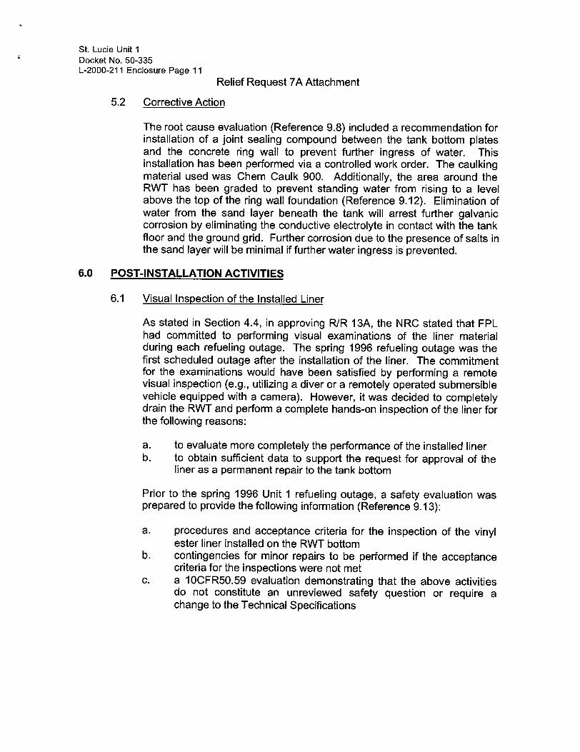
5.2 Corrective Action
The root cause evaluation (Reference 9.8) included a recommendation for installation of a joint sealing compound between the tank bottom plates and the concrete ring wall to prevent further ingress of water. This installation has been performed via a controlled work order. The caulking material used was Chem Caulk 900. Additionally, the area around the RWT has been graded to prevent standing water from rising to a level above the top of the ring wall foundation (Reference 9.12). Elimination of water from the sand layer beneath the tank will arrest further galvanic corrosion by eliminating the conductive electrolyte in contact with the tank floor and the ground grid. Further corrosion due to the presence of salts in the sand layer will be minimal if further water ingress is prevented.
6.0 POST-INSTALLATION ACTIVITIES
6.1 Visual Inspection of the Installed Liner
As stated in Section 4.4, in approving R/R 13A, the NRC stated that FPL had committed to performing visual examinations of the liner material during each refueling outage. The spring 1996 refueling outage was the first scheduled outage after the installation of the liner. The commitment for the examinations would have been satisfied by performing a remote visual inspection (e.g., utilizing a diver or a remotely operated submersible vehicle equipped with a camera). However, it was decided to completely drain the RWT and perform a complete hands-on inspection of the liner for the following reasons:
a. to evaluate more completely the performance of the installed liner b. to obtain sufficient data to support the request for approval of the
liner as a permanent repair to the tank bottom
Prior to the spring 1996 Unit 1 refueling outage, a safety evaluation was prepared to provide the following information (Reference 9.13):
a. procedures and acceptance criteria for the inspection of the vinyl ester liner installed on the RWT bottom
b. contingencies for minor repairs to be performed if the acceptance criteria for the inspections were not met
c. a 10CFR50.59 evaluation demonstrating that the above activities do not constitute an unreviewed safety question or require a change to the Technical Specifications

St. Lucie Unit 1 Docket No. 50-335 L-2000-211 Enclosure Page 12
Relief Request 7A Attachment
On May 18, 1996, during the spring 1996 Unit 1 refueling outage, an inspection of the bottom liner of the RWT was performed. The liner was inspected for acceptability of the following properties:
a. hardness b. delamination c. adhesion d. peeling e. flaking f. undercutting g. blistering h. cracking i. checking j. discoloration k. holidays 1. pinholes
The inspections performed on the RWT liner were non-destructive in nature. The majority of the inspections were visual only. Some of the inspections (i.e., hardness, undercutting) involved the application of pressure with the edge or point of a knife or paint scraper; this did not result in any cutting of the liner surface. The inspections for delamination and adhesion involved physical sounding, in which the liner surface was struck with a hammer. The liner was only struck hard enough to enable the inspector to listen to the sound made; the force applied was insufficient to cause any damage to the liner.
The installed liner was found to be acceptable. The liner met the acceptance criteria for all of the properties listed above, and showed no signs of degradation, which could affect its ability to perform its required functions. There were two minor conditions found which warranted additional investigation, as noted below:
a. At one location, a small diameter hole (diameter approximately 1/32 inch) was found. Upon excavation, the hole was found to be less than 1/16 inch deep, and did not penetrate through the topcoat layer. No path was found for water from the RWT to penetrate through the liner material. Therefore, the condition was considered to be an installation anomaly, and was not classified as a pinhole. For these reasons, the as-found condition was determined to be acceptable. The excavated area was sanded, cleaned with an alcohol wipe, and filled in with Duromar SAR-UW. This repair left the total coating thickness in the area of the anomaly equivalent to that of the remainder of the liner.

St. Lucie Unit I Docket No. 50-335 L-2000-211 Enclosure Page 13
Relief Request 7A Attachment
b. At one location, a small amount of duct tape was found on the RWT wall and covered by the Protecto-Line topcoat. The tape was completely covered by the liner material, and was completely restrained by the liner from becoming dislodged. The duct tape had originally been placed on the wall for temporary attachment of shielding materials. The tape was removed by cutting the liner with a knife, removing the liner material from above the tape, and removing the tape. Additional liner material was removed to accommodate the installation of a vortex suppressor (Reference 9.14). The liner material near the cut line was sanded and wiped with alcohol; the surface of the newly exposed aluminum was prepared in accordance with SSPC-SP-11. Duromar SAR-UW epoxy was then placed with a 1-inch (minimum) overlap on both the liner and the aluminum to provide a seal at the cut line.
The complete report of the results of the liner inspection, including the additional investigations described above, is documented in Reference 9.15.
During the two subsequent refueling outages (SL1-15 and SLI-16), remote visual inspections of the RWT liner were performed. These inspections were performed on October 17, 1997 and September 9, 1999. The liner was visually inspected for acceptability of the following properties:
a. peeling b. flaking c. undercutting d. blistering e. cracking
These inspections were performed utilizing a remotely operated submersible vehicle equipped with a camera. The visual signal from the camera was observed by the nuclear coatings specialist and an engineering representative. During each inspection, the RWT liner was found to be in an acceptable condition, with no observable degradation; it was concluded that the liner continues to provide the required levels of quality and safety equivalent to those provided by the original code of record.
The complete reports of the results of the two remote visual inspections are documented in References 9.29 and 9.30.
St. Lucie Unit 1 Docket No. 50-335 L-2000-211 Enclosure Page 14
Relief Request 7A Attachment
6.2 Additional Inspections
As discussed in Section 5.2, a caulking compound has been installed between the RWT bottom and the concrete ring wall foundation to prevent further ingress of water. This caulking installation is required to be inspected on an annual basis to verify that the corrective measures continue to prevent ingress of standing or rain water beneath the RWT. The first required inspection was performed on August 26, 1996. Visual inspection was performed at the interfaces between (a) the base of the RWT and the asphalt and (b) between the asphalt and the concrete RWT foundation. These inspections revealed minor defects in the caulk layers. These defects consisted of pitting (small holes, less than 1/16-inch diameter) and minor separation (approximately 1/32-inch wide) between the caulk and the adjacent surfaces. The extent of the defects was not sufficiently large to have created a potential for ingress of substantial amounts of water beneath the RWT. However, in order to prevent future problems in this area, the caulk at the interfaces (a) between the base of the RWT and the asphalt and (b) between the asphalt and the concrete RWT foundation was repaired as necessary. This installation was reinspected on September 12, 1996, and was determined to be satisfactory for the prevention of ingress of standing or rain water beneath the RWT. The complete report of the inspection and re-inspection is documented in Attachment 12.5 of Reference 9.16.
Subsequent inspections of the caulking installation have noted similar instances of minor degradation. None of the defects observed was sufficiently extensive to have created the potential to allow a substantial amount of water to ingress underneath the RWT. After each inspection, the caulk was repaired as required, then re-inspected by engineering. The complete reports of the inspections and re-inspections are documented in References 9.31 and 9.32.
6.3 Tests of Physical Properties of Liner Material
Dudick, Inc., has published test values for the following physical properties of the Protecto-Line 800 liner system (Reference 9.9): - adhesion strength - ability to bridge holes up to 0.5-inch in diameter - specific gravity - ability to accommodate "oil canning" - effects of radiation exposure on tensile bond test results - resistance to 5,000 ppm boron concentration - compressive strength - coefficient of thermal expansion - taber abrasion
St. Lucie Unit 1 Docket No. 50-335 L-2000-211 Enclosure Page 15
Relief Request 7A Attachment
flame spread water vapor transmission electrical resistance
Discussion of these properties, including any laboratory testing performed to confirm the capabilities of this liner material with regard to its use in the Unit 1 RWT, is provided in the following paragraphs.
(a) Adhesion Strenqth
Two sets of adhesion strength tests were performed at the FPL CSI laboratory in West Palm Beach, Florida on January 3, 1995 and January 30, 1995. Adhesion tests were performed in accordance with ASTM D4541-93. Test samples were prepared by applying Dudick Protecto-Line 800 (using the same batches as were applied to the RWT bottom) to aluminum plates of the same material as specified for the RWT. The coating was applied in individual layers (primer, basecoat, mat, topcoat) which were exposed at different strips along the test plate. Loading fixtures were attached to the surface of the liner test samples using an epoxy adhesive. The portable tester used was an Elcometer Model No. 106 (0-2,000 psi). The pulling force was applied through the Elcometer testing apparatus to the loading fixture until failure occurred. Special care was taken to turn the wrench in a plane parallel to the substrate to avoid the application of shear loads or other eccentric loads. The failure loads (in psi) and nature of failure were also recorded.
A total of 32 loading fixtures were tested for pull-off strength. The summary of these tests is as follows:
Date of System Number Average Pull-Off Test Component of Tests Strength
1/3195 Primer 1 500 psi 1130/95 Primer 3 233 psi 113/95 Mat 1 400 psi 1/30/95 Mat 1 200 psi 1/3/95 Base Coat 2 500 psi 1/30/95 Base Coat 2 550 psi 1/3/95 Top Coat 11 600 psi 1/30/95 Top Coat 11 620 psi
All of the failures of the test specimens were a result of failure of the glue attaching the test fixtures to the sample panel. No adhesion or cohesion failures of the coating were observed.

St. Lucie Unit 1 Docket No. 50-335 L-2000-211 Enclosure Page 16
Relief Request 7A Attachment
Dudick has published test data (Attachment 12.11 to Reference 9.16) indicating that the tensile bond strengths of the Protecto-Line 800 liner components are as follows:
a. base coat (adhesion to primed aluminum): 750 psi b. top coat (adhesion to total system): 1050 psi
During the testing, the glue bonding the loading fixtures to the liner generally failed before the above loads could be applied. Therefore, it was not possible to confirm the adhesion values published by Dudick. However, some of the individual tests performed exceeded the published values. It may be concluded that higher adhesion values could have been obtained if stronger glue had been available. The test values obtained are sufficient to ensure that the coating will not suffer adhesion or cohesion failure. Therefore, the values obtained during the testing indicate that the Dudick Protecto-Line 800 system has sufficient adhesion and cohesion strength to perform its intended functions as a liner for the St. Lucie Unit 1 RWT.
The complete reports of these tests are documented in Attachments 12.6 and 12.7 of Reference 9.16.
(b) Ability to bridge holes up to 0.5-inch in diameter
Three sample plates were tested at FPL's CSI laboratory in West Palm Beach, Florida, on January 3 and 30, 1995.
Tests were performed to evaluate the ability of the liner material to span over holes of 1-inch, 2-inch, and 3-inch diameters. Holes of these sizes were drilled in the test plates, and then covered with tape, prior to application of the liner material. After the liner material had cured, the tape was removed from the underside of the cured liner material; this left holes in the plates over which the liner spanned. This set-up replicates the hypothetical situation in which the aluminum plate deteriorates after the application of the liner.
Loads were applied to the liner material spanning the holes to simulate the loads which would result from water pressure at the bottom of the RWT. The table below lists the loads applied to the liner for each hole size, and the margin of safety with regard to postulated loading conditions (i.e., the ratio between the test loading applied and the load which the liner would have to carry in situ at the bottom of the RWT).

St. Lucie Unit 1 Docket No. 50-335 L-2000-211 Enclosure Page 17
Relief Request 7A Attachment
Test Load In Situ Margin of Hole Size Applied Load * Safety
1-inch 140 1bs 13 Ibs 11 2-inch 150 lbs 53 lbs 2.8 3-inch 220 Ibs 119 Ibs 1.8
[* The water pressure at the bottom of the RWT is 16.9 psi
(Reference 9.17). Therefore, the in situ load to be carried by the liner spanning over a postulated hole is equal to 16.9 psi multiplied by the area of the hole.]
For each hole size tested, the loads that were applied during laboratory testing did not cause failure (either by structural failure or by adhesion/cohesion failure) of the test sample. No deflection or visual signs of distress of the liner material were observed. Therefore, the actual margin of safety of the liner material is higher than the values determined above.
The conclusion reached from this test is that the Dudick ProtectoLine 800 system liner material, in its application in the St. Lucie Unit 1 RWT, can span over holes up to 3 inches in diameter with a satisfactory margin of safety.
The complete report of these tests is documented in Attachment 12.8 of Reference 9.16.
(c) Specific Gravity
A sample of the Dudick Protecto-Line 800 liner material was applied to a removable plastic medium and allowed to cure. When curing was complete, the liner system was removed from the medium. A sample was then cut from this material, and the dimensions and weight were measured and recorded. These measurements were taken at FPL's CSI laboratory in West Palm Beach, Florida on January 3, 1995.
From the measurements taken, the volume of the sample was determined to be 2861 mm 3 , while the weight was measured as 4.86 grams. From this, the specific gravity of the liner sample was determined to be 1.7 (greater than that of water in the RWT). As a confirmatory test, a sample of liner material was placed into a beaker of tap water. Several different orientations were used (i.e., the sample was placed onto the surface of the water with the flat

St. Lucie Unit 1 Docket No. 50-335 L-2000-211 Enclosure Page 18
Relief Request 7A Attachment
surface horizontal as well as vertical). Each time the sample was placed into the water, it sank immediately to the bottom of the beaker. This confirms the claim of Dudick, Inc. that the specific gravity of the Protecto-Line 800 liner is greater than that of water.
This result confirms the original conclusion (Reference 9.9) that, if any liner material installed in the RWT were to come loose, it would remain on the bottom of the tank and not be drawn into suction penetrations (as stated in Reference 9.9, the fluid velocities in the vicinity of the penetration are very low and insufficient to draw any significant debris off the bottom of the tank).
The complete report of these tests is documented in Attachment 12.9 of Reference 9.16.
(d) Ability to accommodate "oil canning"
In FPL memorandum JPN-CSI-95-045 (Reference 9.18), documentation was provided of the observation of "oil canning" of the bottom plates of the RWT after the application and curing of the Dudick Protecto-Line 800 system. This "oil canning" was caused by the weight of personnel walking on the tank bottom which had distended upward when the weight of the water normally stored in the tank had been removed. The effect was observed to be applied cyclically (i.e., downward deflection when an individual stood on a floor panel, with the panel returning to its original position when the weight of the individual was removed. This "oil canning" was observed to be of a magnitude approximating 3 to 4 inches. No cracking, disbondment, or other signs of distress in the liner were observed as a result of this occurrence. Similar observations (both of the extent of "oil canning" and of the absence of distress in the liner) were made during the inspection of the RWT liner on May 18, 1996. Therefore, it is concluded that the Protecto-Line 800 liner will not be adversely affected by the "oil canning" effect resulting from the cyclic removal and addition of loads on the RWT bottom plates (i.e., the draining and filling of the tank).
(e) Effects of radiation exposure on tensile bond test results
An aluminum test panel coated with the Dudick Protecto-Line 800 system was submitted to SteriGenics, Inc. who subjected this test panel to an exposure of 107,100,000 rads (Attachments 12.11 and 12.14 of Reference 9.16). This is greater than the projected total dose to the RWT bottom, which is estimated to be 35,000 rem overall or 350,000 rem at hot spots (Reference 9.19). The

St. Lucie Unit 1 Docket No. 50-335 L-2000-211 Enclosure Page 19
Relief Request 7A Attachment
irradiated panel was then provided to Dudick, who performed adhesion tests in accordance with ASTM D4541. The results of this testing were identical to previous tests, thus verifying that the radiation exposure had no effect on the tensile bond strength of the liner material (Attachment 12.11 of Reference 9.16). After testing, the test panel was returned to FPL.
The FPL coatings specialist performed confirmatory adhesion testing in accordance with ASTM D4541-93 on the irradiated sample received from Dudick (Reference 9.20). All of the failures of the test specimens were a result of failure of the glue attaching the test fixtures to the sample panel; in each case, the applied load at failure was between 500 and 750 psi. No adhesion or cohesion failures of the coating were observed. The values obtained during the testing indicate that the Dudick Protecto-Line 800 system maintains sufficient adhesion and cohesion strength to perform its intended functions as a liner for the St. Lucie Unit 1 RWT.
(f) Resistance to 5,000 ppm boron concentration
Dudick, Inc., recommends the Protecto-Line 800 fiberglass reinforced vinyl ester liner system for applications involving concentrated acid spills, acid neutralization, and caustic handling areas. General-purpose polyester resins reinforced with fiberglass have good chemical resistance, except to alkalis; however, materials in this class which are based on bisphenol are more resistant to alkalis (Reference 9.21, page 23-61). General-purpose polyesters have good to excellent chemical resistance to 10% solutions of hydrochloric, sulfuric, nitric, and acetic acids (Reference 9.21, Table 23-9). Also, polyesters have excellent resistance to mineral acids such as boric acid (Reference 9.21, Table 23-11).
Even at 5,000 ppm, the concentration of boric acid in water is very dilute (much less than 10%). Therefore, from the industry data and historical information referenced in the paragraph above, the Protecto-Line 800 liner material will adequately resist a boron concentration of 5,000 ppm.
Makeup to the RWT is supplied via a blended flow of reactor makeup water from the primary water tank and boric acid (approximately 3% concentration) from the boric acid makeup tanks (Reference 9.22). This combination yields the Technical Specification required RWT concentration of 1720 ppm boron (approximately 1% boric acid). This is much less than the 10%

St. Lucie Unit 1 Docket No. 50-335 L-2000-211 Enclosure Page 20
Relief Request 7A Attachment
concentration evaluated above. Therefore, the Protecto-Line 800 liner material will adequately resist the boron concentration present in the RWT.
Visual inspection performed on May 18, 1996 (Reference 9.15) indicated no changes in the physical attributes of the installed liner; this is a primary indication of chemical resistance.
(g) Compressive strength
The water pressure at the bottom of the RWT is 16.9 psi (Reference 9.17). Because of this low uniform load to be carried, and the absence of concentrated loads on the RWT bottom, it was concluded that compressive strength is not a critical property for the liner material. However, subsequent tests were performed to verify that the liner material can withstand, with an adequate safety margin, the uniform compressive loads to which it will be subjected in the RWT.
Two samples of Dudick Protecto-Line 800 material were subjected to compression testing in the FPL research and evaluation laboratory in West Palm Beach, Florida on August 28, 1996. The compression loads were applied with a Tinius Olsen 5000 pound universal testing machine. The complete report of this testing is documented in Attachment 12.13 of Reference 9.16.
The samples were placed in the testing machine between parallel plates. A thin piece of rubber blanket was placed on top of the sample to smooth out any irregularities. The sample was compressed in 1,000 pound increments at a rate of approximately 1,000 pounds per minute. At each increment, the sample was removed and visually examined for signs of failure.
The first sample tested measured 1.1-inches by 1.117-inches, with an area of 1.23 square inches. The maximum compressive load applied to this sample was 5030 pounds, which resulted in a compressive stress of 5030/1.23 or 4090 psi. The second sample tested measured 1.124-inches by 1.126-inches, with an area of 1.27 square inches. The maximum compressive load applied to this sample was 5021 pounds, which resulted in a compressive stress of 5021/1.27 or 3950 psi. Neither test sample showed any signs of failure at the maximum load. Therefore, the margin of safety for the liner material with regard to compressive strength is at least 3950/16.9 or 234. The test values obtained indicate that the Dudick Protecto-Line 800 system has sufficient compressive

St. Lucie Unit 1 Docket No. 50-335 L-2000-211 Enclosure Page 21
Relief Request 7A Attachment
strength to perform its intended function as a liner for the St. Lucie Unit I RWT.
(h) Coefficient of thermal expansion
From information published by Dudick, Inc., the coefficient of expansion for the Protecto-Line 800 system is 12-15 x 10-6
inch/inch/oF (Attachment 4.4 of Reference 9.9). The coefficient of thermal expansion for aluminum is 12.8 x 10⁻⁶ inch/inch/F (Reference 9.23, p. 19-46). The values of the coefficient of thermal expansion for the two materials are approximately equal.
The assumed minimum temperature of the water in the RWT is 55'F (Reference 9.3, Table 6.3-6). The design temperature of the water in the RWT is 125'F (Reference 9.3, Table 6.3-2). Because of this limited temperature range, the coefficient of thermal expansion is not a critical property. Over a 50 foot length (the diameter of the RWT), a strip of aluminum subjected to a 70OF temperature increase would increase in length by only (12.8 x 10⁻⁶
inch/inch °F) x (50x12 inches) x (700 F) or approximately 1/2 inch. Even a major variance in the coefficient of expansion of the liner material would not result in a large differential expansion between the liner and the aluminum; therefore, the value of the coefficient of thermal expansion does not need to be verified.
(i) Water vapor transmission
Water vapor transmission (WVT) is a measure of the rate at which water vapor can be transmitted through a coating. This property is generally used as a guide in the selection of coatings (i.e., paint) which are normally applied to a dry film thickness (DFT) of 10-20 mils and which would be more susceptible to blistering. The value of WVT published by Dudick for the Protecto-Line 800 system (0.0017 perm. inch) is very low. Because of the high DFT (125 mils or greater) of the liner system, and the low WVT rate, the ProtectoLine 800 system is not susceptible to osmotic blistering. Therefore, the water vapor transmission rate does not need to be verified.
(j) Other properties Because of the nature of this application of the liner material (i.e., underwater on the non-traffic-bearing interior surfaces of the nonstructural bottom plates of a water storage tank), verification of the properties of Taber abrasion, flame spread, and electrical resistance is not required.

St. Lucie Unit 1 Docket No. 50-335 L-2000-211 Enclosure Page 22
Relief Request 7A Attachment
6.4 Tests of chemical properties of liner material
Samples of the materials used in the application of the Protecto-Line 800 system (primer, coating, filler, hardener, and fiberglass roving) were sent to Professional Service Industries (Pittsburgh Testing Lab Division) for chemical analysis. The intent of this analysis was to confirm the composition of the liner materials, and to determine whether the amounts of impurities in the materials are within the limits specified in FPL Administrative Procedure 0010507 (Reference 9.24) for materials used in the primary system. [Subsequent to the analysis, Administrative Procedure AP 0010507 was replaced by Administrative Procedure ADM02.01 (Reference 9.37). The impurity limits were not revised.]
To analyze the composition of the liner materials, infrared spectroscopic analysis was performed on samples of the basecoat and the filler material. The spectrum of the basecoat material appeared to represent a mixture of materials from which typical vinyl esters are formed. The spectrum of the filler material was determined to be similar to several siliceous materials. From this analysis, it was concluded that the chemical composition of the two samples agreed with the description published by Dudick, except that the basecoat sample did not contain silica. This conclusion was as expected; although the purchase requisition describes the basecoat as being a "vinyl ester resin with graded silica," the silica is a separate filler which is added at the time of application, and would not have been present in the basecoat material analyzed. Therefore, the results of this analysis confirm that the liner material is in conformance with the published description.
Tests were also performed to determine the concentration of halogens (chloride, fluoride, bromide, and iodide), sulfur, and metals (mercury, lead, copper, zinc, tin, cadmium, and phosphorus) present in the liner materials. These impurities are as identified in References 9.24 and 9.37. The testing was performed using recognized ASTM and EPA standards and inductively coupled plasma spectroscopy. This testing indicated that the levels of all impurities (except for chloride and sulfur) in each of the liner components were within the acceptable limits. The levels of chloride and sulfur were above the acceptable limits. These results were obtained from the testing of the individual component elements of the Protecto-Line 800 system. When these components are mixed together to form the applied liner, the reactions between the elements change the final chemical composition of the liner. For this reason, the levels of impurities in the component elements are not necessarily indicative of the levels to be found in the final system; the chemical reactions could cause the concentrations of the free elements to be reduced. Since the levels of impurities (except chloride and sulfur) in each of the liner components

St. Lucie Unit 1 Docket No. 50-335 L-2000-211 Enclosure Page 23
Relief Request 7A Attachment
were within the acceptable limits, it was concluded that the levels of these impurities in the liner are acceptable. Further investigation of total chloride and sulfur levels was required. The complete report of the chemical analysis performed by Professional Service Industries (Pittsburgh Testing Lab Division) is documented in Reference 9.25.
Additional tests were performed on a sample of the cured Protecto-Line 800 system liner to determine total chloride, total sulfur, and leachable chloride. This testing was performed at the FPL central testing laboratory in West Palm Beach, Florida on August 28, 1996 and August 29, 1996. A sample of the liner was burned in a Parr Oxygen Combustion Bomb. The bomb washings were then analyzed for chloride and sulfate by ion chromatography (EPA Method 300.0). The test results indicated that the total sulfur content of the cured liner material was 87 ppm, which is within the acceptable limit of 100 ppm. Total chloride was determined to be 460 ppm, which is above the specified limit of 100 ppm.
For the vinyl ester liner, the total chloride is not an appropriate measure of the amount of chloride that can come into contact with the primary system. In compounds of this nature, the majority of the chloride is bound within the matrix of the cured liner material; the only chloride that can come into contact with the primary system is that which can leach out of the cured chemical compound. For this reason, an additional test was performed to determine the amount of leachable chloride in the liner material. For this test, a sample of the cured liner was leached in ionized water and boiled for one hour. After cooling, the water was analyzed by ion chromatography. This test indicated that the concentration of leachable chloride in the cured liner material is 83 ppm; this is within the acceptable limit of 100 ppm. The use of leachable chlorides as an indicator is an accepted practice within the nuclear coatings industry. The complete report of the testing performed at FPL's central testing laboratory is documented in Reference 9.26.
The results of the chemical tests performed by Professional Testing Industries and FPL's central testing laboratory indicate that the Dudick Protecto-Line 800 liner is composed of the materials specified by Dudick, Inc., and that the levels of impurities in the material are within the acceptable limits as specified in References 9.24 and 9.37.
7.0 EVALUATION OF PRESENTLY INSTALLED LINER
7.1 Design of the RWT bottom
The RWT was designed in accordance with ANSI B96.1 Welded Aluminum Alloy Field Erected Storage Tanks. The main base plates are

St. Lucie Unit 1 Docket No. 50-335 L-2000-211 Enclosure Page 24
Relief Request 7A Attachment
0.25 inches thick and are welded to a 0.375 inch thick annular base plate. The tank is supported on an 8.5-feet high by 2-feet wide reinforced concrete ring wall foundation. The RWT base is anchored to the ring wall foundation with 45 two-inch diameter ASTM A36 carbon steel anchor bolts (References 9.27 and 9.28).
The RWT bottom plates are continuously supported by structural fill material. There is a 6-inch thick sand and oil cushion placed on approximately 8 feet of Class I fill compacted to 95% of maximum dry density; underlying this is Class I fill compacted to 98% of maximum dry density (Reference 9.22). The tank shell is supported directly by the concrete ring wall and does not depend on the bottom plate for structural support. Per ANSI B96.1, the flat bottom of the tank is not subject to specific design rules for calculating minimum thickness and allowable stresses are not given for the tank bottom. The function of the bottom plate is to provide a barrier between the tank fluid and the underlying fill material. The bottom plate does not transfer loads to the shell or the annular base plate and ring wall foundation. Pressure stress loads are carried by the fill beneath the tank bottom. Therefore, the tank bottom may be considered a liner.
During the various repairs made to the RWT bottom, the support conditions of the bottom plate have not been changed from the original design.
7.2 Effects of alternative design on quality and safety
7.2.1 As discussed in Section 6.3, FPL has performed confirmatory testing to verify the manufacturer's published information concerning the physical properties of the Dudick Protecto-Line 800 system. These test results provide the necessary confirmation of the ability of the Dudick system to perform its intended functions as a liner for the St. Lucie Unit 1 RWT.
7.2.2 As discussed in Section 6.4, FPL has performed chemical testing to confirm the composition of the liner materials. The results of this testing indicate that the Protecto-Line 800 liner system is composed of the materials specified by Dudick, Inc., and does not exceed the acceptable limits for impurities as specified by FPL administrative procedures for materials in contact with the primary system.
7.2.3 The fiberglass-reinforced vinyl ester liner was installed during the fall 1994 refueling outage. During the spring 1996 refueling outage, the RWT was drained and a full hands-on visual inspection of the liner was performed. As discussed in Section 6.1, the liner met the

St. Lucie Unit I Docket No. 50-335 L-2000-211 Enclosure Page 25
Relief Request 7A Attachment
acceptance criteria for all properties evaluated during this inspection, and showed no signs of degradation which could affect its ability to perform its required functions.
7.2.4 As discussed in Section 5.0, FPL has performed a root cause analysis of the tank bottom corrosion mechanism. The failure mechanism was determined to be galvanic corrosion resulting from a galvanic couple between the exterior surface of the RWT floor and the surrounding copper ground grid. The root cause of the failure was determined to be the absence of a seal between the tank bottom plates and the concrete ring wall, which permitted the periodic ingress of water beneath the tank. Corrective action has been taken to eliminate this root cause by installing a joint sealing compound between the tank bottom plates and the ring wall. Additionally, the area around the RWT has been graded to prevent standing water from rising to a level above the top of the ring wall foundation. By preventing further ingress of water beneath the RWT, further corrosion of the tank bottom due to the presence of salts in the sand layer will be minimal.
7.2.5 For the reasons discussed above, the Dudick Protecto-Line 800 system has been determined to be an appropriate material to be used as a liner for the aluminum RWT. Visual inspections have indicated no degradation of the material since installation. Since the tank bottom does not transfer loads to the shell or to the annular base plate and ring wall foundation, it is considered a liner (i.e., a barrier between the tank fluid and the underlying fill material) in accordance with ANSI B96.1 (the design code of record). Therefore, the installed Dudick Protecto-Line 800 liner is considered an alternative design which is equivalent to the design originally installed per the code of record (ANSI B96.1), and will provide an acceptable level of quality and safety.
The liner material extends approximately 24 inches up the tank wall, which is a structural, load carrying element of the tank. As indicated in Section 6.3(d), the liner has exhibited the ability to accommodate approximately 3 to 4 inches of deflection on the tank bottom. This exceeds any bending deflection that will be experienced in the lowest 2 feet of the tank wall under postulated loading conditions. Therefore, loads causing stresses and accompanying deformations in the RWT wall will not result in loss of adhesion of the liner material to either the tank wall or the bottom.

St. Lucie Unit 1 Docket No. 50-335 L-2000-211 Enclosure Page 26
Relief Request 7A Attachment
7.2.6 The installed Protecto-Line 800 liner system meets quality standards commensurate with the importance of the safety function to be performed (i.e., acting as a liner to retain the water in the RWT), as indicated by the following.
a. The liner was installed in accordance with Reference 9.9, which is a safety-related engineering package.
b. The liner material has been subjected to physical and chemical tests (as discussed in Sections 6.3 and 6.4) to confirm its ability to perform its intended functions as a liner for the RWT.
c. FPL is proposing an augmented inspection program (see Section 8.0) to provide ongoing verification that the liner will continue to adequately perform its intended functions.
8.0 FUTURE PLANS
8.1 Planned use of the liner
Florida Power and Light proposes to use the installed fiberglass-reinforced vinyl ester liner (Dudick Protecto-Line 800 system) in place on the Unit 1 RWT bottom as a permanent alternative design, and also proposes to continue to use the RWT to meet its required Technical Specification functions.
The Unit 1 UFSAR (Reference 9.3), Section 6.3.2.2.1, states that the NRC has approved the liner "as an alternative non-code repair ... until the steam generator refueling outage, at which time a code repair shall be made." An FSAR change package (FCP) has been prepared to delete the requirement to perform a code repair at the time of the steam generator replacement outage. The UFSAR has been updated to incorporate this FCP.
8.2 Proposed schedule for inspection of liner
8.2.1 The following inspections will be performed during the period beginning with the steam generator replacement outage and for the subsequent ten years (i.e., through the third ten-year ISI interval, which ends on February 10, 2008).
a. Beginning with the SL1-20 refueling outage (the fifth outage following the steam generator replacement outage and the sixth outage following the last hands-on inspection

St. Lucie Unit 1 Docket No. 50-335 L-2000-211 Enclosure Page 27
Relief Request 7A Attachment
performed), and during every sixth subsequent refueling outage (i.e., approximately every nine years), a full inspection of the RWT liner will be performed. For these inspections, the RWT will be completely drained; inspectors will enter the tank to perform a hands-on inspection. These inspections will be similar to the inspection performed during the spring 1996 refueling outage (see Section 6.1). The liner will be inspected for acceptability of the following properties:
- hardness - delamination - adhesion - peeling - flaking - undercutting - blistering - cracking - checking - discoloration - holidays - pinholes
b. Beginning with the SLI-15 outage (the steam generator replacement outage), and during every refueling outage for which a full, hands-on inspection is not scheduled (as specified in Section 8.2.1.a), a remote visual inspection of the RWT liner will be performed. These remote inspections may be performed with the use of a diver or a remotely operated submersible vehicle equipped with a camera. During these inspections, the following visual examinations will be performed on the liner:
- peeling - flaking - undercutting - blistering - cracking
8.2.2 The proposed inspection schedule outlined in Section 8.2.1 is only applicable through the end of the third ten-year ISI interval. A separate submittal will be made to the NRC regarding a proposed inspection schedule for the period beginning with the fourth tenyear ISI interval (which begins on February 11, 2008). The proposed inspection schedule will be based on the results of

St. Lucie Unit 1 Docket No. 50-335 L-2000-211 Enclosure Page 28
Relief Request 7A Attachment
inspections performed up to the time of submittal, along with the documented performance of the RWT liner.
8.2.3 Should any RWT liner inspections indicate unacceptable results (in accordance with criteria similar to those contained in Reference 9.13), or if there are any documented occurrences of leakage through the RWT bottom, the inspection schedule (and types of inspections required) shall be revised as follows: a full hands-on inspection shall be performed during the first refueling outage following the unacceptable inspection results or documented leakage, and during every third refueling outage thereafter (through the end of the third ten-year ISI interval).
8.2.4 See Table 1 for a summary of proposed augmented inspections.
8.2.5 Justification for revision to augmented inspection schedule
The RWT is outside of the primary containment; inadequate performance of the liner, however, could adversely affect the orderly and safe shutdown of the plant. Therefore, the RWT liner is considered to be Service Level III as defined by EPRI TR-109937, Guideline on Nuclear Safety-Related Coatings (Reference 9.33). The RWT liner was installed prior to the issuance of Reference 9.33; however, special process controls used during the installation of the liner are in compliance with the EPRI guidelines. The EPRI guideline is referenced in Regulatory Guide 1.54 (Reference 9.34), and is considered an industry guideline for coatings both inside and outside of containment.
EPRI guidance for the inspection of coatings is found in Section 8, Condition Assessment, of Reference 9.33. Table 8-1 recommends that the condition of ECCS water storage sources (e.g., the RWT) be assessed once every five years. It is also stated within the guideline that "once initial inspections have been conducted.... then the inspection scopes can be adjusted based on an analysis of the findings. Should inspections indicate satisfactory conditions, then frequencies of future inspections may be adjusted accordingly." The RWT was drained in 1996, one and one-half years after the installation of the liner. A hands-on inspection of the liner was performed at that time by the FPL nuclear coatings specialist. The liner was inspected for acceptability of the following properties:
hardness delamination adhesion

St. Lucie Unit 1 Docket No. 50-335 L-2000-211 Enclosure Page 29
Relief Request 7A Attachment
- peeling - flaking - undercutting - blistering - cracking - checking - discoloration - holidays - pinholes
The liner met the acceptance criteria for all of the properties listed, and showed no signs of degradation.
In addition, remote visual inspections of the liner were performed by the nuclear coatings specialist in 1997 and 1999, using a remotely controlled submersible device outfitted with a camera. The liner was inspected for peeling, flaking, undercutting, blistering, and cracking. During each of these inspections, the liner was found to be in an acceptable condition, with no evidence of degradation.
The RWT liner is a reinforced vinyl ester with an epoxy primer; the system has been evaluated and qualified for the required service. This type of system is widely used as a tank lining for conditions considerably more corrosive than that created by the slightly acidic borated water present in the RWT. The liner cures by a chemical reaction between the resin and the catalyst, which cross-links to form a solid insoluble coating. Fiberglass and fillers have been incorporated into the design of this system to compensate for the shrinkage, which takes place in vinyl ester when polymerization takes place. Any problems associated with this type of liner would likely be associated with delaminating or loss of adhesion caused by shrinkage after installation. This condition would be accompanied by cracking of the liner, and (if present) would have been discovered during the final inspection of the liner after installation. This liner has been inspected three times since its original installation in 1994 (one hands-on inspection with the tank completely drained, and two remote visual inspections), with no defects or change in appearance found.
Due to the excellent performance of the installed liner material as verified through the augmented inspection schedule performed to date, it is proposed that the inspection schedule be adjusted (as addressed in the EPRI guidelines, Reference 9.33). The revised proposed inspection schedule requires a hands-on inspection of the RWT liner once every six outages (approximately once every nine

St. Lucie Unit 1 Docket No. 50-335 L-2000-211 Enclosure Page 30
Relief Request 7A Attachment
years), beginning with SL1-20, and a remote visual inspection every outage for which a hands-on inspection is not scheduled (approximately once every 18 months). This is considered acceptable for the following reasons:
- the special process controls used during installation (under the direct supervision of the nuclear coatings specialist)
- the material data of the liner, as verified through laboratory testing
- the historical performance data of the liner - the results of the inspections performed to date - the nature of the water stored in the tank
8.3 Inspection of Caulkingi Material
As discussed in Section 6.2, the conditions at the bottom of the RWT shall be inspected on an annual basis to verify that the corrective measures implemented (i.e., the caulking material between the RWT bottom and the concrete ring wall) continue to prevent ingress of standing or rain water beneath the RWT (Reference 9.17).
9.0 REFERENCES
9.1 St. Lucie Unit I Technical Specifications, updated through Amendment 164.
9.2 ANSI B96.1-1967, "Welded Aluminum Alloy Field Erected Storage Tanks."
9.3 St. Lucie Unit I Updated Final Safety Analysis Report, updated through Amendment 17.
9.4 Generic Letter No. 90-05, Guidance for Performing Temporary Non-Code Repair of ASME Code Class 1, 2, and 3 Piping, dated June 15, 1990.
9.5 FPL Letter L-93-190 from D. A. Sager to U. S. Nuclear Regulatory Commission, dated July 30, 1993.
9.6 U. S. Nuclear Regulatory Commission letter from Herbert N. Berkow to Mr. J. H. Goldberg, dated October 21, 1993.
9.7 Letter ESI-NDE-93-172, from C. M. Redding/S. M. Alberico to A. G. Menocal, Final Report of the Refueling Water Tank, St. Lucie Unit 1, August 1993, prepared by Florida Power & Light Company, Nuclear Engineering, ESI, dated August 13, 1993.

St. Lucie Unit 1 Docket No. 50-335 L-2000-211 Enclosure Page 31
Relief Request 7A Attachment
9.8 Letter MET-94-227 from Mark Joseph (FPL Component Support and Inspection Group) to Dan Denver (FPL Nuclear Engineering), dated January 19, 1995.
9.9 PC/M No. 128-194, Addition of a Reinforced Vinyl Ester Liner to the Bottom of the Refueling Water Tank, Revision 1.
9.10 FPL Letter L-94-291 from D. A. Sager to U. S. Nuclear Regulatory Commission, dated November 16, 1994.
9.11 Letter from Mohan C. Thadani (NRR) to Mr. J. H. Goldberg (FPL), Subj: Proposed Alternative to the ASME Code for Replacement of the Refueling Water Tank Bottom at St. Lucie Unit No. 1, (TAC No. M90762) dated November 25, 1994
9.12 Nonconformance Report (NCR) No. 1-741 dated January 22, 1993.
9.13 Safety Evaluation No. JPN-PSL-SECP-96-053, Inspection Procedures and Repair Contingencies for the Refueling Water Tank Bottom Liner," Revision 0.
9.14 PC/M No. 96-085, Refueling Water Tank Vortex Suppressor, Revision 0.
9.15 Letter JPN-SPSL-96-0245 from D. J. Denver (FPL Nuclear Engineering) to H. L. Fagley (FPL Projects Maintenance Support), dated May 23, 1996
9.16 Safety Evaluation No. JPN-PSL-SECS-96-082, Refueling Water Tank Alternative Bottom Design, Revision 0.
9.17 St. Lucie Action Report (STAR) No. 1-94110485 dated November 21, 1994.
9.18 Letter JPN-CSI-95-045 from G. S. Dolderer to K. H. Greene dated February 3, 1995.
9.19 Letter 93-021 from Ray McCullers (St. Lucie Health Physics) to Garth Dolderer (JPNIJB), dated September 22, 1993.
9.20 Letter JPN-CSI-96-113 from G. S. Dolderer to K. H. Greene dated September 12, 1996.
9.21 Perry, Robert H., and Cecil H. Chilton, Chemical Engineers' Handbook, Fifth Edition, McGraw-Hill Book Company, copyright 1973.

St. Lucie Unit I Docket No. 50-335 L-2000-211 Enclosure Page 32
Relief Request 7A Attachment
9.22 Safety Evaluation JPN-PSL-SENP-93-035, Evaluation of Inventory Loss from the Refueling Water Tank, Revision 2.
9.23 Gaylord, Edwin H., Jr., and Charles N. Gaylord, Structural Engineering Handbook, McGraw-Hill Book Company, copyright 1968.
9.24 FPL Administrative Procedure No. 0010507, Control of Chemicals and Materials for the Maintenance of Plant Systems, Revision 9.
9.25 Professional Service Industries, Inc., Test Report for Protecto-Line 800 Material for Florida Power & Light Co., Project No. 831-5T084-1, dated March 6, 1995.
9.26 Florida Power and Light Central Laboratory Report of Analysis (Sample Identification: Dudick Protecto-Line 800 FPL Lab WITS ID: W-96-81), dated September 4, 1996.
9.27 Drawing No. 8770-4510, Refueling Water Tank - Bottom Details, Revision 5.
9.28 Drawing No. 8770-G-671, Component Cooling Pumps Foundations Masonry, Revision 9.
9.29 Letter ENG-SPSL-97-0556 from C. R. Bible (FPL Nuclear Engineering) to R. J. Frechette (FPL Projects Maintenance Support), dated November 22, 1997.
9.30 Letter ENG-SPSL-99-0355 from C. R. Bible (FPL Nuclear Engineering) to S. Marchigiano (FPL Projects Maintenance Services), dated September 10, 1999.
9.31 Plant Management Action Item PM97-11-149, Inspection of Caulking at Unit I R WT.
9.32 Letter ENG-SPSL-00-0045 from C. R. Bible (FPL Nuclear Engineering) to S. Marchigiano (FPL Projects Maintenance Services) dated February 10, 2000.
9.33 EPRI TR-109937, Guideline on Nuclear Safety-Related Coatings, April 1998.
9.34 USNRC Regulatory Guide 1.54, Service Level 1, II, and Ill Protective Coatings Applied to Nuclear Power Plants, Revision 1, July 2000.

St. Lucie Unit 1 Docket No. 50-335 L-2000-211 Enclosure Page 33
Relief Request 7A Attachment
9.35 Letter from Frederick J. Hebdon (U. S. Nuclear Regulatory Commission) to Mr. Thomas F. Plunkett (FPL), dated May 27, 1997 Subj: Safety Evaluation of St. Lucie Unit 1, Refueling Water Tank Bottom Epoxy Lining Relief Request (TAC No. M97706).
9.36 Letter from Sheri R. Peterson (U. S. Nuclear Regulatory Commission) to Mr. Thomas F. Plunkett (FPL), dated June 18, 1999 Administrative Procedure No. ADM-02.01, Control of Chemicals and Materials for the Maintenance of Plant Systems, Revision OA.
Copyright © 2022 FDOKUMEN