Ibuprofen loading into Mesoporous Silica Nanoparticles using ...

Journal of Mechamcat Sctence and Technology, Vol 19, No 2, pp. 567~577, 2005 567
Analysis of a Composite Double Cantilever Beam with Stitched Reinforcements Under Mixed Mode Loading" Formulation (I)
I n s i k Jang* Department of Mechano-lnfbrmatics and Design Engineering, Hongtk University,
300 Jochiwon-eup, Yonkt gun, Chungnam-do 339-701, Korea
B h a v a n i V. S a n k a r
Department of Mechanical and Aerospace Engineering, Umverstty of Florida, P O.Box 116250 Gameswlle, FL 32611-6250, U.SA
Several methods for improving the lnterlammar strength and fracture toughness of composite
materials are developed Through-the-thickness sntchmg is considered one of the most common
ways to prevent delammatmn Sntchmg s~gmficantly increases the Mode I fracture toughness
and moderately improves the Mode 11 fracture toughness An analyncal model has been
developed for simulating the behavior of stitched double cantilever beam specimen under
various loading conditions For z-dl rectmnal load and moment about ttle y-axis the nttmencal
solutions are compared with the exact solutions The derived formulation shows good accuracy
when the relatwe error of d~splacement and rotation between numerical and exact solution were
calculated Thus we can use the present model with confidence in analyzing other problems
mvolwng stitched beams
Key Words : Composite Double Cantilever Beam, SUtched Reinforcement,
Mixed Mode Loading, Analytical Modelhng
Nomenclature As' Cross-sectmnal area of the stitch yarn
A~, Cross-sectional area of beam
b Beam width
c The length of bridging zone
E Equivalent Young's modulus of beam
Es Young's modulus of the stitch material
G Equivalent shear modulus of beam
h~ Height of top beam
/l Moment of merUa of beam
k Spring constant of stitch
Mt y-d l recnona l moment at top beam
N Number of sntches per unit area
P~ x-d l reenona l load at top beam
* Corresponding Author, E.mail Nang@honglk ackr I'EL +82-41-860-2608, FAX +82-41 866-6152 Department of Mechano-InformaUcs and Design Engl neenrtg, ttong, k Umverslty, 300 Jochtwon-eup, Yonkl- gun, Chungnam-do 339-701, Karea (ManuscrJpi Re- ceived July [, 2004, Revised December 20, 2004)
tn ~ direenonal tractmn by stitch
ts x-direct ional tracnon by stitch
ut x-dlrecUonai displacement
Vt z-direct ional load at top beam
wt" z-dlrecuonal y-displacement
~ . Rotation about y-ax~s
The subscript t indicates the top beam property
and b the bottom beam property
1. Introduction
Composite materials are unhzed increasingly
m industry because of h~gh strength w~th reta-
nvely low weight Especially, graphite-epoxy la-
minated composites have very high stiffness and
strength to weight ratios, which make them very attracnve m structural applicauons The orienta-
tion of the fibers has significant effect on the m
plane propernes of these materials The strength
in the thickness dlrectmn, however, is hmlted by
Copyright (C) 2005 NuriMedia Co., Ltd.
568 Insik Jang and Bhavani K Sankar
the matrix material, and is typically about 5 to
10% of the strength in the fiber direction. There-
fore, these materials suffer from poor interlaminar
properties, and easily delaminate.
Several methods for improving the interla-
minar strength and fracture toughness of these
materials include 3D weaving, Z -p inn ing and
stitching. Translaminar reinforcement can be pro-
vided by inserting pins in the thickness direction
(z pinning) of the laminate or by stitching the
layers with suitable yarns before resin impregna-
tion. Through the thickness stitching is consi-
dered one of the most common ways to prevent
delamination. Sankar and Sharma (1995) report
that stitching significantly increases the Mode I
fi'aeture toughness and moderately improves the
Mode 11 fracture toughness. In practical applica-
tions it is very rare to encounter pure Mode I or
Mode I] loading conditions, since it is typical to
have a combination of the two modes. Ridards
and Korjakin (1998) used the tradit ional mixed
mode setup to test the fi+acture toughness of un-
stitched laminated composites. Reeder and Crews
(1992) proposed a new mixed-mode bending
method for delamination testing. This test allows
a wide range of ratios of Mode I and Mode II
and has several advantages over the traditional
methods. Chen, lfju and Sankar (200l) develop-
ed new methodology and testing apparatus for
double cantilever beam test for stitched composite
laminates. Rugg, Cox and Massabo (2002) inves-
tigated the mixed mode delamination behavior of
carbon epoxy laminates by using two different
test specimens, Other fracture mechanics from
cracks subjected to mixed mode loading can be
found. Choi and Chai (2002, in Korea) inves-
tigated interracial crack initiation and propaga+ tion using biaxial loading device for various
mixed modes. Song and Lee (2003+ in Korea)
analyzed the propagation behavior of fatigue
cracks of cold roiled stainless steel under mixed
-mode conditions. Although there are several
approaches for testing of stitched composites, not
much work has been done in developing analy-
tical models. Sankar and Dharmapuri (1998)
proposed analytical method for stitched DCB
(double cantilever beam) with Mode I loading
condition. They found a closed form solution for
the problem of beam on elastic foundation and
utilized the model to simulate the DCB test and
subsequent crack propagation. Chen, Sankar and
lfju (2003) proposed a new methodology for tes-
ting mixed mode DCB specimens. The develop-
ed apparatus is very efficient to apply the mixed
mode load. They compared the results of experi-
ments and finite element analysis as well. In this
study, an analytical approach is proposed for
stitched DCB under mixed mode loading condi-
tions. The related differential equations are deriv-
ed and solved for several loading conditions. The
numerical results are compared with the exact
solutions and the accuracy of the numerical solu-
tion is discussed,
2. Analytical Model of Stitched Double Cantilever Beam
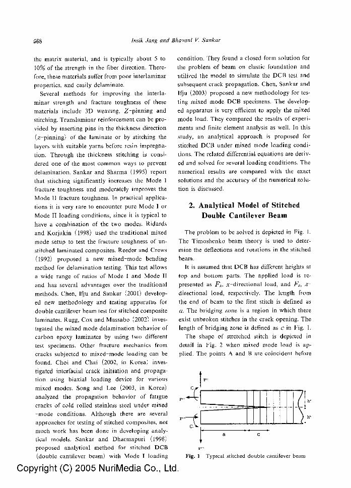
The problem to be solved is depicted in Fig. 1.
The Timoshenko beam theory is used to deter-
mine the deflections and rotations in the stitched
beam. It is assumed that DCB has different heights at
top and bottom parts. The applied load is re-
presented as f x , x-di rec t ional load, and Fz, z
directional load, respectively. The length from
the end of beam to the first stitch is defined as
a. The bridging zone is a region in which there
exist unbroken stitches in the crack opening. The
length of bridging zone is defined as c in Fig. 1,
The shape of stretched stitch is depicted in
detail in Fig. 2 when mixed mode load is ap-
plied. The points A and B are coincident before
Fig. 1 Typical stitched double cantilever beam
Copyright (C) 2005 NuriMedia Co., Ltd.

Analys~s o f a Compostte Double Cantdever Beam wtth Stocked Reinforcements Under M~ced Mode 569
loading u and w represent x dlrect~onai d~spla-
cement and Z-dlrecuonal dasplacement, respec-
tively Therefore, the length of a smch increases
by AB
In the p~esent study the stitch is considered as
a spring with sprmg constant k, which is cal-
culated as
k = 2NA~E~ h~+h~ (I)
The factor 2 appears in Eq (1) to account for the
two bobbm yarns that consmute one through the
thickness suteh Tracuon due to the stitches m the
x and z d~rectmns are computed as
t. = kAw = k (w~ - Wb)
t s=kAu=k(u~ us)
The eqmhbnum equauons lnvolwng, the longi-
tudinal force, shear force and bending moment
are described using the dtsplacements and spring
constant of the retch as follows"
dP~ _ t~b = bk ( ut-- u~) (3) dx
dVt _ t.b = bk ( wt - w~) (4) dx
dM~ h, dx - V,---~- bk( m - u ~ ) (5)
From the laminate constnutwe equatmns we
can obtain the foltowmg relauons between force
resultants and displacements
P t = A t E dut dx
M, = I~E dr dx
(6)
(7)
Fig. 2 D e f o r m a t m n of a st i tch unde r rmxed mode
load
{ dw~ + V t=A,G \ dx r ) (8)
Combining (3)-(8) results xn governing equa-
uons for the top part of the stitched DCB take
the form,
A , E d2ut b k ( u , - u ~ ) = 0 (9) d x ~ - -
d2Pt A dwt h~ EL-57.2 -G ,P~-6A~ .~ +~-bk(ut-ub)=O ( ~0) aX ~.~ z
GAt ~ f f -+ GAt d~wt bk - d f S - (w , -w~) o (ll)
Let us define three snffness constants for the con-
vemence of representatmn of equatmns
A , E b = B t axial snffness
EL b = D ~ flexural suffness
A,G b = Q t shear suffness
Then the govermng equauons (9 ) - (1 t ) , can be
rewritten using the newly defined stiffness con-
stants
d z B, ~ . .~ - - k ( . , - .~ ) =o (t2)
( i x
d2r d w ~ , h , , , , o 29, ~ 0,#,-0, (13) ~ ) - * T ntu~-u~) =u
d~t + ~ - - k ( w t - - w b ) =0 (14) O, --3Z O, ax
S~mflar equations for the bottom beam can be
derived as follows
d~ub ~h [~
D d2~ ~.,. ~ dw~+hb~:o ~ ~ w - ~ - d x T ~ , ~ , u~):0 (16) a x
dr + - d2wb_ Qb dx Qb d~xz ~k (w ' - -wb)=O (17)
It may be noted that the tractions exerted by the
smehes on the top and bottom are equal and
opposite, and hence the sign reversal m terms
containing the stiffness constant km the equations
for the bottom beam Boundary condmons at the
ends of the beam are as follows
Copyright (C) 2005 NuriMedia Co., Ltd.

570 Ins~k orang and Bhavani V, Sankar
At x = 0 one can apply, in general, an axial
force, a transverse force and a couple, Therefore,
the force boundary conditions are
Pt=AtE flUt =Fx, pb=A~E d~=Fxb a x
d~ t_ . _ dftb C Mt=LE~dx - G , Mb=2~--dx = b
(t8) E ~ A , G ( dw, + r = F . ,
\ d x
G---AbG ( - ~ - + ~b )= F~b
At x=c the rigid end boundary condlnons are
given by
w~=wt ,=0 , C,=,~b=0, u,--ub=O (19)
3. Solution Procedure for the Governing Equations
The longitudinal displacements zit and l, tb can
be found by solving equations (12) and (15)
smmltaneously Rearranging (12) and (15) and
ehmlnatmg u~ wdl result m a 4 t~ order differen-
tial equation m z~t as
1 1 (20) dx ~
Let us assume solution of the form
u,=ce a~ (21)
By subsututmg the solutions from equation (21)
mto the govetrung equation (20) we obtain the
solution
ue=c~+c2x +caea'X+c4e ~x (22)
where
and from the relationship between /& and u~ m
equation (12)
us =c, + c~x + c~( 1 - - ~ A~ )e a'* (23)
+c,( 1--- FB' ~) e~,~
After applying the boundary condmons, the min-
nltaneous equations for the unknown constants
can be represented in a matrix form
1 C e qc e hc ca
The x-di rec t ional displacement (22) and (23)
can be obtained by solving the above simulta-
neous equations
By differentiating (14) and (17) with respect to
x and ehmmatmg wt and wb, we can obtain the
coupled differential equauons for Ot and Pb
. . . . . . /Dr ,. Db ~[,.'~+k(r D *Vt - -R~ ~'- grt ----~-- ' ~ t t,d b (25)
k'[ht hb~, , h e . , . ,,, = T \ ~ - - ~ ] v u , - u~j - - 2 ,e~u, - u , j
Dbd4'"+k(-~ # - ~: ~; ' ) -k(P,-~) (26)
k 2[h, hb\, _hi U " =-TkV--O~)~u, .,) ~.,-u"'.~
Let us assume the solutions of the equations (25)
and (26) as
(h=pe ~*, ~-b~qe ~x (27)
If we substttute the equation (27) into equanons
(25) and (26) we obtain the following simulta-
neous equation for finding p and q
where Rt and Rb represent non-homogeneous
terms For the gpeetfie ~ , the ratio os eoefflelentg
p, and q, is computed as
D 4 .Dr ,a, x - ~ d + k r,=q' (29)
To make the problem sm~ple let us assume that
the cross seetmns of bottom and upper beams are
identical Then, the snffness constants become
De = D ~ - - D , Q, = Ob = O
Copyright (C) 2005 NuriMedia Co., Ltd.

Analysis of a Composae Double Cantdever Beam with Stttehed Reinforcements Under Mtxed Mode �9 571
For the homogenous solutions we can obtain
the roots of characteristic equation
sis,a,.=0 (30)
a~'~'r's=-al Q - V \ Q - ] D
Homogeneous solutions for !kt and ~k~ can be
expiessed as
4 8
~kn,=~_~p,x ' - l+ ~=J),e a'x (32)
4 8
The general solutions for ~kt and ~& become
r = #m + gae<Z+ E4e a~x 4 8
= ~p~x ,-~ + ~#,e~ ,~+g3ea,X+&e*~
4 8
= 52 r,P,x' ~ + ~ r ,p ,e~*+ haea'~+ h4e a~x ~=L t~5
(34)
where the coefficJents g and h can be obtained
by applying the pamcular parts m equatmn (28)
The constants ga and ha can be calculated using
equatmns (35) and (36) shown below, which are
derived from (25) and (26) by substituting the
pamcular solutions, ~w~=gae a~, r a,~, and the particular funcnons, tAtmCae &x, IA~,=
4 D 2 D 2 hB 4
Q O
D 2 ~ D 2 hB 4 ( - -kA-k )ga+(D/ l l - - -k21+k)h~=--7-cv t l (36) O 0
Similar procedures may be used to obtain g4 and
h~ We need eaght boundary condmons to deter-
mine p,, z:= 1, .,., 8 They correspond to (18) and (19) at the two ends of the top and bottom
beams, The expressmn for w, and wb that Include
unknowns b,, ~ - I , ..., 8 can be obtained by
subsmutmg (34) into equatmns (13) and (t6)
w t = ( ~ - N - b,) I 6D z +T( ~- l),-l~ ) x~ 1 s
3 =
t h
(37)
~./)b = ( 2~ ~__pl) ..~ I [ 6D \ 2 x TI-Vb,- )x
1 8 3 = / d ' ,
+ ( ~ / l ~ _ l ) h a a,x+[D ,2 l\h4ea,X
i h + T --O B (cd,# ,~ + c, ke ~ )
(38)
By applying the eight boundary condihons relat-
ed to rotation and transverse dmplacements we
obtain a set of linear equauons in the coefficients
P, which are given m Appendix I Once the
coefficaents are determined, the soJutton of the
problem depicted in Fig 2 as obtained Deriving
the expressions for the deflecuon curve, stitch
elongation and energy release rate at the crack
tip, calculating shear force and bending moment
resultants, at any cross section are matter of str-
aightforward computatmn and are d~scussed in
the tbllowmg section
4. Numerica l Results and Discuss ion
Graphne/epoxy is selected as the beam mater>
al and Kevlar| is the stitch material for the
present analysis The beam is assumed to be 7
inches long and 0 71 inch wide, stitched with 1600
denier Kevlar yarn with two yarns m each stitch
sntch density is 4 • means that there are The
20 stJtches per square inch, where the pitch 1s
1/4 inch and the spacing between two adjacent
stttch rows is 1/5 inch Fol slmphclty we constder
that the depth of top beam is equal to that of
bottom beam The mechamcal properties of the beam and Ml[ch mate r i a l s are summattzed in
Tables I and 2, respectively
To vahdate the formulation deNved here we
compare the displacements calculated from this
Copyright (C) 2005 NuriMedia Co., Ltd.

572 lnsik Jang and Bhavani V. Sankar
procedure with the exact solution (Young, 1989).
The bridging zone of stitched DCB under loads
is considered as a finite length beam on elastic
foundation subjected to transverse forces and ben-
ding moment. The stiffness of elastic foundation is equivalent to the spring constant calculated in equation (1). The exact solutions are expressed in
analytical form, and are shown in Appendix II.
The example problem is to analyze a part of
DCB with stitch reinforcement under z direc-
tional load or moment about y-axis, which are
depicted in Fig, 1, We confine the analyzed region
within bridging zone of the beam. The length of
bridging zone, which is denoted by c, is taken as
1 inch. Numerical and analytical results of z direc-
tion displacement are shown in Fig. 3 for applied z~directional loads, which are F , o = 5 0 0 0 N and F** = - 5 0 0 0 N. It is very difficult to differentiate
Table 1 Mechanical properties of beam
E~(psi) E2(~psi) ~]l ~. Gzz(psi)]G,a(psi) G,a(psi)
Table 2 Mechanical properties of stitch
- - ~ Tensile ] modulusElastic Material strength (GPa) I (GPa)
eviar-11.441 f30
xlO: 3
25
15
- 0 "~0 "
Fig. 3
<\
~,.,.
Comparison of z-direction displacement For applied load (solid : numerical, dotted �9 analytical)
the numerical result from the analytical one in
Fig. 3 because the two results have almost same
value. We introduce the relative error, the differ- etice between numerical solution and the exact one divided by the largest displacement, to evalu- ate the accuracy of the numerical result. It can be
noted from Fig. 4 that the present method is very
accurate with a maximum error of 1.49/oo.
The rotation of beam due to the applied z -
directional lbrce is shown in Fig. 5. The relative
error, rotation difference divided by the largest
rotation, shows high accuracy (max. 0.7%) as
well in Fig.& In Fig. 7 through 10, displacements, rotation
and related relative error for applied moments
14
12
I( ' :
6
4
4:
v4
. . . _ .
c~slar~
Fig. 4 Relative z direction displacement error for applied toad
0 #35"
00S " "
0 025 �9 '% ',
oo~ '\
-0 005 0 eCO9 00 t
Fig. 5
. . . . . . . . . . . . . . . . . . . . . . . . . . . . . . . . . . . . . . . . . . . , . . . . . . . . . . . . . . . . . . :
gOl , �9
0 e l 5 ~ 02 0025 a 03
Comparison of rotation for applied load (solid : numerical, dotted : analytical)
Copyright (C) 2005 NuriMedia Co., Ltd.

Analysis o f a Compo.vite Doubh Cantilever Beam with St#ched Reinforceme,izs Under Mixed Mode ... ,57;1
f..,
L
IFig. 6 Relative rotation error to, applied load
s e'-"
9 O2.:
( . ) ; "
~" OO!."
C 2,'
o ; : .5
5
g 9:." 5
, + ' ! ?
Fig, 7
� 9
:x o.'.~ ~ ,71 : ; :% ,3 02 ,; 3 : 5 {~ %
Comparison of z-direction displacement t'~r
applied moment (solid : numerical, dotted :
analytical)
are shown. The applied moments are C~ = - 5 0 0 0
N "m and C ~ , - 5 0 0 0 N . m . From accuracy point o f
view these results represent almost same trend as
the cases of applied transverse load.
From the results above, the present formula-
tion for stitched beams is accurate enough to be
util ized to calculate the displacements for wtrious
load conditions+
We may classify the type of load in the DCB by
the fracture Mode�9 Mode 1 case is wherein the
applied loads are symmetrical about the plane of
delaminat ion and the crack tip is under Mode I
fracture condition. In this mode the applied load
is i t ; the positive z direction o n the upper beam
and negative z - d h e c t i o n on the lower beam as
1 2
~0
s,
2
0
�9 2 c
Fig. 9
O r 0 " 3 -15 ::, 2 ~ 025 ,? o~
Compa,'ison of rotation for applied moment
(solid: numerical, dotted : analytical)
4
2
14
~2
lC
? .
-3
4
0
�9 55 0 CO'~ O . " 9 , : : !5 0 { 2 r ,~ :'a
' 5 Fig. 8 Relative z direction displacemem error tbr
applied moment Fig. 10
Copyright (C) 2005 NuriMedia Co., Ltd.
,3...05 0 .'1 ,3 015 C ,2,2 i) ,225 0 0.1
Relatit.e rotation error for applied moment

574 Insik Jang and Bhavani I/. Sankar
shown in Fig. 1. The applied loads are F ~ = 5000
N and Fzt------5000 N. Displacement and rota-
tion for Mode I are shown in Fig. 11. There is
no x-directional displacement because only F
load, which is depicted in Fig. 1, is applied. The
displacement in the z-direction and rotation are
shown in Figs. 12 and 13, respectively. The defor-
mations of the top and bottom parts are symmet-
ric because the heights of top and bottom beam are equal.
In Mode II the loads are antisymmetric and
the crack tip is under Mode II condition. The
applied loads for Mode II are F x ~ - 5 0 0 0 N and
Fx~=-5000 N. The x-directional displacement
0.~4
0.I]2 �9
001
o . . . . . . . . . . . . . . . . . . . ....': ::: . . . . . . . . . . . . - - = . . . . . . . . .
0.01" ,"
Fig, 13 Rotat ion for Mode [
(solid : top, dotted : bottom)
06
0~.
o 0 ....................................................................................................................... :
- 0 4
~0 ~ . . . . . . .
. 05 ,
0 0 005 001 0015 002 002~ 0 O~ distance
Fig. 11 x-direct ion displacement for Mode I
(solid : top, dotted : bottom)
k10 s 2 5 ,
. . , . , , , .
1L
[ -1[
d ~
�9 . . . . .
" " . . . . . . .
�9 �9149149 :> :
-2.% .......................................................................................................... ~ O 0 ~ 5 0 01 0 015 0 02 0 0 2 5 0 . 0 3
dI~ESNe
Fig. 14 x-direct ion displacement for Mode II
(solid : top, dotted : bottom
x l 0 ~
}, I i ,
-I I ./
i / i /
2! , "
Fig. 12 z-direct ion displacement for Mode 1
(solid : top, dotted : bottom)
Copyright (C) 2005 NuriMedia Co., Ltd.
/ , 35 - " / ",
3 / ,,
25 // '~.
/
/ 1 5 . . . / '
1, f /
05 " / "
j" x
�9 i 'o ................................. ~c~ oo~ o~i~ oo2 o~25 003
Fig. 15 z direction displacement for Mode II
(solid : top, dotted : bottom)

Analysis of a Composite Double Cantilever Beam with Stitched Reinjbrcements Under Mixed Mode ,.. 575
8 02
-II (.~
�9 6 I n eoo~ o 6 ' 0 0 i 5 a~:2 6 0 2 5 o e S
Fig, 16 Rotation for Mode li (solid : top. dotted: bottom)
almost linearly decreases with respect to x as
shown in Fig. 14. However, transverse deflection
and rotation are of higher order in x, and top
and bottom parts show identical trend as shown
in Figs. 15 and 16, The stitches have an effect on
the ,e-direction displacements although there is
only :c-directional applied load.
The results for mixed mode loading, combina-
tion of Mode I and Mode II, can be obtained by
superposition.
5. Conclusion
An analytical model has been developed for
simulating the behavior of stitched double can-
tilever beam specimen under various loading
conditions. For z-directional load and moment
about the y-axis the numerical solutions are com-
pared with the exact solutions, The stitched beam
is considered as a finite length beam on elastic
foundation when we try to find exact solutions
of the problem. The derived formulation shows
good accuracy when the relative error of dis-
placement and rotation between numerical and
exact solution were calculated. Thus we can use
the present model with confidence in analyzing
otlte~ problems involving stitched beams. The
calculations have been carried out for two differ-
ent load conditions. Three kinds of displacement,
x and z-directional displacements and rotation
about the y-axis, are obtained for each mode.
Mode I is the case where the applied toad is
symmetric. There is no x-directlonal displaceme-
nt because of only z--direction load. The dis-
placement in the z direction and rotation are
symmetrical shape because of the symmetry of the
top and bottom beams.
When a positive axial load (in the + x direc-
tion) is applied on the lower beam and a negative
load (in the - -x direction) load is applied on
the upper beam the condition becomes Mode II.
The x directional displacement almost linearly
decreases. However, only x-directlonal displace-
ment is symmetric and linear in the Mode I1 con-
dition. The z-direction displacement and rotation
behavior of top and bottom beam is equal in the
Mode lI. The results for mixed mode conditions
can be obtained by superposition. The methods
described in this paper can be easily extended to
other loading conditions such as applied end
couple. After the displacements are calculated, the
forces in the stitches can be determined from Eqs.
(6 8), and can be used to find the load at which
the stitch will break. Calculation of energy release
rate at the crack tip and estimating the bridging
length etc. will be the topic of future work and
they will be discussed in a sequel to this paper,
The method developed in this paper will be usefhl
in analyzing progressive damage in stitched com-
posite beams and in estimating their apparent
fracture toughness.
Acknowledgment
This work had been done during sabbatical
leave at University of Florida, The authors are
grateful for the support provided by Hongik Unit
versity.
References
Chen, L., l(ju, P, G. and Sankar, B.V., 2001,
"A Novel Double Cantilever Beam Test for
Stitched Composite Laminates," Journal of Corn-
posite Materials, Vol§ 35, No. 13, pp. 1137-- 1149.
Chen, L., Sankar, B.V. and tt~u, P§ G., 2003,
"Mixed Mode Fracture Toughness Tests for Sti-
tched Composite Laminates," AIAA 2003 1874.
Copyright (C) 2005 NuriMedia Co., Ltd.

576 Insik dang and Bhavani V. Sankar
Chin, B S and ChaL Y S, 2002, "Interfacml Crack Propagauon Under Various Mode-M~x-
es," KSME International Journal, Voi 16, No 1, pp 39~45 (m Korea)
Reeder, J R and Crews, J H Jr , 1992, "Re- design of the Mixed Mode Bending Delamma- tlon Test to Reduce Nonhnear Effect," Journal of Composite Technology and Research, pp 12~ 18
Ridards, R and Korjakln, A , 1998, '~
lammm Fracture Toughness of GFRP Influenc- ed by F~ber Surface Treatment," Journal of Com- posite Materials, Vol 32, No 17, pp 1528~1559
Rugg, K L, Cox, B N and Massabo, R ,
2002, "Mixed Mode Delammataon of Polymer
Composite Laminates Reinforced Through the Thickness by Z-fibers," Composites-Part A . Ap- plied Science and Manufacturing, Vol 33, No 2,
pp 177~ 190 Sankar, B V and Dharmapurl, S M, 1998,
"Analysts of a Stitched Double Cantilever Beam ,"
Journal of Composite Matertats, Vol 32, No 24, pp 2203~2225
Sankar, B V and Sharma, K S, 1995, "Effects of Through-the-thickness St~tchlng on Impact and Interlammar Fracture Propemes of Textile
Graphite/Epoxy Laminates," NASA CR-195042 NASA Langley, Hampton, VA
Song, S H and Lee, J M, 2003, "Fatigue Crack Propagatmn Behavior in STS304 Under M~xed-Mode Loading," KSME International Journal, Vol 17, No 6, pp 796~804 (in Korea)
Young, W C, 1989, Roark's Formulas for Stress and Strata, S~xth Edmon, McGraw-Hill Book Co, New York, p 140
Appendix I
The matrix form of hnear equatmn m p.
A P = B
where
A=
2D -1 0 0
2D -1 0 Q 0 1 0
0 1 0 0 rsc~
l c d d e ~
1 c c 2 d n e "~
1 ~2Dc c~ 3Dc~ c4 ( ~ ) e ~'~ - C - y C O 3 Q 4 d - !
t 2Dc cS 3Dcz c*(D ] r J 'c - c - y c O 3 Q 4 d - I c~
F~ Q
F~ Q
g =
D D D D O ~ rscg ~ r,a~ -~ rTd -~ r~d~
r6og ea, c
ruea~ c
1 h 2 2
D 2 2 1 h O (,~lh~+,~h~) - - ~ Q- B (e~l~4-e~)~)
C, D g3A~-gaA2
Co h~A- h4,~ D
--g3Caac--g4~a~c
--h~eh r h~eZ: c
. . . . .
Copyright (C) 2005 NuriMedia Co., Ltd.
rTa7 rso~ eat c eaoe
yve a~ r~ea~ e
1 h B(CaAle~+c4Aze~,~) 2 Q
1 h B (c3~e ~'~ + c ~ e ~ ) 2 Q

Analysts of a Composite Double Cantilever Beam with Stttehed Remforeement9 Under Mixed Mode 577
Appendix II
The analytical solutlons of deflection and rota- tion for z dtrecuonal load F are expressed as follows
ua-ya~- cosh/~x cos 3x
+ ~;-(cosh/~x sm/?x +smh Bx cos i
F (cosh ~qx sm/~x-smh 3x cos/~x) 4EIB ~
# - ~,~ cash b'x cos ~x - y ~ 3 (cosh/~x sm $x-slnh Bx cos 5x)
F - 4E i~ smh [3x sin/3x
where
F G G - G G ya~ 2E13 a 2 AC Cll
F 2C, C3+C,C, ~AF 2EI~ ~ 2 + C ~
The analytmal solutmns of deflecuon and rota- non for apphed moment M are expressed as
follows
w~=y~ cosh/~x cos ~x
+ 2-2-2-~(cosh/~x sin ~x +smh/~x cos/~x)
M + 2 ~ s l n h Sx sm fix
~,= #~ cosh ~x cos ~x -yauC?(cosh/3x sin r cos 3x)
M +x-~.~ (cosh ~?x sin r fix cos ~x)
ZP_.,/#
where
M 2C~C3-C2C~ YaU-2Elfl2 2 + C u
M CzC~+C, C3 EIt~ 2+ Cn
boko v,
Cl=COsh ~l cos/~l C2=cosh fiZ sm H +sinh 31 cos/31 C~ =smla .81 sm ~l C,=cosh/~l s in /~1-smh Bl cos r C~1 =slnl9/31-sin ~flt
Copyright (C) 2005 NuriMedia Co., Ltd.
Copyright © 2022 FDOKUMEN