ANALYSIS AND FABRICATION OF HEAT PIPE AND ... - iaeme
13
http://iaeme.com/Home/journal/IJMET 160 [email protected] International Journal of Mechanical Engineering and Technology (IJMET) Volume 8, Issue 12, December 2017, pp. 160–172, Article ID: IJMET_08_12_017 Available online at http://iaeme.com/Home/issue/IJMET?Volume=8&Issue=12 ISSN Print: 0976-6340 and ISSN Online: 0976-6359 © IAEME Publication Scopus Indexed ANALYSIS AND FABRICATION OF HEAT PIPE AND THERMOSYPHON M Sandeep Research Scholar, K L University, Vijayawada, Andhra Pradesh, India A.Abinay Asst. Professor, ACE Engineering College, Hyderabad, Telangana, India Dr P.Jamaleswara Kumar Associate Professor, K L University, Guntur, Andhra Pradesh, India ABSTRACT: Effective thermal conductivity of a heat pipe wick structure filled with a working fluid is measured. A simple evaluation method using a heating rod is described and the value of effective thermal conductivity is obtained by comparing the numerical results with the experimental ones. Full numerical simulation of heat pipes was performed for heat pipe under various operating conditions with water as working fluid. Two and three-dimensional models were developed assuming a laminar incompressible vapor core. Finally, a homogenous multiphase model referred to as volume of fluid modeling (VOF) was developed for simulation of a Heat pipe. A simple thermosyphon was fabricated. The thermal response time of a thermosyphon in comparison to a copper rod was observed. The response time and temperature profile along thermosyphon was measured. The effective thermal conductivity of it was calculated in a procedure like the heat pipe. Then the thermal conductivities of heat pipe and thermosyphon were compared. Using PRO-E/CATIA software we try to evaluate the design of the respective heat pipe. Later, we try to analyze the 3-D incompressible flow. The methodology of the project is to design the heat pipe system to carry out an analysis of the same using mechanical software based on the design and analysis of the heat pipe will be modeled. Keywords: volume of fluid (VOF) modeling; thermosyphon; PRO-E; analysis; Cite this Article: M Sandeep, A.Abinay and Dr P.Jamaleswara Kumar, Analysis and Fabrication of Heat Pipe and Thermosyphon, International Journal of Mechanical Engineering and Technology 8(12), 2017, pp. 160–172. http://iaeme.com/Home/issue/IJMET?Volume=8&Issue=12
-
Upload
khangminh22 -
Category
Documents
-
view
0 -
download
0
Transcript of ANALYSIS AND FABRICATION OF HEAT PIPE AND ... - iaeme
http://iaeme.com/Home/journal/IJMET 160 [email protected]
International Journal of Mechanical Engineering and Technology (IJMET)
Volume 8, Issue 12, December 2017, pp. 160–172, Article ID: IJMET_08_12_017
Available online at http://iaeme.com/Home/issue/IJMET?Volume=8&Issue=12
ISSN Print: 0976-6340 and ISSN Online: 0976-6359
© IAEME Publication Scopus Indexed
ANALYSIS AND FABRICATION OF HEAT PIPE
AND THERMOSYPHON
M Sandeep
Research Scholar, K L University, Vijayawada, Andhra Pradesh, India
A.Abinay
Asst. Professor, ACE Engineering College, Hyderabad, Telangana, India
Dr P.Jamaleswara Kumar
Associate Professor, K L University, Guntur, Andhra Pradesh, India
ABSTRACT:
Effective thermal conductivity of a heat pipe wick structure filled with a working
fluid is measured. A simple evaluation method using a heating rod is described and
the value of effective thermal conductivity is obtained by comparing the numerical
results with the experimental ones. Full numerical simulation of heat pipes was
performed for heat pipe under various operating conditions with water as working
fluid. Two and three-dimensional models were developed assuming a laminar
incompressible vapor core. Finally, a homogenous multiphase model referred to as
volume of fluid modeling (VOF) was developed for simulation of a Heat pipe. A simple
thermosyphon was fabricated. The thermal response time of a thermosyphon in
comparison to a copper rod was observed. The response time and temperature profile
along thermosyphon was measured. The effective thermal conductivity of it was
calculated in a procedure like the heat pipe. Then the thermal conductivities of heat
pipe and thermosyphon were compared. Using PRO-E/CATIA software we try to
evaluate the design of the respective heat pipe. Later, we try to analyze the 3-D
incompressible flow. The methodology of the project is to design the heat pipe system
to carry out an analysis of the same using mechanical software based on the design
and analysis of the heat pipe will be modeled.
Keywords: volume of fluid (VOF) modeling; thermosyphon; PRO-E; analysis;
Cite this Article: M Sandeep, A.Abinay and Dr P.Jamaleswara Kumar, Analysis and
Fabrication of Heat Pipe and Thermosyphon, International Journal of Mechanical
Engineering and Technology 8(12), 2017, pp. 160–172.
http://iaeme.com/Home/issue/IJMET?Volume=8&Issue=12

M Sandeep, A.Abinay and Dr P.Jamaleswara Kumar
http://iaeme.com/Home/journal/IJMET 161 [email protected]
1. INTRODUCTION
Capillary-driven two-phase systems offer significant advantages over traditional single-phase
systems. With the typically increased thermal capacity associated with the phase change of a
working fluid, considerably smaller mass flow rates are required to transport equivalent
amounts than in single-phase liquid or gas systems for a given temperature range. Moreover,
heat transfer coefficients of two-phase systems are much greater than in single-phase flows
and result in enhanced heat transfer. Lower mass flow rates and enhanced thermal
characteristics provide the benefits of smaller system size (and weight) while providing
increased performance. The thermal capacity of a single-phase system depends on the
temperature change of the working fluid; thus, a large temperature gradient or a high mass
flow rate is required to transfer a large amount of heat. However, a two-phase system can
provide essentially isothermal operation regardless of variations in the heat load. Additionally,
single phase systems require the use of mechanical pumps and fans to circulate the working
fluid, while capillary-driven two-phase systems have no external power requirements, which
make such systems more reliable and free of vibration. The best known capillary-driven two-
phase system is the heat pipe, where a schematic of a conventional heat pipe is shown in
Figure 1.
Figure 1 Typical heat pipe construction and operation
The concept of the heat pipe was first presented by Gaugler (1944) and Trefethen (1962),
but was not widely publicized until an independent development by Grover et al. (1964) at the
Los Alamos Scientific Laboratories. Heat pipes are passive devices that transport heat from a
heat source (evaporator) to a heat sink (condenser) over relatively long distances via the latent
heat of vaporization of a working fluid. As shown, a heat pipe generally has three sections: an
evaporator section, an adiabatic (or transport) section, and a condenser section. The major
components of a heat pipe are a sealed container, a wick structure, and a working fluid. The
wick structure is placed on the inner surface of the heat pipe wall and is saturated with the
liquid working fluid and provides the structure to develop the capillary action for liquid
returning from the condenser to the evaporator section. With evaporator heat addition, the
working fluid is evaporated as it absorbs an amount of heat equivalent to the latent heat of
vaporization, while in the condenser section; the working fluid vapor is condensed. The mass
addition in the vapor core of the evaporator section and mass rejection in the condenser end
results in a pressure gradient along the vapor channel which drives the corresponding vapor
flow. Return of the liquid to the evaporator from the condenser is provided by the wick
structure.

Analysis and Fabrication of Heat Pipe and Thermosyphon
http://iaeme.com/Home/journal/IJMET 162 [email protected]
Due to the two-phase characteristics, the heat pipe is ideal for transferring heat over long
distances with a very small temperature drop and for creating a nearly isothermal surface for
temperature stabilization. As the working fluid operates in a thermodynamic saturated state,
heat is transported using the latent heat of vaporization instead of sensible heat or conduction
where the heat pipe then operates in a nearly isothermal condition. This nearly isothermal
condition offers benefits of transporting copious amounts of heat efficiently, decreasing the
overall heat transfer area and saving system weight. The amount of heat that can be
transported using latent heat is typically several orders of magnitude greater than transported
by sensible heat for a geometrically equivalent system. Additionally, no mechanical pumping
systems are required due to the capillary-driven working fluid. Given the wide range of
operating temperatures for working fluids, the high efficiencies, the low relative weights, and
the absence of external pumps in heat pipes, these systems are attractive options in a wide
range of heat transfer applications.
Table 1 Heat Pipe working fluids
Working fluid Triple pint(K) Critical point (K) Useful range(K)
Oxygen 54.3 154.8 55-154
Nitrogen 63.1 126.2 65-125
Ethane 89.9 305.5 100-305
Butane 134.8 425,0 260-350
Methanol 175.2 513.2 273-503
Toluene 178.1 593.9 275-473
Acetone 180.0 508.2 250-475
Ammonia 195.5 405.6 200-405
Mercury 234.3 1763 280-1070
Water 273.2 647.3 273-643
Potassium 336.4 2250 400-1800
Sodium 371.0 2500 400-1500
Lithium 453.7 3800 500-2100
Silver 1234 7500 1600-2400
Gravity assisted heat pipes or wickless heat pipes are highly efficient heat transfer devices
often referred to us as thermal super conductors or thermal short circuits. The efficient
thermal conductivity of thermosyphon exceeds that of copper 200-500 times [1]. A two phase
closed thermosyphon is a passive heat transfer device containing the working fluid in closed
container. It is used to transport a large amount of heat at a high rate with small temperature
difference between the sink and source. This is achieved by making use of the highly efficient
thermal transport process of evaporation and condensation. The thermal performance of two
phase closed thermosyphon (TPCT) has been extensively studied for a long period of time.
The behavior of TPCT filled with water, ammonia, toluene and conventional refrigerants like
R11 and R12 in a steady state situation are well known and numerous experimental and
analytical works are available in the literature [2-8]. The use of refrigerants as working fluids
is easy for certain applications because they work with positive work.
The literature survey revealed that the many of the research work deals with the TPCT
filled conventional refrigerants like R11, R12 and R22. However, knowledge of thermal
performance of TPCT filled with alternate refrigerant is of great importance since the
conventional refrigerants are banned due to their potential to deplete the ozone layer. Very
few investigations are made to study the thermal behavior of TPCT filled withR134a, which

M Sandeep, A.Abinay and Dr P.Jamaleswara Kumar
http://iaeme.com/Home/journal/IJMET 163 [email protected]
is considered as an eco- friendly refrigerant and a generally accepted substitute for R11 and
R12.
Payakaruket. al, studied experimentally the effect of dimensionless numbers (Bond
numbers, Froude numbers, Weber numbers and Kutateladze numbers) on heat transfer
characteristics of an inclined thermosyphons. Copper thermosyphons withR22, R123, R134a,
ethanol and water as the working fluids are employed to predict heat transfer characteristics of
an inclined closed two phase thermosyphon at normal conditions. The effect of thermosyphon
inner diameter, fill ratio, aspect ratio and inclination angle is also studied.
Faghri et. al, reported the performance of a thermosyphon filled withR134a. They
concluded that the heat flux transferred increased with high coolant mass flow rates, high fill
ratios and greater temperature difference between bath and condenser in this experimental
work, the evaporator was immersed in a water bath to maintain constant temperature on
evaporator side. This type of TPCT can be termed as temperature controlled thermosyphon.
Abou- Ziyan et al. has investigated the effect of vibration on thermosyphon filled with
R134a. They found that minor or no effect is experienced with R134a below the boiling limit and
enhancement up to 250% existed above the boiling point.
The evaporator section of a thermosyphon covered with a heater to supply the required
flux can be termed as flux controlled thermosyphons. The experimental studies of a flux
controlled thermosyphon filled with R134a are not easily found in literature. Hence the
thermal behavior of R134a thermosyphon was undertaken in this work. This paper considers
the effect of controlling variables (Heat input, Coolant mass flow rate and coolant
temperature) on thermal performance of a flux controlled R134a thermosyphon.
WHY WE ARE COMPARING THE HEAT PIPE WITH THERMOSYPHON?
• General purpose of the heat pipe and thermosyphon to transfer the heat from one
position to the other.
• The heat pipe is very costly than compare with the thermosyphon.
• We have comparing the thermal conductivity of the thermosyphonwith the heat
pipe so that we provide the heat transfer equipment with the less cost.
• When compare with the thermosyphon the manufacturing method of the heat pipe
is more complex.
• We try to reduce the cost of manufacturing with the most efficient heat Transfer
with the high thermal conductivity.
2. EXPERIMENTAL DETAILS
2.1. Heat Pipe CAD Model designed using CATIA
Commonly referred to as a 3D Product Lifecycle Management software suite, CATIA
supports multiple stages of product development (CAX), including conceptualization, design
(CAD), engineering (CAE) and manufacturing (CAM). CATIA facilitates collaborative
engineering across disciplines around its 3DEXPERIENCE platform, including surfacing &
shape design, electrical, fluid and electronic systems design, mechanical engineering and
systems engineering.
CATIA facilitates the design of electronic, electrical, and distributed systems such as fluid
and HVAC systems, all the way to the production of documentation for manufacturing. The
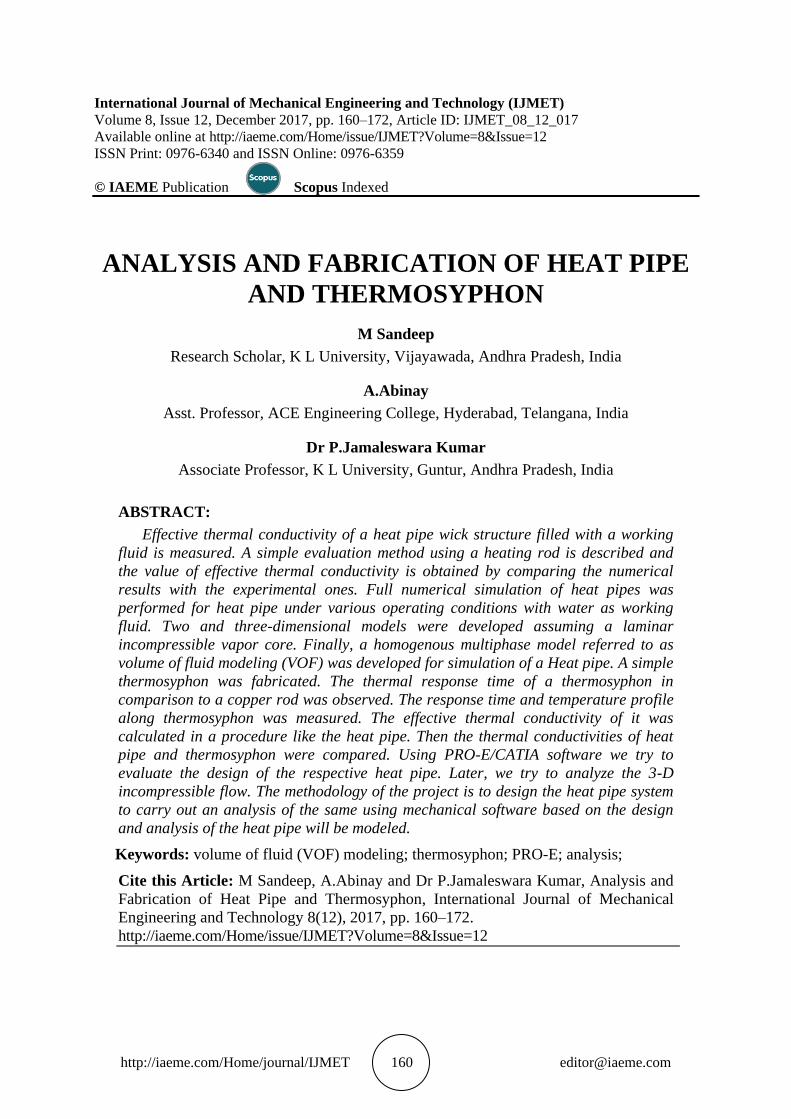
Heat Pipe model is designed using CATIA, which is shown in the fig. 2.1.
Analysis and Fabrication of Heat Pipe and Thermosyphon
http://iaeme.com/Home/journal/IJMET 164 [email protected]
Figure 2.1 Heat Pipe (3D shell) with thickness of 2mm
Thermosyphon CAD Model designed using CATIA
Figure 2.2 Thermosyphon (Wick less Heat Pipe)
Analysing the Thermosyphon Using ANSYS WorkBench
ANSYS have the wide range of applications in the finite element problems.
• It is used to find out the design considerations i.e. what the type of meshing we
need to provide the accurate results
• In the ANSYS part the boundary considerations requirements are compulsory
i.e. which face is needed to be fixed and what amount of force we need to
apply at what particular point
• In the ANSYS we find out the stresses development what amount of
deformations taking place without manufacturing the equipment to save the
expenditure over it.
Thermosyphon model which has developed in the CATIA has been imported to the
ANSYS workbench, and the mesh has been applied, which is shown in the figure 2.3.

M Sandeep, A.Abinay and Dr P.Jamaleswara Kumar
http://iaeme.com/Home/journal/IJMET 165 [email protected]
Figure 2.3 Thermosyphon Mesh Model
The heat pipe cad model developed in CATIA has been imported in the same way as
Thermosyphon and mesh has been applied using ANSYS for applying the input parameters,
which is shown in the figure 2.4.
Figure 2.4 Heat Pipe Mesh Model
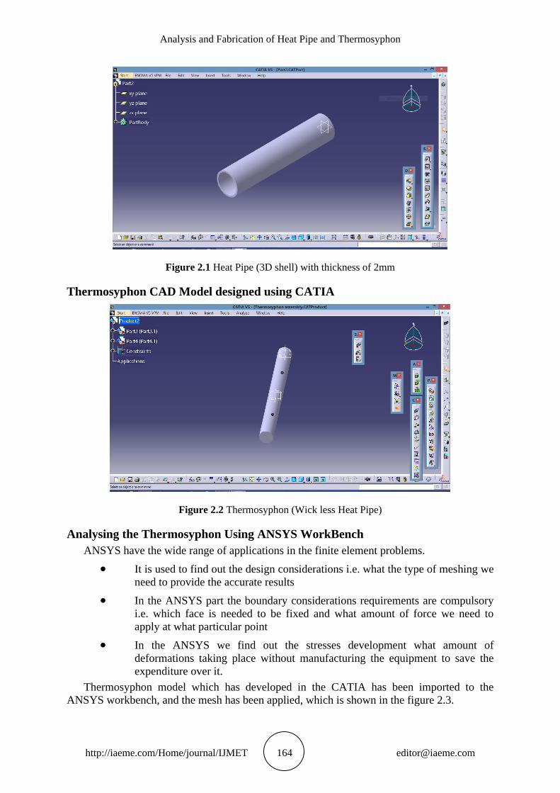
At diferent temperatures, the reperesentation of the thermosyphon is shown in the figure
2.5.
Analysis and Fabrication of Heat Pipe and Thermosyphon
http://iaeme.com/Home/journal/IJMET 166 [email protected]
Figure 2.5 Different Temperatures of Thermosyphon
The trajectory of the input parameters applied to the thermosyphon mesh model for the
number of iterations is shown in the figure 2.6.
Figure 2.6 Input Parameters vs Iterations
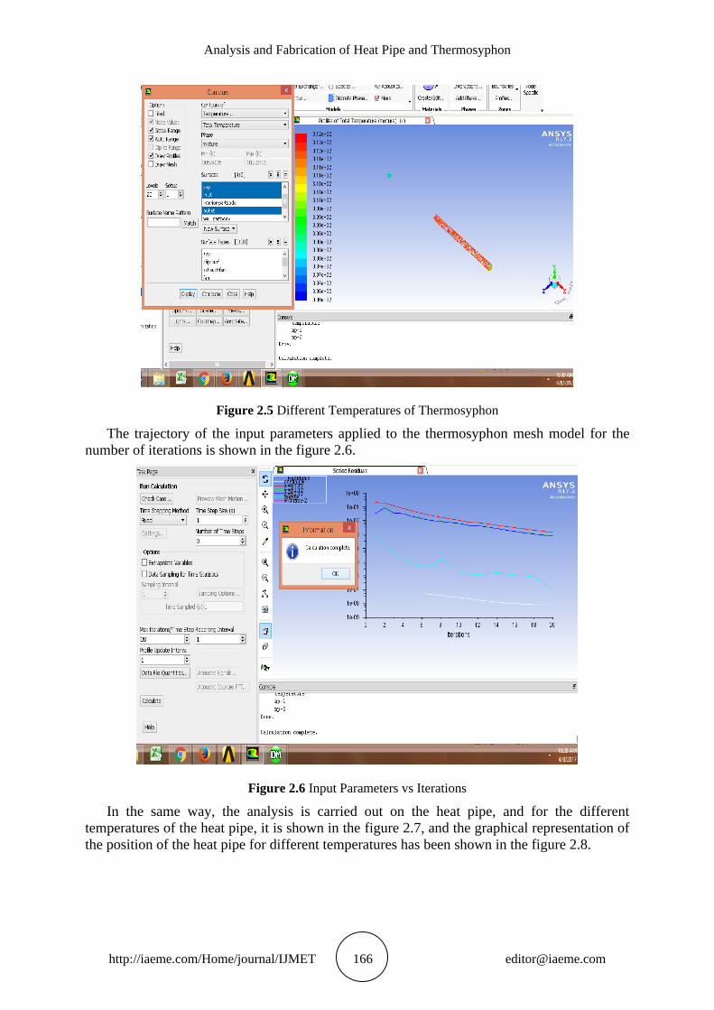
In the same way, the analysis is carried out on the heat pipe, and for the different
temperatures of the heat pipe, it is shown in the figure 2.7, and the graphical representation of
the position of the heat pipe for different temperatures has been shown in the figure 2.8.
M Sandeep, A.Abinay and Dr P.Jamaleswara Kumar
http://iaeme.com/Home/journal/IJMET 167 [email protected]
Figure 2.7 Different Temperatures of Heat Pipe
Figure 2.8 Different Temperatures vs Position
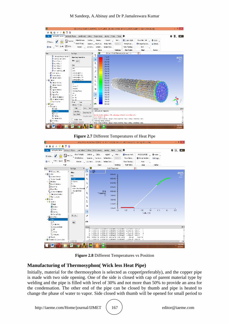
Manufacturing of Thermosyphon( Wick less Heat Pipe)
Initially, material for the thermosyphon is selected as copper(preferably), and the copper pipe
is made with two side opening. One of the side is closed with cap of parent material type by
welding and the pipe is filled with level of 30% and not more than 50% to provide an area for
the condensation. The other end of the pipe can be closed by thumb and pipe is heated to
change the phase of water to vapor. Side closed with thumb will be opened for small period to
Analysis and Fabrication of Heat Pipe and Thermosyphon
http://iaeme.com/Home/journal/IJMET 168 [email protected]
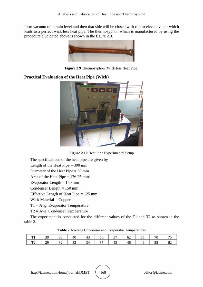
form vacuum of certain level and then that side will be closed with cap to elevate vapor which
leads to a perfect wick less heat pipe. The thermosyphon which is manufactured by using the
procedure elucidated above is shown in the figure 2.9.
Figure 2.9 Thermosyphon (Wick less Heat Pipe)
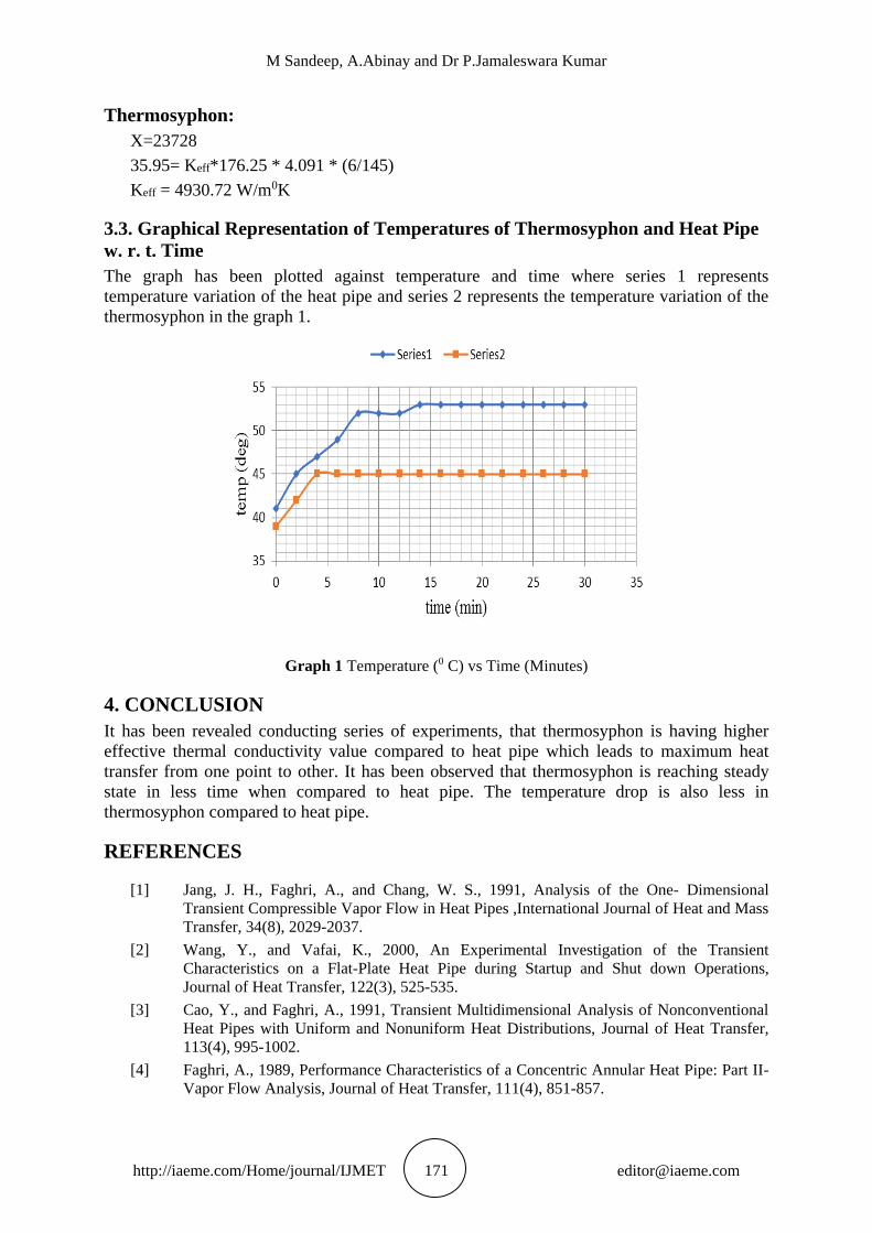
Practical Evaluation of the Heat Pipe (Wick)
Figure 2.10 Heat Pipe Experimental Setup
The specifications of the heat pipe are given by
Length of the Heat Pipe = 300 mm
Diameter of the Heat Pipe = 30 mm
Area of the Heat Pipe = 176.25 mm2
Evaporator Length = 150 mm
Condenser Length = 150 mm
Effective Length of Heat Pipe = 125 mm
Wick Material = Copper
T1 = Avg. Evaporator Temperature
T2 = Avg. Condenser Temperature
The experiment is conducted for the different values of the T1 and T2 as shown in the
table 2.
Table 2 Average Condenser and Evaporator Temperatures
T1 30 36 40 43 50 57 62 65 70 75
T2 29 32 33 34 35 43 46 49 55 62

M Sandeep, A.Abinay and Dr P.Jamaleswara Kumar
http://iaeme.com/Home/journal/IJMET 169 [email protected]
Practical Evaluation of Wick less Heat Pipe
Figure 2.11 Heat Pipe Experimental Setup
The temperature of the thermosyphon and the water at regular intervals of two minutes is
shown in the table 3.
Table 3 Temperature Variation of Thermosyphon
Sl. No. Thermosyphon
Temperature(0C)
Water
Temperature(0C)
Time
(min)
1 34 38 0
2 35 38 2
3 36 44 4
4 38 46 6
5 43 49 8
6 44 51 10
7 44 53 12
8 46 55 14
9 48 57 16
10 48 59 18
11 49 61 20
12 51 63 22
13 52 65 24
14 52 66 26
15 52 68 28
16 52 69 30
17 52 70 32
3. RESULTS AND DISCUSSION
3.1. Comparision of Temperature drop of Thermosyphon and Heat Pipe Using
ANSYS
After importing the Thermosyphon CAD Model and Heat Pipe CAD Model which are
designed in CATIA are analyzed using ANSYS Workbench and the positions of the
thermosyphon and the heat pipe with respect to total temperature mixture are shown in the
figure 3.1 and 3.2.

Analysis and Fabrication of Heat Pipe and Thermosyphon
http://iaeme.com/Home/journal/IJMET 170 [email protected]
Figure 3.1 Thermosyphon Position for Total Temperature
Figure 3.2 Heat Pipe Position for Total Temperature
3.2. Evaluation of Effective Thermal Conductivity
The analysis of the thermosyphon and heat pipe carried out in the ANSYS Workbench gives
the position i.e. effective length, which is used to evaluate the effective thermal conductivity
of the thermosyphon and heat pipe as follows.
From the Fourier Law of Heat Conduction,
Q = K. A.
Where
Q = Heat input K = Effective thermal conductivity
dt = Temperature distribution dx = Effective length
A = Area through which heat flows
dt = (average evaporator temperature-average condenser temperature)
Heat Pipe:
Average evaporator temperature=1680K
Average condenser temperature=600K
Q=52.8 KW
A=114.5 mm2
52.8= Keff * 0.000706 * (11.6/0.125)
Keff= 1100 W/m0K
M Sandeep, A.Abinay and Dr P.Jamaleswara Kumar
http://iaeme.com/Home/journal/IJMET 171 [email protected]
Thermosyphon:
X=23728
35.95= Keff*176.25 * 4.091 * (6/145)
Keff = 4930.72 W/m0K
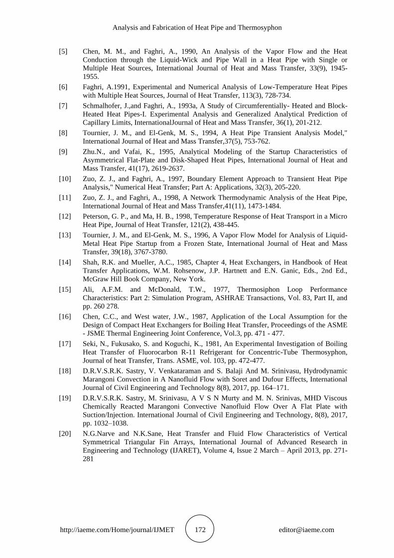
3.3. Graphical Representation of Temperatures of Thermosyphon and Heat Pipe
w. r. t. Time
The graph has been plotted against temperature and time where series 1 represents
temperature variation of the heat pipe and series 2 represents the temperature variation of the
thermosyphon in the graph 1.
Graph 1 Temperature (0 C) vs Time (Minutes)
4. CONCLUSION
It has been revealed conducting series of experiments, that thermosyphon is having higher
effective thermal conductivity value compared to heat pipe which leads to maximum heat
transfer from one point to other. It has been observed that thermosyphon is reaching steady
state in less time when compared to heat pipe. The temperature drop is also less in
thermosyphon compared to heat pipe.
REFERENCES
[1] Jang, J. H., Faghri, A., and Chang, W. S., 1991, Analysis of the One- Dimensional
Transient Compressible Vapor Flow in Heat Pipes ,International Journal of Heat and Mass
Transfer, 34(8), 2029-2037.
[2] Wang, Y., and Vafai, K., 2000, An Experimental Investigation of the Transient
Characteristics on a Flat-Plate Heat Pipe during Startup and Shut down Operations,
Journal of Heat Transfer, 122(3), 525-535.
[3] Cao, Y., and Faghri, A., 1991, Transient Multidimensional Analysis of Nonconventional
Heat Pipes with Uniform and Nonuniform Heat Distributions, Journal of Heat Transfer,
113(4), 995-1002.
[4] Faghri, A., 1989, Performance Characteristics of a Concentric Annular Heat Pipe: Part II-
Vapor Flow Analysis, Journal of Heat Transfer, 111(4), 851-857.
Analysis and Fabrication of Heat Pipe and Thermosyphon
http://iaeme.com/Home/journal/IJMET 172 [email protected]
[5] Chen, M. M., and Faghri, A., 1990, An Analysis of the Vapor Flow and the Heat
Conduction through the Liquid-Wick and Pipe Wall in a Heat Pipe with Single or
Multiple Heat Sources, International Journal of Heat and Mass Transfer, 33(9), 1945-
1955.
[6] Faghri, A.1991, Experimental and Numerical Analysis of Low-Temperature Heat Pipes
with Multiple Heat Sources, Journal of Heat Transfer, 113(3), 728-734.
[7] Schmalhofer, J.,and Faghri, A., 1993a, A Study of Circumferentially- Heated and Block-
Heated Heat Pipes-I. Experimental Analysis and Generalized Analytical Prediction of
Capillary Limits, InternationalJournal of Heat and Mass Transfer, 36(1), 201-212.
[8] Tournier, J. M., and El-Genk, M. S., 1994, A Heat Pipe Transient Analysis Model,"
International Journal of Heat and Mass Transfer,37(5), 753-762.
[9] Zhu.N., and Vafai, K., 1995, Analytical Modeling of the Startup Characteristics of
Asymmetrical Flat-Plate and Disk-Shaped Heat Pipes, International Journal of Heat and
Mass Transfer, 41(17), 2619-2637.
[10] Zuo, Z. J., and Faghri, A., 1997, Boundary Element Approach to Transient Heat Pipe
Analysis," Numerical Heat Transfer; Part A: Applications, 32(3), 205-220.
[11] Zuo, Z. J., and Faghri, A., 1998, A Network Thermodynamic Analysis of the Heat Pipe,
International Journal of Heat and Mass Transfer,41(11), 1473-1484.
[12] Peterson, G. P., and Ma, H. B., 1998, Temperature Response of Heat Transport in a Micro
Heat Pipe, Journal of Heat Transfer, 121(2), 438-445.
[13] Tournier, J. M., and El-Genk, M. S., 1996, A Vapor Flow Model for Analysis of Liquid-
Metal Heat Pipe Startup from a Frozen State, International Journal of Heat and Mass
Transfer, 39(18), 3767-3780.
[14] Shah, R.K. and Mueller, A.C., 1985, Chapter 4, Heat Exchangers, in Handbook of Heat
Transfer Applications, W.M. Rohsenow, J.P. Hartnett and E.N. Ganic, Eds., 2nd Ed.,
McGraw Hill Book Company, New York.
[15] Ali, A.F.M. and McDonald, T.W., 1977, Thermosiphon Loop Performance
Characteristics: Part 2: Simulation Program, ASHRAE Transactions, Vol. 83, Part II, and
pp. 260 278.
[16] Chen, C.C., and West water, J.W., 1987, Application of the Local Assumption for the
Design of Compact Heat Exchangers for Boiling Heat Transfer, Proceedings of the ASME
- JSME Thermal Engineering Joint Conference, Vol.3, pp. 471 - 477.
[17] Seki, N., Fukusako, S. and Koguchi, K., 1981, An Experimental Investigation of Boiling
Heat Transfer of Fluorocarbon R-11 Refrigerant for Concentric-Tube Thermosyphon,
Journal of heat Transfer, Trans. ASME, vol. 103, pp. 472-477.
[18] D.R.V.S.R.K. Sastry, V. Venkataraman and S. Balaji And M. Srinivasu, Hydrodynamic
Marangoni Convection in A Nanofluid Flow with Soret and Dufour Effects, International
Journal of Civil Engineering and Technology 8(8), 2017, pp. 164–171.
[19] D.R.V.S.R.K. Sastry, M. Srinivasu, A V S N Murty and M. N. Srinivas, MHD Viscous
Chemically Reacted Marangoni Convective Nanofluid Flow Over A Flat Plate with
Suction/Injection. International Journal of Civil Engineering and Technology, 8(8), 2017,
pp. 1032–1038.
[20] N.G.Narve and N.K.Sane, Heat Transfer and Fluid Flow Characteristics of Vertical
Symmetrical Triangular Fin Arrays, International Journal of Advanced Research in
Engineering and Technology (IJARET), Volume 4, Issue 2 March – April 2013, pp. 271-
281