Analisis Persepsi Konsumen dan Strategi Pemasaran Beras Analog (Analog rice
Upload
khangminh22Category
view
0download
0
Analog Devices Welcomes Hittite Microwave Corporation
NO CONTENT ON THE ATTACHED DOCUMENT HAS CHANGED
www.analog.com www.hittite.com

THIS PAGE INTENTIONALLY LEFT BLANK

For price, delivery and to place orders: Hittite Microwave Corporation, 2 Elizabeth Drive, Chelmsford, MA 01824Phone: 978-250-3343 Fax: 978-250-3373 Order On-line at www.hittite.com
Application Support: Phone: 978-250-3343 or [email protected]
Bia
s C
on
tr
oll
er
s -
Ch
ip
1
HMC980v00.0312
Active BiAs controller High current
General DescriptionFunctional Diagram
Featurestypical Applications
hMC980 is an active bias controller that can automatically adjust the gate voltage of an external amplifier to achieve constant bias current. With an integrated controller, hMC980 achieves safe power on/off, disable/enable and automatic supply sequencing ensuring the safety of the external amplifier. it can be used to bias any enhancement and depletion type amplifier operating in Class-a regime with drain voltages (VDrain) from 5V to 16.5V and drain currents (iDrain) up to 1.6 a, offering a complete biasing solution.
hMC980 achieves excellent bias stability over supply, temperature and process variations, and eliminates the required calibration procedures usually employed to prevent rF performance degradation due to such variations. all data shown herein is taken with appropriate probes.
• Microwave radio & Vsat
• Military & space
• test instrumentation
• Fiber optic Modulator Driver Biasing
• CatV laser Driver Biasing
• Cellular Base station
• Wireless infrastructure equipment
• automatic Gate voltage adjustment (no Calibra-tion required)
• supply Voltage (5V to 16.5V)
• Bias both enhancement or Depletion type devices
• adjustable Drain Current up to 1.6 a
• sink or source gate current
• internal negative voltage generation
• Can be disabled to use external negative rail
• Fast enable/Disable
• trigger-out output for Daisy Chain
• power-Up and power-Down sequencing
• over/Under Current alarm with built-in hystresis
• Die size: 1.4 x 2.26 x 0.25mm

For price, delivery and to place orders: Hittite Microwave Corporation, 2 Elizabeth Drive, Chelmsford, MA 01824Phone: 978-250-3343 Fax: 978-250-3373 Order On-line at www.hittite.com
Application Support: Phone: 978-250-3343 or [email protected]
Bia
s C
on
tr
oll
er
s -
Ch
ip
2
HMC980v00.0312
Active BiAs controller High current
electrical specifications, tA = +25°c, vDD=12v, vDiG= 3.3v, Depletion MasterUnless Otherwise Noted
parameter symbol Conditions Min. typ. Max. Units
supply Voltage Vdd 5 16.5 V
VDD Quiescent Current iDD
VDD = 5Ven = VDiG 19 ma
en = GnD 7.5 ma
VDD = 12Ven = VDiG 20 ma
en = GnD 9 ma
VDiG Quiescent Current iDiGVDiG= 3.3 V 3.5 ma
VDiG= 5 V 6.5 ma
Charge pump oscillator Frequency FosC 300 khz
Voltage reference VreF 1.44 V
alMtriG input threshold alMtriGVinlow 1 V
Vinhigh 1.4 V
enable input threshold enthrsVinlow 1 V
Vinhigh 1.4 V
s0, s1 input threshold sWthrsVinlow 1 V
Vinhigh 1.4 V
VDRAIN Characteristics
Drain Current adjustment range iDrain
s1=s0=GnD 0.05 0.3 a
s1=GnD, s0=VDiG 0.3 0.6 a
s1=VDiG, s0=GnD 0.6 1.2 a
s1=VDiG, s0=VDiG 1.2 1.6 a
Drain Current Change over Digital VoltageΔiDrainV
VDrain set to 12V, iDrain set to 400 ma
0.4 %/V
Drain Current Change over temperature 0.023 %/C
Drain range VDrain 5 16.5 V
VDrain Change over temperature ΔVDrainVDrain set to 12V,
iDrain set to 400 ma 0.02 %/C
VNEG Characteristics
negative Voltage output VneG -2.46 V
VneG Current sink ineG 0 60 ma
VGATE Characteristics
Gate Current supply iG -4 4 ma
VGate low level VG_Min VneG V
VGate high level VG_MaX VneG+4.5 V
VG2 Characteristics
VG2 Current supply iG2
VG2<2V -0.1 0.1 ma
6V>VG2>2V -1 1 ma
VG2>6V -5 5 ma
VG2 adjustment range VG2 1 VDD-1.3 V
VDIG Characteristics
adjustment range VDiG 3.3 5 V
VDiG Quiescent Current iDiGVDD= 12V,
VDiG=en =3.3 V3.5 ma
SW Characteristics
internal switch resistance rDs_on
s1=s0=GnD 2.8 ohm
s1=GnD, s0=VDiG 1.55 ohm
s1=VDiG, s0=GnD 0.85 ohm
s1=VDiG, s0=VDiG 0.7 ohm

For price, delivery and to place orders: Hittite Microwave Corporation, 2 Elizabeth Drive, Chelmsford, MA 01824Phone: 978-250-3343 Fax: 978-250-3373 Order On-line at www.hittite.com
Application Support: Phone: 978-250-3343 or [email protected]
Bia
s C
on
tr
oll
er
s -
Ch
ip
3
HMC980v00.0312
Active BiAs controller High current
Bias current Accuracy[2]
Power Up Waveform
Bias current Accuracy[1]
370
375
380
385
390
395
400
405
3.3 3.5 3.6 3.8 4.0 4.2 4.3 4.5 4.7 4.8 5.0
+25 C+85 C -55 C
IDR
AIN
(mA
)
VDIG (V)
IDrain is set to: 388mA
1300
1325
1350
1375
1400
1425
1450
1475
3.3 3.5 3.6 3.8 4 4.2 4.3 4.5 4.7 4.8 5
+25 C+85 C -55 C
IDR
AIN
(mA
)
VDIG (V)
IDrain is set to: 1409mA
enable Waveform
shutdown Waveform
-4
-2
0
2
4
6
8
10
12
14
0 20 40 60 80 100 120 140 160 180 200
VDD(V)VDRAIN (V)VDIG (V)VG2 (V)VNEG (V)VGATE (V)
VO
LTA
GE
(V)
TIME (ms)
-12
-8
-4
0
4
8
12
16
0 1 2 3 4 5 6
EN(V)VDRAIN (V)VG2 (V)VNEG (V)VGATE (V)
VO
LTA
GE
(V)
TIME (ms)
Disable Waveform
-6
-4
-2
0
2
4
6
8
10
12
14
4 5 6 7 8 9 10
EN(V)VDRAIN (V)VG2 (V)VNEG (V)VGATE (V)
VO
LTA
GE
(V)
TIME (ms)
-4
-2
0
2
4
6
8
10
12
14
0 10 20 30 40 50 60 70 80 90 100
VDD (V)VDRAIN (V)VDIG(V)VG2 (V)VNEG (V)VGATE (V)
VO
LTA
GE
(V)
TIME (ms)
[1] hMC637lp5 is used as external amplifier[2] hMC591lp5 is used as external amplifier

For price, delivery and to place orders: Hittite Microwave Corporation, 2 Elizabeth Drive, Chelmsford, MA 01824Phone: 978-250-3343 Fax: 978-250-3373 Order On-line at www.hittite.com
Application Support: Phone: 978-250-3343 or [email protected]
Bia
s C
on
tr
oll
er
s -
Ch
ip
4
HMC980v00.0312
Active BiAs controller High current
load regulation @ vDD=5v, vDiG=3.3v, sW0=GnD, sW1=GnD
2
3
4
5
6
50 100 150 200 250 300
+25C+85C -55C
IDRAIN (mA)
VD
RA
IN (
V)
load regulation @ vDD=5v, vDiG=3.3v, sW0=3.3v, sW1=GnD
2
3
4
5
6
300 350 400 450 500 550 600
+25C+85C -55C
IDRAIN (mA)
VD
RA
IN (
V)
load regulation @ vDD=16.5v, vDiG=5.0v, sW0=GnD, sW1=vDiG
13
14
15
16
17
600 700 800 900 1000 1100 1200
+25C+85C -55C
IDRAIN (mA)
VD
RA
IN (
V)
load regulation @ vDD=16.5v, vDiG=5.0v, sW0=vDiG, sW1=vDiG
-2.5
-2.4
-2.3
-2.2
-2.1
-2
0 5 10 15 20 25 30 35 40 45 50 55 60 65 70
+25 C+85 C -55 C
VN
EG
(V)
INEG (mA)
vneG load regulation @ vDD=5v vneG load regulation @ vDD=16.5v
-2.5
-2.4
-2.3
-2.2
-2.1
-2
0 5 10 15 20 25 30
+25 C+85 C -55 C
VN
EG
(V)
INEG (mA)
13
14
15
16
17
1200 1300 1400 1500 1600
+25C+85C -55C
IDRAIN (mA)
VD
RA
IN (
V)

For price, delivery and to place orders: Hittite Microwave Corporation, 2 Elizabeth Drive, Chelmsford, MA 01824Phone: 978-250-3343 Fax: 978-250-3373 Order On-line at www.hittite.com
Application Support: Phone: 978-250-3343 or [email protected]
Bia
s C
on
tr
oll
er
s -
Ch
ip
5
HMC980v00.0312
Active BiAs controller High current
vneG load transient vDD=5v
-2.6
-2.55
-2.5
-2.45
-2.4
-2.35
-2.3
-2.25
-2.2
-40
-30
-20
-10
0
10
20
30
40
0 1 2 3 4 5 6 7 8 9 10
VN
EG
(V
) INE
G (m
A)
TIME (ms)
vneG load transient vDD=16.5v
-2.6
-2.55
-2.5
-2.45
-2.4
-2.35
-2.3
-2.25
-2.2
-40
-30
-20
-10
0
10
20
30
40
0 1 2 3 4 5 6 7 8 9 10
VN
EG
(V
) INE
G (m
A)
TIME (ms)
vGAte load regulation @ vDD=12v [1]
-1.5
-1.25
-1
-0.75
-0.5
-0.25
0
-7 -6 -5 -4 -3 -2 -1 0 1 2 3 4 5 6 7
+25C+85C-55C
IG (mA)
VG
AT
E (
V)
IDrain is set to : 388mA
vG2 load regulation @ vDD=12v [1]
0
1
2
3
4
5
6
7
8
9
10
-8 -6 -4 -2 0 2 4 6 8
VG2=0.97VVG2=1.81VVG2=3.73VVG2=6.68V
IG2 (mA)
VG
2 (V
)
IDrain is set to : 388mA
-2.5
-2.48
-2.46
-2.44
5 7 9 11 13 15 17
+25C+85C-55C
SUPPLY VOLTAGE (V)
VN
EG
(V
)
No load condition
vneG line regulation vs. supply voltage
[1] hMC637lp5 is used as external amplifier

For price, delivery and to place orders: Hittite Microwave Corporation, 2 Elizabeth Drive, Chelmsford, MA 01824Phone: 978-250-3343 Fax: 978-250-3373 Order On-line at www.hittite.com
Application Support: Phone: 978-250-3343 or [email protected]
Bia
s C
on
tr
oll
er
s -
Ch
ip
6
HMC980v00.0312
Active BiAs controller High current
outline Drawing
Absolute Maximum ratingsVDD 18V
s0, s1, en, alM,alMtrG, VreF, VneGFB, VGateFB, triG_oUt, isense, alMl, iset, alMh, FiX-Bias
-0.5V to VDiG + 0.5V
Cp_VDD VDD-0.5V to VDD+0.5V
Cp_oUt, VG2_Cont, VG2, VDrain -0.5V to VDD + 0.5V
VDiG 5.5V
VneG -4V to GnD
VGate VneG to GnD
Junction temperature 125 °C
eleCtrostatiC sensitiVe DeViCeoBserVe hanDlinG preCaUtions
Continuous pdiss (t = 85 °C)(Derate 94.79 mW/°C above 85 °C)
3.8 Watt
thermal resistance (rth)(Junction to package bottom)
10.6 °C/W
storage temperature -65 to +150 °C
operating temperature -55 to +85 °C
esD sensitivity (hBM) Class 1a
note that there are two different voltage domains on hMC980; a high voltage domain Vdd, and a low voltage domain VDiG. take necessary precautions not to violate aBs MaX ratings of each subdomains.
notes:1. all DiMensions are in inChes [MM]2. Die thiCKness is .010”3. BonD paD per taBle4. BonD paD MetaliZation: alUMinUM5. no BaCKsiDe Metal6. oVerall Die siZe ±.002”

For price, delivery and to place orders: Hittite Microwave Corporation, 2 Elizabeth Drive, Chelmsford, MA 01824Phone: 978-250-3343 Fax: 978-250-3373 Order On-line at www.hittite.com
Application Support: Phone: 978-250-3343 or [email protected]
Bia
s C
on
tr
oll
er
s -
Ch
ip
7
HMC980v00.0312
Active BiAs controller High current
Pad Descriptionspad number Function Description interface schematic
1,12,13,20,21,35
GnDthese pads and the die bottom must be connected to a
high quality rF/DC ground.
2 alMover/under current alarm. provides an active high signal (VDiG) if the quiescent bias exceed the upper threshold
or drops below the lower threshold.
19 triGoUt
trigger out signal. Generates a hiGh (3.3V) signal whenthe active bias system stabilizes. this signal can be
used to trigger next device (enaBle) if more than onehMC980 is used in a daisy chain.
3 alMtrGDummy alarm trigger signal to create test alarm whentaken hiGh (3.3V). Defaults to loW (GnD) when left
floating.
4 enenable pad. Bias control loop is enabled when Ven is hiGh(VDiG). if left floating, Ven defaults to hiGh
(enabled).
5,6 s1,s0
Control pads for internal switch resistance. if left float-ing, default to hiGh.
refer to table-1 in application notes for recommended settings.
7,8,9,10,11 VDDBias supply pad. Connect supply voltage to this pad
with appropriate filtering.
14 FiXBiasa high precision (e.g. 0.5%, ±25 ppm tCr) 10K resistor
to ground is recommended for good bias accuracy.

For price, delivery and to place orders: Hittite Microwave Corporation, 2 Elizabeth Drive, Chelmsford, MA 01824Phone: 978-250-3343 Fax: 978-250-3373 Order On-line at www.hittite.com
Application Support: Phone: 978-250-3343 or [email protected]
Bia
s C
on
tr
oll
er
s -
Ch
ip
8
HMC980v00.0312
Active BiAs controller High current
Pad Descriptions (Continued)
pad number Function Description interface schematic
15 alMh
a high precision resistor (e.g. 0.5%, ±25 ppm tCr) to iset pad is recommended for good bias accuracy. the value of the resistor sets the threshold. if alarm feature
is not used alMh can be shorted to iset.
16 iset
a high precision resistor (e.g. 0.5%, ±25 ppm tCr) between alMl and iset is recommended for good bias accuracy. the total external resistance from iset pad to
GnD should always be equal to 5 k Ω.
17 alMl
a high precision resistor (e.g. 0.5%, ±25 ppm tCr) to GnD is recommended for good bias accuracy. the value of the resistor sets the threshold value for under
current alarm. if alarm feature is not used alMl can be shorted to iset.
18 isense
Drain current adjustment pad. to adjust the bias current of the external amplifier connect a resistor (rsense)
from isense pad to GnD according to eqn(2) on page 13-15. a high precision resistor (e.g. 0.5%, ±25 ppm
tCr) is recommended for good bias accuracy.

For price, delivery and to place orders: Hittite Microwave Corporation, 2 Elizabeth Drive, Chelmsford, MA 01824Phone: 978-250-3343 Fax: 978-250-3373 Order On-line at www.hittite.com
Application Support: Phone: 978-250-3343 or [email protected]
Bia
s C
on
tr
oll
er
s -
Ch
ip
9
HMC980v00.0312
Active BiAs controller High current
pad number Function Description interface schematic
22,23,24,2526
VDrain
Drain voltage. should be connected to the supply termi-nal of the external amplifier. a minimum 10 nF capacitor
has to be placed close to the external amplifier to improve load regulation.
27 VGate
Gate Control pad for external amplifier. Connect to the gate (base) of the external amplifier. in order to guar-
antee stability, a 2.2μF capacitor should be connected between the gate (base) terminal of the external ampli-
fier and GnD as close to the amplifier as possible.
28 VneG
negative input to the chip. should be supplied with CpoUt when negative voltage generator is enabled, or connect to external Vss when negative voltage genera-tor is enabled. Defaults to -2.5V. if a value different than
-2.5V required, please contact factory.
29 VG2 second gate control.
30 VG2_ContControl voltage of the second gate pad VG2. Use a
resistor divider between VDD and GnD to set the volt-age. VG2 is typically 1.3V lower than the VG2Cont.
Pad Descriptions (Continued)

For price, delivery and to place orders: Hittite Microwave Corporation, 2 Elizabeth Drive, Chelmsford, MA 01824Phone: 978-250-3343 Fax: 978-250-3373 Order On-line at www.hittite.com
Application Support: Phone: 978-250-3343 or [email protected]
Bia
s C
on
tr
oll
er
s -
Ch
ip
10
HMC980v00.0312
Active BiAs controller High current
pad number Function Description interface schematic
31 VGateFBControl pad for VGateFB. Float VGateFB when a
depletion mode transistor is biased. selects the mode of operation along with VneGFB pad.
32 VneGFB
Feedback (Control) pad for negative Voltage Genera-tor Charge pump. Float to activate the negative voltage generator / short to GnD to disable the negative voltage
generator.
33 VreF 1.44V reference voltage.
34 VDiG3.3V-5V Digital Bias supply pad. Connect supply volt-
age to this pad with appropriate filtering.
37 Cp_oUtnegative voltage generator charge pump output. nega-
tive voltage generator requires a flying capacitor, a reservoir capacitor and two diodes to operate.
38 Cp_VDDBias supply for negative voltage generator. Connect
supply voltage with appropriate filtering. Cp_VDD supply voltage should be same as VDD.
Pad Descriptions (Continued)

For price, delivery and to place orders: Hittite Microwave Corporation, 2 Elizabeth Drive, Chelmsford, MA 01824Phone: 978-250-3343 Fax: 978-250-3373 Order On-line at www.hittite.com
Application Support: Phone: 978-250-3343 or [email protected]
Bia
s C
on
tr
oll
er
s -
Ch
ip
11
HMC980v00.0312
Active BiAs controller High current
Application circuit
notes:
[1] a variable resistor is assembled on rsense slot to adjust bias current for evaluating various different amplifiers without soldering.

For price, delivery and to place orders: Hittite Microwave Corporation, 2 Elizabeth Drive, Chelmsford, MA 01824Phone: 978-250-3343 Fax: 978-250-3373 Order On-line at www.hittite.com
Application Support: Phone: 978-250-3343 or [email protected]
Bia
s C
on
tr
oll
er
s -
Ch
ip
12
HMC980v00.0312
Active BiAs controller High current
Application Notes
Detailed Descriptionall amplifiers require stable quiescent current to operate at their specifications. Many amplifiers in the market require external biasing to achieve stable quiscent current. hMC980 is a fully integrated biasing solution for such amplifiers.With an internal feedback, the automatic gate voltage control achieves constant quiescent bias through the amplifier under bias, independent of temperature and amplifier threshold variations. the quiescent current is adjusted with a resistor connected externally. the hMC980 employs an integrated control circuitry to manage safe power-up and power-down sequencing of the targeted amplifier. the hMC980 can provide auto-bias solution to virtually any amplifier in the market (both enhancement and depletion type) with a quiescent current of up to 1.6a and a supply voltage of up to 16.5V.
the hMC980 has an integrated negative voltage generator to create negative voltages required to drive depletion mode amplifiers. if an external negative supply is already available or an enhancement mode device is targeted, the negative voltage generator can be disabled.
the hMC980 achieves excellent bias stability over supply and temperature variations. the gate control can both sink and source current (±4 ma) which is required to compensate for charging gate current of the amplifier over input power variations. the hMC980 also generates a second gate voltage VG2. VG2 can be adjusted through a resistor divider connected to VDD for the amplifiers which require second gate voltage.
the hMC980 ensures safety of the external amplifier during turn on/off by automatically adjusting the sequence of VDrain, VGate and VG2 outputs.
the hMC980 has a built-in over-under current alarm feature. if a fault conditions arises (either under or over current) an alarm signal is generated (alM, active hiGh). the current alarm signal provided in hMC980 does not affect the operation of the controller. it is included for monitoring purposes where a system level protection can be implemented with external control circuitry.
the hMC980 employs s0, s1 pads to control rDs_on resistance of the internal switch between VDD and VDrain. refer to the section under the “supply and Drain Voltage” section for details.
the hMC980 has a built-in self protection feature to protect itself against short circuit conditions at the VDrain output. the hMC980 has also a built-in VneG fault protection feature to protect both itself and the amplifier under bias against short circuit conditions at the VneG pad.
Digital Power supply (vDiG)the hMC980 requires an external low voltage bias rail (3.3V to 5.0V). VDiG powers the internal logic circuitry. VDiG
draws and average of 3.5 ma from a 3.3V. VDiG can accept voltages up to 5.0V.
supply and Drain voltage (vDD and vDrAin)the VDD supply to the hMC980 is directly connected to the VDrain output through an internal MosFet switch. this internal MosFet is controlled through power-up sequencing which ensures that no voltage is applied to the drain of the external amplifier until the gate voltage is pulled down to VneG (ensuring external amplifier is pinched-off). the VDrain output of the hMC980 should be connected to the drain (collector) of the amplifier under bias for the active bias control feedback and power-up/down sequencing to operate properly.
there will be a voltage drop from VDD to VDrain due to finite rDs_on resistance of the internal switch. to compensate for this voltage drop choose the VDD value as shown in equation (1).
VDD = VDrain + iDrain x rDs_on (1)

For price, delivery and to place orders: Hittite Microwave Corporation, 2 Elizabeth Drive, Chelmsford, MA 01824Phone: 978-250-3343 Fax: 978-250-3373 Order On-line at www.hittite.com
Application Support: Phone: 978-250-3343 or [email protected]
Bia
s C
on
tr
oll
er
s -
Ch
ip
13
HMC980v00.0312
Active BiAs controller High current
where VDrain is the supply voltage of the external amplifier and iDrain is the desired constant bias current through the external amplifier.
note that rDs_on resistance of the internal Fet switch can be adjusted through s0, s1 pads based on the Drain current requirement as shown in table-1. rDs_on is typically equal to 0.7 ohm when s0 and s1 are pulled up to VDiG, and is typically equal to 2.8 ohm when s0 and s1 are pulled down to GnD. if s0 and s1 pads are left floating, it is pulled up to VDiG through an internal weak pull-up. recommended settings for the s0 and s1 positions are given in table-1. not using the hMC980 in the recommended settings may increase the power dissipation of the part and the part-to-part variation.
Table 1. Recomended Current Range Configuration
negative voltage Generator (vneGoUt)the hMC980 has internal regulated charge pump circuitry to generate the negative voltage (VneGoUt) required for depletion mode devices. the hMC980 generates -2.5V at the VneGoUt output in default configuration. it requires two diodes and two capacitors connected externally as shown in the sample application schematics. it can be dis-abled through the VGateFB and VneGFB pads, if an enhancement device is targeted or a negative supply is already available in the system. in this configuration, simply connect the available negative supply to the VneG pad. see table-2 for the operation mode selection. the hMC980 is designed to reject the ripple on the VneGoUt pad by iso-lating VneGoUt from the VGate. thus, switching noise of the charge-pump is effectively isolated from the external amplifier.
enable/Disable (en)the active bias control loop is enabled when en is pulled up to VDiG, and it is disabled when it is pulled down to GnD. if en is left floating hMC980 is enabled through an internal weak pull-up. note that VneG operation is independent of en condition. en signal controls the operation of only VGate, VG2 and VDrain outputs. When en pulled down to GnD, the hMC980 discharges VDrain and VG2 down to GnD and it pulls the VGate down to VneG. When en pulled high to VDiG, hM980 enables, VDrain and VG2, and enables the bias control loop to automatically adjust the VGate voltage. please see the “active Bias Control loop” section for detailed explanation and refer to the enable and Disable waveforms for transient characteristics.
Active Bias control loopthe hMC980 regulates the bias current (iDrain) of the amplifier under bias through VGate output connected to the gate of the external amplifier. in this closed loop operation the current passing through the amplifier under bias is sampled and is used to automatically adjust VGate to achieve constant quiescent bias through the external amplifier.
the hMC980 continuously adjusts VGate voltage to achieve constant Drain current over any supply, tempera-ture, process variations and threshold drifts due to aging. the part-to-part, temperature, and supply variation of the hMC980 is excellent. thus, by using an accurate sense resistor connected to the isense pad, expensive calibration procedures in high volume production could be avoided.
the gate control of the hMC980 is designed to both sink and source current in to the gate of the targeted amplifier (at least ±4 ma). this unique feature is important to achieve nearly constant quiescent bias through the amplifier under varying gate current at different input power values.
Current Range (A) Condition RD_ON Value (Ohm)
0.05 to 0.3 s1=s0=GnD 2.8
0.3 to 0.6 s1=GnD, s0=VDiG 1.55
0.6 to 1.2 s1=VDiG, s0=GnD 0.85
1.2 to 1.6 s1=VDiG, s0=VDiG 0.7

For price, delivery and to place orders: Hittite Microwave Corporation, 2 Elizabeth Drive, Chelmsford, MA 01824Phone: 978-250-3343 Fax: 978-250-3373 Order On-line at www.hittite.com
Application Support: Phone: 978-250-3343 or [email protected]
Bia
s C
on
tr
oll
er
s -
Ch
ip
14
HMC980v00.0312
Active BiAs controller High current
the bias current passing through the external amplifier can be adjusted with rsense, where rsense is the r10 connected from isense to GnD. Use the relation given in equation (2) to set the desired bias current through the external amplifier.
iDrain=150/rsense (a) (2)
vG2 voltage Adjustmentthe hMC980 generates a second gate voltage (VG2). VG2 can be adjusted through a resistor divider connected to VG2_Cont for the amplifiers which require second gate voltage. eqn. (3) gives the formula to adjust VG2: VG2(V)= VDD*r4/(r3+r4) - 1.3 (3)
For instance, choosing 5.1k ohm as r3 and 3.3k ohm as r4 sets VG2 voltage to 3.4V when VDD=12V. For improved accuracy, choose resistor values below 5k ohm on r3.
self Protection FeatureDue to the small resistance of the internal switch Fet between VDD and VDrain, a large amount of current may flow through the hMC980. hMC980 limits the maximum current to self protect itself under such fault conditions, by turning
off VDrain and VGate.the hMC980 will remain in this protection mode until a full power-cycle or enable/disable cycle is applied.
vneG Fault Detection Featurein depletion mode operation VneG is continuously monitored against short circuit fault to GnD. if VneG rises above a preset value (typically -0.6V) the system and the external amplifier are disabled by pulling VDrain and VG2 to GnD and VGate to VneG. the system will stay in this stand-by mode until short fault at VneG is fixed.
over/Under current Alarmthe hMC980 provides over and under current alarm indicator alM (pad#2) signal. the alM is pulled up to VDiG when the iDrain current exceeds ± 6% (With the given r11, r12, and r13 values in application circuit) of iDrain regulation target value as shown in Figure 1. the alarm threshold level is user adjustable through r11,r12, and r13 according to the following equations:
over current alM threshold = iocth = iDrain (1+r11/(r12+r13)),
Under current alM threshold = iucth = iDrain (1-r12/(r12+r13)) ,
where r12+r13 should always be equal to 5 kΩ (%1 accuracy)
threshold values possess a small built-in hysterisis. the condition of alM signal does not effect the operation of
hMC980. it is provided only for monitoring purposes.
For price, delivery and to place orders: Hittite Microwave Corporation, 2 Elizabeth Drive, Chelmsford, MA 01824Phone: 978-250-3343 Fax: 978-250-3373 Order On-line at www.hittite.com
Application Support: Phone: 978-250-3343 or [email protected]
Bia
s C
on
tr
oll
er
s -
Ch
ip
15
HMC980v00.0312
Active BiAs controller High current
Power-up and enable sequencingto ensure the safety of the external amplifier, the hMC980 provides an automatic power-up sequence for enabling the active bias control loop. During start-up VDrain and VG2 are kept at GnD while VGate is taken to the most nega-tive supply available (VGate=VneG). this ensures that external amplifier is completely pinched-off before VDrain is applied. When en signal is received, VDrain is applied and the active bias loop is enabled. after the VDrain is applied, VG2 is generated. the power-up sequence is completed by increasing the VGate linearly until the set iDrain value is reached.For power-down and disabling, the same sequencing is applied in the reverse order.
Daisy-chain operationhMC980 produces a trigger out signal (triGoUt pad#19) when the quiscent current is in regulation. this trigger signal can be used to enable additional hMC980 chips in a chain of amplifiers. the triggering sequence can be routed in any way, from input to output, or from output to input depending on the use. Figure-2 shows a sample use of three hMC980s in an amplification chain. please note that, only one of the hMC980 (in master mode) is used to generate the negative voltage and the remaining hMC980 (in slave mode) is set to receive external negative voltage (which is provided from the master depletion mode hMC980). Generating negative voltage from a single hMC980 reduces the number of the components in the system, and decreases the over all current consumption.
please note that, to ensure proper start-up, the system enable signal should be applied to the depletion master mode device that has the negative voltage generator.
Over current
Set current
Under current
ALARM
Figure 1. Current Alarm Behavior

For price, delivery and to place orders: Hittite Microwave Corporation, 2 Elizabeth Drive, Chelmsford, MA 01824Phone: 978-250-3343 Fax: 978-250-3373 Order On-line at www.hittite.com
Application Support: Phone: 978-250-3343 or [email protected]
Bia
s C
on
tr
oll
er
s -
Ch
ip
16
HMC980v00.0312
Active BiAs controller High current
Figure 2. Daisy Chain Operation
operation ModeshMC980 can be configured to bias both enhancement and depletion mode external amplifiers. the mode of operation can be selected by setting two pads (VneGFB, VGateFB) as tabulated in table-2. the connection to the VneGin should be adjusted accordingly.
in order not to bias external amplifier in a wrong region, please make sure that the correct mode of operation is selected before powering up the hMC980.
the hMC980 does not allow the internal negative voltage generator to work if an enhancement mode is selected. therefore, if VneGFB is left floating while VGateFB is grounded, hMC980 will stay in standby mode.
please note that in depletion slave mode the external negative voltage should be between -2.3V to -3.5V for hMC980 to operate. if your application requires negative voltages outside this range please contact hittite application support.
table 2. Mode selectionVneGFB VGateFB VneGin Description
MoDe1(Depletion/Master Mode)
Float FloatConnected to VneGoUt
Depletion mode transistor. internal negative voltage generator is active and generates -2.5V. sample application schematic given
shown in Fig.3a.
MoDe2(Depletion/slave Mode)
GnD FloatConnected to external Vss
Depletion mode transistor. internal negative voltage generator is disabled. an external negative voltage less than -2.3V should be
connected to VneGin. sample application schematic given shown in Fig.3b.
--- Float GnD n/a not allowed. hMC980 stays in standby.
MoDe3(enhancement Mode)
GnD GnDConnected to
GnDenhancement mode transistor. internal negative voltage generator is
disabled. sample application schematic given shown in Fig.3c.

For price, delivery and to place orders: Hittite Microwave Corporation, 2 Elizabeth Drive, Chelmsford, MA 01824Phone: 978-250-3343 Fax: 978-250-3373 Order On-line at www.hittite.com
Application Support: Phone: 978-250-3343 or [email protected]
Bia
s C
on
tr
oll
er
s -
Ch
ip
17
HMC980v00.0312
Active BiAs controller High current
Figure 3a. Depletion/Master Mode Amplifier Typical Application Circuit (Mode 1)
Figure 3b. Depletion/Slave Mode Amplifier Typical Application Circuit (Mode 2)
For price, delivery and to place orders: Hittite Microwave Corporation, 2 Elizabeth Drive, Chelmsford, MA 01824Phone: 978-250-3343 Fax: 978-250-3373 Order On-line at www.hittite.com
Application Support: Phone: 978-250-3343 or [email protected]
Bia
s C
on
tr
oll
er
s -
Ch
ip
18
HMC980v00.0312
Active BiAs controller High current
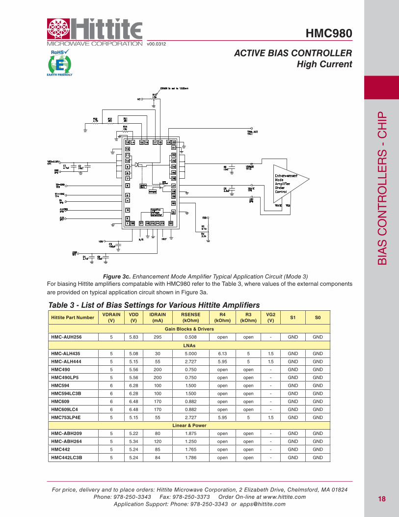
Figure 3c. Enhancement Mode Amplifier Typical Application Circuit (Mode 3)
table 3 - list of Bias settings for various Hittite AmplifiersHittite Part Number
VDRAIN (V)
VDD (V)
IDRAIN (mA)
RSENSE (kOhm)
R4 (kOhm)
R3 (kOhm)
VG2 (V)
S1 S0
Gain Blocks & Drivers
HMC-AUH256 5 5.83 295 0.508 open open - GnD GnD
LNAs
HMC-ALH435 5 5.08 30 5.000 6.13 5 1.5 GnD GnD
HMC-ALH444 5 5.15 55 2.727 5.95 5 1.5 GnD GnD
HMC490 5 5.56 200 0.750 open open - GnD GnD
HMC490LP5 5 5.56 200 0.750 open open - GnD GnD
HMC594 6 6.28 100 1.500 open open - GnD GnD
HMC594LC3B 6 6.28 100 1.500 open open - GnD GnD
HMC609 6 6.48 170 0.882 open open - GnD GnD
HMC609LC4 6 6.48 170 0.882 open open - GnD GnD
HMC753LP4E 5 5.15 55 2.727 5.95 5 1.5 GnD GnD
Linear & Power
HMC-ABH209 5 5.22 80 1.875 open open - GnD GnD
HMC-ABH264 5 5.34 120 1.250 open open - GnD GnD
HMC442 5 5.24 85 1.765 open open - GnD GnD
HMC442LC3B 5 5.24 84 1.786 open open - GnD GnD
For biasing hittite amplifiers compatable with hMC980 refer to the table 3, where values of the external components are provided on typical application circuit shown in Figure 3a.

For price, delivery and to place orders: Hittite Microwave Corporation, 2 Elizabeth Drive, Chelmsford, MA 01824Phone: 978-250-3343 Fax: 978-250-3373 Order On-line at www.hittite.com
Application Support: Phone: 978-250-3343 or [email protected]
Bia
s C
on
tr
oll
er
s -
Ch
ip
19
HMC980v00.0312
Active BiAs controller High current
Hittite Part Number VDRAIN
(V)VDD (V)
IDRAIN (mA)
RSENSE (kOhm)
R4 (kOhm)
R3 (kOhm)
VG2 (V)
S1 S0
HMC442LM1 5 5.24 85 1.765 open open - GnD GnD
HMC499 5 5.56 200 0.750 open open - GnD GnD
HMC499LC4 5 5.56 200 0.750 open open - GnD GnD
HMC-ABH241 5 5.62 220 0.682 open open - GnD GnD
HMC-APH403 5 5.74 475 0.316 open open - GnD VDiG
HMC-APH460 5 5.77 900 0.167 open open - VDiG GnD
HMC-APH462 5 6.22 1440 0.104 open open - VDiG GnD
HMC-APH473 5 5.92 1080 0.139 open open - VDiG GnD
HMC-APH478 5 5.77 900 0.167 open open - VDiG GnD
HMC-APH510 5 5.99 640 0.234 open open - GnD VDiG
HMC-APH518 5 5.81 950 0.158 open open - VDiG GnD
HMC-APH596 5 6.12 400 0.375 open open - GnD GnD
HMC-APH608 5 5.81 950 0.158 open open - VDiG GnD
HMC486 7 8.11 1300 0.115 open open - VDiG GnD
HMC486LP5 / HMC486LP5E
7 8.11 1300 0.115 open open - VDiG GnD
HMC487LP5 / HMC487LP5E
7 8.11 1300 0.115 open open - VDiG GnD
HMC489LP5 / HMC489LP5E
7 8.11 1300 0.115 open open - VDiG GnD
HMC498 5 5.70 250 0.600 open open - GnD GnD
HMC498LC4 5 5.70 250 0.600 open open - GnD GnD
HMC590 7 7.70 820 0.183 open open - VDiG GnD
HMC590LP5 / HMC590LP5E
7 7.70 820 0.183 open open - VDiG GnD
HMC591 7 8.14 1340 0.112 open open - VDiG GnD
HMC591LP5 / HMC591LP5E
7 8.14 1340 0.112 open open - VDiG GnD
HMC592 7 8.16 750 0.200 open open - GnD VDiG
HMC608LC4 5 5.87 310 0.484 open open - GnD GnD
HMC693 5 6.24 800 0.188 open open - GnD VDiG
HMC756 7 8.22 790 0.190 open open - GnD VDiG
HMC757 7 8.11 395 0.380 open open - GnD GnD
HMC757LP4E 5 6.12 400 0.375 open open - GnD GnD
HMC863 6 7.05 375 0.400 open open - GnD GnD
HMC863LP4E 6 7.05 375 0.400 open open - GnD GnD
HMC864 6 7.16 750 0.200 open open - GnD VDiG
HMC906 6 7.02 1200 0.125 open open - VDiG GnD
HMC943LP5E 5.5 6.52 1200 0.125 open open - VDiG GnD
HMC949 7 8.02 1200 0.125 open open - VDiG GnD
HMC965LP5E 6 7.02 1200 0.125 open open - VDiG GnD
HMC968 6 6.77 900 0.167 open open - VDiG GnD
HMC969 6 6.77 900 0.167 open open - VDiG GnD
Wideband (Distributed)
HMC-AUH232 5 5.50 180 0.833 5.18 5 1.5 GnD GnD
HMC-AUH249 5 5.56 200 0.750 5.07 5 1.5 GnD GnD
HMC-AUH312 8 8.17 60 2.500 3.06 5 1.8 GnD GnD
table 3 - list of Bias settings for various Hittite Amplifiers (Continued)

For price, delivery and to place orders: Hittite Microwave Corporation, 2 Elizabeth Drive, Chelmsford, MA 01824Phone: 978-250-3343 Fax: 978-250-3373 Order On-line at www.hittite.com
Application Support: Phone: 978-250-3343 or [email protected]
Bia
s C
on
tr
oll
er
s -
Ch
ip
20
HMC980v00.0312
Active BiAs controller High current
Hittite Part Number VDRAIN
(V)VDD (V)
IDRAIN (mA)
RSENSE (kOhm)
R4 (kOhm)
R3 (kOhm)
VG2 (V)
S1 S0
HMC460 8 8.17 60 2.500 open open - GnD GnD
HMC460LC5 8 8.21 75 2.000 open open - GnD GnD
HMC463 5 5.17 60 2.500 open open - GnD GnD
HMC463LH250 5 5.17 60 2.500 open open - GnD GnD
HMC463LP5 5 5.17 60 2.500 open open - GnD GnD
HMC465 8 8.45 160 0.938 2.48 5 1.5 GnD GnD
HMC465LP5 8 8.45 160 0.938 2.48 5 1.5 GnD GnD
HMC562 8 8.22 80 1.875 open open - GnD GnD
HMC633 5 5.50 180 0.833 open open - GnD GnD
HMC633LC4 5 5.50 180 0.833 open open - GnD GnD
HMC634 5 5.50 180 0.833 open open - GnD GnD
HMC634LC4 5 5.50 180 0.833 open open - GnD GnD
HMC-930 10 10.49 175 0.857 4.22 5 3.5 GnD GnD
HMC-459 8 8.81 290 0.517 4.77 5 3 GnD GnD
HMC-464 8 8.81 290 0.517 4.77 5 3 GnD GnD
HMC464LP5 / HMC464LP5E
8 8.81 290 0.517 4.77 5 3 GnD GnD
HMC559 10 11.12 400 0.375 4.55 5 4 GnD GnD
HMC619 12 12.84 300 0.500 4.82 5 5 GnD GnD
HMC619LP5 / HMC619LP5E
12 12.84 300 0.500 4.82 5 5 GnD GnD
HMC635 5 5.78 280 0.536 open open - GnD GnD
HMC635LC4 5 5.78 280 0.536 open open - GnD GnD
HMC637 12 13.12 400 0.375 6.27 5 6 GnD GnD
HMC637LP5 / HMC637LP5E
12 13.12 400 0.375 4.62 5 5 GnD GnD
HMC659 8 8.84 300 0.500 4.74 5 3 GnD GnD
HMC659LC5 8 8.84 300 0.500 4.74 5 3 GnD GnD
HMC797 10 11.12 400 0.375 3.80 5 3.5 GnD GnD
HMC797LP5E 10 11.12 400 0.375 3.80 5 3.5 GnD GnD
Microwave & Optical Drivers
HMC870LC5 7 7.46 165 0.909 open open - GnD GnD
HMC871LC5 8 8.21 75 2.000 open open - GnD GnD
table 3 - list of Bias settings for various Hittite Amplifiers (Continued)
Copyright © 2022 FDOKUMEN