
An Overview of the n-dim Environment
48
An Overview of the n-dim Environment EDRC-05-65-93 Sean Levy 1 , Eswaran Subrahmanian 2 , Suresh Konda 3 , Robert Coyne 4 , Arthur Westerberg 5 , Yoram Reich 6 Email Addresses: [email protected] 1 , [email protected] 2 , [email protected] 3 , [email protected] 4 , [email protected] 5 , [email protected] 6 Fax: +1 412 268 5229 Voice: +1 412 268 5221 February 22, 1993
Transcript of An Overview of the n-dim Environment
An Overview of the n-dim EnvironmentEDRC-05-65-93
Sean Levy1, Eswaran Subrahmanian2, Suresh Konda3,Robert Coyne4, Arthur Westerberg5, Yoram Reich6
Email Addresses:
[email protected], [email protected], [email protected],
[email protected], [email protected], [email protected]
Fax: +1 412 268 5229
Voice: +1 412 268 5221
February 22, 1993
Abstract
The premise of our work is that designers, in the process of doing their work, create modelsof various kinds, for various purposes, and that it is the negotiation of the structure andcontent of these models that comprises the bulk of the task of doing design. We give herean overview of a framework for enabling designers to capture and structure as much ofthe information they use and generate as is possible. We have designed and implementedsuch a system for creating models in a computer that can be
� shared with other designers in the course of an ongoing design,
� made persistent for future recall,
� classified and categorized so as to facilitate both the study of how design is done ina given organization and the study of design in general.
Our system is generic enough to be useful in domains outside of design, and we positit to be useful in general for anyone who needs to manipulate information in a structuredway, an activity called Information Modeling. The acronym chosen for the system, n-dim,stands for n-dimensional information modeling, to indicate the authors’ view that the totalspace of information under consideration is multi-dimensional in nature.
Contents
1 Introduction 1
2 Motivation and Background 22.1 Modeling and Design: Overview : : : : : : : : : : : : : : : : : : : : : 22.2 Modeling and Design: Background : : : : : : : : : : : : : : : : : : : : 3
2.2.1 Empirical Studies done by EDRC : : : : : : : : : : : : : : : : : 32.2.2 Problems in Collaborative Work : : : : : : : : : : : : : : : : : : 5
3 Conceptual Description 73.1 Representation : : : : : : : : : : : : : : : : : : : : : : : : : : : : : : : 11
3.1.1 Attributes : : : : : : : : : : : : : : : : : : : : : : : : : : : : : 113.1.2 Persistence : : : : : : : : : : : : : : : : : : : : : : : : : : : : : 123.1.3 Structures, Projections and Presentations : : : : : : : : : : : : : 133.1.4 Rules and Events : : : : : : : : : : : : : : : : : : : : : : : : : 153.1.5 Operations : : : : : : : : : : : : : : : : : : : : : : : : : : : : : 16
4 Implementation 164.1 Layers : : : : : : : : : : : : : : : : : : : : : : : : : : : : : : : : : : : 174.2 BOS: The Basic Object System : : : : : : : : : : : : : : : : : : : : : : 19
4.2.1 Prototypes, Identity and Mutability : : : : : : : : : : : : : : : : 204.3 Object Storage (Workspaces) : : : : : : : : : : : : : : : : : : : : : : : 224.4 The RDBMS in n-dim : : : : : : : : : : : : : : : : : : : : : : : : : : : 224.5 Generalized Searches : : : : : : : : : : : : : : : : : : : : : : : : : : : 24
5 Applications and Extensions of n-dim 275.1 Modeling and analysis with n-dim: An example : : : : : : : : : : : : : : 285.2 Tool Integration : : : : : : : : : : : : : : : : : : : : : : : : : : : : : : 33
5.2.1 Levels of integration : : : : : : : : : : : : : : : : : : : : : : : : 345.2.2 Experiments with Tool Integration : : : : : : : : : : : : : : : : : 37
6 Summary and Future Directions 43
1 Introduction
This report is a compendium of the work of the n-dim research group in that it is thecentral repository of all previous and ongoing work conducted by the members of thegroup collectively and individually around the project. As such, it is a “living” documentand is expected to be highly dynamic.
n-dim stands for n-dimensional modeling and represents both a research program anda computer software artifact. As a research program, it is a series of on-going researchprojects on the theoretical and empirical aspects of design practice. As an artifact, it is both
1

an embodiment of the lessons learned, and a test bed for testing some of the hypothesesgenerated from, the former.
In the second section we indicate the motivation and background upon which n-dim is based. The third section contains a conceptual description of the n-dim designenvironment with the fourth section containing details of the current implementation. Thefourth section gives details of applications and extensions and the final section concludesthe report.
2 Motivation and Background
In this section, we seek to motivate n-dim from its origins in the study of design and theway designers work. It should be noted that n-dim as it is developed in this documentis not meant to be the final solution to the problems raised here; rather, it serves on twofronts: first, as a tool to gather empirical data on a rather broad domain of which little isreally known (design), and second as a test bed for trying out solutions to some problemsalready well established in this domain (for instance, the creation and maintenance ofshared concept networks within groups of designers).
There is a chicken-and-egg problem here, which is common in enterprises such asn-dim. On the one hand, there is not really enough data available to propose, a priori, aworkable solution to the total problem with any confidence. On the other hand, in orderto gather the necessary data, one needs a working system that will exhibit (we posit) atleast some characteristics of such a solution to even get started.
We will first present an overview of the underlying observations and principles behindour approach, and then proceed to give more a more detailed description of backgroundstudies and information that have informed the evolution of this approach.
2.1 Modeling and Design: Overview
In the course of designing things, designers make models of various kinds, dependingon what kind of designers they are and what they are designing. By “designer”, weintend to take in the full range of possible assignations: engineers, architects, writers (ofdocumentation as well as of other sorts), managers, marketing people all are involved, insome sense, in some sort of design.
The models that people make vary, both according to the domain in which they areworking, which may include standard formulas for accomplishing certain things,1 as wellas according to personal preference and judgment (presumably based on experience withpast designs).
From studies of design, several interesting features of how designers work in variousorganizations have been uncovered vis a vis modeling:
1Standards either being taken from the work of standards-setting bodies like ISO and ANSI, or from thepolicies and procedures of the particular organization or discipline in which the individual works.
2

� Different designers (and groups of designers) use different vocabularies to describethe same or very closely related sets of things.
� Engineers typically spend at most 15% of their time doing standard analytical tasks[10], the rest of their time being spent negotiating various aspects of the design,including the structure of the task of doing the design itself.
� Individuals tend to organize information in ways understandable to them, generallyin the form of sketches and notes. There is usually substantial overhead incurred inthe process of merging all of the individual representations in a design team into asingle, coherent view.
From these and other observations, we have developed a notion of an InformationModeling environment which differs substantially from similar concepts developed else-where (e.g. in the database and AI literature [12]).
One of the key elements of n-dim is the focus on the human user instead of oncomputational entities. This is partly due to the emphasis on the gathering of empiricaldata using n-dim, and partly due to the conviction that the real difficulty lies in an areanot easily susceptible to automation, namely, negotiation.
2.2 Modeling and Design: Background
Through the course of several empirical studies (our own and those of others), it becameclear the a large emphasis must be placed on supporting and capturing information usedfor negotiating and creating a shared understanding of the design task, as well as capturing,as much as possible, the negotiations themselves [6]. Our focus thus became more andmore one of providing an environment in which designers can collaborate, in the broadestpossible sense. The next two sections will provide a summary of both the empirical studiesthemselves, as well as some problems involved in collaborative (design) work.
2.2.1 Empirical Studies done by EDRC
EDRC has been involved in a number of empirical studies of design in the area of electricalconnector design [27], power system control design at Westinghouse Electric Corporation[23] and transformer design at Asea-Brown-Boveri [11]. We also studied the problems ofgathering and making accessible materials information in Alcoa Technical Center acrossdivisions that generate data on properties and performance of materials [24].
In these studies, we identified functional requirements for a design environment tomanage and organize dispersed documents, drawings, and other forms of information.One of the most fundamental of these requirements was the ability to foster both individualand group efforts.
In the study of transformer design, we identified functional requirements to facilitatethe accretion of, and access to, institutional memory (viz. “shared memory” in [16]), bothas it relates to design and to the activities surrounding design (marketing, testing, qualityassurance, delivery, etc.) in a large, multi-national organization.
3

Des
ign
Eff
icie
ncy
Level of Computer Support
1.0
Discrete Design Tools
Partial Integration
Information/Knowledge Integration
0
Figure 1: Design Efficiency vs Level of Computer Support
The results of the study show that intra-project and inter-project information flows arenot integrated in the current practice of design. Some key deficiencies observed include:
� stand-alone tools are insufficient in producing high quality designs if they are notintegrated and maintained in the context of design practice.
� many errors are due to miscommunications and incomplete information integration.
� a partial integration of analysis tools is insufficient to achieve design efficiency.
In Figure 1, we illustrate the relationship over time between design efficiency and thelevel of computer support. Efficiency must be achieved through the integration of theinformation technology in the context of the overall process. Our observations about thedesign process and the need for integration of information is supported by other studiessuch as the comparative cross-national automobile industry study by Clark and Fujimoto[5]. They have established a clear inter-relationship between integration of problemsolving and design efficiency.
In Figure 2 we illustrate the critical functionalities that an design support system mustprovide based on the experience and the role of the design engineer. The nature of designpractice appears to vary systematically between designers of varying skill and experiencelevels [11]; as a consequence, the nature of the information available to and the assistancerequired by designers various along the same dimensions. Nevertheless, the synergisticand returns-to-scale from a common system across all levels of designers implies that thedesign system should support a range of requirements.
The novice requires the maximum level of support including being alerted aboutproblems and guidance in what to change in a design. Experts, on the other hand, need
4

InformationAvailability
Novice
ExpertExpertConsultant
Accumulation of Expertise0
Fac
ility
for
Pro
duct
kno
wle
dge
orga
niza
tion
Fac
ility
for
Per
sona
l Kno
wle
dge
Org
aniz
atio
n &
Acc
ess
to P
rod.
Kno
wl
Access to product knowledgeAid for consultationAlerting - potential problems
1.0
Figure 2: Function Requirements by Experience of Designer
support more in the area of managing personal and organizational product knowledge andaccess to a corporate-wide memory bank of design experiences.
Without the ability to support a variety of functionalities, design consistency andquality cannot be achieved easily. Therefore, the design system should not just integrateinformation, but must also meet the functional requirements of the range of participants,from novice to expert, in the design team. The need for management of cross-functionalinformation content and complexity, and the facility to maintain individual and shared(i.e. product) information were both apparent in our studies of design [11] [23], and leadto the central importance of the ability to view the same information in multiple ways andto index that information in idiosyncratic ways in order that individual access and recallbe made more easy and meaningful.
Another critical issue discovered in the study was the need to provide for terminologydifferences that had to be taken into account based on the requirements of the customer invarious parts of the world, along with cross country variations in the standards information.
The same conclusions could be drawn in the Alcoa project, where the divisions werelocated in the same location but the terminology differences in the existing materialsdata and information had to be reconciled for use across multiple projects, divisions, andproducts. Here again the necessity for maintaining multiply cross indexed terminologywas identified as a fundamental requirement, and as a solution, a preliminary materialinformation system embedding these functionalities system developed.
2.2.2 Problems in Collaborative Work
To be effective in practice, concurrent engineering requires access to and organization,communication and negotiation of knowledge accumulated over time and across productversions and customers. Studies conducted by us and others indicate that design is
5

a continual negotiation of constraints, terminology and trade-offs for the creation of ashared understanding and meaning of the design process and product.
For effective communication between members of the design group there must beconsensus on the
� naming (i.e., a shared semantic understanding of relevant terms and concepts)
� constraints (on manufacturing, performance, disposal etc.)
� problem decomposition
� design trade-offs.
Without such agreements, effective communication and coordination of work cannotoccur. However, such agreements cannot, in general, be imposed from the outside but mustbe generated by the design group consensually. In order to facilitate reaching consensus,the design environment must be conducive to conducting and capturing a dialog among theengineers. This become especially critical when, for a various reasons, there is an absenceof face-to-face contacts. This situation can arise when, for instance, design teams membersare separated by significant time and distance or when designers belong to multiple teamsmaking their physical presence at each team meeting prohibitively expensive in terms ofboth money and designer burnout. Hence, individual engineers must be able to participatein this dialog in an asynchronous manner – different time and different place. However,in order that the dialog not “drift” over time, it is critical that the context of the dialog bemaintained with maximal fidelity and in particular without loss of the time sequence andidentity of the exchanges (i.e., “who said what to whom when”).
In order to facilitate dialog to effect asynchronous collaboration we need to distinguishbetween three important aspects of information used in design:
� Information comes in a variety of representational forms including sketch, picture,gesture, text (oral and verbal), table, geometry, layout.
� The information is exchanged in a number of media including, paper, face-to-face,computer, video, film.
� The representational forms exchanged in these media come in formal to informalmodes of communication: reports, memos, e-mail, equational, functional and geo-metric configurations and descriptions.
Just as important as the form, media, and mode of information in design is its hetero-geneity. Large scale design projects usually must coordinate expertise from many differentdisciplines representing the functional decomposition of the artifact being produced. Themanagement of this diversity is the management of cross-functional information in bothits content and its complexity. Moreover, the companies involved in large-scale designare themselves many-faceted involving a number of different departments devoted todesign engineering, engineering analysis, manufacturing, quality assurance, suppliers,
6

subcontractors, procurement, legal matters, fiscal matters, marketing, customer serviceand management. All of these departments plus the sub-departments in charge of vari-ous parts of design must manage their own information gathering and production. Moreimportant, these separate information and knowledge resources have to be shared and co-ordinated if successful design is to be accomplished. Our studies of information exchangein design tasks have been crucial in guiding the development of n-dim for the managementof work and information in design.
Coordination and management of group activities and work-flow requires that infor-mation be made available in a meaningful form at the appropriate time. It is the creationof and access to meaningful information with the seamless integration of these varietiesof information used in and created during the design of the product, is what we terminformation management.
Information capture and structuring depends on which representational forms, media,and modes of communication are used. For example, information techniques useful fortext management are not useful for graphical information. In fact, if such forms are notappropriately distinguished in the flow of information, they can interfere with and distortone another. On the other hand, organizational units or concepts extracted from textualinformation can be useful in classifying graphical information such as sketches, drawings.etc.
While the computer is the target medium for information management, care must betaken to transfer information from other media to it. Insisting that engineers use onlythe computer would be counter productive. Hence, the results produced on these othermedia must be transferred to or interlinked with the computer. However, tasks performedin other media like writing and sketching with paper and pencil can be simulated in thecomputer using such technologies as electronic tablets as input devices.
Finally, information must be evaluated differently according to the communicationmode in which it is exchanged. For example, most often information coming via e-mailhas to be treated differently from information provided in a report or technical article.
In summary, extensive studies across multiple design domains, cultures, and organi-zational context lead us to put forward the following “shalls” as a starting point for thedesign of n-dim:
The support environment should enable design and design management to be carriedout within the same uniform information modeling environment. Facilities should be builtinto the environment that will enable designers to create shared structures of information(text, geometry, layout, sketch, pictures). The environment should also permit asyn-chronous group activity. Finally, facilities are required to enable retrieval of informationby designers with diverse views of that information.
3 Conceptual Description
In this section, we attempt to give first a brief overview of the way in which n-dimallows one to model information, and then elaborate on certain key elements of thisrepresentation, as well as operational issues associated with using it. Detailed discussion
7
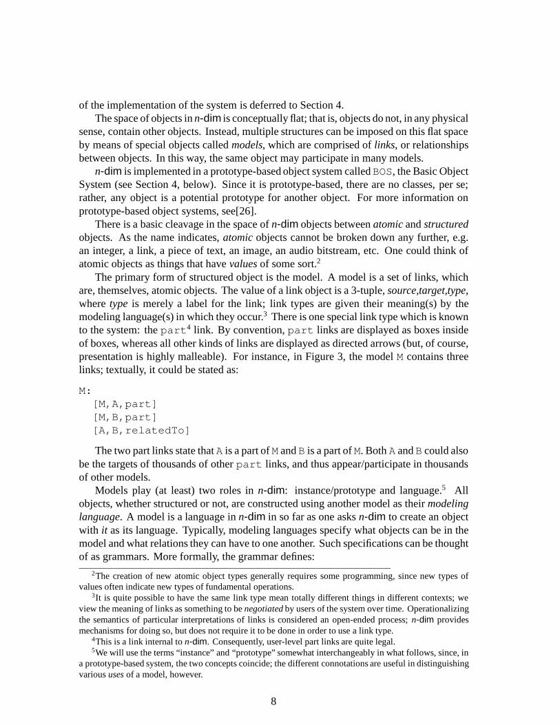
of the implementation of the system is deferred to Section 4.The space of objects in n-dim is conceptually flat; that is, objects do not, in any physical
sense, contain other objects. Instead, multiple structures can be imposed on this flat spaceby means of special objects called models, which are comprised of links, or relationshipsbetween objects. In this way, the same object may participate in many models.
n-dim is implemented in a prototype-based object system calledBOS, the Basic ObjectSystem (see Section 4, below). Since it is prototype-based, there are no classes, per se;rather, any object is a potential prototype for another object. For more information onprototype-based object systems, see[26].
There is a basic cleavage in the space of n-dim objects between atomic and structuredobjects. As the name indicates, atomic objects cannot be broken down any further, e.g.an integer, a link, a piece of text, an image, an audio bitstream, etc. One could think ofatomic objects as things that have values of some sort.2
The primary form of structured object is the model. A model is a set of links, whichare, themselves, atomic objects. The value of a link object is a 3-tuple, source,target,type,where type is merely a label for the link; link types are given their meaning(s) by themodeling language(s) in which they occur.3 There is one special link type which is knownto the system: the part4 link. By convention, part links are displayed as boxes insideof boxes, whereas all other kinds of links are displayed as directed arrows (but, of course,presentation is highly malleable). For instance, in Figure 3, the model M contains threelinks; textually, it could be stated as:
M:[M,A,part][M,B,part][A,B,relatedTo]
The two part links state that A is a part of M and B is a part of M. Both A and B could alsobe the targets of thousands of other part links, and thus appear/participate in thousandsof other models.
Models play (at least) two roles in n-dim: instance/prototype and language.5 Allobjects, whether structured or not, are constructed using another model as their modelinglanguage. A model is a language in n-dim in so far as one asks n-dim to create an objectwith it as its language. Typically, modeling languages specify what objects can be in themodel and what relations they can have to one another. Such specifications can be thoughtof as grammars. More formally, the grammar defines:
2The creation of new atomic object types generally requires some programming, since new types ofvalues often indicate new types of fundamental operations.
3It is quite possible to have the same link type mean totally different things in different contexts; weview the meaning of links as something to be negotiated by users of the system over time. Operationalizingthe semantics of particular interpretations of links is considered an open-ended process; n-dim providesmechanisms for doing so, but does not require it to be done in order to use a link type.
4This is a link internal to n-dim. Consequently, user-level part links are quite legal.5We will use the terms “instance” and “prototype” somewhat interchangeably in what follows, since, in
a prototype-based system, the two concepts coincide; the different connotations are useful in distinguishingvarious uses of a model, however.
8

Figure 3: A simple n-dim model
� the set of legal parts which models in that language may contain;
� the set of legal link types or labels between parts of models in that language;
� rules for composing legal links from the set of legal parts and the set of legal links.
Normally, one would expect an n-dim model intended for use as a modeling language tohave as parts only other modeling languages; that is, in some form of a “meta” language.However, there is no such constraint in n-dim; any object can be used as a modelinglanguage. If, for example, one were to ask n-dim to use an Integer object6 with thevalue 1 as a modeling language, one would get an object in the language 1, which couldonly have as its value the number 1. The grammar has one sentence. Consequently, n-dimmodels can operate as both instances and prototypes.
As an example, Figure 4 shows a model called TASK which, when interpreted asa modeling language, would allow creation of models containing BASICTASK objects,TASK objects, and, further, allows a precedes link to be created between two TASK (orBASICTASK) objects.7 In BNF, the grammar would be:
TASK := BASICTASK | TASK p TASK;
6Note that Integer objects are atomic!7That is, the grammar is recursive. Also, we have not defined what BASICTASK is, but it would
presumably be some form of textual object.
9
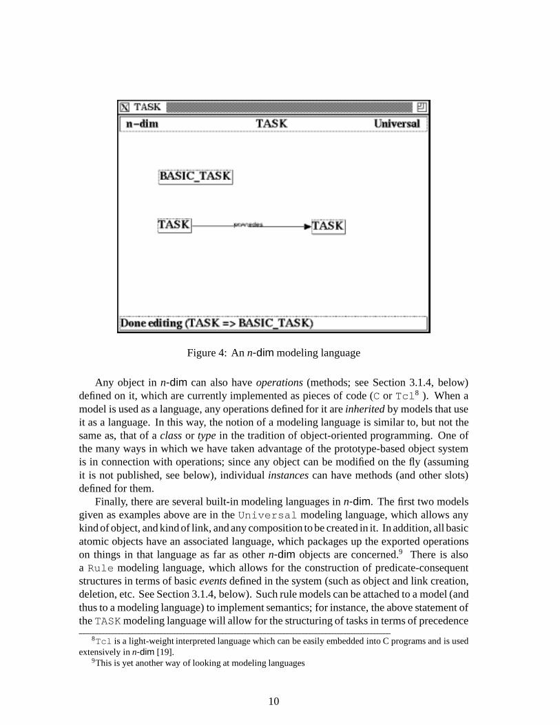
Figure 4: An n-dim modeling language
Any object in n-dim can also have operations (methods; see Section 3.1.4, below)defined on it, which are currently implemented as pieces of code (C or Tcl8 ). When amodel is used as a language, any operations defined for it are inherited by models that useit as a language. In this way, the notion of a modeling language is similar to, but not thesame as, that of a class or type in the tradition of object-oriented programming. One ofthe many ways in which we have taken advantage of the prototype-based object systemis in connection with operations; since any object can be modified on the fly (assumingit is not published, see below), individual instances can have methods (and other slots)defined for them.
Finally, there are several built-in modeling languages in n-dim. The first two modelsgiven as examples above are in the Universal modeling language, which allows anykind of object, and kind of link, and any composition to be created in it. In addition, all basicatomic objects have an associated language, which packages up the exported operationson things in that language as far as other n-dim objects are concerned.9 There is alsoa Rule modeling language, which allows for the construction of predicate-consequentstructures in terms of basic events defined in the system (such as object and link creation,deletion, etc. See Section 3.1.4, below). Such rule models can be attached to a model (andthus to a modeling language) to implement semantics; for instance, the above statement ofthe TASKmodeling language will allow for the structuring of tasks in terms of precedence
8Tcl is a light-weight interpreted language which can be easily embedded into C programs and is usedextensively in n-dim [19].
9This is yet another way of looking at modeling languages
10

and, via recursion, by subtasks. It does not, however, place any restrictions on the numberof tasks allowed in a model of that type, nor does it disallow circular task precedencelinkages, both of which might be desirable. To do so would require the creation of rulemodels which, when links are created, check that the attempted construction is not onlygrammatically correct, but semantically correct as well.
Given this overview, we will now delve further into the way in which n-dim objectsare represented.
3.1 Representation
n-dim objects all have certain attributes, regardless of whether they are atomic or struc-tured. In addition, structured objects can have their structure projected in a multiplicityof ways, which is important vis a vis their interpretation as languages. All objects canbe presented in different ways which can be extended by users of n-dim. Finally, rules,events and operations are related in a number of ways.
3.1.1 Attributes
Preliminary to any attribute is the issue of naming. All n-dim objects have names uniquewithin the universe of all n-dim objects. This name is system-generated, and utilizesvarious pieces of information to be found in any modern, networked environment10 togenerate the name. Thus, the real name (or just name for the remainder of this document)is generally not known to ordinary users of n-dim; this name is not to be confused withany title (or, interchangeably, label) given to the object.
Attributes come in two flavors: intrinsic and contextual. The intrinsic attributes of anobject cannot be separated from it, and, properly speaking, define the object. They do notchange with the context an object is in (e.g. a model it may be part of), and are stored asphysical slots on the (underlying) object.
By contrast, contextual attributes are attributes associated with an object in a particularcontext or model. An object can have many values for the same contextual attribute, andn-dim decides which one is appropriate by context. One associates contextual attributeswith an object by creating an ATTRIBUTE model containing the object, the name of theattribute, the model(s) in which the object has this attribute and, optionally, a value orset of values for the attribute in those models. Certain attribute names, such as titleare known to n-dim to mean specific things; one can impose such semantics by writingcode to perform arbitrary actions when an object is viewed in a context. For example, onecould associate a shape attribute with an object in certain models and then write codeto be invoked to interpret the value of the shape attribute in order to render the objectspecially when viewed in those models.
The set of intrinsic attributes in n-dim has been kept to an absolute minimum.
Owner/Creator. The person who created the object. People are also objects in the system,so this is the name of an object.
10Network address, system time and time zone, numeric user ID, etc.
11

Time created. The time the object was created. An integer.
Time last modified. The time the object was last modified. An integer.
Title. The label given by the owner upon creating it. While the title can be changed by theowner – if the object is not published (see section 3.1.2) – it is essentially inherent– in that it is not contextually variant.
Published. Whether or not the object has been published. See 3.1.2, below, for a fullerdescription. This is a boolean flag.11
Language. The name of the model which is this objects language.
Access. The name of the model which describes who has access to this object.
All of the object-valued attributes (creator, language and access) must be published.While the title (or label) of an object is an intrinsic attribute, a very important feature
of n-dim objects is that they can have different titles in different contexts. This is achievedby providing a contextual “alias” attribute which allows a user to refer to the same thingwith different names in different contexts and still have it be intrinsically the same thing.12
The access attribute deserves some special mention. Every object has an access-control model,13 which describes who has what kind of access to the object. It is possibleto hide even one’s published objects from outside view, if so desired. Access models aresimply the n-dim form of an access control list, with some embellishments. In order to beactivated, an access model must be published; to change the access model for an object,the old one must be copied and the copy published. It is thus also possible to ask n-dimquestions such as “who had access to this object on this date?”, since the whole chain ofaccess models for that object is available. This is a very important point, since anyonewho had access to an object could’ve copied it, even if their access had been rescinded ata later date.
3.1.2 Persistence
All objects have one and only one owner and reside, conceptually, in only one place. Anobject’s ownership can never be changed, and is set at the time it is created. If an objectis copied, then the copy will be owned by the person making the copy; however, pedigreeinformation will be retained, so that the owner of the object so copied can inquire as towhat use (i.e. what copies) has been made of his object. This pedigree information is in
11We are experimenting with the notion of “sticky” models, which are write-only. Such a loosening of thenotion of publication would permit certain forms of synchronous collaboration within n-dim without intro-ducing the entire range of difficulties (consistency management, locking, etc.) associated with synchronouscollaboration systems.
12In version 0.91, this is not actually implemented and was found to be one of the major limitations of the0.91 prototype. Version 1.0 remedies this by means of the more general answer to the question of attributesgiven here.
13In a built-in language called ACCESS.
12

the form of a system-generated (and system-maintained) model, which links the copiedobject to its copies; of course, this model is available to the user like any other model.
When an object is first created, it is malleable, but only in so far as its owner isconcerned. Until it is published, no one but its owner can even know of its existence.14
The act of publishing an object is similar to the notion of publishing a paper; once thepaper is published, its author cannot go to all of the libraries in the world and removeit from circulation. In the same way, publishing an object makes it visible to the rest ofthe world and, at the same time, immutable, even to its original author. If one wants tochange a published object, it must be copied, and the copy revised, at which time thepedigree-maintenance mechanisms described above are activated. In this way, the pathany published object has taken through its many copies can always be traced.
To publish an object, everything that it depends on must be published, namely, alltargets of part links with the object as source. One is thus guaranteed that when apublished object is manipulated, even some time (e.g. years) after it was published, it willbehave exactly as it did at the time of publication.15 This is a critical property of publishedobjects, and one reason for the way in which it has been formulated in n-dim.
An example will serve to both crystallize the concept of publication and show whywe have formulated it in such a fashion. Consider an n-dim model containing a pieceof computational software. If it were to be published, then the compiler, linker, andlibraries which together could be shown to work (by, for instance containing test casesand results) would also be published and frozen. Years later, if one were to use (reuse)this software, it would be possible to recreate the original program quite faithfully. Whileperhaps extreme, the example does show the need for some rigid specifications regardingpersistence of objects and their contexts for them to be of real use in the design situationwhere, often, it is very difficult to reconstruct the why and how of often reused pieces orapproaches.
Published objects can never be destroyed, although n-dim does have a notion ofarchival vs. active storage, in the same way that libraries move little-used books andmaterial to less easily accessed but more efficient storage, such as microfiche.
3.1.3 Structures, Projections and Presentations
The fact that one can create types (e.g. modeling languages) in the same way as one createsinstances, and refer to the normally in other types raises certain issues of interpretation. Inaddition, it is quite often desirable to see the same structure through different filters. Forinstance, one might have a very large and complicated model which one would like to viewwith certain link types hidden, or with certain parts hidden. All of these considerationsare dealt with by the structure, projection, presentation split in n-dim.
Every structured object can potentially correspond to a set of models describing var-
14In the sense that the results of a search are always either objects owned by the searcher or publishedobjects.
15In order to be used as a language, a model must first be published; therefore, any models created usingthat language are also guaranteed that their language will not change out from underneath them.
13

n−dim Universal Universaln−dim M2BM2A
TASK
TASK
TASK
TASK TASKprecedes precedes
Figure 5: Two projections of a model
ious aspects of it. There are three basic layers: structure, projection and presentation.16.Projections serve to distinguish between different topological views of the same structure,each of which can have a different meaning. For instance, Figure 5 shows two projec-tions (which are, of course, models), M2A and M2B, of the structure M2 whose textualrepresentation could be something like:17.
M2:[M2,TASK,part][TASK,TASK,precedes]
Note that all of the appearances of TASK have the same label, since they are allreflections of the same object; in fact, the user would not be able to distinguish betweenthem. While the different projections are legal models qua model, they have differentmeanings when interpreted as languages.
Our example in Figure 5, interpreted as a language, describes a class of models thatcould be called task-flow models. It can be seen why projections are so critical in thiscontext. The M2A projection of M2, when interpreted as a language, says that one canmake models containing TASK parts linked to themselves. The M2A projection, on theother hand, says that one can make models containing TASK parts linked to other suchparts. Textually:
M2A:[M2A,TASK1,part][TASK1,TASK1,precedes]
M2B:16Atomic objects have only the first and the last, projections being nonsensical for them.17This is an expansion on the previous example involving the TASK model; see Figure 4
14
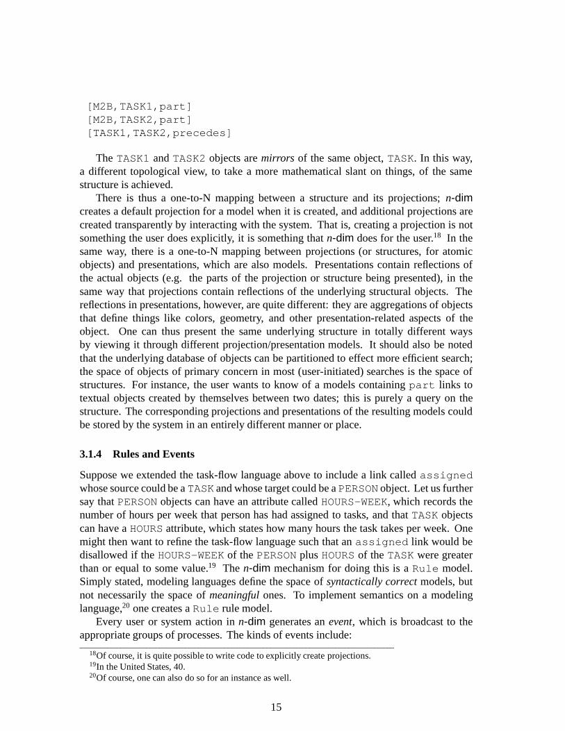
[M2B,TASK1,part][M2B,TASK2,part][TASK1,TASK2,precedes]
The TASK1 and TASK2 objects are mirrors of the same object, TASK. In this way,a different topological view, to take a more mathematical slant on things, of the samestructure is achieved.
There is thus a one-to-N mapping between a structure and its projections; n-dimcreates a default projection for a model when it is created, and additional projections arecreated transparently by interacting with the system. That is, creating a projection is notsomething the user does explicitly, it is something that n-dim does for the user.18 In thesame way, there is a one-to-N mapping between projections (or structures, for atomicobjects) and presentations, which are also models. Presentations contain reflections ofthe actual objects (e.g. the parts of the projection or structure being presented), in thesame way that projections contain reflections of the underlying structural objects. Thereflections in presentations, however, are quite different: they are aggregations of objectsthat define things like colors, geometry, and other presentation-related aspects of theobject. One can thus present the same underlying structure in totally different waysby viewing it through different projection/presentation models. It should also be notedthat the underlying database of objects can be partitioned to effect more efficient search;the space of objects of primary concern in most (user-initiated) searches is the space ofstructures. For instance, the user wants to know of a models containing part links totextual objects created by themselves between two dates; this is purely a query on thestructure. The corresponding projections and presentations of the resulting models couldbe stored by the system in an entirely different manner or place.
3.1.4 Rules and Events
Suppose we extended the task-flow language above to include a link called assignedwhose source could be a TASK and whose target could be a PERSON object. Let us furthersay that PERSON objects can have an attribute called HOURS-WEEK, which records thenumber of hours per week that person has had assigned to tasks, and that TASK objectscan have a HOURS attribute, which states how many hours the task takes per week. Onemight then want to refine the task-flow language such that an assigned link would bedisallowed if the HOURS-WEEK of the PERSON plus HOURS of the TASK were greaterthan or equal to some value.19 The n-dim mechanism for doing this is a Rule model.Simply stated, modeling languages define the space of syntactically correct models, butnot necessarily the space of meaningful ones. To implement semantics on a modelinglanguage,20 one creates a Rule rule model.
Every user or system action in n-dim generates an event, which is broadcast to theappropriate groups of processes. The kinds of events include:
18Of course, it is quite possible to write code to explicitly create projections.19In the United States, 40.20Of course, one can also do so for an instance as well.
15

� creation of an object (including links),
� destruction of an object,
� invocation of an operation (method),
� publication of an object.
All events are available in the system event stream. Internally, almost everything auser does generates an event, which can fire any number of rules. Rules are structured asa set of predicates and a consequence, with the predicates being a composition of booleanoperations on events, and the consequence being, at the moment, a piece of code.21
Depending on the type of event, certain arguments may be available for a rule to matchagainst, e.g. a rule might declare its interest in creation of a certain type of link in a model(or in instances of a modeling language). In this way, n-dim actually resembles a large,distributed production system, which some additional structure.
When fired, a rule can return a value to the system that will influence the furtherprocessing of the event (or the event that caused the event). Specifically, a rule can
� allow the operation to continue;
� raise an error, which will cause the termination of the operation in progress;
� raise an warning, which will present the user with a message and the option toproceed or not.
In addition, rule consequences can produce side-effects, which can, in turn, generateother events, and thus fire other rules.
3.1.5 Operations
Internally, operations are actually special cases of rules that are fired by an INVOKE event(either generated due to a user interaction or from a piece of code). Currently, operationsmust either be coded in Tcl or in C.
4 Implementation
This section describes version 0.91 of the n-dim prototype, currently being used by then-dim group itself. This prototype is being used to “bootstrap” the building of n-dimitself; at the moment, the further development of the prototype is being done largely inn-dim.
Version 1.0 of n-dim is due for release in early 1993; the prototype implementationdescribed herein is missing some key components of our conceptual design, which 1.0
21Various representations for the consequent are being considered and experimented with.
16

implements more fully. In particularly, the structure, projection, presentation split, con-textual attributes, some of the the modeling-language machinery and the rule system aremissing or not fully implemented in 0.91. Never the less, even with so limited a proto-type, we have found our experience with using this (and previous, even more primitive)prototypes of the system to be, on the whole, very good.
4.1 Layers
The architecture of n-dim is layered and adheres to open systems philosophy. There arefive layers in the architecture; from bottom to top (see Figure 6), they are:
� information modeling system (e.g. n-dim itself)
� object system
� a distributed applications layer
� a relational engine for information structuring and management
� the native operating system
� the raw hardware
The object system kernel is prototype based rather than class based. The utility ofa prototype-based object system for engineering applications is well documented (theSPLINTER from Open University (UK) [28], and the ASCEND system from the EDRC[20]). From an architectural point of view, any object system can used for this layer. Therestrictions on the type of object system is tied more to the domain of work rather thanbeing an architectural limitation. In fact, it can easily be shown that one can implementany form of object-oriented environment (strict class-based a la Smalltalk, mixed classesand meta-objects a la CLOS, etc.) using a prototype-based one.
We have created an object-oriented environment around Tcl (an embeddable, smallinterpreter that is easily integrated into other programs [19]) called BOS, the Basic ObjectSystem. Due to the nature of Tcl, it is a relatively painless thing to move the implementa-tion of something fromTcl to C; in effect, the C compiler is our “compiled environment”,and Tcl (with its object-oriented wrappings) is our “interpreted environment”. Currently,BOS version 2 is being implemented and tested, and contains many substantial improve-ments over BOS version 1, including a cleaner separation between interpreted syntaxes formethods and the methods themselves, through a virtual machine (in version 1, interpretedmethods are written in Tcl). We have, in effect, used Tcl and BOS to prototype anobject-oriented environment based partly on some of the ideas in SELF [26]. In effect,this is a hybrid environment, with compiled and interpreted components in different lan-guages. We find such an environment to have many compelling arguments for it overLisp-based environments and other available object-oriented environments. Argumentsfor this approach are beyond the scope of this document, but are articulated [17].
17

Architecture Layers
Modeling Kernel
Object System
Distributed System
RDBMS
OS
Hardware
n−dim
BOS
ISIS
POSTGRES,Informix.
Mach,Ultrix,SunOS,AIX,HP−UX
MIPS,SPARC,HP−PA,RS6K
Current Implementation Future Development
...
...
...,OSF/DCE
Oracle,SYBASE,...
OSF/1
Alpha,...
Figure 6: Architecture and Current implementation
As has already been stated, the space of objects in n-dim is flat; i.e., all objects arestored only once no matter how many models “contain” an object. Hence, the overheadin using objects in multiple models is close to zero since only the the part link needsto be stored. Thus, the storage of objects in multiple models is significantly reduced.Note however, that the architecture allows for objects to be stored in multiple locations ifrequired for efficiency; it is simply that it does not require multiple storage.
The distributed applications kernel in the current implementation is ISIS, a toolkitfor building distributed systems developed at Cornell University [1]. ISIS providescommunication facilities at different levels of granularity and network configuration,including situations where many local-area networks are interconnected via (relatively)slow, long-haul links.
The database layer has undergone several revisions, using several different relationaldatabases. In the architecture presented above, one will notice that the database is belowthe distributed system functionality. In fact, this is currently how we have implementedaccess to relational databases; ISIS process groups are used to implement various piecesof the architecture, including the relational database. One thus access it by broadcastingrequests to this set of process; we are thus independent of which actual relational databaseis used. The program responsible for answering requests is called the back end. Thereare currently versions of the back end implemented on top of Informix and postgres, withmore versions being written as necessary. The back end is structured so that there isa generic, non-RDBMS-specific portion which uses a very stylized interface to call theRDBMS. Any RDBMS which a C API can be fitted into n-dim by writing three routinesin C and linking together a new back end program.
18

It should be noted that the objects themselves are not stored in the database, but onlythe attributes necessary to search for objects (e.g. the intrinsic attributes; see Section 3.1.1,above). The objects themselves are stored locally in individual workspaces, or (possibly)in shared spaces if they have been published (and thus made immutable). In fact, thisseparation between the space in which objects are stored vs. the space in which attributesabout them are kept for the purpose of search can be utilized to great advantage in scalingn-dim up for large (hundreds of thousands to millions of objects) applications.
The collection of a set of database processes and workspace processes is called a cell.A broad range of cell configurations is possible, from a single, centralized database withseveral users clustered about it (a small work group), to a totally distributed configurationwith both central and localized components for individual users (entire organization orsub-organization, or clusters of smaller work groups). Studies will be conducted for theappropriate configuration based on network and load balancing requirements. At somepoint, it should be possible to experiment with the use of high-speed networks (such asCMU’s NECTAR or BBN’s Butterfly) depending on the needs of the actual engineeringapplication. These are issues for further research in the development and deployment ofthe collaborative environment.
4.2 BOS: The Basic Object System
The motivation for BOS comes from a variety of factors, including:22
� A lack of generally-available prototype-based systems.
� Most available object-oriented systems are large, monolithic “worlds” which onemust buy into as a whole; if one wishes to use different tools for building GUIs,accessing relational databases or trying out new ideas, life can be made difficult byall of the associated baggage.
� The lack of a generally-available object-oriented system that is easily embeddablein other applications, and which works on or easily ports to the maximum numberof platforms with the minimum amount of effort.
� The need for a system which, in addition to the above points, allows for bothinterpreted and compiled methods, possibly written in different languages; the ad-vantages of interpreted environments for fast prototyping has been widely discussed[13].
The need for prototype-based systems has been discussed in the literature in a varietyof contexts [3] [4] [20]. Our efforts have been particularly informed by the work of theSELF group [26] and their arguments for prototype-based object-oriented systems as themost basic form of object-oriented system, from which any other kind of object-oriented
22The following sections on BOS taken from an unpublished manuscript that make a separate case forit, outside of the context of n-dim. However, certain aspects of BOS are critical to the understanding ofn-dim’s implementation and use.
19

system can be “grown”. Further, our own work on n-dim, and the requirements in thedomain of engineering in general have been a constant source of ideas and imperativesfor us in this area [28].
BOS is a C-callable library that implements a basic data structured called a BOS object.In BOS an object is essentially a data structure: a named collection of slots. Inheritance isa semantic concept placed “over” the relationships of these data structures to one another.Calls are available to create and destroy objects, serialize them into and unpack them frombinary byte-streams, add, remove and modify slots in objects, and, the most crucial, sendmessages to objects. These primitives are available both from C and from Tcl; in thelatter case, all BOS objects appear as commands in the Tcl interpreter. Thus, the familiarsyntax of
object message [arguments...]
is achieved from the interpreted level at no cost. In BOS version 1,23 the Tcl inter-preter’s argument matching mechanisms have been used to simplify the implementationof the method invocation portions of BOS. In BOS version 2, the dependence on Tcl hasbeen removed, and the system greatly extended and optimized for larger-scale applications.More information on BOS itself is available in [17].
We will attempt to briefly summarize some key points pertaining to prototype-basedobject systems and the use of BOS in n-dim.
4.2.1 Prototypes, Identity and Mutability
If one had to summarize in a single sentence the main difference between prototype-basedand class-based object-oriented systems, it could be stated this way:
� A prototype is an instance plus its class(es).
In biological terms, every prototype has its own “DNA”, with which it can “clone”itself; it not only contains the values of its slots, but it also contains the definitions of itsslots.24 By way of comparison, in a class-based object-oriented system, supposing onehad a class for points in three-space, defined as a tuple of three real numbers, if you hadthe address of the starting location in memory of an instance of this class, but no pointerto the class object that had its definition, you could not make sense out of what was storedthere25: to understand the object, you must refer to the class. In a prototype-based system,there would be a prototypical point in three-space with x, y and z slots, which you wouldclone to create a new point object. All one needs to know about the new point is in theobject itself.
Generally speaking, one of the major implications of this difference is that in class-based systems, when you change a class definition, all instances of that class change. In
23BOS version 1.31 has been used to implement the version of n-dim described in this paper (0.91).24or pointers to other objects from which it inherits definitions25unless, of course, you knew a-priori
20

a prototype-based system, when you change a prototype, it only affects that object; anyobjects that may have been cloned from it before you made the change are unaffected.Every prototype is free to evolve on its own, and every prototype is mutable both in termsof structure and in terms of content. In fact, it is quite possible to clone an object andmute it to the point where it no longer has anything in common at all with the objectyou cloned it from. Unless the discipline of strict class-based systems is imposed in thecreation of objects in a prototype based system, it is not possible to do type checking. Ina prototype-based system where no such discipline is enforced, the system, when askedthe type of an object, can at best provide a list of objects from which it inherits, since theobject could have been modified after having been cloned from its “class”. In spite of thislimitation, it is just this mutability that makes prototypes so attractive for the early stagesof development, when there is a sort of “soup” of ideas and features in which one is tryingto pick out the relevant pieces and compose them into a first implementation.
In general, a purely prototype- or class-based system is not desirable. Even though thesemantics of a class-based system can be implemented in a prototype-based one, the needfor one over the other in different settings makes having a system which allows for bothmodels desirable. For example, in geometric modeling applications, which might haveto manipulate millions of points, surfaces, lines, etc., all of whose structure is guaranteednever to change, having each object represented as a prototype, with the mutability thatimplies, is both inefficient and undesirable. Philosophically, as well as pragmatically,there is not necessarily any need for each one of those million points to have its ownidentity, only its own values.
In BOS we have recognized that mutability during development and design, andefficiency during production use are concerns that must go hand in hand, and are notmutually exclusive.
The public interface to BOS mentions only one kind of thing, an object. Internally,however, BOS has two different representations for objects: as prototypes (the default),and as instances. A prototype object is, as has been discussed, mutable with respect to itsstructure. Instances, by contrast, cannot have their structure changed; only the values oftheir slots can change. All instances point to the prototype from which they were created,and contain in themselves no structural information, only values. One consequence ofthis is that, once a prototype has been used to create instances, when the structure of theprototype changes (e.g. slots are added or removed), all of its instances will change in alike manner; that is, the prototype serves as a class for those instances. BOS provides twodistinct operations to support this functionality:
Clone. Cloning an object produces an exact copy of it. If the object is a prototype, theresulting clone will also be a prototype. If it is an instance, the clone will also be aninstance.
Instantiate. Instantiation always creates an instance. If the source object is a prototype,an instances of that prototype is created. If it is an instance, the effect is the sameas if it were cloned.
21

The two kinds of objects are indistinguishable from the point of view of the caller, withthe exception that the primitives which change the structure of objects (add a slot, removea slot) return errors when applied to instances. Sending a message to an instance may takeslightly longer than sending a message to a prototype (one additional layer of lookup isrequired, e.g. following the pointer from the instance to its prototype), but instances alsorequire significantly less memory to store, since only the values of the slots, and not theirdefinitions, are required26.
4.3 Object Storage (Workspaces)
Every user of n-dim has a workspace which is, conceptually, a single place where all oftheir (unpublished) objects are stored.27 In addition, there is a library workspace, whereall the published objects in a cell are available (they may also be available in other placesas well - n-dim has the potential to optimize access to published objects in whatever wayit sees fit, as they are guaranteed to never change).
An n-dim workspace finds out about other objects by broadcasting queries to therelational database (Section 4.4, below, describes the structure of this database briefly).What comes back is always a stream of unique object identifiers (e.g. the ID column).The objects named in this stream are guaranteed to either be
� owned by the sender, in which case they are stored in the sender’s workspace, or
� published, in which case they are accessible by a broadcast to the library.
Objects are stored on disk in a binary hashed file, keyed by object ID, with the slotsof the object stored as a binary byte-stream. All BOS objects can have their in-memoryrepresentation translated into a serial stream of bytes, and back again. BOS allows certainslots in an object to be marked as ephemeral, which means that BOS will effect thistranslation differently for those slots. Slots whose values are by nature temporary (a filedescriptor, a temporary file name, a reference to another object that may only exist for ashort time, etc.) can be marked in this way, in which case BOS will store a null value forthe slot at this point in the byte-stream.
4.4 The RDBMS in n-dim
As was noted above, the contents of objects are not stored in the relational database; rather,structural attributes of objects, plus some additional information about link objects arestored in relational tables. The tables are structured as shown in Tables 1 and 2.28
26Caching and other optimizations can make the difference in speed of message sends insignificant.27An individual workspace may actually be a process group, distributed over several machines; this is
necessary in cases where, for example, specific objects must reside on a specific machine so that softwarelicensed for that machine can be used on them (or, more correctly, their contents).
28Of course, in actually operationalizing n-dim, we take certain liberties, as long as they do not showthemselves to any layer(s) conceptually above the one being operationalized. The table structure presentedin Tables 1 and 2 are simplified for the purposes are illustration.
22

ID TIMESTAMP CREATOR LANGUAGE ACCESS PUBLISHEDUnique ID Creat. Time User Modeling lang. Acc. Ctrl. Pub’d.
Table 1: Columns of the OBJECTS Table
ID SOURCE TARGET TYPE MODELID of Link from OBJECTS ... of src ... of trg. type tag container
Table 2: Columns of the LINKS Table
The ID attribute of an object is its unique, system-generated name. Links are cross-indexed from the LINKS table to the OBJECTS table. So, for instance, finding all of thelinks in a model is a single query to the database.
All access to the database happens via ISIS broadcasts. The database subsystemactually has two components:
� The watchdog, which is responsible for making sure that back-ends are running andfor optimizing the configuration of the back-ends in the cell;
� The back-end, which actually answers queries.
Both of these parts are implemented as ISIS process groups.29 The back-end isstructured in such a way as to be easily portable to different RDBMS systems; in fact,only one module in the entire system is RDBMS-specific (the one which actually makescalls to the RDBMS’ native API).30 The system is designed in such a way as to allowmultiple back-ends to exist in a cell. The watch-dog process group is responsible foroptimizing the over-all configuration of the cell in terms of the number, placement andresponsibilities of the back-end processes, as well as providing some higher-level querydecomposition semantics (see Section 4.5, below, for a more detailed explanation of thefull-blown query machinery). A protocol (which has not yet been fully implemented)for allowing back-ends to split themselves in two, move from one machine to another,and generally reconfigure themselves allows the watch-dog to adapt the configuration ofthe cell’s relational database service to changing conditions. In addition, an intermediatequery language and associated translator in the back-end is planed, although not yetimplemented (currently, SQL is used as the query language).
Finally, we wish to experiment with allowing different types of back-ends and opti-mization strategies to be used in the same cell. At the very least, our present design callsfor two types of back-end processes:
29Currently, n-dim requires the commercial version of ISIS to operate (version 2.2 or higher). We plan tohave a version of n-dim that will work on the freely-available version of ISIS (version 2.1) by early 1993.
30Currently, we have implemented versions of the back-end using postgresand Informix. Ingres, SYBASEand Oracle are planned for 1993.
23

Stable. Stable back-ends are the base-line back-end functionality. They do not haveexperimental features in them, and are meant to be used by the majority of auser population. Published objectbases (e.g. library workspaces) will have theirattributes serviced by such back-ends.
Experimental. Experimental back-ends might have extensions to the base back-end pro-tocol in them, optimizations for particular kinds of searches, and other such featuresthat make them undesirable for general use.
In general, it is expected that any given back-end process can and will die at somepoint, and the system (e.g. the watch-dog processes) should be able to smoothly recoverfrom such a failure. Experimental back-ends are expected to crash much more often thanstable ones. We wish to be able to configure a cell so that users who wish to simply usethe system can co-exist with developers who are actively extending the system.
4.5 Generalized Searches
The combination of separate storage for objects and attribute information in the relationaldatabase provides for a maximum of flexibility and scalability in the system. Our initialexperiences with the system show that this has been a good approach. However, withoutextension, the base-line architecture described in Sections 4.3 and 4.4 cannot handlequeries over the content of objects. For instance,
Find me all models in language L not owned by mecontaining part links whose target isan object in language TEXT which are owned by me
is a textual rendering of a perfectly acceptable (although, in SQL, quite cumbersome)query. However, if one were to, in addition, ask that the TEXT objects in the above queryalso contain a certain string, or match a certain regular expression, one needs additionalfacilities to give an answer, as the contents of the objects (e.g. the value of a TEXT object)are not in the RDBMS.
In addressing this problem, we have also taken into consideration the more generalproblem in terms of the type of contents, e.g. textual, image, audio, video, etc. Everyquery is considered by n-dim to have two parts:
� A structural part, which can be answered totally in terms of the information in the,and
� A content part, which can only be answered by examining the contents of atomicobjects.
Thus, in our small example query above, the structural part is the text of the querygiven above, which returns a stream of object IDs, each of which must then be examinedto answer the content part of the query. The basic architecture is shown in Figure 7.
24

W
W
W
W
B
B
B
x abc
x abcx abcx abc
x abcx abc
id attrx abc
x abcx abcx abc
x abcx abc
id attr
WS
DB
T1: q
T2: aT3: q’
processp. group
bcastdeliveryreply
contentquery
struct.query
answer(final)
ID SRC TRG TYP M
LINKS
ID TS OWN ML ACC PUB
OBJECTS
M: language=L ANDlink(M,?X,part) AND?X: language=TEXT AND[?X regexpMatch "*foo*"]
id_set: { G1234abxg,G1276ahsi,...}
content_q: [?X regexpMatch "*foo*"]
X: id in { G1234abxg,G1276ahsl,...}AND [X regexpMatch ...]
Figure 7: Search Architecture
25

Queries are sent to the database process group, DB, which applies some heuristics toit to determine in which order things should be done: structure first or content first.31 Thetwo parts of the query are processed in sequence; in Figure 7, the structural portion wasanswered first (e.g. broadcast to the backend processes, B, which is a subgroup of theDB group), and yielded a set of objects. DB replies with a compound result: the resultsof the structural query (idset), plus the content query that was “left over”. These twothings are put together to form yet another query, which is then broadcast to the workspaceprocess group, WS; each individual workspace, W, answers for the objects in the set thatreside in it, creating temporary indices of the matching objects on the fly and returningany objects so found.
Every workspace has associated with it something resembling a relational enginewhich can be used to build indices over its objects. For any type of data that one wishesto make indicies, four pieces of information must be made available to n-dim:
� An alphabet of symbols. For text, this is the ASCII encoding.32 For other types ofdata, it may vary. For instance, some recent work at Xerox PARC [18] has beendone in the field of indexing paintings by gesture. In this case, the alphabet is theset of gestures so derived;
� An access method. This is a piece of code that will return the raw data from thevalue of an atomic n-dim object in the form needed by the indexing and storagemethods;
� An indexing method. This is a piece of code that, given a query over the alphabet(or compositions of strings of symbols from the alphabet), builds an index into theset of objects of the given type matching the criteria;
� A storage method. This is a piece of code that will store the results of a run by theindexer in some internal format on disk for later use. It also manages invalidationof indicies due to changes in the underlying objectbase.
In Figure 7, the content parts of the query have been broadcast to the workspaceprocess group, which will build indices of their individual objects that match the queryand return the results, which finally are the contents of the reply to the original query.
Our rationale for adopting such an approach is rooted in the critical considerations offlexibility and scalability. Although the kinds of informationstored in the workspace objectindices and the central relational database are similar (tables of attributes and values), thevolatility of the information in the two places is inverted: attribute information aboutobjects in the relational database is very small (less than a hundred bytes per object), andchanges very slowly. The number of attributes is known, a priori, which makes buildingstable indices possible, and even imperative.
31It could very well be the other way around, depending on whatever heuristics are available at the timeas to which strategy will narrow the search space fastest.
32Or some other, more recent standard, such as the ISO standard for encoding Latin text.
26

By contrast, a single text or picture object’s value in a workspace may be severalkilobytes in length, and may change very rapidly at any given time. Its attributes are not,strictly speaking, fixed, and any arbitrary number of indices which mention the objectmay be built and, as the objects change, invalidated over time.
Thus, from a scalability point of view, the processes that depend on the relationaldatabase as a shared resource (that is, all of the workspaces in the system) are notpenalized for queries that involve searching over the contents of objects. As long as aworkspace transmits queries only over the structure of objects (which, we must stress, weconsider to be the most likely case), most of the machinery just described is not needed;the relational database can answer the query and return the results. Having minimizedthe amount of information stored in the relational database, we have also automaticallyminimized the amount of data that must be transmitted across the network, which is, afterall, the most expensive thing one can do. If further refinement of a search is needed, thework to do so can be automatically balanced across the set of workspace processes. Froma flexibility point of view, new types of data and new methods for accessing it can bedeveloped, implemented, refined and improved over time without disturbing the existingset of mechanisms.
5 Applications and Extensions of n-dim
In the introductory sections, we noted that engineers use a variety of modeling and analysisprocedures. It is our contention that no single representation or abstraction technique canbe imposed on designers a priori, without severely limiting their ability to effectivelymodel. We thus use a notion of conceptual information modeling that allows multipleclassifications to be imposed over a corpus of information. Abstraction levels are imposedby the users, in whatever way they see fit.
Since designers use a variety of representations to model and analyze designs, de-pending on the types of functionalities required in the performance of the task, n-dimsupports the incorporation of any tools designers find appropriate to carry out the aboveactivities. As has been described in previous sections, supporting this integration capa-bility and insisting that n-dim maintains its usability and scalability requires addressingsignificant problems in diverse areas such as: visual programming, distributed databases,graph grammars, human-computer interaction, and machine learning.
Given these objectives, it is clear that artificial intelligence (AI) is incidental to ourapproach; we are, however, using techniques from AI such as semantic network repre-sentations, rule structures, machine learning techniques, and other techniques and rep-resentations, as elements in our work. In so far as such, or any other (i.e., relationaldatabases, hypermedia, graph grammars, etc.) techniques can be used to empower theuser to organize, conceptualize, and reason over (including model) information, they areuseful to us.
Although our work focuses on enhancing the support for informal modeling andanalysis, we also allow for easy integration of formal modeling and analysis techniques.This allows n-dim to benefit from research on numerical modeling and analysis developed
27

within engineering disciplines as well as from research on symbolic modeling and analysis.While design is a social process, it also takes place in a larger social context. Thus,
two types of hurdles need to be overcome in applying our technique to real life problems:organizational and technical. Our contention is that the organizational is more importantthan the technical: Seemingly sound techniques fail constantly in practice due to lackof attention to organizational issues. Our development approach—participatory designand evolutionary prototyping—is geared towards alleviating this problem [21], while thetechniques implemented in n-dim are meant to provide designers the ability to model andanalyze their organization, the interactions with their peers, and the flow of informationwithin the organization.
n-dim has been conceived to facilitate modeling starting from the initiation of adesign process and continuing throughout the life-cycle of the artifact [25]. The thirdgeneration of n-dim is currently built in a participatory evolutionary prototyping mode:we encourage users to use the tool and participate in its development; we use it to modeland implement its design in several ways, including issue-based models (like gIBIS, [6]),models of the actual implementation of the software (decompositions in terms of classhierarchies, functional requirements, documents, etc.) and other kinds of information;and we introduce changes incrementally, rather than abruptly.
5.1 Modeling and analysis with n-dim: An example
n-dim can provide support for a wide range of modeling and analysis activities. Thissection demonstrates this variety as manifest in designing with n-dim. We show that asignificant part of design relies on informal modeling and analysis activities that, in turn,have a critical impact on the final product. We illustrate these ideas through an exampleof designing a hypothetical product: a computer that can be carried by an operator alongthe Alaska pipeline to gather information about the conditions of the pipe.
The abstract description of the product just mentioned is sufficient for the designersto start modeling it. Figure 8 shows several models created by the designers. Thefirst model, customer specs built in the Universal modeling language includesan object notes that contains the textual description of the customer’s specification.33
model.The model includes an initial structured description of the textual specification. The
highlighted objects constitute an abstract model for searching through previous designs.In order to operationalize such a search, previous designs must have been classified inmany different ways (in this case, by function and various properties, which also may beclassified separately). Such classifications would have been created over time by bothhuman designers and, potentially, with the aid of computers.34
The search carried out by the designers is a classification-based analysis of previousdesigns that allows them to retrieve the relevant cases, which may (and, in this example,
33Universal is a built-in language that places no restrictions on the user; any kind of object or link canbe put in a Universal
34The authors are experimenting with the use of natural language and machine learning techniques to aidin the building of such classification structures.
28

notes
n−dim Universal
customer specs
design issues
based−on
based−on
pipeline monitor
prelim. design
n−dim design issues
pipeline monitor
cost
software
operatingconditions
power
storageweight
temperatureram
romdisk
interface
futuredevelopment
sub−issuesub−issue
sub−issuesub−issue
sub−issue sub−issue
sub−issue
sub−issuesub−issue
sub−issuesub−issue
sub−issuesub−issuesub−issue
sub−issue
Negotiate
hardware
n−dim prev:by_properties Universal
gather information
carriedby hand
function
propertycomputer
n−dim customer specs
operatorAlaskapipeline
gather information
carriedby hand
pipelinecondition
user
employed−by
function
about
propertycomputer
notes
Universal
previous designs
previous designs
Figure 8: Example, part 1
29

will) serve as prototypes. The designers found that the results of this search were useful,and so decided to save the query, results, and some annotations in a separate model sothat future designers (including themselves) would be able to understand the context ofthe design currently being carried out.
Figure 8 also contains a simple model of the preliminary design called pipelinemonitor. It includes the customer specs model just discussed and simply outlinesthat the preliminary design is based on the design issues derived from the customerspecifications. It also includes a previous designs model that will be used later inthe design (see Figure 9).
Thedesign issuesmodel, created in aNegotiatemodeling language (a variantof gIBIS) depicts the critical issues of the present design and their relationships. Thismodel can provide input to the functional decomposition or to the tasks assigned todifferent designers. Note that this model could be the product of discussions between thedesigners on the present problem, but could also be borrowed from one of the computersretrieved in the search with some relevant modifications.
In Figure 9, the designers are looking at the previous designs found in the last figure,attempting to solve their problem by taking pieces of other designs and composing theminto an initial cut at solving the present problem. None of the previous designs found willsuit all of the needs of the present situation, because the issues involved in the cases foundwere slightly different (i.e. performance was more an issue than operating environment orweight). Of the designs found, two look like they might be able to be modified to meet thecost constraints. The designers realize, by searching through parts catalogs in the system,that another kind of memory could be used in the present design, which had not been usedin any previous designs of this kind. Further, it appears that if this memory were used, itwould have the dual effect of bringing the cost within range, as well as satisfying (possiblywith some sort of sensitivity analysis) the other major criteria. An initial decomposition ofthe current design (pipeline monitor) is composed by copying the relevant piecesof the previous designs and the new memory into a part decomposition model.
Note that this illustration does not attempt to present the entire spectrum of queries,analyses, information-gatheringand other activities that would no undoubtedly be requiredin a real use of n-dim. Rather, what is shown is, at a simple level of abstraction, anexample of how designers could go about narrowing a potentially enormous space downto a plausible set of alternatives.
Thus far, the designers followed an unstructured sequence of modeling activities tocreate an artifact. They progressed from very abstract models to the creation of a modelthat contains some previous designs. In this illustration, without the use of a single formalmodeling and analysis technique, we have shown how the designers could committedthemselves to designing a variant of previous designs.
In Figure 10, the designers have retrieved a simple cost analysis model from a libraryof such models, which takes into account only very basic parameters, in this case, the costof the power supply, PC board, disk, memory and a general factor for other costs. In theSimple Costmodel, those subparts might, in turn, be other models that accumulate theestimated cost by looking at other subparts of the component. The designers copied thissimple cost model and made linkages between the components they chose and the cost
30

powermain circuit
interfacepackage
disk memorycpu
sub−part
sub−partsub−part
sub−partsub−part
sub−part
sub−part
Partn−dim car computer
car computer
n−dim Universal
remote coll.
car computer
pager(intellicomp)
reminder book
name: nec 16mb d
access: 0.2ms
packages: 48,64
power: 2
n−dim memory Frame
powermain circuit
interfacepackage
sensordisk
memory
cpu
sub−part
sub−partsub−part
sub−partsub−partsub−part
sub−part
sub−part
Partremote coll.
remote coll.
n−dim
powermain circuit
interfacepackage
sensordisk
memory
cpu
sub−part
sub−partsub−part
sub−partsub−partsub−part
sub−part
sub−part
Partn−dim pipeline monitor
pipeline monitor
previous designs
Figure 9: Example, part 2
31

main circuit
cost
power supply
pc board
disk
memory
other
+
power
disk
memory
n−dim Simple Cost Expression
powermain circuit
interfacepackage
sensordisk
memory
cpu
sub−part
sub−partsub−part
sub−partsub−partsub−part
sub−part
sub−part
Partn−dim pipeline monitor
pipeline monitor
n−dim cost Real
1250.40
n−dim design issues
operatingconditions
weight
temperature
sub−issuesub−issue
sub−issuesub−issue
sub−issue
sub−issue
sub−issuesub−issue
sub−issuesub−issue
sub−issuesub−issuesub−issue
sub−issue
Negotiate
hardware
cost
software
storage
ram
rom
interface
disk
power
pipeline monitor
Simple Cost
working−resolution
assign
assign
assign
assign
opop
op
op
op
Figure 10: Example, part 3
32

calculation models. The Expression modeling language has rules in it for attemptingto map values along assign links, and would raise an error if it were not possible,e.g., if the power supply sub-expression needed a value that was not present in thepower part. Such an n-dim modeling language is useful as a crude tool for doing simplecalculations, and for prototyping more complicated types of expressions.
At this point, the designer has decided that this is a good enough design to start workingon in more detail. The design issues model has a working-resolution linkinserted into it between the cost issue and the Simple Cost model, by way ofjustifying the decision. The designer now has to go into more detailed types of analysis andmay require the use of traditional formal modeling techniques which can be incorporatedeasily into n-dim. In addition, as the design progresses, the issues involved in the designmay change, new sub-issues might emerge through interaction with the customer, etc.
After completing the design, the complete set of activities of all the designers isremained recorded in n-dim. All the models, with their assumptions, are available inthe system and can be used in future design situations. Once the product enters theproduction and usage stages, additional information is accumulated about the product.35
The designers can further detail their design models, at least with annotations, with criticalinformation that validate their assumptions and design decisions. This information is theresult of yet another analysis that is critical for future designs.
5.2 Tool Integration
In engineering design, a large number of complex programs have been written to supportvarious analysis and design functions. Studies of current practice in engineering designreveal that one of the key problems impacting quality and productivity in design is thatof dispersed and loosely coupled information and design tools. Despite networked com-puter infrastructures and sophisticated interfaces to many individual design systems, mostcomputer-based design tools remain primarily stand alone in terms of their interoperabilitywith other tools and, of greater importance, in terms of their integration with the complexweb of information that constitutes an evolving design.
Therefore, if n-dim is to support the integration of design management with design,enable the capture of design histories and the reuse of designs, the n-dim environmentmust address issues of tool operation and integration. We can expect that designers in anyengineering design domain will require access to a variety of analysis and synthesis tools.At all stages in a team-based design process, a computer based information infrastructurefor design should enable both the operation and interoperability of tools - that is, it shouldallow designers to transfer data from one tool to the next. In addition, the environmentshould allow one to state and retain the interrelationships among the input and output to thetools, document what problem is being solved and why, attach memos on the implicationsof the results, and generally annotate the use of design tools as desired.
35In addition, even at the early stages of design, simple models describing the base design can be givento manufacturing engineers, who can give their feedback and raise issues of their own.
33

5.2.1 Levels of integration
Capturing Input/Output of Decoupled Tools As a first step, at the simplest level n-dim can be very useful by just enabling the capture of the design products of tool usageincluding both inputs and outputs - these could be files of data in various forms or imagesof graphical output. At this level, tools need not be integrated in the environment or eveninvoked from within n-dim but their inputs and/or products can be linked into the designmodeling environment, browsed, annotated, and and reasoned about in the context of theoverall web of design information.
For example, the ABLOOS [7] system for layout synthesis can be adapted and appliedto layout problems in various domains.36 Since a given designer or design team may berunning ABLOOS on problems from different projects or domains or for multiple layoutproblems within a project, it would be most helpful to use the n-dim modeling capability toorganize the results, link the results to particular design sequences, documents or researchpapers, to make annotations or comments, and so on. (see Figure 11)
As another example, consider the currentmethods and tools for object-orientedanalysis(OOA), design (OOD) and programming (OOP). Capturing the output of OOA/OOD toolssuch as OMT [22], or OOSE [14] as images would allow designers to preserve and annotateversions of requirements and object models (see Figure 13), or link those models todesign rationales or alternatives that emerge in a design issue base (n-dim’s Negotiatemodeling language enables the creation of IBIS-type [6] issue bases for communication,discussion and resolution of design issues. Current implementations of OOA/OOD toolsto support OO development methods are immature and rapidly evolving. At this time theydo not support maintaining versions of requirements models, object-models, etc. Thesemodels must be overwritten as revisions are made in the iterative development process.Hence there is no direct support for preserving alternatives or the development history 37
A convenient capability that is simple to implement, but non-essential, to the first andperhaps even the second level of tool integration is to create a model for running a tool outof n-dim, e.g., a Run-ABLOOSmodel which when opened brings up the ABLOOS system.This combined with other facilities of n-dim makes it very convenient to collect outputsfrom tools and interrelate these to input files of other information that can be indexed fromn-dim.
As a refinement of the tool product capture level of tool integration the captured outputof tools would not be static but would support interaction. That is, when a designer openedthe product “file” or model (for instance, as models in n-dim) the tool that produced theoutput would be activated. The designer could then dynamically interact with the output,change it, save the changes, etc. This type of capability is similar in certain respects to the“Publish and Subscribe” services available in the version of Microsoft Word and related
36ABLOOS is a generative design system to support layout in in multiple domains including engineeringand architectural design domains. It supports a complimentary partnership between human and computerdesign agents. It enables a cooperative design process based on hierarchical generate-and-test that is partiallyautomated and interactive.
37In a conversation at OOPSLA92, Ivar Jacobson of Objective Systems stated that a future version oftheir tool Objectory, which supports the OOSE method, would support saving versions of models and wouldcontain some kind of issue base.
34

applications for document production under System 7 on Apple MacIntoshes. 38 n-dimalready supports this capability for certain types of tools such as text editors, and intendsto extend it to other types of tools where feasible. 39
In both of the above examples, designers can already gain significant advantage byusing the n-dim environment to reference and index their use of tools in design practicewith only minimal integration of the actual tools. This level might represent a typicalbeginning in a progression of experimentation with a tool and its gradual integration bydegrees (through the levels described next) into the n-dim environment.
Encapsulation of Tools. At this level, n-dim will directly support the operation andinteroperability of tools integrated. There are two basic alternative approaches to toolcoupling/integration:
1. multiple translators between pairs of tools or sequences of tools; if there are n toolswith their own representations, this can involve as many nn translators.
2. use a central representation and encapsulate the tools - by means of wrap-pers/translators on the tools - to exchange input and output with the central rep-resentation; for n tools this approach requires a maximum of n wrappers.
Several commercial and academic environments for tool integration exist.40 Most ofthese systems suggest placing an encapsulation around the tool. This encapsulation carriesout the functions of: (1) translating data kept in a central repository into the form neededby the tool to carry out the task to be requested of it, (2) a triggering of the execution ofthe tool, and (3) a capturing of the output from the tool with a translation of that output toa form that can be put back into the central data repository. The encapsulation is typicallywritten in a language like C or C++. Also these systems typically support storing a toolinvocation description - where it is located in the computer network and the protocol tomake it execute - in the central data repository. A designer need only point at that recordand indicate where the system should look for the source data and where it should placethe results to get the tool to execute.
At a higher level of abstraction, combinations of tools can become a single tool.Jacome and Director [15] suggest another level of abstraction which is to place a modelwhich describes what a tool can do into the central data repository. Another tool can thenuse that information to decide which tools to use to accomplish a higher level task. Thiswork also suggests there are abstract descriptions of the type of data to be transferredbetween the tools. The translation routines for the data input and output then are awareof these abstract data types. In this approach, the system will typically have alternative
38In n-dim, if the tool product were published, a copy would have to be made or the product would be“read-only” - see section 3.1.2. In this respect n-dim differs fundamentally from the semantics of “publish”as utilized by MSWord where changes are deliberately inherited.
39There are some problems in this area shared by MSWord, n-dim and everyone else - e.g., what if theapplication is not available? what if it is incompatible version? how can tools be invoked remotely butbring up the screen(s) of interest locally fast enough, etc.?
40e.g. PowerFrame [9], CadWeld [8]
35
combinations of tools to accomplish the same task. The system, often with user input,chooses which to use.
Currently, most tool integration frameworks are specialized for certain domains suchas e-cad and opt for the second approach to encapsulation. However, these go only partway towards resolving the problems mentioned above with the main focus of enabling theinteroperabilityof tools. n-dim’s concept for tool integration, and to a limited extent certaincommercial modeling environments for engineering design such as Wisdom Systems“Concept Modeler” and Metis Software, expand on the idea of tool interoperability toinclude interconnecting input and output from tools with the network of information,decisions and broader concerns of the evolving design.
Currently we are experimenting with the encapsulation level of tool integration inton-dim for the ABLOOS system; this example, and some experiments at other levels ofintegration, are discussed in Section 5.2.2. The hypothesis is that these systems could bemore effectively used if the input for these programs can be extracted from the modelingspace (n-dim), and the results returned to the modeling space. By doing so some potentialadvantages are that
� the interface burden is placed on the n-dim rather than on the support tool/program,so that the support program can continue to be used unchanged;
� the support program will be interconnected with the higher level tracking and mod-eling of the evolving design - the overall “web of information”; as a consequence,for instance, users that require the generated information receive it via the n-dimschange notification mechanism;
� a level of abstraction is achieved from the specific program/tool implementing asupport function - when the support function can better be performed by a newprogram or tool the old support program can be retired .
Replication of Tools For certain tools significant advantage may be gained by rewritingthe tool and embedding it within n-dim. For example, as mentioned above there are a va-riety of OOA/OOD methods centered around making combined text and graphical modelsfor different views of the system under development. These are typically centered aroundthe creation of graphical class and object models with rectangles or “roundtangles”.41
These models show the definition of and inheritance between classes and the associa-tions between objects including their composition structure in the system.
Many of these methods are supported by tools for creating these graphical models.However, many object-oriented system developers currently prefer to use just standarddrawing tools such as MacDraw because the OOA/D methods and tools are immatureand rapidly evolving. At this time, they also only provide a minimum of support forconsistency checking across models, translation between models, versioning, annotation,
41As an exception Booch [2] uses stylized “cloud diagrams” for classes which many developers find hardto use because they are hard to draw without a dedicated tool.
36

or the customization or creation of new relationships in or between models by softwaredevelopment teams.42
In principle, the generic modeling capabilities of n-dim may be considered to bea superset of the capabilities of the current OOA/D tools. Therefore, the overhead inreplicating one of these types of tools in n-dim may be reasonable (not to underestimatethe time and resources required to produce the interfaces and performance of more robustOOA/D that are commercially available). In addition to augmenting the advantagescited for the first level integration of this type of tool in n-dim - support for versioning,annotation, design history maintenance, linking to discussion and issue bases - there areadditional benefits to be gained from the deeper integration at this level. Additionalsupporting models and modeling languages may be constructed in n-dim to automaticallyextract and record from requirements and object models metrics for productivity andquality assurance in object-oriented software development. For instance, various modelsfor review, critique and evaluation can be made and linked to the different object-orientedsystem view models - requirements, object model, etc. These models would record andautomatically calculate the number and kinds of changes
� from one object model to a revised version;
� made by different development team members;
� made on different projects using the same or different development methods.
We are just beginning to consider and experiment with the possible replication ofcertain tools within n-dim. Many of the issues are still to be determined and it is tooearly to evaluate the effort and significance of this level of tool integration. In general,characteristics of candidate tools for this approach appear to be:
� tools whose representations and operations are similar to or easily duplicated by thegeneric modeling capabilities of n-dim
� tools whose functionalities can be significantly augmented by replication in n-dim,or whose existing functionalities are enhanced or extended by being “embedded” inan information modeling infrastructure.
� tools of for which the overhead of replication is modest
5.2.2 Experiments with Tool Integration
We are currently exploring the issues and potential advantages/disadvantages of integratingcertain EDRC design systems and other commercial systems, written in various languagesand with varying interfaces, into n-dim.
42There are several products rapidly appearing that provide generic node and link style object modelingcapabilities and rules for customizing the structure and appearance of the models to adapt the tool to aparticular modeling method.
37

ABLOOS The encapsulation of ABLOOS within n-dim enables designers to easily re-formulate layout problems for input to ABLOOS at a high level in n-dim. Designers arealso able to capture partial and complete layout solutions as output and link these to therespective formulations which may vary in the list of objects to be placed, the attributesof the objects, their decomposition, constraints on their placement, etc.
Figures 11 and 12 contain screen dumps of models illustrating the integra-tion of ABLOOS and an example of its operation from within n-dim. Figure 11shows a cascade of opened models starting in the upper left with a model titledABLOOS_ProjectDocumentation which is a history of issues and design deci-sions related to this tool encapsulation experiment. Below that there is an ABLOOS_ws(for ABLOOS workspace) model selected (highlighted) within user “bs36’s” n-dimworkspace. In this example, ABLOOS_ws is shown opened and contains models forapplications and papers.43 The applications model contains models forapplications of ABLOOS in two (widely different) domains, computer board layout andbuilding layout. The computer_board_layout model (middle right in figure) con-tains models for two different board layout projects, dec - a power supply board, andvuman - the cpu for a portable (wearable) computer for viewing blueprints in the field.Additionally, computer_board_layout contains a model which serves as a libraryof circuit board component types from which a designer can instantiate components (andadd new component types if needed); the designer may need to edit the property valuesof instantiated components to suit a particular board layout problem.
dec contains a model of a specific board layout problem dec1 and a model for run-ning theABLOOS system (abloos-run-dec), customized for the particular application,from within n-dim. The model dec1 contains a number of models of alternative problemstatements (formulations of the dec1 board layout problem)dec1_ps1, dec1_ps2, etc.It also shows that for dec1_ps1 a corresponding input file model has been generated (inCommonLisp) and a results model, results_12/21/91, was created to collect prod-ucts from running ABLOOS on the dec1 board with this particular problem formulation.The results_12/21/91model is shown open containing other models in which inter-mediate and final layout results have been collected by the designer; in the solutionsmodel, graphical and symbolic (tool readable) representations of each layout solution maybe indexed. The upper right shows ABLOOS running on a “Power-board” layout problem- a starting layout is shown, with preplaced components around the edge of the board.With the modeling capabilities illustrated in this example, a designer is enabled to captureand index whatever part of a layout design history that s/he finds useful including projectdescriptions, documentation and respective input to and output from ABLOOS.
The modeling described so far for ABLOOS could all be accomplished at the firstlevel of tool integration, however the designer would be required to manually create inputfiles and link them to problem statements. Figure 12 illustrates the tool encapsulationlevel of the integration of ABLOOS. The board layout project represented by the modeldec1 is shown again opened in the upper left corner. The rest of the models in the
43ABLOOS is a research design system and the papers model includes links to publications which areinterrelated to results of applications, pictures of solutions generated, etc.
38
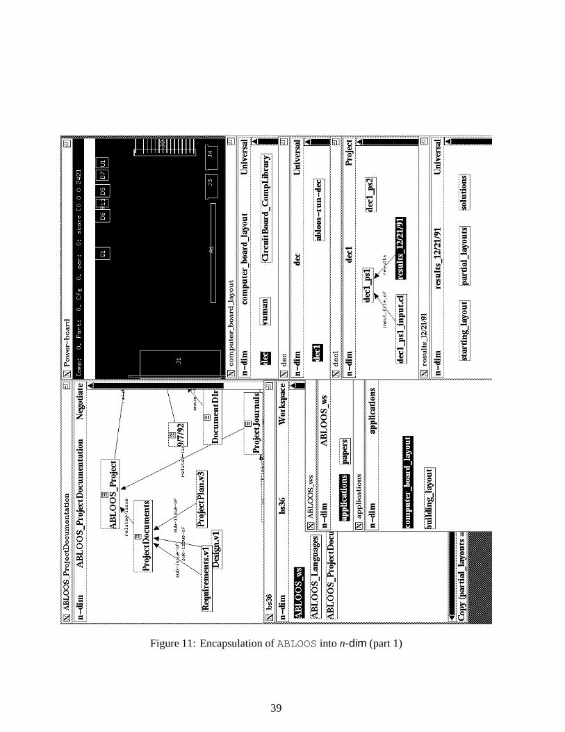
Figure 11: Encapsulation of ABLOOS into n-dim (part 1)
39

Figure 12: Encapsulation of ABLOOS into n-dim (part 2)
40

figure illustrate a (simplified) view of using models and modeling languages customizedfor ABLOOS to build a structured problem statement model (from a library of compo-nents for board layout domains) and to automatically generate the corresponding inputfile to run the problem in ABLOOS. The problem statement model dec1_ps1 reflectsthe layout problem formulation specified by the designer in terms of domain components,their decomposition, order of insertion, and so on. In this example, the layout of com-ponents by ABLOOS is split into two phases. The capacitor component in the modelphase1_components was copied from CircuitBoard_CompLibrary (lowerleft), and its property values edited (middle right, in the CAPACITOR-10-QT039-C1model). When the designer has completed structuring the problem statement s/he mayselect the problem statement model (e.g., dec1_ps1), and choose GenerateInputFile(not shown) from a menu in the “Project” modeling language (see the dec1model, upperleft in figure). This will invoke an ABLOOS translator within n-dim to automaticallyproduce the corresponding input file in CommonLisp, readable by ABLOOS. The systemcreated input file dec_ps1_input.cl is shown in the lower right opened within a texteditor, and the upper right corner shows the ABLOOS system generating layouts based onthat input file.
The ABLOOS encapsulation is currently limited to the generation of input files. Addi-tional products of this tool encapsulation experiment are:
� an issue base of the design decisions made by the project team in developingthe ABLOOS/n-dim encapsulation. This may be a useful reference for future toolencapsulation efforts or for the extension/refinement of the current effort at a latertime. (See the model ABLOOS_ProjectDocumentation in the upper left offigure 11.)
� a browser of the code produced - e.g., new modeling languages created. This alsoshould prove useful for understanding the implementation of the tool encapsulationfor future reference. (This model is shown (unopened) in figure 11, lower left cornerwithin the workspace of user “bs36”).
Other experiments There are several other on-going efforts at tool integrations atvarious levels in n-dim. In fact, part of the every-day work of the group has consistedin creating small, on-the-fly tool integrations using simple shell scripts and programs toglue together external programs (editors, text processors, modeling systems) and n-dim.A simple example of this is the way in which the products of the OMT modeling tool [22]have been integrated into n-dim. A file pointer object44 is used to name files containingOMT models. The user has told n-dim that, when such pointers are opened, a script shouldbe run that will arrange to execute OMT on the given file (see Figure 13).
44This is a pre-defined low-level object type in n-dim that contains the name of a file in the filesystem.Using such objects, the user can, at the very least, point at a file in the system, even if its contents areunintelligible without the aid of some other program. If the file is executable (either a script or a binaryprogram), opening such an object results in that program being executed. Otherwise, the user can given-dim hints about what to do with certain kinds of files. This mechanism is still very crude, but even in itscurrent state is one of the most useful features of the current n-dim prototype.
41

Figure 13: An OMT Model Encapsulated in n-dim
42

In addition, in this example, the OMT model45 has been included in another modeland annotated with a textual object. This action may be broadcast (as illustrated in thefigure) to all currently active n-dim users via the n-dim talk window.46 Already, with onlyminimal effort expended on the creation of the script that runs OMT, a large improvementin the ability to communicate (and negotiate about) structures created in this externaltool has been gained. In Figure 13, for instance, an OMT model has been pointed to andannotated inside of an n-dim model, and other users of the system have been told thatsuch an annotation exists. Such a capability already goes a long way towards alleviatingcommunication breakdowns and errors that can occur; for instance, we observed that agroup of students attempting to use OMT for software design in a class had to resort todrawing ASCII versions of parts of OMTmodels within computer bulletin board and emailtraffic, resulting in large and ungainly messages. The ability to simply pass references canbe quite a powerful tool in itself.
Finally, an on-going effort in the integration of the ASCEND system [20] into n-dim isbeing carried out by the group.47 This is a system that allows for the construction of large,equation-based models in a declarative, object-oriented fashion; the system compiles thedeclarative version of the model into an internal representation and chooses the appropriatesolver for the task. Libraries of models can be built, used and re-used.
6 Summary and Future Directions
This paper describes work in progress by the n-dim group at the Engineering ResearchDesign Center at Carnegie Mellon University. Although our experiences and reactionsfrom industrial collaborators have been extremely positive, we are still in preliminarystages of research and deployment of n-dim. Some topics not covered in this paper, butwhich deserve mention include
NLP. Members of our group have been experimenting with and implementing natural-language processing tools for creating thesauri of terms in large corpora of textrelevant to a particular domain. Such thesuari are then used to generate indicies ofsimilarity among documents, and to aid in building conceptual networks describ-ing the domain. All of these activities are being pursued within the framework ofn-dim, both to model the conceptual structures thus uncovered and to model therelationships between individual documents, documents and concepts, and, eventu-ally, between different domains. Experiments are being conducted in the areas oflarge- and medium-core power transformer design and risk assessment in softwaredesign.
45Or, to be more precise, the n-dim pointer to it46This facility is currently very limited, and allows for simple textual messages and references to published
objects to be passed around by all active users of the system.47It should be noted that one of n-dim’s philosophical “parents” is the ASCEND system, and the inter-
linkages of ideas, designs, philosophy and structure goes back to the earliest days of n-dim.
43

Multi-media. We believe that n-dim could provide an ideal environment for structuringinformation in multiple media, and for providing a uniform way of accessing andsearching over such information (as the architecture presented in Section 4.5 im-plies). We are actively pursuing incorporating multi-media objects such as videodata streams into n-dim.
Modeling standards. Several standards efforts that relate to information modeling arebeing constantly monitored, and efforts to implement linkage between those stan-dards and n-dim is ongoing. Standards such as SGML (and, thus, HyTime) andPDES/STEP, as well as other related efforts are included in this.
Z3950. The draft ANSI standard Z3950 describes a protocol for enabling access to basesof information via natural-language-like queries in plain text. We are pursuing theintegration of this protocol into n-dim to provide access to Z3950 databases fromwithin n-dim. One such database is the Carnegie Mellon University online librarycatalog system, which includes bibliographic databases and other information. It isour goal to be able to our library seamlessly from n-dim by the end of 1993.
Inter-cell linkages. We expect to deploy a number of n-dim cells in 1993, and intend touse some of them48 as a basis for experimenting with wide-area, n-dim object bases.Certain aspects of search and the rule-system are impacted by such a situation, andextending n-dim so that, as much as possible, “reasonable” semantics are preservedin such a situation is an open issue.
References
[1] K. Birman and et al. The ISIS Distributed Systems Toolkit Programmer’s Manual.ISIS Distributed Systems, Inc., 1992.
[2] G. Booch. Object-Oriented Design With Applications. Benjamin Cummins Publish-ing Company, Inc., NY, 1991.
[3] A. Borning. ThingLab: A Constraint Programming System. PhD thesis, StanfordUniversity, 1985.
[4] A. Borning. DeltaTalk: An Empirically and Aesthetically Motivated Simplifica-tion of the Smalltalk-80 Language. In European Conference on Object-ORientedProgramming. ECOOP, 1987. Paris.
[5] K. Clark and T. Fujimoto. Product Development Performance. Harvard BusinessPress, Cambridge, MA, 1991.
[6] J. Conklin and M. L. Begeman. gIBIS: A Hypertext Tool For Exploratory PolicyDiscussion. ACM Transaction on Office Information Systems, 6(4):303–331, 1988.
48Some cells will be deployed in corporations, who may not wish to be a part of inter-cell experiments.
44

[7] R. F. Coyne. ABLOOS: A Computational Design Framework For Layout Synthesis.PhD thesis, Department of Architecture, Carnegie Mellon University, Pittsburgh,PA, 1991.
[8] J. D. Daniell. An Object Oriented Approach to CAD Tool Control. PhD thesis,Department of Electrical and Computer Engineering, Carnegie Mellon University,1989.
[9] Design Automation, Inc. Design Management and Engineering Process Automation,1989.
[10] R.S. Englemore and J.M. Tenenbaum. The Engineers Associate: ISAT SummerStudy Report. Unpublished Report, Stanford University., 1990.
[11] S. Finger and et al. Progress Report to ABB. Unpublished, 1992.
[12] M. Flavin. Fundamental Concepts of Information Modeling. Yourdon Press, Engle-wood Cliffs, NJ, 1981.
[13] C. Floyd, H. /, R. Budde, and R. Keil-Slawik, editors. Software Development andReality Construction. Springer-Verlag, Berlin, 1992.
[14] I. Jacobson, M. Christerson, P. Jonsson, and G. Overgaard. Object-Oriented SoftwareEngineering: A Use Case Driven Approach. Addison-Wesley Publishing Company,NY., 1991.
[15] M. Jacome and S. Director. Design Process Management for CAD Frameworks.Technical Report 18-27-92, Engineering Design Research Center, Carnegie MellonUniversity, 1992.
[16] S. Konda, I. Monarch, P. Sargent, and E. Subrahmanian. Shared Memory in Design:A Unifying Theme For Research and Practice. Research in Engineering Design,4(1):23–42, 1992.
[17] S. Levy, E. Subrahmanian, and S. Konda. BOS: A Prototype-based Object System.Unpublished, 1992.
[18] R. Makkuni. The Electronic Sketch Book of Tibetan Thangka Paintings. VisualComputer (West Germany), 5(4):227–42, 1989.
[19] J. Ousterhout. Tcl: An Embeddable Command Language. In Usenix Winter 1990Proceedings. USENIX, 1990. Winter conference.
[20] P. C. Piela, T. G. Epperly, K. M. Westerberg, and A. W. Westerberg. ASCEND:an object-oriented computer environment for modeling and analysis: the modelinglanguage. Computers & Chemical Engineering, 15(1):53–72, 1991.
45

[21] Y. Reich, S. Konda, I. Monarch, and E. Subrahmanian. Participation and Design:An Extended View. In M. J. Muller, S. Kuhn, and J. A. Meskill, editors, PDC’92:Proceedings of the Participatory Design Conference (Cambridge, MA), pages 63–71,Palo Alto, CA, 1992. Computer Professionals for Social Responsibility.
[22] J. Rumbaugh, M. Blaha, W. Premerlani, F. Eddy, and William Lorensen. Object-Oriented Modeling and Design. Prentice Hall, Englewood Cliffs, NJ, 1991.
[23] M. Rychner and A. Westerberg. White Paper on Engineering Design. Report toWestinghouse Corp., 1987.
[24] P.M. Sargent, E. Subrahmanian, M. Downs, R. Greene, and D. Rishel. Materials’information and Conceptual Data Modeling. In T. I. Barry and K. W. Reynard,editors, Computerization and Networking of Materials Databases: Third Volume,ASTM STP 1140. American Society For Testing and Materials, 1992.
[25] E. Subrahmanian, A. W. Westerberg, and G. Podnar. Towards A Shared InformationEnvironment For Engineering Design. In D. Sriram, R. Logcher, and S. Hukuda,editors, Computer-Aided Cooperative Product Development, MIT-JSME Workshop(Nov., 1989), Berlin, 1991. Springer-Verlag.
[26] D. Ungar and R. B. Smith. SELF: the power of simplicity. LISP and SymbolicComputation, 4(3):187–205, 1991.
[27] D. J. Wilkins, J. M. Henshaw, S. H. Munson-Mcgee, J. J. Solberg, J. A. Heim,J. Moore, A. Westerberg, E. Subrahmanian, L. Gursoz, R. A. Miller, and G. Glozer.CINERG: A Design Discovery Experiment. In NSF Engineering Research Confer-ence, pages 161–182, Amherst, MA, 1989. College of Engineering, University ofMassachusetts.
[28] J. Zucker and A. Demaid. Prototype-Oriented Representation of Engineering DesignKnowledge. Artificial intelligence in Engineering, 7(1):47–61, 1992.
46