Overview - Indico
21
Emittance Control at the SLS XVII ESLS Workshop 26/11/09 Overview • SR - Lattice Errors – Sources of Vertical Emittance – Sources of Vertical Dispersion • SR - Lattice Calibration – Beta Function Measurement – Beta Function Correction • SR - Multipole Correctors • SR - Dispersion Correction • SR - Betatron Coupling Correction • SR - Emittance (Sigma) Monitor • SR - Sigma and Emittance • SR - Summary • SR - Lattice Errors – SR - Sextupole Beam-Based Alignment – SR - Girder Re-alignment It’s a long way to go ... Michael B ¨ oge 1
-
Upload
khangminh22 -
Category
Documents
-
view
0 -
download
0
Transcript of Overview - Indico

Emittance Control at the SLS
XVII ESLS Workshop 26/11/09
Overview
• SR - Lattice Errors
– Sources of Vertical Emittance
– Sources of Vertical Dispersion
• SR - Lattice Calibration
– Beta Function Measurement
– Beta Function Correction
• SR - Multipole Correctors
• SR - Dispersion Correction
• SR - Betatron Coupling Correction
• SR - Emittance (Sigma) Monitor
• SR - Sigma and Emittance
• SR - Summary
• SR - Lattice Errors
– SR - Sextupole Beam-Based Alignment
– SR - Girder Re-alignment
It’s a long way to go ...
Michael Boge 1

Emittance Control at the SLS
XVII ESLS Workshop 26/11/09
SR - Lattice Errors - Sources of Vertical Emittance I
0
10
20
30
40
50
60
70
80
0.0001 0.001 0.01
num
ber
of s
eeds
emittance ratio κ
sextupoles, tilt, no corrsextupoles, tilt, corr
sextupoles, no tilt, no corrsextupoles, no tilt, corr
no sextupoles, tilt, no corrno sextupoles, tilt, corr
no sextupoles, no tilt
0.002
emittance couplingbetatron couplingmeasurementno sextupoles
with standard
misalignments
• Betatron coupling: dQ=0.007 (in commissiong year 2001)
– Emittance coupling in absence of spurious vertical dispersion: 0.2% (Guignard)
• Left: Emittance coupling after betatron coupling correction with initially 6 skew quadrupoles≈ 0.1%
(simulation for 200 seeds)
Michael Boge 2

Emittance Control at the SLS
XVII ESLS Workshop 26/11/09
SR - Lattice Errors - Sources of Vertical Dispersion
0
5
10
15
20
25
30
35
40
-0.001 0 0.001 0.002 0.003 0.004 0.005 0.006
num
ber
of s
eeds
ηyrms and ηymean [m]
co+qu 1.25198e-03+/-4.59177e-04
total 2.88592e-03+/-1.02626e-03
quadrupoles+correctors ηyrmsquadrupoles+correctors ηymean
total ηyrmstotal ηymean
-0.015
-0.01
-0.005
0
0.005
0.01
0.015
0 50 100 150 200 250 300
η y [m
]
s [m]
quadrupolescorrectors
total
measurement
4.8 mmDy~
quads+correctors
quadscorrectors
• Left: Dispersion waves from quadrupoles and correctors in antiphase if BPM-quadrupole errors aresmall (<50µm RMS) (→ Beam-Based Alignment) after correction to quad centers using “hardcorrection” (all SVD weighting factors used).
• Right: Main contribution to dispersion fromsextupolesthrough betatron coupling (simulation for 200seeds) ! Contributions from quads and correctors cancel !
Michael Boge 3

Emittance Control at the SLS
XVII ESLS Workshop 26/11/09
SR - Lattice Calibration - Beta Function Measurement I
Hysteresis Correction based on tune measurement before and after the quadvariation. Allows to restore the original
−> important in order to minimize opticsdistortions during the measurement !
average beta function in the quad.
(177 Quads with individual PS)
Courtesy: A. Streun
Michael Boge 4

Emittance Control at the SLS
XVII ESLS Workshop 26/11/09
SR - Lattice Calibration - Beta Function Correction I
-0.004
-0.002
0
0.002
0.004
0 50 100 150 200 250
δk/k
s [m]
"QfdK.10.dat" u 3:12"QfdK.10.dat" u 3:12
0.1
1
10
100
1000
0 20 40 60 80 100 120 140 160
wei
ghtin
g fa
ctor
wi
index i
allused
quad
rupo
le #
1−#n
dk
Average Beta Variation @ quadrupoles #1−#n
Quadrupole − Average Beta Response Matrix
x horizontal y vertical
From Model or Measured
− plug the measured average beta functions into
− calculate quadrupole variations dk_i which fit modelthe "inverted" matrix
best to the measured average beta functions (cutweighting factors since quadrupoles are not the onlythe only source of beta variations !)
− measure average beta functions in quadrupoles
SLS: 177 x (2x177=354) = 62658 coefficients
− Invert 177 x 354 Matrix using SVD
cutoff <13
quadrupole variations
weighting factors
not used
dk/k +−0.2% p−p
− apply the −dk_I to the machine in order to correct thebeta beat.
Recent Beta Function Measurement @ the SLS
2.8 / 2.3 % beat with respect to model
Michael Boge 5

Emittance Control at the SLS
XVII ESLS Workshop 26/11/09
SR - Lattice Calibration - Beta Function Measurement II
First measurements at the SLS
Courtesy: M. Aiba, CERN
!
1 2
Michael Boge 6

Emittance Control at the SLS
XVII ESLS Workshop 26/11/09
SR - Lattice Calibration - Beta Function Correction II
Orbit Response MatrixCoupled
SLS: 146x146
quadrupole #3 dkquadrupole #2 dk
quadrupole #1 dk
Corrector Index x+y
BP
M In
dex
x+y
quadrupole #n−1 dk
which fit the model best to the Orbit− calculate quadrupole variations dk_i
From Model or Measured Doing it the LOCO way
J. Safranek, SSRL
Linear Optics from Closed Orbits
quadrupole #n dk (SLS: 177)
− measure the Orbit Response MatrixCorrector Index x+y
quad
rupo
le #
1−#n
dk
Quadrupole − Coupled Orbit Response Matrix
SLS: 177 x (146x146=21316) = 3772932 coefficients
BPM Index x+y
− plug ORP into the "inverted" Matrix− invert 177 x 21316 Matrix using SVD
Note:No DipoleErrors
handled !can be
Response Matrix (cut weight. facs)
to correct the beta beat.− apply −dk_i to the machine in order− iterate within model for large errors
Michael Boge 7

Emittance Control at the SLS
XVII ESLS Workshop 26/11/09
SR - Multipole Correctors
Michael Boge 8

Emittance Control at the SLS
XVII ESLS Workshop 26/11/09
SR - Dispersion Correction I
-0.015
-0.01
-0.005
0
0.005
0.01
0.015
0 50 100 150 200 250 300
vert
ical
dis
pers
ion
[m]
s[m]
Measurement before correction (rms=0.0048)Measurement error (mean=0.0009)
-0.015
-0.01
-0.005
0
0.005
0.01
0.015
0 50 100 150 200 250 300
vert
ical
dis
pers
ion
[m]
s[m]
Model prediction (rms=0.0023)Measurement after correction (rms=0.0023)
Measurement error (mean=0.0009)
Vertical DispersionVertical Dispersionbefore correctionafter correction
x2.1
RMS 2.3 mmRMS 4.8 mm
Measurement Error MEAN 0.9 mm !Model Prediction RMS 1.4 mm
Vertical Dispersion @ BPMs
Dis
p S
kew
Qua
ds
Skew Quad − Dispersion Response Matrix
− measure difference orbits for various dp/p
− feed measured dispersion into it to determineDispersive Skew Quads values for correction
− determine vertical dispersion knowing dp/p
− invert Skew Quad − Dispersion Response Matrix
− Get a Model Prediction
− Apply correction and remeasure
SLS: 12 x 73 coefficients
Michael Boge 9

Emittance Control at the SLS
XVII ESLS Workshop 26/11/09
SR - Dispersion Correction II
BPM Tilt = Factor * Current Ratio
Corrector currentswithin FOFB loopwhile changing thethe BPM referenceby +−0.150 mm
Dispersion before Tilt Correction: 2.1 mm rmsDispersion after Tilt Correction: 1.3 mm rms
BPM Tilt * Horizontal Dispersion
Measured DispersionDispersion from BPM Tilt vs.Correlation
15 mrad rms BPM Tilt
Michael Boge 10

Emittance Control at the SLS
XVII ESLS Workshop 26/11/09
SR - Betatron Coupling Correction
0
2
4
6
8
10
12
14
16
0 5 10 15 20
wei
ghtin
g fa
ctor
wi
index i
all + used
Orbit Response MatrixCoupled
SLS: 146x146
Corrector Index x+y
BP
M In
dex
x+y
which fit the model best to the Orbit− calculate quadrupole variations dk_i
From Model or Measured
− measure the Orbit Response MatrixCorrector Index x+yBPM Index x+y
skew quad #n−1 dkskew quad #n dk (SLS: 24)
skew quad #3 dkskew quad #2 dk
skew quad #1 dksk
ew q
uad
#1−#
n dk
Skew Quad − Coupled Orbit Response Matrix
SLS: 24 x (146x146=21316) = 511584 coefficients
horizontal
vertical
Alternative: just fit skew terms
− plug ORP into the "inverted" Matrix− invert 24 x 21316 Matrix using SVD
SLS Alternative: 24 x (73x73=5329) = 127896 coefficients
Response Matrix
weighting factors
no cutoff
to correct the betatron coupling.− apply −dk_i to the machine in order− iterate within model for large errors
factor 5reduction !
Michael Boge 11

Emittance Control at the SLS
XVII ESLS Workshop 26/11/09
SR - Dispersion/Betatron Coupling Correction
Empirical Optimizationof skew quads by mini−mization of driving termsin the hamiltonian byobserving beamsize overlifetime. (court. A. Streun)
Michael Boge 12

Emittance Control at the SLS
XVII ESLS Workshop 26/11/09
SR - Betatron Coupling Feed-Forward
-100
-50
0
50
100
0 50 100 150 200 250
beam
elli
pse
twis
t [m
rad]
ring position [m]
before coupling correctionafter coupling correction
PolLux-0.0006
-0.0004
-0.0002
0
0.0002
0.0004
0.0006
150 152 154 156 158 160 162
vert
ical
bea
m p
ositi
on [m
]
ring position [m]
dipole
900 m−300 rad
skew quadrupole
µ
monitor
sextupolecorrector
µ
PolLux
4−Bump Coupling
Coupling correction
• Left: Layout of the vertical asymmetrical “polarization” bump consisting of four successive dipolecorrectors (magentabars) for the dipole (thickbluebar) beamline PolLux. Dedicated skew quadrupoles(redbars) are used to locally compensate for the betatron coupling induced by the sextupoles (greenbars) within the bump (→coupling feed-forward).
• Right: Twist of the electron beam ellipse as a function of the longitudinal SLS storage ring position fora -300µrad steering for the PolLux beamline before (greenline) and after (redline) betatron couplingcorrection. The arrow denotes the location of the 4-bump forthe PolLux beamline.
• The 4-bump is implemented as a reference change of 2 BPMs within the framework of the Fast OrbitFeedback with a feed-forward table for the skew quadrupoles(< 2 Hz switching frequency).
Michael Boge 13
Emittance Control at the SLS
XVII ESLS Workshop 26/11/09
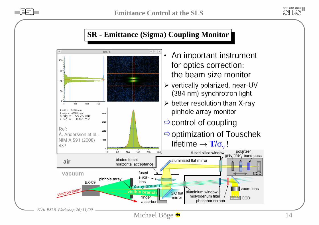
SR - Emittance (Sigma) Coupling Monitor
Michael Boge 14
Emittance Control at the SLS
XVII ESLS Workshop 26/11/09
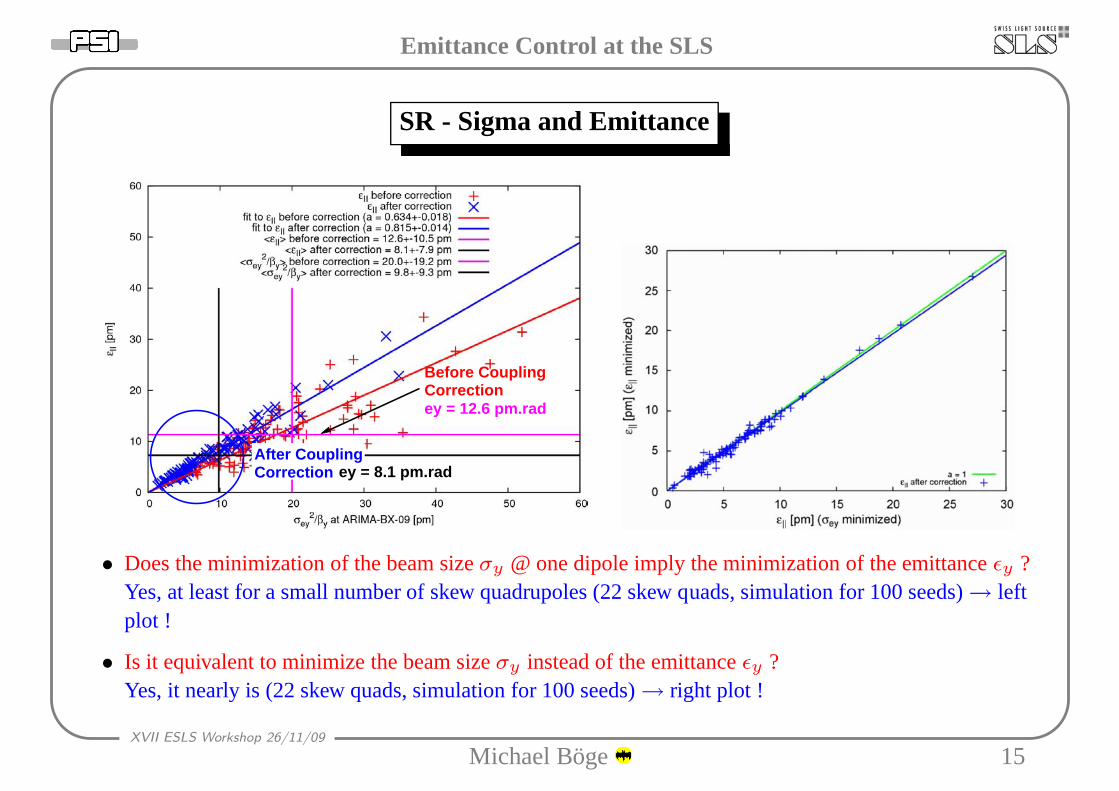
SR - Sigma and Emittance
After Coupling
Before CouplingCorrection
Correction
ey = 12.6 pm.rad
ey = 8.1 pm.rad
• Does the minimization of the beam sizeσy @ one dipole imply the minimization of the emittanceǫy ?Yes, at least for a small number of skew quadrupoles (22 skew quads, simulation for 100 seeds)→ leftplot !
• Is it equivalent to minimize the beam sizeσy instead of the emittanceǫy ?Yes, it nearly is (22 skew quads, simulation for 100 seeds)→ right plot !
Michael Boge 15

Emittance Control at the SLS
XVII ESLS Workshop 26/11/09
SR - Dispersion/Betatron Coupling Correction - Summary
Michael Boge 16

Emittance Control at the SLS
XVII ESLS Workshop 26/11/09
SR - Sigma and Emittance - Operation
Michael Boge 17

Emittance Control at the SLS
XVII ESLS Workshop 26/11/09
SR - Lattice Errors - Sources of Vertical Emittance II
• Term K + Sηx related tolocal chromaticityξ (≈0 forcorrected localξ).
• Term Gy≈0 for well (tocenters of quadrupoles) cor-rectedyc.
• TermKsqηx is small sincethe quadrupole roll errorsare small.
• Local ξ ONLY ≈0 if yc
is corrected in quadrupolesand sextupoles simultane-ously !
Michael Boge 18

Emittance Control at the SLS
XVII ESLS Workshop 26/11/09
SR - Lattice Errors - Sextupole Beam-Based Alignment I
Courtesy:S.L. Kramer,NSLS−II
Michael Boge 19

Emittance Control at the SLS
XVII ESLS Workshop 26/11/09
SR - Lattice Errors - Sextupole Beam-Based Alignment II
Beam Based Alignment at the KEK ATF, M. Ross et al.
sextupoleunder test
Center of sextupole
Reading of adjacent BPM [um]
0
0
measurement error~6 um
• At KEK ATF skew quadrupole trims (K=0.01 m−1) on the sextupoles were used (sextupole center =skew quad center). The kick induced by the offset of the beam in the skew quad is determined from thedifference orbit using the machine model. This fit is done forseveral closed orbit bump amplitudes atthe location of the sextupole under test.At the SLS 36 out of 120 sextupoles are equipped withauxiliary skew quadrupoles (K=0.03 m−1) for betatron coupling and dispersion correction.
Michael Boge 20

Emittance Control at the SLS
XVII ESLS Workshop 26/11/09
SR - Lattice Errors - Girder Re-alignment
BX_09: 71 um BX_11: 95 um
BX_12: 83 umBX_06: 57 um
BX_01: 102 um BX_05: 95 um
BX_10: 48 um
Girder n
Girder n+1
Vertical Orbit
• Corrector Pattern can be used to determine alignment errors(→No Cutoff).
• Prominent girder-girder alignment errors related to localcorrector patterns (circles).
• Girder-girder errors introduce mechanical steps driving the adjacent correctors.
• Leads to saturation of correctors in machines with large alignment errors (→Eigenvalue Cutoff =“Long Range Correction”).
• →Beam-based girder alignment (magnets on girders as super-correctors).
Michael Boge 21