An Overview of Slope Failure in Mining Operations - MDPI
35
Citation: Kolapo, P.; Oniyide, G.O.; Said, K.O.; Lawal, A.I.; Onifade, M.; Munemo, P. An Overview of Slope Failure in Mining Operations. Mining 2022, 2, 350–384. https://doi.org/ 10.3390/mining2020019 Academic Editors: Mohammad H.B. (Farzine) Nasseri, Bibhu Mohanty and Kamran Esmaeili Received: 18 March 2022 Accepted: 19 May 2022 Published: 2 June 2022 Publisher’s Note: MDPI stays neutral with regard to jurisdictional claims in published maps and institutional affil- iations. Copyright: © 2022 by the authors. Licensee MDPI, Basel, Switzerland. This article is an open access article distributed under the terms and conditions of the Creative Commons Attribution (CC BY) license (https:// creativecommons.org/licenses/by/ 4.0/). Review An Overview of Slope Failure in Mining Operations Peter Kolapo 1, *, Gafar Omotayo Oniyide 2 , Khadija Omar Said 3 , Abiodun Ismail Lawal 2 , Moshood Onifade 4 and Prosper Munemo 5 1 Department of Mining Engineering, University of Kentucky, Lexington, KY 40506, USA 2 Department of Mining Engineering, Federal University of Technology, Akure 340100, Nigeria; [email protected] (G.O.O.); [email protected] (A.I.L.) 3 Department of Mining and Mineral Processing Engineering, Taita Taveta University, Voi 80300, Kenya; [email protected] 4 Department of Civil and Mining Engineering, University of Namibia, Ongwediva P.O. Box 3624, Namibia; [email protected] 5 Department of Mining and Mineral Processing Engineering, Manicaland State University of Applied Science, Mutare P.O. Box 7001, Zimbabwe; [email protected] * Correspondence: [email protected] Abstract: The primary aim of every twenty-first century mining operation is to extract as much ore as possible in a safe and economical manner. Failure in mine excavation occurs when the shear stress acting on the rock is greater than the shear strength of the rock mass. The stability of rock slopes in open-pit mine and quarry operations is extremely important from both economic and safety points of view because unstable slopes can result in the loss of human life and damage to properties. This paper presents an overview of several case studies of slope failure in mining operations and explains various modes of failure in rock slopes, as well as factors that influence the stability of slope walls. With the aim of enforcing the importance of monitoring and evaluating slope stability in mining, both linear equilibrium and numerical modeling techniques were reviewed to elaborate their importance in designing stable slopes. In addition, the process of slope failure was discussed, and key signs of failure were indicated. In an effort to prevent mines from experiencing the hazards of slope failure, this study reports previous work performed in determining slope failure and the current state-of-the- art models, which entail the integration of analytical methods with artificial intelligence techniques. This innovation would help overcome the drawbacks of conventional prediction techniques that are cumbersome and ambiguous. Keywords: slope failure; in situ; shear stress; rockmass; mining; factor of safety 1. Introduction The stability of slopes in open-pit mining operations and quarries is extremely impor- tant from both economic and safety points of view. The stability of rock slopes entails the design of safe, economical, and functional excavated slopes to attain equilibrium conditions of natural slopes [1]. It is generally accepted that during the design of a stable slope, a proper understanding of the geological processes, such as stratigraphy, weathering, geo- morphology, petrography, and earthquakes, is necessary. The most significant structures that influence the stability of slopes are joints, bedding planes, and the intersection of joints, faults, and shear zones [2]. Instability in rock slopes can be harmful and could result in the loss of human life and damage to basic properties. Failure in slope occurs as a result of the downward movement of materials due to the effects of gravity. However, it is assumed that the sliding of a rock slope will take place where there is an intersection of joint sets. Failure of rock mass is inevitable when the shear stress is greater than the shear strength of the rock [3]. However, failure of slope walls depends on some activities such as cracking of rock mass, weathering, increase in pore pressure, presence of decomposed clay rock filling materials, leaching, Mining 2022, 2, 350–384. https://doi.org/10.3390/mining2020019 https://www.mdpi.com/journal/mining
-
Upload
khangminh22 -
Category
Documents
-
view
0 -
download
0
Transcript of An Overview of Slope Failure in Mining Operations - MDPI
Citation: Kolapo, P.; Oniyide, G.O.;
Said, K.O.; Lawal, A.I.; Onifade, M.;
Munemo, P. An Overview of Slope
Failure in Mining Operations. Mining
2022, 2, 350–384. https://doi.org/
10.3390/mining2020019
Academic Editors: Mohammad H.B.
(Farzine) Nasseri, Bibhu Mohanty
and Kamran Esmaeili
Received: 18 March 2022
Accepted: 19 May 2022
Published: 2 June 2022
Publisher’s Note: MDPI stays neutral
with regard to jurisdictional claims in
published maps and institutional affil-
iations.
Copyright: © 2022 by the authors.
Licensee MDPI, Basel, Switzerland.
This article is an open access article
distributed under the terms and
conditions of the Creative Commons
Attribution (CC BY) license (https://
creativecommons.org/licenses/by/
4.0/).
Review
An Overview of Slope Failure in Mining OperationsPeter Kolapo 1,*, Gafar Omotayo Oniyide 2, Khadija Omar Said 3, Abiodun Ismail Lawal 2, Moshood Onifade 4
and Prosper Munemo 5
1 Department of Mining Engineering, University of Kentucky, Lexington, KY 40506, USA2 Department of Mining Engineering, Federal University of Technology, Akure 340100, Nigeria;
[email protected] (G.O.O.); [email protected] (A.I.L.)3 Department of Mining and Mineral Processing Engineering, Taita Taveta University, Voi 80300, Kenya;
[email protected] Department of Civil and Mining Engineering, University of Namibia, Ongwediva P.O. Box 3624, Namibia;
[email protected] Department of Mining and Mineral Processing Engineering, Manicaland State University of Applied Science,
Mutare P.O. Box 7001, Zimbabwe; [email protected]* Correspondence: [email protected]
Abstract: The primary aim of every twenty-first century mining operation is to extract as much oreas possible in a safe and economical manner. Failure in mine excavation occurs when the shear stressacting on the rock is greater than the shear strength of the rock mass. The stability of rock slopes inopen-pit mine and quarry operations is extremely important from both economic and safety pointsof view because unstable slopes can result in the loss of human life and damage to properties. Thispaper presents an overview of several case studies of slope failure in mining operations and explainsvarious modes of failure in rock slopes, as well as factors that influence the stability of slope walls.With the aim of enforcing the importance of monitoring and evaluating slope stability in mining, bothlinear equilibrium and numerical modeling techniques were reviewed to elaborate their importancein designing stable slopes. In addition, the process of slope failure was discussed, and key signs offailure were indicated. In an effort to prevent mines from experiencing the hazards of slope failure,this study reports previous work performed in determining slope failure and the current state-of-the-art models, which entail the integration of analytical methods with artificial intelligence techniques.This innovation would help overcome the drawbacks of conventional prediction techniques that arecumbersome and ambiguous.
Keywords: slope failure; in situ; shear stress; rockmass; mining; factor of safety
1. Introduction
The stability of slopes in open-pit mining operations and quarries is extremely impor-tant from both economic and safety points of view. The stability of rock slopes entails thedesign of safe, economical, and functional excavated slopes to attain equilibrium conditionsof natural slopes [1]. It is generally accepted that during the design of a stable slope, aproper understanding of the geological processes, such as stratigraphy, weathering, geo-morphology, petrography, and earthquakes, is necessary. The most significant structuresthat influence the stability of slopes are joints, bedding planes, and the intersection of joints,faults, and shear zones [2].
Instability in rock slopes can be harmful and could result in the loss of human life anddamage to basic properties. Failure in slope occurs as a result of the downward movementof materials due to the effects of gravity. However, it is assumed that the sliding of a rockslope will take place where there is an intersection of joint sets. Failure of rock mass isinevitable when the shear stress is greater than the shear strength of the rock [3]. However,failure of slope walls depends on some activities such as cracking of rock mass, weathering,increase in pore pressure, presence of decomposed clay rock filling materials, leaching,
Mining 2022, 2, 350–384. https://doi.org/10.3390/mining2020019 https://www.mdpi.com/journal/mining

Mining 2022, 2 351
increase in water permeability, strain softening, and change in groundwater dynamics,which causes an increment in shear stress [4]. Therefore, the nature and behavior of therock mass must be well-understood to ensure that the design of a pit wall remains stable forthe life of the mine while extracting as much ore as safely and economically as possible [5].
The most common mode of failure in rock slopes is a plane failure. This type of failurehappens when the angle of a structural discontinuity plane such as a bedding plane issmaller than the slope angle and greater than the angle of friction of the discontinuitysurface [6]. Moreover, the water forces acting along the potential failure plane can alsodestabilize the slope. According to Wang and Niu [7], the dynamic loading and surchargeforces are other factors that contribute to the driving force that causes failure in rockslopes. The plane failure is influenced by factors such as the geometry, groundwater condi-tions, dynamic loading, potential failure plane characteristics and surcharge conditions [8].However, the presence of major structural features such as faults, major joint planes, andunfavorably oriented bedding planes may also have a significant influence on the stabilityof the slope.
Over the last few decades, there have been significant advances in slope stabilityresearch works that investigated the causes of slope failure and factors that can triggerfailure in slope. These factors are categorized by Sha [4] as internal and external factors.The internal factors that can affect the stability of a sloping wall include the mineralcomposition of the rock, rock types, and geotechnical and structural strengths. In addition,environmental factors such as earthquakes, rainfall, and weathering that can reduce thestrength of the rock mass are also categorized as internal factors, while the external factorsare mainly caused by human activity [9].
The increase in mineral demand in the 21st century has without a doubt compelled theexpansion of mining operations globally, which has resulted in the extraction of mineralsin larger capacities and deeper levels. However, it is important that these operations areconducted in a safe and economical manner. Therefore, this means that competent designsand techniques should be adopted to support the ever-growing mining capacities. Despitethe analysis of slope stability using conventional techniques, mines are still experiencingslope failures, which have proven to be catastrophic and expensive. Therefore, this requiresa better understanding of slope failure and the development of accurate prediction modelsto forecast this hazard before it occurs. Therefore, this study reports the application ofslope stability evaluation techniques using linear equilibrium and numerical modeling, aswell as the mechanism of slope failure. Additionally, the common factors known to affectslope stability are discussed, together with the various slope failure cases recorded globally.Last but not least, the application of artificial intelligence in predicting mine slope failure isreviewed, together with recommendations to improve prediction modelling.
Instability and Rock Mass Failure in Slopes
Unstable strata in rock slopes can lead to rock mass movement and cause harmfulincidents that can affect mining operations and loss of ore reserves. Consequently, it canresult in the premature closure of mines. Nicholas and Sims [9] reported the risk associatedwith slope failures in mining operations. These ranged from the loss of equipment to loss ofreserves or mine closure and, in the worst cases, loss of life. Hustrulid et al. [10] argued thatinstability in rock mass slopes is largely caused by mining activities such as rock drilling,blasting, and the use of heavy machines. Similarly, Read and Stacey [11] indicated that thepresence of groundwater, slope design, complex geology, discontinuities on rock mass, andmining operations are factors that affect the stability of rock slopes in mines. Accordingto Eberhardt [12], the most common factors that influence the stability of rock slopes areredistribution of in situ stresses, complexity in geology, anisotropy and inhomogeneity ofthe rock materials, pressure pores and seismic loading. Similarly, Stacey and Swart [13]reported that the effects of blasting and groundwater are the only two major significantfactors that control the stability of slopes. In addition, they indicated that blasting can
Mining 2022, 2 352
cause ground vibration that in turn may have a significant influence on the stability ofthe highwall.
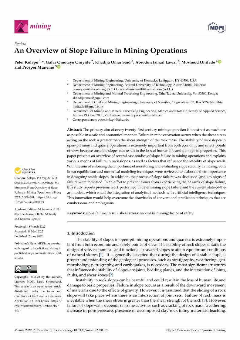
Practical experience in the design of rock slope projects has demonstrated the impor-tance of having a robust design. The basic parameters to be considered in the design areheight, overall slope angle, and area of failure surface, as shown in Figure 1 [14]. There is acorrelation between the height and stability of the slope wall; the slope stability decreaseswith the increment in the height of the wall. Similarly, the slope needs to be steeped tominimize the amount of waste rock mined, thereby reducing mining costs. However, theeconomic effect of steeping a slope is that some portion of the waste material will be minedbut the slope will be stabled [5].
Mining 2022, 2, FOR PEER REVIEW 3
Stacey and Swart [13] reported that the effects of blasting and groundwater are the only two major significant factors that control the stability of slopes. In addition, they indicated that blasting can cause ground vibration that in turn may have a significant influence on the stability of the highwall.
Practical experience in the design of rock slope projects has demonstrated the im-portance of having a robust design. The basic parameters to be considered in the design are height, overall slope angle, and area of failure surface, as shown in Figure 1 [14]. There is a correlation between the height and stability of the slope wall; the slope stability de-creases with the increment in the height of the wall. Similarly, the slope needs to be steeped to minimize the amount of waste rock mined, thereby reducing mining costs. However, the economic effect of steeping a slope is that some portion of the waste material will be mined but the slope will be stabled [5].
Figure 1. Design parameters in rock slope (Adapted from [14]).
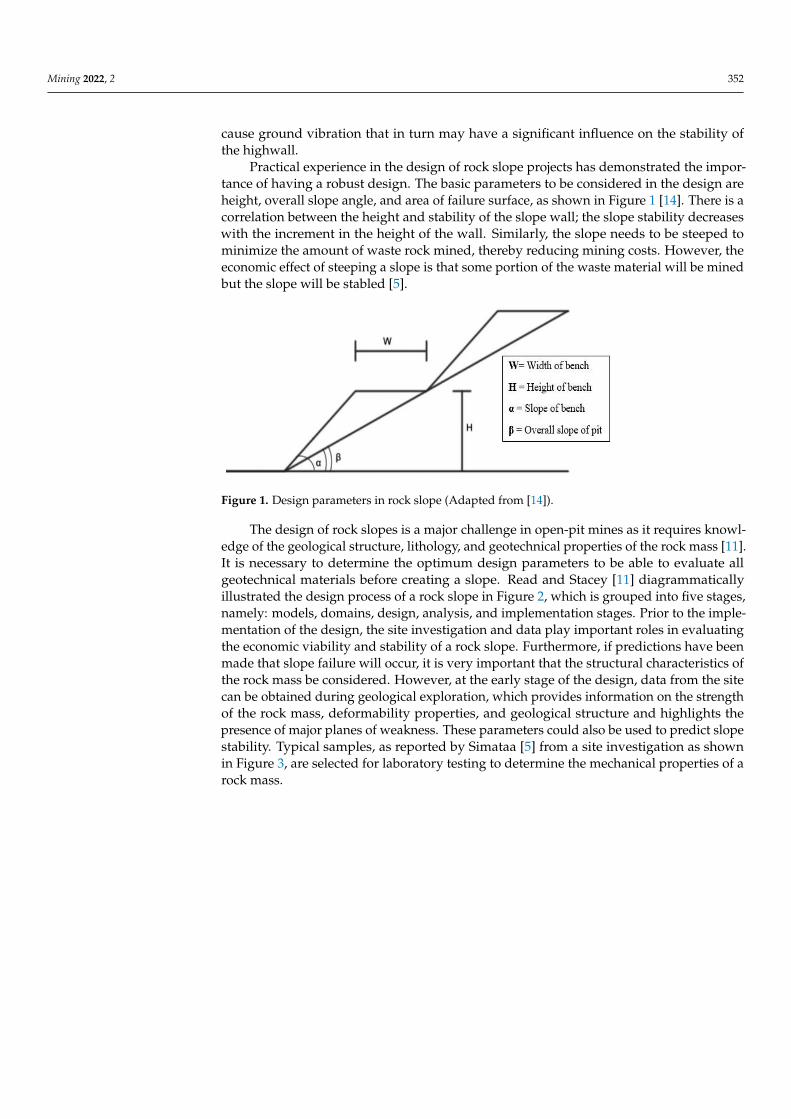
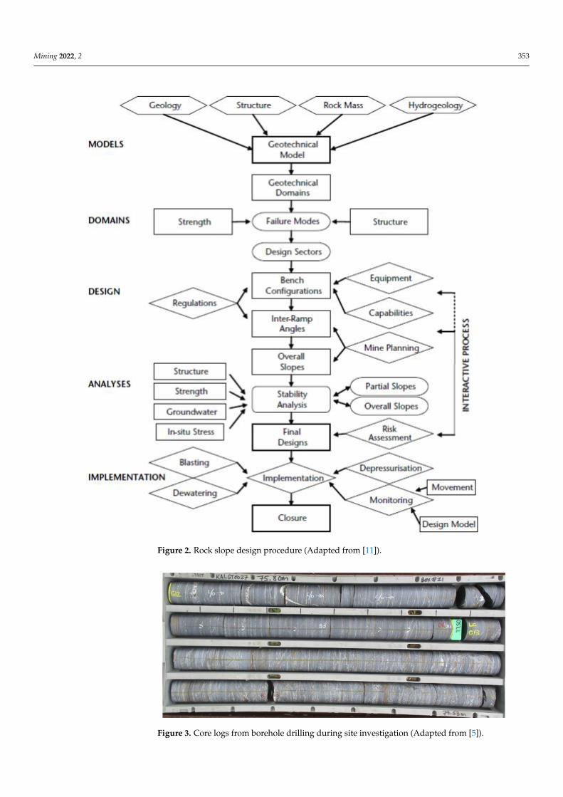
The design of rock slopes is a major challenge in open-pit mines as it requires knowledge of the geological structure, lithology, and geotechnical properties of the rock mass [11]. It is necessary to determine the optimum design parameters to be able to eval-uate all geotechnical materials before creating a slope. Read and Stacey [11] diagrammat-ically illustrated the design process of a rock slope in Figure 2, which is grouped into five stages, namely: models, domains, design, analysis, and implementation stages. Prior to the implementation of the design, the site investigation and data play important roles in evaluating the economic viability and stability of a rock slope. Furthermore, if predictions have been made that slope failure will occur, it is very important that the structural char-acteristics of the rock mass be considered. However, at the early stage of the design, data from the site can be obtained during geological exploration, which provides information on the strength of the rock mass, deformability properties, and geological structure and highlights the presence of major planes of weakness. These parameters could also be used to predict slope stability. Typical samples, as reported by Simataa [5] from a site investi-gation as shown in Figure 3, are selected for laboratory testing to determine the mechani-cal properties of a rock mass.
Figure 1. Design parameters in rock slope (Adapted from [14]).
The design of rock slopes is a major challenge in open-pit mines as it requires knowl-edge of the geological structure, lithology, and geotechnical properties of the rock mass [11].It is necessary to determine the optimum design parameters to be able to evaluate allgeotechnical materials before creating a slope. Read and Stacey [11] diagrammaticallyillustrated the design process of a rock slope in Figure 2, which is grouped into five stages,namely: models, domains, design, analysis, and implementation stages. Prior to the imple-mentation of the design, the site investigation and data play important roles in evaluatingthe economic viability and stability of a rock slope. Furthermore, if predictions have beenmade that slope failure will occur, it is very important that the structural characteristics ofthe rock mass be considered. However, at the early stage of the design, data from the sitecan be obtained during geological exploration, which provides information on the strengthof the rock mass, deformability properties, and geological structure and highlights thepresence of major planes of weakness. These parameters could also be used to predict slopestability. Typical samples, as reported by Simataa [5] from a site investigation as shownin Figure 3, are selected for laboratory testing to determine the mechanical properties of arock mass.
Mining 2022, 2 353Mining 2022, 2, FOR PEER REVIEW 4
Figure 2. Rock slope design procedure (Adapted from [11]).
Figure 3. Core logs from borehole drilling during site investigation (Adapted from [5]).
Figure 2. Rock slope design procedure (Adapted from [11]).
Mining 2022, 2, FOR PEER REVIEW 4
Figure 2. Rock slope design procedure (Adapted from [11]).
Figure 3. Core logs from borehole drilling during site investigation (Adapted from [5]). Figure 3. Core logs from borehole drilling during site investigation (Adapted from [5]).
Mining 2022, 2 354
2. Evaluation of Slope Stability in Mining
Failure of rock slope occurs when excess loading shear stress in a rock mass is re-distributed and the load exceeds the strength of the rock. The shear strength of a rockmass plays an important role in the stability of the rock mass. Therefore, factors thattend to change the shear strength must be taken into consideration during the design asthese factors may have an overriding influence on the stability of the slope. Accordingto Abramson [15], failure starts in the rock slope from a single point and propagates tothe entire rock mass. According to the study by Eberhardt et al. [16], during slope failuresimulations, their model suggested that in the absence of triggering events, the strengthreduction and progressive failure in a rock mass are attributed to causes of failure in therock mass.
Over the years, a number of researchers have conducted research on the evaluation ofslope stability. However, numerous methods were proposed, but only two major techniques,namely the limit equilibrium method (LEM) and numerical analysis (deformation analysis),are commonly used to evaluate the performance of rock slopes’ stability [17,18].
2.1. Limit Equilibrium Method (LEM)
Hoek et al. [19] stated that the LEM has been available for more than 25 years and canbe considered as a reliable slope design tool. The LEM approach is based on evaluatingthe applied forces and the strength of the ground. This method has been the most populartechnique used in estimating the stability of a slope in geotechnical engineering [20]. Inaddition, Duncan et al. [21] described the LEM as the procedure used to calculate the shearstrength of the ground against some factors causing the shear stresses. In general terms,the factor of safety (FOS) of a slope is described as the ratio of strength to the stress load. Ina potential failure surface, the resisting force (strength of the rock mass) could be comparedagainst the driving force. The balance between the shear stress acting along the potentialfailure surface and the strength conditions of the rock mass also describes the FOS.
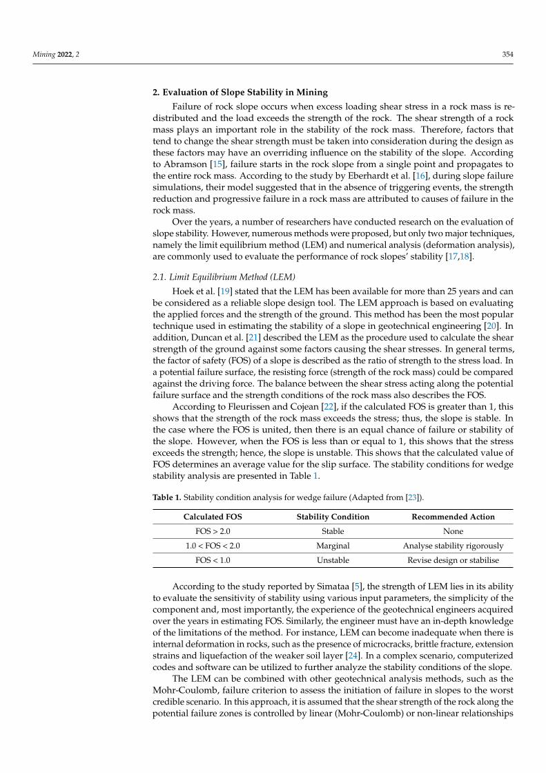
According to Fleurissen and Cojean [22], if the calculated FOS is greater than 1, thisshows that the strength of the rock mass exceeds the stress; thus, the slope is stable. Inthe case where the FOS is united, then there is an equal chance of failure or stability ofthe slope. However, when the FOS is less than or equal to 1, this shows that the stressexceeds the strength; hence, the slope is unstable. This shows that the calculated value ofFOS determines an average value for the slip surface. The stability conditions for wedgestability analysis are presented in Table 1.
Table 1. Stability condition analysis for wedge failure (Adapted from [23]).
Calculated FOS Stability Condition Recommended Action
FOS > 2.0 Stable None
1.0 < FOS < 2.0 Marginal Analyse stability rigorously
FOS < 1.0 Unstable Revise design or stabilise
According to the study reported by Simataa [5], the strength of LEM lies in its abilityto evaluate the sensitivity of stability using various input parameters, the simplicity of thecomponent and, most importantly, the experience of the geotechnical engineers acquiredover the years in estimating FOS. Similarly, the engineer must have an in-depth knowledgeof the limitations of the method. For instance, LEM can become inadequate when there isinternal deformation in rocks, such as the presence of microcracks, brittle fracture, extensionstrains and liquefaction of the weaker soil layer [24]. In a complex scenario, computerizedcodes and software can be utilized to further analyze the stability conditions of the slope.
The LEM can be combined with other geotechnical analysis methods, such as theMohr-Coulomb, failure criterion to assess the initiation of failure in slopes to the worstcredible scenario. In this approach, it is assumed that the shear strength of the rock along thepotential failure zones is controlled by linear (Mohr-Coulomb) or non-linear relationships

Mining 2022, 2 355
in between the shear strength and the normal stress on the failure surface, which is definedby FOS [24]. However, the LEM is so fast that it can make thousands of FOS calculations,while the numerical modelling method takes a longer period to estimate just one FOS [8,25].
Despite the advantages of LEM in analyzing the stability of slopes, there are still somelimitations reported by Ceryan et al. [26], as stated below.
(a) In estimating the stability of slopes, if the movement of rock mass is detected, the LEMapproach cannot estimate the impact of such movement on the overall stability [27];
(b) LEM is restricted to the evaluation of slope stability with simple problems, such asproviding little insight into the slope failure mechanism [12];
(c) LEM can only identify the onset of slope failure. Complex rock slope stability problemsassociated with in situ stresses, such as the geometry of the slope, pre-pressureand seismic loading, require a continuum-mechanics-based numerical modelingapproach [28].
2.2. Numerical and Mathematical Modeling Method of Slope Stability Analysis
The numerical modeling method of analyzing instability in rock slopes has offeredsolutions for complex scenarios. The design of open-pit mines often involves complexitiesas a result of inherent geological conditions that can be too cumbersome for the conventionalLEM to solve. The numerical modeling approach can be applied in such cases for thesimulation of potential rock slope failure mechanisms and to carry out a comprehensiverock slope investigation [29]. However, many researchers have applied computational tools,such as PLAXIS 2D, FLAC 3D by Itasca Consulting Group Inc and Phase2 from RocscienceInc., for such cases.
Over the years, the advancements in technology and high computing software toolshave brought about the introduction of computer codes and computational tools thatcan provide more comprehensive and reliable slope stability analyses for geotechnicalengineering. The two most commonly used numerical methods are the finite elementmethod (FEM) and finite difference method (FDM) [30]. The shear strength reductionis the most widely used approach for performing FEM in slope analysis [31]. Hammahet al. [32] conducted a study on the principle of systematical reduction in the shear strengthof materials by FOS and computed the FEM models of the slope until deformations wereunacceptably high. The FOS in the numerical simulation methods was calculated using theshear strength reduction techniques that relate the existing strength to the limit equilibriumstrength [26].
In the numerical modeling approach, slopes are divided into elements. The splitelements are modeled with the stress–strain relationship and deformation properties ofthe slope to predict the behavior of slopes. The boundary conditions are defined, and thenumerical modeling software is able to determine FOS and predict the displacement of rockmass that will take place during failure [26]. Similarly, a study by Chiwaye [8] reportedthat numerical software is capable of calculating FOS using the shear strength reductiontechniques. The calculated FOS determined by the numerical modeling approach is usuallyequal to or slightly less than that of the conventional LEM.
According to Eberhardt [12], the numerical method of analyzing slope stability canbe categorized into two approaches, viz., continuous and discontinuous modeling. Thecontinuous computer codes assume that the material is continuous throughout the body.This technique is used to analyze slopes that are massive, have weak strata, are heavilyfractured and have soil-like rock masses [32]. However, with this technique, the discon-tinuous surface does not form with the continuous modeling and it is impossible to haveafter failure analysis. In addition, discontinuities inside the rock mass cannot be modeledclearly [33]. On the other hand, the discontinuous modeling approach is applicable if thestability of the slope is governed by a joint bounded blocks or intact deformation [34]. Dur-ing modeling, the model treats the rock slope as an arrangement of deformable blocks [12].However, the discontinuous modeling requires the geometry of the discontinuities, shearstrength of the rock, groundwater characteristic, in situ stress condition, and the intact
Mining 2022, 2 356
constitutive criteria as the input parameters [8,29]. Nonetheless, of the capabilities of thediscontinuous modeling approach, some shortcomings are associated with this method.Chiwaye [8] acknowledged that modeling of rock mass with discontinuous methods re-quires a representative of the discontinuity geometry. A study by Stead et al. [29] reportedthat both continuous and discontinuous computer codes can be used to analyze variousfailure modes in rocks but are most suitable for rocks with complex translation or rotationalinstabilities where failure brittle fracturing, internal yielding and shearing are present.
The main advantage of the numerical approach in analyzing slope stability is topredict the deformation analysis (stress–strain distribution), which may be used in theinterpretation of slope behavior [10]. In addition, Hammah et al. [32] stated that numericalmodeling has two major advantages; firstly, the ability of models to compute deformationand displacement of a rock mass and the proficiency of the method to process moresophisticated and complex problems than LEM. Secondly, numerical models can analyzecomplex geometries, simulation of stages in excavation and the influence of stress fieldconditions and groundwater seepage on the stability of the slope.
Recent studies have shown that the application of geomechanical parameter modelingof rock slopes is another approach to conducting stability analysis of geotechnical structurein slopes. Ground properties such as the cohesion and friction angle are the most usedparameters that are required for the modeling [34]. The modeling of geomechanical pa-rameters has been widely used by a great number of researchers to predict the stabilityfactor and effects of the geomechanical structure of rock slopes. Lei et al. [35] appliedthe discrete fracture network (DFN) to model a couple of geomechanical properties ofnatural discontinuity rocks. Additionally, four copulas, that is, the Gaussian, Plackett,Frank, and Number 16 copulas, were used by Tang et al. [34] to model the dependencestructure between cohesion and friction angle. The outcomes of the model were employedto construct the joint probability density function of cohesion and friction angle.
Similarly, Ahmad et al. [36] used Tree Augmented Naïve Bayes (TAN) to develop aBayesian belief network to create seven nodes (unit weight, slope stability, slope angle, porepressure ratio, slope height, cohesion, and internal friction angle) that represent parameterssuch as the “slope geometry”, “geomaterial shear strength” and “water condition” to predictthe slope stability. In another study by Haghshenas et al. [37], a meta-heuristic algorithm,that is, Harmony Search (HS) algorithm and K-means algorithm, was used to determine aclustering analysis that will highlight whether a slope will be stable or fail. Additionally,to develop a slope engineering geological model framework, an algorithm model wasintroduced by Huang et al. [38] to evaluate decision-making in slope management. Thismodel was developed from soft set theory and fuzzy soft set theory. A probabilisticapproach was applied in complex anisotropic rock masses to model a factor of safety inFigueredo et al. [39]. The study made use of a series of stochastic simulations that providedscenarios for the failure moment, and a factor of safety close to 1 was obtained.
The study by Tugelbayeva [40] developed prediction models for describing dynamicbehaviors of non-uniform media and structures to solve non-stationary issues in rigidbodies. The study developed mathematical models to determine mechanical processesutilizing explicit finite-difference techniques for explaining finite-difference techniquesfor solving partial differential equations and a numerical solution method using integraltransformation. The study analyzed wave propagation with a cavity lying on an elasticfoundation under dynamics loads from the surface overlying the cavity. The study utilizeddiscontinuity decay for analyzing stress-strain variables. Analysis of the results provedthat the models can be used to design and assess geomechanical features in mineraldeposits [40]. Another study by Nemirovisky and Tyrymov [41] utilized mathematicalmodeling of a deformable body to calculate stress–strain conditions of layered rock masswith an overlying mountainous.
Mining 2022, 2 357
3. Process and Mechanisms of Slope Failure
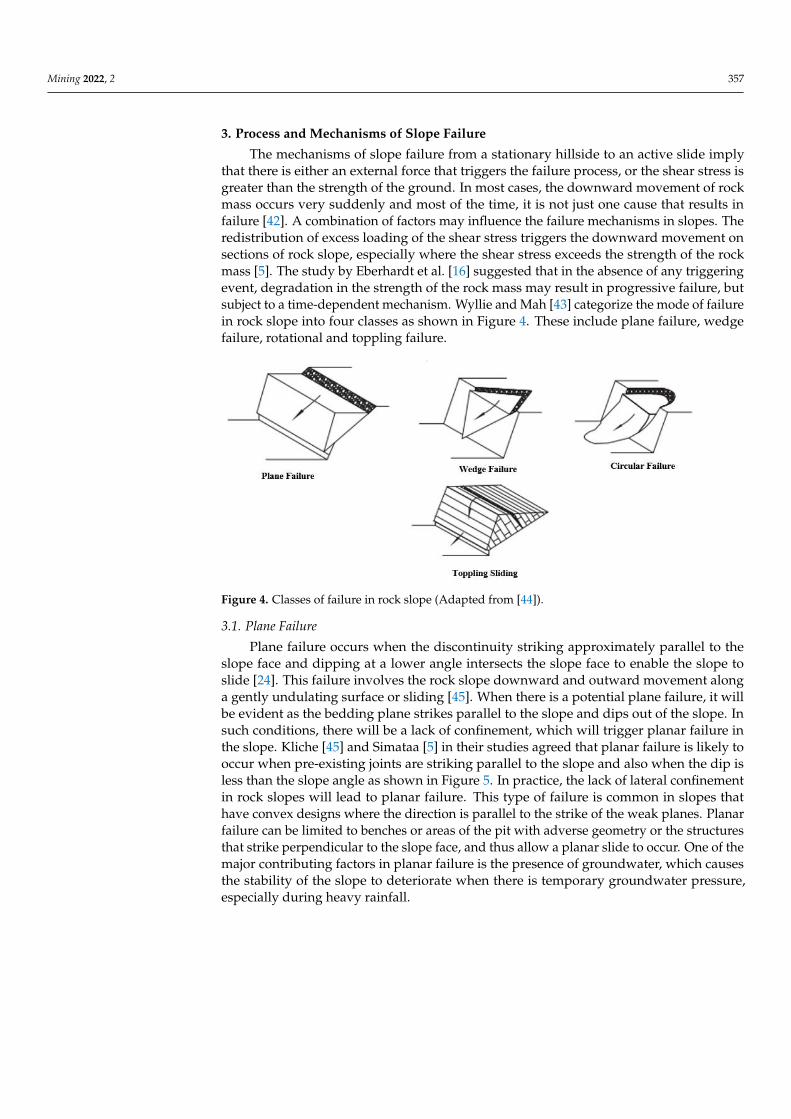
The mechanisms of slope failure from a stationary hillside to an active slide implythat there is either an external force that triggers the failure process, or the shear stress isgreater than the strength of the ground. In most cases, the downward movement of rockmass occurs very suddenly and most of the time, it is not just one cause that results infailure [42]. A combination of factors may influence the failure mechanisms in slopes. Theredistribution of excess loading of the shear stress triggers the downward movement onsections of rock slope, especially where the shear stress exceeds the strength of the rockmass [5]. The study by Eberhardt et al. [16] suggested that in the absence of any triggeringevent, degradation in the strength of the rock mass may result in progressive failure, butsubject to a time-dependent mechanism. Wyllie and Mah [43] categorize the mode of failurein rock slope into four classes as shown in Figure 4. These include plane failure, wedgefailure, rotational and toppling failure.
Mining 2022, 2, FOR PEER REVIEW 8
transformation. The study analyzed wave propagation with a cavity lying on an elastic foundation under dynamics loads from the surface overlying the cavity. The study uti-lized discontinuity decay for analyzing stress-strain variables. Analysis of the results proved that the models can be used to design and assess geomechanical features in min-eral deposits [40]. Another study by Nemirovisky and Tyrymov [41] utilized mathemati-cal modeling of a deformable body to calculate stress–strain conditions of layered rock mass with an overlying mountainous.
3. Process and Mechanisms of Slope Failure The mechanisms of slope failure from a stationary hillside to an active slide imply
that there is either an external force that triggers the failure process, or the shear stress is greater than the strength of the ground. In most cases, the downward movement of rock mass occurs very suddenly and most of the time, it is not just one cause that results in failure [42]. A combination of factors may influence the failure mechanisms in slopes. The redistribution of excess loading of the shear stress triggers the downward movement on sections of rock slope, especially where the shear stress exceeds the strength of the rock mass [5]. The study by Eberhardt et al [16] suggested that in the absence of any triggering event, degradation in the strength of the rock mass may result in progressive failure, but subject to a time-dependent mechanism. Wyllie and Mah [43] categorize the mode of fail-ure in rock slope into four classes as shown in Figure 4. These include plane failure, wedge failure, rotational and toppling failure.
Figure 4. Classes of failure in rock slope (Adapted from [44]).
3.1. Plane Failure Plane failure occurs when the discontinuity striking approximately parallel to the
slope face and dipping at a lower angle intersects the slope face to enable the slope to slide [24]. This failure involves the rock slope downward and outward movement along a gen-tly undulating surface or sliding [45]. When there is a potential plane failure, it will be evident as the bedding plane strikes parallel to the slope and dips out of the slope. In such conditions, there will be a lack of confinement, which will trigger planar failure in the slope. Kliche [45] and Simataa [5] in their studies agreed that planar failure is likely to occur when pre-existing joints are striking parallel to the slope and also when the dip is less than the slope angle as shown in Figure 5. In practice, the lack of lateral confinement in rock slopes will lead to planar failure. This type of failure is common in slopes that have convex designs where the direction is parallel to the strike of the weak planes. Planar fail-ure can be limited to benches or areas of the pit with adverse geometry or the structures
Figure 4. Classes of failure in rock slope (Adapted from [44]).
3.1. Plane Failure
Plane failure occurs when the discontinuity striking approximately parallel to theslope face and dipping at a lower angle intersects the slope face to enable the slope toslide [24]. This failure involves the rock slope downward and outward movement alonga gently undulating surface or sliding [45]. When there is a potential plane failure, it willbe evident as the bedding plane strikes parallel to the slope and dips out of the slope. Insuch conditions, there will be a lack of confinement, which will trigger planar failure inthe slope. Kliche [45] and Simataa [5] in their studies agreed that planar failure is likely tooccur when pre-existing joints are striking parallel to the slope and also when the dip isless than the slope angle as shown in Figure 5. In practice, the lack of lateral confinementin rock slopes will lead to planar failure. This type of failure is common in slopes thathave convex designs where the direction is parallel to the strike of the weak planes. Planarfailure can be limited to benches or areas of the pit with adverse geometry or the structuresthat strike perpendicular to the slope face, and thus allow a planar slide to occur. One of themajor contributing factors in planar failure is the presence of groundwater, which causesthe stability of the slope to deteriorate when there is temporary groundwater pressure,especially during heavy rainfall.
Mining 2022, 2 358
Mining 2022, 2, FOR PEER REVIEW 9
that strike perpendicular to the slope face, and thus allow a planar slide to occur. One of the major contributing factors in planar failure is the presence of groundwater, which causes the stability of the slope to deteriorate when there is temporary groundwater pres-sure, especially during heavy rainfall.
Figure 5. Pre-existing joints dipping out of slope face and striking parallel to the face (Adapted from [44]).
Wyllie and Mah [43] improved on the conditions reported by Hoek and Bray [46] and suggested the conditions that must be satisfied for planar failure to occur as follows:
(a) The strike of the plane of weakness must be within +/−20° of the crest of the slope; (b) The toe of the failure plane must daylight between the toe and the crest of the slope; (c) The dip of the failure plane must be less than the dip of the slope face and greater
than the angle of internal friction of the failure plane; (d) The upper end of the sliding surface either intersects the upper slope or terminate in
tension cracks; (e) Release surfaces that provide negligible resistance to sliding must be present in the
rock mass to define the lateral boundaries of the slide.
3.2. Wedge Failure Wedge failure occurs as a result of the intersection of two or more discontinuities that
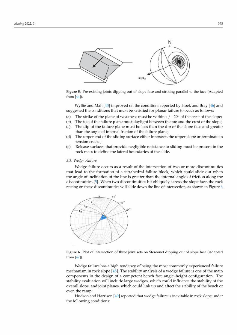
lead to the formation of a tetrahedral failure block, which could slide out when the angle of inclination of the line is greater than the internal angle of friction along the discontinu-ities [5]. When two discontinuities hit obliquely across the slope face, the rock resting on these discontinuities will slide down the line of intersection, as shown in Figure 6.
Figure 6. Plot of intersection of three joint sets on Stereonet dipping out of slope face (Adapted from [47]).
Figure 5. Pre-existing joints dipping out of slope face and striking parallel to the face (Adaptedfrom [44]).
Wyllie and Mah [43] improved on the conditions reported by Hoek and Bray [46] andsuggested the conditions that must be satisfied for planar failure to occur as follows:
(a) The strike of the plane of weakness must be within +/−20 of the crest of the slope;(b) The toe of the failure plane must daylight between the toe and the crest of the slope;(c) The dip of the failure plane must be less than the dip of the slope face and greater
than the angle of internal friction of the failure plane;(d) The upper end of the sliding surface either intersects the upper slope or terminate in
tension cracks;(e) Release surfaces that provide negligible resistance to sliding must be present in the
rock mass to define the lateral boundaries of the slide.
3.2. Wedge Failure
Wedge failure occurs as a result of the intersection of two or more discontinuitiesthat lead to the formation of a tetrahedral failure block, which could slide out whenthe angle of inclination of the line is greater than the internal angle of friction along thediscontinuities [5]. When two discontinuities hit obliquely across the slope face, the rockresting on these discontinuities will slide down the line of intersection, as shown in Figure 6.
Mining 2022, 2, FOR PEER REVIEW 9
that strike perpendicular to the slope face, and thus allow a planar slide to occur. One of the major contributing factors in planar failure is the presence of groundwater, which causes the stability of the slope to deteriorate when there is temporary groundwater pres-sure, especially during heavy rainfall.
Figure 5. Pre-existing joints dipping out of slope face and striking parallel to the face (Adapted from [44]).
Wyllie and Mah [43] improved on the conditions reported by Hoek and Bray [46] and suggested the conditions that must be satisfied for planar failure to occur as follows:
(a) The strike of the plane of weakness must be within +/−20° of the crest of the slope; (b) The toe of the failure plane must daylight between the toe and the crest of the slope; (c) The dip of the failure plane must be less than the dip of the slope face and greater
than the angle of internal friction of the failure plane; (d) The upper end of the sliding surface either intersects the upper slope or terminate in
tension cracks; (e) Release surfaces that provide negligible resistance to sliding must be present in the
rock mass to define the lateral boundaries of the slide.
3.2. Wedge Failure Wedge failure occurs as a result of the intersection of two or more discontinuities that
lead to the formation of a tetrahedral failure block, which could slide out when the angle of inclination of the line is greater than the internal angle of friction along the discontinu-ities [5]. When two discontinuities hit obliquely across the slope face, the rock resting on these discontinuities will slide down the line of intersection, as shown in Figure 6.
Figure 6. Plot of intersection of three joint sets on Stereonet dipping out of slope face (Adapted from [47]).
Figure 6. Plot of intersection of three joint sets on Stereonet dipping out of slope face (Adaptedfrom [47]).
Wedge failure has a high tendency of being the most commonly experienced failuremechanism in rock slope [48]. The stability analysis of a wedge failure is one of the maincomponents in the design of a competent bench face angle–height configuration. Thestability evaluation will include large wedges, which could influence the stability of theoverall slope, and joint planes, which could link up and affect the stability of the bench oreven the ramp.
Hudson and Harrison [49] reported that wedge failure is inevitable in rock slope underthe following conditions:
Mining 2022, 2 359
(a) When the line of intersection of two discontinuity planes associated with the poten-tially unstable wedge is daylighting on the slope plane;
(b) When the dip of the slope exceeds the dip of the line of intersection of the two discontinuityplanes associated with the potentially unstable;
(c) When the line of intersection of the two discontinuity planes associated with the poten-tially unstable wedge must be such that the strengths of the two planes are reached.
Low [50] argued that there are four classes of failure modes for a wedge, namely:
(a) Sliding along the line of intersection of both planes forming the block;(b) Sliding along plane A only;(c) Sliding along plane B only;(d) A floating type of failure.
In evaluating the stability of wedge failure in rock slope, one of the most rapid andconvenient methods is the use of stereonet. The stereonet has widely been used to examinethe kinematic feasibility of wedge failure, i.e., the type of sliding that is likely to occurwhen there is intersection of two or more major planes. However, the method cannot beused to determine the actual FOS but can be estimated from the geometry of the wedge, thestrength of each plane and the water pressure [43]. Moreover, the application of a frictionstability chart is another rapid method to check the stability of two-plane wedges. In thisapproach, the chart only considers the frictional strength on the plane of weakness whileignoring the cohesion and water pressure. When using the friction method, the calculatedFOS value must be greater than 2; a slope with FOS less than 2 is regarded as potentiallyunstable [43]. In using the stereonet approach to determine the stability of wedges, greatcircles for the planes of weakness are plotted on the stereonet by considering the shearstrength on the weakness planes. Similarly, the slope designer must also consider thefrictional strength using a friction circle.
3.3. Circular Failure
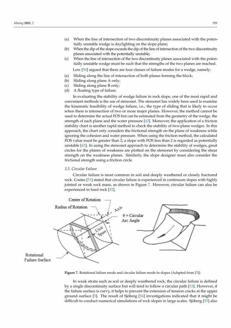
Circular failure is most common in soil and deeply weathered or closely fracturedrock. Coates [51] stated that circular failure is experienced in continuum slopes with highlyjointed or weak rock mass, as shown in Figure 7. However, circular failure can also beexperienced in hard rock [52].
Mining 2022, 2, FOR PEER REVIEW 11
Figure 7. Rotational failure mode and circular failure mode in slopes (Adapted from [5]).
In weak strata such as soil or deeply weathered rock, the circular failure is defined by a single discontinuity surface but will tend to follow a circular path [53]. However, if the failure surface is curvy, it helps to prevent the extension of tension cracks at the upper ground surface [5]. The result of Sjöberg [54] investigations indicated that it might be dif-ficult to conduct numerical simulations of rock slopes in large scales. Sjöberg [55] also managed to carry out a model study of circular failure which showed that circular failure occurs in six (6) stages, as shown in Figure 8. The six stages are explained below:
(a) Elastic displacement is caused by the removal of rock material during mining activities;
(b) Yielding commences at the toe and spreads upwards as more material is removed or as a result of mining to a new and critical slope height;
(c) Accumulation of shear strain at the toe of the slope will progress upward; (d) When failure surface is developed, the slope will start showing some displacements,
which can be tracked if there is a good monitoring system in place; (e) Slope fails with time with larger displacement starting from the toe; (f) When failure occurs, the failing mass can slide away from the slope.
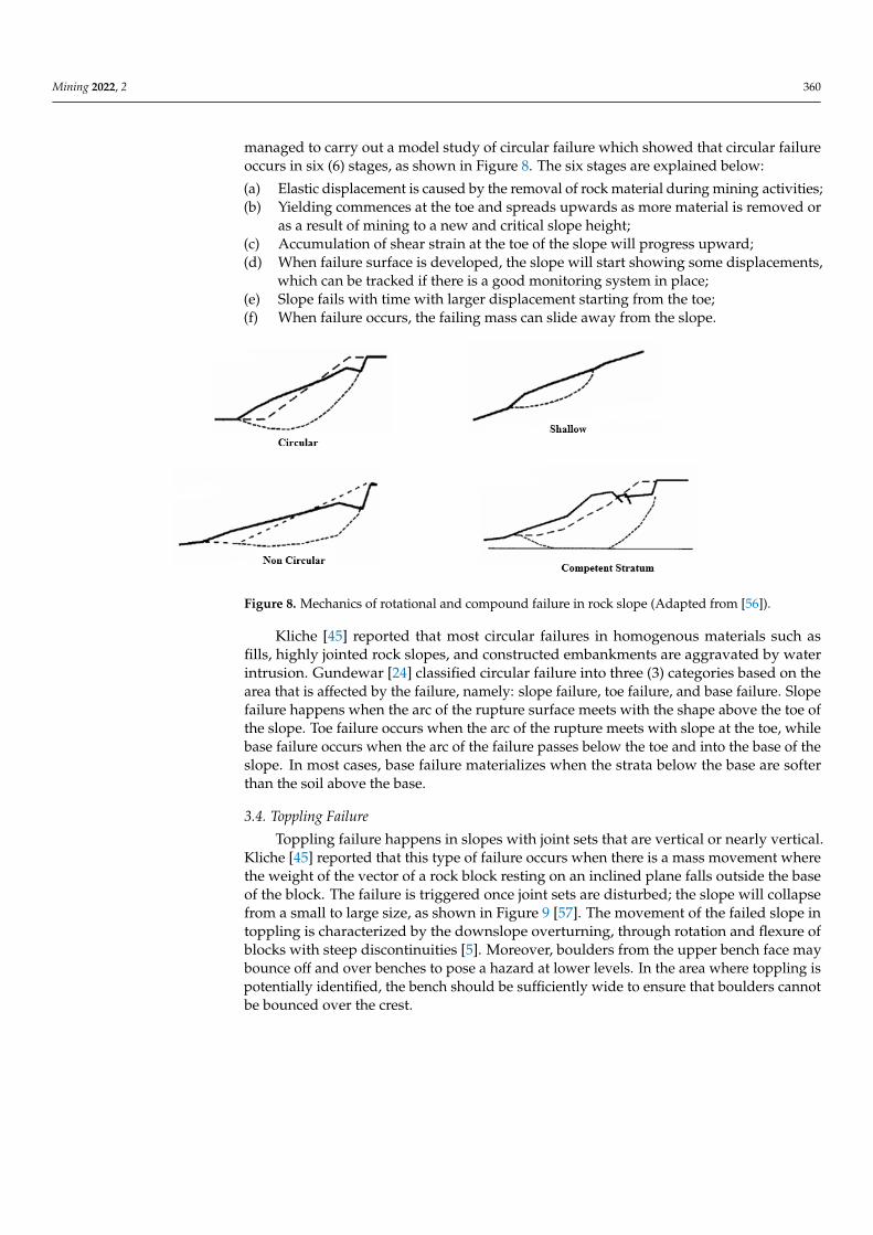
Figure 8. Mechanics of rotational and compound failure in rock slope (Adapted from [56]).
Figure 7. Rotational failure mode and circular failure mode in slopes (Adapted from [5]).
In weak strata such as soil or deeply weathered rock, the circular failure is definedby a single discontinuity surface but will tend to follow a circular path [53]. However, ifthe failure surface is curvy, it helps to prevent the extension of tension cracks at the upperground surface [5]. The result of Sjöberg [54] investigations indicated that it might bedifficult to conduct numerical simulations of rock slopes in large scales. Sjöberg [55] also
Mining 2022, 2 360
managed to carry out a model study of circular failure which showed that circular failureoccurs in six (6) stages, as shown in Figure 8. The six stages are explained below:
(a) Elastic displacement is caused by the removal of rock material during mining activities;(b) Yielding commences at the toe and spreads upwards as more material is removed or
as a result of mining to a new and critical slope height;(c) Accumulation of shear strain at the toe of the slope will progress upward;(d) When failure surface is developed, the slope will start showing some displacements,
which can be tracked if there is a good monitoring system in place;(e) Slope fails with time with larger displacement starting from the toe;(f) When failure occurs, the failing mass can slide away from the slope.
Mining 2022, 2, FOR PEER REVIEW 11
Figure 7. Rotational failure mode and circular failure mode in slopes (Adapted from [5]).
In weak strata such as soil or deeply weathered rock, the circular failure is defined by a single discontinuity surface but will tend to follow a circular path [53]. However, if the failure surface is curvy, it helps to prevent the extension of tension cracks at the upper ground surface [5]. The result of Sjöberg [54] investigations indicated that it might be dif-ficult to conduct numerical simulations of rock slopes in large scales. Sjöberg [55] also managed to carry out a model study of circular failure which showed that circular failure occurs in six (6) stages, as shown in Figure 8. The six stages are explained below:
(a) Elastic displacement is caused by the removal of rock material during mining activities;
(b) Yielding commences at the toe and spreads upwards as more material is removed or as a result of mining to a new and critical slope height;
(c) Accumulation of shear strain at the toe of the slope will progress upward; (d) When failure surface is developed, the slope will start showing some displacements,
which can be tracked if there is a good monitoring system in place; (e) Slope fails with time with larger displacement starting from the toe; (f) When failure occurs, the failing mass can slide away from the slope.
Figure 8. Mechanics of rotational and compound failure in rock slope (Adapted from [56]). Figure 8. Mechanics of rotational and compound failure in rock slope (Adapted from [56]).
Kliche [45] reported that most circular failures in homogenous materials such asfills, highly jointed rock slopes, and constructed embankments are aggravated by waterintrusion. Gundewar [24] classified circular failure into three (3) categories based on thearea that is affected by the failure, namely: slope failure, toe failure, and base failure. Slopefailure happens when the arc of the rupture surface meets with the shape above the toe ofthe slope. Toe failure occurs when the arc of the rupture meets with slope at the toe, whilebase failure occurs when the arc of the failure passes below the toe and into the base of theslope. In most cases, base failure materializes when the strata below the base are softerthan the soil above the base.
3.4. Toppling Failure
Toppling failure happens in slopes with joint sets that are vertical or nearly vertical.Kliche [45] reported that this type of failure occurs when there is a mass movement wherethe weight of the vector of a rock block resting on an inclined plane falls outside the baseof the block. The failure is triggered once joint sets are disturbed; the slope will collapsefrom a small to large size, as shown in Figure 9 [57]. The movement of the failed slope intoppling is characterized by the downslope overturning, through rotation and flexure ofblocks with steep discontinuities [5]. Moreover, boulders from the upper bench face maybounce off and over benches to pose a hazard at lower levels. In the area where toppling ispotentially identified, the bench should be sufficiently wide to ensure that boulders cannotbe bounced over the crest.
Mining 2022, 2 361
Mining 2022, 2, FOR PEER REVIEW 12
Kliche [45] reported that most circular failures in homogenous materials such as fills, highly jointed rock slopes, and constructed embankments are aggravated by water intru-sion. Gundewar [24] classified circular failure into three (3) categories based on the area that is affected by the failure, namely: slope failure, toe failure, and base failure. Slope failure happens when the arc of the rupture surface meets with the shape above the toe of the slope. Toe failure occurs when the arc of the rupture meets with slope at the toe, while base failure occurs when the arc of the failure passes below the toe and into the base of the slope. In most cases, base failure materializes when the strata below the base are softer than the soil above the base.
3.4. Toppling Failure Toppling failure happens in slopes with joint sets that are vertical or nearly vertical.
Kliche [45] reported that this type of failure occurs when there is a mass movement where the weight of the vector of a rock block resting on an inclined plane falls outside the base of the block. The failure is triggered once joint sets are disturbed; the slope will collapse from a small to large size, as shown in Figure 9 [57]. The movement of the failed slope in toppling is characterized by the downslope overturning, through rotation and flexure of blocks with steep discontinuities [5]. Moreover, boulders from the upper bench face may bounce off and over benches to pose a hazard at lower levels. In the area where toppling is potentially identified, the bench should be sufficiently wide to ensure that boulders cannot be bounced over the crest.
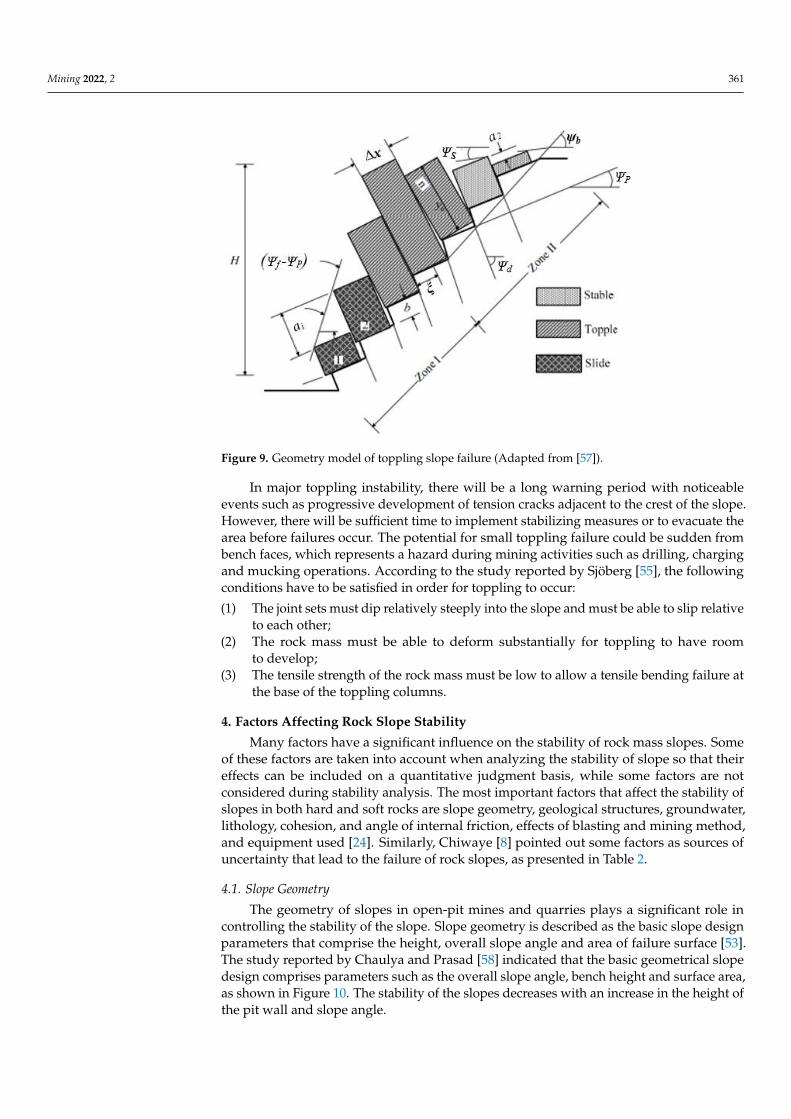
Figure 9. Geometry model of toppling slope failure (Adapted from [57]).
In major toppling instability, there will be a long warning period with noticeable events such as progressive development of tension cracks adjacent to the crest of the slope. However, there will be sufficient time to implement stabilizing measures or to evacuate the area before failures occur. The potential for small toppling failure could be sudden from bench faces, which represents a hazard during mining activities such as drilling, charging and mucking operations. According to the study reported by Sjöberg [55], the following conditions have to be satisfied in order for toppling to occur: (1) The joint sets must dip relatively steeply into the slope and must be able to slip
relative to each other;
Figure 9. Geometry model of toppling slope failure (Adapted from [57]).
In major toppling instability, there will be a long warning period with noticeableevents such as progressive development of tension cracks adjacent to the crest of the slope.However, there will be sufficient time to implement stabilizing measures or to evacuate thearea before failures occur. The potential for small toppling failure could be sudden frombench faces, which represents a hazard during mining activities such as drilling, chargingand mucking operations. According to the study reported by Sjöberg [55], the followingconditions have to be satisfied in order for toppling to occur:
(1) The joint sets must dip relatively steeply into the slope and must be able to slip relativeto each other;
(2) The rock mass must be able to deform substantially for toppling to have roomto develop;
(3) The tensile strength of the rock mass must be low to allow a tensile bending failure atthe base of the toppling columns.
4. Factors Affecting Rock Slope Stability
Many factors have a significant influence on the stability of rock mass slopes. Someof these factors are taken into account when analyzing the stability of slope so that theireffects can be included on a quantitative judgment basis, while some factors are notconsidered during stability analysis. The most important factors that affect the stability ofslopes in both hard and soft rocks are slope geometry, geological structures, groundwater,lithology, cohesion, and angle of internal friction, effects of blasting and mining method,and equipment used [24]. Similarly, Chiwaye [8] pointed out some factors as sources ofuncertainty that lead to the failure of rock slopes, as presented in Table 2.
4.1. Slope Geometry
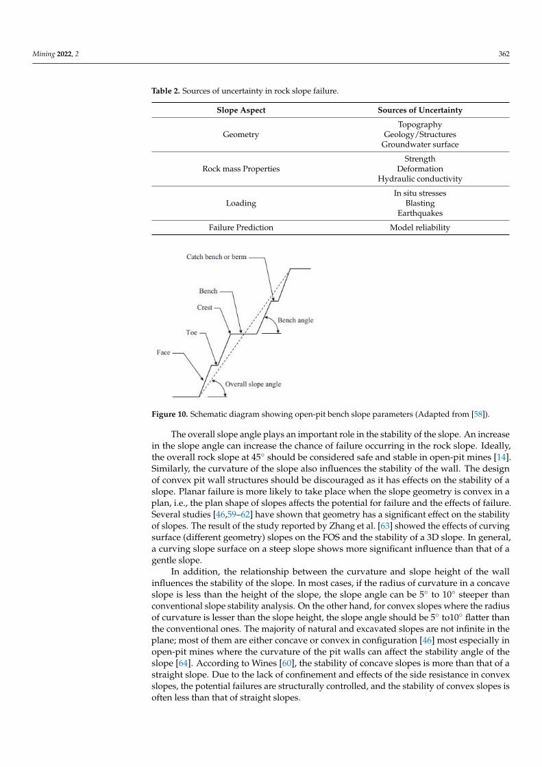
The geometry of slopes in open-pit mines and quarries plays a significant role incontrolling the stability of the slope. Slope geometry is described as the basic slope designparameters that comprise the height, overall slope angle and area of failure surface [53].The study reported by Chaulya and Prasad [58] indicated that the basic geometrical slopedesign comprises parameters such as the overall slope angle, bench height and surface area,as shown in Figure 10. The stability of the slopes decreases with an increase in the height ofthe pit wall and slope angle.
Mining 2022, 2 362
Table 2. Sources of uncertainty in rock slope failure.
Slope Aspect Sources of Uncertainty
TopographyGeometry Geology/Structures
Groundwater surface
StrengthRock mass Properties Deformation
Hydraulic conductivity
In situ stressesLoading Blasting
Earthquakes
Failure Prediction Model reliability
Mining 2022, 2, FOR PEER REVIEW 13
(2) The rock mass must be able to deform substantially for toppling to have room to develop;
(3) The tensile strength of the rock mass must be low to allow a tensile bending failure at the base of the toppling columns.
4. Factors Affecting Rock Slope Stability Many factors have a significant influence on the stability of rock mass slopes. Some
of these factors are taken into account when analyzing the stability of slope so that their effects can be included on a quantitative judgment basis, while some factors are not con-sidered during stability analysis. The most important factors that affect the stability of slopes in both hard and soft rocks are slope geometry, geological structures, groundwater, lithology, cohesion, and angle of internal friction, effects of blasting and mining method, and equipment used [24]. Similarly, Chiwaye [8] pointed out some factors as sources of uncertainty that lead to the failure of rock slopes, as presented in Table 2.
Table 2. Sources of uncertainty in rock slope failure.
Slope Aspect Sources of Uncertainty Topography
Geometry Geology/Structures Groundwater surface Strength
Rock mass Properties Deformation Hydraulic conductivity In situ stresses
Loading Blasting Earthquakes
Failure Prediction Model reliability
4.1. Slope Geometry The geometry of slopes in open-pit mines and quarries plays a significant role in con-
trolling the stability of the slope. Slope geometry is described as the basic slope design parameters that comprise the height, overall slope angle and area of failure surface [53]. The study reported by Chaulya and Prasad [58] indicated that the basic geometrical slope design comprises parameters such as the overall slope angle, bench height and surface area, as shown in Figure 10. The stability of the slopes decreases with an increase in the height of the pit wall and slope angle.
Figure 10. Schematic diagram showing open-pit bench slope parameters (Adapted from [58]).
The overall slope angle plays an important role in the stability of the slope. An increasein the slope angle can increase the chance of failure occurring in the rock slope. Ideally,the overall rock slope at 45 should be considered safe and stable in open-pit mines [14].Similarly, the curvature of the slope also influences the stability of the wall. The designof convex pit wall structures should be discouraged as it has effects on the stability of aslope. Planar failure is more likely to take place when the slope geometry is convex in aplan, i.e., the plan shape of slopes affects the potential for failure and the effects of failure.Several studies [46,59–62] have shown that geometry has a significant effect on the stabilityof slopes. The result of the study reported by Zhang et al. [63] showed the effects of curvingsurface (different geometry) slopes on the FOS and the stability of a 3D slope. In general,a curving slope surface on a steep slope shows more significant influence than that of agentle slope.
In addition, the relationship between the curvature and slope height of the wallinfluences the stability of the slope. In most cases, if the radius of curvature in a concaveslope is less than the height of the slope, the slope angle can be 5 to 10 steeper thanconventional slope stability analysis. On the other hand, for convex slopes where the radiusof curvature is lesser than the slope height, the slope angle should be 5 to10 flatter thanthe conventional ones. The majority of natural and excavated slopes are not infinite in theplane; most of them are either concave or convex in configuration [46] most especially inopen-pit mines where the curvature of the pit walls can affect the stability angle of theslope [64]. According to Wines [60], the stability of concave slopes is more than that of astraight slope. Due to the lack of confinement and effects of the side resistance in convexslopes, the potential failures are structurally controlled, and the stability of convex slopes isoften less than that of straight slopes.

Mining 2022, 2 363
The relationship between the radius of curvature and the height of the slope is anotherfactor that is used in the stability analysis of slopes. When the radius of curvature of aconcave slope is less than the height of the slope, the slope angle can be 10 steeper thanthe angle suggested from the conventional stability analysis [46]. Similarly, the ratio ofthe curvature radius to the height due to an increase in the lateral pressure causes anincrease in the stability of a slope [64]. However, practical experiences have shown thatconcave geometry is the most widely used type of curvature design of slope geometry,most especially in open-pit mines, narrow long pits, circular pits and in the wall at the endof the pits [60].
4.2. Geological Structure
This is an important factor to be considered in evaluating various factors that influencethe stability of slopes. It is essential, not only from a safety but also from an economic pointof view. A wrong approach to geological conditions during design and operations canhave severe consequences in mining operations. Geological structures include fault, joints,presence of bedding plane and intra-formational shear zones that influence the stability ofa rock slope. In most cases, geological structures, also known as discontinuities, control thetype of failure that will take place in the rock slopes. The properties of the discontinuitiesinclude roughness, orientation, and persistence and mineral infillings such as clay materialpresent in between rocks play important role in the stability of the rock slope. For instance,the joint orientation (dip and the dip direction) can be used to predict the mechanism offailure that will occur. The intersection of discontinuities such as joints and fractures inrocks results in instability and accidental falling of rock blocks in rock mass as a result of theactual strength of the in situ rock mass being less than the strength of the intact rock [8,61].These discontinuities are usually several sets occurring at different directions, which causesseparation in rock mass into discrete and interlocking pieces. However, intersection ofdiscontinuities causes a reduction in the shear and tensile strength of the rock, resulting insliding along the structural plane [65].
The geological structure and strength of rocks have a significant influence on the me-chanical properties of the rock. According to Liu et al. [66], the mechanical properties of theground depend on different factors such as stone content, rock shape, rock distribution andbonding strength. In most cases, the mechanical properties serve as input parameters forevaluating the stability of slopes and to understand the characteristics of a rock mass [67].
The initiation of tensile and shear failure in rock mass often leads to instability ofrock slopes, which usually occur as a result of response from several factors, such astemperature and insolation [68], seismic loading [69], weathering [70] and precipitation [71].In underground excavations, the rock in the roof behaves oppositely, where there areoverhanging and threatening blocks or slabs remaining in their position because of thestrength initiation of discontinuities, which are mainly arising from the rock bridges [72].However, results from investigations revealed that rock bridges significantly increase withthe shear strength of individual incipient rock discontinuities, especially when they areunder constant normal stiffness boundary conditions [73]. The intersection of joints in rockmasses results in the formation of discrete blocks with variable geometries, especially whenthe discontinuities are not fully continuous [74].
The main geological structures known to influence slope stability include directionof dip, intra-formational shear zones, joints, discontinuities and faults. Slope failure myoccur due to failure along the structural discontinuities of intact zones or along surfacesformed close to discontinuities [75,76]. In addition to that, dip direction affects slopestability especially when the dip direction of the strata of discontinuity is similar to slopedip direction with an angle of the strike of less than 20, which consequently triggersfailure from the toe zone. Furthermore, slope failure is promoted when seepage occursfrom beneath the ground into the strata, which lubricates the rock mass and consequentlytriggers material failure in the upper zones, leaving a planar surface [77]. Additionally, inzones where the rocks have weathered, the infiltration of water into the sediments increases
Mining 2022, 2 364
pore pressure, alters the degree of saturation, and compromises the shear strength of rockmass leading to failure [78]. The density of slope material has considerable implicationson its stability, as a very low density promotes water seepage into the rock mass, while ahigh-density limits infiltration [79].
4.3. Groundwater
Groundwater opens up the little cracks and activates the force on blocks and wedgesthat cause instability of slopes in rocks. The water pressure on potential failure planesreduces the normal stresses across planes, which in turn reduces the frictional strengthon these planes. Consequently, it increases the thrust and driving forces, which in turncontrols the stability of the slope.
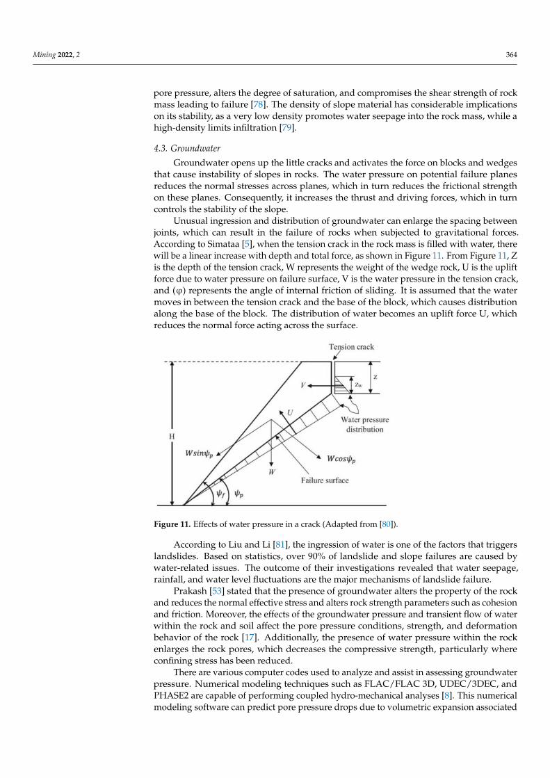
Unusual ingression and distribution of groundwater can enlarge the spacing betweenjoints, which can result in the failure of rocks when subjected to gravitational forces.According to Simataa [5], when the tension crack in the rock mass is filled with water, therewill be a linear increase with depth and total force, as shown in Figure 11. From Figure 11, Zis the depth of the tension crack, W represents the weight of the wedge rock, U is the upliftforce due to water pressure on failure surface, V is the water pressure in the tension crack,and (ϕ) represents the angle of internal friction of sliding. It is assumed that the watermoves in between the tension crack and the base of the block, which causes distributionalong the base of the block. The distribution of water becomes an uplift force U, whichreduces the normal force acting across the surface.
Mining 2022, 2, FOR PEER REVIEW 16
Figure 11. Effects of water pressure in a crack (Adapted from [81]).
According to Liu and Li [82], the ingression of water is one of the factors that triggers landslides. Based on statistics, over 90% of landslide and slope failures are caused by wa-ter-related issues. The outcome of their investigations revealed that water seepage, rain-fall, and water level fluctuations are the major mechanisms of landslide failure.
Prakash [53] stated that the presence of groundwater alters the property of the rock and reduces the normal effective stress and alters rock strength parameters such as cohe-sion and friction. Moreover, the effects of the groundwater pressure and transient flow of water within the rock and soil affect the pore pressure conditions, strength, and defor-mation behavior of the rock [17]. Additionally, the presence of water pressure within the rock enlarges the rock pores, which decreases the compressive strength, particularly where confining stress has been reduced.
There are various computer codes used to analyze and assist in assessing groundwa-ter pressure. Numerical modeling techniques such as FLAC/FLAC 3D, UDEC/3DEC, and PHASE2 are capable of performing coupled hydro-mechanical analyses [8]. This numeri-cal modeling software can predict pore pressure drops due to volumetric expansion asso-ciated with the excavation of a pit. However, modeling of groundwater pressure and ex-pansions with numerical modeling software is cumbersome.
Hydrogeological conditions of the rock mass influence slope stability, which nor-mally manifests through ground seepage from an underground water aquifer, surface water, or precipitation from stormwater or snow thaw. The influence of groundwater on slope failure can generally be experienced in three major avenues. To begin with, the pres-ence of water in the rock mass creates hydrostatic pressure, which tends to lift present rock blocks, thereby posing lateral pressure on present discontinuity planes. Conse-quently, the imposed lateral pressure reduces plane resistance against sliding, as well as the shear strength through a reduction in normal stress on the discontinuity plane, which loosens rock blocks, resulting in slope failure. Furthermore, depending on the nature of the groundwater, such a condition may alter the physical and chemical compositions of discontinuity fillings, thereby reducing the shear friction and ultimately leading to slope failure [83].
4.4. Lithology The lithology of rock mass is an essential factor that influences the failure process of
rock slopes in open-pit and quarry operations. In most cases, the physical characteristics of the rock mass show the potential areas that are prone to failure. The mineral constitu-ents forming the rock control the mechanical properties and the behavior of the rock mass and also determine the strength of the rock mass [14,84]. McNeilly et al [85] stated that the porosity, mineralogy, density, and degree of cementation are the rock properties that can
Figure 11. Effects of water pressure in a crack (Adapted from [80]).
According to Liu and Li [81], the ingression of water is one of the factors that triggerslandslides. Based on statistics, over 90% of landslide and slope failures are caused bywater-related issues. The outcome of their investigations revealed that water seepage,rainfall, and water level fluctuations are the major mechanisms of landslide failure.
Prakash [53] stated that the presence of groundwater alters the property of the rockand reduces the normal effective stress and alters rock strength parameters such as cohesionand friction. Moreover, the effects of the groundwater pressure and transient flow of waterwithin the rock and soil affect the pore pressure conditions, strength, and deformationbehavior of the rock [17]. Additionally, the presence of water pressure within the rockenlarges the rock pores, which decreases the compressive strength, particularly whereconfining stress has been reduced.
There are various computer codes used to analyze and assist in assessing groundwaterpressure. Numerical modeling techniques such as FLAC/FLAC 3D, UDEC/3DEC, andPHASE2 are capable of performing coupled hydro-mechanical analyses [8]. This numericalmodeling software can predict pore pressure drops due to volumetric expansion associated
Mining 2022, 2 365
with the excavation of a pit. However, modeling of groundwater pressure and expansionswith numerical modeling software is cumbersome.
Hydrogeological conditions of the rock mass influence slope stability, which normallymanifests through ground seepage from an underground water aquifer, surface water,or precipitation from stormwater or snow thaw. The influence of groundwater on slopefailure can generally be experienced in three major avenues. To begin with, the presence ofwater in the rock mass creates hydrostatic pressure, which tends to lift present rock blocks,thereby posing lateral pressure on present discontinuity planes. Consequently, the imposedlateral pressure reduces plane resistance against sliding, as well as the shear strengththrough a reduction in normal stress on the discontinuity plane, which loosens rock blocks,resulting in slope failure. Furthermore, depending on the nature of the groundwater, sucha condition may alter the physical and chemical compositions of discontinuity fillings,thereby reducing the shear friction and ultimately leading to slope failure [82].
4.4. Lithology
The lithology of rock mass is an essential factor that influences the failure process ofrock slopes in open-pit and quarry operations. In most cases, the physical characteristics ofthe rock mass show the potential areas that are prone to failure. The mineral constituentsforming the rock control the mechanical properties and the behavior of the rock mass andalso determine the strength of the rock mass [14,83]. McNeilly et al. [84] stated that theporosity, mineralogy, density, and degree of cementation are the rock properties that caninfluence the strength of rock. The mineralogy dictates the rock type, strength of the rock,color and other properties of the rock. According to Yasir et al. [85], the strength propertiesof the rock increase with the degree of cementation. The mineral composition and thephysical properties of the rock mass affect the strength of the rock, thus influencing thestability of the slope. In the design of rock slope, pit high wall that contains weatheredrocks or alluvium rock materials will have low shear strengths and a high propensity tofurther weathering through erosion. Despite the roles cohesion and frictional angle play inthe stability of rock slope by opposing the effects of the magnitude of the shear stress, thereare some limitations of these strength parameters. In most cases, the estimated value ofthese parameters contains errors during calculations that influence the uncertainty in theresult [86]. Likewise, Sullivan et al. [87] stated that the friction angle is influenced by thegrain sorting, grain size and grain angularity, while the chemical bonding and cementationalso affect the cohesion.
4.5. Cohesion and Angle of Internal Friction
Rock strength properties such as cohesion (c) and angle of internal friction (ϕ) areused in evaluating the FOS of rock slopes during the design stage. The shear strengthis a key mechanical characteristic of rock–soil related to slope stability assessment. Thecohesion and friction angle values are used to describe the shear strength of the rocks.These parameters are determined in the laboratory through a triaxial compression test.The angle of internal friction in a rock defines the ability of the rock to withstand shearstress [53]. However, the particle size of the rock affects the angle of internal friction; i.e.,the larger the particle size, the larger the angle of internal friction. In addition, high watercontent, undercutting slopes, ground vibration, and alternating expansion by wetting andcontraction by dryness of water reduce the strength of cohesion in a rock mass.
The cohesion and friction angle of rock–soil aggregates are influenced by the particlesize distribution characteristics and other conditions, especially the water content [88]However, the lower the cohesion in a rock mass, the lower the stability of the slope, and thehigher the internal frictional angle of rock, the higher the slope wall will be. Therefore, it isnecessary to evaluate the cohesion and the angle of internal friction from the core specimenduring site investigation to determine whether the slope will be stable or not. In analyzingthe stability of the slope both in rock and soil, the cohesion and the angle of internal frictionmust be taken into account as these properties control the shear strength of the rock [89].
Mining 2022, 2 366
4.6. Blasting
Poor blasting in open-pit mining operations is detrimental to rock slope stability, notonly due to blasting-induced vibrations but more largely because the rock behind the slopeface can be fragmented and loosened [5]. The ground vibration that occurs as a result ofpoor blasting causes redistribution of stresses in the rock slope, which eventually leads to adynamic acceleration of materials, which in turn causes instability in the slope plane [14].Similarly, the effects of poor blasting largely result in the creation of discontinuities such asfractured zones, faults, joints, and fissures in rock slopes [90]. Poor blasting reduces thecohesion and creates the potential for ingress of water, which causes further loosening ofthe rock mass.
Another implication of poor blasting is that it reduces the bench-face angle andeventually leads to ground vibration that could potentially cause failure in a rock mass [53].During blasting operations, natural cracks and fractures in a rock mass structure areextended by additional stresses induced by the blasting, and therefore the shear strength ofthe rock mass is significantly reduced, thereby causing instability of the rock mass.
Over the course of detonation, seismic waves are produced, which spread in the formof a stress wave within a rock mass. The effects of this distributed seismic wave on thegeometry of a slope will produce vertical and horizontal constant acceleration that willresult in an unstable slope. When the stress wave is higher than the tensile strength of therock, there may be potential damage of the rock mass as a result of seismic waves, elasticvibration and elastic stress waves caused by poor blasting and the presence of fracturezones, thus leading to slope instability and other damages. However, a combination of theeffects of poor blasting with the external loading can also create a surcharge on the crest ofthe benches.
4.7. Mining Method and Equipment Usage
In mining operations, the surrounding rock mass around excavation develops defor-mation due to changes in the in situ stress field conditions. During excavation, naturalslopes may face deformation as a result of the reduction in shear strength, which can lead toslope failure [91]. The rock mass movement may continue if no solutions are implementedon the cut slope. The overall slope stability must be considered when selecting miningmethods and equipment usage. Similarly, the state of in situ stress field conditions de-scribed by the magnitude and orientation of the principal stress must be taken into accountduring the excavation process [92]. In the open-pit mining method, the highwall slopesare designed to be steeped due to the increase in slope height that is prone to the bucklingmode of failure [53]. Additionally, the movement of heavy equipment during mining formine haulage and other operational equipment such as rigs give rise to an increase insurcharge, which in turn increases the forces that trigger the downward movement ofthe slope.
4.8. Stresses on Slope
The presence of field stress conditions in rock masses has a significant influence onthe stability of a slope [93]. The in situ field-stress condition of a rock mass can be used toinvestigate the behavior of slopes regarding the height of the wall and provide a summaryof several failures. Although the impact of in situ stress fields can be less significant insmall slopes, it has to be considered for the design of a very large slope. The advantagesof using the stress analysis approach to evaluate the stability of slope include modelingof the excavation sequence, modeling of deformation, modeling of water pressure andflow in the rock mass and modeling of the progressive development of yield and failurezones. However, the stress can be advantageous as it provides confinement to the rockmass [94]. The confinement assists in stabilizing the slope. Hoek et al. [19] stated that thelateral stresses during rock excavation have an important influence on the stability of theslope. At high confinement conditions, most of the joints reach their residual aperture, and

Mining 2022, 2 367
as a result, the stiffness of the rock is no longer affected by the increment in the confiningstress [95].
The presence of discontinuities in rocks influences the shear strength, which in turndetermines the stability properties of the rock mass. The effects of discontinuities (geologicalstructures) significantly influence the load condition of the rock mass. Notably, naturaldiscontinuities such as joints and faults are evident in rocks that influence the mechanicalbehavior of the rock and also create stress in the anisotropy, heterogeneity and scale effects.The mechanical properties of a jointed rock mass are controlled by the geometry andproperties of the discontinuities. Additionally, the physical properties of discontinuitiessuch as friction, compressive strength, weathering and the presence of infilling materials(clay) affect the mechanical behavior of the rock mass. This is more reason why the jointnetwork and other geological structures reduce the strength of the rock mass and increasethe deformability of the rock. Therefore, it is important to investigate the properties of jointsto be able to accurately determine the stability factor of slopes. Moreover, knowing thejoints network will enable a safe and economic design of the slope and stability analysis [96].The nature of the jointing, such as their orientations, length, the distance between jointsand joint spacing, also influence the stability of slopes.
During site investigation, discontinuities are classified according to how they areformed. In most cases, discontinuities with the same category usually have the sameproperties in terms of their shear strength property, which can be used to predict the stabilityconditions of the excavation. Evaluation of joints network and the strength properties canserve as the guide for designing a stable slope and other rock engineering applications.It is assumed strength properties of jointed rock masses depend on the properties of theintact rock pieces and the freedom of the pieces of the slide and rotate under differentstress conditions. Ryan [97] stated that the strength of jointed rock masses depends onthe strength of the joints, the strength of the intact rock locks between the joints and thedegree of interlocking between the rock blocks. For instance, in jointed rock masses, it isexpected that the water pressure in the joints will continue to increase and dissipate fasterthan the pore pressure of the intact rocks, most especially in rocks where the porosity andpermeability are low.
In slope stability analysis, the joints are too many to be taken into account individually;thus, an approximate property is usually considered. Other influences of discontinuitiesare represented by the shape, the block size and the strength of the rock mass. Likewise,the importance of taking into account joint conditions in the rock mass is that the jointinformation is used to highlight the failure mechanisms as well as the failure intact betweenjoints [98]. According to Cundall et al. [99], the compressive strength of the rock is the bestdescribed property of the rock against shearing under confined conditions. Recently, theadvancements in technologies have brought about accuracy in the method of predictingslope stability in jointed rock masses. The availability of various computer programs cansimulate different stability scenarios in jointed rock masses. However, the application ofcomputer programs such as the finite element method (FEM) and the discrete elementmethod (DEM) have proven to be effective in analyzing slope stability. These approachesmake use of the shear strength reduction (SRR) methods to determine the stability factor ina jointed rock mass. However, to use the computer programs for jointed rock mass, it isnecessary to consider the joint patterns to obtain an adequate representation of real rockconfiguration. That is, when all the joint components are considered in the model, it ispossible to predict the slope failure mechanism and joint movement that can influence thesliding of the rock mass.
5. Slope Failure in Mining Operations
Slope stability is a crucial consideration in the management of mining operations asslope failure compromises the economical and safety aspect of production. Due to theincrease in demand for mineral resources and the invention of more sophisticated miningmethods as well as machinery, most mines are designed to reap more resources from

Mining 2022, 2 368
deeper or steeper mines. Such mines have a higher angle of inclination, which make themmore susceptible to slope failure. Slope failure can lead to injury of personnel, damageof mine machinery, and disruption of operations, which all negatively impact the miningperformance. In order to prevent such a hazard from occurring, it is imperative thatextensive geotechnical studies are conducted to ensure that FOS is within a tolerable range(>1) far from failure. In cases where the FOS is very low, more attention should be given tomonitoring such slopes to prevent slope failure.
Slope failures are common in open-pit mines and become unavoidable as excavationis becoming deeper and, as such, more difficult to manage. A review of existing failedslopes around the globe provides a better understanding of the failure modes and factorsto be considered in controlling the mechanisms that trigger mass movement of materials inslope engineering [55]. Mitigation of slope failure risk requires an in-depth understandingof structural geology, rock mass properties, influence of groundwater pressure and otherexternal forces in the area [100]. Failure in rock slopes occurs due to many reasons, whichhave been discussed earlier in this paper. During excavation, stripping excavation walls arerequired to be as steep as possible for operational efficiency. Failure may occur if the slopedesign is over steeped [101], although most failures in open-pit mines are triggered byfracture and shear on existing defects. Structures inside the rock mass interact in differentways as the rock deforms, and thus affect the general behavior of the rock. In addition,understanding the in situ stress field pattern is critical in understanding the deformationprocesses in open-pit mines. For instance, mining of ore using open-pit mining methodsexpose the surface and the rock adjacent to the pit wall; therefore, it becomes unconfined inthe direction normal to the slope face over large areas [102].
When a rock mass comprises blocks separated by joints, shear zones and beddingplanes, sliding on multiple discontinuity sets as well as tensile and shear failure are boundto occur [103]. For instance, the report of the slope failure that occurred at Yanqianshaniron mine in China confirmed that the eastern part of the slope collapsed as a result ofdeformed strata in the area [104]. The collapsed area comprises of eight build-up stagesthat are represented by actions from point (a) to point (g). These stages are classified as acave rock zone, cracking zone, toppling zone, and sliding, as shown in Figure 12. Basedon the report of the investigations, the process of initiation and development of failurezones were categorized into three stages: (i) overlaying area above the goaf, (ii) initiation ofthe collapsed strata sliding into the pit to form a small landslide and (iii) a large landslideoccurring as a result of mining activities and creeping of rock that triggered the massmovement in the northeastern phyllite slope. The disturbance produced by undergroundmining activities initiated the potential sliding body on the northern phyllite slope and theretaining wall structure gradually tended towards instability.
Similarly, another slope failure was reported in Western Macedonia in Northern Greeceas a result of sliding along the sub horizontal direction, unfavorably sloping as shownin Figure 13. From the analyses, the stability was governed by the interface betweenlignite and an underlying stiff presence of plastic clay or a marl layer that are very closeto the bottom of the slope where there is a significant amount of stress. Based on thestudy reported by Zevgolis et al. [105], some factors such as groundwater conditions, pitgeometry and shear strength of the critical interfaces between clays and lignite influencedthe stability of the slope.
In addition, a massive landslide at the Grasberg gold and copper mine in Indonesia,which forced the pit to suspend operations, was reported by DTE [106]. In October 2003, afatal accident happened at the southern wall of the open-pit mine, which collapsed andclaimed the life of eight people and injured another five people. This incident moved2.3 million tons of rock and mud down the slope, thereby engulfing mineworkers andheavy equipment. Similarly, a rock mass slippage happened in the year 2000 at the samemine when the overburden was washed by heavy rainfall into Lake Wanagon [107]. Themain cause of material movement was attributed to ingress of groundwater from a nearbywater table, coupled with an abnormally high rainfall season.
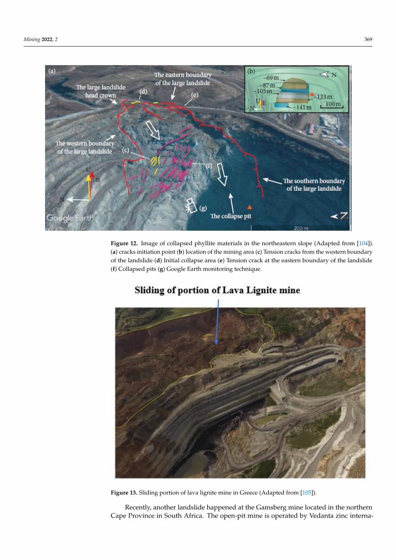
Mining 2022, 2 369
Mining 2022, 2, FOR PEER REVIEW 20
if the slope design is over steeped [102], although most failures in open-pit mines are trig-gered by fracture and shear on existing defects. Structures inside the rock mass interact in different ways as the rock deforms, and thus affect the general behavior of the rock. In addition, understanding the in situ stress field pattern is critical in understanding the de-formation processes in open-pit mines. For instance, mining of ore using open-pit mining methods expose the surface and the rock adjacent to the pit wall; therefore, it becomes unconfined in the direction normal to the slope face over large areas [103].
When a rock mass comprises blocks separated by joints, shear zones and bedding planes, sliding on multiple discontinuity sets as well as tensile and shear failure are bound to occur [104]. For instance, the report of the slope failure that occurred at Yanqianshan iron mine in China confirmed that the eastern part of the slope collapsed as a result of deformed strata in the area [105]. The collapsed area comprises of eight build-up stages that are represented by actions from point (a) to point (g). These stages are classified as a cave rock zone, cracking zone, toppling zone, and sliding, as shown in Figure 12. Based on the report of the investigations, the process of initiation and development of failure zones were categorized into three stages: (i) overlaying area above the goaf, (ii) initiation of the collapsed strata sliding into the pit to form a small landslide and (iii) a large land-slide occurring as a result of mining activities and creeping of rock that triggered the mass movement in the northeastern phyllite slope. The disturbance produced by underground mining activities initiated the potential sliding body on the northern phyllite slope and the retaining wall structure gradually tended towards instability.
Figure 12. Image of collapsed phyllite materials in the northeastern slope (Adapted from [105]). (a)cracks initiation point (b)location of the mining area (c)Tension cracks from the western bound-ary of the landslide (d)Initial collapse area (e) Tension crack at the eastern boundary of the land-slide (f) Collapsed pits (g)Google Earth monitoring technique
Similarly, another slope failure was reported in Western Macedonia in Northern Greece as a result of sliding along the sub horizontal direction, unfavorably sloping as shown in Figure 13. From the analyses, the stability was governed by the interface be-tween lignite and an underlying stiff presence of plastic clay or a marl layer that are very close to the bottom of the slope where there is a significant amount of stress. Based on the study reported by Zevgolis et al [106], some factors such as groundwater conditions, pit
Figure 12. Image of collapsed phyllite materials in the northeastern slope (Adapted from [104]).(a) cracks initiation point (b) location of the mining area (c) Tension cracks from the western boundaryof the landslide (d) Initial collapse area (e) Tension crack at the eastern boundary of the landslide(f) Collapsed pits (g) Google Earth monitoring technique.
Mining 2022, 2, FOR PEER REVIEW 21
geometry and shear strength of the critical interfaces between clays and lignite influenced the stability of the slope.
Figure 13. Sliding portion of lava lignite mine in Greece (Adapted from [106]).
In addition, a massive landslide at the Grasberg gold and copper mine in Indonesia, which forced the pit to suspend operations, was reported by DTE [107]. In October 2003, a fatal accident happened at the southern wall of the open-pit mine, which collapsed and claimed the life of eight people and injured another five people. This incident moved 2.3 million tons of rock and mud down the slope, thereby engulfing mineworkers and heavy equipment. Similarly, a rock mass slippage happened in the year 2000 at the same mine when the overburden was washed by heavy rainfall into Lake Wanagon [108]. The main cause of material movement was attributed to ingress of groundwater from a nearby wa-ter table, coupled with an abnormally high rainfall season.
Recently, another landslide happened at the Gamsberg mine located in the northern Cape Province in South Africa. The open-pit mine is operated by Vedanta zinc interna-tional (VZI), which currently produces 40,000 tons of ore per month [109]. According to Petley [110], the landslide incident that occurred at the south pit of Gamsberg was de-scribed as a “geotechnical failure”. According to the report, eight mine workers were res-cued after the incident, while two people were still missing at the time when the report was published. The failure happened across the road that provides an access ramp. The incident appears to have occurred above the access ramp, but the debris reached the pit floor, as shown in Figure 14. After the failed slope, Vedanta Zinc International (VZI) sus-pended all mining-related activities at Gamsberg to carry out a proper investigation into the slope failure.
Figure 13. Sliding portion of lava lignite mine in Greece (Adapted from [105]).
Recently, another landslide happened at the Gamsberg mine located in the northernCape Province in South Africa. The open-pit mine is operated by Vedanta zinc interna-
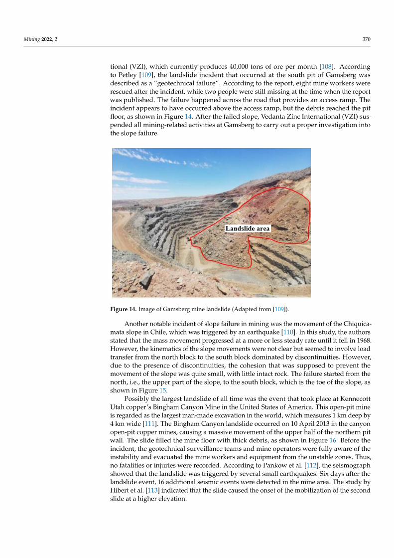
Mining 2022, 2 370
tional (VZI), which currently produces 40,000 tons of ore per month [108]. Accordingto Petley [109], the landslide incident that occurred at the south pit of Gamsberg wasdescribed as a “geotechnical failure”. According to the report, eight mine workers wererescued after the incident, while two people were still missing at the time when the reportwas published. The failure happened across the road that provides an access ramp. Theincident appears to have occurred above the access ramp, but the debris reached the pitfloor, as shown in Figure 14. After the failed slope, Vedanta Zinc International (VZI) sus-pended all mining-related activities at Gamsberg to carry out a proper investigation intothe slope failure.
Mining 2022, 2, FOR PEER REVIEW 22
Figure 14. Image of Gamsberg mine landslide (Adapted from [110]).
Another notable incident of slope failure in mining was the movement of the Chiquicamata slope in Chile, which was triggered by an earthquake [111]. In this study, the authors stated that the mass movement progressed at a more or less steady rate until it fell in 1968. However, the kinematics of the slope movements were not clear but seemed to involve load transfer from the north block to the south block dominated by discontinu-ities. However, due to the presence of discontinuities, the cohesion that was supposed to prevent the movement of the slope was quite small, with little intact rock. The failure started from the north, i.e., the upper part of the slope, to the south block, which is the toe of the slope, as shown in Figure 15.
Figure 15. A large scale image of some portion of Chiquicamata slope (Adapted from [1]).
Possibly the largest landslide of all time was the event that took place at Kennecott Utah copper’s Bingham Canyon Mine in the United States of America. This open-pit mine is regarded as the largest man-made excavation in the world, which measures 1 km deep
Figure 14. Image of Gamsberg mine landslide (Adapted from [109]).
Another notable incident of slope failure in mining was the movement of the Chiquica-mata slope in Chile, which was triggered by an earthquake [110]. In this study, the authorsstated that the mass movement progressed at a more or less steady rate until it fell in 1968.However, the kinematics of the slope movements were not clear but seemed to involve loadtransfer from the north block to the south block dominated by discontinuities. However,due to the presence of discontinuities, the cohesion that was supposed to prevent themovement of the slope was quite small, with little intact rock. The failure started from thenorth, i.e., the upper part of the slope, to the south block, which is the toe of the slope, asshown in Figure 15.
Possibly the largest landslide of all time was the event that took place at KennecottUtah copper’s Bingham Canyon Mine in the United States of America. This open-pit mineis regarded as the largest man-made excavation in the world, which measures 1 km deep by4 km wide [111]. The Bingham Canyon landslide occurred on 10 April 2013 in the canyonopen-pit copper mines, causing a massive movement of the upper half of the northern pitwall. The slide filled the mine floor with thick debris, as shown in Figure 16. Before theincident, the geotechnical surveillance teams and mine operators were fully aware of theinstability and evacuated the mine workers and equipment from the unstable zones. Thus,no fatalities or injuries were recorded. According to Pankow et al. [112], the seismographshowed that the landslide was triggered by several small earthquakes. Six days after thelandslide event, 16 additional seismic events were detected in the mine area. The study byHibert et al. [113] indicated that the slide caused the onset of the mobilization of the secondslide at a higher elevation.
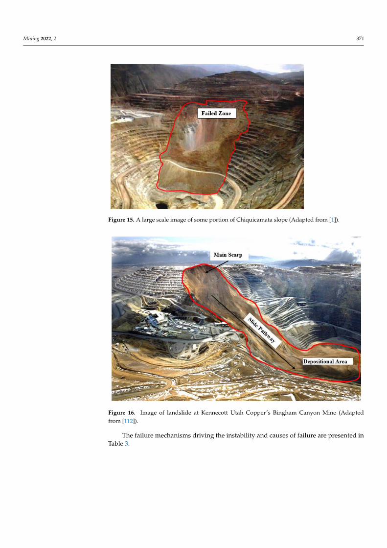
Mining 2022, 2 371
Mining 2022, 2, FOR PEER REVIEW 22
Figure 14. Image of Gamsberg mine landslide (Adapted from [110]).
Another notable incident of slope failure in mining was the movement of the Chiquicamata slope in Chile, which was triggered by an earthquake [111]. In this study, the authors stated that the mass movement progressed at a more or less steady rate until it fell in 1968. However, the kinematics of the slope movements were not clear but seemed to involve load transfer from the north block to the south block dominated by discontinu-ities. However, due to the presence of discontinuities, the cohesion that was supposed to prevent the movement of the slope was quite small, with little intact rock. The failure started from the north, i.e., the upper part of the slope, to the south block, which is the toe of the slope, as shown in Figure 15.
Figure 15. A large scale image of some portion of Chiquicamata slope (Adapted from [1]).
Possibly the largest landslide of all time was the event that took place at Kennecott Utah copper’s Bingham Canyon Mine in the United States of America. This open-pit mine is regarded as the largest man-made excavation in the world, which measures 1 km deep
Figure 15. A large scale image of some portion of Chiquicamata slope (Adapted from [1]).
Mining 2022, 2, FOR PEER REVIEW 23
by 4 km wide [112]. The Bingham Canyon landslide occurred on 10 April 2013 in the can-yon open-pit copper mines, causing a massive movement of the upper half of the northern pit wall. The slide filled the mine floor with thick debris, as shown in Figure 16. Before the incident, the geotechnical surveillance teams and mine operators were fully aware of the instability and evacuated the mine workers and equipment from the unstable zones. Thus, no fatalities or injuries were recorded. According to Pankow et al [113], the seismograph showed that the landslide was triggered by several small earthquakes. Six days after the landslide event, 16 additional seismic events were detected in the mine area. The study by Hibert et al [114] indicated that the slide caused the onset of the mobilization of the second slide at a higher elevation.
Figure 16. Image of landslide at Kennecott Utah Copper’s Bingham Canyon Mine (Adapted from [113]).
The failure mechanisms driving the instability and causes of failure are presented in Table 3.
Table 3. List of failed mine slopes.
Country Location Names of Mining
Company Mode of Failure Causes of Failure Sources
Botswana Central District Letlhakane mine Toppling Presence of tension crack
formation, crack widening and extension
i
Canada
British Columbia Afton Mine Wedge,
Toppling and circular failure
Multiple failures occurred as a result of intersection of
discontinuities j, r, a
British Columbia Brenda Mine Toppling Intersection of joint sets q, a, j
British Columbia Cassiar Mine Toppling Presence of shear zones, faults
and sets of discontinuities j, k
British Columbia Highland Valley
Copper Toppling
Steeply dipping joints, increase in groundwater
pressure and melting of snow t
Figure 16. Image of landslide at Kennecott Utah Copper’s Bingham Canyon Mine (Adaptedfrom [112]).
The failure mechanisms driving the instability and causes of failure are presented inTable 3.

Mining 2022, 2 372
Table 3. List of failed mine slopes.
Country Location Names of Mining Company Mode of Failure Causes of Failure Sources
Botswana Central District Letlhakane mine Toppling Presence of tension crack formation, crackwidening and extension i
Canada
British Columbia Afton Mine Wedge, Toppling and circularfailure
Multiple failures occurred as a result ofintersection of discontinuities j, r, a
British Columbia Brenda Mine Toppling Intersection of joint sets q, a, j
British Columbia Cassiar Mine Toppling Presence of shear zones, faults and setsof discontinuities j, k
British Columbia Highland Valley Copper Toppling Steeply dipping joints, increase ingroundwater pressure and melting of snow t
British Columbia Lonex Pit at Highland valley Toppling Groundwater condition, Steeplydipping faults o
British Columbia Highmont Planar Structural discontinuities, precipitation, runoff, poor quality and low strength rock mass o
Vancouver Island Copper Wedge and Toppling Large fault zone passing through a weakerrock mass l
Quebec Jeffrey Mine, Asbestos Wedge and Planar Intersection of several thick shear zones andsmaller scale discontinuities t, c
British Columbia Nickel Plate Mine Wedge Steeply dipping joint sets and faults t
China
Mongolia Changshanhao open-pit Wedge and Toppling Presence of faults and joints s
Shazhenxi Qianjiangping Planar Increase in water level, poor geologicalstructure and continuous rainfall h
Norway Hange i Dalane Tellness Dagbrudd Wedge Heavy rainfall n
Mexico Calama, Antofagasta Chiquicamata Toppling Presence of fault zones f, p
Spain Seville Aznacollar Mine Complex Presence of tension cracks, Heavy rainfall,groundwater pressure g
Sweden Kiruna Kirunavaara Rotational Presence of tension cracks u

Mining 2022, 2 373
Table 3. Cont.
Country Location Names of Mining Company Mode of Failure Causes of Failure Sources
United States of America
Utah Bingham Canyon Mine Rotational, Planar Rise in water table, fractured rock mass withminor joints and larger fault structure t, v
Nevada Carlin Trend NA Presence of wider fault zones andclay infillings v
Arizona Cyprus Bagdad and Sierrita Toppling Presence of steeply joint sets j
Nevada Liberty Pit Wedge Intersection of joint sets c
Nevada Veteran—Tripp Pit Wedge Intersection of faults, presence of clay gougein fault zones m
Nevada Kimbley pit Wedge Presence of flat sipping fault, Highwater pressure b
Arizona Twin Butes Toppling Numerous faults and several joints c
South AfricaLimpopo Palabora Mine Wedge Presence of faults and set of joints t, d
Mokopane Sandsloot open pit Planar and Wedge Presence of set of joints e
Zambia Chingola Nchanga Open Pit Wedge Intersection of joint sets, abnormallyrainfall, weathering u
Source codes: a: Blackwell and Calder [114]; b: Blake [115]; c: Brawner [116]); d: Brummer et al. [117]; e: Bye [118]; f: Call et al. [119]; g: Golder Associates UK Ltd [120]; h: Jian et al. [121];i: Kayesa [122]; j: Martin [123]; k: Martin and Mehr [124]; l: Mathis et al. [125]; m: Miller [126]; n: Nilsen and Hagen [127], o: Newcomen and Martin [128]; p: Rapiman [129]; q: Pritchardand Savigny [130]; r: Reid and Stewart [131]; s: Ren et al. [132]; t: Stacey [133]; u: Sjoberg [54]; v: Zavodni and Mccarter [134].
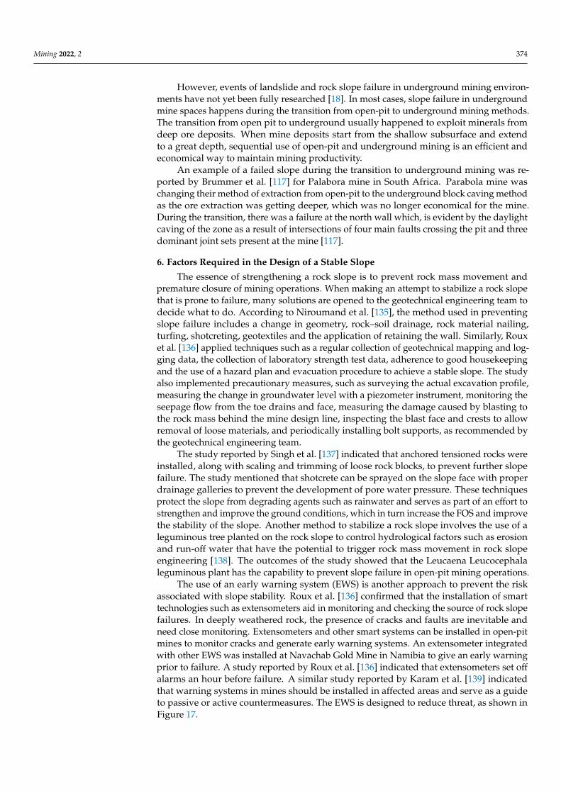
Mining 2022, 2 374
However, events of landslide and rock slope failure in underground mining environ-ments have not yet been fully researched [18]. In most cases, slope failure in undergroundmine spaces happens during the transition from open-pit to underground mining methods.The transition from open pit to underground usually happened to exploit minerals fromdeep ore deposits. When mine deposits start from the shallow subsurface and extendto a great depth, sequential use of open-pit and underground mining is an efficient andeconomical way to maintain mining productivity.
An example of a failed slope during the transition to underground mining was re-ported by Brummer et al. [117] for Palabora mine in South Africa. Parabola mine waschanging their method of extraction from open-pit to the underground block caving methodas the ore extraction was getting deeper, which was no longer economical for the mine.During the transition, there was a failure at the north wall which, is evident by the daylightcaving of the zone as a result of intersections of four main faults crossing the pit and threedominant joint sets present at the mine [117].
6. Factors Required in the Design of a Stable Slope
The essence of strengthening a rock slope is to prevent rock mass movement andpremature closure of mining operations. When making an attempt to stabilize a rock slopethat is prone to failure, many solutions are opened to the geotechnical engineering team todecide what to do. According to Niroumand et al. [135], the method used in preventingslope failure includes a change in geometry, rock–soil drainage, rock material nailing,turfing, shotcreting, geotextiles and the application of retaining the wall. Similarly, Rouxet al. [136] applied techniques such as a regular collection of geotechnical mapping and log-ging data, the collection of laboratory strength test data, adherence to good housekeepingand the use of a hazard plan and evacuation procedure to achieve a stable slope. The studyalso implemented precautionary measures, such as surveying the actual excavation profile,measuring the change in groundwater level with a piezometer instrument, monitoring theseepage flow from the toe drains and face, measuring the damage caused by blasting tothe rock mass behind the mine design line, inspecting the blast face and crests to allowremoval of loose materials, and periodically installing bolt supports, as recommended bythe geotechnical engineering team.
The study reported by Singh et al. [137] indicated that anchored tensioned rocks wereinstalled, along with scaling and trimming of loose rock blocks, to prevent further slopefailure. The study mentioned that shotcrete can be sprayed on the slope face with properdrainage galleries to prevent the development of pore water pressure. These techniquesprotect the slope from degrading agents such as rainwater and serves as part of an effort tostrengthen and improve the ground conditions, which in turn increase the FOS and improvethe stability of the slope. Another method to stabilize a rock slope involves the use of aleguminous tree planted on the rock slope to control hydrological factors such as erosionand run-off water that have the potential to trigger rock mass movement in rock slopeengineering [138]. The outcomes of the study showed that the Leucaena Leucocephalaleguminous plant has the capability to prevent slope failure in open-pit mining operations.
The use of an early warning system (EWS) is another approach to prevent the riskassociated with slope stability. Roux et al. [136] confirmed that the installation of smarttechnologies such as extensometers aid in monitoring and checking the source of rock slopefailures. In deeply weathered rock, the presence of cracks and faults are inevitable andneed close monitoring. Extensometers and other smart systems can be installed in open-pitmines to monitor cracks and generate early warning systems. An extensometer integratedwith other EWS was installed at Navachab Gold Mine in Namibia to give an early warningprior to failure. A study reported by Roux et al. [136] indicated that extensometers set offalarms an hour before failure. A similar study reported by Karam et al. [139] indicatedthat warning systems in mines should be installed in affected areas and serve as a guideto passive or active countermeasures. The EWS is designed to reduce threat, as shown inFigure 17.
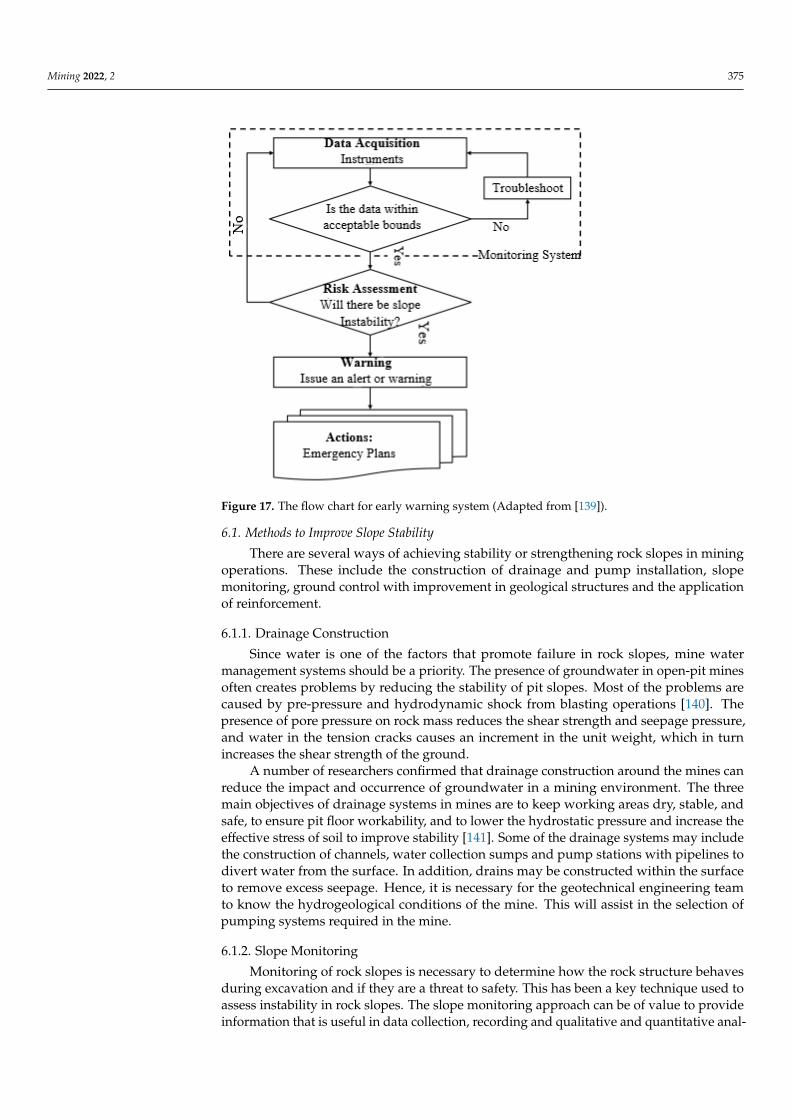
Mining 2022, 2 375
Mining 2022, 2, FOR PEER REVIEW 26
serve as a guide to passive or active countermeasures. The EWS is designed to reduce threat, as shown in Figure 17.
Figure 17. The flow chart for early warning system (Adapted from [140]).
6.1. Methods to Improve Slope Stability There are several ways of achieving stability or strengthening rock slopes in mining
operations. These include the construction of drainage and pump installation, slope mon-itoring, ground control with improvement in geological structures and the application of reinforcement.
6.1.1. Drainage Construction Since water is one of the factors that promote failure in rock slopes, mine water man-
agement systems should be a priority. The presence of groundwater in open-pit mines often creates problems by reducing the stability of pit slopes. Most of the problems are caused by pre-pressure and hydrodynamic shock from blasting operations [141]. The presence of pore pressure on rock mass reduces the shear strength and seepage pressure, and water in the tension cracks causes an increment in the unit weight, which in turn increases the shear strength of the ground.
A number of researchers confirmed that drainage construction around the mines can reduce the impact and occurrence of groundwater in a mining environment. The three main objectives of drainage systems in mines are to keep working areas dry, stable, and safe, to ensure pit floor workability, and to lower the hydrostatic pressure and increase the effective stress of soil to improve stability [142]. Some of the drainage systems may include the construction of channels, water collection sumps and pump stations with pipelines to divert water from the surface. In addition, drains may be constructed within the surface to remove excess seepage. Hence, it is necessary for the geotechnical engineer-ing team to know the hydrogeological conditions of the mine. This will assist in the selec-tion of pumping systems required in the mine.
Figure 17. The flow chart for early warning system (Adapted from [139]).
6.1. Methods to Improve Slope Stability
There are several ways of achieving stability or strengthening rock slopes in miningoperations. These include the construction of drainage and pump installation, slopemonitoring, ground control with improvement in geological structures and the applicationof reinforcement.
6.1.1. Drainage Construction
Since water is one of the factors that promote failure in rock slopes, mine watermanagement systems should be a priority. The presence of groundwater in open-pit minesoften creates problems by reducing the stability of pit slopes. Most of the problems arecaused by pre-pressure and hydrodynamic shock from blasting operations [140]. Thepresence of pore pressure on rock mass reduces the shear strength and seepage pressure,and water in the tension cracks causes an increment in the unit weight, which in turnincreases the shear strength of the ground.
A number of researchers confirmed that drainage construction around the mines canreduce the impact and occurrence of groundwater in a mining environment. The threemain objectives of drainage systems in mines are to keep working areas dry, stable, andsafe, to ensure pit floor workability, and to lower the hydrostatic pressure and increase theeffective stress of soil to improve stability [141]. Some of the drainage systems may includethe construction of channels, water collection sumps and pump stations with pipelines todivert water from the surface. In addition, drains may be constructed within the surfaceto remove excess seepage. Hence, it is necessary for the geotechnical engineering teamto know the hydrogeological conditions of the mine. This will assist in the selection ofpumping systems required in the mine.
6.1.2. Slope Monitoring
Monitoring of rock slopes is necessary to determine how the rock structure behavesduring excavation and if they are a threat to safety. This has been a key technique used toassess instability in rock slopes. The slope monitoring approach can be of value to provideinformation that is useful in data collection, recording and qualitative and quantitative anal-
Mining 2022, 2 376
ysis. The effectiveness of any monitoring system depends on the ability to give warningsbefore rock mass movement or failure takes place [142] Traditionally, there are geotechnicalinstrumentations (piezometers, crack meters, tiltmeters, borehole extensometers, and stressmeters) available for the monitoring of slopes in mining and civil engineering. Despitethe contribution of these instruments in the monitoring of rock instabilities, they also havesome limitations.
Over the years, there have been improvements in geotechnical monitoring instrumen-tations, which include the use of remote-sensed technological tools. These instrumentsare commercially available to monitor rock mass movement in a mining environment andare cost-effective. Examples of these are the integration of synthetic aperture radar (SAR)with optical images and interferometric SAR (InSAR), which are currently being used tocharacterize instabilities in slopes. Advancement in remote sensing technology systemshas brought about differential synthetic aperture radar (DInSAR) with high-resolutionimage processing, which is also being used to monitor instabilities. Similarly, there is aground-based radar monitoring instrument known as linear SAR (LISA), which is capableof assessing the deformation of an unstable area in slopes that are characterized by highradar reflectivity [139]. Other advanced geotechnical monitoring instruments are lightdetection and ranging (LiDAR) and optical satellite images.
6.1.3. Ground Improvement with Enhancement of Geological Structures
The interpretation of the data acquired during site investigation provides informationabout the structure of the rock mass, strength of the rocks, planes of weakness, and the rangeof their strengths. This will provide adequate information on the relationship between slopeparameters, such as the spatial relationship, face inclination of the rock, and geometricaldimensions of each of the individual elements of a particular sector of the mine shell, suchas ramp and geotechnical berm width, bench spill berm width, individual slope height,and slope angle, slope bench, etc.
Apart from the design parameters, the geotechnical engineering team must be familiarwith the geology of the mine, i.e., the discontinuities and engineering properties of therock mass that can influence the stability of the slope. Karama et al. [139] argued thatgravitational load is the most important load affecting the stability of the mine and, notably,the shear strength of the ground, which confers major resistance to failure. To preventfurther damage of the rock mass, the shear strength of the ground must be enhancedto strengthen and protect the ground. This strengthening can be completed with theapplication of backfill, rapid yielding properties, the construction of a retaining wall, thespraying of shotcrete, and application of reticulated micropiles.
6.1.4. Installation of Reinforcement Units
The application of reinforcement in rock slope is a viable approach to increase thestability of unstable slopes. The installation of various support systems increases the shearstrength of rocks and reduces sliding effects along the slip surface [143]. The essence ofreinforcement in weathered rock or soil is to stiffen the base and to reduce shear stressmagnitudes. The two most commonly used support systems in rock slope and slopeengineering measures are rock bolt fame and anchor cable fame [144]. These reinforcementtools have proven to be effective in resisting the shear stress in rock mass deformationby transferring the load to the bounded rock so that resistance is provided by the rockto balance the deformation. During the installation of bolts, the effects of the inclinationangle of bolts must be defined by the designer of the slope for effective reinforcement.According to Sazzad et al. [145], the FOS of slopes increases with an increase in the angle ofinclination. However, the FOS value depends on the overall angle of the slope. Therefore,the relationship between the slope angle and inclination angle for a maximum FOS shouldbe enhanced, i.e., the positioning of the bolts is a key factor in reinforcement design. Inaddition, when installing a bolt to resist dip bedding slope, the failure mechanism andprocess occurring in such slope need to be considered. A great number of researchers have
Mining 2022, 2 377
acknowledged the effectiveness of bolts as reinforcement tools in controlling the movementof discontinuous layers that are subjected to shearing. The installation of rock bolts inunstable zones can be regarded as one of the major techniques used to improve and controlthe unstable ground in open-pit mines.
6.2. Role of Artificial Intelligence in the Management of Slope Failure As a Reflection on theCurrent State of the Art
The monitoring and evaluation of slope stability in mining operations is a crucialnecessity to avoid potential damage to both the personnel safety and financial base ofmining companies. Despite the effort to reduce slope failure, the geotechnical phenomenonis known to be complex, comprising numerous factors such as ground conditions, geo-logical activities and human actions, which make the prediction of slope failure challeng-ing [146,147]. More so, these factors are dynamic and ever-changing, making it cumbersometo continuously measure them. However, the invention of artificial intelligence (AI) hasgreatly aided engineers in forecasting possible slope failure using detailed analysis ratherthan solely relying on phenomenological models [148].
The study by Kothari and Momayez [148] compared the prediction performance ofinverse velocity (IV) and the artificial neural network (ANN) model to forecast slope failureof an open-cast mine. Twenty-two datasets were collected using radar equipment, andwe developed a double-layered feed-forward ANN in the MATLAB environment. Theoutput from the study indicated that ANN prediction was 86% accurate compared to IV. Atotal of 82% of the slope failure predictions indicated that the slopes were safe, while 18%indicated that the slopes were unsafe. The unsafe predictions were approximated within5 min before actual failure, proving that the ANN model gave a safer prediction comparedto IV. Another study by Chebrolu et al. [149] utilized 46 datasets (23 obtained from wetslopes and 23 obtained from dry slopes) to predict the FOS of a slope using multi-genegenetic programming (MGGP) and multi-adaptive regression spline (MARS). Thirty-twodatasets were used in training the models, and fourteen datasets were used in testingthe models. Despite both models proving to have an accurate prediction, MGGP has abetter prediction performance, with R-values of 84.38% in training and 85.71% in testing,compared to MARS with R-values of 81.25% in training and 85.71% in testing.
To establish an accurate prediction model for determining the slope failure of a minein Vietnam, a study by Bui et al. [146] integrated the M5-rule and genetic algorithms todevelop a novel prediction model that was then compared with conventional AI models,including ANN, support vector regression (SVR), the firefly algorithm (FFA), the imperialistcompetitive algorithm (ICA), artificial bee colony (ABC), and the genetic algorithm (GA).This study utilized bench height, soil unit weight, cohesion, angle of internal friction,and slope angles as input parameters to forecast the factor of safety against failure. Theresults of this study indicated that prediction performance from the M5-rules GA modelgave the best accuracy due to its enhanced optimization prowess. Another study by Duet al. [150] utilized a ground-based interferometric radar (GB-SAR) to record 150 datasets inthe Anjialing open-pit coalmine of China. Twelve input parameters (slope shape coefficient,deformation rate, reverse deformation rate, deformation amplitude, rainfall, temperature,atmospheric pressure, relative humidity, wind speed and direction, and groundwatertemperature and level) and one output variable (deformation) were used to develop fiveprediction models. These models included backpropagation, NN, support vector machine(SVM), recurrent neural network (RNN), adaptive neural fuzzy inference system (ANFIS),and relevant vector machine (RVM). From this result, it was evident that not all models canbe reliable in the prediction of slope failure due to high error values. The error values foreach model were 4.122 mm for BPNN, 3.612 mm for SVM, 1.660 for ANFIS, 0.578 mm forRNN, and 0.442 mm for RVM. RVM had the lowest root-mean-square error value (RMSE)of 2.64, while BPNN had the highest RSME value of 4.58.
In addition, a study by Ferentinou and Fakir [151] developed a BP-NN model using141 databases obtained from worldwide cases of surface mines and eighteen (18) input

Mining 2022, 2 378
variables, including environmental factors, rock quality, rock mass characteristics, rockstresses, hydraulic profile, presence of geological features, dimensions of slopes, blastdesign and previous instability occurrence. This study established slope stability indices,where all slopes were examined to predict failure. The results obtained indicated a meansquare error value of 0.0001 converging at 98%, proposing the utilization of BP-ANN as areliable tool to predict slope failure in feasibility studies. To evaluate and monitor the slopestability of open-cast mines, Luo et al. [147] developed a particle swarm optimization-cubistalgorithm (PSO-CA) to forecast the factor of safety of a Vietnamese mine. This model usedfive input variables, including bench height, angle of slope and internal friction, cohesioncoefficient, and specific weight of the material. The output from this model was thencompared with the output obtained from the prediction of the same variables using SVM,classification and regression tree (CART), and k-nearest neighbor. Performance comparisonof the models inferred that PSO-CA had the lowest error values (mean absolute error (MAE)of 0.009 and root mean square error (RMSE) of 0.025 and a high correlation coefficientR-value of 0.981. The SVM, CART, and k-NN produced poor prediction performance withMAE values of 0.014 to 0.038, RMSE 0.030–0.056, and R 0.917–0.974.
The reported studies that have utilized AI in determining factors of safety in mineshave proven to be efficient and effective in accurately forecasting slope failure before thehazard occurs. Moreover, the models are endowed with the ability to handle large amountsof data at a given time and execute predictions at a high rate compared to conventionalstability analysis techniques. The models are designed using various factors known toaffect slope stability in order to map out FOS. Various AI models have been used to predictslope failure in mines, but limited studies have been conducted to compare and validatethe most accurate model for such a task. Therefore, in order to establish the most robust,versatile, and reliable model, more comparative studies need to be conducted to improveprediction performance.
7. Concluding Remarks
Stability analysis of slopes in open-pit mines and quarries is extremely importantfrom both economic and safety points of view. The effect of unstable ground cannotbe over-emphasized as it may lead to the temporary or permanent closure of the minedepending on the level of damage. Instabilities usually occur where there is a presenceof geological discontinuities such as fractures, cracks, faults, unfavorably oriented bed-ding planes, etc. Rock slope failures are triggered when the shear stress exceeds the shearstrength of the rock mass. Several factors, such as geometry of the slope, groundwatercondition of the rock, lithology, geological structures, cohesion and angle of internal fric-tion, effect of blasting, mining method and equipment selection, have been declared toinfluence the failure of rocks. The effects of all these factors must be considered duringthe planning and designing stage of the mine, not only that these factors have effects onthe design, but that they also influence the engineering judgement on the stability of theslope. Several techniques, such as construction of drainages, slope monitoring, applicationof reinforcement and improvement of geological structures, have been used over the yearsto improve and maintain the stability of the rock slope.
Advancements in technology have brought about improvement in slope monitoringtechniques and provide an understanding of slope dynamics through the assessment ofstability over time. The accurate prediction of slope failure is an important task in activeopen-pit mines in order to avoid slope failure so as to prevent injury to personnel anddamage to machinery. When determining the stability of a slope, it is imperative to assessthe factors affecting slope stability. Different studies have used different AI models withvarious input variables to predict slope failure in mining. These studies have reported theprowess of AI models as being fast, reliable in mapping out FOS and sturdy to handle largeamounts of data at a given time. Despite the usage of such a model, there is a need forcomparing the output of various AI models in order to determine the most accurate modelfor forecasting slope stability. In addition, various elements known to affect slope stability

Mining 2022, 2 379
should be captured and used as input variables to forecast slope stability and compareperformance of different AI models.
Author Contributions: Original manuscript writing, review and editing, P.K.; ManuscriptAdministration, G.O.O.; Review and Manuscript Editing, K.O.S.; Manuscript Administration, A.I.L.;Conceptualization and Manuscript Draft, M.O.; Manuscript Editing, P.M. All authors have read andagreed to the published version of the manuscript.
Funding: This research received no external funding.
Conflicts of Interest: The authors declare no conflict of interest.
References1. Naghadehi, M.; Jimenez, R.; Khalokakaie, R.; Jalali, S.-M. A probabilistic systems methodology to analyze the importance of
factors affecting the stability of rock slopes. Eng. Geol. 2011, 118, 82–92. [CrossRef]2. Ghobadi, M. Engineering Geological Factors Influencing the Stability of Slope in the Illawarra Region. Ph.D. Thesis, University of
Wollongong, Wollongong, Australia, 1994; p. 1.3. Gao, W.; Dai, S.; Xiao, T.; He, T. Failure process of rock slopes with cracks based on the fracture mechanics. Eng. Geol. 2017,
231, 190–199. [CrossRef]4. Sha, L. Analysis of slope instability factors and protection. Int. J. Multidiscip. Res. Dev. 2016, 3, 181–182.5. Simataa, E. Investigating Slope Stability in Open Pit Mine—A Case Study of the Phyllites Wall at Sentinel Pit; The University of
Witwatersrand: Johannesburg, South Africa, 2019.6. Raghuvanshi, T. Plane failure in rock slopes—A review on stability analysis techniques. J. King Saud Univ. Sci. 2019, 31, 101–109.
[CrossRef]7. Wang, X.; Niu, R. Spatial forecast of landslides in three gorges based on spatial. Sensors 2009, 9, 2035–2061. [CrossRef] [PubMed]8. Chiwaye, H. A Comparison of the Limit Equilibrium and Numerical Modelling Approaches to Risk Analysis for Open Pit
Mine Slopes. Ph.D. Thesis, Faculty of Engineering and the Built Environment, University of the Witwatersrand, Johannesburg,South Africa, 2010.
9. Nicholas, D.E.; Sims, D.B. Collecting and Using Geological Structure Data for Slope Design; Hustrulid, W.A., McCarter, M.K.,Van Zyl, D.J.A., Eds.; Society for Mining, Metallurgy, and Exploration: Golden, CO, USA, 2000.
10. Hustrulid, W.A.; McCarter, M.K.; Van Zyl, D.J.A. Slope Stability in Surface Mining; Society for Mining, Metallurgy, and Exploration:Littleton, CO, USA, 2000; pp. 81–88.
11. Read, J.; Stacey, P. Guidelines for Open Pit Slope Design, 1st ed.; CSIRO: Canberra, Australia, 2009.12. Eberhardt, E. Rock Slope Stability Analysis—Utilization of Advanced Numerical Techniques; Earth and Ocean Sciences at UBC Report;
University of British Columbia (UBC): Vancouver, BC, Canada, 2003.13. Stacey, T.R.; Swart, A.H. Booklet Practical Rock Engineering Practice for Shallow and Opencast Mines; The Safety in Mines Research
Advisory Committee (SIMRAC): Johannesburg, South Africa, 2001.14. Suman, S. Slope Stability Analysis Using Numerical Modelling; B.Tech Report; National Institute of Technology: Rourkela, India, 2015.15. Abramson, L. Slope Stability and Stabilization Methods, 2nd ed.; Wiley: New York, NY, USA, 2002.16. Eberhardt, E.; Stead, D.; Coggan, J.S. Numerical analysis of initiation and progressive failure in natural rock slopes. Int. J. Rock
Mech. Min. Sci. 2004, 41, 69–87. [CrossRef]17. Johansson, J. Impact of Water-Level Variations on Slope Stability; Luleå University of Technology: Luleå, Sweden, 2014.18. Zhu, J.; Xue, Y.; Tao, Y.; Zhang, K.; Li, Z.; Zhang, X.; Yang, Y. The Numerical Simulation on the Stability of Steep Rock Slope by
DDA. Bydgoszcz, Poland. AIP Conf. Proc. 2017, 1839, 020134.19. Hoek, E.; Read, J.; Karzulovic, A.; Chen, Z.Y. Rock slopes in Civil and Mining Engineering. In Proceedings of the International
Conference on Geotechnical and Geological Engineering, GeoEng, Melbourne, Australia, 19–24 November 2000.20. Li, A.J.; Cassidy, M.J.; Wanga, Y.; Merifield, R.S.; Lyamin, A.V. Parametric Monte Carlo studies of rock slopes based on the
Hoek–Brown failure criterion. Comput. Geotech. 2012, 45, 11–18. [CrossRef]21. Duncan, J.; Wright, S.; Brandon, T. Soil Strength and Slope Stability, 2nd ed.; John Wiley & Sons: Hoboken, NJ, USA, 2005.22. Fleurisson, J.-A.; Cojean, R. Error Reduction in Slope Stability Assessment; MINES ParisTech: Paris, France, 2014.23. Stacey, T.R. Mechanics and Design of Major Rock Slopes, Lecture Note; The University of Witwatersrand: Johannesburg, South Africa,
2018; unpublished.24. Gundewar, C. Application of Rock Mechanics In surface and Underground Mining; Indian Bureau of Mines: Nagpur, Maharashtra,
India, 2014; pp. 62–66.25. Valdivia, C.; Lorig, L. Slope stability at Escondida mine. In Slope Stability in Surface Mining; Hustrulid, M., Zyl, V., Eds.; SME:
Golden, CO, USA, 2000; pp. 153–162.26. Ceryan, N.; Kesimal, A.; Ceryan, S. Probabilistic Analysis Applied to Rock Slope Stability: A Case Study from Northeast Turkey.
In Integrating Disaster Science and Management; Samui, P., Kim, D., Ghosh, C., Eds.; Elsevier: Amsterdam, The Netherlands, 2018;pp. 221–261.
Mining 2022, 2 380
27. Corkum, A.; Martin, C. Analysis of a rockslide stabilized with a toe-berm: A case study in British Columbia, Canada. Int. J. RockMech. Min. Sci. 2004, 41, 1109–1121. [CrossRef]
28. Chiwaye, H.; Stacey, T. A comparison of limit equilibrium and numerical modelling approaches to risk analysis for open pitmining. S. Afr. Inst. Min. Metall. 2010, 110, 571–580.
29. Stead, D.; Eberhardt, E.; Coggan, J. Developments in the characterization of complex rock slope deformation and failure usingnumerical modelling techniques. Eng. Geol. 2006, 83, 217–235. [CrossRef]
30. Fredj, M.; Hafsaoui, A.; Boukarm, R.; Nakache, R.; Saardoum, A. Numerical Modelling of Slope Stability in Open Pit Phosphate.Prague, Czech, World Multidisciplinary Earth Sciences Symposium (WMESS). IOP Conf. Ser. Earth Environ. Sci. 2018, 221, 012020.[CrossRef]
31. Griffiths, D.; Lane, P. Slope stability analysis by finite elements. Geotechnique 1999, 49, 387–403. [CrossRef]32. Hammah, R.; Yacoub, T.; Corkum, B. The Shear Strength Reduction Method for the Generalized Hoek-Brown Criterion; American Rock
Mechanics Association (ARMA): Anchorage, AK, USA, 2005.33. Alzo’ubi, A. Rock slopes processes and recommended methods for analysis. Int. J. Geomate 2016, 11, 2520–2527. [CrossRef]34. Tang, X.-T.; Li, D.-Q.; Rong, G.; Phoon, K.-K. Zhou Impact of copula selection on geotechnical reliability under incomplete
probability information. Comput. Geotech. 2013, 49, 264–278. [CrossRef]35. Lei, Q.; Latham, J.-P.; Tsang, C.-F. The use of discrete fracture networks for modelling coupled geomechanical and hydrological
behaviour of fractured rocks. Comput. Geotech. 2017, 85, 151–176. [CrossRef]36. Ahmad, F.; Tang, X.-W.-N.; Wróblewski, P.; Ahmad, M. Prediction of slope stability using Tree ugmented Naive-Bayes classifier:
Modeling and performance evaluation. Math. Biosci. Eng. 2022, 19, 4526–4546. [CrossRef]37. Haghshenas, S.S.; Haghshenas, S.S.; Geem, Z.W.; Kim, T.H.; Mikaeil, R.; Pugliese, L.; Troncone, A. Application of Harmony Search
Algorithm to Slope Stability Analysis. Land 2021, 10, 1250. [CrossRef]38. Huang, L.; Liu, F.; Dong, V. Geotechnical Slope Protection Model Based on Genetic Algorithm. Nat. Environ. Pollut. Technol. 2019,
18, 1509–1513.39. Figueiredo, L.; Barros, M.; Hammah, R.; Santos, Y.; Souza, T.; Nogueira, C. Case Study: Open Pit Three-Dimensional Slope Stability
Back-Analysis for an Anisotropic Iron Ore Rock Mass; Australian Centre for Geomechanics: Perth, Australia, 2021.40. Tugelbayeva, G.K. Mathematical models for numerical solution of nonstationary problems of geomechanics. AIP Conf. Proc. 2020,
2312, 050024.41. Nemirovisky, Y.V.; Tyrymov, A.A. Mathematical modeling in problems of geomechanics of layered rock massifs. AIP Conf. Proc.
2021, 2448, 020025.42. Pirklbauer, A. The influence of land use on the stability of slopes with examples from the European Alps. Mitt. Naturwiss. Ver.
Steiermark 2002, 132, 43–62.43. Wyllie, D.C.; Mah, C.W. Rock Slope Engineering: Civil and Mining, 4th ed.; Spon Press: New York, NY, USA, 2004.44. Babikar, A.; Smith, C.; Gilbert, M.; Ashbly, J. Non-associative limit analysis of the toppling-sliding failure. Int. J. Rock Mech. Min.
Sci. 2014, 71, 1–11. [CrossRef]45. Kliche, C. Rock Slope Stability; Society for Mining, Metallurgy and Exploration: Littleton, CO, USA, 1999.46. Hoek, E.; Bray, J. Rock Slope Engineering, 3rd ed.; CRC: Boca Raton, FL, USA, 1981.47. Alabideen, K.; Helal, M. Determination of the Safe Orientation and Dip of a Rock Slope in an Open Pit Mine in Syria Using
Kinematic Analysis. Al-Nahrain Univ. Coll. Eng. J. (NUCEJ) 2016, 19, 33–45.48. Goodman, R.E.; Kieffer, D.S. Behaviour of rock in slopes. J. Geotech. Geoenviron. Eng. 2000, 126, 675–684. [CrossRef]49. Hudson, J.A.; Harrison, J.P. Engineering Rock Mechanics; Elsevier: Oxford, UK, 1997; p. 444.50. Low, B.K. Reliability analysis of rock wedges. J. Geotech. Geoenviron. Eng. 1997, 123, 498–505. [CrossRef]51. Coates, D.F. Rock Mechanics Principles; Canadian Centre for Mineral and Energy Technology (CANMET): Energy, Mines, and
Resources Canada in Ottawa: Ottawa, ON, Canada, 1981; p. 410.52. Dahner-Lindqvist, C. Liggvagga Stabiliteten I Kiirunavaara. In Proceedings of the Bergmekanikdagen, Papers presented at Rock
Mechanics Meeting, Stockholm, Sweden, 19 March 1992; pp. 37–52.53. Prakash, B. Design of Stable Slope for Open Cast Mines; B.Tech Report; National Institute of Technology: Rourkela, India, 2009.54. Sjöberg, J. Analysis of Large-Scale Rock Slopes. Ph.D. Thesis, University of Technology, Luleå, Sweden, 1999.55. Sjöberg, J. Failure Mechanisms for High Slopes in Hard Rock. Colorado, Denver, USA, Slope Stability in Surface Mining; Hustrulid, M.,
Zyl, V., Eds.; Society for Mining, Metallurgy & Exploration: Englewood, CO, USA, 2000.56. Adeyeri, J. Technology and Practice in Geotechnical Engineering: Stability of Earth Masses and Slopes; IGI Global: Pennsylvania, PA,
USA, 2014; pp. 528–588.57. Guo, S.; Qi, S.; Yang, G.; Zhang, S.; Saroglou, C. An Analytical Solution for Block Toppling Failure of Rock Slopes during an
Earthquake. Appl. Sci. 2017, 7, 1008. [CrossRef]58. Chaulya, S.; Prasad, G. Slope Failure Mechanism and Monitoring Techniques. In Sensing and Monitoring Technologies for Mines and
Hazardous Areas: Monitoring and Prediction Technologies; Elsevier: Amsterdam, The Netherlands, 2016; pp. 1–86.59. Chakraborty, A.; Goswami, D. State of the art: Three-Dimensional (3D) Slope-Stability Analysis. Int. J. Geotech. Eng. 2016,
10, 493–498. [CrossRef]60. Wines, D. A comparison of slope stability analyses in two and three dimensions. J. South. Afr. Inst. Min. Metall. 2016, 116, 399–406.
[CrossRef]
Mining 2022, 2 381
61. Totonchi, A.; Askari, F.; Farzaneh, O. 3D stability analysis of concave slopes in plan view using linear finite element and lowerbound method. Iran. J. Sci. Technol. Trans. Civ. Eng. 2012, 36, 181–194.
62. Cala, M. Convex and concave slope stability analyses with numerical methods. Arch. Min. Sci. 2007, 52, 75–89.63. Zhang, Y.; Chen, G.; Zheng, L.; Li, Y.; Zhuang, X. Effects of geometries on three-dimensional slope stability. Can. Geotech. J. 2013,
50, 233–249. [CrossRef]64. Dana, H.; Kakaie, R.; Rafiee, R.; Bafghi, A. Effects of geometrical and geomechanical properties on slope stability of open-pit
mines using 2D and 3D finite difference methods. J. Min. Environ. 2018, 9, 941–957.65. Keykha, H.; Huat, B.; Asadi, A.; Moayedi, H. The effect of discontinuities on stability of rock blocks in tunnel. Int. J. Phys. Sci.
2011, 6, 7132–7138.66. Liu, S.; Huang, X.; Zhou, X.; Hu, J.; Wang, W. Soil-Rock Slope Stability Analysis by Considering the Nonuniformity of Rocks.
Math. Probl. Eng. 2018, 2018, 3121604. [CrossRef]67. Kolapo, P.; Munemo, P. Investigating the correlations between point load strength index, uniaxial compressive strength and
Brazilian tensile strength of sandstones. A case study of QwaQwa sandstone deposit. Int. J. Min. Miner. Eng. 2021, 12, 67–83.[CrossRef]
68. Brian, D.; Greg, M. Rockfall triggering by cyclic thermal stressing of exfoliation fractures. Nat. Geosci. 2016, 9, 395–400.69. Cravero, M.; Labichino, G. Analysis of the flexural failure of an overhanging rock slab. Int. J. Rock Mechanics Min. Sci. 2004,
41 (Suppl. S1), 605–610. [CrossRef]70. Borrelli, L.; Greco, R.; Gulla, G. Weathering grade of rock masses as a predisposing factor to slope instabilities: Reconnaissance
and control procedures. Geomorphology 2007, 87, 158–175. [CrossRef]71. Wieczorek, G.; Jager, S. Triggering mechanisms and depositional rates of postglacial slope-movement processes in the Yosemite
Valley, California. Geomorphology 1996, 15, 17–31. [CrossRef]72. Shang, J.; West, L.J.; Hencher, S.R.; Zhao, Z. Geological discontinuity persistence: Implication and quantification. Eng. Geol. 2018,
241, 41–54. [CrossRef]73. Shang, J.; Zhao, Z.; Hu, J.; Handley, K. 3D particle-based DEM investigation into the shear behaviour of incipient rock joints with
various geometries of rock bridges. Rock Mech. Rock Eng. 2018, 51, 3563–3584. [CrossRef]74. Kalenchuk, K.; Diederichs, M.; Mckinnon, S. Characterizing block geometry in jointed rock masses. Int. J. Rock Mechanics Min. Sci.
2006, 43, 1212–1225. [CrossRef]75. Higuchi, K.; Fujisawa, K.; Asai, K.; Pasuto, A.; Marcato, G. Development of slope failure displacement detection sensor using
optical fiber in the OTDR method. In Proceedings of the 44th Colloquium of Japan Slope Failure Society, Sasebo, Japan, 2015;pp. 315–318.
76. Ganapathy, G.; Mahendran, K.; Sekar, S. Need and urgency of slope failure risk planning for Nilgiris district, Tamil Nadu State,India. Intern. J. Geosci. 2012, 1, 29–40.
77. Central Geological Survey. Taiwan Geoscience Portal. 2014. Available online: https://twgeoref.moeacgs.gov.tw/GipOpenWeb/wSite/mp (accessed on 10 June 2021).
78. Tiwari, B.; Beena, A.; Mohammed, K.; Samin, D.; Rosalie, C. Developments in Earth Retention, Support Systems, and Tunneling.In Proceedings of the International Foundations Congress & Equipment Expo, Orlando, FL, USA, 5–6 March 2018.
79. Tiwari, B.; Caballero, S. Experimental Model of Rainfall Induced Slope Failure in Compacted Clays. Geotech. Spec. Publ. 2015,256, 1217–1226.
80. Aladejare, A.; Akeju, V. Design and Sensitivity Analysis of Rock Slope Using Monte Carlo Simulation. Geotech. Geol. Eng. 2020,38, 573–585. [CrossRef]
81. Liu, Q.; Li, J. Effects of Water Seepage on the Stability of Soil-Slopes; Procedia IUTAM: Beijing, China, 2015.82. Zhu, Y.; Xiao, Y. Slope Stability from a Hydrological Perspective: Taking Typical Soil Slope as an Example. Adv. Civ. Eng. 2020,
17, 2020. [CrossRef]83. Tandon, R.; Gupta, V. The control of mineral constituents and textural characteristics on the petrophysical & mechanical (PM)
properties of different rocks of the Himalaya. Eng. Geol. 2013, 153, 125–143.84. McNeilly, M.; Funkhouser, M.; Lupo, J. Design and Evaluation of Ground Support for the Exchange Place Station Improvements
Project. In Proceedings of the North American Tunneling Conference, Atlanta, GA, USA, 17–22 April 2004.85. Yasir, S.; Awang, H.; Ayub, M. The Relationship of Sandstone’s Strength with Mineral Content and Petrographic Characteristics
in Sungai Tekai, Jerantut, Pahang. In Proceedings of the AIP Conference Proceedings, Depok, Indonesia, 6–8 November 2021.86. Villeneuve, M.; Heap, M. Calculating the cohesion and internal friction angle of volcanic rocks and rock masses. Volcanica 2022,
4, 279–293. [CrossRef]87. Sullivan, R.; Anderson, R.; Biesiadecki, J.; Bond Stewart, H. Cohesions, friction angles, and other physical properties of Martian
regolith from Mars Exploration Rover wheel trenches and wheel scuffs. J. Geophys. Res. 2011, 116, 1–38. [CrossRef]88. Zhou, J.-W.; Shi, C.; Xu, F.-G. Geotechnical Characteristics and Stability Analysis of Rock-Soil Aggregate Slope at the Gushui
Hydropower Station, Southwest China. Sci. World J. 2013, 2013, 540636. [CrossRef] [PubMed]89. Harabinová, S.; Panulinová, E. Impact of Shear Strength Parameters on Slope Stability. In Proceedings of the MATEC Web of
Conferences, Tlen/Osie, Poland, 8–11 September 2020.90. Yin, Z.-Q.; Hu, Z.-X.; Wei, Z.-D.; Zhao, G.-M.; Hai-Feng, M.; Zhang, Z.; Feng, R.-M. Assessment of Blasting-Induced Ground
Vibration in an Open-Pit Mine under Different Rock Properties. Adv. Civ. Eng. 2018, 2018, 4603687. [CrossRef]

Mining 2022, 2 382
91. Sutejo, Y.; Gofar, N. Effect of Area Development on the stability of cut slopes. In Proceedings of the 5th International Conferenceof Euro Asia Civil Engineering Forum (EACEF-5), Surabaya, East Java, Indonesia, 15–18 September 2015.
92. Zou, D.; Kaiser, P.K. Determination of in situ stresses from excavation-induced stress changes. Rock Mech. Rock Eng. 1990,23, 167–218. [CrossRef]
93. Stacey, T.; Ndlovu, X.; Ortlepp, W. Dynamic Rock Failures Due to “High” Stress at Shallow Depth; Deep Mining: Australia Centre forGeomechnaics: Perth, Australia, 2007.
94. Stacey, T.; Wesseloo, J. In situ stresses in mining areas in South Africa. J. South Afr. Inst. Min. Metall. 1998, 98, 365–368.95. Vazaios, I.; Farahmand, K.; Vlachopoulos, N.; Dederichs, M. Effects of confinement on rock mass modulus: A synthetic rock mass
modelling (SRM) study. J. Rock Mech. Geotech. Eng. 2018, 10, 436–456. [CrossRef]96. Peng, C.; Guo, Q.; Yan, Z.; Wang, M.; Pan, J. Investigating the Failure Mechanism of Jointed Rock Slopes Based on Discrete
Element Method. Adv. Civ. Eng. 2020, 2020, 8820158.97. Ryan, T. Shear Strength of Closely Jointed Porphyry Rock Masses. In Proceedings of the 40th U.S. Symposium on Rock Mechanics
(USRMS): Rock Mechanics for Energy, Mineral and Infrastructure Development in the Northern Regions, Anchorage, AK, USA,25–29 June 2005.
98. Pariseau, W.; Puri, S.; Schmelter, S. A new model for effects of impersistent joint sets on rock slope stability. Int. J. Rock Mech. Min.Sci. 2008, 45, 122–131. [CrossRef]
99. Cundall, P.; Damjanac, B. Considerations on Slope Stability in a Jointed Rock Mass. In 50th U.S. Rock Mechanics/GeomechanicsSymposium; America Rock Mechanics Association: Houston, TX, USA, 2016.
100. Carlàab, T.; Farinab, P.; Intrieri, E.; Botsialas, K.; Casaglib, N. On the monitoring and early-warning of brittle slope failures in hardrock masses: Examples from an open-pit mine. Eng. Geol. 2017, 228, 71–81. [CrossRef]
101. Simmons, J.; Simpson, P. Composite failure mechanisms in coal measures rock masses-myths and reality. Journal South. Afr. Inst.Min. Metall. 2006, 106, 459–469.
102. Wesseloo, J.; Dight, P. Rock mass damage in hard rock open pit mine slopes. In Proceedings of the 2009 International Symposiumon Rock Slope Stability in Open Pit and Civil Engineering, Santiago, Chile, 10 September 2009; Read, J.R., Ed.; University de LosAndes: Los Andes, Chile, 2009; Volume CD ROM, p. 7.
103. Hoek, E. Fundamentals of slope design. In Proceedings of the Keynote address at Slope Stability 2009, Santiago, Chile, 9–11November 2009.
104. Hu, Y.; Ren, F.; Ding, H.; Fu, Y.; Tan, B. Study on the Process and Mechanism of Slope Failure Induced by Mining under Open PitSlope: A Case Study from Yanqianshan Iron Mine, China. Adv. Civ. Eng. 2019, 1–27. [CrossRef]
105. Zevgolis, I.; Deliveris, A.; Koukouzas, N. Slope failure incidents and other stability concerns in surface lignite mines in Greece.J. Sustain. Min. 2019, 18, 182–197. [CrossRef]
106. DTE. Down to Earth (DTE). Available online: https://www.downtoearth-indonesia.org/story/protests-over-fatal-collapse-freeportrio-tinto-west-papua-mine (accessed on 19 July 2021).
107. Graham, R. The Northern Miner: Slippage Causes Deaths at Grasberg. 2003. Available online: https://www.northernminer.com/news/slippage-causes-deaths-at-grasberg/1000143698 (accessed on 25 July 2021).
108. Reuters. Reuters: Vedanta Zinc suspends mining at South Africa’s Gamsberg mine after accident. 2020. Available online:https://www.reuters.com/article/us-vedanta-zinc-accident-idINKBN27Y0VO (accessed on 4 April 2021).
109. Petley, D. Advance Earth Science. 2020. Available online: https://blogs.agu.org/landslideblog/2020/12/15/the-large-landslide-at-gamsberg-mine-high-resolution-satellite-images/#:~:text=used%20with%20permission.-,The%20large%20landslide%20at%20Gamsberg%20mine%3A%20high%20resolution%20satellite%20images,been%20anti (accessed on 9 April 2021).
110. Voight, B.; Kennedy, B.A. Slope failure of 1967–1969, Chiquicamata Mine Chile. In Rockslides & Avalanches; Voight, B., Ed.;Developments in Geotechnical Engineering, 14b; Elsevier: Amsterdam, The Netherlands, 1979; pp. 595–632.
111. Serna, M.; Williams, D.; Ruest, M. Analysis of Kennecott Utah copper’s Bingham Canyon mine pit wall slides. In Proceedings ofthe Tailing and Mine Waste, Denver, CO, USA, 2–5 October 2016.
112. Pankow, K.L.; Moore, J.R.; Hale, J.M.; Koper, K.D.; Kubacki, T.; Whidden, K.M.; McCarter, M.K. Massive landslide at Utah coppermine generates wealth of geophysical data. Geol. Soc. Am. 2014, 24, 4–9. [CrossRef]
113. Hibert, C.; Ekström, G.; Stark, C. Dynamics of the Bingham Canyon Mine landslides from seismic signal analysis. Geophys. Res.Lett. 2014, 41, 4535–4541. [CrossRef]
114. Blackwell, G.H.; Calder, P.N. Practical aspects of wall stability at Brenda Mines Ltd., Peachland, B.C. In Proceedings of the ThirdInternational Conference on Stability in Surface Mining, Vancouver, BC, Canada, 1–3 June 1981; Brawner, C.O., Ed.; Society ofMining Engineers, AIME: New York, NY, USA, 1982; pp. 573–605.
115. Blake, W. Finite Element Model Study of Slope Modification at the Kimbley Pit. Trans. Soc. Min. Eng. 1968, 241, 525–532.116. Brawner, C.O. Chapter 1, Introduction. In Proceedings of the First International Conference on Stability in Open Pit Mining,
Vancouver, BC, Canada, 23–25 November 1971; Brawner, C.O., Milligan, V., Eds.; Society of Mining Engineering: New York, NY,USA, 1971; pp. 1–3.
117. Brummer, R.; Li, H.; Moss, A. The transition from open pit to underground mining: An unusual slope failure mechanism atPalabora. In Proceedings of the International Conference S44 Stability of Rock Slopes in Open Pit Mining and Civil Engineering,Cape Town, South Africa, 3–6 April 2006.

Mining 2022, 2 383
118. Bye, A. Stability assessment and slope design at Sandsloot open pit, South Africa. Int. J. Rock Mech. Min. Sci. 2001, 38, 449–466.[CrossRef]
119. Call, R.; Ryan, T.; Barkely, R. Geotechnical analysis for open pit mining in areas of large-scale slope instability. In Proceedings ofthe Innovative Mine Design for the 21st Century, Kingston, ON, Canada, 23–26 August 1993; A.A. Balkema: Rotterdam, TheNetherlands; pp. 45–56.
120. Golder Associate (UK) Ltd. Slope Stability Review East Football, Aznalcollar Mine; Draft report to Boliden Aspira: Seville, Spain, 1995.121. Jian, W.X.; Xu, Q.; Yang, H.F.; Wang, F.W. Mechanism and failure process of Qianjiang Ping landslide in the Three Gorges
Reservoir, China. Environ. Earth Sci. 2014, 72, 2999–3013. [CrossRef]122. Kayesa, G. Prediction of Slope Failure at Letlhakane Mine with the Geomos Slope Monitoring System. In International Symposium
on Stability of Rock Slopes in Open Pit Mining and Civil Engineering; The South African Institute of Mining and Metallurgy:Cape Town, South Africa, 2006.
123. Martin, D.C. Deformation of Open Pit Mines Slopes by Deep Seated Toppling. Int. J. Surf. Min. Reclam. 1990, 4, 153–164.[CrossRef]
124. Martin, D.C.; Mehr, E.F. Assesment of Slope Deformation and Deep Seated Instability in the CAssiar Open Pit. CIM Bull. 1993,86, 58–67.
125. Marthis, J.I.; Robertson, A.M.; Robertson, R.B. Mining Below Sea Level: Design and Performance of the South Slope Expansion atIsland Copper. In Proceedings of the Innovative Mine for the 21st Century, Kingston, ON, Canada, 23–26 August 1993; Balkema:Rotterdam, The Netherlands, 1993; pp. 57–65.
126. Miller, V. The northeast tripp slide—A 11.7 million cubic Meter Wedge Failure at Kennecott’s Nevada Mine Division. InProceedings of the 3rd International Conference on Stability in Surface Mining, Vancouver, BC, Canada, 1 December 1982; Societyof Mining Engineers, A.I.M.E.: New York, NY, USA; pp. 743–752.
127. Nilsen, B.; Hagen, R. Stabilitwtsproblemer og forslag till ukonvensjonell Sikring ved Tellness dagbrudd. FjellsprengningsteknikkBergmek./Geotek. 1990, 23, 1–20. (In Norwegian)
128. Newcomen, H.; Martin, D. Geotechnical Assessment of the Southeast wall slope failre at Highmont Mine, British Columbia. CIMBull. 1988, 81, 71–76.
129. Rapiman, M. Slope stability and rock mechanics analyses Chiquicamata mine, Codelco, Chile. In Proceedings of the InnovativeMine Design for the 21st Century, Kingston, ON, Canada, 23–26 August 1993; A.A. Balkema: Rotterdam, The Netherlands, 1993;pp. 35–44.
130. Pritchard, M.; Savigny, K. Numerical mobility of toppling. Can. Geotech. J. 1990, 27, 823–834. [CrossRef]131. Reid, G.; Stewart, D. A large-Scale Toppling Failure at Afton. In Proceedings of the International Symposium on Geotechnical
Stability in Surface Mining, Calgary, AL, Canada, 6–7 November 1986; A.A Balkema: Rotterdam, The Netherlands, 1996;pp. 215–223.
132. Ren, S.-L.; He, M.-C.; Pang, S.-H.; Li, M.-N.; Xu, H.-T. Stability analysis of open-pit gold mine slopes and optimization of miningscheme in Inner Mongolia, China. J. Mt. Sci. 2020, 17, 2997–3011. [CrossRef]
133. Stacey, P.F. Pit Slope Designs for the 21st Century. In Proceedings of the Innovative Mine Design for the 21st Century, Kingston,ON, Canada, 23–26 August 1993; A.A. Balkema: Rotterdam, The Netherlands, 1993; pp. 3–11.
134. Zavodni, Z.M.; McCarter, M.K. Main Hill Slide Zone, Utah Copper Division. In The 17th US Symposium on Rock Mechanics(USRMS); Monograph on Rock Mechanics Applications in Mining, AIME: New York, NY, USA, 1977; pp. 84–92.
135. Niroumand, H.; Kassim, K.A.; Ghafooripour, A.; Nazir, R.; Far, S.Y.Z. Investigation of Slope Failures in Soil Mechanics. Electron. J.Geotech. Eng. 2012, 17, 2703–2719.
136. Roux, M.; Terbrugge, M.; Badenhorst, M. Slope management at Navachab Gold Mine, Namibia. In Proceedings of the SouthAfrica Institute of Mining and Metallurgy: International Symposium on Stability of Rock Slopes in Open Pit Mining and CivilEngineering, Cape Town, South Africa, 12–14 October 2015.
137. Singh, P.; Kainthola, A.; Prasad, S.; Singh, T. Protection Measures on the Failed Cut-slope along the Free Expressway, Chembur,Mumbai, India. J. Geol. Soc. India 2015, 86, 687–695. [CrossRef]
138. Normaniza, O.; Faisal, H.; Barakbah, S. Engineering properties of Leucaena leucocephala for prevention of slope failure. Ecol.Eng. 2008, 31, 215–221. [CrossRef]
139. Karam, K.; He, M.; Sousa, L. Slope stability risk management in open pit mines. In Proceedings of the 7th GiT4NDM and 5thEOGL International Conference, Abu Dhabi, United Arab Emirates, 14–16 March 2015; UAE University: Al-Ain, United ArabEmirates, 2015.
140. Brawner, C. Control of groundwater in surface mining. Int. J. Mine Water 1982, 1, 1–16. [CrossRef]141. Kecojevic, V.; Mrugala, M.; Simic, R.; Stankovic, R. A computer-aided system for design of drainage facilities in surface mining.
Mine Water Environ. 2003, 22, 149–154. [CrossRef]142. Cawood, F.; Stacey, T. Survey and geotechnical slope monitoring considerations. J. S. Afr. Inst. Min. Metall. 2006, 106, 495–502.143. Simonetta, C.; Alberto, B.; Corrado, P.; Stefano, F.; Giovanni, S.; Giulia, T. Reinforcement works for the slope stabilization:
Standard and new approaches for the use of micropiles and anchors. In Proceedings of the 11th International Workshop onMicropiles, ISM, Milano, Italy, 3–6 October 2012.
144. Hua, Z.; Yang, L.; Qiang, C. Numerical Simulation of Reinforcement for Rock Slope with Rock Bolt (Anchor Cable) Frame Beam.J. Highw. Transp. Res. Dev. 2008, 3, 65–71.

Mining 2022, 2 384
145. Sazzad, M.; Hie, A.; Hossain, M.S. Stability analysis of reinforcement slope using FEM. Int. J. Adv. Struct. Geotech. Eng. 2016,5, 83–88.
146. Bui, X.-N.; Nguyen, H.; Choi, Y.; Nguyen-Thoi, T.; Zhou, J.; Dou, J. Prediction of slope failure in open-pit mines using a novelhybrid artificial intelligence model based on decision tree and evolution algorithm. Sci. Rep. 2020, 10, 1–17. [CrossRef] [PubMed]
147. Luo, Z.; Bui, X.N.; Nguyen, H. A novel artificial intelligence technique for analyzing slope stability using PSO-CA model. Eng.Comput. 2021, 37, 533–544. [CrossRef]
148. Kothari, U.C.; Momayez, M. Machine Learning: A Novel Approach to Predicting Slope Instabilities. Int. J. Geophys. 2018, 1–10.[CrossRef]
149. Chebrolu, A.; Sasmal, S.K.; Behera, R.N.; Das, S.K. Prediction of Factor of Safety for Slope Stability Using Advanced ArtificialIntelligence Techniques. In Advances in Intelligent Systems and Computing; Springer: Singapore, 2019; pp. 173–181.
150. Du, S.; Feng, G.; Wang, J.; Feng, S.; Malekian, R.; Li, Z. A New Machine-Learning Prediction Model for Slope Deformation of anOpen-Pit Mine: An Evaluation of Field Data. Energies 2019, 12, 1288. [CrossRef]
151. Ferentinou, M.; Fakir, M. Integrating rock engineering systems device and artificial neural networks to predict stability conditionsin an open pit. Eng. Geol. 2018, 246, 293–309. [CrossRef]