An Overview of Materials Technology at IGCAR
56
An Overview of Materials Technology at IGCAR Dr. Baldev Raj Distinguished Scientist & Director INDIRA GANDHI CENTER FOR ATOMIC RESEARCH KALPAKKAM – 603 102 Institut de Soudure, May 10, 2007
-
Upload
khangminh22 -
Category
Documents
-
view
0 -
download
0
Transcript of An Overview of Materials Technology at IGCAR
An Overview of Materials Technology at IGCAR
Dr. Baldev Raj
Distinguished Scientist & Director
INDIRA GANDHI CENTER FOR ATOMIC RESEARCH KALPAKKAM – 603 102
Institut de Soudure, May 10, 2007
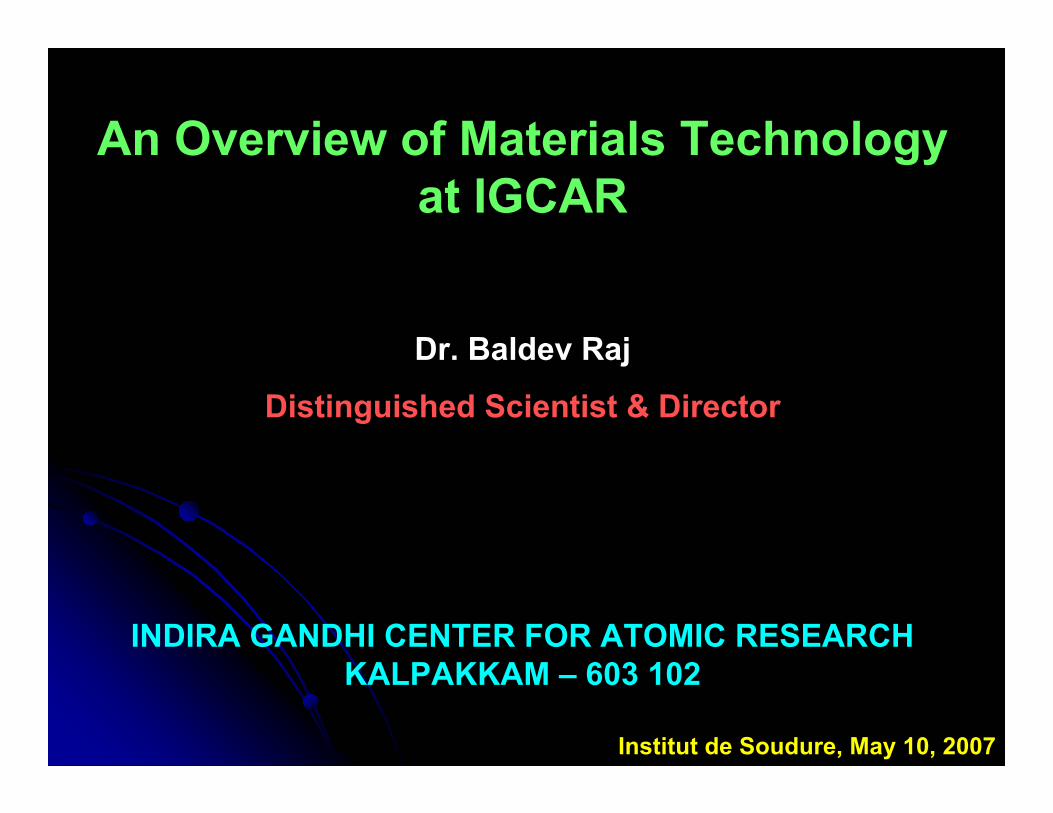
Indian Energy Growth Scenario
COAL
Th-FBR
U-FBR
OIL GAS HYDRO
U-PHWR
Resource Potential Energy Growth
Target of GDP growth rate: 10 % (2007 – 2012)
Energy Target : 400 GWe ( to reach world average in per capita generation)
~ 275~ 0
5305
3699
2454
1620
1000613
0
1000
2000
3000
4000
5000
6000
2002 2012 2022 2032 2042 2052
Time periodPe
r Cap
ita G
ener
atio
n (k
Wh)
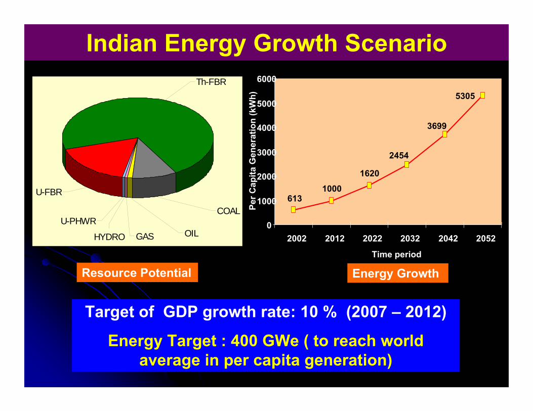
Stage – I PHWRs•15 - Operating• 3 - Under construction• Several others planned• Scaling to 700 MWe• Gestation period being
reduced• POWER POTENTIAL ≅
12,000 MWe
LWRs• 2 BWRs Operating• 2 VVERs under
construction
Three Stage Nuclear Power Program
Stage - IIFast Breeder Reactors
• 40 MWth FBTR -Operating since 1985
• Technology Objectives realised
• 500 MWe PFBR-Under Construction
• Technology development forclosing the fuel cycle
• POWER POTENTIAL ≅540,000 MWe
Stage – III and BeyondThorium Based Reactors
• 30 kWth KAMINI- Operating
• 300 MWe AHWR-BEING LAUNCHED
• POWER POTENTIAL IS 155,000 GWe-y
•Availability of ADS can enable early introduction of Thorium on a large scale
•Participation in ITER for fusion energy
81
91
8582
8075
7167
60
90868484
7975
6972
90
50
55
60
65
70
75
80
85
90
95
1995-96 1996-97 1997-98 1998-99 1999-00 2000-01 2001-02 2002-03 2003-04
Ava
ilabi
lity/C
apac
ity F
actor
(%) -
---->
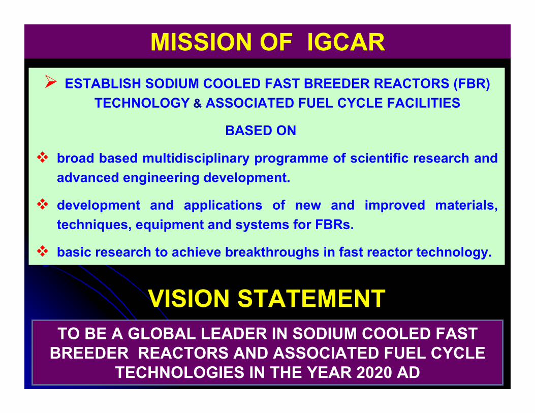
MISSION OF IGCARESTABLISH SODIUM COOLED FAST BREEDER REACTORS (FBR)
TECHNOLOGY & ASSOCIATED FUEL CYCLE FACILITIES
BASED ON
broad based multidisciplinary programme of scientific research and advanced engineering development.
development and applications of new and improved materials, techniques, equipment and systems for FBRs.
basic research to achieve breakthroughs in fast reactor technology.
VISION STATEMENTTO BE A GLOBAL LEADER IN SODIUM COOLED FAST
BREEDER REACTORS AND ASSOCIATED FUEL CYCLE TECHNOLOGIES IN THE YEAR 2020 AD
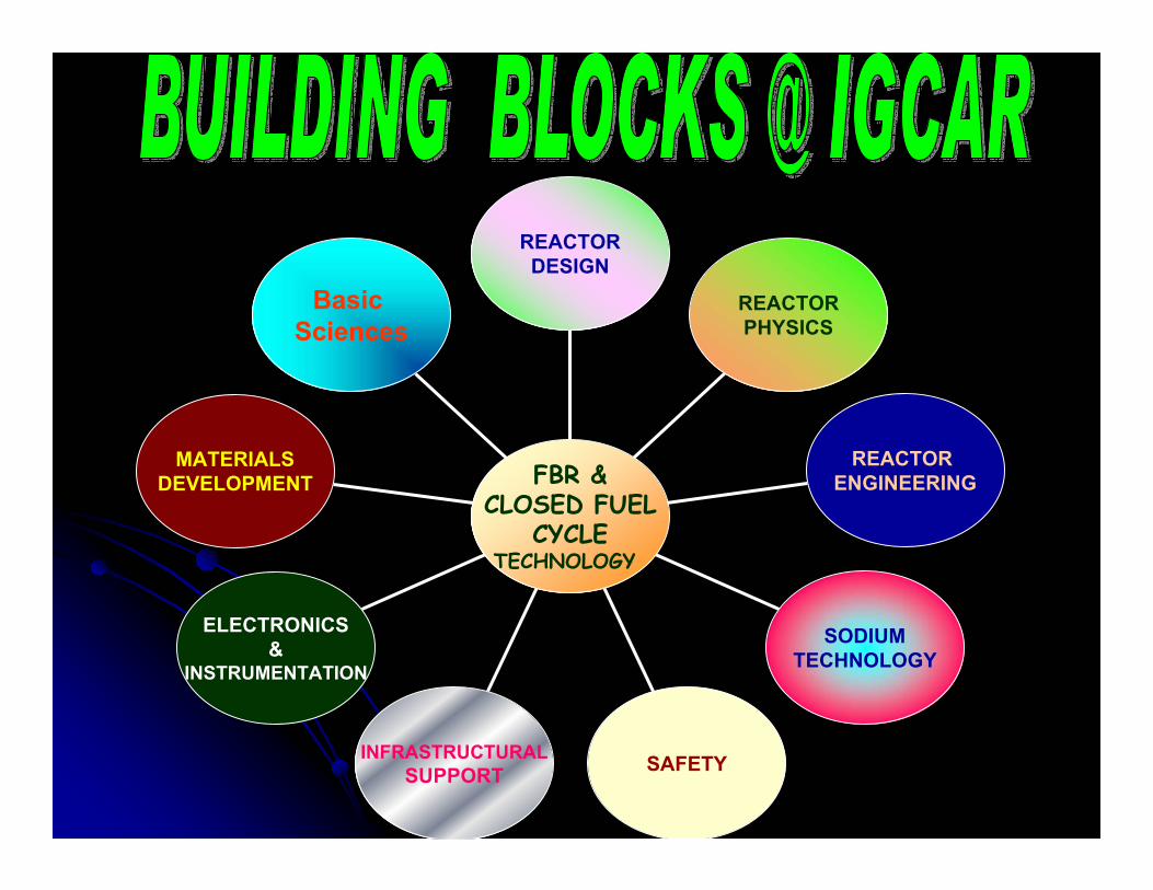
SAFETY
MATERIALSDEVELOPMENT
ELECTRONICS&
INSTRUMENTATION
INFRASTRUCTURALSUPPORT
SODIUMTECHNOLOGY
REACTOR ENGINEERING
REACTORPHYSICS
REACTORDESIGN
FBR &CLOSED FUEL
CYCLETECHNOLOGY
Basic Sciences
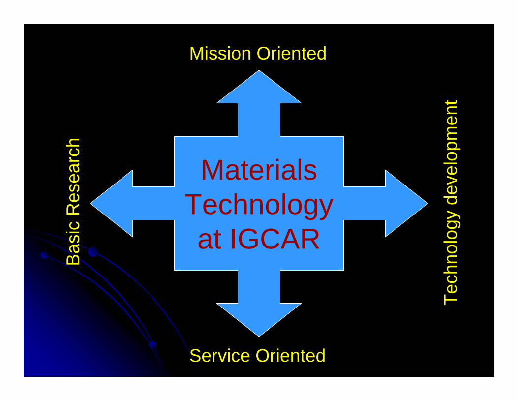
MaterialsTechnologyat IGCAR
Mission Oriented
Service Oriented
Bas
ic R
esea
rch
Tech
nolo
gy d
evel
opm
ent

Physical Metallurgy and Characterization
Mechanical Behaviourand Characterization
Post Irradiation Examination and Robotics
Material Mechanics and Technology
Nondestructive Testing and Evaluation
Corrosion Science and Technology
Basic Research in Material Science
Innovative Designs and Synthesis
•Fracture & Damage Mechanics Based Evaluationof FBR Materials•Studies on Fatigue and/or Creep Crack Growth•Welding Technology & Weldability Studies•Development of Hardfacing & Repair Welding Technology•Materials Development & Processing Technology •Tribological Studies
•Tensile Properties at Different Temperatures
•Creep, Low Cycle Fatigue& Creep-Fatigue Interactions
•Structural Integrity & Life Assessment
•Thermo-Mechanical Fatigue Studies
•Material Development forFBRs
•Creep & Fatigue Studiesin Flowing Na
•Analytical & High Resolution Microscopy•Thermo-Physical Studies -Modeling/Experiments•Synthesis of Novel Materials•Micro-Chemical StudiesUsing EPMA
•Embrittlement Studies in Ferritic Steels•Design of Reprocessing& FBR Materials
•Ion Beam Applications & Radiation Damage•Positron Annihilation &Defect Spectroscopy
•Light Scattering & Soft Condensed Matter•Superconductivity; SQUIDS •High Pressure Studies & Material Synthesis
•X-Ray & Crystal Growth•Surface Science &Nanomaterials
•Theory & ComputerSimulations
•Post Irradiation Examination of FBTR Fuel & Structural Materials •Development of RoboticsDevices for in-Service Inspection of PFBR & Reprocessing Plants•Development of RemoteHandling Equipment•Development of Miniature Specimen Testing Techniques•Failure Analysis of Engineering Components
•NDE for Quality Assurance & in-ServiceInspection•Expertise to Strategic & Core Sectors •Acoustic Emission & Infrared Thermographyin Characterizing Various Deformation Processes•Application of Micromagnetic, XRD &Ultrasound Techniques inMicrostructural Studies
•Design, Fabrication & Assembly of Irradiation Experiment Capsules•Precision Machining, Welding & Assemblyof Small & Miniature Components •Making of Calibration Defects for Nondestructive Testing•Studies on Temperature Distribution during Welding
•Localized & Microbial Corrosion Studies•Biodegradation & Alkali Aggregate Reactions in Concrete•Stress Corrosion Studies•Compatibility Studies in Nitric Acid & Na
•Molten Salt Corrosion & Development of Protective Coatings•Development of Online Corrosion Monitoring Techniques
NDE SETUP for Na EXPOSURE
25.0°C
35.0°C
26
28
30
32
34
7.1% 58.9% 74.2%
THERMAL IMAGES for DEFORMATION
DROP-WEIGHT TESTING MACHINE
SQUID MAGNETOMETER
SQUID Sensor
THERMO-MECHANICAL FATIGUE MACHINE
LASER WELDING OF MINIATURE RUPTURE
DISC
NITRIC ACIDLOOP
HIGH-RESOLUTION ELECTRON MICROSCOPE
ROBOT for STEAM GENERATOR
INSPECTION
HOT CELL FACILITY
PROGRAMME
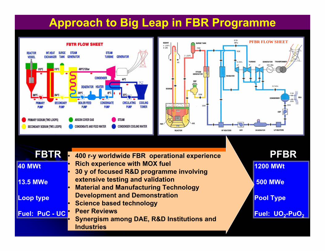
Approach to Big Leap in FBR Programme
FBTR
PFBR
1200 MWt
500 MWe
Pool Type
Fuel: UO2-PuO2
40 MWt
13.5 MWe
Loop type
Fuel: PuC - UC
FBTR PFBR• 400 r-y worldwide FBR operational experience• Rich experience with MOX fuel • 30 y of focused R&D programme involving
extensive testing and validation• Material and Manufacturing Technology
Development and Demonstration• Science based technology• Peer Reviews• Synergism among DAE, R&D Institutions and
Industries
PFBR FLOW SHEET
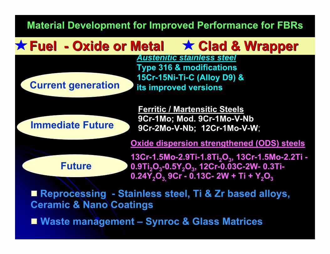
Fuel Fuel -- Oxide or Metal Oxide or Metal Clad & Wrapper Clad & Wrapper
Ferritic / Martensitic Steels9Cr-1Mo; Mod. 9Cr-1Mo-V-Nb9Cr-2Mo-V-Nb; 12Cr-1Mo-V-W;
Current generation
Immediate Future
Future
Oxide dispersion strengthened (ODS) steels13Cr-1.5Mo-2.9Ti-1.8Ti2O3, 13Cr-1.5Mo-2.2Ti -0.9Ti2O3-0.5Y2O3, 12Cr-0.03C-2W- 0.3Ti-0.24Y2O3, 9Cr - 0.13C- 2W + Ti + Y2O3
Reprocessing - Stainless steel, Ti & Zr based alloys, Ceramic & Nano Coatings
Waste management – Synroc & Glass Matrices
Austenitic stainless steelType 316 & modifications15Cr-15Ni-Ti-C (Alloy D9) & its improved versions
Material Development for Improved Performance for FBRs
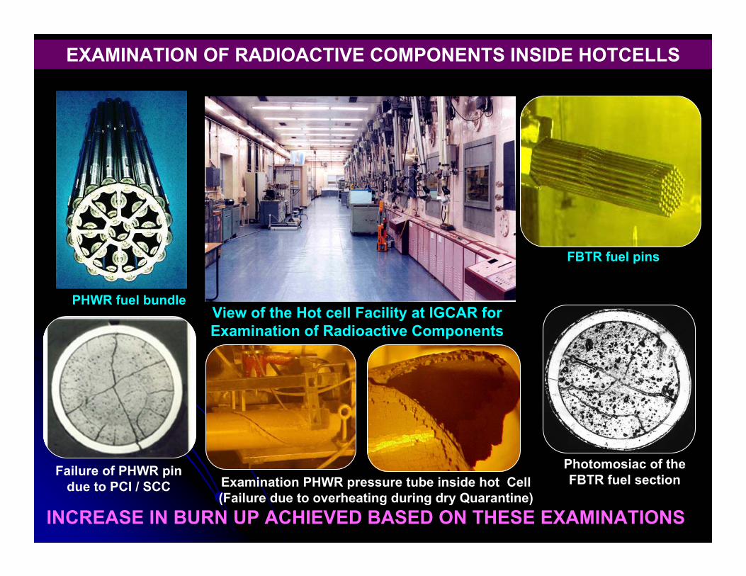
EXAMINATION OF RADIOACTIVE COMPONENTS INSIDE HOTCELLS
PHWR fuel bundle
FBTR fuel pins
View of the Hot cell Facility at IGCAR for Examination of Radioactive Components
Failure of PHWR pin due to PCI / SCC
Photomosiac of the FBTR fuel sectionExamination PHWR pressure tube inside hot Cell
(Failure due to overheating during dry Quarantine)INCREASE IN BURN UP ACHIEVED BASED ON THESE EXAMINATIONS
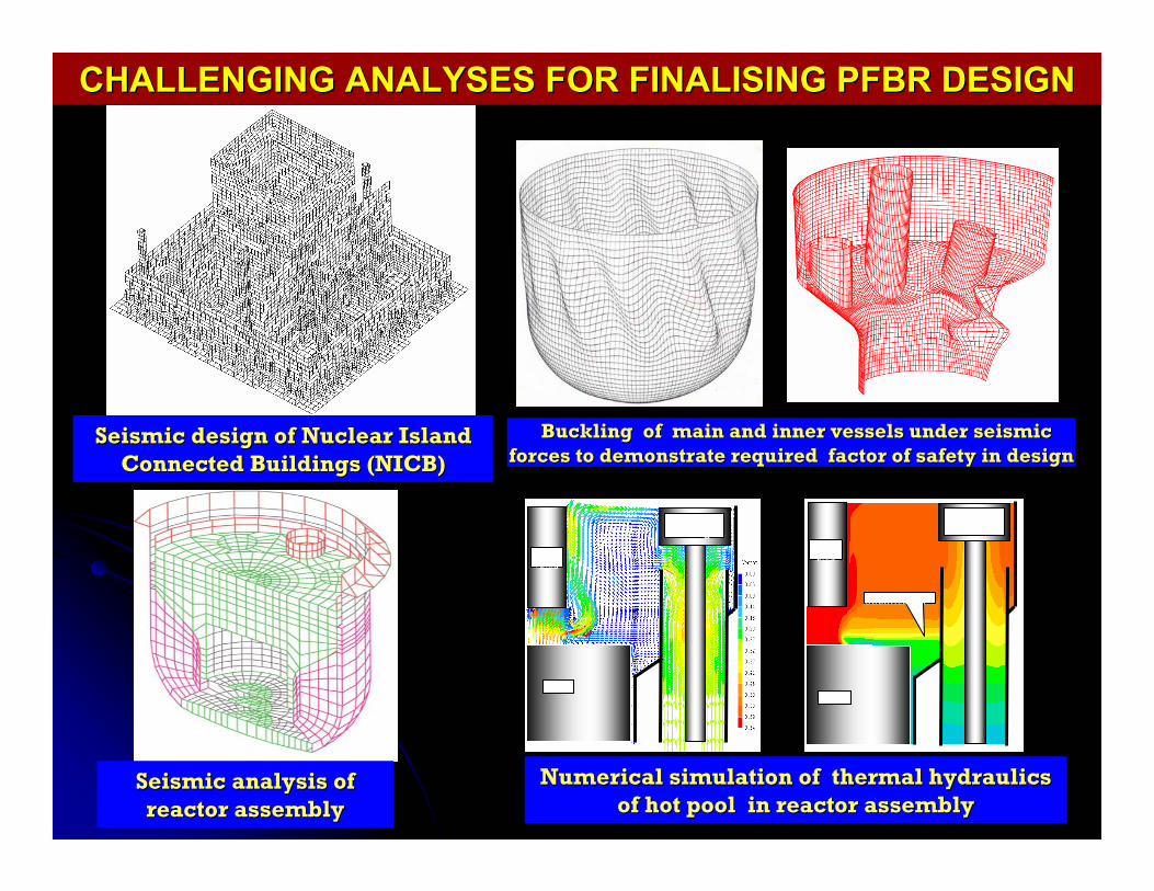
CHALLENGING ANALYSES FOR FINALISING PFBR DESIGN CHALLENGING ANALYSES FOR FINALISING PFBR DESIGN
Buckling of main and inner vessels under seismic Buckling of main and inner vessels under seismic forces to demonstrate required factor of safety in design forces to demonstrate required factor of safety in design
Seismic design of Nuclear Island Seismic design of Nuclear Island Connected Buildings (NICB)Connected Buildings (NICB)
Seismic analysis of Seismic analysis of reactor assembly reactor assembly
Numerical simulation of thermal hydraulics Numerical simulation of thermal hydraulics of hot pool in reactor assembly of hot pool in reactor assembly
Control plug
Core
Heat exchanger
Stratification
Control plug
Core
Heat exchanger
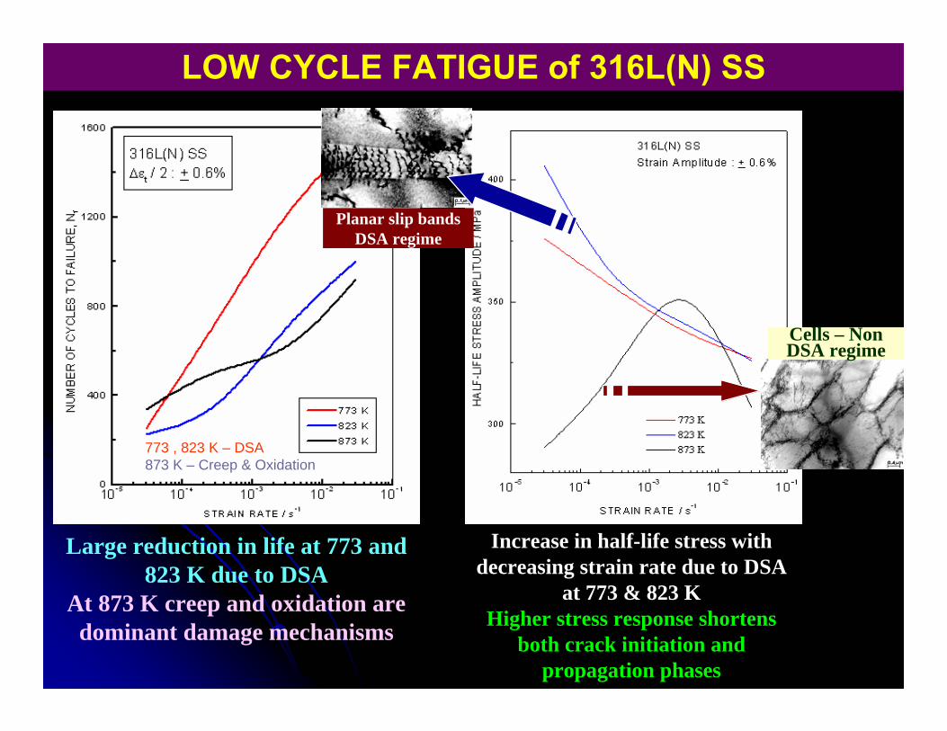
Large reduction in life at 773 and 823 K due to DSA
At 873 K creep and oxidation are dominant damage mechanisms
Increase in half-life stress with decreasing strain rate due to DSA
at 773 & 823 KHigher stress response shortens
both crack initiation and propagation phases
773 , 823 K – DSA873 K – Creep & Oxidation
LOW CYCLE FATIGUE of 316L(N) SS
Cells – Non DSA regime
Planar slip bands DSA regime
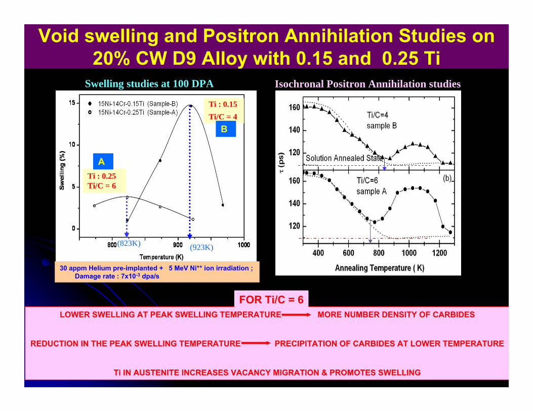
Void swelling and Positron Annihilation Studies on 20% CW D9 Alloy with 0.15 and 0.25 Ti
Swelling studies at 100 DPA Isochronal Positron Annihilation studies
30 appm Helium pre-implanted + 5 MeV Ni++ ion irradiation ; Damage rate : 7x10⁻³ dpa/s
Model alloy without Ti
Ti : 0.25 Ti/C = 6
Ti : 0.15 Ti/C = 4
(823K) (923K)
LOWER SWELLING AT PEAK SWELLING TEMPERATURE MORE NUMBER DENSITY OF CARBIDES
REDUCTION IN THE PEAK SWELLING TEMPERATURE PRECIPITATION OF CARBIDES AT LOWER TEMPERATURE
Ti IN AUSTENITE INCREASES VACANCY MIGRATION & PROMOTES SWELLING
FOR Ti/C = 6
A
B
100 1000 1000100
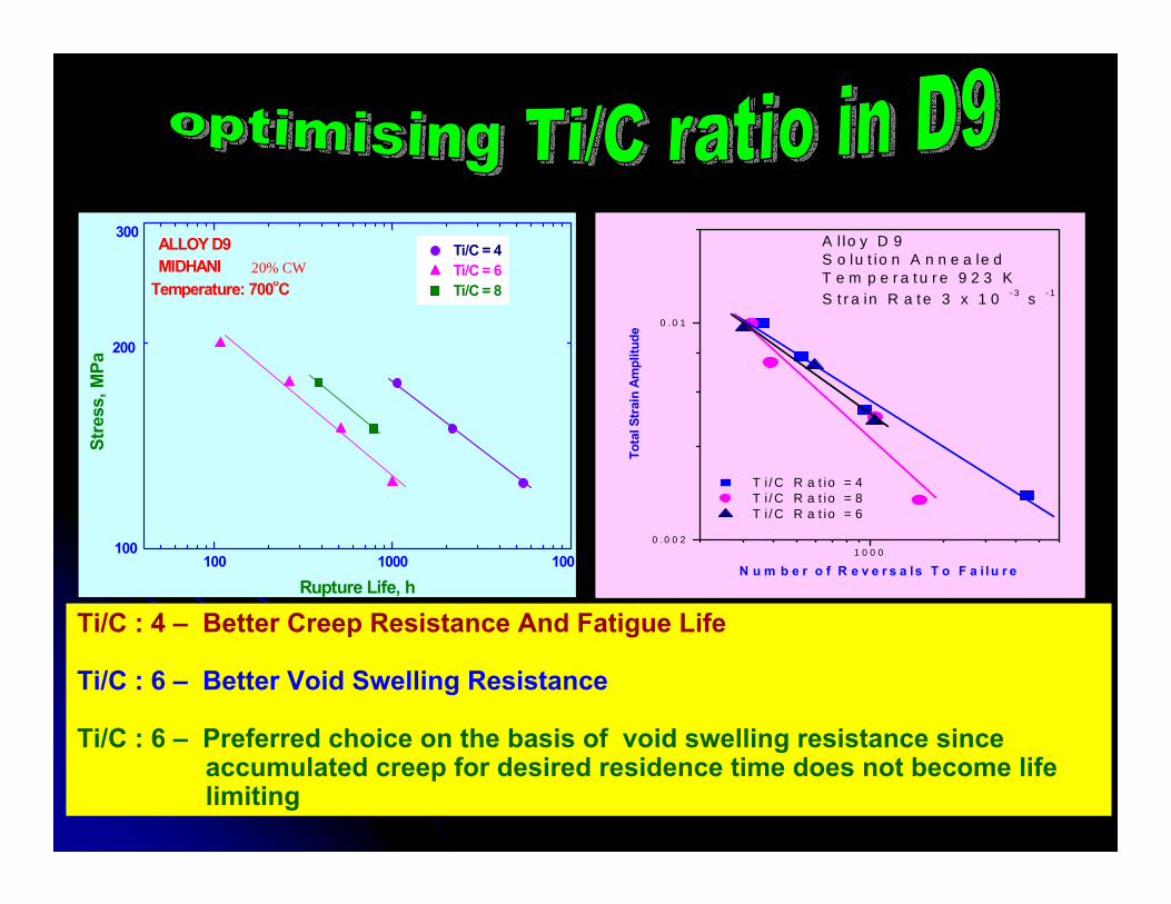
Temperature: 700oC
300
200
ALLOY D9MIDHANI
Ti/C = 4Ti/C = 6Ti/C = 8
Stre
ss, M
Pa
Rupture Life, h
Ti/C : 4 – Better Creep Resistance And Fatigue Life
Ti/C : 6 – Better Void Swelling Resistance
Ti/C : 6 – Preferred choice on the basis of void swelling resistance since accumulated creep for desired residence time does not become life limiting
20% CW
1 0 0 00 . 0 0 2
0 . 0 1
A l lo y D 9S o lu t io n A n n e a le dT e m p e r a t u r e 9 2 3 KS t r a in R a t e 3 x 1 0 - 3 s - 1
T i / C R a t io = 4 T i / C R a t io = 8 T i / C R a t io = 6
Tota
l Str
ain
Ampl
itude
N u m b e r o f R e v e r s a ls T o F a i lu r e
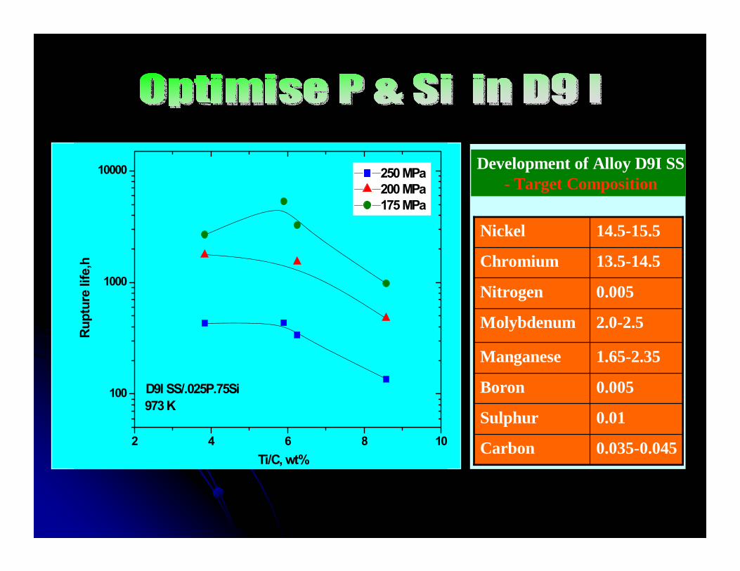
0.035-0.045Carbon
0.01Sulphur
0.005Boron
1.65-2.35Manganese
2.0-2.5Molybdenum
0.005Nitrogen
13.5-14.5Chromium
14.5-15.5Nickel
Development of Alloy D9I SS- Target Composition
2 4 6 8 10
100
1000
10000
973 KD9I SS/.025P.75Si
Rupt
ure
life,
h
Ti/C, wt%
250 MPa200 MPa175 MPa
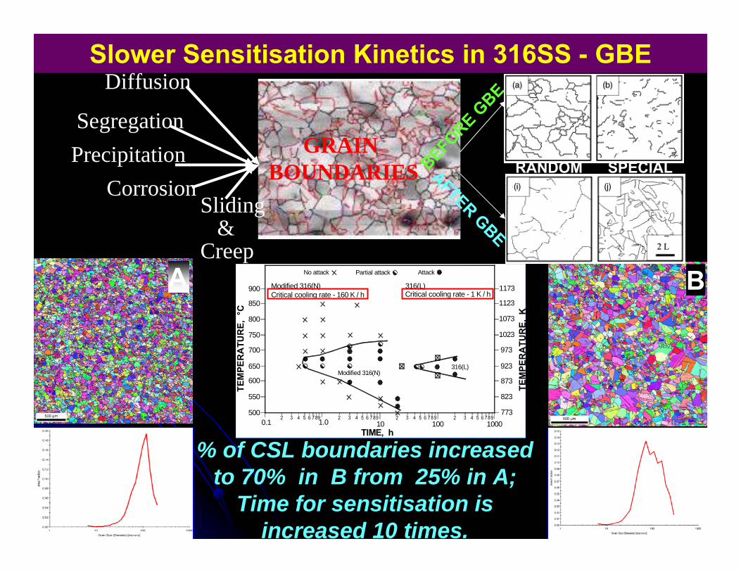
Slower Sensitisation Kinetics in 316SS - GBE
% of CSL boundaries increased to 70% in B from 25% in A;
Time for sensitisation is increased 10 times.
0.1500
1.0 10 100 1000773
823
873
923
973
1023
1073
1123
1173
550
600
650
700
750
800
850
900Critical cooling rate - 1 K / h
No attack
316(L)Modified 316(N)
TIME, h
TEM
PER
ATU
RE,
°C
TEM
PER
ATU
RE,
K
Critical cooling rate - 160 K / hModified 316(N) 316(L)
Partial attack AttackA B
GRAIN BOUNDARIES
CorrosionSliding
&Creep
Diffusion
SegregationPrecipitation
AFTER GBE
RANDOM SPECIALBEFORE GBE
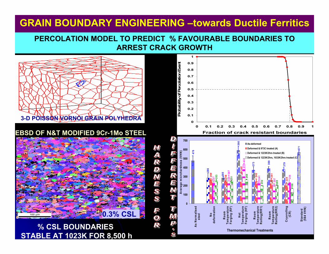
GRAIN BOUNDARY ENGINEERING –towards Ductile Ferritics
0
0.1
0.2
0.3
0.4
0.5
0.6
0.7
0.8
0.9
1
0 0.1 0.2 0.3 0.4 0.5 0.6 0.7 0.8 0.9 1
Fraction of crack resistant boundaries
Prob
abili
ty o
f Per
cola
tion
Even
t
PERCOLATION MODEL TO PREDICT % FAVOURABLE BOUNDARIES TO ARREST CRACK GROWTH
3-D POISSON VORNOI GRAIN POLYHEDRA
0.3% CSL
EBSD OF N&T MODIFIED 9Cr-1Mo STEEL
251
205
168
373 38
8
379
590
28528
6
476 57
1
22426
1
246
348
269
258
287
227
20724
1
433
234
253
268
202
0
100
200
300
400
500
600
700
As
Nor
mal
ised
stee
l
No
defo
rmat
ion
Roo
mTe
mpe
ratu
reFo
rgin
g (R
F)
Hot
Tem
pera
ture
Forg
ing
(HF)
Roo
mTe
mpe
ratu
reR
ollin
g(R
R1)
Roo
mTe
mpe
ratu
reR
ollin
g(R
R2)
Cry
orol
ling
(CR
)
Stan
dard
(5
64 V
HN
)
Thermomechanical Treatments
Ave
rage
mic
roha
rdne
ss (V
HN
)
As-deformed
Deformed & 973C treated (A)
Deformed & 1223K/2hrs treated (B)
Deformed & 1223K/2hrs, 1033K/2hrs treated (C)
% CSL BOUNDARIES STABLE AT 1023K FOR 8,500 h
400 450 500 550 600 650 700 750 800 850400
450
500
550
600
650
700
750
800
850
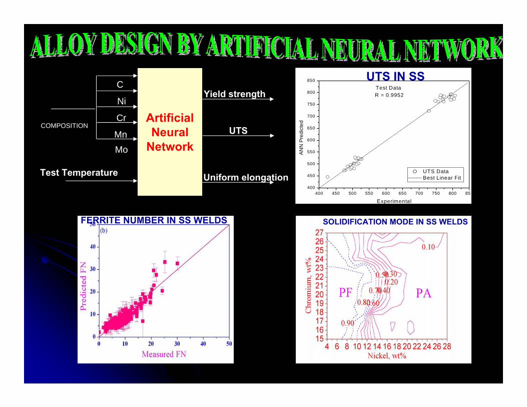
R = 0.9952Test Data
ANN
Pre
dict
ed
Experimental
UTS Data Best Linear Fit
ArtificialNeural
Network
Yield strength
UTS
Uniform elongationTest Temperature
C
Ni
Cr
MnMo
COMPOSITION
FERRITE NUMBER IN SS WELDS
UTS IN SS
SOLIDIFICATION MODE IN SS WELDS
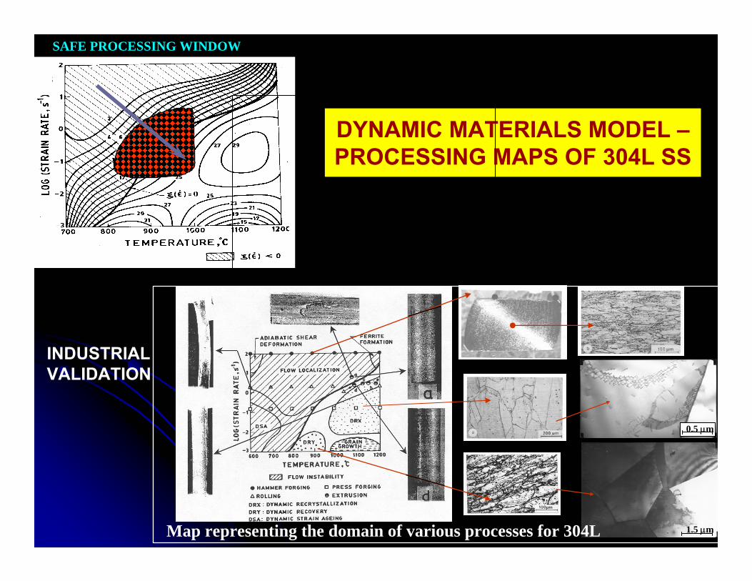
DYNAMIC MATERIALS MODEL –PROCESSING MAPS OF 304L SS
SAFE PROCESSING WINDOW
0.5 μm
1.5 μmMap representing the domain of various processes for 304L
INDUSTRIALVALIDATION
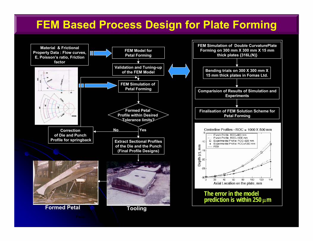
FEM Based Process Design for Plate Forming
Petal
Material & Frictional Property Data : Flow curves, E, Poisson’s ratio, Friction
factor
FEM Model for Petal Forming
Validation and Tuning-upof the FEM Model
FEM Simulation of Petal Forming
Correction of Die and Punch
Profile for springback
Formed Petal Profile within Desired
Tolerance limits?
Extract Sectional Profilesof the Die and the Punch
(Final Profile Designs)
No Yes
FEM Simulation of Double CurvaturePlateForming on 300 mm X 300 mm X 15 mm
thick plates {316L(N)}
Bending trials on 300 X 300 mm X 15 mm thick plates in Fomas Ltd.
Comparision of Results of Simulation and Experiments
Finalisation of FEM Solution Scheme for Petal Forming
The error in the model prediction is within 250 μm
Formed Petal Tooling
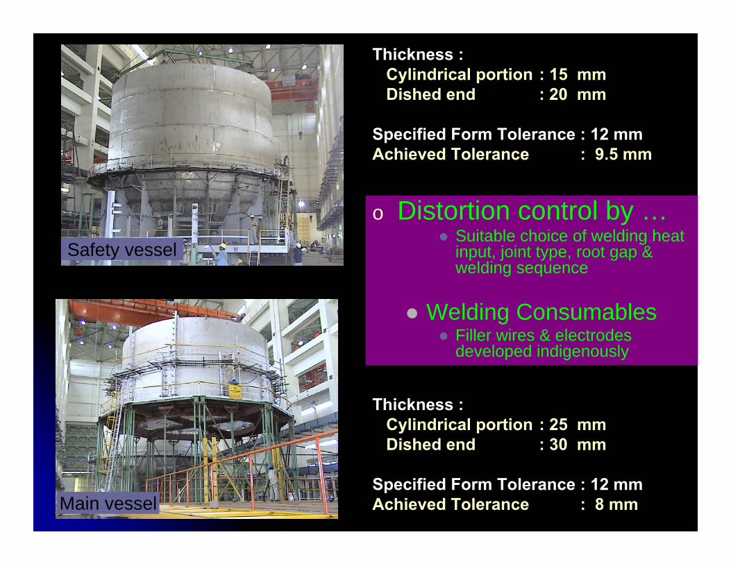
Main vessel
Safety vessel
Thickness : Cylindrical portion : 15 mmDished end : 20 mm
Specified Form Tolerance : 12 mm Achieved Tolerance : 9.5 mm
Thickness : Cylindrical portion : 25 mmDished end : 30 mm
Specified Form Tolerance : 12 mm Achieved Tolerance : 8 mm
o Distortion control by …Suitable choice of welding heat input, joint type, root gap & welding sequence
Welding ConsumablesFiller wires & electrodes developed indigenously
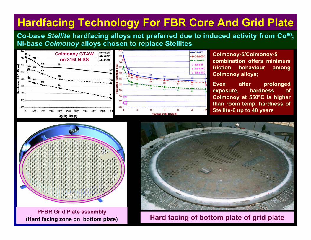
Hardfacing Technology For FBR Core And Grid Plate Co-base Stellite hardfacing alloys not preferred due to induced activity from Co60; Ni-base Colmonoy alloys chosen to replace Stellites
Colmonoy GTAWon 316LN SS
Colmonoy-5/Colmonoy-5 combination offers minimum friction behaviour among Colmonoy alloys;
Even after prolonged exposure, hardness of Colmonoy at 550°C is higher than room temp. hardness of Stellite-6 up to 40 years
Hard facing of bottom plate of grid platePFBR Grid Plate assembly
(Hard facing zone on bottom plate)
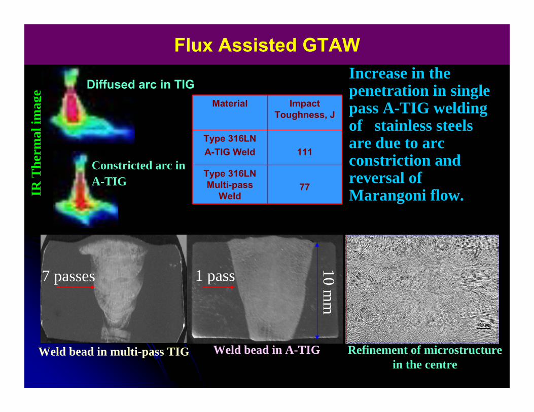
Flux Assisted GTAW
Weld bead in multi-pass TIG Weld bead in A-TIG
IR T
herm
al im
age
7 passes 1 pass
Refinement of microstructure in the centre
Increase in the penetration in single pass A-TIG welding of stainless steels are due to arc constriction and reversal of Marangoni flow.
10 mm
Diffused arc in TIG
Constricted arc in A-TIG 77
Type 316LN Multi-pass
Weld
111Type 316LN A-TIG Weld
Impact Toughness, J
Material
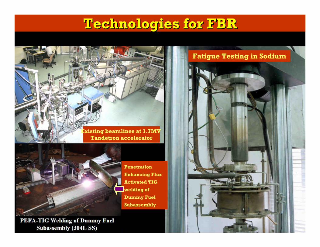
Technologies for FBRTechnologies for FBR
Existing beamlines at 1.7MV Tandetron accelerator
Fatigue Testing in Sodium
Penetration
Enhancing Flux
Activated TIG
welding of
Dummy Fuel
Subassembly
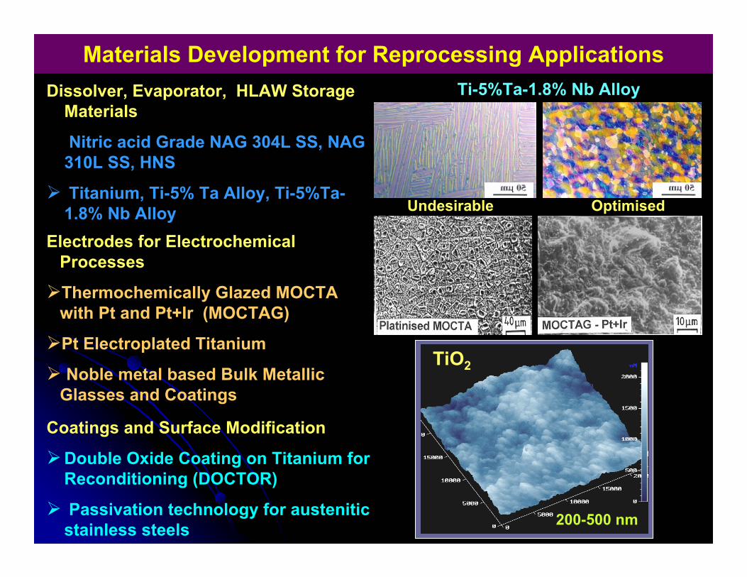
Materials Development for Reprocessing Applications
Undesirable Optimised
Ti-5%Ta-1.8% Nb Alloy
Coatings and Surface Modification
Double Oxide Coating on Titanium for Reconditioning (DOCTOR)
Passivation technology for austenitic stainless steels
Electrodes for Electrochemical Processes
Thermochemically Glazed MOCTA with Pt and Pt+Ir (MOCTAG)
Pt Electroplated Titanium
Noble metal based Bulk Metallic Glasses and Coatings
Dissolver, Evaporator, HLAW Storage Materials
Nitric acid Grade NAG 304L SS, NAG 310L SS, HNS
Titanium, Ti-5% Ta Alloy, Ti-5%Ta-1.8% Nb Alloy
200-500 nm
TiO2
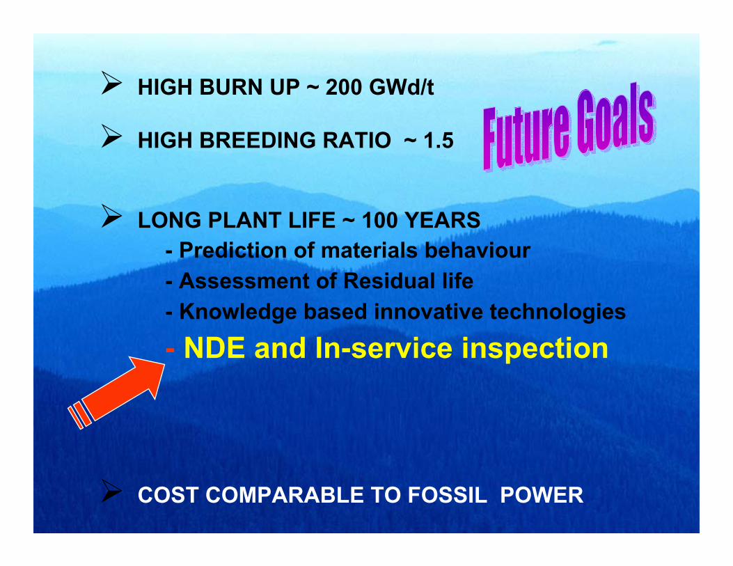
HIGH BURN UP ~ 200 GWd/t
HIGH BREEDING RATIO ~ 1.5
LONG PLANT LIFE ~ 100 YEARS- Prediction of materials behaviour- Assessment of Residual life- Knowledge based innovative technologies
- NDE and In-service inspection
COST COMPARABLE TO FOSSIL POWER
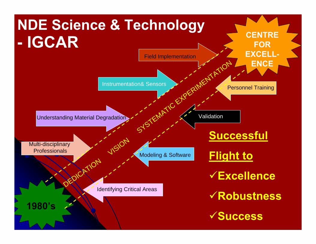
1980’s
CENTRE FOR
EXCELL-ENCE
DEDICATIONVISION
SYSTEMATIC EXPERIMENTATION
Multi-disciplinary Professionals
Understanding Material Degradation
Identifying Critical Areas
Instrumentation& Sensors
Field Implementation
Modeling & Software
Validation
NDE Science & Technology
Successful
Flight to
Excellence
Robustness
Success
- IGCAR
Personnel Training
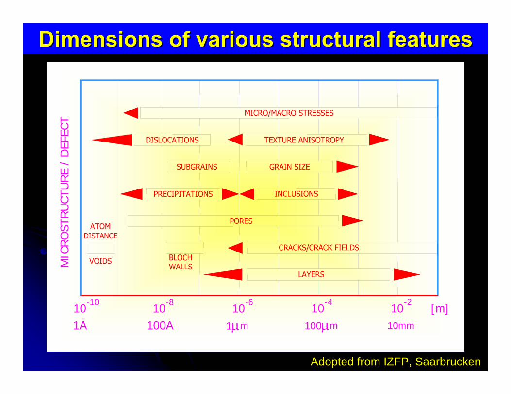
-610
-810
-1010
1A 100A 1μm
MIC
ROST
RUCT
URE
/ D
EFEC
T
[m]10-4
10-2
m100μ 10mm
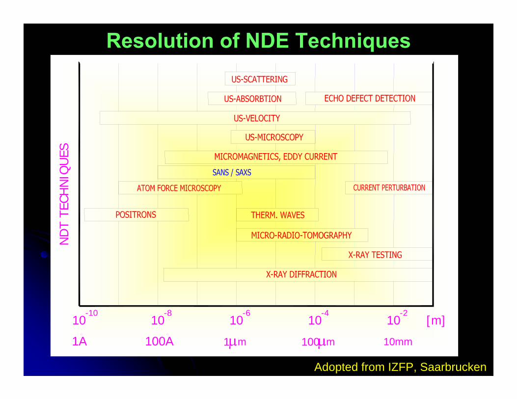
Dimensions of various structural featuresDimensions of various structural features
Adopted from IZFP, Saarbrucken
ND
T TE
CHN
IQU
ES
10
100A
-10
1A
10-8
10-6 -2
10mm
10-4
10 [m]
1μm m100μ
Resolution of NDE Techniques
Adopted from IZFP, Saarbrucken
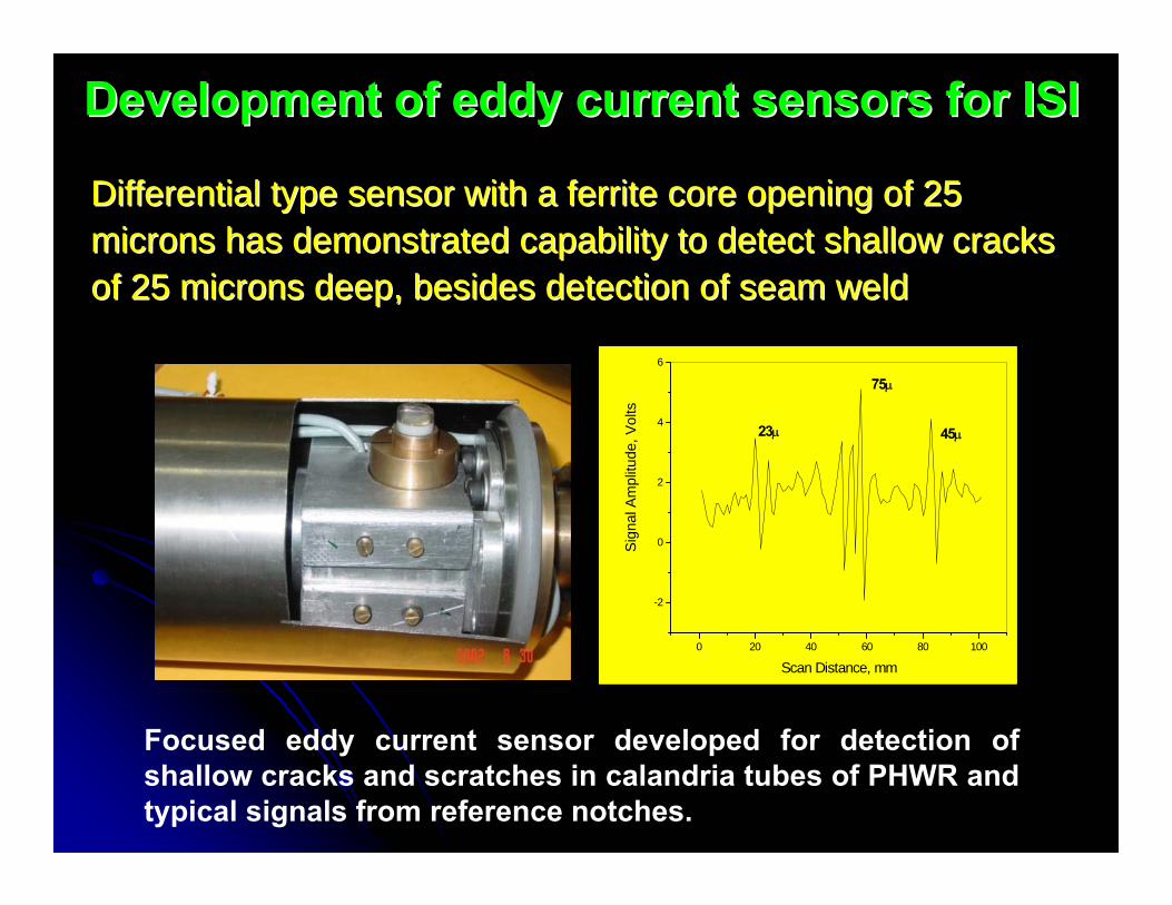
Development of eddy current sensors for ISIDevelopment of eddy current sensors for ISI
Differential type sensor with a ferrite core opening of 25Differential type sensor with a ferrite core opening of 25microns has demonstrated capability to detect shallow cracksmicrons has demonstrated capability to detect shallow cracksof 25 microns deep, besides detection of seam weldof 25 microns deep, besides detection of seam weld
Focused eddy current sensor developed for detection of shallow cracks and scratches in calandria tubes of PHWR and typical signals from reference notches.
0 20 40 60 80 100
-2
0
2
4
6
45μ
75μ
23μ
Sig
nal A
mpl
itude
, Vol
ts
Scan Distance, mm
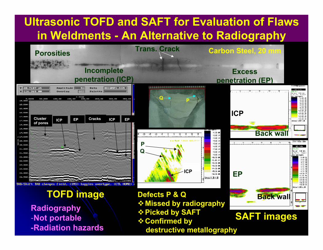
Ultrasonic TOFD and SAFT for Evaluation of Flaws in Weldments - An Alternative to Radiography
Radiography-Not portable-Radiation hazards
Back wall
EP
ICP
Back wall
SAFT images
TOFD image
Cluster of pores
EP Cracks ICP EPICP
PQ
ICP
P
QQP
ICP
Defects P & Q Missed by radiographyPicked by SAFT Confirmed by destructive metallography
Porosities
Incomplete penetration (ICP)
Excess penetration (EP)
Trans. Crack Carbon Steel, 20 mm

A
B
C
D
Inner Surface Profiling of Dissolver Vessel in Lead Mini Cell using LASER Triangulation Technique
In-house Development in Collaboration with CAT, Indore
Position sensitive device for triangulation (~ 2-3 microns) for non-contact inspection of reprocessing vessel- 11N HNO3 at high temperature
Weld internal profile
PSD
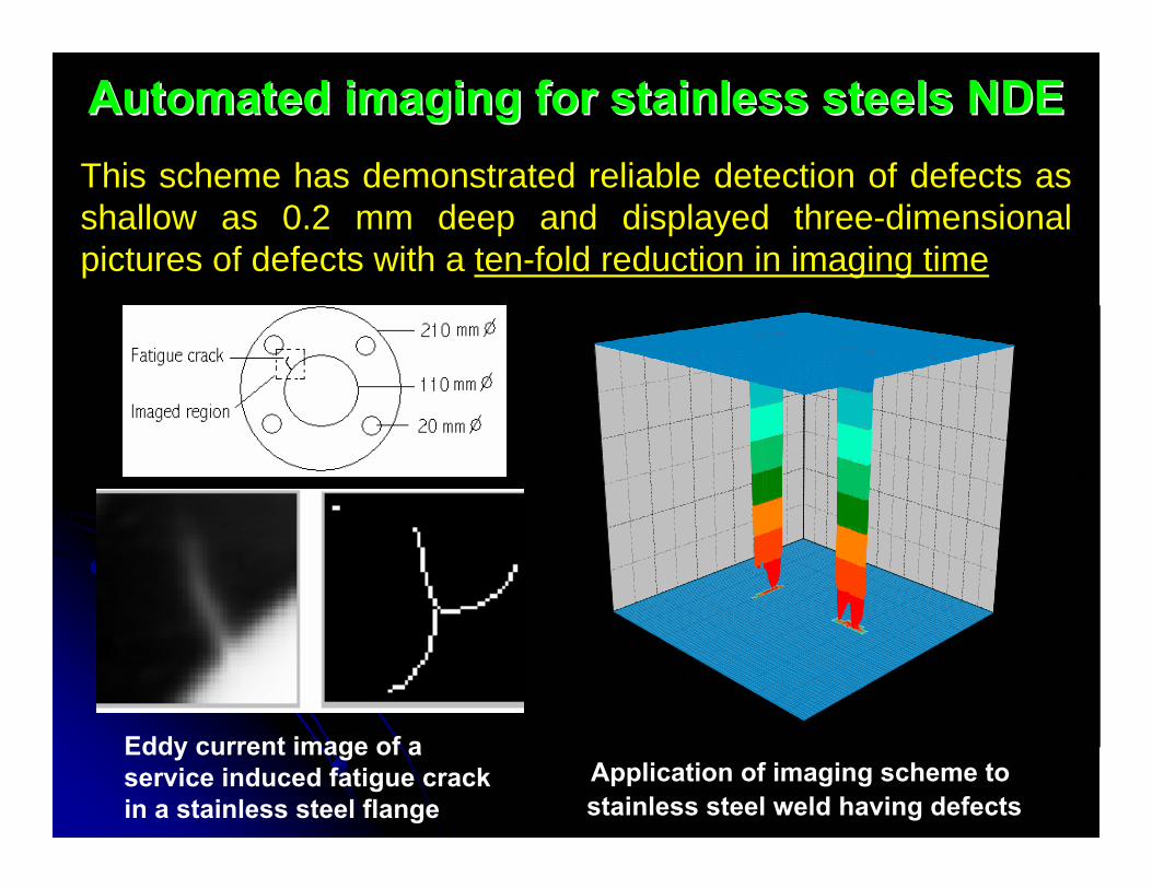
Automated imaging for stainless steels NDEAutomated imaging for stainless steels NDE
05
1015
20250
510
1520
253035
0.0
0.2
0.4
0.6
Dept
h, m
m
Y Axis, mm X Axis, mm
Application of imaging scheme to stainless steel weld having defects
Eddy current image of a service induced fatigue crack in a stainless steel flange
This scheme has demonstrated reliable detection of defects as shallow as 0.2 mm deep and displayed three-dimensional pictures of defects with a ten-fold reduction in imaging time
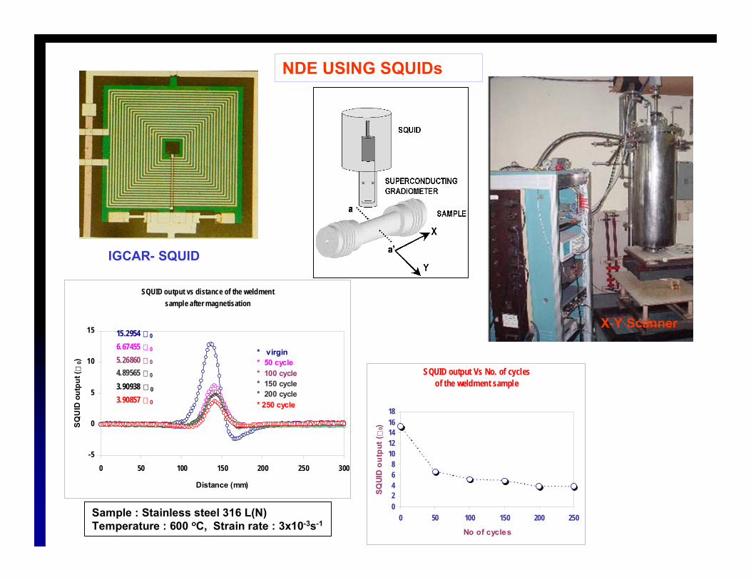
NDE USING SQUIDs
SQUID output vs distance of the weldment sample after magnetisation
-5
0
5
10
15
0 50 100 150 200 250 300
Distance (mm)
SQU
ID o
utpu
t (0)
15.2954 0
6.67455 0
5.26860 0
4.89565 0
3.90938 0
3.90857 0
* virgin* 50 cycle* 100 cycle* 150 cycle* 200 cycle * 250 cycle
Sample : Stainless steel 316 L(N)Temperature : 600 oC, Strain rate : 3x10⁻³s-1
SQUID output Vs No. of cycles of the weldment sample
02468
1012141618
0 50 100 150 200 250
No of cycles
SQUI
D o
utpu
t (0)
X-Y Scanner
IGCAR- SQUID
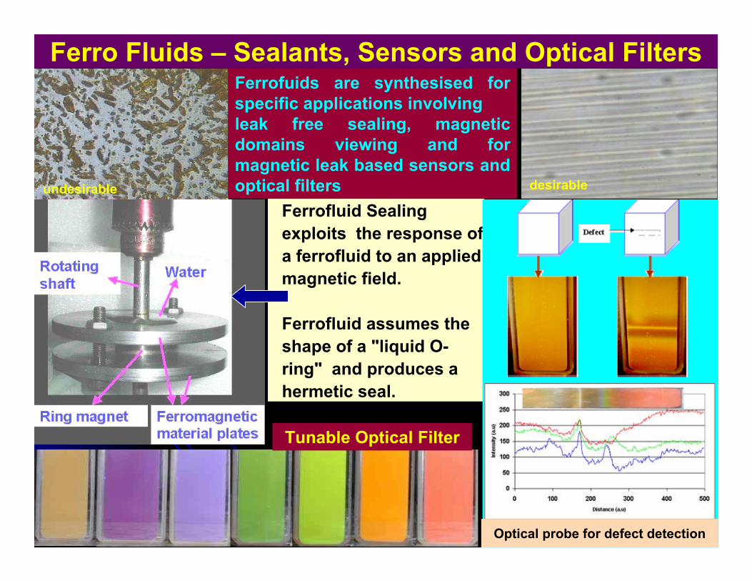
Ferro Fluids – Sealants, Sensors and Optical Filters
Ferrofluid Sealing exploits the response of a ferrofluid to an applied magnetic field.
Ferrofluid assumes the shape of a "liquid O-ring" and produces a hermetic seal.
Ferrofuids are synthesised for specific applications involving leak free sealing, magnetic domains viewing and for magnetic leak based sensors and optical filters
Tunable Optical Filter
Optical probe for defect detection
undesirable desirable
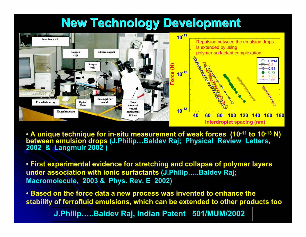
New Technology DevelopmentNew Technology Development
J.Philip…..Baldev Raj, Indian Patent 501/MUM/2002
• A unique technique for in-situ measurement of weak forces (10-11 to 10-13 N) between emulsion drops (J.Philip…Baldev Raj; Physical Review Letters, 2002 & Langmuir 2002 )
• First experimental evidence for stretching and collapse of polymer layers under association with ionic surfactants (J.Philip…..Baldev Raj; Macromolecule, 2003 & Phys. Rev. E 2002)
• Based on the force data a new process was invented to enhance the stability of ferrofluid emulsions, which can be extended to other products too
10-13
10-12
10-11
40 60 80 100 120 140 160 180
0 mM0.20.530.721.332.66
Forc
e (N
)
Interdroplet spacing (nm)
Repulsion between the emulsion drops is extended by using polymer-surfactant complexation
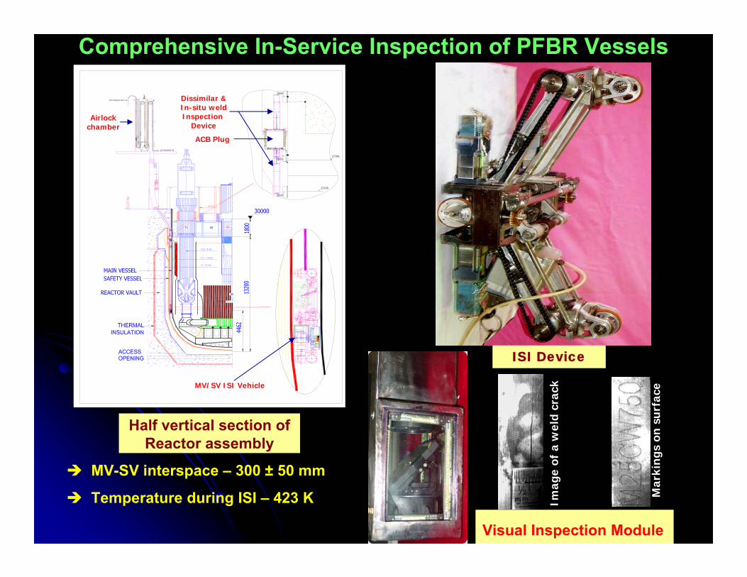
Comprehensive In-Service Inspection of PFBR Vessels
MV-SV interspace – 300 ± 50 mm
Temperature during ISI – 423 K
Half vertical section of Reactor assembly
ISI Device
13 08 09
05
27100
27700
NITROGEN IN
NITROGEN OUT
MV/SV ISI Vehicle
ACB Plug
Dissimilar &In-situ weldInspection
DeviceAirlock
chamber
Visual Inspection ModuleIm
age
of a
wel
d cr
ack
Mar
king
s on
su
rfac
e
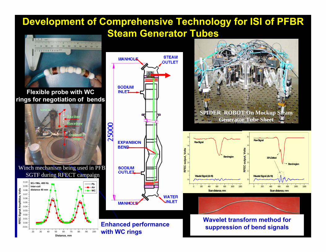
SPIDER ROBOT On Mockup Steam Generator Tube Sheet
Winch mechanism being used in PFBR SGTF during RFECT campaign
RFEC PROBEExciter
Receiver
Depleted Urings
WINCH
Flexible probe with WC rings for negotiation of bends
0 200 400 600 800 1000 1200
0
1
2
3
4
5
Wavelet Signal (db-10)
Raw Signal
Bend region
RFE
C o
utpu
t, Vo
lts
Scan distance, mm0 200 400 600 800 1000 1200
0
1
2
3
4
5
Wavelet Signal (db-10)
Raw Signal
30% Defect
Bend region
RFEC
out
put,
Volts
Scan distance, mm
Wavelet transform method for suppression of bend signalsEnhanced performance
with WC rings20 30 40 50 60 70 80 90 100
-0.01
0.00
0.01
0.02
0.03
0.04
0.05
0.06
0.07
0.08
0.09
0.10 9Cr-1Mo, 400 HzInter-coildistance 40 mm
Pb Air WC
RFE
C S
igna
l Am
pltid
ue, V
olts
Distance, mm
Development of Comprehensive Technology for ISI of PFBR Steam Generator Tubes
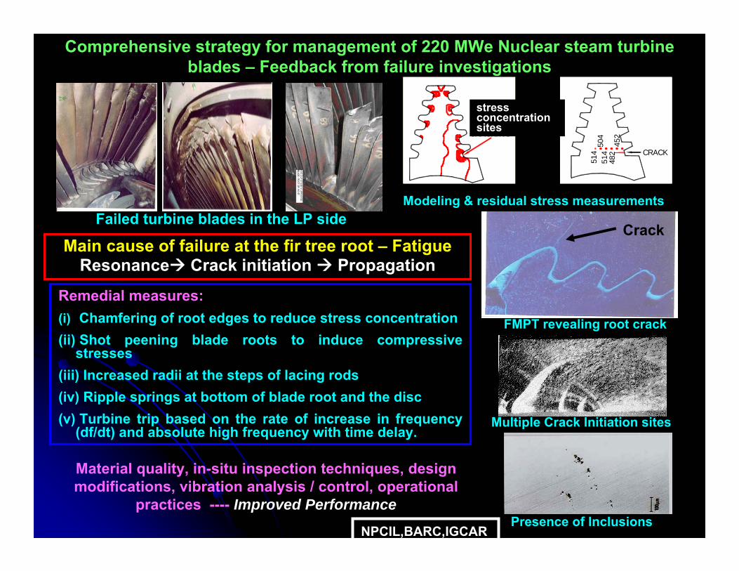
Remedial measures:(i) Chamfering of root edges to reduce stress concentration (ii) Shot peening blade roots to induce compressive
stresses (iii) Increased radii at the steps of lacing rods (iv) Ripple springs at bottom of blade root and the disc(v) Turbine trip based on the rate of increase in frequency
(df/dt) and absolute high frequency with time delay.
Main cause of failure at the fir tree root – FatigueResonance Crack initiation Propagation
FMPT revealing root crack
Material quality, in-situ inspection techniques, design modifications, vibration analysis / control, operational
practices ---- Improved Performance
Failed turbine blades in the LP sideCrack
Modeling & residual stress measurements
CRACK
514
504
482
452
514
LOCATION OCRACKING
stress concentration sites
Multiple Crack Initiation sites
Presence of Inclusions NPCIL,BARC,IGCAR
Comprehensive strategy for management of 220 MWe Nuclear steam turbine blades – Feedback from failure investigations
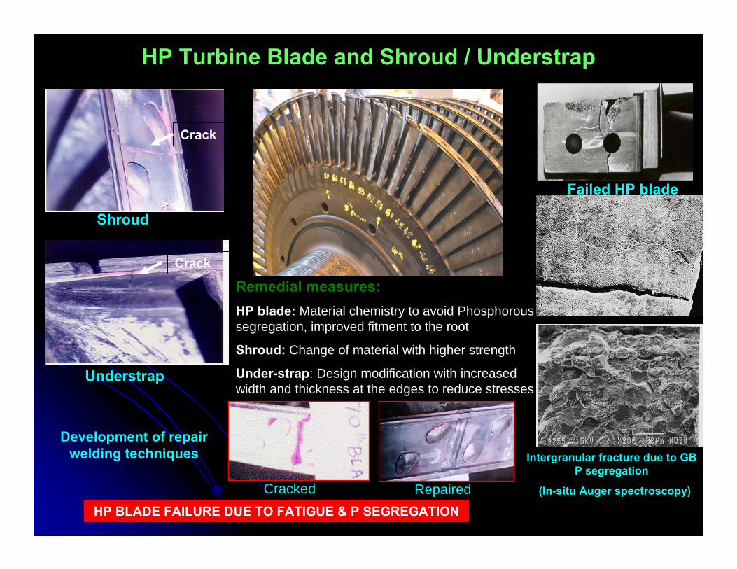
HP Turbine Blade and Shroud / Understrap
HP BLADE FAILURE DUE TO FATIGUE & P SEGREGATION
Development of repair welding techniques
Remedial measures:HP blade: Material chemistry to avoid Phosphorous segregation, improved fitment to the root
Shroud: Change of material with higher strength
Under-strap: Design modification with increased width and thickness at the edges to reduce stresses
Shroud
Understrap
Failed HP blade
Intergranular fracture due to GB P segregation
(In-situ Auger spectroscopy)
Crack
Crack
Cracked Repaired
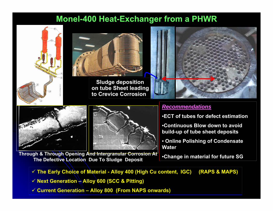
Monel-400 Heat-Exchanger from a PHWR
Sludge deposition on tube Sheet leading to Crevice Corrosion
Through & Through Opening And Intergranular Corrosion At The Defective Location Due To Sludge Deposit
Recommendations•ECT of tubes for defect estimation
•Continuous Blow down to avoid build-up of tube sheet deposits
• Online Polishing of Condensate Water
•Change in material for future SG
The Early Choice of Material - Alloy 400 (High Cu content, IGC) (RAPS & MAPS)
Next Generation – Alloy 600 (SCC & Pitting)
Current Generation – Alloy 800 (From NAPS onwards)
244.6 K
378.0 K
260
280
300
320
340
360
646.3 K
1149.2 K
700
800
900
1000
1100
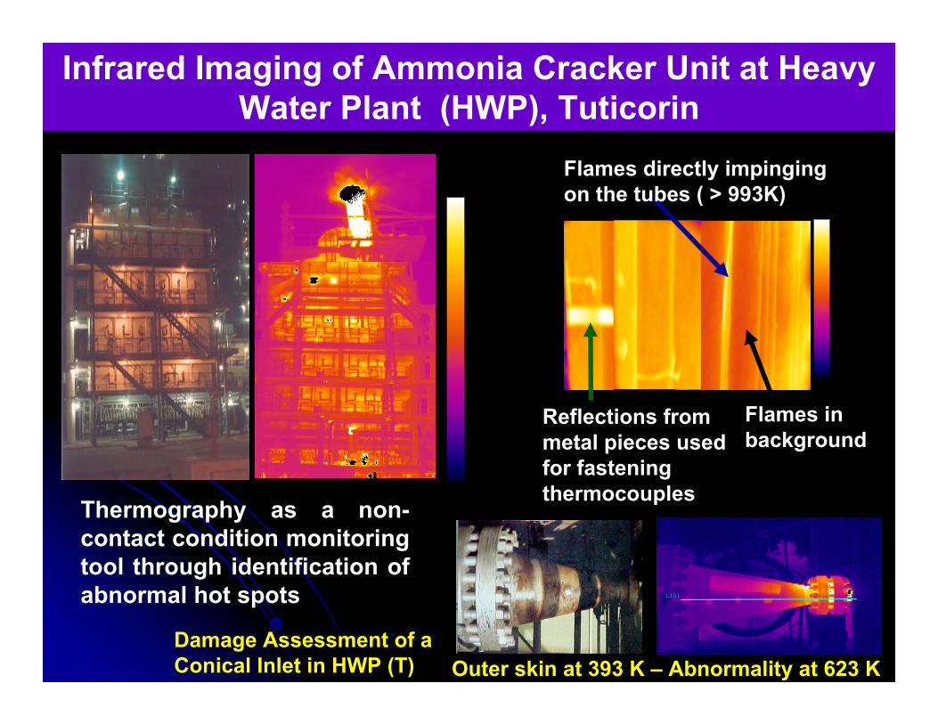
Flames directly impinging on the tubes ( > 993K)
Reflections from metal pieces used for fastening thermocouples
Flames in background
Infrared Imaging of Ammonia Cracker Unit at Heavy Water Plant (HWP), Tuticorin
LI01
Damage Assessment of a Conical Inlet in HWP (T) Outer skin at 393 K – Abnormality at 623 K
Thermography as a non-contact condition monitoring tool through identification of abnormal hot spots
The expertise developed have been effectively put to use for Life Extension / Failure Analysis
in other Core Sectors likeDefense
Aerospace
Oil and Petrochemical
Fertilizer industries
Expertise Offered to other Core Sectors
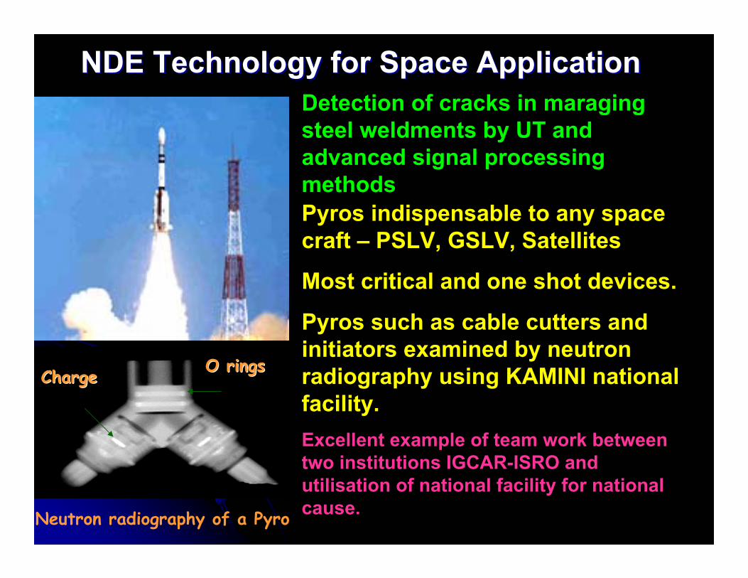
NDE Technology for Space Application NDE Technology for Space Application Detection of cracks in maragingsteel weldments by UT and advanced signal processing methodsPyros indispensable to any space craft – PSLV, GSLV, Satellites
Most critical and one shot devices.
Pyros such as cable cutters and initiators examined by neutron radiography using KAMINI national facility.Excellent example of team work between two institutions IGCAR-ISRO and utilisation of national facility for national cause.Neutron radiography of a Pyro
ChargeCharge O ringsO rings
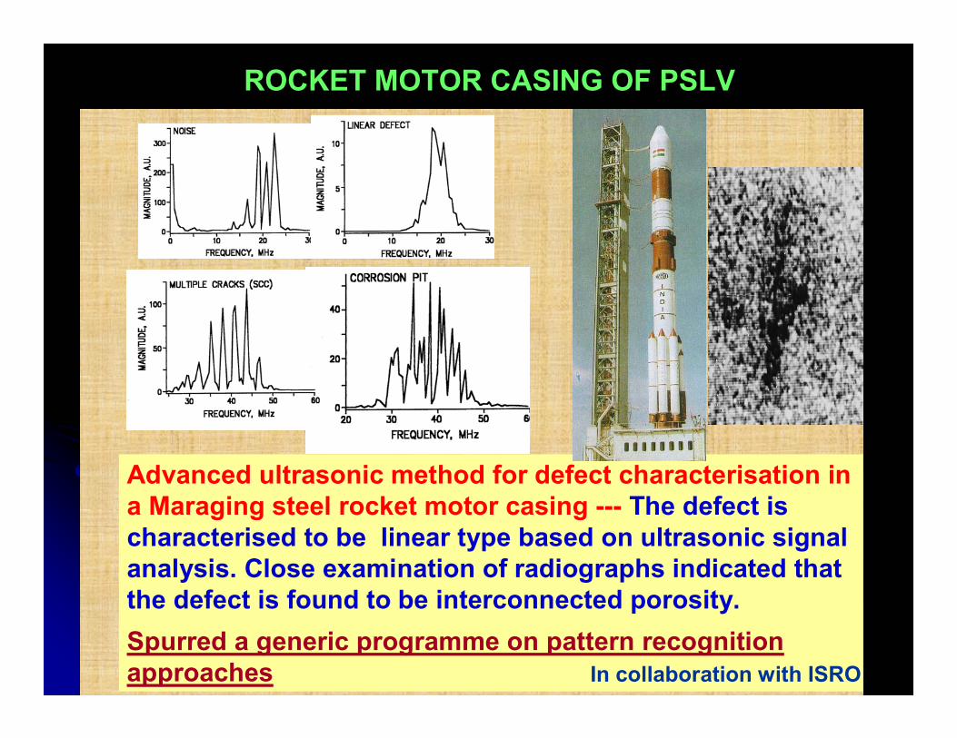
Advanced ultrasonic method for defect characterisation in a Maraging steel rocket motor casing --- The defect is characterised to be linear type based on ultrasonic signal analysis. Close examination of radiographs indicated that the defect is found to be interconnected porosity.Spurred a generic programme on pattern recognition approaches In collaboration with ISRO
ROCKET MOTOR CASING OF PSLV
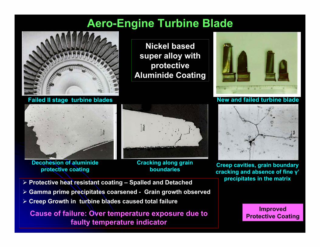
Aero-Engine Turbine Blade
Protective heat resistant coating – Spalled and DetachedGamma prime precipitates coarsened - Grain growth observed Creep Growth in turbine blades caused total failure
Cause of failure: Over temperature exposure due to faulty temperature indicator
Creep cavities, grain boundary cracking and absence of fine γ’
precipitates in the matrix
Decohesion of aluminideprotective coating
Cracking along grain boundaries
Failed II stage turbine blades New and failed turbine blade
Nickel based super alloy with
protective Aluminide Coating
Improved Protective Coating
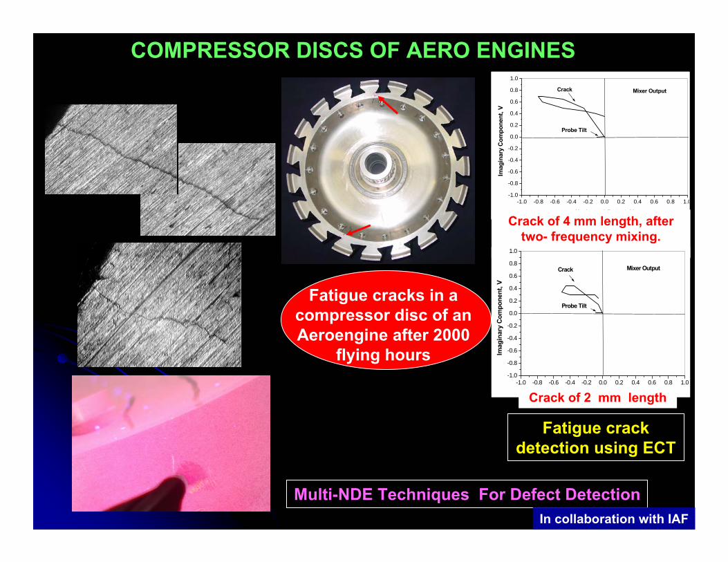
Multi-NDE Techniques For Defect DetectionIn collaboration with IAF
-1.0 -0.8 -0.6 -0.4 -0.2 0.0 0.2 0.4 0.6 0.8 1.0-1.0
-0.8
-0.6
-0.4
-0.2
0.0
0.2
0.4
0.6
0.8
1.0
Mixer Output
Probe Tilt
Crack
Imag
inar
y C
ompo
nent
, V
Horizontal Output, V
Crack of 4 mm length, after two- frequency mixing.
-1.0 -0.8 -0.6 -0.4 -0.2 0.0 0.2 0.4 0.6 0.8 1.0-1.0
-0.8
-0.6
-0.4
-0.2
0.0
0.2
0.4
0.6
0.8
1.0
Mixer Output
Probe Tilt
Crack
Imag
inar
y Co
mpo
nent
, V
Horizontal Output, VCrack of 2 mm length
Fatigue crack detection using ECT
Fatigue cracks in a compressor disc of an Aeroengine after 2000
flying hours
COMPRESSOR DISCS OF AERO ENGINES
NUMBER OF LANDINGS
-6000
RE
SID
UAL
STR
ESS
, MP
a
-200
-400
-500
-300
-100
100
0
800400
1200
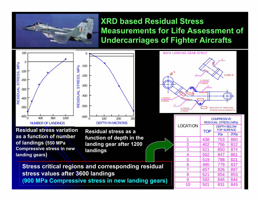
XRD based Residual Stress Measurements for Life Assessment of Undercarriages of Fighter Aircrafts
Residual stress variation as a function of number of landings (550 MPa Compressive stress in new landing gears)
K
7-FRONT8-REAR
5-FRONT6-REAR
3-FRONT4-REAR
9
10
VIEW -K
2
1
REGIONS OF RESIDUAL
MAIN LANDING GEAR STRUT
STRESS M EASUREMENTS
Stress critical regions and corresponding residual stress values after 3600 landings (900 MPa Compressive stress in new landing gears)
RES
IDU
AL
STR
ESS
, MP
a
-600 0
-400
-500
-300
-100
-200
0
300DEPTH IN MICRONS
100 200
Residual stress as a function of depth in the landing gear after 1200 landings
12345678910
519
592501
657621
480
438
621592
402
798
846831
854826779
763
847850756
843844853897837821861874812860
LOCATIONTOP
RESIDUAL STRESS (MPa)COMPRESSIVE
DEPTH BELOWTOP SURFACE10μ 200μ
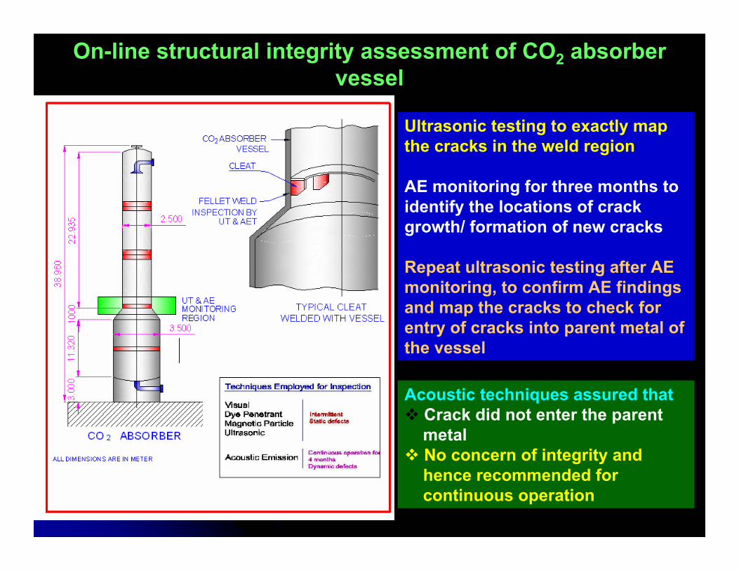
On-line structural integrity assessment of CO2 absorber vessel
Ultrasonic testing to exactly map the cracks in the weld region
AE monitoring for three months to identify the locations of crack growth/ formation of new cracks
Repeat ultrasonic testing after AE monitoring, to confirm AE findings and map the cracks to check for entry of cracks into parent metal of the vessel
Acoustic techniques assured thatCrack did not enter the parent metalNo concern of integrity and hence recommended forcontinuous operation
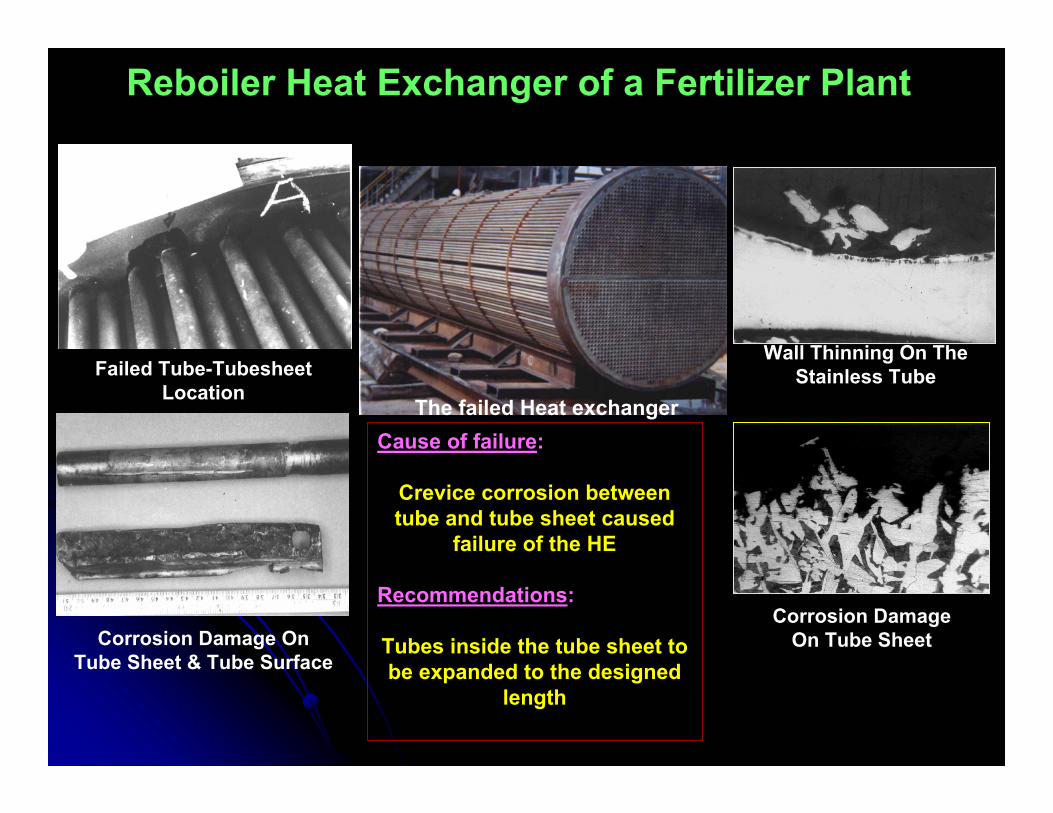
Reboiler Heat Exchanger of a Fertilizer Plant
The failed Heat exchangerCause of failure:
Crevice corrosion between tube and tube sheet caused
failure of the HE
Recommendations:
Tubes inside the tube sheet to be expanded to the designed
length
Wall Thinning On The Stainless Tube
Corrosion Damage On Tube Sheet
Failed Tube-Tubesheet Location
Corrosion Damage On Tube Sheet & Tube Surface

Characterisation and Conservation of Objects of Cultural Heritage
Identification and Application of NDE methods for characterising and fingerprinting metallic art objects (south Indian bronzes)
(DST-IGCAR-Govt. Museum over 200 rare pieces investigated)
Delhi Iron Pillar –Insight into fabrication technology
Ardhanareswarar– 11th century Rustless Wonder – Delhi
Iron Pillar
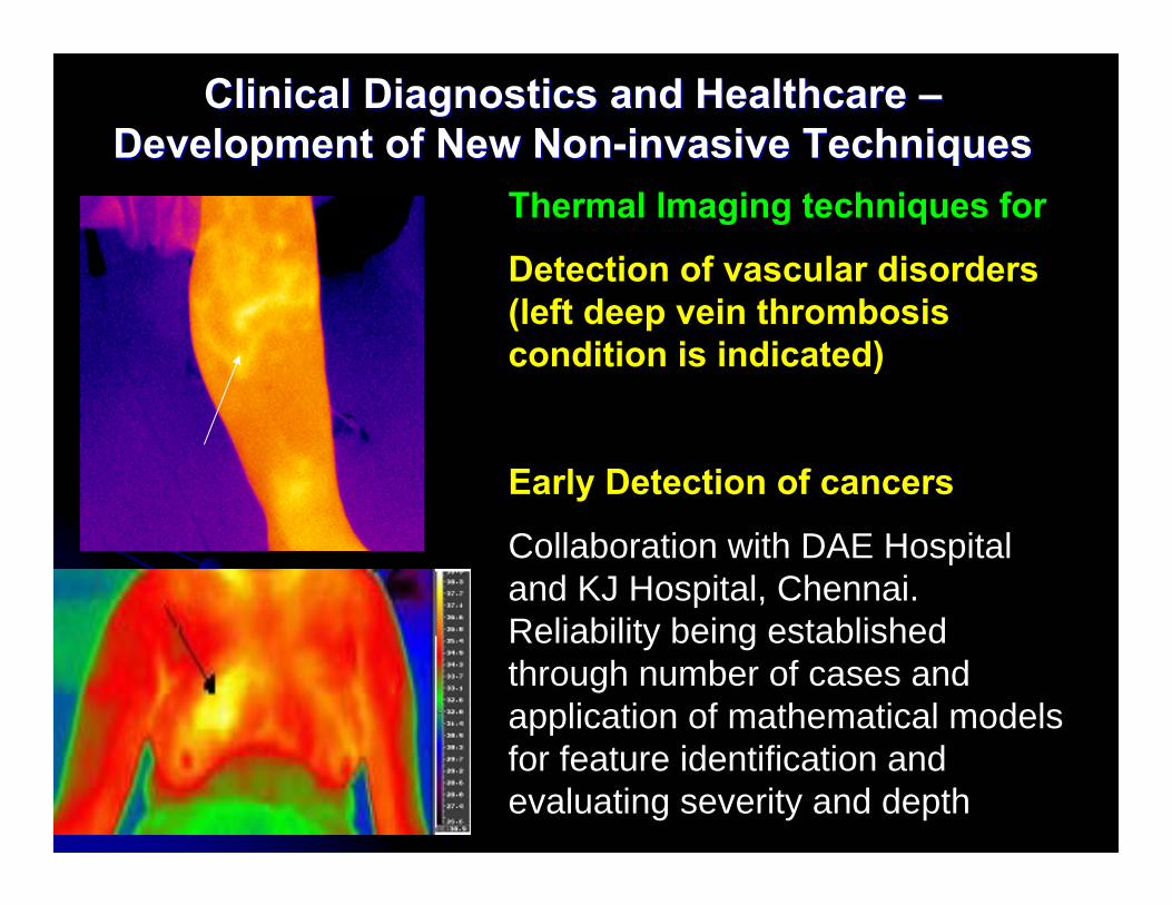
Clinical Diagnostics and Healthcare Clinical Diagnostics and Healthcare ––Development of New NonDevelopment of New Non--invasive Techniquesinvasive Techniques
Thermal Imaging techniques for
Detection of vascular disorders (left deep vein thrombosis condition is indicated)
Early Detection of cancers
Collaboration with DAE Hospital and KJ Hospital, Chennai. Reliability being established through number of cases and application of mathematical models for feature identification and evaluating severity and depth
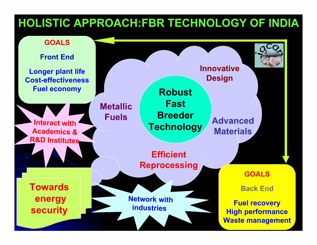
RobustFast
BreederTechnology
EfficientReprocessing
InnovativeDesign
AdvancedMaterials
MetallicFuels
Towardsenergy
security
GOALS
Front End
Longer plant lifeCost-effectiveness
Fuel economy
GOALS
Back End
Fuel recoveryHigh performance
Waste management
Network withindustries
Interact withAcademics &
R&D Institutes
HOLISTIC APPROACH:FBR TECHNOLOGY OF INDIA
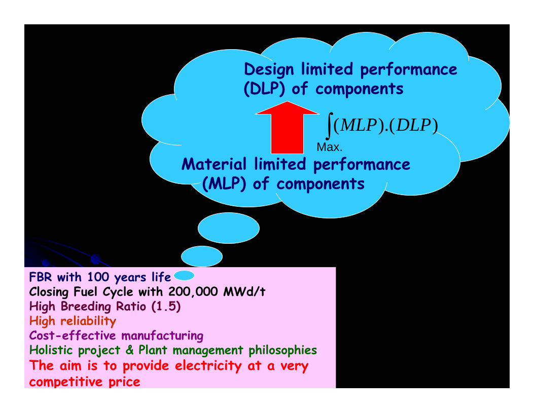
FBR with 100 years lifeClosing Fuel Cycle with 200,000 MWd/tHigh Breeding Ratio (1.5)High reliabilityCost-effective manufacturingHolistic project & Plant management philosophiesThe aim is to provide electricity at a very competitive price
Material limited performance(MLP) of components
Design limited performance (DLP) of components
∫ )).(( DLPMLPMax.

F B T RAuroville, Pondicherry
Science and art belong to the whole world, and before them vanish the barriers of nationality
Theosophical Society, Chennai
Kanchipuram Mamallapuram
Kalpakkam
Towards Energy Security for Indian Prosperity