Materials and Surface Technology for Implants - RMS ...
36
Materials and Surface Technology for Implants Tuesday, 19 th March 2019 Arte Konferenzhotel Riggenbachstrasse 10 4600 Olten / Switzerland Conference Documentation Main organizer Sponsors Partner
-
Upload
khangminh22 -
Category
Documents
-
view
13 -
download
0
Transcript of Materials and Surface Technology for Implants - RMS ...

Materials and Surface Technology for Implants
Tuesday, 19th
March 2019
Arte Konferenzhotel
Riggenbachstrasse 10
4600 Olten / Switzerland
Conference
Documentation
Main organizer
Sponsors
Partner

[MEET THE EXPERT] IMPLANTS ● Materials and Surface Technology for Implants ● 19 March 2019 ● Olten
2
Main Organizer
Sponsors
Partner

[MEET THE EXPERT] IMPLANTS ● Materials and Surface Technology for Implants ● 19 March 2019 ● Olten
3
General Information
Venue
Arte Konferenzhotel Riggenbachstrasse 10 4600 Olten / Switzerland
Powerpoint presentations
The PowerPoint Presentations shown at this event remain in the property of the authors and presenters. The organizer will not distribute the presentations. Please contact the corresponding author if you wish to receive more information on a specific presentation. E-Mail addresses of the authors can be found on the list of authors at the end of this documentation.
Audio recording and use of cameras
Audio recording and the use of cameras (photo and video) is not allowed during the sessions. Please contact the corresponding author if you wish to receive more information on a specific presentation. E-Mail addresses of the authors can be found on the list of authors at the end of this documentation.
Publication
All abstracts that qualify will be published online in a Conference Collection of the eCM Conferences Open Access online periodical. Please register on the eCM Conferences site for paper
notification: http://ecmconferences.org/
Pdf-File of this conference documentation
The pdf version of this documentation as well as the documentations of past conferences are published on the website of the RMS Foundation:
https://www.rms-foundation.ch/en/mte-conference
Feedback
There will be no comment form. If you would like to give us feedback, be it recognition or suggestions for improvement, please send an e-mail to [email protected]
Badge return
Please leave your badge in the recycling box at the exit after the event.

[MEET THE EXPERT] IMPLANTS ● Materials and Surface Technology for Implants ● 19 March 2019 ● Olten
4
Exhibition area and list of exhibitors
Table Company
1 teltec systems ag / FOBA Laser Marking + Engraving
2 FHNW
3 Fuchs AG
4 inspire AG
5 ORTHOMANUFACTURE - Epic & MIC sarl
6 Schaefer-Tec AG
7 Bangerter Microtechnik AG
8 RMS Foundation
9 knoell Germany GmbH
10 MPS Micro Precision Systems AG
12 MOTOREX AG LANGENTHAL
13 Rösler Schweiz AG
14 KKS Ultraschall AG
15 Früh Verpackungstechnik AG
16 Steiger Galvanotechnique SA
17 Portmann Instruments AG
18 Positive Coating SA
19 MTS Systems GmbH
20 ProWaTech AG
21 INVENTEC PERFORMANCE CHEMICALS SA
22 SuSoS AG
23 Cendres+Métaux SA
24 Medicoat AG
25
26 QUO AG

[MEET THE EXPERT] IMPLANTS ● Materials and Surface Technology for Implants ● 19 March 2019 ● Olten
5

[MEET THE EXPERT] IMPLANTS ● Materials and Surface Technology for Implants ● 19 March 2019 ● Olten
6
Meeting Program
08:30 Registration / Welcome Coffee
09:00-09:15 Welcome message
Session 1: Infections Chairperson: Lukas Eschbach
09:15-09:45
Keynote 1: Dr. Mario Morgenstern, Universitätsspital Basel, Switzerland:
The role of biomaterials in prophylaxis and treatment of fracture related infections
09:45-10:30 Flash Presentations Exhibitors and Posters (1 min. each)
10:30-11:00 Break (Exhibition and Poster)
Session 2: Surfaces / Coatings Chairperson: Michael de Wild
11:00-11:20
Dr. Cyril Voisard, Medicoat AG, Mägenwil, Switzerland:
Porous coating by vacuum plasma spray on ceramics hip resurfacing implants
11:20-11:40
Dr. Agnese Carino, Paul Scherrer Institut, Villigen PSI, Switzerland:
Implant surface modification by a controlled biomimetic approach
11:40-12:00
John Disegi, Advanced Biomaterial Consulting LLC, Reading, USA:
Development of an Anodized Titanium Implant Film with Antimicrobial Properties
12:00-12:20
Jakob Oranskiy, Dento-L-Master, LLC, Moscow, Russia:
Protective coating application for individual dental superstructures from CoCr alloys
12:20-12:40
Simona Rohrer, RMS Foundation, Bettlach, Switzerland:
Characterization of particulate contaminants and its challenges
12:40-14:00 Lunch (Exhibition and Poster)
Session 3: Material Integrity Chairperson: Francisco Faoro
14:00-14:30
Keynote 2: Dr Lari Sapoznikov, Basal Implantology Center, Tel Aviv, Israel:
Autogenic dentin as ever best grafting material
14:30-14:50
Dr. Jean Geringer, Mines Saint-Etienne, Saint-Etienne, France:
Effect of Ti on the wear properties of CoCrMo alloy. Investigation under fretting corrosion
14:50-15:10
Dr. Roman Heuberger, RMS Foundation, Bettlach, Switzerland:
Particles and Ions Generated in Total Hip Joint Prostheses: In Vitro Wear Test Results of
UHMWPE and XLPE Acetabular Components
15:10-15:30
Antoine Pfeil, ICUBE Laboratory, University of Strasbourg, INSA, Strasbourg, France:
Evaluation of gamma irradiation impact on 3D-printed multimaterial polymer
15:30-16:00 Break (Exhibition and Poster)
Session 4: Surface / Quality Chairperson: Simon Berner
16:00-16:30
Keynote 3: Martin Schuler, AO Foundation, Zurich, Switzerland:
Surviving the medical device regulation
16:30-16:50
Dr. Ella Dehghani, Ernst & Young, Zurich, Switzerland:
How advancement in surface science and technology will support the challenges of upcoming
regulations
16:50-17:10
Dr Boopathy Dhanapal, Zimmer Biomet, Winterthur, Switzerland:
Cleanliness aspects of coated orthopaedic devices
17:10-17:30
Prof. Michael de Wild, FHNW, Muttenz, Switzerland:
Holographic identification of titanium implants
17:30-17:45 Roundup
17:45 10th Anniversary Aperitif

[MEET THE EXPERT] IMPLANTS ● Materials and Surface Technology for Implants ● 19 March 2019 ● Olten
7
Porous coating by vacuum plasma spraying on ceramics hip resurfacing implant
C Voisard1, S Berner1, C Halewood2, P Gruner1
1 Medicoat AG, Mägenwil, CH. 2 Embody Orthopaedic Ltd, London UK
INTRODUCTION: Clinical complications
following metallic ions release from metal-on-metal
hip resurfacing implants has led to an early
reduction in the deployment of this type of material
combination [1]. The need for low wear material
pairing and large diameter implants for lower
dislocation risks remains though and drives
development of alternative solutions like ceramics-
on-ceramics bearings and full ceramics implants.
Coating the ceramic liner suppresses indeed the
need of a metallic case (cup) and allows larger
ceramics design. In this study a new coating process
of titanium and hydroxyapatite using vacuum
plasma spraying (VPS) has been specifically
developed for a high strength zirconia-toughened
alumina (BIOLOXdelta from CeramTec,
Plochingen Germany) and applied to a new
resurfacing full ceramics design [2].
METHODS: A rough and porous titanium coating
subsequently covered by a hydroxyapatite (HA)
coating has been applied to a new resurfacing
ceramics prosthesis consisting of a femoral head
and an acetabular cup, both made of BIOLOXdelta
ceramics [2]. The titanium layer was directly coated
on the smooth ceramic surface. Conventional grit
blasting process of the surface has been prevented
to avoid reduction in fracture strength.
Furthermore, a pull off test [3] was developed to
assess the adhesion strength directly on the implant
surface in addition to the tests required by the
international standards [4] like adhesion strength
[5], biaxial flexural strength [6] performed with flat
coupons.
Fig. 1: Post Op X-Ray of H1 resurfacing system
(Courtesy Embody Orthopaedics Ltd.).
RESULTS: Biaxial flexure strength of the
ceramics substrate of 773 MPa as measured on test
coupons is not significantly reduced by the VPS
coating process. Nor is the static adhesion tensile
strength of 86 MPa influenced by the ceramics
surface preparation, as measured on various
surfaces (as-fired, milled, ground and polished).
Autoclave heat treatment to simulate hydrothermal
aging and immersion in Ringer solution slightly
reduced the adhesion strength to values in the order
of 75 MPa but without reaching the critical value of
22 MPa [4]. The coating adhesion strength could be
verified directly on implants with the local pull out
test.
DISCUSSION & CONCLUSIONS: Both as-
coated and aged coatings have been tested and high
adhesion strengths could be demonstrated under
various conditions, well above the minimum value
of 22 MPa defined by various international
standards. The novelty of this process is that the
implants are not grit blasted and thus the integrity
of the ceramics could be preserved as demonstrated
with biaxial flexure strength.
REFERENCES: 1 Sershon et al (2016) Curr Rev
Musculoskelet Med 9(1):84-92. 2 Multicentre
Observational Study Evaluating the Clinical
Outcome of the H1 Ceramic Hip Resurfacing
Arthroplasty (H1HRA), ClinicalTrials.gov
Identifier: NCT03326804. 3 ASTM D4541:
Standard Test Method for Pull-Off Strength of
Coatings Using Portable Adhesion Testers. 4 ISO
13179-1 Implants for surgery-Plasma sprayed
unalloyed titanium coatings on metallic surgical
implants. 5 ASTM F1147: Standard test method for
tension testing of calcium phosphate and metallic
coatings. 6 ASTM C1499: Standard Test Method
for Monotonic Equibiaxial Flexural Strength of
Advanced Ceramics at Ambient Temperature.
[MEET THE EXPERT] IMPLANTS ● Materials and Surface Technology for Implants ● 19 March 2019 ● Olten
8
Implant surface modification by a controlled biomimetic approach
A Carino1, A Testino1, E Mueller2, M de Wild3, F Dalcanale3, P Gruner4, W Moser5, B Hoechst6
1 Paul Scherrer Institut, ENE-LBK, Villigen, CH. 2 Paul Scherrer Institut, BIO-EMF, Villigen, CH. 3School of Life Sciences FHNW, Institute for Medical Engineering and Medical Informatics,
Muttenz, CH. 4 Medicoat AG, Maegenwill, CH. 5 Atesos Medical AG, Aarau, CH. 6 Hager &
Meisinger GmbH, Neuss, DE
INTRODUCTION: Titanium and its alloys are
the most frequently used biocompatible materials in
medical engineering. Accelerated osseointegration
can be achieved by modifying the Ti surface with a
layer of calcium phosphate (CaP). Current
processes typically generate a relatively thick CaP
(e.g., by plasma spray) and only a few thin coatings
are available [1, 2]. We developed a cost-effective
protocol for Ti surface modification with a thin
CaP layer using a wet biomimetic route [3].
METHODS: A sand-blasted and acid-etched Ti
grade 4 material is used as starting substrate. The
surface topography is similar to that of
commercially available dental implants. The novel
surface treatments consist of two steps. In the first
step (a modified version of the Kokubo method [4]),
the formation of a highly porous layer of hydrogen
sodium titanate ceramics is promoted. This layer is
strongly joined to metal and renders the implant
surface able to accelerate the formation of apatite
(grafting layer, Figure 1A). In a second step, a thin
layer of synthetic bone (CaP) is grown by a wet
chemistry technique. The physicochemical
parameters which allow the controlled growth of the
synthetic bone are calculated by means of an
accurate thermodynamic-kinetic model of the
aqueous system [5]. The CaP deposition occurs in
the porosity of the grafting layer and on top of it
(Figure 1B). During the whole process pH, ionic
strength, temperature, and saturation level of the
system are controlled on-line and in-situ ensuring
the steady state conditions and the reproducibility of
the process. Therefore, careful control over
thickness, chemical phase, and morphology of the
deposited synthetic bone is achieved.
RESULTS: A thin bioactive synthetic bone layer
on Ti implant surface is attained. The layer does not
alter the roughness induced by blasting or acid-
etching and the implant surface results to be
homogenously modified, regardless of its micro-
and macroscopic shape. The synthetic bone layer is
firmly grafted to the metal. Mechanical tests
demonstrate that the modified surface is preserved
upon implantation and the layer does not
delaminate. The mechanic stability is obtained
thanks to the optimized metal-ceramic joining of the
grafting layer, whereas the modified surface with
synthetic bone offers an ideal substrate for natural
bone growth after implantation.
Fig. 1: Modified surfaces: (A) FIB cross-section;
(B) surface after step 2.
Thanks to the control over the process, a <100 nm
layer hydroxyapatite (HA) or octacalcium
phosphate (OCP) can be deposited. In particular,
OCP is considered the most bioactive CaP phase,
being the precursor of natural bone in the
osteogenesis. Reduced healing time and faster
transition between primary and secondary stability
of the implant can be expected. Moreover, the
synthetic bone layer has a solubility higher than that
of mature hydroxyapatite, which could promote
remodelling to natural bone.
DISCUSSION & CONCLUSIONS: Ti implant
prototypes with biomimetically modified surface
have been produced and show promising chemical
and mechanical in-vitro properties.
REFERENCES: 1 Promimic AB, Sweden,
www.promimic.com. 2 L. M. Svanborg et al (2014)
Evaluation of bone healing on sandblasted and Acid
etched implants coated with nanocrystalline
hydroxyapatite: an in vivo study in rabbit femur.
International Journal of Dentistry 197581. 3 PCT/EP2018/076267. 4 T. Kokubo et al (2010)
Bioactive Ti Metal and its Alloys Prepared by
Chemical Treatments: State-of-the-Art and Future
Trends. Advanced Biomaterials 12:B597. 5 A.
Carino et al (2018) Formation and transformation
of calcium phosphate phases under biologically
relevant conditions: Experiments and modelling.
Acta Biomaterialia 74:478.
ACKNOWLEDGEMENTS: We thank the Swiss
Nanoscience Institute and Medicoat AG for the
financial support, and Hager & Meisinger for
supplying the implants.
A

[MEET THE EXPERT] IMPLANTS ● Materials and Surface Technology for Implants ● 19 March 2019 ● Olten
9
Development of an anodized titanium implant film with antimicrobial properties
J Disegi1, S Williamson2, M Roach2
1 Advanced Biomaterial Consulting LLC, Reading PA, USA. 2 University of Mississippi Medical Center, Jackson MS, USA
INTRODUCTION: Anatase and rutile allotropic
forms of titanium dioxide (TiO2) demonstrate
photocatalytic properties that have been shown to
suppress bacterial activity [1]. A pulsed titanium
anodization waveform was investigated in order to
determine if a crystalline TiO2 structure could be
produced with antimicrobial properties.
METHODS: Test coupons consisted of 2.00 mm
thick CP Ti Grade 4 sheet that met ASTM F67
standard. Coupons were cleaned, immersed in
HNO3-HF, and gold anodized in H2SO4 or neutral
salt bath to provide amorphous TiO2 controls. Four
carbon counter electrodes and a copper bar were
used for pulsed anodization trials. Two-theta X-Ray
Diffraction (XRD) scans were performed between
23° - 30° at a continuous scan rate of 2° per
minute. Surface morphology was evaluated via
Zeiss Supra 40 SEM, Clemex image analysis, and
Veeco Bioscope Catalyst AFM. Triplicate colonies
of S. sanguinis (associated with dental infections)
and Methicillin Resistant Staphylococcus Aureus
(MRSA) were grown to logarithmic phase (108
colony forming units/ml) for exposure periods of 24
or 48 hours at 37 °C. Near-UV light activation was
performed at 350-385 nm wavelength based on
documented information. One-way ANOVA
analysis determined significant differences
(α = 0.05) and post-hoc Tukey analysis separated
significant groups.
RESULTS: Previous evaluations indicated 5.6 M
H2SO4 maximized a gold anatase structure, 2.8 M
H2SO4 maximized a dark green anatase structure,
and neutral salt bath anodizing was ineffective.
Dark green anodizing had the highest anatase and
rutile peak intensities. A SEM micrograph of a dark
green anodized sample is shown in Fig. 1.
Fig. 1 SEM micrograph of dark green anodized
sample with a 5% duty cycle (on-off time) in 2.8 M
H2SO4. (1 micron marker in lower left).
Triplicate pore measurements yielded 15.7 ± 0.6 %
porosity, 10.7 ± 0.9 µm2 density, and 138 ± 5 nm
mean diameter. MRSA antimicrobial activity is
shown in Fig. 2.
Fig. 2: MRSA bacterial count after 24 and
48 hours. All values represent significant
differences versus control except for gold UVA at
24 hours.
DISCUSSION: Pulse anodization trials in H2SO4
produced dark green anodized TiO2 films that
demonstrated statistically significant antimicrobial
activity against S. sanguinis and MRSA. Near-UV
light activation at 350-380 nm wavelength
improved. S. sanguinis antimicrobial response but
was inconclusive for MRSA. Other researchers [2]
have shown that textured stainless steel reduced
E.coli bacterial cells after 48 hours exposure.
Photocatalytic TiO2 response and nano surface
features may have both contributed to antimicrobial
activity. The nanometer surface film should
improve osteoblast adhesion, durability, and
adherence when compared to bulk coatings.
Regulatory pathway should be straightforward
since the TiO2 surface contains no intentionally
added substances.
REFERENCES: 1 L Visia et al (2011) Titanium
oxide antibacterial surfaces in biomedical devices;
Int J Artif Organs 34 (9):929-46. 2 Y Jang et al
(2018) Inhibition of Bacterial Adhesion on
Nanotextured Stainless Steel 316L by
Electrochemical Etching; ACS Biomater Sci Eng
4(1):90-7.
ACKNOWLEDGEMENTS: DePuy Synthes
provided funding for this research project.

[MEET THE EXPERT] IMPLANTS ● Materials and Surface Technology for Implants ● 19 March 2019 ● Olten
10
Protective coating for individual dental superstructures from CoCr alloy
J Oranskiy1, DV Tetyukhin2, SA Molchanov2, EN Kozlov2
1 Dento-L-Master LLC, Moscow, Russia. 2 CONMET LLC, Moscow, Russia
INTRODUCTION: Presently, individually milled
superstructures made from CoCr alloys are widely
spread due to the availability of CAD/CAM
technologies. However, CoCr alloy application has
the following disadvantages: oxidation of metal
surfaces that were not coated by dental ceramic
during the sintering process under high
temperatures. The need for oxidized layer removal
(e.g. by sandblasting treatment) leads to a change in
shape and size of the superstructure interface and,
consequently, increase of micro-mobility and
hermeticity loss in the implant-abutment connection
and emergence of a galvanic pair with titanium
implants. Deposition of submicron nanocrystalline
coating of Al2O3 with the thickness of 0.1 - 0.5 μm
allowed to solve the issues.
METHODS: For coating individually milled
superstructures an atomic layer deposition method
(ALD) was applied. The method allows applying
thin and conformal metal oxide coatings [1].
Aluminium oxide is chosen due to its high heat
resistance, strength and bio-inertness. To confirm
the protective properties, experiments were
performed on CoCr samples of dental
superstructures and its pre-mills with Al2O3
coatings with a thickness of 0.1 μm and 0.15 μm.
To test the heat resistance, the samples were
subjected to cyclic heating in an atmosphere
according to the standard mode for facing CoCr
alloy frame with ceramic masses. Then the samples
were checked for the integrity and stability of the
oxide layer. For assessing the barrier properties of
the coating, its dielectrical strength was being
determined. Spherical electrodes with a diameter of
4 mm were applied to the flat or cylindrical surface
of coated samples. A constant voltage from the DC
power supply was applied stepwise by 0.05 V to
electrodes. The emergence of breakdown was
determined by the appearance of a current in the
circuit, which was limited to 0.001 A.
RESULTS: The created Al2O3 submicron coating
with 0.15 μm thickness allowed to protect the
surface of individual dental superstructures from
thermal oxidation during the sintering process
(5 cycles of heating up to 1000 °C (Fig. 1)), and to
improve as well the barrier properties of the surface
due to the high dielectrical strength of the coating
(Table 1), significantly reducing the risk of the
galvanic pair emergence.
Fig. 1: Individual dental superstructures after
5 cycles of ceramic facing a) without the protective
coating, b) with the protective coating.
Table 1. Dielectric strength of Al2O3 coatings on
CoCr samples.
No Description of
samples
Coating
thicknes
s, μm
Breakdown
voltage, V
1 Pre-mill with
coating
0.1 0.775 ± 0.025
2 Pre-mill with
coating
0.15 2.45 ± 0.05
3 Individual
superstructure
with coating and
ceramic facing
0.15 2.45 ± 0.05
DISCUSSION & CONCLUSIONS: The
conducted studies confirm that the use of Al2O3
coating in the manufacturing process of
superstructure produced from CoCr alloys excludes
interface oxidation during the dental ceramic
sintering process, as well as formation of dielectric
barrier between the superstructure and a titanium
implant. Taking into account innovativeness of the
ALD-method it is necessary to conduct additional
research, in vitro and in vivo studies.
REFERENCES: 1 V. Miikkulainen, M. Leskelä,
M. Ritala, and R. L. Puurunen (2013) Crystallinity
of inorganic films grown by atomic layer
deposition: Overview and general trends; J. Appl.
Phys. 113:021301.
a) b)

[MEET THE EXPERT] IMPLANTS ● Materials and Surface Technology for Implants ● 19 March 2019 ● Olten
11
Fig. 1: Microscopy images of different particles –
a) shows an unalloyed steel particle found in a
water extract from the client's polymer film. b)
shows a crystallized antioxidant found in all
hexane extracts of polymer films.
Characterization of particulate contaminants and its challenges
S Rohrer1, D Streit2, F Bigolin2, R Wirz1, N Döbelin1, M Bohner1
1 Bioceramics & Biocompatibility Group, 2 Materials Group, RMS Foundation, Bettlach, CH
INTRODUCTION: Manufacturers of medical
devices are being requested by the FDA to indicate
the level and type of particle contamination of their
product and to evaluate the potential risk for the
patients. As part of a 510(k) premarket approval
submission, a client had to determine the particle
contamination of the polymeric film component of
its negative pressure wound therapy kit, and to
compare it to that of a predicate device.
METHODS: Contaminant particles were extracted
from the polymer films and from blanks in three
different solvents at 50 °C, according to ISO
10993-12:2012 [1] and to special requirements of
the FDA. The particles were then collected on a
polyamide filter, counted and divided into non-
metallic, fibres, and metal particles with an
automatic filter analysis system of JOMESA
(JOMESA HFD), and characterized by FTIR
(Bruker LUMOS) or EDX (Zeiss Evo MA25). All
experiments were done in triplicate.
RESULTS: The highest total number of particles
determined per client or predicate device film was
516 and 1233, respectively. The highest number of
≥ 25 µm particles determined per client or predicate
device film was 155 and 542, respectively. While
the amounts of particles extracted from the client's
films were always below the thresholds specified in
the USP <788> standard (max. 300 ≥ 25 µm
particles and 3000 ≥ 10 µm particles) [2], the
amount of ≥ 25 µm particles extracted from one
predicate device film was above this threshold.
Overall, 16 types of particles were detected in the
extracts of the client’s films (e.g., a non-alloy steel
particle shown in Fig. 1a). Comparing, 36 types of
particles were detected in the extracts of the
predicate device film and 20 types in the blank
controls presumably due to residual particles from
the clean room environment. Regardless of the
extraction medium, the vast majority of the
particles found were non-metallic particles. The
most abundant contaminants in the extracts of the
client’s film were PU particles, cellulose fibers,
CrNi steel particles, the antioxidant, cellulose,
polyamide, and polypropylene particles. Except for
the CrNi steel particles, all these particle types were
also repeatedly observed in the extract of the
predicate device films. However, these extracts
additionally contained particles out of proteins
(possibly skin residues), wool (animal derived), and
nail polish.
The polymer films of the client and the predicate
device showed partial decomposition in hexane and
ethanol. Fine needles (Fig. 1b) precipitated during
hexane cooling. These needles were identified as the
antioxidant N,N′-Hexamethylenebis(3,5-di-tert-
butyl-4-hydroxyhydrocinnamamide), which is used
in the raw material of the films. Extraction in
95 vol% ethanol resulted in the formation of fine
white particles in the sediment, which were
identified as polyurethane film base material.
DISCUSSION & CONCLUSIONS: Difficulties
were encountered at different levels such as: (i) the
design of the extraction experiments, (ii) the large
size, surface area, and electrostatic behaviour of the
film; (iii) the technical limitations of optical
microscopy and FTIR chemical identification; (iv)
the partial decomposition of the films in hexane and
ethanol; (v) the contaminants present in our clean
room; (vi) the statistical analysis. However, the
results demonstrated that the client product
contained fewer contaminant particles than the
threshold values set in the standard USP <788> and
that their chemical compositions were
unproblematic. Contrarily, a predicate device
contained too many particular contaminants, and
some were critical, such as nail polish and wool /
proteins.
REFERENCES: 1 ISO 10993-12:2012: Biol.
evaluation of medical devices - Part 12: Sample
preparation and reference materials. International
Organization for Standardization (07-2012). 2 USP <788>: Particulate Matter in lnjections.
United States Pharmacopeia (01-07-2012).
ACKNOWLEDGEMENTS: The authors would
like to thank the client for the possibility to publish
their case.
a b

[MEET THE EXPERT] IMPLANTS ● Materials and Surface Technology for Implants ● 19 March 2019 ● Olten
12
Sponsors

[MEET THE EXPERT] IMPLANTS ● Materials and Surface Technology for Implants ● 19 March 2019 ● Olten
13
Autogenic dentin as ever best grafting material
L Sapoznikov
Basal Implantology Center, Tel Aviv, Israel
SUMMARY: It has been known for many years
that human dentin has the same properties and
consistence as that of bone, especially cortical one
and can be used as bone substitute. However,
extracted teeth remain to be clinical waist and are
simply discarded being autologous graft material
(golden rules of grafting and transplantation).
In this presentation, I want to show the clinical
procedure for using autogenic dentin from extracted
teeth for every day practice as for general dental
practitioners as well as for implantologists and
maxillofacial surgeons.

[MEET THE EXPERT] IMPLANTS ● Materials and Surface Technology for Implants ● 19 March 2019 ● Olten
14
Effect of Ti on the wear properties of CoCrMo-alloy:
Investigations under fretting corrosion
K Maeda1, S Nakahara1, T Masanori1, K Ueda1, T Narushima1, F Farizon2, J Geringer3
1 Dpt of Materials processing / Tohoku University, Japan. 2 University Hospital of Saint‐Etienne,
CHU‐COT, INSERM U1059, Saint‐Etienne, France. 3 Health Engineering Center, Mines
Saint‐Etienne, INSERM U1059, Saint‐Etienne, France
INTRODUCTION: Fretting corrosion
phenomenon can lead to wear and corrosion of
many contact surfaces found in a corrosive media.
Fretting corrosion can occur in motors of cars,
turbines, and sometimes this phenomenon can occur
on some parts of the metallic surfaces of
orthopaedic implants, thus resulting in wear
particles release that can be deleterious for the
patient’s health. Decreasing the wearing of metals
in vivo as a result of fretting is an important point
to achieve, thereby decreasing the level of allergic
reactions and immune responses to metallic wear
particles in the human body. CoCrMo is an alloy
which is widely used in industry for manufacturing
of artificial joints.
METHODS: This study focuses on understanding
the effect of 1 % Ti on the resistivity of CoCrMo-
alloy against wearing when subjected to fretting
corrosion conditions. The fretting corrosion
experiments were conducted with CoCrMo and
CoCrMo with 1 % Ti alloys (Fig 1). The samples
were subjected to fretting against different polymers
such as PMMA (Polymethyl-methacrylate), PEKK
(polyetherketoneketone), and PEKK with 30 %
carbon fibres. The goal was to compare the wearing
resistivity of the CoCrMo-alloy with and without
1 % Ti against different types of polymers. The
duration of the experiment was 4 hours in 0.1 M
NaCl + 30 g/L albumin solution and the
displacement was 80 μm. In addition, 3D
profilometric and SEM images were taken to
characterize the shape of the worn zones on the
surface of the metallic samples.
RESULTS: Wearing of CoCrMo was the highest
against PMMA. On the other hand, CoCrMo
showed lower wearing against PEKK and the
lowest wearing was against PEKK with 30 % CF.
As for CoCrMo with 1 % Ti, the wearing was
lower against the 3 polymers compared to CoCrMo
upon fretting against PMMA, PEKK and PEKK
with 30 % carbon fibres. The effect of 1 % Ti on
CoCrMo alloys was a better resistance against
fretting corrosion phenomenon.
Fig. 1: Back Scattering Electron Image of the Co-
28Cr-6Mo-0.25C-1Ti.
Fig. 2: Fretting corrosion machine
DISCUSSION & CONCLUSIONS: The
CoCrMo-alloy with 1 % Ti might be a good
candidate to decrease the wear under fretting
corrosion conditions.
REFERENCES: 1 K. Ueda, M. Kasamatsu, M.
Tanno, K. Ueki, J. Geringer, T. Narushima (2016)
Materials Transactions 57:2054-9.

[MEET THE EXPERT] IMPLANTS ● Materials and Surface Technology for Implants ● 19 March 2019 ● Olten
15
Particles and ions generated in total hip joint prostheses:
in vitro wear test results of UHMWPE and XLPE acetabular components
H Zohdi, B Andreatta, R Heuberger
RMS Foundation, Bettlach, CH
INTRODUCTION: The accurate and detailed
characterization of wear particles and ions released
from total hip joint prostheses is essential to
understand the cause and development of osteolysis,
aseptic loosening and hypersensitivity.
METHODS: The wear particles and ion release of
22 different test liquids from hip simulator studies
were investigated. Wear particles generated from
acetabular components made of ultra-high-
molecular-weight polyethylene (UHMWPE) or
cross-linked polyethylene containing vitamin E
(XLPE, all from Mathys Ltd. Bettlach, CH) were
isolated by acidic digestion and characterised using
scanning electron microscopy (SEM) and laser
diffraction. Additionally, we investigated the effect
of accelerated ageing, running-in versus steady-
state, head materials and calcium sulphate third-
body particles [1] on the morphology and size of the
created debris.
The Fe, Ni, Mn, Nb, Co, Mo and Al ions released
from femoral heads made of stainless steel,
CoCrMo and alumina ceramic were analysed using
inductively coupled plasma mass spectrometry
(ICP-MS).
RESULTS: The wear particles were predominantly
in the submicron range and of globular shape, with
occasional fibrils (Fig. 1). The size distributions of
the UHMWPE and XLPE particles were similar
(Fig. 2); however, more fibrils were observed
among the UHMWPE particles [2]. The average
particle size decreased for most samples in the
Fig. 1: SEM-image of globular wear particles and
fibrils from an aged UHMWPE liner.
steady-state phase compared to the running-in. The
accelerated ageing and the presence of third-body
particles generally caused larger UHMWPE wear
particles only.
The ion concentrations were very low and close to
the detection limit. However, increasing the size of
the stainless steel femoral heads led to an increased
ion level [2].
DISCUSSION & CONCLUSIONS: Although
SEM is the most standardized technique to
characterize the morphology of wear debris, it led
to an over-estimation of the particle size (Fig. 2).
However, the combination of SEM and laser
diffraction was very powerful to analyse both the
morphology and the particle-size distributions of the
polyethylene wear particles.
Most particles were in the submicron range and
globular, whereas the size distribution from
UHMWPE and from XLPE particles were similar.
Low concentrations of ions were released from the
head materials.
0.0 0.1 0.2 0.3
0.0
0.1
0.2
0.3
0.4
0.5
0.6 UHMWPE
d95
d80
d50
d20
d5
XLPE
d95
d80
d50
d20
d5
Dia
met
er b
y S
EM
, µ
m
Diameter by Laser Diffraction, µm
Fig. 2: Percentiles of the equivalent diameter of
polyethylene particles determined with SEM vs.
diameter determined using laser diffraction.
REFERENCES: 1 R. Heuberger, P. Wahl, J.
Krieg, E. Gautier (2014) eCM 28:246. 2 H. Zohdi,
B. Andreatta, R. Heuberger (2017) Tribol Lett
65:92.
ACKNOWLEDGEMENTS: We thank O. Loeffel
and T. Imwinkelried (both RMS Foundation) for
their help and the RMS Foundation for the financial
support.

[MEET THE EXPERT] IMPLANTS ● Materials and Surface Technology for Implants ● 19 March 2019 ● Olten
16
Evaluation of gamma irradiation impact on 3D-printed multimaterial polymer
A Pfeil1, F Schuler2, L Barbé1, F Geiskopf1, M de Wild2, P Renaud1
1 INSA-ICUBE, Strasbourg, France. 2 FHNW-HLS, Muttenz, CH
INTRODUCTION: Multimaterial additive
manufacturing may offer new possibilities for
design of medical devices thanks to the freedom of
shape and material. Rigid and flexible
biocompatible materials are now available so
polymer devices could benefit from the materials
and the novel production process [1-2]. To this
purpose, we investigate the impact on mechanical
performance of ɤ-irradiation, a standard
sterilization process, to polymer parts.
METHODS: Polyjet technology (Stratasys Ltd,
USA) is being studied with a Connex 350 system
processing UV-curing resins. A rigid material,
commercialized as Verowhite Plus, and a flexible
one, TangoBlack Plus, are assessed. Mechanical
performance is tested using tensile tests according
to ISO 527-1 for the rigid material, with type 1A
specimen. For the flexible material, a sample is
designed to have a length of reduced section of
25 mm, and a cross section of 4*4 mm2. Five
specimens of rigid materials and one of flexible
material are tested, before and after irradiation at
34 kGy. In addition, an assembly of 3D-printed
parts of both materials to build a pneumatic medical
actuator [3] is tested in terms of biopsy-needle
positioning velocity before and after irradiation.
RESULTS: The stress-strain curves of the rigid
material are shown in Fig. 1. The Young’s modulus
(mean±std) of the unexposed and the ɤ-exposed
specimens are equal to 1830±38 MPa and
2810±37 MPa, respectively. ɤ-irradiation has a
significant stiffening effect. It is also to be noted
that 2 out of 5 specimens show a rupture before
4.5 % of strain. The other 3 specimens present a
stress increase in the plastic domain, that was not
observed before irradiation. No significant impact is
noted for the flexible material. The pneumatic
actuator (Fig. 2) is still functional after irradiation
despite the Young’s modulus increase of rigid
material, with no significant variation of velocity.
DISCUSSION & CONCLUSIONS: The 53 %
increase of the Young’s modulus and the stress-
strain relationship of the rigid material could be
explained by a reticulation of the polymer structure
under gamma exposition. This work allows the
designer to compensate the stiffening effect during
design for additive manufacturing process. The
insignificant impact on flexible material and the
satisfying behaviour of pneumatic actuators are
encouraging to further test the materials and
perform microbiological testing of ɤ-exposed
materials.
Fig. 1: Stress-strain curve of the rigid polymer
specimens, before and after ɤ-sterilization.
Fig. 2: 3D printed multimaterial pneumatic
medical biopsy actuator after gamma irradiation.
REFERENCES: 1 N. Nagarajan, A. Dupret-
Bories, E. Karabulut, P. Zorlutuna, N.E. Vrana
(2018) Enabling personalized implant and
controllable biosystem development through 3D
printing; Biotechnology Advances 36(2):521–33. 2 A. Amelot, M. Colman, J.-E. Loret (2018) The
Spine Journal 18(5):892–9. 3 A. Pfeil, L. Barbé, B.
Wach, A. Bruyas, F. Geiskopf, M. Nierenberger, et
al (2018) A 3D-Printed Needle Driver Based on
Auxetic Structure and Inchworm Kinematics.
ASME IDETC V05AT07A057.
ACKNOWLEDGEMENTS: The SPIRITS
project is supported by the Region Grand Est, Land
Baden-Württemberg, Land Rheinland-Pfalz,
Cantons Baselstadt, Basellandschaft, Aargau,
Swiss Confederation and by the program
INTERREG Upper Rhine from the ERDF
(European Regional Development Fund).

[MEET THE EXPERT] IMPLANTS ● Materials and Surface Technology for Implants ● 19 March 2019 ● Olten
17
How advancement in surface science and technology will support the challenges
of upcoming regulations
ES Dehghani
Ernst & Young, Zurich, CH
INTRODUCTION: As the populations are aging,
the need for medical devices and specifically
implants are increasing. Although these devices
have saved many lives, they have – at times – been
detrimental to patients’ health, as several scandals
have come into light. Notably, EU-Medical Device
Regulations (EU-MDR) was introduced to ensure
that customer’s safety and needs are met, by
focusing on how medical devices, including
implants are designed, manufactured, distributed,
and tracked through their life-cycle. Specifically,
this regulation takes a closer look at what is present
at the surface of the medical devices, and it requires
the brand to provide specifications of the chemical
and physical nature of surfaces. Specifically, EU-
MDR specifies that “Devices shall be designed and
manufactured in such a way as to reduce – as much
as possible – the risks posed by substances or
particles, including wear debris, degradation
products and processing residues that may be
released from the device”. The new emphasis on
substances leaking from the device and their wear
debris, requires the medical device companies to
take a closer look at Materials Specification Sheet
and the manufacturing processes which are used, to
determine the exact chemical composition and
debris size of the medical device surface.
These challenges bring a new breath into an
industry which has been using the same procedures
and manufacturing over the last several decades.
Advancements in surface science will bring new
light on how brand and label medical device
companies design and manufacture their products.
In this talk, an introduction to the regulations
focusing on surface science will be provided.
TECHNIQUES: In this talk, X-ray photoelectron
spectroscopy (XPS), attenuated total reflection
(ATR), scanning electron microscopy (SEM), X-
ray diffraction (XRD), Fourier transform infrared
analysis (FTIR), transmission electron microscopy
(TEM), nuclear magnetic resonance (NMR),
thermogravimetric analysis (TGA), gel permeation
chromatography (GPC), and mass spectrometry
will be discussed in regards to their capabilities,
applications, advantages and disadvantages.
CONCLUSION: At the end of this lecture, target
audiences and medical device companies will have a
better understanding on how to employ technical
expertise to meet the EU-MDR requirements.

[MEET THE EXPERT] IMPLANTS ● Materials and Surface Technology for Implants ● 19 March 2019 ● Olten
18
Cleanliness aspects of coated orthopaedic devices
B Dhanapal
Analytical Testing Services, Quality Assurance, EMEA, Zimmer Biomet, Winterthur, CH
INTRODUCTION: Cleaning orthopaedic implant
devices commonly involves aqueous detergent based
processes. The detergent solutions can be acidic,
alkaline, neutral or enzymatic and ultrasonic may
also be utilized. Typically, coated devices represent
challenges for cleaning, as the cleaning process
must remove manufacturing materials, processing
aids, and other contaminations, but retain the coated
surface unaffected. Ultrasonic cleaning removes not
only the contaminations but also a part of the
coating materials.
For Hydroxyapatite-coated (HA) devices, first of all
it is essential that the raw material is in compliance
to ASTM F1185 [1]. During coating, masking
materials are used to cover areas of the implant that
are not intended to receive surface treatments. The
masking material residue shall be removed with an
appropriate solvent.
Purified water based cleaning may be detrimental to
HA-coated implants because HA is partly soluble in
water and has high affinity to a broad range of
contaminations. For instance bacterial endotoxins
are adsorbed to the surface. Extraction according to
ASTM F2459 [2] method accounts for polar and
non-polar contaminations. An ultrasonic assisted
process does not only remove contamination, but
also parts of the coating material, which is intended
to be present by design. This makes it challenging
to use only gravimetric methods for residual
analysis. Therefore it is essential to use or combine
more specific analytical methods, such as ICP and
HPLC as described in ASTM F2847 [3].
METHODS: In our approach, the test parts were
assayed for extractable residues by Fourier
Transform Infrared spectroscopy (FT-IR), for
water extractable residues by Total Organic Carbon
(TOC), and for water extractable insoluble
particulate matter by gravimetric method.
RESULTS: Based on our experience using ASTM
F2459 to quantify residuals gravimetrically, the
typical detection limit (DL) for soluble residues of
0.3 mg/part is more than a factor ten (0.02 mg/part)
higher than the FT-IR method described there.
Lower DLs may be necessary to assure a reliable
assessment of the cleanliness of certain products in
a statistical manner.
DISCUSSION: There are challenges with respect
to manufacture and quality control of coated
devices. In this presentation we focus on
manufacturing, cleaning and quality assurance of
the device.
Although ASTM F2459 has made a significant
contribution to the orthopaedic industry in regards
to evaluating the cleanliness of 100 % metallic
medical devices, more standardization is needed
especially in the case of coated devices.
CONCLUSIONS: Relationship between biological
evaluation, cleaning validation, and sterilization
validation is illustrated in the ISO 19227 standard
[4]. Control of critical in-process cleaning is
essential in order to achieve clean coated devices
according to ISO 19227. Cleaning validation can be
declared complete only when the sterilization
validation and the biological evaluation of the
implants are completed in accordance to ISO
10993-1.
REFERENCES: 1 ASTM F1185, Standard
composition of hydroxyapatite. 2 ASTM F2459,
Standard test method for extracting residues from
metallic medical components and quantifying via
gravimetric analysis. 3 ASTM F2847, Standard
practice for reporting and assessment of residues on
single use Implants and single use sterile
Instruments. 4 ISO19227 Implants for surgery,
Cleanliness of orthopaedic implants – General
Requirements.
ACKNOWLEDGEMENTS: Thanks to the active
collaboration of ASTM F04, ISO/TC 150 and
Zimmer Biomet colleagues.

[MEET THE EXPERT] IMPLANTS ● Materials and Surface Technology for Implants ● 19 March 2019 ● Olten
19
Holographic identification of titanium implants
M de Wild1, R Krähenbühl2, D Kallweit2, R Marek1, M Estermann3, M Schnieper2
1 University of Applied Sciences Northwestern Switzerland, School of Life Sciences, Muttenz, CH. 2 Centre Suisse d'Electronique et de Microtechnique CSEM, Muttenz, CH.
3 Thommen Medical AG, Grenchen, CH
INTRODUCTION: An innovative design attribute
was developed as Unique Device Identification
(UDI) for medical devices. [1] Holographic security
features and highly complex Diffractive Optical
Elements (DOE, revealing images like QR codes,
logos, article or lot numbers when illuminated by a
laser, see Fig. 2) are integrated directly into the
titanium implant material to ensure traceability or
brand protection to prevent product counterfeiting.
This nanostructured surface-labelling is fully tissue-
compatible because the embossing process is based
on a physical structuring of the implant surface
without additives or coating. The underlying
holographic nanostructures are resistant to all
conventional sterilization methods.
METHODS: A structured, ultra-hard steel stamp
was used to emboss the surface of titanium parts
for holographic labelling. The visibility of the
created holograms was investigated for different
process parameters and the precise and detailed
sub-micrometer structure of the embossed surface
was qualified by SEM and AFM. Wear tests have
been performed for up to 5’000 stamping cycles on
a moving titanium plate to prevent the same spot
from being repeatedly stamped.
Fig. 1: a, b) Clearly visible embossed holograms
on Ti abutments. c) Scanning Electron Microscopy
image shows the periodicity of the diffractive
structure on the tooled titanium surface.
RESULTS: The holographic structures can be
transferred from the stamp to the surface of the
titanium components. Diffractive characteristics
like iridescent light effect can be detected visually
under white light (see Figures 1a and b) and the
corresponding periodic pattern can be observed by
SEM (Figure 1c). The most important process
parameters identified were the temperature, the
contact force per unit area and the surface
roughness of the area to be stamped. With constant
forming force, the embossing process becomes more
efficient at higher process temperature and
decreasing surface roughness of the stamping area.
The durability test of the stamp revealed a
serviceability up to 5’000 tooling cycles. Although
the average grating height of the master structure on
the stamp was reduced by 32 %, the holographic
effect is still nicely visible on the stamp and on the
imprinted Ti devices. Even incompletely embossed
patterns work as long as there is periodicity.
Fig. 2: A DOE-diffracted laser produces a visible,
precalculated image on a screen.
DISCUSSION & CONCLUSIONS: It has been
demonstrated that it is possible to transfer
diffractive sub-micrometer structures such as
visible holograms and Diffractive Optical Elements
into titanium implant material. This unique
holographic identification feature allows
verification of the authenticity of implants,
prosthetic parts or instrument and could serve as a
UDI for medical devices.
REFERENCES: 1 Unique Device Identification
(UDI) for medical devices, Task Order No. 24, food
and drug administration (2012).
ACKNOWLEDGEMENTS: This study was
supported by InnoSuisse grant 18679.2 PFIW-IW.

[MEET THE EXPERT] IMPLANTS ● Materials and Surface Technology for Implants ● 19 March 2019 ● Olten
20
Sponsors

[MEET THE EXPERT] IMPLANTS ● Materials and Surface Technology for Implants ● 19 March 2019 ● Olten
21
Poster Session
1
Bioactivity in osseointegration of tantalum oxynitrides coatings for dental implants
Joël Matthey, Haute Ecole Arc Ingénierie, La Chaux-de-Fonds, Switzerland
2
Delayed Delamination Mechanisms of DLC Coatings on Articulating Implants
Emilija Ilic, Empa / EPFL, Dübendorf, Switzerland
3
Hydroxyapatite coating delaminated from hip stem after 14 months in-situ – a case report
Christoph Sprecher, AO Research Institute Davos, Davos, Switzerland
4
Cleaning of 3D-Printed Titanium Implants
Dr. Clément Cremmel, KKS Ultraschall AG, Steinen, Switzerland
5
Towards functional Silicon Nitride Coatings on Joint Replacements
Dr. Susann Schmidt, IHI Ionbond AG, Olten, Switzerland
6
Experimental Mapping of Contact Stresses Related to Hip Arthroplasty Using Dual Mobility Cup
Dr. Jean Geringer, Mines Saint-Etienne, Saint-Etienne, France
7
Direct Part Laser Marking in the Medtech Industry – How to make UDI-Code Marking safe and compliant
Son Tran, FOBA Laser Marking + Engraving I Alltec GmbH, Selmsdorf, Germany
8
Bridging cartilage defects: Could a metal foam/polymer-compound be an option?
Dr. Thomas Imwinkelried, RMS Foundation, Bettlach, Switzerland
9
Increasing the primary stability of cementless monoblock cups
Dr. Martin Schmidt, Jossi Orthopedics AG, Islikon, Switzerland

[MEET THE EXPERT] IMPLANTS ● Materials and Surface Technology for Implants ● 19 March 2019 ● Olten
22
Bioactivity in osseointegration of tantalum oxynitrides coatings for dental
implants
J Matthey1, O Banakh1, S Durual2
1 University of Applied Sciences (Haute Ecole Arc Ingénierie HES-SO), La Chaux-de-Fonds, CH. 2 University of Geneva, School of Dental Medicine, Geneva, CH
INTRODUCTION: Since decades, surface
engineering plays a key role in the medical industry.
Nowadays, coating technology research grows fast
and offers novel solutions to improve the quality
and durability of medical devices. Among new
materials, metal oxynitrides are considered
promising for applications in implantology due to
their potential to accelerate early osseointegration
[1]. The purpose of this study was to assess the
osseointegration potential of sputtered tantalum
oxynitride (TaOxNy) coatings with different
nitrogen and oxygen contents grown on a standard
dental implant material.
METHODS: TaOxNy coatings with different
nitrogen and oxygen contents have been deposited
by Magnetron Sputtering and High Power Impulse
Magnetron Sputtering technologies onto micro-
rough titanium and micro-rough stainless steel
substrates. The coating thickness was set to 300
nm. Tailoring the coating composition can be
performed with help of the target current hysteresis
effect. Ion-induced secondary electron emission
increases with the nitrogen flow while it decreases
with the oxygen flow. Regarding surface
preparation, Metal-Ion-Etching (MIE) clearly
showed a modification of the titanium substrate
micro-roughness. In some experiments, water vapor
replaced oxygen in the process in order to bind
hydroxyl groups at the coating surface. The micro-
rough titanium surface was chosen as control and
all obtained thin films were evaluated for their
influence on cell proliferation with HOS osteoblast
cells using a resazurin assay at days 4, 8, 14 and
21. Regarding the corrosion resistance, coated
samples were tested in Ringer’s solution + 0.2M
sodium fluoride.
RESULTS: All developed coatings showed cell
proliferation values comparable to the micro-rough
titanium control and can therefore be considered
cyto-compatible. The same coatings deposited onto
micro-rough stainless steel showed significantly
higher cell proliferation at days 14 and 21 than the
uncoated control. The replacement of oxygen by
water vapor demonstrated an improvement of the
corrosion resistance in isotonic solution as well as a
slight enhancement of cell adhesion compared to
bare micro-rough titanium. It is worth noting that
coated dental implants do not exhibit any significant
damage during a screwing procedure into artificial
bone (cellular foam).
Fig. 1: Osteoblast proliferation assessed with a
resazurin assay at days 4, 8, 14 and 21. Results
were expressed as % of micro-rough titanium at
the same day.
DISCUSSION & CONCLUSIONS: On micro-
rough titanium samples, surface biocompatibility of
coated samples was equal to bare control samples
irrespective of the coating composition. The cell
proliferation on micro-rough stainless steel was
largely improved by tantalum oxynitride coatings.
This shows a potential to apply tantalum
oxynitrides coatings on other substrates than
titanium (e.g. CoCr).
REFERENCES: 1 S. Durual, P. Rieder, G.
Garavaglia, A. Filieri, M. Cattani-Lorente, S.S.
Scherrer and A. Wiskott (2013) TiNOx coatings on
roughened titanium and CoCr alloy accelerate early
osseointegration of dental implants in minipigs,
Bone 52:230–237.
ACKNOWLEDGEMENTS: Interreg V France-
Switzerland Program for its financial support in the
frame of project “OXYTAN”.

[MEET THE EXPERT] IMPLANTS ● Materials and Surface Technology for Implants ● 19 March 2019 ● Olten
23
Delayed delamination mechanisms of DLC coatings on articulating implants
E Ilic1,2, A Pardo1, R Hauert1, P Schmutz1, S Mischler2
1 Empa, Laboratory for Joining Technologies and Corrosion, Dübendorf, CH. 2 EPFL, Tribology and Interfacial Chemistry Group, Lausanne, CH
INTRODUCTION: Diamond-like carbon (DLC)
coatings are promising materials for improving the
wear resistance of articulating biomedical implants,
due to their hardness and durability. However,
despite successful in vitro high-force load testing,
some DLC coated hip and knee replacements still
failed after a few years in patients, mainly due to
coating delamination induced by corrosion of the
adhesion promoting interlayer, silicon (Si) [1].
Currently the performance of artificial joints is
evaluated through articulating simulators that
assess fatigue related problems, however these do
not take into account slow corrosion processes,
which may develop as a function of time in a
corrosive media.
The aim of this work is to gain a better
understanding of the corrosive mechanisms
responsible for coating delamination at an
interlayer/interface, and to use this information to
ultimately achieve a more accurate prediction of the
implant`s lifetime.
METHODS: The buried interlayer/interface is
revealed through low-angle flat milling with an ion
beam, then by utilizing a micro-electrochemical
technique (consisting of a glass micro-capillary that
acts as a miniaturized electrochemical cell), the
coating/substrate interface is targeted and locally
attacked, providing electrochemical data which can
be used to predict the speed of deterioration of the
coating in the corresponding electrolyte (HyClone®
Wear Test Fluid (WTF)).
RESULTS:
Fig. 1: a) SEM image of 1 µm DLC/100 nm Si/Ti
flat-milled sample before immersion. b) SEM
image of the same sample after immersion in
HyClone® WTF for 1.5
years.
0 5 10 15 20 25
-800
-600
-400
-200
0
Ti
Si
OC
P (
mV
)
Time (h)
Electrolyte: HyCloneâ WTF
DLC
Fig. 2. Evolution of the OCP on DLC, Ti, and Si
interlayer, measured with a 40 µm diameter
capillary filled with HyClone® WTF.
DISCUSSION & CONCLUSIONS: Fig. 1a
shows a SEM image of a flat-milled 1 µm
DLC/100 nm Si/Ti sample, and Fig 1b shows the
same sample after 1.5 years of immersion in
HyClone® WTF. The initial Si interlayer has
dissolved and the DLC has delaminated close to the
interlayer interface. Contrary to lengthy immersion
tests, Fig. 2 shows 24 h OCP measurements
conducted on the initial flat-milled sample (Fig. 1a),
with a 40 µm HyClone® WTF filled capillary. The
DLC and Ti substrate show stable potentials
plateauing at ca.-50 mV and -250 mV, respectively.
While the Si interlayer shows a significantly lower
potential, ca. -780 mV. The equilibrium potential of
Si is ca.-1000 mV at ca. pH 7.4 (from the Si-H2O
Pourbaix system). The influence of proteins and
additional species (phosphate, chloride, etc.) in
HyClone® WTF can increase this equilibrium
potential, narrowing the SiO2 stability domain, so
that a potential of ca. -780 mV results in SiO2
dissolution. It can be concluded then that Si is an
unstable interlayer in synovial-like fluid, and with
micro-electrochemical characterization of the flat-
milled sample, this conclusion can be reached much
faster, as opposed to waiting 1.5 years with an
immersion experiment.
REFERENCES: 1 R. Hauert, K. Thorwarth, and
G. Thorwarth (2013) Surf. Coatings Technol.
233:119–30.

[MEET THE EXPERT] IMPLANTS ● Materials and Surface Technology for Implants ● 19 March 2019 ● Olten
24
Hydroxyapatite coating delamination –
A case report 14 months after total hip arthroplasty
P Wahl1, C Meier1, S Milz2, A Dommann3, A Neels3, CM Sprecher4
1 Cantonal Hospital Winterthur, CH. 2 Anatomy LMU Munich, Germany. 3 EMPA, St.Gallen, CH. 4 AO Research Institute Davos, CH
INTRODUCTION: In uncemented total hip
arthroplasty (THA) Hydroxyapatite (HA) coating
has become very popular [1]. The increased
porosity and specific surface topography of this
coating might help accelerate integration into
surrounding bone especially when compared to
roughened titanium [2,3]. However, the interface
between such a coating and the underlying metal
represents a potentially weak zone. In the present
case, the HA coating separated from the metal stem
and this contributed to early failure after THA.
CASE REPORT: In another clinic a HA coated
hip stem was implanted without cement in a 68
years old osteoporotic, deaf and dumb male patient
for treating a femoral neck fracture. Following a
minor trauma 14 months later, a periprosthetic
fracture required a removal of the loose stem. The
stem could be recovered without any
instrumentation and a new implant was set. Early
postoperative recovery and rehabilitation for now
14 months followed without adverse events.
METHODS: Clinical follow-up x-rays
documented the reaction of the mineralized tissue
around the implant. Tissue specimens removed
during operation from the medullary cavity of the
proximal femur have been examined by -CT and
PMMA histology. Cut and ground undecalcified
sections were stained with Giemsa-Eosin. The
crystallographic phases of the HA coating were
determined by X-ray diffraction (XRD) methods.
RESULTS: Conventional x-rays identified a thin
and dense line parallel to the medial edge of the
implant. Analysis of the corresponding tissue
samples by µ-CT identified this as the HA coating
which seemed well attached to the bone (Fig. 1).
Histologically, this could be confirmed and the bone
appeared viable with numerous nuclei in the
osteocyte lacunae. No adverse reaction to either
metal or HA particles could be observed. HA was
the main crystallographic phase determined by X-
ray diffraction in the coating layers that were
attached to stem and bone.
DISCUSSION & CONCLUSIONS: Selection of
an obviously under-sized stem at primary
uncemented THA in an osteoporotic bone
contributed to the fracture which followed the minor
trauma [4]. The tissue samples obtained during the
reoperation showed that bone was intimately grown
to and connected with the HA coating. This could
be documented with µ-CT as well as with
histological investigations. However, delamination
of a HA coating from a metal stem after only 14
months in situ is a fairly poor result for a
permanent implant. Although the biomechanical
situation with an under-sized stem might be more
challenging than with a suitably sized implant, this
type of failure required more attention. Further
investigations of the interface between the hip stem
and the coating and the bonding strength of the
coating phases are needed. It is also necessary to
closely monitor patients with comparable implant
designs in order to get further information on the
long-term durability of these coatings.
Fig. 1: In the clinical x-ray, the bright line
(marked with arrows) of the delaminated HA
coating is clearly visible. In the µ-CT image the
coating (bright grey) with an on-grown trabecular
bone (grey) could be shown and in the histological
section the osteocyte nuclei (blue dots within red
bone) can be seen.
REFERENCES: 1 A. Troelsen et al. (2013) Clin
Orthop Relat Res 471:2052-9. 2 S.A. Hacking et al.
(2002) Clin Orthop Relat Res 405:24-38. 3 K.
Soeballe et al. (1992) J Orthop Res 10:285-99. 4 M.P. Abdel et al. (2016) Bone Joint J 98-B:461-
7.

[MEET THE EXPERT] IMPLANTS ● Materials and Surface Technology for Implants ● 19 March 2019 ● Olten
25
Cleaning of 3D-printed titanium implants
CVM Cremmel
KKS Ultraschall AG, Steinen, CH
INTRODUCTION: The interests in printing
metals grew in the last few years, while the
techniques start to be mature enough to generate
reproducible and reliable results. Parts produced
using these techniques can now rely on qualified
equipment and highly reproducible powders. Such
high quality of equipment and raw materials
allowed the development of 3D-printing for medical
device applications [1], as well as for other
industries.
While 3D-printing is often seen as a tool where no
limits are given, the post-processing of the parts
remains as of today challenging. The obtained
surfaces often present high roughness and a high
number of half-embedded particles, which could be
the origin of critical issues during further
applications, in particular for medical implants
made from metals.
Approaches for cleaning 3D-printed parts of
different metals and geometry are presented.
METHODS: Grid samples and sponge-like
structure of selective laser melting 3D-printed
titanium alloy Ti6Al4V ELI were received either as
printed or after a heat treatment. The samples were
first pre-cleaned in an ultrasonic bath with an
alkaline cleaner. A further treatment with an
aqueous solution of proprietary composition and
proprietary parameters was performed to remove
the half-embedded powder remains. Surface
topography was further analyzed using SEM
(Hitachi, TM3000) or light microscopy. Roughness
measurements were performed using a Hommel
Tester T1000 (Jenoptik).
RESULTS: The use of ultrasound alone does not
achieve the removal of half-embedded particles, and
this independently of the used frequency (Figure 1a
and 1b).The new wet process developed by KKS
Ultraschall AG enables the removal of the surface
embedded particles on all exposed surfaces and
generates fully clean surfaces (Figure 1a and 1c).
This surface treatment allows to remove particles in
any complex geometry such as grids or bone-like
meshes.
A stable surface is only achieved after heat
treatment, which then allows color-coding.
The roughness of the treated parts is slightly
decreased by the treatment, as shown in Figure 2.
Fig. 1: SEM micrographs of titanium 3D-printed
parts. a) As received after printing, b) after
ultrasonication and c) after KKS surface
treatment. Scale bar is 200 µm.
Fig. 2: Ra Value of 3D-printed titanium before
and after treatment as well as after anodization.
DISCUSSION & CONCLUSIONS: It is shown
that application of ultrasound of different
frequencies is able to remove remaining loosely
attached metal powder but not the half-embedded
particles coming from the selective laser melting
process. The developed proprietary method enables
the removal of the surface-embedded particles
remaining after 3D-Printing. The method is based
on a wet process which allows the cleaning of parts
even of very complex geometry, and a further color-
coding. In contrast, standard techniques such as
sand-blasting or electropolishing do not allow the
removal of the half-embedded particles due to their
line-of-sight effects.
REFERENCES: 1 https://www.fda.gov/MedicalDe
vices/ProductsandMedicalProcedures/3DPrintingof
MedicalDevices/ucm500539.htm, accessed
14/12/2017.

[MEET THE EXPERT] IMPLANTS ● Materials and Surface Technology for Implants ● 19 March 2019 ● Olten
26
Experimental mapping of contact stresses related to hip arthroplasty
using dual mobility cup
A Dangin1, S Boulat1, B Boyer1, F Farizon1, J Geringer2
1 University Hospital of Saint-Etienne, CHU-COT, INSERM U1059, Saint-Etienne, France. 2 Health Engineering Center, Mines Saint-Etienne, INSERM U1059, Saint-Etienne, France
INTRODUCTION: The concept of dual mobility
developed by Prof. Gilles Bousquet concerning total
hip prostheses has shown its clinical interest
concerning the reduction of hip dislocation risk.
However, there is the problem of implants wear
which is one of the main causes of long-term
failures. The study of dual mobility explants
revealed specific wear of the polyethylene insert of
dual mobility prostheses. The objective of the study
is therefore to establish the causal link between the
distribution of the stresses applied on the
polyethylene insert and the wear observed on the
explants. The experimental model was based on the
use of a pressure sensor placed between the
acetabular cup and the polyethylene insert, first
time concerning Hip prosthesis.
METHODS: The first step of our study was to
demonstrate the reproducibility and the repeatability
of the experimental model using a pressure sensor
in static conditions. Secondarily, the consequences
of the different artifices constituting the
experimental model to support dynamic stresses
were analysed. These results were then compared
with the explants wear to determine the relevance of
the model. Finally, the analysis of an interface
protein suspension was investigated to determine
the consequence of physical mechanisms induced by
the adsorption phenomenon.
The experimental model was based on the use of an
MTS 855 Bionix walking simulator equipped with
a standard dual mobility prosthesis with an ultra-
high molecular weight polyethylene and a 22.2 mm
metal femoral head. The stresses distribution and
values were collected using the TEKSCAN®
piezoelectric pressure sensor 4402 K-Scan placed
between the insert and the acetabular cup. To
analyse the effect of adsorption phenomenon, a
protein suspension was applied between the insert
and the sensor.
RESULTS: The experimental values were
reproducible and repeatable under static conditions
(typically 15 % and in the best case about 2 % of
difference). There was no statistically significant
difference when analyzing the insert position using
a polyvinylidene chloride film. During the dynamic
simulations we were able to observe the
displacement of the stress peak maximum
reproducing wear zones described on the explants
(high stress means high wear). The presence of a
suspension also didn’t show any statistically
significant difference.
Fig. 1: Displacement of the maximum of the
pressure peak (grey mark) on the film, running
conditions.
DISCUSSION & CONCLUSIONS: The
experimental model allowed reproducing the wear
pattern on the explants. The study of the effects of a
protein suspension didn’t reveal any difference.
However, many other settings should be analysed to
optimize the model. Furthermore, the sensor
fixation to the cup should be improved to support
hip natural movements and stresses by any
operator. The development of an experimental
model for dual mobility hip arthroplasty will allow
understanding more the wear phenomena. The
experimental measurements are assessing the wear
patterns isolated on explants [1]. By evaluating all
parameters potentially involved in wear, it will
allow improving the design and the material choice
concerning the insert.
REFERENCES: 1 J. Geringer, B. Boyer, F.
Farizon (2011) Understanding the dual mobility
concept for total hip arthroplasty. Investigations on
a multiscale analysis - highlighting the role of
arthrofibrosis; Wear 271(9-10):2379-85.
ACKNOWLEDGEMENTS: The authors want to
acknowledge Mr. Philippe Marmonnier, SERF,
about manufacturing the typical UHMWPE cup.
[MEET THE EXPERT] IMPLANTS ● Materials and Surface Technology for Implants ● 19 March 2019 ● Olten
27
Bridging cartilage defects:
Could a metal foam/polymer-compound be an option?
T Imwinkelried1, S Eggli2
1 RMS Foundation, Bettlach, CH. 2 Orthopaedic Clinic Sonnenhof, Bern, CH
INTRODUCTION: Small cartilage defects in the
knee might be bridged temporarily by a metal foam
/polymer compound. An osteoconductive titanium
foam acts as an anchoring material in the
subchondral bone. The infiltrated UHMWPE
functions as gliding material in contact with the
remaining natural cartilage.
METHODS: Titanium foam cylinders (Ø38 mm)
with porosities ranging from 57 % to 77 % were
produced by powder metallurgy [1] with two
different grain sizes of the space holder (fine: 340 ±
110 µm, coarse: 530 ± 160 µm). The sintered
titanium foam cylinders were infiltrated with
UHMWPE powder (P) on one end and bulk (B) at
the other end, at two different temperatures
(160 °C, 200 °C) using a constant pressure of
20 MPa for 15 minutes.
Smaller cylinders (Ø16 mm) were retrieved from
the compound material by water jet cutting. The
infiltration depths were determined by optical
microscopy. The mechanical anchoring of the
UHMWPE was measured by a shear test and the
mechanical properties of the titanium foam were
verified by a subsequent compression test.
The tribological behaviour was investigated using a
cartilage pin sliding against a UHMWPE disc with
a simulated gap.
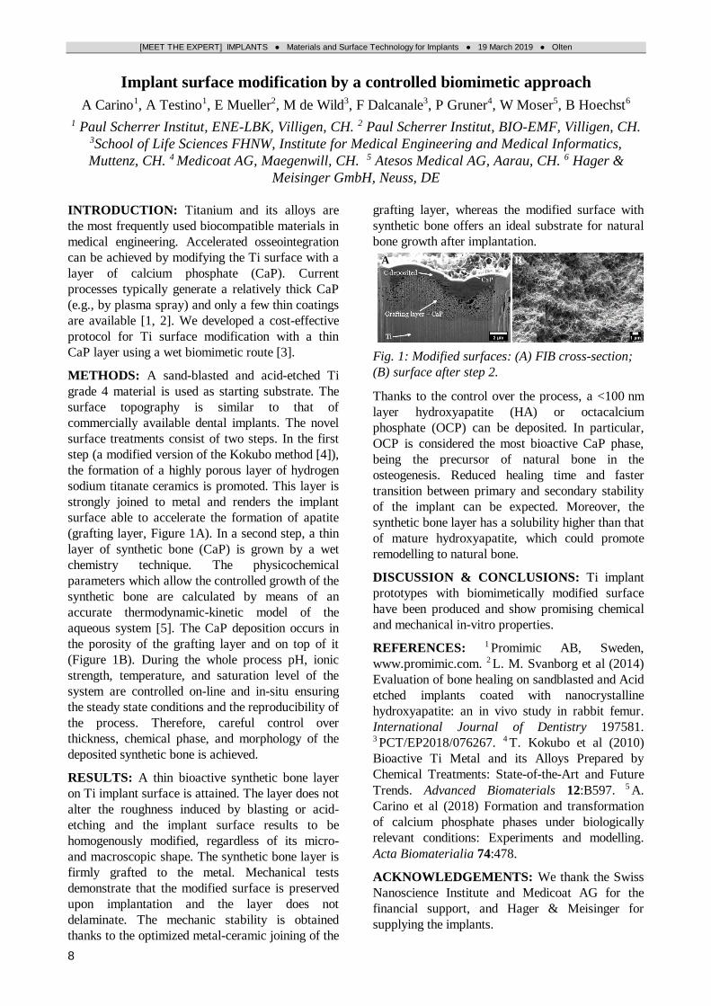
RESULTS: Figure 1 shows a titanium foam
cylinder with infiltrated UHMWPE after water jet
cutting and after a shear test at one end. The only
statistical differences in infiltration depth (Table 1)
were found between fine and coarse pores
(student’s t-test, p < 0.01).
Fig. 1: Titanium foam cylinder (Ø16 mm / left)
infiltrated with UHMWPE as powder (P) and as
bulk (B). Compound after a shear test (right).
The shear strength of the compounds exceeded the
values obtained for a UHMWPE-cylinder alone
with maximum forces ranging from 2800 - 4000 N.
Table 1. Average infiltration depth (± standard
deviation) of UHMWPE into titanium foams with
different porosities (n = 4)
pore
size temp.
infiltration depth /mm
powder bulk
fine 160 °C 1.26 ±0.08 1.27 ±0.13
200 °C 1.20 ±0.04 1.26 ±0.11
coarse 160 °C 1.72 ±0.08 1.67 ±0.19
200 °C 1.57 ±0.13 1.51 ±0.18
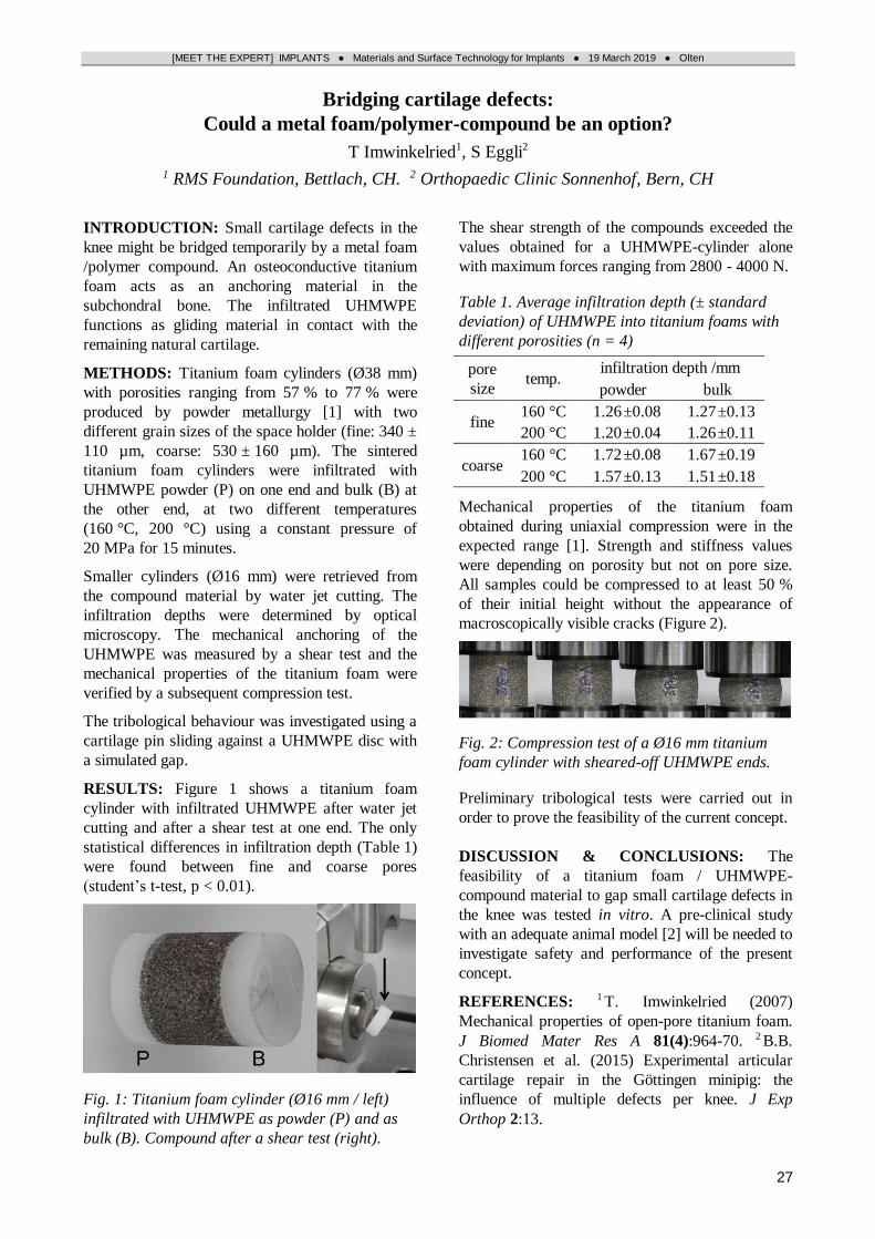
Mechanical properties of the titanium foam
obtained during uniaxial compression were in the
expected range [1]. Strength and stiffness values
were depending on porosity but not on pore size.
All samples could be compressed to at least 50 %
of their initial height without the appearance of
macroscopically visible cracks (Figure 2).
Fig. 2: Compression test of a Ø16 mm titanium
foam cylinder with sheared-off UHMWPE ends.
Preliminary tribological tests were carried out in
order to prove the feasibility of the current concept.
DISCUSSION & CONCLUSIONS: The
feasibility of a titanium foam / UHMWPE-
compound material to gap small cartilage defects in
the knee was tested in vitro. A pre-clinical study
with an adequate animal model [2] will be needed to
investigate safety and performance of the present
concept.
REFERENCES: 1 T. Imwinkelried (2007)
Mechanical properties of open-pore titanium foam.
J Biomed Mater Res A 81(4):964-70. 2 B.B.
Christensen et al. (2015) Experimental articular
cartilage repair in the Göttingen minipig: the
influence of multiple defects per knee. J Exp
Orthop 2:13.

[MEET THE EXPERT] IMPLANTS ● Materials and Surface Technology for Implants ● 19 March 2019 ● Olten
28
Increasing the primary stability of cementless monoblock cups
M Schmidt
Jossi Orthopedics AG, Islikon, CH
INTRODUCTION: Cementless, macro structured,
modular acetabular cups proved to be safe and
effective implants with excellent clinical results.
Their production costs are significantly lower than
those of porous coated or 3-D printed cups. Thus,
macro structures are the design of choice, especially
for thin-walled shells, in markets with high volumes
but low budgets.
This is why the proven PrimeFit macro structure
(Fig. 1) has been proposed for so-called monoblock
designs, applied especially to cementless dual
mobility shells and factory assembled ceramic
monoblocks consisting of a metal back and a
ceramic insert (Fig. 2). For both designs, the goal is
to offer the largest possible ball head diameter for
good joint stability which implies the use of shells
with minimum wall thickness.
CHALLENGE: In some high volume markets,
such as India and China, it is state-of-the-art to
secure a modular press fit cup with 2 bone screws.
The excellent primary stability of the proven
PrimeFit structure alone could not convince
orthopaedic companies. But, as a matter of fact,
monoblock designs do not offer the opportunity to
place screw holes. The only way to overcome this
dilemma was to modify the implant design, without
changing instrumentation and handling.
SOLUTION: Our development lead to an arc-
shaped macro structure, trademarked PrimeFit
Arcus (Fig. 3). It can be impacted like any other
press fit cup, with identical reaming and impaction
procedure. During impaction the shell performs a
slight turn of less than 5°, and the surgeon neither
feels this little twist nor a change of impaction
force.
But how is primary stability affected? PrimeFit
Arcus was tested against a market leading macro
structured cup with identical press fit in PU blocks,
density 15 PCF, regular and with defects.
RESULTS: Mean push out force was 822 N vs
550 N (+49%, N=4). Lever out moments were 37
Nm vs 23 Nm (+61%, N=2) and in blocks with
defects 14 Nm vs. 7 Nm (+100%, N=4) in the
direction of the defect (worst case). These results
have been confirmed in a client’s lab.
CONCLUSION: If a cup has the characteristics of
a screw, even though with a small turn, the
discussion to set additional bone screws becomes
obsolete. This is valid for monoblock designs as
well as modular primary acetabular cups. Handling
and instrumentation remain unchanged, and being
able to avoid bone screws saves costs and OT time.
Fig. 1: The PrimeFit structure, developed by Jossi
Orthopedics, has been adopted by 3 orthopaedic
companies. So far, approx. 15'000 PrimeFit cups
have been implanted.
Fig. 2a (left): Design proposition for a dual
mobility shell with PrimeFit structure. Fig. 2b
(right): PrimeFit Monoblock, a project with
CeramTec.
Fig. 3: PrimeFit Arcus, an arc-shaped macro
structure, with doubled primary stability compared
to a market leading macro structured cup under
worst-case conditions.
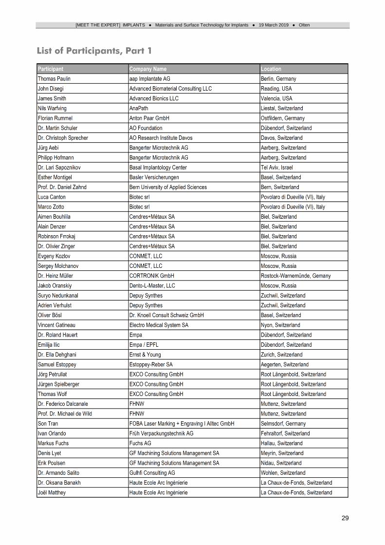
[MEET THE EXPERT] IMPLANTS ● Materials and Surface Technology for Implants ● 19 March 2019 ● Olten
29
List of Participants, Part 1

[MEET THE EXPERT] IMPLANTS ● Materials and Surface Technology for Implants ● 19 March 2019 ● Olten
30
List of Participants, Part 2

[MEET THE EXPERT] IMPLANTS ● Materials and Surface Technology for Implants ● 19 March 2019 ● Olten
31
List of Participants, Part 3

[MEET THE EXPERT] IMPLANTS ● Materials and Surface Technology for Implants ● 19 March 2019 ● Olten
32
Authors, Chairpersons, Organizers

[MEET THE EXPERT] IMPLANTS ● Materials and Surface Technology for Implants ● 19 March 2019 ● Olten
33
Notes

[MEET THE EXPERT] IMPLANTS ● Materials and Surface Technology for Implants ● 19 March 2019 ● Olten
34
Notes

[MEET THE EXPERT] IMPLANTS ● Materials and Surface Technology for Implants ● 19 March 2019 ● Olten
35
Notes