
HR/MR Engine - Technology Overview - Nissan Global
7
INLINE 4-CYLINDER GASOLINE ENGINE HR/MR Engine Technology Overview
-
Upload
khangminh22 -
Category
Documents
-
view
4 -
download
0
Transcript of HR/MR Engine - Technology Overview - Nissan Global
I N L I N E 4 - C Y L I N D E R G A S O L I N E E N G I N E
HR/MR EngineTechnology Overview
2 3
HR/MR EngineTechnology Overview
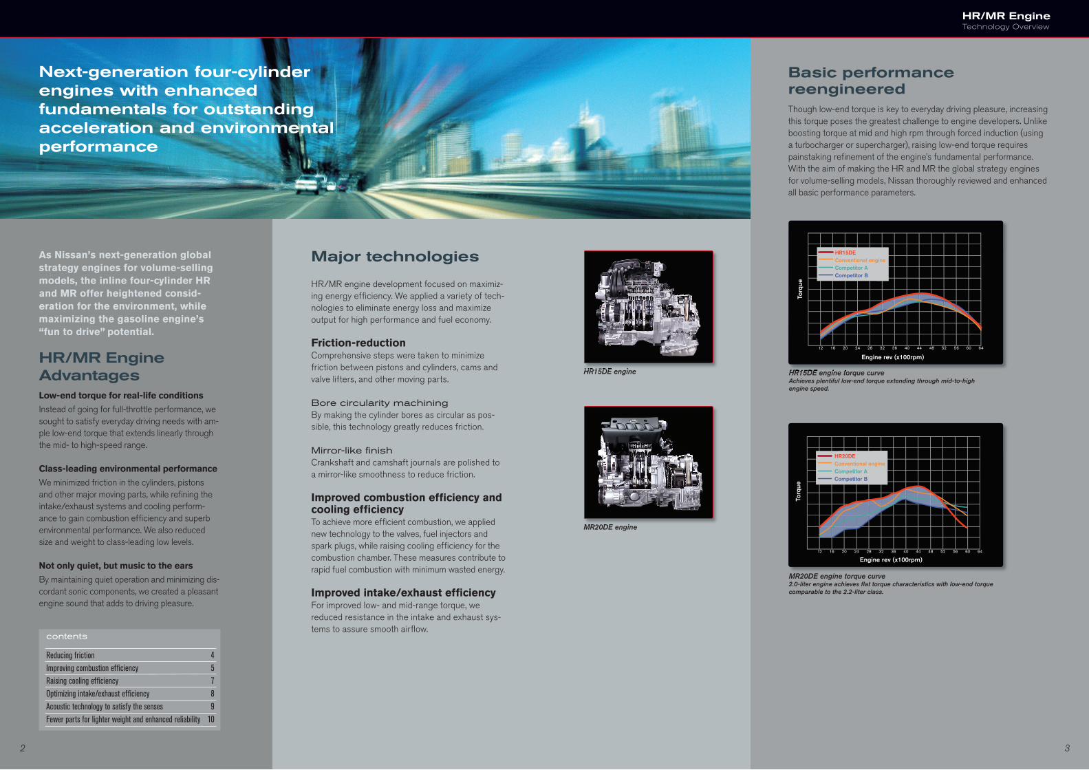
HR15DE engine torque curveAchieves plentiful low-end torque extending through mid-to-high engine speed.
MR20DE engine torque curve 2.0-liter engine achieves fl at torque characteristics with low-end torque comparable to the 2.2-liter class.
MR20DE engine
HR15DE engine HR15DE engine torque curve
Torq
ue
Engine rev (x100rpm)
HR15DEConventional engineCompetitor ACompetitor B
MR20DE engine
HR15DE engine
Torq
ue
Engine rev (x100rpm)
HR20DEConventional engineCompetitor ACompetitor B
contents
Reducing friction 4Improving combustion effi ciency 5Raising cooling effi ciency 7Optimizing intake/exhaust effi ciency 8Acoustic technology to satisfy the senses 9Fewer parts for lighter weight and enhanced reliability 10
Next-generation four-cylinder engines with enhanced fundamentals for outstanding acceleration and environmental performance
As Nissan’s next-generation global strategy engines for volume-selling models, the inline four-cylinder HR and MR offer heightened consid-eration for the environment, while maximizing the gasoline engine’s “fun to drive” potential.
Major technologies
HR/MR engine development focused on maximiz-ing energy effi ciency. We applied a variety of tech-nologies to eliminate energy loss and maximize output for high performance and fuel economy.
Friction-reductionComprehensive steps were taken to minimize friction between pistons and cylinders, cams and valve lifters, and other moving parts.
Bore circularity machiningBy making the cylinder bores as circular as pos-sible, this technology greatly reduces friction.
Mirror-like fi nish Crankshaft and camshaft journals are polished to a mirror-like smoothness to reduce friction.
Improved combustion effi ciency and cooling effi ciencyTo achieve more effi cient combustion, we applied new technology to the valves, fuel injectors and spark plugs, while raising cooling effi ciency for the combustion chamber. These measures contribute to rapid fuel combustion with minimum wasted energy.
Improved intake/exhaust effi ciencyFor improved low- and mid-range torque, we reduced resistance in the intake and exhaust sys-tems to assure smooth airfl ow.
Basic performancereengineeredThough low-end torque is key to everyday driving pleasure, increasing this torque poses the greatest challenge to engine developers. Unlike boosting torque at mid and high rpm through forced induction (using a turbocharger or supercharger), raising low-end torque requires painstaking refi nement of the engine’s fundamental performance. With the aim of making the HR and MR the global strategy engines for volume-selling models, Nissan thoroughly reviewed and enhanced all basic performance parameters.
HR/MR Engine AdvantagesLow-end torque for real-life conditions
Instead of going for full-throttle performance, we sought to satisfy everyday driving needs with am-ple low-end torque that extends linearly through the mid- to high-speed range.
Class-leading environmental performance
We minimized friction in the cylinders, pistons and other major moving parts, while refi ning the intake/exhaust systems and cooling perform-ance to gain combustion effi ciency and superb environmental performance. We also reduced size and weight to class-leading low levels.
Not only quiet, but music to the ears
By maintaining quiet operation and minimizing dis-cordant sonic components, we created a pleasant engine sound that adds to driving pleasure.
4 5
HR/MR EngineTechnology Overview
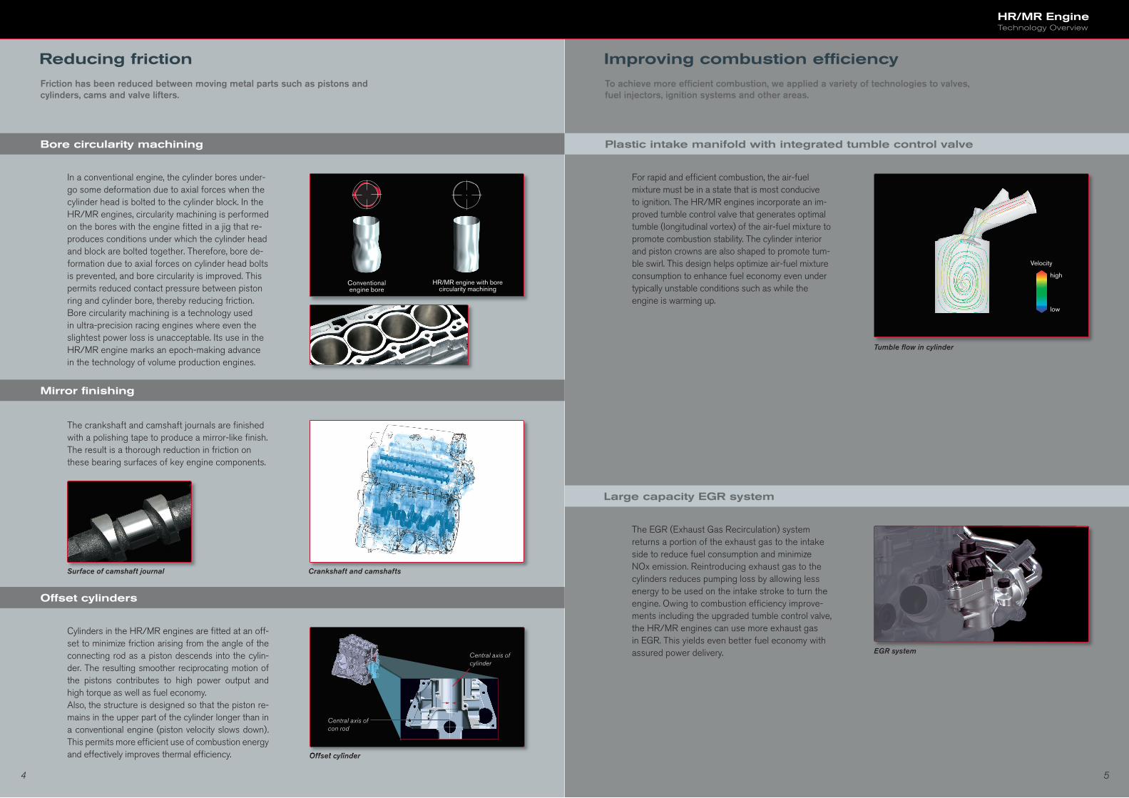
In a conventional engine, the cylinder bores under-go some deformation due to axial forces when the cylinder head is bolted to the cylinder block. In the HR/MR engines, circularity machining is performed on the bores with the engine fi tted in a jig that re-produces conditions under which the cylinder head and block are bolted together. Therefore, bore de-formation due to axial forces on cylinder head bolts is prevented, and bore circularity is improved. This permits reduced contact pressure between piston ring and cylinder bore, thereby reducing friction. Bore circularity machining is a technology used in ultra-precision racing engines where even the slightest power loss is unacceptable. Its use in the HR/MR engine marks an epoch-making advance in the technology of volume production engines.
The crankshaft and camshaft journals are fi nished with a polishing tape to produce a mirror-like fi nish. The result is a thorough reduction in friction on these bearing surfaces of key engine components.
Crankshaft and camshafts
Offset cylinders
Cylinders in the HR/MR engines are fi tted at an off-set to minimize friction arising from the angle of the connecting rod as a piston descends into the cylin-der. The resulting smoother reciprocating motion of the pistons contributes to high power output and high torque as well as fuel economy. Also, the structure is designed so that the piston re-mains in the upper part of the cylinder longer than in a conventional engine (piston velocity slows down). This permits more effi cient use of combustion energy and effectively improves thermal effi ciency. Offset cylinderOffset cylinder
Central axis of cylinder
Central axis of con rod
Plastic intake manifold with integrated tumble control valve
Large capacity EGR system
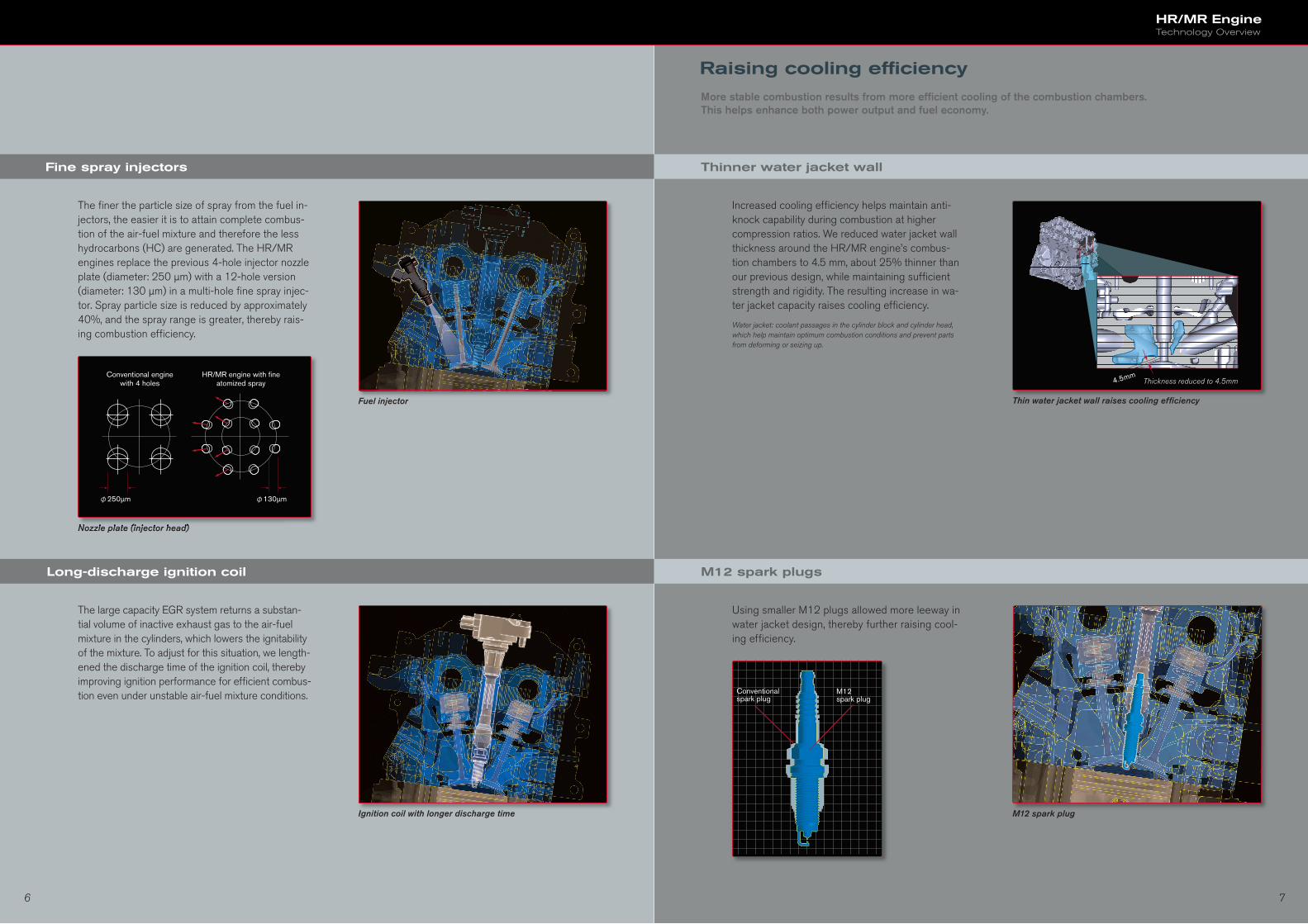
For rapid and effi cient combustion, the air-fuel mixture must be in a state that is most conducive to ignition. The HR/MR engines incorporate an im-proved tumble control valve that generates optimal tumble (longitudinal vortex) of the air-fuel mixture to promote combustion stability. The cylinder interior and piston crowns are also shaped to promote tum-ble swirl. This design helps optimize air-fuel mixture consumption to enhance fuel economy even under typically unstable conditions such as while the engine is warming up.
The EGR (Exhaust Gas Recirculation) system returns a portion of the exhaust gas to the intake side to reduce fuel consumption and minimize NOx emission. Reintroducing exhaust gas to the cylinders reduces pumping loss by allowing less energy to be used on the intake stroke to turn the engine. Owing to combustion effi ciency improve-ments including the upgraded tumble control valve, the HR/MR engines can use more exhaust gas in EGR. This yields even better fuel economy with assured power delivery.
Tumble fl ow in cylinder
EGR system
Conventionalengine bore
HR/MR engine with bore circularity machining
Velocity
high
low
Surface of camshaft journal
Reducing friction
Friction has been reduced between moving metal parts such as pistons and cylinders, cams and valve lifters.
Bore circularity machining
Mirror fi nishing
Improving combustion effi ciency
To achieve more effi cient combustion, we applied a variety of technologies to valves, fuel injectors, ignition systems and other areas.
6 7
HR/MR EngineTechnology Overview
Fine spray injectors
Long-discharge ignition coil
The fi ner the particle size of spray from the fuel in-jectors, the easier it is to attain complete combus-tion of the air-fuel mixture and therefore the less hydrocarbons (HC) are generated. The HR/MR engines replace the previous 4-hole injector nozzle plate (diameter: 250 µm) with a 12-hole version (diameter: 130 µm) in a multi-hole fi ne spray injec-tor. Spray particle size is reduced by approximately 40%, and the spray range is greater, thereby rais-ing combustion effi ciency.
The large capacity EGR system returns a substan-tial volume of inactive exhaust gas to the air-fuel mixture in the cylinders, which lowers the ignitability of the mixture. To adjust for this situation, we length-ened the discharge time of the ignition coil, thereby improving ignition performance for effi cient combus-tion even under unstable air-fuel mixture conditions.
Ignition coil with longer discharge time
Nozzle plate (injector head)Nozzle plate (injector head)
φ130µmφ250µm
Conventional engine with 4 holes
HR/MR engine with fi ne atomized spray
Thinner water jacket wall
Increased cooling effi ciency helps maintain anti-knock capability during combustion at higher compression ratios. We reduced water jacket wall thickness around the HR/MR engine’s combus-tion chambers to 4.5 mm, about 25% thinner than our previous design, while maintaining suffi cient strength and rigidity. The resulting increase in wa-ter jacket capacity raises cooling effi ciency.
Water jacket: coolant passages in the cylinder block and cylinder head, which help maintain optimum combustion conditions and prevent parts from deforming or seizing up.
M12 spark plugs
Using smaller M12 plugs allowed more leeway in water jacket design, thereby further raising cool-ing effi ciency.
Conventional spark plug
M12 spark plug
Thin water jacket wall raises cooling effi ciency
M12 spark plug
Fuel injector
4.5mmThickness reduced to 4.5mm
Raising cooling effi ciency
More stable combustion results from more effi cient cooling of the combustion chambers. This helps enhance both power output and fuel economy.
8 9
HR/MR EngineTechnology Overview
Exhaust
Intake
Front intake/rear exhaust layout
C-VTC
Valve
Continuous Valve Timing Control
C-VTC helps optimize torque characteristics
MR20DE
Increased torque in the practical rpm range
Engine rev (x100rpm)
Torq
ue
Chain links
Manifold branches are equalized
6th harmonic4th harmonic
2nd harmonic
Frequency
Conventional engine
Eng
ine
Rev
Eng
ine
Rev
HR/MR engine
Frequency
pin
impact
Redesigned shape (right) reduces noise
Conventional chain Silent chain
Link plate sprocket
pin
sprocket
impact
The HR/MR engines have a front air intake and rear exhaust system layout. The system has long intake runners effective in promoting ample torque at low and mid-range engine speeds, and also achieves smooth exhaust fl ow. The straight exhaust system reduces fl ow-resistance, while compact packaging permits a stylish design.
Front intake/rear exhaust layout
C-VTC enables variable valve timing in response to engine rpm and throttle opening. Enhanced control and reduced system friction improve response and optimize torque characteristics. While maintaining linear torque at high rpm, the system controls valve timing to raise torque particularly in the practical range around 2000 rpm. For example, to over-come slow intake gas-fl ow to the cylinder head in the practical speed range, charging effi ciency is improved by advancing intake valve closure timing. The C-VTC has also been made thinner to contrib-ute to a lighter, more compact engine.
Continuous Valve Timing Control (C-VTC)
We reduced air resistance in the intake/exhaust systems to assure smooth airfl ow for improved torque in the low- to mid-speed range.
Optimizing intake/exhaust effi ciency
Going beyond the goal of quiet operation, we sought a sound that would enhance the sensation of acceleration. The result is a softly purring engine that is a pleasure to the senses.
Acoustic technology to satisfy the senses
Acoustically equal length manifold branches
Silent chain drive
The impression given by an engine’s sound is not determined by volume alone, but is also greatly in-fl uenced by timbre and a mixture of dull mechanical noises. For the intake manifold on HR/MR engines, we gave the four branches acoustically equal lengths. This effectively emphasizes only the lighter, clearer components, while greatly reducing those that muddy the sound. The rough sound an engine can make during acceleration is minimized, leav-ing an attractively pleasing result. Also, as engine speed increases, rising sound pressure acoustically dramatizes the pleasant sensation of acceleration.
This “silent chain” reduces impact noise to deliver quieter operation. Impact noise is generated by the camshaft drive chain as its pins mesh with the sprockets. For the HR/MR engine, we redesigned the links so they engage the sprockets at points in addition to the pins themselves, thereby distributing impact to reduce this noise.
10 11
HR/MR EngineTechnology Overview
FIP FIP
Conventional engine HR/MR engine
High-adhesion FIP gasket and chamfer shape
Pulleys are in a single plane
Coolant pipe built into cylinder block
Cracking-processed connecting rod and cross-sectionsCracking-processed connecting rod and cross-sectionsCracking-processed connecting rod and cross-sections
Fewer parts for lighter weight and enhanced reliability
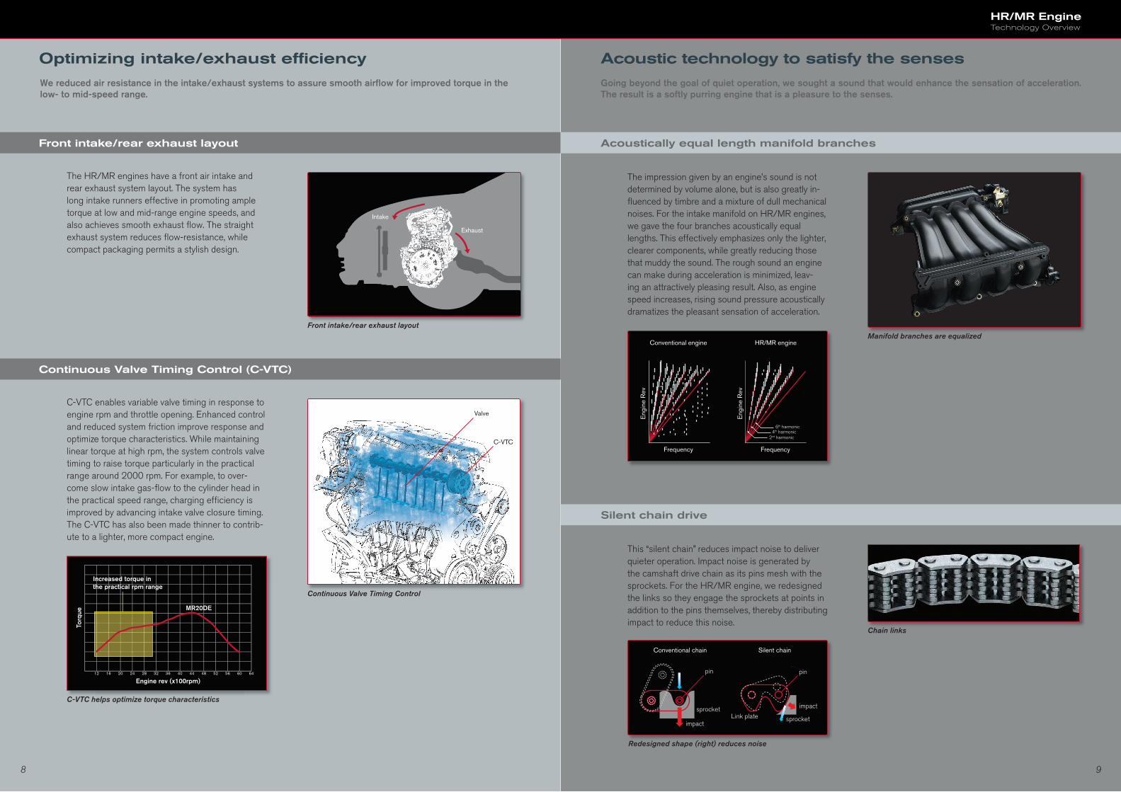
The HR/MR engines employ a range of innovative technologies for downsizing and weight reduction that are essential to improved fuel economy. We reduced the number of parts by approximately 20% compared with the previous engine design, thereby enhancing reliability and manufacturing productivity.
Coolant pipes built in
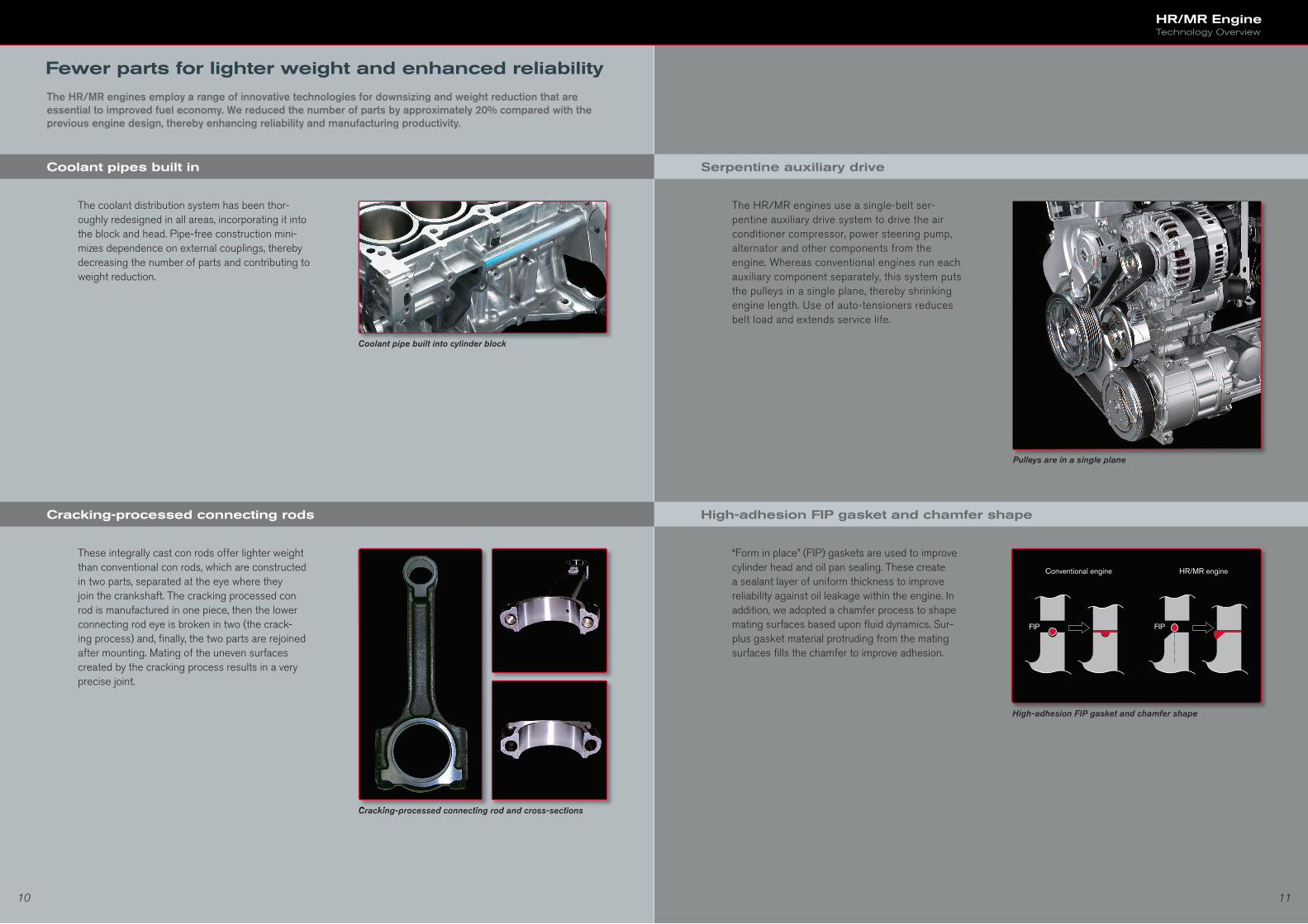
Cracking-processed connecting rods
These integrally cast con rods offer lighter weight than conventional con rods, which are constructed in two parts, separated at the eye where they join the crankshaft. The cracking processed con rod is manufactured in one piece, then the lower connecting rod eye is broken in two (the crack-ing process) and, fi nally, the two parts are rejoined after mounting. Mating of the uneven surfaces created by the cracking process results in a very precise joint.
The coolant distribution system has been thor-oughly redesigned in all areas, incorporating it into the block and head. Pipe-free construction mini-mizes dependence on external couplings, thereby decreasing the number of parts and contributing to weight reduction.
Serpentine auxiliary drive
High-adhesion FIP gasket and chamfer shape
The HR/MR engines use a single-belt ser-pentine auxiliary drive system to drive the air conditioner compressor, power steering pump, alternator and other components from the engine. Whereas conventional engines run each auxiliary component separately, this system puts the pulleys in a single plane, thereby shrinking engine length. Use of auto-tensioners reduces belt load and extends service life.
“Form in place” (FIP) gaskets are used to improve cylinder head and oil pan sealing. These create a sealant layer of uniform thickness to improve reliability against oil leakage within the engine. In addition, we adopted a chamfer process to shape mating surfaces based upon fl uid dynamics. Sur-plus gasket material protruding from the mating surfaces fi lls the chamfer to improve adhesion.