
AN ISO 9001 & 14001 COMPANY TENDER DOCUMENT e ...
1167
Additional Conditions of Contract Engineering Projects (India) Limited _____________________________________________________________________________________________________________ Signature of the Bidder with seal Page 1 of 23 EPI AN ISO 9001 & 14001 COMPANY TENDER DOCUMENT e-TENDER No:SRO/CON/ETS/083 dtd 28.04.2021 Tender for Construction of Civil and Architectural works of Super Structure Works of Main Plant Unit 1&3 at 5 x 800 MW Yadadri TPS-Veerlapalem Village ,Dameracherla Mandal, Nalgonda District, Telangana State VOLUME – II Additional Conditions of Contract General, Construction Program, Notice to Display, Tools & Plants , Technical Specifications (TSGENCO), BHEL Tender Documents and Drawings ENGINEERING PROJECTS (INDIA) LIMITED (A GOVT. OF INDIA ENTERPRISE) Southern Regional Office, Chennai
-
Upload
khangminh22 -
Category
Documents
-
view
7 -
download
0
Transcript of AN ISO 9001 & 14001 COMPANY TENDER DOCUMENT e ...

Additional Conditions of Contract Engineering Projects (India) Limited _____________________________________________________________________________________________________________
Signature of the Bidder with seal Page 1 of 23 EPI
AN ISO 9001 & 14001 COMPANY
TENDER DOCUMENT
e-TENDER No:SRO/CON/ETS/083 dtd 28.04.2021
Tender for Construction of Civil and Architectural works of Super Structure Works of Main Plant Unit 1&3 at 5 x 800 MW Yadadri TPS-Veerlapalem Village ,Dameracherla Mandal, Nalgonda District, Telangana State
VOLUME – II
Additional Conditions of Contract General, Construction Program, Notice to Display, Tools & Plants , Technical Specifications (TSGENCO), BHEL Tender Documents and Drawings
ENGINEERING PROJECTS (INDIA) LIMITED (A GOVT. OF INDIA ENTERPRISE) Southern Regional Office, Chennai

Additional Conditions of Contract Engineering Projects (India) Limited _____________________________________________________________________________________________________________
Signature of the Bidder with seal Page 2 of 21 EPI
INDEX
Sl. No.
Description
Page No. No. of Pages
1.
Additional Conditions of Contract (ACC)
3-17
15
2.
Construction Program
18-20 03
3. Notice to Display 21 01
4. Tools & Plants 22-23 02
5. Client Technical Specification & Drawings 24-1768 1744

Additional Conditions of Contract Engineering Projects (India) Limited _____________________________________________________________________________________________________________
Signature of the Bidder with seal Page 3 of 23 EPI
ADDITIONAL CONDITIONS OF CONTRACT (ACC) 1.0 The following Additional Conditions of Contract shall be read in conjunction with General Conditions of Contract. If there are any provisions in these Additional Conditions of Contract, which are at variance with the provisions of General Conditions of Contract, the provisions in these Additional Conditions of Contract shall take precedence. 2.0 Introduction 5 x 800 MW Yadadri Thermal power stations is being set up by TELANGANA STATE POWER GENERATION CORPORATION (hereinafter called “Owner”) at a site in Veerlapalem village, Dameracherla Mandal, NALGONDA DISTRICT, TELANGANA STATE, India. The said project was operated as an EPC contract by BHEL (hereinafter called BHEL) as EPC contractor. Further, the EPC project has divided in to multiple package and civil and structural works of unit 1 & 3 as package -1 was awarded to EPI as a “MAIN CONTRACTOR”. EPI invites offer from the eligible BIDDERS/CONTRACTORS to execute the “Tender for Construction of Civil and Architectural works of Super Structure Works of Main Plant Unit 1&3 at 5 x 800 MW Yadadri TPS-Veerlapalem Village ,Dameracherla Mandal, Nalgonda District, Telangana State” (hereinafter referred to as “Works”) and detailed scope of work is mentioned in subsequent para. The Bidder shall acquaint himself by a visit to the site, with the conditions prevailing at site before submission of the bid. The information given here in under is for general guidance and shall not be contractually binding on EPI / BHEL/ Owner. All relevant site data /information as may be necessary shall have to be obtained /collected by the Bidder. 3.0 Scope of work: The project site for the work is clear and readily available. The brief scope of work included in this tender shall include (but not limited to) Construction of Civil and Architectural works of Super Structure Works of Main Plant Unit 1&3 at 5 x 800 MW Yadadri TPS-Veerlapalem Village ,Dameracherla Mandal, Nalgonda District, Telangana State as mentioned below, including supply of all materials (excluding cement & Reinforcement Steel and MS Rounds for below ground earthing), labour, tools and plants. The scope of work is indicative but not limited to the given below." (herein after referred to as “Works’) as per Technical specifications, Drawings, BOQ, Instructions and Terms and conditions given in Tender Documents. The works consists of civil and architectural works of superstructure of power house, bunker and civil and architectural works in other areas of main plant of Units 1 & 3 .Each Unit of this package consisting of the following structures,
i) Superstructure civil works of Power house building including CCR ii) Coal bunker floors iii) ESP control room building iv) Cable trenches v) Paving, roads & drains vi) Interconnecting walkway vii) Boiler lifts machine room viii) Underground utilities

Additional Conditions of Contract Engineering Projects (India) Limited _____________________________________________________________________________________________________________
Signature of the Bidder with seal Page 4 of 23 EPI
ix) Pavement including miscellaneous buildings (including foundations) x) Filling (Part of levelling and grading works in plant area as per site condition) xi) Superstructure civil works of Power house building including CCR xii) Apart from above, any other services(Building/Foundation/Structure) not covered above but required as per direction of EPI / BHEL/Owner are deemed to be included in the scope of work.
The work is to be carried out on Item rate basis as per bill of quantities and tender conditions. 4.0 Order of Precedence Clause 42.1 of GCC stands amended as under: In case of difference, contradiction, discrepancy, dispute with regard to Conditions of Contract, Specifications, Drawings, Bill of Quantities and Rates quoted by the Contractor and other documents forming part of the contract, the following shall prevail in order of precedence 4.1 Contract Agreement which includes NIT, Special Instructions to Tenderer, Memorandum. 4.2 Letter of Intent, detailed letter of Work Order 4.3 Bill of Quantity / Schedule of Quantities 4.4 Additional Conditions of Contract. 4.5 General Technical Specification ( Telangana State Power Generation Corporation Ltd ) 4.6 General Conditions of Contract (EPI). 4.7 Drawings 4.8 BHEL Technical Condition of Contract, SCC and GCC 4.9 CPWD technical specifications & DSR latest edition 4.10 National Building Code (Latest Edition) 4.11 BIS specifications 5.0 TIME SCHEDULE & PROGRESS The clause No. ’43.2’ of General Conditions of Contract (GCC) of this Tender document shall be read as under: The contract period for completion of entire work of each package under scope shall be 15 (Fifteen) months from the “COMMENCEMENT OF CONTRACT PERIOD” as specified elsewhere for completion of the entire work. Tentative completion program as required by BHEL is enclosed as Annexure-1. However, the contractor shall also furnish within 10 days of date of letter of Intent a Time and Progress Chart (Bar Chart) for completion of work within stipulated time by the consultation with EPI / BHEL Site in Charge.The contractor shall also ensure achievement of the intermediate milestones M1,M2 and M3 for Unit 1 and M4 , M5 and M6 for Unit-3 are mentioned below.
S. No.
Description Time allowed for Achievement of financial Targets (since
inception of project)
Intermediate Milestone
Name Unit-1
1. ESP Building RCC Slabs 03 Months M1 2. RCC Slabs in Power House 05 Months M2 3. TD BFP deck for Unit#1 06 Months M3 Unit-3
1. RCC Slabs in Power House 09 Months M1 2 TD BFP deck for Unit #3 12 Months M2 3 Paving and Finishing Works 14 Months M3

Additional Conditions of Contract Engineering Projects (India) Limited _____________________________________________________________________________________________________________
Signature of the Bidder with seal Page 5 of 23 EPI
The approved Bar Chart shall form a part of the agreement. Achievement of milestones as well as total completion has to be within the time period allowed. The said mile stones in terms of financial targets, failing which intermediate liquidity damages shall be liable to be effected as per terms agreed in contract by EPI/BHEL. The milestones indicated are tentative and may vary according to BHEL/CLIENT priority which shall be reviewed from time to time. 5.1 COMMENCEMENT OF CONTRACT PERIOD The date of commencement of work shall be reckoned from the 10th day from the date of issue of Letter Of Intent. 6.0 DEFECT LIABILITY PERIOD: Defect Liability Period as per GCC Clause No: 74.0 stands amended as “Guarantee period” and total time period of Guarantee Period is twelve months (12 months). The said Guarantee period of 12 months for the package shall commence from the date of completion of the whole of the work in the package, as certified by EPI site in charge/BHEL Engineer. 7.0 SECURITY DEPOSIT CUM PERFORMANCE BANK GUARANTEE Clause 9.0 of GCC shall be read as “Security Deposit” and stands amended as below: 7.1 In the event of award of “Works”, Contractor shall submit to EPI, Bank Guarantees OR Demand draft (in the name of Engineering Projects (India) Ltd., payable at New Delhi ) from a Nationalized Bank / Scheduled Bank towards security deposit @ 3.0% (Three Point Zero Percentage) of the contract value of the accepted tender within 10 days from the date of LOI as per the EPI format enclosed and BG shall be initially upto the completion period as stipulated in the Letter of Intent + 3 months, and the same shall be kept valid by proper renewal till the acceptance of Final Bills of the Contractor, by EPI/BHEL failing which EPI at his discretion may revoke the LOI & forfeit the EMD furnished along with tender. 7.2 At least 50% of the Security Deposit including the EMD (if deposited in DD/ Cash) should be deposited in any form as prescribed above and the balance 50% of the Security Deposit will be recovered by deducting 10% of the gross amount progressively from each running bills of the contractor till the total amount of the required Security Deposit is collected. 7.3 The recoveries made from running bills (cash deduction towards balance SD amount) will be released against submission of equivalent Bank Guarantee in the prescribed formats, but only once, before completion of work. The Security Deposit shall not carry any interest. 7.4 Release of Security Deposit /BankGuarantee(s) to the Contractor shall be made only after receipt of same from client by EPI, after deducting all expenses / other amounts due to EPI/BHEL under the contract / other contracts entered into with them by EPI/BHEL. 8.0 RETENTION MONEY Clause no. 10.0 of GCC shall be read as “PERFOMANCE SECURITY DEPOSIT” and stands amended as under: 8.1 After award of work, before commencement of work at site Contractor shall submit 5% of the contract value towards Performance Security Deposit, in the form of (a) or (b) below. 8.1.1 CASH 5% of the contract Value towards Performance Security Deposit, before commencing
the contract (or)

Additional Conditions of Contract Engineering Projects (India) Limited _____________________________________________________________________________________________________________
Signature of the Bidder with seal Page 6 of 23 EPI
8.1.2 Recovery 5% from Each Running Bill towards Performance security deposit. 8.2 Refund of Retention Amount shall be as follows: 8.2.1 50% of retention amount along with ‘Final Bill’ 8.2.2 Balance 50% will be released after completion of Performance Guarantee Period (i.e., after
expiry of Guarantee period), provided all the defects noticed during the guarantee period have been rectified to the satisfaction of EPIL site in charge / BHEL Construction Manager, and after deducting all expenses/ other amounts due to EPI/BHEL under the contract/ other contracts entered into by EPI/BHEL with them. This portion of Performance Security Deposit, amount ca n be released on commencement of the Guarantee Period, on submission of equivalent Bank Guarantee.
8.3 The performance security deposit mentioned herein above is in addition to Security Deposit Cum Performance Bank Guarantee as stated in clause no. 7.0. 9.0 MOBILIZATION Clause no. 8.0 stands amended as under: Mobilization advance shall be paid limited to 5% of the contract value and Clause no. 8.0 of General Conditions of Contract (GCC) stands modified as here under 9.1 Interest bearing advance for Mobilization, limited to 5% of the contract value will be paid against
submission of bank guarantee of at least 110% of the advance, valid for the contract period, which will be recovered as stated in recovery plan. The advance for mobilization shall be paid as under:
9.2 Stage-1: Two Percentage (2%) of contract value after receipt of initial Security Deposit and additional security deposit as applicable if any, as per relevant clauses in the GCC/TCC along with unqualified acceptance of detailed letter of intent.Stage-2 : One Point Five Percentage (1.5%)of contract value on completion of site
9.3 Mobilization of Phase-1 Machinery & T&P as required by EPI /BHEL and on certification by EPI site in-charge for compliance.
9.3.1 Back hoe loader like JCB – 1 No. 9.3.2 Excavator equivalent to capacity of Poclain CK90 or higher to suit the requirement of work at site –
1 No 9.3.3 Automatic concrete batching plant with printing facility (minimum capacity of 30 CUM/Hr each)
with DG backup with minimum 2 Nos. of silo per batching plant (100MT each)-1 no. 9.3.4 Transit mixer (5/6 M3 capacity)– 4 Nos. 9.3.5 Truck mounted concrete mixer cum pump along with placing boom minimum 36 m high
i.e.Concrete boom placer (36m) – 1 No. 9.3.6 Concrete pump (60 CUM/ hr min capacity & lift 90M) – 1 No. Note: Concrete pump can be replaced by concrete boom placer in addition to those mentioned above in sl. No. (v) with due approval of Engineer In-Charge. The number of tools & plant shall be as per mutually agreed depending upon front available. 9.4 Stage-3: One Point Five Percentage (1.5%) of contract value on completion of site
Mobilization of phase-2 Machinery & T&P as required by EPI /BHEL in addition to the above, and on certification by site in charge for compliance.
9.4.1 Back hoe loader like JCB – 1 No. 9.4.2 Excavator equivalent to capacity of Poclain CK90 or higher to suit the requirement of work at site
1No 9.4.3 Self-priming dewatering pump 5 HP (diesel/electric)- 5 nos. 9.4.4 Dumper (Min 15 CUM each)– 8 nos. 9.4.5 Transit mixer (5/6 M3 capacity) – 2 Nos 9.4.6 Truck mounted concrete mixer cum pump along with placing boom minimum 36 m high
i.e.Concrete boom placer (36m) – 1 No. 9.4.7 Civil Laboratory – 1 No Note: Concrete pump can be replaced by concrete boom placer in addition to those mentioned above in sl. No. (v) with due approval of Engineer In-Charge. The number of tools & plant shall be as per mutually agreed depending upon front available.

Additional Conditions of Contract Engineering Projects (India) Limited _____________________________________________________________________________________________________________
Signature of the Bidder with seal Page 7 of 23 EPI
9.5 The rate of interest applicable for the above advances shall be the Base rate of State Bank of India prevailing at the time of disbursement of the advance + 6% ( Plus Six Percentage ) and such rate will remain fixed till the total advance amount is recovered.
9.6 Recovery of mobilization advance Unadjusted amount of advances paid shall not exceed 5% of the total contract value at any point of time. Recovery of advances shall be made progressively from each Running Bill such that the advance amounts paid along with the interest is fully recovered by the time the contractor’s billing reaches 90% of contract value 10.0 SECURED ADVANCE: Clause no. 35 of GCC stands deleted: 11.0 PAYMENT CONDITIONS:- Clause no 37.0 of GCC stands amended as under. 11.1 Interim bills in the form of monthly running bills prepared by the contractor in soft as well as
Hard copies shall be based on the quantities executed and measured. 11.2 The Contractor shall become entitled for payment of RA bills /Final bill etc., after receipt of
corresponding payment(s) from the BHEL/ Owner.. The Contractor shall have no claim on EPI in case the payments are delayed due to any reason whatsoever.
12.0 METHOD OF MEASUREMENT Following clauses shall be read in conjunction with Clause no 36.0 of GCC Mode of measurement shall be as per relevant clauses of technical specification of this tender. In case the same is not available the relevant IS 1200 in conjunction with IS 3385 shall be adopted. In case the same is also not available, the standard procedure adopted in CPWD shall be adopted. In case the same is not available in CPWD also, the measurement of the work done will be based on the mutual agreement between EPI/ BHEL and contractor. In all the above cases, the interpretation of EPI / BHEL will be final and binding to the contractor. 13.0 TAXES AND DUTIES : The following shall be also read in conjunction with clause no 13 of GCC: 13.1 The bidder/Contractor must be registered with GST and should have valid GSTIN number of
the respective state of the project. 13.2 The bidder/contractor must submit as an compliances of GST Act, the invoices in GST
compliant format. 13.3 Contractor’s price/rates shall be exclusive of GST & Labour Cess. Contractor shall
submit to EPI / BHEL the GST compliant tax invoice/debit note/credit note/ revised tax invoice on the basis of which EPI/BHEL will claim the input tax credit in its return. Since this is a works contract, the GST rate shall be @ 18%, as applicable presently.
13.4 GST charged in the tax invoice/debit note/revised tax invoice by the contractor shall be released separately to the contractor only after contractor files the outward supply details in GSTR-1 on GSTN portal and input tax credit of such invoice is matched with time of filing the monthly return. TDS under GST shall be deducted at prevailing rates on gross invoice value from the running bills.
13.5 Labour cess shall be deposited @ 1% of value of work done or as applicable from to time as per the directions of Government of Telangana by EPI. However, all the documentations and labour records shall be maintained properly by the contractor. It shall be produced to EPI / BHEL / Govt Authorities as and when is required.
13.6 Seigniorage Charges : The rate quoted by bidder inclusive of all royalty / signorages. The Seigniorage charges will be recovered as per rules from the work bills of the contract or based on the theoretical requirement of material as per GO Ms. No 198 of Industries and commerce (MI) Dept. dated 13-08-2009 at the rates decided by Govt. from time to time
13.7 The contractor shall keep necessary books of accounts and other documents for the purpose of this condition as may be necessary and shall allow inspection of the same by a duly authorized

Additional Conditions of Contract Engineering Projects (India) Limited _____________________________________________________________________________________________________________
Signature of the Bidder with seal Page 8 of 23 EPI
representative of EPI and shall also furnish such other information/document as EPI may require from time to time.
13.8 In case of any reduction in rate of taxes in future or the project getting exemption status prior to the last date of Bid submission or afterwards, the contractor shall pass on the benefit to EPIL immediately, failing which EPIL shall have the right to recover the differential amount from the amounts due to the contractor . Further in case of any increase in rate of taxes in future or the project losing exemption status prior to last date of bid submission or afterwards, the said increase of taxes shall be paid / reimbursed to the contractor , subject to the conditions that the client reimburses the said increased taxes to EPIL.
14.0 All men, materials, machinery, tools and plants, infra-structure, resources etc., as required for execution of “Works” shall be provided and arranged by CONTRACTOR for their portion of work. The amount/rate quoted in their offer by CONTRACTOR to EPI includes all charges, all direct and indirect cost of works, materials, labour, plant & equipment, all taxes( Except GST) , duties, levies, royalties, and labour welfare cess etc., all transportation charges including for cartage of issue material, electricity and water charges, site offices expenses, labour camp, bank guarantee charges, insurance charges (EPI already availed by EPI for the project. Cost of the insurance for this scope of work will be deducted on pro-rata basis) , EPF/CPF/ Statutory contributions, preparation of all required design & detailed engineering and all required drawings etc., other expenses whatsoever, incurred on execution, completion and maintenance of the “Works” as per ‘Tender Documents’ and their own overheads and profit etc. CONTRACTOR shall comply with all the requirements laid down as per ‘Tender Documents’ as per terms, conditions, specifications, drawings, documents etc. given in the ‘Tender Documents’ for the completion, handing over, maintenance period etc. for the project. The contractor will not be allowed to take out equipment’s from the site without the written permission of Owner /BHEL/EPI. 15.0 The rate quoted by the contractor is inclusive of constructing temporary approach road to site, fencing, HSE/ safety gadgets, firefighting equipment’s, etc.as required for completion of work. Non conformity of safety rules and safety appliances will be viewed seriously and the BHEL has rights to impose fines on the contractor as per HSE manuals of BHEL. 16.0 PRICE VARIATION : Clause 16.0 of GCC of EPI stands modified as under. No escalation/price variation clause shall be applicable on this contract. All rates as per Bill of Quantities (BOQ)/Price-Bid quoted by Contractor shall be firm and fixed for entire contract period as as mentioned in LOI/ Contract agreement. For the extended contract period, escalation/price variation clause shall be applicable as per BHEL tender conditions. The payment towards the escalation/price variation shall be paid to contractor by EPI only after receipt of the corresponding payment from BHEL/TSGENCO. 17.0 QUANTITY VARIATION : Following clauses shall be read in conjunction with Clause no 69.1 of GCC 17.1 The quantities given in the contract are tentative and may change to any extent (both in plus
side and minus side). The quoted rates for individual items shall remain firm irrespective of any variations in the individual quantities
17.2 No compensation becomes payable in case the variation of the final executed contract value is within the limit of plus / Minus (+/-) 50% (Fifty Percentage) of awarded contract value.

Additional Conditions of Contract Engineering Projects (India) Limited _____________________________________________________________________________________________________________
Signature of the Bidder with seal Page 9 of 23 EPI
17.3 In case the finally executed contract value increases above the awarded Contract Value due to quantity variation, there will be no upward revision in the rates for the individual items and also contractor is not eligible for any compensation.
18.0 PAYMENT AGAINST EXTRA / SUPPLIEMENTARY ITEMS: Following clauses (i.e 2.15 & 2.16 of BHEL GCC) shall be read in conjunction with Clause no 69.0 of GCC 18.1 EXTRA ITEMS: Rates for extra works arising due to (1) non availability of boq (rate schedule),
or (2) change in specifications of materials / works (3) rectification / modification / dismantling & re erecting etc due to no fault of contractor, shall be in the order of the following:
18.1.1 Item rates are to be derived from similar nature of items in the BOQ (Rate Schedule) with applicable escalation derived from All India Consumer Price Index for Whole Sale Commodities. 18.1.2 As per CPWD-DSR-2007 (or latest edition) with applicable escalation derived from All India Consumer price Index for Whole Sale Commodities, OR, Notification issued by the office of CPWD for ‘Cost Index’ in that Region where the project is being executed, whichever is less. 18.1.3 As per CPWD-DSR-2007 (or latest edition) with applicable escalation derived from All India Consumer price Index for Whole Sale Commodities, OR, Notification issued by the office of CPWD for ‘Cost Index’ in that Region where the project is being executed, whichever is less 18.2 SUPPLIEMENTARY ITEMS: Rates for Supplementary works/Additional works arising out
due to additions/alterations in the original scope of works as per contract subject to certification of EPI/ BHEL engineer shall be worked out as under:
18.2.1 Item rates which are available in existing BOQ (Rate Schedule) shall be operated with applicable escalation derived from All India Consumer Price Index for Whole Sale Commodities 18.2.2 Items of works which are not available in existing BOQ shall be operated as an ‘Extra Works’
and rate shall be derived as per clause no 18.1 of this ACC
18.3 General:
18.3.1 Execution of Supplementary Works/Additional Works through the Contractor shall be at the sole discretion of EPI/ BHEL, and shall be considered as part of executed contract value for the purpose of Quantity Variation as per clause 17.0 of this ACC 18.3.2 EPI/ BHEL Engineer’s decision regarding fixing the rate as above is final and binding on the contractor. 18.3.3 Extra/ Deviation items shall be carried out with prior approval of BHEL/EPI. 18.3.4 However, payment shall be released after receipt of corresponding payment(s) from the Owner/ Owner. 18.3.5 EPI overheads expenditure of 10% will be deducted from each corresponding payment.
19.0 FREE ISSUE OF MATERIAL Clause no 45.0 of GCC shall be read in Conjunction with Clause no -1.13.1, 1.13.2 in VOLUME-IA PART-I of TCC CHAPTER – XIII ACCOUNTING OF MATERIAL ISSUE of BHEL 19.1 The Contractor shall, at his own expense, provide all materials, required except Cement &
Steel for the works. 19.2 Cement & Reinforcement steel for civil works & MS round for below ground earthing shall be
provided by BHEL free of cost at BHEL stores. Necessary transportation from BHEL stores to site/ Fabrication yard & Fabrication Yard to Site shall be in the scope of contractor. Embedment /inserts required for the works in general shall be supplied by the bidder and payment shall be made as per corresponding item in BOQ.
19.3 Wastages: For steel works Wastage beyond THREE percent (+3%) of the aforesaid theoretical consumption shall be Penal rate. And for cement Actual consumption beyond one and half percent (+1.5%) of above shall be Penal rate.

Additional Conditions of Contract Engineering Projects (India) Limited _____________________________________________________________________________________________________________
Signature of the Bidder with seal Page 10 of 23 EPI
19.4 Contractor is responsible for carrying out design mix as per IS 456/10262 (Latest revision), sampling and testing of cement as per Indian Standard / Specification / approved quality plan in the testing laboratory established by the bidder.
19.5 Cement storage: The cement shall be provided normally in bulkers and shall be unloaded in the silos (2 Nos cement silo of 100MT each per 30 CUM/hr batching plant) to be installed by the bidder nearer to their batching plants. In addition, Contractor should make storage arrangement for cement issued in bag forms.
19.6 Steel storage: Contractor should require making an arrangement for steel issued by BHEL / EPI.
19.7 PENAL RATE OF MATERIALS are as follows Material Basic cost excluding taxes
and duties
REINFORCEMENT STEEL (Cold rolled steel, high strength, deformed bar or mild steel round bars including earthing rod MS round)
Rs. 50,778/- per MT
STRUCTURAL STEEL MS plates, MS flats, rolled steel joists, channels, and angles, MS pipes, Chequered Plates, etc in sizes and lengths as available (Note: Structural steel will be issued only for embedment/ inserts from scrap)
Rs. 59,693/- per MT
CEMENT (OPC/ PPC/PSC) Rs. 4,358/- per MT
19.8 If contractor is unable to procure requisite material within a reasonable time, the
material shall be arranged by EPI and cost shall be debited.
20.0 WATER & ELECTRICITY – Clause no 44.0 of GCC stands amended as follows, Water (Raw water) and Electricity required for construction purposes will be provided at one single point source within the plant area free of cost as provided by Owner/BHEL. 20.1 For water: - The required pumps & accessories, pipes for drawing water from the given point
and further distribution will be arranged by the contractor at their cost to go on without interruptions.
20.2 For Electricity: - contractor to Provide necessary meter for measuring the power consumption. 20.3 The contractor shall make his own arrangement for further distribution with necessary cables,
isolator/LCB etc. 20.4 However Sufficient back up / alternate arrangement for water and electricity shall be arranged
by the contractor to get urgent and important work to go on without interruptions. 20.5 Contractor has to make their own arrangements for water & electricity requirement for labour
colony and other than project related usages at his own cost 21.0 COMPENSATION FOR DELAY : Clause no. 72.1 of GCC for compensation for delay shall be read as Penalty Intermediate Milestones and Liquidity Damages and stands modified as under: 21.1 Penalty for Intermediate Milestones 21.1.1 Incase delay in achieving M1 milestone is solely attributable to the contractor,0.5% per week
of executable contract value* limited to Maximum 2% of executable contract value will be withheld. 21.1.2 Incase delay in achieving M2 &M3 milestone is solely attributable to the contractor,0.5% per
week of executable contract value* limited to maximum 3% of executable contract value will be withheld.

Additional Conditions of Contract Engineering Projects (India) Limited _____________________________________________________________________________________________________________
Signature of the Bidder with seal Page 11 of 23 EPI
21.1.3 Amount already withheld, if any, against slippage of M1 milestone, shall be released only if there is no delay attributable to contractor in achievement of M2 milestone.
21.1.4 Amount required to be withheld on account of slippage of identified intermediate milestone(s) shall be withheld out of respective milestone payment and balance amount (if any) shall be withheld @10% of RA Bill amount from subsequent RA bills.
21.1.5 Final deduction towards LD (if applicable), on account of delay attributable to contractor shall be based on final delay analysis on completion / closure of contract. Withheld amount, if any due to slippage of intermediate milestones shall be adjusted against LD or released as the case may be.
21.1.6 The milestones indicated are tentative and may vary according to BHEL/CLIENT pripiroty which shall be reviewed from time to time.
21.2 Penalty for overall scope delay- (Project LD) 21.2.1 If the contractor fails to maintain the required progress of work which results in delay in the
completion of the work as per the contractual completion period, EPIL shall have the right to impose Liquidated Damage/Penalty at the rate of 0. 5% of the contract value, per week of delay or part thereof subject to a maximum of 10% of the contract value.
22.0 CANCELLATION / DETERMINATION OF CONTRACT IN FULL OR PART
Clause no 72.2 of GCC stands good 23.0 CONTRACTOR LIABLE TO PAY COMPENSATION EVEN IF ACTION NOT TAKEN
Clause no 72.3 of GCC stands good
24.0 TIME ESSENCE OF CONTRACT & EXTENSION FOR DELAY
Clause no 72.4 of GCC stands good
25.0 Contractor has to submit the schedules of deliverables including material procurement plan for EPI/BHEL approval. In the event of failure of contractor to adhere to approved procurement schedule. EPI shall purchase the required material on behalf of contractor with its own cost and the cost of procurement including freight, loading, unloading plus EPI overhead charges @10% of the landed cost of material at site shall be debited from contractor with any payable amount or from subsequent RA bill. 26.0 The CONTRACTOR shall be fully responsible to complete the “Works” in workmen like manner to the satisfaction of BHEL and EPI by maintaining high standard of quality and precision as per ‘Tender documents’, Agreements, Terms & Conditions, Specifications, Drawings etc., within the contractual completion period and within their contract value. In case Owner reduces or increases scope of work related to CONTRACTOR’s portion of work, the same shall be binding on CONTRACTOR and the CONTRACTOR has to execute the same at rates paid by the Owner less EPI’s margin. 27.0 Issues related to interpretation and claims, if any, related to CONTRACTOR’s scope of work, arising out of contract between EPI and BHEL shall be referred with full justification by CONTRACTOR to EPI for settlement with Owner including arbitration with Owner, if inescapable, and outcome of such a settlement shall be binding on CONTRACTOR. EPI at its option may associate the CONTRACTOR in the above process of settlement for CONTRACTOR’s portion of work. The cost & expenses on arbitration with BHEL/Owner shall be shared by EPI and CONTRACTOR in proportion of CONTRACTOR’s contract price and EPI's margin towards its overheads & profits. In case the award/settlement with the Owner is in favour of EPI, ninety percent of the award/settlement amount shall be shared between EPI and CONTRACTOR in proportion of CONTRACTOR’s contract price

Additional Conditions of Contract Engineering Projects (India) Limited _____________________________________________________________________________________________________________
Signature of the Bidder with seal Page 12 of 23 EPI
with EPI and EPI's MARGIN towards its overheads & profits. The balance ten percent of the award/settlement amount shall be retained by EPI towards its administrative charges. In case the award/settlement is against EPI, the entire damages/counterclaims imposed, if any, shall be borne by CONTRACTOR alone and the CONTRACTOR shall have no claim whatsoever against, EPI in such a settlement. Further, EPI shall have no liability towards any claim of the CONTRACTOR, which is not paid by the BHEL/Owner. 28.0 COMPLETION AND TAKING OVER As soon as the project is finally completed, the Contractor shall inform EPI and EPI shall in turn inform to BHEL/Owner. BHEL shall nominate a Board of Officers for checking/ verification of completed work as per the scope of work for final taking over the project. 29.0 A final certificate of rectification of all defects pointed out by the handing over taking over board detailed by BHEL/Owner /EPI and / or during Guarantee Period shall be obtained from the nominated officer of BHEL/Owner /EPI prior to releasing of the Security deposit by EPI. 30.0 FINAL BILL: The final bill will be submitted by the contractor within 90 days from the date of acceptance of completion of work accompanied by the following documents: 30.1 Completion certificate issued by the BHEL/Owner/EPI specifying the handing over of the work including list of inventories (fittings & fixtures). 30.2 Computerized stage wise payments. 30.3 No claim certificate by the contactor. 30.4 No claim certificate from the sub-agencies / Vendors engaged by the contractor. 30.5 Duly approved by the BHEL ‘As built’ drawings in required sets. 30.6 Certified measurements. 30.7 All operation and maintenance manuals. 30.8 All statutory approvals from various state / central govt. local bodies, if required for completion & handing over of the work as included in scope of Contractor. 30.9 Manufacture’s guarantee of various machines / equipment’s installed as part of works. 31.0 DRAWINGS 31.1 The detailed drawings, specifications available with EPI / BHEL engineers will be made available to the contractor during execution of work at site. The contractor will also ensure availability of all drawings / documents at work place. 31.2 The contractor shall maintain a record of all drawings and documents available with him in a register as per format given by EPI/BHEL Engineer. Contractor shall ensure use of pertinent drawings / data / documents and removal of obsolete ones from work place and returning to EPI/BHEL. 31.3 Should any error or ambiguity be discovered in the specification or information the contractor shall forthwith bring the same to the notice of BHEL before commencement of work. BHEL's interpretation in such cases shall be final and binding on the contractor. 32.0 TECHNICAL STAFF FOR WORK:- Following Technical staff is required to be deployed in conjunction with Technical Staff Requirement as per clause 27.0 of GCC failing which EPI shall deploying the same and the cost shall be debited:
Requirement of Technical Staff Minimum experience
(Years)
Rate of recovery Qualification Number
i) Project Manager with degree
ii) Quality Control Engineer (Diploma)
iii) Safety Supervisor
1
1
1
10 5 3
Rs. 60,000/- p.m
Rs.30,000/- p.m
Rs 30,000/- p.m

Additional Conditions of Contract Engineering Projects (India) Limited _____________________________________________________________________________________________________________
Signature of the Bidder with seal Page 13 of 23 EPI
Rate of recovery in case of non-compliance of will be as above. In addition to above, the following staff have been deployed by EPI directly for this project, wherein the cost shall be recovered as below:
S.No: Designation Nos Rate of recovery Remarks 1 Safety Officer 1 Rs. 45,000/-p.m 2 Sr. Engineer 1 Rs. 15,000/- p.m 3 QC Engineer 1 Rs. 15,000/- p.m
33.0 FURNISHED OFFICE ACCOMMODATION & MOBILITY AND COMMUNICATION TO BE PROVIDED BY CONTRACTOR TO EPI Clause no 28.3 of GCC stands good and in conjunction to that the following provision shall be applicable. Immediately on placement of LOI/Work order (whichever is earlier) by EPI on the Contractor, the Contractor at its own cost shall provide furnished office, facilities etc. exclusively for the use of personnel of EPI as per details given below. The Contractor shall make his rates/prices in his offer sufficiently comprehensive to cover the cost of the facilities as per details shown below and the Contractor shall not be entitled for any extra payment for the same.
DESCRIPTION QUANTITY/ AMOUNT
A) OFFICE ACCOMMODATION Fully furnished site office having Field laboratory, stores,a sample room, AC meeting room/ staff room along with toilet, pantry with file storage facility with basic amenities like drinking water arrangement, lights fans etc. for exclusive use of EPI’s/clients’ Engineers & Staff and maintenance of the same till Guarantee Period. The Specifications and Design of accommodation shall be as approved by EPI.
Rs 9,00,000/-
B) FURNITURE OF TOTAL VALUE Rs.1,00,000/- C) OFFICE EQUIPMENT i) Fax Machine
NIL
ii) Computer (Windows i5, Office Edition) with minimum 1 TB HDD along with UPS and Latest version of Software like MS Project, AutoCAD, Windows, MS Office etc.
1 Nos. iii) Laser or any other Printer of equiv. Amount of A4 & A3 size (one no each) 1 Nos. iv) Internet Facilities(broad band) (If available in location of site) 1 Nos. v) Air Conditioner with cooling & heating (1.5 Ton Capacity) 1 Nos. D) CONSUMABLES i) All consumables like Stationary, ink etc. shall be provided by PARTY till
end of defect liability period. (Stationary items are inclusive of photocopies, photocopy papers & other items of daily office use). Amount shall be restricted to:
Rs.5000/ per month
ii) Running & maintenance of the equipment mentioned above are to be done by the PARTY at his cost.
As per Actual
E) TELEPHONE WITH STD FACILITY AND INSTRUMENT
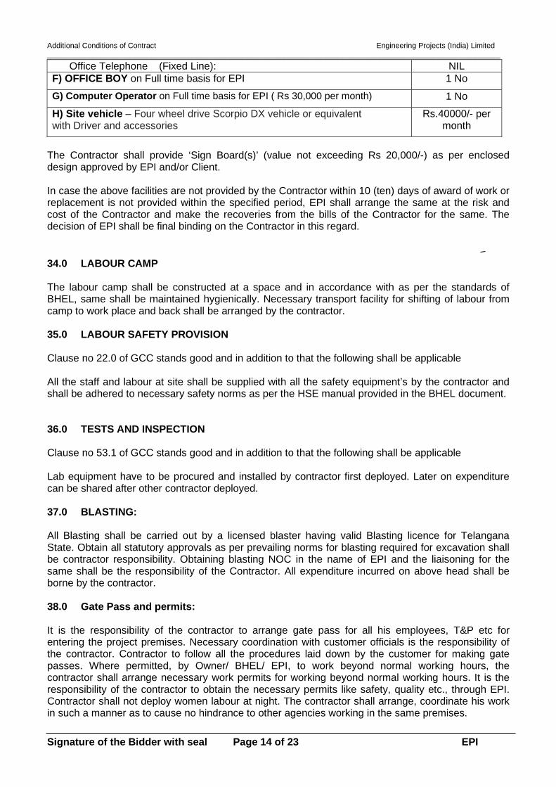
Additional Conditions of Contract Engineering Projects (India) Limited _____________________________________________________________________________________________________________
Signature of the Bidder with seal Page 14 of 23 EPI
Office Telephone (Fixed Line): NIL F) OFFICE BOY on Full time basis for EPI 1 No G) Computer Operator on Full time basis for EPI ( Rs 30,000 per month) 1 No H) Site vehicle – Four wheel drive Scorpio DX vehicle or equivalent with Driver and accessories
Rs.40000/- per month
The Contractor shall provide ‘Sign Board(s)’ (value not exceeding Rs 20,000/-) as per enclosed design approved by EPI and/or Client. In case the above facilities are not provided by the Contractor within 10 (ten) days of award of work or replacement is not provided within the specified period, EPI shall arrange the same at the risk and cost of the Contractor and make the recoveries from the bills of the Contractor for the same. The decision of EPI shall be final binding on the Contractor in this regard. 34.0 LABOUR CAMP The labour camp shall be constructed at a space and in accordance with as per the standards of BHEL, same shall be maintained hygienically. Necessary transport facility for shifting of labour from camp to work place and back shall be arranged by the contractor. 35.0 LABOUR SAFETY PROVISION Clause no 22.0 of GCC stands good and in addition to that the following shall be applicable All the staff and labour at site shall be supplied with all the safety equipment’s by the contractor and shall be adhered to necessary safety norms as per the HSE manual provided in the BHEL document.
36.0 TESTS AND INSPECTION Clause no 53.1 of GCC stands good and in addition to that the following shall be applicable Lab equipment have to be procured and installed by contractor first deployed. Later on expenditure can be shared after other contractor deployed. 37.0 BLASTING: All Blasting shall be carried out by a licensed blaster having valid Blasting licence for Telangana State. Obtain all statutory approvals as per prevailing norms for blasting required for excavation shall be contractor responsibility. Obtaining blasting NOC in the name of EPI and the liaisoning for the same shall be the responsibility of the Contractor. All expenditure incurred on above head shall be borne by the contractor. 38.0 Gate Pass and permits: It is the responsibility of the contractor to arrange gate pass for all his employees, T&P etc for entering the project premises. Necessary coordination with customer officials is the responsibility of the contractor. Contractor to follow all the procedures laid down by the customer for making gate passes. Where permitted, by Owner/ BHEL/ EPI, to work beyond normal working hours, the contractor shall arrange necessary work permits for working beyond normal working hours. It is the responsibility of the contractor to obtain the necessary permits like safety, quality etc., through EPI. Contractor shall not deploy women labour at night. The contractor shall arrange, coordinate his work in such a manner as to cause no hindrance to other agencies working in the same premises.

Additional Conditions of Contract Engineering Projects (India) Limited _____________________________________________________________________________________________________________
Signature of the Bidder with seal Page 15 of 23 EPI
39.0 TOOLS AND PLANTS / MONITORING AND MEASURING EQUIPMENT (MMEs) T&P shown in the ANNEXURE-III is tentative requirement considering parallel working in all areas mentioned in scope of work. However, mobilization schedule and quantity/ numbers as mutually agreed at site for major T&Ps, have to be adhered to. Numbers/ time of requirement of T&Ps will be reviewed time to time by EPI/ BHEL site and contractor will provide required T&P/ equipment’s to ensure completion of entire work within schedule/target date of completion without any additional financial implication to BHEL.
40.0 DISQUALIFICATION The tenderers may note that they are liable to be disqualified and not considered for the opening of Price Bid if; a) Representation in the forms, statements and attachments submitted in the pre- qualification document are proved to be incorrect, false and misleading.
b) They have record of poor performance during the past 10 (ten) years such as abandoning the work, rescinding of contract for which the reasons are attributable to the non-performance of the contractor, inordinate delay in completion, consistent history of litigation / arbitration awarded against the contractor or any of its constituents or financial failures due to bankruptcy etc. in their ongoing / past projects.
c) They have submitted incompletely filled in formats without attaching certified supporting documents and credentials to establish their eligibility to participate in the Tender.
d) If the tenderers attempt to influence any member of the selection committee. EPI reserves its right to take appropriate action including disqualification of tenderer(s) as may be deemed fit and proper by EPI at any time without giving any notice to the contractor in this regard. The decision of EPI in the matter of disqualification shall be final and binding on the Tenderers.
41.0 CONCILIATION AND ARBITRATION General Conditions of Contract (GCC) Sub Clause no.76.1 and 76.3 of Arbitration Clause no.76.0 are amended as given below. Sub Clause no.76.2 will remain unchanged.
76.0Conciliation and Arbitration
Before resorting to arbitration as per the clause given below, the parties if they so agree may explore the possibility of conciliation as per the provisions of Part III of the Arbitration and Conciliation Act, 1996 as amended by Arbitration and Conciliation (Amendment) Act, 2015. When such conciliation has failed, the parties shall adopt the following procedure for arbitration: a) Except where otherwise provided for in the contract, any disputes and differences
relating to the meaning of the Specifications, Design, Drawing and Instructions herein before mentioned and as to the quality of workmanship or materials used in the work or as to any other questions, claim, right, matter or things whatsoever in any way arising out of or relating to the Contract, Designs, Drawings, Specifications, Estimates, Instructions, or these conditions or otherwise concerning

Additional Conditions of Contract Engineering Projects (India) Limited _____________________________________________________________________________________________________________
Signature of the Bidder with seal Page 16 of 23 EPI
the works of the execution or failure to execute the same whether arising during the progress of the work or after the completion or abandonment thereof shall be referred to the Sole Arbitrator mutually agreed and appointed by both the parties as per the provisions of Arbitration and Conciliation Act, 2015 or any statutory modification or re-enactment thereof and the rules made thereunder. The person approached for appointment as Arbitrator shall disclose in writing circumstances, in terms of Sub-Section (1) of Section (12) of the Arbitration and Conciliation Act, 1996 as amended by Arbitration and Conciliation (Amendment) Act, 2015 as follows:
(i) such as the existence either direct or indirect, of any past or present
relationship with or interest in any of the parties or in relation to the subject-matter in dispute, whether financial, business, professional or other kind, which is likely to give rise to justifiable doubts as to his independence or impartiality; and
(ii) which are likely to affect his ability to devote sufficient time to the arbitration
and in particular his ability to complete the entire arbitration within a period of twelve months.
The Arbitrator shall be appointed within 30 days of the receipt of letter of invocation of arbitration duly satisfying the requirements of this clause.
b) If the arbitrator so appointed resigns or is unable or unwilling to act due to any reason whatsoever, or dies, the parties may mutually appoint a new arbitrator in accordance with these terms and conditions of the contract, to act in his place and the new arbitrator so appointed may proceed from the stage at which it was left by his predecessor.
c) It is a term of the contract that the party invoking the arbitration shall specify the dispute/ differences or questions to be referred to the Arbitrator under this clause together with the amounts claimed in respect of each dispute.
d) The Arbitrator may proceed with the arbitration ex-parte, if either party, in spite of a notice from the arbitrator, fails to take part in the proceedings.
e) The work under the contract shall continue as directed by the Engineer-In-Charge of EPI, during the arbitration proceedings.
f) Unless otherwise agreed, the venue of arbitration proceedings shall be at the venue given in the ‘Memorandum’ to the ‘Form of Tender”.
g) The award of the Arbitrator shall be final, conclusive and binding on both the parties.
h) Subject to the aforesaid, the provisions of the Arbitration and Conciliation Act, 1996 as amended by Arbitration and Conciliation (Amendment) Act, 2015 or any statutory modifications or re-enactment thereof and the Rules made there under and for the time being in force shall apply to the arbitration proceedings and Arbitrator shall publish his Award accordingly.
42.0 JURISDICTION:

Additional Conditions of Contract Engineering Projects (India) Limited _____________________________________________________________________________________________________________
Signature of the Bidder with seal Page 17 of 23 EPI
Clause no.76.3 are amended as under,
The courts in Chennai alone will have jurisdiction to deal with matters arising from the contract.
43.0 MAKE IN INDIA
Contractors to use as much as possible, the material/service from MSEs & Local suppliers/Manufacturers for promotion of Make in India For Promotion of Public Procurement (Preference to Make In India) order 2017 (amended on 28.05.2018) GOI Guideline for procurement, the equivalent Indian makes of materials conforming to requisite quality in addition to List of Makes/Brands may be considered subject to approval of BHEL/EPI Engineer In charge. Also “local supplier\bidder at the time of tendering, bidding or solicitation shall be required to provide self-certification in his letter head that the item offered meets the minimum local content and shall give the details of the location(s) at which the local value addition is made”. 44.0 PF & ESI Contribution & Returns 44.1 Contractor shall submit a copy of latest PF& ESI returns and inspection reports from statutory authorities along with a copy of challans for having deposited PF & ESI contributions every month. 44.2 PF & ESI Rate of interest and share contribution of employee and employer shall be as per Government of India latest Guidelines 44.3 Contractor shall fully comply all other formalities as per the PF & ESI statutory provisions and submit a copy of the same for replying to Statutory authorities in case of any complaints. 44.4 It is the responsibility of contractor to undertake necessary care and make arrangement for transportation and treatment of his employee at ESI Hospital or any tie up hospitals of ESIC. 44.5 Contractor should assist and guide his employees for claiming lawful benefits from ESI.
SIGNATURE OF THE CONTRACTOR WITH SEAL

Additional Conditions of Contract Engineering Projects (India) Limited _____________________________________________________________________________________________________________
Signature of the Bidder with seal Page 18 of 23 EPI
ANNEXURE – I Construction Program

ID Task Mode
Task Name Duration Start Finish Predecessors
1 0.04 mons Fri 02-08-19
2 Pakage-13 unit-14 EPSControlroom5 ESP Control Room Building
foundations -Unit-15 mons Thu 01-08-19 Tue 31-12-19
6 ESP Control Room Building 7 mons Tue 31-12-19 Thu 30-07-20 5
7 Auxiliary boiler foundations-unit-1 6 mons Thu 01-08-19 Thu 30-01-20
8 miletone1 MS1 0 mons Tue 31-12-19 Tue 31-12-19
9 Pipe Rack foundations -Unit-1 10 mons Thu 01-08-19 Sat 30-05-20
10 POWERHOUSE11 Power house - AC plant 10 mons Thu 01-08-19 Sat 30-05-20
12 Power house - Switch gear 10 mons Thu 01-08-19 Sat 30-05-20
13 Power House - Boiler MCC Room 10 mons Thu 01-08-19 Sat 30-05-20
14 Power house - Common control room (CCR)
12 mons Thu 01-08-19 Thu 30-07-20
15 Power house-MD BFP deck 12 mons Thu 01-08-19 Thu 30-07-20
16 Power house - TD BFP deck 18 mons Thu 01-08-19 Wed 27-01-21
17 Duct Support Foundations 10 mons Thu 01-08-19 Sat 30-05-20
18 Power House - 0.0m equipment foundations including cable trench & grade slab
11 mons Thu 01-08-19 Tue 30-06-20
19 Mill bunker floors 12 mons Thu 30-01-20 Wed 27-01-21 16FF
20 Transformer Yard including transformer foundations, cable trenches, bus duct foundations and fencing
18 mons Thu 01-08-19 Thu 28-01-21
21 Underground utilities 24 mons Thu 01-08-19 Thu 29-07-21
22 Milestone 2-MS-2 0 mons Sun 31-01-21 Sun 31-01-21
23 Unit-324 ESP Control Room Building
foundations -Unit-35 mons? Mon 02-12-19 Thu 30-04-20 5SS+4 mons
25 ESP Control Room Building 7 mons Fri 01-05-20 Sat 28-11-20 6SS+4 mons,24
26 Auxiliary boiler foundations-unit-3 6 mons Sat 30-11-19 Sat 30-05-20 7SS+4 mons
27 Pipe Rack foundations -Unit-3 10 mons Sat 30-11-19 Tue 29-09-20 9SS+4 mons
28 POWER HOUSE (UNIT 3)29 Power house - Switch gear 10 mons Sat 30-11-19 Tue 29-09-20 12SS+4 mons
30 Power house - AC plant 10 mons Sat 30-11-19 Tue 29-09-20 11SS+4 mons
31 Power House - Boiler MCC Room 10 mons Sat 30-11-19 Tue 29-09-20 13SS+4 mons
32 Power house - Common control room (CCR)
12 mons Sat 30-11-19 Sat 28-11-20 14SS+4 mons
33 Power house-MD BFP deck 12 mons Sat 30-11-19 Sat 28-11-20 15SS+4 mons
34 Power house - TD BFP deck 18 mons Sat 30-11-19 Fri 28-05-21 16SS+4 mons
35 Duct Support Foundations 10 mons Sat 30-11-19 Tue 29-09-20 17SS+4 mons
36 Power House - 0.0m equipment foundations including cable trench & grade slab
11 mons Sat 30-11-19 Thu 29-10-20 18SS+4 mons
37 Mill bunker floors 12 mons Sat 30-05-20 Fri 28-05-21 19SS+4 mons,34F
38 Transformer Yard including transformer foundations, cable trenches, bus duct foundations and fencing
18 mons Sat 30-11-19 Sat 29-05-21 20SS+4 mons
39 Underground utilities 24 mons Sat 30-11-19 Sat 27-11-21 21SS+4 mons
40 Common area41 Miscellaneous building 8 mons Tue 30-03-21 Sat 27-11-21 39FF
42 Pavement, roads & drains 10 mons Sat 27-02-21 Tue 28-12-21 39FF+1 mon
31-12
31-01
M-1 M1 M2 M3 M4 M5 M6 M7 M8 M9 M10 M11 M12 M13 M14 M15 M16 M17 M18 M19 M20 M21 M22 M23 M24 M25 M26 M27 M28 M29 M30 M
Task
Split
Milestone
Summary
Project Summary
External Tasks
External Milestone
Inactive Task
Inactive Milestone
Inactive Summary
Manual Task
Duration-only
Manual Summary Rollup
Manual Summary
Start-only
Finish-only
Deadline
Critical
Critical Split
Late
Progress
Slack
NAME OF WORK : BHEL :PSSR:SCT:1791 for Civil works-Super structure& architecture works of 5 X 800 MW Yadadri TPS Project at Veerlapalem
BHEL 2 Page 1 EPI
Project: Project1-test2Date: Mon 15-07-19

ID Task Mode
Task Name Duration Start Finish Predecessors
43 Filling (Part of levelling and grading works as per direction of Engineer In-Charge)
10 mons Sat 27-02-21 Tue 28-12-21 39FF+1 mon
44 Handing over and documentation45 physical handling over 1 mon Sat 27-11-21 Tue 28-12-21 3,40,21,37,38,39
46 Documentation, reconciliation 2 mons Sat 27-11-21 Thu 27-01-22 45SS
47 Final Bill submission for contract closing
2 mons Sat 27-11-21 Thu 27-01-22 45SS
M-1 M1 M2 M3 M4 M5 M6 M7 M8 M9 M10 M11 M12 M13 M14 M15 M16 M17 M18 M19 M20 M21 M22 M23 M24 M25 M26 M27 M28 M29 M30 M
Task
Split
Milestone
Summary
Project Summary
External Tasks
External Milestone
Inactive Task
Inactive Milestone
Inactive Summary
Manual Task
Duration-only
Manual Summary Rollup
Manual Summary
Start-only
Finish-only
Deadline
Critical
Critical Split
Late
Progress
Slack
NAME OF WORK : BHEL :PSSR:SCT:1791 for Civil works-Super structure& architecture works of 5 X 800 MW Yadadri TPS Project at Veerlapalem
BHEL 2 Page 2 EPI
Project: Project1-test2Date: Mon 15-07-19

Additional Conditions of Contract Engineering Projects (India) Limited _____________________________________________________________________________________________________________
Signature of the Bidder with seal Page 21 of 23 EPI
ANNEXURE -II

Additional Conditions of Contract Engineering Projects (India) Limited _____________________________________________________________________________________________________________
Signature of the Bidder with seal Page 22 of 23 EPI
ANNEXURE-III T&Ps and MMEs TO BE DEPLOYED BY CONTRACTOR All the tools and plants required for satisfactory completion of the work have to be arranged by the contractor. Sl.no Tool & plant items Numbers &
mobilization time 1 Excavator Equivalent To Capacity Of Poclain CK90 Or Higher To Suit The
Requirement Of Work At Site 1 nos
2 Automatic Concrete Batching Plant With Printing Facility (Minimum Capacity Of 30 CUM/Hr Each) With DG Backup.
1 Nos
3 Silo Per Batching Plant (100MT Each) 2 Nos 4 Truck Mounted Concrete Mixer Cum Pump Along With Placing Boom
Minimum 36 M High I.E. Concrete Boom Placer (36m) 1 Nos
5 Concrete Pump (60 CUM/ Hr Min Capacity & Lift 90M) N.B. 1 Nos 6 Transit Mixer (5/6 CUM Capacity) Including Standby 1 Nos. 5 Nos 7 Back Hoe Loader Like JCB 1 nos 8 Dumper (Min 15CUM Each) 2 Nos min and max
as per requirement 9 Diesel Mixer Machine Of 0.5CUM Capacity As per BHEL
requirement at site. 10 Self-Priming Dewatering Pump 5 HP (Diesel) 5 nos 11 Self-Priming Dewatering Pump 5 HP (Electric) 5 nos 12 Curing Pump – 1.5 /2 HP (Pump For Curing At Heights) 4 nos 13 Reinforcement Bending Machine 3 nos 14 Reinforcement Cutting Machine 3 nos 15 Vibromax (Earth Compactor) 1 nos 16 PICK & CARRY Cranes Minimum 9MT Capacity As per BHEL
requirement at site.
17 MS Scaffolding Pipe / ACROW PIPE 18 Building Hoist 19 Power Driven Earth Rammer (Roller Type 1/2 T) 20 Civil Laboratory Equipment’s 1 nos 21 Total Station With Adequate Arrangement For Surveyors 1 nos 22 Theodolite 1 Second Accuracy NIL 23 Auto Level & Staff 2 nos 24 Concrete Cube Moulds 90 nos 25 Small Trucks 2T/5T For Shifting Of Reinforcement/ Cement / Shuttering
Etc. Within Site As per BHEL requirement at site. 26 Construction Power Cable
27 Construction Water Pipeline 28 Trailor For Shifting Of Crawler Mounted Equipment’s Like Poclain, Dozer 1 nos / additional
as per BHEL requirement at site.
29 Concrete Vibrator With Adequate Needle (Minimum 20 Nos. Diesel/Electric)
5 Nos
30 Portable Fire Extinguishers As Below: Soda Acid – 10 Sets., Dry Chemical Powder – 10 Sets, CO2 – 10 Sets. Water & Sand Bucket (4 Buckets In One Stand) – 10 Sets. Fire Hose With Nozzle (50 M Length) – 5 Sets.
25% within 30 days and balance progressively within 90 days.
31 Truck Mounted 125 KVA DG Set
1 nos
32 compression testing machine (200 T capacity) nil 33 Drinking water tank–5000 lit. 2 Nos 34 Mobile toilet blocks for labour use. 2 nos

Additional Conditions of Contract Engineering Projects (India) Limited _____________________________________________________________________________________________________________
Signature of the Bidder with seal Page 23 of 23 EPI
Note: 1. Mobilization of concrete boom placer in place of concrete pump will be allowed based on site
requirement of BHEL. 2. In addition to the above, any other tools and plants required for execution of the above work are in
contractor’s scope. 3. The Contractor shall establish and maintain a field laboratory on the site and this laboratory shall be
available at all time for testing. 4. The age of the contractor deployed cranes upto 150 T should be within 15 years as on date of
deployment. Contractor has to provide documentary proof for the age of the crane at the time of deployment to the EPI/ BHEL Engineer.
5. In the event of need of change of type of any of major T&Ps, approval shall be taken from EPI/ BHEL Engineer in-charge prior to mobilization. The decision of Number of T&P required due to replacing the enlisted T&P as per above table, shall be taken after analyzing the production capacity and suitability of both the T&Ps.
6. All T&P and all IMTEs, which are required for successful and timely execution of the work covered within the scope of this tender, shall be arranged and provided by the contractor at his own cost in working condition.
7. In the event of non-mobilization of any T&P by the successful bidder and as a result progress of work suffered, EPI reserves the right to engage required T&P and expenditure incurred will debited from contractors liability

Additional Conditions of Contract Engineering Projects (India) Limited _____________________________________________________________________________________________________________
Signature of the Bidder with seal Page 19 of 21 EPI
ANNEXURE -II

Additional Conditions of Contract Engineering Projects (India) Limited _____________________________________________________________________________________________________________
Signature of the Bidder with seal Page 20 of 21 EPI
ANNEXURE-III T&Ps and MMEs TO BE DEPLOYED BY CONTRACTOR All the tools and plants required for satisfactory completion of the work have to be arranged by the contractor. Sl.no Tool & plant items Numbers &
mobilization time 1 Excavator Equivalent To Capacity Of Poclain CK90 Or Higher To
Suit The Requirement Of Work At Site 1 nos
2 Automatic Concrete Batching Plant With Printing Facility (Minimum Capacity Of 30 CUM/Hr Each) With DG Backup.
1 Nos
3 Silo Per Batching Plant (100MT Each) 2 Nos 4 Truck Mounted Concrete Mixer Cum Pump Along With Placing
Boom Minimum 36 M High I.E. Concrete Boom Placer (36m) 1 Nos
5 Concrete Pump (60 CUM/ Hr Min Capacity & Lift 90M) N.B. 1 Nos 6 Transit Mixer (5/6 CUM Capacity) Including Standby 1 Nos. 5 Nos/ as per site
requirement 7 Back Hoe Loader Like JCB 1 nos 8 Dumper (Min 15CUM Each) 1 Nos 9 Diesel Mixer Machine Of 0.5CUM Capacity As per BHEL
requirement at site.
10 Self-Priming Dewatering Pump 5 HP (Diesel) 1 nos 11 Self-Priming Dewatering Pump 5 HP (Electric) 1 nos 12 Curing Pump – 1.5 /2 HP (Pump For Curing At Heights) 4 nos 13 Reinforcement Bending Machine 2 nos 14 Reinforcement Cutting Machine 2 nos 15 Vibromax (Earth Compactor) 1 nos 16 PICK & CARRY Cranes Minimum 9MT Capacity As per BHEL
requirement at site.
17 MS Scaffolding Pipe / ACROW PIPE 18 Building Hoist 19 Power Driven Earth Rammer (Roller Type 1/2 T) 20 Civil Laboratory Equipment’s as per site
requirement 21 Total Station With Adequate Arrangement For Surveyors 1 nos 22 Theodolite 1 Second Accuracy N/a 23 Auto Level & Staff 5 nos 24 Concrete Cube Moulds 60 nos 25 Small Trucks 2T/5T For Shifting Of Reinforcement/ Cement /
Shuttering Etc. Within Site As per BHEL requirement at site.
26 Construction Power Cable 27 Construction Water Pipeline 28 Trailor For Shifting Of Crawler Mounted Equipment’s Like Poclain,
Dozer 1 nos / additional as per BHEL requirement at site.
29 Concrete Vibrator With Adequate Needle (Minimum 20 Nos. Diesel/Electric)
3 Nos
30 Portable Fire Extinguishers As Below: Soda Acid – 10 Sets., Dry Chemical Powder – 10 Sets, CO2 – 10 Sets. Water & Sand Bucket (4 Buckets In One Stand) – 10 Sets. Fire Hose With Nozzle (50 M Length) – 5 Sets.
25% within 30 days and balance progressively within 90 days.

Additional Conditions of Contract Engineering Projects (India) Limited _____________________________________________________________________________________________________________
Signature of the Bidder with seal Page 21 of 21 EPI
31 Truck Mounted 125 KVA DG Set
1 nos
32 compression testing machine (200 T capacity) 1 nos / additional as per BHEL requirement at site.
33 Drinking water tank–5000 lit. 2 Nos 34 Mobile toilet blocks for labour use. 2 nos
Note: 1. Mobilization of concrete boom placer in place of concrete pump will be allowed based on site
requirement of BHEL. 2. In addition to the above, any other tools and plants required for execution of the above work are in
contractor’s scope. 3. The Contractor shall establish and maintain a field laboratory on the site and this laboratory shall
be available at all time for testing. 4. The age of the contractor deployed cranes upto 150 T should be within 15 years as on date of
deployment. Contractor has to provide documentary proof for the age of the crane at the time of deployment to the EPI/ BHEL Engineer.
5. In the event of need of change of type of any of major T&Ps, approval shall be taken from EPI/ BHEL Engineer in-charge prior to mobilization. The decision of Number of T&P required due to replacing the enlisted T&P as per above table, shall be taken after analyzing the production capacity and suitability of both the T&Ps.
6. All T&P and all IMTEs, which are required for successful and timely execution of the work covered within the scope of this tender, shall be arranged and provided by the contractor at his own cost in working condition.
7. In the event of non-mobilization of any T&P by the successful bidder and as a result progress of work suffered, EPI reserves the right to engage required T&P and expenditure incurred will debited from contractors liability.

TECHNICAL CONDITIONS OF CONTRACT (TCC)
Tender Specification No.: BHEL: PSSR: SCT: 1791
VOLUME – IA Part I & II
TECHNICAL
CONDITIONS OF CONTRACT
(TCC)
BHARAT HEAVY ELECTRICALS LIMITED

TECHNICAL CONDITIONS OF CONTRACT (TCC)
Tender Specification No.: BHEL: PSSR: SCT: 1791
CONTENTS
Sl No. DESCRIPTION Chapter No. of Pages
Vol I A Part-I: Contract specific details 1 Project Information Chapter-I 02 2 Scope of works Chapter-II 03 3 Facilities in Scope of Contractor / BHEL (Scope Matrix) Chapter-III 09 4 T&Ps and MMEs to be deployed by Contractor Chapter-IV 08 5 T&Ps to be deployed by BHEL on sharing basis Chapter-V 01 6 Time Schedule Chapter-VI 06 7 Terms of Payment Chapter-VII 03 8 Taxes and other Duties Chapter-VIII 02 9 Bill of Quantity Chapter-IX 02
10 General Chapter-X 08 11 Progress of work Chapter-XI 02 12 Material Handling Chapter-XII 02 13 Accounting of material issue Chapter-XIII 09
Vol IA Part-II: Technical specifications
1 Corrections / Revisions in Special Conditions of Contract, General Conditions of Contract and Forms & Procedures Chapter 1 18
2 Technical Specification- Civil, Structural & Architectural Works-Section C Chapter 2 677
3 Technical Specification- Civil, Structural & Architectural Works-Section D Chapter 3 386
4 Bore Log Details Chapter 4 313 5 Hire Charges on issue of Tools & Plants Chapter 5 08 6 Technical Specification for Labour Colony Chapter 6 08
7 Drawings- General Labour Colony Details and Typical Layout of Labour Colony
Chapter 7 02
8 Plot Plan Chapter 8 01
9 “HSE Plan for Site Operations by Subcontractor” (Document No. HSEP: 14 Rev 00) Chapter 9 72
10 Form No.: F-14 (Rev 01) - Monthly Plan Review with Contractor Chapter 10 05
11 Form No.: F-15 (Rev 02)- Monthly Performance-Evaluation of Contractor
Chapter 11 06
12 No Deviation Certificate Chapter 12 01 13 Format for Integrity Pact Chapter 13 05 14 Pro-forma for Bank Guarantee for EMD Chapter 14 03
15 Procedure For Conduct Of Conciliation Proceedings
Chapter 15 11

TECHNICAL CONDITIONS OF CONTRACT (TCC)
Tender Specification No.: BHEL: PSSR: SCT: 1791
VOLUME - IA PART – I CHAPTER – I PROJECT INFORMATION
1.1.1 YADADRI THERMAL POWER STATION 5 x 800 MW Yadadri Thermal power station is being set up by TELANGANA STATE GENERATION CORPORATION at a site in Veerlapalem village, Dameracherla Mandal, NALGONDA DISTRICT, TELANGANA STATE, India. The Bidder shall acquaint himself by a visit to the site, if felt necessary, with the conditions prevailing at site before submission of the bid. The information given here in under is for general guidance and shall not be contractually binding on BHEL/Owner. All relevant site data /information as may be necessary shall have to be obtained /collected by the Bidder. PROJECT INFORMATION
1 Name of the Project YADADRI Thermal Power Station 2 Station Capacity 5X800 MW (Coal based)
3 Owner Telangana State Power Generation Corporation Limited (TSGENCO)
4 Site Location Site is located 7 km from the SH2. Miryalaguda-Vadapalle Highway.
5 Latitude 16° 42'20.40 N 6 Longitude 79° 34'41.56 E 7 Nearest Town 30 Km Miryalaguda
8 Nearest Railway Station 6.5 Km Damercherla
9 Nearest Airport 130 Kms (Vijayawada) 10 Site Conditions i. Ambient Temperature
Daily minimum (average) 10°C
Daily maximum (average) 47°C
Design Ambient Temperature 50°C
Ambient temperature (performance) 38°C
ii. Relative Humidity for design / efficiency 48-84 %
iii. Annual rainfall, mm 600 mm

TECHNICAL CONDITIONS OF CONTRACT (TCC)
Tender Specification No.: BHEL: PSSR: SCT: 1791
iv. Plant Elevation above MSL 85 m above MSL
v. Mean Wind Speed 8 km/h vi. Wind Pressure As per the latest revision of IS 875/1987 vii. Seismic co-efficient Zone-II as per IS- 1893 (Part-IV)

TECHNICAL CONDITIONS OF CONTRACT (TCC)
Tender Specification No.: BHEL: PSSR: SCT: 1791
VOLUME-IA PART-I CHAPTER – II SCOPE OF WORKS
(APPLICABLE FOR EACH PACKAGE) 1.2.1 The scope of works covers Civil & Architectural works of main plant area of
Units 1,2,3&4 of 5 x 800MW Yadadri TPS as mentioned below, including supply of all materials (excluding cement & Reinforcement Steel and MS Rounds for below ground earthing), labour, tools and plants. The scope of work is indicative but not limited to the given below.
1.2.2 The scope of work consists of two packages: 1.2.2.1 Package 1 consists of civil and architectural works of superstructure of power
house, bunker and civil and architectural works in other areas of main plant of Units 1 & 3
and 1.2.2.2 Package 2 consists of civil and architectural works of superstructure of power
house, bunker and civil and architectural works in other areas of main plant of Units 2 & 4
1.2.3 The list of structures and buildings in each package is mentioned below.
1.2.4 AREAS OF WORK 1.2.4.1 Package 1 (Unit 1 and Unit 3)
i) Superstructure civil works of Power house building including CCR ii) Coal bunker floors iii) Auxiliary boiler foundations (1 no.) iv) ID system duct supporting foundations v) ESP control room building vi) Transformer yard including GT/ST foundations vii) Cable trenches viii) Paving, roads & drains ix) Pipe rack foundations x) Interconnecting walkway xi) Boiler lift machine room xii) Underground utilities xiii) Pavement including miscellaneous buildings (including foundations) xiv) Filling (Part of levelling and grading works in plant area as per site
condition)
1.2.4.2 Package 2 (Unit 2 & Unit 4): i) Superstructure civil works of Power house building including CCR ii) Coal Bunker floors iii) ID system duct supporting foundations

TECHNICAL CONDITIONS OF CONTRACT (TCC)
Tender Specification No.: BHEL: PSSR: SCT: 1791
iv) ESP control room building v) Transformer yard including GT/ST foundations vi) Cable trenches vii) Paving, roads & drains viii) Pipe rack foundations ix) Interconnecting walkway x) Boiler lift machine room xi) Underground utilities xii) Pavement including miscellaneous buildings (including foundations) xiii) Filling (Part of levelling and grading works in plant area as per site
condition)
Note: The above provided list is indicative only for the bidder’s guideline. Any other building / structure / foundation not mentioned above, but required for completion of the project in total, deemed to have been included in the bidder scope under this contract. Such work will be executed under this contract by bidder as per the direction of Engineer in charge. If any item of work not available in the rate schedule of this contract, the rate will be fixed in line with clause 2.15.7 of GCC.
1.2.5 Cement & Reinforcement steel for civil works & MS round for below ground earthing shall be provided by BHEL free of cost. Embedments /inserts required for the works in general shall be supplied by the bidder and payment shall be made as per corresponding item in BOQ. If BHEL provides Structural Steel for embedments/inserts from scraps (if available), payment shall be made as per corresponding item in BOQ.
1.2.6 The works to be performed under this contract consist of providing all labour, supervision, material, scaffolding, construction equipment’s, tools and plants, temporary works, supplies including POL, transportation and all incidental items not shown or specified but reasonably implied or necessary for the proper completion of work in all respects. Testing of all materials, concrete, earthwork other allied works, preparation of bar bending schedules on the basis of construction drawings, preparation of fabrication drawings etc. are included on the rates of items of work.
1.2.7 The area of work shall be cleared of all vegetation, rubbish and other objectionable matter and materials removed shall be burnt or otherwise disposed of as directed by The Engineer-in-Charge. No separate payment for these operations shall be made. The cost of all these operations shall be deemed to have been included in the unit rates rendered for the different items under bill of quantities.
1.2.8 All the works areas shall be adequately flood lighted to the satisfaction of the Engineer-in-Charge when the work is in progress during the night shifts.

TECHNICAL CONDITIONS OF CONTRACT (TCC)
Tender Specification No.: BHEL: PSSR: SCT: 1791
1.2.9 The unit rates shall include all material equipment, fixtures, labour construction plant, temporary works and everything whether of permanent or temporary nature necessary for the completion of job in all respects.
1.2.10 The unit rates for various items of B.O.Q shall include all the stipulations mentioned in technical specifications and nothing extra over B.O.Q rates shall be payable.
1.2.11 Drawings showing enough details for the construction as per the specification shall be furnished to the contractor in a phased manner.
1.2.12 The bidder should fully apprise himself of the prevailing conditions at the proposed site, climatic conditions including monsoon pattern, local conditions, soil strata and site specific parameters and shall include for all such conditions and contingent measures in the bid, including those which may have not been specifically brought out in the specifications.

TECHNICAL CONDITIONS OF CONTRACT (TCC)
Tender Specification No.: BHEL: PSSR: SCT: 1791
VOLUME IA PART – I CHAPTER – III FACILITIES IN THE SCOPE OF CONTRACTOR / BHEL
(SCOPE MATRIX) (APPLICABLE FOR EACH PACKAGE)
Sl.No Description
PART I
Scope to be taken care by Remarks
BHEL Bidder 1.3.1.1 ESTABLISHMENT
1.3.1.1.1 FOR CONSTRUCTION PURPOSE:
A Open space for office Yes As provided by TSGENCO
B Open space for storage Yes As provided by TSGENCO
C Construction of bidder’s office, canteen and storage building, cement storage shed including supply of materials and other services
Yes
D Bidder’s all office equipment’s, office / store / canteen consumables
Yes
E Canteen facilities for the bidder’s staff, supervisors and engineers etc.
Yes
F Firefighting equipment’s like buckets, extinguishers etc.
Yes
G Fencing of storage area, office, canteen etc. of the bidder
Yes
1.3.1.1.2 FOR LIVING PURPOSES OF THE BIDDER

TECHNICAL CONDITIONS OF CONTRACT (TCC)
Tender Specification No.: BHEL: PSSR: SCT: 1791
Sl.No Description
PART I
Scope to be taken care by Remarks
BHEL Bidder A Open space Yes As
provided by TSGENCO
B Living accommodation Yes 1.3.1.2 ELECTRICITY 1.3.1.2.1 Electricity For construction
purposes Free
charges as provided
by TSGENCO
1.3.1.2.1.1 Single point source
Yes
1.3.1.2.1.2 Further distribution for the work to be done which include supply of materials and execution
Yes
1.3.1.2.2 Electricity for the office, stores, canteen, labour hutments, etc of the bidder which include:
Yes
1.3.1.2.2.1 Distribution from single point including supply of materials and service
Yes
1.3.1.2.2.2 Supply, installation and connection of material of energy meter including operation and maintenance
Yes
1.3.1.2.2.3 Duties and deposits including statutory clearances for the above
Yes
1.3.1.2.2.4 Demobilization of the facilities after completion of works
Yes

TECHNICAL CONDITIONS OF CONTRACT (TCC)
Tender Specification No.: BHEL: PSSR: SCT: 1791
Sl.No Description
PART I
Scope to be taken care by Remarks
BHEL Bidder 1.3.1.2.3 Electricity for living
accommodation of the bidder’s staff, engineers, supervisors etc on the above lines. (in case BHEL provides this facility, the scope should be given without ambiguity)
Yes
1.3.1.3 WATER SUPPLY 1.3.1.3.1 For construction purposes: Yes Free of
charges as provided
by TSGENCO
1.3.1.3.1.1 Making the water available at single point
Yes As provided
by TSGENCO
1.3.1.3.1.2 Further distribution as per the requirement of work including supply of materials and execution
Yes
1.3.1.3.2 Water supply for bidder’s office, stores, canteen, labour hutments, etc.
Yes
1.3.1.3.2.1 Making the water available at single point
Yes
1.3.1.3.2.2 Further distribution as per the requirement of work including supply of materials and execution
Yes
1.3.1.4 LIGHTING 1.3.1.4.1 For construction work (supply of
all the necessary materials) At office storage area At the preassembly area At the construction site / area
Yes

TECHNICAL CONDITIONS OF CONTRACT (TCC)
Tender Specification No.: BHEL: PSSR: SCT: 1791
Sl.No Description
PART I
Scope to be taken care by Remarks
BHEL Bidder 1.3.1.4.2 For construction work (Execution
of the lighting work / arrangements)
At office storage area At the preassembly area At the construction site /area At the labour hutment
Yes
1.3.1.5 COMMUNICATION FACILITIES for site operations of the bidder
-
1.3.1.5.1 Telephone, Fax, internet, intranet, email etc
Yes
Sl.No Description
PART II
Scope to be taken care by Remarks
1.3.2 BHEL Bidder CONSTRUCTION FACILITIES
1.3.2.1 Engineering works for construction
1.3.2.1.1 Providing the construction drawings for all the equipment covered under this scope
Yes Progressively
1.3.2.1.2 Detailing of drawings for construction
Yes In consultation with BHEL
1.3.2.1.3 As-built drawings – wherever deviations observed and executed and also based on the decisions taken at site- example – routing of small bore pipes
Yes Yes ”
1.3.2.1.4 Shipping lists etc for reference and planning the activities
Yes Yes ”

TECHNICAL CONDITIONS OF CONTRACT (TCC)
Tender Specification No.: BHEL: PSSR: SCT: 1791
Sl.No Description
PART II
Scope to be taken care by Remarks
1.3.2 BHEL Bidder 1.3.2.1.5 Preparation of site construction
schedules and other input requirements
Yes In consultation with BHEL, As per requirement of BHEL targets
1.3.2.1.6 Review of performance (Form-14) and revision of site construction schedules in order to achieve the end dates and other commitments
Yes
1.3.2.1.7 Weekly construction schedules based on Sl No 1.3.2.1.5
Yes
1.3.2.1.8 Daily construction / work plan based on Sl No 1.3. 2.1.7
Yes For daily monitoring meeting at site
1.3.2.1.9 Periodic visit of the senior official of the bidder to site to review the progress so that works are completed as per schedule. It is suggested this review by the senior official of the bidder should be done once in every two months.
Yes
1.3.2.1.10 Preparation of preassembly bay Yes 1.3.2.1.11 Laying of racks for gantry crane if
provided by BHEL or brought by the contractor / bidder himself
Not applicable
1.3.3 OPEN SPACE: 1.3.3.1 Open space, as provided by TSGENCO, will be provided to the bidder free of
cost. Availability of land within plant boundary is very limited and the contractor has to plan and use the existing land considering the use of land by other Civil /mechanical/ electrical contractors and the storage of plant machineries and materials. The existing land shall be shared by all erections agencies. Land will be allocated with certain time frame and to the extent available/ considered necessary, and will be reviewed by BHEL depending upon the area availability. Area within plant premises for batching plant, office, storage area etc. for construction purpose shall be provided as per availability free of cost. The contractor will be responsible for handing back all lands, as handed over to him by BHEL.

TECHNICAL CONDITIONS OF CONTRACT (TCC)
Tender Specification No.: BHEL: PSSR: SCT: 1791
1.3.3.2 Land for labour colony shall be provided by BHEL nearer to site (outside plant premises) free of cost as provided by TSGENCO. The contractor to construct labour colony/ hutment as per the technical specification No.PSSR/PMX/CVL/Labour colony/01, Rev-00 enclosed in Part-II of Volume-IA, Technical Conditions of Contract of this tender at his own cost. The contractor shall provide adequate water arrangement for drinking/washing/bathing with required toilets, drainage system, and electrification etc. in labour colony at his own cost. Suitable paved area to be provided in the labour colony at the cost of contractor.
1.3.4 ELECTRICITY: 1.3.4.1 Construction power will be provided to the contractor free of cost at one single
point within the plant area by BHEL as provided by TSGENCO. The contractor to Provide necessary meter for measuring the power consumption. The contractor shall make his own arrangement for further distribution with necessary isolator/LCB etc.
1.3.4.2 Necessary “Capacitor Banks” to improve the Power factor to a minimum of 0.9 shall be provided by the contractor at his cost. Penalty if any levied by customer on this account will be recovered from contractor’s bills.
1.3.4.3 Any duty, deposit involved in getting the Electricity shall be borne by the bidder. As regards contractor’s office shed also all such expenditure shall be borne by the contractor.
1.3.4.4 Provision for distribution of electrical power from the given single central common point to the required places with proper distribution boards, approved cables and cable laying including supply of all materials like cables, switch boards, pipes etc., observing the safety rules laid down by electrical authority of the State / BHEL / their customer with appropriate statutory requirements shall be the responsibility of the tenderer / contractor.
1.3.4.5 BHEL is not responsible for any loss or damage to the contractor’s equipment as a result of variations in voltage / frequency or interruptions in power supply.
1.3.4.6 Contractor has to make their own arrangements for electricity requirement for labour colony at his own cost.
1.3.4.7 As there are bound to be interruptions in regular power supply, power cut/ load shedding in any construction sites, contractor should make his own arrangement for alternative source of power supply through deployment of adequate number of DG sets at their cost during the power breakdown / failure to get urgent and important work to go on without interruptions. No separate payment shall be made for this contingency.

TECHNICAL CONDITIONS OF CONTRACT (TCC)
Tender Specification No.: BHEL: PSSR: SCT: 1791
1.3.5 WATER: 1.3.5.1 Water (Raw water) required for construction purposes will be provided at
one single point within the plant area free of cost as provided by TSGENCO. The required pumps & accessories, pipes for drawing water from the given point and further distribution will be arranged by the contractor at their cost to go on without interruptions.
1.3.5.2 In case of non-availability of water, the contractor shall make his own arrangements of water suitable for construction purpose to have uninterrupted work. No separate payment shall be made for any contingency arrangement made by contractor, due to delay / failure for providing water supply.
1.3.6 MATERIAL SUPPLY: 1.3.6.1 Supply / providing aggregate, sand (river sand only) and all other materials
required (except free supply materials i.e. cement, reinforcement steel, structural steel for embedments/inserts from scraps (if available), foundation bolts & inserts/embedments supplied by manufacturing units of BHEL) for the work are in the scope of the contractor. BHEL shall provide Cement, reinforcement steel for civil works and MS rounds for below ground earthing only for incorporation in the permanent work AS FREE SUPPLY. Embedments /inserts required for the works in general shall be supplied by the bidder and payment shall be made as per corresponding item in BOQ. If BHEL provides Structural Steel from scraps (if available), payment shall be made as per corresponding item in BOQ.
1.3.6.1.1 Regarding supply of cement, the cement shall be provided normally in bulkers and shall be unloaded in the silos (2 Nos minimum 100MT each per 30 CUM/hr batching plant) to be installed by the bidder nearer to their batching plants. This is only minimum requirement and the number of cement silos shall be increased based on the site requirement. On advance request of the bidder, the cement shall be supplied in Bags for other than RCC works like masonry, flooring works etc. Advance request for supply of cement in bags shall be minimum two months.
1.3.6.1.2 The steel material will be issued from BHEL stores, within the plant premises. Collection and transporting to the place of work is in contractor’s scope without any extra cost to BHEL. The steel will be issued to the agency in standard lengths. In some instances, for 8mm, 10mm &12mm dia reinforcement steel will be supplied in coil form. No extra claims will be entertained against issue of Non-standard lengths of steel and de coiling of 8mm, 10mm &12mm dia. steel.
1.3.6.1.3 If any matching sections of steel are not available with BHEL, contractor may arrange these sections on certification of BHEL and the landing cost of sections to site will be reimbursed based on the prevailing rate at SAIL at

TECHNICAL CONDITIONS OF CONTRACT (TCC)
Tender Specification No.: BHEL: PSSR: SCT: 1791
the time of procurement at the nearest SAIL outlet with the freight charges against supporting document.
1.3.7 CONSUMABLE 1.3.7.1 All consumables, like gas, electrodes, chemicals, lubricants etc. required for
the scope of work, shall be arranged by the contractor at his cost unless otherwise specifically mentioned in the contract. Prior approval from Engineer In Charge shall be obtained for all the consumables to be used in the permanent work.
1.3.7.2 In the event of failure of contractor to bring necessary and sufficient consumables, BHEL may arrange for the same at the risk and cost of the contractor. The entire cost towards this along-with overhead shall be paid by the contractor or deducted from the contractor’s bills.
1.3.8 LIGHTING FACILITY: 1.3.8.1 Adequate lighting facilities such as flood lamps, hand lamps and area
lighting shall be arranged by the contractor at the site of construction, and contractor’s material storage area etc. at his cost.
1.3.9 CONTRACTOR'S OBLIGATION ON COMPLETION: 1.3.9.1 On completion of work, all the temporary buildings, structures, pipe lines,
cables etc. shall be dismantled and leveled and debris shall be removed as per instructions of BHEL by the contractor at his cost. In the event of his failure to do so, the expenditure towards clearance of the same will be recovered from the contractor. The decision of BHEL Engineer in this regard is final.
1.3.10 BLASTING 1.3.10.1 Contractor should produce documentary evidence of valid blasting license
for Telangana State (or) should produce documents for having tie-up with agency who is possessing valid blasting license for Telangana State within 30 days from issue of LOI.
1.3.10.2 For details on Blasting refer enclosed Bill of quantity (rate schedule) and technical Specifications available in Part-II, Volume-IA, Technical Conditions of Contract of this tender.
1.3.11 DEWATERING 1.3.11.1 Contractor shall ensure at all times that his work area & approach/ access
roads are free from accumulation of water, so that the materials are safe and the erection/ progress schedule are not affected. No separate claim in this regard shall be admitted by BHEL. No separate payments for dewatering of subsoil, surface water or catchments water, if required, at any time during execution of the work including monsoon period shall be considered by BHEL.

TECHNICAL CONDITIONS OF CONTRACT (TCC)
Tender Specification No.: BHEL: PSSR: SCT: 1791
1.3.12 BID DRAWINGS 1.3.12.1 Bid drawings enclosed are for information only and this may get revised
during execution.

TECHNICAL CONDITIONS OF CONTRACT (TCC)
Tender Specification No.: BHEL: PSSR: SCT: 1791
VOLUME-IA PART-I CHAPTER – IV T&Ps and MMEs TO BE DEPLOYED BY CONTRACTOR
T&PS TO BE DEPLOYED BY CONTRACTOR FOR EACH PACKAGE 1.4.1 All the tools and plants required for satisfactory completion of the work have
to be arranged by the contractor. 1.4.2 The contractor is required to arrange the following tentative Major T&Ps and
other T&Ps for each package for the satisfactory completion of the work: 1.4.2.1
Sr No T&P items Mobilizing time from the date of start of work
A. Major T&P items
A. 1 2 No. excavator equivalent to capacity of Poclain CK90 or higher to suit the requirement of work at site
1 no. within 20 days, balance in a progressive manner per BHEL requirement in site.
A. 2
2 no. automatic concrete batching plant with printing facility (minimum capacity of 30 CUM/Hr each) with DG backup. With minimum 2 Nos of silo per batching plant (100MT each)
1 no. to be commissioned within 45 days and balance to be commissioned as mutually agreed between bidder and Engineer In-Charge of BHEL.
A. 3 2 Nos Truck mounted concrete mixer cum pump along with placing boom minimum 36 m high i.e. Concrete boom placer (36m)
1 No within 45 days and balance as per BHEL requirement at site
A. 4
1 nos. concrete pump (60 CUM/ hr min capacity & lift 90M) N.B. – Concrete pump can be replace by providing additional concrete boom placer of adequate capacity with prior approval of Engineer In-Charge.
As per BHEL requirement at site
A. 5 10 nos. transit mixer (5/6 CUM capacity) including standby 2 nos.
4 no’s within 45 days. Balance progressively as per BHEL requirement at site.

TECHNICAL CONDITIONS OF CONTRACT (TCC)
Tender Specification No.: BHEL: PSSR: SCT: 1791
Sr No T&P items Mobilizing time from the date of start of work
B. Other T&P items
B. 1 4 No. back hoe loader like JCB 2 no. within 30 days and balance as per BHEL requirement at site.
B. 2 10 nos. dumper (Min 15CUM each) 2 nos. Within 20 days. Another 3 nos. within 45 days. Balance as per BHEL requirement at site.
B. 3 4 nos. diesel Mixer machine of 0.5CUM capacity
As per BHEL requirement at site.
B. 4 5 nos. self-priming dewatering pump 5 HP (diesel) Within 20 days.
B. 5 5 nos. self-priming dewatering pump 5 HP (electric) Within 30 days
B. 6 8 nos. curing pump – 1.5 /2 HP (pump for curing at heights) Within 60 days.
B. 7 10 nos. reinforcement bending machine
3 nos. within 20 days, another 3 nos. within 45 days and balance progressively as per BHEL requirement at site
B. 8 1 no. Vibromax (earth compactor) As per BHEL requirement at site.
B. 9 10 nos. reinforcement cutting machine
3 nos. within 20 days, another 3 nos. within 45 days and balance progressively as per BHEL requirement at site
B. 10 2 nos. PICK & CARRY cranes minimum 9MT capacity
As per BHEL requirement at site
B. 11 MS scaffolding pipe / ACROW PIPE
As per BHEL requirement at site
B. 12 4 nos. building hoist As per BHEL requirement at site
B. 13 2 nos. motorized external platforms (sky climber)
As per BHEL requirement at site
B. 14 1 no. power driven earth rammer (Roller Type 1/2 T)
As per BHEL requirement at site

TECHNICAL CONDITIONS OF CONTRACT (TCC)
Tender Specification No.: BHEL: PSSR: SCT: 1791
Sr No T&P items Mobilizing time from the date of start of work
B. 15
Civil laboratory equipment’s as per list in clause 1.4.4.2 with temporary building one AC lab size 4.5mtrx6mtr and 1 non AC lab 4.5 mtrx4.5 mtr.
Within 55 days.
B. 16 2 nos. total station with adequate arrangement for Surveyors.
1 no. Within 15 days and balance progressively as per BHEL requirement at site
B. 17 2 no theodolite 1 second accuracy
1 no. within 15 days. and balance progressively as per BHEL requirement at site, theodolite can be replaced by total station based on requirement at site.
B. 18 5 or more nos. auto level & staff
2 nos. Within 15 days and balance as per BHEL requirement at site. No. of auto level shall be mutually agreed between contractor & Engineer In-charge.
B. 19 200 nos concrete cube moulds 150 nos. within 30 days and balance progressively as per BHEL requirement at site
B. 20 Adequate no. of small trucks 2T/5T for shifting of reinforcement/cement/shuttering etc. within site
As per BHEL requirement at site
B. 21 2 nos. truck mounted 125 KVA DG set
1 no. within 30 days and balance within 60 Days.
B. 22 Construction power cable As per BHEL requirement at site
B. 23 Construction water Pipeline As per BHEL requirement at site
B. 24 1 no. trailor for shifting of crawler mounted equipment’s like Poclain, Dozer
As per BHEL requirement at site
B. 25 Concrete vibrator with adequate needle (Minimum 20 nos. diesel/electric)
6 nos. (at least 3 nos. diesel driven) within 45 Days. Balance as per BHEL requirement at site.

TECHNICAL CONDITIONS OF CONTRACT (TCC)
Tender Specification No.: BHEL: PSSR: SCT: 1791
Sr No T&P items Mobilizing time from the date of start of work
B. 26
Portable fire extinguishers as below: Soda acid – 10 sets. Dry chemical powder – 10 sets CO2 – 10 sets. Water & sand bucket (4 buckets in one stand) – 10 sets. Fire hose with nozzle (50 M length) – 5 sets.
25% within 30 days and balance progressively within 90 days.
B. 27 1 no. compression testing machine (200 T capacity)
1 no. within 30 days and balance as per BHEL requirement at site.
B. 28 4 nos. drinking water tank–5000 lit. 1 no. within 30 days. Balance as per BHEL requirement at site
B. 29 4 nos. mobile toilet blocks for labour use.
1 no. within 30 days balance within 75 days.
1.4.2.2 Notes: 1.4.2.2.1 T&P shown in the above mentioned list is tentative requirement considering
parallel working in all areas mentioned in scope of work. However, mobilization schedule and quantity/ numbers as mutually agreed at site for major T&Ps, have to be adhered to. Numbers/ time of requirement of T&Ps will be reviewed time to time by BHEL site and contractor will provide required T&P/ equipment’s to ensure completion of entire work within schedule/target date of completion without any additional financial implication to BHEL. Vendor will give advance intimation & certification regarding capacity etc. prior to dispatch of heavy equipment’s. Also on completion of the respective activity, demobilization of T&P in total or in part can be done with the due approval of engineer in charge. Retaining of the T&P’s during the contract period will be mutually agreed in line with construction requirement.
1.4.2.2.2 All T&P and all IMTEs, which are required for successful and timely execution of the work covered within the scope of this tender, shall be arranged and provided by the contractor at his own cost in working condition.
1.4.2.2.3 In the event of non-mobilization of any T&P by the successful bidder and as a result progress of work suffered, BHEL reserves the right to engage required T&P in line with clause no. 4.2.1.7 of Special Conditions of Contract (Volume IB of Volume I Book II).

TECHNICAL CONDITIONS OF CONTRACT (TCC)
Tender Specification No.: BHEL: PSSR: SCT: 1791
1.4.2.2.4 In the event of need of change of type of any of major T&Ps, approval shall be taken from BHEL Engineer in-charge prior to mobilization. The decision of Number of T&P required due to replacing the enlisted T&P as per above table, shall be taken after analyzing the production capacity and suitability of both the T&Ps.
1.4.2.2.5 The age of the contractor deployed cranes upto 150 T should be within 15 years as on date of deployment. Contractor has to provide documentary proof for the age of the crane at the time of deployment to the BHEL Engineer.
1.4.2.2.6 Mobilization of concrete boom placer in place of concrete pump will be allowed based on site requirement of BHEL.
1.4.3 In addition to the above, any other tools and plants required for execution of the above work are in contractor’s scope.
1.4.4 The Contractor shall establish and maintain a field laboratory on the site and this laboratory shall be available at all time for testing.
1.4.4.1 The laboratory must have qualified technicians to carry out all tests and must be adequately equipped to ensure that all necessary testing work can be carried out in compliance with the standards.
1.4.4.2 Field and laboratory testing procedures for materials follow Indian Standard Specifications with necessary equipment’s like as given in table below:
A. CONCRETE TESTING EQUIPMENT Sl. No.
NAME OF TEST NAME OF EQUIPMENT
SIZE OF EQUIPMENT
IS REF.
A. 1 Initial & final setting time, Consistency of cement
Vicat Apparatus with desk pot
Standard IS 5513
A. 2 Shrinkage of cement, Auto Clave Test
Le Chatelier's appratus Auto Clave Equipment
Standard IS 5514
A. 3 Abrasion value test
Los Angles Abrasion testing machine
Standard IS 2386
A. 4 Aggregate Impact value test
Aggregate Impact value testing machine with blow counter
Standard IS 9377

TECHNICAL CONDITIONS OF CONTRACT (TCC)
Tender Specification No.: BHEL: PSSR: SCT: 1791
Sl. No.
NAME OF TEST NAME OF EQUIPMENT
SIZE OF EQUIPMENT
IS REF.
A. 5 Aggregate crushing value test
Crushing value apparatus
Standard IS 2386
A. 6 Flakiness index Thickness gauge for measuring flakiness index
Standard IS 2386
A. 7 Elongation Index Elongation guage
Standard IS 2386
A. 8 Bulk density, voids and bulking apparatus
Measuring cylinders
3, 5,10 & 15 liters cylinders
A. 9 Workability of concrete
Slump cone Standard, at least 04 no’s
IS 456
A. 10 Specific gravity of aggregates
Pycnometer Standard, at least 02 no’s
IS 383
A. 11 Cement mortar cube vibrating
Motorised vibration machine for cement testing
Standard IS 4031
A. 12 Course aggregate Sieve analysis (Concrete & Road Works)
Sieve set 450mm dia GI Frames Size: 125 mm, 90 mm, 75 mm, 63 mm, 53 mm, 40 mm, 20 mm, 16 mm, 12.5 mm, 10 mm, 4.75 mm, Pan and cover
IS 383
A. 13 Fine aggregate sieve analysis
Sieve set 200 mm dia Brass sieves; Size 4.75 mm, 2.36 mm, 1.18 mm 600 micron, 300 micron, 150 micron, 75 micron, 75 micron, Pan and cover
IS 383
A. 14 Sieve Shaker Motorized Sieve shaker
Mfg. Catalogue
A. 15 Silt content check
Sand silt content beaker
Standard

TECHNICAL CONDITIONS OF CONTRACT (TCC)
Tender Specification No.: BHEL: PSSR: SCT: 1791
B. SOIL TESTING EQUIPMENT Sl. No.
NAME OF TEST NAME OF EQUIPMENT
SIZE OF EQUIPMENT IS REF.
B. 1 Liquid limit test Liquid limit apparatus
Standard IS 2720
B. 2 Core Cutter test core cutter apparatus
Rammer, 6 nos. of Std. core cutter mould, dolly
IS 2720
B. 3 Proctor density test
Std proctor Compaction apparatus
Standard IS 2720
B. 4 Moisture Content Rapid moisture meter
Standard, at least 04 nos. IS 2720
1.4.5 Contractor shall have at all times experienced operators and technicians for routine and breakdown maintenance of the equipment. Any delay in rectification of defects will warrant BHEL rectifying the defect and charging the cost to the contractor.
1.4.6 The area and infrastructure development of the work area are to be carried out by the customer. However, in construction projects of this magnitude it is possible that all the areas / approaches may not be ready. In such cases consolidation of ground and arrangement of sleepers / sand bag filling etc. for safe operation / movement of equipment including cranes / trailers etc. shall be the responsibility of the contractor at his cost. No compensation on this account shall be payable.
1.4.7 In case the contractor fails to provide any T&P which is in the scope of contractor and if BHEL provides such T&P or higher capacity T&P as available with BHEL, hire charges prevailing (as per BHEL norms) as on that day will be recovered from the contractor as per the prevailing BHEL Corporate Crane hire charges. Corresponding pages of Corporate Crane hire charges are enclosed in Chapter 5 of part II of Technical Conditions of Contract (Volume-IA Book-I). This may get revised further as per the BHEL corporate guidelines. However, prevailing rates as on date of execution may be applicable.
1.4.8 In general, any crane for the tendered scope will not be provided by BHEL. However, if requirement of crane of higher capacity (i.e. more than 150MT) arises for any unforeseen circumstance, bidder may request BHEL to provide crane on chargeable basis, but BHEL reserves right of provision of crane. If provided, in that case, Crane operators deployed by the contractor shall be tested by BHEL before they are allowed to operate the cranes.
1.4.9 In case, cement is issued through bulkers being supplied from manufacturer /stockiest, the same shall be emptied in cement silos of batching plant and necessary assistance shall be provided by contractor without any additional

TECHNICAL CONDITIONS OF CONTRACT (TCC)
Tender Specification No.: BHEL: PSSR: SCT: 1791
financial implication to BHEL. Contractor to note that each batching plant being established at site shall have minimum 2 Nos cement silos of 100 MT capacities each as mentioned at Sl. No. A.2 in list of Major T&P items in clause 1.4.2.1 above.

TECHNICAL CONDITIONS OF CONTRACT (TCC)
Tender Specification No.: BHEL: PSSR: SCT: 1791
VOLUME-IA PART-I CHAPTER - V T&Ps TO BE DEPLOYED BY BHEL ON SHARING
BASIS T&Ps provided by BHEL (APPLICABLE FOR EACH PACKAGE)
1.5.1 BHEL shall not provide any T & Ps. However, if in any unforeseen circumstances, requirement of any T&Ps (available with BHEL at site) arises, on request of bidder the same may be provided on chargeable basis but BHEL reserves the right of provision of such T&Ps.

TECHNICAL CONDITIONS OF CONTRACT (TCC)
Tender Specification No.: BHEL: PSSR: SCT: 1791
VOLUME-IA PART-I CHAPTER - VI TIME SCHEDULE
(APPLICABLE FOR EACH PACKAGE) 1.6.1 TIME SCHEDULE 1.6.1.1 The entire work of Civil and Architectural works under each package as
detailed in the Tender Specification shall be completed within 30 (Thirty) months from the date of commencement of work at site.
1.6.1.2 The date of commencement of work at site shall be mutually agreed date between bidder and BHEL. The scope of work under this contract is deemed to be completed only when so certified by the site Engineer. The decision of BHEL in this regard shall be final and binding on the contractor.
1.6.1.3 During the total period of contract, the contractor has to carry out the activities in a phased manner as required by BHEL and the program of scheduled events including milestone events. The work fronts for construction will get released progressively during the course of execution at site. The required documents / drawings for construction will be progressively issued to the contractor during the course of execution at site.
1.6.1.4 The contractor is required to refer Form 15 Monthly Performance Evaluation of Contractors in Volume-ID Book-II, for all the instructions to be taken immediately after receipt of LOI. Please note that the Monthly Performance Evaluation of Contractor Form -15 in Vol 1D - Forms and Procedures Book II is revised and attached in Part-2, Chapter-11 which is applicable for this tender.
1.6.2 COMMENCEMENT OF CONTRACT PERIOD 1.6.2.1 The date of commencement of contract period for each package shall be
the date of commencement of work at site which shall be shall be mutually agreed date between bidder and BHEL. In case of discrepancy, the decision of BHEL Site Engineer is final.
1.6.3 MOBILISATION 1.6.3.1 The Contractor has to subsequently augment his resources in such a
manner to achieve the COMPLETION SCHEDULES for his respective each package. The tentative construction schedule for Package 1 and Package 2 is given below:
1.6.3.1.1 Construction Schedule for Civil Works of Package 1 Tentative construction schedule for civil works of the first unit (i.e. Unit-1) & for common area in the package is as mentioned below. Phase shift of four months shall be considered for another unit (i.e. Unit-3) except common area. Overall completion period for the completion of entire works of package-1 and submission of final bill is 30 months.

TECHNICAL CONDITIONS OF CONTRACT (TCC)
Tender Specification No.: BHEL: PSSR: SCT: 1791
Sl.No Area Completion from the date of commencement of civil work
1 ESP control room building foundations
Progressively upto 5th Month
2 Auxiliary boiler foundations Progressively upto 6th month
3 Pipe rack foundations Progressively upto 10th month
4 Power house – Switch gear room Progressively upto 10th
month
5 Power house – AC plant Progressively upto 10th month
6 Power house - Boiler MCC room Progressively upto 10th month
7 Duct support foundations Progressively upto 10th month
8 Power house – 0.0m equipment foundations including cable trench & grade slab
Progressively upto 11th month
9 ESP control room building Progressively upto 12th month
10 Power house – Common control room (CCR)
Progressively upto 12th month
11 Power house – MD BFP deck Progressively upto 12th month
12 Mill bunker floors Progressively upto 12th month
13 Transformer yard including transformer foundations, cable trenches, bus duct foundations and fencing
Progressively upto 18th month
14 Power house – TD BFP deck Progressively upto 18th months
15 Underground utilities Progressively upto 24th month
16 Miscellaneous building Progressively upto 26th month
17 Pavement, roads & drains Progressively upto 28th month

TECHNICAL CONDITIONS OF CONTRACT (TCC)
Tender Specification No.: BHEL: PSSR: SCT: 1791
Sl.No Area Completion from the date of commencement of civil work
18 Filling (Part of levelling and grading works as per direction of Engineer In- Charge)
Progressively upto 28th month
19 Documentation, reconciliation 29th month
20 Final bill submission for contract closing 30th month
Intermediate Milestones for Package 1 ( For Unit 1 and Unit 3) The intermediate milestones M1 and M2 for Package 1 are mentioned below:
Sl.No Description
Completion month from the contractual date of start of the work
Intermediate Milestone
1 ESP Control Room Building foundations for Unit#1
5th Month M1
2 TD BFP deck for Unit#1
18th month M2
Note: Refer Sl. No. 7, Part-II, Chapter-1 of Technical Conditions of Contract (Volume IA of Volume I Book I) for Penalty in case of slippage of Intermediate Milestones.
1.6.3.1.2 Construction Schedule for Civil Works of Package 2 Tentative construction schedule for civil works of the first unit (i.e. Unit 2) & for common area in the package is as mentioned below. Phase shift of four months shall be considered for another unit (i.e. Unit 4) except common area. Overall completion period for the completion of entire works of package 2 and submission of final bill is 30 months.
Sl.No Area Completion from the date of commencement of civil work
1 ESP control room building foundations
Progressively upto 5th Month
2 Pipe rack foundations Progressively upto 10th month
3 Power house – Switch gear room Progressively upto 10th month

TECHNICAL CONDITIONS OF CONTRACT (TCC)
Tender Specification No.: BHEL: PSSR: SCT: 1791
Sl.No Area Completion from the date of commencement of civil work
4 Power house – AC plant Progressively upto 10th month
5 Power house - Boiler MCC room Progressively upto 10th month
6 Duct support foundations Progressively upto 10th month
7 Power house – 0.0m equipment foundations including cable trench & grade slab
Progressively upto 11th month
8 ESP control room building Progressively upto 12th month
9 Power house – Common control room (CCR)
Progressively upto 12th month
10 Power house – MD BFP deck Progressively upto 12th month
11 Mill bunker floors Progressively upto 12th month
12 Transformer yard including transformer foundations, cable trenches, bus duct foundations and fencing
Progressively upto 18th month
13 Power house – TD BFP deck Progressively upto 18th months
14 Underground utilities Progressively upto 24th month
15 Miscellaneous building Progressively upto 26th month
16 Pavement, roads & drains Progressively upto 28th month
17 Filling (Part of levelling and grading works as per direction of Engineer In- Charge)
Progressively upto 28th month
18 Documentation, reconciliation 29th month
19 Final bill submission for contract closing 30th month

TECHNICAL CONDITIONS OF CONTRACT (TCC)
Tender Specification No.: BHEL: PSSR: SCT: 1791
Intermediate Milestones for Package 2 ( For Unit 2 and Unit 4) The intermediate milestones M1 and M2 for Package 2 are mentioned below:
Sl.No Description
Completion month from the contractual date of start of the work
Intermediate Milestone
1 ESP Control Room Building foundations for Unit#2
5th Month M1
2 TD BFP deck for Unit#2
18th month M2
Note: Refer Sl. No. 7, Part-II, Chapter-1 of Technical Conditions of Contract (Volume IA of Volume I Book I) for Penalty in case of slippage of Intermediate Milestones.
1.6.3.2 The above schedule is tentative. In case the project is to be advanced, the civil works in the scope of the contractor is to be advanced to meet the project requirement. No extra payment whatsoever shall be paid on this account.
1.6.3.3 The above schedule is for entire completion and handing over the structure/ Building to BHEL.
1.6.3.4 The foundations, pedestals, floors, etc, required for the mechanical equipment erection/ structural erection shall be handed over to BHEL progressively within the scheduled period given in the above table, as per the BHEL site requirement.
1.6.3.5 The left out minor finishing works shall also be completed and handed over to BHEL within the contract period.
1.6.3.6 The above time allowed for completion of work including Sundays and Holidays is from the date of commencement of work. Detailed program to be prepared by the tenderer taking in to consideration of the COMPLETION SCHEDULES /site decision on drawings flow (latest) and submitted for BHEL’s approval.
1.6.3.7 In order to meet above schedule in general, and any other intermediate targets set, to meet customer / project schedule requirements, contractor shall arrange & augment all necessary resources from time to time on the instructions of BHEL Engineer.
1.6.3.8 SUBMISSION OF L3 SCHEDULE The contractor shall submit and a detailed area/structure wise L3 schedule within 15 days from date of issue of LOI, in consultation with BHEL based on

TECHNICAL CONDITIONS OF CONTRACT (TCC)
Tender Specification No.: BHEL: PSSR: SCT: 1791
the corresponding tentative schedule provided in clause 1.6.3.1. The detailed L3 schedule shall be approved by BHEL and same shall be implemented. Bidder shall submit L3 schedule in MS Projects to meet the agreed project schedule covering various milestone activities and their split up details such as construction, procurement of materials, fabrication & erection activities. This schedule shall also clearly indicate the interface facilities/inputs to be provided by BHEL/Customer and the dates by which such facilities/inputs are required. The schedule shall be acceptable to BHEL for meeting their mile stone targets/schedule.
1.6.3.9 DETAILED SCHEDULE The bidder must submit a detail schedule (area wise) for completion of work to meet corresponding construction schedule for civil works given in clause 1.6.3.1 within 15 days from the date of issue of LOI. The major activities as mentioned against the work construction schedule given in clause above are to be indicated in detailed schedule which shall be prepared by the bidder.
1.6.4 CONTRACT PERIOD The contract period for completion of entire work of each package under scope shall be 30 (Thirty) months from the “COMMENCEMENT OF CONTRACT PERIOD” as specified earlier for completion of the entire work.
1.6.5 GUARANTEE PERIOD Guarantee period of 12 months for each package shall commence from the date of completion of the whole of the work in each package, as certified by BHEL Engineer.

TECHNICAL CONDITIONS OF CONTRACT (TCC)
Tender Specification No.: BHEL: PSSR: SCT: 1791
VOLUME-IA PART-I CHAPTER - VII TERMS OF PAYMENT
(APPLICABLE FOR EACH PACKAGE) TERMS OF PAYMENT
1.7.1 Secured Advance Not applicable
1.7.2 Advance for Mobilization 1.7.2.1 Interest bearing advance for Mobilization, limited to 5% of the contract value
will be paid against submission of bank guarantee of at least 110% of the advance valid for the contract period, which will be recovered from the first running bill onwards. The advance for mobilization shall be paid as under:
1.7.2.1.1 2% of contract value after receipt of initial Security Deposit and additional security deposit as applicable if any, as per relevant clauses in the GCC/TCC along with unqualified acceptance of detailed letter of intent.
1.7.2.1.2 1.5% of contract value on completion of site Mobilization of Machinery & T&P as given below and on certification by site in-charge for compliance. i) Back hoe loader like JCB – 1 No. ii) Excavator equivalent to capacity of Poclain CK90 or higher to suit the
requirement of work at site – 1 No iii) Automatic concrete batching plant with printing facility (minimum
capacity of 30 CUM/Hr each) with DG backup with minimum 2 Nos. of silo per batching plant (100MT each)-1 no.
iv) Transit mixer (5/6 M3 capacity)– 4 Nos. v) Truck mounted concrete mixer cum pump along with placing boom
minimum 36 m high i.e. Concrete boom placer (36m) – 1 No. vi) Concrete pump (60 CUM/ hr min capacity & lift 90M) – 1 No.
Note: Concrete pump can be replaced by concrete boom placer in addition to those mentioned above in sl. No. (v) with due approval of Engineer In- Charge
1.7.2.1.3 1.5% of contract value on completion of site Mobilization of Machinery & T&P as given below in addition to the above, and on certification by site in-charge for compliance. i) Back hoe loader like JCB – 1 No. ii) Excavator equivalent to capacity of Poclain CK90 or higher to suit the
requirement of work at site – 1 No iii) Self-priming dewatering pump 5 HP (diesel/electric)- 5 nos. iv) Dumper (Min 15 CUM each)– 8 nos.

TECHNICAL CONDITIONS OF CONTRACT (TCC)
Tender Specification No.: BHEL: PSSR: SCT: 1791
v) Transit mixer (5/6 M3 capacity) – 2 Nos. vi) Truck mounted concrete mixer cum pump along with placing boom
minimum 36 m high i.e. Concrete boom placer (36m)– – 1 No. vii) Civil Laboratory – 1 No.
1.7.2.2 Payment of the advance as specified herein and recovery of the advance will be as per clause 2.13 of GCC. Option of availing the interest bearing mobilization advance is left with the bidder.
1.7.2.3 Mobilization of concrete pump can be replaced by mobilization of additional concrete boom placer after approval of BHEL Engineer In-Charge.
1.7.3 Royalty/Seigniorage charges 1.7.3.1 Royalty/seigniorage charges for excavation as applicable as per Govt. of
Telangana shall be reimbursable to the bidder by BHEL for the quantum of earth work done on submission of necessary proof of payments as required by M/s TSGENCO for reimbursement and realization of reimbursement from TSGENCO to BHEL.
1.7.3.2 In addition to Performance Security Deposit, as defined under Sl. No. 16 in chapter 1 of Part II of Technical Conditions of Contract (Volume IA Book I), 1% of Executed Contract Value shall be retained towards royalty/ seigniorage from each running bill admitted, including PVC bills. The same shall be released after submission of clearance certificate for full payments of royalty/ seigniorage (Applicable for subject work) to the department concerned in Govt. of Telangana.
1.7.4 Interim Payment 1.7.4.1 Interim bills in the form of monthly running bills prepared by the contractor
in soft as well as Hard copies shall be based on the quantities executed and measured.
1.7.4.2 95% item rate shall be released after completion of works certification by Engineer in charge.
1.7.4.3 5% of the item rate shall be released after submission of the quality check formats as per the quality plan for the quantum of work billed and duly certified by Engineer in charge.
1.7.4.4 BHEL Site Engineer, at his discretion, may operate the part rate of the items in line with clause no. 2.23.1 (v) of General Conditions of Contact (Volume IC Book II). Payment for supply portion (subjected to approval of Engineer In-Charge) shall be made only after receipt of material at site.
1.7.5 METHOD OF MEASUREMENT Mode of measurement shall be as per relevant clauses of technical specification of this tender. In case the same is not available the relevant IS 1200 in conjunction of IS code 3385 shall be adopted. In case the same is also not available, the standard procedure adopted in CPWD shall be

TECHNICAL CONDITIONS OF CONTRACT (TCC)
Tender Specification No.: BHEL: PSSR: SCT: 1791
adopted. In case the same is not available in CPWD also, the measurement of the work done will be based on the mutual agreement between BHEL and contractor. In all the above cases, the interpretation of BHEL will be final and binding to the contractor.
NOTES NOTE 1: Please Refer Chapter 1 of Part II of Technical Conditions of Contract
(Volume-IA Book-I) for PVC, ORC, Performance Security Deposit. NOTE 2: No claim what so ever may be, will be entertained under this contract, after
duly signing the final bill along with measurement books and accepted by BHEL.

TECHNICAL CONDITIONS OF CONTRACT (TCC)
Tender Specification No.: BHEL: PSSR: SCT: 1791
VOLUME -IA PART -I CHAPTER -VIII
TAXES AND OTHER DUTIES (APPLICABLE FOR EACH PACKAGE)
1.8.1 Goods and service Tax (GST) & Cess 1.8.1.1 The successful bidder shall furnish proof of GST registration with GSTN
Portal in the State in which the Project is being executed, covering the services under this contract. Registration should also bear endorsement for the premises from where the billing shall be done by the successful bidder on BHEL for this project/ work.
1.8.1.2 Contractor’s price/rates shall be exclusive of GST & Cess (if applicable) (herein after termed as GST). Contractor shall submit to BHEL the GST compliant tax invoice/debit note/revised tax invoice on the basis of which BHEL will claim the input tax credit in its return. Since this is a works contract, the applicable rate shall be @ 18% GST, as applicable presently.
1.8.1.3 Bidder shall note that the GST Tax Invoice complying with GST Invoice Rules wherein the ‘Bill To’ details will as below: BHEL GSTN - 36AAACB4146P1ZG NAME BHEL PSSR Site Office ADDRESS – Yadadri Thermal Power Station, 5X800 MW (Coal based),
Veerlapalem village, Dameracherla Mandal, Nalgonda District, Telangana State
1.8.1.4 GST charged in the tax invoice/debit note/revised tax invoice by the contractor shall be released separately to the contractor only after contractor files the outward supply details in GSTR-1 on GSTN portal and input tax credit of such invoice is matched with corresponding details of outward supply of the contractor and has paid the GST at the time of filing the monthly return.
1.8.1.5 In case BHEL has to incur any liability (like interest / penalty etc.) due to denial/reversal / delay of input tax credit in respect of the invoice submitted by the contractor, for the reasons attributable to the contractor, the same shall be recovered from the contractor.
1.8.1.6 Further, in case BHEL is deprived of the Input tax credit due to any reason attributable to contractor, the same shall not be paid or Recovered if already paid to the contractor.
1.8.1.7 Tax invoice/debit Note/revised tax invoice shall contain all such particulars as prescribed in GST law and comply to the timelines for issue of the same. Invoices shall be submitted on time to the concerned BHEL Engineer In Charge.

TECHNICAL CONDITIONS OF CONTRACT (TCC)
Tender Specification No.: BHEL: PSSR: SCT: 1791
1.8.1.8 TDS under GST (if/ as & when applicable) shall be deducted at prevailing rates on gross invoice value from the running bills.
1.8.1.9 E-way bills / Transit passes / Road Permits, if required for materials / T&P etc., bought into the project site is to be arranged by the Contractor only.
1.8.1.10 BHEL shall not reimburse any amounts towards any interest / penalty etc., incurred by contractor. Any additional claim at a later date due to issues such as wrong rates / wrong classification by contractor shall not be paid by BHEL.
1.8.2 All taxes and duty other than GST & Cess 1.8.2.1 The contractor shall pay all (except the specific exclusion viz GST & Cess)
taxes, fees, license charges, deposits, duties, tools, royalty, commissions, Stamp Duties, or other charges / levies, which may be levied on the input goods & services consumed and output goods & services delivered in course of his operations in executing the contract and the same shall not be reimbursed by BHEL. In case BHEL is forced to pay any of such taxes, BHEL shall have the right to recover the same from his bills or otherwise as deemed fit.
1.8.3 Statutory Variations 1.8.3.1 Statutory variations are applicable under the GST Acts, against production
of proof. The changes implemented by the Central / State Government during the tenure of the contract viz. increase / decrease in the rate of taxes, applicability, etc. and its impact on upward revision / downward revision are to be suitably paid/ adjusted from the date of respective variation. The bidder shall give the benefit of downward revision in favour of BHEL. No other variations shall be allowed during the tenure of the contract.
1.8.4 New Taxes/Levies 1.8.4.1 In case Government imposes any new levy / tax after submission of bid
during the tenure of the contract, BHEL shall reimburse the same at actual on submission of documentary proof of payment subject to the satisfaction of BHEL that such new levy / tax is applicable to this contract.
1.8.5 Direct Tax 1.8.5.1 BHEL shall not be liable towards Income Tax of whatever nature including
variations thereof arising out of this contract as well as tax liability of the bidder and their personnel. Deduction of tax at source at the prevailing rates shall be effected by BHEL before release of payment as a statutory obligation, unless exemption certificate is produced by the bidder. TDS certificate will be issued by BHEL as per the provisions of Income Tax Act.

TECHNICAL CONDITIONS OF CONTRACT (TCC)
Tender Specification No.: BHEL: PSSR: SCT: 1791
VOLUME-IA PART-I CHAPTER IX BILL OF QUANTITY
(APPLICABLE FOR EACH PACKAGE)
1.9.1 Bill Of Quantity (BOQ) As mentioned in Part-C: Bill of Quantities in ‘Price Bid’ Volume-II of this tender.
1.9.2 Notes to BOQ 1. The quantity indicated in the BOQ in Part-C of Price bid Volume II is
for one package (package-1) only and the quantity of the secondpackage (Package-2) is same as that of Package-1. The quantityindicated in the BOQ in Part-C of Price bid Volume II of this tender isapproximate only and is liable for variation. Payment will be as peractual quantity executed as certified by BHEL Engineer.
2. Bidders shall quote ‘Total Amount’ in the format for Price Bidavailable in the E-procurement portal.Bidders may also quote ‘Total Amount’ in the format given in Part –B of Price Bid Volume II of this tender. (Optional)Any other entry elsewhere in the price bid shall be treated as Nulland Void.
3. The above mentioned ‘Total amount’ is for the entire Bill of Quantity(BOQ) given in Part -C in Price Bid, Volume II of this tender.
4. BHEL has pre-fixed the weightages for the amount of individual itemsof Bill of Quantity with respect to the ‘Total Amount’ in Part-C in PriceBid, Volume II of this tender.
5. Based on the pre-fixed weightages, the amount for the individualitems of the Bill of Quantity shall be arrived at. This amount shall berounded off to the nearest rupee.
6. Based on the quantities of individual item and the amount arrived inSl. No: 5 above, unit rate of individual items shall be derived. Thisunit rate shall be rounded off to four decimal places.
7. Bidders to note that this is an item rate contract. Payment shall bemade for the actual quantities of work executed at the unit ratearrived at as per Sl No.6 above.
8. The quantities given in the contract are tentative and may change toany extent (both in plus side and minus side). The derived item rates(as mentioned above) for individual items shall remain firmirrespective of any variations in the individual quantities. No

TECHNICAL CONDITIONS OF CONTRACT (TCC)
Tender Specification No.: BHEL: PSSR: SCT: 1791
compensation becomes payable in case the variation of the final executed contract value is within the limit of Minus (-) 30% of awarded contract value.

TECHNICAL CONDITIONS OF CONTRACT (TCC)
Tender Specification No.: BHEL: PSSR: SCT: 1791
VOLUME-IA PART-I CHAPTER-X GENERAL
(APPLICABLE FOR EACH PACKAGE)
The scope of the work will comprise of but not limited to the following: (All the works mentioned hereunder shall be carried out within the accepted rate
unless otherwise specified.) 1.10.1 Bidders are requested to furnish the following at PSSR-HQ
i) Security Deposit and additional Security Deposit. ii) Unqualified Acceptance for Detailed LOI / Work Order. iii) Rs.100/- Stamp Paper for preparation of Contract Agreement. iv) Option (whether a or b of said clause) exercised by towards Performance
Security Deposit for the subject contract as per Sl. No. 16 of Volume IA Part II Chapter 1 of TCC.
1.10.2 Bidders are requested to furnish the proof of documents for the following
at the respective PSSR- Site i) PF Regn No. ii) Labour License No. iii) Workmen Insurance Policy No.
1.10.3 In addition to the clause 2.8 of General Conditions of Contract (Volume-1C of Book-II) the contractor shall comply with the following.
1.10.3.1 BOCW Act & BOCW Welfare Cess Act 1.10.3.1.1 The Contractor should Register their Establishment under BOCW Act
1996 read with rules 1998 by submitting Form I (Application for Registration of Establishment) and Form IV (Notice Of Commencement / Completion of Building other Construction Work) to the respective Labour Authorities i.e.,
a) Assistant Labour Commissioner (Central) in respect of the project premises which is under the purview of Central Govt.-NTPC, NTPL etc.
b) Appropriate State authorities in respect of the project premises which is under the purview of State Govt.
1.10.3.1.2 The Contractor should comply with the provisions of BOCW Welfare Cess Act 1996 in respect of the work awarded to them by BHEL.
1.10.3.1.3 The contractor should ensure compliance regarding Registration of Building Workers as Beneficiaries, Hours of work, welfare measures and other conditions of service with particular reference to Safety and Health measures like Safety Officers, safety committee, issue of Personal

TECHNICAL CONDITIONS OF CONTRACT (TCC)
Tender Specification No.: BHEL: PSSR: SCT: 1791
protective equipments, canteen, rest room, drinking water, Toilets, ambulance, first aid centre etc.
1.10.3.1.4 The contractor irrespective of their nature of work and manpower (Civil, Mechanical, Electrical works etc) should register their establishment under BOCW Act 1996 and comply with BOCW Welfare Cess Act 1996.
1.10.3.1.5 Contractor shall make remittance of the BOCW cess as per the Act in consultation with BHEL as per the rates in force (presently 1%) BHEL shall reimburse the same upon production of documentary evidence. However, BHEL shall not reimburse the Fee paid towards the registration of establishment, fees paid towards registration of Beneficiaries and Contributions of Beneficiaries remitted.
1.10.3.1.6 Non-compliance to provisions of the BOCW Act and BOCW Welfare Cess Act is not acceptable. In case of any non-compliance, BHEL reserves the right to withhold any sum it deems fit. Only upon total compliance to the BOCW Act and also discharge of total payment of Cess under the BOCW Cess Act by the Contractor, BHEL shall consider refund of the amounts.
1.10.3.2 PROVIDENT FUND 1.10.3.2.1 The contractor is required to extend the benefit of Provident Fund to the
labour employed by you in connection with this contract as per the Employees Provident Fund and Miscellaneous Provisions Act 1952. For due implementation of the same, you are hereby required to get yourself registered with the Provident Fund authorities for the purpose of reconciliation of PF dues and furnish to us the code number allotted to you by the Provident Fund authorities within one month from the date of issue of the letter of intent. In case you are exempted from such remittance an attested copy of authority for such exemption is to be furnished. Please note that in the event of your failure to comply with the provisions of said Act, if recoveries therefore are enforced from payments due to us by the customer or paid to statutory authorities by us, such amount will be recovered from payments due to you.
1.10.3.2.2 The final bill amount would be released only on production of clearance certificate from PF / ESI and labour authorities as applicable.
1.10.3.3 OTHER STATUTORY REQUIREMENTS 1.10.3.3.1 The Contractor shall submit a copy of Labour License obtained from the
Licensing Officer (Form VI) u/r25 read with u/s 12 of Contract Labour (R&A) Act 1970 & rules and Valid WC Insurance copy or ESI Code (if applicable) and PF code no. along with the first running bill.
1.10.3.3.2 The contactor shall submit monthly running bills along with the copies of monthly wages (of the preceding month) u/r78(1)(a)(1) of Contract

TECHNICAL CONDITIONS OF CONTRACT (TCC)
Tender Specification No.: BHEL: PSSR: SCT: 1791
Labour Rules, copies of monthly return of PF contribution with remittance Challans under Employees Provident Fund Act 1952 and copy of renewed WC Insurance policy or copies of monthly return of ESI contribution with Challans under ESI Act 1948 (if applicable) in respect of the workmen engaged by them.
1.10.3.3.3 The Contractor should ensure compliance of Sec 21 of Contract Labour (R&A) Act 1970 regarding responsibility for payment of Wages. In case of “Non-compliance of Sec 21 or non-payment of wages” to the workmen before the expiry of wage period by the contractor, BHEL will reserve its right to pay the workmen under the orders of Appropriate authority at the risk and cost of the Contractor.
1.10.3.3.4 The Contractor shall submit copies of Final Settlement statement of disbursal of retrenchment benefits on retrenchment of each workmen under I D Act 1948, copies of Form 6-A (Annual Return of PF Contribution) along with copies of PF Contribution Card of each member under PF Act and copies of monthly return on ESI Contribution – Form 6 under ESI Act 1948 (if applicable) to BHEL along with the Final Bill.
1.10.3.3.5 In case of any dispute pending before the appropriate authority under ID Act 1948, WC Act 1923 or ESI Act 1948 and PF Act 1952, BHEL reserve the right to hold such amounts from the final bills of the Contractor which will be released on submission of proof of settlement of issues from the appropriate authority under the act.
1.10.3.3.6 In case of any dispute prolonged / pending before the authority for the reasons not attributable to the contractor, BHEL reserves the right to release the final bill of the contractor on submission of Indemnity bond by the contractor indemnifying BHEL against any claims that may arise at a later date without prejudice to the rights of BHEL.
1.10.3.3.7 DEPLOYMENT OF SKILLED / SEMI-SKILLED TRADESMEN The following clause is applicable in case the contract value / contract
price is Rs.Five crores and above. The contractor shall, at all stages of work deploy skilled / semi-skilled
tradesmen who are qualified and possess certificate in particular trade from CPWD Training Institute / Industrial Training .Institute / National Institute of Construction Management and Research (NICMAR), National Academy of Construction, CIDC or any similar reputed and recognized Institute managed / certified by State / Central Government. The number of such qualified tradesmen shall not be less than 20% of total skilled / semi-skilled workers required in each trade at any stage of work. The contractor shall submit number of man days required in respect of each trade, its scheduling and the list of qualified tradesmen along with requisite certificate from recognized Institute to Engineer-in-

TECHNICAL CONDITIONS OF CONTRACT (TCC)
Tender Specification No.: BHEL: PSSR: SCT: 1791
Charge for approval. Notwithstanding such approval, if the tradesmen are found to have inadequate skill to execute the work of respective trade, the contractor shall substitute such tradesmen within two days of written notice from Engineer-in-Charge. Failure on the part of contractor to obtain approval of Engineer-in-Charge or failure to deploy qualified tradesmen will attract a compensation to be paid by contractor at the rate of Rs. 100 per such tradesman per day. Decision of Engineer-in-Charge as to whether particular tradesman possesses requisite skill and amount of compensation in case of default shall be final and binding.
1.10.3.4 Site Visit by the Bidder 1.10.3.4.1 The bidder shall, prior to submitting his tender for the work, visit, examine
and acquire full knowledge & information and necessary conditions prevailing at the site and its surroundings of the plant premises together with all statutory, obligatory, mandatory requirements of various authorities about the site of works at his own expense, and obtain and ascertain for himself on his own responsibility that may be for preparing his tender and entering into a contract, and take the same into account in the quoted contract price for the work.
1.10.3.4.2 The bidder shall satisfy themselves about the following factors: i) Site conditions including access to the site, existing and required roads
and other means of transport/communication for use by him in connection with the work including diverting and re-routing of services.
ii) Requirement and availability of land and other facilities of his enabling works, establishment of his nursery, office, stores etc.
iii) Ground conditions including those bearing upon transportation, disposal, handling and storage of materials required for the work or obtained there-from.
iv) Source and extent of availability of suitable materials, including water etc., and labour (skilled and unskilled) required for work, and laws and regulations governing their use and employment.
v) Geological, meteorological, topographical and other general features of the site and its surroundings as are pertaining to and needed for the performance of the work.
vi) The limit and extent of surface and subsurface water to be encountered during the performance of the work, and the requirement of drainage and pumping.
vii) The type of equipment and facilities needed, for and in the performance of the work;
viii) The extent of lead and lift required for the work in complete form over the entire duration of the contract, and
ix) All other information pertaining to and needed for the work including information as to the risks, contingencies and other circumstances which may influence or affect the work or the cost thereof under this contract.

TECHNICAL CONDITIONS OF CONTRACT (TCC)
Tender Specification No.: BHEL: PSSR: SCT: 1791
1.10.3.4.3 The bidder should note that information, if any, in regard to the local conditions, as contained in these tender documents, has been given to tenderer merely for guidance and is not warranted to be complete.
1.10.3.4.4 A bidder shall be deemed to have full knowledge of the site, whether he inspects it or not, and no extra charges consequent on any misunderstanding or otherwise shall be allowed.
1.10.3.4.5 The bidder and any of his personnel or agents will be granted permission by the Site-In-Charge or his authorized nominee, on receipt of formal application in respect thereof a week in advance of the proposed date of inspection of site, to enter upon his premises and lands for purpose of such inspection, but only on the express condition that the tenderer (and his personnel and agents) will relieve and indemnify the Employer (and his personnel and agents) from and against all liability in respect thereof and will be responsible for personal injury (whether fatal or otherwise), loss of or damage to property and any other loss, damage, costs and expenses however caused which, but for the exercise of such permission, would not have arisen.
1.10.3.5 Scope of work covered under this specification requires quality workmanship, engineering and green belt management along with the supply of all consumables, tools and tackles and testing instruments. The contractor shall ensure timely completion of work. The contractor shall have adequate tools, measuring instruments etc. in his possession. He shall also have adequate trained, qualified and experienced engineers, supervisory staff and skilled personnel. The manpower deployment identified by contractor shall match with above scope of works.
1.10.3.6 It is not the intent to specify herein all details of all material. Any item related this work not covered by this but necessary to complete the system will be deemed to have been included in the scope of the work.
1.10.3.7 All the necessary certificates and licenses required to carry out this scope of work are to be arranged by the contractor then and there at no extra cost.
1.10.3.8 Site testing wherever required shall be carried out for all items / materials installed by the contractor to ensure proper installation and functioning in accordance with drawings, specifications and manufacturer's recommendations.
1.10.3.9 The contractor shall carryout additional tests if any, which the Engineer feels necessary because of site conditions and also to meet system specification.
1.10.3.10 All the work shall be carried out as per instructions of BHEL engineer. BHEL engineer's decision regarding the correctness of the work and method of working shall be final and binding on the contractor.

TECHNICAL CONDITIONS OF CONTRACT (TCC)
Tender Specification No.: BHEL: PSSR: SCT: 1791
1.10.3.11 Wherever work sequences are furnished by BHEL, the contractor shall follow the same sequence.
1.10.3.12 Contractor shall execute the supply and works as per sequence prescribed by BHEL at site engineer. No claims for extra payment from the contractor will be entertained on the grounds of deviation from the methods of execution of similar job in any other site or for any reasons whatsoever.
1.10.3.13 If required by BHEL, the contractor shall change the sequence of his operation so that work on priority sectors can be completed within the projects schedule. The contractor shall afford maximum assistance to BHEL in this connection without causing delay to agreed completion date.
1.10.3.14 Contractor shall, transport all materials to site and unload at site / working area for inspection and checking. All material handling equipment required shall be arranged by the contractor.
1.10.3.15 Contractor shall retain all T&P / Testing instrument / Material handling equipments etc at site as per advice of BHEL engineer and same shall be taken out from site only after getting the clearances from engineer in charge.
1.10.3.16 The contractor at his cost shall arrange necessary security measures for adequate protection of his machinery, equipment, tools, materials etc. BHEL shall not be responsible for any loss or damage to the contractor’s construction equipment and materials. The contractor may consult the Engineer-in-Charge on the arrangements made for general site security for protection of his machinery equipment tools etc.
1.10.3.17 The Contractor may have to execute work in such a place and condition where other agencies also will be under such circumstances. However completion time for work agreed will be subject to the condition that contractor’s work is not hampered by the agencies.
1.10.3.18 Contractor has to work in close co-ordination with other work agency at site. BHEL engineer will co-ordinate area clearance. In a project of such magnitude, it is possible that the area clearance may be less / more at a particular given time. Activities and work program have to be planned in such a way that the milestones are achieved as per schedule/ plans. Contractor shall arrange & augment the resources accordingly.
1.10.3.19 The contractor must obtain the signature and permission of the security personnel of the customer for bringing any of their materials inside the site premises. Without the Entry Gate Pass these materials will not be allowed to be taken outside.
1.10.3.20 Contractor shall remove all scrap materials periodically generated from his working area and collect the same at one place earmarked for the

TECHNICAL CONDITIONS OF CONTRACT (TCC)
Tender Specification No.: BHEL: PSSR: SCT: 1791
same. Load of scraps is to be shifted to a place earmarked by BHEL. Failure to collect the scrap is likely to lead to accidents and as such BHEL reserves the right to collect and remove the scrap at contractor's risk and cost if there is any failure on the part of contractor in this respect.
1.10.3.21 The contractor shall ensure that his premises are always kept clean and tidy to the extent possible. Any untidiness noted on the part of the contractor shall be brought to the attention of the contractor’s site representative who shall take immediate action to clean the surroundings to the satisfaction of the Engineer-in-Charge.
1.10.3.22 The contractor is strictly prohibited from using BHEL’s regular components like angles, channels, beams, plates, pipe / tubes, and handrails etc for any temporary supporting or scaffolding works. Contractor shall arrange himself all such materials. In case of such misuse of BHEL materials, a sum as determined by BHEL engineer will be recovered from the contractor’s bill. The decision of BHEL engineer is final and binding on the contractor.
1.10.3.23 No member of the already erected structure / buildings, other component and auxiliaries should be removed / modified without specific approval of BHEL engineer.
1.10.3.24 Contractors shall ensure that all their Staff / Employees are exposed to periodical training programme conducted by qualified agencies/ personnel on ISO 9001 – 2015 Standards.
1.10.3.25 The terminal points decided by BHEL are final and binding on the contractor for deciding the scope of work and effecting the payment for the work done up to the terminals.
1.10.3.26 Crane operators deployed by the contractor shall be tested by BHEL before he is allowed to operate the cranes.
1.10.3.27 On Completion of work, all the temporary buildings, structures, pipe lines, cable etc. shall be dismantled and leveled and debris shall be removed as per instruction of BHEL by the contractor at his cost. In the event of his failure to do so, the expenditure towards clearance of the same will be recovered from the contractor. The decision of BHEL Engineer in this regard is final.
1.10.3.28 It is the responsibility of the contractor to do the checking, testing etc. if necessary, repeatedly to satisfy BHEL Engineer with all the necessary tools and tackles, manpower etc. without any extra cost. The testing will be completed only when jointly certified so, by the BHEL Engineer.
1.10.3.29 If any item or equipment not covered but requires being executed, same shall be carried out by the contractor. Equivalent or proportional unit rate shall be considered wherever possible from the BOQ. The rates quoted

TECHNICAL CONDITIONS OF CONTRACT (TCC)
Tender Specification No.: BHEL: PSSR: SCT: 1791
by the contractor shall be uniform as far as possible for similar items appearing in rate schedule.
1.10.3.30 The contractor’s work shall not hinder other work, either underground or over ground, such as electrical, phone lines, water or sewage lines, etc. In areas of overlap, the contractor shall work in coordination with other related contractors. Any damage by the landscape contractor’s team to such utilities will be penalized and contractor shall be responsible for cost for such damages.
1.10.3.31 SITE INSPECTION BHEL or his authorized agents may inspect various stages of work during the currency of the contract awarded to him. The contractor shall make necessary arrangements for such inspection and carry out the rectification pointed out by the owner / employer without any extra cost to the owner / employer. No cost whatsoever such duplication of inspection of work be entertained. BHEL will have full power and authority to inspect the works at any time, either on the site or at the contractor’s premises. The contractor shall arrange every facility and assistance to carry out such inspection. On no account will the contractor be allowed to proceed with work of any type unless such work has been inspected and entries are made in the site inspection register by BHEL. Wherever the performance of work by the contractor is not satisfactory in respect of workmanship, deployment of sufficient labour or equipment, leading to delay in execution of work or any other matter, BHEL shall have the right to engage labour at normal ruling rates and get the work executed through other agency and debit the cost to the contractor and the contractor shall have no right to claim compensation thereof. In such a case, BHEL shall have the right to utilize the materials and tools brought by the contractors for the same work.
1.10.3.32 DOCUMENTATION 1.10.3.32.1 The following information shall be furnished by the bidder within two
weeks of award of contract for purchaser’s approval: a) Bar chart covering planned activities at site b) Detailed organization chart c) Details of T&P available with contractors with documents proofs.
1.10.3.32.2 The following information shall be furnished by the bidder after testing and inspection: Test certificates of various tests conducted at site. All inspection and test certificates shall be signed by BHEL representative also.

TECHNICAL CONDITIONS OF CONTRACT (TCC)
Tender Specification No.: BHEL: PSSR: SCT: 1791
VOLUME-IA PART-I CHAPTER-XI PROGRESS OF WORK
(APPLICABLE FOR EACH PACKAGE)
The scope of the work will comprise of but not limited to the following: (All the works mentioned hereunder shall be carried out within the accepted rate unless otherwise specified.)
1.11.1 Refer revised forms F -14, F-15 as per corresponding chapters of Part II Volume IA Technical Conditions of Contract (Volume-I Book-II) and forms F-16 to F-18 of volume I D (Forms & Procedure) of Volume -I Book-II. Plan and review will be done as per these formats.
1.11.2 The progress reports shall indicate the progress achieved against plan, indicating reasons for delays, if any. The report shall also give remedial actions which the contractor intends to make good the slippage or lost time so that further works can proceed as per the original plan, the slippages do not accumulate and affect the overall programme.
1.11.3 It is the responsibility of the contractor to provide all relevant information on a regular basis regarding progress of work, labour availability, equipment deployment, testing, etc.
1.11.4 Contractor is required to draw mutually agreed monthly work programs in consultation with BHEL well in advance. Contractor shall ensure achievement of agreed program and shall also timely arrange additional resources considered necessary at no extra cost to BHEL.
1.11.5 Progress review meetings will be held at site during which actual progress during the week vis-a-vis scheduled program shall be discussed for actions to be taken for achieving targets. Contractor shall also present the program for subsequent week. The contractor shall constantly update / revise his work program to meet the overall requirement. All quality problems shall also be discussed during above review meetings. Necessary preventive and corrective action shall be discussed and decided upon in such review meetings and shall be implemented by the contractor in time bound manner so as to eliminate the cause of nonconformities.
1.11.6 The contractor shall submit daily, weekly and monthly progress reports, manpower reports, materials reports, consumables (gases / electrodes / ferules / lugs) report, cranes availability report and other reports as per Performa considered necessary by the Engineer as per BHEL formats. The periodicity of the reports will be decided by BHEL Engineer at site.
1.11.7 The contractor shall submit weekly / fortnightly / monthly statement report regarding consumption of all consumables for cost analysis purposes.

TECHNICAL CONDITIONS OF CONTRACT (TCC)
Tender Specification No.: BHEL: PSSR: SCT: 1791
1.11.8 The contractor shall submit a report of any damage, shortage, discrepancy etc., every week detailing in this regard.
1.11.9 The monthly report as a booklet shall be submitted at the end of every month and shall contain the following details :- a. Progress photographs in colour. b. Work progress in terms of percentage of work completion as relevant
to the respective work areas against planned. Construction progress in terms of quantity, CUM, etc., completed as relevant to the respective work areas against planned.
c. Site Organization chart of engineers & supervisors as on the last day of the month with further mobilization plan.
d. Category- wise man hours engaged during the previous month under the categories of bar benders, carpenters, mason, fitters, welders, riggers, khalasis, grinder-men, gas-cutters, electricians, crane operations, store keepers, lab technicians helpers, security etc. Data shall be split up under the work areas.
e. Consumables report giving consumption of all types of gases and electrodes during the previous month, as applicable.
f. Availability report of cranes, T&Ps. g. Safety implementation report in the format. h. Status of updating details in SCMS package of BHEL, as applicable. i. Pending drawings / materials and any other inputs required from BHEL
for activities planned during the subsequent month. 1.11.10 The manpower reports shall clearly indicate the manpower deployed,
category wise specifying also the activities in which they are engaged. 1.11.11 During the course of construction, if the progress is found unsatisfactory, or
if the target dates fixed from time to time for every milestone are to be advanced, or in the opinion of BHEL, if it is found that the skilled workmen like fitters, operators, technicians etc employed are not sufficient BHEL will induct required additional workmen to improve the progress and recover all charges incurred on this account including all expenses together with BHEL overheads from contractor’s bills.
1.11.12 It is the responsibility of the contractor to provide all relevant information on a regular basis regarding construction progress, labour availability, equipment deployment, testing, etc.
1.11.13 The contractor to reflect actual progress achieved during the month and will be submitted to BHEL, so that slippages can be observed and necessary action taken in order to ensure that the situation does not get out of control will update the construction schedule forming part of this contract each month.

TECHNICAL CONDITIONS OF CONTRACT (TCC)
Tender Specification No.: BHEL: PSSR: SCT: 1791
VOLUME-IA PART-I CHAPTER-XII MATERIAL HANDLING (APPLICABLE FOR EACH PACKAGE)
1.12.1 Open land as available shall be provided by BHEL on free of cost basis as provided by TSGENCO. Contractor shall maintain one centralized fenced store cum bar bending yard at his own cost. Hard surfacing of this yard and all round drain shall be carried out by the contractor at his own cost within the quoted rate. Batching plant area, shall be provided nearer plant premises and contractor shall make use of the area for installation and operation of the Batching Plant at his own cost. The bidder shall make complete arrangement of necessary security personnel, to safeguard all such materials in his custody at his own cost. Materials issued will be used only for construction of permanent work. The contractor shall take care of material issued by BHEL and shall protect the same from theft, damage and weathering at his own cost.
1.12.2 The system for receipt, storage & issue of materials shall be available with vendors for easy traceability.
1.12.3 Periodic audit of system of purchasing, storing and issue, etc. will have to be carried out by the vendors. BHEL will also audit the same.
1.12.4 The contractor shall construct waterproof cement store (capacity 400MT) at his own cost for initial period for storing and stacking of cement, CGI/ asbestos roofing (slope) with brick masonry wall, PCC flooring. Materials required for the same shall be provided by contractor at his own cost. Cement has to be kept over wooden raised platform. Stacking of cement is to be done as per IS codes with proper illumination and locking arrangements.
1.12.5 The contractor shall in no case be entitled for any compensation or damages on account of any delay in supply or non-supply thereof for all or any such material.
1.12.6 Clotting of cement and excessive rusting of steel must be avoided. In case, due to any cause attributable to the contractor, rusting of steel for BHEL issued steel occur rendering the same unusable, then such quantity of cement, steel shall be recovered from the interim payment at the penal rate specified in the tender.
1.12.7 The contractor shall maintain proper store account for all the BHEL issued materials and shall give three copies of computerized reconciliation statement of such account to the BHEL with each running bill.
1.12.8 All TMT shall be stacked over sleeper’s diameter wise.

TECHNICAL CONDITIONS OF CONTRACT (TCC)
Tender Specification No.: BHEL: PSSR: SCT: 1791
1.12.9 Materials shall not under any circumstances taken out of the project site unless otherwise permitted by BHEL.

TECHNICAL CONDITIONS OF CONTRACT (TCC)
Tender Specification No.: BHEL: PSSR: SCT: 1791
VOLUME-IA PART-I CHAPTER - XIII ACCOUNTING OF MATERIAL ISSUE
(APPLICABLE FOR EACH PACKAGE) ACCOUNTING OF MATERIALS ISSUE The material issued to the contractor by BHEL will be accounted as follows:
1.13.1 CEMENT 1.13.1.1 ISSUE OF CEMENT 1.13.1.1.1 The cement issued by the BHEL shall be properly accounted (issue and
reconciliation). 1.13.1.1.2 Cement as received from the manufacturer/ stockiest will be issued free
of cost to the contractor. The cement shall be provided normally in bulkers and shall be unloaded in the silos (2 Nos cement silo of 100MT each per 30CUM/hr batching plant) to be installed by the bidder nearer to their batching plants. This is only minimum requirement and the number of cement silos shall be increased based on the site requirement. Unloading arrangements shall be provided by the bidder at his own cost.
1.13.1.1.3 Bidder is responsible for unloading the cement as soon as the arrival of cement, either in silo, if received in bulker or in the weather proof cement storage sheds, if received bags. Bagged cement shall be stored in a weatherproof sheds having dense impervious bituminous or concrete floors which shall be kept swept clean at all times. The storage arrangements (to be made by the contractor at his own cost) shall be fully completed and approved by the owner (BHEL/TSGENCO) before any cement is delivered to site. The construction of cement storage sheds as per the requirement of BHEL, unloading of cement bags, stacking properly in the storage sheds, removal of the sheds after the completion of the work is in the scope of bidder within the quoted price.
1.13.1.1.4 On advance request of the bidder, the cement shall be supplied in 50kg tamper proof sealed Bags for other than RCC works like masonry, flooring works etc. The theoretical weight of each bag of cement for issued purposes will be considered as 50 kg, the contractor shall be accountable for the cement issued to him on this notional weight only. No claim whatsoever will be entertained because of difference between theoretical and actual weight of the bags of cement. The empty cement bags duly accounted for against issue shall be in the custody of the contractor and the same shall be disposed by the contractor as per statutory regulation prevailing in the project.

TECHNICAL CONDITIONS OF CONTRACT (TCC)
Tender Specification No.: BHEL: PSSR: SCT: 1791
1.13.1.1.5 The contractor shall submit to the engineer, a statement indicating estimated quantity of cement required during a quarter, at least two months in advance of the quarter. In addition, the contractor shall also furnish the estimated requirement of cement during a month by the third week of the previous month indicating his requirement.
1.13.1.1.6 The contractor shall satisfy himself of the quality and quantity of supplied cement at the time of taking delivery from BHEL stores. No claims whatsoever will be entertained by BHEL because of quality or quantity after the materials are taken by the contractor from BHEL stores.
1.13.1.1.7 Bidder is responsible for unloading the cement as soon as the arrival of cement, either in silo, if received in bulker or in the weather proof cement storage sheds, if received bags. Bagged cement shall be stored in a weatherproof sheds having dense impervious bituminous or concrete floors which shall be kept swept clean at all times. The storage arrangements(to be made by the contractor at his own cost) shall be fully completed and approved by the owner (BHEL/TSGENCO) before any cement is delivered to site. The construction of cement storage sheds as per the requirement of BHEL, unloading of cement bags, stacking properly in the storage sheds, removal of the sheds after the completion of the work is in the scope of bidder within the quoted price. Though the cement is unloaded directly at the contractor storage shed, it will be deemed to be considered that the cement was issued from BHEL stores. Necessary documents are to be submitted.by the contractor to BHEL stores for having received cement.
1.13.1.1.8 Bidder is responsible for sampling and testing of cement as per Indian Standard/Specification/approved quality plan in the testing laboratory established by the bidder.
1.13.1.1.9 Bidder is responsible for carrying out design mix as per IS 456/10262 Latest revision and specification, using the cement provided by BHEL and submit the design mix proportions for the approval of BHEL/TSGENCO. The design/trial mix shall be carried out time to time on change of brand/type of cement supplied by BHEL and suitable adjustments on the quantity of ingredients (sand, aggregates, admixture) of the concrete to get the required workability and durability, shall be the responsibility of the bidder without any extra cost to BHEL.
1.13.1.1.10 Following shall be limit for the maximum quantity of BHEL issue materials that would be with the contractor at any point of time when

TECHNICAL CONDITIONS OF CONTRACT (TCC)
Tender Specification No.: BHEL: PSSR: SCT: 1791
work is in progress (excluding what has already been incorporated in the works).
SLNO ISSUE OF MATERIALS MAX. QTY IN CONTRACTOR’S STORE
1. Cement Requirement of one month
1.13.1.2 RETURN OF CEMENT 1.13.1.2.1 Sealed/untampered cement bags remaining unused and in perfectly
good condition at the time of completion or termination of the contract shall be returned promptly, (within 15 days from assessment) if BHEL/ Engineer is satisfied of the physical condition of the cement. Return of such cement to the project stores/ place as identified within the project area by Engineer/ BHEL will not be entitled to handling and incidental charges. Surplus sealed and good conditioned cement bags will be taken back on weighment basis.
1.13.1.2.2 Cement unloaded in the silos shall be returned on weighment basis, only when the cement is unloaded in the silo 30days before.
1.13.1.2.3 Sweep cement will not be taken back by BHEL
1.13.1.3 CEMENT CONSUMPTION AND WASTAGE The theoretical consumption of cement shall be based on the following. i. For design mix concrete as per approved design mix. ii. For nominal mix concrete work, as per minimum cement as specified
or as approved by Engineer-in-charge. For item of works, where volume mix is permitted in writing by the BHEL, for masonry works, plaster other miscellaneous items, the cement consumption shall be governed by the “Statement of Cement Consumption” attached to the Delhi schedule of Rates of CPWD-DSR- LATEST REVISION unless otherwise specified in the specifications or the drawing of contract or mutually agreed by Engineer-in-charge and contractor. Actual consumption = Issue – Surplus/ unused quantity of cement
returned in good condition by contractor to store. (No sweep cement will be taken back by BHEL).
1.13.1.4 CEMENT WASTAGE Allowable wastage: One and half percent (+1.5%) of theoretical
consumption of cement unless specified otherwise in the technical specification.

TECHNICAL CONDITIONS OF CONTRACT (TCC)
Tender Specification No.: BHEL: PSSR: SCT: 1791
1.13.1.5 BASIS OF ISSUE AND RECOVERY For any material issued by BHEL to the contractor free of cost, and which is not accounted by the contractor to BHEL, then recovery for such material shall be effected at penal rates. Sl No Cement consumption Basis of issue &
penal recovery
C-1 Theoretical consumption (without considering any wastage or loss).
Free
C-2 Actual consumption being Limited to one and half percent (+1.5%) of aforesaid theoretical consumption towards allowable wastage.
Free
C-3 Actual consumption beyond one and half percent (+1.5%) of above (C-1).
Penal rate
1.13.2 STEEL 1.13.2.1 ISSUE OF STEEL 1.13.2.1.1 The steel shall be issued to the contractor on the following basis:
Sl. No.
Description Basis
(a) Structural Steel (if any issued) Weighment basis (Unit – MT)
(b) Reinforcement Steel and Earthing Rod (MS Round)
Weighment basis (Unit – MT)
1.13.2.1.2 All the steel (structural (if any), reinforcement, earthing MS rod,) issued by the BHEL shall be properly accounted for. The total quantity of steel required for the work will be calculated from the approved Bar Bending schedule, fabrication drawings, approved laps, chairs and lugs. The measurement for payment as well as for accounting (issue, return of materials and reconciliation) shall be based on the sectional weights as indicated in the following IS specifications. No rolling tolerance shall be accepted in any case for issue, return of materials, reconciliation and payment purposes. IS: 808-1964 Beams, Channels and Angles IS: 1730-1961 Plates, Sheets and Strips/Flats IS: 1732-1971 Rounds including deformed high yield strength bars

TECHNICAL CONDITIONS OF CONTRACT (TCC)
Tender Specification No.: BHEL: PSSR: SCT: 1791
In case any such sectional weights are not available in the above documents, the manufacturer recommendation shall be binding.
1.13.2.1.3 The steel issued to the contractor shall be mainly in standard length and sections as received from the supplier. However, the contractor shall be bound to accept the steel in length as available in the project stores. No claims for extra payment because of issue of non-standard length will be entertained.
1.13.2.1.4 The contractor shall satisfy himself of the quality and quantity of the materials at the time of taking delivery from BHEL stores. No claims whatsoever will be entertained by BHEL because of quality or quantity after the materials are taken by the contractor from BHEL stores.
1.13.2.1.5 The contractor shall submit to the engineer, a statement indicating estimated quantity of steel required during a quarter, at least two months in advance of the quarter. In addition, the contractor shall also furnish the estimated requirement of steel during a month by the third week of the previous month indicating his requirement.
1.13.2.1.6 Following shall be limit for the maximum quantity of BHEL issue materials that would be with the contractor at any point of time when work is in progress (excluding what has already been incorporated in the works).
Sl. No.
Issue of Materials Max. quantity in contractor’s store
(a) Reinforcement Steel and Earthing Rod MS Round
Requirement of one month
(b) Structural Steel (only for embedments/inserts)
Requirement of one month
1.13.2.1.7 Bidder to note that steel materials required for foundation bolts, embedded items, etc. other than those supplied by BHEL shall be supplied by the bidder. However, Bidder shall use the scrap materials (if issued by BHEL) for their use in the permanent works as embedment/inserts etc. after necessary store issue formalities and shall be accounted for monthly reconciliation.
1.13.2.2 RETURN OF STEEL MATERIALS a) All surplus steel and all wastage materials will be taken back on
weighment basis. b) Surplus, unused and untampered steel shall be sorted section-wise and
returned separately for a place directed by BHEL/Engineer within the

TECHNICAL CONDITIONS OF CONTRACT (TCC)
Tender Specification No.: BHEL: PSSR: SCT: 1791
project area. Return of such materials will not be entitled to any handling and incidental charges.
c) All wastage / scrap (including melting scrap, wastage, un usable scrap) shall be promptly returned to the stores and a receipt obtained for material accounting purposes. Return of such material will not be entitled to any transportation and incidental charge.
1.13.2.2.1 SCRAP & SERVICEABLE MATERIALS: a) All pipes measuring 2 metre and above in length shall be treated as
serviceable materials provided they are in good and acceptable condition. Pipe in less than 2 metre length shall be treated as scrap.
b) All TMT measuring 3 metre and above in length shall be treated as serviceable materials provided they are in good and acceptable condition. TMT in less than 3 metre length shall be treated as scrap.
1.13.2.3 STEEL CONSUMPTION AND WASTAGE 1.13.2.3.1 REINFORCEMENT AND EARTHING ROD MS ROUND STEEL CONSUMPTION AND WASTAGE.
a) CONSUMPTION. The theoretical consumption of various sections and/or diameter of reinforcement and earthing rod steel shall be based on approved construction drawing and bar bending schedule. Weight shall be calculated considering the sectional weights as per Indian standards. No extra cost shall be payable to the contractor for any deviation in weights for the different procedures adopted for issue and calculation of the theoretical consumption including rolling tolerances.
Actual consumption = Issue – Surplus. Surplus = UN tampered & unused quantity of steel and
serviceable materials as stipulated under clause “Scrap and Serviceable Materials (Refer Clause 1.13.2.2.1 above)” returned by the contractor to BHEL store along with relevant documents.
Wastage = Actual consumption – Theoretical consumption. b) WASTAGE
ALLOWABLE WASTAGE: - (+3%) of the theoretical consumption shall be considered as allowable wastage. Invisible wastage (max limit to 0.5%), if any, shall be considered to be included in the specified +3 % allowable wastage.

TECHNICAL CONDITIONS OF CONTRACT (TCC)
Tender Specification No.: BHEL: PSSR: SCT: 1791
c) BASIS OF ISSUE & RECOVERY Sl No REINFORCEMENT STEEL &
EARTHING ROD MS ROUND BASIS OF ISSUE & PENAL RECOVERY
R-1 Theoretical consumption (without considering wastage and scrap or loss).
Free
R-2 Wastage limited to plus THREE percent (+3%) of aforesaid theoretical consumption (R-1) towards allowable wastage (cut pieces plus scrap to be returned to BHEL).
Free
R-3 Wastage beyond THREE percent (+3%) of the theoretical consumption above (R-1).
Penal rate
1.13.2.3.2 STRUCTURAL STEEL, (ROLLED SECTION, PLATES ETC.) CONSUMPTION & WASTAGE.
a) CONSUMPTION: - The theoretical consumption of various sections shall be based on approved drawings. Weights shall be calculated considering the sectional weights as per Indian standard. No extra payment shall be payable to the contractor for any deviation in weights for the two different procedures adopted for issue and calculation of the theoretical consumption including rolling tolerances.
Wastage = Actual consumption – Theoretical consumption.
b) WASTAGE Allowable wastage: - +4% (FOUR percent) of the theoretical consumption shall be considered. Wastage shall be considered as cut pieces and scrap material, measured as per actual weightment basis. Invisible wastage ( max limit to 0.5%), if any, shall be considered to be included in the specified +4 % allowable wastage.

TECHNICAL CONDITIONS OF CONTRACT (TCC)
Tender Specification No.: BHEL: PSSR: SCT: 1791
c) BASIS OF ISSUE & RECOVERY Sl No CONSUMPTION OF STRUCTURAL
STEEL (Rolled Section, Plates & SS liner)
BASIS OF ISSUE & PENAL RECOVERY
S-1 Theoretical consumption (without considering wastage and scrap or loss) as per spec. & drg.
Free
S-2 Wastage limited to plus FOUR percent (+4%) of the aforesaid theoretical consumption (S-1) towards allowable wastage.
Free
S-3 Wastage beyond FOUR percent (+4%) of the aforesaid theoretical consumption (S-1).
Penal rate
1.13.2.3.3 RECONCILIATION OF MATERIALS
a) The contractor shall submit a reconciliation statement of steel issued to him with each RA Bill.
b) At the time of submission of bills, the contractor shall properly account for the material issued to him as specified herein to the satisfaction of BHEL certifying that the balance material are available with contractor’s custody at site.
c) At the time of submission of bills by the contractor, if it is noticed by BHEL that the wastage is high and calls recovery at the penal rate, then, BHEL will proceed for recovery for the excess wastage as per penal recovery rates as specified.
d) The reference drawings for actual material consumption to be used for the purpose of reconciliation shall be drawings prepared by the BHEL and drawings approved by BHEL for fabrication works and such other drawings approved by BHEL. This shall also include the bar bending schedule prepared by the contractor and approve by BHEL.
1.13.3 RECOVERY OF MATERIAL If wastage exceeds the specified limit, the recovery of excess wastage shall be made from monthly R/A Bill at the Penal Rate.

TECHNICAL CONDITIONS OF CONTRACT (TCC)
Tender Specification No.: BHEL: PSSR: SCT: 1791
PENAL RATE OF MATERIALS A REINFORCEMENT STEEL
Cold rolled steel, high strength, deformed bar or mild steel round bars including earthing rod MS round
Rs. 50,778/- per MT Excluding GST and / or other taxes & duties
B STRUCTURAL STEEL MS plates, MS flats, rolled steel joists, channels, and angles, MS
pipes, Chequered Plates, etc in sizes and lengths as available (Note: Structural steel will be issued only for embedment/ inserts from scrap)
Rs. 59,693/- per MT Excluding GST and / or other taxes & duties
C CEMENT (OPC/ PPC/PSC) Rs. 4,358/- per MT Excluding GST and / or other taxes & duties

TECHNICAL CONDITIONS OF CONTRACT (TCC)
Tender Specification No.: BHEL: PSSR: SCT: 1791
VOLUME-IA PART – II CHAPTER 1 CORRECTIONS / REVISIONS IN SPECIAL CONDITIONS OF CONTRACT, GENERAL CONDITIONS OF CONTRACT AND
FORMS & PROCEDURES Sl No: 1 Clause 4.1.11 of SCC is deleted. Sl No: 2: OCCUPATIONAL HEALTH, SAFETY & ENVIRONMENT MANAGEMENT/ QUALITY ASSURANCE PROGRAMME The following clauses in Occupational Health, Safety & Environment Management / Quality Assurance Programme published in Chapter-IX of Special Conditions of Contract (Volume I Book-II) is revised as under. Chapter IX Clause 9.1 is modified as below: Contractor will comply with HSE (Health, Safety & Environment) requirements of BHEL as per the “HSE Plan for Site Operations by Subcontractor” (Document No. HSEP: 14 Rev00) enclosed. Chapter IX Clause 9.1.1 to 9.1.25 stands deleted. Chapter IX Clause 9.2 to 9.62 stands deleted. Sl No: 3: Clause No. 10.5 on RA Bill Payments, in Special Conditions of Contract (SCC), Volume-IB, Book-II, is revised as under: The payment for running bills will normally be released within 30 days of submission of running bill complete in all respects with all documents. It is the responsibility of the contractor to make his own arrangements for making timely payments towards labour wages, statutory payments, outstanding dues etc., and other dues in the meanwhile. Sl No: 4 The EARNEST MONEY DEPOSIT (EMD) clause 1.9 published in General Conditions of Contract (Volume IC Book-II) is revised as under.
1.9. EARNEST MONEY DEPOSIT 1.9.1. Every tenderer must furnish the prescribed amount of Earnest Money
Deposit (EMD) in the manner described herein. i. Electronic Fund Transfer credited in BHEL account (before tender
opening) ii. Earnest Money Deposit (EMD) shall also be paid directly to BHEL-
PSSR through Online EMD payment portal, before tender opening, by following these steps.
1. Visit www.onlinesbi.com -> Go to State Bank Collect (In the tab section)

TECHNICAL CONDITIONS OF CONTRACT (TCC)
Tender Specification No.: BHEL: PSSR: SCT: 1791
2. Click Check box to proceed for payment -> Click on Proceed
3. Under State of Corporate/Institution ->Select Tamilnadu 4. Under Type of Corporate/Institution -> Select PSU –
Public Sector Undertaking ->Go 5. Under PSU – Public Sector Undertaking Name -> Select
BHEL PSSR CHENNAI and Submit 6. Under Select Payment Category -> SCT Tender EMD &
Tender Fees iii. Banker’s cheque or Pay order or Demand Draft in favour of
‘Bharat Heavy Electricals Limited’ (along with offer) and payable at ‘BHEL-PSSR, EVR Periyar Building, 690, Anna Salai, Nandanam, Chennai – 600035’
iv. Fixed Deposit Receipt (FDR) issued by Scheduled Banks/ Public Financial Institutions as defined in the Companies Act (FDR should be in the name of the Contractor, a/c BHEL).
Note: a) In addition to above, the EMD amount in excess of Rs. Two Lakh may
be accepted in the form of Bank Guarantee from Scheduled bank. The Bank Guarantee in such cases shall be valid for at least six months from the scheduled due date of tender submission mentioned in the Notice Inviting Tender. Proforma of BG for EMD enclosed.
b) Date of Expiry of Claim shall be minimum of 60 days after the validity of Bank Guarantee.
c) Proforma for Bank Guarantee for EMD is enclosed with this Tender. Bank Details for the purpose of Taking EMD BG
Name and Address of Beneficiary:
Bharat Heavy Electricals Ltd. #690, EVR Periyar Building, Nandanam, Anna Salai, Chennai - 35
Name of Bank of Client :
State Bank Of India
Bank Branch Address:
SBI Saidapet Branch, EVR Periyar Building, Nandanam, Anna Salai, Chennai - 35
IFSC Code : SBIN0000912 Account No. : 10610819499
Details for SFMS (Structured Financial Messaging System) transmission of BG
Bank and Branch SBI TFCPC Branch Branch Code 5056 IFSC Code SBIN0005056

TECHNICAL CONDITIONS OF CONTRACT (TCC)
Tender Specification No.: BHEL: PSSR: SCT: 1791
1.9.2. EMD shall not carry any interest. 1.9.3. EMD by the Tenderer will be forfeited as per NIT Conditions, if:
i. After opening the tender and within the offer validity period, the Tenderer revokes his tender or makes any modification in his tender which is not acceptable to BHEL.
ii. The Contractor fails to deposit the required Security deposit or commence the work within the period as per LOI/Contract
1.9.4. EMD given by all unsuccessful tenderers will be refunded normally within 15 days of award of work.
1.9.5. EMD of successful tenderer will be retained as part of Security Deposit. 1.9.6. EMD by the tenderer shall be withheld in case any action on the tenderer
is envisaged under the provisions of extant” Guidelines on Suspension of Business dealings with suppliers/contactors” and forfeited / released based on the action determined under these guidelines.
Sl No: 5 The SECURITY DEPOSIT (SD) clause 1.10 published in General Conditions of Contract (Volume IC Book-II) is revised as under. 1.10. Security Deposit: 1.10.1. Upon acceptance of Tender, the successful Tenderer should deposit the
required amount of Security Deposit for satisfactory completion of work, as given below:
1.10.2. The total amount of Security Deposit will be 5% of the contract value. EMD of the successful tenderer shall be converted and adjusted towards the required amount of Security Deposit.
1.10.3. The security Deposit should be furnished before start of the work by the contractor.
1.10.4. Modes of deposit: 1.10.4.1. The balance amount to make up the required Security Deposit of 5% of
the contract value may be furnished in any one of the following forms i. Cash (as permissible under the extant Income Tax Act) ii. Local cheques of Scheduled Banks (subject to realization)/ Pay
Order/ Demand Draft/ Electronic Fund Transfer in favour of BHEL iii. Bank Guarantee from Scheduled Banks / Public Financial
Institutions as defined in the Companies Act. The Bank Guarantee format for Security Deposit shall be in the prescribed formats.
iv. Fixed Deposit Receipt issued by Scheduled Banks/ Public Financial Institutions as defined in the Companies Act. The FDR should be in the name of the contractor, A/C BHEL, duly discharged on the back.

TECHNICAL CONDITIONS OF CONTRACT (TCC)
Tender Specification No.: BHEL: PSSR: SCT: 1791
v. Securities available from Indian Post offices such as National Savings Certificates, Kisan Vikas Patras etc. (Certificates should be held in the name of Contractor furnishing the security and duly endorsed/ hypothecated/ pledged, as applicable, in favour of BHEL and discharged on the back)
(Note: BHEL will not be liable or responsible in any manner for the collection of interest or renewal of the documents or in any other matter connected therewith)
1.10.5. At least 50% of the Security Deposit including the EMD should be deposited in any form as prescribed before start of the work and the balance 50% of the Security Deposit will be recovered by deducting 10% of the gross amount progressively from each running bills of the contractor till the total amount of the required Security Deposit is collected.
1.10.6. The recoveries made from running bills (cash deduction towards balance SD amount) will be released against submission of equivalent Bank Guarantee in the prescribed formats, but only once, before completion of work.
1.10.7. The Security Deposit shall not carry any interest. 1.10.8. If the value of work done at any time exceeds the contract value, the
amount of Security Deposit shall be correspondingly enhanced and the excess Security Deposit due the enhancement shall be immediately deposited by the Contractor or recovered from payment/s due to the Contractor.
1.10.9. The validity of Bank Guarantees towards Security Deposit shall be initially upto the completion period as stipulated in the Letter of Intent/Award + 3 months, and the same shall be kept valid by proper renewal till the acceptance of Final Bills of the Contractor, by BHEL
1.10.10. BHEL reserves the right of forfeiture of Security Deposit in addition to other claims and penalties in the event of the Contractor’s failure to fulfill any of the contractual obligations or in the event of termination of contract as per terms and conditions of contract. BHEL reserves the right to set off the Security Deposit against any claims of other contracts with BHEL.
1.10.11. Penalty for Delayed Remittance of Security Deposit If the contractor fails to furnish SD before start of work, in line with 1.10.3 above, Simple Interest against delayed remittance of the Security Deposit shall be deducted from the sub-contractor at the rate of SBI PLR + 2% on the value of 50% SD of the contract, for the delayed period (i.e.,

TECHNICAL CONDITIONS OF CONTRACT (TCC)
Tender Specification No.: BHEL: PSSR: SCT: 1791
period between start of work and date of remittance of Initial SD, i.e., atleast 50% of SD). In case, the delayed period has different SBI PLR rates, Simple Interest shall be calculated based on different rates by considering the corresponding time period. On similar lines Penalty shall be levied for delayed remittance of Additional Security Deposit (if applicable). Note: - Bank details & SFMS details provided above in Sl. No. 04 Earnest Money Deposit) may be used for the purpose of arranging Bank Guarantees towards Security Deposit / Additional Security Deposit also.
Sl No: 6 Clause 2.7.2 and 2.7.3 in GCC regarding Rights of BHEL is revised as under: 2.7.2. 2.7.2.1. To terminate the contract or withdraw portion of work and get it done
through other agency, at the risk and cost of the contractor after due notice of a period of 14 days’ by BHEL in any of the following cases:
i. Contractor’s poor progress of the work vis-à-vis execution timeline as stipulated in the Contract, backlog attributable to contractor including unexecuted portion of work does not appear to be executable within balance available period considering its performance of execution.
ii. Withdrawal from or abandonment of the work by contractor before completion of the work as per contract.
iii. Non-completion of work by the Contractor within scheduled completion period as per Contract or as extended from time to time, for the reasons attributable to the contractor.
iv. Termination of Contract on account of any other reason (s) attributable to Contractor.
v. Assignment, transfer, subletting of Contract without BHEL’s written permission.
vi. Non-compliance to any contractual condition or any other default attributable to Contractor.
Risk & Cost Amount against Balance Work: Risk & Cost amount against balance work shall be calculated as follows: Risk & Cost Amount= [(A-B) + (A x H/100)] Where, A= Value of Balance scope of Work (*) as per rates of new contract B= Value of Balance scope of Work (*) as per rates of old contract being paid to the contractor at the time of termination of contract i.e. inclusive of PVC & ORC, if any. H = Overhead Factor to be taken as 5 In case (A-B) is less than 0 (zero), value of (A-B) shall be taken as 0 (zero). * Balance scope of work (in case of termination of contract):

TECHNICAL CONDITIONS OF CONTRACT (TCC)
Tender Specification No.: BHEL: PSSR: SCT: 1791
Difference of Contract Quantities and Executed Quantities as on the date of issue of Letter for ‘Termination of Contract’, shall be taken as balance scope of Work for calculating risk & cost amount. Contract quantities are the quantities as per original contract. If, Contract has been amended, quantities as per amended Contract shall be considered as Contract Quantities. Items for which total quantities to be executed have exceeded the Contract Quantities based on drawings issued to contractor from time to time till issue of Termination letter, then for these items total Quantities as per issued drawings would be deemed to be contract quantities. Substitute/ extra items whose rates have already been approved would form part of contract quantities for this purpose. Substitute/ extra items which have been executed but rates have not been approved, would also form part of contract quantities for this purpose and rates of such items shall be determined in line with contractual provisions. However, increase in quantities on account of additional scope in new tender shall not be considered for this purpose. NOTE: Incase portion of work is being withdrawn at risk & cost of contractor instead of termination of contract, contract quantities pertaining to portion of work withdrawn shall be considered as ‘Balance scope of work’ for calculating Risk & Cost amount. LD against delay in executed work in case of Termination of Contract: LD against delay in executed work shall be calculated in line with LD clause no. 2.7.9 of GCC, for the delay attributable to contractor. For limiting the maximum value of LD, contract value shall be taken as Executed Value of work till termination of contract. Method for calculation of “LD against delay in executed work in case of termination of contract” is given below. i). Let the time period from scheduled date of start of work till
termination of contract excluding the period of Hold (if any) not attributable to contractor = T1
ii). Let the value of executed work till the time of termination of contract= X
iii). Let the Total Executable Value of work for which inputs/fronts were made available to contractor and were planned for execution till termination of contract = Y
iv). Delay in executed work attributable to contractor i.e. T2=[1-(X/Y)] x T1
v). LD shall be calculated in line with LD clause (clause 2.7.9) of the Contract for the delay attributable to contractor taking “X” as Contract Value and “T2” as period of delay attributable to contractor.

TECHNICAL CONDITIONS OF CONTRACT (TCC)
Tender Specification No.: BHEL: PSSR: SCT: 1791
2.7.2.2. In case Contractor fails to deploy the resources as per requirement, BHEL can deploy own/hired/otherwise arranged resources at the risk and cost of the contractor and recover the expenses incurred from the dues payable to contractor. Recoveries shall be actual expenses incurred plus 5% overheads or as defined in TCC.
2.7.3. Recoveries arising out of Risk & Cost and LD or any other recoveries due from Contractor Following sequence shall be applicable for recoveries from contractor:
a) Dues available in the form of Bills payable to contractor, SD, BGs against the same contract.
b) Demand notice for deposit of balance recovery amount shall be sent to contractor, if funds are insufficient to effect complete recovery against dues indicated in (a) above.
c) If contractor fails to deposit the balance amount to be recovered within the period as prescribed in demand notice, following action shall be taken for balance recovery: i) Dues payable to contractor against other contracts in the same Region
shall be considered for recovery. ii) If recovery cannot be made out of dues payable to the contractor as
above, balance amount to be recovered, shall be informed to other Regions/Units for making recovery from the Unpaid Bills/Running Bills/SD/BGs/Final Bills of contractor.
iii) In-case recoveries are not possible with any of the above available options, Legal action shall be initiated for recovery against contractor.
SL No: 7 In addition to clause 2.7.9 of General Conditions of Contract (GCC), a New clause 2.7.9.1 is added as below. 2.6.9.1 Penalty for Intermediate Milestones 2.6.9.1.1 M1 and M2 shall be intermediate Milestones for each unit of this work. 2.6.9.1.2 In case of slippage of these identified Intermediate Milestones, Delay
Analysis shall be carried out on achievement of each of these two Intermediate Milestones in reference to Form 14.
2.6.9.1.3 Incase delay in achieving M1 milestone is solely attributable to the contractor,0.5% per week of executable contract value* limited to Maximum 2% of executable contract value will be withheld.
2.6.9.1.4 Incase delay in achieving M2 milestone is solely attributable to the contractor,0.5% per week of executable contract value* limited to maximum 3% of executable contract value will be withheld.
2.6.9.1.5 Amount already withheld, if any, against slippage of M1 milestone, shall be released only if there is no delay attributable to contractor in achievement of M2 milestone.
2.6.9.1.6 Amount required to be withheld on account of slippage of identified intermediate milestone(s) shall be withheld out of respective milestone

TECHNICAL CONDITIONS OF CONTRACT (TCC)
Tender Specification No.: BHEL: PSSR: SCT: 1791
payment and balance amount (if any) shall be withheld @10% of RA Bill amount from subsequent RA bills.
2.6.9.1.7 Final deduction towards LD (if applicable), on account of delay attributable to contractor shall be based on final delay analysis on completion / closure of contract. Withheld amount, if any due to slippage of intermediate milestones shall be adjusted against LD or released as the case may be.
2.6.9.1.8 In case of termination of contract due to any reason attributable to contractor before completion of work, the amount already withheld against slippage of intermediate milestones shall not be released and be converted in to recovery.
Note: *Executable contract value-value of work for which inputs/fronts were made available to contractor and were scheduled for execution till the date of achievement of that milestone.
SL No: 8 OVERRUN COMPENSATION (ORC) The OVERRUN COMPENSATION (ORC) clause 2.12 published in General Conditions of Contract (Volume IC Book-II) is revised as under. 2.12 OVERRUN COMPENSATION (ORC) 2.12.1 ORC during original contract period: No ORC shall be applicable during
the original contract period. 2.12.2 ORC during extended period for the reasons solely attributable to
contractor: No ORC shall be applicable during the extended period granted for the reasons solely attributable to contractor and work executed during this period shall be paid as per original contract rates.
2.12.3 ORC during extended period for the reasons not attributable to contractor: ORC shall be payable as per following procedure:
2.12.3.1 For initial period of twelve months of extended period, ORC rate applicable over executed value shall be 5%. For every subsequent period of twelve months, ORC rate shall be further increased by 5% over the previous rate. For example, ORC rates applicable for initial period of 12 months and subsequent period of 12 months are given below.
This process of increasing ORC rate for each subsequent period of 12 months shall continue till applicability of ORC.
2.12.3.2 On completion of original contract period as well as on completion of each subsequent period of twelve months i.e. at the time of change in applicable
Sl. No.
Extended Period for the reasons attributable to BHEL
ORC rate applicable over executed value
1 First 12 months 5% 2 13th-24th month and so on 10.25%
{[(1.05 x 1.05)-1] x 100}

TECHNICAL CONDITIONS OF CONTRACT (TCC)
Tender Specification No.: BHEL: PSSR: SCT: 1791
ORC rate, Delay Analysis shall be carried out and percentage shortfall attributable to both BHEL & Contractor shall be calculated.
2.12.3.3 For the purpose of calculation of ORC, executed value of work in the month shall be divided in Part-1 and Part-2 in proportion of percentage shortfall attributable to BHEL and contractor respectively, based on the last delay analysis as worked out in 2.12.3.2. ORC shall be payable only on Part-1 and no ORC shall be payable on Part-2. Value of Part-1 shall be further limited to the value of actual inputs provided by BHEL i.e. “Plan - Shortfall attributable to BHEL” for the month, as per Form-14 for calculation of ORC.
2.12.3.4 Payment of ORC amount shall be further regulated as follows: (i) 50% of the ORC is allocated for deployment of matching resources
(with weightages) agreed as per the joint programme drawn vide 2.11.4. ORC Payment against resources shall be calculated in proportion to percentage of resources actually deployed w.r.t. planned resources, as per Form-14.
(ii) 50% of ORC is allocated for achieving of planned progress agreed as per the joint programme drawn vide 2.11.4. ORC Payment shall be reduced in proportion to percentage shortfall attributable to contractor w.r.t. “Plan - Shortfall attributable to BHEL” for the month, as per Form-14.
2.12.3.5 The maximum amount of ORC payable for the month shall be limited to Rs. 5,00,000/-.
2.12.3.6 In case, there is no shortfall attributable to contractor for the month and also contractor has deployed the resources as agreed in Form-14 but ORC amount payable for the month worked out as per procedure mentioned in clause 2.12.3.3, 2.12.3.4 and 2.12.3.5, is less than Rs.1,00,000/-, then ORC amount payable for the month shall be Rs.1,00,000/- otherwise ORC amount payable for the month shall remain same.
2.12.3.7 In case execution is on HOLD (Other than Force Majeure), ORC shall be payable as per following:
i) Contractor has not been permitted by BHEL to de-mobilize a) ORC amount of Rs. 1,00,000/- per month shall be applicable
during the period of HOLD provided resources as planned are deployed (not demobilised) during the period of hold.
b) Subsequent to lifting of HOLD, Period of HOLD shall not be excluded in calculation of period for deciding applicable ORC rate as per clause 2.12.3.1.
ii) Contractor has been permitted to demobilize and to remobilize after lifting of HOLD
a) No ORC shall be payable to contractor for the period of HOLD. b) Subsequent to lifting of HOLD, Period of HOLD shall not be
excluded in calculation of period for deciding applicable ORC rate as per clause 2.12.3.1.

TECHNICAL CONDITIONS OF CONTRACT (TCC)
Tender Specification No.: BHEL: PSSR: SCT: 1791
2.12.3.8 In case Force Majeure is invoked: (i) No ORC shall be applicable during the period of Force Majeure. (ii) Subsequent to revocation of Force Majeure, period of Force Majeure
shall be excluded in calculation of period for deciding applicable ORC rate as per clause 2.12.3.1.
2.12.4 Applicability of ORC: ORC shall not be applicable for following activities. (i) Area cleaning, removal of temporary structures and return of scrap. (ii) Punch list points / pending points liquidation pending due to reasons
attributable to contractor (iii) Submission of “As built Drawing” (iv) Material Reconciliation (v) Completion of Contract Closure formalities like HR Clearance/ No
dues from various dept./ Statutory Authorities etc. 2.12.5 Total Over Run Compensation shall be limited to 10% of the cumulatively
executed contract value till the month (excluding Taxes and Duties if payable extra). For this purpose, executed contract value excludes PVC, ORC and Extra/Supplementary Works.
Sl No: 9 Clauses 2.13.1, 2.13.6 & 2.13.7 on Interest Bearing Recoverable Advances of General Conditions of Contract (Volume IC Book-II) is revised as under:
Clause 2.13.1 in GCC is revised as “Normally no advance payment shall be payable to the contractor. Mobilization advance payment in exceptional circumstances shall be interest bearing and secured through a Bank Guarantee and shall be limited to a maximum of 5% of contract value. This ‘Interest Bearing Recoverable Advance’ shall be payable in not less than two installments with any of the installment not exceeding 60% of the total eligible advance”.
Clause 2.13.6 in GCC is revised as “The rate of interest applicable for the above advances shall be the Base rate of State Bank of India prevailing at the time of disbursement of the advance + 6%, and such rate will remain fixed till the total advance amount is recovered”.
Clause 2.13.7 in GCC is revised as “Unadjusted amount of advances paid shall not exceed 5% of the total contract value at any point of time. Recovery of advances shall be made progressively from each Running Bill such that the advance amounts paid along with the interest is fully recovered by the time the contractor’s billing reaches 90% of contract value.”
Sl. No: 10 Clause 2.14.1 on Quantity Variation in General Conditions of Contract (GCC), Volume-IC, Book-II, is revised as under: 2.14.1 The quantities given in the contract are tentative and may change to any
extent (both in plus side and minus side). The derived item rates for

TECHNICAL CONDITIONS OF CONTRACT (TCC)
Tender Specification No.: BHEL: PSSR: SCT: 1791
individual items shall remain firm irrespective of any variations in the individual quantities. No compensation becomes payable in case the variation of the final executed contract value is within the limit of Minus (-) 30% of awarded contract value.”
Sl No: 11 PRICE VARIATION COMPENSATION (PVC) The PRICE VARIATION COMPENSATION (PVC) clause 2.17 published in General Conditions of Contract (Volume IC Book-II) is revised as under. 2.17 PRICE VARIATION COMPENSATION 2.17.1 In order to take care of variation in cost of execution of work on either side,
due to variation in the index of LABOUR, HIGH SPEED DIESEL OIL, WELDING ROD, CEMENT, STEEL, MATERIALS, Price Variation Formula as described herein shall be applicable (only for works executed during extended period, if any, subject to other conditions as described in this section).
2.17.2 85% component of executed Contract Value shall be considered for PVC calculations and remaining 15% shall be treated as fixed component. The basis for calculation of price variation in each category, their component, Base Index, shall be as under: Sl. No.
CATEGORY BASE INDEX PERCENTAGE COMPONENT (‘K’) CIVIL PACKAGES (See Note A/B/C)
MECHANICAL
PACKA
GES
Electrical, C&I, Material
Management / Handling and other labour
oriented packages
A B** C
i) LABOUR (ALL CATEGORIES)
‘MONTHLY ALL-INDIA AVERAGE CONSUMER PRICE INDEX NUMBERS FOR INDUSTRIAL WORKERS’ published by Labour Bureau, Ministry of Labour and Employment, Government of India. (Website: labourbureau.nic.in)
40 25 30 65 80
ii) HIGH SPEED DIESEL OIL
Name of Commodity: HSD Commodity code: 1202000005 (See Note E)
5 3 5 5 5
iii) WELDING ROD Name of Commodity: MANUFACTURE OF BASIC METALS Commodity code:1314000000 (See Note E)
15
iv) CEMENT Name of Commodity: ORDINARY PORTLAND CEMENT
20 30

TECHNICAL CONDITIONS OF CONTRACT (TCC)
Tender Specification No.: BHEL: PSSR: SCT: 1791
Commodity code: 1313050003 (See Note E)
v) STEEL (Structural and Reinforcement Steel)
Name of Commodity: MILD STEEL: LONG PRODUCTS Commodity code: 1314040000 (See Note E)
25
vi) ALL OTHER MATERIALS (Other than Cement & Steel)
Name of Commodity: ALL COMMODITIES Commodity code: 1000000000 (See Note E)
40 12 20
Note: A) Cement & Steel: Free Issue (BHEL Scope) B) Cement & Steel: In Contractor Scope C) Cement in Contractor Scope, and Steel is Free Issue (BHEL Scope) D) For Composite packages (i.e. Civil + Mechanical + Electrical and / or
CI or Civil + Mechanical or Mechanical + Electrical and / or CI), the Component (‘K’) for various categories shall be as per respective packages as above
E) As per the ‘MONTHLY WHOLE SALE PRICE INDEX’ for the respective Commodity and Type, published by Office of Economic Adviser, Ministry of Commerce and Industry, Government of India. (Website: http://www.eaindustry.nic.in/download data 0405.asp). Revisions in the index or commodity will be re adjusted accordingly.
2.17.3 Void 2.17.4 Payment / recovery due to variation in index shall be determined on the
basis of the following notional formula in respect of the identified component (‘K’) viz LABOUR, HIGH SPEED DIESEL OIL, WELDING ROD, CEMENT, STEEL, MATERIALS. P = K x R x (XN - Xo)
Xo Where P = Amount to be paid/recovered due to variation in the Index for Labour,
High Speed Diesel Oil, Welding Rod, Cement, Steel and Materials K = Percentage component (‘K’) applicable for Labour, High Speed
Diesel Oil, Welding Rod, Cement, Steel and Materials R = Value of work done for the billing month (Excluding Taxes and Duties
if payable extra) XN = Revised Index for Labour, High Speed Diesel Oil, Welding Rod,
Cement, Steel and Materials for the billing month under consideration
Xo = Index for Labour, High Speed Diesel Oil, Welding Rod, Cement, Steel and Materials as on the Base date.
2.17.5 Base date shall be the calendar month of the schedule completion date (i.e. Actual Start date + Scheduled Contractual Completion period as per Letter of Intent / award and / or work order).

TECHNICAL CONDITIONS OF CONTRACT (TCC)
Tender Specification No.: BHEL: PSSR: SCT: 1791
2.17.6 PVC shall not be payable for the ORC amount, Supplementary / Additional Items, Extra works. However, PVC will be payable for items executed under quantity variation of BOQ items under originally awarded contract.
2.17.7 The contractor shall furnish necessary monthly bulletins in support of the requisite indices from the relevant websites along with his Bills.
2.17.8 The contractor will be required to raise the bills for price variation payments on a monthly basis along with the running bills irrespective of the fact whether any increase/decrease in the index for relevant categories has taken place or not. In case there is delay in publication of bulletins (final figure), the provisional values as published can be considered for payments and arrears shall be paid/recovered on getting the final values.
2.17.9 PVC shall be applicable only, during extended period of contract (if any) after the scheduled completion period and for the portion of work delayed/backlog for the reasons not attributable to the contractor. However, the total Quantum of Price Variation Amount payable/recoverable shall be regulated as follows: i) For the portion of shortfall/backlog not attributable to contractor, PVC
Shall be worked out on the basis of indices applicable for the respective month in which work is done. Base index shall be applicable as defined in clause 2.17.5.
ii) In case of Force Majeure, the PVC shall be regulated as per (a) or (b) below. a) Force Majeure is invoked before “Base Date” / “revised base date”
(as explained below) OR immediately after “base date” / “revised base date” in continuation (i.e. during the period when PVC is not applicable): 1. Base date shall be revised: Revised Base date = Previous
base date + duration of Force Majeure. No PVC will be applicable for the work done till revised base date.
2. PVC will be applicable for the work done after “base date”/” revised date” as the case may be (during extended period when delay is not attributable to contractor). PVC shall be worked out on the basis of indices applicable for the respective month in which work is done with base index as on “base date”/ “revised base date” as the case may be.
b) Force Majeure is invoked after “base date”/ “revised base date” as the case may be (during extended period when delay is not attributable to contractor). 1. PVC shall be applicable for the work done after revocation of
Force Majeure. 2. PVC for the work done after revocation of Force Majeure shall
be worked out on the basis of indices applicable for the respective month on which work is done excluding the effect

TECHNICAL CONDITIONS OF CONTRACT (TCC)
Tender Specification No.: BHEL: PSSR: SCT: 1791
of change in indices during total period of Force Majeure(s) invoked after “base date” / “revised base date” as the case may be. Base index shall be taken as on “base date” / “revised base date” as the case may be.
iii) The total amount of PVC shall not exceed 15% of the cumulatively executed contract value. Executed Contract value for this purpose is exclusive of PVC, ORC, Supplementary / Additional items and Extra works except items due to quantity variation.
Sl No: 12 The clause 2.21 “Arbitration” published in General Conditions of Contract (Volume IC Book-II) is amended as follows: 2.21 ARBITRATION & CONCILIATION 2.21.1 ARBITRATION: 2.21.1.1 Except as provided elsewhere in this Contract, in case Parties are unable to
reach amicable settlement (whether by Conciliation to be conducted as provided in Clause 2.21.2 herein below or otherwise) in respect of any dispute or difference; arising out of the formation, breach, termination, validity or execution of the Contract; or, the respective rights and liabilities of the Parties; or, in relation to interpretation of any provision of the Contract; or. in any manner touching upon the Contract (hereinafter referred to as the ‘Dispute’), then, either Party may, commence arbitration in respect of such Dispute by issuance of a notice in terms of section 21 of the Arbitration & Conciliation Act, 1996 (hereinafter referred to as the ‘Notice’). The Notice shall contain the particulars of all claims to be referred to arbitration in sufficient detail and shall also indicate the monetary amount of such claim. The arbitration shall be conducted by a sole arbitrator to be appointed by the Head of the BHEL Power Sector Region issuing the Contract within 60 days of receipt of the complete Notice. The language of arbitration shall be English.
The Arbitrator shall pass a reasoned award. Subject as aforesaid, the provisions of Arbitration and Conciliation Act 1996 (India) or statutory modifications or re-enactments thereof and the rules made thereunder as in force from time to time shall apply to the arbitration proceedings under this clause. The seat of arbitration shall be Chennai (the place from where the contract is Issued). The Contract shall be governed by and be construed as per provisions of the laws of India. Subject to this provision 2.21.1.1 regarding ARBITRATION, the principal civil court exercising ordinary civil jurisdiction over the area where the seat of arbitration is located shall have exclusive jurisdiction over any DISPUTE to the exclusion of any other court.

TECHNICAL CONDITIONS OF CONTRACT (TCC)
Tender Specification No.: BHEL: PSSR: SCT: 1791
2.21.1.2 In case of Contract with Public Sector Enterprise (PSE) or a Government Department, the following shall be applicable: In the event of any dispute or difference relating to the interpretation and application of the provisions of commercial contract(s) between Central Public Sector Enterprises (CPSEs)/ Port Trusts inter se and also between CPSEs and Government Departments/Organizations (excluding disputes concerning Railways, Income Tax, Customs & Excise Departments), such dispute or difference shall be taken up by either party for resolution through AMRCD (Administrative Mechanism for Resolution of CPSEs Disputes) as mentioned in DPE OM No. 4(1)/2013-DPE(GM)/FTS-1835 dated 22-05-2018 as amended from time to time.
2.21.1.3 The cost of arbitration shall initially be borne equally by the Parties subject to the final allocation thereof as per the award/order passed by the Arbitrator.
2.21.1.4 Notwithstanding the existence of any dispute or differences and/or reference for the arbitration, the Contractor shall proceed with and continue without hindrance the performance of its obligations under this Contract with due diligence and expedition in a professional manner unless the dispute inter-alia relates to cancellation, termination or short-closure of the Contract by BHEL.
2.21.2 CONCILIATION:
If at any time (whether before, during or after the arbitral or judicial proceedings), any Disputes (which term shall mean and include any dispute, difference, question or disagreement arising in connection with construction, meaning, operation, effect, interpretation or breach of the agreement, contract), which the Parties are unable to settle mutually, arise inter-se the Parties, the same may, be referred by either party to Conciliation to be conducted through Independent Experts Committee (IEC) to be appointed by competent authority of BHEL from the BHEL Panel of Conciliators. Notes: 1. No serving or a retired employee of BHEL/Administrative Ministry of
BHEL shall be included in the BHEL Panel of Conciliators.
2. Any other person(s) can be appointed as Conciliator(s) who is/are mutually agreeable to both the parties from outside the BHEL Panel of Conciliators.
The proceedings of Conciliation shall broadly be governed by Part-III of the Arbitration and Conciliation Act 1996 or any statutory modification thereof and as provided in Procedure 2.3 (As enclosed in Volume IA Part II as Chapter 15).
TECHNICAL CONDITIONS OF CONTRACT (TCC)
Tender Specification No.: BHEL: PSSR: SCT: 1791
The Procedure 2.3 together with its Formats will be treated as if the same is part and parcel hereof and shall be as effectual as if set out herein in this GCC.
The Contractor hereby agrees that BHEL may make any amendments or modifications to the provisions stipulated in the Procedure 2.3 (As enclosed in Volume IA Part II as Chapter 15) from time to time and confirms that it shall be bound by such amended or modified provisions of the Procedure 2.3 with effect from the date as intimated by BHEL to it.
2.21.3 No Interest payable to Contractor
Notwithstanding anything to the contrary contained in any other document comprising in the Contract, no interest shall be payable by BHEL to Contractor on any moneys or balances including but not limited to the Security Deposit, EMD, Retention Money, RA Bills or the Final Bill, or any amount withheld and/or appropriated by BHEL etc., which becomes or as the case may be, is adjudged to be due from BHEL to Contractor whether under the Contract or otherwise.
Sl No: 13 Clause 1.4.2 on Reverse Auction published in General Conditions of Contract
(Volume IC Book-II) is revised as under. Void. (Explanation: Reverse auction is not applicable for this tender.)
The chapter Reverse auction procedure published in ‘Forms and Procedures’ of Volume I Book-II stands deleted. (Explanation: Reverse auction is not applicable for this tender.)
Sl No: 14 Existing format on Monthly Performance Evaluation of Contractor, as available in Form No F-14 of Volume ID Forms and procedure stands Deleted. Form No.- F-14 (Rev 01) is enclosed. Sl No: 15 Existing format on Monthly Performance Evaluation of Contractor, as available in Form No F-15 of Volume ID Forms and procedure stands Deleted. Form No.- F-15 (Rev 02) is enclosed. Sl No: 16 The RETENTION AMOUNT clause 2.22 published in General Conditions of Contract (Volume IC Book-II) is revised as under.

TECHNICAL CONDITIONS OF CONTRACT (TCC)
Tender Specification No.: BHEL: PSSR: SCT: 1791
2.22 Performance Security Deposit 2.22.1 After award of work, before commencement of work at site Vendor shall
submit 5% of the contract value towards Performance Security Deposit, in the form of (a) or (b) below.
(a) CASH 5% of the contract Value towards Performance Security Deposit, before commencing the contract (or)
(b) Recovery 5% from Each Running Bill towards Performance security deposit.
(Note: Subcontractor has to choose either Option (a) or (b) before issue of Detailed LOI). (c) However, Performance Security Deposit on part of PVC will be
recovered at the rate of 5% from every running bill towards performance security deposit.
2.22.2 Refund of Performance Security Deposit: a) 50% of Performance Security Deposit shall be released along with
the final bill (and)
b) Balance 50% will be released after completion of Performance Guarantee Period (i.e., after expiry of Guarantee period), provided all the defects noticed during the guarantee period have been rectified to the satisfaction of BHEL Site Engineer/ BHEL Construction Manager, and after deducting all expenses/ other amounts due to BHEL under the contract/ other contracts entered into by BHEL with them. This portion of Performance Security Deposit, amount can be released on commencement of the Guarantee Period, on submission of equivalent Bank Guarantee.
The performance security deposit mentioned herein above, is in addition to Security Deposit as per Sl No. 5 above.
Sl No: 17 Existing format on No Deviation Certificate, as available in Form No F-03 of Volume ID Forms and Procedure stands Deleted. Revised Format for No Deviation Certificate is enclosed.
Sl No: 18 Existing format for Integrity Pact, as available in Volume ID Forms and procedure stands Deleted. Revised Format is enclosed.

TECHNICAL CONDITIONS OF CONTRACT (TCC)
Tender Specification No.: BHEL: PSSR: SCT: 1791
Sl. No.: 19 PRICE BID OPENING Clause 1.6 (v) in General Conditions of Contract (Volume IC Book-II) regarding Price Bid opening is revised as under. 1.6. v) Price Bids of the shortlisted bidders, submitted in E-Procurement portal
https://www.bhel.abcprocure.com,shall only be opened.

TECHNICAL CONDITIONS OF CONTRACT (TCC)
Tender Specification No.: BHEL: PSSR: SCT: 1791
VOLUME-IA PART-II CHAPTERS 2-15 Chapters 2-15 in the next 1498 pages is as follows:
Sl No. DESCRIPTION Chapter No. of Pages
2 Technical Specification- Civil, Structural & Architectural Works-Section C Chapter 2 677
3 Technical Specification- Civil, Structural & Architectural Works-Section D Chapter 3 386
4 Bore Log Details Chapter 4 313 5 Hire Charges on issue of Tools & Plants Chapter 5 08 6 Technical Specification for Labour Colony Chapter 6 08
7 Drawings- General Labour Colony Details and Typical Layout of Labour Colony
Chapter 7 02
8 Plot Plan Chapter 8 01
9 “HSE Plan for Site Operations by Subcontractor” (Document No. HSEP: 14 Rev 00) Chapter 9 72
10 Form No.: F-14 (Rev 01) - Monthly Plan Review with Contractor Chapter 10 05
11 Form No.: F-15 (Rev 02)- Monthly Performance-Evaluation of Contractor
Chapter 11 06
12 No Deviation Certificate Chapter 12 01 13 Format for Integrity Pact Chapter 13 05 14 Pro-forma for Bank Guarantee for EMD Chapter 14 03
15 Procedure For Conduct Of Conciliation Proceedings
Chapter 15 11
TELANGANA STATE POWER GENERATION CORPORATION LIMITED
[TSGENCO]
CIVIL, STRUCTURAL & ARCHITECTURAL WORKS
SECTION - C
SPECIFIC TECHNICAL REQUIREMENTS OF TSGENCO (PART 1 & 2)
IN THIS DOCUMENT 1x800MW KOTHAGUDEM SHALL BE READ AS 5x800MW YADADRI THERMAL POWER STATION
Bharat Heavy Electricals Limited
Project Engineering Management PPEI Building, Power Sector,
Plot No. 25, Sector 16A, Noida (U.P.)-201301

TELANGANA STATE POWER GENERATION CORPORATION LIMITED
[TSGENCO]
CIVIL, STRUCTURAL & ARCHITECTURAL WORKS
SECTION - C
SPECIFIC TECHNICAL REQUIREMENTS OF TSGENCO (PART 1)
IN THIS DOCUMENT 1x800MW KOTHAGUDEM SHALL BE READ AS 5x800MW YADADRI THERMAL POWER STATION
Bharat Heavy Electricals Limited
Project Engineering Management PPEI Building, Power Sector,
Plot No. 25, Sector 16A, Noida (U.P.)-201301

Telangana State Power Generation Corporation Ltd EPC Bid Document 1x800 MW Kothagudem TPS e-PCT/TS/K/02/2014-15
DEVELOPMENT CONSULTANTS (PCA.CD-005.e-PCT-TS-K-02-2014-15-VII-C_SEC1_KTPS.DOC)
VOLUME : VII-C
TECHNICAL SPECIFICATION FOR
CIVIL, STRUCTURAL AND ARCHITECTURAL WORKS

Telangana State Power Generation Corporation Ltd EPC Bid Document 1x800 MW Kothagudem TPS e-PCT/TS/K/02/2014-15
DEVELOPMENT CONSULTANTS (PCA.CD-005.e-PCT-TS-K-02-2014-15-VII-C_SEC1_KTPS.DOC)
CONTENT
VOLUME : VII-C TECHNICAL SPECIFICATION FOR CIVIL, STRUCTURAL AND ARCHITECTURAL WORKS
SECTIONS DESCRIPTION
SECTION-I LAND SURVEY AND ESTABLISHING REFERENCE GRIDS AND BENCH MARK PILLARS
SECTION-II GEO TECHNICAL INVESTIGATION
SECTION-III AREA GRADING
SECTION-IV EARTHWORK IN EXCAVATION AND BACKFILLING
SECTION-V CEMENT CONCRETE – PLAIN AND REINFORCED
SECTION-VI DRIVEN PRECAST CONCRETE PILES
SECTION-VII DRIVEN CAST IN SITU CONCRETE PILES
SECTION-VIII BORED CAST IN SITU CONCRETE PILES
SECTION-IX FABRICATION OF STRUCTURAL STEEL WORK
SECTION-X ERECTION OF STRUCTURAL STEEL WORK
SECTION-XI ROADS AND DRAINAGE
SECTION-XII CONSTRUCTION OF REINFORCED CONCRETE CHIMNEY
SECTION-XIII PROPERTIES, STORAGE AND HANDLING OF COMMON BUILDING MATERIAL
SECTION-XIV ANTI-TERMITE TREATMENT
SECTION-XV QUALITY ASSURANCE AND INSPECTION FOR CIVIL WORKS
SECTION-XVI MASONRY AND ALLIED WORK

Telangana State Power Generation Corporation Ltd EPC Bid Document 1x800 MW Kothagudem TPS e-PCT/TS/K/02/2014-15
DEVELOPMENT CONSULTANTS (PCA.CD-005.e-PCT-TS-K-02-2014-15-VII-C_SEC1_KTPS.DOC)
CONTENT [Contd...]
VOLUME : VII-C TECHNICAL SPECIFICATION FOR CIVIL, STRUCTURAL AND ARCHITECTURAL WORKS [Contd...]
SECTIONS DESCRIPTION
SECTION-XVII FINISH TO MASONRY AND CONCRETE
SECTION-XVIII SINGLE AND SANDWICH METAL CLADDING
SECTION-XIX CARPENTRY AND JOINERY
SECTION-XX METAL DOORS, WINDOWS, VENTILATORS, LOUVERS, CURTAIN WALLS, STRUCTURAL GLAZING ETC.
SECTION-XXI ROLLING STEEL SHUTTERS AND GRILLS
SECTION-XXII GLASS AND GLAZING
SECTION-XXIII FLOOR FINISHED AND ALLIED WORK
SECTION-XXIV FALSE FLOORING
SECTION-XXV PAINTING, WHITE WASHING AND POLISHING ETC.
SECTION-XXVI SUSPENDED CEILING
SECTION-XXVII SHEET WORK IN ROOF AND SIDE WALL
SECTION-XXVIII ROOF WATER PROOFING, INSULATION AND ALLIED WORK
SECTION-XXIX WATER SUPPLY
SECTION-XXX DRAINAGE AND SANITATION

Telangana State Power Generation Corporation Ltd EPC Bid Document 1x800 MW Kothagudem TPS e-PCT/TS/K/02/2014-15
DEVELOPMENT CONSULTANTS (PCA.CD-005.e-PCT-TS-K-02-2014-15-VII-C_SEC1_KTPS.DOC)
VOLUME : VII-C
SECTION-I
TECHNICAL SPECIFICATION FOR
LAND SURVEY AND ESTABLISHING REFERENCE GRIDS AND BENCH MARK PILLARS

Telangana State Power Generation Corporation Ltd EPC Bid Document 1x800 MW Kothagudem TPS e-PCT/TS/K/02/2014-15
DEVELOPMENT CONSULTANTS (PCA.CD-005.e-PCT-TS-K-02-2014-15-VII-C_SEC1_KTPS.DOC)
CONTENT
CLAUSE NO. DESCRIPTION PAGE NO.
1.0 SCOPE VII-C/S-I : 1
2.0 GENERAL VII-C/S-I : 2
3.0 INSTRUMENTS AND CONSTRUCTION MATERIALS VII-C/S-I : 3
4.0 EXECUTION VII-C/S-I : 4
5.0 TECHNICAL SPECIFICATIONS VII-C/S-I : 6
6.0 RATES VII-C/S-I : 9
7.0 METHOD OF MEASUREMENT VII-C/S-I : 9

Telangana State Power Generation Corporation Ltd EPC Bid Document 1x800 MW Kothagudem TPS e-PCT/TS/K/02/2014-15
DEVELOPMENT CONSULTANTS VII-C/S-I : 1 (PCA.CD-005.e-PCT-TS-K-02-2014-15-VII-C_SEC1_KTPS.DOC)
VOLUME : VII-C
SECTION-I
TECHNICAL SPECIFICATION FOR
LAND SURVEY AND ESTABLISHING REFERENCE GRIDS AND BENCH MARK PILLARS
1.0 SCOPE
This specification is intended to cover topographical surveys and preparation of plans (maps) showing all permanent features including buildings, large trees, pucca & kutchha nullas, ditches, (with or without water), nearby roads / approaches, railway track, culverts, overhead transmission & communication lines, ridges, boundary wall, fencing, demarcation line etc. of the project area as well as sectional views of the drains, ditches, creek, culverts and similar items (with all dimensions and invert levels). Carrying of the Bench Mark (existing reference BM outside the project area) to project site by levelling, establishing bench marks and grids in the field, spot level survey at specified intervals and on change points, contouring, constructing and fixing of bench mark pillars & grid pillars in the field, clearing of jungles & debris and cutting of trees (to the minimum extent as required for the work and as per instruction of the Owner) etc. shall also form a part of the scope of work. In addition, the true north, magnetic north and the angle between the grid lines (established at site) and the true north or magnetic north shall be indicated in all drawings.
It may also be necessary to interconnect the existing grid lines (with measured angles and distances) and level references as well as a few permanent buildings and permanent roads adjacent / near the specified project site area during the proposed survey work and thus incorporate the same in the survey plans / maps.
The drawing no 13A06-DWG-M-001 (Plot Plan) gives location of the project and an indication of the project area to be surveyed. These drawings are preliminary and do not cover the entire scope of work. These may be modified, survey area increased / decreased, and any new drawing may be given before award of the Work or during execution of the work (keeping sufficient time for field survey work and plotting).
Permanent features and levels of a few existing items as given in the above drawings shall not be used as reference without verification by actual survey with precision instruments by the contractor and plotted in his maps / drawings accordingly.

Telangana State Power Generation Corporation Ltd EPC Bid Document 1x800 MW Kothagudem TPS e-PCT/TS/K/02/2014-15
DEVELOPMENT CONSULTANTS VII-C/S-I : 2 (PCA.CD-005.e-PCT-TS-K-02-2014-15-VII-C_SEC1_KTPS.DOC)
The grid pillars and B.M. pillars shall be maintained and checked frequently to ensure the correctness of the value of the pillar till the completion of the job and handing them over to the Owner. It shall be responsibility of the Contractor to check the pillars jointly with Owner / Engineer at the time of final handing over of the work to the Owner.
The tenderers should visit the project site, at his own cost, before quoting rates for this tender. No extra claim (in terms of extension of time or revision in rates, etc.) shall be entertained at a later date on the ground of insufficient knowledge about the site or for lack of clarifications on this specification.
2.0 GENERAL
2.1 Work to be Provided for by the Contractor
2.1 Work to be provided by the Contractor, unless specified otherwise, shall include but not be limited to the following :
a) Furnish necessary instruments and all other tools and materials including pegs, marking plates for reference grid and bench mark pillars, construction materials for pillars, labour & skilled surveyors, supervision by competent engineers, services, necessary transport, full insurance and all other incidental items as may be necessary for on-time and successful completion of the surveying and mapping work.
b) Furnish original field & level books, notes taken on special features and field drawings with readings & relevant features plotted.
c) Preparation, thorough checking & cross checking in the field and submission of completed survey plans / maps and drawings in specified scale incorporating sectional views and details as included under Section - 1.0.
d) Construction and installation of reference grids and bench mark pillars at specified locations.
2.2 Work to be provided for by others
No work under this specification will be provided by any agency other than the Contractor unless specifically mentioned elsewhere in the Contract.
Telangana State Power Generation Corporation Ltd EPC Bid Document 1x800 MW Kothagudem TPS e-PCT/TS/K/02/2014-15
DEVELOPMENT CONSULTANTS VII-C/S-I : 3 (PCA.CD-005.e-PCT-TS-K-02-2014-15-VII-C_SEC1_KTPS.DOC)
2.3 Information to be Submitted by the Tenderer.
2.3.1 With Tender
The tenderer shall indicate in his tender the number of different surveying instruments (with make and year of manufacture), skilled & experienced surveyors, and competent engineers that will be deployed at the site for this work. His experience during last five years in similar survey work shall be detailed in the tenderer’s offer which shall also include his present commitments.
2.3.2 After Award
The contractor shall inform and satisfy the Engineer regarding deploymet of personnel engaged by him for quality work under an agreed time-frame for completion of the work under this Contract.
He shall also prepare, discuss with Owner / Engineer and submit an agreed work programme within seven (7) days of award of the Work and during which period he shall also mobilize his instruments, tools, personnel at the project site.
The survey documents shall be submitted to the Owner / Engineer by the Contractor progressively during execution of the Work in order to enable him to review the work and, if necessary, cross-check at site along with Contractor’s surveyor and engineer and point out the deficiencies / discrepancies, if any, therein. However, the Contractor shall be still responsible for the correctness of the entire work and shall resurvey and replot any portion of the Work which may be found to be defective later on. During such checking / cross-checking as well as supervision during execution of the entire work, the Contractor shall extend all facilities including proper instruments, tools, other materials, surveyors & labour, etc. to the Owner / Engineer.
The Contractor shall engage qualified engineers, surveyors, drafting persons, etc. for executing the work under this Contract.
3.0 INSTRUMENTS AND CONSTRUCTION MATERIALS
3.1 Instruments
The entire field surveying shall be done with the combination of transit / optic Theodolites (which can read upto 20 seconds or less), Prismatic Compass, Precision Levelling Instruments with well-graduated & accurate staff, Chain, Measuring Steel Tapes and Plane Table Survey by Clenometer with the help of Clenograph Scale, ranging rods, etc.

Telangana State Power Generation Corporation Ltd EPC Bid Document 1x800 MW Kothagudem TPS e-PCT/TS/K/02/2014-15
DEVELOPMENT CONSULTANTS VII-C/S-I : 4 (PCA.CD-005.e-PCT-TS-K-02-2014-15-VII-C_SEC1_KTPS.DOC)
Theodolite should be optically centred and the levels should be tilting type. Measuring tapes shall be used with calibrated tension. The calibration charts for the instruments shall be submitted before the start of the Work.
High quality surveying instruments (particularly, theodolites & levels) of reputed manufacturers shall be deployed for accurate and dependable survey work. Electronic instruments, if available with the Contractor, will be preferred.
3.2 Construction Materials for Reference Grid and Bench Mark Pillars
Concrete for pillars shall be of mix 1:2:4 (one cement : two coarse sand : four 20 mm down stone aggregates). All the component materials shall be of best & acceptable quality and conforming to the provisions of the latest version of the Indian Standards.
Steel plates for engraving B.M. value and reference grids shall be of mild steel, conforming to IS : 2062.
4.0 EXECUTION
4.1 Permanent Adjustments
All permanent adjustments of the instruments shall be made before starting the work, to the satisfaction of the Owner / Engineer.
4.2 Contour Intervals and Scale of Drawings
4.2.1 Contour Intervals
For contouring, spot levels shall be taken at 10 m horizontal intervals or less in both directions to establish the contours at 300 mm intervals for nearly flat terrains and at 0.5 m to 1.0 m intervals for undulating hilly terrains, as per schedule of items and direction of the Owner / Engineer.
4.2.2 Scale of Drawings
Depending upon the area to be covered, survey maps shall be prepared in the scale of 1 : 500 or 1 : 1000, as indicated in Schedule of Items, and all permanent features (as indicated under Section - 1.0), grid pillars, bench mark pillars, reference grid and bench mark pillars, contours (as specified in 4.2.1 above) etc. shall be plotted.
Sectional views of the drains, ditches, culverts, roads, etc., however, can be prepared in a scale suitable for furnishing all pertinent dimensions, levels and information, and in a separate drawing sheet.

Telangana State Power Generation Corporation Ltd EPC Bid Document 1x800 MW Kothagudem TPS e-PCT/TS/K/02/2014-15
DEVELOPMENT CONSULTANTS VII-C/S-I : 5 (PCA.CD-005.e-PCT-TS-K-02-2014-15-VII-C_SEC1_KTPS.DOC)
4.3 Submission of Drawings and Documents
The following documents shall submitted to the Owner / Engineer :
4.3.1 Original field and level books and notes taken on special features, plus a photo-copy each of the above documents.
4.3.2 Field drawings with readings and relevant features and sectional views plotted - three (3) copies for review by Owner / Engineer. (One copy will be returned to the Contractor with comments, if any).
4.3.3 Original and one (1) copy of the above field drawings (item 4.3.2 above) after field verification of the comments and incorporating the corrected features.
4.3.4 Original tracing and four (4) prints of the final survey maps and drawings showing other details, all prepared in ink and in clear legible form. Format of and title block on the drawing / map shall be as per direction of Owner / Engineer.
4.4 Time of Completion
Time shall be deemed to be the essence of the Contract. The entire survey work including submission of the final survey maps and drawings as well as other documents (ref. : 4.3 above) shall be completed within a period of weeks / months in the following manner :
a) Mobilisation and firming up time schedule and survey groups... : 1 week
b) Completion of field survey work and submission of three (3) copies of the field drawings and a photo-copy of the field & level books and the field notes, etc. (Items 4.3.1 & 4.3.2 above). : 6 weeks
c) Submission of the final survey maps & drawings and other documents (item 4.3.1, 4.3.3 & 4.3.4 above). : 2 weeks
Construction and installation of grid and bench marks pillars, however, are to be subsequently completed within 2 weeks of the clearance from Owner / Engineer.
If the Owner / Engineer feels that the progress of the work is not satisfactory, he shall notify the Contractor to take necessary measures to complete the Work on time. If the Contractor fails to comply with the Owner’s directive or fails to complete the Work on time, Owner will be at liberty to get the Work done by any other agency and forfeit the amount related to unfinished works and the Earnest Money / Security Deposit of the Contractor.
Telangana State Power Generation Corporation Ltd EPC Bid Document 1x800 MW Kothagudem TPS e-PCT/TS/K/02/2014-15
DEVELOPMENT CONSULTANTS VII-C/S-I : 6 (PCA.CD-005.e-PCT-TS-K-02-2014-15-VII-C_SEC1_KTPS.DOC)
4.5 Security Rules and Statutory Regulations
The Contractor shall strictly follow at site all security rules and regulations enforced by Owner from time to time regarding movement of materials, equipment / instrument, personnel to and from site, issue of identity cards, badges, control of entry and all similar matters.
The Contractor, his employees and agents shall not disclose any information or drawings prepared by him or furnished to him by the Owner / Engineer.
He shall also follow all safety rules and regulations and shall take sufficient measures to adhere to the same.
The Contractor shall conform in all respects with the provisions of any statute, ordinance law, rules, regulations, by-laws of Central, State, Local or other duly constituted Authority. The Contractor shall give all notices and fees to be given or paid.
In respect of labour, the Contractor shall comply with all rules framed by the Government for the protection of health, wages, welfare and safety of the workers. The Contractor shall be responsible for effective insurance under the Indian Workman’s Compensation Act., Third Party Liability Insurance, etc. in accordance with the Indian Law and Regulation at his own cost.
In fine, the Contractor shall keep the Owner and Engineer indemnified against all penalties and liabilities of every kind.
5.0 TECHNICAL SPECIFICATIONS
5.1 Establishing of Bench Marks
At least two permanent bench marks at each site at approved locations shall be established from the existing bench marks. While carrying the bench mark, levels shall be established on permanent objects as directed by the Engineer. Levelling survey shall be done in the forward and reverse direction and the closing error should not be more than � 05 mm.
5.2 Establishing of Grid Pillars
Permanent grid pillars shall be established in either direction at every 100 m intervals or as directed. *One reference pillar and one reference grid direction shall be provided by the Owner. For carrying reference pillars, additional station points shall be established for traversing or triangulation as directed by the Engineer. The closing error for any closed traverse shall not exceed the specified limits as per clause 5.6. The maximum tolerance for any grid location shall be � 1 mm. Generally for all angular measurements, transit of theodolite shall be done. Measurement shall be verified by cross-checking the diagonal angle as directed by the Engineer. For observing bearing from magnetic north, care should be taken that no magnetic substance to influence the bearing reading is there. The magnetic north should also be periodically verified.

Telangana State Power Generation Corporation Ltd EPC Bid Document 1x800 MW Kothagudem TPS e-PCT/TS/K/02/2014-15
DEVELOPMENT CONSULTANTS VII-C/S-I : 7 (PCA.CD-005.e-PCT-TS-K-02-2014-15-VII-C_SEC1_KTPS.DOC)
Reference shall be taken from the existing permanent objects identifying from the Cadestal map for establishing the new grid line and shall be related to true north line where grids are not existing.
5.3 Reference Grid Pillars and Bench Marks
All reference grid pillars and permanent bench marks shall be 900 mm x 200 mm x 200 mm cement-concrete pillars with 150 mm projecting above ground. 150 mm square x 12 mm thick steel plates (with two L-shaped 20 cm long M.S. lugs welded to the plate) or 6 mm thick aluminium plates with bolts shall be embedded or bolted on top of the pillars. Grid points & lines shall be accurately punched on the plates as also the numerical values of grid lines and levels. Grid lines and levels as required shall be painted.
5.4 Topographical Surveying and Mapping
Positions, both in plan and elevation, of all natural and artificial features of the area in question (including permanent objects) are to be established and subsequently delineating them on survey maps by means of conventional symbols (preferably those of Survey of India maps). Necessary levelling work of the project area shall be combined with methods of establishing horizontal location so that location and sketching of contours for the area can be done at specified intervals and in specified scales on maps. Rock outcrops, springs / falls (if any) and other unusual ground formations / conditions shall be noted and locations plotted on the maps.
The field work shall be done in the following steps :
a) Establishing horizontal and vertical controls and locating reference grids and bench marks in the area.
b) Levelling and plotting contours.
c) Surveying and locating the natural, artificial and permanent features in details as described earlier.
d) Taking of longitudinal and cross-sections of the corridors for pipe line and road / rail and drains, ditches, water bodies, culverts, etc.
All survey work shall be related with true north and true north shall be established at site beforehand.

Telangana State Power Generation Corporation Ltd EPC Bid Document 1x800 MW Kothagudem TPS e-PCT/TS/K/02/2014-15
DEVELOPMENT CONSULTANTS VII-C/S-I : 8 (PCA.CD-005.e-PCT-TS-K-02-2014-15-VII-C_SEC1_KTPS.DOC)
5.5 Traversing and Ground Controls
Triangulation or Traversing or a combination of the two methods shall be adopted for the purpose of establishing horizontal controls, in order to determine the exact relationships between various existing points / features on ground, so that surveys required under the present scope of work and in future may be correlated and tied together.
Before commencement of work, the plan showing base lines and the grid lines and their spacings shall be got approved by the Owner / Engineer at site. First, a traverse covering the entire survey area shall be established with reference to a permanent object / reference grid pillar already existing at Site (as instructed by the Owner / Engineer).
The closing error in traverse (primary / secondary) shall not exceed one in three thousand in terms of length or, L �N second (total) in angular measurement, whichever is less. (Where, L = the least count of the instrument and N = the number of stations).
5.6 Contouring
Spot level surveying at specified intervals shall be adopted for contouring the area, so that accurate contouring can be done. At places of sharp curvature or abrupt changes in direction and elevation, points selected shall be close to represent the actual ground configuration.
Levelling operation shall always start on a control station / nearby bench mark and end on the same.
5.7 Route Survey
Route Survey shall be conducted along a narrow strip / belt of the terrain selected after field reconnaissance or as directed by Owner / Engineer at Site. Topographical survey for existing storm drainage lines as well as for routing pipe lines, transportation and communication lines, etc. shall be conducted. Longitudinal profiles as well as cross-sections shall be taken at 50 m intervals or less in nearly flat / undulating terrains and at 20 m intervals in hilly terrains, as per direction of the owner / Engineer. All cross-sections shall be with reference to centre line of corridor showing levels at every 2 - 5 metre intervals and all breaks in the profile. The width of strip / corridor shall be as specified in the drawing or as directed by Owner / Engineer.

Telangana State Power Generation Corporation Ltd EPC Bid Document 1x800 MW Kothagudem TPS e-PCT/TS/K/02/2014-15
DEVELOPMENT CONSULTANTS VII-C/S-I : 9 (PCA.CD-005.e-PCT-TS-K-02-2014-15-VII-C_SEC1_KTPS.DOC)
6.0 RATES
The rates for the items of land survey and establishing reference grids and bench mark pillars shall include the cost of materials consumed in this work or incidental to it, the cost of instruments, tools and plants, labour, supervision, transport, installation, taxes, insurance, royalties and revenue expenses, security and safety measures, approaches, power, fuel, services, preliminary and enabling works, camps, stores, water, etc. and overheads & profits complete. In case no specific item is provided in the schedule to cover any particular item of work, it is implied that the contractor will include the cost of executing such work in the rates quoted for connected items in the schedule.
7.0 METHOD OF MEASUREMENT
Unless specified otherwise in the schedule of items, the measurement of items shall be done as follows :
7.1.0 Carrying and Establishment of Bench Mark (B.M.)
Carrying of the bench mark from nearby available permanent B.M. to site (at boundary point) shall be measured in running kilometre along the route of survey passing over all kinds of ground conditions which includes levelling, establishing bench marks, complete as per specification. Supply and installation of B.M. pillars shall be measured separately.
7.2.0 Topographic Survey
Areas of topographic survey shall be measured in Hectare which includes surveying and plotting of topographic features, physical features of all objects, areas of shallow water bodies, pucca & kutcha nallas, ditches, nearby roads / approaches, railway tracks, culverts, overhead transmission & communication lines and supports, ridges, etc., levelling and establishing grid lines complete as per specification. Supply and installation of grid pillars shall be measured separately.
7.3.0 Route Survey
Area of route survey shall be measured in Hectare for the specified corridor width of land which includes surveying and plotting of topographic features, physical features of all objects, pucca & kutcha nallas, ditches (with or without water), roads / approaches, railway tracks, overhead transmission & communication lines, and supports, ridges, etc., levelling and establishing grid lines complete as per specification. Supply and installation of grid pillars shall be measured seperately.
7.4.0 Bench Mark Pillars and Grid Pillars
Pillars shall be measured in number as per specification and schedule of items.

Telangana State Power Generation Corporation Ltd EPC Bid Document 1x800 MW Kothagudem TPS e-PCT/TS/K/02/2014-15
DEVELOPMENT CONSULTANTS (PCA.CD-005.e-PCT-TS-K-02-2014-15-VII-C_SEC2_KTPS.DOC)
VOLUME : VII-C
SECTION-II
TECHNICAL SPECIFICATION FOR
GEO TECHNICAL INVESTIGATION

Telangana State Power Generation Corporation Ltd EPC Bid Document 1x800 MW Kothagudem TPS e-PCT/TS/K/02/2014-15
DEVELOPMENT CONSULTANTS (PCA.CD-005.e-PCT-TS-K-02-2014-15-VII-C_SEC2_KTPS.DOC)
CONTENT
CLAUSE NO. DESCRIPTION PAGE NO.
1.00.00 SCOPE VII-C/S-2 : 1
2.00.00 GENERAL VII-C/S-2 : 1
3.00.00 SOIL EXPLORATION VII-C/S-2 : 4
4.00.00 PENETRATION TESTS VII-C/S-2 : 11
5.00.00 GROUND WATER INVESTIGATION VII-C/S-2 : 12
6.00.00 FIELD TESTS VII-C/S-2 : 14
7.00.00 TESTS FOR DYNAMIC PROPERTIES VII-C/S-2 : 19
8.00.00 FIELD DETERMINATION OF CALIFORNIA BEARING RATIO VII-C/S-2 : 21
9.00.00 LABORATORY TESTS ON SOIL SAMPLES/ROCK CORES VII-C/S-2 : 22
10.00.00 REPORT ON SUB-SOIL INVESTIGATION VII-C/S-2 : 23

Telangana State Power Generation Corporation Ltd EPC Bid Document 1x800 MW Kothagudem TPS e-PCT/TS/K/02/2014-15
DEVELOPMENT CONSULTANTS VII-C/S-2 : 1(PCA.CD-005.e-PCT-TS-K-02-2014-15-VII-C_SEC2_KTPS.DOC)
VOLUME : IIG/3
SECTION-II
TECHNICAL SPECIFICATION FOR
GEO TECHNICAL INVESTIGATION
1.00.00 SCOPE
This specification covers the complete soil exploration work including carrying out field tests and laboratory tests to evaluate static as well as dynamic parameters of soil/rock and preparation of detailed report including the recommendations regarding founding level, type of foundation for different kinds of structures/machines and methods of deep excavation.
2.00.00 GENERAL
The contractor shall perform all work under the purview of this specification along with all incidentals and related work including setting out, staging, approach to test locations, contractor's office, stores and protection of adjacent buildings, structures or services / facilities. No separate payments shall be made on such accounts. The tenderer should therefore take into account all such relevant items while quoting his unit rates against the schedule of items.
2.01.00 Work to be provided for the contractor
The work to be provided by the contractor, unless specified otherwise shall include but not be limited to the following.
a) Furnish necessary plant and equipment, tools and tackles, instruments, necessary power, fuel, water, labour, supervisions by qualified and experienced engineers and supervisors specialised in the type of investigation, transport of materials, men and equipment etc., services, full insurance and all other incidental items as may be necessary for entime and successful completion of the work as per tender terms, drawings, specifications and instruction of the owner / engineer.
b) Locate in the field and in layout drawing all boreholes and other field investigation items.
c) Furnish progressively and periodically field bore logs, investigation observations, test results with relevant data and features in triplicate.

Telangana State Power Generation Corporation Ltd EPC Bid Document 1x800 MW Kothagudem TPS e-PCT/TS/K/02/2014-15
DEVELOPMENT CONSULTANTS VII-C/S-2 : 2(PCA.CD-005.e-PCT-TS-K-02-2014-15-VII-C_SEC2_KTPS.DOC)
d) Prepare and submit draft (in duplicate) and final (after incorporating comments, if any) sub soil investigation report as per specification, schedule of items and instructions of the owner / his engineer.
2.02.00 Work to be provided by others
No work under this specification will be provided by any agency other than the contractor unless specifically mentioned elsewhere in the contract.
2.03.00 Location and Levels
Location of all boreholes and field test points and levels of the existing ground at such locations shall be established by the contractor at his own cost from two reference grids and one bench mark given by the owner/ his engineer and these shall be subsequently plotted in the layout plan, bore logs and other relevant field test data sheets / tables to be incorporated in the report by the contractor.
Making bench mark pillar ( s ) and reference line pillers (whatever are required for the work) and maintaining them upto the completion of the work shall be the responsibility of the contractor at no extra cost by the owner,
2.04.00 Codes and Standards
The following is the general list of IS Codes to be used for the soil investigation work and preparation of report. In all cases latest revision along with amendments, if any, shall be referred to.
IS:1498 - Classification and identification of soils for General Engineering purposes.
IS:1888 - Method of load tests on soils
IS:1892 - Subsurface investigation for foundation
IS:1904 - Structural safety of buildings : shallow foundations
IS:2131 - Method for standard penetration test for soils
IS:2132 - Code of Practice for thin walled tube sampling of soils
IS:2720 - Methods of tests for soils
IS:2809 - Glossary of terms and symbols relating to Soil Engineering.
IS:2810 - Glossary of terms relating to soil dynamics

Telangana State Power Generation Corporation Ltd EPC Bid Document 1x800 MW Kothagudem TPS e-PCT/TS/K/02/2014-15
DEVELOPMENT CONSULTANTS VII-C/S-2 : 3(PCA.CD-005.e-PCT-TS-K-02-2014-15-VII-C_SEC2_KTPS.DOC)
IS:3025 - Methods of sampling and testing for water used in industry
IS:3043 - Code of Practice for earthing
IS:4078 - Indexing and storage of drill cores
IS:4434 - Code of Practice for insitu vane shear test for soils
IS:4453 - Code of Practice for exploration by pits, trenches, drifts and shafts
IS:4464 - Presentation of drilling information and core description in foundation investigation
IS:4968 - Dynamic Cone Penetration Test. (Part-II)
IS:4968 - Static Cone Penetration Test. (Part-III)
IS:5249 - Method of test for determination of dynamic properties of soil.
IS:5313 - Guide for core drilling observations
IS:5529 - In situ permeability tests - tests in over-burden (Part I)
IS:5529 - In situ permeability tests - tests in bed rock (Part II)
IS:6403 - Determination of allowable bearing pressure on shallow foundations.
IS:6926 - Diamond core drilling for site investigation for river valley projects.
IS:6935 - Method of determination of water level in boreholes
IS:7746 - In situ shear test on rock
IS:8009 - Calculation of settlement of foundations -
(Part-I) Shallow foundations subjected to symmetrical static vertical loads
(Part-II) Deep foundations subjected to symmetrical static vertical loading.

Telangana State Power Generation Corporation Ltd EPC Bid Document 1x800 MW Kothagudem TPS e-PCT/TS/K/02/2014-15
DEVELOPMENT CONSULTANTS VII-C/S-2 : 4(PCA.CD-005.e-PCT-TS-K-02-2014-15-VII-C_SEC2_KTPS.DOC)
IS:8763 - Guide for undisturbed sampling of sands
IS:8764 - Method for determination of point load strength index of rocks
IS:9143 - Method for the determination of unconfined compressive strength of rock materials
IS:9179 - Method for preparation of rock specimen for laboratory testing
IS:9214 - Method of determination of modulus of subgrade reaction (k-value) of soils in field
IS:9221 - Method for determination of modulus of elasticity and poisson's ratio of rock materials in uniaxial compression.
IS:9259 - Liquid limit apparatus for soils
IS:9640 - Specification for split spoon sampler
IS:10108 - Sampling of soils by thin wall samples with stationary piston
IS:10589 - Equipment for subsurface sounding of soils
IS:10837 - Specification of moulds for determination of relative density and its accessories
IS:11229 - Specification for shear box testing of soils
IS:11315 - Description of discontinuities in rock mass - core (Part II) recovery and rock quality
3.00.00 SOIL EXPLORATION
3.01.00 Test Boring
Test Boring through different layers of soil shall be carried out by the contractor at the locations marked in the drg. no. and/or at such other locations as directed by the Engineer in a manner described below.
Various methods of boring as described in IS:1892 may be adopted. The tenderer shall furnish in his tender the complete details of the equipment and the method he proposes to follow. Minimum diameter of boring shall be 150 mm.

Telangana State Power Generation Corporation Ltd EPC Bid Document 1x800 MW Kothagudem TPS e-PCT/TS/K/02/2014-15
DEVELOPMENT CONSULTANTS VII-C/S-2 : 5(PCA.CD-005.e-PCT-TS-K-02-2014-15-VII-C_SEC2_KTPS.DOC)
During the boring operations if rock strata is not encountered, the boring shall be continued upto 30 m depth for two bore holes and upto 20m depth for the remaining boreholes unless stated otherwise. Incase rock strata is encountered within the above depths, boring operations shall be discontinued and drilling operation as enumerated in clause 4.0 below shall be resorted to. If the present formation level is above the natural ground with filled-up soil, the depth of boring mentioned above shall exclude such filled-up soil.
The contractor shall describe in detail the equipment and method of boring he proposes to use. In the absence of dry boring equipment, wash boring at the discretion of the Engineer may be allowed, but the particular way of cleaning the casing by washing has to be approved by the Engineer. However, if the engineer, at any time, feels that the washing process is disturbing the samples to be taken, he may stop the work and the contractor shall have no claim whatsoever on this score. If the contractor can, however, improve the method to the satisfaction of the Engineer, he may be allowed to resume the wash boring work.
When boring cannot be advanced due to presence of hard material, it should be checked whether there is continuous strata of hard material below before resorting to drilling methods. If only a local boulder is present it should be chopped using suitable chopping bits and the detris removed and normal boring continued.
Ground water level for each bore hole shall be checked during boring operation and shall be recorded in bore log. Sub-soil water samples shall also be collected from each borehole and recorded.
Where possible, completed boreholes shall be capped and a G.I. pipe inserted in order to preserve them for future ground water level observation. The contractor shall use his own materials for this and the unit rate quoted shall be inclusive of the same. These bore holes after completion of observation shall
be handed over to the owner in such condition as to enable future observation of ground water possible. The other boreholes not used for observation shall be backfilled by the contractor using sand fill as and when directed by the Engineer.
3.01.00 Stabilization of Boreholes
Boreholes shall is stabilized, whenever required, against caving of the sides of the drill hole and heaving of the bottom of the hole. especially in cases where the hole is carried below the ground water level, by use of drive pipe or casing or by means of drilling fluids ( water or mixtures of water and colloidal, gel forming thixotropic clays such as betonite ), grouting (in rack) or other suitable methods.

Telangana State Power Generation Corporation Ltd EPC Bid Document 1x800 MW Kothagudem TPS e-PCT/TS/K/02/2014-15
DEVELOPMENT CONSULTANTS VII-C/S-2 : 6(PCA.CD-005.e-PCT-TS-K-02-2014-15-VII-C_SEC2_KTPS.DOC)
3.02.00 Open Trial Pits
The location of open trial pits shall be as indicated in approved drawing and/or at such other locations as directed by the Engineer. If the present formation level is above the natural ground level with filled-up soil, the depth of trial pits shall be upto a depth of 3.5m below natural ground level or not below the ground water table or as directed by the Engineer. In no case, the depth shall be extended over 5m. The size of pits shall be 3.0m x 3.0m or as directed by the Engineer. Samples of undisturbed soil shall be obtained preferably at every 1.5m or where a change in strata is noticed.
The contractor shall provide a suitable access to the bottom of the pits. Sampling in trial pits shall be done as directed by the engineer.
The contractor shall be paid at contract unit price for each trial pit which will include all costs for earthwork in excavation with necessary side slope and backfilling and shoring/ sheeting for side protection, if required. If the pits exceed over 3.5m in depth, the contractor shall be paid at unit price for the extra depths of excavation.
After completion of the test, sampling and visual examination, the pit shall be suitably backfilled as directed by the engineer. Unless otherwise specified, excavated soil shall be used for this purpose.
3.03.00 Boring in River Bed
For carrying out boring in river bed, the barge / boat should be properly anchored so that there is no movement of the platform due to waves which can cause damage to the drill rods and casing.
3.04.00 Rock Drilling
During boring operation, once rock strata is encountered, the normal method of boring operation as described under clause 3.01.00 earlier shall have to be stopped and drilling operation will be resorted to for determining depth and nature of rock strata, in a manner as described below.
Rotary core drilling technique with continuous core recovery should be adopted for drilling through rock. The tenderer shall indicate in his tender the type of coring bit he proposes to use. The behaviour of rock mass is governed more significantly by the nature of fractures in the rock then by the type and hardness of the material composing the rock itself. Hence, good drilling technique should be adopted to obtain an intact sample truly representative of the in-situ material and for achieving highest percentage of recovery possible. Variations in the speed of rotation, the downward pressure on the core barrel, the pressure at which the drilling fluid is introduced into the hole and the length of hole drilled (run length) prior to removal of the core are major items which must be controlled by the driller. In general, coring should be initiated with short runs both because the upper portions of rock masses are commonly highly fractured and also because the elevations at which core

Telangana State Power Generation Corporation Ltd EPC Bid Document 1x800 MW Kothagudem TPS e-PCT/TS/K/02/2014-15
DEVELOPMENT CONSULTANTS VII-C/S-2 : 7(PCA.CD-005.e-PCT-TS-K-02-2014-15-VII-C_SEC2_KTPS.DOC)
losses occur can be more accurately determined. If conditions indicate that it is possible, the length of the runs may be determined by the length of the core barrel.
In zones which are highly fractured or where the barrel continuously becomes blocked it is essential that short runs be used even though this means removal of the entire string of drilling tools every 300 mm or less. Reduced bit pressure should be resorted to when rod vibration or chatter occurs. The pressure under which the drilling fluid should be introduced into the hole will be the minimum to be consistent with adequate removal of cuttings from the hole and proper cooling of the bit. To minimise the erosive action of the drilling fluid on the core and thereby to improve core recovery, double tube core barrels should be used. The casing and core barrel to be used shall be of designation BX or NX.
During the drilling operation for each bore-hole the contractor shall record the rate of sinking of drill rods, ground water table elevations, if any, nature, type and sequence of rock drilled. From the recovered cores the contractor shall determine nature of fractures and degree of weathering of rock for each bore hole. The contractor shall also note and record any appreciable loss of drilling fluid throughout the entire drilling operations for each bore hole. The contractor shall also determine the percentage recovery ratio and rock quality designation from the recovered cores for each stages of core advance and for all the bore-holes. Rock quality designation is defined as the ratio of cumulative lengths of intact pieces of core greater than 10 cm to the length of core advance.
The contractor shall furnish all the information mentioned above fully verified and signed by the Engineer at site and submit them in triplicate to the Engineer.
The drilling operation shall be terminated when more than 75% of the core recovery is possible. If core recovery is lower and the nature of rock is weathered, drilling must be continued upto 30m for two bore holes and 20m for the remaining boreholes below the natural ground level.
In addition to the above mentioned points the contractor shall also take into consideration the provisions of the latest revisions of the following Codes of Practice :
a) IS:6926 - Code of practice for diamond core drilling for site investigation for river valley projects (optional).
b) IS:4078 - Code of Practice for indexing and storage of drill cores.
c) IS:4464 - Code of Practice for presentation of drilling information and core description in foundation investigation.

Telangana State Power Generation Corporation Ltd EPC Bid Document 1x800 MW Kothagudem TPS e-PCT/TS/K/02/2014-15
DEVELOPMENT CONSULTANTS VII-C/S-2 : 8(PCA.CD-005.e-PCT-TS-K-02-2014-15-VII-C_SEC2_KTPS.DOC)
3.05.00 Adits and Test shafts
An exploratory adit is a horizontal or near horizontal excavation made by mining methods in rock . The term "test shaft" is used to refer to a vertical excavation, generally in rock and to very deep test pits . These are used for in- situ examination of the nature of the rock and its structural features such as joints, fractures, faults and shear zones. Adits may also be used for insitu tests to determine the modulus of deformation of rock.
3.06.00 Sampling
Bored spoil shall be collected continuously during boring to note any change of strata . Samples of undisturbed soil shall be obtained preferably at every 1.5 m where a change in strata is indicated by the slurry flowing out . In no case shall the depth between successive sampling be more than 3.0 m and a sample shall be obtained on the average for every 2.0 m depth of boring, since it is intended to ascertain the characteristics of the soil at various depths. If, however, there is fair uniformity in the characteristics of the soil for certain depths the engineer may limit the number of samples stipulated above.
3.06.01 Tube Sampling
For obtaining undisturbed samples in its simplest from, an open drive thin wall tube sampler shall be attached to a rod and shall be lowered to the bottom after completely cleaning the borehole bottom by washing. The samplers to be used should have area ratio less than 13 percent and preferably less than 10 percent. The head should have check valve and ports to permit easy escape of drilling fluid or air from the sample tube as the sample enters it.
Sampling will be accomplished by jacking or driving the tube depending on the type of soil to be sampled. Upon completion of the sampling operation the sampler shall be withdrawn from the borehole and the sample of soil carefully taken out. Approximately on inch length of soil is to be removed from each end for identification . If there is any surface water on the sample, this shall be wiped off with soaking paper, all sludge of cuttings from advancement of borehole removed and the sample immediately packed in an airtight, close fitting container marked with respective test bore numbers, elevation at which the sample was taken and other relevant information as per IS:1892 . The size of soil test samples shall preferably be 65 mm dia x 200 mm high, but not less than 50 mm dia. x 150 mm high.

Telangana State Power Generation Corporation Ltd EPC Bid Document 1x800 MW Kothagudem TPS e-PCT/TS/K/02/2014-15
DEVELOPMENT CONSULTANTS VII-C/S-2 : 9(PCA.CD-005.e-PCT-TS-K-02-2014-15-VII-C_SEC2_KTPS.DOC)
Representative / disturbed samples shall also be taken in different strata for visual classification, water content, grain size analysis, Atterberg limits, determination of specific gravity and compaction tests.
3.06.02 Chunk Samples
In cohesive soils, undisturbed samples of regular shapes shall be collected. The samples shall be cut and trimmed to a suitable size (0.3 x 0.3 x 0.3 m). A square area (0.35 x 0.35 m) shall be marked at the centre of the levelled surface at the bottom of the pit. Without disturbing the soil inside the marked area, the soil around this marking shall be carefully removed upto a depth of 0.35 m. The four vertical faces of the soil block protruding at the centre shall be trimmed slowly so that its size reduced to 0.3 x 0.3 m. Wax paper cut to suitable size shall be wrapped uniformly and covered with two layers of thin cloth over all the 5 exposed surfaces of the soil block and sealed properly using molten wax. A firmly constructed wooden box of size 0.35m x 0.35m (internal dimensions) with the top and bottom open shall be placed around the soil block and held in such a manner that its top edge protrudes just above the surface of the block. The space between the soil block and the box shall be filled uniformly and tightly with moist saw dust. The top surface shall also be covered with saw dust before nailing the wooden lid to cover the box firmly taking care that the soil block is not disturbed. The area of contact between the bottom portion of the block and the ground shall be reduced slowly by removing soil in small quantities using small rods, so that the block can be separated from the ground slowly without disturbance. After inverting the wooden box along with the soil block, the bottom portion shall be trimmed and covered with wax paper, cloth and sealed with molten wax. A wooden lid shall be nailed to the box after providing proper saw dust cushion below it. An arrow mark shall be made on the vertical face of the wooden box to indicate the top surface along with the coordinates and depth of sampling.
3.06.03 Sampling in rock
Sampling in rock shall be accomplished during the drilling process by employing double tube core barrels for continuous core recovery . The drilling procedure to be followed should be the one which brings about the highest percent recovery and the exact procedure must be determined in the field.
3.07.00 Record of Boring
Detailed chronological record of drilling and sampling operations shall be maintained in the field log and should be submitted to the owner after completion of boring work at site. The final log showing pertinent subsurface information and results of field and laboratory testing should be submitted with the soil report.
The field log should contain at least the following information :

Telangana State Power Generation Corporation Ltd EPC Bid Document 1x800 MW Kothagudem TPS e-PCT/TS/K/02/2014-15
DEVELOPMENT CONSULTANTS VII-C/S-2 : 10(PCA.CD-005.e-PCT-TS-K-02-2014-15-VII-C_SEC2_KTPS.DOC)
a) Reference information like project number, title and location, exploration number and location by coordinates, inclination of the boring and if inclined the bearing or azimuth of the dip of the hole, reference level and datum.
b) Personnel information - name of drilling contractor, driller and inspecting engineer.
c) Equipment data - manufacturer's name and model designation.
d) Sampling and coring information :
i) General : Sample type and number, sampler dimension, depth at start and completion of sampling, length of sample, recovery ratio and complete visual description of each sample in "as retrieved" state.
ii) Drive samplers : weight and height of drop of hammer and number of blows for each 150 mm penetration.
iii) Push samplers : hydraulic pressure and rate of penetration.
iv) Soil or rock coring : average rotational speed, down-ward hydraulic pressure and rate of penetration.
v) Rock coring : Rock quality designation (R Q D).
e) Description of material penetrated but not sampled.
f) Casing information - size, depth at which required, length and depth of bottom of casing; weight and height of drop of hammer and number of blows for each 300 mm of penetration for driven casing, and average rotational speed and downward pressure on casing and average rate of penetration for drilled casing.
g) Seepage pressure test information-depth and duration of test.
h) Groundwater information - depth to water surface recorded daily and continued till water level has stabilized.
I) Artesian pressure information - depth at which encountered, measured head and lime at which each measurement is made.
j) Elevation of top and bottom of hole and top of rock
k) Date and time of all operations and delays with reasons.

Telangana State Power Generation Corporation Ltd EPC Bid Document 1x800 MW Kothagudem TPS e-PCT/TS/K/02/2014-15
DEVELOPMENT CONSULTANTS VII-C/S-2 : 11(PCA.CD-005.e-PCT-TS-K-02-2014-15-VII-C_SEC2_KTPS.DOC)
l) Miscellaneous information to aid interpretation of sub-surface conditions.
m) Additional pertinent information.
The final log shall be a condensation of the field log refined on the basis of field and laboratory tests. The final log should present a clear, concise and accurate picture of subsurface conditions to be utilized by the engineer.
4.00.00 PENETRATION TESTS
Penetration tests using various types of equipment as specified shall be conducted to measure the resistance of soil to penetration.
4.01.00 Standard Penetration Test
Standard penetration test (SPT) shall be carried out in accordance with IS:2131 at every change in strata or at 1.5 m intervals or as directed by the engineer. The contractor shall record the number of blows for each 150 mm penetration of the standard split spoon sampler over a depth of 450 mm. The number of blows for the first 150 mm of penetration shall not be considered in evaluating the penetration resistance. Rammer used for driving the sampler rod shall be 65 kg and drops of 750 mm shall be maintained. Records of the test including depth at which driving is initiated and the number of blows for each 150 mm penetrating shall be shown in the field log, the final log shall indicate the actual SPT value (sum of number of blows for last 300 mm of penetration) at appropriate depths.
4.02.00 Static Cone Penetration Test
The test shall be carried out at locations as shown on the drawing and/or at such other locations as directed by the Engineer. A steel cone with an apex angle of 60 deg. and overall base diameter of 35.7 mm giving a cross-sectional area of 10 Sq.cm shall be pushed through soil strata through a distance in accordance with the design of the equipment and cone resistance is noted. Thereafter the cone and the friction jacket with 36 mm OD are pushed together for a distance depending upon the design of the cone and the friction jacket assembly and combined values of cone and friction resistance noted. The procedure shall be repeated upto the desired depth. Rate of penetration shall be 1 cm/sec. unless otherwise instructed by the Engineer. The test shall be carried out upto a depth of ... m or upto the top of rock layer whichever is earlier.
The driving mechanism shall have a capacity of not less than 10 tonne for the mechanically operated equipment. If approved by the Engineer, manually operated equipment may be used for shallow depths (Not greater than 10 m) in case of soft clay layer.

Telangana State Power Generation Corporation Ltd EPC Bid Document 1x800 MW Kothagudem TPS e-PCT/TS/K/02/2014-15
DEVELOPMENT CONSULTANTS VII-C/S-2 : 12(PCA.CD-005.e-PCT-TS-K-02-2014-15-VII-C_SEC2_KTPS.DOC)
The contractor shall get the dial and pressure gauges calibrated by an approved testing laboratory before commencing the actual test and produce the test certificates to the Engineer.
The test shall be carried out in accordance with IS:4968 (Part-III), latest edition. Cone resistance and frictional resistance shall be separately provided in the report together with a borehole log.
4.03.00 Dynamic Cone Penetration Test
Dynamic cone penetration test shall be conducted to predict stratification, density, bearing capacity etc. of soils. The test shall be conducted by driving a standard size cone attached to the bottom of a string of drill rods. The test shall be conducted upto the specified depth or terminated earlier if the number of blows exceeds 35 for 100 mm penetration when the cone is driven dry and 20 for 100 mm penetration when the cone is penetrated by circulating bentoite, in order to avoid damage to the equipment.
The specification for the equipment and accessories for performing this test, test procedure , field observations and reporting or results shall conform to IS:4968 Part - II . the driving system shall comprise of a 65 kg . drive mass having a free fall of 0.75m . The cone shall be of 62.5 mm diameter provided with vents for continuous flow of bentonite slurry through the cane and rods in order to avoid friction between the rods and soil. The use of bentonite slurry may not be necessary when the investigation required is upto a depth of 6m only. On completion of the test, the results shall be presented as a continuous record of the number of blows required for every 300 mm penetration of the cone into the soil in a suitable chart supplemented by a graphical plot of blow count for 300 mm penetration vs. depth.
5.00.00 GROUND WATER INVESTIGATION
Groundwater investigation shall comprise determination of groundwater levels and pressures and permeability of subsurface materials. The effect of tidal variations (if applicable for the site) on ground water level shall also be observed by noting the water level in boreholes during high and low tide periods.
5.01.00 Ground water level observation
The contractor shall make necessary arrangements to prepare the boreholes for ground water observation . Completed boreholes should be capped and a G.I. pipe inserted in order to preserve them for future ground water observation. These observations will be taken by the contractor during the period of investigation . At the end of the site investigation work , these boreholes shall be handed over to the owner in such a condition that further observations can be taken by the owner for a period of at least a year.

Telangana State Power Generation Corporation Ltd EPC Bid Document 1x800 MW Kothagudem TPS e-PCT/TS/K/02/2014-15
DEVELOPMENT CONSULTANTS VII-C/S-2 : 13(PCA.CD-005.e-PCT-TS-K-02-2014-15-VII-C_SEC2_KTPS.DOC)
Piezometers will have to be installed in boreholes as directed by the owner . A piezometer consisting of either a simple standpipe of PVC tubing with a slotted end and surrounded by granular filter of plastic fabrics shall be used for granular soils or permeable rocks . In impermeable soils, hydraulic piezometer consisting of a porous element connected by twin small-bore plastic tubing to a remote reading station will be used.
5.02.00 In-Situ Permeability Test
In-situ permeability test shall be performed in the ... boreholes specified in drg. no. and/or at such other locations at specified depths as directed by the Engineer for determination of the permeability co-efficient of the soil. The type of test shall be either pump-in or pump-out test depending on the sub-soil and ground water conditions. Pump- in test shall be conducted whether ground water in the borehole exists or not. Pump-out test with piezometer installations shall be conducted to obtain data for dewatering purposes when ground water is met in the borehole.
The specification for the equipment required for the test and the procedure of testing shall be in accordance with IS:5529, Part-I. The contractor shall provide all necessary equipment (diesel operated). When it is required to carry out the permeability test for a particular section of the soil strata above the ground water table, bentonite slurry shall not be used while boring.
5.02.01 Pump - in Test
Pump-in test shall be conducted in the borehole/trial pit by allowing water to percolate into the soil. Choice of the method of testing shall depend on the soil permeability and prevailing ground water level. Only clear water shall be used for conducting the test. Before conducting the test, the bore hole shall be cleaned. Water shall be allowed to percolate through the test section for sufficient period of time to saturate the soil before starting the observation.
a) Constant Head Method (in borehole)
This test shall be conducted in boreholes where soils have a high permeability. Water shall be allowed into the bore hole through a metering system ensuring gravity flow at constant head so as to maintain a steady water level in the bore hole. A reference mark shall be made at a convenient level which can be easily seen in the casing pipe to note down the fluctuations of water level. The fluctuations shall be counteracted by varying the quantity of water flowing into the bore hole. The elevation of water shall be observed at every 5 minute interval. When three consecutive readings show constant level of water surface above test depth, diameter of casing pipe, etc. shall be noted and recorded as per the proforma recommended in IS : 5529, Part-I, Appendix-A.

Telangana State Power Generation Corporation Ltd EPC Bid Document 1x800 MW Kothagudem TPS e-PCT/TS/K/02/2014-15
DEVELOPMENT CONSULTANTS VII-C/S-2 : 14(PCA.CD-005.e-PCT-TS-K-02-2014-15-VII-C_SEC2_KTPS.DOC)
b) Falling Head Method (in borehole)
This method shall be adopted for soils of low permeability and which can stand without casing. The test section shall be sealed by the bottom of the boreholes and a packer at the top of test section. If the test has to be conducted at an intermediate section of pre-bored hole then, double packers shall be used. Access to the test section through the packer shall be by means of a pipe which shall extend to above the ground level. Water shall be filled into the pipe upto the level marked just below the top of the pipe and water allowed to drain into the test section. The water level in the pipe shall be recorded at regular intervals as mentioned in IS : 5529, Part-I, Appendix-B. The test shall be repeated till constant records of water level are achieved.
c) Percolation test (in trial pit)
Percolation test shall be conducted in the trial pit in areas where effluent is stored / discharged in ground level tanks. The loss of water due to percolation into the soil shall be estimated by the soil absorption capacity. This test shall be conducted in trial pits as per the procedure given in IS : 2470-Part-I, Appendix-A.
5.02.02 Pump - Out Test
This test shall be adopted to determine accurate values of permeability of soil below water table. Observation pipes of 50 mm dia shall be installed at regular intervals along three radial lines extending from the borehole at 120 degrees to each other. Length of these pipes shall depend on the ground level and estimated lowering of the ground water table. The test shall be carried out by pumping out the water to a known depth and recording the water levels in the observation pipes at regular intervals of time till the water level is stabilized. The observations shall be recorded as specified in IS : 5529, Part-I, Appendix-D.
6.00.00 FIELD TESTS
In situ tests shall be performed as desired by the engineer to meassure properties of soil during the field investigation work.
6.01.00 Menard Pressuremeter test
This test shall be carried out as per clause 3.7 of IS:1892 in the bore holes as indicated in approved drawing and/or at such other locations as directed by the Engineer to the full depth of bore holes, to assess the co-efficient of earth pressure at rest and the stress-strain modulus of soil. The tests shall be carried out at every 3.0 m intervals.

Telangana State Power Generation Corporation Ltd EPC Bid Document 1x800 MW Kothagudem TPS e-PCT/TS/K/02/2014-15
DEVELOPMENT CONSULTANTS VII-C/S-2 : 15(PCA.CD-005.e-PCT-TS-K-02-2014-15-VII-C_SEC2_KTPS.DOC)
The tenderer shall furnish in his tender the complete details of the equipment and method he proposes to follow.
The contractor will submit, for approval of the Engineer detailed arrangement drawings for the tests including the detail of the equipment he proposes to use and satisfy the Engineer about its adequacy. The contractor shall also check and confirm whether the equipment he proposes to use will be suitable for carrying out this test in bore holes of size specified under clause 3.01.00 of this section. If not, separate bore holes of suitable diameter shall be made at locations approved by Engineer for conducting this test.
6.02.00 Direct Load Tests on Soils
The direct load tests on soil shall be carried out in the trial pits as indicated in approved drawing and/or at such other locations as directed by the Engineer. This test is to be carried out at 2.5m/3.5m below the natural ground level as indicated in the above drawing/as directed by the Engineer. The plate sizes to be used shall depend on the nature of the soil, a 45 cm square plate will be used in clayey soil and in sandy soils; three plates of size varying between 30 cm to 75 cm will be used. The test shall be carried out in a manner as to give dependable assessment of bearing capacities of the soils at particular level. The results of the test shall also be used for arriving at the modulus of sub-grade reaction and deformation modulus of soil.
The tenderer shall furnish in his tender the complete detail of the equipment and method he proposes to follow.
The excavation and side protection during the test and back- filling after the test shall be carried out by the contractor. If ground water table is at a depth higher than the specified test depth, the ground water table shall be lowered and maintained at the test depth for the entire duration of the test. The cost of dewatering shall be borne by the contractor.
The contractor will submit, for approval of the Engineer, a detailed arrangement drawing for the tests and satisfy the Engineer about its adequacy in respect of strength and safety and of its being capable of giving accurate data. However, the contractor shall have to modify the arrangement at his own cost if it is ultimately found to be deficient.
The contractor must get the dial and pressure gauges calibrated by an approved testing laboratory before commencing the direct load tests at the site and produce the certificates of the tests to the Engineer. There shall be adequate number of standby gauges available at the site for quick replacement of faulty gauges. The contractor shall bring not less than two dial gauges and one pressure gauge as standby.
In no case settlement observations by means of level and staff shall be accepted.

Telangana State Power Generation Corporation Ltd EPC Bid Document 1x800 MW Kothagudem TPS e-PCT/TS/K/02/2014-15
DEVELOPMENT CONSULTANTS VII-C/S-2 : 16(PCA.CD-005.e-PCT-TS-K-02-2014-15-VII-C_SEC2_KTPS.DOC)
The tests shall be carried out as described in IS:1888 unless otherwise specifically directed. The application of load may be by gravity or by reaction as detailed out in the above standard.
The test plate shall be preloaded with a load of 700 Kg/ sq.m. retained for a reasonable period and then replaced to take out all slacks of the arrangement. All settlement observations shall start thereafter. Unless the ultimate bearing capacity can be calculated from the available soil data, the contractor shall assess ultimate bearing capacity of the soil under test. Increments of the load shall be of about one fifth of the ultimate bearing capacity. The increments shall continue to an extent that allows locating the 'Yield Value of the Soil' as defined in IS:1888 or upto practicable limit of testing.
While releasing the loads, the rebounds are to be observed in a similar manner as the settlement observations.
The observations shall be recorded directly in log books, proforma of which has to be approved by the Engineer, who shall also be present to check the data. The Engineer shall be notified well in advance of the detailed programme of the test and shall also be informed prior to start of releasing the load so that the total settlement can be checked by him.
In addition to carrying out plate load tests, undisturbed/disturbed soil samples shall also be collected at regular intervals during excavation.
The payment shall be lumpsum for each test and shall include all costs inclusive of earthwork in excavation upto 3.5m depth below natural ground level, shoring for side protection, if necessary, and back filling after the test. For the depths over 3.5m extra payments shall be made only for earthwork and shoring, if any. If water table is required to be lowered during the test, necessary diesel operated pumping arrangement will have to be provided by the contractor himself. All expenses in this connection shall be included in his quoted rates.
6.03.00 Vane Shear Tests
Vane shear test shall be conducted for measuring the strength of soft clay in-situ at all depths from the surface to at least 30m and at locations as specified. The test shall be conducted by pushing into the clay a small four-bladed vane of suitable size (75mm or 100 mm diameter depending upon the soil condition), attached to the end of a rod and then measuring the maximum torque necessary to cause rotation. This torque is a measure of the moment developed by the shear strength of the clay acting over the surface of the cylinder.

Telangana State Power Generation Corporation Ltd EPC Bid Document 1x800 MW Kothagudem TPS e-PCT/TS/K/02/2014-15
DEVELOPMENT CONSULTANTS VII-C/S-2 : 17(PCA.CD-005.e-PCT-TS-K-02-2014-15-VII-C_SEC2_KTPS.DOC)
The test can be performed at desired depths either inside boreholes or by direct penetration from ground surface. If cuttings at the test depth in the bore hole show any presence of gravel, sand, shells, decomposed wood etc., which are likely to influence the test results, the test at that particular depth may be ommitted with the permission of the engineer.
The specification for the equipment and accessories required for performing this test procedure, field observations and reporting of results shall conform to IS:4434.
6.04.00 Determination of Dry-Density of Soils
In place dry density of soil is required for assessment of bearing capacity of soils analysis for stability of natural slopes and in settlement calculations for estimating overburden pressure at different depths. The following methods depending on the scope of application in different types of soils shall be adopted as directed by the engineer for determination of in-place dry density of soils.
6.04.01 Sand Replacement Method
This method is suitable for fine, medium and coarse grained soils. Small sand pouring cylinder should be used when the soil consists of fine to medium size grains while for soils containing stones where difficulties would be encountered with this method, a large sand pouring cylinder should be used. The sand used for filling shall be clean, uniformly graded natural sand; passing 1.00 mm IS sieve and retained on 600 micron IS sieve. It shall be free from organic matter, oven dired and stored for suitable period to allow its water content to reach equilibrium with atmospheric humidity.
Equipment and accessories, test procedure, observations and reporting of results shall conform to IS:2720 (Part XXVIII)
6.04.02 Core-cutter Method
The specification for this test shall be as per IS:2720 (Part XXIX). The method should be applied for fine grained soil, free from aggregates. Fine grained soils for the purpose of application of this method is defined as soil with not less than 90 percent passing 4.75 mm IS sieve.
6.04.03 Ring and Water Replacement Method
The specification for equipment, test procedure, observation and reporting of results for this test shall conform to IS:2720 (Part XXXIII). The test equipment shall consist of a circular ring placed at the surface of the ground and plastic film inserted in the hole to retain the water. The method should be applied in coarse grained soils including gravels, cobbles, boulders and rock. Density can be determined for either the total material or material smaller than specified or given size.
Telangana State Power Generation Corporation Ltd EPC Bid Document 1x800 MW Kothagudem TPS e-PCT/TS/K/02/2014-15
DEVELOPMENT CONSULTANTS VII-C/S-2 : 18(PCA.CD-005.e-PCT-TS-K-02-2014-15-VII-C_SEC2_KTPS.DOC)
6.04.04 Rubber balloon Method
The equipment, testing method, observations and reporting of results shall be as per IS:2720 (Part XXXIV) . This method should be applied for firmly bonded soils, it is unsuitable for very soft soils which will deform under slight pressure or in which the volume of the hole cannot be maintained at a constant value.
6.05.00 In-situ Block Shear / Wedge Shear Test
The test shall be carried out in a manner as to give a dependable assessment of shear resistance of rock, when at a shallow depth, rock is encountered.
The tenderer shall furnish in his tender the complete detail of the equipment and the method he proposes to follow.
The test shall be carried out in the trial pits as indicated in approved drawing and/or at such other locations as directed by the Engineer. The interpretation of test data and report shall be as per the provisions of IS:7746. The set up without an arrangement for direct application of normal load as detailed in the above standard shall be followed.
Regarding the approval of detailed arrangement drawings for the test, adequacy of conducted test, dial gauges to be used for the test and recording of observations for the test the provisions as laid down for direct load tests on soils shall hold good.
The payment terms as indicated for clause 3.02.00 above shall hold good for this test.
6.06.00 Test for Measurement of soil Resistivity
For designing the earthing system for the project it is necessary to find out the electric resistivity of the soil at some representative locations of the project site.
Soil resistivity is determined in Ohmmeter by using "WENNER's FOUR ELECTRODE METHOD" . The principle of the above method is generally as under :
Four electrodes are driven into the earth along a straight line at equal intervals of 'S'. This distance 'S' can be varied and different readings taken for electrode spacing S = 5, 10, 15, 20 metres etc. to detect the vertical variations of resistivity at a certain location . A current I is passed through the two outer electrodes and the earth. The voltage difference, V, between the two inner electrodes is measured. The current I flowing into the earth produces an electric field proportional to its density and to the resistivity of the soil. The voltage V measured between the inner electrodes is, therefore , proportional to this field . Consequently , the resistivity will be proportional to the ratio of voltage to current.

Telangana State Power Generation Corporation Ltd EPC Bid Document 1x800 MW Kothagudem TPS e-PCT/TS/K/02/2014-15
DEVELOPMENT CONSULTANTS VII-C/S-2 : 19(PCA.CD-005.e-PCT-TS-K-02-2014-15-VII-C_SEC2_KTPS.DOC)
If the depth of burial of electrodes in the ground is negligible compared to the spacing between the electrodes , then the soil resisvity.
= 2 X 3.14 X S.V / I
Where , Resistivity of soil in Ohm-meter
S = Spacing between electrodes in metre
V = Voltage difference between two inner electrodes in volts.
= Current flowing through two outer electrodes in amp.
Earth testers normally used for the above purpose comprise the current source and meters in a single instrument and directly read the resistance. Such an instrument is known as four terminal meggar . Using such meggar for measurement , above formula becomes
= 2 X 3.14 X S.R.
where R is meggar reading in Ohms.
Depth of burial of electrodes shall not be more than 1/20 or the spacing between the electrodes.
Correction of the test results should be done, if necessary, using the method outlined in IS:3043.
The location and number of the test points are shown in the plant layout . The number shall be increased if the test results obtained in different locations show a significant difference .
7.00.00 TESTS FOR DYNAMIC PROPERTIES
For evaluation of in-situ dynamic and damping properties of soils, Block Vibration Test, Cyclic Plate Load Test and Wave Propagation Test shall be conducted. The triaxial test method using repeated static loading should also be carried out for arriving at the value of the Young's Modulus.
The Tenderer shall furnish in his tender the complete details of the equipment and method of testing he proposes to follow.

Telangana State Power Generation Corporation Ltd EPC Bid Document 1x800 MW Kothagudem TPS e-PCT/TS/K/02/2014-15
DEVELOPMENT CONSULTANTS VII-C/S-2 : 20(PCA.CD-005.e-PCT-TS-K-02-2014-15-VII-C_SEC2_KTPS.DOC)
The locations at which such tests are to be carried out shall be as indicated in approved drawing and/or at such locations as directed by the Engineer.If the present formation level is above the natural ground level with filled-up soil, the depth of trial pits shall exclude such filled-up soil.
The tests shall be carried out as described in IS:5249 or IS:1888 as applicable. The contractor will submit, for approval of the Engineer, a detailed arrangement drawing for the tests and satisfy the Engineer about its adequacy in respect of strength and safety and of it being capable of giving accurate data. However, the contractor shall have to modify the arrangement at his own cost if it is ultimately found to be deficient.
The observations shall be recorded directly in log books, proforma of which has to be approved by the Engineer, who shall also be present to check the data. The Engineer shall be notified well in advance of the detailed programme of the test and shall also be informed prior to the start of releasing the load so that the total settlement can be checked by him.
The payment shall be lumpsum for each test and shall include all costs inclusive of earthwork in excavation, shoring for side protection (if necessary) construction/curing of plain concrete test block, supply and embedment of foundation bolts etc. and backfilling after the test.
7.01.00 Block Vibration Test
Test pits of size 4.5m x 2.75m at the bottom shall have to be made. Then at the bottom of the pit a Plain Cement Concrete block of grade M15 and of size 1.5m x 0.75m x 0.70m shall be constructed. Suitable foundation bolts shall be embedded in the concrete block during casting for fixing the oscillator assembly. The concrete block shall be cured for a minimum of fifteen days and then the following Block Forced/Free vibration Test shall be carried out as per the recommendations of IS:5249 :
a) Vertical Vibration Test
b) Longitudinal Horizontal Vibration Test
c) Free Vertical Vibration Test
d) Horizontal Free Vibration Test.
7.02.00 Wave Propagation Test
The wave propagation test for determination of shear modulus shall be conducted both by exciting the block to steady state vibrations in the vertical direction and by making seismic waves to pass through the ground by impact of hammer and determining the time of travel of these waves between two points at a known distance apart.

Telangana State Power Generation Corporation Ltd EPC Bid Document 1x800 MW Kothagudem TPS e-PCT/TS/K/02/2014-15
DEVELOPMENT CONSULTANTS VII-C/S-2 : 21(PCA.CD-005.e-PCT-TS-K-02-2014-15-VII-C_SEC2_KTPS.DOC)
7.03.00 Cyclic Plate Load Test
The test shall be carried out in a manner as to give a dependable assessment of load-deformation characteristics within the soil mass.
The provisions of IS:1888 shall be followed for conducting the test. The application of load may be by gravity or by reaction as detailed out in the above Standard.
The contractor must get the dial gauges and pressure gauges calibrated by an approved testing laboratory before commencing the test at site and produce the certificates of the test to the Engineer. There shall be adequate number of standby gauges available at the site for quick replacement of faulty gauges. The contractor shall bring not less than two dial gauges and one pressure gauge as standby.
The contractor shall provide a layer of cement-sand mortar (1:1 mix) below the bearing plate to level-off any uneven parts and interstices on the rock surface. Also to achieve a uniform distribution of pressure over the loaded surface, the contractor shall provide a flexible layer in the form of rubber pad over the loaded surface.
For conducting the load test the contractor shall apply cyclic loading and unloading, with four or five cycles, increasing in successive of 20% to 25% of full load. While releasing the loads the rebounds to be observed in a similar manner as the settlement observations. The range of cyclic loading shall be decided only after the static net bearing capacity is established by conventional plate load tests.
8.00.00 FIELD DETERMINATION OF CALIFORNIA BEARING RATIO
The test shall be carried out at locations as shown on the drawing or at locations as directed by the Engineer. The test shall be carried out at a depth of 500 mm below the finished ground level.
The contractor shall submit, for approval of the Engineer complete detail of the equipment and the method he proposes to use. However, the contractor shall have to modify the arrangement at his own cost if it is ultimately found to be deficient.
The surface area to be tested shall be exposed, cleaned of all loose and dried material, levelled and then soaked till saturation with a surcharge weight of 15 kg. After soaking is complete, the test surface shall be drained of all free water and allowed to stand for at least 15 minutes before starting further operations.

Telangana State Power Generation Corporation Ltd EPC Bid Document 1x800 MW Kothagudem TPS e-PCT/TS/K/02/2014-15
DEVELOPMENT CONSULTANTS VII-C/S-2 : 22(PCA.CD-005.e-PCT-TS-K-02-2014-15-VII-C_SEC2_KTPS.DOC)
The test shall be carried out strictly in accordance with the provisions as laid down is IS:2720 (Part XXXI) latest edition. Surcharge weights of 15 kg including that of the annular weight of 5 kg shall be applied before application of load on the penetration piston. Load shall be applied on the penetration piston such that the penetration is approximately 1.25 mm/min. The load readings shall be recorded at penetrations of 0, 0.5, 1.0, 1.5, 2.0, 2.5, 3.0, 4.0, 5.0, 7.5, 10.0 and 12.5 mm. The maximum load and penetration shall be recorded if it occurs for a penetration of less than 12.5 mm.
After completion of the test, a sample of soil shall be taken from the point of penetration for moisture content determination. In place density shall also be determined.
From the plot of load penetration curve, after necessary correction, the bearing ratios shall be calculated for penetrations of 2.5 mm and 5 mm. If the bearing ratio at 2.5 mm penetration is greater than that at 5 mm penetration the former shall be taken as the bearing ratio. If bearing ratio at 2.5 mm penetration is less than that at 5 mm penetration, the test shall be repeated and if the ratio at 5 mm penetration is consistently greater than that at 2.5 mm penetration, the ratio at 5 mm penetration shall be taken.
9.00.00 LABORATORY TESTS ON SOIL SAMPLES/ROCK CORES
The contractor shall carry out the tests as listed out in the Schedule of Items, and/or as decided by the Engineer, in laboratory. He shall furnish the name/s of laboratories where he proposes to have the tests carried out and have them approved by the Engineer.
The owner shall have the right of access to contractor's laboratory and/or any other laboratory where tests have been arranged to be carried out during the progress of this investigation.
Adequate volume of test samples of soil/rock cores shall have to be collected from site and stored, labelled and transported carefully to the approved laboratory for carrying out the tests. The method and procedure of testing to be followed shall be as per the relevant Indian Standard Codes of Practice. The results of the tests shall be submitted to the Engineer in sextuplicate duly signed by the laboratory- in-charge. In tests for rock cores L/D = 1.0 of samples must be maintained.

Telangana State Power Generation Corporation Ltd EPC Bid Document 1x800 MW Kothagudem TPS e-PCT/TS/K/02/2014-15
DEVELOPMENT CONSULTANTS VII-C/S-2 : 23(PCA.CD-005.e-PCT-TS-K-02-2014-15-VII-C_SEC2_KTPS.DOC)
10.00.00 REPORT ON SUB-SOIL INVESTIGATION
10.01.00 General
a) On completion of all the field and laboratory work, the contractor shall submit a formal report containing geological information of the region, procedure adopted for investigation, field observations, summarised test data, conclusion and recommendations. The report shall include detailed borelogs, subsoil sections, field test results, laboratory observations and test results both in tabular as well as graphical form, practical and theoretical considerations for the interpretation of test results, the supporting calculation for the conclusions drawn etc. Initially, the contractor shall submit five copies of the report in draft form for the owner's review.
b) The contractor's qualified geotechnical engineer shall visit the owner's corporate office for a detailed discussion on the owner's comments on his draft report. During the discussions, it shall be decided as to the modifications that need to be done in the draft report. Thereafter the contractor shall incorporate in his report the agreed modifications and after getting the amended draft report approved, five copies of the detailed final report shall be submitted along with one set of reproducibles of the graphs, tables, etc.
c) The detailed final report based on field observations, in-situ and laboratory tests shall encompass theoretical as well as practical considerations for foundations for different type of structures envisaged in the area under investigations. The contractor shall acquaint himself about the type of structures, foundations loads and other information required from the Engineer.
10.02.00 Data to be furnished
The report shall include the enlisted items but not be limited to them.
a) Purpose and scope of investigation
b) Authorization enabling the contractor to carry out the work at the site.
c) Project description including proposed facilities and construction materials required for the works.
d) Desciption of the site which shall include :
i) Location of the site and existing facilities.
ii) Topography of the site
iii) Drainage Characteristics

Telangana State Power Generation Corporation Ltd EPC Bid Document 1x800 MW Kothagudem TPS e-PCT/TS/K/02/2014-15
DEVELOPMENT CONSULTANTS VII-C/S-2 : 24(PCA.CD-005.e-PCT-TS-K-02-2014-15-VII-C_SEC2_KTPS.DOC)
e) A plot plan showing the locations and reduced levels of all field tests e.g., boreholes, trial pits, static cone penetration tests, dynamic cone penetration tests, plate load tests etc., properly drawn to scale and dimensioned with reference to the established grid lines.
f) A true cross section of all individual bore holes and trial pits with reduced levels and coordinates showing the classification and thickness of individual stratum, position of ground water table, various in-situ tests conducted and samples collected at different depths and the rock stratum, if met with.
g) A set of longitudinal and transverse profiles connecting various boreholes shall be presented in order to give a clear picture of the site, how soil/rock strata is varying vertically and horizontally.
h) Geological information
i) Regional geology - geologic province, topographic position of site, processes of formation of subsurface materials at site.
ii) Description of overburden and bedrock at the site (if applicable for the site )
iii) Comments on texture and structure of rock, joints, bedding planes, fissures, weathering condition etc (of applicable for the site )
iv) Effect of geologic features on design.
i) Past observations and historical data, if available, for the area or for other areas with similar profile or for similar structures in the nearby area.
j) Bore hole & trial pit logs on standard proforma showing the depths, extent of various soil strata etc.
k) Plot of SPT (N) value (both uncorrected and corrected) with depth.
l) Procedure of investigations employed - field tests and laboratory investigation.
m) Results of all laboratory test summarised (i) for each sample as well as (ii) for each layer along with all the relevant charts, tables, graphs, figures, supporting calculations, conclusions and photographs of representative rock cores.

Telangana State Power Generation Corporation Ltd EPC Bid Document 1x800 MW Kothagudem TPS e-PCT/TS/K/02/2014-15
DEVELOPMENT CONSULTANTS VII-C/S-2 : 25(PCA.CD-005.e-PCT-TS-K-02-2014-15-VII-C_SEC2_KTPS.DOC)
n) For all triaxial shear tests stress vs. strain diagrams as well as Mohr's circle envelopes shall be furnished. If back pressure is applied for saturation, the magnitude of the same shall be indicated. The value of modulus of elastricity E shall be furnished for all tests along with relevant calculations.
o) For all consolidation tests, the following curves shall be furnished :
e vs. log p e vs. p and compression vs. log t or
Compression vs. square root of t (depending upon the shape of the plot for proper determination of co-efficient of consolidation).
The point showing the initial conditions (e, P ) of the soil shall be marked on the curves.
p) The procedure adopted for calculating the compression index from the field curve and settlement of soil strata shall be clearly specified. The time required for 50% and 90% primary consolidation along with secondary settlements, if significant, shall also be calculated.
q) For pressure meter tests, the following curves shall be furnished :
Field pressure meter, creep and air calibration curves indicating Po, Pf and P1.
Corrected pressure meter and creep curves indicating P'o, P'f & P'1.
r) From the pressure meter test results the value of cohesion, angle of internal friction, pressure meter modulus, shear modulus and coefficient of subgrade reaction shall be furnished along with sample calculation. Calculation for allowable bearing pressures and corresponding total settlements, for shallow foundations mentioned below and capacity calculation of piles in various modes shall also be included.
10.03.00 Recommendations
Recommendations shall be given areawise duly considering the type of soil, structure and foundation in the area. The recommendations shall include but not be limited to the following :
a) Type of foundations to be adopted for various structures, duly considering the sub soil characteristics, water table, total settlements permissible for structures and equipment. Minimum depth and width of foundation shall also be recommended. The provision in relevant IS codes indicated in clause 2.04.00 shall be considered.

Telangana State Power Generation Corporation Ltd EPC Bid Document 1x800 MW Kothagudem TPS e-PCT/TS/K/02/2014-15
DEVELOPMENT CONSULTANTS VII-C/S-2 : 26(PCA.CD-005.e-PCT-TS-K-02-2014-15-VII-C_SEC2_KTPS.DOC)
b) For shallow foundations, the following shall be indicated with comprehensive supporting calculations :
i) Net safe allowable bearing pressure for isolated square and continuous strip footings of different sizes at different founding depths below ground level considering both shear failure and settlement criteria, giving reasons for type of shear failure adopted in the calculation.
ii) Net safe allowable bearing pressure for mat foundations at different founding depths below ground level considering both shear failure and settlement criteria.
iii) Rate and magnitude of settlement expected of the structure.
iv) Modulus of subgrade reaction, modulus of elasticity, deformation modulus from plate load test results alongwith time-settlement and load-settlement curves for the various footing sizes at different founding levels indicated above. The recommended values shall include the effect of size, shape and depth of foundation.
c) If piling is envisaged, the following shall be indicated with comprehen-sive supporting calculations :
i) Type of pile and reasons for recommending the same considering soil characteristics.
ii) Suitable founding strata for pile.
iii) Estimated length and diameter of pile for various values of pile capacities. End bearing and frictional resistance shall be indicated separately.
iv) Magnitude of negative skin friction, if any, to be considered in pile design.
d) Recommendations on foundations for special structures like tanks, transformers, sub-station structures, conveyor trestles, silo/stack like structures, etc.
e) Recommendations regarding bases of roads and pavements.
10.04.00 Additional Recommendations
a) Co-efficient of permeability of various sub soil and rock strata based on in-situ permeability tests.

Telangana State Power Generation Corporation Ltd EPC Bid Document 1x800 MW Kothagudem TPS e-PCT/TS/K/02/2014-15
DEVELOPMENT CONSULTANTS VII-C/S-2 : 27(PCA.CD-005.e-PCT-TS-K-02-2014-15-VII-C_SEC2_KTPS.DOC)
b) Cone resistance, frictional resistance, total resistance, relation between cone resistance and SPT(N) value and settlement analysis for different footing sizes based on CPT/SPT.
c) Electricity resistivity of sub-soil based on electrical resistivity tests including electrode spacing vs cumulative resistivity curve.
d) Evaluation of design parameters for design and analysis based on dynamic parameters of soil like Amplitude vs. Frequency curves, co-efficient of elastic uniform compression and elastic uniform shear of soil, co-efficient of elastic non-uniform compression, co-efficient of elastic non-uniform shear, value of damping co-efficient, elastic and shear modulus of soil and Poisson's ratio of soils.
e) Co-efficient of earth pressure at rest and stress strain modulus of soil from Menard pressuremeter test.
f) Recommendations regarding earth pressure as a function of depth below grade as applied to side walls of underground structures. Values of co-efficient of permeability shall be included in the report.
g) Recommendations regarding method and slope of deep excavations.
h) Recommendations regarding stability of slopes, during excavations, etc.
i) Potential of rock slides and methods of stabilisation of slides for very steep cut.
j) If expansive soil is met with recommendation on removal or retainment of the same under the structures/roads etc. shall be given. In the latter case detailed specification of any special treatment required including specification for materials to be used, construction method, equipment to be deployed etc. shall be furnished.
k) Susceptibility of sub soil strata to liquefaction in the event of earthquake and recommendation on remedial measures, if necessary.
l) Information of special significance like dewatering schemes etc. which may have a bearing on design and construction.
m) Aggressiveness of percolating water through sub-soil/ rock fissures to reinforced concrete foundation/sub- structures and also recommended protective measures, if required.
n) Recommendation for the type of cement to be used and any treatment to the underground concrete structures based on the chemical composition of soil and sub-soil water.

Telangana State Power Generation Corporation Ltd EPC Bid Document 1x800 MW Kothagudem TPS e-PCT/TS/K/02/2014-15
DEVELOPMENT CONSULTANTS VII-C/S-2 : 28(PCA.CD-005.e-PCT-TS-K-02-2014-15-VII-C_SEC2_KTPS.DOC)
o) Recommendation on suitability of the overburden soil as material of construction of earthen embankments and in back filling of excavated pits / trenches.
p) Recommendation on the use of rock available as construction material.
q) Recommendation on the availability of material for use as aggregates at the site.
r) Recommendation for additional investigation beyond the scope of the present work if the contractor considers it necessary.
s) Plates
I) General plan showing location of site, and areal geology.
ii) Plan showing existing features, proposed facilities, contours and locations of boring and other investigations.
iii) Geologic sections and soil profiles.
t) Appendices
i) Logs of subsurface explorations
ii) Field test results
iii) Laboratory test results

Telangana State Power Generation Corporation Ltd EPC Bid Document 1x800 MW Kothagudem TPS e-PCT/TS/K/02/2014-15
DEVELOPMENT CONSULTANTS (PCA.CD-005.e-PCT-TS-K-02-2014-15-VII-C_SEC3_KTPS.DOC)
VOLUME : VII-C
SECTION-III
TECHNICAL SPECIFICATION FOR
AREA GRADING

Telangana State Power Generation Corporation Ltd EPC Bid Document 1x800 MW Kothagudem TPS e-PCT/TS/K/02/2014-15
DEVELOPMENT CONSULTANTS (PCA.CD-005.e-PCT-TS-K-02-2014-15-VII-C_SEC3_KTPS.DOC)
CONTENT
CLAUSE NO. DESCRIPTION PAGE NO.
1.0.0 SCOPE VII-C/S-3 : 1
2.0.0 GENERAL VII-C/S-3 : 1
3.0.0 EXECUTION VII-C/S-3 : 3
4.0.0 TESTING AND ACCEPTANCE CRITERIA VII-C/S-3 :15
5.0.0 NFORMATION TO BE SUBMITTED VII-C/S-3 :15
6.0.0 RATES VII-C/S-3 :16
7.0.0 MEASUREMENT VII-C/S-3 :17

Telangana State Power Generation Corporation Ltd EPC Bid Document 1x800 MW Kothagudem TPS e-PCT/TS/K/02/2014-15
DEVELOPMENT CONSULTANTS VII-C/S-3 : 1(PCA.CD-005.e-PCT-TS-K-02-2014-15-VII-C_SEC3_KTPS.DOC)
VOLUME : VII-C
SECTION-III
TECHNICAL SPECIFICATION FOR
AREA GRADING
1.0.0 SCOPE
This specification shall govern all clearing, grubbing, excavating, area filling, grading and compacting soils for areas designated on the drawings. The work shall include excavation, hauling, dumping and spreading of soil, undercutting to remove unstable soil areas, compacting existing soil surfaces and bottom of excavated areas to receive fills, compacting excavated areas for subgrade, placing and compacting soils in fills, pumping to keep excavated areas dry, final grading of designated areas, disposing off unsuitable and excess excavated materials and incidentals thereof.
2.0.0 GENERAL
2.1.0 Work to be provided for by the Contractor
The work to be provided for by the Contractor, unless specified otherwise, shall include but not be limited to the following :
a) Furnish all labour, supervision, services, earth-moving machineries and equipment, tools and plants, survey instruments, transportation etc. required for the work.
b) Prepare and submit working drawings showing the approaches, slopes, berms, sumps for dewatering, space for temporary stacking of spoils, disposal area, borrow pits, fencing etc. and all other details as may be required by the Engineer.
c) To carry out and submit to the Engineer, results of soil compaction tests whenever required by the Engineer to assess the degree of compaction.
d) If blasting is resorted to, necessary licenses to be procured from the proper authorities.

Telangana State Power Generation Corporation Ltd EPC Bid Document 1x800 MW Kothagudem TPS e-PCT/TS/K/02/2014-15
DEVELOPMENT CONSULTANTS VII-C/S-3 : 2(PCA.CD-005.e-PCT-TS-K-02-2014-15-VII-C_SEC3_KTPS.DOC)
2.2.0 Work to be provided for by others No work under this specification will be provided by any agency other than the
Contractor unless specifically mentioned elsewhere in the Contract.
However, the Owner reserves the right to award the whole work to one Contractor or to split up the work for awarding to two or more Contractors.
2.3.0 Codes and Standards
All work under this specification, unless specified otherwise, shall conform to the latest revision and/or replacements of the following or any other relevant Indian Standard Specifications and Codes of Practice. In case any particular aspect of work is not covered specifically by Indian Standard Specification any other standard practice as may be specified by the Engineer shall be followed :
IS : 3764 : Indian Standard for Safety Code for Excavation Work.
IS : 1200 : Indian Standard Method of Measurement of Building (Part-I)and Civil Engineering Work Part-I - Earthwork.
IS : 4701 : Indian Standard Code of Practice for Earthwork on Canals.
IS : 4081 : Safety Code for Blasting and Related Drilling Operations.
2.4.0 Conformity with Designs
The Contractor shall carry out the work as per the drawings issued to him and/or Contractor's drawings which are approved by the Engineer and/or the Engineer's instructions.
2.5.0 Materials to be used
2.5.1 General
All materials required for the work shall be of best commercial variety and as approved by the Engineer.

Telangana State Power Generation Corporation Ltd EPC Bid Document 1x800 MW Kothagudem TPS e-PCT/TS/K/02/2014-15
DEVELOPMENT CONSULTANTS VII-C/S-3 : 3(PCA.CD-005.e-PCT-TS-K-02-2014-15-VII-C_SEC3_KTPS.DOC)
2.5.2 Borrow Material
Borrow material required for area filling shall be excavated from approved locations and levels and shall consist of selected material, approved by the Engineer, free from roots, vegetations, decayed organic matter, harmful salts and chemicals, free from lumps and clods. If specified, clean graded sand, free from harmful and deleterious materials from approved quarries, shall be used as fill material.
2.6.0 Quality Control
The Contractor shall establish and maintain quality control for the various aspects of the work, method, materials and equipment used. The quality control operation shall include but not be limited to the following items of work :
a) Lines, Levels and Grades :
i) Periodic Surveys
ii) Establishment of markers, Boards etc.
iii) Checking levels and slopes of the graded surface.
b) Area filling :
i) Checking the quality of fill material
ii) Checking moisture content of the fill
iii) Checking the degree of compaction.
2.7.0 Information regarding Site Conditions
Boring and sub-surface data regarding the nature of soil, rock, sub-soil water etc. shown on drawings or otherwise furnished to the Contractor shall be taken as a guidance only and variation therefrom shall not affect the terms of the Contract. The Contractor must satisfy himself regarding the character and volume of all work under this contract and expected surface, sub-surface and/or sub-soil water to be encountered. He must also satisfy himself about the general conditions of site and ascertain the existing and future construction likely to come up during the execution of the Contract so that he may evolve a realistic programme of execution.

Telangana State Power Generation Corporation Ltd EPC Bid Document 1x800 MW Kothagudem TPS e-PCT/TS/K/02/2014-15
DEVELOPMENT CONSULTANTS VII-C/S-3 : 4(PCA.CD-005.e-PCT-TS-K-02-2014-15-VII-C_SEC3_KTPS.DOC)
3.0.0 EXECUTION
3.1.0 Setting Out
Within 15 days of award of Contract, the Contractor will prepare and submit to the Engineer, detailed drawings of the excavation and filling work necessary, as proposed to be executed by him, showing the dimensions as per drawings and specification, adding his proposals for slopes, approaches, dewatering sumps, berms etc. On receiving the approval from the Engineer with modifications and corrections if necessary, the Contractor will set out the work from the control points furnished by the Engineer and fix permanent points and markers for future checking. These permanent points and markers will be checked by the Engineer and certified by him after which the Contractor will proceed with the work. Engineer shall be provided with necessary men, material and instruments for such checking. It should be noted that this checking by the Engineer prior to start of the work will in no way absolve the Contractor of his responsibility of carrying out the work to true lines, levels and grades as per drawing and subsequent corrections, if any. In case any errors are noticed in the Contractor's work at any stage, the same shall be remedied by the Contractor at his own cost.
3.2.0 Initial Levels
Initial levels either in a definite grid pattern or as directed by the Engineer will be taken by the Contractor jointly with the Engineer over the original ground prior to starting actual excavation work and after setting out. These initial levels will be used for preparing cross-sections for volume measurement or for cross-checking the depths obtained from tape measurements.
3.3.0 Clearing and Grubbing etc.
The area to be excavated shall be cleared out of fences, trees, logs, stumps, bush vegetation, rubbish, slush, etc. and levelled up. Trees upto 300 mm girth shall be uprooted. Trees above 300mm girth which are required to be cut, shall be got identified by the Engineer and then marked.
Felling of trees shall include taking out roots upto 600 mm below ground level. After the tree is cut and roots taken out, the pot- holes formed shall be filled with good earth in 250 mm layers and compacted to acceptable degree unless directed by the Engineer otherwise. The trees shall be cut in suitable pieces as instructed by the Engineer and then shall be transported to the Owner's store or any other space as directed by the Engineer.
Before earthwork is started, all the spoils and unserviceable materials and rubbish shall be Ash shall be spread or removed as directed by the Engineer. Useful materials, saleable timber, firewood, etc. shall be the property of the Owner and shall be stacked properly at the worksite in a manner as directed by the Engineer.

Telangana State Power Generation Corporation Ltd EPC Bid Document 1x800 MW Kothagudem TPS e-PCT/TS/K/02/2014-15
DEVELOPMENT CONSULTANTS VII-C/S-3 : 5(PCA.CD-005.e-PCT-TS-K-02-2014-15-VII-C_SEC3_KTPS.DOC)
3.4.0 Classification
Materials involved in earthwork shall be classified under the following categories. No distinction will be made whether the material is dry or wet. The Engineer's decision in regard to such classification shall be final and binding on the Contractor :
a) Ordinary and hard soil
This shall include clay, silt, sand, moorum, shingle, kankar, gravel, loam, peat, ash and other similar materials in soft, hard or dense state which can generally be excavated with ordinary spade, pick axe, shovel etc. and does not require the use of wedges, pneumatic breaking equipment and/or blasting for removal. It shall also include loose rock boulders present in the soil, with dimensions not exceeding 500 mm in any direction. Breaking of consolidated brick ballast and mud concrete shall be considered equivalent to excavation work under this type of soil.
b) Soft and Decomposed Rock
This shall include rocks like chalk, slate, mica schist, laterite and other similar materials which in the opinion of the Engineer is rock, but does not require blasting for removal and could be removed with picks, hammers, crow bars, wedges, pneumatic breaking equipment etc. It shall also include boulders with dimensions greater than 500 mm but not exceeding 1000 mm in any direction. The mere fact that the Contractor resorts to blasting for his own convenience shall not mean that the rock will beclassifiedas hard rock.
Excavation in macadam and tarred roads and pathways, brick work etc. shall be considered at the same rate as excavation of this type of soil.
c) Hard Rock
This shall include rocks occuring in large masses which cannot be removed except by blasting. Harder varieties of rock such as trap, with or without veins and secondary mineral which in the opinion of the Engineer require blasting for removal shall also be considered as hard rock. It shall also include boulders bigger than 1000 mm in any direction. Construction in concrete, both reinforced and unreinforced, which is required to be dismantled during earthwork, shall be measured under this item, unless a separate provision is made in the schedule of Quantities for the same.

Telangana State Power Generation Corporation Ltd EPC Bid Document 1x800 MW Kothagudem TPS e-PCT/TS/K/02/2014-15
DEVELOPMENT CONSULTANTS VII-C/S-3 : 6(PCA.CD-005.e-PCT-TS-K-02-2014-15-VII-C_SEC3_KTPS.DOC)
3.5.0 Earthwork in Excavation
3.5.1 General
All excavation shall be done to the minimum dimensions as required for safety and working facility. Prior approval of the Engineer shall be obtained by the Contractor, in each individual case, for the method he proposes to adopt for the excavations including dimension, side slopes, dewatering, disposal, etc.
This approval, however, shall not in any way make the Engineer responsible for any consequent loss or damage. The excavation must be carried out in the most expeditious and efficient manner.
Prior to starting the excavation, the ground level at the location shall be checked jointly with the Engineer.
The rough excavation may be carried upto a maximum depth of 150 mm above the final level. The balance shall be excavated with special care. If directed by the Engineer, soft and undesirable spots shall be removed even below the final level. The extra excavation shall be filled up as instructed by the Engineer and the Contractor shall be paid for the extra excavation and the filling at the appropriate item rates.
If the excavation is done to a depth greater than that shown on the drawing, or directed by the Engineer, due to the Contractor's fault, the excess depth shall be filled up to the required level at the latter's cost with selected earth and compacted to 95% of modified Proctor Density or as directed by the Engineer.
The excavation shall be carried out as per the approved proposal, modified and corrected where necessary by the Engineer. The work shall be carried out in a workmanlike manner without endangering the safety of nearby structures or works roads, railway tracks, cables, pipelines etc. if any, and without causing hindrance to other activities in the area. As the excavation reaches the required dimensions, lines, levels and grades, the work will be checked by the Engineer thoroughly and the balance work will be carried out carefully to avoid any over-excavation.
On completion, the work will be finally checked and approved by the Engineer. In cases where excavation in soil, soft and decomposed rock and/or hard rock are involved, the soil or soft and decomposed rock layers, shall be removed by turn and levels of the underlying rock surfaces observed to enable measurements. Further work shall be resumed after getting clearance from the Engineer.

Telangana State Power Generation Corporation Ltd EPC Bid Document 1x800 MW Kothagudem TPS e-PCT/TS/K/02/2014-15
DEVELOPMENT CONSULTANTS VII-C/S-3 : 7(PCA.CD-005.e-PCT-TS-K-02-2014-15-VII-C_SEC3_KTPS.DOC)
3.5.2 Excavation in Hard Rock
Overburden, if any, consisting of top soil, ordinary and hard soil, soft and decomposed rock as per classification of soil, which do not require blasting shall be completely stripped off and the levels of the hard rock surface shall be taken to enable measurement. Further work in hard rock shall be resumed after clearance from the Engineer.
Personnel deployed for rock excavations shall be protected from all hazards such as loose rock/boulder rolling down and from general slips of excavated surfaces. Where the excavated surface is such that it is not stable against sliding, necessary supports, props, bracings or bulkheads shall be provided and maintained during the period of construction. Where danger exists of loose rock/boulder falling from the excavated surfaces deeper than 2 metres, steel mesh anchored to the lower edge of excavation and extending over and above the rock face, adequate to retain the dislodged material shall be provided and maintained.
In case where blasting, though otherwise required, is prohibited for any reasons, the excavation shall be carried out by chiselling, wedging or any other approved method. All loose or loosened rock in the sides shall be removed by barring, wedging, etc. The unit rate for excavation in hard rock shall include the cost of all these operations.
3.5.3 Blasting
3.5.3.1 General
Excavation shall be continued in hard rock to such widths, lengths, depths and profiles as are shown on the drawings or such other lines and grades as may be specified by the Engineer. As far as possible all blasting shall be completed prior to commencent of construction. At all stages of excavation, precautions shall be taken to preserve the rock below and beyond the lines for the excavation, in the soundest possible condition. The quantity and strength of explosive used, shall be such as will neither damage nor crack the rock outside the limits of excavation. All precautions, as directed by Engineer, shall be taken during the blasting operations and care shall be taken that no damage is caused to adjoining buildings or structure as a result of blasting operations. In case of damage to permanent or temporary structures, Contractor shall repair the same to the satisfaction of Engineer at his cost. As excavation approaches its final lines and levels, the depth of the charge holes and amount of explosives used shall be progressively and suitably reduced.
Unless otherwise stated herein, I.S. Specification IS:4081 "Safety Code for Blasting & Related Drilling Operation" shall be followed.

Telangana State Power Generation Corporation Ltd EPC Bid Document 1x800 MW Kothagudem TPS e-PCT/TS/K/02/2014-15
DEVELOPMENT CONSULTANTS VII-C/S-3 : 8(PCA.CD-005.e-PCT-TS-K-02-2014-15-VII-C_SEC3_KTPS.DOC)
Specific permission of Engineer will have to be taken by Contractor for blasting rock and he shall also obtain a valid Blasting licence from the authorities concerned.
Contractor shall obtain necessary licence for storage of explosives, fuses and detonators issued to him from owner's stores or from supplier arranged by him, from the authorities dealing with explosives.
The fees, if any, required for obtaining such licence, shall be borne by Contractor. Contractor shall have to make necessary storage facilities for the explosives etc. as per rules of local, State and Central Govt. authorities and statutory bodies/ regulations.
In no case shall blasting be allowed closer than 30 metres to any structure or to locations where concrete has just been placed. In the latter case the concrete must be at least 7 days old.
Contractor shall employ a competent experienced supervisor and licensed blaster in-charge of each set of operation, who shall be held personally responsible to ensure that all safety regulations are carried out.
Before any blasting is carried out, Contractor shall intimate Engineer and obtain his approval in writing for resorting to such operations. He shall intimate the hours of firing charges, the nature of explosive to be used and the precautions taken for ensuring safety.
The blasting of rock near any existing buildings, equipments or any other property shall be done under cover and Contractor has to make all such necessary muffling arrangements. Covering may preferably be done by M.S. plates with adequate dead weight over them. Blasting shall be done with small charges and where directed by Engineer, a trench shall have to be cut by chiselling prior to the blasting operation seperating the area under blasting from the existing structures.
When excavation has almost reached the desired level, hand trimming shall have to be done for dressing the surface to the desired level. Any rock excavation beyond an overbreak limit of 75 mm shall be filled up as instructed by Engineer, with concrete of strength not less than M 100. The cost of filling such excess depth shall be borne by Contractor and the excavation carried out beyond the limit specified above will not be paid for. Stepping in rock excavation shall be done by hand trimming.
Contractor shall be responsible for any accident to workmen, public or Owner's property due to blasting operations. Contractor shall also be responsible for strict observance of rules, laid by Inspector of Explosives, or any other authority duly constituted under the State and/or Union Government.

Telangana State Power Generation Corporation Ltd EPC Bid Document 1x800 MW Kothagudem TPS e-PCT/TS/K/02/2014-15
DEVELOPMENT CONSULTANTS VII-C/S-3 : 9(PCA.CD-005.e-PCT-TS-K-02-2014-15-VII-C_SEC3_KTPS.DOC)
Storage, handling and use of explosives shall be governed by the current explosive rules laid down by the Central and the State Governments. The Contractor shall ensure that these rules are strictly adhered to. The following instruction, wherever found in variance with the above rules, shall be considered as superceeded by the above rules.
No child under the age of 16 and no person who is in a State of intoxication shall be allowed to enter the premises where explosives are stored nor they shall be allowed to handle the explosives.
3.5.3.2 Storage of Explosive
Storage of explosives shall be governed by the current Explosive Rules, Explosives shall be stored in a clean, dry, well ventilated magazine to be specially built for the purpose. Under no circumstances should a magazine be erected within 400 m of the actual work site or any source of fire. A space surrounding the magazine shall be fenced in. The ground inside the fence shall be kept clear and free from trees, bushes etc. The admission to this fenced space shall be by one gate only and no person shall be allowed inside this fence without permission of the Officer-in- charge. The clear space between the fence and the magazine shall not be less than 90m. The megazine shall be perfectly well drained.
Two lightning conductors shall be provided to the magazine, one at each end. The lightning conductors shall be tested once in every year.
Fuses and detonators shall be stored in separate magazines. However, detonators can be kept in an annexe adjoining the magazine provided that their number does not exceed 25,000 and that the annexe is so constructed that not less than 60 cm masonry and 100 cm of air space shall intervene between any detowators in such annexe and the interior of the main magazine. Cases containing explosives are not to be opened in a magazine. Explosive in open cases are not to be received into a magazine. Explosives which appear to be in a damaged or dangerous condition are not to be kept in any magazine, but must be removed without delay to a safe distance and destroyed.
Artificial light is not to be allowed in any magazine. No smoking shall be allowed within 100 m of a magazine.
Magazine shoes without nails shall be used while entering the magazine.
The mallets, levers, wedges etc. for opening barrels or cases are to be of wood. Inside a magazine the cases of explosives are to be carried by hand and shall not be rolled or dragged. Explosives which have been issued and returned to the magazine are to be issued first; otherwise those which have been longest in store are to be issued first.

Telangana State Power Generation Corporation Ltd EPC Bid Document 1x800 MW Kothagudem TPS e-PCT/TS/K/02/2014-15
DEVELOPMENT CONSULTANTS VII-C/S-3 : 10 (PCA.CD-005.e-PCT-TS-K-02-2014-15-VII-C_SEC3_KTPS.DOC)
Cases of explosives must be kept clear of the walls and floors for free circulation of air on all sides, special care is to be taken to keep the floor free from grains of powder or portions of explosive matter fallen on the floors due to leakage of cases etc.
The magazine shall not be opened during any duststorm or thunderstorm nor any person shall be allowed in the vicinity of the magazine.
All magazines shall be officially inspected at definite intervals and a record kept of the results of such inspections.
3.5.3.3 Carriage of Explosives
Dctonators and explosives shall be transported separately to the blast site. Explosives shall be kept dry and away from the direct rays of the sun, naked lights, steam pipes or heated metal and other sources of heat. Before explosives are removed, each cage or package is to be carefully examined to ascertain that it is properly closed and shows no sign of leakage.
No person except the driver shall be allowed to travel on a vehicle conveying explosives. No carriage or vessel shall be used for transporting explosives unless all iron or steel therein with which a package containing any explosive is likely to come in contact is effectually covered with lead, leather, wood, cloth or other suitable material. No lights shall be carried on the vehicle carrying explosives.
No operation connected with the loading, unloading and handling of explosives shall be conducted after sunset.
3.5.3.4 Use of Explosives
The Contractor shall appoint an agent who shall personally superintend the firing and all operations connected therewith. The contractor shall satisfy himself that the person so appointed is fully acquainted with the responsibilities imposed on him.
Holes for charging explosives shall be drilled with Pneumatic drills, the drilling pattern being so planned that the rock pieces after blasting will be suitable for handling.
The hole diameter shall be of such a size that cartridges can easily pass down them and undue force is not required during charging. Charging operations shall be carried out by or under the personal supervision of the shotfirer. Wrappings shall never be removed from explosive cartridges. Only wooden rods shall be used for loading and stemming shotholes. Only one cartridge at a time shall be inserted and gently passed home with the wooden tamping rod.

Telangana State Power Generation Corporation Ltd EPC Bid Document 1x800 MW Kothagudem TPS e-PCT/TS/K/02/2014-15
DEVELOPMENT CONSULTANTS VII-C/S-3 : 11 (PCA.CD-005.e-PCT-TS-K-02-2014-15-VII-C_SEC3_KTPS.DOC)
Only such quantities of explosives as are required for the particular amount of work to be done shall be brought to the works. Should any surplus remain when all the holes have been charged, it shall be carefully removed to a point at least 300 m from the firing point.
The explosives shall be fired by means of an electric detonator placed inside the cartridge. For simultaneous firing of a number of charges the electric detonators shall be connected with the exploder through the shotfiring cable in a simple series circuit. Due precautions shall be taken to keep the firing circuit insulated from the ground, bare wires, rails, pipes or any other path of stray current and to keep the lead wires short circuited until ready to fire. Any Kinks in detonator leading wire shall be avoided.
For simultaneous firing of a large number of shotholes, use of cordtex may be done. Cordtex shall be initiated by an electric detonator attached to its side with adhesive tape, connecting wire or string.
All connections shall be made by the authorised shotfirer himself. The shotfiring cable shall not be dragged along the ground to avoid possible damage to the insulation. The shotfiring cable shall be tested for continuity and possible short circuiting before it is used each time.
The shotfirer shall always carry the exploder handle on his person until he is ready to fire shots. The number of shots fired at a time shall not exceed the permissible limits.
Before any blasting is carried out, it shall be ensured that all workmen, vehicles and equipment on the site are cleared from an area of minimum 300 metres radius from the firing point, or as required by statutory regulations, at least ten minutes before the time of firing by sounding a warning siren. The area shall be encirled by red flags.
At least five minutes after the blast has been fired in case of electric firing or as stipulated in the regulations the authorised shotfirer shall return to the blast area and inspect carefully the work and satisfy himself that all charged holes have exploded. Cases of misfired unexploded charges shall be exploded by drilling a parallel fresh hole not less than 600 mm from the misfired hole and by exploding a new charge. The authorised shotfirer shall be present during removal of the debris liable to contain unexploded explosives near the misfired hole. The workmen shall not return to the site of firing until atleast half an hour after firing.
Adequate safety precautions as per building bye-laws, safety code, statutory regulations etc. shall be taken during blasting operations.

Telangana State Power Generation Corporation Ltd EPC Bid Document 1x800 MW Kothagudem TPS e-PCT/TS/K/02/2014-15
DEVELOPMENT CONSULTANTS VII-C/S-3 : 12 (PCA.CD-005.e-PCT-TS-K-02-2014-15-VII-C_SEC3_KTPS.DOC)
3.5.4 Disposal
The excavated spoils will be disposed off within the specified lead in any or a combination of some of the following manners, as directed by the Engineer :
a) By stacking separately the materials suitable for area filling and materials not suitable.
b) By stacking it temporarily for use in backfilling at a later date.
c) i) By either spreading or ii) Spreading and compacting at designated disposal areas.
d) By selecting the useful material and stacking it neatly in areas designated by the Engineer for use in back-filling or other purposes by some other agency.
The rate for excavation in soil should include the cost of filling and compaction in case (c) (ii). The rate for excavation in rock should include the cost of disposal as per (d).
3.5.5 Dewatering
All areas shall be kept free of water. Grading in the vicinity of excavations shall be controlled to prevent surface water running into excavated areas. The Contractor shall remove by pumping or other means approved by the Engineer, any water inclusive of rain water and subsoil water accumulated in the area without any extra cost. Method of dewatering shall be got approved by the Engineer.
3.6.0 Treatment of Slips
The Contractor will take all precautions to avoid high surcharges and provide proper surface drainage to prevent flow of water over the sides. These precautions along with proper slopes, berms, and control of ground water should cause no slips to occur. If however slips do occur due to causes beyond control of the Contractor, the same shall be removed by him and payment shall be made to him on appropriate item rate of earthwork. Slips caused due to negligence of the Contractor will be cleared and backfilled later by him at his own expenses.

Telangana State Power Generation Corporation Ltd EPC Bid Document 1x800 MW Kothagudem TPS e-PCT/TS/K/02/2014-15
DEVELOPMENT CONSULTANTS VII-C/S-3 : 13 (PCA.CD-005.e-PCT-TS-K-02-2014-15-VII-C_SEC3_KTPS.DOC)
3.7.0 Earthwork in Filling
3.7.1 The material to be used for area filling shall be selected material, approved by the Engineer, obtained directly from excavation for area grading, from nearby areas where excavation work by the same agency is in progress, from temporary stacks of excavated spoils or from borrow pits in selected areas designated by the Engineer. The quality of the material shall conform to that mentioned in clause 2.5.2 of this specification.
Where excavated material is mostly rock, the boulders shall be broken into pieces not longer than 150 mm size, mixed with properly graded fine material consisting of murum or earth to fill up the voids and the mixtures used for filling.
If any material is rejected by the Engineer, Contractor shall remove the same forthwith from the site at no extra cost of the owner. Surplus fill material shall be deposited/disposed off as directed by the Engineer after the fill work is completed.
No earthfill shall commence until surface water discharges and streams have been properly intercepted or otherwise dealt with as directed by the Engineer.
Before commencement of area filling the existing top soil shall be removed upto a minimum depth of 150 mm, or more, as directed by the Engineer in order to clear the surface of undesirable materials. After this the filling operation shall be performed with earth in layers not exceeding 250 mm, loose thickness. Each layer shall be watered and properly compacted to 95% of modified Proctor Density unless otherwise permitted/directed by the Engineer. Earth shall be compacted with approved machine and usually manual compaction shall not be allowed unless specifically permitted by the Engineer.
Since the degree of compaction depends on the moisture content of the soil, a close watch shall be kept on this aspect and corrections done to optimise the moisture content. The adequacy of the compaction and moisture control of the soil shall be determined by performing field density tests and other tests as and when directed by the Engineer and shall conform to the stipulations laid down in IS:4701.
Field compaction test shall be carried out at different stages of filling and also after the fill to the entire height has been completed. This shall hold good for embankments as well.
The fill shall be carried out to such dimensions and levels as indicated on the drawings after the stipulated compaction. The fill will be considered as incomplete if the desired compaction has not been obtained.

Telangana State Power Generation Corporation Ltd EPC Bid Document 1x800 MW Kothagudem TPS e-PCT/TS/K/02/2014-15
DEVELOPMENT CONSULTANTS VII-C/S-3 : 14 (PCA.CD-005.e-PCT-TS-K-02-2014-15-VII-C_SEC3_KTPS.DOC)
If so specified, the rock as obtained from excavation may be used for filling and levelling to indicated grades without further breaking. In such an event, filling shall be done in layers not exceeding 50 cms. approximately. After rock filling to the approximate level, indicated above has been carried out, the void in the rocks shall be filled with finer materials such as earth, broken stone, etc. and the area flooded so that the finer materials fill up the voids. Care shall be taken to ensure that the finer fill material does not get washed out. Over the layer so filled, a 100 mm thick mixed layer of broken material and earth shall be laid and consolidation carried out by a 12 tonne roller. No less than 12 passes of the roller shall be accepted before subsequent similar operations are taken up.
3.7.2 Filling in Disposal Areas
Excavated materials if not used in area filling, will be disposed off in designated disposal areas as directed or as indicated in the drawings. The earth shall not be dumped haphazardly but shall be spread in horizontal layers not exceeding 500 mm in thickness and nominal compaction done to the satisfaction of the Engineer. All clods shall be broken before placing the fill. Earthmoving machinery including dumpers, dozers and trucks shall be allowed to ply over the fill to permit compaction to take place.
In wide areas rollers may be employed and nominal compaction done to the satisfaction of the Engineer. No payment for compaction shall be made for such nominal compaction.
3.8.0 Approaches and Fencing
The Contractor shall provide and maintain proper approaches for workmen and for inspection. The roads and approaches around the area shall be kept clear at all times so that there is no hindrance to the movement of men, material and equipment of various agencies connected with the Project. Sturdy and elegant fencing is to be provided around the top edge of the excavation as well as the bottom of the fill at the surplus disposal area where dumping from a high bench is in progress, if directed by the Engineer.
3.9.0 Lighting
Full scale area lighting is to be provided if night work is permitted or directed by the Engineer. Even if no night work is in progress, red warning lights should be provided at the top in edges of the excavated area and the edges of the fill, unless otherwise permitted by the Engineer.

Telangana State Power Generation Corporation Ltd EPC Bid Document 1x800 MW Kothagudem TPS e-PCT/TS/K/02/2014-15
DEVELOPMENT CONSULTANTS VII-C/S-3 : 15 (PCA.CD-005.e-PCT-TS-K-02-2014-15-VII-C_SEC3_KTPS.DOC)
4.0.0 TESTING AND ACCEPTANCE CRITERIA
4.1.0 Excavation
On completion of excavation, the dimensions of the area will be checked as per the drawings after the area is completely dewatered.
The work will be accepted after all undercuts have been set right and all over excavations filled back to required lines, levels and grades by compacted earth, at the Contractor's cost.
Over excavation of the sides will be made good free of cost by the Contractor. The excavation work will be accepted after the above requirements are fulfilled & all temporary approaches encroaching inside the required dimension of the excavation have been removed.
4.2.0 Area-filling The degree of compaction required will be as per the stipulations laid down in
appropriate sections of this specification. The actual method for measuring the compaction achieved will be as decided by the Engineer. The work of area filling will be accepted after the Engineer is satisfied with the degree of compaction achieved.
5.0.0 INFORMATION TO BE SUBMITTED
5.1.0 With Tender
Following details of Machineries, transport vehicles, equipment proposed to be used for excavation, area-filling and compaction have to be submitted along with the tender :
I) Equipment, machinery & earthmoving vehicles, available with the Contractor and proposed to be used for excavation and haulage giving details regarding make, model, capacity, year of manufacture, numbers available for this contract and general condition.
ii) Equipment proposed to be used for area filling and compaction giving similar details as in item 5.1.0 (i) above.
iii) Method of transportation.
5.2.0 After Award
After award of contract the successful tenderer shall submit the following for approval and adoption :

Telangana State Power Generation Corporation Ltd EPC Bid Document 1x800 MW Kothagudem TPS e-PCT/TS/K/02/2014-15
DEVELOPMENT CONSULTANTS VII-C/S-3 : 16 (PCA.CD-005.e-PCT-TS-K-02-2014-15-VII-C_SEC3_KTPS.DOC)
a) Within 15 days of Award of the contract, the Contractor shall submit a detailed programme of work as proposed to be executed giving completion dates of excavation of the various areas and the time required for area-filling and compaction. The programme should also show how the excavation and area- filling quantities will be balanced, minimising temporary stacking of spoils. It is to be noted that the Engineer even after initial approval of the programme, may instruct to enhance or retard the progress of work during the actual execution, in order to match with overall construction schedule without attracting any claims from the Contractor. The initial programme being submitted by the Contractor should have sufficient flexibility to take care of such reasonable variations.
b) Within 15 days of award, the Contractor shall submit drawings showing details of slopes, approaches, sump pits, dewatering lines, borrow pits,if any, fencing etc. for approval of the Engineer for adoption.
6.0.0 RATES
6.1.0 Excavation and Disposal
The rates of earthwork for all types of soils, soft and decomposed rock and hard rock and leads as listed in the Schedule of Items will include the cost of all materials consumed, hire charges of tools and plants and equipment, cost of labour, insurance, taxes and royalties, security and safety arrangements, power, fuel, lubricants, services, accommodations, supervisions, overheads, profits etc.
The rates of excavation should also include the cost of dewatering. The Contractor will have to give a rebate for non-compaction in case the excavated material is stacked for use in back-fill by some other agency at a later date or dumped and spread in the disposal area with nominal compaction.
6.2.0 Area-Filling by Excavated Earth and Compaction
The rates to be quoted for this item should be complete in all respects including transporting earth available from excavation under Cl. 6.1.0 and include all the components of cost listed under Cl. 6.1.0. No extra will be payable for filling at any depth.

Telangana State Power Generation Corporation Ltd EPC Bid Document 1x800 MW Kothagudem TPS e-PCT/TS/K/02/2014-15
DEVELOPMENT CONSULTANTS VII-C/S-3 : 17 (PCA.CD-005.e-PCT-TS-K-02-2014-15-VII-C_SEC3_KTPS.DOC)
6.3.0 Area-Filling by Earth brought from Borrow Pits or Stacks left by other Agencies
In case sufficient earth of proper quality is not available from the excavated spoils, the Engineer may direct area filling to be done by bringing earth from borrow pits or selectively from stacks left by other agencies. The material in the stacks which are considered by the Engineer to be unfit for use in the fill, shall be carted away by the Contractor to the disposal area.
The rate to be quoted against the relevant item of the schedule should be complete in all respects and include all the components of cost listed under Cl.No. 6.1.0 of this specification. No extra will be payable for filling at any depth. Leads will however be paid as per Schedule of Items.
6.4.0 Dewatering
The rate for any dewatering of the area during the period of contract, original or extended, shall be deemed to have been included in the unit rate of excavation.
7.0.0 MEASUREMENT
7.1.0 Clearing and Grubbing
No separate measurement shall be done for this item for the purpose of payment in general, except for cutting of trees, having girth more than 300 mm.
7.2.0 Excavation and Disposal
Actual quantity of excavation required and approved by the Engineer shall be measured in Cu.M. No extra shall be paid for keeping the excavations dewatered as required. Necessary disposal of the spoil for filling or stacking as described in the Schedule of Items shall be included in the quoted rate.
The measurement may be done by direct tape measurement or by cross sections derived from initial and final levels.
7.3.0 Area Filling with Earth from Stacks
Actual quantity of filling as worked out from the contour drawings or the volume of the stack with a deduction of 30% (thirty percent) for compensating the voids shall be measured in Cu.M. The measurements will be taken before any monsoon passes over the area.

Telangana State Power Generation Corporation Ltd EPC Bid Document 1x800 MW Kothagudem TPS e-PCT/TS/K/02/2014-15
DEVELOPMENT CONSULTANTS VII-C/S-3 : 18 (PCA.CD-005.e-PCT-TS-K-02-2014-15-VII-C_SEC3_KTPS.DOC)
7.4.0 Area-Filling with Earth from Borrow Pits and Stacks
Actual quantity of excavation in the Borrow pits, or the volume of the stack with a deduction of 30% percent for voids, in case filling is done from stacks, shall be measured in Cu.M. The lead as mentioned in the Schedule of Items shall be included in the rates quoted.

Telangana State Power Generation Corporation Ltd EPC Bid Document 1x800 MW Kothagudem TPS e-PCT/TS/K/02/2014-15
DEVELOPMENT CONSULTANTS (PCA.CD-005.e-PCT-TS-K-02-2014-15-VII-C_SEC4_KTPS.DOC)
VOLUME : VII-C
SECTION-IV
TECHNICAL SPECIFICATION FOR
EARTHWORK IN EXCAVATION AND BACKFILLING

Telangana State Power Generation Corporation Ltd EPC Bid Document 1x800 MW Kothagudem TPS e-PCT/TS/K/02/2014-15
DEVELOPMENT CONSULTANTS (PCA.CD-005.e-PCT-TS-K-02-2014-15-VII-C_SEC4_KTPS.DOC)
CONTENT
CLAUSE NO. DESCRIPTION PAGE NO.
1.0.0 SCOPE VII-C/S-4 : 1
2.0.0 GENERAL VII-C/S-4 : 1
3.0.0 EXECUTION VII-C/S-4 : 4
4.0.0 TESTING AND ACCEPTANCE CRITERIA VII-C/S-4 : 17
5.0.0 INFORMATION TO BE SUBMITTED VII-C/S-4 : 18
6.0.0 RATES VII-C/S-4 : 18
7.0.0 MEASUREMENTS VII-C/S-4 : 19

Telangana State Power Generation Corporation Ltd EPC Bid Document 1x800 MW Kothagudem TPS e-PCT/TS/K/02/2014-15
DEVELOPMENT CONSULTANTS VII-C/S-4 : 1(PCA.CD-005.e-PCT-TS-K-02-2014-15-VII-C_SEC4_KTPS.DOC)
VOLUME : VII-C
SECTION-IV
TECHNICAL SPECIFICATION FOR
EARTHWORK IN EXCAVATION AND BACKFILLING
1.0.0 SCOPE
This specification covers excavation in all types of soil, soft and decomposed rock not requiring blasting and rocks requiring blasting, shoring, dewatering, filling around foundations and to grade, compaction of fills and approaches, protective fencing, lighting, etc. relevant to structures and locations covered under the scope of this contract.
2.0.0 GENERAL
2.1.0 Work to be provided for by the Contractor
The work to be provided for by the Contractor, unless specified otherwise, shall include but not be limited to the following :
a) Furnish all labour, supervision, services including facilities as required under statutory labour regulations, materials, scaffolds, equipment, tools and plants, transportation, etc. required for the work.
b) Prepare and submit working drawings showing the approaches, slopes, berms, shoring, sumps for dewatering, including drains and outfall for drainage, space for temporary stacking of spoils, disposal area, fencing, etc. and all other details as may be required by the Engineer.
c) To carry out sampling and testing and submit to the Engineer, results of soil compaction tests Whenever required by the Engineer to assess the degree of compaction.
d) Construction, maintenance and removal after completion of Magazine of proper capacity as well as design for storing of explosives required for blasting work to be carried out under the scope of this tender including procurement of necessary licenses from proper authorities.

Telangana State Power Generation Corporation Ltd EPC Bid Document 1x800 MW Kothagudem TPS e-PCT/TS/K/02/2014-15
DEVELOPMENT CONSULTANTS VII-C/S-4 : 2(PCA.CD-005.e-PCT-TS-K-02-2014-15-VII-C_SEC4_KTPS.DOC)
2.2.0 Work to be provided for by others
No work under this specification will be provided by any agency other than the Contractor unless specifically mentioned elsewhere in the Contract.
2.3.0 Codes and Standards
All works under this specification, unless specified otherwise, shall conform to the latest revision and/or replacement of the following or any other Indian Standard Specifications and Codes of Practice. In case any particular aspect of work is not covered specifically by Indian Standard Specification any other standard practice as may be specified by the Engineer shall be followed :
IS:1200 : Method of Measurement of Building and Civil (Part-I) Engineering work;Part-I Earthwork.
IS:2720 : Determination of Moisture Content (Part-II)
IS:2720 : Determination of Moisture content / Dry Relation (Part-VII) using Light Compaction.
IS:2720 : Determination of Density Index (Relative Density) (Part-xiv) of cohesionless soils.
IS:2720 : Determination of Dry Density , in place, by core (Part-xxix)cutter method .
IS:2720 : Determination of Dry Density of soils, in place, xxviii) (Part-by sand replacement methods.
IS:3764 : Safety code for Excavation work.
IS:4081 : Blasting and Related Drilling Operations
IS:4701 : Earthwork on canals
2.4.0 Conformity with Designs
The Contractor is to carry out the work as per the drawings issued to him and/or Contractor's drawings which are approved by the Engineer and/or the Engineer's instructions.
2.5.0 Materials to be used
2.5.1 General
All materials required for the work shall be of best commercial variety and approved by the Engineer.

Telangana State Power Generation Corporation Ltd EPC Bid Document 1x800 MW Kothagudem TPS e-PCT/TS/K/02/2014-15
DEVELOPMENT CONSULTANTS VII-C/S-4 : 3(PCA.CD-005.e-PCT-TS-K-02-2014-15-VII-C_SEC4_KTPS.DOC)
2.5.2 Borrow Material
Borrow material required for back-filling shall be excavated from approved locations and levels and shall consist of material, approved by the Engineer, free from roots, vegetations, decayed organic matter, harmful salts and chemicals, free from lumps and clods. If specified, clean graded sand free from harmful and deleterious material from approved quarries, shall be used as fill material.
2.6.0 Quality Control The Contractor shall establish and maintain quality control for the various
aspects of the work, method, materials and equipment used. The quality control operation shall include but not be limited to the following items of work :
a) Lines, Levels and Grades :
i) Periodic surveys
ii) Establishment of markers, boards etc.
b) Back-filling :
i) Checking the quality of fill material
ii) Checking moisture content of the backfill
iii) Checking the degree of compaction
2.7.0 Information regarding site conditions
Surface and Sub-surface data regarding the nature of soil , rock , sub-soil water etc. shown on drawing or otherwise furnished to the Contractor shall be taken as a guidance only and variation there from shall not affect the terms of the contract. The Contractor must satisfy himself regarding the character and volume of all work under this contract and expected surface, Sub-surface and / or sub-soil water to be encountered . He must also satisfy himself about the general conditions of site and ascertain the existing and future construction likely to come up during the execution of the contract so that he may evolve a realistic programme of execution.
Telangana State Power Generation Corporation Ltd EPC Bid Document 1x800 MW Kothagudem TPS e-PCT/TS/K/02/2014-15
DEVELOPMENT CONSULTANTS VII-C/S-4 : 4(PCA.CD-005.e-PCT-TS-K-02-2014-15-VII-C_SEC4_KTPS.DOC)
3.0.0 EXECUTION
3.1.0 Setting Out
Within 15 days of award of Contract, the Contractor will prepare and submit to the Engineer, detailed drawings of the excavation work as proposed to be executed by him showing the dimensions as per drawings and specification adding his proposals of slopes, shorings, approaches, dewatering sumps, berms, etc. On receiving the approval from the Engineer with modifications and corrections, if necessary, the Contractor will set out the work from the control points furnished by the Engineer and fix permanent points and markers for ease of future checking. These permanent points and markers will be fixed at intervals prescribed by the Engineer and checked by the Engineer and certified by him after which the Contractor will proceed with the work. Engineer shall be provided with necessary men, material and instructions for such checking. It should be noted that this checking by the Engineer prior to start of the work will in no way absolve the Contractor of his responsibility of carrying out the work to true lines and levels and grades as per drawing and subsequent corrections, if necessary, free of cost to the Owner in case any errors are noticed in the Contractor's work at any stage.
3.2.0 Initial Levels
Initial levels of the ground either in a definite grid pattern or as directed by the Engineer will be taken by the Contractor jointly with the Engineer over the original ground prior to starting actual excavation work and after setting out. These initial levels will be used for preparing cross- sections for volume measurement or for cross-checking the depths obtained from tape measurements.
All records of levels, measurements etc. and also any drawing, cross section etc. made therefrom, shall be jointly signed by the authorised respresentative of the contractor and the Engineer before the commencement of work and they shall form the basis of all payments in future.
3.3.0 Clearing and Grubbing, etc.
The area to be excavated or filled shall be cleared outof fences, trees, logs, stumps, bush, vegetation, rubbish, slush, etc. and levelled up. Trees upto 300mm girth shall be uprooted. Trees above 300mm girth to be cut, shall be approved by the Engineer and then marked. Felling of trees shall include taking out roots upto 600mm below ground level or 150mm below formation level whichever is lower. After the tree is cut and roots taken out the pot-holes formed shall be filled with good earth in 250mm layers and consolidated unless directed by the Engineer otherwise. The trees shall be cut in suitable pieces as instructed by the Engineer.

Telangana State Power Generation Corporation Ltd EPC Bid Document 1x800 MW Kothagudem TPS e-PCT/TS/K/02/2014-15
DEVELOPMENT CONSULTANTS VII-C/S-4 : 5(PCA.CD-005.e-PCT-TS-K-02-2014-15-VII-C_SEC4_KTPS.DOC)
Before earthwork is started, all the spoils and unserviceable materials and rubbish shall be burned or removed from the site to approved disposal areas as may be specified. Ash shall be spread or removed. Useful materials, saleable timber, firewood, etc. shall be the property of the Owner and shall be stacked properly at the worksite in a manner as directed by the Engineer.
3.4.0 Classification
All earthwork shall be classified under the following categories :
No distinction will be made whether the material is dry or wet.
a) Ordinary Soil
This shall comprise vegetable or organic soil, turf, sand, silt, loam, clay, mud, peat, black cotton soil, soft shale or loose moorum, a mixture of these and similar material which yields to the ordinary application of pick and shovel, rake or other ordinary digging implement. Removal of gravel or any other nodular material having diameter in any one direction not exceeding 75 mm occuring in such strata shall be deemed to be covered under this category.
b) Hard Soil
This shall include :
i) stiff heavy clay, hard shale, or compact moorum requiring grafting tool or pick or both and shovel, closely appllied ;
ii) gravel and cobble stone having maximum diameter in any one direction between 75 and 300 mm ;
iii) soling of roads, paths, etc., and hard core ;
iv) macadam surfaces such as water bound, and bitumen/tar bound;
v) lime concrete, stone masonry in lime mortar and brick work in lime/cement mortar, below ground level ;
vi) soft conglomerate, where the stones may be detached from the matrix with picks ; and
vii) generally any material which requires the close application of picks, or scarifiers to loosen and not affording resistance to digging greater than the hardest of any soil mentioned in (i) and (vi) above.

Telangana State Power Generation Corporation Ltd EPC Bid Document 1x800 MW Kothagudem TPS e-PCT/TS/K/02/2014-15
DEVELOPMENT CONSULTANTS VII-C/S-4 : 6(PCA.CD-005.e-PCT-TS-K-02-2014-15-VII-C_SEC4_KTPS.DOC)
c) Soft and Decomposed Rock
This shall include :
i) limestone, sandstone, laterite, hard conglomerate or other soft or disintegrated rock which may be quarried or split with crowbars ;
ii) unreinforced cement concrete which may be broken up with crowbars or picks and stone masonry in cement mortar below ground level ;
iii) boulders which do not require blasting having maximum diameter in any direction of more than 300 mm, found lying loose on the surface or embedded in river bed, soil, talus, slope wash and terrace material of dissimilar origin; and
iv) any rock which in dry state may be hard, requiring blasting, but which when wet becomes soft and manageable by means other than blasting.
d) Hard Rock (requiring blasting)
This shall include :
i) any rock or cement concrete for the excavation of which the use of mechanical plant or blasting is required ;
ii) reinforced cement concrete (reinforcement cut through but not separated from the concrete) below ground level; and
iii) boulders requiring blasting.
e) Hard Rock (blasting prohibited)
Hard rock requiring blasting as described under (d) but where blasting is prohibited for any reason and excavation has to be carried out by chiselling, wedging or any other agreed method.
In case of any dispute regarding classification, the decision of the Engineer shall be final.
Telangana State Power Generation Corporation Ltd EPC Bid Document 1x800 MW Kothagudem TPS e-PCT/TS/K/02/2014-15
DEVELOPMENT CONSULTANTS VII-C/S-4 : 7(PCA.CD-005.e-PCT-TS-K-02-2014-15-VII-C_SEC4_KTPS.DOC)
3.5.0 Excavation for Foundations and Trenches
3.5.1 General
All excavations shall be done to the minimum dimensions as required for safety and working facility. Prior approval of the Engineer shall be obtained by the Contractor, in each individual case, for the method he proposes to adopt for the excavations including dimension, side slopes, shoring, dewatering, disposal, etc. This approval, however, shall not in any way make the Engineer responsible for any consequent loss or damage. The excavation must be carried out in the most expeditious and efficient manner.
All excavation in open cuts shall be made true to line, slopes and grades shown on the drawing or directed by the Engineer. No material shall project within the dimension of minimum excavation lines marked. Boulders projecting out of the excavated surfaces shall be removed, if in the opinion of the Engineer they are likely to be a hindrance to the workers.
Method of excavation shall be in every case subject to the approval of the Engineer and the Contractor shall ensure the stability and safety of the excavation, adjacent structures, services and works.
The Contractor shall have full responsibility of the stability of the excavation and safety of the workmen. If any slip occurs, the Contractor shall remove all slipped material from the excavated pit.
All loose boulders, semi-detached rocks, not directly in excavation but so close to the area to be excavated as to be liable, in the opinion of the Engineer, to fall or otherwise endanger the workmen, equipment of the work, etc., shall be stripped off and removed away from the areas of excavation. The method used shall be such as not to shatter or render unstable or unsafe the portion which was originally sound and safe. Any materials not requiring removal as contemplated in the work, but which, in the opinion of the Engineer, is later to become loose or unstable shall also be promptly and satisfactorily removed as directed by the Engineer.
Prior to starting the excavation, the ground level at the location shall be checked jointly with the Engineer.
The rough excavation may be carried upto a maximum depth of 150 mm above the final level. The balance shall be excavated with special care. If directed by the Engineer, soft and undesirable spots shall be removed even below the final level. The extra excavation shall be filled up as instructed by the Engineer and the Contractor shall be paid for the extra excavation and the filling at the appropriate item rates.

Telangana State Power Generation Corporation Ltd EPC Bid Document 1x800 MW Kothagudem TPS e-PCT/TS/K/02/2014-15
DEVELOPMENT CONSULTANTS VII-C/S-4 : 8(PCA.CD-005.e-PCT-TS-K-02-2014-15-VII-C_SEC4_KTPS.DOC)
If the excavation is done to a depth greater than that shown on the drawing, or directed by the Engineer, due to the Contractor's fault, the excess depth shall be filled up to the required level at the latter's cost (with cement concrete not leaner than 1:4:8 ordinary concrete or richer) as directed by the Engineer in each individual case.
In formation of rock requiring blasting, those overcuts which are unavoidable will be made up by ordinary cement concrete 1:2:4 which will be paid for under appropriate rate, provided this overcut is not due to negligence of the Contractor. The decision of the Engineer as to the admissibility of such overcut for payment will be final. All excavated materials such as hard rock, boulders, bricks, dismantled concrete blocks, etc. shall be stacked separately as directed by the Engineer and shall be the property of the Owner.
3.5.2 Excavation in Ordinary Soil, Hard Soil and Soft and Decomposed Rock The excavation in ordinary soil, hard soil, soft and decomposed rock will be carried out as per the approved proposal, modified and corrected where necessary by the Engineer. The work will be carried out in a workmanlike manner without endangering the safety of nearby structures/services or works and without causing hindrance to other activities in the area. As the excavation reaches the required dimensions, lines, levels and grades, the work will be checked by the Engineer thoroughly and the balance work will be carried out carefully to avoid any over-excavation. On completion, the work will be finally checked and approved by the Engineer. In certain cases, where deterioration of the ground, upheaval, slips, etc. are expected, the Engineer may order to suspend the work at any stage and instruct the Contractor to carry out the balance work just before the foundation work of the structure can be started. No extra will be paid to the Contractor for such unavoidable temporary suspension of work.
3.5.3 Excavation in Hard Rock
In case where excavation, both in ordinary soil and hard rock, are involved, the ordinary soil comprising of soft, hard and dense soils (including laterite formations) and rock including weathered rocks, lateritic rocks, etc. which can be excavated without blasting, shall be completely stripped off and the levels of the hard rock surface shall be taken to enable measurements. Further work in hard rock shall be resumed after clearance from the Engineer.
Personnel deployed for rock excavations shall be protected from all hazards such as loose rock/boulder rolling down and from general slips of excavated surfaces. Where the excavated surface is such that it is not stable against sliding, necessary supports, props, bracings or bulkheads shall be provided and maintained during the period of construction. Where danger exists of loose rock/boulder falling from the excavated surfaces deeper than 2 metres, steel mesh anchored to the lower edge of excavation and extending over and above the rock face, adequate to retain the dislodged material shall be provided and maintained.

Telangana State Power Generation Corporation Ltd EPC Bid Document 1x800 MW Kothagudem TPS e-PCT/TS/K/02/2014-15
DEVELOPMENT CONSULTANTS VII-C/S-4 : 9(PCA.CD-005.e-PCT-TS-K-02-2014-15-VII-C_SEC4_KTPS.DOC)
In case where blasting, though otherwise required, is prohibited for any reasons, the excavation shall be carried out by chiselling, wedging or any other approved method and payment appropriate to blasting shall be made, unless otherwise mentioned in the Schedule.
3.5.4 Blasting
3.5.4.1 General
Storage, handling and use of explosives shall be governed by the current explosive rules laid down by the Central and the State Governments. The Contractor shall ensure that these rules are strictly adhered to. The following instruction, wherever found in variance with the above rules, shall be considered as superceeded by the above rules.
No child under the age of 16 and no person who is in a State of intoxication shall be allowed to enter the premises where explosives are stored nor they shall be allowed to handle the explosives.
3.5.4.2 Storage of Explosive
Storage of explosives shall be governed by the current Explosive Rules, Explosives shall be stored in a clean, dry, well ventilated magazine to be specially built for the purpose. Under no circumstances should a magazine be erected within 400 m of the actual work site or any source of fire. A space surrounding the magazine shall be fenced in. The ground inside the fence shall be kept clear and free from trees, bushes etc. The admission to this fenced space shall be by one gate only and no person shall be allowed inside this fence without permission of the Officer-in- charge. The clear space between the fence and the magazine shall not be less than 90m. The megazine shall be perfectly well drained.
Two lightning conductors shall be provided to the magazine, one at each end. The lightning conductors shall be tested once in every year.
Fuses and detonators shall be stored in separate magazines. However, detonators can be kept in an annexe adjoining the magazine provided that their number does not exceed 25,000 and that the annexe is so constructed that not less than 60 cm masonry and 100 cm of air space shall intervene between any detonators in such annexe and the interior of the main magazine. Cases containing explosives are not to be opened in a magazine. Explosive in open cases are not to be received into a magazine. Explosives which appear to be in a damaged or dangerous condition are not to be kept in any magazine, but must be removed without delay to a safe distance and destroyed.
Artificial light is not to be allowed in any magazine. No smoking shall be allowed within 100 m of a magazine.
Magazine shoes without nails shall be used while entering the magazine.

Telangana State Power Generation Corporation Ltd EPC Bid Document 1x800 MW Kothagudem TPS e-PCT/TS/K/02/2014-15
DEVELOPMENT CONSULTANTS VII-C/S-4 : 10 (PCA.CD-005.e-PCT-TS-K-02-2014-15-VII-C_SEC4_KTPS.DOC)
The mallets, levers, wedges etc. for opening barrels or cases are to be of wood. Inside a magazine the cases of explosives are to be carried by hand and shall not be rolled or dragged. Explosives which have been issued and returned to the magazine are to be issued first; otherwise those which have been longest in store are to be issued first.
Cases of explosives must be kept clear of the walls and floors for free circulation of air on all sides, special care is to be taken to keep the floor free from grains of powder or portions of explosive matter fallen on the floors due to leakage of cases etc.
The magazine shall not be opened during any duststorm or thunderstorm nor any person shall be allowed in the vicinity of the magazine.
All magazines shall be officially inspected at definite intervals and a record kept of the results of such inspections.
3.5.4.3 Carriage of Explosives
Detonators and explosives shall be transported separately to the blast site. Explosives shall be kept dry and away from the direct rays of the sun, naked lights, steam pipes or heated metal and other sources of heat. Before explosives are removed, each cage or package is to be carefully examined to ascertain that it is properly closed and shows no sign of leakage.
No person except the driver shall be allowed to travel on a vehicle conveying explosives. No carriage or vessel shall be used for transporting explosives unless all iron or steel therein with which a package containing any explosive is likely to come in contact is effectually covered with lead, leather, wood, cloth or other suitable material. No lights shall be carried on the vehicle carrying explosives.
No operation connected with the loading, unloading and handling of explosives shall be conducted after sunset.
3.5.4.4 Use of Explosives
The Contractor shall appoint an agent who shall personally superintend the firing and all operations connected therewith. The contractor shall satisfy himself that the person so appointed is fully acquainted with the responsibilities imposed on him.
Holes for charging explosives shall be drilled with Pneumatic drills, the drilling pattern being so planned that the rock pieces after blasting will be suitable for handling.
The hole diameter shall be of such a size that cartridges can easily pass down them and undue force is not required during charging. Charging

Telangana State Power Generation Corporation Ltd EPC Bid Document 1x800 MW Kothagudem TPS e-PCT/TS/K/02/2014-15
DEVELOPMENT CONSULTANTS VII-C/S-4 : 11 (PCA.CD-005.e-PCT-TS-K-02-2014-15-VII-C_SEC4_KTPS.DOC)
operations shall be carried out by or under the personal supervision of the shotfirer. Wrappings shall never be removed from explosive cartridges. Only wooden rods shall be used for loading and stemming shotholes. Only one cartridge at a time shall be inserted and gently passed home with the wooden tamping rod.
Only such quantities of explosives as are required for the particular amount of work to be done shall be brought to the works. Should any surplus remain when all the holes have been charged, it shall be carefully removed to a point at least 300 m from the firing point.
The explosives shall be fired by means of an electric detonator placed inside the cartridge. For simultaneous firing of a number of charges the electric detonators shall be connected with the exploder through the shotfiring cable in a simple series circuit. Due precautions shall be taken to keep the firing circuit insulated from the ground, bare wires, rails, pipes or any other path of stray current and to keep the lead wires short circuited until ready to fire. Any Kinks in detonator leading wire shall be avoided.
For simultaneous firing of a large number of shotholes, use of cordtex may be done. Cordtex shall be initiated by an electric detonator attached to its side with adhesive tape, connecting wire or string.
All connections shall be made by the authorised shotfirer himself. The shotfiring cable shall not be dragged along the ground to avoid possible damage to the insulation. The shotfiring cable shall be tested for continuity and possible short circuiting before it is used each time.
The shotfirer shall always carry the exploder handle on his person until he is ready to fire shots. The number of shots fired at a time shall not exceed the permissible limits.
Blasting shall only be carried out at certain specified times to be agreed jointly by the contractor and the Engineer.
Before any blasting is carried out, it shall be ensured that all workmen, vehicles and equipment on the site are cleared from an area of minimum 300 metres radius from the firing point, or as required by statutory regulations, at least ten minutes before the time of firing by sounding a warning siren. The area shall be encirled by red flags.
At least five minutes after the blast has been fired in case of electric firing or as stipulated in the regulations the authorised shotfirer shall return to the blast area and inspect carefully the work and satisfy himself that all charged holes have exploded. Cases of misfired unexploded charges shall be exploded by drilling a parallel fresh hole not less than 600 mm from the misfired hole and by exploding a new charge. The authorised shotfirer shall be present during removal of the debris liable to contain unexploded explosives near the misfired hole. The workmen shall not return to the site of firing until atleast half an hour after firing.

Telangana State Power Generation Corporation Ltd EPC Bid Document 1x800 MW Kothagudem TPS e-PCT/TS/K/02/2014-15
DEVELOPMENT CONSULTANTS VII-C/S-4 : 12 (PCA.CD-005.e-PCT-TS-K-02-2014-15-VII-C_SEC4_KTPS.DOC)
When blasting is conducted in the neighbourhood of roads, structures, buildings etc. controlled blasting has to be carried out by drilling shallow shotholes and filling the same with light charge of explosives.
Adequate safety precautions as per building bye-laws, safety code, statutory regulations etc. shall be taken during blasting operations.
3.5.5 Disposal
The excavated spoils will be disposed of in any or all the following manners :-
a) By using it for backfilling straightway.
b) By stacking it temporarily for use in backfilling at a later date during execution of the Contract.
c) i) By either spreading, Or
ii) spreading and compacting at designated filling areas and / or disposal areas.
d) By selecting the useful material and stacking it neatly in areas designated by the Engineer for use in backfilling by some other agency.
The rate for excavation in soil should include the cost of filling and compaction in case (c) (ii). The rate for excavationin rock should include the cost of disposal as per (d).
3.5.6 Disposal of Surplus
All surplus material from excavation shall be carried away from the excavation site to designated disposal area selected by the Engineer.
All good and sound rock excavated from the pits and all assorted materials of dismantled structures shall be the property of the Owner and if the Contractor wants to use it, he shall have to obtain it from the Engineer at a mutually agreed rate for the same.
All sound rock and other assorted materials like excavated bricks, etc. shall be stacked separately and shall be measured in stacks deducting 30% volumetric measure for voids.

Telangana State Power Generation Corporation Ltd EPC Bid Document 1x800 MW Kothagudem TPS e-PCT/TS/K/02/2014-15
DEVELOPMENT CONSULTANTS VII-C/S-4 : 13 (PCA.CD-005.e-PCT-TS-K-02-2014-15-VII-C_SEC4_KTPS.DOC)
3.5.7 Protection
The Engineer shall be notified by the Contractor as soon as the excavation is expected to be completed within a day so that it may be inspected by him at the earliest. Immediately after approval of the Engineer, the excavation must be covered up in the shortest possible time. But, in no case the excavation shall be covered up or worked on before approval and measurement by the Engineer. Excavated material shall be placed beyond 1.5 metres from the edge of the pit or trench or half the depth of the pit or trench whichever is more or further away if directed by the Engineer.
Excavation shall not be carried out below the foundation level of structure close by until required precautions have been taken.
Adequate fencing is to be made enclosing the excavation.
The Contractor shall protect all under-ground services exposed by excavation. The Contractor shall also divert all surface drains, etc. affected by the excavation to maintain the working area neat and clean.
3.5.8 Dealing with Surface Water
All working areas shall be kept free of surface water as far as reasonably praticable. Works in the vicinity of cut areas shall be controlled to prevent the ingress of surface water.
No works shall commence until surface water streams have been properly intercepted , redirected or otherwise dealt with.
Where works are undertaken in the monsoon period , the Contractor may need to construct temporary drainage systems at his own cost to drain surface water from working areas.
3.5.9 Dewatering
All excavations shall be kept free of water and slush. Grading in the vicinity of excavations shall be controlled to prevent surface water running into excavated areas. The Contractor shall remove by pumping or other means approved by the Engineer any water inclusive of rain water and subsoil water accumulated in excavation and keep the trench dewatered until the construction of foundation structure and backfilling are complete in all respects. (except where such dewatering would need installation of well points or deep wells for which separate payment will be made) Sumps made for dewatering must be kept clear of the foundations. Method of pumping shall be approved by the Engineer but in any case, the pumping arrangement shall be such that there shall be no movement of subsoil or blowing in due to differential head of water during pumping.

Telangana State Power Generation Corporation Ltd EPC Bid Document 1x800 MW Kothagudem TPS e-PCT/TS/K/02/2014-15
DEVELOPMENT CONSULTANTS VII-C/S-4 : 14 (PCA.CD-005.e-PCT-TS-K-02-2014-15-VII-C_SEC4_KTPS.DOC)
If necessary, the Engineer may direct the Contractor to continue dewatering beyond his original or extended contract period in which case he will be paid separately for dewatering as per terms mentioned elsewhere under payment and measurement, provided the Contractor has completed all the work satisfactorily.
3.5.10 Timber Shoring
Timber Shoring made out of approved quality of timber shall be 'close' or 'open' type, depending on the nature of soil and the depth of pit or trench and the type of timbering shall be determined by the Engineer. It shall be the reponsibility of the Contractor to take all necessary steps to prevent the sides of trenches and pits from collapsing.
3.5.10.1 Close Timbering
Close timbering shall be done by completely covering the sides of the trenches and pits generally with short, upright members called 'polling boards'. These shall be of minimum 250 x 40 mm sections as directed by the Engineer. The boards shall generally be placed in position vertically in pairs, one board on each side of cutting, and shall be kept apart by horizontal walers of strong wood at maximum 1.2 metres spacings, cross strutted with ballies or as directed by the Engineer. The length of the bally struts shall depend on the width of the trench or pit.
In case where the soil is very soft and loose, the boards shall be placed horizontally against the sides of the excavation and supported by vertical walers, which shall be strutted to similar timber pieces on the opposite face of the trench or pit. The lowest board supporting the sides shall be taken into the ground. No portion of the vertical side of the trench or pit shall remain exposed, so that the earth is not liable to slip out.
The withdrawal of the timber shall be done very carefully to prevent the collapse of the pit or trench. It shall be started at one end and proceeded systematically to the other end. Concrete or masonry shall not be damaged during the removal of the timber. No claim shall be entertained for any timber which cannot be withdrawn and is lost or buried.
3.5.10.2 Open Timbering
In the case of open timbering, the entire surface of the side of trench pit is not required to be covered. The vertical board of minimum 250 mm width and minimum 40 mm depth shall be spaced sufficiently apart to leave unsupported strips of maximum 500 mm average width. The detailed arrangement, sizes of the timber and the distances apart shall be subject to the approval of the Engineer. In all other respects, specification for close timbering shall apply to open timbering.
3.6.0 Treatment of Slips

Telangana State Power Generation Corporation Ltd EPC Bid Document 1x800 MW Kothagudem TPS e-PCT/TS/K/02/2014-15
DEVELOPMENT CONSULTANTS VII-C/S-4 : 15 (PCA.CD-005.e-PCT-TS-K-02-2014-15-VII-C_SEC4_KTPS.DOC)
he Contractor will take all precaution to avoid high surcharges and provide proper surface drainage to prevent flow of water over the sides. These precautions along with proper slopes, berms, shoring and control of ground water should cause no slips to occur. If however slips do occur due to causes beyond the control of the Contractor, the same shall be removed by him and payment shall be made to him on appropriate item rate of earthwork. Slips caused due to negligence of the Contractor will be cleared and back-filled later by him at his own expenses.
3.7.0 Back-filling
3.7.1 General
The material used for backfilling shall consist of material, approved by the Engineer obtained directly from nearby areas where excavation work by the same agency is in progress, from temporary stacks of excavated spoils or from borrow pits from selected areas designated by the Engineer. The material shall be free from lumps and clods, roots and vegetations, harmful salts and chemicals, organic materials, etc.
In certain locations, the Engineer may direct sand fillings. The sand should be clean, well graded and be of quality normally acceptable for use in concrete.
3.7.2 Filling and Compaction in Pits and Trenches around Structures
As soon as the work in foundations has been accepted and measured, the spaces around the foundation structures in pits and trenches shall be cleared of all debris, brick bats, mortar droppings, etc., and filled with earth in layers not exceeding 250 mm in loose thickness each layer being watered, rammed and properly compacted to achieve a dry density of not less that 9o% of proctor's dry density at optimum moisture content as per IS-2720 ( Part-VII) where backfilling with cohesive soil and sandy silt containing high percentage of Silt. For back filling with sand having little or no silt, each layer shall be compacted to a relative density of 75% as per IS-2720 part XIV. Earth shall be rammed with approved mechanised compaction machine. Usually, no manual compaction shall be allowed unless specifically permitted by the Engineer. The final surface shall be trimmed and levelled to proper profile as shown in the drawing and as desired by the Engineer.
Since the degree of compaction depends on the moisture content of the soil, a close watch sould be kept on it and corrections done to optimise the moisture content.

Telangana State Power Generation Corporation Ltd EPC Bid Document 1x800 MW Kothagudem TPS e-PCT/TS/K/02/2014-15
DEVELOPMENT CONSULTANTS VII-C/S-4 : 16 (PCA.CD-005.e-PCT-TS-K-02-2014-15-VII-C_SEC4_KTPS.DOC)
3.7.3 Plinth Filling
The plinth shall be filled with earth in layers not exceeding 250 mm in loose thickness, watered and compacted as stated under clause no. 3.7.2 with approved compaction machine or manually, if specifically permitted by the Engineer. When the filling reaches the finished level, the surface shall be flooded with water for at least 24 hours, allowed to dry and then rammed and compacted, in order to avoid any settlement at a later stage. The finished level of the filling shall be trimmed to the slope intended to be given to the floor.
3.7.4 Filling in Trenches for Water Pipes and Drains
Earth used for filling shall be free from salts, organic or other foreign matter. All clods of earth shall be broken or removed. Where excavated material is mostly rock, the boulders shall be broken into pieces not bigger than 150 mm size in any direction, mixed with fine material consisting of disintearated rock, moorum or earth as available, so as to fill up the voids as far as possible and then the mixture used for filling. The types of bedding & pipe surround material shall be as specified in the drawings .
Filling in trenches for pipes and drains shall be commenced as soon as the joints of pipes and drains have been tested and passed.
Where the trenches are excavated in soil, the filling shall be done with earth on the sides and top of pipes in layers not exceeding 150 mm, watered, rammed and compacted taking care that no damage is caused to the pipe below. Filling of trenches shall be carried out simultaneously on both sides of the pipe in such a manner that unequal pressures do not occur.
In case of excavation of trenches in rock, the filling upto a depth of 300 mm or the diamter of the pipe whichever is more, above the crown of pipe or barrel shall be done with fine material such as earth, moorum, disintegrated rock or ash according to the availability at site. The remaining filling shall be done with rock filling of boulders of size not exceeding 150 mm mixed with fine material as available to fill up the voids, watered, rammed and compacted.
3.7.5 Filling in Disposal Area
Surplus material from excavation which is not required for backfilling will be disposed of in designated disposal areas. The spoils shall not be dumped haphazardly but should be spread in layers approximately 250 mm thick when loose and compacted with the help of compacting equipment. In wide areas rollers will be employed and compaction done to the satisfaction of the Engineer at the optimum moisture content which shall be checked and controlled by the Contractor.

Telangana State Power Generation Corporation Ltd EPC Bid Document 1x800 MW Kothagudem TPS e-PCT/TS/K/02/2014-15
DEVELOPMENT CONSULTANTS VII-C/S-4 : 17 (PCA.CD-005.e-PCT-TS-K-02-2014-15-VII-C_SEC4_KTPS.DOC)
In certain cases the Engineer may direct disposal without compaction which can be done by tipping the spoils from a high bench neatly maintaining always a proper level and grade of the bench.
3.8.0 Approaches and Fencing
The Contractor should provide and maintain proper approaches for workmen and for inspection. The roads and approaches around the excavated pits should be kept clear at all times so that there is no hindrance to the movement of men, material and equipment of various agencies connected with the Project. Sturdy and elegant fencing is to be provided around the top edge of the excavation as well as the bottom of the fill at the surplus disposal area where dumping from a high bench is in progress.
3.9.0 Lighting
Full scale area lighting is to be provided if night work is permitted or directed by the Engineer. If no night work is in progress, red warning lights should be provided at the corners of the excavated pit and the edges of the fill.
4.0.0 TESTING AND ACCEPTANCE CRITERIA
4.1.0 Excavation
On completion of excavation, the dimensions of the pits will be checked as per the drawings after the pits are completely dewatered the work will be accepted after all undercuts have been set right and all over excavations filled back to required lines, levels and grades by placing ordinary concrete of 1:4:8 proportion and/or richer and/or by compacted earth, as directed by the Engineer, at the Contractor's cost. The choice of grade of concrete will be a matter of unfettered discretion of the Engineer. Over excavation of the sides will be made good free of cost by the Contractor while carrying out the back-filling. The excavation work will be accepted after the above requirements are fulfilled and all temporary approaches encroaching inside the required dimension of the excavation have been removed.
4.2.0 Back-filling
The degree of compaction shall be sufficient to achieve a dry density of not less than 90% of proctor's dry density at optimum moisture content as per IS-2720 ( Part - vii) or a relative density of 75% as per IS-2720 (Part-xiv)as applicable depending on the nature of back filling material as stated in clause no. 3.7.2 of this specification . The work of back-filling will be accepted after the Engineer is satisfied with the degree of compaction achieved.

Telangana State Power Generation Corporation Ltd EPC Bid Document 1x800 MW Kothagudem TPS e-PCT/TS/K/02/2014-15
DEVELOPMENT CONSULTANTS VII-C/S-4 : 18 (PCA.CD-005.e-PCT-TS-K-02-2014-15-VII-C_SEC4_KTPS.DOC)
5.0.0 INFORMATION TO BE SUBMITTED
5.1.0 With Tender
Details of Equipment proposed to be used for excavation, back-filling and compaction have to be submitted along with the tender.
5.2.0 After Award
After award of the Contract the successful tenderer shall submit the following for approval and adoption :
a) Within 30 days of Award of the Contract, the Contractor shall submit a detailed programme of the work as proposed to be executed giving completion dates of excavation of the various foundations and the time required for back-filling and compaction after completing the foundation for structures. In case the Earthwork Contractor is also the agency for the foundation work, the Earthwork programme is to be connected with the foundation programme. The programme should also show how the excavation and back-filling quantities will be balanced, minimising temporary stacking of spoils. It is to be noted that the Engineer even after initial approval of the programme, may instruct to enhance or retard the progress of work during the actual execution, in order to match with the progress of foundations without attracting any claims from the Contractor. The initial programme being submitted by the Contractor should have sufficient flexibility to take care of such reasonable variations.
b) Within 15 days of award, the Contractor shall submit drawings showing details of slopes, shorings, approaches, sump pits, dewatering lines, fencing etc. for approval of the Engineer for adoption.
6.0.0 RATES
The rates for the items shall include cost of all materials consumed in the works, hire charges of materials, tools and plant, cost of labour, insurance, all transport, taxes, royalties, security and safety arrangements, supervision, profit etc. The rates of excavation shall also include the cost of dewatering (except where such dewatering would need installation of well points or deep wells for which separate payment will be made) and stacking the excavatedspoils properly within a lead of 30M, unless otherwise mentioned in the Schedule of items.
The Contractor will have to give a rebate if the excavated earth is directly used for back-filling.

Telangana State Power Generation Corporation Ltd EPC Bid Document 1x800 MW Kothagudem TPS e-PCT/TS/K/02/2014-15
DEVELOPMENT CONSULTANTS VII-C/S-4 : 19 (PCA.CD-005.e-PCT-TS-K-02-2014-15-VII-C_SEC4_KTPS.DOC)
Where back-filling is to be done with sand, it shall be of good quality from quarries approved by the Engineer. The rate shall include all operations including the cost of sand.
In case the Contractor is required to continue dewatering of the excavated pits beyond the period of the contract, original or extended, he will be paid separately for it as per the schedule of items only for the period beyond the final terminal date of the contract. The rate will be complete in all respects including the cost of consumables, if any.
7.0.0 MEASUREMENTS
7.1.0 Clearing and Grubbing
No separate measurement shall be done for this item for the purpose of payment in general except for cutting of trees having girth more than 30 cms. and works connected to this.
7.2.0 Excavation
Actual quantity of excavation required and approved by the Engineer shall be measured in Cu.M. No extra shall be paid for keeping the excavations dewatered as required for completion of the structure to come in. Necessary disposal of the spoils as described in the schedule of items shall be included in the quoted rate.
7.3.0 Shoring
The actual effective area of shoring as approved by the Engineer, shall be measured in Sq.M. All planks, wallings, verticals, struts, props and all other materials as required for the shoring and subsequent safe dismantling and removal shall be included in the rates quoted.
7.4.0 Back-filling
7.4.1 With Assorted Earth from Excavationsfor Foundations, Trenches etc.
Actual quantity of consolidated backfill shall be measured in Cu.M. The cost of lead, lift, etc. shall be as per schedule of items and included in the rate quoted.

Telangana State Power Generation Corporation Ltd EPC Bid Document 1x800 MW Kothagudem TPS e-PCT/TS/K/02/2014-15
DEVELOPMENT CONSULTANTS VII-C/S-4 : 20 (PCA.CD-005.e-PCT-TS-K-02-2014-15-VII-C_SEC4_KTPS.DOC)
7.4.2 With Earth from borrow pits and stacks
Actual quantity of consolidated back-filling or actual quantity of excavation in the borrow pits, or the excavated volume of the stack with a deduction of 30% for voids, in case filling is done by earth from stack, whichever is less, shall be paid in Cu.M. The lead, lift, etc. as mentioned in the Schedule of Items shall be included in the rates quoted.
7.4.3 Sand filling
Actual quantity of consolidated sand filling shall be measured in Cu.M. The rate shall include cost of sand and all necessary works for execution of the items.
7.5.0 Leads and Lifts
The leads for excavation and/or back-filling will be measured between the centroid of the actual disposal area and that of the plan of the pit. The distance between these two points will be measured along the shortest practicable haulage path as decided by the Engineer.
Lifts will be measured vertically between the average ground level from where the pit excavation was started and the botton level of the excavated pit. Level lines corresponding to the stages where
lifts become payable will be drawn on the cross section of the pit and the volumes of excavation contained between these horizontal planes will be computed and paid according to the corresponding rates.
7.6.0 Dewatering
Dewatering for work beyond the Contract period original or extended will be measured on the basis of horse power - hour which will be obtained by multiplying the estimated requirement of horse power required to run the pumps or actually employed, whichever is less, by the actual hours run, approximated to the nearest half hour.

Telangana State Power Generation Corporation Ltd EPC Bid Document 1x800 MW Kothagudem TPS e-PCT/TS/K/02/2014-15
DEVELOPMENT CONSULTANTS (PCA.CD-005.e-PCT-TS-K-02-2014-15-VII-C_SEC5_KTPS.DOC)
VOLUME : VII-C
SECTION-V
TECHNICAL SPECIFICATION FOR
CEMENT CONCRETE [PLAIN & REINFORCED]

Telangana State Power Generation Corporation Ltd EPC Bid Document 1x800 MW Kothagudem TPS e-PCT/TS/K/02/2014-15
DEVELOPMENT CONSULTANTS (PCA.CD-005.e-PCT-TS-K-02-2014-15-VII-C_SEC5_KTPS.DOC)
CONTENT
CLAUSE NO. DESCRIPTION PAGE NO. 1.00.00 SCOPE VII-C/S-5 : 1
2.00.00 GENERAL VII-C/S-5 : 1
3.00.00 INSTALLATION VII-C/S-5 : 11
4.00.00 SAMPLING AND TESTING VII-C/S-5 : 52
5.00.00 ACCEPTANCE CRITERIA VII-C/S-5 : 54
6.00.00 LIST OF I.S. CODES AND STANDARDS FOR REFERENCE VII-C/S-5 : 55

Telangana State Power Generation Corporation Ltd EPC Bid Document 1x800 MW Kothagudem TPS e-PCT/TS/K/02/2014-15
DEVELOPMENT CONSULTANTS VII-C/S-5 : 1 (PCA.CD-005.e-PCT-TS-K-02-2014-15-VII-C_SEC5_KTPS.DOC)
VOLUME : VII-C
SECTION-V
TECHNICAL SPECIFICATION FOR
CEMENT CONCRETE [PLAIN & REINFORCED]
1.00.00 SCOPE
1.01.00 General
This specification covers all the requirements, described hereinafter for general use of Plain and Reinforced Cement Concrete work in Structures and locations, cast-in-situ or precast, and shall include all incidental items of work not shown or specified but reasonably implied or necessary for the completion of the work.
1.02.00 This specification shall also apply to the extent it has been referred to or applicable with the special requirements of structures covered in SCOPE of IS:456.
1.03.00 IS:456 shall form a part of this specification and shall be complied with unless permitted otherwise. For any particular aspect not covered by this Code, appropriate IS Code, specifications and/or replacement by any International Code of practice as may be specified by the Engineer shall be followed. All codes and Standards shall conform to its latest revisions. A list of IS codes and Standards is enclosed hereinafter for reference.
2.00.00 GENERAL
2.01.00 Work to be provided for by the Contractor
The work to be provided by the Contractor, unless otherwise specified shall include but not be limited to the following :
a) Furnish all labour, supervision, services including facilities as may be required under statutory labour regulations, materials, forms, templates, supports, scaffolds, approaches, aids, construction equipment, tools and plants, transportations, etc. required for the work.
b) Except where it is excluded from the Scope of Contract, Contractor shall prepare progressively and submit for approval of detailed drawings and Bar Bending Schedules for reinforcement bars showing the positions and details of spacers, supports, chairs, hangers etc.

Telangana State Power Generation Corporation Ltd EPC Bid Document 1x800 MW Kothagudem TPS e-PCT/TS/K/02/2014-15
DEVELOPMENT CONSULTANTS VII-C/S-5 : 2 (PCA.CD-005.e-PCT-TS-K-02-2014-15-VII-C_SEC5_KTPS.DOC)
c) Design and prepare working drawings of formworks, scaffolds, supports, etc. and submit for approval.
d) Submit for approval of shop drawings for various inserts, anchors, anchor bolts, pipe sleeves, embedments, hangers, openings, frames etc.
e) Submit for approval of detailed drawings of supports, templates, hangers, etc. required for installation of various embedments like inserts, anchor bolts, pipe sleeves, frames, joint seals, frames, openings etc.
f) Submit for approval of detailed schemes of all operations required for executing the work, e.g. Material handling, Concrete mixing, Placement of concrete, Compaction, curing, services, Approaches, etc.
g) Design and submit for approval of concrete mix designs required to be adopted on the job.
h) Furnish samples and submit for approval of results of tests of various properties of the following:
i) The various ingredients of concrete
ii) Concrete
iii) Embedments
iv) Joint seals
i) Provide all incidental items not shown or specified in particular but reasonably implied or necessary for successful completion of the work in accordance with the drawings, specifications and Schedule of Items.
j) For supply of certain materials normally manufactured by specialist firms, the Contractor may have to produce, if directed by the Engineer, a guarantee in approved proforma for satisfactory performance for a reasonable period as may be specified, binding both the manufacturers and the Contractor, jointly and severally.
2.02.00 Work by Others
No work under this specification will be provided by any agency other than the Contractor unless specifically mentioned elsewhere in the contract.

Telangana State Power Generation Corporation Ltd EPC Bid Document 1x800 MW Kothagudem TPS e-PCT/TS/K/02/2014-15
DEVELOPMENT CONSULTANTS VII-C/S-5 : 3 (PCA.CD-005.e-PCT-TS-K-02-2014-15-VII-C_SEC5_KTPS.DOC)
2.03.00 Information to be submitted by the Tenderer
2.03.01 With Tender
The following technical information are required with the tender:
a) Source and arrangement of processing of aggregates proposed to be adopted.
b) Type of plant and equipment proposed to be used.
c) Names of firms, if any, with which association is sought for to execute the special items of work in the contract.
d) Types of formwork proposed to be used.
2.03.02 After Award
The following information and data including samples, where necessary, shall be submitted by the Contractor progressively during execution of the contract.
a) Programme of Execution and Requirement of Materials
Within 30 days of the award of contract, the Contractor will submit a Master Programme for completion of the work giving month-wise requirements of materials, particularly mentioning in details the materials which are to be supplied by the Owner and for the procurement of which the help of the Owner is required as per the terms and conditions of the Contract. In case the Contractor proposes to take on hire any machineries or tools and plants from the Owner, the detailed phased out programme of such hire is also to be submitted.
This Master Programme may have to be reviewed and updated by the Contractor, quarterly or at more frequent intervals as may be directed by the Engineer depending on the exigencies of the work.
Detailed day to day programme of every month is to be submitted by the Contractor before the end of the previous month.
b) Samples
Samples of the following materials and any other materials, proposed to be used, shall be submitted as directed by the Engineer, in sufficient quantities free of cost, for approval. Approved samples will be preserved by the Engineer for future reference. The approval of the Engineer shall not, in any way, relieve the Contractor of his responsibility of supplying materials of specified qualities:
i) Coarse and fine aggregates.

Telangana State Power Generation Corporation Ltd EPC Bid Document 1x800 MW Kothagudem TPS e-PCT/TS/K/02/2014-15
DEVELOPMENT CONSULTANTS VII-C/S-5 : 4 (PCA.CD-005.e-PCT-TS-K-02-2014-15-VII-C_SEC5_KTPS.DOC)
ii) Admixtures.
iii) Plywood for Formwork.
iv) Embedded and anchorage materials as may be desired by the Engineer.
v) Joint sealing strips and other waterproofing materials.
vi) Joint filling compounds.
vii) Foundation quality Rubber Pads. c) Design Mix
Design mix as per Clauses 2.1 (g) & 3.4 of this specification giving proportions of the ingredients, sources of aggregates and cement, along with accompanying test results of trial mixes as per relevant I.S. Codes, is to be submitted to the Engineer for his approval before it can be used on the works.
d) Detail Drawings and Bar Bending Schedules
Detailed working drawings and Bar Bending Schedules in accordance with Clause 2.1(b) and 3.16.1 of this specification.
e) Detailed Drawings and Designs of Formworks to be used
Detailed design data and drawings of formworks to be used as per clause 2.1 (c).
f) Detailed Drawings for Templates & Temporary Supports for Embedments
As per Clause 2.1 (e).
g) Mill Test Reports for Cement & Reinforcing Steel
Mill Test Reports for Cement and Reinforcing Steel in case these materials are supplied by the Contractor.
h) Inspection Reports
Inspection Reports in respect of Formwork and Reinforcement and any other item of work as may be desired by the Engineer in accordance with Clause 2.4 of this specification.
i) Test Reports
Telangana State Power Generation Corporation Ltd EPC Bid Document 1x800 MW Kothagudem TPS e-PCT/TS/K/02/2014-15
DEVELOPMENT CONSULTANTS VII-C/S-5 : 5 (PCA.CD-005.e-PCT-TS-K-02-2014-15-VII-C_SEC5_KTPS.DOC)
Reports of tests of various materials and concrete as required under Clause 4.0: SAMPLING & TESTING of this specification.
j) Any other data which may be required as per this specification.
2.04.00 Conformity with Design
The Contractor will prepare check lists in approved proforma which will be called 'Pour Cards'. These Pour Cards will list out all items of work involved. The Contractor will inform the Engineer, sufficiently in advance, whenever any particular pour is ready for concreting. He shall accord all necessary help and assistance to the Engineer for all checking required in the pour. On satisfying himself that all details are in accordance to the drawings and specifications, the Engineer will give written permission on the same 'Pour Card' allowing the Contractor to commence placement of concrete. Details of all instructions issued by the Engineer and the records of compliance by the Contractor, deviations allowed by the Engineer and any other relevant information will be written on accompanying sheets attached to the Pour Cards. These sheets, termed as 'Progress Cards', will be prepared by the Contractor on approved proforma. The Pour Cards along with accompaniments will be handed over to the Engineer before starting placement of concrete. One of the mix designs developed by the Contractor as per the I.S. Specifications and established to the satisfaction of the Engineer by trial mixes shall be permitted to be used by the Engineer, the choice being dictated by the requirements of designs and workability. The methods of mixing, conveyance, placement, vibration, finishing, curing, protection and testing of concrete will be as approved or directed by the Engineer.
2.05.00 Materials to be used
2.05.01 General Requirement
All materials whether to be incorporated in the work or used temporarily for the construction shall conform to the relevant IS Specifications unless stated otherwise and be of best approved quality.
2.05.02 Cement
Generally the following type of cement shall be used with prior approval of the Engineer :
a) 43 Grade Ordinary Portland Cement conforming to IS: 8112
b) 53 Grade Ordinary Portland Cement conforming to IS: 12269
c) Portland Slag Cement conforming to IS: 455
d) Portland Pozzolana Cement (fly ash based, by intergrinding Portland Clinker) conforming to IS:1489 (Part-1)

Telangana State Power Generation Corporation Ltd EPC Bid Document 1x800 MW Kothagudem TPS e-PCT/TS/K/02/2014-15
DEVELOPMENT CONSULTANTS VII-C/S-5 : 6 (PCA.CD-005.e-PCT-TS-K-02-2014-15-VII-C_SEC5_KTPS.DOC)
e) Portland Pozzolana Cement (calcined clay based) as per IS: 1489 (Part-2)
In special cases, the following types of cement may be required to be used with prior approval by the Engineer:
a) Rapid hardening Portland Cement conforming to IS: 8041
b) Hydrophobic Cement conforming to IS: 8043
c) Low heat Portland Cement conforming to IS: 12600
d) Sulphate Resisting Portland Cement conforming to IS: 12330
N.B.: Blending of Fly Ash with Ordinary Portland Cement at site is not allowed.
2.05.03 Aggregates
Aggregates shall be natural or crushed gravel or crushed rock and free from deleterious materials. It shall comply with the requirements of IS-383. All fine and coarse aggregate shall be tested for susceptibility to Alkali Silicate reaction in a laboratory approved by the Engineer.
a) Coarse Aggregate
Aggregate of sizes ranging between 4.75 mm and 150 mm will be termed as Coarse Aggregate. Only Coarse Aggregate from approved quarries and conforming to IS: 383 will be allowed to be used on the works. Aggregates shall be washed to make it free from deleterious materials, if necessary.
The grading of coarse aggregates by sieve analysis shall be as per IS: 383.
b) Fine Aggregate
Aggregate smaller than 4.75 mm and within the grading limits and other requirements set in IS: 383 will be termed as Fine Aggregate or Sand. Only Fine Aggregate from approved sources and conforming to the above IS Specification will be allowed to be used on works.
In certain cases there may be two types of sand , one very fine and the other very coarse. In such cases, the two types shall be combined to meet the requirements of a particular zone of IS: 383. In most cases, the preferred zone is Zone - II.
In certain cases crushed stone sand may be added to natural sand in order to achieve the required grading.

Telangana State Power Generation Corporation Ltd EPC Bid Document 1x800 MW Kothagudem TPS e-PCT/TS/K/02/2014-15
DEVELOPMENT CONSULTANTS VII-C/S-5 : 7 (PCA.CD-005.e-PCT-TS-K-02-2014-15-VII-C_SEC5_KTPS.DOC)
Crushed stone sand alone may be used only with the approval of the Engineer.
2.05.04 Water
Water for use in Concrete shall be clear and free from injurious oils, acids, alkalis, organic matter, salt, silts or other impurities. Normally potable water is found to be suitable. Generally, IS: 3550 will be followed for routine tests. Acceptance test for water shall be as per IS: 3025, and Table - 1 of IS: 456.
In case of doubt regarding development of strength, the suitability of water for making concrete shall be ascertained by compressive strength and initial setting time tests as per method of tests in accordance with the requirements of IS: 516 & IS: 4031 respectively. The PH value of water shall generally be not less than 6.
2.05.05 Admixture
Only admixture of approved quality will be used when directed or permitted by the Engineer. The different types of admixtures which may be necessary to satisfy the concrete mix and the design requirement shall be as per the following I.S. Standards:
IS: 2645 - Integral cement water proofing compound
IS: 9103 - Indian standard specification for Admixtures for Concrete
Or equivalent American Codes (ASTM C494 and ASTM C260) or British Codes (BS 5075, Part 1 to 3) and may be one of the following:
a) Accelerating admixtures
- Set accelerating admixtures like "Sigunit Powder" or "Sigunit LN10" or approved equivalent.
b) Retarding admixtures
- Modified lignosulphonate based set retarding concrete admixture like "Plastiment R" or approved equivalent.
c) Water reducing admixtures
- Modified sulphonated melamine formaldehyde based water reducing concrete admixture like "Sikament" or approved equivalent.
d) Air entraining admixtures
However, percentage passing through 150 micron and 75micron shall not exceed 15% and 10% respectively forcrushed stone sand.

Telangana State Power Generation Corporation Ltd EPC Bid Document 1x800 MW Kothagudem TPS e-PCT/TS/K/02/2014-15
DEVELOPMENT CONSULTANTS VII-C/S-5 : 8 (PCA.CD-005.e-PCT-TS-K-02-2014-15-VII-C_SEC5_KTPS.DOC)
- Modified lignosulphonate based air entraining concrete admixture like “FLOMO AEP " or surface active agents like "Sika AER" or approved equivalent.
e) Water proofing admixtures
- Modified lignosulphonate based waterproofing admixture like "Plastocrete Super" or approved equivalent.
However, the Contractor shall furnish following technical information about the admixtures (alongwith the manufacturer's Catalogue) which he is planning to use in different areas within the scope of work for the approval of the Engineer:
i) Type of admixture
ii) Mix proportion & mode of application in concrete/mortar
iii) Manufacturer’s specification & necessary quality assurance certificates (mainly on chloride & sulphate content, PH value, infra red analysis & solid content).
2.05.06 Reinforcement
Reinforcement shall be as per relevant IS Specification as mentioned in the Contract/ Drawing/ Instructions. All bars shall be of tested quality.
2.06.00 Storage of Materials
2.06.01 General
All materials shall be so stored as to prevent deterioration or intrusion of foreign matter and to ensure the preservation of their quality and fitness for the work. Any material, which has deteriorated or has been damaged or is otherwise considered defective by the Engineer, shall not be used for concrete and shall be removed from site immediately, failing which, the Engineer shall be at liberty to get the materials removed and the cost incurred thereof shall be realised from the Contractor's dues. The Contractor shall maintain up-to-date accounts of receipt, issue and balance (stack-wise) of all materials. Storage of materials shall conform to IS: 4082.
2.06.02 Cement
Sufficient space for storage, with open passages between stacks, shall be arranged by the Contractor to the satisfaction of the Engineer.
Cement shall be stored off the ground in dry, leak proof, well ventilated ware-houses at the works in such a manner as to prevent deterioration due to moisture or intrusion of foreign matter.

Telangana State Power Generation Corporation Ltd EPC Bid Document 1x800 MW Kothagudem TPS e-PCT/TS/K/02/2014-15
DEVELOPMENT CONSULTANTS VII-C/S-5 : 9 (PCA.CD-005.e-PCT-TS-K-02-2014-15-VII-C_SEC5_KTPS.DOC)
Cement shall be stored in easily countable stacks with consignment identification marks. Consignments shall be used in the order of their receipts at site. Sub-standard or partly set cement shall not be used and shall be removed from the site, with the knowledge of the Engineer, as soon as it is detected.
Different types of cement shall be clearly marked with the type & different types of cement shall not be intermixed.
2.06.03 Aggregates
Aggregates shall be stored on planks or steel plates or on concrete or masonry surface. Each size shall be kept separated with wooden or steel or concrete or masonry bulk- heads or in separate stacks and sufficient care shall be taken to prevent the material at the edges of the stock piles from getting intermixed. Stacks of fine and coarse aggregates shall be kept sufficiently apart with proper arrangement of drainage. The aggregates shall be stored in easily measurable stacks of suitable depths as may be directed by the Engineer.
2.06.04 Reinforcement
Reinforcing steel shall be stored consignment wise and size wise off the ground and under cover, if desired by the Engineer. It shall be protected from rusting, oil, grease and distortions. If necessary, the reinforcing steel may be coated with cement wash before stacking to prevent scale and rust at no extra cost to the Owner. The stacks shall be easily measurable. Steel needed for immediate use shall only be removed from storage.
2.07.00 Quality Control
Contractor shall establish and maintain quality control for different items of work and materials as may be directed by the Engineer to assure compliance with contract requirements and maintain and submit to the Engineer records of the same. The quality control operation shall include but not be limited to the following items of work:
a) Admixture : Type, quantity, physical and chemical properties that affect strength, workability and durability of concrete
For air entraining admixtures, dosage to be adjusted to maintain air contents within desirable limits
b) Aggregate : Physical, chemical and mineralogical qualities. Tests for grading, moisture content and impurities.
c) Water : Impurities tests.

Telangana State Power Generation Corporation Ltd EPC Bid Document 1x800 MW Kothagudem TPS e-PCT/TS/K/02/2014-15
DEVELOPMENT CONSULTANTS VII-C/S-5 : 10 (PCA.CD-005.e-PCT-TS-K-02-2014-15-VII-C_SEC5_KTPS.DOC)
d) Cement : Tests to satisfy relevant IS Specifications (If Contractor’s supply).
e) Formwork : Material, shapes, dimensions, lines, elevations, surface finish, adequacy of form, ties, bracing and shoring and coating.
f) Reinforcement : Shapes, dimensions, length of splices, clearances, ties and supports. Quality and requirement of welded splices.
Material tests or certificates to satisfy relevant IS Specification (If Contractor's supply).
g) Grades of : Usage and mix design, testing of all properties. concrete
h) Batching & : Types and capacity of plant, concrete mixers Mixing and transportation equipment.
i) Joints : Locations of joints, water stops and filler materials. Dimension of joints, quality and shape of joint material and splices.
j) Embedded & : Material, shape, location, setting. Anchorage Items
k) Placing : Preparation, rate of pouring, their limitations, time intervals between mixing and placing and between two successive lifts, covering over dry or wet surfaces, cleaning and preparation of surfaces on which concrete is to be placed, application of mortar/slurry for proper bond, prevention of cold joint, types of chutes or conveyors.
l) Compaction : Number of vibrators, their prime mover, frequency and amplitude of vibration, diameter and weight of vibrators, duration of vibration, hand-spreading, rodding and tamping.
m) Setting of base : Lines, elevations and bedding mortar. & Beaming plates
n) Concrete : Repairs of surface defects, screening, floating, steel Finishes trowelling and brooming, special finishes.
o) Curing : Methods and length of time.

Telangana State Power Generation Corporation Ltd EPC Bid Document 1x800 MW Kothagudem TPS e-PCT/TS/K/02/2014-15
DEVELOPMENT CONSULTANTS VII-C/S-5 : 11 (PCA.CD-005.e-PCT-TS-K-02-2014-15-VII-C_SEC5_KTPS.DOC)
Copies of records and tests for the items noted above, as well as, records of corrective action taken shall be submitted to the Engineer for approval as may be desired.
3.00.00 INSTALLATION
All installation requirements shall be in accordance with IS: 456 and as supplemented or modified herein or by other best possible standards where the specific requirements mentioned in this section of the specification do not cover all the aspects to the full satisfaction of the Engineer.
3.01.00 Washing and Screening of Aggregates
Washing and Screening of coarse aggregate shall be carried out to remove fines, dirts or other deleterious materials.
Washing of fine aggregate shall not be allowed, Fine aggregates shall be screened only to remove dirt or other deleterious materials.
However, all washing & screening of aggregates shall be carried out by approved means as approved by the engineer to ensure compliance with the aggregate specification.
3.02.00 Admixture
All concrete shall be designed for normal rate of setting and hardening at normal temperature. Variations in temperature and humidity under different climatic conditions will affect the rate of setting and hardening, which will, in turn, affect the workability and quality of the concrete. Admixtures may be permitted to be used in accordance with IS: 456 to modify the rate of hardening, to improve workability or as an aid to control concrete quality. The Engineer reserves the right to require laboratory test or use test data, or other satisfactory reference before granting approval. The admixture shall be used strictly in accordance with manufacturer's directions and/or as directed by the Engineer.
3.03.00 Grades of Concrete
Concrete shall be in any of the grades designated in IS: 456. Grade of concrete to be used in different parts of work shall be as shown on the drawing or as per the Engineer's instructions. In case of liquid retaining structures, IS: 3370 will be followed.
3.04.00 Proportioning and Works Control
3.04.01 General
Proportioning of ingredients of concrete shall be made by any of the two following methods as directed by the Engineer.

Telangana State Power Generation Corporation Ltd EPC Bid Document 1x800 MW Kothagudem TPS e-PCT/TS/K/02/2014-15
DEVELOPMENT CONSULTANTS VII-C/S-5 : 12 (PCA.CD-005.e-PCT-TS-K-02-2014-15-VII-C_SEC5_KTPS.DOC)
a) With preliminary tests by designing the concrete mix. Such concrete shall be called 'Design Mix Concrete'.
b) Without preliminary tests adopting nominal concrete mix. Such concrete shall be called 'Nominal Mix Concrete'.
As far as possible, design mix concrete shall be used on all concrete works. Nominal mix concrete, in grades permitted in accordance with IS: 456 may be used if shown on drawings or approved by the Engineer. In all cases the proportioning of ingredients and works control shall be in accordance with IS: 456 and shall be adopted for use after the Engineer is satisfied regarding its adequacy and after obtaining his approval in writing.
3.04.02 Mix Design Criteria
Concrete mixes will be designed by the Contractor to achieve the strength, durability and workability necessary for the job, by the most economical use of the various ingredients. In general, the design will keep in view the following considerations:
a) Consistent with the various other requirements of the mix, the quantity of water should be kept at the lowest possible level.
b) The nominal maximum size of coarse aggregate shall be as large as possible within the limits specified.
c) The various fractions of coarse and fine aggregates should be mixed in such a proportion as to produce the best possible combined internal grading giving the densest and most workable mix.
d) Chemical admixtures may be used to modify the rate of hardening, to improve workability (maintaining low water - cement ratio) or as an aid to control concrete quality.
e) The finished concrete should have adequate durability in all conditions, to withstand satisfactorily the weather and other destructive agencies which it is expected to be subjected to in actual service.

Telangana State Power Generation Corporation Ltd EPC Bid Document 1x800 MW Kothagudem TPS e-PCT/TS/K/02/2014-15
DEVELOPMENT CONSULTANTS VII-C/S-5 : 13
The requirement of adequate structural strength is catered for by the choice of proper grade of concrete adopted in design and specified on drawings by the Engineer. The Contractor will strictly abide by the same in his design of concrete mix installation.
Notwithstanding anything mentioned in various tables given in IS: 456 giving specific values and degrees of workability for different condition of concrete placing, minimum cement content and maximum water-cement ratio for concrete exposed to sulphate attack and for concrete to ensure durability under different condition of exposure, strength requirement for different grades of concrete, proportion for nominal mix concrete, the following tables are included in the specification. For identical condition if values given in the tables shown herein below are different from those mentioned in IS: 456, the values as indicated in the table shown herein below shall prevail.
Various trials shall be given by the contractor with specific cement content on each trial. In some cases, plasticizers and other admixtures may be necessary to achieve the desired results.
TABLE – I
STRENGTH REQUIREMENT OF CONCRETE
Grade Designation Specified Characteristic Compressive strengthof 150 mm Cube at 28 days(All values in N/Sq.mm)
M 10 10
M 15 15
M 20 20
M 25 25
M 30 30
M 35 35
M 40 40
Note - 1 : Nominal mix concrete of proportions M7.5 or M10 may be used as lean concrete for simple foundations for masonry walls, below the reinforced concrete foundations and mass filling.
Note - 2 : Grades of concrete lower than M20 shall not be used in reinforced concrete.
(PCA.CD-005.e-PCT-TS-K-02-2014-15-VII-C_SEC5_KTPS.DOC)

Telangana State Power Generation Corporation Ltd EPC Bid Document 1x800 MW Kothagudem TPS e-PCT/TS/K/02/2014-15
DEVELOPMENT CONSULTANTS VII-C/S-5 : 14 (PCA.CD-005.e-PCT-TS-K-02-2014-15-VII-C_SEC5_KTPS.DOC)
TABLE - II MIX PROPORTIONS (BY WEIGHT) EXPECTED TO GIVE
DIFFERENT DEGREES OF WORKABILITY WITH DIFFERENT VALUES OF WATER - CEMENT RATIO
(FOR GUIDANCE) CEMENT/TOTAL AGGREGATE RATIOS
WORKABILITY WATER/CEMENT
RATIO
RATIO BY WEIGHT OF CEMENT TO GRAVEL
AGGREGATE
RATIO BY WEIGHT OF CEMENT TO
CRUSHED STONE AGGREGATE
20 mm 38 mm 20 mm 38 mm Size size size size
0.4 1:4.8 1:5.3 1:4.5 1:5.00.5 1:7.2 1:7.7 1:6.5 1:7.40.6 1:9.4 1:10 1:7.8 1:9.6
Very low Slump 0-25 mm
0.7 1:10 1:12 1:8.7 1:10.60.4 1:3.9 1:4.5 1:3.5 1:4.00.5 1:5.5 1:6.7 1:5.0 1:5.50.6 1:6.8 1:7.4 1:6.3 1:7.0
Low Slump25-50 mm
0.7 1:8.0 1:8.5 1:7.4 1:8.00.4 1:3.5 1:3.8 1:3.1 1:3.60.5 1:4.8 1:5.7 1:4.2 1:5.0Medium Slump
50-100 mm 0.6 1:6.0 1:7.3 1:5.2 1:6.20.4 1:3.2 1:3.5 1:2.9 1:3.30.5 1:4.4 1:5.2 1:3.9 1:4.60.6 1:5.4 1:6.7 1:4.7 1:5.7
High Slump 100-150 mm
0.7 1:6.2 1:7.4 1:5.5 1:6.5
Note - 1 : Notwithstanding anything mentioned above, the cement/Total aggregate ratio is not to be increased beyond 1:9.0 without specific permission of the Engineer.
Note - 2 : It should be noted that such high aggregate cement ratios will be
required or concretes of very low slump and high water-cement ratios which may be required to be used in mass concrete work only.
Note - 3 : The above figures are for guidance only, the actual cement/ aggregate
ratios are to be worked out from the specific gravities of coarse aggregates and sand being used and from trial mixes.

Telangana State Power Generation Corporation Ltd EPC Bid Document 1x800 MW Kothagudem TPS e-PCT/TS/K/02/2014-15
DEVELOPMENT CONSULTANTS VII-C/S-5 : 15
3.05.00 Strength Requirements
The strength requirements of both design mix and nominal mix concrete where Ordinary Portland Cement or Portland Slag Cement is used shall be as per Table-2 of IS: 456. All other relevant clauses of IS: 456 shall also apply.
3.06.00 Minimum Cement Content
The minimum cement content recommended for each grade of concrete will be as shown below as per Table 5 of IS: 456.
TABLE - III
MINIMUM CEMENT CONTENT SPECIFIED FOR DIFFERENT GRADES OF CONCRETE
Grade of Minimum Cement Content/Cu.M Concrete of Finished Concrete
M 15 Kg 240
M 20 Kg 300
M 25 Kg 300
M 30 Kg 320
M 35 Kg 340
M 40 Kg 360
The minimum cement contents mentioned above are for average conditions and for 20 mm size aggregate. For 40 mm size aggregate the cement content may be reduced (Refer Table 6 of IS: 456).
In case the cement content can be reduced due to continuous and consistent favourable conditions, on account of better quality of cement or by the addition of suitable plasticizer / super plasticizers, then the Engineer may instruct lower cement content, and the Contractor shall abide by the stipulations laid down hereunder:
a) The Contractor shall design the mixes for 10% (Ten per cent) higher strength over and above those specified in Table - I under Clause 3.4, for the various grades of concrete and different slump requirements.
(PCA.CD-005.e-PCT-TS-K-02-2014-15-VII-C_SEC5_KTPS.DOC)

Telangana State Power Generation Corporation Ltd EPC Bid Document 1x800 MW Kothagudem TPS e-PCT/TS/K/02/2014-15
DEVELOPMENT CONSULTANTS VII-C/S-5 : 16 (PCA.CD-005.e-PCT-TS-K-02-2014-15-VII-C_SEC5_KTPS.DOC)
b) Sufficient number of trial mixes (to be decided by the Engineer) will be taken at the laboratory for the various designs and graphs of w/c ratio Vs crushing strengths at various ages will be plotted.
c) All tests will be done in presence of the Engineer who shall be the final authority to decide upon the adoption of any revised minimum cement content. The Contractor will always be responsible to produce quality concrete of the required grade as per the acceptance criteria of IS: 456.
d) The Engineer will always have the unquestionable right to revise the minimum cement content as decided above, if, in his opinion, there is any chance of deterioration of quality on account of use of lower cement content or any other reason.
In case there is a downward revision of the minimum cement content from that specified in the contract, the particular unit rate of concrete will be reduced by an amount equal to the cost of cement saved, calculated at the issue rate. The relevant cost of wastage and handling on the cement saved, which is inherent in the total cost of structure, will not be deducted from the unit rate and will thus pass on to the Contractor.
3.07.00 Water Cement Ratio
The choice of water cement ratio in designing a concrete mix will depend on
a) The requirement of strength.
b) The requirement of durability.
3.07.01 Strength Requirement
In case of ‘Design Mix Concrete’, the water-cement ratio of such value as to give acceptable test results as per IS: 456 will be selected by trial and error. The values of water- cement ratios for different grade and mix designs will have to be established after conducting sufficiently large number of preliminary tests in the laboratory to the satisfaction of the Engineer. Frequent checks on test will have to be carried out and the water-cement ratios will be revised if the tests produce unsatisfactory results. Notwithstanding anything stated above the Contractor’s responsibility to produce satisfactory test results and to bear all the consequences in case of default remains unaltered.
In case of nominal mix concrete, the maximum water-cement ratio for different grades of concrete is specified in Table-9 of IS: 456 and no tests are necessary. The acceptance test criteria for nominal mix concrete shall be as per IS: 456.
3.07.02 Durability Requirement

Telangana State Power Generation Corporation Ltd EPC Bid Document 1x800 MW Kothagudem TPS e-PCT/TS/K/02/2014-15
DEVELOPMENT CONSULTANTS VII-C/S-5 : 17
Tables 3, 4 & 5 of IS: 456 give the maximum water-cement ratio permissible from the point of view of durability of concrete subjected to adverse exposure to weather, sulphate attacks, and contact with harmful chemicals. Impermeability may also be an important consideration.
Whenever the water-cement ratio dictated by durability consideration is lower than that required from strength criterion, the former shall be adopted.
The water cement ratio between 0.4 and 0.45 is generally found desirable to satisfy the durability requirement and from the consideration of impermeability of concrete. The contractor may propose lower water cement ratio as mentioned above by addition of a suitable plasticizer / super- plasticizer. However the contractor has to propose specifically along with field trials in the event of lower cement content if found suitable along with a plasticizer. It will be preferable to use Melamine based plasticizer.
3.08.00 Workability
The degree of workability necessary to allow the concrete to be well consolidated and to be worked into the corners of formwork and around the reinforcement and embedments and to give the required surface finish shall depend on the type and nature of structure and shall be based on experience and tests. The usual limits of consistency for various types of structures are given below:
TABLE - IV
LIMITS OF CONSISTENCY
Slump in mm with Degree of Standard Cone as Use for which concrete is suitable Workability per IS: 1199
Min. Max.
Very low 0 25 Large Mass concrete structure with heavy compaction equipments, roads and like
Low 25 50 Uncongested wide and shallow R.C.C. structures
Medium 50 100 Deep but wide R.C.C. structures with congestion of reinforcement and inserts
High 100 150 Very narrow and deep R.C.C. structures with congestion due to reinforcement and inserts.
NOTE Notwithstanding anything mentioned above, the slump to be obtained for work in progress shall be as per direction of the Engineer.
(PCA.CD-005.e-PCT-TS-K-02-2014-15-VII-C_SEC5_KTPS.DOC)

Telangana State Power Generation Corporation Ltd EPC Bid Document 1x800 MW Kothagudem TPS e-PCT/TS/K/02/2014-15
DEVELOPMENT CONSULTANTS VII-C/S-5 : 18 (PCA.CD-005.e-PCT-TS-K-02-2014-15-VII-C_SEC5_KTPS.DOC)
With the permission of the Engineer, for any grade of concrete, if the water has to be increased in special cases, cement shall also be increased proportionately to keep the ratio of water to cement same as adopted in trial mix design for each grade of concrete. No extra payment will be made for this additional cement.
The workability of concrete shall be checked at frequent intervals by slump tests. Alternatively where facilities exist or if required by the Engineer, the compacting factor test in accordance with IS: 1199 and Clause 7of IS: 456 shall be carried out.
3.09.00 Size of Coarse Aggregates
The maximum size of coarse aggregates for different locations shall be as follows unless otherwise directed by the Engineer:
Very narrow space - 12 mm Reinforced concrete except foundation - 20 mm Ordinary Plain concrete and Reinforced concrete foundations - 40 mm Mass concrete - 80 mm Mass concrete in very large structure - 150 mm
Grading of coarse aggregates for a particular size shall conform to relevant I.S. Codes and shall also be such as to produce a dense concrete of the specified proportions, strength and consistency that will work readily into position without segregation.
Coarse aggregate will normally be separated into the following sizes and stacked separately in properly designed stockpiles:
150 mm to 80 mm, 80 mm to 40 mm, 40 mm to 20 mm and 20 mm to 5 mm. In certain cases it may be necessary to further split the 20 mm to 5 mm fraction into 20 mm to 10 mm and 10 mm to 5 mm fractions.
This separation of aggregates in different size fractions is necessary so that they may be remixed in the desired proportion to arrive at a correct internal grading to produce the best mix.
3.10.00 Mixing of Concrete
Concrete shall always be mixed in mechanical mixer unless specifically approved by the Engineer for concrete to be used in unimportant out of the way locations in small quantities. Water shall not normally be charged into the drum of the mixer until all the cement and aggregates constituting the batch are already in the drum and mixed for at least one minute. Mixing of each batch shall be continued until there is a uniform distribution of the materials and the mass is uniform in colour and consistency, but in no case shall mixing be done for less than 2 (two) minutes and at least 40 (forty) revolutions after all the materials and water are in the drum. When absorbent

Telangana State Power Generation Corporation Ltd EPC Bid Document 1x800 MW Kothagudem TPS e-PCT/TS/K/02/2014-15
DEVELOPMENT CONSULTANTS VII-C/S-5 : 19 (PCA.CD-005.e-PCT-TS-K-02-2014-15-VII-C_SEC5_KTPS.DOC)
aggregates are used or when the mix is very dry, the mixing time shall be extended as may be directed by the Engineer. Mixers shall not be loaded above their rated capacity as this prevents thorough mixing.
The entire contents of the drum shall be discharged before the ingredients for the next batch are fed into the drum. No partly set or remixed or excessively wet concrete shall be used. Such concrete shall be immediately removed from site. Each time the work stops, the mixer shall be thoroughly cleaned & when the next mixing commences, the first batch shall have 10% additional cement at no extra cost to the Owner to allow for loss in the drum.
Regular checks on mixer efficiency shall be carried out as directed by the Engineer as per IS: 4634 on all mixers employed at site. Only those mixers whose efficiencies are within the tolerances specified in IS: 1791 will be allowed to be employed.
Ingredients for design mix concrete shall be measured by weight. For small jobs portable swing weigh Batchers conforming to IS: 2722 may be used.
Batching plant conforming to IS: 4925 shall be used for large jobs. The accuracy of the measuring equipment shall be within ± 1% of the quantity of Cement, water or total aggregates being measured and within ± 3% of the quantity of any admixture being used. The batching equipment shall be fitted with an accurate mechanism for weighing separately the cement, fine aggregate and coarse aggregate. Water may be measured by volume or by weight. All measuring equipment should be maintained in a clean serviceable condition, and their accuracy shall be checked periodically.
Mechanical/electrical control shall be provided on the mixing equipment to ensure the batch cannot be discharged until approved mixing time has elapsed and the entire batch shall be discharged before the mixer is recharged.
Where admixtures are employed, separate containers & measuring devices shall be used.
For minor concreting works, batching by volume according to specific weight may be permitted by the Engineer. In that case the whole bags of cement shall be used and gauge boxes used for measuring aggregates.
When hand mixing is permitted by the Engineer, it shall be carried out on a water-tight platform and care shall be taken to ensure that mixing is continued until the mass is uniform in colour and consistency. In case of hand-mixing, 10% extra cement shall be added to each batch at no extra cost to the Owner.
3.11.00 Conveying Concrete
Concrete shall be handled and conveyed from the place of mixing to the place of laying as rapidly as practicable by approved means and placed and

Telangana State Power Generation Corporation Ltd EPC Bid Document 1x800 MW Kothagudem TPS e-PCT/TS/K/02/2014-15
DEVELOPMENT CONSULTANTS VII-C/S-5 : 20 (PCA.CD-005.e-PCT-TS-K-02-2014-15-VII-C_SEC5_KTPS.DOC)
compacted in the final position before the initial setting of the cement starts. Concrete should be conveyed in such a way as will prevent segregation or loss of any of the ingredients. For long distance haulage, agitator cars of approved design will be used. If, in spite of all precautions, segregation does occur during transport, the concrete shall be properly re-mixed before placement. During very hot or cold weather, if directed by the Engineer, concrete shall be transported in deep containers which will reduce the rate of loss of water by evaporation or loss of heat. If necessary, the container may have to be covered and insulated. Conveying equipments for concrete shall be well maintained and thoroughly cleaned before commencement of concrete mixing. Such equipments shall be kept free from set concrete.
3.12.00 Placing and Compacting Concrete
Where specifically covered, the relevant I.S. Code will be followed for the procedure of surface preparation, placement, consolidation, curing, finishes, repairs and maintenance of concrete. If, however, there is no specific provision in the relevant I.S. Code for any particular aspect of work, any other standard Code of practice, as may be specified by the Engineer, will be adopted. Concrete may have to be placed against the following types of surfaces:
a) Earth foundation b) Rock foundation c) Formwork d) Construction joint in concrete or masonry
The surface on or against which concrete is to be placed has to be cleaned thoroughly. Rock or old construction joint has to be roughened by wire brushing, chipping, sand blasting or any other approved means for proper bond. All cuttings, dirt, oil, foreign and deleterious material, laitance, etc. are to be removed by air water jetting or water at high pressure. All excavated areas for foundations, ring beams, plinths, pile caps etc. shall be rammed & consolidated properly before blinding with nominal mix plain concrete, as per drawing and / or direction of the Engineer and shall be allowed to cure prior to setting out, steel fixing, shuttering and concrete pouring for the main structural element.
Formwork, reinforcement, preparation of surface, embedments, joint seals etc., shall be approved in writing by the Engineer before concrete is placed. As far as possible, concrete shall be placed in the formwork by means approved by the Engineer and shall not be dropped from a height or handled in a manner which may cause segregation. Any drop over 1500 mm shall have to be approved by the Engineer.
Rock foundation or construction joint will be kept moist for at least 72 hours prior to placement. Concrete will be placed always against moist surface but never on pools of water. In case the foundation cannot be dewatered completely, special procedure and precaution, as directed by the Engineer will have to be adopted.

Telangana State Power Generation Corporation Ltd EPC Bid Document 1x800 MW Kothagudem TPS e-PCT/TS/K/02/2014-15
DEVELOPMENT CONSULTANTS VII-C/S-5 : 21 (PCA.CD-005.e-PCT-TS-K-02-2014-15-VII-C_SEC5_KTPS.DOC)
Formwork will be cleaned thoroughly and smeared lightly with form oil or grease of approved quality just prior to placement.
A layer of mortar of thickness 12 mm of the same or less w/c ratio and the same proportion as that of the concrete being placed and cement slurry will be spread thoroughly on the rock foundation or construction joint just prior to placement of concrete. The cost of application of such cement slurry and mortar will be deemed to be included in the unit rate of concrete.
After concrete has been placed, it shall be spread, if necessary and thoroughly compacted by approved mechanical vibration to maximum subsidence without segregation and thoroughly worked around shape. Vibrators shall not be used for pushing concrete into adjoining areas. Vibrators must be operated by experienced workmen and the work carried out as per relevant IS Code of Practice. In thin members with heavy congestion of reinforcement or other embedments, where effective use of internal vibrator is, in the opinion of the Engineer, doubtful, in addition to immersion vibrators the contractor may have to employ form vibrators conforming to IS: 4656. For slabs and other similar structures, the contractor will additionally employ screed vibrator as per IS: 2506. Hand tamping may be allowed in rare cases, subject to the approval of the Engineer. Care must be taken to ensure that the inserts, fixtures, reinforcement and formwork are not displaced or distorted during placing and consolidation of concrete.
The temperature of concrete shall not exceed 40 deg C measured at discharge into the works. However, for STG Top Deck and foundations for rotating equipments the temperature at discharge point of concrete shall not exceed 28 degree C or as per the instruction of the Engineer.
The maximum allowable temperature differential between any two points in the same element is 15 deg Additional temperature control measures during construction (such as use of insulated formwork) shall be required. Contractor to prepare a process control chart and method statement verifying measures to achieve these requirements. The temperature monitoring of concrete work is required where:
a) the minimum dimension of any casting is 0.8m or more, or
b) where otherwise instructed by the Engineer
The rate of placement of concrete shall be such that no cold joint is formed and fresh concrete is placed always against green concrete which is still plastic and workable. No concrete shall be placed in open, during rains. During rainy season, no placement in the open is to be attempted unless sufficient tarpaulins or other similar protective arrangement for completely covering the still green concrete from rain is kept at the site of placement. If there has been any sign of washing of cement and sand, the entire affected concrete shall be removed immediately. Suitable precautions shall be taken

Telangana State Power Generation Corporation Ltd EPC Bid Document 1x800 MW Kothagudem TPS e-PCT/TS/K/02/2014-15
DEVELOPMENT CONSULTANTS VII-C/S-5 : 22 (PCA.CD-005.e-PCT-TS-K-02-2014-15-VII-C_SEC5_KTPS.DOC)
in advance to guard against rains before leaving the fresh concrete unattended. No accumulation of water shall be permitted on or around freshly laid concrete.
The size of the concrete pours must be carefully considered prior to commencement to ensure the structural elements are poured in on continuous shift to avoid cold joints.
Slabs, beams and similar members shall be poured in one operation, unless otherwise instructed by the Engineer. Moulding, throating, drip course, etc., shall be poured as shown on the drawings or as directed by the Engineer. Holes shall be provided and bolts, sleeves, anchors, fastenings or other fixtures shall be embedded in concrete as shown on the drawings or as directed by the Engineer. Any deviation therefrom shall be set right by the Contractor at his own expense as instructed by the Engineer.
In case the forms or supports get displaced during or immediately after the placement and bring the concrete surface out of alignment beyond tolerance limits, the Engineer may direct to remove the portion and reconstruct or repair the same at the Contractor's expense.
The Engineer shall decide upon the time interval between two placements of concrete of different ages coming in contact with each other, taking in consideration the degree of maturity of the older concrete, shrinkage, heat dissipation and the ability of the older concrete to withstand the load imposed upon it by the fresh placement.
Once the concrete is deposited, consolidated and finished in its final position, it shall not be distributed.
3.13.00 Construction Joints and Cold Joints
3.13.01 Construction Joints
It is always desirable to complete any concrete structure by continuous pouring in one operation. However, due to practical limitation of methods and equipment and certain design considerations, construction joints are formed by discontinuing concrete at certain predetermined stages. These joints will be formed in a manner specified in the drawings/Instruction. Vertical construction joints will be made with rigid stop-board forms having slots for allowing passage of reinforcement rods and any other embedments and fixtures that may be shown. Next stage concrete shall be placed against construction joint as per clause 3.12. For water retaining structures and leak-proof buildings suitable approved water bars will be installed at the construction joints.
Where the locations of the joints are not specified, it will be in accordance with the following:

Telangana State Power Generation Corporation Ltd EPC Bid Document 1x800 MW Kothagudem TPS e-PCT/TS/K/02/2014-15
DEVELOPMENT CONSULTANTS VII-C/S-5 : 23 (PCA.CD-005.e-PCT-TS-K-02-2014-15-VII-C_SEC5_KTPS.DOC)
a) In a column, the joint shall be formed 75 mm below the lowest soffit of the beam framing into it.
b) Concrete in a beam shall preferably be placed without a joint, but if provision of a joint is unavoidable, the joint shall be vertical and within the middle third of the span.
c) A joint in a suspended floor slab shall be vertical and within the middle third of the span and at right angles to the principal reinforcement.
d) Feather-edges in concrete shall be avoided while forming a joint.
e) A construction joint should preferably be placed in a low-stress zone and at right angles to the direction of the principal stress.
f) In case the Contractor proposes to have a construction joint anywhere to facilitate his work, the proposal should be submitted well in advance to the Engineer for study and approval without which no construction joint will be allowed.
3.13.02 Cold Joint
An advancing face of a concrete pour, which could not be covered by fresh concrete before expiry of initial setting time (due to an unscheduled stoppage or delay on account of breakdown in plant, inclement weather, low rate of placement or any other reason), is called a cold joint. The Contractor should always remain vigilant to avoid cold joints.
If, however, a cold joint is formed due to unavoidable reasons, the following procedure shall be adopted for treating it:
a) If the concrete is so green that it can be removed manually and if vibrators can penetrate the surface without much effort, fresh concrete can be placed directly against the old surface. The old concrete should be covered by fresh concrete as quickly as possible and the joint thoroughly and systematically vibrated.
b) In case concrete has hardened a bit more than (a) but can still be easily removed by a light hand pick, the surface will be raked thoroughly and the loose concrete removed completely without disturbing the rest of the concrete in depth. A rich mortar layer 12 mm in thickness will be placed on the cold joint, fresh concrete shall be placed on the mortar layer and the joint will be thoroughly and systematically vibrated penetrating the vibrator deep into the old layer of concrete.
c) In case the concrete at the joint has become so stiff that it cannot be remoulded and mortar or slurry does not rise inspite of extensive vibration, the joint will be left to harden for at least 12 - 24 hrs. It will then be treated as a regular construction joint, after cutting the

Telangana State Power Generation Corporation Ltd EPC Bid Document 1x800 MW Kothagudem TPS e-PCT/TS/K/02/2014-15
DEVELOPMENT CONSULTANTS VII-C/S-5 : 24 (PCA.CD-005.e-PCT-TS-K-02-2014-15-VII-C_SEC5_KTPS.DOC)
concrete to required shape and preparing the surface as described under clause 3.12.
3.14.00 Repairs, Finishes and Treatment of Concrete surfaces
3.14.01 Adequate and sound concrete surfaces, whether formed or unformed, can be obtained by employing a concrete mix of proper design, competent formwork, appropriate methods of handling, placing and consolidation by experienced workmen.
Unsound concrete resulting from improper mix design, incompetent methods, equipment and formwork, poor workmanship and protection will not be accepted and will have to be dismantled, removed and replaced by sound concrete at the Contractor's cost. The Engineer may, at his sole discretion, allow to retain concrete with minor defects provided the Contractor is able to repair it by approved methods at no extra cost to the Owner. All concrete work shall be inspected by the Contractor immediately after the forms are removed and he will promptly report occurrence of any defects to the Engineer. All repair works will be carried out as per the instructions and in the presence of the Engineer or his representative. Generally, repair work will consist of any or all of the following operations:
a) Sack rubbing with mortar and stoning with carborundum stone.
b) Cutting away the defective concrete to the required depth and shape.
c) Cleaning of reinforcement and embedments. It may be necessary to provide an anticorrosive coating on the enforcement.
d) Roughening by sand blasting or chipping.
e) Installing additional reinforcement/welded mesh fabric.
f) Dry packing with stiff mortar.
g) Plastering, guniting, shotcreting etc.
h) Placing and compacting concrete in the void left by cutting out defective concrete.
i) Grouting with cement sand slurry of 1:1 mix.
j) Repairing with a suitable mortar either cement or resin modified mortar.
k) Polymer modified patching and adhesive repair mortar for beams & columns.
3.14.02 Finishing Unformed Surface

Telangana State Power Generation Corporation Ltd EPC Bid Document 1x800 MW Kothagudem TPS e-PCT/TS/K/02/2014-15
DEVELOPMENT CONSULTANTS VII-C/S-5 : 25 (PCA.CD-005.e-PCT-TS-K-02-2014-15-VII-C_SEC5_KTPS.DOC)
The Contractor is to include in his quoted rate for concrete, the provision of normal finishes in unformed surfaces which can be achieved by screeding, floating, trowelling etc., as and where required by the Engineer without any extra cost to the Owner. A few typical and common cases of treatment of concrete surface are cited below:
a) Floor
Whenever a non-integral floor finish is indicated, the surface of reinforcement concrete slab shall be struck off at the specified levels and slopes and shall be finished with a wooden float fairly smooth removing all laitance. No overtrowelling, to obtain a very smooth surface, shall be done as it will prevent adequate bond with the subsequent finish. If desired by the Engineer, the surface shall be scored and marked without any extra cost to the Owner to provide better bond.
Where monolithic finish is specified or required, concrete shall be compacted and struck off at the specified levels and slopes with a screed, preferably a vibrating type and then floated with a wooden float. Steel trowelling by hand or by rotary power float is then started after the moisture film and shine have disappeared from the surface and after the concrete has hardened enough to prevent excess of fines and water to rise to the surface but not hard enough to prevent proper finishing of aberrations. Steel trowelling properly done will flatten and smoothen sandy surface left by wooden floats and produce a dense surface free from blemishes, ripples and trowel marks. A fine textured surface that is not slick and can be used where there is likelihood of spillage of oil or water can be obtained by trowelling the surface lightly with a circular motion after initial trowelling keeping the steel trowel flat on the surface.
To provide a better grip the Engineer may instruct marking the floor in a regular geometric pattern after initial trowelling.

Telangana State Power Generation Corporation Ltd EPC Bid Document 1x800 MW Kothagudem TPS e-PCT/TS/K/02/2014-15
DEVELOPMENT CONSULTANTS VII-C/S-5 : 26 (PCA.CD-005.e-PCT-TS-K-02-2014-15-VII-C_SEC5_KTPS.DOC)
b) Beams, Columns & Walls
If on such or any other concrete structure it is intended to apply plaster or such concrete surfaces against which brickwork or other allied works are to be built, the Contractor shall hack the surface adequately as soon as the form is stripped off so that proper bond can develop. Pattern, adequacy and details of such hacking shall meet with the approval of the Engineer, who shall be informed to inspect such surfaces before they are covered up.
3.15.00 Protection and Curing of concrete
Newly placed concrete shall be protected by approved means from rain, sun and wind. Concrete placed below the ground level shall be protected against contamination from falling earth during and after placing. Concrete placed in ground containing deleterious substances, shall be protected from contact with such ground, or with water draining from such ground, during placing of concrete and for a period of at least three days or as otherwise instructed by the Engineer. The ground water around newly poured concrete shall be kept to an approved level by pumping out or other adequate means of drainage to prevent floatation or flooding. Steps, as approved by the Engineer, shall be taken to protect immature concrete from damage by debris, excessive loadings, vibration, abrasion, mixing with earth or other deleterious materials, etc. that may impair the strength and durability of the concrete.
As soon as the concrete has hardened sufficiently, it shall be covered either with sand, polythene sheet, hessian, canvas or similar materials & kept continuously wet for at least 14 (fourteen) days after final setting. Curing by continuous sprinkling of water will be allowed if the Engineer is satisfied with the adequacy of the arrangements made by the Contractor.
If permitted by the Engineer, curing compound like "ANTISOLE (WP)" or approved equivalent may be used for prevention of premature water loss in concrete and thereby effecting curing of concrete. This type of curing compound shall be sprayed on newly laid concrete surfaces to form thin film barrier against premature water loss without disturbances to normal setting action. The curing compound shall comply with ASTM requirements for acceptance.
The curing compound shall be applied following the final finishing operation and immediately after disappearance of water sheen from concrete surface. It is important not to apply the curing compound when standing water is still present on concrete.
The contractor shall arrange for the manufacturer’s supervision at no extra cost to the owner.
The Contractor shall remain extremely vigilant and employ proper equipment and workmen under able supervision for curing. The Engineer's decision

Telangana State Power Generation Corporation Ltd EPC Bid Document 1x800 MW Kothagudem TPS e-PCT/TS/K/02/2014-15
DEVELOPMENT CONSULTANTS VII-C/S-5 : 27 (PCA.CD-005.e-PCT-TS-K-02-2014-15-VII-C_SEC5_KTPS.DOC)
regarding the adequacy of curing is final. In case any lapse on the part of the Contractor is noticed by the Engineer, he will inform the Contractor or his supervisor verbally or in writing to correct the deficiency in curing. If no satisfactory action is taken by the Contractor within 3 (three) hours of issuance of such instruction, the Engineer will be at liberty either to employ sufficient means through any agency to make good the deficiency and recover the cost thereof from the Contractor, or pay for the part where adequate curing was not noticed at a reduced rate, entirely at the discretion of the Engineer.
3.16.00 Reinforcement
Mild steel round bars, cold twisted and deformed bars as medium tensile or high yield strength steel, plain hard drawn steel wire fabric etc., will be used as reinforcement as per drawings and directions. In an aggressive environment an anti-corrosive coating on the reinforcement may be provided as per IS: 9077, as shown on the drawing or as directed by the Engineer.
3.16.01 Bar Bending Schedules
The Contractor shall submit to the Engineer for approval of Bar Bending Schedules with working drawings in triplicate, showing clearly the arrangements proposed by the Contractor to match available stock of reinforcing steel, within one month of receipt of the Letter of Intent or of the receipt of the relevant design drawings, whichever is later. Upon receipt of the Engineer’s final approval of the Bar Bending Schedule and drawings, the Contractor shall submit 6 (six) prints of the final drawings with one reproducible print after incorporating necessary modifications or corrections, for final record and distribution. Approval of such detailed drawings by the Engineer shall not relieve the Contractor of his responsibility for correctness nor of any of his obligations to meet the other requirements of the Contract.
3.16.02 Cleaning
All steel for reinforcement shall be free from loose scales, oil, grease, paint or other harmful matters immediately before placing the concrete.
3.16.03 Cutting & Bending of Reinforcement
Unless otherwise specified, reinforcing steel shall be bent in accordance with the procedure specified in IS:2502 or as approved by the Engineer. Bends and shapes shall comply strictly with the dimensions corresponding to the approved Bar Bending Schedules. Bar Bending Schedules shall be rechecked by the Contractor before any bending is done.
No reinforcement shall be bent when already in position in the work, without approval of the Engineer, whether or not it is partially embedded in concrete.
Bars shall not be straightened in a manner that will injure the material. Rebending can be done only if approved by the Engineer. Reinforcing bars

Telangana State Power Generation Corporation Ltd EPC Bid Document 1x800 MW Kothagudem TPS e-PCT/TS/K/02/2014-15
DEVELOPMENT CONSULTANTS VII-C/S-5 : 28 (PCA.CD-005.e-PCT-TS-K-02-2014-15-VII-C_SEC5_KTPS.DOC)
above 16 mm diameter shall be bent by machine producing a gradual and even motion. Bars of 16 mm or below may be bent by hand. All the bars shall be cold bent unless otherwise approved. Bending hot at a cherry-red heat (not exceeding 845 Deg.C) may be allowed under very exceptional circumstances except for bars whose strength depends on cold working. Bars bent hot shall not be cooled by quenching.
Reinforcing bars, whether high yield or mild steel shall be cut using either hand held shears, guillotines or foot operated pneumatic cutters. Cutting bars using cold chisels may be allowed by the Engineer at exceptional cases.
3.16.04 Placing in Position
All reinforcements shall be accurately fixed and maintained in position as shown on the drawings by such approved and adequate means like mild steel chairs and/or concrete spacer blocks irrespective of whether such supports are payable or not. Bars intended to be in contact at crossing points, shall be securely tied together at all such points by No. 20 G annealed soft iron wire. Tack welding of bars should not be done unless permitted by the Engineer. Binders shall tightly embrace the bars with which they are intended to be in contact and shall be securely held. The vertical distance between successive layers of bars shall be maintained by provision of mild steel spacer bars. They should be spaced such that the main bars do not sag perceptibly between adjacent spacers. Before actual placing, the Contractor shall study the drawings thoroughly and inform the Engineer in case he feels that placement of certain bars is not possible due to congestion. In such cases he should not start placing any bar before obtaining clearance from the Engineer.
3.16.05 Welding
Normal bond laps in reinforcement may be placed by lap or butt welding reinforcement bars, if asked by the Engineer, under certain conditions. The work should be done with suitable safeguards in accordance with relevant Indian Standards for welding of mild steel bars used in reinforced concrete construction as per IS:2751 and IS:456. Welded mesh fabrics conforming to IS: 1566 may also be used if specified in the Schedule of Items and Drawings.
3.16.06 Control
The placing of reinforcements shall be completed well in advance of concrete pouring. Immediately before pouring, the reinforcement shall be examined by the Engineer for accuracy of placement and cleanliness. Necessary corrections as directed by him shall be carried out. Laps and anchorage lengths of reinforcing bars shall be in accordance with IS:456, unless otherwise specified. If the bars in a lap are not of the same diameter, the smaller will guide the lap length. The laps shall be staggered as far as practicable and as directed by the Engineer. Arrangements for placing concrete shall be such that reinforcement in position does not have to bear extra load and get disturbed.

Telangana State Power Generation Corporation Ltd EPC Bid Document 1x800 MW Kothagudem TPS e-PCT/TS/K/02/2014-15
DEVELOPMENT CONSULTANTS VII-C/S-5 : 29 (PCA.CD-005.e-PCT-TS-K-02-2014-15-VII-C_SEC5_KTPS.DOC)
The cover for concrete over the reinforcements shall be as shown on the approved drawings unless otherwise directed by the Engineer. Where concrete blocks are used for ensuring the cover and positioning reinforcement, they shall be made of mortar not leaner than 1 (one) part cement to 2 (two) parts sand by volume and cured in a pond for at least 14 (fourteen) days. The type, shape, size and location of the concrete blocks shall be as approved by the Engineer.
3.17.00 Cold Weather Concreting
When conditions are such that any operation of concreting may be expected to be done at 5 Deg.C atmospheric temperature or below the work shall conform to the requirement of Clause 14 of IS: 456 and IS: 7861(Part II).
3.18.00 Hot Weather Concreting
When depositing concrete in very hot weather, the Contractor shall take all precautions as per IS:7861 (Part-I) and stagger the work to the cooler parts of the day to ensure that the temperature of wet concrete used in massive structures does not exceed 40 Deg.C while placing. Positive temperature control by precooling, postcooling or any other method, if required, will be specified and paid for separately.
3.19.00 Concreting under water
When it is necessary to deposit concrete under water it shall be done in accordance with the requirements of clause 14.2 of IS: 456.
3.20.00 Form Work
3.20.01 General
The formwork shall be designed and constructed as per clause 11 of IS 456. Formwork shall conform to the shape, grade, lines, levels and dimension as shown on the drawings. The contractor shall prepare design & working drawings for formwork & temporary support system for important structures and get them approved by the Engineer prior to commencement of actual work.
Materials used for the formwork inclusive of the supports and centering shall be capable of withstanding the working load and remain undistorted throughout the period it is left in service. All supports and scaffolds should be manufactured from structural or tubular steel except when specifically permitted otherwise by the Engineer.
The centering shall be true to vertical, rigid and thoroughly braced both horizontally and diagonally. Rakers are to be used where forms are to support inclined members. The forms shall be sufficiently strong to carry without undue deformation, the dead weight of the concrete as a liquid as well as the

Telangana State Power Generation Corporation Ltd EPC Bid Document 1x800 MW Kothagudem TPS e-PCT/TS/K/02/2014-15
DEVELOPMENT CONSULTANTS VII-C/S-5 : 30 (PCA.CD-005.e-PCT-TS-K-02-2014-15-VII-C_SEC5_KTPS.DOC)
working load. In case the Contractor wishes to adopt any other design criteria, he has to convince the Engineer about its acceptability before adopting it. Where the concrete is vibrated, the formwork shall be strong enough to withstand the effects of vibration without appreciable deflection, bulging, distortion or loosening of its components. The joints in the formwork shall be sufficiently tight to prevent any leakage of slurry or mortar.
To achieve the desired rigidity, tie bolts, spacer blocks, tie wires and clamps as approved by the Engineer shall be used but they must in no way impair the strength of concrete or cause stains or marks on the finished surface. Where there are chances of these fixtures being embedded, only mild steel or concrete of adequate strength shall be used. Alternatively, except in case of water retaining structures through rods and the tie bolts shall be sleeved with PVC conduits to allow retraction of the ties on removal of the shutters. Where required, the annulus of the conduits will be filled with expanding mortar to seal the void. Bolts passing completely through liquid retaining walls/slabs for the purpose of securing and aligning the formwork shall not be used.
The formwork shall be such as to ensure a smooth uniform surface free from honeycombs, air bubbles, bulges, fins and other blemishes. Any blemish or defect found on the surface of the concrete must be brought to the notice of the Engineer immediately and rectified free of charge as directed by him.
For exposed interior and exterior concrete surfaces of beams, columns and wall, plywood or other approved form shall be thoroughly cleaned and tied together with approved corrosion- resistant devices. Rigid care shall be exercised in ensuring that all column forms are plumb and true and thoroughly cross braced to keep them so. All floor and beam centering shall be crowned not less than 8 mm in all directions for every 5 metres span. Unless specifical-ly described on the drawings or elsewhere to the contrary, bevelled forms 25 mm by 25 mm shall be fixed in the form-work at all corners to provide chamfering of the finished concrete edges without any extra charge. The formwork should lap and be secured sufficiently at the lift joints to prevent bulges and offsets.
Temporary openings for cleaning, inspection and for pouring concrete shall be provided at the base of vertical forms and at other places, where they are necessary and as may be directed by the Engineer. The temporary openings shall be so formed that they can be conveniently closed when required, during pouring operations without leaving any mark on the concrete.

Telangana State Power Generation Corporation Ltd EPC Bid Document 1x800 MW Kothagudem TPS e-PCT/TS/K/02/2014-15
DEVELOPMENT CONSULTANTS VII-C/S-5 : 31 (PCA.CD-005.e-PCT-TS-K-02-2014-15-VII-C_SEC5_KTPS.DOC)
3.20.02 Cleaning and Treatment of Forms
All parts of the forms shall be thoroughly cleaned of old concrete, wood shavings , saw dust, dirt and dust sticking to them before they are fixed in position. All rubbish, loose concrete, chippings, shavings, saw dust etc. shall be scrupulously removed from the interior of the forms before concrete is poured. Compressed air jet and/or water jet along with wire brushes, brooms etc. shall be used for cleaning. The inside surface of the formwork shall be treated with approved non-staining oil based shutter release agent like “Separol/Sika form oil/ Siparol Concentrate” or approved equivalent before it is placed in position. Care shall be taken that oil or other compound does not come in contact with reinforcing steel or construction joint surfaces. They shall not be allowed to accumulate at the bottom of the formwork. The oiling of the formwork will be inspected just prior to placement of concrete and redone wherever necessary.
3.20.03 Design
The formwork shall be so designed and erected that the forms for slabs and the sides of beams, columns and walls are independent of the soffits of beams and can be removed without any strain to the concrete already placed or affecting the remaining formwork. Removing any props or repropping shall not be done except with the specific approval of the Engineer. If formwork for column is erected for the full height of the column, one side shall be left open and built up in sections, as placing of concrete progress. Wedges, spacer bolts, clamps or other suitable means shall be provided to allow accurate adjustment and alignment of the formwork and to allow it to be removed gradually without jarring the concrete.
The design of formwork shall take into account all vertical and lateral loads that the forms will carry or be subjected to during the construction process. Besides weight and pressures of reinforced concrete and weight of the forms themselves, the design shall consider loading due to unsymmetrical placement of concrete; impact from dumping of concrete; movement of men and construction equipment; wind action and any other imposed load during construction. The contractor shall assess the magnitude of vertical live load to be taken for design of formwork duly considering his method, sequence and rate of pour of concrete. However, minimum design vertical live load to be considered shall be 750 kg/sqm excluding weight of concrete. Regarding design and detailing of formwork, reference may be made to IS 14687.

Telangana State Power Generation Corporation Ltd EPC Bid Document 1x800 MW Kothagudem TPS e-PCT/TS/K/02/2014-15
DEVELOPMENT CONSULTANTS VII-C/S-5 : 32 (PCA.CD-005.e-PCT-TS-K-02-2014-15-VII-C_SEC5_KTPS.DOC)
3.20.04 Inspection of Forms
Casting of Concrete shall start only after the formwork has been inspected and approved by the Engineer. The concreting shall start as early as possible within 3 (three) days after the approval of the formwork and during this period the formwork shall be kept under constant vigilance against any interference. In case of delay beyond three days, a fresh approval from the Engineer shall be obtained.
3.20.05 Removal of Forms
Before removing any formwork, the Contractor must notify the Engineer well in advance to enable him to inspect the concrete if he so desires.
The Contractor shall record on the drawing or in any other approved Banner, the date on which concrete is placed in each part of the work and the date on which the formwork is removed there from and have this record checked and countersigned by the Engineer regularly. The Contractor shall be responsible for the safe removal of the formwork and any work showing signs of damage through premature removal of formwork or loading shall be rejected and entirely reconstructed by him without any extra cost to the Owner. The Engineer may, however, instruct to postpone the removal of formwork if he considers it necessary.
Forms for various types of structural components shall not be removed before the minimum periods specified herein and the removal after the minimum periods shall also be subject to the approval of the Engineer in each case.

Telangana State Power Generation Corporation Ltd EPC Bid Document 1x800 MW Kothagudem TPS e-PCT/TS/K/02/2014-15
DEVELOPMENT CONSULTANTS VII-C/S-5 : 33 (PCA.CD-005.e-PCT-TS-K-02-2014-15-VII-C_SEC5A_KTPS.DOC)
TABLE – V
SCHEDULE OF REMOVAL OF FORM
Ordinary Portland Cement Concrete Rapid Hardening Portland Cement Concrete
Part of Structure
Temperature Deg. C Temperature Deg. C
> 40 40 -20 20 - 5 < 5 > 40 40 -20 20 - 5 < 5 Days Days Days Days Days Days Days Days a)Columns & Walls
2 1 1 1 1 1
b)Beam sides 3 2 3 2 1 1 c)Slabs, 125 mm
10 7 8 7 4 5
d)Slabs over 125 mm thick and soffit of minor beams
18 14 16 12 8 9
e)Soffit of main beams
24 21 22
Do not remove forms until site cured test specimen develop at least 50% of the specified 28 days strength
14 10 12
Do not remove forms until site cured test specimen develop at least 50% of the specified 28 days strength
Wherever exposed surfaces of concrete can be effectively sealed to prevent loss of water, the periods specified for temperature above 40 Deg.C can be reduced to those of the temperature range of 20 Deg.C to 40 Deg.C subject to approval of the Engineer.
Construction joints in beams, if required to be provided, will be located within the middle third of span according to clause 3.13.1(b) of this specification. In such cases, however, entire span of beam shall have to be kept supported by formwork till its removal for the portion of beam, cast at a later date, is due and so approved by the Engineer.
If any type of cement other than ordinary Portland cement and Rapid hardening Portland cement is used the time of removal or forms shall be revised as approved by the Engineer such that the strength of this cement at the time of removal of forms match with strength of Portland cement at the time of removal of form as mentioned above. This has to be supported by regular tests.

Telangana State Power Generation Corporation Ltd EPC Bid Document 1x800 MW Kothagudem TPS e-PCT/TS/K/02/2014-15
DEVELOPMENT CONSULTANTS VII-C/S-5 : 34 (PCA.CD-005.e-PCT-TS-K-02-2014-15-VII-C_SEC5A_KTPS.DOC)
3.20.06 Tolerance
The formwork shall be so made as to produce a finished concrete, true to shape, lines, levels, plumb and dimensions as shown on the drawings subject to the following tolerances unless otherwise specified in this Specification or drawings or directed by the Engineer:
For - a) Sectional dimension - +_ 5 mm
b) Plumb - 1 in 1000 of height c) Levels - +_ 3 mm before any deflection
has taken place
The tolerance given above are specified for local aberrations in the finished concrete surface and should not be taken as tolerances for the entire structure taken as a whole or for the setting and alignment of formwork, which should be as accurate as possible to the entire satisfaction of the Engineer. Any error, within the above tolerance limits or any other as may be specially set up by the Engineer, if noticed in any lift of the structure after stripping of forms, shall be corrected in the subsequent work to bring back the surface of the structure to its true alignment.
3.20.07 Re-use of Forms
Before re-use, all forms shall be thoroughly scraped, cleaned, joints and planes examined and when necessary repaired, and inside surface treated as specified herein before. Formwork shall not be used / re-used if declared unfit or unserviceable by the Engineer.
3.20.08 Classification
Generally, the ‘ordinary’ class formwork shall be used unless otherwise directed by the Engineer:
a) Ordinary
These shall be used in places where ordinary surface finish is required and shall be composed of steel and/or approved good quality partially seasoned timber.
b) Plywood
These shall be used in exposed surfaces, where a specially good finish is required and shall be made of approved brand of heavy quality plywood to produce a perfectly uniform and smooth surface conforming to the shape described in the drawing with required grain texture on the concrete. Re-use may only be permitted after special inspection and approval by the Engineer. He may also permit �hosphate�n of used plywood for the ‘ordinary’ class, if it is still in good condition.

Telangana State Power Generation Corporation Ltd EPC Bid Document 1x800 MW Kothagudem TPS e-PCT/TS/K/02/2014-15
DEVELOPMENT CONSULTANTS VII-C/S-5 : 35 (PCA.CD-005.e-PCT-TS-K-02-2014-15-VII-C_SEC5A_KTPS.DOC)
c) Ornamental
These shall be used where ornamental and curved surface are required and shall be made of selected best quality well seasoned timbers or of plywood, which can be shaped correctly.
d) Metal Decking
The metal decking shall consist of cold rolled light gauge mild steel sheets conforming to IS: 513 having a troughed profile and a minimum thickness of 0.8 mm. The troughed profile of the sheet shall be such that the depth of the valley is minimum 44 mm and center to center of the valley is about 130 mm. The decking sheets are to be �hosphate on both sides conforming to IS: 3618. The phosphating shall be medium duty B class conforming to the above code. Over the phosphating the decking sheets shall be coated with one coat of chlorinated rubber paint applied on outside face at the manufacturer’s work. Metal deck shall be installed strictly in accordance with manufacturer’s recommendations.
3.21.00 Opening, Chases, Grooves, Rebates, Blockouts etc.
The Contractor shall leave all openings, grooves, chases, etc. in concrete work as shown on the drawings or as specified by the Engineer.
3.22.00 Anchor Bolts, Anchors, Sleeves, Inserts, Hangers, Conduits, Pipes and
other Miscellaneous Embedded Fixtures
The Contractor shall build into concrete work all the items noted below and shall embed them partly or fully as directed and secure the same as may be required. The materials, if required to be supplied by the Contractor, shall be as specified and be of best quality available according to relevant Indian Standards of approved manufacture and to the satisfaction of the Engineer. Exposed surfaces of embedded materials are to be painted with one coat of approved anti- corrosive paint and/or bituminous paint without any extra cost to the Owner. If welding is to be done subsequently on the exposed surface of embedded material the paint shall be cleaned off the member to a minimum length of 50 mm beyond each side of the weld line.
Necessary templates, jigs, fixtures, supports etc. shall be used as may be required or directed by the Engineer, free of cost to the Owner. Items to be embedded -
a) Inserts, hangers, anchors, frames around openings, manhole covers,
frames, floor clips, sleeves conduits and pipes.
b) Anchor bolts and plates for machinery, equipment and for structural steel work.

Telangana State Power Generation Corporation Ltd EPC Bid Document 1x800 MW Kothagudem TPS e-PCT/TS/K/02/2014-15
DEVELOPMENT CONSULTANTS VII-C/S-5 : 36 (PCA.CD-005.e-PCT-TS-K-02-2014-15-VII-C_SEC5A_KTPS.DOC)
c) Steel structures to be left embedded for future extension, special
connection etc.
d) Lugs or plugs for door and window frames occurring in concrete work.
e) Flashing and jointing in concrete work.
f) Any misc. embedments and fixture as may be required.
Correct location and alignment, as per drawings/instruction of all these embedded items shall be entirely the responsibility of the Contractor.
3.23.00 Expansion and Isolation Joints 3.23.01 General
Expansion and isolation joints in concrete structures shall be provided at specific places as per details indicated on the drawings. The materials and types of joints shall be as specified hereinafter. In case of liquid retaining structures, additional precautions shall be taken to prevent leakage of liquids as may be specified on the drawings or as directed by the Engineer. All materials are to be procured from reliable manufacturers and must have the approval of the Engineer. Where it is the responsibility of the Contractor to supply the material, the Engineer may demand test certificates for the materials and/or instruct the Contractor to get them tested in an approved laboratory free of cost to the Owner. Joints shall be formed true to line, level, shape, dimension and quality as per drawings and specifications. Prior approval of the method of forming the joints should be obtained from the Engineer before starting the work.
3.23.02 Bitumen Board/Expanded Polystyrene Board
a) Bitumen Board
Bitumen impregnated fiber board of approved manufacturer as per IS: 1838 may be used as fillers for expansion joints. It must be durable and waterproof. It shall be compressible and possess a high degree of rebound. The dimensions of the board should be equal to that of the joint being formed. It should, preferably be manufactured in one piece, matching the dimension of the joint and not prepared by cutting to size smaller pieces from larger boards at site. At the exposed end, the joint shall be sealed with approved sealing compound to a depth of at least 25 mm after application of an approved primer. The sealing compound and the primer shall be applied as specified by the manufacturer.

Telangana State Power Generation Corporation Ltd EPC Bid Document 1x800 MW Kothagudem TPS e-PCT/TS/K/02/2014-15
DEVELOPMENT CONSULTANTS VII-C/S-5 : 37 (PCA.CD-005.e-PCT-TS-K-02-2014-15-VII-C_SEC5A_KTPS.DOC)
b) Expanded Polystyrene Boards
If required, commercial quality of expanded polystyrene products commonly used for thermal insulations may also be used as filler material in expansion joints. The thickness may vary from 12 mm to 50 mm. The material will have to be procured from reliable manufacturers as approved by the Engineer. The method of installations will be similar to that recommended by the manufacturers for fixing on cold storage walls. A coat of Bitumen paint may have to be applied on the board against which concrete will be placed.
3.23.03 Joint Sealing Strips
Joint sealing strips may be provided at the construction, expansion and isolation joints as a continuous diaphragm to contain the filler material and/or to exclude passage of water or any other material into or out of the structure. The sealing strips will be non-metallic like rubber or P.V.C.
Sealing strips will not have any longitudinal joint and will be procured and installed in largest practicable lengths having a minimum number of transverse joints. The material is to be procured from reputed manufacturers having proven records of satisfactory supply of joint strips of similar make and shape for other jobs. The jointing procedure shall be as per the manufacturer’s recommendations, revised if necessary, by the Engineer. The Contractor is to supply all labour and material for installation including the material and tools required for jointing, testing, protection, etc. If desired by the Engineer, joints in rubber seals may have to be vulcanized.
Non-metallic sealing strips will be normally in Rubber or P.V.C. Rubber or P.V.C. joint seals can be of shape having any combination of the following features:
i) Plain ii) Central bulb iii) Dumb-bell or flattened ends iv) Ribbed and Corrugated Wings v) V shaped
As these types of seals can be easily handled in very large lengths, transverse joints will be allowed only under unavoidable circumstances and with the specific approval of the Engineer.
The method of forming these joints, laps etc. shall be as specified by the Manufacturer and/or as approved by the Engineer taking particular care to match the central bulbs and the edges accurately.

Telangana State Power Generation Corporation Ltd EPC Bid Document 1x800 MW Kothagudem TPS e-PCT/TS/K/02/2014-15
DEVELOPMENT CONSULTANTS VII-C/S-5 : 38 (PCA.CD-005.e-PCT-TS-K-02-2014-15-VII-C_SEC5A_KTPS.DOC)
a) Rubber Sealing Strips
The minimum thickness of Rubber sealing strips shall be 3 mm and the minimum width 100 mm. The actual size and shape will be as shown in drawings/schedule of items and/or as directed by the Engineer. The material will be natural rubber and be resistant to corrosion, abrasion and tear and also to attacks from the acids, alkalis and chemicals normally encountered in service. The physical properties will be generally as follows. The actual requirements may be slightly different as decided by the Engineer:
Specific Gravity : 1.1 to 1.15 Shore Hardness : 65A to 75A Tensile Strength : 25 – 30 N/Sq.mm Max. Safe Continuous Temperature : 75 Deg.C Ultimate Elongation : Not less than 350%
b) P.V.C. Sealing Strips
The minimum thickness of P.V.C. sealing strips will be 3 mm and the minimum width 100 mm. The actual size and shape will be as shown in drawings/schedule of items and/or as directed by the Engineer. The material should be of good quality Polyvinyl Chloride highly resistant to tearing, abrasion and corrosion as well as to chemicals likely to come in contact with during use. The physical properties will generally be as follows. The actual requirements, which will be directed by the Engineer, may vary slightly:
Specific Gravity : 1.3 to 1.35 Shore Hardness : 60A to 80A Tensile Strength : 10 – 15 N/Sq.mm Max. Safe Continuous Temperature : 70 Deg.C Ultimate Elongation : Not less than 275%
3.23.04 Joint Sealing Compound
When directed, the gap in expansion joints shall be thoroughly cleaned and bitumen compound laid as per manufacturer’s specifications. The compound to be used shall be of approved manufacture and shall conform to the requirements of IS: 1834.

Telangana State Power Generation Corporation Ltd EPC Bid Document 1x800 MW Kothagudem TPS e-PCT/TS/K/02/2014-15
DEVELOPMENT CONSULTANTS VII-C/S-5 : 39 (PCA.CD-005.e-PCT-TS-K-02-2014-15-VII-C_SEC5A_KTPS.DOC)
Alternatively, when directed, the expansion Joints may be filled with joint sealing compound like “Sikalastic” or approved equivalent and shall be applied as per manufacturer’s specification.
3.23.05 Isolation Joints
Strong and tough alkathene or PVC sheet or equivalent, about 1 mm in thickness and as approved by the Engineer shall be used in isolation joints. It shall be fixed by an approved adhesive compound on the cleaned surface of the already set concrete, to cover it fully. Fresh concrete shall be laid against the sheet, care being taken not to damage the sheet in any way.
3.23.06 Rubber Pad
Hard foundation quality rubber pads of required thickness and shapes shall be put below machine or other foundations as shown on the drawings or as directed by the Engineer. The rubber shall have a unit weight of 1500 Kg/Cu.m, a shore hardness – 65A to 70A and be of best quality of approved manufacture, durable, capable of absorbing vibration and must be chemically inert in contact with moist or dry earth or any other deleterious material expected under normal conditions.
3.24.00 Grouting under Machinery or Structural Steel Bases
If required, grouting under base plates of machines or structural steel etc. shall be carried out by the Contractor. In general, the mix shall be 1 (one) part cement and 1 (one) part sand and just enough water to make it flow as required. The areas to be grouted shall be cleaned thoroughly with compressed air jet and/or with water in locations where accumulated surplus water can be removed. Where directed by the Engineer, 6 mm down stone chips may have to be used in the mix. Surface to be grouted shall be kept moist for at least 24 hours in advance. The grout shall be placed under expert supervision, so that there is no locked up air. Edges shall be finished properly. Finished grout shall be cured to ensure proper strength. If desired by the Engineer, admixtures like Aluminium powder, ‘Ironite’ etc. may have to be added with the grout in proportions to be decided by the Engineer. Admixture, if directed to be added, without any extra cost to the owner.
Alternatively non-shink, free flow, cementious grout like “Sikagrout 214 / Ankor NSG” / Masterflow 918 or approved equivalent specifically selected for the type of equipment to be located (vibrating , static etc. ) may also be used for grouting as per manufacturer’s specification with necessary approval of the Engineer.

Telangana State Power Generation Corporation Ltd EPC Bid Document 1x800 MW Kothagudem TPS e-PCT/TS/K/02/2014-15
DEVELOPMENT CONSULTANTS VII-C/S-5 : 40 (PCA.CD-005.e-PCT-TS-K-02-2014-15-VII-C_SEC5A_KTPS.DOC)
3.25.00 Concrete for Special Work 3.25.01 Precast Concrete
The Specification for precast concrete will be similar as for the cast-in-place concrete described herein and as supplemented in this section. All precast work shall be carried out in a yard made for the purpose.
This yard shall be dry, properly leveled and having a hard and even as well as well drained surface to prevent excessive uneven settlement due to softening of soil during casting & curing. If the ground is to be used as a soffit former of the units, it shall be paved with concrete or masonry and provided with a layer of plaster (1:2 proportions) with smooth neat cement finish or a layer of M.S. sheeting. Where directed by the Engineer, casting will have to be done on suitable vibrating table. The yard, lifting equipment, curing tank, finished material storage space etc. shall be designed such that the units are not lifted from the mould before 10 (Ten) days of curing and can be removed for erection after 28 (twenty eight) days of curing. The moulds shall preferably be of steel or of timber lined with G.I. sheet metal and must be rigid enough to prevent distortion during placing and compaction of the concrete.
Other than normal curing by applying water through spray nozzles or perforated hose curing by high pressure steam, steam vapour or other accepted processes may also be employed to accelerate the hardening of the concrete and to reduce the curing time.
Lifting hooks, where necessary or as directed by the Engineer, shall be embedded in correct position of the units to facilitate erection, even though they may not be shown on the drawings, and shall be burnt off and finished after erection.
All members shall be indelibly marked with a unique identification mark on a surface which will not be permanently exposed to show on which production line they were manufactured, their type, the class of concrete, the data of casting and if they are of a symmetrical section the face which will be uppermost when the member is in its correct position after erection.
Precast concrete units, when ready, shall be transported to site by suitable means approved by the Engineer. Care shall be taken to ensure that no damage occurs during transportation. All adjustments, leveling and plumbing shall be done as per instructions of the Engineer. The Contractor shall render all help with instruments, materials and men to the Engineer for checking the proper erection of the precast units.
After erection and alignment, the joints shall be filled with grout or concrete as directed by the Engineer. If centering have to be used for supporting the precast units, they shall not be removed until the joints have attained sufficient strength and in no case before 14 (fourteen) days. The joint between precast roof planks shall be pointed with 1:2 cement : sand mortar where called for in the drawings.

Telangana State Power Generation Corporation Ltd EPC Bid Document 1x800 MW Kothagudem TPS e-PCT/TS/K/02/2014-15
DEVELOPMENT CONSULTANTS VII-C/S-5 : 41 (PCA.CD-005.e-PCT-TS-K-02-2014-15-VII-C_SEC5A_KTPS.DOC)
3.25.02 Construction by Slip/Jump/Climb form Method
Slip/Jump/Climb form method of construction when considered by the Bidder, type of process proposed for formwork should be indicated in the bid along with sketches, drawings and construction methods statement as explained hereinafter. Number, type and capacities of jacks, the control system and achievable rate of progress (in case of slip form) in mm/hour should also be indicated. The chosen scheme shall be of a past proven design. A certified performance record of the scheme should be submitted with the offer to guarantee workability of the scheme both from execution time and safety point of view.
The Bidder should furnish a brief but comprehensive report indicating the planning and method of work to be followed at the time of submitting the Bid. This report shall include the following items :
Type and description of (Slip/Jump/Climb) formwork proposed along with Equipment and its accessories.
i) Design of scaffolding and staging.
ii) Description of materials including admixtures to be used for
construction.
iii) Manpower planning, construction spaces required and standby arrangement.
iv) Temporary Lightning arrestor arrangement.
v) Rate of Slip-forming/average rate of Jumps/Climbs per week.
vi) Proposed workability requirement of concrete and type of cement &
admixture to be used.
vii) Quality and safety assurance programme.
viii) Method of Transportation of material
ix) Planned interruption, if proposed and activities during planned interruption.
x) Treatment of construction joints.
xi) Contingency solution for unplanned interruptions.
xii) Time of completion.

Telangana State Power Generation Corporation Ltd EPC Bid Document 1x800 MW Kothagudem TPS e-PCT/TS/K/02/2014-15
DEVELOPMENT CONSULTANTS VII-C/S-5 : 42 (PCA.CD-005.e-PCT-TS-K-02-2014-15-VII-C_SEC5A_KTPS.DOC)
While selecting the Contractor, due consideration will be given to the merit of the above mentioned method statement proposed by the Bidder and minimum time of completion, apart from his past experience in such types of work and also his technical and financial resources.
Notwithstanding what have been specified in earlier clauses, following guidelines are being presented which should be kept in view by intending Bidders, while quoting for Slip/Jump/Climb form method of construction:
1. Care to be taken to prevent dragging of concrete alongwith upward
movement or removal of the shuttering. For this purpose following steps are advisable:
a) Shutter plates have to be smooth and should be thoroughly
clean.
b) In areas where concrete thickness is 750 mm or more rate of pouring should be such that the minimum slipping rate of slip form is 100 mm per hour.
c) Mix design should be so done that it will be self-lubricant at the
contact face of shutter and concrete and thus reduce friction. Suitable cement of approved manufacturer (conforming to relevant I.S. Specification) may be used for the purpose. An optimum ratio of coarse/fine aggregate should be established to suit the purpose depending on the type of aggregates used.
d) Mix design also should be so done that it has a slump of
minimum 50 mm at the point where concrete is placed under the ambient temperature conditions. This will also keep the required vibration by needle vibrators to minimum. Slump should not drop down to zero in less than 45 minutes. Suitable retarding agent and plasticizer of approved manufacture may be added in the mix to achieve this purpose. These admixtures to be properly identified by preliminary tests both for performance and for compatibility with particular type of cement and aggregates proposed to be used. The admixtures shall be used strictly as per the manufacturer’s Specification.
Additional steps like spraying of water over the shutters and keeping down the temperature of coarse aggregates by continuous spraying of water over those may be resorted to if ambient temperature is higher than 40 Deg.C.
2. Care must be taken to prevent twist, which predominantly occurs in
the initial stages because of low slipping rate, in the horizontal plane of Slip-form assembly. A thorough check on this aspect must be kept at every 15 minutes interval. One person should exclusively be assigned this work together with rectifying any defect.

Telangana State Power Generation Corporation Ltd EPC Bid Document 1x800 MW Kothagudem TPS e-PCT/TS/K/02/2014-15
DEVELOPMENT CONSULTANTS VII-C/S-5 : 43 (PCA.CD-005.e-PCT-TS-K-02-2014-15-VII-C_SEC5A_KTPS.DOC)
3. Every endeavor has to be made to eliminate any tilt in the shutter
assembly. To achieve this following steps need be taken:
a) Performance of jacks has to be closely observed and any defective one needs immediate replacement. Difference in levels of opposite jacks at any instant of time should not exceed 5 mm.
b) Loading on Slip-form truss/yokes or A-Frame and hoist has to
be fairly equal.
c) Sleeves, through which the jacking rod passes for slip form shuttering, has to be of sufficient length so that the latter gets a uniform clearance and does not get any chance to tilt. Sleeves should have a minimum wall thickness of 3.25 mm and should be such that jacking rod gets a maximum clearance of 1 mm to 1.5 mm around.
4. In designing the mix following aspects should be borne in mind:
a) Cement used should have an initial setting time of not less
than 50 minutes and preferably should have a specific surface around 3700 Sq.Cm./gramme.
b) Coarse and fine aggregates should be well graded and
rounded aggregates offer better performance in Slip-form technique. These help to keep down water/cement ratio and also offer better lubrication between concrete and shutter surface. 40 mm down size of coarse aggregates should preferably be used unless reinforcement detailing calls for lesser size aggregates.
c) From the point of view of creep, shrinkage as well as
initial setting property of concrete, cement content should not preferably be more than 400 Kg. per Cu.M of concrete.
d) Minimum compressive strength (after 4 to 6 hours of
mixing) of concrete immediately below the shutter as slipform proceeds should not be less than 0.1 MPa.
e) It is advisable to use cement from a single source during
the entire operation of shell casting using slip form technique since once the operation starts, there might not be any time left for conducting further trial for design mixes if the source of procurement of cement changes.

Telangana State Power Generation Corporation Ltd EPC Bid Document 1x800 MW Kothagudem TPS e-PCT/TS/K/02/2014-15
DEVELOPMENT CONSULTANTS VII-C/S-5 : 44 (PCA.CD-005.e-PCT-TS-K-02-2014-15-VII-C_SEC5A_KTPS.DOC)
5. Large diameter vibrator needles should not be used for vibrating
concrete. Sizes of these needles should preferably be restricted to 25 mm diameter. 40 mm diameter may be used only in exceptional cases. Sufficient numbers (at least two) of standby vibrator units should always be maintained on top of working deck at all times during the entire period of shell casting operation.
6. Proper arrangement has to be made for adequate supply of curing
water for continuous spraying on both inside and outside surfaces with spraying equipment. Necessary length of pipelines and pumps of adequate capacity and head to serve the purpose shall be made available with Stand-by arrangements.
Membrane curing compounds may be allowed on fresh surfaces emerging out of shutter panels for curing. The applied compound has to be removed suitably before further surface treatment. If curing compound is to be used then the compound to be applied should be such that it may be removed easily without leaving any stain on the concrete surfaces.
7. Exact number and capacity of jacks as well as spacing of yoke frames
are to be determined taking into account various loadings including self weight of the system, dead and live loads on working and other platforms, horizontal load on formwork, wind load etc.
It is desirable that the jacking system, based on which the slip/climbing form system works, should consist of jacks 3 Tonne to 6 Tonne capacity and hydraulic pump with necessary pipe connections.
Spacing of yoke legs should preferably be kept within 2 metres to prevent overloading on jacks and consequent failure resulting in twist of the formwork.
Jacking rods should be of 25 mm diameter for 3 Tonne Jacks and 32 mm diameter for 6 Tonne Jacks.
8. At least 30% spare jacks and jacking rods should be kept ready
during the entire operation. It is obligatory to maintain spare hydraulic pump along with a set of loose pipes in perfect working condition on top of working deck.
9. In sections where thickness is 500 mm or more it is prudent to go in for
two nos. of jacks for each slipform yoke.
10. For effective utility of this technique following areas need careful attentions at the very conceptual stage :

Telangana State Power Generation Corporation Ltd EPC Bid Document 1x800 MW Kothagudem TPS e-PCT/TS/K/02/2014-15
DEVELOPMENT CONSULTANTS VII-C/S-5 : 45 (PCA.CD-005.e-PCT-TS-K-02-2014-15-VII-C_SEC5A_KTPS.DOC)
a) Detailed quality assurance programme.
b) Advance Planning and preparations.
c) Arrangement for on-site supervision and adequate access
facilities.
11. Construction methods including description and types of different equipment proposed to be used, structural arrangement and analysis of the system, description and type of different materials, planned interruptions, description and frequency of various checks and tests for Slipform/climbing technique as well as for material, method of preparing, transporting and pouring of concrete, solution for probable defects during slipping, sequence of operations during planned interruptions etc. should be prepared beforehand by executing agency and to be approved by Engineer before starting the actual work.
12. Placing and binding of reinforcement is also a very critical item
and needs special attention. From practical considerations not more than two or three layers of horizontal steel can be tied at a time and this causes a definite limitation in placement of reinforcement.
Vertical reinforcements should be kept vertical by providing suitable holders within the formwork system.
13. For Slip form process, in particular, it is desirable to have a planned
break of at least one day for every two weeks of continuous operation. Such break should be utilized for various maintenance activities, removal of jack rods etc.
14. Numbers and locations of hoists for lifting concrete, reinforcement and
other materials have to be planned well in advance. Capacity of hoists should be such as to match with hourly requirement of concrete and reinforcement. If felt necessary one hoist may be exclusively earmarked for transporting concrete. For movement of personnel supervising the work a separate hoist must be arranged for.
15. If concrete is to be placed using concrete pumps then the complete
operation such as mix design, transportation and placing of concrete, availability of sufficient equipment such as truck mixers, concrete pumps, placer booms etc. should be well planned and ensured before the concreting activities commence.

Telangana State Power Generation Corporation Ltd EPC Bid Document 1x800 MW Kothagudem TPS e-PCT/TS/K/02/2014-15
DEVELOPMENT CONSULTANTS VII-C/S-5 : 46 (PCA.CD-005.e-PCT-TS-K-02-2014-15-VII-C_SEC5A_KTPS.DOC)
16. The slipform system being operative round the clock it is
obligatory to have adequate lighting arrangement both on various platform levels as well as on ground below. Arrangement has to be made for facilitating continuous upward movement of the entire system along with slipform.
17. The vertical alignment must be checked constantly using laser
equipment. Further manual checks should be performed using plumb bobs, theodolites or other means.
18. In case of interruption in the course of slipping of formwork following
measures should be taken :
a) Provision of a key and additional reinforcement at the junction of new and old concrete.
b) Formwork system should be brought up freely to have a
minimum overlap of 100 mm or so over previously cast concrete.
c) Washing of old concrete surface with compressed air and
water jet and thereafter pouring a layer of neat cement grout.
d) Clearing of shuttering panels of loose materials, concrete etc. by compressed air and applying a coat of epoxy paint, if felt necessary by Engineer.
e) Neatly finishing the interface of old and new concrete as soon
as it comes out of shutter panel.
19. It is preferable to suspend the construction work under high wind condition and high lightning frequency.
20. It is of utmost importance that for effective implementation of this
system an Engineer fully conversant with Slip/Jump/Climb form technique with enough experience in planning and control of formwork should be in overall command of the site and he should be ably supported by well trained mid level supervisory staff, skilled workers and operators.
21. Operation of slip/Jump/Climb form method of construction is
practically a continuous/continual operation and demands continuous and intermittent inspection of accuracies in line, level, dimensions and position and immediate rectification of any noticed deviation. All these ask for personnel of high quality having constant vigilance over the construction activity.

Telangana State Power Generation Corporation Ltd EPC Bid Document 1x800 MW Kothagudem TPS e-PCT/TS/K/02/2014-15
DEVELOPMENT CONSULTANTS VII-C/S-5 : 47 (PCA.CD-005.e-PCT-TS-K-02-2014-15-VII-C_SEC5A_KTPS.DOC)
22. While all the activities in effective implementation of the work
needs utmost care keeping safety of men and material in mind it is obligatory that all activities should be carried out under the guidance of a qualified and trained safety Engineer.
Safety measures as listed below must be adhered to but should not be limited to only these :
a) Safety helmets and belts to be provided to a supervising staff and workers.
b) Safety nets to be provided below both inside and outside
platforms as instructed by Engineer.
c) Handrailing & toe guard to be provided around all openings & platforms.
d) Regular maintenance of equipment, checking of hoists,
scaffoldings etc.
e) Passenger hoist must have multiple ropes. f) Emergency lights, coloured lamps to be provided in
accordance with relevant Indian Standards and as supplemented in the Specification and to be operative in case of sudden power failure Emergency standby generator must be kept ready during the entire period of slipform method of construction.
g) Emergency vehicles, first aid facilities must be kept ready
during the entire period of work.
23. Permissible construction tolerances should be limited to the following: Variation in wall thickness : (-) 5 mm, (+) 25 mm
Variation from Design Diameter : (+_ ) 12.5 mm per 3 m dia., but in no case more than (+_ ) 75 mm.
Out of Plumb in General: 1 in 1000 of height subject to a maximum of 200 mm.

Telangana State Power Generation Corporation Ltd EPC Bid Document 1x800 MW Kothagudem TPS e-PCT/TS/K/02/2014-15
DEVELOPMENT CONSULTANTS VII-C/S-5 : 48 (PCA.CD-005.e-PCT-TS-K-02-2014-15-VII-C_SEC5A_KTPS.DOC)
3.26.00 Waterproofing of Concrete Structure 3.26.01 General
Waterproofing of concrete structures shall be done by either suitable extraneous treatments like applying waterproofing paints like “Sikatop Seal” or approved equivalent, fixing bitumen felts etc. or internally by suitable design of the concrete mix, addition of suitable admixtures conforming to IS: 2645 and equivalent American or British codes in the concrete or mortar at the time of mixing and/or installing water bars at the joints.
The design, material and workmanship shall conform to the relevant I.S. Codes where applicable. The Engineer’s approval of the materials shall be obtained by the Contractor before procurement. If desired by the Engineer, test certificates for the materials and samples shall be submitted by the Contractor free of charge. The materials shall be of best quality available indigenously, fresh clean and suitable for the duties called upon.
3.26.02 Water Bar/Seal/Special Treatment of Construction Joint
Water bearing structures and underground structures may have water bar/seals installed at the joints. They may be rubber or P.V.C. The materials and installation will be as described under Clause 3.23.3. Construction joint should be provided as per clause 3.13.1 with or without water bar / Seal as shown on the drawing. In case of water bars being used at the construction Joint, fixing of the same has to be done carefully so that the water bar is not disturbed during concreting. The construction joint shall also be treated by any one of the following methods:
Method 1: A surface retarder in the form of a thixotropic gel shall be applied on the joint surface of the previous pour in case of joint on the wall and in case of floor the same shall be applied on the formwork against which previous pour of concreting shall be done. The retarder may be liquid or paste form depending on the type of formwork. The formwork shall be removed within 24 hours after concreting. Within 2 hours of striking of the formwork the retarder shall be washed off with strong water jet to make surface rough and clean. Then a rich cement mortar using cement, sand and aggregates (maximum size 8 mm) along with synthetic rubber emulsion type water resistant bonding agent shall be applied for a depth of 50 mm just before pouring the next stage of concreting in case of walls. The above bonding agent will be mixed with water which will be used for making the cement mortar. The proportion of mixing of this bonding agent with water shall be as per manufacturer’s specification. In case of floor joint, however, after washing of retarder a solvent free two component epoxy resin bonding agent will be used at the joint before the next pour of concrete. The above bonding agent shall have the following properties after 28 days:

Telangana State Power Generation Corporation Ltd EPC Bid Document 1x800 MW Kothagudem TPS e-PCT/TS/K/02/2014-15
DEVELOPMENT CONSULTANTS VII-C/S-5 : 49 (PCA.CD-005.e-PCT-TS-K-02-2014-15-VII-C_SEC5A_KTPS.DOC)
Compressive strength - 55 to 60 N / Sq. mm Flexural Strength - 25 to 30 N / Sq. mm Tensile strength - 15 N / Sq. mm (approx) Bonding strength to concrete - 3 N / Sq. mm (approx) Bonding strength to steel - 20 N / Sq. mm (approx)
The whole operation shall be done as per manufacturer’s specification. The contractor shall provide manufacturer’s supervision at no extra cost to owner.
Method 2 : One row of threaded nozzles at regular intervals not exceeding 1.5 m centre to centre shall be placed in concrete along the construction joint during casting. Injection of cement water together with a suitable waterproof expanding grouting admixture of approved quality shall be done through the nozzles after the construction joint in walls and slabs. The injection shall be done under pressure of approximately 2 to 4 Kg/Sq cm. The nozzles shall be sealed off with suitable admixture after the injection is over. The whole operation shall be carried out as per manufacturer’s specification and supervision. The cost of such manufacturer’s supervision shall be borne by the contractor.
3.26.03 Waterproofing Admixtures
The waterproofing admixture for concrete and cement mortar / plaster shall conform to relevant IS code. The admixture shall not cause decrease of strength of concrete / plaster at any stage and it is free from chlorides and sulphates. The admixture shall not affect the setting time by more than 5 %.
The maximum permissible dosage of admixture will be 3 % (three percent) by weight of cement but a lower dosage will always be preferred.
The product shall be stored in strong moisture proof packings.
However, in case of important structures where M25 or higher grade concrete is specified, the use of melamine based, high range water resistant concrete admixture shall be used as per manufacturer’s specification to provide a waterproof concrete.
a) In concrete : The approved admixture shall be based on
modified lignosulphonate like “Plastocrete – N/Super” or approved equivalent. The method of application and other details shall conform to the manufacturer’s specification and/or as instructed by the Engineer. The Contractor shall have the services of the manufacturer’s supervisor at no extra cost to the Owner to supervise the work, if desired by the Engineer.

Telangana State Power Generation Corporation Ltd EPC Bid Document 1x800 MW Kothagudem TPS e-PCT/TS/K/02/2014-15
DEVELOPMENT CONSULTANTS VII-C/S-5 : 50 (PCA.CD-005.e-PCT-TS-K-02-2014-15-VII-C_SEC5A_KTPS.DOC)
b) In Plaster : The concrete surface, to be plastered, shall be
hacked to Engineer’s satisfaction, cleaned thoroughly and kept wetted for 24 hours. The plaster shall be in cement sand mortar mixed in proportion varying from 1:1 to 1:4 by volume along with the approved waterproofing admixture like “No leek CP/ Sika Latex” or approved equivalent and laid in appropriate thickness and in layers not exceeding 15 mm/layer or as per manufacturer’s specification. The additive shall be of quality and type approved by Engineer. If desired by the Engineer, the Contractor shall have the work supervised by the manufacturer’s supervisor at no extra cost to the Owner. On completion, the plastered surface shall be cured continuously for a minimum period of 14 days like concrete.
3.26.04 Bituminous or Tar Coating on External Surface
The surface to be waterproofed shall be rendered absolutely dry, clean and dust free. The surface shall be sand papered, cleaned and completely coated with hot coal tar pitch of approved manufacturer and quality as per IS: 216 (not heated above 375 Deg.F) using not less than 2 Kg. per Sq.M. or with hot asphalt i.e., bitumen according to IS:73 (not heated above 400 Deg.F) using not less than 1.5 kg. per Sq.M. When the first coat has completely dried up and approved by the Engineer, the second coat shall be applied in the same manner using not less than 1.25 Kg. per Sq.M. in case of coal tar and 1 Kg. per Sq.M. in case of asphalt. Immediately after application of the second coat and before it is dried up, sand shall be spread on the surface to cover it completely. Sufficient time shall be allowed after spreading of sand before backfilling is done in order to allow the final coat to dry up completely. In place of hot application by coal tar / asphalt the coating of the outside surfaces of walls may be carried out using a ready to use liquid, bituminous emulsion/ rubber protective coating of approved manufacturer.
3.26.05 Protective Coating on Inside Surface
Two coats of cement based two-components polymer modified flexible protective and waterproofing slurry having 1 mm thickness for each coat shall be applied on the walls/ floor after proper surface preparation as per manufacturer’s specification. The slurry shall be applied by brush.
3.26.06 Bitumen Felt : Application for Tanking
This specification shall cover laying the waterproof course on the outside and inside of the walls and bases of structures.

Telangana State Power Generation Corporation Ltd EPC Bid Document 1x800 MW Kothagudem TPS e-PCT/TS/K/02/2014-15
DEVELOPMENT CONSULTANTS VII-C/S-5 : 51 (PCA.CD-005.e-PCT-TS-K-02-2014-15-VII-C_SEC5A_KTPS.DOC)
The materials shall conform to IS: 1322, and the workmanship to IS: 1609. The bitumen felt shall be hessian base and/or fibre base as specified in Drawing/Schedule of Items. If required by the Engineer, tests as specified in relevant IS Codes shall be arranged by the Contractor without charging any extra to the Owner.
The Contractor shall execute this work in direct collaboration with one of the well known �pecialized firm approved by the Engineer.
Cleaning the surface, keeping it dry, providing necessary corner fillets and cement rendering and cutting chases, etc. shall be included in the rate for this item. If any protective brickwork on/against concrete sub-bases or walls is required, these will be paid extra under suitable items in the contract. A 10 (ten) years’ guarantee for satisfactory performances shall be given by the Contractor as well as his specialist sub-contractor jointly and severally, for this item of work. Free rectification of any defects noted in the work within this guarantee period will be carried out by the Contractor even if it is beyond the specified maintenance period of the contract as a whole.
3.26.07 Polyethylene Films : Application in Walls or Base of Structures
Waterproof treatment shall be applied as outlined and as per sequence given hereunder:
i) the concrete surface shall be made smooth with 12 mm cement
plaster 1:6
ii) apply hot bitumen 80/100 grade (IS:73-1961) @ of 1.0 Kg/Sq.m minimum
iii) lay black polyethylene film 250 micron (IS:2508-1977) with cut back
bitumen adhesive in overlaps over hot bitumen surface, gently pressed, taking care not to puncture the film.
Alternatively, the overlaps shall be heat sealed by an electric iron having three parallel sealing bars. A long piece of plywood is to be placed below the polyethylene film to be heat sealed. On the plywood a rubber gasket is to be laid to provide a cushion for better welding of the film. On the rubber padding, a cellophane tape is to be spread and on this the LDPE film, with 100 mm overlap, is to be stretched. On the overlapped film another cellophane tape is to be placed to prevent the heat sealer from sticking to the LDPE film. After this, the electric iron is to be pressed on the overlap joint for sufficient time so as to allow perfect welding. The operation is to be repeated for subsequent lengths of joints. After heat sealing, the cellophane tape is to be removed and the joints are to be tested for leaks.
iv) Lay 100 gm brown craft paper laminated with a layer of straight run
bitumen

Telangana State Power Generation Corporation Ltd EPC Bid Document 1x800 MW Kothagudem TPS e-PCT/TS/K/02/2014-15
DEVELOPMENT CONSULTANTS VII-C/S-5 : 52 (PCA.CD-005.e-PCT-TS-K-02-2014-15-VII-C_SEC5A_KTPS.DOC)
v) Lay hot bitumen 80/100 grade (IS:73-1961) at 1.0 Kg/Sq.m minimum.
vi) Lay 250 micron polyethylene film as second layer similar to (iii) above.
vii) Lay second layer of 100 gm. Brown craft paper laminated as (iv)
above.
viii) Apply hot bitumen (straight run grade) to IS:73-1961 at 1.0 Kg/Sq.m dusted with fine sand.
ix) Protecting with a layer of 75 mm plain cement concrete M10 or a layer
of brick laid in cement mortar 1:6. In case of wall apply a 12 mm thick plaster as shown on the drawing or a protective brick wall in 1:6 cement mortar as shown on the drawing.
3.27.00 Protective coating on Concrete Surface 3.27.01 On Foundation
The outside faces of foundation of important structures will be protected from adverse effect of soil/ underground water, if shown on drawing or instructed by the Engineer, by using rubber / bitumen emulsion protective coating of approved manufacturer.
3.28.00 Waterproofing by Pressure / Chemical Grouting
Where required, waterproofing for underground concrete structure shall be done by injecting high polymer based non- shrink waterproof grouting compound through nozzle under pressure as per manufacturer’s recommendation. The pressure during injection shall not be less than 2.5 kg/Sq.m and the thickness of epoxy resinous emulsion �aterproof paint (to be applied on the external surface of walls/ slabs) shall not be less than 700 microns.
4.00.00 SAMPLING AND TESTING 4.01.00 General
The Contractor shall carry out all sampling and testing in accordance with the relevant Indian Standards and as supplemented herein for the following items at his own cost unless otherwise specified in this specification. The Contractor shall get the specimens tested in a laboratory approved by the Engineer and submit to the Engineer the test results in triplicate within 3 (three) days after completion of the test.

Telangana State Power Generation Corporation Ltd EPC Bid Document 1x800 MW Kothagudem TPS e-PCT/TS/K/02/2014-15
DEVELOPMENT CONSULTANTS VII-C/S-5 : 53 (PCA.CD-005.e-PCT-TS-K-02-2014-15-VII-C_SEC5A_KTPS.DOC)
4.02.00 Cement
Representative samples will be taken from each consignment of cement received from the manufacturer/supplier for carrying out the tests for fineness (by hand sieving), setting time and compressive strengths. Soundness Tests may also be required to be carried out if required by the Engineer. The tests shall be carried out free of charge by the Owner if cement is supplied by him. In case the Contractor is directed to arrange for the supply of cement as per the terms and conditions of the Contract the tests shall be carried out by him without any expense to the owner. In case due to any circumstances, the agency of supply is changed in the middle of the Contract, the party who bore the original contractual obligation will carry on with the test, free of charge to the other, till the end of the job. No cement from a particular consignment/batch will be used on the works unless satisfactory 3 (three) days and 7 (seven) days test results for compressive strength are known. The Owner, Engineer and Contractor will jointly associate themselves with the tests irrespective of whether they are carried out by the Owner or the Contractor. These tests are of great importance as their results will have a bearing on the acceptance of concrete or otherwise as per the terms and conditions of the Contract.
4.03.00 Aggregates
The Contractor shall carry out any or all the tests for aggregates as may be required by the Engineer in accordance with IS: 2386 PARTS-I to VIII. The acceptance criteria of the samples tested shall be in accordance with the requirements of the relevant Indian Standards.
4.04.00 Water
Sampling and Testing of water being used for concrete works as per IS: 3550 will be carried out by the Contractor at regular intervals and whenever directed by the Engineer. The final acceptance criteria in case of doubt will be as per IS: 3025 & IS: 456.
4.05.00 Admixture 4.05.01 Air Entraining Agents (A.E.A)
Initially, before starting to use A.E.A., relationship between the percentage of air entrained and the cube crushing strength vis-à-vis quantity of A.E.A. used for all types of concrete will be established by the Contractor free of charge by carrying out sufficiently large number of tests. Thereafter, the tests shall be carried out at regular intervals and whenever directed by the Engineer, the Contractor will check up free of charge, the actual percentages of air entrained and corresponding crushing strengths to correlate with the earlier test results.

Telangana State Power Generation Corporation Ltd EPC Bid Document 1x800 MW Kothagudem TPS e-PCT/TS/K/02/2014-15
DEVELOPMENT CONSULTANTS VII-C/S-5 : 54 (PCA.CD-005.e-PCT-TS-K-02-2014-15-VII-C_SEC5A_KTPS.DOC)
4.05.02 Other Admixtures
Tests for establishing the various properties of any other admixtures which may be required to be added shall be carried out by the Contractor free of charge to the Owner.
4.06.00 Concrete
The sampling of concrete, making the test specimens, curing and testing procedure etc. shall be in accordance with IS: 516 and IS: 1199 the size of specimen being 15 cm cubes. Normally, only compression tests shall be performed but under special circumstances the Engineer may require other tests to be performed in accordance with IS: 516.
Sampling procedure, frequency of sampling and test specimen shall conform to Clause 15 of IS: 456.
To control the consistency of concrete from every mixing plant, slump tests and/or compacting factor tests in accordance with IS: 1199 shall be carried out by the Contractor every two hours or as directed by the Engineer. Slumps corresponding to the test specimens shall be recorded for reference.
The acceptance criteria of concrete shall be in accordance with Clause 16 of IS: 456.
Concrete work found unsuitable for acceptance shall have to be dismantled and replacement is to be done as per specification by the Contractor without any extra cost to the owner. No payment for the dismantled concrete, the relevant formwork and reinforcement, embedded fixtures, etc. wasted in the dismantled portion shall be made. In the course of dismantling, if any damage is done to the embedded items or adjacent structures, the same shall be made good, free of charge by the Contractor, to the satisfaction of the Engineer.
5.00.00 ACCEPTANCE CRITERIA 5.01.00 Standard Deviation
Standard deviation shall be based on test results and determination of Standard deviation shall conform to clause 9.2.4 of IS: 456.
5.02.00 Acceptance Criteria
The strength requirements and acceptance criteria shall conform to Clause 16 of IS: 456.

Telangana State Power Generation Corporation Ltd EPC Bid Document 1x800 MW Kothagudem TPS e-PCT/TS/K/02/2014-15
DEVELOPMENT CONSULTANTS VII-C/S-5 : 55 (PCA.CD-005.e-PCT-TS-K-02-2014-15-VII-C_SEC5A_KTPS.DOC)
5.03.00 Inspection and Core Tests
Inspection of concrete work immediately after stripping the formwork and Core Test, Non-destructive Tests of structures shall conform to Clause 17 of IS: 456.
5.04.00 Load Test
Load tests of structural members may be required by the Engineer, when the strength of test specimen results fall below the required strength, as per ‘Load Tests for flexural members’, Clause 17.6 of IS: 456. If load testing is decided by the Engineer, the member under consideration shall be subjected to a test load equal to full dead load of the structure plus 1.25 (one and a quarter) times the specified live load used for design and this load shall be maintained for a period of 24 (twenty four) hours before removal. The detailed procedure of the test is to be decided by the Engineer. Load tests shall not be made until the structure is at least 28 days old.
If the member shows evident failure, such changes as are necessary to make the structure adequately strong shall be made by the Contractor free of cost to the Owner. Alternatively, if permitted under Statutory Regulations and at the discretion of the Engineer, the structure under test or a portion thereof may be retained as such without any modification by derating its load bearing capacity, provided the design criteria allows such derating.
A reinforced concrete beam, floor or roof shall be deemed to have passed the test if the maximum deflection at the end of 24 hours does not exceed the deflection given in Clause 17.6 of IS: 456.
The entire cost of load testing shall be borne by the Contractor. If a portion of the structure is found to be unacceptable, it shall be dismantled and replaced by a new structure as per the specification. The entire cost of dismantling and replacement and restoration of the site shall be borne by the Contractor.
If, in the course of dismantling, any damage is done to the embedded items and or other adjacent structures, the same will be made good, free of charge by the Contractor to the satisfaction of the Engineer.
6.00.00 LIST OF IS CODES AND STANDARDS FOR REFERENCE
All work under this specification shall, unless specified otherwise, conform to the latest revisions and/or replacements of the following or any other Indian Standard Specifications and Codes of Practice. In case any particular aspect of work is not specifically covered by Indian Standard Specifications, any other standard practice, as may be specified by the Engineer, shall be followed:

Telangana State Power Generation Corporation Ltd EPC Bid Document 1x800 MW Kothagudem TPS e-PCT/TS/K/02/2014-15
DEVELOPMENT CONSULTANTS VII-C/S-5 : 56 (PCA.CD-005.e-PCT-TS-K-02-2014-15-VII-C_SEC5A_KTPS.DOC)
IS : 73 - Indian Standard Specification for Paving Bitumen IS : 216 - Indian Standard Specification for Coal Tar Pitch IS : 383 - Indian Standard Specification for Coarse and Fine Aggregates
from Natural Sources for Concrete
IS : 432 - Indian Standard Specification for Mild Steel and Medium Tensile Steel Bars and Hard Drawn Steel Wire for concrete Reinforcement - Part 1 & 2
IS : 455 - Indian Standard Specification for Portland Slag Cement IS : 456 - Indian Standard Code of Practice for Plain and Reinforced
Concrete IS : 457 - Indian Standard Code of Practice for General Construction of Plain
and Reinforced Concrete for Dams and other Massive Structures IS : 513 - Indian Standard Code of Practice for Cold Reduced Low Carbon
Steel Sheet and Strip IS : 516 - Indian Standard Specification for Methods of Test for Strength of
Concrete IS : 737 - Indian Standard Specification for Wrought Aluminium and Aluminium
Alloy sheet and strip for general Engineering purpose IS : 1199 - Indian Standard Specification for Methods of Sampling and
Analysis of Concrete IS : 1200 - Indian Standard Specification for Method of Measurement (Part-II) Cement Concrete Works IS : 1200 - Indian Standard Specification for Method of Measurement (Part-V) of Formwork IS : 1322 - Indian Standard Specification for Bitumen Felts for Waterproofing
and Damp-proofing IS : 1489 - Indian Standard Specification for Portland - Pozzolona Cement -
Part 1 & 2 IS : 1566 - Indian Standard Specification for hard drawn steel wire fabric for
concrete reinforcement IS : 1609 - Code of Practice for Laying Damp-proof Treatment using Bitumen
Felts

Telangana State Power Generation Corporation Ltd EPC Bid Document 1x800 MW Kothagudem TPS e-PCT/TS/K/02/2014-15
DEVELOPMENT CONSULTANTS VII-C/S-5 : 57 (PCA.CD-005.e-PCT-TS-K-02-2014-15-VII-C_SEC5A_KTPS.DOC)
IS : 1786 - Indian Standard Specification for high strength deformed Bars &
wires for Concrete Reinforcement IS : 1791 - Indian Standard Specification for Batch Type Concrete Mixers IS: 1834 - Indian standard specification for hot applied sealing compound for
joint in concrete. IS : 1838 - Indian standard specification for Preformed Fillers for Expansion
Joint in Concrete Pavement and Structures (Non Extruding and Resilient Type)
IS : 2062 - Steel for general structural purpose. IS : 2185 - Indian Standard Specification for Hollow and solid/ solid light wt.
Cement Concrete Blocks - Part - 1 & 2 IS : 2210 - Indian Standard Specification for Design of Reinforced Concrete
Shell Structures and Folded Plates IS : 2386 - Indian Standard Specification for Methods of Test for Aggregates
for Concrete - Part-I to VIII IS : 2430 - Indian standard specification for method of sampling of Aggregate
for concrete. IS : 2502 - Indian Standard Code of Practice for Bending and Fixing of Bars
for Concrete Reinforcement IS : 2505 - Indian Standard Specification for Concrete Vibrators Immersion
Type IS : 2506 - Indian Standard Specification for Screed Board Concrete Vibrators IS : 2508 - Indian Standard Specification for Low Density Polyethylene Films IS : 2514 - Indian Standard Specification for Concrete Vibrating tables IS : 2645 - Integral Cement water proofing compound IS : 2722 - Indian Standard Specification for Portable Swing Weigh Batchers
for Concrete (Single and Double Bucket type) IS : 2751 - Code of Practice for Welding of Mild Steel Bars used for
Reinforced Concrete Construction IS : 2770 - Indian Standard Specification for Method of Testing Bond in
Reinforced Concrete. Part - 1: Pull out Test

Telangana State Power Generation Corporation Ltd EPC Bid Document 1x800 MW Kothagudem TPS e-PCT/TS/K/02/2014-15
DEVELOPMENT CONSULTANTS VII-C/S-5 : 58 (PCA.CD-005.e-PCT-TS-K-02-2014-15-VII-C_SEC5A_KTPS.DOC)
IS : 3025 - Indian Standard Specification for Methods of Sampling and Test
(Physical and Chemical) for Water & waste water - part - 1 to 37 IS : 3201 - Indian Standard Specification for Design and Construction of
Precast Concrete Trusses and purlins. IS : 3370 - Indian Standard Specification for Code of Practice for Concrete
Structures for Storage of Liquids Part 1 to 4 IS : 3384 - Indian standard specification for / Bitumen primer for use in
waterproofing and Damp proofing IS : 3414 - Code of practice for Design and Installation of joints in Buildings IS : 3550 - Indian Standard Specification for Method of Test for Routine
Control for Water used in Industry IS : 3558 - Code of Practice for use of Immersion Vibrators for Consolidating
Concrete IS : 3618 - Indian Standard Specification for Phosphate Treatment of Iron and
Steel for Protection against Corrosion IS : 3696 - Safety Code for Part-1: Scaffolding and Part 2: Ladders IS : 3812 - Indian Standard Specification for Fly Ash for Use as Pozzolana &
Admixture IS : 4031 - Indian Standard Specification for Method of Tests for Hydraulic
Cement - Part - 1 to 14 IS : 4082 - Indian Standard Specification for Recommendation on Stacking
and Storage of Construction Materials at site IS : 4090 - Indian Standard Specification for Design of Reinforced Concrete
Arches IS : 4634 - Indian Standard Specification for Method of Testing Performance
of Batch-type Concrete Mixers IS : 4656 - Indian Standard Specification for Form Vibrators for Concrete IS : 4925 - Indian Standard Specification for Concrete Batching and Mixing
Plant IS : 4926 - Indian Standard Specification for Ready Mixed Concrete IS : 4990 - Indian Standard Specification for Plywood for Concrete Shuttering
work

Telangana State Power Generation Corporation Ltd EPC Bid Document 1x800 MW Kothagudem TPS e-PCT/TS/K/02/2014-15
DEVELOPMENT CONSULTANTS VII-C/S-5 : 59 (PCA.CD-005.e-PCT-TS-K-02-2014-15-VII-C_SEC5A_KTPS.DOC)
IS : 4991 - Indian Standard Specification for Blast Resistant Design of
Structure for Explosion above ground IS : 4995 - Indian Standard Specification for Design of Reinforced Concrete (Part-I&II) Bins for the Storage of Granular and Powdery Materials IS : 4998 - Indian Standard Specification for Design of Reinforced (Part - I) Concrete Chimneys IS : 5512 - Indian Standard Specification for Flow Table for use in Tests of
Hydraulic Cement and Pozzolanic Materials IS : 5513 - Indian Standard Specification for Vicat Apparatus IS : 5515 - Indian Standard Specification for Compaction Factor Apparatus IS : 5751 - Indian Standard Specification for Precast Concrete Coping Blocks IS : 5816 - Indian Standard Specification for Method of Test for Splitting
Tensile Strength of Concrete Cylinders IS : 5891 - Indian Standard Specification for Hand Operated Concrete Mixers IS : 6452 - Indian Standard Specification for High Alumina Cement for
Structural Use IS : 6909 - Indian Standard Specification for Supersulphated Cement IS : 6923 - Indian Standard Specification for Method of Test for performance
of Screed Board Concrete Vibrators IS : 6925 - Indian Standard Specification for Method of Test for Determination of
Water Soluble Chloride in Concrete Admixtures IS : 7242 - Indian Standard Specification for Concrete Spreaders IS : 7246 - Indian Standard Specification for Table Vibrators for Consolidating
Concrete IS : 7251 - Indian Standard Specification for Concrete Finishers IS : 7320 - Indian Standard Specification for Concrete Slump Test Apparatus IS : 7861 - Indian Standard Specification for Recommended Practice for (Part-I&II) hot and cold Weather Concreting IS : 7969 - Safety Code for Storage and Handling of Building Materials IS : 8041 - Indian Standard Specification for Rapid Hardening Portland cement

Telangana State Power Generation Corporation Ltd EPC Bid Document 1x800 MW Kothagudem TPS e-PCT/TS/K/02/2014-15
DEVELOPMENT CONSULTANTS VII-C/S-5 : 60 (PCA.CD-005.e-PCT-TS-K-02-2014-15-VII-C_SEC5A_KTPS.DOC)
IS : 8043 - Indian standard specification for hydrophobic cement IS : 8112 - Indian Standard Specification for 43 grade Ordinary Portland Cement IS : 8142 - Indian Standard Specification for Determining Setting time of
Concrete by Penetration Resistance IS : 8989 - Safety Code for Erection of Concrete Framed Structures IS : 9013 - Indian Standard Specification for Method of Making, Curing and
Determining Compressive Strength of Accelerated - cured Concrete Test Specimens
IS : 9077 - Code of Practice for Corrosion Protection of Steel Rails in RB and
RCC Construction IS : 9103 - Indian Standard Specification for Admixtures for Concrete. IS : 9417 - Recommendation for welding cold worked bars for reinforced
concrete construction IS : 10262 - Recommended Guideline for concrete Mix Design IS : 12269 - Indian standard specification for 53 grade ordinary Portland
cement IS : 12330 - Indian standard specification for sulphate resting Portland cement IS : 12600 - Indian standard specification for low heat Portland cement IS : 14687- Indian Standard Guidelines For Falseworks For Concrete Structures

Telangana State Power Generation Corporation Ltd EPC Bid Document 1x800 MW Kothagudem TPS e-PCT/TS/K/02/2014-15
DEVELOPMENT CONSULTANTS (PCA.CD-005.e-PCT-TS-K-02-2014-15-VII-C_SEC6_KTPS.DOC)
VOLUME : VII-C
SECTION-VI
TECHNICAL SPECIFICATION FOR
DRIVEN PRECAST CONCRETE PILE

Telangana State Power Generation Corporation Ltd EPC Bid Document 1x800 MW Kothagudem TPS e-PCT/TS/K/02/2014-15
DEVELOPMENT CONSULTANTS (PCA.CD-005.e-PCT-TS-K-02-2014-15-VII-C_SEC6_KTPS.DOC)
CONTENT
CLAUSE NO. DESCRIPTION PAGE NO.
1.00.00 SCOPE VII-C/S-6 : 1
2.00.00 GENERAL VII-C/S-6 : 1
3.00.00 INSTALLATION VII-C/S-6 : 5
4.00.00 TESTING AND ACCEPTANCE CRITERIA VII-C/S-6 : 10
5.00.00 INFORMATION TO BE SUBMITTED VII-C/S-6 : 12

Telangana State Power Generation Corporation Ltd EPC Bid Document 1x800 MW Kothagudem TPS e-PCT/TS/K/02/2014-15
DEVELOPMENT CONSULTANTS VII-C/S-6 : 1 (PCA.CD-005.e-PCT-TS-K-02-2014-15-VII-C_SEC6_KTPS.DOC)
VOLUME : VII-C
SECTION-VI
TECHNICAL SPECIFICATION FOR
DRIVEN PRECAST CONCRETE PILE
1.00.00 SCOPE
This Specification deals with the requirements regarding materials, workmanship, casting, curing, handling, transportation and driving of precast concrete piles (both vertical and raker) and all related items of work like surveying, layout of piles, sand filling in holes (considering driving of precast piles into the ground using follower) after driving of the piles, lengthening of the piles, redriving of the piles, jetting, and load testing of the piles, etc.
IS:2911 (Part I/Sec.3) shall form a part of this Specification and shall be complied with unless they are at variance with the Specification where the latter will prevail.
2.00.00 GENERAL
2.01.00 Work to be Provided by the Contractor
Work to be provided for by the Contractor, unless otherwise specified, shall include but not be limited to the following :
a) Furnish all labour, supervision, services, materials, forms, templates, supports, approaches, aids, construction equipment, tools and plants, transportations, etc. required for the work.
b) Prepare and submit for approval detailed drawings and bar bending schedules for reinforcement bars showing the positions and details of spacers, supports, etc.
c) Submit for approval detailed scheme of all operations required for executing the work e.g. Material handling, casting, curing, handling, transporting, driving, testing, services, approaches, sand filling of holes etc.
d) Design and submit for approval concrete mix designs required to be adopted for the job.

Telangana State Power Generation Corporation Ltd EPC Bid Document 1x800 MW Kothagudem TPS e-PCT/TS/K/02/2014-15
DEVELOPMENT CONSULTANTS VII-C/S-6 : 2 (PCA.CD-005.e-PCT-TS-K-02-2014-15-VII-C_SEC6_KTPS.DOC)
e) Furnish samples and submit for approval results of tests for various properties e.g. various ingredients of concrete, concrete cubes etc.
f) Supply & install the pile shoes made of chilled cast iron of approved design.
g) Supply and paint Bitumen coating, if required, on the outer surfaces of the piles prior to their driving, as per schedule of items.
h) Provide all incidental items not shown or specified in particular but reasonably implied or necessary for successful completion of the work in accordance with the drawings, specifications and schedule of items.
2.02.00 Work to be Provided by Others
No work under this specification shall be provided by any agency other than the Contractor, unless specifically mentioned otherwise elsewhere in the contract.
2.03.00 Codes and Standards
All work under this Specification shall, unless specified otherwise, conform to the latest revisions and/or replacements of the following or any other Indian Standard Specifications and Codes of Practices.
IS-269 : I.S. Specification for ordinary, and Low Heat Portland Cement.
IS-383 : I.S. Specification for Coarse and Fine Aggregates from Natural Source for concrete.
IS-432 : I.S. Specification for Mild Steel and Medium Tensile Steel Bars and Hard Drawn Steel Wire for Concrete Reinforcement.
IS-456 : I.S. Code of Practice for Plain and Reinforced Concrete.
IS-516 : I.S. Specification for Methods of Test for Strength of Concrete.
IS-1199 : I.S. Specification for Methods of Sampling and Analysis of Concrete
IS-1786 : I.S. Specification for Cold-twisted Steel Bars for Concrete reinforcement.

Telangana State Power Generation Corporation Ltd EPC Bid Document 1x800 MW Kothagudem TPS e-PCT/TS/K/02/2014-15
DEVELOPMENT CONSULTANTS VII-C/S-6 : 3 (PCA.CD-005.e-PCT-TS-K-02-2014-15-VII-C_SEC6_KTPS.DOC)
IS-2386 : I.S. Specification for Methods of Test for Aggregates for Concrete - Part - I to VIII.
IS-2502 : Codes of Practice for Bending and Fixing of Bars for concrete Reinforcement.
IS-2751 : Code of practice for welding of mild steel bars used for Reinforced concrete construction.
IS-2911 : Code of practice for Design and (Part-I/ Construction of Pile Foundations. Sec.3) Driven Precast Concrete Piles.
IS:2911 : Code of Practice for Design and (Part-IV) Construction of Pile Foundations - Load Test of Piles.
IS:3558 : Code of Practice for use of immersion Vibrators for Consolidating Concrete.
IS-6999 : I.S. Specifications for super-sulphated cement.
IS-8112 : I.S. Specification for high strength Ordinary Portland Cement.
2.04.00 Conformity with Design
The Contractor will prepare check lists in approved proforma which will be called "Pile Installation Cards". At each important stage of the work as decided by the Engineer, the work will be checked and approved by the Engineer for Correctness and conformity with the design, Specifications and drawings, before allowing the next phase of the work to commence. The intermediate checks and approval by the Engineer will not, however, absolve the Contractor from his total responsibility to execute the work as per the specification and drawings and remove and/or rectify all work which is defective or inaccurate.
2.05.00 Materials
2.05.01 Cement
Cement used shall conform to IS:269 (or Portland Cement), IS:455 (Slag cement), IS:6909 (Supper-sulphated cement) or any other I.S. Specification as indicated in the schedule of items.

Telangana State Power Generation Corporation Ltd EPC Bid Document 1x800 MW Kothagudem TPS e-PCT/TS/K/02/2014-15
DEVELOPMENT CONSULTANTS VII-C/S-6 : 4 (PCA.CD-005.e-PCT-TS-K-02-2014-15-VII-C_SEC6_KTPS.DOC)
2.05.02 Aggregates
Aggregates both fine and coarse shall comply with requirements of IS:383. Size of coarse aggregates shall be selected considering the size of section. Generally 20 mm down coarse aggregate shall be used.
2.05.03 Steel
Reinforcement Steel shall conform to IS:432 (Part-I) and IS:1786.
2.05.04 Concrete
Controlled concrete grade M30 shall be used for the piles, unless specified otherwise in the schedule of items. Water/cement ratio including water contained in aggregates shall not be more than 0.45. However, minimum cement content and corresponding W/c ratio shall be determined by trial mix design and as approved by the Engineer. Materials and methods of manufacture of concrete shall be in accordance with IS:456. In addition, the materials shall have special resistance against sulphate attack where subsoil conditions warrant it.
2.05.05 Water
Clear water, free from acids and other impurities, shall be used for the manufacture of concrete. Normally potable water is found to be suitable.
2.06.00 Storage of Materials
All materials shall be stored so as to prevent deterioration or intrusion of foreign matter and to ensure the preservation of their quality and fitness for the work. Any material which has deteriorated or has been damaged or is otherwise considered defective by the Engineer shall not be used, failing which, the Engineer shall be at liberty to get the materials removed and the cost increased thereof shall be realised from the Contractor's dues.
2.07.00 Quality Control
The Contractor shall establish and maintain quality control for different items of work and materials as may be directed by the Engineer to assure compliance with contract requirements and maintain and submit to the Engineer records of the same. The requirements will include but not be limited to the following :
a) Casting of piles
b) Inspections of piles

Telangana State Power Generation Corporation Ltd EPC Bid Document 1x800 MW Kothagudem TPS e-PCT/TS/K/02/2014-15
DEVELOPMENT CONSULTANTS VII-C/S-6 : 5 (PCA.CD-005.e-PCT-TS-K-02-2014-15-VII-C_SEC6_KTPS.DOC)
c) Location and Plumb : Control survey for accuracy in plan and check for verticality.
d) Driving : Correlation of weight of hammer, length of stroke, number of strokes per minute and rate of penetrations.
e) Load tests.
3.00.00 INSTALLATION
All installation requirements shall be in accordance with IS:2911 (Part-I/ Sec. 3) latest edition and as supplemented or modified herein or by other best possible standards where the specific requirements mentioned in this section of the specification might not have covered all this aspects to the full satisfaction of the Engineer.
3.01.00 General
The tenderer shall furnish complete information about the type of piles offered, method of driving of piles, details and availabilities of driving equipment, formula or data curve on which the tenderer bases the load carrying capacity of piles as well as the criteria for determining suitable and sufficient`founding'of individual piles and any other relevant details.
The Contractor shall acquaint himself fully about the nature of the soil encountered from bore hole logs or any other data as available with the owner. All piles will have to be driven to the required set and/or based on load tests, as decided by the Engineer. In case the Contractor is required to drive piles to greater or shallower depths than that is envisaged the rates will be adjusted as per relevant items in Schedule of Items and no other extra claims will be entertained. The tenderer should, in his own interest, investigate the site thoroughly and take additional bore holes if he feels it necessary to assess the type of equipment to be used and the depths to which the piles may have to be driven finally.
3.02.00 Casting and Curing
Precast concrete piles shall be square with chamfered edges. (25mm x 25mm) and conical bottom. The top edges of all piles shall also be chamfered (25mm x 25mm).
Before placing in moulds, the steel skeletons shall be accurately fabricated and assembled away from the moulds, complete with metal shoe if specified, accurately fitted so that the point is truly on the axis of the pile.

Telangana State Power Generation Corporation Ltd EPC Bid Document 1x800 MW Kothagudem TPS e-PCT/TS/K/02/2014-15
DEVELOPMENT CONSULTANTS VII-C/S-6 : 6 (PCA.CD-005.e-PCT-TS-K-02-2014-15-VII-C_SEC6_KTPS.DOC)
Care shall be taken to ensure that the binders are perfectly tight and main reinforcements straight and true. Spacer fork of approved design are to be inserted throughout and spacing shall not be more than 1.5 m apart.
Longitudinal bars shall be in one length. In cases where laps in reinforcement bars cannot be avoided, the bars shall be staggered. Welded joints in reinforcement may be used with prior approval of the Engineer. Welding of reinforcements shall be done in accordance with the recommendations of relevant IS Code of practice. The cages shall be rigidly fixed straight and parallel to the moulds and held correctly as to maintain cover by spacer blocks. Care shall be taken to ensure correct and uniform cover throughout.
Formwork to be used for casting of the piles must be strong and level so that the outer faces of the piles are smooth and free from undulations. The prefabricated steel formwork with proper fasteners shall be used. Deformed and out of alignment formwork will be rejected.
The Casting Yard shall be so located that the piles can be lifted directly from their beds and transported to the piling frame with a minimum of handling. The casting yard should have a well drained surface to prevent excessive uneven settlement due to softening of soil during manufacturing and curing. The contractor shall submit layout drawing of the casting yard to the Engineer for approval prior to its construction.
Each pile shall be cast in continuous operation from end to end. The concrete shall be thoroughly compacted against the forms and around the reinforcement by means of immersion and/or shutter vibrators. Care shall be taken to ensure that the heads of the piles are formed plane and square to the axis. Particular attention must be paid to compaction at head and toe having regard to the more closely spaced reinforcement and the need for the densest possible concrete.
Immediately on completion of the casting the top surface shall be finished level without excess trowelling. Care shall be taken to ensure that vibration from adjacent work does not affect the previously placed concrete for piles during the setting period.
Side shutters shall be stripped off only after 24 hours of concreting. The piles shall be kept continuously wet for at least 7 days and protected from rapid drying by sheltering them from the wind and direct sunlight by covering the stacks.

Telangana State Power Generation Corporation Ltd EPC Bid Document 1x800 MW Kothagudem TPS e-PCT/TS/K/02/2014-15
DEVELOPMENT CONSULTANTS VII-C/S-6 : 7 (PCA.CD-005.e-PCT-TS-K-02-2014-15-VII-C_SEC6_KTPS.DOC)
3.03.00 Storing and Handling
Storage area shall be of firm ground free from liability to unequal subsidence or settlement under weight of the stack of piles. The piles shall be placed on timber supports which are truly level and spaced so as to avoid undue bending in the piles. The supports shall be vertically one above the other. Space shall be left round the piles to enable them to be lifted without difficulty. The order of stacking shall be such that the older piles can be withdrawn for driving without disturbing the new piles.
Great care shall be taken at all stages of transporting, lifting and handling of the piles that they are not damaged and cracked. Piles shall be lifted only by means of bolts or shackles inserted through the lifting holes provided and in no other way. Any pile damaged in handling shall be replaced free of charge by the Contractor.
All lifting and toggle holes shall be formed by casting in pieces of steel pipe for the full length of the concrete section. In places where lifting holes have not been provided in the piles, the points of lifting shall be clearly marked on the surface of the pile over at least half the perimeter. If the piles are put down temporarily after being lifted, they shall be placed on trestles or blocks located at lifting points. Lifting shall be by two points i.e. at 1/5th length of pile from either end so as to keep the handling stress minimum. Single point lifting is not permitted.
Piles must not be taken for driving before 28 days have passed after casting.
3.04.00 Driving
The proposed arrangement for driving, the equipment and accessories shall be to the approval of the Engineer.
The equipment and accessories are to be selected considering the hardness of driving, the capacity suitable for the size and weight of the pile to be handled. Piles may be driven with any type of hammer provided they penetrate to the prescribed depth or attain the specific resistance without being damaged. A hammer may be 'single acting' or 'double acting'. The hammer, dolly, helmet and the pile should be co-axial and sit squarely one upon the other. For a single acting or drop hammer, the fall should be limited to 1.2m, preferably 1m.
The head of precast concrete piles shall be protected with packing of resilient material, evenly spread and held securely in place. A helmet should be placed over the packing and provided with dolly of hardwood or equivalent not thicker than the width of pile.

Telangana State Power Generation Corporation Ltd EPC Bid Document 1x800 MW Kothagudem TPS e-PCT/TS/K/02/2014-15
DEVELOPMENT CONSULTANTS VII-C/S-6 : 8 (PCA.CD-005.e-PCT-TS-K-02-2014-15-VII-C_SEC6_KTPS.DOC)
Any sudden change in rate of penetration which cannot be explained due to normal change of nature of the ground should be noted and the cause ascertained before driving is continued.
Jetting may be used in case of sand, gravel and fine grained soils provided percentage of clay is small, after approval of the Engineer, as a means of minimizing the to resistance and skin resistance along the pile shaft. Jetting shall not be used in case of clay soils. The pressure of jetting should be from 6 Kg./Sq.cm. to 10 Kg./Sq.cm. Proper arrangement shall be made for taking away water that emerge at the ground so that the stability of the piling equipment is not endangered by softening of the ground. Special care should be taken to ensure that pile penetrates vertically.
Jetting shall be stopped prior to completing the driving which should always be made by ordinary methods. Jetting shall also be stopped if there is any tendency of the pile tip to be drawn towards the piles already driven owing to disturbance of the ground.
Piles should be installed as accurately as possible as per the drawings. As a guide, for vertical piles a deviation 1.5% and for raker piles a deviation of 4% shall not be exceeded. Piles shall not deviate more than 75 mm from their designed position. Spacing of the piles shall be as per the drawings.
In case of piles deviating beyond these limits, the piles shall be replaced or, supplemented by one or more piles as instructed by the Engineer at no extra cost to the owner.
In a group the sequence of installation shall be from the centre to the periphery of the group or from one side to the other, such that the carrying capacity of previously installed pile is not reduced. The driving shall not cause appreciable upheaval of the ground or cause unusual soil resistance to rest of the pile driving. It shall be ensured that soil is not flowing out literally during driving operation.
Set criteria shall be same as those used when the sets of test piles were obtained under identical driving conditions.
3.05.00 Stripping of Pile Heads
If specified in the schedule of items the concrete shall be stripped to the cut-off levels shown on the drawings. Reinforcements shall be exposed for the full bond length appropriate to the diameter of the bar and projected in the pile cap. All concrete and cement shall be removed from the bars which shall also be wire brushed to remove any loose rust, dirt and scale. Any cracked or defective concrete shall be cut away and made good with new concrete properly bonded to the old concrete.

Telangana State Power Generation Corporation Ltd EPC Bid Document 1x800 MW Kothagudem TPS e-PCT/TS/K/02/2014-15
DEVELOPMENT CONSULTANTS VII-C/S-6 : 9 (PCA.CD-005.e-PCT-TS-K-02-2014-15-VII-C_SEC6_KTPS.DOC)
3.06.00 Lengthening of Piles
Length of individual piece of precast pile is generally restricted from handling point of view. Considering the required total length of pile and the length of individual piece as mentioned above, the contractor shall develop standard splicing detail using studs, dowels, keys etc. at the spliced end of the piles and get it approved by the Engineer. The splice shall be as strong as the pile segments.
If due to unforeseen site conditions over and above the preplanned splicing mentioned above, further lengthening of pile is required during driving the longitudinal reinforcement shall be exposed by stripping of head and jointed properly either by welding or lapping as directed by the Engineer. The exposed surface of the concrete shall be hacked to form a key, brushed to remove loose material and covered with 25 mm thick cement mortar (1:2 mix) immediately before the new concrete is placed.
3.07.00 Risen Piles
In places where the piles may rise due to ground heaving, levels of the tops of the piles should be measured at interval while nearby piles are being installed. Piles which have risen as a result of driving adjacent piles should be redriven to the original depth as per the direction of the Engineer.
3.08.00 Defective Piles
Defective piles shall be removed or left in place without affecting performance of the adjacent piles as per direction of the Engineer. Additional piles shall be provided by the Contractor free of charge.
3.09.00 Idle Period
The phasing of construction and movement of plant shall be done as desired by the Engineer. The phasing may involve some extra movement of the plant or some idle period, but the Contractor will not be entitled for any claim due to this reason.
During the actual testing of the piles, the Contractor's plant and personnel may remain temporarily idle. Again, during the period of redesign, if any, (based on the pile test results), the plant personnel of the contractor may remain idle for any reason whatsoever.
For such idle periods mentioned above, the Contractor will not be entitled to any claim and rates quoted by him shall include the same. However, during the testing of piles and other hold ups, pile driving operation may be allowed on other piles wherever possible, if decided by the engineer with a view to minimise idle times.

Telangana State Power Generation Corporation Ltd EPC Bid Document 1x800 MW Kothagudem TPS e-PCT/TS/K/02/2014-15
DEVELOPMENT CONSULTANTS VII-C/S-6 : 10 (PCA.CD-005.e-PCT-TS-K-02-2014-15-VII-C_SEC6_KTPS.DOC)
If due to change in loading, elevations or any other alteration, some amendments become necessary in the design of foundations, the Contractor shall not be entitled to any claim whatsoever for such amendments in the pile layout during the progress of work including claims for any idle labour or tools and plant on this account.
3.10.00 Test Pile
The Contractor may have to construct test piles, if desired by the Engineer, before he starts systematic piling operation at locations indicated. For this purpose, the pile construction process shall be the same as in usual piling process to be followed on this job. Load test on such piles shall be as per the provisions under "Procedure for Initial Load Test" in IS:2911.
4.00.00 TESTING AND ACCEPTANCE CRITERIA
4.01.00 General
The Contractor shall carry out all sampling and testing for the components of reinforced concrete in accordance with the relevant Indian Standards at his own cost unless otherwise specified in the Contract. Whenever directed, the Contractor shall get the specimens tested in a laboratory approved by the engineer and submit to the Engineer the test results in triplicate within three (3) days of completion of the test.
Initial tests and/or routine tests as indicated in the Schedule of Items or as directed by the Engineer shall be carried out on single pile or pile groups to ascertain the capacities of the piles and their behaviour.
Any or all of the following tests shall be carried out as indicated in the Schedule of Items and as directed by the Engineer.
a) Vertical load test on pile (Compression)
b) Lateral load test on pile
c) Pull out test on pile
All the above tests are to be performed as per requirements of IS:2911 (Part-IV) - latest revision and as supplemented herein.

Telangana State Power Generation Corporation Ltd EPC Bid Document 1x800 MW Kothagudem TPS e-PCT/TS/K/02/2014-15
DEVELOPMENT CONSULTANTS VII-C/S-6 : 11 (PCA.CD-005.e-PCT-TS-K-02-2014-15-VII-C_SEC6_KTPS.DOC)
4.02.00 Static Load Test on Working Piles
In order to determine the carrying capacity of piles, static load tests shall be undertaken by the Contractor on single pile or pile groups, as indicated on drawings. Before any load test is made, the proposed arrangement of the structure, dead load to be used in making the load test, and method of application of load to the pile shall have to be approved by the Engineer. All load tests shall be made under the supervision of the Engineer. All responsibilities for conducting the test safely and properly lie with the Contractor.
The test load to be applied on pile or piles shall be one and a half times the proposed load value of the pile or piles as claimed by the Contractor. The test load shall be applied in 6 increments equal to one fourth, half, three fourth, one, one and one fourth and one and one half times the proposed working load. Readings of settlements and rebounds shall be referred to a constant elevation bench mark and shall be recorded with the help of three dial gauges of 0.02 mm sensitivity each positioned at equal distance around the pile. Each stage of loading, except the final test load of one and one half times the working load, shall be maintained till the rate of movement of the pile top is not more than 0.02 mm per hour. The final test load shall be maintained for 24 hours and hourly readings of settlements are to be recorded. The total test load shall be removed in decrements not exceeding 1/5 of the total test load with intervals of not less than one hour. The rebounds shall be recorded after each decrement is effected and the final rebound shall be recorded 24 hours after the entire test load has been removed. A complete record in triplicate shall be filed with the Engineer on the loads and readings obtained duly verified and countersigned by the Engineer.
The tested piles shall be used as usual foundation piles if they satisfy the acceptance criteria and no extra payment shall be made except for load tests on the piles.
If so desired by the Engineer, special test caps may have to be cast and subsequently dismantled at no extra cost.
4.03.00 Acceptance Criteria
The piles shall be accepted as satisfactory only when the work has been executed in order with this Specification to the satisfaction of the engineer and satisfy the following requirements :
a) Deviations shall be within the prescribed limit of tolerance specified in this specification.
b) Results of the load tests satisfy the specification and IS Code requirements.

Telangana State Power Generation Corporation Ltd EPC Bid Document 1x800 MW Kothagudem TPS e-PCT/TS/K/02/2014-15
DEVELOPMENT CONSULTANTS VII-C/S-6 : 12 (PCA.CD-005.e-PCT-TS-K-02-2014-15-VII-C_SEC6_KTPS.DOC)
4.04.00 Recording Data
The Contractor shall maintain a separate register, signed jointly by him and the Engineer, giving the following information during installation of the piles:
a) The sequence of installation of piles in each group with dates of starting and completion
b) The dimensions of the pile including the reinforcement details of the piles
c) The depth driven
d) The final set for the last ten blows or as may be specified by the Engineer
e) Cut-off levels
f) The type and size of hammer and its stroke, or with double acting hammers, the number of blows per minute
g) The type and condition of the packing on the pile head and the dolly in the helmet; and
h) Any other important observation
5.00.00 INFORMATION TO BE SUBMITTED
5.01.00 With Tender
The tenderer shall submit the following information along with his tender.
5.01.01 Programme of Construction
The tenderer will submit the details of the method of construction and the construction equipment that he will employ. A proposed construction programme, matching with the capacity of the equipment and taking into consideration the various idle and non production periods on account of shifting of equipment, testing and possible delays due to modifications of design should be drawn up and submitted along with the tender, keeping in view the completion dates stipulated in the tender.
5.02.00 After Award
After award of the contract, the successful tenderer is to submit the following details.

Telangana State Power Generation Corporation Ltd EPC Bid Document 1x800 MW Kothagudem TPS e-PCT/TS/K/02/2014-15
DEVELOPMENT CONSULTANTS VII-C/S-6 : 13 (PCA.CD-005.e-PCT-TS-K-02-2014-15-VII-C_SEC6_KTPS.DOC)
5.02.01 Execution Plan
Within 15 days of the receiving the Letter of Intent the Contractor will submit 6 (six) copies of drawings showing the sequence of driving. The drawings will be prepared on the basis of a master plan giving identification number of the piles, which will be furnished by the Engineer.
5.02.02 Detailed Construction Programme
Within 30 (thirty) days of the award of contract, a detailed construction programme for completion of the work is to be submitted. This master programme will be reviewed and updated every month or at more frequent intervals as directed by the Engineer, incorporating the various factors which have caused or are likely to cause changes in the programme.
5.02.03 Requirement of Materials, Tools and Plants and Equipment
In accordance with the master programme, a detailed material, tools and plants and equipment requirement schedule, particularly for those items which the Owner is to supply or is to help in procurement as per the terms and conditions of the Contract, is to be submitted within 30 (thirty) days of the contract.
5.02.04 Test Results
The test data and result for the various ingredients of R.C.C., concrete cubes and cylinders, driving of the pile, static load test on single piles and group will be submitted regularly and as and when directed by the Engineer.
Telangana State Power Generation Corporation Ltd EPC Bid Document 1x800 MW Kothagudem TPS e-PCT/TS/K/02/2014-15
DEVELOPMENT CONSULTANTS (PCA.CD-005.e-PCT-TS-K-02-2014-15-VII-C_SEC7_KTPS.DOC)
VOLUME : VII-C
SECTION-VII
TECHNICAL SPECIFICATION FOR
DRIVEN CAST IN SITU CONCRETE PILE

Telangana State Power Generation Corporation Ltd EPC Bid Document 1x800 MW Kothagudem TPS e-PCT/TS/K/02/2014-15
DEVELOPMENT CONSULTANTS (PCA.CD-005.e-PCT-TS-K-02-2014-15-VII-C_SEC7_KTPS.DOC)
CONTENT
CLAUSE NO. DESCRIPTION PAGE NO.
1.00.00 SCOPE VII-C/S-7 : 1
2.00.00 GENERAL VII-C/S-7 : 1
3.00.00 INSTALLATION VII-C/S-7 : 5
4.00.00 TESTING AND ACCEPTANCE CRITERIA VII-C/S-7 : 11
5.00.00 INFORMATION TO BE SUBMITTED VII-C/S-7 : 14
6.00.00 RATES VII-C/S-7 : 15
7.00.00 METHOD OF MEASUREMENT VII-C/S-7 : 15

Telangana State Power Generation Corporation Ltd EPC Bid Document 1x800 MW Kothagudem TPS e-PCT/TS/K/02/2014-15
DEVELOPMENT CONSULTANTS VII-C/S-7 : 1(PCA.CD-005.e-PCT-TS-K-02-2014-15-VII-C_SEC7_KTPS.DOC)
VOLUME : VII-C
SECTION-VII
TECHNICAL SPECIFICATION FOR
DRIVEN CAST IN SITU CONCRETE PILE
1.00.00 SCOPE
This specification covers driven reinforced cement concrete cast in situ piles including movement of pile driving equipment as per drawings as made available from time to time, and all related items of work like sand filling in the holes left after casting the piles, testing the load bearing capacity of individual piles and group of piles, etc. The relevant clauses of the "Technical Specification for Cement Concrete (Plain or Reinforced)" appearing in this document elsewhere, fall within the Scope of this Specification.
IS : 2911 (Part-I/Sec-2) shall form a part of this specification and shall be complied with unless they are at variance with the specification where the latter will prevail.
Other items of work like, excavation, casting pile caps, beams etc. which in most cases, will be required to be executed in connection with piling, will fall under the Scope of other relevant sections of the Technical Specifications which appear separately in this document.
2.00.00 GENERAL
2.01.00 Work to be provided by the Contractor
The work to be provided for by the Contractor, unless otherwise specified, shall include but not be limited to the following :
a) Furnish all labour, supervision, services, materials, equipment, tools, plants, transportation etc. required for the supply and installation of piles of desired capacity.
b) Mark the proposed sequence of driving on six (6) copies of identification plan. The identification plan will be prepared by the Contractor as per the basic plan furnished by the Engineer, if so desired by him.
c) Furnish detailed drawings in six (6) copies of the pile driving equipment giving all salient dimensions and loads.

Telangana State Power Generation Corporation Ltd EPC Bid Document 1x800 MW Kothagudem TPS e-PCT/TS/K/02/2014-15
DEVELOPMENT CONSULTANTS VII-C/S-7 : 2(PCA.CD-005.e-PCT-TS-K-02-2014-15-VII-C_SEC7_KTPS.DOC)
d) Submit detailed daily report of pile driving incorporating information as required by the Engineer.
e) Carry out load tests to the satisfaction of the Engineer including casting and dismantling of test caps if necessary and submit the test results in approved proforma.
f) Make necessary earthwork and approaches for movement of the pile driving rig.
g) Provide all necessary work mentioned under the "Technical Specification for Cement Concrete (Plain or Reinforced)" , as may be applicable.
2.02.00 Work to be provided by others
No work under this Specification will be provided by any agency other than the Contractor unless specifically mentioned otherwise elsewhere in the Contract.
2.03.00 Codes and Standard
All work under this Specification shall, unless specified otherwise, conform to the latest revisions and/or replacements of the following or any other Indian Standards Specifications and codes of Practice. In case any particular aspect of work is not specifically covered by Indian Standard Specifications, any other Standard Practice as may be specified by the Engineer shall be followed :
IS : 269 - Indian standard Specifications for 33 Grade ordinary Portland Cement
IS : 383 - Indian Standard Specifications for Coarse and fine Aggregates from Natural sources for concrete.
IS : 432 - I.S. specification for Mild Steel and Medium (Part -I)Tensile Steel Bars and Hard Drawn Steel Wire for Concrete Reinforcement : Part I Mild Steel and Medium Tensile Steel Bars.
IS : 455 - Indian Standard Specification for Portland Slag Cement.
IS : 456 - Code of Practice for Plain and Reinforced concrete.
IS : 516 - Indian Standard Specification for Methods of test for Strength of concrete.
IS : 1199 - Indian Standard Specification for Method of sampling and Analysis of Concrete.

Telangana State Power Generation Corporation Ltd EPC Bid Document 1x800 MW Kothagudem TPS e-PCT/TS/K/02/2014-15
DEVELOPMENT CONSULTANTS VII-C/S-7 : 3(PCA.CD-005.e-PCT-TS-K-02-2014-15-VII-C_SEC7_KTPS.DOC)
IS : 1786 - Indian standard Specification for Cold worked steel High strength Deformed Steel Bars and Wires for Concrete Reinforcement.
IS : 2502 - Code of practice for bending & Fixing of Bars for Concrete Reinforcement.
IS : 2722 - Indian Standard Specification for Portable Swing Weight Batches for Concrete (Single and Double Bucket Type).
IS : 2751 - Code of Practice for Welding of Mild Steel Bars used for Reinforced Concrete Construction.
IS : 2911 - Code of Practice for Design and (Part-I/Construction of Pile Foundations - Driven Sec-2)Cast-in-situ Concrete Piles.
IS : 2911 - Code of Practice for Design and Construction (Part-IV) of Pile Foundations - Load Test on Piles.
IS : 4926 - Indian Standards Specification for Ready Mixed Concrete.
IS : 5121 - Safety Code for Piling and other Deep Foundations.
2.04.00 Conformity with design
The Contractor will prepare check lists in approved proforma which will be called "Pile Installation Cards". At each important stage of the work as decided by the Engineer, the work will be checked and approved by the Engineer for correctness and conformity with the design, specifications and drawings, before allowing the next phase of the work to commence. The intermediate checks and approvals by the Engineer will not, however, absolve the Contractor from his total responsibility to execute the work as per the specification and drawings and to remove and/or rectify all work which is defective or inaccurate.
2.05.00 Materials
2.05.01 General
All materials whether incorporated in the works or used temporarily as aids or for executing enabling works will be of best approved quality conforming to the latest Indian Standard Specification.
2.05.02 Pile Shoes and Shells
Piles shoes, where used, should be manufactured out of best quality cast Iron or Steel with proper treatment, the composition and thickness of the materials being of special importance where they are likely to be in contact with harmful chemicals and organic materials causing deterioration in service. The shell tubes which are to be left in place should also receive similar consideration in selection.

Telangana State Power Generation Corporation Ltd EPC Bid Document 1x800 MW Kothagudem TPS e-PCT/TS/K/02/2014-15
DEVELOPMENT CONSULTANTS VII-C/S-7 : 4(PCA.CD-005.e-PCT-TS-K-02-2014-15-VII-C_SEC7_KTPS.DOC)
2.05.03 Cement
Cement used shall conform to IS : 269, IS : 8112 or IS : 12269 (Portland Cement), IS : 6909 (Super-sulphated cement), IS : 12330 (Sulphate resisting Portland Cement) or any other I.S. specification as indicated in the schedule of items.
2.05.04 Aggregates
Aggregares both fine and coarse shall comply with the requirements of IS : 383. Size of coarse aggregates shall be selected considering the size of the section. Generally, 20 mm down coarse aggregares shall be used.
2.05.05 Steel
Reinforcement steel shall conform to iS : 432 (Part - I) (Mild Steel plain bars) or IS : 1786 (High yield strength deformed bars).
2.06.00 Storage of Materials
2.06.01 General
All materials shall be stored so as to prevent deterioration or intrusion of foreign matter and to ensure the preservation of their quality and fitness for the work. Any material which has deteriorated or has been damaged or is otherwise considered defective by the Engineer shall not be used, failing which, the Engineer shall be at liberty to get the materials removed and the cost incurred thereof shall be realised from the Contractor's dues. The relevant clauses pertaining to storage of material under "Technical Specification for Cement Concrete (Plain & Reinforced)" will apply.
2.06.02 Cast Iron or Steel Shoes and Shells
All cast iron or steel shoes and shells will be painted with two coats of anticorrosive paint or smeared with protective layer of grease and kept stored in weatherproof sheds, off the ground, on sturdy racks in such a manner as to enable quick and easy inspection.
2.07.00 Quality Control
The Contractor shall establish and maintain quality control for different items of work and materials as may be directed by the Engineer to assure compliance with contract requirements and maintain and submit to the Engineer records of the same. The Quality Control requirements stipulated under the "Technical Specifications for Cement Concrete (Plain and Reinforced)" will apply wherever relevant. In addition, the requirements will include but not be limited to the following :

Telangana State Power Generation Corporation Ltd EPC Bid Document 1x800 MW Kothagudem TPS e-PCT/TS/K/02/2014-15
DEVELOPMENT CONSULTANTS VII-C/S-7 : 5(PCA.CD-005.e-PCT-TS-K-02-2014-15-VII-C_SEC7_KTPS.DOC)
a) Location and Plumb :Control survey for accuracy in planand check for verticality.
b) Driving : Correlation of wt. of hammer, length of stroke,number of strokes perminute and rate of penetration.
c) Casting of Piles : Check inside casing, reinforcement cage,concrete mix, placing, conso- lidation and curing.
d) Inspection of Pile
e) Load Tests
2.07.01 Non-conformance
Any work which fails to conform to the specification will be subject to the issue of a non-conformance report in line with the quality control procedures to be implemented at site. Corrective or remedial action, design modification or product rejection will be reviewed in accordance with site quality plan.
3.00.00 INSTALLATION
All installation requirements shall be in accordance with IS:2911 (Part I) and as supplemented or modified herein or by other best possible standards where the specific requirements mentioned in this section of the specification might not have covered all the aspects to the full satisfaction of the Engineer.
3.01.00 General
The Tenderer shall furnish complete information about the type of piles offered with sketches of pile sections showing reinforcement, method of driving the piles, details and availability of driving equipment, formula or data curve on which the Tenderer bases the load carrying capacity of piles as well as the criteria for determining suitable and sufficient 'founding' of individual piles and any other relevant details.
The Tenderer will be supplied with bore hole logs or any other data indicating the nature of the soil expected to be encountered. The information furnished to the Contractor shall be taken as a guidance only and variation therefrom shall not affect the terms of the Contract. All piles will have to be driven to the required set and/or based on load tests, as decided by the Engineer. In case the Contractor is required to drive piles to greater or shallower depths than that is envisaged the rates will be adjusted as per relevant items in the Schedule of Items and no other extra claims will be entertained. The tenderer should, in his own interest, investigate the site thoroughly and take additional bore holes if he feels it necessary to assess the type of equipment to be used and the depths to which the piles may have to be driven finally.

Telangana State Power Generation Corporation Ltd EPC Bid Document 1x800 MW Kothagudem TPS e-PCT/TS/K/02/2014-15
DEVELOPMENT CONSULTANTS VII-C/S-7 : 6(PCA.CD-005.e-PCT-TS-K-02-2014-15-VII-C_SEC7_KTPS.DOC)
3.02.00 Type of Pile
All piles shall be adequately reinforced cast in situ concrete piles driven as specified on the drawing/s. The reinforcement and diameters of piles should be exactly as indicated in the drawing and specification. Only cast in situ piles with complete reinforcement for the total length and casing driven to total depth required for pouring controlled concrete mixture shall be accepted.
Inspite of different methods of driving, concreting, etc. of different types of cast in situ piles, the allowable vertical load carrying capacity of piles shall be as follows:
Nominal diameter of pile Max. allowable loadcarrying capacity of single pile
450 mm : 60 M.T.
550 mm : 100 M.T.
3.03.00 Identification of Piles
A plan, in triplicate, showing clearly the designation of all piles by an identifying system shall be filed with the Engineer before installation of piles is started if so desired by the Engineer.
3.04.00 Sequence of Construction
The piles shall be installed in such a sequence that the carrying capacity of previously installed pile is not reduced. The driving shall not cause appreciable upheaval of the ground or cause unusual soil resistance to rest of the pile driving. It shall be ensured that the soil is not flowing out laterally during driving operation. The Engineer shall decide on the sequence of the groups of piles and the Contractor shall have to follow this sequence.
3.05.00 Driving of Piles
Piles shall be installed with due consideration to the adjacent structures and by a method which leaves their strength unimpaired and which develops and retains the required bearing resistance. Equipment and the method of driving the pile shall be such that the pile is installed in its proper position and alignment. The pile shall not be out of plumb by more than 2% of the pile length. If any pile goes out of plumb by more than 2% of the pile length, the design of the foundation shall have to be modified in a manner approved by the Engineer to support the resulting vertical and lateral forces properly. The cost of modification, however, has to be borne by the Contractor at no extra cost to the Owner. A maximum positional deviation of 7.5 cm at the cut off level from the designed location of pile may be permitted, beyond which modification in the design shall become necessary.

Telangana State Power Generation Corporation Ltd EPC Bid Document 1x800 MW Kothagudem TPS e-PCT/TS/K/02/2014-15
DEVELOPMENT CONSULTANTS VII-C/S-7 : 7(PCA.CD-005.e-PCT-TS-K-02-2014-15-VII-C_SEC7_KTPS.DOC)
Jetting shall not be done except when permitted in writing by the Engineer. The driving shall start from the existing ground level. After completion of driving, concrete shall be placed and compacted to fill up the hole left by the driving up to 300 mm above the cut of level. The balance depth between the G.L. and the top of concrete shall be filled up with sand so that the next pile does not move out of place during construction. To construct the pile cap, the ground will be excavated to expose the top portion of the piles, which will be dismantled neatly upto the cut off level removing all cracked , loose and unsound concrete. the top surface of the piles will be kept rough to ensure bond with the pile cap in which they will be ultimately embedded. The reinforcement rods of the pile should project out of the top by at least the value of bond length for the bar depending on its diameter and grade of concrete in pile cap. This length of bar will be later on bent and embedded in the pile cap concrete.
During the process of driving, should an obstruction be encountered, through which piling tube can not penetrate, the Contractor shall be compensated for the cost of removal of such obstruction at actual cost plus 20%.
Liquefaction of soil or localised compaction of soil due to driving of piles, if occurring, may create conditions when determination of load bearing capacity by the usual method of 'set' sometimes gives erroneous results. The pile, in such cases, shall be driven to the set desired or the desired strata based on the experience gained on the various load tests as desired by the Engineer.
The Contractor shall ensure that any green concrete in the nearby piles or any pile loaded in testing operation is not disturbed by driving the tube adjacent to it.
3.06.00 Concrete in Pile
This shall conform to the requirements of "Technical Specification for Cement Concrete (plain and reinforced)" enclosed herewith, to the extent it has been referred to or as applicable to this Specification. The concrete shall be of controlled grade and approved quality preferably M 20 and M 25 but in no case shall it be less than M 15 grade. The stipulation laid down in IS:2911 (Part I), regarding selection of mix shall be generally followed unless otherwise specified by the Engineer.
Concreting shall start as soon as possible after the hole is completed. Concrete shall be so placed as to fill the entire volume of the hole without segregatopm and formation of voids caused by faulty consolidation or entrapped air. The volume of concrete placed shall be observed in the initially cast piles and the average figure obtained shall be used to check whether there is undue deviation in concrete consumption for the subsequent piles.
Where the concrete is cast in place in a tube, its consistency shall be suitable to the method of compaction employed in the formation of piles. If necessary, concrete shall be as dry as possible to minimise shrinkage and to minimise the possibility of cement being washed down by flow of subsoil water while casing is withdrawn. Care shall be taken against seggregation of concrete while passing

Telangana State Power Generation Corporation Ltd EPC Bid Document 1x800 MW Kothagudem TPS e-PCT/TS/K/02/2014-15
DEVELOPMENT CONSULTANTS VII-C/S-7 : 8(PCA.CD-005.e-PCT-TS-K-02-2014-15-VII-C_SEC7_KTPS.DOC)
the reinforcement cage, and against inflow of soil and water during withdrawal of the tube by maintaining sufficient head of concrete inside the tube. The extraction of casing shall not cause any shearing or necking of the poured concrete thereby reducing the capacity of piles.
The method of concreting shall strictly conform to the above specification and no deviation shall be allowed.
As mentioned in Section 3.5, concreting of the pile shall have to be done at least 300 mm above the cut off level of the pile. The remaining part of the hollow formed by the withdrawal of driving tube from ground down to the top of the concreted pile shall be filled up with sand.
3.06.01 Trimming of Pile Heads
Completed piles shall be trimmed to the cut-off levels shown on the drawings or until sound concrete is found. In the event of trimming being carried below the cut-off level, the pile shall be made up to the correct cut-off level, with concrete of the same quality as used in the piles at the contractor's expense. A 'non-conformance' will be raised in such circumstances. Reinforcement shall be exposed for the full bond length appropriate to the diameter of the bar and projected in the pile cap as per drawing. All concrete and cement shall be removed from the bars, which shall also be wire-brushed to remove any loose rust, dirt and scale.
3.06.02 Lengthening of Piles
Where it is necessary to increase the length of any pile after it has been installed, the head of the pile shall be cut-off to expose the reinforcement for a full bond length of the bars to lap with the new bars. The exposed surface of the concrete shall be chiselled to form a key brushed to remove loose material and covered with 25 mm thick cement mortar (1 : 2 mix) immediately before the new concrete is placed.
3.07.00 Reinforcement in Piles
Steel Reinforcement conforming to IS:432, IS:1139 or IS:1786 grade suitable for reinforced cement concrete for general building work shall be applicable for the specification to the extent it has been referred to or applicable.
Pile has to be reinforced throughout its length. In spite of different methods of driving, concreting, etc. of different types of cast-in-situ driven piles, the minimum area of longitudinal reinforcement within the pile shaft shall be 0.4 percent of the sectional area calculated on the basis of outside diameter of the casing of the shaft when mild steel plain bars conforming to IS : 432 Grade I are used. For other grades of steel noted above, the area of reinforcement may be adjusted suitably, but in no case shall the number of vertical reinforcing bars be less than six and the bar diameter less than 16 mm. The minimum diameter of the links or spirals shall be 6 mm and their spacing shall not be less than 150

Telangana State Power Generation Corporation Ltd EPC Bid Document 1x800 MW Kothagudem TPS e-PCT/TS/K/02/2014-15
DEVELOPMENT CONSULTANTS VII-C/S-7 : 9(PCA.CD-005.e-PCT-TS-K-02-2014-15-VII-C_SEC7_KTPS.DOC)
mm. In addition to the binders/links, spacer bars of 8 mm diameter shall be welded at the inside face of the cage of suitable intervals.
Reinforcement used in cast in situ piles shall be made up into cages sufficiently well wired or spot welded to withstand handling without damage. The bars shall be so spaced as not to impede the placing of the concrete. Care shall be taken to preserve correct cover and alignment of reinforcement throughout the whole operation of placing the concrete by means of concrete rollers or by any other means approved by the Engineer. Any distortion or displacement of reinforcement, during the compaction of concrete or while extracting the tube, shall be avoided. The reinforcement in the pile shall be exposed for a minimum length of the anchor length in tension above cut off level to permit it to be adequately bonded into the pile cap. All reinforcement in piles including the dowels projecting above the piles, shall be measured and paid separately.
3.08.00 Dowels
The Contractor shall provide necessary dowels as directed by the Engineer. In case of inadequate length of dowels, the same shall be extended by welding or by mechanical devices, if necessary as per direction of the Engineer. The expenditure on this account shall be borne by the Contractor. The extra reinforcement thus required shall be taken into consideration during reconciliation if the same is supplied by the Owner.
3.09.00 Inspection
Before placing the reinforcement and concrete in the driven pile, the same shall be inspected by lowering a battery or flash lamp or by any other method approved by the Engineer to ensure water tightness of the tube. In case of water in any bore or damage to any cast iron shoe, the tube shall be extracted and redriven after earthfilling of the hole, with a fresh shoe at the cost of the Contractor.
3.10.00 Record for driving of Piles
A joint record of the entire penetration shall be maintained by the Contractor in a proforma approved by the Engineer for every pile for the behaviour of such pile during its entire process of construction. Such records shall be submitted to the Engineer regularly as the job progresses. Any sudden change in the rate of penetration which can not be ascribed to the nature of the ground or any deviation from the designed location, alignment or load carrying capacity of any pile or any upheaval or subsidence noticed on any pile driven under this Contract shall be promptly reported to the Engineer and adequate corrective measures shall be taken free of any charge as decided by the Engineer.
Upon completion of the pile driving, all records together with the records of such additional borings or other subsurface information that were obtained during the process of driving shall also be filled with the Engineer in triplicate.

Telangana State Power Generation Corporation Ltd EPC Bid Document 1x800 MW Kothagudem TPS e-PCT/TS/K/02/2014-15
DEVELOPMENT CONSULTANTS VII-C/S-7 : 10 (PCA.CD-005.e-PCT-TS-K-02-2014-15-VII-C_SEC7_KTPS.DOC)
3.11.00 Defective Piles
Piles that are defective or piles with deviation in alignment of the tube or position of the base more than that permissible under this specification shall be pulled out or left in place as per the direction of the engineer. Additional piles shall be driven to replace them and/or the pile cap shall be redesigned in consultation with the engineer. All the additional costs associated with the corrective action shall be borne by the Contractor. However, the extra reinforcement and cement that will be required for such work shall be taken into consideration during reconciliation of Owner's material, if the same are supplied by the Owner.
3.12.00 Idle Period
The phasing of construction and movement of plant shall be done as desired by the Engineer. The phasing may involve some extra movement of the plant or some idle period, but the Contractor will not be entitled for any claim due to this reason.
During the actual testing of the piles, the contractor's plant and personnel may remain temporarily idle. Again, during the period of redesign, if any, (based on the pile test results), the plant personnel of the contractor may remain idle for any reason whatsoever.
For such idle periods mentioned above, the Contractor will not be entitled to any claim and rates quoted by him shall include the same. However, during the testing of piles and other hold ups, pile driving operation may be allowed on other piles wherever possible, if decided by the engineer with a view to minimise idle times.
If due to change in loading, elevations or any other alteration, some amendments become necessary in the design of foundations, the Contractor shall not be entitled to any claim whatsoever for such amendments in the pile layout during the progress of work including claims for any idle labour or tools and plant on this account.
In case of extra rolling of rig arising out of a decision taken by the Engineer due to non-availability of drawings or site, or priority consideration, the same shall be paid under the relevant item in the schedule of items.
3.13.00 Test Pile
The Contractor may have to construct test piles, if desired by the Engineer, before he starts systematic piling operation at locations indicated. For this purpose, the pile construction process shall be the same as in usual piling process to be followed on this job. Initial test shall be carried out on such piles as per the relevant provision in IS : 2911 (Part - IV).

Telangana State Power Generation Corporation Ltd EPC Bid Document 1x800 MW Kothagudem TPS e-PCT/TS/K/02/2014-15
DEVELOPMENT CONSULTANTS VII-C/S-7 : 11 (PCA.CD-005.e-PCT-TS-K-02-2014-15-VII-C_SEC7_KTPS.DOC)
4.00.00 TESTING AND ACCEPTANCE CRITERIA
4.01.00 General
The Contractor shall carry out all sampling and testing in accordance with the relevant Indian Standards and as supplemented herein for the following items at his own cost unless otherwise specified in the Contract. Whenever directed, the Contractor shall get the specimens tested in a laboratory approved by the engineer and submit to the Engineer the test results in triplicate within three (3) days of completion of the test.
4.02.00 Components of R.C.C
The testing and acceptance criteria for the components of Reinforced Cement concrete shall be as stipulated in the relevant clauses of the Technical Specification for Cement concrete (Plain and Reinforced) appearing in the document elsewhere.
4.03.00 Static Load Test on Working Piles
In order to determine the carrying capacity of piles, static load tests shall be undertaken by the Contractor on single pile or pile groups, as indicated on drawings. Piles to be tested shall be cast at least 30 days before loading unless otherwise directed by the Engineer. Before any load test is made, the proposed arrangement of the structure, dead load to be used in making the load test, and method of application of load to the pile shall have to be approved by the Engineer. All load tests shall be made under the supervision of the Engineer. All responsibilities for conducting the test safely and properly lie with the Contractor.
The test load to be applied on pile or piles shall be one and a half times the proposed load value of the pile or piles as claimed by the Contractor. The test load shall be applied in 6 increments equal to one fourth, half, three fourth, one, one and one fourth and one and one half times the proposed working load. Readings of settlements and rebounds shall be referred to a constant elevation bench mark and shall be recorded with the help of minimum two dial gauges of 0.02 mm sensitivity and resting on diametrically opposite sides. Each stage of loading, except the final test load of one and one half times the working load, shall be maintained till the rate of movement of the pile top is not more than 0.02 mm per hour. The final test load shall be maintained for 24 hours and hourly readings of settlements are to be recorded. The total test load shall be removed in decrements not exceeding 1/5 of the total test load with intervals of not less than one hour. The rebounds shall be recorded after each decrement is effected and the final rebound shall be recorded 24 hours after the entire test load has been removed. A complete record in triplicate shall be filed with the Engineer on the loads and readings obtained duly verified and countersigned by the Engineer.

Telangana State Power Generation Corporation Ltd EPC Bid Document 1x800 MW Kothagudem TPS e-PCT/TS/K/02/2014-15
DEVELOPMENT CONSULTANTS VII-C/S-7 : 12 (PCA.CD-005.e-PCT-TS-K-02-2014-15-VII-C_SEC7_KTPS.DOC)
The tested piles shall be used as usual foundation piles if they satisfy the acceptance criteria, and no extra payment shall be made except for load tests on the piles.
If so desired by the Engineer, special test caps may have to be cast and subsequently dismantled at no extra cost.
4.03.01 Acceptance Criteria
The pile or piles tested shall be accepted to carry the proposed working load provided that the total settlement of the pile top under the load does not exceed 12 mm.
4.04.00 Lateral Load Tests/Pull out Tests
If desired by the Engineer lateral load tests on piles will be carried out by the Contractor as per IS:2911. Pull out tests will be carried out in special cases if required by either cantilever or fulcrum loading as may be approved by the Engineer. The quantum and nature of test loading will be as approved by the Engineer.
4.05.00 Non-destructive Dynamic Testing on Working Piles
In addition to the above load tests, the Contractor may also have to carry out testing of piles by non-descructive dynamic testing methods before or during piling work as desired by the engineer.
4.05.01 "Low Strain" Method for Integrity Investigation of Concrete Piles
The method of testing shall conform to ASTM D4945. All equipment including small impact device, 16 lbs nylon tipped hand held hammer accelerometer pile integrity tester and pile driving analyser shall be arranged by the Contractor. Analysis shall be carried out by exponential amplification of the signal with line and the average velocity curve obtained by numerically integrating the acceleration record to be submitted. From analysis of the results any defect like necking, honey-combing, segregation or weakness in concrete, when detected shall be reported in detail.
4.05.02 "High Strain" Method for Determination of Pile Capacity
The method of testing shall conform to ASTM D 4945. All equipment including piezoelectric transducers, strain gauges, pile driving analyser, two track oscilloscope for displaying data and contractor for every hammer below the analyser shall determined the following data :
a) Pile bearing capacity
b) Transferred energy

Telangana State Power Generation Corporation Ltd EPC Bid Document 1x800 MW Kothagudem TPS e-PCT/TS/K/02/2014-15
DEVELOPMENT CONSULTANTS VII-C/S-7 : 13 (PCA.CD-005.e-PCT-TS-K-02-2014-15-VII-C_SEC7_KTPS.DOC)
c) Maximum compression force
d) Maximum tension force
e) Maximum impact velocity
f) Maximum acceleration
g) Maximum displacement
which are to be properly recorded and analysed and submitted in detailed report form.
4.06.00 Lateral Dynamic Load Test on Piles
Two types of tests, namely, free and forced vibration lateral tests shall be carried out to observe response of soil-pile system under horizontal dynamic loads and for the evaluation of soil pile stiffness, soil modulus, natural frequency, time period and damping characteristics of soil- pile system.
A minimum of three representative piles of same type in almost similar soil conditions shall be tested. Two adjacent piles shall be subjected first to free vibrations and then to forced vibrations, the third pile shall only be tested under forced vibrations.
The equipment and accessories for the test, setting up and test procedure and recording of observations shall be as described in relevant sections IS : 9716 (Guide for Lateral Dynamic Load Test on Piles).
The tests shall normally be carried out without sustained vertical load other than that of the oscillator assembly. However, sustained weight can be used to increase dynamic force to obtain resonance or nearly resonance condition.
From analysis of test data, the following parameters shall be determined :
i) Frequency of vibrations
ii) Amplitude of vibrations
iii) Imparted dynamic force
iv) Natural frequency
v) Damping coefficient
vi) Soil-pile stiffness
vii) Coefficient of horizontal soil modulus variation

Telangana State Power Generation Corporation Ltd EPC Bid Document 1x800 MW Kothagudem TPS e-PCT/TS/K/02/2014-15
DEVELOPMENT CONSULTANTS VII-C/S-7 : 14 (PCA.CD-005.e-PCT-TS-K-02-2014-15-VII-C_SEC7_KTPS.DOC)
5.00.00 INFORMATION TO BE SUBMITTED
5.01.00 With Tender
The Tenderer should submit the following information alongwith his tender :
5.01.01 Design Data
The Contractor will submit full details of method of construction, design data and drawings for the type of piles he wishes to adopt.
5.01.02 Programme of construction
The Contractor will also submit the details of the construction equipment that he will employ. A proposed construction programme, matching with the capacity of the equipment and taking into consideration the various idle and non production periods on account of shifting of equipment, testing and possible delays due to modifications of design should be drawn up and submitted along with the tender, keeping in view the completion dates stipulated in the tender.
5.02.00 After Award
After award of the contract, the successful tenderer is to submit the following details.
5.02.01 Execution Plan
Within 15 days of receiving the letter of Intent the Contractor will submit 6 (six) copies of drawings showing the sequence of driving. The drawings will be prepared on the basis of a master plan giving identification number of the piles, which will be furnished by the Engineer.
5.02.02 Detailed Construction Programme
Within 30 (thirty) days of the award of contract, a detailed construction programme for completion of the work is to be submitted. This master programme will be reviewed and updated every month or at more frequent intervals as directed by the Engineer, incorporating the various factors which have caused or are likely to cause changes in the programme.
5.02.03 Requirement of Materials, Tools and Plants and Equipment
In accordance with the master programme, a detailed material, tools and plants and equipment requirement schedule, particularly for those items which the Owner is to supply or is to help in procurement as per the terms and conditions of the Contract, is to be submitted within 30 (thirty) days of the contract.

Telangana State Power Generation Corporation Ltd EPC Bid Document 1x800 MW Kothagudem TPS e-PCT/TS/K/02/2014-15
DEVELOPMENT CONSULTANTS VII-C/S-7 : 15 (PCA.CD-005.e-PCT-TS-K-02-2014-15-VII-C_SEC7_KTPS.DOC)
5.02.04 Test Results
The test data and result for the various ingredients of R.C.C., concrete cubes and cylinders, driving of the shell, static load test on single piles and group and non- destructive dynamic test on working piles will be submitted regularly and as and when directed by the Engineer. For testing the ingredients of R.C.C. the relevant clauses of the "Technical Specification for Cement Concrete (Plain and Reinforced)" will apply.
6.00.00 RATES
The rate for the item of installation of piles shall include the cost of all materials consumed in the work or incidental to it as well as testing of materials, the cost of plants and equipment, labour, supervision, transport, taxes, insurances, royalties and revenue expenses, securities and safety measures, approaches, power, fuel, lubricants, services, preliminary and enabling works, camps, stores, etc. and overheads and profits complete. The rate shall include the entire cost of driving, supplying and installing concrete including the cost of providing extra concrete above cut off level and subsequent dismantling and removing the same. Rate for providing reinforcement including cutting, bending, binding and placing in position shall be quoted separately. The work to be provided for by the Contractor for installing cast in situ piles is given under clause 2.1 and elsewhere in this specification. In case no specific items is provided in the schedule to cover any particular item of work, it is implied that the Contractor will include the cost of executing such work in the rates quoted for connected items in the schedule.
7.00.00 METHODS OF MEASUREMENT
7.01.00 Installation of Piles
a) Measurement of length for payment will be done by letting down a tape with a heavy weight attached at the end, through the hole left by driving, before the reinforcement cage is lowered and concreting commences. The additional depth driven and covered with the shoe or any other materials like aggregates or concrete will not be considered for payment.
b) Unless specified otherwise in the schedule of items, piles of specific size and length will be measured in numbers. For any addition or reduction over the above specified lengths, the extra/rebate for specific sizes will be measured in length. Reinforcement in piles shall be measured in weight.

Telangana State Power Generation Corporation Ltd EPC Bid Document 1x800 MW Kothagudem TPS e-PCT/TS/K/02/2014-15
DEVELOPMENT CONSULTANTS VII-C/S-7 : 16 (PCA.CD-005.e-PCT-TS-K-02-2014-15-VII-C_SEC7_KTPS.DOC)
7.02.00 Sand Filling The theoretical volume of sand required to fill the hole left by driving and casting
the pile, upto the original ground level or the actual volume of sand used whichever is less, will be measured for payment.
7.03.00 Load Test
Measurement will be taken for static / dynamic, lateral load or pull out tests on single pile or groups as per specification and schedule of items on each occassion of test.
7.04.00 Other Items
The mode of measurement of the other connected item of work like excavation, casting pile caps and beams etc. will be governed by the relevant clauses of the Technical Specification for earthwork, concrete etc.

Telangana State Power Generation Corporation Ltd EPC Bid Document 1x800 MW Kothagudem TPS e-PCT/TS/K/02/2014-15
DEVELOPMENT CONSULTANTS (PCA.CD-005.e-PCT-TS-K-02-2014-15-VII-C_SEC8_KTPS.DOC)
VOLUME : VII-C
SECTION-VIII
TECHNICAL SPECIFICATION FOR
BORED CAST-IN-SITU CONCRETE PILE

Telangana State Power Generation Corporation Ltd EPC Bid Document 1x800 MW Kothagudem TPS e-PCT/TS/K/02/2014-15
DEVELOPMENT CONSULTANTS (PCA.CD-005.e-PCT-TS-K-02-2014-15-VII-C_SEC8_KTPS.DOC)
CONTENT
CLAUSE NO. DESCRIPTION PAGE NO.
1.00.00 SCOPE VII-C/S-8 : 1
2.00.00 GENERAL VII-C/S-8 : 1
3.00.00 INSTALLATION VII-C/S-8 : 5
4.00.00 TESTING AND ACCEPTANCE CRITERIA VII-C/S-8 : 15
5.00.00 INFORMATION TO BE SUBMITTED VII-C/S-8 : 20
6.00.00 RATES VII-C/S-8 : 21
7.00.00 METHOD OF MEASUREMENT VII-C/S-8 : 22

Telangana State Power Generation Corporation Ltd EPC Bid Document 1x800 MW Kothagudem TPS e-PCT/TS/K/02/2014-15
DEVELOPMENT CONSULTANTS VII-C/S-8 : 1(PCA.CD-005.e-PCT-TS-K-02-2014-15-VII-C_SEC8_KTPS.DOC)
VOLUME : VII-C
SECTION-VIII
TECHNICAL SPECIFICATION FOR
BORED CAST-IN-SITU CONCRETE PILE
1.00.00 SCOPE
This specification deals with the requirements regarding materials, workmanship and installation of bored cast- in-situ reinforced concrete piles and all related items of work like sand filling in the holes after casting the piles, testing the load bearing capacity of individual piles and group of piles, etc. The relevant clauses of the "Technical Specification for Concrete Work", appearing elsewhere in this document, fall within the scope of this specification.
IS:2911 (Part-I/Sec-2) shall form a part of this specification and shall be complied with unless they are at variance with the specification where the latter shall prevail.
2.00.00 GENERAL
2.01.00 Work to be provided by the contractor
The work to be provided for by the contractor, unless otherwise specified, shall include but not be limited to the following :
a) Furnish all labour, supervision, services, materials, equipment and accessories, tools, plants transportation including consumables and temporary works required for the supply and installation of piles of desired capacity.
b) Mark the proposed sequence of installation on six (6) copies of identification plan. The identification plan will be prepared by the contractor as per the basic plan furnished by the Engineer, if so desired by him.
c) Furnish full details of the proposed piling equipment, accessories, temporary works and method of pile construction for approval of the engineer.
d) Submit detailed daily report of boring and pile casting incorporating information as required by the Engineer.

Telangana State Power Generation Corporation Ltd EPC Bid Document 1x800 MW Kothagudem TPS e-PCT/TS/K/02/2014-15
DEVELOPMENT CONSULTANTS VII-C/S-8 : 2(PCA.CD-005.e-PCT-TS-K-02-2014-15-VII-C_SEC8_KTPS.DOC)
e) Carryout load tests to the satisfaction of the engineer including casting and dismantling of test caps if necessary and submit the test results in approved proforma.
f) Make necessary earthwork and approaches for movement of pile installation equipment.
g) Provide all necessary work mentioned under "Technical Specification for Cement Concrete (Plain and Reinforced)", as may be applicable.
2.02.00 Work to be provided by others
No work under this specification will be provided by any agency other than the contractor unless specified elsewhere in the Contract.
2.03.00 Codes and Standards
All work under this specification shall, unless specfied otherwise, conform to the latest revisions and/or replacements/amendments of the following or any other Indian Standard Specifications and Code of Practice.
IS : 269 - Indian Standard Specifications for 33 Grade Ordinary Portland Cement.
IS : 383 - Indian Standard Specifications for Natural Sources for Concrete.
IS : 432 - Indian Standard Specification for (Part - I)Mild Steel & Medium Tensile Steel Bars and Hard drawn Steel Wire for Concrete Reinforcement : Part I Mild Steel and Medium Tensile Steel Bars.
IS : 455 - Indian Standard Specifications for Portland Slag Cement.
IS : 456 - Indian Standard Code of Practice for Plain and Reinforced Concrete.
IS : 516 - Indian Standard Specifications for Methods of Test for Strength of Concrete.
IS : 1199 - Indian Standard Specifications for Methods of Sampling and Analysis of Concrete.
IS : 1786 - Indian Standard Specifications for high strength
deformed steel bars and wires for concrete reinforcement.
IS : 2062 - Steel for General Structural Purposes

Telangana State Power Generation Corporation Ltd EPC Bid Document 1x800 MW Kothagudem TPS e-PCT/TS/K/02/2014-15
DEVELOPMENT CONSULTANTS VII-C/S-8 : 3(PCA.CD-005.e-PCT-TS-K-02-2014-15-VII-C_SEC8_KTPS.DOC)
IS : 2386 - Indian Standard Specification for Methods of Test for Aggregates for Concrete Part - I to VIII.
IS : 2502 - Code of Practice for Bending & Fixing of Bars for Concrete Reinforcement.
IS : 2722 - Indian Standard Specifications for Portable Swing Weight Batches for Concrete (Single and Double Bucket Type).
IS : 2751 - Code of Practice for Welding of Mild Steel Bars used for Reinforced Concrete Construction.
IS : 2911 - Code of Practice for Design and Cons-truction of Pile Foundations - Bored Cast-in-situ piles. (Part-I/Sec.2)
IS : 2911 - Code of Practice for Design and (Part - IV)Construction of Pile Foundations - Load Test on Piles.
IS : 4926 - Indian Standard Specifications for Ready Mixed Concrete.
IS : 9716 - Guide for Lateral Dynamic Load Test on Piles.
2.04.00 Conformity with design The contractor will prepare check lists in approved proforma which will be
called "Pile Installation Cards". At each important stage of the work as decided by the engineer, the work will be checked and approved by the engineer for correctness and conformity with the design, specification and drawings, before allowing the next phase of work to commence. The intermediate checks and approvals by the engineer will not, however, absolve the contractor from his total responsibility to execute the work as per the specification and drawings and to remove and/or rectify all work which is defective or inaccurate.
2.05.00 Materials
2.05.01 General
All materials whether incorporated in the works or used temporarily as aids or for executing enabling works will be of best approved quality conforming to the latest Indian Standard specification.

Telangana State Power Generation Corporation Ltd EPC Bid Document 1x800 MW Kothagudem TPS e-PCT/TS/K/02/2014-15
DEVELOPMENT CONSULTANTS VII-C/S-8 : 4(PCA.CD-005.e-PCT-TS-K-02-2014-15-VII-C_SEC8_KTPS.DOC)
2.05.02 Casing
Casing in boreholes where used, should be manufactured out of best quality mild steel with proper treatment, the composition and thickness of the materials being of special importance where they are likely to be in contact with harmful chemicals and organic materials causing deterioration in service. Casing to be left in place like in offshore piling should also receive similar consideration in selection. They shall have sufficient strength and rigidity to permit their being driven and not to be distorted by soil pressure or driving of adjacent tubes. They shall be sufficiently water-tight to exclude water during placing of concrete.
2.05.03 Concrete
Concrete type M-15/M-20 grade shall be used for piles as indicated in drawings. Materials and method of manufacture for cement concrete shall in general be in accordance with IS : 456. The concrete cube strength on 15 cm. cubes at 28 days shall satisfy the acceptance criteria as per IS : 456. Concrete cubes will be cast as per instruction of the Engineer. These will be cast and cured by the Contractor at site for testing. The concrete shall be of such consistency as to give a slump of 100 to 150 mm. Cement used for the concrete shall be Portland Blast Furnace Slag or 33 Grade ordinary Portland cement conforming to IS:455 & IS:269 respectively. The minimum cement content should be 350 kg/m3 and 385 kg/m3 for M-15 & M-20 grade concrete respectively based on subsoil condition requirement besides that required from strength and other considerations.
2.05.04 Reinforcement
Reinforcement shall be mild steel bars conforming to IS: 432. If instead of mild steel, Tor steel bars are used, they shall conform to IS : 1786.
2.06.00 Storage of Materials 2.06.01 General
All materials shall be stored so as to prevent deterioration or intrusion of foreign matter and to ensure the preservation of their quality and fitness for the work. Any material which has deteriorated or has been damaged or is otherwise considered defective by the engineer shall not be used, failing which, the engineer shall be at liberty to get the materials removed and the cost incurred thereof shall be realised from the contractor's dues. The relevant clauses pertaining to storage of material under "Technical Specification for Cement Concrete (Plain and Reinforced)" will apply.

Telangana State Power Generation Corporation Ltd EPC Bid Document 1x800 MW Kothagudem TPS e-PCT/TS/K/02/2014-15
DEVELOPMENT CONSULTANTS VII-C/S-8 : 5(PCA.CD-005.e-PCT-TS-K-02-2014-15-VII-C_SEC8_KTPS.DOC)
2.06.02 Casing
Mild steel casing will be painted outside with two coats of anticorrosive paint or smeared with protective layer of grease and kept stored in weather proof sheds, off the ground, on sturdy racks in such a manner as to enable quick and easy in spectrum. Epoxy painting on outside surface shall be provided if so specified in the drawing.
2.07.00 Quality Control
The contractor shall establish and maintain quality control for different items of work and materials as may be directed by the engineer to assure compliance with contract requirements and maintain and submit to the engineer records of the same. The quality control requirements stipulated under the "Technical Specification for Cement Concrete (Plain and Reinforced)" will apply wherever relevant. In addition, the requirement will include but not be limited to the following.
a) Location and plumb : Control survey for accuracy in plan and check for verticality.
b) Driving of casing : Correction of weight of hammer, length of fall, number of strokes per minute and rate of penetration.
c) Boring : Boring method to suit soil profile.
d) Casting of piles : Check inside casing, reinforcement cage, concrete mix, placing, consolidation and curing.
e) Inspection of pile
f) Load tests
2.07.01 Any work which fails to conform to the specification will be subject to the issue of a `non-conformance report' in line with the quality control procedures to be implemented at site. Corrective or remedial action, design modification or product rejection will be reviewed in accordance with site quality plan.
3.00.00 INSTALLATION
All installation requirements shall be in accordance with IS : 2911 (Part - I/ Sec.2) and as supplemented or modified herein or by other best possible standards where the specific requirements mentioned in this section of the specification might not have covered all the aspects to the full satisfaction of the engineer.

Telangana State Power Generation Corporation Ltd EPC Bid Document 1x800 MW Kothagudem TPS e-PCT/TS/K/02/2014-15
DEVELOPMENT CONSULTANTS VII-C/S-8 : 6(PCA.CD-005.e-PCT-TS-K-02-2014-15-VII-C_SEC8_KTPS.DOC)
3.01.00 General
The tenderer shall furnish complete information about the type of piles offered with sketches of pile sections showing reinforcement, method of boring, details and availability of equipment and accessories formula or data curve on which the tenderer bases the load carrying capacity of piles as well as the criteria for determining suitable and sufficient founding of individual piles and any other relevant details.
The tenderer will be supplied with bore hole logs or any other data indicating the nature of the soil expected to be encountered. The information furnished to the contractor shall be taken as a guidance only and variation therefrom shall not affect the terms of the contract. Piles should be founded on suitable continuous hard strata. In case the contractor is required to drive piles to greater or shallower depths than that is envisaged, the rates will be adjusted as per relevant items in the schedule of items and no other extra claims will be entertained. The tenderer should, in his own interest, investigate the site thoroughly and take additional bores if he feels it necessary to assess the type of boring equipment to be used and the depth to suitable founding strata.
3.02.00 Design of Pile
The contractor shall satisfy the engineer as to the boring procedure and equipment which he proposes to use for the particular conditions of the site. If the engineer desires, sufficient test piles shall be installed to prove the adequacy of the pile, at the places indicated by the engineer and a load test shall be performed on each pile.
The Contractor shall satisfy the Engineer as to the boring procedure and equipment which he proposes to use for the particular conditions of the site. If the Engineer desires, sufficient test piles shall be driven to prove the adequacy of the pile, at the places indicated by the Engineer, and a load test shall be performed on each pile.
Piles have to be reinforced throughout their length. Main longitudinal reinforcement in the length of the piles as well as links or spirals shall be provided as shown in the drawings. Longitudinal bars shall preferably be in one length. Reinforced cage shall be handled and installed carefully without damaging its shape. All other requirements of reinforcement bars i.e., qualilty, workmanship, etc. shall be as specified for reinforced concrete work in Technical Specification for Concrete work.
The average basic length of the piles shown in the drawing/schedule of items is tentative and is to be assumed from cut-off level to the tip of the pile, but the final length will be decided by the Contractor with approval of the Engineer on the basis of boring resistance actually observed at site at the particular location. It will be the responsibility of the Contractor to prove by subsequent load tests/pull-out tests that the adopted length of the pile shall carry the safe loads, in compression and tension with the resulting

Telangana State Power Generation Corporation Ltd EPC Bid Document 1x800 MW Kothagudem TPS e-PCT/TS/K/02/2014-15
DEVELOPMENT CONSULTANTS VII-C/S-8 : 7(PCA.CD-005.e-PCT-TS-K-02-2014-15-VII-C_SEC8_KTPS.DOC)
deflections being within permissible limits. To ensure this, the length of the pile actually installed will be subject to change if considered necessary from the abovementioned basic length and payment shall be made to the Contractor on the basis of the actual lengths of pile installed at the rates quoted by the Contractor for deviation in length above or below the stipulated basic length.
If the load test is satisfactory and the Engineer accepts the type of the pile as suitable, payment shall be made for the pile. If the piles by reasons of defec- tive workmanship or failure of one or more load tests, are found to be unsatisfactory, the cost of the test piles shall be borne by the Contractor.
3.03.00 Identification of Piles A plan in triplicate, showing clearly the designation of all piles by an
identifying system shall be filed with the engineer before installation of piles is started if so desired by the engineer.
3.04.00 Sequence of Piling
Individual piles and pile groups shall be constructed in such a sequence that the adjacent piles already installed are not disturbed, nor their carrying capacity reduced by subsequent boring/driving operation. The Contractor shall submit the sequence order and programme chart to the Engineer and get his confirmation before starting the work.
3.05.00 Boring
3.05.01 With Casing
Boring equipment and accessories shall generally conform to IS:2911 - relevant section. Boring may be done by either rotary or percussion equipment or grabbing equipment using reversed or direct mud circulation method. In case of unstable soils the boring tools used should be such that suction effects are minimised. Stabilisation of the sides of bore hole shall be done by use of casing. The size of cutting tools shall not be less than the diameter of the pile by more than 75 mm.
The casing should be used from the ground level and shall be kept ahead of boring in case where there is danger of caving-in due to subsoil water entering into the bore hole or where the soil is loose. While boring below subsoil water level, precaution shall be taken so that no boiling of the bottom of the hole occurs due to difference in hydrostatic head.
Boring shall proceed by alternatively driving the casing and extracting the bored material with the boring tools. While boring in soft material liable to cavitation boring tools shall not be operated at a level below the toe of the casing. Care shall be taken to ensure that the volume of water added to the bore shall be not more than the minimum necessary for the operation of the boring tools. The casing shall be driven down through the soft material to

Telangana State Power Generation Corporation Ltd EPC Bid Document 1x800 MW Kothagudem TPS e-PCT/TS/K/02/2014-15
DEVELOPMENT CONSULTANTS VII-C/S-8 : 8(PCA.CD-005.e-PCT-TS-K-02-2014-15-VII-C_SEC8_KTPS.DOC)
penetrate a hard stratum not subjected to cavitation and shall be sealed in this material as far as possible. Thereafter the boring shall be continued by means of the boring tools until the approved bearing layer is reached.
Criteria for approval of the bearing layer will be agreed between the Engineer and the Contractor based on visual inspection of recognisable samples, recovered from the pile bore in the upper levels of the compact layer. The approved samples shall consist of sound material shall be consistent in quality for a depth of 300 mm in the pile bore. A sample of this material shall be supplied by the Contractor to the Engineer duly labelled for maintaining records of the founding strata.
The piles shall be installed with due consideration for safety of adjacent structures by a method which leaves their strength unimpaired and which develops and retains the required bearing resistance.
Where the soil is such that driving of a pile causes previously installed piles to heave, load test shall be conducted at the expense of the Contractor on such pro- portion of the heaved piles which shall be ordered by the Engineer.
3.05.02 With Drilling Fluid
Alternate to the boring with casing, stabilisation of the sides of bore hole can be effected by the use of drilling fluids.
In such cases the drilling fluid must be used at least from the level of subsoil water, as the hole, should then be always kept almost full with the fluid. The density and composition of the fluid shall be such as to suit the requirements of ground conditions and to maintain the fine materials from the boring in suspension. At the last stage of boring or in inter- mediate hard layers chisel or a chopper may be used. The rate for piling work should be inclusive of any chiselling, chopping of hard strata, clearing of bottom of pile borehole etc. complete as per specifications and necessary penetration test as may be required to prove the soundness of the founding strata. A five per cent bentonite suspension would be generally suitable and its quality shall conform to specification given in Appendix 'A' of IS : 2911 (Part-I/Sec.2).
3.06.00 Spacing of Piles
In general, all piles shall have a minimum spacing on centres of 3 d (where 'd' is the diameter of the pile) unless shown otherwise in the drawings.
3.07.00 Placing of Reinforcement
Reinforcement as required shall be made into stiff cages sufficiently wired or welded to withstand handling without any damage or distortion. Reinforcement shall be placed immediately after cleaning and inspection of the bottom of bore holes. The reinforcement should be supported away from the sides of the shaft by means of suitable space block to ensure concentric

Telangana State Power Generation Corporation Ltd EPC Bid Document 1x800 MW Kothagudem TPS e-PCT/TS/K/02/2014-15
DEVELOPMENT CONSULTANTS VII-C/S-8 : 9(PCA.CD-005.e-PCT-TS-K-02-2014-15-VII-C_SEC8_KTPS.DOC)
alignment in the shaft. Steps shall be taken to ensure correct positioning during concreting of reinforcement in the piles without any distortion.
Nominal lap between reinforcement cages shall be 60 cm and the main reinforcing steel shall project for a length sufficient to develop bond (45 times the diameter of reinforcing bar) above the level of the underside of the pile cap.
The concrete cover to main reinforcement shall not be less than 5 cm and suitable spacer blocks shall be provided at intervals not exceeding 2 metres and wired to the main reinforcement.
3.08.00 Concreting
Immediately before concreting the bottom of the hole shall be cleaned very carefully. The cleaning of the hole shall be ensured by careful operation by air lifting process unless otherwise allowed by the Engineer. To lift the spoil at founding level before concreting, borehole shall be agitated by jetting with fresh drilling mud with relatively higher pressure than that used during boring or air through tremie pipe. While boring by use of drilling mud, the specific gravity of the mud suspension in the vicinity of the bottom of the borehole shall be determined by suitable slurry sampler in a first few piles and at suitable interval of the piles and recorded. Consistency of the drilled mud suspension shall be controlled throughout the boring as well as concreting operation in order to keep the hole stabilised and to avoid concrete mixed up with the thicker suspension of the mud.
Concreting of boreholes shall start as soon as possible after the completion of boring. If a borehole, be left unconcreted for more than two hours, it shall be cleaned thoroughly as directed by the Engineer before concreting. Concrete shall be so placed as to fill the entire volume of the tube or bore without the formation of voids caused by faulty consolidation or entrapped air. Great care shall be taken to ensure that the fluid alluvial soil does not penetrate between batches of the concrete. Concreting under water shall be done in one operation. Concrete shall be placed by means of a tremie pipe. It shall, however, be ensured that concrete ente- ring the tremie pipe does not get mixed up with the slurry and 1/4 kg of granulated vermiculite shall be poured in the tremie pipe before pouring concrete as directed by the Engineer.
3.08.01 Tremie Method of Concreting
The tremie pipes and funnel shall be filled and lifted just 15 cm above bottom before releasing the concrete column to facilitate flushing out the bottom. The concrete levels in the tremie shall be checked every few centimetres in order to note the difference, if any, between the theoritical quantity that should have been placed and actual quantity that has gone in. This is to locate the position of over cut during boring.

Telangana State Power Generation Corporation Ltd EPC Bid Document 1x800 MW Kothagudem TPS e-PCT/TS/K/02/2014-15
DEVELOPMENT CONSULTANTS VII-C/S-8 : 10(PCA.CD-005.e-PCT-TS-K-02-2014-15-VII-C_SEC8_KTPS.DOC)
In addition to the normal precautions to be taken in tremie concreting as per relevant section of IS:2911 the following specifications shall be particularly applicable for the use of tremie concrete in pipes :
a) The concrete shall be coherent, rich in cement (not less than 400 kg/m3) and of slump not less than 100 mm.
b) The hopper and tremie shall be closed system embedded in the placed concrete, through which water cannot pass.
c) The tremie shall be large enough with due regard to the size of the aggregate. For 20 mm aggregate the tremie pipe shall be of diameter not less than 200 mm, aggregates more than 20 mm shall not be used.
d) The first charge of concrete shall be placed with a sliding plug pushed down the tube ahead of it or with a steel plate of adequate charge to prevent mixing to concrete and water. However, the plug shall not be left in the concrete as a lump.
e) The tremie pipe shall always penetrate well into the concrete with an adequate margin if safety against withdrawal of the pipe is required while discharging the concrete.
f) The pile shall be concreted wholly by tremie and the method of deposition shall not be changed part way up the pile, to prevent the laittance from being entrapped within the pile.
g) All tremie tubes shall be scrupulously cleaned after use.
Normally concreting of the piles shall be uninterrupted. In exceptional cases interruption of concreting may be allowed but it will be resumed within 1 or 2 hours. The tremie shall not be taken out of the concrete, instead it shall be raised and lowered slowly, from time to time to prevent the concrete around the tremie from setting. Concreting should be resumed by introducing a little richer concrete with a higher slump for taking care of the partly set concrete in the bore.
If the concreting cannot be resumed before final setting of concrete already placed, the pile so cast may be rejected.
In case of withdrawal of tremie out of the concrete, either accidentally or to remove a choke in the tremie, the tremie may be reintroduced in the following manner to prevent impregnation of laittance or scum lying on the top of the concrete already deposited in the bore.

Telangana State Power Generation Corporation Ltd EPC Bid Document 1x800 MW Kothagudem TPS e-PCT/TS/K/02/2014-15
DEVELOPMENT CONSULTANTS VII-C/S-8 : 11(PCA.CD-005.e-PCT-TS-K-02-2014-15-VII-C_SEC8_KTPS.DOC)
The tremie shall be gently lowered on to the old concrete with very little penetration initially. A ver- miculite plug shall be introduced in the tremie. Fresh concrete of slump between 150 mm and 175 mm shall be filled in the tremie which will push the plug forward and will emerge out of the tremie displacing laitance/scum. The tremie will be pushed further in steps making fresh concrete sweep away laitance/scum in its way. When tremie is buried by about 60 to 100 cm, concreting may be resumed.
3.08.02 Concreting in Cased Holes
In case of cased holes, after the required founding level is encountered, the bottom shall be sealed with concrete and the reinforcement cage shall be lowered. If the borehole is dry, concrete shall be deposited by direct pour from the top followed by gradual withdrawal of casings. If water is present in the borehole, it shall be bailed out by bailer.
If it is difficult to dewater by the bailer, concrete shall be placed under water by means of a placer. After the head of water has been neutralised by the head of the concrete, excess water shall be bailed out and concrete shall then be deposited by direct pouring from the top, as is done, if the borehole is dry.
Extraction of casing shall be done in such a way that no necking or shearing of the concrete in the shaft takes place.
During the extraction of casing, slumping of concrete shall be observed and when required, additional quantity of concrete shall be poured so that the pile is formed above the cut-off level as per the requirements indicated below.
3.08.03 Cut-off Level
The top of concrete in a pile shall be brought above the cut-off level to permit removal of all laitance and weak concrete before capping and to ensure good concrete at the cut-off level for proper embedment into the pile cap.
Where cut-off level is less than 1.5 m below the working level concrete shall be cast to a minimum of 500 mm above cut-off level. For each additional 0.3 m increase in cut-off level below the working level additional coverage of 50 mm minimum shall be allowed. Higher allowance may be necessary depending on the length of the pile as directed by the Engineer. When concrete is placed by tremie method, concrete shall be cast to the piling platform level to permit overflow of concrete for visual inspection or to a minimum of one metre above cut-off level. In the circumstances where cut-off level is below ground water level, the need to maintain a pressure on the unset concrete equal to or greater than water pressure shall be observed and accordingly length of extra concrete above cut-off level shall be determined and allowed in Works.

Telangana State Power Generation Corporation Ltd EPC Bid Document 1x800 MW Kothagudem TPS e-PCT/TS/K/02/2014-15
DEVELOPMENT CONSULTANTS VII-C/S-8 : 12(PCA.CD-005.e-PCT-TS-K-02-2014-15-VII-C_SEC8_KTPS.DOC)
3.09.00 Steel Pipe or Casing tube
This item shall be fabricated with mild steel plates conforming to IS : 2062 and/or steel tubes for structural purpose conforming to IS : 1161 & IS : 1239 as shown on drawings and/or described in the schedule of items.
Fabrication work and welding of steel shall be done in accordance with IS : 800 and IS : 9595. Welding of pipes shall be done by experienced and good welder who have been qualified by tests in accorance with IS : 817.
3.10.00 Trimming of Pile Heads
Completed piles shall be trimmed to the cut-off levels shown on the drawings or until sound concrete is found to the satisfaction of the Engineer. In the event of trimming being carried below the cut-off level, the pile shall be made upto the correct cut-off level, with concrete of the same quality as used in the piles at the Contractor's expense. Reinforcement shall be exposed for the full bond length appropriate to the diameter of the bar and projected in the pile cap. The minimum distance of keying of pile into pile cap shall be 75 mm unless noted otherwise. All concrete and cement shall be removed from the bars, which shall also be wire-brushed to remove any loose, rust, dirt and scale.
Manual chipping shall be permitted after three (3) days of pile casting. Pneumatic chipping, if permitted by the Engineer, shall not be started before seven (7) days. In case Portland Pozzolana cement is used, chipping shall only be started as directed by the Engineer.
3.11.00 Lengthening of Piles
Where it is necessary to increase the length of any pile after it has been driven, the head of the pile shall be cut-off to expose the reinforcement for a full bond length of the bars to lap with the new bars. The exposed surface of the concrete shall be hacked to form a key, brushed to remove loose material and covered with 25 mm thick cement mortar (1:2 mix) immediately before the new concrete is placed.
3.12.00 Removal of Spoil
The Contractor shall be responsible for the prompt removal from the site of all spoil due to the boring to places indicated by the Engineer. The cost of such disposal shall be deemed to have been included in the cost of piling.
3.13.00 Back-Filling of Abandoned Borings
The Contractor shall backfill all the abandoned borings between the concrete pile and the surface level after setting of concrete of the piles, by sand or by other materials as directed by the Engineer.

Telangana State Power Generation Corporation Ltd EPC Bid Document 1x800 MW Kothagudem TPS e-PCT/TS/K/02/2014-15
DEVELOPMENT CONSULTANTS VII-C/S-8 : 13(PCA.CD-005.e-PCT-TS-K-02-2014-15-VII-C_SEC8_KTPS.DOC)
All permanently abandoned boreholes generally shall be backfilled with selected materials and for a depth of 5 M below cut-off level with plain concrete of mix 1:4:8 so that resistance to lateral forces on neighbouring piles are developed.
3.14.00 Record for Installation of Piles
The Engineer and the Contractor shall maintain separate registers, signed jointly by both the parties, giving the following information for each pile or any other proforma as agreed between Engineer and Contractor. These data shall be submitted to the Engineer, in triplicate, on completion of installation of each pile.
a) Date of completion, pile number & sequence of installation of piles in a group.
b) Bored depth, concreted depth, empty boring and nature of stratum at founding level.
c) Pile diameter, details of reinforcement and details of mild steel liner where provided along with stiffener.
d) Volume of concrete poured, time taken, cement bag consumption, slump of concrete and RL of top of concrete.
e) Time taken for penetration of every 15 cm during last 2 M depth before founding level.
f) Method of cleaning bottom of hole at founding level before concreting.
g) Records of additional borings or other subsurface information obtained during the process of boring.
h) Any other relevant important information.
Any sudden change in the rate of boring which cannot be ascribed to the nature of the ground or any deviation from the designed location, alignment or load carrying capacity of any pile or any upheaval or subsidence noticed on any pile shall be promptly reported to the engineer and adequate corrective measures shall be taken free of any charge as decided by the engineer.
The data for pile load test (load, displacement, time, etc.) are to be recorded sequentially for the test under consideration in a suitable proforma as agreed between Engineer and Contractor. These data along with the load- displacement curve shall be submitted to the Engineer, in triplicate, on completion of each load test.

Telangana State Power Generation Corporation Ltd EPC Bid Document 1x800 MW Kothagudem TPS e-PCT/TS/K/02/2014-15
DEVELOPMENT CONSULTANTS VII-C/S-8 : 14(PCA.CD-005.e-PCT-TS-K-02-2014-15-VII-C_SEC8_KTPS.DOC)
3.15.00 Defective Piles
Any pile which is shown to be defective under load test shall not be accepted and the Engineer will relate such failure to the acceptance of other piles in the area.
If an individual pile should fail to meet the requirements specified in Clause 16.00.00 above such piles may be deemed to be defective and the Engineer may order such investigation to be made as he considers appropriate.
When any pile is found defective, the Contractor shall perform at his own expense one or more of the following remedial measures as directed by the Engineer.
i) Replacement of defective piles.
ii) Providing additional piles.
iii) Alteration in design of pile caps.
3.16.00 Idle Period
The phasing of construction and movement of plant shall be done as desired by the engineer. The phasing may involve some extra movement of the plant or some idle period, but the contractor will not be entitled to any claim due to this reason.
3.17.00 Test Pile
The contractor may have to construct test piles, if desired by the engineer, before he starts systematic piling operation at locations indicated. For this purpose, the pile construction process shall be the same as in usual piling process to be followed on this job. Load test on such piles shall be as per the provisions under "Procedure for Initial Load Test" in IS : 2911 (Part - IV) or as directed by the engineer.
3.18.00 Offshore Piles Offshore piles, subjected to high horizontal forces and having large
unsupported height above the bed level are to be installed under structures to be constructed on river/sea bed. Installation shall be done with the help of floating rig/crane from the river or by cantilever method from land using moving gantry or similar other equipment. Temporary filling of the area for movement of the piling rig will, however, be allowed to the extent that such filling does not encroach on the flow of the river and also no hindrance is caused to adjoining work. The cost of building such temporary gangway/filling, embedment and removal of the same shall be included in the cost for relevant items related to installation of offshore Piles in the schedule of items.

Telangana State Power Generation Corporation Ltd EPC Bid Document 1x800 MW Kothagudem TPS e-PCT/TS/K/02/2014-15
DEVELOPMENT CONSULTANTS VII-C/S-8 : 15(PCA.CD-005.e-PCT-TS-K-02-2014-15-VII-C_SEC8_KTPS.DOC)
The piles adopted are in general large diameter bored piles with mild steel liner retained for a height as indicated in the related drawings. The liner shall be of 6 mm mild steel plates fabricated to true shape and be provided with protective surface treatment. The concreting shall be done by tremie method as described earlier and according to the other stipulation as described in the Technical Specification.
4.00.00 TESTING AND ACCEPTANCE CRITERIA 4.01.00 General
The contractor shall carry out all sampling and testing in accordance with the relevant Indian Standards and as supplemented herein for the following items at his own cost unless otherwise specified in the contract. Whenever directed, the contractor shall get the specimens tested in a laboratory approved by the engineer and submit to the engineer test results in triplicate within three (3) days of completion of the test.
4.02.00 Components of RCC
The testing and acceptance criteria for components of reinforced cement concrete shall be as stipulated in the relevant clauses of the Technical Specification for Cement Concrete (Plain and Reinforced).
4.03.00 Components of Steel
Testing and acceptance criteria for the component of steel pipe material and fabrication work shall be as stipulated in relevant clauses of IS : 800 and IS : 9595.
4.04.00 Load Tests
4.04.01 General
Initial tests and/or routine tests as indicated in the schedule of items or as directed by the engineer shall be carried out on single pile or pile groups to ascertain the capacities of the piles and their behaviour.
Any or all of the tests described below shall be carried out as indicated in the schedule of items and as directed by the engineer. The tests shall be performed as per requirements of the relevant Indian Standards and as supplemented herein.
4.04.02 Vertical Load Test [as per IS : 2911 (Part-IV)]
Load tests shall be carried out on single piles to check the bearing capacity or the quality of piles in the manner specified below :

Telangana State Power Generation Corporation Ltd EPC Bid Document 1x800 MW Kothagudem TPS e-PCT/TS/K/02/2014-15
DEVELOPMENT CONSULTANTS VII-C/S-8 : 16(PCA.CD-005.e-PCT-TS-K-02-2014-15-VII-C_SEC8_KTPS.DOC)
From among the completed piles the Engineer at his discretion shall select piles for the purpose of testing.
At least 1% of the piles driven shall be tested to an overload of 50% above the working load of the pile and 0.1% of the piles driven shall be tested to an over load of 100% above the working load of the pile.
Load shall be applied in increments of about one-fifth of the design load till the design load is reached and thereafter in increment of 10 tonnes till the test load is reached.
Each increment of load shall be maintained for minimum of half an hour upto design load and thereafter for one hour till the test load is reached. Test load shall be maintained for 24 hours.
For each increment of load, readings of settlement at every ten minutes shall be taken. The next increment of load shall be applied only when the difference in settlement of readings between the last two readings does not exceed 0.02 mm. On application of test load, readings shall be taken at every hour.
Unloading will be done in following decrements of load :
i) Test load to design load
ii) Design load to 50% of design load
iii) 50% of design load to 25% of design load
iv) 25% of design load to complete unloading
Each decreased load shall be kept for a minimum of half an hour and readings of rebound taken every ten minutes. The next decrement shall be applied only when the difference in readings between the last two readings is less than 0.02 mm.
The observation and recording of settlement and rebound shall be done simultaneously by the Contractor and the Engineer's representative. Three copies of all the readings for the test shall be supplied by the Contractor to the Engineer-in-charge. Actual proforma for recording the results shall be proposed by the Contractor and approved by the Engineer-in-charge before the start of the load test.
The pile shall be deemed to be acceptable if the gross settlement at the test load of one and a half times the designed load does not exceed 0.01" per tonne of test load or 1/2" (12 mm) whichever is less.

Telangana State Power Generation Corporation Ltd EPC Bid Document 1x800 MW Kothagudem TPS e-PCT/TS/K/02/2014-15
DEVELOPMENT CONSULTANTS VII-C/S-8 : 17(PCA.CD-005.e-PCT-TS-K-02-2014-15-VII-C_SEC8_KTPS.DOC)
In case a pile fails under or during the load test, the Engineer shall select two additional piles in lieu of each of such piles failed and the Contractor shall carry out load tests on these piles in the same way as the load tests on the original piles at his own cost. This procedure will be repeated in the case of each failure of pile under/during load test.
The Contractor shall arrange at his own expense sufficient amount of knowledge for loading well in advance of the commencement of the load test.
Detailed proposal together with a sketch for the load test arrangement shall be furnished by the Contractor to the Engineer-in-charge for checking and approval.
The pile head shall be chipped off to natural horizontal plane till sound concrete is met. The projecting reinforcement shall be cut-off or bent suitably and the top finished smooth and level. A bearing plate with a hole at the centre shall be placed on the head of the pile for the jacks to rest.
Jacks used in any particular load test should be of the same capacity and their number shall be limited to two only. They should preferably be connected and operated by one pump. The Contractor shall submit certificates certifying the correctness of the calibrations of the pressure gauges and jacks before use. All jacks should be fitted with locking devices. Settlement and rebound shall be recorded by minimum two (2) deflectometers of 0.01 mm sensitivity and also by other independent means of direct measurement. Deflectometers shall be supported independently and in such a way as to be not affected by the settlement of the piles.
4.04.03 Lateral Load Test
The test shall be carried out by introducing hydraulic jack with gauge between two piles under test or the reaction shall be suitably obtained otherwise. When the test is conducted by jack located between two piles, the full load imposed by the jack shall be taken as the lateral resistance of each pile.
Load shall be applied in increments of about one-fifth of the design load. The next increment shall be applied after the rate of displacement is nearer to 0.1 mm per 30 minutes. Displacement shall be read by using at least two (2) deflectometer of 0.01 mm sensitivity spaced by 30 cm and kept horizontally one above the other or by any means as per IS-2911 (Part-4) or as approved by the Engineer. The safe lateral load on pile shall be taken as the least of the followings :
a) Fifty percent (50%) of the final load at which displacement increases to 12 mm.
b) Final load at which the total displacement corresponds to 5 mm.

Telangana State Power Generation Corporation Ltd EPC Bid Document 1x800 MW Kothagudem TPS e-PCT/TS/K/02/2014-15
DEVELOPMENT CONSULTANTS VII-C/S-8 : 18(PCA.CD-005.e-PCT-TS-K-02-2014-15-VII-C_SEC8_KTPS.DOC)
4.04.04 Pull-out Test
The test shall be carried out to an overload of fifty percent (50%) of the estimated safe load or a displacement of 12 mm total whichever is earlier.
Uplift force may preferably be applied by means of hydraulic jack(s) with gauge using a suitable pull-out set up as per IS-2911 (Part-4) or as approved by the Engineer.
The pull-out load increments and consequent displacement readings shall be same as in the case of Vertical Load Test.
The safe load shall be taken as the least of the followings :
a) Two-thirds of the total load at which the load-displacement is 12 mm.
b) Half the load at which the load-displacement curve shows a clear break (downward trend).
4.05.00 Non-destructive Dynamic Test on Working Piles
4.05.01 "Low Strain" Method for Integrity Investigation of Concrete Piles
The method of testing shall conform to ASTM D 4945.
All equipments e.g., small impact device 16 lbs. nylon tipped hand held hammer, accelerometer, pile integrity tester & pile driving analyser shall be arranged by the Contractor. Analysis shall be carried out by exponential amplification of the signal with time and the average velocity curve obtained by numerically integrating the acceleration record to be submitted. From analysis of the results any defect like necking, honey-combing, segregation or weakness in concrete, when detected shall be reported in detail.
4.05.02 "High Strain" Method for Determining of Pile Capacity
The method of testing shall conform to ASTM D 4945. All equipment including piezoelectric transducers, strain gauges, pile driving analyser, two track oscilloscope for displaying data and analog tape recorders for recording data shall be arranged by the contractor. For every hammer below, the analyser shall determie the following data :
i) Pile bearing capacity
ii) Transferred energy
iii) Maximum compression force

Telangana State Power Generation Corporation Ltd EPC Bid Document 1x800 MW Kothagudem TPS e-PCT/TS/K/02/2014-15
DEVELOPMENT CONSULTANTS VII-C/S-8 : 19(PCA.CD-005.e-PCT-TS-K-02-2014-15-VII-C_SEC8_KTPS.DOC)
iv) Maximum tension force
v) Maximum impact velocity
vi) Maximum acceleration
vii) Maximum displacement
which are to be properly recorded and analysed and submitted in a detailed report form.
4.06.00 Acceptance Criteria
The piles shall be accepted as satisfactory only when the work has been executed in accordance with this specification to the satisfaction of the Engineer and the standards stated hereinafter.
a) The head of the pile shall be within 75 mm of the specified position on the drawings.
b) The pile shall not be out of plumb by more than two percent.
c) The toe of the pile shall be at the approved bearing level in each case.
d) The total volume of concrete shall not be less than 20% and not more than 50% greater than the calculated volume. The calculated volume for this purpose shall be the cross-sectional area inside the casing multiplied by the length of the shaft. The concrete shall show the specified strength as indicated by the cube test results.
e) The results of the load tests incl. non- destructive dynamic test carried out in accordance with the contract and with the specifications shall be satisfactory.
f) In case of single pile the positional tolerance shall not be more than 50 mm.
4.07.00 Lateral Dynamic Load Test on Piles
Two types of tests, namely, free and forced vibration lateral tests shall be carried out to observe response of soil-pile system under horizontal dynamic loads and for the evaluation of soil-pile stiffness, soil modulus, natural frequency, time period and damping characteristics of soil-pile system.
A minimum of three representative piles of same type in almost similar soil conditions shall be tested. Two adjacent piles shall be subjected first to free vibrations and then to forced vibrations, the third pile shall only be tested under forced vibrations.

Telangana State Power Generation Corporation Ltd EPC Bid Document 1x800 MW Kothagudem TPS e-PCT/TS/K/02/2014-15
DEVELOPMENT CONSULTANTS VII-C/S-8 : 20(PCA.CD-005.e-PCT-TS-K-02-2014-15-VII-C_SEC8_KTPS.DOC)
The equipment and accessories for the test, setting up and test procedure and recording of observations shall be as described in relevant sections of IS : 9716 (Guide for Lateral Dynamic Load Test on Piles). The tests shall normally be carried out without sustained vertical load other than that of the oscillator assembly. However, sustained weight can be used to increase dynamic force to obtain resonance or nearly resonance condition.
From analysis of test data, the following parameters shall be determined :
i) Frequency of vibrations
ii) Amplitude of vibrations
iii) Imparted dynamic force
iv) Natural frequency
v) Damping coefficient
vi) Soil-pile stiffness
vii) Coefficient of horizontal soil modulus variation
5.00.00 INFORMATION TO BE SUBMITTED
5.00.01 With Tender
The tenderer should submit the following information alog with his tender.
5.01.01 Design Data
The contractor will submit full details of the method of construction, design data and drawings for the type of piles he wishes to adopt.
5.01.02 Programme of Construction
The contractor will also submit the details of the construction equipment that he will employ. A proposed construction programme, matching with the capacity of the equipment and taking into consideration the various idle and non production periods on account of shifting of equipment, testing and possible delays due to modifications of design should be drawn up and submitted along with the tender, keeping in view the completion dates stipulated in the tender.
5.02.00 After Award
After award of the contract, the successful tenderer is to submit the following details :

Telangana State Power Generation Corporation Ltd EPC Bid Document 1x800 MW Kothagudem TPS e-PCT/TS/K/02/2014-15
DEVELOPMENT CONSULTANTS VII-C/S-8 : 21(PCA.CD-005.e-PCT-TS-K-02-2014-15-VII-C_SEC8_KTPS.DOC)
5.02.01 Execution Plan
Within 15 days of receiving the letter of intent the contractor will submit six (6) copies of drawings showing the sequence of piling. The drawings will be prepared on the basis of a master plan giving identification number of the piles, which will be furnished by the engineer.
5.02.02 Detailed Construction Programme
Within thirty (30) days of award of the contract, a detailed construction programme for completion of the work is to be submitted. This master programme will be reviewed and updated every month or at more frequent intervals as directed by the engineer, incorporating the various factors that have caused or are likely to cause changes in the programme.
5.02.03 Requirement of Materials, Tools and Plants and Equipment In accordance with the master programme, a detailed material, tools and
plants and equipment requirement schedule, particularly for those items which the owner is to supply or is to help in procurement as per the terms and conditions of contract is to be submitted within thirty (30) days of award of the contract.
5.02.04 Test Results
The test data and results for the various items like welding of pipes, ingredients of RCC, concrete cubes and cylinders, driving of the shell, static load tests on single piles and pile groups and dynamic tests on working pile will be submitted regularly and as and when directed by the engineer.
6.00.00 RATES
The rates for the items of installation of cast-in-situ bored piles shall include the cost of mateials consumed in this work or incidental to it as well as testing of materials, the cost of plants and equipment, labour, supervision, transport, taxes, insurance, royalties and revenue expenses, security and safety measures, approaches, power, fuel, lubricants, services, preliminary and enabling works, camps, stores, etc. and overheads & profits complete. The rate shall include the entire cost of boring, supplying and installing concrete including the cost of extra concrete above cut-off level and subsequently dismantling and removing the same and providing steel casing wherever required. In case no specific item is provided in the schedule to cover any particular item of work, it is implied that the contractor will include the cost of executing such work in the rates quoted for connected items in the schedule.

Telangana State Power Generation Corporation Ltd EPC Bid Document 1x800 MW Kothagudem TPS e-PCT/TS/K/02/2014-15
DEVELOPMENT CONSULTANTS VII-C/S-8 : 22(PCA.CD-005.e-PCT-TS-K-02-2014-15-VII-C_SEC8_KTPS.DOC)
7.00.00 METHOD OF MEASUREMENT
7.01.00 Piles
Unless specified otherwise in the schedule of items piles shall be measured in number and payment shall be done for the number of piles of a specific size and with a specified length measured from the toe of piles upto the pile cut-off level.
For any addition or reduction over the above specified lengths, the extra/rebate in rates for specific sizes shall be measured in length units.
7.02.00 Permanent Steel Casing The weight of M.S.plate for use as casing shall be measured for payment.
7.03.00 Reinforcement Length of reinforcing steel measured or calculated from drawings, whichever
is less, including laps will be multiplied by standard unit weights to arrive at the quantity to be paid for.
7.04.00 Filling in boreholes
The theoretical volume of the selected material required to fill the borehole between the concrete pile and surface level or the actual quantity of such material provided, whichever is less, shall be measured for payment.
7.05.00 Load Tests
For load tests, measurement shall be taken for vertical, lateral load or pull-out tests on single piles or pile group and dynamic test on working piles as per specification and schedule of items on each occasion of test.

Telangana State Power Generation Corporation Ltd EPC Bid Document 1x800 MW Kothagudem TPS e-PCT/TS/K/02/2014-15
DEVELOPMENT CONSULTANTS (PCA.CD-005.e-PCT-TS-K-02-2014-15-VII-C_SEC9_KTPS.DOC)
VOLUME : VII-C
SECTION-IX
TECHNICAL SPECIFICATION FOR
FABRICATION OF STRUCTURAL STEELWORK

Telangana State Power Generation Corporation Ltd EPC Bid Document 1x800 MW Kothagudem TPS e-PCT/TS/K/02/2014-15
DEVELOPMENT CONSULTANTS (PCA.CD-005.e-PCT-TS-K-02-2014-15-VII-C_SEC9_KTPS.DOC)
CONTENT
CLAUSE NO. DESCRIPTION PAGE NO.
1.0.0 SCOPE VII-C/S-9 : 1
2.0.0 GENERAL VII-C/S-9 : 1
3.0.0 WORKMANSHIP VII-C/S-9 : 11
4.0.0 INSPECTION, TESTING, ACCEPTANCE CRITERIA AND DELIVERY VII-C/S-9 : 20
5.0.0 INFORMATION TO BE SUBMITTED VII-C/S-9 : 25
6.0.0 RATES VII-C/S-9 : 26
7.0.0 METHOD OF MEASUREMENT VII-C/S-9 : 27
8.0.0 PAYMENT VII-C/S-9 : 28

Telangana State Power Generation Corporation Ltd EPC Bid Document 1x800 MW Kothagudem TPS e-PCT/TS/K/02/2014-15
DEVELOPMENT CONSULTANTS VII-C/S-9 : 1(PCA.CD-005.e-PCT-TS-K-02-2014-15-VII-C_SEC9_KTPS.DOC)
VOLUME : VII-C
SECTION-IX
TECHNICAL SPECIFICATION FOR
FABRICATION OF STRUCTURAL STEELWORK
1.0.0 SCOPE
This specification covers supply, fabrication, testing, painting and delivery to site of structural steelwork including supply of all consumable stores and bolts, nuts, washers, electrodes and other materials required for fabrication and field connections of all structural steelwork in general covered under the scope of the contract. However, for any special structures such as rail & road bridges, steel chimney, tanks, transmission towers, furnace structures, etc., the relevant Indian Standard or IRC specification and Codes of Practices shall be given due consideration over & above this specification.
2.0.0 GENERAL
2.1.0 Work to be provided for by the Contractor
The work to be provided for by the Contractor, unless otherwise specified elsewhere in the contract, shall include, but not be limited to the following :
a) Preparation of complete detailed fabrication drawings and erection marking drawings required for all the structures covered under the scope of the contract based on approved design drawings marked ‘Released for construction’.
b) To submit revised design with calculations and detailed fabrication drawings in case any substitution of the designed sections are to be made.
c) To submit design calculations for joints and connections developed by the contractor along with detailed fabrication drawings.
d) Prepare and submit monthly materials reconciliation statement showing effective utilization of raw steel materials supplied from EPC contractor’s store for time to time assessment of scrape generation.

Telangana State Power Generation Corporation Ltd EPC Bid Document 1x800 MW Kothagudem TPS e-PCT/TS/K/02/2014-15
DEVELOPMENT CONSULTANTS VII-C/S-9 : 2(PCA.CD-005.e-PCT-TS-K-02-2014-15-VII-C_SEC9_KTPS.DOC)
e) Furnish shop painting of all fabricated steelwork as per requirementsof this Specification.
f) Suitably mark, bundle and pack for transport all fabricated materials.
g) Prepare and furnish detailed Bill of Materials, Drawing OfficeDespatch lists, Bolt List and any other list of bought out items requiredin connection with the fabrication and erection of the structuralsteelwork.
h) Insure, load and transport all fabricated steelwork field connectionmaterials to site.
2.2.0 Work by others
No work under this specification will be provided for by any agency other than the contractor, unless specifically mentioned otherwise elsewhere in the contract.
2.3.0 Codes and standards
All work under this specification shall, unless otherwise specified in the contract, conform to the requirements of the latest revision and/or replacements of the following or any other relevant Indian Standard specifications and codes of practice. In case any particular aspect of the work is not specifically covered by any Indian Standard Specification, any other standard practice, as may be specified by the Engineer shall be followed :
IS : 800 - Code of practice for general construction in steel.
IS : 801 - Code of practice for use of cold formed light gaugesteel structural members in general buildingconstruction.
IS : 806 - Code of practice for use of steel tubes in generalbuilding construction.
IS : 808 - Dimensions for rolled steel beams, channels and anglesections.
IS : 812 - Glossary of terms relating to welding & cutting ofmetals.
IS : 813 - Scheme of symbols for welding.
IS : 814 - Covered electrodes for metal arc welding of carbon andcarbon manganese steel.

Telangana State Power Generation Corporation Ltd EPC Bid Document 1x800 MW Kothagudem TPS e-PCT/TS/K/02/2014-15
DEVELOPMENT CONSULTANTS VII-C/S-9 : 3(PCA.CD-005.e-PCT-TS-K-02-2014-15-VII-C_SEC9_KTPS.DOC)
IS : 815 - Classification coding of covered electrodes for metal arc welding of mild steel and low alloy high tensile steel.
IS : 816 - Code of practice for use of metal arc welding for general construction in mild steel.
IS : 817 - Code of practice for training & testing metal arc welders.
IS : 818 - Code of practice for safety and health requirements in electric and gas welding and cutting operations.
IS : 819 - Code of practice for resistance spot welding for light assemblies in mild steel.
IS : 822 - Code of practice for inspection of welds.
IS : 919 - Recommendations for limits and fits for engineering. (Part - 1&2)
IS : 1161 - Steel Tubes for structural purposes.
IS : 1182 - Recommended practice for Radiographic Examination of fushion welded butt joints in steel plates.
IS : 1200 - Method of measurement of steel work and iron work (Part - 8) IS : 1239 - Mild steel tubes, tubulars & other wrought steel fittings (Part - 1&2)
IS : 1363 - Hexagon head bolts, screws & nuts of product grade C (Part - 1 to 3)
IS : 1364 - Hexagon head bolts, screws and nuts of product grade (Part - 1 to 5) A & B
IS : 1365 - Slotted counter sunk head screws (dia. 1.6 to 20 mm)
IS : 1367 - Technical supply conditions for threaded steel (Part - 1 to 18) fasteners.
IS : 1608 - Method for tensile testing of steel products.
IS : 1730 - Dimensions for steel plate, sheet and strip for structural and general engineering purposes.

Telangana State Power Generation Corporation Ltd EPC Bid Document 1x800 MW Kothagudem TPS e-PCT/TS/K/02/2014-15
DEVELOPMENT CONSULTANTS VII-C/S-9 : 4(PCA.CD-005.e-PCT-TS-K-02-2014-15-VII-C_SEC9_KTPS.DOC)
IS : 1852 - Rolling and cutting tolerances for hot-rolled steel product.
IS : 1977 - Structural steel (Ordinary quality)
IS : 2016 - Plain washer
IS : 2062 - Steel for general structural purposes.
IS : 2629 - Recommended practice for hot-dip galvanising of iron and steel.
IS : 2633 - Method for testing uniformity of coating on zinc coated articles.
IS : 3644 - Code of practice for ultrasonic pulse echo testing by contact and immersion method.
IS : 3757 - High Strength Structural Bolt
IS : 4000 - High strength bolts in steel structure
IS : 4759 - Specifications for hot-dip zinc coatings on structural steel and other allied products.
IS : 4923 - Hollow steel sections for structural use.
IS : 5334 - Code of practice for magnetic particle flaw detection of weld.
IS : 5369 - General requirements for plain washers and lock washer.
IS : 6005 - Code of practice for phosphating of iron and steel.
IS : 6649 - Specification for hardened and tempered washers for high strength structural bolts and nuts.
IS : 6623 - Specification for high strength structural nuts.
IS:7215 - Tolerances for fabrication of steel structures.
IS : 7280 - Bare wire electrode for submerged arc welding
IS : 8500 - Structural steel micro alloyed (medium & high strength quality).

Telangana State Power Generation Corporation Ltd EPC Bid Document 1x800 MW Kothagudem TPS e-PCT/TS/K/02/2014-15
DEVELOPMENT CONSULTANTS VII-C/S-9 : 5(PCA.CD-005.e-PCT-TS-K-02-2014-15-VII-C_SEC9_KTPS.DOC)
IS : 8629 - Code of practice for protection of iron steel & structures (Part - I to III) from atmospheric corrosion.
IS : 9595 - Recommendation for metal arc welding of carbon manganese steels.
PAINTING
IS : 117 - Specification for ready mixed paint, brushing, finishing, exterior, semi-gloss, for general purposes.
IS : 128 - Specification for ready mixed paint, brushing, finishing, semi-gloss for general purposes, black.
IS : 1477 - Code of practice for painting of ferrous metal in building (Part - I & II)
IS : 2074 - Ready mixed paint, air-drying red-oxide zinc chrome priming.
IS : 2339 - Specification for aluminium paints for general purposes in dual container.
IS : 2932 - Specification for enamel, synthetic exterior type - I.
IS : 2933 - Specification for enamel, synthetic exterior type - II.
2.4.0 Conformity with Designs
Except where the standard connection details are furnished, the contractor shall design all connections, supply and fabricate all steelwork and furnish all connection materials in accordance with the approved drawings and/or as instructed by the Engineer Keeping in view the maximum utilization of the available sizes and sections of steel materials. The methods of painting, marking, packing and delivery of all fabricated materials shall be in accordance with the provisions of the contract and/or as approved by the Engineer. Provision of all relevant Indian Standard Specifications and Codes of Practice shall be followed unless otherwise specified in the contract.

Telangana State Power Generation Corporation Ltd EPC Bid Document 1x800 MW Kothagudem TPS e-PCT/TS/K/02/2014-15
DEVELOPMENT CONSULTANTS VII-C/S-9 : 6(PCA.CD-005.e-PCT-TS-K-02-2014-15-VII-C_SEC9_KTPS.DOC)
2.5.0 Materials to be used
2.5.1 General
All steel materials shall be free from all imperfections, mill scales, slag intrusions, laminations, pittings, rusts etc. that may impair their strength, durability and appearance. All materials shall be of tested quality only unless otherwise permitted by the Engineer and/or Consultant.
If desired by the Engineer, Test Certificates of materials supplied by the contractor in respect of each consignment shall be submitted in triplicate. Whenever the materials are required to be used from unidentified stocks, if permitted by the Engineer, a random sample shall be tested at an approved laboratory from each lot of 50 tonnes or less of any particular section.
The arc welding electrodes shall conform to the relevant Indian Standard Codes of Practice and Specifications and shall be of heavily coated type and the thickness of the coating shall be uniform and concentric. With each container of electrodes, the manufacturer shall furnish instructions giving recommended voltage and amperage (Polarity in case of D.C. supply) for which the electrodes are suitable.
2.5.2 Steel
All steel materials to be used in construction within the purview of this specification shall comply with any of the following Indian Standard Specifications as may be applicable :
IS : 801 - Cold formed light gauge steel structural member.
IS : 806 - Steel tubes in general building construction.
IS : 1161 - Steel tubes for structural purpose. IS : 1977 - Structural steel (Ordinary quality) St-42-0
IS : 2062 - Steel for general structural purpose
IS : 8500 - Structural steel-microalloyed (Ordinary & high strength quality)
In case of imported steel materials being used, these shall conform to specifications equivalent to any of the above as may be applicable.
2.5.3 Electrodes
All electrodes to be used under the Contract shall comply with any of the following Indian Standard Specifications as may be applicable :

Telangana State Power Generation Corporation Ltd EPC Bid Document 1x800 MW Kothagudem TPS e-PCT/TS/K/02/2014-15
DEVELOPMENT CONSULTANTS VII-C/S-9 : 7(PCA.CD-005.e-PCT-TS-K-02-2014-15-VII-C_SEC9_KTPS.DOC)
IS : 814 - Covered electrodes for metal arc welding structural steel
IS : 815 - Classification and coding of covered electrodes for metal arc welding of mild steel and low alloy high tensile steel.
IS : 7280 - Base wire electrode for submerged arc welding.
2.5.4 Bolts and Nuts
All bolts and nuts shall conform to the requirements of Indian Standard Specification IS:1367 - Technical Supply Conditions for Threaded Fasteners.
Materials for Bolts and nuts under the purview of this contract shall comply with any of the following Indian Standard Specifications as may be applicable.
a) Mild Steel : All mild steel for bolts and nuts when tested in accordance with the following Indian Standard Specification shall have a tensile strength of not less than 44 Kg/mm2 and a minimum elongation of 23 per cent on a gauge length of 5.6 ÖA, where 'A' is the cross sectional area of the test specimen :
IS : 1367 - Technical supply conditions for threaded fasteners.
IS : 1608 - Method for tensile testing of steel other than sheet, strip, wire and tube.
b) High Tensile Steel : The material used for the manufacture of high tensile steel bolts and nuts shall have the mechanical properties appropriate to the particular class of steel as set out in IS:1367 or as approved by the Engineer.
2.5.5 Washers
Washers shall be made of steel conforming to any of the following Indian Standard Specifications as may be applicable under the provisions of the Contract :
IS : 1977 - Structural steel (Ordinary Quality) St-42-0
IS : 2062 - Steel for general structural purpose
IS : 8500 - Structural steel - microalloyed (medium & high strength quality)
IS : 6623 - High Strength Structural Nuts

Telangana State Power Generation Corporation Ltd EPC Bid Document 1x800 MW Kothagudem TPS e-PCT/TS/K/02/2014-15
DEVELOPMENT CONSULTANTS VII-C/S-9 : 8(PCA.CD-005.e-PCT-TS-K-02-2014-15-VII-C_SEC9_KTPS.DOC)
IS : 6649 - Hardened and tampered washers for high strength structural bolts & nuts.
2.5.6 Paints
Paints to be used for shop coat of fabricated steel under the purview of this contract shall conform to the Indian Standard Specification IS:2074 - Ready mixed Paint, Air Drying, Red Oxide - Zinc Chromate Priming.
In highly corrosive environment other type of primer such as epoxy rasin based zinc rich primer (such as blast steel EZ1 of Shalimer Paints Ltd., or equivalent) may be necessary.
2.6.0 Storage of Material
2.6.1 General
All materials shall be so stored as to prevent deterioration and to ensure the preservation of their quality and fitness for the work. Any material which has deteriorated or has been damaged shall be removed from the contractor's yard immediately, failing which, the Engineer shall be at liberty to get the material removed and the cost incurred thereof shall be realised from the Contractor. The Contractor shall maintain upto date accounts in respect of receipt, use and balance of all sizes and sections of steel and other materials. In case the fabrication is carried out in contractor's fabrication shop outside the plant site where other fabrication works are also carried out, all materials meant for use in this contract shall be stacked separately with easily identifiable marks.
2.6.2 Steel
The steel to be used in fabrication and the resulting cut- pieces shall be stored in separate stacks off the ground section-wise and length-wise so that they can be easily inspected, measured and accounted for at any time. If required by the Engineer, the materials may have to be stored under cover and suitably painted for protection against weather.
2.6.3 Electrodes
The electrodes for electric are welding shall be stored in properly designed racks, separating different types of electrodes in distinctly marked compartments. The electrodes shall be kept in a dry and warm condition if necessary by resorting to heating.

Telangana State Power Generation Corporation Ltd EPC Bid Document 1x800 MW Kothagudem TPS e-PCT/TS/K/02/2014-15
DEVELOPMENT CONSULTANTS VII-C/S-9 : 9(PCA.CD-005.e-PCT-TS-K-02-2014-15-VII-C_SEC9_KTPS.DOC)
2.6.4 Bolts, Nuts and Washers
Bolts, nuts and washers and other fastening materials shall be stored on racks off the ground with a coating of suitable protective oil. These shall be stored in separate gunny bags or compartments according to diameter, length and quality.
2.6.5 Paints
Paints shall be stored under cover in air tight containers. Paints supplied in sealed containers shall be used up as soon as possible once the container is opened.
2.7.0 Quality Control The Contractor shall establish and maintain quality control procedures for
different items of work and materials to the extent he deems necessary to ensure that all work is performed in accordance with this specification. In addition to the Contractor's quality control procedures, materials and workmanship at all times shall be subjected to inspection by the Engineer or Engineer's representative. As far as possible, all inspection by the Engineer or Engineer's representative shall be made at the Contractor's fabrication shop whether located at Site or elsewhere. The Contractor shall co-operate with the Engineer or Engineer's representative in permitting access for inspection to all places where work is being done and in providing free of cost all necessary help in respect of tools and plants, instrument, labour and materials required to carry out the inspection. The inspection shall be so scheduled as to provide the minimum interruption to the work of the Contractor.
Materials or workmanship not in reasonable conformance with the provisions of this Specification may be rejected at any time during the progress of the work.
The quality control procedure shall cover but not be limited to the following items of work :
a) Steel : Quality, manufacturer's test certificates, test reports of representative samples of materials from unidentified stocks if permitted to be used.
b) Bolts, Nuts : Manufacturer's certificate, dimension & Washers checks, material testing.
c) Electrodes : Manufacturer's certificate, thickness and quality of flux coating.
d) Welders : Qualifying Tests

Telangana State Power Generation Corporation Ltd EPC Bid Document 1x800 MW Kothagudem TPS e-PCT/TS/K/02/2014-15
DEVELOPMENT CONSULTANTS VII-C/S-9 : 10 (PCA.CD-005.e-PCT-TS-K-02-2014-15-VII-C_SEC9_KTPS.DOC)
e) Welding sets : Performance Tests
f) Welds : Inspection, X-ray, Ultrasonic tests
g) Paints : Manufacturer's certificate, physical Inspection reports
h) Galvanizing : Tests in accordance with IS : 2633 - Method for testing uniformity of coating on Zinc Coated Articles and IS : 4759 - Specification for Hot- Dip Zinc coatings on Structural Steel and other allied products.
2.8.0 Standard Dimensions, Forms and Weights
The dimensions, forms, weights and tolerances of all rolled shapes bolts, nuts, studs, washers etc. and other members used in the fabrication of any structure shall, wherever applicable, conform to the requirements of the latest relevant Indian Standards, wherever they exist, or, in the absence of Indian Standards, to other equivalent standards.
2.9.0 Shop Drawings
The contractor shall within thirty (30) days after the award of the Contract submit to the Engineer the Schedule of Fabrication and delivery of structural steelwork for approval. He shall, within forty-five (45) days after the award of the contract start to submit progressively for approval, the shop drawings based on the approved Design Drawings and, before proceeding with the fabrication work, shall get the said shop drawings approved in accordance with the contract.
The sequence of submission of shop drawings for approval shall match with the approved fabrication and delivery schedule. The approval for the shop drawings will be accorded only towards the general conformity with the design requirements as well as specification and will ensure the correctness of general arrangement for centre line dimensions and levels, Section sizes, and adequacy of connections including splice joints as to the no. of bolts, weld length, size of gusset/end plates. The correctness of all other details like cutting lengths, matching of holes, notch dimensions, match markings, bill of materials, bolt list etc. will be entirely the contractor's responsibility. The approval of the drawing however shall not relieve the contractor of his sole responsibility in carrying out the work correctly and fulfilling the complete requirements of contract documents.
The shop drawings shall include but not be limited to the following :
a) Assembly drawings giving exact sizes of the sections to be used and identification marks of the various sections.

Telangana State Power Generation Corporation Ltd EPC Bid Document 1x800 MW Kothagudem TPS e-PCT/TS/K/02/2014-15
DEVELOPMENT CONSULTANTS VII-C/S-9 : 11 (PCA.CD-005.e-PCT-TS-K-02-2014-15-VII-C_SEC9_KTPS.DOC)
b) Dimensional drawings of base plates, foundation bolt location etc.
c) Details of all connections with supporting calculations.
d) Comparison sheets to show that the proposed alternative section, if any, are as strong as the original sections shown on the Design Drawings.
e) Complete Bill of Materials and detailed drawings of all sections as also their billing weights.
f) Any other drawings or calculations that may be required for the clarification of the works or substituted parts thereof.
The shop drawings shall give all the necessary information for the fabrication, erection and painting of the steelwork in accordance with the provisions of this Specification. Shop drawings shall be made in accordance with the best modern practice and with due regard to sequence, speed and economy in fabrication and erection. Shop drawings shall give complete information necessary for fabrication of various components of the steelwork, including the location, type, size and extent of welds. These shall also clearly distinguish between shop and field bolts and welds and specify the class of bolts and nuts. The drawings shall be drawn to a scale large enough to convey all the necessary information adequately. Notes on the shop drawings shall indicate those joints or groups of joints in which it is particularly important that the welding sequence and technique of welding shall be carefully controlled to minimize the locked -up stresses and distortion. Welding symbols used shall be in accordance with the requirements of the Indian Standard Specification --IS:813 - Scheme of symbols for Welding, and shall be consistent throughout. Weld lengths called for on the drawings shall mean the net effective length.
The Contractor shall be responsible for and shall pay for any alterations of the work due to any discrepancies, errors or omissions on the drawings or other particulars supplied by him, whether such drawings or other particulars have been duly approved or not in accordance with the Contract.
3.0.0 WORKMANSHIP
3.1.0 Fabrication
3.1.1 General
All workmanship shall be equal to the best practice in modern structural shops, and shall conform to the provisions of the Indian Standard IS:800 - Code of Practice for use of Structural Steel in General Building Construction and other relevant Indian Standards or equivalent.

Telangana State Power Generation Corporation Ltd EPC Bid Document 1x800 MW Kothagudem TPS e-PCT/TS/K/02/2014-15
DEVELOPMENT CONSULTANTS VII-C/S-9 : 12 (PCA.CD-005.e-PCT-TS-K-02-2014-15-VII-C_SEC9_KTPS.DOC)
3.1.2 Straightening Material
Rolled materials before being laid off or worked, must be clean, free from sharp kinks, bends or twists and straight within the tolerances allowed by the Indian Standard Specification IS:1852 - Specification for rolling and cutting tolerance for hot-rolled steel products. If straightening is necessary, it may be done by mechanical means or by the application of a limited amount of localized heat. The temperature of heated areas, as measured by approved methods, shall not exceed 600 Deg. C.
3.1.3 Cutting
Cutting shall be effected by shearing, cropping or sawing. Use of a mechanically controlled gas cutting torch may be permitted for mild steel only. Gas cutting of high tensile steel may also be permitted provided special care is taken to leave sufficient metal to be removed by machining, so that all metal that has been hardened by flame is removed. Gas cutting without a mechanically controlled torch may be permitted if special care is taken and done under expert hand, subject to the approval of the Engineer.
To determine the effective size of members cut by gas, 3 mm shall be deducted from each cut edge. Gas cut edges, which will be subjected to substantial stress or which are to have weld metal deposited on them, shall be reasonably free from gouges. Occasional notches or gauges not more than 4 mm deep will be permitted. Gouges greater than 4 mm, that remain from cutting, shall be removed by grinding. All re-entrant corners shall be shaped notch-free to a radius of at least 12 mm. Shearing, cropping and gas cutting shall be clean, reasonably square and free from any distortion.
3.1.4 Planning of Edges
Planning or finishing of sheared or cropped edges of plates or shapes or of edges gas-cut with a mechanically controlled torch shall not be required, unless specifically required by design and called for on the drawings, included in a stipulation for edge preparation for welding or as may be required after the inspection of the cut surface. Surface cut with hand-flame shall generally be ground, unless specifically instructed otherwise by the Engineer.
3.1.5 Clearances
The erection clearance for cleated ends of members connecting steel to steel shall preferably be not greater than 2 mm at each end. The erection clearance at ends of beams without web cleats shall be not more than 3 mm at each end, but where, for practical reasons, greater clearance is necessary, suitably designed cleatings shall be provided.
Telangana State Power Generation Corporation Ltd EPC Bid Document 1x800 MW Kothagudem TPS e-PCT/TS/K/02/2014-15
DEVELOPMENT CONSULTANTS VII-C/S-9 : 13 (PCA.CD-005.e-PCT-TS-K-02-2014-15-VII-C_SEC9_KTPS.DOC)
3.2.0 Bolted Construction
3.2.1 Holes
Holes through more than one thickness of material for members, such as compound stanchions and girder flanges, shall be drilled after the members are assembled and tightly clamped or bolted together. Punching may be permitted before assembly, if the thickness of the material is not greater than the nominal diameter of bolt plus 3 mm subject to a maximum thickness of 16 mm provided that the holes are punched 3 mm less in diameter than the required size and reamed after assembly to the full diameter.
Holes for rivets or black bolts shall be not more than 1.5 mm or 2.0 mm (depending on whether the diameter of the bolt is less or more than or equal to 25 mm) larger in diameter than the nominal diameter of the black bolt passing through them.
Holes for turned and fitted bolts shall be drilled to a diameter equal to the nominal diameter of the shank or barrel subject to a tolerance grade of H8 as specified in IS:919. Parts to be connected shall be firmly held together by tacking welds or clamps and the holes drilled through all the thicknesses in one operation and subsequently reamed to size. Holes not drilled through all thickness in one operation shall be drilled to a smaller size and reamed out after assembly.
Holes for bolts shall not be formed by gas cutting process.
3.2.2 Assembly
Drifting to enlarge unmatching holes shall not generally be permitted. In case drifting is permitted to a slight extent during assembly, it shall not distort the metal or enlarge the holes. Holes that must be enlarged to admit the bolts shall be reamed. Poor matching of holes shall be cause for rejection. The component parts shall be so assembled that they are neither twisted not otherwise damaged, and shall be so prepared that the specified cambers, if any, are maintained.
Bolted construction shall be permitted only in case of field connections if called for on the Drawings and is subjected to the limitation of particular connections as may be specified. In special cases, however, shop bolt connections may be allowed if directed by the Engineer.

Telangana State Power Generation Corporation Ltd EPC Bid Document 1x800 MW Kothagudem TPS e-PCT/TS/K/02/2014-15
DEVELOPMENT CONSULTANTS VII-C/S-9 : 14 (PCA.CD-005.e-PCT-TS-K-02-2014-15-VII-C_SEC9_KTPS.DOC)
Washers shall be tapered or otherwise suitably shaped, where necessary, to give the heads and nuts of bolts a satisfactory bearing. The threaded portion of each bolt shall project out through the nut at least one thread. In all cases the bolt shall be provided with a washer of sufficient thickness under the nut to avoid any threaded portion of the bolt being within the thickness of the parts bolted together. In addition to the normal washer, one spring washer or lock-nut shall be provided for each bolt for connections subjected to vibrating forces or otherwise as may be specified on the Drawings.
3.3.0 Welded Construction 3.3.1 General
Welding shall be in accordance with relevant Indian Standards and as supplemented in the Specification Welding shall be done by experienced and good welders who have been qualified by tests in accordance with IS:817.
3.3.2 Preparation of Material
Surface to be welded shall be free from loose scale, slag, rust, grease, paint and any other foreign material except that mill scale which withstands vigorous wire brushing may remain. Joint surfaces shall be free from fins and tears. Preparation of edges by gas-cutting shall, wherever practicable, be done by a mechanically guided torch.
3.3.3 Assembling
Parts to be fillet welded shall be brought in as close contact as practicable and in no event shall be separated by more than 4 mm. If the separation is 1.5 mm or greater, the size of the fillet welds shall be increased by the amount of the separation. The fit of joints at contact surfaces which are not completely sealed by welds, shall be close enough to exclude water after painting. Abutting parts to be butt-welded shall be carefully aligned. Misalignments greater than 3 mm shall be corrected and in making the correction the parts shall not be drawn into a sharper slope than two degrees (2 Deg.).
The work shall be positioned for flat welding whenever practicable.
3.3.4 Welding Sequence
In assembling and joining parts of a structure or of built-up members, the procedure and sequence of welding shall be such as will avoid needless distortion and minimize shrinkage stresses. Where it is impossible to avoid high residual stresses in the closing welds of a rigid assembly, such closing welds shall be made in compression elements.

Telangana State Power Generation Corporation Ltd EPC Bid Document 1x800 MW Kothagudem TPS e-PCT/TS/K/02/2014-15
DEVELOPMENT CONSULTANTS VII-C/S-9 : 15 (PCA.CD-005.e-PCT-TS-K-02-2014-15-VII-C_SEC9_KTPS.DOC)
In the fabrication of cover-plated beams and built-up members, all shop splices in each component part shall be made before such component part is welded to other parts of the member. Long girders or girder sections may be made by shop splicing not more than three sub-sections, each made in accordance with this paragraph.
When required by the Engineer, welded assemblies shall be stress relieved by heat treating in accordance with the provisions of the relevant Indian Standard or any other Standard approved by the Engineer.
3.3.5 Welding Technique
All complete penetration groove welds made by manual welding, except when produced with the aid of backing material not more than 8 mm thick with root opening not less than one-half the thickness of the thinner part joined, shall have the root of the initial layer gouged out on the back side before welding is started from that side, and shall be so welded as to secure sound metal and complete fusion throughout the entire cross- section. Groove welds made with the use of the backing of the same material as the base metal shall have the weld metal thoroughly fused with the backing material. Backing strips need not be removed. If required, they may be removed by gouging or gas cutting after welding is completed, provided no injury is done to the base metal and weld metal and the weld metal surface is left flush or slightly convex with full throat thickness.
Groove welds shall be terminated at the ends of a joint in a manner that will ensure their soundness. Where possible, this should be done by use of extension bars or run-off plates. Extension bars or run-off plates need not be removed upon completion of the weld unless otherwise specified elsewhere in the Contract.
To get the best and consistent quality of welding, automatic submerged arc process shall be preferred. The technique of welding employed, the appearance and quality of welds made, and the methods of correcting defective work shall all conform to the relevant Indian Standards.

Telangana State Power Generation Corporation Ltd EPC Bid Document 1x800 MW Kothagudem TPS e-PCT/TS/K/02/2014-15
DEVELOPMENT CONSULTANTS VII-C/S-9 : 16 (PCA.CD-005.e-PCT-TS-K-02-2014-15-VII-C_SEC9A_KTPS.DOC)
3.3.6 Temperature
No welding shall normally be done on parent material at a temperature below (-) 5 Deg.C. However, if welding is to be undertaken at low temperature, adequate precautions as recommended in relevant Indian Standard shall be taken. When the parent material is less than 40 mm thick and the temperature is between (-) 5 Deg. C and 0 Deg. C, the surface around the joint to a distance of 100 mm or 4 times the thickness of the material, whichever is greater, shall be preheated till it is handwarm. When the parent material is more than 40 mm thick, the temperature of the area mentioned above shall be in no case be less than 20 Deg. C. All requirements regarding preheating of the parent material shall be in accordance with the relevant Indian Standard.
3.3.7 Peening
Where required, intermediate layers of multiple-layer welds may be peened with light blows from a power hammer, using a round-nose tool. Peening shall be done after the weld has cooled to a temperature warm to the hand. Care shall be exercised to prevent scaling or flaking of weld and base metal from over peening.
3.3.8 Equipment
These shall be capable of producing proper current so that the operator may produce satisfactory welds. The welding machine shall be of a type and capacity as recommended by the manufacturers of electrodes or as may be approved by the engineer.
3.4.0 Finish
Column splices and butt joints of compression members depending on contact for stress transmission shall be accurately machined and close-butted over the whole section with a clearance not exceeding 0.2 mm locally at any place. In column caps and bases, the ends of shafts together with the attached gussets, angles, channels etc., after welding together, should be accurately machined so that the parts connected butt over the entire surfaces of contact. Care should be taken that those connecting angles or channels are fixed with such accuracy that they are not reduced in thickness by machining by more than 2.0 mm.
3.5.0 Slab bases and caps
Bases and caps fabricated out of steel slabs, except when cut from material with true surface, shall be accurately machined over the bearing surface and shall be in effective contact with the end of the stanchion. A bearing face which is to be grouted direct to a foundation need not be machined if such face is true and parallel to the upper face.

Telangana State Power Generation Corporation Ltd EPC Bid Document 1x800 MW Kothagudem TPS e-PCT/TS/K/02/2014-15
DEVELOPMENT CONSULTANTS VII-C/S-9 : 17 (PCA.CD-005.e-PCT-TS-K-02-2014-15-VII-C_SEC9A_KTPS.DOC)
To facilitate grouting, holes shall be provided, where necessary, in stanchion bases for the escape of air.
3.6.0 Lacing bars
The ends of lacing bars shall be neat and free from burrs.
3.7.0 Separators
Rolled section or built-up steel separators or diaphragms shall be required for all double beams except where encased in concrete, in which case, pipe separators shall be used.
3.8.0 Bearing Plates
Provision shall be made for all necessary steel bearing plates to take up reaction of beams and columns and the required stiffeners and gussets whether or not specified in Drawings.
3.9.0 Architectural Clearances
Bearing plates and stiffener connections shall not be permitted to encroach on the designed architectural clearances.
3.10.0 Shop Connections
a) All shop connections shall be welded as specified on the Drawings.
b) Certain connections, specified to be shop connections, may be changed to field connections if desired by the Engineer for convenience of erection and the Contractor will have to make the desired changes at no extra cost to the Owner.
3.11.0 Castings
Steel castings shall be annealed
3.12.0 Shop Erection
The steelwork shall be temporarily shop-erected complete or as directed by the Engineer so that accuracy of fit may be checked before despatch. The parts shall be shop-erected with a sufficient number of parallel drifts to bring and keep the parts in place. In case of parts drilled or punched using steel jigs to make all similar parts interchangeable, the steelwork shall be shop erected in such a way as will facilitate the check of interchangeability.

Telangana State Power Generation Corporation Ltd EPC Bid Document 1x800 MW Kothagudem TPS e-PCT/TS/K/02/2014-15
DEVELOPMENT CONSULTANTS VII-C/S-9 : 18 (PCA.CD-005.e-PCT-TS-K-02-2014-15-VII-C_SEC9A_KTPS.DOC)
3.13.0 Shop Painting
3.13.1 General
Unless otherwise specified, steelwork which will be concealed by interior building finish need not be painted; steelwork to be encased in concrete shall not be painted. Unless specifically exempted, all other steelwork shall be given one coat of shop paint, applied thoroughly and evenly to dry surfaces which have been cleaned, in accordance with the following paragraph, by brush, spray, roller coating, flow- coating or dipping as may be approved by the Engineer.
After inspection and approval and before leaving the shop, all steelwork specified to be painted shall be cleaned by hand- wire brushing or by other mechanical cleaning methods to remove loose mill scale, loose rust, weld slag or flux deposit, dirt and other foreign matter. Oil and grease deposits shall be removed by solvent. Steelwork specified to have no shop paint shall, after fabrication, be cleaned of oil or grease by solvent cleaners and be cleaned of dirt and other foreign material by through sweeping with a fibre brush.
After completion of the pre-cleaning, the metal surface shall be immediately painted with red oxide zinc chromate primer conforming to IS : 2074.
In highly corrosive environment, all steelwork shall be given a coat of shop paint, applied thoroughly and evenly to dry surfaces which have been cleaned by sand blasting to SA 2/1/2 grade minimum. The shop paint shall be epoxy rasin based zinc rich primer such as Blast Steel EZ1 of Shalimer Paint Limited or equivalent.
3.13.2 Inaccessible Parts
Surfaces not in contact, but inaccessible after assembly, shall receive two coats of shop paint, positively of different colours to prove application of two coats before assembly. This does not apply to the interior of sealed hollow sections.
3.13.3 Contact Surfaces
Contact surface shall be cleaned in accordance with Sub-clause 3.13.1 before assembly.
3.13.4 Finished Surfaces
Machine finished surfaces shall be protected against corrosion by a rust inhibiting coating that can be easily removed prior to erection or which has characteristics that make removal unnecessary prior to erection.

Telangana State Power Generation Corporation Ltd EPC Bid Document 1x800 MW Kothagudem TPS e-PCT/TS/K/02/2014-15
DEVELOPMENT CONSULTANTS VII-C/S-9 : 19 (PCA.CD-005.e-PCT-TS-K-02-2014-15-VII-C_SEC9A_KTPS.DOC)
3.13.5 Surfaces adjacent to field welds
Unless otherwise provided for, surfaces within 50 mm of any field weld location shall be free of materials that would prevent proper welding or produce objectionable fumes while welding is being done.
3.14.0 Galvanizing
3.14.1 General
Structural steelwork for switchyard or other structures as may be specified in the Contract shall be hot dip galvanized in accordance with the American Society for Testing and Materials Specification ASTM-A 123 or IS : 2629 - Recommended practice for Hot-Dip Galvanising of Iron and steel. Where the steel structures are required to be galvanized the field connection materials like bolts, nuts and washers shall also be galvanized.
3.14.2 Surface Preparation
All members to be galvanized shall be cleaned, by the process of pickling of rust, loose scale, dirt, oil, grease, slag and spatter of welded areas and other foreign substances prior to galvanizing. Pickling shall be carried out by immersing the steel in an acid bath containing either sulphuric or hydrochloric acid at a suitable concentration and temperature. The concentration of the acid and the temperature of the bath can be varied, provided that the pickling time is adjusted accordingly.
The pickling process shall be completed by thoroughly rinsing with water, which should preferably be warm, so as to remove the residual acid.
3.14.3 Procedure
Galvanizing shall be carried out by hot dip process in a proper and uniformly heated bath. It shall meet all the requirements when tested in accordance with IS:2633 - Method for testing uniformity of coating on Zinc Coated Articles and IS:4759 - Specification for Hot-dip zinc coatings on Structural Steel & other allied products.
After finishing the threads of bolts, galvanizing shall be applied over the entire surface uniformly. The threads of bolts shall not be machined after galvanizing and shall not be clogged with zinc. The threads of nuts may be tapped after galvanizing but care shall be taken to use oil in the threads of nuts during erection.
The surface preparation for galvanizing and the process of galvanizing itself, shall not adversely affect the mechanical properties of the materials to be galvanized. Where members are of such lengths as to prevent complete dipping in one operation, great care shall be taken to prevent warping.
Materials on which galvanizing has been damaged shall be acid stripped and re-galvanized unless otherwise directed, but if any member becomes

Telangana State Power Generation Corporation Ltd EPC Bid Document 1x800 MW Kothagudem TPS e-PCT/TS/K/02/2014-15
DEVELOPMENT CONSULTANTS VII-C/S-9 : 20 (PCA.CD-005.e-PCT-TS-K-02-2014-15-VII-C_SEC9A_KTPS.DOC)
damaged after having been dipped twice, it shall be rejected. Special care shall be taken not to injure the skin on galvanized surfaces during transport and handling. Damages, if occur, shall be made good in accordance with the provisions of this Specification or as directed by the Engineer.
4.0.0. INSPECTION, TESTING, ACCEPTANCE CRITERIA AND DELIVERY
4.1.0 Inspection
Unless specified otherwise, inspection to all work shall be made by the Engineer or Engineer's representative at the place of manufacture prior to delivery. The Engineer or his representative shall have free access at all reasonable times to those parts of the manufacturer's works which are concerned with the fabrication of the steelwork under this Contract and he shall be afforded all reasonable facilities for satisfying himself that the fabrication is being done in accordance with the provisions of this Specification.
The Contractor shall provide free of charge, such labour, materials, electricity, fuel, water, stores, tools and plant, apparatus and instruments as may be required by the Engineer to carry out inspection and/or tests in accordance with the Contract.
The Contractor shall guarantee compliance with the provisions of this Specification.
4.2.0 Testing and Acceptance Criteria
4.2.1 General
The Contractor shall carry out sampling and testing in accordance with the relevant Indian Standards and as supplemented herein for the following items at his own cost, unless otherwise specified in the Contract. The Contractor shall get the specimens tested in a laboratory approved by the Engineer and submit to the Engineer the test results in triplicate within 3 (three) days after completion of the test.
4.2.2 Steel
All steel supplied by the Contractor shall conform to the relevant Indian Standards. Except otherwise mentioned in the Contract, only tested quality steel having mill test reports shall be used. In case unidentified steel materials are permitted to be used by the Engineer, random samples of materials will be taken from each unidentified lot of 50 M.T. or less of any particular section for tests to conform to relevant Indian Standards. Cost of all tests shall be borne by the Contractor. All material shall be free from all imperfections, mill scales, slag intrusions, laminations, pittings, rusts etc. that may impair their strength, durability and appearance.

Telangana State Power Generation Corporation Ltd EPC Bid Document 1x800 MW Kothagudem TPS e-PCT/TS/K/02/2014-15
DEVELOPMENT CONSULTANTS VII-C/S-9 : 21 (PCA.CD-005.e-PCT-TS-K-02-2014-15-VII-C_SEC9A_KTPS.DOC)
4.2.3 Testing Criteria for checking Lamination in raw steel plates
All raw steel plate of thickness more than 20 mm supplied by the contractor shall be checked against lamination before procurement & prior to commencement of fabrication work in the following ways as directed by the Engineer :
a) Ultrasonic testing along the edge of specified points of the plates shall be carried out to delete lamination in the plates, if any.
b) If the results of the tests in (a) are not satisfactory, the whole area of the plates shall be checked by ultrasonic testing at specified nodal points formed at equidistant grid locations. The spacing of the grids shall be determined from tests in (a) or as directed by the Engineer.
If the results of the above tests are not satisfactory, the plates shall not be taken up for fabrication work. Even after fabrication at shop, if the Engineer requires any ultrasonic testing to detect lamination of plates, the same shall be carried out by the Contractor. If the plates in the fabricated item is found to be laminated, the component will be rejected.
4.2.4 Welding
All electrodes shall be procured from reliable manufacturers with test certificates. The correct grade and size of electrode which has not deteriorated in storage shall be used. The inspection and testing of welding shall be performed in accordance with the provisions of the relevant Indian Standards or other equivalents. For every 50 tonnes of welded fabrication, the Engineer may ask for at least 1 (one) test-destructive or non-destructive including X-ray, ultrasonic test or similar, the cost of which shall be borne by the Contractor. In the event of further tests as may be desired by the Engineer, the cost of such test shall be borne by the Contractor if the results are found to be unsatisfactory; and if the test shows no defect, the cost shall be borne by the Owner. In cases of the test results showing deficiency, the Engineer shall have option to reject or instruct any remedial measures to be taken free of charge to the Owner.
4.2.5 Bolts, nuts and washers
All bolts, nuts and washers shall be procured from reputed manufacturer approved by the Engineer and shall conform to the relevant Indian Standards. If desired by the Engineer, representative samples of these materials may have to be tested in an approved laboratory and in accordance with the procedures described in relevant Indian Standards. Cost of all such testing shall have to be borne by the Contractor.
4.2.6 Shop painting

Telangana State Power Generation Corporation Ltd EPC Bid Document 1x800 MW Kothagudem TPS e-PCT/TS/K/02/2014-15
DEVELOPMENT CONSULTANTS VII-C/S-9 : 22 (PCA.CD-005.e-PCT-TS-K-02-2014-15-VII-C_SEC9A_KTPS.DOC)
All paints and primers shall be of standard quality and procured from approved manufacturers and shall conform to the provisions of the relevant Indian Standards.
4.2.7 Galvanizing
All galvanizing shall be uniform and of standard quality when tested in accordance with IS:2633 - Method for testing uniformity of coating on Zinc Coated Articles and IS:4759 - specification for Hot-Dip Zinc Coatings on Structural Steel & other allied products.
4.3.0 Tolerance
The tolerances on the dimensions of individual rolled steel components shall be as specified in IS:1852 - specification for rolling and Cutting Tolerances for Hot-rolled Steel Products. The tolerances on straightness, length etc. of various fabricated components (such as beams and girders, columns, crane gantry girder etc.) of the steel structures other than steel railway & road bridges, structures subjected to dynamic loading (like wind, seismic etc.) and thin walled construction (like box girders) shall be as specified in IS:7215 - Tolerances for Fabrication of Steel Structures.
4.4.0 Acceptance
Should any structure or part of a structure be found not to comply with any of the provisions of this Specification, the same shall be liable to rejection. No structure or part of the structure, once rejected, shall be offered again for test, except in cases where the Engineer considers the defects rectifiable. The Engineer may, at his discretion, check the test results obtained at the Contractor's works by independent tests at an approved laboratory and should the items, so tested, be found to be unsatisfactory, the costs shall be borne by the contractor, and if satisfactory, the costs shall be borne by the Owner.
When all tests to be performed in the Contractor's shop under the terms of this contract have been successfully carried out, the steelwork will be accepted forthwith and the Engineer will issue an acceptance certificate, upon receipt of which, the items will be shop painted, packed and despatched. No item to be delivered unless an acceptance certificate for the same has been issued. The satisfactory completion of these tests or the issue of the certificates shall not bind the Owner to accept the work, should it, on further tests before or after erection, be found not in compliance with the Contract.

Telangana State Power Generation Corporation Ltd EPC Bid Document 1x800 MW Kothagudem TPS e-PCT/TS/K/02/2014-15
DEVELOPMENT CONSULTANTS VII-C/S-9 : 23 (PCA.CD-005.e-PCT-TS-K-02-2014-15-VII-C_SEC9A_KTPS.DOC)
4.5.0 Delivery of Materials
4.5.1 General
The Contractor will deliver the fabricated structural steel materials to site with all necessary field connection materials in such sequence as will permit the most efficient and economical performance of the erection work. the Owner may prescribe or control the sequence of delivery of materials, at his own discretion.
4.5.2 Marking
Each separate piece of fabricated steelwork shall be distinctly marked on all surfaces before delivery in accordance with the markings shown on approved erection drawings and shall bear such other marks as will further facilitate identification and erection.
4.5.3 Packing and Shipping
All projecting plates or edges and all ends of members of joints shall be stiffened, all straight members and plates, shall be bundled, all screwed ends and machined surfaces shall be suitably packed and all bolts, nuts, washers, and small loose parts shall be packed separately in order to prevent damage or distortion during shipping.
Shipping shall be strictly in accordance with the sequence stipulated in the agreed programme. Payment may be held up for items sent in advance of the sequence till they could be erected. The Contractor shall include and provide for in his rates, the freight and other charges for despatching the materials to the worksite and also for securely protecting and packing the materials to avoid loss or damage during transport by rail, road or water. All packings shall allow for easy removal and checking at site. Special precautions shall be taken against rusting, corrosion, breakage or damage otherwise of the materials. All parts shall be adequately braced to prevent damage in transit.
Each bundle, bale or package delivered under this contract shall be marked on as many sides as possible and such distinct marking (all previous irrelevant markings being carefully obliterated) shall show the following : -
a) Name and address of the consignee
b) Name and address of the consignor
c) Gross weight of the package in tonnes and its dimensions
d) Identification marks and/or number of the package
e) Custom registration number, if required

Telangana State Power Generation Corporation Ltd EPC Bid Document 1x800 MW Kothagudem TPS e-PCT/TS/K/02/2014-15
DEVELOPMENT CONSULTANTS VII-C/S-9 : 24 (PCA.CD-005.e-PCT-TS-K-02-2014-15-VII-C_SEC9A_KTPS.DOC)
All markings shall be carried out with such materials as would ensure quick drying and indelibility.
Each component or part or piece of material when shipped, shall be indelibly marked and/or tagged with reference to assembly drawings and corresponding piece numbers.
Each packing case shall contain in duplicate in English a packing list pasted on to the inside of the cover in a water- proof envelope, quoting especially -
a) Name of the Contractor
b) Number and date of the Contract
c) Name of the office placing the contract
d) Nomenclature of stores
e) A schedule of parts or pieces, giving the parts or piece number with reference to assembly drawings and the quantity of each.
The shipping dimensions of each package shall not exceed the maximum dimensions permissible for transport over the Indian Railways/Roads.
After delivery of the materials at site, all packing materials shall automatically become the property of the Owner without any extra payment.
Notwithstanding anything stated here in before, any loss or damage resulting from inadequate packing shall be made good by the Contractor at no additional cost to the Owner. When facilities exist, all shipments shall be covered by approved Insurance Policy for transit at the cost of the Contractor.
The contractor shall ship the complete materials or part on board a vessel belonging to an agency approved by the Owner or on rail and/or road transport as directed. The Contractor shall take all reasonable steps to ensure correct appraisal of freight rates, weights and volumes and in no case will the Owner be liable to pay any warehouse, wharfage, demurrage and other charges.
If, however, the Owner has to make payment of any of the above mentioned charges, the amount paid will be deducted from the progressive bills of the Contractor.
Necessary advise regarding the shipment with relevant details shall reach the Engineer at least a week in advance.

Telangana State Power Generation Corporation Ltd EPC Bid Document 1x800 MW Kothagudem TPS e-PCT/TS/K/02/2014-15
DEVELOPMENT CONSULTANTS VII-C/S-9 : 25 (PCA.CD-005.e-PCT-TS-K-02-2014-15-VII-C_SEC9A_KTPS.DOC)
5.0.0. INFORMATION TO BE SUBMITTED
5.1.0 With Tender
The following information are required to be submitted with the Tender :
a) Progress Schedule
The Contractor shall quote in his Tender a detailed schedule of progress of work and total time of completion, itemizing the time required for each of the following aspects of work.
i) Preparation and approval of shop drawings
ii) Procurement of materials
iii) Fabrication and shipping of all anchor bolts
iv) Fabrication and shipping of main steelwork
v) Fabrication and shipping of steelwork for bunkers. Tanks and/ or silos as applicable.
vi) Fabrication and shipping of all other remaining steel work including miscellaneous steelwork
vii) Final date of completion of all shipments
Time required for completion being one of the main criteria for selecting the successful bidder, it is desired that the bidder quotes the minimum time required by him for completing the work.
b) Shop
Location of the Tenderer's fabrication workshop giving details of equipment, manpower, the total capacity and the capacity that will be available exclusively for this contract shall be submitted.
c) Matching Steel
A rough indication of the quantities and details of matching steel sections required to start the work shall be furnished.
5.2.0 After Award
After award of the Contract the successful Tenderer is to submit the following :

Telangana State Power Generation Corporation Ltd EPC Bid Document 1x800 MW Kothagudem TPS e-PCT/TS/K/02/2014-15
DEVELOPMENT CONSULTANTS VII-C/S-9 : 26 (PCA.CD-005.e-PCT-TS-K-02-2014-15-VII-C_SEC9A_KTPS.DOC)
a) Complete fabrication drawings, material lists, cutting lists, bolt lists, field welding schedules based on the design drawings furnished to him in accordance with the approved schedule.
b) Monthly Progress Report with necessary photographs in six (6) copies to reach the Engineer on or before the 7th day of each month, giving the up-to-date status of preparation of detailed shop drawings, bill of materials, procurement of materials, actual fabrication done, shipping and all other relevant information.
c) Detailed monthly material reconciliation statements relevant to the work done and reported in the Progress Report, giving the stock at hand of raw steel, work in progress, finished materials and scrap.
d) Results of any test as and when conducted and as required by the Engineer.
e) Manufacturer's mill test report in respect of steel materials, bolts, nuts and electrodes as may be applicable.
6.0.0 RATES
6.1.0 General
In general, even though it may not be specifically mentioned in the Schedule of Items, the rates for items mentioned in the Schedule of Items shall include cost of all materials consumed in the work or incidental to it, hire charges of tools and plants, cost of labour, insurance, all transport charges including taking delivery of raw steel from Contractor’s Site Stores and transporting the same to the Contractor's fabricating workshop and delivery of finished fabricated materials back to sites, all taxes, royalties,, making approaches, security and safety arrangements, power, fuel, lubricant, preparation of all fabrication drawings, material lists, cutting lists, bolt lists, field welding schedule, services, supervision, overheads, profits etc. complete in all respects unless certain items specifically excluded by the terms and conditions of the Contract and as mentioned in the following sub-clauses.
6.2.0 Fabrication
The rates quoted for fabrication of various categories of steelwork shall specifically include taking delivery and transport of raw steel from the stockyard as mentioned in the Contract upto the Contractor's fabricating shop and one shop coat of approved metal protection paint but exclude any transport of the fabricated materials. The rates for fabrication shall also include supply of all electrodes required for shop and field work including 10% extra for field work.
6.3.0 Transport

Telangana State Power Generation Corporation Ltd EPC Bid Document 1x800 MW Kothagudem TPS e-PCT/TS/K/02/2014-15
DEVELOPMENT CONSULTANTS VII-C/S-9 : 27 (PCA.CD-005.e-PCT-TS-K-02-2014-15-VII-C_SEC9A_KTPS.DOC)
The rate quoted for transport shall include all C.I.F. from the Contractor's fabricating shop upto the Site and loading of the fabricated materials on railway wagons or trucks at the fabricating shop but shall generally exclude unloading at site(which is generally included in the rate for erection). But, in case the terms & conditions of the contract so desire, the cost of unloading of the fabricated material at site shall also be included in the quoted rates for transport.
6.4.0 Bolts, nuts and washers
The rates quoted for the supply of bolts, nuts and washers shall include the total cost of delivery of the materials at site or to the Owner's Site stores as directed by the Engineer.
7.0.0 METHOD OF MEASUREMENT
7.1.0 Fabrication
Measurement shall be in tonnes and based on the unit weights as per relevant Indian Standards and on the following considerations : -
a) All members, except plate works paid under rates for bunkers, tanks, etc., will be measured square.
b) All plate works paid under rates for bunkers, tanks, etc. as applicable will be measured as actual.
c) No deduction will be made for bolt and/or holes and/or holes upto 25 Sq.Cm.
d) Unless otherwise specified no allowance shall be made for weld metals in case of welded steel structure.
7.2.0 Supply of bolts, nuts and Washers
The supply of bolts, nuts and washers will be measured on standard unit weight basis or actuals whichever is less.
7.3.0 Transport
The measurement for transport of fabricated steelwork will be for the net weight of the fabricated materials as measured under Sub-clause 7.1.0 excluding the weight of all packing and supporting materials necessary for transport.
8.0.0 PAYMENT

Telangana State Power Generation Corporation Ltd EPC Bid Document 1x800 MW Kothagudem TPS e-PCT/TS/K/02/2014-15
DEVELOPMENT CONSULTANTS VII-C/S-9 : 28 (PCA.CD-005.e-PCT-TS-K-02-2014-15-VII-C_SEC9A_KTPS.DOC)
Unless mentioned otherwise in the tender / contract document, for fabricated materials delivered to Site, the Contractor shall be entitled to 90% of the value of the materials supplied and the balance 10% shall be paid only after the final erection, and aligning of the fabricated materials. In addition, the Security Money as stipulated in the Contract, shall be deducted from each payment.

Telangana State Power Generation Corporation Ltd EPC Bid Document 1x800 MW Kothagudem TPS e-PCT/TS/K/02/2014-15
DEVELOPMENT CONSULTANTS (PCA.CD-005.e-PCT-TS-K-02-2014-15-VII-C_SEC10_KTPS.DOC)
VOLUME : VII-C
SECTION-X
TECHNICAL SPECIFICATION FOR
ERECTION OF STRUCTURAL STEEL WORK
Telangana State Power Generation Corporation Ltd EPC Bid Document 1x800 MW Kothagudem TPS e-PCT/TS/K/02/2014-15
DEVELOPMENT CONSULTANTS (PCA.CD-005.e-PCT-TS-K-02-2014-15-VII-C_SEC10_KTPS.DOC)
CONTENT
CLAUSE NO. DESCRIPTION PAGE NO.
1.0.0 SCOPE VII-C/S-X : 1
2.0.0 GENERAL VII-C/S-X : 1
3.0.0 WORKMANSHIP VII-C/S-X : 5
4.0.0 TESTING AND ACCEPTANCE CRITERIA VII-C/S-X: 12
5.0.0 INFORMATION TO BE SUBMITTED VII-C/S-X : 17
6.0.0 RATES VII-C/S-X : 18
7.0.0 METHOD OF MEASUREMENT VII-C/S-X : 18
8.0.0 PAYMENT VII-C/S-X : 19

Telangana State Power Generation Corporation Ltd EPC Bid Document 1x800 MW Kothagudem TPS e-PCT/TS/K/02/2014-15
DEVELOPMENT CONSULTANTS VII-C/S-X : 1 (PCA.CD-005.e-PCT-TS-K-02-2014-15-VII-C_SEC10_KTPS.DOC)
VOLUME : VII-C
SECTION-X
TECHNICAL SPECIFICATION FOR
ERECTION OF STRUCTURAL STEEL WORK
1.0.0 SCOPE
This specification covers the erection of structural steelwork including receiving and taking delivery of fabricated structural steel materials arriving at Site, and/or from Contractor's Site Stores or store Yard, installing the same in position, painting and grouting the stanchion bases all complete as per Drawings, this Specification and other provision of the Contract.
2.0.0 GENERAL
2.1.0 Work to be provided for by the Contractor
The work to be provided for by the Contractor, unless otherwise specified in the Contract, shall include but not be limited to the following :
a) The Contractor shall provide all construction and transport equipment, tools, tackle, consumables, materials, labour and supervision required for the erection of the structural steelwork.
b) Receiving, unloading, checking and moving to storage yard at Site including prompt attendance to all insurance matters as necessary for all fabricated steel materials arriving at Site. The Contractor shall pay all demurrage and/or wharfage charges etc. on account of default on his part.
c) Transportation of all fabricated structural steel materials from Site storage yard, handling, rigging, assembling, bolting, welding and satisfactory installation of all fabricated structural steel materials in proper location according to approved erection drawings and/or as directed by the Engineer. If necessary suitable temporary approach roads to be built for transportation of fabricated steel structures.
d) Checking center lines, levels of all foundation blocks including checking line, level, position and plumb of all bolts and pockets. any defect observed in the foundation shall be brought to the notice of the Engineer. The Contractor shall fully satisfy himself regarding the correctness of the foundations before installing the fabricated steel structures on the foundation blocks.

Telangana State Power Generation Corporation Ltd EPC Bid Document 1x800 MW Kothagudem TPS e-PCT/TS/K/02/2014-15
DEVELOPMENT CONSULTANTS VII-C/S-X : 2 (PCA.CD-005.e-PCT-TS-K-02-2014-15-VII-C_SEC10_KTPS.DOC)
e) Aligning, plumbing, leveling, bolting, welding and securely fixing the fabricated steel structures in accordance with the Drawings or as directed by the Engineer.
f) Painting of the erected steel structures if required by the Contract.
g) All minor modifications of the fabricated steel structures as directed by the Engineer including but not limited to the following:-
i) Removal of bends, kinks, twists etc. for parts damaged during transport and handling.
ii) Cutting, chipping, filling, grinding etc. if required for preparation and finishing of site connections.
iii) Reaming of holes for use of higher size bolt if required.
iv) Welding of connections in place of bolting for which holes are either not drilled at all or wrongly drilled during fabrication. Welding in place of bolting will be permitted only at the discretion of the Engineer.
v) Refabrication of parts damaged beyond repair during transport and handling or Refabrication of parts which are incorrectly fabricated.
vi) Fabrication of parts omitted during fabrication by error, or subsequently found necessary.
vii) Drilling of holes which are either not drilled at all or are drilled in incorrect location during fabrication.
viii) Carry out tests in accordance with this Specification if directed.
2.2.0 Work by others
No work under this Specification will be provided for by any agency other than the Contractor unless specifically mentioned elsewhere in the Contract.
2.3.0 Codes and Standards
All work under this Specification shall, unless specified otherwise, conform to the latest revisions and/or replacements of the following or any other Indian Standard Specification and codes of Practice of equivalent :

Telangana State Power Generation Corporation Ltd EPC Bid Document 1x800 MW Kothagudem TPS e-PCT/TS/K/02/2014-15
DEVELOPMENT CONSULTANTS VII-C/S-X : 3 (PCA.CD-005.e-PCT-TS-K-02-2014-15-VII-C_SEC10_KTPS.DOC)
IS-800 : Code of Practice for general construction in steel
IS-456 : Code of Practice for plain or reinforced concrete
IS-7205 : Safety Code for erection of Structural Steel work
IS-12843 : Tolerance for erection of Steel Structures
2.4.0 Conformity with designs
The Contractor will erect the entire fabricated steel structure, align all the members, complete all field connections and grout the foundations all as per the provisions of this specification and the design criteria detailed in the approved erection drawings and/or other stated document. All work shall conform to the provisions of the relevant Indian Standard Specifications and/or the instructions of
the engineer. The testing and acceptance of the erected structures shall be in accordance with the provisions of this Specification and /or the instructions of the Engineer.
2.5.0 Material
2.5.1 General
All fabricated steel structures and connection materials shall be supplied by the Contractor for fabrication work. The Contractor for erection work will take delivery of all the materials from the Contractor's Stores or storage yard at Site. The Contractor may also have to take delivery directly from railway wagons or trucks at Site as per terms & condition of the contract, in which case he shall have to unload the materials and perform all formalities like checking of materials and attend to insurance matters in accordance with Sub-Clause 2.1.0 and as specified herein before.
While taking delivery, the Contractor will check the quantity, quality and the sizes of the materials and verify the adequacy of the same in accordance with the Drawings and Specifications. In case the Contractor finds any material inadequate, he shall inform the Engineer immediately prior to taking delivery of the same. No claim whatsoever, in respect of bad quality, shortages or difference in size will be entertained once the delivery is taken and the Contractor shall make good any such deficiency, if detected later, either by repair or with fresh material as may be directed by the Engineer at the Contractor's Own cost.

Telangana State Power Generation Corporation Ltd EPC Bid Document 1x800 MW Kothagudem TPS e-PCT/TS/K/02/2014-15
DEVELOPMENT CONSULTANTS VII-C/S-X : 4 (PCA.CD-005.e-PCT-TS-K-02-2014-15-VII-C_SEC10_KTPS.DOC)
Excepting all field connection materials like bolts, nuts, washers and electrodes, which will be supplied by the fabrication Contractor to the extent of 10% in excess of the estimated requirements as per Drawings, all other consumables like oxygen and acetylene gas, paints, fuels, lubricants, oil, grease, cement, sand, aggregates and any other material that may be required for the execution of the works in accordance with the contract will be supplied by the contractor for erection work and will be deemed to have been included in this rates.
2.5.2 Materials to conform to Indian Standards
All materials required to be supplied by the Contractor under this Contract shall conform to the relevant Indian Standard Specifications.
2.6.0 Storage of materials
2.6.1 General
All material shall be so stored as to prevent deterioration and to ensure the preservation of their quality and fitness for use in the works. Any material which has been deteriorated or damaged beyond repairs and has become unfit for use shall be removed immediately from the site, failing which, the Engineer shall be at liberty to get the materials removed by agency and the cost incurred thereof shall be realised from the Contractor's dues.
2.6.2 Yard
The Contractor will have to establish a suitable yard in an approved location at site for storing the fabricated steel structures and other materials which will be delivered to him by the Owner according to the Contract. The yard shall have proper facilities like, drainage, lighting, suitable access for large cranes, trailers and other heavy equipments. The yard shall be fenced all around with security arrangement and shall be of sufficiently large area to permit systematic storage of the fabricated steel structures without overcrowding and with suitable access for cranes, trailers and other equipment for use in erection work in proper sequence in accordance with the approved programme of work.
The Tenderer should visit the site prior to submission of his Tender to acquaint himself with the availability of land and the development necessary by way of filling, drainage, access roads, fences, sheds etc. all of which shall be carried out by the Contractor at his own cost as directed by the Engineer.
2.6.3 Covered Store
All field connection materials, paints, cement etc. shall be stored on well designed racks and platforms off the ground in a properly covered store building to be built at the cost of the Contractor.

Telangana State Power Generation Corporation Ltd EPC Bid Document 1x800 MW Kothagudem TPS e-PCT/TS/K/02/2014-15
DEVELOPMENT CONSULTANTS VII-C/S-X : 5 (PCA.CD-005.e-PCT-TS-K-02-2014-15-VII-C_SEC10_KTPS.DOC)
2.7.0 Quality control
The contractor shall establish and maintain quality control procedures for different items of work and materials as may be directed by the Engineer to assure compliance with the provisions of the Contract and shall submit the records of the same to the Engineer. The quality control operation shall include but not be limited to the following items of work :
a) Erection : Lines, levels, grades, plumbs, joint characteristics including tightness of bolts.
b) Grouting : Cleaning and roughness of foundation, quality of materials used for grouting, admixtures, consistency and strength of grout.
c) Painting : Preparation of surface for painting, quality of primers and paints, thinners, application and uniformity of coats.
2.8.0 Taking Delivery
The erection Contractor shall take delivery of fabricated structural steel and necessary connection materials supplied by the fabrication Contractor from railhead, trucks and/or the Owner's stores at site as may be necessary and as per terms & conditions of the contract or as directed by the Engineer. He shall check, unload, transport the materials to his stores for proper storing at his own cost. The erection Contractor shall submit claims to insurance or other authorities and pursue the same in case of loss or damage during transit and handling and all loss thereof shall be borne by him.
The erection contractor shall also take all precautions against damage of the materials in his custody after taking delivery and till the same are erected in place and accepted. The Contractor shall salvage, collect and deliver all the packing materials to the Owner free of charge.
3.0.0 WORKMANSHIP
3.1.0 Erection
3.1.1 Plant and equipment
The suitability and adequacy of all erection tools and plant and equipment proposed to be used shall be efficient, dependable, in good working condition and shall have the approval of the Engineer.

Telangana State Power Generation Corporation Ltd EPC Bid Document 1x800 MW Kothagudem TPS e-PCT/TS/K/02/2014-15
DEVELOPMENT CONSULTANTS VII-C/S-X : 6 (PCA.CD-005.e-PCT-TS-K-02-2014-15-VII-C_SEC10_KTPS.DOC)
3.1.2 Method and sequence of erection
The method and sequence of erection shall have the prior approval of the Engineer. The Erection shall arrange for most economical method and sequence available to him consistent with the Drawings and Specifications and such information as may be furnished to him prior to the execution of the Contract.
3.1.3 Temporary bracing
Unless adequate bracing is included as a part of the permanent framing, the erector during erection shall install, free of cost to the Owner, temporary guys and bracings where needed to secure the framing against loads such as wind or seismic forces comparable in intensity to that for which the structure has been designed, acting upon exposed framing as well as loads due to erection equipment and erection operations.
If additional temporary guys are required to resist wind or seismic forces acting upon components of the finished structure installed by others during the course of the erection of the steel framing, arrangement for their installation by the erector shall be made free of cost to the Owner.
The responsibility of the Contractor in respect of temporary bracings and guys shall cease when the structural steel is once located, plumbed, levelled, aligned and grouted within the tolerances permitted under the specification and guyed and braced to the satisfaction of the Engineer.
The temporary guys, braces, false work and cribbing shall be removed immediately upon completion of the steel erection and shall return to the Owner's store in good condition if the materials are supplied by the Owner otherwise permission shall be given to Contractor to take out the materials from the project site. The Owner may remove and return the materials in good condition to the Contractor without any charge if they have been left in place under other agreed arrangement.
3.1.4 Temporary floors for buildings
It shall be the responsibility of the Contractor to provide free of cost planking and to cover such floors during the work in progress as may be required by any Act of Parliament and/or by-laws of state, Municipal or other local authorities.
3.1.5 Setting out
Positioning and leveling of all steelwork, plumbing of stanchions and placing of every part of the structure with accuracy shall be in accordance with the approved Drawings and to the satisfaction of the Engineer. Concrete foundations, where required, shall be made by other agencies. Anchor bolts and other anchor steel shall be embedded by other agencies. The Contractor

Telangana State Power Generation Corporation Ltd EPC Bid Document 1x800 MW Kothagudem TPS e-PCT/TS/K/02/2014-15
DEVELOPMENT CONSULTANTS VII-C/S-X : 7 (PCA.CD-005.e-PCT-TS-K-02-2014-15-VII-C_SEC10_KTPS.DOC)
shall check the positions and levels of the anchor bolts, etc. before concreting and get them properly secured against disturbance during pouring operations. He shall remain responsible for correct positioning. For heavy columns, etc. the Contractor shall set proper screed bars if desired by the Engineer, to maintain proper level. No extra payment shall be made for this.
Each tier of column shall be plumbed and maintained in a true vertical position subject to the limits of tolerance allowable under this Specification.
No permanent field connections by bolting or welding shall be carried out until proper alignment and plumbing has been attained.
3.1.6 Field bolting
All relevant portions in respect of bolted construction of the Specification for Fabrication of Structural Steelwork applicable to the Project shall also be applicable for field bolting in addition to the following :
Bolts shall be inserted in such a way so that they may remain in position under gravity even before fixing the nut. Bolted parts shall fit solidly together when assembled and shall not be separated by gaskets or any other interposed compressible materials. When assembled, all joint surfaces, including those adjacent to the washers shall be free of scales except tight mill scales. They shall be free of dirt, loose scales, burns, and other defects that would prevent solid seating of the parts. Contact surfaces within friction-type joints shall be free of oil, paint, lacquer, or galvanizing.
All high tensile bolts shall be tightened to provide, when all fasteners in the joint are tight, the required minimum bolt tension by any of the following methods.
a) Turn-of-nut method
When the turn-of-nut method is used to provide the bolt tension, there shall first be enough bolts brought to a "snug tight" condition to ensure that the parts of the joint are brought into good contact with each other. "snug tight" is defined as the tightness attained by a few impacts of an impact wrench or the full effort of a man using an ordinary spud wrench. Following this initial operation, bolts shall be placed in any remaining holes in the connection and brought to snug tightness. All bolts in the joint shall then be tightened additionally by the applicable amount of nut rotation specified in Table-1 with tightening progressing systematically from the most rigid part of the joint to its free edges. During this operation there shall be no rotation of the part not turned by the wrench.

Telangana State Power Generation Corporation Ltd EPC Bid Document 1x800 MW Kothagudem TPS e-PCT/TS/K/02/2014-15
DEVELOPMENT CONSULTANTS VII-C/S-X : 8
TABLE - I
Bolts length not Bolt length Remarks exceeding 8 x dia. exceeding 8xdia. or 200 mm or 200 mm
1/2 turn 2/3 turn Nut rotation is relative to bolt regardless of the element (nut or bolt) being tur- ned. Tolerance on rotation - 30 over or under.
Bolts may be installed without hardened washers when tightening is done by the turn-of-nut method. However, normal washers shall be used.
Bolts tightened by the turn-of-nut method may have the outer face of the nut match-marked with the protruding bolt point before final tightening, thus affording the inspector visual means of noting the actual nut rotation. Such marks can be made by the wrench operator by suitable means after the bolts have been brought up snug tight.
b) Torque Wrench tightening
When torque wrenches are used to provide the bolt tensions, the bolts shall be tightened to the torques specified in TABLE - II. Nuts shall be in tightening motion when torque is measured. When using torque wrenches to install several bolts in a single joint, the wrench shall be returned to touch up bolts previously tightened, which may have been loosened by the tightening of subsequent bolts, until all are tightened to the required tension.
TABLE - II
Nominal Bolt Torque to be applied Diameter (mm) (Kg.M) for bolt class 8.8 of IS : 1367
20 59.94 22 81.63 24 103.73
(PCA.CD-005.e-PCT-TS-K-02-2014-15-VII-C_SEC10_KTPS.DOC)

Telangana State Power Generation Corporation Ltd EPC Bid Document 1x800 MW Kothagudem TPS e-PCT/TS/K/02/2014-15
DEVELOPMENT CONSULTANTS VII-C/S-X : 9 (PCA.CD-005.e-PCT-TS-K-02-2014-15-VII-C_SEC10_KTPS.DOC)
NOTE :
The above torque values are approximate for providing tensions of 14.7 MT for 20 mm dia., 18.2 MT for 22 mm dia; and 21.2 MT for 24 mm dia. bolts under moderately lubricated condition. The torque wrench shall be calibrated at least once daily to find out the actual torque required to produce the above required tension in the bolt by placing it in a tension indicating device. These torques shall be applied for tightening the bolts on that day with the particular torque wrench.
In either of the above two methods, if required, for bolt entering and wrench operation clearances, tightening may be done by turning the bolt while the nut is prevented from rotating.
Impact wrenches if used shall be of adequate capacity and sufficiently supplied with air to perform the required tightening of each bolt in approximately ten seconds.
Holes for turned bolts to be inserted in the field shall be reamed in the field. All drilling and reaming for turned bolts shall be done only after the parts to be connected are assembled. Tolerances applicable in the fit of the bolts shall be in accordance with relevant Indian Standard Specifications. All other requirements regarding assembly and bolt tightening shall be in accordance with this sub clause.
3.1.7 Field Welding
All field assembly and welding shall be carried out in accordance with the requirements of the specification for fabrication work applicable to the project, excepting such provisions therein which manifestly apply to shop conditions only. Where the fabricated structural steel members have been delivered painted, the paint shall be removed before field welding for a distance of at least 50 mm on either side of the joints.
3.1.8 Holes, cutting and fitting
No cutting of sections, flanges, webs, cleats, bolts, welds etc. shall be done unless specifically approved and / or instructed by the Engineer.
The erector shall not cut, drill or otherwise alter the work of other trades, or his own work to accommodate other trades, unless such work is clearly specified in the Contract or directed by the Engineer. Wherever such work is specified the Contractor shall obtain complete information as to size, location and number of alterations prior to carrying out any work. The Contractor shall not be entitled for any payment on account of any such work.

Telangana State Power Generation Corporation Ltd EPC Bid Document 1x800 MW Kothagudem TPS e-PCT/TS/K/02/2014-15
DEVELOPMENT CONSULTANTS VII-C/S-X : 10 (PCA.CD-005.e-PCT-TS-K-02-2014-15-VII-C_SEC10_KTPS.DOC)
3.2.0 Drifting
Correction of minor misfits and reasonable amount of reaming and cutting of excess stock from rivets will be considered as permissible. For this, light drifting may be used to draw holes together and drills shall be used to enlarge holes as necessary to make connections. Reaming, that weakens the member or makes it impossible to fill the holes properly or to adjust accurately after reaming shall not be allowed.
Any error in shop work which prevents the proper assembling and fitting of parts by moderate use of drift pins and reamers shall immediately be called to the attention of the Engineer and approval of the method of correction obtained. The use of gas cutting torches at erection site is prohibited.
3.3.0 Grouting of stanchion bases and bearings of beams and girders on stone, brick or concrete (Plain or reinforced) Grouting shall be carried out with Ordinary Cement grout as described below
:
The mix shall be one (1) part cement and one (1) part sand and just enough water to make it workable. The positions to be grouted shall be cleaned thoroughly with compressed air jet and wetted with water and any accumulated water shall be removed. These shall be placed under expert supervision, taking care to avoid air-locks. Edges shall be finished properly. If the thickness of grout is 25 mm or more, two (2) parts of 6 mm down graded stone chips may be added to the above noted cement-sand grout mix, if required, by the Engineer or shown on the drawings.
Admixtures like aluminium powder, "ironite" or equivalent may be required to be added to the grout to enhance certain desirable properties of the grout.
Alternatively, the grouting may be done with non-shrink high strength free flow cementious grout (ready mixed) like Conbextra-GP-1 or "Sika grout - 214", or "Anchor NSG" or approved equivalent.
No grouting shall be carried out until a sufficient number of bottom lengths of stanchions have been properly lined, leveled and plumbed and sufficient floor beams are tied in position.
Whatever method of grouting is employed, the operation shall not be carried out until the steelwork has been finally leveled and plumbed, the stanchion bases being supported meanwhile by steel wedges, and immediately before grouting, the space under steel shall be thoroughly cleaned.

Telangana State Power Generation Corporation Ltd EPC Bid Document 1x800 MW Kothagudem TPS e-PCT/TS/K/02/2014-15
DEVELOPMENT CONSULTANTS VII-C/S-X : 11 (PCA.CD-005.e-PCT-TS-K-02-2014-15-VII-C_SEC10_KTPS.DOC)
3.4.0 Painting after erection
Field painting, if required to be done by the erection Contractor, shall only be done after the structure is erected, leveled, plumbed, aligned and grouted in its final position, tested and accepted by the Engineer. However, touch up paintings, making good any damaged shop painting and completing any unfinished portion of the shop coat shall be carried out by the erection Contractor free of cost to the Owner. The materials and specification for such painting in the field shall be in accordance with the requirements of the specification for fabrication of structural steelwork applicable for the project.
Painting shall not be done in rainy or foggy weather or when humidity is such as to cause condensation on the surfaces to be painted. Before painting of steel, which is delivered unpainted, is commenced, all surfaces to be painted shall be dried and thoroughly cleaned from all loose scale and rust.
All field bolts, welds and abrasions to the shop coat shall be spot painted with the same paint used for the shop coat. Where specified, surfaces which will be in contact after site assembling shall receive a coat of paint (in addition to the shop coat, if any) and shall be brought together while the paint is still wet.
Surface which will be inaccessible after field assembly shall receive the full specified protective treatment before assembly. Bolts and fabricated steel members which are galvanized or otherwise treated and steel members to be encased in concrete shall not be painted.
The specification for paint and workmanship shall be in accordance with the requirements of the specification for fabrication of structural steelwork applicable to the project. The number of coats and the shades to be used shall be as specified or as directed by the Engineer.
3.5.0 Stainless Steel Plate Lining in Bunker Hopper
The hopper portion of the coal bunkers shall be lined with stainless steel plates of 3 mm thickness. The stainless steel shall be of AISI-316 quality. The work includes supply, fabrication, welding and fixing of stainless steel lining plate to bunker M.S. plate as per drawing & specification.
The stainless steel liner shall be fixed to the tanker hopper MS shall be plug welding using special electrodes (such as, Inox-CW coding AWS-310-16, ISMBOS-311 or Inox-D2 coding AWSE-309-16, ISMB 04-311 manufactured by Advani Oerlikon Ltd. or equivalent). Such plug welding shall be done by drilling 21.5 mm dia. holes at 300 mm centre to centre both ways as per drawings. The plug welding shall be ground flush with the lining plate.
4 304

Telangana State Power Generation Corporation Ltd EPC Bid Document 1x800 MW Kothagudem TPS e-PCT/TS/K/02/2014-15
DEVELOPMENT CONSULTANTS VII-C/S-X : 12 (PCA.CD-005.e-PCT-TS-K-02-2014-15-VII-C_SEC10_KTPS.DOC)
3.6.0 Final cleaning up
Upon completion of erection and before final acceptance of the work by the Engineer, the Contractor shall remove free of cost all false work, rubbish and all Temporary Works resulting in connection with the performance of his work.
3.7.0 Safety Measures during Erection
The safety measures to workmen and supervisors during all types of erection work (e.g., use of lifting appliances, slingning, welding, gas cutting, etc.) should be taken as per IS : 7205. When any statutory provisions exist, the same shall be complied with in addition to the provisions contained in the above code.
4.0.0 TESTING AND ACCEPTANCE CRITERIA
4.1.0 General
Loading tests shall be carried out on erected structures, if required by the Engineer, to check adequacy of fabrication and/or erection. Any structure or a part thereof found to be unsuitable for acceptance as a result of the test shall have to be dismantled and replaced with suitable member as per the Contract of either fabrication or erection of steelwork whoever is responsible for it and no payment towards the cost of the dismantled portion and any connected work shall be made to the Contractor, unless it is proved that the deficiency is due to reasons beyond the Contractor's scope. On the basis of the tests, the Engineer will decide whether the fabricator or the erector is responsible for the unacceptable member or structure and his decision will be final. In case it is established that the unacceptability of the member or structure is due to design deficiency, the cost of replacement and/or modifications will be borne by the Owner. In course of dismantling, if any damage is done to any other parts of the structure or to any fixtures, the same shall be made good free of cost by the Contractor responsible,
to the satisfaction of the Engineer. The cost of the tests specified hereinafter shall be borne by the Owner. Any extra claim due to loss of time, idle labour, etc. arising out of these testing operations shall not be entertained, however, only reasonable and appropriate time extensions will be allowed.
The structure or structural member under consideration shall be loaded with its actual dead load for as long a time as possible before testing and the tests shall be conducted as indicated in the following Sub-clauses 4.1.1, 4.1.2 and 4.1.3. The method of testing and application of loading shall be as approved by the Engineer.
4.1.1 Stiffness Test

Telangana State Power Generation Corporation Ltd EPC Bid Document 1x800 MW Kothagudem TPS e-PCT/TS/K/02/2014-15
DEVELOPMENT CONSULTANTS VII-C/S-X : 13 (PCA.CD-005.e-PCT-TS-K-02-2014-15-VII-C_SEC10_KTPS.DOC)
In this test, the structure or member shall be subjected, in addition to its actual dead load, to a test load equal to 1.5 times the specified superimposed load, and this loading shall be maintained for 24 hours. The maximum deflection attained during the test shall be within the permissible limit. If, after removal of the test load, the member or structure does not show a recovery of at least 80 per cent of the maximum strain or deflection shown during 24 hours under load, the test shall be repeated. The structure or member shall be considered to have sufficient stiffness, provided that the recovery after this second test is not less than 90 per cent of the maximum increase in strain or deflection recorded during the second test.
4.1.2 Strength Test
The structure or structural member under consideration shall be subjected, in addition to its actual dead load, to a test load equal to the sum of the dead load and twice the specified superimposed load, and this load shall be maintained for 24 hours.
In the case of wind load, a load corresponding to twice the specified wind load shall be applied and maintained for 24 hours, either with or without the vertical test load for more severe condition in the member under consideration or the structure as a whole. Complete tests under both conditions may be necessary to verify the strength of the structure. The structure shall be deemed to have adequate strength if, during the test, no part fails and if on removal of the test load, the structure shows a recovery of at least 20 per cent of the maximum deflection or strain recorded during the 24 hours under load.
4.1.3 Structure of same design
Where several structures are built to the same design and it is considered unnecessary to test all of them, one structure, as a prototype, shall be fully tested, as described in previous Sub-clauses, but in addition, during the first application of the test load, particular note shall be taken of the strain or deflection when the test load 1.5 times the specified superimposed load has been maintained for 24 hours. This information is required as a basis of comparison in any check test carried out on samples of the structure.
When a structure of the same type is selected for a check test, it shall be subjected, in addition to its actual dead load, to a superimposed test load, equal to 1.5 time the specified live load, in a manner and to an extent prescribed by the Engineer. This load shall be maintained for 24 hours, during which time, the maximum deflection shall be recorded. The check test shall be considered satisfactory, provided that the maximum strain or deflection recorded in the check test does not exceed by more than 20% of the maximum strain or deflection recorded at similar load in the test on the prototype.
4.1.4 Repair for subsequent test and use after strength tests

Telangana State Power Generation Corporation Ltd EPC Bid Document 1x800 MW Kothagudem TPS e-PCT/TS/K/02/2014-15
DEVELOPMENT CONSULTANTS VII-C/S-X : 14 (PCA.CD-005.e-PCT-TS-K-02-2014-15-VII-C_SEC10_KTPS.DOC)
An actual structure which has passed the "Strength Test" as specified in Sub-clause 4.1.2 herein before and is subsequently to be erected for use, shall be considered satisfactory for use after it has been strengthened by replacing any distorted members and has subsequently satisfied the 'Stiffness Test' as specified in Sub-clause 4.1.1. herein before.
4.2.0 Tolerances
Some variation is to be expected in the finished dimensions of structural steel frames. Unless otherwise specified, such variations are deemed to be within the limits of good practice when they are not in excess of the cumulative effect of detailed erection clearances, fabricating tolerances for the finished parts and the rolling tolerances for the profile dimensions permitted under the Specifications for fabrication of structural steelwork applicable to this Project and as specified below:
I. For Buildings Containing Cranes
Component Description Variation Allowed
Main columns a) Shifting of column axis at foundation level with respect to building line
i) In longitudinal direction i) +_ 3.0 mm
ii) In lateral direction ii) +_ 3.0 mm
b) Deviation of both major column axis from vertical between foundation and other member connection levels :
i) For a column upto i) +_ 3.5 mm and including 10M from true height vertical

Telangana State Power Generation Corporation Ltd EPC Bid Document 1x800 MW Kothagudem TPS e-PCT/TS/K/02/2014-15
DEVELOPMENT CONSULTANTS VII-C/S-X : 15 (PCA.CD-005.e-PCT-TS-K-02-2014-15-VII-C_SEC10_KTPS.DOC)
Component Description Variation Allowed
ii) For a column greater ii) +_ 3.5 mm than 10M but less from true
than 40M height vertical for any 10M length measured between conn- ection levels, but not more than +_ 7.0 mm per 30 m length
c) For adjacent pairs of columns across the width of the building prior to +_ 9 mm on true placing of truss. span.
d) For any individual column deviation of any bearing or resting level from levels shown on drawings. +_ 3.0 mm
e) For adjacent pairs of columns either across the width of building or longitudinally level difference allowed between bearing or seating level supposed to be at the same level. 3 mm
Trusses a) Deviation at centre of 1/1500 of the span of upper chord span or not member from vertical plane greater than running through centre 10 mm which of bottom chord ever is the least
b) Lateral displacement of 1/250 of depth top chord at centre of of truss or span from vertical plane 20 mm which- running through centre ever is the of supports least

Telangana State Power Generation Corporation Ltd EPC Bid Document 1x800 MW Kothagudem TPS e-PCT/TS/K/02/2014-15
DEVELOPMENT CONSULTANTS VII-C/S-X : 16 (PCA.CD-005.e-PCT-TS-K-02-2014-15-VII-C_SEC10_KTPS.DOC)
Component Description Variation Allowed
Crane a) Difference in levels of Girders & crane rail measured bet- Tracks ween adjacent columns. 2.0 mm
b) Deviation to crane rail gauge +_ 3.0 mm
c) Relative shifting of ends of adjacent crane rail in plan and elevation after thermit welding. 1.0 mm
d) Deviation of crane rail axis from centre line of web. +_ 3.5 mm
Setting of At the time of setting of Expansion the expansion gaps, due gaps regard shall be taken of the ambient temperature above or below 30oC.
The coefficient of expan- sion or contraction shall be taken as 0.000012 per Deg.C per unit length.
II. For Building without Cranes
The maximum tolerances for line and level of the steel work shall be ± 3.0 mm on any part of the structure. The structure shall not be out of plumb more than 3.5 mm on each 10M section of height and not more than 7.0 mm per 30 M section.
These tolerances shall apply to all parts of the structure unless the drawings issued for erection purposes state otherwise.
4.3.0 Acceptance
Structures and members which have passed the tests and conform to all requirements specified in the foregoing Sub-clause 4.1.0, 4.1.1, 4.1.2, 4.1.3 and 4.1.4 and other applicable provisions of this Specification and are within the limits of tolerances specified in Sub-clause 4.2.0 and/or otherwise approved by the Engineer shall be treated as approved and accepted for the purpose of fulfilment of the provisions of this Contract.

Telangana State Power Generation Corporation Ltd EPC Bid Document 1x800 MW Kothagudem TPS e-PCT/TS/K/02/2014-15
DEVELOPMENT CONSULTANTS VII-C/S-X : 17 (PCA.CD-005.e-PCT-TS-K-02-2014-15-VII-C_SEC10_KTPS.DOC)
5.0.0 INFORMATION TO BE SUBMITTED
5.1.0 Before Tender
Along with the Tenders the Tenderers will be required to submit the following information :
5.1.1 Tentative Programme
The Tenderer shall submit a tentative programme based on the information available in the Tender Document and visit to Site indicating the structure-wise erection schedule proposed to be maintained by the Contractor to complete the job in time in accordance with the Contract.
5.1.2 Constructional Plant and Equipment, Tools, Temporary Works & Manpower
A detailed list of all Constructional Plant & Equipment like cranes, derricks, winches, welding sets, erection tools etc. along with their make, model, present condition and location available with the Tenderer which he will be able to employ on the job to maintain the progress of work in accordance with the Contract shall be submitted along with the Tender. The total number of each category of experienced personnel like fitters, welders, riggers etc. that he will be able to employ on the job shall also be indicated.
5.1.3 Erection yard
A site plan showing the layout and location of the erection yard proposed to be established by the Tenderer shall be attached with the Tender indicating the storage space for fabricated steel materials, site-fabrication and repair shop, covered stores, offices, locations of erection equipments and other facilities. The Engineer shall have the right to modify the arrangement and location of the proposed yard to suit site conditions and the Contractor shall comply with the same without any claim whatsoever.
5.2.0 After award of the Contract
After award of the contract, the Contractor shall submit the following :
5.2.1 Detailed Programme
The Contractor shall submit a detailed erection programme within a month of the award of the Contract for completion of the work in time in accordance with the Contract. This will show the target programme, with details of erection proposed to be carried out in each fortnight, details of major equipment required and an assessment of required strength of various categories of workers in a proforma approved by the Engineer.

Telangana State Power Generation Corporation Ltd EPC Bid Document 1x800 MW Kothagudem TPS e-PCT/TS/K/02/2014-15
DEVELOPMENT CONSULTANTS VII-C/S-X : 18 (PCA.CD-005.e-PCT-TS-K-02-2014-15-VII-C_SEC10_KTPS.DOC)
5.2.2 Fortnightly Progress Report
The Contractor shall submit fortnightly progress reports in triplicate to the Engineer showing along with necessary photographs, 125 mm x 90 mm size, and all details of actual achievements against the target programme specified in Sub- clause 5.2.1 above. Any shortfall in the achievement in a particular fortnight must be made up within the next fortnight. Along with this report, the Contractor shall also furnish details of fabricated materials in hand at site and the strength of his workers.
6.0.0 RATES
Even though it may not be specifically mentioned in the Schedule of Items, the rates shall include all work to be provided by the Contractor in accordance with Sub-clause 2.1.0 of this Contract and cost of all materials and labour required to complete the work or incidental to it, hire charges of Constructional Plant and Equipment and erection tools, insurance, all necessary transport, taxes and royalties, making necessary arrangements for approaches, yard, security, safety and other facilities, power, fuel, lubricant, services, supervisions, overheads, profits etc. complete in all respects. It shall also include cost of all other work and supplies not specifically mentioned but reasonably implied as being necessary to complete the works in all respects in accordance with the Contract.
7.0.0 METHOD OF MEASUREMENT
7.1.0 Erection
All measurement shall be in tonnes and based on the theoretical unit weights as per Indian Standard and on the following considerations :
a) All members, except plate work paid under rates for bunkers, tanks, etc. shall be measured square.
b) All plate work paid at rates for bunkers, tanks, etc. shall be measured as actual.
c) No deduction shall be made for bolt and/or holes for other purposes upto 25 Sq.cm. in area.
d) Unless otherwise specified in the case of welded steel structure, no allowance shall be made for the weld metal.
e) No separate payment shall be made for field connection materials such as permanent bolts, nuts, washers, erection bolts and nuts. No extra payment shall be made for site welding.
7.2.0 Grouting

Telangana State Power Generation Corporation Ltd EPC Bid Document 1x800 MW Kothagudem TPS e-PCT/TS/K/02/2014-15
DEVELOPMENT CONSULTANTS VII-C/S-X : 19 (PCA.CD-005.e-PCT-TS-K-02-2014-15-VII-C_SEC10_KTPS.DOC)
The measurement of grouting the stanchion and other base plates shall be on the basis of theoretical volume of the voids to be filled in Cu.M. without any deduction for the volume of embedments. Edges of the grouting shall be measured square neglecting chamfers, if any.
7.3.0 Painting
The finish painting, other than touch up and other painting, if required to be done within the quoted rates as per this Specification, shall be measured on the basis of the tonnage of the structure erected and painted calculated on the basis of Sub-clause 7.1.0.
8.0.0 PAYMENT
Unless mentioned otherwise in the Tender/Contract document for fabricated materials erected, aligned, plumbed, levelled and grouted, the Contractor shall be paid 95% (ninety-five percent) of the value of erection. the balance 5% (five percent) shall be paid after acceptance of the structure withstanding necessary tests in accordance with the Contract. Necessary deductions towards Security Money shall be made from all bills of the Contractor in accordance with the Contract.

Telangana State Power Generation Corporation Ltd EPC Bid Document 1x800 MW Kothagudem TPS e-PCT/TS/K/02/2014-15
DEVELOPMENT CONSULTANTS (PCA.CD-005.e-PCT-TS-K-02-2014-15-VII-C_SEC11_KTPS.DOC)
VOLUME : IIG/3
SECTION-XI
TECHNICAL SPECIFICATION FOR
ROADS AND DRAINAGE

Telangana State Power Generation Corporation Ltd EPC Bid Document 1x800 MW Kothagudem TPS e-PCT/TS/K/02/2014-15
DEVELOPMENT CONSULTANTS (PCA.CD-005.e-PCT-TS-K-02-2014-15-VII-C_SEC11_KTPS.DOC)
CONTENT CLAUSE NO. DESCRIPTION PAGE NO.
1.00.00 SCOPE V2/G-3/S-XI : 1
2.00.00 GENERAL V2/G-3/S-XI : 1
3.00.00 EXECUTION V2/G-3/S-XI : 6
4.00.00 TESTING AND ACCEPTANCE CRITERIA V2/G-3/S-XI : 26

Telangana State Power Generation Corporation Ltd EPC Bid Document 1x800 MW Kothagudem TPS e-PCT/TS/K/02/2014-15
DEVELOPMENT CONSULTANTS VII-C/S-XI : 1 (PCA.CD-005.e-PCT-TS-K-02-2014-15-VII-C_SEC11_KTPS.DOC)
VOLUME : IIG/3
SECTION-XI
TECHNICAL SPECIFICATION FOR
ROADS AND DRAINAGE
1.00.00 SCOPE
This specification covers all work required for the construction of road including box-cutting, edging, preparation of sub-base, water bound macadam, bituminous macadam, wearing course etc. excluding toppings and shall include all incidental items of work not shown or specified but reasonably implied or necessary for the completion of the work. Notwithstanding the provisions of the technical specification, all road works shall be carried out as per IRC / MORT&H specification.
This specification also includes all work required for drainage including road side RCC drain, RCC culverts, pipe-culverts, drainage pipes, manholes etc. and all other incidental items.
2.00.00 GENERAL
2.01.00 Work to be provided for by the Contractor
The work to be provided for by the Contractor, unless specified otherwise, shall include but not be limited to the following :
a) Furnish all labour, supervision, services, materials, equipment, tools and plants, transportation etc. required for the work.
b) Submit for approval detailed schemes of all operations required for executing the work e.g. material handling, placement, services, approaches etc.
c) To carry out and submit to the Engineer results of tests whenever required by the Engineer to assess the quality of work.
2.02.00 Work to be provided for by others
No work under this specification will be provided for by any agency other than the Contractor unless specifically mentioned elsewhere in the Contract.

Telangana State Power Generation Corporation Ltd EPC Bid Document 1x800 MW Kothagudem TPS e-PCT/TS/K/02/2014-15
DEVELOPMENT CONSULTANTS VII-C/S-XI : 2 (PCA.CD-005.e-PCT-TS-K-02-2014-15-VII-C_SEC11_KTPS.DOC)
2.03.00 Codes and Standards
All work under this specification, unless specified otherwise, shall conform to the latest revision and/or replacements of the following or any other relevant I.S. Specifications and Codes of Practice.
1. Specification for road and bridge works of Ministry of Road Transport & Highways (Fourth Revision). Published by the IRC, New Delhi-2001.
2. IRC-19 Standard specifications and Code of Practice for Water Bound Macadam.
3. IRC : SP-11 Hand Book of Quality Control for Construction of Roads and Runways.
4. IS : 456 Indian Standard Code of Practice for Plain and Reinforced Concrete.
5. IS : 783 Code of Practice for Laying of Concrete Pipes.
6. IRC : 36 Recommended Practice for Construction of Earthen embankments for Road Works.
7. IRC : 37 Guidelines for the design of Flexible pavements
8. Other specifications mentioned elsewhere in this specification.
In case any particular aspect of work is not covered specifically by Indian Standard Specification, any other standard practice as may be specified by the Engineer shall be followed.
2.04.00 Conformity with Designs
The contractor shall carryout the work as per the drawings issued to him and/or contractor's drawings which are approved by the Engineer and/or the Engineer's instructions.
2.05.00 Materials to be Used
2.05.01 General
All materials required for the work shall be of best commercial variety and as approved by the Engineer. Material to be used in the work shall conform to the specifications mentioned on the drawings, the requirements laid down in MORT&H Specification and specification for relevant items of work carried under these specifications.

Telangana State Power Generation Corporation Ltd EPC Bid Document 1x800 MW Kothagudem TPS e-PCT/TS/K/02/2014-15
DEVELOPMENT CONSULTANTS VII-C/S-XI : 3 (PCA.CD-005.e-PCT-TS-K-02-2014-15-VII-C_SEC11_KTPS.DOC)
2.06.00 Control of Alignment, Level and Surface Regularity The Contractor shall establish and maintain quality control for the various
aspects of the work, method, materials and equipment used. All works performed shall conform to the lines, grades, cross sections and dimensions shown on the drawings or as directed by the Engineer. Permitted tolerances for roadworks are described hereinafter.
i) Horizontal Alignments
Horizontal alignments shall be reckoned with respect to the centre line of the carriageway as shown on the drawings. The edges of the carriageway as constructed shall be correct within a tolerance of+_ 10 mm therefrom. The corresponding tolerance for edges of the roadway and lower layers of pavement shall be+_ 25 mm.
ii) Surface Levels
The levels of the subgrade and different pavement courses as constructed, shall not vary from those calculated with reference to the longitudinal and cross-profile of the road shown on the drawings or as directed by the Engineer beyond the tolerances mentioned in Table1.
TABLE-1. TOLERANCES IN SURFACE LEVELS (Table 900-1 of MORT&H)
1. Subgrade + 20 mm - 25 mm
2. Sub-base + 10 mm :
a) Flexible pavement - 20 mm
b) Concrete pavement + 6 mm (Dry lean concrete or Rolled concrete) - 10 mm
3. Base-course for flexible pavement a) Bituminous course + 6 mm
- 6 mm
b) Other than bituminous + 10 mm
i) Machine laid - 10 mm + 15 mm
ii) Manually laid - 15 mm

Telangana State Power Generation Corporation Ltd EPC Bid Document 1x800 MW Kothagudem TPS e-PCT/TS/K/02/2014-15
DEVELOPMENT CONSULTANTS VII-C/S-XI : 4
4. Wearing course for flexible pavement :
a) Machine laid + 6 mm - 6 mm
b) Manually laid +10 mm -10 mm
5. Cement concrete pavement + 5 mm - 6 mm *
* This may not exceed - 8 mm at 0- 30 cm from the edges.
Provided, however, that the negative tolerance for wearing course shall not be permitted in conjunction with the positive tolerance for base course, if the thickness of the former is thereby reduced by more than 6 mm for flexible pavements and 5 mm for concrete pavements.
For checking compliance with the above requirement for subgrade, sub-base and base courses, measurements of the surface levels shall be taken on a grid of points placed at 6.25 m longitudinally and 3.5 m transversely. For any 10 consecutive measurements taken longitudinally or transversely, not more than one measurement shall be permitted to exceed the tolerance as above, this one measurement being not in excess of 5 mm above the permitted tolerance.
(PCA.CD-005.e-PCT-TS-K-02-2014-15-VII-C_SEC11_KTPS.DOC)

Telangana State Power Generation Corporation Ltd EPC Bid Document 1x800 MW Kothagudem TPS e-PCT/TS/K/02/2014-15
DEVELOPMENT CONSULTANTS VII-C/S-XI : 5 (PCA.CD-005.e-PCT-TS-K-02-2014-15-VII-C_SEC11_KTPS.DOC)
TABLE-2
MAXIMUM PERMITTED NUMBER OF SURFACE IRREGULARITIES (Table 900-2 of MORT & H)
------------------------------------------------------------------------------------------------------------------------- Surfaces of Surfaces of laybys, service Carriageways areas and all bituminous base and paved courses shoulders -------------------------------------------------------------------------------------------------------------------------Irregularity 4mm 7mm 4mm 7mm
Length (m) 300 75 300 75 300 75 300 75
National Highways/ Expressways* 20 9 2 1 40 18 4 2
Roads of lower category* 40 18 4 2 60 27 6 3
-------------------------------------------------------------------------------------------------------------------------
*Category of each section of road as described in the Contract.
The maximum allowable difference between the road surface and underside of a 3 m straight-edge when placed parallel with, or at right angles to the centre line of the road at points decided by the Engineer shall be:
for pavement surface (bituminous and cement concrete) 3 mm
for bituminous base courses 6 mm
for granular sub-base/base courses 8 mm
for sub-bases under concrete pavements 10 mm
2.07.00 Rectification
Where the surface regularity of subgrade and the various pavement courses fall outside the specified tolerances, the Contractor shall be liable to rectify these in the manner described below and to the satisfaction of the Engineer.

Telangana State Power Generation Corporation Ltd EPC Bid Document 1x800 MW Kothagudem TPS e-PCT/TS/K/02/2014-15
DEVELOPMENT CONSULTANTS VII-C/S-XI : 6 (PCA.CD-005.e-PCT-TS-K-02-2014-15-VII-C_SEC11_KTPS.DOC)
i) Subgrade : Where the surface is high, it shall be trimmed and suitably compacted. Where the same is low, the deficiency shall be corrected by scarifying the lower layer and adding fresh material and recompacting to the required density. The degree of compaction and the type of material to be used shall conform to the requirements of Clause 305 of MORT&H.
ii) Granular sub-base: Same as at (i) above, except that the degree of compaction and the type of material to be used shall conform to the requirements of Clause 401 of MORT&H.
iii) Water Bound Macadam/Wet Mix Macadam Sub-base/Base: Where the surface is high or low, the top 75 mm shall be scarified, reshaped with added material as necessary and recompacted to Clause 404. This shall also apply to wet mix macadam to Clause 406 of MORT&H.
iv) Bituminous Constructions: For bituminous construction other than wearing course, where the surface is low, the deficiency shall be corrected by adding fresh material over a suitable tack coat if needed and recompacting to specifications. Where the surface is high, the full depth of the layer shall be removed and replaced with fresh material and compacted to specifications.
For wearing course, where the surface is high or low, the full depth of the layer shall be removed and replaced with fresh material and compacted to specifications. In all cases where the removal and replacement of a bituminous layer is involved, the area treated shall not be less than 5 m in length and not less that 3.5 m in width.
2.08.00 Quality Control Tests During Construction
As per Clause 903 of MORT&H specification.
3.00.00 EXECUTION
3.01.00 Shoulder
3.01.01 Description
This work shall consist of constructing shoulders on either side of the pavement in accordance with the requirements of MORT&H specification and in conformity with the lines, grades and cross- sections shown on the drawings or as directed by the Engineer.

Telangana State Power Generation Corporation Ltd EPC Bid Document 1x800 MW Kothagudem TPS e-PCT/TS/K/02/2014-15
DEVELOPMENT CONSULTANTS VII-C/S-XI : 7 (PCA.CD-005.e-PCT-TS-K-02-2014-15-VII-C_SEC11_KTPS.DOC)
3.01.02 Materials
Shoulder may be of selected earth/ granular material/paved conforming to the requirements of MORT&H specification.
3.01.03 Construction Operations
Shoulder
The sequence of operations shall be such that the construction of paved shoulder is done in layers each matching the thickness of adjoining pavement layer. Only after a layer of pavement and corresponding layers in paved and earth shoulder portion have been laid and compacted, the construction of next layer of pavement and shoulder shall be taken up.
Where the materials in adjacent layers are different, these shall be laid together and the pavement layer shall be compacted first. The corresponding layer in paved shoulder portion shall be compacted thereafter, which shall be followed by compaction of earth shoulder layer. The adjacent layers having same material shall be laid and compacted together.
Compaction requirement of earthen shoulder shall be as per latest MORT&H specification. In the case of bituminous course, work on shoulder (earthen/hard/paved), shall start only after the pavement course has been laid and compacted.
During all stages of shoulder (earthen/hard/paved) construction, the required crossfall shall be maintained to drain off surface water.
Regardless of the method of laying, all shoulder construction material shall be placed directly on the shoulder. Any spilled material dragged on to the pavement surface shall be immediately removed, without damage to the pavement, and the area so affected thoroughly cleaned.
3.02.00 Sub-base (Granular Sub-base)
3.02.01 Description
This work shall consist of laying and compacting well-graded material on prepared subgrade in accordance with the requirements of MORT&H specifications. The material shall be laid in one or more layers as shown on the drawings and according to lines, grades and cross sections shown on the drawings or as directed by the Engineer.

Telangana State Power Generation Corporation Ltd EPC Bid Document 1x800 MW Kothagudem TPS e-PCT/TS/K/02/2014-15
DEVELOPMENT CONSULTANTS VII-C/S-XI : 8 (PCA.CD-005.e-PCT-TS-K-02-2014-15-VII-C_SEC11_KTPS.DOC)
3.02.02 Materials
The materials to be used for the work shall be natural sand, moorum, gravel, crushed stone, crushed slag, crushed concrete, brick metal, laterite, kanker etc. or combinations thereof depending upon the grading required. The material shall be free from organic or other deleterious constituents and conform to one of the three gradings given in Table 3.
While the gradings in Table 3 are in respect of close-graded granular sub-base materials, one each for maximum particle size of 75 mm, 53 mm and 26.5 mm, the corresponding gradings for the coarse-graded materials for each of the three maximum particle sizes are given at Table 4. The grading to be adopted for a project shall be as specified in the Contract.
TABLE-3
GRADING FOR CLOSE-GRADED GRANULAR SUB-BASE MATERIALS (TABLE 400-1 of MORT&H)
IS Sieve Per cent by weight passing the IS sieve ______________________________________________________ Designation Grading I Grading II Grading III
75.0 mm 100 - - 53.0 mm 80-100 100 - 26.5 mm 55-90 70-100 100 9.50 mm 35-65 50-80 65-95 4.75 mm 25-55 40-65 50-80 2.36 mm 20-40 30-50 40-65 0.425 mm 10-25 15-25 20-35 0.075 mm 3-10 3-10 3-10
CBR Value (Minimum) 30 25 20

Telangana State Power Generation Corporation Ltd EPC Bid Document 1x800 MW Kothagudem TPS e-PCT/TS/K/02/2014-15
DEVELOPMENT CONSULTANTS VII-C/S-XI : 9 (PCA.CD-005.e-PCT-TS-K-02-2014-15-VII-C_SEC11_KTPS.DOC)
TABLE-4
GRADING FOR COARSE GRADED GRANULAR SUB-BASE MATERIALS (Table 400-2 of MORT&H)
IS Sieve Per cent by weight passing the IS Sieve ______________________________________________________
Designation Grading I Grading II Grading III
75.0 mm 100 - - 53.0 mm 100 26.5 mm 55-75 50-80 100 9.50 mm 4.75 mm 10-30 15-35 25-45 2.36 mm 0.425 mm 0.075 mm <10 <10 <10
CBR Value (Minimum) 30 25 20
Note : The material passing 425 micron (0.425 mm) sieve for all the three gradings when tested according to IS : 2720 (Part 5) shall have liquid limit and plasticity index not more than 25 and 6 percent respectively.
3.03.03 Physical Requirements
The material shall have a 10 per cent fines value of 50 kN or more (for sample in soaked condition) when tested in compliance with BS: 812 (Part III). The water absorption value of the coarse aggregate shall be determined as per IS: 2386 (Part 3); if this value is greater than 2 per cent, the soundness test shall be carried out on the material delivered to site as per IS: 383. For Grading II and III materials, the CBR shall be determined at the density and moisture content likely to be developed in equilibrium conditions which be taken as being the density relating to a uniform air voids content of 5 percent.
3.03.04 Spreading and Compacting
The sub-base material of grading specified in the Contract shall be spread on the prepared subgrade with the help of a motor grader of adequate capacity, its blade having hydraulic controls suitable for initial adjustment and for maintaining the required slope and grade during the operation or other means as approved by the Engineer.

Telangana State Power Generation Corporation Ltd EPC Bid Document 1x800 MW Kothagudem TPS e-PCT/TS/K/02/2014-15
DEVELOPMENT CONSULTANTS VII-C/S-XI : 10(PCA.CD-005.e-PCT-TS-K-02-2014-15-VII-C_SEC11_KTPS.DOC)
Manual mixing shall be permitted only where the width of laying is not adequate for mechanical operations, as in small-sized jobs. The equipment used for mix-in-place construction shall be a rotavator or similar approved equipment capable of mixing the material to the desired degree. If so desired by the Engineer, trial runs with the equipment shall be carried out to establish its suitability for the work.
Moisture content of the loose material shall be checked in accordance with IS: 2720 (Part II) and suitably adjusted by sprinkling additional water from a hose line, truck mounted water tank or other approved means so that at the time of compaction it is from 1 percent above to 2 percent below the optimum moisture content corresponding to IS:2720 (Part VIII). While adding water, due allowance shall be made for evaporation losses. After water has been added, the material shall be processed by mechanical or other approved means if so directed by the Engineer until the layer is uniformly wet.
Immediately thereafter, rolling shall be started with 8 to 10 tonne smooth wheeled rollers or other approved plant. Rolling shall commence at the edges and progress towards the centre longitudinally except that on super elevated portions it shall progress from the lower to the upper edge parallel to the centre line of the pavement. Each pass of the roller shall uniformly overlap not less than one third of the track made in the preceding pass. During rolling, the grade and camber shall be checked and any high spots or depressions which become apparent corrected by removing or adding fresh material.
Rolling shall be continued till the density achieved is at least 95% of the maximum dry density for the material determined as per IS: 2720 (Part VII). The surface of any layer of material on completion of compaction shall be well closed, free from movement under compaction plant and from compaction planes, ridges, cracks or loose material. All loose, segregated or otherwise defective areas shall be made good to the full thickness of layer and re- compacted.
3.04.00 Water Bound Macadam Sub-base/Base Course
3.04.01 Description
Water bound macadam shall consist of clean, crushed aggregates mechanically interlocked by rolling,, and bonded together with screenings, binding material, where necessary and water, laid on a prepared subgrade or sub-base, as the case may be, and finished in accordance with the requirements of MORT&H Specifications and in conformity with the lines, grades and cross-sections shown on the drawings or otherwise directed by the Engineer.
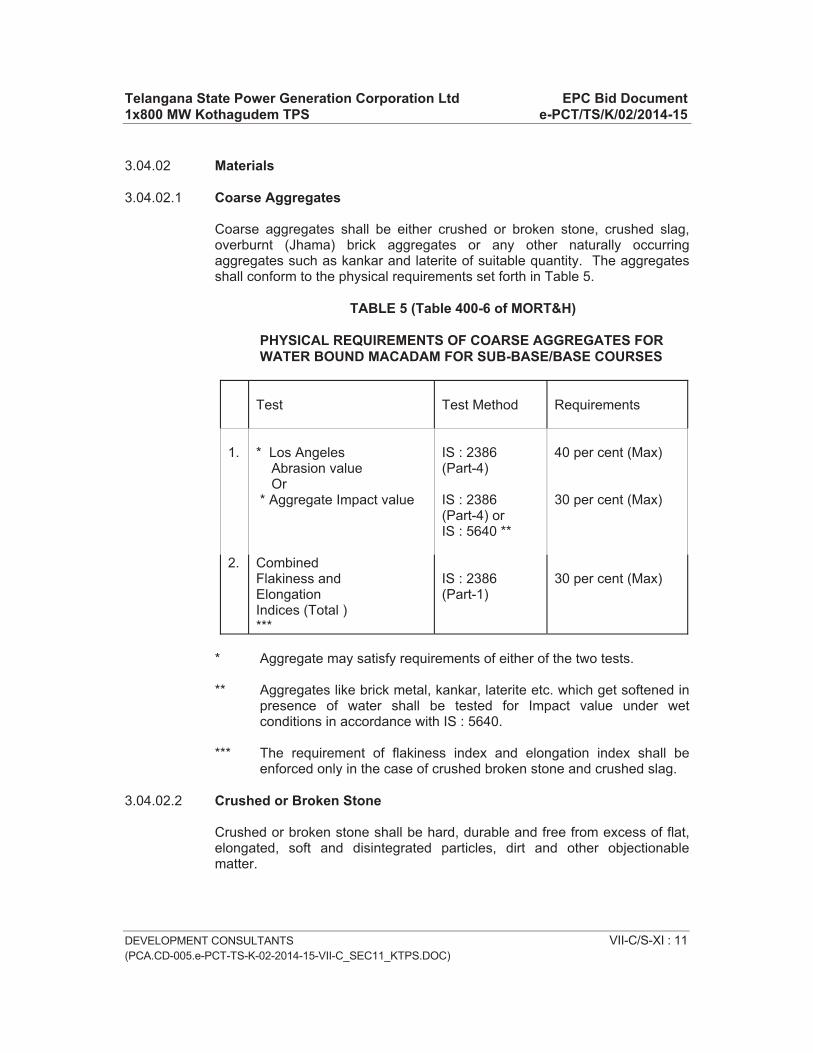
Telangana State Power Generation Corporation Ltd EPC Bid Document 1x800 MW Kothagudem TPS e-PCT/TS/K/02/2014-15
DEVELOPMENT CONSULTANTS VII-C/S-XI : 11 (PCA.CD-005.e-PCT-TS-K-02-2014-15-VII-C_SEC11_KTPS.DOC)
3.04.02 Materials
3.04.02.1 Coarse Aggregates
Coarse aggregates shall be either crushed or broken stone, crushed slag, overburnt (Jhama) brick aggregates or any other naturally occurring aggregates such as kankar and laterite of suitable quantity. The aggregates shall conform to the physical requirements set forth in Table 5.
TABLE 5 (Table 400-6 of MORT&H)
PHYSICAL REQUIREMENTS OF COARSE AGGREGATES FOR WATER BOUND MACADAM FOR SUB-BASE/BASE COURSES
Test Test Method Requirements
1. * Los Angeles Abrasion value Or * Aggregate Impact value
IS : 2386 (Part-4)
IS : 2386(Part-4) or IS : 5640 **
40 per cent (Max)
30 per cent (Max)
2. CombinedFlakiness and ElongationIndices (Total ) ***
IS : 2386(Part-1)
30 per cent (Max)
* Aggregate may satisfy requirements of either of the two tests.
** Aggregates like brick metal, kankar, laterite etc. which get softened in presence of water shall be tested for Impact value under wet conditions in accordance with IS : 5640.
*** The requirement of flakiness index and elongation index shall be enforced only in the case of crushed broken stone and crushed slag.
3.04.02.2 Crushed or Broken Stone
Crushed or broken stone shall be hard, durable and free from excess of flat, elongated, soft and disintegrated particles, dirt and other objectionable matter.

Telangana State Power Generation Corporation Ltd EPC Bid Document 1x800 MW Kothagudem TPS e-PCT/TS/K/02/2014-15
DEVELOPMENT CONSULTANTS VII-C/S-XI : 12 (PCA.CD-005.e-PCT-TS-K-02-2014-15-VII-C_SEC11_KTPS.DOC)
3.04.02.3 Grading Requirements of Coarse Aggregates
The coarse aggregates shall conform to one of the gradings given in Table 6, provided, however, the use of Grading No. 1 shall be restricted to sub-base courses only.
TABLE 6 (Table 400-8 of MORT&H)
GRADING REQUIREMENTS OF COARSE AGGREGATES
GradingNo.
Size Range IS Sieve Designation
Per cent by Weight passing
1. 90 mm to 45 mm 125 mm 90 mm 63 mm 45 mm 22.4 mm
10090-10025-600-150-5
2.63 mm to 45 mm 90 mm
63 mm 53 mm 45 mm 22.4 mm
10090-10025-750-150-5
3. 53 mm to 22.4 mm 63 mm 53 mm 45 mm 22.4 mm 11.2 mm
10095-10065-900-100-5
Note : The compacted thickness for a layer with Grading 1 shall be 100 mm while for layer with other Gradings e.g. 2 & 3, it shall be 75 mm.

Telangana State Power Generation Corporation Ltd EPC Bid Document 1x800 MW Kothagudem TPS e-PCT/TS/K/02/2014-15
DEVELOPMENT CONSULTANTS VII-C/S-XI : 13(PCA.CD-005.e-PCT-TS-K-02-2014-15-VII-C_SEC11_KTPS.DOC)
3.04.02.4 Screenings
Screenings to fill voids in the coarse aggregate shall generally consist of the same material as the coarse aggregate. However, where permitted, predominantly non-plastic material such as moorum or gravel (other than rounded river borne material) may be used for this purpose provided liquid limit and plasticity index of such material is below 20 and 6 respectively and fraction passing 75 micron sieve does not exceed 10 percent.
Screenings shall conform to the gradings set forth in Table7.
TABLE 7
GRADINGS FOR SCREENINGS (Table 400-8 of MORT&H)
GradingClassification
Size of Screenings
IS Sieve Designation
Per cent by weight passing the IS Sieve
A 13.2 mm 13.2 mm 11.2 mm 5.6 mm
180 micron
10095-100
15-350-10
B 11.2 mm 11.2 mm 5.6 mm
180 micron
100 90-100
15-35
3.04.02.5 Binding Material
Binding material to be used for water bound macadam as a filter material meant for preventing ravelling, shall comprise of a suitable material approved by the Engineer having a Plasticity Index (PI) value of less than 6 as determined in accordance with IS : 2720 (Part-5).
The quantity of binding material where it is to be used, will depend on the type of screenings. Generally, the quantity required for 75 mm compacted thickness of water bound macadam will be 0.06-0.09 m3/10m2 and 0.08-0.10m3/10m2 for 100 mm compacted thickness.
The above mentioned quantities should be taken as a guide only, for estimation of quantities for construction etc.
Application of binding materials may not be necessary when the screenings used are of crushable type such as moorum or gravel.

Telangana State Power Generation Corporation Ltd EPC Bid Document 1x800 MW Kothagudem TPS e-PCT/TS/K/02/2014-15
DEVELOPMENT CONSULTANTS VII-C/S-XI : 14 (PCA.CD-005.e-PCT-TS-K-02-2014-15-VII-C_SEC11_KTPS.DOC)
3.04.03 Construction Operations
3.04.03.1 Preparation of Base The sub-grade/sub-base to receive the water bound macadam coarse shall
be prepared to the specified grade and camber and made free of dust and other extraneous material. Any ruts or soft yielding places shall be corrected in an approved manner and rolled until firm surface is obtained if necessary by sprinkling water.
3.04.03.2 Inverted Choke
If the water bound macadam is to be laid directly over the subgrade, without any other intervening pavement course, a 25 mm course of screenings (Grading B) shall be spread on the prepared subgrade before application of the coarse aggregates is taken up.
3.04.03.3 Spreading Coarse Aggregate The coarse aggregates shall be spread uniformly upon the prepared surface
in such quantities that the thickness of the compacted layer is 100 mm for grading 1 and 75-100 mm for gradings 2 and 3 for each layer.
The spreading shall be done from stockpiles along the side of the roadway or directly from vehicles. In no case shall the aggregate be dumped in heaps directly on the surface prepared to receive the aggregate nor shall hauling over uncompacted or partially compacted base be permitted.
The surface of the aggregates spread shall be carefully checked with templates and all high or low spots remedied by removing or adding aggregate as may be required. No segregation of large or fine particles shall be allowed and the coarse aggregate as spread shall be of uniform gradation with no pockets of fine material.
The coarse aggregate shall not normally be spread more than 3 days in advance of the subsequent construction operations.
3.04.03.4 Rolling
Immediately following the spreading of the coarse aggregate, rolling shall be started with three wheeled power rollers of 80 to 100 kN capacity or tandem or vibratory rollers of approved type. The weight of the roller shall depend upon the type of the aggregate and be indicated by the Engineer.

Telangana State Power Generation Corporation Ltd EPC Bid Document 1x800 MW Kothagudem TPS e-PCT/TS/K/02/2014-15
DEVELOPMENT CONSULTANTS VII-C/S-XI : 15 (PCA.CD-005.e-PCT-TS-K-02-2014-15-VII-C_SEC11_KTPS.DOC)
Except on super elevated portions where the rolling shall proceed from inner edge to the outer, rolling shall begin from the edges gradually progressing towards the centre. First the edge/edges shall be compacted with roller running forward and backward. The roller shall then move inwards parallel to the centre line of the road, in successive passes uniformly lapping preceding tracks by at least one half width.
Rolling shall continue until the aggregates are thoroughly keyed and the creeping of aggregates ahead of the roller is no longer visible. During rolling slight sprinkling of water may be done, if necessary. Rolling shall not be done when the subgrade is soft or yielding or when it causes a wave-like motion in the subgrade or sub-base course.
The rolled surface shall be checked transversely and longitudinally with templates and any irregularities corrected by loosening the surface, adding or removing necessary amounts of aggregate and re-rolling until the entire surface conforms to desired camber and grade. In no case shall the use of screenings be permitted to make up depressions.
3.04.03.5 Applications of Screenings
After the coarse aggregate has been rolled, screenings to completely fill the interstices shall be applied gradually over the surface. These shall not be damp or wet at the time of application. Dry rolling shall be done while the screenings are being spread so that vibrations of the roller cause them to settle into the voids of the coarse aggregate. The screenings shall not be dumped in piles but be spread uniformly in successive thin layers either by the spreading motion of hand shovels or by mechanical spreaders, or directly from trucks. Trucks operating for spreading the screenings shall be so driven as not to disturb the coarse aggregate.
The screenings shall be applied at a slow and uniform rate (in three or more applications) so as to ensure filling of all voids. This shall be accompanied by dry rolling and brooming with mechanical brooms, hand-brooms or both. In no case shall the screenings be applied so fast and thick as to form cakes or ridges on the surface in such a manner as would prevent filling of voids or prevent the direct bearing of the roller on the coarse aggregate. These operations shall continue until no more screenings can be forced into the voids of the coarse aggregate.
The spreading, rolling and brooming of screenings shall be carried out in only such lengths of the road which could be completed within one day's operation.

Telangana State Power Generation Corporation Ltd EPC Bid Document 1x800 MW Kothagudem TPS e-PCT/TS/K/02/2014-15
DEVELOPMENT CONSULTANTS VII-C/S-XI : 16 (PCA.CD-005.e-PCT-TS-K-02-2014-15-VII-C_SEC11_KTPS.DOC)
3.04.03.6 Sprinkling and Grouting
After the screenings have been applied, the surface shall be copiously sprinkled with water, swept and rolled. Hand brooms shall be used to sweep the wet screenings into voids and to distribute them evenly.
The sprinkling, sweeping and rolling operations shall be continued, with additional screenings applied as necessary, until the coarse aggregate has been thoroughly keyed, well-bonded and firmly set in its full depth and a grout has been formed of screenings. Care shall be taken to see that the base or subgrade does not get damaged due to the addition of excessive quantities of water during construction.
3.04.03.7 Application of Binding Material
After the application of screenings, the binding material where it is required to be used shall be applied successively in two or more thin layers at a slow and uniform rate. After each application, the surface shall be copiously sprinkled with water, the resulting slurry swept in with hand brooms, or mechanical brooms to fill the voids properly, and rolled during which water shall be applied to the wheels of the rollers if necessary to wash down the binding material sticking to them. These operations shall continue until the resulting slurry after filling of voids, forms a wave ahead of the wheels of the moving roller.
3.04.03.8 Setting and Drying
After the final compaction of water bound macadam course, the road shall be allowed to dry overnight. Next morning hungry spots shall be filled with screenings or binding material as directed, lightly sprinkled with water if necessary and rolled. No traffic shall be allowed on the road until the macadam has set. The Engineer shall have the discretion to stop hauling traffic from using the completed water bound macadam course if in his opinion it would cause excessive damage to the surface.
3.05.00 Tack Coat
3.05.01 Description
The work shall consist of application of a single coat of low viscosity liquid bituminous material to an existing bituminous road surface preparatory to the superimposition of bituminous mix, when specified in the Contract or instructed by the Engineer.

Telangana State Power Generation Corporation Ltd EPC Bid Document 1x800 MW Kothagudem TPS e-PCT/TS/K/02/2014-15
DEVELOPMENT CONSULTANTS VII-C/S-XI : 17 (PCA.CD-005.e-PCT-TS-K-02-2014-15-VII-C_SEC11_KTPS.DOC)
3.05.02 Materials
Binder: The binder used for tack coat shall be bitumen emulsion complying with IS: 8887 of a type and grade as specified in the Contract or as directed by the Engineer.
3.05.03 Construction Operations
3.05.03.1 Preparation of Base
The surface on which the tack coat is to be applied shall be clean and free from dust, dirt and any extraneous material. Immediately before the application of the tack coat, the surface shall be swept clean with a mechanical broom and high pressure air jet, or by other means as directed by the Engineer.
3.05.03.2 Application of tack coat
The application of tack coat shall be at the rate specified in the Contract, and shall be applied uniformly. The normal range of spraying temperature for a bituminous emulsion shall be 20 degree Celsius - 70 degree Celsius and for a cutback 50 degree Celsius – 80 degree Celsius if RC-70/MC-70 grade is used. The method of application of the tack coat will depend on the type of equipment to be used, size of nozzles, pressure at the spray bar, and speed of forward movement. The contractor shall demonstrate at a spraying trial, that the equipment and method to be used is capable of producing a uniform spray, within the tolerances specified.
3.06.00 Bituminous Macadam Binder Course
3.06.01 Description
This work shall consist of construction, in a single course, of 50 mm to 100 mm thickness or in multiple courses of compacted crushed aggregates premixed with a bituminous binder on a previously prepared base to the requirements of MORT&H Specifications.
3.06.02 Materials
3.06.02.1 Bitumen
The bitumen shall be paving bitumen of penetration grade complying with Indian Standard Specifications for “Paving Bitumin”IS: 73, and of the penetration indicated in table 500-4 of MORT&H

Telangana State Power Generation Corporation Ltd EPC Bid Document 1x800 MW Kothagudem TPS e-PCT/TS/K/02/2014-15
DEVELOPMENT CONSULTANTS VII-C/S-XI : 18 (PCA.CD-005.e-PCT-TS-K-02-2014-15-VII-C_SEC11_KTPS.DOC)
3.06.02.2 Coarse Aggregates
The aggregates shall consist of crushed stone, crushed gravel or other hard material retained on the 2.36 mm sieve. They shall be clean, hard, durable, of cubical shape, free from dust and soft or friable matter, organic or other deleterious matter. Where crushed gravel is used, not less than 90 per cent by weight of the crushed material retained on 4.75 mm sieve shall have at least two fractured faces.
The aggregates shall satisfy the physical requirements set forth in Table 8.
TABLE 8 (Table 500-3 of MORT&H)
PHYSICAL REQUIREMENTS FOR COARSE AGGREGATES FOR BITUMINOUS MACADAM
Property Test Specification Cleanliness Grain size analysis Max 5 % passing 0.075 mm
sieve
Particle shape Flakiness and Elongation Index(combined)2
Max 30%
Strength Los Angeles Abrasion Value Aggregate Impact Value
Max 40% Max 30%
Durability Soundness :
Sodium Sulphate
Magnesium Sulphate
Max 12%
Max 18%
Water Absorption Water Absorption Max 2%
Stripping Coating and Stripping of BitumenAggregate Mixtures
Minimum retained coating 95%
Water Sensitivity Retained Tensile Strength Min 80%
3.06.02.3 Fine aggregates
Fine aggregates shall consist of crushed or naturally occurring material, or a combination of the two, passing 2.36 mm sieve and retained on 75 micron sieve. They shall be clean, hard, durable, dry and free from dust, and soft or friable matter, organic or other deleterious matter

Telangana State Power Generation Corporation Ltd EPC Bid Document 1x800 MW Kothagudem TPS e-PCT/TS/K/02/2014-15
DEVELOPMENT CONSULTANTS VII-C/S-XI : 19 (PCA.CD-005.e-PCT-TS-K-02-2014-15-VII-C_SEC11_KTPS.DOC)
3.06.02.4 Proportioning of Materials
The aggregates shall be proportioned and blended to produce a uniform mixture complying with the requirements of table 500-4 of MORT&H.The binder content shall be within a tolerance of
3.06.03 Construction Operations
3.06.03.1 Weather and Seasonal Limitations
Bituminous macadam shall not be laid during rainy weather or when the base course is damp or wet.
3.06.03.2 Preparation of Base
The base on which bituminous macadam is to be laid shall be prepared, shaped and conditioned to the specified lines, grade and cross sections as directed by the Engineer. The surface shall be thoroughly swept and scraped clean and free from dust and foreign matter.
3.06.03.3 Tack Coat
A tack coat shall be applied over the base.
3.06.03.4 Preparation and Transport of Mix It would be carried out as per Clause 501.3 and 501.4 of MORT&H
3.06.03.5 Spreading
It would be carried out as per Clause 501.5.3 of MORT&H.
3.06.03.6 Rolling
It would be carried out in accordance with the provisions of Clauses 501.6 and 501.7 of MORT&H.
3.07.00 Bituminous Concrete
3.07.01 Scope
This clause specifies the construction of bituminous concrete, for use in wearing and profile corrective courses. This work shall consist of construction in a single or multiple layers of bituminous concrete on a previously prepared bituminous bound surface. A single layer shall be 25 mm to 100 mm in thickness.

Telangana State Power Generation Corporation Ltd EPC Bid Document 1x800 MW Kothagudem TPS e-PCT/TS/K/02/2014-15
DEVELOPMENT CONSULTANTS VII-C/S-XI : 20 (PCA.CD-005.e-PCT-TS-K-02-2014-15-VII-C_SEC11_KTPS.DOC)
3.07.02 Materials
3.07.02.1 Bitumen
The bitumen shall be paving bitumen of penetration grade complying with Indian Standard Specification for Paving Bitumen. IS:73 and of the penetration indicated in Table 500-18 of MORT&H, for bituminous concrete or this bitumen as modified by one of the methods specified in clause 521 of MORT&H, or as otherwise specified in the contract. Guidance on the selection of an appropriate grade of bitumen is given in The Manual for Construction and Supervision of Bituminous Works.
3.07.02.2 Coarse Aggregates
The coarse aggregates shall be generally as specified in clause 507.2.2 of MORT&H, except that the aggregates shall satisfy the physical requirements of Table 500-17 of MORT&H.
3.07.02.3 Fine Aggregates
The fine aggregates shall be all as specified in clause 507.2.3 of MORT&H.
3.07.02.4 Filler
Filler shall be generally as specified in clause 507.2.4 of MORT&H. Where the aggregates fail to meet the requirements of the water sensitivity test in Table 500-17 of MORT&H then 2 percent by total weight of aggregate, of hydrated lime shall be added without additional cost.
3.07.02.5 Aggregate grading and binder content
When tested in accordance with IS:2386 Part 1 (Wet grading method), the combined grading of the coarse and fine aggregates and added filler shall fall
Within the limits shown in Table 500-18 of MORT&H for gradings 1 or 2 as specified in the Contract.
3.07.03 Mixture Design
3.07.03.1 Requirements for the mixture
Apart from conformity with the grading and quality requirements for individual ingredients, the mixture shall meet the requirements set out in Table 500-19 of MORT&H.
The requirements for minimum percent voids in mineral aggregate (VMA) are set out in Table 500-12 of MORT&H.

Telangana State Power Generation Corporation Ltd EPC Bid Document 1x800 MW Kothagudem TPS e-PCT/TS/K/02/2014-15
DEVELOPMENT CONSULTANTS VII-C/S-XI : 21 (PCA.CD-005.e-PCT-TS-K-02-2014-15-VII-C_SEC11_KTPS.DOC)
3.07.03.2 Binder content
The binder content shall be optimised to achieve the requirements of the mixture
Set out in Table 500-19 of MORT&H and the traffic volume as specified in the Contract. The Marshall method for determining the optimum binder content shall be adopted as described in the Asphalt Institute Manual MS-2, replacing the aggregates retained on the 26.5 mm sieve and retained on the 22.4 mm sieve, where approved by the Engineer.
3.07.03.3 Job mix formula
The procedure for formulating the job mix formula shall be generally as specified in clause 507.3.3 of MORT&H and the results of tests enumerated in Table 500-19 of MORT&H as obtained by the Contractors.
3.07.03.4 Plant trials-permissible variation in job mix formula
The requirements for plant trials shall be all as specified in clause 507.3.3 of MORT&H and the results of tests enumerated in Table 500-19 as obtained by the contractors.
3.07.03.5 Laying trials
The requirements for plant trials shall be all as specified in clause 507.3.5 of MORT&H.
3.07.04 Construction Operations
3.07.04.01 Weather and seasonal limitations
The provisions of clause 501.5.1 of MORT&H shall apply.
3.07.04.02 Preparation of base
The surface on which the bituminous concrete is to be laid shall be prepared in accordance with clauses 501 and 902 of MORT&H as appropriate, or as directed by the engineer. The surface shall be thoroughly swept clean by mechanical broom and dust removed by compressed air. In locations where a mechanical broom cannot access, other approved methods shall be used as directed by the engineer.
3.07.04.03 Tack coat
Where specified in the Contract, or otherwise required by the Engineer, a tack coat shall be applied in accordance with the requirements of clause 503 of MORT&H.

Telangana State Power Generation Corporation Ltd EPC Bid Document 1x800 MW Kothagudem TPS e-PCT/TS/K/02/2014-15
DEVELOPMENT CONSULTANTS VII-C/S-XI : 22 (PCA.CD-005.e-PCT-TS-K-02-2014-15-VII-C_SEC11_KTPS.DOC)
3.07.04.04 Mixing and transportation of the mixture
The provisions as specified in clauses 501.3 and 501.5.4 of MORT&H shall apply.
3.07.04.05 Spreading
The general provisions of clauses 501.5.3 and 501.5.4 of MORT&H shall apply.
3.07.04.06 Rolling
The general provisions of clauses 501.6 and 501.7 of MORT&H shall apply, as modified by the approved laying trials.
3.07.05 Opening to traffic
The newly laid surface shall not be open to traffic for at least 24 hours after laying and the completion of compaction, without the express approval of the engineer in writing.
3.07.06 Surface finish and Quality control
The surface finish of the completed construction shall conform to the requirements of clause 902 of MORT&H. All materials and workmanship shall comply with the provisions set out in section 900 of this specification.
3.07.07 Arrangements for traffic
During the period of construction, arrangements for traffic shall bemade in accordance with the provisions of clause 112 of MORT&H.
3.08.00 Road Side Drains
3.08.01 Formation of Drains
The road side drains shall be made in sizes and slopes as shown on drawings and/or as instructed by the Engineer. The minimum side slope shall be as instructed by the Engineer. The sides and bottom shall be neatly dressed after excavation. Proper connections shall be made to the culverts, outside plant area, as per instructions of the Engineer.
The excavated spoils shall be transported and filled in low areas within the plant area or in embankments as instructed by the Engineer. The lining for the drains shall be as per Dwg.

Telangana State Power Generation Corporation Ltd EPC Bid Document 1x800 MW Kothagudem TPS e-PCT/TS/K/02/2014-15
DEVELOPMENT CONSULTANTS VII-C/S-XI : 23 (PCA.CD-005.e-PCT-TS-K-02-2014-15-VII-C_SEC11_KTPS.DOC)
3.09.00 Culverts
Excavation in trenches for foundation of culverts and wing walls shall be done with side slopes as per the instructions of Engineer after clearing the site, etc. as per specifications of earthwork. Backfilling with ramming and watering shall be done after construction of the foundations.
The construction of culverts shall be done true to lines and levels and as shown on the drawing. The specification for Masonry and/or Plain and Reinforced Cement concrete shall be followed, as applicable.
3.10.00 Pipe Culverts and Drainage Pipes
3.10.01 Materials
The drainage pipes unless otherwise shown on drawings or instructed by the Engineer shall be made of R.C.C. and shall be either Class NP2 or NP3.
Pipe culverts shall be made of reinforced concrete pipe and shall be of class NP3 or of RDSO class for railway as decided by the Engineer or shown in the drawing. All pipes shall meet the requirements of IS:458-Latest edition and shall be procured from approved manufacturers with collars as per manufacturer's standard specifications. The tenderer shall specifically mention the particular manufacturer's product he proposes to use.
Cement shall be ordinary Portland cement as per IS: 8112 - Latest edition.
Aggregates shall be as per IS: 383 - Latest edition - Maximum size shall not exceed one third the thickness of the pipe or 20 mm whichever is smaller.
Fine aggregates for concrete shall be as per IS: 383 - Latest edition.
3.10.02 Laying of Pipes
Laying of concrete pipes shall correspond to IS:783 - Latest edition - and to specification given below :
a) The foundation bed for pipe shall be excavated true to lines and grades shown on the drawings or as directed by the Engineer. When trenching is involved its width on either side of the pipe shall not be less than 150 mm nor more than one-third the diameter of pipe unless otherwise instructed/ permitted by the Engineer. The sides of the trench shall be as nearly vertical as possible. Side slope, shoring, bailing out water, etc. as required shall be done by the Contractor without any extra cost to the Owner. Side slips, if there be any, shall be removed by the Contractor without any extra cost to the Owner. After laying of the pipes are completed, backfilling of the trenches shall be done in 250 mm layers, measured loose clods and lumps

Telangana State Power Generation Corporation Ltd EPC Bid Document 1x800 MW Kothagudem TPS e-PCT/TS/K/02/2014-15
DEVELOPMENT CONSULTANTS VII-C/S-XI : 24 (PCA.CD-005.e-PCT-TS-K-02-2014-15-VII-C_SEC11_KTPS.DOC)
broken, watered and compacted with iron rammers to the satisfaction of the Engineer. The surplus spoils shall be transported and filled in low areas within the plant area, as instructed by the Engineer.
When bed-rock or boulder strata are encountered, excavation shall be taken down to at least 200 mm below the bottom level of the pipe with prior permission of the Engineer and all rock/boulders in the area shall be removed and space filled with approved earth free from stone or fragmented material, shaped to the requirements and thoroughly compacted to provide adequate support for the pipe.
Filling of trench shall be carried out simultaneously on both sides of the pipe in such a manner that unequal pressures do not occur.
When two or more pipes are to be laid adjacent to each other, they shall be separated by a distance equal to at least half the diameter of the pipe subject to a minimum of 450 mm.
Laying of pipes shall start from the outlet and proceed towards inlet.
All pipes and fittings shall be gradually lowered into the trench or placed on the supports by approved means taking due care not to damage them. Under no circumstances the pipes shall be dropped into the trench or on supports from a height.
b) Pipe bedding shall be first class projection bedding for positive projecting pipes as per IS:783 - Latest edition - having a projection ratio of not greater than 0.70, in which the pipe is carefully bedded on fine granular materials in an earth foundation carefully shaped to fit the lower part of the pipe exterior for at least ten percent of its overall height, and in which earth filling material is thoroughly rammed and tamped in layers not exceeding 15 cm in depth around the pipe for the remainder of the lower 30 percent of its height.
If the pipe is laid in trench, pipe bedding shall be first class bedding as per IS: 783.
When indicated on the drawings or directed by the Engineer, the pipe shall be bedded on a craddle constructed of concrete having a mix not leaner than M25. The shape and dimension of the cradle shall be as indicated on the drawing or directed by the Engineer. The pipe shall be laid on the concrete bedding before the concrete has set.
c) The drop walls shall be made with first class brickwork in 1:4 cement mortar.
d) The pipe culverts shall be made with proper care regarding the invert of the pipe, gradient, if any, etc. as specified on drawings and/or as instructed by the Engineer.

Telangana State Power Generation Corporation Ltd EPC Bid Document 1x800 MW Kothagudem TPS e-PCT/TS/K/02/2014-15
DEVELOPMENT CONSULTANTS VII-C/S-XI : 25 (PCA.CD-005.e-PCT-TS-K-02-2014-15-VII-C_SEC11_KTPS.DOC)
e) Where R.C.C. pipes are encased in concrete at road crossings or at other places the pipes need be suitably supported avoiding reinforcements of concrete blocks, joints properly done before concreting is taken up. Concreting of total height of block may be done in a single operation or may be done upto some height for pipes to be properly laid in position and remaining height of block to be concreted subsequently.
f) The R.C.C. pipes shall be joined with cement mortar. Cement mortar shall consist of 1 part cement and 2 parts of clean sand with only enough water for workability. Procedure of jointing shall be as per IS:783 - latest edition.
3.10.03 Relation with Water Supply Pipeline
Unless specifically cleared by the Engineer, under no circumstances shall drainage pipes be allowed to come close to water supply pipelines.
3.11.00 Manholes and Inspection Chambers
The maximum distance between manholes shall be 30 meter unless specifically permitted otherwise. In addition at every change of alignment, gradient or diameter there shall be a manhole or inspection chamber. The distance between manhole or inspection chamber and gully chamber shall not exceed 6 meters unless permitted otherwise. Manhole shall be constructed so as to be watertight under test. The channel or drain at the bottom of chamber shall be plastered with 1:2 cement sand mortar and finished smooth to the grade. The channels and drains shall be shaped and laid to provide smooth flow.
Connection to existing pipelines shall be through a manhole.
Manholes shall be provided with standard covers, usually C.I. or as directed by the Engineer. The covers shall be close fitting so as to prevent gases from coming out.
3.12.00 Plaster to Concrete
Before application of plaster the surface shall be cleaned of all dirt, grease or loose particles by hard brush and water. The surface shall be thoroughly moist to prevent absorption of water from the base course. Any excess water shall be mopped up.
Unless otherwise mentioned in the schedule of items plastering shall be done with cement sand mortar - 1 part by volume of cement to 4 parts by volume of clean, sharp, well graded sand. For sand cement plaster, sand and cement in the specified proportion shall be mixed dry on a watertight platform and minimum water added to achieve working consistency. For lime gauge plaster, lime putty or hydrated lime and sand in the required proportion shall

Telangana State Power Generation Corporation Ltd EPC Bid Document 1x800 MW Kothagudem TPS e-PCT/TS/K/02/2014-15
DEVELOPMENT CONSULTANTS VII-C/S-XI : 26 (PCA.CD-005.e-PCT-TS-K-02-2014-15-VII-C_SEC11_KTPS.DOC)
be mixed on a watertight platform with necessary addition of water and thoroughly ground in mortar mill. This mix shall then be transferred to a mechanical mixer to which the required quantity of cement is added and mixed for at least 3 minutes.
No mortar which has stood for more than half an hour shall be used.
Plaster, when more than 12 mm thick, shall be applied in two coats. All plaster work shall correspond to IS: 1661- latest edition.
3.12.01 Finish
Generally, all plastered surfaces shall have a standard finish unless otherwise shown on the drawing or directed by the Engineer. The interior plaster shall be finished to a smooth surface by steel trowelling. The exterior surfaces shall be finished with a wooden float.
However, if shown on the drawing or directed by the Engineer the plastered surface shall have a neat cement finish. Immediately after achieving a true plastered surface with the help of a wooden straight edge, the entire area shall be uniformly treated with a paste of neat cement at the rate of one (1) kg per Sq.M. and rubbed smooth with a trowel.
4.00.00 TESTING AND ACCEPTANCE CRITERIA
4.01.00 Roads
All testing, as mentioned in the body of the specification and as mentioned in section 900 of MORT&H shall be carried out by the Contractor as per direction of the Engineer. No extra payment shall be made for such tests.
4.02.00 Cement Concrete
The strength requirements and acceptance criteria shall conform to the relevant clauses of IS: 456.

Telangana State Power Generation Corporation Ltd EPC Bid Document 1x800 MW Kothagudem TPS e-PCT/TS/K/02/2014-15
DEVELOPMENT CONSULTANTS (PCA.CD-005.e-PCT-TS-K-02-2014-15-VII-C_SEC12_KTPS.DOC)
VOLUME : VII-C
SECTION-XII
TECHNICAL SPECIFICATION FOR
CONSTRUCTION OF REINFORCED CONCRETE CHIMNEY

Telangana State Power Generation Corporation Ltd EPC Bid Document 1x800 MW Kothagudem TPS e-PCT/TS/K/02/2014-15
DEVELOPMENT CONSULTANTS (PCA.CD-005.e-PCT-TS-K-02-2014-15-VII-C_SEC12_KTPS.DOC)
CONTENT
CLAUSE NO. DESCRIPTION PAGE NO.
1.00.00 SCOPE VII-C/S-XII : 1
2.00.00 GENERAL VII-C/S-XII : 1
3.00.00 EXECUTION VII-C/S-XII : 11
4.00.00 TESTING AND ACCEPTANCE CRITERIA VII-C/S-XII : 34
5.00.00 INFORMATION TO BE SUBMITTED VII-C/S-XII: 35

Telangana State Power Generation Corporation Ltd EPC Bid Document 1x800 MW Kothagudem TPS e-PCT/TS/K/02/2014-15
DEVELOPMENT CONSULTANTS(PCA.CD-005.e-PCT-TS-K-02-2014-15-VII-C_SEC12_KTPS.DOC)
VII-C/S-XII: 1
VOLUME : VII-C
SECTION-XII
TECHNICAL SPECIFICATION FOR
CONSTRUCTION OF REINFORCED CONCRETE CHIMNEY
1.00.00 SCOPE
This specification covers plain and reinforced cement concrete work, lining and insulation work, miscellaneous steel and metal work, painting and protective treatment work, lightning protection system and aviation obstruction lighting system, connected with construction of RCC Chimney.
2.00.00 GENERAL
2.01.00 Work to be provided for by the Contractor
Work to be provided by the Contractor, unless specified otherwise, shall include but shall not be limited to the following :
a) Furnish all labour, supervision, services, insurance, material, power, fuel, forms, templates, supports, scaffolding, tools, plants, construction equipment, approaches, transportation etc. required for the entire work.
b) Design and prepare working drawings for formworks, scaffoldings, supports, staging etc. and submit them for approval.
c) Prepare and submit for approval, as per approved schedule, detailed drawings for R.C. work in shell, hopper, platforms and ground floor and bending schedules for reinforcement bars, showing the positions and details of spacers, chairs, supports, hangers, openings etc.
d) Prepare detailed fabrication and erection marking drawings for steel and metal works and submit them for approval.
e) Prepare detailed shop drawings for various inserts, anchors, sleeves, frames, templates, anchor bolts etc. showing relative locations of their installations and submit them for approval.
f) Prepare and submit for approval the detailed schemes for operations like material handling, placement of concrete etc. and for items like approaches, services etc.

Telangana State Power Generation Corporation Ltd EPC Bid Document 1x800 MW Kothagudem TPS e-PCT/TS/K/02/2014-15
DEVELOPMENT CONSULTANTS(PCA.CD-005.e-PCT-TS-K-02-2014-15-VII-C_SEC12_KTPS.DOC)
VII-C/S-XII: 2
g) Design and submit for approval the mix proportions for concrete to be adopted on job.
h) Furnish samples and submit for approval the results of tests for various properties of the following materials :-
i) Ingredients of concrete, (ii) Concrete, (iii) Metal work components, (iv) Acid proof bricks, (v) Fire bricks, (vi) Castable refractories, (vii) Insulation material, (viii) Paints, (ix) Electrical Items.
i) Provide all incidental items not specified or shown on drawings in particular but reasonably implied or necessary for successful completion of the work in accordance with drawings and specifications.
j) Produce, if directed by the Engineer, a guarantee, in approved proforma, for satisfactory performance, for a specified period, of material manufactured by specialist firms.
2.02.00 Work by others
No work under this specification will be provided for by agency other than the Contractor for this Contract unless specifically mentioned otherwise in the Contract.
2.03.00 Codes and Standards
All works under this Specification, unless specified otherwise, shall conform to the latest revisions/replacements of the following Indian Standard Codes, Criteria, Specifications, alongwith those mentioned therein. In case any particular aspect of work is not covered by Indian Standards, other standard specification, as may be specified by the Engineer, shall be followed. 'IS Specification' shall mean Codes, Criteria etc. of IS -
IS:6 : Moderate heat duty fireclay refractory, Group-A.
IS:104 : Ready mixed paint, brushing, zinc chrome, priming.
IS:158 : Ready mixed paint, brushing, bituminous, black, lead- free, acid, alkali, water and heat resisting for general purposes.
IS:226 : Structural Steel (Standard Quality).
IS:269 : Ordinary, and low heat Portland cement.

Telangana State Power Generation Corporation Ltd EPC Bid Document 1x800 MW Kothagudem TPS e-PCT/TS/K/02/2014-15
DEVELOPMENT CONSULTANTS(PCA.CD-005.e-PCT-TS-K-02-2014-15-VII-C_SEC12_KTPS.DOC)
VII-C/S-XII: 3
IS:383 : Coarse and fine aggregates from natural sources for concrete.
IS:432 : Mild steel and medium tensile steel bars.
IS:456 : Code of practice for plain and reinforced concrete.
IS:516 : Methods of test for strength of concrete.
IS:732 : Code of practice for electrical wiring installations (System voltage not exceeding 650 Volts).
IS:800 : Code of practice for general construction in steel.
IS:808 : Rolled steel beam, channel & angle sections.
IS:813 : Scheme of symbols for welding.
IS:814 : Covered electrodes for metal arc welding of structural steel.
IS:816 : Code of practice for use of metal arc welding for general construction in mild steel.
IS:817 : Code of practice for training and testing of metal arc welders.
IS:818 : Code of practice for safety and health requirements in electric and gas welding and cutting operations.
IS:822 : Code of procedure for inspection of welds.
IS:1139 : Hot rolled mild steel, medium tensile steel and high yield strength steel deformed bars for concrete reinforcements.
IS:1161 : Steel tubes for structural purposes.
IS:1199 : Methods of sampling and analysis of concrete.
IS:1200 : Methods of measurement of building works.
IS:1239 : Mild steel tubes. (Part-I)
IS:1367 : Technical supply conditions for threaded fasteners.
IS:1526 : Sizes and shapes for firebricks (230 mm. series).
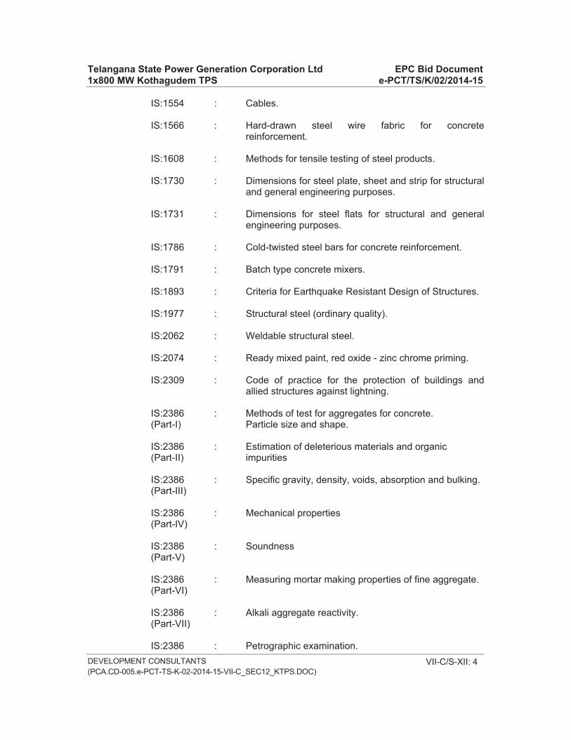
Telangana State Power Generation Corporation Ltd EPC Bid Document 1x800 MW Kothagudem TPS e-PCT/TS/K/02/2014-15
DEVELOPMENT CONSULTANTS(PCA.CD-005.e-PCT-TS-K-02-2014-15-VII-C_SEC12_KTPS.DOC)
VII-C/S-XII: 4
IS:1554 : Cables.
IS:1566 : Hard-drawn steel wire fabric for concrete reinforcement.
IS:1608 : Methods for tensile testing of steel products.
IS:1730 : Dimensions for steel plate, sheet and strip for structural and general engineering purposes.
IS:1731 : Dimensions for steel flats for structural and general engineering purposes.
IS:1786 : Cold-twisted steel bars for concrete reinforcement.
IS:1791 : Batch type concrete mixers.
IS:1893 : Criteria for Earthquake Resistant Design of Structures.
IS:1977 : Structural steel (ordinary quality).
IS:2062 : Weldable structural steel.
IS:2074 : Ready mixed paint, red oxide - zinc chrome priming.
IS:2309 : Code of practice for the protection of buildings and allied structures against lightning.
IS:2386 : Methods of test for aggregates for concrete. (Part-I) Particle size and shape.
IS:2386 : Estimation of deleterious materials and organic (Part-II) impurities
IS:2386 : Specific gravity, density, voids, absorption and bulking. (Part-III)
IS:2386 : Mechanical properties (Part-IV)
IS:2386 : Soundness (Part-V)
IS:2386 : Measuring mortar making properties of fine aggregate. (Part-VI)
IS:2386 : Alkali aggregate reactivity. (Part-VII)
IS:2386 : Petrographic examination.

Telangana State Power Generation Corporation Ltd EPC Bid Document 1x800 MW Kothagudem TPS e-PCT/TS/K/02/2014-15
DEVELOPMENT CONSULTANTS(PCA.CD-005.e-PCT-TS-K-02-2014-15-VII-C_SEC12_KTPS.DOC)
VII-C/S-XII: 5
(Part-VIII)
IS:2502 : Code of practice for bending and fixing of bars for concrete reinforcement.
IS:2505 : Concrete vibrators, immersion type.
IS:2506 : Screed board concrete vibrators.
IS:2633 : Methods of testing uniformity of coating on zinc coated articles.
IS:2722 : Portable swing weigh batchers for concrete (single and double bucket type).
IS:2750 : Steel scaffoldings.
IS:2751 : Code of practice for welding of mild steel bars used for reinforced concrete construction.
IS:3025 : Methods of sampling and test (Physical and Chemical) for water used in industry.
IS:3043 : Code of Earthing
IS:3144 : Methods of Test for Mineral Wool Thermal Insulation Material.
IS:3346 : Method for the determination of thermal conductivity of thermal insulation materials (two slab, guarded hot- plate method).
IS:3495 : Method of test for clay building bricks. (Part-I to IV)
IS:3550 : Methods of test for routine control for water used in industry.
IS:3558 : Code of practice for use of immersion vibrators for consolidating concrete.
IS:3677 : Unbonded rock and slag wool for thermal insulation.
IS:4014 : Code of practice for steel tubular scaffolding. (Part-I&II)
IS:4031 : Method of physical tests for hydraulic cement.
IS:4634 : Method for testing performance of batch-type concrete mixers.

Telangana State Power Generation Corporation Ltd EPC Bid Document 1x800 MW Kothagudem TPS e-PCT/TS/K/02/2014-15
DEVELOPMENT CONSULTANTS(PCA.CD-005.e-PCT-TS-K-02-2014-15-VII-C_SEC12_KTPS.DOC)
VII-C/S-XII: 6
IS:4687 : Gland packing asbestos.
IS:4860 : Acid-resistant bricks.
IS:4990 : Plywood for concrete shuttering work.
IS:4998 : Criteria for design of reinforced concrete chimneys. (Part-I)
IS:5410 : Cement paint, colour as required.
IS:5445 : Long fluted machine reamers with Morse taper shanks.
IS:5495 : Sizes and shapes for firebrick (300 mm. and higher series).
IS:8112 : High strength ordinary portland cement.
IS:8183 : Bonded Mineral Wool.
IS:9595 : Recommendation for Metal Arc Welding of Carbon and Carbon Manganese steels.
CP326 : British Standard - Protection of structures against lightning.
NEPA NO. 78 : Code of protection against lightning.
Draft Code of Practice for the protection of buildings against lightning - 1954 of Institution of Engineers (India).
The Indian Electricity Rules.
The requirements of Department of Civil Aviation, Govt. of India.
2.04.00 Conformity with drawings and specifications
The Contractor shall carry out all the work in strict accordance with the drawings stamped Released for Construction' and specification issued to him and as per Contractor's detailed drawings approved by the Consulting Engineer. Prior to concreting, the Contractor shall prepare a check list on a set format of all items of work involved, and inform the Engineer well in advance so that the Engineer shall have the opportunity of satisfying himself if the works mentioned in the format are done according to drawings and specification, and he can allow the Contractor in writing to start pouring of concrete. The entire operation of concreting shall be carried on as per specification, to the complete satisfaction of the Engineer. No deviation from the drawings will be allowed unless otherwise directed by the Engineer in writing.

Telangana State Power Generation Corporation Ltd EPC Bid Document 1x800 MW Kothagudem TPS e-PCT/TS/K/02/2014-15
DEVELOPMENT CONSULTANTS(PCA.CD-005.e-PCT-TS-K-02-2014-15-VII-C_SEC12_KTPS.DOC)
VII-C/S-XII: 7
For steelwork and metal work, the Contractor shall design all connections, inserts for scaffolding, supply and fabricate all steelwork and metal work and furnish all connection materials in accordance with approved shop drawings prepared by him and/or as instructed by the Engineer, keeping in view the maximum utilisation of the available sizes and shapes for metal components.
2.05.00 Materials to be used
2.05.01 General Requirement
All materials, whether to be incorporated in the work or to be used temporarily for the construction, shall conform to the relevant IS specifications unless stated otherwise and shall be of the quality approved by the Engineer.
2.05.02 Cement
Portland Cement shall be as per the requirements laid down in IS:269.
2.05.03 Coarse Aggregate
Coarse aggregate shall be graded crushed or broken stone from approved sources, free from impurities and shall be screened free of dust and other deleterious matter. It shall conform to IS:383 or IS:515 and shall be washed clean, if necessary. The maximum size of coarse aggregate for chimneys shall be 20 mm. down graded, unless otherwise stated (vide serial 5(b) of clause 3.03.00). Grading for a particular size shall conform to relevant IS Codes and shall be such as to produce a dense concrete of specified proportion and strength and shall be of consistency that will work readily into position without segregation.
2.05.04 Fine Aggregate
Fine aggregate shall be river or pit sand, free from any clay, earth, vegetable matters, salt or other impurities and shall be clean and fit for use, to the satisfaction of the Engineer. Sand acceptable for the work shall normally have a grading falling within the limits of one of the three grades, mentioned in the relevant IS Specifications.
2.05.05 Water
The water for both mixing and curing of concrete shall be clean, free from oil, acid, alkali, organic or other deleterious substances. Contractor shall test the water as and when required by the Engineer, at no extra cost to the Owner.
2.05.06 Reinforcement
Mild steel or Medium or High Tensile steel deformed bars specified for reinforcement shall conform to the latest relevant IS Specifications and shall

Telangana State Power Generation Corporation Ltd EPC Bid Document 1x800 MW Kothagudem TPS e-PCT/TS/K/02/2014-15
DEVELOPMENT CONSULTANTS(PCA.CD-005.e-PCT-TS-K-02-2014-15-VII-C_SEC12_KTPS.DOC)
VII-C/S-XII: 8
be of tested quality under ISI Certification Scheme. The reinforcement shall be free from any oil, foreign material or mill or rust scales.
2.05.07 Structural Steel
All steel materials to be used in construction of Chimney ladder, hand rails, flue opening frame, access door frame, door shutters etc. shall comply with IS:226, IS:1239, IS:1367, IS:1608 and with other relevant IS Specifications.
2.05.08 Paints
Paints to be used for shop coat of fabricated steel shall conform to the IS:2074. Paint for treatment of outside face of Chimney with Cement water proof paint shall conform to IS:5410.
2.05.09 Fire Bricks, Acid Resistant Bricks and Castable Refractories
Fire Bricks for the internal lining of the chimney shall conform to IS:6-1983 Group-A and IS:5445. Acid resistant bricks for internal lining of shell and hopper shall conform to IS:4860. Castable refractories shall be of hydraulic setting, rapid hardening type. It shall have refractory properties similar to Fire bricks conforming to IS:6, Group-A and working temperature shall be upto 1350 Deg.C.
2.06.00 Storage of Materials
2.06.01 General
All materials shall be so stored as to prevent deterioration and intrusion of foreign matter and to ensure the preservation of their quality and characteristics for the work. Any material, which is deteriorated or is damaged or is otherwise considered defective by the Engineer, shall not be used for construction and shall be removed from site immediately, failing which the Engineer shall be at liberty to get the materials removed and the cost incurred thereof shall be realised from the Contractor's dues. The Contractor shall maintain an up to date accounts of receipt, issue and balance of all materials issued by the Owner.
2.06.02 Cement
Contractor shall store cement in water-tight and properly designed stores so that the Cement can be kept dry and the stock can be handled in rotation. The doors of stores shall be at least 30 cm. above G.L. Deteriorated cement shall be removed immediately from the site. Not more than ten bags of cement shall be stacked one above the other.
2.06.03 Aggregate
Different materials shall be transported, handled and stored separately in such a manner as to prevent damage, deterioration or contamination.

Telangana State Power Generation Corporation Ltd EPC Bid Document 1x800 MW Kothagudem TPS e-PCT/TS/K/02/2014-15
DEVELOPMENT CONSULTANTS(PCA.CD-005.e-PCT-TS-K-02-2014-15-VII-C_SEC12_KTPS.DOC)
VII-C/S-XII: 9
Stockpiles of fine and coarse aggregates shall be allowed to drain, so that aggregates do not contain too much water.
2.06.04 Reinforcement
Reinforcement shall be stored preferably under cover and stacked off ground in size and grade-wise separate stacks for easy identification.
2.06.05 Steel, Metal and Fittings
All steel, metal and fittings to be used for fabrication and erection shall be stored sectionwise and lengthwise in separate stacks, off ground, so that they can be handled, inspected, measured and accounted for easily at any time. If required by the Engineer, the materials may have to be stored in a covered shed.
2.06.06 Paints
Paints shall be stored under cover, in air-tight containers. Paints supplied in sealed containers shall be used as soon as possible once the container is opened. Left over paints shall be kept in air-tight containers.
2.06.07 Bricks
Bricks shall be stored in systematic stacks for ease of handling and counting. While unloading the bricks from trucks, they shall be stacked right away and shall not be dumped in a heap.
2.06.08 Insulation Material
All insulation materials like glass or mineral wool, asbestos ropes etc. shall be stored in packing boxes, under covered shed, avoiding their coming in contact with objectionable matter.
2.06.09 Electrical Items
All electrical items shall be stored properly under covered water- tight shed so that they do not come in contact with moisture or cement dust.

Telangana State Power Generation Corporation Ltd EPC Bid Document 1x800 MW Kothagudem TPS e-PCT/TS/K/02/2014-15
DEVELOPMENT CONSULTANTS(PCA.CD-005.e-PCT-TS-K-02-2014-15-VII-C_SEC12_KTPS.DOC)
VII-C/S-XII: 10
2.07.00 Quality Control Contractor shall establish and maintain quality control for different items or
work and materials as may be directed by the Engineer to assure compliance with contract requirement and submit to the Engineer records of the same. The Contractor shall submit all records and test results in original to the Engineer for his approval, if so desired by him.
The quality control operation shall include but shall not be limited to the following items of work :-
a) Cement : Test to satisfy relevant IS Specifications if supplied by the Contractor.
b) Aggregate : Physical, Chemical and Mineralogical qualities, grading, moisture contents and impurities.
c) Water : Impurities Test.
d) Reinforcement: Material tests or certificates to satisfy relevant IS Specification if supplied by the Contractor
e) Structural Steel: Material tests or certificate to satisfy relevant IS Specification if supplied by the Contractor.
f) Bricks : Compressive strength, water absorption, efflorescence, warpage.
g) Fire Bricks : Cold crushing strength, alumina content & water absorption test, density test, thermal conductivity test
h) Acid Resistant : Compressive and tensile strength, acid bricks/tiles resistance and water absorption test.
i) Mortar : Compressive and tensile strength, adhesion and acid resistance test.
j) Insulation : Thermal conductivity, density, heat and acid resistance.

Telangana State Power Generation Corporation Ltd EPC Bid Document 1x800 MW Kothagudem TPS e-PCT/TS/K/02/2014-15
DEVELOPMENT CONSULTANTS(PCA.CD-005.e-PCT-TS-K-02-2014-15-VII-C_SEC12_KTPS.DOC)
VII-C/S-XII: 11
3.00.00 EXECUTION
3.01.00 Concrete
3.01.01 Trial Mix, Grades of Concrete
At least three weeks before commencing any concreting in the work the Contractor shall make trial mixes using samples of coarse aggregates, sand, water and cement, typical of those to be used in the work. A clean dry mixer shall be used for mixing and the first batch shall be discarded.
For guidance in designing the mix, standard tables for maximum allowable water-cement ratio, minimum cement content, maximum proportion of aggregates and limits of consistency may be used by the Contractor. The Contractor's design mix shall fall within limits of the following tables :-
i) Strength requirements of concrete : Table-2 of IS:456-2000.
ii) Concrete Mix Proportion : Table-3 of IS:456-2000.
iii) Minimum cement content/Cu.m. of finished concrete shall be as per table-V of IS-456-2000.
iv) Limit of consistency : Refer Table in Item 3.1.4 of this specification.
v) Cement/Total Aggregate Ratio : As per the following table.

Telangana State Power Generation Corporation Ltd EPC Bid Document 1x800 MW Kothagudem TPS e-PCT/TS/K/02/2014-15
DEVELOPMENT CONSULTANTS(PCA.CD-005.e-PCT-TS-K-02-2014-15-VII-C_SEC12_KTPS.DOC)
VII-C/S-XII: 12
MIX PROPORTIONS (BY WEIGHT) EXPECTED TO GIVE DIFFERENT DEGREES
OF WORKABILITY WITH DIFFERENT VALUES OF WATER - CEMENT RATIO (FOR GUIDANCE)
CEMENT/TOTAL AGGREGATES RATIOS
_________________________________________________________________________
Water/ Ratio by weight of cement Ratio by weight of cement to Workability Cement to gravel aggregate crushed stone aggregate Ratio _________________________________________________________________________ 20 mm. size 38 mm. size 20 mm. size 38 mm. size _________________________________________________________________________
Very Low 0.4 1:4.8 1:5.3 1:4.5 1:5 slump 0.5 1:7.2 1:7.7 1:6.5 1:7.4 0-25 mm. 0.6 1:9.4 1:10 1:7.8 1:9.6 0.7 1:10 1:12 1:8.7 1:10.6
Low 0.4 1:3.9 1:4.5 1:3.5 1:4 slump 0.5 1:5.5 1:6.7 1:5 1:5.5 25-50 mm 0.6 1:6.8 1:7.4 1:6.3 1:7 0.7 1:8 1:8.5 1:7.4 1:8
Medium 0.4 1:3.5 1:3.8 1:3.1 1:3.6 slump 0.5 1:4.8 1:5.7 1:4.2 1:5 50-100mm. 0.6 1:6 1:7.3 1:5.2 1:6.2
High 0.4 1:3.2 1:3.5 1:2.9 1:3.3 slump 0.5 1:4.4 1:5.2 1:3.9 1:4.6 100 - 0.6 1:5.4 1:6.7 1:4.7 1:5.7 175 mm. 0.7 1:6.2 1:7.4 1:5.5 1:6.5 _________________________________________________________________________
NOTE -1 :
Notwithstanding anything mentioned above, the cement /Total aggregate ratio is not to be increased beyond 1:9 without specific permission of the Engineer.
It should be noted that such high aggregate cement ratios will be required for concretes of very low slump and high water-cement ratios, which may be required to be used in mass concrete work only.

Telangana State Power Generation Corporation Ltd EPC Bid Document 1x800 MW Kothagudem TPS e-PCT/TS/K/02/2014-15
DEVELOPMENT CONSULTANTS(PCA.CD-005.e-PCT-TS-K-02-2014-15-VII-C_SEC12_KTPS.DOC)
VII-C/S-XII: 13
NOTE - 2 :
The above figures are for guidance only, the actual cement/ aggregate ratios are to be worked out from the specific gravities of coarse aggregates and sand being used and from trial mixes.
For each grade of concrete, a set of eighteen cubes shall be made. Of these not more than six may be made on any day and further, of the six cubes made in one day not more than two cubes may be made from any single batch. Nine of these cubes each representing a different batch of concrete shall be tested at the age of seven days and remaining at twenty-eight days. The making of the cubes, their curing, storing, transporting and testing shall be in accordance with the relevant IS Specifications. The test shall be carried out in laboratory approved by the Engineer. If the average strength of the concrete cubes falls below the requirement, the method described above shall be repeated till acceptable results are obtained. The method may have to be repeated whenever there is a significant change in the quality of any of the ingredients for concrete, at the discretion of the Engineer. All cost for trial mixes and tests shall be borne by the Contractor and shall be included in the contract rates.
3.01.02 Batching of concrete
For controlled concrete, only weigh batching shall be allowed. All concrete ingredients, except water, shall be batched by weight, using an approved make of weigh batcher. Batching shall be accurate to 1/2 Kg. The batcher shall be tested for accuracy of calibration, first before commencement of work and at least once a fortnight or as directed by the Engineer thereafter. Water shall be batched by weight or by volume measures, as approved by the Engineer.
3.01.03 Mixing of Concrete
Materials for concrete shall be emptied in rotation into the mixer. When all the ingredients are in the drum, the drum will rotate for one minute for dry mixing. After that water shall be added in measured quantities in the manner specified. The mixer shall then rotate for at least two minutes, or at least forty revolutions or until there is apparent uniform distribution of the materials and till the mass is uniform in colour. The entire content of the drum shall be discharged before the ingredients for the succeeding batch are fed into the drum. The mixer shall be thoroughly cleaned to the satisfaction of the Engineer, before a different quality of concrete is put through the mixer and also at the end of day's work.

Telangana State Power Generation Corporation Ltd EPC Bid Document 1x800 MW Kothagudem TPS e-PCT/TS/K/02/2014-15
DEVELOPMENT CONSULTANTS(PCA.CD-005.e-PCT-TS-K-02-2014-15-VII-C_SEC12_KTPS.DOC)
VII-C/S-XII: 14
3.01.04 Workability of Concrete
The degree of workability necessary to allow the concrete to be well consolidated and to be worked into the corners of formwork and around the reinforcement and embedments, and to give the required surface finish shall depend on the type and nature of structure and shall be based on experience and tests. 15 mm. to 40 mm. slump in chimney works shall be adopted subject to Engineer's approval unless stated otherwise (vide serial 1(d) of clause no. 3.03.00). The usual limits of consistency for various types of structure are given below :
LIMITS OF CONSISTENCY _________________________________________________________________________
Degree of Slump in mm. with Use for which concrete is suitable workability standard concrete _________________ . Min. Max _________________________________________________________________________
Very Low 0 15 Large mass concrete work with heavy compaction equipment.
Low 15 35 Uncongested wide and shallow RCC structures.
Medium 35 65 Deep and wide RCC structures with congestion of reinforcement and inserts.
High 65 100 Very narrow and deep RCC with congestion due to reinforcement and inserts.
------------------------------------------------------------------------------------------------------------------------- NOTE : The above table is for guidance only. Notwithstanding anything mentioned above, the slump to be obtained for work in progress shall be as per direction of the Engineer.
With the permission of the Engineer, for any grade of concrete, if the water has to be increased in special cases, cement shall also be increased proportionately, to keep the ratio of water to cement same, as adopted in trial mix design, for each grade of concrete. No extra payment will be made for this additional cement.
The workability of concrete shall be checked at frequent intervals by slump tests. Alternatively, where facilities exist or if required by the Engineer, the compacting factor test, in accordance with IS:1199, shall be carried out.

Telangana State Power Generation Corporation Ltd EPC Bid Document 1x800 MW Kothagudem TPS e-PCT/TS/K/02/2014-15
DEVELOPMENT CONSULTANTS(PCA.CD-005.e-PCT-TS-K-02-2014-15-VII-C_SEC12_KTPS.DOC)
VII-C/S-XII: 15
3.01.05 Placing and Compaction of Concrete
Concreting shall proceed in a manner directed by the Engineer, concrete shall be placed in forms as soon as possible but in no case later than twenty minutes, after mixing.
The height of any single lift of concrete, for different structural members, shall be decided by the Engineer. The concrete shall be placed in the forms gently and not dropped from a height, which may cause segregation of aggregates. Each layer of concrete shall be compacted fully before the succeeding layer is placed and separate batches shall follow each other so closely that the succeeding layer shall be placed and fully compacted before the layer immediately below has taken an initial set.
The concrete, after placing, shall be consolidated only by power driven vibrators. The vibrators shall be of a make and size, approved by the Engineer. In using the vibrator, the standard practice and the Engineer's directions, shall be followed.
Vibration shall begin as soon as one batch of concrete has been placed and shall continue till the entire section being poured has been thoroughly consolidated.
To secure even and dense surfaces, free from aggregate pockets, vibration shall be supplemented by tamping or rodding by hand in the corners of forms and along the form surfaces while the concrete is plastic, without damaging or endangering the stability of the formwork.
A sufficient number of spare vibrators including petrol vibrators shall be kept readily accessible to the place of deposition of the concrete to assure adequate vibration in case of breakdown of those in use.
3.01.06 Curing of Concrete
Curing of exposed surface of concrete shall commence immediately after the concrete has set. Exposed sides shall be covered with canvas etc. immediately after stripping of forms, and curing shall be continued for a period of not less than 14 days, reckoned from the date and hour of completion of concreting. All surfaces of the pour shall be kept wet with water at all times after concreting and till the curing period is over. The Contractor shall plan and employ proper equipment and sufficient labour considered adequate by the Engineer under able supervisor for curing and all cost for this purpose shall be borne by him.

Telangana State Power Generation Corporation Ltd EPC Bid Document 1x800 MW Kothagudem TPS e-PCT/TS/K/02/2014-15
DEVELOPMENT CONSULTANTS(PCA.CD-005.e-PCT-TS-K-02-2014-15-VII-C_SEC12_KTPS.DOC)
VII-C/S-XII: 16
3.01.07 Construction Joints
In concreting the chimney shell one full ring lift shall be completed in a day's pour. Before the formwork for the following pour starts the horizontal surface of the Chimney shell shall be chipped, cleaned and washed with water, and when the formwork is complete, the surface shall be cleaned and washed again and covered with 1:2 sand cement slurry before fresh concrete is placed. The horizontal construction joints shall be so arranged and made that they are regular and neat. No vertical joint shall be allowed. No separate payment shall be allowed to the Contractor for forming joints or chipping and cleaning them or cover with slurry prior to concreting. The number of construction joint shall be kept minimum and the spacing should not exceed three (3) meters. The Contractor shall submit to the Engineer, any proposal of providing construction joints to facilitate his work, for the study and approval of the Engineer well in advance.
3.01.08 Ordinary Concrete
Ordinary concrete like lean concrete shall be of nominal mix as per relevant clauses of IS:456.
3.02.00 Reinforcement
3.02.01 Bending of Reinforcement
All bars shall be carefully and accurately bent by the Contractor in accordance with approved Drawings and bar bending schedules. Special care shall be taken to ensure correct lengths of laps. The bars shall not be bent or straightened in any manner that will injure the bars or impair the bond between reinforcement & concrete. Bends and hooks are to be provided as laid down in the IS:2502.
3.02.02 Placing
All reinforcement shall be placed and maintained in the position shown in the drawings. Contractor shall provide approved type of cover blocks to suit the requirement of the Drawings. Where reinforcement is to be provided on two faces of the shell, the Contractor shall provide adequate number of separators, with the approval of the Engineer. Any additional support to the reinforcing cage, if required at the time of concreting, shall also be provided, to the satisfaction of the Engineer. Lapping of reinforcement as specified in the drawings or as directed by the Engineer, shall be provided. Laps shall be staggered and too many laps shall be avoided. Welded laps shall be provided only when directed or approved by the Engineer.

Telangana State Power Generation Corporation Ltd EPC Bid Document 1x800 MW Kothagudem TPS e-PCT/TS/K/02/2014-15
DEVELOPMENT CONSULTANTS(PCA.CD-005.e-PCT-TS-K-02-2014-15-VII-C_SEC12_KTPS.DOC)
VII-C/S-XII: 17
3.02.03 Fixing of Reinforcement
18 SWG annealed steel wire shall be used as binding wire. Bar crossing one another and contact laps shall be bound with this wire twisted tight to make the skeleton or network rigid so that the reinforcement is not displaced during placing of concrete.
3.03.00 Forms
Construction by slip-form Method
Slip-form construction will be encouraged if proposed by the Tenderer. Type of Slip-form proposed should be indicated in the offer with sketches, drawings and construction statement as explained hereinafter. Number, type and capacities of jacks, the control system and achievable rate of progress in mm/hour should also be indicated. The chosen scheme shall be of a past proven design. A certified performance record of the scheme should be submitted with the offer to guarantee workability of the scheme both from execution time and safety point of view.
The Tenderer should furnish a brief but comprehensive statement indicating the planning & programme and method of work to be followed, for the approval of Owner at the time of submitting Tender. This statement shall include the following items :
i) Type and description of Slip-form equipment and its accessories.
ii) Design of scaffolding and staging.
iii) Description of materials including admixtures to be used for construction.
iv) Manpower planning, construction spaces required, standby arrangement.
v) Rate of Slip-forming.
vii) Proposed workability requirement of concrete and type of cement & admixture to be used.
viii) Quality assurance programme.
ix) Method of Transportation of material
x) Method of curing and rectification of defects.
xi) Planned interruption, if proposed, and activities during planned interruption. Treatment of construction joint.

Telangana State Power Generation Corporation Ltd EPC Bid Document 1x800 MW Kothagudem TPS e-PCT/TS/K/02/2014-15
DEVELOPMENT CONSULTANTS(PCA.CD-005.e-PCT-TS-K-02-2014-15-VII-C_SEC12_KTPS.DOC)
VII-C/S-XII: 18
xii) Contingency solution for unplanned interruptions.
xiii) Time of completion.
While selecting the Contractor, due consideration will be given to the merit of the above mentioned statement proposed by the Tenderer and minimum time of completion, apart from his past experience in such types of work as also technical and financial resources of the Tenderer.
Not withstanding what have been specified in earlier clauses, following guide lines are being presented which should be kept in view by intending Tenderers, while quoting for Slip-form method of construction :
1. Care to be taken to prevent dragging of concrete along with upward movement of the shuttering. For this purpose following steps are advisable :
a) Shutter plates have to be smooth and should be thoroughly clean. Before fixing them in position all the surfaces which will be coming in contact with concrete to have a coat of epoxy paint.
b) In areas where concrete thickness is 750 mm or more rate of pouring should be such that minimum slipping of shuttering is 100 mm per hour.
c) Mix design should be so done that it will be self- lubricant at the contact face of shutter and concrete and thus reduce friction. Suitable cement of approved manufacturer (conforming to relevant I.S. Specification) may be used for the purpose. An optimum ratio of coarse/fine aggregate should be established to suit the purpose depending on availability of aggregates.
d) Mix design also should be so done that it has a slump of 50 mm at the point where concrete is placed under an ambient temperature of around 40�C. This will also keep vibration by needle vibrators to required minimum. Slump should not drop down to zero in less than 45 minutes. Suitable retarding agent and plasticizer of approved manufacture may be added in mix to achieve this purpose. These admixtures to be properly identified by preliminary tests both for performance and for compatibility with particular type of cement proposed to be used. The admixtures shall be used strictly as per manufacturer's Specification.

Telangana State Power Generation Corporation Ltd EPC Bid Document 1x800 MW Kothagudem TPS e-PCT/TS/K/02/2014-15
DEVELOPMENT CONSULTANTS(PCA.CD-005.e-PCT-TS-K-02-2014-15-VII-C_SEC12_KTPS.DOC)
VII-C/S-XII: 19
Additional steps like spraying of water over the shutters and keeping down the temperature of coarse aggregates by continuous spraying of water over those may be resorted to if ambient temperature is more than 40�C.
e) The slip form platform shall have a parallel platform 2M below the main platform on inside and outside to provide finishing to the surface of the chimney wherever required.
2. Care must be taken to prevent twist, which predominantly occur in the initial stages because of low slipping rate, in the horizontal plane of Slip-form assembly. A thorough check on this aspect must be kept at every 15 minutes interval. One person should exclusively be assigned this work together with rectifying any defect.
3. Every endeavour has to be made so as not to occur any tilt in the shutter assembly. To achieve this following steps need be taken :
a) Performance of jacks has to be closely observed and any defective one needs immediate replacement. Difference in levels of opposite jacks at any instant of time should not exceed 5 mm.
b) Loading on Slip-form truss/yokes has to be fairly equal.
c) Sleeve through which jacking rod passes has to be of sufficient length so that later gets an uniform clearance and does not get any chance to tilt. Sleeve should have a minimum wall thickness of 3.25 mm and should be such that jacking rod gets a maximum clearance of 1 mm to 1.5 mm all-round.
4. For taper walled chimneys overlapping of shutters which are kept to effect the tapering, needs careful attention otherwise these may be filled with concrete slurry.
5. In designing the mix following aspects should be borne in mind :
a) Cement used should have an initial setting time of not less than 50 minutes and preferably should have a specific surface around 3600 Sq.Cm. per gram.
b) Coarse and fine aggregates should be well graded and rounded aggregates offer better performance in Slip-form technique. These help to keep down water/cement ratio and also offers better lubrication between concrete and shutter surface. 40 mm down size of coarse aggregates should preferably be used unless reinforcement detailing calls for lesser size aggregates.

Telangana State Power Generation Corporation Ltd EPC Bid Document 1x800 MW Kothagudem TPS e-PCT/TS/K/02/2014-15
DEVELOPMENT CONSULTANTS(PCA.CD-005.e-PCT-TS-K-02-2014-15-VII-C_SEC12_KTPS.DOC)
VII-C/S-XII: 20
c) From the point of view of creep, shrinkage as well as initial setting property of concrete, cement content should not preferably be more than 400 Kg. per Cu.M of concrete.
d) Minimum compressive strength (after 4 to 6 hours of mixing) of concrete immediately below the shutter as slipform proceeds should be between 0.1 to 0.2 Newton/ Sq.mm.
e) It is advisable to use cement from a single source during the entire operation of slip form technique since once the system starts, there might not be any time left for conducting trial mixes if the source of procurement of cement changes.
6. Large diameter vibrator needles should not be used for vibrating concrete. Sizes of these needles should preferably be restricted to 25 mm diameter and to 40 mm diameter - only in exceptional cases. At least two nos. standby vibrator units should always be maintained on top of working deck at all time during the entire period of slipform operation.
7. It is preferable to have membrane curing compounds sprayed on fresh surfaces emerging out of shutter panels for ensuring proper curing at great heights.
In case such spraying is not envisaged then elaborate arrangement has to be made for adequate supply of water both on inside and outside vertical surfaces with spraying arrangement, necessary length of pipelines and pump of adequate head to serve the purpose. It is always advisable to have a stand-by pump for effective utilisation of the system.
8. If Slipforming is carried out in summer, rate of slipping should be around 400 mm per hour. If lesser value is contemplated appropriate retarders should be specified.
9. Exact number and capacity of jacks as well as spacing of yoke frames are to be determined taking into account various loadings including self weight of the system, dead and live loads on working and other platforms, horizontal load on formwork, wind load etc.
It is desirable that jacking system, based on which the entire slipform system works, should consist of jacks 3 Tonne/6 Tonne capacity and a hydraulic pump with necessary pipe connections.
Spacing of yoke legs should preferably be kept within 2 metres to prevent overloading on jacks and consequent failure resulting in twist of the formwork.

Telangana State Power Generation Corporation Ltd EPC Bid Document 1x800 MW Kothagudem TPS e-PCT/TS/K/02/2014-15
DEVELOPMENT CONSULTANTS(PCA.CD-005.e-PCT-TS-K-02-2014-15-VII-C_SEC12_KTPS.DOC)
VII-C/S-XII: 21
Jacking rods should be of 25 mm diameter for 3 Tonne Jacks and 32 mm diameter for 6 Tonne Jacks.
10. At least 30% spare jacks and jacking rods should be kept ready during the entire operation. It is obligatory to maintain spare hydraulic pump along with a set of loose pipes in perfect working condition on top of working deck.
11. In sections where thickness is 500 mm or more it is prudent to go in for two nos. of jacks for each slipform yoke.
12. For effective utility of this technique following areas need careful attentions at the very conceptual stage :
a) Detailed quality assurance programme.
b) Advance Planning and preparations.
c) Arrangement for on site supervision and adequate access facilities.
13. Construction methods including description and types of different equipment proposed to be used, structural arrangement and analysis of the system, description and type of different materials, planned interruptions, description and frequency of various checks and tests for Slipform technique as well as for material, method of preparing, transporting and pouring of concrete, solution for probable defects during slipping, sequence of operations during planned interruptions etc. should be prepared beforehand by executing agency and to be approved by Engineer before starting the actual work.
14. Placing and binding of reinforcement is also a very critical item and needs special attention. From practical considerations not more than two or three layers of horizontal steel can be tied at a time and this causes a definite limitation in placement of reinforcement.
Vertical reinforcements should be kept vertical by providing suitable holders within the slipform system.
15. It is desirable to have a break of at least one day for every two weeks of continuous operation. Such break should be utilised for various maintenance activities, removal of jack rods etc.
16. Numbers and locations of hoists for lifting concrete, reinforcement and other materials have to be planned well in advance. Capacity of hoists should be such as to match with hourly requirement of concrete and reinforcement. If felt necessary one hoist may be exclusively earmarked for transporting concrete.

Telangana State Power Generation Corporation Ltd EPC Bid Document 1x800 MW Kothagudem TPS e-PCT/TS/K/02/2014-15
DEVELOPMENT CONSULTANTS(PCA.CD-005.e-PCT-TS-K-02-2014-15-VII-C_SEC12_KTPS.DOC)
VII-C/S-XII: 22
For movement of personnel supervising the work a separate hoist must be arranged for.
17. The system being operative round the clock it is obligatory to have adequate lighting arrangement both on various platform levels as well as on ground below. Arrangement has to be made for facilitating continuous upward movement of the entire system along with slipform.
18. Winches for lifting men and material and mixers, if located within unsafe area around chimney, should be protected by adequate shelter from possible damage.
19. Proper telecommunication system has to be established between the personnel working on top of Chimney and control room below.
20. A small laboratory should be maintained at site for testing different materials like cement, coarse and fine aggregates. A cube testing machine may also be installed at site for getting quick feed back results.
Apart from using plumb bobs, level and the odolite instruments for survey purpose arrangement should also be kept for lasers.
21. In case of interruption in the course of slipping of formwork following measures should be taken:
a) Provision of a key and additional reinforcement at the junction of new and old concrete.
b) Slipform system should be brought up freely to have a minimum overlap of 100 mm or so over previously cast concrete.
c) Washing of old concrete surface with compressed air and water jet and thereafter pouring a layer of neat cement grout.
d) Clearing of shuttering panels of loose materials, concrete etc. by compressed air and applying a coat of epoxy paint, if felt necessary by Engineer.
e) Neatly finishing the interface of old or new concrete as soon as it comes out of shutter panel.
22. It is preferable to suspend the construction work under high wind condition.

Telangana State Power Generation Corporation Ltd EPC Bid Document 1x800 MW Kothagudem TPS e-PCT/TS/K/02/2014-15
DEVELOPMENT CONSULTANTS(PCA.CD-005.e-PCT-TS-K-02-2014-15-VII-C_SEC12_KTPS.DOC)
VII-C/S-XII: 23
23. It is of utmost importance that for effective implementation of this system an Engineer fully conversant with Slipform technique with enough experience in planning and control of formwork should be in overall command of the site and he should be ably supported by well trained mid level supervisory staff, skilled workers and operators.
24. Operation of slipform method of construction is a continuous one and it demands continuous/intermediate inspection of accuracies in line, level, dimensions and position and immediate rectification of any noticed deviation. All these ask for personnel of high quality having constant vigilance over the construction activity.
25. While all the activities in effective implementation of the work needs utmost care keeping safety of men and material in mind it is obligatory that all activities should be carried out under the guidance of a qualified and trained safety Engineer.
Safety measures as listed below must be adhered to but should not be limited to only these :
a) Safety helmets and belts to be provided to all supervising staff and workers.
b) Safety nets to be provided below both inside and outside platforms as instructed by Engineer.
c) Hand railing and toe guard to be provided around all openings and platforms.
d) Regular maintenance of equipment, checking of hoists, scaffoldings etc.
e) Passenger hoist must have multiple ropes.
f) Emergency lights, coloured lamps to be provided in accordance with relevant Indian Standards and as supplemented in the Specification and to be operative in case of sudden power failure Emergency standby generator must be kept ready during the entire period of slipform method of construction.
g) Emergency vehicles, first aid facilities must be kept ready during the entire period of work.

Telangana State Power Generation Corporation Ltd EPC Bid Document 1x800 MW Kothagudem TPS e-PCT/TS/K/02/2014-15
DEVELOPMENT CONSULTANTS(PCA.CD-005.e-PCT-TS-K-02-2014-15-VII-C_SEC12_KTPS.DOC)
VII-C/S-XII: 24
26. Permissible construction tolerances should be limited to the following :
Variation in wall thickness : (-) 5 mm, (+) 25 mm
Variation from Design Diameter : (+_) 25 mm or (+_) 12.5 mm per 3 m dia. whichever is larger, but in no case more than (+_) 75 mm.
Out of Plumb in General : 1 in 1000 of height subject to a maximum of 200 mm.
Although deviations in general will not be encouraged, the Contractor, however may mention in his offer the additions to or deviations from drawings/Technical Conditions issued with the tender papers and any other special requirement implied with the adoption of the Slipform method, which may include but need not be limited to the following items as applicable :-
a) Particular requirement of type and brand of cement, if any.
b) Special admixture to be added to concrete.
c) Any change required in the geometry of the Chimney including the shell thickness or side slope from that shown in the N.I.T. drawing.
d) Any change/special requirement in the arrangement of reinforcement.
e) Implications if any of necessary in situ bending of rebars for corbels/brackets etc. and straightening/cleaning of the same prior to casting of brackets.
f) Any additional constructional opening in the shell required at ground level for concreting.
All deviations from tenders must be justified and tender price shall include all such variation/deviation. Such deviation without assigning any reason will be rejected.
3.04.00 Chimney Steel and Metal Work
3.04.01 General
All workmanship shall be of best practice in modern structural shops, and shall conform to the provisions of the IS:800 and other relevant IS Specifications, unless otherwise specified.

Telangana State Power Generation Corporation Ltd EPC Bid Document 1x800 MW Kothagudem TPS e-PCT/TS/K/02/2014-15
DEVELOPMENT CONSULTANTS(PCA.CD-005.e-PCT-TS-K-02-2014-15-VII-C_SEC12_KTPS.DOC)
VII-C/S-XII: 25
3.04.02 Fabrication
Rolled materials, before being used for fabrication, shall be straight and shall be within the tolerance laid down in the IS:852. Straightening, if necessary, may be done by mechanical means and if required, by applying localised heat, the temperature of the material not exceeding 600 Deg.C locally. Cutting of mild steel members shall be effected by power saw or gas cutting. If gas cutting is used, allowance shall be made in working out the effective length, based on the shop drawing and templates. Care shall be taken in gas cutting so that the member does not bend or warp. Edge preparation for welding may be done by gas cutting with necessary precautions and cleaning. Holes shall be drilled with power drill. Arrangement shall be made for clamping the member to be drilled so that the member is not displaced while drilling is in progress. When two or more members are to be drilled together, all the parts shall be clamped together. After drilling they shall be separated and burs shall be removed with power driven hand grinder. Boltholes shall not be formed by a gas-cutting torch.
3.04.03 Assembly
Riveting, bolting and welding shall be carried out as per requirements laid down in IS:800. Shop assembly of elements of platforms or the entire platforms, brackets and similar items if required and/or asked for by the Engineer, shall be arranged so as to check the accuracy of fit. Necessary temporary supports like props, cross bracings etc. shall be provided to keep the parts in place both for mock up and at the time of erection. Each steel piece shall bear erection marking, written in paint.
3.04.04 Painting
If steel and iron members are to be painted as per contract, it shall be done as per requirement laid down in IS:800. A coat of shop painting shall be applied to all steel and metal work, unless stated otherwise. All steel ladder, platforms, balconies, hand railing, frames, doors etc. which are specified for painting shall be painted first with two coats of red oxide zinc chromate paint conforming to IS:2074 and then with two coats of Synthetic enamel paint (as per IS:2932 & 2933) or aluminium paint (as per IS:2339) of approved quality or acid resisting paints as specified in drawing or elsewhere.
Total dry-film thickness of paints provided on structures located outside windshield shall be 190 microns and that on inside be 125 microns minimum.
All paints shall be of make and shade as instructed and approved by the Engineer. Necessary test certificates, manufacturer's literature and samples shall be submitted to the Engineer for his approval, before bulk purchase is made.

Telangana State Power Generation Corporation Ltd EPC Bid Document 1x800 MW Kothagudem TPS e-PCT/TS/K/02/2014-15
DEVELOPMENT CONSULTANTS(PCA.CD-005.e-PCT-TS-K-02-2014-15-VII-C_SEC12_KTPS.DOC)
VII-C/S-XII: 26
The metal surfaces which are to be painted shall be prepared properly by rubbing, washing, treating prior to application of paint as per paint manufacturer's specifications and as per relevant IS Specifications.
3.04.05 Galvanizing
All steel including threaded bolts, nuts and washers, unless specified otherwise in contract, shall be hot dip galvanized in accordance with American Society for Testing and Material Specification ASTM 123 or IS:2629 - Recommended practice for Hot- Dip Galvanising of Iron and Steel.
All members to be galvanized shall be cleaned thoroughly, to the satisfaction of the Engineer, by the process of pickling. Pickling shall be carried out in an acid bath containing sulphuric or hydrochloric acid of suitable and adjusted concentration and temperature. Pickling process shall be completed by rinsing the members thoroughly in warm water.
Galvanizing shall be carried out by hot dip process in a proper and uniformly heated bath and it shall meet all the requirements when tested in accordance with IS:2633 and IS:4759. The zinc coating shall be of uniform thickness. If the galvanizing of any member is damaged, the Engineer shall be shown of the extent of damage and if so directed, the galvanizing may have to be redone in the similar manner stated above.
3.04.06 Erection
Erection of structural members and C.I. Chimney caps shall be done as per requirement of IS:800. The Contractor shall submit to the Engineer a programme of erection for his approval. All plant, equipment, tools, tackle and any other accessories required for the erection shall be provided by the Contractor. Storing and handling of fabricated materials for erection, setting out of members, providing temporary supports, bracing, fasteners, bolts, nuts etc. shall be the responsibility of the Contractor and shall be taken into account in quoting the rate.
3.04.07 Cast Iron Chimney Cap
The cast iron cap, fitted at the top of the chimney, shall be of thickness not less than 10 mm. This shall preferably be a single cap covering both the concrete shell and the lining, with the segments bolted together securely and properly anchored inside the concrete in such a manner as to form a complete annular unit, allowing for unequal circumferential and vertical expansion and contraction of concrete shell and lining and for deflection of shaft due to wind.

Telangana State Power Generation Corporation Ltd EPC Bid Document 1x800 MW Kothagudem TPS e-PCT/TS/K/02/2014-15
DEVELOPMENT CONSULTANTS(PCA.CD-005.e-PCT-TS-K-02-2014-15-VII-C_SEC12_KTPS.DOC)
VII-C/S-XII: 27
All bolts, nuts, washers, rag bolts and other fasteners as required for fixing cast iron cap shall be of bronze material. Gaps between segments are to be filled with asbestos mill-board or fibreglass packing. Casting is to be assembled to match with the dimensions specified in approve drawings, before despatch to site. C.I. caps to be painted with two coats of acid resisting paints over primer coats as recommended by paint manufacturer.
3.05.00 Insulation and Protective Treatment
3.05.01 Acid and Heat Resistant Paint
The inside surface of concrete shell and corbels and outside surface for height as specified in the drawing shall receive a protective treatment of three coats of acid and heat resistant black paint. The quality and type of the paint shall have the prior approval of the Engineer. For this, a small area shall be painted and a sample of paint shall be shown to the Engineer.
The surface to be painted shall be prepared and primary coat, if required as per the paint manufacturer's specification and direction of the Engineer, shall be applied. The paint shall conform, unless otherwise stated, to the requirement of IS:158. Necessary samples, test certificates and manufacturer's literature shall be submitted to the Engineer for his approval. The surface to be painted shall be completely dry before the paint is applied and the drying time between consecutive coats shall not be less than 5 hours.
3.05.02 Cement Paint
The outside face of the Chimney shell, unless specified otherwise, shall be painted with Cement water proof paint. The quality shall be approved by the Engineer. Necessary samples shall be submitted to the Engineer for his approval. The surface of the shell shall be prepared as per paint manufacturer's specification. In addition, care shall be taken that the surface is free from stain, honey comb and any rough and uneven surface. The joints between two shuttering and two lifts of shuttering shall be so prepared that any unevenness, if by chance exists, shall be removed. If one coat of paint is not sufficient to give the required finish, the Contractor, at his own cost, shall repaint the surface, until the Engineer is satisfied with the workmanship. The paint shall conform, unless otherwise stated, to IS:5410. Necessary samples, test certificates and manufacturer's literature shall be submitted to the Engineer for approval.
3.05.03 Acid Resistant Brick Lining
The Contractor shall use acid resistant bricks for the job. They shall be fine grained in texture, dense and homogeneous. The brick shall be sound, true to shape, flat and free form flaws and other manufacturing defects affecting their utility. The bricks shall conform to IS:4860-1968 Class-I for acid resistant bricks. The bricks shall be of necessary curvature and of taper so that the lining conforms to the inner radius of the flue lining and hopper surface. No attempt shall be made to use straight bricks and than to try to match with the

Telangana State Power Generation Corporation Ltd EPC Bid Document 1x800 MW Kothagudem TPS e-PCT/TS/K/02/2014-15
DEVELOPMENT CONSULTANTS(PCA.CD-005.e-PCT-TS-K-02-2014-15-VII-C_SEC12_KTPS.DOC)
VII-C/S-XII: 28
inner radius of the lining of chimney by providing extra mortar. No broken bricks shall generally be used. The compressive strength of the bricks shall not be less than 700 Kg/Sq.cm as per IS:4860 Class-I. The Contractor shall provide sample for visual inspection and approval . For testing purposes, the Contractor shall select, at random, bricks from the stack, in presence of the Engineer. The sample bricks thus collected, shall be sent to laboratory for testing of compressive strength, acid resistance and water absorption. The cost of sending to the laboratory, testing and any other incidental expenditure shall be borne by the Contractor and the rate should include such test.
The Contractor shall submit to the Engineer the original test results for his scrutiny and approval.
Bricks shall be thoroughly wetted before using. The mortar to be used shall have similar characteristics, i.e., it shall also be acid resistant. The mortar shall be acid-proof mortar-potassium silicate type (resistant to sulphuric acid) as per IS-4832 Part-I & IS-4441. The mortar shall also be tested at Contractor's cost, in a laboratory approved by the Engineer. The mortar shall be used immediately after mixing. The water cement ratio and the workability shall be strictly maintained. The brickwork shall be flush pointed, after necessary raking of joints and cleaning of surfaces. The lining shall be kept wet for a period of at least 3 days, after which exposed face shall be thoroughly cleaned. The air space and all ventilation holes in the shell and corbels shall be kept clean of any mortar for thorough ventilation. The mortar between bricks shall not be more than 3 mm. thick and the mortar used shall be freshly prepared, used within the setting time. No re-tampering shall be permitted.
3.05.04 Fire Brick Lining
The Contractor shall use fire bricks for lining of the Chimney and hopper. The bricks shall be of necessary curvature and of taper so that the lining conforms to the inner radius of the flue lining. No attempt shall be made to use straight bricks and then to try to match with the inner radius of flue lining of chimney by providing extra mortar. Fire bricks shall be well burnt, compact and of homogeneous texture generally white to yellowish white in colour and free from cracks and other flaws; no broken bricks shall be allowed to be used except for closing the course. The crushing strength of the bricks shall be not less than 200 Kg./Sq.cm and shall be of Group-A conforming to IS:6-1983, Specification for Moderate Heat Duty Fireclay Refractories, Group-A. The water absorption of the bricks shall not exceed 13% and the density of bricks shall be approximately 1800 to 2000 kg/Cu.m. Thermal conductivity of firebrick shall not exceed 1 kcal/hr.m.deg.C. Sample of bricks shall be submitted by the contractor for approval of the Engineer. For testing of bricks sample shall be taken according to the scheme given in IS:1528-1962, IS for Sampling and Physical Testing of Refractory Material; and cost for testing and incidental expenditure shall be borne by the Contractor and rates quoted shall include the cost.

Telangana State Power Generation Corporation Ltd EPC Bid Document 1x800 MW Kothagudem TPS e-PCT/TS/K/02/2014-15
DEVELOPMENT CONSULTANTS(PCA.CD-005.e-PCT-TS-K-02-2014-15-VII-C_SEC12_KTPS.DOC)
VII-C/S-XII: 29
The brick shall be laid with air setting fireclay mortar free from potassium/Sodium silicate. The mortar may be "Tataset-FK-40" manufactured by Tata Refractories Ltd. The material shall be kept in a cool place under covered shed before use. The mortar shall be applied strictly as per manufacturer's instructions.
Thickness of mortar joint shall not be more than 3 mm. The bricks are to be laid one course of header followed by two courses of stretchers and so on or as directed by the Engineer. The exposed face shall be true to the line, parallel to the Chimney shell unless shown otherwise. Steel straps made of flats shall be provided on the exterior surface of brick lining both circumferentially and vertically for both acid resistant brick lining and firebrick lining. The steel straps shall be double hot dip galvanised.
3.05.05 Insulation and Packing
All packing and insulation material shall be of thickness, diameter and type required for the heat load and as per relevant codes requirement. The packing and insulating material shall be made of asbestos rope, vermiculite concrete, slag or mineral wool and asbestos millboards.
a) Asbestos Rope
The diameter of the rope shall be as per approved drawing. The material shall be of best quality available in the market and shall be purchased after a sample is approved by the Engineer. The rope shall be plain, Grade-I, conforming to IS:4687-1968. The strand shall be long, well twisted and no torn thread shall stick out. The rope shall be firmly packed so as to prevent gas leakage.
b) Slag or mineral wool
The thickness of packed slag wool shall be as required for the heat load and as per relevant codes requirement. The packed density of the wool shall be within the range of 175 to 200 Kg./cu.m. and the co-efficient of thermal conductivity shall conform to the requirement of IS:3677 at a mean temperature of 150 Deg.C. The material shall be well packed in position where possible. IS:3677 for Rock and Slag wool mats for thermal insulation may be referred for guidance. The co-efficient of thermal conductivity and packed density shall be tested according to IS:3677 and IS:3346.
c) Vermiculite Concrete
Vermiculite concrete shall be made by mixing exfoliated vermiculite, portland cement and water. It shall be of Grade-B, having a density of 210 Kg./Cu.M. The vermiculite aggregate size shall be maximum 6 mm. The mix shall be 1 cement and 8 vermiculite by volume.
d) Asbestos Mill Board

Telangana State Power Generation Corporation Ltd EPC Bid Document 1x800 MW Kothagudem TPS e-PCT/TS/K/02/2014-15
DEVELOPMENT CONSULTANTS(PCA.CD-005.e-PCT-TS-K-02-2014-15-VII-C_SEC12_KTPS.DOC)
VII-C/S-XII: 30
It shall be of best quality of standard make available in the market and samples shall be submitted to the Engineer for approval. It shall be plain, dense and homogeneous texture, without cracks, flaw and any other manufacturing defect. It shall be laid directly onto the concrete bed after removing any loose material or any aggregate. The concrete shall be prepared without mortar so that the board can have a good seating.
3.06.00 Lightning Protection System
3.06.01 General
The lightning protection system to be installed on the chimney by the Contractor shall be strictly as per drawings and specifications and shall satisfy the following requirements.
3.06.02 Air Terminals
The Chimney shall be provided with pointed air terminals uniformly distributed along the top rim of the chimney. The projected length of the air terminals above the top of the chimney shall not be less than 1000 mm. The air terminals shall be made of lead coated solid copper rods having a minimum diameter of 20 mm. The air terminals shall be secured to the top of chimney by at least two fasteners of substantial construction to withstand high wind pressure acting in the area commensurate with the height involved. All the air terminals shall be electrically connected together by means of a band of 75 x 6 mm galvanized steel flat which shall form a close loop 600 mm. below the top of the chimney. Each segment for the cast iron cap of the chimney shall be connected to this galvanized steel flat band by means of tightly bolted connections.
3.06.03 Down Conductors
There will be two separate system of vertical down conductors of 50x6 mm flats spaced as shown in the drawings. One system, envisaged for lightning protection, will have two numbers of down conductors starting from the top encircling band leading to the ground. The other system, envisaged for earthing of platforms/ ladders etc. on the stack, will also have ground conductors originating below the platform and leading to ground. Galvanised steel 50x6 mm flat bands shall be provided below each platform. These bands shall be connected to each ground conductor. No part of the down conductor system for lightning protection shall have electrical contact with hand rails of platform, cage ladder and encircling band ring forming the earthing system.

Telangana State Power Generation Corporation Ltd EPC Bid Document 1x800 MW Kothagudem TPS e-PCT/TS/K/02/2014-15
DEVELOPMENT CONSULTANTS(PCA.CD-005.e-PCT-TS-K-02-2014-15-VII-C_SEC12_KTPS.DOC)
VII-C/S-XII: 31
The connections of the galvanized steel down conductors to the copper air terminals shall be brazed and connection to the nearest grounding grid at the bottom shall be arc welded. Connection between any two galvanized steel flats/bands shall be made by arc welding.
The galvanized steel flat encircling bands shall be supported at an interval of maximum 600 mm. and the vertical down conductors shall be supported at an interval of approx. 2500 mm. The fasteners shall be of same grade of material as the conductors and have to be galvanized. The conductor shall be laid straight and sharp bends shall be avoided as far as practicable. A suitable bolted test piece shall be provided at each down conductor at a convenient height near the bottom of the chimney.
At All supports, the portion embedded inside the chimney shell concrete shall not touch the reinforcement bars and shall be duly insulated from them.
3.06.04 Bonding
All exposed metallic parts of the chimney shall be bonded to the ground conductors. Such parts shall include ladders, balconies, conduits, etc. If the metal has considerable length, it shall be bonded at each end. If the metallic components are composed of electrically discontinuous parts, each part shall be bonded to the ground conductors. The bond shall have a minimum cross sectional area equal to that of the ground conductor.
3.06.05 Joints
The joints in the lightning/ground conductors shall be kept to a minimum and there shall be no joint in the underground portions of conductors. All joints, except those for the air terminals, shall be done by arc welding process. Overlapping of the conductors at straight joints shall not be less than 150 mm. The bolted joint of the test piece shall be covered with thick coating of bituminous paint after successful testing. The connections between the down conductors/short piece (of 50 x 6 mm. galvanized steel flat) and the copper air terminals shall be brass brazed as shown in the drawing (with the help of brass rods, manufactured by Indian Oxygen Limited (Silos or Ruptum 14) or equivalent.
3.07.00 Aviation Obstruction Lighting System
3.07.01 Lighting System
The Contractor shall supply and install the aviation obstruction Lighting system on the chimney strictly as per drawings and specification and shall consist of the following items :-

Telangana State Power Generation Corporation Ltd EPC Bid Document 1x800 MW Kothagudem TPS e-PCT/TS/K/02/2014-15
DEVELOPMENT CONSULTANTS(PCA.CD-005.e-PCT-TS-K-02-2014-15-VII-C_SEC12_KTPS.DOC)
VII-C/S-XII: 32
a) 4 sets of single obstruction lights with fixtures at balcony levels.
b) Complete C.I. conduits, PVC insulated wires, G.I. grounding conductor, weatherproof outdoor junction box and all accessories viz. supports, clamps, junction boxes, etc. to make the installation complete in all respects. Conduit wiring shall be from the lighting fixtures to the junction box located at the bottom of the chimney.
3.07.02 Lighting Fixtures
The lighting fixtures shall be suitable for 240 V � 10%, 50 Hz � 5%, single phase, A.C. supply. All fixtures and accessories shall be weatherproof, outdoor type, capable of withstanding highly humid and flue-laden atmosphere. The obstruction lighting fixtures shall be equivalent to G.E.C. Cat. No. ZH750 and complete with all necessary accessories. The intensity of each light shall not be less than 10 (ten) candles of red light. A set of four nos. single lights shall be installed on each balcony at 90 Deg.C apart with suitable supporting arrangement to withstand high wind pressure.
3.07.03 Conduit Wiring
All the obstruction lights shall be uniformly distributed over three single-phase circuits. Conduit wiring for lighting installation shall be done with PVC cables drawn through the G.I. conduit of proper size. The GI conduits shall be terminated to a fuse box mounted on the chimney shell, at an accessible height from the ground. The cables shall be 1100/650V Grade, 1/c, 10Sq.mm, PVC insulated and sheathed Stranded Aluminium conductor. The conduits shall be clamped at interval not greater than 600 mm. by means of approved type of saddles, clamps, etc. securely fixed on the shell/ladder. PVC bush shall be used at either end of the conduit. The minimum size of conduit to be used for the installations shall be 65 mm. Pull boxes, at intervals of not more than 10 meters, inspection bends, etc. are to be provided at suitable locations to facilitate laying of wires. 8 SWG G.I. wire shall be run along the conduit for grounding purpose. All conduit accessories and junction boxes shall be hot-dip galvanized and of approved type. Wiring shall be done as per the relevant IS. Specification.
3.07.04 Junction Box
The junction box at the chimney bottom shall be weatherproof and suitable for flue laden atmosphere and provided with suitable terminal blocks and conduit knockouts for incoming and outgoing conduits. 4-core PVC insulated cable with Aluminium Conductor will be used to feed power supply to the bottom most junction box. Purchaser will arrange for laying the cables but the Contractor shall terminate this cable to the bottom most junction box, which shall have suitable double compression type cable gland.

Telangana State Power Generation Corporation Ltd EPC Bid Document 1x800 MW Kothagudem TPS e-PCT/TS/K/02/2014-15
DEVELOPMENT CONSULTANTS(PCA.CD-005.e-PCT-TS-K-02-2014-15-VII-C_SEC12_KTPS.DOC)
VII-C/S-XII: 33
3.07.05 Painting and Lead Coating
All welded joints with galvanized steel shall be provided with cold galvanizing paint. Other accessories necessary for lightning protection as well as brackets, supports and other items of obstruction lighting installations, shall be painted with two coats of Red Oxide priming paint and one coat of Aluminium finishing paint. The Red Oxide paint shall be applied on the down conductors and bands before installation and the Aluminium paint coating shall be applied after the installation is over. The copper air terminals, conductors, fasteners and other accessories up to the top encircling band shall have a continuous lead covering of about 2 mm. thickness, for protection against corrosion due to gases and weather.
3.07.06 Temporary Obstruction Lights
The Contractor shall provide at least two (2) lights located at diametrically opposite points at the top of the chimney during the period of construction till the permanent obstruction lights are installed and energised, to serve as temporary obstruction lighting.
3.08.00 Sampling Port
Sampling ports of minimum 0.1 m dia shall be provided in the Chimney as shown in the drawing to maintain records of emission. Minimum length of port shall be 0.5 m measured from inside face of the lining to the outside end of the port. The port shall be provided with industrial flange capped when not in use. Location of port shall be at least two times the top diameter below the stack exit and at least eight times the stack diameter above the last obstruction. One meter below sampling port a working platform has to be provided at least 1 m wide with safeguard rail and access ladder. Ladder well shall be located at least 1 m away from ports. There shall be no obstructions within 1 m horizontal radius on platform beneath ports. A power source of 220 V, 15A single phase 50 Hz AC shall be located on the platform. There shall be two ports 90 Deg. apart when stack dia is less than 3 m plus port length and 4 ports when stack dia is more than 3 m plus port length.
3.09.00 MS insert plates for mounting of instruments for the measurement of amplitude of vibration and wind speed :
For mounting of accelerometer and wind speed censors 600 x 600 x 20 thick, MS inserts with 25 nos. threaded (1/2" whit worth) holes shall be fixed on the outer circumference of the chimney shell with MS lugs as shown on the drawing. During casting, the holes shall be temporarily plugged to prevent concrete from filling in the holes. Two nos. of such inserts shall be fixed at the top of the chimney for mounting accelerometers and a set of four nos. of such inserts shall be fixed at one-third and two-third heights of the chimney for mounting wind speed censors. A working platform of 1 meter width with safeguard rail shall be provided 1 metre below each level of these inserts as shown on the drawing.

Telangana State Power Generation Corporation Ltd EPC Bid Document 1x800 MW Kothagudem TPS e-PCT/TS/K/02/2014-15
DEVELOPMENT CONSULTANTS(PCA.CD-005.e-PCT-TS-K-02-2014-15-VII-C_SEC12_KTPS.DOC)
VII-C/S-XII: 34
For laying of cables, the same cable tray used for illumination/ aviation light shall be utilised.
4.00.00 TESTING AND ACCEPTANCE CRITERIA
4.01.00 General
The Contractor shall carry out all sampling and testing in accordance with the relevant IS Specifications and as supplemented herein, for the following items or any other item as may be required by the Engineer, at his own cost, unless otherwise specified in this specification. The Contractor shall get the specimens tested in laboratory, approved by the Engineer and shall submit to him, the original test results in triplicate, within seven days after the completion of the test.
4.02.00 Cement
Representative samples shall be taken as per the relevant IS Specification from each consignment of Cement received from the manufacturer/supplier for carrying out the tests for fineness (by hand sieving), setting time, compressive strength and soundness tests, and the Contractor shall carry out the above tests as per relevant Indian Standard.
4.03.00 Aggregate
The Contractor shall carry out any or all the tests on aggregates as may be required by the Engineer, in accordance with IS:2386 Parts-I to VIII. The acceptance criteria of the samples tested shall be in accordance with the requirements of the relevant IS specifications.
4.04.00 Water
Sampling and testing of water being used for concrete works shall be carried out as per IS:3550, by the Contractor, at regular intervals and whenever directed by the Engineer. The final acceptance criterion in case of doubt shall be as per IS:3025.
4.05.00 Concrete
The Contractor shall take cubes for works test as per requirement laid down in IS:516 regularly from the day's pour. The number of test cubes to be taken shall be as per IS:456. The Engineer may also use his discretion in deciding the rate of cubes to be taken. The acceptance criteria is to meet the requirement of IS:456. If the cube test results indicate that some portions of the work is below the required strength, the Engineer may order demolition of that portion of work which is below strength and ask the Contractor to rebuild, provided a satisfactory method of load testing is not possible. Such testing or

Telangana State Power Generation Corporation Ltd EPC Bid Document 1x800 MW Kothagudem TPS e-PCT/TS/K/02/2014-15
DEVELOPMENT CONSULTANTS(PCA.CD-005.e-PCT-TS-K-02-2014-15-VII-C_SEC12_KTPS.DOC)
VII-C/S-XII: 35
demolishing and rebuilding shall be carried out by the Contractor at his own cost.
5.00.00 INFORMATION TO BE SUBMITTED
5.01.00 With Tender
The following technical information are required with the tender:-
a) Source and arrangement of processing of aggregates proposed to be adopted.
b) Type of plant and equipment proposed to be used.
c) Names of firms with which association is sought for to execute the special items of work in the contract.
d) Types of formwork proposed to be used. All details as per clause no. 3.03.00 to be submitted, if slip form method is proposed to be used.
e) Proposal for lifting of men and material in constructing the chimney.
5.02.00 After Award
The following information and data including samples where necessary, shall be submitted by the Contractor, progressively during the execution of the Contract.
5.02.01 Programme of execution and requirement of materials
Within 30 days of the award of the Contract, the Contractor will submit a Master Programme for completion of the work giving month-wise requirement of materials, and for the procurement of which the help of the Owner is required as per the terms & conditions of the Contract. In case the Contractor proposes to take on hire any machinery or tools and plants from the Owner, the detailed phased out programme of such hire is also to be submitted.
The master programme may have to be reviewed and updated by the Contractor quarterly or at more frequent intervals as may be directed by the Engineer depending on the exigencies of the work.
Detailed day to day programme of every month is to be submitted by the Contractor before the commencement of the month.
5.02.02 Samples

Telangana State Power Generation Corporation Ltd EPC Bid Document 1x800 MW Kothagudem TPS e-PCT/TS/K/02/2014-15
DEVELOPMENT CONSULTANTS(PCA.CD-005.e-PCT-TS-K-02-2014-15-VII-C_SEC12_KTPS.DOC)
VII-C/S-XII: 36
Samples of all materials proposed to be used shall be submitted as directed by the Engineer, in sufficient quantities, free of cost, for approval. All samples shall be submitted well in advance of starting work at site. Approved samples will be preserved by the Engineer for future reference. The approval of the Engineer shall not, in any way, relieve the Contractor of his responsibility of supplying material of specified quality.
5.02.03 Design Mix
Design mix as per details of this specification giving proportions of ingredients, sources of aggregates and cement along with accompanying test results of trial mixes as per relevant IS Specifications shall be submitted to the Engineer, for his approval, before it can be used on the work.
5.02.04 Detail Drawings
Following items shall be provided by the Contractor which are to be approved by the Owner.
a) Detail drawings and designs of form work including scaffolding to be used. If slipform method of construction is adopted, then detail drawings showing all the arrangements for slipform technique including methods for reducing internal diameter and providing required slopes on outer diameter.
b) Detail drawings and bar bending schedules for concrete components.
c) Shop drawings for steel and metal work, including inserts etc.
d) Detail drawings for templates and temporary supports for embedments.
5.02.05 Reports
Following Test Reports shall be furnished by the Contractor :-
a) Mill Test Report for cement and reinforcing steel.
b) Inspection Report of formwork and reinforcement.
c) Reports of tests of various material and concrete.
d) Any other data or report or test result required by the relevant IS Specifications and if required by the Engineer for satisfactory quality control of the workmanship.

Telangana State Power Generation Corporation Ltd EPC Bid Document 1x800 MW Kothagudem TPS e-PCT/TS/K/02/2014-15
DEVELOPMENT CONSULTANTS (PCA.CD-005.e-PCT-TS-K-02-2014-15-VII-C_SEC13_KTPS.DOC)
VOLUME : VII-C
SECTION-XIII
TECHNICAL SPECIFICATION FOR
PROPERTIES, STORAGE AND HANDLING OF COMMON BUILDING MATERIALS
Telangana State Power Generation Corporation Ltd EPC Bid Document 1x800 MW Kothagudem TPS e-PCT/TS/K/02/2014-15
DEVELOPMENT CONSULTANTS (PCA.CD-005.e-PCT-TS-K-02-2014-15-VII-C_SEC13_KTPS.DOC)
CONTENT
CLAUSE NO. DESCRIPTION PAGE NO.
1.00.00 SCOPE VII-C/S-XIII : 1
2.00.00 MATERIALS VII-C/S-XIII : 1
3.00.00 STORAGE AND HANDLING OF MATERIALS VII-C/S-XIII : 6

Telangana State Power Generation Corporation Ltd EPC Bid Document 1x800 MW Kothagudem TPS e-PCT/TS/K/02/2014-15
DEVELOPMENT CONSULTANTS VII-C/S-XIII : 1 (PCA.CD-005.e-PCT-TS-K-02-2014-15-VII-C_SEC13_KTPS.DOC)
VOLUME : VII-C
SECTION-XIII
TECHNICAL SPECIFICATION FOR
PROPERTIES, STORAGE AND HANDLING OF COMMON BUILDING MATERIALS
1.00.00 SCOPE
The scope of this Section is to specify the properties, storage and handling of common building materials unless otherwise mentioned in drawings or schedule of items.
2.00.00 MATERIALS
a) Bricks
i) Common Burnt Clay Bricks : Bricks for general masonry work shall conform to IS: 1077-1970 and for face brick work shall conform to the specifications in IS: 2691-1972.
Bricks for general masonry work shall be of first class (Class-A) quality, well burnt, of uniform size, shape and colour free from cracks, flaws warpage or nodules or free lime, having a frog 100mm in length 40 mm in width and 10mm to 20mm deep on one of its flat sides and omit clear ringing sound when struck. Fractured surface shall show uniform texture free from grits, lumps boles etc.
Compressive strength shall be as per table-1 below. The bricks, when tested, shall have a minimum average compressive strength for various classes as given in Table-1 below. The compressive strength of any individual brick tested shall not fall below the min. average compressive strength specified for the corresponding class of brick by more than 20%. In case compressive strength of any brick tested exceeds the upper limit for the corresponding class of bricks, the same shall be limited to upper limit of the class as specified in Table-1 for the purpose of calculating the average compressive strength.
The average value of water absorption of bricks when tested shall not be more than 20% by weight.

Telangana State Power Generation Corporation Ltd EPC Bid Document 1x800 MW Kothagudem TPS e-PCT/TS/K/02/2014-15
DEVELOPMENT CONSULTANTS VII-C/S-XIII : 2 (PCA.CD-005.e-PCT-TS-K-02-2014-15-VII-C_SEC13_KTPS.DOC)
All bricks shall have rectangular faces and sharp straight edges. Maximum permissible chippage for face bricks shall be 6 mm at the edges and 10 mm for corners. The rating of efflorescence shall not be more than ‘moderate’.
Each brick shall have the manufacturer’s identification marks clearly marked on the frog. Representative samples shall be submitted and approved sample shall be retained by the Engineer for future comparison and reference. The colour and texture of face bricks shall be up to the specification and defective bricks shall be removed immediately from site at the Contractor’s own cost.
TABLE-1
Average compressive strength Not less than Less than
ClassDesignation
N/mm2 (kg/cm2) N/mm2 (kg/cm2)12.5(125) 12.5 (125) 15.0 15010 (100) 10 (100) 12.5 1257.5 (75) 7.5 (75) 10 1005 (50) 5 (50) 7.5 753.5 (35) 3.5 (35) 5.0 50
ii) Fly Ash Lime Bricks (FLAG Bricks): The Fly Ash Lime Bricks (flag Bricks) shall conform to IS 12894. Visually the bricks shall be sound, compact and uniform in shape free from visible cracks, warpage, flaws and organic matter. The bricks shall be solid and with or without frog on one of its flat side. Fly ash shall confirm to IS 3812.
Note : This item will be operated only for load bearing structure up to 2 storied and for non-load bearing walls 23cms thick for multi-storeyed buildings.
Bottom ash used as replacement of sand shall not have more than 12 % loss on ignition when tested.
Sand : Deleterious materials, such as clay and silt in the sand shall preferably be less than 5%.
Lime : Lime shall confirm to class ‘C’ hydrated lime of IS 712

Telangana State Power Generation Corporation Ltd EPC Bid Document 1x800 MW Kothagudem TPS e-PCT/TS/K/02/2014-15
DEVELOPMENT CONSULTANTS VII-C/S-XIII : 3 (PCA.CD-005.e-PCT-TS-K-02-2014-15-VII-C_SEC13_KTPS.DOC)
Additives : Any suitable additive considered not detrimental to the durability of bricks may be used.
iii) Clay Fly Ash Bricks : The clay fly ash bricks shall conform to IS 13757. The bricks shall be sound, compact and uniform in shape and colour. Bricks shall have smooth rectangular faces with sharp and square corners. The bricks shall be free from visible cracks, flaws, warpage, nodules of free lime and organic matter, the bricks shall be hand or machine moulded. The bricks shall have frog of 100 mm in length 40 mm width and 10 to 20 mm deep on one of its flat sides. If made by extrusion process may not be provided with frogs. Fly ash shall conform to grade I or Grade II of IS 3812.
iv) Mechanised Autoclave Fly Ash Lime Brick: These bricks shall be machine moulded and prepared in plat by appropriate proportion of fly ash and lime. The autoclave fly ash bricks shall conform to IS 12894. Visually, the bricks shall be sound, compact and uniform shape, free from visible cracks, warpage and organic matters. The brick shall be solid with or without frog, and of 100/80 mm in length, 40 mm width and 10 to 20 mm deep one of its flat side as per IS 12894. The brick shall have smooth rectangular faces with sharp corners and shall be uniform in shape and colour. Fly ash shall conform to IS 3812 and lime shall conform to class ‘C’ hydrated lime of IS 712.
b) Stone
All stones shall be from approved quarries, hard, tough, durable compact grained, uniform in texture and colour and free from decay, flaws, veins, cracks and sand holes. The surface of a freshly broken stone shall be bright, clean and sharp and shall show uniformity of texture, without loose grains and free from any dull, chalky or earthy appearance. Stone showing mottled colours shall not be used for face work. A stone shall not absorb more than 5 per cent of its weight of water after 24 hours immersion and for laterite this percentage is 12%. The type of stone shall be as specified on drawings and/or instructed by the Engineer. Samples shall be submitted by the Contractor and approved samples shall be retained by the Engineer for comparison of bulk supply. The compressive strength of common types of stones shall be as per Table below.

Telangana State Power Generation Corporation Ltd EPC Bid Document 1x800 MW Kothagudem TPS e-PCT/TS/K/02/2014-15
DEVELOPMENT CONSULTANTS VII-C/S-XIII : 4 (PCA.CD-005.e-PCT-TS-K-02-2014-15-VII-C_SEC13_KTPS.DOC)
TABLE-2
Type of stone Maximum Water Absorption Percentage
by weight
Minimum Compressive Strength kg/sq.cm
Granite 0.5 1000Basalt 0.5 400Lime stone(Slab & Tiles) 0.15 200Sand stone (Slab & Tiles) 2.5 300Marble 0.40 500Quartzite 0.40 800Laterite(Block) 12 35
c) Lime
Lime shall be stone lime and conform to the specification Building Limes - IS: 712. Lime putty may be prepared from hydrant lime or quick lime. Hydrated lime shall be mixed with water to form putty and stored with reasonable care to prevent evaporation for at least 24 hours before use. Quick lime shall be shaked with enough water to make a cream, passed through a No. 0 Sieve and then stored with reasonable care to prevent evaporation for at least 7 days before use.
d) Cement
Cement used shall be ordinarily Portland cement conforming to Code for ordinary cement in IS: 269 and shall be fresh when delivered. The Contractor shall submit the manufacturer’s certificate for each consignment of cement procured to the Engineer. If the cement is procured by the Owner and issued to the Contractor, the Contractor shall satisfy himself at the time of taking delivery that the quality, quantity and freshness of cement are up to the specified standards. No complain later on regarding the cement supplied by the Owner shall be entertained and all rectification work on this account shall be done by the Contractor at his own expense. If at any time, the Engineer feels that the cement being used by the Contractor is not up to specification, he may stop the work and send the samples of the cement to a testing laboratory for standard tests and all expenses incurred thus shall be borne by the Contractor. The Contractor shall also have no claim for this type of suspension of work.
e) Coarse Aggregates
Coarse aggregates shall be as per IS:383 latest edition, consisting of hard, strong and durable pieces of crushed stone and shall be free from organic or clay coatings and other impurities like disintegrated stones, soft flaky particles etc. and any other material liable to affect the strength, durability or appearance of concrete.

Telangana State Power Generation Corporation Ltd EPC Bid Document 1x800 MW Kothagudem TPS e-PCT/TS/K/02/2014-15
DEVELOPMENT CONSULTANTS VII-C/S-XIII : 5 (PCA.CD-005.e-PCT-TS-K-02-2014-15-VII-C_SEC13_KTPS.DOC)
Aggregates other than crushed stone conforming to the provisions of specification may be used if permitted by the Engineer.
Washing of aggregates by approved means shall be carried out, if desired by the Engineer.
Grading of coarse aggregates shall generally conform to IS:383 and shall be such as to produce a dense concrete of the specified proportions and strength and of consistency that will work readily into position without segregation.
f) Sand
Sand shall be hard, durables, clean and free from adherent coatings or organic matter and shall not contain clay balls or pellets. The sand shall be free from impurities such as iron pyrities, alkalis, salts, coal, mica or other laminated materials in such forms or quantities as to affect adversely the hardening, strength, durability or appearance of mortar, plaster or concrete or to cause corrosions to any metal in contact with such mortar, plaster or concrete. All sand shall be properly graded. Unless otherwise directed by the Engineer all sand shall pass through IS Sieve No. 240 and 15 to 35% of and for masonry mortar and 5 to 50% of sand for plaster shall pass through IS Sieve No. 30. Sand for concrete shall conform to IS: 383.
g) Water
Water shall be clean, fresh and free from organic matters, acids or soluble salts and other deleterious substances which may cause corrosion, discolouration, efflorescence etc.
h) Reinforcement
Reinforcement steel shall be clean and free from loose mill scales, dust, loose rust, oil and grease or other coatings which may impair proper bond. Structural steel shall conform to IS: 226. Mild steel and medium tensile steel bars and hard-drawn steel wire for concrete reinforcement shall conform to IS: 432 Cold twisted steel bars shall conform to IS: 1786. Hexagonal wire netting shall conform to IS: 3150. All steel bars including and above 10 mm diameter shall be of tested quality. All wire netting shall be galvanised.

Telangana State Power Generation Corporation Ltd EPC Bid Document 1x800 MW Kothagudem TPS e-PCT/TS/K/02/2014-15
DEVELOPMENT CONSULTANTS VII-C/S-XIII : 6 (PCA.CD-005.e-PCT-TS-K-02-2014-15-VII-C_SEC13_KTPS.DOC)
3.00.00 STORAGE AND HANDLING OF MATERIALS
a) Bricks
Bricks shall not be dumped at site. They shall be stacked in regular tiers, even as they are unloaded, to minimise breakage and defacement of bricks. Bricks selected for different situation of use in the work shall be stacked separately.
b) Stones
Stones shall be stored at site in manner approved by the Engineer. Dressed stone for wall facing, paving etc. shall be stored with special care to avoid defacement of faces and edges or damp and rust stains.
c) Lime
Lime shall be stored in weatherproof sheds.
d) Cement
The cement shall be stored above the ground level in perfectly dry and watertight sheds. The bags shall be stacked in a manner so as to facilitate removal or first in first out basis. Any material considered defective by the Engineer shall not be used by the Contractor and shall be removed from the site immediately.
e) Coarse and Fine Aggregates
Aggregates shall be stored on brick soling or an equivalent platform so that they do not come in contact with dirt, clay, grass or any other injurious substances at any stage. Aggregate of different size shall be kept in separate stacks. If so desired by the Engineer aggregate from different sources shall be stacked separately with proper care to prevent intermixing.
f) Reinforcement
Reinforcement bars shall be stored off the ground and under cover if so desired by the Engineer. If necessary, a coat of cement wash shall be given to the bars to guard against rusting.

Telangana State Power Generation Corporation Ltd EPC Bid Document 1x800 MW Kothagudem TPS e-PCT/TS/K/02/2014-15
DEVELOPMENT CONSULTANTS (PCA.CD-005.e-PCT-TS-K-02-2014-15-VII-C_SEC14_KTPS.DOC)
VOLUME : VII-C
SECTION-XIV
TECHNICAL SPECIFICATION FOR
ANTI-TERMITE TREATMENT

Telangana State Power Generation Corporation Ltd EPC Bid Document 1x800 MW Kothagudem TPS e-PCT/TS/K/02/2014-15
DEVELOPMENT CONSULTANTS (PCA.CD-005.e-PCT-TS-K-02-2014-15-VII-C_SEC14_KTPS.DOC)
CONTENT
CLAUSE NO. DESCRIPTION PAGE NO.
1.00.00 SCOPE VII-C/S-XIV : 1
2.00.00 EXECUTION VII-C/S-XIV : 1
3.00.00 ACCEPTANCE CRITERIA VII-C/S-XIV : 4
4.00.00 RATES VII-C/S-XIV : 4
5.00.00 METHOD OF MEASUREMENT VII-C/S-XIV : 4
6.00.00 I. S. CODES VII-C/S-XIV : 5

Telangana State Power Generation Corporation Ltd EPC Bid Document 1x800 MW Kothagudem TPS e-PCT/TS/K/02/2014-15
DEVELOPMENT CONSULTANTS VII-C/S-XIV : 1 (PCA.CD-005.e-PCT-TS-K-02-2014-15-VII-C_SEC14_KTPS.DOC)
VOLUME : VII-C
SECTION-XIV
TECHNICAL SPECIFICATION FOR
ANTI-TERMITE TREATMENT
1.00.00 SCOPE
The scope of work is to prevent the subterranean termites from reaching the super-structure of the building and its contents can be achieved by creating a chemical barrier between the ground, from where the termites come and other contents of the building which may form food for the termites while the building is under construction. This is achieved by treating the soil beneath the building and around the foundation with a suitable insecticide.
2.00.00 EXECUTION
2.01.00 General
All work shall in general be executed as specified in IS: 6313 Part II-1981 and as per approved specification of the agency having special know-how for the job.
All necessary work to ensure uniform distribution and proper penetration of treatment of treating solution shall be done according to the instruction of the Engineer.
Soil treatment shall not be done when it is raining or when the soil is wet with rain or subsoil water. Once formed, the treated soil barrier shall not be disturbed.
Anti-termite treatment chemical is available in concentrated form in the market and concentration is indicated on the sealed containers. To achieve the specified percentage of concentration, chemical should be diluted with water in required quantity before it is used. Graduated containers shall be used for dilution of chemical with water in the required proportion to achieve the desired percentage of concentration. 19 parts of water shall be added to one part of chemical for achieving 1% concentration.

Telangana State Power Generation Corporation Ltd EPC Bid Document 1x800 MW Kothagudem TPS e-PCT/TS/K/02/2014-15
DEVELOPMENT CONSULTANTS VII-C/S-XIV : 2 (PCA.CD-005.e-PCT-TS-K-02-2014-15-VII-C_SEC14_KTPS.DOC)
2.02.00 Safety Precautions
Chemical used for anti-termite treatment are insecticides with a persistent action and are highly poisonous. This chemical can have an adverse effect upon health when absorbed through the skin, inhaled as vapours or spray mists or swallowed.
The containers having emulsifiable concentrates shall be clearly labeled and kept securely closed in stores so that children or pet cannot get at them. Storage and mixing of concentrates shall not be done near any fire source or flame. Persons using these chemical shall be warned that absorption though skin is the most likely source of accidental poisoning. Particular care shall be taken to prevent skin contract with concentrates and prolonged exposure to dilute emulsion shall also be avoided. After handling the concentrates or dilute emulsion, workers shall wash themselves with soap and water and wear clean clothing, especially before eating. In the event of severe contamination, clothing shall be removed at once and skin washed with soap and water. If chemical has splashed into the eyes, they shall be flushed with plenty of soap and water and immediate medical attention shall be sought.
Care should be taken in the application of chemicals to see they are not allowed to contaminate wells or springs which serve as source of drinking water.
2.03.00 Chemicals and Rate of Application
Any of the following chemicals (conforming to relevant Indian Standards) in water emulsion shall be applied by pressure pumps, uniformly over the area treated.
Chemicals Concentration by Weight, Percentage
Chlorpyrifos Emulsifiable (20EC) (IS 8944 - 1978) : 1.0
Heptachlor Emulsifiable (20EC) Concentrate (IS: 6439 - 1978) : 0.5
Chlordane Emulsifiable (20EC) Concentrate (IS: 2682 - 1984) : 1.0
Lindane (20 EC) (IS: 632) : 1.0

Telangana State Power Generation Corporation Ltd EPC Bid Document 1x800 MW Kothagudem TPS e-PCT/TS/K/02/2014-15
DEVELOPMENT CONSULTANTS VII-C/S-XIV : 3 (PCA.CD-005.e-PCT-TS-K-02-2014-15-VII-C_SEC14_KTPS.DOC)
2.03.01 Treatment
To facilitate proper penetrations of chemical in to the surface to be treated, hand operated pressure pump shall be used. To have proper check for uniform penetration of chemical, graduated containers shall be used. Proper check should be kept so that the specified quantity of chemical is used for the required area during the operation. Chemical treatment for the eradication and control of sub-terranean termites shall be done as per IS 6313 (Part III).
2.03.02 Treatment of Column Pits, Wall Trenches and Basement Excavations
Foundations, basements etc. may either be fully enveloped by the chemical barrier or the treatment may start 500 mm below ground level. The bottom surface and sides of excavation (up to a height of about 300 mm) for column pits, walls trenches and basements shall be treated with chemicals at the rate of 5 litres / M2 of surface area. Backfills around columns, walls etc. shall be treated at the rate of 7.5 litres / M2 of the vertical surface. Chemical treatment shall be done in stages following the compaction of earth in layers. The treatment shall be carried out after the ramming operation is done by rodding the earth at 150 mm centres close to the wall surface and spraying the chemicals in the specified dose.
If there is a concrete or masonry apron around the building, approximately 12mm diameter holes shall be drilled as close as possible to the plinth wall about 300mm apart, deep enough to reach the soil below and the chemical emulsion pumped into these holes to sock the soil below at the rate of 2.25 litres per linear metre.
2.03.03 Treatment of Top Surface of Plinth Filling
Holes 50 mm to 75 mm deep at 150 mm centres both ways shall be made with crowbars on the surface of compacted plinth fill. Chemical emulsion at the rate of 5 litres / M2 of surface shall be applied prior to laying soling or sub-grade. Special care shall be taken to maintain continuity of the chemical barrier at the junction of vertical and horizontal surfaces.
2.03.04 Treatment of Soil Surrounding Pipes, Wastes and Conduits
Special care shall be taken at the points where pipes and conduits enter the building and the soil shall be treated for a distance of 150 mm and a depth of 75 mm at the point where they enter the building.
2.03.05 Treatment of Expansion Joints
These shall receive special attention and shall be treated in a manner approved by the Engineer.

Telangana State Power Generation Corporation Ltd EPC Bid Document 1x800 MW Kothagudem TPS e-PCT/TS/K/02/2014-15
DEVELOPMENT CONSULTANTS VII-C/S-XIV : 4 (PCA.CD-005.e-PCT-TS-K-02-2014-15-VII-C_SEC14_KTPS.DOC)
2.03.06 Treatment at Junction of the Wall and the Floor
Special care shall be taken to establish continuity of the vertical chemical barrier on inner wall surfaces from ground level up to the level of the filled earth surface.
A small channel 30 x 30 mm shall be made at all the junctions of wall and columns with the floor. Rod holes made in the channel up to the ground level 150 mm apart and the chemical emulsion poured along the channel at the rate of 7.5 litres per square meter of the vertical wall or column surface. The soil should be tamped back into place after this operation.
3.00.00 ACCEPTANCE CRITERIA
The Contractor shall give a 10-year service guarantee in writing supplemented by a separate and unilateral guarantee from the specialised agency for the job to keep the building free of termites for the specified period at no extra cost to the owner.
4.00.00 RATES
The rates shall include the cost of labour and all other inputs including concentrated chemical involved in all the operations described above including making holes, channels etc. Rates shall be of complete work per unit length or area as stated in the Schedule.
5.00.00 METHOD OF MEASUREMENT
Complete work of anti-termite treatment shall be measured as per items stated in the BOQ.
This includes treatment, to foundations, walls, trenches, basements, plinth, burried pipes, conduits etc. The extended portions of foundation and like beyond plinth limit shall be the part of complete work and no extra payment shall be made.

Telangana State Power Generation Corporation Ltd EPC Bid Document 1x800 MW Kothagudem TPS e-PCT/TS/K/02/2014-15
DEVELOPMENT CONSULTANTS VII-C/S-XIV : 5 (PCA.CD-005.e-PCT-TS-K-02-2014-15-VII-C_SEC14_KTPS.DOC)
6.00.00 I.S. CODE
Relevant code applicable for this Specification.
IS: 6313 (Part-II) 1981 : Code of Practice of Anti-Termite Measures in Buildings (pre-constructional)
IS : 632 : Gamma-BHC (Lindane) emulsifiable Concentrates
IS : 8944 – 1978 : Chlorpyrifos emulsifiable concentrates
IS : 8963 : Chlorpyrifos- Technical specifications
IS : 6439 – 1978 : Heptachlor Emulsifiable
IS : 2682 – 1984 : Chlordane Emulsifiable
Pre-constructional chemical treatment measures.

Telangana State Power Generation Corporation Ltd EPC Bid Document 1x800 MW Kothagudem TPS e-PCT/TS/K/02/2014-15
DEVELOPMENT CONSULTANTS (PCA.CD-005.e-PCT-TS-K-02-2014-15-VII-C_SEC15_KTPS.DOC)
VOLUME : VII-C
SECTION-XV
QUALITY ASSURANCE AND INSPECTION FOR
CIVIL AND STRUCTURAL WORK

Telangana State Power Generation Corporation Ltd EPC Bid Document 1x800 MW Kothagudem TPS e-PCT/TS/K/02/2014-15
DEVELOPMENT CONSULTANTS (PCA.CD-005.e-PCT-TS-K-02-2014-15-VII-C_SEC15_KTPS.DOC)
CONTENT
CLAUSE NO. DESCRIPTION PAGE NO. 1.00.00 INTRODUCTION VII-C/S-XV : 1 2.00.00 QUALITY ASSURANCE PROGRAMME VII-C/S-XV : 1 3.00.00 QA AND QC MANPOWER VII-C/S-XV : 3 4.00.00 SAMPLING AND TESTING OF CONSTRUCTION MATERIALS VII-C/S-XV : 3 5.00.00 LABORATORY AND FIELD TESTING VII-C/S-XV : 5 6.00.00 PURCHASE AND SERVICE VII-C/S-XV : 5 7.00.00 MANUFACTURING QUALITY PLAN AND FIELD QUALITY PLAN VII-C/S-XV : 7 8.00.00 DISPOSITIONING OF NON CONFORMITIES VII-C/S-XV : 8 9.00.00 QUALITY AUDIT VII-C/S-XV : 8 10.00.00 QA DOCUMENTATION PACKAGE VII-C/S-XV : 9 11.00.00 GENERAL QA REQUIREMENTS VII-C/S-XV : 9 12.00.00 SHOP TEST EOT CRANES, OTHER CRANES & HOIST VII-C/S-XV : 28 13.00.00 CATHODIC PROTECTION VII-C/S-XV : 29
ATTACHMENTS ANNEXURE-I QA & QC ORGANISATION SETUP VII-C/S-XV : 31 ANNEXURE-II TYPICAL QA/QC LAB EQUIPMENT VII-C/S-XV : 32 ANNEXURE-III INDICATIVE LIST OF BOUGHT OUT ITEMS FOR CIVIL WORKS VII-C/S-XV : 34 ANNEXURE-IV INDICATIVE FIELD QUALITY PLAN 25 SHEETS ANNEXURE-V LIST OF VENDORS 1 SHEET

Telangana State Power Generation Corporation Ltd EPC Bid Document 1x800 MW Kothagudem TPS e-PCT/TS/K/02/2014-15
DEVELOPMENT CONSULTANTS VII-C/S-XV : 1 (PCA.CD-005.e-PCT-TS-K-02-2014-15-VII-C_SEC15_KTPS.DOC)
VOLUME : VII-C
SECTION-XV
QUALITY ASSURANCE AND INSPECTION
FORCIVIL AND STRUCTURAL WORK
1.00.00 INTRODUCTION 1.01.00 This part of the specification covers the sampling, testing and quality
assurance requirement (including construction tolerances and acceptance criteria) for all civil and structural works covered in this specification.
1.02.00 This part of the technical specification shall be read in conjunction with other
parts of the technical specifications, general technical requirements & erection conditions of the contract. Wherever IS code or standards have been referred they shall be the latest revisions.
1.03.00 The rate for respective items of work or price shall include the cost for all
works, activities, equipment, instrument, personnel, material etc. whatsoeverassociated to comply with sampling, testing and quality assurance requirement including construction tolerances and acceptance criteria and as specified in subsequent clauses of this part of the technical specifications. The QA and QC activities in all respects as specified in the technicalspecifications/ drawings / data sheets / quality plans / contract documents shall be carried out at no extra cost to the owner.
1.04.00 The contractor shall prepare detailed construction and erection methodology
scheme which shall be compatible to the requirements of the desired progress of work execution, quality measures, prior approvals if any and the same shall be got approved by the Engineer. If required, work methodology may be revised/ reviewed at every stage of execution of work at site, to suit the site conditions by the contractor at no extra cost to the owner.
2.00.00 QUALITY ASSURANCE PROGRAMME 2.01.00 The contractor shall adopt suitable Quality Assurance Programme (QAP) to
ensure that the equipments and services under the scope of contract whether manufactured or performed within contractor's works or at his sub-contractor's premises or at the OWNER'S site or at any other place of work are in accordance with the specifications. Such QAP shall be outlined by the contractor and shall be finally accepted by the OWNER or their authorized representative after discussions before the start of work. The QAP shall be generally in line with IS/ISO Systems.

Telangana State Power Generation Corporation Ltd EPC Bid Document 1x800 MW Kothagudem TPS e-PCT/TS/K/02/2014-15
DEVELOPMENT CONSULTANTS VII-C/S-XV : 2 (PCA.CD-005.e-PCT-TS-K-02-2014-15-VII-C_SEC15_KTPS.DOC)
The contractor shall furnish complete QA & QC programme for the work envisaged which may include the following
• Organization structure for the management and implementation of the
proposed quality assurance programme • Quality System Manual • Design Control System • Documentation and Data Control System • Qualification data / details for Contractor's key personnel • The procedure for purchase of materials, parts, components and selection of
subcontractor's services including vendor analysis, source inspection, incoming raw-material inspection, verification of materials purchased, etc.
• System for shop manufacturing and site erection controls including process,
fabrication and assembly • Control of non-conforming items and system for corrective actions and
resolution of deviations • Inspection and test procedure both for manufacture and field activities. • Control of calibration and testing of measuring testing equipment. • System for Quality Audits • System for identification and appraisal of inspection status • System for authorizing release of manufactured product to the OWNER • System for handling, storage and delivery. • System for maintenance of records • Quality plans for manufacturing and field activities detailing out the specific
quality control procedure adopted for controlling the quality characteristics relevant to each item of work/ equipment/component.

Telangana State Power Generation Corporation Ltd EPC Bid Document 1x800 MW Kothagudem TPS e-PCT/TS/K/02/2014-15
DEVELOPMENT CONSULTANTS VII-C/S-XV : 3 (PCA.CD-005.e-PCT-TS-K-02-2014-15-VII-C_SEC15_KTPS.DOC)
3.00.00 QA AND QC MANPOWER 3.01.00 The contractor shall nominate one overall QA coordinator for the contract
detailing the name, designation, contact details and address at the time of post bid discussions. All correspondence related to Quality Assurance shall be addressed by the contractor's QA coordinator to OWNER. OWNER shall address all correspondence related to Quality issues to the contractor's QA coordinator. The contractor's QA coordinator shall be responsible for co-ordination of Quality activities between various divisions of the contractor and their sub-vendors on one hand & with OWNER on the other hand.
3.02.00 The contractor shall appoint a dedicated, experienced and competent
QA&QC in-charge at site, preferably directly reporting to the Project Manager, supported as necessary by experienced personnel, to ensure the effective implementation of the approved QAP. An indicative structure of contractor's QA&QC manpower required to be deployed at site is enclosed at Annexure-I. Based on the finalized L-2 network and the approved Field Quality plan, the contractor shall finalize and submit a deployment schedule of QA&QC personnel along with their details to OWNER for approval/ acceptance and further shall ensure their availability well before the start of the concern activity.
3.03.00 The QA&QC in-charge shall have the organizational freedom and authority to
implement the requirements of these quality assurance arrangements, free from commercial and programme restraints. The QA&QC setup of the contractor shall consist of qualified and experienced Civil, Electrical, Mechanical Engineers and Laboratory assistants with their supporting staff both at their works and site.
3.04.00 The deployment of man power for QA & QC set up shall be affected on the
basis of agreed manpower deployment schedule, which shall be prepared by the contractor based on the L-2 network and the same shall be submitted to the engineer-in-charge for acceptance.
4.00.00 SAMPLING AND TESTING OF CONSTRUCTION MATERIALS 4.01.00 The method of sampling for testing of construction materials and work / job
samples shall be as per the relevant IS / standards / codes and in line with the requirements of the technical specifications / quality plans. All samples shall be jointly drawn, signed and sealed wherever required, by the contractor and the engineer or his authorized representative.
4.02.00 The contractor shall carry out testing in accordance with the relevant IS /
standards/codes and in line with the requirements of the technical specifications/quality plans. Where no specific testing procedure is mentioned, the tests shall be carried out as per the best prevalent engineering practices and to the directions of the Engineer. All testing shall be done in the presence of the engineer or his authorized representative.

Telangana State Power Generation Corporation Ltd EPC Bid Document 1x800 MW Kothagudem TPS e-PCT/TS/K/02/2014-15
DEVELOPMENT CONSULTANTS VII-C/S-XV : 4 (PCA.CD-005.e-PCT-TS-K-02-2014-15-VII-C_SEC15_KTPS.DOC)
4.03.00 Before execution of any civil work the contractor shall conduct full-scale
suitability tests on various construction and building material such as fine and coarse aggregates, cement, reinforcement, construction chemicals, supplementary cementitious materials and construction water to ascertain their suitability for use and the concrete mix designs conducted from reputed institutes such as NCB-Ballabhgarh, CSMRS-Delhi, IIT’s, etc. as agreed by the engineer. The test samples for such full scale testing shall be jointly sampled and sealed by the engineer and contractor, thereafter these shall be sent to the concerned laboratory through the covering letter signed by field quality assurance (FQA) representative of the engineer.
4.04.00 The contractor shall timely initiate the action with regard to the evaluation of
aggregates and other building material including concrete mix design, so as to ensure completion of these tests before start of civil works at site, thereby not affecting any project work. The test reports and recommendations for suitability of the materials including concrete mix design shall be promptly submitted by the contractor to the engineer.
4.05.00 Evaluation of aggregate for potential alkali-aggregate reactivity shall be
carried out as per following scope of work A. Evaluation of Aggregates for Mechanical / Physical Properties
a) To carry out different tests on coarse aggregate sample i.e. specific gravity, water absorption, sieve analysis, deleterious material; soundness, crushing value, impact value, abrasion value, elongation index and fiakiness index, as per IS: 2386.
b) To carry out different tests on fine aggregate sample i.e.
specific gravity, water absorption, sieve analysis, deleterious material, soundness, silt content, clay content and organic impurities as per IS: 2386.
c) To prepare evaluation report based on test results of a) and b)
above and to advise regarding suitability of fine and coarse aggregates.
B. Evaluation of Aggregates for Potential Alkali-Aggregate Reactivity:
a) To carry out petrographic analysis and accelerated Mortar bar Test on aggregate samples (1N NaOH at 80 deg. Centigrade for 14 days as per ASTM 1260, or the method established/ developed by CSMRS for 22days test).
b) To prepare a report based on test results of a) above and to
advise regarding suitability of aggregates to be used and further testing required if any.

Telangana State Power Generation Corporation Ltd EPC Bid Document 1x800 MW Kothagudem TPS e-PCT/TS/K/02/2014-15
DEVELOPMENT CONSULTANTS VII-C/S-XV : 5 (PCA.CD-005.e-PCT-TS-K-02-2014-15-VII-C_SEC15_KTPS.DOC)
5.00.00 LABORATORY AND FIELD TESTING 5.01.00 The field laboratory for QA and QC activities shall be constructed and set-up
by the contractor in line with the indicative field QA&QC laboratory set-up enclosed at Annexure-II. The Laboratory building shall be constructed and installed with the adequate facilities to meet the requirement of envisaged test setup. Temperature and humidity controls shall be available wherever necessary during testing of samples. The quality plan shall identify the testing equipments/ instrument, which the contractor shall deploy and equip the field quality laboratory for meeting the field quality plan requirements. The contractor shall furnish a comprehensive list of testing equipments/ instrument required to meet the planned/scheduled tests for the execution of works for OWNER acceptance/ approval. The contractor shall mobilize the requisite laboratory equipment and QA&QC manpower at least 15 days prior to the planned test activity as per the schedule of tests.
5.02.00 All equipments and instruments in the field shall be calibrated before the
commencement of tests and then at regular intervals, as per the manufacturer's recommendation and as directed by the OWNER. The calibration certificates shall specify the fitness of the equipments and instruments within the limit of tolerance for use. Contractor shall arrange for calibration of equipments and instruments by an NABL / NPL accredited agency and the calibration report shall be submitted to OWNER.
5.03.00 The tests which cannot be carried out in the field laboratory shall be done at a
laboratory of repute. This includes all IITs, NCB, CSMRS, reputed government / autonomous laboratories / organizations, NITs and other reputed testing laboratories. The test samples for such test shall be jointly selected and sealed by the engineer and thereafter these shall be sent to the concerned laboratory through the covering letter signed by OWNER engineer. The test report along with the recommendations shall be obtained from the laboratories without delay and submitted to OWNER.
5.04.00 Based on the schedule of work agreed with the engineer-in-charge and the
approved FQP, the contractor shall prepare a schedule of tests and submit them to the engineer-in-charge and organize to carry out the tests as scheduled /agreed.
6.00.00 PURCHASE AND SERVICE 6.01.00 The major items/ equipments/ components to be manufactured in the shop of
the contractor i.e. in-house items and those procured from sub-vendors / sub- manufacturer / sub-contractors i.e. bought out items (BOIs) shall be listed out by the contractor in their bid proposal.

Telangana State Power Generation Corporation Ltd EPC Bid Document 1x800 MW Kothagudem TPS e-PCT/TS/K/02/2014-15
DEVELOPMENT CONSULTANTS VII-C/S-XV : 6 (PCA.CD-005.e-PCT-TS-K-02-2014-15-VII-C_SEC15_KTPS.DOC)
6.02.00 An indicative list of major bought out items (not exhaustive) and services for
civil works is enclosed at Annexure- III, for which the contractor shall submit the requisite details / lists of manufacturer's in their bid proposal. The list of manufacturers/ sub-vendors for all the BOIs envisaged in contract shall be included in the bid proposal by the contractor which shall be discussed / reviewed by the OWNER during post bid discussions and the list of proposed manufacturers / sub-vendors for each of the BOls shall be agreed/ approved. If any item is left out or gets included during detailed engineering, the contractor shall propose the manufacturer's / sub-vendor's details for review / approval of OWNER, prior to initiating the procurement of such materials.
6.03.00 Where the manufacturers are placed in details required ("DR") category, the
details of the manufacturers / sub-vendors placed in the "DR" category shall be submitted to the OWNER for approval in the prescribed OWNER format within the period agreed at the time of post bid discussions. The contractor's proposal shall include vendor's site facilities, expertise, facilities established at the respective works, the process capability, process stabilization, QC systems followed, experience list, etc. along with his own technical evaluation for identified sub-Contractors proposed. The formats for furnishing above details shall be given to the Contractor at post bid discussion stage. Monthly progress reports on sub-contractor detail submission / approval shall be furnished. Such manufacturers / sub-vendors approval shall not relieve the contractor from any obligation, duty or responsibility under the contract.
6.04.00 To facilitate advance planning of material testing/ approval of bought out
items, well before the start of activity as per L-2 network, representative samples shall be procured by the contractor from approved sub-vendors and submitted to the engineer for his approval before bulk procurement at least two months prior to start of works. In case of manufacturers test certificate (MTC) is submitted for acceptance, it shall be clearly traceable and correlated with the consignment received at site. MTC of all bought out items shall essentially contain all the test parameters / characteristics specified in the Technical specifications / standards / codes. In case the manufacturer’s test certificate does not mention these details, sample from each lot shall be tested for these properties at the third party lab acceptable to OWNER. Approval of material / sample by the engineer shall not relieve the contractor of his responsibility, for their conformance to the specification, as well as the requisite performance and quality of material.
6.05.00 Structural steel supply is in the scope of the EPC contractor and shall be
procured from approved vendors of APGENCO only as shown in the ANNEXURE-V. In case of non-availability of some of the sections with the approved vendors, the contractor may propose to procure the sections from the re-rollers of the main steel producers, the name of such re-rollers will have to be cleared by corporate quality assurance of OWNER for which details such as BIS approval, main steel producer's approval, past experience for production of sections of specified material, details of machines plants testing facilities etc., Confirmation that the process control and manufacturing of steel sections by re-rollers shall be same as that of main steel producers,

Telangana State Power Generation Corporation Ltd EPC Bid Document 1x800 MW Kothagudem TPS e-PCT/TS/K/02/2014-15
DEVELOPMENT CONSULTANTS VII-C/S-XV : 7 (PCA.CD-005.e-PCT-TS-K-02-2014-15-VII-C_SEC15_KTPS.DOC)
that billets for re-rolling will be sourced from main steel producers only shall be furnished with regards to re-roller.
6.06.00 Even after clearance of re-rollers, induction of billets with identified and
correlated Mill test certificates (TC's) in the process of re-rolling, sampling of steel, quality checks thereof and stamping of final product for further identification and correlation with TC's prior to dispatch shall be the responsibility of the contractor and these shall be performed in presence of the authorized representative of the main Contractor.
6.07.00 Reinforcement steel supply is in the scope of the contractor and shall be
procured from approved vendors of APGENCO. In case any size /diameter specified is not available with main steel producers and are proposed to be supplied from the conversion agent of the main steel producer the name of such conversion agent / re-roller shall have to be approved by OWNER for which details such as BIS approval, Main steel producer's approval, Past experience for production of sections of specified material, details of machines, plants testing facilities etc., and confirmation that the process control and manufacturing of steel sections by re-rollers is the same as that of main steel producers, that billets for re-rolling are sourced from main steel producers only shall be furnished with regards to re-roller.
7.00.00 MANUFACTURING QUALITY PLAN AND FIELD QUALITY PLAN 7.01.00 All materials / components and equipment covered under the scope of work,
shall be procured by the contractor for the purpose of the contract, after obtaining the written approval of the OWNER, which are to be manufactured at shop/ factory of the vendor/sub vendor shall be covered under a comprehensive quality assurance programme. The contractor's purchase specifications and inquiries shall call for Manufacturing Quality Plans (MQP) to be submitted by the sub-contractor/ sub-supplier/ sub-vendor. The MQP called for from the sub-contractor shall detail out for all the components and equipment, various tests / inspection, to be carried out as per the requirements of this specification and standards mentioned therein, quality practices and procedures followed by contractor's / sub-contractor's / sub-supplier's quality control organization, the relevant reference documents and standards, acceptance norms, inspection documents raised etc., during all stages of materials procurement, manufacture, assembly and final testing/performance testing. Such quality plans of the vendors / sub-vendors shall be submitted to the OWNER for approval for MQP and such approved quality plans shall form a part of the purchase order / contract between the contractor and sub-contractor. The quality plans shall be submitted on electronic form e.g. CD or E-mail in addition to hard copy, for review and approval of OWNER. After approval the same shall be submitted in compiled form on CD in addition to hard copy.
7.02.00 The contractor shall furnish copies of the reference documents/ plant
standards / acceptance norms/ tests and inspection procedure etc., as referred in quality plans. These quality plans and reference

Telangana State Power Generation Corporation Ltd EPC Bid Document 1x800 MW Kothagudem TPS e-PCT/TS/K/02/2014-15
DEVELOPMENT CONSULTANTS VII-C/S-XV : 8 (PCA.CD-005.e-PCT-TS-K-02-2014-15-VII-C_SEC15_KTPS.DOC)
documents/standards etc. will be subject to OWNER approval without which manufacturer shall not proceed. These approved documents shall form a part of the contract. In these approved quality plans, OWNER shall identify customer hold points (CHP), i.e. test/ checks which shall be carried out in presence of the OWNER engineer or his authorized representative andbeyond which the work shall not proceed without consent of OWNER in writing. All deviations to this specification, approved quality plans and applicable standards must be documented and referred to OWNER along with technical justification for approval and dispositioning.
7.03.00 Within three weeks of the release of the purchase orders /contracts for such
bought out items /components, a copy of the same without price details but together with the detailed purchase specifications, quality plans and delivery conditions shall be furnished to the OWNER for reference / record by thecontractor along with a report of the purchase orders placed so far for the contract.
7.04.00 Well before the start of the work, the contractor shall prepare and submit the
Field Quality Plans (FQP) and obtain approval of OWNER, which shall detail out for all the works, equipments, services, quality practices and procedures etc in line with the requirement of the technical specifications to be followed by the contractor at site. This FQP shall cover for all the items / activities covered in the contract / schedule of items required, right from materialprocurement to completion of the work at site. An Indicative Field Quality Plan for civil works is enclosed at Annexure - IV-A (Indicative FQP for civil works)& Annexure - IV-B (Indicative FQP for structural steel works).
8.00.00 DISPOSITIONING OF NON CONFORMITIES 8.01.00 The non-conformity for the site works on being detected / noted shall be
reported by the contractor in the standard format of OWNER under the system of dispositioning of non conformity report (NCR) to the engineer. The dispositioning of the NCR relating to equipment, assemblies, materials condition or process during construction / erection shall describe the proposed correction and also include the preventive / corrective action plan for future.
9.00.00 QUALITY AUDIT 9.01.00 OWNER reserves the right to carry out quality audit and quality surveillance
of the quality management and control activities, systems and procedures of the contractor or their sub-contractor. The contractor shall provide all necessary assistance to enable the OWNER carry out such audit and surveillance. The contractor shall also take necessary measures, raise NCRs wherever required based on the audit findings / observations.

Telangana State Power Generation Corporation Ltd EPC Bid Document 1x800 MW Kothagudem TPS e-PCT/TS/K/02/2014-15
DEVELOPMENT CONSULTANTS VII-C/S-XV : 9 (PCA.CD-005.e-PCT-TS-K-02-2014-15-VII-C_SEC15_KTPS.DOC)
10.00.00 QA DOCUMENTATION PACKAGE 10.01.00 The contractor shall be required to submit the QA documentation in two hard
copies and two CD ROMs, as identified in respective quality plan with tick (�) mark. Typical contents of QA documentation pertaining to field activities asper approved MQP, FQP and other agreed manuals / procedures, prior to commissioning of individual system shall generally contain the Quality Plan, Material mill test reports, Non-destructive examination results / reports, Heat Treatment Certificate/Record, Non-conformance Reports, CHP, Certificate of Conformance (COC)and MDCC.
11.00.00 GENERAL QA REQUIREMENTS 11.01.00 The contractor shall ensure that the works, BOIs and services under the
scope of contract whether manufactured or performed within contractor's works or at his subcontractor's premises or at the OWNER'S site or at any other place of work are in accordance with the OWNER technical specification, applicable standards / codes, approved drawings / data sheets / quality plans and BOQ. All the works, BOIs and services shall be carried out as per the best prevalent engineering practices and to the directions of the Engineer.
11.01.01 Storage and Handling of Construction Materials All materials shall be stacked and stored by the Contractor as per IS-4082
and as per the requirements specified in OWNER Technical Specification. 11.01.02 Excavation and Filling Works The contractor shall submit a work methodology covering various items of
works for alt stages of excavation and filling works. This methodology shall broadly include the quantity wise and classification wise identification ofsource of excavation and filling, suitability tests as per specification requirements, method of stockpiling, transportation, placement, spreading , compaction, equipment, list of protocols, in-situ tests, third party lab test if required, acceptance checks for final clearance.
For blasting work at site if required, the contractor shall associate themselves
with the reputed specialized blasting agency such as CMRI, NIRM for trialsblasts, design blasts, blasting pattern, monitoring of blast during the blasting operations at site. The contractor shall install and operate equipment {such as tri-axial seismograph) for continuous monitoring and control of blast induced vibrations, noise level/ air pressure, dust, silica and noxious gases during all blasting operations in line with the technical specification requirements in association with the specialized blasting agency. The contractor shall submit the un-priced copy of the award on the specialized blasting agencies to OWNER, highlighting the scope of services / work awarded to them by contractor. The services of such specialized blasting agency shall be available through out the period in which the blasting work is undertaken at

Telangana State Power Generation Corporation Ltd EPC Bid Document 1x800 MW Kothagudem TPS e-PCT/TS/K/02/2014-15
DEVELOPMENT CONSULTANTS VII-C/S-XV : 10 (PCA.CD-005.e-PCT-TS-K-02-2014-15-VII-C_SEC15_KTPS.DOC)
site. The blasting operation shall remain in charge of a responsible, competent, authorized and experienced supervisor (man-in-charge) and thoroughly acquainted workmen, All blasting work shall be done as per approved blasting scheme/ design/ pattern in line with the technicalspecification requirements and all statutory laws, rules, regulations, relevant standards pertaining to the acquisition, transport, storage, handling along with use of explosives shall be strictly followed by the contractor.
Tolerance for finished surface level shall be within 20 mm of the level shown
in the drawing. For an unimportant area, tolerance up to +75mm shall be acceptable at the discretion of the engineer. However, these tolerances shall be applicable for localized areas only.
Acceptance criteria shall be a) When only one set of sample is tested, then all individual samples
collected an tested should pass without any deviation b) For retest of any sample two additional samples shall be collected and
tested, and both should pass without any deviation. c) Where a large number of samples are tested for a particular test then
9 samples out of every 10 consecutive samples tested shall meet the specification requirement.
11.01.03 Masonry and Allied Works The execution, finishing, testing and acceptance of masonry related works
shall be as per the provisions of technical specifications / relevant practices IS code. Local depressions on account of faulty workmanship, broken / chipped edges shall not be acceptable.
All masonry shall be built true and plumb within the tolerances prescribed as
below, Care shall be taken to keep the perpends properly aligned. Unless specified otherwise the tolerances in construction of masonry works shall be as below: :
SI. No. Type of Check Tolerance Deviation in verticality in total
height of any wall of a building Shall not exceed ± 12.5mm (more than one storey) + 6mm per 3m height (within a storey)
Deviation from the position shown on the plan of any brickwork
Shall not exceed 12.5mm (more than one storey)
Relative displacement between load bearing walls in adjacent storeys intended to be in vertical alignment
Shall not exceed 6mm

Telangana State Power Generation Corporation Ltd EPC Bid Document 1x800 MW Kothagudem TPS e-PCT/TS/K/02/2014-15
DEVELOPMENT CONSULTANTS VII-C/S-XV : 11 (PCA.CD-005.e-PCT-TS-K-02-2014-15-VII-C_SEC15_KTPS.DOC)
SI. No. Type of Check Tolerance Deviation of bed joint from
horizontal in any length, and it Shall not exceed 6mm (upto 12m) Shall not exceed 12.5mm total (in any length over 12m)
Deviation from the specified thickness of bed-joints, cross-joints or perpends
Shall not exceed ± 3mm
Finished plastered surface Deviation not more than 4 mm when checked with a straight edge of 2 m length placed against the surface
The average thickness of plaster Not be less than the specified thickness
The minimum thickness over any portion of the surface
Not less than the specified thickness by more than 3 mm for plaster thickness above 12mm and 1 mm for ceiling plaster
11.01.04 Concrete Works For concreting works provisions of technical specifications and IS: 456 shall
apply. A detailed methodology for concrete works shall be submitted by the contractor to OWNER for approval. The methodology may require change / modification based on the site conditions, for which suitable revisions shall be submitted.
The methodology for concrete works shall broadly contain the suitability of
source of aggregates, cement, admixture, water and reinforcement steel, etc. The available concrete mix design recommended from a specialist institute, results of trial mix carried out at site, method / control of batching, mixing, transportation, layer wise placement, compaction, fixing / removal of form work, staging, fixing of water stops at appropriate locations along with specials, expansion joints, contraction joints and construction joints, cover blocks and method of curing, methodology of repair of newly placed hardened concrete, testing and sampling of concrete during production and placement and acceptance checks for final clearance.
The equipment, deployment of manpower and machinery shall be arranged
by the contractor to ensure the continuous rate of placement of specified grade of concrete so as to prevent segregation, bleeding, formation of cold joints, temperature control for concreting in extreme weather conditions and for mass concreting works,
Exposed surfaces of concrete shall be kept continuously in a damp or wet
condition for at least seven days from the date of placing concrete in case of ordinary Portland cement, not be less than 10 days for concrete exposed to dry and hot weather conditions, at least 10 days or period may be extended to 14 days where mineral admixtures or blended cements are used. Approvedcuring compounds may be used in lieu of moist curing with the permission of engineer-in-charge.

Telangana State Power Generation Corporation Ltd EPC Bid Document 1x800 MW Kothagudem TPS e-PCT/TS/K/02/2014-15
DEVELOPMENT CONSULTANTS VII-C/S-XV : 12 (PCA.CD-005.e-PCT-TS-K-02-2014-15-VII-C_SEC15_KTPS.DOC)
Reinforcement steel shall conform to relevant IS codes. Lapping / spacing of
reinforcement shall be so staggered that under no circumstances more than 50% of bars at any cross section shall be lapped. Corrosion resistance Steel shall be used for the foundations wherever specified in the technical specification. Sample test for 3% of the number of mechanical bars grips subject to a minimum of three, shall be carried out up to the yield strength of reinforcement of bars.
Test shall be conducted for the water tightness of the liquid retaining
structures as per technical specifications, IS 3370 and IS 6494. All the materials, equipments, processes used in pre cast concrete work shall
conform to the requirements for the cast-in-situ concrete. If fly ash is used in concrete, source of supply shall be checked for suitability
as per IS 3812 (Part-I). Routine tests for retention of particles on 45μ sieve and loss on ignition shall be carried out on each lot of fly ash before its use. The storage of fly ash shall be similar to that of cement. Separate Silo for fly ash shall be provided in the batching plant. Validation of Mix design using fly ash shall be carried out by an approved specialist agency, before start of concrete production.
The acceptance criteria of concrete shall be in accordance with clause no,16
of IS 456. However in exceptional circumstances and that too in non-critical areas, the engineer may accept concrete work which is marginally unacceptable as per the criteria laid down in IS 456. For such accepted work, payment shall be made at a reduced rate pro rata to the concrete cube strength obtained, against that stipulated.
All records of concreting, reinforcement, testing of materials, as-built
dimensions, the details of the rectification, etc, shall be maintained as given below. Four copies of such record in a bound form shall be submitted to owner for their record and future reference.
a) Testing data/report of aggregates including petrographic examination
& potential reactivity of aggregate and repeated temperature cycle tests wherever specified.
b) Mix design details and record of trial mixes carried out at site c) Testing records of admixture as per IS-9103 / ASTM C494 including
third party test reports. d) Approved scheme for concreting e) Hourly records of concreting including pour card f) Protocol indicating the dimensional tolerance and details of inserts

Telangana State Power Generation Corporation Ltd EPC Bid Document 1x800 MW Kothagudem TPS e-PCT/TS/K/02/2014-15
DEVELOPMENT CONSULTANTS VII-C/S-XV : 13 (PCA.CD-005.e-PCT-TS-K-02-2014-15-VII-C_SEC15_KTPS.DOC)
g) Records giving the details of rectification giving the location of
grouting, the quantity of grout used at each location, type of grout used
h) Bar bending schedule. i) Location and details of mechanical anchoring used for reinforcement. j) Protocol giving the details of checking of reinforcements before
concreting and conformance to the reinforcement details as shown in the construction drawings
k) Photographs showing the areas where rectification works have been
carried out. Photographs should be taken before and after rectification I) Temperature control record of concrete at the time of placement if
applicable. m) Details of curing, staging and fixing / removal of formwork, checklist
for formwork as per Clause 9.9 and Annexure-C of IS 14687 includingall machine foundations.
n) Batching Plant shall be calibrated regularly at least once in a 3 months
Computerized output shall be taken for each batch of production of concrete. For concreting works of ash pipe pedestals, mixer with weight batcher may be used. Production and supply of concrete from batching plant shall conform to the provisions of IS 4926.
o) Dimensions (length, cross sectional dimensions, straightness,
squareness, and flatness) and tolerances for pre cast members as per OWNER Technical Specification. Load test on Pre cast members (except pre- cast tiles to be laid in the reservoir) shall be carried out @ 2% up to 1000 nos., @1% from more than 1000 nos. precast members of one type. The load test shall be carried out as per theprovisions of IS-456

Telangana State Power Generation Corporation Ltd EPC Bid Document 1x800 MW Kothagudem TPS e-PCT/TS/K/02/2014-15
DEVELOPMENT CONSULTANTS VII-C/S-XV : 14 (PCA.CD-005.e-PCT-TS-K-02-2014-15-VII-C_SEC15_KTPS.DOC)
TOLERANCES Description of Item/ Structural Element Max
(mm) Min (mm)
Cast In Situ Concrete 1. Faces of concrete in foundations and structural
members against which back fill is placed +25 -10
2. Eccentricity of footing as percentage of footing width in the direction of placement
2% but limited to 50mm
3. Top surfaces of slabs and of concrete to receive base plates to be grouted
+5 -5
4. Alignment of beams, lintels, columns, walls, slabs and similar structural elements
+5 -5
5. Cross sectional dimensions of walls, slabs and similar structural elements
+5 -5

Telangana State Power Generation Corporation Ltd EPC Bid Document 1x800 MW Kothagudem TPS e-PCT/TS/K/02/2014-15
DEVELOPMENT CONSULTANTS VII-C/S-XV : 15 (PCA.CD-005.e-PCT-TS-K-02-2014-15-VII-C_SEC15_KTPS.DOC)
TOLERANCESDescription of Item/ Structural Element Max
(mm)Min(mm)
6. Deviation from specified dimensions of cross-section
of columns and beams +12 -6
7. Alignment of holding down bolts without sleeves +1.5 -1.58. Alignment of holding down bolts with sleeves +5 -59. Level of holding down bolt assemblies +10 -10
10. Embedded Parts (in any direction). +5 -511. Level of embedment for equipment support +1.5 012. Level of embedment for other embedded parts +5 -513. Centers of pockets or holes with greatest lateral
dimension not exceeding 150mm +10 -10
14. Variation in steps • Riser • Tread
+1.5 +3.0
-1.5 -3.0
Pre- Cast Concrete 15. Length: +/-0.1 percent +/-5 + 1016. Straightness or
Bow 1/750 of the length +/-5 +/-10
17. Cross-sectional dimensions
+/- 3 mm or +/- 0.1 percent whichever is greater
18. Squareness: When considering the squareness of the corner the length of the two adjacent sides being checked shall be taken as the base line. The shorter side shall not vary in length from the perpendicular by more than 5 mm.
19. Flatness : The maximum deviation from a 1.5m straight edge placed in any position on a nominal plantsurface shall not exceed 5 mm.
Placing of reinforcement and for cover Clause 12.3.1 and 12.3.2 of IS 456
Formwork Clause 9.6 of IS 14687 and 11.1 of IS 456
Batching Clause 10.2.2 of IS 456

Telangana State Power Generation Corporation Ltd EPC Bid Document 1x800 MW Kothagudem TPS e-PCT/TS/K/02/2014-15
DEVELOPMENT CONSULTANTS VII-C/S-XV : 16 (PCA.CD-005.e-PCT-TS-K-02-2014-15-VII-C_SEC15_KTPS.DOC)
11.01.05 Structural Steel Work For structural steel works provisions of technical specifications and IS: 800
shall apply. A detailed methodology for structural steel works shall be submitted by the contractor to OWNER for approval. The methodology may require change / modification based on the site conditions, for which suitable revisions shall be submitted.
The contractor shall submit the welding procedures specification (WPS), heat
treatment procedures, NDT procedures etc. at least ninety days before scheduled start of erection work at site. All welding and brazing shall be submitted to the OWNER and carried out as per procedure drawn and qualified in accordance with requirements of ASME Section IX/BS-4870 or other International equivalent standard acceptable to the OWNER.
All brazers, welders and welding operators employed on any part of the
contract either in the contractor's / sub-contractor's works or at site or elsewhere shall be qualified as per AWSD1.1/ASME Section-IX or BS-4871 or other equivalent International Standards acceptable to the OWNER.
The records of welding procedure qualification and welder qualification test
results shall be furnished to the OWNER for approval. However, where required by the OWNER, the tests shall be conducted in presence of OWNER / authorized representative.
No welding shall be carried out on cast iron components for repair. All the
heat treatment results shall be recorded on time temperature charts and verified with recommended regimes.
All Non-destructive examination shall be performed in accordance with written
procedures as per International Standards and as mentioned elsewhere in the technical specification. The NDT operator shall be qualified as per SNT-TC-IA (of the American Society of non-destructive examination). NDT shall be recorded in a report, which includes details of methods and equipment used, result/evaluation, job data and identification of personnel employed and details of co-relation of the test report with the job. The records of RT (Films) and UT (inspection records or printed reports if possible) shall be documentedand produced to OWNER.
Low hydrogen electrode (AWS E-7018) for welding of High/Medium tensile
steel, for M.S (IS 2062 Gr. A/Gr. B, IS 8500) sections thickness above 20mm shall be used. Preheating and Post weld heat treatment requirements shall be complied as specified in the technical specification / approved WPS.

Telangana State Power Generation Corporation Ltd EPC Bid Document 1x800 MW Kothagudem TPS e-PCT/TS/K/02/2014-15
DEVELOPMENT CONSULTANTS VII-C/S-XV : 17 (PCA.CD-005.e-PCT-TS-K-02-2014-15-VII-C_SEC15_KTPS.DOC)
The requirements of pre-heating shall be
Thickness of thickest part at the area of welding/heat affected zone
Welding using other than low hydrogen welding electrodes IS-2062
Welding using tow hydrogen welding electrodes or submerged arc welding IS 2062
Upto 20 mm (including)
None None
Over 20 mm to 40 mm (including)
Not allowed 20UC
Over 40 mm to 63 mm (including)
Not allowed 66UC
Over 63 mm Not allowed 110UC
The following tests / checks shall be carried out for structural steel works
Sl.No.
Tests / Checks Quantum / Standard
1. Physical and chemical properties of material if supply in the scopeof contractor
As per relevant codes, review of correlated mill test certificates or check testing in absence of MTC
2. Ultrasonic test on plates above 40mm
As per ASTM A435
3. Welding procedure & welders qualification test
AWSD1.1/ASME Section-IX or BS-4871 or other equivalent International Standards
Fillet Weld 4. Macro-etch examination on
production test coupons for main fillet welds
Minimum one joint per built up beams, columns and crane girder etc.
5. tension member of crane girder Dye penetration test on 25% weld length
6. All other fillet welds DPT on 25% of the total length. Dye penetration test shall be carried out to the root run.

Telangana State Power Generation Corporation Ltd EPC Bid Document 1x800 MW Kothagudem TPS e-PCT/TS/K/02/2014-15
DEVELOPMENT CONSULTANTS VII-C/S-XV : 18 (PCA.CD-005.e-PCT-TS-K-02-2014-15-VII-C_SEC15_KTPS.DOC)
Sl. No. Tests/Checks Quantum/Standard
Butt Weld 7. DPT 100% after back gouging on ail
butt welds except for coal bunker bins 10% after back gouging-For coal bunker bins 100% of the total length. Dye penetration test shall be carried out to the root run after back gouzing.
8. Mechanical testing of production test coupons
Minimum one joint per built up beam, column and crane girder.
9. Radiography test on butt welds (In case of failure of any welds in SPOT/RT or UT the % of retesting shall be doubled at that particular location. Acceptance criteria of NDT on welds shall be as per AWS D1.1. Wherever RT is not feasible UT to be carried out with the approval of the engineer)
100% RT on butt welds of tension flange (bottom flange) of crane girders 10% RT weld length of each welder on butt welds, except for crane girders and coal bunker 5% spot RT on butt welds / at inaccessible locations UT on butt welds- For coal bunker bins 100% radiography test shall be carried out for the plates of 32mm thick and above. 25% radiography test shall be carried out for the plates below 32mm thick. 100% radiography test shall be carried out of the crane girders and bunker girders irrespective of thickness of the plate.
10. Ultrasonic testing on full penetration welds (other than butt welds)
100% UT on the web to flange joint of crane girder 10% UT on other full penetration joints
11. Control assembly check in shop before erection
1st and further every 10th set of identical structure

Telangana State Power Generation Corporation Ltd EPC Bid Document 1x800 MW Kothagudem TPS e-PCT/TS/K/02/2014-15
DEVELOPMENT CONSULTANTS VII-C/S-XV : 19 (PCA.CD-005.e-PCT-TS-K-02-2014-15-VII-C_SEC15_KTPS.DOC)
Sl. No. Tests /Checks Quantum / Standard
12. Dimensional tolerances during fabrication and erection
as per IS-7215 and IS-12843
13. Surface Preparation and Paint thickness
SA 2.1/2 , By elcometer random after each coat, each member
CW Liners site fabrication (Field shop) test
14. WPS.PQR& welder's Qualification 100% 15. DPT on root run 100% DPT for pipes upto
1200mm diameter 16. DPT after back gouging 100% DPT for pipes above
1200mm diameter 17. UT Not recommended. 18. RT 5% RT 19. DPT on finished butt welds 10% DPT 20. Hydraulic tests 1.5 times the design pressure
or 2 times the working pressure which ever is higher.
CW Liners erection site test 21. WPS.PQR& welder's Qualification 100%
22. DPT on root run 100% DPT for pipes upto 1200mm diameter
23. DPT after back gouging 100% DPT for pipes above 1200mm diameter
24. UT Not recommended.
25. RT 5% RT
26. DPT on finished butt welds 10% DPT
27. Hydraulic tests 1.5 times the design pressure or 2 times the working pressure which ever is higher. In cases where hydraulic test is not possible the same may be substituted with 100%RT
28. Tolerances As per approved drawings, as per IS : 7215 for fabrication and IS : 12843 for erection of steel structures

Telangana State Power Generation Corporation Ltd EPC Bid Document 1x800 MW Kothagudem TPS e-PCT/TS/K/02/2014-15
DEVELOPMENT CONSULTANTS VII-C/S-XV : 20 (PCA.CD-005.e-PCT-TS-K-02-2014-15-VII-C_SEC15_KTPS.DOC)
11.01.05.1 Stoplog and Trash Racks Structural design shall be as per IS 5620 and IS 4622 and as per details
given in technical specifications. The trash rack to be provided shall be Type-1 trash rack (removable section rack), conforming to IS: 11388 (latest). Filling valves shall be provided in the stop logs to balance the water pressure before lifting the stop log. Leakage test shall be carried out in the stop logs as per the methodology specified in the technical specification. The leakage measured shall not be more than 5 liters/ minute /meter of length of seal under maximum head. Radiographic examination or magnetic particle testing or other comparable tests shall be carried out for determining the soundness of steel castings and shall be conducted by the contractor as per the technical specification requirements. The contractor shall submit a manufacturing and field quality plans in OWNER format incorporating all the quality aspects mentioned in the technical specifications.
The lifting beam is to be tested for twice the weight of the heaviest component
to be lifted by the beam. IS 13591 shall be referred for measurement of the deflection and acceptance criteria.
11.01.05.2 Coal Tar Anti-Corrosion Tape Coal tar anti corrosion tape shall conform to the requirements of technical
specifications. The Manufacturers test certificate for each lot of supply of the coal tar anti corrosion tape shall contain the softening point, needle penetration, filler content, breaking load in the longitudinal direction, service temperature, direct impact test, cathodic disbanding and solubility, in case the manufacturer's test certificate does not mention these details, sample from each lot shall be tested for these properties at the third party lab acceptable to OWNER.
Tests for Adhesion, holiday test and thickness shall be carried out at site. 11.01.06 Painting Works Painting works shall be carried out as per the provisions of technical
specifications. A detailed methodology for painting works shall be submitted by the contractor to OWNER for approval. The methodology may require change / modification based on the site conditions, for which suitable revisions shall be submitted.
The methodology for painting works shall broadly contain the source of
approved brand of paints, shot / sand blasting as specified, minimum acceptable size of shot used for blasting, application of primer, intermediate coat and final coat, experience of applicator, etc. testing of painting work and acceptance checks for final clearance. For PU coating works if specified, material shall be procured from OWNER approved source and the application of the PU coating shall be carried out by an experienced authorized applicator of the material supplier approved by OWNER. A separate quality plan and methodology for PU coating works shall be submitted by the contractor for

Telangana State Power Generation Corporation Ltd EPC Bid Document 1x800 MW Kothagudem TPS e-PCT/TS/K/02/2014-15
DEVELOPMENT CONSULTANTS VII-C/S-XV : 21 (PCA.CD-005.e-PCT-TS-K-02-2014-15-VII-C_SEC15_KTPS.DOC)
approval of OWNER. Based on the approved quality plan, the tests on material and works shall be got conducted at specialist laboratories like IICT Hyderabad, CECRI Karaikudi.
11.01.07 Sheeting Works All bought out items shall be procured from the manufacturer's approved by
engineer and tested as per relevant IS Codes/ Specification. Raw material of colour coated sheets shall meet the chemical & physical properties as per relevant standards / codes referred in the approved data sheet. It shall be tested for colour match, bare metal thickness, weight of Z/AZ coating, thickness of painting system, reverse impact, T-Bend adhesion, scratch resistance, salt spray test for 1000 Hrs. and any other test / properties as specified in the technical specifications. Colour coated sheets shall be marked with video jet printing at the interval not more than 2m bearing manufacturer's name, date and time of manufacturing. Fasteners shall also be tested for 1000 hrs salt spray test as per the requirement of technical specifications.
Bonded Mineral Wool Insulation shall meet the requirements of thickness,
density, thermal Conductivity, all other tests as per the technical specifications and IS-8183.
For sheet installation no gas cut opening shall be allowed at the site,
whenever opening is specified these shall be properly cut in the factory and shall be filled with lipping / flashing for true shape / dimension etc. The sheets/ packets shall be stacked neatly clear off the ground at an angle to the ground, over a base pallet to provide drainage. Water / moisture should not be allowed to stagnate on surface, or in between layers. This can damage the coating, and cause corrosion.
11.01.08 Tile Works The execution, finishing, testing and acceptance of tile works shall be as per
the provisions of technical specifications. The material for tile works shall be procured from the OWNER approved brand / source. Local depressions on account of faulty workmanship, tiles / natural stones with cracked or broken / chipped edges shall not be acceptable.
The tests shall be carried out on acid resistant bricks / tile- water absorption,
compressive strength, resistance to acid, flexural strength, dimensions and all other tests as per IS 4860 and IS 4457, bitumastic ready mixed paint as per IS 158, bitumastic as per IS 9510, potassium silicate, resin type and sulphur type mortars as per IS 4832, part I, II and III, surface preparation for painting as per IS 2395, epoxy painting shall be carried for required coating thickness and dry film thickness.

Telangana State Power Generation Corporation Ltd EPC Bid Document 1x800 MW Kothagudem TPS e-PCT/TS/K/02/2014-15
DEVELOPMENT CONSULTANTS VII-C/S-XV : 22 (PCA.CD-005.e-PCT-TS-K-02-2014-15-VII-C_SEC15_KTPS.DOC)
11.01.09 Fire Proof Doors Fire Proof doors shall be tested for the requirements mentioned in the
Technical Specification. The type test of the doors shall be carried out at CBRI Roorkee for minimum 2 hours fire rating and its Fabrication drawing shall also be approved by CBRI, Roorkee. DFT of paint of Fire Proof Doors and its fittings and fixtures as per BOQ shall be checked. The doors shall be finished with suitable fire retardant painting system
11.01.10 Water Proofing The execution, finishing, testing and acceptance of water proofing works shall
be as per the provisions of technical specifications. The material for the works shall be procured from the OWNER approved brand / source and the works shall be executed by the authorized applicator of the supplier.
Water proofing shall be tested for water tightness by creating a pond of water
minimum 25 mm height on area of 6 m x 6 m, for the period of 48 hrs on fully dried elastomeric membrane surfaces. Minimum 5% area of the roof shall be subjected to water tightness test. Such test necessarily be conducted on vulnerable areas like drain channel / drain head. No dampness shall be visible on the underneath side of roof (i.e. ceiling), parapet and wall junctions etc. which have been subjected for testing. The above testing shall be earned out prior to application of wearing course.
11.01.11 Piling Work For piling works provisions of technical specifications, approved drawings,
BOQs and relevant IS codes / standards shall apply. The piling works shall be executed by the agency meeting the qualifying requirements as specified. A detailed methodology for piling works shall be submitted by the contractor to OWNER for approval. The methodology may require change / modification based on the site conditions, for which suitable revisions shall be submitted.
The methodology for piling works shall broadly contain the method of boring,
stability of bore hole, termination criteria, tests / checks for termination level, fabrication of cage, cage lowering, concrete batching / mixing, transportation, placing, recording of the time of construction operations, method of conducting initial and routine load tests, testing and sampling of concrete during production and placement and acceptance checks on piles for final clearance.
The equipment, deployment of manpower and machinery shall be
arrangement by the contractor to prevent the collapse of bore hole and to ensure continuous rate of placement of specified grade of concrete.
The piling works shall be executed as per the technical specifications,
approved drawings, relevant codes / standards, FQP and BOQ. In addition to the requirements of technical specifications, the following shall also be ensured while execution of piling works :

Telangana State Power Generation Corporation Ltd EPC Bid Document 1x800 MW Kothagudem TPS e-PCT/TS/K/02/2014-15
DEVELOPMENT CONSULTANTS VII-C/S-XV : 23 (PCA.CD-005.e-PCT-TS-K-02-2014-15-VII-C_SEC15_KTPS.DOC)
a) Time gap between completion of pile boring and start of concreting
should be kept to the minimum. However the maximum time gap shall not be more than 6 hours.
b) Muck Debris should be removed from the pile bore by air lift
technique(by keeping the tremie & air pipe as close as to bottom of pile bore) i.e. after completion of boring, after completion of SPT(wherever applicable), after lowering reinforcement cage, but before start of concreting.
c) Density of bentonite slurry shall be checked from the sample taken
from the bottom of pile bore (not at 1.0 m above the bottom of the pile bore)
d) Minimum two welding sets shall be kept ready to join the two cages of
reinforcement by engaging 3 or more welders. This will ensure the lowering of R/F cage in minimum time.
e) While lowering the R/F cage into the pile bore, two hooks shall always
be used to ensure balanced/symmetrical insertion of cage into the pile bore.
f) Concrete cover blocks at the junction of two R/F cage shall be
ensured before lowering the second segment.
g) Surge concreting of about 1.0 cum shall be ensured at the start of concreting (i.e. in the first pour), by suddenly allowing to fall through the tremie pipe from the funnel. This will help in displacing left out muck/debris in the pile bore (by the impact).
h) Continuous feeding of concrete shall be ensured by deploying at least
two transit concrete mixers (if required to be deployed) and mixing done through concrete batching plant (if deployed). Cold joints in the pile shall be avoided.
i) In a pile group, SPT shall be carried out at termination level in the pile,
taken up first. j) Bentonite slurry circulation to be ensured from start of boring to start
of concreting. Flushing of bentonite slurry will only ensure maintaining of density of bentonite slurry uniformly and will not allow bentonite jelly to settle at the bottom, whereas air lift technique with bentonite circulation will ensure removal of muck debris from the bottom of pile bore.
k) Properties of drilling mud shall be checked prior to commencement of
the piling work and thereafter, minimum once per week or as found necessary by the engineer. One sample consisting of 3 specimens shall be tested for the above.

Telangana State Power Generation Corporation Ltd EPC Bid Document 1x800 MW Kothagudem TPS e-PCT/TS/K/02/2014-15
DEVELOPMENT CONSULTANTS VII-C/S-XV : 24 (PCA.CD-005.e-PCT-TS-K-02-2014-15-VII-C_SEC15_KTPS.DOC)
I) Low strain pile integrity test on all job piles and test piles shall be
conducted as specified in the Technical Specification. This test shall be suitably used to identify the piles for routine tests. High Strain dynamic test shall be done as per the technical specification. The frequency of the test shall be as per the BOQ
m) For Working Piles: Minimum one sample consisting of 6 test cubes
shall be made for first ten piles. Out of these 3 shall be tested for 7 days cube strength and 3 for 28 days cube strength. Minimum one sample of 6 test cubes for every 25 nos. of piles shall be tested, out of these 3 shall be tested for 7 days cube strength and 3 for 28 days cube strength
Pile Load Test Pile load testing shall conform to the requirements of IS-2911 (Part IV) and
the technical specification. Initial load tests as specified in the contract documents shall be conducted to assess the safe load carrying capacity of pile before start of work. To verify the load carrying capacity of the working piles, routine load test shall be conducted.
Pile load-testing procedure and the test setup / scheme shall be submitted for
approval of OWNER. The contractor shall use the test setup having arrangement for anchor piles / rock anchors alone or combination of anchor piles / rock anchors and kentledge for both vertical compression and uplift (tension) Load test (initial) on piles. The cost of reaction system / piles shall deem to be included in the cost of test piles
All the gauges and instruments shall be calibrated before the start of the tests
on test piles and working piles and the calibration record shall be verified before start of execution of the test.
11.01.12 Water Supply, Drainage & Sanitation Material used for sanitary and plumbing fittings and fixtures shall conform to
and be tested as per the requirements of relevant IS Codes specified in OWNER technical specification.
The obstructions in sewer lines shall be checked by inserting a smooth ball, of
diameter 13 mm less than the pipe bore at the high end of the sewer or drain. If absence of any obstructions, such as yarn or mortar projecting through the joints, ball shall roll down the invert of the pipe and emerge at the lower end. The straightness shall be checked by means of a mirror at one end of the line and lamp at the other. If the pipeline is straight, the full circle of the light may be observed. The mirror will also indicate obstruction in the barrel, if the pipeline is not straight.

Telangana State Power Generation Corporation Ltd EPC Bid Document 1x800 MW Kothagudem TPS e-PCT/TS/K/02/2014-15
DEVELOPMENT CONSULTANTS VII-C/S-XV : 25 (PCA.CD-005.e-PCT-TS-K-02-2014-15-VII-C_SEC15_KTPS.DOC)
The service pipes shall be slowly and carefully charged with water, allowing all air to escape avoiding all shock or water hammer. The service pipe shall then be inspected under test / working condition of pressure and flow, when all draw-off taps are closed. The service pipes shall be checked for satisfactory support and protection from damage, corrosion and frost.
11.01.13 Architectural & Misc. Works Material used for sanitary and plumbing fittings and fixtures, floor finishes and
allied work shall conform and tested as per the requirements of relevant IS Codes specified in OWNER technical specification.
Fabricated item like metal doors, windows, ventilators, louvers, rolling
shutters and grills etc. shall be checked for correctness of locations and smoothness of operation and fixtures. All controls and locking devices shall give fault free performance. Door and window shutters shall operate without jamming. The clearance at head and jamb for door shutters shall not exceed 1.5 mm. For double leaf doors, the gap at the meeting stiles shall not be more than 2.5 mm.
Materials used in glass and glazing shall be procured from source approved
by OWNER and shall conform to the requirements of the Technical Specification and IS Codes.
False ceiling panels shall be best quality material in thickness and properties
called for in the specification / schedule of items. Material Test Certificate to be submitted before bulk supply.
All bought items covered in the scope of contract shall be procured from
sources approved by OWNER and shall conform to the requirements of the technical specifications and referred standards / codes.
11.01.14 Road Work Quality Assurance and testing requirements for roadwork shall be as per the
MOSRTH-Specification (Section 900), IRC specifications or CPWD specifications as specified in the technical specifications and BOQ of the contract.
The testing and sampling shall include the checks on earth work for
embankment and subgrade, sub bases and bases and bituminous constructions. The sampling and testing of concrete pavements shall be as per the respective items of earthwork, subgrade / sub-base, concrete, etc.
11.01.15 Fabric Expansion Compensator Each layer of fabric Compensator shall be checked for thickness, unit weight,
tensile strength & elongation, composite layer of the expansion joint shall be tested for temperature withstandability test.

Telangana State Power Generation Corporation Ltd EPC Bid Document 1x800 MW Kothagudem TPS e-PCT/TS/K/02/2014-15
DEVELOPMENT CONSULTANTS VII-C/S-XV : 26 (PCA.CD-005.e-PCT-TS-K-02-2014-15-VII-C_SEC15_KTPS.DOC)
Thermal Insulation shall be checked for thickness, density, thermal conductivity test and all other tests as per IS:8183.
Tests and checks on all other items shall be carried out as per relevant
codes. 11.01.16 QA Requirements for Slip form Shuttering
1. The monitoring of the leveling of the yoke and the platform of the slip form shuttering to be done in each shift to avoid tilt during the casting of the chimney shell.
2. Manning of each shift shall be done by at least two experienced
operators and a foreman particularly in night shift. 3. Suitable removal/ reduction of overhung / excess yoke beam length
shall be affected with the decrease in the diameter of Chimney shell, as per the approved plan.
4. The laser centering method to be deployed for chimney alignment and
Monitoring of chimney centre should be done by laser instruments at least two points. Monitoring/Recording of the same shall be done in each shift of 8 hours
5. Shuttering plates to be used for slip form shall be new and the grade
of steel shall conform to the specification requirements. 6. The outage of the alignment of chimney centre shall be prevented by
creating a counterbalance for alignment purpose to avoid differential loading, arising out of placement of reinforcement bars at one side or unloading of concrete in a hopper at one side of the platform for slip form shuttering.
11.01.17 QA Requirements for Dyke Work/Impervious Soil Fill/ Other Fill Works The suitability of the fill materials from each source using laboratory/ field
tests shall be determined / ascertained by the contractor prior to start of filling work and shall be approved by Engineer. The fill material free from shingle, salts, organic matters, roots sod or any other foreign substances shall be used for filling.
11.01.17.1 Embankment Filling The fill materials shall be free from debris, wood, vegetable matter and other
deleterious matter. Control tests shall be carried out in laboratory from time to time to determine whether the fill produced by methods employed satisfies the requirements of the specifications. Routine field tests shall also be carried out by the Engineer and the work shall be inspected regularly. Field density test should be particularly and specially made in the following areas:

Telangana State Power Generation Corporation Ltd EPC Bid Document 1x800 MW Kothagudem TPS e-PCT/TS/K/02/2014-15
DEVELOPMENT CONSULTANTS VII-C/S-XV : 27 (PCA.CD-005.e-PCT-TS-K-02-2014-15-VII-C_SEC15_KTPS.DOC)
a) Where the degree of compaction is doubtful. b) Where embankment operations are concentrated i.e. where 2 or more
layers are placed one over the other on the same day. c) To represent every 2000 cum in case of earth and/or 1000 cum in
case of ash placed in the embankment. d) Atleast one test for every full or part shift of compaction operations
and e) Atleast one test for every 250 m length of dyke in each layer. The
Engineer shall determine whether the desired results are being obtained.
QA&QC test for Embankment Filling shall be carried out in line with
the Technical Specification, PART-B. 11.01.17.2 Impervious Soil Filling The suitability of the material from each source shall be determined by
laboratory tests and shall be approved by Engineer. QA&QC test for Impervious Soil Filling shall be carried out in line with the Technical Specification, PART-B. The spreading of the next layer shall be carried out only after the underlying layer has been approved by the Engineer or his authorized representative.
11.01.17.3 Sand Blanket, Chimney And Filter The material for blanket, chimney and sand filters shall consist of clean sound
and well graded coarse sand. The materials shall be free from debris, wood, vegetable matter and other deleterious matter. The gradation of sand material shall meet the requirements as specified. QA&QC test for Sand Blanket, Chimney and Filter shall be carried out in line with the Technical Specification, PART-B.
11.01.17.4 Graded Coarse Aggregate Filter The coarse aggregate material shall consist of durable well graded broken
rock of hard stone variety from the specified quarries and shall be approved prior to being transported to the area of deposition. The materials shall range in the size from 10 mm to 75 mm and shall satisfy the specified filter criteria. QA&QC test for Graded Coarse Aggregate Filter shall be carried out in line with the Technical Specification, PART-B.

Telangana State Power Generation Corporation Ltd EPC Bid Document 1x800 MW Kothagudem TPS e-PCT/TS/K/02/2014-15
DEVELOPMENT CONSULTANTS VII-C/S-XV : 28 (PCA.CD-005.e-PCT-TS-K-02-2014-15-VII-C_SEC15_KTPS.DOC)
11.01.17.5 Rock-Toe, Rip-Rap Works, Rr Masonary Rock toe shall be formed with rock material consisting of sound, durable and
well-graded broken rock obtained from approved quarries and shall be of approved quality. The materials shall range in size from 10 to 45 cm. QA&QC test for rock-toe, rip-rap works hall be carried out in line with the Technical Specification, PART-B.
11.01.17.6 Slope Protection Works Slope protection works with dry brick packing or ash-cement/ soil-cement
mortar ash cement concrete on the slopes, confined within brick masonry panel walls shall be constructed with approved quality of materials. Slope protection works with turfing on downstream slope shall be as per IRC standards. Slope protection works with ash cement concrete on the downstream slopes shall be constructed with approved quality of materials. QA&QC tests for slope protection works shall be carried out in line with the Technical Specification, PART-B.
11.01.17.7 Bentonite Liner Construction Quality Control (CQC) tests as indicated in Table shall be
performed by the Contractor's Quality Control Team at regular intervals upon completion of the Soil-Bentonite liner.
QCQ Requirements for Impervious Liner
Parameter Test Frequency per layer Moisture Content 1 per 5,000 Cum Field Density 1 per 5,000 Cum Falling Head Permeability 1 per 25,000 Cum
All CQC test results shall achieve the required values as established by the
engineer. Failure to achieve these values shall require re-working of the Impervious mixture in the failed areas.
12.00.00 SHOP TEST EOT CRANES, OTHER CRANES & HOIST 1.0 Hooks 1.1 All tests including proof load test as per relevant IS/BS/DtN shall be carried
out. 1.2 MPI/DPT shall be carried out after proof load test.

Telangana State Power Generation Corporation Ltd EPC Bid Document 1x800 MW Kothagudem TPS e-PCT/TS/K/02/2014-15
DEVELOPMENT CONSULTANTS VII-C/S-XV : 29 (PCA.CD-005.e-PCT-TS-K-02-2014-15-VII-C_SEC15_KTPS.DOC)
2.0 Steel Casting 2.1 DPT on machined surface shall be carried out. 3.0 Girders, end carriage.crab, gear box and rope drum 3.1 The plates of thickness 25mm and above shall be ultrasonically tested. 3.2 NDT requirements on weldments shall be as follows: a) BUTT WELDS IN TENSION : 100% RT AND 100% DPT b) BUTT WELDS IN COMPRESSION : 10% RT AND 100% DPT c) BUTT WELDS IN ROPE DRUM : 100% RT AND 100% DPT d) FILLET WELDS : RANDOM 10% DPT 4.0 Forging (Wheel, Gears, Pinions, Axle, Hooks & Hook Trunion) 4.1 All forgings greater than or equal to 50 mm diameter or thickness shall be
subjected to ultrasonic testing. 4.2 DPT/MPI shall be done after hardfacing and machining. 5.0 Wire rope shall be tested as per relevant standard. 6.0 Reduction gears shall be tested for reduction ratio, backlash & contact
pattern. gear box shall be subjected to no-load run test to check for oil leakage, temperature rise, noise and vibration.
7.0 The cranes shall be completely assembled at shop for final testing. all tests
for dimension, deflection, load, overload, hoisting motion, cross travel etc. as per is-3177 shall be carried out at shop.
8.0 All electric hoists shall be tested as per is-3938 and chain pulley blocks shall
be tested as per is-3832. 13.00.00 CATHODIC PROTECTION Quality of cathodic protection system shall be as per given table.

Telangana State Power Generation Corporation Ltd EPC Bid Document 1x800 MW Kothagudem TPS e-PCT/TS/K/02/2014-15
DEVELOPMENT CONSULTANTS VII-C/S-XV : 30
IMPRESSED CURRENT CATHODIC PROTECTION
Transformer Rectifier Unit
Attributes Characteristics
Items / Components / Sub-assembly
Mak
e, M
odel
, Typ
e, R
atin
g &
Fini
sh
Che
mic
al &
Mec
hani
cal T
ests
She
et S
teel
Pre
treat
men
t &
Pai
ntin
g pr
oces
s ch
ecks
Ope
ratio
nal &
Fun
ctio
nal
Che
cks
Con
form
to re
leva
nt S
tand
ard
Dim
ensi
onal
che
ck a
nd P
aint
sh
ade,
thi
ckne
ss, a
dhes
ion
&
Fini
sh c
heck
s C
ompl
ete
phys
ical
exa
min
atio
n fo
r con
stru
ctio
nal f
eatu
res
of
TRU
as
per O
WN
ER
sp
ecifi
catio
n
Effi
cien
cy T
est o
n TR
U &
Tr
ansf
orm
er
Hea
t Run
Tes
t
Rat
io &
Pol
arity
Tes
t on
TRU
HV
& IR
Tes
t
Rectifier Transformer (IS : 2026)
Y Y Y Y
Electronic Components Y Y PCB & Electronic Cards Y Y Control & Selector Switches (IS : 6875)
Y Y Y
Indicating Meters (IS : 1248)
Y Y Y
Indicating Lamps (IS : 13947)
Y Y Y
Air Break Switches / Fuses (IS : 13947/13703)
Y Y Y
Control Terminal Blocks (IS : 13947)
Y Y
Control Transformer (IS : 12021)
Y Y Y
Push Buttons (IS : 4794) Y Y Y MCB (IS : 8828) Y Y Y PVC insulated Copper control wires (IS : 694)
Y Y
Sheet Steel (IS : 513) Y Y Y Y Synthetic Rubber Gaskets Y Y Y Annunciator Y Y Transformer Rectifier Unit Y Y Y Y Y Y Y Notes 1. 2.
This is an indicative list of tests / checks. The manufacturer is to furnish a detailed Quality Plan indicating the practice and procedure along with relevant supporting documents. Makes of all major Bought Out Items will be subject to OWNER approval.
(PCA.CD-005.e-PCT-TS-K-02-2014-15-VII-C_SEC15_KTPS.DOC)

Telangana State Power Generation Corporation Ltd EPC Bid Document 1x800 MW Kothagudem TPS e-PCT/TS/K/02/2014-15
DEVELOPMENT CONSULTANTS VII-C/S-XV : 31
QA & QC ORGANISATION SETUP
Geotechnical Engineer (I/c Earth work)
Civil Engineer (Field 1*)
Civil Engineer (Field 2**)
Civil Engineer (Field 3***)
Engineer (NDT) (Mech))
Qualified Manpower RT level II – 1 No. UT level II – 2 No.
LAB ASSISTANT & SUFFICIENT SKILLED
MANPOWER
Civil Engineer (
Engineer (Welding & fiitup)
)
Manager (Quality)
Project Manager
NOTE : 1. The above organization setup is minimum however their deployment shall be as per
the agreed deployment schedule. The contractor shall prepare a manpower deployment schedule in line with the finalized work plan and the same shall be submitted to the engineer-in charge for acceptance/ approval.
2. The contractor shall mobilize the QA& QC manpower in line with the finalized
manpower deployment schedule and shall ensure their availability well in advance (15 days approx.) of the beginning of the concerned activity/ work.
3. The contractor shall further mobilize required number of skilled & supporting staff and
additional resources, if any to meet the work schedule. 4. For concrete work 2 Nos. (one for foundation work & one for superstructure) 5. ** For lines and levels -1 No. 6. *** For Finishes and cladding work -1 No
(PCA.CD-005.e-PCT-TS-K-02-2014-15-VII-C_SEC15_KTPS.DOC)

Telangana State Power Generation Corporation Ltd EPC Bid Document 1x800 MW Kothagudem TPS e-PCT/TS/K/02/2014-15
DEVELOPMENT CONSULTANTS VII-C/S-XV : 32 (PCA.CD-005.e-PCT-TS-K-02-2014-15-VII-C_SEC15_KTPS.DOC)
TYPICAL QA/QC LAB EQUIPMENT
Sl. No. Equipment Nos. 1 Vicat Apparatus with deskpot 2 2 Le chatelier flask 2 3 Le chatelier Mould 2 4 Cube Moulds for cement testing 12 5 Vibration Machine 1 6 Length comparator 2 7 Shrinkaqe Bar mould 2 8 Sieve shaker 1 9 Sieves for sand, coarse & fine aqgregate 1 set for each
10 Sieves for coarse aggregate for Road 1 set 11 Proctor testing equipment ' 2 sets + 18 cores 12 Slump testing equipment 6 sets 13 Oven 2 14 Physical balance 1 15 Rapid moisture meter 2 16 Thermometer 4 17 Burret 2 18 Measuring cylinders 9 19 Measuring flasks 3 20 Compression testing machine 2 sets of 2000 kN capacity each
21 Cube moulds 30 22 Electronic balance 2 (12 kg capacity), 2 ( 200 mg
capacity) 23 pH balance As per requirement 24 Radiographic facilities As per requirement. Party should
deploy BARC approved agency for carrying out RT
25 Mechanical weighinq machine 1 (100 kg capacity) 26 Ultrasonic testing machine As per requirement 27 D.P. Test kit 10 28 Vernier 300 mm. 600 mm 229 Micrometer (0.25 mm) out side (25.00) 230 Radioqraphy film viewer 2 31 Inside Micrometer 25-750 dia 2 32 Digital elcometer for paint thickness 2 33 Baking oven for electrode 3 34 Portable ovens 2 35 Rebar detector to locate the reinforcement before core
cuttinq operation 1
36 Concrete coring machine (55mm, 60mm upto 150 mm dia core bit)
1
37 Rebound hammer 1 38 Ultrasonic pulse velocity tester May be arranged from specialist
laboratory.

Telangana State Power Generation Corporation Ltd EPC Bid Document 1x800 MW Kothagudem TPS e-PCT/TS/K/02/2014-15
DEVELOPMENT CONSULTANTS VII-C/S-XV : 33 (PCA.CD-005.e-PCT-TS-K-02-2014-15-VII-C_SEC15_KTPS.DOC)
1. The equipments listed above are indicative and required to be mobilised as minimum
requirement, additional equipment if any .required for successful completion of work shall be provided /arranged by the contractor.
2. All test reports/ inspection reports have to be computerized and maintained on LAN
with an access to the owner 3. Computers - 2 Nos. shall be deployed with Windows operating system and
connected to the OWNER server 4. Based on the schedule (L2/L3 Network), Quality control & Quality Assurance work
plan shall be finalized by the contractor and the same shall be submitted to the engineer-in-charge for acceptance/approval. The Finalized work plan shall be maintained on the computer to be accessed by the owner for database and day to day monitoring.

Telangana State Power Generation Corporation Ltd EPC Bid Document 1x800 MW Kothagudem TPS e-PCT/TS/K/02/2014-15
DEVELOPMENT CONSULTANTS VII-C/S-XV : 34 (PCA.CD-005.e-PCT-TS-K-02-2014-15-VII-C_SEC15_KTPS.DOC)
INDICATIVE LIST OF BOUGHT OUT ITEMS FOR CIVIL WORKS
Sl. No. Bought Out Item Proposed Make
Proposed list of Manufacturers
1. Cement, if procured by Contractor 2. Structural and Reinforcement Steel, if procured by Contractor
3. Construction Chemicals- admixtures, waterproofing, accelerators, Epoxy Resin, grouts etc.
4. Bitumen, Bitumen Impregnated Fiber Board Joint Filler, Joint Sealing Compound, Bituminous Compound, Joint Sealant
5. Colour Coated Sheets 6. Paint and Painting System, PU Coating 7. Floor Tiles / Flooring/ Acid & Alkali resistant tiles 8. Glass and Glazing 9. False Ceiling - Glass Reinforced Gypsum System, Mineral
Fiber Board System, Pre-painted Coil Coated Steel System
10. PVC water stops, hydrophilic strips, 11. Particle Boards, Plywood, Fire proof doors 12. Roof Water Proofing 13. Electro-Forged Gratings 14. Anodized Aluminum Sections 15. Fittings and fixtures for water supply works 16. PVC Pipes and accessories 17. Polyethylene water storage tank 18. Heavy duty anchor fasteners 19. Stop log. Trash Rack, Lifting Beam etc. 20. PTFE Bearing 21. Flexible Open Bellow Strap 22. HDPE Liner 23. Cathodic protection system 24. Anti weed treatment 25. HSFG Bolts 26. Any other specific high value and critical bought out Item
required, meeting the specification requirements
Note : The Bidders are required to indicate the list of proposed manufacturers/ sub-vendors for each of the BOI in their Bid proposal, which shall be discussed for finaiization at post bid stage.

1
0
Pag
e 18
of 1
8
SI.
No
Act
ivity
and
ope
ratio
nC
lass
of
chec
kTy
pe o
f Che
ckQ
uant
um O
f che
ckA
ccep
tan
ce
Nor
ms
Rem
arks
12
45
68
9D
*10
14.4 i
moi
stur
e co
nten
t (fo
r con
cret
e an
d m
orta
r on
ly)
as re
quire
dB
Phy
sica
lO
nce
per w
eek
SR
/TR
iigr
adat
ion-
gra
in s
ize
anal
ysis
siev
e se
tA
Phy
sica
lO
nce
for e
ach
sour
ceS
R/T
R�
iiisp
ecifi
c gr
avity
pycn
omet
erA
Phy
sica
lO
nce
for e
ach
sour
ceS
R/T
R�
min
2.4
0
iS
peci
fic g
ravi
tyas
requ
ired
AP
hysi
cal
Onc
e fo
r eac
h so
urce
SR
/TR
�M
in 2
.5
iisu
lpha
te s
ound
ness
Che
mic
als,
ove
n ba
lanc
e et
c,A
Phy
sica
lO
nce
for e
ach
sour
ceS
R/T
R�
Max
imum
10%
w
eigh
t los
s af
ter
five
c ycl
esiii
Impa
ct V
alue
Impa
ct V
alue
test
ing
appr
atus
AP
hysi
cal
Onc
e fo
r eac
h so
urce
SR
/TR
�M
ax. 3
0%
ivW
ater
abs
orpt
ion
Bal
ance
, ove
nA
Phy
sica
lO
nce
for e
ach
sour
ceS
R/T
R�
Min
imum
2.5
%
vsl
ake
Dur
abili
tyas
requ
ired
AP
hysi
cal
Onc
e fo
r eac
h so
urce
SR
/TR
�M
inim
um 8
5 %
af
ter t
wo
cycl
es o
f 10
min
utes
vipl
acem
ent p
rofil
e th
ickn
ess
as re
quire
dB
Phy
sica
lR
ando
m in
eac
h sh
iftS
R/T
R�
15.0 i
Dep
loym
ent o
f app
rove
d G
eote
chni
cal
Inve
stig
atio
n A
genc
y -
E
quip
men
ts,
Man
pow
er e
tc
As
requ
ired/
agre
edA
Phy
sica
lO
nce
befo
re
com
men
cem
ent o
f wor
kS
R�
iiE
xecu
tion
of G
eote
chni
cal I
nves
tigat
ion
loca
tions
, typ
e et
c as
per
sch
eme
As
requ
ired
/ agr
eed
BP
hysi
cal
Eac
h Lo
catio
nS
R�
iiiC
olle
ctio
n of
dis
turb
ed a
nd u
ndis
turb
ed
sam
ples
, the
ir pa
ckin
g an
d st
orag
eA
s re
quire
d / a
gree
dB
Phy
sica
lea
ch s
ampl
ing
SR
ivC
ondu
ctin
g
file
d
test
s
as
p
er
inve
stig
atio
n
sch
eme-
s
uch
a
s,
SP
T/E
RT/
SC
PT/
PLT
/PM
T et
c
As
requ
ired
/ agr
eed
BP
hysi
cal
each
fiel
d te
stS
R
VS
ubm
issi
on o
f Fie
ld B
orel
ogs
in a
ppro
ved
form
atA
s re
quire
d / a
gree
dB
Rev
iew
With
in 2
4 ho
urs
afte
r co
mpl
etio
n of
eac
h B
HS
R�
viS
ubm
issi
on o
f lab
orat
ory
test
sch
edul
e an
d se
lect
ion
of s
ampl
es fo
r lab
orat
ory
test
ing
As
requ
ired
/ agr
eed
AR
evie
w a
nd
acce
ptan
ceas
per
con
sulta
tion
with
E
ngin
eer d
urin
g di
spat
ch o
f sa
mpl
es to
app
rove
d la
bora
tor y
SR
�
VI!
Sub
mis
sion
o
f F
inal
G
eote
chni
cal
inve
stig
atio
n
rep
ort
al
ong
w
ith
reco
mm
enda
tions
As
requ
ired
/ agr
eed
BP
hysi
cal
Afte
r com
plet
ion
of
inve
stig
atio
n w
ork
and
revi
ew o
f dra
ft re
ports
�
As
per t
echn
ical
spe
cific
atio
ns a
nd re
leva
nt IS
Cod
es
As
per t
echn
ical
spe
cific
atio
ns a
nd re
leva
nt IS
Cod
es
As
per t
echn
ical
spe
cific
alio
ns a
nd re
leva
nt IS
Cod
es
Lege
nd to
be
used
: Cla
ss #
: A -
Crit
ical
, B-M
ajor
, C=M
inor
, SR
, TR
, MTC
, LB
As
per t
echn
ical
spe
cific
a!to
ns a
nd re
leva
nt IS
Cod
es
As
per t
echn
ical
spe
cific
atio
ns a
nd re
leva
nt IS
Cod
es
As
per t
echn
ical
spe
cific
atio
ns a
nd re
leva
nt IS
Cod
es
As
per t
echn
ical
spe
cific
atio
ns a
nd re
leva
nt IS
Cod
es
IS:1
0050
and
Tec
hnic
al S
peci
ficat
ions
IS:8
237
and
Tech
nica
l Spe
cific
atio
ns
GE
OTE
CH
NIC
AL
INV
ES
TIG
ATI
ON
WO
RK
PR
OJE
CT:
P
AC
KA
GE
:
C
ON
TRA
CT
NO
.
MA
IN C
ON
TRA
CTO
RR
efer
ence
Doc
umen
tFo
rmat
of R
ecor
d
IS:2
386
and
Tech
nica
l Spe
cific
atio
ns
LOG
OS
UP
PLI
ER
S N
AM
E A
ND
A
DD
RE
SS
:IN
DIC
ATI
VE
FIE
LD Q
UA
LITY
PLA
NIT
EM
: C
IVIL
WO
RK
SU
B-S
YS
TEM
: GE
OTE
CH
INV
I, FO
UN
DA
TIO
NS
,
EX
CA
VA
TIO
N &
FIL
L, S
ITE
LE
VE
LLIN
G, C
ON
CR
ETE
, RO
AD
,
BU
ILD
ING
ETC
.
QP
NO
.:
RE
V. N
O.;
DA
TE:
P
AG
E:
Cha
ract
eris
tics
/ ins
trum
ents
3
7
AN
NE
XU
RE
-IVA
IS:2
386,
IS:3
63 a
nd T
echn
ical
Spe
cific
atio
ns
IS.-2
386
Par
t I. !
S :9
429 &
IS :3
83 a
nd T
echn
ical
Spe
cific
atio
ns
IS:2
386
part-
l and
Tec
hnic
al
IS:2
386
and
Tech
nica
l Spe
cific
atio
ns
14.5
Roc
k M
ater
ial f
or R
ip R
ap, R
ock
Toe
and
Ran
dom
Rub
ble
Mas
onry
IS:1
122
and
Tech
nica
l Spe
cific
atio
ns
IS:1
126a
nd T
echn
ical
Spe
cific
atio
ns
(PC
A.C
D-0
05.e
-PC
T-TS
-K-0
2-20
14-1
5-V
II-C
_SE
C15
A_K
TPS
.XLS
)
Pag
e 18
of
18

0
7 of
7
SI.
No
Act
ivity
and
ope
ratio
nC
lass
* of
ch
eck
Type
of C
hech
Qua
ntum
Of c
heck
Acc
epta
nce
Nor
ms
Rem
arks
12
45
68
9D
*10
iiTo
lera
nce
OD
/ ov
ality
stee
l tap
eB
Mea
sure
men
t10
0%S
R13
.8H
YD
RO
TE
STI
NG
Leak
age
tight
ness
Hyd
ro te
st
Arr
ange
men
tA
Leak
age
test
s10
0%S
R
�
For s
hop
wel
ded
join
ts b
efor
e en
case
men
t in
conc
rete
/ pai
ntin
g an
d er
ectio
n jo
ints
14.0
0
14.1
MA
TER
IAL
Che
ck Q
uant
ity (i
n ca
se o
f rec
eipt
) and
co
mpl
eten
ess
and
dam
age,
sur
face
de
fect
s
CV
isua
l10
0%S
R�
14.2
ER
EC
TIO
N
Alig
nmen
t lev
ellin
gP
lum
b, P
iano
w
ire,w
ater
leve
lC
Mea
sure
men
t10
0%In
spec
tion
Rep
ort
Wel
ding
, if a
ny,
invo
lved
at s
ite w
ill b
e do
ne b
y w
elde
rs a
nd
proc
edur
e qu
alifi
ed
as p
er A
SM
E-IX
in
pres
ence
of
OW
NE
R's
Eng
inee
r
14.3 i
Sha
deB
Vis
ual
100%
Insp
ectio
n R
epor
tii
DFT
Elc
omet
erA
Mea
sure
men
tR
ando
m-d
o-�
14.4 i.
Free
mov
emen
t of s
top
log
/ tra
sh ra
ck in
gui
des
unde
r dry
an
d un
der l
ull w
ater
con
ditio
n
Low
erin
g or
rais
ing
for f
ull l
engt
h fo
r 2/3
tim
esA
Phy
sica
l10
0%-d
o-
iiLe
akag
e fo
r sto
p Lo
gM
easu
rem
ent o
f lea
kage
As
read
,A
Phy
sica
l10
0%-d
o-
�
Max
imum
leak
age
rate
5
litre
/min
ute/
met
re
leng
th o
f sea
l und
er
max
-hea
d as
per
IS
:462
2iii
Load
test
for l
iftin
g be
amLo
ad T
est
As
reqd
.A
Phy
sica
l10
0%-d
o-�
Man
ufac
t ur
er/ S
ub
supp
lier
Mai
n-su
pplie
r
Sm
ooth
ope
ratio
n, T
ech.
Spe
cific
atio
n, iS
:462
2
Cha
ract
eris
tics
/ ins
trum
ents
3
AN
NE
XU
RE
IVB
PR
OJE
CT:
PA
CK
AG
E:
QP
NO
.:
RE
V. N
O.:
DA
TE:
PA
GE
:
LOG
OS
UP
PLI
ER
S N
AM
E A
ND
A
DD
RE
SS
:IN
DIC
ATI
VE
FIE
LD Q
UA
LITY
PLA
N
ITE
M :
STR
UC
TUR
AL
STE
EL
WO
RK
SU
B-S
YS
TEM
: FA
BR
ICA
TIO
N &
ER
EC
TIO
N
Spe
cfic
atio
n/ A
ppro
ved
draw
ing
PA
INTI
NG
/ S
UR
FAC
E P
RE
PA
RA
TIO
N
Tech
Spe
cific
atio
rt
STO
P L
OG
GA
TE, T
RA
SH
RA
CK
AN
D L
IFTI
NG
BE
AM
Cha
llan
/ Rel
ease
No
dam
age,
sur
face
def
ect n
ote
CO
NTR
AC
T N
O.
MA
IN C
ON
TRA
CTO
R Ref
eren
ce D
ocum
ent
Form
at o
f Rec
ord
7 As
per a
ppro
ved
draw
ing
The
type
of p
aint
ing/
su
rface
trea
tmen
t of
parts
sha
ll be
as
per
Tech
nica
l f
Spe
cfic
atio
n/ A
ppro
ved
draw
ing
TES
TIN
G
Spe
cfic
atio
n/ A
ppro
ved
draw
ing
Leak
age
rate
with
in li
mit
No
defle
ctio
n /N
o D
efor
mat
ion
LEG
EN
D: D
*
Rec
ords
, ide
ntifi
ed w
ith T
ick"
(�)
sha
ll be
ess
entia
lly in
clud
ed b
v su
pplie
r in
QA
Lege
nd to
be
used
: Cla
ss #
: A=
Crit
ical
, B=M
ajor
, C=M
inor
, SR
, TR
, MTC
, LB
Cat
egor
izat
ion
Witn
essi
ng &
Acc
eptin
g (A
s pe
r ow
ner Q
A&
I Sys
tem
) Cat
egor
y 'A
' FQ
A E
ngin
eer I
n as
soci
atio
n w
ith
Exe
cutin
g E
ngin
eer,
Cat
egor
y 'B
' Exe
cutin
g E
ngin
eer,
Cat
egor
y 'C
' Exe
cutin
g E
ngin
eer ;
SR
- S
ite R
egis
ter,
TR=
Test
R
epor
t,MfrT
C =
Man
ufac
ture
r's T
est C
ertif
icat
eS
igna
ture
This
doc
umen
t sha
ll be
read
in c
onju
nctio
n w
ith o
wne
r Tec
h. S
peci
ficat
ions
, BO
Q, D
raw
ings
(PC
A.C
D-0
05.e
-PC
T-TS
-K-0
2-20
14-1
5-V
II-C
_SE
C15
B_K
TPS
.XLS
)P
age
7 of
7

Telangana State Power Generation Corporation Ltd EPC Bid Document 1x800 MW Kothagudem TPS e-PCT/TS/K/02/2014-15
DEVELOPMENT CONSULTANTS (PCA.CD-005.e-PCT-TS-K-02-2014-15-VII-C_SEC16_KTPS.DOC)
VOLUME : VII-C
SECTION-XVI
TECHNICAL SPECIFICATION FOR
MASONRY AND ALLIED WORK

Telangana State Power Generation Corporation Ltd EPC Bid Document 1x800 MW Kothagudem TPS e-PCT/TS/K/02/2014-15
DEVELOPMENT CONSULTANTS (PCA.CD-005.e-PCT-TS-K-02-2014-15-VII-C_SEC16_KTPS.DOC)
CONTENT
CLAUSE NO. DESCRIPTION PAGE NO.
1.00.00 SCOPE VII-C/S-XVI : 1
2.00.00 INSTALLATION VII-C/S-XVI : 1
3.00.00 RATES VII-C/S-XVI : 7
4.00.00 METHOD OF MEASUREMENT VII-C/S-XVI : 7
5.00.00 I. S. CODES VII-C/S-XVI : 9

Telangana State Power Generation Corporation Ltd EPC Bid Document 1x800 MW Kothagudem TPS e-PCT/TS/K/02/2014-15
DEVELOPMENT CONSULTANTS VII-C/S-XVI : 1 (PCA.CD-005.e-PCT-TS-K-02-2014-15-VII-C_SEC16_KTPS.DOC)
VOLUME : VII-C
SECTION-XVI
TECHNICAL SPECIFICATION FOR
MASONRY AND ALLIED WORK
1.00.00 SCOPE
This specification covers furnishing, providing, installation, repairing, finishing, curing, protection, maintenance and handing over of masonry and allied works for use in structures and locations covered under the scope of the Contract.
2.00.00 INSTALLATION
2.01.00 Soling
2.01.01 Brick Soling
The ground shall be dressed, consolidated by ramming or by light rolling and a 12 mm thick cushion of sand laid. On the sand cushion the bricks shall be laid with fine joints and placed firmly in position by hammering with wooden mallet. The surface shall be free from undulations. The 'frog' side shall be on the underside. The joints shall be broken the in all direction and bricks cut as required. The pattern of laying and number of layers shall be as per Schedule of Item. Orientation shall be as desired by the Engineer. After lying of each layer of bricks sand shall be spread over and worked into the joints to pack the bricks tight.
2.01.02 Stone Soling
The stones for soling shall be selected on the basis of thickness of soling specified in the Schedule of Items. The larger stones shall be laid and the gaps filled by smaller stones. The interstices shall then be firmly packed with sand by flooding with water.
2.02.00 Brick Edging
Excavation shall be done close to the brick dimensions and in perfect alignment. Bricks shall be firmly placed by hammering with wooden mallets and sides and joints packed firmly with earth so that the edging is not disturbed easily. Alignment and level shall be acceptable to the Engineer.

Telangana State Power Generation Corporation Ltd EPC Bid Document 1x800 MW Kothagudem TPS e-PCT/TS/K/02/2014-15
DEVELOPMENT CONSULTANTS VII-C/S-XVI : 2 (PCA.CD-005.e-PCT-TS-K-02-2014-15-VII-C_SEC16_KTPS.DOC)
2.03.00 Masonry
2.03.01 General
All masonry work shall be true to lines and levels as shown on drawings. All masonry shall be tightly built against structural members and bonded with dowels, inserts etc. as shown on drawings.
2.03.02 Mortar
Mix for mortar shall be specified in the Schedule of Items.
When lime is used hydrated lime shall be mixed with water to form putty and stored with care to prevent evaporation for at least 24 hours before use. Quick lime shall be slaked with enough water to make a cream, passed through a No. 10 sieve and stored avoiding evaporation for seven days before use.
Lime putty and sand in proper proportion shall be mixed on a watertight platform with necessary addition of water and thoroughly ground in a mortar mill. This mix shall be transferred to a mechanical mix, required quantity of cement added and the content mixed for at least 3 minutes. Mixtures of lime putty and sand may be stored avoiding drying out. For cement sand mortar cement and sand in requisite proportions shall be mixed dry in a mechanical mixer and then water added and mixed further. Minimum quantity of water shall be added to achieve working consistency.
Surplus mortar droppings from masonry, if received on surface free from dirt may be mixed with fresh mortar if permitted by the Engineer who may direct addition of additional cement without any extra payment. No mortar, which has stood for more than half an hour, shall be used.
Lime shall not be used where reinforcement is provided in brick work.
2.03.03 Brick Masonry
Bricks shall be soaked in water before use for a period for the water to just penetrate the whole depth of the bricks. Alternatively bricks may be adequately soaked in stacks by profusely spraying with clean water at regular intervals for a period not less than six hours. The bricks required for masonry work using mud mortar shall not be soaked. When the bricks are soaked they shall be removed from the tank sufficiently early so that at the time of laying they are skin-dry. Such soaked bricks shall be stacked on a clean place where they are not again spoiled by dirt earth etc.

Telangana State Power Generation Corporation Ltd EPC Bid Document 1x800 MW Kothagudem TPS e-PCT/TS/K/02/2014-15
DEVELOPMENT CONSULTANTS VII-C/S-XVI : 3 (PCA.CD-005.e-PCT-TS-K-02-2014-15-VII-C_SEC16_KTPS.DOC)
Bricks shall be laid in English bond unless specified otherwise. Broken bricks shall not be used. Cut bricks shall be used if necessary to complete bond or as closers. For brick work in half brick wall, bricks shall be laid in stretcher bond. Header bond shall be used preferably in all courses in curved plan for ensuring better alignment. Bricks shall be laid with frogs upwards over full mortar beds. Bricks shall be pressed into mortar and tapped into final position so as to embed fully in mortar. Inside faces shall be buttered with mortar before the next bricks is placed and pressed against it. Thus all joints between bricks shall be fully filled with mortar. At the joint of brick masonry with RCC column/beam/wall, the mortar shall be with rich grade to avoid shear cracks.
Mortar joints shall be kept uniformly 10 mm thick. All joints on face shall be raked to minimum 10 mm depth using raking tool while the mortar is still green to provide bond for plaster or pointing. The inside face of the brick work shall be buttered with mortar before the next brick is laid and pressed against it. Joints shall be fully filled and packed with mortar such that no hollow space are left inside the joints. Where plaster or pointing is not provided, the joints shall be struck flush and finished immediately. Brickworks two bricks thick or more shall have both faces in true plane. Brickwork of lesser thickness shall have one selected face in true plane.
2.03.04 Exposed Brickwork
Brickwork in superstructures, which is not covered by plaster, shall be as shown on drawing and executed by especially skilled mason. Courses shall be truly horizontal and vertical joints truly vertical. Wooden straight edges with brick course graduations and position of windowsills and lintels shall be used to control uniformity of brick courses. Masons must check workmanship frequently with plumb, spirit level, rule and string. All brickwork shall be cleaned at the end of days work. If face bricks are specified in the Schedule of Item, the brickwork shall be in composite bricks, with face bricks on the exposed face and balance in routine bricks, but maintaining the bond fully. Where face bricks are not specified, bricks for the exposed face shall be specially selected from routine bricks. All exposed brickwork on completion of work shall be rubbed down, washed clean and pointed as specified. Where face bricks are used carborandum stone shall be used for rubbing down.
2.03.05 Reinforced Brickworks
Reinforcements shall be as specified in the Schedule of Items. All reinforcements shall be thoroughly cleaned and fully embedded in mortar. Where M.S. bars are used as reinforcement, these shall be lapped with dowels if left in R.C. Columns or welded to steel stanchions.

Telangana State Power Generation Corporation Ltd EPC Bid Document 1x800 MW Kothagudem TPS e-PCT/TS/K/02/2014-15
DEVELOPMENT CONSULTANTS VII-C/S-XVI : 4 (PCA.CD-005.e-PCT-TS-K-02-2014-15-VII-C_SEC16_KTPS.DOC)
2.03.06 Cavity Wall
It is wall comprising of two leaves, each leaf being built of masonry units and separated by a cavity so as to provide an air space within the wall and tied together with metal ties or bonding units to ensure that two leaves act as one structural unit. The width of the cavity shall not be less than 50mm and not more than 115mm. Each leaf of the cavity wall shall not be less than 75mm. The space between the leaves being either left as cavity or filled with non-load bearing insulating and water proofing material.
2.03.06.01 Metal Ties
These may be of galvanized iron, wrought iron, gun metal, brass, copper, stainless steel or ant such corrosion resistant metal, made of flats 20 x 5 mm cranked or twisted at their mid point with ends split and fish tailed. The ties shall be built into horizontal bed joints during erection, placed sloping towards the exterior side to prevent water from flowing along it from outer to inner leaf side.
2.03.06.02 Bonding Units
These shall be preferably precast R.C.C. units.
Length of the Bonding units will be sum of thickness of both leaves plus width of cavity if the leaves plus width of cavity if the leaves are 75mm or 115mm. If the leaves are more than 115mm thick, then the length of a unit will be 2x115+width of cavity. Precast RCC units shall be provided with 2 no. , 6mm mild steel reinforcement bars tied with 2 no. 3 mm. dia. wire/hard drawn wire cross bars placed in the centre of units.
Cement concrete used in the bonding units shall not be leaner than 1:3:6 (1cement: 3coarse sand: 6 graded stone aggregate 20mm nominal size)
2.03.06.03 Spacing
Metal ties/bonding units shall be spaced not more than 90cm apart horizontally and 45cm vertically and staggered in each course. Additional ties shall be used near openings.
2.03.06.04 Restrictions
Cavity walls shall not normally be built more than 7.5 metres in height and 9 metres in length. Where large lengths and heights are desired, the wall shall be divided into panels with strengthening measures such as pillars etc. Cavity shall be covered at the top with at least two courses of masonry unit and/or a coping over it.

Telangana State Power Generation Corporation Ltd EPC Bid Document 1x800 MW Kothagudem TPS e-PCT/TS/K/02/2014-15
DEVELOPMENT CONSULTANTS VII-C/S-XVI : 5 (PCA.CD-005.e-PCT-TS-K-02-2014-15-VII-C_SEC16_KTPS.DOC)
Adoption of cavity walls is not recommended when heavy concentrated load from beam etc. are to be supported by walls.
2.03.07 Stone Masonry
Stones shall be thoroughly soaked before laying. Stones shall be laid on their natural quarry beds. Individual stones shall be fitted with mallet and properly wedged to reduce thickness of mortar joints. Thickness of joint shall be not less than 8 mm and not greater than 25 mm. Al least two stones shall run the full width of the wall for every square meter of surface area.
2.03.08 Exposed Stonework
Stonework, which is to be kept exposed, shall be as shown on drawing or described in the Schedule of Items. Especially especially skilled mason shall execute it. Stones used for exposed face shall be specially selected. All exposed stone faces shall be kept clean and free from mortar and pointed up neatly as the work proceeds in a manner called for in the drawings or the Schedule of Items or instructions. A sample wall, 10sq.m. In area shall be built and approved by the Engineer and all works shall match with this sample.
2.03.08 Hollow and Solid concrete block Masonry
Hollow and solid concrete block shall conform to the requirement of I.S 2185. Hollow concrete block shall be sound, free from broken edges; free from cracks, honeycombing and other defects, which may give a defective work, impaired the required strength.
Dimensional stability: concrete masonry units shall be made of proper sizes and shape to suit the construction need and shall be in neutral of the following sizes:
The nominal size of concrete block /solid concrete block.
Length : 400,500,600.
Height : 200,100
Width : 50, 75,100,150,200,250,300.
In addition block shall be manufactured in half-length of correspondence to full length. Maximum tolerance of length shall be (+) 5mm and in height &with shall be + 3mm.

Telangana State Power Generation Corporation Ltd EPC Bid Document 1x800 MW Kothagudem TPS e-PCT/TS/K/02/2014-15
DEVELOPMENT CONSULTANTS VII-C/S-XVI : 6 (PCA.CD-005.e-PCT-TS-K-02-2014-15-VII-C_SEC16_KTPS.DOC)
The average crushing strength shall be determined as per I.S 2185 and shall be of Load bearing wall density of block shall be not less than 1500 kg /mm3
and minimum average compressive strength of units shall be 3.5 to 7 N/mm3
and minimum strength of individual unit shall be 2.8 to 5.6 for block density less than 1500 kg /mm3 but not less than 1000 kg /mm3 average compressive strength of units shall be 2.0 to5 N/mm3 and minimum strength of individual unit shall be 1.6 to 4.0 N/mm3
For non load bearing wall block density shall be not less than 1000kg / mm3
and minimum average compressive strength of units shall be1.5 N/mm3 and minimum strength shall be 1.2 N/mm3
2.03.08 Composite Masonry
Where stonework facing with brick masonry backing is specified the bond between them shall be achieved by bond stones of dimensions and frequency as desired by the Engineer.
2.03.09 Expansion & Separation Joints
Location of joints shall strictly be as shown on drawings or as instructed by the Engineer. Expansion joints shall be as shown on drawings and specified in the Schedule of Items. Expansion joint filler boards and sealing strips shall have minimum transverse joints. Transverse joints shall meet the approval of the Engineer.
Separation joints shall be with standard waterproof paper or with alkathene sheets about 1 mm in thickness. Length and sealing of laps shall be to the satisfaction of the Engineer.
2.03.10 Moldings, Cornices, Drip Course
These shall be made as shown in drawings. Bricks or stone shall be cut and dressed as required. If no subsequent finish is envisaged, these shall be rubbed to correct profile with carborandum stone.
2.03.11 Curing
Masonry shall be cured by keeping it wet for seven days from the date of laying. In dry weather at the end of days work top surface of masonry shall be kept wet by ponding.
2.03.12 Embedding of fixtures
All fixtures shall generally be embedded in mortar and masonry units shall be cut as required.

Telangana State Power Generation Corporation Ltd EPC Bid Document 1x800 MW Kothagudem TPS e-PCT/TS/K/02/2014-15
DEVELOPMENT CONSULTANTS VII-C/S-XVI : 7 (PCA.CD-005.e-PCT-TS-K-02-2014-15-VII-C_SEC16_KTPS.DOC)
2.03.13 Encasing of Structural Steel
This shall be done by building masonry work, around flanges, webs etc. of steel members and filling the gap between steel and masonry by minimum 12 mm thick rich mortar. Encased members shall be wrapped with minimum 18G chicken wire mesh when shown on drawings or instructed by the Engineer, before plastering work.
The minimum lap in chicken wire mesh shall be 50 mm.
2.04.00 Damp Proof Course
Unless otherwise specified Damp-proof course shall be 40 mm or as per schedule thick 'artificial stone' in proportion 1:1-1/2:3 cement sand stone-chips (10 mm down) with admixture of a waterproofing compound as approved by the Engineer. The percentage of admixture shall be as per manufacturer’s specifications but not less than 2% by weight of cement. The top surface shall be double chequered and cured by ponding for seven days.
2.05.00 Damp Proof Membrane
Damp proof treatment using fiber or Hessian base bitumen felt shall be 6, 8 or 10 course treatments as specified in IS: 1609. The number of courses shall be as mentioned in the Schedule of Items. Sequence or work shall be as directed by the Engineer. Extreme care shall be taken to prevent damage to felt during and after lying. The Contractor shall be obliged, at his own expense, to rectify any leakage appearing within 5 years of installation by removing and renewing the coats at the point of leakage.
Where shown on drawing, damp proof membrane with one layer bitumen paper or one layer alkathene sheet shall be laid with minimum 150mm lap under slabs on grade.
3.00.00 RATES
Rates shall be unit rates for the complete work as detailed out in the Specification unless any particular portion is specifically excluded in the Schedule of Items.
4.00.00 METHOD OF MEASUREMENT
4.01.00 Soling
Soling of different types as enumerated in the Schedule of Items shall be measured on actual area basis. Deductions shall not be made for areas less than 0.1 Sq.M.

Telangana State Power Generation Corporation Ltd EPC Bid Document 1x800 MW Kothagudem TPS e-PCT/TS/K/02/2014-15
DEVELOPMENT CONSULTANTS VII-C/S-XVI : 8 (PCA.CD-005.e-PCT-TS-K-02-2014-15-VII-C_SEC16_KTPS.DOC)
4.02.00 Brick Edging
Edging shall be measured on running length unless included in other relevant items.
4.03.00 Masonry
4.03.01 Thickness of brick walls shall be measured in nominal brick sizes.
4.03.02 For masonry work exceeding 150 mm in thickness, actual volume of work shall be measured and deductions for openings, lintels, sills, conduit ducts, pipes etc. shall be made. No opening less than 0.1 Sq.M. in area shall however be deducted.
4.03.03 No deductions shall be made for embedded fixtures nor any extra be paid for the mortar used for fixing or for necessary cutting of bricks.
4.03.04 For encasing of steel beams, columns etc. The sizes as shown on drawings shall be measured and deductions made for the volume of encased steel.
4.03.05 No extra payment shall be made for cutting of masonry units.
4.03.06 Walls 150 mm in thickness or less shall be measured for actual area of works and deductions made as in Clause 5.1.4.3.2.
4.03.07 Exposed brickwork using selected ordinary brick or face bricks for the exposed face shall be measured in area as an extra over the ordinary brickwork if so provided in the Schedule of Items. It shall be measured by volume including the composite backing if so provided in the Schedule. Deductions shall be made as described in Clause 5.1.4.3.2.
4.03.08 Reinforcements shall be measured and paid separately under relevant items in the schedule unless included in the items for masonry work.
Laps in wire mesh reinforcements shall not be measured. Reinforcing mesh shall be measured on actual area basis. Reinforcing bars shall be measured by weight.
The weight shall be arrived at on the basis of sectional weights as per I.S. No extra shall be paid for necessary modifications of existing dowels, if any, to tie up with the Contractor's work.
4.03.09 Exposed Stonework
Exposed Stonework using selected stone for exposed face shall be measured in area as an extra over ordinary stonework if so provided in the Schedule of Items. Deductions shall be made as described in Clause 5.1.4.3.2.
4.03.10 Composite Masonry

Telangana State Power Generation Corporation Ltd EPC Bid Document 1x800 MW Kothagudem TPS e-PCT/TS/K/02/2014-15
DEVELOPMENT CONSULTANTS VII-C/S-XVI : 9 (PCA.CD-005.e-PCT-TS-K-02-2014-15-VII-C_SEC16_KTPS.DOC)
Composite masonry shall be measured for volume including backing if so provided in the Schedule of Items. If not, brickwork and stonework shall be measured separately and paid under relevant items.
4.03.11 Expansion and Separation Joints
Joints shall be measured for length or area for the complete work as shown on drawings including filler boards, sealant strips, sealing compounds, painting, cover etc. If so provided in the Schedule of Items unless any particular work is specifically excluded from the item.
4.03.12 Mouldings, Cornice, Drip Course
Mouldings, cornice, drip course unless indicated specifically under separate items shall be considered to be included in masonry items. However, cut in bricks or stone shall be neglected in measurements.
4.03.13 Embedded Fixtures
Inserts etc. Shall be measured by weight or by number and paid separately under relevant item in the Schedule of Items.
4.04.00 Damp Proofing
Damp proofing shall be measured and paid in net area. No deductions shall however be made for openings less than 0.1 sq. M. in area. No separate payment shall be made for preparation of base, formworks and additive for cast-in-situ damp proofing unless specified otherwise.
5.00.00 I.S. CODES
Some of the important relevant codes for this section are: -
IS : 1127 : Recommendations for dimensions and workmanship of natural building stones for masonry work.
IS : 2185 : Code Practice for hollow concrete block.
IS : 1597 : Code of Practice for Construction of stone Masonry.
IS : 1609 : Code of Practice for laying Damp-proof treatment Using bitumen felts.

Telangana State Power Generation Corporation Ltd EPC Bid Document 1x800 MW Kothagudem TPS e-PCT/TS/K/02/2014-15
DEVELOPMENT CONSULTANTS VII-C/S-XVI : 10 (PCA.CD-005.e-PCT-TS-K-02-2014-15-VII-C_SEC16_KTPS.DOC)
IS : 2212 : Code of Practice for Brickwork.
IS : 2250 : Code of Practice for preparation and use of Masonry Mortar.
IS : 5134 : Bitumen Impregnated Paper & Board.

Telangana State Power Generation Corporation Ltd EPC Bid Document 1x800 MW Kothagudem TPS e-PCT/TS/K/02/2014-15
DEVELOPMENT CONSULTANTS (PCA.CD-005.e-PCT-TS-K-02-2014-15-VII-C_SEC17_KTPS.DOC)
VOLUME : VII-C
SECTION-XVII
TECHNICAL SPECIFICATION FOR
FINISH TO MASONRY AND CONCRETE

Telangana State Power Generation Corporation Ltd EPC Bid Document 1x800 MW Kothagudem TPS e-PCT/TS/K/02/2014-15
DEVELOPMENT CONSULTANTS (PCA.CD-005.e-PCT-TS-K-02-2014-15-VII-C_SEC17_KTPS.DOC)
CONTENT
CLAUSE NO. DESCRIPTION PAGE NO.
1.00.00 SCOPE VII-C/S-XVII : 1
2.00.00 INSTALLATION VII-C/S-XVII : 1
3.00.00 ACCEPTANCE CRITERIA VII-C/S-XVII : 17
4.00.00 RATES VII-C/S-XVII : 17
5.00.00 METHOD OF MEASUREMENT VII-C/S-XVII : 18
6.00.00 I. S. CODES VII-C/S-XVII : 18

Telangana State Power Generation Corporation Ltd EPC Bid Document 1x800 MW Kothagudem TPS e-PCT/TS/K/02/2014-15
DEVELOPMENT CONSULTANTS VII-C/S-XVII : 1 (PCA.CD-005.e-PCT-TS-K-02-2014-15-VII-C_SEC17_KTPS.DOC)
VOLUME : VII-C
SECTION-XVII
TECHNICAL SPECIFICATION FOR
FINISH TO MASONRY AND CONCRETE
1.00.00 SCOPE
This Specification covers furnishing, installation, repairing, finishing, curing, testing, protection, maintenance till handing over of finishing items for masonry and concrete. This shall also include the work to be done to make the surface suitable for receiving the finishing treatment.
Before commencing finishing items the Contractor shall obtain the approval of the Engineer regarding the scheduling of work to minimize damage by other trades. He shall also undertake normal precaution to prevent damage or disfiguration to work of other trades or other installation.
2.00.00 INSTALLATION
2.01.00 Scaffolding
For all exposed brick work or tile work double scaffolding independent of the work having two sets of vertical supports shall be provided. The supports shall be sound and strong, tied together with horizontal pieces over which scaffolding planks shall be fixed.
For all other work in buildings, single scaffolding shall be permitted. In such cases the inner end of the horizontal scaffolding pole shall rest in a hole provided only in the header course for the purpose. Only one header for each pole shall be left out. Such holes for scaffolding shall, however, not are allowed in pillars/columns less than one metre in width or immediately near the skew backs of arches. The holes left in masonry works for scaffolding purpose shall be filled and made good before plastering.
Note : In case of special type of brick work, scaffolding shall be got approved from Engineer-in-Charge in advance.
2.01.00 Preparation of Surface
The cement plaster shall be 6 mm, 12mm, 15mm, 18mm or 20mm as specified in the item.

Telangana State Power Generation Corporation Ltd EPC Bid Document 1x800 MW Kothagudem TPS e-PCT/TS/K/02/2014-15
DEVELOPMENT CONSULTANTS VII-C/S-XVII : 2 (PCA.CD-005.e-PCT-TS-K-02-2014-15-VII-C_SEC17_KTPS.DOC)
All joints in masonry walls shall be raked out to a depth of at least 10 mm with a hooked tool made for the purpose while the mortar is still green. Walls shall be brushed down with stiff wire brush to remove all loose dust from joints. Efflorescence if any shall be removed by brushing and scrapping. The surface shall then be thoroughly washed with water, cleaned and kept wet before plastering is commenced. All laitance shall be removed from concrete to be plastered.
For all types of flooring, skirting and dado work, the base cement concrete slab or masonry surface shall be roughened by chipping and cleaned of all dirt, grease or loose particles by hard brush and water. The surface shall be thoroughly moist to prevent absorption of water from the base course. Any excess of water shall be mopped up.
At any point, the level of base shall be lower than the theoretical finished floor level by the thickness of floor finish. Any chipping or filling to be done to bring the base in the required level shall be brought to the notice of the Engineer and his approval shall be taken regarding the method and extent of rectification work required.
Prior to commencement of actual finishing work, the approval of the Engineer shall be taken as to the acceptability of the base.
2.02.00 Plastering
2.02.01 Mortar
Mortar for plastering shall be as specified in the Schedule of Items.
For sand cement plaster, sand and cement in the specified proportion shall be mixed dry on a watertight platform and minimum water added to achieve working consistency.
For lime gauged plaster, lime putty or hydrated lime and sand in the required proportion shall be mixed on a watertight platform with necessary addition of water and thoroughly ground in mortar mill. This mix shall then be transferred to a mechanical mixer to which the required quantity of cement is added and mixed for at least 3 minutes.
No plaster, which has stood for more than half an hour, shall be used; plaster that shows tendency to become dry before this time shall have water added to it.
2.02.02 Application of Plaster
Ceiling plaster shall be completed before commencement of wall plaster.

Telangana State Power Generation Corporation Ltd EPC Bid Document 1x800 MW Kothagudem TPS e-PCT/TS/K/02/2014-15
DEVELOPMENT CONSULTANTS VII-C/S-XVII : 3 (PCA.CD-005.e-PCT-TS-K-02-2014-15-VII-C_SEC17_KTPS.DOC)
Plastering shall be started from the top and worked down towards the floor. All putlog holes shall be properly filled in advance of the plastering as the scaffolding is being taken down. To ensure even thickness and a true surface, plaster about 15 x 15 cm shall be first applied, horizontally and vertically, at not more than 2 metres intervals over the entire surface to serve as gauges. The surface of these gauged areas shall be truly in the plane of the finished plaster surface. The mortar shall then be laid on the wall, between the gauges with trowel. The mortar shall be applied in a uniform surface slightly more than the specified thickness. This shall be brought to a true surface, by working a wooden straight edge reaching across the gauges, with small upward and sideways movements at a time. Finally the surface shall be finished off true with trowel or wooden float according as a smooth or a sandy granular texture is required. Excessive troweling or over working or over working the float shall be avoided.
All corners, arises, angles and junctions shall be truly vertical or horizontal as the case may be and shall be carefully finished. Rounding or chamfering corners, arises, provision of grooves at junctions etc. where required shall be done without any extra payment. Such rounding, chamfering or grooving shall be carried out with proper templates or battens to the sizes required.
When suspending work at the end of the day, the plaster shall be left, cut clean to line both horizontally and vertically. When recommencing the plastering, the edge of the old work shall be scrapped cleaned and wetted with cement slurry before plaster is applied to the adjacent areas, to enable the two to properly join together. Plastering work shall be closed at the end of the day on the body of wall and not to nearer than 15 cm to any corners or arrises. It shall not be closed on the body of the features such as plasters, bands and cornices, nor at the corners of arrises. Horizontal joints in the plaster work shall not also occur on parapet tops and copings as these invariably lead to leakages. The plastering and finishing shall be completed within half an hour of adding water to the dry mortar.
No portion of the surface shall be left out initially to be patched up later on. The plastering and finishing shall be completed within half an hour of adding water to the dry mortar.
Thickness
Where the thickness required as per description of the item is 20mm the average thickness of the plaster shall not be less than 20mm weather the wall treated is of brick or stone. In the case of brick work, the minimum thickness over any portion of the surface shall be not less than 15mm while in case of stone work the minimum thickness over the bushings shall be not less than 12mm.

Telangana State Power Generation Corporation Ltd EPC Bid Document 1x800 MW Kothagudem TPS e-PCT/TS/K/02/2014-15
DEVELOPMENT CONSULTANTS VII-C/S-XVII : 4 (PCA.CD-005.e-PCT-TS-K-02-2014-15-VII-C_SEC17_KTPS.DOC)
Curing
Curing shall be started as soon as the plaster has hardened sufficiently not to be damaged when watered.
The plaster shall be kept wet for a period of at least 7 days. During this period, it shall be suitable protected from all damages at the contractor’s expense by such means as the Engineer-in-Charge may approve. The dates on which the plastering is done legibly marked on the various sections plastered so that curing for the specified period thereafter can be watched.
2.02.03 Finish
The plaster shall be finished to a true and to the proper degree of smoothness as required. The work shall be tested frequently as the work proceeds with true straight edge not less than 2.5 m long and with plumb bobs. All horizontal lines and surface shall be tested with a level and all jambs and corners with a plumb bob as the work proceeds.
Precaution
Any cracks which appear in the surface and all portions which sounds hollow when tapped, or are found to be soft or otherwise defective, shall be cut out in rectangular shape and redone as directed by the Engineer-in-Charge.
i) When ceiling plaster is done, it shall be finished to chamfered edge at an angle at its junction with a suitable tool when plaster is being done. Similarly when the wall plaster is being done, it shall be kept separate from the ceiling plaster by a thin straight groove not deeper than 6mm drawn with any suitable method with the wall while the plaster is green.
ii) To prevent surface cracks appearing between junctions of column/beam and walls, 150mm wide chicken wire mesh should be fixed with U nails 150mm centre to centre before plastering the junction. The plastering of walls and beam/column in one vertical plane should be carried out in one go. For providing and fixing chicken wire mesh with U nails payment shall not be made separately.
iii) Due to faulty construction, if the plaster thickness increases more than 20 mm, the contractor shall provide chicken mesh to hold the plaster, at his own cost.

Telangana State Power Generation Corporation Ltd EPC Bid Document 1x800 MW Kothagudem TPS e-PCT/TS/K/02/2014-15
DEVELOPMENT CONSULTANTS VII-C/S-XVII : 5 (PCA.CD-005.e-PCT-TS-K-02-2014-15-VII-C_SEC17_KTPS.DOC)
Deductions in measurements, for opening etc. will regulated as Follows :
a) No deduction will be made for openings or ends of joints, beams, posts, girders, steps etc. up to 0.5 sqm in areas and no additions shall be made either, for the jambs, soffits and sills of such openings. The above procedure will apply to both faces of wall.
b) Deduction for opening exceeding 0.5 sqm but not exceeding 3 sqm each shall be made for reveals, jambs, soffits sills, sills, etc. of these openings.
i) When both faces of walls are plastered with same plaster,
ii) Deductions shall be made for one face only.
iii) When two faces of walls are plastered with different types of plaster or if one face is plastered and other is pointed or one face is plastered and other is unplastered, deduction shall be made from the plaster or pointing on the side of the frame for the doors, windows etc. on which width of reveals is less than that on the other side but no deduction shall be made on the other side.
iv) Where width of reveals on both faces of wall is equal, deduction of 50% of area of opening on each face shall be made from area of plaster and/or pointing as the case may be.
v) For opening having door frame equal to or projecting beyond thickness of wall, full deduction for opening shall be made from each plastered face of wall.
c) For opening exceeding 3 sqm area, deduction will be made in the measurements for the full opening of the wall treatment on both faces, while at the same time, jambs, sills and soffits will be measured for payment
In measuring jambs, sills and soffits, deduction shall not be made for the area in contact with the frame of doors, windows etc.
Cement Plaster with a Floating coat of Neat Cement
The cement plaster shall be 12, 15, or 20mm thick, finished with a floating coat of neat cement, as described in the item.
Specifications for this item of work shall be same as describe above except for the additional floating coat which shall be carried out as below.

Telangana State Power Generation Corporation Ltd EPC Bid Document 1x800 MW Kothagudem TPS e-PCT/TS/K/02/2014-15
DEVELOPMENT CONSULTANTS VII-C/S-XVII : 6 (PCA.CD-005.e-PCT-TS-K-02-2014-15-VII-C_SEC17_KTPS.DOC)
When plaster has been brought to a true surface with the wooden straight edge, it shall be uniformly treated over its entire area with a pest of neat cement and rubbed smooth, so that the whole surface is covered with neat cement coating. The quality of cement applied for floating coat shall be 1 kg per sqm. Smooth finishing shall be completed with trowel immediately and in no case later than half an hour of adding water to the plaster mix. The rest of the specifications described in above shall apply.
18mm Cement Plaster (Two Coat Work)
The specification for scaffolding and preparation of surface shall be as described above.
Mortar
The mix and type of the aggregate specified in the description of item shall be used for the respective coats. Generally the mix of the finishing coat unless otherwise described in the item.
Generally coarse sand shall be used for the under coat and fine sand for the finishing coat , unless otherwise specified for external work and under coat work, the fine aggregate shall conform to grading zone IV. For finishing coat work the fine aggregate conforming to grading zone V shall be used.
Application
The plaster shall be applied in two coats i.e. 12 mm under coat and then 6mm finishing coat and shall have an average total thickness of not less than 18mm.
12mm under coat
This shall be applied as specified earlier except that when the plaster has been brought to a true surface a wooden straight edge and the surface shall be left rough and furrowed 2 mm deep with a scratching tool diagonally both ways, to form key for the finishing coat. The surface shall be kept wet till the finishing coat is applied.
6mm finishing coat
The finishing coat shall be applied after the under coat has sufficiently set but not dried and in any case within 48 hours and finished in the manner specified earlier.
Specifications for curing, Finishing and Precautions shall be as describe earlier.
6mm Cement Plaster on Cement Concrete and Reinforced Cement

Telangana State Power Generation Corporation Ltd EPC Bid Document 1x800 MW Kothagudem TPS e-PCT/TS/K/02/2014-15
DEVELOPMENT CONSULTANTS VII-C/S-XVII : 7 (PCA.CD-005.e-PCT-TS-K-02-2014-15-VII-C_SEC17_KTPS.DOC)
Concrete Work
Scaffolding
Stage scaffolding shall be provided for the work. This shall be independent of the walls.
Preparation of Surface
Projecting burrs of mortar formed due to the gaps at joints in shuttering shall be removed. The surface shall be scrubbed with wire brushes. In addition concrete surfaces to be plastered shall be pock marked with a pointed tool, at spacing of not more than 5 cm. Centers, the pock being made not less than 3mm deep. This is to ensure a proper key for the plaster. The mortar shall be washed off and surface, cleaned off all oil, grease etc. and well wetted before the plaster is applied.
Mortars
Mortar of the specified mix using the types of sand described in the item shall be used.
Application
To ensure even thickness and true surface, gauges of plaster 15 x 15 cm. shall be first applied at more than 1.5m intervals in both directions to serve as guides for the plastering. Surface of these gauged areas shall be truly in the plane of the finished plaster surface. The plaster shall be then be applied in a uniform surface to a thickness slightly more than the specified thickness and shall then be brought to true and even surface by working a wooden straight edge reaching across the gauges. Finally the surface shall be finished true with a trowel or with wooden float to give a smooth or sandy granular texture as required. Excess troweling or over working of the floats shall be avoided. The plastering and finishing shall be completed within half an hour of adding water to the dry mortar.
Plastering of ceiling shall not be commenced until the slab above has been finished and centering has been removed. In the case of ceiling of roof slabs, plaster shall be commenced until the terrace work has been completed. These precautions are necessary in order that the ceiling plaster is not disturbed by the vibrations set up in the above operations.

Telangana State Power Generation Corporation Ltd EPC Bid Document 1x800 MW Kothagudem TPS e-PCT/TS/K/02/2014-15
DEVELOPMENT CONSULTANTS VII-C/S-XVII : 8 (PCA.CD-005.e-PCT-TS-K-02-2014-15-VII-C_SEC17_KTPS.DOC)
Finish
The plaster shall be finished to a true and plumb surface and to the proper degree of smoothness as required. The work shall be tested frequently as the work proceeds with a true straight edge not less than 2.5m long and with plumb bobs. All horizontal lines and surfaces shall be tested with a level and all jambs and corners with a plumb bob as the work proceeds.
Thickness
The average thickness of plaster shall not be less than 6 mm. The minimum thickness over any portion of the surface shall not be less than 5mm.
Curing
The specification as stated earlier
Precautions
The specification as stated earlier
Deductions
Deduction shall not be made for openings or for ends of columns, or columns caps of 0.5sqm each in area and under. No additions will be made either for the plastering of the sides of such openings. For openings etc. of areas exceeding 0.5 sqm deduction will be made for the full opening but the sides of such openings shall be measured for payment
2.02.04 Other Finish
Generally, the standard finish shall be used unless otherwise shown on drawing or directed by the Engineer. Wherever any special treatment to the plastered surface is indicated, the work shall be done exactly as shown on the drawings, to the entire satisfaction of the Engineer regarding the texture, colour and finish.
a) Standard Finish
Wherever punning is indicated, the interior plaster shall be finished rough. Otherwise the interior plaster shall generally be finished to a smooth surface. The exterior surface shall generally be finished with a wooden float.

Telangana State Power Generation Corporation Ltd EPC Bid Document 1x800 MW Kothagudem TPS e-PCT/TS/K/02/2014-15
DEVELOPMENT CONSULTANTS VII-C/S-XVII : 9 (PCA.CD-005.e-PCT-TS-K-02-2014-15-VII-C_SEC17_KTPS.DOC)
b) Neat Cement Finish
Immediately after achieving a true plastered surface with the help of a wooden straight edge, the entire area shall be uniformly treated with a paste of neat cement at the rate of one (1) kg. Per Sq.M. or as per schedule and rubbed smooth with a trowel.
c) Coloured Plaster Finish
This shall be done in the same way as specified in clause 6.1.2.2.2 but using coloured cement in place of ordinary cement. When coloured plastering is specified in more than one coat, the topcoat only shall be made with coloured cement.
Coloured cement shall be either ready mixed material or may be obtained by mixing pigments and cement at site, as approved by the Engineer. The pigments to be mixed with cement shall conform to Appendix-A of IS: 2114 latest edition.
Samples of colouring material shall be submitted to the Engineer for approval and material procured, shall conform in all respects to the approved samples, which shall remain with the Engineer. All coloured cement and/or pigments shall be stored in an approved manner in order to prevent deteriorations.
d) Pebble-dash Finish (In Situ Work)
The specification shall be the same as for rough cast plaster, except that the washed pebble or crushed stone graded from 12.5 mm to 6.3mm or as specified shall be dashed over the plaster base and the vacant spaces if any shall be filled in by pressing pebbles or crushed stone as specified by hand, so that the finished surface represents a homogeneous surface.
Specification for scaffolding, preparation of surface and mortar shall be as described earlier.
e) Rough-Cast Finish
Rough cast finish comprises of a mixture of sand and gravel in specified proportions dashed over a freshly plastered surface.
Preparation of surface
The joints shall be raked out, dust and loose mortar, shall be brushed out. The surface shall be thoroughly washed with water, cleaned and kept wet before plastering is commenced.

Telangana State Power Generation Corporation Ltd EPC Bid Document 1x800 MW Kothagudem TPS e-PCT/TS/K/02/2014-15
DEVELOPMENT CONSULTANTS VII-C/S-XVII : 10 (PCA.CD-005.e-PCT-TS-K-02-2014-15-VII-C_SEC17_KTPS.DOC)
Mortar
Mortar of specified mix using the type of sand described in the item shall be used, where coarse sand is to be used, the fineness modulus of the sand shall not be less than 2.5mm
Application
The plaster base over which roughcast finish is to be applied shall consist of two coats, under layer 12mm thick and top layer 10mm.
12mm Under Layer
This shall be applied in the same manner as specified in earlier under 18mm cement plaster except that the finishing, after the mortar has been brought to a level with the wooden straight edge, shall be done with wooden float only.
Top Layer
The top layer shall be applied a day or two after the under layer has taken initial set. The latter shall not be allowed to dry out, before the top layer is laid on. The mortar used for applying top layer shall be sufficiently plastic and of rich mix 1: 3 (1 cement: 3 fine sand) or as otherwise specified so that the mix of sand and gravel gets well pitched with the plaster surface. In order to make the base plastic, about 10% of finely grouted hydrated lime by volume of cement, shall be added when preparing mortar for the top layer.
Finish
It shall be ensured that the base surface which is to receive rough cast mixture is in plastic state. The rough cast mixture shall consist of sand or gravel or crushed stone of uniform colour from 2.36 mm to 12.5mm or as specified and in the proportions as specified accurately to the effect required. The mixture gets well pitched into the plaster base. The mix shall again be dashed over the vacant spaces if any so that the surface represents a homogeneous surface of sand mixed with gravel. A sample of rough cast plaster shall be got approved by the Engineer-in-charge.
Specification for other details like precautions etc. as described earlier.

Telangana State Power Generation Corporation Ltd EPC Bid Document 1x800 MW Kothagudem TPS e-PCT/TS/K/02/2014-15
DEVELOPMENT CONSULTANTS VII-C/S-XVII : 11 (PCA.CD-005.e-PCT-TS-K-02-2014-15-VII-C_SEC17_KTPS.DOC)
f) Scraped Finish
Ordinary plaster as described under Clause 6.1.2.2.2 after being levelled and allowed to stiffen for a few hours shall be scraped with a steel straight edge to remove the surface skin. The pattern shall be as approved by the Engineer.
g) Textured Finish
Mortar consisting of 1 part cement and 3 parts sand by volume shall be applied in a manner as specified under “Plastering” Clause 6.1.2.2.2. Ornamental treatments in the form of horizontal or vertical rib texture fan texture etc. shall be applied by means of suitable tools to the freshly applied plastered surface, as approved by the Engineer.
h) External Quality Glass Mosaic Tiles
Glass mosaic tiles to be laid in pattern and profiles on a bed of cement mortar 1:3 (with coarse sand) and set in cement paste or adhesive of approved quality & make, joints filled and finished by neat in pigmented cement or sealant of approved quality & brand and cured including necessary adjustment at edges corners etc. complete, strictly as per the manufacturer's specification & details. in walls, ceiling, soffits up to all elevations in straight or curved surface as murals or wall claddings per drawing & instruction of the Engineer-in-charge.
The following important steps to be followed for installation of “Glass Mosaic” tiles
Preparing the surface
The surface to be tiled must be clean, smooth and clean of dust. It must be in plumb and should be dry.
Application of adhesive
A good quality Latex-Modified thinest to be applied as approved by Engineer-in-charge for fixing of mosaic tiles. Thinset should be compatible with the substrate and environment (i.e. wet areas or exterior areas). The adhesive should be thick enough to avoid mosaic sheets from slipping once placed on the wall. Spread the adhesive uniformly (about 3mm thick) on the wall using the straight edge of the trowel. With the toothed edge of the trowel, comb the adhesive through.

Telangana State Power Generation Corporation Ltd EPC Bid Document 1x800 MW Kothagudem TPS e-PCT/TS/K/02/2014-15
DEVELOPMENT CONSULTANTS VII-C/S-XVII : 12 (PCA.CD-005.e-PCT-TS-K-02-2014-15-VII-C_SEC17_KTPS.DOC)
Installation mosaic mounted on paper
Mosaic sheets with the paper side to be faced up. After pressing the sheets firmly in one direction, rubbers float to be used to tap the sheets. A wooden float may also be used but never a metal one. It is to check that all sheets are placed at the exact same distance from each other as the tiles.
After the mosaics have started to set, but before they become fully bonded the paper the paper should be removed. A damp sponge to be used on the surface of the sheets to ensure easy removal of the paper. Paper to be removed carefully by pulling one corner of the paper diagonally across the sheet. This must be done gently to ensure that no tiles are dislodged in the process. Realign any tiles with a spatula and remove excess adhesive at this point. Let the adhesive dry for approximately 24 hrs before beginning the grouting process.
Installation of mosaic mounted on mesh
Mosaic sheets with the mesh backing to be installed by pressing directly on the adhesive. A rubber or wooden float to be used to tap the sheets to ensure a flat and even surface. It is to check that all sheets are placed at the exact same distance from each other as the tiles. Adhesive to be applied as much as possible so that it can be covered with in 10 to 20 minutes or until surface is still wet and tacky. Tiles to be allowed to set until firm. Clean excess adhesive from the surface of the tile to set firm. Clean excess adhesive from the surface of the tile with wet cloth or sponge while the setting material is fresh. Leave the surface to dry before beginning the grouting process.
Grouting
Sponge & warm water to be used to remove any excess adhesive on the sheets. The surface must be free from dust. Using a hard rubber float, spread the grout horizontally and vertically on the mosaic sheet. Cover an area of not more than 2 sq mtr. at a time. Excess grout to be removed with the rubber float by working diagonally across the mosaics. After grouting, wait approximately 20 minutes before cleaning the excess grout.

Telangana State Power Generation Corporation Ltd EPC Bid Document 1x800 MW Kothagudem TPS e-PCT/TS/K/02/2014-15
DEVELOPMENT CONSULTANTS VII-C/S-XVII : 13 (PCA.CD-005.e-PCT-TS-K-02-2014-15-VII-C_SEC17_KTPS.DOC)
Material specification
Glass mosaic tiles to be either gloss or mat finish quality with the size 20x20mm to 25x25mm, weight 7.5 kg to 8.7 kg per sqm, thickness 3.8 to 4.5mm, water absorption < 0.1%. It should have excellent stain resistant, UV resistant, frost resistant, thermal shock resistant and chemical resistant property. Size and type of tiles (Gloss or matt finish) to be as per drawing and approval of the Engineer-in-charge.
i) 1st Quality Ceramic Glazed External Wall Tiles
Ceramic exterior wall tiles of work size 150 x 300mm (textured surface) with thickness varies from 8.5mm to 10mm on a single tile due to 3D surface, applicable only for wet cladding. It should conform to ISO 13006 / EN 159 Group B III. The linear thermal expansion of tiles should be 9 X 10⁻⁶K-1, Max.
Application
Surfaces to be tiled must be dry, clean and free from all contamination and should be dried and cured for at least two weeks.
The adhesive should be added to clean water and mixed thoroughly until a slump-free mortar is obtained. The adhesive is immediately ready – for- use and has a pot life of 3 hours. No further water should be added.
1. Spread not more than 1 sq.m. at a time , apply the adhesive to the wall surface.
2. Comb the adhesive to the required depth (between 3-6 mm) using a suitable trowel.
3. Press the tiles firmly into position with a slight twisting action, checking periodically that good contact is maintained with the back of each tile. Leave no voids behind the tiles when solid-bed fixing.
4. Tiles should be fixed within 20 minutes of the adhesive being applied, depending on the porosity of the surface and atmospheric conditions. Tiles can be adjusted up to 5-10 mins. after fixing.
5. Leave adequate joints (2-3 mm) between individual wall tiles by using spacer & to be grouted with polymer grout. This has to be maintained to avoid expansion – contraction problem due to climatic change as it will be exposed to sun.

Telangana State Power Generation Corporation Ltd EPC Bid Document 1x800 MW Kothagudem TPS e-PCT/TS/K/02/2014-15
DEVELOPMENT CONSULTANTS VII-C/S-XVII : 14 (PCA.CD-005.e-PCT-TS-K-02-2014-15-VII-C_SEC17_KTPS.DOC)
6. Clean off surplus adhesive from the tile face and between joints.
7. Do not use in damp conditions.
8. Grouting should not be carried out for at least 24 hours.
j) Heritage Granular Finish Work
Heritage granular finish should be with special silica sand coloured wide inorganic pigments along with acrylic co-polymer bonding agent containing biocides / fungicides and stabilizing adhesive. Application thickness will be 0.8mm to 1.2 mm as per JISA 6909.
The application to be done on plastered surface at all elevations as per design, drawing, manufacturers specification and direction of Engineer-in-charge, complete in all respect
2.03.00 Pointing to Masonry
All joints of brickwork shall be raked out to a depth of 10 mm with a hooked tool made for the purpose while the mortar is still green. The brickwork shall then be brushed down with a stiff wire brush, so as to remove all loose dust from the joints and thoroughly washed with water. Mortar consisting of 1 part cement and 3 parts clean, sharp, well graded sand by volume shall be pressed carefully into the joints and finishes with suitably tools to shape as shown on the drawings. Any surplus mortar shall be scraped off the wall face leaving the surface clean.
The pointed surface shall be kept wet for at least three days for curing.
2.04.00 Plaster with Metal Lath
The supports, hangers, brackets, cleats etc. shall be as shown on drawings and/or as approved by the Engineer. These shall have a coat of prime paint before and another coat of approved paint after erection.
The metal lath shall be expanded metal, with 12 mm x 38 mm mesh, 16 BG thick and 3 mm wide strands. Side laps shall be minimum 12 mm and end laps 25 mm minimum. The plastering shall be minimum 20 mm thick measured from the back of lath and applied in two layers. The mortar for plastering shall consist of 1 part cement, 1/2 part lime and 4 parts sand by volume, or 1 part cement and 4 parts sand by volume mixed as specified in plastering, Clause 6.1.2.2.1. The application, finish etc. shall be as specified under relevant clause above. Where called for in the Schedule of Items, a 2 mm Plaster of Paris punning shall be applied over plaster as a finishing coat to give perfectly smooth and even finish.

Telangana State Power Generation Corporation Ltd EPC Bid Document 1x800 MW Kothagudem TPS e-PCT/TS/K/02/2014-15
DEVELOPMENT CONSULTANTS VII-C/S-XVII : 15 (PCA.CD-005.e-PCT-TS-K-02-2014-15-VII-C_SEC17_KTPS.DOC)
2.05.00 Lime Punning
For plastered surfaces, where an even smooth surface is specified, lime punning with 5 parts of shell lime properly slaked, strained and aged, mixed with 1 part clean, washed, sieved, fine sand by volume shall be done. The thickness of lime punning shall be not less than 2 mm and more than 3 mm. The plastered surface shall be saturated with water before application of the lime punning. The punning shall be applied by skilled workman and given a smooth and even finish free from undulations, cracks etc. and to the satisfaction of the Engineer.
2.06.00 Plaster of Paris Punning
Plastered surfaces, where specified shall be finished with Plaster-of-Paris punning. The material shall be from approved manufacturers and approved by the Engineer. The thickness of the punning shall be 2 mm and shall be applied by skilled workmen. The finish shall be smooth, even and free from undulation, cracks etc.
Before bulk work is taken in hand, a sample of punning shall be done on roughly 10 Sq.M. area and approval of the Engineer taken. The work shall then be taken in hand as per approved sample.
2.07.00 Stone Facing
Stone facing where specified shall be done as shown on design drawings and approved shop drawings. The stone shall be as specified on drawings and/or schedule of items. Samples of stone shall be submitted to the Engineer for approval and then bulk purchase made. The Contractor shall submit three copies of shop drawing for the Engineer’s approval before commencing the work.
The thickness of facing stone shall be not less than 25 mm unless otherwise specified on drawings.
The stone slabs shall be cut and finished to sizes as per pattern shown on drawings. They shall be fastened to wall with suitable noncorrodable anchorage as approved by the Engineer. Where mild steel clamps, stays etc. are used for anchorage, they shall be galvanised (weight of zinc coating shall not be less than 700 gms per square meter of surface) to prevent rust stains developing on the finished surface. There shall be at least 12 mm gap between the stone and masonry, which shall be filled up and packed by a mortar of 1 part cement and 3 parts of sand by volume. After the mortar is set and cured for at least four days, the exposed surface shall be rubbed and polished as approved by the Engineer. The completed surface shall be neat, or uniform texture and acceptable to the Engineer.

Telangana State Power Generation Corporation Ltd EPC Bid Document 1x800 MW Kothagudem TPS e-PCT/TS/K/02/2014-15
DEVELOPMENT CONSULTANTS VII-C/S-XVII : 16 (PCA.CD-005.e-PCT-TS-K-02-2014-15-VII-C_SEC17_KTPS.DOC)
Where pointing is specified on drawings it shall be done by mortar as specified on drawings and/or Schedule of Items.
2.08.00 White Cement Putty Punning
Plastered surfaces, where specified shall be finished with White Cement Putty punning. The material shall be from approved manufacturers and approved by the Engineer. The finish shall be smooth, even and free from undulation, cracks etc.
Before bulk work is taken in hand, a sample of punning shall be done on roughly 10 sq.m. area and approval of the Engineer taken. The work shall then be taken in hand as per approved sample.
PROPERTY
1. Tensile Adhesion Strength(N/MM2) @ 28 Days > 1.0
2. Compressive Strength(N/MM2) @ 28 Days > 9.0
3. Setting Time (Minutes) - Initial Final
=> 100 =< 500
4. Water Absorption Coefficient -Kg/M2.H1/2 < 1.0
5. Water Capillary Absorption(ML) @ 24 Hrs. 0.8
6. Water Retentivity % > 98
Surface Preparation
All loosely adhering materials on the plastered wall surface is to be removed with the help of emery stone, putty blade or wire brush and clean water. The substrate should be cleaned, free from dust, grease and loose materials. Dry and absorbent surface should be moistened with sufficient quantity of clean water.
Mixing
White cement putty should be mixed slowly with 30-35% of clean water to form a paste. Mixing is to be continued for 10-15 minutes to form a uniform paste.

Telangana State Power Generation Corporation Ltd EPC Bid Document 1x800 MW Kothagudem TPS e-PCT/TS/K/02/2014-15
DEVELOPMENT CONSULTANTS VII-C/S-XVII : 17 (PCA.CD-005.e-PCT-TS-K-02-2014-15-VII-C_SEC17_KTPS.DOC)
Application method
First coat shall be applied on well moistened plastered wall surface from bottom to upward direction uniformly with putty blade. After drying of first coat the surface shall be rubbed gently with wet sponge or putty blade to remove loose particles. Surface shall be allowed 3 hours to dry before applying the second coat. After complete drying of second coat, loose particles shall be removed by gently rubbing the surface with wet sponge or putty blade. After mixing the putty should be utilized within 2 hours. Total thickness of coats shall not be more than 1.5mm or as per manufacturer specifications.
2.09.00 Cement Water Proofing Compound
It shall be used for cement mortar for plastering or concrete work.
Water Proofing Compound
Integral cement water proofing compound conforming to IS 2645 and of approved brand and manufacturer, enlisted by the Engineer-in-Charge from time to time shall be used.
The contractor shall bring the materials to the site in their original packing. The containers will be opened and the material mixed with dry cement in the proportion by weight, recommended by the manufacturers or as specifically described in the description of the item. Care shall be taken in mixing, to see that the water proofing material gets well and integrally mixed with the cement and does not run out separately when water is added. It shall be measured by weight.
The rate shall include the cost of all labour and materials involved in all the operations described above.
3.00.00 ACCEPTANCE CRITERIA
Finish to masonry and concrete shall fully comply with the Specifications, approved samples and instructions of the Engineer with respect to lines, levels, thickness, colour, texture, pattern and any other special criteria as mentioned in the body of the specification or as shown on drawings.
4.00.00 RATES
Rates shall be for the complete work as detailed out in the specification unless any particular portion is specifically excluded in the Schedule of Items.

Telangana State Power Generation Corporation Ltd EPC Bid Document 1x800 MW Kothagudem TPS e-PCT/TS/K/02/2014-15
DEVELOPMENT CONSULTANTS VII-C/S-XVII : 18 (PCA.CD-005.e-PCT-TS-K-02-2014-15-VII-C_SEC17_KTPS.DOC)
5.00.00 METHOD OF MEASUREMENT
a) All surface finish shall be measured on actual area laid. No deductions shall be made for openings, pipes, and sleeves etc. upto 0.1 Sq.M. in area.
b) Unless separate item is provided for special corner or edge finish, drip course, grooves, mouldings, curbs etc. these shall not be measured separately. Where separate item is provided in the Schedule of Items, such work shall be measured for length.
c) No separate payment shall be made for finishing round openings, sleeves, pipes, etc. No separate payment shall be made for formwork, templates etc. required for achieving true lines and profiles as shown on drawing.
d) Finishes applied integrally with walls, floors, steps and ceilings shall be measured separately and paid under relevant items.
e) Any reinforcement incorporated in the finish shall be measured and paid separately under relevant items.
f) Unless otherwise mentioned in the Schedule of Items, hangers, supports and laths for lath plastering shall be measured and paid separately under relevant items.
6.00.00 I. S. CODE
Important relevant code for this Section :
a) IS : 1661 : Code of practice for cement and cement-lime plaster finish on walls and ceilings.
b) IS : 4101 : Code of practice for external facings and veneers.
c) IS : 1200 (Pt-XII) : Method of Measurements of Building and Civil
Engineering Works: Part: XII- Plastering and Pointing

Telangana State Power Generation Corporation Ltd EPC Bid Document 1x800 MW Kothagudem TPS e-PCT/TS/K/02/2014-15
DEVELOPMENT CONSULTANTS (PCA.CD-005.e-PCT-TS-K-02-2014-15-VII-C_SEC18_KTPS.DOC)
VOLUME : VII-C
SECTION-XVIII
TECHNICAL SPECIFICATION FOR
SINGLE AND SANDWICH METAL CLADDING

Telangana State Power Generation Corporation Ltd EPC Bid Document 1x800 MW Kothagudem TPS e-PCT/TS/K/02/2014-15
DEVELOPMENT CONSULTANTS (PCA.CD-005.e-PCT-TS-K-02-2014-15-VII-C_SEC18_KTPS.DOC)
CONTENT
CLAUSE NO. DESCRIPTION PAGE NO.
1.00.00 GENERAL VII-C/S-XVIII : 1
2.00.00 PRODUCTS VII-C/S-XVIII : 3
3.00.00 DOUBLE SKIN INSULATED METAL CLADDING VII-C/S-XVIII : 4
4.00.00 EXECUTION VII-C/S-XVIII : 5
5.00.00 RATES VII-C/S-XVIII : 6
6.00.00 METHOD OF MEASUREMENT VII-C/S-XVIII : 6

Telangana State Power Generation Corporation Ltd EPC Bid Document 1x800 MW Kothagudem TPS e-PCT/TS/K/02/2014-15
DEVELOPMENT CONSULTANTS VII-C/S-XVIII : 1 (PCA.CD-005.e-PCT-TS-K-02-2014-15-VII-C_SEC18_KTPS.DOC)
VOLUME : VII-C
SECTION-XVIII
TECHNICAL SPECIFICATION FOR
SINGLE AND SANDWICH METAL CLADDING
1.00.00 GENERAL
1.01.00 Description
1.01.01 This section covers, providing, furnishing and installation of sandwich/double skin metal cladding with insulation for wall/roof as shown in contract drawings including making cut outs for various openings for doors, windows, ducts, pipes, conductors etc and fixing of such components with the cladding arrangement with necessary flashing, sealant as required as per contract drawings. The contractor shall furnish all labour, materials, tools and equipment required to complete the work.
1.02.00 Applicable Codes and Standards
1.02.01 The following codes and standards are intended to provide an acceptable level of quality for materials and products. The contractor may propose alternative codes and standards provided they give an equivalent degree of quality as the referred codes and standards and are submitted for consultants/owner’s approval.
1.02.02 ASTM - American Society for Testing Materials.
1.02.02.1 A446 - Zinc-coated (Galvanized) steel sheets of structural quality. Coils and cut lengths.
1.02.02.2 A611 - Steel, cold rolled sheet.
1.03.00 Submittals
1.03.01 The contractor shall submit to the owner the following items for review before commencing work.
1.03.01.1 Samples
a) Three 300 x 300 mm pieces of each type of pre-coated and preformed metal sheet for top skin and bottom skin.

Telangana State Power Generation Corporation Ltd EPC Bid Document 1x800 MW Kothagudem TPS e-PCT/TS/K/02/2014-15
DEVELOPMENT CONSULTANTS VII-C/S-XVIII : 2 (PCA.CD-005.e-PCT-TS-K-02-2014-15-VII-C_SEC18_KTPS.DOC)
b) Type of insulation proposed for use and its thickness and density.
c) Fabricated sandwich metal cladding- Sample size shall be 300 x 300 mm three nos.
d) Edge sealing and flashing.
1.03.01.2 Manufacturer’s literature indicating the nature of preformed profiled, colour coating, manufacturer’s recommended installation, instructions and maintenance procedure.
1.03.01.3 Manufacturer’s certification of compliance with each delivery.
1.03.01.4 Shop Drawings
Showing fabrication details of sandwich/double skin metal cladding with Insulation, preformed sheet profile and total colour thickness for profiled top skin and slightly ribbed bottom skin, thickness and nature of insulation, installation and erection, anchorage, fasteners and details of accessories, metal flashing and its fixing including various openings for doors, windows, louvres, pipes etc.
1.03.02 Test Reports
Two copies of Test Reports and Source of Quality Control Tests.
1.03.03 Supplier Certificates
Two copies of technical data showing that the proposed finish product is suitable for the environmental conditions of the job site and that the materials meet specification requirements.
1.04.00 Product Handling
1.04.01 Delivery of Materials to job site in manufacturer’s original unopened packaging.
1.04.02 Identify contents with name of manufacturer, brand name, thermal value and applicable standard.
1.04.03 Store materials in an area protected from adverse climatic conditions, moisture and open flame or spark and shall be stored off the ground with one end elevated for drainage. The sheets shall be protected from inclement weather with a waterproof covering with ventilation to avoid condensation.

Telangana State Power Generation Corporation Ltd EPC Bid Document 1x800 MW Kothagudem TPS e-PCT/TS/K/02/2014-15
DEVELOPMENT CONSULTANTS VII-C/S-XVIII : 3 (PCA.CD-005.e-PCT-TS-K-02-2014-15-VII-C_SEC18_KTPS.DOC)
2.00.00 PRODUCTS
2.01.00 General
2.01.01 All goods and products covered by these specifications shall be procured from manufacturer duly approved by the owner
2.01.02 Roof insulation shall have a minimum R-value of 2.083 M2 oK/Watt. Thickness of sandwich cladding shall be as required to meet the specified “R” values.
2.01.03 Sandwich material shall be of “Rib and Flute” design to ensure wide spanning and quick recovery after being subjected to excessive load. Double skin materials shall be interlocking type 150mm wide strip and inner sheet shall be mild rib & flute type profile to ensure quick recovery after being subjected to excessive load.
2.01.04 Material
2.01.04.1 Base Material High tensile steel
2.01.04.2 Metal protection Galvalume
2.01.04.3 Organic coating Silicon Modified Polyester (SMP) Fluoro polymer (PVF2) and plastisols to resist aggressive climate of the jobsite
2.01.05 Material shall be prefabricated sandwich panel with polystyrene insulation/high density rock wool slab insulation shall be conformed to relevant ASTM or alternative codes and standard. Insulation shall be bonded to steel sheet with industrial grade adhesive. Sheeting material shall be preformed and precoated profile sheeting of thickness 0.60 mm or as recommended by manufacturer to resist the climate of the jobsite for Top skin (Weather side) and Bottom skin or inner side slightly ribbed type and minimum 0.5 mm thick or as recommended by manufacturer of similar pre coated panel.
2.01.06 Insulating core shall vary from 25 mm to 100 mm thick according to the climatic requirement of the site and shall be either polystyrene block or rock wool slab made to profile of the sheet. The maximum density shall be 32.35 Kg / M3 for polystyrene and shall have minimum R-value 2.083 M2
oK/Watt.
2.01.07 Panel size shall be largest available size.
2.01.08 Warranty for precoated profiled metal sandwich /double skin cladding shall be for a minimum period of 40 years.

Telangana State Power Generation Corporation Ltd EPC Bid Document 1x800 MW Kothagudem TPS e-PCT/TS/K/02/2014-15
DEVELOPMENT CONSULTANTS VII-C/S-XVIII : 4 (PCA.CD-005.e-PCT-TS-K-02-2014-15-VII-C_SEC18_KTPS.DOC)
2.01.09 Sealants
Penetration and end laps in sheeting shall be sealed with a non-hardening approved sealant as recommended by the manufacturer.
2.01.10 Profile HDPE Filler
2.01.10.1 Profile HDPE Filler shall be die cut in profile to match the profile of the sheet.
2.01.10.2 Metal flashing shall be of similar material and colour of top skin.
3.00.00 DOUBLE SKIN INSULATED METAL CLADDING
3.01.00 General
3.01.01 Metal cladding may be of double skin separated by an approved insulation in between. External sheet shall be of interlocking type.
3.01.02 Providing, erecting, fitting & fixing at all elevations double skin insulated roofing / wall cladding with Luxalon or equivalent 150 F and profiled steel sheets made out of 0.55mm (TCT) permanently colour-coated galvalume steel (150gsm Zinc Aluminium alloy coating total of both as per AS 1397:1993) having 550 MPa yield strength. Colour coating shall comprise of Polyester coating of approved colour. The Polyester colour coating shall comprise of 15-20 micron finished coat over 5 micron primer coat on the exposed side and manufacturer’s back coat of 5 microns over a primer coat on the inner side.
The external sheet shall be Luxalon or equivalent 150 F fixed on to the hat sections with the help of specially designed carriers to hold the external Luxalon cladding. The inner sheet shall have 980mm cover width, 28mm high crest at 195mm c/c. with special male / female side-laps and anti-siphoning features to prevent leakage. Two small ribs are there in between the two profiles. The inner sheet along with sub-girths of size 50mm x 50mm x 50mm manufactured out of 1.6mm GI sheet in ‘C’ / ‘Z’ shape would be fixed to the purlin by means of self-drilling fasteners (12G - 14TPI x required length). Outer sheeting shall be fixed with the help of concealed compatible interlocking clips and wafer-head Zinc-coated self-drilling fasteners / screws on to the sub-girths. The clips shall be concealed and no fasteners are to penetrate the external sheeting.
An insulation of 50mm thick Rockloyd Resin-bonded Rockwool of density 48 kg./m3 conforming to IS:8183 shall be provided and fixed between two sheets.

Telangana State Power Generation Corporation Ltd EPC Bid Document 1x800 MW Kothagudem TPS e-PCT/TS/K/02/2014-15
DEVELOPMENT CONSULTANTS VII-C/S-XVIII : 5 (PCA.CD-005.e-PCT-TS-K-02-2014-15-VII-C_SEC18_KTPS.DOC)
3..01.03 Providing and fixing of double skin prefabricated factory assembled rock wool insulated wall cladding system comprising of profiled external sheet manufactured out of 0.55mm TCT (Total Coated Thickness) permanently colour coated zincalume steel (150 gsm. zinc – aluminium alloy coating total of both sides as per AS 1397: 1993) having 550 Mpa yield strength. The colour coating shall comprise of SMP / super polyester PVF2. The inner sheeting shall be 0.50mm/0.6mm TCT of SMP / super polyester PVF2 coated zincalume steel 150 gsm. (Zinc – aluminium alloy coating mass total of both sides as per AS 1397:1993) having 550 Mpa yield strength or 180gsm galvanised of 240 mpa. The colour coating shall comprise of 20 microns finish coat over a 5-micron primer coat on the exposed side and a back coat of 5 microns over a primer coat of 5 micron on the reverse side. The external sheet shall have 500mm cover width, 47mm high crests at 250mm centres with special male / female side laps and anti-siphoning feature to prevent leakage. The inner sheet shall have 980mm cover width 28mm high crests at 195mm centres with special male / female side laps and anti-siphoning features to prevent leakages. The inner sheet shall be fixed to the structure by means of self drilling fasteners no. 12-24 x 25 mm conforms to AS: 3566 Class-3 long at valley. Outer sheeting shall be fixed with the help of concealed compatible interlocking clips and wafer head zinc coated self drilling fasteners / screws 4.2 x 25mm long on to the steel runner. The clips shall be concealed and no fasteners are to penetrate the external sheeting. Insulation of density 100 Kg/m3 and average thickness 50 mm. conforming to IS 8183 having a thermal conductivity value of 0.034 W/mk at 50 degree C mean temperature. Wherever single skin metal cladding shall be used over brickwork, the material shall be same as the outer skin of insulated metal cladding system.
4.00.00 EXECUTION
4.01.00 Inspection
4.01.01 the contractor shall examine the area, which will be covered, and the masonry wall where the edge of the sandwich/double skin cladding will be fixed and the structural alignments.
4.01.02 Contractor shall correct any unsatisfactory conditions prior to start of work.
4.02.00 Installation
4.02.01 Sandwich panel shall be fixed over structural members with joints overlapped and fastened using stainless steel fasteners self-drilling type or as recommended by the manufacturer.
4.02.02 Double skin wall cladding shall be installed strictly as per manufacturer specification and details.

Telangana State Power Generation Corporation Ltd EPC Bid Document 1x800 MW Kothagudem TPS e-PCT/TS/K/02/2014-15
DEVELOPMENT CONSULTANTS VII-C/S-XVIII : 6 (PCA.CD-005.e-PCT-TS-K-02-2014-15-VII-C_SEC18_KTPS.DOC)
4.02.03 All end laps of profiled sheeting and joints of flashing shall be sealed properly with non-hardening natural cure silicon sealant or as recommended by the manufacturer.
4.02.04 Accessories like fasteners, tape, and foam fillers, flashing etc. as required shall be provided as per recommendation of manufacturer.
4.03.00 Clean-Up
Remove sealant splatters and smears remove steel particles generated by drilling to avoid damage.
5.00.00 RATES
Rates shall be for unit rate for complete item described in the Schedule and shall include all wastages.
6.00.00 METHOD OF MEASUREMENT
a) No allowance shall be made for laps.
b) Roofing and side sheeting shall be measured for net area of work done. Corrugated / Trough sheeting shall be measured flat and not girthed. Openings less than 0.1 Sq.m shall not be deducted.
c) Special features like flashings, ridge pieces, caves, corner pieces, north-light curves etc. shall be measured for length of installation.
d) Gutter and down comers shall be measured for length along their centre lines and bends, junctions, shoes ends, etc. shall not be considered for measurement.
e) Opening area of Doors, Windows, Louvers, Cutouts which falls under metal clad area shall be measured for deduction form total metal clad / clad area.
f) Curved roofing sheets shall be measured for area of curve.

Telangana State Power Generation Corporation Ltd EPC Bid Document 1x800 MW Kothagudem TPS e-PCT/TS/K/02/2014-15
DEVELOPMENT CONSULTANTS (PCA.CD-005.e-PCT-TS-K-02-2014-15-VII-C_SEC19_KTPS.DOC)
VOLUME : VII-C
SECTION-XIX
TECHNICAL SPECIFICATION FOR
CARPENTRY AND JOINERY

Telangana State Power Generation Corporation Ltd EPC Bid Document 1x800 MW Kothagudem TPS e-PCT/TS/K/02/2014-15
DEVELOPMENT CONSULTANTS (PCA.CD-005.e-PCT-TS-K-02-2014-15-VII-C_SEC19_KTPS.DOC)
CONTENT
CLAUSE NO. DESCRIPTION PAGE NO.
1.00.00 SCOPE VII-C/S-XIX : 1
2.00.00 INSTALLATION VII-C/S-XIX : 1
3.00.00 ACCEPTANCE CRITERIA VII-C/S-XIX : 17
4.00.00 RATES VII-C/S-XIX : 18
5.00.00 METHOD OF MEASUREMENT VII-C/S-XIX : 18
6.00.00 I. S. CODES VII-C/S-XIX : 19

Telangana State Power Generation Corporation Ltd EPC Bid Document 1x800 MW Kothagudem TPS e-PCT/TS/K/02/2014-15
DEVELOPMENT CONSULTANTS VII-C/S-XIX : 1 (PCA.CD-005.e-PCT-TS-K-02-2014-15-VII-C_SEC19_KTPS.DOC)
VOLUME : VII-C
SECTION-XIX
TECHNICAL SPECIFICATION FOR
CARPENTRY AND JOINERY
1.00.00 SCOPE
This shall include supply, fitting and fixing of timber frames to doors and windows with M S holdfasts, paneled or flush doors, windows, shutters, partitions, wall paneling, pelmets, shelves, furniture, etc. as shown in drawings, including a prime coat of approved paint, varnish, or fixing of decorative plastic laminate where called for in the schedule. This shall also include the supply and fixing of all hardware and fixtures shown in drawing or specified in the “Schedule of Fixtures”.
2.00.00 INSTALLATION
2.01.00 Materials
a) Timber
Unless otherwise specified, all timber shall be best quality well seasoned C P teakwood free from decay, fungal growth, boxed heart, pitch pockets or steaks on the exposed edges, splits, large or loose, knots cracks or other defects. Where specified, timber shall be treated with approved wood preservative before use. Before starting the carpenter’s work, the Tendered shall have the rough timber approved by the Engineer.
b) Plywood
Plywood boards are formed by gluing and pressing three or more layers of veneers with the grains of adjacent veneers running at right angles to each other. The veneers shall be either rotary cut or sliced and shall be sufficiently smooth to permit an even spread of glue. Face veneers may be either decorative on both sides or one side commercial and the other decorative. Ply wood shall be BWP grade or BWR grade as per IS 303. Plywood shall be commercial quality or with decorative surface veneer. Unless specifically permitted otherwise, the adhesive used in plywood shall be phenol formaldehyde resin of B W R grade conforming to IS: 848.

Telangana State Power Generation Corporation Ltd EPC Bid Document 1x800 MW Kothagudem TPS e-PCT/TS/K/02/2014-15
DEVELOPMENT CONSULTANTS VII-C/S-XIX : 2 (PCA.CD-005.e-PCT-TS-K-02-2014-15-VII-C_SEC19_KTPS.DOC)
c) Decorative Laminated Plastic Sheets
The colour, pattern, finish and texture shall be approved by the Engineer and the bulk supply procured in sheet sizes which will ensure the least number or joints in one surface.
d) Flush Doors
Flush door shutters shall have a solid core with commercial or decorative or non-decorative (Paintable type as per IS 2202 Part I) faces and hardwood edges. The core for solid core doors shall be of block board or wood particleboard. Manufacturer’s literature and test certificates shall be submitted for the approval of the Engineer. The Contractor shall give a guarantee that the adhesive used is phenol formaldehyde of BWR grade, conforming to IS: 848. The thickness shall be as specified in the “Schedule of Items”. The moisture content in timbers used in the manufacture of flush door shutters shall be not more than 12 percent when tested according to IS 1708.
Face Panel
The face panel shall be formed by gluing, by the hot-press process on both faces of the core, either plywood or cross-bands and face veneers. The thickness of the cross bands as such or in the plywood shall be between 1.0mm and 3.0mm. The thickness of the face veneers as such or in the plywood shall be between 0.5 mm and 1.5mm for commercial veneers and between 0.4 mm and 1.0mm for decorative veneers, provided that the combined thickness of both is not less than 2.2mm. The direction of the veneers adjacent to the core shall be at right angles to the direction of the wooden strips. Finished faces shall be sanded to smooth even texture. Commercial face veneers shall conform to marine grade plywood and decorative face veneers shall conform to type I decorative plywood in IS 1328.
Lipping
Lipping, where specified, shall be provided internally on all edges of the shutters. Lipping shall be done with battens of first class hardwood or as specified of depth not less than 25mm. For double leaved shutters, depth of the lipping at meeting of stiles shall be not less than 35 mm. Joints shall not be permitted in the lipping.
Rebating
In the case of double leaves shutters the meeting of stiles shall be rebated by 8mm to 10mm. The rebating shall be either splayed or square type as shown in the drawing where lipping is provided. The depth of lipping at the meeting of stiles shall not be less than 30 mm.

Telangana State Power Generation Corporation Ltd EPC Bid Document 1x800 MW Kothagudem TPS e-PCT/TS/K/02/2014-15
DEVELOPMENT CONSULTANTS VII-C/S-XIX : 3 (PCA.CD-005.e-PCT-TS-K-02-2014-15-VII-C_SEC19_KTPS.DOC)
Opening for glazing
When required, glazing shall be provided and unless otherwise specified the opening for glazing shall be 250mm in height and 150mm or 200mm in width unless directed otherwise. The bottom of the opening shall be at a height of 1.4 m from the bottom of the shutter. Opening for glazing shall be lipped internally with wooden batten of width not less than 25mm. Opening for glazing shall be provided where specified or shown in the drawing.
Tolerance
Tolerance on the width and height shall be +3 mm and tolerance on nominal thickness shall be ± 1.2mm. The thickness of the door shutter shall be uniform throughout with a permissible variation of not more than 0.8 mm when measured at any two points.
Adhesive
Adhesive used for bonding various components of flush door shutters namely, core, core frame, lipping, cross-bands, face veneers, plywood etc. and for bonding plywood shall conform to BWP type, phenol formaldehyde synthetic resin adhesive conforming to IS 848.
e) Panelled Glazed or Panelled and Glazed Shutters
Panel door shall be of teakwood shutter frame unless otherwise noted and panels with teakwood/commercial ply/teakwood particleboard as per “Schedule of Items” and as per drawing or as recommended and approved by Engineer in charge.
Panelled or glazed shutters for doors, windows, ventilators and cupboards shall be constructed in the form of timber frame work of stiles and rails with panel inserts of timber, plywood, block board, veneered particle board, fiber board wire gauze or float glass. The shutters may be single or multipanelled, as shown in the drawings or as directed by the Engineer-in-Charge. Timber for frame work, material for panel inserts and thickness of shutters shall be as specified. All members of the shutters shall be straight without any wrap or bow and shall have smooth well planed face at right angles to each other.
Other considerations shall be as mentioned in item (d) above.
Window and Ventilator Shutters
Window and Ventilator shutters shall conform to IS 1003 (Part 2)

Telangana State Power Generation Corporation Ltd EPC Bid Document 1x800 MW Kothagudem TPS e-PCT/TS/K/02/2014-15
DEVELOPMENT CONSULTANTS VII-C/S-XIX : 4 (PCA.CD-005.e-PCT-TS-K-02-2014-15-VII-C_SEC19_KTPS.DOC)
f) Laminated Veneer Lumber (LVL)
Laminated Veneer Lumber door frames and shutters shall conform to IS 14616
Material
i) Laminated Veneer Lumber (LVL)
Laminated Veneer Lumber is made of rubber wood silver oak, eucalyptus, Poplars, acacias etc. veneers glued tighter having grains of all the veneers in one direction under high temperature and pressure to develop high Modulus of Rapture & Modulus of elasticity. Veneers for LVL shall be of thickness between 1.5 to 2.5mm.
ii) Veneers shall be free from knot holes, decayed knots except pin knots, unfilled splits wider than 3 mm, concentrated borer holes, shakes, objectionable decay or termite attack, except that for the face veneers none of these defects or cross grain exceeding 1 in 10 shall be permitted. The nominal thickness of all the veneers used shall be identical and uniform within a tolerance of ± 5 percent.
iii) Adhesives : Only BWP grade adhesive conforming to IS 848 shall be used for making LVL.
iv) Preservatives : Veneers used for LVL shall be given preservative treatment before lamination, with a preservative that is compatible with the adhesive to be used. Only fixed type of water soluble preservatives, CCA or CCB, or non-leachable, solvent soluble preservatives as per IS 401 shall be used for treating the veneers. Retentions of preservatives shall be as per IS 401 depending upon the proposed end use.
All the Veneers shall be given preservative treatment by one of the water soluble fixed type treatment, Copper Chrome-Boron Composition. (CCB) as per IS 401. The treated Veneers shall than be dried having moisture content less than 6%. The Veneers shall be glued together, by keeping all the grains in one direction, with BWP grade synthetic resin adhesive conforming to IS 848. The Veneers having moisture content less than 6% so glued, shall be pressed in hot press at high temperature of 140 degree C to 180 degree C. and pressure 1.4 to 1.8 MPa. The net absorption of preservative in LVL when tested as per IS 2753 shall not be less than 8.0 kg/m3 Veneersshall be scarf joined only length wise and not in the direction of width with EWP type synthetic resin adhesive. However, the length of individual Veneer shall not be less than 600mm.

Telangana State Power Generation Corporation Ltd EPC Bid Document 1x800 MW Kothagudem TPS e-PCT/TS/K/02/2014-15
DEVELOPMENT CONSULTANTS VII-C/S-XIX : 5 (PCA.CD-005.e-PCT-TS-K-02-2014-15-VII-C_SEC19_KTPS.DOC)
Moisture Content
The average moisture content of three test specimens, when determined in accordance with IS 1734 (Part 1) shall be between 5 to 15%.
g) Laminated Veneer Lumber (LVL) Door Shutters
This specification lays down requirements regarding types, sizes, material, construction, workmanship and finish, performance evaluation, sampling, measurements, rates and testing of Laminated Veneer Lumber (LVL) door shutter for use in domestic buildings, offices, schools, hospitals, etc. This specification does not cover large size door shutters for industrial and special buildings such as workshops, garages, godowns etc.
The material of each lot shall be supported by a certificate to that effect:
Each lot of LVL materials shall be accompanied by the test reports. Fabricated shall take up manufacturing of shutters only if provisions of clause mentioned above fulfilled, failing which, shutters so manufactured are liable for rejection.
Panelling Materials
Plain Particle Board : Plain particle boards used for panels shall be FPT-1 conforming to IS 3087 and shall have been bonded with BWP type of synthetic resin adhesive as per IS 848.
Pre-laminated Particle Board : Pre-laminated particle boards used for panels shall conform to IS 12823. The plain particle boards used in pre-laminated particle boards shall be as per stated above.
Medium Density Fiber Board : Medium density fibre board used for panels shall confirm to exterior grade as per IS 12406 made from agro-forest products or agricultural wastes or natural fibers.
Pre-laminated Medium Density Fiber Board : Pre-lamination in pre-laminate medium density fiber board shall confirm to the requirements such as Abrasion Resistance, Resistance to Steam, Crack Resistance, Resistance to Cigarette Burn and Resistance to Stain as specified in IS 12823. The medium density fiber board used in pre-laminated medium density fiber board shall be as per stated above.
Glass: Glass for glazing shall confirm to IS 2835 or IS 2553. The use of other types of glass, such as frosted glass, wired glass may also be specified by the Engineer-in-Charge.

Telangana State Power Generation Corporation Ltd EPC Bid Document 1x800 MW Kothagudem TPS e-PCT/TS/K/02/2014-15
DEVELOPMENT CONSULTANTS VII-C/S-XIX : 6 (PCA.CD-005.e-PCT-TS-K-02-2014-15-VII-C_SEC19_KTPS.DOC)
Wire Gauze : Wire gauze shall generally confirm to IS 1568 and shall be regularly woven with equally spaced galvanized mild steel wires of 0.63 mm nominal diameter in both warp and weft directions to form aperture of average width 1.40 mm.
h) Construction and Workmanship
Laminated Veneer Lumber (LVL) paneled, glazed and panelled and glazed shutter shall be constructed in he form of LVL framework of stiles and rails with panel inserted conforming (as per stated above) of plain or perlaminated particle board, plain or perlaminated medium density fibre board, wire gauze or glass. The panels shall be fixed by either providing grooves in stiles and rails and beadind as specified. The stiles top rails, lock rails and bottom rails shall be jointed to each other by mortice and tenon joints. Rails having width of 150 mm or more shall have plain double tenon joints. Other rails shall have single tenon joints. The bottom lock and top rails shall be inserted 25+3 mm short of the width of stiles to form a stub mortice & tenon joint. After assembling shutters complete with panels, Bamboo pins of 6 mm dia shall be fitted on each tenon and mortice joint by drilling suitable size of holes (2 pins per joint for rail width upto 150 mm and 3 pins for rails of greater width). All the four edges of shutter shall be beaded with 12 mm thick rubberwood /plantation wood lipping. Lipping shall be seasoned and chemically treated. Lipping on top and bottom rails shall be of one piece and lipping on stiles may be in two pieces. All lippings shall be glued to shutter with water resisting glue (Synthetic rubber passed adhesive) at the rate of 0.15 kg/m2.
All members of the shutters shall be straight, smooth and with well planed faces at right angles to each other. Any wrap and bow shall not exceed 1.5 mm. The right angle for the shutters shall be checked by measuring the two diagonals from one extreme corner to the opposite one and the difference between the two diagonals shall not be more than 3 mm.
Beading : All the panels except glass and wire gauze shall be fixed with grooves but additional beading may be provided either on one side or on both the sides, if so specified. In so far as glass and wire gauze panels are concerned, beading shall be provided without grooves. In such a case where beading is provided without the grooves, the beading shall be only on one side, the other side being supported by rebate from stiles. The beading shall have a size not less than 15 mm x 10 mm. It can be fixed by suitable handless nailing or screwing. The beading shall be of plantation timber section, preservative chemically treated of fixed type as per IS 401–1982.
Stiles, top rails, bottom rails and lock rails of shutters shall each be made in one piece of LVL, only.

Telangana State Power Generation Corporation Ltd EPC Bid Document 1x800 MW Kothagudem TPS e-PCT/TS/K/02/2014-15
DEVELOPMENT CONSULTANTS VII-C/S-XIX : 7 (PCA.CD-005.e-PCT-TS-K-02-2014-15-VII-C_SEC19_KTPS.DOC)
Muliions and glazing bars shall be stubtenoned to the maximum depth which the size of the member wood permit or to a depth of 25 mm, whichever is less.
The minimum depth of grooves of stiles and rails shall be 12 mm for all types of panelling. The panels shall be framed into grooves to the full depth of groove leaving an air space of 1.5 mm and the faces shall be closely fitted to the sides of the groove.
LVL shutters shall be manufactured in factories under controlled conditions.
i) Panelling
Plain and perlaminated Particle Board Panelling : The panels shall be made of one piece of plain or prelaminated particle board of thickness 12 mm or more.
Wire Gauze Panelling : Wire gauze panel shall be so designed that no single panel shall exceed 0.5 sqm. in area.
j) Rebating
In case of double leaved shutters, the meeting of the stiles shall be rebated either splayed or squire type as per IS 1003 (part-1).
k) Gluing of Joints
The contact surfaces of tenon and mortice shall be treated before putting together as per IS 1003 (part-1). All the tenon and mortice joints should be glued together and pinned to full thickness of the door with Bamboo pins.
l) Tolerances
Tolerance on the size of door shutter shall be +3 mm and in thickness +1.2 mm.
m) Location of Fittings and Accessories
Each door shutter shall be fixed to the frame with four hinges, unless otherwise specified by the Engineer-in-Charge, of the type specified.
The lock rail of door shutters, where provided, shall be so placed that its centre line is at a height 850+5 mm from the bottom of the shutter. Hinges and other fixtures shall be fixed to shutter with full threaded steel screws after coating the screws with adhesive such as fevicol etc. For fixing of hinges, holes of 3.5 mm diameter and 52 mm length shall be bored and No. 10 full threaded parallel shank steel screws, 50

Telangana State Power Generation Corporation Ltd EPC Bid Document 1x800 MW Kothagudem TPS e-PCT/TS/K/02/2014-15
DEVELOPMENT CONSULTANTS VII-C/S-XIX : 8 (PCA.CD-005.e-PCT-TS-K-02-2014-15-VII-C_SEC19_KTPS.DOC)
mm long, coated with adhesive shall be used. In no circumstances screws shall be hammered into board.
Cleats and blocks made of LVL wood shall be fixed to door shutter, if required, by the user as per size and shape approved. Pull bolt or sliding door bolt etc. shall be provided in the door shutter at a height of 850 mm from bottom of shutter. These shall be fixed to shutter as per method of fixing described above.
For rescrewing, a plastic sleeve of appropriate diameter shall be inserted into the hole and then fixing with full threaded screws shall be done. Fittings other than hinges shall be provided as per scheduled by the user. The fittings shall conform to specifications as described above.
Panelled shutter may be provided with louvers of vision panels as specified. Where such a provision is made, the position, size and shape of louver or vision panel opening shall be as specified.
n) Finish
All the four edges of the shutter shall be squire. The shutter shall be free from twist or warp in its plane. Panels of the door shutters shall be flat and well sanded to a smooth and level surface. All the surfaces shall be delivered without protective coat of wood primer polish or varnish.
o) Glazing
Glazing in the shutters of door and window shall be as per in specifying sizes of the openings or panels of glass, the first dimension shall be width. The glass shall be embedded in putty and secured to the rebate by the wooden beading of suitable size and shape.
p) Fixtures
Fixtures for doors, windows, furniture, etc. shall be as shown on drawing or specified in the “Schedule of Fixtures”. However minimum number of fixtures shall be as follows :
1. For external single leaf door :
� 6Nos hold fast or anchor bolts. � 3Nos 100mm long SS hinge � 10mm dia & 300mm long SS tower bolt on inside face. � Mortise lock & latch either barrel type or rectangular
type.� SS doorknob or handle on both faces. � SS Door stopper with EPDM stay piece.

Telangana State Power Generation Corporation Ltd EPC Bid Document 1x800 MW Kothagudem TPS e-PCT/TS/K/02/2014-15
DEVELOPMENT CONSULTANTS VII-C/S-XIX : 9 (PCA.CD-005.e-PCT-TS-K-02-2014-15-VII-C_SEC19_KTPS.DOC)
� Heavy duty automatic door closer. � Rain drip
2. For external double leaf door :
� 6Nos hold fast or anchor bolts. � 3Nos 100mm long SS hinge on both shutters. � 10mm dia & 300mm long SS tower bolt on inside face
on both shutters. � Mortise lock & latch either barrel type or rectangular
type.� SS doorknob or handle on both faces. � SS Door stopper with EPDM stay piece. � Heavy duty automatic door closer on active shutter. � Rain drip
3. For external single leaf window :
� 6Nos hold fast or anchor bolts. � 3Nos 100mm long SS hinge � 10mm dia & 300mm long SS tower bolt on inside face. � SS pull ring minimum 6mm thick and 50~75mm dia. � SS window stay piece.
2.02.00 Partitions
These shall be conform to drawings an all details. No unsightly nail marks etc. shall be permitted. Plywood grains shall be matched to give a uniform and pleasing appearance.
a) Materials
Gypsum Board conforming to IS 2095 (Part-1)
Non asbestos multi-purpose cement board conforming to IS 14862 Tapered edge calcium silicate board
Tapered Edge Calcium Silicate Board is manufactured from Siliceous and Calcareous materials reinforced with fibers. The boards are made in a laminar process and then autoclaved to give a stable crystalline structure. It is lightweight and can be fixed to either side of timber, aluminium or lightweight galvanized metal sections. The partitions are non-load bearing and can easily be assembled at site.
b) Installation
The G.I. frame and board partitions shall be fixed as per nomenclature of the item and directions of Engineer-in-Charge.

Telangana State Power Generation Corporation Ltd EPC Bid Document 1x800 MW Kothagudem TPS e-PCT/TS/K/02/2014-15
DEVELOPMENT CONSULTANTS VII-C/S-XIX : 10 (PCA.CD-005.e-PCT-TS-K-02-2014-15-VII-C_SEC19_KTPS.DOC)
c) Jointing & Finishing
Joints of the boards are finished with specially formulated joining compounding and fiber tape to provide seamless finish. Board surface can be decorated with any type of paint, wall paper, wood veneer & hard laminates. Services should be incorporated before commencement of board fixing.
d) Fitting and Fixtures
It is easy and simple to attach different fittings to wall panelling boards. Inclined nails can be fixed to the boards itself for light materials. For heavier materials the fastening should be centered on internal stud work or steel or wood frame behind the boards, fixed before boarding. Services should be incorporated before commencement of board fixing.
e) Tolerance
Tolerance in dimensions shall be ± 5 mm.
2.03.00 UPVC-Door Frames
a) Material
Polyvinyl chloride Resin suspension grade is the basic raw material for forming PVC compound. PVC resin then is mixed with chemicals like Calcium, Stearate, Hydrocarbon Wax, Titanium Dioxide, Calcium Carbonate, Acrylic processing aids. Further, additives like impact modifiers, pigments, epoxy plasticizer, UV stabilizer, lubricants, chemical blowing agent etc. are added. The purpose of adding the chemicals and additives is to impart cellular structure, strength, surface finish, colour and resistance to fading by light rays. These chemicals are mixed in the desied proportion and shall be used in the formulation of PVC material and for free and smooth extrusion of PVC profiles.

Telangana State Power Generation Corporation Ltd EPC Bid Document 1x800 MW Kothagudem TPS e-PCT/TS/K/02/2014-15
DEVELOPMENT CONSULTANTS VII-C/S-XIX : 11 (PCA.CD-005.e-PCT-TS-K-02-2014-15-VII-C_SEC19_KTPS.DOC)
b) UPVC Door Frame
UPVC door fame shall be made of PVC material conforming to IS 10151. The door frame shall be made from extrude UPVC section having overall dimensions of 48 x 40 mm or 42 x 50 mm having wall thickness of 2.0 mm ± 0.2 mm. Corners of the door frame to be jointed by M.S. galvanized brackets. Joints mitred and plastic welded. The hinge side vertical outer frames shall be reinforced by galvanized M.S. Tube of size 19 x 19 mm of wall thickness 1 mm ± 0.1 mm and a tie rod shall be provided at the bottom of the frame. The frame shall be fabricated in factory as per nomenclature of the item and directions of Engineer-in-Charge.
c) Fixing of Frames
The frames are to be fixed in prepared openings in the walls. All civil work and tiling should be completed before the fixing of the frames. The fames are to be fixed directly on the plastered wall. In case tiling is to be done in the place the fames are to be fitted, a 50 mm strip should be left untiled at the location where the frames are to be fitted. The frames are erected in the prepared opening such that the vertical members of the door frame are embedded 50 mm in the floor. The frame shall be fitted truly in plumb. One bolt shall be fixed at 200 mm from the top member and one bolt shall be fixed at 200 mm from the floor. The third anchor bolt shall be fixed in the centre. The top horizontal member shall be fixed using two 65/100 size anchor bolts or screws at a distance of 200 mm from both the corners.
2.04.00 PVC Door Shutters
The shutters shall be fabricated at factory as per nomenclature of the item and directions of Engineer-in-Charge. Shutter shall be made of PVC material conforming to IS 10151.
24 mm thick PVC Door Shutter 30 mm Thick PVC Door Shutter Sampling and Criteria for Conformity
a) General Precautions
The test specimens shall not have been exposed to a temperature below 400C for 24 hours immediately preceding the test and shall be free from all / visible moisture. The specimen shall be inspected and any specimen with visible flaws shall be discarded.
If the test specimen fails because of mechanical reason, such as failure of testing equipment or improper specimen preparation, it shall be discarded and another specimen taken.

Telangana State Power Generation Corporation Ltd EPC Bid Document 1x800 MW Kothagudem TPS e-PCT/TS/K/02/2014-15
DEVELOPMENT CONSULTANTS VII-C/S-XIX : 12 (PCA.CD-005.e-PCT-TS-K-02-2014-15-VII-C_SEC19_KTPS.DOC)
b) Sampling
Sampling criteria for conformity shall be in accordance with IS 4020 (Part-I)
Lot in any Consignment of shutters shall be of the same grade and type and manufactured under similar conditions of production which shall be grouped together to from a lot.
The number of shutters to be selected at random from a lot shall depend upon its size.
c) Fixing of Shutters
PVC door shutters shall be side hung on three bolt hinges of size 100 mm, one at the centre and the other two at 200 mm from the top and bottom of the shutter. The flat of the hinges shall be neatly counter sunk in to the recesses cut out to the exact dimensions of the hinge flap. The door shall be drilled on the thickness to fit hinges. Screws for fixing the hinges shall be screwed in with screwdrivers and not hammered. The length of the screws should be 8 mm / 30 mm. The hinges used should be of stainless steel.
d) Tolerance
The tolerance on the width and the height of the door shall be ± 5 mm and the tolerance on the nominal thickness of the door shall be ± 2 mm.
e) Fittings
Fittings shall be provided as per scheduled of fittings decided by Engineer-in-Charge. In moisture prone areas M.S fittings and screws should not be used. Hardware such as handles, tower bolt, stopper, buffer etc. should be directly screwed (not pre-drilled) and fitted on the door.
2.04.00 PVC Door Frame
Solid PVC Door Frames consisting of section 50 x 47 mm shall be fabricated from 5 mm PVC sheet having density of 600 kg./cum. The sheet used may be in plain colour, printed design or prelam veneer shade as approved by the Engineer-in-Charge. The weight per running metre of the door frame including reinforcement should be a minium of 1.5 kg./sqm. The depth of the rebate of door frame shall be 10 mm. Frames shall have smooth surface, without any warping or bending in any member. All the parts of the door frame are to be jointed to each other using solvent adhesive conforming to IS 14182. A tolerance of ± 3 mm. shall be permitted in the specified dimension of PVC section in the door frames.

Telangana State Power Generation Corporation Ltd EPC Bid Document 1x800 MW Kothagudem TPS e-PCT/TS/K/02/2014-15
DEVELOPMENT CONSULTANTS VII-C/S-XIX : 13 (PCA.CD-005.e-PCT-TS-K-02-2014-15-VII-C_SEC19_KTPS.DOC)
The solid PVC door frames shall be fabricated in factory as per nomenclature of the item and directions of the Engineer-in-Charge.
Fixing of Frames : As stated earlier
2.04.00 Panel PVC Door Shutter
Panel PVC Shutters are factory made shutter and shall be brought to site fully assembled. The Solid Panel PVC Door shall be fabricated from 5 mm PVC sheet. The sheets used may be in plain colour, printed design or prelam veneer shade as approved by the Engineer-in-Charge. The shutters shall be fabricated at factory as per nomenclature of the item and directions of the Engineer-in-Charge.
a) 30 mm thick panel PVC door shutters.
2.05.00 Fibre Glass Reinforced Plastic (FRP) Door Frames
Door frames shall be three legged of cross section 90 mm x 45 mm having single rebate of size 32 mm x 15 mm to receive shutter of 30 mm thickness. The frame shall be made of laminate of thickness of 2 mm and shall be filled with wooden blocks of exterior grade MDF or seasoned and treated hard wood inside the laminate in all the three legs of the frame. The frame to be moulded by either hand lay up to resin transfer moulding process. The process shall consist of laying gelcoat at 1000 gms./sqm. and laid over with layer of FRP Mat (CSM mat) gelcoat and FRP (CSM Mat) are defined in IS 14856. The CSM mat shall be bonded with lsophatholic resin in the ratio not less than 1:2 (One part of Mat to two parts of lsopathlic resin and fillers & additives) by weight. The edge shall be sealed with gelcoat and FRP mat to obtain smooth finish. Sufficient roving shall be laid in the corner to have smooth curve while laying the CSM mat.
a) FRP door shall be manufactured as per specifications laid down in IS 14856, nomenclature of items & direction of Engineer-in-Charge.
b) Tolerance : Tolerance of size of frame to be ± 2 mm. and on size of rebate to be +1 mm.
c) Finish : The surface of the moulded frame shall be free from any visible defects such as small pores, crazing, blistering, wrinkling, impurities, defective impregration, colour bolts and aggregate defects, as mentioned in IS 14856. Scattered pin holes duly repaired and finished by applying resin and not noticeable shall be acceptable. Frame laminate shall be flat and shall have smooth and level surface. Laminate shall be finished in colour and shade as approved by Engineer-in-Charge.
d) Fixing of Frame : As stated earlier.

Telangana State Power Generation Corporation Ltd EPC Bid Document 1x800 MW Kothagudem TPS e-PCT/TS/K/02/2014-15
DEVELOPMENT CONSULTANTS VII-C/S-XIX : 14 (PCA.CD-005.e-PCT-TS-K-02-2014-15-VII-C_SEC19_KTPS.DOC)
2.06.00 Fibre Glass Reinforced Plastic (F.R.P.) Shutters
a) F.R.P. Shutters shall be manufactured conforming to the specifications as per IS 14856 and nomenclature of item & direction of Engineer-in-Charge.
b) Blocks of any seasoned hard wood of bulk density not less than 450 kg / cum At 12 per cent moisture content or any other material of sufficient thickness and length shall be provided inside the shutter at suitable place to hold fittings and fixtures such as aldrops, tower bolt, handle, sliding door bolt, mortice lock etc. Blocks for hinges shall be provided at three locations, unless otherwise specified by the purchaser. One at the centre and other two at 200 mm from the top and the bottom of the shutter. Blocks shall be provided at predetermined places in the shutter so as to fix hinges mortice locks, tower bolts, aldrops, door closures, etc. The finished surface shall be buffed and polished with wax.
c) Location of Fittings and Accessories : The lock rail of door shutters shall be so placed that is centre line is at a height 850 + 5 mm from the bottom of the shutter. Door shutter shall be fixed to the frame with three hinges, unless otherwise specified by the purchaser, of the type specified. These locations shall be, one at centre and other two at 200 mm from the top and the bottom of the shutter, where blocks have already been provided and suitable location by depressing the profile has been made. Screws for fixing the hinges shall be screwed in with screwdrivers & not hammered. The length of screw should be 8/30 mm. The hinges used shall be stainless steel or aluminium.
d) Sampling & Criteria for conformity : As stated earlier
e) Finish : Stated earlier
f) Fixing of Shutter : Stated earlier
g) Tolerance: Stated earlier
2.07.00 Solid PVC Fome Profile Doors
a) Solid PVC Foam Profile Frame
Solid PVC foam profile frame doors are made from solid PVC foam profiles 60 x 30 mm with integral skin cut to required size. Doors are provided with naturally strong stiffener frame and sandwich panelled to offer sound and heat insulation with pressure laminate/infill panel to provide scratch resistance surface. The frame shall be fabricated in factory as per nomenclature of the item and directions of the Engineer-in-Charge. PVC door frame should have shore hardness more than 70.

Telangana State Power Generation Corporation Ltd EPC Bid Document 1x800 MW Kothagudem TPS e-PCT/TS/K/02/2014-15
DEVELOPMENT CONSULTANTS VII-C/S-XIX : 15 (PCA.CD-005.e-PCT-TS-K-02-2014-15-VII-C_SEC19_KTPS.DOC)
b) Fixing of Frames: Stated earlier
2.08.00 Solid PVC Foam Shutters
Solid PVC foam shutters are made from solid PVC foam profiles with integral skin. Door are provided with naturally strong stiffener frame and sandwich paneled to offer sound and heat insulation with pressure laminate/infill panel provides scratch resistance surface. Door shutters can be nailed, screwed, drilled, glued, sawn lapped or welded just like wood and characterized by excellent screw holding strength (200 kgf.).
a) 28 mm Thick Door Shutters
Profile is cut in required length to make vertical & horizontal site. Mitered cut joint are made using solvent based PVC adhesive & epoxy solvent. GI ‘C’ stiffener 39 x 19 x 19 or 40 x 20 x 19g. M.S. Pipe is fixed in the grooves made in frame. Telescopic polymeric corners are provided at corners are provided at corners for better rigidity. Infill panel 3 mm thick HPL sheet is fixed with is fixed with csk screws of required size to the profile frame as specified. Mirror image of shutter frame is jointed using solvent based PVC adhesive as well as csk type sheet metal screws of required size at four corners at top & bottom. Additional bonding strength is provided by using silicon sealant epoxy sealant at joints. Lock rail is provided by using PVC profile & ‘C’ type GI stiffener 40 x 10 in the groove & fixed with adhesive to frame & infill. Decorative corner moulding is fixed to impart elegant look.
The fabrication shall be done in done in factor as per nomenclature of the item and directions of Engineer-in-Charge.
b) Sampling and Criteria for conformity : Stated above
c) Fixing of Shutters: Stated above
d) Tolerance: Stated above
e) Fittings: Stated above

Telangana State Power Generation Corporation Ltd EPC Bid Document 1x800 MW Kothagudem TPS e-PCT/TS/K/02/2014-15
DEVELOPMENT CONSULTANTS VII-C/S-XIX : 16 (PCA.CD-005.e-PCT-TS-K-02-2014-15-VII-C_SEC19_KTPS.DOC)
2.09.00 Factory Made Fibre Glass Reinforced Plastic Chajja
F.R.P. chajja shall be 4 mm thick of required colour/size, design and drawing as approved. The chaja shall have smooth gradual slope curvature for easy drainage of water & shall be factory manufactured as per nomenclature of item & directions of Engineer-in-Charge.
Material
1) Glass Fibre (chopped strand mat) shall be as per IS 11551
2) Unsaturated Polyester Resin shall be as per IS 6746
3) Surface Burning Characteristics of Building Material – ASTM E84-77a
4) Unsaturated Polyester Resin Gel coat shall be as per IS 6746
5) Curing Agents – Cobalt Napthanate and MEKP
6) Test of Products – IS 14425
7) Glass Fiber Roving – IS 11320
The F.R.P. chajja laminate shall be water and chemical resistant and shall have very high transit strength to weight ratio and high modules of elasticity, good textile processing and excellent fiver reinforcement properties. The laminate shall have low coefficient of thermal expansion and a high thermal conductivity and high dielectric constants. The F.R.P. laminate shall be diversionally stable, shall have moisture and corrosion resistance.
Tolerance
Tolerance of ± 10 mm in overall size of FRP chajja is permissible.
2.10.00 Workmanship
2.10.01 General
Skilled carpenters as per details shown on drawing or instructed by the Engineer shall do the work.
Framing timber and other work shall be close-fitting with proper wood joinery, accurately set to required lines or levels and rigidly secured in place. The surface of frames etc. that will come in contact with masonry after fixing shall be given two coats of approved paint before fixing. Mastic caulking shall be done after fixing external door and window frames. Special care shall be taken to match the grain of timber or plywood, which will be subsequently polished. Screwing or nailing will not be permitted to the edge of plywood and particleboard. The edge of all plywood, block board and particle board shall be finished with teakwood lipping unless otherwise shown on drawings.

Telangana State Power Generation Corporation Ltd EPC Bid Document 1x800 MW Kothagudem TPS e-PCT/TS/K/02/2014-15
DEVELOPMENT CONSULTANTS VII-C/S-XIX : 17 (PCA.CD-005.e-PCT-TS-K-02-2014-15-VII-C_SEC19_KTPS.DOC)
Fixing for frames and partitions shall generally be with 40 mm x 6 mm x 300 mm long MS holdfasts bifurcated at end and grouted with 1:2:4 cement concrete. The gap between masonry and external door and window frame shall be caulked with polysulphide mastic. M. S. grills or guard bars shall be provided to windows where called for in the drawings or schedule of items.
2.10.02 Finish
All carpentry work after finishing shall be sand papered smooth. Prime coat paint shall be given after inspection of the Engineer to all surfaces other than those, which shall be subsequently polished or covered with laminated plastic sheet.
2.10.03 Surface Treatment
When shown on drawings or called for in Schedule, decorative ply or laminated plastic sheets shall be bonded under pressure to the surface to be finished. The adhesive used shall be of approved brand and brought to site in sealed containers. The rate of application and the length of time for which the pressure is to be applied shall be as per the manufacturer’s instructions. The edge of sheets shall be protected by teak lipping or bevelled as shown on drawings.
3.00.00 ACCEPTANCE CRITERIA
3.01.00 Door and Window Frames
All frames shall be square and flat at the time of delivery and shall be checked for dimensions and corner angles. After fixing they shall be on a fine vertical plane. All external door and window frames shall be caulked with mastic.
3.02.00 Door and Window Shutters
Shall be of proper size, shape and design and free of warp. When fixed to frames, these shall operate smoothly without jamming and all latching or locking devices shall engage properly without undue pressure.
3.03.00 Pelmets, Furniture, etc.
3.03.01 General
These shall conform to drawings in all details. No unsightly nail marks etc. shall be permitted. Plywood grains shall be matched to give a uniform and pleasing appearance.

Telangana State Power Generation Corporation Ltd EPC Bid Document 1x800 MW Kothagudem TPS e-PCT/TS/K/02/2014-15
DEVELOPMENT CONSULTANTS VII-C/S-XIX : 18 (PCA.CD-005.e-PCT-TS-K-02-2014-15-VII-C_SEC19_KTPS.DOC)
3.03.02 Pelmets
Shall be checked for rigidity of fixing and adequate clearance of fixture.
3.03.03 Cupboard Shutters
Shall operate smoothly without jamming and locks, holding chains, bolts and double ball catches shall engage securely. Single ball catches shall not be used.
3.03.04 Drawers
Shall operate smoothly and have backstops to prevent them from being pushed too far. Locks shall engage securely.
3.03.05 Loose Furniture
When placed on level surface tables tops etc. shall be horizontal and the pieces stand stably on legs or supports.
4.00.00 RATES
Rates shall be unit rates including preservatives, shop coats, primers varnishing, polishing etc. against items mentioned in Schedule. No separate payment will be made for fixing caulking etc. unless separately provided for in Schedule.
5.00.00 METHOD OF MEASUREMENT
5.01.00 Door and Window Frames, Handrails etc.
Woodwork in frames handrails etc. shall be measured for the volume of timber used, i.e. the minimum theoretical rectangular section from which the shape can be obtained multiplied by the length of timber required. In computing the length, timber required for tennons, scarves, embedding to walls over the finished length shall be added. Mitred pieces shall be measured along the longest length.
5.02.00 Holdfasts
Shall be measured for actual number used.
5.03.00 Door and Window Shutters
Shall be measured for actual outer area of shutters for different thickness and types described in Schedule.

Telangana State Power Generation Corporation Ltd EPC Bid Document 1x800 MW Kothagudem TPS e-PCT/TS/K/02/2014-15
DEVELOPMENT CONSULTANTS VII-C/S-XIX : 19 (PCA.CD-005.e-PCT-TS-K-02-2014-15-VII-C_SEC19_KTPS.DOC)
5.04.00 Glass and Glazing
Shall be measured and paid separately under relevant items.
5.05.00 Fittings and Fixtures
Shall be measured separately in actual numbers used for different sizes and types described in Schedule.
5.06.00 M S Grills and Guard Bars
Shall be measured and paid separately under relevant items.
5.07.00 Partitions, Paneling, etc.
Shall be measured for actual area excluding door shutters. Door shutters shall be measured and paid separately under relevant items.
5.08.00 Pelmet, Shelves, etc.
Shelves shall be measured for actual area of finished surface. Pelmets shall be measured for length of different types enumerated in the Schedule.
5.09.00 Furniture
Shall be measured for actual number of each type.
6.00.00 IS CODES
Some of the important relevant Codes for the Sections are:
IS : 4021 - Timber door, window and ventilator frames
IS : 1003 - Timber paneled and glazed shutters.
IS : 2191 - Wooden flush door shutter (Cellular and hollow core type)
IS : 2202 - Wooden flush door shutters (Solid core type)

Telangana State Power Generation Corporation Ltd EPC Bid Document 1x800 MW Kothagudem TPS e-PCT/TS/K/02/2014-15
DEVELOPMENT CONSULTANTS (PCA.CD-005.e-PCT-TS-K-02-2014-15-VII-C_SEC20_KTPS.DOC)
VOLUME : VII-C
SECTION-XX
TECHNICAL SPECIFICATION FOR
METAL DOORS, WINDOWS, VENTILATORS, LOUVRES, CURTAIN WALL, STRUCTURAL GLAZING, ETC.

Telangana State Power Generation Corporation Ltd EPC Bid Document 1x800 MW Kothagudem TPS e-PCT/TS/K/02/2014-15
DEVELOPMENT CONSULTANTS (PCA.CD-005.e-PCT-TS-K-02-2014-15-VII-C_SEC20_KTPS.DOC)
CONTENT
CLAUSE NO. DESCRIPTION PAGE NO.
1.00.00 SCOPE VII-C/S-XX : 1
2.00.00 INSTALLATION VII-C/S-XX : 1
3.00.00 ACCEPTANCE CRITERIA VII-C/S-XX : 19
4.00.00 INFORMATION TO BE SUBMITTED VII-C/S-XX : 20
5.00.00 RATES VII-C/S-XX : 21
6.00.00 METHOD OF MEASUREMENT VII-C/S-XX : 21
7.00.00 I. S. CODES VII-C/S-XX : 22

Telangana State Power Generation Corporation Ltd EPC Bid Document 1x800 MW Kothagudem TPS e-PCT/TS/K/02/2014-15
DEVELOPMENT CONSULTANTS VII-C/S-XX : 1 (PCA.CD-005.e-PCT-TS-K-02-2014-15-VII-C_SEC20_KTPS.DOC)
VOLUME : VII-C
SECTION-XX
TECHNICAL SPECIFICATION FOR
METAL DOORS, WINDOWS, VENTILATORS, LOUVRES, CURTAIN WALL, STRUCTURAL GLAZING, ETC.
1.00.00 SCOPE
The work in general shall consist of supplying and/or erecting and installing of all metal doors, windows, ventilators, louvers, glazed partitions, etc. as shown on drawings with all materials complete excluding supply of glass and glazing. The scope of work shall also include the assembly and the Owner from the store at site shall supply erection of all doors, windows, louvers, glazed partitions, etc. for which fabricated materials. Supplying and/or fixing of all door and window accessories and hardware are also included in the scope.
2.00.00 INSTALLATION
2.01.00 Materials
Steel sections used for fabrication of doors, windows etc. shall be standard rolled steel sections specified in IS: 1038 and IS: 1361 or as specified in drawing and schedules.
Steel sheets for frames, shutters, louver blades etc. shall be of gauge mentioned in drawings and schedules.
Aluminium sections for fabricating doors, windows, partitions, etc. shall be extruded sections conforming to IS: 733 and 1285 for chemical composition and mechanical properties. The stainless steel screws shall be grade AISI 304.The alloy used shall conform to IS Designation HE 9-WP of IS: 733.
Hardware and fixtures shall be as specified in “Schedule of Fixtures” and the best quality from approved list of manufacturers shall only be used. The Tenderer shall specifically state the list of manufacturer’s materials he proposes to use. “Schedule of Fixtures” is for the purpose of stating the minimum requirement and improper alignment or faulty operation due to inadequate strength of hardware or fixture shall entirely be the Contractor’s responsibility.

Telangana State Power Generation Corporation Ltd EPC Bid Document 1x800 MW Kothagudem TPS e-PCT/TS/K/02/2014-15
DEVELOPMENT CONSULTANTS VII-C/S-XX : 2 (PCA.CD-005.e-PCT-TS-K-02-2014-15-VII-C_SEC20_KTPS.DOC)
All hardware and fixtures shall be able to withstand repeated use. Door closers shall conform to IS: 3564 and shall be suitable for doors weighing 61-80 Kg. unless otherwise stated in schedule. Each closer shall be guaranteed against manufacturing defect for one year and any defect found within this period shall be rectified or the closer replaced free of charge. Concealed door closers shall be either floor mounted or transom mounted, suitable for installation with metal doors. It shall conform to the performance requirements & endurance test stated in IS: 3564 Appendix- A.
The Contractor shall submit three samples of each type of hardware to the Engineer for approval. The approved samples shall be retained by the Engineer for comparison of bulk supply. The samples shall be returned to the Contractor towards the end for incorporation in the job.
The mastic for caulking shall be of best quality from a manufacturer approved by the Engineer. In general, the mastic for fixing of metal frames shall be as per IS: 1081 and/or as approved by the Engineer.
2.02.00 Fabrication
2.02.01 Steel Doors, Windows, Ventilators, Louvers, etc.
a) Door Frames
Frames shall be fabricated from 16 G sheets. They shall be mortised, reinforced, drilled and tapped for hinges and lock and bolt strikes. Where necessary, frames shall be reinforced for door closers. Welded construction with mitered corners shall be used. Rubber door silencers shall be furnished for the striking jamb. Loose “T” masonry anchors shall be provided. Frames shall finish flush with floor and adjustable floor anchors shall be supplied. Frames shall be brought to site with floor ties/weather bars installed in place.
b) Double Plate Flush Door Shutters
Door shutters shall be 45 mm thick, completely flush design and shall comprised of two outer sheets or 18 G steel sheets, rigidly connected and reinforced inside with continuous vertical 20 G stiffeners, spot welded in position at not more than 150 mm on centers.
Both edges of doors shall be joined and reinforced full height by steel channels placed immediately inside and welded to the door faces. Top and bottom of doors shall be reinforced horizontally as shown on drawing by steel channels running full width of door. Doors shall not have more than 2.5 mm clearance at jambs and heads, shall have proper level on lock stiles and rails to operate without binding, and shall be reinforced at corners to prevent sagging or twisting. Pairs or double doors shall have meeting stile edges beveled or rebated. Where shown on drawing or called for in the schedule of items the

Telangana State Power Generation Corporation Ltd EPC Bid Document 1x800 MW Kothagudem TPS e-PCT/TS/K/02/2014-15
DEVELOPMENT CONSULTANTS VII-C/S-XX : 3 (PCA.CD-005.e-PCT-TS-K-02-2014-15-VII-C_SEC20_KTPS.DOC)
doors shall be sound deadened by filling the inside voids with mineral wool or other suitable approved materials.
Doors shall be mortised, reinforced, drilled and tapped in shop for hinges, locks and bolts. They shall also be reinforced for closers, push-plates and other surface hardware where necessary. Any drilling and tapping required for surface hardware shall be done at site. Where shown in drawing, provision shall be made for fixing glazing, vision panels, louvers etc. glazing mouldings shall be of 18 G steel or extruded aluminium sections with profiles shown in drawing and suitable for fixing 6 mm glass. Louvres blades shall be V or Z shaped and made out of 16 G sheets.
c) Single Sheet Door Shutters
Single sheet doors shall be made from best quality 18 G mild steel sheets and shall present a flush surface on the outside. The inside shall be stiffened with semi-tubular edge and central stiffening rail, which shall convey the lock and other furniture. The frames shall be made from best quality 16 G mild steel sheets.
Wherever required as shown on drawings, provisions for fixing glass panes, louvers, etc. shall be made.
The manufacturing shall be done as specified in “Double Plate Flush Door Shutters”.
d) Sliding Doors
These shall be manufactured as per drawings and specification. These shall be fabricated from mild steel sheet.
The shutter shall be double or single leaf shutter as specified. The shutters shall be fabricated of specified size of M.S. angle iron frame diagonally braced with the same size of M.S. angle riveted/ welded together with 3mm gusset plate at junction to form a rigid frame. Sliding doors shall be either double plate or single plate construction as called for in drawings and schedules made out of 18 gauge steel sheets with adequate stiffeners. The Contractor shall specify the weight of the door in his shop and submit the manufacturer’s catalogue of the sliding gear he proposes to use. Where shown on drawings or call for in the Schedule of Items, these shall be provided with top and bottom guide rails of specified size angles or T-irons and 25mm diameter pulley or with 25mm diameter ball bearing at the bottom and guide block with steel pulleys at the top. The shutters shall be provided with locking arrangement, handles, stoppers, and holdfasts, other fittings as specified in the description of item. Doors shall close positively to exclude rainwater from seeping in. When called for in schedule, sliding doors shall withstand specified wind

Telangana State Power Generation Corporation Ltd EPC Bid Document 1x800 MW Kothagudem TPS e-PCT/TS/K/02/2014-15
DEVELOPMENT CONSULTANTS VII-C/S-XX : 4 (PCA.CD-005.e-PCT-TS-K-02-2014-15-VII-C_SEC20_KTPS.DOC)
loads without buckling or jamming. The door shall slide freely under all ambient conditions.
The guide rail shall be sufficiently long and continued along the wall on both ends so that the sliding shutters can against the walls, giving full opening when so required.
FIXING : The guide rail shall be fixed to the floor by means of anchor bolts embedded in the cement concrete floor. The steel section at the top shall be suitably supported from the walls. Two channel sections shall be suitably fixed vertically below the extreme clamps in the wall and floor to avoid the shutter from going out of the supports at top and bottom. A suitable clamping arrangement will be provided at either end of the opening to avoid the shutters from rolling back into the opening.
The adjoining work damaged in fixing shall be made good to match the existing work.
e) Door Threshold
Door threshold shall be provided as shown on drawing. Doors without threshold shall have bottom tie of approved type.
f) Steel Windows, Sashes, and Ventilators etc.
These shall conform in all respects to IS: 1038 and IS: 1361 latest editions and as shown on drawings. The details as called for in the above codes shall be applicable for coupling mullions, transoms, weather bars, pivot arrangements for ventilators, etc. or as shown on drawings or called for in the Schedule of Items.
All welds shall be dressed flush on all exposed and contact surfaces.
Where composite unit openings are shown on drawings, the individual window units shall be joined together with requisite transoms and mullions as shown on drawings. All windows shall be outside glazed fixed with putty or metal glazing beads as shown on the drawings and/or specified under Schedule of Items. Where aluminium glazing beads are specified they shall be extruded aluminium channel 9.5 mm x 9.5 mm x 1.6 mm (Indal Section No. 2209) unless otherwise shown on drawings. Aluminium beads shall be given one coat of zinc chromate primer before fixing to windows.

Telangana State Power Generation Corporation Ltd EPC Bid Document 1x800 MW Kothagudem TPS e-PCT/TS/K/02/2014-15
DEVELOPMENT CONSULTANTS VII-C/S-XX : 5 (PCA.CD-005.e-PCT-TS-K-02-2014-15-VII-C_SEC20_KTPS.DOC)
2.02.02 Aluminium Door, Windows and Frames
Extruded sections shall have a minimum 3 mm wall thickness. All sections shall be approved by the Engineer before fabrication is taken up. Doors, frames, mullions, transom etc. shall be anodized in a bath of sulphuric acid to provide a clear coating of minimum 0.6 mm thickness. The anodized materials shall then be sealed by immersing in boiling water for 15 minutes. A protective transparent coating shall be applied to the sections before shipment from the factory.
Where required factory made evenly baked powder coated coloured aluminium extruded sections shall be used. DFT shall not be less than 0.8 mils. Colour shall be as per Colour Schedule or as per instruction of the Engineer-in-Charge.
All work shall be fitted and shop assembled to a first class job and ready for erection. Shop joints shall be made to hairlines and then welded or braced by such method as will produce a uniform colour throughout the work. Work on the above, other than described, shall be carefully fitted and assembled with neat joints with concealed fasteners. Wherever possible, joints shall be made in concealed locations and on edges of doors. Field connections of all work may be made with concealed screws or other approved type of fasteners. Glazing beads shall be snap fit type without visible screws and shall be of sizes to accommodate 6 mm thick glazing. All work shall be adequately braced and reinforced as necessary for strength and rigidity.
2.02.03 Fire Door
Hollow metal fire rated doors should be as per IS 3614 Part-1 & Part-2.It should be made of pressed Galvanised steel conforming to IS 277. It should be tested at CBRI or ARAI for maximum rating of 2 hrs with vision panel. Test certificates should be available for vision lites/ panels as part of the fire door assembly. Independent glass test certificates will not be accepted. Manufacturer test certificate shall cover doors both single and double leaf and all doors supplied should be within the tested specimen, deviation in specification and sheet thickness other than what is mentioned in the test certificates will not be allowed. Proper label conforming the type of door and the hourly rating is mandatory.
Door Frame : Door frame shall be double rebate profile of size 143 x 57 mm made out of 1.60mm (16 gauge) minimum thick G.I. sheet ( zinc coating not less than 120gm/sqm ) duly filled with vermiculite based concrete mix. Suitable for mounting 60 minutes fire rated door shutters. The frame is fitted with intumuscent fire seal strip of size 10 x 4 mm (minimum) all-round the frame and fixing with dash fastener of approved size and make, including applying a coat of approved brand fire resistant primer. Frames shall be metered and field assembled with self tabs. All provision should be mortised, drilled and tapped for receiving appropriate hardware. Rubber door silencers should be provided on the skirting jamb. Frames should be provided with

Telangana State Power Generation Corporation Ltd EPC Bid Document 1x800 MW Kothagudem TPS e-PCT/TS/K/02/2014-15
DEVELOPMENT CONSULTANTS VII-C/S-XX : 6 (PCA.CD-005.e-PCT-TS-K-02-2014-15-VII-C_SEC20_KTPS.DOC)
black plate bracket for installation on a finished plastered masonry wall opening. Once frame installed should be grouted with cement & sand slurry of approved proportion necessary for fire doors on the clear masonry opening.
Door Shutter : Door shutters will be 50 mm thick (unless otherwise stated in the drawing) of 60 minutes fire rating conforming to IS: 3614(Part-II) tested and certified as per laboratory approved by Engineer-in-Charge with suitable mounting on door frame, consisting of vertical styles, lock rail, top rail 100 mm wide, bottom rail 200 mm wide, shall fully flush double skin door with or without vision lite. Door shall be manufactured from 1.6 mm (16 gauge) minimum thick SWG G.I. sheet (zinc coating not less than 120gm/sqm) duly filled FR insulation material and fixing with necessary stainless steel ball bearing hinges of approved make (if mentioned in the drawing) including applying a coat of approved fire resistant primer. The internal construction of the door should be rigid reinforcement pads for receiving appropriate hardware. All doors shall be factory prepared for receiving appropriate hardware and provided with necessary reinforcement hinges, locks and door closers. The edges should be interlocked with a bending radius of 1.4 mm. For pair of doors astragals has to be provided on the meeting stile for both active and inactive leaf. 200 x 300mm Vision lite wherever applicable should be provided as per manufacturer’s recommendation with a beeding and screws from inside. The glass should be 6 mm clear borosilicate fire rated glass of relevant rating of the door.
The door leaf and frame shall have passed minimum 250hours of salt spray test.
Paint : All doors and frames shall be finished with etched primer coating, stove zinc phosphate primer and thermosetting polyurethane aliphatic grade paint of approved colour.
Rate : Rate should include supply and installation of door and hardware set as mentioned in the door and hardware schedule.
2.03.00 Structural Glazing
Aluminium semi unitised vertical Structural glazing system with single glass vision panel and spandrel panel of approved make having main frame of verticals and horizontals made out of specially designed extruded aluminium sections to withstand wind pressure of 175 kg/sq.m at a height of 40m and fabricated, fixed at all levels, elevation and heights to the Masonry / RC walls with necessary clamps, brackets and anchor fasteners. All clamps and brackets shall be Mild Steel Hot dip galvanized minimum 80 microns thick and shall conform to IS: 4759-1996. The extruded aluminium section shall be anodised in approved colour with a anodic coating of minimum 20 microns. Extruded section shall be of 6063 T5 or T6 alloy conforming to ASTM B 221. Any other fastening straps, nuts, bolts, rivets, washers, Fire stops at all floor levels etc. shall be in stainless steel SS 304 grade. All tapes shall be of approved make.

Telangana State Power Generation Corporation Ltd EPC Bid Document 1x800 MW Kothagudem TPS e-PCT/TS/K/02/2014-15
DEVELOPMENT CONSULTANTS VII-C/S-XX : 7 (PCA.CD-005.e-PCT-TS-K-02-2014-15-VII-C_SEC20_KTPS.DOC)
The system shall be designed to withstand a wind pressure of 200 kg/Sqm and shall be fixed to the masonry/RC walls with necessary clamps, brackets and anchor fasteners, clamps and brackets shall be Hot dip galvanized minimum 80 microns thick, all complete as per manufacturer's manual and specifications. The spandrel panel shall have 50mm thick fiber glass insulation of 48 kg/cum density of approved make conforming to IS-8183 and 1.0 mm thick Twiga black tissue conforming to BS 476 Part 7. This insulation shall be enclosed in a GI tray fabricated out of 1mm thk. GI sheet and fixed to the glazing framework with stainless steel fasteners.
The gap between the GI framework and the concrete framework shall be sealed with Aluminium flashing fixed with stainless steel fasteners. All gaps shall be sealed with Silicone sealant of approved brand. Insulation should be provided in between the Structural glazing aluminium frame work (i.e., behind the spandrel glazed panel) and the structure. Providing 6 mm thick toughened fully tempered hard coated glass of blue/green/blue-green or approved colour having VLT = 35 to 50 % ,External reflectance= 6 to 15% ,Internal reflection = 8 to 15%, Solar factor = 0.36 to 0.43, U Factor = 2.8 to 3.0 W/sqm K etc.
2.04.00 Aluminium Curtain Wall System
2.04.01 General
1) Aluminium Curtain Wall System shall be designed for the following effects :
a) Permanent Deformation, thermal expansion.
b) Wind and seismic load
c) Air and water infiltration or leakage.
d) Lateral deflection per floor height
2) Unless otherwise specified the design of the system shall be prepared by the specialized firm for executing such works and submitted to the EIC / Department for approval after detailed scrutiny and checking design calculations and drawings.
3) The work shall bear five years guarantee. It will be obligatory on the part of the contractor to execute the work systematically and conduct the necessary mock-up unit tests, before taking up the work to the satisfaction of EIC / Department.
2.04.02 Specification for Materials used for Curtain Wall

Telangana State Power Generation Corporation Ltd EPC Bid Document 1x800 MW Kothagudem TPS e-PCT/TS/K/02/2014-15
DEVELOPMENT CONSULTANTS VII-C/S-XX : 8 (PCA.CD-005.e-PCT-TS-K-02-2014-15-VII-C_SEC20_KTPS.DOC)
1 Glazing Glazing work shall be as specified in the description of the item and / or as described under the chapter Glass & Glazing of this book.
2 Framingsystem
Aluminium anodized extruded sections manufactured by reputed approved manufacturers, for all types of members like brackets, mullions, transom etc.
3 Sealant As specified in the item or silicon sealant 4 Insulation 50 mm thick rock wool of minimum density 48 kg/cum
sandwiched with black polythene sheet 100 micron on one side and aluminium foil of 100 micron on the other side or as specified by manufacturer at spandrel area. The surface after fixing insulation shall be plain without any distortion
5 HeatReflectiveToughenedGlass
As specified elsewhere in the specification. Colour of any shade approved by the Engineer-in-Charge.
2.04.03 Aluminium Alloy Extruded Sections
Extruded sections to be used for fabrication of framing system for curtain walls shall be manufactured and supplied by approved reputed companies. In absence of specific extruded section, sections available conforming to BIS specification, manufactured by approved reputed companies, shall be used in the works. Dimensions and weights of the sections shall be as per approved drawings.
2.04.04 Components, General specifications, Glazing, Panelling etc. for Curtain Wall System : These shall be generally as per relevant Chapters in this book.
2.04.05 Scope of Work
2.04.05.01 Preliminary Requirements
i) The contractor shall design, test, fabricate, deliver, install and guarantee all construction necessary to provide a complete curtain wall system, all in conformity with the drawings and approval of the Engineer-in-Charge.
ii) Specification and all relevant construction regulations including providing any measures that may be required to that end, notwithstanding any omissions or inadequacies of the drawings,
iii) The curtain wall system shall also include the following activities :
a) Metal frames, glass glazing, spandrels, ventilators, finish hardware, copings, metal closure, windows etc.

Telangana State Power Generation Corporation Ltd EPC Bid Document 1x800 MW Kothagudem TPS e-PCT/TS/K/02/2014-15
DEVELOPMENT CONSULTANTS VII-C/S-XX : 9 (PCA.CD-005.e-PCT-TS-K-02-2014-15-VII-C_SEC20_KTPS.DOC)
b) All anchors attachments, reinforcement and steel reinforcing for the systems required for the complete installations.
c) All thermal insulation associated with the system. (d) All fire protection associated with the system.
d) All copings and closure and metal cladding to complete the system.
e) All sealing and flushing including sealing at junctions with other trades to achieve complete water tightness in the system.
f) Isolation of dissimilar metals and moving parts,
g) Anticorrosive treatment on all metals used in the system, (i) Polyester powder coating aluminium sections,
iv) The contractor shall also be responsible for providing the following :
a) Engineering proposal, shop drawings, engineering data and structural calculations in connection with the design of the curtain wall system.
b) Mock-ups, samples and test units.
c) Performance testing of the curtain wall framing and glazing assembly. (d) Co-ordination with the work of other trade.
d) Insulation with glass wool 48 kg/cum at spandrels area.
e) All final exterior and interior cleaning and finishing of the curtain wall system.
f) Protection.
g) As built record drawings and photographs.
h) Guarantees and warranties.
i) All hoisting, scaffolding, staging and temporary services.
j) Conceptualising and design of a suitable maintenance system for curtain glazing,
v) The water tightness and structural stability of the whole curtain wall system shall be the prime responsibility of the contractor. Any defect or leakage found within the guarantee period shall be sealed and made good all at the risk and cost of the contractor.

Telangana State Power Generation Corporation Ltd EPC Bid Document 1x800 MW Kothagudem TPS e-PCT/TS/K/02/2014-15
DEVELOPMENT CONSULTANTS VII-C/S-XX : 10 (PCA.CD-005.e-PCT-TS-K-02-2014-15-VII-C_SEC20_KTPS.DOC)
vi) The curtain wall system shall be designed to provide for expansion and contraction of components which will be caused by an ambient temperature range without causing buckling, stress on glass, failure of joint sealants, undue stress on structural elements or other detrimental effects, specific details should be designed to accommodate thermal and building movements.
2.04.06 Design Requirements
i) Curtain wall shall comply with all government codes and regulations, building bye-laws, if any.
ii) All curtain walling, individual aluminium and glass components and all completed work shall be designed and erected to comply with the following requirements.
2.04.06.01 Basic requirement
The basic design and architectural requirements shall consist of the size of window, net glass area, ventilator, configuration of windows and spandrels to be retained. However the contractor may propose alternatives on the construction details for approval of the Engineer-in-Charge, provided that all basic functional and architectural requirements are fulfilled.
2.04.06.02 Quality Consideration and other Activities
i) The contractor while submitting the detailed design calculations should submit the following information on the quality of materials to be used and other aspects as detailed below:
1) Metal quality, finishes and thickness
2) Glass quality, coating and thickness and proposed manufacturer’s brand names.
3) Aluminium extruded sections including mullions and transoms together with structural calculations and proposed manufacturer’s brand name and also the name of agency proposed for fabrication work.
4) Arrangement and jointing of components.
5) Field connections especially mullion to mullion and transom to mullion.
6) Fixing and anchorage system of typical wall unit together with structural calculations.

Telangana State Power Generation Corporation Ltd EPC Bid Document 1x800 MW Kothagudem TPS e-PCT/TS/K/02/2014-15
DEVELOPMENT CONSULTANTS VII-C/S-XX : 11 (PCA.CD-005.e-PCT-TS-K-02-2014-15-VII-C_SEC20_KTPS.DOC)
7) Drainage system and provision in respect of water leakage in the curtain wall system.
8) Provisions for thermal movements.
9) Sealant and sealing methods.
10) Glazing Method
11) Wind load and seismic load and any other specific load considered in the design
ii) Design concept over lighting protection link-up system of the curtain wall for connection and incorporation into the lighting conductor system of the building (Lighting conductor system of the building shall be done by other approved specialized agency).
iii) The maximum permissible structural tolerances of the building that the system has been designed to accommodate in case these tolerances exceed those specified in the specification.
2.04.06.03 Tolerances : Any parts of the curtain wall, when completed, shall be within the following tolerances:
1) Deviation from plumb level or dimensioned angle must not exceed 3 mm per 3.5 m length of any member, or 6 mm in any total run in any line.
2) Deviation from theoretical position on plan or elevation, including deviation from plumb, level or dimensioned angle must not exceed 9mm total at any location.
3) Change in deviation must not exceed 3mm for any 3.5 m run in any direction.
2.04.06.04 Samples : The contractor shall also submit samples of aluminium extruded sections; mullion and transom sections in lengths of 300 mm with the same finish and workmanship as per the tender proposals and 300 mm x 300 mm samples of glass for approval of the EIC. (samples to include exposed screws and other exposed securing devices if any).
2.04.06.05 Ancillary Requirements to be fulfilled by the contractor
i) The contractor / approved specialized agency shall submit a maintenance manual for the curtain wall system inclusive of all metal parts, glass and finish etc.

Telangana State Power Generation Corporation Ltd EPC Bid Document 1x800 MW Kothagudem TPS e-PCT/TS/K/02/2014-15
DEVELOPMENT CONSULTANTS VII-C/S-XX : 12 (PCA.CD-005.e-PCT-TS-K-02-2014-15-VII-C_SEC20_KTPS.DOC)
ii) During detailed design scrutiny and also during the actual execution of the work any additions and extra provisions that will have to be made as per theoretical requirements or site conditions shall be implemented and executed by the contractor at his own cost, without claiming any thing extra under any circumstances.
2.04.07 Execution of work
2.04.07.01 Performance Testing - General Requirements
i) Mock-up units shall be constructed by the contractor and tested to determine the structural stability as well as air and water infiltration or leakage at glazing beads and all other joints designed into the face of the building.
ii) After the approval of structural calculations and the drawing for construction of the curtain wall, one test unit for performance testing of the curtain wall shall be constructed by the contractor at an independent laboratory or at a laboratory approved by the Engineer-in-Charge.
iii) Erect mock-up under manufacturer's / Fabricator's direct supervision and employ workmen as they would be employed during the actual erection at the job site.
iv) The contractor shall submit to the Engineer-in-Charge the test procedures to be adopted, test schedule and location for testing before the work of actual testing is taken up.
v) Prior to the fabrication of test units, the contractor shall submit shop drawings and design calculations of the test unit for approval of the Engineer-in-Charge.
vi) The contractor shall not start the work of erection of curtain wall on site till the approval for the successful completion of the mock up test and clear instruction in writing to start the work is received from the Engineer-in-Charge.
vii) The decision of the Engineer-in-charge in respect of the procedure to be adopted, in conducting the mock-up test and the judgment over the net results, shall be final and binding on the contractor.
2.04.07.02 Test of Wind Pressure
i) The equivalent load of wind pressure or wind suction shall be given to the test unit as increasing or decreasing the inside pressure in the "pressure chamber" at which the test unit is fixed.

Telangana State Power Generation Corporation Ltd EPC Bid Document 1x800 MW Kothagudem TPS e-PCT/TS/K/02/2014-15
DEVELOPMENT CONSULTANTS VII-C/S-XX : 13 (PCA.CD-005.e-PCT-TS-K-02-2014-15-VII-C_SEC20_KTPS.DOC)
ii) The static wind pressure shall be applied up to 1.5 kpa at maximum wind pressure.
iii) The variation of dynamic pressure shall be of any approximate sine curve line.
iv) Deflection on each observational points of the test unit shall be observed and recorded under static pressure as described above.
v) Any damage and harmful permanent deformation on any parts except sealing materials shall not be found at maximum wind pressure.
vi) The deflection on the main structural parts in this condition shall not exceed :
1) 1/175 of the span between supports or 20 mm, whichever is less for vertical elements.
2) 1/250 of the span between supports for horizontal elements.
3) The extent of recovery of deformation, 15 minutes after the removal of the test load, is to be at least 95%.
2.04.07.03 Test of Lateral Deflection per floor height
i) Lateral deflection per floor height shall occur on the test unit, when the structural frame which fixes the test unit is deflected horizontally.
ii) The deflection of every ± 2.5 mm shall be increased up to ± 13 mm on the test unit (static deflection test)
iii) The dynamic deflection shall be applied up to ± 13 mm.
iv) The variation of dynamic deflection shall be of an approximate sine curve line, one period of 3 seconds.
v) The dimensions of the deflection on each observational point of the test unit shall be measured under the condition as described above and the damage shall be observed.
vi) Any damage and harmful permanent deformation shall not be found in any parts of the curtain wall except the damage to sealant at maximum deflection.
2.04.07.04 Water-tightness Test
i) Water shall be sprinkled to the Test Unit' under wind pressure.

Telangana State Power Generation Corporation Ltd EPC Bid Document 1x800 MW Kothagudem TPS e-PCT/TS/K/02/2014-15
DEVELOPMENT CONSULTANTS VII-C/S-XX : 14 (PCA.CD-005.e-PCT-TS-K-02-2014-15-VII-C_SEC20_KTPS.DOC)
ii) Pressure shall not be applied to the test unit.
iii) The volume of the sprinkling water in one minute shall be 5 litres per sqm minimum.
iv) All water leakage and drainage system at the joint and the open able sash of the curtain wall system shall be observed from the outside of the chamber.
v) Hold the test two times, in sequence as described below, conforming to the above mentioned conditions.
vi) Water leakage shall not be observed inside at all parts of the test unit during first water-tightness test.
1) Install the test unit.
2) Hold first water-tightness test.
3) Hold test of wind pressure as described above.
4) Hold second water-tightness test.
5) Lateral deflection test.
2.04.07.05 Test Report : The contractor shall submit five copies of test report to the Engineer-in-charge.
2.04.07.06 Cost of Performance Test
i) The contractor shall allow in his tender for the cost of the performance testing and fabrication, erection, corrections to and demolition of the test units including any special provision required in the testing laboratory for the tests mentioned above.
ii) The contractor shall allow for amendments and adjustments to the mock-up unit as instructed and required by the Engineer-in-Charge / Architect or the consultant.
iii) If the mock-up test unit fails to pass the initial testing, the contractor shall make the necessary corrections to the test unit and shall get the test unit retested by the testing laboratory until it passes the test.
iv) Cost of corrections to the test unit and the cost of retesting shall be borne by the contractor.

Telangana State Power Generation Corporation Ltd EPC Bid Document 1x800 MW Kothagudem TPS e-PCT/TS/K/02/2014-15
DEVELOPMENT CONSULTANTS VII-C/S-XX : 15 (PCA.CD-005.e-PCT-TS-K-02-2014-15-VII-C_SEC20_KTPS.DOC)
v) The contractor shall be allowed six calendar months time after the work is awarded to set up the test unit and conduct the required test as described above to the satisfaction of the Engineer-in-charge.
vi) In case the contractor fails to conduct the necessary tests as described above or fails to meet the required test results, without any genuine cause within the allotted period of six months, the Engineer-in-charge shall be free to rescind the contract with all costs including the forfeiture of E.M.D. and any other securities deposited by the contractor under the condition of contract.
2.04.07.07 Record of Test and Drawings
i) The testing laboratory shall keep the approved copy of the shop drawing and calculations of the test unit at testing laboratory during testing of test unit.
ii) The testing laboratory shall accurately and nearly record on the above mentioned shop drawings all changes, revisions, modifications etc. made to test unit, which shall become the record drawing.
iii) On completion of testing and after approval of the test reports the testing laboratory shall submit the final record drawings to the Engineer-in-charge.
2.04.07.08 Fabrication and Erection
i) Frames shall be square and flat, both the fixed and openable frames shall be constructed of sections, which have been cut to length, mitred and mechanically jointed at the corners, Sub-dividing bar of units shall be tenoned and riveted into frames.
All frames shall have corners welded to true right angles. For jointing hollow sections flash butt welding, argon arc welding or mechanical jointing by inserts shall be used. (Gas welding or brazing shall not be done). Concealed screws shall be used for joining the sub-units.

Telangana State Power Generation Corporation Ltd EPC Bid Document 1x800 MW Kothagudem TPS e-PCT/TS/K/02/2014-15
DEVELOPMENT CONSULTANTS VII-C/S-XX : 16 (PCA.CD-005.e-PCT-TS-K-02-2014-15-VII-C_SEC20_KTPS.DOC)
ii) The grid for the curtain wall system shall be fabricated carefully with aluminium extruded sections like mullions and transom in the exactly same pattern as per the final drawings with amendments if any received from the laboratory after conducting the mock-up unit test.
iii) The sizes of different members of the curtain wall system shall be exactly as adopted for the mock-up unit tests and the grid shall be fixed to the building member as shown in the drawing, received after conducting the mock-up unit test.
iv) Care should be taken to see that any gap between the frame and support and the frame itself is sealed with silicon sealant.
v) Finish of grid frame shall be either anodized, organic coating, backed enamel finish or as specified in the item of work, no visual variation in anodizing / colour shall be accepted.
vi) Care shall be taken to see that the curtain wall system is not deformed, damaged during erection and it shall be protected from direct contact with wet or intermittent wet cement concrete mortar etc.
2.04.08 Representative of the contractor
Full time attendance of a qualified civil engineer with sufficient experience in construction of curtain wall system shall be provided for erection of test unit, all testing and later on actual construction.
2.04.09 Performance Guarantee
The contractor shall provide a performance guarantee as indicated in the Schedule of Quantities for a period of five years, to provide for expenses to cover the risk and cost of rectification of defect, noticed during the five years guarantee period. Guarantee period shall start from the date of completion and handing over of the project.
2.04.10 Measurements
i) The breadth and the height of the finished work including the openable windows shall be measured in metres and cm and the net quantity for payment shall be calculated in sqm up to two places of decimal.
ii) The area to be considered for measurement shall be the net area of the exterior face of the curtain wall as fixed including the openable windows, if any, as part of the curtain wall.

Telangana State Power Generation Corporation Ltd EPC Bid Document 1x800 MW Kothagudem TPS e-PCT/TS/K/02/2014-15
DEVELOPMENT CONSULTANTS VII-C/S-XX : 17 (PCA.CD-005.e-PCT-TS-K-02-2014-15-VII-C_SEC20_KTPS.DOC)
2.04.11 Rate
The rate shall include the cost of all operations described above including the cost of materials, labour, design, shop drawings, erection and testing, mock-up test units, fabrication, erection, finishing, scaffolding, undertaking performance guarantee etc. No other claims of any kind pertaining to this work shall be entertained.
2.05.00 Aluminium Sun Louver With Stringer System
Plain panel Aluminium Sun Louver system as per manufacturers specification of approved colour, shall consists of panel 84 mm wide x 16 mm deep x 0.6mm thick in standard length of upto 6m. The panel shall be coil coated in a continuous paint line, double baked and roll formed from stove enameled corrosion resistant aluminium Alloy AA 5050/3005 for higher strength and roll forming characteristics. The panel shall be clipped on to a backed & enamelled aluminium stringer 33mm wide x 86mm deep made from 0.95mm thick backed & enamelled aluminium alloy AA 5050 (sl.mg.) in standard length of 5 m in white colour with cutouts to hold the panels in a module of 86mm c/c. The first stringers shall be fixed at 150mm from both ends and thereafter at a distance of 0.75mm c/c depending on wind load. The stringer shall be fixed to a suitable sub-structure/wall with Nut/Bolt and washer.
Paint Finish
Panel shall have exterior paint finish which will be of 3 layers:
The Anorcoat Pretreatment
The colour coating and
Transparent top coat
The paint used shall be epoxy based & finished with a polyamide/Nylon coating. The paint system shall have the following characteristics.
Coating thickness : 24-32 Microns
Gloss : 28 (+/-5)
Gloss Variation : +/-3 units (within delivery)
Adhesive Impact/Bending : No Loss of Adhesive
Durability : Higher Category
Humidity Resistance : Blisters less than size 2

Telangana State Power Generation Corporation Ltd EPC Bid Document 1x800 MW Kothagudem TPS e-PCT/TS/K/02/2014-15
DEVELOPMENT CONSULTANTS VII-C/S-XX : 18 (PCA.CD-005.e-PCT-TS-K-02-2014-15-VII-C_SEC20_KTPS.DOC)
2.06.00 Shop Coat or Paint
The shop paint for steel doors, windows, etc. shall be best lead or zinc chromate primer paint from approved manufacturer conforming to IS 2074. All surfaces shall be thoroughly cleaned of rust, grease, loose mill scales etc. and given one coat of shop paint. Portions like mullions, transoms etc. that will be inaccessible after assembly of units shall be given an extra coat of paint before assembly.
Where called for in the Schedule of Items all steel doors, windows, etc. shall be hot dip galvanised to give a coating weight of 1-1/2 - 2 Oz per sft. One coat zinc chromate primer coat shall then be applied as shop paint.
Portions of aluminium frame which come in contact with masonry construction shall before shipment from workshop be protected with a heavy coat of alkali paint. Aluminium coming in contact with other incompatible metals shall be coated with zinc chromate primer.
2.07.00 Handling & Storage of Fabricated Material
All metal doors, windows, etc. shall be packed and crated properly before dispatch to ensure that there will be no damage to the fabricated materials. Loading into wagons and trucks shall be done with all care to ensure safe arrival of materials at site in undamaged condition.
When taking delivery of items supplied by Owner, the Contractor shall satisfy himself that the items supplied are upto the specified standard. Any defect detected shall promptly be brought to the notice of the Engineer.
All metal doors, windows, etc. shall be stored under cover in a way to prevent damage or distortion. Special care shall be taken to prevent staining of aluminum products by rust, mortar, etc.
2.08.00 Assembly & Erection at Site
In general, the fixing of steel doors, windows, ventilators, louvers, etc. shall conform to IS: 1081 and as shown on drawings. The Contractor shall assemble and install all steel doors, windows, sashes, fixed metal louvers, etc. including transoms and mullions for composite units in respective places as shown on drawing keeping proper lines and levels, and in approved workman like manner to give trouble free and leak-proof installations. The installation shall be done according to the instructions of the manufacturer, and/or as approved by the Engineer. If required by the Engineer, the installation shall have to be carried out under the supervision of the manufacturer’s staff. The Contractor shall take every precaution against damage of the components during installation. Necessary holes, chases, etc. required for fixing shall be made by the Contractor and made good again as per original, after installation without any extra charge.

Telangana State Power Generation Corporation Ltd EPC Bid Document 1x800 MW Kothagudem TPS e-PCT/TS/K/02/2014-15
DEVELOPMENT CONSULTANTS VII-C/S-XX : 19 (PCA.CD-005.e-PCT-TS-K-02-2014-15-VII-C_SEC20_KTPS.DOC)
After installation of steel doors, windows, etc. all abrasions to shop-coat of paint shall be retouched and made good with the same quality of paint used in shop coat.
All coupling mullions, transoms, frames, etc. in contact with adjacent steel and other members, shall be well bedded in mastic. The Contractor shall bring to the site the mastic cement in original sealed containers of manufacturer and shall apply it as per the instructions. For all frames supplied by either the Owner or the Contractor mastic shall be supplied by the Contractor and caulking done properly as per drawings, specifications and as per instructions of the Engineer.
Door shutters, partitions hardware fixtures etc. shall be fixed only after major equipments have been installed in rooms.
Wherever required nylon cords of approved quality shall be supplied along with pivoted sashes and shall be of adequate length to terminate one metre from the floor. Loose ends of cords shall end in metal or plastic pull as approved by the Engineer.
3.00.00 ACCEPTANCE CRITERIA
3.01.00 For Fabricated Items
a) Overall dimensions shall be within ± 1.5 mm of the size shown on drawings.
b) Mullions, transoms etc. shall be in one length and permissible deviations from straightness shall be limited to + 1.5 mm from the axis of the member.
c) Door and window shutters shall operate without jamming. The clearance at head and jamb for door shutters shall not exceed 1.5 mm. For double leaf doors, the gap at the meeting stiles shall not be more than 1.5 mm.
d) Door leaves shall be undercut where shown on drawings.
e) Doors, windows, frames, etc. shall be on a true planes, free from warp or buckle.
f) All welds shall be dressed flush on exposed and contact surfaces.
g) Correctness of location and smoothness of operations of all shop installed hardware and fixtures.
h) Provisions for hardware and fixtures to be installed at site.
I) Glazing beads shall be cut with mitered corners.

Telangana State Power Generation Corporation Ltd EPC Bid Document 1x800 MW Kothagudem TPS e-PCT/TS/K/02/2014-15
DEVELOPMENT CONSULTANTS VII-C/S-XX : 20 (PCA.CD-005.e-PCT-TS-K-02-2014-15-VII-C_SEC20_KTPS.DOC)
j) Glazing clips, fixing devices etc. shall be supplied in adequate numbers.
k) Shop coats shall be properly applied.
l) Exposed aluminium surfaces shall be free from scratches, stains and discolouration. Anodised surfaces shall present a uniform and pleasing look.
3.02.00 For Installed Items
a) Installations shall be at correct location, elevation and in general on a true vertical plane.
b) Fixing details shall be strictly as shown on drawings.
c) Assembly of composite units shall be strictly as per drawings with mastic caulking of transoms and mullions, gaskets, weather strips etc. complete.
d) All frames on external walls shall be mastic caulked to prevent leakage through joint between frames and masonry.
e) All openable section shall operate smoothly without jamming.
f) Locks, fasteners, etc. shall engage positively. Keys shall be non-interchangeable.
g) Cutting to concrete or masonry shall be made good and all abrasions to shop paint shall be touched up with paint of same quality as shop paint.
h) Aluminium doors, windows, etc. shall be free from scratches stain or discolouration.
4.00.00 INFORMATION TO BE SUBMITTED
4.01.00 With Tender
a) Names of manufacturers for doors, windows, etc.
b) Manufacturer’s catalogue for all hardware and fixtures proposed to be used.
4.02.00 After Award

Telangana State Power Generation Corporation Ltd EPC Bid Document 1x800 MW Kothagudem TPS e-PCT/TS/K/02/2014-15
DEVELOPMENT CONSULTANTS VII-C/S-XX : 21 (PCA.CD-005.e-PCT-TS-K-02-2014-15-VII-C_SEC20_KTPS.DOC)
a) Before starting fabrication of all metal doors, windows, etc. the Contractor shall submit detailed fabrication drawings to the Engineer for approval. The fabrication shall be started only after approval of drawings.
b) He shall submit a programme of work to be done for the approval of the Engineer.
c) Before bulk supply, he shall submit for the approval of the Engineer samples of all bought out items and samples of each type of fabricated items. The samples shall be retained by the Engineer for comparison of bulk supply and returned to the Contractor towards the end for final incorporation in the job.
5.00.00 RATES
Rates shall be unit rates for items described in schedule.
6.00.00 METHOD OF MEASUREMENT
a) Supply and installation of doors shall be measured in number of each type used. The types shall be as shown on drawings and described in Schedule of Items.
b) Supply of windows shall be measured in number of each type of unit used either single or in combination.
c) Installation including assembly and erection of windows shall be measured in number of types of combinations mentioned in the Schedule of Items.
d) Supply and installation of louvers shall be measured for area of opening in which the louver is to be installed.
e) Supply of mullions and transoms shall be measured for net length of different types shown on drawings and described in Schedule. In computing the length, the length required for embedding in concrete or masonry shall not be considered. No extra payment shall be made for end or cover plates.
f) Vision panels, louvers to doors and insulation between door faces shall be measured for actual area and paid separately over the basic rate doors.
g) Glazing beads, weather stripping, fixing devices etc. shall not be measured separately but shall be included in the supply rate of respective items.

Telangana State Power Generation Corporation Ltd EPC Bid Document 1x800 MW Kothagudem TPS e-PCT/TS/K/02/2014-15
DEVELOPMENT CONSULTANTS VII-C/S-XX : 22 (PCA.CD-005.e-PCT-TS-K-02-2014-15-VII-C_SEC20_KTPS.DOC)
h) And curing or grouting to concrete and masonry or welding and drilling to steel required for installation shall be included in the installation rate. No separate payment shall be made for caulking and jamming or frames or making good to concrete or masonry.
I) Glass and glazing shall be measured and paid under relevant items.
j) Door and window fixtures, locks, door closures etc. shall be measured in actual numbers use.
7.00.00 I.S. CODES
Following are some of the important I.S. Codes as relevant to this section :
Steel doors, windows and ventilators - IS : 1038
Steel windows for industrial buildings - IS : 1361
Aluminium doors windows and ventilators - IS : 1948
Aluminium windows for industrial buildings - IS : 1949
Steel doorframes - IS : 4351
Code of practice for fixing and glazing of - IS : 1081 Metal (steel and aluminium) doors, windows, And ventilators.
Wrought Aluminium and Aluminium Alloys, Bars, Rods and Sections (For General Engineer
Purposes) – Specification - IS : 733
Wrought Aluminium and Aluminium Alloy sheet,and strip for General Engineer Purposes -Specification - IS : 737
Wrought Aluminium and Aluminium Alloy, Extruded Round Tube and Hollow sections (For GeneralEngineering Purposes) –Specification - IS : 1285
Anodic coating on Aluminium and its Alloys – Specification - IS : 1868
Specification for Aluminium equal leg angles - IS : 3908
Specification for Aluminium unequal leg angles - IS : 3909

Telangana State Power Generation Corporation Ltd EPC Bid Document 1x800 MW Kothagudem TPS e-PCT/TS/K/02/2014-15
DEVELOPMENT CONSULTANTS VII-C/S-XX : 23 (PCA.CD-005.e-PCT-TS-K-02-2014-15-VII-C_SEC20_KTPS.DOC)
Dimensions for wrought Aluminium andAluminium Alloys bars, rods and sections. - IS : 3965
Method of testing anodic coating on aluminiumand Its alloys - IS : 5523
Measurement of coating thickness by EddyCurrent Method - IS : 6012
Floor springs (Hydraulically regulated) forheavy doors Specifications IS : 6315
Dimensions of extruded hollow section andtolerances - IS : 6477

Telangana State Power Generation Corporation Ltd EPC Bid Document 1x800 MW Kothagudem TPS e-PCT/TS/K/02/2014-15
DEVELOPMENT CONSULTANTS(PCA.CD-005.e-PCT-TS-K-02-2014-15-VII-C_SEC21_KTPS.DOC)
VOLUME : VII-C
SECTION-XXI
TECHNICAL SPECIFICATION FOR
ROLLING STEEL SHUTTERS, GRILLS AND COLLAPSIBLE DOORS

Telangana State Power Generation Corporation Ltd EPC Bid Document 1x800 MW Kothagudem TPS e-PCT/TS/K/02/2014-15
DEVELOPMENT CONSULTANTS(PCA.CD-005.e-PCT-TS-K-02-2014-15-VII-C_SEC21_KTPS.DOC)
CONTENT
CLAUSE NO. DESCRIPTION PAGE NO.
1.00.00 SCOPE VII-C/S-XXI : 1
2.00.00 INSTALLATION VII-C/S-XXI : 1
3.00.00 ACCEPTANCE CRITERIA VII-C/S-XXI : 8
4.00.00 RATES VII-C/S-XXI : 9
5.00.00 METHOD OF MEASUREMENT VII-C/S-XXI : 9
6.00.00 I. S. CODES VII-C/S-XXI : 9

Telangana State Power Generation Corporation Ltd EPC Bid Document 1x800 MW Kothagudem TPS e-PCT/TS/K/02/2014-15
DEVELOPMENT CONSULTANTS VII-C/S-XXI : 1 (PCA.CD-005.e-PCT-TS-K-02-2014-15-VII-C_SEC21_KTPS.DOC)
VOLUME : VII-C
SECTION-XXI
TECHNICAL SPECIFICATION FOR
ROLLING STEEL SHUTTERS, GRILLS AND COLLAPSIBLE DOORS
1.00.00 SCOPE
This specification covers the design, supply of materials, fabrication, delivery and erection of Rolling Shutters/Grills/partly closed and partly grilled/collapsible doors with motor drive and/or manual operation including all accessories as hereinafter specified.
2.00.00 INSTALLATION
2.01.00 Components
a) Slats for rolling shutters shall be made from tested bright cold rolled, annealed M.S. strips, not less than 0.9 mm thick of CR grade for shutters upto 4.5 M wide and not less than 2.25 mm thick of CR grade for shutters 5.5 M wide and above, machine rolled at 75 mm rolling centers, interlocking with each other. The profile will be such as to prevent excessive deflection under specified wind load.
b) Rolling grills shall be constructed out of 6 mm dia. rods at 35 mm on centres running horizontally flexible connected with vertical links spaced not more than 200 mm centres. Alternatively, rolling grills shall be made from perforated slats of approved design reinforced with 6 mm dia. rods.
c) End locks shall be heavy type M.C.I./C.I. and shall be provided at each end of alternate slats unless specified otherwise in the Schedule.
d) Bottom bars shall be finished with two angles not less than 6 mm thick for external shutters. When shown on drawings, a flexible weather strip shall be applied to make tight contact with the floor.
e) Guides shall be of such depth as to retain the shutter under a wind pressure of 100 Kg/Sq.M or as specified in Schedule.

Telangana State Power Generation Corporation Ltd EPC Bid Document 1x800 MW Kothagudem TPS e-PCT/TS/K/02/2014-15
DEVELOPMENT CONSULTANTS VII-C/S-XXI : 2 (PCA.CD-005.e-PCT-TS-K-02-2014-15-VII-C_SEC21_KTPS.DOC)
f) Shafts shall be of steel pipe of sufficient size to carry the torsional load with a maximum deflection of 1/360th of span. Grease packed ball bearings or bushings shall be provided for smooth trouble free operation.
g) Hoods shall be formed of not less than 20 gauge steel, suitable reinforced to prevent sag.
h) Locks shall be slide bolt and hasp, or cylinder lock operable from one or both sides. Provision securing hand chain with pad-lock, provision for removable handle for hand cranks etc. shall be made as described in Schedule or as described by the Engineer.
i) Power unit shall be suitable for 3 phase, 50 cycle, 400 volt A.C. power supply and shall be either floor or wall mounted unit. The motor shall be of sufficient capacity to move the shutter in either direction at a speed of 0.3 metres per second. In addition to the gear motor each standard power unit shall include a magnetic brake, a reversing starter with built-in overload protection, a geared limit switch and one push button station located inside the building unless otherwise stated in Schedule or drawing.
It is desirable that the bottom bar of motor operated doors shall be provided with a sensitive edge, electrically connected to stop the travel of the door on meeting an obstruction.
j) Operating chains shall be of tested quality, heavily galvanised and with all ends rounded to assure smooth operation and hand protection.
k) Reduction gears shall be high strength gray cast iron, machine moulded from machine out patterns.
2.02.00 Manually Operated Shutters / Grills
Manually operated shutters shall be easily operable by one person. The speed of operation shall be about 1.3 metres per second. In general manually operated shutters shall be push pull type for openings upto 9 sq. metre in area. Larger shutters shall be either chain or gear operated or crank and gear operated. The crank handle shall be removable. All shutters shall be lockable from one or both sides as described in Schedule or as desired by the Engineer.

Telangana State Power Generation Corporation Ltd EPC Bid Document 1x800 MW Kothagudem TPS e-PCT/TS/K/02/2014-15
DEVELOPMENT CONSULTANTS VII-C/S-XXI : 3 (PCA.CD-005.e-PCT-TS-K-02-2014-15-VII-C_SEC21_KTPS.DOC)
2.03.00 Power Operated Shutters / Grills
These shall be operable from a push button station conveniently located beside the door or as shown on drawings. One emergency hand chain/crank operation shall also be provided for use in case of failure of the electric system. Where called for in Schedule, externally mounted shutters shall be operated by control mechanism located inside the building.
2.04.00 Rolling Shutters without grill
Rolling shutters shall conform to IS 6248. These shall include necessary locking arrangement and handles etc. These shall be suitably fixing in the position as specified i.e. outside or inside on or below lintel or between jambs of the opening. The door shall be either push and pull type or operated with mechanical device supplied by the firm. Shutters up to 10 sq. metre shall be of push and pull type and shutters with an area of over 10 sq. metre shall generally be provided with reduction gear operated by mechanical device with chain or handle, if bearings are specified for each of operation, these shall be paid for separately.
Shutter : The shutter be built up of inter locking lath section formed from cold rolled steel strips. The thickness of the sheets from which the lath sections have been rolled shall be not less than 0.90mm for the shutters up to 3.5m width and not less than 2.25 mm thick of CR grade for shutters 5.5 M wide and above. Shutters above 9 metres width should be divided in 2 parts with provision of one middle fixed or movable guide channel or supported from the back side to resist wind pressure of 100 kg/sq.m. The lath section shall be rolled so as to have interlocking curls at both edges and a deep corrugation at the centre with a bridge depth of not less than 12 mm to provide sufficient curtain of stiffness for resisting manual pressures and normal wind pressure. Each lath section shall be continuous single piece without any welded joint. When interlocked, the lath sections shall have a distance of 75 mm rolling centers. Each alternate lath section shall be fitted with malleable cast iron or mild steel clips securely riveted at either ends, thus locking in the lath section at both ends preventing lateral movement of the individual lath sections. The clips shall be so designed as to fit the contour of the lath sections.
Spring : The spring shall be coiled type. The spring shall be manufactured from high tensile spring steel wire or strips of adequate strength conforming to IS 4454 - Part I.
Roller and Brackets : The suspension shaft of the roller shall be made of steel pipe conforming to heavy duty as per IS 1161 to carry the tortional load with a maximum deflection of 1/360th of span. For shutter up to 6 metre width and height not exceeding 5 metre, steel pipes of 50mm nominal bore shall be used. The shaft shall be supported on mild steel brackets of size 375 x 375 x 3.15 mm for shutters up to clear height of 3.5 metre. The size of mild steel brackets shall be 500 x 500 x 10 mm for shutters of clear height above 3.5m and up to 6.5 m. The suspension shaft clamped to the brackets shall be fitted

Telangana State Power Generation Corporation Ltd EPC Bid Document 1x800 MW Kothagudem TPS e-PCT/TS/K/02/2014-15
DEVELOPMENT CONSULTANTS VII-C/S-XXI : 4 (PCA.CD-005.e-PCT-TS-K-02-2014-15-VII-C_SEC21_KTPS.DOC)
with rotatable cast iron pulleys to which the shutter is attached. The pulleys and pipe shaft shall connected by means of pretensioned helical springs to counter balance the weight of the shutter and to keep the shutter in equilibrium in any partly open position.
When the width of the opening is greater than 3.5 mtr, the cast iron pulleys shall be interconnected with a cage formed out of mild steel flats of at least 32 x 6 mm and mild steel dummy rings made of similar flats to distribute the torque uniformly. Self aligning two row ball bearings with special cast iron casings shall be provided at the extreme pulley and caging rings shall have a minimum spacing of 15 mm and at least 4 number flats running throughout length of roller shall be provided.
In case of shutters of large opening with mechanical device for opening the shutter the roller shall be fitted with a purion wheel at one end which in contact with a worm fitted to the bracket plate, caging and pulley with two ball bearing shall be provided.
Guide Channel : The width of guide channel shall be 25mm the minimum depth of guide channels shall be as follows :
Clear width of shutter Depth of guide channel Up to 3.5 m 65mm
3.5m up to 8m 75mm8m and above 100mm
The gap between the two legs of the guide channels shall be sufficient to allow the free movement of the shutter and at the same time close enough to prevent rattling of the shutter due to wind.
Each guide channel shall be provided with a minimum of three fixing cleats or supports for attachment to the wall or column by means of bolts or screws. The spacing of cleats shall not exceed 0.75 m. Alternatively, the guide channels may also be provided with suitable dowels, hooks or pins for embedding in the walls.
The guide channels shall be attached to the jambs, plumb and true either in the overlapping fashion or embedded in grooves, depending on the method of fixing.
Cover : Top cover shall be mild steel sheets not less than 0.90mm thick and stiffened with angle or flat stiffeners at top and bottom edges to retain shape.
Power unit : Power unit shall be suitable for 3 phases, 50 cycles, 400 volt A.C. power supply and shall be either floor or wall mounted unit. The motor shall be of sufficient capacity to move the shutter in either direction at a speed of 0.3 metres per second. In addition to the gear motor each standard power unit shall include a magnetic brake, a reversing starter with built-in overload

Telangana State Power Generation Corporation Ltd EPC Bid Document 1x800 MW Kothagudem TPS e-PCT/TS/K/02/2014-15
DEVELOPMENT CONSULTANTS VII-C/S-XXI : 5 (PCA.CD-005.e-PCT-TS-K-02-2014-15-VII-C_SEC21_KTPS.DOC)
protection, a geared limit switch and one push button station located inside the building unless otherwise stated in Schedule or drawing.
It is desirable that the bottom bar of motor operated doors shall be provided with a sensitive edge, electrically connected to stop the travel of the door on meeting an obstruction.
Lock plates with sliding bolts, handles and anchoring rods shall be as per IS 6248.
Operating chains shall be of tested quality, heavily galvanised and with all ends rounded to assure smooth operation and hand protection.
Reduction gears shall be high strength gray cast iron, machine moulded from machine out patterns.
Fixing : The arrangement for fixing in different situations in the opening shall be as per IS 6248.
Brackets shall be fixed on the lintel or under the lintel as specified with rawl plugs and screws bolts etc. The shaft along with the spring shall then be fixed on the brackets.
The lath portion (shutter) shall be laid on ground and the side guide channels shall be bound with ropes etc. The shutter shall then be placed in position and top fixed with pipe shaft with bolts and nuts. The side guide channels and cover frames shall then be fixed to the walls through the plate welded to the guides. These plates and brackets shall be fixed by means of steel screws bolts, and rawl plugs concealed in plaster to make their location invisible. Fixing shall be done accurately in workmen like manner that the operation of the shutter is easy and smooth.
Measurements :
Clear width and clear height of the opening for rolling shuttering shutter shall be clear width and the clear distance between the sill and the soffit (bottom of lintel) of the opening shall be the clear height.
The area shall be calculated in square metres correct to two places of decimal.
Unless included in the main team, whether stripping at bottom bar and mullions shall be measured separately for length.
Cylinder locks shall be for actual numbers used. Pad locks shall be supplied by others.

Telangana State Power Generation Corporation Ltd EPC Bid Document 1x800 MW Kothagudem TPS e-PCT/TS/K/02/2014-15
DEVELOPMENT CONSULTANTS VII-C/S-XXI : 6 (PCA.CD-005.e-PCT-TS-K-02-2014-15-VII-C_SEC21_KTPS.DOC)
Rate
The rate shall include the cost of materials and labour involved in all the operations described above including cost of top cover and spring except ball bearing and mechanical device of chain and crank operation, which shall be paid for separately.
2.05.00 Rolling Grills – Shutters
Rolling grill shutter is meant to provide visibility or ventilation or both, the degree of protection and safety is less as compared to a rolling shutter. The situations where a certain amount of ventilation combined with safety is required rolling shutter-cum-grill may be provided in which the rolling shutter may have a rolling grill portion either at the top or at the bottom or at both places. In addition, the rolling grill portion may also be provided in the middle of the shutter. The total height of the grill portion in all the segments of rolling shutter-cum grill shall not exceeded 1.0m and the height of the grill portion in any individual segment shall not be more than 0.5m.
Rolling grills shutters are similar in design, construction and operation to rolling shutters and all the provisions of Para 10.8 shall be applicable to rolling grills shutters except in respect of the shutter portion and shall conform to IS 6248.
Shutters
Rolling grill shutter and the rolling grill portion of the rolling shutter-cum grill shall be fabricated with 8 mm diameter mild steel round bars. Straight bars and bars bent to the required profile are placed alternatively and held in position with 20mm wide and 5mm thick mild steel flat links. Straight bars shall be spaced not exceeding 150mm centre to centre and the bars bent to required profile shall be placed symmetrically between two consecutive straight bars. Unless otherwise specified or directed by the Engineer-in-charge, bars placed alternatively with straight bars shall be bent to form a corrugated profile such that the pitch of the corrugation is 100 to 120mm and the depth of corrugation is 80 to 100mm. all the bent bars shall have uniform profile. Straight bar along with the adjoining bent bars on it both sides shall be held in position by passing the bars through holes in the links. Each link shall have three holes and the length of the links shall be such that the distance from the centre of the hole to the nearest edge of the flat is not less than the diameter of the hole. The corner of the links shall be rounded. All links shall be of uniform size and shape. The spacing of the links measured along the straight bar shall be the same as centre to centre distance between two consecutive crests/ troughts of the bars bent to the required profile. Each bar and link shall be continuous single piece without any joint.
Measurement & Rate

Telangana State Power Generation Corporation Ltd EPC Bid Document 1x800 MW Kothagudem TPS e-PCT/TS/K/02/2014-15
DEVELOPMENT CONSULTANTS VII-C/S-XXI : 7 (PCA.CD-005.e-PCT-TS-K-02-2014-15-VII-C_SEC21_KTPS.DOC)
The measurement and rate shall be as specified in clause 2.02.01(g). In case of Rolling Shutter-cum-Grill, where the area of the grill portion is half or less than half the area of opening, it shall be measured and paid as rolling shutter and where the area of grill portion is more than half the area of opening, it shall be measured and paid as rolling grill.
2.06.00 Shop Coat
Shutters shall be painted with one coat of red lead or zinc chromate primer. Where specified, doors shall be galvanized and subsequently painted one coat of zinc chromate for adhesion of field coat. Wherever galvanized door not specified, the door shall be painted with synthetic enamel paint with two coats
2.07.00 Erection
Door shall be installed by the manufacturer or his authorised representative and all work shall be as per manufacturer's instructions. Any drilling or cutting to concrete, masonry etc. shall be made good after erection of shutters and all abrasion to shop coat shall be touched up. All electrical work shall be in strict accordance with the latest Indian Electricity Rules.
2.08.00 Collapsible Gate / Door
2.08.01 These shall be of approved manufacture and shall be fabricated from the mild steel sections.
2.08.02 The gates shall consist of double or single collapsible gate depending on the size of the opening. These shall consist of vertical double channels each 20 x 10 x 2 mm. at 10 cm. centre to centre braced with flat iron diagonals 20 x 5 mm and top and bottom rails of T- iron 40 x 40 x 6 mm @ 3.5 kg/m with 40 mm dia. ball bearings in every fourth double channel, unless otherwise specified. Wherever collapsible gate is not provided within the opening and fixed along the outer wall surface, T- iron at the top may be replaced by flat iron 40 x 10 mm.
The collapsible gate shall be provided with necessary bolts and nuts, locking arrangement, stoppers and handles. Any special fittings like spring, catches and locks, shall be so specified in the description of item where so required. The gate shall open and close smoothly and easily.

Telangana State Power Generation Corporation Ltd EPC Bid Document 1x800 MW Kothagudem TPS e-PCT/TS/K/02/2014-15
DEVELOPMENT CONSULTANTS VII-C/S-XXI : 8 (PCA.CD-005.e-PCT-TS-K-02-2014-15-VII-C_SEC21_KTPS.DOC)
2.08.03 Fixing
T- iron rails shall be fixed to the floor and to the Lintel at top by means of anchor bolts embedded in cement concrete of floor and lintel. The anchor bolts shall be placed approximately at 45 cm centers alternatively in the two flanges of the T- iron. The bottom runner (T- iron) shall be embedded in the floor and proper groove shall be formed along the runner for the purpose. The collapsible shutter shall be fixed at sides by fixing the end double channel with T-iron rails and also by hold- fasts bolted to the end double channel and fixed in masonry of the side walls on the other side. In case the collapsible shutter is not required to reach the lintel, beam or slab level, a Tee-section suitably designed may be fixed at the top, embedded in masonry and provided with necessary clamps and roller arrangement at the top. All the adjoining work damaged in fixing of gate shall be made good to match the existing work, without any extra cost.
2.08.04 Painting
All the members of the collapsible gate including T-iron shall be thoroughly cleaned off rust, scales, dust etc. and given a priming coat of approved steel primer conforming to IS 2074 before fixing them in position.
2.08.05 Measurements
The height and breadth shall be measured correct to a cm. The height of the gate shall be measured as the length of the double channels and breadth from outside to outside of the end fixed double channels in open position, of the gate. The area shall be calculated in square metres, correct to two places of decimal.
2.08.06 Rate
The rate shall include the cost of materials and labour involved in all the operations described above.
3.00.00 ACCEPTANCE CRITERIA
3.01.00 Shop Inspection
After completing the manufacture of the different components of the rolling shutter, an arrangement for shop inspection by the Engineer shall be made to check the conformity with approved shop drawings.

Telangana State Power Generation Corporation Ltd EPC Bid Document 1x800 MW Kothagudem TPS e-PCT/TS/K/02/2014-15
DEVELOPMENT CONSULTANTS VII-C/S-XXI : 9 (PCA.CD-005.e-PCT-TS-K-02-2014-15-VII-C_SEC21_KTPS.DOC)
3.02.00 Field Inspection
After installing the shutters, the Contractor shall test the performance of the shutter in the presence of the Engineer. The doors shall be smoothly operable under all ambient conditions. All control and locking devices shall give fault-free performance.
3.03.00 Guarantee
The Contractor shall give one year's guarantee for the successful operation of the shutters. This shall be supported by a separate and unilateral guarantee from the manufacturer of the shutters.
4.00.00 RATES
Rates shall be unit rates for complete items for supply and/or erection of rolling shutters, including all drives, accessories, hardware etc. No extra payment shall be made for cutting, drilling, welding, grouting etc. to structure for installation of the shutters.
The rates shall include the mounting of controls, wire and wiring from the nearest junction box, conduit and other electrical connections.
5.00.00 METHOD OF MEASUREMENT
a) Rolling shutters or grills shall be measured for area of opening in which they shall be installed. Alternatively, shutters shall be measured for actual number of different sizes used.
b) Cylinder locks shall be for actual numbers used. Pad locks shall be supplied by others.
6.00.00 I.S. CODE
IS : 6248 - Metal rolling shutters and rolling grills.
IS : 10521 - Collapsible Gate

Telangana State Power Generation Corporation Ltd EPC Bid Document 1x800 MW Kothagudem TPS e-PCT/TS/K/02/2014-15
DEVELOPMENT CONSULTANTS(PCA.CD-005.e-PCT-TS-K-02-2014-15-VII-C_SEC22_KTPS.DOC)
VOLUME : VII-C
SECTION-XXII
TECHNICAL SPECIFICATION FOR
GLASS AND GLAZING

Telangana State Power Generation Corporation Ltd EPC Bid Document 1x800 MW Kothagudem TPS e-PCT/TS/K/02/2014-15
DEVELOPMENT CONSULTANTS(PCA.CD-005.e-PCT-TS-K-02-2014-15-VII-C_SEC22_KTPS.DOC)
CONTENT
CLAUSE NO. DESCRIPTION PAGE NO.
1.00.00 SCOPE VII-C/S-XXII : 1
2.00.00 INSTALLATION VII-C/S-XXII : 1
3.00.00 ACCEPTANCE CRITERIA VII-C/S-XXII : 5
4.00.00 RATES VII-C/S-XXII : 5
5.00.00 METHOD OF MEASUREMENT VII-C/S-XXII : 5
6.00.00 I. S. CODES VII-C/S-XXII : 6
Telangana State Power Generation Corporation Ltd EPC Bid Document 1x800 MW Kothagudem TPS e-PCT/TS/K/02/2014-15
DEVELOPMENT CONSULTANTS VII-C/S-XXII : 1 (PCA.CD-005.e-PCT-TS-K-02-2014-15-VII-C_SEC22_KTPS.DOC)
VOLUME : VII-C
SECTION-XXII
TECHNICAL SPECIFICATION FOR
GLASS AND GLAZING
1.00.00 SCOPE
The work in general shall consist of supplying and fixing all glass and glazing including all clips, putty, mastic cement etc wherever required as shown on drawings and specifications, supply of metal glazing beads and neoprene gaskets shall not be included in this scope.
2.00.00 INSTALLATION
2.01.00 General
The Contractor shall supply and install all glass and glazing as required for various doors, windows, sashes, ventilators and fixed louvers, miscellaneous glazing and partitions from approved manufacturer, shall have uniform refractive index and free from flaws, specks and bubbles. The glass shall be brought to site in the original packing from the manufacturer and cut to size at site.
Materials
a) Clear glass shall be float glass and should be approved by the Engineer-in-Charge and shall be at least 4 mm thick for windows and for doors & glazed partitions shall be minimum 8mm thick or as indicated in doors’ and windows schedule. It shall be clear, float transparent and free from cracks subject to allowable defects. The float glass shall conform to the IS 14900. The thickness of float glass shall be measured with micrometers or a calliper which is graduated to 0.01 mm or with a measuring instrument having an equivalent capacity.
b) Obscure glass shall have a cast surface in one side.
c) 24mm thick insulated double glazing having 6mm thick tinted heat-reflecting type float glass on outer side and 6mm thick clear float glass on inner side with 12mm air gap & hermetically sealed shall be mounted on 15 micron coloured anodised aluminium frame suitable for structural glazing system.

Telangana State Power Generation Corporation Ltd EPC Bid Document 1x800 MW Kothagudem TPS e-PCT/TS/K/02/2014-15
DEVELOPMENT CONSULTANTS VII-C/S-XXII : 2 (PCA.CD-005.e-PCT-TS-K-02-2014-15-VII-C_SEC22_KTPS.DOC)
d) In general, the putty shall conform to IS: 400 and be of best quality from approved manufacturer. It shall be brought to site in the manufacturer’s original packing. Quick setting putty glass is used where it shall be non-setting type.
e) The EPDM Gaskets shall be of size and profile as shown in drawings and as called for, to render the glazing, doors, windows, ventilators etc. air and water tight. Samples of gaskets shall be submitted for approval and the EPDM gasket approved by Engineer-in-Charge shall only be used. The contractor shall submit documentary proof of using the above material in the work to the entire satisfaction of Engineer-in-Charge.
The EPDM gasket shall meet the requirements as given in Table below :
SL.No.
Description StandardFollow
Specification
1 Tensile strength kg.f/cm2 ASTM-D 412 70 Min.
2 Elongation at break % ASTM-D 412 250 Min.
3 Modulus 100% Kgf/cm2 ASTM-D 412 22 Min.
4 Compression set % at 0º CC 22 Hrs.
ASTM-D 395 50 Max.
5 Ozone resistance ASTM-D 1149 No visible cracks
Quality of glass
a) All glass shall comply with ECBC 2007 requirements.
b) Single glass panels shall have properties like – VLT = 35 to 50%, external reflection=6 to 15%, internal reflection=8 to
15%, solar factor=0.36 to 0.43, U value=2.8 to 3.0 W/sqm K to be provided.
c) Double glazed panels with glass having properties like- VLT = 30 to 45%, external reflection=8 to 20%, internal reflection=15
to 30%, solar factor=0.26 to 0.29, U value=1.8 to 1.9 W/sqm K. shall be provided.�

Telangana State Power Generation Corporation Ltd EPC Bid Document 1x800 MW Kothagudem TPS e-PCT/TS/K/02/2014-15
DEVELOPMENT CONSULTANTS VII-C/S-XXII : 3 (PCA.CD-005.e-PCT-TS-K-02-2014-15-VII-C_SEC22_KTPS.DOC)
2.02.00 Reflective Glass
Definitions
i) Shading Coefficient : The shading coefficient is the ratio of total solar transmittance to the transmittance through 3.2 mm (1/8”) clear glass. Windows with low shading coefficient values improve comfort for building, lower the total cooling load of the building and help smooth out of the difference in cooling loads between perimeter & core zones.
ii) Luminous Efficiency Constant (Ke) indicates a windows relative performance in rejection solar heat-while transmitting day light. It is the ratio of the visible transmittance to the shading coefficient; clear glass which lets in roughly equal amounts of visible light and solar near-infrared energy has a Ke close to 1.0. The solar radiation contains about 50% invisible near-infrared & ultra violet light. Therefore, a perfectly selective glazing, which would all allow visible light pass through while blocking all of the invisible near-infrared & ultraviolet light, would have Ke of about 2.0.
iii) Resistance to Heat Conduction (R-valve) : It is a measure of resistance to heat flow that occurs because of temperature difference between the two sides of the windows. The inverse of R-value is termed as U-value.
Reflective Glass
This is an ordinary float glass with a metallic coat to reduce solar heat. Clear glass transmits most of the sunlight that shines upon it, and most of the solar heat as well; the metallic coated glass i.e. reflective glass has better shading coefficients because they reflect rather than absorb infrared energy. However, most of reflective glazing blocks day light more than solar heat.
Types of Coatings : There are two types of reflective glass, Pyroltic (Hard) coated and vacuum (soft) coated.
i) Pyroltic : It is a coating applied during glass manufacture. The coating is fused in to the glass at 1200ºC.
ii) Vacuum Coated Glass : It involves the deposition of metal particles on the glass surface by a chain reaction in a vacuum vessel. It is often called a soft coat; because the coating is more susceptible to damage than hard coat glass. Where toughening of product is required, the product must be toughened first & then vacuum coated. Vacuum coated products have better shading coefficient values than Pyroltic products.

Telangana State Power Generation Corporation Ltd EPC Bid Document 1x800 MW Kothagudem TPS e-PCT/TS/K/02/2014-15
DEVELOPMENT CONSULTANTS VII-C/S-XXII : 4 (PCA.CD-005.e-PCT-TS-K-02-2014-15-VII-C_SEC22_KTPS.DOC)
Performance of Reflective Glass : The performance of reflective glass 6 mm of nominal thickness is given below:
Sl.No.
Parameter Threshold Ratio in %age
1. Visible Light - Transmittance (%) - Reflectance (%)
15-4612-24
2. Total Solar Energy: - Transmittance (%) - Reflectance (%)
16-248-12
3. Ultra Violet Rays: - Transmittance (%) 2-10
4. U-Value- Summer - Winter
0.580.45
5. Shading Coefficient 0.25-0.35
Testing : The reflective glass shall be tested for the followings :
i) Physical/Field Test: In a true reflective glass, when a pointed pencil is placed, then tip of pencil (physical) & image should coincide.
ii) Laboratory Test: In the laboratory, the reflective glass shall be tested for the parameter specified in the table above.
2.03.00 Glazing, Setting and Finish
All glazing clips, bolts, nuts, putty, mastic cement etc. as required shall be supplied by the Contractor.
All glass shall be thoroughly cleaned before putting in position. Each glass pane shall be held in place by special glazing clips of approved type. As specified in relevant I.S. Codes, four glazing clips shall be provided per glass pan, except for large panes where six or more clips shall be used as per Engineer’s instructions. All holes that may be necessary for holding the clips glazing heads and all other attachments shall be drilled by the Contractor.
Glass panes shall be set without springing, and shall be bedded in putty and back puttied, except where moulding or gasket are specified, putty, mastic cement etc. shall be smoothly finished to the even line and figured glass shall be set with smooth side out.
Necessary glazing clips, putty, mastic cement etc. shall be supplied by the Contractor. The Contractor shall be responsible for damage of glass supplied by the Owner, during handling, transportation, fixing etc maximum wastage allowance shall be 5%.

Telangana State Power Generation Corporation Ltd EPC Bid Document 1x800 MW Kothagudem TPS e-PCT/TS/K/02/2014-15
DEVELOPMENT CONSULTANTS VII-C/S-XXII : 5 (PCA.CD-005.e-PCT-TS-K-02-2014-15-VII-C_SEC22_KTPS.DOC)
After completion of glazing work, the Contractor shall remove all dirt stains, excess putty etc. clean the glass panes and leave the work in perfectly acceptable condition. All broken cracked or damaged glass shall be replaced by new ones at the Contractor’s own cost.
3.00.00 ACCEPTANCE CRITERIA
a) All installation shall be free from cracked, broken or damaged glass. Edges of large panes of thicker glass and heat absorbing glass shall be inspected carefully for chipped, cracked or underground edges.
b) Glazing shall be carefully done to avoid direct contact with metal frames.
c) All glass shall be embedded in mastic or fixed by EPDM gaskets to give a leak proof installation.
d) At completion, the panes shall be free from dirt, stains, excess putty etc. to the complete satisfaction of the Engineer.
4.00.00 RATES
a) Rates shall be unit rates for supply and / or installation of different kinds of glass mentioned in the Schedule of Items.
b) No separate payment shall be made for glazing clips, mastic cement, putty, nails etc. for drilling holes in frames for inserting glazing clips.
c) No separate payment shall be made for cutting of glass to require size, edge finishing etc.
d) No separate payment shall be made for cleaning the glass after installation.
5.00.00 METHOD OF MEASUREMENT
All supply and / or installation of glass shall be measured for actual area of work done.

Telangana State Power Generation Corporation Ltd EPC Bid Document 1x800 MW Kothagudem TPS e-PCT/TS/K/02/2014-15
DEVELOPMENT CONSULTANTS VII-C/S-XXII : 6 (PCA.CD-005.e-PCT-TS-K-02-2014-15-VII-C_SEC22_KTPS.DOC)
6.00.00 IS CODES
Following are some of the important I.S.Codes relevant to this Section;
IS : 3548 - Code of practice for glazing in building.
IS : 1083 - Code of practice for fixing and glazing metal doors, windows and ventilators.
IS : 14900 - Transparent Float glass- Specifications.

Telangana State Power Generation Corporation Ltd EPC Bid Document 1x800 MW Kothagudem TPS e-PCT/TS/K/02/2014-15
DEVELOPMENT CONSULTANTS (PCA.CD-005.e-PCT-TS-K-02-2014-15-VII-C_SEC23_KTPS.DOC)
VOLUME : VII-C
SECTION-XXIII
TECHNICAL SPECIFICATION FOR
FLOOR FINISHES AND ALLIED WORKS

Telangana State Power Generation Corporation Ltd EPC Bid Document 1x800 MW Kothagudem TPS e-PCT/TS/K/02/2014-15
DEVELOPMENT CONSULTANTS (PCA.CD-005.e-PCT-TS-K-02-2014-15-VII-C_SEC23_KTPS.DOC)
CONTENT
CLAUSE NO. DESCRIPTION PAGE NO.
1.00.00 SCOPE VII-C/S-XXIII : 1
2.00.00 INSTALLATION VII-C/S-XXIII : 2
3.00.00 ACCEPTANCE CRITERIA VII-C/S-XXIII : 47
4.00.00 RATES VII-C/S-XXIII : 47
5.00.00 METHOD OF MEASUREMENT VII-C/S-XXIII : 48
6.00.00 I. S. CODES VII-C/S-XXIII : 48

Telangana State Power Generation Corporation Ltd EPC Bid Document 1x800 MW Kothagudem TPS e-PCT/TS/K/02/2014-15
DEVELOPMENT CONSULTANTS VII-C/S-XXIII : 1 (PCA.CD-005.e-PCT-TS-K-02-2014-15-VII-C_SEC23_KTPS.DOC)
VOLUME : VII-C
SECTION-XXIII
TECHNICAL SPECIFICATION FOR
FLOOR FINISHES AND ALLIED WORKS
1.00.00 SCOPE
This specification covers furnishing, installation, finishing, curing, testing, protection, maintenance till handing over various types of floor finishes and allied items of work as listed below:
a) In Situ Finishes
i) Integral finish to concrete base
ii) Red Oxide of Iron finish
iii) Terrazzo finish
iv) Granolithic finish
v) Patent Stone
vi) Metallic Hardener like “Ironite” or equivalent finish
vii) Mastic Asphalt finish
viii) Chemical Resistant finish
b) Tiled Finishes
a) Terrazzo tile
b) Chequered tile
c) Glazed tile
d) Tesserae (Mosaic etc.)
e) Chemical Resistant
f) Rubber, Vinyl etc.
g) Stone slab

Telangana State Power Generation Corporation Ltd EPC Bid Document 1x800 MW Kothagudem TPS e-PCT/TS/K/02/2014-15
DEVELOPMENT CONSULTANTS VII-C/S-XXIII : 2 (PCA.CD-005.e-PCT-TS-K-02-2014-15-VII-C_SEC23_KTPS.DOC)
h) Steelcrete tile
i) Vitrified tiles
1.01.00 Base
The base to receive the finish is covered under other relevant specifications.
1.02.00 Sequence
Commencement, scheduling and sequence of the finishing works shall be planned in detail and must be specifically approved by the Engineer in view the activities of other agencies working in that area. However, the Contractor for the finishing items shall remain fully responsible for all normal precautions and vigilance to prevent any damages whatsoever till handing over.
2.00.00 INSTALLATION
2.00.01 Special Materials
Basic materials are covered under Specification “Properties Storage and Handling of Common Building Materials”. Special materials required for individual finishing items are specified under respective items. In general, all such materials shall be as per relevant I.S. Codes where available. In all cases these materials shall be of the best quality available indigenously, unless specified otherwise.
The materials for finishing items must be procured from well-reputed specialised manufacturers and on the basis of approval of samples by the Engineer. The materials shall be ordered, procured and stored well in advance to avoid compulsion to use substandard items to maintain in the construction schedule.
2.00.02 Workmanship
Only workers specially experienced in particular items of finishing work shall be engaged, where such workers are not readily available, with the Engineer’s permission, experienced supervisors recommended by the manufacturer shall be engaged. In particular cases where the Engineer so desires that the Contractor shall get the finishing items installed by the manufacturer.

Telangana State Power Generation Corporation Ltd EPC Bid Document 1x800 MW Kothagudem TPS e-PCT/TS/K/02/2014-15
DEVELOPMENT CONSULTANTS VII-C/S-XXIII : 3 (PCA.CD-005.e-PCT-TS-K-02-2014-15-VII-C_SEC23_KTPS.DOC)
2.00.03 Preparation of the Base Surface
The surface to be treated shall be thoroughly examined by the Contractor. Any rectification necessary shall be brought to the notice of the Engineer and his approval shall be taken regarding method and extent of such rectification work.
For all types of flooring, skirting, dado and similar locations, the base to receive the finish shall be adequately roughened by chipping, raking out joints and cleaning thoroughly all dirts, grease etc. with water and hard brush and detergent if required, unless otherwise directed by the manufacturer of any special finishing materials or specifically indicated in this specification under individual item.
To prevent of water from the finishing treatment the base shall be thoroughly soaked with water and all excess water mopped up.
The surface shall be done dry where adhesives are used for fixing the finishes.
Prior to commencement of actual finishing work the approval of the Engineer shall be taken as per the acceptability of the surface.
2.01.00 In Situ Finishes
2.01.01 Integral Finish to Concrete Base
Flooring shall be laid on base concrete where so provided. The base concrete shall be provided with the slopes required for the flooring. Flooring in verandah, courtyard, kitchens & baths shall have slope ranging from 1:48 to 1:60 depending upon location and decided by the Engineer-in-Charge. Floors in water closet portion shall have slope of 1:30 or as decided by the Engineer-in-Charge to drain off washing water. Further, necessary drop in flooring in bath, WC, kitchen near floor traps ranging from 6mm to 10mm will also be provided to avoid spread of water. Necessary margin to accommodate this drop shall be made in base concrete. Plinth masonry off set shall be depressed so as to allow the base concrete to rest on it. While the surface of the concrete laid as per specification for ‘Cement Concrete has been fully compacted and levelled but the concrete is still green thick slurry made with neat cement shall be applied evenly and worked in with iron floats. When the slurry starts to set it shall be pressed with iron floats to have a firm compact smooth surface without trowel mark or undulations. This finish shall be as thin a possible by using 2.2 kg. of cement per sq.m. of area. in verandah, courtyard.

Telangana State Power Generation Corporation Ltd EPC Bid Document 1x800 MW Kothagudem TPS e-PCT/TS/K/02/2014-15
DEVELOPMENT CONSULTANTS VII-C/S-XXIII : 4 (PCA.CD-005.e-PCT-TS-K-02-2014-15-VII-C_SEC23_KTPS.DOC)
Laying
Panels : Flooring of specified thickness shall be laid in the pattern including the borders given in the drawings or as directed by the Engineer-in-Charge. The border panels shall not exceed 450mm in width and the joints in the boarder shall be in line with panel joints. The panels shall be of uniform size and no dimension of a panel shall exceed 2 m and the area of a panel shall not be more than 2 sqm. The joints of borders at corners shall be mitred for provision of strips.
Laying of Flooring with Strips : Normally cement concrete flooring shall be laid in one operation using glass/aluminium/PVC/brass strips/stainless steel strips or any other strips as required as per drawing or instructions of the Engineer-in-Charge, at the junction of two panels. This method ensures uniformity in colour of all the panels and straightness at the junction of the panels. 4mm thick glass strips or 2mm PVC strips or 2mm aluminium or brass strips shall be fixed with their tops at proper level, giving required slopes. Use of glass and metallic strips shall be avoided in areas exposed to sun. Cost of providing and fixing strips shall be paid separately.
Concreting : Cement concrete shall be placed in the panels and be levelled with the help of straight edge and trowel and beaten with thapy or mason’s trowel. The blows shall be fairly heavy in the beginning but as consolidation takes place, light rapid strokes shall be given. Beating shall cease as soon as the surface is found covered with a thin layer of cream of mortar. The evenness of the surface shall be tested with straight edge. Surface of flooring be true to required slopes. While laying concrete, care shall be taken to see that the strips are not damaged/disturbed by the labourers. The tops of strips shall be visible clearly after finishing with cement slurry.
Laying of Flooring without strips : Laying of cement concreting flooring in alternate panels may be allowed by the Engineer-in-Charge in case strips are not to be provided.
Shuttering : The panels shall be bounded by angles iron or flats. The angle iron/flat shall have the same depth as the concrete flooring. These shall be fixed in position, with their top at proper level giving required slopes. The surface of the angle iron or flats, to come in contact with concrete shall be smeared with soap solution or non-sticking oil (Form oil or raw linseed oil) before concreting. The flooring shall butt against the unplastered masonry wall.
Concreting : The concreting shall be done in the manner described earlier. The angle iron/flats used for shuttering, shall be removed on the next day of the laying of cement concrete. The ends thus exposed shall be repaired, if damaged with cement mortar 1:2 (1 cement: 2 coarse sand) and allowed to set for minimum period of 24 hours. The alternate panels shall then be cleaned of dust, mortar, droppings etc. and concrete laid. While laying concrete, care shall be taken to see that the edges of the previously laid

Telangana State Power Generation Corporation Ltd EPC Bid Document 1x800 MW Kothagudem TPS e-PCT/TS/K/02/2014-15
DEVELOPMENT CONSULTANTS VII-C/S-XXIII : 5 (PCA.CD-005.e-PCT-TS-K-02-2014-15-VII-C_SEC23_KTPS.DOC)
panels are not damaged and fresh mortar is not splashed over them. The joints between the panels should come out as fine straight lines.
Finishing
The finishing of the surface follow immediately after the cessation of beating. The surface shall be left for some time till moisture disappears from it or surplus water can be mopped up. Use of dry cement or cement and sand mixture stiffening the concrete to absorb excessive moisture shall not be permitted. Excessive trowelling shall be avoided.
Fresh cement shall be mixed with water to form a thick slurry and spreaded @ 2 to 2.2 kg of cement over an area of one sqm of flooring while the flooring concrete is still green. The cement slurry shall then be properly processed and finished smooth.
The edge of the sunk floors shall be finished & rounded with cement mortar 1:2 (1 cement: 2 coarse sand) and finished with a floating coat of neat cement.
The junction of floor with wall plaster, dado or skirting shall be rounded off where so specified.
The men engaged on finishing operations shall be provided with raised wooden platform to sit on so as to prevent damage to new work.
Curing
The curing shall be done for a minimum period of ten days. The surface shall be kept in shade for 24 hours and then cured for at least 10 days continuously by flooding with water. The surface shall not be subjected to any load or abrasion till 21 days after laying. Curing shall not be commenced until the top layer has hardened. Covering with empty gunnies bag shall be avoided as the colour of the flooring is likely to be bleached due to the remnants of cement dust from the bags.
As desired by the Engineer the surface, while still ‘green’ shall be indented by pressing strings. The marking shall be of even depth, in straight lines and the panels shall be of uniform and symmetrical patterns.
Precautions
Flooring in lavatories and bath room shall be laid only after fixing of water closet and squatting pans and floor traps. Traps shall be plugged while laying the floors and opened after the floors are cured and cleaned. Any damage done to W.C.’s squatting pans and floor traps during the execution of work shall be made good.

Telangana State Power Generation Corporation Ltd EPC Bid Document 1x800 MW Kothagudem TPS e-PCT/TS/K/02/2014-15
DEVELOPMENT CONSULTANTS VII-C/S-XXIII : 6 (PCA.CD-005.e-PCT-TS-K-02-2014-15-VII-C_SEC23_KTPS.DOC)
During cold weather, concreting shall not be done when the temperature falls below 4ºC. The concrete placed shall be protected against frost by suitable covering. Concrete damaged by frost shall be removed and work redone. During hot whether, precautions shall be taken to see that the temperature of wet concrete does not exceed 38ºC. No concreting shall be laid within half an hour of the closing time of the day, unless permitted by the Engineer-in-Charge. To facilitate rounding of junction of skirting, dado and floor, the skirting/dado shall be laid along with the border or adjacent panels of floor.
Measurement
Length and breadth shall be measured before laying skirting, dado or wall plaster. No deduction shall be made nor extra paid for voids not exceeding 0.20 sqm. Deduction for ends of dissimilar materials or other articles embedded shall not be made for areas not exceeding 0.10 sqm.
The flooring done either with strips (in one operation) or without strips (in alternate panels) shall be treated as same and measured together.
2.01.02 Red Oxide of iron finish
It shall consist of an underbed and a topping over already laid and matured concrete base.
a) Thickness
Unless otherwise specified the total thickness of the finish shall be minimum 50 mm or as per schedule of item for horizontal and 20 mm or as per schedule of item for vertical surface of which the topping shall (not less than 10 mm) while the topping shall be of uniform thickness the underbed may vary in thickness to provide necessary slopes. The vertical surface shall project out 6 mm from the adjacent plaster or other finishes. Necessary cutting into the surface receiving the finish shall be done to accommodate the specified thickness.
All junctions of vertical with horizontal shall be rounded neatly to uniform radius off 25 mm.
b) Mix
i) Underbed
The underbed for floors and similar horizontal surfaces shall consist of a mix of 1 part cement, 2 parts coarse sand and 4 parts 10 mm down graded stone chips by volume. For vertical and similar surfaces the mix shall consist of 1 part cement to 3 parts coarse sand by volume.
ii) Topping

Telangana State Power Generation Corporation Ltd EPC Bid Document 1x800 MW Kothagudem TPS e-PCT/TS/K/02/2014-15
DEVELOPMENT CONSULTANTS VII-C/S-XXIII : 7 (PCA.CD-005.e-PCT-TS-K-02-2014-15-VII-C_SEC23_KTPS.DOC)
For the topping cement, screened through a fine mesh and red oxide of iron pigment powder similarly screened shall be dry mixed thoroughly in right proportions to produce the desired colour when laid. The mix shall then be prepared with 1 part cement (mixed with pigment) and 3 parts coarse sand by volume. The whole quantity required for each visible area shall be prepared in one batch to ensure uniform colour.
c) Laying
The underbed shall be laid in panels of mixing area 5 Sq.M. each and no side shall be more than 2.5 along. For outdoor locations the maximum area shall be 2.0 Sq.M. The forms for the panels shall have perfectly aligned edges to the full depth of the total thickness of finish. If specified aluminium or glass dividing strips shall be used.
The panels shall be laid in alternate bays or in chequered board pattern. No panel shall be cast in contact with another already laid until the contraction of the latter has taken place. The underbed shall be laid, compacted, levelled and brought to proper grade with a screed or float. The topping shall be placed after about 24 hours while the underbed is still somewhat ‘green’ but firm enough to receive the topping. The surface of the underbed shall be roughened for better bonding. The topping shall be rolled for horizontal areas and thrown and pressed for vertical areas to extract all superfluous cement and water to achieve a compact dense mass fully bonded with the underbed. The topping shall then be levelled up by trowelling and finished smooth with slurry made with already prepared cement and pigment mixture. About 2.0 kg of the mixture shall be consumed/per sq.m for horizontal surface, and 1.0 kg for vertical surface. The surface shall be cured for seven days by keeping it moist.
d) Polishing
About 36 hours after laying when the surface has hardened sufficiently it shall be polished with polishing stone till a smooth shiny surface to the satisfaction of the Engineer, is achieved. The finish shall be washed and cleaned just before handing over.
2.01.03 Terrazzo Finish: In Situ
It shall consist of an underbed and a topping laid over an already laid and matured concrete base.

Telangana State Power Generation Corporation Ltd EPC Bid Document 1x800 MW Kothagudem TPS e-PCT/TS/K/02/2014-15
DEVELOPMENT CONSULTANTS VII-C/S-XXIII : 8 (PCA.CD-005.e-PCT-TS-K-02-2014-15-VII-C_SEC23_KTPS.DOC)
a) Thickness
Unless otherwise specified the total thickness of the finish shall be minimum 50 mm for horizontal and 20 mm or as per schedule of items for vertical surface of which the topping shall be not less than 10 mm or as per schedule of items. While the topping shall be of uniform thickness the underbed may vary in thickness to provide necessary slopes. The vertical surface shall project cut 6 mm from the adjacent plaster or other finish. Necessary cutting into the surface receiving the finish shall be done to accommodate the specified thickness.
All junctions of vertical with horizontal shall be rounded neatly to uniform radius of 25 mm.
b) Mix
i) Underbed
The underbed for floors and similar horizontal surfaces shall consist of a mix of 1 part cement, 1 1/2 parts sand and 3 parts stone chips by volume. For vertical surfaces the mix shall consist of 1 part cement to 3 parts sand by volume. The sand shall be coarse. The stone chips shall be 10 mm down well graded. Only sufficient water is to be added to give a workable consistency. The panels shall be of uniform size, not exceeding 2 sqm in area or 2 m in length for inside situations. In exposed situations, the length of any side of the panel shall not be more than 1.25 metre. Cement slurry @ 2.00kg per sqm shall be applied before laying of under layer over the base cement concrete/RCC base.
ii) Fixing of Strips
4 mm thick glass strips or 2mm thick PVC strips/aluminium strips/brass strips/stainless steel strips/copper strips unless otherwise specified shall be fixed with their top at proper level to required slope. Strips of stone or marble or any other material of specified thickness can also be used if specifically required. Use of glass and metallic strips shall be avoided in areas exposed to sun. The fixing and laying shall be as specified earlier.
iii) Topping
The mix for the topping shall be composed of cement, with or without colour pigment, marble dust, marble chips and water. Proportions of the ingredients shall be such as to produce the terrazzo of colour texture and pattern approved by the Engineer. The cement shall be white or grey or a mixture of

Telangana State Power Generation Corporation Ltd EPC Bid Document 1x800 MW Kothagudem TPS e-PCT/TS/K/02/2014-15
DEVELOPMENT CONSULTANTS VII-C/S-XXIII : 9 (PCA.CD-005.e-PCT-TS-K-02-2014-15-VII-C_SEC23_KTPS.DOC)
the two to which pigment shall be added to achieve the desired colour. 3 parts of this mixture 1 part marble powder by volume or weight shall be added and thoroughly mixed dry. To 1 part of this mix 1 to 1½ parts of marble chips by volume shall be added and thoroughly mixed dry again.
The marble chips shall be white or pink Makrana, black Bhainslana, Chittor black, Jaisalmer Yellow, Baroda green, Dehradun white, Chittor pink, yellow Patam cherala ( Madras), Grey Gadu (Surat), Chitoor green and yellow and Alwar black or as specified. It shall be uniform in colour and free from stains, cracks, decay and weathering. The maximum thickness of the top layer for various sizes of marble aggregates (marble chips) shall be as shown in Table below.
GradeNo.
Size of Aggregates
in (mm)
Proportion of Aggregates to
Binder Mix
MinimumThickness of
TopLayer(mm)
00 1 – 2 1.75:1 60 2 – 4 1.75:1 61 4 – 7 1.75:1 92 7 - 10 1.5:1 12
Where aggregate of size larger than 10 mm are used, the minimum thickness of topping shall not be less than one and one third times the maximum size of the chips. Where larger size chips such as 20mm or 25mm are used, it shall be used only with a flat shape and bedded on the flat face so as to keep the minimum thickness of wearing layer.
Before starting the work, the contractor shall get the sample of marble chips approved from the Engineer-in-Charge. This shall be done in advance by mixing different colour marble chips and panel samples of minimum 1 m x 1 m size shall be prepared and got approved from the Engineer-in-Charge before laying of flooring. The cement to be used shall be ordinary grey cement, white cement, cement with admixture of colouring matter of approved quality in the ratio specified in the description of the item in the ratio to get the required shade as ordered by the Engineer-in-Charge. Colouring materials where specified shall be mixed dry thoroughly with the cement and marble powder and then marble chips added and mixed as specified above. The full quantity of dry mixture of mortar required for a room shall be prepared in a lot in order to ensure a uniform colour. This mixture shall be stored in a dry place and well covered and protected from moisture. The dry mortar shall be mixed with water in the usual way as and when required. The mixed mortar shall be homogeneous and stiff and contain just sufficient water to make it workable.

Telangana State Power Generation Corporation Ltd EPC Bid Document 1x800 MW Kothagudem TPS e-PCT/TS/K/02/2014-15
DEVELOPMENT CONSULTANTS VII-C/S-XXIII : 10 (PCA.CD-005.e-PCT-TS-K-02-2014-15-VII-C_SEC23_KTPS.DOC)
The pigment must be stable and non-fading. It must be very finely ground. The marble powder shall be from white marble and shall be finer than IS Sieve No. 30. The size of marble chips may be between 1 mm to 10 mm.
Sufficient quantity to cover each visible area shall be prepared in one lot to ensure uniform colour. Water to make it just workable shall be added to a quantity that can be used up immediately before it starts to set.
c) Laying
The underbed shall be laid in panels. The panels shall not be more than 2 sq.m. in area of which no side shall be more than 2.0 M long. The panel shall be laid in alternate bays or chequered board pattern. No panel shall be cast in contact with another already laid until the latter has contracted to the full extent.
Dividing strips as stated earlier shall be used for forming the panels. The strips shall exactly match the total depth of underbed plus topping.
After laying, the underbed shall be levelled compacted and brought to proper grade with a screed or float. The topping shall be laid after about 24 hours while the underbed is still somewhat “green” but firm enough to receive the topping. Slurry of the mixture of cement and pigment already made shall be spread evenly and brushed in just before laying the topping. The topping shall be rolled for horizontal areas and thrown and pressed for vertical areas to extract all superfluous cement and water and to achieve a compact dense mass fully bonded with the underbed. The surface of the topping shall be trowelled over, pressed and brought to a smooth dense surface showing a minimum 75% area covered by marble chips in a even pattern of distribution.
d) Curing
The surface shall be left for curing for about 12 to 18 hours depending on atmospheric temperature conditions and then cured by allowing water to stand on the surface or by covering with wet sack for four days.

Telangana State Power Generation Corporation Ltd EPC Bid Document 1x800 MW Kothagudem TPS e-PCT/TS/K/02/2014-15
DEVELOPMENT CONSULTANTS VII-C/S-XXIII : 11 (PCA.CD-005.e-PCT-TS-K-02-2014-15-VII-C_SEC23_KTPS.DOC)
e) Grinding and Polishing
The grinding and polishing may be commenced not before 2 days from the time of completion of laying for manual grinding and not before 7 days for machine grinding. When the surface has sufficiently hardened it shall be watered and ground evenly with rapid cutting coarse grade (no. 60) grit blocks, till the marble chips are exposed and the surface is smooth. Then the surface shall be thoroughly washed and cleaned. A grout with already prepared mixture of cement and pigment shall be applied to fill up all pinholes. The surface shall be cured for 7 days by keeping it moist and then ground with fine grit blocks (no. 120). It shall again be cleaned with water, the slurry applied again to fill up any pinholes that might have appeared and allowed to be cured again for 5 days. Finally, the surface is ground a third time with very fine grit blocks (no. 320) to get smooth surface without any pinhole. The grinding shall be done by a suitable machine. Where grinding machine can not be used hand grinding may be allowed when the first rubbing shall be with carborundum stone of coarse grade (no. 60), second rubbing with medium grade (no. 80) and final rubbing and polishing with fine grade (no. 120).
Where use of machine for polishing is not feasible or possible, rubbing and polishing shall be done by hand, in the same manner as specified for machine polishing except that carborundum stone of coarse grade (No. 60) shall be used for the 1st rubbing, stone of medium grade (No. 80) for second rubbing and stone of final rubbing polishing.
The surface shall be cleaned with water, dried and covered with soil free, clean sawdust if directed by the Engineer. The final polishing shall be postponed till before handing over if desired by the Engineer. Just before handing over the surface shall be dusted with oxalic acid at the rate of 33 gm. per. sq.m sprinkled with water on to it and rubbed hard with a nemdah block (Pad of Wooden rags). The floor shall be cleaned with soft moist rag and dried. However, all excess wax polish to be wiped off and the surface to be left glossy but not slippery.
Curing shall be done by suitable means such as laying moist sawdust or ponding water.
Precautions
Flooring in lavatories and bathrooms shall be laid after fixing of water closet and squatting pans and floor traps. Traps shall be plugged, while laying the floors and opened after the floors are cured and cleaned. Any damage done to WC’s squatting pans and floor traps during the execution of work shall be made good.
During cold weather, concreting shall not be done when the temperature falls below 4ºC. The concrete placed shall be protected

Telangana State Power Generation Corporation Ltd EPC Bid Document 1x800 MW Kothagudem TPS e-PCT/TS/K/02/2014-15
DEVELOPMENT CONSULTANTS VII-C/S-XXIII : 12 (PCA.CD-005.e-PCT-TS-K-02-2014-15-VII-C_SEC23_KTPS.DOC)
against frost by suitable coverings. Concrete damaged by frost shall be removed and work redone. During hot weather, precautions shall be taken to see the temperature of wet concrete does not exceed 38ºC. No concreting shall be laid within half an hour of the closing time of the day, unless permitted by the Engineer-in-Charge.
2.01.04 Wax Polishing
Application, Polishing and Precautions
Wax polish shall be of approved brand and manufacture and in sealed containers. It shall be applied in uniform layer to the dry surface of the flooring/skirting.
When the layer of the wax is shifted and surface of the floor is saturated with the polish, polishing shall be restored with machine fitted with bobs (pad of rags) and shall be done until shades of all chips have appeared and glossy surface is obtained.
The fresh polished wall surface shall be spreaded with dry saw dust to a thickness of about 12 mm uniformly. After the surplus wax has been soaked from the floor surface the saw dust shall be removed.
2.01.05 Crazy Marble Flooring
Base Concrete
Crazy marble stone flooring shall be laid on cement concrete base. The base concrete shall be provided with slope required for the flooring in verandahs and courtyards to drain off washing and rain water. The surface of base shall be roughened with steel wire brushes, without disturbing the concrete, wetted and smeared with a floating coat of cement slurry at 23 kg of cement spread over an area of one sqm so as to get a good bond between base and flooring.
Before laying the flooring on RCC slabs, the laitance shall be removed, the surface of slab hacked and a coat of cement slurry at rate of 2 kg of cement spread over an area of one sqm shall be applied so as to get a good bond between RCC slab and floor.
Under layer
The under layer of crazy marble flooring shall be of cement concrete of thickness 25mm or as specified. The mix shall normally be 1:2:4 (1 cement : 2 coarse sand : 4 graded stone aggregate 12.5 mm nominal size) by volume unless otherwise specified.
Top layer
The mix of crazy marble stone flooring shall consists of white cement with or without pigment, marble powder, marble chips of 00 Nos. and marble stone

Telangana State Power Generation Corporation Ltd EPC Bid Document 1x800 MW Kothagudem TPS e-PCT/TS/K/02/2014-15
DEVELOPMENT CONSULTANTS VII-C/S-XXIII : 13 (PCA.CD-005.e-PCT-TS-K-02-2014-15-VII-C_SEC23_KTPS.DOC)
pieces and water. The marble stone pieces shall be hard, sound, dense and homogeneous in texture with crystalline and concrete grains. It shall be uniform in colour and free from stains, cracks, decay and weathering. Before starting the work the contractor shall get the sample of marble stone approved by the Engineer-in-Charge. The marble stone pieces shall be of sizes as approved by the Engineer-in-Charge but the thickness shall be according to the overall thickness specified which could be achieved when laid over the under layer as specified. Thus for 50mm thick floor, the thickness of marble pieces will be 25mm while for 40mm thick floor, the thickness will be 15mm.
The white cement and marble powder shall be mixed in proportion of three parts of cement and one part of marble powder by weight, and the proportion of marble chips to binder mix by volume shall be 7 parts of marble chips to 4 parts of binder mix. The marble chips shall be as specified. It shall be hard, sound, dense and homogeneous in texture. It shall be uniform in colour and free from stains, cracks decay and weathering.
Laying
A coat of cement slurry at the rate of 2 kg of cement per sqm of area shall be spread and then the marble stone pieces shall be set by hand in such a manner that the top surface of all the set marble stones shall be true to the required level and slopes. After fixing the stones, the cement marble chips mixture shall be filled in between the gaps of laid marble stone pieces. The filled surface then shall be trowelled over, pressed and brought to the level of the laid marble stone pieces.
Polishing
Curing and Finishing shall be as described earlier.
Precautions
Flooring in lavatories and bathrooms shall be laid after fixing of water closet and squatting pans and floor traps. Traps shall be plugged, while laying the floors and opened after the floors are cured and cleaned.

Telangana State Power Generation Corporation Ltd EPC Bid Document 1x800 MW Kothagudem TPS e-PCT/TS/K/02/2014-15
DEVELOPMENT CONSULTANTS VII-C/S-XXIII : 14 (PCA.CD-005.e-PCT-TS-K-02-2014-15-VII-C_SEC23_KTPS.DOC)
Measurements
Length and breadth shall be measured correct to a cm before skirting, dado or wall plaster and it shall be calculated in sqm correct to two decimal places. No deduction shall be made nor extra paid for voids not exceeding 0.20 square metres. Deductions for ends of dissimilar materials or other articles embedded shall not be made for areas not exceeding 0.10 square metres. Nothing extra shall be paid for laying floor at different levels in the same room or courtyards.
2.01.06 Granolithic Finish
Granolithic finish shall either be laid monolithically over base concrete or separately over hardened base concrete.
a) Thickness
The finish shall be average 20 mm and minimum 12 mm thick, unless specified otherwise.
b) Mix
The mix shall consist of 1 part cement: 1 part coarse sand: 2 parts coarse aggregate by volume. The coarse aggregate shall be very hard like granite and well graded between 6 mm and 12 mm. Minimum quantity of water to get workability shall be added.
c) Laying of Monolithic Topping
The concrete base shall be laid as per specification “Cement Concrete” and levelled up to the required grade. The form shall remain sufficiently protruding to take the finish.
Within about 3 hours of laying the base while it is still fully “green” the topping shall be laid evenly to proper thickness and grade. If it is considered necessary the surface of the base shall roughened by wire brushing. Unless manual operation is permitted by the Engineer, mechanical vibrators of suitable design shall be used to press the topping firmly and work vigorously and quickly to secure full bond with concrete base.
The laitance brought to the surface during compression shall be removed carefully without disturbing the stone chips. The surface shall then be lightly trowelled to remove all marks. When sufficiently set, hand trowelling shall be done to secure a smooth surface without disturbing the stone-chips.

Telangana State Power Generation Corporation Ltd EPC Bid Document 1x800 MW Kothagudem TPS e-PCT/TS/K/02/2014-15
DEVELOPMENT CONSULTANTS VII-C/S-XXIII : 15 (PCA.CD-005.e-PCT-TS-K-02-2014-15-VII-C_SEC23_KTPS.DOC)
For large areas the laying shall be in panels of maximum 25 Sq.M area. The panels shall be laid in chequered board pattern.
d) Laying of Topping Separately on Hardened Base.
The base concrete shall be prepared as stated in clause 7.1.2.0.3 and a slurry of neat cement applied just prior to laying the granolithic concrete mix (1:1:2). The method of compaction etc. shall be same as for monolithic topping.
e) Curing
Immediately after laying, the finish shall be protected against rapid drying. As soon as the surface had hardened sufficiently, it shall be kept continuously moist for at least 10 days by means of wet gunny bags or pounding of water on the surface. The floor shall not be exposed to heavy traffic during this period.
f) Grinding
If grinding is specified, it shall start only after the finish has fully set. Clause 2.01.03 (e) shall be followed. However, the ultimate polish required shall be decided upon by the Engineer.
g) Finishing
Where specified, sodium silicate or magnesium or zinc silico fluoride treatment shall be done. The number of coats to be applied shall be as specified in the Schedule of Items. The concentration and method of application of the solutions shall be as specified in IS: 5491.
2.01.07 Patent Stone
It shall consist of an underbed and a topping laid on an already laid and matured concrete base.
a) Thickness
The patent stone finish shall have thickness as stipulated under clause 2.01.03(a) except that the topping shall be 6 mm thick.
b) Mix
i) Underbed
The mix shall be as stipulated under clause 2.01.03 (b).
ii) Topping

Telangana State Power Generation Corporation Ltd EPC Bid Document 1x800 MW Kothagudem TPS e-PCT/TS/K/02/2014-15
DEVELOPMENT CONSULTANTS VII-C/S-XXIII : 16 (PCA.CD-005.e-PCT-TS-K-02-2014-15-VII-C_SEC23_KTPS.DOC)
The mix for the topping shall consist of 1 part cement and 1 part fine sand by volume.
c) Laying
The Patent Stone finish, including the underbed shall be laid in alternate bays or in chequered board pattern. No panel shall be as in contact with another already laid till the contraction of the latter has already taken place.
The maximum area of each panel shall be 3 Sq.M. of which no side shall be more than 2 M long.
A cement grout shall be applied and worked into the surface to receive the finish; the underbed then laid, compacted and levelled to proper grade with a screed or float. The topping shall be applied evenly on the underbed while it is not fully set but firm enough and rolled and pressed to get full bond. The topping shall be trowelled to a dense finish to the satisfaction of the Engineer. All trowel marks shall be mopped out with a soft cloth to give a clean smooth surface.
After the surface is sufficiently set, the finished floor shall be kept moist for 7 days for curing. If desired the finish shall be polished as directed by the Engineer.
2.01.08 Cement Concrete Flooring with Metallic Hardener Topping
Wherever floors are required to withstand heavy wear and tear, use of floor hardener shall be avoided as far as possible by using richer mixes of concrete, unless the use of a metallic hardener is justified on the basis of cost.
This will consist of a topping (incorporating iron particles) to bond with concrete base while the latter is “Green”.
a) Thickness
Unless otherwise specified the metallic hardener finish shall be of 12 mm depth.
b) Material
The hardening compound shall be of approved quality consisting of uniformly graded iron particles free from non-ferrous metal impurities, oil, grease, sand soluble alkaline compounds or other injurious materials. When desired by the engineer, actual samples shall be tested.
c) Mix

Telangana State Power Generation Corporation Ltd EPC Bid Document 1x800 MW Kothagudem TPS e-PCT/TS/K/02/2014-15
DEVELOPMENT CONSULTANTS VII-C/S-XXIII : 17 (PCA.CD-005.e-PCT-TS-K-02-2014-15-VII-C_SEC23_KTPS.DOC)
The top layer shall consist of 12mm thick layer of mix 1: 2 (1 cement: 2 stone aggregate 6mm nominal size) by volume or as otherwise specified with which metallic hardening compound is mixed in the ratio of 1:4 (1 metallic concrete hardener: 4 cement) by weight or as per manufacturer’s specification relevant to medium/heavy duty floor. Metallic hardener shall be dry mixed thoroughly with cement on a clean dry pacca platform. This dry mixture shall be mixed with stone aggregate 6mm nominal size or as otherwise specified in the ratio of 1:2 ( 1 cement :2 stone aggregate) and well turned over. Just enough water shall then be added to this dry mix as required for floor concrete.
d) Laying
The concrete floor shall be laid as per specification “Cement Concrete” and levelled upto the required grade. The forms, if any shall remain sufficiently projecting to take the finish. The surface shall be roughened by wire brush as soon as possible.
The mixture so obtained shall be laid in 12mm thickness, on cement concrete floor while the concrete under bed is still very “green” within 2 to 4 hours of it’s laying. The topping shall be laid true to provide a uniform and even surface without trowel marks, pin holes etc. It shall be firmly pressed into the bottom concrete so as to have good bond with it. Just when the initial set starts the surface shall be finished smoothened with steel trowel.
The finished floor shall be cured for 7 days by keeping it wet.
2.01.09 Mastic Asphalt Finish
This is a one-layer treatment on concrete or brick base.
a) Thickness
The thickness shall be as specified in the drawing or schedule of items.
b) Materials
Bitumen shall be industrial bitumen of the grades 90/15 and 75/15 conforming to IS: 702.
Mineral filler shall be dry stone dust passing through 75-micron IS Sieve.
Fine aggregate shall be crushed and graded natural limestone or other hard work.

Telangana State Power Generation Corporation Ltd EPC Bid Document 1x800 MW Kothagudem TPS e-PCT/TS/K/02/2014-15
DEVELOPMENT CONSULTANTS VII-C/S-XXIII : 18 (PCA.CD-005.e-PCT-TS-K-02-2014-15-VII-C_SEC23_KTPS.DOC)
Coarse aggregate shall be crushed siliceous stone or other approved aggregate 6 mm stone chips shall be used for finish upto 20 mm thick and 10 mm chips for thicker finish.
c) Composition
Bitumen mastic shall conform to IS: 1195 and shall be either brought to site in blocks weighing about 25 Kg. or prepared at site. If brought in blocks, these shall be re-melted in mechanically agitated mastic cookers and coarse aggregate, preferably preheated fed in successive portions until the complete change is thoroughly incorporated. At no stage during the re-melting and mixing process, shall the temperature exceed 205o C.
d) Laying
The hot mastic shall be laid on dry base surface cleaned thoroughly by wire brushing and sweeping. The mastic shall be levelled and when cooled to some extent shall be finished with a wooden float with addition of small quantity of fine sand if required. No load shall be allowed till the finish has cooled to normal temperature.
The mastic shall be laid in suitable panels of about 15 Sq.M. in area each formed by formers. Succeeding panels shall be laid overlapping the finish panel so as to melt its edges and form a continuous finish without joint.
2.01.10 Acid or Alkali Resistant Tiles
Manufacture and Finish
The tiles shall be of vitreous ware and free from deleterious substances. The iron oxide content allowable in the raw material shall not exceed two percent. The tiles shall be vitrified at the temperature of 1100ºC and above and shall be kept unglazed. The finished, tile, when fractured shall appear fine grained in texture, dense and homogeneous. The tiles shall be sound, true to shape, flat and free from flows and manufacturing defects affecting their utility.
The tiles shall be conforming to IS 4457. The tiles to be tested for water absorption, compressive strength, acid resistance as per IS 4457. Sampling procedure for acceptance tests and criteria for conformity to be as per IS 4457. The tiles shall be of required colour.

Telangana State Power Generation Corporation Ltd EPC Bid Document 1x800 MW Kothagudem TPS e-PCT/TS/K/02/2014-15
DEVELOPMENT CONSULTANTS VII-C/S-XXIII : 19 (PCA.CD-005.e-PCT-TS-K-02-2014-15-VII-C_SEC23_KTPS.DOC)
Dimensions and Tolerances
Ceramic unglazed vitreous acid-resistant tiles shall be made in three sizes namely 98.5 x 98.5 mm, 148.5 x 148.5mm and 198.5 x 198.5mm. They shall be available in the following thickness: 35, 30, 25, 20 and 15 mm. The depth of the grooves on the under side of the tile shall not exceed 3 mm. Tolerance on length, breadth and thickness of tiles shall be ± 2 percent.
Shape
The tiles shall be square shaped. Half tiles rectangular in shape shall also be available. Half tiles for use with full tiles shall have dimensions which shall be such as to make two half tiles, when joined together, match with the dimension of full tile. The shape of tiles other than square shall be as agreed to between the purchaser and the manufacturer. Tiles shall be checked for square ness and warp as per IS 4457.
Performance Requirements
The tiles when tested in accordance with method given in IS 4457, shall conform to be requirement specified in the code (IS 4457).
Loss in Abrasion
The maximum percentage of loss in abrasion of the ceramic unglazed vitreous acid resistant tiles determined in accordance with the procedure laid down in IS 1237, shall be as mentioned in IS 4457.
Marking
Tiles shall be legibly marked on the back with the name of the manufacturer or his trade mark. Manufacturer’s batch number and year of manufacture.
Each tile may also be marked with the ISI certification mark.
Preparation of Surface and Laying
Base concrete or the RCC slab on which the tiles are to be laid shall be cleaned, wetted and mopped. The average thickness of the bedding shall be 10mm or as specified while the thickness for dado/skirting to be 12mm or specified on item.
Alkali resistant mortar shall be spread, tamped and corrected to proper levels and allowed to harden sufficiently to offer a fairly rigid cushion for the tiles to be set and to enable the mason to place wooden plank across and squat on it.

Telangana State Power Generation Corporation Ltd EPC Bid Document 1x800 MW Kothagudem TPS e-PCT/TS/K/02/2014-15
DEVELOPMENT CONSULTANTS VII-C/S-XXIII : 20 (PCA.CD-005.e-PCT-TS-K-02-2014-15-VII-C_SEC23_KTPS.DOC)
Over the mortar bedding neat grey cement slurry of honey like consistency shall be spread at the rate of 3.3 kg of acid alkali resistant cement per square metre over an area up to one square metre. Tiles shall be socked in water washed clean and shall be fixed in this grout one after another, each tile gently being tapped with a wooden mallet till it is properly bedded and in level with the adjoining tiles. The joints shall be kept as thin as possible and in straight lines or to suit the required pattern.
The surface of the flooring during laying shall be frequently checked with a straight edge about 2 m long, so as to obtain a true surface with the required slope. In bath, toilet W.C. kitchen and balcony/verandah flooring, suitable tile drop or as shown in drawing will be given in addition to required slope to avoid spread of water. Further tile drop will also be provided near floor trap.
Where full size tiles cannot be fixed these shall be cut (sawn) to the required size, and their edge rubbed smooth to ensure straight and true joints.
Tiles which are fixed in the floor adjoining the wall shall enter not less than 10mm under the plaster, skirting or dado.
After tile has been laid surplus cement slurry shall be cleaned off.
Pointing and finishing
The joints shall be cleaned off the grey cement slurry with wire/coir brush or trowel to a depth of 2 mm to 3mm and all dust and loose mortar removed. Joints shall then be flush pointed with white cement added with pigment if required to match the colour of tiles. Where spacer lug tiles are provided, the half the depth of joint shall be filled with polysulphide or as specified on top with under filling with cement grout the lugs remaining exposed. The floor shall then be kept wet for 7 days. After surface shall be washed and finished clean. The finished floor shall not sound hollow when tapped with a wooden mallet.
Measurements
Length and breadth shall be measured correct to a cm before laying skirting, dado or wall plaster and the area calculated in square metre correct to two places of decimal. Where covers are used at the junctions, the length and breadth shall be measured between the lower edges of the coves.
No deduction shall be made nor extra paid for voids not exceeding 0.20 square metres. Deductions for ends of dissimilar materials or other articles embedded shall not be made for areas not exceeding 0.10squre metre.
Areas, where glazed tiles or different types of decorative tiles are used will be measured separately.
Rate

Telangana State Power Generation Corporation Ltd EPC Bid Document 1x800 MW Kothagudem TPS e-PCT/TS/K/02/2014-15
DEVELOPMENT CONSULTANTS VII-C/S-XXIII : 21 (PCA.CD-005.e-PCT-TS-K-02-2014-15-VII-C_SEC23_KTPS.DOC)
The rate for flooring shall include the cost of all materials and labour involved in all the operations described above. For tiles of sizes up to 0.16 sqm, unless otherwise specified in the description of the item. Nothing extra shall be paid for the use of cost (Swan) tiles in the work.
2.02.00 Tiled Finish
These shall include finish tiles, stone slabs and similar manufactured or natural items over already laid and matured base of concrete or masonry by means of an underbed or an adhesive layer.
2.02.01 Terrazzo Tile Finish
The finish will consist of manufacture terrazzo tile and an underbed.
a) Thickness
The total thickness including the underbed shall be minimum 40 mm for floors 30 mm for walls unless otherwise specified.
The skirting, dado and similar vertical surfaces shall project out 6 mm uniformly from the adjacent plaster or other wall finishes. The necessary cutting into the surface receiving the tiled finish, to accommodate the specified thickness shall be done.
b) Tiles: Terrazzo
Terrazzo tiles shall generally conform to IS 1237-Edition 2.3. The tiles shall, unless specifically permitted in special cases be machine made under quality control in a shop. The tile shall be manufactured in a factory under pressure process subject to pressed hydraulically to a minimum of 140 Kg. per sq.cm and shall be given the initial grinding with machine and grouting of the wearing layer before delivery to site. The wearing layer shall be free from projections, depressions, cracks, holes, cavities and other blemishes. The edges of wearing layer may be rounded. Tiles shall be packed properly to prevent damage during transit and storage. The tiles must be carefully stored to prevent staining by damp, rust, oil, and grease or other chemicals. Tiles made in each batch shall be kept and used separately so that colour of each area of the floor may remain uniform. The manufacturer shall supply along with the tiles the grout mix containing cement and pigment in exact proportions as used in topping of the tiles. The containers for the grout mix shall be suitably marked to relate it to the particular type and batch of tiles.
Each tile shall bear on its back permanent and legible trademark of the manufacturer. All angles of the tiles shall be right angles all arises

Telangana State Power Generation Corporation Ltd EPC Bid Document 1x800 MW Kothagudem TPS e-PCT/TS/K/02/2014-15
DEVELOPMENT CONSULTANTS VII-C/S-XXIII : 22 (PCA.CD-005.e-PCT-TS-K-02-2014-15-VII-C_SEC23_KTPS.DOC)
sharp and true, colour and texture of the wearing face uniform throughout. Maximum tolerance allowance length and breadth shall be + 1 mm and the thickness +5 mm. The variation of dimensions in any one delivery of tiles shall not exceed 1 mm on length and breadth and 3mm on thickness. Face of the tile shall be plane, free from pinholes and other blemishes.
The proportion of cement to aggregate in the backing of tiles shall be not leaner than 1:3 by weight. Where colouring material is used in the wearing layer, it shall not exceed 10 percent by weight of cement used in the mix.
The finished thickness of the upper layer shall not be less than 5 mm for size of marble chips ranging from the smallest up to 6mm and also, not less than 5 mm for size of marble chips ranging from the smallest up to 12mm, and not less than 6mm for size of marble chips varying from the smallest up to 20mm.
The topping shall be as specified under clause 2.01.03 (b) (iii).
c) Mix : Underbed
Base concrete or RCC slab on which the tiles are to be laid shall be cleaned, wetted and mopped. The bedding for the tiles shall be with cement mortar of specified proportion and in conformity with provisions in relevant para of chapter on ‘Mortar’
Cement mortar 1:4 (1 cement: 4 coarse sand) bedding shall be used. Average thickness of the bedding mortar shall be 20mm and the thickness at any place shall not be less than 10 mm.
d) Laying
The underbed mortar shall be evenly spread and brought to proper grade and consolidated to a smooth surface. The surface shall be roughened for better bond. Before the underbed had time to set and while it is still fairly moist but firm, neat cement slurry of honey like consistency shall be spread at the rate of 4.4 kg of cement per square metre over such an area as would accommodate about twenty tiles. The tiles shall immediately be placed upon and firmly pressed by wooden mallet on to the underbed until it achieves the desired level. The tiles shall be kept soaked for about 10 minutes just before laying. The joints between tiles shall be as close as possible and not more than 1 mm wide.
Special care shall be taken to check the level of the surface and the lines of the joints frequently so that they are perfect.

Telangana State Power Generation Corporation Ltd EPC Bid Document 1x800 MW Kothagudem TPS e-PCT/TS/K/02/2014-15
DEVELOPMENT CONSULTANTS VII-C/S-XXIII : 23 (PCA.CD-005.e-PCT-TS-K-02-2014-15-VII-C_SEC23_KTPS.DOC)
When tiles are required to be cut to match the dimensions these shall be sawn and edges rubbed smooth. The location of cut tiles shall be planned in advance and approval of the Engineer taken.
At the junction of horizontal surface with vertical surface the tiles on the former shall enter at least 12 mm under the latter.
After fixing, the floor shall be kept moist and allowed to mature undisturbed for 7 days. Heavy traffic shall not be allowed.
If desired dividing strips as specified under Clause 2.01.03 (b ii) may be used for dividing the work into suitable panels.
e) Grinding and Polishing
The day after the tiles are laid all joints shall be cleaned of the grey cement grout with a wire brush or trowel to a depth of 5 mm and all dust and loose mortar removed and cleaned. Joints shall then be grouted with grey or white cement mixed with or without pigment to match the shape of the topping of the wearing layer of the tiles. The same cement slurry shall be applied to the entire surface of the tiles in a thin coat with a view to protect the surface from abrasive damage and fill the pin holes that may exist on the surface.
The floor shall then be kept wet for a minimum period of 7 days. The surface shall thereafter be grounded evenly with machine fitted with coarse grade grit block (No.60). Water shall be used profusely during grinding. After grinding the surface shall be thoroughly washed to remove all grinding mud, cleaned and mopped. It shall then be covered with a thin coat of grey or white cement, mixed with or without pigment to match the colour of the topping of the wearing surface in order to fill any pin hole that appear. The surface shall be again cured. The second grinding shall then be carried out with machine fitted with fine grade grit block (No. 120)
The final grinding with machine fitted with the finest grade grit blocks (No. 320) shall be carried out the day after the second grinding described in the preceding para or before handing over the floor, as ordered by the Engineer-in-Charge.
For small areas or where circumstances so require, hand grinding/polishing with hand grinder may be permitted in lieu of machine polishing after laying. For hand polishing the following carborundum stones, shall be used:
1st grinding - coarse grade stone (No. 60)
Second grinding - medium grade (No. 80)

Telangana State Power Generation Corporation Ltd EPC Bid Document 1x800 MW Kothagudem TPS e-PCT/TS/K/02/2014-15
DEVELOPMENT CONSULTANTS VII-C/S-XXIII : 24 (PCA.CD-005.e-PCT-TS-K-02-2014-15-VII-C_SEC23_KTPS.DOC)
Final grinding - fine grade (No. 120)
In all other respects, the process shall be similar as for machine polishing.
After the final polish, oxalic acid shall be dusted over the surface at the rate of 33 gm per sqm sprinkled with water and rubbed hard with a ‘namdah’ block (pad of woollen rags). The following day the floor shall be wiped with a moist rag and dried with a soft cloth and finished clean.
If any tile is distributed or damaged, it shall be refitted or replaced, properly jointed and polished.
The finished floor shall not sound hollow when tapped with a wooden mallet.
2.02.02 Chequered Tile Finish
The finish shall consist of manufactured grey or coloured cement tiles or terrazzo tiles with chequered face and an underbed laid over concrete or brick surface.
a) Thickness
Thickness shall be same as in clause 2.02.01
b) Tiles: Chequered
The tiles shall be of nominal sizes such as 20 x 20 cm, 25 x 25 cm and 30 x 30 cm or standard sizes with equal sides. The size of tiles to be used shall be as shown in drawings or as required by the Engineer-in-Charge. The tiles shall have chequers not less than 2.5 cm. c/c and not more than 5 cm c/c, Depth of grooves shall be not less than 5 mm. The grooves shall be uniform and straight.
The tiles shall conform to clause 2.2.1 (b) except that these may have the topping in terrazzo or plain grey cement or colour pigment added to cement as specified.
c) Underbed
As per clause 2.02.01 (c).
d) Laying
As per clause 2.02.01 (d)
e) Grinding and Polishing

Telangana State Power Generation Corporation Ltd EPC Bid Document 1x800 MW Kothagudem TPS e-PCT/TS/K/02/2014-15
DEVELOPMENT CONSULTANTS VII-C/S-XXIII : 25 (PCA.CD-005.e-PCT-TS-K-02-2014-15-VII-C_SEC23_KTPS.DOC)
As per clause 2.01.03 (e) except that the tiles shall be ground and polished by hand after laying taking special care in polishing the grooves properly and uniformly.
2.02.03 Pressed Ceramic Tile Flooring
The tiles shall be of approved make and shall generally conform to IS 15622. They shall be flat, and true to shape and free from blisters crazing, chips, welts, crawling or other imperfections detracting from their appearance. The tile shall be tested as per IS 13630.
Classification and Characteristics of pressed ceramic tiles shall be as per IS 13712.
The tiles shall be square or rectangular of nominal size. Table 1, 3, 5 and 7 of IS 15622 give the modular preferred sizes and table 2, 4, 6 and 8 give the most common non modular sizes. Thickness shall be specified by the manufacturer. It includes the profiles on the visible face and the rear side. Manufacturer/supplier and party shall choose the work size of tiles in order to allow a nominal joint width up to 2 mm for uncertified floor tiles and up to 2mm for uncertified floor tiles and up to 1mm for rectified floor tiles. The joint in case of spacer lug tile shall be as per spacer. The tile shall conform to table 10 of IS 15622 with water absorption to 3% to 6% (Group BII)
The tiles surface of the tiles shall be glazed. Glazed shall be either glossy or matt as specified. The underside of the tiles shall not have glaze on more than 5% of the area in order that the tile may adhere properly to the base. The edges of the tiles shall be preferably free from glaze. However, any glaze if unavoidable, shall be permissible on only up to 50% of the surface area of the edges.
Coloured Tiles
Only the glaze shall be coloured as specified. The sizes and specifications shall be the same as for the white glazed tiles.
Decorative Tiles
The type and size of the decorative tiles shall be as follows :

Telangana State Power Generation Corporation Ltd EPC Bid Document 1x800 MW Kothagudem TPS e-PCT/TS/K/02/2014-15
DEVELOPMENT CONSULTANTS VII-C/S-XXIII : 26 (PCA.CD-005.e-PCT-TS-K-02-2014-15-VII-C_SEC23_KTPS.DOC)
i) Decorated white back ground tiles
The size of these tiles shall be as per IS 15622
ii) Decorative and having coloured back-ground
The sizes of the tiles shall be as per IS 15622.
Preparation of Surface and Laying
Base concrete or the RCC slab on which the tiles are to be laid shall be cleaned, wetted and mopped. The bedding for the tile shall be with cement mortar 1:4 (1 cement: 4 coarse sand) or as specified. The average thickness of the bedding shall be 20mm or as specified while the thickness under any portion of the tiles not to be less than 10mm.
Mortar shall be spread, tamped and corrected to proper levels and allowed to harden sufficiently to offer a fairly rigid cushion for the tiles to be set and to enable the mason to place wooden plank across and squat on it.
Over the mortar bedding neat grey cement slurry of honey like consistency shall be spread at the rate of 3.3 kg of cement per squre metre. Tiles shall be soaked in water washed clean and shall be fixed in this grout one after another, each tile gently being tapped with a wooden mallet till it is properly bedded and in level with the adjoining tiles. The joints shall be kept as thin as possible and in straight lines or to suit the required pattern.
The surface of the flooring during laying shall be frequently checked with a straight edge about 2 m long, so as to obtain a true surface with the required slope. In bath, toilet W.C. kitchen and balcony/verandah flooring, suitable tile drop or as shown in drawing will be given in addition to required slope to avoid spread of water. Further tile drop will also be provided near floor trap.
Where full size tiles cannot be fixed these shall be cut (sawn) to the required size and their edge rubbed smooth to ensure straight and true joints.
Tiles which are fixed in the floor adjoining the wall shall enter not less than 10mm under the plaster, skirting or dado.
After tiles have been laid surplus cement slurry shall be cleaned off.
This finish shall be composed of glazed earthenware tiles with an underbed laid over a concrete or masonry base.

Telangana State Power Generation Corporation Ltd EPC Bid Document 1x800 MW Kothagudem TPS e-PCT/TS/K/02/2014-15
DEVELOPMENT CONSULTANTS VII-C/S-XXIII : 27 (PCA.CD-005.e-PCT-TS-K-02-2014-15-VII-C_SEC23_KTPS.DOC)
Pointing and Finishing
The joints shall be cleaned off the grey cement slurry with wire/coir brush or trowel to a depth of 2 mm to 3 mm and all dust and loose mortar removed. Joints shall then be flush pointed with white cement added with pigment if required to match the colour of tiles. Where spacer lug tiles are provided, the half the depth of joint shall be filled with polysulphide or as specified on top with under filling with cement grout without the lugs remaining exposed. The floor shall then be kept wet for 7 days. After curing, the surface shall be washed and finished clean. The finished floor shall not sound hollow when tapped with a wooden mallet.
Measurements
Length and breadth shall be measured correct to a cm before laying skirting, dado or wall plaster and the area calculated in square metre correct to two places of decimal. Where covers are used at the junctions, the length and breadth shall be measured between the lower edges of the coves.
No deduction shall be made nor extra paid for voids not exceeding 0.20 square metre. Deductions for ends of dissimilar materials or other articles embedded shall not be made for areas not exceeding 0.10 square metre.
Areas, where glazed tiles or different types of decorative tiles are used will be measured separately.
Rate
The rate for flooring shall include the cost of all materials and labour involved in all the operations described above. For tiles of size up to 0.16 sqm. Unless otherwise specified in the description of the item. Nothing extra shall be paid for the use of cut (swan) tiles in the work.
Extra over and above the normal rate for white tiles shall be paid where coloured or any other type of decorative tiles have been used.
2.02.04 Pressed Ceramic Tile Flooring (Vitrified Tile Flooring)
Tiles shall conform to Table 12 of IS and the joint thickness in flooring shall not be more than 1mm.
a) Materials : Vitrified Tiles
The tiles shall be of approved make and shall generally conform to the approved standards. They shall be flat and true to shape, free from cracks, crazing spots, chipped edges and corners. Unless otherwise specified, the nominal sizes of tiles shall be as under:

Telangana State Power Generation Corporation Ltd EPC Bid Document 1x800 MW Kothagudem TPS e-PCT/TS/K/02/2014-15
DEVELOPMENT CONSULTANTS VII-C/S-XXIII : 28 (PCA.CD-005.e-PCT-TS-K-02-2014-15-VII-C_SEC23_KTPS.DOC)
The tiles shall be square or rectangular of nominal sizes such as: 600 x 600 mm; 900 x 900 mm or as per tender schedule / drawings or as directed by the Engineer-in-Charge. Thickness shall be as per recommendations of the approved manufacturers. However the floor tile thickness shall not be less than 10mm.
Technical specifications of the tiles shall be generally conforming to the following standards:
Technical Specifications For Vitrified Tiles
No. Property Expected Standards
1 Deviation in length (+/-) 0.6%
2 Straightness of sides (+/-) 0.5%
3 Rectangularity (+/-) 0.6%
4 Surface flatness (+/-) 0.5%
5 Water absorption < 0.50%
6 Mohs. Hardness > 6
7 Flexural strength > 27 N / mm2
8 Abrasion resistance < 204 mm2
9 Skid resistance (friction coefficient) > 0.4
10 Glossiness Min. 85% reflection
The tiles shall conform to the relevant standards in all respects. Samples of tiles shall be got approved from the Engineer-in-charge before bulk procurement for incorporation in the work.
b) Preparation of Surface for Flooring
Following procedure shall be followed :
• Sub grade
Concrete or RCC slab or side brick wall / or plastered surfaces on which tiles are to be laid shall be cleaned, wetted and mopped as specified for terrazzo tile flooring.
• Mortar and bedding

Telangana State Power Generation Corporation Ltd EPC Bid Document 1x800 MW Kothagudem TPS e-PCT/TS/K/02/2014-15
DEVELOPMENT CONSULTANTS VII-C/S-XXIII : 29 (PCA.CD-005.e-PCT-TS-K-02-2014-15-VII-C_SEC23_KTPS.DOC)
Cement mortar for bedding shall be prepared of mix 1:4 or as specified in the schedule of items, to a consistent paste and shall conform to the specification for materials; preparations etc. as specified under cement mortar. The amount of water added while preparing mortar shall be the minimum necessary to give sufficient plasticity for laying. Care shall be taken in preparation of the mortar to ensure that there are no hard lumps that would interfere with even bedding of the tiles. Before spreading the mortar bed the base shall be cleaned off all dirt, scum or laitance and loose materials and well wetted without forming any pools of water on the surface. The mortar of specified proportion and thickness shall then be evenly and smoothly spread over the base by use of screed battens to proper level or slope.
Once the mix is prepared, no further water be added and the same shall be used within one hour of adding water.
Apply on an average 20 mm thick bedding of mortar over an area of 1 sqm at a time over surface of the area for laying tiles, in proper level and allowed to harden sufficiently to offer a fairly good cushion for the tiles to set.
c) Laying Of Tiles for Flooring
The tiling work shall be done as per the pattern shown in the drawing or as directed by the Engineer-in-Charge. As a general practice laying of tiles shall be commenced from the centre of the area and advanced towards the walls. Cut tiles, if any, shall be laid along wall with necessary border pattern as shown / directed by the Engineer-in-Charge. Tiling work shall be completed by pressing tiles firmly into place along the wall /floor. White cement slurry to the back of the tile to be applied to ensure proper and full bedding. The tiles shall be laid on the bedding mortar when it is still plastic but has become sufficiently stiff to offer a fairly firm cushion for the tiles. Tiles, which are fixed on the flooring adjoining the wall, shall be so arranged that the surface on the round edge tiles shall correspond to the skirting or dado. Press gently the tile with wooden mallet for even adherence at the back of the tile. Do not use an iron hammer or some heavy material to press the tile. The edges of the tiles shall be smeared with neat white cement slurry and fixed in this grout one after the other, each tile being well pressed and gently tapped with a wooden mallet till it is properly bedded and in level with the adjoining tiles. There shall be no hollows in bed or joints. The joints shall be kept as close as possible and in straight line. Unless otherwise specified, joint-less tiling shall be done butting the tiles with each other. If joint is specified, the same shall not exceed 1.00 mm. in width. The joint shall be grouted with white / matching colour cement slurry. After fixing the

Telangana State Power Generation Corporation Ltd EPC Bid Document 1x800 MW Kothagudem TPS e-PCT/TS/K/02/2014-15
DEVELOPMENT CONSULTANTS VII-C/S-XXIII : 30 (PCA.CD-005.e-PCT-TS-K-02-2014-15-VII-C_SEC23_KTPS.DOC)
tiles, finally in an even plane or slope, the flooring shall be covered with wet sand and allowed undisturbed for 14 days.
d) Fixing Tiles For Dado & Skirting / Facia
The fixing of tiles on wall surfaces shall be done only after completing fixing of the tiles on the floor. Following procedure shall be followed:
DAE / DCSEM: 102: SPN-CVL
The back of tiles shall be cleaned off and covered with layer of approved adhesive like BAL-ENDURA or equivalent with proper trowelling as per manufacturers recommendations.
The edges of the tiles shall be smeared with the adhesive and fixed on the wall one after the other, each tile being well pressed and gently tapped with a wooden mallet till it is properly fixed in level with the adjoining tiles. There shall be no hollows on the back or in joints. Unless otherwise specified, joint-less tiling shall be done butting the tiles with each other. If joint is specified, the same shall not exceed 1.00 mm. in width. The joint shall be grouted with approved adhesive. The joints shall be kept in straight line or as per the approved pattern.
While fixing tiles in dado / skirting work, care shall be taken to break the joints vertically. The top line shall be touched up neatly with the rest of the plaster above. If doors, windows or other openings are located within the dado area, the corners, sills, jambs etc. shall be provided with true right angles without any specials. The contractor will not be entitled to any extra claims on this account for cutting of tiles if required.
The fixing shall be done from bottom of wall to upward without any hollows in the bed of joints. Each tile shall be as close as possible to one adjoining. All tiles faces shall be in one vertical plane.
e) Grouting Of Joints In Floor / Skirting / Dado
The joints, if specified, shall be cleaned off and all dust and loose particles removed. Joints shall then be filled with approved adhesive like BAL-ENDURA or equivalent grouts.
After finishing the grouting process, after 15 minute, wipe off excess grout with a damp sponge and polish the tiles with a soft & dry cloth for a clean surface. The Finished work shall not sound hollow when tapped with a wooden mallet.

Telangana State Power Generation Corporation Ltd EPC Bid Document 1x800 MW Kothagudem TPS e-PCT/TS/K/02/2014-15
DEVELOPMENT CONSULTANTS VII-C/S-XXIII : 31 (PCA.CD-005.e-PCT-TS-K-02-2014-15-VII-C_SEC23_KTPS.DOC)
f) Cleaning
As directed by the Engineer-in-Charge, the tiles shall be cleaned by mild acid (However, Hydrofluoric acid and its derivatives should not be used). After the tiles have been laid in a room or the days fixing work is completed, the surplus cement grout / adhesive that may have come out of the joints shall be cleaned off before it sets. The dado / skirting shall be thoroughly cleaned. In the case of flooring, once the floor has set, the floor shall be carefully washed clean and dried. When drying, the floor shall be covered with oil free dry sawdust. It shall be removed only after completion of the construction work and just before the floor is used.
g) Mode of Measurement and Rate
Dado / flooring / skirting shall be measured in sqm correct to two places of decimal. Length and breadth shall be measured correct to 1 cm. between the exposed surfaces of skirting or dado. No deductions shall be made nor extra paid for any opening of area upto 0.1 sqm. The rate shall include all the cost of labour and materials involved.
h) Cleaning Agents for Vitrified Tiles
Vitrified tiles are resistant to all chemicals (except hydrofluoric acid and its derivatives), hence commercially available detergents and cleaning agents can also be used for regular maintenance. Any spills and stains must be removed immediately. If left dry they may leave stains, which may be difficult to remove completely.
Cleaning Agents for Vitrified Tiles
Stains Cleaning Agent
Robin Blue Household detergent / Warm water Marker ink Turpentine / Acetone / Trichloroethylene Pen ink Acetone / Isopropyl alcohol Methylene blue Isopropyl alcohol / Acetone Sauce Ammonia solution Cement Turpentine / Acetone / Trichloroethylene
/ Conc. HCL Tea Hydrochloric acid / Bleaching powder Coffee Sodium hydroxide / Potassium hydroxide Beer Sodium hydroxide / Potassium hydroxide Diesel Acetone / Petrol Lab indicator Acetone / Isopropyl alcohol Cement and grouting Hydrochloric acid Pencil mark Benzene or Toluene or Xylene Plaster of Paris (POP) Ammonium sulphate solution

Telangana State Power Generation Corporation Ltd EPC Bid Document 1x800 MW Kothagudem TPS e-PCT/TS/K/02/2014-15
DEVELOPMENT CONSULTANTS VII-C/S-XXIII : 32 (PCA.CD-005.e-PCT-TS-K-02-2014-15-VII-C_SEC23_KTPS.DOC)
Stains Cleaning Agent
Iodine (Tincture iodine) Sodium hydroxide / Potassium hydroxide Hair dye Per chloric acid Paan Lemon juice or citric acid Marker pen Acetone
Rate
The rate for flooring shall include the cost of all materials and labour involved in all the operations described above. Nothing extra shall be paid for the use of cut (sawn) tiles in the work.
2.02.05 Pressed Ceramic Tiles In Skirting And Dado
The tiles shall be approved make and shall generally conform to IS 15622. The tiles shall be pressed ceramic covered by a glaze thoroughly matured and fitted to the body. The tiles shall be sound, true to shape, flat and free from flaws and other manufacturing defects affecting their utility.
The top surface of the tiles shall be glazed. The underside of the tiles shall not have glaze or more than 5% of the area in order that the tile may adhere properly to the base. The edges of the tiles shall be free from glaze; however, any glaze if unavoidable shall be permissible on only up to 50% of the surface area of edges.
The glaze shall be free from welts, chips, craze specks, crawling or other imperfections detracting from the appearance when viewed from a distance of one metre. The glaze shall be either glossy or matt as specified. The glaze shall be white in colour except in the case of coloured tiles when colours shall be specified by the Engineer-in-Charge. There may be more than one colour on a tile.
Dimensions and Tolerances
Glazed pressed ceramic tiles shall be made square or rectangular in sizes Table 1, 3, 5, & 7 of IS 15622 give the modular sizes and table 2, 4, 6 & 8 of IS 15622 gives the sizes of non modular tiles. The tiles shall conform to IS 15622 for dimensional tolerance, physical and chemical properties.
Half tiles for use as full tiles shall have dimensions which shall be such as to make the half tiles when joined together (with 1mm joint) match with dimensions of full tiles. Tiles may be manufactured in sizes other than those specified above.
The thickness of the tiles shall be 5 mm or 6 mm or as specified.

Telangana State Power Generation Corporation Ltd EPC Bid Document 1x800 MW Kothagudem TPS e-PCT/TS/K/02/2014-15
DEVELOPMENT CONSULTANTS VII-C/S-XXIII : 33 (PCA.CD-005.e-PCT-TS-K-02-2014-15-VII-C_SEC23_KTPS.DOC)
The dimensions of fittings associated with the glazed tiles namely cover base, round edge tile, angles corner cups, ridge and legs and capping beds shall be of the shape and dimensions as required and thickness of fittings shall be the same as the thickness of tiles given above.
Preparation of Surface
The joints shall be raked out to a depth of at least 15mm in masonry walls. In case of concrete walls, the surface shall be hacked and roughened with wire brushes. The surface shall be cleaned thoroughly, washed with water and kept wet before skirting is commenced.
Laying
12mm thick plaster of cement mortar 1:3 (1 cement: 3 coarse sand) mix of as specified shall be applied and allowed to harden. The plaster shall be roughened with wire brushes or by scratching diagonal at closed intervals.
The tiles should be soaked in water, washed clean and a coat of cement slurry applied liberally at the back of tiles and set in the bedding mortar. The tiles shall be tamped and corrected to proper plane and lines. The tiles shall be set in the required pattern and joined. The joints shall be as fine as possible. Top of skirting or dado shall be truly horizontal and joints truly vertical except where otherwise indicated. Odd size/cut size of tile shall be adjusted at bottom to take care of slope of the flooring. Skirting and dado shall rest on the top of the flooring. Where full size tiles cannot be fixed these shall be cut (swan) to the required size and their edges rubbed smooth. Skirting/ dado shall not project from the finished “surface of wall” by more than the thickness, undulations if any shall be adjusted in wall.
Curing and Finishing
The joints shall be cleaned off the grey cement grout with wire/coir brush or trowel to a depth of 2 mm to 3 mm and all dust and loose mortar removed. Joints shall then be flush pointed with white cement added with pigments if required to match the colour of tiles. The work shall then be kept wet for 7 days.
After curing, the surface shall be washed and finished clean. The finished work shall not sound hollow when tapped with a wooden mallet.
2.02.06 Tesserae Finish (Mosaic etc.)
This finish consists of manufactured vitreous, glass, ceramic or similar hard small pieces set in an underbed over a concrete or masonry surface, already laid.
a) Thickness

Telangana State Power Generation Corporation Ltd EPC Bid Document 1x800 MW Kothagudem TPS e-PCT/TS/K/02/2014-15
DEVELOPMENT CONSULTANTS VII-C/S-XXIII : 34 (PCA.CD-005.e-PCT-TS-K-02-2014-15-VII-C_SEC23_KTPS.DOC)
The total thickness including the underbed shall be between 20 mm and 40 mm.
b) Tesserae Finish
These shall usually be 6 mm thick small piece of ceramic vitreous china, tinted glass or similar hard wearing, strong and durable material in desired shapes and sizes and patterns. Mosaic tiles shall be of grey/white base as per the requirement and as per directives of Engineer-in–charge.
The supply shall come in the desired pattern in full or sections conveniently for handling, stuck to pieces of strong thick paper on the surface to be exposed. The gum used for this purpose must be water soluble and non-staining. The sections shall be properly marked to avoid mistakes and master drawing shall be available at the site for guidance.
c) Mix : Underbed
Same as clause 2.02.01(c)
d) Laying
The specification for laying if given by the manufacturer of the item shall be followed provided it is approved by the Engineer. Otherwise clause 2.02.01(d) shall generally be followed. However, instead of grey cement the slurry shall be made with white cement to fix the panels. The paper-mounted patterns in sections shall be carefully placed and pressed in position true to lines and levels. Earliest possible the paper shall be peeled off and surface examined and cleaned, joints flush pointed with white cement and cured for 7 days by keeping it wet.
2.02.07 Chemical Resistant Tiled Finish
This shall include all verities of special tiles used for specific chemical resistance function and an underbed over already laid concrete or masonry.
a) Tiles
The chemical resistant tiles as detailed in the Schedule of items shall be of the best indigenous manufacture unless otherwise specified and shall be resistant to the chemical described in the Schedule of Items. The tiles shall have straight edges, uniform thickness, plain surface, uniform non-fading colour and textures.
Glazed tiles if permitted to act as chemical resistant finish shall be considered under clause 2.02.03.

Telangana State Power Generation Corporation Ltd EPC Bid Document 1x800 MW Kothagudem TPS e-PCT/TS/K/02/2014-15
DEVELOPMENT CONSULTANTS VII-C/S-XXIII : 35 (PCA.CD-005.e-PCT-TS-K-02-2014-15-VII-C_SEC23_KTPS.DOC)
Usually the chemical resistant tiles shall not absorb water more than 2% by weight. The tiles shall have at least compression strength of 700 Kg/Cm2. The surface shall be abrasion resistant and durable.
b) Laying
The mortar used for setting or for underbed the tiles shall be durable and strong. The grout which shall be to the full depth of tile shall have equal chemical resistant properties. Joints shall be pointed if so desired. The setting and fixing shall be according to the manufacturer’s specification approved by the Engineer.
2.02.08 Rubber, Vinyl or Vinyl Asbestos Tiles Finish
This shall include various types of tiles manufactured from rubber, vinyl, etc. set with an adhesive on concrete or masonry base. An underbed may be required to secure desirable surface and grade.
a) Thickness
The thickness of the tiles shall be mentioned in the Schedule or in drawing.
b) Tiles
Unless otherwise desired the tiles shall be squares of approved dimensions. The tolerance in dimensions shall be + 1.5 mm.
The face of the tiles shall be free from porosity, blisters, cracks, embedded foreign matters or either physical defects which affect appearance or serviceability. All edges shall be cut true and square. The colour shall be non-fading and uniform in appearance, insoluble in water and resistant to alkalise, cleaning agents and usual floor polishes.
Each tile shall be marked on the back legibly and indelibly with manufacturer’s trademark, the thickness, sizes, batch number and date of manufacture.
Tiles shall be delivered securely packed and stored in clean, dry well ventilated place at a temperature near about to that the tiles shall be called upon to stand ultimately.

Telangana State Power Generation Corporation Ltd EPC Bid Document 1x800 MW Kothagudem TPS e-PCT/TS/K/02/2014-15
DEVELOPMENT CONSULTANTS VII-C/S-XXIII : 36 (PCA.CD-005.e-PCT-TS-K-02-2014-15-VII-C_SEC23_KTPS.DOC)
Adhesive to be used for sticking the tiles shall be approved by the tile manufacturer. The adhesive shall have a short drying time and long life in addition to toughness.
c) Mix: Underbed
The underbed where required to make up the specified thickness or to give the required grade or to get the right type of surface shall be composed of 1 part like putty: 1 part cement: 4 parts coarse sand mixed with just sufficient water to make it workable.
d) Laying
The tiles shall be kept in the room to be tiled for at least 24 hours to bring them to the same temperature as the room. For air-conditioned space, the air-conditioning shall be completed before tiling is taken up.
The surface to receive this finish shall be firm even textured but not too smooth, without undulations and other deficiencies. If an underbed is laid the same shall be cured for at least 7 days by keeping it moist and then fully dried.
The surface shall be thoroughly cleaned. All loose dust particles shall be removed. Oil and grease if any shall be completely cleaned by use of detergent.
The adhesive shall be applied to fully dry surface in desired thickness uniformly. The adhesive shall also be applied to the backs and edges of the tiles and allowed to surface dry. The tiles shall be placed neatly on the surface exactly to the approved pattern and set with a suitable tool. If the edges tend to curl, weights are to be used to keep the edges down. Special care shall be taken to avoid formation of air pockets under the tiles. The joints shall be very fine. Any adhesive squeezed out through the joints shall be removed immediately.
e) Finishing
If any adhesive mark is there on the surface a soft cloth soaked in solvent shall be used to wipe it off. The surface shall be cleaned with soft soap, dried and polished with an approved type of polish just before handing over.

Telangana State Power Generation Corporation Ltd EPC Bid Document 1x800 MW Kothagudem TPS e-PCT/TS/K/02/2014-15
DEVELOPMENT CONSULTANTS VII-C/S-XXIII : 37 (PCA.CD-005.e-PCT-TS-K-02-2014-15-VII-C_SEC23_KTPS.DOC)
2.02.09 Stone Slab Finish: Marble, Stone and Similar Fine Grained Stone
a) Dressing of slabs
Every stone shall be cut to the required size and shape, fine chisel dressed on all sides to the full depth so that a straight edge laid along the side of the stone shall be fully in contact with it. The top surface shall also be fine chisel dressed to remove all waive ness. In case machine cut slabs are used, fine chisel dressing of machine cut surface need not be done provided a straight edge laid any where along the machine cut surface is in contact with every point on it. The sides and top surface of slabs shall be machined rubbed or table rubbed with coarse sand before paving. All angles and edges of the marble slabs shall be true, square and free from chippings and the surface shall be true and plane.
b) Thickness
The underbed shall be average 20 mm thick. The thickness of the slabs shall be 18, 30, or 40mm as specified in the description of the item. Tolerance of ± 3% shall be allowed for the thickness. In respect of length and breadth of slabs a tolerance of ± 2% shall be allowed.
c) Stone Slab
The stone slabs shall come from specific regions and in specified quality with top surface fine chisel dressed. All sides shall also be fine chisel dressed to the full depth to allow finest possible joints.
The slabs shall be delivered to the site well protected against damages and stored in dry place under cover.
d) Mix: Underbed
Same as clause 2.01.03 (c).
e) Laying
Base concrete or the RCC slab on which the slabs are to be laid shall be cleaned, wetted and mopped. The bedding for the slabs shall be with cement mortar 1:4 (1 cement: 4 coarse sand) or as given in the description of the item.
The average thickness of the bedding mortar under the slab shall be 20mm and the thickness at any place under the slab shall be not less than 12mm.

Telangana State Power Generation Corporation Ltd EPC Bid Document 1x800 MW Kothagudem TPS e-PCT/TS/K/02/2014-15
DEVELOPMENT CONSULTANTS VII-C/S-XXIII : 38 (PCA.CD-005.e-PCT-TS-K-02-2014-15-VII-C_SEC23_KTPS.DOC)
The slabs shall be laid in the following manner :
Mortar of the specified mix shall be spread under the area of each slab, roughly to the average thickness specified in the item. The slab shall be washed clean before laying. It shall be laid on top, pressed, tapped with wooden mallet and brought to level with the adjoining slabs. It shall be lifted and laid aside. The top surface of the mortar shall then be corrected by adding fresh mortar at hollows. The mortar is allowed to harden a bit and cement slurry of honey like consistency shall be spread over the same at the rate of 4.4 kg of cement per sqm. The edges of the slab already paved shall be buttered with grey or white cement with or without admixture of pigment to match the shade of the marble slabs as given in the description of the item.
The slab to be paved shall then be lowered gently back in position and tapped with wooden mallet till it is properly bedded in level with and close to the adjoining slabs with as fine a joint as possible. Subsequent slabs shall be laid in the same manner. After each slab has been laid, surplus cement on the surface of the slabs shall be cleaned off. The flooring shall be cured for a minimum period of seven days. The surface of the flooring as laid shall be true to levels and slopes as instructed by the Engineer-in-Charge. Joint thickness shall not be more than 1 mm.
Due care shall be taken to match the grains of slabs which shall be selected judiciously having uniform pattern of veins/streaks or as directed by the Engineer-in-Charge.
The slabs shall be matched as shown in drawings or as instructed by the Engineer-in-Charge.
Slabs which are fixed in the floor adjoining the wall shall enter not less than 12mm under the plaster skirting or dado. The junction between wall plaster and floor shall be finished neatly and without waviness.
Marble slabs flooring shall also be laid in combination with other stones and/or in simple regular pattern/design as described in item of work and/or drawing.
f) Polishing, Finishing
Fine chiselling shall be done to remove the slight undulations that usually exist at the joints. The polishing and finishing shall be done as specified under clause 2.01.03 (e). However, the joints shall be so fine in the case of stone slabs that grouting shall not be called for. Cement slurry with or without pigment shall not be applied on the surface before each polishing.
2.02.10 Stone Slab Finish: Sand Stone and Similar Coarse Grained Stone Finish

Telangana State Power Generation Corporation Ltd EPC Bid Document 1x800 MW Kothagudem TPS e-PCT/TS/K/02/2014-15
DEVELOPMENT CONSULTANTS VII-C/S-XXIII : 39 (PCA.CD-005.e-PCT-TS-K-02-2014-15-VII-C_SEC23_KTPS.DOC)
Generally clause 2.02.10 shall be followed except that the workmanship and finish shall not be fine as which are explained hereunder.
The slabs shall be rough chiselled or fine chiselled as specified. Tolerance may be allowed up to + 3 mm for rough finish, but no sharp unevenness and shall be allowed. For fine chiselling the unevenness shall be limited to + 2 mm. The sides shall be chisel dressed at least to half slab depth so that the maximum deviation from straight line shall be within 25 mm. Beyond this depth the edge may be slightly splayed.
The joint thickness shall be kept limited to 5 mm in case of rough finish and 3 mm in case of fine finish unless wider joints are specified. The joints shall be grouted with white or coloured cement.
2.02.11 Marble Stone In Risers Of Steps And Skirting
Marble Stone Slabs and Dressing of slabs shall be as specified in Clause no. 2.02.09 except that the thickness of the slabs shall be 18mm. A tolerance of ± 3% shall be allowed, unless otherwise specified in the description of the item.
Preparation of Surface
It shall be as specified in 2.02.05 where necessary; the wall surface shall be cut uniformly to the requisite depth so that the skirting face shall have the projection from the finished face of wall as shown in drawings or as required by the Engineer-in-Charge. In no case the skirting should project by more than thickness of stone.
Laying
The riser of steps and skirting shall be in grey or white cement admixed with or without pigment to match the shade of the stone, as specified in the description of the item, with the line of the slab at such a distance from the wall that the average width of the gap shall be 12mm and at no place the width shall be less than 10mm, if necessary, the slabs shall be held in position by temporary M.S. hooks fixed in to the wall at suitable intervals. The skirting or riser face shall be checked for plane and plumb and corrected. The joints shall thus be left to harden then the rear of the skirting or riser slab shall be packed with cement mortar 1:3 (1cement: 3 coarse sand) or other mix as specified in the description of the item. The fixing hooks shall be removed after the mortar filling the gap has acquired sufficient strength.
The joints shall be as fine as possible but nor more than 1 mm. The top line of skirting and risers shall be truly horizontal and joints truly vertical, except where otherwise indicated.
The risers and skirting slab shall be matched as shown in drawings or as instructed by the Engineer-in-Charge.

Telangana State Power Generation Corporation Ltd EPC Bid Document 1x800 MW Kothagudem TPS e-PCT/TS/K/02/2014-15
DEVELOPMENT CONSULTANTS VII-C/S-XXIII : 40 (PCA.CD-005.e-PCT-TS-K-02-2014-15-VII-C_SEC23_KTPS.DOC)
Curing, Polishing and Finishing
It shall be as specified in 2.02.01(e) as far as possible, except that cement slurry with or without pigment shall not be applied on the surface and polishing shall be done only with hand. The face and top of skirting shall be polished.
2.02.12 Kota Stone Flooring
Kota Stone Slabs
The slabs shall be selected quality, hard, sound, dense and homogeneous in texture free from cracks, decay, weathering and flaws. They shall be hand or machine cut to the requisite thickness. They shall be of the colour indicated in the drawings or as instructed by the Engineer-in-Charge.
The slabs shall have the top (exposed) face polished before being brought to site, unless otherwise specified. The slabs shall conform to the size required. Before starting the work the contractor shall get the samples of slabs approved by the Engineer-in-Charge.
Dressing
Every slab shall be cut to the required size and shape and fine chisel dressed on the sides to the full depth so that a straight edge laid along the sides of the stone shall be in full contact with it. The sides (edges) shall be table rubbed before paving. All angles and edges of the slabs shall be true, square and free from chippings and the surface shall be true and plane.
The thickness of the slab after it is dressed shall be 20, 25, 30, or 40 mm as specified in the description of the item. Tolerance of ± 2 mm shall be allowed for the thickness. In respect of length and breadth of slabs Tolerance of ± 5 mm for hand cut slabs and ± 2 mm for machine cut slabs shall be allowed.
Preparation of Surface and Laying
The specification as described in 2.02.10 except that the edges of the slabs to be joined shall be buttered with grey cement, with admixture of pigment to match the shade of the slab. The thickness of the joints should be minimum as possible. In any location, it shall not exceed 1 mm.
Telangana State Power Generation Corporation Ltd EPC Bid Document 1x800 MW Kothagudem TPS e-PCT/TS/K/02/2014-15
DEVELOPMENT CONSULTANTS VII-C/S-XXIII : 41 (PCA.CD-005.e-PCT-TS-K-02-2014-15-VII-C_SEC23_KTPS.DOC)
Polishing and Finishing
The specifications shall be as described in 2.02.10 except that (a) first polishing with coarse grade carborundum stone shall not be done, (b) cement slurry with or without pigment shall not be applied on the surface before polishing.
2.02.13 Kota Stone In Risers of Steps, Skirting and Dado
Kota Stone Slabs and Dressing shall be as specified in 2.02.12 except that the thickness of the slabs shall be 25mm or as specified in the description of the item. The slabs may be of uniform size if required.
Preparation of surface shall be as specified in 2.02.11.
Laying shall be as specified in 2.02.11 except that the joints of the slabs shall be set in grey cement mixed with pigment to match the shade of the slabs.
Curing, Polishing and Finishing shall be as specified in 2.02.11 except that first polishing with coarse grade carborundum stone shall not be done.
2.02.14 Wooden Flooring
Seasoning and Preservation
All timber used for timber floors shall be thoroughly seasoned in accordance with IS 1141. After seasoning the timber shall be treated with preservative in accordance with IS 401. Seasoning and preservative treatment shall be paid for separately unless otherwise specifically included in the description of the item of flooring.
Supporting Joists
Main beams and joists of the class of wood sections specified in the description of the item for beams and joists, or as instructed by the Engineer-in-Charge shall be fixed in position to dead levels. The width of the joists shall not be less than 50mm. The arrangement and spacing of beams joists etc. shall be as per design furnished.
Boards
It shall be the class of timber and thickness specified in the description of the item. Only selected boards of uniform width shall be used. Unless otherwise specified or shown in the drawings, the width of boards selected shall not be less than 100 mm nor more than 150 mm. The same width of boards shall not be maintained throughout except where the width of the room is not an exact multiple of the boards. In the latter case, the difference shall be equally adjusted between the two end boards (adjacent to walls). The length of the boards shall not exceed 3 metre anywhere. Ordinarily, the minimum length of

Telangana State Power Generation Corporation Ltd EPC Bid Document 1x800 MW Kothagudem TPS e-PCT/TS/K/02/2014-15
DEVELOPMENT CONSULTANTS VII-C/S-XXIII : 42 (PCA.CD-005.e-PCT-TS-K-02-2014-15-VII-C_SEC23_KTPS.DOC)
boards shall be such that the boards shall rest at least on three supports, except where otherwise required by the pattern specified in the drawings or as directed by the Engineer-in-Charge.
The boards shall be planed true on the top face only unless otherwise specified in the description of the item. Where the bottom face is exposed and it is also required to be planed, then such planing shall be paid for extra.
Unless otherwise described in the item, the longitudinal joints of planks shall be tongued and grooved to a minimum depth of 12 mm while the heading joints shall be of the squire butt type and shall occur over the centre line of the supporting joists. Heading joists in adjacent boards shall be placed over the same joists.
Iron screws
Iron Screws shall be of the slotted counter sunk head type, of length not less than the thickness of planks plus 25 mm, subject to a minimum of 40 mm, and of designation No. 9 confirming to IS 451.
Fixing
The joints on which the planks shall be fixed shall be checked and corrected to levels. The end boards shall be accurately fixed with the sides parallel and closed to the walls. Each adjoining board shall be carefully jointed and shall be tightened in position and screwed. For fixing the boards to the joists, two screws shall be used at each end of the boards and one screw at each of the intermediate joists in a zig zag manner. The screws shall be countersunk and screw holes filled with approved stopping.
The junction between timber flooring and adjacent flooring shall be formed by inserting a metal strip (brass or aluminium) at the junction. The metal strip shall be fixed to the end of the planks by screws. The strips shall be paid for extra.
The flooring shall be truly level and plane. The joints shall be truly parallel and or perpendicular to the walls, unless otherwise specified.
The floor shall be planed in both directions and made perfectly even, true and smooth.
Note : No wood of any kind shall be placed within 60 cm of any fire place or flue. Provision shall be made for ventilation in the space below the floor in case of ground floor and between floor and top of ceiling in the case of upper floors. Such arrangements shall be paid for separately.

Telangana State Power Generation Corporation Ltd EPC Bid Document 1x800 MW Kothagudem TPS e-PCT/TS/K/02/2014-15
DEVELOPMENT CONSULTANTS VII-C/S-XXIII : 43 (PCA.CD-005.e-PCT-TS-K-02-2014-15-VII-C_SEC23_KTPS.DOC)
Finishing
The surface of the floor shall be bees waxed or finished otherwise as directed by the Engineer-in-Charge. The lower face shall be painted or treated with wood preservative as directed. The finishing shall be paid for separately unless specifically included in description of the flooring item.
2.02.15 Anti Static PVC Flooring
PVC flooring of 2mm thick should be of approved make & brand with scratch proof, flexible & impregnated polyurethane reinforced (PUR) permanently static conductive Vinyl sheet, consists of impregnated polyurethane homogeneous mixture of PVC, plasticizers, urethane, colour pigments and filler calendared of approved colours and pattern detail. The material should be fixed with synthetic acrylic adhesive after preparing the floor, leveling & smoothening when necessary with suitable putty, as per the design & instruction of the Engineer-in-charge. Electrical resistance should be min R108 ohm as per ESD approval, SP-method 2472. Anti-static sheets should be confirming clean Room Test Class A as per ASTMF 51/100.
2.02.16 Heavy Duty Cement Concrete Tiles (Steelcrete or equivalent)
1. Materials
Cement - Cement used in the manufacture of tiles shall be ordinary Portland cement conforming to IS: 269-1976t or rapid hardening Portland cement conforming to IS: 8041-1978 or white Portland cement conforming to IS: 8042-1978t or Portland Puzzolana cement conforming to IS: 1489-1976.
Aggregates - Aggregates used in the backing layer of tiles shall conform to the requirements of IS: 383-1970s. For the wearing layer, unless otherwise specified aggregates shall consist of natural stone chips, like carborundum.
Pigments - Pigments, synthetic or otherwise, used for colouring tiles shall have durable colour. It shall not contain matters detrimental to concrete and shall according to the colour required be one of the following or their combination:

Telangana State Power Generation Corporation Ltd EPC Bid Document 1x800 MW Kothagudem TPS e-PCT/TS/K/02/2014-15
DEVELOPMENT CONSULTANTS VII-C/S-XXIII : 44 (PCA.CD-005.e-PCT-TS-K-02-2014-15-VII-C_SEC23_KTPS.DOC)
Pigments Relevant Indian Standard
a) Black or red or brown pigment IS: 44-196911
b) Green pigments IS: 54-19757
c) Blue pigments IS: 55-1970 or IS: 56-1975 or IS : 3574 ( Part II )-1966
d) White pigments IS: 411-196845
e) Yellow pigments IS: 50-19791111 or IS : 3574 ( Part I )-1965
Colours other than mentioned above may also be used. The pigments shall not contain zinc compounds or organic dyes. Lead pigments shall not be used unless otherwise specified by the purchaser.
2. Manufacture
2.1 Cement concrete flooring tiles shall be manufactured from a mixture of cement, natural aggregates, and colouring material where required, by pressure process. During manufacture the tiles shall be subjected to a pressure of not less than 14 N/mm” (140 kg/cm”).
2.2 The proportion of cement to aggregate in the backing of the tiles shall be not leaner than 1: 3 by mass.
2.3 Where colouring material is used in the wearing layer, it shall not exceed 10 percent by mass of cement used in the mix.
2.4 On removal from the mould, the tiles shall be kept in moist condition continuously for such a period that would ensure their conformity to the requirements of this standard. Tiles shall be stored under cover.
3. Dimensions
The size of cement concrete flooring tiles shall be as follows :
Length (mm) Breadth (mm) Thickness (mm)
200 200 20 250 250 22 300 300 25
Half tiles rectangular in shape shall also be available. Half tiles for use with full tiles in the floor shall have dimensions which shall be such as to make two half tiles when joined together, match with the dimensions of the one full tile.

Telangana State Power Generation Corporation Ltd EPC Bid Document 1x800 MW Kothagudem TPS e-PCT/TS/K/02/2014-15
DEVELOPMENT CONSULTANTS VII-C/S-XXIII : 45 (PCA.CD-005.e-PCT-TS-K-02-2014-15-VII-C_SEC23_KTPS.DOC)
4. Tolerances
4.1 Tolerances on length or breath of tiles shall be + 1mm. In addition the difference in length of side between the longest side and shorter side in the sample shall not exceed 1mm.
4.2 Tolerance on thickness shall be +5 mm. In addition the difference in thickness between the thickest and the thinnest tile in the sample shall not exceed 3 mm.
4.3 Thickness of Wearing Layer - The minimum thickness of wearing layer for the various classes of cement concrete flooring tiles shall be as specified in Table 1.
4.3.1 The thickness of the wearing layer shall be measured at several points along the fracture line of the tile that was tested for wet transverse strength in accordance with 11.5. The arithmetic mean of the two measurements which yielded the lowest value shall be the minimum thick- ness of the wearing layer.
TABLE 1 THICKNESS OF WEARlNG LAYER
SL.NO.
CLASSIC OF TITLE MINIMUM THICKNESS OR
WEARING LAYER (mm)
(1) (2) (3)
i) Plain cement and plain coloured tiles for general purpose
5
ii) Terrazo tiles with chips of riie varying from the smallest up to 6 mm, for general purpose
5
iii) Terrazo tiles with chips of size varying from the smallest up to 12 mm, for general purpose
5
iv) Terrazo tiles with chips of size varying from the smallest up to 20 mm, for general purpose
6
6v) Plain cement and plain coloured tiles, for
heavy duty

Telangana State Power Generation Corporation Ltd EPC Bid Document 1x800 MW Kothagudem TPS e-PCT/TS/K/02/2014-15
DEVELOPMENT CONSULTANTS VII-C/S-XXIII : 46 (PCA.CD-005.e-PCT-TS-K-02-2014-15-VII-C_SEC23_KTPS.DOC)
5. General Quality
5.1 Unless otherwise specified, the tiles shall be supplied with initial grinding and grouting of the wearing layer. The wearing layer of the tiles shall be free from projections, depressions, cracks (hair cracks not included), holes, cavities and other blemishes layer may be rounded.
6. Finish
6.1 The colour and texture of the wearing layer shall be uniform through- out its thickness. No appreciable difference in the appearance of the tiles, from the point of view of colour of aggregate, its type and its distribution on the surface of the wearing layer shall be present.
6.2 When indenting for terrazzo tile, the purchaser shall state the size of chips to be used in the wearing layer of size 2B.
7. Physical Requirements
7.0 The tests on tile shall not be carried out earlier than 28 days from the date of manufacture.
7.1 Flsitness of the Tile Surface - The tiles when tested, the amount of concavity and convexity shall not exceed 1 mm.
7.2 Perpendicularity - When tested the longest gap between the arm of the ‘square’ and the edge of the tile shall not exceed 2 percent of the length of the edge.
7.3 Straightness - When tested the gap between the thread and the plane of the tile shall not exceed 1 percent of the length of the edge.
7.4 Water Absorption - When tested according to the procedure laid down by the method for determination of water absorption that is given below, the average percentage of water absorption shall not exceed 10.
8. Method For Determination Of Water Absorption
1. Six full size tiles selected in accordance with 14 shall be used for the test. They shall be immersed in water for 24 hours, then taken out and wiped dry.
2. Each tile shall be weighed immediately after saturation and wiping as in D-l. The tile shall then be oven-dried at a temperature of 65 f (±) 1°C for a period of 24 hours cooled to room temperature and reweighed.

Telangana State Power Generation Corporation Ltd EPC Bid Document 1x800 MW Kothagudem TPS e-PCT/TS/K/02/2014-15
DEVELOPMENT CONSULTANTS VII-C/S-XXIII : 47 (PCA.CD-005.e-PCT-TS-K-02-2014-15-VII-C_SEC23_KTPS.DOC)
3. The water absorption for each tile shall be determined as follows: Water absorption, percent by mass =( M1 - M2 ) / M2x 100 where MI = mass in g of the saturated specimen, and MB = mass in g of the oven-dried specimen.
4. The average value shall be reported.
3.00.00 ACCEPTANCE CRITERIA
The finish shall be checked specially for :
a) Level, Slope, Plumb as the case may be
b) Pattern and Symmetry
c) Alignment of joints, dividing strip etc.
d) Colour, texture
e) Surface finish
f) Thickness of joints
g) Details at edges, junctions etc.
h) Performance
i) Precautions specified for durability
4.00.00 RATES
Rates shall be for the complete finishing work including necessary forms, underbed, sticker and preparation of the surface including cutting and chipping to receive the finish but exclusive of the base unless specially included in Contract.
The dividing strips in case of in situ terrazzo finish shall be included in the rates. Similarly, indentations, laying in desired patterns and in panels shall be inclusive in the rates.
All necessary cutting tiles, slabs, etc. cost of specials if any shall be included in the rates. No extra shall be paid for rounding corners and edges. Unless specifically mentioned otherwise, same rates will apply to floor, skirting, dado, treads, nosing, etc.
5.00.00 METHOD OF MEASUREMENT

Telangana State Power Generation Corporation Ltd EPC Bid Document 1x800 MW Kothagudem TPS e-PCT/TS/K/02/2014-15
DEVELOPMENT CONSULTANTS VII-C/S-XXIII : 48 (PCA.CD-005.e-PCT-TS-K-02-2014-15-VII-C_SEC23_KTPS.DOC)
The finished surface shall be measured for area. Any opening less than 0.1 Sq.M. (and 0.05 Sq.M. in case of marble finish only) shall not be taken into account neither any extra shall be paid for it.
For terrazzo finish, either in situ or tiled shall be paid at the same rate unless mentioned separately in the schedule of items.
Except in case of in situ terrazzo finish and unless mentioned in the Schedule dividing strips shall be measured in length.
6.00.00 I.S. CODES
Important relevant codes for this section:
IS: 777 : Glazed earthenware tiles
IS: 1196 : Code of practice for laying bitumen mastic flooring.
IS: 1197 : Code of practice for laying of rubber floors
IS: 1237 : Cement concrete flooring tiles
IS: 1443 : Code of practice for laying and finishing of cement concrete flooring tiles.
IS: 2114 : Code of practice for laying in situ terrazzo floor.
IS: 3461 : PVC asbestos floor tiles
IS: 4860 : Specification for acid resistant bricks
IS: 5518 : Code of practice for laying of flexible PVC sheet and tile flooring.
IS: 5491 : Code of practice for laying in situ granolithic floor topping.
IS: 4457 : Specification for ceramic unglazed vitreous acid resisting tiles
IS: 4441 : Code of practice for use of silicate type chemical resistant mortars.
IS: 4443 : Code of practice for use of resin type chemical resistant mortars.
IS: 4832 (part I) Specification for chemical resistant mortar: silicon type.

Telangana State Power Generation Corporation Ltd EPC Bid Document 1x800 MW Kothagudem TPS e-PCT/TS/K/02/2014-15
DEVELOPMENT CONSULTANTS VII-C/S-XXIII : 49 (PCA.CD-005.e-PCT-TS-K-02-2014-15-VII-C_SEC23_KTPS.DOC)
IS: 4832 (part II) Specification for chemical resistant mortar: resin type.
IS: 4832 (part III) Specification for chemical resistant mortar: sulphur type.
IS: 13753 : Specification for dust pressed ceramic tiles with water absorption of E>10%
IS: 13755 : Specification for dust pressed ceramic tiles with water absorption of 3%, E6% (Group B11a)

Telangana State Power Generation Corporation Ltd EPC Bid Document 1x800 MW Kothagudem TPS e-PCT/TS/K/02/2014-15
DEVELOPMENT CONSULTANTS (PCA.CD-005.e-PCT-TS-K-02-2014-15-VII-C_SEC24_KTPS.DOC)
VOLUME : VII-C
SECTION-XXIV
TECHNICAL SPECIFICATION FOR
FALSE FLOORING

Telangana State Power Generation Corporation Ltd EPC Bid Document 1x800 MW Kothagudem TPS e-PCT/TS/K/02/2014-15
DEVELOPMENT CONSULTANTS (PCA.CD-005.e-PCT-TS-K-02-2014-15-VII-C_SEC24_KTPS.DOC)
CONTENT
CLAUSE NO. DESCRIPTION PAGE NO.
1.00.00 SCOPE VII-C/S-XXIV : 1
2.00.00 FALSE FLOORING SYSTEM VII-C/S-XXIV : 1
3.00.00 STRENGTH VII-C/S-XXIV : 2
4.00.00 SURFACE FINISH VII-C/S-XXIV : 2
5.00.00 SKIRTING VII-C/S-XXIV : 2
6.00.00 INSTALLATION VII-C/S-XXIV : 2
7.00.00 METALLIC FALSE FLOORING VII-C/S-XXIV : 2

Telangana State Power Generation Corporation Ltd EPC Bid Document 1x800 MW Kothagudem TPS e-PCT/TS/K/02/2014-15
DEVELOPMENT CONSULTANTS VII-C/S-XXIV : 1 (PCA.CD-005.e-PCT-TS-K-02-2014-15-VII-C_SEC24_KTPS.DOC)
VOLUME : VII-C
SECTION-XXIV
TECHNICAL SPECIFICATION FOR
FALSE FLOORING
1.00.00 SCOPE
This specification covers supplying, installation, repairing, finishing, testing, protection and maintenance till handing over of removable free access false flooring systems consisting of an assembly of panels mounted on adjustable pedestal and supporting steel grid system to provide an under floor space.
2.00.00 FALSE FLOORING SYSTEM
2.01.01 Base
The system shall be placed over a base of R.C.C. floor slab and with necessary grouting etc. to fix the supporting structure.
2.01.02 Supporting Structure
The supporting structure shall comprise of fabricated jacks made out of 25 mm. dia. MS rounds having 150 mm. threads at top. This jack shall be welded to 100 mm x 100 mm x 6 mm thick MS base plate pedestal. Pedestals shall be vertically true and located at 600 mm. centre to centre to conform to the size of the floor panels and shall be fixed to the RCC floor slab with ARALDITE. The jack shall be equipped with locking device to prevent loss of finished elevation. Adjustment shall be provided by the threaded rod member and elevating nut. The capital shall be of aluminium alloy die cast and shall receive cold rolled MS floor supporting channels of size 40 mm x 40 mm x 3.15 mm thickness as per drawings, both for main and cross runners. The pedestal shall be equipped with conducting grounding pad. All MS members shall be treated with steel protective paint as per drawing.
2.01.03 Floor Panel
The floor panels shall be made of phenol formaldehyde bonded particleboard treated with fire resistant paint as per schedule items. Size of each panel shall be 600 mm. x 600 mm. with all panel edges finished to a tolerance of +0.25 mm. on the diagonals. The edges of the floor panels shall be covered by 4 mm. thick rigid PVC edging. The underside of the panel shall have 0.05-mm. thick Aluminium foils, which shall be fixed to the particleboard with resin-based adhesive.

Telangana State Power Generation Corporation Ltd EPC Bid Document 1x800 MW Kothagudem TPS e-PCT/TS/K/02/2014-15
DEVELOPMENT CONSULTANTS VII-C/S-XXIV : 2 (PCA.CD-005.e-PCT-TS-K-02-2014-15-VII-C_SEC24_KTPS.DOC)
3.00.00 STRENGTH
Each 600 mm x 600 mm floor panel must be capable of supporting an uniform minimum live load of 1220 Kg/Sq. or a concentrated minimum load of 450 Kg. applied through a phenolic caster 75 mm in diameter and 45 mm wide, or a rolling minimum load of 450 Kg. at any point with a maximum deflection of 2 mm. The ultimate strength shall be capable of carrying a 2300 Kg. axial load without deformation of any part.
4.00.00 SURFACE FINISH
All removable panels shall have the top surface finished with 2 mm thick Antistatic Vinyl Flooring bonded to the surface with adhesive as per manufacturer’s specification.
5.00.00 SKIRTING
Skirting shall be of the same Antistatic Vinyl tiles, 150 mm. high and 2 mm. thick, completely matching with the false flooring surface and shall be fixed with the plastered wall surface as per manufacturer’s specification.
6.00.00 INSTALLATION
All steel surfaces are to be protected by pointing over a primer, as per schedule of items and any damage to the paint during installation shall be made good. Finished floor surface, when specified by the Engineer-in-Charge shall be protected by the Contractor with Kraft paper taped and sealed at edges to prevent tearing.
Any damage to the sub floor during installation of the false flooring system shall be made good by the Contractor without any extra cost to the owner.
7.00.00 METALLIC FALSE FLOORING
7.01.00 Laminated Panel
Floor panel of size 600x600 mm shall be all steel welded construction, with an enclosed bottom pan of 49 hemispherical and 36 reverse cones and top plain sheet which are fuse welded at 129 locations to form a panel of an overall depth of 37 mm. The panel after cleaning, degreasing, phosphating by 11 tank process is coated with 40-60 micron epoxy coat and is heated to achieve maximum adhesion to the panel surface and corrosion resistance. The inner empty core of the panel is injected with a light weight fire retardant, non combustible cementitious compound at high pressure to fill in all the

Telangana State Power Generation Corporation Ltd EPC Bid Document 1x800 MW Kothagudem TPS e-PCT/TS/K/02/2014-15
DEVELOPMENT CONSULTANTS VII-C/S-XXIV : 3 (PCA.CD-005.e-PCT-TS-K-02-2014-15-VII-C_SEC24_KTPS.DOC)
crevices of the panel and ensures support of not less than 90% of the top surface area of the panel.
The panel is then laminated with 1.5/2.00 mm thick fire retardant floor grade Antistatic Laminate / ESD Laminate – PVC / Conductive PVC on a semi -automated lamination line to ensure maximum bonding to the steel surface. The edges of the laminated are protected with black Conductive PVC edge trim 5mm wide on all sides. This edge trim is mechanically locked and sealed in place to avoid detachment
7.02.00 Sub Structure-Pedestal Assembly
Sub structure installed to support the panel shall be suitable to achieve a minimum finished floor height of 65 mm to a maximum of 600 mm from the existing floor level. Pedestal design shall confirm speedy assembly and removal for relocation and maintenance. The assembly shall provide easy adjustment of leveling and accurately align panels for a maximum of ± 25 mm in the vertical direction. Pedestals shall support an axial load without permanent deflection and an ultimate load as laid out in System Performance requirement.
The Pedestal head assembly shall consist of a 75 x 75 mm x 3.5 mm embossed head mechanically riveted to a 100mm long 19 mm Dia rolled formed stud and 2 check nuts for level adjustment and arresting vertical movement. The pedestal head shall consist of an anti-irrational PVC cap, for Panel and stringer location.
The Pedestal Base assembly shall consist of 22.20 mm OD pipe of thickness 1.6mm mechanically locked on a press for perpendicularity and then welded to a base plate of 100 x 100 x 2mm thick with stiffening folds.
The sub structure assembly shall be suitably anchored to the floor with suitable adhesive or fastener as recommended by the manufacturer. All steel components shall be zinc electro plated.
7.03.00 Stringers
The stringer is hot dipped galvanized steel cold rolled construction specially designed with ribs embossed on 3 sides for strength, lateral stability, rolling loads and to support the panels on all four sides for alignment. The stringer to have a counter sunk holes at both ends to accommodate bolting of M6 machine screws to the pedestal head assembly. The stringers shall be 21 x 32 x .8mm x 570 mm length.

Telangana State Power Generation Corporation Ltd EPC Bid Document 1x800 MW Kothagudem TPS e-PCT/TS/K/02/2014-15
DEVELOPMENT CONSULTANTS VII-C/S-XXIV : 4 (PCA.CD-005.e-PCT-TS-K-02-2014-15-VII-C_SEC24_KTPS.DOC)
PERFORMANCE CONFORMING TO MASTER SPECS 10270 / 096900 (USA)
A. Structural Performance : CISCA A/F, ‘Recommended Test Procedures for Access Floors’
� Concentrated Loads
540 Kgs (1200 lbf) with a top-surface deflection under load and a permanent set not to exceed , respectively, 2.54 & 0.25 mm (0.10 & 0.010 inch ) according to CISCA A/F, Section I ‘’ Concentrated Loads’’
� Ultimate Concentrated Load
1350 Kgs (3000 lbf) without failing according to CISCA A/F, Section II ‘’ Ultimate Loading’’
� Rolling Loads
270 kgs ( 600 lbf ) of the following magnitude, with a combination of local and overall deformation not to exceed 1.02 mm (0.040 inch) according to CISCA A/F, Section III ‘’ Rolling Loads’’
CISCA AF Rolling Load: 10000 Passes
� Stringer Load Testing
204 Kgs (450 lbf) at the centre of the span with a permanent set not to exceed 0.25mm ( 0.010 inch) as determined by CISCA A/F, Section IV, ‘’ Stringer Load Testing’’
� Pedestal Axial Load Test
22 Kn axial Load per pedestal, according to CISCA A/F, Section V, ‘’Pedestal Axial Load Test ’’
� Pedestal Over Turning Moment Test
113 N x meters, according to CISCA A/F, Section VI, ‘’Pedestal Overturning Moment Test’’

Telangana State Power Generation Corporation Ltd EPC Bid Document 1x800 MW Kothagudem TPS e-PCT/TS/K/02/2014-15
DEVELOPMENT CONSULTANTS VII-C/S-XXIV : 5 (PCA.CD-005.e-PCT-TS-K-02-2014-15-VII-C_SEC24_KTPS.DOC)
B. Other Optional Structural Parameters
� Floor Panel Impact – Load Performance
100 lbf when dropped from 36 inches ( 914 mm) on to 1-Sq.Inch (6.5 sq.cm) area located anywhere on Panel without failing.
� Uniformly Distributed Load (UDL)
1620 kg/m2 with a maximum permissible deflection of not more than 1.52 mm as per definition of “Uniform load” of CISCA tested over an area of 300x300 mm square for 100kgs load
Note : The uniform load rating of an access floor panel as specified here in should not be confused with the “uniform live load” as specified in seismic zone application.
C. Other Non structural Parameters
� Fire Rating
The Panels shall confirm to Class O & Class 1 Fire Ratings tested as per BS 476 Part 6 (Fire Propagation) & 7 (Surface spread of flame) as also ASTM E84 1998 (Flammability) and ASTM E136 (Combustibility)
� Electrical Resistivity
As per ASTM F150/ NFPA 99 / ANSI S7.1 but modified for surface to ground to place one electrode on the floor surface and to attach the other electrode on the pedestal. Resistance to be tested at 500 volts
1. Conductive range : 2.5x10⁴ – 1x 10⁶ Ohms (surface to ground)
2. Static dissipative range : 1x10⁶- 1x10⁹ Ohms (surface to ground)
3. Anti static range : 1x10⁹ – 2x10¹⁰ Ohms (surface to surface )

Telangana State Power Generation Corporation Ltd EPC Bid Document 1x800 MW Kothagudem TPS e-PCT/TS/K/02/2014-15
DEVELOPMENT CONSULTANTS VII-C/S-XXIV : 6 (PCA.CD-005.e-PCT-TS-K-02-2014-15-VII-C_SEC24_KTPS.DOC)
� Fabrication Tolerance
A. Floor panel flatness : ± 0.76 mm in any direction
B. Floor panel width or length from specified size : ± 0.25 mm
C. Floor panel squareness : ± 0.38 mm
7.04.00 Acceptance Criteria
The false flooring system shall be checked specially for :
a) Level
b) Alignment of joints
c) Thickness of joints
d) Surface finish
e) Colour and texture

Telangana State Power Generation Corporation Ltd EPC Bid Document 1x800 MW Kothagudem TPS e-PCT/TS/K/02/2014-15
DEVELOPMENT CONSULTANTS (PCA.CD-005.e-PCT-TS-K-02-2014-15-VII-C_SEC25_KTPS.DOC)
VOLUME : VII-C
SECTION-XXV
TECHNICAL SPECIFICATION FOR
PAINTING, WHITE WASHING AND POLISHING ETC.

Telangana State Power Generation Corporation Ltd EPC Bid Document 1x800 MW Kothagudem TPS e-PCT/TS/K/02/2014-15
DEVELOPMENT CONSULTANTS (PCA.CD-005.e-PCT-TS-K-02-2014-15-VII-C_SEC25_KTPS.DOC)
CONTENT
CLAUSE NO. DESCRIPTION PAGE NO.
1.00.00 SCOPE VII-C/S-XXV : 1
2.00.00 INSTALLATION VII-C/S-XXV : 1
3.00.00 PAINTING VII-C/S-XXV : 11
4.00.00 PAINTING PRIMING COAT ON WOOD, IRON OR PLASTERED SURFACES VII-C/S-XXV : 19
5.00.00 PAINTING CAST IRON RAIN WATER, SOIL, WASTE AND VENT PIPES AND FITTINGS VII-C/S-XXV : 22
6.00.00 PAINTING WITH WOOD PRESERVATIVE VII-C/S-XXV : 24
7.00.00 COAL TARRING VII-C/S-XXV : 24
8.00.00 SPRAY PAINTING WITH FLAT WALL PAINT ON NEW SURFACE VII-C/S-XXV : 25
9.00.00 SPRAY PAINTING WITH FLAT WALL PAINT ON OLD SURFACE VII-C/S-XXV : 26
10.00.00 WALL PAINTING WITH PLASTIC EMULSION PAINT VII-C/S-XXV : 27
11.00.00 PAINTING WITH SYNTHETIC ENAMEL PAINT VII-C/S-XXV : 28
12.00.00 PAINTING WITH ALUMINIUM PAINT VII-C/S-XXV : 29
13.00.00 PAINTING WITH ACID PROOF PAINT VII-C/S-XXV : 30
14.00.00 PAINTING WITH ANTI-CORROSIVE BITUMASTIC PAINT VII-C/S-XXV : 30
15.00.00 FLOOR PAINTING VII-C/S-XXV : 30

Telangana State Power Generation Corporation Ltd EPC Bid Document 1x800 MW Kothagudem TPS e-PCT/TS/K/02/2014-15
DEVELOPMENT CONSULTANTS (PCA.CD-005.e-PCT-TS-K-02-2014-15-VII-C_SEC25_KTPS.DOC)
CONTENT [Contd ….]
CLAUSE NO. DESCRIPTION PAGE NO.
16.00.00 VARNISHING VII-C/S-XXV : 31
17.00.00 FRENCH SPIRIT POLISHING VII-C/S-XXV : 34
18.00.00 EPOXY COATING/PAINTING VII-C/S-XXV : 35
19.00.00 ACCEPTANCE CRITERIA VII-C/S-XXV : 36
20.00.00 RATES VII-C/S-XXV : 36
21.00.00 METHOD OF MEASUREMENT VII-C/S-XXV : 36
22.00.00 I. S. CODES VII-C/S-XXV : 38

Telangana State Power Generation Corporation Ltd EPC Bid Document 1x800 MW Kothagudem TPS e-PCT/TS/K/02/2014-15
DEVELOPMENT CONSULTANTS VII-C/S-XXV : 1 (PCA.CD-005.e-PCT-TS-K-02-2014-15-VII-C_SEC25_KTPS.DOC)
VOLUME : VII-C
SECTION-XXV
TECHNICAL SPECIFICATION FOR
PAINTING, WHITE WASHING AND POLISHING ETC.
1.00.00 SCOPE
This specification covers painting, white washing, varnishing, polishing etc. of both interior and exterior surfaces on wood work, masonry, masonry surface with lime punning or white cement putty, concrete plastering, plaster of Paris punning, false ceiling, structural and other miscellaneous steel items, rain water down comer, floor and roof drains, soil, waste and service water pipes, and other ferrous and non-ferrous metal items as shown on drawings, schedule or as directed by the Engineer.
Copper, bronze, chromium plate, nickel, stainless steel, aluminium and monel metal shall generally not be painted or finished except if otherwise specified.
The painting Contractor shall inspect the work of others prior to the application of paint. If surface to be finished cannot be put in suitable condition for painting by customary preparatory methods, the painting contractor shall notify the Engineer in writing or assume responsibility for and rectify unsatisfactory finishing those results.
Before commencing painting, the painting contractor shall obtain the approval of the Engineer in writing regarding the schedule of work to minimize damage, disfiguration or staining by other trades. He shall also undertake normal precautions to prevent damage, disfiguration or staining to work of other trades or other installations. Contractor shall keep record of number of coats of painting. Before applying second coat, the contractor shall obtain prior approval of Engineer in Charge
2.00.00 INSTALLATION
2.01.00 Materials
Materials shall be Grade-1 quality from well-known approved manufacture and shall be delivered to the site in original sealed containers, bearing brand name, manufacturer’s name and colour shade, with labels intact and seals unbroken. All materials shall be subject to inspection, analysis and approved by the Engineer. It is desired that materials of one manufacturer only shall be used as far as possible and paint or one shade is obtained from the same

Telangana State Power Generation Corporation Ltd EPC Bid Document 1x800 MW Kothagudem TPS e-PCT/TS/K/02/2014-15
DEVELOPMENT CONSULTANTS VII-C/S-XXV : 2 (PCA.CD-005.e-PCT-TS-K-02-2014-15-VII-C_SEC25_KTPS.DOC)
manufacturing batch. All paint shall be subject to analysis from random samples taken at site from painter’s bucket, if so desired by the Engineer.
All prime coats shall be compatible to the material of the surface to be finished as well as to the finishing coats to be applied.
All unspecified materials such as shellac, turpentine or linseed oil shall be of the highest quality available and shall conform to the latest IS standards. All such materials shall be made by reputable recognised manufacturers and shall be approved by the Engineer.
All colours shall be as per painting schedule and tinting and matching shall be done to the satisfaction of the Engineer. In such cases, where samples are required, they shall be executed in advance with the specified materials for the approval of the Engineer.
a) White Washing
Preparation of Surface : Before new work is white washed, the surface shall be thoroughly brushed free from mortar droppings an foreign matters.
Preparation of Lime wash : The lime wash be prepared from fresh stone white lime (Natural or Dehradun quality) or fat lime, or a mixture of both as instructed by the Engineer, and shall conform to IS: 712 latest editions and shall be submitted to the Engineer for approval and approved sample shall be brought to site in unslaked condition. The lime shall be thoroughly slaked on the spot, mixed and stirred with sufficient water to make a thin cream. This shall be allowed to stand for a period of 24 hours and then shall be screened through a clean coarse cloth. 40 gm of gum dissolved in hot water, shall be added to each 10 cubic decimeter of the cream. The approximate quantity of water to be added in making the cream will be 5 liters of water to one kg of lime.
Indigo (Neel) up to 3 gm per kg of lime dissolved in water, shall then be added and stirred well. Water shall then be added at the rate of about 5 liters per kg. of lime to produce a milky solution.
Application: The white wash shall be applied with moonj brushes to the specified number of coats. The operation for each coat shall consist of a stroke of the brush given from the top downwards, another from the bottom upwards over the first stroke, and similarly one stroke horizontally from the right and another from the left before it dries.

Telangana State Power Generation Corporation Ltd EPC Bid Document 1x800 MW Kothagudem TPS e-PCT/TS/K/02/2014-15
DEVELOPMENT CONSULTANTS VII-C/S-XXV : 3 (PCA.CD-005.e-PCT-TS-K-02-2014-15-VII-C_SEC25_KTPS.DOC)
Each coat shall be allowed to dry before the next coat is applied. Further each coat shall be inspected and approved by the Engineer-in-Charge before the subsequent coat is applied. No portion of the surface shall be left out initially to be patched up later on.
For new work, three or more coats shall be applied till the surface presents a smooth and uniform finish through which the plaster does not show. The finished dry surface shall not show any signs of cracking and peeling nor shall it come off readily on the hand when rubbed.
Protective Measures : Doors, windows, floors, articles of furniture etc. and such other parts of the building not to be white washed, shall be protected from being splashed upon. Splashing and droppings, if any shall be removed by the contractor at his own cost and the surfaces cleaned. Damages if any to furniture or fittings and fixtures shall be recoverable from the contractor.
Measurements : Length and breadth shall be measured correct to a cm. and area shall be calculated in sqm correct to two places of decimals.
Measurements for Jambs, Soffits and Fills etc. for openings shall be as described earlier.
Corrugated surfaces shall be measured flat as fixed and the area so measured shall be increased by the following percentages to allow for the girthed area.
Corrugated non-asbestos cement sheet 20%
Semi corrugated non-asbestos cement sheet 10%
Cornices and other such wall or ceiling features shall be measured along the girth and included in the measurements.
The number of coats of each treatment shall be stated. The item shall include removing nails, making good holes, cracks, patches etc exceeding 50 sq. cm. each with material similar in composition to the surface to be prepared.
The rate shall include all material and labour involved in all the operations described above.

Telangana State Power Generation Corporation Ltd EPC Bid Document 1x800 MW Kothagudem TPS e-PCT/TS/K/02/2014-15
DEVELOPMENT CONSULTANTS VII-C/S-XXV : 4 (PCA.CD-005.e-PCT-TS-K-02-2014-15-VII-C_SEC25_KTPS.DOC)
b) Colour Washing
The mineral colours, not affected by lime, shall be added to white wash. Indigo (Neel) shall however, not be added. No colour wash shall be done until a sample of the colour wash of the required tint or shade has been got approved from the Engineer-in-Charge. The colour shall be of even tint or shade over the whole surface. If it is blotchy or otherwise badly applied, it shall be redone by the contractor.
For new work, the priming coat shall be of white wash with lime or with whiting as specified in the description of the item. Two or more coats, shall then be applied on the entire surface till it represents a smooth and uniform finish.
For old work, after the surface has been prepared (as described above) a coat of colour wash shall be applied over the patches and repairs. Then a single coat, or two or more coats of colour wash, as stipulated in the description of the item shall be applied over the entire surface. The colour washed surface shall present a uniform finish.
The finished dry surface shall not be powdery and shall not readily come off on the hand when rubbed.
Other specifications as described eallier.
c) Dry Distemper
Materials : Dry distemper of required colour (IS 427) and of approved brand and manufacture shall be used. The shade shall be got approved from the Engineer-in-Charge before application of the distemper. The dry distemper colour as required shall be stirred slowly in clean water using6 decilitres (0.6 litre) of water per kg of distemper or as specified by the makers. Warm water shall preferably be used. It shall be allowed to stand for at least 30 minutes (or if practicable over night) before use. The mixture shall be well stirred before and during use to maintain an even consistency.
Distemper shall not be mixed in larger quantity than is actually required for one day’s work.
Preparation of Surface : Before new work is distempered, the surface shall be thoroughly brushed free from mortar droppings and other foreign matter and sand papered smooth.
New plastered surfaces shall be allowed to dry completely, before applying, distemper.

Telangana State Power Generation Corporation Ltd EPC Bid Document 1x800 MW Kothagudem TPS e-PCT/TS/K/02/2014-15
DEVELOPMENT CONSULTANTS VII-C/S-XXV : 5 (PCA.CD-005.e-PCT-TS-K-02-2014-15-VII-C_SEC25_KTPS.DOC)
In the case of old work, all loose pieces and scales shall be removed by sand papering. The surface shall be cleaned of all grease, dirt, etc.
Pitting in plaster shall be made good with plaster of paris mixed with the colour to be used. The surface shall then be rubbed down again with a fine grade sand paper and made smooth. A coat of the distemper shall be applied over the patches. The patched surface shall be allowed to dry thoroughly before the resular coat of distemper is applied.
Priming Coat : A priming coat of whiting shall be applied over the prepared surface in case of new work, if so stipulated in the description of the item. No white washing coat shall be used as a priming coat for distemper.
The treated surface be allowed to dry before distemper coat is given.
Application : In the case of new work, the treatment shall consist of a priming coat of whiting followed by the application of two or more coats of distemper till the surface shows an even colour.
For old work, the surface prepared (as described before) shall be applied one or more coats of distemper till the surface attains an even colour.
The application of each coat shall be as follows :
The entire surface shall be coated with the mixture uniformly, with proper distemper brushes (ordinary white wash brushed shall not be allowed) in horizontal strokes followed immediately by vertical ones which together shall constitute one coat.
The subsequent coats shall be applied only after the previous coat has dried.
The finished surface shall be even and uniform and shall show no brush marks.
Enough distemper shall be mixed to finish one room at a time. The application of a coat in each room shall be finished in one operation and no work shall be started in any room, which cannot be completed the same day.
After each day’s work, the brushes shall be washed in hot water and hang down to dry. Old brushes which are dirty or caked with distemper shall not be used.

Telangana State Power Generation Corporation Ltd EPC Bid Document 1x800 MW Kothagudem TPS e-PCT/TS/K/02/2014-15
DEVELOPMENT CONSULTANTS VII-C/S-XXV : 6 (PCA.CD-005.e-PCT-TS-K-02-2014-15-VII-C_SEC25_KTPS.DOC)
The specifications in respect of scaffolding and protective measures shall be as described before.
d) Oil Emulsion (Oil Bound) Washable Distemper
Materials
Oil emulsion (Oil Bound) washable distemper (IS 428) of approved brand and manufactures shall be used. The primers where used as on new work shall be cement primer or distemper primer as described in the item. These shall be of the same manufacture as distemper. The distemper shall be diluted with water or any other prescribed thinner in a manner recommended by the manufacturer. Only sufficient quantity of distemper required for day’s work shall be prepared.
The distemper and primer shall be brought by the contractor in sealed tins in sufficient quantities at a time to suffice for a fortnight’s work, and the same shall be kept in the joint custody of the contractor and the Engineer-in-Charge. The empty tins shall not be removed from the site of the work, till this item of work has been completed and passed by the Engineer-in-Charge.
Preparation of the Surface
For new work the surface shall be thoroughly cleaned of dust, old white or colour wash by washing & scrubbing. The surface shall then be allowed to dry for that at least 48 hours. It shall then be sand papered to give a smooth and even surface. Any unevenness shall be made good by applying putty, made of plaster of paris mixed with water on the entire surface including filling up the undulations and then sand papering the same after it is dry.
In the case of old work, all loose pieces and scales shall be removed by sand papering. The surface shall be cleaned of all grease, dirt etc.
Pitting in plaster shall be made good with plaster of paris mixed with the colour to be used. The surface shall then be rubbed down again with a fine grade sand paper and made smooth. A coat of distemper shall be applied over the patches. The patched surface shall be allowed to dry thoroughly before the regular coat of distemper is applied.
Application
Priming Coat : The priming coat shall be with distemper primer or cement primer, as required in the description of the item. The application of the distemper primer shall be as described before.

Telangana State Power Generation Corporation Ltd EPC Bid Document 1x800 MW Kothagudem TPS e-PCT/TS/K/02/2014-15
DEVELOPMENT CONSULTANTS VII-C/S-XXV : 7 (PCA.CD-005.e-PCT-TS-K-02-2014-15-VII-C_SEC25_KTPS.DOC)
Note: If the wall surface plastered has not dried completely, cement primer shall be applied before distempering the walls. But if distempering is done after the wall surface is dried completely, distemper primer shall be applied.
Oil bound distemper is not recommended to be applied, within six months of the completion of wall plaster. However, newly plastered surface if required to be distempered before a period of six months shall be given a coat of alkali resistant priming Paint confirming to IS 109 and allowed to dry for atleast 48 hours before distempering is commenced.
For old work no primer coat is necessary.
Distemper Coat : For new work, after the primer coat has dried for at least 48 hours, the surface shall be lightly sand papered to make it smooth for receiving the distemper, taking care not to rub out the priming coat. All loose particles shall be dusted off after rubbing. One coat of distemper properly diluted with thinner (water or other liquid as stipulated as stipulated by the manufacturer) shall be applied with brushes in horizontal strokes followed immediately by vertical ones which together constitutes one coat.
The subsequent coats shall be applied in the same way. Two or more coats of distemper as are found necessary shall be applied over the primer coat to obtain an even shade.
A time interval of at least 24 hours shall be allowed between successive coats to permit proper drying of the preceding coat.
For old work the distemper shall be applied over the prepared surface in the same manner as in new work. One or more coats of distemper as are found necessary shall be applied to obtain an even and uniform shade.
15 cm double bristled distemper brushes shall be used. After each days work, brushes shall be thoroughly washed in hot water with soap solution and hang down to dry. Old brushes which are dirty and caked with distemper shall not be used on the work.
The specifications in respect of scaffolding, protective measures shall be as described before.

Telangana State Power Generation Corporation Ltd EPC Bid Document 1x800 MW Kothagudem TPS e-PCT/TS/K/02/2014-15
DEVELOPMENT CONSULTANTS VII-C/S-XXV : 8 (PCA.CD-005.e-PCT-TS-K-02-2014-15-VII-C_SEC25_KTPS.DOC)
e) Cement Primer Coat
Cement primer coat is used as a base coat on wall finish of cement, lime or lime cement plaster or on non-asbestos cement surfaces before oil emulsion distemper Paints are applied on them. The cement primer is composed of a medium and pigment which are resistant to the alkalies present in the cement, lime or lime cement in wall finish and provides a barrier for the protection of subsequent coats of oil emulsion distemper Paints.
Primer coat shall be preferably applied by brushing and not by spraying. Hurried priming shall be avoided particularly on absorbent surfaces. New plaster patches in old work should also be treated with cement primer before applying oil emulsion Paints etc.
Preparation of the Surface : The surface shall be thoroughly cleaned of dust, old white or colour wash by washing and scrubbing. The surface shall then be allowed to dry for at least 48 hours. It shall then be sand papered to give a smooth and even surface. Any uneveness shall be made good by applying putty, made of plaster of paris mixed with water on the entire surface including filling up the undulations and then sand papering the same after it is dry.
Application : The cement primer shall be applied with a brush on the clean dry and smooth surface. Horizontal strokes shall be given first and vertical strokes shall be applied immediately afterwards. This entire operation will constitute one coat. The surface shall be finished as uniformly as possible leaving no brush marks. It shall be allowed to dry for at least 48 hours, before oil emulsion Paint is applied.
The specifications in respect of scaffolding, protective measures shall be as described before.
f) Cement Paint
Material : The cement Paint shall be (confirming to IS 5410) of approved brand and manufacturer.
The cement Paint shall be brought to the site of work by the contractor in its original containers is sealed condition. The material shall be brought in at a time in adequate quantities to suffice for the whole work or at least a fortnight’s work. The materials shall be kept in the joint custody of the Contractor and the Engineer-in-Charge. The empty containers shall not be removed from the site of work till the relevant item of the work has been completed and permission obtained from the Engineer-in-Charge.

Telangana State Power Generation Corporation Ltd EPC Bid Document 1x800 MW Kothagudem TPS e-PCT/TS/K/02/2014-15
DEVELOPMENT CONSULTANTS VII-C/S-XXV : 9 (PCA.CD-005.e-PCT-TS-K-02-2014-15-VII-C_SEC25_KTPS.DOC)
Preparation of the Surface : For new work, the surface shall be thoroughly cleaned of all mortar dropping, dirt dust, algae, grease and other foreign matter by brushing and washing. Pitting in plaster shall be made good and a coat of water proof cement Paint shall be applied over patches after wetting them thoroughly.
Preparation of Mix : Cement Paint shall be mixed in such quantities as can be used up within an hour of its mixing as otherwise the mixture will set and thicken, affecting flow and finish. Cement Paint shall be mixed with water in two stages. The first stage shall comprise of 2 parts of cement Paint and one part of water stirred thoroughly and allowed to stand for 5 minutes. Care shall be taken to add the cement Paint gradually to the water and not vice versa. The second stage shall comprise of adding further one part of water to the mix and stirring thoroughly to obtain a liquid of workable and uniform consistency. In all cases the manufacturer’s instructions shall be followed meticulously.
The lids of cement Paint drums shall be kept tightly closed when not in use, as by exposure to atmosphere the cement Paint rapidly becomes air set due to its hygroscopic qualities.
In case of cement Paint brought to in gunny bags, once the bag is opened, the contents should be consumed in full on the day of its opening. If the same is not likely to be consumed in full, the balance quantity should be transferred and preserved in an airtight container to avoid its exposure to atmosphere.
Application : The solution shall be applied on the clean and wetted surface with brushes or spraying machine. The salutation shall be kept well stirred during the period of application. It shall be applied on the surface which is on the shady side of the building so that the direct heat of the sun of the sun on the surface is avoided. The method of application of cement Paint shall be as per manufacturer’s specification. The completed surface shall be watered after the days work.
The second coat shall be applied after the first coat has been set for at least 24 hours. Before application of the second or subsequent coats, the surface of the previous coat shall not be wetted.
For new work, the surface shall be treated with three or more coats of water proof cement Paint as found necessary to get a uniform shade.
For old work, the treatment shall be with one or more coats as found necessary to get a uniform shade.

Telangana State Power Generation Corporation Ltd EPC Bid Document 1x800 MW Kothagudem TPS e-PCT/TS/K/02/2014-15
DEVELOPMENT CONSULTANTS VII-C/S-XXV : 10 (PCA.CD-005.e-PCT-TS-K-02-2014-15-VII-C_SEC25_KTPS.DOC)
Precaution : Water proof cement Paint shall not be applied on surfaces already treated with white wash, colour wash, distemper dry or oil bound, varnishes, Paints etc. It shall not be applied on gypsums, wood and metal surfaces.
If water proofing cement is required to be applied on existing surface, previously treated with white wash, colour wash etc., the surface shall be thoroughly cleaned by scrapping off all the white wash, colour wash etc. completely. Thereafter, a coat of cement primer shall be applied followed by two or more coat of water proof cement.
The specifications in respect of scaffolding and protective measures shall be as described before. The coefficient for cement paint on RCC Jalli shall be 2 x (for painting all over).
g) Exterior Painting on Wall
Material : The paint shall be (Textured exterior paint / Acrylic smooth exterior paint / premium acrylic smooth exterior paint) of approved brand and manufacture.
This paint shall be brought to the site of work by the contractor in its original containers in sealed condition. The material shall be brought in at a time in adequate quantities to suffice for the whole work or at least a fortnight’s work. The material shall be kept in the joint custody of the contractor and the Engineer-in-Charge. The empty containers shall not be removed from the site of work till the relevant item of work has been completed and permission obtained form the Engineer-in-Charge.
Preparation of Surface : For new work, the surface shall be thoroughly cleaned off all mortar dropping, dirt dust, algae, fungus or moth, grease and other foreign matter of brushing and washing, pitting in plaster shall make good, surface imperfections such as cracks, holes etc. should be repaired using white cement. The prepared surface shall have received the approval of the Engineer-in-Charge after inspection before painting is commenced.
Application :
Base coat of water proofing cement paint – All specifications in respect of base coat of water proofing cement paint shall be as described before.
Before pouring into smaller containers for use, the paint shall be stirred thoroughly in its container, when applying also the paint shall be continuously stirred in the smaller containers so that its consistency is kept uniform. Dilution ratio of paint with portable water can be altered taking into consideration the nature of surface climate and as per recommended dilution given by manufacturer. In all cases, the

Telangana State Power Generation Corporation Ltd EPC Bid Document 1x800 MW Kothagudem TPS e-PCT/TS/K/02/2014-15
DEVELOPMENT CONSULTANTS VII-C/S-XXV : 11 (PCA.CD-005.e-PCT-TS-K-02-2014-15-VII-C_SEC25_KTPS.DOC)
manufacturer’s instructions & directions of the Engineer-in-Charge shall be followed meticulously.
The lids of paint drums shall be kept tightly closed when not in use as by exposure to atmosphere the paint may thicken and also be kept safe from dust.
Paint shall be applied with a brush on the cleaned and smooth surface. Horizontal strokes shall be given, First and vertical strokes shall be applied immediately afterwards. This entire operation will constitute one coat. The surface shall be finished as uniformly as possible leaving no brush marks.
The specifications in respect of scaffolding and protective measures shall be as describe before.
3.00.00 PAINTING
Materials
Paints, oils, varnishes etc. of approved brand and manufacture shall be used. Only ready mixed Paint (Exterior grade) as received from the manufacturer without any admixture shall be used.
If for any reason, thinning is necessary in case of ready mixed paint, the brand of thinner recommended by the manufacturer or as instructed by the Engineer-in-Charge shall be used.
Approved paints, oil or varnishes shall be brought to the site of work by the contractor in their original containers in sealed condition. The material shall be brought in at a time in adequate quantities to suffice for the whole work or at least a fortnight’s work. The materials shall be kept in the joint custody of the contractor and the Engineer-in-Charge. The empties shall not be removed from the site of the work, till the relevant item of work has been completed and permission obtained from the Engineer-in-Charge.
Commencing Work
Painting shall not be started until the Engineer-in-Charge has inspect the items of work to be painted, satisfied himself about their proper quality and given his approval to commence the painting work. Painting of external surface should not be done in adverse weather condition like hail storm and dust storm.
Painting, except the priming coat, shall generally be taken in hand after practically finishing all other building work.
The rooms should be thoroughly swept out and the entire building cleaned up, at least one day in advance of the Paint work being started.

Telangana State Power Generation Corporation Ltd EPC Bid Document 1x800 MW Kothagudem TPS e-PCT/TS/K/02/2014-15
DEVELOPMENT CONSULTANTS VII-C/S-XXV : 12 (PCA.CD-005.e-PCT-TS-K-02-2014-15-VII-C_SEC25_KTPS.DOC)
Preparation of Surface
The surface shall be thoroughly cleaned and dusted off. All rust, dirt, scales, smoke splashes, mortar droppings and grease shall be thoroughly removed before painting is started. The prepared surface shall have received the approval of the Engineer-in-Charge after inspection, before painting is commenced.
Application
Before pouring into smaller containers for use, the Paint shall be stirred thoroughly in its containers, when applying also, the Paint shall be continuously stirred in the smaller containers so that its consistency is kept uniform.
The painting shall be laid on evenly and smoothly by means of crossing and laying off, the latter in the direction of the grains of wood. The crossing and laying off consists of covering the area over the Paint, brushing the surface hard for the first time over and then brushing alternately in opposite direction, to or three times and then finally brushing lightly in a direction at right angles to the same. In this process, no brush marks shall be left after the laying off is finished. The full process of crossing and laying off will constitute one coat.
Where so stipulated, the painting shall be done by spraying. Spray machine used may be (a) high pressure (small air aperture) type, or (b) a low pressure (large air gap) type, depending on the nature and location of work to be carried out. Skilled and experienced workmen shall be employed for this class of work. Paints used shall be brought to the requisite consistency by adding a suitable thinner.
Spraying should be done only when dry condition prevails. Each coat shall be allowed to dry out thoroughly and rubbed smooth before the next coat is applied. This should be facilitated by through ventilation. Each coat except the last coat, shall be lightly rubbed down with sand paper or fine pumice stone and cleaned off dust before the next coat is laid.
No left over Paint shall be put back into the stock tins. When not in use, the containers shall be kept properly closed.
No hair marks from the brush or clogging of Paint puddles in the corners of panels, angles of moulding etc. shall be left on the work.
In painting doors and windows, the putty round the glass panes must also be painted but care must be taken to see that no Paint stains etc. are left on the glass. Tops of shutters and surfaces in similar hidden locations shall not be left out in painting. However, bottom edge of the shutters where the painting is not practically possible, need to be done nor any deduction on this account will be done but two coats of primer of approved make shall be done on the bottom edge before fixing the shutters.

Telangana State Power Generation Corporation Ltd EPC Bid Document 1x800 MW Kothagudem TPS e-PCT/TS/K/02/2014-15
DEVELOPMENT CONSULTANTS VII-C/S-XXV : 13 (PCA.CD-005.e-PCT-TS-K-02-2014-15-VII-C_SEC25_KTPS.DOC)
On painting steel work, special care shall be taken while painting over bolts, nuts, rivets overlaps etc.
The additional specifications for primer and other coats of Paints shall be as according to the detailed specifications under the respective headings.
Brushes and Containers
After work, the brushes shall be completely cleaned of Paint and linseed oil by rinsing with turpentine. A brush in which Paint has dried up is ruined and shall on no account be used for painting work. The containers when not in use, shall be kept closed and free from air so that Paint dose not thicken and also shall be kept safe from dust. When the paint has been used, the containers shall be washed with turpentine and wiped dry with soft clean cloth, so that they are clean, and can be used again.
Measurements
The length and breadth shall be measured correct to a cm. The area shall be calculated in the sqm. (correct to two places of decimal), except otherwise stated.
Small articles not exceeding 10 sq. decimeter (0.1 sqm) of painted surfaces where not in conjunction with similar painted work shall be enumerated.
Note: Components of trusses, compound girders, stanchions, lattices and similar work shall, however, be given in sqm. irrespective of the size or girth of members. Priming coat of painting shall be included in the work of fabrication.
In measuring painting, varnishing, oiling etc. of joinery and steel work etc. The coefficients as indicated in following tables shall be used to obtain the area payable. The coefficients shall be applied to the areas measured flat and not girthed.

Tela
ngan
a St
ate
Pow
er G
ener
atio
n C
orpo
ratio
n Lt
d EP
C B
id D
ocum
ent
1x80
0 M
W K
otha
gude
m T
PS
e-PC
T/TS
/K/0
2/20
14-1
5
DEV
ELO
PMEN
T C
ON
SULT
ANTS
VII-C
/S-X
XV :
14
(PC
A.C
D-0
05.e
-PC
T-TS
-K-0
2-20
14-1
5-VI
I-C_S
EC25
_KTP
S.D
OC
)
Tabl
e 1
Equi
vale
nt P
lain
Are
as o
f Une
ven
surf
ace
Sl.
No.
Des
crip
tion
of W
ork
How
mea
sure
d M
ultip
lyin
g C
oeffi
cien
ts
I.W
ood
Wor
k D
oors
, Win
dow
s et
c.
1.P
anel
led
or fr
amed
and
bra
ced
door
s, w
indo
ws
etc.
M
easu
red
flat (
not g
irthe
d in
clud
ing)
1.
30 (f
or e
ach
side
) 2.
Ledg
ed a
nd b
atte
ned
or le
dged
, bat
tene
d an
d br
aced
do
ors,
win
dow
s et
c.
Cho
wkh
at o
r fra
me,
Edg
es,
choc
ks,
clea
ts,
etc.
sh
all b
e de
emed
to b
e in
clud
ed in
the
item
. 1.
30 (f
or e
ach
side
)
3.Fl
ush
door
s et
c.
. ---
do
---
1.20
(for
eac
h si
de)
4.P
art
pane
led
and
part
glaz
ed
or
gauz
ed
door
s,
win
dow
etc
. (E
xclu
ding
pai
ntin
g of
wire
gau
ze p
ortio
n)
. ---
do
---
1.00
(for
eac
h si
de)
5.Fu
lly
glaz
ed
or
gauz
ed
door
s,
win
dow
s et
c.
(Exc
ludi
ng p
aint
ing
of w
ire g
auze
por
tion)
. -
-- d
o --
- 0.
80 (f
or e
ach
side
)
6.Fu
lly v
enet
ione
d or
louv
ered
doo
rs, w
indo
ws
etc.
. -
-- d
o --
- 1.
80 (f
or e
ach
side
) 7.
Trel
lis (o
r Jaf
fri) w
ork
one
way
or t
wo
way
M
easu
red
flat
over
all,
no d
educ
tion
shal
l be
m
ade
for
open
sp
aces
, su
ppor
ting
mem
bers
sh
all n
ot b
e m
easu
red
sepa
rate
ly
2.00
(for
pai
ntin
g al
l ove
r)
8.C
arve
d or
enr
iche
d w
ork
Mea
sure
d fla
t 2.
00 (f
or e
ach
side
) 9.
Wea
ther
boa
rdin
g M
easu
red
flat
(not
gi
rthed
su
ppor
ting
fram
e w
ork)
sha
ll no
t be
mea
sure
d se
para
tely
1.
20 (f
or e
ach
side
)
10.
Woo
d si
ngle
roof
ing
Mea
sure
d fla
t (no
t girt
hed)
1.
10 (f
or e
ach
side
) 11
.B
oard
ing
with
cov
er fi
llets
and
mat
ch b
oard
ing
Mea
sure
d fla
t (no
t girt
hed)
1.
05 (f
or e
ach
side
) 12
.Ti
le a
nd s
late
bat
teni
ng
Mea
sure
d fla
t ov
eral
l no
ded
uctio
ns s
hall
be
mad
e fo
r ope
n sp
aces
0.
08 (f
or p
aint
ing
all o
ver)

Tela
ngan
a St
ate
Pow
er G
ener
atio
n C
orpo
ratio
n Lt
d EP
C B
id D
ocum
ent
1x80
0 M
W K
otha
gude
m T
PS
e-PC
T/TS
/K/0
2/20
14-1
5
DEV
ELO
PMEN
T C
ON
SULT
ANTS
VII-C
/S-X
XV :
15
(PC
A.C
D-0
05.e
-PC
T-TS
-K-0
2-20
14-1
5-VI
I-C_S
EC25
_KTP
S.D
OC
)
Sl.
No.
Des
crip
tion
of W
ork
How
mea
sure
d M
ultip
lyin
g C
oeffi
cien
ts
II.St
eel W
ork
Doo
rs, W
indo
ws
etc.
13
.P
lane
she
eted
ste
el d
oors
or w
indo
ws
Mea
sure
d fla
t (n
ot
girth
ed)
incl
udin
g fra
me
edge
s et
c.
1.10
(for
eac
h si
de)
14.
Fully
gla
zed
or g
auze
d st
eel
door
s an
d w
indo
ws
(Exc
ludi
ng p
aint
ing
of w
ire g
auze
por
tion)
. -
-- d
o --
- 0.
50 (f
or e
ach
side
)
15.
Par
t pa
nele
d an
d pa
rtly
glaz
ed o
r ga
uzed
doo
rs a
nd
win
dow
s et
c.
(Exc
ludi
ng
pain
ting
of
wire
ga
uze
porti
on)
. ---
do
---
0.80
(for
eac
h si
de)
16.
Cor
ruga
ted
shee
ted
stee
l doo
rs o
r win
dow
s . -
-- d
o --
- 1.
25 (f
or e
ach
side
) 17
.C
olla
psib
le g
ates
. -
-- d
o --
- 1.
50 (f
or p
aint
ing
all o
ver)
18
.R
ollin
g sh
utte
rs o
f int
erlo
cked
lath
s M
easu
red
flat
1.10
(for
eac
h si
de)

Tela
ngan
a St
ate
Pow
er G
ener
atio
n C
orpo
ratio
n Lt
d EP
C B
id D
ocum
ent
1x80
0 M
W K
otha
gude
m T
PS
e-PC
T/TS
/K/0
2/20
14-1
5
DEV
ELO
PMEN
T C
ON
SULT
ANTS
VII-C
/S-X
XV :
16
(PC
A.C
D-0
05.e
-PC
T-TS
-K-0
2-20
14-1
5-VI
I-C_S
EC25
_KTP
S.D
OC
)
Sl.
No.
Des
crip
tion
of W
ork
How
mea
sure
d M
ultip
lyin
g C
oeffi
cien
ts
III.
Gen
eral
19.
Exp
ande
d m
etal
, ha
rd
draw
n st
eel
wire
fa
bric
of
ap
prov
ed q
ualit
y, g
rill
wor
ks a
nd g
ratin
gs i
n gu
ard
bars
, ba
lust
rade
s, r
ailin
g pa
rtitio
ns a
nd M
S B
ars
in
win
dow
s fra
mes
.
Mea
sure
d fla
t ov
eral
l; no
ded
uctio
n sh
all
be
mad
e fo
r op
en
spac
es;
supp
ortin
g m
embe
rs
shal
l not
be
mea
sure
d se
para
tely
1.00
(for
Pai
nt a
ll ov
er)
20.
Ope
n pa
lisad
e fe
ncin
g an
d ga
tes
incl
udin
g st
anda
rds,
br
aces
, rai
ls s
tays
etc
. in
timbe
r or s
teel
. -
-- d
o --
- (S
ee n
ote
no. 1
2)
1.00
(for
Pai
nt a
ll ov
er)
21.
Cor
ruga
ted
iron
shee
ting
in ro
ofs,
sid
e cl
addi
ng e
tc.
. ---
do
---
Mea
sure
d fla
t (no
t girt
hed)
1.
14 (f
or e
ach
side
) 22
.A
C c
orru
gate
d sh
eetin
g in
roof
s, s
ide
clad
ding
etc
. . -
-- d
o --
- 1.
20 (f
or e
ach
side
) 23
.A
C s
emi c
orru
gate
d sh
eetin
g in
roo
fs,
side
cla
ddin
g et
c. o
r Nai
nita
l pat
tern
usi
ng p
lane
she
ets
. ---
do
---
1.10
(for
eac
h si
de)
24.
Wire
gau
ze s
hutte
rs in
clud
ing
pain
ting
of w
ire g
auze
. -
-- d
o --
- 1.
00 (f
or e
ach
side
)

Telangana State Power Generation Corporation Ltd EPC Bid Document 1x800 MW Kothagudem TPS e-PCT/TS/K/02/2014-15
DEVELOPMENT CONSULTANTS VII-C/S-XXV : 17 (PCA.CD-005.e-PCT-TS-K-02-2014-15-VII-C_SEC25_KTPS.DOC)
Explanatory Notes for Table 1
1. Measurement for doors windows etc., shall be taken flat (and not girthed) over all including chowkhuts or frames, where provided. Where Chowkhuts or frames are not provided, the shutter measurements shall be taken.
2. Where doors, windows etc., are of composite types, different portion shall be measured separately with their appropriate coefficients, the centre line of the common rail being taken as the dividing line between the two portions.
3. The coefficients for doors and windows shall apply irrespective of the size of frames and shutter members.
4. In case steel frames are used the area of doors, windows shutters shall be measured flat excluding frames.
5. When the two faces of a door, window etc. are to be treated with different specified finishes, measurable under separate items, the edges of frames and shutters shall be treated with the one or the other type of finish as ordered by the Engineer-in-Charge and measurement of this will be deemed to be included in the measurement of the face treated with that finish.
6. In the case where shutters are fixed on both faces of the frames, the measurement for he door frame and shutter on one face shall be taken in the manner already described, while the additional shutter on the other face will be measured for the shutter only excluding the frame.
7. Where shutters are provided with clearance at top or / and bottom each exceeding 15 cm height, such openings shall be deducted from the overall measurements and relevant coefficient shall be applied to obtain the area payable.
8. Collapsible gates shall be measured for width from outside to outside of gate in its expanded position and for height from bottom to top of channel vertical. No separate measurements shall be taken for the top and bottom guide rails rollers, fittings etc.
9. Coefficients for sliding doors shall be the same as for normal types of doors in the table. Measurements shall be taken outside to outside of shutters, and no separate measurements shall be taken for the painting guide rails, rollers, fittings etc.
10. Measurements of painting as above shall be deemed to include painting all iron fittings in the same or different shade for which no extra will be paid.

Telangana State Power Generation Corporation Ltd EPC Bid Document 1x800 MW Kothagudem TPS e-PCT/TS/K/02/2014-15
DEVELOPMENT CONSULTANTS VII-C/S-XXV : 18 (PCA.CD-005.e-PCT-TS-K-02-2014-15-VII-C_SEC25_KTPS.DOC)
11. The measurements of guard bars, expanded metal, hard drawn steel wire fabric of approved quality, grill work and gratings, when fixed in frame work, painting of which is once measured else where shall be taken exclusive of the frames. In other cases the measurements shall be taken inclusive of the frames.
12. For painting open palisade fencing and gates etc., the height shall be measured from the bottom of the lowest rail, if the palisade do not go below it, (or from the lower end of the palisades, if they project below the lowest rail), upto the top of rails or palisades whichever are higher, but not up to the top standards when the letter are higher than the top rails or the palisades.
Width of moulded work of all other kinds, as in hand rails, cornices, architraves shall be measured by girth.
For trusses, compound girders, stanchions, lattice girders, and similar work, actual areas will be measured in sqm. and no extra shall be paid for painting on bolt heads, nuts, washers etc. even when they are picked out in a different tint to the adjacent work.
Painting of rain water, soil, waste, vent and water pipes etc. shall be measured in running metres of the particular diameter of the pipe concerned. Painting of specials such as bends, heads, branches, junctions, shoes, etc. shall be included in the length and no separate measurements shall be taken for these or for painting brackets, clamps etc.
Measurements of wall surfaces and wood and other work not referred to already shall be recorded as per actual.
Flag staffs, steel chimneys, aerial masts, spires and other such objects requiring special scaffolding shall be measured separately.
Precautions
All furnitures, fixtures, glazing, floors etc. shall be protected by covering and stains, smears, splashing, if any shall be removed and any damages done shall be made good by the contractor at his cost.
RateRates shall include cost of all labour and materials involved in all the operations described above and in the particular specifications given under the several items

Telangana State Power Generation Corporation Ltd EPC Bid Document 1x800 MW Kothagudem TPS e-PCT/TS/K/02/2014-15
DEVELOPMENT CONSULTANTS VII-C/S-XXV : 19 (PCA.CD-005.e-PCT-TS-K-02-2014-15-VII-C_SEC25_KTPS.DOC)
4.00.00 PAINTING PRIMING COAT ON WOOD, IRON OR PLASTERED SURFACES
Primer
The primer for wood work, iron work or plastered surface shall be as specified in the description of item.
Primer for plaster / wood work / Iron & Steel / Aluminium surfaces shall be as specified below.
Table-2
Sl.No Surfaces Primer to be used
1. Wood work (hard and soft wood) Pink conforming to IS 3536
2. Resinour wood and plywood Aluminium primer confirming to IS 3585
3. (A) Aluminium and light alloys
(B) Iron, Steel and Galvanized steel
Zinc chromate primer confirming to IS 104
Red Oxide Zinc chromate Primer confirming IS 2074
4. Cement/Concrete/RCC/brickwork,Plastered surfaces, non-asbestos surfaces to receive Oil bound distemper or Paint finish.
Cement primer confirming to IS 109
The primer shall be ready mixed primer of approved brand and manufacture.
Where primer for wood work is specified to be mixed at site, it shall be prepared from a mixture of red lead, white lead and double boiled linseed oil in the ratio of 0.7 kg : 0.7 kg : 1 litre.
Where primer for steel work is specified to be mixed at site, it shall be prepared from a mixture of red lead, raw linseed oil and turpentine in the ratio of 2.8 kg :1 litre : 1 litre.
The specifications for the base vehicle and thinner for mixed on site primer shall be as follows:
i) White Lead : The white lead shall be pure and free from adulterants like barium sulphate and whiting. It shall confirm to IS 103.

Telangana State Power Generation Corporation Ltd EPC Bid Document 1x800 MW Kothagudem TPS e-PCT/TS/K/02/2014-15
DEVELOPMENT CONSULTANTS VII-C/S-XXV : 20 (PCA.CD-005.e-PCT-TS-K-02-2014-15-VII-C_SEC25_KTPS.DOC)
ii) Red Lead: This shall be in powder form and shall be pure and free from adulterants like brick dust etc. It shall confirm to IS 102.
iii) Raw Linseed Oil: Raw linseed oil shall be lightly viscous bit clear and of yellowish colour with light brown tinge. Its specific gravity at a temperature of 30 degree C shall be between 0.923 and 0.928.
Note: The oil shall be mellow and sweet to the taste with very little small. The oil shall be of sufficiently matured quality. Oil turbid or thick, with acid and bitter taste and rancid odour and which remains sticky for a considerable time shall be rejected. The oil shall confirm in all respects to IS 75. The oil shall be of approved brand and manufacture.
iv) Double Boiled Linseed Oil: This shall be more viscous than the raw oil, have a deeper colour and specific gravity between 0.931 and 0.945 at a temperature of 30 degree C. It shall dry with a glossy surface. It shall confirm in all respects to IS 77. The oil shall be of approved brand and manufacture.
Turpentine : Mineral turpentine i.e. petroleum distillate which has the same rate of evaporation as vegetable turpentine (distillate product of oleoresin of conifers) shall be used. It shall have no grease or other residue when allowed to evaporate. It shall confirm to IS 533.
All the above materials shall be approved manufacture and brought to site in their original packing in sealed condition.
4.01.00 Preparation of Surface
4.01.01. Wooden Surface : The wood work to be painted shall be dry and free from moisture. The surface shall be thoroughly cleaned. All unevenness shall be rubbed down smooth with sand paper and shall be well dusted. Knots, if any shall be covered with preparation of red lead made by grinding red lead in water and mixing with strong glue sized and used hot. Appropriate filler material confirming to IS 345 with same shade as Paint shall be used where specified. The surface treated for knotting shall be dry before paint is applied. After obtaining approval of Engineer-in-Charge for wood work, the priming coat shall be applied before the woo work is fixed in position. After the priming coat is applied, the holes and indentation on the surface shall be stopped with glazier’s putty or wood putty. Stopping shall not be done before the priming coat is applied as the wood will absorb the oil in stopping and the latter is therefore liable to crack.

Telangana State Power Generation Corporation Ltd EPC Bid Document 1x800 MW Kothagudem TPS e-PCT/TS/K/02/2014-15
DEVELOPMENT CONSULTANTS VII-C/S-XXV : 21 (PCA.CD-005.e-PCT-TS-K-02-2014-15-VII-C_SEC25_KTPS.DOC)
4.01.02. Iron and Steel Surface : All rust and scales shall be removed by scrapping or by brushing with wire brushes. Hard skin of oxide formed on the surface of wrought iron during rolling which becomes loose by rusting, shall be removed.
All dust and dirt shall be thoroughly wiped away from the surface.
If the surface is wet, it shall be dried before priming coat is undertaken.
4.01.03. Plastered Surface : The surface shall ordinarily not be painted until it has dried completely. Trial patches of primer shall be laid at intervals and where drying is satisfactory, painting shall then be taken in hand. Before primer is applied, holes and undulations shall be filled up with plaster of paris and rubbed smooth.
Application
The primer shall be applied with brushes, worked well into the surface and spread even and smooth. The painting shall be done by crossing and laying off as described before.
Treatment on Steel for Aggressive Environment
A second coat of ready mixed red oxide zinc chromate primer may be applied where considered necessary in aggressive environment such as near Industrial Establishment and Coastal regions where the steel members are prone to corrosion. The second coat (which shall be paid for separately) is to be applied after placing the member in position and just before applying Paint. The second coat of primer is not necessary in case of painting with synthetic enamel Paint as it is applied over and under coat of ordinary Paint.
Painting Priming Coat On Wood, Iron Or Plastered Surfaces
Synthetic Enamel
Paint, suitable for painting over G.S. sheets, of approved brand and manufacture and of the required shade shall be used. New or weathered G.S sheets shall be painted with a priming coat of one coat of redoxide zinc chromate Paint. Primer shall be applied before fixing sheets in place.

Telangana State Power Generation Corporation Ltd EPC Bid Document 1x800 MW Kothagudem TPS e-PCT/TS/K/02/2014-15
DEVELOPMENT CONSULTANTS VII-C/S-XXV : 22 (PCA.CD-005.e-PCT-TS-K-02-2014-15-VII-C_SEC25_KTPS.DOC)
Preparation of Surface
Painting New Surface : The painting of new G.S. sheets shall not usually be done till the sheets have weathered for about a year. When new sheets are to be painted before they have weathered they shall be treated with a mordant solution prepared by mixing 38 gm of copper acetate in a litre of soft water or 13 gm hydrochloric acid in a solution of 13 gm each of copper chloride, copper nitrate and ammonium chloride dissolved in a litre of soft water. This quantity of solution is sufficient for about 235 sqm. to 280 sqm. of area and is applied for ensuring proper adhesion of Paint. The painting with the mordant solution will be paid for separately.
Before painting on new or weathered G.S. sheets, rust patches shall be completely cleaned with coarse emery paper and brush. All grease marks shall also be removed and surface washed and dried and rusted surface shall be touched with synthetic enamel paint of approved brand, manufacturer and shade.
Painting Old Surface : If the old Paint is firm and sound, it shall be cleaned and grease, smoke etc. The surface shall then be rubbed down with sand paper and dusted. Rusty patches shall be cleaned up and touched with synthetic enamel paint.
If the old Paint is blistered and flaked, it shall be completely removed as described before. Such removal shall be paid for separately and painting shall be treated as on new work.
Application
The number of coats to be applied shall be as in the description of item. In the case of C.G.S. sheets, the crowns of the corrugations shall be painted first and when these get dried the general coat shall be given to ensure uniform finish over the entire surface without the crowns showing signs of thinning.
The second or additional coats shall be applied when the previous coat has dried.
5.00.00 PAINTING CAST IRON RAIN WATER, SOIL, WASTE AND VENT PIPES AND FITTINGS
The primer shall be prepared on site or shall be of approved brand and manufacture as specified in the item.
Paint shall be anti-corrosive bitumastic Paint, aluminium Paint or other type of Paint as specified in the description of the item.

Telangana State Power Generation Corporation Ltd EPC Bid Document 1x800 MW Kothagudem TPS e-PCT/TS/K/02/2014-15
DEVELOPMENT CONSULTANTS VII-C/S-XXV : 23 (PCA.CD-005.e-PCT-TS-K-02-2014-15-VII-C_SEC25_KTPS.DOC)
Painting New Surface
Preparation of Surface : The surface shall be prepared for priming coat as described earlier.
Application : The number of coat of painting over the priming coat shall be as stipulate in the description of the item. The application of Paint over priming coat shall be carried out as specified above.
Measurements : Measurements will be taken over the finished line of pipe including specials etc. in running metres, correct to a cm.
Pipes of different diameters of bore shall be measured and paid for separately.
Specials and fittings such as holder bat clamps, plugs etc. will not be measured separately.
Rate : The rate shall include the cost of all materials and labour involved in all the operations described above, including painting of all specials and fittings.
Painting on Old Surface
Preparation of Surface : If the old Paint is firm and sound, it shall be cleaned and grease, smoke etc. The surface shall then be rubbed down with sand paper and dusted. Rusty patches shall be cleaned up and touched with synthetic enamel paint.
If the old Paint is blistered and flaked, it shall be completely removed as described before. Such removal shall be paid for separately and painting shall be treated as on new work.
Application : The specifications for application shall be as described earlier.
Measurements : Measurements will be taken over the finished line of pipe including specials etc. in running metres, correct to a cm.
Pipes of different diameters of bore shall be measured and paid for separately.
Specials and fittings such as holder bat clamps, plugs etc. will not be measured separately.
Rate : The rate shall include the cost of all materials and labour involved in all the operations described above, including painting of all specials and fittings.
6.00.00 PAINTING WITH WOOD PRESERVATIVE

Telangana State Power Generation Corporation Ltd EPC Bid Document 1x800 MW Kothagudem TPS e-PCT/TS/K/02/2014-15
DEVELOPMENT CONSULTANTS VII-C/S-XXV : 24 (PCA.CD-005.e-PCT-TS-K-02-2014-15-VII-C_SEC25_KTPS.DOC)
Oil type wood preservative of specified quality and approved make, confirming to IS 218 shall be used. Generally, it shall be creosote oil type-I or anthracene oil.
Painting on New Surface
Preparation of Surface : Painting shall be done only when the surface is perfectly dry to permit of good absorption. All dirt, dust or other foreign matter shall be removed from the surface to be painted. All roughness shall be sand papered and cleaned.
Application : The preservative shall be applied liberally with a stout brush and not daubed with rags or cotton waste. It shall be applied with a pencil brush at the joints of the wood work. The first coat shall be allowed at least 24 hours to soak in before the second (the final) coat is applied. The second coat shall be applied in the same manner as the first coat. The excess of preservative which does not soak into the wood shall be wiped off with a clean dry piece of cloth.
Painting on Old Surface
The work shall be done in the same manner as on new surface except that only one coat shall be done.
7.00.00 COAL TARRING
Coal tar of approved manufacture confirming to IS 290 shall be used. The tar, to every litre of which 200 gm of unslaked lime has been added, shall be heated till it begins to boil. It must then be taken off the fire and kerosene oil added to it slowly at the rate of one part of kerosene oil to six or more parts by volume and stirred thoroughly. The addition of lime is for preventing the tar from running.
Coal Tarring on New Surface
Preparation of Surface : This shall be done as specified in 4.01.00 except that sand papering is not necessary. Where iron work is to be painted it shall be free from scales and rust before painting.
Application : The mixture shall be applied as hot as possible with a brush. The second coat shall be applied only after the first coat has thoroughly dried up. Where possible, the article to be tarred, shall be dipped in the hot mixture for better results. The quantity of tar to be used for the first or second coat shall be not less than 0.16 and 0.12 litre per sqm respectively. Thinning with kerosene oil shall be suitable done to ensure this.
Coal Tarring on Old Surface

Telangana State Power Generation Corporation Ltd EPC Bid Document 1x800 MW Kothagudem TPS e-PCT/TS/K/02/2014-15
DEVELOPMENT CONSULTANTS VII-C/S-XXV : 25 (PCA.CD-005.e-PCT-TS-K-02-2014-15-VII-C_SEC25_KTPS.DOC)
The work shall be done in the same manner as specified above (Coal Tarring on New Surface) except that only one coat using 0.12 litre per sqm. area shall be done.
8.00.00 SPRAY PAINTING WITH FLAT WALL PAINT ON NEW SURFACE
The work shall include a priming coat of ‘Distempering Primer’ or ‘Cement Primer’ as specified in the description of the item. Flat wall Paint shall normally be applied on walls 12 months after their completions, in which case Distemper primer will suffice. If the walls are to be painted earlier, the primer coat shall consist of cement primer.
The primer and the flat wall Paint shall be of approved brand and manufacture and of the required shade.
Preparation of the Surface : The surface shall be thoroughly cleaned of dust, old white or colour wash by washing and scrubbing. The surface shall then be allowed to dry for at least 48 hours. It shall then be sand papered to give a smooth and even surface. Any uneveness shall be made good by applying putty, made of plaster of paris mixed with water on the entire surface including filling up the undulations and then sand papering the same after it is dry.
Application
Priming Coat : The specified primer shall be painted or sprayed over the surface in an even and uniform layer.
Painting Coats : When the surface is dry, the spray painting with the wall Paint in uniform and even layers will be done to the required number of coats. Each coat shall be allowed to dry overnight and lightly rubbed with every fine grade of sand paper and loose particles brushed off before the next coat is sprayed.
Spraying should be done only when dry condition prevails. During spraying the spray gun shall be held perpendicular to the surface to be coated and shall be passed over the surface in a uniform sweeping motion. Different air pressures and fan adjustment shall be tried so as to obtain the best application. The air pressure shall not be kept too high as otherwise the Paint will fog up and will be wasted.
At the end of the job, the spray gun shall be cleaned thoroughly so as to be free from dirt. Incorrect adjustments shall be set right, as otherwise they will result in variable spray patterns, runs, sags and uneven coats.
If after the final coat of wall Paints, the surface obtained is not upto the mark, further one or more coats as required shall be given after rubbing down the surface and dusting off all loose particles to obtain a smooth and even finish.

Telangana State Power Generation Corporation Ltd EPC Bid Document 1x800 MW Kothagudem TPS e-PCT/TS/K/02/2014-15
DEVELOPMENT CONSULTANTS VII-C/S-XXV : 26 (PCA.CD-005.e-PCT-TS-K-02-2014-15-VII-C_SEC25_KTPS.DOC)
If the primer or wall Paint gets thickened during the application, it shall be thinned suitably with the thinner recommended by the manufacture.
Adequate ventilation shall be provided to disperse spray fumes. Fitments and floor shall be protected from the spray.
9.00.00 SPRAY PAINTING WITH FLAT WALL PAINT ON OLD SURFACE
Where the old Paint is in sound condition, renewal shall be carried out as described below, otherwise the old Paint shall be completely stripped and spray painting shall be carried out as over new work. Such removal shall be paid for separately.
The flat wall Paint shall be of approved brand and manufacture and of required shade.
Preparation of Surface
The surface shall be washed to remove dust and dirt. A mild detergent solution like soap water shall be used for washing and surface shall also be rubbed down lightly with abrasive paper when dry. Any patches appearing on the surface shall first be touched up with a coat of Paint. These shall be allowed to dry and then rubbed down tightly.
Application
The paint shall then be applied with spraying machine in uniform and even layer. A second coat shall be applied if considered necessary by the Engineer-in-Charge but only after the first coat is complete dry and hard.
Spraying should be done only when dry condition prevails. During spraying the spray gun shall be held perpendicular to the surface to be coated and shall be passed over the surface in uniform sweeping motion. Different air pressures and fan adjustment shall be tried so as to obtain the best application. The air pressure shall not be kept too high as otherwise the Paint will fog up and will be wasted. At the end of the job, the spray gun shall be cleaned thoroughly so as to be free from dirt. Incorrect adjustments shall be set right, as otherwise they result in variable spray patterns, runs, sags and uneven coats.
10.00.00 WALL PAINTING WITH PLASTIC EMULSION PAINT
The plastic emulsion Paint is not suitable for application on external, wood and iron surface and surfaces which are liable to heavy condensation. These Paints are to be used on internal surfaces except wooden and steel.

Telangana State Power Generation Corporation Ltd EPC Bid Document 1x800 MW Kothagudem TPS e-PCT/TS/K/02/2014-15
DEVELOPMENT CONSULTANTS VII-C/S-XXV : 27 (PCA.CD-005.e-PCT-TS-K-02-2014-15-VII-C_SEC25_KTPS.DOC)
Plastic emulsion Paint as per IS 5411 of approved brand and manufacture and of the required shade shall be used.
Painting on New Surface
The surface shall be thoroughly cleaned and dusted off. All rust, dirt, scales, smoke splashes, morter droppings and grease shall be thoroughly removed before painting is started. The prepared surface shall have received the approval of the Engineer-in-Charge after inspection, before painting is commended.
Application : The number of coats shall be as stipulated in the item. The Paint will be applied in the usual manner with brush, spray or roller. The Paint dries by evaporation of the water content and as soon as the water has evaporated the film gets hard and the next coat can be applied. The time of drying varies from one hour on absorbent surface to 2 to 3 hours on non-absorbent surfaces.
The thinning of emulsion is to be done with water and not with turpentine. Thinning with water will be particularly required for the under coat which is applied on the absorbent surface. The quantity of water to be added shall be as per manufacturer’s instructions.
The surface on finishing shall present a flat velvety smooth finish. If necessary more coats will be applied till the surface presents a uniform appearance.
Precautions
a) Old brushes if they are to be used with emulsion Paints, should be completely dried of turpentine or oil Paints by washing in warm soap water.
Brushes should be quickly washed in water immediately after use and kept immersed in water during break periods to prevent the Paint from hardening on the brush.
b) In the preparation of wall for plastic emulsion painting, no oil base putties shall be used in filling cracks, holes etc.
c) Splashes on floors etc. shall be cleaned out without delay as they will be difficult to remove after hardening.
d) Washing of surfaces treated with emulsion Paints shall not be done within 3 to 4 weeks of application.
Painting on Old Surface

Telangana State Power Generation Corporation Ltd EPC Bid Document 1x800 MW Kothagudem TPS e-PCT/TS/K/02/2014-15
DEVELOPMENT CONSULTANTS VII-C/S-XXV : 28 (PCA.CD-005.e-PCT-TS-K-02-2014-15-VII-C_SEC25_KTPS.DOC)
Preparation of Surface : This shall be done, generally as specified in 4.01.01 except that the surface before application of Paint shall be flattened well to get the proper flat velvety finish after painting.
Application : The number of coats to be applied shall be as in description of item. The number of coats shall be as stipulated in the item. The Paint will be applied in the usual manner with brush, spray or roller. The Paint dries by evaporation of the water content and as soon as the water has evaporated the film gets hard and the next coat can be applied. The time of drying varies from one hour on absorbent surface to 2 to 3 hours on non-absorbent surfaces.
The thinning of emulsion is to be done with water and not with turpentine. Thinning with water will be particularly required for the under coat which is applied on the absorbent surface. The quantity of water to be added shall be as per manufacturer’s instructions.
The surface on finishing shall present a flat velvety smooth finish. If necessary more coats will be applied till the surface presents a uniform appearance.
Except the above the thinning with water shall not normally be required.
11.00.00 PAINTING WITH SYNTHETIC ENAMEL PAINT
Synthetic Enamel Paint (confirming to IS 2933) of approved brand and manufacture and of the required colour shall be used for the top coat and an under coat of ordinary Paint of shade to match the top coat as recommended by the same manufacture as far the top coat shall be used.
Painting on New Surface
Preparation of Surface : Preparation of surface shall be as specified in 4.01.00 as the case may be.
Application : The number of coats including the undercoat shall be as stipulated in the item.

Telangana State Power Generation Corporation Ltd EPC Bid Document 1x800 MW Kothagudem TPS e-PCT/TS/K/02/2014-15
DEVELOPMENT CONSULTANTS VII-C/S-XXV : 29 (PCA.CD-005.e-PCT-TS-K-02-2014-15-VII-C_SEC25_KTPS.DOC)
a) Under Coat : One coat of he specified ordinary Paint of shade suited to the shade of the top coat, shall be applied and allowed to dry overnight. It shall be rubbed next day with the finest grade of wet abrasive paper to ensure a smooth and even surface, free from brush marks and all loose particles dusted off.
b) Top Coat: Top coat of synthetic enamel Paint of desired shade shall be applied after the under coat is thoroughly dry. Additional finishing coats shall be applied if found necessary to ensure properly uniform glossy surface.
Other details shall be as specified in ‘EXTERIOR PAINTING ON WALL’ as far as they applicable.
Painting on Old Surface
Preparation of Surface : Where the existing Paint is firm and sound it shall be cleaned of grease, smoke etc. and rubbed with sand paper to remove all loose particles dusted off. All patches and cracks shall then be treated with stopping and filler prepared with the specified Paint. The surface shall again be rubbed and made smooth and uniform.
If the old Paint is blistered and flaked it will be necessary to completely remove. Such removal shall be paid for separately and the painting shall be treated as on new surface.
Painting : The number of coats as stipulated in the item shall be applied with synthetic enamel Paint. Each coat shall be allowed to dry and rubbed down smooth with very fine wet abrasive paper, to get an even glossy surface. If however, the surface is not satisfactory additional coats as required shall be applied to get correct finish.
12.00.00 PAINTING WITH ALUMINIUM PAINT
Aluminium Paint shall be (confirming to IS 2339) of approved brand and manufacture. The Paint comes in compact dual container with the paste and the medium separately.
The two shall be mixed together to proper consistency before use.
Preparation of Surface
Steel Work (New Surfaces) : All rust and scales shall be removed by scraping or brushing with steel wire brushes and then smoothened with sand paper. The surface shall be thoroughly cleaned of dust.

Telangana State Power Generation Corporation Ltd EPC Bid Document 1x800 MW Kothagudem TPS e-PCT/TS/K/02/2014-15
DEVELOPMENT CONSULTANTS VII-C/S-XXV : 30 (PCA.CD-005.e-PCT-TS-K-02-2014-15-VII-C_SEC25_KTPS.DOC)
C.G.S. Sheets (New Surfaces) : The preparation of surface shall be as specified in ‘PAINTING SYNTHETIC ENAMEL PAINT OVER G.S. SHEETS on Painting New Surface’.
Steel Work or C.G.S. Sheets (Old Surfaces) : The specifications shall be as described in ‘PAINTING SYNTHETIC ENAMEL PAINT OVER G.S. SHEETS on Painting Old Surface’.
Application
The number of coats to be applied shall be as given in the item. Each coat shall be allowed to dry for 24 hours and lightly rubbed down with fine grade sand paper and dusted off before the next coat is applied. The finished surface shall present an even and uniform appearance.
As aluminium paste is likely to settle in the container, care shall be taken to frequently stir the Paint during used. Also the Paint shall be applied and laid off quickly, as surface is otherwise not easily finished.
13.00.00 PAINTING WITH ACID PROOF PAINT
Acid proof Paint of approved brand and manufacture and of the required shade shall be used.
Preparation of surface and application shall be as specified under 11.00.00 for new/old surface as the case may be.
Other details shall be as specified in 3.00.00 as far as they applicable
14.00.00 PAINTING WITH ANTI-CORROSIVE BITUMASTIC PAINT
Ready mixed Paint (confirming to IS 158) shall be of approved brand and manufacture. It shall be black, lead free, acid-alkali-heat-water resistant.
Preparation of surface and application shall be as specified in 13.32 for Painting on new or old surfaces as the case may be.
The drying time between consecutive coats, however, shall be not less than 3 hours.
Other details shall be specified in 3.00.00 as far as applicable.
15.00.00 FLOOR PAINTING
Floor Paint of approved brand and manufacture and of the required colour shall be used.

Telangana State Power Generation Corporation Ltd EPC Bid Document 1x800 MW Kothagudem TPS e-PCT/TS/K/02/2014-15
DEVELOPMENT CONSULTANTS VII-C/S-XXV : 31 (PCA.CD-005.e-PCT-TS-K-02-2014-15-VII-C_SEC25_KTPS.DOC)
Preparation of Surface
All dirt, grease shall be removed from the floor by wiping with rags, soaked in turpentine and scraping where necessary and then washing with warm water, containing caustic soda or washing soda in solution. The floor should then be rinsed thoroughly with water and dried. Cracks and holes shall then be filled with specified filler as recommended by the manufacture and rubbed smooth.
It should be noted that the painting with floor paints shall not be done over concrete surfaces less than two years old.
Old surface shall be prepared as specified in ‘PAINTING WITH SYNTHETIC ENAMAL PAINT, Painting on Old Surface, Preparation of Surface’.
Application
The number of coats as in the description of the item shall be applied. Each coat shall be allowed to dry for not less than 24 hours before the next coat is applied. The flooring should not be brought into use for a week after final coat so that the painted surface can thoroughly harden.
16.00.00 VARNISHING
Ordinary copal varnish or superior quality spray varnish shall be used. The work includes sizing of transparent wood filler.
Varnish (confirming to IS 347 for the finishing and undercoats shall be of the approved manufacturer.
Varnishing on New Surfaces
Preparation of Surface : New wood work to be varnished shall have been finished smooth with a carpenter’s plan. Knots shall be cut to a slight depth. Cracks and holes shall be cleaned of dust. The knots, cracks etc. shall then be filled in with wood putty made as follows:
On a piece of wood say 20 x 15 cm face and on the side where cross grains appear, a small quantity of glue size shall be poured and surface scraped with the edge of a fine carpenter’s chisel. Very fine wood powder shall be mixed with the glue and the stiff paste thus formed shall be used for the filling.

Telangana State Power Generation Corporation Ltd EPC Bid Document 1x800 MW Kothagudem TPS e-PCT/TS/K/02/2014-15
DEVELOPMENT CONSULTANTS VII-C/S-XXV : 32 (PCA.CD-005.e-PCT-TS-K-02-2014-15-VII-C_SEC25_KTPS.DOC)
The fillings when dry shall be rubbed down with a carpenter’s file and then the entire surface shall be rubbed down perfectly smooth with medium grained and fine sand papers and wiped with dry clean cloth so that it presents uniform appearance. In no case shall sand papers be rubbed across the grains, as in this case even the finest marks will be visible when the varnishing is applied.
Sizing or Transparent Wood Filler Coat : The surface shall then be treated with either glue sizing or with transparent wood filler coat as stipulated in the description of item.
a) Sizing : When sizing is stipulated, an application of thin clean size shall be applied hot on the surface. When dry, the surface shall be rubbed down smooth with sand paper and cleaned. It shall then be given another application of glue size nearly cold. The sized wood work shall again be rubbed down smoothly with fine sand paper and cleaned. The surface shall be perfectly dry and all dust shall be removed not only from the surface but also from the edges and joints before varnishing is commenced. If the wood work is to be stained, the staining colour shall be mixed with the second coat of the size which must be applied evenly and quickly keeping the colour on the flow.
Any jointing up with work already dry will show badly. The object of application of the glue size is to seal the pores in wood to prevent absorption of the oil in the varnish.
Glue sizing is inadvisable on floors, table tops and other horizontal surfaces likely to carry wet household untensils which are likely to disturb the size coatings and thus expose bare wood.
Where glue sizing is omitted to be done the rate for the work shall be suitably reduced.
b) Transparent Wood Filler Coat : Where instead of glue sizing, transparent wood filler application is stipulated in the item, then the surface prepared as described earlier, shall be given as application of the application of the filler with brush or rag in such a way that the filler fills up all the pores and indentations and levels up the surface. It shall be allowed to dry for 24 hours. Then it shall be cut and rubbed with emery paper so that the surface of the wood is laid bare, with the filler only in the pores and crevices of the wood.
Application of Varnish : The number of coats to be applied shall be as stipulated in the description of the item.

Telangana State Power Generation Corporation Ltd EPC Bid Document 1x800 MW Kothagudem TPS e-PCT/TS/K/02/2014-15
DEVELOPMENT CONSULTANTS VII-C/S-XXV : 33 (PCA.CD-005.e-PCT-TS-K-02-2014-15-VII-C_SEC25_KTPS.DOC)
The undercoat shall be with a flatting varnish. This dries hard and brittle and when cut and rubbed down to produce a smooth surface enhance the gloss of the finishing varnish. The top coat shall be given with stipulated brand of finishing varnish.
The varnish shall be applied liberally with a full brush and spread evenly with short light strokes to avoid frothing. If the work is vertical the varnish shall be crossed and recrossed and then laid off, letter being finished on the upstrokes so that varnish, as it sets, flows down and eliminates brush marks, the above process will constitute one coat. If the surface is horizontal, varnished shall be worked in every direction, with light quick strokes and finish in one definite direction so that it will set without showing brush marks, in handling and applying varnish care should be taken to avoid forming froth or air bubbles. Brushes and containers shall be kept scrupulously clean.
Rubbing down and flatting the surface shall be done after each coat except the final coat with fine sand paper.
The work shall be allowed to dry away from droughts and dump air. The finished surface shall then present a uniform appearance and fine glossy surface free from streaks, blister etc.
Any varnish left over in the small container shall not be poured back into the stock tin, as it will render the latter unfit for use.
Special fine haired varnishing brushes shall be used and not ordinary Paint brushes. Brushes shall be well worn and perfectly clean.
Other details shall be as specified in 3.00.00 as far as they are applicable.
Varnishing on Old Surface
Preparation of Old Surface : If the old varnished surface is firm and sound it shall be cleaned of grease and dirt with turpentine and then rubbed with wet sand paper until the surface is clean and smooth. It shall be dried and wiped clean with a soft cloth. Knots, holes and cracks shall be stopped as specified in ‘Varnishing on New Surfaces, Preparation of Surface’. The entire surface shall then be rubbed down smooth with sand paper and wiped clean.
If the old varnished surface is peeled or cracked then it will be necessary to remove the entire varnish and such removal shall be paid for separately outside the rate for varnishing. Future the varnishing itself will have to be done like new work and will be paid for as such.
Application : The specification shall be same as described in ‘Application of Varnish’ as far as applicable except that the coats to be applied will be with the stipulated quality of varnish for finishing coat.

Telangana State Power Generation Corporation Ltd EPC Bid Document 1x800 MW Kothagudem TPS e-PCT/TS/K/02/2014-15
DEVELOPMENT CONSULTANTS VII-C/S-XXV : 34 (PCA.CD-005.e-PCT-TS-K-02-2014-15-VII-C_SEC25_KTPS.DOC)
Other details shall be as specified in 3.00.00 as far as they are applicable.
17.00.00 FRENCH SPIRIT POLISHING
Pure shellac confirming to IS 16 varying from pale orange to lemon yellow colour, free from resin or dirt shall be dissolved in methylated spirit at the rate of 140 gm of shellac to 1 litre of spirit. Suitable pigment shall be added to get the required shade. Ready made polish confirming to IS 348 can also be used.
Polishing New Surface
Preparation of Surface : The surface shall be cleaned. All unevenness shall be rubbed down smooth with sand paper and well dusted. Knots if visible shall be covered with a preparation of red lead and glue size laid on while hot. Holes and indentations on the surface shall be stopped with glazier’s putty. The surface shall then be given a coat of wood filler made by mixing whiting (ground chalk) in methylated spirit at the rate of 1.5 Kg of whiting per litre of spirit. The surface shall again be rubbed down perfectly smooth with glass paper and wiped clean.
Application : The number of coats of polish to be applied shall be as described in the item.
A pad of wooden cloth covered by a fine cloth shall be used to apply the polish. The pad shall be moistened with the polish and rubbed hard on the wood, in a series of overlapping circles applying the mixture sparingly but uniformly over the entire area to given an even level surface. A trace of linseed oil on the face of the pad facilitates this operation. The surface shall be allowed to dry and the remaining coats applied in the same way. To finish off, the pad shall be covered with a fresh piece of clean fine cotton cloth slightly damped with methylated spirit and rubbed lightly and quickly with circular motions. The finished surface shall have a uniform texture and high gloss.
Other details shall be as specified in 3.00.00 as far as they are applicable.
Polishing Old Surface
Preparation of Surface : If the old polished surface is not much solid it shall be cleaned of grease and dirt by rubbing with turpentine and then rubbed with fine sand paper.
If the old polished surface is much soiled then it will be necessary to remove the entire polish and such removal shall be paid for separately outside the rate of polishing. Further the polishing itself will have to do done like new work and will be paid for as such.

Telangana State Power Generation Corporation Ltd EPC Bid Document 1x800 MW Kothagudem TPS e-PCT/TS/K/02/2014-15
DEVELOPMENT CONSULTANTS VII-C/S-XXV : 35 (PCA.CD-005.e-PCT-TS-K-02-2014-15-VII-C_SEC25_KTPS.DOC)
Application : The specifications shall be same as described above and as far as applicable.
Other details shall be as specified in 3.00.00 as far as they are applicable.
18.00.00 EPOXY COATING/PAINTING
On the clean surface of concrete after properly drying of the following system is to be adopted as per manufacturers specification:
One coat of primer of following proportion to be applied over clean and dried concrete surface by brush application.
ARALDITE GY 250 - 100 Parts by weight
HARDENER HY 840 - 50 Parts by weight
Over the primer, the uneven surface of concrete should be filled with levelling putty as mentioned above. The cost of putty is included in the item rate without fixing prior limit to consumption of putty. Two top coats of the protective treatment to be applied over the prepared smooth surface in the following proportion.
ARALDITE GY 250 - 100 Parts by weight
HARDENER HY 830 - 45 Parts by weight
HARDENER BY 850 - 15 Parts by weight
SILICA FLOUR - 20 Parts by weight
FLOW CONTROL - 2 Parts by weight AGENT
Pigment may be added if desired by Engineer. The first top coat is applied over the primer and is left to reach a tack free state. At this stage, the final top coat is applied.
18.01.00 Protection
Furniture and other movable objects, equipments, fittings and accessories shall be moved, protected and replaced upon completion of work. All stationary equipments shall be well covered so that no paint can fall on them. Work finished by other agencies shall be well protected. All protections shall be done as per instructions of the Engineer.

Telangana State Power Generation Corporation Ltd EPC Bid Document 1x800 MW Kothagudem TPS e-PCT/TS/K/02/2014-15
DEVELOPMENT CONSULTANTS VII-C/S-XXV : 36 (PCA.CD-005.e-PCT-TS-K-02-2014-15-VII-C_SEC25_KTPS.DOC)
18.02.00 Cleaning up
In addition to provisions in general conditions the Contractor shall, upon completion of painting etc. remove all marks and make good surfaces, where paint has been spilled, splashed or splattered, including all equipment, fixtures, glass, furniture, fittings etc. to the satisfaction of the Engineer.
19.00.00 ACCEPTANCE CRITERIA
a) All painted surfaces shall be uniform and pleasing in appearance.
b) All varnished surfaces shall be of uniform texture and high glossy finish.
c) The colour, texture etc. shall match exactly with those of approved samples.
d) All stains, splashes and splatters of paints and varnishes shall be removed from surrounding surfaces.
20.00.00 RATES
Rates shall be unit rates for complete items described in the Schedule of Items. No extra payment will be made for preparation of surface before painting or for cleaning up after the work is complete.
21.00.00 METHOD OF MEASUREMENT
a) All structural steelwork whose any or all faces are to be painted shall be measured and paid according to Table-1.
b) Painting or whitewashing to concrete or masonry shall be measured and on the area painted. For measurement of openings whose jambs, sills, soffits etc. are to be painted the following procedure shall be followed:
i) For openings up to 0.5 sq.m. but not exceeding 3.0 sq.m. each deductions shall be made for half the area of openings and no additions shall be made for jambs, sills, etc.
ii) For openings exceeding 0.5 sq.m. but not exceeding 3.0 sq.m. each deductions shall be made for half the area of openings, and no additions shall be made for jambs, sills etc.

Telangana State Power Generation Corporation Ltd EPC Bid Document 1x800 MW Kothagudem TPS e-PCT/TS/K/02/2014-15
DEVELOPMENT CONSULTANTS VII-C/S-XXV : 37 (PCA.CD-005.e-PCT-TS-K-02-2014-15-VII-C_SEC25_KTPS.DOC)
iii) For openings exceeding 3.0 sq.m. each, deductions shall be made for the whole area, and additions shall be made for the jambs, sills soffits, reveals etc.
c) For openings, pipes, sleeves etc. whose sides are not finished no deductions shall be made for openings etc. upto 0.1 sq.m. in area each and full deductions shall be made for all openings above 0.1 sq.m. in area each.
d) No extra shall be paid for painting etc. done around openings, sleeves, pipes, ducts, inserts, etc.
e) No extra payment shall be made for painting, etc. on wall features such as grooves, ducts, beads, projections, cornices, etc. unless give different finish or otherwise specified in the “Schedule of Items”. The actual area of the features shall be girthed and included in the wall measurements.
f) For painting of uneven surfaces in doors, windows, ventilators, louvers, guard bars, balustrades, gratings, railings, gates, etc. equivalent plain areas shall be measured as given in Clause 17.2 (Table II) of IS:1200.
g) Corrugated surfaces shall be measured flat as fixed and not girthed. The quantities as measured shall be multiplied by the following factors to get equivalent plain area :
i) Corrugated steel sheets - shall be multiplied by 1.14.
ii) Corrugated asbestos sheets with large corrugations shall be multiplied by 1.20
iii) Semi-corrugated asbestos cement sheets shall be multiplied by 1.10.
iv) Any other non-standard corrugated surfaces shall be measured as decided by the Engineer.
h) For painting pipes for sanitary and plumbing work, measurement shall be made on actual work done in R.M. for different diameters. Measurements shall be along the central lines of pipes laid. No deductions or additions shall be made for valves, fittings, etc.
i) Unless specifically stated on the schedule of items, all painting, varnishing or polishing of wood shall be measured and paid on the area treated. For measurement of uneven surfaces, equivalent Main area shall be measured as per Clause 17.2 (Table II) of IS: 1200.

Telangana State Power Generation Corporation Ltd EPC Bid Document 1x800 MW Kothagudem TPS e-PCT/TS/K/02/2014-15
DEVELOPMENT CONSULTANTS VII-C/S-XXV : 38 (PCA.CD-005.e-PCT-TS-K-02-2014-15-VII-C_SEC25_KTPS.DOC)
22.00.00 I. S. CODE
Important relevant IS Codes for this Sections are listed below :
IS: 348 : Specification for French polish
IS: 427 : Specification for Distemper, dry colour as required.
IS: 428 : Specification for Distemper oil emulsion, colour as required.
IS: 1477 : Code of Practice for painting of ferrous metal in (I & II) buildings.
IS: 2338 : Code of Practice for finishing of wood and wood (I & II) based materials.
IS: 2339 : Specification for Aluminium Paints for general purposes in dual containers.
IS: 2395 : Code of Practice for painting concrete, masonry and plaster surface.
IS: 2932 : Specification for enamel, synthetic, exterior, type-I.
IS: 5410 : Specification for cement paint, colour as required.

Telangana State Power Generation Corporation Ltd EPC Bid Document 1x800 MW Kothagudem TPS e-PCT/TS/K/02/2014-15
DEVELOPMENT CONSULTANTS (PCA.CD-005.e-PCT-TS-K-02-2014-15-VII-C_SEC26_KTPS.DOC)
VOLUME : VII-C
SECTION-XXVI
TECHNICAL SPECIFICATION FOR
SUSPENDED CEILING
Telangana State Power Generation Corporation Ltd EPC Bid Document 1x800 MW Kothagudem TPS e-PCT/TS/K/02/2014-15
DEVELOPMENT CONSULTANTS (PCA.CD-005.e-PCT-TS-K-02-2014-15-VII-C_SEC26_KTPS.DOC)
CONTENT
CLAUSE NO. DESCRIPTION PAGE NO.
1.00.00 SCOPE VII-C/S-XXVI : 1
2.00.00 INSTALLATION VII-C/S-XXVI : 1
3.00.00 ACCEPTANCE CRITERIA VII-C/S-XXVI : 5
4.00.00 RATES VII-C/S-XXVI : 5
5.00.00 METHOD OF MEASUREMENT VII-C/S-XXVI : 5
6.00.00 I. S. CODES VII-C/S-XXVI : 6

Telangana State Power Generation Corporation Ltd EPC Bid Document 1x800 MW Kothagudem TPS e-PCT/TS/K/02/2014-15
DEVELOPMENT CONSULTANTS VII-C/S-XXVI : 1 (PCA.CD-005.e-PCT-TS-K-02-2014-15-VII-C_SEC26_KTPS.DOC
VOLUME : VII-C
SECTION-XXVI
TECHNICAL SPECIFICATION FOR
SUSPENDED CEILING
1.00.00 SCOPE
The work under this Section shall include the supply and insulation of suspended ceiling using insulation / acoustic boards, plaster of paris boards. Perspex etc. together with the suspension system as shown on drawing or specified in Schedule with all materials labour and equipment. The work shall also include providing of openings in the ceiling for lighting, air conditioning diffusers etc. as shown on drawings or instructed by the Engineer.
2.00.00 INSTALLATION
2.01.00 Suspension System
2.01.01 General
Suspension system shall consist of the grid supporting the ceiling panels, intermediate runner supports for the grid if any and hangers, wall angles etc. required to suspend the grid or the runners from structural walls, slabs and beams or trusses.
All members of the suspension system shall be of sufficient strength and rigidity to carry the ceiling boards or sheets in a true and level plane without exceeding a deflection of 1/360th of their span. All joints in ceiling panels shall run straight and cross joint shall be securely fixed to walls. All drillings of structural concrete or welding to steel for installation of the suspension system shall be included in the rate. All M S sections used for supports etc. shall be given one coat of synthetic enamel paint over a coat of red lead primer. All wood supports shall be painted with two coats of “Solignum” or other approved wood preservative before erection.
2.01.02 Metal Grid Suspension System
Aluminium grid ceiling system shall be “Bead lock” as manufactured by W A Beard shell and Co. Pvt. Ltd. or approved equal. Steel grid ceiling system shall be snap grid as manufactured by Anil Hardboards Ltd. or approved equal.

Telangana State Power Generation Corporation Ltd EPC Bid Document 1x800 MW Kothagudem TPS e-PCT/TS/K/02/2014-15
DEVELOPMENT CONSULTANTS VII-C/S-XXVI : 2 (PCA.CD-005.e-PCT-TS-K-02-2014-15-VII-C_SEC26_KTPS.DOC
Angle cleats or other suitable fixing device shall be fixed to the structural beam or slab above for fixing of hangers. Main runners shall be hung by M S flats angles or 12 g or heavier galvanized tie wire hangers at maximum 1.2 centres. Extra hangers shall be provided at light fixtures that are supported from the ceiling system. The spacing of main and cross runners shall be as shown on drawings.
The cross tees shall intersect main runners in pattern shown on drawing and positively looked together with intersection clips. All perimeter areas shall have angle mouldings fixed to vertical wall surfaces and end tees shall rest on the moulding, unless otherwise shown on drawings.
2.01.03 Timber Grid Suspension System
Unless otherwise shown on drawings, the suspension system shall consist of 50 mm x 50 mm pre-treated teakwood batten grid suspended in the same manner described for metal grid system. The spacing of timber battens shall be as shown on drawing. Extra battens shall be provided where necessary for openings for light fixtures A C grills etc.
2.02.00 Ceiling Panels
2.02.01 Materials
Ceiling panels shall be best quality material in thickness and properties call for in the “Schedule of Items”. The Contractor shall submit test certificates to the Engineer for approval before bulk supply. The ceiling panels may be of the following types :
a) Plaster of Paris boards
b) Expanded polystyrene insulation boards
c) Fibre insulation boards
d) Wood particle boards
e) Glass fibre reinforced polystyrene sheets
f) Glass Reinforced Gypsum Board / Gypsum Board or Tiles
g) Mineral Fibre Board
h) Aluminium Panel – Linear / square / plank type false ceiling
i) Calcium silicate Board or tiles

Telangana State Power Generation Corporation Ltd EPC Bid Document 1x800 MW Kothagudem TPS e-PCT/TS/K/02/2014-15
DEVELOPMENT CONSULTANTS VII-C/S-XXVI : 3 (PCA.CD-005.e-PCT-TS-K-02-2014-15-VII-C_SEC26_KTPS.DOC
Acrylic plastic sheets translucent or figured glass sheets moulded plastic louvers etc. shall be from approved manufacturers and in thickness specified in schedule.
2.02.02 Installation of Ceiling Panels
Installation of ceiling panels shall be strictly as per manufacturer’s instruction.
For exposed grid ceiling system, tile hold down clips shall be used at the rate of minimum one per 1.2 meter length of perimeter. These shall however be omitted in access panels which shall be located as per the instruction of the Engineer.
For concealed grid ceiling system, tiles shall be fixed to the supporting grid in manner shown on drawing or as specified by the manufacturer. Where V joints in tiles are called for in drawings, these shall begin true lines. Where flush surface is required, the joints shall be filled with approved filler material and finished to give a neat uniform surface. Where shown on drawings and schedule of items, 6 mm thick cement : lime : sand surface of ceiling boards and finished in a true and even surface without undulations suitable for subsequent painting. Special care shall be taken to neatly finish the ceiling at junctions with walls, light fixtures, diffusers etc.
2.03.00 False ceiling systems with different materials
2.03.01 Glass Reinforced Gypsum (GRG) or Gypsum Moisture Resistant Tiles / Board
1. Load bearing galvanized light gauge sections shall be used for supporting of (seamless) finished ceiling. G.I. channels of size 0.55 mm thickness having one flange of 300 mm. and a web of 27 mm. shall be fixed along with perimeter of ceiling, screw fixed to brick wall/ partition with the help of nylon sleeves & screws at 610 mm centres. Then suspending G.I. intermediate channels of size 45 mm. 0.9 mm. thick with two flanges of size 15 mm. each from the soffit at 1200 mm centres with ceiling angle of width 25 mm X 25 mm X 0.55 mm thick fixed to soffit with G.I. cleat and steel expansion fastner. Ceiling section of 0.55 mm thickness having knurled web of 51.5 mm and two flanges of 26 mm each with lips of 10.5 mm are then fixed to the intermediate channel with the help of connecting clips and in direction perpendicular to the intermediate channel at 457 mm centres. 12 mm thick GRG/Gyp MR Board is then screw fixed to ceiling sections with 25 mm dry wall screws at 230 mm centres. The board shall be joined and finished to have a flush look.
2. For profiled and curved surface, supporting structure from galvanized steel shall be made in required shape. Board shall be formed in to the curved shape while wet before fixing.
2.03.02 Mineral Fibre Board

Telangana State Power Generation Corporation Ltd EPC Bid Document 1x800 MW Kothagudem TPS e-PCT/TS/K/02/2014-15
DEVELOPMENT CONSULTANTS VII-C/S-XXVI : 4 (PCA.CD-005.e-PCT-TS-K-02-2014-15-VII-C_SEC26_KTPS.DOC
For laying Mineral Fibre Board in tile of 600 mm X 600 mm the supporting grid system shall be formed by light gauged galvanized steel T- sections. Supporting grid system shall be rolled formed double web galvanized tees and shall meet the requirements of ASTM C-635. Nominal size of T-section shall be 24x38 mm for main runner. Exposed flange surface i.e. 24 mm wide shall be precoated or provided with a matching coloured cap. Main supporting section shall be suspended from RCC soffit / steel member with 4 mm dia galvanized rod & spring steel clip @ 1200 mm c/c. Suspensions from RCC shall be taken using expansion fasteners. The main supporting member shall be placed @ 1200 cross T-sections is inserted into the slots provided in main supporting member at 600 mm c/c so as to give a maximum size of 1200 mm x 600 mm.
Mineral Fibre Board Tiles shall be laid onto the grid 4 nos. of PVC holding clips shall be provided for each panel.
Aluminium Panels – Linear / Square tiles (lay-in or lay-on type) / planks
Aluminium panel ceiling, perforated or un-perforated as per requirement, of approved make, colour consisting of panel 150 mm wide x 15.5 mm deep x 0.5 mm thick with bevel edge, panel length up to 6 mtr, Coil Coated on a Continuous Paint Line, Double baked and roll formed from enamelled corrosion resistance Aluminium alloy AA 5050(Al.mg) for higher strength and good roll forming characteristics. The Panels about each other with a narrow V grove. Panel shall be clipped to a baked enamelled Aluminium Panel carrier of 32 mm wide x 39 mm deep x 0.95 mm thick in standard length of 5 mtr made of double baked enamelled Aluminium alloy AA 5050 (Al.mg) black with cut-outs to hold the panels in a module of 150 mm closed at a distance 1.00 mtr. Panel carrier shall be suspended by means of G.I. suspension rod 4-mm diameter and a Galvanised suspension spring clip at a distance of 1.7 mtr c/c. Paint Finish: Aluminium Panels shall be chromatised for maximum bond between metal and paint enamelled twice under high temperature, one side with a full primer and finish coat the other side (inner side) with a primer coating and Skin Coat on a Continuous Paint Line. Mode of Measurements: Measurements shall be wall to wall without any deductions for lights, diffusers, columns etc.
Or tile of 600mm wide and 600mm long manufactured out of 0.7mm thick Aluminium alloy AA 5050(Al.mg). Tile ends will be raised with pips and stops to ensure positive engagement into the spring to enable for de-mounting of individual panels. The Tile sides will be sufficiently high to ensure a minimum deflection across the length of Tile. All Tiles will be bevel edged. The Tile shall be Polyester based, powder coated in white colour. The Tile shall be clipped into clip in profile of 0.5mm thick G.I. The clip in profile shall be supported from slab by means of rigid suspension of 4mm G.I. Rod, Hold on Clamp with Clip. Mode of Measurements: Measurements shall be wall to wall without any deductions for lights, diffusers, columns etc.Or Aluminium lineal ceiling system shall be “Luxalon 84C” or approved equal and the installation shall be strictly as per manufacturer’s instruction/ specification subject to approval of the Engineer. Aluminium lineal ceiling

Telangana State Power Generation Corporation Ltd EPC Bid Document 1x800 MW Kothagudem TPS e-PCT/TS/K/02/2014-15
DEVELOPMENT CONSULTANTS VII-C/S-XXVI : 5 (PCA.CD-005.e-PCT-TS-K-02-2014-15-VII-C_SEC26_KTPS.DOC
shall comprise of plain panels, 84 mm wide and 12.5 mm deep with a 23.9 mm recessed flange, roll formed out of 0.5 mm thick aluminium alloy panels stove enamelled on both sides, fixed on roll-formed carriers made of enamelled 0.95 mm thick aluminium, 32 mm wide and 39 mm deep with prongs to hold panels in the module of 100mm, at maximum spacing 1.2 M centre to centre. The carriers shall be suspended from roof by 4 mm dia galvanised steel wire hangers with special height adjustment clips made out of spring steel at maximum spacing of 1.2 M c/c. Hangers shall be fixed to roof by 12mm dia 50mm long anchor bolts and nylon inserts. 25 mm thick resin bonded mineral wool (spintex 300 or equivalent) insulation bound in polythene shall be laid on top of panels. Lineal ceiling shall be fixed in pattern as per detailed drawings.
3.00.00 ACCEPTANCE CRITERIA
Finished ceiling shall be at the correct plane and present a pleasing and uniform appearance, free from sags, warps, figures or damaged boards, joints, exposed grids etc. shall be in true lines and symmetrically placed in manner shown on drawings. Cut-outs for light fixtures, diffusers etc. shall be of exact dimensions and in exact locations.
4.00.00 RATES
Shall be unit rates for complete items called for in the “Schedule of Items”. No extra payment will be made for arrangement for lighting fixtures air conditioning diffusers access panels, etc. The rate shall include all cutting and wastage from standard size sheets boards, runners, etc.
5.00.00 METHOD OF MEASUREMENT
a) Actual area of work done shall be measured.
b) No deduction will be made for opening upto 0.25 sq. metre in area each
c) Where a rigid steel framework is required to support the ceiling, it shall be measured and paid separately under relevant item in the Schedule.
6.00.00 I. S. CODES
IS: 2441 - Code of Practice for fixing ceiling coverings.

Telangana State Power Generation Corporation Ltd EPC Bid Document 1x800 MW Kothagudem TPS e-PCT/TS/K/02/2014-15
DEVELOPMENT CONSULTANTS (PCA.CD-005.e-PCT-TS-K-02-2014-15-VII-C_SEC27_KTPS.DOC)
VOLUME : VII-C
SECTION-XXVII
TECHNICAL SPECIFICATION FOR
SHEET WORK IN ROOF AND SIDE WALL

Telangana State Power Generation Corporation Ltd EPC Bid Document 1x800 MW Kothagudem TPS e-PCT/TS/K/02/2014-15
DEVELOPMENT CONSULTANTS (PCA.CD-005.e-PCT-TS-K-02-2014-15-VII-C_SEC27_KTPS.DOC)
CONTENT
CLAUSE NO. DESCRIPTION PAGE NO.
1.00.00 SCOPE VII-C/S-XXVII : 1
2.00.00 INSTALLATION VII-C/S-XXVII : 1
3.00.00 ACCEPTANCE CRITERIA VII-C/S-XXVII : 8
4.00.00 RATES VII-C/S-XXVII : 8
5.00.00 METHOD OF MEASUREMENT VII-C/S-XXVII : 8
6.00.00 I. S. CODES VII-C/S-XXVII : 9

Telangana State Power Generation Corporation Ltd EPC Bid Document 1x800 MW Kothagudem TPS e-PCT/TS/K/02/2014-15
DEVELOPMENT CONSULTANTS VII-C/S-XXVII : 1 (PCA.CD-005.e-PCT-TS-K-02-2014-15-VII-C_SEC27_KTPS.DOC)
VOLUME : VII-C
SECTION-XXVII
TECHNICAL SPECIFICATION FOR
SHEET WORK IN ROOF AND SIDE WALL
1.00.00 SCOPE
This specification covers the erection of asbestos, C.G.I., aluminium or other sheet plain /corrugated/trough covering to roof and side walls at various elevations and the fabrication and/or installation of asbestos, C.G.I or aluminium gutters, flashings etc., as shown on drawings and schedule of items.
2.00.00 INSTALLATION
2.01.00 Storage of Materials
All materials shall be stored by the Contractor in proper way to prevent all damage. If the materials are issued at site by the Owner, the Contractor shall at the time of issue, satisfy himself about the condition of issued sheets, gutters, etc. and no complaints shall be entertained later.
2.02.00 Workmanship
The workmanship shall be according to best construction practice to give a water tight finish to the satisfaction of the Engineer fixing of gutters and down pipes shall be according to IS:2527.
2.02.01 Asbestos Sheeting
Asbestos sheets of profiles as stated in the Schedule of Items, shall be fixed with minimum 150 mm end lap and side laps as per manufacturer's specification Hook bolts or J-bolts shall be 8 mm dia. at 305 centres 6 mm dia galvanised iron seam bolt and nut with G.I. flat washers and bitumen washers shall be used for stiching ridge cappings, corner pieces, ventilators, north light curves etc.
2.02.02 C.G.I. Sheeting and Aluminium Sheeting
This shall be of the thickness specified in the description of the item and shall conform to IS 277. The sheets shall be of 275 grade of coating unless otherwise specified in the description of item.

Telangana State Power Generation Corporation Ltd EPC Bid Document 1x800 MW Kothagudem TPS e-PCT/TS/K/02/2014-15
DEVELOPMENT CONSULTANTS VII-C/S-XXVII : 2 (PCA.CD-005.e-PCT-TS-K-02-2014-15-VII-C_SEC27_KTPS.DOC)
The sheet shall be free from cracks, split edges, twists, surface flaws etc. They shall be clean, bright and smooth. The galvanizing shall be non-injured and in perfect condition. The sheets shall not show signs of rust or white powdery deposit on the surface. The corrugations shall be uniform in depth and pitch and parallel with the side.
Purlins : Purlins of the specified material or M.S. rolled sections of requisite size shall be fixed over the principal rafters and the spacing will be as specified in the drawing.
Slope : Roof shall not be pitched at a flatter slope than 1 vertical to 5 horizontal or as specified in the drawing. The normal pitch adopted shall usually be 1 vertical to 3 horizontal.
Laying and Fixing : The sheets shall be laid and fixed in the manner described below, unless otherwise shown in the working drawings or directed by the Engineer-in-Charge.
The sheets shall be laid with a minimum lap of 15 cm at the ends and 2 ridges of corrugations at each side. The above minimum end lap of 15 cm shall apply to slopes of 1 vertical to 2 horizontal and steeper slopes. For flatter slopes the minimum permissible end lap shall be 20 cm. The minimum lap of sheets with ridge, hip and valley shall be 20 cm measured at right angles to the line of the ridges, hip and valley respectively. These sheets shall be cut to suit the dimensions or shapes of the roof, either along their length or their width or in a slant across their lines of corrugations at hips and valleys. They shall be cut carefully with a straight edge chisel to give a smooth and straight finish.
Lapping in C.G.I. sheets shall be painted with a coat of approved steel primer and two coats of painting with approved paint suitable for G.I. sheet, before the sheets are fixed in place.
Sheet shall not generally be fixed in to gables and parapets. They shall be bent up along their side edges close to the wall and junction shall be protected by suitable flashing or by a projecting drip course, the later to cover the junction by at least 7.5 cm.
The laying operation shall include all scaffolding work involved.
Sheets shall be fixed to the Purlins or other roof members such as hip or valley rafters etc. with galvanized J or L hook bolts and nuts, 8 mm diameter, with bitumen and G.I. limpet washers or with a limpet washers filled with white lead as directed by the Engineer-in-Charge. While J hooks are used for fixing sheets on angle iron Purlins, and L hooks are used for fixing the sheet to R.S. joists, timber or precast concrete Purlins. The length of the hook bolt shall be varied to suit the particular requirements.
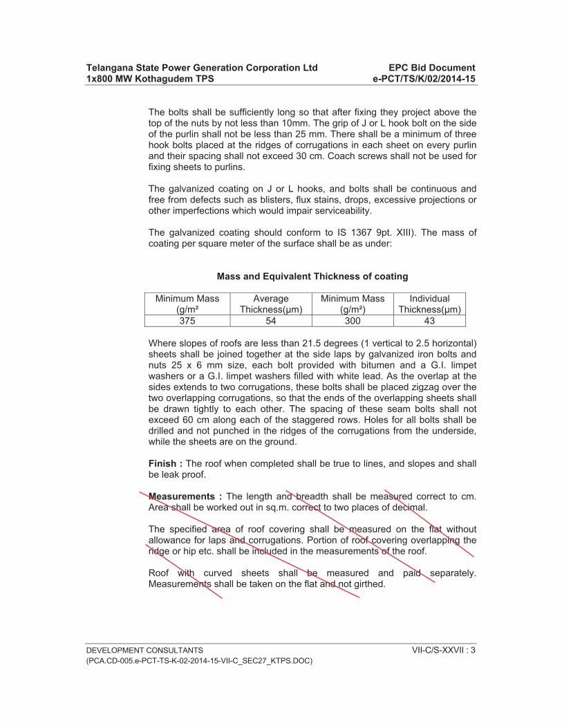
Telangana State Power Generation Corporation Ltd EPC Bid Document 1x800 MW Kothagudem TPS e-PCT/TS/K/02/2014-15
DEVELOPMENT CONSULTANTS VII-C/S-XXVII : 3 (PCA.CD-005.e-PCT-TS-K-02-2014-15-VII-C_SEC27_KTPS.DOC)
The bolts shall be sufficiently long so that after fixing they project above the top of the nuts by not less than 10mm. The grip of J or L hook bolt on the side of the purlin shall not be less than 25 mm. There shall be a minimum of three hook bolts placed at the ridges of corrugations in each sheet on every purlin and their spacing shall not exceed 30 cm. Coach screws shall not be used for fixing sheets to purlins.
The galvanized coating on J or L hooks, and bolts shall be continuous and free from defects such as blisters, flux stains, drops, excessive projections or other imperfections which would impair serviceability.
The galvanized coating should conform to IS 1367 9pt. XIII). The mass of coating per square meter of the surface shall be as under:
Mass and Equivalent Thickness of coating
Minimum Mass (g/m²
AverageThickness(μm)
Minimum Mass (g/m²)
IndividualThickness(μm)
375 54 300 43
Where slopes of roofs are less than 21.5 degrees (1 vertical to 2.5 horizontal) sheets shall be joined together at the side laps by galvanized iron bolts and nuts 25 x 6 mm size, each bolt provided with bitumen and a G.I. limpet washers or a G.I. limpet washers filled with white lead. As the overlap at the sides extends to two corrugations, these bolts shall be placed zigzag over the two overlapping corrugations, so that the ends of the overlapping sheets shall be drawn tightly to each other. The spacing of these seam bolts shall not exceed 60 cm along each of the staggered rows. Holes for all bolts shall be drilled and not punched in the ridges of the corrugations from the underside, while the sheets are on the ground.
Finish : The roof when completed shall be true to lines, and slopes and shall be leak proof.
Measurements : The length and breadth shall be measured correct to cm. Area shall be worked out in sq.m. correct to two places of decimal.
The specified area of roof covering shall be measured on the flat without allowance for laps and corrugations. Portion of roof covering overlapping the ridge or hip etc. shall be included in the measurements of the roof.
Roof with curved sheets shall be measured and paid separately. Measurements shall be taken on the flat and not girthed.

Telangana State Power Generation Corporation Ltd EPC Bid Document 1x800 MW Kothagudem TPS e-PCT/TS/K/02/2014-15
DEVELOPMENT CONSULTANTS VII-C/S-XXVII : 4 (PCA.CD-005.e-PCT-TS-K-02-2014-15-VII-C_SEC27_KTPS.DOC)
No deduction in measurement shall be made for opening up to 0.4sqm and nothing extra shall be allowed for forming such openings. For any opening exceeding 0.4 sqm in area, deduction in measurements for the full opening shall be made and in such cases the labour involved in making these openings shall be paid for separately. Cutting across corrugation shall be measured on the flat and not girthed. No additions shall be made for laps cut through.
Rate : The rate shall include the cost of all the materials and labour involved in all the operations described above including a coat of approved steel primer and two coats of approved steel paint on overlapping of C.G.I. sheets. This includes the cost the cost of roof sheets, galvanized iron J or L hooks, bolts and nuts, galvanized iron seam bolts and nuts, bituminous and galvanized iron limpet washers etc.
Ridges and Hips of Plain Galvanised Steel Sheets
Ridges and Hips : Ridges and hips of C.G.I. roof shall be covered with ridge and hip sections of plain G.S. sheet with a minimum lap of 20 cm on either side over the C.G.I. sheets. The end laps of the ridges and hips and between ridges and hips shall also be not less than 20 cm. The ridges and hips shall be of 60 cm overall width plain G.I. sheet, 0.6mm or 0.8 mm thick as given in the description of the item and shall be properly bent in shape.`
Fixing : Ridges shall be fixed to the purlins below with the same 8 mm dia G.I. hook bolts and nuts and bitumen and G.I. limpet washers which fix the sheets to the purlins.
Similarly, hips shall be fixed to the roof members below such as purlins, hip and valley rafters with the same 8 mm dia G.I. hook bolts and nuts and bitumen and G.I. limpet washers which fix the sheets to those roof members. At least one of the fixing bolts shall pass through the end laps of ridges and hips on either side. If this is not possible extra hook bolts shall be provided.
The end laps of ridges and hips shall be joined together with C.G.S sheet by galvanized iron seam bolts 25 x 6 mm size each with a bitumen and G.I. washer or white lead as directed by the Engineer-in-Charge. There shall be at least two such bolts in each end lap.
Surface of C.G.I. sheets of ridge and hip sections and roofing sheets which overlap each other shall be painted with a coat of approved primer and two coats of approved paint suitable for painting G.I. sheets before they are fixed in place.
Finish : The edges of the ridges and hips shall be straight from end to end and their surfaces should be plane and parallel to the general plane of the roof. The ridges and hips shall fit in squarely on the sheets.

Telangana State Power Generation Corporation Ltd EPC Bid Document 1x800 MW Kothagudem TPS e-PCT/TS/K/02/2014-15
DEVELOPMENT CONSULTANTS VII-C/S-XXVII : 5 (PCA.CD-005.e-PCT-TS-K-02-2014-15-VII-C_SEC27_KTPS.DOC)
Measurement : The measurements shall be taken for the finished work in length along the centre line of ridge or hip, as the case may be, correct to a cm. The laps in ridges and hips and between ridges and hips shall not be measured.
Rate : The rate shall include the cost of all labour and materials specified above, including painting, cost of seam bolts and any extra G.I. hook bolts, nuts and washers, required.
Valley and Flashing of Plain Galvanised Steel Sheets
Valley and Flashing : Valley shall be 90 cm wide overall plain G.I. sheet 1.6 mm thick or other size as specified in the item bent to shape and fixed. They shall lap with the C.G.I. sheets not less than 25 cm width on other side. The end laps of valley shall also be not less than 25 cm.
Valley sheets shall be laid over 25 mm thick wooden boarding if so required.
Flashing shall be of plain G.I. sheet of 40 cm overall width 1.25 mm thick or 1.00 mm thick as specified in the item bend to shape and fixed. They shall lap not less than 15 cm over the roofing sheets. The end laps between flashing pieces shall not less than 25 cm.
Laying and Fixing : Flashing and valley sheets shall be fixed to the roof members below, such as purlins and valley rafters with the same 8 mm dia G.I. hook bolts and nuts and bitumen and G.I. limpet washers which fix the sheets to those roof members.
At least one of the fixing bolts shall pass through the end laps of the valley pieces on other side. If this is not possible extra hook bolts shall be provided. The free end of flashing shall be fixed at least 5 cm inside masonry with the mortar of mix 1:3 (1cement: 3 coarse sand).
Surface of G.I. sheets under overlaps shall be painted with a coat of approved primer and two coats of approved paint suitable for painting G.I. sheets.
Finish : The edges of valley and flushing should be straight from end to end. The surface should be true and without bulges and depressions.
Measurements : The length of the valleys and flashing shall be measured for the finished work correct to a cm. The laps along the length of the valley or flashing pieces, including the portion embedded in masonry, shall not be measured.
Rates : The rate for valleys, shall be for all the labour and materials specified above, including painting, cost of seam bolts and the cost of requisite G.I. hook bolts, nuts and washers required over and above those needed for connecting the roof sheets to the roof members. The rate for valleys shall exclude the cost of boarding underneath which shall be paid for separately.

Telangana State Power Generation Corporation Ltd EPC Bid Document 1x800 MW Kothagudem TPS e-PCT/TS/K/02/2014-15
DEVELOPMENT CONSULTANTS VII-C/S-XXVII : 6 (PCA.CD-005.e-PCT-TS-K-02-2014-15-VII-C_SEC27_KTPS.DOC)
The rate for flashing shall be for all the labour and materials specified above, and shall include the cost of painting and mortar for fixing in wall.
Gutters Made of Plain Galvanised Steel Sheets
Gutters : Gutter shall be fabricated from plain G.I. sheets of thickness as specified in the item
Eaves gutters shall be of the shape and section specified in the description in the item. The overall width of the sheet referred to their in shall mean the peripheral width of the gutter including the rounded edges. The longitudinal edges shall be turned back to the extent of 12 mm and beaten to form rounded edges. The ends of the sheets at junction of pieces shall be hooked in to each other and beaten flush to avoid leakage.
Slope : Gutters shall be laid with a minimum slope of 1 in 120.
Laying and fixing : Gutters shall be supported on and fixed to M.S. flat iron brackets bent to shape and fixed to the requisite slope. The maximum spacing of brackets shall be 1.20 metres.
Where these brackets are to be fixed to the sides of rafters, they shall be of 40 x 3 mm section bend to shape and fixed rigidly to the sides of rafters with 3 nos. 10 mm dia bolts, nuts and washers. The brackets shall overlap rafter not less than 30 cm and the connecting bolts shall be at 12 cm centers.
Where the brackets are to be fixed to the purlins, the bracket shall consist of 50 x 3 mm M.S. flat iron bent to shape with one end turned at right angle and fixed to the purlin face with 2 nos. of 10 mm diameter bolts, nuts and washers. The bracket will be stiffened by provision of 50 x 3 mm M.S. flat whose over hung portion bent to right angle shape with its longer leg connected to the bracket with 2 nos. 6 mm dia M.S. bolts, nuts and washers and its shorter leg fixed to face of purlin with 1 no. 10 mm dia bolt, nut and washer. The overhang of the vertical portion of the bracket from the face of the purlin shall not exceed 22.5 cm with this arrangement. The spacing of the brackets shall not exceed 1.20 metres.
The gutter shall be fixed to the brackets with 2 nos. G.I. bolts and nuts 6 mm dia, each fitted with a pair of G.I. and bitumen washers. The connecting bolts shall be above the water line of the gutters.
For connection to down take pipes, a proper drop end or funnel shaped connecting piece shall be made out of G.I. sheet of the same thickness as the gutter and reverted to the gutter, the other end tailing in to the socket of the rain-water pipe. Wherever stop ends, angles etc., should be provided.
Finish : The gutters when fixed shall be true to line and slope and shall be leak proof.

Telangana State Power Generation Corporation Ltd EPC Bid Document 1x800 MW Kothagudem TPS e-PCT/TS/K/02/2014-15
DEVELOPMENT CONSULTANTS VII-C/S-XXVII : 7 (PCA.CD-005.e-PCT-TS-K-02-2014-15-VII-C_SEC27_KTPS.DOC)
Measurements : Measurements shall be taken for the finished work along the centre line of the top width of the gutter connection to a cm. The hooked lap portion in the junctions and gutter lengths shall not be measured. The number of brackets which are fixed to purlins with stiffener flats should be measured.
Rate : The rate shall include the cost of all labour and materials specified above, including all specials such as angles, junctions, drop ends or funnel shaped connecting pieces, stop ends etc., flat iron brackets and bolts and nuts required for fixing latter to the roof members. Brackets of 50 x 3 mm flats fixed to purlins with stiffener flats will be paid extra.
2.02.03 Fiber Glass Reinforced Plastic Sheeting
This shall be of thickness and profile as mentioned in the Schedule of Item. Colour and light transmittance shall be as mentioned in drawings and or schedules. Where used in conjunction with C.G.I. or asbestos sheeting the end and side laps and fixing device shall be same as used for general sheeting. Where used in lieu of glass, the fixing shall be by means of timber or metal glazing beads as mentioned in schedule of items. In all cases, the installation shall be completely watertight and able to withstand the designed wind-pressure as mentioned in Schedule.
2.02.04 Precoated metal sheet
Precoated metal sheeting for roof shall be of precoated cold rolled sheet of total coated thickness (TCT) 0.58 to 0.68 mm of approved manufacturer. The sheet shall be metallic hot deep coated with an alloy of 55% aluminium, 43% zinc and 1.55 silicon coating mass shall be 150 gms/sq.m. sheet shall be fixed with fastening clip and self tapping fastener. Ridge for slope roof shall be of similar material and shall be fixed with necessary self tapping screws as per manufacturer details.
Thermally insulated sandwiched metal cladding for external facade shall be of approved manufacturer. Sheeting shall Hi Rib 0.5 mm troughed sheeting manufactured from aluminium alloy high tensile steel (550Mpa) coated with fluro polymer (PV F2 or equivalent ) and shall have life span sustenance against aggressive weathering action. Inner profiled sheet shall be with profile sheet of .6 mm thick (total coated thickness) permanently coated galvanised sheet.
Galvanised coating shall be not less than 120 gm/sq.m. and sandwiched insulation of 25 mm thick or as per design requirement shall be bonded mineral wool blanket or equivalent conforming to IS: 8183 (minimum density of 32/kg/cum for glass wool and 48/kg/cum for rock wool) having minimum coefficient of thermal conductivity of 0.49 m W/cm deg C (at 50 degree C) Cladding shall be fixed to supports/rails by nuts, bolts, hooks, washers self tapping screws of stainless steel Austentic grade) conforming to IS:1367 (part

Telangana State Power Generation Corporation Ltd EPC Bid Document 1x800 MW Kothagudem TPS e-PCT/TS/K/02/2014-15
DEVELOPMENT CONSULTANTS VII-C/S-XXVII : 8 (PCA.CD-005.e-PCT-TS-K-02-2014-15-VII-C_SEC27_KTPS.DOC)
14) including sealants, gaskets, PVC tape 0.25 mm thick, flashing, black synthetic rubber external trough filler and 25X3 mm aluminium earthling.
2.02.04 Polycarbonate Sheeting Work
Solid Polycarbonate sheet of minimum 4mm thick should be of UV resistant and high temperature resistant. Sheet should be of approved brand and quality, colour and transparency for ceiling/ roofing on plain, sloped, curved surfaces to any pitch or height including fixing purlins with polymer quoted galvanized self drilling, self tampering metal screws and fasteners and EPDM washers, rubber gasket with closing caps, adequate adhesive and sealants as per manufacturer’s specification etc. complete but excluding the cost of purlins, rafters, trusses etc.(if any). Polycarbonate sheets shall be uniform pigmentation and thickness with out air pockets and shall conform to IS: 14443: 1997 and including cutting to required length and size including profile machine bending of sheets to achieve the desired profile by conforming minimum joints and laps as per drawing.
3.00.00 ACCEPTANCE CRITERIA
The installations shall present a neat appearance and shall be checked for water tightness. The following shall be checked:
a) Side and end laps
b) Absence of cracks, holes or damages in sheet
c) Spacing of bolts
d) Provision of double washers (G.I. and asbestos or bituminous washers)
e) Proper installation of flashing
4.00.00 RATES
Rates shall be for unit rate for complete item described in the Schedule and shall include all wastages as mentioned earlier.
5.00.00 METHOD OF MEASUREMENT
a) No allowance shall be made for laps.
b) Roofing and side sheeting shall be measured for net area of work done. Corrugated sheeting shall be measured flat and not girthed. Openings less than 0.4 Sq.m shall not be deducted. Detailed stated earlier.

Telangana State Power Generation Corporation Ltd EPC Bid Document 1x800 MW Kothagudem TPS e-PCT/TS/K/02/2014-15
DEVELOPMENT CONSULTANTS VII-C/S-XXVII : 9 (PCA.CD-005.e-PCT-TS-K-02-2014-15-VII-C_SEC27_KTPS.DOC)
c) Special features like flashings, ridge pieces, caves, corner pieces, north-light curves etc. shall be measured for length of installation.
d) Gutter and down comers shall be measured for length along their centre lines and bends, junctions, shoes ends, etc. shall not be paid properly.
e) S-type asbestos louvers shall be measured for area of opening in which it is installed.
f) Curved asbestos roofing sheets shall be measured for area of curve.
g) Asbestos ventilators, roof lights shall be measured and paid under relevant items.
6.00.00 IS CODES
The following are some of the important IS Codes relevant to these sections:
IS : 3007 : Code of practice for laying of asbestos cement sheets
IS : 2527 : Code of practice for fixing rain water gutters and down pipes for roof drainage
IS : 1626 : Specification for asbestos cement building pipes gutters and fittings
IS : 277 : Specification for galvanised steel sheets (plain and corrugated)
IS : 1200 (PT.IX) : Method of measurements of building and civil
engineering works: Part – 9 Roof covering (including cladding)
IS : 2633 : Method of testing uniformity of coating on zinc coated articles.
IS : 3144 : Method of test for mineral wool thermal insulation materials.
IS : 3346 : Method of the determination of thermal conductivity of thermal insulation materials.
IS : 8183 : Bonded mineral wool

Telangana State Power Generation Corporation Ltd EPC Bid Document 1x800 MW Kothagudem TPS e-PCT/TS/K/02/2014-15
DEVELOPMENT CONSULTANTS (PCA.CD-005.e-PCT-TS-K-02-2014-15-VII-C_SEC28_KTPS.DOC)
VOLUME : VII-C
SECTION-XXVIII
TECHNICAL SPECIFICATION FOR
ROOF WATER PROOFING, INSULATION AND ALLIED WORKS

Telangana State Power Generation Corporation Ltd EPC Bid Document 1x800 MW Kothagudem TPS e-PCT/TS/K/02/2014-15
DEVELOPMENT CONSULTANTS (PCA.CD-005.e-PCT-TS-K-02-2014-15-VII-C_SEC28_KTPS.DOC)
CONTENT
CLAUSE NO. DESCRIPTION PAGE NO.
1.00.00 SCOPE VII-C/S-XXVIII : 1
2.00.00 INSTALLATION VII-C/S-XXVIII : 1
3.00.00 ACCEPTANCE CRITERIA VII-C/S-XXVIII : 9
4.00.00 I. S. CODES VII-C/S-XXVIII : 9

Telangana State Power Generation Corporation Ltd EPC Bid Document 1x800 MW Kothagudem TPS e-PCT/TS/K/02/2014-15
DEVELOPMENT CONSULTANTS VII-C/S-XXVIII : 1 (PCA.CD-005.e-PCT-TS-K-02-2014-15-VII-C_SEC28_KTPS.DOC)
VOLUME : VII-C
SECTION-XXVIII
TECHNICAL SPECIFICATION FOR
ROOF WATER PROOFING, INSULATION AND ALLIED WORKS
1.00.00 SCOPE
This specification covers providing, furnishing, installation, repairing, finishing, curing, testing,, protection, maintenance till handing over of roof water-proofing, insulation and allied work for buildings and at locations covered under the scope of the Contract.
2.00.00 INSTALLATION 2.01.00 Before taking up the water proofing work the construction of parapet walls,
including finishing should be completed. Similarly, the ancillary items like haunches, khurras, grooves to take the fiber cloth layer, fixing up of all down take pipes, water pipes and electric conduits etc. should be completed and no such work should be allowed on the area to be treated during the progress of water proofing treatment or even later.
2.01.01 There is no necessity of hacking the surface to be treated shall be cleaned including removing the mortar dropping from the surface.
2.01.02 Grading Underbed
The surface to receive the underbed shall be roughened and thoroughly cleaned with wire brush and water. Oil patches if any shall be removed with detergent. The surface shall be soaked with water and all excess water removed just before laying of the underbed.
The underbed shall not be laid under direct hot sun and shall be kept in shade immediately after laying so as to avoid quick loss of water from the mix and separation from the roof surface. The underbed shall be cured under water for at least 7 days.
The underbed shall be laid to provide an ultimate run off gradient not less than 1 in 120 and as directed by the Engineer. Upto an average thickness of 25 mm the underbed shall usually be composed of cement and sand plaster. For higher thickness the underbed shall be made with cement concrete.

Telangana State Power Generation Corporation Ltd EPC Bid Document 1x800 MW Kothagudem TPS e-PCT/TS/K/02/2014-15
DEVELOPMENT CONSULTANTS VII-C/S-XXVIII : 2 (PCA.CD-005.e-PCT-TS-K-02-2014-15-VII-C_SEC28_KTPS.DOC)
The underbed shall be finished to receive the waterproofing treatment direct or insulation as the case may be.
2.01.03 The grading plaster shall be average 25mm thick maximum. It shall consist of cement and coarse sand in the ratio 1:4 nominal by volume. The same and cement shall be thoroughly mixed dry and them water added. Each batch of mix shall be consumed before the initial set starts.
The plaster shall be fully compacted to the desired grade in continuous operation. The surface shall be even and reasonably smooth.
2.02.00 Concrete
The concrete shall be used where the sub-grade is more than average 25mm thick. It shall consist of cement concrete 1:2:4 nominal mix by volume with 12mm down stone chips and coarse sand. The aggregate shall be mixed dry and minimum quantity of water shall be added to make the mix workable.
The mix shall be laid to proper grade, fully consolidated and surface shall be smooth and even.
2.03.00 Insulation
The Tenderer shall along with the tender send specification of insulating materials he proposes to use and the proposed method of laying. Before bulk supply, the contractor shall send samples of insulating material to the Engineer, and after approval of the samples, the Contractor shall procure and transport the bulk material to the site. Whenever asked by the Engineer, the Contractor shall furnish test certificates from testing laboratory on the insulating and other properties of the materials.
After laying the insulation the surface shall be made ready as required to receive the waterproofing treatment. If any plastering is used it shall be not leaner than 1:4 cement sand by volume and not thinner than 12mm and it shall be cured for seven days.
2.03.01 Foam Concrete
This shall be of light weight foam concrete of average 50 mm thickness or as specified or as shown on drawings. This may be laid in situ in suitable panels or in precast blocks. The insulating properties shall be such that the thermal conductivity shall not exceed 0.125 Kcl m/m degree C. The weight of the insulating material shall be from 0.3 to 0.5 gm/cm.
Before starting the laying of foam concrete samples shall be prepared at site and got tested for approval of the Engineer.

Telangana State Power Generation Corporation Ltd EPC Bid Document 1x800 MW Kothagudem TPS e-PCT/TS/K/02/2014-15
DEVELOPMENT CONSULTANTS VII-C/S-XXVIII : 3 (PCA.CD-005.e-PCT-TS-K-02-2014-15-VII-C_SEC28_KTPS.DOC)
The foam concrete laid shall be sufficiently strong to make the usual work load and standard loads expected on the roof. Any damaged portion shall be removed and replaced forthwith. Approval of the Engineer shall be taken before laying the waterproofing over the insulation.
While laying the foam concrete, samples from each batch of the mix shall be kept for test if so desired by the Engineer.
2.03.02 Expanded Polystyrene Blocks
The expanded polystyrene block insulation shall be fire retardant quality and shall have a maximum thermal conductivity of 0.026 KCl m/m degree C. It must be strong enough to withstand without deformation the workload and standard loads expected on the roof.
The Contractor shall lay the expanded polystyrene block as per manufacturer’s approved specification. Only specifically experienced workers shall be used for this work. If the Engineer is not satisfied about the efficiency of the workers the Contractor shall have to secure manufacturer’s supervision.
Material: Expanded polystyrene shall conform to IS 4671. It is of two types given below :
Type N-Normal
Type SE – It shall be of self extinguishing type when tested in accordance with IS 4671.
Dimensions : The size of the finished boards shall be 1.0 x 0.5 m or as specified and having a thickness of 15, 20, 25, 40, 50, 60, 75 or 100mm.
Tolerance : The tolerances on the length, width and thickness of the finished board shall be ± mm.
Requirements for Expanded Polystyrene for General Use :
Requirements at various nominal apparent densities in kg/cum
Sl.No.
Characteristics
15 20 25 30 35
TestReference
1. Thermal conductivity (k. value) (a) at 0ºC (b) at 10ºC
0.34 0.32 0.30 0.29 0.28 0.37 0.35 0.33 0.32 0.30
IS 3346
2. Compressive strength at 10% deformation in kg/sq.cm Minimum.
0.7 0.9 1.1 1.4 1.7 IS 4671

Telangana State Power Generation Corporation Ltd EPC Bid Document 1x800 MW Kothagudem TPS e-PCT/TS/K/02/2014-15
DEVELOPMENT CONSULTANTS VII-C/S-XXVIII : 4 (PCA.CD-005.e-PCT-TS-K-02-2014-15-VII-C_SEC28_KTPS.DOC)
Requirements at various nominal apparent densities in kg/cum
Sl.No.
Characteristics
15 20 25 30 35
TestReference
3. Cross breaking strength in kg/sq.cm Minimum.
1.4 1.6 1.8 2.2 IS 4671
4. Water vapour permeance in g/sqm 24 hrs. Max.
50 40 30 20 IS 4671
5. Thermal stability Percent Max.
1 1 1 1 IS 4671
6. Water absorption Less than 0.5% by volume (after 24 hrs. immersion)
IS 4671
Sampling : In a single consignment all the items of the same type, shape and dimensions belonging to the same batch of manufacture shall be grouped together to constitute a lot. For the purpose of judgment conformity to the requirements each lot shall be considered separately. The number of sample items for this purpose shall depend on the size of the lot and shall be in accordance with col. 1 & 2 of Table given below. The sample shall be taken at random from the lot.
No. of items in the lot No. of sample items Permissible number of defective sample items
1 2 3Up to 25 3 026 to 100 5 0101 to 300 8 0301 to 1000 13 01001 to 3000 20 13001 and above 32 2
All the sample items selected from the lot shall be tested for all requirements of the specifications. Any item failing in one or more of the requirements shall be regarded as defective.
General : Expanded polystyrene can either be fixed with suitable adhesive to the false ceiling board or else it can simply be rolled ober the suspended false ceiling.
Measurements : Length and breadth of the roofing insulation shall be measured correct to a cm and the surface area worked out in square metre of the finished work.

Telangana State Power Generation Corporation Ltd EPC Bid Document 1x800 MW Kothagudem TPS e-PCT/TS/K/02/2014-15
DEVELOPMENT CONSULTANTS VII-C/S-XXVIII : 5 (PCA.CD-005.e-PCT-TS-K-02-2014-15-VII-C_SEC28_KTPS.DOC)
No deduction shall be made for openings of area up to 40 square decimeter. No extra payment will be made for any extra material or labour involved in forming such openings. For openings exceeding 40 square decimeter in area deduction for the full opening will be made, but nothing extra will be paid for any extra material/labour involved in forming such openings.
Rate : The rate shall include the cost of material and labour in providing and fixing the polystyrene boards.
2.03.03 With Resin Bonded Fiber Glass Wool (Bonded Mineral Wool)
Material : The material shall be mineral wool made from sock slag or glass processed from a molten state in to fibrous form and shall be bonded with a suitable binder. Bonded mineral wool shall be 25, 40, 50, conform to specifications of group I of IS 8183.
Dimensions : The bonded mineral wool shall be supplied in width of 50, 60, 75 and 100 cms, and length of 100, 120 and 140 cms and the thickness of the bonded material wool shall be 25, 40, 50, 65 or 75 mm.
Tolerance : For width and length, the dimensional tolerance of the bonded material wool shall be -1/2 %. For nominal thickness in the range 25 to 75 mm the tolerance shall be -2 mm. An excess, in all dimensions is permitted.
Requirements for Fiber Glass Wool
Sl.No.
Characteristics Group I Test Reference
1. Bulk density 12 to 15 kg/cum IS 3144 2. Recovery after compression Not less than 90% of
original thickness Annexure. A of
IS 31443. Shot content max 500 micron-5%
250micron-15%IS 8183
4. Moisture content and absorption
Not more than 2% IS 3144
5. In combustibility Incombustible IS 31446. Thermal conductivity deg. C
at mean temperature 50 deg. C
0.49 mw/ cmºC IS 3346
7. Sulphur content Not more than 0.6% IS 3144
General : Bonded mineral wool insulation can be either laid over false ceiling or alternatively it can be fixed to the ceiling when the space above false ceiling is being used for carrying return air. In the first case the bonded mineral wool can either be fixed with suitable adhesive to the false ceiling board or else it can simply be rolled over the suspended false ceiling.

Telangana State Power Generation Corporation Ltd EPC Bid Document 1x800 MW Kothagudem TPS e-PCT/TS/K/02/2014-15
DEVELOPMENT CONSULTANTS VII-C/S-XXVIII : 6 (PCA.CD-005.e-PCT-TS-K-02-2014-15-VII-C_SEC28_KTPS.DOC)
Measurements : Length and breadth of roofing insulation shall be measured correct to a cm and the surface area worked out in square metre of the finished work.
No deduction shall be made for openings of areas up to 40 square decimeter. No extra payment will be made for any extra material or labour involved in forming such openings. For openings exceeding 40 square decimeter in areas, deduction for the full opening will be made, but no extra will be paid for any extra material or labour involved in forming such openings.
Boarding fixed to curved surface in narrow widths shall be measured and paid for separately. Circular cutting and waste shall be measured and paid for separately in running metres.
Rate : The rate shall include the cost of all materials and labour required in providing bonded mineral wool.
Either of above items (cl. No. 2.3.1 or 2.3.2 or 2.3.3) can be adopted subject to approval of engineer.
2.04.00 Fillets
Fillets at junction of roofs and vertical walls shall be provided with the same insulating material as provided for the main roof insulation. The fillets shall be 150 mm x 150 mm in size unless otherwise shown on drawings or instructed by the Engineer.
Where there is no insulation over roof slab, fillets shall be cast-in-situ cement concrete (1:2:4) nominal mix by volume.
2.05.00 Water proofing by epoxy resin based application
Exposed surfaces of cement concrete, lime concrete or brickwork to be treated for waterproofing by the resin based application shall be throughly cleaned and the epoxy resin based material to be applied as directed by the manufacturer. The material shall not have any adverse effect on the surface on which it is applied and must stick to it uniformly to make a strong durable bond. It shall not be affected by short duration from fire, sun, and light traffic. The application shall be resistant to growth of fungus and proof against saltpeter action. If desired by the Engineer, a sample shall be prepared in advance and tested for waterproofness for 48 hours under 300 mm depth of standing water. The Contractor shall arrange the demonstration by providing free the materials and labours for the application.

Telangana State Power Generation Corporation Ltd EPC Bid Document 1x800 MW Kothagudem TPS e-PCT/TS/K/02/2014-15
DEVELOPMENT CONSULTANTS VII-C/S-XXVIII : 7 (PCA.CD-005.e-PCT-TS-K-02-2014-15-VII-C_SEC28_KTPS.DOC)
2.06.00 Flashing
Unless otherwise stated flashing shall be done in the same way as the waterproofing except that the last layer, instead of being finished with pea-sized gravel, shall be finished with two coats of bituminous primer. The flashing shall be extended up the vertical surfaces as shown on drawing. The flashing shall end in grooves in vertical walls. The grooves shall be at least 65 mm deep and caulked with waterproof mastic cement. The minimum overlap with horizontal roofing felt shall be 100 mm.
Where specified on drawings or directed by the Engineer, metal flashing shall be provided. The metal flashing shall be done as shown on the drawings. The materials shall be 18g or 22g G.I. sheets, as specified on the drawings and/or as directed by the Engineer.
2.07.00 Elastomeric Membrane
2.07.01 Primer Coat
It shall consist of polyurethane (P.U.) or any other equivalent material. Primer coat shall be a special blend of moisture curing urethane pre-polymers in solvent. A single coat of this primer shall be applied by brush /spray with airless spray equipment over the prepared bed as an adhesion coat with an application rate of 6-8 sq.m per liter depending on the surface porosity.
The primer shall be allowed to dry for a minimum period of 2 to 4 hours time before the successive finishing coats of P.U. liquid membrane are applied. In any case successive finishing coat shall be applied within 24 hours.
The substrate shall be properly prepared by removing all loose materials by vigorous brushings, fungal growth with proprietary fungicide as recommended. Priming coat shall not be applied to damp substrate.
2.07.02 Finishing Coats
The finishing coats shall consist of two successive liquid coatings of high solid content urethane pre-polymers material to form an elastomeric membrane. Application shall be with brush or spray to form an uniform joint less elastomeric membrane. The overall dry film thickness shall be 1.5 mm subject to minimum 750 gm per sq.m per coat application rate.
Each coat shall be allowed to dry for minimum 12 hours before applying the next coat. The surface should be dry and smooth before application.
The coating shall be continued up the parapets/walls for minimum of 150 mm over the finished roof surface or fillet with suitable tucking into the vertical wall surface. It shall be continued into rain water pipes by at least 100 mm.

Telangana State Power Generation Corporation Ltd EPC Bid Document 1x800 MW Kothagudem TPS e-PCT/TS/K/02/2014-15
DEVELOPMENT CONSULTANTS VII-C/S-XXVIII : 8 (PCA.CD-005.e-PCT-TS-K-02-2014-15-VII-C_SEC28_KTPS.DOC)
The final coat of PU liquid when tacky shall be sprinkled with the sand.
For edges, expansion joints and any vulnerable points a layer of polyscrim cloth/fabric are to be embedded between 2 finishing coats.
The entire work shall be carried out under the suspension of approved authorized agency.
2.07.03 Surface Finish
Areas of roof treatment shall be provided with wearing course consisting of minimum 25 mm thick PCC 1:11/2:3(using 12.5 mm size aggregate) cast in panel of maximum size of 1.20 m x 1.20 m and reinforced with 0.56 mm diameter galvanized chicken wire mesh and sealing of joints using sealant or elastomeric compound to ensure perfect waterproofing.
When the roof surface is subjected to foot traffic or used as a working area, a cement mortar (1:4) shall be applied over the top most layer of roofing treatment. Over this, a layer of chequered cement concrete flooring tiles conforming to IS: 13801 shall be provided. The tiles shall be laid as per IS 1443.
2.08.00 Under Deck Insulation
2.08.01 Insulation material shall be Closed Cell Elastomeric Nitrile Rubber
2.08.02 Density of Material shall be between 40 to 60 Kg/m3
2.08.03 Thermal conductivity of elastomeric nitrile rubber shall not exceed 0.035 W/m�K at an average temperature of 0�C
2.08.04 The insulation shall have fire performance such that it passes Class 1 as per BS476 Part 7 for surface spread of flame as per BS 476 and also pass Fire Propagation requirement as per BS476 Part 6 to meet the Class ‘O’ Fire category as per 1991 Building Regulations (England & Wales) and the Building Standards (Scotland) Regulations 1990
2.08.05 Material should be FM (Factory Mutual), USA approved.
2.08.06 Water vapour permeability shall not exceed 0.017 Perm inch (2.48 x 10⁻¹⁴ Kg/m.s.Pa), i.e. Moisture Diffusion Resistance Factor ‘μ’ value should be minimum 7000.
2.08.07 Under-deck insulation thickness shall be as per HVAC requirement and calculation.
2.08.08 Under-deck insulation shall be provided for all AC areas having roof exposed to sun.

Telangana State Power Generation Corporation Ltd EPC Bid Document 1x800 MW Kothagudem TPS e-PCT/TS/K/02/2014-15
DEVELOPMENT CONSULTANTS VII-C/S-XXVIII : 9 (PCA.CD-005.e-PCT-TS-K-02-2014-15-VII-C_SEC28_KTPS.DOC)
3.00.00 ACCEPTANCE CRITERIA
The surface level shall be such as to allow quick draining of rains without leaving any pool anywhere. The finishing course shall be fully secured and shall have an even density. There shall not be any bubble formation or crushed or squeezed insulation or underbed.
The Contractor shall give a guarantee in writing for all work executed under this specification supplemented by a separate and unilateral guarantee from the specified agency for the roof water-proofing treatment work. The guarantee shall be for materials and workmanship for a period of minimum 10 years. The mode of execution of the guarantee shall be acceptable to the Owner. Any bad work or any damage to the treatment shall be repaired and made good by the contractor at his own cost.
4.00.00 I.S. CODES AND STANDARDS
a) IS:73 : Paving Bitumen
b) IS:702 : Industrial Bitumen
c) IS:1203 : Methods of testing tar and bitumen
d) IS:1322 : Bitumen felts for waterproofing and damp proofing
e) IS:1346 : Code of Practice for waterproofing of roofs with bitumen felts
f) IS:3384 : Bitumen primer for use in waterproofing and damp proofing.
g) IS:2645 : Specification for integral water proofing compounds for cement mortar and concrete.
h) IS:3144 : Methods of test for mineral wool thermal insulation materials.
i) IS:4641 : Expanded polystyrene for thermal insulation purpose.

Telangana State Power Generation Corporation Ltd EPC Bid Document 1x800 MW Kothagudem TPS e-PCT/TS/K/02/2014-15
DEVELOPMENT CONSULTANTS(PCA.CD-005.e-PCT-TS-K-02-2014-15-VII-C_SEC29_KTPS.DOC)
VOLUME : VII-C
SECTION-XXIX
TECHNICAL SPECIFICATION FOR
WATER SUPPLY

Telangana State Power Generation Corporation Ltd EPC Bid Document 1x800 MW Kothagudem TPS e-PCT/TS/K/02/2014-15
DEVELOPMENT CONSULTANTS(PCA.CD-005.e-PCT-TS-K-02-2014-15-VII-C_SEC29_KTPS.DOC)
CONTENT
CLAUSE NO. DESCRIPTION PAGE NO.
1.00.00 SCOPE VII-C/S-XXIX : 1
2.00.00 INSTALLATION VII-C/S-XXIX : 6
3.00.00 TESTING AND ACCEPTANCE VII-C/S-XXIX : 13
4.00.00 RATES VII-C/S-XXIX : 14
5.00.00 MEASUREMENT VII-C/S-XXIX : 14
6.00.00 I. S. CODES VII-C/S-XXIX : 16

Telangana State Power Generation Corporation Ltd EPC Bid Document 1x800 MW Kothagudem TPS e-PCT/TS/K/02/2014-15
DEVELOPMENT CONSULTANTS VII-C/S-XXIX : 1 (PCA.CD-005.e-PCT-TS-K-02-2014-15-VII-C_SEC29_KTPS.DOC)
VOLUME : VII-C
SECTION-XXIX
TECHNICAL SPECIFICATION FOR
WATER SUPPLY
1.00.00 SCOPE
This section includes supply of all materials, labour and incidentals for water supply for residential, business and industrial and other types of buildings. The water supply system of a building or premises covers service pipes and the necessary connecting pipes, fittings, control valves and all appurtenances in or adjacent to the building or premises.
General Requirements
Any damage caused to the building, or to electric, sanitary water supply or other installations etc. therein either due to negligence on the part of the contractor, or due to actual requirements of the work, shall be made good and the building or the installations shall be restored to its original condition by the contractor. Nothing extra shall be paid for it, except where otherwise specified.
All water supply installation work shall be carried out through licensed plumber.
It is most important to ensure that wholesome water supply provided for drinking and culinary purpose is in no way liable to contamination from any less satisfactory water. There shall, therefore, be no cross connection whatsoever between a pipe or fitting for conveying or containing wholesome water and a pipe or fitting for conveying or containing impure water or water liable to contamination or of uncertain quality of water which has been used for any purpose. The provision of reflux or non-return valves or closed and sealed valves shall not be constructed a permissible substitute for complete absence of cross-connection.
Where a supply of wholesome water is required as an alternative or standby to supply of less satisfactory water or is required to be mixed with the latter, it shall be delivered only in to a cistern, and by a pipe or fitting discharging in to the air gap at a height above the top edge of the cistern equal to twice its normal bore, and in no case less than 15 cm.

Telangana State Power Generation Corporation Ltd EPC Bid Document 1x800 MW Kothagudem TPS e-PCT/TS/K/02/2014-15
DEVELOPMENT CONSULTANTS VII-C/S-XXIX : 2 (PCA.CD-005.e-PCT-TS-K-02-2014-15-VII-C_SEC29_KTPS.DOC)
No piping shall be laid or fixed so as to pass into, through or adjoining any sewer, scour outlet or drain or any manhole connected therewith nor through any ash pit or manure-pit or any material of such that can cause undue deterioration of the pipe.
Where the laying of any pipe through fouled soil or previous material is unavailable, the piping shall be properly protected from contact with such soil or material by being carried through an exterior cast iron tube or by some other suitable means. Any piping or fitting laid or fixed which does not comply with the above requirements, shall be removed and re-laid in conformity with the above requirements.
The design of the pipe work shall be such that there is no possibility of backflow towards the source of supply from any cistern or appliance whether by siphonage or otherwise, and reflux or non-return valves shall not be relied upon to prevent such back flow.
All pipe work shall be so designed, laid or fixed, and maintained so that it remains completely watertight, thereby avoiding wastage of water damage to property and the risk of contamination of the water conveyed.
In designing and planning the layout of the pipe work, due attention shall be given to the maximum rate of discharge, required economy in labour and materials, protection against damage and corrosion, protection from frost, if required, and to avoidance or airlocks, noise transmission and unsightly arrangement.
To reduce frictional losses, piping shall be as smooth as possible inside. Methods of jointing shall be such as to avoid internal roughness and projection at the joints, whether of the jointing materials or otherwise.
Change in diameter and direction shall preferably be gradual rather than abrupt to avoid undue loss of head. No bend or curve in piping shall be made so as to materially reduce or alter the cross-section.
Underground piping shall be laid at such a depth that it is unlikely to be damaged by frost or traffic loads and vibrations. It shall not be laid in ground liable to subsidence, but where such ground cannot be avoided; special precautions shall be taken to avoid damage to the piping. Where piping has to be laid across recently disturbed ground, the ground shall be thoroughly consolidated so as to provide a continuous and even support.
Where the service pipe is of diameter less than 50mm the stop valves shall be of the screw-down type and shall have loose washer plates to act as non-return valves. Other stop valves in the service line may be of the gate type.

Telangana State Power Generation Corporation Ltd EPC Bid Document 1x800 MW Kothagudem TPS e-PCT/TS/K/02/2014-15
DEVELOPMENT CONSULTANTS VII-C/S-XXIX : 3 (PCA.CD-005.e-PCT-TS-K-02-2014-15-VII-C_SEC29_KTPS.DOC)
In flats and tenements supplied by a common service pipe a stop valve shall be fixed to control the each branch separately. In large buildings a sufficient number of stop valves shall be fixed on branch pipes, and to control groups of ball valves and draw off taps so as to minimize interruption of the supply during repairs, all such stop valves shall be fixed in accessible positions and properly protected from being tampered with, they may be of the gate type to minimize loss of head by friction.
Water for drinking or for culinary purposes as far as possible shall be on branch pipes connected directly to the service pipe.
Pumps shall not be allowed on the service pipe as they cause a drop of pressure on the suction side thereby affecting the supply to the adjoining properties. In cases where pumping is required, a properly protected storage tank of adequate capacity shall be provided to feed the pump.
Service pipes shall be so designed and constructed as to avoid air-locks, so that all piping and fittings above ground can be completely emptied of water to facilitate repairs. There shall be draining taps or draw-off taps (not under ground) at the lowest points, from which the piping shall rise continuously to draw-off taps, ball valves, cisterns, or vents ( where provided at the high points).
Service pipes shall be designed so as to reduce the production and transmission of noise as much as possible. Appliances which create noise shall be installed as far distant as possible from the living rooms of the house. High velocity of water in piping and fittings shall be avoided. Piping shall be confined, as far as possible, to rooms where appliances are fixed, it shall have easy bends, and where quietness is particularly desired, holder bats or claps shall be insulated from the piping by suitable pads.
The rising pipe to the storage cistern, if any, or to any feed cistern shall be taken as directly as possible to the cistern and shall be fixed away from windows or ventilators.
All pipe work shall be planned so that the piping is accessible for inspection, replacement and repair. To avoid its being unsightly, it is usually possible to arrange it in or adjacent to cupboards, recesses, etc. provided there is sufficient space to work on the piping with the usual tools. Piping shall not be buried in walls or solid floors. Where unavoidable, piping may be buried for short distances provided that adequate protection is given against damage and that no joints are buried. If piping is laid in ducts or chases, these shall be roomy enough to facilitate repairs and shall be so constructed as to prevent the entry of vermin. To facilitate removal of pipe casing, floor boards covering piping shall be fixed with screws or bolts.

Telangana State Power Generation Corporation Ltd EPC Bid Document 1x800 MW Kothagudem TPS e-PCT/TS/K/02/2014-15
DEVELOPMENT CONSULTANTS VII-C/S-XXIX : 4 (PCA.CD-005.e-PCT-TS-K-02-2014-15-VII-C_SEC29_KTPS.DOC)
When it is necessary for a pipe to pass through a wall or floor, a sleeve shall be fixed therein for insertion of the pipe and to allow freedom for expansion, contraction and other movement. Piping laid in wood floors shall, where possible, be parallel with the joints.
Where storage tanks are provided to meet overall requirements of water connection of service pipe with any distributing pipe shall not be permitted except one direct connection for culinary or drinking requirements.
No service pipe shall be connected to any water closet or urinal. All such supplies shall be from flushing cistern which shall have supply from storage tank.
No service or supply pipe shall be connected directly to any hot water system or to any apparatus used for heating other than through a feed cistern thereof.
1.01.00 Materials
All materials, fittings, fixtures and appliances shall be of the best quality conforming to relevant Indian Standard and shall be procured from approved manufacturers. Unless specifically allowed by the Engineer, the Contractor shall submit samples of fittings and fixtures which will be retained by him for comparison when bulk supplies are received at the site. Ultimate choice of type, model and manufacturer lies completely with the Engineer.
It shall be the responsibility of the Contractor to procure the materials selected by the Engineer. Hence order is to be placed with the manufacturers in time, so that the materials are available at the site well ahead of their requirement.
The materials brought to the site, shall be stored in a separate secured enclosure away from the building materials. Pipe threads, sockets and similar items shall be specially protected till final installation. Brass and other expensive items shall be kept under lock and key. Fragile items shall be checked thoroughly when received at the site and items found damaged shall not be retained at the site.
1.02.00 Pipes and Pipe Fittings
Under scope of this specification, pipes and pipe fittings may be any or a combination of the following types:
a) Cast Iron
b) Steel: lined, coated with bituminous composition, out coated with cement concrete or mortar or galvanised.
c) Reinforced Concrete

Telangana State Power Generation Corporation Ltd EPC Bid Document 1x800 MW Kothagudem TPS e-PCT/TS/K/02/2014-15
DEVELOPMENT CONSULTANTS VII-C/S-XXIX : 5 (PCA.CD-005.e-PCT-TS-K-02-2014-15-VII-C_SEC29_KTPS.DOC)
d) Prestressed Concrete
e) Asbestos Cement
f) Lead (Not to be used for potable water)
g) P. V. C.
h) Copper
i) Brass
j) Wrought iron
k) Galvanized Iron- heavy & medium duty pipes- is 1239 & is 4736
l) PP-R Pipes – IS 15801
1.03.00 Water Tanks
Water tanks shall be made of PVC, HDPE, MS pressed steel, GI, Concrete masonry. PVC/HDPE/Pressed Steel tanks shall be factory made and from reputed brand with proper test certificates. The capacity of tanks shall be as per drawing design or as per instruction of Engineer-in-Charge.
1.04.00 Related Works
All works, like earthwork, masonry, concrete, steelwork, cutting holes, chases, repairs and rectification associated directly with installation of water supply systems shall come under scope of the Contractor unless specifically excluded. These works are not detailed out in this Specification.
1.05.00 Regulation
The work which is required to be carried out under the scope of this section, shall be executed by a licensed plumber only (engaged by the Contractor) and he shall obtain all necessary sanctions, permissions, certificates etc. from Municipal and/or other Local Authorities and shall abide by all the rules of such Authorities. The fee paid to the Authorities shall be reimbursed by the Owner.

Telangana State Power Generation Corporation Ltd EPC Bid Document 1x800 MW Kothagudem TPS e-PCT/TS/K/02/2014-15
DEVELOPMENT CONSULTANTS VII-C/S-XXIX : 6 (PCA.CD-005.e-PCT-TS-K-02-2014-15-VII-C_SEC29_KTPS.DOC)
2.00.00 INSTALLATION
While basic layouts may be available in the drawings provided by the Owner, the details might have to be supplemented by the Contractor for approval of the Engineer.
Special attention shall be given by the Contractor to economy. Symmetry of layout is very important. Fittings meant for operation shall be located and oriented to allow easy reach and operation. Maintenance, repairs and replacements of pipes, fittings and fixtures must be conveniently possible.
2.01.00 Pipe Lines
2.01.01 Laying
In addition to fulfilling the functional requirements all pipelines shall be laid true to line, plumb and level. Any deviation shall need approval of the Engineer. Meticulous care shall be taken to avoid chances of airlock and water hammer.
Pipes shall be laid on continuous unyielding surface or on reliable supports at least one near each joint and spacing as directed by the Engineer. The support must be strong, neat and shall have provisions for securing the pipes in every direction and easy maintenance. Pipes shall be encased or concealed in masonry or concrete if shown on drawing or directed by the Engineer.
2.01.02 Back Flow
The layout of pipe work shall be such that there is no possibility of back flow towards the source of supply from any cistern or appliances, whether by siphonage or otherwise. All pipe works shall be so laid or fixed and maintained as to be and to remain completely water-tight, thereby avoiding waste of water, damage of property and the risk of contamination of the water conveyed.
2.01.03 Contamination
There shall be no cross connection whatsoever between a pipe or fitting for conveying or containing wholesome water and a pipe or fitting for containing impure water or water liable to contamination or of uncertain quality of water which has been used for any purpose.
No piping shall be laid or fixed so as to pass into or through any sewer, scour outlet or drain or any manhole connected therewith.

Telangana State Power Generation Corporation Ltd EPC Bid Document 1x800 MW Kothagudem TPS e-PCT/TS/K/02/2014-15
DEVELOPMENT CONSULTANTS VII-C/S-XXIX : 7 (PCA.CD-005.e-PCT-TS-K-02-2014-15-VII-C_SEC29_KTPS.DOC)
2.01.04 Underground Pipings
Underground piping shall be laid at such a depth that it is not likely to be damaged by traffic and other loads and frost, where applicable.
The size and depth of the trench shall be as approved by the Engineer. Back-filling shall be done with selected fine earth, unless otherwise permitted in 150 mm layers and carefully consolidated. Special care shall be taken while filling in the vicinity of the pipe to avoid damage. Before backfilling the laid pipe shall be fully tested and approved.
Where the pipe rests on rock it may be bedded on a layer of fine selected material or concrete to avoid local point support.
The trench shall be so treated by gradient and filling in the area that it does not act as a drainage channel.
2.01.05 Concealed Piping
Where desired by the Engineer or shown on the drawings the pipes shall be concealed in masonry or concrete of the structure. The Contractor may co-ordinate with the building Contractor for leaving the chases, openings, conduits as necessary. However, the Contractor will rectify if required the chases, openings and conduits, supplement and make good after laying and testing of the concealed pipelines.
2.01.06 Jointing of Pipes
Jointing of pipes shall be completely leak proof and durable. Instruction of the manufacturer shall be followed unless desired otherwise by the Engineer. However, usually recommended practices are stated below for guidance:
a) Cast Iron
i) Spigot and Socket Joints
Lead joint : The joint is made by first caulking in clean spun yarn upto half depth and filling the reminder by running in molten lead taking care that no dross enters the joint and then thoroughly caulking the lead. The lead need not extend into the joint further than the back of the groove formed in the socket. After completing the joint it shall not be allowed to move. For rectification the joint shall be completely redone.

Telangana State Power Generation Corporation Ltd EPC Bid Document 1x800 MW Kothagudem TPS e-PCT/TS/K/02/2014-15
DEVELOPMENT CONSULTANTS VII-C/S-XXIX : 8 (PCA.CD-005.e-PCT-TS-K-02-2014-15-VII-C_SEC29_KTPS.DOC)
ii) Flanged Joints : Flanged joints shall be made by jointing rings of good quality, smooth and hard compressed fibre board of thickness not less than 1.5 mm and of such width as to fit inside the circle of bolt. Diagonally opposite bolts shall be tightened in pairs and in stages so that degrees of all bolts in a joint are similar. Damaged gaskets shall be replaced.
b) Steel
Plain ended steel pipes may be jointed by welding. Screwed and socketed joints shall be carefully tightened. Care shall be taken to remove any burr from the ends of the pipes. Jointing compound, if used, shall be lead free and approved by the Engineer. Once a joint has been screwed up it shall not be backed off unless threads are recleaned and new compound applied.
c) G I Pipes
Threads shall be cut with sharp tools, and before jointing all scales shall be removed from pipes by suitable means. The screw / threads of the pipe shall be cleaned out and the joint made by screwing the fittings after treating the threads with approved pipe jointing compound. Once a joint has been screwed up it shall not be backed off unless threads are recleaned and new compound applied.
d) Asbestos Cement Pipes
Socket and spigot ended pipes shall be jointed by caulking with tarred gaskets and grouted with 1:3 cement sand mortar.
e) Lead
Lead and lead alloy pipes shall be jointed with wiped solder joints.
f) Concrete
Concrete pipes may be socket and spigot ended collar or band jointed. Joints shall be effected by caulking with 1:3 cement sand mortar.
g) P. V. C. / UPVC/ HDPE/PP-R
Manufacturer’s instruction shall be followed. For heating approved equipment with adequate control shall be used.

Telangana State Power Generation Corporation Ltd EPC Bid Document 1x800 MW Kothagudem TPS e-PCT/TS/K/02/2014-15
DEVELOPMENT CONSULTANTS VII-C/S-XXIX : 9 (PCA.CD-005.e-PCT-TS-K-02-2014-15-VII-C_SEC29_KTPS.DOC)
h) Tyton Joint
The manufacturer’s instruction shall be strictly followed in making such joints. Tyton joints shall be made by push-on type specification stipulated by the pipe manufacturer. The tools specified by the pipe manufacturer shall be used to secure the jont fully.
2.01.07 Painting
Where mentioned in the Schedule, underground steel and cast iron pipes shall be given 2 coats of bituminous paint on the outside after laying, when painting is to be done above ground G.I. pipes shall be given a coat of zinc chromate primer, C.I. and M.S. pipes shall be given one coat of red lead or zinc chromate primer. Top coats shall be minimum 2 coats of best quality paint.
2.02.00 Storage Tank - Pressed Steel Tank
Unless otherwise mentioned, water storage tanks shall be pressed steel tanks of nominal size and capacity as mentioned in the Schedule and fabricated with all flanges external, all flanges internal, or bottom flange internal and side flanges external, as shown on drawings or schedule of items. The fabricator shall supply 6 prints of fabrication drawings to the Engineer for prior approval showing thickness of plates, method of jointing the plates, all supports, stays, gussets etc. Pads, cleats etc. required for supporting the tanks shall be supplied by the manufacturer. Inlet, overflow vent pipes, manholes etc. shall be arranged and provided as shown on drawing or mentioned in the schedule. Unless otherwise specified, the outlet pipe shall be 50 mm above the bottom of the tank and there shall be a 150 mm free board at the top of the tank.
All tanks shall be supplied with mosquito-proof covered top with manhole not less than 450 mm diameter. Tanks deeper than 1.00 Metre shall be provided with m.s. internal access ladder adjacent to the manhole. Water level indicator shall be provided if asked for. Two coats of anti-corrosive paint over a suitable primer shall be applied to both internal and external surface of tanks. Such paint if used shall not impart any taste or odour to water and be of lead free composition..
Erection of tanks shall be in accordance with detailed drawings and manufacturer’s instructions. The two finishing coats of paint shall be applied to outside after erecting is complete.

Telangana State Power Generation Corporation Ltd EPC Bid Document 1x800 MW Kothagudem TPS e-PCT/TS/K/02/2014-15
DEVELOPMENT CONSULTANTS VII-C/S-XXIX : 10 (PCA.CD-005.e-PCT-TS-K-02-2014-15-VII-C_SEC29_KTPS.DOC)
2.02.01 G. I. Water Tank
G. I. water tanks shall be procured from a reputed manufacturer. The design shall be good enough to withstand the loads safely. Galvanised iron water storage tank shall be made of minimum 2 mm thick galvanised iron sheet. Plain sheets shall be fixed at the corner to angle iron frames by means 6 mm rivets at 40 mm pitch for tanks upto 1000 litres capacity and 8 mm rivets at 35 mm pitch for tanks above 1000 litres capacity. Tanks above 1000 litres shall have 20 mm dia. galvanised / iron stay rods, one fixed to angle framing at top and two in the body of the tank for extra strength. Holes for riveting shall be drilled and not punched. White lead shall be applied to the joints before riveting.
In case it is desired by the Engineer that corners of tank should be welded instead of riveted then the sheets shall be welded to form a tank will not have angle iron frame.
Tanks shall have 400 mm dia. holes at the top with hinged covers. The covers shall be made of galvanised iron sheet with angle iron frame. The cover shall be just loose but close fitting to keep out dust and mosquito and will not be airtight. It shall be complete with lockable arrangement.
Tanks shall be provided with rising main inlets of 40 mm dia. galvanised iron pipe or as shown on Drawing and 25 mm dia. G.I. overflow pipe. The rising main shall be connected to the tank with a ball valve near the top which disconnects the supply when tank is full up to the point of overflowing.
The ball valve permits the entry of water when the tank is empty and disconnects the supply when the tank is full. It consists of a hollow floating ball made of copper, plastic or hand Tubber, 110 mm in diameter, attached to an arm which is so pivoted that the end near the pivot closes the orifice of the main when the ball is raised to the required height of water in the tank and opens the main as soon as the ball drops with the fall of water level as it is drawn off through the distribution pipes. The ball valve shall be fixed to the tank independent of the inlet pipe and set in such a position that the body of the ball valve cannot submerge when the tank is full upto the water line. The ball valve shall be so adjusted as to limit the level of the water line. The level of the water in the tank to 75 mm below the lip of the overflow pipe. Free surface shall be about 150 mm above the maximum water filled level.

Telangana State Power Generation Corporation Ltd EPC Bid Document 1x800 MW Kothagudem TPS e-PCT/TS/K/02/2014-15
DEVELOPMENT CONSULTANTS VII-C/S-XXIX : 11 (PCA.CD-005.e-PCT-TS-K-02-2014-15-VII-C_SEC29_KTPS.DOC)
2.02.02 Polythene Water Storage Tanks
Material
Polythene used for manufacture of tanks and manhole lids may be high density (HDPE), low density (LDPE) or linear low density (LLDPE) and shall conform to IS 10146. Polyethylene shall be compounded with carbon black so as to make the tank resistant to ultra violet rays from the sun. The percentage of carbon black content in polyethylene shall be 2.5 ± 0.5 percent and it shall be uniformly distributed. The materials used for the manufacture of tank, manhole lid and fittings shall be such that they neither contaminated the water nor impart any test, colour, odour or toxity to water.
Manufacture and Finish
The tanks shall be manufactured by rotational moulding process. Each tank and the manhole lid shall be single piece having arrangement for fixing and locking the manhole lid with the tanks. Excess material at the mould parting line and near the top rim shall be neatly cut and finished. The internal and external surface of the tanks shall be smooth, clean and free from hidden internal defects like air bubbles, pit and metallic or other foreign material inclusion. Capacity of the tank, minimum weight of the empty tank (without manhole lid) and the manufacture brand name shall be embossed on the top surface of the tank near manhole.
Shape, Size and Capacity
The tank shall be cylindrical vertical with closed top having a manhole. Diameter and height of the tank of various capacities shall be as per manufacturer’s specifications and a clearance of ± 3 percent shall be permitted on these dimensions. Capacity of the tank or up to the bottom of the inlet location whichever is less. Capacity of the tank shall be specified. Extra capacity if any shall be ignored.
Weight and Wall Thickness
The flat base of the tank shall be fully supported over its whole bottom area on a durable rigid flat and level platform sufficiently strong to stand without deflection the weight of the tank when fully filled with water. Depending upon the capacity and the location tanks may be suitably anchored as per the directions of the Engineer-in-Charge. For inlet, outlet and other connections fully threaded GI, HDPE or PVC connections with hexagonal check nuts and washers on either side of the tank wall shall be provided. Holes for threaded connections shall be drilled and not punched. Pipes entering of leaving the tank shall be provided with unions and suitably supported on a firm base to avoid damage to the tank walls.
Manhole Lid

Telangana State Power Generation Corporation Ltd EPC Bid Document 1x800 MW Kothagudem TPS e-PCT/TS/K/02/2014-15
DEVELOPMENT CONSULTANTS VII-C/S-XXIX : 12 (PCA.CD-005.e-PCT-TS-K-02-2014-15-VII-C_SEC29_KTPS.DOC)
The lid shall rest evenly and fit over the rim of the manhole so as to prevent the ingress of any foreign matter in to the tank. The lid shall be provided with suitable arrangement for locking it with the tank.
The tank and its components shall conform to the local bye-laws for preventions of mosquito menace.
Sl.No.
Capacity(litres)
Minimum Wall Thickness (mm)
Minimum Weight of Empty Tank (kg)
1 2 3 41. 200 4.4 7.82. 300 4.4 9.03. 400 5.5 15.04. 500 6.0 18.0
5. 700 7.0 23.5 6. 1000 6.6 33.07. 1250 7.0 40.08. 1500 7.0 47.09. 1700 7.0 54.0
10. 2000 7.0 64.011. 2500 8.2 81.012. 3000 8.2 96.013. 4000 8.8 138.014. 5000 10.4 191.015. 6000 10.7 209.016. 7500 10.7 250.017. 10000 11.5 363.018. 15000 11.5 550.019. 20000 13.2 814.0
Rates
The rate shall include the cost of the tank. Manhole lid, carriage and delivery at the place specified. Hoisting, installation, fittings, platform and anchoring shall be payable separately.
2.02.03 Tube Wells with Hand Pumps
Casing Pipe
The casing pipe shall be of M.S. or W.I. of 100 mm dia. And strong enough to stand hammering and vibrations to which it is subjects.

Telangana State Power Generation Corporation Ltd EPC Bid Document 1x800 MW Kothagudem TPS e-PCT/TS/K/02/2014-15
DEVELOPMENT CONSULTANTS VII-C/S-XXIX : 13 (PCA.CD-005.e-PCT-TS-K-02-2014-15-VII-C_SEC29_KTPS.DOC)
Filter and Brass Strainer
The filter shall consist of a G.I. pipe of the required diameter with 15 mm diameter holes covered with brass strainer both inside and outside. It shall have a driving point riveted or welded to it.
Hand Pump
This shall be of approved quality. It shall be complete with necessary bolt and nuts for jointing to the masonry or concrete base.
2.03.00 Valve, Cocks, Taps
All valves, stop cocks, taps etc. shall conform to relevant Indian Standard Specification and shall be of best quality from approved manufacturers. These shall be suitable for working pressures mentioned in the Schedule. Nominal size and material shall be as per schedule.
2.04.00 Protection
Open end of each pipe shall be protected during installation by suitable covers or plugs so that the ends, threads, sockets or spigot are not damaged and no foreign material can find its way into the pipe line.
Fittings and fixtures liable to be misused or stolen during the construction phase shall be fitted only before testing and handing over.
3.00.00 TESTING AND ACCEPTANCE
3.01.00 Inspection Before Installation
All pipes, fittings and appliance shall be inspected, before delivery at the site to see whether they conform to accepted standards. The pipes and fittings shall be inspected on site before laying and shall be sounded to disclose cracks. Any defective items shall be clearly marked as rejected and forthwith removed from the site.
3.02.00 Testing of Mains after Laying
After laying and jointing, the main shall be slowly and carefully charged with water, so that all air is expelled from the main by providing a 25 mm inlet with a stop cock, allowed to stand full of water for a few days if time permits, and then tested under pressure. The test pressure shall be 5 Kg/CM2 or double the maximum working pressure, whichever is greater. The pressure shall be applied by means of a manually operated test pump, or in the case of long mains or mains of a large diameter, by a power driven test pump, provided that the pump is not left unattached. In either case due precaution shall be taken to ensure that the required test pressure is not exceeded. Pressure

Telangana State Power Generation Corporation Ltd EPC Bid Document 1x800 MW Kothagudem TPS e-PCT/TS/K/02/2014-15
DEVELOPMENT CONSULTANTS VII-C/S-XXIX : 14 (PCA.CD-005.e-PCT-TS-K-02-2014-15-VII-C_SEC29_KTPS.DOC)
gauges shall be accurate and shall preferably have been recalibrated before the test. The pump having been stopped, the test pressure shall maintain itself without measurable less for at least five minutes. The end of the main shall be closed by fitting a water-tight expanding plug and the plug shall be secured by struts to resist the end thrust of the water pressure in the mains.
3.03.00 Testing of Service Pipes and Fittings
The service pipes shall be slowly and carefully charged with water allowing all air to escape avoiding all shock or water hammer. The service pipe shall then be inspected under working conditions of pressure and flow. When all draw-off taps are closed, the service pipes shall be absolutely water-tight. All piping, fittings and appliances shall be checked for satisfactory support and protection from damage, corrosion and frost.
4.00.00 RATES
Rates shall be unit rates for the complete work as mentioned in the specification unless any particular portion is specifically excluded in the Schedule of Items.
If any material, fittings or fixtures are provided by the Owner f ree, the Contractor shall have to take delivery, keep in safe custody and be responsible till fitted and handed over.
5.00.00 MEASUREMENT
For method of measurement regarding works under scope of the specification IS: 1200 (Part-XVI) latest edition shall be followed unless contrary to the following:
5.01.00 Trenches
Unless particular items are included in the schedule, no separate measurement shall be made to lead, lift, dewatering, dressing, storing, backfilling, consolidation etc. that may be required in this connection.
5.02.00 Concrete Masonry
The measurement shall be on gross area or volume basis as mentioned under the relevant items.

Telangana State Power Generation Corporation Ltd EPC Bid Document 1x800 MW Kothagudem TPS e-PCT/TS/K/02/2014-15
DEVELOPMENT CONSULTANTS VII-C/S-XXIX : 15 (PCA.CD-005.e-PCT-TS-K-02-2014-15-VII-C_SEC29_KTPS.DOC)
5.03.00 Soling
No separate measurement should be made for dressing and ramming the surface. The soling shall be measured on gross area of the work under the item.
5.04.00 Pipe Works
No separate measurement shall be made for specials, supports and fixtures, cutting chases, holes and rectification unless specially indicated in the Schedule of Items. If the specials are separately indicated in the Schedule, the measurement for these shall be over and above the measurement of the pipe work as mentioned below :
The pipes of different nominal bores shall be measured separately.
The pipe work shall be measured in length inclusive of sockets, specials, fittings etc. in position.
5.05.00 Fittings and Fixtures
Measurement for fittings and fixtures where applicable shall be in number. No separate measurement shall be made for anchors unless they form a separate item in the Schedule.
5.06.00 Chases, Holes
If items for cutting and remaking of chases, holes and similar works are included in the Schedule the measurement shall be on gross length, area or volume as appropriate.
5.07.00 Painting
Painting pipe works shall be measured on the basis of length for different nominal diameters of the pipes. Painting of steel work may be on the basis of weight or area or otherwise as mentioned against the particular items.

Telangana State Power Generation Corporation Ltd EPC Bid Document 1x800 MW Kothagudem TPS e-PCT/TS/K/02/2014-15
DEVELOPMENT CONSULTANTS VII-C/S-XXIX : 16 (PCA.CD-005.e-PCT-TS-K-02-2014-15-VII-C_SEC29_KTPS.DOC)
6.00.00 I.S.CODES
Important relevant IS Codes for this Specification are listed below :
Latest editions shall always be consulted.
IS:2065 : Code for Practice for water supply in buildings
IS:1172 : Code of basic requirements for water supply, drainage and sanitation
IS:1200 : Laying of water and sewer lines including (Pt.XVI) appcurtnant items.
IS:1239(Pt. I & II)
: Specification for Mild Steel Tubes and Mild Steel Tubulars and other wrought steel pipe fittings (10 mm to 15 mm nominal diameter)
IS:1536 : Specification for Centrifugally cast (Spun) iron pressure pipes for water gas and sewage
IS:1537 : Specification for vertically cast iron pressure pipes for water, gas and sewage.
IS:3486 : Specification for Cast iron spigot and socket drain pipes (80 mm to 250 mm nominal diameter)
IS:3589 : Specification for Electrically welded steel pipe for water, gas and sewage (200 mm to 2000 mm nominal diameter)
IS:784 : Prestressed concrete pipes
IS:458 : Concrete pipes (with or without reinforcement)
IS:783 : Code of Practice for laying of concrete pipes
IS:1592 : Asbestos cement pressure pipes
IS:1626 : Asbestos cement pressure pipes, gutters and fittings (Spigot and Socket types)
IS:404 : Lead pipes
IS:3076 : Low density polyethylene pipes for potable water supplies
IS:4984 : High density polythylene pipes for potable water

Telangana State Power Generation Corporation Ltd EPC Bid Document 1x800 MW Kothagudem TPS e-PCT/TS/K/02/2014-15
DEVELOPMENT CONSULTANTS VII-C/S-XXIX : 17 (PCA.CD-005.e-PCT-TS-K-02-2014-15-VII-C_SEC29_KTPS.DOC)
supplies
IS:2501 : Copper tubes for general engineering purposes
IS:407 : Brass tubes for general purposes
IS:1230 : Cast iron rain water pipes and fittings
IS:804 : Rectangular pressed steel tanks
IS:4736-1986
: Hot-dip zinc coatings on steel tubes. (Reaffirmed – 2001)

Telangana State Power Generation Corporation Ltd EPC Bid Document 1x800 MW Kothagudem TPS e-PCT/TS/K/02/2014-15
DEVELOPMENT CONSULTANTS (PCA.CD-005.e-PCT-TS-K-02-2014-15-VII-C_SEC30_KTPS.DOC)
VOLUME : VII-C
SECTION-XXX
TECHNICAL SPECIFICATION FOR
DRAINAGE AND SANITATION

Telangana State Power Generation Corporation Ltd EPC Bid Document 1x800 MW Kothagudem TPS e-PCT/TS/K/02/2014-15
DEVELOPMENT CONSULTANTS (PCA.CD-005.e-PCT-TS-K-02-2014-15-VII-C_SEC30_KTPS.DOC)
CONTENT
CLAUSE NO. DESCRIPTION PAGE NO.
1.00.00 SCOPE V-IIC/S-XXX : 1
2.00.00 INSTALLATION V-II-C/S-XXX : 1
3.00.00 TESTING AND ACCEPTANCE V-IIC/S-XXX : 15
4.00.00 RATES V-IIC/S-XXX : 17
5.00.00 MEASUREMENT V-IIC/S-XXX : 17
6.00.00 I. S. CODES V-IIC/S-XXX : 19

Telangana State Power Generation Corporation Ltd EPC Bid Document 1x800 MW Kothagudem TPS e-PCT/TS/K/02/2014-15
DEVELOPMENT CONSULTANTS VII-C/S-XXX : 1 (PCA.CD-005.e-PCT-TS-K-02-2014-15-VII-C_SEC30_KTPS.DOC)
VOLUME : VII-C
SECTION-XXX
TECHNICAL SPECIFICATION FOR
DRAINAGE AND SANITATION
1.00.00 SCOPE
1.01.00 This section covers the layout and construction of drains for roof water, surface water and sewage together with all fittings and fixtures and inclusive of ancillary works, such as connections, manholes and inspection chambers used within the building and from the building to the connection to a public sewer or to treatment work, septic tank and soak pit dispersion trenches.
2.00.00 INSTALLATION
2.00.01 General
All pipe lines, locations of fittings and fixtures, etc. shall be as per drawings or as directed by the Engineer. Correctness of lines, plumb, orientation, symmetry and levels shall be strictly ensured. All items shall be fully secured against movement in any direction and so located as to allow easy maintenance.
All pipe lines, fittings and fixtures shall be installed leak proof. When the works under scope of this specification linked up with works executed by others, the connections shall be such as to prevent any splashing or spilling or emission of foul odour and gases.
2.01.00 Rainwater Down comers & Soil and Drainage Pipes
Rainwater downcomers shall be standard Cast Iron, UPVC, and Asbestos Cement Pipes. In case where specifically desired, M.S. pipes may also be used. M.S. pipes shall be painted outside with two coats of anticorrosive paints under a coat of primer.
Rainwater downcomers shall run along and be secured to walls, columns etc. Where desired by the Engineer these may have to be installed in chases cut in the structure.

Telangana State Power Generation Corporation Ltd EPC Bid Document 1x800 MW Kothagudem TPS e-PCT/TS/K/02/2014-15
DEVELOPMENT CONSULTANTS VII-C/S-XXX : 2 (PCA.CD-005.e-PCT-TS-K-02-2014-15-VII-C_SEC30_KTPS.DOC)
All pipes shall be well secured and supported by adequately strong brackets. The brackets may be wrought iron clevis type, split ring type or perforated strap iron type as approved by the Engineer. For vertical runs each pipe shall hang freely on its brackets fixed just below the socket. Suitable spacer blocks shall be provided against the vertical surface to which the pipe is fixed.
All bends and junctions shall be supplied with watertight cleanouts.
Roof and floor drains and yard gullies shall be installed, if required, by cutting into the structure and grouted with 1:2:4 cement concrete. All gutters shall be provided with removable gratings.
All horizontal pipes shall have a minimum fall of 1 in 100.
2.01.01 Unplasticized Polyvinyl Chloride (UPVC) Pipes
The specification covers requirements for plain and socket end unplasticised polyvinyl chloride (UPVC) pipes with nominal outside diameters 40 mm to 160 mm for use for soil and waste discharge system inside buildings including ventilating and rain water applications. In this specification nominal outside diameter DN of pipes are 40, 50, 63, 75, 90,110,125,140 and 160 mm.
Surface colour of the pipes shall be dark shed of grey. For other details and specifications refer code IS: 13592-1992 (amended to 1995)
Above quality of pipes are divided into two types. Type –A (IS 13592) meant for rain water pipes & Type- B meant for soil pipes.
Colour of Pipe
Surface colour of the pipes shall be dark shade of grey or as specified.
Marking
Each pipe shall be clearly and indelibly marked with the following information at intervals not more than 3 meters.
a) Manufacturer’s name or trade mark.
b) Nominal outside dia of pipe.
c) Type ‘A’
d) Batch number.

Telangana State Power Generation Corporation Ltd EPC Bid Document 1x800 MW Kothagudem TPS e-PCT/TS/K/02/2014-15
DEVELOPMENT CONSULTANTS VII-C/S-XXX : 3 (PCA.CD-005.e-PCT-TS-K-02-2014-15-VII-C_SEC30_KTPS.DOC)
Dimensions
Diameter and Wall Thickness : Mean outside diameter, outside diameter at any point and wall thickness for type-A or type-B manufactured plain or with socket shall be as given in Table-1 of IS 13592.
UPVC rain water/ soil pipe shall of the dia, specified in the description of the item and shall be in nominal lengths of 2, 3, 4 or 6 metres either plain or with sliding/grooved socket unless shorter lengths are required at junctions with fittings. Tolerance on specified length shall be + 10mm and – 0 mm.
Fixing and Jointing
Pipes shall be secured to the walls at all joints with PVC Pipes clips by means of 50 x50x50 mm hard wood plugs, screwed with M.S. screws of required length i/e cutting brick work and fixing in cement mortar 1:4 ( 1 cement : 4 coarse sand). The clips shall be kept about 25 mm clear off finished face of wall, so as to facilitate cleaning of pipes. Pipes shall be fixed perfectly vertical or to the lines as directed. The pipes shall be fitted to fittings with seal ring conforming to IS 5382 allowing 10 mm gap for thermal expansion.
Installation in Wall/ Concrete
The walls/concrete slots should allow for a stress free installation. Pipes and fittings to be inserted in to the slots without a cement base have to be applied first with a thin coat of PVC solvent cement followed by sprinkling of dry sand ( medium size). Allow it to dry. The process gives a sound base for cement fixation. This process is repeated while joining PVC material to CI/AC materials.
Fittings
Fittings used shall be of the same make as that of the PVC pipes injection moulded or fabricated by the manufacturer and shall have a minimum wall thickness of 302 mm. The fittings shall be supplied with grooved socketted ends with square grooves and provided with Rubber Gasket conforming to IS 5382. The plain ends of the fittings should be chamfered. The fittings shall be joined with the help of Rubber lubricant. The details of fittings refer IS 13592.
Measurements
The fittings shall be measured by numbers. The pipes shall be measured net when fixed correct to a cm. including or excluding all fittings along its length as stated/described in the BOQ.

Telangana State Power Generation Corporation Ltd EPC Bid Document 1x800 MW Kothagudem TPS e-PCT/TS/K/02/2014-15
DEVELOPMENT CONSULTANTS VII-C/S-XXX : 4 (PCA.CD-005.e-PCT-TS-K-02-2014-15-VII-C_SEC30_KTPS.DOC)
2.01.02 Cement concrete pipes (with and without Reinforcement) (Light Duty, Non-Pressure)
The pipes shall be with or without reinforcement as required and shall be of class not less than NP2. These shall conform to IS: 458. The reinforced cement concrete pipes shall be manufactured by centrifugal (or spun) process while un-reinforced cement concrete pipes by spun or pressure process. All pipes shall be true to shape, straight, perfectly sound and free from cracks and flaws. The external and internal surface of the pipes shall be smooth and hard. The pipes shall be free from defects resulting from imperfect grading of the aggregate mixing or moulding.
Concrete used for the manufacture of reinforced concrete pipes and collars shall not be leaner than 1:2:4 (1 cement: 2 coarse sand: 4 graded stone aggregate). The maximum size of aggregate should not exceed one third of the thickness of the pipe or 20 mm whichever is smaller. The reinforcement in the reinforced concrete pipes shall extend throughout the length of the pipe. The circumferential and longitudinal reinforcements shall be adequate to withstand the specified hydrostatic pressure and further bending stresses due to the weight of water when running full across a span equal to the length of pipe plus three times its own weight.
2.01.03 Cast Iron (Centrifugally cast) Pipes and Specials
The spun iron pipes shall conform to IS 1536. The spun iron pipes shall be cast iron cast centrifugally and vary in diameters from 80 mm to 750 mm. These shall be of class LA, class A and class B, as specified. Pipes shall be tested hydrostatically at the pressure specified in the IS Code.
Specials : The special shall conform to IS 1538. The hydraulic test pressure of each class shall be as detailed mentioned in the IS Code.
2.01.04 Pipes-Galvanised Iron
The pipes (tubes) shall be galvanized mild steel hot finished seamless (HFS) or welded (ERW) HIRW or HFW screwed and socketted conforming to the requirements to IS 1239 Part – I for medium grade. They shall be of the diameter (nominal bore) specified in the description of the item, the sockets shall be designated by the respective nominal bores of the pipes for which they are intended.
Galvanising shall conform to IS 4736 : The zinc coating shall be uniform adherent, reasonably smooth and free from such imperfections as flux, ash and dross inclusions, bare batches, black spots, pimples, lumping runs, rust stains, bulky white deposits and blisters. The pipes and sockets shall be clearly finished, well galvanized in and out and free from cracks, surface flaws laminations and other defects. All screw threads shall be cleaned and well cut. The ends shall be cut clearly and square with the axis of the tube.

Telangana State Power Generation Corporation Ltd EPC Bid Document 1x800 MW Kothagudem TPS e-PCT/TS/K/02/2014-15
DEVELOPMENT CONSULTANTS VII-C/S-XXX : 5 (PCA.CD-005.e-PCT-TS-K-02-2014-15-VII-C_SEC30_KTPS.DOC)
All screwed tubes and sockets shall have pipe threads conforming to the requirements of IS 554. Screwed tubes shall have taper threads while the sockets shall have parallel threads.
All tubes shall withstand a test pressure of 50 kg/sq.cm without showing defects of any kind.
Fittings : The fittings shall be of mild steel tubular or wrought steel fittings conforming to IS 1239 (Part-2) or as specified. The fittings shall be designated by the respective nominal bores of the pipes for which they are intended.
2.02.00 Gutters
The gutters shall be made of G.I. or A.C. All gutters shall be supplied by reputable specialized firms. Each section shall be sufficiently rigid, edges and corners straight and the slopes perfectly uniform. G.I. gutters shall have the edges strengthened by suitable means.
Unless noted otherwise the gutters shall have a minimum fall of 1 in 120. Adequate number of string supports shall be provided so that there is no reflection even when the gutter is full. Each joint must have a support. Unless otherwise specified the supports shall be fabricated M.S. brackets. All junctions shall be thoroughly watertight. The joints may be made by rivetting, bolting or soldering. All joints between successive lengths of gutters shall have on overlap of at least 5 cm. The drop in the overlap shall always be in the direction of the fall of the gutter. Ends of gutters shall be closed watertight. Junction with rainwater down comers shall be made fully watertight and secured.
2.03.01 Gradients
If not specified the minimum gradients of soil and drainage pipe line shall be as follows :
100 mm nominal dia : 1 in 35
150 mm nominal dia : 1 in 65
230 mm nominal dia : 1 in 120
300 mm nominal dia : 1 in 200
2.03.02 Relation with water supply pipe lines
Unless specifically cleared by the Engineer, under no circumstances shall special drainage and soil pipes be allowed to come close to water supply pipelines.
2.03.03 Laying

Telangana State Power Generation Corporation Ltd EPC Bid Document 1x800 MW Kothagudem TPS e-PCT/TS/K/02/2014-15
DEVELOPMENT CONSULTANTS VII-C/S-XXX : 6 (PCA.CD-005.e-PCT-TS-K-02-2014-15-VII-C_SEC30_KTPS.DOC)
Each separate pipe shall be individually set for line and for level. Where lengths of sewer or drain pipes are laid in trench, properly painted sight rails shall be fixed across the trench at a height, equal to length of the boning rod to be used, above the required invert level of the drain or sewer at the point where the sight is fixed. More sight rails shall be required at manholes, change of gradient and intermediate positions if the distance for sighting is more than 50 ft. apart. The excavation shall be boned in at least once in every 6 ft. The foot of the boning rod shall be set on a block of wood of the exact, thickness of the wall of the pipe. Each pipe shall be separately and accurately boned between sight rails.
2.03.04 Support and Protection on Pipelines
All pipes shall be laid with sockets leading uphill. Preferably the pipe shall rest on solid and even foundations for the full length of the barrel. However, the pipe manufacturer's instruction as approved by the Engineer shall be followed in the matter of support and jointing.
To achieve full and continuous support, concrete for bedding and packing is the best. Where pipes are not bedded on concrete, the floor shall be left slightly high and carefully placed so that the pipe barrels rest on undisturbed ground. If anywhere the excavation has been carried too low packing shall be done in concrete. Where laid on rock or very hard ground which cannot be easily excavated to a smooth surface, the pipes shall be laid on a cradle of fine concrete floor of gravel and crushed stone over laid with concrete or on a well consolidated gravel and crushed stone bed as desired by the Engineer. PVC or similar pipes shall be laid directly on stable soil and packed with selected soil.
The minimum support and protection for glazed stoneware pipes shall be as follows:
a) When cover is less than 2 metre below ground level and where pipes are unavoidably exposed above ground surface, the pipes shall be completely encased or surrounded with concrete.
b) Where pipes are laid on soft soil with the maximum water table laying at the invert of the pipe, the sewer shall be bedded on concrete.
c) Where the pipes have to be laid on soft soil with the maximum water table rising above the invert of the pipe, but below the top of the barrel, the pipe sewer shall be hunched.
d) Where maximum water table is likely to rise above the top of the barrel or wherever the pipe is laid on soft soil the pipe sewers shall be completely encased or surrounded with concrete.
Vitrified clay pipes shall be laid on a bed of 150 mm thick cement concrete (1:3:6) nominal mix by volume.

Telangana State Power Generation Corporation Ltd EPC Bid Document 1x800 MW Kothagudem TPS e-PCT/TS/K/02/2014-15
DEVELOPMENT CONSULTANTS VII-C/S-XXX : 7 (PCA.CD-005.e-PCT-TS-K-02-2014-15-VII-C_SEC30_KTPS.DOC)
Cast iron pipes and concrete pipes may be supported on suitable concrete or brick support, where specified. The supports shall be unyielding and strong enough. At least one support shall be located close to ends. Spacing of intermediate supports shall be as decided by the Engineer. Pipes shall be secured to the supports by approved means.
Anchoring of pipes where necessary shall be achieved by suitable concrete encasing designed for the expected thrust.
Laying Of Cement Concrete Pipes : Loading, transporting and unloading of concrete pipes shall be done with care. Handling shall be such as to avoid impact. Gradual unloading by inclined plane or by chain pulley block is recommended. All pipe sections and connections shall be inspected carefully before being laid. Broken or defective pipes or connections shall not be used. Pipes shall be lowered into the trenches carefully. Mechanical appliances may be used. Pipes shall be laid true to line and grade as specified. Laying of pipes shall proceed upgrade of a slope.
If the pipes have spigot and socket joints, the socket ends shall face upstream. In the case of pipes with joints to be made with loose collars, the collars shall be slipped on before the next pipe is laid. Adequate and proper expansion joints shall be provided where directed.
In case where foundation conditions are unusual such as in the proximity of trees or holes, under existing or proposed tracks manholes etc. the pipe shall be encased all-around in 15 cm thick cement concrete 1:5:10 (1 cement : 5 fine sand : 10 graded stone aggregate 40 mm nominal size) or compacted sand or gravel.
In cases where the natural foundation is inadequate the pipes shall be laid either in concrete cradle supported on proper foundations or on any other suitably designed structure. If a concrete cradle bedding is used the depth of concrete below the bottom of the pipe shall be at least 1/4th of the internal dia of the pipe subject to the min. of 10 cm and a maximum of 30 cm. The concrete shall extend up to the sides of the pipe at least to a distance of 1/4th of the outside diameter of pipes 300 mm and over a dia. The pipe shall be laid in this concrete bedding before the concrete has set.

Telangana State Power Generation Corporation Ltd EPC Bid Document 1x800 MW Kothagudem TPS e-PCT/TS/K/02/2014-15
DEVELOPMENT CONSULTANTS VII-C/S-XXX : 8 (PCA.CD-005.e-PCT-TS-K-02-2014-15-VII-C_SEC30_KTPS.DOC)
2.03.05 Entry into structures
For entry of the pipe lines into any building of structure suitable conduits under the structure or sleeves shall be used. The conduits and sleeves shall be such as to allow easy repairs and replacement of the pipes. When openings or chases are required to be made in the structure for entry of pipe lines, locations and sizes shall be marked and checked by the Engineer. After laying of the pipeline the openings and chases shall be mended.
2.03.06 Ducts
Where solid, waste and ventilating pipes are accommodated in ducts, access to cleaning areas shall be provided. Connection to drain shall be through a gully with sealed cover to guard against ingress of sewer gas, vermin or backflow.
2.03.07 Traps and Ventilating Pipes
Pipes are carrying off the waste from water closets and waste water and overflow water from baths, wash basins, sinks to drains shall be trapped immediately beneath such fixtures. Traps shall have minimum water seal of 50 mm and shall be ventilated whenever such ventilation is necessary to maintain water seal of the trap.
Ventilating pipes shall be carried up vertically from the drain to a height of at least 600 mm above the outer covering of the roof of the building or as shown on drawings. All vertical ventilating, anti-siphonage and similar pipe shall be covered on top with a cowl. The cowl shall be made of C.I. unless desired otherwise by the Engineer.
2.03.08 Manhole and Inspection Chambers
The maximum distance between manholes shall be 30 meter unless specially permitted otherwise. In addition, at every change of alignment gradient or diameter there shall be a manhole or inspection chamber. The distance between manhole or inspection chamber and gully chamber shall not exceed 6 metres unless desired otherwise.
Manhole shall be constructed so as to be watertight under test. The bending at the sides shall be carried out in such a manner as to provide no lodgment for any splashing in case of accidental flashing of the chamber. The channel or drain at the bottom of chamber shall be plastered with 1:2 cement, sand mortar and finished smooth to the grade. The channels and drains shall be shaped and laid to provide smooth flow.
Connecting to existing sewer lines shall be through a manhole.

Telangana State Power Generation Corporation Ltd EPC Bid Document 1x800 MW Kothagudem TPS e-PCT/TS/K/02/2014-15
DEVELOPMENT CONSULTANTS VII-C/S-XXX : 9 (PCA.CD-005.e-PCT-TS-K-02-2014-15-VII-C_SEC30_KTPS.DOC)
Manholes shall be provided with standard C.I. covers. The covers shall be close fittings so as to prevent gases from coming out. Suitable heavy duty covers shall be used where necessary as decided by the Engineer.
2.03.09 Cutting of Pipes
Manufacturer's instructions shall be followed for cutting of pipes where necessary. Suitable and approved tools shall be used for the cutting so as to leave surface clean and square to the axis of the pipe.
2.03.10 Jointing
Jointing of laid pipes shall be so planned as to avoid completely any movement or strain to the joints already made. If any joint is suspected to be damaged it shall be opened out and redone.
All joints between pipes, pipes and fittings and manholes shall be gas-tight when above ground and water-tight when underground. Method of jointing shall be as per instructions of the pipe and fittings manufacturer and as approved by the Engineer. However, in the absence of any instruction available from the manufacturer the methods as detailed hereunder shall be used.
a) Cast Iron Pipes
Socket and spigot pipes shall be jointed by the cast lead joints. The spigot shall be centered in the socket of the next pipe by tightly caulking in sufficient turns of tarred gasket or hemp yarn to have unfilled half the depth of socket. When the gasket or hemp yarn has been caulked tightly a jointing shall be placed round the barrel and tightened against the face of the socket to prevent airlock. Molten lead shall then be poured in to fill the remainder of the socket and caulked with suitable tools right round the joint to make up for shrinkage of the molten metal on cooling and shall be finished 3 mm behind the socket face.
Joints in cast iron pipes with special jointing arrangements like 'Tyton' joints etc. shall follow the instructions of the manufactures.
In special cases if flanged joints are accepted by the Engineer the joints shall be made leak proof by inserting approved type of rubber gaskets. The bolts shall be secured in stages to avoid uneven strain.
b) Concrete Pipes
Care shall be taken to place the collar centrally over the joint.
c) Glazed Stoneware Pipes

Telangana State Power Generation Corporation Ltd EPC Bid Document 1x800 MW Kothagudem TPS e-PCT/TS/K/02/2014-15
DEVELOPMENT CONSULTANTS VII-C/S-XXX : 10 (PCA.CD-005.e-PCT-TS-K-02-2014-15-VII-C_SEC30_KTPS.DOC)
Tarred gasket or hemp yarn soaked in thick cement slurry shall first be placed round the spigot of each pipe and the spigot shall then be placed into the socket of the pipe previously laid. The pipe shall then be adjusted and fixed in the correct position and the gasket caulked tightly so as not to fill more than 1/4 of the total depth of the socket. The remainder of the socket shall be filled with a stiff mixture of cement mortar of 1:1 proportion. Then the socket is filled, a fillet shall be formed round the joint with a trowel, forming an angle of 45 deg. with the barrel of the pipe. The newly made joints shall be protected, until set and shall be covered with damp cloth or other suitable materials.
d) Vitrified clay pipes
These shall be made from refractory clay mixed with crushed pottery and stone and burnt at a high temperature. These shall be hard, compact and glazed to make them acid resistant and impervious, and shall be obtained from approved manufacturer.
Special care shall be taken in handling these pipes. The pipes shall not be jointed until the earth has been partly refilled over the portion of the pipe between the joint holes. Before laying the second pipe, the socket of the first pipe laid shall be thinly painted all round on the inside with cement slurry (1 part of cement and 2 parts of clean, sharp sand). A ring of rope yarn (closely twisted hemp or jute) dipped in neat cement paste or tar or bitumen, shall be inserted in the socket of pipe and driven home with caulking tools. The rope shall fully encircle the spigot with a slight overlap and shall not occupy more than one-fourth of the total depth of the socket. Where the spigot end of the pipe is made for receiving the gasket, Specification for Building it shall be wrapped with two or three turns of tarred spun, as close to the end as possible, before inserting into the socket. The joint shall then be completely filled with cement mortar (1:1) which shall have very little water and levelled to form a splayed fillet at an angle of 45 degrees with the outside pipe. Special care shall be taken so that any excess mortar etc. left inside the pipe joints is neatly cleaned off immediately after each joint is made. A semi-circular wooden scrapper or a rubber disc to which a long handle is fixed could be used for this purpose.
e) Lead Pipes
The joints in lead pipes shall be made as wiped solder joint. The minimum and the maximum length of the wiped solder joints shall be 8 cm. and 9 cm. respectively. The solders shall generally consist of two parts of lead and one part of tin.
f) Polyethylene Pipes

Telangana State Power Generation Corporation Ltd EPC Bid Document 1x800 MW Kothagudem TPS e-PCT/TS/K/02/2014-15
DEVELOPMENT CONSULTANTS VII-C/S-XXX : 11 (PCA.CD-005.e-PCT-TS-K-02-2014-15-VII-C_SEC30_KTPS.DOC)
The joints shall be thermo-welded or bolted as per manufacturer's instructions.
g) Jointing Cast Iron Pipes with Stoneware Pipes
Where any cast iron soil pipe, ventilating pipe or trap is connected with a stoneware or semi-vitrified waste pipe or drain communicating with a sewer, the beaded spigot end of such cast iron soil pipe, waste or ventilating pipe or trap shall be inserted into a socket of such stoneware pipe or drain and the joint made with mortar consisting of one part of cement and one part of clean sharp sand after placing a ratted gasket or hemp yarn soaked in neat cement slurry round the joint and inserted in it by means of a caulking tool.
h) Jointing Stoneware with Cast Iron Pipes
Where any water closet pan or earth ware trap connected to such a pan is to be jointed with a cast iron soil pipe, the joint between the stoneware spigot and the cast iron socket shall always be of a flexible nature. Such joint shall be made with a mixture of bitumen and chopped asbestos fiber.
2.04.00 Trenches and other excavations
Width of the trench at the bottom shall be such as to provide 200 mm clearance on either side of the pipe for facility of laying and jointing.
Excavated material shall be stacked sufficiently away from the edge of the trench and the side of the spoil bank shall not be allowed to endanger the stability of the excavation. Spoil may be carted away and used for filling the trench behind the work.
Turf, top soil or other surface material shall be set aside, turf being carefully rolled and stacked for use in reinstatement.
All excavation shall be properly timbered, where necessary.
Efficient arrangements for dewatering during excavation and keeping it dry till backfilling shall be made to the satisfaction of the Engineer. Sumps for dewatering shall be located away from the pipe layout.
Where the excavation proceeds through roads necessary permissions shall be secured by the Contractors from the appropriate authorities.

Telangana State Power Generation Corporation Ltd EPC Bid Document 1x800 MW Kothagudem TPS e-PCT/TS/K/02/2014-15
DEVELOPMENT CONSULTANTS VII-C/S-XXX : 12 (PCA.CD-005.e-PCT-TS-K-02-2014-15-VII-C_SEC30_KTPS.DOC)
Special care shall be taken not to damage underground services, cables etc. These when exposed shall be kept adequately supported till the trench is backfilled.
The backfilling shall be done only after the pipeline has been tested and approved by the Engineer. Special care shall be taken under and sides of the pipe during hand packing with selected material. At least 300 mm over the pipe shall also be filled with soft earth or sand. Consolidation shall be done in 150 mm layers. The surface water shall be prevented from getting into the filled up trench. Traffic shall not be inconvenienced by heaping up unduly the backfilling material to compensate future settlement. All future settlements shall be made good regularly to minimise inconvenience of traffic where applicable.
2.05.00 Fixtures
The Tenderer shall mention in his bid the type and make of the fixtures he intends to use enclosing manufacturer’s current catalogues. In the absence of any such agreement, the Engineer shall be at liberty to choose any type and make.
All fixtures and fittings shall be of approved quality and type manufactured by well known manufacturers. All items brought to the site must bear identification marks of the type of the manufacturer. Procurements shall be made well in advance and inspected and approved immediately by the Engineer. All fixtures shall be adequately protected, covered and plugged till handed over.
All fittings, gratings, fasteners, unless specified otherwise, shall be chromium plated. The connecting lead pipes and bends shall weigh at least 3 kg. per 25 mm dia per meter length. Where PVC or similar pipes are allowed the Contractor shall produce the test reports and convince the Engineer about their durability.
Unless specified in the contract the fixtures shall be as specified hereinafter.
2.05.01 Water closet
a) Raised type
It shall include glazed vitreous china basin with siphon, open front solid plastic seat and plastic cover, low level glazed stoneware flushing cistern with valve less fittings, supply connections and necessary fittings. All fittings shall be chromium plated. Colour of basin, cistern, seat and cover shall be as desired by the Engineer.

Telangana State Power Generation Corporation Ltd EPC Bid Document 1x800 MW Kothagudem TPS e-PCT/TS/K/02/2014-15
DEVELOPMENT CONSULTANTS VII-C/S-XXX : 13 (PCA.CD-005.e-PCT-TS-K-02-2014-15-VII-C_SEC30_KTPS.DOC)
b) Squatting type
It shall include glazed vitreous china pan with foot rests and high level cast iron flushing cistern with valve less fittings, supply connections and necessary fittings. All fittings shall be chromium plated. The foot rests shall be made of white glazed vitreous china with chequered surface. The flushing cistern shall be painted as desired by the Engineer.
2.05.02 Urinals
It shall consist of wall type glazed vitreous china urinals, cast iron automatic flushing cistern complete with supply connections, flush pipe, lead pipes, gratings, traps and all other necessary fittings. Automatic flushing shall be approximately once every five minutes. For a number of urinals located together may be served by one cistern of adequate capacity. All fittings shall be chrome plated.
2.05.03 Wash basin
It shall be made of glazed vitreous china. The basin shall be flat back, wall hung by painted cast iron brackets and complete with pattern with hot and cold brass faucets with nylon washers, waste chain, waste washers, lead waste pipes with traps, perforated waste complete with necessary fittings. All fittings including faucets shall be chromium plated.
2.05.04 Sink
It shall be made of glazed stoneware. It shall be wall hung by painted cast iron brackets and complete with one brass faucet with nylon washers, waste chain, waste washers, lead waste pipes with traps, perforated waste with necessary fittings. All fittings including faucets shall be chromium plated.
2.05.05 Bathroom mirror
It shall be made of the best quality 6 mm thick glass and produced by a reputed mirror manufacturer. It shall be wall mounted with adjustable revolving brackets. The brackets, screws and other fittings shall be chromium plated.
2.05.06 Glass shelves
Glass shelves shall consist of 6 mm thick clear glass with guard rails and shall be wall mounted with brackets. All brackets, guard rails and screws shall be chromium plated.

Telangana State Power Generation Corporation Ltd EPC Bid Document 1x800 MW Kothagudem TPS e-PCT/TS/K/02/2014-15
DEVELOPMENT CONSULTANTS VII-C/S-XXX : 14 (PCA.CD-005.e-PCT-TS-K-02-2014-15-VII-C_SEC30_KTPS.DOC)
2.05.07 Towel rail
Towel rails shall be 20 mm dia chromium plated MS pipes wall mounted with steel brackets. The brackets, screws etc. shall also be chromium plated.
2.05.08 Soap holder
It shall be made of chromium plated strong members. The holders shall be wall mounted with chromium plated screws.
2.05.09 Liquid soap dispenser
It shall be round and easily revolving with removable threaded nozzle. The body, bracket for wall mounting and screws shall be chromium plated.
2.05.10 Toilet roll holder
It shall be made of glazed vitreous china with suitable cover cum cutter. Wall mounting screws shall be chromium plated.
2.05.11 Installation
All plumbing fittings and fixtures shall be installed in most workmanlike manner by skilled workers. These shall be perfect in level, plumb, plane, location and symmetry. All items shall be securely anchored to walls and floors. All cuttings in walls and floors shall be made good by the Contractor.
2.06.00 Septic tank & effluent disposal
2.06.01 Septic tank
Septic tank shall consist of the tank itself with inlet and outlets there from complete with all necessary earthwork and backfilling. The details of septic tank shall be as shown on drawings. This item shall also include ventilating pipe of at least 100 mm dia. Whose top shall be provided with a suitable mosquito proof wire mesh and cowl, Ventilating pipe shall extend to a height of about 2 meter when the septic tank is at least 15 meter away from the nearest building and to a height of 2 meter above the top of building when it is located closer than 15 meter. Ventilating pipes can be connected to the normal soil ventilating system of the building where allowed.
2.06.02 Effluent Disposal
The effluent from the septic tank shall be disposed by allowing it into an open channel or a body of water if the concerned authority approves or into a soak pit for absorption by soil or shall be allowed to be absorbed by soil through open jointed SW pipes laid in a trench filled with broken bricks.

Telangana State Power Generation Corporation Ltd EPC Bid Document 1x800 MW Kothagudem TPS e-PCT/TS/K/02/2014-15
DEVELOPMENT CONSULTANTS VII-C/S-XXX : 15 (PCA.CD-005.e-PCT-TS-K-02-2014-15-VII-C_SEC30_KTPS.DOC)
2.06.03 Soak pit
The soak pit shall be complete as shown on drawing. It shall consist of a 900 mm dia. pit 1000 mm in depth below the invert level of the inlet pipe. The pit shall be lined with stone, brick or concrete blocks set in cement mortar (1:6) and filled with brick bats. Inlet pipe shall be taken down to a depth of 900 mm from the top as an anti-mosquito measure.
2.06.04 Open joined SW Pipe / dispersion trenches
Minimum dia. of the SW pipes shall be 150 mm nominal. The trench for laying the pipes shall be minimum 600 x 600 mm pipes. The joints of the pipes shall be left unsealed. The entire length of the pipe within the trench shall be buried in a 250 mm layer gravel or crushed stone of uniform size. On top of gravel/crushed stone layer is a 150 mm bed of well graded coarse aggregate. Ordinary soil is used for filling the top of trench.
2.06.05 Commissioning septic tank
After the septic tank has been proved watertight and the sewage system is checked the tank shall be filled with water to its outlet level before the sewage is let into the tank. It shall be seeded with well digested sludge obtained from septic tank or sludge digestion tank. In the absence of digested sludge a small quantity of decaying organic matter such as digested cow-dung may be introduced.
3.00.00 TESTING AND ACCEPTANCE
3.01.00 Inspection before installation
All pipes, fittings and fixtures shall be inspected, before delivery at the site to see whether they conform to accepted standards. The pipes shall again be inspected on site before laying by sounding to disclose cracks. All defective items shall be clearly marked and forthwith removed from the site.
3.02.00 Testing of Pipelines
Comprehensive tests of all pipe lines shall be made by simulating conditions of use. The method of actual tests shall be decided by the Engineer. All test data shall be recorded and submitted to the Engineer for review and instruction. The Engineer’s discretion regarding tolerance shall be final.

Telangana State Power Generation Corporation Ltd EPC Bid Document 1x800 MW Kothagudem TPS e-PCT/TS/K/02/2014-15
DEVELOPMENT CONSULTANTS VII-C/S-XXX : 16 (PCA.CD-005.e-PCT-TS-K-02-2014-15-VII-C_SEC30_KTPS.DOC)
General guidance for the tests are given below :
a) Smoke test
All soil pipes, waste pipes and vent pipes and all other pipes when above ground shall be approved gastight by a smoke test conducted under a pressure of 25 mm of water and maintained for 15 minutes after all trap seals have been filled with water. The smoke is produced by burning oily waste or tar paper or similar material in the combustion chamber of a smoke machine. Chemical smokes are not satisfactory.
b) Water test
For pipes other than Cast Iron
Glazed ware and concrete pipes shall be subjected to a test pressure of at least 1.5 m head of water at the highest point of the section under tests. The tolerance figure of two litres per centimeter of diameter per kilometer may be allowed during a period of 10 (ten) minutes. The test shall be carried out by suitably plugging the low end of the drain and the ends of connections, if any, and filling the system with water. A knuckle bend shall be temporarily jointed in at the top end and a sufficient length of the vertical pipe jointed to it so as to provide the required test head or the top end may be plugged with a connection to a hose ending in a funnel which could be raised or lowered till the required head is obtained and fixed suitably for observation.
Subsidence of test water may due to one or more of the following cases :
a) Absorption by pipes and joints
b) Sweating of pipes or joints
c) Leakage at joints or from defective pipes
d) Trapped air.
Allowance shall be made for (a) by adding water until absorption has ceased and after which the test proper should commence. Any leakage and the defective part of the work shall be cut out and made good.

Telangana State Power Generation Corporation Ltd EPC Bid Document 1x800 MW Kothagudem TPS e-PCT/TS/K/02/2014-15
DEVELOPMENT CONSULTANTS VII-C/S-XXX : 17 (PCA.CD-005.e-PCT-TS-K-02-2014-15-VII-C_SEC30_KTPS.DOC)
For cast iron pipes
Cast iron sewers and drains shall be tested as for glazed ware and concrete pipes. The drain plug shall be suitably strutted to prevent their being forced out of the pipe during the test.
c) For straightness
i) By inserting at the high end of the sewer or drain a smooth ball of a diameter 13 mm less than the pipe bore. In the absence of obstruction, such as yarn or mortar projecting through the joints, the ball with roll down the invert of the pipe end emerge at the lower end; and
ii) By means of a mirror at one end of the line and lamp at the other. If the pipe line is straight, the full circle of light may be observed. The mirror will also indicate obstruction in the barrel if the pipe line is not straight.
3.03.00 Testing Septic Tank
The septic tank shall be tested for water tightness. It shall be filled up with water and allowed to soak for 24 hours. Then, it shall be topped up and allowed to stand again for 24 hours and loss of level recorded. The fall shall not be more than 15 mm.
3.04.00 Fixtures etc.
All fixtures and fittings shall be connected by watertight joints. No dripping shall be accepted.
4.00.00 RATES
Rates shall be unit rates for the complete work as detailed out in the Specification unless any particular portion is specifically excluded in the Schedule of Items.
If any material fittings or fixtures are provided by the Owner free, the Contractor shall have to take delivery, keep in safe custody and be responsible till fitted and handed over.
5.00.00 MEASUREMENT
For method of measurement regarding work under scope of this Specification IS: 1200 (Part-XVI) shall be followed unless contrary to the following:

Telangana State Power Generation Corporation Ltd EPC Bid Document 1x800 MW Kothagudem TPS e-PCT/TS/K/02/2014-15
DEVELOPMENT CONSULTANTS VII-C/S-XXX : 18 (PCA.CD-005.e-PCT-TS-K-02-2014-15-VII-C_SEC30_KTPS.DOC)
5.01.00 Trenches
Unless particular items are included in the Schedule, no separate measurement shall be made for lead, lift, dewatering, dressing, storing, backfilling consolidation etc. that may be required in this connection.
5.02.00 Concrete, masonry
Unless lumped with other items in the Schedule the measurement shall be on gross area or volume basis as mentioned under relevant items.
5.03.00 Pipe work
No separate measurement shall be made for special supports and fixtures, cutting chases, holes and rectification unless specially indicated in the Schedule of Items. If the specials are separately indicated in the Schedule, the measurement for these shall be over and above the measurement, of the pipe work as mentioned below:
The pipes of different nominal bores shall be measured separately. The pipe work shall be measured in length inclusive of sockets specials, fittings etc. in position.
5.04.00 Fittings and fixtures
Measurement for fittings and fixtures where applicable shall be in number for the complete item inclusive of anchors, brackets and fasteners required. However, in special cases anchors, brackets and similar items may be measured separately if included as such in the Schedule of Items.
5.05.00 Chases and holes
No measurement shall be made for cutting chases, holes etc. and making good for any work within the scope of this specification and shall be inclusive.
5.06.00 Painting
All items likely to rust shall be painted with one coat of primer which shall not be measured separately. Where finishing coat of paints are supplied that shall be measured as indicated in the Schedule of Items. Usually, painting of pipes shall be measured in length for each different nominal diameter without giving any extra allowance for specials sockets, etc.

Telangana State Power Generation Corporation Ltd EPC Bid Document 1x800 MW Kothagudem TPS e-PCT/TS/K/02/2014-15
DEVELOPMENT CONSULTANTS VII-C/S-XXX : 19 (PCA.CD-005.e-PCT-TS-K-02-2014-15-VII-C_SEC30_KTPS.DOC)
5.07.00 Septic tank, Soak pit
Usually it shall be measured in number for the complete septic tank or soak pit as per drawing. All earthwork, backfilling masonry, concrete, manhole, pipes and fittings included. In case, it is intended to pay for individual items the same shall be indicated in the Schedule and measured in number, length, area or volume as appropriate.
6.00.00 CODES AND STANDARDS
Some of the important Codes and Standards relevant to this specification shall be followed: Latest editions shall always be consulted.
IS: 1172 - Code of basic requirements for water supply drainage and sanitation.
IS: 1200 - Laying of water and sewer lines including appurtenant (Pt. XVI) items.
IS: 1239 - Mild Steel Tubes and Mild Steel Tubular and other (Pt.I & II)
wrought steel pipe fittings.
IS: 1536 - Centrifugally cast (Spun) iron pressure pipes for water gas and sewage.
IS: 1537 - Vertically cast iron pressure pipe for water, gas & sewage.
IS: 3486 - Cast Iron spigot & socket drain pipes.
IS: 1742 - Code of Practice for building drainage.
IS: 5329 - Code of Practice for sanitary pipe work above ground for buildings.
IS: 2470 - Code of Practice for designs and construction of septic tank for small and large installations.
IS: 3076 - Low density polythelene pipes for potable water supplies.
IS: 4984 - High density polythelene pipes for potable water supplies.
IS: 1537 - Vertically cast iron pressure pipes for water, gas and sewage.
IS: 1538 - Cast Iron fittings for pressure pipes for water, gas & sewage.
IS: 1230 - Cast Iron rain water pipes and fittings.

Telangana State Power Generation Corporation Ltd EPC Bid Document 1x800 MW Kothagudem TPS e-PCT/TS/K/02/2014-15
DEVELOPMENT CONSULTANTS VII-C/S-XXX : 20 (PCA.CD-005.e-PCT-TS-K-02-2014-15-VII-C_SEC30_KTPS.DOC)
IS: 3889 - Centrifugally cast (spun) iron spigot & socket soil waste and ventilating pipes, fittings and accessories.
IS: 1729 - Sand cast iron spigot & socket soil, waste and ventilating pipes and accessories.
IS: 1626 - Asbestos cement building pipes, gutters and fittings (spigot & socket types).
IS: 458 - Concrete pipes (with and without reinforcement)
IS: 783 - Code of Practice for laying of concrete pipes.
IS: 784 - Prestressed concrete pipes.
IS: 651 - Salt glazed stoneware pipes & fittings.
IS: 4127 - Code of practice for laying of glazed stoneware pipes.
IS: 1726 - Cast Iron manhole covers and frames intended for use in drainage works.
IS: 5961 - Cast Iron gratings for drainage purposes.
IS: 5219 - 'P' & 'S' traps. (Part 1)
IS: 771 - Glazed earthen-ware sanitary appliance.
IS: 772 - General requirements of enamelled cast iron sanitary appliances.
IS: 774 - Flushing cistern for water closets & urinals (valve less siphonic type).
IS: 775 - Cast Iron brackets & supports for wash basins and sinks.
IS: 2548 - Plastic water closet seats & covers.
IS: 2527 - Code of Practice for fixing rain water gutters and down-pipes for roof drainage.
IS: 1703 - Water fittings- copper alloy float valves (horizontal plunger type) - Specification.
IS: 1795 - Specification for pillar taps for water supply purpose.
IS: 2556 (Part-1, Part-2, Part-3, Part-4, Part-5, Part-6, Part-7, Part-14, and Part-15)

Telangana State Power Generation Corporation Ltd EPC Bid Document 1x800 MW Kothagudem TPS e-PCT/TS/K/02/2014-15
DEVELOPMENT CONSULTANTS VII-C/S-XXX : 21 (PCA.CD-005.e-PCT-TS-K-02-2014-15-VII-C_SEC30_KTPS.DOC)
- Part-1: General requirements - Part-2: Specific requirements of wash-down water closets. - Part-3: Specific squatting pans. - Part-4: Specific requirements of wash basins. - Part-5: Specific requirements of laboratory sinks. - Part-6: Specific requirements of Urinal & Partition plates. - Part-7: Specific requirements of accessories for sanitary - Part-14: Specific requirements of integrated squatting pans. - Part-15: Specific requirements of universal water closets.
IS: 3989 - Specification for centrifugally cast 9spun) iron spigot and Socket soil, waste and ventilating pipes fittings and accessories.
IS: 4827 - Specification for electroplated coating of nickel and chromium on copper and copper alloys.
IS: 4985 - Unplasticised P.V.C pipes for potable water supply- Specifications.
IS: 4127 - Code of Practice for Laying of Glazed Stone Ware Pipes.
IS: 4885 - Specifications for Sewer Bricks.
IS: 12592 - Pre-cast Concrete Manhole Covers and Frames – Specifications.

TELANGANA STATE POWER GENERATION CORPORATION LIMITED
[TSGENCO]
CIVIL, STRUCTURAL & ARCHITECTURAL WORKS
SECTION - C
DATA FOR ARCHITECTURAL WORKS (PART 2)
IN THIS DOCUMENT 1x800MW KOTHAGUDEM SHALL BE READ AS 5x800MW YADADRI THERMAL POWER STATION
Bharat Heavy Electricals Limited
Project Engineering Management PPEI Building, Power Sector,
Plot No. 25, Sector 16A, Noida (U.P.)-201301

Telangana State Power Generation Corporation Ltd EPC Bid Document 1x800 MW Kothagudem TPS e-PCT/TS/K/02/2014-15
DEVELOPMENT CONSULTANTS VII-B : 38 (PCA.CD-005.e-PCT-TS-K-02-2014-15-VII-B_KTPS.DOC)
All control rooms shall be provided with toilet facilities and drinking water supply facilities. All doors of toilet shall be of standard PVC door of approved make & colour.
6.07.00 Interior Finish Schedule For Non Plant Buildings (Refer attachment for
finish schedule) 7.00.00 DESIGN DATA FOR ARCHITECTURAL WORKS 1 Brick works – internal and external : 230 mm thick fly ash brick wall
with 1:6 Cement- Sand mortar. All Brick work as mentioned in this document shall be with Fly Ash Bricks unless noted otherwise.�
2 Half brick thick wall : 1:4 cement: Sand mortar with 2
nos. 6 mm dia M.S. rod in every fourth layer.
3 One third brick wall : 1:3 cement: sand mortar with 2
nos. 6 mm dia M.S. rod at every alternate layer.�
4. Damp proof course : 40mm thick 1:1.5:3 Concrete with
a 2% admixture of water proofing compound or as per manu-facturer’s recommendation.
5. Plaster: Exterior & rough side : 20 mm thick with 1:4 cement-
sand of interior brick wall mortar in two layers except where special finish provided.
Interior : 12 mm thick with 1:4 cement-
sand mortar Ceiling : 6 mm thick with 1:3 cement-
sand mortar 6. White Cement Putty Punning : 2 mm thick punning to be
provided to all areas receiving acrylic emulsion or Acrylic Distemper paint.
3 mm punning subjected to even surface at ceiling shall be maintained.

Telangana State Power Generation Corporation Ltd EPC Bid Document 1x800 MW Kothagudem TPS e-PCT/TS/K/02/2014-15
DEVELOPMENT CONSULTANTS VII-B : 39 (PCA.CD-005.e-PCT-TS-K-02-2014-15-VII-B_KTPS.DOC)
7. Cladding for Power house Providing and fixing of double skin insulated wall cladding system comprising of profiled external sheet manufactured out of 0.55mm TCT (Total Coated Thickness) permanently colour coated zincalume steel (150 gsm. Zinc – aluminium alloy coating total of both sides as per AS 1397: 1993) having 300 Mpa yield strength. The colour coating shall comprise of SMP. The inner sheeting shall be 0.50mm/0.6mm TCT of SMP coated zincalume steel 150 gsm. (Zinc – aluminium alloy coating mass total of both sides as per AS 1397:1993) having 550 Mpa yield strength or 180gsm galvanised of 240 mpa. The colour coating shall comprise of 20 microns finish coat over a 5-micron primer coat on the exposed side and a back coat of 5 microns over a primer coat of 5 micron on the reverse side. The external sheet shall have 500mm cover width, 47mm high crests at 250mm centres with special male / female side laps and anti- siphoning feature to prevent leakage. The inner sheet shall have 980mm cover width 28mm high crests at 195mm centres with special male / female side laps and anti-siphoning features to prevent leakages. The inner sheet shall be fixed to the structure by means of self drilling fasteners no. 12-24 x 25 mm conforms to AS: 3566 Class-3 long at valley. Sub- girts of size 50mm x 50mm x 50mm manufactured out of 16G GI (1.6mm GI) ‘Z’ shape would be fixed the inner sheeting on face side at runner locations and outer sheeting shall be fixed with the help of concealed compatible interlocking clips and wafer head zinc coated self drilling fasteners / screws 4.2 x 25mm long on to the sub-girts. The clips shall be concealed and no fasteners are to penetrate the external sheeting. An insulation of 50mm thick Rockwool Insulation of density 48KG/M3 conforming to IS: 8183 shall be provided and fixed to the inner sheet and between the two sheets as per specification. If the insulation is made of polyurethane foam then the core in between the outer profiled sheet and the inner sheet will be formed out of polyurethane foam in 30mm thickness having a density of 40-45 kg/cum. The foam shall be in filled in between the outer and the inner sheet using a highly dedicated foaming machine and the entire process of forming the panel will be carried out at factory Panels may be prefabricated factory made panels or in-situ type. Wherever single skin metal cladding shall be used over brickwork, the material shall be same as the outer skin of insulated metal cladding system.
Approved Manufacturer : LLOYD Insulations (India) Ltd.
TATA Blue Scope Steel, or similar approved.

Telangana State Power Generation Corporation Ltd EPC Bid Document 1x800 MW Kothagudem TPS e-PCT/TS/K/02/2014-15
DEVELOPMENT CONSULTANTS VII-B : 40 (PCA.CD-005.e-PCT-TS-K-02-2014-15-VII-B_KTPS.DOC)
8. False Ceiling : Aluminium pre-painted false ceiling, either lineal panel system or aluminium tile/plank system.
Approved make : LUXALON by Hunter Dauglas,
LLOYD, Armstrong, INTERARCH or similar approved.
In other air-conditioned areas
12.5 mm Gypsum board/Mineral fibreboard /Calcium Silicate Board / Fibre Cement Board ceiling with aluminium grid will be used.
Approved make : Saint Gobain Gyproc India Ltd,
Armstrong, AMF, Everest, HILUX, Aerolite or similar approved.
9. Floor finish
a) Generally finish to utility areas shall be 40 mm thick heavy-duty patent stone with metallic hardener on concrete slab.
The heavy-duty overlay shall be ready-to-use, metallic aggregates
based powder after application of epoxy based bonding agent of two components, solvent less epoxy resin based equal or similar to BASF’s MASTERTOP 230i. It shall be formulated to meet the requirement of ASTM C881 Type 2, Grade 2, and Class B &C. The Bonding agent shall exhibit minimum open time of 6 hours and shall exceed the tensile strength of concrete in terms of its adhesive bond strength. The Floor topping product shall be high strength with compressive strength of 80 MPa at 28 days; flexural strength exceeding 8 MPa at 28 days. The product shall be capable of resisting metal crawler chassis and shall have abrasive wear less than 0.15 mg/cycle on H22 wheel, ASTM C501 test method. The product shall have adhesive bond strength in excess of 1.5 MPa when tested as per ASTM D4541. Curing of the layer to be done with non-degrading membrane forming curing & sealing compound shall be equal or similar to MASTERKURE 181, acrylic resin based formulation. The product shall comply with ASTM C 309 Class B. The product shall exhibit water loss not more than 0.55 kg/m2 in 72 hours when tested as per ASTM C156. The product shall form non-degrading abrasion resistance film which shall also exhibit capability as primer for subsequent protective coatings or bituminous overlays.
Approved make : BASF, Ironite or similar

Telangana State Power Generation Corporation Ltd EPC Bid Document 1x800 MW Kothagudem TPS e-PCT/TS/K/02/2014-15
DEVELOPMENT CONSULTANTS VII-B : 41 (PCA.CD-005.e-PCT-TS-K-02-2014-15-VII-B_KTPS.DOC)
b) For T.G. Hall (operating floor) Granite / Kota stone flooring finish will be
as follows :
Minimum 18~20 mm thick polished Granite/ Kota stone slab or 600x600 mm tiles to be used over minimum 30 mm thick under-bed. Stones shall be hard, sound, homogeneous and dense in texture and free from flaws. Angles and edges shall be true, square, and free from chipping and surface shall be plane. The slabs shall preferably be machine cut to the required dimensions. Tolerance of + 5 mm in dimensions and + 2 mm in thickness will be allowed. During laying the slabs the edges of the slab shall be buttered with slurry of cement, mixed with pigment matching the colour of the stone slabs. Just before handing over the surface shall be dusted with oxalic acid at the rate of 0.33 gm. Per. Sq.m. water sprinkled on to it and finished by buffing with felt or Hessian bobs.
c) For battery room, battery charger room, chemical laboratories,
chlorination room etc., the areas handling corrosive liquids, overall 40 mm thick Acid and Alkali resistant vitrified tiles flooring with 20mm thick tiles with silica based epoxy mortar shall be used. Acid and Alkali resistant vitrified tiles with silica based epoxy mortar up to 2.1M height from finished floor level shall be used as dado. Acid and Alkali resistant paint shall be applied up to the ceiling level above Acid and Alkali resistant tiles dado. Ceiling shall also be painted with Acid & Alkali resistant paint.
Approved Make : ENDURA of Jhonson,
Chemstone of BOSS Profiles Ltd, RESTILE Ceramics Ltd. Or similar approved.
Paints : ICI, ASIAN Paints, Berger or
similar approved.
d) For battery room finished with Epoxy Flooring (where required)
On the prepared substrate, one coat of a solvent free, resin based dispersion, Primer shall be applied. Density of the primer is around 1kg/lt and the mixing ratio of two components,
Comp A and B : 1:2.5 by weight
Over the primed surface, epoxy modified cementitious self �levelling floor topping shall be laid maintaining the thickness of 2mm. The mixing ratio of three component Comp.A :Comp.B: Comp.C: 1:2.5:17 by weight, compressive strength at 30ºC approx. 45N/mm² after 28days, the mortar density is around 2.2 kg/lt.

Telangana State Power Generation Corporation Ltd EPC Bid Document 1x800 MW Kothagudem TPS e-PCT/TS/K/02/2014-15
DEVELOPMENT CONSULTANTS VII-B : 42 (PCA.CD-005.e-PCT-TS-K-02-2014-15-VII-B_KTPS.DOC)
Priming should be done again with a primer of two component product, comp. A: comp. B: 4:1 (By weight). Prior to mixing of these two components,only comp. A shall be stirred mechanically. When all of part B is added to part A, the mix is to be stirred for 3 minutes until a smooth consistency is achieved. Finally, after drying of the primer, two coats of high-build, slightly thixotropic, chemical resistant epoxy protective coating shall be applied as the top coat. Minimum 2 coats are required. This is two component products, comp. A: comp. B: 3:1 (by weight).
The mixed density is 1.5kg/lt at 270 C. The system shall be allowed for curing for 3 days.
Approved Make : Sika India (P) Ltd., BASF or
similar.
e) All areas of toilet, including W.C and urinal shall have vitrified ceramic tiles floor. Dado shall be of glazed tiles of minimum 5/6 mm thickness up to 100 mm higher than lintel level starting from finish floor level.
Approved Make : Ferrastone/Hardstone of BOSS
Profiles Ltd, RESTILE Ceramics Ltd. , Marbonite, Kajaria, Nitco, Endura of H R Jonson, or similar approved.
f) Access Floor panel of size 600x600 mm shall be all steel welded
construction, with an enclosed bottom pan of 49 hemispherical and 36 reverse cones and top plain sheet which are fuse welded at 129 locations to form a panel of an overall depth of 37 mm. The panel after cleaning, degreasing, phosphating by 11 tank process is coated with 40-60 micron epoxy coat and is heated to achieve maximum adhesion to the panel surface and corrosion resistance. The inner empty core of the panel is injected with a light weight fire retardant, non combustible cementitious compound at high pressure to fill in all the crevices of the panel and ensures support of not less than 90% of the top surface area of the panel.
The panel is then laminated with 1.5/2.00 mm thick fire retardant floor grade Antistatic Laminate / ESD Laminate - PVC/ Conductive PVC on a semi –automated lamination line to ensure maximum bonding to the steel surface. The edges of the laminated are protected with black Conductive PVC edge trim 5mm wide on all sides. This edge trim is mechanically locked and sealed in place to avoid detachment

Telangana State Power Generation Corporation Ltd EPC Bid Document 1x800 MW Kothagudem TPS e-PCT/TS/K/02/2014-15
DEVELOPMENT CONSULTANTS VII-B : 43 (PCA.CD-005.e-PCT-TS-K-02-2014-15-VII-B_KTPS.DOC)
Sub structure installed to support the panel shall be suitable to achieve a minimum finished floor height of 65mm to a maximum of 600 mm from the existing floor level. Pedestal design shall confirm speedy assembly and removal for relocation and maintenance. The assembly shall provide easy adjustment of �evelling and accurately align panels for a maximum ± 25 mm in the vertical direction. Pedestals shall support an axial load without permanent deflection and an ultimate load as laid out in System Performance requirement. The Pedestal head assembly shall consist of a 90 x 90 mm x 4.00 mm embossed head mechanically riveted to a 100mm long 20mm Dia rolled formed stud and 2 check nuts for level adjustment and arresting vertical movement. The pedestal head shall consist of an anti-vibrational PVC cap, for Panel and stringer location.
The Pedestal Base assembly shall consist of 25.00 mm OD pipe of thickness 2.00 mm mechanically locked on a press for perpendicularity and then welded to a base plate of 125 x 125 x 2.50 mm thick with stiffening folds.
The sub structure assembly shall be suitably anchored to the floor with suitable adhesive or fastener as recommended by the manufacturer. All steel components shall be zinc electro plated.
The stringer is hot dipped galvanized steel cold rolled construction specially designed with ribs embossed on 3 sides for strength, lateral stability, and rolling loads and to support the panels on all four sides for alignment. The stringer to have a counter sunk holes at both ends to accommodate bolting of M6 machine screws to the pedestal head assembly. The stringers shall be 21 x 32 x .8mm x570 mm length.
Approved make of Til e: Unitile® USF 1500 or similar approved.
g) Floor/staircase and the areas prone to slippage due to oil spillage etc.
Shall be provided with non-skid floor finish. h) 750 mm wide, minimum, R.C. paving as plinth protection, shall be
provided around all buildings with surface drain of required size. i) Risers and treads of concrete staircase of powerhouse shall be of white
marble slab and in all other stairs; same shall be of Kota stone finish. 20/25 mm thick Kota stone finish excepting main stair riser and treads shall be of marble. All areas shall have 150 mm high skirting unless indicated otherwise in the specification.
j) For MCC and Switchgear rooms flexible electric insulated PVC
synthetic sheet as per IS: 15652 2006 of Suntex Insulatic Pvt Ltd or similar shall be applied.

Telangana State Power Generation Corporation Ltd EPC Bid Document 1x800 MW Kothagudem TPS e-PCT/TS/K/02/2014-15
DEVELOPMENT CONSULTANTS VII-B : 44 (PCA.CD-005.e-PCT-TS-K-02-2014-15-VII-B_KTPS.DOC)
10. Doors and Windows
a) Hollow metal door at all levels shall be installed from ISO 9001-2000 certified Manufacturer. All hollow metal general doors with or without vision panel. Pressed Galvanised steel Single /Double leaf to required sizes which consist of frame, shutter, infill and finish as detailed below and conforming to IS 277.
Door frame shall be Single rebate profile of size 100 x 57 mm made out of 1.20 mm thick galvanised steel sheet (18 gauge). Frames should be Mitered and field assembled with self tabs. Frames should be provided with back plate bracket and anchor fasteners for installation on a finished plastered masonry wall opening. Once frame installed should be grouted with cement slurry if recommended on the clear masonry opening.
Door leaf should be 46 mm thick fully flush double skin door with or without vision lite. Door leaf shall be manufactured from 0.8mm (22 gauge) minimum thick galvanised steel sheet. The internal construction of the door should be rigid with steel stiffeners/ pads and reinforcement. The infill material shall be resin bonded honeycomb core. All doors should be factory prepped for receiving appropriate hardware and provided with necessary reinforcement for hinges, locks, and door closers. The edges should be interlocked with a bending radius of 1.4mm. For pair of doors astragals has to be provided on the meeting stile for both active and inactive leaf. Vision lite wherever applicable should be as per joinery details with a screw on glass beading on the inside. The glass should be 5 mm clear toughened glass. Louvers when recommended should be site proof and shall be flush fixed on the external surface.
All doors and frames shall be finished with etched primer coating, stove zinc phosphate primer and thermosetting polyurethane aliphatic grade paint of approved colour. The door leaf and frame shall have passed minimum 250 hours of salt spray test.
Rate should include supply and installation of door and hardware.
Approved make : Shakti Met Dor, NCLSeccolor,
Godrej, Gandhi Automation Pvt Ltd, or similar.
Approved Harrware : DORMA, Guardian

Telangana State Power Generation Corporation Ltd EPC Bid Document 1x800 MW Kothagudem TPS e-PCT/TS/K/02/2014-15
DEVELOPMENT CONSULTANTS VII-B : 45 (PCA.CD-005.e-PCT-TS-K-02-2014-15-VII-B_KTPS.DOC)
b) Hollow metal fire rated doors as per IS 3614 part-1 & part-2 for
stability and integrity. Pressed Galvanized steel confirming to IS 277 with the following specification shall be used. Recommended fire door shall have doors tested at CBRI for maximum rating of 2 hrs with vision panel. Test certificates should be available for vision litters /panels as part of the fire door assembly. Independent glass test certificates will not be accepted. Manufacturer test certificate shall cover doors both single and double leaf and all doors supplied should be within the tested specimen, deviation in specification and sheet thickness other than what is mentioned in the test certificates are not allowed. Proper label confirming the type of door and the hourly rating is mandatory.
Door frame shall be double rebate profile of size 143 x 57 mm made out of 1.60 mm (16 gauge) minimum thick galvanized steel sheet. Frames shall be Mitered and field assembled with self tabs. All provision should be mortised, drilled and tapped for receiving appropriate hardware. Rubber door silencers should be provided on the striking jamb. Frames should be provided with back plate bracket and anchor fasteners for installation on a finished plastered masonry wall opening. Once frame installed should be grouted with cement & sand slurry necessary for fire doors on the clear masonry opening. Door leaf shall be 46 mm thick fully flush double skin door with or without vision lite. Door leaf shall be manufactured from 1.2 mm (18 gauge) minimum thick galvanised steel sheet. The internal construction of the door should be rigid reinforcement pads for receiving appropriate hardware. The infill material shall be resin bonded honeycomb core. All doors shall be factory prepped for receiving appropriate hardware and provided with necessary reinforcement for hinges, locks, and door closers. The edges should be interlocked with a bending radius of 1.4 mm. For pair of doors astragals has to be provided on the meeting stile for both active and inactive leaf. Vision lite wherever applicable should be provided as per manufacturer’s recommendation with a beeding and screws from inside. The glass should be 6 mm clear borosilicate fire rated glass of relevant rating of the door. All doors and frames shall be finished with etched primer coating, stove zinc phosphate primer and thermosetting polyurethane aliphatic grade paint of approved colour. The door leaf and frame shall have passed minimum 250 hours of salt spray test.

Telangana State Power Generation Corporation Ltd EPC Bid Document 1x800 MW Kothagudem TPS e-PCT/TS/K/02/2014-15
DEVELOPMENT CONSULTANTS VII-B : 46 (PCA.CD-005.e-PCT-TS-K-02-2014-15-VII-B_KTPS.DOC)
Rate should include supply and installation of door and hardware set as mentioned in the door and hardware schedule.
Approved Make : Shakti Met Dor, Godrej,
Navair, Promat, Gandhi Entrance Automation Pvt Ltd, or equivalent.
Hardware list : Hinge, Door closer, Panic Bar
with external trim, Mortise lock & latch with lever handle for without panic bar door.
Approved Hardware : DORMA, Guardian
c) Main Entrance of Control Room, Control Equipment Room shall be provided with air-locked lobby with provision of double doors of aluminium framework with glazing with sensor operated sliding type for main entrance for main control room, service building, administrative building and double swing type for control equipment room, etc.. Doors of control room, control equipment room, computer room, etc. Shall be full glazed pre-coated minimum 3mm thick aluminium i.e. coloured anodized aluminium. Full glazed aluminium partition with airlock shall be provided along (B) row of Turbine hall operating floor where clear view is desired. Glazing between air-conditioned areas shall be single glass whereas that between air- conditioned and non-air- conditioned area shall be with hermetically sealed insulating glass.
Approved Make : Ferrastone/Hardstone of BOSS
Profiles Ltd, RESTILE Ceramics Ltd. , Marbonite, Kajaria, Nitco, Endura of H R Jonson, or similar approved. al Systems of HYDRO, Hidalco, DORMA, or equivalent.
d) Doors of W.C. and shower shall be wooden panel door.
e) All windows and ventilators for prestigious buildings like power
house, service building canteen, fire station, administrative building etc. Shall be glazed aluminium windows conforming to IS:1949 & IS: 1948.
Approved Make : Domal Systems of HYDRO,
Hindalco, DORMA or equivalent.

Telangana State Power Generation Corporation Ltd EPC Bid Document 1x800 MW Kothagudem TPS e-PCT/TS/K/02/2014-15
DEVELOPMENT CONSULTANTS VII-B : 47 (PCA.CD-005.e-PCT-TS-K-02-2014-15-VII-B_KTPS.DOC)
f) Pre-coated (polyester painted) steel windows and ventilators may
be used for auxiliary plant buildings. Approved make : Ncl Altek & Seccolor Ltd.
g) Alternatively steel reinforced UPVC windows may be used for
some non plant building if agreed by the owner. Approved make : “Fenesta” by DSC Ltd.
Approved Hardware for doors shall be of HAFELE, DORMA or
similar approved. 11. Rolling Shutters : Rolling shutters as per IS: 6248 with suitable
operating arrangement (manual, mechanical and/or electric) according to size shall be provided in buildings to facilitate handling and transportation of equipment. The curtains of rolling shutter will be of interlocking scrolls made of hot rolled double dipped galvanised steel lath section of 18swg tested mild steel strips at 75mm rolling centres, locked with galvanised malleable iron clips. The bottom lath will be coupled to a locked plated fabricated from 3mm thick galvanised steel plate and security riveted with stiffening angles.
Approved Make : DiTEC-Gandhi Entrance
Automation Pvt Ltd or similar approved.
12. Glazing
a) Glazing for windows in general shall be minimum 6 mm clear
float glass and as mentioned elsewhere in this document. b) Glazing in Control room between A/C & non-A/C area shall be
with double glazed insulating glass consisting of 2 nos. 6 mm clear toughened float glass with 12 mm air gap in between, hermetically sealed.
c) Minimum 6.0 mm thick toughened float glass as specified below
shall be provided in doors, partitions, windows of Power house building, Service Building, Administrative Building, etc.
d) 24mm thick insulated double glazing having 6mm thick tinted heat-
reflecting type outer float glass and 6mm thick plain inner float glass with 12mm air gap & hermetically sealed shall be mounted on 15 micron coloured anodised aluminium frame suitable for structural glazing system. Quality of glass is given below.

Telangana State Power Generation Corporation Ltd EPC Bid Document 1x800 MW Kothagudem TPS e-PCT/TS/K/02/2014-15
DEVELOPMENT CONSULTANTS VII-B : 48 (PCA.CD-005.e-PCT-TS-K-02-2014-15-VII-B_KTPS.DOC)
e) 6mm thick Glass quality shall be toughened hard coated CVD on
line process glass with Low –E coated in surface # 2 having (Light Transmission 82%, Visible light Reflectance- 10% & inside – 11%, Total Solar Energy Transmittance – 66% Reflectance–10% UV transmission – 49%, Solar Heat Gain Coefficient – 0.70 Shading Coefficient – 0.81 ,U – Factor Air 2.77 W/m2k, Sound Insulation – 31db outer lite.
f) 6 mm thick toughened Blue low E hard coated CVD on line process
glass with Low –E coated in surface # 2 having (Light Transmission 35%, Reflectance 13%outside & inside – 30 %, Total Solar Energy Transmittance – 19%, Reflection – 9%, UV – 9 %, Solar Heat Gain Coefficient – 0.29 Shading Coefficient – 0.33,U –Factor Air – 1.9 W/m2k, Sound Insulation – 33db outer lite ( # 2 surface) Glass with a combination of 6 mm thick toughen Optifloat clear 6mm glass inner lite (# 3 Surface) Now the two sheets of glass will be separated by an aluminium spacer leaving an air gap of 12.7 mm thick and sealed with the weather proof sealant.
Approved make : AIS of Asahi India Glass Ltd.,
Pilkington Glass India Pvt. Ltd. Saint Gobain or approved equivalent.
13. Roof waterproofing
a) Roof water proofing treatment shall be as follows :
i) For roofs with structural slope :
The cleaning and preparation of the substrate to which the elastomeric membrane is applied must be carried out thoroughly to leave a sound base for the application. Any laitance present on the surface must be removed mechanically. Release oil and other contaminants which may impair adhesion must be removed.
Over the finished well prepared sloped surface of RCC slab, application of elastomeric membrane shall be, a single component the liquid, cold applied, elastomeric polyurethane based, that cures by reaction with atmospheric moisture to form a tough but flexible waterproofing membrane. It is elastomeric, seamless waterproof membrane applied in 2 coats to a DFT of 1.2 mm thick having a elongation capacity of over 600% and average tensile strength of 1 MPa, tear resistance as per GBT 19250-2003 >20N/m. The material shall comply with –

Telangana State Power Generation Corporation Ltd EPC Bid Document 1x800 MW Kothagudem TPS e-PCT/TS/K/02/2014-15
DEVELOPMENT CONSULTANTS VII-B : 49 (PCA.CD-005.e-PCT-TS-K-02-2014-15-VII-B_KTPS.DOC)
ASTM C 836 National Std. of Canada 37.58 – M86 by CGSB. over the entire surface of waterproofing membrane laying a separation layer of non-woven polypropylene geo-textile of 120 gsm followed by application of rigid insulation board expanded polystyrene BASF PERIPOR of BASF or similar approved for thermal insulation as per HVAC requirement shall be laid over the finished separation layer of geotextile. The insulation board shall have interlocking tongue-groove arrangement. The insulation board shall have the following specifications : � Colour: Orange � Thickness: 50 mm � Compressive strength: 200-220 kN/m2 � Thermal Conductivity (K): 0.034 W/mK � Thermal Transmittance (U): 0.5-0.6 W/m2 oC � Water Absorption (% vol): <0.1% (by total immersion)
The top surface of the rigid polystyrene block of Peripore of BASF or similar approved shall be finished with pressed precast concrete tiles (size minimum 600 mm x 600 mm) of 20 mm thick on 15 mm thick cement plaster (1:4) which laid over 120 gsm non-woven polypropylene geo-textile separation layer. Provision for thermal expansion of roofing tiles shall be kept by providing an expansion gap in both directions filled up with polysulphide joint sealant. The expansion gap shall be provided in the cement sand mortar under bed layer also.
ii) For roofs having no structural slope: The cleaning and
preparation of the substrate to which the elastomeric membrane is applied must be carried out thoroughly to leave a sound base for the application. Any laitance present on the surface must be removed mechanically. Release oil and other contaminants which may impair adhesion must be removed.
Over the finished well prepared flat surface of RCC slab, application of elastomeric membrane shall be a single component the liquid, cold applied, elastomeric polyurethane based, that cures by reaction with atmospheric moisture to form a tough but flexible waterproofing membrane. It is elastomeric, seamless waterproof membrane applied in 2 coats to a DFT of 1.2 mm thick having a elongation capacity of over 600% and average tensile strength of 1 MPa, tear resistance as per GBT 19250-2003 >20N/m. The material shall comply with – ASTM C 836 National Std. of Canada 37.58 – M86 by CGSB. over the entire surface of SONOSHIELD HLM 5000R waterproofing membrane laying a separation layer of non-woven polypropylene geo-textile of 120 gsm followed by application of rigid insulation board expanded polystyrene BASF PERIPOR for thermal insulation as per HVAC

Telangana State Power Generation Corporation Ltd EPC Bid Document 1x800 MW Kothagudem TPS e-PCT/TS/K/02/2014-15
DEVELOPMENT CONSULTANTS VII-B : 50 (PCA.CD-005.e-PCT-TS-K-02-2014-15-VII-B_KTPS.DOC)
requirement shall be laid over the finished separation layer of geotextile. The insulation board shall have interlocking tongue-groove arrangement. The insulation board shall have the following specifications : � Colour: Orange � Thickness: 50 mm � Compressive strength: 200-220 kN/m2 � Thermal Conductivity (K): 0.034 W/mK � Thermal Transmittance (U): 0.5-0.6 W/m2 oC � Water Absorption (% vol): <0.1% (by total immersion)
The top surface of the rigid polystyrene block of Peripore shall be finished with pressed precast concrete tiles (size minimum 600 mm x 600 mm) of 20 mm thick on screed concrete mix (1:2:4) grading having minimum 25 mm thickness at the lowest point of the slope over R.C.C. slab and shall be laid as per the slope laid over 120 gsm non-woven polypropylene geo-textile separation layer. Provision for thermal expansion of roofing tiles shall be kept by providing an expansion gap in both directions filled up with polysulphide joint sealant. The expansion gap shall be provided in the cement sand mortar under bed layer also.
iii) For other plant and non Plant buildings rigid insulating board
(expanded / extruded polystyrene block) as per HVAC requirement shall be laid over screed concrete mix (1:2:4) grading having minimum 25mm thickness at the lowest point of the slope over R.C.C. slab and shall be laid as per the slope specified elsewhere in the specification. Top surface of rigid insulating board shall be finished with 15mm thick cement plaster (1:4) which shall be laid over Geo-textile membrane layer. Over the finished surface APP Bitumen membrane as specified below shall be laid and top of the Bitumen membrane shall be finished with pressed precast concrete tiles (size minimum 600 mm x 600 mm) of 20 mm thickness on 15 mm thick cement: sand (1:4) mortar underbed. Provision for thermal expansion of roofing tiles shall be kept by providing an expansion gap in both directions filled up with polysulphide joint sealant. The expansion gap shall be provided in the cement sand mortar underbed layer also.
h) APP modified Bituminous Polyester reinforced waterproofing membrane of Sika® WP Shield-104 P or similar approved shall be manufactured from a rich mixture of bitumen and selected polymers blended together to obtain excellent heat resistant, flexibility, UV resistance. Modified bitumen then coated onto a dimensionally stable carrier to obtain excellent tensile strength, tear and puncture resistance.

Telangana State Power Generation Corporation Ltd EPC Bid Document 1x800 MW Kothagudem TPS e-PCT/TS/K/02/2014-15
DEVELOPMENT CONSULTANTS VII-B : 51 (PCA.CD-005.e-PCT-TS-K-02-2014-15-VII-B_KTPS.DOC)
i) APP membrane shall conform to Conforms to: UEAtc, ASTM
D146, DIN52123, ASTM D36, ASTM D5, UEAtc, ASTMD 5147, ASTM D4799.
j) Technical Data
� Chemical Base APP modified Bituminous Polyester
� Thickness 4mm
� Unit weight 4.40 kg/m2(According to UEAtc)
k) Mechanical / Physical Properties
� Tensile Strength (L/T) N/SCM - 800/600 (According to UEAtc,ASTM D146)
� Elongation at break (L/T) - 40/50 - (According to UEAtc,ASTM D146)
� Resistance to water pressure - No leakage - (According to DIN52123)
� Carrier (Polyster) weight- 180 g/m2 � Softening Point - 145 oC - (According to ASTM D36) � Penetration - 15-25 at 25oC d mm-(According to
ASTM D5) � Tear resistance (L/T) N-170/180- -(According to
UEATc) � Water Absorption% (BSP)- <0.15-(According to
ASTMD 5147) � Heat Resistance-�No Flow at 100oC- � Resistance to Aging after 2000 hrs (Weather –O-
Meter)- No Delamination- (According to ASTM D4799)
l) Concrete, mortar surfaces must be clean, free from grease, oil, and loosely adhering particles. Steel and iron surfaces must be free from scale, rust, grease and oil. All surfaces must be as true as possible.
m) Bituminous primer is to be applied to a clean, smooth and dry
surface by brush, roller or spray. The material is to be Unrolled and align and re rolled correctly before torching. Overlaps should be minimum 100 mm. Gas burner is to be used to heat the substrate and thermo fusible film on the underside on lower face of membrane. When the thermo- fusible film melts after torching, the membrane is ready to stick. The membrane should be Rolled forward and press firmly against the substrate to bond. Both the overlaps shall be heated and the round tipped trowel shall be used for heating the same to smoothen and press into seam.

Telangana State Power Generation Corporation Ltd EPC Bid Document 1x800 MW Kothagudem TPS e-PCT/TS/K/02/2014-15
DEVELOPMENT CONSULTANTS VII-B : 52 (PCA.CD-005.e-PCT-TS-K-02-2014-15-VII-B_KTPS.DOC)
n) All angles and abutments should be sealed with extra care to
ensure full bondage. The edges should be sealed well into the grooves.
iv) For Liquid, cold-applied PU elastomeric waterproofing
membrane system shall be a single component the liquid, cold applied, of elastomeric polyurethane base, that cures by reaction with atmospheric moisture to form a tough but flexible waterproofing membrane of BASF’s SONOSHIELD HLM 5000R or similar approved. It is elastomeric, seamless waterproof membrane applied in 2 coats to a DFT of 1.2 mm thick having a elongation capacity of over 600% and average tensile strength of 1 MPa, tear resistance as per GBT 19250-2003 >20N/m. The material shall comply with – ASTM C 836 National Std. of Canada 37.58 – M86 by CGSB.
Approved make of elastomeric membrane: SIKA India Pvt.
Ltd, LLOYD, STP Ltd., BASF, Dr. Fixit or similar approved. Approved make of APP Bitumen membrane: SIKA or similar
approved.
Note : Waterproofing materials should be applied by the manufacturer authorised applicators only.
b) For efficient disposal of rainwater, the run off gradient for the roof
shall not be less than 1:100. The top surface of finished roof shall be such as to allow quick drainage of rainwater.
c) The contractor shall give guarantee in writing for all works executed
under this specification supplemented by a separate and unilateral guarantee from the specified agency for the roof water proofing treatment work. The guarantee shall be for materials and workmanship for twenty (20) years. The mode of execution of the guarantee shall have to be acceptable to the owner.
d) Heavy duty HDPE pipes conforming to relevant BIS Code shall be
provided to drain off rainwater from the roof. The numbers and size of down comers shall be governed by IS: 1742 and IS: 2527.
14. Painting
a) External masonry surfaces of all buildings shall be finished with
External Quality Acrylic Emulsion paint similar to “Apex Ultima”, “Weathergurd” / “Weathershield” over plaster. Granular textured paint may also be combined along with External Quality Emulsion paint to form suitable pattern on building façade.

Telangana State Power Generation Corporation Ltd EPC Bid Document 1x800 MW Kothagudem TPS e-PCT/TS/K/02/2014-15
DEVELOPMENT CONSULTANTS VII-B : 53 (PCA.CD-005.e-PCT-TS-K-02-2014-15-VII-B_KTPS.DOC)
b) Acrylic plastic emulsion paint of AkzoNobel/Asian Paints/ Berger or
any other reputed make approved by TSGENCO shall be provided in control room, control equipment room, computer room, UPS room, all office areas and all air-conditioned areas including entrance lobby.
c) All other areas shall be provided with Acrylic Distemper paint. d) Internal surface of walls in rooms for pumps, machineries and
maintenance shall be painted with washable synthetic enamel paint of dark shade up to a height of 1.5 m above floor level.
e) Battery room and all other areas coming in contact with acid/alkali or
other corrosive liquid shall be painted with acid/alkali resistant paint. Acid and Alkali resistant paint shall be applied up to the ceiling level above Acid and Alkali resistant tiles dado as specified elsewhere in this section. Ceiling shall also be painted with Acid & Alkali resistant paint.
f) All structural steel members including doors, windows, ventilators,
louvers, rolling shutters and all other exposed steel work shall have two or more coats anti-corrosive paint and shall have minimum 110 micron DFT. Anti corrosive paint shall be Specification in short: Self Priming, Single Pack, Elastomeric ( 450% elongation ), thermoplastic, fire retardant, Coating skin tensile strength 18 to 21 kg. Per sq. Cm. Antifungal, antibacterial, anticorrosive, non toxic graft Co-polymer coating of Meta Chem Paints & Adhesive Pvt. Ltd or similar approved.
g) All woodwork shall be painted with two coats of synthetic enamel paint
over a coat of approved primer. DFT shall conform to IS specification.
h) All fire exits shall be painted in Post Office red.
i) Epoxy paint shall be provided in oil equipment room, oil canal, fuel oil pump house, etc.
j) Fire-proof putty in cable penetration on walls of cable spreader rooms
shall be provided. k) Paints shall be of reputed brand of reputed manufacturer like
AkzoNobel/Berger/Asian Paints, Nerolac. For granular textured coating Vineratex, Heritage or equivalent shall be used.

Telangana State Power Generation Corporation Ltd EPC Bid Document 1x800 MW Kothagudem TPS e-PCT/TS/K/02/2014-15
DEVELOPMENT CONSULTANTS VII-B : 54 (PCA.CD-005.e-PCT-TS-K-02-2014-15-VII-B_KTPS.DOC)
15. Aluminium Composite Panels
1. Material: Total thickness of the panel – 4mmThickness of the aluminium
skin – 0.5mm, Tensile strength of aluminium skin –120N/mm2 minimum, Density of PE core – 920 – 980 Kg/m3 (Non toxic grade Polyethylene) Coating – PVDF Adhesive film – DUPONT, USA Coating thickness (front foil) – 24μ - 30μ in PVDF including primer.15μ - 18μ in polyester coating. Coating thickness (back foil) – 4μ - 7μ polyester coating.
2. Colour – as indicated in the drawing. 3. Fixing arrangement – aluminium composite sheets shall be
folded inwardly on four edges (without cutting the outer skin) to from Aluminium Composite Panels (ACP) and shall be riveted to the aluminium extruded section like angel or channel. There shall be at least one rivet at the both ends of the folded edge and other rivets shall be200mm c/c per panel edge/fold. Aluminium angles shall form a frame around the panel and shall be fixed to the steel sub-frame by self tapping screws with EPDM shim to prevent by-metallic reaction. The gap/groove between two adjacent panels shall be filled with Silicon sealant of approved make (GE or similar make) to prevent water seepage.
4. The supply fabrication and erection of ACP is inclusive of steel
sub-base frame work if necessary as per site condition. The contractor shall take site measurement and produce working drawings for approval of engineer before erection of ACP.
5. Name of system provider- Eurobond, Alu Bond, or
similar.
16. Poly Carbonate Sheet:
1. 4mm thick Compact Polycarbonate sheet, transparent or smoke tinted, of Lexan Polycarbonate or similar approved.
2. Framing shall be specially designed aluminium sections, colour anodised, with EPDM Gasket as per system provider’s details. Framing shall be fixed to the steel structure as per site measurement, drawings and – Engineer in Charge.
3. Sealing of joints shall be done with Silicon sealant.
Approved make : BAYER India, GE or similar

Telangana State Power Generation Corporation Ltd EPC Bid Document 1x800 MW Kothagudem TPS e-PCT/TS/K/02/2014-15
DEVELOPMENT CONSULTANTS VII-B : 55 (PCA.CD-005.e-PCT-TS-K-02-2014-15-VII-B_KTPS.DOC)
a) Shape of the roofing shall be as per drawing and
approved by the owner. b) Name of system provider – McCoy Architectural
Systems Pvt. Ltd. / Citadel Architectural Solutions Pvt. Ltd. / or equivalent.
c) System provider shall prepare and submit the detailed
working drawing for approval of engineer before erection.
17. Stairs
a) All stairs shall have not more than 13 risers in one flight but in
case of fire escape stairs, 15 risers may be allowed instead of 13 risers. Height of risers and width of treads shall be180 mm (maximum) and 250 mm (minimum) respectively for fire escape stairs and 166mm (maximum) & 250mm (minimum) for general staircases. Minimum width of stairs shall be1000mm for fire escape stairs and 1200 mm for general stairs. In general rises shall be 150 mm.
b) Aluminium angle nosing shall be provided for edge protection
of RCC stairs. Moulded marble nosing shall be provided for the main stairs finished with marble slab / Kota slab finishes.
c) 40ø NB stainless steel pipe handrail for stair in T.G. Hall area
and 32ø NB medium class G.I pipe Handrail for stairs in other areas, minimum1.0 metre high, shall be provided around all floor/roof openings, projections/balconies, walkways platforms, concrete and steel stairs.1200mm high railing may be provided for external fire escape stairs. Handrail shall be two rail systems with the top rail 1000mm / 1200mm above the walkway/ platform/ floor surface and the intermediate rail 500mm below the top rail. Guardrail post spacing will be proportional to the length of the protected horizontal opening but will not exceed 1500mm c/c to posts. Stainless steel class shall be 304 grades.
18. Draining out water from floors
In all buildings, suitable floor drainage system to drain out water
collected from equipment, blow downs, leakages, floor washings, fire fighting etc. Shall be provided in each floor.

Telangana State Power Generation Corporation Ltd EPC Bid Document 1x800 MW Kothagudem TPS e-PCT/TS/K/02/2014-15
DEVELOPMENT CONSULTANTS VII-B : 56 (PCA.CD-005.e-PCT-TS-K-02-2014-15-VII-B_KTPS.DOC)
19. Fencing
Minimum 3.0 metre high fencing above toe wall shall be provided around switch yard, trans-former yard, building transformer area, fuel oil area, Dry ash storage silo area & other areas where fencing is necessary due to statutory requirements. Fencing shall comprise 2.4 metre high PVC quoted galvanized chain link fencing of minimum 8 gauges (including PVC coating) of mesh size 75 mm and galvanized concertina for switch yard/transformer yard. Galvanized barbed wires of a height of 0.6 metres shall be provided above the chain link fence. The diameter of steel wire for chain link fencing excluding PVC coating shall not be less than 12 gauges. Steel entry gate matching construction shall be provided for all fenced areas. Top of the toe wall shall be minimum 200 mm above the formation level.
20. Water Supply and Sanitation
a) RCC roof water tank of adequate capacity depending on the
number of users for 8 hours storage shall be provided for each building.
b) Galvanized MS Pipe of medium class shall be used for
internal piping work for potable water supply. c) Extra heavy cast iron pipes with lead joints or UPVC pipes
with thermoplastic joints shall be used for sanitary work below ground.
d) UPVC pipes with proper sealing shall be used for sanitary work
above ground level. e) Each toilet shall contain following best quality fittings/porcelain
fixtures in adequate numbers as per National Building Code. In toilets primarily meant for workers an additional squatting type WC shall be provided. Minimum one exclusive toilet facilities for handicapped shall be provided in each floor.
� Water closet – Indian & European type. � Large flat back urinal with porcelain divider. � Shower set. � Wash basin – Counter-top wash basin to be provided in
office areas selectively as per Owner’s desire. � Sink – Stainless steel sink with integrated drain-board
to be provided in janitor’s closets, kitchen, pantry areas of “FRANKE” or similar approved make.

Telangana State Power Generation Corporation Ltd EPC Bid Document 1x800 MW Kothagudem TPS e-PCT/TS/K/02/2014-15
DEVELOPMENT CONSULTANTS VII-B : 57 (PCA.CD-005.e-PCT-TS-K-02-2014-15-VII-B_KTPS.DOC)
� Metal storage cabinets, under- counter as well as overhead, shall be provided in janitor’s room, kitchen, pantry and similar areas as per requirement of Owner.
� Minimum 600 mm long porcelain tray. � Minimum 500 mm long stainless steel towel rail. � Stainless steel liquid soap holder. � Recessed porcelain soap tray in shower area. � Stainless steel toilet paper roll holder. � Robe hooks � 450x750 mm high square edge 6 mm thick float glass
mirror of adequate width to match toilet layout and interior décor.
� Septic tanks with up-flow filter including all accessories
and extra heavy cast iron soil lines shall be provided. � Effluent from septic tank shall pass through chlorination
chamber to bring down BOD level to acceptable limit before discharging to nearest drain or to STP Main line.
� Drinking fountains in adequate numbers.
The exact number of fittings and fixtures, brand, colour etc. shall, however be finalized during detail engineering stage and same shall be of Owner’s choice and Approval. Note Toilets in Power House Operating Floor, Operating floor of service shall have coloured fixtures including counter-top wash basins with wide mirror, European type water closet with flush valve, sensor operated urinal, exclusive shower set etc. Other toilets in general shall have white porcelain fixtures, low down cisterns, sensor operated urinals etc. Toilets for handicapped persons shall have adequate grab bars, barrier-free access and appropriate fittings and fixtures.
Approved Make of toilet fixtures : KOHLER, Hindware, Parryware,
Nycer, Cera. Approved make of toilet fittings : KOHLER, Jaquar, ESCO, ESS
ESS,.

Telangana State Power Generation Corporation Ltd EPC Bid Document 1x800 MW Kothagudem TPS e-PCT/TS/K/02/2014-15
DEVELOPMENT CONSULTANTS VII-B : 58 (PCA.CD-005.e-PCT-TS-K-02-2014-15-VII-B_KTPS.DOC)
21. Under-Deck & Over-Deck Insulation
� Insulation material shall be Closed Cell Elastomeric Nitrile Rubber
� Density of Material shall be between 40 to 60 Kg/m3
� Thermal conductivity of elastomeric nitrile rubber shall not exceed 0.035 W/m�K at an average temperature of 0�C
� The insulation shall have fire performance such that it passes Class 1 as per BS476 Part 7 for surface spread of flame as per BS 476 and also pass Fire Propagation requirement as per BS476 Part 6 to meet the Class ‘O’ Fire category as per 1991 Building Regulations (England & Wales) and the Building Standards (Scotland) Regulations 1990
� Material should be FM (Factory Mutual), USA approved.
� Water vapour permeability shall not exceed 0.017 Perm inch (2.48 x 10⁻¹⁴ Kg/m.s.Pa), i.e. Moisture Diffusion Resistance Factor ‘μ’ value should be minimum 7000.
Under-deck Insulation thickness shall be minimum 26mm for Kizen Project. Under-deck insulation shall be provided for all AC areas having roof exposed to sun.
Approved manufacturer- Armaflex, Kflex
For thermal over-deck insulation on the terrace BASF’s PERIPOR board or similar shall be used. The insulation board shall have interlocking tongue-groove arrangement. The insulation board shall have the following specifications; Colour: Orange Thickness: 50 mm Compressive strength: 200-220 kN/m2 Thermal Conductivity (K): 0.034 W/Mk Thermal Transmittance (U): 0.5-0.6 W/m2 oC Water Absorption (% vol): <0.1% (by total immersion) Actual area covered would be used for measurement.

Telangana State Power Generation Corporation Ltd EPC Bid Document 1x800 MW Kothagudem TPS e-PCT/TS/K/02/2014-15
DEVELOPMENT CONSULTANTS VII-B : 59 (PCA.CD-005.e-PCT-TS-K-02-2014-15-VII-B_KTPS.DOC)
22. Sealant
1. Polysulphide Elastomeric joint sealant shall be, two-component, high performance polysulfide formulation equal or similar to MASTERFLEX 700i of BASF having weathering resistance to ultraviolet ray property. The product shall exhibit shore ‘A’ hardness of 25 and have movement accommodation factor of 25%. The sealant must comply with the performance specifications as laid in BS:4254 and ASTM C 920. All the joints must be primed using compatible primer for the substrate from the equal or similar to MASTERFLEX PRIMER range of BASF. Sealant application shall be carried out, strictly in accordance with Manufacturer’s recommendations.
2. Polyurethane based single component joint sealant materials
based upon polyurethane resins shall be similar or equal toMasterflex 472/474 of BASF. They have been formulated with different modulus of elasticity 0.25-0.45 N/mm2 and Shore ‘A’ hardness of 15-30 which makes them suitable for slightly different applications. The product shall exhibit elongation at break 600 % and recovery of 80%.
3. Bitumen sealing compound shall be conformed to IS:1834.
Preformed bitumen impregnated fibre board conforming to IS:1838 shall be used as joint filler.
23. Approved make of other items
a) Expansion Joint Control 3R Construction Solutions Pvt
Ltd or similar b) Silicon Sealant Dow Corning India Pvt. Ltd,
McCoy Silicones Ltd. Or similar c) Insulation TWIGA-for glass wool insulation,
LLOYD, Mineral Rock Fibers Ltd.- for mineral fibre wool insulation.
LLOYD for Rockwool insulation

Telangana State Power Generation Corporation Ltd EPC Bid Document 1x800 MW Kothagudem TPS e-PCT/TS/K/02/2014-15
DEVELOPMENT CONSULTANTS VII-B : 60 (PCA.CD-005.e-PCT-TS-K-02-2014-15-VII-B_KTPS.DOC)
For extruded polystyrene foam
insulation, “Insuboard” by The Supreme Industries Ltd BASF, TEXA or similar approved.
For PU Insulation by BAYER India or similar approved.
d) Toilet Partition: Merino-Besco or equivalent.
24. Statutory rules
a) Design shall be complied with all applicable statutory rules pertaining to Factories Act as applicable for the State, Rules of Tariff Advisory Committee (TAC), and Water Act for pollution control etc.
b) Provision of safety, health and welfare according to Factories Act
shall be complied with. These shall include provision of continuous walkway, minimum 500 mm wide, along the crane girder at crane girder level on both sides, comfortable approach to EOT crane cabin, fire escape, locker room for workmen, pantry, toilets, rest rooms etc.
c) Provision for fireproof doors, number of staircases, fire separation
walls, encasing of structural members (in fire prone areas) etc. Shall be made according to the recommendation of Loss Prevention Association of India / Tariff Advisory Committee.
d) Statutory clearance and norms of State Pollution Control Board
shall be followed as per Water Act for effluent quality from plant.

TELANGANA STATE POWER
GENERATION CORPORATION LIMITED [TSGENCO]
5 x 800MW YADADRI TPS
VOLUME II-B
CIVIL, STRUCTURAL AND ARCHITECTURAL WORKS
SECTION – D GENERAL TECHNICAL SPECIFICATION
Bharat Heavy Electricals Limited
Project Engineering Management PPEI Building, Power Sector,
Plot No. 25, Sector 16A, Noida (U.P.)-201301

PREAMBLE
VOLUME – II-B This volume is subdivided into following sections: Section-C1 & C2: This section indicates the technical requirements specific to the contract not covered in the section-D.
Section-D: This section comprises of technical specification.
Note: In case of any conflict between section–C and section-D, Section C of specification prevails.

SECTION – D comprises of sub-sections as mentioned below:
Sub-section D1: Earthwork in excavation and backfilling
Sub-section D2: Cement concrete (Plain and reinforced) and formwork
Sub-section D3: Carpentry and joinery
Sub-section D4: Roof and underground structures water proofing, insulation and allied works
Sub-section D5: Metal doors, windows, ventilators, louvers etc.
Sub-section D6: Glass and Glazing
Sub-section D7: Rolling Steel Shutter and Grills
Sub-section D8: Miscellaneous Metal
Sub-section D9: Masonry and allied works
Sub-section D10: Finish to masonry and concrete
Sub-section D11: Painting, Whitewashing, polishing
Sub-section D12: Floor finish and allied works
Sub-section D13: Sheet work in roof and siding
Sub-section D14: Suspended ceiling
Sub-section D15: Water supply, drainage & sanitation
Sub-section D16: Road & drainage
Sub-section D17: Fabrication of structural steelwork
Sub-section D18: Erection of structural steelwork
Sub-section D19: Roof decking
Sub-section D20: False flooring
Sub-section D21: Bored cast-in-situ RCC piles
Sub-section D22: Site levelling & grading works
Sub-section D23: Anti-termite treatment

TITLE: TECHNICAL SPECIFICATION FOR EARTHWORK IN EXCAVATION AND BACKFILLING
SPECIFICATION NO. PE-TS-999-600-C001
VOLUME - II B
SECTION - D | SUB-SECTION – D1
REV.NO. DATE 17/07/2017 SHEET 1 OF 22
VOLUME: II B
SECTION - D
SUB-SECTION – D1
EARTHWORK IN EXCAVATION AND BACKFILLING
SPECIFICATION NO. PE-TS-999-600-C001
Bharat Heavy Electricals Limited Project Engineering Management
PPEI Building, Power Sector, Plot No. 25, Sector 16A,
Noida (U.P.)-201301

TITLE: TECHNICAL SPECIFICATION FOR EARTHWORK IN EXCAVATION AND BACKFILLING
SPECIFICATION NO. PE-TS-999-600-C001
VOLUME - II B
SECTION - D | SUB-SECTION – D1
REV.NO. DATE 17/07/2017 SHEET 2 OF 22
C 0 N T E N T
CLAUSE NO. DESCRIPTION SHEET NO.
1.00.0 SCOPE 3 2.00.00 GENERAL 3 3.00.00 EXECUTION 6
4.00.00 TESTING AND ACCEPTANCE CRITERIA 19 5.00.00 RATES AND MEASUREMENTS 19 6.00.00 INFORMATION TO BE SUBMITTED BY THE BIDDER 20

TITLE: TECHNICAL SPECIFICATION FOR EARTHWORK IN EXCAVATION AND BACKFILLING
SPECIFICATION NO. PE-TS-999-600-C001
VOLUME - II B
SECTION - D | SUB-SECTION – D1
REV.NO. DATE 17/07/2017 SHEET 3 OF 22
STANDARD TECHNICAL SPECIFICATION FOR EARTHWORK IN EXCAVATION AND BACKFILLING
1.0.0 SCOPE
This specification covers earth work excavation in all types of soil, soft rock and hard rock including setting out, clearing and grubbing, shoring, dewatering, back filling around foundations/pipelines to grade, watering, compaction of fills, testing, approaches, disposal of surplus earth, protective fencing, lighting etc relevant to the structures and locations covered under this contract.
2.0.0 GENERAL
2.1.0 Work to be provided for by the Contractor
The work to be provided for by the contractor unless specified otherwise shall include but not be limited to the following.
a) Supplying and providing all labour, supervision services, earth moving machineries, surveying instruments including facilities as required under statutory labour regulations, materials, scaffolds, equipment, tools and plants, transportation, etc. required for the work. b) Preparation and submission of working drawings showing the approaches, slopes, berms, shoring, sumps for dewatering including drainage, space for temporary stacking of soils, disposal area, fencing etc and all other details as may be required by the engineer.
c) To carry tests and submit to the Engineer, test results of fill materials and degree of soil compaction of fill whenever required by the Engineer to assess the quality of fill. d) Design, construction and maintenance of Magazine of proper capacity for storage of explosives for blasting work and removal of the same after completion of the work etc. including procurement of necessary licenses from proper authorities.
2.2.0 Work to be provided by others
No work under this specification will be provided by any agency other than the contractor unless specifically mentioned elsewhere in the contract.

TITLE: TECHNICAL SPECIFICATION FOR EARTHWORK IN EXCAVATION AND BACKFILLING
SPECIFICATION NO. PE-TS-999-600-C001
VOLUME - II B
SECTION - D | SUB-SECTION – D1
REV.NO. DATE 17/07/2017 SHEET 4 OF 22
2.3.0 Codes and Standards
All works shall be carried out as per this specification and shall conform to the latest revision and/or replacements of the following or any other Indian Standard (IS) Codes unless specified otherwise.
IS-1200 Method of measurement of building and civil engineering
works, Part-I: Earthwork IS-2720 Method of test for soils (Relevant parts) IS-3764 Excavation work - Code of safety IS-4081 Safety code for blasting and related drilling operations IS-4701 Indian Standard Code of Practice for earthwork on Canals IS:6922 Criteria for safety and design of structures subject to
underground blasts IS: 3764 Excavation work – code of safety In case of conflict between this specification and those (IS Codes) referred to herein, the former shall prevail. In case any particular aspect of work is not covered specifically by this specification/IS Codes, any other standard practice as may be specified by the engineer shall be followed.
2.4.0 Conformity with Designs
The contractor shall carry out the work as per the approved drawings, specification and as directed by the engineer.
2.5.0 Materials 2.5.1 General
All materials required for the work shall be of the best commercial variety and approved by the engineer.
2.5.2 Material for Excavation
For the purpose of identifying the various strata encountered during the course of excavation, refer clause no. 3.4.0 for the classification of earth strata.
2.5.3 Material for Filling
Material to be used for back filling shall be free from vegetations, roots, salts, rubbish, lumps, organic matter and any other harmful chemicals etc and shall be got approved by the engineer. Normally excavated earth shall be used for back filling. In case such earth contains deleterious salts, the same shall not be used. All clods of earth shall be broken or removed. Where the excavated material is mostly rock and if filling with the same is permitted by the engineer in writing, then the filling with rock shall be done in the following

TITLE: TECHNICAL SPECIFICATION FOR EARTHWORK IN EXCAVATION AND BACKFILLING
SPECIFICATION NO. PE-TS-999-600-C001
VOLUME - II B
SECTION - D | SUB-SECTION – D1
REV.NO. DATE 17/07/2017 SHEET 5 OF 22
manner. The boulders shall be broken into pieces not exceeding 150mm size in any direction and mixed with fine materials consisting of decomposed rock, moorum or any approved earth to fill the voids as for as possible and the mixture shall then be used for filling.
In case the earth required for backfilling is over and above the earth available from the compulsory excavations within the project area, then borrow areas for obtaining suitable fill material shall be arranged by the contractor himself from outside the plant boundary limits and all expenses including royalties, taxes, duties etc shall be borne by him. The selected earth from the borrow areas shall be got approved by the engineer. The borrowed material shall be free from roots, vegetations, decayed organic matter, harmful salts and chemicals, free from lumps and clods etc. The contractor shall obtain and submit necessary clearances/permissions from the concerned authorities for the borrow areas/materials acquired to the engineer. If specified, the back filling shall be done with clean well graded sand from approved quarries free from harmful and deleterious materials.
2.6.0 Quality Control
All works shall confirm to the lines, levels, grades, cross sections and dimensions shown on the approved drawings and/or as directed by the engineer. The contractor shall establish and maintain quality control for the various aspects of the work, method of construction, materials and equipments used etc. The quality control operation shall include but not be limited to the following.
Sl. No. Activity Check 1 Lines, levels &
grades a) By periodic surveys b) By establishing markers, boards
etc 2 Back filling (a) On quality of fill material
(b) On moisture content of back fill (c) On degree of compaction
achieved
2.7.0 Information regarding site conditions
Surface and Sub-surface data regarding the nature of soil, rock, sub-soil water etc. shown on drawing or otherwise furnished to the Contractor shall be taken as a guidance only and variation therefrom shall not affect the terms of the contract. The Contractor must satisfy himself regarding the character and volume of all work under this contract and expected surface, sub-surface and / or sub-soil water to be encountered. He must also satisfy himself about the general conditions of site and ascertain the existing and future construction

TITLE: TECHNICAL SPECIFICATION FOR EARTHWORK IN EXCAVATION AND BACKFILLING
SPECIFICATION NO. PE-TS-999-600-C001
VOLUME - II B
SECTION - D | SUB-SECTION – D1
REV.NO. DATE 17/07/2017 SHEET 6 OF 22
likely to come up during the execution of the contract so that he may evolve a realistic programme of execution.
3.0.0 EXECUTION
The contractor shall prepare and submit the detailed drawings/schemes for excavation and back filling works as proposed to be executed by him showing the dimensions as per the construction drawings and specification adding his proposal of slopes, shoring, approaches, dewatering, drainage, berms etc. for the approval of engineer.
3.1.0 Setting out
On receiving the approval from the engineer with modifications and corrections if any, the contractor shall set out the work from the control points furnished by the engineer and fix permanent points and markers for ease of periodic checking as the work proceeds. These permanent points and markers shall be fixed at the interval as prescribed by the engineer and shall be got checked and certified by the engineer after whom the contractor shall proceed with the work. It should be noted that this checking by the engineer prior to the start of the work will in no way relieve the contractor of his responsibility of carrying out the work to true lines, levels and grades as per the drawings and specification. If any errors are noticed in the contractor’s work at any stage, the same shall be rectified by the contractor at his own risk and cost.
3.2.0 Initial Levels
Initial levels of the ground either in a definite grid pattern or as directed by the Engineer will be taken by the Contractor jointly with the Engineer over the original ground prior to starting actual excavation work and after setting out. These initial levels will be used for preparing cross-sections for volume measurement or for cross-checking the depths obtained from tape measurements. All records of levels, measurements etc. and also any drawing, cross-section etc. made therefrom, shall be jointly signed by the authorised representative of the contractor and the Engineer before the commencement of work and they shall form the basis of all payments in future.
3.3.0 Clearing and Grubbing
The area to be excavated shall be cleared out of fences, trees, logs, stumps, bushes, vegetation, rubbish, slush etc. Trees upto 300mm girth shall be uprooted. Trees above 300mm girth to be cut shall be approved by the engineer and marked. Cutting of trees shall include removing roots as well. After the tree is cut and roots taken out, the pot holes formed shall be filled with good earth in 250mm layers and compacted unless directed otherwise by the engineer. The trees shall be cut in to suitable pieces as instructed by the

TITLE: TECHNICAL SPECIFICATION FOR EARTHWORK IN EXCAVATION AND BACKFILLING
SPECIFICATION NO. PE-TS-999-600-C001
VOLUME - II B
SECTION - D | SUB-SECTION – D1
REV.NO. DATE 17/07/2017 SHEET 7 OF 22
engineer. Before earthwork is started, all the spoils, unserviceable materials and rubbish shall be burnt or removed and disposed to the approved disposal area(s) as specified by the engineer. Useful materials, saleable timber, fire woods etc shall be the property of the owner and shall be stacked properly at the worksite in a manner as directed by the engineer.
3.4.0 Classification All earthwork shall be classified under the following categories:
No distinction will be made whether the material is dry or wet.
a) Ordinary Soil
This shall comprise vegetable or organic soil, turf, sand, silt, loam, clay, mud, peat, black cotton soil, soft shale or loose moorum, a mixture of these and similar material which yields to the ordinary application of pick and shovel, rake or other ordinary digging implement. Removal of gravel or any other nodular material having diameter in any one direction not exceeding 75 mm occurring in such strata shall be deemed to be covered under this category.
b) Hard Soil
This shall include : i) stiff heavy clay, hard shale, or compact moorum requiring grafting tool or pick or both and shovel, closely applied ; ii) gravel and cobble stone having maximum diameter in any one direction between 75 and 300 mm ; iii) soling of roads, paths, etc., and hard core ; iv) macadam surfaces such as water bound, and bitumen/tar bound; v) lime concrete, stone masonry in lime mortar and brick work in lime/cement mortar, below ground level ; vi) soft conglomerate, where the stones may be detached from the matrix with picks ; and vii) generally any material which requires the close application of picks, or scarifiers to loosen and not affording resistance to digging greater than the hardest of any soil mentioned in (i) and (vi) above.
c) Soft and Decomposed Rock
This shall include : i) limestone, sandstone, laterite, hard conglomerate or other soft or disintegrated rock which may be quarried or split with crowbars ; ii) unreinforced cement concrete which may be broken up with crowbars or picks and stone masonry in cement mortar below ground level ; iii) boulders which do not require blasting having maximum diameter in any direction of more than 300 mm, found lying loose on the surface or embedded

TITLE: TECHNICAL SPECIFICATION FOR EARTHWORK IN EXCAVATION AND BACKFILLING
SPECIFICATION NO. PE-TS-999-600-C001
VOLUME - II B
SECTION - D | SUB-SECTION – D1
REV.NO. DATE 17/07/2017 SHEET 8 OF 22
in river bed, soil, talus, slope wash and terrace material of dissimilar origin ; and iv) any rock which in dry state may be hard, requiring blasting, but which when wet becomes soft and manageable by means other than blasting.
d) Hard Rock (requiring blasting)
This shall include : i) any rock or cement concrete for the excavation of which the use of mechanical plant or blasting is required ; ii) reinforced cement concrete (reinforcement cut through but not separated from the concrete) below ground level; and iii) boulders requiring blasting. e) Hard Rock (blasting prohibited) Hard rock requiring blasting as described under (d) but where blasting is prohibited for any reason and excavation has to be carried out by chiselling, wedging or any other agreed method. In case of any dispute regarding classification, the decision of the Engineer shall be final.
3.5.0 Excavation for Foundations and Trenches 3.5.1 General
All excavation shall be done to the minimum dimensions as required for the safety and working facility. In each individual case, the contractor shall obtain prior approval of the engineer for the method he proposes to adopt for the excavation including dimensions, side slopes, shoring, dewatering, drainage and disposal etc. This approval however shall not in any way make the engineer responsible for any consequent loss or damage. The excavation must be carried out in the most expeditious and efficient manner. All excavation in open cuts shall be made true to the line, slopes and grades as shown on the drawings and/or as directed by the engineer. No material shall project within the dimension of minimum excavation lines marked. Boulders (if any) projecting out of the excavated surfaces shall be removed if they are likely to be a hindrance to the work/workers in the opinion of the engineer.
Method of excavation shall in every case be subject to the approval of the engineer. The contractor shall ensure the stability and safety of the excavation, adjacent structures, services and works etc including the safety of the workmen. If any slip occurs, the contractor shall remove all the slipped materials from the excavated pit without any extra cost to the engineer/owner. All loose boulders and semi detached rocks which are not inside but so close to the area to be excavated and may liable to fall or otherwise endanger the

TITLE: TECHNICAL SPECIFICATION FOR EARTHWORK IN EXCAVATION AND BACKFILLING
SPECIFICATION NO. PE-TS-999-600-C001
VOLUME - II B
SECTION - D | SUB-SECTION – D1
REV.NO. DATE 17/07/2017 SHEET 9 OF 22
workmen, equipment of the work etc during excavation in the opinion of the engineer shall be stripped off and removed away from the area of excavation. The method to be used for removal shall be such that it should not shatter or render unstable or unsafe the portion which was originally sound and safe. In case any material not required to be removed initially but later to become loose or unstable in the opinion of the engineer shall also be promptly and satisfactorily removed.
The rough excavation may be carried out upto a maximum depth of 150 mm above the final level. The balance shall be excavated with special care. If directed by the engineer, soft and undesirable spots shall be removed even below the final level. The extra excavation shall be filled up as instructed by the engineer. If the excavation (in all types of soil and rock) is done to a depth greater than that shown on the drawing or as directed by the engineer, the excess depth up to the required level shall be filled with cement concrete not leaner than 1:4:8 or richer as directed by the engineer at the own risk and cost of the contractor. In case where excavation in soil, soft rock (including weathered rock) and hard rock are involved, the excavation in each stratum shall be carried out separately with the approved methodology and as per the instructions of the engineer. All excavated materials such as rock, boulders, bricks, dismantled concrete blocks etc shall be the property of the owner and shall be stacked separately as directed by the engineer. All gold, silver, oil, minerals, archeological and other findings of importance, trees cut or other materials of any description and all precious stones, coins, treasures, relics, antiquities and other similar things which may be found in or upon the site shall be the property of the owner and the contractor shall duly preserve the same to the satisfaction of the engineer/owner. The contractor shall deliver the same to such person or persons as may be authorized or appointed from time to time by the owner to receive the same. Prior to starting the excavation, the ground level at the location shall be checked jointly with the engineer.
3.5.2 Excavation in All Type of Soil and in Soft Rock
The excavation in all type of soil, soft rock including decomposed rock etc shall be carried out as per the approved proposal and as directed by the engineer. The work shall be carried out in a workmanlike manner without endangering the safety of nearby structures/services or works and without causing hindrance to any other activities in the area. Foundation pits shall not be excavated to the full depth unless construction is imminent. The last 150mm depth shall be excavated once concreting work is imminent. At the discretion of the engineer, the full depth may be excavated and the bed be covered with lean concrete as specified after watering and compacting the bed. As the excavation reaches the required dimensions, lines, levels and grades

TITLE: TECHNICAL SPECIFICATION FOR EARTHWORK IN EXCAVATION AND BACKFILLING
SPECIFICATION NO. PE-TS-999-600-C001
VOLUME - II B
SECTION - D | SUB-SECTION – D1
REV.NO. DATE 17/07/2017 SHEET 10 OF 22
etc, the work shall be got checked and approved by the engineer. In cases where deterioration of the ground, upheaval, slips etc are expected, the engineer may order to suspend the work at any stage and instruct the contractor to carry out the protection works before the excavation will be restarted.
3.5.3 Excavation in Hard Rock
Hard rocks shall normally be excavated by means of blasting. In case where blasting is prohibited for any reasons, the excavation shall be carried out by chiselling or any other approved method as directed by the engineer. Personnel deployed for rock excavation shall be protected from all hazards such as loose rock/boulder rolling down and from general slips of excavated surfaces. Where the excavated surface is not stable against sliding, necessary supports such as props, bracings or bulkheads shall be provided and maintained during the period of construction. Where the danger of falling loose rock/boulder from the excavated surfaces deeper than 2m exist, steel mesh anchored to the lower edge of the excavation and extending over and above the rock face adequate to retain the dislodged material shall be provided and maintained.
3.5.4 Blasting
Storage, handing and use of explosives shall be governed by the current explosive rules/regulations laid down by the Central and the State Governments. The contractor shall ensure that these rules/regulations are strictly adhere to. The following instructions are also to be strictly followed and the instructions wherever found in variance with the above said rules/regulations, the former (instructions) shall be superseded with the later (above said rules/regulations). No child under the age of 16 and no person who is in a state of intoxication shall be allowed to enter the premises where explosives are stored nor they shall be allowed to handle the explosives. The contractor shall obtain licence from the District Authorities for undertaking the blasting work as well as for obtaining and storing the explosives as per Explosives Rules, 1940 corrected upto date. The contractor shall purchase the explosives, fuses, detonators etc only from a licensed dealer and shall be responsible for the safe custody and proper accounting of the explosive materials. The engineer or his authorized representative shall have the access to check the contractor's store of explosives and his accounts at any time. It is the full responsibility of the contractor to transport the explosives as and when required for the work in a safe manner to the work spot. Further, the engineer may issue modifications, alterations and new instructions to the contractor from time to time. The contractor shall comply with the same without these being made a cause for any extra claim.

TITLE: TECHNICAL SPECIFICATION FOR EARTHWORK IN EXCAVATION AND BACKFILLING
SPECIFICATION NO. PE-TS-999-600-C001
VOLUME - II B
SECTION - D | SUB-SECTION – D1
REV.NO. DATE 17/07/2017 SHEET 11 OF 22
3.5.4.1 Materials
All materials such as explosives, detonators, fuses, tamping materials etc proposed to be used in the blasting operation shall have the prior approval of the engineer. Only explosives of approved make and strength are to be used. The fuses known as instantaneous fuse must not be used. The issue of fuse with only one protective coat is prohibited. The fuse shall be sufficiently water resistant as to be unaffected when immersed in water for 30 minutes. The rate of burning of the fuse shall be uniform and shall be not less than 4 seconds per inch of length with 10% tolerance on either side. Before use, the fuse shall be inspected. Moist, damaged or broken ones shall be discarded. When the fuses are in stock for long, the rate of burning of fuses shall be tested before use. The detonators shall be capable of giving an effective blasting of the explosives. Moist and damaged detonators shall be discarded.
3.5.4.2 Storage of Explosives
The current Explosive Rules shall govern the storage of explosives. Explosives shall be stored in a clean, dry and well ventilated magazine to be specially built for the purpose. Under no circumstances should a magazine be erected within 400m of the actual work site or any source of fire. The space surrounding the magazine shall be fenced and the ground inside shall be kept clear and free from trees, bushes etc. The admission to this fenced space shall be through a single gate only and no person shall be allowed without the permission of the officer-in-charge. The clear space between the fence and the magazine shall not be less than 90m. The magazine shall be well drained. Two lightning conductors, one at each end shall be provided to the magazine. The lightning conductors shall be tested once in every year. Explosives, fuses and detonators shall each be separately stored. Cases of explosives must be kept clear of the walls and floors for free circulation of air on all sides. Special care shall be taken to keep the floor free from any grains of explosives. Cases containing explosives shall not be opened inside the magazine and the explosives in open cases shall not be received into a magazine. Explosives which appear to be in a damaged or dangerous condition are not to be kept in any magazine but must be removed without delay to a safe distance and be destroyed.
Artificial light, matches, inflammable materials, oily cotton, rag waste and articles liable to spontaneous ignition shall not be allowed inside the magazine. Illumination shall be obtained from an electric storage battery lantern. No smoking shall be allowed within 100m distance from any magazine. Magazine shoes without nails shall be used while entering the magazine. The persons entering the magazine must put on the magazine shoes which shall be

TITLE: TECHNICAL SPECIFICATION FOR EARTHWORK IN EXCAVATION AND BACKFILLING
SPECIFICATION NO. PE-TS-999-600-C001
VOLUME - II B
SECTION - D | SUB-SECTION – D1
REV.NO. DATE 17/07/2017 SHEET 12 OF 22
provided at the magazine for this purpose and should be careful
* not to put their feet on the clean floor unless the magazine shoes on. * not to touch the magazine shoes on ground outside the clean floor. * not to allow any dirt or grit to fall on the clean floor.
Persons with bare feet shall dip their feet in water before entering the magazine and then step directly from the tub to the clean floor. No person having article of steel or iron with/on him shall be allowed to enter the magazine. Workmen shall be examined before entering the magazine to check none of the prohibited articles are with them. A brush broom shall be kept in the lobby of the magazine for cleaning the magazine. Cleaning shall be done immediately after each occasion whenever the magazine is opened for receipt, delivery or inspection of the explosives. The mallets, levers, wedges etc for opening the barrels or cases shall be of wood. The cases of explosives are to be carried by hand and shall not be rolled or dragged inside the magazine. Explosives which have been issued and returned to the magazine are to be issued first; otherwise those which have been stored long in the store are to be issued first. Neither the magazine shall be opened nor any person shall be allowed in the vicinity of the magazine during any dust storm or thunderstorm. All magazines shall be officially inspected at definite intervals and a record of such inspections shall be kept.
3.5.4.3 Carriage of Explosives
Detonators and explosives shall be transported separately to the blast site. Explosives shall be kept dry and away from direct rays of the sun, artificial lights, steam pipes or heated metal and other sources of heat. Before explosives are removed, each case or package shall be carefully examined to ascertain that it is properly closed and shows no sign of leakage.
No person except the driver shall be allowed to travel on the vehicle conveying explosives. No explosive shall be transported in a carriage or vessel unless all iron or steel therein the carriage or vessel which are likely to contact the package containing explosives are effectually covered with lead, leather, wood, cloth or any other suitable material. No light shall be carried on the vehicle carrying explosives and no operation connected with the loading, unloading and handling of explosives shall be conducted after sunset.
3.5.4.4 Use of Explosives
The contractor shall appoint an agent who shall personally superintend the firing and all operations connected therewith. The contractor shall satisfy himself that the person so appointed is fully acquainted with his

TITLE: TECHNICAL SPECIFICATION FOR EARTHWORK IN EXCAVATION AND BACKFILLING
SPECIFICATION NO. PE-TS-999-600-C001
VOLUME - II B
SECTION - D | SUB-SECTION – D1
REV.NO. DATE 17/07/2017 SHEET 13 OF 22
responsibilities.
Holes for charging the explosives shall be drilled with pneumatic drills and the drilling pattern shall be so planned that the rock pieces after blasting will be suitable for handling. The hole diameter shall be of such a size that the cartridges can easily pass down through them and any undue force is not required during charging. Charging operation shall be carried out by or under the personal supervision of the shot firer. Wrappings shall never be removed from the explosive cartridges. Only one cartridge at a time shall be inserted in a hole and wooden rods shall only be used for loading and stemming the shot holes. Only such quantities of explosives as are required for a particular work shall be brought to the work site. Should any surplus remain when all the holes have been charged shall be carefully removed to a point at least 300m away from the firing point.
The authorized shot firer himself shall make all the connections. The shot firing cable shall not be dragged along the ground to avoid any damage to the insulation. The shot firing cable shall be tested each time for its continuity and possible short circuiting. The shot firer shall always carry the exploder handle with him until he is ready to fire shots. The number of shots fired at a time shall not exceed the permissible limits. Before any blasting is carried out it shall be ensured that all workmen, vehicles and equipment on the site are cleared from an area of minimum 300m radius from the firing point or as required by the statutory regulations at least 10 minutes before the time of firing by sounding a warning siren and the area shall be encircled by red flags. The explosives shall be fired by means of an electric detonator placed inside the cartridge. For simultaneous firing of a number of charges, the electric detonators shall be connected with the exploder through the shot firing cable in a simple series circuit. Due precautions shall be taken to keep the firing circuit insulated from the ground, bare wires, rails, pipes or any other path of stray current etc and keep the lead wires short circuited until it is ready to fire. Any kink in the detonator leading wire shall be avoided. For simultaneous firing of a large number of shot holes, use of cordtex may be done. An electric detonator attached to its side with adhesive tape shall initiate cordtex connecting wire or string. Blasting shall only be carried out at certain specified times to be agreed jointly by the contractor and the engineer. At least five minutes after the blast has been fired in case of electric firing or as stipulated in the regulations, the authorized shot firer shall return to the blast area and inspect carefully the work and satisfy himself that all the charged holes have exploded. Cases of misfired unexploded charges shall be exploded by drilling a parallel fresh hole at a distance of not less than 600mm from the misfired hole and by exploding a new charge. The authorized shot firer shall be present during the removal of debris as it may contain unexploded explosives near the misfired hole. The workmen shall not return to the site of firing until at least half an hour after firing.

TITLE: TECHNICAL SPECIFICATION FOR EARTHWORK IN EXCAVATION AND BACKFILLING
SPECIFICATION NO. PE-TS-999-600-C001
VOLUME - II B
SECTION - D | SUB-SECTION – D1
REV.NO. DATE 17/07/2017 SHEET 14 OF 22
Where blasting is to be carried out in proximity of other structures, controlled blasting by drilling shallow shot holes and proper muffling arrangements with steel plates loaded with sand bags etc shall be used on top of the blast holes to prevent the rock fragments from causing any damage to the adjacent structures and other properties. Adequate safety precautions as per building byelaws, safety codes, statutory regulations etc shall be taken during blasting operations.
3.5.4.5 Restrictions in Blasting
a) Blasting which may disturb or endanger the stability, safety or quality of the adjacent structures/foundations shall not be permitted. b) Blasting within 200m of a permanent structure or construction work in progress shall not be permitted. c) Progressive blasting shall be limited to two third of the total remaining depth of excavation. d) No large scale blasting operations will be resorted to when the excavation reaches the last one metre and only small charge preferably black powder may be allowed so as not to shatter the parent rock. e) The last blast shall not be more than 0.50 m in depth. f) In rocky formations, at locations where specifically indicated or ordered in writing by the engineer, the use of explosives shall be discontinued and excavation shall be completed by chiselling or any other suitable method as approved by the engineer.
3.5.5 Disposal
The excavated spoils shall be disposed of in any (or all) of the following manner as directed by the engineer.
a) By using it straightway for backfilling.
b) By stacking it temporarily to use for backfilling at a later date during execution of the contract. c) i) By either spreading or ii) By spreading and compacting at designated disposal areas. a) By selecting the useful material and stacking it neatly in designated areas as indicated by the engineer for use in backfilling by some other agency.
3.5.6 Disposal of Surplus Materials
All surplus material from excavation shall be removed and disposed of from the excavation site to the designated disposal area indicated by the engineer.

TITLE: TECHNICAL SPECIFICATION FOR EARTHWORK IN EXCAVATION AND BACKFILLING
SPECIFICATION NO. PE-TS-999-600-C001
VOLUME - II B
SECTION - D | SUB-SECTION – D1
REV.NO. DATE 17/07/2017 SHEET 15 OF 22
All good and sound rocks obtained from excavations and all assorted materials of dismantled structures are the property of the owner and if the contractor wants to use it, he shall have to obtain it from the engineer at a mutually agreed rate. All sound rocks and other assorted materials like excavated bricks etc shall be stacked separately.
3.5.7 Protection
The contractor shall notify the engineer as soon as the excavation is expected to be completed within a day so that he shall inspect it at the earliest. Immediately after approval of the engineer, the excavation must be covered up in a shortest possible time. But in no case the excavation shall be covered up or worked on before approval by the engineer. Excavated material shall be placed 1.5m or half the depth (of excavation) whichever is more from the edge of the excavation or further away if directed by the engineer. Excavation shall not be carried out below the foundation level of the structure close by until the required precautions are taken. Adequate fencing is to be made enclosing the excavation. The contractor shall protect all the underground services exposed during excavation. All existing surface drains in the work area shall be suitably diverted by the contractor before taking up excavation to maintain the working area neat and clean.
3.5.8 Dealing with Surface Water
All working areas shall be kept free of surface water as far as reasonably praticable. Works in the vicinity of cut areas shall be controlled to prevent the ingress of surface water. No works shall commence until surface water streams have been properly intercepted , redirected or otherwise dealt with. Where works are undertaken in the monsoon period, the Contractor may need to construct temporary drainage systems to drain surface water from working areas.
3.5.9 Dewatering
All excavation shall be kept free of water and slush. Grading in the vicinity shall be controlled to prevent the surface water running into the excavations. The contractor shall remove any water inclusive of rain water and subsoil water etc accumulated in the excavation by pumping or other means as approved by the engineer and keep the excavations dewatered and/or lower the subsoil water level to 300mm below the founding level until the construction of foundation and backfilling are completed in all respects. Sumps made for dewatering must be kept clear of the foundations. The engineer’s prior approval on the method of pumping to be adopted shall be

TITLE: TECHNICAL SPECIFICATION FOR EARTHWORK IN EXCAVATION AND BACKFILLING
SPECIFICATION NO. PE-TS-999-600-C001
VOLUME - II B
SECTION - D | SUB-SECTION – D1
REV.NO. DATE 17/07/2017 SHEET 16 OF 22
taken; but in any case, the pumping arrangement shall be such that there shall be no movement or blowing in of subsoil due to the differential head of water during pumping.
3.5.10 Timber Shoring
Close or open type timber shoring as approved by the engineer depending on the nature of sub-soil, depth of pit or trench and the type of timbering shall be adopted. Timbers made out of approved quality shall only be used. It shall be the responsibility of the contractor to take all necessary steps to prevent the sides of trenches and pits from collapsing.
3.5.10.1 Close Timbering
Close timbering shall be done by completely covering the sides of the trenches and pits generally with short, upright members called "polling boards". These shall be of 250mm wide(min.) and 40mm thick(min.) sections as directed by the engineer. The boards shall generally be placed vertically in pairs, one on each side of the cut and shall be kept apart (maximum spacing is limited to 1.20m ) by horizontal walers of strong wood cross strutted with wooden struts or as directed by the engineer. The length of wooden struts shall depend on the width of the trench or pit.
In case where the soil is very soft and loose, the boards shall be placed horizontally against the sides of excavation and supported by vertical walers which shall be strutted to similar timber pieces on the opposite face of the trench or pit. The lowest board supporting the sides shall be taken into the ground. No portion of the vertical side of the trench or pit shall remain exposed to avoid any slipping out of earth. The withdrawal of the timber shall be done very carefully to prevent the collapse of the pit or trench. It shall be started from one end and proceeded systematically to the other end. Concrete or masonry shall not be damaged during the removal of the timber. No claim shall be entertained for any timber which cannot be withdrawn and is lost or buried.
3.5.10.2 Open Timbering
In case of open timbering, vertical board of 250mm wide(min.) and 40mm thick(min.) shall be spaced sufficiently apart to leave unsupported strips of maximum 500mm average width. The detailed arrangement, size of timber and the spacing etc shall be subjected to the approval of the engineer. In all other respects, the specification for close timbering shall apply to open timbering as well.

TITLE: TECHNICAL SPECIFICATION FOR EARTHWORK IN EXCAVATION AND BACKFILLING
SPECIFICATION NO. PE-TS-999-600-C001
VOLUME - II B
SECTION - D | SUB-SECTION – D1
REV.NO. DATE 17/07/2017 SHEET 17 OF 22
3.6.0 Treatment of Slips
The contractor shall take all precautions to avoid high surcharges and provide proper surface drainage to prevent flow of water over the sides of the excavations. These precautions along with proper slopes, berms, shoring and control of ground water should cause no slips to occur. If however slips still occur, the same shall be removed by the contractor with his own risk and cost.
3.7.0 Backfilling 3.7.1 General
The material to be used for backfilling shall be approved by the engineer which shall be obtained directly from the excavation, from the nearby areas where excavation work by the same agency is in progress, from the temporary stacks of excavated spoils or from the borrow pits as directed by the engineer. The material shall be free from lumps and clods, roots and vegetations, harmful salts and chemicals, organic materials etc. In locations where sand filling is required, the sand used should be clean, well graded and be of the quality normally acceptable for use in concrete.
3.7.2 Filling and Compaction in Pits and Trenches all Around the Structures
As soon as the work in foundation has been accepted, the spaces around the foundation in pits and trenches shall be cleared of all debris, brick bats, mortar droppings etc and filled with approved earth in layers not exceeding 250mm (in loose thickness). Each layer(loose) shall be watered, rammed and properly compacted to the required degree to the satisfaction of the engineer. Earth shall be compacted with approved mechanized compaction machine. Usually, no manual compaction shall be allowed unless specifically permitted by the engineer. The moisture content of the fill material during compaction shall be controlled near to its optimum moisture content so as to obtain the required degree of compaction. The final surface shall be trimmed and levelled to proper profile as desired by the engineer.
3.7.3 Plinth Filling
The plinth shall be filled with earth in layers not exceeding 250mm (in loose thickness) and each layer shall be watered and compacted to the required degree with approved compaction machine or manually if specifically permitted by the engineer. When the filling reaches the finished level, the surface shall be flooded with water for at least 24 hours, allowed to dry and then rammed and compacted in order to avoid any settlement at a later stage. The finished surface of fill shall be trimmed to the slope intended to be provided for the floor.

TITLE: TECHNICAL SPECIFICATION FOR EARTHWORK IN EXCAVATION AND BACKFILLING
SPECIFICATION NO. PE-TS-999-600-C001
VOLUME - II B
SECTION - D | SUB-SECTION – D1
REV.NO. DATE 17/07/2017 SHEET 18 OF 22
3.7.4 Filling in Trenches for Water Pipes and Drains
Filling in trenches for pipes and drains shall be commenced as soon as the joints of pipes and drains have been tested and passed. Where the trenches are excavated in soil, the filling shall be done with earth on the sides and top of pipes in layers not exceeding 150mm, watered, rammed and compacted taking care that no damage is caused to the pipe below. In case of trenches excavated in rock, the filling upto a height of 300mm or the diameter of the pipe whichever is more above the crown of the pipe or barrel shall be done with fine material such as earth, moorum, disintegrated rock or ash as per the availability at site and shall be filled in compacted layers not exceeding 150mm. The remaining filling shall be done in layers with the mixture of boulders (of size not exceeding 150mm) and fine material as specified elsewhere in the specification. Each layer shall be watered, rammed and compacted to the required degree and to the satisfaction of the engineer.
3.7.5 Filling in Disposal Area
Surplus materials from excavation which are not required for backfilling shall be disposed of in the designated disposal areas. The spoils shall not be dumped haphazardly but should be spread in layers approximately 250mm thick when loose, watered and compacted with the help of a compacting equipment as per the directions of the engineer. In wide areas, rollers shall be employed and compaction shall be done to the satisfaction of the engineer at the optimum moisture content which shall be checked and controlled by the contractor. In certain cases the engineer may direct the contractor to dispose the surplus materials without compaction which can be done by tipping the spoils from a high bench neatly maintaining a proper level and grade of the bench.
3.8.0 Approaches and Fencing
The contractor should provide and maintain proper approaches for the workmen and inspection. The roads and approaches around the excavation should be kept clear at all times so that there is no hindrance to the movement of men, material and equipment of various agencies connected with the project. Sturdy and elegant fencing is to be provided around the top edge of the excavation as well as around the bottom of the fill at the surplus disposal area where dumping from a high bench is in progress.
3.9.0 Lighting
Full scale area lighting is to be provided if night work is permitted or directed by the engineer. If no night work is in progress, red warning lights should be provided at the corners of the excavated pit and the edges of the fill.

TITLE: TECHNICAL SPECIFICATION FOR EARTHWORK IN EXCAVATION AND BACKFILLING
SPECIFICATION NO. PE-TS-999-600-C001
VOLUME - II B
SECTION - D | SUB-SECTION – D1
REV.NO. DATE 17/07/2017 SHEET 19 OF 22
4.0.0 TESTING AND ACCEPTANCE CRITERIA 4.1.0 Excavation
On completion of excavation, the dimension of the pits will be checked as per the drawings after the pits are completely dewatered. The work will be accepted after all undercuts have been set right and all over excavations are filled back to the required lines, levels and grades by placing ordinary cement concrete of 1:4:8 proportion and/or richer and/or by compacted earth as directed by the engineer. The choice of the grade of concrete will be a matter of unfettered discretion of the engineer. Over excavation of the sides shall be made good by the contractor while carrying out the backfilling. The excavation work will be accepted after the above requirements are fulfilled and all the temporary approaches encroaching inside the excavation have been removed.
4.2.0 Backfilling
The degree of compaction required will be as per the stipulation laid down in IS: 4701 and the actual method of measuring the degree of compaction will be as decided by the engineer. The work of back filling will be accepted after the engineer is satisfied with the degree of compaction achieved.
5.0.0 RATES AND MEASUREMENTS 5.1.0 Rates
a) The item of work in the schedule of quantities describe the work very briefly. The various items of the schedule of quantities shall be read in conjunction with the corresponding section in the technical specification including amendments and additions if any. For each item in the schedule of quantities, the bidder’s rate shall include all the activities covered in the description of the items as well as for all necessary operations in detail as described in the technical specification.
b) No claims shall be entertained if the details shown on the released for construction drawings differ in any way from those shown on the tender drawings.
c) The unit rate quoted shall include minor details which are obviously and fairly intended and which may not have been included in these documents but are essential for the satisfactory completion of the work.
d) The bidder’s quoted rate shall be inclusive of supplying and providing all labour, men, materials, equipments, tools and plants, supervision, services, approaches, schemes etc.

TITLE: TECHNICAL SPECIFICATION FOR EARTHWORK IN EXCAVATION AND BACKFILLING
SPECIFICATION NO. PE-TS-999-600-C001
VOLUME - II B
SECTION - D | SUB-SECTION – D1
REV.NO. DATE 17/07/2017 SHEET 20 OF 22
f) In case blasting in hard rock is envisaged, the unit rate quoted for earth work shall include the cost of storage and safety arrangements for the materials required for blasting. No separate payment will be made on this account.
5.2.0 Measurements
Method of measurements are specified as below:
a) The length, breadth and depth shall be measured correct to the nearest centimeter if measurements are taken by tape. Rounding of numerical shall be as per relevant IS Codes. If the measurements are taken with staff and level, the levels shall be recorded correct to 5mm. The area and volume shall be worked out in square meter and cubic meter respectively correct to the nearest of two decimal places.
b) For earth work in excavation, the ground levels shall be taken before and after completion of the work in the actually excavated area. The quantity of earth work in excavation shall be computed from these levels in cubic meter.
c) In case of open footings (rafts/ pilecaps/ drains/ cable trench/ pipe trench/ sub soil beams etc.) up to the depth of 2.0 metres from ground level, alround excavation of 30 cm beyond the outer dimension of footing (not the PCC dimension below footing) shall be measured for payment to make allowances for centering and shuttering. Any additional/excess excavation beyond this limit shall be at the risk and cost of the contractor and shall not be measured for payment for item of work on excavation, backfilling, carriage, dewatering etc. Required shoring & strutting, side slopes, benching, dewatering sump pits, approaches to the excavated pit etc. are deemed to be included in the quoted rates in the schedule of quantities.
d) In case of open footings (Rafts/ pilecaps / drains/ cable trench/ pipe trench/ sub soil beams etc.) at a depth of more than 2.0 metre from ground level, alround excavation of 75 cm beyond the outer dimension of footing (not the PCC dimension below footing) shall be measured for payment to make allowances for centering and shuttering. Any additional/excess excavation beyond this limit shall be at the risk and cost of the contractor and shall not be measured for payment for item of work on excavation, backfilling, carriage, dewatering etc. Required shoring & strutting, side slopes, benching, dewatering sump pits, approaches to the excavated pit etc. are deemed to be included in the quoted rates in the schedule of quantities.
e) Where soft rock and hard rock are mixed, the measurement shall be done as follows. The two types of rock shall be stacked separately and measured in stacks. The net quantity of each type of rock shall be so arrived by applying a

TITLE: TECHNICAL SPECIFICATION FOR EARTHWORK IN EXCAVATION AND BACKFILLING
SPECIFICATION NO. PE-TS-999-600-C001
VOLUME - II B
SECTION - D | SUB-SECTION – D1
REV.NO. DATE 17/07/2017 SHEET 21 OF 22
deduction of 50% for looseness/voids in the stacks. If the sum of net quantity of the two types of rock so arrived exceeds the total quantity of excavation, then the quantity of each type of rock shall be worked out from the total quantity (from excavation) in the ratio of net quantities in stack measurements of the two types of rock. If stacking is not feasible, the method as suggested by the engineer shall be followed.
f) Where soil, soft rock and hard rock are mixed, the measurement shall be done as follows. The soft and hard rock shall be removed from the excavated material and stacked separately and measured in stacks. The net quantity of each type of rock shall be so arrived by applying a deduction of 50% for looseness/voids in stacks. The difference between the entire excavation and the sum of the quantities of soft and hard rock so arrived shall be taken as soil.
g) The authorized quantity (calculated on the basis of authorized width/ working space under clause no. 5.2.0 c & 5.2.0 d) or those actually excavated, whichever, are less, shall be measured for payment. h) Tree cutting having girth more than 300mm shall be measured in number and are separately payable as deemed not covered in excavation items of work in the schedule of quantities.
6.0.0 INFORMATION TO BE SUBMITTED BY THE BIDDER 6.1.0 With Tender
Detail of equipments and machineries proposed to be used for excavation, backfilling and compaction shall be submitted along with the tender.
6.2.0 After Award
After award of the contract the successful bidder shall submit the following for approval. a) Within 30 days of the award of contract, the contractor shall submit a detailed programme of the work as proposed to be executed giving completion dates of excavation for the various foundations and the time required for backfilling and compaction after completion of foundation for the structures. The earthwork programme shall be planned in accordance with the foundation programme. The programme should also show how the excavation and backfilling quantities will be balanced minimizing the temporary stacking of

TITLE: TECHNICAL SPECIFICATION FOR EARTHWORK IN EXCAVATION AND BACKFILLING
SPECIFICATION NO. PE-TS-999-600-C001
VOLUME - II B
SECTION - D | SUB-SECTION – D1
REV.NO. DATE 17/07/2017 SHEET 22 OF 22
spoils. It is to be noted that the engineer even after initial approval of the programme may instruct the contractor to enhance or to retard the progress of work during the actual execution in order to match with the progress of foundations. The initial programme being submitted by the contractor should have sufficient flexibility to take care of such reasonable variations.
b) Within 15 days of the award of contract, the contractor shall submit the drawings for earth work in excavation and backfilling showing detail of slopes, shoring, approaches, sump pits, dewatering lines, fencing etc for the approval of the engineer.

TECHNICAL SPECIFICATION FOR CEMENT CONCRETE (PLAIN &
REINFORCED)
SPECIFICATION NO. PE-TS-999-600-C002
VOLUME - II B
SECTION - D SUB SECTION - D2
REV.NO. 0 DATE : 30/11/2015
SHEET 1 OF 56
VOLUME – II B
CIVIL, STRUCTURAL & ARCHITECTURAL WORKS
SPECIFICATION NO. PE-TS-999-600-C002
SECTION – D
SUB SECTION – D2
GENERAL TECHNICAL SPECIFICATION
CEMENT CONCRETE (PLAIN & REINFORCED)
Bharat Heavy Electricals Limited Project Engineering Management
PPEI Building, Power Sector, Plot No. 25, Sector 16A,
Noida (U.P.)-201301

TECHNICAL SPECIFICATION FOR CEMENT CONCRETE (PLAIN &
REINFORCED)
SPECIFICATION NO. PE-TS-999-600-C002
VOLUME - II B
SECTION - D SUB SECTION - D2
REV.NO. 0 DATE : 30/11/2015
SHEET 2 OF 56
C 0 N T E N T
CLAUSE NO. DESCRIPTION SHEET NO.
1.00.00 SCOPE 3 2.00.00 GENERAL 3 3.00.00 INSTALLATION 12 4.00.00 SAMPLING AND TESTING 41 5.00.00 ACCEPTANCE CRITERIA 43 6.00.00 RATES AND MEASUREMENTS 43 7.00.00 LIST OF I.S.: CODES AND STANDARDS 51
FOR REFERENCE

TECHNICAL SPECIFICATION FOR CEMENT CONCRETE (PLAIN &
REINFORCED)
SPECIFICATION NO. PE-TS-999-600-C002
VOLUME - II B
SECTION - D SUB SECTION - D2
REV.NO. 0 DATE : 30/11/2015
SHEET 3 OF 56
SUB-SECTION – D2
CEMENT CONCRETE (PLAIN & REINFORCED) 1.00.00 SCOPE 1.01.00 General
This specification covers all the requirements, described hereinafter for general use of Plain and Reinforced Cement Concrete work in Structures and locations, cast-in-situ or precast, and shall include all incidental items of work not shown or specified but reasonably implied or necessary for the completion of the work. Special requirements for structures such as reinforced concrete chimney, cooling towers, etc. have been covered under the respective specifications. Those specifications shall be used in conjunction with this specification.
1.02.00 IS: 456 shall form a part of this specification and shall be complied with
unless permitted otherwise. For any particular aspect not covered by this Code, appropriate Code, specifications and/or replacement by any International code of practice as may be specified by the Engineer shall be followed. All codes and Standards shall conform to its latest revisions. A list of IS codes and Standards is enclosed hereinafter for reference. However, should the list be not exhaustive and does not cover any aspect of the work, then relevant Indian and, in its absence, relevant International code shall apply.
2.00.00 General 2.01.00 Work to be provided for by the Contractor
The work to be provided for by the Contractor, unless otherwise specified shall include but not be limited to the following
a) Furnish all labour, supervision, services including facilities as may be
required under statutory labour regulations, materials, forms, templates, supports, scaffolds, approaches, aids, construction equipment, tools and plants, transportations, etc. required for the work.
b) Prepare Bar bending Schedules for reinforcement bars showing the
positions and details of spacers, supports, chairs, hangers etc.
c) Prepare working drawings of formworks, scaffolds, supports, etc.
d) Prepare shop drawings for various inserts, anchors, anchor bolts, pipe sleeves, embedments, hangers, openings, frames etc.
e) Prepare detailed drawings of supports, templates, hangers, etc. required for

TECHNICAL SPECIFICATION FOR CEMENT CONCRETE (PLAIN &
REINFORCED)
SPECIFICATION NO. PE-TS-999-600-C002
VOLUME - II B
SECTION - D SUB SECTION - D2
REV.NO. 0 DATE : 30/11/2015
SHEET 4 OF 56
installation of various embedments like inserts, anchor bolts, pipe sleeves, frames, joint seals, frames, openings etc.
As decided by the Engineer some or all of the drawings & schedules prepared under item (b) to (e) above will have to be submitted for approval.
f) Submit for approval detailed schemes of all operations required for
executing the work, e.g. material handling, Concrete mixing, Placement of concrete, Compaction, curing, services, Approaches, etc.
g) Design and submit for approval concrete mix designs required to be
adopted on the job.
Furnish samples and submit for approval results of tests of various properties of the following:
i) The various ingredients of concrete
ii) Concrete
iii) Embedments
iv) Joint seals
i) Provide all incidental items not shown or specified in particular but reasonably implied or necessary for successful completion of the work in accordance with the drawings and specifications.
j) For supply of certain materials normally manufactured by specialist firms,
the Contractor may have to produce, if directed by the Engineer, a guarantee in approved Performa for satisfactory performance for a reasonable period as may be specified, binding both the manufacturers and the Contractor, jointly and severally.
2.02.00 Work by others
No work under this specification will be provided by any agency other than the Contractor unless specifically mentioned elsewhere in the contract.
2.03.00 Information to be submitted by the Tenderer 2.03.01 With Tender
The following technical information’s are required with the tender: a) Source and arrangement of processing of aggregates proposed to be
adopted.

TECHNICAL SPECIFICATION FOR CEMENT CONCRETE (PLAIN &
REINFORCED)
SPECIFICATION NO. PE-TS-999-600-C002
VOLUME - II B
SECTION - D SUB SECTION - D2
REV.NO. 0 DATE : 30/11/2015
SHEET 5 OF 56
b) Type of plant and equipment proposed to be used.
c) Names of firms with which association is sought for to execute the special
items of work in the contract.
d) Types of formwork proposed to be used. 2.03.02 After Award
The Contractor shall submit the following information and data including samples where necessary, progressively during the execution of the contract.
a) Programme of Execution
Within 30 days of the award of contract, the Contractor will submit a Master Programme for completion of the work.
This Master Programme may have to be reviewed and updated by the Contractor, quarterly or at more frequent intervals as may be directed by the Engineer depending on the exigencies of the work.
Detailed day-to-day Programme of every month is to be submitted by the Contractor before the end of the previous month.
b) Samples
Samples of the following materials and any other materials proposed to be used shall be submitted as directed by the Engineer, in sufficient quantities free of cost, for approval. The Engineer for future reference will preserve approved samples. The approval of the Engineer shall not, in any way, relieve the Contractor of his responsibility of supplying materials of specified qualities:
i) Coarse and fine aggregates. ii) Admixtures. iii) Plywood for Formwork. iv) Embedded and anchorage materials as may be desired by the Engineer. v) Joint sealing strips and other*waterproofing materials. vi) Joint filling compounds. vii) Foundation quality Rubber Pads.

TECHNICAL SPECIFICATION FOR CEMENT CONCRETE (PLAIN &
REINFORCED)
SPECIFICATION NO. PE-TS-999-600-C002
VOLUME - II B
SECTION - D SUB SECTION - D2
REV.NO. 0 DATE : 30/11/2015
SHEET 6 OF 56
c) Design Mix
Design mix as per specification giving proportions of the ingredients, sources of aggregates and cement, along with test results of trial mixes as per relevant I.S., is to be submitted to the Engineer for his approval before it can be used on the works.
d) Bar Bending Schedules
Bar Sending Schedules in accordance with Clause 2.01.00 (b) and 3.16.01 of this specification.
e) Detailed Drawings and Designs of Formworks to be used
Detailed design data and drawings of standard formworks to be used as per clause 2.01.00 (c).
f) Detailed Drawings for Templates & Temporary Supports for embedment
As per Clause 2.01.00 (e).
g) Mill Test Reports for Cement & Reinforcing Steel.
h) Inspection Reports
The Engineer in accordance with Clause 2.04.00 of this specification may desire inspection Reports in respect of Formwork and Reinforcement and any other item of work as.
i) Test Reports
Reports of tests of various materials and concrete as required under Clause 4.0: SAMPLING & TESTING of this specification or as directed by the Engineer.
j) Any other data, which may be required as per this specification or as
directed by the Engineer. 2.04.00 Conformity with Design
The Contractor will prepare checklists in approved Performa, which will be called "Pour Cards". These Pour Cards will list out all items of work involved. The Contractor will inform the Engineer, sufficiently in advance, whenever any particular pour is ready for concreting. He shall accord all necessary help and assistance to the Engineer for all checking required in the pour. On satisfying himself that all details are in accordance to the drawings and specifications, the engineer will give written permission on the same Pour

TECHNICAL SPECIFICATION FOR CEMENT CONCRETE (PLAIN &
REINFORCED)
SPECIFICATION NO. PE-TS-999-600-C002
VOLUME - II B
SECTION - D SUB SECTION - D2
REV.NO. 0 DATE : 30/11/2015
SHEET 7 OF 56
Cards allowing the contractor to commence placement of concrete. Details of all instructions issued by the Engineer and the records of compliance by the Contractor, deviations allowed by the Engineer and any other relevant information will be written on accompanying sheets attached to the Pour Cards. The Pour Cards along with accompaniments will be handed over to the Engineer before starting placement of concrete. One of the mix designs developed by the Contractor as per the I.S. Specifications and established to the satisfaction of the Engineer by trial mixes shall be permitted to be used by the Engineer, the choice being dictated by the requirements of designs and workability. The methods of mixing, conveyance, placement, vibration, finishing, curing, protection and testing of concrete will be as approved or directed by the Engineer.
2.05.00 Materials to be used 2.05.01 General Requirement
All materials whether to be incorporated in the work or used temporarily for the construction shall conform to the relevant IS Specifications unless-stated otherwise and be of best approved quality.
2.05.02 Cement
Ordinary Portland cement of grade-43 as per IS:8112/fly ash based Portland puzzolona cement conforming to IS:1489 (Part-1) shall preferably be used in reinforced/plain cement concrete works for all areas other than for the critical structures identified below. However, other types of cement such as ordinary Portland cement conforming to IS:269, Portland slag cement conforming to IS:455 respectively can be used under special circumstances. Cement used in all concrete mixes shall be in general of grade 33/43 unless design requires a higher grade. Ordinary Portland cement shall be used for following structure.
a) TG foundation top deck and sub structures including raft.
b) Spring Supporting decks of all machine foundations.
c) Structures requiring grade of concrete of M30 and above. In special cases, Rapid Hardening Portland Cement, Low Heat Cement, Sulphate resistant cement, high strength Ordinary Portland Cement etc. may be permitted or directed to be used by the Engineer. For Brickwork, plaster, flooring and other finishing works, ordinary Portland cement of 33/43 grade shall be used.
2.05.03 Coarse Aggregate
Aggregate of sizes ranging between 4.75 mm and 150 mm will be termed as

TECHNICAL SPECIFICATION FOR CEMENT CONCRETE (PLAIN &
REINFORCED)
SPECIFICATION NO. PE-TS-999-600-C002
VOLUME - II B
SECTION - D SUB SECTION - D2
REV.NO. 0 DATE : 30/11/2015
SHEET 8 OF 56
Coarse Aggregate. Coarse aggregate for concrete shall be chemically inert, hard, strong durable against weathering, of limited porosity, and free from deleterious materials. It shall be properly graded. Coarse aggregates shall be either crushed gravel or stone. All aggregates shall meet the requirement of IS:383:1970. Only Coarse Aggregate from, approved quarries and conforming to IS-383 will be allowed to be used on the works. Petrographic test shall be carried out by the contractor free of cost for checking the quality of rock from quarry. This test shall be repeated by the Contractor free of cost for change in quarry or as directed by the Engineer. The results shall be checked for reactivity of silica in aggregate with alkalis of cement.
2.05.04 Fine Aggregate
Aggregate smaller than 4.75 mm and within the grading limits and other requirements set in IS: 383 are termed as Fine Aggregate or Sand. Only Fine Aggregate from approved sources and conforming to the above IS Specification will be allowed to be used in works. Sand shall be hard, durable, clean and free from adherent coatings or organic matter and clay balls or pellets. Sand when used as fine aggregate in concrete shall conform to IS:383. For plaster, it shall conform to IS:1542 and for masonry work to IS:2116.
2.05.05 Water
Water for use in Concrete shall be clear and free from injurious oils, acids, alkalis, organic matter, salt, silts, or other impurities. Generally, IS: 3550 will be followed for routine tests. Acceptance of water shall be as per IS: 456.
2.05.06 Admixture
Only admixtures of approved quality will be used when directed or permitted by the Engineer. The different types of admixtures, which may be necessary to satisfy the concrete mix and the design requirement, shall be as per IS-9103 and may be one of the followings:
a) Accelerating admixture b) Retarding admixture c) Water reducing admixture d) Air entraining admixture e) Water proofing admixture The contractor shall inform the Engineer about the type of admixture which he is planning to use in different areas within the scope of work for the approval
TECHNICAL SPECIFICATION FOR CEMENT CONCRETE (PLAIN &
REINFORCED)
SPECIFICATION NO. PE-TS-999-600-C002
VOLUME - II B
SECTION - D SUB SECTION - D2
REV.NO. 0 DATE : 30/11/2015
SHEET 9 OF 56
of the Engineer. The admixture shall be of proven make and from a reputed manufacturer. It should not have any adverse effect on strength, durability of concrete and reinforcement. Super plasticizers conforming to IS: 9103 or ASTMC-494 shall only be used as admixture having the above properties either individually or in a combination as per the direction of the Engineer.
2.05.07 Reinforcement
Reinforcement shall be as per relevant IS Specification as mentioned in the Contract/Drawing/Instructions. All bars shall be of tested quality.
2.06.00 Storage of Materials 2.06.01 General
All materials shall be stored so as to prevent deterioration or intrusion of foreign matter and to ensure the preservation of their quality and fitness for the work. Any material, which has deteriorated or has been damaged or is otherwise considered defective by the Engineer, shall not be used for concrete and shall be removed from site immediately, failing which, the Engineer shall be at liberty to get the materials removed and the cost incurred thereof shall be realised from the Contractor's dues. The Contractor shall maintain upto-date accounts of receipt, issue and balance (stack wise) of all materials. Storage of materials shall conform to IS: 4082.
2.06.02 Cement
Sufficient space for storage, with open passages between stacks, shall be arranged by the Contractor to the satisfaction of the Engineer.
Cement shall be stored off the ground in dry, leak proof, well-ventilated warehouses at the works in such a manner as to prevent deterioration due to moisture or intrusion of foreign matter.
Cement shall be stored in easily countable stacks with consignment identification marks. Consignments shall be used in the order of their receipts at site. Sub-standard or partly set cement shall not be used and shall be removed from the site, with the knowledge of the Engineer, as soon as it is detected.
2.06.03 Aggregates
Aggregates shall be stored on raised surface constructed by providing planks or steel plates or on concrete or brick masonry pavement. Each size shall be kept separated with wooden or steel or concrete or masonry bulkheads or in separate stacks and sufficient care shall be taken to prevent the material at the

TECHNICAL SPECIFICATION FOR CEMENT CONCRETE (PLAIN &
REINFORCED)
SPECIFICATION NO. PE-TS-999-600-C002
VOLUME - II B
SECTION - D SUB SECTION - D2
REV.NO. 0 DATE : 30/11/2015
SHEET 10 OF 56
edges of the stock piles from getting intermixed. Stacks of fine and coarse aggregates shall be kept sufficiently apart with proper arrangement of drainage. The aggregates shall be stored in easily measurable stacks of suitable depths as may be directed by the Engineer.
2.06.04 Reinforcement
Reinforcing steel shall be stored consignment-wise and size-wise off the ground and under cover, if desired by the Engineer. It shall be protected from rusting, oil, grease, and distortions.
If necessary, the reinforcing steel may be coated with cement wash before stacking to prevent scale and rust at no extra cost to the Owner. The stacks shall be easily measurable. Steel needed for immediate use shall only be removed from storage.
2.07.00 Quality Control
Contractor shall establish and maintain quality control for different items of work and materials as may be directed by the Engineer to assure compliance with contract requirements and maintain and submit to the Engineer records of the same. The quality control operation shall include but not be limited to the following items of work:
a) Admixture: Type, quantity, physical, and chemical properties
that affects strength, workability, and durability of concrete.
For air entraining admixtures, dosage to be adjusted to maintain air contents within desirable limits.
b) Aggregate: Physical, chemical and mineralogical qualities.
Grading, moisture content and impurities.
c) Water: Impurities tests.
d) Cement: Tests to satisfy relevant IS Specifications. e) Formwork: Material, shapes, dimensions, lines, elevations,
surface finish, adequacy of form, ties, bracing and shoring and coating.
f) Reinforcement: Shapes, dimensions, length of splices, clearances, ties and supports. Quality and requirement of welded splices.

TECHNICAL SPECIFICATION FOR CEMENT CONCRETE (PLAIN &
REINFORCED)
SPECIFICATION NO. PE-TS-999-600-C002
VOLUME - II B
SECTION - D SUB SECTION - D2
REV.NO. 0 DATE : 30/11/2015
SHEET 11 OF 56
Material tests or Certificates to satisfy relevant IS Specification.
g) Grades of Concrete: Usage and mix design, testing of all properties. h) Batching & Mixing: Types and capacity of plant, concrete mixers and transportation equipment. i) Joints: Locations of joints, water stops and filler materials. Dimension of joints, quality, and shape of joint
material and splices. j) Embedded and Anchorage Items: Material, shape, location, setting.
k) Placing: Preparation, rate of pouring, weather limitations, time intervals between mixing and placing and between two successive lifts, covering over dry or wet surfaces, cleaning and preparation of surfaces on which concrete is to be placed, application of mortar/slurry for proper bond, prevention of cold joint, types of chutes or conveyors.
l) Compaction: Number of vibrators, their prime mover,
frequency and amplitude of vibration, diameter and weight of vibrators, duration of vibration, hand-spreading, rodding and tamping.
m) Setting of base &
Bearing plates: Lines, elevations, and bedding mortar.
n) Concrete Finishes: Repairs of surface defects, screening, floating, steel trowelling and brooming, special finishes.
o) Curing: Methods and length of time.
Copies of records and tests for the items noted above, as well as, records of corrective action taken shall be submitted to the Engineer for approval as may be desired.
3.00.00 INSTALLATION
All installation requirements shall be in accordance with IS: 456 and as supplemented or modified herein or by other best possible standards where the specific requirements mentioned in this section of the specification do not

TECHNICAL SPECIFICATION FOR CEMENT CONCRETE (PLAIN &
REINFORCED)
SPECIFICATION NO. PE-TS-999-600-C002
VOLUME - II B
SECTION - D SUB SECTION - D2
REV.NO. 0 DATE : 30/11/2015
SHEET 12 OF 56
cover all the aspects to the full satisfaction of the Engineer. 3.01.00 Washing and Screening of Aggregates
Washing and screening of coarse and fine aggregates to remove fines, dirt, or other deleterious materials shall be carried out by approved means as desired by the Engineer.
3.02.00 Admixture
All concrete shall be designed for normal rate of setting and hardening at normal temperature. Variations in temperature and humidity under different climatic conditions will affect the rate of setting and hardening, which will, in turn, affect the workability and quality of the concrete. Admixtures including plasticisers of approved make may be used with the Engineer's approval in accordance with IS-456 to modify the rate of hardening, to improve workability or as an aid to control concrete quality. The Engineer reserves the right to require laboratory test or use test data, or owner satisfactory reference before granting approval. The admixture shall be used strictly in accordance with the manufacturer's directions and/or as directed by the Engineer.
3.03.00 Grades of Concrete
Concrete shall be in one of the grades designated in IS: 456. Grade of concrete to be used in different parts of work shall be as shown on the drawing. In case of liquid retaining structures, IS: 3370 will be followed. Minimum cement content shall be as per IS: 456.
3.04.00 Proportioning and Works Control 3.04.01 General
“Design Mix Concrete” and “Nominal Mix Design” is defined as follows for use in this specification:
a) Proportioning of ingredients of concrete made with preliminary tests by designing the concrete mix. Such concrete shall be called "Design Mix Concrete".
b) Proportioning of ingredients of concrete made without preliminary tests
adopting nominal concrete mix. Such concrete shall be called "Nominal Mix Concrete".
As far as possible, design mix concrete shall be used on all concrete works. Nominal mix concrete, in grades M-15 or lower only may be used if shown on drawings or approved by the Engineer. In all cases the Proportioning of ingredients and works control shall be in accordance with IS: 456 and shall be

TECHNICAL SPECIFICATION FOR CEMENT CONCRETE (PLAIN &
REINFORCED)
SPECIFICATION NO. PE-TS-999-600-C002
VOLUME - II B
SECTION - D SUB SECTION - D2
REV.NO. 0 DATE : 30/11/2015
SHEET 13 OF 56
adopted for use after the Engineer is satisfied regarding its adequacy and after obtaining his approval in writing.
3.04.02 Mix Design Criteria
Concrete mixes will be designed by the Contractor to achieve the strength, durability, and workability necessary for the job, by the most economical use of the various ingredients. In general, the design will keep in view the following considerations a) Consistent with the various other requirements of the mix, the quantity of
water should be kept at the lowest possible level. b) The nominal maximum size of coarse aggregate shall be as large as
possible within the limits specified. c) The various fractions of coarse and fine aggregates should be mixed in such
a proportion as to produce the best possible combined internal grading giving the densest and most workable mix.
d) The finished concrete should have adequate durability in all condition, to
withstand satisfactorily the weather and other destruction agencies, which it is expected to be subjected to in actual service.
e) The mix design shall have required workability and characteristic strength
as per IS: 456. The quantity of cement, aggregates, and admixtures shall be determined by mass.
The requirement of adequate structural strength is catered for by the choice
of proper grade of concrete in structural design. The Contractor will strictly abide by the same in his design of concrete mix installation. Various trials shall be given by the contractor with specific cement content on each trial. In some cases, plasticizers and other admixtures may be necessary to achieve the desired results.
3.05.00 Strength Requirements
The strength requirements of both design mix and nominal mix concrete where ordinary Portland Cement or Portland Blast furnace slag cement is used, shall be as per IS:456. All other relevant clauses of IS:456 shall also apply.
3.06.00 Minimum Cement Content
The minimum cement content for each grade of concrete shall be as per IS: 456. Contractor has to consider actual environmental exposure condition at

TECHNICAL SPECIFICATION FOR CEMENT CONCRETE (PLAIN &
REINFORCED)
SPECIFICATION NO. PE-TS-999-600-C002
VOLUME - II B
SECTION - D SUB SECTION - D2
REV.NO. 0 DATE : 30/11/2015
SHEET 14 OF 56
site. Based on various tests results and as per Engineer, the environment condition shall be adopted for which minimum cement content shall be considered. No extra payment shall be made on account of any variation in environment condition.
a) Sufficient number of trial mixes (to be decided by the Engineer) will be
taken at the laboratory for the various designs and graphs of w/c ratio Vs crushing strengths at various ages will be plotted.
b) All tests will be done in presence of the Engineer who shall be the final
authority to decide upon the adoption of any revised minimum cement content. The Contractor will always be responsible to produce quality concrete of the required grade as per the acceptance criteria of IS: 456.
c) The Engineer will always have the unquestionable right to revise the
minimum cement content as decided above, if, in his opinion, there is any chance of deterioration of quality on account of use of lower cement content or any other reason.
3.07.00 Water-Cement Ratio
The choice of water-cement ratio in designing a concrete mix will depend on:-
a) The requirement of strength.
b) The requirement of durability. 3.07.01 Strength Requirement
In case of "Design Mix Concrete" the water-cement ratio of such value as to give acceptable test results as per IS: 456, will be selected by trial and error. The values of water-cement ratios for different grade and mix designs will have to be established after conducting sufficiently large number of preliminary tests in the laboratory to the satisfaction of the Engineer. Frequent checks on test will have to be carried out and the water-cement ratios will be revised if the tests produce unsatisfactory results. Notwithstanding anything stated above the Contractor's responsibility to produce satisfactory test results and to bear all the consequences in case of default remains unaltered.
In case of nominal mix concrete, the maximum water-cement ratio for different grades of concrete is specified in Table-5 of IS: 456 and no tests are necessary. The acceptance test criterion for nominal mix concrete shall be as per IS: 456.
3.07.02 Durability Requirement

TECHNICAL SPECIFICATION FOR CEMENT CONCRETE (PLAIN &
REINFORCED)
SPECIFICATION NO. PE-TS-999-600-C002
VOLUME - II B
SECTION - D SUB SECTION - D2
REV.NO. 0 DATE : 30/11/2015
SHEET 15 OF 56
Tables 4 & 5 of IS: 456 give the maximum water-cement ratio permissible from the point of view of durability of concrete subjected to adverse exposure to weather, sulphate attacks, and contact with harmful chemicals. Impermeability may also be an important consideration. Whenever the water-cement ratio dictated by Durability consideration is lower than that required from strength criteria, the former should be adopted. In general the water cement ratio between 0.4 and 0.45 will be desirable to satisfy the durability requirement and from the consideration of impermeability of concrete. The contractor may propose lower water cement ratio as mentioned above by addition of a suitable plasticizer/super-plasticizer. Trial mix shall be carried out accordingly. However, the contractor has to propose specifically along with field trials in the event of lower cement content if found suitable along with a plasticizer.
3.08.00 Workability
The degree of workability necessary to allow the concrete to be well consolidated and to be worked into the corners of formwork and around the reinforcement and embedments and to give the required surface finish shall depend*on the type and nature of structure and shall be based on experience and tests. The usual limits of consistency for various types of structures are given below:
TABLE-V
LIMITS OF CONSISTENCY Slump in mm with Degree of Standard Cone as Use for which concrete is suitable

TECHNICAL SPECIFICATION FOR CEMENT CONCRETE (PLAIN &
REINFORCED)
SPECIFICATION NO. PE-TS-999-600-C002
VOLUME - II B
SECTION - D SUB SECTION - D2
REV.NO. 0 DATE : 30/11/2015
SHEET 16 OF 56
workability per IS: 1199
Min. Max.
Very low 0 25 Large Mass concrete structure with heavy compaction equipments, roads
Low 25 50 Uncongested wide and shallow R.C.C. structures
Medium 50 100 Deep but wide R.C.C. structures with
congestion of reinforcement and inserts
High 100 150 Very narrow and deep R.C.C. structures with congestion due to
reinforcement and inserts.
Note: Notwithstanding anything mentioned above, the slump to be obtained for work in progress shall be as per direction of the Engineer.
With the permission of the Engineer, for any grade of concrete, if the water has to be increased in special cases, cement shall also be increased proportionately to keep the ratio of water to cement same as adopted in trial mix design for each grade of concrete. No extra payment will be made for this additional cement. The workability of concrete shall be checked at frequent intervals by slump tests.
3.09.00 Size of coarse Aggregates
The maximum size of coarse aggregates for different locations shall be as follows unless otherwise directed by the Engineer
Very narrow space - 12 mm
Reinforced concrete Except foundation - 20 mm
Ordinary Plain concrete and Reinforced concrete foundations - 40 mm
Mass concrete - 80 mm

TECHNICAL SPECIFICATION FOR CEMENT CONCRETE (PLAIN &
REINFORCED)
SPECIFICATION NO. PE-TS-999-600-C002
VOLUME - II B
SECTION - D SUB SECTION - D2
REV.NO. 0 DATE : 30/11/2015
SHEET 17 OF 56
Lean concrete - 40 mm
Grading of coarse aggregates for a particular size shall conform to relevant I.S. Codes and shall also be such as to produce a dense concrete of the specified proportions, strength and consistency that will work readily into position without segregation. Coarse aggregate will normally be separated into the following sizes and stacked separately in properly designed stockpiles 80 mm to 40 mm, 40 mm to 20 mm and 20 mm to 5 mm. In certain cases it may be necessary to further split the 20 mm to 5 mm fraction into 20 mm to 10 mm and 10 mm to 5 mm fractions. This separation of aggregates in different size fractions is necessary so that they may be remixed in the desired proportion to arrive at a correct internal grading to produce the best mix.
3.09.01 Temperature control of concrete in top decks of machine foundations (i.e. of
TGs, BFPs, Fans and Mills) as extra payable over RCC item of BOQ:
The temperature of fresh concrete shall not exceed 23C when placed. A suitable measuring device for measuring the temperature of concrete as approved by the Engineer shall be used. For maintaining the limiting temperature of the 23C, crushed ice shall be used as mixing water. The ice shall be formed of water conforming IS: 456. The Contractor shall establish the quantity of crushed ice to be mixed in order to achieve the limiting temperature of 23C.
3.09.02 Base raft of Turbo Generator foundations and top decks of all machine foundations shall be cast in a continuous operation without any construction joint.
3.10.00 Mixing of Concrete
Ingredients of the concrete mix shall be measured by weight. Concrete shall always be mixed in mechanical mixer. Water shall not normally be charged into the drum of the mixer until all the cement and aggregates constituting the batch are already in the drum and mixed for at least one minute. Mixing of each batch shall be continued until there is a uniform distribution of the materials and the mass is uniform in colour and consistency, but in no case shall mixing be done for less than 2 (two) minutes and at least 40 (forty) revolutions after all the materials and water are in the drum. When absorbent Aggregates are used or when the mix is very dry, the mixing time shall be extended as may be directed by the Engineer. Mixers shall not be loaded above their rated capacity as this prevents thorough mixing.

TECHNICAL SPECIFICATION FOR CEMENT CONCRETE (PLAIN &
REINFORCED)
SPECIFICATION NO. PE-TS-999-600-C002
VOLUME - II B
SECTION - D SUB SECTION - D2
REV.NO. 0 DATE : 30/11/2015
SHEET 18 OF 56
The entire contents of the drum shall be discharged before the ingredients for the next batch are fed into the drum. No partly set or remixed or excessively wet concrete shall be used. Such concrete shall be immediately removed from site. Each time the work stops, the mixer shall be thoroughly cleaned & when the next mixing commences, the first batch shall have 10% additional cement at no extra cost to the Owner to allow for loss in the drum. Regular checks on mixer efficiency shall be carried out as directed by the Engineer as per IS: 4634 on all mixers employed at site only those mixers whose efficiencies are within the tolerances specified in IS: 1791 will be allowed to be employed. Batching Plant shall conform to IS: 4925. The measuring gauges of batching plant shall be periodically calibrated for which the contractor shall provide standard weights. The accuracy of all gauges shall be within limits prescribed by the Engineer. When hand mixing is permitted by the Engineer, for unimportant out of the way locations in small quantities, it shall be carried out on a water-tight platform and care shall be taken to ensure that mixing is continued until the mass is uniform in colour and consistency. In case of hand-mixing, 10% extra cement shall be added to each batch at no extra cost to the owner.
3.11.00 Conveying Concrete
Concrete shall be handled and conveyed from the place of mixing to the place of laying as rapidly as practicable by approved means and placed and compacted in the final position before the initial setting of the cement starts. Concrete should be conveyed in such a way as will prevent segregation or loss of any of the ingredients. For long distance haulage, agitator cars of approved design will be used. If, in-spite of all precautions, segregations does occur during transport, the concrete shall be properly re-mixed before placement. During very hot or cold weather, if directed by the Engineer, concrete shall be transported in deep containers, which will reduce the rate of loss of water, by evaporation or loss of heat. If necessary, the container may have to be covered and insulated. Conveying equipments for concrete shall be well maintained and thoroughly cleaned before, commencement of concrete mixing. Such equipments shall be kept free from set concrete.
3.12.00 Placing and Compacting Concrete
Where specifically covered, the relevant I.S. Code will be followed for the procedure of surface preparation, placement, consolidation, curing, finishes, repairs and maintenance of concrete. If, however, there is no specific provision in relevant I.S. code for any particular aspect of work, any other standard code of practice, as may be specified by the Engineer, will be

TECHNICAL SPECIFICATION FOR CEMENT CONCRETE (PLAIN &
REINFORCED)
SPECIFICATION NO. PE-TS-999-600-C002
VOLUME - II B
SECTION - D SUB SECTION - D2
REV.NO. 0 DATE : 30/11/2015
SHEET 19 OF 56
adopted. Concrete may have to be placed against the following types of surfaces:
a) Earth foundation b) Rock foundation c) Formwork d) Construction joint in concrete or masonry
The surface on or against which concrete is to be placed has to be cleaned thoroughly. Rock or old construction joint has to be roughened by wire brushing, chipping, sand blasting or any other approved means for proper bond. All cuttings, dirt, oil, foreign and deleterious material, laitance, etc. are to be removed by air water jetting or water at high pressure. Earth foundation on which direct placement of concrete is allowed, will be consolidated as directed by the Engineer such that it does not crumble and get mixed up with the concrete during or after placement, before it has sufficiently set and hardened. Formwork, reinforcement, preparation of surface, embedments, joint seals etc., shall be approved in writing by the Engineer before concrete is placed. As far as possible, concrete shall be placed in the formwork by means approved by the Engineer and shall not be dropped from a height or handled in a manner which may cause segregation. Any drop over 1500 mm shall have to be approved by the Engineer. Rock foundation or construction joint will be kept moist for at least 72 hours prior to placement. Concrete will be placed always against moist surface but never on pools of water. In case the foundation cannot be dewatered completely, special procedure and precaution, as directed by the Engineer will have to be adopted. Formwork will be cleaned thoroughly and smeared lightly with form oil or grease of approved quality just prior to placement. A layer of mortar of thickness 12 mm of the same or less w/c ratio and the same proportion as that of the concrete being placed or cement slurry will be spread thoroughly on the rock Foundation or construction joint just prior to placement of concrete. After concrete has been placed, it shall be spread, if necessary & thoroughly compacted by approved mechanical vibration to maximum, subsidence without segregation and thoroughly worked around shape. Vibrators shall not be used for pushing concrete into adjoining areas. Vibrators must be operated by experienced workmen and the work carried out as per relevant IS Code of

TECHNICAL SPECIFICATION FOR CEMENT CONCRETE (PLAIN &
REINFORCED)
SPECIFICATION NO. PE-TS-999-600-C002
VOLUME - II B
SECTION - D SUB SECTION - D2
REV.NO. 0 DATE : 30/11/2015
SHEET 20 OF 56
Practice: In thin members with heavy congestion of reinforcement or other embedments, where effective use of internal vibrator is, in the opinion of the Engineer, doubtful, in addition to immersion vibrators the contractor may have to employ form vibrators conforming to IS: 4656. For slabs and other similar structures, the contractor will additionally employ screed vibrator as per IS: 2506. Hand tamping may be allowed in rare cases, subject to the approval of the Engineer. Care must be taken to ensure that the inserts, fixtures, reinforcement, and formwork are not displaced or distorted during placing & consolidation of concrete. The rate of placement of concrete shall be such that no cold joint is formed and fresh concrete is placed always against green Concrete, which is still plastic and workable. No concrete shall be placed in open, during rains. During rainy season, no placement in the open is to be attempted unless sufficient tarpaulins or other similar protective arrangement for completely covering the still green concrete from rain is kept at the site of placement. If there has been any sign of washing of cement and sand, the entire affected concrete shall be removed immediately. Suitable precautions shall be taken in advance to guard against rains before leaving the fresh concrete unattended. No accumulation of water shall be permitted on or around freshly laid concrete. Slabs, beams, and similar members shall be poured in one operation, unless otherwise instructed by the Engineer. Mouldings, throating, drip course, etc., shall be poured as shown on the drawings or as directed by the Engineer. Holes shall be provided and bolts, sleeves, anchors, fastenings, or other fixtures shall be embedded in concrete as shown on the drawings or as directed by the Engineer. Any deviation there from shall be set right by the Contractor at his own expense as instructed by the Engineer. In case the forms or supports get displaced during or immediately after the placement and bring the concrete surface out of alignment beyond tolerance limits, the Engineer may direct to remove the portion and reconstruct or repair the same -at the Contractor's expense. The Engineer shall decide upon the time interval between two placements of concrete of different ages coming in contact with each other, taking in consideration the degree of maturity of the older concrete, shrinkage, heat dissipation and the ability of the older concrete to withstand the load imposed upon it by the fresh placement. Once the concrete is deposited, consolidated and finished in its final position, it shall not be distributed.
3.13.00 Construction Joints and Cold Joints 3.13.01 Construction Joints

TECHNICAL SPECIFICATION FOR CEMENT CONCRETE (PLAIN &
REINFORCED)
SPECIFICATION NO. PE-TS-999-600-C002
VOLUME - II B
SECTION - D SUB SECTION - D2
REV.NO. 0 DATE : 30/11/2015
SHEET 21 OF 56
It is always desirable to complete any concrete structure by continuous pouring in one operation. However, due to practical limitation of methods and equipment and certain design considerations, construction joints are formed by discontinuing concrete certain predetermined stages. These joints will be formed in a manner specified in the drawings/Instruction. Vertical construction joints will be made with rigid stop-board forms having slots for allowing passage of reinforcement rods and any other embedments and fixtures that may be shown. Next stage concrete shall be placed against construction joint as per clause 3.12. Where the location of the joints are not specified, it will be in accordance with the following: a) In a column, the joint shall be formed 75 mm below the lowest soffit of the
beam framing into it. b) Concrete in a beam shall preferably be placed without a joint, but if
Provision of a joint is unavoidable, the joint shall be vertical and at the middle of the span.
c) A joint in a suspended floor slab shall be vertical and at the middle of the
span and at right angles to the principal reinforcement. d) Feather-edges in concrete shall be avoided while forming a joint.
e) A construction joint should preferably be placed in a low-stress zone and
at right angles to the direction of the principal stress. f) In case the Contractor proposes to have a construction joint anywhere to
facilitate his work, the proposal should be submitted well in advance to the Engineer for study and approval without which no construction joint will be allowed.
3.13.02 Cold Joint
An advancing face of a concrete pour, which could not be covered by fresh concrete before expiry of initial setting time (due to an unscheduled stoppage or delay on account of breakdown in plant, inclement weather, low rate of placement or any other reason), is called a cold joint. The Contractor should always remain vigilant to avoid cold joints.
If, however, a cold joint is formed due to unavoidable reasons, the following procedure shall be adopted for treating it:
a) If the concrete is so green that it can be removed manually and if vibrators

TECHNICAL SPECIFICATION FOR CEMENT CONCRETE (PLAIN &
REINFORCED)
SPECIFICATION NO. PE-TS-999-600-C002
VOLUME - II B
SECTION - D SUB SECTION - D2
REV.NO. 0 DATE : 30/11/2015
SHEET 22 OF 56
can penetrate the surface without much effort, fresh concrete can be placed directly against the old surface. The old concrete should be covered by fresh concrete as quickly as possible and the joint thoroughly and systematically vibrated.
b) In case concrete has hardened a bit more than (a) but can still be easily
removed by a light hand pick, the surface will be raked thoroughly and the loose concrete removed completely without disturbing the rest of the concrete in depth. A rich mortar layer 12 mm in thickness, will be placed on the cold joint fresh concrete shall be placed on the mortar layer and the joint will be thoroughly and systematically vibrated penetrating the vibrator deep into the old layer of concrete.
c) In case the concrete at the joint has become so stiff that it cannot be
remoulded and mortar or slurry does not raise inspite of extensive vibration, the joint, will be left to harden for at least 12 - 24 hrs. It Will then be treated as a regular construction joint, after cutting the concrete to required shape and preparing the surface as described under clause 3.12.
3.14.00 Repairs, Finishes, and Treatment of Concrete surfaces
3.14.01 Adequate and sound concrete surfaces, whether formed or unformed, can be
obtained by employing a concrete mix of proper design, competent formwork, appropriate methods of handling, placing, and consolidation by experienced workmen.
Unsound concrete resulting from improper mix design, incompetent methods, equipment and formwork, poor workmanship and protection will not be accepted and will have to be dismantled, removed and replaced by sound concrete at the Contractor's cost. The Engineer may, at his sole discretion, allow to retain concrete with minor defects provided the Contractor is able to repair it by approved methods at no extra cost to the Owner, All concrete work shall be inspected by the Contractor immediately after the forms are removed & he will promptly report occurrence of any defects to the Engineer. All repair works will be carried out as per the instructions and in the presence of the Engineer or his representative. Generally, repair work will consist of any or all of the following operations: a) Sack rubbing with mortar and stoning with carborundum stone. b) Cutting away the defective concrete to the required depth shape. c) Cleaning of reinforcement & embedments. It may be necessary to
provide an anti-corrosive coating on the reinforcement. d) Roughening by sand blasting or chipping.

TECHNICAL SPECIFICATION FOR CEMENT CONCRETE (PLAIN &
REINFORCED)
SPECIFICATION NO. PE-TS-999-600-C002
VOLUME - II B
SECTION - D SUB SECTION - D2
REV.NO. 0 DATE : 30/11/2015
SHEET 23 OF 56
e) Installing additional reinforcement/welded mesh fabric. f) Dry packing with stiff mortar. g) Plastering, guniting, shotcreting etc. h) Placing and compacting concrete in the void left by cutting out
defective concrete. i) Grouting with cement sand slurry of 1:1 mix. j) Repairing with a suitable mortar either cement or resin modified
mortars. k) Polymer modified patching and adhesive repair& mortar for beams &
columns.
3.14.02 Finishing unformed Surface The contractor shall provide normal finishes in unformed surfaces which can be achieved by screeding, floating, trowelling etc. A few typical and common cases of treatment of concrete surface are cited below
a) Floor Whenever a non-integral floor finish is indicated, the surface of reinforced concrete slab shall be struck off at the specified levels and slopes and shall be finished with a wooden float fairly smooth removing all laitance. No over trowelling, to obtain a very smooth surface, shall be done, as it will prevent adequate bond with the subsequent finish. If desired by the Engineer, the surface shall be scored and marked to provide better bond. Where monolithic finish is specified or required, concrete shall be compacted and struck off at the specified levels and slopes with a screed, preferably a vibrating type and then floated with a wooden float. Steel trowelling is then started after the moisture film and shine have disappeared from the surface and after the concrete has hardened enough to prevent excess of fines and water to rise to the surface but not hard enough to prevent proper finishing of aberrations. Steel trowelling properly done will flatten and smoothen sandy surface left by wooden floats and produce a dense surface free from blemishes, ripples, and trowel marks. A fine textured surface that is not slick and can be used where there is likelihood of spillage of oil or water can be obtained by trowelling the surface lightly with a circular motion after initial trowelling keeping the steel trowel flat on the surface.

TECHNICAL SPECIFICATION FOR CEMENT CONCRETE (PLAIN &
REINFORCED)
SPECIFICATION NO. PE-TS-999-600-C002
VOLUME - II B
SECTION - D SUB SECTION - D2
REV.NO. 0 DATE : 30/11/2015
SHEET 24 OF 56
To provide a better grip the Engineer may instruct marking the floor in a regular geometric pattern after initial trowelling. b) Beans, Columns & Walls If on such or any other concrete structure it is intended to apply plaster or such concrete surfaces against which brickwork or other allied works are to be built, the Contractor shall hack the surface adequately as soon as the form is stripped off so that proper bond can develop. Pattern, adequacy, and details of such hacking shall meet with the approval of the Engineer, who shall be informed to inspect such surfaces before they are covered up.
3.15.00 Protection and Curing of concrete
Newly placed concrete shall be protected by approved means from rain, sun, and wind. Concrete placed below the ground level shall be protected against contamination from falling earth during and after placing. Concrete placed in ground containing deleterious substances, shall be protected from contact with such ground, or with water draining from such ground, during placing of concrete and for a period of at least three days, or as otherwise instructed by the Engineer. The ground water around newly poured concrete shall be kept to an approved level by pumping out or other adequate means of drainage to prevent floatation or flooding. Steps, as approved by the Engineer, shall be taken to protect immature concrete from damage by debris, excessive 'Loadings, vibration, abrasion, mixing with earth or other deleterious materials, etc. that may impair the strength and durability of the concrete. As soon as the concrete has hardened sufficiently, it shall be covered either with sand, hessian, canvas, or similar materials and kept continuously wet for at least 14 (fourteen) days after final setting. Curing by continuous sprinkling of water will be allowed if the Engineer is satisfied with the adequacy of the arrangements made by the Contractor. Quality of water for curing shall be as per IS: 456. If permitted by the Engineer, liquid curing compound may be used for prevention of premature water loss in concrete and thereby effecting curing of concrete. This type of curing compound shall be sprayed on newly laid concrete surfaces to form a thin film barrier against premature water loss without disturbances to normal setting action. The curing compound shall be emulsified paraffin based and shall comply with ASTM requirements for acceptance.
The curing compound shall be applied following the final finishing operation and immediately after disappearance of water from concrete surface. It is important not to apply the curing compound when standing water is still present on concrete.

TECHNICAL SPECIFICATION FOR CEMENT CONCRETE (PLAIN &
REINFORCED)
SPECIFICATION NO. PE-TS-999-600-C002
VOLUME - II B
SECTION - D SUB SECTION - D2
REV.NO. 0 DATE : 30/11/2015
SHEET 25 OF 56
The contractor shall arrange for the manufacturer's supervision at no extra cost. The Contractor shall remain extremely vigilant and employ proper equipment and workmen under able supervision for curing. The Engineer's decision regarding the adequacy of curing is final. In case the Engineer notices any lapse on the part of the Contractor, he will inform the Contractor or his supervisor verbally or in writing to correct the deficiency in curing. If no satisfactory action is taken by the Contractor within 3 (three) hours of issuance of such instruction, the Engineer will be at liberty either to employ sufficient means through any agency to make good the deficiency and recover the cost thereof from the Contractor, or deduct certain amount from contractor's payment for the part where inadequate curing was noticed entirely at the discretion of the Engineer.
3.16.00 Reinforcement
Mild steel round bars, TMT bars, Hot rolled deformed bars or cold twisted deformed bars as medium tensile or high yield strength steel, plain hard drawn steel wire fabric etc, will be used as reinforcement as per drawings and directions. In an aggressive environment an anti-corrosive coating on the reinforcement may be provided as per IS: 9077, as shown on the drawing or as directed by the Engineer.
3.16.01 Bar Bending Schedules
The Contractor shall prepare optimized Bar Bending Schedules showing clearly the arrangements proposed by the Contractor to match available stock of reinforcing steel, progressively, starting within one week of receipt of approval on corresponding design of RCC structure. As decided by the Engineer, some or all the detailed drawings and schedules will have to be submitted for approval. Approval of such detailed drawings by the Engineer shall not relieve the Contractor of his responsibility for correctness nor of any of his obligations to meet the other requirements of the contract. The contractor for record and distribution shall submit six prints of the final drawings & schedules with one reproducible print.
3.16.02 Cleaning
All steel for reinforcement shall be free from loose scales, oil, grease, paint or other harmful matters immediately before placing the concrete.
3.16.03 Bending
Unless otherwise specified, reinforcing steel shall be bent in accordance with the procedure specified in IS: 2502 or as approved by the Engineer. Bends and shapes shall comply strictly with the dimensions corresponding with the

TECHNICAL SPECIFICATION FOR CEMENT CONCRETE (PLAIN &
REINFORCED)
SPECIFICATION NO. PE-TS-999-600-C002
VOLUME - II B
SECTION - D SUB SECTION - D2
REV.NO. 0 DATE : 30/11/2015
SHEET 26 OF 56
final Bar Bending Schedules. Bar Bending Schedules shall be rechecked by the Contractor before any cutting, bending is done. No reinforcement shall be bent when already in position in the work, without approval of the Engineer, whether or not it is partially embedded in concrete. Bars shall not be straightened in a manner that will injure the material. Rebending can be done only if approved by the Engineer. Reinforcing bars shall be bent by machine or other approved means producing a gradual and even motion. All the bars shall be cold bent unless otherwise approved. Bending hot at a cherry-red heat (not exceeding 845C) may be allowed under very exceptional circumstances except for bars whose strength depends on cold working. Bars bent hot shall not be cooled by quenching.
3.16.04 Placing in Position
All reinforcements shall be accurately fixed and maintained in position as shown on the drawings by such approved and adequate means like mild steel chairs and/or concrete spacer blocks. Bars intended to be in contact at crossing points, shall be securely tied together at all such points by No. 20 G annealed soft iron wire or by tack welding in case of Bar larger than 25 mm dia., as may be directed by the Engineer. Binders shall tightly embrace the bars with which they are intended to be in contact and shall be securely held. The vertical distance between successive layers of bars shall be maintained by provision of mild steel spacer bars. They should be spaced such that the main bars do not sag perceptibly between adjacent spacers. Before actual placing, the Contractor shall study the drawings thoroughly and inform the Engineer in case he feels that placement of certain bars is not possible due to congestion. In such cases he should not start placing any bar before obtaining clearance from the Engineer.
3.16.05 Welding / Coupler for Splicing
Lapping shall normally do splicing of reinforcement. For M.S. reinforcement bars, butt-welding may be done, if permitted by the Engineer, under certain conditions. The work should be done with suitable safeguards in accordance with relevant Indian Standards for welding of mild steel bars used in reinforced concrete construction as per IS: 2751 and IS: 456. For High yield strength deformed bars, lap welding may be done, if permitted by the Engineer, under certain conditions. The work should be done with suitable safeguards in accordance with relevant Indian Standards as per IS: 9417. Welding of High yield strength deformed bar shall not be allowed. Splicing of reinforcement using mechanical coupler may be done, if permitted by the Engineer, under certain conditions. The work should be done with suitable safeguards in accordance with relevant Indian standards for “Reinforcement couplers for mechanical splices of bars in concrete” as per IS: 16172. Corrosion test in the coupler-bar connections exposed to marine or

TECHNICAL SPECIFICATION FOR CEMENT CONCRETE (PLAIN &
REINFORCED)
SPECIFICATION NO. PE-TS-999-600-C002
VOLUME - II B
SECTION - D SUB SECTION - D2
REV.NO. 0 DATE : 30/11/2015
SHEET 27 OF 56
severe environmental conditions to rule out any risk of galvanic corrosion will be done by the contractor at no extra cost. Proper fitting & fixing of mechanical coupler to rebar shall be ensured at site for each coupled joint as per inspection testing plan developed at site in consultation with manufacturer of coupler. If so required at site, coupler/ threading on rebar shall be such that two bars can be coupled by moving couplers not rebar (as being heavy reinforcement weight and L shaped, it is not feasible to rotate the rebar for fixing up the coupler) at no extra cost.
3.16.06 Control
The placing of reinforcements shall be completed well in advance of concrete pouring. Immediately before pouring, the reinforcement shall be examined by the Engineer for accuracy of placement and cleanliness. Necessary corrections as directed by him shall be carried out. Laps and anchorage lengths of reinforcing bars shall be in accordance with IS: 456, unless otherwise specified. The laps shall be staggered as far as practicable and as directed by the Engineer. Arrangements for placing concrete shall be such that reinforcement in position does not have to bear extra load and get disturbed. The cover for concrete over the reinforcements shall be as shown on the approved drawings unless otherwise directed by the Engineer. Where concrete blocks are used for ensuring the cover and positioning reinforcement, they shall be made of mortar not leaner than 1 (one) part cement to 2 (two) parts sand by –volume and cured in a pond for at least 14 (fourteen) days. The type, shape, size and location of the concrete blocks shall be as approved by the Engineer.
3.17.00 Cold Weather Concreting
When conditions are such that the ambient temperature may be expected to be 5C or below during the placing and curing period, the work shall conform to the requirement of IS: 456 and IS: 7861.
3.18.00 Hot Weather Concreting
When depositing concrete in very hot weather, the Contractor shall take all precautions as per IS: 7861 and stagger the work to the cooler parts of the day to ensure that the temperature of wet concrete used in massive structures does not exceed 38C while placing. Positive temperature control by precooling, post cooling or any other method, if required, will have to be done by the contractor at no extra cost.
3.19.00 Concreting under water
When it is necessary to deposit concrete under water it shall be done in accordance with the requirements of IS: 456.

TECHNICAL SPECIFICATION FOR CEMENT CONCRETE (PLAIN &
REINFORCED)
SPECIFICATION NO. PE-TS-999-600-C002
VOLUME - II B
SECTION - D SUB SECTION - D2
REV.NO. 0 DATE : 30/11/2015
SHEET 28 OF 56
3.20.00 Form Work 3.20.01 General
If it is so desired by the Engineer, the contractor shall prepare, before commencement of actual work, designs and working drawings for formwork and centring and get them approved by the Engineer. The formwork shall conform to the shape, grade, lines, levels and dimensions as shown on the drawings.
Materials used for the formwork inclusive of the supports and centring shall be capable of withstanding the working load and remain undistorted throughout the period it is left in service. All supports and scaffolds should be manufactured from structural or tubular steel except when specifically permitted otherwise by the Engineer.
The centring shall be true to vertical, rigid and thoroughly braced both horizontally and diagonally. Rakers are to be used where forms are to support inclined members. The forms shall be sufficiently strong to carry without undue deformation, the dead weight and horizontal pressure of the concrete as a liquid as well as the working load. In case the contractor wishes to adopt any other design criteria, he has to convince the Engineer about its acceptability before adopting it. Where the concrete is vibrated, the formwork shall be strong enough to withstand the effects of vibration without appreciable deflection, bulging, distortion or loosening of its components. The joints in the formwork shall be sufficiently tight to prevent any leakage of slurry or mortar. To achieve the desired rigidity, tie bolts, spacer blocks, tie wires and clamps as approved by the Engineer shall be used but they must in no way impair the strength of concrete or cause stains or marks on the finished surface. Where there are chances of these fixtures being embedded, only mild steel and concrete of adequate strength shall be used. Bolts passing completely through liquid retaining walls/slabs for the purpose of securing and aligning the formwork shall not be used. The formwork shall be such as to ensure a smooth uniform surface free from honeycombs, air bubbles, bulges, fins and other blemishes. Any blemish or defect found on the surface of the concrete must be brought to the notice of the Engineer immediately and rectified as directed by him. For exposed interior and exterior concrete surfaces of beams, columns and wall, plywood or other approved form shall be thoroughly cleaned and tied together with approved corrosion-resistant devices. Rigid care shall be exercised in ensuring that all column forms are in true plumb and thoroughly cross-braced to keep them so. All floor and beam centring shall be crowned

TECHNICAL SPECIFICATION FOR CEMENT CONCRETE (PLAIN &
REINFORCED)
SPECIFICATION NO. PE-TS-999-600-C002
VOLUME - II B
SECTION - D SUB SECTION - D2
REV.NO. 0 DATE : 30/11/2015
SHEET 29 OF 56
not less than 8 mm in all directions for every 5 metres span. The formwork should lap and be secured sufficiently at the lift joints to prevent bulges and offsets. Temporary openings for cleaning, inspection and for pouring concrete shall be provided at the base vertical forms and at other places, where they are necessary and as may be directed by the Engineer. The temporary openings shall be so formed that they can be conveniently closed when required, during pouring operations without leaving any mark on the concrete.
3.20.02 Cleaning and Treatment of Forms
All parts of the forms shall be thoroughly cleaned of old concrete, wood shavings, saw dust, dirt and dust sticking to them before they are fixed in position. All rubbish, loose concrete, chippings, shavings, sawdust etc. shall be scrupulously removed from the interior of the forms before concrete is poured. Compressed air jet and/or water jet along with wire brushes brooms etc. shall be used for cleaning. The inside surface of the formwork shall be treated with approved non-staining oil or other compound before it is placed in position. Care shall be taken that oil or other compound does not come in contact with reinforcing steel or construction joint surfaces. They shall not be allowed to accumulate at the bottom of the formwork. The oiling of the formwork will be inspected just prior to placement of concrete and redone wherever necessary.
3.20.03 Design
The formwork shall be so designed and erected that the forms for slabs and the sides of beams, columns, and walls are independent of the soffits of beams and can be removed without any strain to the concrete already placed or affecting the remaining formwork. Removing any props or repropping shall not be done except with the specific approval of the Engineer. If formwork for column is erected for the full height of the column, one side shall be left open and built up in sections, as placing of concrete progress. Wedges, spacer bolts, clamps or other suitable means shall be provided to allow accurate adjustment and alignment of the formwork and to allow it to be removed gradually without jarring the concrete.
3.20.04 Inspection of Forms
Casting of' Concrete shall start only after the formwork has been inspected and approved by the Engineer. The concreting shall start as early as possible within 3 (three) days after the approval of the formwork and during this period the formwork shall be kept under constant vigilance against any interference. In case of delay beyond three days, a fresh approval from the Engineer shall be obtained.

TECHNICAL SPECIFICATION FOR CEMENT CONCRETE (PLAIN &
REINFORCED)
SPECIFICATION NO. PE-TS-999-600-C002
VOLUME - II B
SECTION - D SUB SECTION - D2
REV.NO. 0 DATE : 30/11/2015
SHEET 30 OF 56
3.20.05 Removal of Forms
Formwork shall be kept in position after casting of concrete for a minimum period as mentioned in IS: 456, however the period of retaining form in position can be extended as per drawing, instruction of Engineer or as required for satisfactory completion of work without any extra cost. Before removing any formwork, the Contractor must notify the Engineer well in advance to enable him to inspect the concrete if the Engineer so desires.
The Contractor shall record on the drawing or in any other approved manner, the date on which concrete is placed in each part of the work and the date on which the formwork is removed there from and have this record checked and countersigned by the Engineer regularly. The Contractor shall be responsible for the safe removal of the formwork and any work showing signs of damage through premature removal of formwork or loading shall be rejected and entirely reconstructed by him without any extra cost to the Owner, The Engineer may, however, instruct to postpone the removal of formwork if he considers it necessary. If any other type of cement other than ordinary Portland cement and Rapid hardening cement is used, the time of removal of forms shall be revised such that the strength of this cement at the time of removal of forms match with strength of Portland cement at the time of removal of form.
3.20.06 Tolerance
The formwork shall be so made as to produce a finished concrete, true to shape, lines, levels, plumb and dimensions as shown on the drawings subject to the following tolerances unless otherwise specified in this specification or drawings or directed by the Engineer:-
For - a) Sectional dimension - ± 5 mm
b) Plumb - 1 in 1000 of height c) Levels - ± 3 mm before any deflection has
taken place
The tolerance given above are specified for local aberrations in .the finished concrete surface & should not be taken as tolerances for the entire structure taken as a whole or for the setting and alignment of formwork, which should be as accurate as possible to the entire satisfaction of the Engineer. Any error, within the above tolerance limits or any other as may be specially set up by the Engineer, if noticed in any lift of the structure after stripping of forms, shall be corrected in the subsequent work to bring back the surface of the structure to its true alignment.
3.20.07 Re-use of Forms

TECHNICAL SPECIFICATION FOR CEMENT CONCRETE (PLAIN &
REINFORCED)
SPECIFICATION NO. PE-TS-999-600-C002
VOLUME - II B
SECTION - D SUB SECTION - D2
REV.NO. 0 DATE : 30/11/2015
SHEET 31 OF 56
Before re-use, all forms shall be thoroughly scraped, cleaned, joints and planes examined and when necessary repaired, and inside surface treated as specified hereinbefore. Formwork shall not be used/re-used if declared unfit or unserviceable by the Engineer.
3.20.08 Classification
Generally, the "ordinary" class formwork shall be used unless otherwise specified.
a) Ordinary: These shall be used in places where ordinary surface finish is
required and shall be composed of steel and/or approved good quality partially seasoned timber.
b) Plywood: These shall be used in exposed surfaces, where specially good
finish is required and shall be made of approved brand of heavy quality plywood to produce a perfectly uniform and smooth surface conforming to the shape described in the drawing with required grain texture on the concrete. Re-use may only be permitted after special inspection and approval by the Engineer. He may also permit utilization of used plywood for the "ordinary" class, if it is still in good condition.
c) Ornamental: These shall be used where ornamental and curved surface
are required and shall be made of selected best quality well seasoned timbers or of plywood, which can be shaped correctly.
3.21.00 Opening, Chases, Grooves, Rebates, Blockouts etc.
The Contractor shall leave all openings, grooves, chases, etc. in concrete work as shown on the drawings or as specified by the Engineer.
3.22.00 Anchor Bolts, Anchors, Sleeves, Inserts, Hangers/Conduits/Pipe and other misc. Embedded Fixtures The Contractor shall build into concrete work all the items noted below and shall embed them partly or fully as shown on drawings and secure the same as may be required. The materials shall be as specified and be of best quality available according to relevant Indian Standards of approved manufacture and to the satisfaction of the Engineer. Exposed surfaces of embedded materials are to paint with one coat of approved anti- corrosive paint and/or bituminous paint without any extra cost to the Owner. If welding is to be done subsequently on the exposed surface of embedded material, the paint shall be cleaned off the member to a minimum length of 50 mm beyond each side of the weld line.
Necessary templates, jigs, fixtures, supports etc. shall be used as may be

TECHNICAL SPECIFICATION FOR CEMENT CONCRETE (PLAIN &
REINFORCED)
SPECIFICATION NO. PE-TS-999-600-C002
VOLUME - II B
SECTION - D SUB SECTION - D2
REV.NO. 0 DATE : 30/11/2015
SHEET 32 OF 56
required or directed by the Engineer. Items to be embedded a) Inserts, hangers, anchors, frame around openings, manhole covers, frames,
floor clips, sleeves conduits and pipes. b) Anchor bolts and plates for machinery, equipment and for structural steel
work. c) Steel structurals to be left embedded for future extension, special
connection etc. d) Dowel bars, etc. for concrete work falling under the scope of other
contractors. e) Lugs or plugs for door and window frames occurring in concrete work. f) Flashing and jointing in concrete work. g) Any misc. embedments and fixture as may be required. Correct location and alignment, as per drawings/instruction of all these embedded items shall be entirely the responsibility of the Contractor.
3.23.00 Expansion and Isolation Joints
3.23.01 General Expansion and isolation joints in concrete structures shall be provided at specific places as per details indicated on the drawings. The materials and types of joints shall be as specified hereinafter. In case of liquid retaining structures, additional precautions shall be taken to prevent leakage of liquids as may be specified on the drawings or as directed by the Engineer. All materials are to be procured from reliable manufacturers and must have the approval of the Engineer. Where it is the responsibility of the Contractor to supply the material, the Engineer may demand test certificates for the materials and/or instruct the Contractor to get them tested in an approved laboratory free of cost to the Owner. Joints shall be formed true to line, level, shape, dimension, and quality as per drawings and specifications. Prior approval of the method of forming the joints should be obtained from the Engineer before starting the work.
3.23.02 Bitumen Board/ Expanded Polystyrene Board
a) Bitumen Board

TECHNICAL SPECIFICATION FOR CEMENT CONCRETE (PLAIN &
REINFORCED)
SPECIFICATION NO. PE-TS-999-600-C002
VOLUME - II B
SECTION - D SUB SECTION - D2
REV.NO. 0 DATE : 30/11/2015
SHEET 33 OF 56
Bitumen impregnated fibreboard of approved manufacturer as per IS: 1838 may be used as fillers for expansion joints. It must be durable and waterproof. It shall be compressible and possess a high degree of rebound. The dimensions of the board should be equal to that of the joint being formed. It should, preferably be manufactured in one piece, matching the dimension of the joint and not prepared by cutting to size smaller pieces from larger boards at site. At the exposed end, the joint shall be sealed with approved sealing compound to a depth of at least 25 mm after application of an approved primer. The sealing compound and the primer shall be applied as specified by the manufacturer.
b) Expanded Polystyrene Boards
If required, commercial quality of expanded polystyrene products commonly used for thermal insulations may also be used as filler material in expansion joints. The thickness may vary from 12 mm to 50 mm. The material will have to be procured from reliable manufacturers as approved by the Engineer. The method of installations will be similar to that recommended by the manufacturers for fixing on cold storage walls. A coat of Bitumen paint may have to be applied on the board against which concrete will be placed.
3.23.03 Joint sealing strips
Joint sealing strips may be provided at the construction, expansion, and isolation joints as a continuous diaphragm to contain the filler material and/or to exclude passage of water or any other material into or out of the structure. The sealing strips will be either metallic like G.I., Aluminums, or Copper, or non-metallic like rubber or P.V.C. Sealing strips will not have any longitudinal joint and will be procured and installed in largest practicable lengths having a minimum number of transverse joints. The material is to be procured from reputed manufacturers having proven records of satisfactory supply of joint strips of similar make and shape for other jobs. The jointing procedure shall be as per the manufacturer's recommendations, revised if necessary, by the Engineer. The Contractor is to supply all labour and material for installation -including the material and tools required for jointing, testing, protection, etc. If desired by the Engineer, joints in rubber seals may have to be vulcanized. a) Metal Sealing Strips
Metal sealing strips shall be either G.I., Aluminium or Copper and formed straight, U shaped, Z shaped or any other shape and of thickness as indicated in the drawing. The transverse joints will be gas welded using brass rods and approved flux and will be tested by an approved method to

TECHNICAL SPECIFICATION FOR CEMENT CONCRETE (PLAIN &
REINFORCED)
SPECIFICATION NO. PE-TS-999-600-C002
VOLUME - II B
SECTION - D SUB SECTION - D2
REV.NO. 0 DATE : 30/11/2015
SHEET 34 OF 56
establish that it is leak proof. If required, longer lap lengths and different method of brazing which will render it leak proof, will be adopted by the Contractor. The edges shall be neatly crimped and bent to ensure proper bond with the concrete.
i) G.I. Strips
G.I. strips shall be minimum 1.5 mm thick and 150 mm in width unless specified otherwise. The standard of Galvanizing shall be as per relevant Indian Standards for heavy-duty work. At the joints, the overlapping should be for a minimum length of 50 mm.
ii) Aluminium Strips
Aluminium strips shall be minimum 18 SWG thick and 300 mm wide unless specified otherwise and shall conform to IS: 737 of 19000 grades or 31000 grade (Designation as per IS: 6051). A minimum lap of 50 mm length is required at the joints.
iii) Copper Strips
The Copper strips shall be minimum 18 SWC in thickness and 300 mm width unless specified otherwise and shall conform to the relevant Indian Standards. It should be cleaned thoroughly before use to expose fresh surface, without any reduction in gauge. A minimum lap of 50 mm in length is required at the joints.
b) Non-metallic Sealing Strips
These will be normally in Rubber or P.V.C. Rubber or P.V.C. joint seals can be of shape having any combination of the following features: i) Plain
ii) Central bulb iii) Dumb-bell or flattened ends iv) Ribbed and Corrugated Wings v) V shaped
As these types of seals can be easily handled in very large lengths unlike metal strips, transverse joints will be allowed only under unavoidable circumstances and with the specific approval of the Engineer. The method of forming these joints, laps etc. shall be as specified by the Manufacturer and/or as approved by the Engineer taking particular care to match the

TECHNICAL SPECIFICATION FOR CEMENT CONCRETE (PLAIN &
REINFORCED)
SPECIFICATION NO. PE-TS-999-600-C002
VOLUME - II B
SECTION - D SUB SECTION - D2
REV.NO. 0 DATE : 30/11/2015
SHEET 35 OF 56
central bulbs & the edges accurately. c) Rubber Sealing Strips
The minimum thickness of Rubber sealing strips shall be 3 mm and the minimum width 100 mm. The actual size and shape will be as shown in drawings or as directed by the Engineer. The material will be natural rubber and be resistant to corrosion, abrasion, and tear and also to attacks from the acids, alkalis and chemicals normally encountered in service. The physical properties will be generally as follows. The actual requirements may be slightly different as decided by the Engineer:
Specific Gravity : 1.1 to 1.15
Shore Hardness : 65A to 75A
Tensile Strength : 25 - 30 N/Sq.mm
Maximum Safe Continuous Temperature : 75C
Ultimate Elongation : Not less than 350%
b) P.V.C., Sealing Strips
The minimum thickness of P.V.C. sealing strips will be 3 mm and the minimum width 100 mm. The actual size and shape will be as shown in drawings or as directed by the Engineer. The material should be of good quality Polyvinyl Chloride highly resistant to tearing, abrasion, and corrosion as well as to chemicals likely to come in contact with during use. The physical properties will generally be as follows. The actual requirements, which will be directed by the Engineer, may vary slightly Specific Gravity : 1.3 to 1.35 Shore Hardness : 60A to SOA Tensile Strength : 10 - 15 N/Sq.mm Maximum Safe Continuous Temperature : 70 Deg.C Ultimate Elongation : Not less than 275%
3.23.04 Bitumen Compound
When shown in drawing or directed, the gap in expansion joints shall be

TECHNICAL SPECIFICATION FOR CEMENT CONCRETE (PLAIN &
REINFORCED)
SPECIFICATION NO. PE-TS-999-600-C002
VOLUME - II B
SECTION - D SUB SECTION - D2
REV.NO. 0 DATE : 30/11/2015
SHEET 36 OF 56
thoroughly cleaned and bitumen compound laid as per manufacturer's specifications. The compound to be used shall be of approved manufacture and shall conform to the requirements of IS: 1834.
3.23.05 Isolation Joints Strong and tough alkathene sheet or equivalent, about 1 mm in thickness and as approved by the Engineer shall be used in isolation joints. It shall be fixed by an approved adhesive compound on the cleaned surface of the already set concrete to cover it fully. Fresh concrete shall be laid against the sheet, care being taken not to damage the sheet in any way.
3.23.06 Pad Hard foundation quality rubber pads of required thickness and shapes shall be put below machine or other foundations as shown on the drawings. The rubber shall have a unit weight of 1500 Kg/Cu.m, a shore hardness - 65A to 70A and be of best quality of approved manufacture, durable, capable of absorbing vibration and must be chemically inert in contact with moist or dry earth or any other deleterious material expected under normal conditions.
3.24.00 Grouting under Machinery or Structural Steel Bases If required, grouting under base plates of machines or structural steel etc. shall be carried out by the Contractor. In general, the mix shall be 1 (one) part cement and 1 (one) part sand and just enough water to make it flow as required. The areas to be grouted shall be cleaned thoroughly with compressed air jet and/or with water in locations where accumulated surplus water can be removed. Where directed by the Engineer, 6 mm down stone chips may have to be used in the mix. Surface to be grouted shall be kept moist for at least 24 hours in advance. The grout shall be placed under expert supervision, so that there is no locked up air. Edges shall be finished properly. If specified on drawings, admixtures like Aluminium powder, "Ironite” etc. may have to be added with the grout in required proportions. Premixed non-shrink grout of approved manufacture having proper strength shall be used with Engineer's approval for important machineries.
3.25.00 Precast Concrete The Specification for precast concrete will be similar as for the cast-in-place concrete described herein and as supplemented in this section. All precast work shall be carried out in a yard made for the purpose. This yard shall be dry, properly levelled and having a hard and even surface. If the ground is to be used as a soffit former of the units, it shall be paved with concrete or masonry and provided with a layer of plaster (1:2 proportion) with smooth neat cement finish or a layer of M.S. sheeting. Where directed by the Engineer, casting will have to be done on suitable vibrating table. The yard,

TECHNICAL SPECIFICATION FOR CEMENT CONCRETE (PLAIN &
REINFORCED)
SPECIFICATION NO. PE-TS-999-600-C002
VOLUME - II B
SECTION - D SUB SECTION - D2
REV.NO. 0 DATE : 30/11/2015
SHEET 37 OF 56
lifting equipment, curing tank, finished material storage space etc. shall be designed such that the units are not lifted from the mould before 7 (seven) days of curing and can be removed for erection after 28 (twenty-eight) days of curing. The moulds shall preferably be of steel or of timber lined with G.I. sheet metal. The yard shall preferably be fenced. Lifting hooks, where necessary or as directed by the Engineer, shall be embedded in correct position of the units to facilitate erection, even though they may not be shown on the drawings, and shall be burnt off and finished after erection. Precast concrete units, when ready, shall be transported to site by suitable means approved by the Engineer. Care shall be taken to ensure that no damage occurs during transportation. All adjustments, levelling, and plumbing shall be done as per instructions of the Engineer. The Contractor shall render all help with instruments, materials, and men to the Engineer for checking the proper erection of the precast units. After erection and alignment, the joints shall be filled with grout or concrete as per drawings. If centrings have to be used for supporting the precast units, they shall not be removed until the joints have attained sufficient strength and in no case before 14 (fourteen) days. The joint between precast roof planks shall be pointed with 1:2 cement: sand mortar where called for in the drawings.
3.26.00 Waterproofing of Concrete Structure 3.26.01 General
Where required, waterproofing of concrete structures shall be ensured internally by suitable design of the concrete mix, addition of suitable admixtures in the concrete or mortar at the time of mixing and/or installing water bars at the joints. In addition to the above measures, the structures shall be made watertight by adopting "structural waterproofing" as per specification. The design, material, and workmanship shall conform to the relevant I.S. Codes where applicable. The Engineer's approval of the materials shall be obtained by the Contractor before procurement. If desired by the Engineer, test certificates for the materials and samples shall be submitted by the Contractor free of charge. The materials shall be of best quality available indigenously, fresh clean and suitable for the duties called upon.
3.26.02 Water Bar/Seal/Special Treatment of Construction Joint Water bearing structures and underground structures may have water bar/seals installed at the joints. They may be metallic, rubber, or P.V.C. The materials and installation will be as described under Clause 3.23.3. Construction joint shall be provided as per clause 3.13.1 with or without water bar/seal as shown

TECHNICAL SPECIFICATION FOR CEMENT CONCRETE (PLAIN &
REINFORCED)
SPECIFICATION NO. PE-TS-999-600-C002
VOLUME - II B
SECTION - D SUB SECTION - D2
REV.NO. 0 DATE : 30/11/2015
SHEET 38 OF 56
on the drawing. In case of water bars being used at the construction joint, fixing of the same has to be done carefully, so that the water bar is not disturbed during concreting. The construction joint shall also be treated by any one of the following methods. Method 1: A surface retarder in the form of a thixotropic gel shall be applied on the joint surface of the previous pour in case of joint on the wall and in case of floor the same shall be applied on the formwork against which previous pour of concreting shall be done. The retarder may be liquid or paste form depending on the type of formwork. The formwork shall be removed within 24 hours after concreting. Within 2 hours of striking of the formwork the retarder shall be washed off with strong water jet to make surface rough and clean. Then a rich cement mortar using cement, sand and aggregates (maximum size 8 mm) along with synthetic rubber emulsion type water resistant bonding agent shall be applied for a depth of 50 mm just before pouring the next stage of concreting. In case of walls, the above bonding agent will be mixed with water, which will be used for making the cement mortar. The proportion of mixing of this bonding agent with water shall be as per manufacturer's specification. In case of floor joint, however, after washing of retarder a solvent free two-component epoxy resin-bonding agent will be used at the joint before the next pour of concrete. The above bonding agent shall have the following properties after 28 days Compressive strength - 55 to 60 N/Sq.mm Flexural strength - 5 to 30 N/sq.mm Tensile strength - 15 N/Sq.mm (approx.) Bonding strength to concrete - 3 N/Sq.mm (approx.) Bonding strength to steel - 20 N/Sq.m (approx.) The whole operation shall be done as per manufacturers specification. The contractor shall provide manufacturer's supervision at no extra cost to the owner. Method 2: One row of threaded nozzles at regular intervals not exceeding l.5 m centre to centre shall be placed in concrete along the construction joint during casting. Injection of cement water together with a suitable waterproof expanding grouting admixture of approved quality shall be done through the nozzles after the concrete has set to seal the voids in concrete near the construction joint in walls and slabs. The injection shall be done under pressure of approximately 2 to 4 kg/sq.cm. The nozzles shall be sealed off with suitable admixture after the injection is over. The whole operation shall be carried out as per manufacturer's specification and supervision. The cost of such manufacturer's supervision shall be borne by the contractor.

TECHNICAL SPECIFICATION FOR CEMENT CONCRETE (PLAIN &
REINFORCED)
SPECIFICATION NO. PE-TS-999-600-C002
VOLUME - II B
SECTION - D SUB SECTION - D2
REV.NO. 0 DATE : 30/11/2015
SHEET 39 OF 56
3.26.03 Waterproofing Admixtures
The waterproofing admixture for concrete and cement mortar/plaster shall conform to IS: 2645. The admixture shall not cause decrease of strength of concrete/plaster at any stage and it shall be free from chlorides and sulphates. The admixture shall not affect the setting time by more than 5%. The maximum permissible dosage of admixture will be 3% (three percent) by weight of cement, but a lower dosage will always be preferred. The product shall be stored in strong moisture proof packings. However, in case of important structures where M25 or higher grade concrete is specified, the use of melamine based, high range water reducing concrete admixture shall be used to provide a waterproof concrete, For achieving high strength concrete having cement content around 400 kg/cu.m. a melamine based super plasiticizer will be preferable.
a) In concrete: The admixtures shall be procured from reliable and reputed
manufacturers and approved by the Engineer. The method of application and other details shall conform to the manufacturer's specification and/or as instructed by the Engineer. The Contractor shall have the services of the manufacturer's supervisor at no extra cost to supervise the work, if desired by the Engineer.
b) In Plaster: The concrete surface, to be plastered, shall be hacked to
Engineer’s satisfaction, cleaned thoroughly and kept wetted for 24 hours. The plaster shall be in cement sand mortar mixed in proportion varying from 1:1 to 1:4 by volume along with the approved waterproofing admixture and laid in appropriate thickness and in layers not exceeding 15 mm/layer or as per manufacturer's specification. The additive shall be of quality and type approved by the Engineer. If desired by the Engineer, the Contractor shall have the work supervised by the manufacturer's supervisor at no extra cost. On completion, the Plastered surface shall be cured continuously for a minimum period of 14 days like concrete.
3.26.04 Structural waterproofing
a) Nozzles spaced as required after the concrete is completed shall be drilled
into surfaces to be rendered watertight. Non-shrink cement grout with waterproofing compound as per manufacturers specifications shall be injected under pressure to seal all voids. Special care shall be taken at joints by providing additional nozzles. The pressure grouting shall be done on the internal surface.
b) External Treatment
Two layers of (1:4) plaster of 12 mm thick each with waterproofing compound as per manufacturer's specification shall be provided on outer

TECHNICAL SPECIFICATION FOR CEMENT CONCRETE (PLAIN &
REINFORCED)
SPECIFICATION NO. PE-TS-999-600-C002
VOLUME - II B
SECTION - D SUB SECTION - D2
REV.NO. 0 DATE : 30/11/2015
SHEET 40 OF 56
surface of concrete underground structures.
3.26.05 Protective coating on Inside Surface. Two coats of cement based two components polymer modified flexible protective and waterproofing slurry having 1 mm thick for each coat shall be applied on the walls/floor after proper surface preparation as mentioned above. The slurry shall be applied by brush.
3.26.06 Bitumen Felt: Application for Tanking This specification shall cover laying the waterproof course on the outside and inside of the walls and bases of structures. The materials shall conform to IS: 1322, and the workmanship to IS: 1609. The bitumen felt should be hessian base and/or fibre base as specified in Drawing. If required by the Engineer, tests as specified in relevant IS Codes shall be arranged by the Contractor without charging any extra to the Owner. The Contractor shall execute this work in direct collaboration with one of the well-known specialized firm approved by the Engineer. Cleaning the surface, keeping it dry, providing, necessary corner fillets and cement rendering and cutting chases, etc. shall be done as per drawings and/or instructions. If any protective brickwork on/against concrete sub-bases or walls are required, the same shall be provided. A twenty (20) years guarantee for satisfactory performances shall be given by the Contractor as well as his specialist sub-contractor jointly and severally, for this work. Free rectification of any defects noted in the work within this guarantee period will be carried out by the Contractor even if it is beyond the specified maintenance period of the contract as a whole.
3.26.07 Polyethylene Films: Application in Walls or base of structures Waterproof treatment shall be applied as outlined and as per sequence given hereunder i) the concrete surface shall be made smooth with 12 mm cement plaster 1:6. ii) apply hot bitumen 80/100 grade (IS: 73-1961) at the rate of 1.0 Kg/Sq.m
minimum iii) lay black polyethylene film 250-micron (IS: 2508-1977) with cut back
bitumen adhesive in overlaps over hot bitumen surface, gently pressed, taking care not to puncture the film.
Alternatively, the overlaps shall be heat sealed by an electric iron having

TECHNICAL SPECIFICATION FOR CEMENT CONCRETE (PLAIN &
REINFORCED)
SPECIFICATION NO. PE-TS-999-600-C002
VOLUME - II B
SECTION - D SUB SECTION - D2
REV.NO. 0 DATE : 30/11/2015
SHEET 41 OF 56
three parallel sealing bars. A long piece of plywood is to be placed below the polyethylene film to be heat-sealed. On the plywood a rubber gasket is to be laid to provide a cushion for better welding of the film. On the rubber padding, a cellophane tape is to be spread and on this the LDPE film, with 100 mm overlap, is to be stretched. On the overlapped film another cellophane tape is to be placed to prevent the heat sealer from sticking to the LDPE film. After this, the electric iron is to be pressed on the overlap joint for sufficient time so as to allow perfect welding. The operation is to be repeated for subsequent lengths of joints. After heat-sealing, the cellophane tape is to be removed and the joints are to be tested for leaks.
iv) Lay 100 gm brown craft paper laminated with a layer of straight run
bitumen, v) Lay hot bitumen 80/100 grade (IS: 73-1961) at 1.0 Kg/Sq.m minimum. vi) Lay 250-micron polyethylene film as second layer similar to (iii)above. viii) Lay second layer of 100 gm. brown craft paper laminated similar to (iv) above.
ix) Apply hot bitumen (straight run grade) to IS: 73-1961 at 1.0 Kg/Sq.m
dusted with fine sand. x) Protecting with a layer of 75 mm plain cement concrete M-10, or a layer of
brick laid in cement mortar 1:6 in case of wall apply a 12 mm thick plaster as shown on the drawing or a protective brick wall in 1:6 cement mortar as shown on the drawing.
3.27.00 Protective Coating on Concrete Surface
3.27.01 On Foundation
The outside faces of foundation of important structures will be protected from adverse effect of soil/underground water, if shown on drawing by using rubber/bitumen emulsion protective coating of approved manufacturer.
4.00.00 SAMPLING AND TESTING
4.01.00 General The Contractor shall carry out all sampling and testing in accordance with the relevant Indian Standards and as supplemented herein for the following items at his own cost unless otherwise specified in this specification. The Contractor shall get the specimens tested in a laboratory approved by the Engineer and submit to the Engineer the teat results in triplicate within 3 (three) days after completion of the test.

TECHNICAL SPECIFICATION FOR CEMENT CONCRETE (PLAIN &
REINFORCED)
SPECIFICATION NO. PE-TS-999-600-C002
VOLUME - II B
SECTION - D SUB SECTION - D2
REV.NO. 0 DATE : 30/11/2015
SHEET 42 OF 56
4.02.00 Cement
Representative samples will be taken from each consignment of cement received from the manufacturer/supplier for carrying out the tests for fineness (by hand sieving), setting time and compressive strengths as per guidelines of IS: 269. Soundness Tests may also be required to be carried out if required by the Engineer. The Contractor shall carry out the tests without any expense to BHEL. No cement from a particular consignment/batch will be used on the works unless satisfactory 3 (three) days and 7 (seven) days test results for compressive strength are known. The Engineer and Contractor will jointly associate themselves with the tests irrespective of whether they are carried out by the BHEL or the Contractor. These tests are of great importance, as their results will have a bearing on the acceptance of concrete or otherwise as per the terms and conditions of the Contract.
4.03.00 Aggregates The contractor shall carry out any or all the tests on aggregates as may be required by the Engineer in accordance with IS: 2386 PARTS-I to VIII. The acceptance criteria of the samples tested shall be in accordance with the requirements of the relevant Indian Standards.
4.04.00 Water Sampling and Testing of water being used for concrete works as per IS: 3550 will be carried out by the Contractor at regular intervals and whenever directed by the Engineer. The acceptance criteria will be as per IS: 456.
4.05.00 Admixture
4.05.01 Air Entraining Agents Initially, before starting to use A.E.A., relationship between the percentage of air entrained and the cylinder cube crushing strength vis-a-vis quantity of A.E.A. used for all types of concrete will be established by the Contractor by carrying out sufficiently large number of tests. After that, at regular intervals and whenever directed by the Engineer, the Contractor will check up the actual percentages of air entrained and corresponding crushing strengths to correlate with the earlier test results.
4.05.02 Other Admixtures Tests for establishing the various properties of any other admixtures, which may be required to be added, shall be carried out by the Contractor.
4.06.00 Concrete

TECHNICAL SPECIFICATION FOR CEMENT CONCRETE (PLAIN &
REINFORCED)
SPECIFICATION NO. PE-TS-999-600-C002
VOLUME - II B
SECTION - D SUB SECTION - D2
REV.NO. 0 DATE : 30/11/2015
SHEET 43 OF 56
The sampling of concrete, making the test specimens, curing and testing procedure etc. shall be in accordance with IS: 516 and IS: 1199, the size of specimen being 15 cm cubes. Normally, only compression tests shall be performed but under special circumstances the Engineer may require other tests to be performed in accordance with IS: 516. Sampling procedure, frequency of sampling and test specimen shall conform to IS: 456. To control the consistency of concrete from every mixing plant, slump tests shall be carried out by the Contractor every two hours or as directed by the Engineer. Slumps corresponding to the test specimens shall be recorded for reference. The acceptance criteria of concrete shall be in accordance with IS: 456. Concrete work found unsuitable for acceptance shall have to be dismantled and replacement is to be done as per specification by the Contractor at his own cost. In the course of dismantling, if any damage is done to the embedded items or adjacent structures, the same shall be made good, free of charge by the Contractor, to the satisfaction of the Engineer.
5.00.00 ACCEPTANCE CRITERIA
5.01.00 Standard Deviation Standard deviation shall be based on test results and determination of Standard deviation shall conform to IS: 456.
5.02.00 Acceptance Criteria The strength requirements and acceptance criteria shall conform to IS: 456.
5.03.00 Inspection and Core Tests Inspection of concrete work immediately after stripping the formwork and core test of structures shall conform to IS: 456.
5.04.00 Load Test Load tests of structural members as per IS:456 may be required by the Engineer, when the strength of test specimen results falls below the required strength. If the member shows evident failure, the Contractor shall make the structure adequately strong free of cost to BHEL. The entire cost of load testing shall be borne by the Contractor. If a portion of the structure is found to be unacceptable, it shall be dismantled and replaced by a new structure as per specification. The entire cost of dismantling and replacement and restoration of the site being borne by the Contractor. If, in the course of dismantling, any damage is done to the embedded items

TECHNICAL SPECIFICATION FOR CEMENT CONCRETE (PLAIN &
REINFORCED)
SPECIFICATION NO. PE-TS-999-600-C002
VOLUME - II B
SECTION - D SUB SECTION - D2
REV.NO. 0 DATE : 30/11/2015
SHEET 44 OF 56
and or other adjacent structures, the same will be made good, free of charge by the Contractor to the satisfaction of the Engineer.
6.00.00 RATES AND MEASUREMENTS 6.01.00 Cast-in-situ Concrete 6.01.01 Rates
a) The unit rates shall include the cost of labour, materials, equipment,
handling, transporting, botching, mixing, placing in position, vibrating, compacting, finishing, curing, testing, etc. at all elevations. This shall include the cost of curing by regular wetting or by using curing compound.
b) The unit rates shall include for all working conditions including at
locations under water, liquid, mud, in or under foul positions and extreme weather conditions.
c) The unit rates for exposed concrete works (including machine foundations)
shall include all incidentals, rendering, smoothening with carborandum stone, finishing with a paste of cement sand mortar, curing, etc.
d) The unit rates shall include all arrangement for maintaining stability of
structure during execution.
e) Nothing extra shall be payable for the handling/mixing of extra cement on account of any reason or pouring of second stage concrete.
f) Nothing shall be payable to the Contractor on account of facilities and
arrangement provided by him for conducting ultrasonic pulse velocity (UPV) tests or other relevant tests to ascertain grade and quality, etc. of the concrete in case the concrete quality is in doubt and contractor has to establish the quality by further tests. In case of any defects, the Contractor shall rectify the same by cement/epoxy grout at his own cost.
However, mandatory UPV test as specified in the drawings shall be carried out including arrangement of all its facilities, staging, etc. and shall be payable to the contractor as per BOQ item.
g) The unit rates for controlling of the temperature of concrete shall include
storing and mixing of ice, water, cooling of aggregate etc.
h) The quoted rate shall include the cost of MIX design, making of all trial mixes using admixtures and mixing in concrete etc. complete.
6.01.02 Measurements

TECHNICAL SPECIFICATION FOR CEMENT CONCRETE (PLAIN &
REINFORCED)
SPECIFICATION NO. PE-TS-999-600-C002
VOLUME - II B
SECTION - D SUB SECTION - D2
REV.NO. 0 DATE : 30/11/2015
SHEET 45 OF 56
a) Actual volume of concrete work as executed or as per drawings issued,
whichever is less shall be measured in cubic metres to the nearest two decimals.
b) No deductions shall be made for the following:
i) Ends of dissimilar materials embedded inside for example, beams, posts, girders, rafters, purlins, trusses, corbels and steps upto 500 sqcm in cross section;
ii) Opening upto 0.1 sq.m.
iii) Volume occupied by reinforcement, sleeves, anchor bolts, and similar
items.
iv) Volume occupied by pipes, conduits, sheathing, etc. not exceeding 100 sq.cm. each in cross sectional area.
c) The concrete works of different grades; below and above ground floor
finished level shall be measured separately, unless otherwise specified in the schedule of items. Accordingly rates shall be applied for concrete in foundation for concrete below ground floor finished level and concrete in superstructure for concrete above ground floor finished level.
d) For temperature control measures, measurement shall be done in terms of
quantity of concrete in cum. in concreting of which the ice have been used or cooling of aggregates has been done to keep the temperature of freshly laid concrete to less than 230C.
6.02.00 Reinforcement 6.02.01 Rates
a) The unit rates shall include for cover block, providing binding wire, welding, separator pieces between two or more layers of reinforcement required for keeping the steel in position, etc. at all elevations.
b) No extra will be paid for transportation from stores, cleaning, straightening
of steel, cutting, bending, binding with annealed wire, welding, tack welding, placing the reinforcement modification of already embedded reinforcement, if required, due to faulty fabrication or placement and other cost of tools and plants, materials, labours, return of unused steel to the store, etc. If reinforcement steel issued is by BHEL to the contractor for use in reinforcement steel work, the unit rate shall include stacking of cut pieces/ scrap steel generated out of reinforcement steel work as per size (dia) for easy retrieval for further use.

TECHNICAL SPECIFICATION FOR CEMENT CONCRETE (PLAIN &
REINFORCED)
SPECIFICATION NO. PE-TS-999-600-C002
VOLUME - II B
SECTION - D SUB SECTION - D2
REV.NO. 0 DATE : 30/11/2015
SHEET 46 OF 56
c) However, lap welding of reinforcement steel if permitted shall be paid
under separate item as provided in the BOQ and no deduction for labour and binding wire saved for not providing lap length shall be made. Similarly, splicing of reinforcement bars using mechanical couplers if permitted shall be paid under separate item as provided in the BOQ and no deduction for labour and binding wire saved for not providing lap length shall be made.
d) No extra shall be paid for preparing and getting approved bar bending
schedules (including all revisions). e) Generally members are straight and have straight edges. However, for
bending, binding, placing of reinforcement in any curved member in length or cross section or both, no extra payment shall be made.
6.02.02 Measurements
a) Bar or any other type of reinforcement used like hard drawn steel wire
fabric etc. for reinforced concrete shall be measured by weight in tonnes. The weight shall be arrived at by multiplying the actual or theoretical length measured alongwith standard hooks, cranks, bends, authorized laps, etc. whichever is less by the sectional weights. Claims for payment for this item shall be submitted with supporting documents giving the schedule of bars with sketches. The sectional weight to be adopted shall be IS Section weight. Nothing extra will be payable to the Contractor on account of, difference in weight, if any, due to different methods adopted for issue and measurement.
b) Standard hooks, cranks, bends, authorised laps, supports, hangers and
chairs which are covered in approved bar bending schedule shall be measured in tonnes.
6.03.00 Formwork and Staging 6.03.01 Rates
a) The unit rates shall be inclusive of all staging, scaffolding, making the formwork watertight, etc. for all elevations and in all types of works.
b) No separate payment shall be made for providing fillets, for rounding or
chamfering at junctions, comers, etc. c) The unit rates shall include the cost of labour, materials etc. and the extra
time, which shall be required for the removal of shuttering/ support for satisfactory completion of work.

TECHNICAL SPECIFICATION FOR CEMENT CONCRETE (PLAIN &
REINFORCED)
SPECIFICATION NO. PE-TS-999-600-C002
VOLUME - II B
SECTION - D SUB SECTION - D2
REV.NO. 0 DATE : 30/11/2015
SHEET 47 OF 56
d) No extra payment shall be made on account of difficulty, wastage etc. for placement/removal of formwork between the network of closely placed steel beams or for the lacing/bracing portions and ribbed slab constructions.
e) Payment for curved shuttering shall be made for curved members/wall
whose centerline radius in plan is less than 6m.
f) If the contact surface area in pockets is less than or equal to 0.1 sq.m. in each case, payment shall be done under item for providing formwork in pockets.
6.03.02 Measurements
a) Formwork for different classes (types) shall be measured separately as the actual surface in contact with the concrete and paid on area basis unless included in the rate for concrete. The unit of measurement shall be in sq.m.
b) Openings upto 0.1 sq.m or boxing left for inserts etc. for facility of
Contractor’s work, shall be neglected as if nonexistent for the purpose of formwork measurement of surface in which the openings occur.
For suspended floor, no deduction shall be made for flange area of secondary steel beams.
d) No measurement shall be taken for the formwork in pockets, openings,
chases, blockouts, etc. in concrete, the contact surface area is less than or equal to 0.1 sq.m. in each case.
e) For pockets, if the contact surface area is less than or equal to 0.1 sq.m. in
each case, measurement shall be done under item for providing formwork in pockets.
e) Formwork, if required, for joints shown on drawing or instructed by the
Engineer, shall be paid for the 'leading side' only. 6.04.00 Embedded Parts 6.04.01 Rates
a) The unit rate for erection of embedded steel parts, supplied by Engineer shall include transportation from Owner's store to the place of work, erection & installation including setting material in concrete, etc. complete.
b) The unit rate for MS pipe embedments and PVC pipe embedments shall
include cutting, welding, fabrication, erection, embedding, and transportation to site. Unit rate shall also include the cost of the pipes.

TECHNICAL SPECIFICATION FOR CEMENT CONCRETE (PLAIN &
REINFORCED)
SPECIFICATION NO. PE-TS-999-600-C002
VOLUME - II B
SECTION - D SUB SECTION - D2
REV.NO. 0 DATE : 30/11/2015
SHEET 48 OF 56
c) Rate for expansion fasteners shall include cost of fasteners, installation,
and fixing including cost of washers and nuts and site testing if required. 6.04.02 Measurements
a) The measurement of the embedded steel parts fabricated and installed by the Contractor shall be based on the calculated weight of steel sections in tonne corrected to second place of decimal.
b) Embedded steel parts supplied by Owner and installed by Contractor
Measurement shall be done for the net weight of the embedments installed in tonnes correct to second place of decimal.
c) For PVC pipes/conduits, measurements shall be in quintals correct to
second place of decimal for the net weight. d) For mild steel pipes, measurement shall be in quintals, correct to second
place of decimal, for the net weight of the steel pipe supplied, fabricated, and installed.
e) The lugs shall be measured in Kg. correct to second place decimal for the
net weight. f) The expansion fasteners shall be measured in number according to tension
capacity. g) The rails shall not be treated as embedded steel part and the track shall be
measured in running metres along the centre line and paid for under separate item of work as specified in schedule of items. Other related civil items associated with the laying of track shall be measured separately and paid under respective items of works.
6.05.00 Groutings 6.05.01 Rates
Rate shall include the cost of surface preparation, admixtures, and curing. 6.05.02 Measurements:
a) Measurement shall be in cubic decimeters.
b) Measurement for grouting shall be by volume of the block out, pockets or bolt hole upto the top surface of foundation concrete and shall be calculated from the dimensions shown on the drawings.

TECHNICAL SPECIFICATION FOR CEMENT CONCRETE (PLAIN &
REINFORCED)
SPECIFICATION NO. PE-TS-999-600-C002
VOLUME - II B
SECTION - D SUB SECTION - D2
REV.NO. 0 DATE : 30/11/2015
SHEET 49 OF 56
c) Measurement for underpinning shall be by volume between the top surface of the foundation concrete and the underside of the base plate, the plan dimensions being as indicated on the drawings.
d) No deduction shall be made for shims, bolts, shear keys and such other
embedments. f) Pressure injection grouting with cement based grout if required as per
drawing shall be applied at appropriate spacing to cover the desired surface area and measurement shall be made for the surface area grouted in sqm as per BOQ item. However in water retaining structures, the structural grouting if required to ensure water tightens shall not be payable separately as deemed to be covered in water retaining concrete item of BOQ.
6.06.00 Joints 6.06.01 Rates
The unit rate shall include all the activities described in the schedule of items. 6.06.02 Measurements
a) Bitumen Board/Expanded polystyrene.
The measurement for bitumen board shall be based on actual finished surface area in square meters nearest to second decimal, for the specified thickness.
b) Water Stops
The measurement for water stops shall be in running metres of actual length of the joint covered, for specified thickness, width, and shapes. No separate measurement shall be made for laps/splices for cross-joints and mitered joints.
c) Metal Cover Strips
The measurement for Metal Cover Strips shall be based on actual finished surface area in square metres for the specified thickness.
d) Vibration Damping Resilient Pads
The measurement for this item shall be in square metres for the specified thickness, measured correct to the second place of decimal, of the actual finished surface area.

TECHNICAL SPECIFICATION FOR CEMENT CONCRETE (PLAIN &
REINFORCED)
SPECIFICATION NO. PE-TS-999-600-C002
VOLUME - II B
SECTION - D SUB SECTION - D2
REV.NO. 0 DATE : 30/11/2015
SHEET 50 OF 56
6.07.00 Dismantling/Demolishing Work – RCC and PCC and Chipping of Concrete
6.07.01 Rates
The unit rates shall include the cost of all necessary propping, shoring, underpinning scaffolding, safety measures, temporary enclosures, disposal/ stacking of serviceable/unserviceable materials, etc. for all types of work and for all grades of concrete.
In the case of dismantling/demolishing work, the cutting of reinforcement shall also be included in the rate.
In the case of chipping work, the cutting of reinforcement shall be paid separately. If the serviceable material including reinforcement steel from dismantled structure is allowed to be used/taken out by bidder, suitable rebate shall be given by bidder.
6.07.02 Measurements
a) Dismantling of PCC and RCC work shall be measured in cu.m separately.
Measurement of all work, except hidden work shall be taken before execution of work and no allowance for increase in bulk shall be allowed. Specifications for deductions of voids, openings etc, shall be done on the same basis as that applied for construction work.
b) Chipping of concrete, making holes/pockets etc. shall be measured in cubic decimeters (i.e. 0.001 cu.m.).
c) Cutting of reinforcement in chipping work for making of pockets and
openings shall be measured in sq. cm. of cross-sectional area. 6.08.00 Precast Concrete
This clause shall be read in conjunction with relevant provisions specified elsewhere for cast in-situ Concrete.
6.08.01 Rates
a) The unit rate shall include cost of preparation of casting yard, formwork, concrete and its casting, finishing as specified, setting filling of gaps between adjacent pre-cast concrete units with concrete, or cement mortar, curing, handling, erection, grouting, welding, preparation of supporting surface, etc.

TECHNICAL SPECIFICATION FOR CEMENT CONCRETE (PLAIN &
REINFORCED)
SPECIFICATION NO. PE-TS-999-600-C002
VOLUME - II B
SECTION - D SUB SECTION - D2
REV.NO. 0 DATE : 30/11/2015
SHEET 51 OF 56
6.08.02 Measurements
The measurement of pre-cast concrete members shall be on the basis of volume of concrete in cubic metres nearest to second place of decimal. No deduction shall be made for volume occupied by reinforcement/inserts/sleeves and for openings up to 0.1 sq.m. The setting of element with cement mortar shall not be measured separately The filling of concrete cement mortar between the gaps of adjacent precast units shall be considered while computing the volume of pre-cast concrete work and shall be paid for under this item itself.
7.00.00 LIST OF IS CODES AND STANDARDS FOR REFERENCE All work under this specification shall, unless specified otherwise, conform to the latest revisions and/or replacements of the following or any other Indian Standard Specifications and Codes of Practice. In case any particular aspect of work is not specifically covered by Indian standard Specifications, any other standard practice, as may be specified by the Engineer, shall be followed:- IS: 73 - Indian Standard Specification for Paving Bitumen IS: 216 - Indian Standard Specification for Coal Tar Pitch
IS: 383 - Indian Standard Specification for Coarse and Fine Aggregates
from Natural Sources for Concrete IS: 432 - Indian Standard Specification for Mild Steel and Medium
Tensile Steel Bars and Hard Drawn Steel Wire for concrete Reinforcement
IS: 455 - Indian Standard Specification for Slag Cement IS: 456 - Indian Standard Code of Practice for Plain and Reinforced
Concrete IS: 457 - Indian Standard Code of Practice for General Construction of
Plain and Reinforced Concrete for Dams and other Massive

TECHNICAL SPECIFICATION FOR CEMENT CONCRETE (PLAIN &
REINFORCED)
SPECIFICATION NO. PE-TS-999-600-C002
VOLUME - II B
SECTION - D SUB SECTION - D2
REV.NO. 0 DATE : 30/11/2015
SHEET 52 OF 56
Structures IS: 516 - Indian Standard Specification for Methods of Test for Strength
of Concrete IS: 702 - Indian Standard specification for industrial bitumen. IS: 1199 - Indian Standard Specification for Methods of Sampling and
Analysis of Concrete IS: 1322 - Indian Standard Specification for Bitumen Felts for
Waterproofing and Damp-proofing IS: 1489 - Indian Standard Specification for Portland Pozzolona Cement IS: 1566 - Indian Standard Specification for hard drawn steel wire fabric
for concrete reinforcement. IS: 1609 - Code of Practice for Laying Damp-proof Treatment using
Bitumen Felts IS: 1786 - Indian Standard Specification for High Strength Deformed
Steel Bars and Wires for Concrete Reinforcement. IS: 1791 - Indian Standard Specification for Batch Type Concrete Mixers. IS: 1838 - Indian Standard Specification for preformed fillers for
expansion joints in concrete pavements and structures (non-extruding and resilient type.
IS: 2185 - Indian Standard Specification for Hollow Cement Concrete
Blocks IS: 2210 - Indian Standard Specification for Design of Reinforced
Concrete shell Structures and Folded Plates IS: 2386 - Indian Standard Specification for Methods of Test for
Aggregates for Concrete - Part-I to VIII IS: 2502 - Indian Standard Code of Practice for Bending and Fixing of
Bars for Concrete Reinforcement IS: 2505 - Indian Standard Specification for Concrete Vibrators,
Immersion Type IS: 2506 - Indian Standard Specification for Screed Board Concrete
Vibrators

TECHNICAL SPECIFICATION FOR CEMENT CONCRETE (PLAIN &
REINFORCED)
SPECIFICATION NO. PE-TS-999-600-C002
VOLUME - II B
SECTION - D SUB SECTION - D2
REV.NO. 0 DATE : 30/11/2015
SHEET 53 OF 56
IS: 2514 - Indian Standard Specification for Concrete Vibrating Tables IS: 2571 - Code of practice for laying in-situ cement concrete floors. IS: 2645 - Integral cement water proofing compound IS: 2722 - Indian Standard Specification for Portable Swing Weigh
Batchers for Concrete (Single and Double Bucket type)
IS: 2750 - Indian Standard Specification for steel scaffoldings. IS: 2751 - Code of Practice for Welding of Mild Steel Bars used for
Reinforced Concrete Construction IS: 2770 - Indian Standard Specification for Method of Testing Bond in
Reinforced Concrete IS: 3025 - Indian Standard specification for Methods of Sampling and
Test (Physical and Chemical) for Water used in Industry IS: 3067 - Code of practice for general design details and preparatory
work for damp proofing and water proofing of building. IS: 3201 - Indian Standard Specification for Design and Construction of
Precast Concrete Trusses IS: 3370 - Indian Standard Specification for Code of Practice for Concrete
Structures for Storage of Liquids IS: 3414 - Code of practice for design and installation of joints in
buildings. IS: 3550 - Indian Standard Specification for Method of Test for Routine
Control for Water used in Industry IS: 3558 - Code of Practice for use of Immersion vibrators for
Consolidating Concrete IS: 3696 - Safety Code for Scaffolding and Ladders IS: 3812 - Indian Standard Specification for Fly Ash for Use as
Admixture for Concrete IS: 4014 - Code of practice for steel tubular scaffolding. IS: 4031 - Indian Standard Specification for Method of Tests for

TECHNICAL SPECIFICATION FOR CEMENT CONCRETE (PLAIN &
REINFORCED)
SPECIFICATION NO. PE-TS-999-600-C002
VOLUME - II B
SECTION - D SUB SECTION - D2
REV.NO. 0 DATE : 30/11/2015
SHEET 54 OF 56
Hydraulic Cement IS: 4082 - Indian Standard Specification for Recommendation on
Stacking and Storage of Construction Materials at site
IS: 4090 - Indian Standard Specification for Design of Reinforced Concrete Arches
IS: 4634 - Indian Standard Specification for Method of Testing
Performance of Batch-type Concrete Mixes IS: 4656 - Indian Standard Specification for Form Vibrators for Concrete IS: 4925 - Indian Standard Specification for Concrete Batching and
Mixing Plant IS: 4926 - Indian Standard Specification for Ready Mixed Concrete IS: 4990 - Indian Standard Specification for Plywood for Concrete
Shuttering work IS: 4991 - Indian Standard Specification for Blast Resistant Design of
structure for Explosion above ground IS: 4995 - Indian Standard Specification for Design of Reinforced Part-I
& II Reinforced Concrete Bins for the Storage of Granular and Powdery Materials
IS: 4998 - Indian Standard Specification for Design of Reinforced
Concrete Chimneys. IS: 5256 - Code of practice for sealing joints in concrete lining on canals. IS: 5512 - Indian Standard Specification for Flow Table for use in Tests
of Cement and Pozzolanic materials IS: 5513 - Indian Standard Specification for vacate Apparatus. IS: 5515 - Indian Standard Specification for Compaction Factor
Apparatus. IS: 5525 - Recommendation for detailing of reinforcement in reinforced
concrete works. IS: 5624 - Indian Standard Specification for foundation bolts. IS: 5751 - Indian Standard Specification for Precast Concrete Coping

TECHNICAL SPECIFICATION FOR CEMENT CONCRETE (PLAIN &
REINFORCED)
SPECIFICATION NO. PE-TS-999-600-C002
VOLUME - II B
SECTION - D SUB SECTION - D2
REV.NO. 0 DATE : 30/11/2015
SHEET 55 OF 56
Blocks. IS: 5816 - Indian Standard Specification for Method of Test for Splitting
Tensile strength of Concrete Cylinders. IS: 5891 - Indian Standard Specification for Hand operated Concrete
Mixers. IS: 5892 - Indian Standard Specification for transit mixer and agitators. IS: 6452 - Indian Standard Specification for High Alumina Cement for
Structural Use IS: 6909 - Indian Standard Specification for Super sulphated Cement IS: 6923 - Indian Standard Specification for Method of Test for
Performance of Screed Board Concrete Vibrators.
IS: 6925 - Indian Standard Specification for Method of Test for Determination of Water Soluble Chloride in Concrete Admixtures.
IS: 7242 - Indian Standard Specification for Concrete Spreaders. IS: 7246 - Indian Standard Specification for Table Vibrators for
Consolidating Concrete. IS: 7251 - Indian Standard Specification for Concrete Finishers. IS: 7293 - Safety code for working with construction machinery. IS: 7320 - Indian Standard Specification for Concrete Slump Test
Apparatus. IS: 7861 - Indian Standard Specification for Recommended Practice Part-
I&II for Extreme Weather Concreting. IS: 7969 - Safety Code for Storage and Handling of Building Materials. IS: 8041 - Indian Standard Specification for Rapid Hardening Portland
cement. IS: 8112 - Indian Standard Specification for high strength Ordinary
Portland Cement. IS: 8142 - Indian Standard Specification for Determining Setting time of
concrete by Penetration Resistance.

TECHNICAL SPECIFICATION FOR CEMENT CONCRETE (PLAIN &
REINFORCED)
SPECIFICATION NO. PE-TS-999-600-C002
VOLUME - II B
SECTION - D SUB SECTION - D2
REV.NO. 0 DATE : 30/11/2015
SHEET 56 OF 56
IS: 8989 - Safety Code for Erection of Concrete Framed Structures. IS: 9012 - Recommended method for shortcreting. IS: 9013 - Indian Standard Specification for Method of Making, Curing,
and determining compressive Strength of Accelerated-cured Concrete Test Specimens.
IS: 9077 - Code of Practice for Corrosion Protection of Steel
Reinforcement in RB and RCC Construction.
IS: 9103 - Indian Standard Specification for Admixtures for Concrete. IS: 10262 - Recommended Guidelines for Concrete Mix Design.
IS: 13311 - Non-destructive testing of concrete.
SP: 34 - Handbook of concrete, reinforcement and detailing.

TECHNICAL SPECIFICATION FOR CARPENTRY AND
JOINERY
SPECIFICATION NO. PE-TS-999-600-C003 VOLUME - II B SECTION - D SUB SECTION - D3 REV.NO. 0 DATE : 30/11/2015 SHEET 1 OF 7
VOLUME: II B
SECTION - D
SUB-SECTION – D3
CARPENTRY AND JOINERY
SPECIFICATION NO. PE-TS-999-600-C003
Bharat Heavy Electricals Limited Project Engineering Management
PPEI Building, Power Sector, Plot No. 25, Sector 16A,
Noida (U.P.)-201301
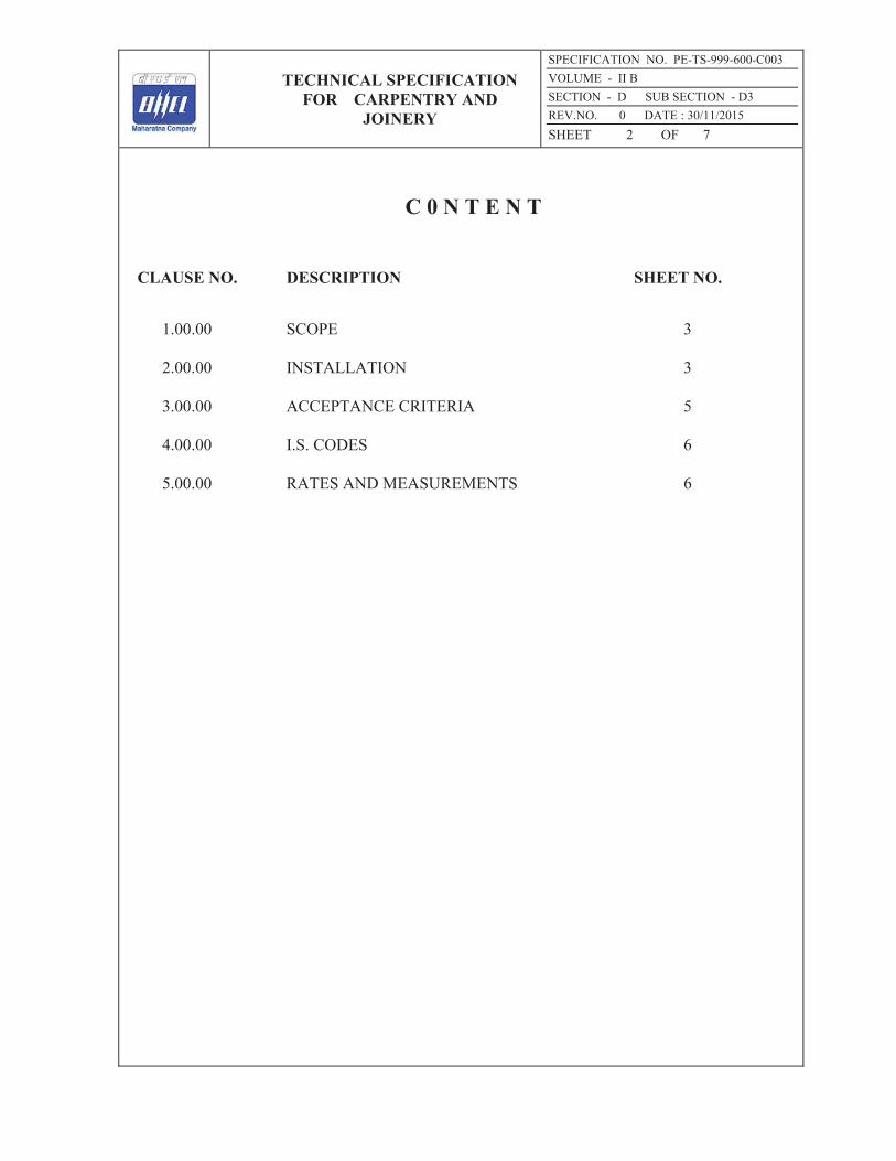
TECHNICAL SPECIFICATION FOR CARPENTRY AND
JOINERY
SPECIFICATION NO. PE-TS-999-600-C003 VOLUME - II B SECTION - D SUB SECTION - D3 REV.NO. 0 DATE : 30/11/2015 SHEET 2 OF 7
C 0 N T E N T
CLAUSE NO. DESCRIPTION SHEET NO.
1.00.00 SCOPE 3
2.00.00 INSTALLATION 3
3.00.00 ACCEPTANCE CRITERIA 5
4.00.00 I.S. CODES 6
5.00.00 RATES AND MEASUREMENTS 6

TECHNICAL SPECIFICATION FOR CARPENTRY AND
JOINERY
SPECIFICATION NO. PE-TS-999-600-C003 VOLUME - II B SECTION - D SUB SECTION - D3 REV.NO. 0 DATE : 30/11/2015 SHEET 3 OF 7
CARPENTRY AND JOINERY
1.00.00 SCOPE
This section covers supply, fitting and fixing of timber frames to doors and windows with M S holdfasts, flush doors, windows, shutters, partitions, wall panelling, pelmets, shelves, furniture, etc. as shown in drawings, including a prime coat of approved paint, varnish, or fixing of decorative plastic laminate where called for. This shall also include the supply and fixing of all hardware and fixtures shown in drawing or specified.
2.00.00 INSTALLATION
2.00.01 Materials
a) Timber
Unless otherwise specified, all timber shall be best quality well seasoned CP teakwood free from large or loose knots, cracks or any other defects. All timber shall be treated with approved wood preservative before use, unless specified otherwise. The rough timber shall be approved by the Engineer before incorporating in the works and starting the carpenter’s work.
b) Plywood
Plywood shall be of commercial quality or with decorative surface veneer. Unless specifically permitted otherwise, the adhesive used in plywood shall be phenol formaldehyde synthetic resin of BWP grade conforming to IS: 848.
c) Decorative Laminated Plastic Sheets
The colour, pattern, finish and texture shall be approved by the Engineer. The bulk supply shall be procured in full sheet sizes which will ensure the least number or joints in one surface.
d) Flush Doors
Flush doors shall be solid core doors with commercial or decorative faces and hardwood edges conforming to IS: 2202 (Part-1). The core for solid core doors shall be of block board or wood particle board. Manufacturer's literature and test certificates shall be submitted for the approval of the Engineer. The Contractor shall give a guarantee that the adhesive used is BWP grade phenol formaldehyde synthetic resin conforming to IS: 848. The thickness shall be as specified.

TECHNICAL SPECIFICATION FOR CARPENTRY AND
JOINERY
SPECIFICATION NO. PE-TS-999-600-C003 VOLUME - II B SECTION - D SUB SECTION - D3 REV.NO. 0 DATE : 30/11/2015 SHEET 4 OF 7
e) Panel Doors
Panel door shall be of teakwood shutter frame, unless otherwise noted and panels with teakwood/commercial ply/teakwood particle board. Other considerations shall be as mentioned in item (d) above.
f) Windows, Ventilators
Windows and ventilators shall made of teakwood shutter frame, unless specified otherwise and glazing of specified thickness shall be fixed with wooden beadings.
g) Fixtures
Fixtures for doors, windows, furniture etc. shall be as shown on drawing or specified.
2.02.00 Workmanship
2.02.01 General
The work shall be done by skilled carpenters as per details shown on drawing or instructed by the Engineer.
Framing timber and other work shall be close - fitting with proper wood joinery, accurately set to required lines or levels and rigidly secured in place. The surface of frames etc., which will come in contact with masonry after fixing, shall be given two coats of approved paint before fixing. Mastic caulking shall be done after fixing external door and window frames. Special care shall be taken to match the grain of timber or plywood, which will be subsequently polished. Screwing or nailing will not be permitted to the edge of plywood and particle board. The edge of all plywood, blackboard and particle board shall be finished with teakwood lipping unless otherwise shown on drawings.
Fixing to frames and partitions shall generally be with 40 mm x 6 mm x 300 mm long M S holdfasts bifurcated at end and grouted with 1:2:4 cement concrete. The gap between masonry and external door and window frame shall be caulked with polysulphide mastic. M.S. grills or guard bars shall be provided to windows where called for in the drawings.

TECHNICAL SPECIFICATION FOR CARPENTRY AND
JOINERY
SPECIFICATION NO. PE-TS-999-600-C003 VOLUME - II B SECTION - D SUB SECTION - D3 REV.NO. 0 DATE : 30/11/2015 SHEET 5 OF 7
2.02.02 Finish
All carpentry work after finishing shall be sand papered smooth. A prime coat paint shall be given after inspection of the Engineer to all surfaces other than those, which shall be subsequently polished or covered with laminated plastic sheet.
2.02.03 Surface Treatment
When shown on drawings or called for, decorative ply or laminated plastic sheets shall be bonded under pressure to the surface to be finished. The adhesive used shall be of brand and brought to site in sealed containers. The rate of application and the length of time for which the pressure is to be applied shall be as per the manufacturer's instructions. The edge of sheets shall be protected by teak lipping or bevelled as shown on drawings.
3.00.00 ACCEPTANCE CRITERIA
3.00.01 Door and Window Frames
All frames shall be square and flat at the time of delivery and shall be checked for dimensions and corner angles. After fixing they shall be on a fine vertical plane. All external door and window frames shall be caulked with mastic.
3.02.00 Door and Window Shutters
All doors and window shutters shall be of proper size, shape, and design and free of warp. When fixed to frames, these shall operate smoothly without jamming and all latching or locking devices shall engage properly without undue pressure.
3.03.00 Partitions, Paneling, Pelmets, Furniture, etc.
3.03.01 General
These shall conform to drawings in all details. No unsightly nail marks etc. shall be permitted. Plywood grains shall be matched to give a uniform and pleasing appearance.
3.03.02 Partition
Shall be checked for rigidity of fixing, plumb and horizontal as well as vertical alignment.

TECHNICAL SPECIFICATION FOR CARPENTRY AND
JOINERY
SPECIFICATION NO. PE-TS-999-600-C003 VOLUME - II B SECTION - D SUB SECTION - D3 REV.NO. 0 DATE : 30/11/2015 SHEET 6 OF 7
3.03.03 Pelmets
Shall be checked for rigidity of fixing and adequate clearance of fixture.
3.03.04 Cupboard Shutters
Shall operate smoothly without jamming and locks, bolts and double ball catches shall engage securely. Single ball catches shall not be used.
3.03.05 Drawers
Shall operate smoothly and have backstops to prevent them from being pushed too far. Locks shall engage securely.
3.03.06 Loose Furniture
When placed on a level surface, tables tops etc. shall be horizontal and the pieces stand stably on legs or supports.
4.00.00 IS CODES
All work shall be carried out as per this specification and shall conform to the latest revision and/or replacements of the following or any other Indian Standard (IS) Codes, unless specified otherwise. In case any particular aspect of work is not specifically covered by Indian Standard Codes, any other standard practice, as may be specified by the Engineer, shall be followed.
IS: 848 - Synthetic resin adhesives for plywood (Phenolic and Aminoplastic)
IS: 1003 - Timber panelled and glazed shutters.
IS: 2191 - Wooden flush door shutter (Cellular and hollow core type).
IS: 2202 - Wooden flush door shutters (solid core type).
IS: 4021 - Timber door, window, and ventilator frames.
5.00.00 RATES AND MEASUREMENT
5.01.00 Rates
Rates shall include of all activities mentioned in “Schedule of Item” for completion of the work. No separate payment shall be made for fixing, caulking, application of primer coat, polishing, providing of butt hinges,

TECHNICAL SPECIFICATION FOR CARPENTRY AND
JOINERY
SPECIFICATION NO. PE-TS-999-600-C003 VOLUME - II B SECTION - D SUB SECTION - D3 REV.NO. 0 DATE : 30/11/2015 SHEET 7 OF 7
holdfasts, sliding/tower bolts, door stoppers, door closers and other fittings and fixtures.
5.02.00 Measurement
Measurement shall be done in Sqm for doors, windows, ventilators, shutters, partitions etc.
Measurement for wooden frame shall be in CuM.
Pelmets shall be measured in RM.

TECHNICAL SPECIFICATION FOR ROOF AND UNDERGROUND
STRUCTURES WATER PROOFING, INSULATION AND ALLIED WORKS
SPECIFICATION NO. PE-TS-999-600-C004
VOLUME - II B
SECTION - D SUB SECTION - D4
REV.NO. 0 DATE : 30/11/2015
SHEET 1 OF 14
VOLUME: II B
SECTION – D
SUB-SECTION – D4
ROOF AND UNDERGROUND STRUCTURES WATER PROOFING, INSULATION AND ALLIED WORKS
SPECIFICATION NO. PE-TS-999-600-C004
Bharat Heavy Electricals Limited Project Engineering Management
PPEI Building, Power Sector, Plot No. 25, Sector 16A,
Noida (U.P.)-201301

TECHNICAL SPECIFICATION FOR ROOF AND UNDERGROUND
STRUCTURES WATER PROOFING, INSULATION AND ALLIED WORKS
SPECIFICATION NO. PE-TS-999-600-C004
VOLUME - II B
SECTION - D SUB SECTION - D4
REV.NO. 0 DATE : 30/11/2015
SHEET 2 OF 14
C 0 N T E N T
CLAUSE NO. DESCRIPTION SHEET NO.
1.00.00 SCOPE 3 2.00.00 INSTALLATION 3 3.00.00 ACCEPTANCE CRITERIA AND GUARANTEE 12 4.00.00 I.S. CODES AND STANDARDS 12 5.00.00 RATES AND MEASUREMENTS 13

TECHNICAL SPECIFICATION FOR ROOF AND UNDERGROUND
STRUCTURES WATER PROOFING, INSULATION AND ALLIED WORKS
SPECIFICATION NO. PE-TS-999-600-C004
VOLUME - II B
SECTION - D SUB SECTION - D4
REV.NO. 0 DATE : 30/11/2015
SHEET 3 OF 14
ROOF AND UNDERGROUND WATER PROOFING,
INSULATION AND ALLIED WORKS 1.00.00 SCOPE
This section covers furnishing, installation, repairing, finishing, curing, testing, protection, maintenance till handing over of roof and underground water-proofing, insulation and allied works for buildings and at locations covered under the scope of this package.
2.00.00 INSTALLATION 2.01.00 GRADING UNDERBED
The surface to receive the underbed shall be roughened and thoroughly cleaned with wire brush and water. Oil patches if any shall be removed with detergent. The surface shall be soaked with water and all excess water removed just before laying of the underbed. The underbed shall not be laid under direct hot sun and shall be kept in shade immediately after laying so as to avoid quick loss of water from the mix and separation from the roof surface. The underbed shall be cured under water for at least 7 days. The underbed shall be laid to provide an ultimate run off gradient not less than 1 in 120 and as directed by the Engineer. Upto an average thickness of 25mm the underbed shall usually be composed of cement and sand plaster. For higher thickness the underbed shall be made with cement concrete. The underbed shall be finished to receive the waterproofing treatment direct or insulation as the case may be.
2.01.01 Cement Mortar Underbed
The underbed grading plaster shall be average 25 mm thick maximum. It shall consist of cement and coarse sand in the ratio 1:4 nominal by volume. The sand and cement shall be thoroughly mixed dry and then water added. Each batch of mix shall be consumed before the initial set starts. The plaster shall be fully compacted to the desired grade in continuous operation. The surface shall be even and reasonably smooth.
2.01.02 Cement Concrete Underbed
The underbed cement concrete shall be used where the subgrade is more than average 25 mm thick. It shall consist of cement concrete 1:2:4 nominal mix

TECHNICAL SPECIFICATION FOR ROOF AND UNDERGROUND
STRUCTURES WATER PROOFING, INSULATION AND ALLIED WORKS
SPECIFICATION NO. PE-TS-999-600-C004
VOLUME - II B
SECTION - D SUB SECTION - D4
REV.NO. 0 DATE : 30/11/2015
SHEET 4 OF 14
by volume with 12 mm down stone chips and coarse sand. The aggregate shall be mixed dry and minimum quantity of water shall be added to make the mix workable. The mix shall be laid to proper grade, fully consolidated and surface shall be smooth and even.
2.02.00 INSULATION
The Tenderer shall, along with the tender, send specifications of insulating materials he proposes to use and the proposed method of laying. Before bulk supply, the contractor shall send samples of insulating material to the Engineer, and after approval of the samples, the Contractor shall procure and transport the bulk material to the site. Whenever asked by the Engineer, the Contractor shall furnish test certificates from testing laboratory on the insulating and other properties of the materials.
After laying the insulation, the surface shall be made ready as required to receive the waterproofing treatment. If any plastering is used it shall be not leaner than 1:4 cement sand by volume and not thinner than 12 mm and it shall be cured for seven days.
2.02.01 Foam Concrete
This shall be of lightweight foam concrete of average 50 mm thickness or as specified or as shown on drawings. This may be laid in situ in suitable panels or precast blocks. The insulating properties shall be such that the thermal conductivity shall not exceed 0.125 Kcl/sq.m. hr degree C. Before starting the laying of foam concrete samples shall be prepared at site and got tested for approval of the Engineer.
The foam concrete laid shall be sufficiently strong to withstand the usual workload and standard loads expected on the roof. Any damaged portion shall be removed and replaced forthwith. Approval of the Engineer shall be taken before laying the waterproofing over the insulation. While laying the foam concrete, samples from each batch of the mix shall be kept for test if so desired by the Engineer.
2.02.02 Expended Polystyrene Blocks
The expanded polystyrene block Insulation shall be fire retardant quality and shall have a maximum thermal conductivity of 0.026 Kcl m/sq.m h C. It must be strong enough to withstand without any deformation under the workload and standard loads expected on the roof.

TECHNICAL SPECIFICATION FOR ROOF AND UNDERGROUND
STRUCTURES WATER PROOFING, INSULATION AND ALLIED WORKS
SPECIFICATION NO. PE-TS-999-600-C004
VOLUME - II B
SECTION - D SUB SECTION - D4
REV.NO. 0 DATE : 30/11/2015
SHEET 5 OF 14
The Contractor shall lay the expanded polystyrene block as per manufacturer’s approved specification. Only specifically experienced workers shall be used for this work. If the Engineer is not satisfied about the efficiency of the workers the Contractor shall secure manufacturers supervision at no extra cost to the Owner.
2.03.00 Fillets
Fillets at Junction of roofs and vertical walls shall be provided with the same insulating material as provided for the main roof insulation. The fillets shall be 150 mm x 150 mm in size unless otherwise shown on drawings or instructed by the Engineer. Where there is no insulation over roof slab, fillets shall be cast-in-situ cement concrete (1:2:4) nominal mix volume.
2.04.00 Waterproofing Treatment 2.04.01 Bitumen Felt Treatment
Waterproofing treatment shall be laid by a specialist firm with long experience in the particular trade. The waterproofing treatment for roofs with bitumen felts shall be done following relevant IS: 1346. Bitumen felt shall conform to IS: 1322 and Bitumen primer to IS: 3384. The bonding materials shall consist of blown type conforming to IS: 702 or residual bitumen conforming to IS: 73 or a mixture of the two to withstand local conditions of prevailing temperature or gradient of roof surface. The Contractor shall convince the Engineer that the bonding material proposed to be used is suitable for the particular job. The Contractor shall state the source from where he proposed to procure the materials. Samples of the self-finished felt shall be submitted in advance to the Engineer along with test certificates for his review. Test certificates for the bonding materials shall also be submitted and samples, if desired by the Engineer, shall be provided for confirmatory tests. Samples shall be submitted if instructed by the Engineer. Minimum overlaps of 100 and 75 mm shall be given at the end and sides of strips of felt and properly bonded with bitumen. Joints in successive layers of felt shall be staggered. Normal treatment with one layer of felt, heavy treatment with two lavers of felt or Extra Heavy treatment with three layers of felt shall be indicated. Brief details of the various treatments shall be as follows:

TECHNICAL SPECIFICATION FOR ROOF AND UNDERGROUND
STRUCTURES WATER PROOFING, INSULATION AND ALLIED WORKS
SPECIFICATION NO. PE-TS-999-600-C004
VOLUME - II B
SECTION - D SUB SECTION - D4
REV.NO. 0 DATE : 30/11/2015
SHEET 6 OF 14
a) Normal Treatment - Five courses
1) Primer coat conforming to IS:3384 applied at the rate 0.27lits/sqm min. 2) Hot applied bitumen at the rate of 1.2 kg/sq.m. (min.) 3) Hessian base self finished felt, type 3, grade 1. 4) Hot applied bitumen at the rate of 1.2 kg/sq.m. (min.) 5) 20 mm thick pressed precast concrete tiles with 15 mm, thick 1:4
cement-sand mortar underbed. b) Heavy Treatment - Seven Courses
With Hessian base felt
1) Primer coat conforming to IS:3384 applied at the rate 0.27lits/sqm min.
2) Hot applied bitumen at the rate of 1.2 kg/sq.m (Min.) 3) Hessian base self-finished felt, type 3, grade 1. 4) Hot applied bitumen at the rate of 1.2 kg/sq.m (Min.) 5) Hessian base self-finished felt, type 3, grade I.
6) Hot applied bitumen at the rate of 1.2 kg/sq.m (Min.) 7) 20 mm thick pressed precast concrete tiles with 15 mm thick 1:4
cement: sand mortar underbed.
or With fiber base felt
1) Primer coat conforming to IS:3384 applied at the rate 0.27lits/sqm
min. 2) Not applied bitumen at the rate of 1.2 kg/sq.m (Min.) 3) Fiber base self-finished felt, type 2, grade 2. 4) Hot applied bitumen at the rate of 1.2 kg/sq.m (Min.) 5) Fiber base self-finished felt, type 2, grade 2.

TECHNICAL SPECIFICATION FOR ROOF AND UNDERGROUND
STRUCTURES WATER PROOFING, INSULATION AND ALLIED WORKS
SPECIFICATION NO. PE-TS-999-600-C004
VOLUME - II B
SECTION - D SUB SECTION - D4
REV.NO. 0 DATE : 30/11/2015
SHEET 7 OF 14
6) Hot applied bitumen at the rate of 1.2 kg/sq.m (Min.) 7) 20 mm thick pressed precast concrete tiles with 15 mm thick 1:4 cement: sand mortar underbed.
c) Extra Heavy Treatment – Nine courses
With fiber based felt
1) Primer coat conforming to IS:3384 applied at the rate 0.27lits/sqm
min. 2) Hot applied bitumen at the rate of 1.2 kg/sqm. (min.) 3) Fiber-base self-finished felt type 2, grade 1. 4) Hot applied bitumen at the rate of 1.2 kg/sq.m (min.)
5) Fibre base self-finished felt type 2, grade 1. 6) Hot applied bitumen at the rate of 1.2 kg/sqm. (min.) 7) Fibre base self-finished felt type 2, grade 1.
8) Hot applied bitumen at the rate of 1.2 kg/sqm. (min.) 9) 20 mm thick pressed precast concrete tiles with 15 mm thick 1:4
cement: sand mortar underbed.
or
With Hessian base felt 1) Primer coat conforming to IS:3384 applied at the rate 0.27lits/sqm min. 2) Hot applied bitumen at the rate of 1.2 kg/sqm. (min.) 3) Hessian base self-finished felt, type 3, grade 1. 4) Hot applied bitumen at the rate of 1.2 kg/sqm. (min.) 5) Hessian base self-finished felt, type 3, grade 1. 6) Hot applied bitumen at the rate of 1.2 kg/sqm. min. 7) Hessian base self-finished felt, type 3, grade 1.

TECHNICAL SPECIFICATION FOR ROOF AND UNDERGROUND
STRUCTURES WATER PROOFING, INSULATION AND ALLIED WORKS
SPECIFICATION NO. PE-TS-999-600-C004
VOLUME - II B
SECTION - D SUB SECTION - D4
REV.NO. 0 DATE : 30/11/2015
SHEET 8 OF 14
8) Hot applied bitumen at the rate of 1.2 kg/sqm. min. 9) 20 mm thick pressed precast concrete tiles with 15 thick 1:4 cement:
sand mortar underbed. However, in special cases, more courses, or a combination of fibre base and hessian base felts may be asked for. The surface to receive the waterproofing treatment must be cleaned and dried satisfactorily and the Engineer's approval taken before starting the work. If any existing waterproofing treatment is being augmented the existing top course shall be completely removed and all damaged felts or other defects repaired. The Engineer may instruct the Contractor to lay part of the stipulated courses at the first instant to be followed later on with the balance courses. This interim finish shall be done with a course of hot applied bitumen. While doing the balance again hot bitumen shall be applied to start with after repair of all damages to the already laid course. After completion the surface shall be cleaned taking care that felt cuttings etc. do not find their way into rainwater down comers.
2.04.02 Elastomeric Membrane
a) Material The material shall consist of high solid content Polyurethane based cold liquid applied coatings as per ASTMC836-89a comprising of urethane pre-polymers extended with flexible material, which cure by reaction with atmospheric moisture to give a continuous film which is rubbery and elastic or any other equivalent material permitted as per ASTM and approved by the Engineer. The material shall consist of high solid coating designed to give a high-build film. The material shall not be diluted. The coating shall have physical feature like high viscosity, 90% solids, high resistance to impact, abrasion and cracking, superior tensile strength, application limit of 700C minimum, 300% elongation and forming a perfectly smooth permanently flexible seamless membrane which should have good adhesion to roof substrates (RCC, tiles, brick, and metals), having a minimum life of 10 years. It should also be resistant to acid (mild concentrated), alkalies and have a very low water absorption rate (0.5%) max. at ambient temp. after 7 days. The pack shall not be older than 9 months after the date of manufacture and packing.

TECHNICAL SPECIFICATION FOR ROOF AND UNDERGROUND
STRUCTURES WATER PROOFING, INSULATION AND ALLIED WORKS
SPECIFICATION NO. PE-TS-999-600-C004
VOLUME - II B
SECTION - D SUB SECTION - D4
REV.NO. 0 DATE : 30/11/2015
SHEET 9 OF 14
b) Primer coat It shall consists of polyurethane (P.U.) or any other equivalent material. Primer coat shall be a special blend of moisture curing urethane pre-polymers in solvent. A single coat of this primer shall be applied by brush over the prepared bed as an adhesion coat of an application rate of minimum 6 sq.m per litre. The primer shall be allowed to dry for minimum of 2hrs. time before the successive finishing coats of P.U. liquid membrane are applied. c) Finishing coats : The finishing coats shall consist of two successive liquid coatings of high solids content urethane pre-polymers or equivalent material to form an elastomeric membrane. The overall dry film thickness shall be 1.5mm subject to minimum 500 gm per sq.m per coat application rate. Each coat shall be allowed to dry for minimum 12 hours before applying the next coat. The surface should be dry and smooth before application. The coating shall be continued up the parapets/walls for a minimum of 150mm over the finished roof surface. It shall be continued into rain water pipes by atleast 100mm. The final coat of P.U. liquid when tacky shall be sprinkled with the sand. For edges, expansion joints and any vulnerable points a later of polyscrim cloth /fabric to be embedded between 2 finishing coats. d) Surface Finish : Areas of roof treatment which are vulnerable to accidental damage shall be provided with wearing course consist of minimum 20 mm thick PCC of Grade M15 (using12.5mm size aggregate) cast in panel of maximum size of 1.20m x 1.20m and reinforced with 0.56mm diameter galvanised chicken wire mesh and sealing of joints using sealant or elastomeric compound. When the roof surface is subjected to foot traffic or used as a working area, a cement mortar (1:4) shall be applied over the top most layer of roofing treatment. Over this, a layer of chequered cement concrete flooring tiles conforming to IS:13801 shall be provided in place of stone grit and cement painted. The tiles shall be laid as per IS:1443.

TECHNICAL SPECIFICATION FOR ROOF AND UNDERGROUND
STRUCTURES WATER PROOFING, INSULATION AND ALLIED WORKS
SPECIFICATION NO. PE-TS-999-600-C004
VOLUME - II B
SECTION - D SUB SECTION - D4
REV.NO. 0 DATE : 30/11/2015
SHEET 10 OF 14
2.04.03 Waterproofing By Epoxy Resin Based Application Exposed surfaces of cement concrete, lime concrete or brickwork to be treated for waterproofing by the resin-based application shall be thoroughly cleaned and the epoxy resin based material to be applied as directed by the manufacturer. The material shall not have any adverse effect on the surface on which it is applied and must stick to it uniformly to make a strong durable bond. It shall not be affected by short duration fire, sun exposure, and light duty traffic. The application shall be resistant to growth of fungus and proof against saltpetre action. If desired by the Engineer, a sample shall be prepared in advance and tested for waterproofness for 48 hours under 300 mm depth of standing water. The Contractor shall arrange the demonstration by providing free the materials and labour for the application as free of cost to Owner. This item shall carry a guarantee as specified.
2.04.04 Flashing Unless otherwise stated flashing shall be done in the same way as the waterproofing except that the last layer shall be finished with two coats of bituminous primer. The flashing shall be extended up the vertical surfaces as shown on drawing. The flashing shall end in grooves in vertical walls. The grooves shall be at leas 65 mm deep and caulked with waterproof mastic cement. The minimum overlap with horizontal roofing felt shall be 100 mm. Where specified or directed by the Engineer, metal flashing shall be provided. The materials shall be 18 Gage or 22 G G.I. sheets, as specified or as directed by the Engineer.
2.05.00 WATER-PROOFING OF UNDERGROUND STRUCTURES
Basements, ducts, pits, tunnels (excluding tanks) etc below the ground water table and in contact with soil are covered under this. Bonding material shall be blown bitumen of 65/25 grade conforming to IS: 702. Waterproofing shall be provided on the outside of walls and top of RCC slab and shall be carried out upto 150mm above ground level. The number of layers of bitumen felt to be used for walls and floor unless otherwise shown in the drawing shall be: a) 2 layers - for depths up to 5m below ground level b) 3 layers - for depths beyond 5m below ground level
2.05.01 Method of laying the bitumen felts and workmanship shall be as per IS: 1609
and IS: 3067. Water proofing work shall be taken in hand only when the sub-soil water level is at its lowest; the site shall be kept dry by adequate arrangements for pumping out water till the work has been completed.

TECHNICAL SPECIFICATION FOR ROOF AND UNDERGROUND
STRUCTURES WATER PROOFING, INSULATION AND ALLIED WORKS
SPECIFICATION NO. PE-TS-999-600-C004
VOLUME - II B
SECTION - D SUB SECTION - D4
REV.NO. 0 DATE : 30/11/2015
SHEET 11 OF 14
For this purpose drains shall be formed along the edges of the excavation but beyond the building line, with suitable collecting sumps. In case of large excavation areas where it is necessary to dewater under the floor, additional land drains shall be formed across the excavation, to adequately drain the area. Adequate arrangement shall be made to protect the sides of excavation from slipping while the work is in progress. The base concrete or mud-mat shall be rendered smooth by a 20mm thick sand-cement plaster (6:1). Any sharp edges/corners, over which the waterproofing course is to be laid, shall be eased out by means of cement. The surface must be dry before the next operation is carried out. Water proofing/damp proofing treatment:
A) Heavy Treatment (Two layers of felt)
i) Primer (For vertical faces only), as per I.S. 3384. ii) Hot applied blown bitumen at the rate of 1.2 Kg/m2 iii) Hessian base, bitumen felt type 3 grades 2 iv) Hot applied blown bitumen @ 1.2 Kg/m2
v) Hessian base, bitumen felt type 3 grade 2 vi) Hot applied blown bitumen @ 1.2 Kg/m2
B) Extra Heavy treatment (Three layers of felt)
i) Primer (for vertical faces only) as per I.S. 3384 ii) Hot applied bitumen at the rate of 1.2 Kg/m2 iii) Hessian base bitumen felt type 3 grades 2 iv) Hot applied bitumen at the rate 1.2 Kg/m2 v) Hessian base bitumen felt type 3 grades 2 vi) Hot applied bitumen at the rate of 1.2 Kg/m2

TECHNICAL SPECIFICATION FOR ROOF AND UNDERGROUND
STRUCTURES WATER PROOFING, INSULATION AND ALLIED WORKS
SPECIFICATION NO. PE-TS-999-600-C004
VOLUME - II B
SECTION - D SUB SECTION - D4
REV.NO. 0 DATE : 30/11/2015
SHEET 12 OF 14
vii) Hessian base bitumen felt type 3 grades 2 viii) Hot applied bitumen at the rate of 1.2 Kg/m2
The surface must be dry before the next operation is carried out at each stage said above. The laying of felt over the bitumen so applied that it shall always commence on the floor, and shall be carried over to the walls only after treatment of the floor is complete. The minimum over lapping at sides and ends of strips shall be 10cm. Point for subsequent layers completely sealed by blow lamp. A protective flooring of either brick flat in cement mortar (1:3) or 6cm thick cement concrete (M 15) or a coat of cement plaster (1:3) 4 cm thick shall be constructed over the bitumen layers to prevent damage to the latter during subsequent construction of the structural floor. The walls shall be treated in a similar way; the bitumen felts joining at the base with the projecting felt laid over the mud-mat. The wall surface shall be made smooth where necessary with a coat of cement plaster (1:3), the felts laid as for the floor, ensuring that the surface to be treated is dry and then a protective brick wall, 12.5 cm nominal thickness shall be built in cement mortar (1:3) over the projecting mud-mat, the space between the wall and felt being grouted with cement.
3.00.00 ACCEPTANCE CRITERIA AND GUARANTEE The surface level shall be such as to allow quick draining of rains without leaving any pool anywhere. The finishing course shall be fully secured and shall have an even density. There shall not be any bubble formation or crushed or squeezed insulation or underbed. The contractor shall give a guarantee in writing for all works executed under this specification supplemented by a separate and unilateral guarantee from the specified agency for the roof waterproofing treatment work. The guarantee shall be for materials and workmanship as under: For Bitumen Felt Treatment under clause no. 2.04.01: 5 years in case of normal treatment, 10 years for heavy treatment and 20 years for extra heavy treatment. For Elastomeric Membrane under clause no. 2.04.02: 10 (ten) years In case guarantee is more stringent in owner specification, more stringent guarantee shall be applicable. The mode of execution of the guarantee shall be such, which shall be acceptable to the Owner.

TECHNICAL SPECIFICATION FOR ROOF AND UNDERGROUND
STRUCTURES WATER PROOFING, INSULATION AND ALLIED WORKS
SPECIFICATION NO. PE-TS-999-600-C004
VOLUME - II B
SECTION - D SUB SECTION - D4
REV.NO. 0 DATE : 30/11/2015
SHEET 13 OF 14
4.00.00 I.S. CODES AND STANDARDS All work shall be carried out as per this specification and shall conform to the latest revision and/or replacements of the following or any other Indian Standard (IS) Codes, unless specified otherwise. In case any particular aspect of work is not specifically covered by Indian Standard Codes, any other standard practice, as may be specified by the Engineer, shall be followed. a) IS: 73 - Paving Bitumen b) IS: 702 - Industrial Bitumen c) IS: 1203 - Methods of testing tar and bitumen d) IS: 1322 - Bitumen felts for waterproofing and damp proofing. e) IS: 1346 - Code of practice for waterproofing of roofs with
bitumen felts.
f) IS: 1609 - Damp-proofing Treatment using Bitumen Felts – Code of Practice
g) IS: 3067 - Code of practice for General design details and
preparatory work for Damp-proofing and water-proofing of buildings
h) IS: 3384 - Bitumen primer for use in waterproofing and damp proofing.
5.00.00 RATES AND MEASUREMENT 5.01.00 Rates
Rates shall be for complete work, including the cost of all materials and labour, as detailed in the specification unless any portion is specifically excluded in the “Schedule of Items”. No extra shall be paid for finishing around opening, sleeves, pipes, ducts, inserts, etc. No separate payments shall be made for cleaning of surface, treating of cracks and surface preparation.
5.02.00 Measurement
The finished work shall be measured in Sqm of actual surface area for the purpose of payment.

TECHNICAL SPECIFICATION FOR ROOF AND UNDERGROUND
STRUCTURES WATER PROOFING, INSULATION AND ALLIED WORKS
SPECIFICATION NO. PE-TS-999-600-C004
VOLUME - II B
SECTION - D SUB SECTION - D4
REV.NO. 0 DATE : 30/11/2015
SHEET 14 OF 14
No deduction shall be made and no extra shall be paid for openings upto 0.4 sqm.

TITLE: TECHNICAL SPECIFICATION FOR METAL DOORS, WINDOWS, VENTILATORS, LOUVERS ETC.
SPECIFICATION NO. PE-TS-999-600-C005 VOLUME - II B SECTION - D | SUB-SECTION – D5 REV.NO. 00 DATE 22/04/2016 SHEET 1 OF 15
VOLUME: II B
SECTION - D
SUB-SECTION – D5
METAL DOORS, WINDOWS, VENTILATORS, LOUVERS ETC.
SPECIFICATION NO. PE-TS-999-600-C005
Bharat Heavy Electricals Limited Project Engineering Management
PPEI Building, Power Sector, Plot No. 25, Sector 16A,
Noida (U.P.)-201301

TITLE: TECHNICAL SPECIFICATION FOR METAL DOORS, WINDOWS, VENTILATORS, LOUVERS ETC.
SPECIFICATION NO. PE-TS-999-600-C005 VOLUME - II B SECTION - D | SUB-SECTION – D5 REV.NO. 00 DATE 22/04/2016 SHEET 2 OF 15
C 0 N T E N T
CLAUSE NO. DESCRIPTION SHEET NO.
1.00.00 SCOPE 3
2.00.00 INSTALLATION 3
3.00.00 ACCEPTANCE CRITERIA 8
4.00.00 INFORMATION TO BE SUBMITTED 9
5.00.00 I.S. CODES 10
6.00.00 RATES AND MEASUREMENTS 10
ATTACHMENT
ANNEXURE – A SCHEDULE OF FIXTURES 12

TITLE: TECHNICAL SPECIFICATION FOR METAL DOORS, WINDOWS, VENTILATORS, LOUVERS ETC.
SPECIFICATION NO. PE-TS-999-600-C005 VOLUME - II B SECTION - D | SUB-SECTION – D5 REV.NO. 00 DATE 22/04/2016 SHEET 3 OF 15
METAL DOORS, WINDOWS, VENTILATORS, LOUVERS ETC.
1.00.00 SCOPE
This section covers supplying and/or erecting and installing of all metal doors, windows, ventilators, louvers, glazed partitions, etc. The scope of work shall also include the assembly and erection of all doors, windows, louvers, glazed partitions, etc. Supplying and/or fixing of all door and window accessories and hardware are also included in the scope.
2.00.00 INSTALLATION
2.01.00 Materials
Steel sections used for fabrication of doors, windows etc. shall be standard rolled steel sections specified in IS: 1038 and IS: 1361 or as specified.
Steel sheets for frames, shutters, louver blades etc. shall be of gauge mentioned in drawings and schedules.
Aluminium sections for fabricating doors, windows, partitions etc. shall be extruded sections conforming to IS:733 or IS:1285 or as manufactured by Indian Aluminium Company Limited or approved equivalent. Aluminium door, windows and ventilator shall be fabricated as per IS:1948 and IS:1949. The alloy used shall conform to IS Designation HE 9-WP of IS: 733.
Hardware and fixtures shall be as specified and the best quality from approved manufacturers shall only be used. The tenderer shall specifically state the particular manufacturer’s materials he proposes to use. Improper alignment or faulty operation due to inadequate strength of hardware or fixture shall entirely be the Contractor’s responsibility.
All hardware and fixtures shall be able to withstand repeated use. Door closures shall conform to IS: 3564 and shall be suitable for doors weighing 61-80 Kg. unless otherwise stated. Each closer shall be guaranteed against manufacturing defect for one year and any defect found within this period shall be rectified or shall be replaced free of charge. Concealed door closers shall be either floor mounted or transom mounted, suitable for installation with metal doors. It shall conform to the performance Requirements and endurance test stated in IS: 3564 - Appendix-A. The Contractor shall submit samples of each type of hardware to the Engineer. The approved samples shall be retained by the Engineer for comparison of bulk supply. The samples shall be returned to the Contractor towards end for incorporation in the job. The mastic for caulking shall be of best quality from a manufacturer approved by, the Engineer. In general, mastic for fixing of metals frames shall be as per IS: 1081 or as approved by the Engineer.

TITLE: TECHNICAL SPECIFICATION FOR METAL DOORS, WINDOWS, VENTILATORS, LOUVERS ETC.
SPECIFICATION NO. PE-TS-999-600-C005 VOLUME - II B SECTION - D | SUB-SECTION – D5 REV.NO. 00 DATE 22/04/2016 SHEET 4 OF 15
2.02.00 Fabrication
2.02.01 Steel Doors, Windows, Ventilators, louvers etc.
a) Door Frames
Frames shall be fabricated from 16 gage(G) sheets. They shall, be mortised, reinforced, drilled, and tapped for hinge lock and bolt strikes. Where necessary, frames shall be reinforced for door closers. Welded construction with mitered Corners shall be used. Rubber door silencers shall be furnished for the striking jamb. Loose “T” masonry anchors shall be provided. Frames shall finish flush with floor and adjustable floor anchors shall be installed. Frames shall be brought to site with floor ties/weather bars installed in, place.
b) Double Plate Flush Door Shutters
Door shutters shall be 45 mm thick, completely flush design and shall comprise of the outer sheets or 18 G steel sheets, rigidly connected and reinforced inside with continuous vertical 20 G stiffeners, spot welded in position at not more than 150 mm on centres.
Both edges of doors shall be joined and reinforced full height by steel channels placed immediately inside and welded to the door faces. Top and bottom of doors shall be reinforced horizontally as shown on drawing by steel channels running full width of door. Doors shall not have more than 2.5 mm clearance at jambs and heads, shall have proper level on lock stiles and rails to operate without binding, and shall be reinforced at corners to prevent sagging or twisting. Pairs or double doors shall have meeting-stile edges bevelled or rebated. Where shown on drawing, or called for in the schedule of items, the doors shall be sound deadened by filling the inside voids with mineral wool or other suitable approved materials.
Doors shall be mortised, reinforced, drilled, and tapped in shop for hinges, locks, and bolts. They shall also be reinforced for closers, push-plates, and other surface hardwares where necessary. Any drilling and tapping required for surface hardware shall be done at site. Where shown drawing, provision shall be made for fixing glazing, vision panels, louvers etc. glazing mouldings shall be of 18 G steel or extruded aluminium sections and suitable for fixing 6 mm. glass. Louvers blades shall be V or Z shaped and made out of 16 G sheets.

TITLE: TECHNICAL SPECIFICATION FOR METAL DOORS, WINDOWS, VENTILATORS, LOUVERS ETC.
SPECIFICATION NO. PE-TS-999-600-C005 VOLUME - II B SECTION - D | SUB-SECTION – D5 REV.NO. 00 DATE 22/04/2016 SHEET 5 OF 15
c) Single Sheet Door Shutters
Single sheet doors shall be made from best quality 18 G mild steel sheets, and shall present a flush surface on the outside. The inside shall be stiffened with semi tubular edge and central stiffening rail, which shall convey the lock and other fixture. The frames shall be made from best quality, 16 G mild steel sheets.
Wherever required, provisions for fixing glass panes, louvers etc. shall be made.
The manufacturing shall be done as specified in 2.02.01 (b) “Double Plate Flush Door Shutters.”
d) Sliding Door
Sliding doors shall be either double plate or single plate Construction made out of 18 gauge steel sheets with adequate stiffeners. The contractor shall specify the weight of the door in his shop and submit the manufacturer's catalogue of the sliding gear he proposes to use. Where called for the Contractor shall make provision for openings to the door for monorail beams. Doors shall close positively to exclude rainwater from seeping in. When called for, sliding doors shall withstand specified wind loads without buckling or jamming. The door shall slide freely under all ambient conditions.
e) Door Threshold
Door threshold shall be provided. Doors without threshold shall have bottom tie of approved type.
f) Steel Windows, Sashes, and Ventilators etc.
These shall conform in all respects to IS: 1038 and IS: 1361 latest editions. The details as called for in the above codes shall be applicable for coupling mullions, transoms, weather bars, and pivot arrangements for ventilators, etc. or as called for. All welds shall be dressed flush on all exposed and contact surfaces. Where composite unit openings are required the individual window units shall be joined together with requisite transoms and mullions. All windows shall be outside glazed, fixed with putty or metal glazing beads as specified. Where aluminium glazing beads are specified, they shall be extruded aluminium channel 9.5 mm x 9.5 mm x 1.6 mm (Indal Section No. 2209) unless otherwise shown on drawings. Aluminium beads shall be given one coat of zinc chromate primer before fixing to windows.

TITLE: TECHNICAL SPECIFICATION FOR METAL DOORS, WINDOWS, VENTILATORS, LOUVERS ETC.
SPECIFICATION NO. PE-TS-999-600-C005 VOLUME - II B SECTION - D | SUB-SECTION – D5 REV.NO. 00 DATE 22/04/2016 SHEET 6 OF 15
2.02.02 Aluminium Door, Windows, and Frames
Extruded sections shall have a minimum 3 mm wall thickness. All sections shall be approved by the Engineer before fabrication is taken up. Doors frames, mullions, transom etc. shall be anodized in a bath of sulphuric acid to provide a clear coating of minimum 15 micron thickness. The anodized materials shall then be sealed by immersing in boiling water for 15 minutes. A protective transparent Coating shall be applied to the sections before shipment from the factory.
All work shall be fitted and shop assembled to a first class job, and ready for erection. Shop joints shall be made to hair lines and then welded or braced by such method as will produce an uniform colour throughout the work. Work on the above, other than described, shall be carefully fitted and assembled with neat joints with concealed fasteners. Wherever possible, joints shall be made in concealed locations and on edges of doors. Field connections of all work may be made with concealed screws or other approved type of fasteners. Glazing beads shall be snap fit type without visible screws and shall be of sizes to accommodate 6 mm thick glazing. All work shall be adequately braced and reinforced as necessary for strength and rigidity.
2.03.00 Shop Coat or Paint
The shop Paint for steel doors, windows etc. shall be best lead or zinc chromate primer paint from, approved manufacturer. All surfaces shall be thoroughly cleaned of rust, grease, loose mill scales etc. and given one coat of shop paint. Portions like mullions, transoms etc. that will be inaccessible after assembly of units shall be given an extra coat of paint before assembly.
Where called for, all steel doors, windows, etc. shall be hot dip galvanized to give a coating weight of 1 - 2 oz. per sqft. One coat zinc chromate primer coat shall then be applied as shop paint.
Portions of aluminium frame, which come in contact with masonry construction shall be (before shipment from workshop) protected with a heavy coat of alkali resistant paint. Aluminium coming in contact with other incompatible metals shall be coated with zinc chromate primer.
2.04.00 Handling & Storage of Fabricated Material
All metal doors, windows, etc. shall be packed and crated properly before dispatch, to ensure that there will be no damage to the fabricated materials. Loading into wagons and trucks shall be done with all care to ensure safe arrival of materials at site in undamaged condition.
When taking delivery of items supplied by Owner, the Contractor shall satisfy

TITLE: TECHNICAL SPECIFICATION FOR METAL DOORS, WINDOWS, VENTILATORS, LOUVERS ETC.
SPECIFICATION NO. PE-TS-999-600-C005 VOLUME - II B SECTION - D | SUB-SECTION – D5 REV.NO. 00 DATE 22/04/2016 SHEET 7 OF 15
himself that the items supplied are up to the specified standard. Any defect detected shall promptly be brought to the notice of the Engineer.
All metal doors, windows etc. shall be stored under cover in a way to prevent damage or distortion. Special care shall be taken to prevent staining of aluminium products by rust, mortar etc.
2.05.00 Assembly & Erection at Site
In general, the fixing of steel doors, windows, ventilators, louvers, etc. shall conform to IS: 1081. The Contractor shall assemble and install all steel doors, windows, sashes, fixed metal louvers, etc. including transoms and mullions for composite units in respective places, keening proper “Lines and levels”, and in approved workmanlike manner, to give trouble free and leak-proof installations. Installation shall be done according to instructions of the manufacturer, and/or as approved by the Engineer. If required by the Engineer, the installation shall have to be carried out under the supervision of the manufacturer's staff. The Contractor shall take all precaution against damage of the components during installation. Necessary holes, chases, etc. required for fixing shall be made by the Contractor and made good again as per original, after installation, without any extra charge.
After installation of steel doors, windows, etc. all abrasions to shop-coat of paint shall be retouched and made good the same quality of paint used in shop coat.
All coupling mullions, transoms, frames, etc. in contact with adjacent steel and other members, shall be well bedded in mastic. The Contractor shall bring to the site the cement in original sealed containers of manufacturer and shall apply it as per the instruction. For all frames supplied by either the owner or the Contractor, mastic shall be supplied by the Contractor and caulking done properly as per drawings, specifications and as per instructions of the Engineer.
Door shutters, partitions hardware fixtures etc. shall be fixed only after major equipments have been installed in rooms.
Wherever required, nylon cords of approved quality shall be supplied along with pivoted sashes and shall be of adequate length to terminate one metres from the floor. Loose ends of cords shall end in metal or plastic pull as approved by the Engineer.
2.06.0 Fire proof Door
Fire proof doors shall be provided at all fire exit points as specified and also to restrict the spread of fire within buildings whether from internal fire or from external fire. The construction details of door shall conform to the

TITLE: TECHNICAL SPECIFICATION FOR METAL DOORS, WINDOWS, VENTILATORS, LOUVERS ETC.
SPECIFICATION NO. PE-TS-999-600-C005 VOLUME - II B SECTION - D | SUB-SECTION – D5 REV.NO. 00 DATE 22/04/2016 SHEET 8 OF 15
requirements stipulated in IS:3614(Part-1). Doors shall comply with the testing requirement mentioned in IS:3614 (Part-2). The doors shall be approved by Tariff Advisory Committee and shall have minimum 2 hrs. fire rating.
Metal covered (on both sides) Doors having insulating core filled up with mineral wool shall be used at all fire exit points and shall open out side.
All necessary accessories and hardware shall also be supplied along with doors. Fire proof door shall be provided with zinc silicate primer (minimum DFT 75 micron) after blast cleaning the surface to near white metal surface and shall be finished painted with epoxy based painting.
3.00.00 ACCEPTANCE CRITERIA
3.01.00 For fabricated Items
a) Overall dimensions shall be within ±1.5 mm of the size shown on drawings.
b) Mullions, transoms etc. shall be in one length and permissible deviations from straightness shall be limited to ±1.5 mm from the axis of the member.
c) Door and window shutters shall operate without jamming. The clearance at head and jamb for door shutters shall not exceed 1.5 mm for double leaf doors; the gap at the meeting stiles shall not be more than 1.5 mm.
d) Door leaves shall be undercut where shown on drawings.
e) Doors, windows, frames, etc. shall be on a true planes, free from warp or buckle.
f) All welds shall be dressed flush on exposed and contact surfaces.
g) Correctness of location and smoothness of operations of all shop installed hardware and fixtures
h) Provision for hardware and fixtures to be installed at site.
i) Glazing beads shall be cut with mitered corners.
j) Glazing clips, fixing devices etc. shall be supplied in adequate numbers.
k) Shop coats shall be properly applied.
l) Exposed aluminum surfaces shall be free from scratches, stains, and discoloration. Anodized surfaces shall present a uniform and pleasing look.

TITLE: TECHNICAL SPECIFICATION FOR METAL DOORS, WINDOWS, VENTILATORS, LOUVERS ETC.
SPECIFICATION NO. PE-TS-999-600-C005 VOLUME - II B SECTION - D | SUB-SECTION – D5 REV.NO. 00 DATE 22/04/2016 SHEET 9 OF 15
3.02.00 For installed Items
a) Installations shall be at correct location, elevation and in general, on a true vertical plane.
b) Fixing details shall be strictly as shown on drawings.
c) Assembly of composite units shall be strictly, as per drawings with mastic caulking of transoms and mullions, gaskets, weather strips etc. complete.
d) All frames on external walls shall be mastic caulked to prevent leakage through joint between frames and masonry.
e) All openable section shall operate smoothly without jamming.
f) Locks, fasteners etc. shall be engage positively. Key shall, be non-interchangeable.
g) Cutting to concrete or masonry shall be made good and all abrasions to shop paint shall be touched up with paint of same quality as shop paint.
h) Aluminium doors, windows, etc. shall be free from scratches stain or discoloration.
4.00.00 INFORMATION TO BE SUBMITTED
4.01.00 With Tender
a) Names of manufacturers for Doors, windows etc.
b) Manufacturer's catalogue for all hardware and fixtures proposed to be used.
4.02.00 After Award
a) Before starting fabrication of all metal doors, windows, etc. the Contractor shall submit detailed fabrication drawings to the Engineer for approval. The fabrication shall be started only after approval of drawings.
b) He shall submit a programme of work to be done for the approval of the Engineer.
c) Before bulk supply, he shall submit for the approval of the Engineer samples of all bought out items and samples of each type of fabricated items. The samples shall by retained by the Engineer for comparison of bulk supply and returned to the Contractor towards the end for final incorporation in the job.

TITLE: TECHNICAL SPECIFICATION FOR METAL DOORS, WINDOWS, VENTILATORS, LOUVERS ETC.
SPECIFICATION NO. PE-TS-999-600-C005 VOLUME - II B SECTION - D | SUB-SECTION – D5 REV.NO. 00 DATE 22/04/2016 SHEET 10 OF 15
5.00.00 IS CODES
All work shall be carried out as per this specification and shall conform to the latest revision and/or replacements of the following or any other Indian Standard (IS) Codes, unless specified otherwise. In case any particular aspect of work is not specifically covered by Indian Standard Codes, any other standard practice, as may be specified by the Engineer, shall be followed.
Specification for Wrought Aluminium and - IS: 733 Aluminium Alloy bars, rods and sections (for general engineering purpose)
Specification for Wrought Aluminium and - IS: 1285 Aluminium Alloy, extruded round tube, hollow section (for general engineering purpose)
Steel doors, windows, and ventilators - IS: 1038
Steel windows for industrial, building - IS: 1361
Aluminium doors windows, and ventilators - IS: 1948
Aluminium windows for industrial buildings - IS: 1949
Steel doorframes - IS: 4351
Code of practice for fixing and glazing of Metal (steel and aluminium) doors, windows and Ventilators. - IS: 1081
Specification for Fire-check Doors – Part 1: Plate, Metal covered and Rolling type - IS: 3614
Hot Rolled Steel Sections for Doors, Windows and Ventilators – Specification - IS: 7452
6.00.00 RATES AND MEASUREMENT
6.01.00 Rates
Rates shall be applicable of all elevation. Rates shall include preparation of working drawings (if required), supply of material, fixtures, gaskets, erection of unit, caulking and jamming of frames, including cutting/drilling/welding, grouting, grinding, making good of the structure for installing the unit etc. complete as per “Schedule of Items”.

TITLE: TECHNICAL SPECIFICATION FOR METAL DOORS, WINDOWS, VENTILATORS, LOUVERS ETC.
SPECIFICATION NO. PE-TS-999-600-C005 VOLUME - II B SECTION - D | SUB-SECTION – D5 REV.NO. 00 DATE 22/04/2016 SHEET 11 OF 15
Rates shall also include cost of surface preparation, application of primer, enamel painting or anodizing as applicable.
Rate for fire proof door is inclusive of providing insulation core, primer, shop painting (epoxy based), all hardware as specified in Schedule of items.
6.02.00 Measurement
Supply and installation of doors, windows, and ventilators shall be measured in Sqm or Kg as per BOQ item. If measured in sqm, it shall be for net outer to outer (excluding frame) area of doors, windows, and ventilators of each type used as described in “Schedule of Items”. Frame for steel or aluminium shall be measured in Kgs. Wooden frames shall be measured in Cum. Measurement for aluminium partition frames shall be in Kg. Panelling and glazing shall be paid separately if not covered in BOQ item description.
Measurement for fire proof door shall be in SqM in net area outer to outer of the door.

TITLE: TECHNICAL SPECIFICATION FOR METAL DOORS, WINDOWS, VENTILATORS, LOUVERS ETC.
SPECIFICATION NO. PE-TS-999-600-C005 VOLUME - II B SECTION - D | SUB-SECTION – D5 REV.NO. 00 DATE 22/04/2016 SHEET 12 OF 15
ANNEXURE-A
SCHEDULE OF FIXTURES
A. TIMBER DOORS
1. For single leaf panel/flush doors
i) 100 mm brass butt hinges with screws - 3 Nos.
ii) 150 mm brass tower bolts with screws - 1 No.
iii) 100 mm x 225 mm clear plastic push Plate with counter sunk brass screws - 1 No.
iv) 30 mm brass ring pull handle with Plates and screws - 1 No.
v) 150 mm brass coat hook with screws - 1 No.
vi) Heavy duty, cylinder looks on active leaf - for flush door. For door-closure, see "Door Schedule".
B. ALUMINIUM DOORS
1. For double leaf door
i) Concealed hanging arrangement for door leaves.
ii) Concealed two points bolt encasing simultaneously at head and threshold on inactive leaf, operable from inside.
iii) Heavy duty, cylinder look on active leaf.
iv) Pull handle of approved design on both leaves.
v) Doors stops for both leaves.
vi) Overhead door closure for both leaves.

TITLE: TECHNICAL SPECIFICATION FOR METAL DOORS, WINDOWS, VENTILATORS, LOUVERS ETC.
SPECIFICATION NO. PE-TS-999-600-C005 VOLUME - II B SECTION - D | SUB-SECTION – D5 REV.NO. 00 DATE 22/04/2016 SHEET 13 OF 15
ANNEXURE-A
C. STEEL DOORS AND WINDOWS
1. Doors
a) Double leaf doors
i) 100 mm butt hinges - 3 Nos. on each leaf.
ii) 300 mm aluminum tower bolt - 2 Nos. (top and bottom) On inside of inactive Leaf. 1. No. (Top only) On inside active leaf.
iii) 200 mm anodized aluminum - 1 No. of each leaf. pull handle
iv) Door stop of approved design - 1 No. of each leaf.
NOTE: For locks, door closure and threshold, see "Door Schedule".
b) Single leaf doors
i) 100 mm butt hinges - 3 Nos.
ii) 300 mm aluminum tower bolt - 2 Nos. top & bottom of Inside face
iii) 200mm anodised aluminum Pull handle - 1 No.
iv) Door stop of approved design - 1 No.
NOTE: For locks, door closures and threshold, see "Door Schedule".
2. Windows, Ventilators, etc.
a) Side Hung Windows
i) Hinges - As per standard Practice of the Manufacturer, but minimum two hinges Per leaf.
ii) 12" peg stays - 1 No. per leaf

TITLE: TECHNICAL SPECIFICATION FOR METAL DOORS, WINDOWS, VENTILATORS, LOUVERS ETC.
SPECIFICATION NO. PE-TS-999-600-C005 VOLUME - II B SECTION - D | SUB-SECTION – D5 REV.NO. 00 DATE 22/04/2016 SHEET 14 OF 15
ANNEXURE-A
iii) 2 point handles - 1 No. per leaf
b) Top Hung Ventilators (Projecting Out)
i) Hinges - As per standard Practice of the Manufacturer, but minimum two hinges Per leaf.
ii) Adjustable sliding fabrication assembles - 2 Nos. per leaf.
iii) 2 point handles - 1 No. per leaf.
c) Bottom Hung Ventilators (Projecting in)
i) Hinges - As per standard Practice of the Manufacturer, but minimum two hinges Per leaf.
ii) Concealed side arms for opening adjustment. - 2 Nos. per leaf.
iii) Spring Catch - 1 No. per leaf.

TITLE: TECHNICAL SPECIFICATION FOR METAL DOORS, WINDOWS, VENTILATORS, LOUVERS ETC.
SPECIFICATION NO. PE-TS-999-600-C005 VOLUME - II B SECTION - D | SUB-SECTION – D5 REV.NO. 00 DATE 22/04/2016 SHEET 15 OF 15
ANNEXURE-A
D. ALUMINIUM WINDOW, VENTILATORS, ETC. (As per IS-1948 latest editions)
a) Side Hung Windows
i) Hinges - As per standard Practice of the Manufacturer, but minimum two hinges Per leaf.
ii) 300 mm peg stays - 1 No per leaf
iii) 2 point handles - 1 No per leaf
b) Top Hung Ventilators (Projecting out)
i) Hinges - As per standard Practice of the Manufacturer, but minimum two hinges Per leaf.
ii) Adjustable sliding fabrication assembles - 2 Nos. per leaf
iii) 2 Point handles - 1 No. per leaf
c) Bottom Hung Ventilation & (Projecting In)
i) Hinges - As per standard Practice of the Manufacturer, but minimum two hinges Per leaf.
ii) Concealed side arms for opening adjustment - 2 Nos. per leaf
iii) Spring Catch - 1 No. per leaf

TITLE:
TECHNICAL SPECIFICATION FOR GLASS AND GLAZING
SPECIFICATION NO. PE-TS-999-600-C006 VOLUME - II B SECTION - D SUB-SECTION – D6 REV.NO. 00 DATE 22/04/2016 SHEET 1 OF 5
VOLUME: II B
SECTION - D
SUB-SECTION – D6
GLASS AND GLAZING
SPECIFICATION NO. PE-TS-999-600-C006
Bharat Heavy Electricals Limited Project Engineering Management
PPEI Building, Power Sector, Plot No. 25, Sector 16A,
Noida (U.P.)-201301

TITLE:
TECHNICAL SPECIFICATION FOR GLASS AND GLAZING
SPECIFICATION NO. PE-TS-999-600-C006 VOLUME - II B SECTION - D SUB-SECTION – D6 REV.NO. 00 DATE 22/04/2016 SHEET 2 OF 5
C 0 N T E N T
CLAUSE NO. DESCRIPTION SHEET NO.
1.00.00 SCOPE 3
2.00.00 INSTALLATION 3
3.00.00 ACCEPTANCE CRITERIA 4
4.00.00 I.S. CODES 4
5.00.00 RATES 5

TITLE:
TECHNICAL SPECIFICATION FOR GLASS AND GLAZING
SPECIFICATION NO. PE-TS-999-600-C006 VOLUME - II B SECTION - D SUB-SECTION – D6 REV.NO. 00 DATE 22/04/2016 SHEET 3 OF 5
GLASS AND GLAZING
1.00.00 SCOPE
This section covers supplying and fixing of all glass and glazing including all clips, putty, mastic cement etc. wherever required as per specifications.
2.00.00 INSTALLATION
2.01.00 General
The Contractor shall supply and install all glass and glazing as required for various doors, windows, sashes, ventilators and fixed louvers, miscellaneous glazing and partitions, from approved manufacturer like Hindustan Pilkinton or equivalent, having uniform refractive index and free from flaws, specks, and bubbles. The glass shall be brought to site in the original packing from the manufacturer and cut to size at site.
Materials a) Glare reducing or beat absorbing glass shall be "Calorex" of Hindustan
Pilkinton or approved equivalent and special care shall be taken to grind smooth and round off the edges before fixing.
b) Clear glass shall be flat draw sheet glass and shall be at least 4 mm thick. Sheet glass for doors shall be minimum 5.5 mm thick.
c) Wired glass shall be thick- rolled glass with centrally embedded 42g wire mesh of Georgian type. This may be of clear or coloured glass, as required.
d) Obscure glasses shall have a cast surface in one side.
e) Coloured and figured glass shall be as per approved sample.
f) In general, the putty shall conform to IS: 400 and be of best quality from approved manufacturer. It shall be brought to site in the manufacturer's original packing.
g) Neoprene gaskets with snap-fit glazing beads shall be fixed as per manufacturer's instructions and shall sit snugly against glass to give a leak proof installation.
2.03.00 Glazing, Setting, and Finish
All glazing clips, bolts, nuts, putty, mastic cement etc. as required shall be supplied by the Contractor.

TITLE:
TECHNICAL SPECIFICATION FOR GLASS AND GLAZING
SPECIFICATION NO. PE-TS-999-600-C006 VOLUME - II B SECTION - D SUB-SECTION – D6 REV.NO. 00 DATE 22/04/2016 SHEET 4 OF 5
All glass shall be thoroughly cleaned before putting in position. Each glass pane shall be held in place by special glazing clips of approved type. As specified in relevant I.S. Codes, four glazing chips shall be provided per glass pane, except for large panes were six or more clips shall be used as per engineer's instructions. All holes that may be necessary for holding the clips glazing heads and all other attachments shall be drilled by, the Contractor.
Glass panes shall be set without springing, and shall be bedded in putty and back puttied, except where mouldings or gasket are specified, putty, mastic cement etc. shall be smoothly finished to the even line and figured glass shall be set with smooth side out.
Where owner will supply glass, the Contractor shall cut it to size and fix them in the same as specified above.
The Contractor shall supply necessary glazing clips, putty, mastic cement etc.
After completion of glazing, the Contractor shall remove all dirt stains, excess putty etc. clean glass panes and leave the work in perfectly acceptable condition. All broken cracked or damaged glass shall be replaced by new ones at the contractor’s own cost.
3.00.00 ACCEPTANCE CRITERIA
a) All installation shall be free from cracked, broken, or damaged glass. Edges of large panes of thicker glass and heat absorbing glass shall be inspected carefully for chipped, cracked, or underground edges.
b) Glazing shall be carefully done to avoid direct contact with metal frames.
c) All glass shall be embedded in mastic or fixed by neoprene gaskets to give a leak proof installation.
d) At completion, the panes shall be free from dirt, stains, excess putty etc. to the complete satisfaction of the Engineer.
4.00.00 I.S. CODES
Following are some of the important I.S.Codes relevant to this Section:
IS: 3548 - Code of practice for glazing in building.
IS: 1081 - Code of practice’ for fixing and glazing metal doors, windows ventilators.

TITLE:
TECHNICAL SPECIFICATION FOR GLASS AND GLAZING
SPECIFICATION NO. PE-TS-999-600-C006 VOLUME - II B SECTION - D SUB-SECTION – D6 REV.NO. 00 DATE 22/04/2016 SHEET 5 OF 5
5.00.00 RATES
Rates of glass and glazing if not included in respective items for supply and installation of window, ventilator, and partitions shall be paid separately as per BOQ items provided. No separate payment shall be made for glazing clips, mastic cement, putty, screws; rails, etc. nor for drilling holes in frames for inserting glazing clips.

TITLE:
TECHNICAL SPECIFICATION FOR ROLLING STEEL SHUTTERS AND GRILLS
SPECIFICATION NO. PE-TS-999-600-C007 VOLUME - II B SECTION - D SUB-SECTION – D7 REV.NO. 00 DATE 30/11/2015 SHEET 1 OF 5
VOLUME: II B
SECTION - D
SUB-SECTION – D7
ROLLING STEEL SHUTTERS AND GRILLS
SPECIFICATION NO. PE-TS-999-600-C007
Bharat Heavy Electricals Limited Project Engineering Management
PPEI Building, Power Sector, Plot No. 25, Sector 16A,
Noida (U.P.)-201301

TITLE:
TECHNICAL SPECIFICATION FOR ROLLING STEEL SHUTTERS AND GRILLS
SPECIFICATION NO. PE-TS-999-600-C007 VOLUME - II B SECTION - D SUB-SECTION – D7 REV.NO. 00 DATE 30/11/2015 SHEET 2 OF 5
C 0 N T E N T
CLAUSE NO. DESCRIPTION SHEET NO.
1.00.00 SCOPE 3
2.00.00 INSTALLATION 3
3.00.00 ACCEPTANCE CRITERIA & GUARANTEE 5
4.00.00 I.S. CODES 5
5.00.00 RATES AND MEASUREMENTS 5

TITLE:
TECHNICAL SPECIFICATION FOR ROLLING STEEL SHUTTERS AND GRILLS
SPECIFICATION NO. PE-TS-999-600-C007 VOLUME - II B SECTION - D SUB-SECTION – D7 REV.NO. 00 DATE 30/11/2015 SHEET 3 OF 5
ROLLING STEEL SHUTTERS AND GRILLS
1.00.00 SCOPE
This Section covers the design and supply of materials, fabrication, delivery and erection of Rolling Shutters/Grills with motor drive and/or manual operation including all accessories as hereinafter specified.
2.00.00 INSTALLATION
2.01.00 Components
a) Slats for rolling shutters shall be made from tested bright cold rolled, annealed M.S. strips, not less than 0.9 mm thick for shutters upto 4.5 M wide and not less than 1.25 mm thick for shutters having width more than 4.5 M, wide and above, machine rolled at 75 mm rolling centers, interlocking with each other. The profile will be such as to prevent excessive deflection under specified wind load.
b) Rolling grills shall be constructed out of 6mm rods at 35 mm on centers running horizontally flexible connected with vertical links spaced not more than 200 centers. Alternatively, rolling grills shall be made from perforated slats of approved design reinforced with 6mm dia rods.
c) End locks shall be heavy type M.C.I./C.I. and shall be provided at each end of alternate slats unless specified otherwise.
d) Bottom bars shall be finished with two angles not less than 6 mm thick for external shutters. When shown on drawings, a flexible weather strip shall be applied to make tight contact with the floor.
e) Guides shall be of such depth as to retain the shutter under a wind pressure of 100 Kg/Sq.m.
f) Shafts shall be of steel pipe of sufficient size to carry the tensional load with a maximum deflection of 1/360th of span. Grease packed ball bearings or bushings shall be provided for smooth trouble free operation.
g) Hoods shall be formed of not less than 20 gauge steel, suitable reinforced to prevent sag.
h) Locks shall be slide bolt and hasp, or cylinder lock operable from one or both sides. Provision securing hand chain with pad-lock, provision for removable handle for hand cranks etc. shall be made as prescribed by the Engineer.

TITLE:
TECHNICAL SPECIFICATION FOR ROLLING STEEL SHUTTERS AND GRILLS
SPECIFICATION NO. PE-TS-999-600-C007 VOLUME - II B SECTION - D SUB-SECTION – D7 REV.NO. 00 DATE 30/11/2015 SHEET 4 OF 5
i) Power unit shall be suitable for 3 phase, 50 cycles, 400-volt A.C. power supply and be either floor or wall mounted unit. The motor shall be of sufficient capacity, to move the shutter in either direction at a speed of 0.3 metres per second. In addition to the gear motor each standard power unit shall include a magnetic brake, a reversing starter with built-in overload protection, a geared limit switch and one push button station located inside the building unless otherwise stated in drawing.
It is desirable that the bottom bar of motor operated doors shall be provided with a sensitive edge, electrically connected to stop the travel of the door on meeting an obstruction.
j) Operating chains shall be of tested quality, heavily galvanized and with all
ends rounded to assure smooth operation and hand protection.
k) Reduction gears shall be high strength grey cast iron, machine moulded from machine out patterns.
2.02.00 Manually Operated Shutters/Grills
Manually operated shutters shall be easily operable by one person. The speed of operation shall be about 1.3 metres per second. In general, manually operated shutters shall be push pull type for opening up to 9 Sq. metre in area. Larger shutters shall, be either chain and gear operated or crank and gear operated. The crank handle shall be removable. All shutters shall be lockable from one or both sides as desired by the Engineer.
2.03.00 Power operated Shutters/Grills
These shall be operable from a push button station conveniently located beside the door. One emergency hand chain/crank operation shall also be provided for use in case of failure of the electric system. Where called for, externally mounted shutters shall be operated by control mechanism located inside the building.
2.04.00 Shop Coat
Shutters shall be painted with one coat of red lead or zinc chromate primer. Where specified, doors shall be galvanized and subsequently painted one coat of zinc chromate for adhesion of field coat.
2.05.00 Erection
Door shall be installed by the manufacturer or his authorized representative and all work shall be as per manufacturer’s instructions. Any drilling or cutting to concrete, masonry etc. shall be made good after erection of shutters and all abrasion to shop coat shall be touched up. All electrical work shall be

TITLE:
TECHNICAL SPECIFICATION FOR ROLLING STEEL SHUTTERS AND GRILLS
SPECIFICATION NO. PE-TS-999-600-C007 VOLUME - II B SECTION - D SUB-SECTION – D7 REV.NO. 00 DATE 30/11/2015 SHEET 5 OF 5
in strict accordance with the latest Indian Electricity Rules.
3.00.00 ACCEPTANCE CRITERIA AND GUARANTEE
3.01.00 Shop Inspection
After completing the manufacture of the different components of the rolling shutter, an arrangement for shop inspection by the Engineer shall be made to check the conformity with approved shop drawings.
3.02.00 Field Inspection
After installing the shutters, the Contractor shall test the performance of the shutter in the presence of the Engineer. The doors shall be smoothly operable under all ambient conditions. All control and locking devices shall give fault free performance.
3.03.00 Guarantee
The Contractor shall give one year's guarantee for the successful operation of the shutters. This shall be supported by a separate and unilateral guarantee from the manufacturer of the shutters.
4.00.00 I.S. CODE
IS: 6248 - Metal rolling shutters and rolling grills.
5.00.00 RATES AND MEASUREMENT
5.01.00 Rates
Rates for rolling shutters and grill shall include the cost of the locks, guide channels, cost of drive as specified. In case of electrically operated rolling shutters, the rate shall also include the mounting of controls, wire and wiring from the nearest junction box, conduit and other electrical connections and cost of electric motor.
5.02.00 Measurement
Supply and installation of rolling shutter and grill shall be measured in Sqm in net outer to outer (including frame) area of each type used as described in “Schedule of Items”.

TITLE: TECHNICAL SPECIFICATION FOR MISCELLANEOUS METAL SIDING
SPECIFICATION NO. PE-TS-999-600-C008
VOLUME - II B
SECTION - D SUB-SECTION – D8
REV.NO. 00 DATE 22/04/2016
SHEET 1 OF 9
VOLUME: II B
SECTION - D
SUB-SECTION – D8
MISCELLANEOUS METAL
SPECIFICATION NO. PE-TS-999-600-C008
Bharat Heavy Electricals Limited
Project Engineering Management PPEI Building, Power Sector,
Plot No. 25, Sector 16A, Noida (U.P.)-201301

TITLE: TECHNICAL SPECIFICATION FOR MISCELLANEOUS METAL SIDING
SPECIFICATION NO. PE-TS-999-600-C008
VOLUME - II B
SECTION - D SUB-SECTION – D8
REV.NO. 00 DATE 22/04/2016
SHEET 2 OF 9
C 0 N T E N T
CLAUSE NO. DESCRIPTION SHEET NO.
1.00.00 SCOPE 3 2.00.00 INSTALLATION 3 3.00.00 ACCEPTANCE CRITERIA 7 4.00.00 IS CODES 8 5.00.00 RATES AND MEASUREMENTS 8

TITLE: TECHNICAL SPECIFICATION FOR MISCELLANEOUS METAL SIDING
SPECIFICATION NO. PE-TS-999-600-C008
VOLUME - II B
SECTION - D SUB-SECTION – D8
REV.NO. 00 DATE 22/04/2016
SHEET 3 OF 9
MISCELLANEOUS METAL 1.00.00 SCOPE
This section covers supply, fabrication and erection of miscellaneous metal items of light nature in gates, balcony and stair hand rails, structural works, ladders, hangers, masonry anchors, anchor bolts, fasteners, chain link fencing, barbed wire fencing etc. as specified or shown on drawing or as instructed by the Engineer. The above items shall be of fabricated or cast of mild steel, aluminium, brass, cast iron, M.S.& galvanized M.S. sheets, aluminium sheets, expanded metal, wire mesh as shown on drawings or specified.
2.00.00 INSTALLATION 2.01.00 Fabrication/casting 2.01.01 General
All work shall be done according to approved shop drawings. All workmanship shall be equal to the best practice in modern structural or foundary shop.
2.01.02 Shop Connections
a) All shop connections shall be riveted or welded except when noted otherwise on drawings.
b) Welding of steel shall be done in accordance with IS: 816. c) Welding of aluminium shall be done accordance with IS: 2812, “Arc
welding of Aluminium and Alloys.” Special care shall be taken to grind smooth all welded surface that shall remain exposed to view. Welds shall be electrically continuous if so required by the Engineer.
2.01.03 Shop Coat
Before leaving the shop, all metal work shall be thoroughly cleaned by effective means of all loose mill seals, rust and foreign matter. Except where encased in concrete, all steelwork shall be given one coat of approved metal protective paint, applied be brush thoroughly and evenly, well worked into joints and other open spaces. All paint shall be applied to dry surfaces. When specified steel work shall be galvanised or painted with a coat of zinc chromate primer. Aluminium surfaces, which shall come in contact with masonry, shall be given one coat of bituminous paint.

TITLE: TECHNICAL SPECIFICATION FOR MISCELLANEOUS METAL SIDING
SPECIFICATION NO. PE-TS-999-600-C008
VOLUME - II B
SECTION - D SUB-SECTION – D8
REV.NO. 00 DATE 22/04/2016
SHEET 4 OF 9
2.02.00 Erection 2.02.01 Bracing
The Contractor shall provide all necessary temporary guys and braces to ensure alignment and stability of the members and to take care of all loads to which the structure may be subjected, including erection of equipment and operation of the same.
2.02.02 Temporary Bolting-Up
As erection proceeds the Contractor shall plum up and level all members and shall securely bolt up to take care of all dead load, wind load and erection stresses. Wherever erection equipment or other loads are carried by members during erection, proper provision shall be made to take care of the stresses resulting from the same.
2.02.03 Turned Bolt
For field connections where bolting is specified, holes for the turned bolts may be reamed in the field, if required. All drilling or reaming for turned bolts shall be done after the parts to be connected are assembled.
2.02.04 Welding
Where specified on drawings, welding shall be done in accordance with IS: 816 for steel and IS: 2812 for Aluminium & Alloys.
2.02.05 Cutting and Fitting
No cutting of sections, flanges, webs of angles shall be done without the approval of the Engineer. Where indicated on the drawings holes, cuttings, etc. shall be provided as required for installation, to the work by the other Contractors. No additional holes or cuttings, than those shown on drawings, shall be made without the approval of the Engineer.
2.02.06 Drifting
Correction minor misfits and a reasonable amount of reading and cutting of excess stock from rivets may be permitted. For this, light drifting may be allowed to draw holes together. Twist drills shall be used to enlarge as necessary to make connections, reaming that weakness the members or make it impossible to fill the holes properly or to adjust accurately after reaming shall not be allowed.
Any error in shop work which prevents the proper assembling and fitting of parts by moderate use of drift pins or a moderate amount or reaming and slight

TITLE: TECHNICAL SPECIFICATION FOR MISCELLANEOUS METAL SIDING
SPECIFICATION NO. PE-TS-999-600-C008
VOLUME - II B
SECTION - D SUB-SECTION – D8
REV.NO. 00 DATE 22/04/2016
SHEET 5 OF 9
chipping and cutting shall immediately be called to the attention of the Engineer-and approval of the method of correction obtained. The use of cutting torches to enlarge or alter rivet holes shall not be permitted.
2.02.07 Spot Painting
All field rivets and bolts and also any serious abrasion to shop paint shall be spot painted with the same materials and used for the shop paint or equivalent.
2.02.08 Good
All cutting to concrete or masonry shall be made good to the satisfaction of the Engineer.
2.02.09 Grouting
All bearing plates, loose, lintels and beams, etc. shall be set to proper grade and level by the Contractor and the Engineer's approval obtained before proceeding with the grouting. Grouting shall be done in 1:1:3 concrete with 6 mm down stone chips or as specified in schedule of items.
2.02.10 Anchor Fasteners
The anchor fasteners shall be of two type viz. light duty for carrying tensile load upto 0.5MT per fasteners and heavy duty for carrying tensile load of 0.5MT to 5.0MT per fasteners. These anchor fasteners shall be fixed into concrete. The Contractor shall submit the Manufacture’s literature showing the average pull out and average shear value for anchor of various sizes. Anchors shall be fixed in position strictly as per the manufacturers instructions and as approved by the Engineer. Heavy Duty Anchor Fasteners The safe tensile load carrying capacity of the anchors shall be arrived by providing the minimum factor of capacity of 2.5 for the characteristic load of the anchor. Minimum size of anchor shall be M8 (8mm). All anchors shall be from the approved manufacturers like HILTI or equivalent. a) Anchor fasteners shall be supplied and fixed in position by the contractor.
Anchor fasteners can be of mechanical bonding or chemical bonding. b) Capacity of the anchor shall be established after considering the effect of
concrete grade, embedment depth, concrete thickness, anchor spacing and edge distance from the concrete edge.
c) The selection for the particular type of bonding for the anchors shall be made after considering the concrete grade, available embedment depth, load to be transferred, space available for installing anchors.
d) The mechanical bonding anchor are torque controlled anchors made from carbon steel of grade 8.8 as per IS:1367 part 3. Anchors in bolt as well as

TITLE: TECHNICAL SPECIFICATION FOR MISCELLANEOUS METAL SIDING
SPECIFICATION NO. PE-TS-999-600-C008
VOLUME - II B
SECTION - D SUB-SECTION – D8
REV.NO. 00 DATE 22/04/2016
SHEET 6 OF 9
nut version are acceptable. The bolt version anchors consists of bolt washer, sleeves, plastic section, expansion sleeves and a cone. Nuts version anchor consists of nuts, threaded rod, washer, sleeves, plastic section, expansion sleeves and a cone. All steel component of anchor shall be electro galvanised to minimum 5 micron coating thickness. The plastic section shall be of polyacetal Derlin 100 or equivalent.
e) Chemical bonding anchor shall consist of foil capsule and threaded rod. The foil capsule shall contain the resin and hardener. The threaded rod shall have chiselled tip. The behaviour of anchors under fire shall conform the heating curves as per ISO:834. Anchors of size M8 to M24 shall conform to grade 5.8 and anchors of size M27 to M39 shall conform to grade 8.8 as per IS:1367 part 3. All steel components of the anchors shall be electro-galvanised to minimum 5 micron thickness.
Light Duty Anchors This anchor shall comprise of stud, nut, washers, expansion sleeve. The one end of the stud shall have thread and the other end shall have cold formed conical head. All steel components of the anchors shall be electro-galvanised to minimum 5 micron thickness. The expansion sleeve shall preferably be of stainless steel of SS316. The anchors shall conform to minimum grade 5.8 as per IS:1367 part 3.
2.02.11 Pipe Joints
MS pipes or GI pipes shall be joined by threaded sockets or by welding. Cast iron pipes shall be socket and spigot joined and caulked with hemp and molten head.
2.03.0 FENCING 2.03.01 Chain Link Fencing
The material requirement shall conform to IS: 2721 latest edition. The chain link fencing shall be woven from 3.15mm dia. wire with mesh size of 50mm. The mesh wire shall not vary from specified dia. by more then +0.05mm. all steel wire shall be hot dipped galvanised wire. The dia shall be measured over the galvanised coating. The line wire shall be 4.0mm dia. mild steel. The stirrup wire for securing the line wire to the intermediate post (RCC/structural steel) shall be 2.5 mm diameter mild steel. The tying wire for securing the chain link fencing to the line wire shall be 1.6mm diameter mild steel. Hair pin chain staples for fastening down the bottom of galvanised chain line fencing to the concrete sill shall be 3.15mm wire. The ends shall be bent outwards for securing anchorage. Cleat for eye bolts shall be of uniform size and shall consist of mild steel angle of 75 x 50 x 8 mm. The eye bolts strainer shall consist of bolt with welded eye

TITLE: TECHNICAL SPECIFICATION FOR MISCELLANEOUS METAL SIDING
SPECIFICATION NO. PE-TS-999-600-C008
VOLUME - II B
SECTION - D SUB-SECTION – D8
REV.NO. 00 DATE 22/04/2016
SHEET 7 OF 9
sufficiently threaded and fitted with a nut and washer. Two-way eye bolt strainer shall have suitable ring nuts fitted after the wires have been strained on one side. Stretcher bar shall consist of mild steel flats 25 x 4.75 mm. They shall be secured to the cleats by steel bolts. The chain link fencing shall be strained between each pair of straining posts and secured to each straining posts by means of a stretcher bar. One of top line wire shall be threaded through appropriate adjacent row of mesh, care being taken that no meshes in the row are bypassed by the line wire except where deviation is necessary at the straining posts. The second top line wire shall be strained in front of the fencing. The fencing shall be attached to the top and bottom line wire by wire ties spaced at 150mm apart and to the other middle line wire by wire ties spaced at 450mm apart. The bottom of fencing shall be treated as follows: Continuous concrete sill 125mm wide x 225mm high for full length between posts shall be cast with the top 25mm above GL and 25mm below the chain link fencing. Hair pin staples shall be threaded through the bottom row of mesh at 750mm c/c and set in the sill to a depth of 150mm.
2.03.02 Barbed Wire Fencing The barbed wire shall be conform to IS:278 latest edition. The barded wire shall be galvanised and galvanising shall conform to the requirement laid down for ‘light-coated wire’ of IS:4826 and it shall be smooth and relatively free of lumps etc. Wire with excessive roughness blisters, salammoniac spots shall be rejected. The barbed wire shall be made from two line wire and two point wire of 2.5 mm thickness each. The barbs shall have four point and shall be formed by twisting two point wires, each two turns, tightly around both or one line wire ( Type A - around both line wire, Type B - around one line wire) making altogether four complete turns. The barbs shall be so finished that four points are set and located or locked as far as possible at right angle to each other. The barbs shall have a length of not less then 13mm and not more than 18mm. The distance between two barbs shall be 75+12mm. Straining posts shall be provided at all ends and corners of fences or at changes in direction or acute variation in level and at intervals not exceeding 66 M on straight lengths of fence. Intermediate posts shall be spaced at regular intervals not exceeding 3.0m. Struts shall be fitted to all straining posts behind the chain link fabric in the direction of line of fence. There shall be four evenly spaced row of line wire in all. The top line wire shall be doubled, making five line wire in all. The bottom wire shall be closed to the ground. Each line wire shall be strained tightly by means of eyebolts strainers or winders at each straining points. Each line wire shall be secured to each intermediate post by a wire stirrup passed through a hold in the post and secured to the line wire by three complete turns on each sides of the post. The barbed wire shall be fitted with one dropper at the centre of each bay, secured

TITLE: TECHNICAL SPECIFICATION FOR MISCELLANEOUS METAL SIDING
SPECIFICATION NO. PE-TS-999-600-C008
VOLUME - II B
SECTION - D SUB-SECTION – D8
REV.NO. 00 DATE 22/04/2016
SHEET 8 OF 9
to the wire so that they could not be bunched together. Droppers for barbed wire shall be of mild steel of not less then 25 x 4.75 mm thick with 38 x 4.85 mm half round staples for fastening the barbed wire to them. Bracing for the rows of barbed wire shall be approved by the Engineer.
3.00.00 ACCEPTANCE CRITERIA
a) All items shall be correct shape, size, weight etc. shown on drawings and schedule of items.
b) For installed items, the tolerances shall be as follows
i) Permissible deviation from, straightness – 1 in 1000. ii) Seats, stiffener connections etc. shall be as per approved drawings and
shall not interfere with architectural clearances. c) All castings shall be free from blowholes, cracks, and other blemishes.
d) All MS wire fencing shall be in true vertical plain, and shall not bulge.
4.00.00 IS CODES
IS:278 Specification for Galvanised Steel Barbed wire for fencing. IS:816 Code of practice for use of Metal Arc welding for general
construction in mild steel. IS:1367 Industrial Fasteners – Threaded steel fasteners - Technical
supply condition. IS:2721 Specification for Galvanised Steel Chain Link fence fabric. IS:2812 Arc welding of Aluminum and Alloy
5.00.00 RATES AND MEASURMENTS 5.01.0 Rates
Rates shall include supply, fabrication and installation for misc. metals works as required for completion of works like gates, fencing, handrails, ladders, hangers, anchors etc., unless otherwise specified in Schedule of Items. Rate for fencing shall also include excavation, concreting and supply, erection & fabrication of post (post made of either structural steel or reinforced cement concrete), unless any specific item is excluded.

TITLE: TECHNICAL SPECIFICATION FOR MISCELLANEOUS METAL SIDING
SPECIFICATION NO. PE-TS-999-600-C008
VOLUME - II B
SECTION - D SUB-SECTION – D8
REV.NO. 00 DATE 22/04/2016
SHEET 9 OF 9
5.02.0 Measurements
Measurement for MS gates shall be in MT. Measurement for galvanised MS wire fencing shall be in Sqm. Measurement for Anchors shall be in nos. for the type as specified in schedule of items. Measurement of other misc. metals shall be done in MT unless otherwise specified in schedule of items.

TECHNICAL SPECIFICATION FOR MASONRY AND ALLIED WORKS
SPECIFICATION NO. PE-TS-999-600-C009
VOLUME - II B
SECTION - D SUB SECTION - D9
REV.NO. 0 DATE : 30/11/2015
SHEET 1 OF 12
VOLUME: II B
SECTION - D
SUB-SECTION – D9
MASONRY AND ALLIED WORKS
SPECIFICATION NO. PE-TS-999-600-C009
Bharat Heavy Electricals Limited
Project Engineering Management PPEI Building, Power Sector,
Plot No. 25, Sector 16A, Noida (U.P.)-201301

TECHNICAL SPECIFICATION FOR MASONRY AND ALLIED WORKS
SPECIFICATION NO. PE-TS-999-600-C009
VOLUME - II B
SECTION - D SUB SECTION - D9
REV.NO. 0 DATE : 30/11/2015
SHEET 2 OF 12
C 0 N T E N T
CLAUSE NO. DESCRIPTION PAGE NO.
1.00.00 SCOPE 3
2.00.00 MATERIALS 3 3.00.00 INSTALLATION 6
4.00.00 I.S. CODES 10
5.00.00 RATES AND MEASUREMENTS 11

TECHNICAL SPECIFICATION FOR MASONRY AND ALLIED WORKS
SPECIFICATION NO. PE-TS-999-600-C009
VOLUME - II B
SECTION - D SUB SECTION - D9
REV.NO. 0 DATE : 30/11/2015
SHEET 3 OF 12
MASONRY AND ALLIED WORKS
1.00.00 SCOPE
This section covers furnishing, installation including handling, transporting,
batching, mixing, laying scaffolding, centering, shuttering, finishing, curing,
protection, maintenance and repair of common building materials till handing
over of masonry and allied works for use in structures and locations covered
under the scope of this package.
2.00.00 MATERIALS a) Brick
Bricks for general masonry work shall be of class designation 7.5 of nominal dimensions as per standard specification under IS: 1077, well burnt, of uniform size, shape and colour, free from cracks, flaws or modules of free lime and emit clear ringing sound when struck. Fractured surface shall show uniform texture free from grits, lumps holes etc. Water absorption after 24 hours immersion shall not exceed 20% by weight for bricks. Dimensional tolerance shall not exceed 8% of the size shown in drawings for bricks. All bricks shall have rectangular faces and sharp straight edges. The bricks shall show no efflorescence after soaking in water and drying in shade.
Each brick shall have the manufacturer’s identification marks clearly marked on the frog. Representative samples shall be submitted and approved samples shall be retained by the Engineer for further comparisons and reference. Any brick not found up to the specification shall be removed immediately from site at the Contractor’s own cost. Bricks shall not be dumped at site. They shall be stacked in regular tiers, even as they are unloaded; to minimize breakage and defacement of bricks. Bricks selected for different situation of use in the work shall be stacked separately.
b) Stone
All stones shall be obtained from approved quarries, hard, tough, durable compact grained, uniform in texture and colour and free from decay, flaws, veins, cracks and sand holes. The surface of a freshly broken stone shall be bright, clean, and sharp and shall show uniformity of texture, without

TECHNICAL SPECIFICATION FOR MASONRY AND ALLIED WORKS
SPECIFICATION NO. PE-TS-999-600-C009
VOLUME - II B
SECTION - D SUB SECTION - D9
REV.NO. 0 DATE : 30/11/2015
SHEET 4 OF 12
loose grains and free from any dull, chalky, or earthly appearance. Stone showing mottled colours shall not be used for face work. A stone shall not absorb more than 5 per cent of its weight of water after 24 hours immersion. The type of stone shall be as specified on drawings and/or instructed by the Engineer. Samples shall be submitted by the Contractor and approved samples shall be retained by the Engineer for comparison of bulk supply.
c) Cement
Cement used shall be Ordinarily Portland Cement or Portland Slag Cement or Portland Pozzolana Cement conforming to IS Codes and shall be fresh when delivered. In special cases, Rapid Hardening Portland Cement, Low Heat Cement etc. may be permitted or directed to be used by the Engineer. The Contractor shall submit the manufacturer’s certificate for each consignment of cement procured to the Engineer. If at any time, the Engineer feels that the cement being used by the Contractor is not up to specification, he may stop the work and send the samples of the cement to a testing laboratory for standard tests and all expenses incurred thus shall be borne by the Contractor. The Contractor shall also have no claim for this type of suspension of work.
The cement shall be stored above the ground level in perfectly dry and watertight sheds. The bags shall be stacked in a manner so as to facilitate removal or first in first out basis. Any material considered defective by the Engineer shall not be used by the Contractor and shall be removed from the site immediately.
d) Coarse Aggregate
Coarse aggregates shall be as per IS: 383 latest editions, consisting of hard, strong and durable pieces of crushed stone and shall be free from organic or clay coatings and other impurities like disintegrated stones, soft flaky particles etc. and any other material liable to affect the strength, durability or appearance of concrete. Aggregates other than crushed stone conforming to the provisions of specification may be used if permitted by the Engineer.
Washing of aggregates by approved means shall be carried out, if desired
by the Engineer.
Grading of coarse aggregates shall generally conform to IS: 383 and shall be such as to produce a dense concrete or the specified proportions and strength and of consistence that will work readily into position without

TECHNICAL SPECIFICATION FOR MASONRY AND ALLIED WORKS
SPECIFICATION NO. PE-TS-999-600-C009
VOLUME - II B
SECTION - D SUB SECTION - D9
REV.NO. 0 DATE : 30/11/2015
SHEET 5 OF 12
segregation. Aggregates shall be stored on brick soling or an equivalent platform so that they do not come in contact with dirt, clay, grass, or any other injurious substances at any stage. Aggregate of different size shall be kept in separate stacks. If so desired by the Engineer aggregate from different sources shall be stacked separately with proper care to prevent intermixing.
e) Sand
Sand shall be hard, durable, clean, and free from adherent coatings or organic matter and shall not contain clay balls or pellets. The sand shall be free from impurities such as iron pyrites, alkalis, salts, coal, mica, shale or other laminated materials in such forms or quantities as to affect adversely the hardening, strength, durability or appearance of mortar, plaster or concrete or to cause corrosion to any metal in contact with such mortar, plaster or concrete. All sand shall be properly graded and shall be as per relevant IS Code. Sand for concrete shall conform to IS: 383.
f) Water
Water shall be clean, fresh and free from organic matters, acids or soluble salts and other deleterious substances which may cause corrosion, discoloration, efflorescence etc.
g) Reinforcement
Reinforcement steel shall be clean and free from loose mill scales, dust, loose rust, oil and grease or other coatings, which may impair proper bond. Structural steel shall conform to IS: 2062. Mild steel and medium tensile steel bars and hard-drawn steel wire for concrete reinforcement shall conform to IS: 432. Cold twisted steel bars shall conform to IS: 1786. Hand drawn steel wire fabric shall conform to IS: 1566. Hexagonal wire netting shall conform to IS: 3150. All steel bars including and above 10 mm diameter shall be of tested quality. All wire netting shall be galvanized. Reinforcement bars shall be stored off the ground and under cover if so desired by the Engineer. If necessary, a coat of cement wash shall be given to the bars to guard against rusting.
3.00.00 INSTALLATION
3:01.00 Soling 3.01.01 Brick Soling

TECHNICAL SPECIFICATION FOR MASONRY AND ALLIED WORKS
SPECIFICATION NO. PE-TS-999-600-C009
VOLUME - II B
SECTION - D SUB SECTION - D9
REV.NO. 0 DATE : 30/11/2015
SHEET 6 OF 12
The ground shall be dressed, consolidated by ramming, or by light rolling and a 12 mm thick cushion of sand laid. On the sand cushion the bricks shall be laid with fine joints and placed firmly in position by hammering with wooden mallet. The surface shall be free from undulations. The ‘frog’ side shall be on the underside. The joints shall be broken the in all direction and bricks cut as required. The pattern of laying and number of layers shall be as per Schedule of item. Orientation shall be as desired by the Engineer. After laying of each layer of bricks sand shall be spread over and worked into the joints to pack the bricks tight.
3.01.02 Stone Soling
The stones for soling shall be selected on the basis of thickness of soling specified in the Schedule of Items. The larger stones shall be laid and the gaps filled by smaller stones. The interstices shall then be firmly packed with sand by flooding with water.
3.02.00 Brick-on-Edge
Excavation shall be done close to the brick dimensions and in perfect alignment. Bricks shall be firmly placed by hammering with wooden mallets and sides and joints packed firmly with earth so that the edging is not disturbed easily. Alignment and level shall be acceptable to the Engineer.
3.03.00 Masonry
3.03.01 General
All masonry work shall be true to lines and levels as shown on drawings. All masonry shall be tightly built against structural members and bonded with dowels, inserts etc. as shown on drawings.
3.03.02 Cement Mortar
Cement mortar shall be prepared with materials specified in clause 2.00.00. Sand for masonry mortar shall conform to IS: 2116. Cement and sand in the specified proportion shall be mixed dry thoroughly and minimum water added to attain required workability.
Surplus mortar droppings from masonry, if received on surface free from dirt
may be mixed with fresh mortar if permitted by the Engineer who may direct
addition of additional cement without any extra payment. No mortar, which
has stood for more than half an hour, shall be used.

TECHNICAL SPECIFICATION FOR MASONRY AND ALLIED WORKS
SPECIFICATION NO. PE-TS-999-600-C009
VOLUME - II B
SECTION - D SUB SECTION - D9
REV.NO. 0 DATE : 30/11/2015
SHEET 7 OF 12
3.03.03 Brick Masonry
Bricks shall be soaked by submergence in clean water for at least two hours in approved vats before use. Bricks shall be laid in English bond unless specified otherwise. Broken bricks shall not be used. Cut bricks shall be used if necessary to complete bond or as closers. Bricks shall be laid with frogs upwards over full mortar beds. Bricks shall be pressed into mortar and tapped into final position so as to embed fully in mortar. Inside faces shall be buttered with mortar before the next bricks is placed and pressed against it. Thus all joints between bricks shall be fully filled with mortar. Mortar joints shall be kept uniformly 10 mm thick. All joints on face shall be raked to minimum 10 mm depth using raking tool while the mortar is still green to provide bond for plaster or pointing. Where plaster or pointing is not provided, the joints shall be struck flush and finished immediately. Brickworks two bricks thick or more shall have both faces in true plane. Brickwork of lesser thickness shall have one selected face in true plane.
3.03.04 Exposed Brickwork
Brickwork in superstructures, which is not covered by plaster, shall be as shown on drawing and executed by specially skilled mason. Courses shall be truly horizontal and vertical joints truly vertical. Wooden straight edges with brick course graduations and position of window sills and lintels shall be used to control uniformity of brick courses. Masons must check workmanship frequently with plumb, spirit level, rule, and string. All brickwork shall be cleaned at the end of days work. If face bricks are specified, the brickwork shall be in composite bricks, with face bricks on the exposed face and balance in routine bricks, but maintaining the bond fully. Where face bricks are not specified, bricks for the exposed face shall be specially selected from routine bricks. All exposed brickwork on completion of work shall be rubbed down, washed clean, and pointed as specified. Where face bricks are used carborandum stone shall be used for rubbing down.
3.03.05 Reinforced Brickworks
Reinforcements shall be as specified. All reinforcements shall be thoroughly cleaned and fully embedded in mortar. Where M.S. bars are used as reinforcement, these shall be lapped with dowels if left in R.C. columns or welded to steel stanchions.
3.03.06 Stone Masonry

TECHNICAL SPECIFICATION FOR MASONRY AND ALLIED WORKS
SPECIFICATION NO. PE-TS-999-600-C009
VOLUME - II B
SECTION - D SUB SECTION - D9
REV.NO. 0 DATE : 30/11/2015
SHEET 8 OF 12
Stones shall be thoroughly soaked before laying. Stones shall be laid on their natural quarry beds. Individual stones shall be fitted with mallet and properly wedged to reduce thickness of mortar joints. Thickness of joint shall be not less than 8 mm and not greater than 25 mm. At least two stones shall run the full width of the wall for every square meter of surface area.
3.03.07 Exposed Stone work
Stonework, which is to be kept exposed, shall be as shown on approved
drawing. It shall be executed by specially skilled mason. Stones used for
exposed face shall be specially selected. All exposed stone faces shall be kept
clean and free from mortar and pointed up neatly as the work proceeds in a
manner called for in the drawings or instructions. A sample wall, 10 Sq.M.
area shall be built and approved by the Engineer and all works shall match
with this sample.
3.03.08 Composite Masonry Where stonework facing with brick masonry backing is specified the bond between them shall be achieved by bond stones of dimensions and frequency as desired by the Engineer.
3.03.09 Expansion & Separation Joints
Location of joints shall strictly be as shown on drawings or as instructed by the Engineer. Expansion joints shall be as shown on drawings and specified. Expansion joint filler boards and sealing strips shall have minimum transverse joints. Transverse joints shall meet the approval of the Engineer.
Separation joints shall be with standard waterproof paper or with alkathene
sheets about 1 mm in thickness. Length and sealing of laps shall be to the
satisfaction of the Engineer.
3.03.10 Mouldings, Cornices, Drip Course These shall be made as shown in drawings. Bricks or stone shall be cut and dressed as required. If no subsequent finish is envisaged, these shall be rubbed to correct profile with Carborundum stone.

TECHNICAL SPECIFICATION FOR MASONRY AND ALLIED WORKS
SPECIFICATION NO. PE-TS-999-600-C009
VOLUME - II B
SECTION - D SUB SECTION - D9
REV.NO. 0 DATE : 30/11/2015
SHEET 9 OF 12
3.03.11 Curing Masonry shall be cured by keeping it wet for seven days from the date of laying. In dry weather at the end of days work top surface of masonry shall be kept wet by ponding.
3.03.12 Embedding of fixtures
All fixtures shall generally be embedded in mortar and masonry units shall be cut as required.
3.03.13 Encasing of Structural Steel
This shall be done by building masonry work round flanges, webs etc., and filling the gap between steel and masonry by minimum 12 mm thick mortar. Encased members shall be wrapped with chicken wire mesh when shown on drawings or instructed by the Engineer. The minimum lap in chicken wire mesh shall be 50 mm.
3.04.00 Damp Proof Course (DPC)
Unless otherwise specified Damp-proof course shall be 40 mm thick ‘artificial stone’ in proportion 1:1:3 cement sand stone-chips (10 mm down) with admixture of a waterproofing compound as approved by the Engineer. The percentage of admixture shall be as per manufacturer’s specifications but not less than 2% by weight of cement. The top surface shall be double chequered and cured by ponding for seven days.
3.05.00 Damp Proof Membrane
Damp proof treatment using fibre or hessian base bitumen felt shall be 6, 8 or 10 course treatment as specified in IS: 1609. The number of courses shall be as shown as drawings or as specified. Sequence of work shall be as directed by the Engineer. Extreme care shall be taken to prevent damage to felt during and after laying. The Contractor shall be obliged, at his own expense, to rectify any leakage appearing within 5 years of installation by removing and renewing the coats at the point of leakage. Where shown on drawing, damp proof membrane with one layer bitumen paper or one layer alkathene sheet shall be laid with minimum 150 mm lap under slabs on grade.
3.05.00 Plinth Protection
Plinth of buildings shall be protected with brick-on-edge paving of minimum 750mm width unless otherwise shown on the drawings. The treatment shall

TECHNICAL SPECIFICATION FOR MASONRY AND ALLIED WORKS
SPECIFICATION NO. PE-TS-999-600-C009
VOLUME - II B
SECTION - D SUB SECTION - D9
REV.NO. 0 DATE : 30/11/2015
SHEET 10 OF 12
consist of laying bricks in cement mortar 1:6 (1 cement: 6 sand) over a 75mm thick bed of dry graded brick aggregate, 40mm nominal size, grouted with sand. The top shall be finished with 1:2 cement mortar pointing (1 cement: 2 sand). Plinth protection shall be laid with a minimum outward slope of 1 in 50. The brick aggregate shall be well graded, broken from well burnt or slightly overbumt and dense brickbats. It shall be homogeneous in texture, roughly cubical in shape, clean and free from dirt or any other foreign matter. The ground shall first be prepared to the required slope around the building. The high portions of the ground should be cut down; hollows and depressions filled up to the required level from the excavated earth and rammed so as to give uniform outward slope. The bed shall be watered and rammed with heavy iron square rammers. Surplus earth, if any, shall be disposed off beyond a lead of 50m or as directed by the Engineer. Over this, 75mm thick bed of aggregate of 40mm nominal size, shall be laid with a minimum outward slope of 1 in 50. Aggregates shall be carefully laid and packed, bigger sized being placed at the bottom. The brick aggregates shall be consolidated dry with heavy iron rammers. The aggregates shall then be grouted evenly with sand at the rate of 0.6 cubic metre per square metre area, adequately watered to ensure filling of voids by sand and again rammed with heavy iron rammers. The finished surface shall give uniform appearance. After the subgrade has been compacted thoroughly, brick flooring with bricks of specified strength in cement mortar 1:6 (1 cement: 6 sand) shall be laid. The bricks shall be laid on edge in Diagonal/Herring Bone Bond or other paftem as specified or as directed by the Engineer. Bricks shall be laid on 12mm thick mortar bed and each brick shall be properly bedded and set home by gentle tapping with handle of trowel or wooden mallet. Its inside face shall be buttered with mortar before the next brick is laid and pressed against it. On completion of the portion of flooring, the vertical joints shall be fully filled from the top with mortar. The surface shall present a true plain surface with the required slope. The pointing shall be done in cement mortar 1:2 (1 cement: 2 sand). The mortar shall be pressed into the joints and shall be finished off flush and level with the edges of the bricks so as give a smooth appearance. The edges shall be neatly trimmed with a trowel and a straight edge. The mortar shall not spread over surface of the masonry. Brick flooring & pointing shall be kept wet for a minimum period of seven days. These shall be protected from rain by suitable covering when the mortar is green.

TECHNICAL SPECIFICATION FOR MASONRY AND ALLIED WORKS
SPECIFICATION NO. PE-TS-999-600-C009
VOLUME - II B
SECTION - D SUB SECTION - D9
REV.NO. 0 DATE : 30/11/2015
SHEET 11 OF 12
4.00.00 I.S. CODES
Some of the important relevant codes for this section are: IS: 1127: Recommendations for dimensions and workmanship of natural
building stones for masonry work.
IS: 1597: Code of Practice for Construction of stone Masonry. IS: 1609: Code of Practice for laying Damp proof treatment using
bitumen felts.
IS: 2212: Code of Practice for Brickwork.
IS: 2250: Code of Practice for preparation and use of masonry Mortar. IS: 5134: Bitumen Impregnated Paper & Board.
5.00.00 RATES AND MEASUREMENTS 5.01.00 Rates
Unit rate for masonry work shall include the following:
a) Raking out joints for plastering or pointing or finishing the joint flush as the work proceeds.
b) Preparing top sand sides of existing wall for joining old with new work.
c) Providing, dismantling and removing the scaffolding.
Unit rate for DPC shall be inclusive of formwork and bitumen painting.
5.02.00 Measurement
Brickwork in wall of half brick thickness shall be measured separately in Sqm stating the wall thickness and more than half brick thickness shall be measured by volume. Plaster thickness shall not be considered for computation of volume. Masonry work in sub structure and super structure shall be measured separately, unless otherwise specified in the Schedule of items. No deductions shall be made and no extra payment shall be made for following: a) Opening upto 0.1 Sqm each in area. In calculating the area of the opening
lintels or sills shall be included along with the size of the opening.

TECHNICAL SPECIFICATION FOR MASONRY AND ALLIED WORKS
SPECIFICATION NO. PE-TS-999-600-C009
VOLUME - II B
SECTION - D SUB SECTION - D9
REV.NO. 0 DATE : 30/11/2015
SHEET 12 OF 12
b) Drainage holes and recesses for cement blocks to embed holdfasts for doors,
windows etc.
c) Pipe and fixtures upto 300mm dia. and nothing extra shall be paid for the mortar used for fixing.
d) Ends of dissimilar materials ( i.e. joists, beams, lintels, posts, girders,
rafters, purlins, trusses, corbels, steps, etc); up to 0.1 sqm in section;
e) Chases of section not exceeding 50 cm in girth;
f) Iron fixtures, such as wall ties and hold fasts for doors and windows;
g) Cement concrete blocks as fcr hold fasts and holding down bolts;
h) Wall plates, bed plaros, and bearing of slabs, CHAJJAS and the like, where thickness does not exceed 10 cm and bearing does not extend over the full thickness of wall;
Reinforcement in masonry work shall be paid separately under respective items.
Damp proof course shall be measured in Sqm. No deduction shall be made and no extra shall be paid for opening upto 0.1 Sqm in area. Plinth protection shall be measured under respective item of works executed required for completion of the work as specified.

TECHNICAL SPECIFICATION FOR
FINISH TO MASONRY AND CONCRETE
SPECIFICATION NO. PE-TS-999-600-C010
VOLUME - II B
SECTION - D SUB SECTION - D10
REV.NO. 0 DATE : 30/11/2015
SHEET 1 OF 9
VOLUME: II B
SECTION - D
SUB-SECTION – D10
FINISH TO MASONRY AND CONCRETE
SPECIFICATION NO. PE-TS-999-600-C010
Bharat Heavy Electricals Limited
Project Engineering Management PPEI Building, Power Sector,
Plot No. 25, Sector 16A, Noida (U.P.)-201301

TECHNICAL SPECIFICATION FOR
FINISH TO MASONRY AND CONCRETE
SPECIFICATION NO. PE-TS-999-600-C010
VOLUME - II B
SECTION - D SUB SECTION - D10
REV.NO. 0 DATE : 30/11/2015
SHEET 2 OF 9
C 0 N T E N T
CLAUSE NO. DESCRIPTION SHEET NO.
1.00.00 SCOPE 3 2.00.00 INSTALLATION 3 3.00.00 ACCEPTANCE CRITERIA 8 4.00.00 I.S. CODE 8 5.00.0 RATES AND MEASUREMENTS 9

TECHNICAL SPECIFICATION FOR
FINISH TO MASONRY AND CONCRETE
SPECIFICATION NO. PE-TS-999-600-C010
VOLUME - II B
SECTION - D SUB SECTION - D10
REV.NO. 0 DATE : 30/11/2015
SHEET 3 OF 9
FINISH TO MASONRY AND CONCRETE
1.00.00 SCOPE
This Section covers finishing, installation, repairing, finishing, curing, testing, protection, maintenance till handing over of finishing items for masonry and concrete. This shall also include the work to be done to make the surface suitable for receiving the finishing treatment. Before commencing finishing items the Contractor shall obtain the approval of the Engineer regarding the scheduling of work to minimize damage by other trades. He shall also undertake normal precaution to prevent damage or disfiguration to work of other trades or other installation.
2.00.01 INSTALLATION 2.01.00 Preparation of Surface
All joints in masonry walls shall be raked out to a depth of at least 10 mm with a hooked tool made for the purpose while the mortar is still green. Walls shall be rushed down with stiff wire brush to remove all loose dust from joints and thoroughly, washed with water. All laitance shall be removed from concrete to be plastered. For all types of flooring, skirting and dado work, the base cement concrete slab or masonry surface shall be roughened by chipping and cleaned of all dirt, grease or loose particles by hard brush and water. The surface shall be thoroughly moist to prevent absorption of water from the base course. Any excess of water shall be mopped up. At any point, the level of base shall be lower than the theoretical finished floor level by the thickness of floor finish. Any chipping or filling to be done to bring the base in the required level shall be brought to the notice of the Engineer and his approval shall be taken regarding the method and extent of rectification work required. Prior to commencement of actual finishing work, the approval of the Engineer shall be taken as to the acceptability of the base.
2.02.00 PLASTERING 2.02.01 Mortar
Mortar for plastering shall be as specified. For sand cement plaster, sand and cement in the specified proportion shall be mixed dry, on a watertight platform and minimum water added to achieve

TECHNICAL SPECIFICATION FOR
FINISH TO MASONRY AND CONCRETE
SPECIFICATION NO. PE-TS-999-600-C010
VOLUME - II B
SECTION - D SUB SECTION - D10
REV.NO. 0 DATE : 30/11/2015
SHEET 4 OF 9
working consistency. The sand for plaster shall conform to IS: 1542.
No plaster, which has stood for more than half an hour, shall be used; plaster that shows tendency to become dry before this time shall have water added to it.
2.02.02 Application of Plaster
Plaster, when more than 12 mm thick, shall be applied in two coats a base coat followed by the finishing coat. Thickness of the base coat shall be sufficient to fill up all unevenness in the surface; no single coat, however, shall exceed 12 mm in thickness. The lower coat shall be thicker than the upper coat; the overall thickness of the coats shall not be less than the minimum thickness shown on the drawings. The undercoat shall be allowed to dry and shrink before applying the second coat of plaster. The undercoat shall be scratched or roughened before it is fully hardened to form a mechanical key. The method of application shall be ‘thrown on’ rather than ‘applied by trowel’. To ensure even thickness and true surface, patches of plaster about 100 mm to 150 mm square or wooden screed 75 mm wide and of the thickness of the plaster, shall be fixed vertically about 2000 mm to 3000 mm apart, to act as gauges. The finished wall surface shall be true to plumb, and the Contractor shall, without any extra cost to the Owner, make up any irregularity in the brickwork with plaster. All vertical edges of brick pillars, doorjambs etc. shall be chamfered or rounded off as directed by the Engineer. All drips, grooves, mouldings and cornices as shown on drawing or instructed by the Engineer shall be done with special care to maintain true lines, levels and profiles. After the plastering work is completed, all debris shall be removed and the area left clean. Any plastering that is damaged shall be repaired and left in good condition at the completion of the job.
2.02.03 Finish
Generally, the standard finish shall be used unless otherwise Shown on drawing or directed by the engineer. Wherever any special treatment to the plastered surface is indicated, the work shall be done exactly as shown on the drawings, to the entire satisfaction of the engineer regarding the texture, color and finish. a) Standard Finish
Wherever punning is indicated, the interior plaster shall be finished rough; otherwise the interior plaster shall generally be finished to a smooth surface. The exterior surface shall generally be finished with a wooden float.

TECHNICAL SPECIFICATION FOR
FINISH TO MASONRY AND CONCRETE
SPECIFICATION NO. PE-TS-999-600-C010
VOLUME - II B
SECTION - D SUB SECTION - D10
REV.NO. 0 DATE : 30/11/2015
SHEET 5 OF 9
b) Neat Cement Finish
Immediately after achieving a true plastered surface with the help of a wooden straight edge, the entire area shall be uniformly treated with a paste of neat cement at the rate of one (1) kg. per Sq.M. and rubbed smooth with a trowel.
c) Coloured Plaster Finish
This shall be done in the same way as specified in Clause 2.02.02 but using Coloured cement in place of ordinary cement. When coloured plastering is specified in more than one coat, the topcoat only shall be made with coloured cement. Coloured cement shall be either ready mixed material or may be obtained by mixing pigments and cement at site, as approved by the Engineer. The pigments to be mixed with cement shall conform to Appendix-A of IS: 2114 latest editions.
Samples of colouring material shall be submitted to the engineer for approval and material procured, shall conform in all respects to the approved samples, which shall remain with the Engineer. All coloured cement and/or pigments shall be stored in an approved manner in order to prevent deteriorations.
d) Pebble-dash Finish
Mortar of required thickness consisting of 1 part cement and 4 parts sand by volume shall be applied in the usual manner as described under plastering Clause 2.02.02. While the mortar is still plastic small pebbles or crushed stone of size generally from 10mm to 20mm as approved by the Engineer shall be thrown on the plastered surface. The aggregate shall be lightly tapped into the mortar with a wood float or the flat end of oil a trowel, in order to ensure satisfactory bond between the dashing and the mortar.
e) Rough-cast Finish
A wet plastic mix of 3 parts coloured cement 6 parts sand and 4 parts aggregate by volume (gravel or crushed stone of size from 6 mm to 12 as approved by the Engineer) shall be thrown on to the wall by means of a plaster’s trowel and left in the rough condition.
f) Scraped Finish
Ordinary plaster as described under Clause 2.02.02 after being leveled and allowed to stiffen for a few hours, shall be scraped with a steel straight edge to remove the surface skin. The pattern shall be as approved by the

TECHNICAL SPECIFICATION FOR
FINISH TO MASONRY AND CONCRETE
SPECIFICATION NO. PE-TS-999-600-C010
VOLUME - II B
SECTION - D SUB SECTION - D10
REV.NO. 0 DATE : 30/11/2015
SHEET 6 OF 9
Engineer.
g) Textured Finish
Mortar consisting of 1 part cement and 3 parts sand by volume shall be applied in a manner as specified under “Plastering” Clause 2.2.2 Ornamental treatments in the form of horizontal or vertical rib texture fan texture etc. shall be applied by means of suitable tools to the freshly applied plastered surface, as approved by the Engineer.
h) Sand Faced Plaster
The plaster shall be applied in 2 coats. The first coat or the scratch coat should be approximately 14mm and shall be continuously carried out without break to the full length of wall or natural breaking points such as doors, windows, etc. The scratch coat shall be dashed on the prepared surface with heavy pressure, brought to true and even surface and then lightly roughened by cross scratch lines, to provide bond for the finishing coat. The mortar proportion for this scratch coat shall be as specified in the respective item or work. The scratch coat shall be cured for at least 7 days & then allowed to dry. The second coat shall be 6mm thick and it shall not be applied until at least 10 days have elapsed after the application of scratch coat. Before application of the second coat, the scratch coat shall be evenly damped. This coat shall be applied from top to bottom in one operation & without joints; finish shall be straight, true, & even. The mortar of this coat shall be as specified under the respective item of work. White sand for finish shall be used for the second coat & for finishing work. Sand for finish shall be of even coarse size & shall be dashed on the surface & sponged.
2.02.04 Curing
All plastered surfaces after laying shall be watered, for a minimum period of seven days, by an approved method, and shall be protected from excessive heat and sunlight by suitable approved means. Moistening shall commence, as soon as the plaster has hardened sufficiently and not susceptible to damage. Each individual coat of plaster shall be kept damp continuously, for at least two days, and then dried thoroughly, before applying the next coat.
2.03.00 Pointing to masonry
All Joints of brickwork shall be raked out to a depth of 10 mm with a hooked tool made for the purpose while the mortar is still green. The brickwork shall then be brushed down with a stiff wire brush, so as to remove all loose dust from the joints and thoroughly washed with water. Mortar consisting of 1 part cement and 3 parts clean, sharp, well graded sand by volume shall be pressed carefully into the joints and finishes with suitably tools to shape as shown on

TECHNICAL SPECIFICATION FOR
FINISH TO MASONRY AND CONCRETE
SPECIFICATION NO. PE-TS-999-600-C010
VOLUME - II B
SECTION - D SUB SECTION - D10
REV.NO. 0 DATE : 30/11/2015
SHEET 7 OF 9
the drawings. Any surplus mortar shall be scalped off the wall face leaving the surface clean. The pointed surface shall be kept wet for at least three days for curing.
2.04.00 Plaster with Metal Lath
The supports, hangers, brackets, cleats etc. shall be as shown on drawings and/or as approved by the Engineer. These shall have a coat of prime paint before and another coat of approved paint after erection. The metal lath shall be expanded metal, with 12 mm x 38 mm mesh, 16 thick and 3 mm wide strands. Side laps shall be minimum 12 mm and end laps 25 mm minimum. The plastering shall be minimum 20 mm thick measured from the back of lath and applied in two-layers. The mortar for plastering shall consist of 1 part cement and 4 parts sand by volume mixed as specified in plastering, Clause 2.02.01. The application, finish etc. shall be as specified under relevant clause above. Where called for a 2 mm Plaster of Paris punting shall be applied over plaster as a finishing coat to give perfectly smooth and even finish.
2.05.00 Lime Punning
For plastered surfaces, where an even smooth surface is specified, lime punning with 5 parts of shell lime properly slaked, strained and aged, mixed with 1 part clean, washed, sieved, fine sand by volume shall be done. The thickness of lime punning shall be not less than 2 mm and more than 3 mm. The plastered surface shall be saturated with water before application of the lime punning. The punting shall be applied by skilled workman and given a smooth and ever finish free from undulations, cracks etc. and to the satisfaction of the Engineer.
2.06.00 Plaster of Paris Punning
Plastered surfaces, where specified shall be finished with Plaster-of-Paris punning. The material shall be from approved manufacturers and approved by the Engineer. The thickness of the punning shall be 2 mm and shall be applied by skilled workmen. The finish shall be smooth, even and free from undulation, cracks etc. Before bulk work is taken in hand, a sample of punning shall be done on roughly 10 Sq.M. areas and approval of the Engineer taken. The work shall then be taken in hand as per approved sample.
2.07.00 Stone Facing
Stone facing where specified shall be done as shown on design drawings and

TECHNICAL SPECIFICATION FOR
FINISH TO MASONRY AND CONCRETE
SPECIFICATION NO. PE-TS-999-600-C010
VOLUME - II B
SECTION - D SUB SECTION - D10
REV.NO. 0 DATE : 30/11/2015
SHEET 8 OF 9
approved shop drawings. The stone shall be as specified on drawings. Samples of stone shall be submitted to the Engineer for approval and then bulk purchase made. The Contractor shall submit three copies of shop drawings for the Engineer’s approval before commencing the work. The thickness of facing stone shall be not less than 25 mm unless otherwise specified on drawings.
The stone slabs shall be cut and finished to sizes as per pattern shown on drawings. They shall be fastened to wall with suitable non-corrodible anchorage as approved by the Engineer. Where mild steel clamps, stays etc. are used for anchorage, they shall be galvanized (weight of zinc coating shall. not be less than 700 gms per square meter of surface) to prevent rust stains developing on the finished surface. There shall be at least 12 mm gap between the stone and masonry, which shall be filled up and packed by a mortar of 1 part cement and 3 parts of sand by volume. After the mortar is set and cured for at least four days, the exposed surface shall be rubbed and polished as approved by the Engineer.
The completed surface shall be neat, or uniform texture and acceptable to the Engineer. Where pointing is specified on drawings it shall be done by mortar as specified on drawings.
3.00.00 ACCEPTANCE CRITERIA
Finish to masonry and concrete shall fully comply with the Specifications, approved samples and instructions of the Engineer with respect to lines, levels, thickness, colour, texture, pattern and any other special criteria as mentioned in the body of the specification or as shown on drawings.
4.00.00 I.S. CODE
All work shall be carried out as per this specification and shall conform to the latest revision and/or replacements of the following or any other Indian Standard (IS) Codes, unless specified otherwise. In case any particular aspect of work is not specifically covered by Indian Standard Codes, any other standard practice, as may be specified by the Engineer, shall be followed. IS: 1661: Code practice for cement and cement-lime plaster finish on
wall & ceilings. IS: 4101: code of practice for external facings and veneers.

TECHNICAL SPECIFICATION FOR
FINISH TO MASONRY AND CONCRETE
SPECIFICATION NO. PE-TS-999-600-C010
VOLUME - II B
SECTION - D SUB SECTION - D10
REV.NO. 0 DATE : 30/11/2015
SHEET 9 OF 9
5.00.00 RATES AND MEASUREMENT 5.01.00 Rates
Rates shall also include providing, dismantling and removing of scaffolding, surface preparation, curing and all type of surface, shapes/ profiles and at all elevations.
5.02.00 Measurement
All plastering shall be measured net (on surface area on which it is applied) in Sqm. Plaster work shall be classified according to the type used and shall be measured separately. Plaster on ceiling and walls shall be measured separately. Soffits of stairs shall measured as plastering on ceiling. No deduction shall be made for opening not exceeding 0.5 Sqm and for ends of beams, joints, etc. also no payment shall be made for reveals, jams, soffits, sills of these openings. 50% deduction shall be made for opening exceeding 0.5 Sqm but not exceeding 3.0 Sqm each and no addition shall be made for reveals, jams, soffits, sills etc. In case of opening exceeding 3.0 Sqm each, deduction shall be made for opening but jams, soffits, and reveals shall be measured and paid for.

TITLE: TECHNICAL SPECIFICATION FOR
PAINTING, WHITEWASHING, POLISHING
SPECIFICATION NO. PE-TS-999-600-C011
VOLUME - II B
SECTION - D SUB-SECTION – D11
REV.NO. 00 DATE 30/11/2015
SHEET 1 OF 12
VOLUME: II B
SECTION - D
SUB-SECTION – D11
PAINTING, WHITEWASHING, POLISHING
SPECIFICATION NO. PE-TS-999-600-C011
Bharat Heavy Electricals Limited
Project Engineering Management PPEI Building, Power Sector,
Plot No. 25, Sector 16A, Noida (U.P.)-201301

TITLE: TECHNICAL SPECIFICATION FOR
PAINTING, WHITEWASHING, POLISHING
SPECIFICATION NO. PE-TS-999-600-C011
VOLUME - II B
SECTION - D SUB-SECTION – D11
REV.NO. 00 DATE 30/11/2015
SHEET 2 OF 12
C 0 N T E N T
CLAUSE NO. DESCRIPTION SHEET NO.
1.00.00 SCOPE 3 2.00.00 INSTALLATION 3 3.00.00 ACCEPTANCE CRITERIA AND TESTING 10 4.00.00 I.S. CODES AND STANDARDS 11 5.00.00 RATES AND MEASUREMENTS 12

TITLE: TECHNICAL SPECIFICATION FOR
PAINTING, WHITEWASHING, POLISHING
SPECIFICATION NO. PE-TS-999-600-C011
VOLUME - II B
SECTION - D SUB-SECTION – D11
REV.NO. 00 DATE 30/11/2015
SHEET 3 OF 12
PAINTING, WHITE WASHING, POLISHING, ETC.
1.00.00 SCOPE
This section covers painting, white washing, varnishing, polishing etc. of both interior and exterior surfaces of wood work, masonry, concrete plastering, plaster of paris, false ceiling, structural and other miscellaneous steel items, rain water down comer, floor and roof drains, soil, waste and service water pipes, and other ferrous and non-ferrous metal items. Copper, bronze, chromium plate, Nickel, stainless steel and aluminium shall generally not be painted or finished except if otherwise specified. Before commencing painting, the Contractor shall obtain the approval of the Engineer in writing regarding the schedule of work to minimize damage; disfiguration or staining to work of other trades or other installations.
2.00.00 INSTALLATION 2.00.01 Materials
Materials shall be highest grade products or well-known approved manufacture and shall be delivered to the site in original sealed containers, bearing brand name, manufacturer's name and colour shade, with labels intact and seals unbroken. All materials shall be subject to inspection, analysis and approved by the Engineer. It is desired that materials of one manufacturer only shall be used as far as possible and paint of one shade is obtained from the same manufacturing batch. Each and every supply of primer, finish paint etc. shall be accompanied by manufacturer’s test certificate. All paint shall be subject to analysis from random samples taken at site from painters bucket, if so desired by the Engineer.
All prime coats shall be compatible to the material of the surface to be finished as well as to the finished coats to be applied. All unspecified materials such as snellac, turpentine or linseed oil shall be of the highest quality available and shall conform to the latest IS standards. All such materials shall be made by reputable recognized manufacturers and shall be approved by the Engineer. All colours shall be as per painting schedule and tinting and matching shall be done to the satisfaction of the Engineer. In such cases, where samples are required, they shall be executed in advance with the specified materials for the approval of the Engineer.

TITLE: TECHNICAL SPECIFICATION FOR
PAINTING, WHITEWASHING, POLISHING
SPECIFICATION NO. PE-TS-999-600-C011
VOLUME - II B
SECTION - D SUB-SECTION – D11
REV.NO. 00 DATE 30/11/2015
SHEET 4 OF 12
a) White Wash/Colour Wash Shall be done from pure shell lime or fat lime, or a mixture of both as instructed by the engineer, and shall conform to IS: 712 latest editions. Samples of lime shall be submitted to the Engineer for approval, and lime as per approved sample shall be brought to site in unslaked condition. After slaking, it shall be allowed to remain in a tank for two days and then stirred up with a pole, until it attains the consistency of thin cream. 100 grams of gum to 6 liters of white wash water and a little of indigo or synthetic ultramarine blue shall be added to the lime. Mineral colour not affected by lime shall be added to white wash to get the required tint/shade approved by the Engineer.
b) Dry distemper
Shall be made from suitable pigments, extenders, lime proof tinters, water-soluble binders etc. and share conform to IS: 427. The distemper shall be diluted with prescribed thinner in a manner recommended by the manufacture. Only sufficient quantity of distemper required for a day’s work shall be prepared.
c) Oil Bound Washable Distemper
Shall be of oil emulsion type containing suitable preservatives and shall conform to IS: 428. The distemper shall be diluted with prescribed thinner in a manner recommended by the manufacturer. Only sufficient quantity of distemper required for a day’s work shall be prepared.
d) Waterproof Cement Paint
Shall be made from best quality white cement and lime resistant colours with accelerators, waterproofing agents and fungicides. The paint shall conform to IS: 5410.
e) Acrylic Emulsion Paint
Shall be water-based acrylic copolymer emulsion with rutile titanium dioxide and other selected pigments and fungicide conforming to IS: 5411 (Part-1). It shall exhibit excellent adhesion to plaster and cement surface and shall resist deterioration by alkali salts. The paint film shall allow the moisture in wall to escape without peeling or blistering. The paint, after it is dried, shall be able to withstand washing with mild soap and water without any deterioration in colour, or without showing flaking, blistering, or peeling.
f) Synthetic Enamel Paint

TITLE: TECHNICAL SPECIFICATION FOR
PAINTING, WHITEWASHING, POLISHING
SPECIFICATION NO. PE-TS-999-600-C011
VOLUME - II B
SECTION - D SUB-SECTION – D11
REV.NO. 00 DATE 30/11/2015
SHEET 5 OF 12
Shall be made from synthetic resins and drying oil with rutile titanium dioxide and other selected pigments to give a smooth, hard, durable and glossy finish to all exterior and resist interior surfaces. White and pastel shades shall not yellowing and darkening with aging. The paint shall conform to IS: 2932 and IS: 2933.
g) Aluminium Paint
Shall be in two pack containers and shall resist weathering. The paint shall conform to IS: 2339.
h) Varnishing
Shall be best quality alkyd varnish suitable for brushing over the tint of paint or light natural wood and shall not darken or yellow with age.
i) French Polish
Shall be made from best quality shellac, denatured spirit and other suitable alcohol soluble ingredients and made by a well known approved manufacturer. The material shall conform to IS: 348. French polish shall not be used on bare wood it shall only be used as finishing coat on wood after the woods pretreated with a liquid wood filler conforming to IS: 345 is applied and rubbed out.
j) Bitumen paint (black bituminous anti-corrosive paint)
Bitumen based anti-corrosive paint conforming to IS: 158 shall be used. 2.00.02 Storage
The Contractor shall arrange for safe and proper storage of all materials and tools. The storage space if allotted within the building shall be adequately protected from damage, disfigurement, & stains. Paint shall be kept covered at all times and mixing shall be done in suitable containers. All necessary precautions shall be taken by the contractor to prevent fire.
2.01.00 Preparation of surface
Before starting the work the Contractor shall obtain the approval of the Engineer regarding the soundness & readiness of the surface to be painted on.

TITLE: TECHNICAL SPECIFICATION FOR
PAINTING, WHITEWASHING, POLISHING
SPECIFICATION NO. PE-TS-999-600-C011
VOLUME - II B
SECTION - D SUB-SECTION – D11
REV.NO. 00 DATE 30/11/2015
SHEET 6 OF 12
2.01.02 Wood
All surfaces shall be free from, dirt and loose or peeling paints. The surface shall be rubbed down smooth. All nails & screws shall be sunk below the surface and filled with putty after applying an under coat. Small knots that do not justify cutting and sap streaks shall be covered with minimum 2 coats of pure shellace coating applied thinly & extended 25 mm beyond the area. All large, loose, or resinous knots shall be removed and filled with sound wood. All work shall be done as per IS: 2338.
2.01.02 Masonry, Concrete, and Plastered Surface
Surface shall be free from all oil, grease, efflorescence, mildew, loose paint, or other foreign and loose materials. Masonry cracks shall be cleaned out and patch filled with mortar similar to the original surface and uniformly textured. Where this type of resurfacing may lead to the finishing paint being different in shade from, the original surfaces, the resurfaces area shall be treated with minimum one coat of cement primer, which should be continued to the surrounding area for a distance of minimum 100 mm.
Surface with Mildew or Efflorescence shall be treated as below: All mildewed surfaces shall be treated with an approved fungicide such as ammoniacal wash consisting of 7g of copper carbonate dissolved in 80ml liquor ammonia and diluted to water, or 2.5 percent magnesium silicofluoride solution and allowed to dry thoroughly before paint is applied.
2.01.03 Metal
The surface preparation shall be done in accordance with IS:1477(Part-1) ‘Code of practice for painting of ferrous metals in building’ and as directed by Engineer. All metal surfaces shall be absolutely clean, dry, and free from rust, scales, weld slag, flux deposit, wax, grease, dried soap films, foreign matters like cement mortar etc and free from existing loose red oxide zinc chromate primer and should be removed by means of wire brushes, hand scrappers, sand paper, emery cloth, emery papers, or by mechanical power tools etc. or as directed by Engineer. For exposed chemical resistant paints, surfaces shall be blast cleaned to near white metal. All galvanized iron surfaces shall be pretreated with a compatible primer according to the manufacturer's direction. Any abrasion in shop coat shall be touched up with the same quality of paint as the original coat. The actual painting work should be commenced only after obtaining clearance from the Engineer regarding proper cleaning of the surface.

TITLE: TECHNICAL SPECIFICATION FOR
PAINTING, WHITEWASHING, POLISHING
SPECIFICATION NO. PE-TS-999-600-C011
VOLUME - II B
SECTION - D SUB-SECTION – D11
REV.NO. 00 DATE 30/11/2015
SHEET 7 OF 12
2.02.00 Application 2.02.01 General
The method of application shall be as recommended by the manufacturer. In case of selection of special shades and colour (not available in standard shades) the Contractor shall mix different shades and prepare test panels of minimum size 1 meter square as per instruction of the Engineer and obtain his approval prior of application of finishing paints. Proper tools and implements shall be used. Scaffoldings used shall be independent of the surface to be painted to avoid shade differences of the freshly repaired anchor notes. Painting shall be done by skilled labours in a workmanlike manner. All materials shall be evenly applied so as to free of sags, runs, crawls, or other defects. All coats shall be of proper consistency. In case of application by brush, no brush marks shall be visible. The brushes shall be clean and in good condition before application of paint.
All priming undercoat for painting shall be applied by brush only, and rollers spray equipments etc. shall not be used. No work shall be done under conditions that are unsuitable production of good results. No painting shall be done when plastering is in progress or is drying. Application of paint, which seals the surfaces to moisture shall only be done after the moisture on and below the surface has dried out.
All coats shall be thoroughly dry before succeeding coat is applied. Coats of painting as specified are intended to cover surfaces perfectly. In case the surface is not covered property by applying the specified number of coats, further coats shall be applied by the Contractor when so desired by the Engineer. All primers and undercoats shall be tinted to approximate the colour of the finishing coats. Finished coats shall be of exact colour and shade as per approved samples and all finish shall be uniform in colour and texture. All parts of mouldings and ornaments shall be left clean and true to finish. Painting on ferrous metal surface shall, be done as per IS: 1477 (Part I & 2). The total dry thickness of film should not be less than 120 Micron.
2.02.02 White Washing
The surface where white washing is to be applied shall be cleared of all loose materials and dirt. All holes and irregularities of the surface shall be filled up with lime putty and shall be allowed to dry up before white washing.

TITLE: TECHNICAL SPECIFICATION FOR
PAINTING, WHITEWASHING, POLISHING
SPECIFICATION NO. PE-TS-999-600-C011
VOLUME - II B
SECTION - D SUB-SECTION – D11
REV.NO. 00 DATE 30/11/2015
SHEET 8 OF 12
One coat of whitewash shall consist of one stroke from top downwards, another from bottom upwards over the first stroke and another from left to right before the previous one dries up. Second coat shall be applied and in case the Engineer feels that one or more coats are required the Contractor shall do so without any extra cost to the Owner. No brush marks shall show on the finished surface.
2.02.03 Dry Distemper
New plastered surface shall be allowed to dry for at least two months. New lime or lime cement plastered surface shall be washed with a solution of 1 part Vinegar to 12 parts water or 1:50 sulphuric acid solution and for 24 hours after which the wall shall be thoroughly washed with clean water. For cement-plastered surface, the surface shall be washed with solution of 100 gms. of zinc sulphate to 1 litre of water and allowed to dry.
Dry distempering shall be done as per manufacturers instruction. In applying the distempers the brush, should first be applied horizontally and immediately crossed off perpendicularly. Brushing shall not be continued too long, otherwise brush marks may result.
2.02.04 Oil bound washable distemper
The distemper shall be applied after surface is primed with an alkali resistant primer, and followed by minimum two coats of oil bound washable distemper all as per manufacturer's instruction.
2.02.05 Waterproof Cement Paint
Surface to be coated with cement paint shall be washed and brushed down. As soon as the moisture has disappeared, the surface shall be given one coat of paint. Care shall be taken so that the paint does not dry out too rapidly. After 4 to 6 hours, the water shall be sprinkled over the surface to assist curing and prevent cracking. After the first coat has dried (24 to 48 hours) the second coat shall be applied in a similar manner. The finished surface shall be kept moist by occasional sprinkling with water for seven days after painting.
2.02.06 Acrylic Emulsion Paint
Paint shall be applied after providing one coat of cement primer solvent of approved quality and primer shall be conform to IS: 109. Lime gauged cement plastered surfaces shall not be painted for at least one month after plastering. A sample patch shall be painted to check alkali reaction if so desired by the Engineer. Painting shall be done strictly as per manufacturer's specification.

TITLE: TECHNICAL SPECIFICATION FOR
PAINTING, WHITEWASHING, POLISHING
SPECIFICATION NO. PE-TS-999-600-C011
VOLUME - II B
SECTION - D SUB-SECTION – D11
REV.NO. 00 DATE 30/11/2015
SHEET 9 OF 12
2.02.07 Synthetic Enamel Paint
Shall be applied on properly primered surface. Subsequential coat shall not be applied till the previous coat is dry. The previous shall be lightly sand papered for better adhesion of subsequent coats.
2.02.08 Aluminium Paint
The paint, supplied in two pack containers shall be mixed and applied strictly as per manufacturer's direction. When more than one coat of paint is required or indicated, the next coat shall only be applied after the previous coat become hard dry.
2.02.09 Clear Synthetic Varnish
The Varnish shall be applied on wood surface after (a) filling, (b) staining & (c) sealing operations are carried out. The application of a combination of filler and stain shall not be permitted. For the finishing coats of varnish, the surface shall be allowed to dry and be rubbed down lightly, wiped off and allowed to dry. Careful attention to cleanliness is required for varnishing. All dust and dirt shall be removed from the surface as well as from the neighbourhood. Damp atmosphere and draughts shall be avoided, and exposure to extreme heat or cold & dampness shall not be allowed.
The varnish shall be applied liberally with a brush and spread evenly over a portion of the surface with light strokes to avoid frothing. It shall be allowed to flow on white the next section is being laid on excess varnish shall then be scrapped off the brush and the first section be crossed, recrossed and then laid off lightly. The varnish once it has begun to set shall not be retouched. In case of any mistake in application, the varnish shall be removed and the work started afresh. The varnish shall be minimum of two coats, with the first coat being a flatting varnish. This shall be allowed to dry hard and be flatted down, before applying the next coat. Sufficient time must be allowed between coats to get a hard dry surface before next coat is applied. All work shall be as per relevant IS Code.
2.02.10 French polish
All unevenness of the surface shall be rubbed down to smoothness with sand paper and the surface shall well dusted .The pores in the shall be filled up with a paste of whitening in water or methylated spirit with a suitable pigment like burnt siemme or umber.

TITLE: TECHNICAL SPECIFICATION FOR
PAINTING, WHITEWASHING, POLISHING
SPECIFICATION NO. PE-TS-999-600-C011
VOLUME - II B
SECTION - D SUB-SECTION – D11
REV.NO. 00 DATE 30/11/2015
SHEET 10 OF 12
After application of the filler paste, the French polish shall be applied with a pad of woollen cloth covered by a fine cloth. The pad shall be moistened with polish and rubbed hard on the surface in a series of overlapping circles so that the polish is sparingly but uniformly applied over the entire area to give an even surface. A trace of linseed oil may be used on the pad for case of application. The surface shall be allowed to dry before further coats are applied in the same manner. To finish off, the pad shall be covered with a fresh piece of clean fine cloth, slightly damped with methylated spirit, and rubbed lightly and quickly with circular motions to leave the finished surface with a uniform texture and high gloss.
2.02.11 Chemical Resistant Paint
For chemical resistant paints, epoxy, chlorinated rubber, or vinyl butryl paint system shall be used. Manufacturer's recommendation shall be followed regarding the paint system, exposed to moderately to severe corrosive condition and subject to acid/alkali spillage & fumes, shall be followed.
2.03.00 Protection
Furniture and other movable objects, equipment, fittings and accessories shall be moved, protected and replaced upon completion of work. All stationary equipment shall be well covered so that no paint can fall on them. Work finished by other agencies shall be well protected. All protections shall be done as per instructions of the Engineer.
2.04.00 Cleaning up
In addition to provisions in general conditions the Contractor shall, upon completion of painting etc. remove all marks and make good surfaces, where paint has been splashed or splattered, including all equipment, fixtures, glass, furniture, fittings etc. to the satisfaction of the Engineer.
3.00.00 ACCEPTANCE CRITERIA AND TESTING
a) All painted surfaces shall be uniform and pleasing in appearance. b) All varnished surfaces shall be of uniform texture and high glossy finish. c) The colour, texture etc. shall match exactly with those of approved samples. d) All stains, splashes, and splatters of paints and varnishes shall be removed
from surrounding surfaces.

TITLE: TECHNICAL SPECIFICATION FOR
PAINTING, WHITEWASHING, POLISHING
SPECIFICATION NO. PE-TS-999-600-C011
VOLUME - II B
SECTION - D SUB-SECTION – D11
REV.NO. 00 DATE 30/11/2015
SHEET 11 OF 12
Testing a) As, each part of the work is under progress, i.e. preparation of surface,
providing primer, providing different coats of finishing paints, it shall be passed by the Engineer. Variation from the drawings or specification or standard etc. shall not be accepted. The Contractor shall ascertain from the Engineer as to which parts will be inspected and passed from time to time. The Contractor shall provide all necessary arrangement for inspection of the painting work during its different working phase. The Contractor shall provide necessary scaffolding, approach for inspection of the above as per direction and satisfaction of the Engineer. All the necessary cost for scaffolding, approach, platform, lighting arrangement testing and inspection shall be borne by the Contractor. Such inspection and testing will not, however, exonerate the Contractor from his responsibilities for proper workmanship, material etc.
b) The Contractor shall carry out all sampling and necessary testing in
accordance with the relevant Indian Standards and shall conduct such tests as called for by the Engineer. Where no specific testing procedure is mentioned in the relevant codes, the tests shall be carried out as per the prevalent accepted Engineering practice as per the direction of the Engineer. Tests shall be done in a laboratory, approved by the Engineer, and cost of testing shall be borne by the contractor.
c) Material/workmanship unsuitable for acceptance shall he removed and
replaced by the Contractor. The work shall be redone as per Specification of the contract and direction of the Engineer without extra cost to owner.
4.00.00 I.S. CODE
All work shall be carried out as per this specification and shall conform to the latest revision and/or replacements of the following or any other Indian Standard (IS) Codes, unless specified otherwise. In case any particular aspect of work is not specifically covered by Indian Standard Codes, any other standard practice, as may be specified by the Engineer, shall be followed.
IS: 348 Specification for French polish IS: 427 Specification for Distemper, dry colour as required. IS: 428 Specification for Distemper oil emulsion, colour as required. IS: 1477 Code of Practice for painting of ferrous metal in buildings. (I & II)

TITLE: TECHNICAL SPECIFICATION FOR
PAINTING, WHITEWASHING, POLISHING
SPECIFICATION NO. PE-TS-999-600-C011
VOLUME - II B
SECTION - D SUB-SECTION – D11
REV.NO. 00 DATE 30/11/2015
SHEET 12 OF 12
IS: 2338 Code of Practice for finishing of wood and (I & II) wood based materials. IS: 2339 Specification for Aluminium, Paints for general purposes in
dual containers. IS: 2395 Code of Practice for painting concrete, masonry, and Plaster
surface. IS: 2932 Specification for enamel, exterior type-1. IS: 5410 Specification for cement paint, colour as required.
5.00.00 RATES AND MEASUREMENT 5.01.00 Rates
Rates shall be unit rates for complete items described in the “Schedule of Items”.
Rate shall include cleaning, preparation of surface, supply and application of primer, painting and providing all protection and scaffolding required at site.
5.02.00 Measurements
Painting over the concrete/masonry/wooden surface shall be measured net (on the surface area on which it is applied) in Sqm. No deduction shall be made for opening not exceeding 0.5 Sqm and ends of beams, joints, etc. also no payment shall be made for reveals, jams, soffits, sill of these openings. 50% deduction shall be made for opening exceeding 0.5 Sqm but not exceeding 3.0 Sqm each and no addition shall be made for reveals, jams, soffits, sills etc. In case of opening exceeding 3.0 Sqm each, deduction shall be made for opening but jams, soffits, and reveals shall be measured and paid for. Corrugated surfaces shall be measured flat and measured area shall be increased by 15%. Painting of structural steel works shall be measured in M.T. of fabricated steel (as per section D-17 clause 6.02.00 i.e Mode of measurement of technical specification for fabrication of structural steel works) unless specified otherwise.

TITLE:
TECHNICAL SPECIFICATION FOR FLOOR FINISH AND ALLIED WORKS
SPECIFICATION NO. PE-TS-999-600-C012
VOLUME - II B
SECTION - D | SUB-SECTION – D12
REV.NO. 00 DATE 22/04/2016
SHEET 1 OF 22 `
VOLUME: II B
SECTION - D
SUB-SECTION – D12
FLOOR FINISH AND ALLIED WORKS
SPECIFICATION NO. PE-TS-999-600-C012
Bharat Heavy Electricals Limited
Project Engineering Management PPEI Building, Power Sector,
Plot No. 25, Sector 16A, Noida (U.P.)-201301

TITLE:
TECHNICAL SPECIFICATION FOR FLOOR FINISH AND ALLIED WORKS
SPECIFICATION NO. PE-TS-999-600-C012
VOLUME - II B
SECTION - D | SUB-SECTION – D12
REV.NO. 00 DATE 22/04/2016
SHEET 2 OF 22 `
C 0 N T E N T
CLAUSE NO. DESCRIPTION SHEET NO.
1.00.00 SCOPE 3 2.00.00 INSTALLATION 4 3.00.00 ACCEPTANCE CRITERIA 20 4.00.00 I.S. CODES 21 5.00.00 RATES AND MEASUREMENTS 21

TITLE:
TECHNICAL SPECIFICATION FOR FLOOR FINISH AND ALLIED WORKS
SPECIFICATION NO. PE-TS-999-600-C012
VOLUME - II B
SECTION - D | SUB-SECTION – D12
REV.NO. 00 DATE 22/04/2016
SHEET 3 OF 22 `
FLOOR FINISH AND ALLIED WORKS 1.00.0 SCOPE
This section covers furnishing, installation, finishing, curing, testing, protection, maintenance till handing over various types of floor finishes, and allied items of work as listed below
a) In Situ Finishes
i) Integral finish to concrete base ii) Terrazzo finish
iii) Granolithic finishes
iv) Patent Stone
v) Metallic Hardener like “Ironte”/Hardonate Finish
vi) Mastic Asphalt finishes vii) Chemical Resistant finish
b) Tiled Finishes
i) Terrazzo tile ii) Chequered tile iii) Glazed tile iv) Tesse rae (Mosaic etc.) v) Chemical Resistant vi) Rubber, Vinyl etc. vii) Stone Slab including Kota Stone.
1.01.00 Base
The base to receive the finish is covered under other relevant specifications.

TITLE:
TECHNICAL SPECIFICATION FOR FLOOR FINISH AND ALLIED WORKS
SPECIFICATION NO. PE-TS-999-600-C012
VOLUME - II B
SECTION - D | SUB-SECTION – D12
REV.NO. 00 DATE 22/04/2016
SHEET 4 OF 22 `
1.01.01 Sequence
Commencement, scheduling and sequence of the finishing works shall be planned in detail and must be specifically approved by the Engineer in view the activities of other agencies working in that area. However, the Contractor for the finishing items shall remain fully responsible for all normal precautions and vigilance to prevent any damages whatsoever till handing over.
2.00.00 INSTALLATION 2.00.01 Special Materials
Basic materials are covered elsewhere under the Specification. In general, all such materials shall be as per relevant Codes where available. In all cases these materials shall be of the best quality available indigenously unless specified otherwise. The materials for finishing items must be procured from well-reputed specialized manufacturers and on the basis of approval of samples by the Engineer. The materials shall be ordered, procured and stored well in advance to avoid compulsion to use substandard items to maintain in the construction schedule.
2.00.02 Workmanship
Only workers specially experienced in particular items of finishing work shall be engaged, where such workers are not readily available, with the Engineer’s permission, experienced supervisors recommended by the manufacturer shall be engaged. In particular cases where the Engineer so desires the Contractor shall get the finishing items installed by the manufacturer.
2.00.03 Preparation of the Base Surface
The surface to be treated shall be thoroughly examined by the Contractor. Any rectification necessary shall be brought to the notice of the Engineer and his approval shall be taken regarding method and extent of such rectification work. For all types of flooring, skirting, dado and similar locations, the base to receive the finish shall be adequately roughened by chipping, raking out joints and cleaning thoroughly all dirts, grease etc. with water and hard brush and detergent if required, unless otherwise directed by the manufacturer of any special finishing materials or specifically indicated in this specification. To prevent of water from the finishing treatment the base shall be thoroughly soaked with water and all excess water mopped up. The surface shall be bone dry where adhesives are used for fixing the finishes.

TITLE:
TECHNICAL SPECIFICATION FOR FLOOR FINISH AND ALLIED WORKS
SPECIFICATION NO. PE-TS-999-600-C012
VOLUME - II B
SECTION - D | SUB-SECTION – D12
REV.NO. 00 DATE 22/04/2016
SHEET 5 OF 22 `
Prior to commencement of actual finishing work the approval of the Engineer shall be taken as per the acceptability of the surface.
2.01.00 In Situ Finishes 2.01.01 Integral Finish To Concrete Base
While the surface of the concrete laid as per specification for ‘Cement Concrete’ has been fully compacted and levelled but the concrete is still `green' thick slurry, made with neat cement shall be applied evenly and worked in with iron floats. When the slurry starts to set it shall be pressed with iron floats to have a firm compact smooth surface without trowel mark or undulations. This finish shall be as thin as possible by using 2.2 kg. of cement per Sq.M. of area. The surface shall be kept in shade for 24 hours and then cured for at least 7 days continuously by flooding with water. The surface shall not be subjected to any load or abrasion till 21 days after lying. As desired by the Engineer the surface, while still ‘green’ shall be indented by pressing strings, the marking shall be of even depth, in straight lines and the panels shall be of uniform and symmetrical patterns.
2.01.02 Terrazzo Finish in Situ
It shall consist of an underbed and a topping laid over an already laid and matured concrete base.
a) Thickness
Unless otherwise specified the total thickness of the ‘finish shall be minimum 40 mm for horizontal and 25 mm for vertical surface of which the topping shall be not less than 10 mm. While the topping shall be of uniform thickness the underbed may very in thickness to provide necessary slopes.The vertical surface shall project out 6 mm from the adjacent plaster or other finish. Necessary cutting into the surface receiving the finish shall be done to acc ate the specified thickness. All junctions of vertical with horizontal shall be rounded neatly to uniform radius of 25 mm.
b) Mix i) Underbed
The underbed for floors and similar horizontal surfaces shall consist of a mix of 1 parts cement, 1 parts sand and 3 parts stone chips by volume. For vertical surfaces the mix shall consist of 1 part cement to

TITLE:
TECHNICAL SPECIFICATION FOR FLOOR FINISH AND ALLIED WORKS
SPECIFICATION NO. PE-TS-999-600-C012
VOLUME - II B
SECTION - D | SUB-SECTION – D12
REV.NO. 00 DATE 22/04/2016
SHEET 6 OF 22 `
3 parts sand by volume. The sand shall be coarse. The stone chips shall be 10 mm down well graded. Only sufficient water to be added to give a workable consistency.
ii) Topping
The mix for the topping shall be composed of cement, colour Pigment, marble dust and marble chips. Proportions of the ingredients shall be such as to produce the terrazzo of colour texture and pattern approved by the Engineer. The cement shall be white or gray or a mixture of the two to which pigment shall be added to achieve the desired colour. To 3 parts of this mixture 1 part marble powder by volume shall be added and thoroughly mixed dry. To 1 part of this mix 1 to 1 parts of marble chips by volume shall be added and thoroughly mixed dry again. The pigment must be stable and nonfading. It must be very finely ground. The marble powder shall be from White marble and shall be finer than IS Seive No.: 30. The size of marble chips shall be between 1 mm to 20 mm. Sufficient quantity to cover each visible area shall be prepared in one lot to ensure uniform colour. Water to make it just workable shall be added to a quantity that can be used up immediately before it starts to set.
c) Laying The underbed shall be laid in panels. The panels shall not be more than 5 Sq.M. in area of which no side shall be more than 2.5 M. long. For exposed locations the maximum area of a panel shall be 2.0 Sq.M. The panel shall be laid in alternate bays or chequered board pattern. No panel shall be cast in contact with another already laid until the latter has contracted to the full extent. Dividing strips made of aluminium or glass shall be used for forming the panels. The strips shall exactly match the total depth of underbeds plus topping. After laying, the underbed shall be levelled compacted and brought to proper grade with a screed or float. The topping shall be laid after about 24 hours while the underbed is still somewhat “green” but firm enough to receive the topping. A slurry of the mixture of cement and pigment already made shall be spread evenly and brushed in just before laying the topping. The topping shall be rolled f or horizontal areas and thrown and pressed for vertical areas to extract all superfluous cement and water and to achieve a compact dense mass fully bonded with the underbed. The surface of the topping shall be trowelled over, pressed and brought to a smooth dense surface showing a minimum 75% area covered by marble chips in a even pattern of distribution.

TITLE:
TECHNICAL SPECIFICATION FOR FLOOR FINISH AND ALLIED WORKS
SPECIFICATION NO. PE-TS-999-600-C012
VOLUME - II B
SECTION - D | SUB-SECTION – D12
REV.NO. 00 DATE 22/04/2016
SHEET 7 OF 22 `
d) Curing The surface shall be left for curing for about 12 to 18 hours and then cured by allowing water to stand on the surface or by covering with wet sack for four days. e) Grinding and Polish When the surface has sufficiently hardened it shall be watered and ground evenly with rapid cutting coarse grade (no.80) grit blocks, till the marble chips are exposed and the surface is smooth. Then the surface shall be thoroughly washed and cleaned. A grout with already prepared mixture of cement and pigment shall be applied to fill up all pinholes. The surface shall be cured for 7 days by keeping it moist and then ground with fine grit blocks (no.: 120). It shall again be cleaned with water, the slurry applied again to fill up any pinholes that might have appeared and allowed to be cured again for 5 days. Finally, the surface is ground a third time with very fine grit blocks (no.: 320) to get smooth surface without any pinhole. A suitable machine shall do the grinding. Where grinding machine can not be used hand grinding may be allowed when the first rubbing shall be with carborundum stone of coarse grade (no.:60), second rubbing with medium grade (no.: 80) and final rubbing and polishing with fine grade (no.: 120). The surface shall be cleaned with water, dried, and covered with soil free, clean sawdust if directed by the Engineer. The final polishing shall be postponed till before handing over if desired by the Engineer. Just before handing over the surface shall be dusted with oxalic acid at the rate of 0.33 gm. per. Sq.M., water sprinkled on to it and finished by buffing with felt or hessian bobs. The floor shall be cleaned with soft moist rag and dried. However, all excess wax polish to be wiped off and the surface to be left glossy, but not slippery.
2.01.03 Granolithic Finish Granolithic finish shall either be laid monolithically over base concrete or separately over hardened base concrete. a) Thickness The finish shall be average 20 mm and minimum 12 mm thick, unless specified otherwise. b) Mix The mix shall consist of 1 part cement: 1 part coarse sand 2 parts coarse aggregate by volume. The coarse aggregate shall be very hard like granite and well graded between 6 mm and 12 mm. Minimum quantity of water to get workability shall be added.

TITLE:
TECHNICAL SPECIFICATION FOR FLOOR FINISH AND ALLIED WORKS
SPECIFICATION NO. PE-TS-999-600-C012
VOLUME - II B
SECTION - D | SUB-SECTION – D12
REV.NO. 00 DATE 22/04/2016
SHEET 8 OF 22 `
c) Laying of Monolithic Topping The concrete base shall be laid as per specification “Cement Concrete” and levelled upto the required grade. The form shall remain sufficiently protruding to take the finish. Within about 3 hours of laying the base while it is still fully -green- the topping shall be laid evenly to proper thickness and grade. If considered necessary the surface ‘ of the base shall roughened by wire brushing. Unless manual operation is permitted by the Engineer, mechanical vibrators of suitable design shall be used to press the topping firmly and work vigorously and quickly secure full bond with concrete base. The laitance brought to the surface during compression shall be removed carefully without disturbing the stone chips. The surface shall then the lightly trowelled to remove all, marks. When sufficiently set, hand trowelling shall be done to secure a smooth surface without disturbing the stone chips. For large areas the laying shall be in panels of maximum 25 Sq.M. area. The panels shall be laid in chequered board pattern. d) Laying of Topping Separately on Hardened Base The base concrete shall be prepared as stated in clause 2.00.03 and a slurry of neat cement applied just prior to laying the granolithic concrete mix (1:1:2). The method of compaction etc. shall be same as for monolithic topping. Curing Immediately after laying, the finish shall be protected against rapid drying. As soon as the surface had hardened sufficiently, it shall be kept continuously moist for at least 10 days by means of wet gunny bags or pounding of water on the surface. The floor shall not be exposed to heavy traffic during this period. f) Grinding If grinding is specified, it shall start only after the finish has fully set. Clause 2.01.02 (e) shall be followed. However, the Engineer shall decide upon the ultimate polish required.
g) Finishing
Where specified, sodium, silicate or magnesium or zinc silico fluoride treatment shall be done. The number of coats to be applied shall be as per

TITLE:
TECHNICAL SPECIFICATION FOR FLOOR FINISH AND ALLIED WORKS
SPECIFICATION NO. PE-TS-999-600-C012
VOLUME - II B
SECTION - D | SUB-SECTION – D12
REV.NO. 00 DATE 22/04/2016
SHEET 9 OF 22 `
approved drawings or as instructed. The concentration and method of application of the solutions shall be as specified in IS: 5491.
2.01.04 Patent Stone
It shall consist of an underbed and a topping laid on an already laid and matured concrete base.
a) Thickness
The patent stone finish shall have thickness as stipulated under clause 2.01.02 (a) except that the topping shall be 12 mm thick.
b) Mix
i) Underbed
The mix shall be as stipulated under clause 2.01.02 (b).
ii) Topping
The mix for the topping shall consist of 1 part cement and 2 part stone aggregate 6mm nominal size by volume.
c) Laying
The Patent Stone finish including the underbed shall be laid in alternate bays or in Chequered board pattern. No panel shall be cast in contact with another already laid till the contraction of the latter has already taken place.
The maximum area of each panel shall be 3 Sq.M. of which no side shall be more than 2 M. long.
A cement grout shall be applied and worked into the surface to receive the finish; the underbed then laid, compacted, and leveled to proper grade with a screed or float. The topping shall be applied evenly on the underbed while it is not fully set but firm enough and rolled and pressed to get full bond. The topping shall be trowelled to a dense finish to the satisfaction of the Engineer. All trowel marks shall be mopped out with a soft cloth to give a clean smooth surface.
After the surface is sufficiently set, the finished floor shall be kept moist for 7 days for curing. If desired the finish shall be polished as directed by the Engineer.

TITLE:
TECHNICAL SPECIFICATION FOR FLOOR FINISH AND ALLIED WORKS
SPECIFICATION NO. PE-TS-999-600-C012
VOLUME - II B
SECTION - D | SUB-SECTION – D12
REV.NO. 00 DATE 22/04/2016
SHEET 10 OF 22 `
2.01.05 Metallic Hardener Like ‘Ironite’/ `Hardonate’ Finish
This will consist of a topping (incorporating iron particles) to bond with concrete base while the latter is `green’. a) Thickness
Unless otherwise specified the metallic hardener finish shall be of 12 mm depth.
b) Material
The hardening compound shall be uniformly graded iron particles free from non-ferrous metal impurities, oil, grease, sand soluble alkaline compounds or other injurious materials when desired by the engineer, actual samples shall be tested.
c) Mix
Proportion of the metallic hardener shall be as specified or as indicated by the manufacturer. However, in absence of any such direction 1 part metallic hardener shall be mixed dry, with 4 parts cement, by weight. To this mixture 6 mm nominal size stone chips shall be added in proportion of 1 part cement (mixed with hardener) to 2 parts of stone chips by volume and uniformly mixed. Minimum quantity of water shall be added to make it workable.
d) Laying
The concrete floor shall be laid as per specification ‘Cement Concrete’ and levelled upto required grade. The forms, if any, shall remain sufficiently projecting to make the finish. The surface shall be roughened by wire brash as soon as possible.
The finish shall be laid while the concrete underbed is still very `green’ within about 3 hours of laying of the latter. The finish shall be of uniform thickness and even dense surface without trowel marks, pin holes etc. This topping layer shall be pressed firmly and worked vigoursly and quickly to secure full bond with the concrete base. Just when the initial set starts the surface shall be finished smoothened with steel trowel. The finished floor shall be cured for 7 days by keeping it wet.

TITLE:
TECHNICAL SPECIFICATION FOR FLOOR FINISH AND ALLIED WORKS
SPECIFICATION NO. PE-TS-999-600-C012
VOLUME - II B
SECTION - D | SUB-SECTION – D12
REV.NO. 00 DATE 22/04/2016
SHEET 11 OF 22 `
2.01.06 Mastic Asphalt Finish
This is a one-layer treatment on concrete or brick base. a) Thickness
The thickness shall be as specified in the drawing.
b) Materials
Bitumen shall be industrial Bitumen of the grade 90/15 and 75/15 conforming to IS: 702. Mineral filler shall be dry stone dust passing through 75 micron IS Sieve. Fine aggregate shall be crushed and graded natural limestone or other hard work. Coarse aggregate shall be crushed siliceous stone or other approved aggregate 6 mm stone chips shall be used for finish upto 20 mm thick & 10 mm chips for thicker finish.
c) Composition
Bitumen mastic shall conform IS: 1195 and shall be either brought to site in blocks weighing about 25 Kg or prepared at site. If brought in blocks, these shall be remelted in mechanically agitated mastic cookers and coarse aggregate, preferably preheated fed in successive portions until the complete change is thoroughly, incorporated. At no stage during the remelting and mixing process, shall the temperature exceed 205C.
d) Laying
The hot mastic shall be laid on dry base surface cleaned thoroughly by wire brushing and sweeping. The mastic shall be leveled and when cooled to some extent shall be finished with a wooden float with addition of small quantity of fine sand if required. No load shall be allowed till the finish has cooled to normal temperature. The mastic shall be laid in suitable panels of about 1.5 Sq.M. in area each formed by formers. Succeeding panels shall be laid overlapping the finish panel so as to melt its edges and form a continuous finish without joint.

TITLE:
TECHNICAL SPECIFICATION FOR FLOOR FINISH AND ALLIED WORKS
SPECIFICATION NO. PE-TS-999-600-C012
VOLUME - II B
SECTION - D | SUB-SECTION – D12
REV.NO. 00 DATE 22/04/2016
SHEET 12 OF 22 `
2.01.07 Chemical Resistant in Situ Finish
Chemical resistant in situ finish shall be as epoxy resin with suitable filler material over a primer. The minimum thickness shall be 6 mm. About its performance the Engineer shall have to be fully satisfied by test results and examination of similar treatment already in existence. The contractor shall get it done by a specialized Manufacturer and get guarantee of performance from the organization and pass it on to the Owner in addition to his own guarantee.
2.02.00 Tiled Finish
These shall include finish tiles, stone slabs, and similar manufactured or natural items over already laid and matured base of concrete or masonry by means of an underbed or an adhesive layer.
2.02.01 Terrazzo Tile Finish
The finish will consist of manufacture terrazzo and an underbed.
a) Thickness
The total thickness including the underbed shall be minimum 40 mm for floors 30 mm for walls unless otherwise specified. The skirting, dado and similar vertical surfaces shall project out 6 mm uniformly from the adjacent plaster or other wall finishes. The necessary cutting into the surface receiving the tiled finish, to accommodate the specified thickness shall be done.
b) Tiles: Terrazzo
The tiles shall, unless specifically permitted in special cases be machine made under quality control in a shop. The tile shall be pressed hydraulically to a minimum of 140 Kg. per Sq.cm.
Each tile shall bear on its back permanent and legible trademark of the manufacturer. All angles of the tiles shall be right angles all arises sharp and true, colour and texture of the wearing face uniform throughout. Maximum tolerance allowance length and breadth shall be ± 1 mm and the thickness ± 3 mm. Face of the tile shall be plane, free from pinholes and other blemishes.
The tiles shall be composed of a backing and topping. The topping shall be of uniform thickness not less than 10 mm.

TITLE:
TECHNICAL SPECIFICATION FOR FLOOR FINISH AND ALLIED WORKS
SPECIFICATION NO. PE-TS-999-600-C012
VOLUME - II B
SECTION - D | SUB-SECTION – D12
REV.NO. 00 DATE 22/04/2016
SHEET 13 OF 22 `
The total thickness including the topping shall be as specified but not less than 20 mm in any case.
The backing shall be composed of 1 part ordinary gray cement and 3 parts of stone chips by weight mixed with water.
The topping shall be as specified under clause 2.01.02 (b). The tile shall be cured at the shop for at last 14 days before delivery to the site. First grinding shall be given to the tiles at the shop before delivery. Tiles shall be packed properly to prevent damage during transit and storage. The tiles must be carefully stored to prevent staining by damp, rust, oil, and grease or other chemicals.
Tiles made in each batch shall be kept and used separately so that colour of each area of the floor may remain uniform.
The manufacturer shall supply along with the tiles the grout mix containing cement and pigment in exact proportions as used in topping of the tiles. The containers for the grout mix shall be suitably marked to relate it to the particular type and batch of tiles.
c) Mix: Underbed
The underbed for floor and similar horizontal surfaces shall be 1 part lime putty: 1 part surkhi: 2 parts coarse sand by weight mixed with sufficient water to form a stiff workable mass. For skirting and dado and all vertical surfaces it shall be about 12 mm thick and composed of 1 part cement and 3 parts coarse sand by weight.
d) Laying
The underbed mortar shall be evenly spread and brought to proper grade and consolidated to a smooth surface. The surface shall be roughened for better bond. Before the underbed had time to set and while it is still fairly moist but firm, cement shall be hand dusted over it or a cement slurry app-lied and the tiles shall immediately be placed upon and firmly pressed by wooden mallet on to the underbed until it achieves the desired level. The tiles shall be kept soaked for about 10 minutes just before laying. The joints between tiles shall be as close as possible and not more than 1.5 mm wide. Special care shall be taken to check the level of the surface and the lines of the joints frequently so that they are perfect. When tiles are required to be cut to match the dimensions these shall be sawn and edges rubbed smooth. The location of cut tiles shall be planned

TITLE:
TECHNICAL SPECIFICATION FOR FLOOR FINISH AND ALLIED WORKS
SPECIFICATION NO. PE-TS-999-600-C012
VOLUME - II B
SECTION - D | SUB-SECTION – D12
REV.NO. 00 DATE 22/04/2016
SHEET 14 OF 22 `
in advance and approval of the Engineer taken. At the junction of horizontal surface with vertical surface the tiles on the former shall enter at least 12 mm under the latter. After fixing, the floor shall be kept moist and allowed to mature undisturbed for 7 days. Heavy traffic shall not be allowed. If desired dividing strips as specified under Clause 2.01.02(c) may be used for dividing the work into suitable panels.
e) Grinding and Polishing
Procedure shall be same as Clause 2.01.02(e). Grinding shall not commence earlier than 14 days after laying of tiles.
2.02.02 Chequered Tile Finish
The finish shall consist of manufactured gray or coloured cement tiles or terrazzo tiles with chequered face and an underbed laid over concrete or brick surface.
a) Thickness
Thickness shall be same as in clause 2.02.01 (a). b) Tiles: Chequered
The tiles shall have chequers not less than 2.5 cm. c/c and not more than 5 cm. c/c. Depth of grooves shall be not less than 5 mm. The grooves shall be uniform and straight.
The tiles shall conform to clause 2.02.01 (b) except that these may have the topping in terrazzo or plain gray cement or colour pigment added to cement.
c) Under-bed As per clause 2.02.01 (c).
d) Laying
As per clause 2.02.01 (d). e) Grinding and Polishing
As per clause 2.02.01 (e) except that the tiles shall be ground and polished by hand and after laying taking special care in polishing the grooves properly and uniformly.

TITLE:
TECHNICAL SPECIFICATION FOR FLOOR FINISH AND ALLIED WORKS
SPECIFICATION NO. PE-TS-999-600-C012
VOLUME - II B
SECTION - D | SUB-SECTION – D12
REV.NO. 00 DATE 22/04/2016
SHEET 15 OF 22 `
2.02.03 Glazed Tiles Finish
This finish shall be composed of glazed earthenware tiles with an underbed laid over a concrete or masonry base.
a) Thickness
The total thickness shall be between 20mm and 25mm including the underbed.
The tile finish on vertical surface shall project out 6 mm uniformly from the adjacent plaster or other wall finishes. The necessary cutting into the surface receiving the finish, to accommodate the specified thickness shall be done.
b) Tiles: Glazed
The tiles shall be of earthenware, covered with glaze white or coloured, plain or with designs, of 150 mm x 150 mm nominal sizes and 5.5 mm to 6 mm on thick unless otherwise specified. The tolerance shall be 1.5 mm for length and breadth and 0.5 mm for thickness specials like internal and external angles; beads, covers, cornices, corner pieces etc. shall match. The top surface of the tiles shall be glazed with a gloss or matt, unfading stable finish as desired by the Engineer. The tiles shall be flat and true to shape. The colour shall be uniform and fractured section shall be fine grained in textures, dense and homogeneous. The tiles shall be strong and free from flaws like cracks, craze, specks, crawlings, etc. and other imperfections. The edge and the underside of the tiles shall be completely free from glaze and the underside shall have ribs or indentations for better anchorage with the fixing mortar. The coloured tiles, when supplied, shall preferably come from one batch to avoid difference in colour.
c) Mix: Underbed
The mix for the underbed shall consist of 1 part cement and 3 parts coarse sand by weight mixed with sufficient water or any other mix if specified.
c) Laying
Same as clause 2.02.01 (d). e) Finishing
The joints shall be cleaned and flush pointed with white cement and cured for 7 days by keeping it wet. The surface shall be cleaned with soap or

TITLE:
TECHNICAL SPECIFICATION FOR FLOOR FINISH AND ALLIED WORKS
SPECIFICATION NO. PE-TS-999-600-C012
VOLUME - II B
SECTION - D | SUB-SECTION – D12
REV.NO. 00 DATE 22/04/2016
SHEET 16 OF 22 `
suitable detergent, washed fully, and wiped with soft cloth to prevent scratching before handing over.
2.02.04 Tesserae Finish (Mosaic etc.)
This finish consists of manufactured vitreous, glass, ceramic or similar hard small pieces set in an underbed over a concrete or masonry surface, already laid. a) Thickness
The total thickness including the underbed shall be between 16 mm & 25 mm. b) Tesserae Finish
These shall usually be 6 mm thick small piece of ceramic vitreous china, tinted glass, or similar hard wearing, strong, and durable material in desired shapes and sizes and patterns.
The supply shall come in the desired pattern in full or sections conveniently for handling, stuck to pieces of strong thick paper on the surface to be exposed. The gum used for this purpose must be water soluble and non-staining. The sections shall be properly marked to avoid mistakes and master drawing shall be available at the site for guidance.
c) Mix: Underbed
Same as clause 2.02.03 (c) d) Laying
The specification for laying if given by the manufacturer of the item shall be followed provided it is approved by the Engineer. Otherwise clause 2.02.03 (d) shall generally be followed. However, instead of gray cement the slurry shall be made with white cement to fix the panels. The paper-mounted patterns in sections shall be carefully placed and pressed in position true to lines and levels. Earliest possible the paper shall be peeled off and surface examined and cleaned, joints flush pointed with white cement and cured for 7 days by keeping it wet.
TITLE:
TECHNICAL SPECIFICATION FOR FLOOR FINISH AND ALLIED WORKS
SPECIFICATION NO. PE-TS-999-600-C012
VOLUME - II B
SECTION - D | SUB-SECTION – D12
REV.NO. 00 DATE 22/04/2016
SHEET 17 OF 22 `
2.02.05 Chemical Resistant Tiled Finish
This shall include all verities of special tiles used for specific chemical resistance function and an underbed over already laid concrete or masonry. a) Tiles
The chemical resistant tiles shall be of the best indigenous Manufacture unless otherwise specified and shall be resistant to the chemical (both acid and alkali). The tiles shall have straight edges, uniform thickness, plain surface, uniform nonfading colour, and textures.
Usually the chemical resistant tiles shall not absorb water more than 2% by weight. The tiles shall have at least compression strength of 700 Kg/cm2. The surface shall be abrasion resistant and durable.
b) Laying
The mortar used for setting or for underbed these tiles shall be durable, strong and chemical resistant epoxy mortar. The grout, which shall be to the full depth of tile, shall have equal chemical resistant properties. Joints shall be pointed if so desired. The setting and fixing shall be according to the manufacturer's specification approved by the Engineer.
2.02.06 Rubber, Vinyl, or Vinyl Asbestos Tiles Finish
This shall include various types of tiles manufactured from rubber, vinyl etc. set with an adhesive on concrete or masonry base. An underbed may be required to secure desirable surface and grade. a) Thickness
The thickness of the tiles shall be as incorporated in drawing. b) Tiles
Unless otherwise desired the tiles shall be squares of approved dimensions. The tolerance in dimensions shall be 1.5 mm.
The face of the tiles shall be free from porosity, blisters, cracks, embedded foreign matters or either physical defects which affect appearance or serviceability. All edges shall be cut true and square. The colour shall be nonfading and uniform in appearance, insoluble in water and resistant to alkalies, cleaning agents and usual floor polishes. Each tile shall be marked on the back legibly and indelibly with manufacturer’s trademark, the thickness, sizes, batch number, and date of

TITLE:
TECHNICAL SPECIFICATION FOR FLOOR FINISH AND ALLIED WORKS
SPECIFICATION NO. PE-TS-999-600-C012
VOLUME - II B
SECTION - D | SUB-SECTION – D12
REV.NO. 00 DATE 22/04/2016
SHEET 18 OF 22 `
manufacturer. Tiles shall be delivered securely packed and stored in clean, dry well ventilated place at a temperature near about to that the tiles shall be called upon to stand ultimately. Adhesive to be used for sticking the tiles shall be approved by the tile manufacturer. The adhesive shall have a short drying time and long life in addition to toughness.
c) Mix: Underbed
The underbed where required to make up the specified thickness or to give the required grade or to get the right type of surface shall be composed of 1 part like putty:1 part cement: 3 parts coarse sand mixed with just sufficient water to make it workable.
d) Laying
The tiles shall be kept in the room to be tiled for at least 24 hours to bring them to the same temperature as the room. For air-conditioned space, the air-conditioning shall be completed before tiling is taken up. The surface to receive this finish shall be firm even textured but not too smooth, without undulations and other deficiencies. If an underbed is laid the same shall be cured for at least 7 days by keeping it moist and then fully dried. The surface shall be thoroughly cleaned. All loose dust particles shall be removed. Oil and grease if any shall be completely cleaned by use of detergent. The adhesive shall be applied to fully dry surface in desired thickness uniformly. The adhesive shall also be applied to the backs and edges of the tiles and allowed to surface dry. The tiles shall be placed neatly on the surface exactly to the approved pattern and set with a suitable tool. If the edges tend to curl, weights are to be used to keep the edges down. Special care shall be taken to avoid formation of air pockets under the tiles. The joints shall be very fine. Any adhesive squeezed out through the joints shall be removed immediately.
e) Finishing
If any adhesive mark is there on the surface a soft cloth soaked in solvent shall be used to wipe it off. The surface shall be cleaned with soft soap, dried, and polished with an approved type of polish just before handing over.

TITLE:
TECHNICAL SPECIFICATION FOR FLOOR FINISH AND ALLIED WORKS
SPECIFICATION NO. PE-TS-999-600-C012
VOLUME - II B
SECTION - D | SUB-SECTION – D12
REV.NO. 00 DATE 22/04/2016
SHEET 19 OF 22 `
2.02.07 Stone Slab Finish: Marble, Stone, and Similar Fine Grained Stone including
Kota stone
a) Thickness
The underbed shall be minimum 12 mm and average 20 mm thick. The slabs will be 20 mm thick.
b) Stone Slab
The stone slabs shall be made from selected stock, which is hard, sound, homogeneous and dense in texture and free from flaws. Angles and edges shall be true, square, and free from chipping and surface shall be plane. The slabs shall preferably be machine cut to the required dimensions. Tolerance of 5 mm in dimensions and 2 mm in thickness will be allowed. Unless specified the slabs shall be minimum 300 mm x 300 mm. The stone slabs shall come from specific regions and in specified quality with top surface fine chisel dressed. All sides shall also be fine chisel dressed to the full depth to allow finest possible joints. The slabs shall be delivered to the site well protected against damages and stored in dry place under cover.
c) Mix: Underbed
Same as clause 2.02.01 (c). d) Laying
The sides and top surface of the slabs shall be machine rubbed or table rubbed with coarse sand stone and washed before laying. The underbed mortar shall be evenly spread and brought to proper level on the area under each slab. The slab shall be laid over the underbed, pressed, and tapped down with wooden mallet to the proper level. The slab shall then be lifted and the underbed corrected as necessary and allowed to stiffen a little. Next, thick cement slurry shall be spread over the surface. The edges of the slab shall be buttered with slurry of cement, gray / white / mixed with pigment matching the colour of the stone slabs. The slab shall be gently laid and tapped with wooden mallet to bed properly to a very fine joint and to the required level. All surplus cement slurry shall be removed and the surface mopped clean with wet soft cloth. The laid finish shall be cured for 7 days by keeping it wet.

TITLE:
TECHNICAL SPECIFICATION FOR FLOOR FINISH AND ALLIED WORKS
SPECIFICATION NO. PE-TS-999-600-C012
VOLUME - II B
SECTION - D | SUB-SECTION – D12
REV.NO. 00 DATE 22/04/2016
SHEET 20 OF 22 `
e) Polishing, Finishing
Fine chiselling shall be done to remove the slight undulations that usually exist at the joints. The polishing and finishing shall be done as specified under clause 2.02.01 (e). However, the joints shall be so fine in the case of stone slabs that grouting shall not be called for.
2.02.08 Stone Slab Finish: Sand Stone and Similar Coarse Grained Stone Finish
Generally clause 2.02.07 shall be followed except that the workmanship and finish shall not be fine as which are explained hereunder. The slabs shall be rough chiselled or fine chiselled as specified. Tolerance may be allowed upto 6 mm for rough finish, but no sharp unevenness and shall be allowed. For fine chiselling the unevenness shall be limited to 2 mm. The sides shall be chisel dressed at least to half slab depth so that the maximum deviation from straight line shall be within 25 mm. Beyond this depth the edge may be slightly splayed. The joint thickness shall be kept limited to 5 mm in case of rough finish and 3 mm in case of fine finish unless wider joints are specified. The joints shall be grouted with white or coloured cement. If fine joints in the flooring are specified, the edges of slabs shall be cut in such a way that it shall form a inverted ‘Y’.
3.00.00 ACCEPTANCE CRITERIA The finish shall be checked specially for: a) Level, Slope, Plumb as the case may be b) Pattern and Symmetry c) Alignment of joints, dividing strip etc. d) Colour, texture e) Surface finish f) Thickness of joints g) Details at edges, junctions etc. h) Performance i) Precautions specified for durability

TITLE:
TECHNICAL SPECIFICATION FOR FLOOR FINISH AND ALLIED WORKS
SPECIFICATION NO. PE-TS-999-600-C012
VOLUME - II B
SECTION - D | SUB-SECTION – D12
REV.NO. 00 DATE 22/04/2016
SHEET 21 OF 22 `
4.00.00 I.S. CODES
All work shall be carried out as per this specification and shall conform to the latest revision and/or replacements of the following or any other Indian Standard (IS) Codes, unless specified otherwise. In case any particular aspect of work is not specifically covered by Indian Standard Codes, any other standard practice, as may be specified by the Engineer, shall be followed. IS: 777 : Glazed earthenware tiles IS: 1196 : Code of practice for laying bitumen mastic flooring. IS: 1197 : Code of practice for laying of rubber floors IS: 1237 : Cement concrete flooring tiles IS: 1443 : Code of practice for laying and finishing of cement
concrete flooring tiles. IS: 2114 : Code of practice for laying in situ terrazzo floor. IS: 3461 : PVC asbestos floor tiles IS: 4860 : Specification for acid resistant bricks IS: 5518 : Code of practice for laying of flexible PVC Sheet and
tile flooring. IS: 5491 : Code of practice for laying in situ granolithic floor
topping.
5.00.00 RATES AND MEASUREMENT 5.01.00 Rates
Rates shall be for the complete work (including dividing strips, ironite, metals, tiles etc. if any) as per the schedule of items. Rates shall be applicable for application on horizontal and vertical surfaces at all elevations and for all types of work including stairs tread and riser, laying in desired pattern and panels, cost of specials (if any) rounding of corners, mouldings etc. Rates shall be including provision of side shuttering (if required) for casting of floor in alternate panels and or without dividing strips.

TITLE:
TECHNICAL SPECIFICATION FOR FLOOR FINISH AND ALLIED WORKS
SPECIFICATION NO. PE-TS-999-600-C012
VOLUME - II B
SECTION - D | SUB-SECTION – D12
REV.NO. 00 DATE 22/04/2016
SHEET 22 OF 22 `
5.02.00 Measurement
The finished surface shall be measured in Sqm for area unless otherwise specified. Deduction shall not be made for opening or embedded articles having area not exceeding 0.1 Sqm.

TITLE:
TECHNICAL SPECIFICATION FOR SHEET WORK IN ROOF AND SIDING
SPECIFICATION NO. PE-TS-999-600-C013
VOLUME - II B
SECTION - D | SUB-SECTION – D13
REV.NO. 00 DATE 30/11/2015
SHEET 1 OF 6
VOLUME: II B
SECTION - D
SUB-SECTION – D13
SHEET WORK IN ROOF AND SIDING
SPECIFICATION NO. PE-TS-999-600-C013
Bharat Heavy Electricals Limited
Project Engineering Management PPEI Building, Power Sector,
Plot No. 25, Sector 16A, Noida (U.P.)-201301

TITLE:
TECHNICAL SPECIFICATION FOR SHEET WORK IN ROOF AND SIDING
SPECIFICATION NO. PE-TS-999-600-C013
VOLUME - II B
SECTION - D | SUB-SECTION – D13
REV.NO. 00 DATE 30/11/2015
SHEET 2 OF 6
C 0 N T E N T
CLAUSE NO. DESCRIPTION SHEET NO.
1.00.00 SCOPE 3 2.00.00 INSTALLATION 3 3.00.00 ACCEPTANCE CRITERIA 5 4.00.00 I.S. CODES 5 5.00.00 RATES AND MEASUREMENTS 6

TITLE:
TECHNICAL SPECIFICATION FOR SHEET WORK IN ROOF AND SIDING
SPECIFICATION NO. PE-TS-999-600-C013
VOLUME - II B
SECTION - D | SUB-SECTION – D13
REV.NO. 00 DATE 30/11/2015
SHEET 3 OF 6
SHEET WORK IN ROOF AND SIDING
1.00.00 SCOPE
This section covers supply, cutting & fabrication and erection of corrugated/plain asbestos, corrugated galvanized iron, aluminum, permanently colour coated troughed zinc-aluminium alloy coated M.S. sheet or other sheet for covering to roof and sides at various elevations as specified.
2.00.00 INSTALLATION 2.01.00 Storage of Materials
All materials shall be stored by the Contractor in proper way to prevent all damage.
2.02.00 Workmanship
The workmanship shall be according to best construction practice to give a watertight finish to the satisfaction of the Engineer. Fixing of gutters and down pipes shall be according to IS: 2527.
2.02.01 Asbestos Sheeting
Asbestos sheets of profiles as specified shall be fixed with minimum 150 mm end lap and side laps as per manufacturer's specification. Hook bolts or J-bolts shall be 8 mm dia. at 305 mm centres. Six (6) mm dia. galvanized iron seam bolt and nut with G.I. flat washers and bitumen washers shall be used for stiching ridge cappings, corner pieces, ventilators, north light curves etc.
2.02.02 C.G.I. Sheeting and Aluminium Sheeting
Side laps shall be 2 corrugations for roof and one corrugation for side sheeting. End laps shall be minimum 150 mm for roof and 100 mm for side sheeting. In ridges and hips where plain sheets are used, the end laps shall be minimum 100 mm. Holes in C.G.I. sheets shall preferably be made on the ground. The sheets should be placed on purlins/trestles and holes punched in the ridge of the corrugation from the outside inward for obtaining proper seating of limpet washers. Sheets shall be secured to sheet framing by 8 mm dia. galvanised iron hooks or J-bolts and maximum spacing of the bolts shall be 305 mm. The length of the hook or J-bolts shall be to suit the sections of the bearers. Sheets shall also be bolted at the ends at every third corrugation with 6 mm dia. galvanized iron seam bolts and G.I. flat washers and bituminous washers.

TITLE:
TECHNICAL SPECIFICATION FOR SHEET WORK IN ROOF AND SIDING
SPECIFICATION NO. PE-TS-999-600-C013
VOLUME - II B
SECTION - D | SUB-SECTION – D13
REV.NO. 00 DATE 30/11/2015
SHEET 4 OF 6
2.02.03 Fibre Glass Reinforced Plastic Sheeting
This shall be of thickness and profile as specified. Colour and light transmittance shall be as mentioned. Where used in conjunction with C.G.I. or asbestos sheeting, the end and side laps and fixing device shall be same as used for general sheeting. Where used in lieu of glass, the fixing shall be by means of timber or metal glazing beads. In all cases, the installation shall be completely watertight and able to withstand the designed wind-pressure.
2.02.04 PERMANENT COLOUR COATED (SANDWICHED INSULATED) METAL CLADDING SYSTEM
i. Troughed zinc-aluminium alloy coated (both sides) M.S. sheet having 0.6mm
minimum thickness (or high tensile steel sheet having minimum yield strength of 350 Mpa of 0.5mm minimum thickness) shall be used on external face (outer face) of cladding system. Weight of coating shall not be less than 150 gm/sq.m. The outer side (exposed face) shall be permanently colour coated with Polyfluro Vinyl Coating (PVF2) of Dry Film Thickness (DFT) 20 microns (minimum) over primer. Inner side of external sheet shall be provided with suitable pre-coating of minimum 7 microns.
ii. Galvanised M.S. sheets of minimum 0.6mm thickness shall be used as inner
liner (internal face) of cladding system. The exposed face shall be permanently colour coated with silicon modified polyester paint of DFT 20 microns (minimum) over primer. Inner face of external sheet shall be provided with suitable pre-coating of minimum 7 microns. The rate of galvanization shall not be less than 275 gm/sqm.
iii. The permanent colour coated sheet shall meet the general requirements of
IS:14246 and shall conform to class 3 for the durability.
iv. Inner sheet shall be fixed directly to side runners and Z spacers made out of at least 2 mm thick galvanized steel sheet of grade 375 as per IS:277. Inner sheet shall be fixed at the rate not more than 1.50M centre to centre to hold the insulation and external sheeting. The fasteners shall be of high quality corrosion resistant grade of self tapping / self drilling type provided with suitable cap.
v. The insulation shall be of bonded mineral wool of minimum thickness 50mm
conforming to IS:8183, having a density of 32 Kg/cu.m. for glass wool & 48 Kg/cu.m. for rock wool.
2.02.05 PERMANENT COLOUR COATED (NON-INSULATED) METAL
CLADDING SYSTEM
i. Troughed zinc-aluminium alloy coated not less than 150 gm/sq.m M.S. sheets having 0.6 mm minimum thickness (or High tensile steel sheet having

TITLE:
TECHNICAL SPECIFICATION FOR SHEET WORK IN ROOF AND SIDING
SPECIFICATION NO. PE-TS-999-600-C013
VOLUME - II B
SECTION - D | SUB-SECTION – D13
REV.NO. 00 DATE 30/11/2015
SHEET 5 OF 6
minimum yield strength of 350 Mpa of 0.5mm minimum thickness) shall be used for the cladding system. The outer side (exposed face) shall be permanently colour coated with PVF2 paint of minimum DFT 20 microns over primer and the inner side (internal face) shall be coated with same paint of minimum DFT 12 microns over primer. These shall be fixed directly to runners. The sheets shall meet the general requirement of IS:14246 and shall conform to class 3 for the durability.
ii. FLASHING, CAPS, TRIM CLOSURES ETC.
All flashings, trim closures caps etc. required for the metal cladding system shall be made out of plain sheets having same material and coating specification as mentioned above for the outer face of the sandwiched metal cladding.
3.00.00 ACCEPTANCE CRITERIA
The installations shall present a neat appearance and shall be checked for water tightness. The following shall be checked: a) Side and end laps b) Absence of cracks, holes or damages in sheet c) Spacing of bolts d) Provision of double washers (G.I. and asbestos or bituminous washers) e) Proper installation of flashing.
4.00.00 I.S. CODE All work shall be carried out as per this specification and shall conform to the latest revision and/or replacements of the following or any other Indian Standard (IS) Codes, unless specified otherwise. In case any particular aspect of work is not specifically covered by Indian Standard Codes, any other standard practice, as may be specified by the Engineer, shall be followed. IS: 3007 : Code of practice for laying of asbestos cement sheets. IS: 2527 : Code of practice for fixing rainwater gutters and down
pipes for roof drainage. IS: 1626 : Specification for asbestos cement building pipes, gutters
and fittings. IS: 277 : Specification for galvanized steel sheets (plain and corrugated).

TITLE:
TECHNICAL SPECIFICATION FOR SHEET WORK IN ROOF AND SIDING
SPECIFICATION NO. PE-TS-999-600-C013
VOLUME - II B
SECTION - D | SUB-SECTION – D13
REV.NO. 00 DATE 30/11/2015
SHEET 6 OF 6
5.00.00 RATES AND MEASUREMENT 5.01.00 Rates
Rates shall be unit rate for complete item described in “Schedule of Items” and shall include all wastage.
5.02.00 Measurement
Sheeting work in roof & sides shall be measured in Sq.M. for net area of the work done. Profiled sheeting shall be measured flat and not girthed. Opening less than 0.40 Sqm shall not be deducted. No extra shall be paid for extra labour in cutting and for wastage etc. No payment shall be made for laps, flashings, sealing, fasteners etc. in sheeting works.

TITLE:
TECHNICAL SPECIFICATION FOR SUSPENDED CEILING
SPECIFICATION NO. PE-TS-999-600-C014
VOLUME - II B
SECTION - D | SUB-SECTION – D14
REV.NO. 00 DATE 30/11/2015
SHEET 1 OF 6
VOLUME: II B
SECTION - D
SUB-SECTION – D14
SUSPENDED CEILING
SPECIFICATION NO. PE-TS-999-600-C014
Bharat Heavy Electricals Limited
Project Engineering Management PPEI Building, Power Sector,
Plot No. 25, Sector 16A, Noida (U.P.)-201301

TITLE:
TECHNICAL SPECIFICATION FOR SUSPENDED CEILING
SPECIFICATION NO. PE-TS-999-600-C014
VOLUME - II B
SECTION - D | SUB-SECTION – D14
REV.NO. 00 DATE 30/11/2015
SHEET 2 OF 6
C 0 N T E N T
CLAUSE NO. DESCRIPTION SHEET NO.
1.00.00 SCOPE 3 2.00.00 INSTALLATION 3 3.00.00 SAMPLES 5 4.00.00 SHOP DRAWINGS 5 5.00.00 ACCEPTANCE CRITERIA 6
6.00.00 RATES AND MEASUREMENTS 6

TITLE:
TECHNICAL SPECIFICATION FOR SUSPENDED CEILING
SPECIFICATION NO. PE-TS-999-600-C014
VOLUME - II B
SECTION - D | SUB-SECTION – D14
REV.NO. 00 DATE 30/11/2015
SHEET 3 OF 6
SUSPENDED CEILING 1.00.00 SCOPE
This section covers supply and installation of suspended ceiling together with the suspension system as shown on drawing or specified in schedule of item with all materials, labour and equipments. The work shall also include providing of openings in the ceiling for lighting, air-conditioning diffusers etc. as shown on drawings or as instructed by the Engineer.
2.00.00 INSTALLATION
2.01.00 Suspension System
2.01.01 General Suspension system shall consist of the grid supporting the ceiling panels, intermediate runner supports for the grid if any and hangers, wall angles etc. required to suspend the grid or the runners from structural works, slabs and beams. All members of the suspension system shall be of sufficient strength and rigidity to carry, the ceiling boards or sheets in a true and level plane without exceeding a deflection of 1/360th of their span. All joints in ceiling panels shall run straight and cross joint shall be at perfect right angles. Angle moulds where shown on drawings shall be securely fixed to walls. All drillings of structural concrete and installation of suitable anchoring device for installation including welding of the suspension system shall be included in the rate. All M.S. sections used for supports etc. shall be given one coat of synthetic enamel paint over a coat of red lead primer.
2.01.02 Metal Grid Suspension System Aluminium grid ceiling system shall be “Bead lock” as manufactured by W A Beard shell and Co. Pvt. Ltd. or Ajit India Limited or approved equal. Steel grid ceiling system shall be 'Jolly Snap Grid' as manufactured by Jolly Board Limited or approved equal. Steel tees as intermediate members and steel channels, as end pieces will be assembled in the form of grid. Size of tees and channels shall be as required. The cross-tees shall intersect main tee runners in pattern shown on drawing and positively locked together with intersection members. All perimeter areas shall have tee runners fixed to vertical wall surfaces and end channels shall be fixed to runners leaving return air space between vertical wall and channels,

TITLE:
TECHNICAL SPECIFICATION FOR SUSPENDED CEILING
SPECIFICATION NO. PE-TS-999-600-C014
VOLUME - II B
SECTION - D | SUB-SECTION – D14
REV.NO. 00 DATE 30/11/2015
SHEET 4 OF 6
unless otherwise shown on drawings. Angle cleats or other suitable fixing device shall be fixed to the structural beams above for fixing of hangers. Main runners shall be hung by M.S. flats, angles, rods or 12G or heavier galvanized tie wire hangers at maximum 1.2 metre centres. Extra hangers shall be provided at light fixtures that are supported from the ceiling system. The spacing of main and cross runners shall be as shown on drawings. Turnbuckles shall be provided in M.S. rods for adjustment in levels.
2.02.00 Ceiling Panels
2.02.01 Material
Ceiling panels shall be best quality material in thickness and properties called for in the “Schedule of items”. The Contractor shall submit test certificates to the Engineer for approval before bulk supply. The ceiling panels may be of following type:
a) Plaster of Paris board (decorative) b) Expanded polystyrene insulation board with plastic fascia. c) Fibre Insulation board. d) Bonded wooden particle board (Plain and decorative) e) Glass fibre reinforced polystyrene sheets. f) Flat asbestos sheets (with plastic fascia).
2.02.02 Installation of Ceiling Panels Installation of Ceiling panels shall be strictly as per manufacturer’s instruction. For concealed grid system, tiles shall be fixed to the supporting grid in manner shown on drawing or as specified by the manufacturer. Where V joints in tiles are called for in drawings, these shall be in true lines. Where flush surface is required, the joints shall be filled with approved filler material and finished to give a neat uniform surface. Special care shall be taken to neatly finish the ceiling at junctions with walls, light fixtures, diffusers etc.
2.02.03 Aluminium Lineal Ceiling System Aluminium lineal ceiling system shall be “Luxalon 84C ” or approved equal and the installation shall be strictly as per manufacturer’s instruction/ specification subject to approval of the Engineer.

TITLE:
TECHNICAL SPECIFICATION FOR SUSPENDED CEILING
SPECIFICATION NO. PE-TS-999-600-C014
VOLUME - II B
SECTION - D | SUB-SECTION – D14
REV.NO. 00 DATE 30/11/2015
SHEET 5 OF 6
Aluminium lineal ceiling shall comprise of plain panels, 84 mm wide and 12.5 mm deep with a 23.9 mm recessed flange, roll formed out of 0.5 mm thick aluminium alloy panels stove enamelled on both sides, fixed on roll-formed carriers made of enamelled 0.95 mm thick aluminium, 32 mm wide and 39 mm deep with prongs to hold panels in the module of 100mm, at maximum spacing 1.2 M centre to centre. The carriers shall be suspended from roof by 4 mm dia galvanised steel wire hangers with special height adjustment clips made out of spring steel at maximum spacing of 1.2 M c/c. Hangers shall be fixed to roof by ‘J’ hooks and nylon inserts. 25 mm thick resin bonded mineral wool (spintex 300 or equivalent) insulation bound in polythene shall be laid on top of panels. Lineal ceiling shall be fixed in pattern as per detailed drawings.
3.00.00 SAMPLES
Samples of Ceiling panels and metal suspension system components as noted below shall be submitted for Engineer's approval: Panels : 3 samples approximately 300 mm square/long each Suspension System : 3 samples of short length : each of main and
secondary system
4.00.00 SHOP DRAWINGS Shop drawings shall be submitted for approval as required and approval shall be obtained prior to delivery of suspended ceiling components. Shop drawings shall be co-coordinated with all related work and shall show the following information: a) A reflected ceiling plan of areas indicated to receive the ceiling showing
electrical and mechanical features. b) Typical Intermediate framing for support where required. c) Hanger fastening details. d) Panels - unit support at ceiling penetrations. e) Details of splicing method for main and cross runners. f) A table indicating load bearing capacity of main and cross runner g) A note stating that the suspension system member furnished will not
deflect more than 1/360 of the span under the indicated loading.

TITLE:
TECHNICAL SPECIFICATION FOR SUSPENDED CEILING
SPECIFICATION NO. PE-TS-999-600-C014
VOLUME - II B
SECTION - D | SUB-SECTION – D14
REV.NO. 00 DATE 30/11/2015
SHEET 6 OF 6
5.00.00 ACCEPTANCE CRITERIA Finished ceiling shall be at the correct plane and present a pleasing and uniform appearance, free from, sags, warps, disfigured, or damaged board. Cutouts for light fixtures, diffusers etc. shall be of exact dimensions and in exact locations.
6.00.00 RATES AND MEASUREMENT 6.01.00 Rates
Rates shall be for the complete item called for in the “Schedule of Items”. No extra payment will be made for alignment and adjustment of lighting fixtures, air-conditioning diffusers, access panels etc. The rate shall include all cutting and wastage from standard size sheets, runners/carries etc.
6.02.00 Measurement
Actual area of work shall be measured in Sqm correct to second place of decimal. However, no deduction will be made for opening upto 0.25 Sqm. each in area.

TITLE: TECHNICAL SPECIFICATION
FOR WATER SUPPLY, DRAINAGE AND SANITATION
SPECIFICATION NO. PE-TS-999-600-C015
VOLUME - II B
SECTION - D | SUB-SECTION – D15
REV.NO. 00 DATE 30/11/2015
SHEET 1 OF 23
VOLUME: II B
SECTION - D
SUB-SECTION – D15
WATER SUPPLY, DRAINAGE AND SANITATION
SPECIFICATION NO. PE-TS-999-600-C015
Bharat Heavy Electricals Limited
Project Engineering Management PPEI Building, Power Sector,
Plot No. 25, Sector 16A, Noida (U.P.)-201301

TITLE: TECHNICAL SPECIFICATION
FOR WATER SUPPLY, DRAINAGE AND SANITATION
SPECIFICATION NO. PE-TS-999-600-C015
VOLUME - II B
SECTION - D | SUB-SECTION – D15
REV.NO. 00 DATE 30/11/2015
SHEET 2 OF 23
C 0 N T E N T
CLAUSE NO. DESCRIPTION SHEET NO.
1.00.00 SCOPE 3 2.00.00 MATERIAL 3 3.00.00 INSTALLATION 6 4.00.00 TESTING AND ACCEPTANCE CRITERIA 17 5.00.00 I.S. CODES 20 6.00.00 RATE AND MEASUREMENT 21

TITLE: TECHNICAL SPECIFICATION
FOR WATER SUPPLY, DRAINAGE AND SANITATION
SPECIFICATION NO. PE-TS-999-600-C015
VOLUME - II B
SECTION - D | SUB-SECTION – D15
REV.NO. 00 DATE 30/11/2015
SHEET 3 OF 23
WATER SUPPLY, DRAINAGE AND SANITATION
1.00.00 SCOPE
This section covers supply of all materials labour and incidentals required for supply, laying and installation of under/over ground pipes for water supply, drainage and sanitation with all fittings, fixtures and jointing, construction of ancillary works like manholes, drop connections, gully chambers, septic tank, soak pits, surface drain etc. The supply and installation of water supply/sanitation fixtures and accessories like water closets, urinals, wash basins, sinks, mirrors, shelves, towel rail, soap container etc. with all fittings, fixtures, water supply/sanitation pipes and water storage tanks etc.
2.00.00 MATERIAL All materials, fittings, fixtures, and appliances shall be of the best quality conforming to relevant Indian Standard and shall be procured from approved manufacturers. Unless specifically allowed by the Engineer, the Contractor shall submit samples of fittings and fixtures, which will be retained by him for comparison when bulk supplies are received at the site. Ultimate choice of type, model, and manufacturer lies completely with the Engineer. It shall be the responsibility of the Contractor to procure the materials selected by the Engineer. Hence orders are to be placed with the manufacturers in time, so that the materials are available at the site well ahead of their requirement. The materials brought to the site, shall be stored in a separate secured enclosure away from the building materials. Pipe threads, sockets, and similar items shall be specially protected till final installation. Brass and other expansive items shall be kept under lock and key. Fragile items shall be checked thoroughly when received at the site and items found damaged shall not be retained at the site.
2.01.01 Pipes and Pipe Fittings
For water supply, galvanised mild steel pipe of medium grade confirming to IS: 1239 shall be used. The galvanising shall not be less than 400gm/sqm of pipe surface area. Galvanising shall be smooth and shall be subjected to testing as per IS: 2633 for uniformity of coating. The zinc coating shall be free from defects. For Roof drainage and building sanitation works following type of pipe are coved in this Section:

TITLE: TECHNICAL SPECIFICATION
FOR WATER SUPPLY, DRAINAGE AND SANITATION
SPECIFICATION NO. PE-TS-999-600-C015
VOLUME - II B
SECTION - D | SUB-SECTION – D15
REV.NO. 00 DATE 30/11/2015
SHEET 4 OF 23
a) Cast Iron pipe b) Steel pipe (lined, coated with bituminous composition, out coated with
cement concrete or mortar or galvanized) c) Concrete pipe d) Asbestos cement pipe e) PVC pipe f) Stoneware pipe
g) Vitrified pipe
h) Lead pipe (not to be used for portable water)
2.02.01 Fixtures All material, fittings, fixtures, appliances, accessories shall be of approved quality and shall be procured from reputed brands like Hindustan/Pasriware/ Cera or equivalent or as approved by Engineer. The bidder shall procure the fixtures from the above named reputed manufacturers and shall mention in his bid the type & make of the fixtures he intends to use. All items brought to the site must bear the manufacturer’s identification mark. Procurements shall be made well in advance and should get inspected & approved immediately by the Engineer. All fixtures shall be adequately protected, covered, and plugged till handing over. All fittings, gratings, fasteners, unless specified otherwise, shall be chromium plated. The chromium plating shall be of grade-2 (10micron thickness) confirming to IS: 4827. Powder coating shall be of approved colour and shall have minimum thickness (DFT) of 20micron. Stainless steel accessories shall be of grade SS-304 and from reputed manufacturer (like Salem Steel) and shall be polished bright finish. Unless specified in the contract the fixtures shall be as specified hereinafter.
Water closet
a) European type
It shall consist of European type glazed vitreous china basin (confirming to IS: 2556, part-II), with siphon open front solid plastic seat and plastic cover, low level glazed stoneware flushing cistern with valve less fittings, supply connections and necessary fittings. All fittings shall be chromium

TITLE: TECHNICAL SPECIFICATION
FOR WATER SUPPLY, DRAINAGE AND SANITATION
SPECIFICATION NO. PE-TS-999-600-C015
VOLUME - II B
SECTION - D | SUB-SECTION – D15
REV.NO. 00 DATE 30/11/2015
SHEET 5 OF 23
plated. Colour of basin, cistern, seat and cover shall be as approved by the Engineer.
b) Squatting type
It shall consist of Orissa pattern glazed vitreous china squatting pan with integral foot rests (confirming to IS:2556, part-III) and high level cast iron flushing cistern with valve less fittings, supply connections and necessary fittings. All fittings shall be chromium plated. The flushing cistern shall be painted as specified by the Engineer.
Urinals
It shall consist of wall type glazed vitreous china urinals (conforming to IS:2556), cast iron automatic flushing cistern complete with supply connections, flush pipe, lead pipes, gratings, traps and all other necessary fittings. Frequency of automatic flushing shall be approximately once every five minutes. For every four urinals (maximum) located together may be served by one cistern of adequately capacity. All fittings shall be chromium plated.
Wash Basin
It shall be made of glazed vitreous china conforming to IS:2556, part-IV. The basin shall be flat back, wall hung by painted cast-iron brackets and complete with hot and cold CP brass faucets with nylon washers, PVC connection pipe with CP brass nuts, CP brass chain with rubber plug, 32mm dia. Chromium plated brass waste of standard pattern, 32mm dia. CP brass trap union complete with necessary fittings.
Sink
It shall be made of glazed vitreous china conforming to IS:2556, part-V. It shall be wall hung by painted cast iron brackets and complete with one CP brass faucet with nylon washers, PVC connection pipe with CP brass nuts, CP brass chain with rubber plug, 40mm dia. chromium plated brass waste of standard pattern, 40mm dia. CP brass trap union complete with necessary fittings.
Bathroom mirror
It shall be made of the best quality 6 mm thick glass and produced by a reputed mirror manufacturer. It shall be wall mounted with adjustable revolving brackets. The brackets, screws, and other fittings shall be chromium plated.

TITLE: TECHNICAL SPECIFICATION
FOR WATER SUPPLY, DRAINAGE AND SANITATION
SPECIFICATION NO. PE-TS-999-600-C015
VOLUME - II B
SECTION - D | SUB-SECTION – D15
REV.NO. 00 DATE 30/11/2015
SHEET 6 OF 23
Glass shelves
Class shelves shall consist of 6 mm thick clear glass with guardrails and shall be wall mounted with brackets. All brackets, guardrails, and screws shall be chromium plated.
Towel rail
Towel rails shall be 20 mm dia chromium plated MS pipes wall mounted with steel brackets. The brackets, screws etc. shall also be chromium plated.
Soap holder
It shall be made of chromium plated strong members. The holders shall be wall mounted with chromium-plated screws.
Liquid Soap Dispenser
It shall be round and easily revolving with removable threaded nozzle. The body, bracket for wall mounting and screws shall be chromium plated.
Toilet roll bolder
It shall be made of glazed vitreous china with suitable cover cum cutter. Wall mounting screw shall be chromium plated. Valve, cocks, Taps
All valves, stop cocks, taps etc. shall conform to relevant Indian standard specification and shall be of best quality from approved manufacturers. These shall be suitable for normal working pressures. Nominal size and material shall be as required / specified.
2.03.00 Water Storage Tank
Water storage tank shall be PVC of approved brand and make (Syntex or equivalent). Reservoirs made of concrete masonry or fabricated steel shall be covered by respective work specifications.
3.00.00 INSTALLATION 3.01.00 General
Basic layouts may be available in the drawings provided, the details might have to be supplemented by the Contractor and get the approval of the Engineer before installation. Special attention shall be given to economise the layout. Symmetry of layout is very important. Fittings meant for operation

TITLE: TECHNICAL SPECIFICATION
FOR WATER SUPPLY, DRAINAGE AND SANITATION
SPECIFICATION NO. PE-TS-999-600-C015
VOLUME - II B
SECTION - D | SUB-SECTION – D15
REV.NO. 00 DATE 30/11/2015
SHEET 7 OF 23
shall be located and oriented to allow easy reach and operation. Maintenance, repairs, and replacements of pipes, fittings, and fixtures must be conveniently possible. All pipe lines, locations of fittings and fixtures, etc. shall be as per drawings or as directed by the Engineer. Correctness of lines, plumb, orientation, symmetry, and levels shall be strictly ensured. All items shall be fully secured against movement in any direction and so located as to allow easy maintenance. All pipelines, fittings, and fixtures shall be installed leak proof. When the works under scope of this specification linked up with works executed by others, the connections shall be such as to prevent any splashing or spilling or emission of foul odour and gases.
3.02.00 Portable water supply Pipe Lines 3.02.01 Laying
In addition to fulfilling the functional requirements all pipelines shall be laid true to line, plumb and level and shall run on the surface of the walls, ceiling or in chases. Any deviation shall need approval of the Engineer. Meticulous care shall be taken to avoid chances of airlock and water hammer. Pipes shall be laid on continuous unyielding surface or on reliable supports at least one near each joint and spacing as directed by the Engineer. The support must be strong, neat and shall have provisions for securing the pipes in every direction and easy maintenance. All pipes used for water supply should be thoroughly and efficiently disinfected before taken in to use.
3.02.02 Back Flow
The layout of pipe work shall be such that there is no possibility of back flow towards the source of supply from any cistern or appliances, whether by siphonage or otherwise. All pipe works shall be so laid or fixed and maintained as to be and to remain completely watertight, thereby avoiding waste of water, damage of property and the risk of contamination of the water conveyed.
3.02.03 Contamination
There shall be no cross connection whatsoever between a pipe/fitting for conveying or containing wholesome water and a pipe/fitting for containing impure water or water liable to contamination or of uncertain quality of water which has been used for any other purpose. No piping shall be laid or fixed so as to pass into or through any sewer, scour outlet or drain or any manhole connected therewith.

TITLE: TECHNICAL SPECIFICATION
FOR WATER SUPPLY, DRAINAGE AND SANITATION
SPECIFICATION NO. PE-TS-999-600-C015
VOLUME - II B
SECTION - D | SUB-SECTION – D15
REV.NO. 00 DATE 30/11/2015
SHEET 8 OF 23
3.02.04 Underground Piping
Underground piping shall be laid at such a depth that it is not likely to be damaged by traffic and other loads and frost, where applicable. The size and depth of the trench shall be as approved by the Engineer. Back filling shall be done with selected fine earth, unless otherwise permitted, in 150 mm layers and carefully consolidated. Special care shall be taken while filling in the vicinity of the pipe to avoid damage. Before backfilling, the laid pipe shall be fully tested and approved. Where the pipe rests on rock it may be bedded on a layer of fine selected material or concrete to avoid local point support. The trench shall be so treated by gradient and filling in the area that it does not act as a drainage channel.
3.02.05 Concealed Piping
Where desired by the Engineer or shown on the drawings the pipes shall be concealed in masonry or concrete of the structure. The Contractor may co-ordinate with the building Contractor for leaving the chases, openings, and conduits as necessary. However, the Contractor will rectify if required the chases, openings, and conduits, supplement and make good after laying and testing of the concealed pipelines.
3.02.06 Jointing of Pipes
All G.I. pipes shall be properly thread/weld jointed and made completely water tight and durable. Burr from the joints shall be removed after screwing. Union joints shall be provided for all required location to facilitate maintance.
3.02.07 Painting Where required, underground G.I. pipes shall be given 2 coats of bituminous paint on the outside after laying. When painting is to be done above ground G.I. pipes shall be given one coat of red lead or zinc chromate primer and top coats shall be minimum 2 coats of best quality paint as specified.
3.03.00 RAINWATER DOWN COMERS 3.03.01 Pipes
Rainwater down comers shall be standard Cast Iron or Asbestos Cement Pipes. In case where specifically desired, M.S. pipes may also be used. M.S. pipes shall be painted outside with two coats of anticorrosive paints under a coat of primer.
Rainwater down comers shall run along and be secured to walls, columns etc.

TITLE: TECHNICAL SPECIFICATION
FOR WATER SUPPLY, DRAINAGE AND SANITATION
SPECIFICATION NO. PE-TS-999-600-C015
VOLUME - II B
SECTION - D | SUB-SECTION – D15
REV.NO. 00 DATE 30/11/2015
SHEET 9 OF 23
Where desired by the Engineer these may have to be installed in chases cut in the structure. All pipes shall be well secured and supported by adequately strong brackets. The brackets may be wrought iron clevis type, split ring type, or perforated strap iron type as approved by the Engineer. For vertical runs each pipe shall hang freely on its brackets fixed just below the socket. Suitable spacer blocks shall be provided against the vertical surface to which the pipe is fixed. All bends and junctions shall be supplied with watertight cleanouts. Roof and floor drains and yard gullies shall be installed, if required, by cutting into the structure and grouted with 1:2:4 cement concrete. All gutters shall be provided with removable gratings. All horizontal pipes shall have a minimum fall of 1 in 100.
3.03.02 Khurras
The khurras shall be constructed before the work in parapet wall is taken up and it shall be 45x45 cm in size, unless otherwise specified and shall be formed of cement concrete of M-20 grade.
3.03.03 Gutters
The gutters shall be made of G.I. or A.C and procured from reputed specialised manufacturers. Each section shall be sufficiently rigid, edges and corners straight and the slopes perfectly uniform. G.I. gutters shall have the edges strengthened by suitable means. Unless noted otherwise the gutters shall have a minimum fall of 1 in 120. Adequate number of string supports shall be provided so that there is no sagging even when the gutter is full. Each joint must have a support. Unless otherwise specified the supports shall be fabricated M.S. brackets. All junctions shall be thoroughly watertight. The joints may be made by riveting, bolting or soldering. All joints between successive lengths of gutters shall have on overlap of at least 5 cm. The drop in the overlap shall always be in the direction of the fall of the gutter. Ends of gutters shall be closed watertight. Junction with rainwater down comers shall be made fully watertight and secured.
3.04.00 SOIL AND DRAINAGE PIPES 3.04.01 Gradients
If not specified the minimum gradients of soil and drainage pipeline shall be as follows:

TITLE: TECHNICAL SPECIFICATION
FOR WATER SUPPLY, DRAINAGE AND SANITATION
SPECIFICATION NO. PE-TS-999-600-C015
VOLUME - II B
SECTION - D | SUB-SECTION – D15
REV.NO. 00 DATE 30/11/2015
SHEET 10 OF 23
100 mm nominal dia : 1 in 35 150 mm nominal dia : 1 in 65 230 mm nominal dia : 1 in 120 300 mm nominal dia : 1 in 200
3.04.02 Relation with water supply pipelines
Unless specifically cleared by the Engineer, under no circumstances shall drainage and sewer pipes be allowed to come close to water supply pipelines.
3.04.03 Laying
Each separate pipe shall be individually set for line and for level. Where lengths of sewer or drain pipes are laid in trench, properly painted sight rails shall be fixed across the trench at a height, equal to length of the boning rod to be used, above the required invert level of the drain or sewer at the point where the sight is fixed. More sight rails shall be required at manholes, change of gradient and intermediate positions if the distance for sighting is more than 50 ft. apart. The excavation shall be boned in at least once in every 6 ft. The foot of the boning rod shall be set on a block of wood of the exact, thickness of the wall of the pipe. Each pipe shall be separately and accurately boned between sight rails.
3.04.04 Support and Protection of Pipelines
All pipes shall be laid with sockets leading uphill. Preferably the pipe shall rest on solid and even foundations for the full length of the barrel. However, the pipe manufacturer's instruction as approved by the Engineer shall be followed in the matter of support and jointing.
To achieve full and continuous support, concrete for bedding and packing is the best. Where pipes are not bedded on concrete, the floor shall be left slightly high and carefully placed so that the pipe barrels rest on undisturbed ground. If anywhere the excavation has been carried too low packing shall be done in concrete. Where laid on rock or very hard ground which cannot be easily excavated to a smooth surface, the pipes shall be laid on a cradle of fine concrete floor of gravel and crushed stone over laid with concrete or on a well consolidated gravel and crushed stone bed as desired by the Engineer. PVC or similar pipes shall be laid directly on stable soil and packed with selected soil. The minimum support and protection for glazed stoneware pipes shall be as follows:
a) When cover is less than 2 metre below ground level and where pipes are
unavoidably exposed above ground surface, the pipes shall be completely encased or surrounded with concrete.

TITLE: TECHNICAL SPECIFICATION
FOR WATER SUPPLY, DRAINAGE AND SANITATION
SPECIFICATION NO. PE-TS-999-600-C015
VOLUME - II B
SECTION - D | SUB-SECTION – D15
REV.NO. 00 DATE 30/11/2015
SHEET 11 OF 23
b) Where pipes are laid on soft soil with the maximum water table laying at the invert of the pipe, the sewer shall be bedded on concrete.
c) Where the pipes have to be laid on soft soil with the maximum water table
rising above the invert of the pipe, but below the top of the barrel, the pipe sewer shall be haunched.
d) Where maximum water table is likely to rise above the top of the barrel or
wherever the pipe is laid on soft soil the pipe sewers shall be completely encased or surrounded with concrete.
Vitrified clay pipes shall be laid on a bed of 150 mm thick cement concrete (1:3:6) nominal mix by volume. Cast iron pipes and concrete pipes may be supported on suitable concrete or brick support, where specified. The supports shall be unyielding and strong enough. At least one support shall be located close to ends. Spacing of intermediate supports shall be as decided by the Engineer. Pipes shall be secured to the supports by approved means. Anchoring of pipes where necessary shall be achieved by suitable concrete encasing designed for the expected thrust.
3.04.05 Entry into structures For entry of the pipe lines into any building of structure suitable conduits under the structure or sleeves shall be used. The conduits and sleeves shall be such as to allow easy repairs and replacement of the pipes. When openings or chases are required to be made in the structure for entry of pipelines, locations and sizes shall be marked and checked by the Engineer. After laying of the pipeline the openings and chases shall be mended.
3.04.06 Ducts
Where solid, waste and ventilating pipes are accommodated in ducts, access to cleaning areas shall be provided. Connection to drain shall be through a gully with sealed cover to guard against ingress of sewer gas, vermin, or backflow.
3.04.07 Traps and Ventilating Pipes Pipes are carrying off the waste from water closets and waste water and overflow water from baths, wash basins, sinks to drains shall be trapped immediately beneath such fixtures. Traps shall have minimum water seal of 50 mm and shall be ventilated whenever such ventilation is necessary to maintain water seal of the trap. Ventilating pipes shall be carried up vertically from the drain to a height of at least 600 mm above the outer covering of the roof of the building or as shown on drawings. All vertical ventilating, anti-

TITLE: TECHNICAL SPECIFICATION
FOR WATER SUPPLY, DRAINAGE AND SANITATION
SPECIFICATION NO. PE-TS-999-600-C015
VOLUME - II B
SECTION - D | SUB-SECTION – D15
REV.NO. 00 DATE 30/11/2015
SHEET 12 OF 23
syphonage and similar pipe shall be covered on top with a cowl. The cowl shall be made of C. I. unless desired otherwise by the Engineer.
3.04.08 Manhole & Inspection Chambers At every change of alignment, gradient or diameter there shall be a manhole or inspection chamber. The maximum distance between manholes shall be 30 meter unless specially permitted otherwise. However, for truck route (for pipes above 900 mm dia.) this distance can be increased to 45 M. The distance between manhole or inspection chamber and gully chamber shall not exceed 6 metres unless desired otherwise provision of IS: 4111 (Part-1) shall be followed for construction of a manhole. Manhole shall be constructed so as to be watertight under test. The change in alignment shall be carried out in such a manner as to provide no lodgement for any splashings in case of accidental flashing of the chamber. The channel or drain at the bottom of chamber shall be plastered with 1:2 cement, sand mortar and finished smooth to the grade. The channels and drains shall be shaped and laid to provide smooth flow. Connecting to existing sewer lines shall be through a manhole.
Unless otherwise specified, 560 mm dia. circular cast iron manhole cover with frame, heavy-duty, conforming to IS: 1726 shall be provided. The covers shall be close fittings so as to prevent gases from coming out.
3.04.09 Cutting of Pipes Manufacturer's instructions shall be followed for cutting of pipes where necessary. Suitable and approved tools shall be used for the cutting so as to leave surface clean and square to the axis of the pipe.
3.04.10 Jointing Jointing of pipes shall be so planned as to avoid completely any movement or strain to the joints already made. If any joint is suspected to be damaged it shall be opened out and redone. All joints between pipes, pipes and fittings and manholes shall be gas-tight when above ground and watertight when underground. Method of jointing shall be as per instructions of the pipe and fittings manufacturer and as approved by the Engineer. However, in the absence of any instruction available from the manufacturer the methods as detailed hereunder shall be used. a) Cast Iron Pipes
Socket and spigot pipes shall be jointed by the cast lead joints. The spigot shall be centred in the socket of the pipe by tightly caulking in sufficient

TITLE: TECHNICAL SPECIFICATION
FOR WATER SUPPLY, DRAINAGE AND SANITATION
SPECIFICATION NO. PE-TS-999-600-C015
VOLUME - II B
SECTION - D | SUB-SECTION – D15
REV.NO. 00 DATE 30/11/2015
SHEET 13 OF 23
turns of tarred gasket or hemp yarn to have unfilled half the depth of socket. When the gasket or hemp yarn has been caulked tightly a jointing shall be placed round the barrel and tightened against the face of the socket to prevent airlock. Molten lead shall then be poured in to fill the remainder of the socket and caulked with suitable tools right round the joint to make up for shrinkage of the molten metal on cooling and shall be finished 3 mm behind the socket face.
Joints in cast iron pipes with special jointing arrangements like 'Tyton' Joints etc. shall follow the instructions of the manufactures. In special cases if flanged joints are accepted by the Engineer the joints shall be made leak proof by inserting approved type of rubber gaskets. The bolts shall be secured in stages to avoid uneven strain.
b) Concrete Pipes
Jointing of concrete pipes shall be generally of rigid type. Unless otherwise stated collar type joint shall be provided. IS: 783 shall be followed for general guidance. The two adjoining pipes shall be butted against each other and adjoined in correct position. The collar shall then be slipped over the joint, covering equally both the pipes. The angular space shall be filled with stiff mixture of cement mortar 1:2 (1 cement : 2 sand) which shall be rammed with caulking tool. After a day’s work, any extraneous material shall be removed from the inside of the pipe and the newly made joint shall be cured for 7 days.
c) Glazed Stoneware Pipes
Tarred gasket or hemp yarn soaked in thick cement slurry shall first be placed round the spigot of each pipe and the spigot shall then be placed into the socket of the pipe previously laid. The pipe shall then be adjusted and fixed in the correct position and the gasket caulked tightly so as not to fill more than 1/4 of the total depth of the socket. The remainder of the socket shall be filled with a stiff mixture of cement mortar 1:1 (1 cement : 1 sand). A fillet shall be formed round the joint with a trowel, forming an angle of 45 deg. with the barrel of the pipe. The newly made joints shall be protected, until set and shall be cured by covering with damp cloth or other suitable materials.
d) Vitrified clay pipes
The vitrified clay pipe shall be made from refractory clay mixed with crushed pottery and stone and burnt at a high temperature. These shall be hard, compact, and glazed to make them acid resistant and impervious, and

TITLE: TECHNICAL SPECIFICATION
FOR WATER SUPPLY, DRAINAGE AND SANITATION
SPECIFICATION NO. PE-TS-999-600-C015
VOLUME - II B
SECTION - D | SUB-SECTION – D15
REV.NO. 00 DATE 30/11/2015
SHEET 14 OF 23
shall be obtained from approved manufacturer. Special care shall be taken in handling these pipes. The pipes shall not be jointed until the earth has been partly refilled over the portion of the pipe between the joint holes. Before laying the second pipe, the socket of the first pipe laid shall be thinly painted all round on the inside with cement slurry (1 part of cement and 2 parts of clean, sharp sand). A ring of rope yarn (closely twisted hemp or jute) dipped in neat cement paste or tar or bitumen, shall be inserted in the socket of pipe and driven home with caulking tools. The rope shall fully encircle the spigot with a slight overlap and shall not occupy more than one-fourth of the total depth of the socket. Where the spigot end of the pipe is made for receiving the gasket, it shall be wrapped with two or three turns of tarred spun, as close to the end as possible, before inserting into the socket. The joint shall then be completely filled with cement mortar (1:1), which shall have very little water. A fillet shall be formed round the joint with trowel, forming an angle of 45 degrees with the outside pipe. Special care shall be taken so that any excess mortar etc. left inside the pipe joints is neatly cleaned off immediately after each joint is made. A semi-circular wooden scrapper or a rubber disc to which a long handle is fixed could be used for this purpose.
e) Lead Pipes The joints in lead pipes shall be made as wiped solder joint. The minimum and the maximum length of the wiped solder joints shall be 8 cm. and 9 cm. respectively. The solders shall generally consist of two parts of lead and one part of tin.
f) Polyethylene Pipes The joints shall be thermo welded or bolted as per manufacturer's instructions.
g) Jointing Cast Iron Pipes with Stoneware Pipes Where any cast iron drain pipe, ventilating pipe or trap is connected with a stoneware or semi-vitrified waste pipe, the beaded spigot end of such cast iron drain pipe, waste or ventilating pipe or trap shall be inserted into a socket of such stoneware pipe and the joint made with mortar consisting of one part of cement and one part of clean sand after placing a ratted gasket or hemp yarn soaked in neat cement slurry round the joint and inserted in it by means of a caulking tool.
h) Jointing Stoneware with Cast Iron Pipes
Where any water closet pan or earthware trap connected to such a pan is to

TITLE: TECHNICAL SPECIFICATION
FOR WATER SUPPLY, DRAINAGE AND SANITATION
SPECIFICATION NO. PE-TS-999-600-C015
VOLUME - II B
SECTION - D | SUB-SECTION – D15
REV.NO. 00 DATE 30/11/2015
SHEET 15 OF 23
be jointed with a cast iron soil pipe, the joint between the stoneware spigot and the cast iron socket shall always be of a flexible nature. Such joint shall be made with a mixture of bitumen and chopped asbestos fibre.
3.04.11 Trenches and other excavations
Width of the trench at the bottom shall be such as to provide 200 mm clearance on either side of the pipe for facility of laying and jointing. Excavated material shall be stacked sufficiently away from the edge of the trench and the side of the spoil bank shall not be allowed to endanger the stability of the excavation. Spoil may be carted away and used for filling the trench behind the work. Turf, top soil or other surface material shall be set aside, turf being carefully rolled and stacked for use in reinstatement. All excavation shall be properly timbered, where necessary. Efficient arrangements for dewatering during excavation and keeping it dry till backfilling shall be made to the satisfaction of the Engineer. Sumps for dewatering shall be located away from the pipe layout. Where the excavation proceeds through roads necessary permissions shall be secured by the Contractors from the appropriate authorities. Special care shall be taken not to damage underground services, cables etc. These when exposed shall be kept adequately supported till the trench is backfilled. The backfilling shall be done only after the pipeline has been tested and approved by the Engineer. Special care shall be taken under and sides of the pipe during hand packing with selected material. At least 300 mm over the pipe shall also be filled with soft earth or sand. Consolidation shall be done in 150 mm layers. The surface water shall be prevented from getting into the filled up trench. Traffic shall not be inconvenienced by heaping up unduly the backfilling material to compensate future settlement. All future settlements shall be made good regularly to minimize inconvenience of traffic where applicable.
3.04.12 Protection
Open end of each pipe shall be protected during installation by suitable covers or plugs so that the ends, threads, sockets, or spigot are not damaged and no foreign material can find its way into the pipeline. Fittings and fixtures liable to be misused or stolen during the construction phase shall be fitted only before testing and handing over.

TITLE: TECHNICAL SPECIFICATION
FOR WATER SUPPLY, DRAINAGE AND SANITATION
SPECIFICATION NO. PE-TS-999-600-C015
VOLUME - II B
SECTION - D | SUB-SECTION – D15
REV.NO. 00 DATE 30/11/2015
SHEET 16 OF 23
3.05.00 WATER STORAGE TANKS
Overhead/loft type water storage tank shall be made of PVC. These tanks shall be provided for each toilet block and placed on the roof/loft of the building. Tank shall be installed with proper supports and anchorage for applicable wind and seismic condition. Installation of tank shall be carried out according to the recommendation of IS: 12701. These tanks shall rest preferable on flat surface so as to distribute the load evenly. The tank shall be leakproof and water tight. The outlet pipe shall be 50 mm above the bottom of the tank and provided preferably with strainers. The wash out or draining pipe shall be connected at the lowest point and flush with bottom of tank. Tank shall be provided with all fittings for inlet, outlet, overflow pipes and ball valves.
3.06.00 SEPTIC TANK AND EFFLUENT DISPOSAL 3.06.01 Septic tank
Septic tank shall consist of the tank itself with inlet and outlets there from complete with all necessary earthwork and backfilling. The details of septic tank shall be as shown on drawings. This item shall also include ventilating pipe of at least 100 m dia whose top shall he provided with a suitable mosquito proof wiremesh and cowl. Ventilating pipe shall extend to a height of about 2 meter when the septic tank is at least 15 meter away from the nearest building and to a height of 2 meter above the top of building when it is located closer than 15 meter. Ventilating pipes can be connected to the normal soil ventilating system of the building where allowed.
3.06.02 Effluent Disposal
The effluent from the septic tank shall be disposed by allowing it into an open channel or a body of water if the concerned authority approves or into a soak pit for absorption by soil or shall be allowed to be absorbed by soil through open jointed SW pipes laid in a trench filled with broken bricks.
3.06.03 Soak pit
The soak pit shall be complete. It shall consist of a 900 mm dia pit 1000 mm in depth below the invert level of the inlet pipe. The pit shall be lined with stone; brick or concrete blocks set in cement mortar (1:6) and filled with brickbats. Inlet pipe shall be taken down to a depth of 900 mm from the top as an anti-mosquito measure.

TITLE: TECHNICAL SPECIFICATION
FOR WATER SUPPLY, DRAINAGE AND SANITATION
SPECIFICATION NO. PE-TS-999-600-C015
VOLUME - II B
SECTION - D | SUB-SECTION – D15
REV.NO. 00 DATE 30/11/2015
SHEET 17 OF 23
3.06.04 Open joined SW Pipe/dispersion trenches
Minimum dia of the SW pipes shall be 150 mm nominal. The trench for laying the pipes shall be a minimum 600 x 600 mm. The joints of the pipes shall be left unsealed. The entire length of the pipe within the trench shall be buried in a 250 mm layer gravel or crushed stone of uniform size. On top of gravel/crushed stone layer is a 150 mm bed of well-graded coarse aggregate. Ordinary soil is used for filling the top of trench.
3.06.05 Commissioning septic tank
After the septic tank has been proved watertight and the sewage system is checked the tank shall be filled with water to its outlet level before the sewage is let into the tank. It shall be seeded with well digested sludge obtained from septic tank or sludge digestion tank. In the absence of digested sludge a small quantity of decaying organic matter such as digested cow-dung may be introduced.
3.07.00 Related Works
All works, like earthwork, masonry, concrete, steelwork, cutting holes, chases, repairs and rectification associated directly with installation of water supply and sanitation systems shall come under scope of the Contractor unless specifically excluded. These works are not detailed out in this Section.
3.08.00 Regulation
The work which is required to be carried out under this section, shall be executed by a licensed Plumber only (engaged by the Contractor) and he shall obtain all necessary sanctions, permissions, certificates etc., from Municipal and/or other Local Authorities and shall abide by all the rules of such Authorities.
4.00.00 TESTING AND ACCEPTANCE CRITERIA 4.01.00 Inspection Before installation
All pipes, fittings, and appliance shall be inspected, before delivery at the site to see whether they conform to accepted standards. The pipes and fittings shall be inspected on site before laying and shall be sounded to disclose cracks. Any defective items shall be clearly marked as rejected and forthwith removed from the site.
4.02.00 Testing of Water Supply pipe line 4.02.01 Testing of Mains After Laying

TITLE: TECHNICAL SPECIFICATION
FOR WATER SUPPLY, DRAINAGE AND SANITATION
SPECIFICATION NO. PE-TS-999-600-C015
VOLUME - II B
SECTION - D | SUB-SECTION – D15
REV.NO. 00 DATE 30/11/2015
SHEET 18 OF 23
After laying and jointing, the main shall be slowly and carefully charged with water, so that all air is expelled from the main by providing a 25 mm inlet with a stop-cock, allowed to stand full of water for a few days if time permits, and then tested under pressure. The test pressure shall be 5 Kg/sq.cm or double the maximum working pressure, whichever is greater. The pressure shall be applied by means of a manually operated test pump, or in the case of long mains or mains of a large diameter, by a power driven test pump, provided that the pump is not left unattached. In either case due precaution shall be taken to ensure that the required test pressure is not exceeded. Pressure gauges shall be accurate and shall preferably have been recalibrated before the test. The pump having been stopped, the test pressure shall maintain itself without measurable less for at least five minutes. The end of the main shall be closed by fitting a watertight expanding plug and the plug shall be secured by struts to resist the end thrust of the water pressure in the mains.
4.02.02 Testing of Service Pipes and Fittings
The service pipes shall be slowly and carefully charged with water allowing all air to escape avoiding all shock or water hammer. The service pipe shall then be inspected under working conditions of pressure and flow. When all draw-off taps are closed, the service pipes shall be absolutely watertight. All piping, fittings, and appliances shall be checked for satisfactory support and protection from damage, corrosion, and frost.
4.03.00 Testing of Drain and Sewerage Pipelines
All soil pipes, waste pipes, ventilating pipes and all other pipes, when above ground, shall be gas tight. All sewers and drainpipes laid below ground shall be tested water tight. The method of actual tests shall be decided by the Engineer. All test data shall be recorded and submitted to the Engineer for review and instruction. The Engineer's discretion regarding tolerance shall be final.
General guidance for the tests are given below:

TITLE: TECHNICAL SPECIFICATION
FOR WATER SUPPLY, DRAINAGE AND SANITATION
SPECIFICATION NO. PE-TS-999-600-C015
VOLUME - II B
SECTION - D | SUB-SECTION – D15
REV.NO. 00 DATE 30/11/2015
SHEET 19 OF 23
a) Smoke test
All soil pipes, waste pipes and vent pipes and all other pipes when above ground shall be approved gastight by a smoke test conducted under a pressure of 25 mm of water and maintained for 15 minutes after all trap seals have been filled with water. The smoke is produced by burning oily waste or tarpaper or similar material in the combustion chamber of a smoke machine. Chemical smokes shall not be used.
b) Water test
The pipes shall be subjected to a test pressure of at least 1.5 m head of water at the highest point of the section under tests. The tolerance figure of two litres per centimetre of diameter per kilometre may be allowed during a period of 10 (ten) minutes. The test shall be carried out by suitably plugging the low end of the drain and the ends of connections, if any, and filling the system, with water. A knuckle bend shall be temporarily jointed in at the top end and a sufficient length of the vertical pipe jointed to it so as to provide the required test head or the top end may be plugged with a connection to a hose ending in a funnel which could be raised or lowered till the required head is obtained and fixed suitably for observation.
Subsidence of test water may be due to one or more of the following cases: a) Absorption by pipes and joints b) Sweating of pipes or joints c) Leakage at joints or from defective pipes d) Trapped air.
Allowance shall be made for (a) by adding water until absorption has ceased and after which the test proper should commence. Any leakage and the defective part of the work shall be cut out and made good.
c) For straightness
i) By inserting at the high end of the sewer or drain a smooth ball of a diameter 13 mm less than the pipe bore. In the absence of obstruction, such as yarn or mortar projecting through the joints, the ball with roll down the invert of the pipe end emerge at the lower end; and
ii) By means of a mirror at one end of the line and lamp at the other. If the
pipeline is straight, the full circle of light may be observed. The mirror will also indicate obstruction in the barrel if the pipeline is not straight.

TITLE: TECHNICAL SPECIFICATION
FOR WATER SUPPLY, DRAINAGE AND SANITATION
SPECIFICATION NO. PE-TS-999-600-C015
VOLUME - II B
SECTION - D | SUB-SECTION – D15
REV.NO. 00 DATE 30/11/2015
SHEET 20 OF 23
4.04.00 Fittings and Fixtures etc. All fittings and fixtures shall be connected by water tight joints. No dripping
of water shall be acceptable. 4.05.00 Testing Septic Tank
The septic tank shall be tested for water tightness. It shall be filled up with water and allowed to soak for 24 hours. Then, it shall be topped up and allowed to stand again for 24 hours and loss of level recorded. The fall shall not be more than 15 mm in 24 hrs.
5.00.00 I.S. CODES
Important relevant IS Codes for this specification are listed below: Latest editions shall always be consulted. IS: 404 : Lead pipes. IS: 407 : Brass tubes for general purposes. IS: 458 : Concrete pipes (with or without reinforcement) IS: 783 : Code of Practice for laying of concrete pipes. IS: 1172 : Code of basic requirements for water supply, drainage
and sanitation. IS: 1200 : Laying of water and sewer lines, including appurtenant (Pt.XVI) items. IS: 1230 : Cast iron rain water pipes and fittings. IS: 1239 : Specification for Mild Steel Tubes and Mild Steel (Pt.I & III) Tubulars and other wrought steel pipe fittings (10 mm
to 15 mm nominal diameter). IS: 1536 : Specification for centrifugally cast (Spun) iron pressure
pipes for water gas and sewage. IS: 1537 : Specification for vertically cast iron pressure pipes for
water, gas and sewage. IS: 1592 : Asbestos cement pressure pipes,

TITLE: TECHNICAL SPECIFICATION
FOR WATER SUPPLY, DRAINAGE AND SANITATION
SPECIFICATION NO. PE-TS-999-600-C015
VOLUME - II B
SECTION - D | SUB-SECTION – D15
REV.NO. 00 DATE 30/11/2015
SHEET 21 OF 23
IS: 1626 : Asbestos cement pressure pipes, gutters and fittings (Spigot and Socket types).
IS: 2065 : Code of Practice for Water Supply in buildings. IS: 2501 : Copper tubes for general engineering purposes. IS: 2556 : Specification for vitreous sanitary appliances (vitreous
china) Part – I - General requirement IS: 2633 : Method of testing, uniformity of coating on zinc coated
articles. IS: 3076 : Low density polyethylene pipes for portable water supplies. IS: 3486 : Specification for Cast iron spigot and socket drain pipes
(80 mm to 250 mm nominal diameter). IS: 3589 : Specification for Electrically welded steel pipe for
water, gas and sewage (200 mm to 2000 mm nominal diameter).
IS: 4827 : Specification for electro plated coatings of nickel and
chromium on copper and copper alloy. IS: 4964 : High-density polyethylene pipes for portable water
supplies. IS: 12701 : Rotational moulded polyethylene water storage tanks
6.00.00 RATE AND MEASUREMENT 6.01.00 RATE 6.01.01 G.I. Pipes For Water Supply
Rate shall include providing and fixing of the pipes including all specials and fittings, such as tees, bands, elbows, clamps, drain heads, cleanouts etc. with cutting, making chases and jointing of pipes, making good the walls.
6.01.02 Rainwater Down-comers
Rate shall include providing and fixing of the pipes including all specials and fittings, such as tees, bands, elbows, clamps, drain heads, cleanouts etc. The rate also include cost of jointing and making good the opening in structure.

TITLE: TECHNICAL SPECIFICATION
FOR WATER SUPPLY, DRAINAGE AND SANITATION
SPECIFICATION NO. PE-TS-999-600-C015
VOLUME - II B
SECTION - D | SUB-SECTION – D15
REV.NO. 00 DATE 30/11/2015
SHEET 22 OF 23
6.01.03 Sanitary Fixtures
Rate shall include providing and fixing of sanitary appliances & fixtures and at all elevation, including all accessories and fittings, connections pipes, waste trap and pipes all complete as per description of “Schedule of Items”. Rate shall also include the jointing of waste & traps to drain pipes.
6.01.04 Drainage and Sewer Pipes Rate shall be inclusive of providing, laying and jointing of pipes as specified. Rate also include cost of lead joints or other joint as specified, cost for painting and cutting and making good walls, floors etc.
6.01.05 Floor and Gully Traps Rate of traps is inclusive of all excavation, filling, repair, making good of opening in floor and walls, grating, painting etc. complete as described in “Schedule of Items”.
6.01.06 Manholes, Septic Tank, Soak Pit and Cover Rate of manholes, septic tank, soak pit shall be paid under respective items of work executed like brick work, plastering, concrete, reinforcement steel etc. provided for completion of the structure as per drawing and specifications. Manhole cover shall be paid separately as per description of item.
6.01.07 Water Storage Tank The rate for water storage tank is inclusive of supply and installation of tank with all fittings, inlets, outlets, valves etc. complete.
6.02.00 MEASUREMENTS 6.02.01 Pipe for Water Supply and Drainage
For G.I.Pipe of water supply line, rainwater down comers, drainage and sewer pipe, the measurements shall be in running metres and shall be taken along centre line of pipe or specials.
The pipe shall be measured separately according to dia. and class of pipe. Fixtures like bibcock, stopcocks, valves etc. shall be measured in numbers.

TITLE: TECHNICAL SPECIFICATION
FOR WATER SUPPLY, DRAINAGE AND SANITATION
SPECIFICATION NO. PE-TS-999-600-C015
VOLUME - II B
SECTION - D | SUB-SECTION – D15
REV.NO. 00 DATE 30/11/2015
SHEET 23 OF 23
6.02.02 Sanitary Appliances & Fixtures and Allied Works
All sanitary appliances & fixtures like sink, washbasin, WC, shall be measured in numbers for the complete work as described in schedule of items. Floor and gully traps shall be measured in numbers unless otherwise specified. Water storage tank shall be measured in numbers for the capacity as specified in “Schedule of Items”. The item of work executed for completion of manholes, septic tank & soak pit shall be measured in respective items of work like brick work, RCC, plastering etc. CI cover shall be measured in numbers as specified in “Schedule of Items”.

TITLE:
TECHNICAL SPECIFICATION FOR ROAD AND DRAINAGE
SPECIFICATION NO. PE-TS-999-600-C016
VOLUME - II B
SECTION - D | SUB-SECTION – D16
REV.NO. 00 DATE 30/11/2015
SHEET 1 OF 36
VOLUME: II B
SECTION - D
SUB-SECTION – D16
SPECIFICATION NO. PE-TS-999-600-C016
ROAD AND DRAINAGE
Bharat Heavy Electricals Limited
Project Engineering Management PPEI Building, Power Sector,
Plot No. 25, Sector 16A, Noida (U.P.)-201301

TITLE:
TECHNICAL SPECIFICATION FOR ROAD AND DRAINAGE
SPECIFICATION NO. PE-TS-999-600-C016
VOLUME - II B
SECTION - D | SUB-SECTION – D16
REV.NO. 00 DATE 30/11/2015
SHEET 2 OF 36
C 0 N T E N T
CLAUSE NO. DESCRIPTION SHEET NO.
1.00.00 SCOPE 3 2.00.0 CODES AND STANDARDS 4 3.00.0 EXECUTION 7 4.00.00 TESTING AND ACCEPTANCE CRITERIA 36 5.00.00 MEASUREMENT 36

TITLE:
TECHNICAL SPECIFICATION FOR ROAD AND DRAINAGE
SPECIFICATION NO. PE-TS-999-600-C016
VOLUME - II B
SECTION - D | SUB-SECTION – D16
REV.NO. 00 DATE 30/11/2015
SHEET 3 OF 36
Standard Technical Specification For Road and Drainage
1.00.00 Scope The scope include all works required for the construction of road including
construction of embankment, sub-base course, base course, tack coat, bituminous macadam, wearing course, liquid seal coat, shoulder and all incidental items of work specified or not shown but reasonably implied or necessary for the completion of the work etc.
The scope also include all works required for the construction of drainage
including construction of road side drains, RCC culverts, pipe culverts, drainage pipes, manholes and all other incidental items necessary for the completion of the work etc.
1.01.00 Works To Be Provided By The Contractor
The works to be provided by the contractor unless specified otherwise shall include but not be limited to the following.
a) Construction of roads including providing all materials, labour, supervision,
services, equipments, tools and plants, transportation etc all required for the completion of the work.
b) Submission of detailed scheme of all operations required for executing the
work (e.g. material handling, placement, services, approaches etc) to the engineer for approval.
c) Carrying out tests whenever required by the engineer to assess the quality of work and submission of the test results to the engineer after completion of the same etc.
1.02.00 Work To Be Provided By Others No work under this specification will be provided for by any agency other
than the contractor unless specifically mentioned elsewhere in the contract. 1.03.00 Conformity With Designs The contractor shall carryout the work as per the construction drawings,
specification and as directed by the engineer.

TITLE:
TECHNICAL SPECIFICATION FOR ROAD AND DRAINAGE
SPECIFICATION NO. PE-TS-999-600-C016
VOLUME - II B
SECTION - D | SUB-SECTION – D16
REV.NO. 00 DATE 30/11/2015
SHEET 4 OF 36
1.04.00 Materials To Be Used All materials required for the work shall be the best commercial variety and as
approved by the engineer. 2.00.00 Codes and Standards All works under this specification shall conform to the latest revision and/or
replacement of the following or any other IRC/IS Codes and Standard Practices unless specified otherwise.
a) Specification for road and bridge works of Ministry of Shipping &
Transport (Road Wing) Published by the IRC b) IRC: 19 - Standard specification and code of practice for Water
bound Macadam c) IRC :SP 11 - Hand Book of Quality Control for Construction of Roads
and Runways
d) IS:456 - Indian Standard Code of Practice for Plain and Reinforced Concrete.
e) IS:2212 - Code of Practice for Brick work f) IS: 783 - Code of Practice for Laying of Concrete Pipes g) IS: 1201 - Methods of testing tar and bituminous materials to 1220 h) IS: 73 - Specification for paving bitumen i) IS: 215 - Specification for Road tar j) IS: 216 - Coal tar pitch k) IS: 217 - Specification for cut-back bitumen l) IS: 454 - Specification for cut-back bitumen from waxy crude
m) IS: 1834 - Specification for hot applied sealing compound for joint in concrete
n) IS: 1838 - Specification for performed fillers for expansion joints in
concrete, non extruding and resilient type Part I Bitumen impregnated fibre

TITLE:
TECHNICAL SPECIFICATION FOR ROAD AND DRAINAGE
SPECIFICATION NO. PE-TS-999-600-C016
VOLUME - II B
SECTION - D | SUB-SECTION – D16
REV.NO. 00 DATE 30/11/2015
SHEET 5 OF 36
Part II CNSL Aldehyde resin and coconut pith o) IS : 334 - Glossary of terms relating to bitumen and tar p) IS: 1077 - Common burnt clay building bricks
q) IS : 3117 - Specification for bitumen emulsion roads (anionic type)
r) IS : 1200 - Method of measurement of building and civil engineering work (Part-17)- Road work including airfield pavements
s) Other specifications mentioned elsewhere in this specification. In case any particular aspect of work is not covered specifically by the
specification/Indian Standard Code of practices, any other standard practice as may be specified by the engineer shall be followed.
2.01.00 Quality Control The Contractor shall establish and maintain quality control for all materials,
procedures, workmanship and equipments used. All works shall conform to the lines, grades, cross sections and dimensions shown on the drawings, specification and as directed by the engineer. Permitted tolerances for road works are described hereinafter.
a) Horizontal Alignment
Horizontal alignment shall be reckoned with respect to the centre line of the carriageway as shown on the drawings. The edges of the carriageway as constructed shall be correct within a tolerance of ± 25mm therefrom. The corresponding tolerance for edges of the roadway and lower layers of the pavement shall be ± 40mm.
b) Longitudinal Profile The finished levels of the sub-grade and different pavement courses as
constructed shall not vary from those calculated with reference to the longitudinal and cross-profile of the road shown on the drawings or as directed by the engineer and shall not exceed the tolerances as mentioned below.
Sub-grade ± 25 mm
Sub-base ± 20 mm Base course ± 15 mm Wearing course ± 10 mm
Tolerance in wearing course shall not be permitted in conjunction with the

TITLE:
TECHNICAL SPECIFICATION FOR ROAD AND DRAINAGE
SPECIFICATION NO. PE-TS-999-600-C016
VOLUME - II B
SECTION - D | SUB-SECTION – D16
REV.NO. 00 DATE 30/11/2015
SHEET 6 OF 36
positive tolerance on base course if the thickness of the wearing course is thereby reduced by more than 6 mm.
c) Surface Regularity of Sub-grade and Pavement Courses
The surface regularity of the completed sub-base, base course and wearing surfaces in the longitudinal and transverse directions shall be within the tolerances indicated in Table - I. The longitudinal profile shall be checked with a 3m long straight edge at the middle of each traffic lane along a line parallel to the centre of the road. The transverse profile shall be checked with a set of three camber boards at intervals of 10m.
TABLE –I
PERMITTED TOLERANCE OF SURFACE REGULARITY FOR PAVEMENT COURSES
Sl. No. Type of Construction Longitudinal profile with 3m straight edge
Cross Profile
Maximum permissible Undulation (mm)
Maximum number of undulations permitted in any 300m length with undulation exceeding (mm)
Maximum permissible variation from specified profile under camber template (mm)
18 12 10 6
1 2 3 4 5 6 7 8
1. Earthen sub-grade 25 30 - - - 15
2. Granular sub-base 15 - 30 - - 12
3. Water Bound Macadam with oversize metal (40-90 mm size)
15 - 30 - - 12
4. Water Bound Macadam with normal size metal (20-50 mm and 40-63 mm size), Bituminous Penetration Macadam
12 - - 30 - 8
5. Surface dressing** (two coat) over WBM (20-50 mm or 40-63 mm size metal), Bituminous penetration macadam
12 - - 20 - 8
6. Open graded premix carpet, mix seal Surfacing
10 - - - 30 6
7. Bituminous macadam 10 - - - 20*** 6

TITLE:
TECHNICAL SPECIFICATION FOR ROAD AND DRAINAGE
SPECIFICATION NO. PE-TS-999-600-C016
VOLUME - II B
SECTION - D | SUB-SECTION – D16
REV.NO. 00 DATE 30/11/2015
SHEET 7 OF 36
8. Semi-dense carpet 10 - - - 20*** 6
9. Asphaltic Concrete 8 - - - 10*** 4
Notes: 1. ** For surface dressing in all other cases, the standards of surface evenness will be the same as those for the surface receiving the surface dressing. 2. *** These are for machine laid surfaces. If laid manually due to unavoidable reasons, tolerance upto 50 percent above these values in this column may be permitted at the discretion of the Engineer. However this relaxation does not apply to the values of maximum undulation for longitudinal and cross profiles mentioned in columns 3 and 8 on the table. 3. Surface evenness requirements in respect of both the longitudinal and cross profiles should be simultaneously satisfied.
3.00.00 Execution 3.01.00 Setting Out Within 15 days of the award of contract, the contractor shall prepare and
submit to the Engineer detailed drawings/schemes of embankment filling and excavation works as proposed to be executed by him showing the dimensions as per construction drawings and specification adding his proposals of drainage and dewatering of pits, watering and compacting the embankment fill etc. On receiving the approval from the Engineer with modifications and corrections if any, the contractor shall set out the work from the control points furnished by the Engineer and fix permanent points and markers for ease of future checking. These permanent points and markers will be checked by the Engineer and certified by him after which the contractor shall proceed with the work. It should be noted that this checking by the Engineer prior to the start of the work will in no way absolve the contractor of his responsibility of carrying out the work to true lines and levels as per the approved drawings. If any errors are noticed in the Contractor’s work at any stage, the contractor at his own risk and cost shall rectify the same. Profiles of the embankment made with Bamboo, earth or other convenient materials and strings shall be set up at suitable intervals for the guidance of the workmen.
3.02.00 Clearing and Grubbing Before commencement of earthwork, the surface area of ground to be
occupied shall be cleared of all fences, trees, logs, stumps, bushes, vegetation, rubbish, slush etc. Cutting of trees shall include trees having girth of any size and removing roots upto a depth of 600mm below ground level or 300mm below formation level whichever is deeper. After the removal of roots of

TITLE:
TECHNICAL SPECIFICATION FOR ROAD AND DRAINAGE
SPECIFICATION NO. PE-TS-999-600-C016
VOLUME - II B
SECTION - D | SUB-SECTION – D16
REV.NO. 00 DATE 30/11/2015
SHEET 8 OF 36
trees, the pot holes formed shall be filled with good earth in 250mm layers (loose thickness) and compacted unless otherwise directed by the Engineer. The trees shall be cut into suitable pieces as instructed by the Engineer. Before earthwork is started, all the spoils and unserviceable materials and rubbish shall be burnt or removed from the site to the approved disposal areas as may be specified. Useful materials, saleable timbers, firewood etc shall be the property of the Owner and shall be stacked properly at the work site in a manner as directed by the Engineer.
3.03.00 Filling in Embankment 3.03.01 General
The material used for constructing the embankment shall be earth, moorum,
gravel or a mixture of the above or any other material approved by the Engineer. The material shall be free from lumps and clods, boulders and rock pieces, roots and vegetation, harmful salts and chemicals, organic materials, loose silts, fine sands and expansive clays in order to provide a stable embankment. The filling and compaction operation should be such that the best available materials are saved for the top portion and will result in an acceptable and uniform gradation of material and provide impermeability and stability to the embankment when compacted. The size of the coarse material in the mixture of earth shall ordinarily not exceed 75mm. However the Engineer may at his discretion permit the use of material coarser than the specified if he is satisfied that the same will not present any difficulty as regard to the placement and compaction of the fill material are concerned. Ordinarily, only the materials satisfying the density requirements as given below in Table-II shall be employed for embankment construction.

TITLE:
TECHNICAL SPECIFICATION FOR ROAD AND DRAINAGE
SPECIFICATION NO. PE-TS-999-600-C016
VOLUME - II B
SECTION - D | SUB-SECTION – D16
REV.NO. 00 DATE 30/11/2015
SHEET 9 OF 36
Table - II
Density Requirements of Embankment Materials
Sl. No. Type of Work Maximum laboratory dry density when tested as per IS: 2720 (Part - VII)
1.
2.
3.
Embankment upto 3m height
Embankment exceeding 3m height and embankment of any height subject to long period of inundation
Top 0.5m of the embankment below sub-base and shoulders (where earth shoulders are specified)
Not less than 1.44 gm/cc Not less than 1.52 gm/cc Not less than 1.65 gm/cc
Expansive clays exhibiting marked swell and shrinkage properties shall not be
used for embankment construction. The material for embankment construction shall be obtained from approved
sources with preference given to the materials available from nearby road excavation or any other excavation under the same contract.
3.03.02 Setting Out After the site clearance, the work shall be set out true to lines, curves, slopes,
grades and sections as shown on the approved drawings or as directed by the Engineer. The contractor shall provide all labour, survey instruments and materials such as strings, pegs, nails, bamboo, stones, lime, mortar, concrete etc required in connection with the setting out of the works and establishment of the bench marks. The limits of the embankment shall be marked by fixing batter pegs on both sides at regular intervals as guides before commencing the earthwork. To ensure the safety, the pegs should normally be fixed about 500mm away from the actual limits of the fill and to be painted in a distinct colour. The centreline of the embankment shall be pegged at regular intervals of 25/30m and at all skews/curves. The actual profile of the embankment shall be made at every third centre line peg with bamboo posts and strings. Preferably prototype profiles developed with wooden planks need to be fixed at every 200m and at the intersection points at curves. The profile shall be about 3m long.

TITLE:
TECHNICAL SPECIFICATION FOR ROAD AND DRAINAGE
SPECIFICATION NO. PE-TS-999-600-C016
VOLUME - II B
SECTION - D | SUB-SECTION – D16
REV.NO. 00 DATE 30/11/2015
SHEET 10 OF 36
3.03.03 Stripping and Storing top soil The construction of the earthen embankment by filling shall conform to the
dimensions, slopes and other details shown in the approved drawings. Before commencement of the embankment construction, the surface area of ground to be occupied after clearing and grubbing shall be stripped off to a minimum depth of 150mm or more as directed by the Engineer in order to remove all perishable materials and any soil which may become unstable on saturation or may interfere with the development or proper bonding between the foundation and embankment. It is not necessary to remove all the soil containing fine hair like roots but only the rather heavy mats are to be removed. In localities where most of the available embankment fill materials are not conducive to plant growth or when so directed by the Engineer, the top soil suitable for plant growth existing over the embankment foundation areas shall be stripped to specified depths not exceeding 150mm and stored for covering the embankment slopes where revegetation is desired.
3.03.04 Compacting Original Ground
In all cases, the original ground after stripping shall be compacted by rolling with a minimum six passes of 8-10 tonne roller and as directed by the Engineer.
Where the height of the proposed embankment is less than 0.5m and the
original ground does not already have a relative compaction of atleast 95 percent of Standard Proctor density (maximum dry density), the same shall be loosened upto a depth of 0.5m and filled in layers not exceeding 250mm in loose thickness and each layer shall be watered and compacted to 100% maximum dry density of the fill material determined in accordance with IS:2720, Part-VII. However before relaying and compacting the loosened material, the surface below this level shall be suitably compacted as directed by the Engineer with a minimum six passes of 8 - 10 tonne roller.
Where so directed by the Engineer, any unsuitable material occurring in the
embankment foundation shall be removed and replaced with approved materials suitably compacted. Embankment work shall not proceed until the foundation soil of the embankment is inspected by the Engineer and approved.
3.03.05 Filling
The embankment material shall be spread uniformly over the entire width of the embankment in layers not exceeding 250mm in loose thickness. Successive layers of embankment shall not be placed until the layer under construction has been thoroughly compacted to the requirements set down hereunder. Moisture content of the fill material shall be checked at the source of supply and if found less than that specified for compaction, the same shall

TITLE:
TECHNICAL SPECIFICATION FOR ROAD AND DRAINAGE
SPECIFICATION NO. PE-TS-999-600-C016
VOLUME - II B
SECTION - D | SUB-SECTION – D16
REV.NO. 00 DATE 30/11/2015
SHEET 11 OF 36
be made good either at the source or after spreading the soil in loose thickness for compaction. In the latter case water shall be sprinkled directly from a hose line or from a truck mounted water tank and flooding shall not be permitted under any circumstances. After adding required amount of water, the soil shall be processed by means of harrows, rotary mixers or by any other approved method until the layer is uniformly wet.
If the material delivered to the road bed is too wet, it shall be dried by
aeration and exposure to the sun till the moisture content is acceptable for compaction. Should circumstances arise where owing to wet weather, the moisture content cannot be reduced to the required amount by the above procedure, the work on compaction shall be suspended.
Moisture content of each layer shall be checked in accordance with IS:2720, Part-II and unless otherwise specified shall be so maintained making due allowance for evaporation losses that during compaction, the moisture content shall be in the range of 1 percent above to 2 percent below the optimum moisture content as determined in accordance with IS:2720, Part-VII.
Clods or hard lumps of earth shall be broken to have a maximum size of
150mm when being placed in the lower layers of the embankment and a maximum size of 60mm when being placed in the top 0.5m portion of the embankment below sub-base.
Hauling equipment shall be dispersed uniformly over the entire surface of the
previously constructed layer to minimise rutting or uneven compaction. Where the embankment is to be constructed across a low swampy ground that
will not support the weight of trucks or other hauling equipments, the lower part of the fill shall be constructed by dumping successive loads in a uniformly distributed layer to a thickness not greater than that necessary to support the hauling equipment while placing subsequent layers.
3.03.06 Compaction Compaction equipment approved by the Engineer shall only be employed for
construction. If directed by the Engineer, the Contractor shall demonstrate the efficiency of the plant he intends to use by carrying out compaction trials.
Each layer shall be thoroughly compacted to the density as specified in Table-III. Subsequent layers shall be placed only after the finished layer has been tested and accepted by the Engineer.

TITLE:
TECHNICAL SPECIFICATION FOR ROAD AND DRAINAGE
SPECIFICATION NO. PE-TS-999-600-C016
VOLUME - II B
SECTION - D | SUB-SECTION – D16
REV.NO. 00 DATE 30/11/2015
SHEET 12 OF 36
Table - III
Compaction Requirements For Embankment
Sl. No. Type of work/material Field dry density as a percentage of maximum laboratory dry density as per IS : 2720, Part-VII
1. 2.
Top 0.5m portion of embankment below sub-base and shoulders Other portions of embankment
Not less than 100 Not less than 95
When density measurements reveal any soft area in the embankment, further compaction shall be carried out as directed by the Engineer. If in spite of that the specified compaction is not achieved, the material in the soft area shall be removed and replaced with approved material and compacted to the density requirements and satisfaction of the Engineer.
3.03.07 Drainage The surface of the embankment at all times during construction shall be
maintained at such a cross fall as will shed water and prevent ponding. 3.03.08 Finishing Operations Finishing operations shall include the work of shaping and dressing the
shoulders, road bed and side slopes to conform the alignment, levels, cross sections and dimensions as shown on the drawings or as directed by the Engineer. Both the upper and lower ends of the side slopes shall be rounded off to improve the appearance and merge the embankment with the adjacent terrain.
3.04.00 Turfing With Sods 3.04.01 General This work shall consist of furnishing and laying live sod of perennial turf
forming grass on embankment slopes, shoulders or other locations as shown on the drawings or as directed by the Engineer. Unless otherwise specified the work shall be taken up following the construction of embankment provided the season is favourable for establishment of the sod.
3.04.02 Materials
The sod shall consist of dense, well rooted growth of permanent and desirable grasses indigenous to the locality where it is to be used and shall be practically

TITLE:
TECHNICAL SPECIFICATION FOR ROAD AND DRAINAGE
SPECIFICATION NO. PE-TS-999-600-C016
VOLUME - II B
SECTION - D | SUB-SECTION – D16
REV.NO. 00 DATE 30/11/2015
SHEET 13 OF 36
free from weeds and other undesirable matters. At the time the sod is cut, the grass shall have a length of approximately 50mm and the sod shall be free from any debris.
Thickness of the sod shall be as uniform as possible with about 50 to 80mm of
soil covering the grass roots depending on the nature of the sod so that practically all the dense root system of the grass are retained in the sod strip. The sods shall be cut in rectangular strips of uniform width not less than 250mm x 300mm in size but not so large so that it is convenient to handle and transport without damage. During wet weather the sod shall be allowed to dry sufficiently to prevent rearing during handling and during dry weather it shall be watered before lifting to ensure its vitality and to prevent dropping of soil during handling.
3.04.03 Placing The Sods The area to be sodded shall be previously constructed to the required slope
and cross section. Soil in the area shall be loosened, freed from all stones larger than 50mm size, sticks, stumps and any other undesirable foreign matters etc and brought to a reasonably granular texture to a depth not less than 25mm for receiving the sod.
Where required, top soil shall be spread over the slopes. Prior to placing the top soil, the slopes shall be roughened and wetted in order to have a satisfactory bond. The depth of top soil (to be spread) shall be 75mm. Following soil preparation and top soiling (if required), fertilizer and ground limestone when specified shall be spread uniformly. After spreading, the materials shall be incorporated in the soil by discing or other means. The prepared sod bed shall be moistened if not already sufficiently moist and the sod shall be placed thereon within 24 hours after the same has been cut. Each sod strip shall be laid in close contact with each other and shall be lightly tamped with suitable wooden or metal tampers so as to eliminate air pockets and to press it into the underlying soil. At points where water may flow over the sod, the upper edges of the sod strips shall be turned into the soil below the adjacent area and a layer of earth shall be placed over it followed by thorough compaction.
3.04.04 Staking the Sods Where the side slope is 2 to 1 or steeper and the distance along the slope is
more than 2m, the sods shall be staked with pegs or nails spaced approximately 500 to 1000mm along the longitudinal axis of the sod strips. Stakes shall be driven approximately plumb through the sods and to be almost flushed with them.

TITLE:
TECHNICAL SPECIFICATION FOR ROAD AND DRAINAGE
SPECIFICATION NO. PE-TS-999-600-C016
VOLUME - II B
SECTION - D | SUB-SECTION – D16
REV.NO. 00 DATE 30/11/2015
SHEET 14 OF 36
3.04.05 Top Dressing After the sods have been laid in position, the surface shall be cleaned of any
loose sod, excess soil and other foreign materials. Thereafter a thin layer of top soil shall be scattered over the top dressed surface and the area shall be thoroughly moistened by sprinkling water.
3.04.06 Watering and Maintenance The turfing so laid shall be well watered and protected until final acceptance.
Watering shall be done in such a way that no erosion or damage to the sodded areas/embankment occur. The Contractor shall erect necessary warning signs and barriers, repair or replace the sods which are failing to show uniform growth of grass or damaged by his operation and shall maintain the sod at his own cost until final acceptance.
3.05.00 Shoulder Construction 3.05.01 Description This work shall consist of constructing shoulder on either side of the pavement
in accordance with the requirements of this specification and in conformity with the lines, grades and cross sections shown on the approved drawings and as directed by the Engineer.
3.05.02 Materials Shoulder shall be made of selected earth or granular material as specified
conforming to relevant IRC standards. 3.05.03 Construction Operations Except in the case of bituminous pavements, the shoulders shall be
constructed in advance to the laying of pavement courses. The compacted thickness of each layer of shoulder shall correspond to the compacted layer of pavement course to be laid adjacent to it. After compaction, the inside edges of shoulders shall be trimmed vertical and the area enclosed between the shoulders shall be cleaned of all spilled materials before proceeding with the construction of the pavement layer.
In the case of bituminous pavements, shoulder shall be constructed only after
the pavement courses have been laid and compacted. Regardless of the method of laying, all shoulder construction material shall be
placed directly on the shoulder. Any spilled material dragged on to the pavement surface shall be immediately removed without any damage to the

TITLE:
TECHNICAL SPECIFICATION FOR ROAD AND DRAINAGE
SPECIFICATION NO. PE-TS-999-600-C016
VOLUME - II B
SECTION - D | SUB-SECTION – D16
REV.NO. 00 DATE 30/11/2015
SHEET 15 OF 36
pavement and the area so affected shall be thoroughly cleaned. During all stages of shoulder construction, the required crossfall shall be maintained to drain off surface water.
3.06.00 Kerb 3.06.01 Material Kerb if required for the construction of footpath shall consist of precast
concrete blocks with concrete grade of M-20. The blocks shall be of 100mm thick and of suitable length. The depth of blocks unless otherwise mentioned elsewhere shall be 375mm considering 225mm height of footpath above the road level.
3.06.02 Laying The kerb shall be laid by cutting trenches of 150mm deep. The width of the
trench shall be minimum and just sufficient to insert the kerbs. The inside faces of the kerbs shall be in plumb and the gap between the block shall not be more than 10mm.The gap shall be filled with cement mortar as specified.
The kerbs shall be thoroughly packed with a mixture of stone chips (50%) and
moorum (50%) at the outside face. The laying and packing shall be done in a proper workmanlike manner acceptable to the Engineer.
3.07.00 Sub-base (Granular Sub-base) 3.07.01 Description This work shall consist of laying and compacting well graded material on the
prepared sub-grade in accordance with the specification. The material shall be laid in one or more layers as shown on the drawings and shall conform to the lines, grades and cross sections shown on the drawings and as directed by the Engineer.
3.07.02 Materials The materials to be used for the work shall be natural sand, moorum, gravel,
crushed stone, crushed slag, crushed concrete, brick metal, laterite, kankar etc or combinations thereof depending upon the grading required. The mixed materials shall be free from organic and other deleterious constituents and conform to one of the three grading given in Table - IV below.

TITLE:
TECHNICAL SPECIFICATION FOR ROAD AND DRAINAGE
SPECIFICATION NO. PE-TS-999-600-C016
VOLUME - II B
SECTION - D | SUB-SECTION – D16
REV.NO. 00 DATE 30/11/2015
SHEET 16 OF 36
Table - IV
Grading for Granular Sub-base Material
Sieve designation
Percent by weight passing the sieve
Grading 1 G
rading 2
Grading 3
80 mm 63 mm 4.75 mm 75 micron
100 90 - 100 35 - 70 0 - 20
100 90 - 100 40 - 90 0 - 25
100 90 - 100 50 - 100
0 - 30
Minimum CBR value for the fraction of material passing 20 mm sieve.
30 % 25% 20%
Note : The materials passing 425micron sieve for all the three gradings when tested according to IS : 2720, Part V shall have liquid limit and plasticity index not more than 25 percent and 6 percent respectively.
3.07.03 Physical Requirements The fraction of materials passing 20mm sieve shall give a CBR value as
specified in Table – IV when tested in accordance with IS : 2720, Part XVI after preparing the samples at maximum dry density and optimum moisture content corresponding to IS : 2720, Part VII and soaking the same in water for 4 days.
3.07.04 Spreading and Compacting Immediately prior to laying of sub-base, the sub-grade already finished shall
be prepared by removing all vegetations and other extraneous matters, lightly sprinkled with water if necessary and rolled with one pass of 8 - 10 tonne smooth wheeled roller.
The sub-base material shall be spread on the sub-grade with the help of a drag
spreader, motor grader or other approved means. The thickness of loose layers shall be so regulated that the maximum thickness of each layer after compaction shall not exceed 150mm.

TITLE:
TECHNICAL SPECIFICATION FOR ROAD AND DRAINAGE
SPECIFICATION NO. PE-TS-999-600-C016
VOLUME - II B
SECTION - D | SUB-SECTION – D16
REV.NO. 00 DATE 30/11/2015
SHEET 17 OF 36
Moisture content of the loose material shall be checked in accordance with IS
: 2720, Part II and shall be suitably adjusted by sprinkling additional water from a hose line, truck mounted water tank or other approved means so that at the time of compaction it shall be from 1 percent above to 2 percent below the optimum moisture content. While adding water, due allowance shall be made for evaporation losses. After water has been added, the material shall be processed by mechanical or other approved means if so directed by the Engineer until the layer is uniformly wet.
Immediately thereafter, rolling shall be done with 8 to 10 tonne smooth
wheeled rollers or with any other approved plant. Rolling shall commence from the edges and progress towards the centre longitudinally except on super elevated portions where it shall progress from the lower to the upper edge parallel to the centre line of the pavement. Each pass of the roller shall uniformly overlap not less than one third of the track made in the preceding pass. During rolling, the grade and camber shall be checked and any high spots or depressions which become apparent shall be corrected by removing or adding fresh material.
Rolling shall be continued till the density achieved is at least 100% of the
maximum dry density of the material determined as per IS : 2720, Part VII. The surface of any layer of material on completion of compaction shall be well closed, free from movement under compaction plant and from compaction planes, ridges, cracks or loose materials. All loose, segregated or otherwise defective areas shall be made good to the full thickness of layer and recompacted.
3.08.00 Water Bound Macadam Sub-base/Base Course 3.08.01 Description Water bound macadam shall consist of clean crushed aggregates mechanically
interlocked by rolling and bonded together with screenings, binding material wherever necessary and water, laid on the prepared sub-grade or sub-base as the case may be and finished in accordance with the specification and in conformity with the lines, grades and cross-sections shown on the approved drawings.
3.08.02 Materials
a) Coarse Aggregates - General Requirements Coarse aggregates shall be either crushed or broken stone. The aggregates
shall conform to the physical requirements set forth in Table - V.

TITLE:
TECHNICAL SPECIFICATION FOR ROAD AND DRAINAGE
SPECIFICATION NO. PE-TS-999-600-C016
VOLUME - II B
SECTION - D | SUB-SECTION – D16
REV.NO. 00 DATE 30/11/2015
SHEET 18 OF 36
Table – V
Physical Requirements of Coarse Aggregates for Water Bound Macadam Sl.No. Type of
Construction Test Test method Requirements
1. 2.
Sub-base Base
Los Angeles Abrasion Value * or Aggregate Impact Value a) Loss Angeles Abrasion value* or Aggregate Impact Value b) Flakiness Index ***
IS : 2386 (Part IV) IS : 2386 (Part IV) or IS : 5640** IS : 2386 (Part IV) IS : 2386 (Part IV) or IS : 5640 ** IS : 2386 (Part I)
50 percent maximum 40 percent maximum 50 percent maximum 40 percent maximum 15 percent maximum
* Aggregates shall satisfy requirements of either of the two tests. ** Aggregates like brick metal, kankar and laterite which get softened in presence of water shall be tested for impact value under conditions in accordance with IS : 5640. *** The requirements of Flakiness Index shall be enforced only in case of crushed or broken stone and crushed slag.
b) Crushed or Broken Stone Crushed or broken stone shall be hard, durable and free from excess flat, elongated, soft and disintegrated particles, dirt and other objectionable matters. c) Grading Requirements of Coarse Aggregates
The coarse aggregates shall conform to one of the gradings given in Table –
VI. However the use of Grading-1 shall be restricted to sub-base courses only.

TITLE:
TECHNICAL SPECIFICATION FOR ROAD AND DRAINAGE
SPECIFICATION NO. PE-TS-999-600-C016
VOLUME - II B
SECTION - D | SUB-SECTION – D16
REV.NO. 00 DATE 30/11/2015
SHEET 19 OF 36
Table - VI
Grading Requirements of Coarse Aggregates
Grading Size range Sieve designation Percent by weight passing the sieve
1.
90mm to 40 mm
100 mm 80 mm 63 mm 40 mm 20 mm
100 65 - 85 25 - 60 0 - 15 0 - 5
2.
63 mm to 40 mm
80 mm 63 mm 50 mm 40 mm 20 mm
100 90 - 100 35 - 70 0 - 15 0 - 5
3. 50 mm to 20 mm 63 mm
50 mm 40 mm 20 mm 10 mm
100 95 - 100 35 - 70 0 - 10 0 - 5
d) Screenings Screenings to fill the voids in the coarse aggregate shall generally consist of the same material as the coarse aggregates. However where permitted, predominantly non-plastic material such as moorum or gravel (other than rounded river borne material) may be used for this purpose provided liquid limit and plasticity index of such material is below 20 and 6 respectively and fraction passing 75 micron sieve does not exceed 10 percent.
As far as possible, screenings shall conform to the grading set forth in Table-VII. Screenings of Type-A in Table-VII shall be used with coarse aggregates of Grading-1 in Table-VI. Screenings of Type-A or B shall be used with coarse aggregates of Grading-2. Screenings of Type-B shall be used with coarse aggregates of Grading-3.

TITLE:
TECHNICAL SPECIFICATION FOR ROAD AND DRAINAGE
SPECIFICATION NO. PE-TS-999-600-C016
VOLUME - II B
SECTION - D | SUB-SECTION – D16
REV.NO. 00 DATE 30/11/2015
SHEET 20 OF 36
Table - VII
Grading For Screenings
Grading classification
Size of screenings Sieve designation Percent by weight passing the sieve
A
12.5 mm
12.5 mm 10.0 mm 4.75 mm
150 micron
100 90 - 100 10 - 30
0 - 8
B 10 mm 10 mm 4.75 mm
150 micron
100 85 - 100 10 - 30
e) Binding Material
Binding material to be used for water bound macadam construction shall
comprise of a suitable material approved by the Engineer having plasticity index value less than 6 as determined in accordance with IS : 2720,Part V. Application of binding material may not be necessary when the screenings used are of crushable type such as moorum or gravel.
3.08.03 Construction Operations
a) The sub-grade/sub-base to receive the water bound macadam coarse shall be prepared to the specified grade and camber and made free of any dust and other extraneous materials. Any ruts or soft yielding places shall be corrected in an approved manner and rolled until firm. Where water bound macadam is to be laid over an existing black topped surface, 50mm x 50mm furrows shall be cut at an angle of 45 degrees to the centre line of the road at 1m intervals in the latter before laying the coarse aggregates.
b) Inverted Choke
If water bound macadam is to be laid directly over the sub-grade without any other intervening pavement course, a 25mm course of screenings (Grading-B) shall be spread on the prepared sub-grade before application of coarse aggregates is taken up.
c) Spreading Coarse Aggregates
The coarse aggregates shall be spread uniformly over the prepared surface in
such quantities that the thickness of each compacted layer is limited to 100mm for Grading-1 and 75 - 100mm for Grading-2 and 3. The spreading shall be

TITLE:
TECHNICAL SPECIFICATION FOR ROAD AND DRAINAGE
SPECIFICATION NO. PE-TS-999-600-C016
VOLUME - II B
SECTION - D | SUB-SECTION – D16
REV.NO. 00 DATE 30/11/2015
SHEET 21 OF 36
done from stockpiles along the side of the roadway or directly from the vehicles. In no case shall the aggregate be dumped in heaps directly on the surface prepared to receive the aggregates nor shall hauling over permitted. The surface of the aggregates spread shall be carefully checked with templates and all high or low spots remedied by removing or adding aggregates as may be required. No segregation of large or fine particles shall be allowed and the coarse aggregates as spread shall be of uniform gradation with no pockets of fine material. The coarse aggregates shall not normally be spread more than 3 days in advance of the subsequent construction operation.
d) Rolling Immediately following the spreading of the coarse aggregates, rolling shall be
started with three wheeled power rollers of 8 to 10 tonne capacity or with tandem or vibratory rollers of approved type. The weight of the roller shall depend upon the type of the aggregate and be indicated by the Engineer.
Except on super elevated portions where the rolling shall proceed from inner
edge to the outer, rolling shall begin from the edges gradually progressing towards the centre. First the edge/edges shall be compacted with roller running forward and backward. The roller shall then move inwards parallel to the centre line of the road. Each pass of the roller shall uniformly overlap not less than one half the width of the track made in the preceding pass.
Rolling shall continue until the aggregates are thoroughly keyed and the
creeping of aggregates ahead of the roller is no longer visible. During rolling slight sprinkling of water may be done if necessary. Rolling shall not be done when the sub-grade is soft or yielding or when it causes a wavelike motion in the sub-grade or sub-base course.
The rolled surface shall be checked transversely and longitudinally with
templates and any irregularities found shall be corrected by loosening the surface, adding or removing necessary amount of aggregates and rerolled until the entire surface conform to the desired camber and grade. In no case shall the use of screenings be permitted to make up the depressions.
e) Application of Screenings
After the coarse aggregate has been rolled, screenings to completely fill the interstices shall be applied gradually over the surface. These shall not be damp or wet at the time of application. Dry rolling shall be done while the screenings are being spread so that vibrations of the roller cause them to settle into the voids of the coarse aggregates. The screenings shall not be dumped in piles but be spread uniformly in successive thin layers either by the spreading motion of hand shovels or by mechanical spreader or directly from trucks. Trucks operating for spreading the screenings shall be so driven as not to disturb the coarse aggregates.

TITLE:
TECHNICAL SPECIFICATION FOR ROAD AND DRAINAGE
SPECIFICATION NO. PE-TS-999-600-C016
VOLUME - II B
SECTION - D | SUB-SECTION – D16
REV.NO. 00 DATE 30/11/2015
SHEET 22 OF 36
The screenings shall be applied at a slow and uniform rate (in three or more
applications) so as to ensure filling of all voids. This shall be accompanied by dry rolling and brooming with mechanical brooms or hand brooms or with both. In no case shall the screenings be applied so fast and thick as to form cakes or ridges on the surface in such a manner as would prevent filling of voids or prevent the direct bearing of the roller on the coarse aggregate. These operations shall continue until no more screenings can be forced into the voids of the coarse aggregates.
The spreading, rolling and brooming of screenings shall be carried out in only such lengths of road which could be completed within one day’s operation. f) Sprinkling and Grouting
After the screenings have been applied, the surface shall be copiously
sprinkled with water, swept and rolled. Hand brooms shall be used to seep the wet screenings into the voids and to distribute them evenly. The sprinkling, sweeping and rolling operations shall be continued with additional screenings applied as necessary until the coarse aggregates are thoroughly keyed, well bonded and firmly set to its full depth and a grout has been formed of screenings. Care shall be taken to see that the base or sub-grade does not get damaged due to the addition of excess quantity of water during construction.
g) Application of Binding Material After the application of screenings, the binding material where it is required to be used shall be applied successively in two or more thin layers at a slow and uniform rate. After each application, the surface shall be copiously sprinkled with water and the resulting slurry shall be swept in with hand brooms or mechanical brooms to fill the voids properly and rolled during which water shall be applied to the wheels of the rollers if necessary to wash down the binding material sticking to them. These operations shall continue until the resulting slurry after filling the voids form a wave ahead of the wheels of the moving roller. h) Setting and Drying
After the final compaction of water bound macadam course, the road shall be allowed to dry overnight. Next morning hungry spots shall be filled with screenings or binding material as directed, lightly sprinkled with water if necessary and rolled. No traffic shall be allowed on the road until the macadam is set. The Engineer shall have the discretion to stop hauling traffic from using the complete water bound macadam course if in his opinion it would cause excessive damage to the surface.

TITLE:
TECHNICAL SPECIFICATION FOR ROAD AND DRAINAGE
SPECIFICATION NO. PE-TS-999-600-C016
VOLUME - II B
SECTION - D | SUB-SECTION – D16
REV.NO. 00 DATE 30/11/2015
SHEET 23 OF 36
3.09.00 Tack Coat 3.09.01 Description The work shall consist of application of a single coat of low viscosity liquid
bituminous material to an existing road surface preparatory to another bituminous construction.
3.09.02 Materials The binder used for tack coat shall be bitumen of a suitable grade as approved
by the Engineer and conforming to IS-73, IS-217 or IS-454 as applicable or any other approved cutback.
3.09.03 Construction Operations
a) Preparation of Base The surface on which the tack coat is to be applied shall be thoroughly swept and scraped clean of dust and any other extraneous materials before the application of the binder. b) Application of Binder Binder shall be heated to the temperature appropriate to the grade of bitumen used and approved by the Engineer and sprayed on the base at the rate specified below. The rate of spread in terms of straight run bitumen shall be 5 kg per 10 square metre area for an untreated water bound macadam surface. The binder shall be supplied uniformly with the aid of sprayers. The tack coat shall be applied just ahead of the oncoming bituminous construction.
3.10.00 Bituminous Macadam Binder Course 3.10.01 Description This work shall consist of construction in a single course of 50mm/75mm
thickness of compacted crushed aggregates premixed with a bituminous binder laid immediately after mixing on a base prepared previously in accordance with the specification and in conformity with the lines, grades and cross sections shown on the approved drawings.
3.10.02 Materials
a) Binder The Binder shall be straight run bitumen of a suitable grade as directed by the

TITLE:
TECHNICAL SPECIFICATION FOR ROAD AND DRAINAGE
SPECIFICATION NO. PE-TS-999-600-C016
VOLUME - II B
SECTION - D | SUB-SECTION – D16
REV.NO. 00 DATE 30/11/2015
SHEET 24 OF 36
Engineer complying with IS : 73. b) Aggregates The aggregates shall consist of crushed stone, crushed gravel (shingle) or other stones. They shall be clean, strong, durable, fairly cubical in shape and free from any disintegrated pieces, organic and other deleterious matter and adherent coats. The aggregates shall preferably be hydrophobic and of low porosity.
The aggregates shall satisfy the physical requirements set forth in Table - VIII.
Table – VIII Physical Requirements of Aggregates For Bituminous Macadam
Sl. No.
Test Test method Requirements
1. 2. 3. 4. 5.
Los Angeles Abrasion Value * Aggregate Impact Value * Flakiness Index Stripping Value Water Absorption
IS : 2386 (Part IV) IS : 2386 (Part IV) IS : 2386 (Part I) IS : 6241 (Part IV) IS : 2386 (Part III)
35 percent maximum 30 percent maximum 35 percent maximum 25 percent maximum 2 percent maximum
*Aggregates may satisfy requirements of either of the two tests. The aggregates for bituminous macadam for different thickness shall conform
to Grading- A or B as given in Table-IX or X as the case may be.

TITLE:
TECHNICAL SPECIFICATION FOR ROAD AND DRAINAGE
SPECIFICATION NO. PE-TS-999-600-C016
VOLUME - II B
SECTION - D | SUB-SECTION – D16
REV.NO. 00 DATE 30/11/2015
SHEET 25 OF 36
Table-IX
Aggregates Grading For 75mm Compacted Thickness of Bituminous Macadam
Sieve Designation
Percent by weight passing the sieve
Grading A
Grading B
63 mm 50 mm 40 mm 25 mm 20 mm
12.5 mm 4.75 mm 2.36 mm
75 micron
100 90 - 100 35 - 65 20 - 40
- 5 - 20
- -
0 - 5
100 70 - 100 50 - 80
- 10 - 30 5 - 20 0 - 4
Table-X
Aggregates Grading For 50mm Compacted Thickness of Bituminous Macadam
Sieve Designation
Percent by weight passing the sieve
Grading A
Grading B
50 mm 40 mm 25 mm 20 mm 12.5 mm 10 mm 4.75 mm 2.36 mm 75 micron
100 90 - 100 50 - 80
- 10 - 30
- - -
0 - 5
100 70 -100 - 35 - 60 15 - 35 5 - 20 0 - 4
c) Proportioning of Materials The binder content for premixing shall be 3.5 and 4.0 percent by weight of the
total mix for aggregate Grading-A and B respectively unless directed otherwise by the Engineer. The quantity of aggregates to be used shall be sufficient to yield the specified thickness after compaction.
d) Variation in Proportioning of Materials
The Contractor shall have the responsibility for ensuring proper proportio ning of materials and producing a uniform mix. A variation in binder content

TITLE:
TECHNICAL SPECIFICATION FOR ROAD AND DRAINAGE
SPECIFICATION NO. PE-TS-999-600-C016
VOLUME - II B
SECTION - D | SUB-SECTION – D16
REV.NO. 00 DATE 30/11/2015
SHEET 26 OF 36
upto 0.3 percent by weight of total mix shall however be permissible for individual specimens taken for quality control tests.
3.10.03 Construction Operations a) Weather and Seasonal Limitations Bituminous macadam shall not be laid during rainy weather or when the base
course is damp or wet. b) Preparation of Base The base on which the bituminous macadam is to be laid shall be prepared,
shaped and conditioned to the specified lines, grade and cross sections as shown on the drawings and as directed by the Engineer. The surface shall be thoroughly swept and scraped clean and free of any dust and foreign matter.
c) Tack Coat A tack coat shall be applied over the base. d) Preparation and Transport of Mix Hot mix plant of adequate capacity shall be used for preparing the mix. The
temperature of binder at the time of mixing shall be in the range 150 Deg. - 165 Deg. C and to that of aggregates shall be in the range 125 Deg. - 150 Deg. C provided the temperature difference between the binder and the aggregate at no time exceeds 25 Deg. C. Mixing shall be thorough to ensure that a homogenous mixture is obtained in which all particles of the aggregates are coated uniformly. The mixture shall be transported from the mixing plant to the point of use in a suitable vehicle. The vehicle employed for transport shall be clean and be covered over in transit if so directed by the Engineer.
e) Spreading After mixing, the mix shall be spread immediately by means of a self
propelled mechanical paver with suitable screeds capable of spreading, tamping and finishing the mix to the specified lines, grade and cross sections. However in restricted locations and in narrow widths where the available plants cannot operate in the opinion of the Engineer may permit manual laying of the mix. The temperature of mix at the time of laying shall be in the range 110 Deg. - 135 Deg. C.
In multilayer construction, the longitudinal joint in one layer shall offset into
the layer below by about 150mm. However, the joint in the topmost layer shall be at the centre line of the pavement.

TITLE:
TECHNICAL SPECIFICATION FOR ROAD AND DRAINAGE
SPECIFICATION NO. PE-TS-999-600-C016
VOLUME - II B
SECTION - D | SUB-SECTION – D16
REV.NO. 00 DATE 30/11/2015
SHEET 27 OF 36
Longitudinal joints and edges shall be constructed true to the delineating lines parallel to the centre line of the road. All joints shall be cut vertical to the full thickness of the previously laid mix and the surface painted with hot bitumen before placing fresh material.
f) Rolling
After spreading of mix, the rolling shall be done with 8 to 10 tonne power roller or with any other approved plant. Rolling should start as soon as the materials are spread. Rolling shall be done with care to avoid any undulation in the pavement surface.
Rolling on the longitudinal joint shall be done immediately after the paving
operation. After this, the rolling shall commence at the edges and progress towards the centre longitudinally except on superelevated portions where it shall progress from the lower to the upper edge parallel to the centre line of the pavement.
The initial or breakdown rolling shall be done as soon as it is possible to roll
the mixture without cracking the surface and no mix pick up on the roller wheels. The second or intermediate rolling shall follow the break down rolling as early as possible and be done while the paving mix is still at a temperature that will result in maximum density. The final rolling shall be done while the material is still workable enough for removal of roller marks.
When the roller has passed over the whole area once, any high spots or
depressions which become apparent shall be corrected by removing or adding fresh materials. The rolling shall then be continued till the entire surface has been rolled to compaction and there is no crushing of aggregates and till all the roller marks are eliminated. Each pass of the roller shall uniformly overlap not less than one third of the track made in the preceding pass. The roller wheels shall be kept damp if necessary to avoid the bituminous material from sticking on the wheels and being picked up. In no case shall fuel/lubricating oil be used for this purpose.
Rolling operation shall be completed in every respect before the temperature
of the mix fall below 80 Deg. C. Rollers shall not stand on the newly laid material as it may lead to undue
deformation. The edges along and transverse of the bituminous macadam laid and compacted earlier shall be cut to their full depth so as to expose fresh surface which shall be painted with a thin surface coat of appropriate binder before the new mix is placed against it.
The bituminous macadam shall be provided with a final surfacing without any
delay. If there is to be any delay the course shall be covered by seal coat before allowing any traffic over it.

TITLE:
TECHNICAL SPECIFICATION FOR ROAD AND DRAINAGE
SPECIFICATION NO. PE-TS-999-600-C016
VOLUME - II B
SECTION - D | SUB-SECTION – D16
REV.NO. 00 DATE 30/11/2015
SHEET 28 OF 36
3.11.00 Open Graded Premix Carpet 3.11.01 Description This work shall consist of laying and compacting open graded carpet of
specified thickness in a single course of suitable small sized aggregates premixed with bituminous binder on a previously prepared base to form wearing course in accordance with the specification.
3.11.02 Materials a) Binder The binder shall be bitumen of suitable grade as approved by the Engineer and
satisfying the requirements of IS: 73, 217, 454 or any other approved cutback as applicable.
b) Aggregates The aggregates shall consist of angular fragments of clean, hard, tough and
durable rock of uniform quality throughout. They shall be obtained by crushing rock, gravel or river shingle and be free of elongated and flaky pieces, soft and disintegrated materials, vegetable and any other deleterious matter etc. They shall preferably be hydrophobic type. The aggregates shall satisfy the quality requirements set forth in Table-VIII except that the flakiness Index shall be limited to a maximum of 30.
c) Proportioning of Materials The materials shall be proportioned as per the quantities given in Table-XI for
20mm thick open graded premix carpet.

TITLE:
TECHNICAL SPECIFICATION FOR ROAD AND DRAINAGE
SPECIFICATION NO. PE-TS-999-600-C016
VOLUME - II B
SECTION - D | SUB-SECTION – D16
REV.NO. 00 DATE 30/11/2015
SHEET 29 OF 36
Table - XI
Quantity of Materials Required For 10 Sq. M of Road Surface For 20mm Thick Open
Graded Premix Carpet
Aggregates for Carpet i) Stone Chippings - 12mm size ; passing 0.18 Cu.m 20 mm sieve and retained on 10 mm sieve ii) Stone Chippings - 10 mm size; passing 12.5 mm sieve and retained on 6.3 mm sieve 0.09 Cu.m ____________ Total 0. 27 Cu.m ____________ Binder for premixing (quantities in terms of straight run bitumen) i) For 0. 18 Cu.m of 12 mm size stone 9.5 Kg Chippings at 52 Kg per Cu.m ii) For 0.09 Cu. M of 10mm size stone Chippings at 56 Kg per Cu.m 5.1 Kg Total 14.6 Kg 3.11.03 Construction Operation a) Weather and Seasonal Limitations Open graded premix carpet shall not be laid during rainy weather or when the
base course is damp or wet or when the atmospheric temperature in shade is 16 Deg. C or below.
b) Preparation of Base The underlying base on which the bituminous carpet is to be laid shall be
prepared, shaped and conditioned to the specified lines, grade and cross section in accordance with the drawing, specification and as directed by the Engineer. The surface shall be well cleaned by removing caked earth and other foreign matters with wire brushes, sweeping with brooms and finally dusting with sacks as necessary.

TITLE:
TECHNICAL SPECIFICATION FOR ROAD AND DRAINAGE
SPECIFICATION NO. PE-TS-999-600-C016
VOLUME - II B
SECTION - D | SUB-SECTION – D16
REV.NO. 00 DATE 30/11/2015
SHEET 30 OF 36
c) Tack Coat A tack coat complying with clause 3.09.00 shall be applied over the base
preparatory to laying of the carpet. However application of tack coat shall not be necessary when the laying of carpet follows soon after laying the bituminous course.
d) Preparation of Premix Mixers of approved type shall be employed for mixing the aggregates with the
bituminous binder. The binder shall be heated to the temperature appropriate to the grade of bitumen approved by the Engineer in boilers of suitable design avoiding local overheating and ensuring a continuous supply. The aggregates shall be dry and suitably heated to a temperature as directed by the Engineer before these are placed in the mixer. After about 15 seconds of dry mixing, the heated binder shall be distributed over the aggregates at the rate specified. The mixing of binder with chipping shall be continued until the chippings are thoroughly coated with the binder. The mix shall be immediately transported from the mixer to the point of use in suitable vehicles or wheel barrows. The vehicles employed for transport shall be clean and be covered over in transit if so directed.
e) Spreading and Rolling
The premixed material shall be spread on the road surface with rakes to the required thickness and camber or distributed evenly with the help of a drag spreader without any undue loss of time. The camber shall be checked by means of camber boards and inequalities evened out. As soon as sufficient length of bituminous material are laid, rolling shall be commenced with 6 to 8 tonne power rollers preferably with smooth wheel tandem type or with any other approved plant. Rolling shall begin at the edges and progress toward the centre longitudinally except on the superelevated portions where it shall progress from the lower to upper edge parallel to the centre line of the pavement.
When the roller has passed over the whole area once, any high spots or depressions which become apparent shall be corrected by removing or adding premixed materials. Rolling shall then be continued until the entire surface has been rolled to compaction and all the roller marks have been eliminated. In each pass of the roller, preceding track shall be overlapped uniformly by at least 1/3 width. The roller wheels shall be kept damp to prevent the premix from adhering to the wheels and being picked up. In no case shall fuel/lubricating oil be used for this purpose. Rollers shall not stand on newly laid material as it may lead to undue deformations.
The edges along and transverse of the carpet laid and compacted earlier shall
be cut to their full depth so as to expose fresh surface which shall be painted

TITLE:
TECHNICAL SPECIFICATION FOR ROAD AND DRAINAGE
SPECIFICATION NO. PE-TS-999-600-C016
VOLUME - II B
SECTION - D | SUB-SECTION – D16
REV.NO. 00 DATE 30/11/2015
SHEET 31 OF 36
with a thin surface coat of approved binder before the new mix is placed against it.
f) Seal Coat A seal coat conforming to clause 3.12.00 shall be applied to the surface
immediately after laying the carpet. No traffic shall be allowed on the road till the seal coat has been placed.
3.12.00 Seal Coat 3.12.01 Description This work shall consist of application of a seal coat as specified for sealing the
voids in the bituminous surface laid to the specified levels, grade and camber. Type-A : Liquid seal coat comprising of an application of a layer of
bituminous binder followed by a cover of stone chippings. Type-B : Premixed seal coat comprising of a thin application of fine
aggregate premixed with bituminous binder. 3.12.02 Materials a) Binder The binder shall be bitumen of suitable grade as directed by the Engineer and
conforming to the requirements of IS : 73, 217 or 454 as applicable or any other approved cutback.
The quantity of binder to be adopted in terms of straight run bitumen shall be
9.8 Kg and 6.8 Kg per 10 square metre area for Type-A and Type-B seal coat respectively.
b) Stone Chippings for Type A Seal Coat The stone chippings shall consist of angular fragments of clean, hard, tough
and durable rock of uniform quality throughout. They shall be free of elongated or flaky pieces, soft or disintegrated stone, vegetable or other deleterious matters etc. Stone chippings shall be of 6mm size defined as 100 percent passing through 10mm sieve and retained on 2.36mm sieve. The quantity used for spreading shall be 0.09 cu.m per 10 sq.m area. The chippings shall satisfy the quality requirements spelled out in Table- VIII except that the upper limit for flakiness Index shall be 30.

TITLE:
TECHNICAL SPECIFICATION FOR ROAD AND DRAINAGE
SPECIFICATION NO. PE-TS-999-600-C016
VOLUME - II B
SECTION - D | SUB-SECTION – D16
REV.NO. 00 DATE 30/11/2015
SHEET 32 OF 36
c) Fine Aggregate for Type B Seal Coat The fine aggregate shall be sand or fine grit and shall consist of clean, hard,
durable, uncoated dry particles and shall be free from dust, soft or flaky material, organic matter or other deleterious substances. The aggregate shall pass 1.7 mm sieve and be retained on 180 micron sieve. The quantity used for premixing shall be 0.06 cubic metre per 10 square metre area.
3.12.03 Construction Operations a) Preparation of Base The seal coat shall be applied immediately after laying the bituminous course
which is required to be sealed. Before application of seal coat, the surface shall be cleaned free of any dust or other extraneous matters.
b) Construction of Type-A Seal Coat The binder shall be heated in boilers of suitable design to the temperature
appropriate to the grade of bitumen approved by the Engineer and sprayed on the dry surface in a uniform manner preferably with the help of mechanical sprayers. Excessive deposits of binder caused by stopping or starting of the sprayer or through leakage or due to any other reason shall be suitably corrected before the stone chippings are spread.
Immediately after the application of binder, stone chippings in a dry and clean
state shall be spread uniformly on the surface preferably by means of a mechanical grittier or otherwise manually so as to cover the surface completely. If necessary the surface shall be broomed to ensure uniform spread of chippings. Immediately after the application of the cover material, the entire surface shall be rolled with a 8 - 10 tonne smooth wheeled roller. Rolling shall commence from the edges and progress towards the centre except in superelevated portions where it shall proceed from the inner edge to the outer. Each pass of the roller shall uniformly overlap not less than one third of the track made in the preceding pass. While rolling is in progress additional chippings shall be spread by hand in whatever quantities required to make up the irregularities. Rolling shall continue until all aggregate particles are firmly bedded in the binder and present an uniform closed surface.
c) Construction of Type-B Seal Coat Mixers of approved type shall be employed for mixing the aggregates with the
bituminous binder. The binder shall be heated in boilers of suitable design to the temperature appropriate to the grade of bitumen approved by the Engineer. Also the aggregates shall be dry and suitably heated to a temperature as directed by the Engineer before the same are placed in the mixer. Mixing of

TITLE:
TECHNICAL SPECIFICATION FOR ROAD AND DRAINAGE
SPECIFICATION NO. PE-TS-999-600-C016
VOLUME - II B
SECTION - D | SUB-SECTION – D16
REV.NO. 00 DATE 30/11/2015
SHEET 33 OF 36
binder with aggregates to the specified proportions shall be continued till the latter is thoroughly coated with the former. The mix shall be immediately transported from the mixing plant to the point of use and spread uniformly on the bituminous surface to be sealed. As soon as sufficient length has been covered with the premixed material, the surface shall be rolled with 6 - 8 tonne smooth wheeled power rollers. Rolling shall be continued till the premixed material completely seals the voids in the bituminous course and a smooth uniform surface is obtained.
3.12.04 Opening to Traffic In case of Type-B Seal coat, traffic may be allowed soon after the final rolling
when the premixed materials are cooled down to the surrounding temperature. However in case of Type- A seal coat, the traffic shall not be permitted until the following day.
3.13.00 Repair of Existing Water Bound Macadam Surfaces Pot holes or patches and ruts in the water bound macadam base or surface
course which is to be surface treated shall be repaired by removing all loose materials by cutting in rectangular patches and replacing with suitable materials. The repair shall be done as under.
Pot holes, patches and ruts shall be drained of any water and cut to regular
shape with vertical sides and then be filled either with i) coarse aggregates and screenings conforming to the specification for water bound macadam and compacted with rollers or other approved rammer etc or with ii) premixed material conforming to the specification for open graded premix carpet and compacted with rollers or other approved means after painting the sides and bottom of the holes with a thin application of bitumen or a combination of both as directed by the Engineer.
3.14.00 Road Side Drains 3.14.01 Drains The road side drains shall be made in sizes and slopes as shown on the
approved drawings. The sides and bottom shall be neatly dressed after excavation. Proper connections shall be made to the culverts outside the plant area as per the drawings and instructions of the Engineer.
The excavated spoils other than that required for backfilling shall be
transported and filled in low areas within the plant area or in embankments as instructed by the Engineer. The lining for drains shall be as per the drawings. Lining of drains may be of bricks or cement concrete blocks of specified grade as shown on the approved drawing or as directed by the Engineer. If shown

TITLE:
TECHNICAL SPECIFICATION FOR ROAD AND DRAINAGE
SPECIFICATION NO. PE-TS-999-600-C016
VOLUME - II B
SECTION - D | SUB-SECTION – D16
REV.NO. 00 DATE 30/11/2015
SHEET 34 OF 36
on approved drawing, drains shall be of R.C.C. construction with necessary slopes.
3.15.00 Culverts Excavation in trenches for foundation of culverts and wing walls shall be done
with side slopes as per the drawings and instructions of the Engineer after clearing the site etc. As described in the “Specification for Earthwork in Excavation and Backfilling”, backfilling in layers with watering and compaction shall be done after the construction of foundations. The construction of culverts shall be done true to the lines and levels as shown on the drawings. The specification for Masonry and/or Plain and Reinforced Cement concrete shall be followed as applicable.
3.16.00 Pipe Culverts and Drainage Pipes 3.16.01 Materials The drainage pipes shall be made of R.C.C and shall be either class NP-2 or
NP-3 as shown on the approved drawings. Pipe culverts shall be made of reinforced concrete pipe and shall be of class NP4 or RDSO class for railways as shown in the drawing. All pipes shall meet the requirements of IS : 458 and shall be procured from approved manufacturers with collars as per manufacturer’s specification. The tenderer shall specifically mention the particular manufacturer’s product he proposes to use.
Cement shall be ordinary Portland Cement as per IS:269. Coarse Aggregates
shall be as per IS:383. Maximum size shall not exceed one third the thickness of the pipe or 20 mm whichever is smaller. Fine aggregates for concrete shall be as per IS:383.
3.16.02 Laying of Pipes Laying of concrete pipes shall correspond to IS:783 and as per the
specification given below. a) The foundation bed for pipe shall be excavated true to lines and grades
shown on the drawings and as directed by the Engineer. When trenching is involved, its width on either side of the pipe shall not be less than 150mm and not more than one third the diameter of pipe unless otherwise instructed/permitted by the Engineer. The sides of the trench shall be as nearly vertical as possible. Side slope, shoring, bailing out water etc as required shall be done by the Contractor.
Side slips if there be any shall be removed by the Contractor. After laying of
the pipes are completed, backfilling of the trenches shall be done as per “Specification for Earthwork in Excavation and Backfilling” to the

TITLE:
TECHNICAL SPECIFICATION FOR ROAD AND DRAINAGE
SPECIFICATION NO. PE-TS-999-600-C016
VOLUME - II B
SECTION - D | SUB-SECTION – D16
REV.NO. 00 DATE 30/11/2015
SHEET 35 OF 36
satisfaction of the Engineer. The surplus spoils shall be transported and filled in low areas within the plant area as instructed by the Engineer.
When bedrock or boulder stratum is encountered during excavation, the
excavation shall be taken down to at least 200mm below the bottom of the pipe with prior permission of the Engineer and all rock/boulders in the area shall be removed and space filled with approved earth free from stone or fragmented materials, shaped to the requirements and thoroughly compacted to provide adequate support for the pipe.
Filling of trench shall be carried out simultaneously on both sides of the pipe
in such a manner that unequal pressures do not occur and shall be done as per the “Specification for Earthwork in Excavation and Backfilling”. When two or more pipes are to be laid adjacent to each other, they shall be separated by a distance equal to at least half the diameter of the pipe subject to a minimum of 450 mm. Laying of pipes shall start from the outlet and proceed towards inlet. All pipes and fittings shall be gradually lowered into the trench or placed on the supports by approved means taking due care to avoid any damage. Under no circumstances the pipes shall be dropped into the trench or on supports from heights.
b) Pipe bedding shall be first class projection bedding for positive projecting pipes as per IS : 783 having a projection ratio not greater than 0.70. The pipe shall be carefully laid on bedding made up of fine granular materials in an earth foundation; the bedding shall be carefully shaped to fit the lower part of the pipe exterior for at least ten percent of its overall height and in which the fill material is thoroughly compacted in layers not exceeding 150mm in depth around the pipe for the remainder of the pipe laid in trench.
When indicated on the drawings or directed by the Engineer, the pipe shall be
bedded on a cradle constructed of concrete having a mix not leaner than M-15. The shape and dimension of the cradle shall be as indicated on the drawing or as directed by the Engineer. The pipe shall be laid on the concrete bedding before the concrete is set.
c) The drop walls shall be made with first class brickwork in 1:4 cement mortar.
d) The pipe culverts shall be made with proper care with respect to the invert
of the pipe, gradient if any etc as specified on the drawings and as instructed by the Engineer.
e) Where R.C.C pipes are encased in concrete at road crossings or at other
places the pipes need be suitably supported avoiding reinforcements of concrete blocks, joints properly done before concreting is taken up. Concreting of total height of block may be done in a single operation or may be done upto some height for pipes to be properly laid in position and the balance height of the block shall be concreted subsequently.

TITLE:
TECHNICAL SPECIFICATION FOR ROAD AND DRAINAGE
SPECIFICATION NO. PE-TS-999-600-C016
VOLUME - II B
SECTION - D | SUB-SECTION – D16
REV.NO. 00 DATE 30/11/2015
SHEET 36 OF 36
f) The R.C.C. pipes shall be joined with cement mortar. Cement mortar shall consist of 1 part of cement and 2 part of clean sand with only enough water for workability. Procedure of jointing shall be as per IS : 783.
3.16.03 Relation With Water Supply Pipeline Unless specifically cleared by the Engineer, under no circumstances shall the
drainage pipes be allowed to come close to water supply pipelines. 3.17.00 Manholes and Inspection Chambers The maximum distance between the manholes shall be 30m unless specifically
permitted otherwise. In addition, at every change of alignment, gradient or diameter there shall be a manhole or inspection chamber. The distance between the manhole or inspection chamber and gully chamber shall not exceed 6 meters unless permitted otherwise. Manhole shall be constructed so as to be water tight under test. The channel or drain at the bottom of chamber shall be plastered with 1:2 cement sand mortar and finished smooth to the grade. The channels and drains shall be shaped and laid to provide a smooth flow. Connection to the existing pipelines shall be through a manhole. Manholes shall be provided with standard covers usually of C.I. or as directed by the Engineer. The cover shall be closely fitted so as to prevent gases from coming out.
4.00.00 Testing and Acceptance Criteria All testing as mentioned in the specification and as mentioned in Clause No.
900 of the “Specification for Roads and Bridge Works, 1983” published by IRC on behalf of Ministry of Shipping and Transport (Roads Wing) shall be carried out by the Contractor as per the direction of the Engineer.
5.00.00 MEASUREMENT
Method of measurement shall be as per the latest version of IS:1200, Part-17 and as directed by the Engineer.

TITLE:
TECHNICAL SPECIFICATION FOR FABRICATION OF STRUCTURAL STEEL WORK
SPECIFICATION NO. PE-TS-999-600-C017
VOLUME - II B
SECTION - D SUBSECTION -D17
REV.NO. 0 DATE 16/03/2016
SHEET 1 OF 40
1
VOLUME: II B
SECTION - D (PART I)
SUB-SECTION – D 17
FABRICATION OF STRUCTURAL STEEL WORK
Bharat Heavy Electricals Limited
Project Engineering Management PPEI Building, Power Sector,
Plot No. 25, Sector 16A, Noida (U.P.)-201301

TITLE:
TECHNICAL SPECIFICATION FOR FABRICATION OF STRUCTURAL STEEL WORK
SPECIFICATION NO. PE-TS-999-600-C017
VOLUME - II B
SECTION - D SUBSECTION -D17
REV.NO. 0 DATE 16/03/2016
SHEET 2 OF 40
2
C 0 N T E N T
CLAUSE NO. DESCRIPTION SHEET NO.
1.00.00 SCOPE 3 2.00.00 GENERAL 3 3.00.00 WORKMANSHIP 19 4.00.00 INSPECTION, TESTING, ACCEPTANCE
CRITERIA AND DELIVERY 29
5.00.00 INFORMATION TO BE SUBMITTED 33
6.00.00 RATES AND MEASUREMENTS 34

TITLE:
TECHNICAL SPECIFICATION FOR FABRICATION OF STRUCTURAL STEEL WORK
SPECIFICATION NO. PE-TS-999-600-C017
VOLUME - II B
SECTION - D SUBSECTION -D17
REV.NO. 0 DATE 16/03/2016
SHEET 3 OF 40
3
SUB-SECTION – D XVII
FABRICATION OF STRUCTURAL STEEL WORK 1.00.00 SCOPE
This specification covers supply, fabrication, testing, painting and delivery to site of structural steelwork including supply of all consumable stores and rivets, bolts, nuts, washers, electrodes and other materials required for fabrication and field connections of all structural steelwork covered under the scope of the contract.
2.00.00 GENERAL
2.01.00 Work to be provided for by the Contractor The work to be provided for by the Contractor, unless otherwise specified elsewhere in the contract, shall include, but not be limited to the following a) Preparation of complete detailed fabrication drawings and erection
marking drawings required for all the structures covered under the scope of the contract based on the approved design drawings. As decided by the Engineer, some or all of these detailed drawings will have to be submitted for approval.
b) To submit revised design with calculations and detailed fabrication
drawings in case any substitution of the designed sections are to be made. c) To submit design calculations for joints and. connections developed by the
contractor along with detailed fabrication drawings. d) Furnish all materials, labour, tools and plant and all consumables required
for fabrication and supply, all necessary rivets, bolts, nuts, washers, tie rods and welding electrodes for field connections,
e) Furnish shop painting of all fabricated steelwork as per requirements of
this Specification. f) Suitably mark, bundle, and pack for transport all fabricated materials. g) Prepare and furnish detailed Bill of Materials, Drawing Office Dispatch
lists, Rivet and Bolt List and any other list of bought out items required in connection with the fabrication and erection of the structural steelwork.
h) Insure, load and transport all fabricated steelwork field connection
materials to site. i) Maintain a fully equipped workshop at site for fabrication, modification

TITLE:
TECHNICAL SPECIFICATION FOR FABRICATION OF STRUCTURAL STEEL WORK
SPECIFICATION NO. PE-TS-999-600-C017
VOLUME - II B
SECTION - D SUBSECTION -D17
REV.NO. 0 DATE 16/03/2016
SHEET 4 OF 40
4
and repairs of steelwork at site as may be required to complete the works in accordance with the Contract.
2.02.00 Work by others
No work under this specification will be provided for by any agency other than the contractor, unless specifically mentioned otherwise elsewhere in the contract.
2.03.00 Codes and standards All work under this specification shall, unless otherwise specified in the contract, conform to the requirements of the latest revision and/or replacements of the following or any other relevant Indian Standard specifications and codes of practice. In case any particular aspect of the work is not specifically covered by any Indian Standard specification, any other standard practice, as may be specified by the Engineer shall be followed: IS : 226 - Structural steel (Standard Quality) IS : 800 - Code of Practice for general construction in steel. IS : 806 - Code of practice for use of steel tubes in general building
construction. IS : 808 - Rolled steel beams, channels, and angle sections IS : 813 - Scheme of symbols for welding IS : 814 - Covered electrodes for metal arc welding of structural steel IS : 815 - Classification and coding of covered electrodes for metal arc
welding of structural steels. IS : 816 - Code of practice for use of metal arc welding for general
construction in mild steel IS : 817 - Code of practice for training and testing metal arc welders IS : 818 - Code of practice for safety and health requirements in electric
and gas welding and cutting operations IS : 822 - Code of practice for inspection of welds IS : 919 - Recommendations for limits and fits for Engineering IS : 961 - Structural Steel (High Tensile)

TITLE:
TECHNICAL SPECIFICATION FOR FABRICATION OF STRUCTURAL STEEL WORK
SPECIFICATION NO. PE-TS-999-600-C017
VOLUME - II B
SECTION - D SUBSECTION -D17
REV.NO. 0 DATE 16/03/2016
SHEET 5 OF 40
5
IS : 1148 - Rivet bars for structural purposes IS : 1149 - High tensile rivet bars for structural purposes IS : 1161 - Steel Tubes for structural purposes IS : 1200 - Method of measurement of steelwork and ironwork (Part 8) IS : 1239 - Mild Steel Tubes IS : 1363 - Black hexagon bolts, nuts and lock nuts (dia. 6 to 30 mm) and
black hexagon screws (dia 6 to 24 mm) IS : 1364 - Precision and semi-precision hexagon bolts, screws, nuts and l locknuts (dia, range 6 to 39 mm) IS : 1367 - Technical supply conditions for threaded fasteners IS : 1442 - Covered electrodes for the metal are welding of high tensile
structural steel IS : 1608 - Method for tensile testing of steel products other than sheet
strip, wire and tube IS : 1730 - Dimensions for steel plate, sheet, and strip for structural and
general engineering purposes. IS : 1731 - Dimensions for steel flats for structural and general engineering
purposes IS : 1852 - Rolling and cutting tolerances for hot-rolled steel products IS : 1977 - Structural steel (ordinary quality) St-42-0 IS : 2062 - Steel for General Structural Purposes IS : 2074 - Ready mixed paint, red oxide Zinc chromate priming IS : 2595 - Code of Practice for Radiographic Testing IS : 2629 - Recommended practice for Hot-Dip Galvanizing of Iron and
Steel IS : 2633 - Method for testing uniformity of coating on Zinc Coated Articles IS : 3757 - High strength structural bolts

TITLE:
TECHNICAL SPECIFICATION FOR FABRICATION OF STRUCTURAL STEEL WORK
SPECIFICATION NO. PE-TS-999-600-C017
VOLUME - II B
SECTION - D SUBSECTION -D17
REV.NO. 0 DATE 16/03/2016
SHEET 6 OF 40
6
IS : 4759 - Specifications for Hot-Dip Zinc Coatings on Structural Steel and other allied products
IS : 7205 - Safety Code for Erection of Structural Steelwork IS : 7215 - Tolerances for fabrication of steel structures IS : 7280 - Bare wire electrodes for submerged arc welding of structural
steels. IS : 9595 - Recommendations for metal arc welding of carbon and carbon
manganese steels. 2.04.00 Conformity with Designs
The contractor shall design all connections, supply and fabricate all steelwork and furnish all connection materials in accordance with the approved drawings and/or as instructed by the Engineer keeping in view the maximum Utilization of the available sizes and sections of steel materials. The methods of painting, marking, packing and delivery of all fabricated materials shall be in accordance with the provisions of the contract and/or as approved by the Engineer. Provision of all relevant Indian Standard Specifications and Codes of Practice shall be followed unless otherwise specified in the contract.
2.05.00 Materials to be used
2.05.01 General All steel materials required for the work will be supplied by the contractor unless otherwise specified elsewhere in the contract. The materials shall be free from all imperfections, mill scales, slag intrusions, laminations, fittings, rusts etc. that may impair their strength, durability, and appearance. All materials shall be of tested quality only unless otherwise permitted by the Engineer and/or Consultant. If desired by the Engineer, Test Certificates in respect of each consignment shall be submitted in triplicate. Whenever the materials are required to be used from unidentified stocks, if permitted by the Engineer, a random sample shall be tested at an approved laboratory from each lot of 50 tones or less of any particular section. The arc welding electrodes shall be of approved reputed manufacture and conforming to the relevant Indian Standard Codes of Practice and Specifications and shall be of heavily coated type and the thickness of the coating shall be uniform and concentric. With each container of electrodes, the manufacturer shall furnish instructions giving recommended voltage and amperage (Polarity in case of D.C. supply) for which the electrodes are suitable.

TITLE:
TECHNICAL SPECIFICATION FOR FABRICATION OF STRUCTURAL STEEL WORK
SPECIFICATION NO. PE-TS-999-600-C017
VOLUME - II B
SECTION - D SUBSECTION -D17
REV.NO. 0 DATE 16/03/2016
SHEET 7 OF 40
7
2.05.02 Steel All steel materials to be used in construction within the purview of this specification shall comply with any of the following Indian Standard Specifications as may be applicable: a) IS : 2062 - Steel for general structural purposes b) IS : 961 - Structural steel High Tensile c) IS : 1977 - Structural steel (Ordinary quality) St-42-0 In case of imported steel materials being used, these shall conform to specifications equivalent to any of the above as may be applicable.
2.05.03 Rivet Steel All rivet steel used in construction within the purview of this Specification shall comply with one of the following Indian Standard Specifications as may be applicable: a) IS : 1148 - Rivet Bars for structural purpose b) IS : 1149 - High tensile rivet bars for structural purposes. Where high
tensile steel is specified for rivets, steps shall be taken to ensure that the rivets are so manufactured that they can be driven and heads formed satisfactorily without the physical properties of steel being impaired.
2.05.04 Electrodes All electrodes to be used under the Contract shall be of approved reputed manufacture, low hydrogen electrode and shall comply with any of the following Indian Standard Specifications as may be applicable a) IS : 814 - Covered electrodes for metal arc welding of structural
steel b) IS : 815 - Classification and coding of covered electrodes for
metal arc welding of mild steel and low alloy high tensile steel
c) IS : 1442 - Covered electrodes for the metal arc welding of high
tensile structural steel d) IS : 7280 - Bare wire electrodes for submerged arc welding of

TITLE:
TECHNICAL SPECIFICATION FOR FABRICATION OF STRUCTURAL STEEL WORK
SPECIFICATION NO. PE-TS-999-600-C017
VOLUME - II B
SECTION - D SUBSECTION -D17
REV.NO. 0 DATE 16/03/2016
SHEET 8 OF 40
8
structural steels
2.05.05 Bolts and Nuts All bolts and nuts shall conform to the requirements of Indian Standard Specification IS: 1367 - Technical Supply Conditions for Threaded Fasteners. Materials for Bolts and nuts under the purview of this contract shall comply with any of the following Indian Standard Specifications as may be applicable. a) Mild Steel
All mild steel for bolts and nuts when tested in accordance with the following Indian Standard Specification shall have a tensile strength of not less than 44 Kg/mm² and a minimum elongation of 23 per cent on a gauge length of 5.6 _/A, where "A" is the cross sectional area of the test specimen
i) IS: 1367: Technical supply conditions for threaded fasteners
ii) IS: 1608: Method for tensile testing of steel products other than sheet, strip, wire and tube
b) High Tensile Steel
The material used for the manufacture of high tensile steel bolts and nuts shall have the mechanical properties appropriate to the particular class of steel as set out in IS: 1367 or as approved by the Engineer.
2.05.06 Washers
Washers shall be made of steel conforming to any of the following Indian Standard Specifications as may be applicable under the provisions of the Contract: a) IS : 2062 - Steel for general structural purposes b) IS : 961 - Structural Steel ( High Tensile Quality) c) IS : 1977 - Structural steel ( Ordinary Quality ) St-42-0 d) IS : 6649 - Hardened washers
2.05.07 Paints
Paints to be used for shop coat of fabricated steel under the purview of this

TITLE:
TECHNICAL SPECIFICATION FOR FABRICATION OF STRUCTURAL STEEL WORK
SPECIFICATION NO. PE-TS-999-600-C017
VOLUME - II B
SECTION - D SUBSECTION -D17
REV.NO. 0 DATE 16/03/2016
SHEET 9 OF 40
9
contract shall conform to the Indian Standard Specification IS: 2074 - Ready mixed Paint, Red oxide Zinc Chromate Priming.
2.06.00 Coal Bin 2.06.01 Shape of bins shall be circular, polygonal, square, or rectangular in plan.
Bottom hopper portion may have be conical-cum-hyperbolic or any other profile shape as shown in the drawing. Bin shall be termed as bunkers or silos according to their shape and plane of rupture of coal.
2.06.02 For general requirements, fabrication and construction details IS: 9178 (Pt.l &
11) shall be followed as general guidance. The bins shall be fabricated and erected in segments.
2.06.03 The Coal bins shall be made of mild steel plates joined together with full
strength butt weld and provided with stiffeners at regular interval. Stiffeners shall be provided on the external face and it may be welded with external face.
2.06.04 Bending of plates and rolled sections to the required shape for fabrication shall
be done by plate bending machine or cold bending process Without resorting to heating, hammering, angle smithy and black smithy process.
2.06.05 Poking hole (manual or pneumatic) and striking plate shall be provided to
facilitate coal flow. Poking holes shall have circular MS pipe and cover cap as detailed in the drawing.
2.07.00 New Erection Marks 2.07.01 Additional structures involving new erection marks may be required to be
added at any stage of work. 2.07.02 All such new erection marks shall be detailed and included in marking
schemes and fabrication carded out thereafter. 2.07.03 All such new erection marks shall be considered under item of original
fabrication work. As a result of additional structures becoming necessary if the work is delayed beyond the time schedule stipulated, the Engineer shall give suitable extension of time provided he is satisfied about the reasonableness of the delay involved. However, no claim for extra payments or revision of rates due to delay shall be entertained.

TITLE:
TECHNICAL SPECIFICATION FOR FABRICATION OF STRUCTURAL STEEL WORK
SPECIFICATION NO. PE-TS-999-600-C017
VOLUME - II B
SECTION - D SUBSECTION -D17
REV.NO. 0 DATE 16/03/2016
SHEET 10 OF 40
10
2.08.00 ELECTRO FORGED STEEL GRATINGS 2.08.01 Factory made fabricated electro forged gratings unit with steel conforming to
IS: 2062 shall be supplied, fabricated, transported, erected and aligned in floorings, platforms, drain and trench covers, walkways, passages, staircases with edge binding strips and anti skid nosing in treads etc.
2.08.02 All grating units shall be rectangular in pattern and electro forged. The size
and the spacing of the bearing bars and cross bars shall be as detailed in fabrication drawings. The contractor shall submit the grating design for different spans and load intensities along with fabrication drawings. The depth of the grating unit shall be 40 mm, unless specified otherwise.
2.08.03 The gratings shall be made up in panel units designed to coincide with the
span of the structural steel framing or openings as indicated in the design/ scope drawings. Maximum possible standardization of the grating panel sizes shall be tried and designed.
2.08.04 The grating unit shall be accurately fabricated and finished, free from wraps,
twists, or any defects that would impair their strength, serviceability, and appearance.
2.08.05 Grating work shall include cut outs and clearance opening for all columns,
pipes, ducts, conduits or any other installation penetrating through the grating work. Such cut outs and clearances shall be treated as specified in subsequent clauses.
2.08.06 The gratings shall be notched, trimmed and neatly finished around flanges and
webs of the columns, moment connections, cap plates, and such other components of the steel structures encountered during the placement of the gratings. In all such cases, the trimming shall be done to follow the profile of the components encountered. After trimming, the binding strip shall be provided on the grating to suit the profile so obtained.
2.08.07 Opening in gratings for pipes or ducts that are 150mm in size or diameter or
larger shall be provided with steel bar toe plates of not less than 5mm thickness and appropriate width, set flush with the bottom of the bearing bars.
2.08.08 Penetrations in gratings that are more than 50mm but less than 150mm in size
or diameter shall be welded with plates of size shown in the detailed drawings set flush with the bottom of the grating panel.
2.08.09 Unless otherwise indicated on the drawings, grating units at all penetrations
shall be made up in split section, accurately fitted and neatly finished to provide for proper assembly and erection at the job site.

TITLE:
TECHNICAL SPECIFICATION FOR FABRICATION OF STRUCTURAL STEEL WORK
SPECIFICATION NO. PE-TS-999-600-C017
VOLUME - II B
SECTION - D SUBSECTION -D17
REV.NO. 0 DATE 16/03/2016
SHEET 11 OF 40
11
2.08.10 Grating units shall be provided with all necessary clips, bolts, nuts and lock washers required for proper assembly and rigid installation and fastening to abutting units supporting structural steel framing members.
2.08.11 The gratings shall be of reputed make and manufacturer, as approved by
Engineer. The unit rate quoted by him for this item shall be inclusive of transport of gratings to the project site, all taxes, duties etc. He shall also provide all facilities and access to the Engineer or his representative to carry out inspection during all stages of manufacturing of gratings.
2.08.12 Maximum deviation in linear dimension from the approved dimension shall
not exceed 12mm. 2.08.13 All fabricated grating section and accessories shall be blast cleaned to near
white metal surface (Sa 2) followed by either of the following two:
(a) Two coats of red lead primer and two coats of black enamel finish paint. (b) Hot dipped galvanization at 610 gm/sq.m.
in the shop prior to erection at site, as the approved drawing.
2.08.14 Prior to finishing all surfaces shall be cleaned, free from rust, mill scale,
grease, oil, or any other foreign matter by blast cleaning. BS: 4232 shall be followed for blast cleaning.
2.08.15 Primer can be applied by spray guns or by brushes, however the finish paint
shall necessarily be applied by means of spray guns. The applied coatings shall be uniform, free from voids and streaks; drilled or punched holes shall be touched up prior to erection or assembly.
2.09.00 GALVANIZATION OF GRATINGS 2.09.01 Purity of Zinc to be used-for galvanizing shall be 99.5% as per IS: 2 15 2.09.02 After the shop work is complete, the structural material shall be punched with
erection mark and be hot double dip galvanized. Before galvanizing the steel section shall be thoroughly blast cleaned to near white metal surface (Sa 2).
2.09.03 The weight of the zinc coating shall be at least 610 gm/m - unless noted
otherwise. 2.09.04 The galvanized surface shall consist of a continuous and uniformly thick
coating of zinc, firmly adhering to the surface of steel. The finished surface shall be cleaned and smooth and shall be free from defects like discoloured patches, bare spots, unevenness of coating, spelter that is loosely attached to the steel, blistered surface, flaking or peeling off etc. The presence of any of
TITLE:
TECHNICAL SPECIFICATION FOR FABRICATION OF STRUCTURAL STEEL WORK
SPECIFICATION NO. PE-TS-999-600-C017
VOLUME - II B
SECTION - D SUBSECTION -D17
REV.NO. 0 DATE 16/03/2016
SHEET 12 OF 40
12
these defects noticed on visual or microscopic inspection shall render the material liable to rejection.
2.09.05 There shall be no flaking or loosening when struck squarely with a chisel
faced hammer. The galvanized steel member shall withstand minimum four one minute dips in copper sulphate solution as per IS: 2633.
2.09.06 When the steel section is removed from the galvanizing kettle, excess spelter
shall be removed by 'bumping'. The processes known as 'wiping' or 'scrapping' shall not be used for this purpose.
2.09.07 Defects in certain members indicating presence of impurities in the
galvanizing bath in quantities larger than that permitted by the specifications or lack of quality control in any manner in the galvanizing plant, shall render the entire, production in the relevant shift liable to rejection.
2.09.08 All structural steel shall be treated with sodium dichromate or an approved
equivalent solution after galvanizing; so as to prevent white storage stains. 2.09.09 If the galvanizing of any member is damaged, the Engineer shall be shown of
the extent of damage, if so directed the galvanizing may have to the redone in the similar manner as stated above at no extra cost to the Owner.
2.10.00 STAINLESS STEEL HOPPERS (As per BOQ item) 2.10.01 Material In case SS Hopper is to be fabricated & erected as per BOQ item with
SS415M, following specification shall be followed. Stainless steel hopper of grade SS 415M as manufactured by SAIL or equivalent shall be provided in the lower portion of bunker hopper. SS 4 15M having the following chemical composition shall be used. Material % Remarks Carbon 10.03% Max. Silicon 1.60% Max. Manganese 0.80% to 1.50%
Phosphorous 0.03% Max. Sulpher 0.03% Max. Chromium 10.80% to 12.50%

TITLE:
TECHNICAL SPECIFICATION FOR FABRICATION OF STRUCTURAL STEEL WORK
SPECIFICATION NO. PE-TS-999-600-C017
VOLUME - II B
SECTION - D SUBSECTION -D17
REV.NO. 0 DATE 16/03/2016
SHEET 13 OF 40
13
Nickel 1.50% Max. Titanium 0.75% Max. Nitrogen 0.03% Max.
The mechanical properties shall be as follows:
Description Value Remarks Hardness Rock Well B Scale 90 Max. Tensile Strength 450 MPa Min. Yield Strength 300 MPa Min. Elongation 25% Min. 2.10.02 Fabrication
The fabrication, erection, alignment and welding shall be carried out as per the accepted practice and in accordance with relevant I.S. and international specification as well as stipulations contained herein. Fabrication drawings shall be prepared by the contractor on the basis of the design / scope drawings furnished by Engineer. The fabrication and erection works shall be done as per the approved fabrication drawings.
2.10.03 Fabrication Drawings
a) Fabrication drawing shall give the cutting plan for each hopper plate. Such, cutting plan shall be based on the size of the Stainless Steel plate available at store. In order to reduce the wastage and ensure the maximum utilization of stainless steel plate, the cutting plan shall take in the consideration of the reverse curvature and place the various elements of hopper plate in opposite fashion to reduce the end wastage. Similarly the hopper plate element having different radii shall be placed one inside the other, to optimize the stainless steel plate use. Such optimization may also required adjustment in the size of the each element of hopper plate and also additional weld joints.
b) The bill of material of hopper plate shall indicate the inner surface area of
the hopper, weight of the hopper based on the inner surface area, weight of each of the cut plate of hopper fabrication, weight of cut and scrap pieces generated. Contractor shall return to the Owner’s store all unutilized (surplus) stainless steel plates and all waste and cut pieces generated. Non return of any part of the surplus/waste steel pieces to the Owner’s store will call for the penal recovery at three (03) times the maximum

TITLE:
TECHNICAL SPECIFICATION FOR FABRICATION OF STRUCTURAL STEEL WORK
SPECIFICATION NO. PE-TS-999-600-C017
VOLUME - II B
SECTION - D SUBSECTION -D17
REV.NO. 0 DATE 16/03/2016
SHEET 14 OF 40
14
procurement rate for the weight of stainless steel pieces not returned to the store.
c) In case the contractor does the cutting of the stainless steel without
approved cutting plan then all the wastage (i.e. the difference between the weight of stainless steel plate cuts and the actual finished weight considered for the measurement for payment) shall be subjected to the penal recovery at the rate mentioned above.
2.10.04 Cuffing
Cutting may be affected by shearing, or by using plasma. The cut edges of all plates shall be perfectly straight and uniform through out. Cutting shall be done as per the cutting plan shown in the fabrication drawing. Should the Engineer find it necessary, the edges shall be ground smooth afterwards by contractor within the unit rates quoted by him. All the edge s shall be ground smooth before they are welded.
2.10.05 Jointing
Welding shall join stainless steel. All weld joints (along the inclined plane) shall be staggered. Any common welding process can weld stainless steel viz. MIG, metal arc or plasma using the covered compatible electrodes as per IS: 5206 or by inert gas arc welding as per IS: 2811. Shielding gas shall be Argon + Hydrogen mixture or Argon + Oxygen mixture. However, Argon + Oxygen mixture shall be preferred. Carbon-di-oxide mixture shall be avoided. 308L and 315L electrodes/fillers shall be used for the welding of Stainless Steel to Stainless Steel and Stainless Steel to Mild Steel respectively. However, the welding process and the type of the electrodes to be used for welding shall be as per welding procedure, as approved by the Engineer. On the basis of the welding procedure, the Contractor shall conduct qualification test.
2.10.06 Bending
The stainless steel plates shall be subjected to cold forming and bending in order to get the desired shape and profile.
2.10.07 Welding sequence
The type of electrodes, welding sequence, preheat and interpass temperature and post weld heat treatment shall be as approved by the Engineer.
2.10.08 Acceptance Criteria of Fabricated Structures
The acceptance of the fabricated structure work shall depend upon correct dimensions and alignment, absence of distortion in the structure, satisfactory results from the inspection and testing of the welded structure joints and the

TITLE:
TECHNICAL SPECIFICATION FOR FABRICATION OF STRUCTURAL STEEL WORK
SPECIFICATION NO. PE-TS-999-600-C017
VOLUME - II B
SECTION - D SUBSECTION -D17
REV.NO. 0 DATE 16/03/2016
SHEET 15 OF 40
15
test specimens, general workmanship being good meeting the tolerance requirements given in IS: 7215.
2.11.00 BEARINGS 2.11.01 PTFE (Poly tetra fluorethylene) slide bearing
a) General
The bearings shall consist of upper and lower units. The upper unit shall include a sole plate with mirror finish stainless steel facing bonded to the bottom surface of the sole plate. The lower unit shall consist of a relevant laminated elastomers pad surfaced with PTFE. A rigid confining medium substructure bonds the PTFE to the pad. When the upper and lower units are mated the stainless steel slides on the PTFE surface with an extremely low coefficient of friction. These bearings shall be designed as per the performance requirements. The bearing shall be of reputed make and manufacturer as approved by Engineer, for required vertical loads, as per the construction drawings and for a maximum displacement of 50 mm.
b) Material
PTFE bearing shall be sliding against highly polished stainless steel and the coefficient of friction between them shall be less than 0.06 at 55 kg/cm. In order to prevent cold flow in the PTFE surface it shall be rigidly bonded by a special high temperature resistant adhesive to the stainless steel sub-strata. The stainless steel surface, which slides against the PTFE, is mirror polished. The stainless steel shall be bonded to the top plate by special high strength adhesive. The thickness of the stainless steel shall be between 1.0 to 1.5mm. The resilient bearing pad shall consist of multiple layers of lightweight fabric impregnated with a high quality elastomer compound vulcanized into slabs of uniform standard thickness as per the requirement. This shall withstand vertical (compressive) load not less than 500 kg/cm and shear loads upto 40 kg/cm.
c) Installation
The seating area for PTFE bearing shall be prepared accurately level and furnished with a thin layer of epoxy resin mortar. The bearing will be placed on this layer while it is still workable and the bearing is levelled. The bearing should not be displaced as the beam is lowered into position. When the mortar and adhesive are fully set and the beam slightly above the top of the bearing. The upper surface of the bearing shall then be coated with sufficient thickness of epoxy resin mortar so that when the beam is lowered on to the temporary supports it comes into full contact

TITLE:
TECHNICAL SPECIFICATION FOR FABRICATION OF STRUCTURAL STEEL WORK
SPECIFICATION NO. PE-TS-999-600-C017
VOLUME - II B
SECTION - D SUBSECTION -D17
REV.NO. 0 DATE 16/03/2016
SHEET 16 OF 40
16
with the mortar and some is squeezed out. The surplus shall be troweled off and after the mortar is fully set the temporary supports removed.
2.12.00 Storage of material
2.12.01 General
All materials shall be so stored as to prevent deterioration and to ensure the preservation of their quality and fitness for the work. Any material, which has deteriorated or has been damaged, shall be removed from the contractor's yard immediately, failing which, the Engineer shall be at liberty to get the material removed and the cost incurred thereof shall be realised from the Contractor. The Contractor shall maintain upto date accounts in respect of receipt, use, and balance of all sizes and sections of steel and other materials. In case the fabrication is carried out in contractor's fabrication shop outside the plant site where other fabrication works are also carried out, all materials meant for use in this contract shall be stacked separately with easily identifiable marks.
2.12.02 Steel The steel to be used in fabrication and the resulting cut-pieces shall be stored in separate stacks off the ground section wise and lengthwise so that they can be easily inspected, measured, and accounted for at any time. If required by the Engineer, the materials may have to be stored under cover and suitably painted for protection against weather.
2.12.03 Electrodes The electrodes for electric arc welding shall be stored in properly designed racks, separating different types of electrodes in distinctly marked compartments. The electrodes shall be kept in a dry and warm condition if necessary by resorting to heating.
2.12.04 Bolts, Nuts and Washers Bolts, nuts and washers and other fastening materials shall be stored on racks off the ground with a coating of suitable protective oil. These shall be stored in separate gunny bags or compartments according to diameter, length, and quality.
2.12.05 Paints Paints shall be stored under cover in air tight containers. Paints supplied in sealed containers shall be used up as soon as possible once the container is opened.

TITLE:
TECHNICAL SPECIFICATION FOR FABRICATION OF STRUCTURAL STEEL WORK
SPECIFICATION NO. PE-TS-999-600-C017
VOLUME - II B
SECTION - D SUBSECTION -D17
REV.NO. 0 DATE 16/03/2016
SHEET 17 OF 40
17
2.13.00 Quality Control The Contractor shall establish and maintain quality control procedures for different items of work and materials to the extent he deems necessary to ensure that all work is performed in accordance with this specification. In addition to the Contractor's quality control procedures, materials and workmanship at all times shall be subjected to inspection by the Engineer or Engineer's representative. As far as possible, all inspection by the Engineer or Engineer’s representative shall be made at the Contractor's fabrication shop whether located at Site or elsewhere. The Contractor shall co-operate with the Engineer or Engineer's representative in permitting access for inspection to all places where work is being done and in providing free of cost all necessary help in respect of tools and plants, instrument, labour and materials required to carry out the inspection. The inspection shall be so scheduled as to provide the minimum interruption to the work of the Contractor. Materials or workmanship not in reasonable conformance with the provisions of this Specification may be rejected at any time during the progress of the work. The quality control procedure shall cover but not be limited to the following items of work a) Steel: Quality manufacturer's test certificates, test reports of representative
samples of materials from unidentified stocks if permitted to be used. b) Rivets, Bolts, : Manufacturer's certificate, dimension checks,
Nuts & Washers material testing. c) Electrodes : Manufacturer's certificate, thickness and quality
of flux coating. d) Welders : Qualifying Tests e) Welding sets : Performance Tests f) Welds : Inspection, X-ray, Ultrasonic tests g) Paints : Manufacturer’s certificate, physical inspection
reports h) Galvanizing : Tests in accordance with IS 2633 - Method for
testing uniformity of coating on Zinc Coated Articles and IS : 4759 - Specification for Hot-Dip Zinc coatings on Structural Steel and other allied products.

TITLE:
TECHNICAL SPECIFICATION FOR FABRICATION OF STRUCTURAL STEEL WORK
SPECIFICATION NO. PE-TS-999-600-C017
VOLUME - II B
SECTION - D SUBSECTION -D17
REV.NO. 0 DATE 16/03/2016
SHEET 18 OF 40
18
2.14.00 Standard dimensions, forms and weights The dimensions, forms, weights and tolerances of all rolled shapes rivets, bolts, nuts, studs, washers etc. and other members used in the fabrication of any structure shall, wherever applicable, conform to the requirements of the latest relevant Indian Standards, wherever they exist, or, in the absence of Indian Standards, to other equivalent standards.
2.15.00 Fabrication Drawings The contractor shall within thirty (30) days after the award of the Contract submit to the Engineer the Schedule of Fabrication and erection of structural Steelworks, for approval. Within one week after receipt of approval on design of any steel structure (part or full) based on the approved design. As decided by the Engineer, six (6) copies each of some or all of the detailed fabrication drawings will have to be submitted for approval. The sequence of preparation of fabrication drawings shall match with the approved fabrication and erection schedule. The above-mentioned approval for fabrication drawings will be accorded only towards the general conformity with the design requirements as well as specifications. The approval of drawing however shall not relieve the contractor of his sole responsibility in carrying out the work correctly and fulfilling the complete requirements of contract documents. The fabrication drawings shall include but not limited to the following: a) Assembly drawings giving exact sizes of the sections to be used and
identification marks of the various sections. b) Dimensional drawings of base plates, foundation bolts location etc. c) Comparison sheets to show that the proposed alternative section, if any, is
as strong as the original sections shown on the Design Drawings. d) Complete Bill of Materials and detailed drawings of all sections as also
their billing weights. e) Any other drawings or calculations that may be required for the
clarification of the works or substituted parts thereof. These drawings shall give all the necessary information for the fabrication, erection, and painting of the steelwork in accordance with the provisions of this Specification. Fabrication drawings shall be made in accordance with the best modern practice and with due regard to sequence, speed and economy in fabrication and erection. Fabrication drawings shall give complete information necessary for fabrication of the various components of the steelwork,

TITLE:
TECHNICAL SPECIFICATION FOR FABRICATION OF STRUCTURAL STEEL WORK
SPECIFICATION NO. PE-TS-999-600-C017
VOLUME - II B
SECTION - D SUBSECTION -D17
REV.NO. 0 DATE 16/03/2016
SHEET 19 OF 40
19
including the location, type, size, and extent of welds. These shall also clearly distinguish between shop and field rivets, bolts, and welds and specify the class of bolts and nuts. The drawings shall be drawn to a scale large enough to convey all the necessary information adequately. Notes on the fabrication drawings shall indicate those joints or groups of joints in which it is particularly important that the welding sequence and technique of welding shall be carefully controlled to minimize the locked up stresses and distortion. Welding symbols used shall be in accordance with the requirements of the Indian Standard Specification. IS: 813 - Scheme of symbols for Welding, and shall be consistent throughout. Weld lengths called for on the drawings shall mean the net effective length. The Contractor shall be responsible for and shall carry out at his cost any alterations of the work due to any discrepancies, errors or omissions on the drawings or other particulars supplied by him, whether such drawings or other particulars have been duly approved or not in accordance with the Contract.
3.00.00 WORKMANSHIP
3.01.00 Fabrication
3.01.01 General All workmanship shall be equal to the best practice in modern structural shops, and shall conform to the provisions of the Indian Standard IS: 800 - Code of Practice for general construction in steel and other relevant Indian Standards or equivalent.
3.01.02 Straightening Material Rolled materials before being laid off or worked, must be clean, free from sharp kinks, bends or twists and straight within the tolerances allowed by the Indian Standard Specification on IS: 1552 - Specification for rolling and cutting tolerance for hot-rolled steel products. If straightening is necessary, it may be done by mechanical means or by the application of a limited amount of localized heat. The temperature of heated areas, as measured by approved methods, shall not exceed 600C.
3.01.03 Cutting Shearing, cropping, or sawing shall affect cutting. Use of a mechanically controlled gas-cutting torch may be permitted for mild steel only. Gas cutting of high tensile steel may also be permitted provided special care is taken to leave sufficient metal to be removed by machining, so that all metal that has been hardened by flame is removed. Gas cutting without a mechanically controlled torch may be permitted if special care is taken and done under expert hand, subject to the approval of the Engineer.

TITLE:
TECHNICAL SPECIFICATION FOR FABRICATION OF STRUCTURAL STEEL WORK
SPECIFICATION NO. PE-TS-999-600-C017
VOLUME - II B
SECTION - D SUBSECTION -D17
REV.NO. 0 DATE 16/03/2016
SHEET 20 OF 40
20
To determine the effective size of members cut by gas, 3 mm shall be deducted from each cut edge. Gas cut edges, which will be subjected to substantial stress or which are to have weld metal deposited on them, shall be reasonably free from gouges, occasional notches or gouges not more than 4 mm deep will be permitted. Gouges greater than 4 mm that remain from cutting shall be removed by grinding. All re-entrant corners shall be shaped notch free to a radius of at least 12 mm. Shearing, cropping and gas cutting shall be clean, reasonably square and free from any distortion.
3.01.04 Planning of edges
Planning or finishing of sheared or cropped edges of plates or shapes or of edges gas-cut with a mechanically controlled torch shall not be required, unless specifically required by design and called for on the drawings, included in a stipulation for edge preparation for welding or as may be required after the inspection of the cut surface. Surface cut with hand-flame shall generally be ground, unless specifically instructed otherwise by the Engineer.
3.01.05 Clearances The erection clearance for cleated ends of members connecting steel to steel shall preferably be not greater than 2 mm at each end. The erection clearance at ends of beams web shall be not more than 3 mm at each end, but where for practical reasons greater clearance is necessary, suitably designed cheatings shall be provided.
3.02.00 Riveted and bolted construction
3.02.01 Holes Holes through more than one thickness of material for members, such as compound stanchions and girder flanges, shall be drilled after the members are assembled and tightly clamped or bolted together. Punching may be permitted before assembly, if the thickness of the material is not greater than the nominal diameter of rivet or bolt plus 3 mm subject to a maximum thickness of 16 mm provided that the holes are punched 3 mm less in diameter than the required size and reamed after assembly to the full diameter. Holes for rivets or black bolts shall be not more than 1.5 mm or 2.0 mm (depending on whether the diameter of the rivet or bolt is less or more than or equal to 25 mm) larger in diameter than the nominal diameter of the rivet or black bolt passing through them. Holes for turned and fitted bolts shall be drilled to a diameter equal to the nominal diameter of the shank or barrel subject to a tolerance grade of BS as specified in IS: 919. Parts to be connected shall be firmly held together by

TITLE:
TECHNICAL SPECIFICATION FOR FABRICATION OF STRUCTURAL STEEL WORK
SPECIFICATION NO. PE-TS-999-600-C017
VOLUME - II B
SECTION - D SUBSECTION -D17
REV.NO. 0 DATE 16/03/2016
SHEET 21 OF 40
21
tacking welds or clamps and the holes drilled through all the thicknesses in one operation and subsequently reamed to size. Holes not drilled through all thickness in one operation shall be drilled to a smaller size and reamed out after assembly. Holes for rivets or bolts shall not be formed by gas cutting process.
3.02.02 Assembly All parts of riveted members shall be well pinned or bolted and rigidly held together while riveting. Drifting to enlarge unmatching holes shall not generally be permitted. In case drifting is permitted to a slight extent during assembly, it shall not distort the metal or enlarge the holes. Holes that must be enlarged to admit the rivets or bolts shall be reamed. Poor matching of holes shall be cause for rejection .The component parts shall be so assembled that they are neither twisted not otherwise damaged, and shall be so prepared that the specified cambers, if any, are maintained. Rivets shall ordinarily be hot driven, in which case their finished heads shall be approximately hemispherical in shape and shall be of uniform size throughout the work for rivets of the same size full, neatly finished and concentric with he holes. Rivets shall be heated uniformly to a temperature not exceeding 1 125C they shall not be driven after their temperature has fallen below 540C. Rivets shall be driven by power riveters, of either compression or manually operated type, employing pneumatic, hydraulic or electric power. Hand driven rivets shall not be allowed unless in exceptional cases specifically approved by the Engineer. After driving, rivets shall be tight, shall completely fill the holes and their heads shall be in full contact with the surface. In case of countersunk rivets, the countersinking shall be fully filled by the rivet, any proudness of the countersunk head being dressed off flush, if required. Riveted members shall have all parts firmly drawn and held together before and during riveting and special care shall be taken in this respect for all single riveted connections. For multiple riveted connections, a service bolt shall be provided in every third or fourth hole.
All loose, burnt, or otherwise defective rivets shall be cut out and replaced and special care shall be taken to inspect all single riveted connections. Special care shall also be taken in heating and driving long rivets. The Contractor shall prove the quality of riveting by cutting some rivets chosen at random by the Engineer. No extra payment will be made to the Contractor for such cutting and replacing. Riveting work, for any particular section or group, will be considered satisfactory when at least 90% of the corresponding cut rivets is found to be sound. If the ratio is below 75%, all the rivets in the particular section or group shall be cut, removed and replaced and tested again at the

TITLE:
TECHNICAL SPECIFICATION FOR FABRICATION OF STRUCTURAL STEEL WORK
SPECIFICATION NO. PE-TS-999-600-C017
VOLUME - II B
SECTION - D SUBSECTION -D17
REV.NO. 0 DATE 16/03/2016
SHEET 22 OF 40
22
Contractor's expense. For cases between 75% and 90% the engineer shall have the option to instruct cutting and replacing any number of further rivets at the Contractor's cost as he deems necessary. Bolted construction shall be permitted only in case of field connections if called for on the Drawings and is subjected to the limitation of particular connections as may be specified. In special cases, however, shop bolt connections may be allowed if shown on drawing or directed by the Engineer. Washers shall be tapered or otherwise suitably shaped, where necessary, to give the heads and nuts of bolts a satisfactory bearing. The threaded portion of each bolt shall project trough the nut at least one thread. In all cases the bolt shall be provided with a washer of sufficient thickness under the nut to avoid any threaded portion of the bolt being within the thickness of the parts bolted together. In addition to the normal washer one spring washer or lock nut shall be provided for each bolt for connections subjected to vibrating forces or otherwise as may be specified on the Drawings.
3.03.00 Welded Construction 3.03.01 General
Welding shall be in accordance with relevant Indian Standards and as supplemented in the Specification. Welding shall be done by experienced and good welders who have been qualified by tests in accordance with IS: 817.
3.03.02 Preparation of material
Surface to be welded shall be free from loose scale, slag, rust, grease, paint, and any other foreign material except that mill scale, which withstands vigorous wire brushing, may remain. Joint surfaces shall be free from fins and tears. Preparation of edges by gas cutting shall, wherever practicable, be done by a mechanically guided torch.
3.03.03 Assembling
Parts to be fillet welded shall be brought in, as close contact as practicable and in no event shall be separated by more than 4 mm. If the separation is 1.5 mm or greater, the size of the fillet welds shall be increased by the amount of the separation. The fit of joints at contact surfaces, which are not completely sealed by, welds, shall be close enough to exclude water after painting. Abutting parts to be butt-welded shall be carefully aligned. Misalignments greater than 3 mm shall be corrected and in making the correction the parts shall not be drawn into a sharper slope than two degrees (2). The work shall be positioned for flat welding whenever practicable.

TITLE:
TECHNICAL SPECIFICATION FOR FABRICATION OF STRUCTURAL STEEL WORK
SPECIFICATION NO. PE-TS-999-600-C017
VOLUME - II B
SECTION - D SUBSECTION -D17
REV.NO. 0 DATE 16/03/2016
SHEET 23 OF 40
23
3.03.04 Welding Sequence In assembling and joining parts of a structure or of built-up members, the procedure and sequence of welding shall be such as will avoid needless distortion and minimize shrinkage stresses in the closing welds of a rigid assembly, such closing welds shall be made in compression elements. In the fabrication of cover-plated beams and built-up members, all shop splices in each component part shall be made before such component part is welded to other parts of the member. Long girders or girder sections may be made by shod splicing not more than three sub-sections, each made in accordance with this paragraph. When required by the Engineer, welded assemblies shall be stress relieved by heat-treating in accordance with the provisions of the relevant Indian Standard or any other Standard approved by the Engineer.
3.03.05 Welding technique
All complete penetration groove welds made by manual welding, except when produced with the aid of backing material not more than 8 m thick with root opening not less than one-half the thickness of the thinner part joined, shall have the root of the initial layer gouged out on the back side before welding is started from that side, and shall be so welded as to secure sound metal and complete fusion throughout the entire cross-section. Groove welds made with the use of the backing of the same material, as the base metal shall have the weld metal thoroughly fused with the backing material. Backing strips need not be removed. If required, they may be removed by gouging or gas cutting after welding is completed, provided no injury is done to the base metal and weld metal and the weld metal surface is left flush or slightly convex with full throat thickness. Groove welds shall be terminated at the ends of a joint in a manner that will ensure their soundness. Where possible, this should be done by use of extension bars or run-off plates. Extension bars or run-off plates need not be removed upon completion of the weld unless otherwise specified elsewhere in the contract. To get the best and consistent quality of welding, automatic submerged arc process shall be preferred. The technique of welding employed, the appearance and quality of welds made, and the methods of correcting defective work shall all conform to the relevant Indian Standards.
3.03. 12 Temperature No welding shall normally be done on parent material at a temperature below (-) 5C. However, if welding is to undertaken at low temperature, adequate precautions as recommended in relevant Indian Standard shall be taken. When

TITLE:
TECHNICAL SPECIFICATION FOR FABRICATION OF STRUCTURAL STEEL WORK
SPECIFICATION NO. PE-TS-999-600-C017
VOLUME - II B
SECTION - D SUBSECTION -D17
REV.NO. 0 DATE 16/03/2016
SHEET 24 OF 40
24
the parent material is less than 40 mm thick and the temperature is between (-) 5C and 0C, the surface around the joint to a distance of 100 mm or 4 times the thickness of the material, whichever is greater, shall be preheated till it is hand warm. When the parent material is more than 40 mm thick, the temperature of the area mentioned above shall be in no case be less than 20C. All requirements regarding preheating of the parent material shall be in accordance with the relevant Indian Standard.
3.03. 13 Peening
Where required, intermediate layers of multiple-layer welds may be peened with light blows from a power hammer, using a round-nose tool, peening shall be done after the weld has cooled to a temperature warm to the hand. Care shall be exercised to prevent scaling or flaking of weld and base metal from over peening.
3.03. 14 Equipment
These shall be capable of producing proper current so that the operator may produce satisfactory welds. The welding machine shall be of a type and capacity as recommended by the manufacturers of electrodes or as may be approved by the engineer.
3.04.00 Finish
Column splices and butt joints of compression members depending on contact for stress transmission shall be accurately machined and close-butted over the whole section with a clearance not exceeding 0.1 mm locally at any place. In column caps and bases, the ends of shafts together with the attached gussets, angles, channels etc; after welding/riveting together, should be accurately machined so that the parts connected butt over the entire surfaces of contact. Care should be taken that those connecting angles of channels are fixed with such accuracy that they are not reduced in thickness by machining by more than 1.0 mm.
3.05.00 Slab bases and caps Bases and caps fabricated out of steel slabs, except when cut material with true surface, shall be accurately machined over the bearing surface and shall be in effective contact with the end of the stanchion. A bearing face, which is to be grouted direct to a foundation, need not be machined if such face is true and parallel to the upper face. To facilitate grouting, holes shall be provided, where necessary, in stanchion bases for the escape of air.

TITLE:
TECHNICAL SPECIFICATION FOR FABRICATION OF STRUCTURAL STEEL WORK
SPECIFICATION NO. PE-TS-999-600-C017
VOLUME - II B
SECTION - D SUBSECTION -D17
REV.NO. 0 DATE 16/03/2016
SHEET 25 OF 40
25
3. 12.00 Lacing bars
The ends of lacing bars shall be neat and free from burns.
3. 13.00 Separators Rolled section or built-up steel separators or diaphragms shall be required for all double beams except where encased in concrete, in which case, pipe separators shall be used.
3.14.00 Bearing Plates Provision shall be made for all necessary steel bearing plates to take up reaction of beams and columns and the required stiffeners and gussets whether or not specified in Drawings.
3.15.00 Floor Grating All grating units shall be rectangular in pattern and of pressure locked assembly. The size and spacing of bearing bars and cross bars shall be as approved in detailed drawings. Alternatively diamond pattern grating if approved may be used. The grating shall be made in panel units designed to span as indicated in structural steel framing drawing or as directed by the Engineer. The grating units shall be finished free from warps, twists, or any other defects. Grating work shall include cutouts and clearance openings for all columns, pipes, ducts, conduits etc. The gratings shall be notched, trimmed, and neatly finished around components of the steel structures encountered. Binding strip shall be provided on the grating to suit the profile. Openings in gratings shall be provided with steel bar toe plates of not less than 5 mm thickness and 100 mm width. Unless otherwise indicated on drawings, all penetrations of grating units shall be made up in split section, accurately fitted, and neatly finished. Grating units shall be provided with all necessary clips, bolts, lock washers etc. for proper assembly and installation on supporting steel members. Maximum deviation in linear dimension shall not exceed 12 mm.
3.10.00 Chequered Plates
Minimum thickness of chequered plate floorings, covers etc. shall be 6 mm O/P. Chequered plate shall be accurately cut to the required sizes and shapes and the cut edges properly ground. Stiffeners shall be provided wherever required from design consideration.

TITLE:
TECHNICAL SPECIFICATION FOR FABRICATION OF STRUCTURAL STEEL WORK
SPECIFICATION NO. PE-TS-999-600-C017
VOLUME - II B
SECTION - D SUBSECTION -D17
REV.NO. 0 DATE 16/03/2016
SHEET 26 OF 40
26
3.11.00 Architectural Clearances
Bearing plates and stiffener connections shall not be permitted to encroach on the designed architectural clearances.
3.11.00 Shop connections a) All shop connections shall be otherwise riveted or welded as specified on
the Drawings. b) Heads of rivets on surfaces carrying brick walls shall be flattened to 10
mm thick projection. c) Certain connections, specified to be shop connections, may be changed to
field connections if desired by the Engineer for convenience of erection and the contractor will have to make the desired changes at no extra cost to the exchequer.
3.13.00 Castings
Steel castings shall be annealed.
3.14.00 Shop erection The steelwork shall be temporarily shop-erected complete or as directed by the Engineer so that accuracy of fit may be checked before dispatch. The parts shall be shop-erected with a sufficient number of parallel drifts to bring and keep the parts in place. In case of parts drilled or punched using steel jigs to make all similar parts interchangeable, the steelwork shall be shop erected in such a way as will facilitate the check of interchange ability.

TITLE:
TECHNICAL SPECIFICATION FOR FABRICATION OF STRUCTURAL STEEL WORK
SPECIFICATION NO. PE-TS-999-600-C017
VOLUME - II B
SECTION - D SUBSECTION -D17
REV.NO. 0 DATE 16/03/2016
SHEET 27 OF 40
27
3.15.00 Shop painting 3.15.01 General
Unless otherwise specified, steelwork, which will be concealed by interior building finish, need not be painted; steelwork to be encased in concrete shall not be painted. Unless specifically exempted, all other steelwork shall be given one coat of shop paint, applied thoroughly and evenly to dry surfaces which have been cleaned, in accordance with the following paragraph, by brush, spray, roller coating, flow-coating or dipping as may be approved by the Engineer. After inspection and approval and before leaving the shop, all steelwork specified to be painted shall be cleaned by hand-wire brushing or by other methods of loose mill scale, loose rust, weld slag or flux deposit, dirt and other foreign matter. Oil and grease deposits shall be removed by the solvent. Steelwork specified to have no shop paint shall, after fabrication, be cleaned of oil or grease by solvent cleaners and be cleaned of dirt and other foreign material by trough sweeping with a fibre brush.
3.15.02 Inaccessible parts
Surfaces not in contact, but inaccessible after assembly, shall receive two coats of shop paint, Positively of different colours to prove application of two coats before assembly. This does not apply to the interior of sealed hollow sections.
3.15.03 Contact surfaces Contact surface shall be cleaned in accordance with sub-clause 3.13.1 before assembly.
3.15.04 Finished surfaces Machine finished surfaces shall be protected against corrosion by a rust inhibiting coating that can be easily removed prior to erection or which has characteristics that make removal unnecessary prior to erection.
3.15.05 Surfaces adjacent to field welds
Unless otherwise provided for, surfaces within 50 of any field weld location shall be free of materials that would prevent proper welding or produce objectionable fumes while welding is being done.

TITLE:
TECHNICAL SPECIFICATION FOR FABRICATION OF STRUCTURAL STEEL WORK
SPECIFICATION NO. PE-TS-999-600-C017
VOLUME - II B
SECTION - D SUBSECTION -D17
REV.NO. 0 DATE 16/03/2016
SHEET 28 OF 40
28
3.16.00 Galvanizing
3.16.01 General Structural steelwork for switchyard or other structures as may be specified in the contract shall be hot dip galvanized in accordance with the American Society for Testing and Materials Specification ASTM-A 123 or IS: 2629 - Recommended practice for Hot-Dip Galvanizing of Iron and steel. Where the steel structures are required to be galvanized the field connection materials like bolts, nuts and washers shall also be galvanized.
3.16.02 Surface Preparation All members to be galvanized shall be cleaned, by the process of pickling of rust, loose scale, oil, grease, slag and spatter of welded areas and other foreign substances prior to galvanizing. Pickling shall be carried out by immersing the steel in an acid bath containing either sulphuric or hydrochloric acid at a suitable concentration and temperature. The concentration of the acid and the temperature of the bath can be varied, provided that the pickling time is adjusted accordingly. The pickling process shall be completed by thoroughly rinsing with water, which should preferably be warm, so as to remove the residual acid.
3.16.03 Procedure
Galvanizing shall be carried out by hot dip process in a proper and uniformly heated bath. It shall meet all the requirements when tested in accordance with IS: 2633 - Method for testing uniformity of coating on Zinc Coated Articles and IS: 4759 - Specification for Hot-dip zinc coatings on Structural Steel & other allied products. After finishing the threads of bolts, galvanizing shall be applied over the entire surface uniformly. The threads of bolts shall not be machined after galvanizing and shall not be clogged with zinc. The threads of nuts may be tapped after galvanizing but care shall be taken to use oil in the threads of nuts during erection. The surface preparation for galvanizing and the process of galvanizing itself, shall not adversely affect the mechanical properties of the materials to be galvanized. Where members are of such lengths as to prevent complete dipping in one operation, great care shall be taken to prevent warping. Materials on which galvanizing has been damaged shall be acid stripped and re-galvanized unless otherwise directed, but if any member becomes damaged after leaving been dipped twice, it shall be rejected. Special care shall be taken not to injure the skin on galvanized surfaces during transport, handling, and

TITLE:
TECHNICAL SPECIFICATION FOR FABRICATION OF STRUCTURAL STEEL WORK
SPECIFICATION NO. PE-TS-999-600-C017
VOLUME - II B
SECTION - D SUBSECTION -D17
REV.NO. 0 DATE 16/03/2016
SHEET 29 OF 40
29
erection. Damages, if occur, shall be made good in accordance or as directed by the Engineer.
4.00.00 INSPECTION, TESTING, ACCEPTANCE CRITERIA AND DELIVERY
4.01.00 Inspection Unless specified otherwise, inspection to all, work shall be made by the or Engineer's representative at the place of manufacture prior to delivery. The Engineer or his representative shall have free access at all reasonable times to those parts of the manufacturer’s works which are concerned with the fabrication of the steelwork under this Contract and he shall be afforded all reasonable facilities for satisfying himself that the fabrication is being done in accordance with the provisions of this Specification. The Contractor shall provide free of charge, such labour, materials, electricity, fuel, water, stores, tools and plant, apparatus and instruments as may be required by the Engineer to carry out inspection and/or tests in accordance with the Contract. The Contractor shall guarantee compliance with the provisions of this Specification.
4.02.00 Testing and Acceptance Criteria 4.02.01 General
The Contractor shall carry out sampling and testing in accordance with the relevant Indian Standards and as supplemented herein for the following items at his own Cost. The Contractor shall get the specimens tested in a laboratory approved by the Engineer and submit to the Engineer the test results in triplicate within 3 (three) days after completion of the test.
4.02.02 Steel All steel supplied by, the Contractor shall conform, to the relevant Indian Standards. Except otherwise mentioned in the contract, only tested quality steel having mill test reports shall be used. In case unidentified steel materials are permitted to be used by the Engineer, random samples of materials will be taken from each unidentified lot of 50 M.T or less of any particular section for tests to conform to relevant Indian Standards. Cost of all tests shall be born by the contractor. All material shall be free from all imperfections, mill scales, slag intrusions, laminations, fittings, rusts etc. that may impair their strength, durability, and appearance.

TITLE:
TECHNICAL SPECIFICATION FOR FABRICATION OF STRUCTURAL STEEL WORK
SPECIFICATION NO. PE-TS-999-600-C017
VOLUME - II B
SECTION - D SUBSECTION -D17
REV.NO. 0 DATE 16/03/2016
SHEET 30 OF 40
30
4.02.02 Welding
a) The weld surface shall be cleaned with steel wire brush to remove spatter metal, slag etc. and 100% of welds shall be inspected visually for size, length of weldment and external defects. Weld gauges shall be used for checking weld sizes. The surface shall be clean with regular beads and free from slags, cracks, blow-holes etc.
b) Non-destructive examination shall be carried out to determine soundness
of weldments as follows:
i) 10% at random on fillet-joints.
ii) 100% on all butt-joints. c) Should the ND tests indicate defects like improper root penetration,
extensive blowholes, slag intrusion etc., such welds shall be back gauged, joints prepared again and rewelded. All defects shall be rectified by the Contractor at no extra costs.
d) All electrodes shall be procured from approved reputed manufacturers
with test certificates. The correct grade and size of electrode, which has not deteriorated in storage, shall be used. The inspection and testing of welding shall be performed in accordance with the provisions of the relevant Indian Standards or other equivalents. For every 50 tones of welded fabrication, the Engineer may ask for 1(one) test-destructive or non-destructive including X -ray, ultrasonic test or similar, the cost of which shall be borne by the Contractor.
4.02.04 Rivets, bolts, nuts and washers
All rivets, bolts, nuts, and washers shall be procured from M/s. Guest Keen William Ltd. or equivalent and shall confirm to the relevant Indian Standards. If desired by the Engineer, representative samples of these materials may have to be tested in an approved laboratory and in accordance with the procedures described in relevant Indian Standards. Cost of all such testing shall have to be borne by the Contractor. In addition to testing the rivets by hammer, 2% (two per cent) of the rivets done shall have to be cut off by chisels to ascertain the fit, quality of material and workmanship. The removal of the cut rivets and re-installing new rivets shall be done by the Contractor at his own cost.
4.02.05 Shop painting All paints and primers shall be of standard quality and procured from approved manufacturers and shall conform to the provisions of the relevant Indian Standards.

TITLE:
TECHNICAL SPECIFICATION FOR FABRICATION OF STRUCTURAL STEEL WORK
SPECIFICATION NO. PE-TS-999-600-C017
VOLUME - II B
SECTION - D SUBSECTION -D17
REV.NO. 0 DATE 16/03/2016
SHEET 31 OF 40
31
4.02. 12 Galvanizing
All galvanizing shall be uniform and of standard quality when tested in accordance with IS: 2633 - Method for testing uniformity of coating on Zinc Coated Articles and 15: 4759 - specification for Hot-Dip Zinc Coatings on Structural Steel & other allied products.
4.03.00 Tolerance The tolerances on the dimensions of individual rolled steel components shall be as specified in IS: 1852 - specification for rolling and Cutting Tolerances for Hot-rolled Steel Products. The tolerances on straightness, length etc. of various fabricated components (such as beams and girders, columns, crane gantry girder etc.) of the steel structures shall be as specified in IS: 721 - Tolerances for Fabrication of Steel Structures.
4.04.00 Acceptance Should any structure or part of a structure be found not to comply with any of the provisions of this specification, the same shall be liable to rejection. No Structure or part of the structure once rejected, shall be offered again for test, except in cases where the Engineer considers the defects rectifiable. The Engineer may, at his discretion, check some of the tests at an appropriate laboratory at the contractors cost. When all tests to be performed in the Contractor’s shop under the terms of this contract have been successfully carried out, the steelwork will be accepted forthwith and the Engineer will issue acceptance certificate, upon receipt of which, the items will be shop painted, packed and dispatched. No item to be delivered unless an acceptance certificate for the same has been issued. The satisfactory completion of these tests or the issue of the certificates shall not bind the Owner to accept the work, should it, on further tests before or after erection, be found not in compliance with the Contract.
4.05.00 Delivery of materials
4.05.01 General The Contractor will deliver the fabricated structural steel materials to site with all necessary field connection materials in such sequence as will permit the most efficient and economical performance of the erection work. The Owner may prescribe or control the sequence of delivery of materials, at his own discretion.

TITLE:
TECHNICAL SPECIFICATION FOR FABRICATION OF STRUCTURAL STEEL WORK
SPECIFICATION NO. PE-TS-999-600-C017
VOLUME - II B
SECTION - D SUBSECTION -D17
REV.NO. 0 DATE 16/03/2016
SHEET 32 OF 40
32
4.05.02 Marking Each separate piece of fabricated steelwork shall be distinctly marked on all surfaces before delivery in accordance with the markings shown on approved erection drawings and shall bear such other marks as will further facilitate identification and erection.
4.05.03 Shipping
Shipping shall be strictly in accordance with the sequence stipulated in the agreed Programme. Contractor shall dispatch the materials to the e worksite securely protecting and packing the materials to avoid loss or damage during transport by rail, road or water. All parts shall be adequately braced to prevent damage in transit. Each bundle, bale or package delivered under this contract shall be marked on as many sides as possible and such distinct marking (all previous irrelevant markings being carefully obliterated) shall show the following: a) Name and address of the consignee b) Name and address of the consignor c) Gross weight of the package in tonnes and its dimensions d) Identification marks and/or number of the package e) Custom registration number, if required All markings shall be carried out with such materials as would ensure quick drying and indelibility. Each component or part or piece of material when shipped, shall be indelibly marked and/or tagged with reference to assembly drawings and corresponding piece numbers. Each packing case shall contain in duplicate in English a packing list pasted on to the inside of the cover in a water-proof envelope, quoting especially - a) Name of the Contractor b) Number and date of the Contract c) Name of the office placing the contract d) Nomenclature of stores

TITLE:
TECHNICAL SPECIFICATION FOR FABRICATION OF STRUCTURAL STEEL WORK
SPECIFICATION NO. PE-TS-999-600-C017
VOLUME - II B
SECTION - D SUBSECTION -D17
REV.NO. 0 DATE 16/03/2016
SHEET 33 OF 40
33
e) A schedule of parts or pieces, giving the parts or piece number with reference to assembly drawings and the quantity of each.
The shipping dimensions of each packing shall not exceed the maximum dimensions permissible for transport over the Indian Railways/Roads. After delivery of the materials at site, all packing materials shall automatically become the property of the Owner. Notwithstanding anything stated hereinbefore, any loss or damage resulting from inadequate packing shall be made good by the Contractor at no additional cost to the Owner. When facilities exist, all shipments shall be covered by approved Insurance Policy for transit at the cost of the Contractor. The contractor shall ship the complete materials or part on board a vessel belonging to an agency approved by the Owner or on rail and/or road transport as directed. The Contractor shall take all reasonable steps to ensure correct appraisal of freight rates, weights and volumes and in no case will the Owner be liable to pay any warehouse, wharfage, demurrage and other charges. If, however, the Owner has to make payment of any of the above-mentioned charges, the amount paid will be deducted from the bills of the Contractor. Necessary advise regarding the shipment with relevant details shall reach the Engineer at least a week in advance.
5.00.00 INFORMATION TO BE SUBMITTED
5.01.00 With Tender
The following information is required to be submitted with the Tender: a) Progress Schedule
The Contractor shall quote in his Tender a detailed schedule of progress of work and total time of completion, itemizing the time required for each of the following aspects of work.
i) Preparation and approval of fabrication drawing
ii) Procurement of Materials
iii) Fabrication and shipping of all anchor bolts
iv) Fabrication and shipping of main steelwork.
v) Fabrication and shipping of steelwork for bunkers, tanks and/or silos

TITLE:
TECHNICAL SPECIFICATION FOR FABRICATION OF STRUCTURAL STEEL WORK
SPECIFICATION NO. PE-TS-999-600-C017
VOLUME - II B
SECTION - D SUBSECTION -D17
REV.NO. 0 DATE 16/03/2016
SHEET 34 OF 40
34
as applicable.
vi) Fabrication and shipping of all other remaining steelwork including miscellaneous steelwork.
vii) Final date of completion of all shipments.
b) Shop
Location of the Tenderer's fabrication workshop giving details of equipment, manpower, the total capacity, and the capacity that will be available exclusively for this contract shall be submitted.
5.02.00 After Award After award of the Contract the successful Tenderer is to submit the following: a) Complete fabrication drawings, material lists, cutting lists, rive and bolt
lists, field welding schedules based on the approved design drawings prepared by him in accordance with the approved schedule.
b) Monthly Progress Report with necessary photographs in six (6) copies to
reach the Engineer on or before the 7th day o. each month, giving the up-to-date status of preparation of detailed shop drawings, bill of materials, procurement of materials, actual fabrication done, shipping and all other relevant information.
c) Detailed monthly material reconciliation statements relevant to the Work
done and reported in the Progress Report, giving the stock at hand of raw steel, work in progress, finished materials.
d) Results of any test as and when conducted and as require by the engineer. e) Manufacturer’s mill test report in respect of steel materials, rivets, bolts,
nuts, and electrodes as may be applicable. 6.00.00 RATES AND MEASUREMENT 6.01.00 Rates
6.01.01 The items of work in the Schedule of items describe the work in brief. The
various items of the Schedule of items shall be read in conjunction with these specifications including amendments and additions, general conditions of contract, special conditions of contracts, and other tender documents, if any. For each item of Schedule of Items, the bidder's rates shall include the activities covered in the description of the item as well as all necessary

TITLE:
TECHNICAL SPECIFICATION FOR FABRICATION OF STRUCTURAL STEEL WORK
SPECIFICATION NO. PE-TS-999-600-C017
VOLUME - II B
SECTION - D SUBSECTION -D17
REV.NO. 0 DATE 16/03/2016
SHEET 35 OF 40
35
operations described in the Specifications.
6.01.02 The bidder's rates shall include cost of all minor details which are obviously and fairly intended and which may not have been included in the description in these documents but are essential for the satisfactory completion of the work. Rates shall also include for taking all safety measures.
6.01.03 The bidder's -rates for all items of schedule of items shall include complete cost towards plant, equipment, erection and dismantling of scaffolding, men, materials and consumables, skilled and unskilled labour, levies, taxes, royalties, duties, transport, storage, repair/rectification/maintenance until handing over, contingencies, overhead and all incidental items not specifically mentioned but reasonably implied and necessary to complete the work.
6.01.04 No claims shall be entertained, if the details shown on the `Released for Construction’ drawings differ from those shown on the bid/tender drawings.
6.01.05 Rates shall be inclusive of all leads and lifts/elevation.
6.01.06 The bidder's rates for Structural Steel shall include for fabrication and erection, transportation to site, preparation checking collecting and distributing of the fabrication drawings and design calculations, erection scheme, alignment, welding, including preheating and post heating, testing of welders, inspection of welds, visual inspection, non destructive and special testing, rectification and correction of defective welding works, production test plate, inspection and testing, erection scheme, protection against damage in transit, stability of structures, etc. The rates shall also be inclusive of providing and installing temporary structures, transport of Owner issue material from store, return of surplus/waste steel materials including cut pieces/waste steel, provision of additional butt/weld joint to reduce the wastage and all other general, special, such requirements as may be required, for the successful completion of the work.
The rates for fabrication are inclusive of all tests on welds and material
and no extra shall be payable for quality tests specified for fabrication of structure in shop or at site.
Separate BOQ items for test on welds like radiography or Ultrasonic,
DPT, magnetic particle tests are kept for tests on material/fabrication not covered under regular fabrication item of BOQ.
6.01.07 The bidder's rates for foundation bolts assembly shall include fabrication, threading, heat treatment, erection, installation, and alignment of complete bolt assembly with nuts, locknuts, anchor plates, stiffener plates, protective tape, etc. This shall also include the cost of all materials not issued by the Owner. Material issued by Owner will be specified in GCC.

TITLE:
TECHNICAL SPECIFICATION FOR FABRICATION OF STRUCTURAL STEEL WORK
SPECIFICATION NO. PE-TS-999-600-C017
VOLUME - II B
SECTION - D SUBSECTION -D17
REV.NO. 0 DATE 16/03/2016
SHEET 36 OF 40
36
6.01.08 The bidders rates for application of inorganic primer shall include surface preparation to near white metal surface by blast cleaning, abrasives, touch up painting, suitable enclosure to avoid contamination and the necessary statutory approval from the factory inspector/pollution control board etc. regarding the method of blast cleaning and abrasives used, and getting approval of the specialized agency supplying the primer specified.
6.01.09 The bidder's rates for application of finish painting system shall include surface preparation, application of intermediate (under) coat, finish coat and final finish coat, and getting approval of the specialized agency supplying the finish paint.
6.01.10 The bidder's rates for electro-forged gratings (if specified) shall include supply, fabrication, transportation to the site, erection and alignment of factory made electro-forged gratings, all taxes, duties thereon etc. The rates shall also include preparation of grating design for different spans and load intensifies, preparation of design and fabrication drawings, edge preparation, blast cleaning followed by finish paint.
6.01.11 The bidder's rates for galvanization of factory made electro-forged gratings (if specified) shall include the application of hot dipped galvanization as finish over the fabricated gratings and the treatment to be given for prevention of white storage stains, as per the technical Aspiration.
6.01.12 The bidder’s rates for permanent mild steel bolts, nuts and washers shall include the supply and fixing of such bolts, nuts and washers in position, for various types of Structural Steel works, as per the technical specification.
6.01.13 The bidder’s rates for high strength structural bolts, nuts and washers shall include the supply and fixing of such bolts, nuts and washers in position, for various types, of Structural Steel works, as per the technical specification.
6.01.14 The bidder’s rates for dismantling, additions to, alterations in and/or modifications shall be inclusive of all operations such as lowering of material, carriage etc., as mentioned in the technical specification. Unutilised steel pieces cut/removed shall be returned to the project stores free of charge. Non-return of unublized steel pieces to the Owner's store would be considered as wastage and recovery would be affected as per the provision of contract for structural steel consumption. This shall not include the weight of temporarily dismantled/supported members, connected member.
The bidder should prepare an optimised cutting plan as per fabrication
drawing to utilise the steel material upto maximum extent and minimise the wastage/scrap. Quantity of wastage/scrap of material should be limited to the percentage mentioned elsewhere in the conditions of tender/ contract specifications.

TITLE:
TECHNICAL SPECIFICATION FOR FABRICATION OF STRUCTURAL STEEL WORK
SPECIFICATION NO. PE-TS-999-600-C017
VOLUME - II B
SECTION - D SUBSECTION -D17
REV.NO. 0 DATE 16/03/2016
SHEET 37 OF 40
37
6.01.15 The bidder's rates for re-erection of erection marks after additions to, alterations in and/or modifications shall be inclusive of all operations mentioned in technical specification for the calculated weight of the rectified/modified erection mark rejected at site. This shall not include the weight of temporarily dismantled/supported members, connected member. All the operations mentioned above for restoring such members shall be carried out at no extra cost. The work of erection of any erection mark which has not been dismantled but have been modified/rectified before erection shall not be paid under this item but shall be paid under relevant item of fabrication and erection of steel work of Schedule of items for the modified weight.
6.01.16 The bidder's rates for PTFE shall include design, supply, transportation of the complete assembly with guides and dust protection cover and installation of bearings in position drilling, bolting, erecting aligning etc. along with any taxes, duties thereon etc.
6.01.17 The bidder's rates for Stainless Steel hopper (if specified) shall include fabrication and erection, transportation to site, preparation checking collecting and distributing of the fabrication drawings and design calculations, all other operations mentioned in the technical specification. The rates shall also include for erection scheme, alignment, making cutting plan, cutting, jointing, bending, rolling, grinding, drilling, bolting, assembly, edge preparation, welding including pre-heating, post-heating, testing of welders, inspection of welds, inspection and testing, protection against damage in transit, stability of structures, installation of temporary structures etc. The rates shall also be inclusive of providing and installing temporary structures, transport of Owner issue material from store, return of surplus / waste steel materials including cut pieces/waste steel, provision of additional butt / weld joint to reduce the wastage and all other general, special, such requirements as may be required, for the successful completion of the work.
6.01.18 The bidders rates for preformed flexible open ended bellow strap of neoprene (if specified) shall include supply and transportation, installation in position, drilling, bolting, aligning etc. complete along with any taxes, duties thereon etc.
6.01.19 The bidder's rates for Stainless Steel Hand Rail (if specified) shall include complete Hand Rail including, materials, fabrication, grinding & finishing, stainless steel beading, stainless steel cleats, stainless steel fasteners, neoprene gaskets, preparation of shop drawing but excluding the cost of glazing. The Owner shall supply no material for this item of work.
6.02.00 MODE OF MEASUREMENT
6.02.01 The measurement for the item of foundation bolts assembly including that of
nuts; locknuts shall be based on the calculated weight of steel installed in Metric Tonne, corrected to second place of decimal. The weight of the

TITLE:
TECHNICAL SPECIFICATION FOR FABRICATION OF STRUCTURAL STEEL WORK
SPECIFICATION NO. PE-TS-999-600-C017
VOLUME - II B
SECTION - D SUBSECTION -D17
REV.NO. 0 DATE 16/03/2016
SHEET 38 OF 40
38
foundation bolt shall be calculated in the same way as that done for the item of fabrication, erection, alignment of structural steel. The weight of the nut / locknut shall be taken as per actual weight supplied by the contractor and accepted by the Engineer.
6.02.02 The measurement for the item of fabrication, erection, alignment, welding, etc. of structural steel work shall be based on the approved weight of steel nearest to a Kg, by applying the unit weight as adopted at the time of issue of structural steel on the measurements worked out as given below.
6.02.03 For ISMB, ISMC, ISA, flats, round bars, square bars and pipes, length shall be taken as per distance between planes normal to the axis of the member passing through the extreme points of the section.
6.02.04 Gussets plates in trusses, and bracings, brackets plates, stiffeners, and skew cuts if any in plates for butt welds, the area shall be assumed as the minimum circumscribed rectangle. However deduction for any notch/skew cut shall be made as mentioned in clause no-6.02.06.
6.02.05 For bunker wall plates, the minimum-circumscribing rectangle of the individual plate/pieces out of which these wall plates are assembled by butt-welding, shall be measured. Care shall be taken to ensure maximum utilization of cut-pieces generated by providing extra butt joints (for which no extra payment shall be made).
6.02.06 For all other plates, where the area of any notch/skew cut in the plate is less than 0.05 sq.m. the area of the plate shall be assumed as that of the minimum circumscribing rectangle for the purpose of measurement and calculation of area for the purpose of payment. However, if the area of any notch/skew cuts in a plate is more than 0.05 sq.m, the area of notch/skew cut shall be deducted from assumed minimum circumscribing rectangular area for the purpose of payment.
6.02.07 No deduction shall be made for the hole in the members, if the area of
individual hole is less than 0.05 sq.m. The weight shall be calculated by deducting the area of holes, if area of individual hole is more than 0.05 sq.m.
6.02.08 All cut-pieces and scrap generated due to cutting of holes, skew-cuts of plates, gussets, brackets, stiffeners, etc. shall be stacked separately and handed over to the project stores without being considered for material accounting as the circumscribing rectangle has been considered for payment.
6.02.09 The splice plate shown in the fabrication drawing or approved by the Engineer shall only be measured for payment.
6.02.10 The weight of permanent bolts, washers and nuts and welds shall not be included in the weights of the members. No extra payment shall be made for

TITLE:
TECHNICAL SPECIFICATION FOR FABRICATION OF STRUCTURAL STEEL WORK
SPECIFICATION NO. PE-TS-999-600-C017
VOLUME - II B
SECTION - D SUBSECTION -D17
REV.NO. 0 DATE 16/03/2016
SHEET 39 OF 40
39
welding/bolting.
6.02.11 The bolts and nuts required for erection purpose shall not be paid for and may be taken away by the Contractor after final welding for members. Erection boltholes left after removal of erection bolts shall be suitably plugged with welds.
6.02.12 The measurement for the item of application of inorganic primer including blast cleaning of steel surfaces shall be based on the weight on which the zinc silicate primer is applied, after blast cleaning in Metric Tonne, corrected to third place of decimal. The weight shall be the weight as approved, for erection mark/element of the mark painted, for payment of the item of fabrication and erection of structural steel works.
6.02.13 The measurement for the item of application of finish primer system shall be based on the weight on which the epoxy based finish primer is applied in Metric Tonne, corrected to third place of decimal. The weight shall be the weight as approved, for erection mark/element of the mark painted, for payment of the item of fabrication and erection of structural steel works.
6.02.14 The measurement for the item of gratings shall be based on the actual weight in Kgs, corrected to second place of decimal, as supplied by the Contractor, and accepted by the Engineer. Nothing extra shall be payable for making cutouts, notches, openings of any profile, trimming profiles etc. in the grating units.
6.02.15 The measurement for the item of hot dipped galvanization of gratings shall be based on the actual weight in Kgs, corrected to second place of decimal of gratings galvanized by the Contractor and accepted by the Engineer.
6.02.16 The measurement for the item of permanent bolts with nuts and washers shall be based on the actual weight in Kgs, corrected to second place of decimal, as supplied by the Contractor and accepted by the Engineer, and as per the approved bolts and nuts schedules.
6.02.17 The measurement for the item of High Strength Structural bolts with nuts and washers shall be based on the actual weight in Kgs, corrected to second place of decimal, as supplied by the Contractor and accepted by the Engineer, and as per the approved bolts and nuts schedules.
6.02.18 The measurement for the item of the work of dismantling, additions, alterations, reerection etc. shall be as given below
6.02.19 For dismantling, the unmodified weight of the actually dismantled erection marks shall only be measured.
6.02.20 For the work of addition to, alteration in and / or modification of 'erection

TITLE:
TECHNICAL SPECIFICATION FOR FABRICATION OF STRUCTURAL STEEL WORK
SPECIFICATION NO. PE-TS-999-600-C017
VOLUME - II B
SECTION - D SUBSECTION -D17
REV.NO. 0 DATE 16/03/2016
SHEET 40 OF 40
40
marks' either in erected position or in the fabrication yard, measurement of weight for payment purpose shall be calculated as the arithmetic sum of weight of steel cut and removed from the erection mark, weight of steel reutilised out of such cut and removed pieces and weight of additional new steel pieces added to the erection mark.
6.02.21 For re-erection the weight of the modified erection mark shall only be measured.
6.02.22 The weight shall be measured nearest to kg. and shall be arrived in a manner similar to the measurement for the item of fabrication, erection, alignment and welding of structural steel.
6.02.23 The measurement for the item of PTFE bearings shall be based on the load carrying capacity of PTFE in MT, corrected to third place of decimal, supplied by the contractor and as accepted by the Engineer and as per the approved bearing schedule, for the total vertical load carrying capacity, for all bearings.
6.02.24 The measurement for the item of stainless steel hopper shall be based on the actual finished weight of hopper weight in Kgs, corrected to second place of decimal. The hopper weight shall be arrived by multiplying of the inner surface area of the hopper with the unit weight of the hopper plate.
6.02.25 The measurement for the item of flexible open-ended bellows straps of neoprene shall be based in running meter, corrected to second place of decimal. Bellow Straps shall be supplied as per the requirement of the approved drawings. The measurement shall be done for the inner circumference of the bunker on which neoprene has been fixed and for the length supplied by the Contractor 'and as accepted by the Engineer.
6.02.26 The measurement for the item of Stainless Steel Hand Railing shall be based on finished weight of handrail in Kgs corrected to second place of decimal. The weight shall also include the weight of Stainless Steel fasteners, Stainless Steel beading, Stainless Steel cleats etc. The weight shall be the finished weight of Hand Rail, as accepted by the Engineer.

TITLE:
TECHNICAL SPECIFICATION FOR ERECTION OF STRUCTURAL STEELWORK
SPECIFICATION NO. PE-TS-999-600-C018
VOLUME - II B
SECTION - D SUBSECTION – D18
REV.NO. 0 DATE 30/11/2015
SHEET 1 OF 17
VOLUME: II B
SECTION - D (PART I)
SUB-SECTION – D 18
ERECTION OF STRUCTURAL STEELWORK
Bharat Heavy Electricals Limited
Project Engineering Management PPEI Building, Power Sector,
Plot No. 25, Sector 16A, Noida (U.P.)-201301

TITLE:
TECHNICAL SPECIFICATION FOR ERECTION OF STRUCTURAL STEELWORK
SPECIFICATION NO. PE-TS-999-600-C018
VOLUME - II B
SECTION - D SUBSECTION – D18
REV.NO. 0 DATE 30/11/2015
SHEET 2 OF 17
C 0 N T E N T
CLAUSE NO. DESCRIPTION SHEET NO.
1.00.00 SCOPE 3 2.00.00 GENERAL 3 3.00.00 WORKMANSHIP 6 4.00.00 TESTING AND ACCEPTANCE CRITERIA 12 5.00.00 INFORMATION TO BE SUBMITTED 16

TITLE:
TECHNICAL SPECIFICATION FOR ERECTION OF STRUCTURAL STEELWORK
SPECIFICATION NO. PE-TS-999-600-C018
VOLUME - II B
SECTION - D SUBSECTION – D18
REV.NO. 0 DATE 30/11/2015
SHEET 3 OF 17
SUB-SECTION – D 18
ERECTION OF STRUCTURAL STEELWORK 1.00.00 SCOPE
This specification covers the erection of structural steelwork including
receiving and taking delivery of fabricated structural steel materials arriving at site, installing the same in position, painting and grouting the stanchion bases all complete as per Drawings, this Specification and other provision of the Contract.
2.00.00 GENERAL
2.01.00 Work to be provided for by the Contractor, unless otherwise specified in the Contract, shall include but not be limited to the following: a) The Contractor shall provide all construction and transport equipment,
tools, tackle, consumables, materials, labour, and supervision required for erection of the structural steelwork.
b) Receiving, unloading, checking, and moving to storage yard at Site
including prompt attendance to all insurance matters as necessary for all fabricated steel materials arriving at Site. The Contractor shall pay all demurrage and/or wharfage charges etc. on account of default on his part.
c) Transportation of all fabricated structural steel materials from Site storage
yard, handling, rigging, assembling, riveting, bolting, welding and satisfactory installation of all fabricated structural steel materials in proper location according to approved erection drawings and/or as directed by the Engineer. If necessary suitable temporary approach roads to be built for transportation of fabricated steel structures.
d) Checking center lines, levels of all foundation blocks including checking
line, level, position and plumb of all bolts and pockets. Any defect observed in the foundation shall be rectified with Engineer's approval. The Contractor shall fully satisfy himself regarding the correctness of the foundations before installing the fabricated steel structures on the foundation blocks.
e) Aligning, plumbing, leveling, riveting, bolting, welding and securely
fixing the fabricated steel structures including floor gratings, chequered plates etc. in accordance with the Drawings or as directed by the Engineer.
f) Painting of the erected steel structures. g) All minor modifications of the fabricated steel structures as directed by the

TITLE:
TECHNICAL SPECIFICATION FOR ERECTION OF STRUCTURAL STEELWORK
SPECIFICATION NO. PE-TS-999-600-C018
VOLUME - II B
SECTION - D SUBSECTION – D18
REV.NO. 0 DATE 30/11/2015
SHEET 4 OF 17
Engineer including but not limited to the following:
i) Removal of bends, kinks, twists etc. for parts damaged during transport and handling.
ii) Cutting, chipping, filling, grinding, etc. if required for preparation and
finishing of site connections. iii) Reaming of holes for use of higher size rivet or bolt if required. iv) Refabrication of parts damaged beyond repair during transport and
handling or refabrication of parts, which are incorrectly fabricated. v) Fabrication of parts omitted during fabrication by error, or
subsequently found necessary. vi) Drilling of holes which are either not drilled at all or are drilled in
incorrect location during fabrication. vii) Carry out tests in accordance with this specification.
2.02.00 Work by Others
No work under this Specification will be provided for by any agency other than the Contractor unless specifically mentioned elsewhere in the contract.
2.03.00 Codes and Standards All work under this Specification shall, unless specified otherwise, conform to the latest revisions and/or replacements of the following or any other Indian Standard Specification and codes of Practice of equivalent: IS: 800 - Code of practice for general construction in steel. IS: 456 - Code of practice for main or reinforced concrete.
2.04.00 Conformity with Designs The Contractor will erect the entire fabricated steel structure, align all the members, complete all field connections and grout the foundations all as per the provisions of this specification and the sequence and the design criteria laid down by the Engineer. All work shall conform to the provisions of this specification and /or instructions of the engineer. The testing and acceptance of the erected structures shall be in accordance with the provisions of this Specifications and/or the instructions o the Engineer.

TITLE:
TECHNICAL SPECIFICATION FOR ERECTION OF STRUCTURAL STEELWORK
SPECIFICATION NO. PE-TS-999-600-C018
VOLUME - II B
SECTION - D SUBSECTION – D18
REV.NO. 0 DATE 30/11/2015
SHEET 5 OF 17
2.05.00 Material
2.05.01 General
All fabricated steel structures and connection materials shall be supplied by the Contractor to the site. The Contractor shall take delivery from railway wagons or trucks at site, and unload the materials and perform all formalities like checking of materials and attend to insurance matters in accordance with Sub-Clause 2.01.00 and as specified hereinbefore.
2.05.02 Materials to conform to Indian standards All materials required to be supplied by the Contractor under this contract shall conform to the relevant Indian Standard specifications.
2.06.00 Storage of Materials 2.06.01 General
All material shall be so stored as to prevent deterioration and to ensure the preservation of their quality and fitness for use in the works. Any material which has been deteriorated or damaged beyond repairs and has become unfit for use shall be removed immediately from the site, failing which, the engineer shall be at liberty to get the materials removed by agency and the cost incurred thereof shall be realised from the Contractor's dues.
2.06.02 Yard
The Contractor will have to establish a suitable yard in an approved location at site for storing the fabricated steel structures and other raw steel materials such as structural sections and plates as required. The yard shall have facilities like drainage, lighting, and suitable access for large cranes, trailers, and other heavy equipments. The yard shall be fenced all around with security arrangement and shall be of sufficiently large area to permit systematic storage of the fabricated steel structures without overcrowding and with suitable access for cranes, trailers and other equipment for use in erection work in proper sequence in accordance with the approved Programme of work. The Tenderer must visit the site prior to submission of his tender to acquaint himself with the availability of land and the development necessary by way of filling, drainage, access roads, fences, sheds etc. all of which shall be carried out by the Contractor at his own cost as directed by the Engineer.
2.06.03 Covered Store
All field connection materials, paints, cement etc. shall be stored on well
TITLE:
TECHNICAL SPECIFICATION FOR ERECTION OF STRUCTURAL STEELWORK
SPECIFICATION NO. PE-TS-999-600-C018
VOLUME - II B
SECTION - D SUBSECTION – D18
REV.NO. 0 DATE 30/11/2015
SHEET 6 OF 17
designed racks and platforms off the ground in a properly covered store building to be built at the cost of the Contractor.
2.07.00 Quality Control
The contractor shall establish and maintain quality control procedures for different items of work and materials as may be directed by the Engineer to assure compliance with the provisions of the Contract and shall submit the records of the same to the Engineer. The quality control operation shall include but not be limited to the Following items of work :
i) Erection: Lines, levels, grades, plumbs, joint characteristics including
tightness of bolts. ii) Grouting: Cleaning and roughness of foundation, quality of materials used
for grouting, admixtures, consistency, and strength of grout. iii) Painting: Preparation of surface for painting, quality of primers and paints,
thinners, application and uniformity of coats.
2.08.00 Taking Delivery The Contractor shall take delivery of fabricated structural steel and necessary connection materials from railhead/trucks as may be necessary and as directed by the Engineer. He shall check, unload; transport the materials to his stores for proper storing at his own cost. The Contractor shall submit claims to insurance or other authorities and pursue the same in case of loss or damage during transit and handling and all loss thereof shall be borne by him. The Contractor shall also take all precautions against damage of the materials in his custody after taking delivery and till the same are erected in place and accepted. The Contractor shall salvage, collect, and deliver all the packing materials to the Owner free of charge.
3.00.00 WORKMANSHIP
3.01.00 Erection
3.01.01 Plant and Equipment The suitability and adequacy of all erection tools and plant and equipment proposed to be used shall be thoroughly verified. They shall be efficient, dependable, in good working condition and shall have the approval of the Engineer.

TITLE:
TECHNICAL SPECIFICATION FOR ERECTION OF STRUCTURAL STEELWORK
SPECIFICATION NO. PE-TS-999-600-C018
VOLUME - II B
SECTION - D SUBSECTION – D18
REV.NO. 0 DATE 30/11/2015
SHEET 7 OF 17
3.01.02 Method and sequence of erection
The method and sequence of erection shall have the prior approval of the Engineer. The Contractor shall arrange for most economical method and sequence available to him consistent with the drawings and specifications and other relevant stipulations of the contract.
3.01.03 Temporary Bracing Unless adequate bracing is included as a part of the permanent framing, the erector during erecrtion shall install, free of cost to the Owne, temporary guys and bracings where needed to secure the framing against loads such as wind or seismic forces comparable in intensity to that for which the structure has been designed, acting upon exposed framing as well as loads due to erection equipment and erection operations. If additional temporary guys are required to resist wind or seismic forces acting upon components of the finished structure installed by others during the course of the erection of the steel framing, arrangement for their installation by the erector shall be made free of cost to the Owner. The requirement of temporary bracings and guys shall cease when the structural steel is once located, plumbed, levelled, aligned, and grouted within the tolerances permitted under the specification and guyed and braced to the satisfaction of the Engineer. The temporary guys, braces, false work, and cribbing shall not be the property of the Owner and they may be removed immediately upon completion of the steel erection.
3.01.04 Temporary Floors for Buildings
It shall be the responsibility of the Contractor to provide free of cost planking and to cover such floors during the work in progress as may be required by any Act of Parliament and/or bylaws of state, Municipal or other local authorities.
3.01.05 Setting Out Positioning and levelling of all steelwork, plumbing of stanchions and placing of every part of the structure with accuracy shall be in accordance with the approved Drawings and to the satisfaction of the Engineer. For heavy columns, etc. the Contractor shall set proper screed bars to maintain proper level. No extra payment shall be made for this.

TITLE:
TECHNICAL SPECIFICATION FOR ERECTION OF STRUCTURAL STEELWORK
SPECIFICATION NO. PE-TS-999-600-C018
VOLUME - II B
SECTION - D SUBSECTION – D18
REV.NO. 0 DATE 30/11/2015
SHEET 8 OF 17
Each tier of column shall be plumbed and maintained in a true vertical position subject to the limits of tolerance under this Specification. No permanent field connections by riveting, bolting or shall be carried out until proper alignment and plumbing has been attained.
3.01.06 Field Riveting All rivets shall be heated and driven with pneumatic tools. Hand passing or "throwing” of rivets are desirable. Any other method of conveying hot rivets from the furnace to the driving point must be approved by the engineer. No-cold rivets shall be driven. All other requirements of riveting including quality and acceptance criteria shall be in accordance with the relevant portions of the Specification for Fabrication of Structural Steelwork of the Project.
3.01.07 Field Bolting
All relevant Portions in respect of bolted construction of the Specification for Fabrication of Structural Steelwork applicable to the Project shall also be applicable for field bolting in addition to the following: Bolts shall be inserted in such a way so that they may remain in position under gravity even before fixing the nut. Bolted parts shall fit solidly together when assembled and shall not be separated by gaskets or any other interposed compressible materials. When assembled, all joint surfaces, including those adjacent to the washers shall be free of scales except tight mill scales. They shall be free of dirt, loose scales, burns, and other, defects that would prevent solid seating of the parts. Contact surfaces within friction type joints shall be free of oil, paint, lacquer, or galvanizing. All high tensile bolts shall be tightened to provide, when all fasteners in the joint are tight, the required minimum bolt tension by any of the following methods. a) Turn-of-nut Method
When the turn-of-nut method is used to provide the bolt tension, there shall first be enough bolts brought to a "snug tight” condition to ensure that the parts of the Joint are brought into good contact with each other. 'Snug tight" is defined as the tightness attained by a few impacts of an impact wrench or the full effort of a man using an ordinary spud wrench. Following this initial operation, bolts shall be placed in any remaining holes in the connection and brought to snug tightness. All bolts in the joint shall then be tightened additionally by the applicable amount of nut rotation specified in Table-I with tightening progressing systematically from the most rigid part of the joint to its free edges. During this operation

TITLE:
TECHNICAL SPECIFICATION FOR ERECTION OF STRUCTURAL STEELWORK
SPECIFICATION NO. PE-TS-999-600-C018
VOLUME - II B
SECTION - D SUBSECTION – D18
REV.NO. 0 DATE 30/11/2015
SHEET 9 OF 17
there shall be no rotation of the part not turned by the wrench. TABLE-I
Bolts length not Bolt length Remarks exceeding 8 times exceeding 8 times dia or 200 mm dia or 200 mm
1/2 turn 2/3 turn Nut rotation is relative to bolt regardless of the element (nut or bolt) being turned.
Tolerance on rotation-30 over or under.
Bolts may be installed without hardened washers when tightening is done by the turn -of-nut -method. However, normal washers shall be used. Bolts tightened by the turn-of-nut method may have the outer face of the match-marked with the protruding bolt point before final tightening, thus affording the inspector visual means of noting the actual nut rotation. Such marks can be made by the wrench operator by suitable means after the bolts have been brought up snug tight. b) Torque Wrench Tightening When torque wrenches are used to provide the bolt tensions, the bolts shall be tightened to the torques specified in TABLE-II (See Note below the Table). Nuts shall be in tightening motion when torque is measured. When using torque wrenches to install several bolts in a single joint, the wrench shall be returned to touch up bolts previously tightened, which may have been loosened by the tightening of subsequent bolts, until all are tightened to the required tension.
TABLE-II Nominal Bolt Diameter (mm) Torque to be applied (Kg.M) for bolt class 8.8 of IS:1367 20 59.94 22 81.63 24 103.73 Note: The above torque values are approximate for providing tensions of 14.

TITLE:
TECHNICAL SPECIFICATION FOR ERECTION OF STRUCTURAL STEELWORK
SPECIFICATION NO. PE-TS-999-600-C018
VOLUME - II B
SECTION - D SUBSECTION – D18
REV.NO. 0 DATE 30/11/2015
SHEET 10 OF 17
7 T for 20 mm dia.; and 21.2 T for 24 mm dia. bolts under moderately lubricated condition. The torque wrench shall be calibrated at least once daily to find out the actual torque required to produce the above required tension in the bolt by placing it in a tension indicating device. These torques shall be applied for tightening the bolts on that day with the particular wrench.
In either of the above two methods, if required, for bolt entering and wrench operation clearances, tightening may be done by turning the bolt while the nut is prevented from rotating. Impact wrenches if used shall be of adequate capacity and sufficiently supplied with air to perform the required tightening of each bolt in approximately ten seconds. Holes for turned bolts to be inserted in the field shall be reamed in the field. All drilling and reaming for turned bolts shall be done only after the parts to be connected are assembled. Tolerances applicable in the fit of the bolts shall be in accordance with relevant Indian Standard Specifications. All other requirements regarding assembly and bolt tightening shall be in accordance with this sub clause.
3.01.08 Field Welding
All field assembly and welding shall be carried out in accordance with the requirements of the specification for fabrication work applicable to the project, excepting such provisions therein which manifestly apply to shop conditions only. Where the fabricated structural steel members have been delivered painted, the paint shall be removed before field welding for a distance of at least 50 mm on either side of the joints.
3.01.09 Holes, Cutting and Fitting
No cutting of sections, flanges, webs, cleats, rivets, bolts, welds etc. shall be done unless specifically approved and /or instructed by the Engineer. The erector shall not cut, drill, or otherwise alter the work of other trades, unless such work is clearly specified in the Contract or directed by the Engineer. Wherever such work is obtain specified the Contractor shall obtain complete information as to size, location and number of alterations prior to carrying out any work. The Contractor shall not be entitled for any payment on account of any such work.
3.02.00 Drifting Correction of minor misfits and reasonable amount of reaming and cutting of excess stock from rivets will be considered as permissible. For this, light drifting may be used to draw holes together and drills shall be used to enlarge holes as necessary to make connections. Reaming, that weakens the member

TITLE:
TECHNICAL SPECIFICATION FOR ERECTION OF STRUCTURAL STEELWORK
SPECIFICATION NO. PE-TS-999-600-C018
VOLUME - II B
SECTION - D SUBSECTION – D18
REV.NO. 0 DATE 30/11/2015
SHEET 11 OF 17
or makes it impossible to fill the holes properly or to adjust accurately after reaming, shall not be allowed. Any error in shop work which prevents the proper assembling and fitting of parts by moderate use of drift pins and reamers shall immediately be called to the attention of the Engineer and approval of the method of correction obtained. The use of gas cutting torches at erection site is prohibited.
3.03.00 Grouting of stanchion bases and bearings of beams and girders on stone, brick or concrete (Plain or reinforced)
Grouting shall be carried out with Ordinary Cement grout as described below: The mix shall be one (1) part cement and one (1) part sand and just enough water to make it workable. The positions to be grouted shall be cleaned thoroughly with compressed air jet and wetted with water and any accumulated water shall be removed. These shall be placed under expert supervision, taking care to avoid air locks. Edges shall be finished properly. If the thickness of grout is 25 mm or more, two (2) parts of 6 mm down graded stone chips may be added to the above noted cement-sand grout mix, if required, by the Engineer or shown on the drawings. No grouting shall be carried out until a sufficient number of bottom lengths of stanchions have been properly lined, leveled, and plumbed and sufficient floor beams are tied in position. Whatever method of grouting is employed, the operation shall not be carried out until the steelwork has been finally levelled and plumbed, the stanchion bases being supported meanwhile by steel wedges, and immediately before grouting, the space under steel shall be thoroughly cleaned. If required by the Engineer, certain admixtures like aluminium powder, “ironite” or equivalent, may be required to be added to the grout to enhance certain desirable properties of the grout. Approved non-shrink pre-mixed grout having required flowability and compressive strength may also be used with Engineer's approval.
3.04.00 Painting after Erection Field painting shall only be done after the structure is erected, levelled, plumbed, aligned and grouted in its final position, tested and accepted by the Engineer. Normally, final painting shall be done only after the floor slabs are concreted and masonry walls are built. However, touch up painting, making good any damaged shop painting and completing any unfinished portion of the shop coat shall be carried out by the Contractor free of cost to the Owner. The materials and specification for such painting in the field shall be in accordance with the requirements of the specification for fabrication of structural

TITLE:
TECHNICAL SPECIFICATION FOR ERECTION OF STRUCTURAL STEELWORK
SPECIFICATION NO. PE-TS-999-600-C018
VOLUME - II B
SECTION - D SUBSECTION – D18
REV.NO. 0 DATE 30/11/2015
SHEET 12 OF 17
steelwork applicable for the project. Painting shall not be done in frosty or foggy weather or when humidity is such as to cause condensation on the surfaces to be painted. Before painting of steel, which is delivered unpainted, is commenced, all surfaces to be painted shall be dried and thoroughly cleaned from all loose scale and rust. All field rivets, bolts, welds, and abrasions to the shop coat shall be spot painted with the same paint used for the shop coat. Where specified, surfaces, which will be in contact after site assembling, shall receive a coat of paint (in addition to the shop coat, if any) and shall be brought together while the paint is still wet. Surface, which will be inaccessible after field assembly shall receive the full, specified protective treatment before Bolts and fabricated steel members who are galvanized or otherwise treated and steel members to be encased shall not be painted. The final painting shall be of tow coats of Synthetics Enamel painting or Aluminium paint of approved manufacture as per the approved “Schedule of Painting”. The shades shall also be as per the approved schedule. Synthetic enamel paint shall conform to IS: 2932.
3.05.00 Final cleaning up Upon completion of erection and before final acceptance of the work by the Engineer, the contractor shall remove free of cost all false work, rubbish and all Temporary Works resulting in connection with the performance of his work.
4.00.00 TESTING AND ACCEPTANCE CRITERIA 4.01.00 General
Loading tests shall be carried out on erected structures, if required by the Engineer, to check adequacy of fabrication and/or erection. Any structure or a part thereof found to be unsuitable for acceptance as a result of the test shall have to be dismantled and replaced with suitable member as per the Contract and no payment towards the cost of the dismantled portion and any connected work shall be made to the contractor. In course of dismantling, if any damage is done to any other parts of the structure or to any fixtures, the same shall be made good free of cost by the Contractor, to the satisfaction of the Engineer. The Cost of the tests specified hereinafter shall be borne by the Owner; but if the structure fails to pass the tests, the cost of the tests shall be recovered from the Contractor. Any extra claim due to loss of time, idle labour, etc. arising out of these testing operations shall not be entertained, however, only reasonable and appropriate time extensions will be allowed.

TITLE:
TECHNICAL SPECIFICATION FOR ERECTION OF STRUCTURAL STEELWORK
SPECIFICATION NO. PE-TS-999-600-C018
VOLUME - II B
SECTION - D SUBSECTION – D18
REV.NO. 0 DATE 30/11/2015
SHEET 13 OF 17
The structure or structural member under consideration shall be loaded with its actual dead load for as long a time as possible before testing and the tests shall be conducted as indicated in the following sub-clauses 4.01.01, 4.01.02 and 4.01.03. The method of testing and application of loading shall be as approved by the Engineer.
4.01.01 Stiffness Test In this test, the structure or member shall be subjected, addition to its actual dead load, to a test load equal to 1.5 times the specified superimposed load, and this loading shall be maintained for 24 hours. The maximum deflection attained during the test shall be within the permissible limit. If, after removal of the test load, the member or structure does not show a recovery of at least 80 per cent of the maximum strain or deflection shown during 24 hours under load, the test shall be repeated. The structure or member shall be considered to have sufficient stiffness, provided that the recovery after this second test is not less than 90 per cent of the maximum increase in strain or deflection recorded during the second test.
4.01.02 Strength Test
The structure or structural member under consideration shall be subjected, in addition to its actual dead load, to a test load equal to the sum of the dead load and twice the specified superimposed load, and this load shall be maintained for 24 hours. In the case of wind load, a load corresponding to twice the specified wind load shall be applied and maintained for 24 hours, either with or without the vertical test load for more severe condition in the member under consideration or the structure as a whole. Complete tests under both conditions may be necessary to verify the strength of the structure. The structure shall be deemed to have adequate strength if, during the test, no part fails and if on the removal of the test load, the structure shows a recovery of at least 20 per cent of the maximum deflection or strain recorded during the 24 hours under load.
4.01.03 Structure of same design Where several structures are built to the same design and it is considered unnecessary to test all of them, one structure, as a prototype, shall be fully tested, as described in previous Sub-clauses, but in addition, during the first application of the test load, particular note shall be taken of the strain or deflection when the test load 1.5 times the specified superimposed load has been maintained for 24 hours. This information is required as a basis of comparison in any check test carried out on samples of the structure.

TITLE:
TECHNICAL SPECIFICATION FOR ERECTION OF STRUCTURAL STEELWORK
SPECIFICATION NO. PE-TS-999-600-C018
VOLUME - II B
SECTION - D SUBSECTION – D18
REV.NO. 0 DATE 30/11/2015
SHEET 14 OF 17
When a structure of the same type is selected for a check test, it shall be subjected, in addition to its actual dead load, to a superimposed test load, equal to 1.5 time the specified live load, in a manner and to an extent prescribed by the Engineer. This load shall be maintained for 24 hours, during which time, the maximum deflection shall be recorded. The check test shall be considered satisfactory, provided that the maximum strain or deflection recorded in the check test does not exceed by more than 20% of the maximum strain or deflection recorded at similar load in the test on the prototype.
4.01.04 Repair for subsequent test and use after strength tests
An actual structure which has passed the “Strength Test” as specified in Sub-clause 4.1.2 hereinbefore and is subsequently to be erected for use, shall be considered satisfactory for use after it has been strengthened by replacing any distorted members and has subsequently satisfied the 'Stiffness Test' as specified in Sub-clause 4.01.01 hereinbefore.
4.02.00 Tolerances
Some variation is to be expected in the finished dimensions of structural steel frames. Unless otherwise specified, such variations are deemed to be within the limits of good practice when they are not in excess of the cumulative effect of detailed erection clearances, fabricating tolerances for the finished parts and the rolling tolerances for the profile dimensions permitted under the Specifications for fabrication of structural steel work applicable to this Project and as specified below: The specified tolerance is mainly for welded erection. In case of bolted erection, no tolerance is desired so that all prefabricated bolt holes are matched on erection. I. For Buildings Containing Cranes Component Description Variation Allowed
1. 2. 3. Main columns a) shifting of column axis at foundation level with respect to building line
i) In longitudinal direction i) ± 3.0 mm
ii) In lateral direction ii) ± 3.0 mm
b) Deviation of both major column axis from vertical between foundation and

TITLE:
TECHNICAL SPECIFICATION FOR ERECTION OF STRUCTURAL STEELWORK
SPECIFICATION NO. PE-TS-999-600-C018
VOLUME - II B
SECTION - D SUBSECTION – D18
REV.NO. 0 DATE 30/11/2015
SHEET 15 OF 17
other member connection levels: i) For a column upto and i) ± 3.5 mm from true
including 10M height vertical ii) For a column greater ii) ± 3.5 mm from than 10M but less true vertical for any
than 40M height 10 M length measured between connection
levels, but not more than ±7 mm per 30m length.
c) For adjacent pairs of columns ± 9.0 mm on true across the width of the building span. prior to placing of truss
d) For any individual column ± 3.0 mm deviation of any bearing or resting level from levels shown on drawings.
e) For adjacent pairs of columns 3.0 mm either across the width of building or longitudinally level difference allowed between bearing or seating
Trusses a) Deviation at centre of span 1/1500 of the span or
of upper chord member from greater than 10mm vertical plane running through whichever is the least. centre of bottom chord. Trusses b) Lateral displacement of 1/250 of depth top chord at center of of truss or 20 mm span from vertical plane which ever is the - running through center of least. supports. Crane Cirders a) Difference in levels of crane rail measured between adjacent columns. 2.0 mm.
b) Deviation to crane rail- ± 3.0 mm gauge

TITLE:
TECHNICAL SPECIFICATION FOR ERECTION OF STRUCTURAL STEELWORK
SPECIFICATION NO. PE-TS-999-600-C018
VOLUME - II B
SECTION - D SUBSECTION – D18
REV.NO. 0 DATE 30/11/2015
SHEET 16 OF 17
c) Relative shifting of ends 1.0 mm. of adjacent crane rail in plan and elevation after thermite welding.
d) Deviation of crane rail axis ± 3.5 mm from centre line of web.
Setting of At the time of setting of Expansion the expansion gaps, due gaps regard shall be taken of the ambient temperature above or below 30C. The coefficient of expansion or contraction shall be taken as 0.000012
per C per unit length. iv) For Building without Cranes The maximum tolerances for line and level of the steel work shall be ±3.0 mm on any part of the structure. The structure shall not be Out of Plumb more than 3.5 mm on each lox section of height and not more than 7.0 mm per 30 m section. These tolerances shall apply to all parts of the structure unless the drawings issued for erection purposes state otherwise.
4.03.00 Acceptance Structures and members have passed the tests and conform to all requirements specified in the foregoing Sub-clause 4.01.00, 4.01.01, 4.01.02, 4.01.03 and 4.01.04 and other applicable provisions of this specification and are within the limits of tolerances specified in Sub-clause 4.02.00 and/or otherwise approved by the Engineer shall be treated as approved and accepted for the purpose of fulfillment of the provisions of this contract.
5.00.00 INFORMATION TO BE SUBMITTED
5.01.00 Before Tender
5.01.01 Tentative Programme The Tenderer shall submit a tentative programme based on the information available in the Tender Document and visit to site indicating the structure-wise erection schedule proposed to be maintained by the Contractor to complete the job in time in accordance with the Contract.

TITLE:
TECHNICAL SPECIFICATION FOR ERECTION OF STRUCTURAL STEELWORK
SPECIFICATION NO. PE-TS-999-600-C018
VOLUME - II B
SECTION - D SUBSECTION – D18
REV.NO. 0 DATE 30/11/2015
SHEET 17 OF 17
5.01.02 Constructional Plant and Equipment, Tools, Temporary works & manpower A detailed list Of all constructional plant and equipment like cranes, derricks, winches, welding sets, erection tools etc. along with their make, model, present condition and location available with the Tenderer which he will be able to employ on the job to maintain the progress of work in accordance with the Contract shall be submitted along with the Tender. The total number of each category of experienced personnel like fitters, welders, riggers etc. that he will be able to employ on the job shall also be indicated.
5.01.03 Erection Yard
A site plan showing the layout and location of the erection yard proposed to be established by the tenderer shall also be attached with the tender indicating the storage space for fabricated steel materials, site-fabrication and repair shop, covered stores, offices, locations of erection equipments and other facilities. The Engineer shall have the right to modify the arrangement and location of the proposed yard to suit site conditions and the Contractor shall comply with the same without any claim whatsoever.
5.02.00 After award of the Contract After award of the contract, the Contractor shall submit the following:
5.02.01 Detailed Programme
The Contractor shall submit a detailed erection programme within a month of the award of the Contract for completion of the work in time in accordance with the Contract. This will show the target programme, with details of erection proposed to be carried out in each fortnight, details of major equipment required, and an assessment of required strength of various categories of workers in a proforma approved by the Engineer.
5.02.02 Fortnightly Progress Report
The Contractor shall submit fortnightly progress reports in triplicate to the Engineer showing along with necessary photographs, 125 mm x 90 mm size, and all details of actual achievements against the target programme specified in Sub-clause 5.02.01 above. Any shortfall in the achievement in a particular fortnight must be made up within the next fortnight. Along with this report, the Contractor shall also furnish details of fabricated materials in hand at site and the strength of his workers.

TITLE:
TECHNICAL SPECIFICATION FOR ROOF DECKING
SPECIFICATION NO. PE-TS-999-600-C019
VOLUME - II B
SECTION - D | SUB-SECTION – D19
REV.NO. 00 DATE 30/11/2015
SHEET 1 OF 7
VOLUME: II B
SECTION - D
SUB-SECTION – D19
ROOF DECKING
SPECIFICATION NO. PE-TS-999-600-C019
Bharat Heavy Electricals Limited
Project Engineering Management PPEI Building, Power Sector,
Plot No. 25, Sector 16A, Noida (U.P.)-201301

TITLE:
TECHNICAL SPECIFICATION FOR ROOF DECKING
SPECIFICATION NO. PE-TS-999-600-C019
VOLUME - II B
SECTION - D | SUB-SECTION – D19
REV.NO. 00 DATE 30/11/2015
SHEET 2 OF 7
C 0 N T E N T
CLAUSE NO. DESCRIPTION SHEET NO.
1.00.00 SCOPE 3 2.00.00 MATERIALS 3 3.00.00 INSTALLATION 3 4.00.00 ACCEPTANCE CRITERIA 6 5.00.00 IS CODES 6 6.00.00 RATES AND MEASUREMENTS 7

TITLE:
TECHNICAL SPECIFICATION FOR ROOF DECKING
SPECIFICATION NO. PE-TS-999-600-C019
VOLUME - II B
SECTION - D | SUB-SECTION – D19
REV.NO. 00 DATE 30/11/2015
SHEET 3 OF 7
ROOF DECKING 1.00.00 Scope
This section of the specification covers the supply, fabrication and erection of profiled light gauge Metal Decks (coated and painted) as roof decking to the main plant building and any other area as indicated in the drawings.
2.00.00 Material 2.01.01 Roof of main plant TG and Deareator bay and bunker building consists of
permanently colour coated (on exposed face) galvanized MS trough metal sheet decking plate of approved colour over roof purlins for cast-in-situ roof slab as per IS: 14246 and conform to class 3. Thickness of deck plate shall be minimum 0.8mm and minimum trough depth of 44 mm and centre to centre of the valley shall be 130mm with minimum yield strength of 250 Mpa. Silicon modified polyester paint shall be used for permanent coating over galvanized surface with minimum rate of galvanization 150 gm/sqm. DFT of permanent colour coating shall be 20 microns. It shall serve as permanent shuttering for cast-in-situ roof slab. It should have adequate strength to support weight of green concrete and imposed load during construction. The thickness of the deck plate shall however be designed suitably according to the spacing of roof purlins.
3.00.00 INSTALLATION
The Contractor shall furnish all labour, equipment and materials as required for the design, fabrication, coating, erection and fixing of the decking over purlins, painting and for the complete performance of the work in accordance with the construction drawings and as described herein.
The description, which follows, gives a general indication of the nature and extent of the work but is not necessarily exhaustive and does not purport to cover all the details/operations which will be necessary in order to carry out the work.
3.01.00 Detailed Design of Roof Decking
The Contractor, in conjunction with the manufacturer, shall be responsible for the detailing of the profiled decking, fittings and fixtures and shall submit with his tender particulars of the proposed manufacturer and of the particular product proposed for use. The detailing is to be based on typical details furnished by the Engineer. The Contractor shall submit to the Engineer, two copies of the general arrangement and detailed working drawings for the proposed design, together with all calculations necessary to verify the adequacy and completeness of the design & detailing of decking sheets,

TITLE:
TECHNICAL SPECIFICATION FOR ROOF DECKING
SPECIFICATION NO. PE-TS-999-600-C019
VOLUME - II B
SECTION - D | SUB-SECTION – D19
REV.NO. 00 DATE 30/11/2015
SHEET 4 OF 7
fixtures, flashings and trims. After approval he shall supply further eight copies.
The Engineer will verify the correct interpretation of his requirements but may not necessarily check the design and details, and the Contractor shall be entirely responsible for the accuracy of the drawings and the correctness of the design and the suitability of the details. Manufacture of roof decking sheets shall not commence until the necessary approval of the Engineer has been obtained.
3.02.00 Erection & Fixing 3.02.01 Sequence of Manufacture/Erection Cutting Schedules, delivery to site and stacking arrangements in store shall
ensure that sheets are erected in a sequence which follows that for the manufacture. The decking sheets shall be erected using an arrangement of sheets and joints to conform with the requirements of this specification. Decking erection for each elevation or feature shall commence at one end only and proceed towards the other end, in order to ensure tight fitting laps.
3.02.02 Position and Location of Laps Side and end laps of roof decking sheets shall be located and positioned in
such a manner as to provide the maximum weather protection taking into account the direction of the prevailing wind.
The lines formed by horizontal laps and fixing shall where possible, be
continuous and coincide with the edges of large openings in the roof. 3.02.03 Alignment of Sheets and Fixings All roof decking sheets shall be fixed plumb and level with all fixings evenly
spaced and accurately lined. All dirt and grease shall be removed from the surfaces of the sheets as the work proceeds.
3.02.04 Site Cutting Approval must be obtained before the roof decking sheets are cut at site.
Generally cutting of sheets to length will not be permitted, only special cutting and trimming for small openings shall allowed. Where possible, site cut edges shall be concealed at laps.
3.02.05 Damaged Sheets Distorted, blemished or water stained sheets and any other fittings shall not be
used.

TITLE:
TECHNICAL SPECIFICATION FOR ROOF DECKING
SPECIFICATION NO. PE-TS-999-600-C019
VOLUME - II B
SECTION - D | SUB-SECTION – D19
REV.NO. 00 DATE 30/11/2015
SHEET 5 OF 7
3.02.06 Laps End laps and side laps to roof decking sheets shall be sufficiently large to
ensure that the decking complies with the weather tightness and other requirements of this specification. The length of each decking sheet shall be adjusted so that the end laps shall bear on the purlins. In no case end laps shall not be less than 150 mm and side laps shall not be less than 53 mm.
3.02.07 End Lap Fixings End lap fixings shall be located at least 25 mm from the end of each sheet. 3.02.08 Side Lap Fixings The spacing of side lap fixings shall ensure compliance with this specification
regarding tightness. The spacing of these fixing screws shall not exceed 500mm. The fixing shall be located in the bottom flat of the corrugation.
3.02.09 Holes Holes in MS decking sheets shall be punched. In case holes are drilled holes,
it is to be ensured that the holes do not go oversize due to the small thickness of the sheeting. All drilling swarf shall be removed from the surfaces of decking, supporting steel work, purlins etc.
3.02.10 Location and Spacing of Fixings Fixings shall be accurately located in position in the centre of the corrugations
to ensure that the heads of bolts, nuts and washers bear squarely down on the surface of the sheeting and are not located at the edge or on the joints in supporting purlins.
3.02.11 Fixings The tenderer shall submit with his tender details of the proposed method for
securing the roofing sheets to the metal purlins. The roof decking sheets are to be fixed to the roof purlins with hex washer head white zinc plated heat treated carbon steel self drilling / self tapping screws of minimum thread diameter of 5.6mm. These self drilling screws shall be drilled through the roofing sheets and purlins supporting the roofing sheets. These purlins shall be suitably spaced as per the requirement of roofing sheets and the roofing sheets shall not sag more than span/250 for the loads likely to be imposed during concreting and in future. The self-drilling screws are to be spaced at a maximum distance of 390mm centre to centre along the length of the purlins and top chord of truss. The screws are to be located preferably in the valley only and shall be installed in accordance with the manufacturer’s

TITLE:
TECHNICAL SPECIFICATION FOR ROOF DECKING
SPECIFICATION NO. PE-TS-999-600-C019
VOLUME - II B
SECTION - D | SUB-SECTION – D19
REV.NO. 00 DATE 30/11/2015
SHEET 6 OF 7
recommendations using tools approved by the manufacturer which do not damage the coating of the decking sheets.
3.03.00 Protection during Construction Precautions shall be taken during the erection of the roof decking to ensure
that partially erected decking are protected during inclement weather and damage at all times.
3.04.00 Damage
Any damage to coating & primer during transportation is to redone with the similar type of coating as per the manufacturer’s specification at no extra cost to the Owner.
4.00.00 Acceptance Criteria The installation shall present a neat appearance and shall be checked for water
tightness. The following shall be checked : a) Side and end laps b) Absence of damage in the sheeting. c) Conformity of fixings with the approved design. 5.00.00 IS Codes All work shall be carried out as per this specification and shall conform to the
latest revision and/or replacements of the following or any other Indian Standard (IS) Codes, unless specified otherwise. In case any particular aspect of work is not specifically covered by Indian Standard Codes, any other standard practice, as may be specified by the Engineer, shall be followed.
IS : 513 - Specification for cold rolled carbon steel sheets. IS : 3618 - Specification for phosphate treatment of iron and steel for
protection against corrosion.
IS : 4431 - Specification for carbon & carbon manganese free cutting steel.
IS : 1573 - Electroplated Coatings of zinc on iron and steel.

TITLE:
TECHNICAL SPECIFICATION FOR ROOF DECKING
SPECIFICATION NO. PE-TS-999-600-C019
VOLUME - II B
SECTION - D | SUB-SECTION – D19
REV.NO. 00 DATE 30/11/2015
SHEET 7 OF 7
6.00.0 RATES AND MEASUREMENTS 6.01.00 Rates Rates shall be unit rate for complete item described in the Schedule of Items
and shall include all wastage. 6.02.00 Method of Measurement Roofing shall be measured for net area of the work done. Profiled
sheeting (coated & painted) shall be measured in plan area of sheets and not girthed. No deduction shall be made for openings measuring up to 0.1 sq.m. in area. No extra shall be paid for extra labour in cutting and for wastage etc. in making opening and cutting to size.
No payments shall be made for laps.

TITLE:
TECHNICAL SPECIFICATION FOR ROOF DECKING
SPECIFICATION NO. PE-TS-999-600-C019
VOLUME - II B
SECTION - D | SUB-SECTION – D19
REV.NO. 00 DATE 30/11/2015
SHEET 1 OF 7
VOLUME: II B
SECTION - D
SUB-SECTION – D19
ROOF DECKING
SPECIFICATION NO. PE-TS-999-600-C019
Bharat Heavy Electricals Limited
Project Engineering Management PPEI Building, Power Sector,
Plot No. 25, Sector 16A, Noida (U.P.)-201301

TITLE:
TECHNICAL SPECIFICATION FOR ROOF DECKING
SPECIFICATION NO. PE-TS-999-600-C019
VOLUME - II B
SECTION - D | SUB-SECTION – D19
REV.NO. 00 DATE 30/11/2015
SHEET 2 OF 7
C 0 N T E N T
CLAUSE NO. DESCRIPTION SHEET NO.
1.00.00 SCOPE 3 2.00.00 MATERIALS 3 3.00.00 INSTALLATION 3 4.00.00 ACCEPTANCE CRITERIA 6 5.00.00 IS CODES 6 6.00.00 RATES AND MEASUREMENTS 7

TITLE:
TECHNICAL SPECIFICATION FOR ROOF DECKING
SPECIFICATION NO. PE-TS-999-600-C019
VOLUME - II B
SECTION - D | SUB-SECTION – D19
REV.NO. 00 DATE 30/11/2015
SHEET 3 OF 7
ROOF DECKING 1.00.00 Scope
This section of the specification covers the supply, fabrication and erection of profiled light gauge Metal Decks (coated and painted) as roof decking to the main plant building and any other area as indicated in the drawings.
2.00.00 Material 2.01.01 Roof of main plant TG and Deareator bay and bunker building consists of
permanently colour coated (on exposed face) galvanized MS trough metal sheet decking plate of approved colour over roof purlins for cast-in-situ roof slab as per IS: 14246 and conform to class 3. Thickness of deck plate shall be minimum 0.8mm and minimum trough depth of 44 mm and centre to centre of the valley shall be 130mm with minimum yield strength of 250 Mpa. Silicon modified polyester paint shall be used for permanent coating over galvanized surface with minimum rate of galvanization 150 gm/sqm. DFT of permanent colour coating shall be 20 microns. It shall serve as permanent shuttering for cast-in-situ roof slab. It should have adequate strength to support weight of green concrete and imposed load during construction. The thickness of the deck plate shall however be designed suitably according to the spacing of roof purlins.
3.00.00 INSTALLATION
The Contractor shall furnish all labour, equipment and materials as required for the design, fabrication, coating, erection and fixing of the decking over purlins, painting and for the complete performance of the work in accordance with the construction drawings and as described herein.
The description, which follows, gives a general indication of the nature and extent of the work but is not necessarily exhaustive and does not purport to cover all the details/operations which will be necessary in order to carry out the work.
3.01.00 Detailed Design of Roof Decking
The Contractor, in conjunction with the manufacturer, shall be responsible for the detailing of the profiled decking, fittings and fixtures and shall submit with his tender particulars of the proposed manufacturer and of the particular product proposed for use. The detailing is to be based on typical details furnished by the Engineer. The Contractor shall submit to the Engineer, two copies of the general arrangement and detailed working drawings for the proposed design, together with all calculations necessary to verify the adequacy and completeness of the design & detailing of decking sheets,

TITLE:
TECHNICAL SPECIFICATION FOR ROOF DECKING
SPECIFICATION NO. PE-TS-999-600-C019
VOLUME - II B
SECTION - D | SUB-SECTION – D19
REV.NO. 00 DATE 30/11/2015
SHEET 4 OF 7
fixtures, flashings and trims. After approval he shall supply further eight copies.
The Engineer will verify the correct interpretation of his requirements but may not necessarily check the design and details, and the Contractor shall be entirely responsible for the accuracy of the drawings and the correctness of the design and the suitability of the details. Manufacture of roof decking sheets shall not commence until the necessary approval of the Engineer has been obtained.
3.02.00 Erection & Fixing 3.02.01 Sequence of Manufacture/Erection Cutting Schedules, delivery to site and stacking arrangements in store shall
ensure that sheets are erected in a sequence which follows that for the manufacture. The decking sheets shall be erected using an arrangement of sheets and joints to conform with the requirements of this specification. Decking erection for each elevation or feature shall commence at one end only and proceed towards the other end, in order to ensure tight fitting laps.
3.02.02 Position and Location of Laps Side and end laps of roof decking sheets shall be located and positioned in
such a manner as to provide the maximum weather protection taking into account the direction of the prevailing wind.
The lines formed by horizontal laps and fixing shall where possible, be
continuous and coincide with the edges of large openings in the roof. 3.02.03 Alignment of Sheets and Fixings All roof decking sheets shall be fixed plumb and level with all fixings evenly
spaced and accurately lined. All dirt and grease shall be removed from the surfaces of the sheets as the work proceeds.
3.02.04 Site Cutting Approval must be obtained before the roof decking sheets are cut at site.
Generally cutting of sheets to length will not be permitted, only special cutting and trimming for small openings shall allowed. Where possible, site cut edges shall be concealed at laps.
3.02.05 Damaged Sheets Distorted, blemished or water stained sheets and any other fittings shall not be
used.

TITLE:
TECHNICAL SPECIFICATION FOR ROOF DECKING
SPECIFICATION NO. PE-TS-999-600-C019
VOLUME - II B
SECTION - D | SUB-SECTION – D19
REV.NO. 00 DATE 30/11/2015
SHEET 5 OF 7
3.02.06 Laps End laps and side laps to roof decking sheets shall be sufficiently large to
ensure that the decking complies with the weather tightness and other requirements of this specification. The length of each decking sheet shall be adjusted so that the end laps shall bear on the purlins. In no case end laps shall not be less than 150 mm and side laps shall not be less than 53 mm.
3.02.07 End Lap Fixings End lap fixings shall be located at least 25 mm from the end of each sheet. 3.02.08 Side Lap Fixings The spacing of side lap fixings shall ensure compliance with this specification
regarding tightness. The spacing of these fixing screws shall not exceed 500mm. The fixing shall be located in the bottom flat of the corrugation.
3.02.09 Holes Holes in MS decking sheets shall be punched. In case holes are drilled holes,
it is to be ensured that the holes do not go oversize due to the small thickness of the sheeting. All drilling swarf shall be removed from the surfaces of decking, supporting steel work, purlins etc.
3.02.10 Location and Spacing of Fixings Fixings shall be accurately located in position in the centre of the corrugations
to ensure that the heads of bolts, nuts and washers bear squarely down on the surface of the sheeting and are not located at the edge or on the joints in supporting purlins.
3.02.11 Fixings The tenderer shall submit with his tender details of the proposed method for
securing the roofing sheets to the metal purlins. The roof decking sheets are to be fixed to the roof purlins with hex washer head white zinc plated heat treated carbon steel self drilling / self tapping screws of minimum thread diameter of 5.6mm. These self drilling screws shall be drilled through the roofing sheets and purlins supporting the roofing sheets. These purlins shall be suitably spaced as per the requirement of roofing sheets and the roofing sheets shall not sag more than span/250 for the loads likely to be imposed during concreting and in future. The self-drilling screws are to be spaced at a maximum distance of 390mm centre to centre along the length of the purlins and top chord of truss. The screws are to be located preferably in the valley only and shall be installed in accordance with the manufacturer’s

TITLE:
TECHNICAL SPECIFICATION FOR ROOF DECKING
SPECIFICATION NO. PE-TS-999-600-C019
VOLUME - II B
SECTION - D | SUB-SECTION – D19
REV.NO. 00 DATE 30/11/2015
SHEET 6 OF 7
recommendations using tools approved by the manufacturer which do not damage the coating of the decking sheets.
3.03.00 Protection during Construction Precautions shall be taken during the erection of the roof decking to ensure
that partially erected decking are protected during inclement weather and damage at all times.
3.04.00 Damage
Any damage to coating & primer during transportation is to redone with the similar type of coating as per the manufacturer’s specification at no extra cost to the Owner.
4.00.00 Acceptance Criteria The installation shall present a neat appearance and shall be checked for water
tightness. The following shall be checked : a) Side and end laps b) Absence of damage in the sheeting. c) Conformity of fixings with the approved design. 5.00.00 IS Codes All work shall be carried out as per this specification and shall conform to the
latest revision and/or replacements of the following or any other Indian Standard (IS) Codes, unless specified otherwise. In case any particular aspect of work is not specifically covered by Indian Standard Codes, any other standard practice, as may be specified by the Engineer, shall be followed.
IS : 513 - Specification for cold rolled carbon steel sheets. IS : 3618 - Specification for phosphate treatment of iron and steel for
protection against corrosion.
IS : 4431 - Specification for carbon & carbon manganese free cutting steel.
IS : 1573 - Electroplated Coatings of zinc on iron and steel.

TITLE:
TECHNICAL SPECIFICATION FOR ROOF DECKING
SPECIFICATION NO. PE-TS-999-600-C019
VOLUME - II B
SECTION - D | SUB-SECTION – D19
REV.NO. 00 DATE 30/11/2015
SHEET 7 OF 7
6.00.0 RATES AND MEASUREMENTS 6.01.00 Rates Rates shall be unit rate for complete item described in the Schedule of Items
and shall include all wastage. 6.02.00 Method of Measurement Roofing shall be measured for net area of the work done. Profiled
sheeting (coated & painted) shall be measured in plan area of sheets and not girthed. No deduction shall be made for openings measuring up to 0.1 sq.m. in area. No extra shall be paid for extra labour in cutting and for wastage etc. in making opening and cutting to size.
No payments shall be made for laps.

TITLE:
TECHNICAL SPECIFICATION FOR FALSE FLOORING
SPECIFICATION NO. PE-TS-999-600-C020
VOLUME - II B
SECTION - D | SUB-SECTION – D20
REV.NO. 00 DATE 30/11/2015
SHEET 1 OF 6
VOLUME: II B
SECTION - D
SUB-SECTION – D20
FALSE FLOORING
SPECIFICATION NO. PE-TS-999-600-C020
Bharat Heavy Electricals Limited
Project Engineering Management PPEI Building, Power Sector,
Plot No. 25, Sector 16A, Noida (U.P.)-201301

TITLE:
TECHNICAL SPECIFICATION FOR FALSE FLOORING
SPECIFICATION NO. PE-TS-999-600-C020
VOLUME - II B
SECTION - D | SUB-SECTION – D20
REV.NO. 00 DATE 30/11/2015
SHEET 2 OF 6
C 0 N T E N T
CLAUSE NO. DESCRIPTION SHEET NO.
1.00.00 GENERAL 3 2.00.00 MATERIALS 3 3.00.00 INSTALLATION 4 4.00.00 ACCEPTANCE CRITERIA 5 5.00.00 IS CODES 6 6.00.00 RATES AND MEASUREMENTS 6

TITLE:
TECHNICAL SPECIFICATION FOR FALSE FLOORING
SPECIFICATION NO. PE-TS-999-600-C020
VOLUME - II B
SECTION - D | SUB-SECTION – D20
REV.NO. 00 DATE 30/11/2015
SHEET 3 OF 6
FALSE FLOORING 1.00.00 General
This section of the specification covers the supply, fabrication and installation of false flooring system having PVC top finish particle board, GI supporting system, painting etc. as per schedule of items in the main plant building and any other area as indicated in the drawings.
The scope of contractor covers supply of all materials, fabrication & installation works required to be carried out for completion of false flooring in the area specified in the drawings.
2.00.00 MATERIAL
2.01.00 Supporting structure
Supporting pedestals shall be made of steel and will be of height as required. Supporting pedestal shall be truly vertical and located at distances to conform with size of floor panels and shall be equipped with locking devices to prevent disturbances of finished elevation. Base of pedestal shall have integral load dispersion plate of size 100x100x8mm to transmit the load evenly to the base floor. Adjustment of pedestal shall be provided by threaded vertical rod of 25mm diameter and elevating nut. The pedestal head shall provide positive interlocking of the steel grid channels supporting system and shall prevent lateral shifting.
The grid channels shall be made of galvanised steel of 40mm x 40mm x 3.15mm thick and shall be placed at 610mm centre to centre both ways to support floor panels in uniform levelled elevations. Nominal height of the false flooring system shall be 600 mm unless otherwise indicated. Pedestal head shall be equipped with conducting grounding pad if so desired by the Engineer
2.02.00 Floor Panels
The floor panels shall be made of fire resistant particle board, phenol formaldehyde bonded. Size of each panel shall be 610mm x 610mm with all panel edges finished to a tolerance of + 0.2mm. Floor panel shall have 2mm thick non-static PVC on top, 2mm thick hard PVC strip lipping on four edges and 26 G aluminium sheet fixed with araldite at bottom. Minimum thickness of the panel shall be 35mm, unless otherwise noted. All panels shall be completely interchangeable and easily removable with a suction lift tool. Panels shall be square within a tolerance of + 0.25 mm on the diagonal. The floor panels shall be cut, wherever required for providing suitable outlets for cables and edges shall be lipped with hard PVC sheets.

TITLE:
TECHNICAL SPECIFICATION FOR FALSE FLOORING
SPECIFICATION NO. PE-TS-999-600-C020
VOLUME - II B
SECTION - D | SUB-SECTION – D20
REV.NO. 00 DATE 30/11/2015
SHEET 4 OF 6
2.02.01 Strength
Each 610mm x 610 mm floor panel must be capable of withstanding the designed service load. The ultimate strength shall provide a safety factor of 3. The false flooring shall be capable of carrying a axial load of 800 kg and uniform load of 2000 kg/sq.m with maximum deflection of 1/350. If required by the Engineer, the samples shall be accepted only after carrying out load tests. The Engineer may relax the test requirements with concentrated load in case cabinets are not handled with castor fitting arrangement.
One additional pedestal shall be provided under floor stringer along front panel area of each control board for taking possible additional load that may occur from time to time.
2.02.02 Surface finish
All removable panels shall have the top surface finished with 2 mm thick flexible PVC flooring conforming to IS:3462 and shall be fixed to the surface with compatible high-creep resistant adhesive. The PVC floor tile shall be in single piece for each floor panel. Under side of panels shall also be painted with suitable epoxy or oil based paint.
2.02.03 Damaged Floor Panels Distorted, blemished or stained floor panels shall not be used. 2.03.00 Skirting
Skirting shall be 150 mm high and 2 mm thick, completely matching with false flooring surface finish materials and shall be fixed to the wall surface as per manufacturer’s installation instructions.
3.00.00 INSTALLATION 3.01.00 Base
The system shall be placed over a base of RCC floor slab and beams. Any grouting etc. that is necessary to fix the supporting structure shall be done.
The concrete sub floor shall be sealed with two coats of polyurethane paint to prevent moisture from coming in contact with cables and to minimise dust problem.
The floor panels and channels shall be completely interchangeable and remain in position without screwing or bolting under working/imposed loadings. Any damage to the sub floor during installation of the false flooring system

TITLE:
TECHNICAL SPECIFICATION FOR FALSE FLOORING
SPECIFICATION NO. PE-TS-999-600-C020
VOLUME - II B
SECTION - D | SUB-SECTION – D20
REV.NO. 00 DATE 30/11/2015
SHEET 5 OF 6
shall be made good by the contractor without any extra cost to the Owner. All steel surfaces are to be protected by two coats of polyurethane paint over a compatible primer and any damage to the paint during installation shall be made good. In case the loads exerted by the weight of machines are above the stated characteristics of floor finish material, the floor shall be protected by overlaying hard board during installation of machine or equipment.
All installation work of the false flooring system shall be supervised by the manufacturer's authorised representative.
3.03.00 Painting After fixing the false flooring supporting system the sub floor shall be given a
coat of polyurethane paint. 3.04.00 Protection during Construction All precautions shall be taken during the erection of the false flooring to
ensure that partially erected flooring are protected and shall not be damaged before handing over to owner.
3.05.00 Damage
Any damage of coating to supporting system caused during transportation is to be redone with the similar type of coating as per the manufacturer’s specification at no extra cost to the Owner.
4.00.00 ACCEPTANCE CRITERIA
The false flooring system shall only be accepted after completion of following checks :
a. Level b. Alignment of joints c. Thickness of joints d. Surface finish e. Colour and texture f. Details of edges, junctions etc.
g. Performance
h. Criteria specified for strength.

TITLE:
TECHNICAL SPECIFICATION FOR FALSE FLOORING
SPECIFICATION NO. PE-TS-999-600-C020
VOLUME - II B
SECTION - D | SUB-SECTION – D20
REV.NO. 00 DATE 30/11/2015
SHEET 6 OF 6
5.00.00 IS CODES
All work shall be carried out as per this specification and shall conform to the latest revision and/or replacements of the following or any other Indian Standard (IS) Codes, unless specified otherwise. In case any particular aspect of work is not specifically covered by Indian Standard Codes, any other standard practice, as may be specified by the Engineer, shall be followed.
IS:5318 Laying of flexible sheet and flooring.
IS:3462 Flexible PVC flooring
IS:3087 Wood particle boards (medium density) for general purposes.
6.00.0 RATES AND MEASUREMENTS 6.01.00 Rates Rates shall be unit rate for complete item described in the Schedule of Items
and shall include, but not limited to, supply & installation of floor panels, supporting systems, paintings atc.
6.02.00 Method of Measurement False flooring shall be measured in Sq.M for net area of the work done. No
deduction shall be made for openings measuring up to 0.4 sq.m. in area. No extra shall be paid for extra labour in cutting and for wastage etc. in making opening and cutting to size.

TITLE:
TECHNICAL SPECIFICATION FOR BORED CAST-IN-SITU RCC PILES
SPECIFICATION NO. PE-TS-999-600-C021
VOLUME - II B
SECTION - D | SUB-SECTION – D21
REV.NO. 00 DATE 30/11/2015
SHEET 1 OF 26
VOLUME: II B
SECTION - D
SUB-SECTION – D21
BORED CAST-IN-SITU RCC PILES
SPECIFICATION NO. PE-TS-999-600-C021
Bharat Heavy Electricals Limited
Project Engineering Management PPEI Building, Power Sector,
Plot No. 25, Sector 16A, Noida (U.P.)-201301

TITLE:
TECHNICAL SPECIFICATION FOR BORED CAST-IN-SITU RCC PILES
SPECIFICATION NO. PE-TS-999-600-C021
VOLUME - II B
SECTION - D | SUB-SECTION – D21
REV.NO. 00 DATE 30/11/2015
SHEET 2 OF 26
CONTENTS CLAUSE NO. DESCRIPTION 1.00.00 SCOPE 3 2.00.00 GENERAL REQUIREMENTS 3 3.00.00 MATERIALS 5 4.00.00 PILE INSTALLATION 6 5.00.0 SAMPLING, TESTING, AND QUALITY ASSURANCE 12
6.00.00 PILE TESTING 15 7.00.00 CODES AND STANDARDS 16 8.00.00 RATES AND MEASUREMENT 17
ANNEXURE-A ANNEXURE-B ANNEXURE-C ANNEXURE-D TABLE - 1

TITLE:
TECHNICAL SPECIFICATION FOR BORED CAST-IN-SITU RCC PILES
SPECIFICATION NO. PE-TS-999-600-C021
VOLUME - II B
SECTION - D | SUB-SECTION – D21
REV.NO. 00 DATE 30/11/2015
SHEET 3 OF 26
TECHNICAL SPECIFICATION FOR INSTALLATION OF BORED
CAST-IN-SITU PILES 1.00.00 SCOPE
This specification covers the installation of bored cast-in-situ reinforced concrete vertical piles of specified load carrying capacity and diameter for various structures. This specification also covers carrying out initial and routine load tests on piles to assess their vertical, horizontal and pull out load carrying capacities.
2.00.00 GENERAL REQUIREMENTS 2.01.00 This specification along with specific requirements under Annexure-A covers the
technical requirements for piling work. 2.02.00 The work shall include supplying and providing necessary materials, mobilization
of all necessary equipments (Annexure-B), providing necessary engineering supervision through qualified and technical personnel, skilled and unskilled labour, etc. as required to carryout the complete piling work, and submission of records as per schedule.
2.03.00 The Contractor shall carryout all works as mentioned in Scope above. All works
shall be executed to the satisfaction of the Engineer. 2.04.00 Pile capacities in vertical compression, horizontal, pullout loads for various pile
diameters are given in Annexure-A. 2.05.00 The Contractor shall confirm and guarantee the "Safe Load" capacities by
conducting both initial and working load test on piles as mentioned in the specific requirements.
2.06.00 The Contractor shall submit along with tender documents his tender design of
piles based on soil data furnished by the Owner along with this specification. The ultimate load capacity of a pile may be estimated using suitable static formula and the minimum factor of safety shall be 2.5. However, safe load carrying capacity shall be conformed and guaranteed by conducting initial and routine load tests.
2.07.00 In case of initial or routine load test piles, if the Contractor fails to establish the
safe load capacity as per his design, the Owner has the right to either derate the pile capacity on prorata basis or insist the Contractor to modify the pile design, to achieve the desired safe load capacity at no extra cost to the Owner.
2.08.00 Derating is acceptable up to 90 percent. In such case, additional piles shall be
installed as per the design requirements.

TITLE:
TECHNICAL SPECIFICATION FOR BORED CAST-IN-SITU RCC PILES
SPECIFICATION NO. PE-TS-999-600-C021
VOLUME - II B
SECTION - D | SUB-SECTION – D21
REV.NO. 00 DATE 30/11/2015
SHEET 4 OF 26
2.09.00 The Owner shall decide whether to derate or modify the design based on the design considerations such as providing additional piles in the designed pile cap, provision for extending the pile cap size, etc.
2.10.00 In case the Owner decides to modify the design instead of derating the pile,
the contractor shall carry out the same and install separate test piles and test the same to guarantee the safe load at no extra cost to the Owner. However no extra shall be charged for the additional test piles as well as testing of these piles as per agreed contract conditions.
2.11.00 In case of working piles, if the pile does not meet the guaranteed capacity or
rejected due to any other reason, the Contractor shall install extra piles at no extra cost to the Owner. Further, the extra cost, due to the increase in the pile cap size if any, on account of extra piles, shall be borne by the Contractor.
2.12.00 It is essential that all equipment and instruments are properly calibrated both at
commencement and immediately after the completion of tests so that they represent true values. Certificates to this effect from an approved institution shall be furnished to the Engineer. If the Engineer so desires the Contractor shall arrange for having the instruments tested at an approved laboratory at no extra cost to the Owner and the test report shall be submitted to the Engineer. If the Engineer desires to witness such tests Contractor shall arrange to conduct the test in his presence.
2.13.00 The Contractor shall make his own arrangements for locating the coordinates and
position of piles as per drawings supplied to him and for determining the Reduced Levels (RL) of these locations with respect to the benchmark indicated by the Engineer. Two established reference lines in mutually perpendicular direction shall be indicated to the Contractor. The Contractor shall provide at site all the required survey instruments to the satisfaction of the Engineer so that the work can be carried out accurately according to specifications and drawings.
2.14.00 The contractor shall assure the quality of piling work including cleaning of pile
bore, quality of concrete, integrity of piles, etc. 2.15.00 AVAILABLE SUB-SOIL DATA
An abstract of the sub soil data is furnished in the tender document. However, the detailed soil investigation report shall be made available for reference of the bidder, if so required, at the office of the Owner. The soil data furnished is in good faith and only for the guidance of the Bidder, to arrive at design parameters and construction methods.

TITLE:
TECHNICAL SPECIFICATION FOR BORED CAST-IN-SITU RCC PILES
SPECIFICATION NO. PE-TS-999-600-C021
VOLUME - II B
SECTION - D | SUB-SECTION – D21
REV.NO. 00 DATE 30/11/2015
SHEET 5 OF 26
3.00.00 MATERIALS 3.01.00 General
All materials viz cement, steel, aggregates, water, etc. which are to be used for pile construction shall conform to relevant IS codes for properties, storage and handling of common building materials. However, aggregates more than 20 mm size shall not be used.
3.02.00 CONCRETE
Concrete shall be manufactured either by central batching plant or Ready Mix concrete. However, for initial test piles suitable method as approved by the Engineer may be used. Concrete shall conform to IS: 10262 & IS: 456.
3.02.01 Technical Specification for Cement Concrete (Plain and Reinforced) works
along with IS: 2911 Part I/Sec 2 shall be followed for concrete works of piles. Use of plasticiser to control the water cement ratio shall be permitted on specific approval from the Engineer. Water cement ratio shall not be greater than 0.5.
3.02.02 Grade and minimum cement content
Minimum grade of concrete shall be as per Annexure-A conforming to IS: 456. Minimum cement content of 400 Kg/M³ of concrete shall be used for M-20 grade concrete.
3.02.03 Slump of concrete
The slump of concrete shall vary between 150 to 180 mm. 3.03.00 REINFORCEMENT 3.03.01 Longitudinal reinforcement in pile shall be high strength deformed steel bars
conforming to IS: 1786 unless specified otherwise. Lateral reinforcement in pile shall be of mild steel conforming to IS: 432 Part-1 or HYSD bars as per IS: 1786.
3.03.02 The longitudinal reinforcement shall be provided considering the combination of
vertical (compression and tension) and horizontal loads. However, the minimum longitudinal reinforcement shall be 0.4 percent of the sectional area calculated on the basis of nominal pile diameter. Minimum six numbers of bars shall be provided for longitudinal reinforcement. The diameter of longitudinal reinforcement bars shall not be less than 12mm. The stipulated minimum reinforcement shall be provided for the full length of pile.
3.03.03 The longitudinal reinforcement shall project 50 times its diameter above cut off
level unless otherwise indicated.

TITLE:
TECHNICAL SPECIFICATION FOR BORED CAST-IN-SITU RCC PILES
SPECIFICATION NO. PE-TS-999-600-C021
VOLUME - II B
SECTION - D | SUB-SECTION – D21
REV.NO. 00 DATE 30/11/2015
SHEET 6 OF 26
3.03.04 The laterals shall be tied to the longitudinal reinforcement to maintain its shape and spacing. The laterals may in the form of links or spirals. The minimum diameter of the links or spirals shall be 6 mm and the spacing of the links or spiral shall not be less than 150 mm and in no case more than 250 mm.
3.03.05 Reinforcement cage shall be sufficiently rigid to withstand handling and
installation without any deformation and damage. As far as possible number of joints (laps) in longitudinal reinforcement shall be minimum. In case the reinforcement cage is made up of more than one segment, these shall preferably be assembled before lowering into casing tube/pilebore by providing necessary laps as per IS: 456.
3.03.06 The minimum clear distance between the two adjacent main reinforcement bars
shall normally be 100 mm for the full depth of cage. 3.03.07 The laps in the reinforcement shall be such that the full strength of the bar is
effective across the joint and the reinforcement cage is of sound construction. 3.03.08 Laps shall be staggered as far as practicable and not more than 50% bars shall be
lapped at a 'particular section. Lap joints shall be staggered by at least 1.3 times the lapped length (Centre to Centre).
3.03.09 Proper cover and central placement of the reinforcement cage in the pile bore
shall be ensured by use of suitable concrete spacers or rollers, cast specifically for the purpose.
3.03.10 Minimum clear cover to the longitudinal reinforcement shall be 50 mm, unless
otherwise mentioned. 3.03.11 Bundling of bars is not permitted. 4.00.00 PILE INSTALLATION
Installation of piles shall be carried out as per pile layout drawings, installation criteria, and the direction of the Engineer.
4.01.00 Equipment and Accessories 4.01.01 The equipment and accessories for installation of bored cast-in-situ piles shall be
selected giving due consideration to the sub soil conditions, ground water conditions and the method of casting, etc. These shall be of standard type and shall have the approval of the Engineer.
4.01.02 List and details of equipment and accessories proposed to be used for the job
shall be submitted along with the bid.

TITLE:
TECHNICAL SPECIFICATION FOR BORED CAST-IN-SITU RCC PILES
SPECIFICATION NO. PE-TS-999-600-C021
VOLUME - II B
SECTION - D | SUB-SECTION – D21
REV.NO. 00 DATE 30/11/2015
SHEET 7 OF 26
4.01.03 The capacity of the rig shall be adequate so as to reach the specified founding level.
4.01.04 Provision shall be kept for chiselling within the pilebore, as specified
elsewhere in this specification. Chiselling shall be carried out only with the approval of Engineer.
4.02.00 Installation Criteria 4.02.01 For determining the founding level of piles in soil as specified elsewhere, the
Contractor shall have to perform Standard penetration test (SPT) as per IS: 2131 in a separate bore hole. The SPT shall be conducted at 1.0 m interval between the depths covering 5 metres each above and below the specified founding level. The bore shall be 100 mm diameter and method of boring shall conform to IS: 1892.
4.02.02 For determining founding level of piles in rock, as specified elsewhere
socketing horizon shall be established by the Contractor by collecting rock cores of NX size in a separate borehole, and testing the same for uniaxial compressive strength (UCS). Cores shall be collected by double tube core barrel attached with diamond bit. Coring shall be done upto a depth as indicated in the "specific requirements." Coring in rock shall conform to IS: 6926.
4.02.03 In case it is not possible to test the cores so obtained for uniaxial compressive
strength, cores shall be tested for point load strength index and correlated to obtain uniaxial compressive strength.
4.02.04 Number of boreholes for carrying out SPT in soil or uniaxial compressive
strength in rock, shall vary from one in 100 to 150 piles or pile group of 150 Sqm depending on the site condition and as decided by the Engineer. However, at the location of initial load test piles, one such borehole shall be done.
4.02.05 A protocol between contractor and BHEL site shall be maintained regarding the
strata at founding level. SPT value and UCS from the nearest borehole shall be indicated therein.
4.02.06 The founding level of the pile shall be decided based on the criteria elaborated in
the specific requirements under Annexure-A. Concreting shall not be done until the above conditions for founding level are satisfied.
4.02.07 Approval of founding level by the Engineer shall in no way absolve the
Contractor of his responsibility to guarantee the Safe load capacity of the piles as indicated in this document.

TITLE:
TECHNICAL SPECIFICATION FOR BORED CAST-IN-SITU RCC PILES
SPECIFICATION NO. PE-TS-999-600-C021
VOLUME - II B
SECTION - D | SUB-SECTION – D21
REV.NO. 00 DATE 30/11/2015
SHEET 8 OF 26
4.03.00 Control of position and alignment 4.03.01 Piles shall be installed as accurately vertical as possible. The permissible limits
for deviation with respect to position and (inclination) alignment shall conform to IS: 2911 Part I/Sec. 2, which is reproduced below for ready reference.
a) The maximum deviation of vertical piles shall not exceed 1.5 per cent in
alignment.
b) Piles shall not deviate more than 75 mm or D/4 whichever is less (75mm or D/10 whichever is more in case of piles having diameter more then 750mm) from their designed position at the working level.
4.04.00 Boring 4.04.01 Boring operations shall be done by rotary or percussion type drilling rigs using
reverse mud circulation (RMC) method. Rotary hydraulic pulley shall be preferred.
4.04.02 The Contractor shall satisfy himself about the suitability of the method to be
adopted for site. If DMC (direct mud circulation) or RMC is used Bentonite slurry shall be pumped through drill rods by means of high-pressure pumps. The cutting tool shall have suitable ports for the bentonite slurry to flow out at high pressure. If on mobilisation, the Contractor fails to make a proper bore for any reason, the Contractor has to switchover to other boring methods as approved by the Engineer at no extra cost to the Owner.
4.04.03 Working level shall be above the cut off level. After the initial boring of about
1.0m a temporary guide casing of suitable length shall be lowered in the pile bore. The diameter of guide casing shall be of such diameter, so as to give the necessary finished diameter of the concrete pile. The centre line of guide casing shall be checked before continuing further boring. Guide casing shall be minimum of 1.0m length. Additional length of casing may be used depending on the condition of the strata, ground water level etc.
4.04.04 Use of drilling mud (bentonite slurry) for stabilizing the sides of the pile bore is
necessary wherever subsoil is likely to collapse in the pile bore. Drilling mud to be used shall meet the requirement as given in Annexure-C.
4.04.05 The bentonite slurry and the cuttings, which are carried to the surface by the
rising flow of the slurry, shall pass through settling tanks of adequate size to remove the sand and spoils from the slurry before the slurry is recirculated to the boring. The bentonite slurry mixing and recirculation plant shall be suitably designed and installed.

TITLE:
TECHNICAL SPECIFICATION FOR BORED CAST-IN-SITU RCC PILES
SPECIFICATION NO. PE-TS-999-600-C021
VOLUME - II B
SECTION - D | SUB-SECTION – D21
REV.NO. 00 DATE 30/11/2015
SHEET 9 OF 26
4.04.06 The bentonite slurry shall be maintained at 1.5m above the ground water level during boring operations and till the pile is concreted. When DMC or RMC method is used the bentonite slurry shall be under constant circulation till start of concreting.
4.04.07 The size of cutting tools shall not be less than the diameter of the pile by more
than 75mm. However, the pile bore shall be of the specified size. 4.05.00 Chiselling 4.05.01 Chiselling may be resorted to with the permission of the Engineer below the
socketing horizon. The chiselling tool or bit shall be of adequate size and weight so as to reach the desired depth.
4.06.00 Cleaning of Pile bore 4.06.01 On completion of the pile bore upto the required depth, the bottom of the hole
shall be cleaned very carefully before concreting work is taken up. Cleaning shall ensure that the pile bore is completely free from sludge/bored materials, debris of rock/boulder etc. Necessary checks shall be made as given in clause 5.0 to confirm the thorough cleaning of the pile bore.
4.06.02 Pile bore shall be cleaned by fresh drilling mud through tremie pipe after
placing reinforcement and just before start of concreting. 4.06.03 Pile bore spoil along with used drilling mud shall be disposed off from site as
directed by the Engineer. 4.06.04 Pile bore bottom shall be thoroughly cleaned to make it free from sludge or any
foreign matter before and after placing the reinforcement cage. 4.07.00 Adjacent Structures 4.07.01 When working near existing structures care shall be taken to avoid any damage to such structures. 4.08.00 Concreting 4.08.01 The Contractor shall carry out concrete mix design in accordance with IS:
10262 and submit mix design calculations and get them approved from the Engineer well in advance for installation of piles. Adequate number of tests on cubes, etc. shall be carried out as mentioned in clause 5.0 to ensure concrete of the minimum specified strength in accordance with IS: 456 at requisite workability (slump).

TITLE:
TECHNICAL SPECIFICATION FOR BORED CAST-IN-SITU RCC PILES
SPECIFICATION NO. PE-TS-999-600-C021
VOLUME - II B
SECTION - D | SUB-SECTION – D21
REV.NO. 00 DATE 30/11/2015
SHEET 10 OF 26
4.08.02 Concreting shall not be done until the Engineer is satisfied that the bearing strata (soil/rock) met with at the termination level of pile.
4.08.03 The time interval between the completion of boring and placing of concrete
shall not exceed 6 hrs. In case the time interval exceeds 6 hrs the pilebore shall be abandoned. However, the Engineer may allow concreting provided the Contractor extends the pile bore by 0.5 m beyond the proposed depth, and clean the pilebore. The entire cost of all operation and materials for this extra length shall be borne by the Contractor.
4.08.04 Proper placement of the reinforcement cage to its full length shall be ensured
before concreting. 4.08.05 Concreting shall be done by tremie method as specified by IS: 2911 (Part I
/Sec.2). The level of drilling mud shall be maintained sufficiently above the ground water level.
4.08.06 The concreting operations shall not be taken up when the specific gravity of bottom
slurry is more than 1.2 and sand content more than 7%. The drilling mud sample shall be collected from the bottom of pilebore as mentioned in clause 5.
4.08.07 Consistency of the drilling mud suspension shall be controlled throughout the
concreting operations in order to keep the bore stabilized as well as to prevent concrete getting mixed up with the thicker suspension of the mud.
4.08.08 It shall be ensured that volume of concrete poured is at least equal to the
theoretically computed volume of pile shaft being cast. 4.08.09 The temporary guide casing shall be withdrawn cautiously, after concreting is done
upto the required level. While withdrawing the casing concrete shall not be disturbed.
4.09.00 Cut off level (COL) 4.09.01 Cut off level of piles shall be as indicated in drawings released for construction
or as indicated by the Engineer. 4.09.02 The top of concrete in pile shall be brought above the COL to remove all
laitance and weak concrete and to ensure good concrete at COL for proper embedment in to pile cap.
4.09.03 When the pile cut off level is less than 1.0 metre below the working level,
concrete shall be cast to the piling platform level to permit overflow of concrete for visual inspection. In case COL of pile is more than 1.0 metre below working level then concrete shall be cast to a minimum of one metre above COL.

TITLE:
TECHNICAL SPECIFICATION FOR BORED CAST-IN-SITU RCC PILES
SPECIFICATION NO. PE-TS-999-600-C021
VOLUME - II B
SECTION - D | SUB-SECTION – D21
REV.NO. 00 DATE 30/11/2015
SHEET 11 OF 26
4.10.00 Sequence of Piling 4.10.01 Each pile shall be identified with a reference number. 4.10.02 The convenience of installation may be taken into account while scheduling the
sequence of piling in a group. This scheduling shall avoid piles being bored close to other recently constructed piles.
4.11.00 Building up of Piles 4.11.01 If any pile, already cast as per construction drawing, requires any extra casting due
to any change in cut off level or the cast pile top level is less than the specified level or for any other reason, then the pile shall be built-up by using atleast one grade higher concrete than that used for concreting of the same pile, ensuring proper continuity with the existing concrete and to the satisfaction of the Engineer. Necessary reinforcement as per design requirement and suitable shuttering shall be provided before casting the concrete. Surrounding soil shall also be built up to the required level by proper compaction to ensure lateral capacity of the pile.
4.12.00 Breaking off of Piles 4.12.01 If any pile already cast, requires breaking due to lowering in cut off level or for
any other reason, then the same shall be carried out, not before seven days of casting without affecting the quality of existing pile such as loosening, cracking etc. and to the satisfaction of the Engineer.
4.13.00 Preparation of Pile head 4.13.01 The soil surrounding the piles shall be excavated upto the bottom of the lean
concrete below the pile cap, with provision for working space, sufficient enough to place shuttering, reinforcement, concreting and any other related operations.
4.13.02 The exposed part of concrete above the COL shall be removed/chipped off and
made to a uniform level at COL, but not before seven days of casting of pile. 4.13.03 The projected reinforcement above COL shall be properly cleaned and bent to the
required shape and level to be anchored into the pile cap. 4.13.04 The pile top shall be embedded into the pile cap by 50mm or clear cover to
reinforcement, whichever is higher. 4.13.05 All loose material, like debris due to chipping/breaking of pile head to the
desired level, shall be removed and disposed off as directed by the Engineer.

TITLE:
TECHNICAL SPECIFICATION FOR BORED CAST-IN-SITU RCC PILES
SPECIFICATION NO. PE-TS-999-600-C021
VOLUME - II B
SECTION - D | SUB-SECTION – D21
REV.NO. 00 DATE 30/11/2015
SHEET 12 OF 26
4.14.00 Rejection and Replacement of Defective Piles 4.14.01 The Engineer reserves the right to reject any pile which in his opinion is
defective on account of load capacity, structural integrity, position, alignment, concrete quality etc. Piles that are defective shall be pulled out or left in place as judged convenient by the Engineer, without affecting the performance of adjacent piles. The Contractor shall install additional piles to substitute the defective piles as per the directions of the Engineer, at no extra cost to the Owner.
4.15.00 Recording of Piling Data 4.15.01 The Contractor shall record all the information during installation of piles.
Typical data sheet for recording pile data shall be as shown in Appendix D of IS: 2911 Part I/Sec.2. The pile data shall also include all the details as in Annexure-D. On completion of each pile installation, pile record in triplicate shall be submitted to Engineer within two days of completion of concreting of the pile.
5.00.00 SAMPLING, TESTING AND QUALITY ASSURANCE 5.01.00 Facilities required for sampling and testing of materials, concrete, etc. in field
and in laboratory should be provided by the Contractor. The Contractor shall carry out all sampling and testing in accordance with the relevant Indian Standards and this Specification. Where no specific testing procedure is mentioned the tests shall be carried out as per the prevalent accepted engineering practice and as per the directions of the Engineer. Tests shall be done in the presence of the Engineer or his authorized representative. In case the Engineer requires additional tests, the Contractor shall arrange to get these tests done and submit to the Engineer the test results in triplicate within three days after completion of any test.
5.02.00 The Contractor shall maintain records of all inspection and testing, which shall be
made available to the Engineer. The Engineer at his discretion may waive some of the stipulations for small and unimportant concreting operations and other works.
5.03.00 Materials found unsuitable for acceptance shall be removed and replaced by the
Contractor. The work done by this unsuitable material shell be redone as per specification requirements & and to the satisfaction of the Engineer at no extra cost to the Owner.
5.04.00 Quality Assurance Programme
a) The Contractor shall submit and finalize a detailed Field Quality Assurance Programme within 30 days from the date of award of the contract, according to the requirements of this specification. This shall include setting up of a testing laboratory, arrangement of testing apparatus/equipment,

TITLE:
TECHNICAL SPECIFICATION FOR BORED CAST-IN-SITU RCC PILES
SPECIFICATION NO. PE-TS-999-600-C021
VOLUME - II B
SECTION - D | SUB-SECTION – D21
REV.NO. 00 DATE 30/11/2015
SHEET 13 OF 26
deployment of qualified/experienced manpower, preparation of field quality plan, etc. On finalized field quality plan, the Owner shall identify, customer hold points, beyond which work shall not proceed without written approval from the Engineer. The testing apparatus/equipment installed in the field laboratory shall be calibrated/ corrected by the qualified persons as frequently as possible to give accurate testing results.
b) Frequency of sampling and testing, etc. and Acceptance Criteria are given in Table - 1. The testing shall be done at field laboratory or any other laboratory approved by the Engineer. However, the testing frequencies set forth are the desirable minimum and the Engineer shall have the full authority to call for tests as frequently as he may deem necessary to satisfy himself that the materials and works comply with the appropriate specifications. The materials shall be tested to meet all the specified requirements before acceptance at manufacturers premises or at independent government approved laboratory. Tests indicated in the table are for cross checking at site the conformity of the materials to some of the specifications.
5.05.00 Testing of Concrete 5.05.01 Concrete and other materials shall be tested for quality, strength and other
properties. Details of testing shall be as specified under technical specification for Cement concrete (Plain and Reinforced).
5.05.02 One sample consisting of six test cubes shall be made from the concrete used in
each test pile, three to be tested after 7 days and three after 28 days. 5.05.03 For working piles, minimum one sample consisting of six test cubes shall be
made from the concrete for the first ten piles, three to be tested after 7 days and three after 28 days. Thereafter, minimum one sample consisting of three test cubes for every 10 piles shall be tested for the 7-days & 28-days cube strength.
5.05.04 In preparation of test cubes or specimens vibrators shall not be used. 5.05.05 Concrete shall be tested for slump at every 1-hour interval during concreting of piles. 5.05.06 The frequency of sampling and testing of concrete and materials shall be done as
per technical specification for cement concrete (Plain & Reinforced). 5.05.07 The acceptance criteria shall be as mentioned in Table-1. 5.06.00 Testing for position and alignment 5.06.01 Each pile shall be checked for its position with respect to specified location. Each
pile bore shall be checked for its alignment. 5.06.02 Permissible limits for deviation shall be as specified under clause no. 4.03.

TITLE:
TECHNICAL SPECIFICATION FOR BORED CAST-IN-SITU RCC PILES
SPECIFICATION NO. PE-TS-999-600-C021
VOLUME - II B
SECTION - D | SUB-SECTION – D21
REV.NO. 00 DATE 30/11/2015
SHEET 14 OF 26
5.07.00 Properties of Drilling mud 5.07.01 Properties of drilling mud shall be checked as per requirement under Annexure C.
Prior to the commencement of piling work and thereafter minimum once in a week or as found necessary by the Engineer, one sample consisting of 3 specimens shall be tested. Acceptance criteria applicable are as specified else where with 5% variation. This relaxation is not applicable for properties of drilling mud before concreting.
5.07.02 Density of the drilling mud shall be checked in each pile before concreting. 5.08.00 Check for Pile bore 5.08.01 On completion of boring and cleaning the bottom of each pilebore shall be
checked from the sample collected from near the bottom of pile bore or by any other methods as approved by the Engineer, to ensure that it is free from pilebore spoil/debris and any other loose material, before concreting. Concreting shall be done only after the approval of the Engineer.
5.08.02 For sampling of drilling mud from the pilebore the following method or any other
suitable method shall be adopted.
a) A solid cone shall be lowered by a string to the bottom of pilebore. A sampler tube closed at top with a central hole (hollow cylinder) is lowered over the cone, and then a top cover shall be lowered over the cylinder. Care shall be taken for proper fittings of assembly to minimize the leakage while lifting the cone assembly to the ground surface. The slurry collected in the sampler tube shall be tested for density and sand content.
b) Use of borehole camera for checking the pile bore spoil and strata is
acceptable on approval of the Engineer. 5.09.00 Pile Integrity test 5.09.01 Low strain integrity test shall be conducted on 50% of the jobs piles and on all
test piles or as directed by Engineer. The system shall have the computer readout facility and report on the findings of this shall be furnished to the Owner. This test shall be used to identify the job piles for routine load test.
Piles shall be trimmed to cut off level or sound concrete level. No pile cap blindage work should be undertaken prior to this test. The cast in-situ piles should not be tested before 14 days of casting.
5.09.02 The test shall be undertaken by persons trained and experienced and capable of
interpreting the results with specific regard to piling. This test is limited to

TITLE:
TECHNICAL SPECIFICATION FOR BORED CAST-IN-SITU RCC PILES
SPECIFICATION NO. PE-TS-999-600-C021
VOLUME - II B
SECTION - D | SUB-SECTION – D21
REV.NO. 00 DATE 30/11/2015
SHEET 15 OF 26
testing the integrity of the shaft and is not intended to replace the use of static load testing.
5.09.03 Low Strain Integrity Test Methodology:
a) In this test, a low stress wave is set up in the pile shaft and is also known as Sonic Integrity or Sonic Echo test.
b) A small metal/hard rubber hammer is used to produce a light blow on top of
the pile. The shock wave travelling down the length of the pile is reflected back from the toe of the pile and recorded through a suitable transducer/ accelerometer in a computer for subsequent analysis.
c) The primary shockwave, which travels down the length of the shaft, is
reflected from the toe by the change in density between the concrete and sub strata. However, if the pile has any imperfections or discontinuities within its length these will set up secondary reflections, which will be added to the return signal.
d) By analysis of the captured signal and knowledge of the conditions of the
ground, age of concrete, etc. a picture of the locations of pile shaft defects can be built up. The observed signals are amplified into digital display as velocity versus length records providing information on structural integrity of piles.
e) The stress wave velocity and approximate pile lengths are provided as
input for the integrity testing. The stress wave velocity is dependent on the Young's Modulus and mass density of pile concrete.
f) More than one recording of signals shall be done until repeatability of
signals is achieved on the same pile. g) The tests shall be conducted at 3-6 locations to cover the entire cross
section of the pile. 6.00.00 PILE TESTING
Pile load test shall be carried out as per IS:2911 Part-4 (latest edition) or as directed by Engineer.
6.01.00 INITIAL LOAD TEST
Initial load test shall be carried out on separately cast piles for confirmation of estimated pile capacities and to fix a more accurate driving criteria viz. set/bow, total number of blows and approximate depth etc. of founding level. At least 2 nos. of tests shall be conducted for each mode (vertical compression, pull out and lateral). The maximum test load shall be as

TITLE:
TECHNICAL SPECIFICATION FOR BORED CAST-IN-SITU RCC PILES
SPECIFICATION NO. PE-TS-999-600-C021
VOLUME - II B
SECTION - D | SUB-SECTION – D21
REV.NO. 00 DATE 30/11/2015
SHEET 16 OF 26
mentioned in bill of quantities.
6.02.00 ROUTINE LOAD TEST
Routine load tests shall be carried out on job (working) piles for 0.5% of total no. of piles (for each mode and type). Maximum test load shall be 1.5 times the design safe load capacity. Piles showing unsatisfactory results as per load test results shall be treated as defective piles. Defective piles shall be removed or left in place and replaced by additional piles as directed by Engineer at no extra cost to the owner. Any additional cost towards design implications, if any, due to above shall be born by the contractor.
7.00.00 CODES AND STANDARDS
All work shall be carried out as per this specification and shall conform to the latest revision and/or replacements of the following or any other Indian Standard (IS) Codes, unless specified otherwise. In case any particular aspect of work is not specifically covered by Indian Standard Codes, any other standard practice, as may be specified by the Engineer, shall be followed. IS: 432 - Specification for mild steel and medium tensile steel bars (Part 1 & 11) and hard drawn steel wire for concrete reinforcement. IS: 456 - Code of practice for plain and reinforced concrete. IS: 1200 - Measurement of Building and Civil Engineering works (Part 23) Piling. IS: 1786 - Code of practice for twisted steel high strength
deformed bars for concrete reinforcement. IS: 1892 - Code of practice for Subsurface Investigation for
foundation. IS: 2131 - Method of Standard Penetration Test for Soils IS: 2911 - Code of practice for design and construction of pile Part I/Sec 2 foundations - Bored cast-in-situ concrete piles. IS: 2911 - Code of practice for design and construction of pile Part IV foundation - Load test on piles. IS: 6926 - Code of practice for Diamond core Drilling for Site
Investigation for River Valley Projects. IS: 10262 - Recommended guidelines for concrete mix design.

TITLE:
TECHNICAL SPECIFICATION FOR BORED CAST-IN-SITU RCC PILES
SPECIFICATION NO. PE-TS-999-600-C021
VOLUME - II B
SECTION - D | SUB-SECTION – D21
REV.NO. 00 DATE 30/11/2015
SHEET 17 OF 26
8.00.00 RATES AND MEASUREMENTS The clauses below shall apply for item rate contracts only. They shall not be
applicable to turnkey/lump sum Contracts. 8.01.00 Rates 8.01.01 The items of work in the schedule of items, describe the work in brief. The
various items in schedule of items shall be read in conjunction with the corresponding sections in the Technical Specifications, including amendments, and additions, if any. For each item in schedule of items, the unit rate shall include for the activities covered in the description of the item as well as for all necessary operations described in the specification and specific requirements.
8.01.02 The unit rates shall include for minor details which are obviously and fairly
intended, and which may not have been included in the description in these documents, but are essential for the satisfactory completion of the work. Unit rates shall also include for all safety measures as required by codal provisions, local regulations, acts, bye-laws, etc. and for execution of work to the satisfaction of the Engineer.
8.01.03 The quoted rate for each item shall be inclusive of mobilization of all plant,
equipment, scaffolding, labour, materials, skilled and unskilled labour, and demobilization after completion of work, supervision, establishing the level and coordinates at each work.
8.01.04 The quoted rate for piling for a particular diameter and capacity of pile shall
remain valid for the actual lengths provided /to be provided irrespective of the minimum length specified elsewhere in this specification.
8.01.05 The quoted rate for piling as per description of item works shall be inclusive of
providing all plant equipment, labour, materials, skilled and unskilled labour, making observations, establishing the ground level and coordinates at each location of pile by carrying levels from one established bench mark and distances from one set of grid lines furnished by the owner.
8.01.06 The quoted rate for piling shall be inclusive of bailing out all the pile bore spoil
from the pilebore, keeping the borehole free from bored material/debris etc. and disposing the bored/chiselled material along with the drilling mud upto 2 Km. beyond plant boundary or as directed by Engineer, flushing the pile bore by fresh bentonite before concreting, collection of samples from bottom of pilebore, transporting to laboratory, testing and reporting of results.
8.01.07 The quoted rate for piling shall include shifting of plant and equipment from one
pile location to another pile locations, providing temporary casing pipe and removal of the same after completing, concreting, supply of necessary materials,

TITLE:
TECHNICAL SPECIFICATION FOR BORED CAST-IN-SITU RCC PILES
SPECIFICATION NO. PE-TS-999-600-C021
VOLUME - II B
SECTION - D | SUB-SECTION – D21
REV.NO. 00 DATE 30/11/2015
SHEET 18 OF 26
equipment and manpower, cost of boring by approved method as specified, circulation of bentonite slurry and cleaning of borehole free from sludge, as specified, etc.
8.01.08 The quoted rate for piling shall also include chiselling, if any, required for
socketing the pile in rock. 8.01.09 The quoted rate for the piling shall include concreting by termite method,
length of pile above COL, withdrawal of guide casing, cost for preparation of pile head and disposal of debris etc., resulting from breaking off of pile upto COL, upto a distance of 2 Km from the plant boundary or as directed by Engineer.
8.01.10 The quoted rate for piling shall also include providing reinforcement and its
cleaning, straightening, cutting, bending, binding with annealed wire, welding, tackwelding, providing concrete cover blocks, spacers, placing the reinforcement cage in pile casing/bore and other cost of tools and plants, materials, labours, carting the steel from store to piling site and return of unused steel to the Owners storage point, etc.
8.02.11 Plasticiser/Admixture when used as directed by the Engineer shall be included
in piling rates. 8.01.12 The quoted rate for piling shall include for all quality assurance requirements, but
not limited to providing for technical inspection, transportation of samples to laboratory, testing samples, maintaining and submitting all test records, etc.
8.01.13 The quoted rate for boring in separate borehole shall be inclusive of
performing of SPT at regular intervals as specified and collecting rock cores from boreholes, upto the depth as specified shall be inclusive of transporting to laboratory, testing and reporting of the results.
8.01.14 Unit rate for low integrity test shall be inclusive of mobilization of the entire set
of equipment, computer readout, printer, and equipment which may not lave been included in the description but are essential for the satisfactory completion of the work as per internationally accepted practice. The rate quoted shall be inclusive of repeatability of test, preparation of pile top surface etc.
8.02.00 Measurement 8.02.01 Piling length shall be measurement by linear measurement from pile cut-off
level to the tip of pile in meters upto second place of decimal separately for each diameter and capacity of pile. The length of pile to be cast above cut off level, as per specification, and as approved by Engineer, shall be considered for cement reconciliation only. Theoretical diameter of piles shall be considered for reconciliation of cement consumption. No extra payment shall be made for the length from existing ground to cut-off level.

TITLE:
TECHNICAL SPECIFICATION FOR BORED CAST-IN-SITU RCC PILES
SPECIFICATION NO. PE-TS-999-600-C021
VOLUME - II B
SECTION - D | SUB-SECTION – D21
REV.NO. 00 DATE 30/11/2015
SHEET 19 OF 26
8.02.02 Reinforcement steel shall be measured for reconciliation purpose only and the
measurement shall be done for providing and placing reinforcement in piles, by weight in tones, up to third place of decimal in the following manner:
i) The weight shall be arrived at by multiplying the actual length measured
alongwith standard hooks, rings or spirals, spacers, cranks, bends, authorized laps, etc. by sectional weight. These shall be submitted with supporting documents giving the schedule of bars with sketches. The sectional weight to be adopted shall be IS code’s sectional weight. Nothing extra shall be payable to the contractor on account of difference in weight, if any, due to different methods adopted for issue and measurement.
ii) Standard hooks, cranks, bend, authorized laps, supports, hangers and
chairs which are covered in approved bar bending schedule shall be measured in tones.
iii) Dowels, neither shown on the drawings nor instructed by the Engineer, but
required for construction facilities shall not be measured. 8.02.03 Breaking off of piles, due to subsequent change in design cut off level, shall be
measured separately. This shall be measured in cubic metres upto second place of decimal. This will be payable only when the pile is cast and on the basis of written instruction of the Engineer for lowering of COL.
8.02.04 Measurements for the item of boring in a separate borehole shall be measured in
metres from ground level upto the depth as specified, upto second place of decimal. Item of work of boring in soil and coring in rock shall be measured separately for the actual length of boring in soil and coring in rock.
8.02.05 The item for pile integrity test shall be measured in terms of no. of piles tested.

TITLE:
TECHNICAL SPECIFICATION FOR BORED CAST-IN-SITU RCC PILES
SPECIFICATION NO. PE-TS-999-600-C021
VOLUME - II B
SECTION - D | SUB-SECTION – D21
REV.NO. 00 DATE 30/11/2015
SHEET 20 OF 26
ANNEXURE-A
Specific Requirements for Bored Cast-in-situ RCC Piles Al.0 Minimum cement concrete grade M-25
Minimum cement content 400 Kg/M³ A1.1 Safe load
Diameter of Pile
Diameter of Pile (mm)
Vertical/ Compression (MT)
Horizontal/ Lateral (MX)
Pul lout/Tension (MT)
* * * * * * * *
A2. Installation criteria
The installed pile(s) shall satisfy the following criteria. A2.1 In Soil/weathered Rock
a) Minimum length of the pile shall be ____________* m below COL. b) The pile shall be terminated after penetrating through the strata having
SPT penetration less than __* cm for ____* blows, for a minimum length of _________* times the diameter of the pile.
A2.2 In Rock
a) Piles shall be installed and socketed into the rocks for a length (socketing
length) equal to _____* times the pile diameter subject to a minimum of ______* meter below the socketing horizon.
b) Socketing horizon shall consist of rock strata having minimum uniaxial
compressive strength of ________* kg/sq.cm.
A3. Average cut-off level for tender design and initial load test can be assumed as _____* m below ground level.
A4. A protocol shall be signed between BHEL site and contractor regarding,
Strata at the founding depth Installation criteria

TITLE:
TECHNICAL SPECIFICATION FOR BORED CAST-IN-SITU RCC PILES
SPECIFICATION NO. PE-TS-999-600-C021
VOLUME - II B
SECTION - D | SUB-SECTION – D21
REV.NO. 00 DATE 30/11/2015
SHEET 21 OF 26
Socketing depth Density of bentonite before concreting Slump of concrete. Time interval between end of boring and start of concreting, * Values shall be indicated separately depending upon subsoil strata of the site.

TITLE:
TECHNICAL SPECIFICATION FOR BORED CAST-IN-SITU RCC PILES
SPECIFICATION NO. PE-TS-999-600-C021
VOLUME - II B
SECTION - D | SUB-SECTION – D21
REV.NO. 00 DATE 30/11/2015
SHEET 22 OF 26
ANNEXURE-B
List of Equipments SI.No Description Capacity No. 1. Piling Rigs 2. Chisel 3 T min
6 T max 3. High pressure Mud Pumps 10 HP min
25 HP max 4. Bentonite mixing plants 5. Concrete batching plant
6. Soil testing equipments
Note: 1. The no. and capacity of the piling equipment varies for each work.
2. Additional equipments shall be mobilized if required as per the
directions of the Engineer to match the work schedule at no extra cost to the Owner.

TITLE:
TECHNICAL SPECIFICATION FOR BORED CAST-IN-SITU RCC PILES
SPECIFICATION NO. PE-TS-999-600-C021
VOLUME - II B
SECTION - D | SUB-SECTION – D21
REV.NO. 00 DATE 30/11/2015
SHEET 23 OF 26
ANNEXURE-C
Bentonite suspension used for piling work shall satisfy the following requirements
a) Liquid limit of bentonite when tested in accordance with IS: 2720(Part V) shall be more than 300 percent and less than 450 percent.
b) Sand content of the bentonite powder shall not be greater than 7 percent. c) Bentonite solution should be made by mixing it with fresh water using
pump for circulation. The density of the freshly prepared bentonite suspension shall be between 1.034 and 1.10 gm/ml depending upon the pile dimensions and type of soil in which the pile is to be installed. However, the density of bentonite suspension after mixing with deleterious materials in the pilebore may be upto 1.25 gm/ml.
d) The Marsh viscosity when tested by a Marsh cone shall be between 30 to 60
seconds. e) The differential free swell shall be more than 540 percent. f) The pH value of the bentonite suspension shall be between 9 and 11.5.

TITLE:
TECHNICAL SPECIFICATION FOR BORED CAST-IN-SITU RCC PILES
SPECIFICATION NO. PE-TS-999-600-C021
VOLUME - II B
SECTION - D | SUB-SECTION – D21
REV.NO. 00 DATE 30/11/2015
SHEET 24 OF 26
ANNEXURE-D PILE DATA
1. Reference No. Location (Co-ordinates) __________________area. 2. Sequence of Piling 3. Pile diameter & Type 4. Working level (Platform level) 5. Cut off level (COL) 6. Actual length below COL 7. Pile termination level 8. Top of finished concrete level 9. Date and time of start and completion of boring. 10. Depth of Ground water table in the vicinity. 11. Type of soil at pile tip 12. Method of boring operation 13. Details of drilling mud as used:
i) Freshly supplied mud Liquid limit - Sand content - Density - Marsh viscosity - Swelling index - pH value -
ii) Contaminated mud
Density - Sand content -

TITLE:
TECHNICAL SPECIFICATION FOR BORED CAST-IN-SITU RCC PILES
SPECIFICATION NO. PE-TS-999-600-C021
VOLUME - II B
SECTION - D | SUB-SECTION – D21
REV.NO. 00 DATE 30/11/2015
SHEET 25 OF 26
14. SPT* N values in soil (from the nearest bore hole). +UCS** value in rock (from the nearest bore hole).
* Standard penetration Test ** Unconfined compression strength
15. Chiseling if any, from..….. m to …... m 16. Date and time of start and completion of concreting. 17. Method of placing concrete 18. Concrete quantity
Actual Theoretical
19. Ref. Number of test cubes 20. Grade and slump of concrete 21. Results of test cubes 22. Reinforcement details:
Main Reinforcement Stirrups: Type No.__________ No.__________ Dia. __________ Dia.__________ Depth _________ Spacing _________
23. Any other information regarding obstructions, delay and other interruption to the
sequence of work.

TITLE:
TECHNICAL SPECIFICATION FOR BORED CAST-IN-SITU RCC PILES
SPECIFICATION NO. PE-TS-999-600-C021
VOLUME - II B
SECTION - D | SUB-SECTION – D21
REV.NO. 00 DATE 30/11/2015
SHEET 26 OF 26
TABLE -1
FREQUENCY OF SAMPLING AND TESTING SI. Type of material Nature of Test/ Method of Test No. of test Acceptance No work characteristics & frequency Criteria 1. Pilebore size a) diameter Physical each pile as per b) length measurement specification 2. Founding level to establish in separate 1 borehole Annexure - B socketing horizon/ borehole meant for 100- and or founding for the purpose 150 piles level & upto depth a) SPT in soils/ or group 5m below founding weathered rock of 150 level. b) Core & UCS Sqm value of rock 3. Bentonite (Mud) Liquid Limit, Marsh properties. Viscosity, Specific a) Basic proper- gravity, sand in lab As per Cl. As per ties of bentonite content, swelling 5.7 Annexure C before use. index, pH value.
b) Contaminated mud from pile bore
Density, sand content
in lab
Each Pile
As per annexure C
bottom before concreting 4. Position and - Physical or any Each Pile As per Cl. 4.3 Alignment Approved method 5. Cleaning of - As per Cl. 5.8 Each Pile Pilebore be free pilebore from bored materialcuttings debris/sludge 6. Reinforcement Physical each cage As per (R/F) Spacing of inspection and approved longitudinal R/F measurement design cover laps bind- ing of laterals 7. Concrete a) Workability Slump cone test Each pile As per Cl. As per 5.5 specification. b) Cubes Compressive As per spec. As per Cl. As per IS: 456 Strength test 5.5 8. Materials like aggregate, sand As per technical specification for concrete and relevant IS codes etc. 9. Pile head Physical each pile

TITLE:
TECHNICAL SPECIFICATION FOR SITE LEVELLING & GRADING WORKS
SPECIFICATION NO. PE-TS-999-600-C022
VOLUME - II B
SECTION - D | SUB-SECTION – D22
REV.NO. 00 DATE 30/11/2015
SHEET 1 OF 16
VOLUME: II B
SECTION - D
SUB-SECTION – D22
SITE LEVELLING & GRADING WORKS
SPECIFICATION NO. PE-TS-999-600-C022
Bharat Heavy Electricals Limited
Project Engineering Management PPEI Building, Power Sector,
Plot No. 25, Sector 16A, Noida (U.P.)-201301

TITLE:
TECHNICAL SPECIFICATION FOR SITE LEVELLING & GRADING WORKS
SPECIFICATION NO. PE-TS-999-600-C022
VOLUME - II B
SECTION - D | SUB-SECTION – D22
REV.NO. 00 DATE 30/11/2015
SHEET 2 OF 16
C 0 N T E N T
CLAUSE NO. DESCRIPTION SHEET NO.
1.00.00 GENERAL 3 2.00.00 SCOPE 3 3.00.00 MATERIALS 4 4.00.00 QUALITY CONTROL 6 5.00.00 EXECUTION 6
6.00.00 RATES AND MEASUREMENTS 15

TITLE:
TECHNICAL SPECIFICATION FOR SITE LEVELLING & GRADING WORKS
SPECIFICATION NO. PE-TS-999-600-C022
VOLUME - II B
SECTION - D | SUB-SECTION – D22
REV.NO. 00 DATE 30/11/2015
SHEET 3 OF 16
GENERAL TECHNICAL SPECIFICATION FOR
SITE LEVELLING AND GRADING 1.00 GENERAL
This specification cover the works to be carried out for “Site Levelling and Grading Works including Slope Protection” etc for the entire plant and associated areas. The specified formation level(s) shall be achieved either by excavation or by raising with controlled fill with excavated/borrowed earth as the case may be.
2.00 SCOPE 2.01 The scope include all works involved in levelling the site to the lines, grades,
cross sections and dimensions as shown on the approved drawings and/or as directed by the engineer including site clearance, setting out, earth work in excavation, stacking, loading, transportation, unloading, dewatering, drainage, filling, watering, compaction, turfing on slopes (if required), lighting, disposal of residual/surplus earth etc. It also include supplying and providing all labour, materials, supervision, services, equipments, tools and plants, testing and all incidental items of work not shown or specified but reasonably implied or necessary for the completion of the work etc.
2.02 All tools and plants, equipments and machineries to be used in this work shall be of standard quality and manufactured by reputed concerns conforming to Indian Standard (IS) codes or equivalent thereof.
2.03 Work to be provided by the Contractor
The works to be provided by the contractor unless specified otherwise shall include but not be limited to the following. a) Supplying and providing all labour, supervision, services including as required under statutory labour regulations, materials, equipments, tools and plants, approaches, transportation etc required for the completion of the work. b) Preparation and submission of detailed scheme of all operations required for executing the work (material handling, placement, services, approaches etc) to the engineer for approval. c) Carrying out sampling and testing on fill materials/fills to assess the quality/moisture content/degree of compaction and submission of the test results whenever required by the engineer. d) Design, construction and maintenance of Magazine of proper capacity for storage of explosives for blasting work and removal of the same after completion of the work etc.

TITLE:
TECHNICAL SPECIFICATION FOR SITE LEVELLING & GRADING WORKS
SPECIFICATION NO. PE-TS-999-600-C022
VOLUME - II B
SECTION - D | SUB-SECTION – D22
REV.NO. 00 DATE 30/11/2015
SHEET 4 OF 16
2.04 Work to be provided by others
No work under this specification will be provided for by any agency other than the contractor unless specifically mentioned elsewhere in the contract.
2.05 Codes and Standards
All work shall be carried out as per this specification and shall conform to the latest revision and/or replacements of the following or any other Indian Standard (IS) codes unless specified otherwise. IS: 1200 Methods of measurement of building and civil engineering works, Part-1: Earthwork IS: 2720 Method of test for soils (Relevant parts) IS: 3764 Excavation work- Code of safety IS: 4081 Safety code for blasting and related drilling operations IS: 4701 Code of practice for earthwork on canals IS: 6922 Criteria for safety and design of structures subject to underground Blasts In case of conflict between this specification and those (IS codes) referred to herein, the former shall prevail. In case any particular aspect of work is not covered specifically by the specification or/and by the IS codes, any other standard practice as may be specified by the engineer shall be followed.
2.06 Conformity with Designs
The contractor shall carry out the work as per the approved drawings, specification and as directed by the engineer.
3.00 MATERIALS
All materials required for the work shall be of best variety and approved by the engineer.
3.01 Materials for Excavation
For the purpose of identifying the various strata met during the course of excavation, the following classification is to be followed.

TITLE:
TECHNICAL SPECIFICATION FOR SITE LEVELLING & GRADING WORKS
SPECIFICATION NO. PE-TS-999-600-C022
VOLUME - II B
SECTION - D | SUB-SECTION – D22
REV.NO. 00 DATE 30/11/2015
SHEET 5 OF 16
a) Soil
It include all type of soil including laterite, moorum etc with/without any percentage of kankars which can be excavated by normal means such as shovel, pick axe, crow bar, spade etc and those which do not fall under clause 3.01 (b) and (c) etc. b) Soft Rock
It include the rocks (including weathered rock ) which are removable by splitting with the help of crow bar, pick axe, wedges, pavement breakers, pneumatic tools, hammers or such implements etc and not requiring blasting (for excavation) in the opinion of the engineer. c) Hard Rock
It includes the rocks, which require blasting for excavation in the opinion of the engineer. Where blasting is prohibited for any reasons, the excavation shall be carried out by chiselling or any other method as approved by the engineer. The mere fact that the contractor resorts to blasting shall not classify the soft rock under hard rock. However, the engineer’s decision on the type of strata encountered during excavation shall be the final and binding on the contractor.
3.02 Materials for Filling
Any coarse grained or fine grained low plastic soil free from vegetation, roots, shingle, salts, organic matters, sod and any other harmful chemicals shall be used for filling. The contractor shall test the fill material to establish its suitability and submit the results to the engineer for approval. Fill material shall be got approved by the engineer. The following type of materials shall not be used for filling. a)Materials from swamps, marshes and bogs b)Expansive clays c)Peat, logs, sod and perishable materials d)Materials susceptible to combustion e)Any material or industrial and domestic produce which will adversely affect other materials of work f)Materials from prohibited areas The earth available by cutting the high grounds within the project site and the materials (if) available from the road excavation or any other excavation under the same contract shall be used for filling depending upon its suitability as fill
material. Filling with excavated rock (in the project site) shall be done only with
TITLE:
TECHNICAL SPECIFICATION FOR SITE LEVELLING & GRADING WORKS
SPECIFICATION NO. PE-TS-999-600-C022
VOLUME - II B
SECTION - D | SUB-SECTION – D22
REV.NO. 00 DATE 30/11/2015
SHEET 6 OF 16
the written permission of the engineer in the following manner. The boulders shall be broken into pieces not exceeding 150mm size in any direction and mixed with fine materials consisting of decomposed rock, moorum or any approved earth to fill the voids as for as possible and the mixture shall then be used for filling. In case the earth required for filling is over and above the earth available from the compulsory excavations within the project area, then borrow areas for obtaining suitable fill material shall be arranged by the contractor himself from outside the plant boundary limits and all expenses including royalties, taxes, duties etc shall be borne by him. He shall obtain and submit the necessary clearances/permissions from the concerned authorities to the engineer for the borrow areas/materials acquired.
4.00 QUALITY CONTROL
All works shall conform to the lines, levels, grades, cross sections and dimensions shown on the approved drawings and/or as directed by the engineer. The contractor shall establish and maintain quality control for the various aspects of the work, method of construction, materials and equipments used etc. The quality control operation shall include but not be limited to the following. Sl. No.
Activity Check
1 Lines, levels & grades a) By periodic surveys b) By establishing markers, boards etc
2 Filling (a) On quality of fill material (b) On moisture content of fill material (c) On degree of compaction achieved
5.00 EXECUTION
The contractor shall prepare and submit the detailed drawings/schemes for excavation and filling works as proposed to be executed by him showing the dimensions as per the construction drawings and specification adding his proposal of approaches, dewatering (if any), drainage and compaction etc within 15 days of award of the contract to the engineer for approval.
5.01 Site Clearance
Before the commencement of earthwork, the entire area of cutting and filling shall be cleared of all trees, stumps, bushes, grasses, vegetation etc with their roots, fences, logs, rubbish, water, slush etc. It is not necessary to remove all the soil containing fine hair like roots but only the rather heavy mats are to be removed. Cutting of trees shall include trees having girth of any size and removing roots upto a depth of 600mm below the existing ground level or 300mm below the formation level whichever is deeper. After the removal of roots of trees, the pot holes formed shall be filled with good earth in 250mm layers (loose thickness) and compacted unless otherwise directed by the engineer. The trees shall be cut in to suitable pieces as instructed by the engineer. Before earthwork is started, all the spoils, unserviceable materials and

TITLE:
TECHNICAL SPECIFICATION FOR SITE LEVELLING & GRADING WORKS
SPECIFICATION NO. PE-TS-999-600-C022
VOLUME - II B
SECTION - D | SUB-SECTION – D22
REV.NO. 00 DATE 30/11/2015
SHEET 7 OF 16
rubbish shall be burnt or removed and disposed off to the approved disposal area(s) as specified by the engineer. Useful materials, saleable timbers, fire woods etc shall be the property of owner and shall be stacked properly at the worksite in a manner as directed by the engineer.
5.02 Setting Out
On receiving the approval from the engineer with modifications and corrections if any, the contractor shall set out the work from the control points furnished by the engineer and fix permanent points and markers for the ease of periodic checking as the work proceeds. These permanent points and markers shall be fixed at the interval as prescribed by the engineer and shall be got checked and certified by the engineer after whom the contractor shall proceed with the work. It should be noted that this checking by the engineer prior to the start of the work will in no way relieve the contractor of his responsibility of carrying out the work to true lines, levels and grades as per the drawings and specification. If any errors are noticed in the contractor’s work at any stage, the contractor at his own risk and cost shall rectify the same. The contractor shall take spot levels of the area (with respect to the bench mark/ available source as provided by the engineer) to be excavated or to be filled at an interval of not more than 10m or as directed by the engineer before starting any earth work and shall be submitted to the engineer for prior approval.
5.03 Excavation Levelling by excavation shall be carried out where the existing ground levels are higher than the specified formation level. Excavation shall include removal of all materials whatever nature as may be and whether wet or dry shall be carried out exactly in accordance with the line, levels, grades and curves shown on the approved drawings and/or as directed by the engineer. All excavations shall be done to the minimum dimensions as required. The contractor shall obtain prior approval of the engineer for the method he proposes to adopt for excavation in different types of strata including dimensions, side slopes and dewatering if any, stacking or disposal etc. This approval however shall not in any way make the engineer responsible for any consequent loss or damage. The excavation must be carried out in the most expeditious and efficient manner. The work shall be carried out in a workmanlike manner without endangering the safety of nearby structures/services or works and without causing hindrance to any other activities in the area. Prior to starting the excavation, the ground level at the location shall be checked jointly with the engineer. The rough excavation may be carried up to a maximum depth of 150mm above the final formation level. The balance shall be excavated with special care and the final surface shall be compacted by rolling with 6 passes of 8 to 10 tonne roller. If directed by the engineer, soft and undesirable spots shall be removed even below the final level. The extra excavation shall be filled up with good earth in 250mm layers (loose thickness) and compacted unless otherwise directed by the engineer. The contractor shall be paid for the extra excavation and filling at the appropriate items of work.

TITLE:
TECHNICAL SPECIFICATION FOR SITE LEVELLING & GRADING WORKS
SPECIFICATION NO. PE-TS-999-600-C022
VOLUME - II B
SECTION - D | SUB-SECTION – D22
REV.NO. 00 DATE 30/11/2015
SHEET 8 OF 16
If the excavation is done to a depth greater than that shown on the drawing or as directed by the engineer due to the contractor’s fault, the excess depth shall be filled up to the required level with good earth in 250mm layers (loose thickness) and compacted unless otherwise directed by the engineer at the own risk and cost of the contractor. Suitable slope in cutting as per the requirements and as directed by the engineer shall be adopted to withhold the face of earth. The contractor shall be held responsible for any damage to any part of the work caused by the collapse of the side of excavations.
5.03.01 Excavation in Hard Rock
Excavation in hard rock shall normally be done with blasting. In case where blasting is prohibited for any reasons, the excavation shall be carried out by chiselling or any other approved method as directed by the engineer. Personnel deployed for rock excavation shall be protected from all hazards such as loose rock/boulder rolling down and from general slips of excavated surfaces.
5.03.02 Blasting
a) General
Storage, handing and use of explosives shall be governed by the current explosive rules/regulations laid down by the Central and the State Governments. The contractor shall ensure that these rules/regulations are strictly adhere to. The following instructions are also to be strictly followed and the instructions wherever found in variance with the above said rules/regulations, the former (instructions) shall be superseded with the later (above said rules/regulations). No child under the age of 16 and no person who is in a state of intoxication shall be allowed to enter the premises where explosives are stored nor they shall be allowed to handle the explosives. The contractor shall obtain licence from the District Authorities for undertaking the blasting work as well as for obtaining and storing the explosives as per Explosives Rules, 1940 corrected upto date. The contractor shall purchase the explosives, fuses, detonators etc only from a licensed dealer and shall be responsible for the safe custody and proper accounting of the explosive materials. The engineer or his authorized representative shall have the access to check the contractor's store of explosives and his accounts at any time. It is the full responsibility of the contractor to transport the explosives as and when required for the work in a safe manner to the work spot. Further, the engineer may issue modifications, alterations and new instructions to the contractor from time to time. The contractor shall comply with the same without these being made a cause for any extra claim.

TITLE:
TECHNICAL SPECIFICATION FOR SITE LEVELLING & GRADING WORKS
SPECIFICATION NO. PE-TS-999-600-C022
VOLUME - II B
SECTION - D | SUB-SECTION – D22
REV.NO. 00 DATE 30/11/2015
SHEET 9 OF 16
b) Materials
All materials such as explosives, detonators, fuses, tamping materials etc proposed to be used in the blasting operation shall have the prior approval of the engineer. Only explosives of approved make and strength are to be used. The fuses known as instantaneous fuse must not be used. The issue of fuse with only one protective coat is prohibited. The fuse shall be sufficiently water resistant as to be unaffected when immersed in water for 30 minutes. The rate of burning of the fuse shall be uniform and shall be not less than 4 seconds per inch of length with 10% tolerance on either side. Before use, the fuse shall be inspected. Moist, damaged or broken ones shall be discarded. When the fuses are in stock for long, the rate of burning of fuses shall be tested before use. The detonators shall be capable of giving an effective blasting of the explosives. Moist and damaged detonators shall be discarded. c) Storage of Explosives
The current Explosive Rules shall govern the storage of explosives. Explosives shall be stored in a clean, dry and well-ventilated magazine to be specially built for the purpose. Under no circumstances should a magazine be erected within 400m of the actual work site or any source of fire. The space surrounding the magazine shall be fenced and the ground inside shall be kept clear and free from trees, bushes etc. The admission to this fenced space shall be through a single gate only and no person shall be allowed without the permission of the officerin- charge. The clear space between the fence and the magazine shall not be less than 90m. The magazine shall be well drained. Two lightning conductors, one at each end shall be provided to the magazine. The lightning conductors shall be tested once in every year. Explosives, fuses and detonators shall each be separately stored. Cases of explosives must be kept clear of the walls and floors for free circulation of air on all sides. Special care shall be taken to keep the floor free from any grains of explosives. Cases containing explosives shall not be opened inside the magazine and the explosives in open cases shall not be received into a magazine. Explosives which appear to be in a damaged or dangerous condition are not to be kept in any magazine but must be removed without delay to a safe distance and be destroyed. Artificial light, matches, inflammable materials, oily cotton, rag waste and articles liable to spontaneous ignition shall not be allowed inside the magazine. Illumination shall be obtained from an electric storage battery lantern. No smoking shall be allowed within 100m distance from any magazine. Magazine shoes without nails shall be used while entering the magazine. The persons entering the magazine must put on the magazine shoes which shall be provided at the magazine for this purpose and should be careful * not to put their feet on the clean floor unless the magazine shoes on.

TITLE:
TECHNICAL SPECIFICATION FOR SITE LEVELLING & GRADING WORKS
SPECIFICATION NO. PE-TS-999-600-C022
VOLUME - II B
SECTION - D | SUB-SECTION – D22
REV.NO. 00 DATE 30/11/2015
SHEET 10 OF 16
* not to touch the magazine shoes on ground outside the clean floor. * not to allow any dirt or grit to fall on the clean floor. Persons with bare feet shall dip their feet in water before entering the magazine and then step directly from the tub to the clean floor. No person having article of steel or iron with/on him shall be allowed to enter the magazine. Workmen shall be examined before entering the magazine to check none of the prohibited articles are with them. A brush broom shall be kept in the lobby of the magazine for cleaning the magazine. Cleaning shall be done immediately after each occasion whenever the magazine is opened for receipt, delivery or inspection of the explosives. The mallets, levers, wedges etc for opening the barrels or cases shall be of wood. The cases of explosives are to be carried by hand and shall not be rolled or dragged inside the magazine. Explosives which have been issued and returned to the magazine are to be issued first; otherwise those which have been stored long in the store are to be issued first. Neither the magazine shall be opened nor any person shall be allowed in the vicinity of the magazine during any dust storm or thunderstorm. All magazines shall be officially inspected at definite intervals and a record of such inspections shall be kept. d) Carriage of Explosives
Detonators and explosives shall be transported separately to the blast site. Explosives shall be kept dry and away from direct rays of the sun, artificial lights, steam pipes or heated metal and other sources of heat. Before explosives are removed, each case or package shall be carefully examined to ascertain that it is properly closed and shows no sign of leakage. No person except the driver shall be allowed to travel on the vehicle conveying explosives. No explosive shall be transported in a carriage or vessel unless all iron or steel therein the carriage or vessel which are likely to contact the package containing explosives are effectually covered with lead, leather, wood, cloth or any other suitable material. No light shall be carried on the vehicle carrying explosives and no operation connected with the loading, unloading and handling of explosives shall be conducted after sunset. e) Use of Explosives
The contractor shall appoint an agent who shall personally superintend the firing and all operations connected therewith. The contractor shall satisfy himself that the person so appointed is fully acquainted with his responsibilities. Holes for charging the explosives shall be drilled with pneumatic drills and the drilling pattern shall be so planned that the rock pieces after blasting will be suitable for handling. The hole diameter shall be of such a size that the cartridges can easily pass down through them and any undue force is not required during charging. Charging operation shall be carried out by or under the personal supervision of the shot firer. Wrappings shall never be removed

TITLE:
TECHNICAL SPECIFICATION FOR SITE LEVELLING & GRADING WORKS
SPECIFICATION NO. PE-TS-999-600-C022
VOLUME - II B
SECTION - D | SUB-SECTION – D22
REV.NO. 00 DATE 30/11/2015
SHEET 11 OF 16
from the explosive cartridges. Only one cartridge at a time shall be inserted in a hole and wooden rods shall only be used for loading and stemming the shot holes. Only such quantities of explosives as are required for a particular work shall be brought to the work site. Should any surplus remain when all the holes have been charged shall be carefully removed to a point at least 300m away from the firing point. The authorized shot firer himself shall make all the connections. The shot firing cable shall not be dragged along the ground to avoid any damage to the insulation. The shot firing cable shall be tested each time for its continuity and possible short circuiting. The shot firer shall always carry the exploder handle with him until he is ready to fire shots. The number of shots fired at a time shall not exceed the permissible limits. Before any blasting is carried out it shall be ensured that all workmen, vehicles and equipment on the site are cleared from an area of minimum 300m radius from the firing point or as required by the statutory regulations at least 10 minutes before the time of firing by sounding a warning siren and the area shall be encircled by red flags. The explosives shall be fired by means of an electric detonator placed inside the cartridge. For simultaneous firing of a number of charges, the electric detonators shall be connected with the exploder through the shot firing cable in a simple series circuit. Due precautions shall be taken to keep the firing circuit insulated from the ground, bare wires, rails, pipes or any other path of stray current etc and keep the lead wires short circuited until it is ready to fire. Any kink in the detonator leading wire shall be avoided. For simultaneous firing of a large number of shot holes, use of cordtex may be done. An electric detonator attached to its side with adhesive tape shall initiate cordtex connecting wire or string. Blasting shall only be carried out at certain specified times to be agreed jointly by the contractor and the engineer. At least five minutes after the blast has been fired in case of electric firing or as stipulated in the regulations, the authorized shot firer shall return to the blast area and inspect carefully the work and satisfy himself that all the charged holes have exploded. Cases of misfired unexploded charges shall be exploded by drilling a parallel fresh hole at a distance of not less than 600mm from the misfired hole and by exploding a new charge. The authorized shot firer shall be present during the removal of debris as it may contain unexploded explosives near the misfired hole. The workmen shall not return to the site of firing until at least half an hour after firing. Where blasting is to be carried out in proximity of other structures, controlled blasting by drilling shallow shot holes and proper muffling arrangements with steel plates loaded with sand bags etc shall be used on top of the blast holes to prevent the rock fragments from causing any damage to the adjacent structures and other properties. Adequate safety precautions as per building byelaws, safety codes, statutory regulations etc shall be taken during blasting operations.

TITLE:
TECHNICAL SPECIFICATION FOR SITE LEVELLING & GRADING WORKS
SPECIFICATION NO. PE-TS-999-600-C022
VOLUME - II B
SECTION - D | SUB-SECTION – D22
REV.NO. 00 DATE 30/11/2015
SHEET 12 OF 16
5.03.04 Restrictions on Blasting
a) Blasting which may disturb or endanger the stability, safety or quality of the adjacent structures/foundations shall not be permitted. b) Blasting within 200m of a permanent structure or construction work in progress shall not be permitted. c) Progressive blasting shall be limited to two third of the total remaining depth of excavation. d) No large scale blasting operations will be resorted to when the excavation reaches the last one metre and only small charge preferably black powder may be allowed so as not to shatter the parent rock. e) The last blast shall not be more than 0.50 m in depth. f) In rocky formations, at locations where specifically indicated or ordered in writing by the engineer, the use of explosives shall be discontinued and excavation shall be completed by chiselling or any other suitable method as approved by the engineer.
5.04 Sorting of Excavated Materials
The excavated material shall be carefully sorted for use in filling the areas in the project site by removing roots, grasses, organic matters and other objectionable materials and be sorted out into different types of materials for use and as directed by the engineer. The excavated material which is not considered fit for filling purpose shall be immediately removed and disposed at such a place and in such a manner as will be directed by the engineer. The material found unusable should be got approved by the engineer before actually disposing it off. The useful materials that cannot be used directly shall be heaped in separate area as stock piles. Stockpiles shall be of regular size as for as possible for ease of measurement. The materials heaped shall be utilised as and when required and as directed by the engineer. The cost of complete item of earthwork includes the cost of rehandling of the materials and temporarily heaped and reused.
5.05 Disposal of Surplus/ Waste Materials Surplus and other waste materials shall be removed and disposed of from the construction site to the area demarcated by the engineer. No material shall be wasted unless approved by the engineer.
5.06 Earth Work in Filling
Levelling by raising with controlled fill of approved excavated/borrowed earth shall be carried out where the existing ground levels are lower than the specified formation level. After clearing site as per clause 5.01, the original ground shall be compacted by rolling subject to a minimum 6 passes of 8 to 10 tonne roller. The approved earth/fill material shall then be spread in horizontal layers not exceeding 300mm in compacted thickness. Each layer shall be watered and thoroughly compacted with proper moisture content and such equipments as may be required to obtain a minimum of 95% of its maximum dry density as

TITLE:
TECHNICAL SPECIFICATION FOR SITE LEVELLING & GRADING WORKS
SPECIFICATION NO. PE-TS-999-600-C022
VOLUME - II B
SECTION - D | SUB-SECTION – D22
REV.NO. 00 DATE 30/11/2015
SHEET 13 OF 16
determined by standard Proctor’s test as per IS: 2720 part-VII or 85% of relative density as per IS:2720 part-XIV as specified. Moisture content of the fill material shall be controlled near optimum moisture content during compaction. The fill material shall be tested for its optimum moisture content and maximum dry density as per IS: 2720, part-VII. Moisture content shall be checked at the source of supply in accordance with IS:2720 part- II and if found less than that required for proper compaction, the same shall be made good either at the source or after spreading the soil in loose thickness for compaction. In the latter case, water shall be sprinkled directly from the hose line or from the truck-mounted water tank etc making due allowance for evaporation losses and the fill material be thoroughly mixed by means of harrows, rotary mixers or by any other suitable approved method until the layer is uniformly wet. Flooding shall not be permitted for watering purpose under any circumstances. If the material delivered is too wet, it shall then be dried by aeration and exposure to the sun till the moisture content is suitable for compaction. Should circumstances arise owing to wet weather the moisture content cannot be reduced to the required amount by the above procedure, the work on compaction shall be suspended. Clods or hard lumps of earth shall be broken to have a maximum size of 150mm when being placed in the layers before compaction. For each of the above tests on the fill material, one sample for every 10,000cu.m shall be tested. Additional samples shall be tested whenever there is a change of source or type of material. Before start of filling, the contractor shall submit the engineer his proposal for the methodology to be adopted for compaction. The compaction equipments as approved by the engineer shall only be employed to compact the different type materials encountered during construction. If directed by the engineer, the contractor shall demonstrate the efficacy of the plant he intends to use by carrying out compaction trials. Moisture content of the fill material shall be controlled near optimum moisture content during compaction. The compacted layer shall be tested for its dry density as per IS:2720, part- XXVIII or XXIX as directed by the engineer. Samples shall be taken at the rate of one sample for every 10,000sq.m area of each compacted layer. In addition random checks shall be carried out in compacted layers by means of Proctor needle penetration test. Contractor shall submit all the test results to the engineer immediately after completion of the tests. A sample shall be deemed to have passed the test when the dry density of the compacted fill is equal to or more than 95% of its maximum dry density. When field density measurements reveal any soft areas in the fills, further compaction shall be carried out as directed by the engineer. If in spite of that, the specified compaction is not achieved, the material in the soft areas shall be replaced with approved material compacted to the density requirements and satisfaction of the engineer.
Subsequent layers shall be placed only after the finished layer has been tested and accepted by the engineer.
Where the filling is to be done across low swampy ground that will not support the weight of trucks or other hauling equipments, the lower part of the fill shall be constructed by dumping successive loads in a uniformly distributed

TITLE:
TECHNICAL SPECIFICATION FOR SITE LEVELLING & GRADING WORKS
SPECIFICATION NO. PE-TS-999-600-C022
VOLUME - II B
SECTION - D | SUB-SECTION – D22
REV.NO. 00 DATE 30/11/2015
SHEET 14 OF 16
layer of a thickness not greater than that necessary to support the hauling equipment while placing subsequent layers.
5.07 Dewatering and Drainage
It shall be ensured that the area to be excavated/filled shall be free from water. The contractor shall remove the water (if any) by pumping or by any other means as approved by the engineer. At all times, the surface of cutting/filling during execution shall be maintained at such a cross fall as will shed water and prevent ponding. All existing drains/channels (if any) in the work area shall be suitably diverted by the contractor before taking up any excavation or filling. These diversions shall be such that it shall ensure effective disposal of water without any accumulation or flooding within the project site and in adjoining areas.
5.08 Finishing Operations
Finishing operation shall include the work of shaping and dressing the excavated/filled ground to the required grades, levels, lines, side slopes, crosssections and dimensions as shown on the approved drawings or as directed by the engineer.
5.09 Turfing
Turfing shall be provided at the slopes and other locations as shown on the drawings or as directed by the engineer. The turf shall be of approved quality of grass. The sod shall consist of dense, well rooted growth of permanent and desirable grasses indigenous to the locality where it is to be used and shall be practically free from weeds or other undesirable matter. The grass on the sod shall have a length of approximately 50mm and the sod shall be free of any debris. Thickness of the sod shall be as uniform as possible with 50 to 80mm of soil covering the grass roots depending on the nature of the sod so that all the dense root system of the grasses are retained in the sod strip. The sods shall be cut in rectangular strips of uniform width not less than about 300mm x 250mm size but not so large so that it is convenient to handle and transport without damage. The area to be sodded shall be previously constructed to the required slope and cross section. Prior to placing the sods, the slopes shall be roughned and wetted in order to have a satisfactory bond. The strips of sod shall be laid in close contact with each other and be tamped firmly in place so as to fill and close the joints between them. The turfing so laid shall be well watered and protected until final acceptance.

TITLE:
TECHNICAL SPECIFICATION FOR SITE LEVELLING & GRADING WORKS
SPECIFICATION NO. PE-TS-999-600-C022
VOLUME - II B
SECTION - D | SUB-SECTION – D22
REV.NO. 00 DATE 30/11/2015
SHEET 15 OF 16
5.10 Approaches
The contractor shall provide proper approaches for workmen and inspection.
5.11 Lighting
Full scale lighting are to be provided if night work is permitted or directed by the engineer. If no night work is in progress, red warning lights should be provided at the edges of excavations and fills.
6.00 RATES AND MEASUREMENTS 6.01 Rates
a) The item of work in the schedule of quantities describe the work very briefly. The various items of the schedule of quantities shall be read in conjunction with the corresponding sections in the technical specification including amendments and additions if any. For each item in the schedule of quantities, the bidder’s rate shall include all the activities covered in the description of the items as well as for all necessary operations in detail as described in the technical specification. b) No claims shall be entertained if the details shown on the released for construction drawings differ in any way from those shown on the tender drawings. c) The unit rate quoted shall include minor details which are obviously and fairly intended and which may not have been included in these documents but are essential for the satisfactory completion of the work. d) The bidder’s quoted rate shall be inclusive of supplying and providing all labour, men, materials, equipments, tools and plants, supervision, services, approaches, schemes etc.
6.02 Measurements
Method of measurements are specified in the proceeding sections. Where not so specified, the latest version of IS:1200, Part-1 shall be applicable. a) The length, breadth and depth shall be measured correct to the nearest centimetre if measurements are taken by tape. Rounding of numericals shall be as per relevant IS Codes. If the measurements are taken with staff and level, the levels shall be recorded correct to 5mm. The area and volume shall be worked out in square meter and cubic meter correct to the nearest of two decimal places. b) For earth work in excavation, the ground levels shall be taken before and after completion of the work in the actually excavated area. The quantity of earth work in cutting shall be computed from these levels in cubic meter.

TITLE:
TECHNICAL SPECIFICATION FOR SITE LEVELLING & GRADING WORKS
SPECIFICATION NO. PE-TS-999-600-C022
VOLUME - II B
SECTION - D | SUB-SECTION – D22
REV.NO. 00 DATE 30/11/2015
SHEET 16 OF 16
c) Where soft rock and hard rock are mixed, the measurement shall be done as follows. The two types of rock shall be stacked separately and measured in stacks. The net quantity of each type of rock shall be so arrived by applying a deduction of 50% for looseness/voids in the stacks. If the sum of net quantity of the two types of rock so arrived exceeds the total quantity of excavation then the quantity of each type of rock shall be worked out from the total quantity (from excavation) in the ratio of net quantities in stack measurements of the two types of rock. If stacking is not feasible, the method as suggested by the engineer shall be followed. d) Where soil, soft rock and hard rock are mixed, the measurement shall be done as follows. The soft and hard rock shall be removed from the excavated material and stacked separately and measured in stacks. The net quantity of each type of rock shall be so arrived by applying a deduction of 50% for looseness/voids in stacks. The difference between the entire excavation and the sum of the quantities of soft and hard rocks so arrived shall be taken as soil. e) For earth work in filling, the actual measurements of fill shall be calculated by taking levels of the original ground before start of the work but after site clearance and after compaction of fills. The quantity of earth work in filling shall be computed from these levels in cubic meter. f) For turfing, the measurement shall be made on the finished work in square meter.

TITLE:
TECHNICAL SPECIFICATION FOR ANTI-TERMITE
TREATMENT
SPECIFICATION NO. PE-TS-999-600-C023
VOLUME - II B
SECTION - D | SUB-SECTION – D23
REV.NO. 00 DATE 30/11/2015
SHEET 1 OF 5
VOLUME – II B
SECTION – D
SUB SECTION – D23
ANTI-TERMITE TREATMENT
SPECIFICATION NO. PE-TS-999-600-C023
Bharat Heavy Electricals Limited
Project Engineering Management PPEI Building, Power Sector,
Plot No. 25, Sector 16A, Noida (U.P.)-201301

TITLE:
TECHNICAL SPECIFICATION FOR ANTI-TERMITE
TREATMENT
SPECIFICATION NO. PE-TS-999-600-C023
VOLUME - II B
SECTION - D | SUB-SECTION – D23
REV.NO. 00 DATE 30/11/2015
SHEET 2 OF 5
TABLE OF CONTENTS
CLAUSE NO. DESCRIPTION PAGE NO.
1.00.00 SCOPE 3
2.00.00 EXECUTION 3
3.00.00 ACCEPTANCE CRITERIA 4 4.00.00 RATES 4 5.00.00 METHOD OF MEASUREMENT 4 6.00.00 I.S. CODES 5

TITLE:
TECHNICAL SPECIFICATION FOR ANTI-TERMITE
TREATMENT
SPECIFICATION NO. PE-TS-999-600-C023
VOLUME - II B
SECTION - D | SUB-SECTION – D23
REV.NO. 00 DATE 30/11/2015
SHEET 3 OF 5
TECHNICAL SPECIFICATION FOR
ANTI-TERMITE TREATMENT
1.00.00 SCOPE The scope of work is to set up a chemical barrier against attack by
subterranean termites while the building is under construction. 2.00.00 EXECUTION 2.01.00 General All work shall in general be executed as specified in IS: 6313 Part II-1981 and
as per approved specification of the agency having special know-how for the job.
All necessary work to ensure uniform distribution and proper penetration of treatment of treating solution shall be done according to the instruction of the Engineer.
Soil treatment shall not be done when it is raining or when the soil is wet with rain or subsoil water. Once formed, the treated soil barrier shall not be disturbed.
2.02.00 Chemicals and Rate of Application Any of the following chemicals (conforming to relevant Indian Standards) in
water emulsion shall be applied by pressure pumps, uniformly over the area treated.
Chemicals Concentration by Weight, Percentage Chlorpyrifos Emulsifiable (IS 8944 - 1978) : 1.0 Heptachlor Emulsifiable Concentrate (IS: 6439 - 1978) : 0.5 Chlordane Emulsifiable Concentrate (IS: 2682 - 1984) : 1.0 2.02.01 Treatment of Column Pits, Wall Trenches and Basement Excavations Foundations, basements etc. may either be fully enveloped by the chemical
barrier or the treatment may start 500 mm below ground level. The bottom surface and sides of excavation (upto a height of about 300 mm) for column pits, walls trenches and basements shall be treated with chemicals at the rate of 5 litres / M2 of surface area. Backfills around columns, walls etc. shall be treated at the rate of 7.5 litres / M2 of the vertical surface. Chemical treatment shall be done in stages following the compaction of earth in layers. The treatment shall be carried out after the ramming operation is done by

TITLE:
TECHNICAL SPECIFICATION FOR ANTI-TERMITE
TREATMENT
SPECIFICATION NO. PE-TS-999-600-C023
VOLUME - II B
SECTION - D | SUB-SECTION – D23
REV.NO. 00 DATE 30/11/2015
SHEET 4 OF 5
rodding the earth at 150 mm centres close to the wall surface and spraying the chemicals in the specified dose.
2.02.02 Treatment of Top Surface of Plinth Filling
Holes 50 mm to 75 mm deep at 150 mm centres both ways shall be made with crowbars on the surface of compacted plinth fill. Chemical emulsion at the rate of 5 litres / M2 of surface shall be applied prior to laying soling or sub-grade. Special care shall be taken to maintain continuity of the chemical barrier at the junction of vertical and horizontal surfaces.
2.02.03 Treatment of Soil Surrounding Pipes, Wastes and Conduits
Special care shall be taken at the points where pipes and conduits enter the building and the soil shall be treated for a distance of 150 mm and a depth of 75 mm at the point where they enter the building.
2.02.04 Treatment of Expansion Joints
These shall receive special attention and shall be treated in a manner approved by the Engineer.
2.02.05 Treatment at Junction of the Wall and the Floor Special care shall be taken to establish continuity of the vertical chemical
barrier on inner wall surfaces from ground level up to the level of the filled earth surface.
A small channel 30 x 30 mm shall be made at all the junctions of wall and columns with the floor. Rod holes made in the channel up to the ground level 150 mm apart and the chemical emulsion poured along the channel at the rate of 7.5 litres per square meter of the vertical wall or column surface. The soil should be tamped back into place after this operation.
3.00.00 ACCEPTANCE CRITERIA The Contractor shall give a 10-year service guarantee in writing
supplemented by a separate and unilateral guarantee from the specialised agency for the job to keep the building free of termites for the specified period.
4.00.00 RATES
Rates shall be of complete work per unit area as stated in the Schedule. 5.00.00 METHOD OF MEASUREMENT Complete work of anti-termite treatment shall be measured for plinth area
treated.

TITLE:
TECHNICAL SPECIFICATION FOR ANTI-TERMITE
TREATMENT
SPECIFICATION NO. PE-TS-999-600-C023
VOLUME - II B
SECTION - D | SUB-SECTION – D23
REV.NO. 00 DATE 30/11/2015
SHEET 5 OF 5
This includes treatment, to foundations, walls, trenches, basements, plinth, burried pipes, conduits etc. The extended portions of foundation and like beyond plinth limit shall be the part of complete work.
6.00.00 I.S. CODE Relevant code applicable for this Specification.
IS: 6313 (Part-II) 1981 : Code of Practice of Anti-Termite Measures in
Buildings Pre-constructional chemical treatment measures.