registro iso 9001 - PLIMEX
17
QMS Spain Este cerficado será válido mientras el tular mantenga su sistema de gesón de acuerdo con la norma publicada. Para validar y comprobar el estado de sus cerficados por favor envié un Este cerficado es propiedad de QMS Spain y debe ser devuelto en el momento de la cancelación REGISTRO ISO Este documento cerfica que el Sistema de J.J. BCN INTERNACIONAL, S.A. C/ De l Ha sido evaluado y aprobado por QMS SPAIN de la El sistema de gesón de la calidad aprobado se aplica FABRICACIÓN, COMERCIALIZACIÓN Y ASISTENCIA TÉCNICADE ACTUADORES Aprobación original: Cerficado actual: Caducidad del cerficado Número de cerficado: En nombre de QMS Spain QMS Spain. C. Alfons IV 43 1º-08402 Granollers (Barcelona) www.qms-spain.com B07785140 válido mientras el tular mantenga su sistema de gesón de acuerdo con la norma publicada. Para validar y comprobar el estado de sus cerficados por favor envié un email a [email protected] Este cerficado es propiedad de QMS Spain y debe ser devuelto en el momento de la cancelación. REGISTRO ISO 9001 cerfica que el Sistema de gesón de la calidad de: J.J. BCN INTERNACIONAL, S.A. C/ De l’Orfeó Català, 7 (P.I. Sud) 08440; CARDEDEU (Barcelona) ESPAÑA Ha sido evaluado y aprobado por QMS SPAIN en relación al sistema de gesón la calidad según normas y directrices: ISO 9001:2015 El sistema de gesón de la calidad aprobado se aplica al siguiente alcance FABRICACIÓN, COMERCIALIZACIÓN Y ASISTENCIA TÉCNICADE ACTUADORES PARA VÁLVULAS 03/09/2001 06/09/2018 Caducidad del cerficado: 06/09/2021 14127433____ QMS Spain válido mientras el tular mantenga su sistema de gesón de acuerdo con la norma publicada. alidad de: sistema de gesón al siguiente alcance: FABRICACIÓN, COMERCIALIZACIÓN Y ASISTENCIA TÉCNICADE ACTUADORES Este cerficado será válido mientras el tular mantenga su sistema de gesón de acuerdo con la norma publicada. Para validar y comprobar el estado de sus cerficados por favor envié un email a [email protected] Este cerficado es propiedad de QMS Spain y debe ser devuelto en el momento de la cancelación.
-
Upload
khangminh22 -
Category
Documents
-
view
1 -
download
0
Transcript of registro iso 9001 - PLIMEX
QMS Spain
Este cer�ficado será válido mientras el �tular mantenga su sistema de ges�ón de acuerdo con la norma publicada.
Para validar y comprobar el estado de sus cer�ficados por favor envié un
Este cer�ficado es propiedad de QMS Spain y debe ser devuelto en el momento de la cancelación
REGISTRO ISO
Este documento cer�fica que el Sistema de
J.J. BCN INTERNACIONAL, S.A.
C/ De l
Ha sido evaluado y aprobado por QMS SPAIN
de la
El sistema de ges�ón de la calidad aprobado se aplica
FABRICACIÓN, COMERCIALIZACIÓN Y ASISTENCIA TÉCNICA DE ACTUADORES
Aprobación original:
Cer�ficado actual:
Caducidad del cer�ficado
Número de cer�ficado:
En nombre de QMS Spain
QMS Spain. C. Alfons IV 43 1º-08402 Granollers (Barcelona)
www.qms-spain.com B07785140 válido mientras el �tular mantenga su sistema de ges�ón de acuerdo con la norma publicada.
Para validar y comprobar el estado de sus cer�ficados por favor envié un email a
Este cer�ficado es propiedad de QMS Spain y debe ser devuelto en el momento de la cancelación.
REGISTRO ISO 9001
cer�fica que el Sistema de ges�ón de la calidad de:
J.J. BCN INTERNACIONAL, S.A.
C/ De l’Orfeó Català, 7 (P.I. Sud)
08440; CARDEDEU (Barcelona)
ESPAÑA
Ha sido evaluado y aprobado por QMS SPAIN en relación al sistema de ges�ón
la calidad según normas y directrices:
ISO 9001:2015
El sistema de ges�ón de la calidad aprobado se aplica al siguiente alcance
FABRICACIÓN, COMERCIALIZACIÓN Y ASISTENCIA TÉCNICA DE ACTUADORES
PARA VÁLVULAS
03/09/2001
06/09/2018
Caducidad del cer�ficado: 06/09/2021
14127433____
QMS Spain
válido mientras el �tular mantenga su sistema de ges�ón de acuerdo con la norma publicada.
alidad de:
sistema de ges�ón
al siguiente alcance:
FABRICACIÓN, COMERCIALIZACIÓN Y ASISTENCIA TÉCNICA DE ACTUADORES
Este cer�ficado será válido
mientras el �tular mantenga su
sistema de ges�ón de acuerdo con
la norma publicada.
Para validar y comprobar el estado
de sus cer�ficados por favor envié
un email a
Este cer�ficado es propiedad de
QMS Spain y debe ser devuelto en
el momento de la cancelación.

ELECTRIC ACTUATOR
S20 - S35 - S55 - S85

2
C GENERAL CHARACTERISTICS Housing: Anticorrosive polyamide (lid & body) Main external shaft: Anticorrosive polyamide External screws: stainless steel Gears: Steel and polyamide Visual position indicator: Polyamide Dome: Polycarbonate Adjustable internal cams: Polyamide Electric motor: Single phase 24VDC Insulation: Class B
Model J3C S20
Voltage VDC/VAC 50/60Hz -0/+5% 24 a 240 (Patent Pending)
Voltage VDC/VAC 12 ONLY -0/+5% Change the power supply PCB
Operation time unload (Sec.) 10 Sec./90º
Maximum torque break 25 Nm / 221 lb/in
Maximum operational torque 20 Nm / 177 lb/in
Duty rating (%) 75 %
Working angle 90º a 270º
Limit switch 4 STDP micro (2 motor stop and 2 confirmations)
Automatic heater 3,5 W
Plugs EN175301-803
Protection IEC 60529 rating IP67
Temperature 20ºC +70ºC / -4ºF +158ºF
Weight (Kg.) 1,8 Kg
ELECTRIC ACTUATOR
DATASHEET
VALVE CONNECTION ISO 5211 Plate : F03/F04/F05 DIN 3337 Female output drive : *14 mm
Options: DIN 3337 Female output drive: *9 or *11 mm F05 to F07 Conversion Kit with *17mm output
V
OPTIONS -J3C S20/S85 DPS 2015 digital positioner: 4-20mA, 0-20mA, 0-10V or 1-10V. -J3C S20/S85 BSR 2015 emergency fail safe kit system by battery -Digital potentiometer: 1K, 5K or 10K. -3 position actuator: 0º-45º-90º or 0º-90º-180º
0
J3C S20
3
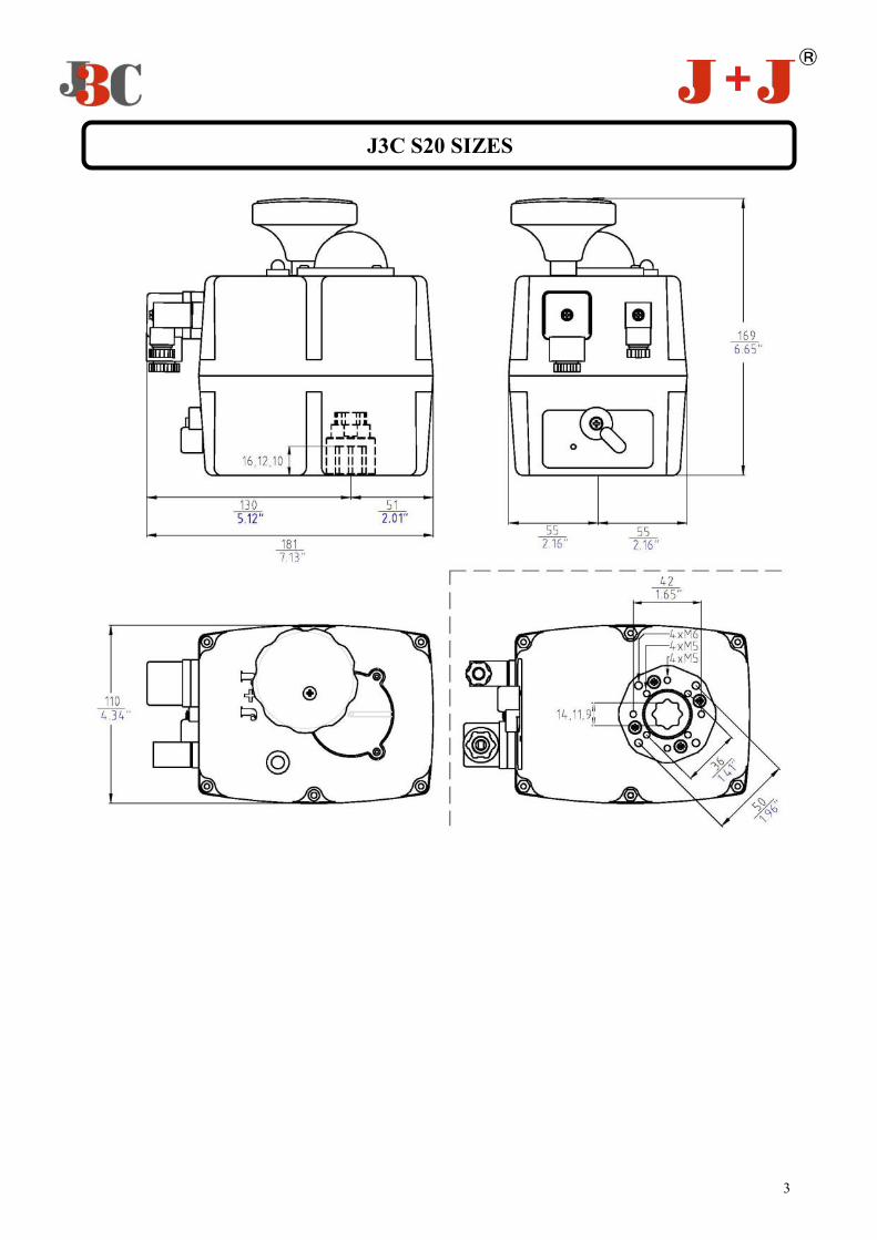
J3C S20 SIZES

4
C GENERAL CHARACTERISTICS Housing: Anticorrosive polyamide (lid & body) Main external shaft: stainless steel External screws: stainless steel Gears: Steel and polyamide Visual position indicator: Polyamide Dome: Polycarbonate Adjustable internal cams: Polyamide Electric motor: Single phase 24VDC Insulation: Class B
Model J3C S35
Voltage VDC/VAC 50/60Hz -0/+5% 24 a 240 (Patent Pending)
Voltage VDC/VAC 12 ONLY -0/+5% Change the power supply PCB
Operation time unload (Sec.) 10 Sec./90º
Maximum torque break 38 Nm / 359.3 lb/in
Maximum operational torque 35 Nm / 309 lb/in
Duty rating (%) 75 %
Working angle 90º a 270º
Limit switch 4 STDP micro (2 motor stop and 2 confirmations)
Automatic heater 3,5 W
Plugs EN175301-803
Protection IEC 60529 rating IP67
Temperature 20ºC +70ºC / -4ºF +158ºF
Weight (Kg.) 1,9 Kg
ELECTRIC ACTUATOR
DATASHEET
VALVE CONNECTION ISO 5211 Plate : F03/F04/F05 DIN 3337 Female output drive : *14 mm
Options: DIN 3337 Female output drive: *9 or *11 mm F05 to F07 Conversion Kit with *17mm output
V
OPTIONS -J3C S20/S85 DPS 2015 digital positioner: 4-20mA, 0-20mA, 0-10V or 1-10V. -J3C S20/S85 BSR 2015 emergency fail safe kit system by battery -Digital potentiometer: 1K, 5K or 10K. -3 position actuator: 0º-45º-90º or 0º-90º-180º
0
J3C S35

5
J3C S35 SIZES

6
C GENERAL CHARACTERISTICS Housing: Anticorrosive polyamide (lid & body) Main external shaft: stainless steel External screws: stainless steel Gears: Steel and polyamide Visual position indicator: Polyamide Dome: Polycarbonate Adjustable internal cams: Polyamide Electric motor: Single phase 24VDC Insulation: Class B
Model J3C S35
Voltage VDC/VAC 50/60Hz -0/+5% 24 a 240 (Patent Pending)
Voltage VDC/VAC 12 ONLY -0/+5% Change the power supply PCB
Operation time unload (Sec.) 14 Sec./90º
Maximum torque break 60 Nm / 530 lb/in
Maximum operational torque 55 Nm / 486 lb/in
Duty rating (%) 75 %
Working angle 90º a 270º
Limit switch 4 STDP micro (2 motor stop and 2 confirmations)
Automatic heater 3,5 W
Plugs EN175301-803
Protection IEC 60529 rating IP67
Temperature 20ºC +70ºC / -4ºF +158ºF
Weight (Kg.) 2,4 Kg
ELECTRIC ACTUATOR
DATASHEET
VALVE CONNECTION ISO 5211 Plate : F05/F07 DIN 3337 Female output drive : *17 mm
Option: DIN 3337 Female output drive: *11 or *14 mm
V
OPTIONS -J3C S20/S85 DPS 2015 digital positioner: 4-20mA, 0-20mA, 0-10V or 1-10V. -J3C S20/S85 BSR 2015 emergency fail safe kit system by battery -Digital potentiometer: 1K, 5K or 10K. -3 position actuator: 0º-45º-90º or 0º-90º-180º
0
J3C S55
7
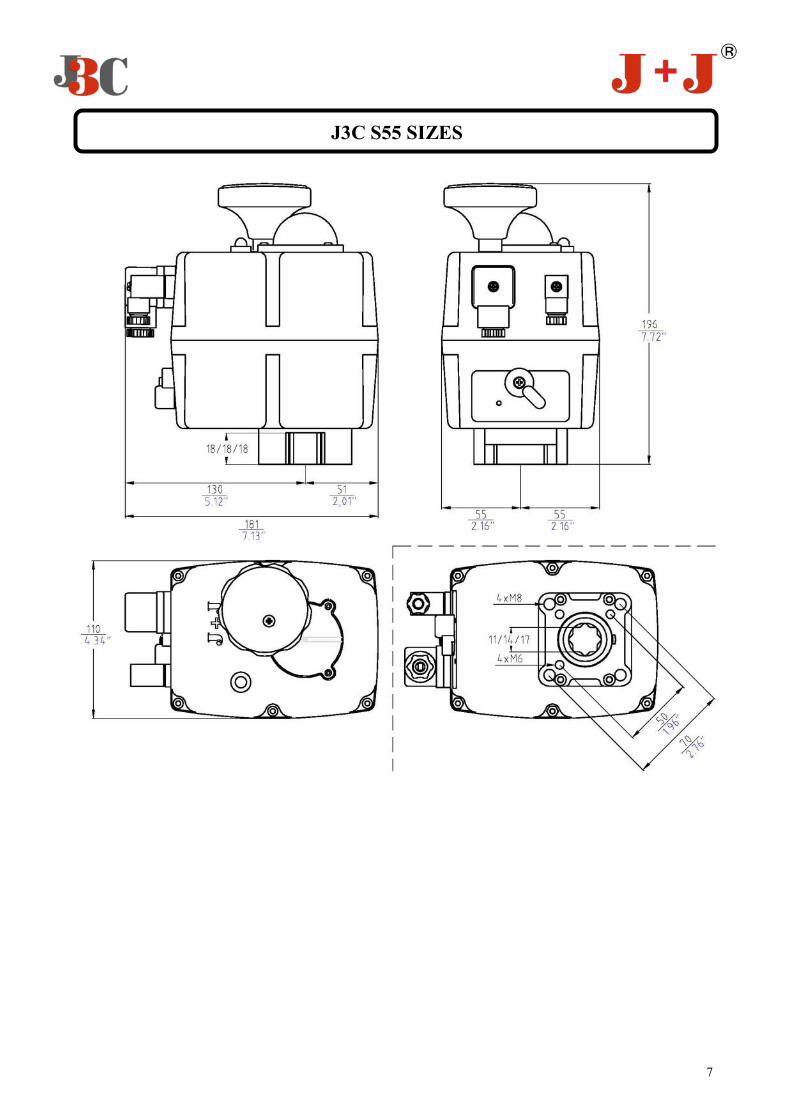
J3C S55 SIZES
8
C GENERAL CHARACTERISTICS Housing: Anticorrosive polyamide (lid & body) Main external shaft: stainless steel External screws: stainless steel Gears: Steel and polyamide Visual position indicator: Polyamide Dome: Polycarbonate Adjustable internal cams: Polyamide Electric motor: Single phase 24VDC Insulation: Class B
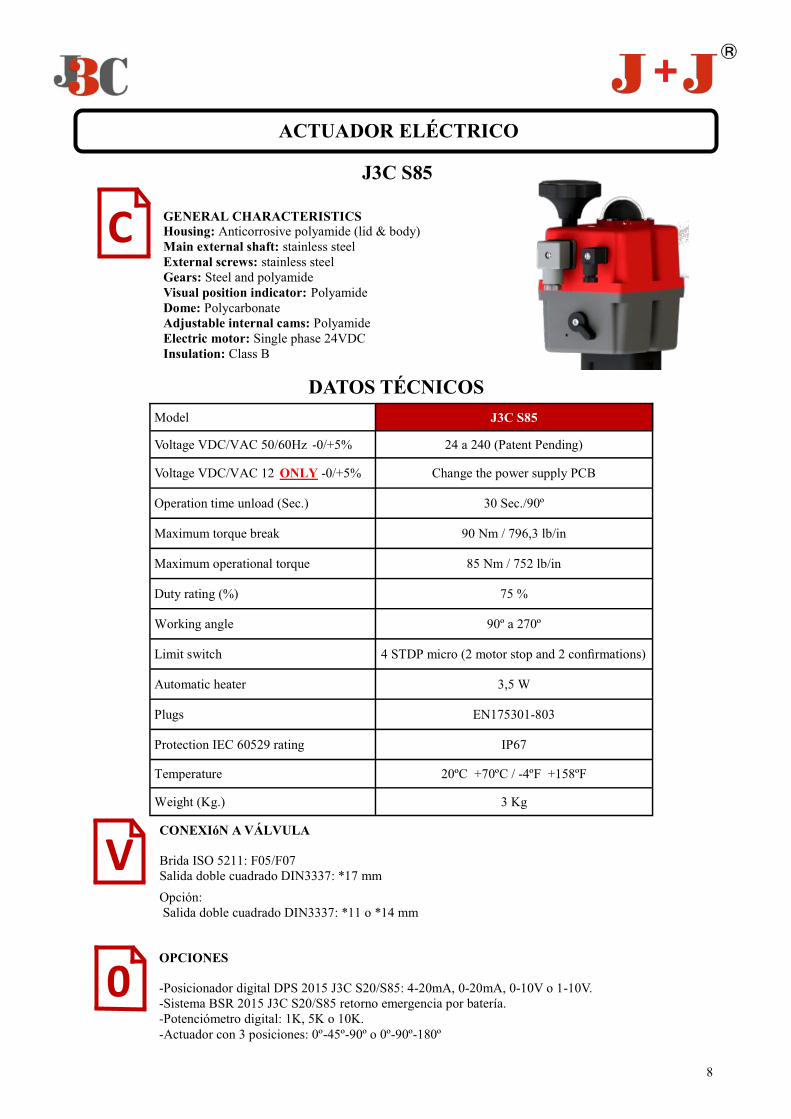
Model J3C S85
Voltage VDC/VAC 50/60Hz -0/+5% 24 a 240 (Patent Pending)
Voltage VDC/VAC 12 ONLY -0/+5% Change the power supply PCB
Operation time unload (Sec.) 30 Sec./90º
Maximum torque break 90 Nm / 796,3 lb/in
Maximum operational torque 85 Nm / 752 lb/in
Duty rating (%) 75 %
Working angle 90º a 270º
Limit switch 4 STDP micro (2 motor stop and 2 confirmations)
Automatic heater 3,5 W
Plugs EN175301-803
Protection IEC 60529 rating IP67
Temperature 20ºC +70ºC / -4ºF +158ºF
Weight (Kg.) 3 Kg
ACTUADOR ELÉCTRICO
DATOS TÉCNICOS
CONEXIóN A VÁLVULA Brida ISO 5211: F05/F07 Salida doble cuadrado DIN3337: *17 mm
Opción: Salida doble cuadrado DIN3337: *11 o *14 mm
V
OPCIONES -Posicionador digital DPS 2015 J3C S20/S85: 4-20mA, 0-20mA, 0-10V o 1-10V. -Sistema BSR 2015 J3C S20/S85 retorno emergencia por batería. -Potenciómetro digital: 1K, 5K o 10K. -Actuador con 3 posiciones: 0º-45º-90º o 0º-90º-180º
0
J3C S85
9
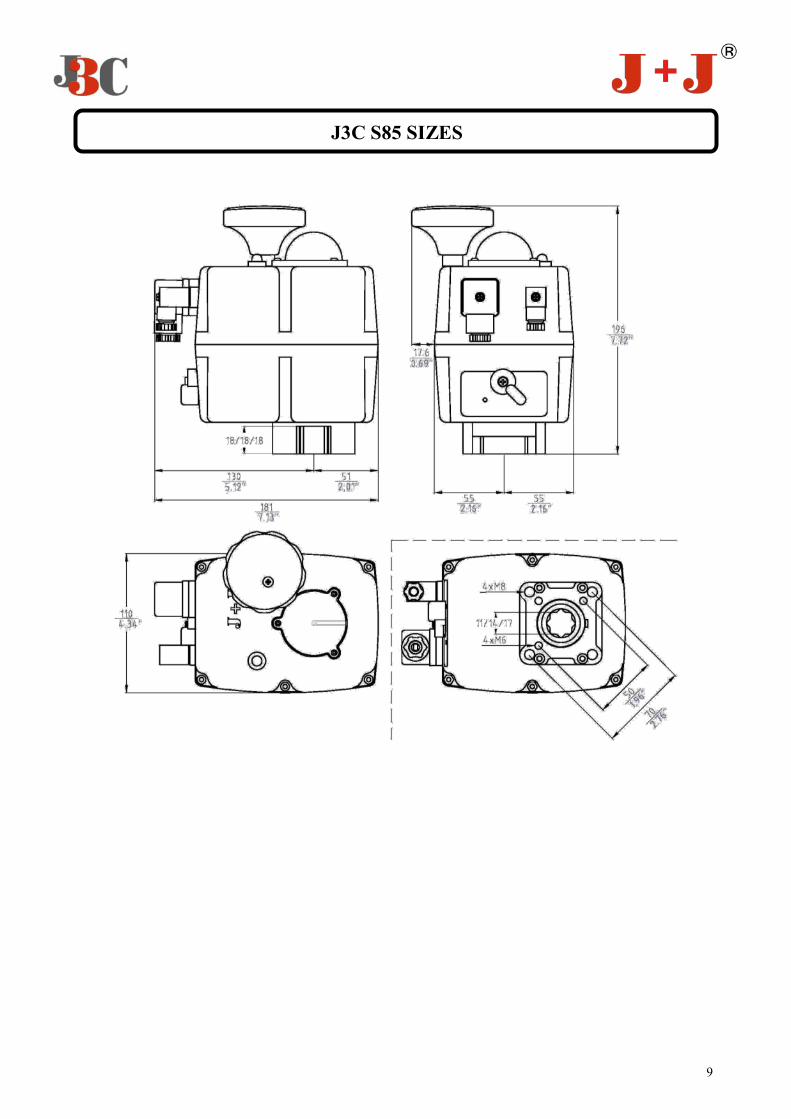
J3C S85 SIZES

10
“S” model - Novelties to be pointed out: 1-VISUAL CONTROL OF OPERATION: Through the VISUAL CONTROL OF OPERATION one could see a different color LED light, fixed or blinking, from which, one could know what is the operation the actuator is making or which is the incidence the actuator is facing. 2- 24 - 240 V MULTIVOLTAGE PCB, (Patent pending) . -All S20 to S85 actuators have been set-up to work from 24-240 VDC/VAC (Patent pending). -In case one would like to work at 12 VAC/VDC ONLY , the actuator should be opened and the already in-stalled Power Supply PCB should be replaced by the one which is inside the “12 VAC/VDC power supply KIT ”. Inside the KIT box there is an instruction manual, which explains, step by step, how to install the new PCB. In case one would like to change the set-up voltage (default 24-240VDC/VAC (Patent pending)), put a mark “X”, on the desired voltage box of the ID actuator label. 3-ID ACTUATOR LABEL
1-Actuator Model. 2-Voltage to be connected, provided that none of the two options below were marked with an “X” (points 3 or 4). 3-If we put an “X” inside this option box, one should know that the actuator will work at 12 VDC/VAC . In case any of options 3 or 4 had an “X”, the default voltage in point 2 would be automatically cancelled. 4-In case “BSR NC” option had a “X” mark, it will mean that the actuator has a pre-installed system, which in case of a power supply failure, the actuator will go the close position automatically. If the option with an “X” mark is “BSR NO”, it will mean that the actuator has a pre-installed system which, in case of a power supply failure, will drive the actuator to the open position, by using an internal battery system. 5-Time the actuator needs to run the indicated degrees. 6- Actuator ready to bear between –20ºC y + 70ºC. 7-Plate to fix the valve to the actuator, following ISO 5211. 8–Female output drive size, following DIN3337.
J3C SERIES - MODEL S20, S35 , S55 & S85
VISUAL CONTROL OF OPERATION
1
3 4 5 6 7 8 9 10
11 12 13 14 15
16
2
11
9-Maximum torque break. 10-Actuator with the CE certificate. 11-Actuator Series. 12-Marked with a tic, means that the actuator has passed our factory quality control steps. 13-Duty: 75%. Example: S20 Model - Maneuver time = 10sec. Time between maneuvers = 3.3 sec. 14-IP67 Certificate. 15-QR Code. 16-Actuator serial number. 4-BSR 2015 J3C S20/S85 KIT For actuators model S20, S35, S55 & S85, there is a new BSR 2015 KIT, which drives the actuator to the OPEN (BSR NO) or to the CLOSE position (BSR NC) in case of a power supply failure, by using an internal battery system. Always depending on the previous set-up configuration. 5-DPS 2015 J3C S20/S85 KIT For actuators model S20, S35, S55 & S85, there is a new DPS 2015 KIT, which allow us to put the actuator in any position throughout its working angle, by using a 4-20mA or a 0-10V signal. In case one would like to use a 0-20mA or a 1-10V signal, ask the distributor.
12
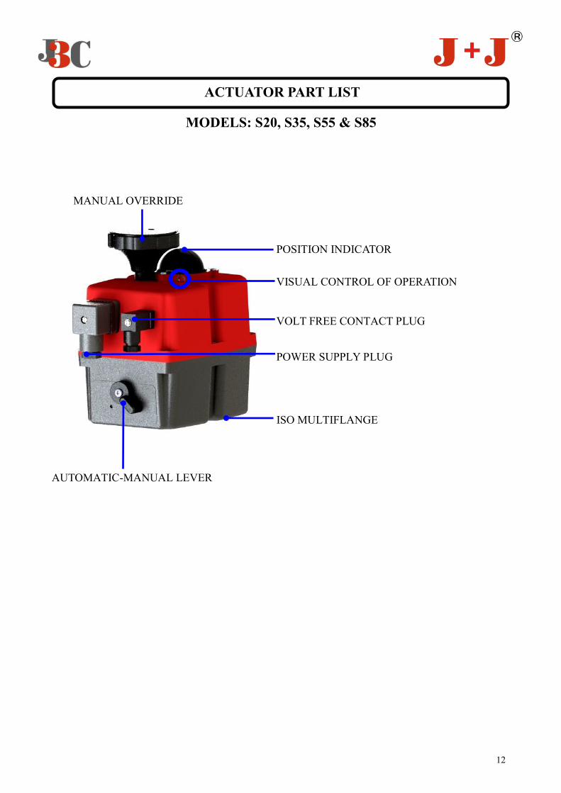
ACTUATOR PART LIST
MODELS: S20, S35, S55 & S85
MANUAL OVERRIDE
POWER SUPPLY PLUG
AUTOMATIC-MANUAL LEVER
POSITION INDICATOR
VISUAL CONTROL OF OPERATION
VOLT FREE CONTACT PLUG
ISO MULTIFLANGE

13
ACTUATOR OPERATIONAL STATUS
MODELS: S20, S35, S55 & S85
The LED Light provides visual communication between the actuator and the user. The current operational status is shown by different LED colors.
VISUAL CONTROL OF OPERATION
J3C-S20 J3C-S35 J3C-S55 J3C-S85
ACTUATOR OPERATIONAL STATUS LED COLORS
Actuator without power being supplied LED OFF
Actuator with power being supplied OPEN = GREEN LED CLOSE = RED LED
Actuator , mouving from ….. .to …., (flashing led) FROM OPEN TO CLOSE = RED / ORANGE FROM CLOSE TO OPEN = GREEN / ORANGE
Actuator with torque limiter function on, mouving from …. to …..,(flashing led) FROM OPEN TO CLOSE = RED / OFF FROM CLOSE TO OPEN = GREEN / OFF
Actuator in MANUAL mode ORANGE / OFF (SYMMETRIC SEQUENCE)
Actuator without power, working with the BSR system. Max. 3 minutes BSR NC = RED / OFF BSR NO = GREEN / OFF
Battery protection. Danger, the battery needs recharging. BSR blocked ORANGE / OFF (ASYMMETRIC SEQUENCE)
Actuator with DPS 2015 STOP = BLUE OPENING = BLUE / GREEN CLOSING = BLUE / RED

14
J3C S20 Consumption Unload Max. Operational Torque 20Nm Max. Torque Break 25Nm
Voltage A W A W A W
24 VDC 0,40 10,30 0,80 19,30 0,80 20,30
48 VDC 0,20 10,20 0,40 18,00 0,40 18,50
110 VDC 0,10 7,50 0,10 13,30 0,10 14,30
24 VAC 0,60 14,20 1,10 25,80 1,20 27,60
48 VAC 0,40 18,40 0,70 31,30 0,70 32,20
110 VAC 0,20 16,50 0,30 27,60 0,30 27,60
240 VAC 0,10 22,20 0,20 37,50 0,20 39,60
J3C S35 Consumption Unload Max. Operational Torque 35Nm Max. Torque Break 38Nm
Voltage A W A W A W
24 VDC 0,40 10,20 1,20 27,60 1,20 28,20
48 VDC 0,20 9,30 0,50 24,40 0,50 25,40
110 VDC 0,10 7,30 0,20 18,20 0,20 18,60
24 VAC 0,60 14,10 1,50 36,40 1,60 38,10
48 VAC 0,40 17,20 0,90 41,90 0,90 43,80
110 VAC 0,10 15,20 0,30 37,30 0,30 38,00
240 VAC 0,10 22,70 0,20 45,90 0,20 45,90
J3C S55 Consumption Unload Max. Operational Torque 55Nm Max. Torque Break 60Nm
Voltage A W A W A W
24 VDC 0,33 08,00 1,21 29,00 1,25 30,00
48 VDC 0,18 08,40 0,56 27,00 0,59 28,30
110 VDC 0,06 06,10 0,17 18,20 0,18 19,60
24 VAC 0,47 11,20 1,69 40,70 1,73 41,60
48 VAC 0,29 14,20 0,97 46,50 1,01 48,30
110 VAC 0,12 13,60 0,36 39,20 0,37 40,70
240 VAC 0,09 21,10 0,20 47,50 0,20 48,00
J3C S85 Consumption Unload Max. Operational Torque -85Nm Max. Torque Break -90Nm
Voltage A W A W A W
24 VDC 0,33 7,90 0,88 21,20 0,90 21,20
48 VDC 0,17 8,10 0,44 21,20 0,48 23,20
110 VDC 0,05 5,80 0,13 14,80 0,15 16,50
24 VAC 0,45 10,80 1,16 27,70 1,17 28,00
48 VAC 0,28 13,30 0,28 33,10 0,71 34,10
110 VAC 0,11 12,30 0,26 29,00 0,27 29,50
240 VAC 0,08 18,50 0,16 38,00 0,16 38,00
TABLE OF CONSUMPTIONS
15
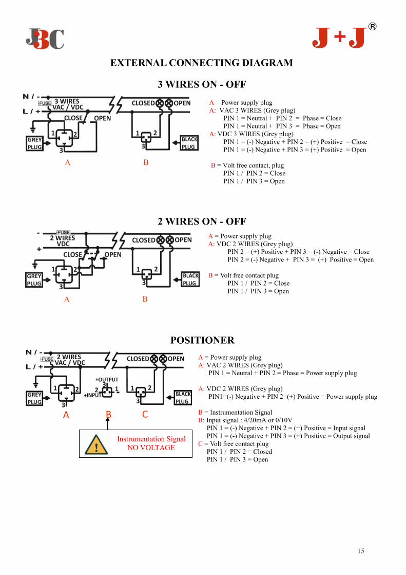
EXTERNAL CONNECTING DIAGRAM
A B
A = Power supply plug A: VAC 3 WIRES (Grey plug) PIN 1 = Neutral + PIN 2 = Phase = Close PIN 1 = Neutral + PIN 3 = Phase = Open A: VDC 3 WIRES (Grey plug) PIN 1 = (-) Negative + PIN 2 = (+) Positive = Close PIN 1 = (-) Negative + PIN 3 = (+) Positive = Open B = Volt free contact, plug PIN 1 / PIN 2 = Close PIN 1 / PIN 3 = Open
3 WIRES ON - OFF
POSITIONER
A = Power supply plug A: VAC 2 WIRES (Grey plug) PIN 1 = Neutral + PIN 2 = Phase = Power supply plug A: VDC 2 WIRES (Grey plug) PIN1=(-) Negative + PIN 2=(+) Positive = Power supply plug B = Instrumentation Signal B: Input signal : 4/20mA or 0/10V PIN 1 = (-) Negative + PIN 2 = (+) Positive = Input signal PIN 1 = (-) Negative + PIN 3 = (+) Positive = Output signal C = Volt free contact plug PIN 1 / PIN 2 = Closed PIN 1 / PIN 3 = Open
Instrumentation Signal NO VOLTAGE
A C B
2 WIRES ON - OFF
A = Power supply plug A: VDC 2 WIRES (Grey plug) PIN 2 = (+) Positive + PIN 3 = (-) Negative = Close PIN 2 = (-) Negative + PIN 3 = (+) Positive = Open B = Volt free contact plug PIN 1 / PIN 2 = Close PIN 1 / PIN 3 = Open
A B

16
12 VAC/VDC POWER SUPPLY PCB MOUNTING KIT
MODELS: S20, S35, S55 & S85
12 VDC/ VAC POWER SUPPLY
PCB
-Only if 12 VAC/VDC wants to be used , we will: 1-Put the lever in MANUAL mode (see “MANUAL” picture”) 2- Turn the manual override until the yellow indicator shows 270º (see “CORRECT POSITION” picture) 3-Open the actuator:
Remove the screw from the top of the hand-wheel and take it off Remove the screws which are fixing the cover to the body carefully
4-Disconnect the wiring (1, 2 & 3), going from the cover to the print circuit board
5-Remove carefully the 4 screws (4, 5 ,6 & 7) which are fixing the print circuit board to the lower metal plate and take the PCB off.
6-Disconnect the “POWER SUPPLY” from the “CONTROL PCB “ by separating a part of the other. 7-Assemble the “12 VDC/ VAC POWER SUPPLY” to the
“CONTROL” and fix it to the metal plate by the screws (4,6 & 7). 8-Connect the cover’s wiring; fix it and the hand-wheel as well
J3C-S20 J3C-S35 J3C-S55 J3C-S85
MANUAL
CORRECT POSITION
1 2 3
4 5 6
7
POWER SUPPLY PCB
CONTROL PCB