Effect of decomposition on the compressibility of fibrous peat

ORIGINAL PAPER
An Intrinsic Compressibility Framework for Clayey Soils
G. Belokas • M. Kavvadas
Received: 31 March 2009 / Accepted: 11 June 2011 / Published online: 28 June 2011
� Springer Science+Business Media B.V. 2011
Abstract A mathematical framework for the
description of structureless clay behaviour is pro-
posed in this paper. It is based on the observation that
there exists a biunique relationship between the radial
stress path direction and the compression curve on the
specific volume (v = 1 ? e)—mean effective stress
(r or p) plane. The projection on the v - r plane
defines the Intrinsic Compression Curve (ICC) of the
corresponding radial stress path, which results in
infinite possible ICC curves. Following a normaliza-
tion procedure, a general methodology is presented,
which can be applied to any mathematical formula-
tion of the ICC curve. The constants included in this
description are called intrinsic properties. This pro-
cedure can be easily implemented to anisotropic
constitutive models. Its importance is based on the
fact that modern constitutive models require a
definition of the structureless state, as this state is
the limiting reference state of the fully destructured
material. In addition, the paper presents a set of
correlations for the estimation of the intrinsic prop-
erties from the index properties, which helps on the
preliminary selection of the material constants.
Keywords Clay � Structure � Structureless �Intrinsic compressibility � Correlations � Stress
dilatancy
List of Symbols
eq Axisymmetric deviatoric strain
ev Volumetric strain
g Stress ratio tensor
gr Tensorial stress ratio
gq Axisymmetric stress ratio
k Intrinsic Compressibility
r Stress tensor
rij Stress tensor
r Mean or isotropic effective stress
rv Vertical effective stress
CSC Critical State Curve
CSE Critical State Envelope
cu Undrained shear strength
dq Axisymmetric dilatancy
e Voids’ ratio
I Unit tensor
ICC Intrinsic Compression Curve
ICC Intrinsic Compressibility Envelope
K Earth pressure coefficient
M Critical slope
Ng Position of ICC
p Mean or isotropic effective stress
G. Belokas (&) � M. Kavvadas
School of Civil Engineering, Geotechnical Department,
National Technical University of Athens, 5, Iroon
Polytechniou Street, 157 80 Zografou, Greece
e-mail: [email protected]
M. Kavvadas
e-mail: [email protected]
123
Geotech Geol Eng (2011) 29:855–871
DOI 10.1007/s10706-011-9422-0
s Deviatoric stress tensor
v Specific volume
1 Introduction
Modern constitutive modelling of structured (e.g.
cemented, leached, aged, preconsolidated) soils
requires the knowledge of the structureless state of
the soil, which is a reference state. Following the
definitions of Vaughan (1988) and Leroueil and
Vaughan (1990) a soil material is found in a
structureless state when the only variables required
to describe its response are the current specific
volume (v = 1 ? e) and current effective stress state
(i.e. stress tensor r). This state has also been
described as intrinsic (Burland 1990) and requires
that the material has no bonding and has erased all its
past stress history memory.
A classic example of a structureless material is the
laboratory reconstituted clay at a moisture content of
about w = 1.0–1.5wL (wL the liquid limit) and
subsequently loaded in the oedometer device at
a large vertical effective stress (e.g. rv [ 1 MPa).
The state of this material is completely defined by the
earth pressure coefficient at rest Ko = rh/rv and the
vertical effective stress (rv). Moreover, this state lies
on the Intrinsic Compression Curve (ICC) proposed
by Burland (1990), which relates e with rv.
The locus of the structureless (or intrinsic) states
represents a reference limiting state of the structured
soils and is important for the constitutive modelling
of structured soils (e.g. Kavvadas 1998). Typical
examples of such models are the ones proposed by
Kavvadas (1995) and Wood (1995), which use
isotropic bounding surface, and Kavvadas and Amo-
rosi (2000), Gajo and Wood (2001), Kavvadas and
Belokas (2001), Belokas (2008) and Belokas and
Kavvadas (2010), which use anisotropic bounding
surface. The use of isotropic bounding surface
simplifies the mathematical definition of the struc-
tureless state, while the use of anisotropic bounding
surface can accommodate a more accurate represen-
tation of the structureless state. Earlier mathematical
assumptions of intrinsic states representation applied
to anisotropic constitutive models have been pre-
sented by Pender (1978), Stipho (1982) and Banerjee
et al. (1984) for unbonded materials, nevertheless
they were not calibrated on experimental data.
This paper proposes a mathematical framework for
the description of all structureless states of a soil
material and has been developed mainly from the
observed behaviour of imposed radial stress paths
under axisymmetric conditions (typical triaxial device)
on clayey soils. It is also presented in the tensorial
stress, which is applicable to constitutive modelling.
The complete mathematical formulation is developed
herein for linear Intrinsic Compression Curve (ICC) in
the v – ln r plane, which can be implemented to any
anisotropic constitutive model with rotational—dis-
tortional hardening. Variances of this Intrinsic Com-
pressibility Framework have been implemented to the
anisotropic elastoplastic constitutive model for natural
soils proposed by Kavvadas and Belokas (2001) and
Belokas (2008). In the final part of this work, a set of
equations that correlate the constants of the framework
(intrinsic properties) with the index properties is
presented. This set of equations is useful for the
preliminary estimation of the intrinsic properties.
The typical tensorial and triaxial (axisymmetric)
stress and strain measures are used throughout the
paper, which correspond to horizontal x-axis and
y-axis and vertical downwards z-axis. Boldface char-
acters are for tensorial quantities and a dot over a
character indicates incremental quantity. Stress tensor
equals to r = rI ? s (or rij = rdij ? sij), where r is
the mean effective stress, s or sij the deviatoric stress,
I the unit tensor and dij the kronecker delta. Useful
measures of stress are: (a) the second invariant
J02;r ¼ sijsji
� �=2 ¼ s : sð Þ=2, where sij, the deviatoric
stress tensor (b) the third invariant J03;r ¼ sijsjkski
� �=3
and (c) the Lode angle h ¼ 13
cos�1 3ffiffi3p
2
J03;r
J03=2
2;r
� �. Strain
tensor equals to e = eI/3 ? e, where e is the isotropic
strain and e the deviatoric strain. The triaxial or
axisymmetric conditions are described by p =
(rz ? 2rx)/3, q = rz - rx stress and ev = ez ? 2ex,
eq = 2(ez - ex)/3 strain measures.
2 Radial Stress Path Response of Structureless
Soils
At a radial stress path the soil is subject to a stress
path in which it is g = constant (where g = s/r), i.e.
a stress path of a constant slope (gr = ct in tensioral
representation, where gr = (s:s/r2)0.5, or gq = ct in
856 Geotech Geol Eng (2011) 29:855–871
123

axisymmetric conditions, where gq = q/p) and a
constant third invariant (the projection in the deviatoric
space). A special case of this loading is the axisym-
metric conditions imposed by the typical triaxial
device, during which rx = ry(=rh) = rz(=rv) and
therefore the earth pressure coefficient K = rx/
rz = ry/rz is directly related to the stress ratio
gq = q/p = 3(rz–rx)/(rz ? 2rx) according to Eq. 1.
gq ¼ q=p ¼ 3 1� Kð Þ= 1þ 2Kð Þ ð1Þ
For a cross anisotropic material (i.e. same response in
x and y axes) the total dilatancy of the material is
defined by Eq. 2.
dq ¼ _eq=_ev ¼ 2 _ez � _exð Þ= 3ð_ez þ 2_exÞ½ � ð2Þ
Special cases of radial stress path axisymmetric
loading (i.e. rx = ry) are the isotropic (K = 1, gq = 0)
and one dimensional compression (K = Ko = (rh/rv)o,
gq = gq,o = 3(1 - Ko)/(1 ? 2Ko), dq = 2/3), which
for a structureless material would result to a dq = 0
and dq = 2/3 respectively.
Radial stress path tests under axisymmetric con-
ditions have led to the conclusion that as mean
effective stress (p) increases, the path in the specific
volume (v) mean effective stress (p) plane tends to
fall into separate but uniquely defined virgin com-
pression curves (e.g. Roscoe et al. 1963; Lewin and
Burland 1970, Fig. 1). It can be argued that at these
states the material has erased all its past memory as
the response is controlled by current state (i.e. stress
state, r, and specific volume, v) and, according to
Leroueil and Vaughan (1990), these states are
structureless. Therefore, these curves can be called
Intrinsic Compression Curves (ICC), similarly to
Burland’s (1990) Intrinsic Compression Line (Fig. 2).
The most common mathematical representation of
ICC curves is given by Eq. 3.
v ¼ Ng � k ln p ð3Þ
This equation includes constants: (a) Ng, which is the
specific volume for p = 1 kPa and controls the
position of ICC at the m – ln r plane and (b) k,
which is the compressibility coefficient and controls
the slope of ICC at the m – ln r plane.
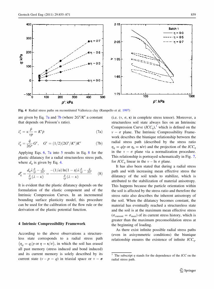
The dependence of the position of the ICC on the
stress ratio (g) has been investigated by various authors
(e.g. Bishop and Eldin 1953; Broms and Ratnam 1963;
Roscoe et al. 1963, Lewin and Burland 1970; Donaghe
and Townshed 1978; Gens 1982; Georgiannou 1988;
Rampello et al. 1997; Belokas et al. 2005), which leads
to the conclusion that as stress ratio increases, constant
Ng reduces. The maximum value of Ng is the Niso,
which corresponds to the ‘‘Isotropic Intrinsic Com-
pression Curve’’ (ICCiso), while the minimum value of
Ng is the C, which corresponds to the ‘‘Critical State
Curve’’ (CSC). It also holds Niso [ NKo [ C, where
NKo is for the ‘‘One Dimensional Intrinsic Compres-
sion Curve’’ (ICCKo).
It has therefore been established that there exists a
biunique relationship between the compression curve
Fig. 1 Dependence of compression curves on earth pressure coefficient during an axisymmetric radial compression by Lewin and
Burland (1970)
Geotech Geol Eng (2011) 29:855–871 857
123

(v - p plot) and the stress ratio (gq) of a radial stress
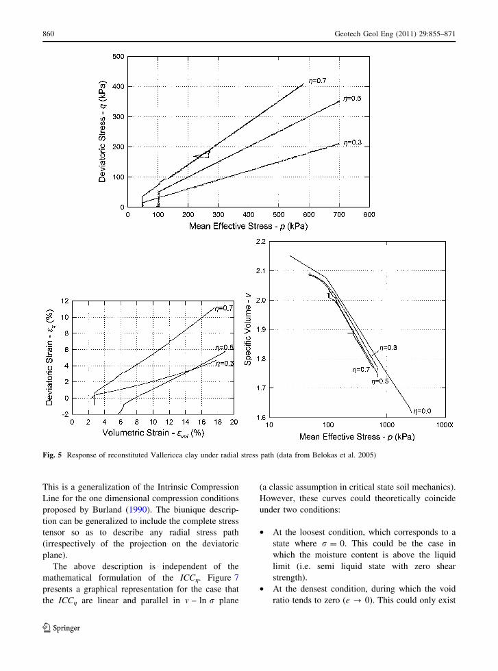
path (e.g. Figs. 1, 3, 4 and 5). Moreover, it appears
that the dilatancy (dq ¼ _eq=_ev) stabilizes after a
certain level of stress (e.g. Gens 1982; Belokas
2008; Fig. 5) as material anisotropy stabilizes. Under
these conditions the behaviour depends only on
current soil’s state (i.e. specific volume v, and stress
state p and q) and the soil is in a structureless state.
The Critical State Line (CSL) represents the lower
boundary of any possible compression line, which
corresponds to a radial stress path of a slope equal to the
critical slope (gq = M, e.g. Gens 1982). According to
Gens (1982), the critical slope also represents the
maximum stress ratio of a continuously hardening
radial stress path (i.e. it does not fail). This slope can
vary only with respect to the third stress invariant.
3 Stress—Dilatancy Relationship Under Radial
Stress Paths
Each soil has a different stress—dilatancy relation-
ship g ¼ q=p versus dq ¼ _eq=_ev under radial com-
pression loading. As already mentioned, the total
dilatancy tends to stabilize for a radial stress path as
the mean effective stress increases. This is attributed
to the fact that the material achieves a certain degree
of anisotropy. A plot of the normalized stress ratio g/
M (where M is the critical slope) with respect to
dilatancy d leads to a unique curve for each soil
(Fig. 6). The resulting curve has two properties: (a) it
starts from (gq/L = 0, eq/ev = 0) and (b) it tends
asymptotically to gq/M = 1 for eq/ev ? ?. An
exponential curve of the form of Eq. 4, where a is
a constant, represents well the stress—dilatancy
relationship (see Fig. 6).
g=M¼ 1� e�adq ) dq ¼� 1=að Þ ln ð1� g=MÞ ð4Þ
Constant a varies from 0.32 to 1.30 for the 10
different materials examined in Fig. 6.
In incremental plasticity the total incremental
strain is decomposed to the elastic and the plastic
component (i.e. _ev ¼ _eev þ _ep
v and _eq ¼ _eeq þ _ep
q in
axisymmetric conditions) and the total dilatancy is
dq ¼ ð_eeq þ _ep
qÞ=ð_eev þ _ep
vÞ. Moroever, the plastic dilat-
ancy dpq ¼ _ep
q=_epv is an inseparable constituent of the
flow rule. Therefore, the plastic dilatancy can be
related to the total dilatancy according to Eq. 5.
dpq ¼
dq _ev � _epq
_ev � _eev
ð5Þ
In Eq. 5 the total volumetric increment for a radial
structureless stress path and an ICC linear in v – ln p
plane is given by Eq. 6.
_ev ¼ k_p
vpð6Þ
Assuming isotropic poroelasticity for the elastic
component, the elastic strain increment components
Fig. 2 Intrinsic Compression Line (Burland 1990)
Fig. 3 Radial stress paths projection on e–ln p0 space for
reconstituted Lower Cromer Till (Gens and Potts 1982)
858 Geotech Geol Eng (2011) 29:855–871
123
are given by Eq. 7a and 7b (where 2Ge/Ke a constant
that depends on Poisson’s ratio).
_eev ¼ j
_p
vp¼ Ke _p ð7aÞ
_eeq ¼
_q
2GeGe; Ge ¼ 1=2ð Þ 2Ge=Keð ÞKe ð7bÞ
Applying Eqs. 6, 7a into 5 results in Eq. 8 for the
plastic dilatancy for a radial structureless stress path,
where dq is given by Eq. 4.
dpq ¼
dqk_p
vp�_q
2Ge
_pvp ðk� jÞ
¼�ð1=aÞ lnð1� gÞk _p
vp�_q
2Ge
_pvp ðk� jÞ
ð8Þ
It is evident that the plastic dilatancy depends on the
formulation of the elastic component and of the
Intrinsic Compression Curves. In an incremental
bounding surface plasticity model, this procedure
can be used for the calibration of the flow rule or the
derivation of the plastic potential function.
4 Intrinsic Compressibility Framework
According to the above observations a structure-
less state corresponds to a radial stress path
gq ¼ q=p or g ¼ s=r� �
, in which the soil has erased
all past memory (stress induced and bond induced)
and its current memory is solely described by its
current state (v – p - q) in triaxial space or m - r
(i.e. (m, r, s) in complete stress tensor). Moreover, a
structureless soil state always lies on an Intrinsinc
Compression Curve (ICCg),1 which is defined on the
v - r plane. The Intrinsic Compressibility Frame-
work describes the biunique relationship between the
radial stress path (described by the stress ratio
gq = q/p or gs = s/r) and the projection of the ICCg
in the m - r plane via a normalization procedure.
This relationship is portrayed schematically in Fig. 7,
for ICCg linear in the v – ln r plane.
It has also been stated that during a radial stress
path and with increasing mean effective stress the
dilatancy of the soil tends to stabilize, which is
attributed to the stabilization of material anisotropy.
This happens because the particle orientation within
the soil is affected by the stress ratio and therefore the
stress ratio also describes the inherent anisotropy of
the soil. When the dilatancy becomes constant, the
material has eventually reached a structureless state
and the soil is at the maximum mean effective stress
(rcurrent = rmax) of its current stress history, which is
greater than the maximum preconsolidation stress at
the beginning of loading.
As there exist infinite possible radial stress paths
(even in axisymmetric conditions) the biunique
relationship ensures the existence of infinite ICCg.
Fig. 4 Radial stress paths on reconstituted Vallericca clay (Rampello et al. 1997)
1 The subscript g stands for the dependence of the ICC on the
radial stress path.
Geotech Geol Eng (2011) 29:855–871 859
123
This is a generalization of the Intrinsic Compression
Line for the one dimensional compression conditions
proposed by Burland (1990). The biunique descrip-
tion can be generalized to include the complete stress
tensor so as to describe any radial stress path
(irrespectively of the projection on the deviatoric
plane).
The above description is independent of the
mathematical formulation of the ICCg. Figure 7
presents a graphical representation for the case that
the ICCg are linear and parallel in m – ln r plane
(a classic assumption in critical state soil mechanics).
However, these curves could theoretically coincide
under two conditions:
• At the loosest condition, which corresponds to a
state where r = 0. This could be the case in
which the moisture content is above the liquid
limit (i.e. semi liquid state with zero shear
strength).
• At the densest condition, during which the void
ratio tends to zero (e ? 0). This could only exist
Fig. 5 Response of reconstituted Vallericca clay under radial stress path (data from Belokas et al. 2005)
860 Geotech Geol Eng (2011) 29:855–871
123

for extremely high stress level, which would also
include particle breakage.
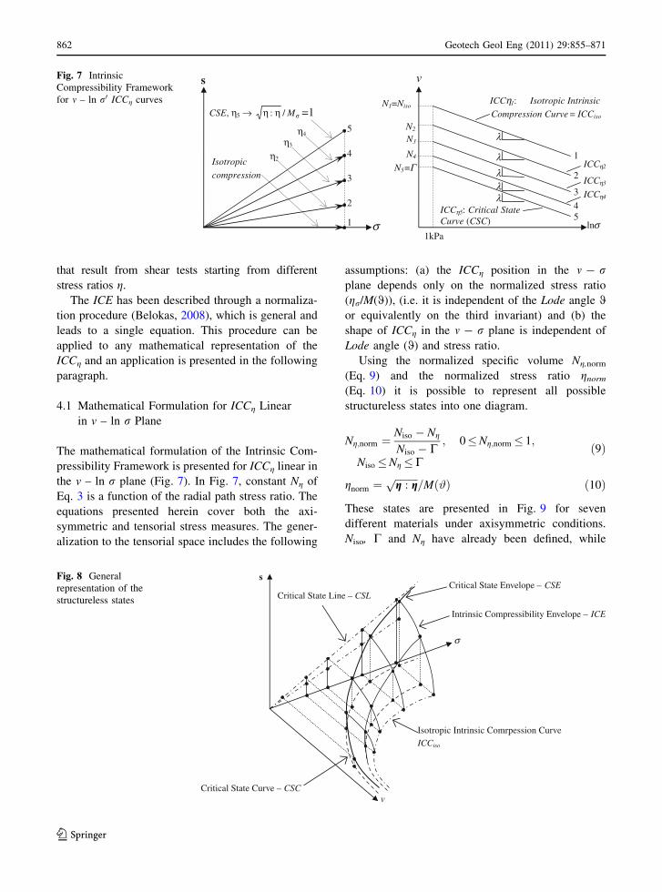
A general description of all structureless states
irrespectively of the ICCg formulation is depicted in
Fig. 8. In the v - r(i.e. v – s - r) hyper space, all
ICCg lie on the Intrinsic Compressibility Envelope
(ICE). The ICE is a kind of Roscoe–Rendulic surface
as it delimits all possible radial stress path structureless
states. This envelope is neither the State Boundary
Surface (SBS) of Critical State Soil Mechanics
(following Lewin and Burland (1970) observations),
nor the modified SBS proposed by Gens (1982), as ICE
describes only structureless states. It has been found
that the stress path traces of v = ct for different
loading conditions (e.g. radial stress path—ICE,
undrained shearing, drained shearing) do not coincide
to define a single SBS (e.g. Lewin and Burland 1970).
On the other hand, the SBS proposed by Gens (1982) is
the bounding envelope of all the v = ct stress paths
Fig. 6 Application of the
stress dilatancy relationship
during radial stress paths for
different soil materials
Geotech Geol Eng (2011) 29:855–871 861
123
that result from shear tests starting from different
stress ratios g.
The ICE has been described through a normaliza-
tion procedure (Belokas, 2008), which is general and
leads to a single equation. This procedure can be
applied to any mathematical representation of the
ICCg and an application is presented in the following
paragraph.
4.1 Mathematical Formulation for ICCg Linear
in v – ln r Plane
The mathematical formulation of the Intrinsic Com-
pressibility Framework is presented for ICCg linear in
the v – ln r plane (Fig. 7). In Fig. 7, constant Ng of
Eq. 3 is a function of the radial path stress ratio. The
equations presented herein cover both the axi-
symmetric and tensorial stress measures. The gener-
alization to the tensorial space includes the following
assumptions: (a) the ICCg position in the m - rplane depends only on the normalized stress ratio
(gr/M(0)), (i.e. it is independent of the Lode angle 0or equivalently on the third invariant) and (b) the
shape of ICCg in the m - r plane is independent of
Lode angle (0) and stress ratio.
Using the normalized specific volume Ng,norm
(Eq. 9) and the normalized stress ratio gnorm
(Eq. 10) it is possible to represent all possible
structureless states into one diagram.
Ng;norm ¼Niso � Ng
Niso � C; 0�Ng;norm� 1;
Niso�Ng�Cð9Þ
gnorm ¼ffiffiffiffiffiffiffiffiffig : gp
=Mð#Þ ð10Þ
These states are presented in Fig. 9 for seven
different materials under axisymmetric conditions.
Niso, C and Ng have already been defined, while
s
σ1
2
3
4
5
CSE, η5 → σηη M/: =1
η4
η3
η2Isotropic
compression
lnσ1kPa
1
λ
λλλλ
2
3
4 5
N1=Niso
N2
N3
N4
N5=Γ
ICCη5: Critical StateCurve (CSC)
ICCη4
ICCη3
ICCη2
ICCη1: Isotropic Intrinsic
Compression Curve = ICCiso
vFig. 7 Intrinsic
Compressibility Framework
for m – ln r0 ICCg curves
Critical State Curve – CSC
Critical State Envelope – CSECritical State Line – CSL
σ
s
v
Intrinsic Compressibility Envelope – ICE
Isotropic Intrinsic Comrpession CurveICCiso
Fig. 8 General
representation of the
structureless states
862 Geotech Geol Eng (2011) 29:855–871
123
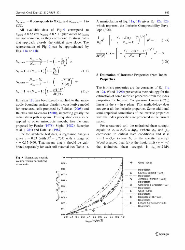
Ng,norm = 0 corresponds to ICCiso and Ng,norm = 1 to
CSC.
All available data of Fig. 9 correspond to
gnorm \ 0.85 jai Mnorm \ 0.5. Higher values of gnorm
are not common, as they correspond to stress paths
that approach closely the critical state slope. The
representation of Fig. 9 can be approximated by
Eqs. 11a or 11b.
Ng;norm ¼Niso � Ng
Niso � C¼ 1� 1�
gq
Mq
� �n
or
Ng ¼ Cþ Niso � Cð Þ 1�gq
Mq
� �n
ð11aÞ
Ng;norm ¼Niso � Ng
Niso � C¼ 1� 1�
ffiffiffiffiffiffiffiffiffig : gp
Mð#Þ
� �n
or
Ng ¼ Cþ ðNiso � CÞ 1�ffiffiffiffiffiffiffiffiffig : gp
Mð#Þ
� �n
ð11bÞ
Equation 11b has been directly applied to the aniso-
tropic bounding surface plasticity constitutive model
for structured soils proposed by Belokas (2008) and
Belokas and Kavvadas (2010), improving greatly the
radial stress path response. This equation can also be
applied to other anisotropic models, like the ones
proposed by Pender (1978), Stipho (1982), Banerjee
et al. (1984) and Dafalias (1987).
For the available test data, a regression analysis
gives n = 0.33 (with R2 = 0.734) with a range of
n = 0.15–0.60. That means that n should be cali-
brated separately for each soil material (see Table 1).
A manipulation of Eq. 11a, 11b gives Eq. 12a, 12b,
which represent the Intrinsic Compressibility Enve-
lope (ICE).
1
M2q
q2 � 1� mþ k ln p� CNiso � C
� �1=n" #2
p2 ¼ 0 ð12aÞ
1
M2ð#Þ s : s� 1� mþ k ln r� CNiso � C
� �1=n" #2
r2 ¼ 0
ð12bÞ
5 Estimation of Intrinsic Properties from Index
Properties
The intrinsic properties are the constants of Eq. 11a
or 12a. Wood (1990) presented a methodology for the
estimation of some intrinsic properties from the index
properties for Intrinsic Compression Curves (ICCg)
linear in the m – ln r plane. This methodology does
not cover all the intrinsic properties. Some additional
semi-empirical correlations of the intrinsic properties
with the index properties are presented in the current
paper.
For a saturated soil, the undrained shear strength
equals to cu = qcs/2 = Mpcs (where qcs and pcs
correspond to critical state conditions) and it is
v = 1 ? Gsw (where Gs is the specific gravity).
Wood assumed that: (a) at the liquid limit (w = wL)
the undrained shear strength is cuL & 2 kPa
Fig. 9 Normalized specific
volume versus normalized
stress ratio
Geotech Geol Eng (2011) 29:855–871 863
123
(Terzaghi et al. 1996, mention a range of 1.5 kPa to
2.5 kPa) and (b) at the plastic limit (w = wP) it is
cuP & 200 kPa (the same value is mentioned by
Mitchell 1992), which means that cuP/cuL & 100. In
the following, the cuP/cuL & 100 assumption is re-
examined. It has been portrayed (Belokas, 2008) that
Wood’s methodology is easily adjusted to any
mathematical formulation of the Intrinsic Compres-
sion Curves.
For ICCg linear in the m - ln r plane (i.e. Eq. 3
holds) Wood’s methodology gives Eqs. 13–16. Wood
(1990) simplified them by further assuming that
cuL & 2 kPa, cuP & 200 kPa and cuP/cuL & 100.
cu ¼M
2exp
C� mk
� �¼M
2exp
C� 1�Gsw
k
� �ð13Þ
k ¼ Gs wL � wPð Þln cuP=cuLð Þ ¼
GsIp
ln cuP=cuLð Þ ð14Þ
M ¼ 2cuL
exp C� 1� GswLð Þ=k½ � ; ð15aÞ
M ¼ 2cuP
exp C� 1� GswPð Þ=k½ � ð15bÞ
C ¼ 1þ GswL þ k ln 2cuL=Mð Þ; ð16aÞC ¼ 1þ GswP þ k ln 2cuP=Mð Þ ð16bÞ
All regression analysis data presented in the following
section correspond to typical triaxial test conditions.
5.1 Intrinsic Compressibility
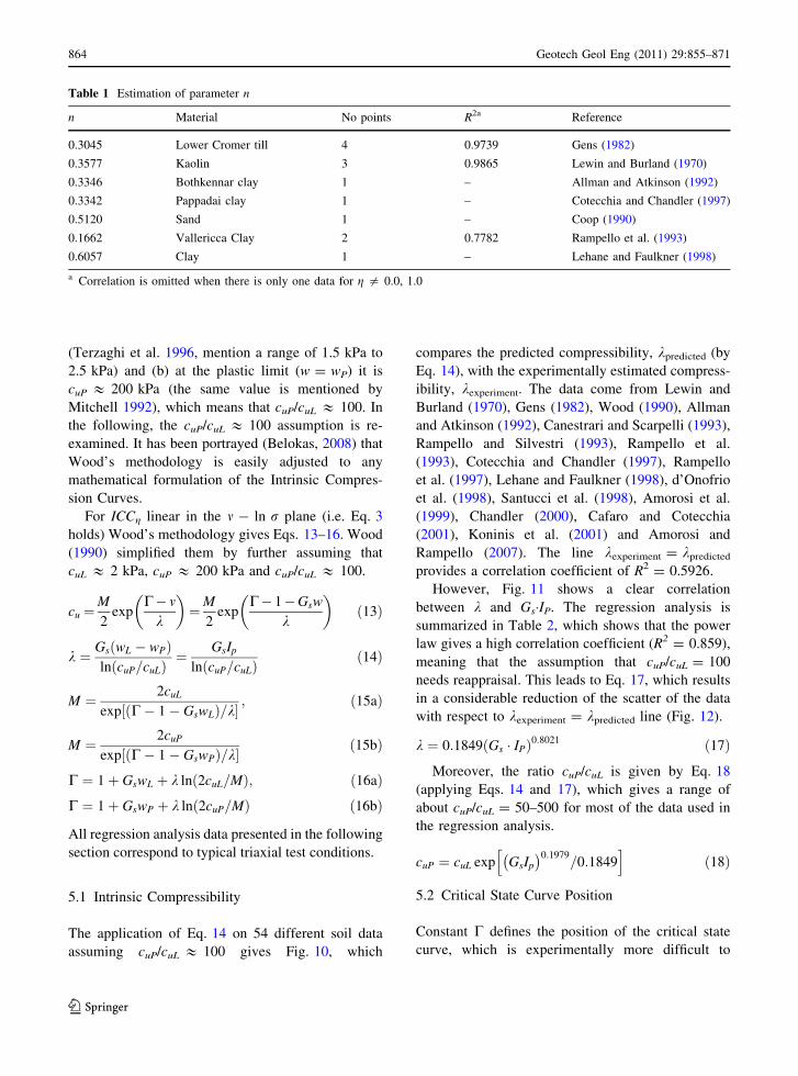
The application of Eq. 14 on 54 different soil data
assuming cuP/cuL & 100 gives Fig. 10, which
compares the predicted compressibility, kpredicted (by
Eq. 14), with the experimentally estimated compress-
ibility, kexperiment. The data come from Lewin and
Burland (1970), Gens (1982), Wood (1990), Allman
and Atkinson (1992), Canestrari and Scarpelli (1993),
Rampello and Silvestri (1993), Rampello et al.
(1993), Cotecchia and Chandler (1997), Rampello
et al. (1997), Lehane and Faulkner (1998), d’Onofrio
et al. (1998), Santucci et al. (1998), Amorosi et al.
(1999), Chandler (2000), Cafaro and Cotecchia
(2001), Koninis et al. (2001) and Amorosi and
Rampello (2007). The line kexperiment = kpredicted
provides a correlation coefficient of R2 = 0.5926.
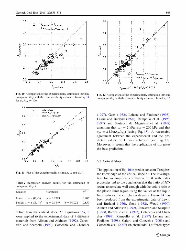
However, Fig. 11 shows a clear correlation
between k and Gs�IP. The regression analysis is
summarized in Table 2, which shows that the power
law gives a high correlation coefficient (R2 = 0.859),
meaning that the assumption that cuP/cuL = 100
needs reappraisal. This leads to Eq. 17, which results
in a considerable reduction of the scatter of the data
with respect to kexperiment = kpredicted line (Fig. 12).
k ¼ 0:1849 Gs � IPð Þ0:8021 ð17ÞMoreover, the ratio cuP/cuL is given by Eq. 18
(applying Eqs. 14 and 17), which gives a range of
about cuP/cuL = 50–500 for most of the data used in
the regression analysis.
cuP ¼ cuL exp GsIp
� �0:1979=0:1849
h ið18Þ
5.2 Critical State Curve Position
Constant C defines the position of the critical state
curve, which is experimentally more difficult to
Table 1 Estimation of parameter n
n Material No points R2a Reference
0.3045 Lower Cromer till 4 0.9739 Gens (1982)
0.3577 Kaolin 3 0.9865 Lewin and Burland (1970)
0.3346 Bothkennar clay 1 – Allman and Atkinson (1992)
0.3342 Pappadai clay 1 – Cotecchia and Chandler (1997)
0.5120 Sand 1 – Coop (1990)
0.1662 Vallericca Clay 2 0.7782 Rampello et al. (1993)
0.6057 Clay 1 – Lehane and Faulkner (1998)
a Correlation is omitted when there is only one data for g = 0.0, 1.0
864 Geotech Geol Eng (2011) 29:855–871
123
define than the critical slope L. Equations 16a, b
were applied to the experimental data of 9 different
materials from Allman and Atkinson (1992), Canes-
trari and Scarpelli (1993), Cotecchia and Chandler
(1997), Gens (1982), Lehane and Faulkner (1998),
Lewin and Burland (1970), Rampello et al. (1993,
1997) and Santucci de Magistris et al. (1998)
assuming that cuL = 2 kPa, cuP = 200 kPa and that
cuP = 2 kPa(cuP/cuL) (using Eq. 18). A reasonable
agreement between the experimental and the pre-
dicted values of C was achieved (see Fig. 13).
Moreover, it seems that the application of cuP gives
the best prediction.
5.3 Critical Slope
The application of Eq. 16 to predict constant C requires
the knowledge of the critical slope M. The investiga-
tion for an empirical correlation of M with index
properties led to the conclusion that the ratio of M/kseems to correlate well enough with the void’s ratio at
the plastic limit (again using the values at the liquid
limit reduces the correlation degree). Figure 14 has
been produced from the experimental data of Lewin
and Burland (1970), Gens (1982), Wood (1990),
Allman and Atkinson (1992), Canestrari and Scarpelli
(1993), Rampello et al. (1993), Cotecchia and Chan-
dler (1997), Rampello et al. (1997) Lehane and
Faulkner (1998), Cafaro and Cotecchia (2001) and
Cotecchia et al. (2007) which include 11 different types
Fig. 10 Comparison of the experimentally estimation intrinsic
compressibility with the compressibility estimated from Eq. 14
for cuP/cuL = 100
Fig. 11 Plot of the experimentally estimated k and Gs�IP
Table 2 Regression analysis results for the estimation of
compressibility k
Equation Constants R2
Linear: k = a (Gs�IP) a = 0.1719 0.803
Power: k = a (Gs�IP)b a = 0.1849 b = 0.8021 0.859
Fig. 12 Comparison of the experimentally estimation intrinsic
compressibility with the compressibility estimated from Eq. 13
Geotech Geol Eng (2011) 29:855–871 865
123
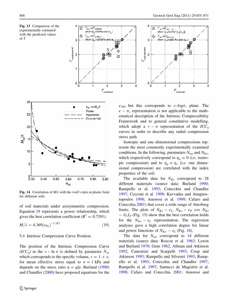
of soil materials under axisymmetric compression.
Equation 19 represents a power relationship, which
gives the best correlation coefficient (R2 = 0.7391).
M=k ¼ 4:369ðePLÞ�1:187 ð19Þ
5.4 Intrinsic Compression Curve Position
The position of the Intrinsic Compression Curve
(ICCg) in the v – ln r is defined by parameter Mg,
which corresponds to the specific volume, m = 1 ? e,
for mean effective stress equal to r = 1 kPa and
depends on the stress ratio g = q/p. Burland (1990)
and Chandler (2000) have proposed equations for the
e100 but this corresponds to e–logrv plane. The
e - rv representation is not applicable to the math-
ematical description of the Intrinsic Compressibility
Framework and to general constitutive modelling,
which adopt a m - r representation of the ICCg
curves in order to describe any radial compression
stress path.
Isotropic and one–dimensional compressions rep-
resent the most commonly experimentally examined
conditions. In the following, parameters Niso and NKo,
which respectively correspond to gq = 0 (i.e. isotro-
pic compression) and to gq = go (i.e. one dimen-
sional compression) are correlated with the index
properties of the soil.
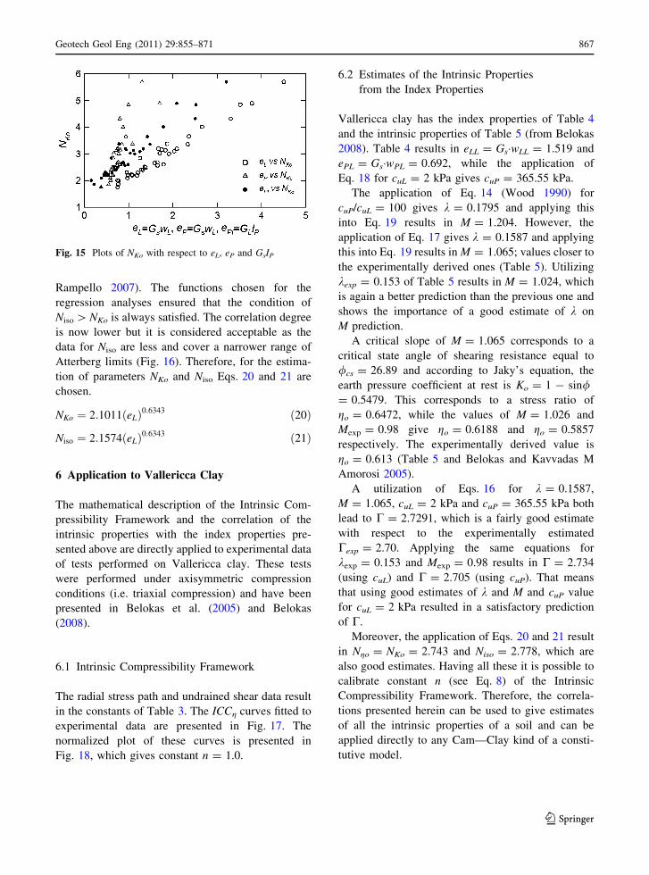
The available data for NKo correspond to 28
different materials (source data: Burland 1990;
Rampello et al. 1993; Cotecchia and Chandler
1997; Cecconi et al. 1998; Kavvadas and Anagnos-
topoulos 1998; Amorosi et al. 1999; Cafaro and
Cotecchia 2001) that cover a wide range of Atterberg
limits. The plots of NKo - eL, NKo - eP jai NKo
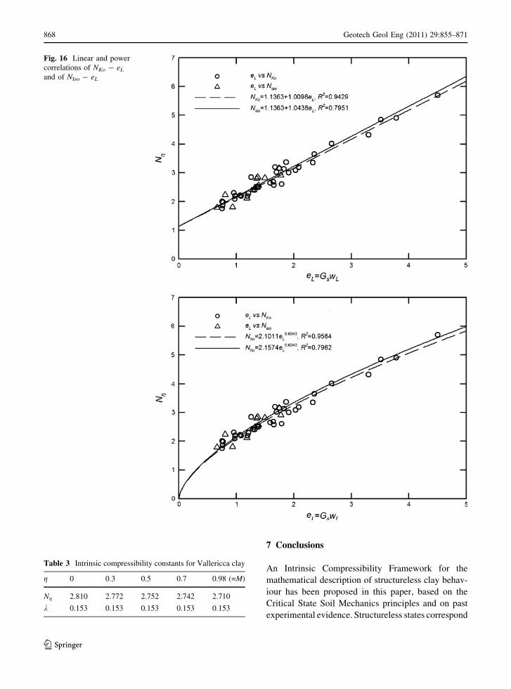
- GsIP (Fig. 15) show that the best correlation holds
for the NKo - eL representation. The regression
analyses gave a high correlation degree for linear
and power functions of NKo - eL (Fig. 16).
The data for Niso correspond to 14 different
materials (source data: Roscoe et al. 1963; Lewin
and Burland 1970; Gens 1982; Allman and Atkinson
1992; Canestrari and Scarpelli 1993; Coop and
Atkinson 1993; Rampello and Silvestri 1993; Ramp-
ello et al. 1993; Cotecchia and Chandler 1997;
Rampello et al. 1997; Santucci de Magistris et al.
1998; Cafaro and Cotecchia 2001; Amorosi and
Fig. 13 Comparison of the
experimentally estimated
with the predicted values
of C
Fig. 14 Correlation of M/k with the void’s ratio at plastic limit
for different soils
866 Geotech Geol Eng (2011) 29:855–871
123
Rampello 2007). The functions chosen for the
regression analyses ensured that the condition of
Niso [ NKo is always satisfied. The correlation degree
is now lower but it is considered acceptable as the
data for Niso are less and cover a narrower range of
Atterberg limits (Fig. 16). Therefore, for the estima-
tion of parameters NKo and Niso Eqs. 20 and 21 are
chosen.
NKo ¼ 2:1011ðeLÞ0:6343 ð20Þ
Niso ¼ 2:1574ðeLÞ0:6343 ð21Þ
6 Application to Vallericca Clay
The mathematical description of the Intrinsic Com-
pressibility Framework and the correlation of the
intrinsic properties with the index properties pre-
sented above are directly applied to experimental data
of tests performed on Vallericca clay. These tests
were performed under axisymmetric compression
conditions (i.e. triaxial compression) and have been
presented in Belokas et al. (2005) and Belokas
(2008).
6.1 Intrinsic Compressibility Framework
The radial stress path and undrained shear data result
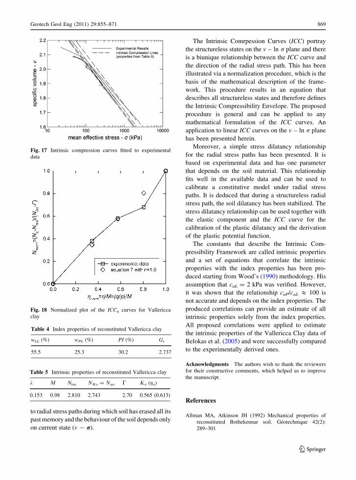
in the constants of Table 3. The ICCg curves fitted to
experimental data are presented in Fig. 17. The
normalized plot of these curves is presented in
Fig. 18, which gives constant n = 1.0.
6.2 Estimates of the Intrinsic Properties
from the Index Properties
Vallericca clay has the index properties of Table 4
and the intrinsic properties of Table 5 (from Belokas
2008). Table 4 results in eLL = Gs�wLL = 1.519 and
ePL = Gs�wPL = 0.692, while the application of
Eq. 18 for cuL = 2 kPa gives cuP = 365.55 kPa.
The application of Eq. 14 (Wood 1990) for
cuP/cuL = 100 gives k = 0.1795 and applying this
into Eq. 19 results in M = 1.204. However, the
application of Eq. 17 gives k = 0.1587 and applying
this into Eq. 19 results in M = 1.065; values closer to
the experimentally derived ones (Table 5). Utilizing
kexp = 0.153 of Table 5 results in M = 1.024, which
is again a better prediction than the previous one and
shows the importance of a good estimate of k on
M prediction.
A critical slope of M = 1.065 corresponds to a
critical state angle of shearing resistance equal to
/cs = 26.89 and according to Jaky’s equation, the
earth pressure coefficient at rest is Ko = 1 - sin/= 0.5479. This corresponds to a stress ratio of
go = 0.6472, while the values of M = 1.026 and
Mexp = 0.98 give go = 0.6188 and go = 0.5857
respectively. The experimentally derived value is
go = 0.613 (Table 5 and Belokas and Kavvadas M
Amorosi 2005).
A utilization of Eqs. 16 for k = 0.1587,
M = 1.065, cuL = 2 kPa and cuP = 365.55 kPa both
lead to C = 2.7291, which is a fairly good estimate
with respect to the experimentally estimated
Cexp = 2.70. Applying the same equations for
kexp = 0.153 and Mexp = 0.98 results in C = 2.734
(using cuL) and C = 2.705 (using cuP). That means
that using good estimates of k and M and cuP value
for cuL = 2 kPa resulted in a satisfactory prediction
of C.
Moreover, the application of Eqs. 20 and 21 result
in Ngo = NKo = 2.743 and Niso = 2.778, which are
also good estimates. Having all these it is possible to
calibrate constant n (see Eq. 8) of the Intrinsic
Compressibility Framework. Therefore, the correla-
tions presented herein can be used to give estimates
of all the intrinsic properties of a soil and can be
applied directly to any Cam—Clay kind of a consti-
tutive model.
Fig. 15 Plots of NKo with respect to eL, eP and GsIP
Geotech Geol Eng (2011) 29:855–871 867
123
7 Conclusions
An Intrinsic Compressibility Framework for the
mathematical description of structureless clay behav-
iour has been proposed in this paper, based on the
Critical State Soil Mechanics principles and on past
experimental evidence. Structureless states correspond
Fig. 16 Linear and power
correlations of NKo - eL
and of NIso - eL
Table 3 Intrinsic compressibility constants for Vallericca clay
g 0 0.3 0.5 0.7 0.98 (=M)
Ng 2.810 2.772 2.752 2.742 2.710
k 0.153 0.153 0.153 0.153 0.153
868 Geotech Geol Eng (2011) 29:855–871
123
to radial stress paths during which soil has erased all its
past memory and the behaviour of the soil depends only
on current state (v - r).
The Intrinsic Comrpession Curves (ICC) portray
the structureless states on the v – ln r plane and there
is a biunique relationship between the ICC curve and
the direction of the radial stress path. This has been
illustrated via a normalization procedure, which is the
basis of the mathematical description of the frame-
work. This procedure results in an equation that
describes all structureless states and therefore defines
the Intrinsic Compressibility Envelope. The proposed
procedure is general and can be applied to any
mathematical formulation of the ICC curves. An
application to linear ICC curves on the v – ln r plane
has been presented herein.
Moreover, a simple stress dilatancy relationship
for the radial stress paths has been presented. It is
based on experimental data and has one parameter
that depends on the soil material. This relationship
fits well in the available data and can be used to
calibrate a constitutive model under radial stress
paths. It is deduced that during a structureless radial
stress path, the soil dilatancy has been stabilized. The
stress dilatancy relationship can be used together with
the elastic component and the ICC curve for the
calibration of the plastic dilatancy and the derivation
of the plastic potential function.
The constants that describe the Intrinsic Com-
pressibility Framework are called intrinsic properties
and a set of equations that correlate the intrinsic
properties with the index properties has been pro-
duced starting from Wood’s (1990) methodology. His
assumption that cuL = 2 kPa was verified. However,
it was shown that the relationship cuP/cuL & 100 is
not accurate and depends on the index properties. The
produced correlations can provide an estimate of all
intrinsic properties solely from the index properties.
All proposed correlations were applied to estimate
the intrinsic properties of the Vallericca Clay data of
Belokas et al. (2005) and were successfully compared
to the experimentally derived ones.
Acknowledgments The authors wish to thank the reviewers
for their constructive comments, which helped us to improve
the manuscript.
References
Allman MA, Atkinson JH (1992) Mechanical properties of
reconstituted Bothekennar soil. Geotechnique 42(2):
289–301
Fig. 17 Intrinsic compression curves fitted to experimental
data
Fig. 18 Normalized plot of the ICCg curves for Vallericca
clay
Table 4 Index properties of reconstituted Vallericca clay
wLL (%) wPL (%) PI (%) Gs
55.5 25.3 30.2 2.737
Table 5 Intrinsic properties of reconstituted Vallericca clay
k L Niso MJo = Mgo C Jo (go)
0.153 0.98 2.810 2.743 2.70 0.565 (0.613)
Geotech Geol Eng (2011) 29:855–871 869
123

Amorosi A, Rampello S (2007) An experimental investigation
on the mechanical behaviour of a structured stiff clay.
Geotechnique 57(2):153–166
Amorosi A, Callisto L, Rampello S (1999) Observed behaviour
of reconstituted clay along stress paths typical of exca-
vations. Pre-fail Deform Char Geomat 2:35–42
Banerjee PK, Stipho AS, Yousif NB (1984) Chapter 1: a the-
oretical and experimental investigation of the behaviour
of anisotropically consolidated clay. In: Banerjee PK,
Butterfield R (eds) Developments in soil mechanics and
foundation engineering, vol II. Elsevier Appl Sci, London,
pp 1–41
Belokas G (2008) Modelling of the mechanical behaviour of
structured and anisotropic soil materials. PhD thesis.
National Technical University of Athens, p 695 (in Greek)
Belokas G, Kavvadas M (2010) An anisotropic model for
structured soils part I: theory. Comput Geotec
37(6):737–747
Belokas G, Kavvadas M, Amorosi A (2005) Modelling the
behaviour of reconstituted soils under radial stress paths.
In: Barla G, Barla M (eds) Proceedings 11th international
conference on computer methods and advances in geo-
mechanics (IACMAG), vol 1. Torino, Italy, pp 249–256
Bishop AW, Eldin AKG (1953) The effect of stress history on
the relation between u and porosity in sand. In: Pro-
ceedings of the third international conference on soil
mechanics and foundation engineering, vol 1. pp 100–105
Broms B, Ratnam MV (1963) Shear strength of an anisotrop-
ically consolidated clay. J Soil Mech Found Div
ASCESM 6:1–26
Burland JB (1990) On the compressibility and shear strength of
natural clays. Geotechnique 40(3):329–378
Cafaro F, Cotecchia F (2001) Structure degradation and
changes in the mechanical behaviour of a stiff clay due to
weathering. Geotechnique 51(5):441–453
Canestrari F, Scarpelli G (1993) Stress-dilatancy and strength
of Ancona clay. In: Proceedings of international sympo-
sium on the geotechnical engineering of hard soils—soft
rocks in Athens, vol 1. Balkema, Rotterdam, pp 417–424
Cecconi M, Viggiani G, Rampello S (1998) An experimental
investigation of the mechanical behaviour of a pyroclastic
soft rock. In: Proceedings of 2nd international symposium
on the geomechanics of hard soils—soft rocks in Napoli,
vol 1. Balkema, Rotterdam, pp 473–482
Chandler RJ (2000) Clay sediments in depositional basins: the
geotechnical cycle. The 3rd glossop lecture. Quart J Eng
Geol Hydrogeol 33:9–39
Coop MR (1990) The mechanics of uncemented carbonate
sands. Geotechnique 40(4):607–626
Coop MR, Atkinson JH (1993) The mechanics of cemented
carbonate sands. Geotechnique 43(1):53–67
Cotecchia F, Chandler RJ (1997) The influence of structure on
the pre-failure behaviour of a natural clay. Geotechnique
47(3):523–544
Cotecchia F, Cafaro F, Aresta B (2007) Structure and mechanical
response of sub-Apennine blue clays in relation to their
geological and recent loading history. Symposium in print:
stiff sedimentary clays—genesis and engineering behav-
iour: part 2. Geotecnique 57(2):167–180
Dafalias YF (1987) An anisotropic critical state clay plasticity
model. In: Desai M et al. (ed) 2nd International
conference on constitutive laws for engineering materials.
Theory and applications, vol 1. Tucson, Arizona,
pp 513–521
Donaghe RT, Townshed FC (1978) Effects of anisotropic
versus isotropic consolidation in consolidated-undrainded
triaxial compression tests of cohesive soils. Geotech Test
J 1(4):173–189
d’Onofrio A, de Magistris FS, Olivares L (1998) Influence of
soil structure behaviour of two natural stiff clays in the
pre-failure range. In: Proceedings of 2nd International
symposium on the geotechnics of hard soils—soft rocks in
Napoli, vol 1. Balkema, Rotterdam, pp 497–505
Gajo A, Wood DM (2001) A new approach to anisotropic,
bounding surface plasticity: general formulation and
simulations of natural and reconstituted clay behaviour.
Int J Num Anal Method Geomech 25:207–241
Gens A (1982) Stress-strain and strength of a low plasticity
clay. PhD thesis. Imperial College of Science, Technology
and Medicine. University of London
Gens A, Potts DM (1982) Application of critical state soil
models to the prediction of the behaviour of a normally
consolidated low plasticity clay. In: International sym-
posium on numerical models in geomechanics in Zurich.
pp 312–323
Georgiannou VN (1988) The behaviour of clayey sands under
monotonic and cyclic loading. PhD thesis. Imperial College
of Science, Technology and Medicine. University of London
Kavvadas M (1995) A plasticity approach to the mechanical
behaviour of bonded soils. In: Proceedings of 4th inter-
national conference on computational plasticity (COM-
PLAS IV), Barcelona
Kavvadas M (1998) Hard soils—soft rocks: modelling the soil
behaviour—selection of soil parameters, general report.
In: Proceedings 2nd international symposium on the
geotechnics of hard soils—soft rock in Napoli, vol 3.
Balkema, Rotterdam, pp 1441–1482
Kavvadas M, Amorosi A (2000) A constitutive model for
structured soils. Geotechnique 50(1):263–273
Kavvadas M, Anagnostopoulos A (1998) A framework for the
mechanical behaviour of structured soils. In: Proceedings
2nd international symposium on the geotechnics of hard
soils—soft rocks in Napoli, vol 2. Balkema, Rotterdam,
pp 591–601
Kavvadas MJ, Belokas G (2001) An anisotropic elastoplastic
constitutive model for natural soils. In: Proceedings of
10th international conference on computer methods and
advances in geomechanics (IACMAG), vol 1. Tucson,
Arizona, pp 335–340
Koninis GE, Tika TM, Kallioglou PA, Sarigiannis D (2001)
The influence of the structure of natural clay material on
their compressibility. Proceedings of 4th panhellenic
conference of geotechnical and geoenvironmental engi-
neering, in Athens, vol 1. pp 81–88 (in Greek)
Lehane B, Faulkner A (1998) Stiffness and strength charac-
teristics of a hard lodgement till. In: Proceedings of 2nd
international symposium on the geotechnics of hard
soils—soft rocks in Napoli, vol 2. Balkema. Rotterdam,
pp 637–646
Leroueil S, Vaughan PR (1990) The general and congruent
effects of structure in natural soils and weak rocks Geo-
technique 40(3):467–488
870 Geotech Geol Eng (2011) 29:855–871
123

Lewin PI, Burland JB (1970) Stress-probe experiments on
saturated normally consolidated clay Geotechnique
20(1):38–56
Mitchell JK (1992) Fundamentals of soil behavior, 2nd edn.
Wiley, New York, p 437
Pender MJ (1978) A model for the behaviour of over consol-
idated soil. Geotechnique 28(1):1–25
Rampello S, Silvestri F (1993) The stress-strain behaviour of
natural and reconstituted samples of two over consoli-
dated clays. In: Proceedings of international symposium
on the geotechnical engineering of hard soils—soft rocks
in Athens, vol 1. Balkema, Rotterdam, pp 769–778
Rampello S, Viggiani G, Georgiannou VN (1993) Strength and
dilatancy of natural and reconstituted Vallericca clay. In:
Proceedings of international symposium on the geotech-
nical engineering of hard soils—soft rocks, in Athens, vol
1. Rotterdam, Balkema, pp 761–768
Rampello S, Viggiani GMB, Amorosi A (1997) Small-strain
stiffness of reconstituted clay compressed along constant
triaxial effective stress ratio paths. Geotechnique
47(3):475–489
Roscoe KH, Schofield AN, Wroth CP (1963) On the yielding
of soils. Geotechnique 8(1):22–52
Santucci de Magistris F, Tatsuoka F, Sato T, Koseki J (1998)
Effects of strain rate and ageing on small strain behaviour
of a compacted silty sand. In: proceedings of international
symposium on the geotechnics of hard soils—soft rocks,
in Napoli, vol 2. Rotterdam, Balkema, pp 843–854
Stipho AS (1982) Extended critical state model for anisotrop-
ically consolidated clays. In: International symposium on
numerical methods in geomechanics in Zurich,
pp 183–188
Terzaghi K, Peck RB, Mesri G (1996) Soil mechanics in
engineering practice, 3rd edn. Wiley, New York, p 549
Vaughan PR (1988) Characterising the mechanical properties
of in situ residual soil. In: Proceedings of 2nd interna-
tional conference geomechanics in tropical soils, vol 2.
Singapore, pp 469–487
Wood DM (1990) Soil behaviour and critical state soil
mechanics. Cambridge University Press, Cambridge
Wood DM (1995) Kinematic hardening model for structured
soil. In: Proceedings of international symposium on
numerical models in geomechanics (NUMOG V), Davos,
Balkema, pp 83–88
Geotech Geol Eng (2011) 29:855–871 871
123
Copyright © 2022 FDOKUMEN