An indoor Bocce game played by autonomous robots - Asee ...
15
Paper ID #19465 An indoor Bocce game played by autonomous robots Dr. Lei Miao, Middle Tennessee State University Lei Miao is currently Assistant Professor of Mechatronics Engineering at Middle Tennessee State Uni- versity. He received his Ph.D. degree from Boston University, Master’s and Bachelor’s degrees from Northeastern University of China, in 2006, 2001, and 1998, respectively. From 2006 to 2009, he was with Nortel Networks in Billerica, MA. From 2009 to 2011, he was with the University of Cincinnati. From 2011 to 2014, he was with NuVo Technologies/Legrand North America. From 2014 to 2015, he was with the State University of New York Farmingdale. Mr. Jamshid E Farzidayeri, Middle Tennessee State University Jamshid Farzidayeri is a Graduate Teaching Assistant for the Department of Mechatronics Engineering and a Ph. D. student in Computational Science at Middle Tennessee State University. Jamshid’s current research is the application of the energy principle to material segregation in rotating cylinders and his in- terest are energy systems, robotics, and space science. Prior to commencing his graduate studies, Jamshid worked as a Field Service Engineer for Beckman Coulter and has received Bachelor’s degrees in Mecha- tronics Engineering and Business Administration. He grew up in Hays, Kansas, and enjoys camping, gaming, and cooking. Dr. Walter Boles Dr. Ahad S. Nasab P.E., Middle Tennessee State University Dr. Ahad Nasab received his PhD from Georgia Institute of Technology in 1987. He then worked as a research scientist at the Center for Laser Applications of Physics Research Group of University of Tennessee Space Institute. In 1991 he joined the faculty of Middle Tennessee State University where he is currently the coordinator of the Mechatronics Engineering degree program. c American Society for Engineering Education, 2017
-
Upload
khangminh22 -
Category
Documents
-
view
0 -
download
0
Transcript of An indoor Bocce game played by autonomous robots - Asee ...
Paper ID #19465
An indoor Bocce game played by autonomous robots
Dr. Lei Miao, Middle Tennessee State University
Lei Miao is currently Assistant Professor of Mechatronics Engineering at Middle Tennessee State Uni-versity. He received his Ph.D. degree from Boston University, Master’s and Bachelor’s degrees fromNortheastern University of China, in 2006, 2001, and 1998, respectively. From 2006 to 2009, he was withNortel Networks in Billerica, MA. From 2009 to 2011, he was with the University of Cincinnati. From2011 to 2014, he was with NuVo Technologies/Legrand North America. From 2014 to 2015, he was withthe State University of New York Farmingdale.
Mr. Jamshid E Farzidayeri, Middle Tennessee State University
Jamshid Farzidayeri is a Graduate Teaching Assistant for the Department of Mechatronics Engineeringand a Ph. D. student in Computational Science at Middle Tennessee State University. Jamshid’s currentresearch is the application of the energy principle to material segregation in rotating cylinders and his in-terest are energy systems, robotics, and space science. Prior to commencing his graduate studies, Jamshidworked as a Field Service Engineer for Beckman Coulter and has received Bachelor’s degrees in Mecha-tronics Engineering and Business Administration. He grew up in Hays, Kansas, and enjoys camping,gaming, and cooking.
Dr. Walter BolesDr. Ahad S. Nasab P.E., Middle Tennessee State University
Dr. Ahad Nasab received his PhD from Georgia Institute of Technology in 1987. He then worked asa research scientist at the Center for Laser Applications of Physics Research Group of University ofTennessee Space Institute. In 1991 he joined the faculty of Middle Tennessee State University where heis currently the coordinator of the Mechatronics Engineering degree program.
c©American Society for Engineering Education, 2017

An indoor Bocce game played by autonomous robots
Abstract: This paper presents a course project assignment in an upper-division engineering course: Controls and Optimizations. Students were divided into groups to build robots which are capable of navigating autonomously indoors. It is a perfect vehicle to integrate electrical, computer, and mechanical knowledge into a mechatronics system. In particular, after the mechanical and electrical design were finished, the students wrote control software to use feedback from ultrasonic sensors and Wi-Fi modules to enable autonomous operation. Each powered by a Raspberry Pi, the robots competed against each other autonomously to play an indoor Bocce game. The jack of the game was a wireless router, and the goal of the robots was to get as close to the jack as possible while not hitting any obstacles. This project and the Bocce game also have practical implications in real-world applications. For example, robots with similar capabilities may be able to rescue people who carry wireless device, to navigate in factories or warehouses to retrieve items, and to lead customers to certain items in supermarkets. In this paper, we will present the electrical, mechanical, and software design of the winning team of the Bocce game. The bill of materials and details of the Bocce game will also be included.
On the educational front, we discuss a couple of efforts we made to help the students build, program, and test the robots: (i) we design an introductory LAB to introduce Raspberry Pi to our students and (ii) we utilize project-based learning techniques to encourage the students to learn new things along the way.
1. Introduction
We recently established a new four-year multidisciplinary engineering program at Middle Tennessee State University (MTSU), and the course curriculum includes elements of mechanical engineering, electrical engineering, and computer science and engineering. Controls and optimization is one of the courses offered in this multidisciplinary program, and this upper-division course introduces classical feedback control to the students. The course was first offered in spring 2016 with a project that serves the following purposes: (i) It should use sensors and actuators commonly encountered in mechatronics systems to perform feedback control; (ii) It should have practical implications; (iii) It should introduce embedded control to the students; and (iv)It must enforce collaboration and teamwork.
After evaluating several options, we decided to let the students build autonomous robots and have a Bocce game competition in the end of the semester. The idea of building robots in an engineering course project is not new, and various robotic kits are readily available nowadays. In [1] and [2], Lego robotic kits are used to build various robots. The modularized design of Lego products makes it more suitable for freshman and K12 students, especially in the settings where learning computer programming is the major objective. Microcontroller and Raspberry Pi based robotic kits have been used for course projects involving more advanced electrical and/or mechanical design. See [3] and [4] for examples. The major differences between this project and the existing ones in the literature are three-fold: (i) We incorporate Wi-Fi signal level into the robots’ navigation algorithm; (ii) We use a fun Bocce game competition to motivate the students; and (iii) We utilize methodologies such as wiki pages to encourage teamwork.

The project was a perfect vehicle to complement the theoretical aspects of course. In particular, the students reinforced the materials taught in lectures, learned embedded control via project-based learning, and gained precious hands-on experiences in a multidisciplinary setting. In this paper, we describe the project and present the design of the winning team of the Bocce game competition.
The organization of the paper is as follows: in Section 2, we describe the project and the learning objectives; in Section 3, we explain the methodologies we used to facilitate project-based learning and to encourage team work; in Section 4, we present the design of the winning team; in Section 5, we discuss the results of the Bocce game and the assessment of the learning objectives; a reflective discussion is provided in Section 6; finally, we conclude in Section 7.
2. Project description and learning objectives
The project requires students to build Raspberry Pi controlled autonomous robots with the capability of playing indoor Bocce game. The jack or pallino of the Bocce game is a wireless router which is at a fixed location. The goal of the robot is to get as close to the jack as possible within certain time interval and not hitting any obstacles. Each autonomous robot can be considered as a closed-loop feedback control system. See Figure 1 for illustration.
Figure 1. Closed-loop control
The input is the desired distance between the robot and the jack/wireless router, and the output is the actual distance between the two. Both input and output transducers are a Wi-Fi module which translates the distance between the robot and the jack into a wireless signal strength level. The disturbance at the first summing junction reflects the inaccuracy introduced by the transducers. The difference between the outputs of the two transducers is essentially the error, and it is the input to the controller. The controller’s output goes into the plant, which are DC motors that moves the robot around. The disturbance at the second summing junction is introduced by the floor surface, difference between the motors, etc. What is not shown in Fig.1 is the ultrasonic sensor and object avoidance control. The ultrasonic sensor keeps sensing the distance between the robot and surrounding objects. If the robot is about to hit an object in the room, the controller must react accordingly and turn the robot to a different direction. We point out that this project has practical implications and may have potential real-world applications. For example, robots with similar capabilities may be able to rescue people who
carry wireless device, to navigate in factories or warehouses to retrieve items, and to lead customers to certain items in supermarkets. In addition, the results of this project could be extended to human-following applications [5] [6]. We have three learning objectives. Objective #1: To utilize feedback control to solve a real-world and multi-disciplinary engineering problem which complements theoretical analysis in classical control theory. As implied above, the autonomous robot is a complex and intelligent device that requires knowledge and skills from mechanical engineering, electrical engineering, and computer programing. The major components of the robot include: a Raspberry Pi, a USB Wi-Fi module, battery, robotic chassis (with DC motors), motor shield, voltage regulator, and an ultra-sonic sensor. Most of the parts needed for building the autonomous robots were provided to the students by our department. Nonetheless, this does not mean that the project is simply putting various parts together. In particular, students first had to design the electrical circuits and mechanical layout of the robot; they then needed to write embedded software that uses the input from various sensors and transducers to control actuators (motors). Our next two learning objectives are: Objective #2: To learn how to interface with and program Raspberry Pi in an embedded environment. Objective #3: To learn the basics of computer networking and Wi-Fi received signal strength (RSS) In what follows, we present how we use project-based learning to inspire the students to achieve the above learning objectives along the way. 3. Project-based learning and teamwork
Several things facilitated project-based learning and teamwork.
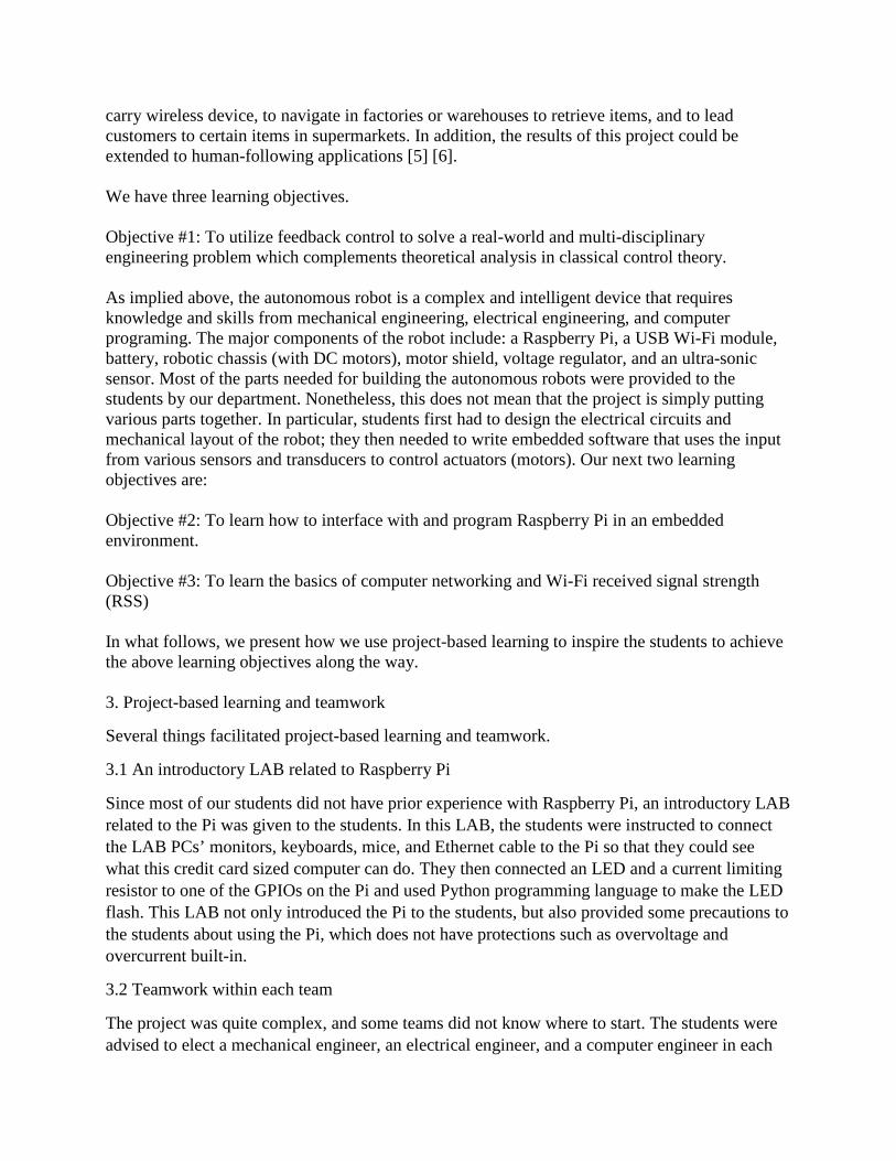
3.1 An introductory LAB related to Raspberry Pi
Since most of our students did not have prior experience with Raspberry Pi, an introductory LAB related to the Pi was given to the students. In this LAB, the students were instructed to connect the LAB PCs’ monitors, keyboards, mice, and Ethernet cable to the Pi so that they could see what this credit card sized computer can do. They then connected an LED and a current limiting resistor to one of the GPIOs on the Pi and used Python programming language to make the LED flash. This LAB not only introduced the Pi to the students, but also provided some precautions to the students about using the Pi, which does not have protections such as overvoltage and overcurrent built-in.
3.2 Teamwork within each team
The project was quite complex, and some teams did not know where to start. The students were advised to elect a mechanical engineer, an electrical engineer, and a computer engineer in each

team (note that we had six teams: five teams had exactly three members and one team had two students). The mechanical engineer’s primary job was to determine how to mount various components onto the robot chassis; the electrical engineer’s primary job was to design and build the electric circuits of the robot; and the computer engineer’s primary job was to design the control algorithm and program the Pi. Instructions were that all three engineers in each team should help each other to achieve the common goal.
3.3 Teamwork among all the teams
In order to accomplish the learning objectives and overcome various technical difficulties, we encouraged the six teams to collaborate. Particularly, the instructor came up with six technical challenges and asked each team to select one to work on. The six technical challenges were: (1) How to enable Wi-Fi USB dongle on the Pi; (2) How to control the Pi over Wi-Fi using Telnet/SSH and scp; (3) How to detect an obstacle using an ultrasonic sensor; (4) How to interface with a motor control module; (5) How to detect the Wi-Fi signal strength of a wireless router from the Pi; and (6) How to control a servo motor. A wiki site was created on www.wikispaces.com for signing up and result sharing purposes. Among many available wiki hosting services, we choose this particular one because their user interface is quite friendly and the usage for educational projects is free. In order to encourage the teams to work on their technical challenges and share the results to other teams, we asked each team to post their solution to their technical challenge on the wiki page and make a presentation to the whole class. This represented twenty percent of the effort, with an additional 5% extra credit to encourage the students to do their best work.
4. Project design and implementation
We now present the project design of the winning team of the Bocce game (details of the Bocce game are described in the next section).
4.1 Hardware
The fully assembled robot is shown in Figure 2.
Figure 2. Assembled robot

Table 1 contains a complete list of all components used in the project as well as their quantities. Note that most of the materials, including the robot chassis and the Wi-Fi modules were available to the students. The Raspberry Pis were the only major items we had to purchase. It is estimated that the total cost of the materials is between $200 and $300.
Table 1. Bill of materials Item Description Quantity Antenna Wi-Fi antenna for dongle 1 Wi-Fi module Ralink RT3572 2T2R USB Wi-Fi dongle 1 Zip Tie 4" white 1 Cable (USB-black) USB 4' cable extension 2 Aluminum Foil Custom signal concentrator (2'x2') 1 Plexiglas Custom Frame, battery holder, mounts (1'x2') 1 Screw (wood) Brass (1/2") 10 Tape Electrical Black (1') 2 Ultrasonic Sensor Parallax Part # 28015 1 Cable (USB-red) USB to Micro USB 1 Battery Digital Energy 9.6 V Rechargeable 2 Spacer Nylon (1") 3 Spacer Nylon (1/4") 5 Connector Red/Black Quick Click connector 2 Machine Screw 4mm x .7 x 30mm 5 Machine Screw 4mm x .7 x 10mm 5 Nut 4mm x .7 10 Regulator 5V DC 2 Capacitor (Large) 334J 1 Capacitor (Small) 104J 1 USB adapter Red with cables 1 Mounting Hardware White - 2 column 1 Raspberry Pi 2 B Computer/Controller 1 Motor Shield Arduino Motor Shield V3 1
MicroSD Card Pre-installed NOOBS card (8GB) 1 Chassis Rover Bot Chassis (with tracks and 4 DC motors) 1 Wiring Misc. connectors 12
Figure 3 through Figure 7 provide details of the individual components for the project as well as some components that the team added to ensure success.

Figure 3. Antenna, Wi-Fi dongle, zip-tie, cable, Wi-Fi signal concentrator
Figure 4. Screw (wood), ultrasound sensor, spacer, bolt, nut, plexiglas bracket
Figure 5. Cable, bracket, battery, platform, connector

Figure 6. Motor shield, spacers, bolts, nuts, brackets, capacitors, 5V regulator, Raspberry Pi 2 B
Figure 7. Wires and rover chassis
4.2 High level design
The team decomposed the project into smaller more manageable subsystems. The subsystem consist of the mechanical components and how they are fastened together. The electrical system and the wiring to properly move power from each component, and the computer system that facilitates motor control and sensory communication. These subsystems allowed the team to correctly delegate tasks. Figure 8 shows a high-level flowchart illustrating the team’s initial design concepts.

Figure 8. Flow chart of high level design
Due to the use of the Raspberry Pi 2 as the computer, Python 3 was selected as the programming language for this project.
To divide labor and ensure high efficiency, the team delegated tasks so that multiple subsystems could be worked upon and completed concurrently. The team self-evaluated each team member’s individual strengths and the task assignments were determined as follows:
Team member 1: Mechanical Engineer/Electrical Engineering
The team member was responsible for the mechanical assembly, fastening of all hardware, fabrication of the frame components, and the custom parabolic signal concentrator. In his role as electrical engineer, the team member wired all electrical components and tested to guarantee that each component would correctly function throughout the competition.
Team member 2: Software Engineer/Wiki Contributor
The team member was responsible for correctly reading sensor data from the ultrasonic sensor and the Wi-Fi dongle and developing the algorithm to find the Wi-Fi source while avoiding obstacles. In completion of these projects, they also had to troubleshoot code to correct any inconsistencies on the wiki page and develop methods to retrieve consistent and reliable Wi-Fi signals.
4.3 Low level design
Assembly
The robot chassis was used as the mounting base for a 4”x8” Plexiglas platform. The wiring harness from the DC motors was routed through the platform and connected to the motor shield. At the rear of the platform the two 9.6V batteries were mounted using a 2.5” x 12” molded strip of Plexiglas. One of the batteries was used to power the Raspberry Pi through one of the 5V regulators. The other battery was sent power to the motor shield and ultrasound sensor. The

power for the ultrasound sensor was sent through the second 5V regulator located on the “mounting hardware (white).” The motor shield was mounted in the center of the platform along with the Raspberry Pi. They were both mounted to the platform using a 2.5” x 7” strip of molded Plexiglas. The wiring for the Raspberry Pi, ultrasound sensor, and motor shield were all routed through the 2.5” x 7” strip to prevent tangling and accidental disconnections. At the front of the platform the Wi-Fi dongle and antenna and ultrasound sensor were both connected via an L shape section of Plexiglas and acrylic hardware. The Custom Parabolic Signal Concentrator was attached around the Wi-Fi dongle and antenna using electrical tape. All components were grounded to common ground on the “mounting hardware (white)”. Programming
Just as in the high level design, the team decomposed each of the programming tasks into smaller modules that could be integrated seamlessly as functions. As each module was completed, it was assimilated into the larger project program. The module is then called as a function anytime that task was needed. Some examples of the smaller coding modules are below.
Ultrasound Code
This function sends a short pulse then listens for the echo. By evaluating the time it takes for this echo to return the distance to an obstacle can be determined. The program calls this function anytime the robot is moving forward to ensure avoidance of all obstacles.
Figure 9. Ultrasonic program
Wi-Fi RSSI Value Code
This code opens a port to the command line and calls the “iwconfig” command, and the result is then parsed for the Wi-Fi signal strength, whose value is returned as an integer for further data processing. This function is called anytime the robot calibrates itself to find the Wi-Fi source. Note that we initially used a USB Wi-Fi module which is marketed for usage on Raspberry Pi. However, it was unable to provide meaningful signal strength values. We had to switch to

another USB Wi-Fi dongle using RT3572: a 2T2R dual-band adapter made by Ralink Technology.
Figure 10. Wi-Fi signal strength detection program
Motor Control and Obstacle Avoidance Code
This code is the main algorithm of the program. The “Locate” function points the robot in the direction of the router. After that, the robot advances while searching for any obstacles within 18 inches. If any obstacle is seen then the robot looks left and then right, evaluates which direction is clear of obstacles and moves in that direction. Every seven seconds the robot recalibrates to find the Wi-Fi source and the process is repeated until a designated signal strength is measured. This signal strength correlates to close proximity to the source.
Figure 11. Motor control and obstacle avoidance program

Finished Program
Upon starting, the robot immediately takes the Wi-Fi signal and averages that for a more consistent reading. The robot then turns 30 degrees and take another average which is compared to the prior to determine the minimum value (the strongest Wi-Fi signal). This is repeated until 360 degrees of rotation has occurred. Once the minimum value is found, the robot repeats the process, comparing the minimum value found to the current values until they match. This process ensures that the robot is pointing in the direction of maximum Wi-Fi signal strength. The robot then moves forward while checking for an obstacle within 16 inches. If there is an obstacle at that distance it will look left and take a distance measurement then look right and take a distance measurement. The robot then determines if there are obstructions in those directions. If there are not, it will go the direction without obstructions; if all are obstructed, it relocates the strongest Wi-Fi signal and starts again. This movement section lasts for 7 seconds, and after that, the Wi-Fi signal location function is called. If at any point the Wi-Fi signal strength received is 23 dBm (within 18 inches of the router) then the robot stops completely. The block diagram shown in Figure 12 depicts the decision structure used in creating the code. This algorithm was used to implement the Python code that made the functioning robot.
Figure 12. Flow chart of the complete program

5. Assessment and the Bocce Game
The grading policy of the project is as follows: 1) Bocce game performance: 40%. • Robot is able to move: 25%. • Robot is able to avoid hitting other objects: 25%. • Robot is able to stop on its own within 2 minutes: 25%. • Robot is able to stop within 6 feet of the jack: 25%. 2) Contribution to the wiki page and Oral Presentation: 20% with possible additional
5% bonus (depending on the difficulty of the topic and the quality of work). 3) Project Report: 40%.
All six robots competed in the indoor Bocce game, which took place in the last week of class in spring 2016. Figure 13 shows the game location in a LAB on campus. During the game, each robot needed to get as close to the router as possible within two minutes while not hitting any obstacles (boxes, trash bin, wall, etc. shown in the figure) To reduce randomness of the game result and to reflect the true performance of the robots, three starting locations are selected. Each robot’s final distance is the average of three attempts, one from each starting point. The overall and break-down grades of all six groups are provided in Table 2. All six robots were able to move and stop on its own within 2 minutes, and they were all controlled by the students via Wi-Fi and ssh sessions. These facts provide solid evidence that we achieved learning objective #2. Among the six groups, four teams were able to stop within 6 feet of the jack. Specifically, the winning team’s final average distance to the router was 0.4m. The second and third place teams’ results were around 1m. We believe that we also achieved learning objectives #1 and #3. The students contributed high quality work to the wiki site, and most teams received extra credit for their hard work. The fact that each team not only solved their own technical challenge, but also learned from other groups provides another evidence showing that learning objectives #2 and #3 were achieved.
Figure 13 Bocce game room

Table 2. Project assessment details Team 1 Team 2 Team 3 Team 4 Team 5 Team 6
Game performance
100% 100% 95% 75% 65% 62.5%
Wiki Page contribution
and oral presentation
125%
90%
100%
125%
110%
115%
Report 95% 75% 90% 75% 60% 79% Overall 103% 88% 94% 85% 72% 79.6%
Finally, the following comments were found in project reports and a student poll:
• “It came out to be a very interesting and effective learning process.” • “The team learned how to successfully evaluate project requirements and how to
decompose large tasks into smaller more manageable subsystems in order to make a functioning robot.”
• “This project was an excellent demonstration of a “divide and conquer” approach as each member had their respective tasks and the final project consisted of the sum of all three group members’ efforts.”
• “We consider this project a success because we learned a great deal and had fun while we worked together with our team chemistry.”
• “Diving deep into the python language was highly educational for us.” • “The knowledge posted by our classmates on the wiki site was helpful.” • “This was my first exposure to using the Raspberry Pi and having software manipulate
devices. My knowledge of programing and interfacing with hardware advanced tremendously.”
• “I learned a lot about using small pieces of code such as for and while loops to serve as feedback for a control system.”
• “I enjoyed learning how to use Putty to remotely access another computer. It is a valuable skill that I have continued to use.”
These comments further prove that the students liked this course project and had learned a lot out of it. 6. Reflective discussion
We think the project could be further improved from several aspects. • The battery provided to the students were several years old, and some of them did not
hold a charge well. As a result, the battery caused the Raspberry Pi and the ultrasonic sensors to behave erratically. One team actually did not do well in the Bocce game, due to a battery issue discovered right before the competition. In the future, we plan to provide new batteries to the students. It may also be a good idea to use a dedicated battery to power the Raspberry Pi.
• Although the project stimulated student enthusiasm through the competition and has practical implications, we did not encourage the students to think further what else can be done beyond the project. It would be very beneficial if we requested the students to incorporate a “future improvement” section in their project reports.

• When this course was offered in spring 2016, most students were graduating in the same semester. Some of them had trouble to focus on their senior design project and this course project at the same time. In order to encourage the students to do their best work, we decided to move this course from the senior year to the junior year, starting from spring 2018.
7. Conclusions
In this paper, we present a course project of an upper-division controls course. The course project required students to build autonomous robots and compete in an indoor Bocce game, utilizing knowledge and skills from multiple disciplines, including mechanical engineering, electrical engineering, and computer engineering. The project has practical implications and used some novel techniques such as the fun Bocce game competition and the wiki site contribution to inspire the students to learn and do their best work in a team environment. The learning objectives were assessed using the results of the Bocce game, student contribution to the wiki site, and student comments in the project reports. Based on the information we collect, we consider that all learning objectives were achieved. We hope the setting used in this project can provide insight to other programs and courses in engineering on interdisciplinary student project design.
Acknowledgement
The authors would like to thank Dr. Charles Perry, Professor and Russell Chair of Manufacturing at MTSU, for supporting the robotic competition.
References
1 Mehrubeoglu, Mehrube. "A Lego Robot Project Using Concept Maps and Peer-Led Teams for a Freshman Course in Engineering and Engineering Technology." American Society for Engineering Education Annual Conference & Exposition, 2009. 2 Rex H. Wong and Sheng-Jen “Tony” Hsieh. “MAKER: An Entry-Level Robotic System Design Project for Undergraduates and K12.” American Society for Engineering Education annual conference & Exposition. New Orleans, LA, June 26-29, 2016 3 Korpela, C. M., and W. J. Adams. "Robotics in multidiscipline multicultural projects." Proceedings of the 2007 Middle Atlantic Section Fall Conference of the American Society for Engineering Education. 2007. 4 Wayne W. Walter and Timothy G. Southerton. “Teaching Robotics by Building Autonomous Mobile Robots Using the Arduino.” American Society for Engineering Education Annual Conference & Exposition. Indianapolis, IN, June 15-18, 2014 5 Hu, Jwu-Sheng, Jyun-Ji Wang, and Daniel Minare Ho. "Design of sensing system and anticipative behavior for human following of mobile robots." IEEE Transactions on Industrial Electronics 61.4 (2014): 1916-1927. 6 Dang, Quoc Khanh, and Young Soo Suh. "Human-following robot using infrared camera." Control, Automation and Systems (ICCAS), 2011 11th International Conference on. IEEE, 2011.