3D Printed Custom Orthotic Device Development - Asee peer
12
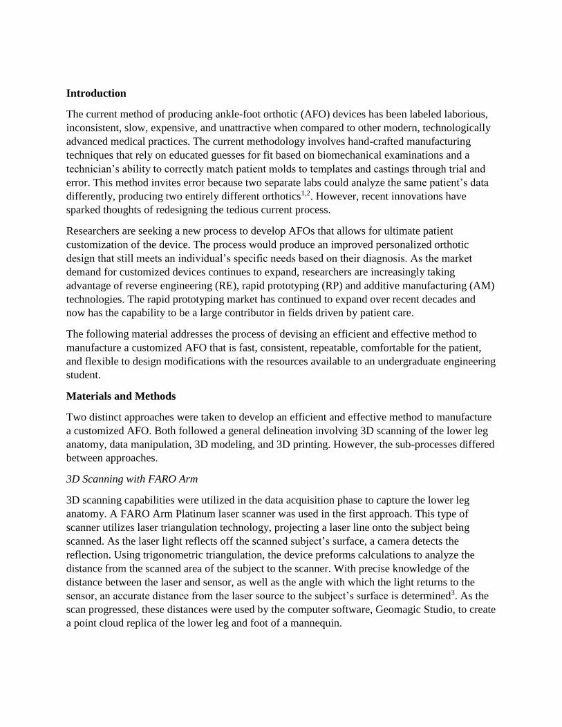
Paper ID #17872 3D Printed Custom Orthotic Device Development: A Student-driven Project April Krivoniak, Robert Morris University Biomedical and Mechanical Engineering Student MS Engineering Management Integrated Student Dr. Arif Sirinterlikci, Robert Morris University Arif Sirinterlikci is a University Professor of Industrial and Manufacturing Engineering and the Depart- ment Head of Engineering at Robert Morris University. He holds BS and MS degrees, both in Mechanical Engineering from Istanbul Technical University in Turkey and his Ph.D. is in Industrial and Systems En- gineering from the Ohio State University. He has been actively involved in ASEE and SME organizations and conducted research in Rapid Prototyping and Reverse Engineering, Biomedical Device Design and Manufacturing, Automation and Robotics, and CAE in Manufacturing Processes fields. c American Society for Engineering Education, 2017
-
Upload
khangminh22 -
Category
Documents
-
view
1 -
download
0
Transcript of 3D Printed Custom Orthotic Device Development - Asee peer
Paper ID #17872
3D Printed Custom Orthotic Device Development: A Student-driven Project
April Krivoniak, Robert Morris University
Biomedical and Mechanical Engineering Student MS Engineering Management Integrated Student
Dr. Arif Sirinterlikci, Robert Morris University
Arif Sirinterlikci is a University Professor of Industrial and Manufacturing Engineering and the Depart-ment Head of Engineering at Robert Morris University. He holds BS and MS degrees, both in MechanicalEngineering from Istanbul Technical University in Turkey and his Ph.D. is in Industrial and Systems En-gineering from the Ohio State University. He has been actively involved in ASEE and SME organizationsand conducted research in Rapid Prototyping and Reverse Engineering, Biomedical Device Design andManufacturing, Automation and Robotics, and CAE in Manufacturing Processes fields.
c©American Society for Engineering Education, 2017

3D Printed Custom Orthotic Device Development:
A Student-driven Project
Abstract
An ankle-foot orthosis (AFO) is an L-shaped orthotic device supporting the lower leg and foot.
AFOs are used to remedy abnormal gait patterns, control ankle movement, and compensate for
muscle weakness in patients experiencing drop foot. They are also used to treat patients with
arthritis, adult acquired flatfoot deformity, and fractures. A junior biomedical engineering
student was tasked to develop a custom fit AFO after she had independently gained 3D scanning
and modeling experience. The following outlines the development process and pedagogical
conclusions from the experience:
• 3D Scanning: Utilizing a FARO Arm laser scanner, a point cloud replica of the lower leg and
foot anatomy was generated. Multiple scans were manually registered and merged to create a
single model, then globally registered to fine tune the anatomical data.
• 3D Data Manipulation: Geomagic Studio software was used to reduce noise and outlying points
while retaining the scanned detail. The Points Wrap command helped reduce the points and
generate a uniform .wrap file. The Polygon Phase capabilities of Geomagic Studio were then
used to repair intersections, fill holes, and refine floating data and edges. The Select by
Curvature command was employed to relax the structure while retaining detail. A NURBS (Non-
Uniform Rational B-Spline) surface was created to finalize the mesh structure and export it as an
.stl file. Once the 3D mesh is generated, the number of triangles comprising the mesh must be
reduced in order to lower computing lag. MeshLab software was utilized to reduce the number of
triangles below 8,000. Autodesk Meshmixer allows for simple, yet detailed modification of .stl
files through direct editing of a mesh geometry, a feature that is not available in SolidWorks.
SolidWorks requires a subtraction command to generate the scanned structure onto a part. With
Meshmixer, the AFO is produced directly from the patient’s original scan without losing much
detail or accuracy. After the .stl was imported, the Extrude command was used to produce depth
for the 3D Printing Process. Next, the data was modified by removing excess material and
utilizing smoothing and sculpting commands to produce a clean and detailed structure.
• 3D Printing: The final .stl file was printed in scale for form checking in a UPrint SE machine.
This lean process results in a custom-fitted AFO matching the patient’s lower limb anatomy.
The use of safe laser scanning technology produces data that will remain available for future
reprints of the custom device in case of wear or lost equipment.
The student was presented a set of Geomagic Tutorials and supplementing data after a FARO
Arm demonstration. No further instructions were given. The student faced a large time
commitment over several months but acquired strong background knowledge and great amount
of skills in 3D Scanning, 3D Data Manipulation, and 3D Printing, along with AFO design
knowledge while successfully completing the task. The student’s competency and confidence
also improved. After completing this project, she took an internship position with a high-tech
tissue simulation/phantom company and performed successfully with the skill and knowledge
gained from this project.
Introduction
The current method of producing ankle-foot orthotic (AFO) devices has been labeled laborious,
inconsistent, slow, expensive, and unattractive when compared to other modern, technologically
advanced medical practices. The current methodology involves hand-crafted manufacturing
techniques that rely on educated guesses for fit based on biomechanical examinations and a
technician’s ability to correctly match patient molds to templates and castings through trial and
error. This method invites error because two separate labs could analyze the same patient’s data
differently, producing two entirely different orthotics1,2. However, recent innovations have
sparked thoughts of redesigning the tedious current process.
Researchers are seeking a new process to develop AFOs that allows for ultimate patient
customization of the device. The process would produce an improved personalized orthotic
design that still meets an individual’s specific needs based on their diagnosis. As the market
demand for customized devices continues to expand, researchers are increasingly taking
advantage of reverse engineering (RE), rapid prototyping (RP) and additive manufacturing (AM)
technologies. The rapid prototyping market has continued to expand over recent decades and
now has the capability to be a large contributor in fields driven by patient care.
The following material addresses the process of devising an efficient and effective method to
manufacture a customized AFO that is fast, consistent, repeatable, comfortable for the patient,
and flexible to design modifications with the resources available to an undergraduate engineering
student.
Materials and Methods
Two distinct approaches were taken to develop an efficient and effective method to manufacture
a customized AFO. Both followed a general delineation involving 3D scanning of the lower leg
anatomy, data manipulation, 3D modeling, and 3D printing. However, the sub-processes differed
between approaches.
3D Scanning with FARO Arm
3D scanning capabilities were utilized in the data acquisition phase to capture the lower leg
anatomy. A FARO Arm Platinum laser scanner was used in the first approach. This type of
scanner utilizes laser triangulation technology, projecting a laser line onto the subject being
scanned. As the laser light reflects off the scanned subject’s surface, a camera detects the
reflection. Using trigonometric triangulation, the device preforms calculations to analyze the
distance from the scanned area of the subject to the scanner. With precise knowledge of the
distance between the laser and sensor, as well as the angle with which the light returns to the
sensor, an accurate distance from the laser source to the subject’s surface is determined3. As the
scan progressed, these distances were used by the computer software, Geomagic Studio, to create
a point cloud replica of the lower leg and foot of a mannequin.

Multiple scans of a detailed mannequin’s lower leg and foot were taken from various angles,
being certain to capture all necessary regions of the anatomy for production of an AFO. When
scanning with the FARO Arm, one had to ensure they moved slowly to capture the detail of the
foot as the single projected laser line moved over the subject. With the arm being attached to a
tabletop, the range of the person performing the scanning was restricted. Thus, it became extra
pertinent that every area of the lower leg and foot was captured with extreme focus and attention
to detail. The scans were manually, then globally registered to enable the capability to create an
accurate, fine-tuned model of the anatomy in future steps illustrated below in Figure 1.
Figure 1. Watertight completed scan model
3D Scanning with Xbox 360 Kinect
An Xbox 360 Kinect was used to capture the lower leg and foot in the second process approach.
The Kinect’s human recognition capabilities stem from its use of 2D and 3D camera systems.
The Kinect transmits an infrared pattern onto the surface of the subject that is being captured.
The pattern is generated with diffraction grating. Once transmitted and reflected from the
scanned subject’s surface, the Kinect receives the reflection of the light with an infrared camera.
The measurements attained by the Kinect are read and stored in the Cartesian coordinate system
and depend on the distance and deviation of the data to the zero axis3.
A scan of a subject’s lower leg and foot anatomy was taken using the Kinect system. To capture
the scan, the SDK Browser that correlates with Kinect’s Windows compatibility and the Skanect
software package needed to be downloaded and available on a nearby PC. The Kinect was
plugged into the wall, as well as the nearby computer through a USB cable attachment that was
sold with the Kinect. The Kinect’s wire attachments did not pose many restrictions. The wires
were of ample length and allowed for the person performing the scanning to move freely around
the subject being scanned. After one full revolution of the Kinect scanner around the lower leg
and foot, the scanned data appeared in the Skanect window and was ready for the data
manipulation phase of the process.
Data Manipulation of Faro Arm Scan
Geomagic Studio software was used to process the data acquired from the FARO Arm Platinum
laser scanner. Geomagic was used to reduce noise and outlying points while retaining the scan’s
detail. The ‘Points Wrap’ command helped reduce the points and generate a uniform .wrap file.
The polygon phase capabilities of Geomagic Studio were used to repair intersections, fill holes,
and refine floating data and edges. The ‘Select by Curvature’ command was employed to relax
the structure while retaining detail. A NURBS (Non-Uniform Rational B-Spline) surface was
generated to finalize the mesh structure and export it as an .stl file.
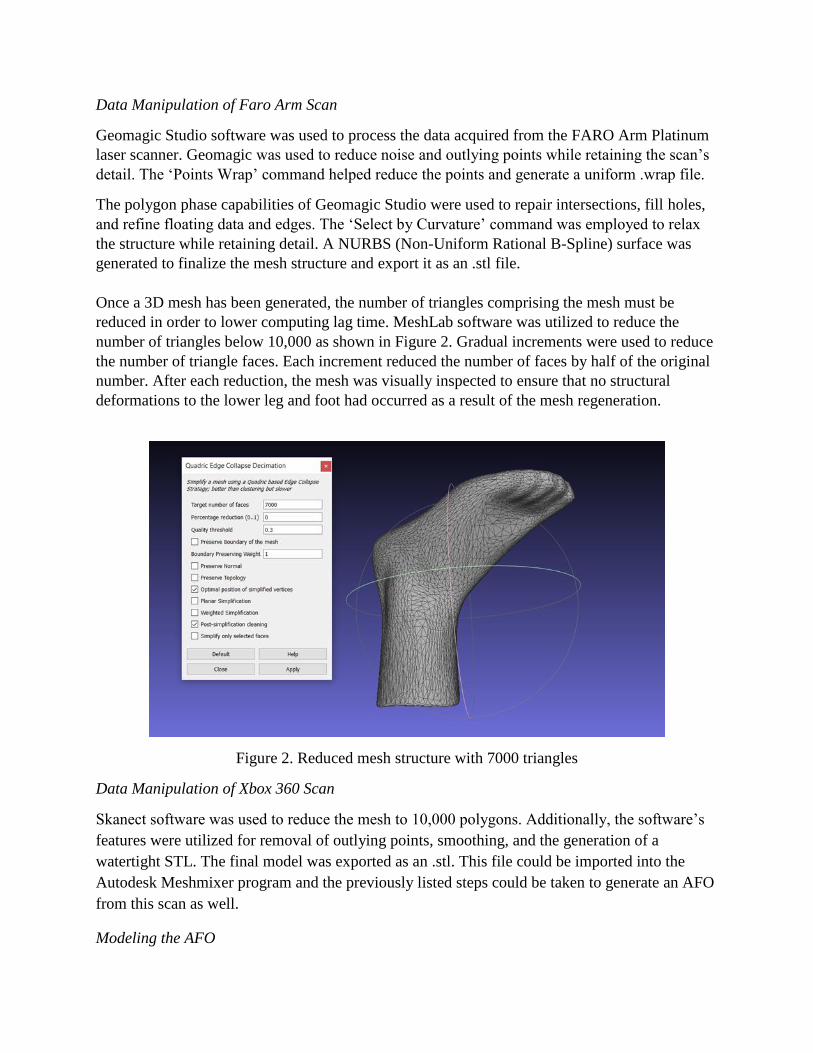
Once a 3D mesh has been generated, the number of triangles comprising the mesh must be
reduced in order to lower computing lag time. MeshLab software was utilized to reduce the
number of triangles below 10,000 as shown in Figure 2. Gradual increments were used to reduce
the number of triangle faces. Each increment reduced the number of faces by half of the original
number. After each reduction, the mesh was visually inspected to ensure that no structural
deformations to the lower leg and foot had occurred as a result of the mesh regeneration.
Figure 2. Reduced mesh structure with 7000 triangles
Data Manipulation of Xbox 360 Scan
Skanect software was used to reduce the mesh to 10,000 polygons. Additionally, the software’s
features were utilized for removal of outlying points, smoothing, and the generation of a
watertight STL. The final model was exported as an .stl. This file could be imported into the
Autodesk Meshmixer program and the previously listed steps could be taken to generate an AFO
from this scan as well.
Modeling the AFO
The Autodesk Meshmixer program allowed simple, yet detailed modifications to be made to the
imported .stl file. The software enabled direct editing of the mesh geometry to occur; this was a
feature that was not available in SolidWorks. SolidWorks required a subtraction command to
impose the scanned structure’s custom geometry onto a part or previously modeled AFO device.
With Meshmixer, the AFO could be produced directly from the patient’s original scan without
the concern of losing much detail or accuracy provided by the custom scan. After the .stl was
imported into the Meshmixer software, the ‘offset’ command was used to set the contact surface
of the AFO 3mm from the surface of the lower leg and foot, allowing for patient comfort and a
realistic fit. Then, the ‘extrude’ command was used to produce depth for the reality of an AFO
and for the 3D printing process. Next, the scanned structure was modified by removing excess
material and utilizing ‘smoothing’ and ‘sculpting’ commands to produce a clean and detailed
structure of an AFO.
3D Printing
A Stratasys uPrint SE, with a build size of 203 x 152 x 152 mm (8 x 6 x 6 in), was used to print
the AFO model in scale for form checking and design evaluation purposes. The uPrint SE used
ABS material with a layer thickness of .254 mm (.010 in) to print the non-functional prototype.
Results
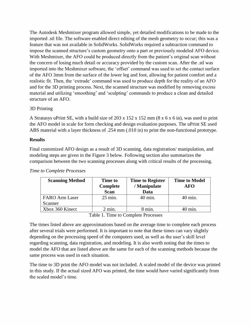
Final customized AFO design as a result of 3D scanning, data registration/ manipulation, and
modeling steps are given in the Figure 3 below. Following section also summarizes the
comparison between the two scanning processes along with critical results of the processing.
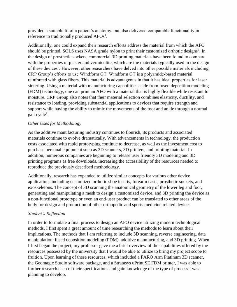
Time to Complete Processes
Scanning Method Time to
Complete
Scan
Time to Register
/ Manipulate
Data
Time to Model
AFO
FARO Arm Laser
Scanner
25 min. 40 min. 40 min.
Xbox 360 Kinect 2 min. 8 min. 40 min.
Table 1. Time to Complete Processes
The times listed above are approximations based on the average time to complete each process
after several trials were performed. It is important to note that these times can vary slightly
depending on the processing speed of the computers used, as well as the user’s skill level
regarding scanning, data registration, and modeling. It is also worth noting that the times to
model the AFO that are listed above are the same for each of the scanning methods because the
same process was used in each situation.
The time to 3D print the AFO model was not included. A scaled model of the device was printed
in this study. If the actual sized AFO was printed, the time would have varied significantly from
the scaled model’s time.

Figure 3. Final customized AFO design as a result of 3D scanning, data registration/
manipulation, and modeling
Scanning Process (FARO vs. Kinect)
Using the FARO Arm laser scanner to capture a 3D scan of the lower leg and foot anatomy took
a considerably longer amount of time than the Xbox 360 Kinect method. Additionally, the FARO
Arm is not a portable scanning device. With the arm mounted to a tabletop, the user had very
little freedom to move the scanning tip around the leg that was being scanned. Though the Kinect
is not a portable when plugged into the necessary sources, this scanning device offers its user a
greater range of motion because it is not permanently mounted, but rather bound by a few long,
flexible cables. The user was able to circle the leg being scanned with ease.
Repeatability of Process
The overall process, whether using the FARO Arm or Kinect to capture the 3D scan, proved to
be a repeatable method for producing AFOs. Each step in the process was standardized and
repeated throughout several trials.
Flexibility of Process
The process also proved to have room for flexibility in the event that a clinician would need to
modify the design of an AFO to match a patient’s specific diagnosis. The nature of the process of
3D scanning a surface to produce a customized device is alone in that it provides a platform to
easily generate a patient’s unique structure digitally. The scanning phase also showed that it
could be flexible amid the different techniques tested throughout this process. Finally, the
modeling phase of the process exposed that it could lend clinicians the freedom to digitally
manipulate an AFO to suit a patient’s specific diagnosed needs before manufacturing or printing
the device.

Consistency of Process and Deliverable (Eliminating Human Error)
The process described above eliminated the possibility of human error when generating a model
of the lower leg and foot anatomy. Rather than the traditional method of attaining an impression
of the patient’s anatomy through casting and molding, Thus, 3D scanning eliminated the
possibility of human interference in the geometry acquisition phase. Additionally, rather than the
laborious guess and check method of forming the orthotic to fit a patient’s lower leg bust, the
method described above generated the device directly from the patient’s digital model of their
anatomy. Again, this also eliminated additional chance for human error in interfering with and
altering the customized shape of the product.
Answering the Large Question
The large question imposed by this study inquired if it was possible to devise an efficient and
effective method to manufacture a customized AFO that is fast, consistent, repeatable,
comfortable for the patient, and flexible to design modifications. The factors of speed,
consistency, repeatability, comfort, and flexibility have been addressed in previous sections.
However, it is also important to note the trade-off of high-accuracy and low-cost associated with
rapid prototyping compared to traditional methods. The highly accurate method of using 3D
scanning to reproduce a patient’s exact anatomy traded with the one-time investment in the
hardware and software needed to execute the process leads to the possession of a highly effective
method of producing customized AFOs.
Additionally, it is worth noting the cost, accessibility, and accuracy associated with this proposed
method. With the associated costs of 3D printing technology being driven down with the recent
surge experienced by the industry, it is becoming increasingly more feasible to utilize a rapid
printing process, like the one explained above, or a newly develop low-cost printing material
with appropriate capabilities to produce orthotic devices. This method introduces numerous
advantages such as the capability to reduce material waste when compared to a traditional
method. In addition, the process can reduce time and labor costs being that it is cheaper and
easier to execute than the common laborious process currently in place. Finally, this
technologically superior method can aid clinicians in their ability to produce more durable and
aesthetically pleasing devices, in turn, attracting a greater market of consumers4.
Conclusions
Future Work
The methodology described above can be used as a basis for other research efforts. After 3D
printing several orthotics to match specific patients and their diagnoses, one could conduct an
analysis to evaluate and compare the mechanical properties of a 3D printed orthotic versus that
of an orthotic produced using a conventional method. Constantinos Mavroidis and his colleagues
conducted a test using a motion capture system in order to compare the biomechanics of the gaits
of patients wearing 3D printed AFOs and those wearing traditionally produced devices. After
studying the parameters, kinematics, and kinetics of the patients’ lower limb joints in the sagittal
plane, they were able to determine that AFOs generated through rapid prototyping not only
provided a suitable fit of a patient’s anatomy, but also delivered comparable functionality in
reference to traditionally produced AFOs1.
Additionally, one could expand their research efforts address the material from which the AFO
should be printed. SOLS uses NASA grade nylon to print their customized orthotic designs5. In
the design of prosthetic sockets, commercial 3D printing materials have been found to compare
with the properties of plaster and vermiculite, which are the materials typically used in the design
of these devices6. However, other researchers have delved into other possible materials including
CRP Group’s efforts to use Windform GT. Windform GT is a polyamide-based material
reinforced with glass fibers. This material is advantageous in that it has ideal properties for laser
sintering. Using a material with manufacturing capabilities aside from fused deposition modeling
(FDM) technology, one can print an AFO with a material that is highly flexible while resistant to
moisture. CRP Group also notes that their material selection combines elasticity, ductility, and
resistance to loading, providing substantial applications to devices that require strength and
support while having the ability to mimic the movements of the foot and ankle through a normal
gait cycle7.
Other Uses for Methodology
As the additive manufacturing industry continues to flourish, its products and associated
materials continue to evolve dramatically. With advancements in technology, the production
costs associated with rapid prototyping continue to decrease, as well as the investment cost to
purchase personal equipment such as 3D scanners, 3D printers, and printing material. In
addition, numerous companies are beginning to release user friendly 3D modeling and 3D
printing programs as free downloads, increasing the accessibility of the resources needed to
reproduce the previously described methodology.
Additionally, research has expanded to utilize similar concepts for various other device
applications including customized orthotic shoe inserts, forearm casts, prosthetic sockets, and
exoskeletons. The concept of 3D scanning the anatomical geometry of the lower leg and foot,
generating and manipulating a mesh to design a customized device, and 3D printing the device as
a non-functional prototype or even an end-user product can be translated to other areas of the
body for design and production of other orthopedic and sports medicine related devices.
Student’s Reflection
In order to formulate a final process to design an AFO device utilizing modern technological
methods, I first spent a great amount of time researching the methods to learn about their
implications. The methods that I am referring to include 3D scanning, reverse engineering, data
manipulation, fused deposition modeling (FDM), additive manufacturing, and 3D printing. When
I first began the project, my professor gave me a brief overview of the capabilities offered by the
resources possessed by the university that I would be able to utilize to bring my project scope to
fruition. Upon learning of these resources, which included a FARO Arm Platinum 3D scanner,
the Geomagic Studio software package, and a Stratasys uPrint SE FDM printer, I was able to
further research each of their specifications and gain knowledge of the type of process I was
planning to develop.

Following my initial research, my professor lent me a series of tutorials to learn and understand
the Geomagic Studio software package that I would utilize to capture a scan and manipulate its
corresponding data into a usable model. Several divisions of the tutorial, or modules, proved
most relevant and could be utilized in my specific project. These modules detailed point cloud
editing, working with large data sets, data registration, and NURBS surface generation. From
these specific divisions of the tutorial, I was able to formulate a broad, initial process for
capturing a scan and manipulating its data into a polygon surface mesh that could be exported as
a watertight .stl.
The process did not develop without multiple trials and iterations of each step defined by the
tutorials. The overall process took nearly 3 months to develop as I used my free-time aside from
class and other extracurricular activities to formulate its structure. Spending this much time
learning the methods of scanning and data manipulation seemed tedious at the time, not to
mention the numerous times program glitches and system lag time added additional monotony
and challenges, forcing entire process restarts. However, reflecting on the experience, taking the
time to learn each of the modules and concepts on my own, outside of a traditional classroom
setting, encouraged me to truly learn each phase’s specifications while having the freedom to
learn through hands-on execution of each tutorial.
At the conclusion of developing a process to scan a lower limb and foot and manipulate the data
into an exportable .stl file, I faced another roadblock. I was unable to import my .stl file into any
other 3D modeling programs available to students at my department because the polygon count
of the mesh was too large. Attempting to upload the mesh into other software such as
SolidWorks or AutoCAD inventor, resulted in the programs not responding, forcing a program
shutdown. After describing this problem to my professor, we worked for a few days to find a
program that would allow us to reduce the number of polygons comprising the lower leg and foot
mesh. After downloading a free version of MeshLab and testing the program’s various
commands, we were able to find a method to reduce the current number of 180,000 triangles to
7,000 triangles without losing the integrity of the scan’s geometry. This reduced model could
then be uploaded to the modeling programs tested earlier.
In theory, the rest of the process involving the design of the actual AFO utilizing the 3D scan file
of the foot should have fallen into place with ease. However, I encountered yet another
roadblock. Though I was able to import the scan into SolidWorks and AutoCAD Inventor, I was
unable to construct an acceptable design of an AFO that incorporated the unique geometry of the
lower leg and foot that I scanned with the process that my professor and I initially believed
would produce our desired deliverable. With this barrier in front of me, I revisited the drawing
board to formulate a new potential sub-process to construct a design of an AFO, specific to the
custom geometry of the scanned foot.
My research efforts involved a search for a program that would allow me to manipulate scanned
data with precision, but a program that would also allow me to work with a great degree of
freedom across multiple surface planes. The later principle was especially important due to the
fact that the scanned mesh was comprised of several thousand triangles, each falling in a
different orientation with respect to the Cartesian coordinate system. My search lead me to one
of Autodesk’s newest program releases, Autodesk Meshmixer. The software met my initial
requirements and offered an extremely user-friendly interface in which I was able to formulate a
new process to manipulate my scan. The final process that I used to develop an actual AFO
device is described above under the Materials and Methods, v. Modifying the AFO section.
With a final digital model in hand, I was able to export an .stl file and transfer it to the Stratasys
uPrint SE printer. The printer’s bed did not offer enough space to print a full-scale model, so a
scaled down version of the AFO was printed for form checking purposes. Though the actual-
sized model was not printed, I was still able to learn and actively engage in the process of 3D
printing a prototype.
Learning about the processes involved with 3D scanning an object, manipulating the data of the
scan, modeling a device, and 3D printing a prototype, and having the ability to personally utilize
the concepts to formulate a process used in bringing an idea to fruition, I was able to gain
valuable knowledge at a level of detail beyond what would have been realized in a traditional
classroom setting. This project provided a platform for me to grow my ability to work
independently on a large task, and gain reputable skills and knowledge for future industry
applications. Since completing this project, I have had the opportunity to present my work at a
conference, structure a technical paper for submission to future conferences and potential journal
submissions, and utilize a similar process in the design of a 3D printed forearm cast for my
senior-level biomedical design class. The information that I gained from my independent
research effort has helped place me ahead of the other students in my class, providing me with a
host of familiarity and knowledge of valuable processes that I have used to develop additional
innovative projects beyond baseline course requirements. Additionally, the project instilled a
new level of confidence in my ability to work independently, communicate with a project
manager, and ultimately formulate an industry relevant process while gaining significant
engineering knowledge and skills. This confidence and its corresponding skills helped me to land
a product design engineering internship with a medical device company, developing tissue
simulating, multimodality phantoms for the medical imaging industry.
Professor’s Reflection
This study is a good example for a student driven project. It can also be seen as a project with a
facilitation component.
The student was presented laboratory capabilities, a set of Geomagic Tutorials and
supplementing data after a FARO Arm demonstration. No further instructions were given, other
than some discussions occurring if there was a problem just like in the case of editing .stl files.
The student faced a large time commitment over several months but acquired strong knowledge
and great amount of skills in 3D scanning, 3D data manipulation, and 3D printing, along with
AFO design knowledge due to her strong work ethics and will to learn. The student’s
competency and confidence also improved. After completing this project, she took an internship
position with a high-tech tissue simulation/phantom company and performed successfully with
the skill and knowledge gained from this project. Following ABET student outcomes are also
covered in this independent study:
(Outcome c) an ability to design a system, component, or process to meet desired needs within
realistic constraints such as economic, environmental, social, political, ethical, health and safety,
manufacturability, and sustainability: The student designed a custom AFO with the realistic
constraints of confirming to actual anatomy, weight.
(Outcome e) an ability to identify, formulate, and solve engineering problems: The student was
able to identify and solve a wide range of problems including SolidWorks software limitations
and triangular mesh size by using other software tools and reducing the number of triangles.
(Outcome g) an ability to communicate effectively: The student successfully prepared a final
report, two conference papers, along with a Power Point presentation. She also shared her results
with two professors
(Outcome i) A recognition of the need for, and an ability to engage in life-long learning: Since
the most of the learning experience took place individually, the student has now the knowledge
and confidence for learning new tools.
(Outcome k) an ability to use the techniques, skills, and modern engineering tools necessary for
engineering practice: The student has now the competency in multiple scanners including FARO
Arm, and Kinect, along with MeshLab, Meshmixer, SolidWorks software tools and UPrint SE
3D printer and its associated software CatalystEX.
References:
[1] Mavroidis, C., Ranky, R. G., Sivak, M. L., Patritti, B. L., DiPisa, J., Caddle, A., … Bonato, P. (2011). Patient
specific ankle-foot orthoses using rapid prototyping. Journal of NeuroEngineering and Rehabilitation.8(1), 1-11.
doi: 10.1186/1743-0003-8-1
[2] New 3D printing technology helps enable customized, in-office-printed orthotics (2015). Los Angeles: Anthem
Media Group. Retrieved from
https://reddog.rmu.edu/login?url=http://search.proquest.com/docview/1718199313?accountid=28365
[3] Zug, S., Penzlin, F., Dietrich, A., Nguyen, T. T., & Sven, A. (2012). Are laser scanners replaceable by Kinect
sensors in robotic applications? Institute of Electrical and Electronics Engineers. Retrieved from
https://pdfs.semanticscholar.org/00a7/bb020b5f1eea7311439289f8c15f79c62429.pdf
[4] Innovations and novel manufacturing techniques to hold the future for orthotic devices. (2015, Jan 06). M2
Presswire, Retrieved from
https://reddog.rmu.edu/login?url=http://search.proquest.com/docview/1642128238?accountid=28365
[5] SOLS; SOLS and WebPT partner to bring custom 3D foot orthotics to rehab therapy professionals nationwide.
(2015). Journal of Engineering, 3937. Retrieved from
https://reddog.rmu.edu/login?url=http://search.proquest.com/docview/1654415561?accountid=28365
[6] Chimento, J., Highsmith, M. J., & Crane, N. (2011). 3D printed tooling for thermoforming of medical devices.
Rapid Prototyping Journal, 17(5), 387-392. doi: http://dx.doi.org/10.1108/13552541111156513
[7] 3D-Printed orthotics from reinforced laser sintering materials. (2015). Medical Design Technology, Retrieved
from https://reddog.rmu.edu/login?url=http://search.proquest.com/docview/1687713503?accountid=28365