
An experimental study on motion error of hexarot parallel manipulator
16
ORIGINAL ARTICLE An experimental study on motion error of hexarot parallel manipulator Mohammad Reza Chalak Qazani & Siamak Pedrammehr & Arash Rahmani & Mehran Shahryari & Aslan Khani Sheykh Rajab & Mir Mohammad Ettefagh Received: 22 October 2013 /Accepted: 31 January 2014 # Springer-Verlag London 2014 Abstract In this paper, a novel 6-DOF parallel manipulator with coaxial actuated arms is introduced and investigated. This mechanism has six rotating arms, and by rotation of arms about the base, positioning and desired movement of the mechanism is achieved. Sine parallel mechanisms have a nonlinear motion while moving from an initial position to a desired position, investigation of nonlinear error in such mechanisms is of par- amount importance. In this paper, inverse and forward kine- matics of the mechanism are studied. Nonlinear error of the mechanism’ s motion in its workspace is extracted using mid- oscillating circle and kinematic relations as well. Moreover, effective parameters on nonlinear motion error of mechanism are determined. The results obtained by theoretical method are further verified through image processing experimental tests. It is found that the results of the theoretical analysis and experi- mental test are in good consistency. Keywords Parallel mechanism . Hexarot . Kinematics . Nonlinear error . Image processing 1 Introduction The general demand on the mechanism design lies primarily in the high acceleration capability of the mechanism axes while at the same time meeting the high demands on accuracy [1]. Currently, most of the mechanisms are designed on the basis of using simple open kinematic chain. Such multiaxes mechanisms suffer from the disadvantage that each axis must either move or carry all other axes that are situated further along the kinematic chain. In order to overcome this weakness, parallel mechanism has found extensive application in the industry. The accuracy is among the primary requirements for all mechanisms. This needs a thorough understanding of the tool path programming. The purpose of the present study was to partially meet this need and fill the gap existing in the literature in this respect. Both the inverse and forward kinematics of parallel mecha- nisms exhibit nonlinear behaviors. In the inverse kinematics, the pods’ lengths do not change linearly with a linear path travelled by the platform [2–4]. In the forward kinematics, when pods are actuated linearly, the platform moves along a nonlinear path. This makes the path control and interpolation functions in parallel mechanisms become more complex than in serial manipulators. Zheng et al. [5] investigated path control for a novel 5-DOF parallel mechanism. They demonstrated the nonlinearity of both inverse and forward kinematics of the mechanism, they proposed a novel interpolation algorithm, and however they did not elab- orate the nonlinearity of the mechanism. Beale [6] made the first serious attempt to measure nonlinearity and proposed four mea- sures of nonlinearity. This problem has been tackled in several research works. Guttman and Meeter [ 7] showed that Beale’ s measures tend to predict that a model will behave linearly even when considerable nonlinearity is present. Box [8] presented a formula for estimating the bias in the LS estimators. Using simulation studies, Gillis and Ratkowsky [9] found that this formula not only predicted bias to the correct order of magnitude in yield density models but also gave a good indication of the M. R. Chalak Qazani (*) Faculty of Technology & Engineering, Department of Mechanical Engineering, Tarbiat Modares University, Tehran, Iran e-mail: [email protected] S. Pedrammehr Faculty of Engineering and Natural Sciences, Sabanci University, Tuzla, Istanbul, Turkey M. Shahryari Faculty of Engineering, Ahar Branch, Islamic Azad University, Ahar, Iran A. Khani Sheykh Rajab Department of Mechanical Engineering, Ilkhchi Branch, Islamic Azad University, Ilkhchi, Iran A. Rahmani : M. M. Ettefagh Faculty of Mechanical Engineering, University of Tabriz, Tabriz, Iran Int J Adv Manuf Technol DOI 10.1007/s00170-014-5685-y
Transcript of An experimental study on motion error of hexarot parallel manipulator

ORIGINAL ARTICLE
An experimental study on motion error of hexarotparallel manipulator
Mohammad Reza Chalak Qazani & Siamak Pedrammehr &
Arash Rahmani & Mehran Shahryari &Aslan Khani Sheykh Rajab & Mir Mohammad Ettefagh
Received: 22 October 2013 /Accepted: 31 January 2014# Springer-Verlag London 2014
Abstract In this paper, a novel 6-DOF parallel manipulatorwith coaxial actuated arms is introduced and investigated. Thismechanism has six rotating arms, and by rotation of arms aboutthe base, positioning and desired movement of the mechanismis achieved. Sine parallel mechanisms have a nonlinear motionwhile moving from an initial position to a desired position,investigation of nonlinear error in such mechanisms is of par-amount importance. In this paper, inverse and forward kine-matics of the mechanism are studied. Nonlinear error of themechanism’s motion in its workspace is extracted using mid-oscillating circle and kinematic relations as well. Moreover,effective parameters on nonlinear motion error of mechanismare determined. The results obtained by theoretical method arefurther verified through image processing experimental tests. Itis found that the results of the theoretical analysis and experi-mental test are in good consistency.
Keywords Parallel mechanism . Hexarot . Kinematics .
Nonlinear error . Image processing
1 Introduction
The general demand on the mechanism design lies primarily inthe high acceleration capability of the mechanism axes while atthe same time meeting the high demands on accuracy [1].Currently, most of the mechanisms are designed on the basis ofusing simple open kinematic chain. Such multiaxes mechanismssuffer from the disadvantage that each axis must either move orcarry all other axes that are situated further along the kinematicchain. In order to overcome this weakness, parallel mechanismhas found extensive application in the industry. The accuracy isamong the primary requirements for all mechanisms. This needsa thorough understanding of the tool path programming. Thepurpose of the present study was to partially meet this need andfill the gap existing in the literature in this respect.
Both the inverse and forward kinematics of parallel mecha-nisms exhibit nonlinear behaviors. In the inverse kinematics, thepods’ lengths do not change linearly with a linear path travelledby the platform [2–4]. In the forward kinematics, when pods areactuated linearly, the platformmoves along a nonlinear path. Thismakes the path control and interpolation functions in parallelmechanisms become more complex than in serial manipulators.Zheng et al. [5] investigated path control for a novel 5-DOFparallel mechanism. They demonstrated the nonlinearity of bothinverse and forward kinematics of themechanism, they proposeda novel interpolation algorithm, and however they did not elab-orate the nonlinearity of the mechanism. Beale [6] made the firstserious attempt to measure nonlinearity and proposed four mea-sures of nonlinearity. This problem has been tackled in severalresearch works. Guttman and Meeter [7] showed that Beale’smeasures tend to predict that a model will behave linearly evenwhen considerable nonlinearity is present. Box [8] presented aformula for estimating the bias in the LS estimators. Usingsimulation studies, Gillis and Ratkowsky [9] found that thisformula not only predicted bias to the correct order of magnitudein yield density models but also gave a good indication of the
M. R. Chalak Qazani (*)Faculty of Technology & Engineering, Department of MechanicalEngineering, Tarbiat Modares University, Tehran, Irane-mail: [email protected]
S. PedrammehrFaculty of Engineering and Natural Sciences, Sabanci University,Tuzla, Istanbul, Turkey
M. ShahryariFaculty of Engineering, Ahar Branch, Islamic Azad University, Ahar,Iran
A. Khani Sheykh RajabDepartment of Mechanical Engineering, Ilkhchi Branch, IslamicAzad University, Ilkhchi, Iran
A. Rahmani :M. M. EttefaghFaculty ofMechanical Engineering, University of Tabriz, Tabriz, Iran
Int J Adv Manuf TechnolDOI 10.1007/s00170-014-5685-y
extent of nonlinear behavior of the model as well. Bates andWatts [10] developed newmeasures of nonlinearity based on thegeometric concept of curvature. They utilized the maximumrelative intrinsic and parameter effects curvatures of the solutionlocus for estimating the extent of nonlinearity. They showed thatthe projections of the straight and equispaced parametric lines inthe parameter space onto the plane tangent to the solution locusare, in general, neither straight nor equispaced. Karimi andNategh [11] employedBates andWatts’measures of nonlinearityto investigate the nonlinearity of the forward kinematics. Theydemonstrated that the length of the region, defined as the linearapproximation of the lifted line, has a significant impact on thenonlinearity of themechanism. Dasgupta andMruthyunjaya [12]developed an algorithm for singularity-free path planning of theStewart platform manipulator. The limitations of their algorithmwere its lack of confidence in detecting the nonexistence of asingularity-free path and its sensitivity to intersections of singu-larity hypersurfaces. Shaw and Chen [13] investigated an algo-rithm for generating the cutting path of a parallel kinematicmachine. Iso-scallop method and genetic algorithm are utilizedrespectively in the process of generating the cutting path andfinding the configurations of the tool without a singular positionin their research work. Merlet [14] investigated trajectory verifi-cation for a classical Gough-Stewart platform. In his study, thereal-time method has been developed and errors have beencontrolled. Pugazhenthi et al. [15] developed an optimal trajec-tory planning algorithm for a parallel kinematic machine duringcontour machining. They developed a code to maximize thestiffness of the structure and minimize the force requirement ofthe actuator, and the constraints of workplace and singularityhave been taken into account in their study. Dash et al. [16]presented a numerical technique for path planning within theworkspace of parallel manipulators. Isolated singularities havebeen eliminated through local routing method based onGrassmann’s line geometry in their study. Afroun et al. [17, 18]presented a technique for generating optimalmotion for a parallelDELTA robot and Gough parallel robot. In their study, thesequential programming quadratic method has been applied tofind the optimal position of the spline control points. Harib et al.[19] developed an analytical model for trajectory planning of aredundant hybrid machine tool structure consisting of a Stewartplatform and a two-degree-of-freedom rotary tilting table.Having presented eight coordinates, they defined five coordi-nates through conventional part programming and other threecoordinates via trajectory planning. Li [20] investigated recon-figuration and tool path planning of hexapod machine tools. Inhis study, appropriate trajectory planning is considered to reducea nonlinear error in the path. Jinsong et al. [21] utilized kinematicnonlinearity of parallel machine tools to investigate their interpo-lation accuracy.
In this paper, inverse and forward kinematic relations ofhexarot mechanism are developed. By having instantaneousvelocity and acceleration in any point, it is possible to obtain
error. Therefore, nonlinear error of the mechanism’s motion inits workspace is extracted using mid-oscillating circle andkinematic relations as well. Effective parameters on nonlinearmotion error of mechanism are also determined. The resultsobtained by theoretical method are also examined throughimage processing. It is found that the results of theoreticalanalysis and experimental test are in good consistency.
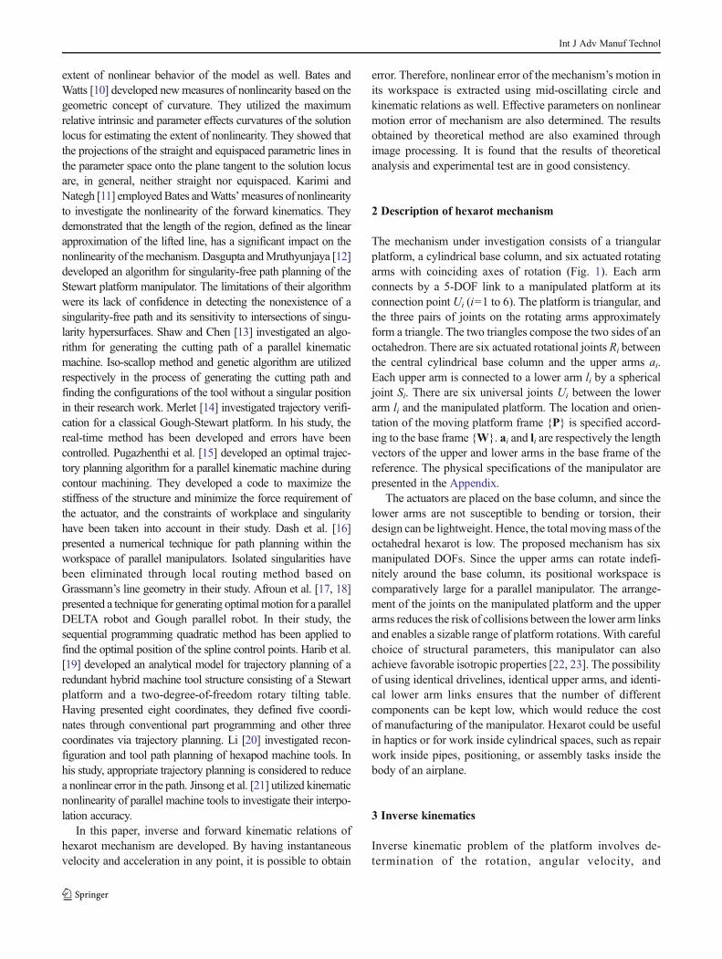
2 Description of hexarot mechanism
The mechanism under investigation consists of a triangularplatform, a cylindrical base column, and six actuated rotatingarms with coinciding axes of rotation (Fig. 1). Each armconnects by a 5-DOF link to a manipulated platform at itsconnection point Ui (i=1 to 6). The platform is triangular, andthe three pairs of joints on the rotating arms approximatelyform a triangle. The two triangles compose the two sides of anoctahedron. There are six actuated rotational joints Ri betweenthe central cylindrical base column and the upper arms ai.Each upper arm is connected to a lower arm li by a sphericaljoint Si. There are six universal joints Ui between the lowerarm li and the manipulated platform. The location and orien-tation of the moving platform frame {P} is specified accord-ing to the base frame {W}. ai and li are respectively the lengthvectors of the upper and lower arms in the base frame of thereference. The physical specifications of the manipulator arepresented in the Appendix.
The actuators are placed on the base column, and since thelower arms are not susceptible to bending or torsion, theirdesign can be lightweight. Hence, the total movingmass of theoctahedral hexarot is low. The proposed mechanism has sixmanipulated DOFs. Since the upper arms can rotate indefi-nitely around the base column, its positional workspace iscomparatively large for a parallel manipulator. The arrange-ment of the joints on the manipulated platform and the upperarms reduces the risk of collisions between the lower arm linksand enables a sizable range of platform rotations. With carefulchoice of structural parameters, this manipulator can alsoachieve favorable isotropic properties [22, 23]. The possibilityof using identical drivelines, identical upper arms, and identi-cal lower arm links ensures that the number of differentcomponents can be kept low, which would reduce the costof manufacturing of the manipulator. Hexarot could be usefulin haptics or for work inside cylindrical spaces, such as repairwork inside pipes, positioning, or assembly tasks inside thebody of an airplane.
3 Inverse kinematics
Inverse kinematic problem of the platform involves de-termination of the rotation, angular velocity, and
Int J Adv Manuf Technol

acceleration of six arms through considering a specifiedposition, velocity, and acceleration of the moving plat-form center.
Considering a vectorial representation of the mech-anism, position vector of the ith spherical joint withthe reference in base frame, ai, can be obtained asfollows:
ai ¼ ai cos φi ai sin φi hi½ �T ð1Þ
where φi is the angle between the ith upper arm and X-axis ofthe reference frame {W} and indicates the rotation of the ithupper arm around the base column.
Considering the moving platform as an equilateral triangle,and taking into account s1 as the length of its sides and s2 asthe distance between the universal joint and the vertex, theposition of each universal joint, Ppi, with reference in frame{P} can be presented as follows:
Ppi ¼s1−s2ð Þ=2 s2=2 s1−2s2ð Þ=2 − s1−2s2ð Þ=2 −s2=2 − s1−s2ð Þ=2
−s1 þ 3s2ð Þ=2ffiffiffi3
p2s1−3s2ð Þ=2
ffiffiffi3
p−s1=2
ffiffiffi3
p−s1=2
ffiffiffi3
p2s1−3s2ð Þ=2
ffiffiffi3
p−s1 þ 3s2ð Þ=2
ffiffiffi3
p0 0 0 0 0 0
24
35 ð2Þ
These vectors can be expressed in the base frame of refer-ence by a translation and rotation transformation as follows:
pi ¼ Oþ R Ppi ð3Þ
in which O is the position vector of the geometricalcenter of the moving platform in base frame andR=RZYZ is the rotation matrix which can be obtainedas:
R ¼cos θ1 cosθ2 cosθ3−sinθ1 sinθ3 − cos θ1 cosθ2 sinθ3−sinθ1 cosθ3 cos θ1sinθ2sinθ1 cosθ2 cosθ3 þ cos θ1 sinθ3 −sinθ1 cosθ2 sinθ3 þ cos θ1 cos θ3 sinθ1sinθ2
−sinθ2 cosθ3 sinθ2 sinθ3 cos θ2
24
35 ð4Þ
in which θ1, θ2, and θ3 are the Euler angles.The length of the ith lower arm, li, can be expressed as follows:
l2i ¼ pi−aij j2 ð5Þ
Substituting Eqs. (1) and (3) into Eq. (5) gives the follow-ing equation:
di1 þ di2 sin φi þ di3 cos φi ¼ 0 ð6Þ
Fig. 1 The hexarot manipulator
Int J Adv Manuf Technol
in which
di1 ¼ x2 þ y2 þ z−hið Þ2−l2i þ a2i þ p2ix þ p2iy þ p2iz þ 2 z−hið Þ piz cos θ2−2 z − hið Þ pix sinθ2 cos θ3 þ 2z z − hið Þ piy sin θ2 sin θ3
−2x pix sin θ1 sin θ3 þ piy sin θ1 cos θ3 − piz cos θ1 sin θ2� �
þ 2y pix cos θ1 sin θ3 þ piy cos θ1 cos θ3 þ piz sin θ1 sin θ2� �
þ 2x cos θ1 cos θ2 cos θ3 pix − piyð Þ þ 2ypix sin θ1 cos θ2 cos θ3−2ypiy sin θ1 cos θ2 sin θ3
ð7Þ
di2 ¼ −2ai yþ pix cos θ1 sin θ3 þ piy cos θ1 cos θ3 þ piz sin θ1 sin θ2�
þpix sin θ1 cos θ2 cos θ3−piy sin θ1 cos θ2 sin θ3�
ð8Þ
di3 ¼ −2ai x−pix sin θ1 sin θ3−piy sin θ1 cos θ3 þ piz cos θ1 sin θ2�
þpix cos θ1 cos θ2 cos θ3−piy cos θ1 cos θ2 sin θ3�
ð9Þ
φi can be obtained by substituting Eqs. (7), (8), and (9) intoEq. (6), which yields the following equation:
φi ¼ −2arctan di2−ffiffiffiffiffiffiffiffiffiffiffiffiffiffiffiffiffiffiffiffiffiffiffiffiffiffiffiffiffiffiffi−d2i1 þ d2i2 þ d2i3
q� �=di1−di3
� �for i ¼ 1; 2; 5; 6
φi ¼ −2arctan di2 þffiffiffiffiffiffiffiffiffiffiffiffiffiffiffiffiffiffiffiffiffiffiffiffiffiffiffiffiffiffiffi−d2i1 þ d2i2 þ d2i3
q� �=di1−di3
� �for i ¼ 3; 4
ð10Þ
Considering Eq. (3), ai can be obtained as follows:
li ¼ Oþ RPpi − ai ð11Þ
Considering ni as the unit vector of the ith lower arm (i.e.,li=lini) and maximizing Eq. (11) to the power of 2 and thentaking the derivative with respect to time on both sides of theresulting equation, yields the following equation:
ni � aið Þ : φ:i ¼ X
:⋅ni þ ni � pið Þ⋅ω ð12Þ
where X:
and ω are respectively the linear and angularvelocity of the moving platform center in the base frame. φ
:i
is also the angular velocity of the ith upper arm.The angular velocity is only in the Z-direction. Therefore,
only the Z parameter of (ni×ai) will be considered in the dotproduct of φ
:i . By considering nazi as the Z parameter of (ni×
ai), this parameter can be defined as follows:
nazi ¼ ainiy cos φi−ainix sin φi ð13Þ
The angular velocity of the ith upper arm can be obtainedby substituting Eq. (13) into Eq. (12), which yields the fol-lowing equation:
φ: ¼ J−1 X
:
ω
� �ð14Þ
in which J−1 is the inverse Jacobian matrix and can beexpressed as follows:
J−1 ¼n1=naz1ð ÞT n1 � p1=naz1ð ÞT
⋮ ⋮n6=naz6ð ÞT n6 � p6=naz6ð ÞT
24
356�6
ð15Þ
Taking the product of the two sides of Eq. (14) with naziand then taking the derivative with respect to time on bothsides of the resulting equation, the angular acceleration of theith upper arm, φ
::
i , can be calculated from the followingequation:
φ̈i ainiy cos φi−ainix sin φi
−φ̇i ainixφ̇i cos φi þ ainiyφ̇i sin φi
� �
þφ̇i ainixωlzi cos φi þ ainiyωlzi sin φi−ainizωlyi sin φi−ainizωlxi cos φi
ð16Þ
¼ J−1 X::
α
� �þ dJ−1
dtX:
ω
� �
where X::
and α are respectively the linear and angular accel-eration of the moving platform center in the base frame ofreference and ωli ¼ ωlxi ωlyi ωlzi
� �Tis the angular ve-
locity of the ith lower arm.
4 Forward kinematics
The forward kinematic problem of the platform is determina-tion of the position, velocity, and acceleration of the movingplatform center through considering a specified rotation, an-gular velocity, and acceleration of the six arms. Therefore, inforward kinematics, unknown parameters are divided in totwo groups of position and orientation of the moving platform.Therefore, there will be six unknown parameters which are x,y, z, θ1, θ2, and θ3.
By substituting Eqs. (7), (8), and (9) into Eq. (6), thefunction fi(xn) can be expressed as follows:
Int J Adv Manuf Technol

f i xnð Þ ¼ εi ¼ x2 þ y2 þ z−hið Þ2− l2i þ a2i þ p2ix þ p2iy þ p2iz þ 2 z−hið Þ piz cos θ2−2 z−hið Þ pix sin θ2 cos θ3 þ 2z z−hið Þ piy sin θ2 sin θ3
−2x pix sin θ1 sin θ3 þ piy sin θ1 cos θ3−piz cos θ1 sin θ2� �
þ 2y pix cos θ1 sin θ3 þ piy cos θ1 cos θ3 þ piz sin θ1 sin θ2� �
þ 2x cos θ1 cos θ2 cos θ3 pix−piy� �
þ 2ypix sin θ1 cos θ2 cos θ3
−2ypiy sin θ1 cos θ2 sin θ3−2ai sin φi yþ pix cos θ1 sin θ3 þ piy cos θ1 cos θ3�
þ piz sin θ1 sin θ2 þ pix sin θ1 cos θ2 cos θ3−piy sin θ1 cos θ2 sin θ3�
−2ai cos φi x−pix sin θ1 sin θ3−piy sin θ1 cos θ3 þ piz cos θ1 sin θ2�
þ pix cos θ1 cos θ2 cos θ3−piy cos θ1 cos θ2 sin θ3�
ð17Þ
in which εi is the error for coordination of the ith joint.The output of forward kinematics is X ¼ x y½ z θ1θ2 θ3�T . By replacing the value of X in Eq. (17), theevaluation function is determined, and the more Xapproaches to its real value, the more the functionapproaches to zero, so that error stays in the desireddomain. Regarding six rotating joints, it should benoted that Eq. (17) must be used for calculation ofeach joint.
In this study, for solving the equation, the Newton-Raphson method [24, 25] is utilized, because this meth-od only needs repeating the prior calculation. This fea-ture leads to stability of the calculations and also leadsto convergence of the method to final answer in lesstime and with less error.
f i xð Þ ¼ f i0 xð Þ xnþ1−xn½ � ð18Þ
where xn are the available values and xn+1 are the valuesobtained from the available values. fi
′(x) is the fractional de-rivative of evaluating function which can be calculated asfollows:
f i0 xnð Þ ¼ ∂ f i xnð Þ
∂xn¼ ∂εi
∂xn¼
∂ε1∂xn
∂ε1∂yn
∂ε1∂zn
∂ε1∂θ1n
∂ε1∂θ2n
∂ε1∂θ3n
⋮ ⋮ ⋮ ⋮ ⋮ ⋮∂ε6∂xn
∂ε6∂yn
∂ε6∂zn
∂ε6∂θ1n
∂ε6∂θ2n
∂ε6∂θ3n
26664
377756�6
ð19Þ
which yields the following equations:
∂εi∂x
¼ 2x−2pix sin θ1 sin θ3−2piy sin θ1 cos θ3 þ 2piz cos θ1 sin θ2þ 2pix cos θ1 cos θ2 cos θ3−2piy cos θ1 cos θ2 sin θ3−2ai cos φi
ð20Þ
∂εi∂y
¼ 2y−2pix cos θ1 sin θ3−2piy cos θ1 cos θ3 þ 2piz sin θ1 sin θ2
þ 2pix sin θ1 cos θ2 cos θ3−2piy sin θ1 cos θ2 sin θ3−2ai sin φi
ð21Þ
∂εi∂z
¼ 2z−2hi þ 2piz cos θ2 þ 2piy sin θ2 sin θ3−2piz cos θ1 sin θ2
−2pix cos θ1 cos θ2 cos θ3 ð22Þ
∂εi∂θ1
¼ 2x pix cos θ1 sin θ3−piy cos θ1 cos θ3−piz sin θ1 sin θ3� �
−2y pix sin θ1 sin θ3 þ piy sin θ1 cos θ3−piz cos θ1 sin θ2� �
þ 2y cos θ1 cos θ2 cos θ3 pix−piy� �
−2xpix sin θ1 cos θ2 cos θ3
þ 2xpiy sin θ1 cos θ2 sin θ3 þ 2ai sin φi pix sin θ1 sin θ3 þ piy sin θ1 cos θ3�
−piz cos θ1 sin θ2−pix cos θ1 cos θ2 cos θ3 þ piy cos θ1 cos θ2 sin θ3�
þ 2ai cos φi pix cos θ1 sin θ3 þ piy cos θ1 cos θ3 þ piz sin θ1 sin θ2�
þ pix sin θ1 cos θ2 cos θ3−piy sin θ1 cos θ2 cos θ3�
ð23Þ
∂εi∂θ2
¼ 2piz hi−zð Þ sinθ2 þ 2xpiz cos θ1 cos θ2 þ 2ypiz sin θ1 cos θ2
þ 2zpix cos θ2 cos θ3 þ 2zpiy cos θ1 sin θ3 þ 2hipix cos θ2 cos θ3
−2hipiy cos θ2 sin θ3−2xpix cos θ1 sin θ2 cos θ3
þ 2xpiy cos θ1 sin θ2 sin θ3−2ypix sin θ1 sin θ2 cos θ3
þ 2ypiy sin θ1 sin θ2 sin θ3
−2ai sin φið−pix sin θ1 sin θ2 cos θ3 þ piy sin θ1 sin θ2 sin θ3
þpiz sin θ1 cos θ2Þ−2ai cos φið−pix cos θ1 sin θ2 cos θ3 þ piy cos θ1 sin θ2 sin θ3
þpiz cos θ1 cos θ2Þ ð24Þ
∂εi∂θ3
¼ −2xpix cos θ1 cos θ3 þ 2xpiy sin θ1 sin θ3 þ 2ypix cos θ1 cos θ3
−2ypiy cos θ1 sin θ3−2zpix sin θ2 sin θ3 þ 2zpiy sin θ2 sin θ3
−2hipix sin θ2 sin θ3−2hipiy sin θ2 cos θ3−2xpix cos θ1 cos θ2 sin θ3
−2xpiy cos θ1 cos θ2 cos θ3−2ypix sin θ1 cos θ2 sin θ3
−2ypiy sin θ1 cos θ2 cos θ3
−2ai sin φiðpix cos θ1 cos θ3−pix sin θ1 cos θ2 sin θ3−piy cos θ1 sin θ3−piy sin θ1 cos θ2 sin θ3Þ
−2ai cos φi pix sin θ1 cos θ3−pix cos θ1 cos θ2 sin θ3ðþpiy sin θ1 sin θ3−piy cos θ1 cos θ2 cos θ3Þ ð25Þ
By substituting Eqs. (20) to (25) into Eq. (19) and then bysubstituting the resulting equation and Eq. (17) into Eq. (18),xn+1 can be calculated from xn.
In this step, there are six linear equations and six unknownparameters in which using the Gauss-Jordan method, it ispossible to obtain xn+1 from xn. This repeating continues tillthe error get in the desired domain which is assumed to be10−3 (millimeters) in this study.
Taking the product of the two sides of Eq. (14) with nazi J,gives the following equation:
X:
ω
� �¼ naziJφ
: ð26Þ
Int J Adv Manuf Technol
Therefore, using the Jacobian matrix, which is obtainedfrom the position of the platform, and using the angularvelocity of the spherical joints as well, it is possible to calcu-late the velocity of the moving platform center.
Considering
ui ¼ ainiyωlzi sin φi−ainizωlyi sin φi þ ainixωlzi cos φi
−ainizωlxi cos φi−ainixφ i cos φi−ainiyφ i sin φið27Þ
and taking the product of the two sides of Eq. (16) with J,gives the following equation:
X::
α
� �¼ J naziφ
::i
þ J uiφ:i
−J
dJ−1
dtX:
ω
� �ð28Þ
Therefore, using the Jacobian matrix, which is ob-tained from the moving platform position, and usingthe angular velocity and acceleration of the sphericaljoints as well as the velocity of the platform, it ispossible to calculate the acceleration of the movingplatform center.
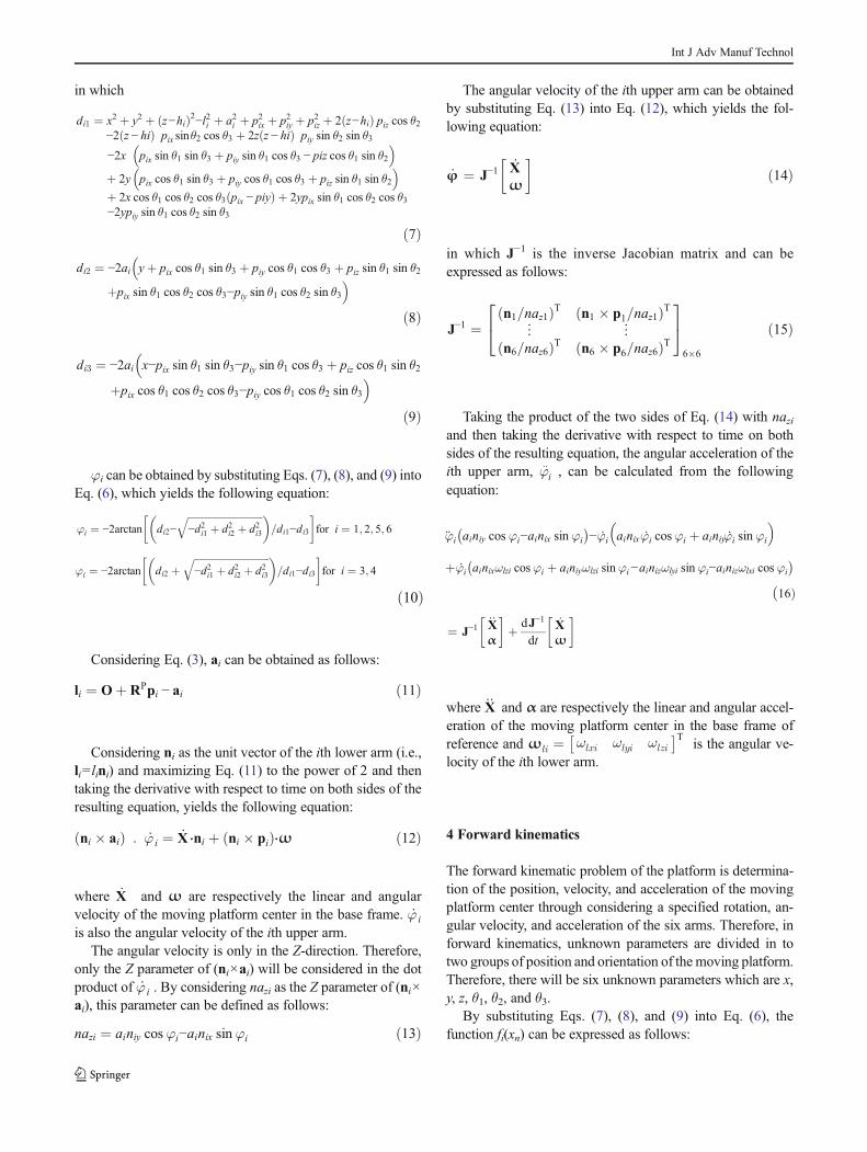
5 Nonlinear error
In order to control the error in an acceptable range, thevalue of nonlinear error must be obtained. Here in thisresearch, a mid-oscillating circle is utilized to obtain thekinematic error.
Oscillating circle of a curve abuts the curve at apoint. In other words, it has the same tangent andcurvature as the curve has at that point. Just as thetangent line is the best line for approximating a curveat a given point, the oscillating circle is the best circlethat approximates the curve at a point. The radius of theosculating circle is simply the inverse of curvature.This, however, is of critical importance both in nonlin-ear motion of the platform and its path programming.
Curvatures vary throughout the whole path, and the radii ofthe oscillating circles at the start and end points of the path aredifferent. Therefore, the radius of the mid-oscillating circle istaken into account in this research (Fig. 2).
The normal vector of the plane consisting of the mid-oscillating circle, H, can be presented as follows:
H ¼ L� N ¼i j kLx Ly LzNx Ny Nz
24
35 ð29Þ
where L is the vector connecting two interpolated points Aand B and N is the unit vector which is normal to the tangentvector. N can be obtained as follows:
N ¼ X::= X::� X
: ð30Þ
in which X::
and X:
are respectively the linear velocity andacceleration vectors of the moving platform between A and B.
Since points A and B are in the plane with the normalvector H, the center of the circular path can be obtained bysolving the system of nonlinear equations as follows:
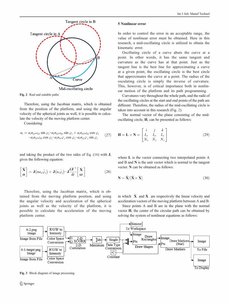
Fig. 3 Block diagram of image processing
Fig. 2 Real and suitable paths
Int J Adv Manuf Technol
L0x−Cx
� �2þ L
0y−Cy
� �2þ L
0z−Cz
� �2¼ ρ2
L0 0x−Cx
� �2þ L
0 0y−Cy
� �2þ L
0 0z−Cz
� �2¼ ρ2
Hx Cx−Lxð Þ þ Hy Cy−Ly þ Hz Cz−Lzð Þ ¼ 0
8>>><>>>:
ð31Þ
where L ′=(Lx′ ,Ly
′ ,Lz′ ) and L ′ ′=(Lx
′ ′,Ly′ ′,Lz
′ ′) are respectively theposition vectors of points A and B and C=(Cx, Cy, Cz) is thecenter of the mid-oscillating circle. ρ is the radius of the mid-oscillating circle and can be obtained as follows:
ρ ¼ ρA þ ρBð Þ=2 ð32Þ
ρA and ρB are respectively the radius of the oscillatingcircle at points A and B and can be defined as follows:
ρA ¼ 1=κA ð33Þ
ρB ¼ 1=κB ð34Þ
where κA and κB are the curvatures in points A and B,respectively. The curvature in these two points can be deter-mined by kinematics of arms and platform.
Considering direct kinematic equations and substitutingEq. (31) into Eqs. (33) and (34), kinematic error equationcan be written as follows:
e ¼ ρ−ffiffiffiffiffiffiffiffiffiffiffiffiffiffiffiffiffiffiffiffiffiρ2− S=2ð Þ2
qð35Þ
where S is the length of the curve between two interpolatedpoints A and B. If kinematic error exceeds acceptable range, Shas to be mitigated. In this condition, changing S is of keyimportance in controlling the path length and kinematic error.
6 Experimental test
Image processing is one of the available methods for measur-ing the movement of various dynamic systems. In this meth-od, using a camera, determined positions of target motion onthe platform are captured. Photographs are imported to theMATLAB Image Processing Toolbox. First, this toolbox pro-vides a matrix for each photo. The elements of this matrix arethe amount of pixels in each photo. For each matrix element,numbers between 0 and 256 are selected by the software. Forexample, white and complete black have numbers 0 and 256,respectively. Target coordinate is imported to the software bythe first photo. So the application finds the status of this smallmatrix in a larger matrix and it follows the motion in the nextphotos. Thus, in the end of the movement, motion coordinateis obtained in pixels. Finally, regarding the relationship be-tween the number of pixels and targets diameters, using acoefficient, the equation of motion is obtained (Fig. 3).
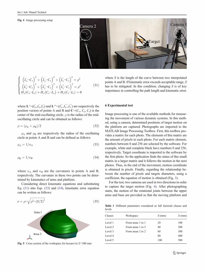
For the test, two cameras are used in two directions in orderto capture the target motion (Fig. 4). After photographingstarts, the motion of the rotational joints between the upperarms and base are provided so that the moving platform and
Fig. 4 Image processing setup
Fig. 5 Cross section of the workspace for hexarot in X=300 mm
Table 1 Different parameters considered as full factorial classes andlevels
Classes Workspace S (mm) X (mm)
Level 1 From areas 1 to 1 20 100
Level 2 From areas 1 to 2 40 200
Level 3 From areas 2 to 2 60 300
Level 4 80 400
Level 5 100 500
Int J Adv Manuf Technol
target on it starts to move. Camera numbers 1 and 2record movements in the YZ- and XZ-planes, respective-ly. In order to make the camera lens perpendicular tothe spherical target, the camera base is completelyaligned with the ground level. To adjust the lens inthe direction of the coordinate axes in the XY-plane,the platform target is moved in the Y- and Z-directionsand the distance between the camera and target is mea-sured. This distance is kept fixed in a perpendiculardirection with rotating the camera and moving the plat-form. It should be noted that this process is performedfor both cameras.
In this paper, two general conditions have been experimen-tally tested and results have been compared with each other. Inthe first case, the orientation of the platform is conserved. Inthe latter case, the rotation of the platform is taken intoaccount.
Since the nonlinear error rate differs in various areas of theworkspace, the workspace of the mechanism is of utmostimportance in determining and controlling this error.Assuming a cross section of the workspace in the X-direction,
and regarding the origin of coordinates which is at thecenter of the platform, one symmetrical plane with twoareas can be considered within the workspace of theplatform (Fig. 5).
Considering one symmetrical plane shown in Fig. 5, allmotions within the workspace and with the specified distancefrom the base column can be provided with three motions.
One of the effective parameters is the X-direction of theworkspace. The closer the distance to the base, the larger thecurvature of the curve will be. In this paper, the parameter X isexamined in five cases of 100, 200, 300, 400, and 500 mm.
The movement distance is the other parameter which af-fects the error rate. In a way that by increasing the movementdistance, the error will increase. In this paper, the movementdistance is examined in five cases of 20, 40, 60, 80, and100 mm.
The test has three effective factors including theworkspace, the distance to the base, and the movement dis-tance. Workspace factor has three levels; however, the otherfactors have five levels (Table 1). Thus, full factorial of testequals to 75.
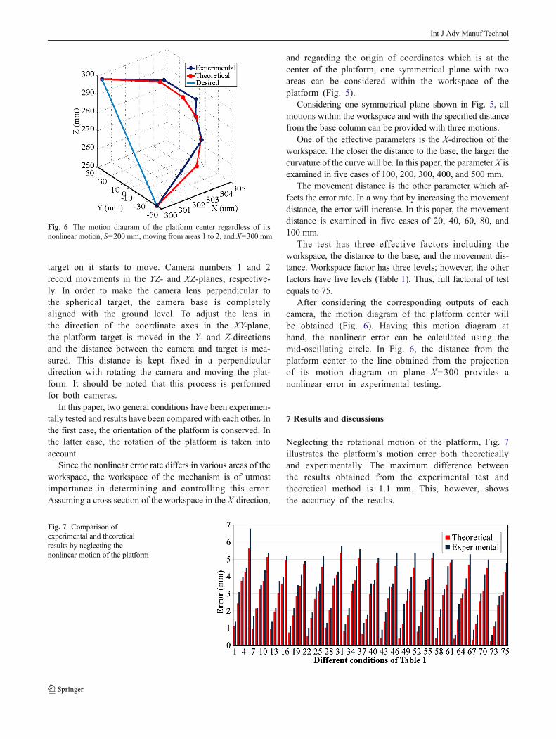
After considering the corresponding outputs of eachcamera, the motion diagram of the platform center willbe obtained (Fig. 6). Having this motion diagram athand, the nonlinear error can be calculated using themid-oscillating circle. In Fig. 6, the distance from theplatform center to the line obtained from the projectionof its motion diagram on plane X=300 provides anonlinear error in experimental testing.
7 Results and discussions
Neglecting the rotational motion of the platform, Fig. 7illustrates the platform’s motion error both theoreticallyand experimentally. The maximum difference betweenthe results obtained from the experimental test andtheoretical method is 1.1 mm. This, however, showsthe accuracy of the results.
Fig. 7 Comparison ofexperimental and theoreticalresults by neglecting thenonlinear motion of the platform
Fig. 6 The motion diagram of the platform center regardless of itsnonlinear motion, S=200 mm, moving from areas 1 to 2, and X=300 mm
Int J Adv Manuf Technol
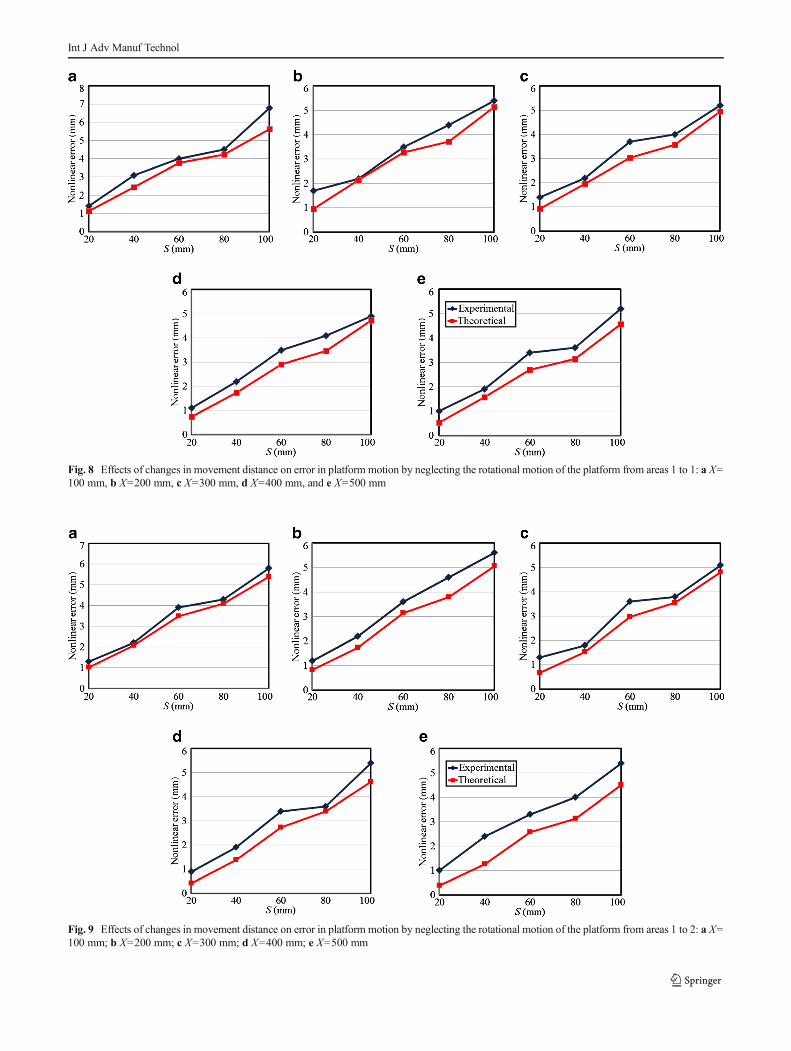
Fig. 9 Effects of changes in movement distance on error in platform motion by neglecting the rotational motion of the platform from areas 1 to 2: a X=100 mm; b X=200 mm; c X=300 mm; d X=400 mm; e X=500 mm
Fig. 8 Effects of changes in movement distance on error in platform motion by neglecting the rotational motion of the platform from areas 1 to 1: a X=100 mm, b X=200 mm, c X=300 mm, d X=400 mm, and e X=500 mm
Int J Adv Manuf Technol

Fig. 11 Effects of changes in distance between the platform and base onmotion error neglecting the rotational motion of the platform from areas 1 to 1: aS=20 mm, b S=40 mm, c S=60 mm, d S=80 mm, and e S=100 mm
Fig. 10 Effects of changes in movement distance on error in platformmotion by neglecting the rotational motion of the platform from areas 2 to 2: a X=100 mm, b X=200 mm, c X=300 mm, d X=400 mm, and e X=500 mm
Int J Adv Manuf Technol

Fig. 13 Effects of changes in distance between the platform and base onmotion error neglecting the rotational motion of the platform from areas 2 to 2: aS=20 mm, b S=40 mm, c S=60 mm, d S=80 mm, and e S=100 mm
Fig. 12 Effects of changes in distance between the platform and base onmotion error neglecting the rotational motion of the platform from areas 1 to 2: aS=20 mm, b S=40 mm, c S=60 mm, d S=80 mm, and e S=100 mm
Int J Adv Manuf Technol
Figures 8 and 9 present the effects of the changes inmovement distance, S, on error regardless of the plat-form’s orientation. Regarding Figs. 8a–e, 9a–e, and10a–e, it should be noted that the error increases byan increase in S. Moreover, it is obvious that the errorin movement from areas 1 to 1 is larger to that of theplatform movement from areas 1 to 2, and the error inmovement from areas 1 to 2 is larger compared to thatof the movement from areas 2 to 2.
Figures 11, 12, and 13 present the effects of changes in thedistance of the platform from base, X, on error regardless ofthe platform’s orientation. Regarding Figs. 11a–e, 12a–e, and
13a–e, it should be noted that the error decreases by anincrease in X.
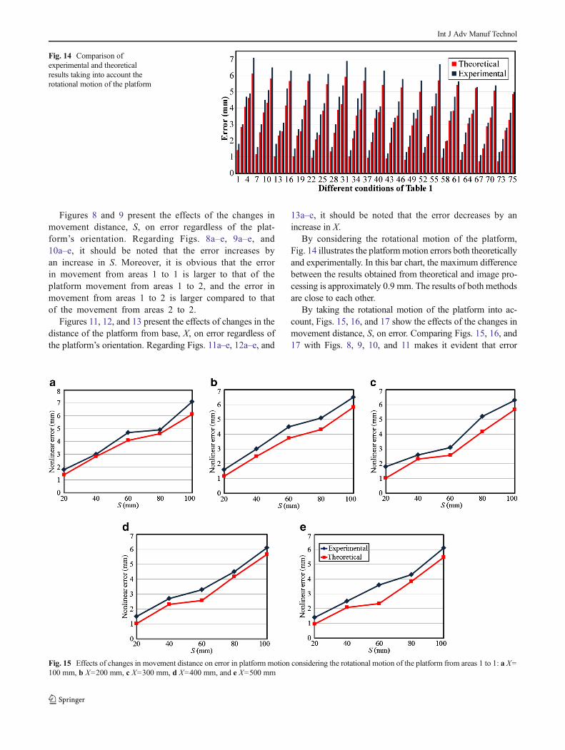
By considering the rotational motion of the platform,Fig. 14 illustrates the platformmotion errors both theoreticallyand experimentally. In this bar chart, the maximum differencebetween the results obtained from theoretical and image pro-cessing is approximately 0.9 mm. The results of both methodsare close to each other.
By taking the rotational motion of the platform into ac-count, Figs. 15, 16, and 17 show the effects of the changes inmovement distance, S, on error. Comparing Figs. 15, 16, and17 with Figs. 8, 9, 10, and 11 makes it evident that error
Fig. 15 Effects of changes in movement distance on error in platform motion considering the rotational motion of the platform from areas 1 to 1: a X=100 mm, b X=200 mm, c X=300 mm, d X=400 mm, and e X=500 mm
Fig. 14 Comparison ofexperimental and theoreticalresults taking into account therotational motion of the platform
Int J Adv Manuf Technol

Fig. 17 Effects of changes in movement distance on error in platform motion considering the rotational motion of the platform from areas 2 to 2: a X=100 mm, b X=200 mm, c X=300 mm, d X=400 mm, and e X=500 mm
Fig. 16 Effects of changes in movement distance on error in platform motion considering the rotational motion of the platform from areas 1 to 2: a X=100 mm, b X=200 mm, c X=300 mm, d X=400 mm, and e X=500 mm
Int J Adv Manuf Technol

Fig. 19 Effects of changes in distance between the platform and base onmotion error considering the rotational motion of the platform from areas 1 to 2:a S=20 mm, b S=40 mm, c S=60 mm, d S=80 mm, and e S=100 mm
Fig. 18 Effects of changes in distance between platform and base on motion error considering the rotational motion of the platform from areas 1 to 1: aS=20 mm, b S=40 mm, c S=60 mm, d S=80 mm, and e S=100 mm
Int J Adv Manuf Technol
increases by an increase in S where the platform’s rotationalmotion is taken into consideration.
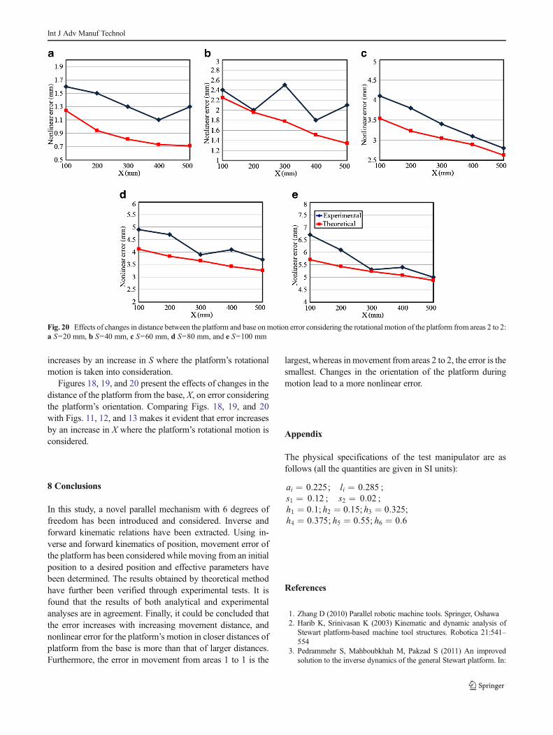
Figures 18, 19, and 20 present the effects of changes in thedistance of the platform from the base, X, on error consideringthe platform’s orientation. Comparing Figs. 18, 19, and 20with Figs. 11, 12, and 13 makes it evident that error increasesby an increase in X where the platform’s rotational motion isconsidered.
8 Conclusions
In this study, a novel parallel mechanism with 6 degrees offreedom has been introduced and considered. Inverse andforward kinematic relations have been extracted. Using in-verse and forward kinematics of position, movement error ofthe platform has been considered while moving from an initialposition to a desired position and effective parameters havebeen determined. The results obtained by theoretical methodhave further been verified through experimental tests. It isfound that the results of both analytical and experimentalanalyses are in agreement. Finally, it could be concluded thatthe error increases with increasing movement distance, andnonlinear error for the platform’s motion in closer distances ofplatform from the base is more than that of larger distances.Furthermore, the error in movement from areas 1 to 1 is the
largest, whereas in movement from areas 2 to 2, the error is thesmallest. Changes in the orientation of the platform duringmotion lead to a more nonlinear error.
Appendix
The physical specifications of the test manipulator are asfollows (all the quantities are given in SI units):
ai ¼ 0:225; li ¼ 0:285 ;s1 ¼ 0:12 ; s2 ¼ 0:02 ;h1 ¼ 0:1; h2 ¼ 0:15; h3 ¼ 0:325;h4 ¼ 0:375; h5 ¼ 0:55; h6 ¼ 0:6
References
1. Zhang D (2010) Parallel robotic machine tools. Springer, Oshawa2. Harib K, Srinivasan K (2003) Kinematic and dynamic analysis of
Stewart platform-based machine tool structures. Robotica 21:541–554
3. Pedrammehr S, Mahboubkhah M, Pakzad S (2011) An improvedsolution to the inverse dynamics of the general Stewart platform. In:
Fig. 20 Effects of changes in distance between the platform and base onmotion error considering the rotational motion of the platform from areas 2 to 2:a S=20 mm, b S=40 mm, c S=60 mm, d S=80 mm, and e S=100 mm
Int J Adv Manuf Technol
Proc. of the 2011 I.E. international conference on mechatronics, ICM2011, 5971317:392–397
4. Pedrammehr S, Mahboubkhah M, Khani N (2012)Improved dynamics equations for the generally configuredStewart platform manipulator. J Mech Sci Technol 26:711–721
5. Zheng K-J, Gao J-S, Zhao Y-S (2005) Path control algorithms of anovel 5-DOF parallel machine tool. In: Proc. of the IEEE interna-tional conference on mechatronics and automation, Niagara Falls, 3:1381–1385
6. Beale EML (1960) Confidence regions in non-linear estimation. J RStat Soc Ser B 22:41–88
7. Guttman I, Meeter DA (1965) On Beale’s measures of nonlinearity.Technometrics 7:623–637
8. Box MJ (1971) Bias in nonlinear estimation. J R Stat Soc Ser B 33:171–201
9. Gillis R, Ratkowsky DA (1978) The behavior of estimators of theparameters of various yield-density relationships. Biometrics 34:191–198
10. Bates DM, Watts DG (1980) Relative curvature measures of nonlin-earity. J R Stat Soc Ser B 42:1–25
11. Karimi D, Nategh MJ (2011) A statistical approach to the forwardkinematics nonlinearity analysis of Gough-Stewart mechanism. JAppl Math 2011:1–17
12. Dasgupata B, Mruthyunjaya TS (1998) Singularity-free path plan-ning for the Stewart platform manipulator. Mech Mach Theory 33:711–725
13. Shaw D, Chen YS (2000) Cutting path generation of the Stewart-platform based milling machine using an end-mill. Int J Prod Res 39:1367–1383
14. Merlet JP (2001) A generic trajectory verifier for the motion planningof parallel robots. ASME J Mech Des 123:509–515
15. Pugazhenthi S, Nagarajan T, Singaperumal M (2001) Optimal trajec-tory planning for a hexapod machine tool during contour machining.Proc Inst Mech Eng C J Mech 216:1247–1257
16. Dash AK, Chen IM, Yeo SH, Yang G (2005) Workspace generationand planning singularity-free path for parallel manipulators. MechMach Theory 40:776–805
17. AfrounM, Chettibi T, Hanchi S (2006) Planning optimal motions fora DELTA parallel robot. In: Proc of the IEEE 14th Mediterraneanconference on control and automation, pp 1–6
18. Afroun M, Chettibi T, Hanchi S, Dequidet A, Vermeiren L (2008)Optimal motions planning for a GOUGH parallel robot. In: IEEE16th Mediterranean conference on control and automation, CongressCentre, Ajaccio, France
19. Harib KH, Sharif Ullah AAM,Hammami A (2007) A hexapod-basedmachine tool with hybrid structure: kinematic analysis and trajectoryplanning. Int J Mach Tools Manuf 47:1426–1432
20. Li Z (2000) Reconfiguration and tool path planning of hexapod machinetools. PhD thesis, New Jersey Institute of Technology, New Jersey
21. Jinsong W, Zhonghua W, Tian H, Whitehouse DJ (2002)Nonlinearity for a parallel kinematic machine tool and its applicationto interpolation accuracy analysis. Sci China Ser A 45:625–637
22. Isaksson M, Brogårdh T, WatsonM, Nahavandi S, Crothers P (2012)The octahedral hexarot-A novel 6-DOF parallel manipulator. MechMach Theory 55:91–102
23. Isaksson M, Watson M (2013) Workspace analysis of a novel six-degrees-of-freedom parallel manipulator with coaxial actuated arms.ASME J Mech Des 135:1–9
24. Liu K, Fitzgerald JM, Lewis FL (1993) Kinematic analysis of aStewart platform manipulator. IEEE Trans Ind Electron 40:282–293
25. Wang L-C, Oen K-T (2002) Numerical direct kinematic analysis offully parallel linearly actuated platform type manipulators. J RobotSyst 19:391–400
Int J Adv Manuf Technol