An Experimental Set-up for Testing Structural Control Strategies Accounting for System Constraints
10
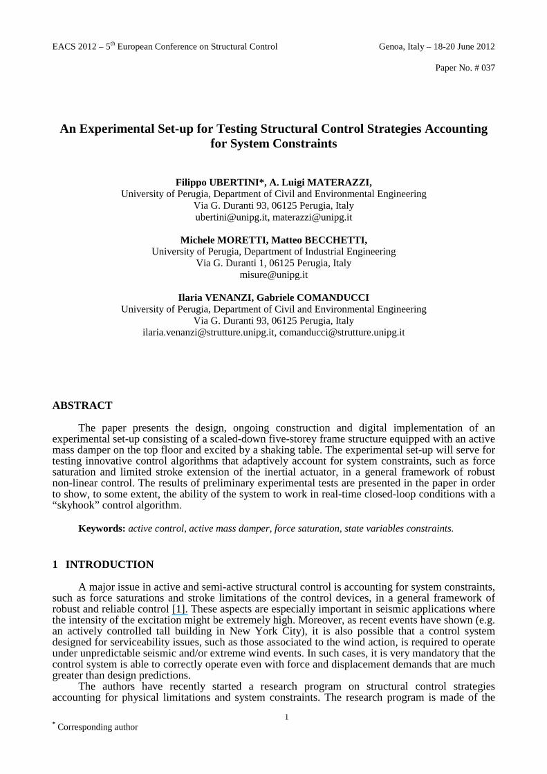
EACS 2012 – 5 th European Conference on Structural Control Genoa, Italy – 18-20 June 2012 Paper No. # 037 1 * Corresponding author An Experimental Set-up for Testing Structural Control Strategies Accounting for System Constraints Filippo UBERTINI*, A. Luigi MATERAZZI, University of Perugia, Department of Civil and Environmental Engineering Via G. Duranti 93, 06125 Perugia, Italy [email protected], [email protected] Michele MORETTI, Matteo BECCHETTI, University of Perugia, Department of Industrial Engineering Via G. Duranti 1, 06125 Perugia, Italy [email protected] Ilaria VENANZI, Gabriele COMANDUCCI University of Perugia, Department of Civil and Environmental Engineering Via G. Duranti 93, 06125 Perugia, Italy [email protected], [email protected] ABSTRACT The paper presents the design, ongoing construction and digital implementation of an experimental set-up consisting of a scaled-down five-storey frame structure equipped with an active mass damper on the top floor and excited by a shaking table. The experimental set-up will serve for testing innovative control algorithms that adaptively account for system constraints, such as force saturation and limited stroke extension of the inertial actuator, in a general framework of robust non-linear control. The results of preliminary experimental tests are presented in the paper in order to show, to some extent, the ability of the system to work in real-time closed-loop conditions with a “skyhook” control algorithm. Keywords: active control, active mass damper, force saturation, state variables constraints. 1 INTRODUCTION A major issue in active and semi-active structural control is accounting for system constraints, such as force saturations and stroke limitations of the control devices, in a general framework of robust and reliable control [1]. These aspects are especially important in seismic applications where the intensity of the excitation might be extremely high. Moreover, as recent events have shown (e.g. an actively controlled tall building in New York City), it is also possible that a control system designed for serviceability issues, such as those associated to the wind action, is required to operate under unpredictable seismic and/or extreme wind events. In such cases, it is very mandatory that the control system is able to correctly operate even with force and displacement demands that are much greater than design predictions. The authors have recently started a research program on structural control strategies accounting for physical limitations and system constraints. The research program is made of the
-
Upload
vegajournal -
Category
Documents
-
view
0 -
download
0
Transcript of An Experimental Set-up for Testing Structural Control Strategies Accounting for System Constraints
EACS 2012 – 5th European Conference on Structural Control Genoa, Italy – 18-20 June 2012
Paper No. # 037
1 * Corresponding author
An Experimental Set-up for Testing Structural Control Strategies Accounting
for System Constraints
Filippo UBERTINI*, A. Luigi MATERAZZI, University of Perugia, Department of Civil and Environmental Engineering
Via G. Duranti 93, 06125 Perugia, Italy [email protected], [email protected]
Michele MORETTI, Matteo BECCHETTI, University of Perugia, Department of Industrial Engineering
Via G. Duranti 1, 06125 Perugia, Italy [email protected]
Ilaria VENANZI, Gabriele COMANDUCCI University of Perugia, Department of Civil and Environmental Engineering
Via G. Duranti 93, 06125 Perugia, Italy [email protected], [email protected]
ABSTRACT
The paper presents the design, ongoing construction and digital implementation of an experimental set-up consisting of a scaled-down five-storey frame structure equipped with an active mass damper on the top floor and excited by a shaking table. The experimental set-up will serve for testing innovative control algorithms that adaptively account for system constraints, such as force saturation and limited stroke extension of the inertial actuator, in a general framework of robust non-linear control. The results of preliminary experimental tests are presented in the paper in order to show, to some extent, the ability of the system to work in real-time closed-loop conditions with a “skyhook” control algorithm.
Keywords: active control, active mass damper, force saturation, state variables constraints.
1 INTRODUCTION
A major issue in active and semi-active structural control is accounting for system constraints, such as force saturations and stroke limitations of the control devices, in a general framework of robust and reliable control [1]. These aspects are especially important in seismic applications where the intensity of the excitation might be extremely high. Moreover, as recent events have shown (e.g. an actively controlled tall building in New York City), it is also possible that a control system designed for serviceability issues, such as those associated to the wind action, is required to operate under unpredictable seismic and/or extreme wind events. In such cases, it is very mandatory that the control system is able to correctly operate even with force and displacement demands that are much greater than design predictions.
The authors have recently started a research program on structural control strategies accounting for physical limitations and system constraints. The research program is made of the
2
following steps: definition of control algorithms for active and semi-active constrained systems; numerical applications in significant cases of earthquake engineering; experimental tests. The first two steps where already presented by some of the authors elsewhere [1]. Within this paper, the design of an experimental set-up and its physical implementation are presented. The set-up, currently under construction in the laboratories of the School of Engineering of University of Perugia, is made of a small shaking table excited by an electro-dynamic servo-controlled shaker, a multistory scaled-down steel frame structure monitored with piezoelectric accelerometers, a data acquisition system, a real time controller and an active mass damper (AMD) [2-7]. This last is composed by an electric torsional motor, a ball screw with an attached mass and a long stroke position transducer. The system is meant to be used for testing control strategies accounting for force saturation and limited stroke constraints.
2 PROBLEM POSITION
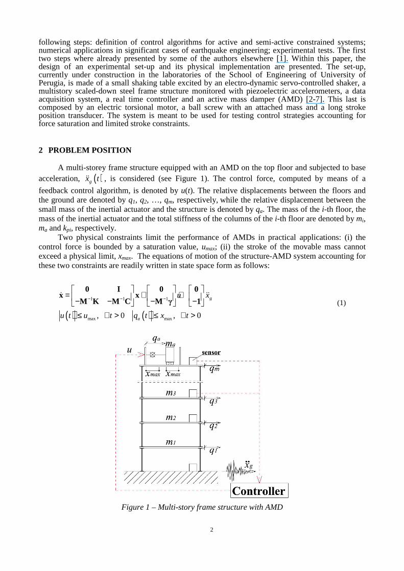
A multi-storey frame structure equipped with an AMD on the top floor and subjected to base acceleration, ( )gx tɺɺ , is considered (see Figure 1). The control force, computed by means of a
feedback control algorithm, is denoted by u(t). The relative displacements between the floors and the ground are denoted by q1, q2, …, qm, respectively, while the relative displacement between the small mass of the inertial actuator and the structure is denoted by qa. The mass of the i-th floor, the mass of the inertial actuator and the total stiffness of the columns of the i-th floor are denoted by mi, ma and kpi, respectively.
Two physical constraints limit the performance of AMDs in practical applications: (i) the control force is bounded by a saturation value, umax; (ii) the stroke of the movable mass cannot exceed a physical limit, xmax. The equations of motion of the structure-AMD system accounting for these two constraints are readily written in state space form as follows:
( ) ( )
1 1 1
max max, 0 , 0
g
a
u x
u t u t q t x t
− − −
= + + − − − −
≤ ∀ > ≤ ∀ >
0 I 0 0x x
M K M C M γ 1ɺ ɺɺ
(1)
Figure 1 – Multi-story frame structure with AMD

3
where a dot denotes time differentiation, [ ],t=x q qɺ is the state vector, with
[ ]1 2
T
m aq q q q=q … , M, K and C are the mass, stiffness and damping matrices of the
structure-AMD system, γ is the location vector of the control force and 1 is the location vector of the seismic input.
The formulation of appropriate control algorithms that allow to contemporaneously satisfy the two constraints contained in Eq. (1) is an open problem, recently investigated in [1].
3 EXPERIMENTAL SET-UP
A physical model of the system depicted in Section 2 has been designed and is currently under construction in the laboratories of the School of Engineering of University of Perugia. The model is conceived to serve as a benchmark for testing control algorithms that account for force saturation and limited stroke constraints.
The experimental set-up is made of the following components: (i) shaking system; (ii) frame structure; (iii) AMD; (iv) monitoring sensors; (v) controller.
The shaking system, which supports the structural model, is composed by a 70x50x2cm shaking table which is driven by an electrodynamic LDS V650 shaker whose engine performance characteristics are summarized in Table 1. A small steel tie allows to fix the base of the structural model for performing free vibration tests.
Figure 2 – Test structure: a) elevation (front), b) elevation (lateral), c) 3D image.
4
The test structure is a five-story single-bay S235 steel frame, shown in Figure 2, having a total height of about 1.9 m. Each floor is made of 70x30x2 cm steel plates of about 32.8 Kg weight. The flexural rigidity of each story can be varied using either 0.5x3x34cm or 0.4x3x34 cm steel columns. The number of degrees of freedom can be changed by means of removable bracing steel elements having cross sections with dimensions 0.3x2cm. The structural configuration considered in this paper consists of the use 0.5x3x34cm columns for the lowest two stories and 0.4x3x34,2cm in the remaining ones, with no bracings.
The AMD, installed on the top floor, is composed by a 60 cm long ball screw that converts the rotational motion of a Kollmorgen AKM33H AC servomotor into a translational motion of a 4 kg mass block (approximately the 2% of the whole structural mass). The characteristics of the servomotor are summarized in Table 2. The maximum stroke of the small mass is equal to ±30cm while the ball screw has a diameter of 25 mm and a pitch of 25 mm. The position of the mass along the ball screw is measured by means of a JX-P420 linear position transducer.
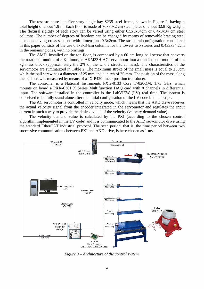
The controller is a National Instruments PXIe-8133 Core i7-820QM, 1.73 GHz, which mounts on board a PXIe-6361 X Series Multifunction DAQ card with 8 channels in differential input. The software installed in the controller is the LabVIEW (LV) real time. The system is conceived to be fully stand alone after the initial configuration of the LV code in the host pc.
The AC servomotor is controlled in velocity mode, which means that the AKD drive receives the actual velocity signal from the encoder integrated in the servomotor and regulates the input current in such a way to provide the desired value of the velocity (velocity demand value).
The velocity demand value is calculated by the PXI (according to the chosen control algorithm implemented in the LV code) and it is communicated to the AKD servomotor drive using the standard EtherCAT industrial protocol. The scan period, that is, the time period between two successive communications between PXI and AKD drive, is here chosen as 1 ms.
Figure 3 – Architecture of the control system.
5
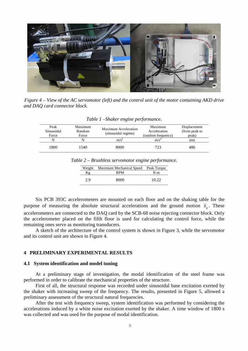
Figure 4 – View of the AC servomotor (left) and the control unit of the motor containing AKD drive and DAQ card connector block.
Table 1 –Shaker engine performance.
Peak Sinusoidal
Force
Maximum Random Force
Maximum Acceleration (sinusoidal regime)
Maximum Acceleration
(random frequency)
Displacement (from peak to
peak) N N m/s2 m/s2 mm
1800 1540 8000 723 486
Table 2 – Brushless servomotor engine performance.
Weight Maximum Mechanical Speed Peak Torque Kg RPM N·m
2.9 8000 10.22
Six PCB 393C accelerometers are mounted on each floor and on the shaking table for the purpose of measuring the absolute structural accelerations and the ground motion gxɺɺ . These
accelerometers are connected to the DAQ card by the SCB-68 noise rejecting connector block. Only the accelerometer placed on the fifth floor is used for calculating the control force, while the remaining ones serve as monitoring transducers.
A sketch of the architecture of the control system is shown in Figure 3, while the servomotor and its control unit are shown in Figure 4.
4 PRELIMINARY EXPERIMENTAL RESULTS
4.1 System identification and model tuning
At a preliminary stage of investigation, the modal identification of the steel frame was performed in order to calibrate the mechanical properties of the structure.
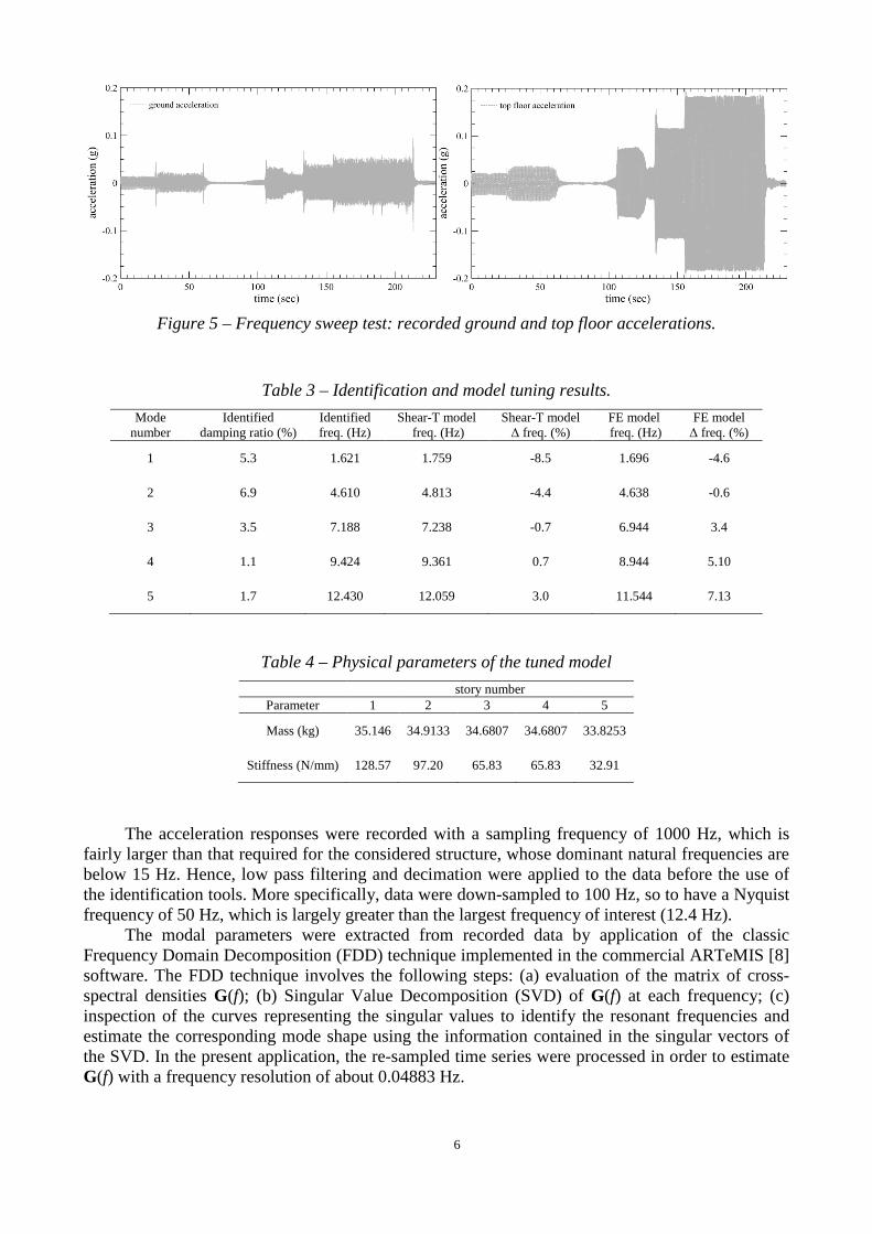
First of all, the structural response was recorded under sinusoidal base excitation exerted by the shaker with increasing sweep of the frequency. The results, presented in Figure 5, allowed a preliminary assessment of the structural natural frequencies.
After the test with frequency sweep, system identification was performed by considering the accelerations induced by a white noise excitation exerted by the shaker. A time window of 1800 s was collected and was used for the purpose of modal identification.
6
Figure 5 – Frequency sweep test: recorded ground and top floor accelerations.
Table 3 – Identification and model tuning results.
Mode number
Identified damping ratio (%)
Identified freq. (Hz)
Shear-T model freq. (Hz)
Shear-T model ∆ freq. (%)
FE model freq. (Hz)
FE model ∆ freq. (%)
1 5.3 1.621 1.759 -8.5 1.696 -4.6
2 6.9 4.610 4.813 -4.4 4.638 -0.6
3 3.5 7.188 7.238 -0.7 6.944 3.4
4 1.1 9.424 9.361 0.7 8.944 5.10
5 1.7 12.430 12.059 3.0 11.544 7.13
Table 4 – Physical parameters of the tuned model
story number Parameter 1 2 3 4 5
Mass (kg) 35.146 34.9133 34.6807 34.6807 33.8253
Stiffness (N/mm) 128.57 97.20 65.83 65.83 32.91
The acceleration responses were recorded with a sampling frequency of 1000 Hz, which is
fairly larger than that required for the considered structure, whose dominant natural frequencies are below 15 Hz. Hence, low pass filtering and decimation were applied to the data before the use of the identification tools. More specifically, data were down-sampled to 100 Hz, so to have a Nyquist frequency of 50 Hz, which is largely greater than the largest frequency of interest (12.4 Hz).
The modal parameters were extracted from recorded data by application of the classic Frequency Domain Decomposition (FDD) technique implemented in the commercial ARTeMIS [8] software. The FDD technique involves the following steps: (a) evaluation of the matrix of cross-spectral densities G(f); (b) Singular Value Decomposition (SVD) of G(f) at each frequency; (c) inspection of the curves representing the singular values to identify the resonant frequencies and estimate the corresponding mode shape using the information contained in the singular vectors of the SVD. In the present application, the re-sampled time series were processed in order to estimate G(f) with a frequency resolution of about 0.04883 Hz.
7
All the five expected modes of the frame, denoted as L1, L2, etc., were identified from the inspection of the singular values, using the FDD technique. It was also checked that the corresponding mode shapes resembled the classic mode shapes of a shear-type frame.
Table 3 summarizes the identified frequencies. These lasts have been used for manually tuning the mass and stiffness parameters of either a shear-type and a finite element model. The natural frequencies predicted by such two models are also summarized in Table 3, showing a satisfactory agreement with experimental results. Also, modeling the structure as a shear-type frame is seen to be an acceptable simplification.
The estimation of damping ratios has been attempted by application of the Enhanced Frequency Domain Decomposition (EFDD) technique, also implemented in ARTeMIS. These results are also summarized in Table 3.
4.2 Control algorithm
A classic “skyhook” control law has been considered and implemented in the controller. This control algorithm consists of a Direct Velocity Feedback (DVFB). Accordingly, the control force u is proportional to the absolute velocity, 5vɺ , of the top floor, that is:
( ) ( )5 5 gu t G v G q x= − ⋅ = − ⋅ +ɺ ɺ ɺ (2)
where G is the control gain. It should be noticed that, in Eq. (2), the absolute velocity of the top floor, 5vɺ , is given by the sum of the relative velocity between the top floor and the ground, 5qɺ , and
the ground velocity, gxɺ .
Since the motor is controlled in velocity mode, at the generic time step it i t= ⋅∆ , t∆ being
the scan engine period, the value of the angular velocity, 1iϑ +ɺ , for the next time step ( )1 1it i t+ = + ⋅ ∆
is commanded to the motor. The absolute velocity, 5vɺ , of the top floor is obtained by real time
integration of the acceleration recorded by the accelerometer placed on the same floor. To this aim, the data recorded by the accelerometer is acquired, integrated in time by the trapezoidal rule and depurated from the mean value every user defined time period.
The equation of motion of the small mass is the following one:
( )5a a gm q q x u+ + =ɺɺ ɺɺ ɺɺ (3)
The acceleration of the mass relative to the fifth floor, aqɺɺ , is proportional to the angular
acceleration, ϑɺɺ , of the motor:
2b
a
pq ϑ
π= ɺɺɺɺ (4)
where pb is the pitch of the ball screw. Substituting Eqs. (2) and (4) into Eq. (3) yields:
5 52b
a g
pm q x G vϑ
π + + = − ⋅
ɺɺ ɺɺ ɺɺ ɺ (5)
8
The velocity demand value to be sent to the motor is readily obtained from Eq. (5) as follows:
1 5 5
2i i g
b a
t Gx q v
p m
πϑ ϑ+
⋅∆= − + + ⋅
ɺ ɺ ɺɺ ɺɺ ɺ (6)
4.3 Digital implementation and preliminary test of the control system
A preliminary test has been carried out in order to verify the ability of the system in tracking a typical velocity profile of the servomotor.
To this aim, a LV code has been implemented in the controller which demands, every scan engine period, an increment of the angular velocity that is proportional to the integrated signal of the accelerometer placed on the fifth floor. So, a simplified version of Eq. (6) is adopted as follows:
1 5i i Gvϑ ϑ+ = −ɺ ɺ ɺ (7)
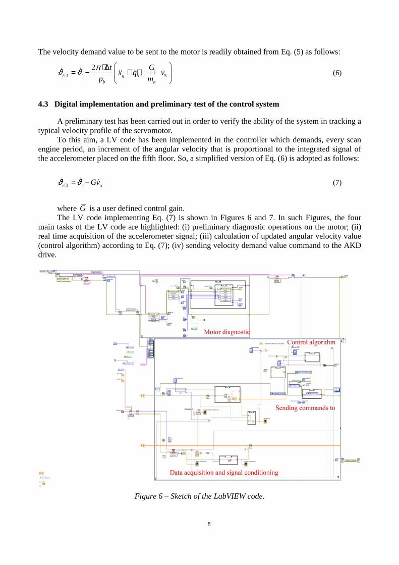
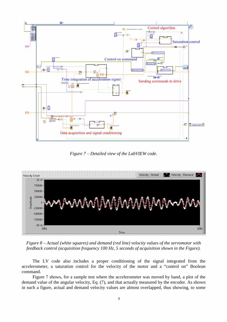
where G is a user defined control gain. The LV code implementing Eq. (7) is shown in Figures 6 and 7. In such Figures, the four
main tasks of the LV code are highlighted: (i) preliminary diagnostic operations on the motor; (ii) real time acquisition of the accelerometer signal; (iii) calculation of updated angular velocity value (control algorithm) according to Eq. (7); (iv) sending velocity demand value command to the AKD drive.
Figure 6 – Sketch of the LabVIEW code.
9
Figure 7 – Detailed view of the LabVIEW code.
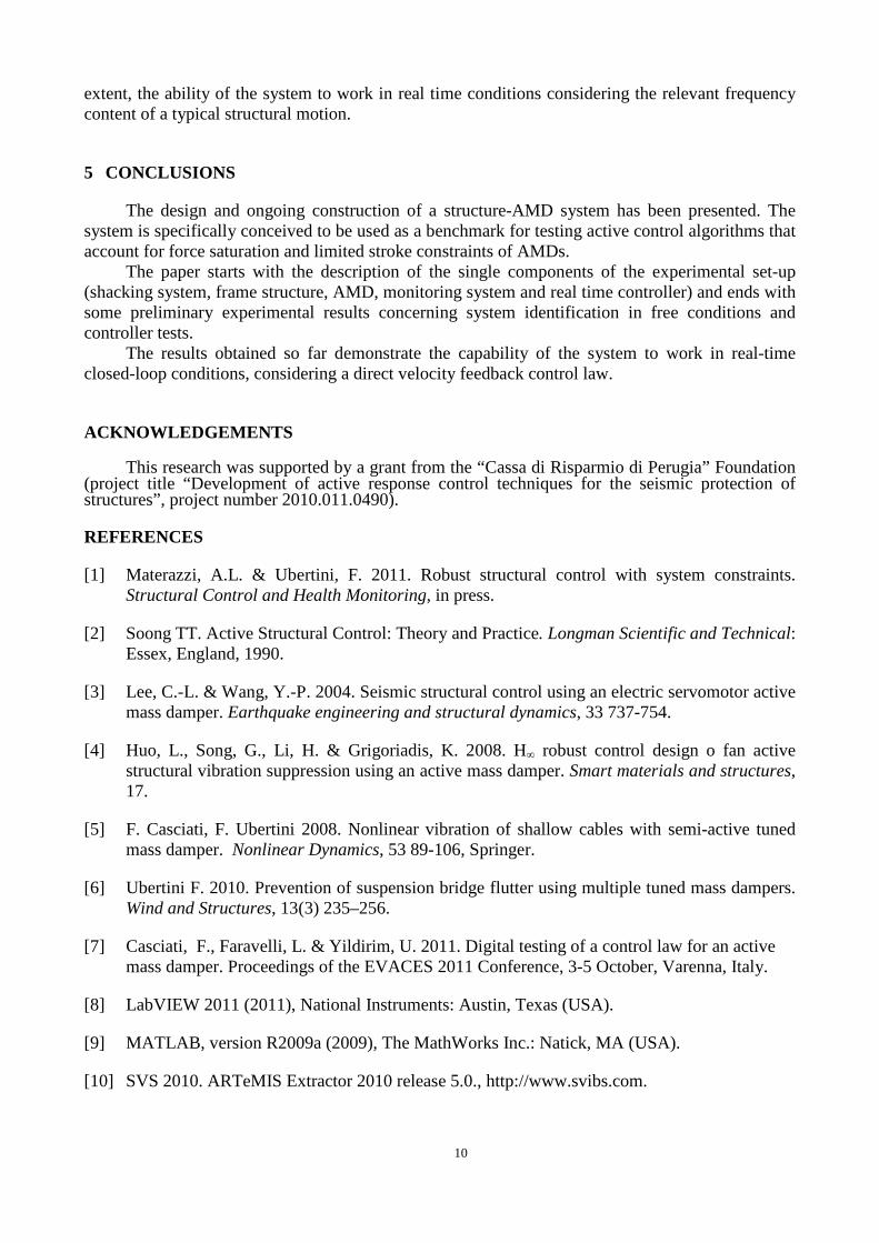
Figure 8 – Actual (white squares) and demand (red line) velocity values of the servomotor with feedback control (acquisition frequency 100 Hz, 5 seconds of acquisition shown in the Figure).
The LV code also includes a proper conditioning of the signal integrated from the
accelerometer, a saturation control for the velocity of the motor and a “control on” Boolean command.
Figure 7 shows, for a sample test where the accelerometer was moved by hand, a plot of the demand value of the angular velocity, Eq. (7), and that actually measured by the encoder. As shown in such a figure, actual and demand velocity values are almost overlapped, thus showing, to some
10
extent, the ability of the system to work in real time conditions considering the relevant frequency content of a typical structural motion.
5 CONCLUSIONS
The design and ongoing construction of a structure-AMD system has been presented. The system is specifically conceived to be used as a benchmark for testing active control algorithms that account for force saturation and limited stroke constraints of AMDs.
The paper starts with the description of the single components of the experimental set-up (shacking system, frame structure, AMD, monitoring system and real time controller) and ends with some preliminary experimental results concerning system identification in free conditions and controller tests.
The results obtained so far demonstrate the capability of the system to work in real-time closed-loop conditions, considering a direct velocity feedback control law.
ACKNOWLEDGEMENTS
This research was supported by a grant from the “Cassa di Risparmio di Perugia” Foundation (project title “Development of active response control techniques for the seismic protection of structures”, project number 2010.011.0490).
REFERENCES
[1] Materazzi, A.L. & Ubertini, F. 2011. Robust structural control with system constraints. Structural Control and Health Monitoring, in press.
[2] Soong TT. Active Structural Control: Theory and Practice. Longman Scientific and Technical: Essex, England, 1990.
[3] Lee, C.-L. & Wang, Y.-P. 2004. Seismic structural control using an electric servomotor active mass damper. Earthquake engineering and structural dynamics, 33 737-754.
[4] Huo, L., Song, G., Li, H. & Grigoriadis, K. 2008. H∞ robust control design o fan active structural vibration suppression using an active mass damper. Smart materials and structures, 17.
[5] F. Casciati, F. Ubertini 2008. Nonlinear vibration of shallow cables with semi-active tuned mass damper. Nonlinear Dynamics, 53 89-106, Springer.
[6] Ubertini F. 2010. Prevention of suspension bridge flutter using multiple tuned mass dampers. Wind and Structures, 13(3) 235–256.
[7] Casciati, F., Faravelli, L. & Yildirim, U. 2011. Digital testing of a control law for an active mass damper. Proceedings of the EVACES 2011 Conference, 3-5 October, Varenna, Italy.
[8] LabVIEW 2011 (2011), National Instruments: Austin, Texas (USA).
[9] MATLAB, version R2009a (2009), The MathWorks Inc.: Natick, MA (USA).
[10] SVS 2010. ARTeMIS Extractor 2010 release 5.0., http://www.svibs.com.