An enhanced system for augmenting urban search and rescue ...
126
Ryerson University Digital Commons @ Ryerson eses and dissertations 1-1-2011 An enhanced system for augmenting urban search and rescue canines Martin Gerdzhev Ryerson University Follow this and additional works at: hp://digitalcommons.ryerson.ca/dissertations Part of the Electrical and Computer Engineering Commons is esis is brought to you for free and open access by Digital Commons @ Ryerson. It has been accepted for inclusion in eses and dissertations by an authorized administrator of Digital Commons @ Ryerson. For more information, please contact [email protected]. Recommended Citation Gerdzhev, Martin, "An enhanced system for augmenting urban search and rescue canines" (2011). eses and dissertations. Paper 706.
-
Upload
khangminh22 -
Category
Documents
-
view
0 -
download
0
Transcript of An enhanced system for augmenting urban search and rescue ...

Ryerson UniversityDigital Commons @ Ryerson
Theses and dissertations
1-1-2011
An enhanced system for augmenting urban searchand rescue caninesMartin GerdzhevRyerson University
Follow this and additional works at: http://digitalcommons.ryerson.ca/dissertationsPart of the Electrical and Computer Engineering Commons
This Thesis is brought to you for free and open access by Digital Commons @ Ryerson. It has been accepted for inclusion in Theses and dissertations byan authorized administrator of Digital Commons @ Ryerson. For more information, please contact [email protected].
Recommended CitationGerdzhev, Martin, "An enhanced system for augmenting urban search and rescue canines" (2011). Theses and dissertations. Paper 706.

AN ENHANCED SYSTEM FOR AUGMENTING URBAN SEARCH AND RESCUE CANINES
By
Martin Gerdzhev
Bachelor of Science
in the Program of Computer Science,
Ryerson University 2008
A thesis
presented to Ryerson University
in partial fulfillment of the
requirements for the degree of
Master of Applied Science
in the Program of
Electrical and Computer Engineering
Toronto, Ontario, Canada, 2011
© Martin Gerdzhev 2011

ii
I hereby declare that I am the sole author of this thesis.
I authorize Ryerson University to lend this thesis to other institutions or individuals for the purpose of scholarly research.
MARTIN GERDZHEV
I further authorize Ryerson University to reproduce this thesis by photocopying or by other means, in total or in part, at the request of other institutions or individuals for the purpose of scholarly research.
MARTIN GERDZHEV

iii
ABSTRACT
AN ENHANCED SYSTEM FOR AUGMENTING URBAN SEARCH AND RESCUE CANINES
Martin Gerdzhev
MASc, Electrical and Computer Engineering, Ryerson University, 2011
One of the most critical factors in urban search and rescue is time, as the chances of
finding someone alive diminish with time. Emergency responders locate casualties, plan
their rescue based on the available information, and then extract them. Measures are taken to
do this as safely as possible as the harsh environment may lead to rescuers being injured.
Our research demonstrates how emergency responders can obtain more information about
the victim and the collapse faster, while potentially increasing their Situational
Awareness(SA), and thus decreasing the time to rescue of the casualties. The system
described is an enhanced version of Canine Augmentation Technology (CAT) – a
telepresence system for augmenting search canines. CAT integrates different
technologies like wireless mesh networks, wearable computing, sensors, and software for
recording, streaming, and scrubbing of video. The goal of our research is to reduce the time
to rescue of victims by providing more relevant information to rescuers faster.

iv
ACKNOWLEDMENTS
I would like to thank my parents for their love and support. Their encouragement and
belief in my abilities have allowed me to complete this thesis.
I would also like to thank my girlfriend Gabriela Kostova for her love and patience.
Her motivation and support kept me going.
I am especially grateful to my supervisor Alex Ferworn who supported and guided me
during the course of this thesis. He is everything that a student can wish for and has taught
me a lot. This thesis would not be possible without him.
A special thanks to Jimmy Tran, who taught me countless things about electronics. He
helped me a lot and his input was very much appreciated.
I am very thankful to The Ontario Provincial Police, Provincial Emergency Response
Team and particularly Constable Kevin Barnum for the help and support in this research.
I appreciate the help of FEMA canine handlers Tom Haus and Athena Haus (FEMA
CA-TF2) for their help in some of the experiments.
I would like to thank Devin Ostrom for his great ideas and designs as well as all his
help in the project.
Lastly thanks to everyone else from the N-CART lab – Cristina Ribeiro, Vijay Somers,
Andrew D’Souza and Sameer Lalji for helping out in the experiments.

v
TABLE OF CONTENTS
ABSTRACT .................................................................................................................................. iii
LIST OF TABLES ..................................................................................................................... viii
LIST OF FIGURES ..................................................................................................................... ix
LIST OF APPENDICES ............................................................................................................ xii
ABBREVIATIONS .................................................................................................................... xiii
CHAPTER 1 INTRODUCTION ........................................................................................... 1
1.1 Introduction ................................................................................................................................. 1
1.2 Problem Definition ...................................................................................................................... 5
1.3 Objectives ..................................................................................................................................... 8
1.4 Thesis Organization .................................................................................................................... 9
CHAPTER 2 BACKGROUND ............................................................................................ 11
2.1 Emergency management .......................................................................................................... 11
2.2 Urban Search And Rescue ....................................................................................................... 13
2.2.1 USAR Rescue Robots ............................................................................................. 17
2.2.2 USAR Canine team ................................................................................................. 26
2.2.3 Augmenting Animals .............................................................................................. 30
2.3 Wireless technologies ................................................................................................................ 41
2.3.1 Wireless Mesh Networks ........................................................................................ 42
2.4 Pattern recognition ................................................................................................................... 43
2.5 Telepresence .............................................................................................................................. 45
2.6 Situational Awareness............................................................................................................... 46
2.7 Computational Public Safety ................................................................................................... 47
2.8 Summary .................................................................................................................................... 47

vi
CHAPTER 3 MATERIALS AND METHODS .................................................................. 49
3.1 Architecture of CAT ................................................................................................................. 49
3.2 CAT Prototypes ......................................................................................................................... 51
3.2.2 CAT 4.0................................................................................................................... 53
3.2.3 CAT 5.0................................................................................................................... 58
3.3 Automated scrubbing of video ................................................................................................. 61
3.3.1 Pre-processing ......................................................................................................... 64
3.3.2 Isolating regions ...................................................................................................... 64
3.3.3 Checking isolated regions ....................................................................................... 65
3.4 DEX ............................................................................................................................................ 66
3.4.1 Dimensions ............................................................................................................. 68
3.4.2 Attaching to the dog ................................................................................................ 68
3.4.3 Electronic hardware ................................................................................................ 70
3.4.4 Control and communication .................................................................................... 71
CHAPTER 4 EXPERIMENTS AND RESULTS ............................................................... 73
4.1 CAT 4.0 Experiments ............................................................................................................... 73
4.1.1 Preliminary video tests ............................................................................................ 74
4.1.2 Rubble pile tests ...................................................................................................... 74
4.1.3 Experiment Results ................................................................................................. 75
4.2 Video Scrubbing Tests .............................................................................................................. 76
4.2.1 Test setup ................................................................................................................ 76
4.2.2 Test Results ............................................................................................................. 77
4.3 WMN Deployment Experiments .............................................................................................. 82
4.3.1 Experiment setup .................................................................................................... 83
4.3.2 Experiment results .................................................................................................. 84

vii
4.4 CAT 5.0 Experiments ............................................................................................................... 86
4.4.1 CAT Experiments ................................................................................................... 86
4.4.2 Experiments Results................................................................................................ 87
4.5 DEX Experiments ..................................................................................................................... 90
4.5.1 Experiments setup ................................................................................................... 91
4.5.2 Experiments Results................................................................................................ 92
CHAPTER 5 CONCLUSION AND FUTURE WORK ..................................................... 97
5.1 Summary of Findings and Conclusions .................................................................................. 97
5.2 Future Research ...................................................................................................................... 101
5.3 Concluding Remarks .............................................................................................................. 104
APPENDICES ........................................................................................................................... 111

viii
LIST OF TABLES Table 2-1: Comparison of the different 802.11 Standards ............................................................ 42
Table 3-1: HSV minimums and maximums ................................................................................. 65
Table 3-2: Dimensions of DEX .................................................................................................... 68
Table 4-1: Approaches and corresponding error .......................................................................... 77
Table 4-2: Neural Network’s convergence and errors .................................................................. 77

ix
LIST OF FIGURES Figure 1-1: Earthquake collapse site in the Sichuan Province, China 2008 (Source: National Geographic) ..................................................................................................................................... 3
Figure 1-2: Robot stuck at edge of rubble ...................................................................................... 6
Figure 1-3: Looking for survivors: A rescuer searches for victims at the collapsed site of a school building after an earthquake in Chongqing municipality, China, 2008 (Source: Reuters) ............. 7
Figure 1-4: One of the first versions of CAT being tested by a canine team ................................. 8
Figure 2-1: Emergency Management Cycle ................................................................................. 12
Figure 2-2: Condition of Victims vs Emergency Response .......................................................... 16
Figure 2-3: BomBot 2 wheeled robot by WVHTC Foundation ................................................... 18
Figure 2-4: G2Bot tracked robot by Mesa Robotics ..................................................................... 19
Figure 2-5: VGTV-Xtreme in its three main positions. In the lowest position for flat surfaces (left), middle position for climbing (center), top position for looking over obstacles (right). ..... 20
Figure 2-6: One robot trapped in the 350mm wide trench ............................................................ 21
Figure 2-7: JL-1 in docked state overcoming the same trench ..................................................... 21
Figure 2-8: Large Talon robot unable to cross the gap and wall delivers a small Toughbot (seen in the gripper of Talon) into a roof opening. ................................................................................ 22
Figure 2-9: Microbot jumping 38 cm. ........................................................................................... 23
Figure 2-10: Robug III rescue robot ............................................................................................. 24
Figure 2-11: OmniTread OT-4 robot ............................................................................................ 25
Figure 2-12: Rubble pile at Disaster City ..................................................................................... 29
Figure 2-13: Following the scent plume to the live victim. This is a simplified diagram, as in rubble the scent might move in various ways. .............................................................................. 30
Figure 2-14: CAT 1 tested by a canine team ................................................................................ 33
Figure 2-15: USAR Dog wearing CAT 2.0 .................................................................................. 34
Figure 2-16: CAT Architecture ..................................................................................................... 35
Figure 2-17: CAT 3.0 worn by California Task Force 1 (CA-TF1) USAR Dog Freitag ............. 36

x
Figure 2-18: The CRDS System. From left to right: Harness, CRDS unit, underdog. ................. 37
Figure 2-19: Canine wearing CRDS with underdog giving a bark indication. ............................. 38
Figure 2-20: The released CRDS leaving the underdog behind. .................................................. 38
Figure 2-21: USAR Canine Dare wearing CPE device ................................................................ 39
Figure 2-22: CAT attached to CWA ............................................................................................. 40
Figure 2-23: Example of Wireless Mesh Network for Audio communications [84] ................... 43
Figure 3-1: Updated CAT Architecture ........................................................................................ 50
Figure 3-2: Diagram of ideal CAT ................................................................................................ 51
Figure 3-3: Beagle Board .............................................................................................................. 55
Figure 3-4: Block Diagram for CAT 4.0 ...................................................................................... 56
Figure 3-5: Streaming video from CAT. ....................................................................................... 57
Figure 3-6: IGEPv2 Board ............................................................................................................ 60
Figure 3-7: Block Diagram for CAT 5.0 ...................................................................................... 60
Figure 3-8: CAT 5.0 with CRDS worn by USAR dog Freitag ..................................................... 61
Figure 3-9: Bag outside in good light conditions .......................................................................... 63
Figure 3-10: Bag in an enclosed space in poor light conditions ................................................... 63
Figure 3-11: DEX ......................................................................................................................... 67
Figure 3-12: DEX with retractable hooks ..................................................................................... 69
Figure 3-13: DEX attached with hooks to CRDS ......................................................................... 69
Figure 3-14: DEX in underdog attached to CRDS ....................................................................... 70
Figure 4-1: Correct classification - Original image ...................................................................... 78
Figure 4-2: Image after thresholding ............................................................................................ 78
Figure 4-3: Image after the ANN filtering .................................................................................... 79
Figure 4-4: False negative - Original Image ................................................................................. 79

xi
Figure 4-5: Image after thresholding ............................................................................................ 80
Figure 4-6: Image after the ANN filtering .................................................................................... 80
Figure 4-7: False positive - Original image .................................................................................. 81
Figure 4-8: Image after thresholding ............................................................................................ 81
Figure 4-9: Image after the ANN filtering .................................................................................... 82
Figure 4-10: Map of tunnels showing victim and router placements. .......................................... 85
Figure 4-11: Rubble Pile 1 at Disaster City .................................................................................. 87
Figure 4-12: CAT 5.0 Failure points ............................................................................................. 88
Figure 4-13: Left camera showing head of the quarry. ................................................................. 90
Figure 4-14: Right camera showing head of the quarry. .............................................................. 90
Figure 4-15: DEX being thrown from Freitag .............................................................................. 93
Figure 4-16: DEX released successfully by the bark barrel ......................................................... 94
Figure 4-17: DEX exploring in the tunnel close to the victim ...................................................... 95
Figure 4-18: Image from DEX showing victim and visual acuity markers .................................. 95

xii
LIST OF APPENDICES A. FOX Board LX832 Specification ....................................................................................... 111
B. CAT 2.0 Power consumption break down .......................................................................... 111
C. CAT 3.0 Power consumption break down .......................................................................... 111

xiii
ABBREVIATIONS AI Artificial Intelligence
ANN Artificial Neural Network
ASTM American Society for Testing Material
CAN-TF3 Canada Task Force 3
CAT Canine Augmentation Technology
CBF Canine Brain Function
COTS Common off the Shelf
CPE Canine Pose Estimation
CPS Computational Public Safety
CPU Central Processing Unit
CRDS Canine Remote Deployment System
CWA Canine Work Apparel
DEX Drop and EXplore robot
DHS Department of Homeland Security
DoF Degrees of Freedom
EMS Emergency Medical Service
FEMA Federal Emergency Management Agency
GPS Global Positioning Systems
IR Infrared
LED Light Emitting Diode
NCART Network-Centric Applied Research Team
NIST National Institute of Standards and Technology
OPP Ontario Provincial Police
PDA Personal Digital Assistant

xiv
PERT Provincial Emergency Response Team
PSEPC Public Safety and Emergency Preparedness Canada
RF Radio Frequency
SA Situational Awareness
SAR Search and Rescue
SBC Single Board Computer
SD Secure Digital
SDK Software Development Kit
SSH Secure Shell
USAR Urban Search and Rescue
WiFi Wireless Fidelity
WLAN Wireless Local Area Network
WMN Wireless Mesh Network

1
CHAPTER 1 INTRODUCTION
1.1 Introduction
Disasters, being unpredictable, can occur anywhere at any given time. Emergency
First responders, as the name implies, are those that are first to deal with the immediate
aftermath of a calamity. The first priority is to search for, find and rescue live humans
trapped within the disaster--these are the goals of any search and rescue (SAR) operation.
One type of SAR operation occurs when the disaster has occurred in an urban centre like a
city. Urban Search and Rescue (USAR) is a SAR operation that occurs in the rubble and
debris of collapsed buildings—adding additional challenges that require special techniques,
training and technology. Finding people who are trapped and injured requires caution and
speed. The faster a search can proceed, the faster individuals can be found and rescued—
increasing survival rates. Thus there is a need for research in this field to try and find new
ways or improve existing techniques and technologies to help provide resources that
improve search speeds to save lives. This thesis describes an innovative system in the area of
urban search and rescue (USAR), which aims to shorten the time to rescue an individual.
Urban disasters are on the rise. We have witnessed the World Trade Center collapse
(2001), Hurricane Katrina (2005), the earthquakes in China (2008) and Haiti (2010). All of
these disasters occurred in urban areas and resulted in many lives lost. In the years to come,
more disasters are bound to occur and their cost will be greater [1]. This is due to a number
of reasons including a changing climate, geographical realities and geopolitical forces-
including terrorism. In 40 years, the world population is projected to increase by 50%, while
the urban population is estimated to double in that same time. We are about to see a shift of

2
populations from rural areas to urban areas [2]. This increase in population means that even
small or moderate disasters can have profound consequences and dealing with the aftermath
of such disasters is a difficult job. This makes improving USAR all the more important.
When a disaster strikes, the impact on a city’s infrastructure is profound. Many
buildings collapse, often creating internal “voids” – pockets of space under the rubble;
which may contain live people trapped in them. The purpose of USAR operations is to
quickly find, extract and stabilize the trapped people, without jeopardizing the lives of first
responders.
The main factor which determines if people will be extracted alive is time. Working
under this constraint, emergency personnel need as much information as possible in order to
establish situational awareness - an understanding of what is going on around them and what
to do about it [3]. This usually means finding the trapped people, determining their
condition, and the condition of the surrounding area. This allows emergency personnel to
develop better rescue plans that may speed up the rescue operation and thus save more lives.
There are several ways to conduct a search some of which are more dangerous for
rescuers than others [4]. Manual search, search with electronic equipment, canine search,
and rescue robot search. Manual search involves human search teams going over the
collapsed site, visually inspecting voids, listening for the presence of victims and marking
the results. Rescuers may also call out to trapped people to knock on a surface so that the
knock can be heard. This could be done by anyone, but only gives limited access to voids,
can be very dangerous for search personnel, and would not locate unconscious, weak or very
young victims. It also tends to be quite slow as the surfaces that searchers must travel over
are often difficult to move over and through (Figure 1-1).

3
Figure 1-1: Earthquake collapse site in the Sichuan Province, China 2008 (Source: National Geographic)
Search using electronic equipment can involve the use of fiberoptic viewers, search
cameras and electronic listening devices [4]. Fiberoptic viewers allow for limited assessment
of victims that are more easily accessible. Search cameras are more easily understood, and
can record the pictures and possibly allow for remote viewing, but are generally limited to
straight line-of-sight. Another option is the use of electronic listening devices that can be
used to detect sounds from the victim that can be trapped deeper in the collapse. The
downside is that unconscious people cannot be detected at all and any noise can interfere
with the process of detecting audible signs of life which tend to be faint. To avoid
background noise, work must be halted in significant parts of the search area—thus
potentially delaying finding other victims. All of these methods require that first responders
be on the rubble pile, and at risk.
Another method for information gathering that is extremely effective is canine search.
A canine team consists of a canine search specialist and a search dog. Together they can

4
cover a large area in a relatively short time. The dog, which is trained to find people using its
sense of smell, is very agile, fast and reliable. These dogs are able to find unconscious as
well as conscious people and are able to identify live humans hidden amongst cadavers.
Even though dogs are very good at locating trapped people, the problem of
communicating that information remains. Dogs are trained to bark when they find live
people, but they have no other means of communicating information to humans. If the dog is
working in an area where the handler cannot follow, a bark may tell us that there is someone
alive there, but it may not be possible to determine where the person is or in what condition
they are in.
Response or rescue robots are another set of tools that has recently become available
to provide data about a disaster environment. These robots are normally teleoperated and can
be equipped with a vast array of sensors [5-7]. Some of these sensors are not as good as their
equivalent in biological systems, e.g. dogs and their sense of smell. However, other sensor
types that can be fitted to robots are not found in nature. The major downside to current
robot designs is their limited mobility. Current designs cannot effectively traverse through
rubble. Also controlling such a robot can be very challenging as the human operator must
take into account angles, position of the robot, as well as carefully plan the path so as to not
flip, become stuck or disabled. Until the mobility problems are overcome, use of rescue
robots will be limited.
A system combining the best of the natural and artificial systems is described in [8-
12]. We are propose an enhanced version of this system, which makes it more reliable, more
useful, and reduces the time it takes to gain better SA, and thus save more people faster [13-
16]. This research falls into the field of Computational Public Safety (CPS), which

5
encompasses the use of computational resources, theory and practice to support safety
processes as well as improve them.
1.2 Problem Definition
Whenever a disaster strikes, buildings tend to suffer structural collapse. Such collapsed
buildings can be very dangerous because the environment they create is unpredictable, and
there is risk of further collapse. Before a human search can occur in such a building, often it
must be stabilized which can take a considerable time.
Ideally, first responders would like the locations and conditions of victims as well as
the condition of the area around them to gain a better SA before attempting a rescue
operation. This is required to ensure the safety of rescuers as well as victims. Thus the
rescue effort needs to be carefully planned and executed. Sometimes this process can take a
long time depending on the information at hand and the conditions on the ground. A way to
gather the information without having to stabilize a building first is required, because
stabilizing parts of the building where no survivors are present just wastes time that could be
used to find people elsewhere.
Search canines are one of the best options for finding survivors. The dog can be
directed by the handler to search a large area in a short time. The dogs can indicate the
presence of a survivor by barking, but if the handler is not able to follow the canine due to
safety precautions, he may not be able to determine the exact location of the victim. The
dogs cannot provide any information on the condition of the survivor nor indicate if there is
more than one, or the state of the environment around them.

6
Response robots are another alternative for searching for victims in rubble from a safe
location. They are capable of providing audio, video, and other sensory information that can
improve SA. However, finding survivors with such robots is not practical in their current
state except in cases where their mobility shortcomings can be replaced by their sensing
advantages. In typical urban disasters terrain is often unpredictable. Response robot
technology is not currently available that can address even relatively simple obstacles much
less the challenges of even a small collapsed building (Figure 1-2). These mobility problems
often do not allow robots to explore all the areas that might have survivors, which can often
easily be searched by dogs. Another limitation is that most of the robots, despite having
numerous potential sensors on-board, rely, almost entirely, on visual cues as presented by
video feeds for finding trapped people. This may be problematic as finding a person in
debris from visual cues alone is somewhat like finding a needle in the proverbial haystack
(Figure 1-3).
Figure 1-2: Robot stuck at edge of rubble

7
Figure 1-3: Looking for survivors: A rescuer searches for victims at the collapsed site of a school building after an earthquake in Chongqing municipality, China, 2008 (Source: Reuters)
A solution to this problem was originally proposed by Dr. Alexander Ferworn of
Ryerson University. The idea was to combine the abilities of canines to find survivors with
the strengths of robotics into a system that aids USAR operations. The system is called
Canine Augmentation Technology (CAT) [10-12]. A basic CAT system is comprised of a
harness equipped with a payload of sensing, actuation and computational equipment, worn
by USAR dogs for transmitting audio, video, and other sensory information wirelessly to the
handler or other human searchers when they cannot follow the dog during a search [10-12].
The idea behind CAT is to help first responders find people faster and assist them in
planning a rescue. It should be noted that the intent of CAT is not to help the dogs—which
do very well on their own. The idea was enhanced by the work of Jimmy Tran of Ryerson
University [9, 13].

8
The system has undergone several revisions from a head-mounted wireless analog
audio/video camera (Figure 1-4), moving to twin side-mounted digital cameras with an on-
dog computer capable of wireless transmission of both camera streams.
Figure 1-4: One of the first versions of CAT being tested by a canine team
1.3 Objectives
The more recent designs of CAT allow for expandability of the sensors and address
many dog factor (dogonomic) needs. These designs still leave a lot of room for
improvements. A persistent set of problems have been the lack of audio transmission, on-
dog recording, user interface, and poor video quality.
The purpose for this thesis is to add to the body of knowledge that supports the effort
to make CAT a methodology and suite of technologies that are an alternative to robotic
applications. We will show this to be done by demonstrating improvements on the concepts
and designs of previous work. Our goal is to improve the SA of the human users of CAT and
to reduce the time needed to make an informed decision about where a victim is and how to
rescue them.
The contributions of this thesis are the design of a new architecture for CAT that
increases the reliability and usability of the system by improving video quality, adding audio

9
transmission support, on-dog recording for when the dog goes out of wireless range, a basic
user interface, as well as reducing the time needed to scrub the video recorded from the dog
for signs of life within it.
Furthermore this thesis describes a way of giving more control over what can be seen
in the vicinity of a victim within the video stream. It also demonstrates some limitations of
the use of wireless transmission that mitigate its usefulness for applications involving fast
moving transmitters in rubble. The new design also describes an extensible architecture that
can be implemented in a future revision of this work. In other words, one of our
contributions is a path forward.
In order to confirm that the goals of this thesis have been met, a number of
experiments were designed to test the efficacy of CAT in operation. While none of the
testing occurred in real disasters, all tests were conducted in purpose-built facilities similar
to those that have been observed in real disasters. To quote Professor Ferworn, “We do not
simulate conditions, we make conditions that simulate disasters”.
1.4 Thesis Organization
This chapter serves as an introduction to the rest of the thesis. Chapter 2 presents an
overview of the field of emergency management and the strategies and technologies that are
used in USAR operations. A literature review of related work in augmenting animals with
technologies, telepresence, pattern recognition and situational awareness is also provided.
The current architecture of CAT is described in chapter 3. All prototypes from the
current generation leading to the latest are described. The algorithm utilizing CAT in canine
assisted USAR operations is explored. The use of CAT to overcome robot mobility

10
problems is also demonstrated. Chapter 4 explains the experimental procedures and presents
our results. This is followed by an analysis and discussion of the results. Finally, chapter 5
presents a summary of this thesis and contains a discussion of future research.

11
CHAPTER 2 BACKGROUND
2.1 Emergency management Hazards, emergencies and disasters threaten us daily. These terms are closely related
and their definitions are provided below. According to [18], a hazard can be defined as a
source of danger or an extreme event that has the potential to affect people, property, and the
natural environment in a given location. Hazards can be further classified into natural
(earthquakes, floods), technological (malfunctioning machines, industrial explosions), and
resulting from deliberate human actions (terrorist attacks, kidnappings).
Emergency has two meanings [18, 19]. The first one describes minor events that
cause a few casualties and some property damage (car crash, house fire). These emergencies
are unforeseen but with predictable circumstances and results. The second meaning refers to
an event that is about to happen in the near future and can have major consequences (a
hurricane forecasted to pass in a populated region, weather predictions that favours tornado
formation, etc.).
The term disaster is reserved for events that produce more losses than a community
can handle [1, 18, 19]. They occur when a hazard, or multiple hazards interact with human
vulnerability. They can seriously disrupt social routines, cause many deaths, much property
damage, or significant environmental damage. Disasters directly impact people or the
systems they use– food, natural resources, transportation, etc. A community that has been
struck with a disaster can cope only with help from outside – state or federal governments,
or other communities. There are many costs associated with a disaster– Direct Financial
Costs (repairing infrastructure, rebuilding homes), Long-Term Economic Costs (businesses

12
closing permanently, employees moving out of the region), Environmental Costs (oil spills,
chemicals leaking into rivers), Societal Costs ( communities lose sense of place and pride),
Human Lives Lost (death of one human being is one death too many) [20].
According to [21], Emergency management is “applying science, technology,
planning and management to deal with extreme events that can injure or kill large numbers
of people, do extensive damage to property, and disrupt community life”. When a disaster
strikes, specially trained people – emergency managers must cope with that event.
Emergency managers are public servants that have the knowledge and expertise to help
jurisdictions reduce the liabilities that lead to disasters [1]. Their roles are to prevent or
reduce losses that occur due to hazards, disasters, and emergencies [18]. The work of
emergency management can be divided into four phases [1,18-20]: mitigation, preparedness,
response and recovery. It is also known as the emergency management cycle or disaster life
cycle (Figure 2-1).
Figure 2-1: Emergency Management Cycle

13
Mitigation activities try to eliminate the causes of a disaster. It is accomplished by
reducing the possibility of a disaster, or by reducing the loss due to its occurrence.
Preparedness activities refer to improving the ability to respond quickly in case of an
emergency. They include the development of plans and procedures, installation of warning
systems as well as training personnel, and stockpiling resources to meet the needs for when a
disaster occurs. Response activities are actions in the immediate aftermath of a disaster that
protect public safety and minimize physical damage. This involves positioning of emergency
equipment and personnel. These personnel are normally called “first responders” and consist
of fire-fighters, police, and emergency medical services (EMS) teams. They deal with the
important operations of search and rescue (SAR), evacuation, providing medical assistance,
etc. Recovery activities try to return the affected community to pre-disaster or even
improved conditions. They occur after the response phase and include the rebuilding and
repair of the infrastructure, as well as restoring power, water, etc., and other activities to
restore normal operations to a community.
The Emergency Management Cycle is intended to apply to all disasters. Some of the
more notable examples of where the cycle can be observed are New Orleans after Hurricane
Katrina [8], Kobe Japan [22], Mexico[23] and Haiti [24] after high-magnitude Earthquakes
and the World Trade Center [25] after terrorist attacks.
2.2 Urban Search And Rescue Search and rescue (SAR) consists of three separate operations: sizeup, search, and
rescue [26]. Sizeup involves assessing the situation and determining a safe action plan.
Search consists of locating victims and documenting their location. Rescue involves the
procedures and methods required to extricate the victims.

14
Urban search-and-rescue (USAR) is a "multi-hazard" discipline, as it may be needed
as a response for a wide variety of emergencies or disasters. These may include earthquakes,
hurricanes, typhoons, storms and tornadoes, floods, dam failures, technological accidents,
terrorist activities, and hazardous materials releases [27].
USAR deals with the location, rescue (extrication), and initial medical stabilization of
victims who may be trapped in confined spaces. It should be noted that many victims of
urban disasters are not trapped and are often found in-situ. Thus search is not required but
rescue is. If a victim becomes trapped, it is usually a result of a structural collapse. However,
transportation accidents, mine collapses, and collapsed trenches may also result in trapped
victims [27].
Due to the multi-hazard nature of USAR, it is organized around the concept of the
“task force” unit. A USAR task force is a partnership between regional fire departments,
law enforcement agencies, federal and local governmental agencies and private companies.
Each unit consists of firefighters, engineers, medical professionals, canine/handler teams,
emergency managers and other professionals that have been specially trained to deal with
USAR environments. A task force is meant to serve as a national resource for disaster
response [28] however, there are many examples of task forces that are city or regionally-
based1
In Canada the organization that is responsible for responding to disasters is called
Public Safety Canada (PS). It provides for 5 USAR Task Forces spread from coast to coast
. In addition to the specialized personnel, each unit has specialized equipment that is
not normally available to local responders.
1 For example, Toronto is served by the city task force called “Heavy Urban Search and Rescue (HUSAR) which also serves the region of Ontario and supports national operations through its designation as one of the 5 Canadian task forces as recognized by Public Safety Canada (CAN-TF3 (Toronto)).

15
[29]. Similarly to Canada and PSC, in the United States, the equivalent organization is called
the Federal Emergency Management Agency (FEMA) of the Department of Homeland
Security (DHS). It supports 28 USAR Task Forces that are spread throughout the continental
United States [30, 32]. The Task Forces are activated when the regional or federal authority
issues a formal declaration of a disaster situation that warrants search and rescue operations.
USAR task force members work in the following four areas of specialization [31]:
• Search: find victims trapped after a disaster.
• Rescue: includes safely digging victims out of tons of collapsed concrete and
metal.
• Technical: made up of structural specialists who make rescues safe for the
rescuers.
• Medical: cares for the victims before and after a rescue, as well as injured task
force members.
For large disasters, the emergency response normally occurs in four phases [32]:
• Initial spontaneous response – unskilled persons, neighbours, community response
teams rush in to save people
• Planned Community Response – by local trained community response teams. They
find people by calling out and through visual search.
• Void Space Rescue – by local emergency services rescue forces. In their searches
they use existing cavities, small cut openings and do some shoring to the buildings
to use as safe havens for victims and first responders.
• Technical, Urban Search and Rescue – by trained task forces, aided by heavy
equipment.

16
Figure 2-2 illustrates the types of structural collapse rescue [32].
Figure 2-2: Condition of Victims vs Emergency Response
At the disaster scene the goals of the USAR task forces are to rescue the most people
in the least amount of time, without becoming victims themselves [26, 33]. This normally
means that easily rescued victims would be rescued first. Time is crucial during an USAR
operation, as the chances of finding someone alive diminish with time. The first hour gives
the best chance for finding live people, but the following day is also critical. The injured and
trapped victims have an 80% chance of survival if rescued within the first day [1]. After the
first day the chance diminishes rapidly. This doesn’t mean that people should just rush into
collapsed buildings without an assessment of the situation, as nearly 60% of confined space
deaths come from would-be rescuers attempting to re-enter the damaged structure [33].
After arriving at the disaster scene, rescuers would do an initial size-up, where they will
identify different buildings. They will then do a general area triage to find the buildings that
are most likely to have more trapped people. After that a hazard assessment of the buildings
would be done and unsafe buildings would be marked as “NO GO” so people would not
enter there. These buildings may be re-evaluated and stabilized after other buildings are
EN-TOMBED
VOID SPACE ENTRAPMENT
NON-STRUCTURAL ENTRAPMENT
INJURED AND NOT TRAPPED
US&R TASK F.
EMERGENCY SERVICE
PROVIDERS COMMUNITY
RESPONSE TEAMS
SPONTANEOUS RESCUE CIVILIANS NEAR COLLAPSE
5%
15%
30%
50%

17
searched. Search operations follow the initial size-up. The search teams would use different
techniques to find victims, depending on the situation and equipment available. These would
normally include search dogs, specialized listening equipment, viewing devices, perhaps
rescue robots, and physical search [5, 6, 7, 34, 35]. Victims that are more easily accessible
are extracted and helped first. The ones that require more work to rescue are handled in turn.
Quite often it may take hours of digging and cutting through concrete or other building
materials to get to a single trapped person. Once they are rescued, victims are stabilized by
Emergency Medical Technicians (EMTs), and then evacuated to second line medical
facilities [36].
2.2.1 USAR Rescue Robots The promise of robots used for “response” or “rescue” in USAR operations has seen a
lot of interest in the past several years. Most notably, this has occurred after the World Trade
Center Disaster of 2001 where they showed some promise as potential tools for finding
victims [37]. The robots are typically teleoperated and can be equipped with a vast array of
sensors [5-7]. Some of these sensors are not as effective as their biological equivalent
systems. Of most interest within this thesis is sensing odour coming from victims which is
done extraordinarily well by dogs. However, other sensor types that can be fitted to robots
(Ground Penetrating Radars, Gas sensors, etc) are not found in nature.
Robots could prove to be a very useful alternative to human search in environments
that are hazardous or inaccessible to humans if it were not for one major limitation –
mobility. Disaster environments can be quite unpredictable, with uneven terrain, lots of
debris and rubble. Even the best of land robots equipped with tracks or wheels have

18
difficulty navigating through simple terrain with obstacles as common place as stairs.
Traversing terrain that is inevitably present in disaster environments is almost an impossible
task. There has been recent progress in robot designs that have attempted to overcome the
mobility problem. Architectures, such as shape-shifting or variable geometry [38, 39, 40],
marsupial delivery [6, 30, 34, 41, 42], multi-robot force cooperation [43-45], and
biologically inspired designs [46-49] are steps forward from traditional designs but are still
in their infancy.
2.2.1.1 Traditional tracked and wheeled robots Traditional tracked or wheeled robots normally consist of a number of fixed wheels or
tracks. Control signals are delivered either through wireless or wired data links. Their
mobility is normally limited by the size of the wheels or length/height of the tracks. Figure
2-3 and Figure 2-4 show examples of wheeled and tracked robots.
Figure 2-3: BomBot 2 wheeled robot by WVHTC Foundation

19
Figure 2-4: G2Bot tracked robot by Mesa Robotics
2.2.1.2 Shape-shifting and Variable geometry robots Shape-shifting/Variable geometry robots, as the name implies, have the ability to
change their shape to better conform to different surfaces or situations where expansion or
contraction would aid mobility. This can be a very useful feature, as different configurations
allow for the traversal of obstacles where a single fixed-wheels/tracks robot wouldn’t be
able to move. As shown in Figure 2-5, VGTV-Xtreme by Inuktun is a typical example of a
variable-geometry robot that can change shape during operation and is commercially
available [40]. Other example robots of this type are Telemax by TelRob, PackBot from
iRobot, as well as a number of research robots like Kenaf [50], Souryu [51], and Helios [52].

20
Figure 2-5: VGTV-Xtreme in its three main positions. In the lowest position for flat surfaces (left), middle position for climbing (center), top position for looking over obstacles (right).
2.2.1.3 Multi-robot force cooperation During a rubble search, some surfaces may prove to be a real challenge for a single
robot to overcome. If there is a hole that is slightly larger than the robot, it might get stuck
while trying to go over it. If a bigger robot is built to cover bigger obstacles, it will have a
limited ability to go into smaller voids. Because of this kind of situation, amongst others,
multi-robot force cooperation has been suggested as a means of overcoming individual robot
shortcomings. This type of robot design incorporates multiple robots cooperating to
overcome a specific obstacle by joining together, and then detaching when the obstacle is
surmounted. JL-1 is a typical example from this class of robots. Figure 2-6 shows JL-1’s
attempts to overcome a 350mm wide trench in single-robot state, and Figure 2-7 shows the
same robot in docked state overcoming that trench. [45] It should be noted that this form of
robot cooperation has never been used operationally (as there just are not that many task
forces capable of fielding such teams) thus all the results for this type of deployment is
theoretical or done as a demonstration.

21
Figure 2-6: One robot trapped in the 350mm wide trench
Figure 2-7: JL-1 in docked state overcoming the same trench
2.2.1.4 Marsupial robots Sometimes a single robot or even a few robots using force cooperation may not be
enough to overcome harder terrain such as a low vertical wall. In such a scenario, another
form of robot cooperation might be able to accomplish the task.
Marsupial operation is a form of cooperative robotic deployment normally used to
deliver USAR assets via the explicit physical interaction of two or more robots to exploit
their individual strengths and overcome their individual weaknesses [53]. The term was
initially introduced in [41] as a relationship between a “mother” robot that carries and
nurtures a smaller “daughter” robot to support USAR operations.
Marsupial robots are often deployed by a mother robot whenever the mother robot
cannot navigate over a difficult terrain, or is too big to go through a hole or crack of interest.
An example of marsupial delivery can be seen in Figure 2-8 where a Talon robot delivers a

22
Toughbot robot into a small opening in a roof. Again, this type of robot cooperation has not
been greatly used in operations since such different robots are not normally part of a task
force’s complement of equipment.
Figure 2-8: Large Talon robot unable to cross the gap and wall delivers a small Toughbot (seen in the gripper of Talon) into a roof opening.
2.2.1.5 Biologically inspired robots Even though marsupial delivery has its benefits, it may still prove to be problematic,
as the “mother” robot would normally have mobility problems and delivering the “child”
robot at a point where the child robot would only get stuck is useless. Other forms of robots
try to move away from tracks and take inspiration from nature.
One such concept is the jumping robot [47, 48]. When an obstacle is met that normally
a tracked or wheeled robot cannot go over, these robots can jump over it. Microbot is a
concept robot from this type of biologically inspired robot class [48]. It uses a form of
mobility where a spring is compressed and released quickly to let it jump some height and
distance. Figure 2-9 shows this robot in action.

23
Figure 2-9: Microbot jumping 38 cm.
Even though jumping can be a very useful form of mobility, where you can jump over
obstacles, the rough terrain would be very hard to navigate with jumping alone as the robot
might still get stuck in places it lands and would be extremely hard to recover. Another line
of biologically inspired designs are legged robots. This system exploits the fact that several
legs support the robot while others move it over obstacles. Such an example is Robug III – a
hexapod spider-like robot designed to enter places too dangerous for humans. It can walk,
climb over debris and even scale vertical walls. Figure 2-10 shows a picture of this robot.
Walking robots have a lot of potential. They can potentially climb over debris, but are
mostly limited to more predictable environments like the flat floors of labs. Real world
environments can be very challenging and there are still many– size, power consumption,
balance, stability, and motion challenges. The legs either make the robot too tall, or too wide
to fit into tighter places like holes and cracks that are present in a collapsed building. In
order to be useful in urban disasters, these issues have to be resolved.

24
Snake-like robots, which are another type of naturally-inspired robot class, are an
attempt to solve the size problem. They consist of many joints, each having multiple degrees
of freedom (DoF). This allows them to change form and climb over obstacles and adapt to
many potential circumstances. Their size allows them to fit in very tight places. Omnitread
OT-4 is one such robot [54]. It has 7 segments each of which is covered by tank tracks. OT-
4 can be seen in Figure 2-11.
Figure 2-10: Robug III rescue robot

25
Figure 2-11: OmniTread OT-4 robot
Although snake-like robots have much potential, there are still problems, including
speed, battery life, limited payload capacity, and limited space for sensors.
2.2.1.6 Rescue Robots performance metrics Based on a review of the locomotion mechanisms of a large number of robots, none of
the current USAR robots can practically and autonomously carry out USAR work in a
disaster environment [55]. In an attempt to improve this situation, the DHS sponsored
Intelligent Systems Division of the National Institute of Science and Technology (NIST) of
the U.S. Department of Commerce is looking into the problem of measuring the
performance of rescue robots. The approach taken is to create a standard set of tests for
robots [56], so that they can be tested against one another for comparison purposes. NIST
have developed a variety of performance standards, meant to test many categories of robot
characteristics [57-59]. Each robot is evaluated on a range of performance metrics –
mobility, sensing, and overall system performance (power, communication and durability).

26
Another area that is evaluated is “cache packaging” which indicates dimensions and other
size and weight characteristics of the robot, as well as any equipment that is needed for it to
operate. This is done to give an idea of how the robot and all the equipment for it will be
packaged for transportation by a task force. These kinds of tests are important as emergency
task forces or any other interested parties can use the evaluations to determine what the
capabilities of each robot is, and to better choose ones that suit their needs. Every year there
is a DHS/NIST sponsored Response Robot Evaluation Exercise on the grounds of Texas
A&M University at their purpose-built training facility - "Disaster City", College Station,
Texas. Participants in that exercise consist of first responders, manufacturers and academics
from all over the world.
Even though these metrics are driving forward the capabilities of response robots, the
improvement of robot mobility is more focused on being able to complete the tests provided
in the evaluation exercises. Currently there does not exist a test for robot mobility on rubble,
which means that the capabilities required for real disaster situations are not expected to
arrive in the near future.
2.2.2 USAR Canine team The idea of using dogs for finding people is very old. Originally dogs were trained to
find people by tracking, but due to a number of limitations with that approach a new method
was proposed. In the 1960s it was proposed that dogs be trained for “air scenting” instead of
tracking [60]. Unlike tracking dogs, air scenting search dogs do not require scent articles or
tracks. The search area does not have to be kept free of other searchers, which means that
rescuers can continue their work. Another advantage of air scenting dogs is that they do not
require a starting point to find people [60]. A dog’s sense of smell is far keener than that of a

27
person and it is the primarily sense for identifying items of interest [61]. This ability makes
canines quite useful in detecting a variety of scents like the smells of explosives [62], drugs
[59] and even cancer [60]. A canine’s olfactory system can also be applied to finding people
very effectively. The scent of a person is given off by bacteria and vapour living on dead
skin cells known as “rafts” that are being shed from our bodies in the thousands per minute,
as well as the volatile chemicals that are released from our bodies and our apparel [60, 61,
65].
Regardless of the types of search dogs, they are normally directed by canine handlers
which are made up of a number of different professions. In the United States, many canine
handlers are volunteers however many are also employed as firefighters and police [66].
Dogs are able to pick up human smell and work their way to the place where the highest
concentration of the smell is found. This means that even if a person is buried under rubble,
the scent could still escape the confined space and be picked up by an air scenting dog. This
is why dogs are invaluable for locating victims at a disaster site.
Before a dog can be employed for actual people searching, both the dog and its
handler need to undergo rigorous training. Not all dogs can be trained to become search and
rescue dogs. Canines with high "toy drive" (the desire to play with a toy, such as a ball or
tug) and nerve strength (the ability to deal with and recover from stress, often caused by
threat) are used for USAR [65] work. Most of the U.S. Federal Emergency Management
Agency (FEMA) certified dogs are Labrador Retrievers, German Shepherd Dogs, Belgian
Malinois, Border Collies and Golden Retrievers [66].
Finding people can be thought of as a game of hide and seek for the dog [66]. During
training, people hide from the dog with a toy, then play with the dog with the toy when the

28
dog finds them. This promise of a reward is quickly learned by dogs and makes them eager
to search.
For a disaster environment dogs need to learn a set of skills and pass several
certifications before they are allowed to work as USAR dogs. These skills may include
obedience, agility, direction and control, and giving a bark indication when a live person is
found. FEMA is the agency that designed the evaluation and certification processes for
USAR canines [67-69]. One of the most important tests that a canine team must pass is the
Rubble Site test. This test is made to simulate a realistic disaster environment where all the
skills are put to the test. The canine is supposed to search independently and off-leash. This
is done because during an actual disaster, a handler may be precluded from going with the
dog due to hazards.
USAR canine teams train on specially built rubble piles if they are available (See
Figure 2-12) or even on construction or demolition sites. It is important that different sites
are used as the dog will learn all the hiding places and just go to those places instead of
doing a thorough search [65].

29
Figure 2-12: Rubble pile at Disaster City
Regardless of how a rubble pile is created, it closely resembles a real collapse and
therefore provides an excellent opportunity for training. Rubble piles can be of any materials
that are found in buildings, with the most common materials being steel rebar reinforced
concrete and wood. The better purpose-built piles will have a tunnel system underneath for
testing in confined spaces and to allow volunteer “victims” to move to different location
without being visually detected by observant dogs.
A typical training scenario would involve one or more persons called “quarries” that
hide somewhere on or within the pile. Each quarry has a dog toy to give as a reward. After
sufficient time has elapsed to allow for the scent of the quarries to build around their hiding
places, the handler will direct the canine to look for the quarries. The dog will go across the
pile back and forth until it finds the scent plume of a quarry. At this point it will zigzag in
and out of the scent going towards the quarry [60]. Figure 2-13 shows an example of the
search pattern in action [65].

30
Figure 2-13: Following the scent plume to the live victim. This is a simplified diagram, as in rubble the scent might move in various ways.
When the dog finds the highest concentration of the scent and can go no further,
usually very close to the quarry, it will start a sustained barking for a period of time. This is
the bark indication for a found live victim. After many barks, the quarry will praise the dog
and give the toy to the dog to play with as a reward for finding them. In essence, the dog
sees finding people as a form of game that gives a reward in the end when successful.
During an actual USAR event, the dog will still be playing the game with the result that lives
will be saved.
2.2.3 Augmenting Animals As can be seen, animals can be very good at some things that would normally be
extremely hard for a person or a robot to do. We call this Biological Intelligence [13, 17].
Sometimes we may want to have more information or to do something more than an animal
can do on its own. This is where technology can play a role. Technology can be used to

31
enhance animals so that they can provide that extra information or accomplish tasks
previously not possible. This concept is not new and actually has been employed for a long
time now. The US Navy use bottlenose dolphins carrying a transponder to find and mark
anti-ship mines [70]. Another instance of augmenting an animal is the use of camera
systems on sharks for research purposes [71].
From the land animals, dogs have received the most attention for augmentation. This
stems from the fact that they can be easily trained for specific tasks. In 1974 a study was
conducted that was seeking to develop procedures for a handler to remotely control a trained
dog’s movements off-leash [72].The purpose was to use dogs as independent scouts. The
results showed the successful conditioning of several dogs to respond to a specific tone
which made them change direction. The study showed that it was possible for dogs to be
controlled for up to half a mile or more under the control of terrain stimuli and tone signals.
A more recent attempt at controlling canine movements autonomously is described in [73].
The author found it possible to control canines autonomously with a success rate of 73% for
simple paths and 62% for complex paths.
During the World Trade Center attacks, USAR dogs were equipped with wireless and
videotape recording cameras attached to their collars. The dogs would be sent to search for
survivors and video form the search would be either streamed live, or would be recorded for
later viewing [74]. Another system that is used on dogs is the FIDO Police Dog Camera by
Industrial Television Limited of the UK [75]. The system attaches a wireless camera to a
harness on the dog’s head to be used in weapons seizure operations.
Of particular interest to this thesis is the Canine Augmentation Technology (CAT)
project. It was initiated by Dr. Alexander Ferworn in 2005 based on the observation that

32
walking robots that could traverse common terrain did not exist, would be expensive to build
and would likely not work as well as biological systems. He would use the biological
intelligence of working dogs to do succeed in walking and augment them with sensors. This
work has continued in the Network-Centric Applied Research Team (N-CART) in the
Department of Computer Science at Ryerson University [12] since that time. In its present
form the project consists of 5 separate subcomponents that have the common goal of
improving the situational awareness of the first responders following the USAR dogs. These
subcomponents [65] are:
• Canine Augmentation Technology (CAT)
• Canine Remote Deployment System (CRDS)
• Canine Pose Estimation (CPE)
• Canine Work Apparel (CWA), and
• Canine Brain Function (CBF)
The research described in this thesis is based on CAT, CRDS and CWA.
CAT is a wireless video, audio, telemetry, and sensing system that is worn by USAR
canines searching for survivors where canine handlers cannot follow. Early prototypes
resembled the FIDO Police Dog camera, but it has been refined and altered several times as
more was discovered about the dogs’ reactions to the system, as well as what could actually
be sensed [65].
The first version of CAT used a head mounted wireless analog camera which showed
that it was possible to wirelessly transmit the video from the dog, and objects could be
identified in the video stream. It had however some severe problems. The dog was
uncomfortable with the system and distracted it from the search task. Another problem was

33
that the placement of the camera on the head showed what the dog was seeing – the ground,
as it was using its sense of smell during searches as opposed to vision.
Figure 2-14: CAT 1 tested by a canine team
The second version of CAT replaced the head mounted camera with two side mounted
pan/tilt cameras on a harness on the dog’s body. The cameras were enclosed in domes to
protect them. It moved away from analog cameras to digital cameras, a computing unit and
WiFi communication. The move to digital communications and a computing unit allowed
for expandability and more control of the information. A new battery pack was designed to
increase operation time of the system. With the development of CAT 2.0 [13], the following
architecture was adopted (Figure 2-16). Although CAT 2.0 was a significant step up from
the first version, it lacked robustness, was very hard to place on the dog, and was very
unreliable.

34
Figure 2-15: USAR Dog wearing CAT 2.0

35
Figure 2-16: CAT Architecture
CAT 3.0 fixed most of the problems with the previous version. It did away with the
servos as they kept breaking and were useless in a fast moving dog. They were replaced with
wide-angle lens. The cameras and domes were replaced with better versions utilizing
commercial domes from security cameras, which had the added benefit of IR illumination
for seeing in the dark. The new domes also provided better protection for the cameras and
did not break as easily. CAT 3.0 also received a hardware upgrade for the computing unit. It
increased the reliability of the system, as well as had the benefit of being more extensible

36
and had an SDK with drivers for some devices and software readily available. The system
was more energy efficient overall than the previous versions.
The problem with the harness of the previous CAT prototypes was addressed with the
emergence of the Canine Work Apparel (CWA) sub-project. It was lead by Dr. Lucia
Dell’Agnese of the School of Fashion at Ryerson University. Dr. Dell’Agnese designed and
made the harness that housed CAT 3.0 and was worn by the dogs (Figure 2-17).
Figure 2-17: CAT 3.0 worn by California Task Force 1 (CA-TF1) USAR Dog Freitag
The garment was designed to address the dogonomic features that could be identified
at the time (including heat dissipation, size, flexibility and endurance). It also had a break-
away safety feature for the dog’s safety. Virtually every handler requested this feature.
Normally dogs search “in the nude” to avoid being snagged by the collar on a piece of debris
and thus become trapped where the handler cannot assist the dog. The CAT 3.0 garment was
designed to fall apart when the dog became snagged, so that it could escape.
The CRDS is another system that can be integrated with CAT or can be used on its
own. It was developed to increase trapped victim survival rates when rescue may be days

37
away but supplies such as food, water, medical supplies or a radio, can be delivered by the
dog [76]. The CRDS utilizes the determination and agility of USAR dogs to deliver these
supplies to the victim in places that are inaccessible by human workers. The supplies are put
in a bright orange bag called the “underdog” that the canine carries under its belly (Figure
2-18 and Figure 2-19).
When a USAR canine has found a victim, it gives a bark indication, showing that it
has found someone. After several barks, the handler triggers the release of the CRDS
remotely, and the underdog drops very close to the trapped person’s maximum scent plume
(Figure 2-20). Newer versions of the CRDS allow for the automatic release of the underdog
triggered by the sustained barking alone—in other words the dog triggers the release itself
[77].
Figure 2-18: The CRDS System. From left to right: Harness, CRDS unit, underdog.

38
Figure 2-19: Canine wearing CRDS with underdog giving a bark indication.
Figure 2-20: The released CRDS leaving the underdog behind.
Canine Pose Estimation is another area of research from N-CART. As the name
implies, it strives to estimate the pose of USAR Dogs [78]. It is meant to communicate
wirelessly the pose (walking, sitting, standing, etc.) of canines by using accelerometers

39
mounted on the dog’s body (Figure 2-21). This gives the canine handlers another insight as
to what their dogs are doing when they are out of sight. This could be beneficial for when
dogs work off-leash and out of sight. As some canines are trained for cadaver search, they sit
when they find a dead human. If the handlers cannot see this then they will not find the
cadaver. Using CPE, handlers can determine the sitting position remotely. Another possible
use for CPE is to correct the camera angles of images coming from CAT.
Figure 2-21: USAR Canine Dare wearing CPE device
Canine Work Apparel is a project that aims to design and test prototype canine
harnesses that would allow for freedom of movement, comfort and safety of USAR working
dogs (Figure 2-22). It is also supposed to provide a stable and reliable platform for the
mounting of the CAT sensing components, as well as any of the rest of the subcomponents
mentioned earlier. Another reason for designing CWA comes from the United States and the
40
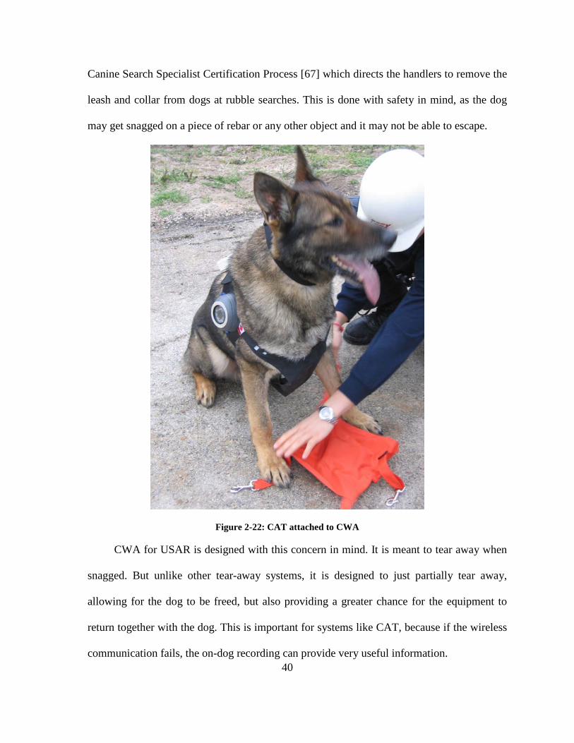
Canine Search Specialist Certification Process [67] which directs the handlers to remove the
leash and collar from dogs at rubble searches. This is done with safety in mind, as the dog
may get snagged on a piece of rebar or any other object and it may not be able to escape.
Figure 2-22: CAT attached to CWA
CWA for USAR is designed with this concern in mind. It is meant to tear away when
snagged. But unlike other tear-away systems, it is designed to just partially tear away,
allowing for the dog to be freed, but also providing a greater chance for the equipment to
return together with the dog. This is important for systems like CAT, because if the wireless
communication fails, the on-dog recording can provide very useful information.

41
Another related subcomponent of CAT is Canine Brain Function. This research has
found that it is possible to sense what a USAR dog is experiencing, by measuring its
physiology during the activity [65, 79]. The experiments use a multi-channel near infrared
brain spectroscope [79, 80]. This type of sensor has the capability of measuring brain
oxygenation by illuminating the brain tissue within the skull and detecting the reflection.
Many handlers believe that they will be able to determine some aspects of the mental
state of their dogs. Using this technology, it may be possible to figure out whether the dog is
actually working on the problem of finding people or doing something else.
2.3 Wireless technologies Generally speaking, there are two major types of wireless communication for mobile
robotics. The first one is an analog radio frequency (RF). The second is digital wireless
communication, of which Wireless Fidelity (WiFi) is the most popular. While RF has a
longer range, it may be diminished because there is a lot of interference around disaster
sites. When several robots are in the same place in the same frequency band, jamming or
interference can occur, leading to loss of signal and loss of control. On the other hand,
digital communication gives us the ability to transmit and receive signals in noisy
environments with relatively low error rates, and as a result is rapidly replacing analog
communication in many fields [81].
This thesis deals with wireless transmissions over a WiFi network. WiFi is used in a
variety of electronic products ranging like computers, mobile phones, Personal Digital
Assistants (PDA), etc. WiFi enables compatible devices to form a local area network
without the need of wires. It provides security of the transmission as well as channel
hopping,

42
which can reduce interference. It consists of several IEEE Wireless Local Area
Network (WLAN) 802.11 standards. [82] Table 2-1 shows a comparison between the
different 802.11 standards.
Standard Release date Frequency Band
Data Rate (Typical)
Data Rate (Maximum)
Range (Indoor)
Range (Outdoor)
802.11a October 1999 5.0/3.7 GHz 23 Mbit/s 54 Mbit/s 35 m 120/5000 m 802.11b October 1999 2.4GHz 4.5 Mbit/s 11 Mbit/s 38 m 140 m 802.11g June 2003 2.4 GHz 19 Mbit/s 54 Mbit/s 38 m 140 m 802.11n October 2009 2.4/5.0 GHz 74 Mbit/s 600 Mbit/s 70 m 250 m
Table 2-1: Comparison of the different 802.11 Standards
2.3.1 Wireless Mesh Networks The limited range of the 802.11 WiFi standard means that building a WLAN that
covers a large area can be a difficult task. Wireless Mesh Networks (WMN) can overcome
this problem. WMNs are available for different wireless technologies, with 802.11 being one
of them. In WMNs, there are two types of nodes – mesh routers and mesh clients. Each
mesh router operates as both a host and as a router, forwarding packets from other nodes
[83]. This allows for multiple routers to connect together and thus form a WLAN that can
span a large area. After a mesh network is formed, each mesh client can communicate with
any other mesh client regardless of which access point it is connected to.
WMNs have some very useful characteristics. They are dynamically self-forming,
self-configuring, and self-healing. The network nodes establish and maintain mesh
connectivity automatically among themselves [83]. Self-forming means that as each mesh
router node goes on-line, it will automatically connect to other mesh routers to form a
network. Self-configuring is the ability of each mesh router to find the fastest and most
reliable paths to send data from one client to another. Self-healing means that each mesh
router is aware of other routers and whenever one fails, it will reroute the data through

43
another node [83]. These characteristics provide for robustness, fault tolerance, and easy
network deployment, which are all very useful in disaster environments due to the
unpredictable conditions.
Figure 2-23: Example of Wireless Mesh Network for Audio communications [84]
2.4 Pattern recognition With the increasing use of robots and other remote sensing and telepresence
equipment in the USAR field, more emphasis is put on being able to distinguish markers or
patterns that signify a human’s presence. Even though humans are naturally good at spotting
patterns, in a situation where every second counts, first responders could use all the help
they can get to aid them in the process. If machines could help with this process it would be
extremely beneficial. This is where pattern recognition comes in. Pattern recognition is
defined as the study of how machines can observe the environment, learn to distinguish
patterns of interest from their background, and make sound and reasonable decisions about

44
the categories of the patterns [85]. The oxford dictionary defines pattern as “an arrangement
or design regularly found in comparable objects” [86], Furthermore, Watanabe defines it as
the opposite of chaos, or something that can be given a name [87].
Automatic pattern recognition is normally done in one of two ways – supervised
classification, and unsupervised classification. With supervised classification, the pattern is
identified as a member of a predefined class. With unsupervised classification on the other
hand, the pattern can be assigned to an unknown class. There are several approaches to
pattern recognition, with the most prominent being template matching, statistical approach,
syntactic approach, and neural networks.
With template matching, a template (usually a shape) is available and patterns are
attempted to be matched against that template. The statistical approach assigns features to
objects and based on how closely these features match a pattern, it may be classified with
some degree of certainty as belonging to one object or another. The syntactic approach
attempts to break the pattern into smaller sub-patterns and try to figure out the relationships
between the smaller pieces. Neural networks can be viewed as an attempt to mimic the
human brain with the key components being learning, generalization, adaptivity, and fault
tolerance. Neural networks can be trained to recognize specific objects, and then through
generalization they can match other patterns that have similar features [85].
Some example uses of pattern recognition to similar problems are shown in [88] for
simple shapes with Artificial Neural Network (ANN), and [89] for search and rescue images
from a plane.

45
2.5 Telepresence Telepresence, or the perception of presence at a remote site is a very important design
ideal [90]. It involves the displacement of the user’s self perception in a computer mediated
environment. Virtual presence (feeling present in a computer generated environment) and
telepresence (feeling present in a remote but real environment) have the same psychological
effect [91]. Telepresence can be exhibited when an operator remotely controls a machine.
There are three main types of telepresence – simple, cybernetic and experiential.
In the simple definition, telepresence is the ability to operate in a computer-mediated
environment. This normally involves the control of machines over a distance [91].
With the cybernetic definition, we have telepresence as quality measurement of the
human-machine interface. It represents how well a human operator can do the task at hand,
by using that interface to teleoperate the machine.
The experiential definition describes telepresence as a mental state, in which the
operator feels physically present in the computer-mediated environment. With this type of
telepresence it is more like an illusion, where the user thinks that he is there together with all
the remote or virtual objects [91].
It is important to make the distinction between the cybernetic definition and the
experiential one. Cybernetic telepresence refers more to how effective are the controls and
displays in doing the task at hand, while experiential telepresence refers to what is being
experienced by the human operator [91]. While the interface contributes to the whole
experience, experiential telepresence is something beyond the cybernetic telepresence. It
actually involves the projection of human consciousness as opposed to cybernetic

46
telepresence, which involves the projection of human capability. From this point on when
we use the term telepresence, we will mean experiential telepresence.
There are many telepresence systems that are in use in our day-to-day lives. Such
systems normally involve the use of a teleoperated robot, and are used when human access
to the location is not possible. Such systems include robotic systems for performing remote
surgery [92, 93], USAR robots [5, 34, 38], pipeline inspection [94], and deep sea work [95].
2.6 Situational Awareness Situational Awareness (SA) has been defined as “the perception of the elements in the
environment within a volume of time and space, the understanding of their meaning and the
projection of their status in the near future” [3]. In short, SA means understanding what is
going on around you and what can you do about it.
SA would be different for different domains, and could have some variations within
those domains based on the different roles of people. Most of the time, SA is used as an
operational term, as a person doesn’t always need to know everything that is happening
around them, but mostly just the information that is needed to complete the task at hand.
For USAR in general, besides having the right gear, rescuers also need to be aware of
their surroundings. Different buildings might have different number of people in them. Also,
elderly people would be harder to rescue than younger people who can more easily move
[1]. It is also important to know the condition a person is in, so that first responders would
know how to move him, or whether he would need to be medically stabilized before
extracting. Another important thing for emergency personnel is to be aware of the conditions
of the building – how stable is it, does it need shoring, etc. FEMA advises rescuers to “Be

47
alert for hazards (e.g., power lines, natural gas leaks, hazardous materials, sharp objects,
etc.)” [26].
On top of these, the more specialized tasks might require some more things to
consider. E.g. a robot operator might need to consider things like the condition of the robot,
its location, angle etc. A canine handler might be more concerned for the dog that he is
directing while still taking into account other relevant things.
2.7 Computational Public Safety Computational Public Safety (CPS) is a field that encompasses the use of
computational resources, theory and practice to support safety processes, as well as improve
them [96]. Examples of systems in this area include response robots, CAT and its sub-
projects CRDS, CPE, CWA and CBF. These systems are meant to provide rescuers with a
better SA, so that they can make an informed decision with respect to rescuing trapped
victims in minimal time.
2.8 Summary To gain a better understanding of the motivation for the thesis, some background
information on USAR and Emergency Management operations were provided. The
information provided described USAR operations, why are they needed, how are they
normally carried out, as well as challenges that may be encountered in the process. Other
key technologies and research having similar goals, such as rescue robots and animal
augmentation were also described. This chapter also provided literature review on wireless
technologies and pattern recognition and its applications for USAR operations. Furthermore
this chapter explained some key processes, concepts and terminology used in this work.

48

49
CHAPTER 3 MATERIALS AND METHODS
3.1 Architecture of CAT The CAT project has seen numerous improvements since its initial development. It has
gone through several prototypes, while taking into account lessons learned from them, with
each one building on the previous one. The first few prototypes leading to CAT 2.0 have
been developed in an ad-hoc manner, without adhering to any architecture or plan. With the
development of CAT 2.0 [13], the architecture shown in Chapter 2 was adopted (Figure
2-16).
This was a necessary next step that addresses the long-term vision for what the ideal
CAT should be. It set some goals for future versions to accomplish. This section suggests
some additions to this architecture, as well as example designs of how the CAT harness
would look like.
During the course of this thesis, it was postulated that another useful kind of
information could be collected using dogs as the transportation mechanism. Environmental
sensory data like air quality, concentration of different gases, temperature, etc. can also be
collected. The above architecture has been slightly modified to reflect this addition (Figure
3-1).

50
Figure 3-1: Updated CAT Architecture
Through careful consideration a more detailed diagram of how the ideal CAT might
look like was created. It is presented in Figure 3-2.

51
Figure 3-2: Diagram of ideal CAT
The harness would have all the wires sewn in the fabric to prevent snagging.
Components attached to CAT should be as flush to the dog as possible, so that they are
better protected. White light LEDs should be used to allow the cameras to be effective in
low-light conditions as well as record in colour. A speaker would allow for bi-directional
communication. Accelerometers to establish the pose of the dog can be integrated on the
harness. Environmental sensors would give a better understanding of the conditions in areas
that the dog is moving through. An external WiFi antenna that is sewn into the harness
might extend the range of the dog. The indicator LED could blink different colors to visually
indicate states like on/off, low battery, connected to WiFi node, etc. Batteries should be hot-
swappable so that the system could operate for longer periods of time.
3.2 CAT Prototypes The CAT prototypes starting from CAT 2.0 follow the new architecture which has
four critical features:
1. Capturing the local situation of the dog
White LED’s for the dog to see
Camera with microphone and white LEDs for illumination (on each side)
Indicator LED
Accelerometers
Speaker CRDS
Battery compartments (on each side)
Computer board compartment
WiFi Antenna
Environmental sensors (right side)
Magnetic collar switch
Bark release for CRDS
Break away safety mechanism, pressure activated.

52
2. Providing a means of transmitting this integrated information
3. Integrating the data into a single separable stream, and
4. Allowing for the system to be expandable.
In order to achieve the goals of the thesis and demonstrate an enhanced dog-based
telepresence system, a prototype that builds on previous designs and incorporates the four
critical features of the design needs to be shown.
Capturing the local state of the dog through CAT must provide sufficient feedback to
the human observers, allowing them to feel like they are present at the location where the
dog is. We do this by using simple cameras, microphones, as well as other sensors.
Another key feature that should be present in the system is that it should provide a
means of transmitting the integrated information that is being collected. WiFi is being used
as the primary means of communication with the handlers and observers. It was chosen for
its simplicity and even though it has a fairly short range, it can be expanded easily when a
WMN is used. We cannot expect to have a constant wireless connection with the dog as
disaster sites are unpredictable, and rebar-reinforced concrete especially can block WiFi
very effectively. That is why the necessity of having an on-dog recording is apparent.
Integrating all the data streams into one is another important architectural feature.
Some of the reasons behind this are the limited bandwidth that is normal in a disaster
environment; and the fact that the data being transmitted is related, but specific to the needs
of the end observers. Different observers will make use of this information in different ways.
For example, the handler may be more interested in the information about the dog –
temperature, pose, physiological features, etc. The structural engineers would be looking to
secure the buildings for humans to attempt a rescue. Search personnel might be interested in

53
the locations of the victims and the path to them. This will allow for them to build a map of
where survivors are located on the disaster area.
Expandability is a key feature of CAT, considering that it is a work in progress. Being
able to integrate more sensors as the need for them arises, or incorporating the different sub-
components of CAT – CRDS, CBF, and CPE is very important. As other sub-projects arise,
they can be integrated into the system, while other pieces can be removed if they are found
to be ineffective.
The following sections describe the new CAT prototypes from the oldest to the newest
one. It is important to show them as they show how lessons learned from older prototypes
were used to create newer ones.
3.2.2 CAT 4.0 CAT 3.0 was a major step from the previous designs but still had limitations that
needed to be overcome.
One such limitation was the lack of CPU power. The FOX boards could only stream
one camera due to the slow CPU. This meant that nothing else could be accomplished as it
would require additional computing power.
Another problem with the CAT 3.0 boards was the limited hardware support. The
drivers for it only supported a very limited number of chipsets of specific cameras and WiFi
adapters. Even newer revisions of the same cameras that were used were not supported. The
hardware used in CAT 3.0 has become obsolete and thus extremely difficult to replace if a
problem occurred.
Furthermore a problem was discovered with the recording mechanism over WiFi. If
the dog roams out of wireless range, the data was lost, meaning that in some places deeper

54
into the rubble piles it would be impossible to see what was happening. Also the video feed
coming from the dog and recorded wirelessly was too choppy and hard to watch. That meant
that when the video was reviewed it would take a substantial amount of time to find the few
useful frames where the survivor can be seen, as well as the immediate area around them.
Another problem that was identified was the fact that canine handlers often would
forget to turn on the equipment when sending the dog to a search. A better way of switching
on/off the system was required.
CAT 4.0 was designed to address all of the above issues. The FOX boards were
replaced with a powerful low-cost Linux-based Single Board Computer (SBC) called a
Beagle board (Figure 3-17). Because it had a single USB port, a powered USB hub was
required to connect all the remaining components. The same two USB Logitech cameras and
WiFi adapter were used and the block diagram for CAT reflects that (Figure 3-5). The
Beagle board boasted a 600MHz ARM CPU and a Digital Signal Processing (DSP) core
allowing it to handle the two camera streams easily, as well as have spare CPU cycles for
other things. It had an SD card slot that could expand the space to 16GB that allowed for
recording the camera feeds on the dog, as well as streaming them simultaneously. This
allowed recording data in places with no wireless signal and had a constant frame rate with
better quality and less choppiness.

55
Figure 3-3: Beagle Board
The main benefit of using this SBC was the fact that it could run a full Linux
distribution with full hardware support for any peripherals desired. This allowed for using
any new camera or WiFi adapter available. The board also featured a serial port, as well as
several Input/Output (I/O) pins for communicating with other embedded sensors and
devices. In essence the possibilities become limitless as to what can be connected to CAT.

56
Figure 3-4: Block Diagram for CAT 4.0
Having a full-fledged Linux distribution also meant that developing software for CAT
would be just as easy as developing for any other computer. Thus software for streaming and
recording the two video streams was written in the C language and utilized the Gstreamer
multimedia libraries for Linux. Utilizing these libraries allowed for compression of the data
to save bandwidth, and opened up the possibility of recording at higher resolution than
transmitting. Different software was made for the computer that would connect to view the
streams from CAT. This made it possible to easily connect and view the camera streams on
the screen (Figure 3-19). The client application was written in Java, thus allowing for easily

57
creating a Graphical User Interface. It also utilized the Gstreamer multimedia libraries. Java
and Gstreamer were specifically chosen as they are both platform independent and allowed
the software to be run on any computer. The software for CAT could be very easily adapted
to work with any embedded Linux computer and enable for the streaming and recording of
any number of cameras, as well as controlling servos and motors, and reading input from
sensors. One such other embedded device that benefited from the software was DEX, which
is described in Chapter 3.4.
Figure 3-5: Streaming video from CAT.
The power consumption of the board itself was comparable of that of the two FOX
boards combined – 2W. This meant that power-wise no sacrifice was made to achieve such
benefits as the Beagle board provided. Additional details on the board are provided in [97].

58
It was identified however from the previous version of CAT that the IR LEDs in each
dome would consume 3W peak each. Thus the power consumption of the entire system
came up to be 10W. This necessitated the change of battery pack to a higher capacity one.
The resulting battery pack provided 7.4V and 2Ah and thus allowing for up to 1 hour of
continuous operation.
The ability to record on the dog allowed for the use of software to speed up the search
in the video streams to find the important segments where the victim is supposed to be [14].
More details on this are provided in Section 3.3.
To address the issue of having an extra step of switching the equipment on, a different
type of switch was used. Instead of having the canine handler physically flipping a switch, a
magnetic switch was introduced. It was attached with a string to the dog collar, so whenever
the dog was to be sent on a search, the collar was removed and with that the magnetic switch
activated the device.
The only downside that was introduced with this iteration of CAT was the size of the
computing box actually increased compared with previous versions of CAT.
3.2.3 CAT 5.0 CAT 4.0 was a good architecture, but it brought some issues that needed to be
addressed. CAT 5.0 was designed to take those issues into account.
One of the major issues that were encountered with CAT 4.0 was the size of the main
computing unit. The added USB hub, as well as the mechanism for switching it on increased
the size of the computing unit. Thus having brought the architecture to only one SBC
actually increased the size of the box that housed the electronics.

59
The problem with the increased size became clear as soon as we put the unit on the
dog. The harness was designed for a smaller computing unit. When the dog started running
and jumping off rubble, the unit fell off the pouch that was housing it and it was dragged on
the ground by the connecting cables. Even though the problem could be partially fixed by
adjusting the pouch size, it could be seen that it was still bulky and uncomfortable for the
dog. It became clear that a smaller unit was needed.
Also the camera domes relied on an off-the-shelf security camera domes that also were
a bit big and could swivel when hit. This meant, that if the dog rubs onto something, the
camera could be dislodged and remain in a position that it is looking at the back of the dog,
or at the ceiling.
Another problem with the domes was that they didn’t let sound in. This meant that
even though CAT 4.0 had the ability to record audio, the microphones from the USB
cameras in the domes could not pick up any sound.
These issues were addressed with the design of CAT 5.0. To reduce the size of the
unit, the platform was moved to a Beagle board clone called IGEPv2 board (Figure 3-6). It
incorporated Bluetooth and WiFi on the board itself, as well as two USB host ports and thus
eliminating the need for a USB hub and an external USB WiFi adapter. The switch to the
new SBC brought in a performance boost as well. The new IGEPv2 board had a 720MHz
ARM based CPU with the same DSP chip and more on-board RAM and NAND Flash,
which could allow for the entire operating system to run on the built-in memory rather than
on the microSD card. Additional details on the board are provided in [98]. This simplified
our block diagram for the system as can be seen in Figure 3-7.

60
Figure 3-6: IGEPv2 Board
Figure 3-7: Block Diagram for CAT 5.0
The camera domes were redesigned to take into account the issues discovered in the
previous CAT prototypes. The outer shell was made of a sturdy material that housed the

61
inner shell which was made from aluminum with a clear plastic cover at the front of the
camera. The inner shell was positioned at an angle facing forward to allow for a better
frontal view from the dog. This design also allowed for adjusting of the inner shell for
several angles depending on the dog that that the CAT system is placed on. The newly
designed camera domes included housings for the microphones which were attached to the
webcams. Thus bringing back audio sensing which has been missing since CAT 2.0. Figure
3-8 shows the CAT 5.0 prototype.
Figure 3-8: CAT 5.0 with CRDS worn by USAR dog Freitag
3.3 Automated scrubbing of video Since the development of CAT 4.0 and the ability to record the video streams from the
dog, it became possible to develop video processing algorithms. These algorithms would
allow for tagging the video where interesting things appear. One such algorithm has been

62
developed for finding times in the video where the victim is most likely to appear [14]. This
algorithm is described in this section.
The algorithm for automated scrubbing of video relies on a protocol called the 3-Dog
protocol that has been previously developed for situations where CAT and CRDS would be
used together [76]. This protocol involving three steps is used whenever a handler cannot
accompany the dog in its search:
• A dog is sent without any equipment to search and find a human in the regular
way.
• If the first dog gets a “hit”, a second dog is sent with a Canine Remote Deployment
System (CRDS) [76] that is capable of automatically dropping a marker when the
dog barks. The bag (called the underdog) is orange (containing supplies, radio,
etc.) and is usually within 1 meter from the scent plume the dog has detected.
• Finally, a third dog equipped with CAT is sent in to collect video of the area and
possibly of the trapped person and their surroundings and condition.
The dropped bag is the key to video processing as the bag is a colour which is different
from the surrounding debris. Thus a technique used by a human scrubbing the video is to
look for the orange bag to appear - the video depicting the victim is likely to be near this
location in the video stream.
The scrubbed images can then be analyzed by structural engineers and rescuers to plan
how to best save the person. We should take into account that going through the video and
analyzing the video frames is a very time-consuming process which adds to the delay before
a rescue can be attempted. Since the underdog may appear in one or two video frames for a
fraction of a second, a person might easily miss seeing it.

63
Software was developed that is able to analyze the video stream, either in real time or
after the video has been extracted, and to tag the video where the orange bag appears. To
accomplish this, each frame is checked for the presence of the orange bag. Thus the problem
becomes finding the bag in an image, as a video is a sequence of images. Because the bag is
not a rigid object (shape recognition cannot be applied) and can appear in the image in
different orientations and distances from the camera, and in different light conditions, thus
the problem becomes quite difficult (See Figure 3-9 and Figure 3-10).
Figure 3-9: Bag outside in good light conditions
Figure 3-10: Bag in an enclosed space in poor light conditions

64
In solving this problem several approaches were tried. One such approach was the use
of the SIFT method [99] to find similar features between the database of trained images and
the test images. The problem with this was that many images of rubble, especially in dark
places look the same, and the key points selected normally would not contain the orange bag
at all. This led to incorrect classification every time and the method was abandoned.
Another approach that proved to be effective is described below.
The problem was split into three parts: pre-processing, isolating regions of the image
that contain an orange coloured blob (based on a threshold), and checking if that region
contains the orange bag (using an Artificial Neural Network). The Software was
implemented in the C language. The libraries used were the OpenCV (Open Computer
Vision) library for image processing and FANN (Fast Artificial Neural Network) library for
the ANN part.
3.3.1 Pre-processing The pre-processing consisted of converting from the RGB colour space to the HSV
colour space. This was done because the HSV colour space describes perceptual colour
relationships more accurately than RGB, and allows us to more easily find colours that are
very similar [100].
3.3.2 Isolating regions For finding the regions with the orange blob, thresholds were selected for the Hue,
Saturation and Value that best capture the colour that was sought in different light
conditions. The values were found to be the following:

65
Table 3-1: HSV minimums and maximums
Hue Saturation Value
Min Max Min Max Min Max
0° 24° 0.44 0.75 0.35 1.00
A second black and white image is created, so that it can be shown which parts of the
image are detected in the colour that is sought. We then go through each pixel in the image
and if it has values within that threshold, we change the corresponding pixel in the
black/white image white, and black otherwise. We then perform an “erosion”2 on the black
and white image to remove any stray pixels that might be detected by accident and then
several “dilations”3
What we are left with at the end of this step is one or more regions that were
determined as probably showing the orange bag. If no regions were detected, then the orange
bag was not found, we discard the image, and we check the next image. If one or more
regions are found, they are each scaled to 30x30 pixels and the HSV values for the 900
pixels are given as an input to the Neural Network in the next step.
, to get a slightly bigger region that we can use for the ANN step.
3.3.3 Checking isolated regions A standard back propagation Artificial Neural Network was trained on 200 30x30
images to recognize the orange bag. It consists of 2700 inputs (900 pixels with HSV values
for each) and 1 output – whether it is the bag or not. Best results were achieved with 2
2 Erosion is a basic operator in mathematical morphology. When used in binary images, it erodes away the boundary of regions of foreground pixels.
3 Dilation is a basic operator in mathematical morphology. When used in binary images, it enlarges the boundaries of regions of foreground pixels

66
hidden layers of 150 neurons each. The Sigmoid Symmetric activation function and a
learning rate of 0.7 were used for all the neurons. When a 30x30 region is given to the ANN,
it provides a floating point result between -1 and 1 depending on how sure the ANN is of the
match. If the result is greater than 0 we assume that it is a positive match and when it is less
than or equal to 0 it is a negative match. Based on these results, we can filter each image and
remove some or all of the regions that were given as part of the previous step and therefore
produce a more accurate result concerning the presence or absence of the orange bag in the
image.
This approach could be used to produce timing information where it detected the
presence of the underdog. This timing information could be used as a marker in the software
for playing the video feeds from the dog. The person reviewing the video feeds would then
be able to just jump to that position in the video where the orange bag has been spotted and
thus find the victim in the video significantly faster than the manual approach.
3.4 DEX Although CAT provides really important information like path to the victim, a view of
the area around the victim, it does not provide any form of control over where the cameras
would be pointed. In most situations the victim can be seen only very briefly, or some areas
may not be seen at all. Sometimes a more detailed examination of the victim and the
immediate area around them is needed. Since dogs cannot be finely controlled, the ideal
situation would allow the search specialist fine control over what can be seen. Robots would
be ideal in a situation like this where the operator has complete control over everything. The
problem with the robots though is that they cannot get to where the person is trapped. As
previously discussed in Chapter 2.2.1 their mobility is very limited. The question then came,

67
what if we can bypass the terrain traversal and put a robot where the victim is? As
previously noted in Chapter 2.2.1, there exist some designs where one robot can carry
another robot in a form of marsupial symbiosis. But these designs also are limited by the
mobility of the “mother” robot. Then the idea occurred that we know that the dog has no
mobility limitations and can easily find the victims. It could also deliver packages to the
survivors through the use of CRDS. So why not deliver a small robot to the victim instead of
a radio? This idea led to the development of Drop and EXplore (DEX) – the first robot in a
new class called Canine-Delivered Marsupial Robot (CDMR). CDMRs can be defined as
robots that are designed to be deployed from search dogs [13, 16].
DEX is a prototype robot that was built specifically to be deployed by a dog (Figure
3-11). As such it was built with several constraints in mind. The first is that it must be able
to fit under the dog well. We suspected that a flat top would fit flush to the dog’s underbelly
making it more acceptable for the dog to carry.
Figure 3-11: DEX

68
It should also be “dogonomic” – ergonomic for dogs. This is important since the dog
must concentrate on its task and not be distracted by the equipment.
These constraints limited the choices for all the other components, such as small
wheels size. This reduced the robot’s mobility over a rougher terrain but was still acceptable
since the robot would be dropped very close to the casualty. DEX also would not need to
move very far to capture the data required. We designed DEX to be a 4 wheeled drive
vehicle to enhance its mobility.
DEX’s small footprint also limits the electronics that can be fitted inside. Hence
processing power is reduced. More details about the robot are presented below.
3.4.1 Dimensions As noted above, dogonomics is an important consideration and thus we tried to
minimize the physical size of DEX. In reality, not all dogs are suitable for this type of work.
We have found that USAR dogs come in many shapes and sizes. As a rough gauge Labrador
and Shepherd breeds work very well in terms of size and build. Table 3-2 lists the
dimensions in detail. The larger the size is the less accepting the dog is likely to be and the
robot will also encumber the dog’s mobility.
Table 3-2: Dimensions of DEX
Length (cm) Width (cm) Height (cm) Wheel Diameter (cm)
18 15.5 6.5 5.5
3.4.2 Attaching to the dog We used the CRDS as the deploying mechanism so another design issue that we had to
consider was how the CRDS, the dog and DEX would be attached. We developed two
methods for attaching DEX to the release mechanism.

69
3.4.2.1 Method 1: We used retractable cable mechanisms, attached hooks to the ends and mounted them on top of the robot. Figure 3-12 shows this on the robot and Figure 3-13 shows how the system is attached.
Figure 3-12: DEX with retractable hooks
Figure 3-13: DEX attached with hooks to CRDS
The retractable hooks CRDS DEX

70
3.4.2.2 Method 2: The robot was nestled inside the underdog. When the CRDS
is triggered, the bag is released along with DEX (Figure 3-14).
Figure 3-14: DEX in underdog attached to CRDS
3.4.3 Electronic hardware The electronic components of DEX include:
• SBC – Beagleboard
• Camera – Logitech C200 webcam
• 4 ports USB Hub
• WiFi adapter – D-Link DWL-G122
• Switching voltage regulator
• Microcontroller board based on Atmel’s ATMega328
• Motor driver – Pololu TB6612FNG Dual Driver
• Lithium Polymer (Li-Po) batteries
Underdog hooks Underdog bag DEX CRDS

71
The main control unit – the Beagle board was the same as the one that was used in
CAT 4.0. It was used to capture the video from the camera and transmit it over a WiFi
WMN. It was also responsible for receiving control signals from another computer and
passing it on to the microcontroller for mechanical functions.
The microcontroller was also connected to the motor driver which provided power to
four geared motors. Aside from the drive motors, a servo motor was used to raise and lower
the camera. The servo motor was controlled by the microcontroller.
DEX was powered by two separate packs of Li-Po batteries. Each batteries pack was
made from two cells in series providing a nominal voltage of 7.4V and has the capacity of
2000mAh. Since all the electronics operated on a 5V logic level, a switching power
regulator was used. The second batteries pack was used just to power the motors. This
design of two separate packs helped reduce the electrical noise from the motors.
3.4.4 Control and communication The robot is controlled through 802.11 standard over a WMN. Our reasoning is that
the network can be easily extended by dropping more nodes, and thus allowing for
connectivity in places where normally no wireless signal could penetrate, such as around
bends in rubble made out of reinforced concrete.
The robot is controlled from a laptop on which the user interface displays a live
audio/video stream from the camera. A joystick-like interface is used for easier control of
the robot movement and 2 buttons for tilting the camera up and down. When a command is
sent to move the robot, it goes through several “hops” of the mesh network to the robot’s
computer which, in turn, interprets the command and sends it to the microcontroller via a
serial interface that controls the individual motors.

72
The video feed from the camera is recorded on a local flash drive, specifically a
Secure Digital (SD) card on the Beagleboard. The video is also streamed through the WMN
to be displayed on the laptop screen where first responders can analyze the information.
The automated video scrubbing, detailed CAT architecture design, the software for
DEX, as well as CAT 4.0/5.0 are the contributions of this research. The next chapter
presents the experiments that test the theories of these developments. The results of those
experiments will show that these contributions satisfy the requirements to achieve the goal
of this thesis.

73
CHAPTER 4 EXPERIMENTS AND RESULTS This section explains the experiments and results obtained from each stage of CAT’s
development. It is meant to complement Chapter 3 and the designs of each prototype. Each
stage was done with the knowledge obtained from the previous stages. The experiments can
be classified in the following sections in chronological order:
• CAT 4.0 Experiments
• Video Scrubbing Tests
• WMN Deployment Experiments
• CAT 5.0 Experiments
• DEX Experiments
In the final sections we will discuss how the captured video and audio through the
different CAT systems, as well as from DEX demonstrated the ability of the systems to
further enhance the situational awareness of an observer when compared to previous CAT
systems. Also we will discuss how the video scrubbing software can reduce the time needed
to locate key frames within a CAT video feed which may ultimately reduce the time needed
to rescue someone.
4.1 CAT 4.0 Experiments CAT 4.0 was designed to make the CAT system more expandable by allowing for
more sensor attachments and to allow recording video on the dog (On-dog recording) for
later review and processing. On-dog recording was a pragmatic response to difficulty of
maintaining a wireless network link with a moving dog in some of the worst radio
communication settings.

74
4.1.1 Preliminary video tests Based on the new hardware and software, CAT 4.0 had the ability to transmit and
record the two camera streams simultaneously. The equipment was first tested in-lab to
determine the performance of recording and streaming the two video feeds. The results from
this test were very encouraging.
The live video feeds showed very good quality at resolutions of 320x240. The video
streams showed almost no lag and little choppiness. The on-board recording showed no
problems whatsoever. There was no lag and the pictures had good quality.
4.1.2 Rubble pile tests With the collaboration of the Ontario Provincial Emergency Response Team (PERT)
of the Ontario Provincial Police (OPP), a purpose-built rubble pile and “confined space”
training and testing facility used as a simulated disaster site was made available for the
experiments.
With the help of Canadian certified and U.S. FEMA certified canine teams4
The second experiment involved a simulated search for a victim on the rubble pile. A
person acting as a quarry was hidden somewhere in the rubble while Dare had to find him.
One WiFi router was placed on the pile at a strategic location, so that it could provide
coverage for a large area. This test would give us an indication of how the video feeds would
, two
experiments were conducted. In the first experiment, the canine “Dare” was equipped with
CAT 4.0 and the canine handler Const. Kevin Barnum walked him around the PERT
headquarters. The video feed from the CAT system was recorded, as well as observations
made as to how the new system fit on the dog.
4 Provincial Constable Kevin Barnum and the Black Labrador Retriever “Dare”

75
look during an actual deployment, as well as tell us how well the system could be worn and
accepted by a dog. It would also show us how having on-dog recording compared to video
over WiFi transmission.
4.1.3 Experiment Results The video recorded from the first experiment showed us that recording on the dog is
better than the streamed video. It produced no lag or interruptions. A perennial problem—
that of shaky video, was addressed. When the dog was moving the shaking was noticeably
reduced. We noted that the main computing unit was not ideally suited for a dog’s comfort
and movement appeared awkward for the dog.
Because the box that housed the computing unit was a little larger than on the previous
version of CAT it did not fit as snugly as before. In addition, the unit placed additional strain
on the harness quick release points which sometime gave way reducing the effectiveness of
CAT. As the computing unit was larger than previous units, it had a tendency to sway in
sympathetic harmony with the dogs motion which several dogs clearly did not like. A field
expedient was used to resolve this issue by snugly duct taping the unit in place against the
harness. Clearly, there were still issues associated with harness comfort and efficacy.
However, these are beyond the scope of this thesis.
Previous CAT units had a very cumbersome method of turning on the various
components. Canine Handlers hated this. The canine handlers appreciated a new method for
turning CAT on. A magnetic switch was incorporated into the harness in proximity to the D-
ring intended for a leash. When a handler removed a leash—readying the dog for a search,
the unit was turned on.

76
In the second experiment, within the first minute of the search Dare started jumping
from place to place on the pile and the box for the computing unit fell out of its pouch. The
unit was then dragged by the dog for several meters hanging by the cable harnesses for the
cameras. It became apparent that the harness would have to be modified to accommodate the
change to a bigger computing box. After duct tape was applied, the box no longer was
falling off and the experiment could be resumed. Dare was able to find the victim in a very
short amount of time. During that time, the wireless connection to CAT had disconnected
multiple times and thus lost parts of the transmitted video information. When the search was
complete and Dare returned, the SD card with the camera feeds was extracted from the dog
and the videos were reviewed. This showed us that on-dog recording was far more reliable
than the WiFi transmission which experienced numerous disconnects.
4.2 Video Scrubbing Tests One of the main benefits that came with the ability to record video streams with CAT
was the possibility to run pattern recognition software on the video feeds to allow for easier
victim location5
[14]
. The software that was developed and presented in Chapter 3.3 was then
tested to determine efficacy.
4.2.1 Test setup A series of tests were conducted on the pattern recognition software for the
thresholding part, the ANN part and the combination of both. The thresholding part and the
combination of thresholding and ANN were tested on a series of 20 images, while the ANN
part was trained on 200 images and tested on 135 images.
5 We refer to finding the victim within the video stream only. Finding the victim is reality is done by the dog.

77
4.2.2 Test Results The error for the ANN converged quickly after only 41 epochs and produced minimal
errors on the testing data as well. The results are presented in Table 4-1 and Table 4-2.
Table 4-1: Approaches and corresponding error
Thresholding Thresholding + ANN
Error 15% 15%
Table 4-2: Neural Network’s convergence and errors
Epochs Training Error Testing Error
41 0.001813 0.067022
While the thresholding approach yielded a 15% error, it actually recognized all the
images that had the orange bag in them, but also picked up some false positives. The two
approaches combined still exhibited 15% errors which means that 15% of the time a false
indications of an orange bag that was not present at a particular location in the image was
produced. Figures 4-1- 4-9 provides examples of correct classifications, false negatives, and
false positives.
As false positive errors are generally far more acceptable than false negatives given
that we are trying to find indirect signs of a trapped human being in the rubble. False
positives can quickly be ruled out by a human observer however a false negative—a failure
to indicate the presence of a colour—could mean our system would miss them completely.

78
Figure 4-1: Correct classification - Original image
Figure 4-2: Image after thresholding
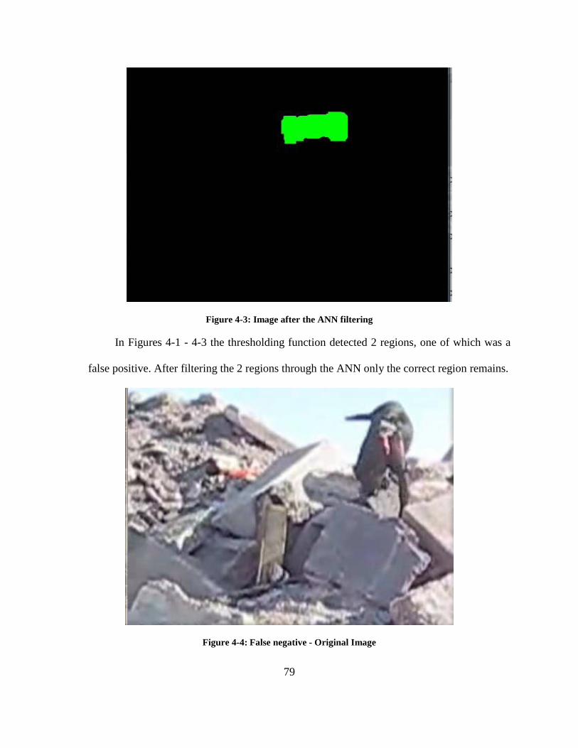
79
Figure 4-3: Image after the ANN filtering
In Figures 4-1 - 4-3 the thresholding function detected 2 regions, one of which was a
false positive. After filtering the 2 regions through the ANN only the correct region remains.
Figure 4-4: False negative - Original Image

80
Figure 4-5: Image after thresholding
Figure 4-6: Image after the ANN filtering
In Figures 4-4 - 4-6 the thresholding function detects 1 region which shows the bag.
After the ANN filtering, that region is ignored and gives a false negative.

81
Figure 4-7: False positive - Original image
Figure 4-8: Image after thresholding

82
Figure 4-9: Image after the ANN filtering
In Figures 4-7 - 4-9 the thresholding function detects 8 regions, all of which are false
positives. These are due to the orange colour of hanging insulation in a partially collapsed
parking garage. After the ANN filtering, 2 of these regions are ignored but still provide a
false positive. This image is particularly difficult to process in order to find the orange bag,
because most of the image has orange shapes most of which look like the bag. It is almost
impossible even for a human looking at the image to figure out whether the bag is present in
it.
4.3 WMN Deployment Experiments When first responders arrive at the scene of a disaster, they need to build the wireless
network on which CAT will run. This has to be done in a way that does not endanger them.
This section describes one way of deploying a WMN.
The experiment was conducted in the tunnel system under Rubble Pile 1 (Figure 4-11)
at Disaster City of Texas A&M University, College Station, Texas. It involved the

83
placement of several WMN routers at strategic locations so that wireless connectivity is
maintained throughout the tunnels.
Normally WMN’s are set up by dropping off access nodes around the rubble in
question. This can be problematic as there is no knowing what connectivity is available in
the midst of debris which cannot be traversed by a human. Our experiments indicate how a
network can be extended into debris without endangering humans.
4.3.1 Experiment setup To simulate a real environment, a “quarry” was hidden somewhere in the tunnels
under the rubble pile. The intent was to place a person in a location that was deep within the
tunnel system, so that it would necessitate the placement of several WMN nodes in order to
establish a connection. The tunnels were made out of reinforced concrete with 90 degree
turns, which limited wireless range significantly (Figure 4-11). The goal was to build the
network without any previous knowledge of where a victim might be located. To do this, we
started with placing a WMN router near the entrance to the tunnels at a distance of 3m. The
remainder of the network was to be built by utilizing a USAR dog and a response robot. The
dog was equipped with a CRDS with a WMN node placed in the “underdog”. The goal was
for the dog to find a victim, bark until the CRDS was activated and the router would be
deployed. Then a person would walk on top of the rubble pile with a WiFi detector to try
and locate where the dog has released the mesh router and give us an approximate location.
A response robot would then be sent in to build the network to the victim. The robot used in
the experiment was a Matilda by Mesa Robotics. It carried another mesh node in its gripper.
This node was to be released when the signal to the node at the entrance to the tunnels was
very weak. The network was to be extended by dropping extra mesh nodes with the Matilda

84
robot until a connection was made to the last node located in the vicinity of the victim
(dropped by the dog).
4.3.2 Experiment results The experiment proved to be a success. The dog that was sent in found the victim,
gave a bark indication and the CRDS released the underdog containing the WMN router. A
walk on top of the rubble pile with a WiFi signal detector gave us an approximate location
of the WNM node. At this point the Matilda robot carrying the second mesh router was sent
in. We had determined that the best position to drop off the second mesh router was at the
second tunnel intersection. Anything further than this would have required more WMN
nodes to be deployed. The Matilda dropped off the mesh node at that location. The mesh
network was formed and within seconds we were able to ping the router that was dropped
off by the dog near the victim. A map of the locations of the victim and the routers is shown
inFigure 4-10.

85
Figure 4-10: Map of tunnels showing victim and router placements.
This network was used in the experiments described in Chapters 4.4 and 4.5.

86
4.4 CAT 5.0 Experiments The main focus of the experiments for CAT 5.0 was testing the video streaming
capabilities of the system in an actual disaster environment. We also wished to confirm how
well the system interacted with the dog.
4.4.1 CAT Experiments Again, our experiments were conducted at Disaster City, College Station, Texas with
the help of FEMA canine handlers Tom Haus and Athena Haus (FEMA CA-TF2) and their
USAR German6
For the first experiment, Freitag was equipped with the CAT 5.0 system and the
handlers Tom and Athena Haus took turns walking him on the grounds of Disaster City. In
this experiment Freitag also had to traverse challenging terrain like a rubble pile (
shepherd Freitag.
Figure
4-11) and different obstacles that existed on the test location. We carried a WiFi router near
the dog to test the streaming and recording capabilities of the system in different conditions.
Special attention was also put on how the new camera domes and the system performed as a
whole.
The second experiment involved looking for a “quarry” in the tunnel system
underneath Rubble Pile 1 (Figure 4-11). A WMN was previously established (Chapter 4.3)
that covered the whole path to the victim. This test was performed to measure the viability
of streaming the video feeds from the dog through the WMN. Another measure was how fast
would the dog find the victim, come back and all the information is retrieved from it.
6 German in the sense that Freitag only understands commands given in the German language.

87
Figure 4-11: Rubble Pile 1 at Disaster City
4.4.2 Experiments Results The results of the experiments were very interesting. The first experiment showed the
reliability of the new camera domes. There were no abrasions or cracks to the domes after
thirty minutes of testing. The domes remained in operational condition in almost any
situation. However one problem that was discovered was the latching mechanism. The inner
shell housing the camera was secured to the harness via a magnet. In certain situations, when
the dog was jumping up or down, the force from the landing would make the magnet slip
and the cameras would pop out of the harness. Another problem that once again stemmed
from the domes was that they were heavy. In some conditions when the dog would run and
shake too much, the safety features of the harness would trigger. This led to the release of
the CAT system when there was no danger of the dog being trapped. The failure points were
marked and temporarily fixed with yellow duct tape. Some of the failure points can be seen

88
inFigure 4-12. The streaming and recording software developed as part of this thesis worked
quite well. The streaming video was a bit choppy and at times had significant delay. Some
network disconnections also occurred. On the other hand, the recording part of the software
performed without any problems. The recorded videos had a constant frame rate, no
choppiness or delays. That meant that regardless of the conditions and network
communication problems, the recorded video can always be extracted and show us good
quality footage from the dog. This test uncovered a problem with our cameras that came
from our assumption that the dog would normally operate in low light conditions. We had
removed the infra-red filters from our cameras so that we can get a better video in the dark
when the IR LEDs turn on. That however meant that in brighter locations like outside the
tunnels, or on top of the rubble pile the cameras would show just a white picture. Other than
these problems, the system performed well.
Figure 4-12: CAT 5.0 Failure points

89
The second experiment showed us some more interesting results. Even though there
were several WMN router nodes covering the whole area through the victim, connection to
the dog was lost several meters after going into the tunnel system. The reason for this was
that at that point, CAT was out of range from the router that was located at the entrance to
the tunnel and was trying to roam to the next router. It was not successful as the dog was
moving so fast that it was already out of range from it before being able to connect. The
same thing was repeated for all the nodes on the network. A short time after finding the
victim, the dog was back out of the tunnels. The SD card from CAT was retrieved and the
videos downloaded to a laptop. The whole process from beginning to having the videos
downloaded on the laptop took less than 4 minutes. The experiment was repeated several
times with the same outcome. Almost no video was available from the wireless
transmission, while the video from the on-dog recording showed a view of the quarry many
times and the routes the dog took in and out. (Figure 4-13 and Figure 4-14). From this result
we can see that the upgraded system presented in this thesis has a far greater potential for
improving SA, as it now allows for video to be recorded despite connectivity problems.
Unfortunately this could not be tested as there is no proper user interface available.

90
Figure 4-13: Left camera showing head of the quarry.
Figure 4-14: Right camera showing head of the quarry.
4.5 DEX Experiments Although information provided by CAT can be very useful, it is still fairly limited.
The video is shaky from the running of the dog and limited around the victim as we would
get a brief view of the victim and their surroundings. Since we do not have control of the
dog’s movements we cannot obtain more information on the trapped person. To give us a
better SA, we needed more control of the cameras that could be obtained by using a robot.
This is why DEX was introduced. One major concern in the development of DEX was
determining if dogs would accept having a robot attached to them. The dog cannot be
distracted from its task of performing searches and this was a real concern whenever we
attach anything to a dog. Another concern was determining if DEX could be successfully
deployed from a search dog and remain operational. In past testing we determined that most
items that were in any way fragile would be broken by an USAR dog eventually. A
successful deployment of DEX would mean that it would maintain all its functionality, such

91
as mobility and video broadcasting after being dropped from the dog. Our first set of
experiments tested these concerns.
4.5.1 Experiments setup The CAT 5.0 experiments were followed by the DEX experiments. A typical exercise
in the training of USAR dogs is called the “bark barrel”. A ”quarry” is placed inside a large
barrel and hidden from view. The purpose of the bark barrel is to get a dog to bark when it
smells the human in the barrel. Eventually, the barrel is moved to a rubble pile and then
removed altogether as the dog becomes used to finding hidden humans in voids and hidden
spaces in rubble piles.
We adopted the bark barrel exercise for our experiment to familiarize the dog with
wearing the equipment. In our experiments we equipped Freitag with the CRDS equipment
and DEX attached to its underbelly, and then the handler guided the dog to do the bark
barrel exercise. Several trials were conducted using both methods of attaching DEX to the
dog. Observations were made to see if having all the equipment on would affect Freitag’s
performance in the bark barrel exercise. Failure points in the deployment of DEX were also
observed.
The second experiment was done at the same rubble pile as the CAT 5.0 and WMN
experiments and used the already established network and “quarry” location from the
previous experiments.
This experiment was designed to test DEX’s ability to capture videos of the victim and
overall visual acuity. A “quarry” was hidden in the same location as the previous
experiments. Visual acuity stickers were placed around the location of the quarry. After the
quarry was placed, the dog was to be sent in to find the quarry. When the dog barked

92
indicating that it has found a casualty, the robot would be deployed. The robot then was to
explore the area trying to capture videos of the casualty and find as many of the stickers as it
can.
4.5.2 Experiments Results The results from the first method of attaching the robot to the CRDS showed us that
that method was a complete failure. Due to the weight of the robot, the cables were sagging
and were getting kicked around by the canine. It seemed to be extremely uncomfortable to
the dog and on one of the trials the retracting cables mechanisms tore off from the robot
body because of the jerking motion of the running dog and the weight of the robot. Figure
4-15shows DEX being thrown when Freitag was running towards the barrel. It was
surprising that DEX was able to drive off after that but another method of releasing the robot
was needed.

93
Figure 4-15: DEX being thrown from Freitag
For the second method of release, the underdog had to be slightly modified to include
bends of the material at the back and sides of the bag, so that the robot wouldn’t fall off
while the dog is running as in the previous method. The underdog was then cinched flush
against the dog’s underbelly, so that it held firmly in place. We observed that the dog was
able to do the barrel exercise as if it was not wearing anything. This indicates that this
method was much more suitable than the first one. Figure 4-16 shows DEX successfully
released by the bark barrel. We tried this test multiple times with this release method and we
were able to reproduce the same results every time.
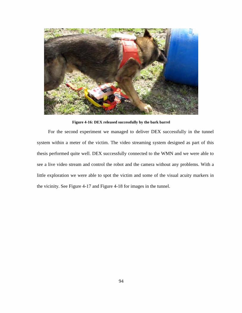
94
Figure 4-16: DEX released successfully by the bark barrel
For the second experiment we managed to deliver DEX successfully in the tunnel
system within a meter of the victim. The video streaming system designed as part of this
thesis performed quite well. DEX successfully connected to the WMN and we were able to
see a live video stream and control the robot and the camera without any problems. With a
little exploration we were able to spot the victim and some of the visual acuity markers in
the vicinity. See Figure 4-17 and Figure 4-18 for images in the tunnel.

95
Figure 4-17: DEX exploring in the tunnel close to the victim
Figure 4-18: Image from DEX showing victim and visual acuity markers
In this test we also quickly ran into the main limitation of the robot – mobility. Due to
the small size of the tires and the small clearance, DEX got caught behind large wooden

96
blocks and could not navigate around or over them. Despite that we were able to obtain
useful information as can be seen in Figure 4-18.

97
CHAPTER 5 CONCLUSION AND FUTURE WORK
5.1 Summary of Findings and Conclusions Disasters are occurring more frequently, have a greater cost and have devastating
impacts on more people than ever before. Many lives are lost in these disasters, but some of
them can be saved. To do this we need the right technology. A lot of the victims survive the
initial building collapses, but then die because they are not found and rescued in timely
manner. Adding technology to the search dogs in order to improve the speed of the Urban
Search and Rescue effort could lead to saving more lives.
The goal of this thesis is to improve various aspects of CAT in order to reduce the time
needed to make an informed decision about where a victim is and how to rescue them. This
thesis introduced a method for automatically scrubbing the video coming from CAT,
overcame the video streaming problems by recording on the dog, enhanced the capabilities
of CAT by providing a better computation platform, developed a streaming and recording
software that can be used on different embedded platforms like CAT and DEX, as well as
helped pave the way in deploying a network in a structural collapse. It also helped to deliver
a robot to a victim. This chapter provides a summary of the findings of this research,
conclusions drawn from them, and suggests some topics that need further work.
When disasters occur in an urban environment, it is quite common for buildings to
suffer structural collapse. Finding survivors other than the lightly trapped ones means that
rescuers need to search deeper into a collapsed building. Those areas however could be very
dangerous for humans to enter, as the damaged structures tend to be very unstable and there
is risk of a secondary collapse. To continue the search, some parts of the wreckage need to

98
be stabilized and made safe. But not knowing if there are survivors in those parts of the
collapse means that valuable time can be wasted stabilizing an area that contains no
survivors, while other survivors continue to wait to be found.
There are several methods available for remotely searching for trapped people in areas
still too dangerous for rescuers to go in – manual search, manual search with electronic
equipment, rescue/response robots, and canine search. The manual search can be very
dangerous to rescuers and also allows for a very limited access to voids. Manual search with
electronic equipment is more effective than manual search alone, but still places the rescuers
on the rubble pile, directly in the way of danger. A safer approach is to use rescue/response
robots. However, due to their limitations (see section 2.2.1) like the inability to traverse
rubble and the reliance on visual cues for finding people, they cannot be used effectively in
the search process. The last method is to use specially trained USAR dogs guided by their
handlers. Dogs are very agile and can quickly traverse rubble and find survivors by using
their excellent sense of smell. The problem however arises when dogs work off-leash in
places where the handlers cannot follow. If a canine finds a victim, it gives off a barking
indication. This only alerts the handlers that there is a survivor, but nothing can be
determined about the condition of the victim or the surrounding area. A way of obtaining
more information is needed to better plan the rescue effort.
Operating under the assumption that dogs are capable of finding any survivors, we can
rely on their biological intelligence to get them to the survivors. There is a lot of evidence to
support their ability to find victims effectively. Thus equipping them with a telepresence
system would allow them to provide more valuable information. We have demonstrated how
we can improve the information available to rescuers by equipping dogs with technology.

99
We have provided a more robust system that addresses the needs of the dog –
dogonomics, and is able to sense and convey more information than before. We have shown
that with the improvements in CAT with versions 4.0 and 5.0, the successful deployment of
a WMN in a structural collapse, as well as the work on DEX, we have significantly reduced
the time to make an informed decision about rescuing victims. Although it is not possible to
describe the comfort experienced by a dog while wearing the system, we have determined
through observation that our system is more practical to wear, as seen in the experiments
described in 4.4. When wearing CAT, the dog was able to move quickly, without any
hindrance from the equipment, and was able to perform searches without any apparent
discomfort.
The CAT 4.0 prototype described in 3.2.2 introduced many improvements over the
previous prototype versions. With the introduction of the new hardware platform, CAT 4.0
was able to support any new hardware components, such as cameras, microphones, and
other sensors. It also allowed for the easier development of software, as it was able to run a
full Linux distribution. Another major step up with this prototype was the ability to record
the sensed information on the dog.
The improvements from CAT 4.0 allowed for the easier development of software for
the platform. Thus a versatile video recording and streaming application was developed, that
could be easily adapted to other embedded telepresence systems. One such system,
described in 3.4 was DEX, a robot that could be delivered to the victim by a USAR dog. The
work on DEX helps to address the limited view of the victim and their surroundings by
giving a live feed of the victim that rescuers can control and obtain more information in
order to improve their SA.

100
The ability to record on the dog, spurred the development of another software that was
meant to speed up the process of extracting useful information from the recorded videos. It
did that by scrubbing the video for the presence of a marker previously dropped by the
victim and noting the time in the video. Further details were provided in 3.3.
The on-dog recording proved to be a highly beneficial feature, as the experiments on
WMN, described in 4.3 and 4.4, showed us that this type of network was not very effective
for the use with a dog. The reason for that was because the dog was moving so fast, that by
the time it roamed to another node, it was already out of range of it.
The CAT 5.0 prototype, described in 3.2.3, was a refinement of the CAT 4.0
prototype. As was discovered from the experiments shown in 4.1, the previous prototype
was a bit bulky and felt cumbersome for the dog. CAT 5.0 addressed that by selecting a
better hardware that was smaller in size and eliminated several components that were no
longer needed. That resulted in improved dogonomics as seen in 4.4. Another improvement
was seen in the improvement of the camera domes, which were made stronger and more
robust. The new prototype also allowed for the recording of audio on the dog, which would
further improve the SA of rescuers.
The purpose of this research was not to provide an ideal telepresence system. This
work has added to the body of knowledge that supports the effort to make CAT a
methodology and suite of technologies that are an alternative to robotic applications. This
research has provided functioning prototypes that improve on the work done in previous
iterations of the system. The results of the experiments conducted in this research show that
the goal of improving the SA of human users of CAT and reducing the time needed to make
an informed decision about where a victim is and how to rescue them has been achieved.

101
Furthermore, without the use of CAT and the streaming and recording software used for it
and DEX, it would not have been possible to obtain the video information extracted from the
experiments described in 4.4 and 4.5.
5.2 Future Research Although CAT 5.0 is the most reliable, robust, and feature rich prototype so far, CAT
is still far from ready to be deployed effectively in real disasters. Many areas still need to be
improved and further research is required.
While CAT 5.0 addresses several problems present in previous prototypes, it still
needs many improvements. The camera domes is one area that needs further research. They
are very durable, but a bit heavy and the latching mechanism relies on a single magnet,
which was not very effective of keeping them in place.
Another issue is the use of IR LEDs. There was no real reason behind this, and using
white light LEDs can bring several benefits. The first one being that the dog would see
better when there is some illumination in the dark. Another one being that the video turns
black and white when recording in the dark. Moving to white light LEDs could keep the
colour of the video, which would help the video scrubbing software that relies on colour to
spot the “underdog”.
The video scrubbing software can see improvements as well. In its current state it
could give many false positive or false negative results. The accuracy of the detection was
85% for either method attempted, meaning that in 15% of the results it could give a false
positive result if using the thresholding function alone. If we combine it with the ANN, 15%
of the results could be false negative or false positive. In most cases the orange bag would be
present in several consecutive frames, which would improve the chances of successfully

102
recognizing it in at least 1 or 2 frames. Incorporating bark detection in the software could
help eliminate most of the wrong results.
Another area of improvement is the user interface. At the moment, the only user
interface is meant for the streaming of the videos and it is very basic. It would need to be
improved to incorporate other sensory information. Since streaming may not be such a
viable solution, another UI is needed for recorded audio/video and sensory information. Also
further investigation is needed to determine what exactly would be appropriate for use by
canine handlers, as they are averse to any form of interface that might jeopardize their
interaction with their dog. A hardware and software solution designed specifically for their
needs would be the best option.
Reliability of the system is still something that is not up to par. We have seen several
prototypes destroyed from electrical sparks. A secondary voltage regulator system should be
put into place to prevent such problems. Sometimes the cameras would stop working after a
fashion and need to be restarted. When there is no wireless connection to the dog, the on-dog
software would need to determine if something has happened and take the appropriate
action.
Dogonomics could still be improved. The placement of the main computing box
underneath the dog is not the best from a dogonomic perspective. This can be seen
especially when using CAT and CRDS at the same time. The “underdog” adds to the bulk of
the computing box and makes it a little awkward for the dog to move. Newer hardware that
is a fraction of the size would mean that the computing box can be placed on the side of the
dog without problems.

103
Modularizing the design of CAT is also a desirable option. Having different self-
contained components in separate locations on the harness would mean easier replacement if
some of them failed.
More work is needed to reduce the size of the different components and make them in
such a way that when placed on the dog, they would protrude only minimally. This way if
the dog brushes against debris it would not be able to break the equipment or tear the
harness.
Tracking the dog’s precise location in the collapsed structure has been on the wish list
of canine handlers for some time. This has the potential of providing rescue workers with a
map showing the dog’s path to a survivor. Since Global Positioning Systems (GPS) do not
work indoors, much less under rubble, this is an open area in research where a lot of work
needs to be done.
A similar function is the ability to map the environment. This technology exists in
rescue robots. Some systems are able to create a 3D map of the environment as it is
traversed. However robots traverse areas very slowly, sometimes stopping to process data.
This is problematic when using a dog as transportation.
The CWA would need to be redesigned to take into account all the necessary changes.
A diagram of the ideal CAT was provided in 3.1.
Another area that could be explored is the improvement of DEX. Since it could
provide a better view of the victims and can be dropped from a dog equipped with CAT and
CRDS, it could be a very good solution to the incomplete video information of the victim
and surrounding area. The mobility of DEX would need to be improved, so that it could

104
navigate around simple obstacles. Better video compression on the video stream from DEX
would allow for using a higher resolution to improve the clarity of the image.
5.3 Concluding Remarks The intent of this thesis is to improve upon the previous work in the augmentation of
search dogs with technological components, and thus create a useful telepresence system for
remote viewers. We hope that we have provided a good stepping stone for future work and
the system could be expanded and improved upon. Since disasters cannot be predicted, we
can at least be more prepared to respond to them. Giving first responders the best available
tools to support them in the search and rescue effort can help them significantly. We hope
that through further research, one day we could see versions of CAT deployed in actual
disasters, where they would enable rescuers to save more lives.

105
BIBLIOGRAPHY
[1] D. A. McEntire, Disaster Response and Recovery: Hoboken, New Jersey: John Wiley & Sons, 2007.
[2] "World Urbanization Prospects: The 2007 Revision Population Database," United Nations Population Division, 2007.
[3] M. Endsley, "Design and evaluation for situation awareness enhancement," in Human Factor Society 32nd Anual Meeting, Anaheim, CA, 1988, pp. 97-101.
[4] TEEX, Participant Manual Book 3, Structural Collapse Technician Course, DHS, 2004
[5] R. R. Murphy, "Rescue Robots at the WTC," Journal of Japan Society of Mechanical Engineers, vol. 106, pp. 794-802, 2003.
[6] R. R. Murphy, "Trial by fire [rescue robots]," Robotics & Automation Magazine, IEEE, vol. 11, pp. 50-61, 2004.
[7] J. L. Burke and R. R. Murphy, "Human-robot interaction in USAR technical search: Two heads are better than one," 2004, pp. 307-312.
[8] T. Davis, A Failure Of Initiative: Final Report of the Select Bipartisan Committee to Investigate the Preparation for and Response to Hurricane Katrina, U. S. House of Representatives, 2006
[9] J. Tran, A. Ferworn, C. Ribeiro, and M. Denko, "Enhancing canine disaster search," in IEEE International Conference of Systems of Systems (SoSE’08), Monterey, CA, USA, 2008, pp. 1-5.
[10] A. Ferworn, A. Sadeghian, K. Barnum, D. Ostrom, H. Rahnama, and I. Woungang, "Canine as Robot in Directed Search," in IEEE International Conference of Systems of Systems (SoSE’07), San Antonio, TX, USA, 2007, pp. 1-5.
[11] A. Ferworn, A. Sadeghian, K. Barnum, D. Ostrom, H. Rahnama, and I. Woungang, "Rubble Search with Canine Augmentation Technology," in IEEE International Conference of Systems of Systems (SoSE’07), San Antonio, TX, USA, 2007, pp. 1-6.
[12] A. Ferworn, A. Sadeghian, K. Barnum, H. Rahnama, H. Pham, C. Erickson, D. Ostrom, and L. Dell'Agnese, "Urban search and rescue with canine augmentation technology," in IEEE International Conference of Systems of Systems (SoSE’06) Los Angeles, CA, USA, 2006, p. 5.
[13] J. Tran, A. Ferworn, M. Gerdzhev, D. Ostrom, “Canine Assisted Robot Deployment for Urban Search and Rescue”, in 8th IEEE International Workshop on Safety, Security, and Rescue Robotics (SSRR-2010), Bremen, Germany, 2010.
[14] M. Gerdzhev, J. Tran, A. Ferworn, K. Barnum and M. Dolderman, "A scrubbing technique for the automatic detection of victims in urban search and rescue video," in Proceedings of the 6th International Wireless Communications and Mobile Computing Conference, Caen, France, 2010, pp. 779-783.
[15] J. Tran, M. Gerdzhev and A. Ferworn, "Continuing progress in augmenting urban search and rescue dogs," in Proceedings of the 6th International Wireless Communications and Mobile Computing Conference, Caen, France, 2010, pp. 784-788.
[16] M. Gerdzhev, J.Tran, A. Ferworn, D. Ostrom, “DEX – A Design for Canine-Delivered Marsupial Robot,” in IEEE International Workshop on Safety, Security & Rescue Robotics (SSRR-2010), July 26 – July 30 2010, Bremen, Germany, 2010

106
[17] J. Tran, "A telepresence system for canine search in an urban search and rescue environment," 2009.
[18] M. K. Lindell, C. Prater, and R. W. Perry, Introduction to emergency management: Wiley, 2007.
[19] R. W. Perry and M. K. Lindell, Emergency planning: Wiley, 2007. [20] A. K. Schwab, K Eschelbach, and D. J. Brower, Hazard mitigation and preparedness:
Wiley, 2007 [21] T. E. Drabek, Emergency management: Principles and practice for local government:
Washington, DC: International City Management Association, 1991 [22] K. J. Tierney and J. D. Goltz, "Emergency response: lessons learned from the Kobe
earthquake," 1997. [23] E. K. Noji, "The nature of disaster: general characteristics and public health effects,"
The public health consequences of disasters, p. 3-20, 1997. [24] Haiti earthquake: search and rescue mission comes to an end,
http://www.telegraph.co.uk/news/worldnews/centralamericaandthecaribbean/haiti/7051910/Haiti-earthquake-search-and-rescue-mission-comes-to-an-end.html, retrieved on August 20th, 2010
[25] R. Simon and S. Teperman, "The World Trade Center attack: lessons for disaster management," Critical Care, vol. 5, p. 318, 2001
[26] FEMA, Chapter 5: Light Search and Rescue, Community Emergency Response Team Participant Manual, http://www.citizencorps.gov/cert/downloads/training/PM-CERT-Unit5Rev2.doc, Federal Emergency Management Agency, 2003, retrieved on August 20th, 2010
[27] FEMA, Urban Search and Rescue, http://www.fema.gov/emergency/usr/index.shtm, retrieved on August 20th, 2010
[28] FEMA, US&R Participants, http://www.fema.gov/emergency/usr/participants.shtm, retrieved on August 20th, 2010
[29] PS, Heavy Urban Search and Rescue (HUSAR), http://www.publicsafety.gc.ca/prg/em/usar/index-eng.aspx, retrieved on August 20th, 2010
[30] E. Kadioglu and N. Papanikolopoulos, "A method for transporting a team of miniature robots," presented at Proceedings of the 2003 IEEE/RSJ Int. Conf. on Intelligent Robots and Systems, 2003.
[31] FEMA, About US&R, http://www.fema.gov/emergency/usr/about.shtm, retrieved on August 20th, 2010
[32] TEEX, Participant Manual Book 1, Structural Collapse Technician Course, DHS, 2004
[33] CMC, Confined Space Entry and Rescue Manual, Santa Barbara, California: CMC Rescue Inc,1996
[34] R. R. Murphy, "Marsupial and shape-shifting robots for urban search and rescue," Intelligent Systems and Their Applications, IEEE [see also IEEE Intelligent Systems], vol. 15, pp. 14-19, 2000.
[35] New York State Urban Search and Rescue Response System, Operations Manual, New York State Office of Fire Prevention and Control, 2007

107
[36] FEMA, "National Urban Search and Rescue Response System: Field Operation Guide”, U. S. D. o. H. Security, Ed., 2003.
[37] A. Davids; , "Urban search and rescue robots: from tragedy to technology," Intelligent Systems, IEEE , vol.17, no.2, pp.81-83, March-April 2002 doi: 10.1109/MIS.2002.999224 URL: http://ieeexplore.ieee.org/stamp/stamp.jsp?tp=&arnumber=999224&isnumber=21472
[38] E. Magid, K. Ozawa, T. Tsubouchi, E. Koyanagi, and T. Yoshida, "Rescue Robot Navigation: Static Stability Estimation in Random Step Environment," 2008, pp. 305-316.
[39] P. Ben-Tzvi, A. A. Goldenberg and J. W. Zu, "Articulated hybrid mobile robot mechanism with compounded mobility and manipulation and on-board wireless sensor/actuator control interfaces," Mechatronics, vol. 20, pp. 627-639, 201009, 2010
[40] M. J. Micire, "Evolution and field performance of a rescue robot," J. Field Robotics, vol. 25, pp. 17-30, 2008.
[41] R. R. Murphy, M. Ausmus, M. Bugajska, and T. Ellis, "Marsupial-like Mobile Robot Societies," ACM Autonomous Agents, 1999.
[42] A. Ferworn, G. Hough, R. Manca, B. Antonishek, J. Scholtz, and A. Jacoff, Expedients for Marsupial Operations of USAR Robots, in IEEE International Workshop on Safety, Security and Rescue Robotics (SSRR06). Gaithersburg, MD, USA, 2006.
[43] C. A. Bererton, P. K. Khosla, “An analysis of cooperative repair capabilities in a team of robots”. IEEE International Conference on Robotics and Automation (ICRA’02), Washington, DC (pp. 2487–2492), 2002
[44] H. B. Brown, J. M. V. Weghe, C. A. Bererton, P. K. Khosla, “Millibot trains for enhanced mobility”, IEEE/ASME Transactions on Mechatronics, 7(2), 452–461, 2002
[45] W. Wang, H. Zhang, G. Zong and J. Zhang, "Force cooperation in a reconfigurable field multirobot system," J. Field Robotics, vol. 25, pp. 922-938, November - December 2008, 2008.
[46] J. K. Hopkins, B. W. Spranklin and S. K. Gupta, "A survey of snake-inspired robot designs," Bioinsp. Biomim., vol. 4, pp. 1-19, June 2009, 2009.
[47] R. Armour, K. Paskins, A. Bowyer, J. Vincent and W. Megill, "Jumping robots: a biomimetic solution to locomotion across rough terrain," Bioinsp. Biomim., vol. 2, pp. S65-S82, September 2007, 2007.
[48] S. Dubowsky, S. Kesner, J. Plante and P. Boston, "Hopping mobility concept for search and rescue robots," Industrial Robot: An International Journal, vol. 35, pp. 238-245, 2008.
[49] B. Luk, S. Galt, D. Cooke, and A. Collie, “An arthropodous robot for working in hazardous environments”, paper presented at 2nd IFAC Conference on Intelligent Vehicles 95, Espoo., 1995.
[50] T. Yoshida, E. Koyanagi, S. Tadokoro, K. Yoshida, K. Nagatani, K. Ohno, et al., “A high mobility 6-crawler mobile robot ìKenafî”. Paper presented at the 4th International Workshop on Synthetic Simulation and Robotics to Mitigate Earthquake Disaster (SRMED2007), Atlanta, USA., June 2007, 2007.
[51] M. Arai, Y. Tanaka, S. Hirose, H. Kuwahara, & S. Tsukui, “Development of ìSouryu-IVî and ìSouryu-V:î Serially connected crawler vehicles for in-rubble searching operations.” Journal of Field Robotics, 25(1-2), 31-65, 2007.

108
[52] M. Guarnieri, P. Debenest, T. Inoh, E. Fukushima, & S. Hirose, “Helios VII: a new vehicle for disaster response-mechanical design and basic experiments.” Advanced Robotics, 19(8), 901-927, 2005.
[53] A. Ferworn, G. Hough, R. Manca, B. Antonishek, J. Scholtz, and A. Jacoff, Expedients for Marsupial Operations of USAR Robots, in IEEE International Workshop on Safety, Security and Rescue Robotics (SSRR06). Gaithersburg, MD, USA, 2006.
[54] J. Borenstein and A. Borrell, "The OmniTread OT-4 serpentine robot," in Robotics and Automation, 2008. ICRA 2008. IEEE International Conference on, 2008, pp. 1766-1767.
[55] Z. Wang and H. Gu, "A review of locomotion mechanisms of urban search and rescue robot," Industrial Robot: An International Journal, vol. 34, pp. 400-411, 2007.
[56] A. Jacoff, E. Messina, and J. Evans, "A standard test course for urban search and rescue robots," Proceedings of the Performance Metrics for Intelligent Systems Workshop, 2000.
[57] E. Messina and A. Jacoff, "Performance standards for urban search and rescue robots," Proceedings of SPIE, vol. 6230, pp. 639-650, 2006.
[58] E. Messina, J. M. E. Llc, and K. T. Consulting, "Standards for Visual Acuity." [59] E. R. Messina and A. S. Jacoff, "Measuring the performance of urban search and
rescue robots," 2007, pp. 28-33. [60] American rescue dog association, Search and Rescue dogs: training the K-9 hero
second edition: Wiley, ARDA, 2002 [61] M. E. Cablk, J. C. Sagebiel, J. S. Heaton, and C. Valentin, "Olfaction-based
Detection Distance: A Quantitative Analysis of How Far Away Dogs Recognize Tortoise Odor and Follow It to Source," Sensors, vol. 8, pp. 2208-2222, 2008.
[62] A. R. Ford and S. W. Reeve, "Sensing and characterization of explosive vapors near 700 cm," in SPIE - International Society for Optical Engineering, 2007, p. 65400Y.
[63] V. D. Acree and U. S. D. o. Justice, "Customs tailored enforcement techniques: trouble for federal lawbreakers," FBI Law Enforcement Bulletin, vol. 45, p. 5, 1976.
[64] D. Pickel, G. P. Manucy, D. B. Walker, S. B. Hall, and J. C. Walker, "Evidence for canine olfactory detection of melanoma," Applied Animal Behaviour Science, vol. 89, pp. 107-116, 2004.
[65] A. Ferworn, "Canine Augmentation Technology for Urban Search and Rescue," in Canine Ergonomics: The Science of Working Dogs, 2009, p. 205.
[66] FEMA, Canine's Role in Urban Search and Rescue, http://www.fema.gov/emergency/usr/canine.shtm, retrieved on August 20th, 2010
[67] FEMA, "Disaster Search Canine Readiness Evaluation Process," U. S. D. o. H. Security, Ed., 2003.
[68] FEMA, "Section II - Type II Disaster Search Canine Readiness Evaluation Process," U. S. D. o. H. Security, Ed., 2003.
[69] FEMA, "Section III - Type I Disaster Search Canine Readiness Evaluation Process," U. S. D. o. H. Security, Ed., 2003.
[70] J. Pickrell, "Dolphins Deployed as Undersea Agents in Iraq," in National Geographic News, March 28, 2003.

109
[71] M. R. Heithaus, G. J. Marshall, B. M. Buhleier, and L. M. Dill, "Employing Crittercam to study habitat use and behaviour of large sharks," Marine Ecology Progress Series, vol. 209, pp. 307-310, 2001.
[72] J. J. Romba, "Remote Control of War Dogs (Remotely Controlled Scout Dog)," ARMY LAND WARFARE LAB ABERDEEN PROVINGGROUND MD, 1974.
[73] W. Britt, “A Software and Hardware System for the Autonomous Control and Navigation of a Trained Canine”. PhD thesis, Auburn University, Auburn, Alabama, 2009.
[74] J. German, "Sandia explores k-9 collar camera kits for hostage rescue, emergency response," Sandia National Laboratories.
[75] I. Thomson, "Police unleash dogcam crime busters," vnunetwork, 2005. [76] A. Ferworn, D. Ostrom, K. Barnum, M. Dallaire, D. Harkness, and M. Dolderman,
"Canine Remote Deployment System for Urban Search and Rescue," Journal of Homeland Security and Emergency Management, vol. 5, p. 9, 2008.
[77] J. Tran, A. Ferworn, “Bark Indication Detection and Release Algorithm for the Automatic Delivery of Packages by Dogs,” in 6th International Wireless Communications and Mobile Computing Conference (IWCMC 2010), June 28 – July 2 2010, Caen, France, 2010
[78] C. Ribeiro, A. Ferworn, M. Denko, J. Tran, and C. Mawson, "Wireless estimation of canine pose for search and rescue," in IEEE International Conference of Systems of Systems (SoSE’08), Monterey, CA, USA, 2008, pp. 1-6.
[79] S. Sharieh, "FULLY MOBILE FUNCTIONAL BRAIN SPECTROSCOPY USING NEAR-INFRARED LIGHT AND WIRELESS NETWORKS," in Computer Science. vol. Master of Science Toronto: Ryerson University, 2008.
[80] M. Boecker, M. M. Buecheler, M. L. Schroeter, and S. Gauggel, "Prefrontal brain activation during stop-signal response inhibition: An event-related functional near-infrared spectroscopy study," Behavioural brain research, vol. 176, pp. 259-266, 2007
[81] G. Hough, “WIRELESS ROBOTIC COMMUNICATIONS IN URBAN ENVIRONMENTS: ISSUES FOR THE FIRE SERVICE” in Security Studies. Vol. Master of Arts, Monterey, CA, Naval Postgraduate School, 2008
[82] IEEE 802.11 WLAN standards website http://standards.ieee.org/about/get/802/802.11.html, Retrieved on December 5th 2010
[83] I. F. Akyildiz, X. Wang, and W. Wang, "Wireless mesh networks: a survey," Computer Networks, vol. 47, pp. 445-487, 2005.
[84] National Institute of Standards and Technology Website http://www.itl.nist.gov/rtm/, Retrieved on December 6th 2010
[85] A. K. Jain, R. P. W. Duin and J. Mao, "Statistical pattern recognition: A review " IEEE TRANSACTIONS ON PATTERN ANALYSIS AND MACHINE INTELLIGENCE, vol. 22, pp. 4; 4-37; -37, 2000.
[86] Oxford Dictionary, “Pattern”, http://www.oxforddictionaries.com/definition/pattern?view=uk, Retrieved on April 8th, 2011
[87] S. Watanabe, Pattern Recognition: Human and Mechanical. New York: Wiley, 1985. [88] H. Zhang, J. Guan, and G. C. Sun, 1992. Artificial neural network-based image
pattern recognition. In Proceedings of the 30th Annual Southeast Regional Conference

110
(Raleigh, North Carolina, April 08 - 10, 1992). ACM-SE 30. ACM, New York, NY, 437-441. DOI= http://doi.acm.org/10.1145/503720.503776
[89] T. Sumimoto, K. Kuramoto, S. Okada, H. Miyauchi, M. Imade, H. Yamamoto and Y. Arvelyna, Detection of a Particular Object from Motion Images under Bad Condition, IEEE Instrumentation and Measurement Technology Conference Budapest, Hungary, May 21-23,2001.
[90] J. V. Draper, D. B. Kaber, and J. M. Usher, "Telepresence," Human Factors, vol. 40, pp. 354-375, 1998.
[91] K. Bystrom, W. Barfield and C. Hendrix, "A Conceptual Model of the Sense of Presence in Virtual Environments ", Presence: Teleoperators, Virtual Environments, vol. 8, pp. 241 - 244, 1999.
[92] G. H. Ballantyne, "Robotic surgery, telerobotic surgery, telepresence, and telementoring," Surgical Endoscopy, vol. 16, pp. 1389-1402, 2002.
[93] M. Anvari, "Robot-assisted remote telepresence surgery," Surgical Innovation, vol. 11, p. 123, 2004.
[94] C. Zhu, "In-pipe robot for inspection and sampling tasks," Industrial Robot: An International Journal, vol. 34, pp. 39-45, 2007. 104
[95] C. R. Stoker, D. R. Barch, B. P. Hine Iii, and J. Barry, "Antarctic undersea exploration using a robotic submarine with a telepresence user interface," IEEE EXPERT, pp. 14-23, 1995
[96] C. Ribeiro, A. Ferworn, “Computational Public Safety in Emergency Management Communications”, in 6th International Wireless Communications and Mobile Computing Conference (IWCMC 2010), June 28 – July 2 2010, Caen, France, 2010
[97] Beagle Board hardware reference manual revision B6 http://www.beagleboard.org/uploads/BBSRM_6.pdf , Retrieved on December 23rd, 2010
[98] IGEPv2 hardware reference manual http://www.igep.es/public_docs/IGEPv2/HW_User_Manuals/MAN-PR-IGEP.0020.HW_USER_MANUAL.pdf, Retrieved on December 23rd, 2010
[99] F. Mokhtarian, R. Suomela and K.C. Chan ―Image Point Feature Detection through Curvature Scale Space‖, IEEE Press, Dec. 1998 p22-23
[100] M. W. Schwarz, W. B. Cowan, and J. C. Beatty, 1987. An experimental comparison of RGB, YIQ, LAB, HSV, and opponent color models. ACM Trans. Graph. 6, 2 (Apr. 1987), 123-158. DOI= http://doi.acm.org/10.1145/31336.31338

111
APPENDICES A. FOX Board LX832 Specification
Manufacturer Acme Systems Operating system Linux kernel 2.6.19 Power consumption 5V at 280mA (1W) CPU 100MIPS Axis ETRAX 100LX 32 bit, RISC, 100MHz Memory 32MB RAM, 8MB Flash
Ports 1 Ethernet (10/100 Mb/s) 2 USB 1.1 1 serial console port
Extension 2 extension sockets with IDE, SCSI, 2 serial lines, parallel ports, I/O lines, I2C bus interface
Dimension 6.6 x 7.2 (cm) B. CAT 2.0 Power consumption break down
Component Current Draw (A)
Voltage Power Consumption (W)
La Fonera Router 1.0 5 5 IP Video Server 0.6 5 3 Serial Servo Controller 0.4 5 2 Servo (4) 0.1 x 4 = 0.4 5 2 Total 2.2 5 12
C. CAT 3.0 Power consumption break down
Current Draw (A)
Voltage Power Consumption (W)
Single FOX Board 0.28 5 1 Single FOX Board + USB camera + WiFi Adapter
0.40 5 2
Complete CAT 3.0 Hardware 0.80 5 4