AN EFFICIENT METHOD TO AUTOMATE POTHOLE ... - IJEAST
10
International Journal of Engineering Applied Sciences and Technology, 2021 Vol. 5, Issue 10, ISSN No. 2455-2143, Pages 161-170 Published Online February 2021 in IJEAST (http://www.ijeast.com) 161 AN EFFICIENT METHOD TO AUTOMATE POTHOLE DETECTION IN ROAD SURFACE USING IOT Mr. Ajith Kumar B, Mr. Vignesh .G (UG Students) Mr. Anbumani. A, M.Tech (Assistant Professor) Department of Computer Science and Engineering Department of Computer Science and Engineering Velammal Institute of Technology Velammal Institute of Technology Panchetti, Tamil Nadu. Panchetti, Tamil Nadu. Abstract - With the development of information technology, the digital image processing has the characteristics of strong permeability, large use of action and good comprehensive benefits. A road maintenance pothole detection is one of the important tasks. A road surface modelling or road image analysis is generally come from computer vision approaches. However, these two categories were always used independently. Furthermore, the accuracy of the pothole detection is not satisfactory. These challenges promote the development of a better application to detect potholes, cracks using the digital image processing like segmentation, extraction, recognition, and morphology from the images of road surface by using image processing. We are proposing an application system with efficient digital image processing techniques to improve the accuracy and consistency of obtaining accurate shapes of potholes and topologies, etc. The successful detection accuracy is around 98.7% and the overall pixel-level accuracy is approximately 99.6%. By using the digital image processing techniques, the detected potholes and cracks are updated to the web server by using IOT device. Keywords - Crack detection, Disparity map, OTSU Threshold, Morphology, Web server update. I. INTRODUCTION Road potholes are the cause of large structural failures on the road surface. Contraction and expansion of the road surface can cause rain water to permeate into the ground. Road potholes must be frequently inspected and repaired in which traffic safety can be ensured. Currently, certified inspectors and structural engineers use manual methods to find and track potholes regularly. The detection results are always subjective, because they purely depend upon their personal experience. As a result, automated pothole detection systems have been developed to efficiently and objectively to identify and locate potholes. Various technologies like active and passive sensing are used before and that have been utilized to acquire road data and aid personal in detecting road potholes. For example, Tsai and Chatterjee used two laser scanner that were mounted on a digital inspection vehicle (DIV) to collect 3D road surface data. Using, semi or fully automatic methods for pothole detection these data were processed. Such systems ensure personal safety, but manual intervention also needed to be reduced. By comparing the road data collected over different periods, evaluation of traffic flow can be done and future road condition can be predicted. The remainder of this section presents the algorithms of pothole detection, contributions, motivation highlights and the outline of this section. In recent years, the development of automobile industries has resulted in the mass deployment of automobiles on roads in both developing and developed countries. Although the quality of automobiles now a days has been improved enormously, there are still low-cost models that operate on roads of developing countries. The reason is because expensive models attracts top earners in a region, but the mid-range citizens can only afford low-cost models that operate on roads of developing countries. In order to support automobiles in reducing accidents by hitting potholes on roads, this research aims to developed an improved real-time watershed-based pothole detection algorithm. The algorithm allows for fully automatic identification of different pothole shapes and sizes on a variety of road surfaces, including smooth, aged, and deteriorated surfaces. Researches have been conducted in, on road object detection using vision sensors. Most common obstacles in road scenarios are either vehicles or pedestrians. Pedestrian detection is lavishly studied in literature and some are reviewed. Different methods used in vehicle detection using vision images are reviewed. All these object categories belong to the super class of ’Positive Obstacles,’ which is defined as the class of objects that lies on top of the ground surface. While positive obstacles are the most common, there is another type of obstacles that includes
-
Upload
khangminh22 -
Category
Documents
-
view
1 -
download
0
Transcript of AN EFFICIENT METHOD TO AUTOMATE POTHOLE ... - IJEAST

International Journal of Engineering Applied Sciences and Technology, 2021 Vol. 5, Issue 10, ISSN No. 2455-2143, Pages 161-170
Published Online February 2021 in IJEAST (http://www.ijeast.com)
161
AN EFFICIENT METHOD TO AUTOMATE
POTHOLE DETECTION IN ROAD SURFACE
USING IOT
Mr. Ajith Kumar B, Mr. Vignesh .G (UG Students) Mr. Anbumani. A, M.Tech (Assistant Professor)
Department of Computer Science and Engineering Department of Computer Science and Engineering
Velammal Institute of Technology Velammal Institute of Technology
Panchetti, Tamil Nadu. Panchetti, Tamil Nadu.
Abstract - With the development of information
technology, the digital image processing has the
characteristics of strong permeability, large use of
action and good comprehensive benefits. A road
maintenance pothole detection is one of the important
tasks. A road surface modelling or road image analysis
is generally come from computer vision approaches.
However, these two categories were always used
independently. Furthermore, the accuracy of the
pothole detection is not satisfactory. These challenges
promote the development of a better application to
detect potholes, cracks using the digital image
processing like segmentation, extraction, recognition,
and morphology from the images of road surface by
using image processing. We are proposing an
application system with efficient digital image
processing techniques to improve the accuracy and
consistency of obtaining accurate shapes of potholes
and topologies, etc. The successful detection accuracy is
around 98.7% and the overall pixel-level accuracy is
approximately 99.6%. By using the digital image
processing techniques, the detected potholes and cracks
are updated to the web server by using IOT device.
Keywords - Crack detection, Disparity map, OTSU
Threshold, Morphology, Web server update.
I. INTRODUCTION
Road potholes are the cause of large structural failures on
the road surface. Contraction and expansion of the road
surface can cause rain water to permeate into the ground.
Road potholes must be frequently inspected and repaired in
which traffic safety can be ensured. Currently, certified
inspectors and structural engineers use manual methods to
find and track potholes regularly. The detection results are
always subjective, because they purely depend upon their
personal experience. As a result, automated pothole
detection systems have been developed to efficiently and objectively to identify and locate potholes. Various
technologies like active and passive sensing are used
before and that have been utilized to acquire road data and
aid personal in detecting road potholes. For example, Tsai
and Chatterjee used two laser scanner that were mounted on a digital inspection vehicle (DIV) to collect 3D road
surface data. Using, semi or fully automatic methods for
pothole detection these data were processed. Such systems
ensure personal safety, but manual intervention also needed
to be reduced. By comparing the road data collected over
different periods, evaluation of traffic flow can be done and
future road condition can be predicted. The remainder of
this section presents the algorithms of pothole detection,
contributions, motivation highlights and the outline of this
section.
In recent years, the development of automobile industries
has resulted in the mass deployment of automobiles on
roads in both developing and developed countries.
Although the quality of automobiles now a days has been
improved enormously, there are still low-cost models that
operate on roads of developing countries. The reason is
because expensive models attracts top earners in a region,
but the mid-range citizens can only afford low-cost models
that operate on roads of developing countries. In order to
support automobiles in reducing accidents by hitting
potholes on roads, this research aims to developed an
improved real-time watershed-based pothole detection algorithm.
The algorithm allows for fully automatic identification of
different pothole shapes and sizes on a variety of road
surfaces, including smooth, aged, and deteriorated surfaces.
Researches have been conducted in, on road object
detection using vision sensors. Most common obstacles in
road scenarios are either vehicles or pedestrians. Pedestrian
detection is lavishly studied in literature and some are
reviewed. Different methods used in vehicle detection
using vision images are reviewed. All these object categories belong to the super class of ’Positive Obstacles,’
which is defined as the class of objects that lies on top of
the ground surface. While positive obstacles are the most
common, there is another type of obstacles that includes

International Journal of Engineering Applied Sciences and Technology, 2021 Vol. 5, Issue 10, ISSN No. 2455-2143, Pages 161-170
Published Online February 2021 in IJEAST (http://www.ijeast.com)
162
holes, ditches, potholes etc. These should also be avoided
by an autonomous vehicle. These types of obstacles are summarized as ’Negative Obstacles,’ which lie below the
ground plane. Autonomous guided vehicles are expected to
enter the road in the future and autonomous robots are
expected to be deployed to clean roads and pedestrian
ways. In fact, there are autonomous robots used in cleaning
corridors and path ways. Autonomous robot or vehicle
being unable to avoid a negative obstacle can lead to
damage itself and surroundings, thus making it a critical
component for safety purposes. Furthermore, unattended
and open man-hole type negative obstacles are present
even when the naturally occurred potholes are absent. On the other hand, absence of natural potholes means there is
good maintenance, which requires some mechanism to
detect such negative obstacles and take corrective measures
our concern is to detect such negative obstacles from
binocular stereo images. Literature on pothole detection is
not extensive as that of human or vehicle detection. The
reasons could be due to the lack of data, especially because
of the well-maintained road network in many developed
countries and on the other hand unavailability of public
datasets with labelled ground truth data for the research
community to work on.
II. LITERATURE REVIEW
The literature review based on crack detection
methodology and GPS location detection
A. This is the paper proposed by Haifeng Li,
Dezhen Song, Yu Liu, and Binbin Li in June
2019.
The image pavement crack detection can be difficult due to
intensity in-homogeneity, topology complexity, low
contrast, and a noisy texture context. Conventional research-based methods fail to achieve representative
teaching samples of instruction. A new multi-scale was
proposed, unsupervised multi fusion crack detection
(MFCD) algorithm that requires no trained data. Candidate
cracks were extracted within each scale of the image we
first create a windowed minimal intensity path-based
process. Second, we look for crack correspondences on
various scales. Finally, crack evaluation model is build
that can be used in combination with a multi-variate
statistical hypothesis test. Our method effectively combines
the strengths of both large-scale detection (which is stable and has low localization) and small scale detection (detail
conserving but clutter sensitive). The computational
complexity of our MFCD algorithm is examined and
experimentally tested. The algorithm that we implement
and thoroughly tested it on two public pavement data sets,
including three public data sets and a runway data set.
Experimental results show that our method outperforms all
counterparts, compared to six existing methods.
Specifically, it increases the precision, recall, and F1
measure over the state of the art by 22%, 12%, and 19%,
respectively, on one public data set.
B. This is the paper proposed by Andrew Fox,
B.V.K. Vijaya Kumar in December 2017.
Smart vehicle’s embedded sensor data now helps them to
identify environmental road characteristics as they have
become more popular (e.g. road tilt angles, potholes, etc.).
Crowd-sourcing can be used to detect environmental
information with greater precision by combining data from
several vehicles. We focus on finding and locating
potholes on multi-lane highways using these data.
Information is extracted from aggregated vehicle data is difficult due to under-sampling sensors, sensor-sensitivity,
asynchronous sensor operation, sensor noise, vehicle and
road heterogeneity, and a GPS position error. In multi-lane
environments, error in GPS position is particularly
problematic since the location error is typically greater
than the usual lane widths. In this paper, we investigate
these issues and develop a crowd sourced framework that
detects and locates potholes in multi-lane environments
using accelerometer data from embedded vehicle sensors.
Network bandwidth is reduced from the crowd sourced
program needed by calculating inclined road and bank
angle information in each vehicle to filter components of the acceleration that do not conform to pothole conditions.
Simulated systems and real world data were tested,
evaluate tradeoffs in the number of vehicles and the
amount of bandwidth required for accurate detection, and
results were compared with the simpler single lane
detection scenario.
C. This is the paper proposed by Zhang Yiyang in
March 2015.
This paper describes a glass crack detection algorithm
based on digital image processing technology that uses pre-processing, image segmentation, extraction function on the
glass crack image, measurement of the target region, and
perimeter of the roundness index to determine if the image
has a crack. The function is achieved to impolder the crack
detection system and the crack detection process, and to
use the programming language Visual Basic 6.0.
D. This is the paper proposed by Dong-Won Jang,
Rae-Hong Park in November 2016.
This research proposes a video-based approach for
detecting potholes using spatio temporal saliency, where a pothole is a type of fault in asphalt pavement. In monocular
vision, potholes typically have two visual properties.
Second, the potholes have low visibility areas that are
deeper than the surrounding pavement due to shadows.
Second, the texture within the potholes is lower than the
nearby pavement. However, due to the lack of texture and
shadows on the surface, these two visual properties are
insufficient to detect potholes accurately. The above issues

International Journal of Engineering Applied Sciences and Technology, 2021 Vol. 5, Issue 10, ISSN No. 2455-2143, Pages 161-170
Published Online February 2021 in IJEAST (http://www.ijeast.com)
163
are discussed in this research by detecting slower objects
that approach a moving vehicle.
E. This is the paper proposed by Yifan Pan,
Xianfeng Zhang, Guido Cervone in October
2018.
Asphalt roads of land transformation are of most basic
forms, and their quality can deteriorate over time due to
ageing and degradation of the road surface. Finally, road
pavement distresses such as potholes and cracks can appear
on the road surface. In order to increase pavement
inspection performance, no destructive effect on modern
types of remote sensing on the pavement are widely used to detect pavement distress, such as digital images, light
detection and range, and radar.
III. PROPOSED WORK POTHOLE
DETECTION ALGORITHM
Disparity map refers to the apparent pixel difference or
motion pair between the stereo images. The measure of the
apparent motion in pixels for each point in a pair of images
derived from stereo cameras, and create an intensity picture
out of the measurements. The block diagram of the
proposed pothole detection algorithm is illustrated in Fig. 1, where the algorithm consists of two main components:
a) Transformation of disparity; b) Extraction of
Undamaged Road Surface.
Fig. 1. The block diagram of the proposed pothole
detection algorithm.
Fig. 2. The Inner Architecture diagram of the proposed pothole detection algorithm
A. Transformation of Disparity
The input of dense disparity map is accuracy of sub pixel.
Since the efficiency of the disparity map modelling is
entirely based on the accuracy of the disparity estimation,
the dense disparity map was obtained from a stereo road
image pair (Fig.3(a)) via our disparity estimation algorithm
[12], where the stereo matching search range propagates
iteratively from the bottom of the image to the top, and the sub-pixel disparity map is refined via iteration. The map of
variance is shown in Fig. 2(b), and displays the related v-
disparity map in Fig. 2(c). A v-disparity map can be
generated by measuring each horizontal row of the
disparity map with a histogram.
The proposed pothole detection algorithm is based on the
work described, which models the inequalities of the
undamaged road surface using a quadratic surface as
follows:
g(u, ν) = c0 + c1u + c2ν + c3u2 + c4ν2 + c5uν,(1)
Where u and v are the map coordinates for horizontal and
vertical differences, respectively. The root of the scheme of
coordinates in (1) is at the middle of the disparity map. The
stereo rig experiments are placed at a relatively low height,
and the curvature of the reconstructed road surface is not
too high. When the stereo rig is completely parallel to the
horizontal road surface, this makes the values of c1, c3 and
c5 in (1) very close to zero. In this case, it can be
concluded that the projection of the road inequalities on the
v-disparity map is a parabola of the form:
g(ν) = α0 + α1ν + α2v2, (2)
In practice, however, the reference of stereo rigs is not
always completely parallel to the horizontal road surface.
This reality that introduce in the imaging process a non-
zero roll angle θ where Tc and h reflect the baseline and the
International Journal of Engineering Applied Sciences and Technology, 2021 Vol. 5, Issue 10, ISSN No. 2455-2143, Pages 161-170
Published Online February 2021 in IJEAST (http://www.ijeast.com)
164
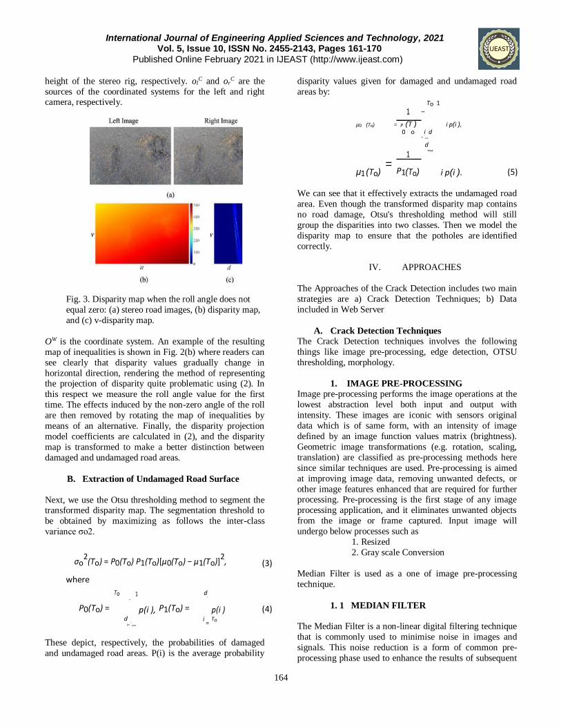
height of the stereo rig, respectively. olC and or
C are the
sources of the coordinated systems for the left and right camera, respectively.
Fig. 3. Disparity map when the roll angle does not
equal zero: (a) stereo road images, (b) disparity map,
and (c) v-disparity map.
OW is the coordinate system. An example of the resulting
map of inequalities is shown in Fig. 2(b) where readers can
see clearly that disparity values gradually change in
horizontal direction, rendering the method of representing the projection of disparity quite problematic using (2). In
this respect we measure the roll angle value for the first
time. The effects induced by the non-zero angle of the roll
are then removed by rotating the map of inequalities by
means of an alternative. Finally, the disparity projection
model coefficients are calculated in (2), and the disparity
map is transformed to make a better distinction between
damaged and undamaged road areas.
B. Extraction of Undamaged Road Surface
Next, we use the Otsu thresholding method to segment the transformed disparity map. The segmentation threshold to
be obtained by maximizing as follows the inter-class
variance σo2.
σo2
(To) = P0(To) P1(To)[μ0(To) − μ1(To)]2
,
(3)
where
To 1
d
˜max
P0(To) = −
P1(To) =
(4) p(i ),
=
p(i ) d i To i= ˜min
These depict, respectively, the probabilities of damaged
and undamaged road areas. P(i) is the average probability
disparity values given for damaged and undamaged road
areas by: To 1 1 −
μ0 (To)
i p(i ),
= P (T )
0 o i d = ˜min
d
1 ˜max
(5) μ1 (To)
i p(i ).
= P1 (To)
We can see that it effectively extracts the undamaged road
area. Even though the transformed disparity map contains
no road damage, Otsu's thresholding method will still
group the disparities into two classes. Then we model the
disparity map to ensure that the potholes are identified
correctly.
IV. APPROACHES
The Approaches of the Crack Detection includes two main
strategies are a) Crack Detection Techniques; b) Data
included in Web Server
A. Crack Detection Techniques
The Crack Detection techniques involves the following
things like image pre-processing, edge detection, OTSU
thresholding, morphology.
1. IMAGE PRE-PROCESSING
Image pre-processing performs the image operations at the
lowest abstraction level both input and output with
intensity. These images are iconic with sensors original
data which is of same form, with an intensity of image
defined by an image function values matrix (brightness).
Geometric image transformations (e.g. rotation, scaling,
translation) are classified as pre-processing methods here
since similar techniques are used. Pre-processing is aimed
at improving image data, removing unwanted defects, or
other image features enhanced that are required for further processing. Pre-processing is the first stage of any image
processing application, and it eliminates unwanted objects
from the image or frame captured. Input image will
undergo below processes such as
1. Resized
2. Gray scale Conversion
Median Filter is used as a one of image pre-processing
technique.
1. 1 MEDIAN FILTER
The Median Filter is a non-linear digital filtering technique
that is commonly used to minimise noise in images and
signals. This noise reduction is a form of common pre-
processing phase used to enhance the results of subsequent

International Journal of Engineering Applied Sciences and Technology, 2021 Vol. 5, Issue 10, ISSN No. 2455-2143, Pages 161-170
Published Online February 2021 in IJEAST (http://www.ijeast.com)
165
processing (such as edge detection on an image). Since it
retains edges under certain conditions while eliminating noise, the digital image processing widely uses the median
filtering technique and signal processing applications. The
key concept of the median filter is to move through the
input signal, replacing each input with the median of neigh-
bouring patterns. The "port" that slides over the entire
signal, entry by entry, is called the "port." The first few
preceding and following entries are the most obvious
window in 1D signals, while more complex window
patterns (such as "box" or "loop" patterns) are possible in
2D (or higher-dimensional) signals such as images.
Remember that if the window has an odd entries in number, the median is defined in a simple way: it is simply
the mid value after all the entries in the window have been
numerically arranged. There’s more than one logical
median for an even number of entries, see Median for more
information.
2. EDGE DETECTION
Edge detection is one of technique for extracting structural
information from different points of vision and for
significantly reduces the amount of data to be processed. It
has been implemented widely across various computer
vision systems.
2.1 CANNY EDGE DETECTION
Canny implemented edge detection by finding the
requirements on various vision systems was fairly
identical. As a result, an edge detection system can be used
to meet requirements in a wide range of circumstances.
Edge detection with a lower rate of errors is one of general
edge detection requirements, which means that detection
should accurately capture as many edges as possible in the
image. An operator’s edge point should be correct in its
position at the edge centre. An image should be marked once within provided edge, and image noise should not
produce false edges where possible.
3. IMAGE SEGMENTATION
Image segmentation is used to separate the digital images
into multiple segments (pixel sets, it is also known as
image objects). The purpose of partitioning is to simplify
and or make the representation of an image more
meaningful and easier to analyse.
3.1 OTSU THRESHOLDING In image processing and computer vision, Otsu's method
for performing automated image thresholding is used. In its
most simplest form, the single intensity threshold is
returned from the algorithm that pixels were divided into
two groups: fore-ground and background. This threshold is
determined by decreasing intra-class variance, or, in other
words, minimizing intra-class variance. Otsu is a one
dimensional method, with Fisher's Discriminant Analysis
of discrete variant, is similar to Jenk’s optimization
method, and is equivalent to a globally optimal k-means on
the strength histogram.
4. MORPHOLOGY
Morphological processing of images is a set of non-linear
operations related to the shape or morphology of features in
an image. According to this, operations on morphology
depend only on the pixel values with relative ordering, not
on their numerical values, and are thus particularly suited
to binary image processing. Morphological operations can
be applied to grey scale images, such that light
transmission functions were not known and there is no
absolute pixel values or minor absolute pixel. A morphological operation on a binary image creates a new
binary image in which the pixel only has a non-zero value
if the experiment at that position in the input image is
successful. The small binary image is an structuring
element, i.e. a matrix of small pixel, each with a value of
zero or one: The dimensions of the matrix determine the
size of the structured element. The one and zero pattern
specify the structuring element form. One of its pixels is
typically an origin of the structuring element, but generally
the origin can be outside the structuring element.
Fig. 4. Techniques of Crack Detection (a) Image
Pre-processing, (b) Edge Detection, (c) Image
Segmentation, and (d) Morphology.
B. Data included in web server
The data of the crack detection is given as input to the web server and locating it using the GPS location.
1. GPS LOCATION
The GPS (Global Positioning System) is a "constellation"
of about 30 satellites orbiting the Earth that enable people

International Journal of Engineering Applied Sciences and Technology, 2021 Vol. 5, Issue 10, ISSN No. 2455-2143, Pages 161-170
Published Online February 2021 in IJEAST (http://www.ijeast.com)
166
with terrestrial receivers to determine their geographic
location. For most devices the positioning accuracy is from 10 to 100 meters everywhere. With special military
approved equipment, accuracy can be defined to within one
(1) meter. GPS equipment is widely used in research, and it
has now become cheap enough for almost everyone to buy
a GPS receiver. GPS is also one of main input to upload in
web server to find exactly where the crack is located.
Hence the GPS plays a vital role. The GPS location is
detected using two main things are Latitude and Longitude.
Fig. 5. Detection of GPS Location.
1.1 LATITUDE
The latitude shows the angle between the straight line in
the particular point and the equatorial plane, and its symbol
is phi. The latitude is determined by degrees, beginning at
0 ° and ending at 90 ° on both sides of the equator,
rendering northern and southern latitude. The equator is a line with a latitude of 0 °.
1.2 LONGITUDE
The longitude is another angular coordinate that determines
a point's location on an earth's surface, and its symbol is
lambda. The longitude is defined as an angle from the
Greenwich Meridian pointing east or west which is taken
as the Prime Meridian. The maximum longitude can be
specified from the Prime Meridian as 180 ° east and from
the Prime Meridian as 180 ° west.
2. WEB SERVER UPDATE
Using the detected crack data and finding the location
using GPS, the inputs are given to web server. A web can
be viewed by anyone in world. Hence updating the data
into web server provides useful information and necessary
department can take actions.
By this more traffic can be avoided and accidents can also
be reduced. If more vehicles are passing in same road that the department can take necessary actions to overcome
these problems. In future also these set of data are also very
helpful. The necessary potholes and cracks can be detected,
repaired and maintained.
Fig. 6. Detected crack data as input and storing it in web server providing useful information.
V. RESULT AND DISCUSSIONS
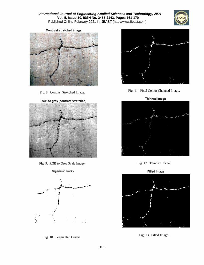
The result of image processing deals with the image as
input. The image is captured by using a camera in the
vehicle. These captured images are given to the crack
detection techniques, to process these images to separate
the crack detected parts from the unwanted parts. The
processing of image includes these processed images like
original image, contrast stretched image, RGB to grey scale, segmented cracks, thinned image, filled image,
cleaned image, final output image.
Fig. 7. Original Image of Road Crack.
International Journal of Engineering Applied Sciences and Technology, 2021 Vol. 5, Issue 10, ISSN No. 2455-2143, Pages 161-170
Published Online February 2021 in IJEAST (http://www.ijeast.com)
167
Fig. 8. Contrast Stretched Image.
Fig. 9. RGB to Grey Scale Image.
Fig. 10. Segmented Cracks.
Fig. 11. Pixel Colour Changed Image.
Fig. 12. Thinned Image.
Fig. 13. Filled Image.

International Journal of Engineering Applied Sciences and Technology, 2021 Vol. 5, Issue 10, ISSN No. 2455-2143, Pages 161-170
Published Online February 2021 in IJEAST (http://www.ijeast.com)
168
Fig. 14. Cleaned Image.
Fig.15. Final Output Image.
By these inputs, the differences between the crack and non-
crack roads can be easily identified. The major difference
will be there is continuous pixel lines in crack-based image, and there will be no continuous pixel lines in non-
crack-based image. The output of non-cracked image as
follows.
Fig. 16. An output image for non-crack-based
image.
With these processed images the location is detected using GPS and these are stored in the web server.
TABLE
The following table shows the successful accuracy of
pothole detection comparison

International Journal of Engineering Applied Sciences and Technology, 2021 Vol. 5, Issue 10, ISSN No. 2455-2143, Pages 161-170
Published Online February 2021 in IJEAST (http://www.ijeast.com)
169
GRAPHS
Fig.17. ROC Curve.
Fig.18. Precision/Recall curve.
Fig.19. F1 Score.
The Graphs like ROC Curve, Precision/Recall curve, F1 Score with respect to threshold index
are taken and compared with existing system with
proposed system. These Graphs show the
increased accuracy of our system.
VI. CONCLUSIONS AND FUTURE WORK
This paper's key contributions are a novel method for
transformation of disparity map modelling algorithm. The
road area which is undamaged in the transformed disparity
map can be better distinguishable with our approach, and it
can be easily removed by applying the Otsu thresholding
algorithm method. The robustness improved greatly of
using this disparity map technique. Furthermore, in the
process of map modelling of disparity, normal vectors of this disparity differs greatly from the ideal one that were
discarded, and this improving accuracy of the modelled
map disparity. By comparing the difference between the
modelled disparity maps with the actual one, the potholes
were eventually found.
The experimental results show that overall accuracy for the
proposed algorithm is approximately calculated as 98.7%
and the accuracy of the pixel is calculated as 99.6%.
The identification of potholes with the parameters set
cannot be applied to all the cases. The transformed disparity map that was planned and deep neural network is
trained to identify the potholes. In addition, the quadratic
is not considered for road surfaces. Thus, proposed pothole
detection algorithm is implemented before, the design of
algorithm that we aim to segment the reconstructed road
surfaces into the group of localized planes.
VII. REFERENCES
[1] R. Fan, X. Ai, and N. Dahnoun, “Road surface 3D
reconstruction based on dense subpixel disparity map
estimation,” IEEE Trans. Image Process., vol. 27, no. 6,
pp. 3025–3035, Jun. 2018.
[2] Wohlschlaeger M, Sauter T, Jasperneite J. The Future
of Industrial Communication: Automation Networks in the
Era of the Internet of Things and Industry 4.0[J]. IEEE
Industrial Electronics Magazine, vol. 42, no. 11, pp. 17-27,
Nov. 2017.
[3] S. Li, C. Yuan, D. Liu, and H. Cai, “Integrated
processing of image and GPR data for automated pothole
detection,” J. Comput. Civil Eng., vol. 30, no. 6, Art. no.
04016015, Nov. 2016.
[4] Khan S M, Atamturktur S, Chowdhury M, et al.
Integration of Structural Health Monitoring and Intelligent
Transportation Systems for Bridge Condition Assessment:
Current Status and Future Direction[J]. IEEE Transactions

International Journal of Engineering Applied Sciences and Technology, 2021 Vol. 5, Issue 10, ISSN No. 2455-2143, Pages 161-170
Published Online February 2021 in IJEAST (http://www.ijeast.com)
170
on Intelligent Transportation Systems, vol. 395, no. 17, pp.
2107-2122, Aug. 2016.
[5] R. G. Lins S. N. Givigi "Automatic crack detection and
measurement based on image analysis" IEEE Trans.
Instrum. Meas. vol. 65 no. 3 pp. 583-590 Mar. 2016.
[6] F. Saeed, S. Qamariatul, M. Rahman, A. Woodside,
"The state of pothole management in UK local authority" in Bituminous Mixtures and Pavements VI, Boca Raton,
FL, USA:CRC Press, pp. 153-159, 2015.
[7] Farrar C R, Doebling S W, Nix D A. Vibration-based structural damage identification[J]. Philosophical
Transactions of The Royal Society B Biological Sciences,
vol. 395, no. 19, pp. 131-149, Sep. 2015.
[8] Hu B, Lu Z, Li H, et al. Convolutional neural network
architectures for matching natural language sentences[J].
vol. 34, no. 9, pp. 2042- 2050, Sep. 2015.
[9] R. Madli, S. Hebbar, P. Pattar, V. Golla, "Automatic
Detection and Notification of Potholes and Humps on
Roads to Aid Drivers", IEEE Sensors Journal, vol. 15, no.
8, pp. 4313-4318, 2015.
[10] J. S. Miller and W. Y. Bellinger, “Distress
identification manual for the long-term pavement
performance program,” Office Infrastructure. Res.
Develop., Federal Highway Admin., Washington, DC,
USA, Tech. Rep. FHWA-HRT-13-092, 2014.
[11] Burgart Steven, Gap Trap: A Pothole Detection and
Reporting System Utilizing Mobile Devices, 2014.
[12] T. Kim, S.-K. Ryu, "Review and analysis of pothole
detection methods", J. Emerging Trends Comput. Inf. Sci.,
vol. 5, no. 8, pp. 603-608, 2014.
[13] T. Shen, G. Schamp, M. Haddad, "Stereo vision based
road surface preview", Proc. Int. Conf. Intelligent
Transportation Systems, pp. 1843-1849, October 2014.
[14] Gelenbe E. Stability of the random neural network
model[J]. Neural Computation, .vol. 84, no. 12, pp. 239-
247, Sep. 2014.
[15] T. Kim and S. K. Ry, “Review and analysis of pothole
detection methods,” J. Emerg. Trends Comput. Inf. Sci.,
vol. 5, no. 8, pp. 603–608, Aug. 2014.
[16] Chen S, Cerda F, Rizzo P, et al. Semi-Supervised
Multiresolution Classification Using Adaptive Graph
Filtering With Application to Indirect Bridge Structural
Health Monitoring[J]. IEEE Transactions on Signal
Processing, vol.62, no. 11, pp.2879-2893, May. 2014.
[17] Z. Zhang, X. Ai, C. K. Chan, and N. Dahnoun, “An
efficient algorithm for pothole detection using stereo
vision,” in Proc. IEEE Int. Conf. Acoust., Speech Signal
Process. (ICASSP), pp. 564–568, May. 2014.
[18] Perera C, Zaslavsky A, Christen P, et al. Context
Aware Computing for The Internet of Things: A Survey[J]. IEEE Communications Surveys & Tutorials, vol. 38, no.
16, pp. 414-454, Feb. 2013.
[19] Lawrence S, Giles C L, Tsoi A C, et al. Face recognition: a convolutional neural-network approach[C]
Computer Vision and Pattern Recognition, 1996.
Proceedings CVPR '96, 1996 IEEE Computer Society
Conference on. IEEE, vol. 74, no. 18, pp. 217-222, Sep.
2012.
[20] Q. Zou Y. Cao Q. Li Q. Mao S. Wang "CrackTree:
Automatic crack detection from pavement images" Pattern
Recognit. Lett. vol. 33 no. 3 pp. 227-238 2012.
[21] Atzori L, Iera A, Morabito G. SIoT: Giving a Social
Structure to the Internet of Things[J]. IEEE
Communications Letters, vol. 62, no. 11, pp. 1193-1195,
Nov. 2011.
[22] Koch and I. Brilakis, “Pothole detection in asphalt
pavement images,” Adv. Eng. Inform., vol. 25, no. 3, pp.
507–515, 2011.
[23] M. Gavilán et al. "Adaptive road crack detection
system by pavement classification" Sensors vol. 11 no. 10
pp. 9628-9657 2011.
[24] Y. Hu C.-X. Zhao H.-N. Wang "Automatic pavement
crack detection using texture and shape descriptors" IETE
Tech. Rev. vol. 27 no. 5 pp. 398-405 2010.
[25] R. Adi, M. Homji, "Intelligent Pothole Repair
Vehicle", Texas A and M University, August 2005.
[26] Hasith Karunasekera, Han Wang, Handuo Zhang.
"Energy Minimization Approach for Negative Obstacle
Region Detection", IEEE Transactions on Vehicular
Technology, 2019.
[27] Haifeng Li, Dezhen Song, Yu Liu, Binbin Li.
"Automatic Pavement Crack Detection by Multi- Scale
Image Fusion", IEEE Transactions on Intelligent
Transportation Systems, 2019.
[28] Liyan Zhang, Guanchen Zhou, Yang Han, Honglei
Lin, Yuying Wu. "Application of Internet of Things
Technology and Convolutional Neural Network Model in
Bridge Crack Detection", IEEE Access, 2018.
[29] Dong‐Won Jang, Rae‐Hong Park. "Pothole detection
using spatio‐temporal saliency", IET Intelligent Transport
Systems, 2016.
[30] Yiyang, Zhang. "The design of glass crack detection
system based on image preprocessing technology", 2014
IEEE 7th Joint International Information Technology and
Artificial Intelligence Conference, 2014.