An assessment of the compression and traction forces ... - l'atide
17
An assessment of the compression and traction forces of obstetrical forceps JOHN V. KELLY, M.D.* GEORGE SINES, PH.D. !.os Angeles, California A SIGNIFICANT percentage of the world's population has arrived here through the medium of a pair of ''iron claws.'' De· spite the fact that the mechanical stresses in the ''tour de force" of birth by forceps can influence the future of so many human beings, little is known about them. Medical history records the early efiorts of obste- tricians to tueasure the forces exerted by obstetrical forn·ps." However, a comprehen· si\·e study of the mechanical forces exerted by these instruments has been delayed by the lack of adequate instrumt>ntation. With the recent development of miniature electric resis- tance strain gages, there has been a renewed interest in the determination of ''the forces of forceps.'' The studies of Fleming, Brande- berry, and Pearse, 4 Pearse, 10 Ullery and co- workers, 1 " and ourselves, 0 · 9 have made pre· liminary efforts to assess both traction and compression forct's. These' exploratory studies were carried out with strain gages applied to an axis-traction handle and/or to the ,hank of the forceps. It appeared to us that additional sensors applicd to the blades themselves would en- able more precise evaluation of the forces exerted by obstetrical forceps and conse- quently a more precise evaluation of their dfects on the baby's head. From Department of Obstetrics and Gynuology, and the Departnunt of Engineering. Unit•ersit)' of California, Los Angeles. *Present address: Department of Obstetrics and Gynecology, Hospital of the l]niversity of Pennsylvania, Philadelphia, Pennsylvania. 521 Method Since it seemed to us that the toe of a forceps blade was the area which might be most important in causing fetal trauma, ini- tial efforts were directed toward implanta· tion of a pressure sensor into this region. A circular recess, 0.25 inch in diameter, was milled into the outer surface of the toe and carried through most of the thickness of the forceps blade (Fig. 1), The bottom of the recess was 0.007 inch from the inner surface of the toe. This area acted as a diaphragm to which a 120 ohm, tempera· ture-compensated, metal foil strain g·ag1· (with a gage factor of 2.05) was cemented. A groove for the connt'cting wires was pro- vided along the back of the blade. After tht· gage and wires had been inserted, the milled recess and grove were filled with a durable resin and finished to a smooth surface. The strain gage was wired into one arm of Wheatstone bridge circuit. Calibration wa' carried out by fixing the forceps in a \·isc and applying weights to a rubber pad which pressed on the inner surface of the tot• op- posite the gage. Thirty deliveries were per- formed employing this strain gage mon- itored Luikart-Simpson forceps in conjunc- tion with a Bill axis-traction handle modi- fied to include a calibrated spring-balancf· (Fi!S. 2). It soon became apparent that this location of the strain gage did not provide sufficient information. From experimental obsen·ations it was noted that the pressure-sensitive di- aphragm at the toe site was not isolated from the bending stress in the blade. The
-
Upload
khangminh22 -
Category
Documents
-
view
0 -
download
0
Transcript of An assessment of the compression and traction forces ... - l'atide

An assessment of the compression and traction
forces of obstetrical forceps
JOHN V. KELLY, M.D.*
GEORGE SINES, PH.D.
!.os Angeles, California
A SIGNIFICANT percentage of the world's population has arrived here through the medium of a pair of ''iron claws.'' De· spite the fact that the mechanical stresses in the ''tour de force" of birth by forceps can influence the future of so many human beings, little is known about them. Medical history records the early efiorts of obstetricians to tueasure the forces exerted by obstetrical forn·ps." However, a comprehen· si\·e study of the mechanical forces exerted by these instruments has been delayed by the lack of adequate instrumt>ntation. With the recent development of miniature electric resistance strain gages, there has been a renewed interest in the determination of ''the forces of forceps.'' The studies of Fleming, Brandeberry, and Pearse,4 Pearse, 10 Ullery and coworkers, 1" and ourselves, 0 ·
9 have made pre· liminary efforts to assess both traction and compression forct's. These' exploratory studies were carried out with strain gages applied to an axis-traction handle and/or to the ,hank of the forceps.
It appeared to us that additional sensors applicd to the blades themselves would enable more precise evaluation of the forces exerted by obstetrical forceps and consequently a more precise evaluation of their dfects on the baby's head.
From Department of Obstetrics and Gynuology, and the Departnunt of Engineering. Unit•ersit)' of California, Los Angeles.
*Present address: Department of Obstetrics and Gynecology, Hospital of the l]niversity of Pennsylvania, Philadelphia, Pennsylvania.
521
Method
Since it seemed to us that the toe of a
forceps blade was the area which might be most important in causing fetal trauma, initial efforts were directed toward implanta· tion of a pressure sensor into this region. A circular recess, 0.25 inch in diameter, was milled into the outer surface of the toe and carried through most of the thickness of the forceps blade (Fig. 1), The bottom of the recess was 0.007 inch from the inner surface of the toe. This area acted as a
diaphragm to which a 120 ohm, tempera· ture-compensated, metal foil strain g·ag1· (with a gage factor of 2.05) was cemented. A groove for the connt'cting wires was provided along the back of the blade. After tht· gage and wires had been inserted, the milled recess and grove were filled with a durable resin and finished to a smooth surface. The strain gage was wired into one arm of ~~
Wheatstone bridge circuit. Calibration wa' carried out by fixing the forceps in a \·isc and applying weights to a rubber pad which pressed on the inner surface of the tot• opposite the gage. Thirty deliveries were performed employing this strain gage monitored Luikart-Simpson forceps in conjunction with a Bill axis-traction handle modified to include a calibrated spring-balancf· (Fi!S. 2).
It soon became apparent that this location of the strain gage did not provide sufficient information. From experimental obsen·ations it was noted that the pressure-sensitive diaphragm at the toe site was not isolated from the bending stress in the blade. The

522 Kelly and Sines
Fig. I. Luikart-Sirnp'"ll forcep s with pr'<'ssur..SPnsor on tO{' 11 n·a .
Fig. 2. Bill axis-traction handle.
latter proved to be appreciab le. ln addition, only a \ 'Cl)' localized pressure could be measured by this g-a~e: llloreover, it was probable that the positions of the maximum localized pressurt• and the sensor did not always coincide . Therefore. it was decided that more useful data could be obtained by implanting multiple strain gages on the toe, the midportions. and the shank of the forceps. These gages would m easure both bending and axial tensile stresses. Analyses of
these stresses would be used to obtain the forces as they were applied to different regions of the forc(·ps. These regions were selected in order to isolate, as rnuch as possible, the forces contributed by the doctor, those originating from the mother's tissues. and those stemming from the baby: the goa l always being the study of the distribution of forces on the fetal head.
The strain gages selected wen~ 120 ohm, tern p era t u rc -compensated, epoxy-backed metal foil gages with a gage factor of 2.* The gage was 0.150 inch in length and 0.06:1
*1ficro-Measurement!', Inr. , Romulus~ Nfichigan. Typt~
EA-09-062, AA 120.
i. k tuh~,.· ) l -1 PJht,
\111 1. t)h~.t. :S· ( ;~rn-; .
A
8
.. ~--~, -"' ~·:!:·~=~:·.;·;•, ~--.:.· . . : , • _M _____ " __ c Fig:. :1 . .-1. Sh.,,-,1-. , l,;,i ,, " ·"· · 1.[1'00\TS. f~. ! ( H ~ 111d Jll i d<Jfl · _;
thirty-two w in· 1t'l'tllil1<1l "ll lj '
1.,: • '. ,
. ; ~d j ,
inch in width. The grid ih<.'ll " ·" ti.llt-.2 !ld l
in len!!;th and lUOO inch 111 -., ichi :. T Jw [,;,ek
ing for the gagc·s was tr in unn1 ''' tkt t iJ,,. ga_ges would fit in the implantation --iu·s. These sites were millt-d ou t ; t!ou~ both •l[J
pt-'1' and lower arms and on both Hat surfaces of the orw blade of <l p;ur of Situpsorr
forceps. They were O.l2j inch in width, Cl.~-Jtl
inch in length, and 0.012 ind , m depth . The gages v~o·en· inserted into til\' t ,·cessnl silt'S and implanted therein with tvpc RTC 1·poxv
cement. +:- Copper wires, O.Cl08 inch in d iameter , were implanted into f!rooves which
"*\V. lkall a nd Cn .. 1891.~~ (;1and 1{ 1\t' l . \ \ •' · lll'iltlll
~·f it: hi~a••·

Volume Yh Number 4
were milled 0.031 inch to 0.062 inch deep and 0.062 inch wide in the forceps. A total of sixteen strain gages were implanted: two on the inner surface of the toe, eight on both outer and inner sudaccs of the midblade, and six on all four surfaces of the shank (Fig. 3, A and B). A terminal strip for the thirty-two win's was placed inside of the handle (Fig. 3, C l. A cable of connecting wires was passed from thr handle to a box containing the matching gages for the multiple WhC'atstone bridge circuits which were necessary.
The strain gages were located and their wiring was arranged so that the following forces could be measured: ( l ) compression forces at the toe area of the upper arm: ( 2) compression forces at the toe area of the lov.,·er arm: ( 3) compression forces at the mid portion of the upper am1: ( 4) compression forces at the midportion of the lower arm; traction fa ret's at the mid portion of the upper arm: ( 6) traction forceps at the mid portion of the lowt:>r arm; compression forces at the shank; (8) traction forces at the shank; and ( 9) \'ertical forces at the shank.
F
(a) DETECTION OF BENDING
Compression and traction forces of forceps 523
The circuits were designed so that the pull forces \vere canceled out in order to detect "pure" compression (measured by the bending stresses) and the compression forces were neutralized in order to detect "pure" pull (measured by the axial tensile stresse~). The measurement of the bending moment was isolated from the axial tensile force hy using gages on both inner and outer surfaces of each ann of the forceps blade. When the active gages are the adjacent arms of a \Vheatstone bridge, as shown in Fig. 4, a. the bending stresses are detected and the effect of axial tensile stress is rliminated."
The measurement of the axial tensile stresses was isolated from the bending stresses by a similar placement of gages on both the inner and outer surfaces of each arm of the forceps blade. By placing these gages in of!po\'lfl' arms of a Wheatstone bridge, as shown in Fig. 4, b, the traction stresses are detected and the effects of bendin,g stresses are eliminated."
Theoretically. this arrangement elirninates the measurement of axial tensile stresses: howc\·er. additional care must be taken hecause the axial tensile stress caust>d bv the
F
(b) DETECTION OF AXIAL FORCE
A, 8 - ACTIVE STRAIN GAGES C, D - 120 OHM RES I STANCES
F- SOURCE OF D.C. VOLTAGE E- D.C. AMPLIFIER AND GALVANOMETER Rt- TRIMMING RESISTANCES
Fig. 4. Strain gage circuitry ,Wheatstone bridges.

524 Kelly and Sines
pull is small compared to the bending stress. If the bending stress differs slightly in magnitude between the compressin· and tensile sides of the blade. this error may interft're with the axial force measurement. Tlw difference in magnitude of bending stress on opposite surfaces of an arm of tlw blade tna\· come from factors surh as a nonsvmrnctric~l beam cross st>ction. a differcnCP i;1 thickness of the strain gage bonding cemt·nt, a difference in depth of the recess at the strain gage sites, unequal lead-wire resistances, a difference in strain gage sensiti\·ities and eycn slight rnisoricntations of tlw strain gages. These diflerences can lw oycrcome hv adding two small variable rcsistanc<'s (RT ;s shown in Fig. 4, b}. By applying a known axial force with ditfen'nt bending moments. thrse resistances are adjusted ( whik maintaining their equality to each other 1 until the bending component of the reading is cancelrd. If cancellation cannot be made with this circuit, then the trimming resistances will have to be shifted to the other side of the amplifier connections. This method works well when the bending stress is appreciable about only one axis of the blade. However, in the sl~ank of the forceps, the bending stress is appreciable about tvvo axes and here this method cannot cancel the effects of both differences, if they should be present.
The thinn<>ss of the t(W portion of the blade made it technically difficult to install ~ages on both inner and outer surfaces of the toe area in order to cancel the axial tensile stresses. However. calibration and analvses. Fig .. 1. demonstrated that the error in measurement of the bendin;; stresses was smalL Calibration showed that a pull of I 0 pounds along the axis of the blade caused a deflection of 18 mm. on the galvanometer while a force pt>rpendicular to tlw axis caused a deflection of 48 mm. The only pull at the toe would come from the friction associated with the compressive force F1
acting on the toe region. It will be shown in determination of coefficients of friction that this friction force Fr 1 can never exceed 0.23 Ft and usually is much less. It would cause
OctohcJ LJ, l:lhb \IlL J. nh:.t. &. Gyrw<
Fig. 5. Forces acting on toe :.rea. Point A ts th•· centPr of gravity of t.he toe arr·a
a deflection of 0.23 :< 18 +. 14 mm. whid1 is less than C) per cC'nt of the .J.8 mm. tkllection caused hv the hendin!.! from F, ;1t
the toe strain gagr:.
Assumptions and idealizations
. In order to interpret the strain gage readmgs, certain assumptions had to b~· made about the distribution of force~ along tlw blade. The distribution of forces is certain!\· a function of the variations of fNal hea~:l sizes and shapes as well as the positions and locations in the pelvic canal: in addition. pelvic dimensions and perineal n·sistances \·ary from patient to patient. Therefore, onh the most elf•mentary simplifying assumption', are justifiabJ£,.
It was assnmed that then· was unifonn pressurr hy the toe region of the blade on the fetal head. The effect of the pressme on the toe region could then be considered in the analyses as a single force acting at the center of (!ra\·ity of the tof' region. The center of ~ravity is defined as that point at which a concentratPd forn· \\oold gin· a
SHANK STRAIN GAGES
MID STRAIN GAGES TOE STRAIN GAGES
Fig. G. Strain gag<" and <'Pnters of "ravity of areas (also set' Tablte 1\.

Volume ~If) l\urnu~r 4
mechanical eJiect on the forceps which would be equal to that of a pressure applied uniformly over the toe. The CPnter of gravity was found by numerical integration over tlw toe re~ion. '!.·
Similarly, the distribution of pressure by the midrcgion of the blade on thP fetal head was asswned to be uniform; therefore, the dfect of the pressure could be treated as a sinL;le force at the center of gravity of this midregion of the blade. The location of this center of gravity was also computed by J Jumerical in tPgra tion. ·*
Initially the position of the effective force on the heel area was estimated from inspections and trials because the maternal rPsistance must yary greatly 0\·er this region and a nunwrical integration to obtain the center of gravity might not be meaningful. Subsequently, a numerical integration was performed::f and the center of gravity was dose to the center of forct> application which had been initially estimated.
The computed centers of gravity are shown in Fig. 6.
Calibration
For purposes of calibration, the handle of the forceps was placed in a vise. A site was marked at the center of the flat portion of the toe. a suture was tied through the fenestration around the toe at this point. A calibrated spring-balance was attached to the suture. A series of known forces was applied via the spring-balance in a direction perpendicular to the plane of the toe strain ~ages. The readings were recorded on the oscillograph. The point of application of these bending forces was 0.65 inch from the c<·nter of gravity of the toe, thus providing a le\·er ann for calculation of moments. In
·*Xumer.ical integration \\as made by tracing the outline of the specjfic rP~;don, (tot·~ mid. or heel) on graph paper with fine squares. The r('gion v,:as divided into seven strips of £>qual \v.idth acfoss the b1ade. The a1·ea of each ~trip
\\:as t>stimatcd by counting the squares. Call thr an•a of the firt-t strip A1J the second A2, etc., and tht• Jevt"r ann frmn tlw ~train gage to the centtT line of the first strip Lt. to thC" centt'r of the second strip Lz, etc. The lcv<'r arm from thf" two s.tl a in !:!ages to th(: center of gravity is:
Compression and traction forces of forceps 525
a similar fashion, the bending strains of the gages at midblade and shank >vere calibrated.
The "pull gages'' of the midbladc and shank areas were calibrated by pulling with known forces from the tip of the toe in a direction parallel to the axes of the midblade and shank areas, respectively. Jn each instance, the loading forces for bend or pull ;vere increased in five equal steps to check the linearity of the responses of the strain gages. All prm·ed to have lint•ar n•sponses.
The following list gives the moments (loading force lever distance from the strain gage to its center of gravity) in pound-inches per millimeter of pen deflection on the oscillograph for the \·arious strain gages.
Lower toe strain gage 0.141 pound-inch Upper toe strain gage 0.361 pound-inch Sum of upper and lower mid bend strain
gages 0. 720 pound-inch Shank bend strain gages l.l 7 pound
inches Midarea's upper arm pull strain gages l.:H)
pounds Midarea's lower arm pull strain gages n. ;t
functioning Shank area's pull strain gages not function
ing
Determination of coefficients of friction
An integral part of the study of forces on the forceps is an assessment of the contribution of friction to the forces of traction. Since no feasible method is known for determination of the coefficients of friction inside the mother's pelvic canal, certain aspects of the delivery must be simulated by in vitro experiments. Accordingly, qualitative studies were performed using a mannikin, the head of which was covered with polyethylene, a model of pelvis and perineum, and the forceps lubricated with liquid soap. From these studies, the need for more objective investigations evolved. Therefore. a quantitative study was designed and perfanned to measure the effective coefficients

526 Kelly and Sines
\PLYWOOD
\ ~ROLLER
\\ SCALE
Uclo!Jt'l L~). l:Jhlr
\oL J ( ll1-,t. & ( ~vn•··
lt~"l""l'"'i""l .....__-_BATHROOM SCALE
F -TOTAL FORCE FN- NORMAL FORCE Ff- FRICTIONAL FORCE
Fig. 7. Apparatus for mr:asurenwnt of coeffici1~nts of friction.
of friction. The scheme is depicted in Fig-. 7.
The normal (perpendicular) force, Fx. was measured by a bathroom scales, and the frictional force, Ff, hy a spring-halance which pulled upon the proximal t>nd of the blade via the fenestration. The outer surface of the toe area of the blade rested flat on a piece of ply,vood, which in turn rested on two soap-lubricated solid glass rods serving as rollers on the scale platform. One investigator placed the thenar eminence of his palm, lubricated with liquid soap. against the toe area of the forceps, and applied a
perpendicular forct~ downward on his hand. The amount of this downward force (F x)
on the toe of the forceps was observed from the reading on the bathroom scales. It was maintained at a preselected yaJue, and simultaneously the other investigator measured Fr by exerting just enough trac-tion via the spring-balance on the forceps to cause slippage of the thenar ('J1linence on the toe of the forceps. The effective coefficient of friction, z, was calculated from tht· ratio oi the friction force to the normal force:
7, = F"
For the experiments where F x ranged from 5 to 40 pounds, the effective coefficient of friction for the toe area, Zto<· was substan-
tially constant, averaging 0.23. By similat studies the Zmirl and zh .. ··l were both determined to be 0.1 0.
The higher z for the toe is attributed to the ''digging-in" of tfH· nmed rim of the toe into the thenar eminence which does not occur in the mid- and her'! areas of tlw blade. Our experimental Yaluc~ are ,onsiderably lower than those assumed 1)\
Rosa." These effective coefficients of friction, PX
JWrimentally determined for tlw lubricated tlwnar eminence, are thou~ht to approximate those between tlw tissue~ of the fetal head and th<> forceps. It is assurm'd that
these values also approximatt" the values iot the effective coefficients of friction bt>twcPn th(· maternal tissues and the forn'ps.
Procedures
A patient was selected for this study il the g-estation was at term. if both her pregnancy and her !irst stage of labor had bt't'll
normaL and if an elective forceps deliven was planned. A total of 8 patients \\Trt>
fnlly studit~d, 5 of them primigravidas and :) of them secundigravidas. Saddle block
anestlwsia was used in each case. The fetal heart tones were monitored electronically throughout the deliveries by means of electrodes on the maternal ahdouwn or tlw ff'tal scalp.

Volunu: 96 "\umfwr 4
When the patient had been prepared for ddiYery, the cable from the forceps was connected to a box containing the Wheatstone bridge circuitry, which in turn was attadwd \·ia cables to an ei~ht-channel,
Type R, Offner dynograph. The from the strain gages were amplified and recorded by an ink-writing oscillograph on paper mm·ing at a speed of 1 0 mm. per second. The forceps were lubricated with liquid soap, carefully inserted into the vagina, and applied to the fetal head in routine manncr. In all cases. the Yertex was in an occiput anterior position; in 5 cases the vertex was at a 1+ or f t- station, in 3 cases. at a 2 • station. After the forceps were positioned correctly, the handles were left wide open and a short time was allowed to elapse, so that the strain gages >vould stabilize to the intrapelvic temperature and base lines would he established on the recording paper.
The first maneuver was the closing- of the forceps handles for 5 seconds, then opening them and later closing them again. C terine contractions were monitored manually. During a uterine contraction. the forceps handles wcrP closed, either on themselves or on an intervening fold of towel, and traction was ext"rted for a period of approximately 20 seconds, after which the handles were opened. The traction efforts were perfonned in the manner recommended bv Dennen:' in 3 cases and in 5 cases with the use of a Bill axis-traction handle, modified to incorporate a spring-balance calibrated from 0 to 100 pounds (Fig. 2). Each traction effort was performed in this way until delivery had been achieved.
Results
All babies weighed between 6 and 9 pounds. There were no maternal complications. The Apgar scores of all 8 babies was between 9 and 10 at one minute of life. Three of the infants had forceps marks which, in each instance, were located on the skin o£ the preanricular areas of the cheeks and over both parietal bones of the head ; the skin or scalp in these areas was hyper-
Compression and traction forces of forceps 527
emic with small areas of ecchymoses. There were no evidences of epithelial lacerations, ner\'e injuries, or other trauma. The forceps marks were not detectable 24 hours after delivery. The condition of all infants was followed closely in the hospital. All babies had normal findings on examination and 7 were discharged from the hospital with tlwir mothers. One infant was normal until the second day of life, when it developed respiratory difficulties: it did poorly thereafter and died on the third day of life. An autopsy was obtained which revealed pulmonary ,ttelectasis and probable hyaline membrane disease. Examination of the brain did not re
veal any abnormalities. In 3 of the 8 deliyeries, traction efforts
in excess of 50 pounds were employed. These 1 infants were the babies who had forceps marks and the baby who died was one of this group. The data for Mrs. M presented ht>re is typical of the 5 deliveries in which tractions between 35 and 45 pounds were exerted.
Analyses of recordings
Cnfortunately, during the 8 deliveries, not all of the sixteen strain gages in the forceps remained in satisfactory operation. One of the pair of strain gages designed to detect vertical bend in the shank acquired a loose connection during the first delivery and this pair >vas subsequently useless. Resin over the upper toe strain gage weakened in one deJiyery and the readings from this site W!'re regarded as unreliable thereafter. The circuitry for the pull strain gages for the shank and for the midarea's upper ann was unable to completely neutralize their sensitivity to bending forces; thus the data from these sources were not precise enough to be used for analysis. These defects have b('en subsequently corrected and information from these areas will be available with further studies.
It was possible to partially compensate for the loss of the sources of traction information because by mathematical resolution of the normal and frictional forces their pull components could be derived. This will be

528 Kelly and Sines
TOE, LOWER ~ TOE, UPPER t
~ SHANK BEND
$HANK PULL (N.G)
MID, LOWER PULL (N.G) ~
MID, UPPER PULL
MID, LOWER BEND
MID, UPPER BEND
• • FORCEPS PULL CLOSED
SITE SITE A B
- 47
·-44
32
~
t t LESS PULL HEAD
EMERGING
(k t,)I H:J' l ~t . i'lO'•
. \111. j . ( Jhs l & (; ~ J) I ' C
t FORCEPS OFF
Fig. 8. Strain gage recordings for Mrs. M' s fmmh a nd tin:tl " ''" lil' ll. · ·:\ .(. .<hank pull and mid, lower pull refers to th<· strong- efTC'ct lh:tt bt· llding strt ·s" ·' lt01d "" th <· , , ; •·adin_gs, and because of this st ron .~~; inte r ac tion th PS(' data could ""1 ,., . :llt nkzt ·d
demonstrated m the sample calculations which follow shortly.
Analyses of the recordings is complex and can probably be best demonstrated by presentation of an analysis of one particular traction effort. The sample calculations consider the traction effort from the no-friction aspect and also from the Jriction-ispresent aspect.
A strain gage at any of the locations on the blade or shank respond to the forces which act on the blade between the gage and the tip of the blade. The distributed forces acting on the blade are ass umed to be uniform over each region of the blade . thus in the analysis they can be treated as concentrated forces acting at the centers of gravity of the toe, mid-, and heel regions , respectively (see Fig. 6 ) .
Sample calculation: J.'riction absent. lt is assunwd tha t the forcc·s "n the toe, mida rea , and hcl'l an ·a arc in the direction as shown in Fi~· . I 0, clockwise• lllOlllcnts being considered as positive. \V(• shall analyze Sik
A in the fourth and linal tranion effort prior to Mrs. M's delivery (Fig. 8 · .
Fot·::" From tht~ calibration for the lower tot.' strain _gag-l\ we determim·d that 1 nun. of needle deflection on the paper was produced hy 0 . 141 pound-inch of movement. At Site A. the needle d etlec tccl 47 nnn . Therefon•. the lower toe strain gage was
·}~ v~u ally tJu-. ht·tH.Jing JllOUlt'lll ~ ;\" IIH'3SIII'e" d by thL' l t•C
a•<·a:-.! :- trai n ~a .u;t·~ in t hr upper· a nd lowl"r arm$ \Vt~IT
a \·,~ •agcd ; hc.H\ '{'Vt· •· .• jn this cast> , the ,,,•ak Jt"sin O \'(' r· th(• upper to~ site caused an unreliable reading and only the low('r toe ~ l r:J in gage n·ading v.as accurate . Comwqul•ntly , i n th f' a nal y:-- i:- u f d a ta it wa~ Jwt'.t•..,~ar v In as~umt· tl1 a t tlw f,,, ·t·c·s n rt the· lltJJH'I l tlf' Wl'le c qt lal I• • ll•n~ t· 1111 tlu• ) ( lwt·!
lot·.

Vohurw 9fi ,:";umfwr 4
rcadina a moment of 4 7 X 0.141 pound inch ,-, 6.63 inches. To determine what force was being exerted on the entire toe area. we ust' the formula:
.Yfonwnt at tfw ~.f!:.
ti.63 pound inche~ Solving, }'1,. ..
F to•· x ( kver, toe s.g. to e.g. toe)
Ft.,., X 0.4L'i* 16.0 pounds
Mid. A similar approach is used to find the force on the midarea of the blade. The upper and lower arms' moments were averag-ed by using the sum of the upper and lower arms' mid strain gage readings. From the calibration of the midareas' upper and lower arms. the sum of the needle deflections was 1 mm. when 0. 72 pound inch of moment was applied. During the delivery of Mrs. M, at Site A the sum of the needles' deflection was 54 mm.: therefore, a moment of 38.9 pound inches was being exerted on the midareas' bend strain gages.
It is apparent that this moment is the total moment from the mid-·strain _gages' sites to the tip of the blade. Therefore, in order to obtain that portion of the moment caused by forceps on the midart>a alont'. it is necessary to use the following formula:
~1oment at mid s.g. == Fmt(l X (lever. mid s.g. to e.g:. mid) + Flo•• Y ()ever, mid s.15. to e.g. toe)
:18.9 pound inchf"s Fmi(l X 0.91 + 16.0 pounds 2.06 Solving) Frnid =7.58 pounds
The same rationale applies for calculation of the force on the het'l area of the blade.
Hal. From calibration of the shank bend strain gages. 1 mm. of needle deflection was caused by 1.17 pound inches of moment. During the delivery of Mrs. M, at Sitt> A the shank bend strain gages reflected +4 mm. Therefore, a moment of 51.5 poundinches was registered by the bend strain ,gages on the shank. Again, this is the total moment from the shank strain gages to the tip of the toe; therefore, the moment for the heel area is derived from the following formula:
*See Table I for lever arms.
Compression and traction forces of forceps 529
~fomt"nt at ~hank s.g. llt'el)
+ Fmtd X Ot'Vt'r. ~hank s.g. to Ct{.
mid) + F 1 o,. :~x; ( lt>ver. shank s.g. to 1oe)
-F,,..,., X .LH + 7.58 pound' 5.71 + J{).O puuud~ X 6.40
·:::: ~H.:) pnunds
Thus, the bending forces on the forceps, at Site A of the delivery of Mrs. M, are (without considering friction), 16.0 pounds at the toe area: 7.6 pounds at midblade area; and 28.3 pounds at the heal area. From each of these bending forces pull components can be mathematically derived, if the angles are known between the tangents to the forceps surfaces at the respective centers of trravity and the axis of the shank. These ;~gles have been measured directly and are shown in Fig. 9. By determining the sines of the angles, the pull components at the respective centers of gravity ran be derived as is depicted in Fig. 10.
Therefore, the sum of the pull components for the various areas of the forceps blade equals 18.9 pounds. This is multiplied by two (for each blade) providing a total t'X
tractive forct' of 37.8 pounds exerted at the Sitr A of the fourth pull during Mrs. M's delivery when frictional forces are ignon·d in the analysis.
The sum of the pull components for the toe and midarea should approximate the readin,gs of the pull gages on the midsections. Tht> calibration of the midarea's upper arm pull gage showed that 1 mm. of deflection was caused by 1.3 pounds of traction. At site A in Mrs. M's delivery, the midarea's upper arm pull g-age showed a deflection of 4 mm.: therefore, reflecting a pull of 5.2 pounds. Considering the low sensitivity of the pull gages, this agrees rcasonablv well with the sum of the mathematic;lly resolvt>d pull components for toe and midareas of 9.3 pounds.
The above sample calculation ignored the friction forces. The true friction forces are unknown. but they must be somewhere between zero and the maximal values at the moment of slippage which were determined experimentally as described above.

530 Kelly and Sines I i~·;•,l~t·! ! , t 1;fl;.
\n1 f ,· }iJ,; ,.., t,
Sample calculation: Friction present. It is assumed that the normal forces and friction forces on tile toe, t11idarea. and lwd area are in the direction as shown in Fig. l I. Like the normal forces, the friction forces also cause bending moments on thP bladL This sample calculation sokes for these normal forces when the maximum friction forct's are considered actin~·. i.e., incipif'nt slipping is assumed. The same measured moments are used as in the previous sampk calculation. The friction lewrs are noted in Table J.
Table l. Lno:! ,niJI,; J.,, :J••:H:,; '"'
lrictiott:JI fln·c;·<:"
Tor· s.g. to e.g. of to<> Mid s.g. to c g. of mid Mid s.t;. to e.g. of toe Shank ur to (' ;;;. of h•·•·l Shank s.g. In '.g. of mid Shank ro e.g. of toe
; i . ~ l i i (
:.!ih:·
I ',.
,, .. , l!irh.r'> ·
!] i
1Tiu· wormal fnJ<'t' ;.., a":.unwd !11 ,w1 dw t'1·nk• o!
Thus, the bending forces on the forcep~.
during the deli\·ery of Mrs. M. at Site A. considering friction are 16.0 pounds at th(~
toe area; 7.75 pounds at tlw midarea: 23.+ pounds at thP heel area.
L:'l<l\jty of •lll :ut·a of tlw fot!'!'f>' ~,ud I• jWijH'Ildifllb !(•
tlw "t!l"facv of tlw lliadt· at that point r::l lcvn .l' !il ; ...
tfH· Pf'Jpr·udicul;u di;-;tance f1om tht "l!.Ufl ~~t.ll;t' tn !IH· li•H'
oi dCtion nt tllt' nonnal hnc~·- Tht ti•n1al !toln ;,
a":-.nmnl lt• act .d tht· n·ttlct of l!ldVit; ,d .ttl <1lLl ,t d11•
!otc•·p~. and i» paralJt'] to tlu· ~Htfan· td th• hlad(' ,Jl !ktt
point. Th·· 'l1 ininnal !t·\'t'J arm·· 1~ dH
f • lninual fnt n . As done pn·\'iously, the pull compo-
Toe
Mid
Heel
l\1nmcnt at toe S.!-(". x ~le\·r'l', to<' s.g. to e.g. toe) + F~.,,, x : frict. cod. ltH'.
x · frict. ln·cr, tot• s .. g. to e.g.)
6.63 lh. in. F1,~ x fUl'i F,,,. x O.Ll /. ll.OS Solving. F,.,. 16.0 lh.
:Moment at mid s.g. ~- Fmld x ·levt•r. mid s.g. to c..g. mid·
38.9 lb. in. Fuliil
Solving. Fmid
Moment at shank s.g.
f Fmi<t 1 fri<l. N>!'f. mid · frit I. lt•vt·r, mid '·li· to c .g.
F1,,. x (lever. mid s.g. ((I c .g·. to<'
+ Fv,. x ( frict. coef. to(•,
x !fri<'t. ]eyer. tnicl ·'·!!· tll e.g. (<w ·
., 0.91 F"''" • 0. !0 "' II. I/ ' I h.O lh. , :.!.I Hi
16.0 lb. 0.23 X (), 2()
7.7:1 I h.
Flu•r·l x 'lever, shank ,,,g. I<• <.g. her·])
Fh~>i'l >< :· fricL cnf'f. hf'el) x · frict. lt-ver, 'hank s.,g. to e.g. lwei.
"' l·ml<I 'lc\'<'L shank ~ .. g. tn e.g. mid) + Fmid x ( cnef. frirt. mid)
x ( frict. l•·n·r, ::hank s.g. to c .g. mid
+ FloP x ( lcv•·r. shank s.g. to cg.
F1,, 'ft·ict. C(H'f. tne) 1 frict. 1<-v<'r. ::hank s.g. to e.g. tor·
51.5 lb. in. ·Fh~el 3.33 Fhe~l O.lU x 0.35 7.75 lb. x :J.71 7.75 Jb. X 0.)0 X 2.7<J 16.0 lb. X 6.4 J6.Q lb.
o.:.:~ " '\.7<)
2:1.1· lh.

Volnnn· qf)
':\umbt•r 4 Compression and traction forces of forceps 531
I zoo
Fig. 9. The angles for surfaces of forceps' blade. Points A, B. and C are the cE'nters of gravity of the toe. mid, and heel areas, r<espC'ctin·ly.
PULL COMPONENTS
HEEL 28.3 x SIN 20° = 9.66 MID 7.6 x SIN 15° = 2.00 TOE 16 x SIN 27° 7.26
PULL FOR ONE SLADE 18.9
I I I 20° ~ f I I I I I I I I I I I I I
Fig. 10. The pull components of the forceps' forces. (The black arrows are pull components .. :
nents can be mathematically derived as is depicted in Fig. 11, including those derived from both normal forces and friction forces.
The sum of the pull components for the various areas of the forceps blade equals 23.5 pounds. For the total pull on the two blades, this is multiplied by 2, thus making
a total extracting force of 4 7.0 pounds when frictional force is considered to be acting. In summary, we can compare the compression and extractive forces for this Site A in Mrs. M's delivery, both with an absence of friction and consideration of maximal friction. The true values lie somewhere in hetween these two limits.
532 Kelly and Sines
Cmn Jn cssion ( jJounds) T",. Mid Heel
Pull t•· r Mrui, .\lid
1 /'Ulilli/1 He,/
1. kH•ht·r I-~, t~Jht.
\w.j.(lf,.,t.&(;\!Jt''
!'\o frict. .f\lax. frict.
lti.O 16.il
7.G 7.H
2H.3 _iLl 111 .. <1 'ii.-,
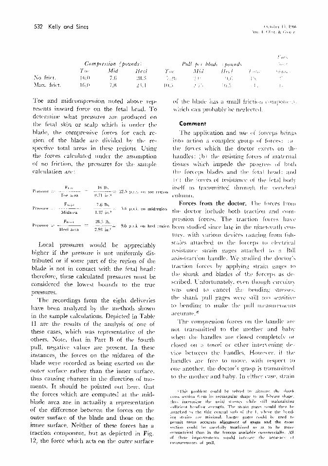
Toe and midcompression noted above rep· resents inward forcP on the fetal head. To determine what pressures are produced on the fetal skin or scalp which is under the blade. the compressive forces for t>ach region of the blade arC' divided bv tht' n'· spective total areas in thesc regions. Using the forces calculated under the assumption of no friction. tlw pressures for the sample calculation are:
F,..,. Hi I h. Pn"~"me 22.-1 p.::.i. nn toe rr!Z;inu
Tor 11.71 a Jell in.~
Ftntd 7.6 I h. l'rP!'Sllrf' -~~~~- .').(; p.~.i. on mldregion
MidUJ~a 1.17 in.?
F~t,·r·l :28.3 lb. Pn:-s~ute 9.6 p.s.i. on heel
Heel area 2.9~ in.:'!
Local pressures would be appreciably higher if the pressure is not uniformly distributed or if some part of the region of the blade is not in contact with the fetal head: therefore, these calculated pressures must be considered the lowest hounds to the true pressures.
The recordings from the eight deliveries have b(•en analyzed by the methods shown in the sample calculations. Depicted in Table II are the results of the analysis of one of these cases, which was representatin· of the otht>rs. );rote, that in Part R of the fourth pulL negative values are present. In these instances, the forces on the midarea of the blade were recorded as being exerted on the outer surface rather than the inner surface. thus causing changes in the direction of moments. It should be pointed out here, that the forces which are computed at tlw midblade area art' in actuality a representation of the difference between the forces on the outer surface of the blade and those on the inner surface. Neither of these forces has a traction component. but as depicted in Fig. 12, the force which acts on the outer surface
Jegion
nf the blade has a small frictJ< •n r• 'lilJIOli• · .; .
which cw probably he nc!!lt·cte•l.
Comment
The application and Ust• ,f forcqJ~ bring~ into action a complex group of fmn·;,: ; a the forces which the doctor t·xerts on tlw handles: ( b i the resisting forn·~ of maternal ti~sm·s which impede the progn''' of IJ(,th t IH' forceps blades and tlw ft•ta I !wad: .\lid '· c : tlw lor('l'S of n·sistancc uf the feta I h()(h ibelf as transmitted through tlw \'l'rt<·hral column.
Forces from the doctor. l'h\' forces lrot11 tlw doctor induclt> hoth traction and compression forces. The traction forces han· bef'n studit>d since late in the nirwt\'enth n'Jl·
tmY. with \·arious devices ranging from tishscales attadwd to the forceps w r·lectrical rcsistam·t· strain gages attached to a Bill axis-traction handle. \Vc stmliPcl the doctor\
traction font's by applying strain gages tn
the shank and blades of thl' fun·pps a;; ch·~cribcd. l' nfortunately. l'\'('!1 though circuitn was used to caned thp fwmling ;;tn•s,;c~.
the shank pull gag<'S WlTe ~till tno scnsiti1 ,. to bending to makP the pnll nwa,;un·Jm•nts accuratt-."*
The compression forces on the handle ;tn·
not transmitted to the motlwr and bahv when the handles are dosed complPtelv or closed on a towt'! or other intc·n Pning dt·viet' het ween the handles. Howe\'er. if tfw handles are free to mon·. with n·spcn to one another, the doctor's grasp is transmitted tn the mother and baby. In eitlwr case. strain
'Thi" ptoblnn could he :-olvrd lr.- alt{'J int! tht' ~hank
ClO'iS sN'tinn ftom it" n·ctangulat· ~;hath' h1 an 1-beam shapf', thth incre-3:-:ing th1' axial '>ilTS"P"' 'shih· 'till maintainin~ ... uHicic·ut h:·ndin~ ..;trength. T}w ;;t1 ain g'<tl{t't> would Hwn hr_· attachPd to tlw thit, ('t•ntral \vt•lJ of thl' L vdH'lC the ht·nding strain,. arc minimal. Largt•J ~agt·s CO\t]d b<· used to pPrrnit mort": accurate alignment o£ gages and the cross ~cction could he carefully machincd so as to be mnrt" "vmmrtdca) than in 1hf' forcep~ available comm<>lciallv, All of tht:i>t• irnprnvt·m<'nts would incr('a·w rlw accuran" ni
nwa:mn:mt•ntx of pulL

Vohm1c 96 :\"umht·r 4
Compression ond traction forces of forceps 533
PULL COMPONENTS FROM NORMAL FORCE + FRICTION FORCE
HEEL 23.4 SIN 20° + 0.1 x 2::1.4 COS 20° • 10.2 MID 7.75SINI5"+0.1x7.75COSI5"• 2.75 TOE 16 SIN 27"+0.23 x 16 COS 27° = 10.53
PULL FOR ONE BLADE 23.5
PULL COMPONENTS = BOLO ARROWS
I 2oo f-' I
I
I I I I I I I I I
Fig. 11. The pull components of the forceps forcPs when maximal friction forces are assumed to act. (The black arrows are pull components.)
Fig. 12. Maternal frictional forces at midblade. Point B is the center of gravity of thf' midarea.
gages on the shank measure the moment which is being transmitted to the mother and baby.
The compression forces on the blades themselves had never been studied previously. Knowledge of the distribution of forces
along the blades is mandatory in order to isolate the forces of maternal resistance from the forces on the fetal head.
Forces from the doctor and maternal resistance. The traction exerted by the doctor must equal the sum of the resistance of the

534 Kelly and Sines
Table II. Forces during Mrs. M's delivery
lvlaximal point of compression (pound.,) ~~ --- -------~-- ------ -----,- ---- ----- -- --
Toe Mid Heel*
First pull .'i'o friction 15.1 li.IH 16 . .1 With friction I'U li.lll 1:.'.!
Second pull .'i'o frktion l 7 .ll 1:1 :!·1 .5 \'\'ith friction 17 II u 19.7
Third pull No friction I 1.2 9.'\ :!~.5
With friction IL.' !-1.6 18.5
Fourth pull No friction 16.0 7.6 :!ll.:i Site A With friction 16.0 7.H 2:H
Fourth pull No friction 17.0 +.J. IS.~
Site B With friction 17.0 3.2 15.2
*This is the force of the maternal tis.;,ues ()I\ the outside
maternal tissues on the heel areas of the forceps blades plus the pull on the head. Let us consider the findings during the second pull of Mrs. M's delivery. From Table II, it will be observed that the maternal resistance on the forceps (heel pull) ranged between 8.3 ·< 2 = 16.6 pounds and 8. 7 Y 2 1 7. 4 pounds. whereas the pull of the forceps on the fetal head (toe plus mid pull! ranged between 2 ( 7.6 + 1.2! 17.6 pounds and 2 ( 11.0 + 1. 7 I == 25.4 pounds. These values reflect a forceps pul! at a station of plus three to plus four. The total traction exerted by the doctor ranged between 34.2 and 42.8 pounds. The important point is that the axial pulling forces on the fetal head were approximately half of the doctor's traction force. This distribution of the doctor's traction force has bet:>n overlooked in all previous studies. because the blades themselves were not monitored by strain gages.
Forces on the fetal head. The forces on the fetal head result from direct traction and compression from the forceps blades per se, plus the resisting forces of the maternal tissues. The traction force applied to the fetal head by the forceps blades must be slightly greater than the forct:s of maternal resistance and the fetal body for descent to be achieved. However. since the velocity of progress is very small, for all practical purposes, these opposing forces can be considered equal. In the lithotomy position which is normally used for forceps
of th,.
Toe Mzd
liB i)(i
f;g 1l.O
/.li I 1.11
5.11 ~-~ •) "i.l
7.:) ~.0
111.5 c.S
7.b l.! 1!.0 U.:)
lwei aJl'a of the for<Yps
P'<:l
Heel
)Jl
S.l
H.:l H. 7
7 .li 9
9.b Ill. I
6.~ 6.{j
blacho.
{ktol~<'! l.l. j'lt)h
-\II; ; { H.>~t. & ( ··~ H···
r'J· ·' I
'II 1
I },{! -l\1_{!
.;,. I;
ltt~l 3 7.H H·,.H
L~., _:_().i
! . '_>,"J.:_:
deliveries, the force rqnTseuted b~ tlw weight of the fetal body is negligible. Then·fore, the major force to be overcome is that of the maternal resistance. The force n·quired to do this Inun be transmitted front the forceps blades through the fetal !wad to those surfaces of the upper half ol tlw head shown as a shaded area in FiQ. I:) which are in working contact with the of resisting 111aternal tis~ues \\ hich consi.;;ts of both bony and soft tissue;;. This uppet
half of the fetal head is subjecl to the hight•st forces of compression fro!ll lht• ring of
lllaternal tissues, excPpt for those portion;;
which an' CO\t'rt'd by tlw font'P' blades. If \\'t' wish to determint• ho\' intf'n~(· i,;
this rompressin~ force from the of 1whic tissues. we can do so in lhL· following manner. It is apparent that the force of tlw do,·tor· s pull P mu:;t equal the s11tn of dh· n·sisting forces: (a 1 11w components along tht· traction axis of tlw nm1pn·ssion font'
0
~~f \t ~;11111!111111111111111111111~~ l'ig. 13. Forces acting on the fetal head.

V'olume 9ti ~umlwr 4
and frictional force exerted by the ring of maternal tissues on the fetal head; and (b) the component along- the traction axis of the forces exerted by the maternal tissue on the heel area of the forceps. (This is the heel pull for('(~ which we have calculated.)
P FhNul, mat X sinO + frict. coef Fl~>·a•l, mat cosO+ Fh•···l pull· Solving,
F ht-atl, mnt sin& + frict. cocf x cosO
Thus this maternal force compressing the fetal head is a function of the coefficient of friction between the fetal scalp and maternal tissues as well as the angle 0 the contacting surfaces make with the axis of traction. The coefficient of friction cannot be easily measured but let us assume that it is approximated by 0.10 measured on soaped skin. \'\Then the largest cross section of the head is just at the smallest diameter of the peh·ic then the effective angle of contact is thought by the authors to be nearly zero. Therefore, sinO is near zero and cosO is near one. and the following equation is possible:
If we substitute in this equation values for the second pull from Table II
42.8 2 X 8.7 O.lO = 254 pounds.
This is the force distributed around the circumferential band on the fetal head in intense contact \Vith the ring of pelvic tissue.
This high estimate tends to be nonconservative by the assumption that () is near zero, while it may tend to be conservative by the assumption of a coefficient of friction of 0.10 which may be high for the moist and slippery tissues of the pelvic canal and fetal scalp. However, it must be remembered that the efforts of maternal contractions add to the above estimate. ~otice that if the angle in the above speculative estimate had been 5. 7 degrees, the sine in the denominator would have reduced the force by half. The exact shapes of the molded head and
Compression and traction forces of forceps 535
stressed pelvic ring, as well as their elastic and plastic behavior defy measure, but a study of elastic models might be revealin!.!.
It is obvious that the compression force of the maternal tissues on the fetal head is many times greater than the compressive force from the toe and midareas of the forceps. For the second pull in Table II, the compressive force from the toe and midareas of the forceps equals 21.7 pounds c_:
17 + 4.7 in comparison to 254 pounds. (The 254 pounds pressure is distributed around the circumference of the head, so perhaps a fairer comparison would be with 254/2 =-
127 pounds.) \Ve speculate that the forces of the toe and
midareas of the forceps which are directed against the zygomatic arches of the head may cause some local tissue trauma but relatively small brain compression. Howe\'f,r, the compressive forces of the maternal tissues on a circumferential band of upper fetal head cause molding and elongation and result in increasing intracranial pressures. These long forces are potentially hazardous in contrast to the localized pressures from the forceps per se which may cause only superficial epithelial damage.
An attempt has been made to measure the forces of certain rna ternal tissues on the upper head areas of the fetus. Lindgren and Smyth' have measured the forces of the C<'l'·
vix on the head which is a similar problem. Any such measurements as this, howev<•r, require instrumentation with miniature sensors in order to a void disturbing the very forces one is measuring and such miniaturized sensors have not yet been developed.
The amounts of compression from the maternal tissues and also from the forceps are dependent on factors, surh as the sL-:es of the fetal head, the pelvic dimensions, the amount of pre\'ious perinf'al muscle stretching, i.e., their inherent tone, the presence or absence of anesthesia, the plasticity or moldability of head or how much it has already been deformed in shape, the position of the head, and th<' station of the h<'ad. In regard to the station of the head: The traction exerted by the doctor must overcome

536 Kelly and Sines
both the maternal rcsistanu· on th,· heel areas of the forceps as well a.' tlw ring· of maternal resislann· on the fetal ht-:td. At \Try low stations. when the head i~ about to emerge the matPrnal re;,istanct· on thl'
forceps decreases and thus, the traction forces on the head will increase if the pull exerted by the doctor rs not decreased. This is illustrated in Fig. +. where Site A represents the events occurrin;_; prior to
cmergin;_; and Site B ~hows the e\·ents which take place at the head t'lllerges. I\'otice that the lower toe forces are at a high lt:\'el at Site A and are maintaiiH·d high during emergence of the head ( Si k B 1 • although the forces at the shank markedly decrease as the head emerges.
It is ob\"ious that forceps implemented with gages only on the shank, would be unable to obst't'\'e this phenomenon of the higher forces exerted hv the toe. In addition, forceps which are monitored with shank gages only. cannot provide an accurate assessment of compn·ssion. For example. let's
use Pearse's assumptions'" with our shank strain gag1~s and calibrations: Our calibra
tion shows that 1.1 7 pound inches of monwnt czmsed I mm. of needle deflection. With Mrs. M's second pulL thC' shank strain gage showed +i: mm. of needle deflection:
therefore. the shank moment equals 51.4 pound inches. 'L' sing Pearse's shank to mid distance of 1 I em. ( +.:i') inches i:
51.4 11.86 pounds of com-
4.33 inches
pn·;;sion. l',ing strai11 ga~!t':--
;!lid -.hank. \\'(. ,ho\\ t•d ;-..{'('
ill<' ('0l1ljil't''i'lUII fon·,., \\Tl
til•· tot• and -L-1 ]ll>il!ltb ;]1
,,·hich l' rwarly t\\in· tlw tlw u~t· of sl1ank ~,'at.:,e~ unly,
\ k1q!Jn 1:. Jlltifl \lll J t HJ'..r. & ( ~~ lwt.
,lt ; l ~~ 1nL, n
1.1 i! "'
:);
;!J,. 'i.l;
\ ~ l j; )\ li [I: !);
Pn·,·iou, \\()J'h'!';; han· attt'llli>li·d !<•
tlw amount of compression pwthwnl 1)\ ,,
foru·ps ptdl. Early estimat•·o; J'sntnl thai
the t·ompn·ssion forces ranged I n.Hll II l tn ')!I
per n·nt ol tlw traction fore'-'.' ' 0111
t•xperinwnts indicate that. a<'lualh. tlw co111
pression hv tlw forceps itself ran~<·,; from )II
to 59 ptT (Tlll of the tra<iion lon·t· I TahitI I 1 '. Om studit•s tend to l onlillll tilt· tlu·on·tical ca leu lations of Rosa.' 1 lit· contended
that with a ~~ pound pull. tilt' nHnpn·s~i''Il
forces were I ,·1-UO to 1,500 !!Tall I' ptT 'CJUdl<'
centiuwtn at the tip I lew .tn·a of tlw lor
ceps. Lsing our \·<dues from tlw lir,t pull
i 24.8 pounds in comparison lo Rosa·, 22 pounds· in Table II. the l'Olll{Jl ession force at the toe is Li.l pounds !6.Bh4 gT<llil'
Knowing the trw an·a is IL squan· inch ;4.:-lh squan· centilllt'ler~: i1 can lw taktl
hlted that with the lirq p11ll. tiltTc wa, :1
pn·ssure (lr l . .'"llfl gTam~ p('r '(jlian· '''Iltlnwtt·rs fnr Pach toe. This experinwBtal ligtu ,.
closdy approximates Rosa·~ tlwnn·tical < ;d
ndation. .\11 these studies prc)\·idl' inf< 'rntation nn
con1pression of the head Ill sillmtion, in
which the handles an· dost·d tw.(d!tt·t nr
upon an intt'lY<'ning towl'l '•r sl!nct 11 n· ·
if tlw handles are open. then tlte -;qw·t·zt·
Table III. Compression-traction ratio during Mrs. M's delin·n ----------
I ' Foru·p: Motnnal tis.,ue 1
Doctor's pull I cun;prf':diou of Ratio of of (x2) with friction head* cornpre.ssion furttJ estimatnl
, (pounds) I (pounds) to pull force (pounds)
First pull 30.4 15.1 0.50 196 Second pull -1-2.8 :.' 1.7 0.51 :!.'i-1-Third pull :'1 7 .ll :.>0.8 0.56 :!12 Fourth pull-Site A 46.8 :!3.8 0.51 ~t6
Fourth B 3-1-.2 :!() 2 0.59 :!10
~:-This is the compressive force exerted on tht> head by ouc blade of the f,.:ln·p~~ thr fmce from th(' otlwt' hlad~ actint4 the opposite side of the head must be equaJ to this. To use the sum of these twn forces would be misleading because evf'ry force must have an equal reaction. However 1 it the swn of the pull lorct>s f1 om the two blades that is. t>xerterl against th<• n·action of th<> mati'rnai n·.,i~tanct• <m thP head; therefore, it is thi" :.urn tha1 ~ignificant in ddlning- lhe pHil Thr· ralcub.tcd matt>nHtl ti~sue cumpre~:-.iou of the lwad i::. distributed Pfl .• ci:<:'umf!'Jt'n11al !tand p.f the fwad and Jt!•Jc :t j, not dt'aJ
whether the total fmce or half of it is thl' better description.

Vnluwe 9f) '.:umlwr 4-
by the doctor during an extractive effort will deliw·r even greater compression of the head.
The compressive forces arc important in their intensity, and also to a limited extent in their duration. The calculation of '"total force"' defined as product of the compressiw· forces and time duration of application'· 1
"· 1
"
may be useful for correlation with fetal damage due to clc·livery, but it has never been proved that such a simple relationship is the sig;nif1cmt parameter. It is our belief that the pc·ak or maximal forces is probably the most important factor but the problem is complex. To obtain a reliable assessment of damagt' and to correlate it with the forcetime parameter would take thousands of delivf'ries.
Two exten<;ions of this study should prow· fruitful:
1. The usc of adequately instrumented forceps in a large number of ddiveries so that a statistical correlation could be made with the measured forces and the subsequent condition of the child over an extended periocl.
2. Designing and de,·eloping instnnnentation to measure the comprrssion exerted by the maternal resistance on the fetal head during deliveries with and without forceps and thr suhsequPnt follow-up studies on the child's condition.
REFERENCES
1. Baxter. J.: J. Obst. & Gynacc.. Brit. Emp. 53: 212, 1946,
2. Strain Gage Handbook. Waltham, Massachusetts. 196't, BLH Electronics Bulletin 4311A, pp. 18-19.
:t Dennen. E.: Forceps Deliveries, ed. 2. Philadelphia, 1964, F. A. Davis Company.
4. Fleming, A., Brandeberry, K., and Pearse, W.: AM. J. OnsT. & GY:>.:Ec. 78: 125. 1959.
5. Kelly. J.: AM. J. O!lsT. & GyxEc. 87: 529, 1963.
6. Kelly, J.: AM. J. 0BsT. & GYNEC. 85: 687, 1963.
Compression and traction forces of forceps 537
Summary
1. A standard Simpson forceps has been implemented with sixteen strain gages inserted into the toe, midblade, and shank areas of the forceps.
2. The locations and circuitry of the strain gages have been designed so as to measure both traction forces and compre;,sion forces.
::l. The strain gages have been calibrated and a series of deliveries have been carried out with these forceps.
4. Using experimentally derived coef
ficients of friction and certain specific a'sumptions, the recordings from the deliwrit'S have been analyzed.
5. Sample calculations of the traction and compression forces haw been presented, both for a ''no friction .. situation and for a ''maximal friction" situation.
6. The findings have been discussed in relation to the following: the compression forces and traction forces at variom areas on the forceps; (b) the distribution of forces on the fetal head; (c) the intracranial pressure and local fetal skin trauma; (d) the reports of pre\·ious workers in this field:. and (c) the significance of this and future studies.
The authors wish to acknowledge the valuable assistancr of 1vlr. Gabriel Bonnt't and ~[r. Leo Morgan.
7. Lindgren, C. L., and Smyth, C. N.: J. Obst. Gynaec. Brit. Comm. 68: 901. 1961.
8. Mclntire, M .. and Pearse, W.: A~r. J. Onsr. & GYNEC, 89: 540. 196-t.
9. Mishell, D., and Kelly, J.: Obst. & Gyn<'c. 19: 204, 1962.
10. Pearse, W.: A;.r. J. 0BsT. & GY:<~Ec. 86: 43, 1963.
11. Rosa, P.: Bruxelles Me d. 35: 1590, 1955. 12. Ullery, J., Teteris, N., Botschner, A., and
McDaniels, B.: A:<.r. J. OnsT, & GYNEC. 85: 1066. 196'\.