Cyclone III Device Handbook, Volume 1, Section 1. Device Core
Upload
independentCategory
view
2download
0
An Approach to Medical Device Design Considering a Second Life by
Albert Calvin Morton
A thesis submitted to the Graduate Faculty of Auburn University
in partial fulfillment of the requirements for the Degree of Master of Industrial Design
Auburn, Alabama August 6, 2011
Keywords: Medical Device, User Interface, Design Methodology, Design
Copyright 2011 by Albert Calvin Morton
Approved by
Shea Tillman, Chair, Associate Professor of Industrial Design Clark Lundell, Professor of Industrial Design
Jerrod Windham, Assistant Professor of Industrial Design

ii
Abstract
During the span of one year, a study will be conducted to see if an approach
to medical device design could be altered to better consider the second life. This
study will be performed with the thought that considering the second life of a
product would improve the overall performance of the device in its first existence.
Technology in the health care market has advanced at a rapid pace in the developed
world, leaving some countries behind. This study will take a close look into the
ability to have outdated devices from the developed world sent to developing
countries. It will also look to see if the approach to medical device design
considering the second life will make the device transition easier from the
developed world to developing counties.

iii
Acknowledgements
Foremost, I owe my loving thanks to my wife Susanne for being so
supportive, understanding, and caring throughout this study. To my mother and
father, thank you both for your guidance and love. To my mother and father in-‐law,
the most sincere thanks are due for your encouragement and support. To the
Antrican, King, Halfaker, Fife, and Sanders families and close friends Casey and
Chris, for which I am deeply grateful for, thank you all for your support and helping
define whom I am today. I also wish to express my gratitude to my committee chair
Professor Shea Tillman for guiding me throughout this study. My thanks are also
due to Professor Jerrod Windham and Department Head Clark Lundell for their
advice, important support, and direction. A special thanks to Project C.U.R.E.,
Healing Hands International, and David B. Turner, a pulmonary biomedical
specialist at Saint Thomas Hospital, for all the assistance in my research. Lastly, and
most importantly, I wish to thank both of my grandmothers, Ann Morton and Lois
Jones.

iv
Table of Contents
Abstract.......................................................................................................................................................... ii
Acknowledgments ................................................................................................................................... iii
List of Tables..............................................................................................................................................vii
List of Figures .......................................................................................................................................... viii
List of Abbreviations ..............................................................................................................................xii
Chapter 1. Introduction ......................................................................................................................... 1
1.1. Problem Statement ........................................................................................................... 1
1.2. Need for Study ................................................................................................................... 2
1.3. Objective of Study .............................................................................................................. 4
1.4. Definition of Terms .......................................................................................................... 5
1.5. Literature Review ............................................................................................................11
1.6. Assumptions .....................................................................................................................26
1.7. Scopes and Limits .............................................................................................................27
1.8. Procedures and Methods ............................................................................................28
1.9. Anticipated Outcome .....................................................................................................29
Chapter 2. Research ..............................................................................................................................31
2.1. Introduction ......................................................................................................................31
2.2 Donated Medical Devices ..............................................................................................31

v
2.2.1. Project C.U.R.E. ...............................................................................................31
2.2.2. Healing Hands International ....................................................................42
2.2.3. Medical Device Life Cycle ...........................................................................44
2.3. Environmental Conditions ..........................................................................................46
2.4. Medical Device Methods ...............................................................................................46
2.5. Industrial Design Methods .........................................................................................48
2.6. Medical Regulations .......................................................................................................50
2.7. Market Landscape ...........................................................................................................52
2.8. Materials ..............................................................................................................................54
2.9. User Interface ...................................................................................................................55
2.9.1. Principles and Considerations .................................................................55
2.9.2. User Profile ......................................................................................................58
2.9.3. User Interface Principles Charting .........................................................60
Chapter 3. Development of a C-‐Arm Imaging Machine Considering a Second Life ...63
3.1. Introduction ......................................................................................................................63
3.2. Second Life Approach ....................................................................................................64
3.3. User Interface Prototype ..............................................................................................70
3.4. Icons and Ethnography .................................................................................................82
3.5. Systems Architecture Scenarios.................................................................................85
3.6. Sketching and Development ......................................................................................88
3.7. Test Computer Model ....................................................................................................89
3.8. Sketch Model ....................................................................................................................93
3.9. Development of a User Interface ..............................................................................98

vi
3.10. Systems Design – The Network ...........................................................................111
3.11. Final Computer Prototype .....................................................................................113
3.12. Final Analysis ...............................................................................................................121
3.13. Limitations of the Study ..........................................................................................121
Chapter 4. Findings ............................................................................................................................123
4.1. Findings ...........................................................................................................................123
Chapter 5. Discussion ........................................................................................................................124
5.1. Second Life Approach ................................................................................................124
Chapter 6. Conclusions .....................................................................................................................127
6.1. Future of Medical Devices ........................................................................................127
6.2. Impacting Developing Regions ...............................................................................128
6.3. Benefits for the Manufacture ..................................................................................129
6.4. Final Conclusion ............................................................................................................129
References .............................................................................................................................................131
Appendix Siemens User Manual.....................................................................................................135

vii
List of Tables
Table 1 Emerging Markets Aykin (2007) .....................................................................................20
Table 2 Lifecycle of a Medical Device .............................................................................................45
Table 3 Medical Device Innovation Initiative White Paper (2011) ...................................47
Table 4 Industrial Design Process ...................................................................................................49
Table 5 Medical Device Science Cycle ............................................................................................51
Table 6 Medical Device Regulatory Cycle .....................................................................................52
Table 7 Information Chart Created from Medical Product Outsourcing (2006) .......54
Table 8 Device Classifications. FDA (2002)..................................................................................63
Table 9 Donation Process.....................................................................................................................68
Table 10 End User Process ..................................................................................................................69
Table 11 Universal Icons .....................................................................................................................84
Table 12 Development Scenarios ....................................................................................................86
Table 13 Design Improvements .......................................................................................................89
Table 14 User Interface Flow Chart .............................................................................................110
Table 15 Systems Network ..............................................................................................................112
Table 16 Further Improvement .....................................................................................................113
Table 17 Medical Device Revised Approach .............................................................................125

viii
List of Figures
Figure 1 Project C.U.R.E. Nashville, TN ..........................................................................................32
Figure 2 Ventilator Comparison .......................................................................................................33
Figure 3 C-‐Arm..........................................................................................................................................35
Figure 4 Siemens C-‐Arm Sharpie ......................................................................................................36
Figure 5 New C-‐Arm Photos courtesy of Shea Tillman ..........................................................37
Figure 6 Information Panel on C-‐Arm Imaging Machine........................................................38
Figure 7 Incubators.................................................................................................................................39
Figure 8 Philips C-‐Arm ..........................................................................................................................40
Figure 9 Philips C-‐Arm Lever .............................................................................................................41
Figure 10 Philips C-‐Arm Interface ...................................................................................................42
Figure 11 Healing Hands International Nashville, TN ............................................................42
Figure 12 Anesthesia Machine and Beds.......................................................................................44
Figure 13 Category Examples.............................................................................................................64
Figure 14 Test Loading Screen...........................................................................................................70
Figure 15 Test Language Screen ......................................................................................................71
Figure 16 Test Selection ......................................................................................................................72
Figure 17 Test Profile 1.........................................................................................................................73
Figure 18 Test Profile 2.........................................................................................................................74

ix
Figure 19 Test Home Screen ..............................................................................................................75
Figure 20 Test Add Patient .................................................................................................................76
Figure 21 Test Patient Information ................................................................................................77
Figure 22 Test Confirmation...............................................................................................................78
Figure 23 Test Take Image ..................................................................................................................79
Figure 24 Test Save ................................................................................................................................80
Figure 25 Test Home Screen with Patient ...................................................................................81
Figure 26 Test Home Screen ..............................................................................................................82
Figure 27 Example of Sketches .........................................................................................................88
Figure 28 C-‐Arm Overall View ...........................................................................................................90
Figure 29 C-‐Arm Interface ...................................................................................................................90
Figure 30 C-‐Arm Wireless Antenna and Arm Adjustment.....................................................91
Figure 31 C-‐Arm Mechanical Arm Top View ...............................................................................92
Figure 32 C-‐Arm Side View..................................................................................................................93
Figure 33 Wood Frame..........................................................................................................................94
Figure 34 Foam Core Application .....................................................................................................95
Figure 35 Final Foam Core Sketch Model......................................................................................96
Figure 36 Final Model Front Wheels ...............................................................................................97
Figure 37 Load Screen ...........................................................................................................................98
Figure 38 Language Screen .................................................................................................................99
Figure 39 Login Screen.......................................................................................................................100
Figure 40 Home Screen......................................................................................................................100
Figure 41 Load Patient Information .............................................................................................101

x
Figure 42 Conformation of Patient Information .....................................................................102
Figure 43 Current Patient Information .......................................................................................102
Figure 44 Documents..........................................................................................................................103
Figure 45 File Selection Screen.......................................................................................................104
Figure 46 Template Selection Screen...........................................................................................104
Figure 47 Save to a Location............................................................................................................105
Figure 48 Save Conformation..........................................................................................................105
Figure 49 Tablet Screen .....................................................................................................................106
Figure 50 Tablet Viewing Other Monitor ...................................................................................107
Figure 51 Tablet as a Monitor .........................................................................................................107
Figure 52 Tablet Image Saving........................................................................................................108
Figure 53 Interface Conformation Screen..................................................................................108
Figure 54 Spanish Template ............................................................................................................109
Figure 55 C-‐Arm and Monitor Cart ..............................................................................................114
Figure 56 Side View C-‐Arm...............................................................................................................115
Figure 57 Raised Interface Detail ..................................................................................................115
Figure 58 Exploded Interface Detail.............................................................................................116
Figure 59 Details of USB and Arm Lock ......................................................................................117
Figure 60 Detail of Foot Lock...........................................................................................................117
Figure 61 C-‐Arm Turned ..................................................................................................................118
Figure 62 Monitor Cart Hero ...........................................................................................................118
Figure 63 Monitor Cart Back View ................................................................................................119
Figure 64 Monitor Cart Profile........................................................................................................120

xi
Figure 65 CPU Detail ...........................................................................................................................120
Figure 66 Future Devices Ergonomidesign (2010) ..............................................................128

xii
List of Abbreviations
EMC Electromagnetic Compatibility
FDA Food and Drug Administration
PMA Pre-‐Market Approval
HHI Healing Hands International
ID Industrial Design
IDE Investigational Device Exemption
PMA Pre-‐Market Approval
UI User Interface

1
Chapter 1 Introduction
1.1. Problem Statement
The life of a medical device often extends far beyond what one might be
aware. A typical product’s life cycle can continue long after its initial intended use
for purchase and initial use. As an example, in a United States hospital a $75K
ultrasound machine may be replaced with a newer model two years after it is
purchased. Repurposing this device can pose a challenge for a hospital. While the
device may still retain years of usefulness, the technical knowledge required to
operate it may make it impractical or even dangerous to repurpose. Many medical
devices are donated to non-‐profit companies that become go-‐between distributors
so that the device can be sent to developing regions around the world.
One of the main issues with the study of medical device design, considering a
second life, is the issue with language barriers in using a device. Specialized medical
equipment often integrates specialized controls and manuals that are designed for
the initial customer rather than for a product’s second life cycle outside the United
States. The problem with trying to find a solution to this issue is that the designer
would have to create a universal system for the device. The second major issue deals
with the device manufacturers and the limited liability they carry for the life cycle of
the products they produce. The typical manufacturer often has little interest in

2
designing universal medical products used for a second life cycle due to the liability
involved for misuse.
The problem with the language for the current devices arises when the
product is outdated in the major developed countries and is sent to the developing
world as medical aid. Once the device is in the developing countries, the device has
the potential to be misused. The language in the user interface or environmental
issues can lead directly or indirectly to this misuse.
A typical medical device manufacturer limits the time they will assume
liability for the device. If a manufacturer were to consider a second life of a product,
there would have to be a means for the manufacturer to withdraw itself from the
liability of the product in the second life. The manufacturer could have a release
form for the organization that the device is sent to. This might allow for a safer
device to be developed and the manufacturer would not be held liable for the device.
In closing, the thought of a manufacturer having the ability to release devices
to organizations has the ability to impact many people that are in need of medical
aid. Safer and better designed devices that fit the environment they are used in
would limit the device’s malfunctions. Also considering language and environment
in the initial design might allow for a better overall product for the first life in the
developed world.
1.2. Need for Study
The study of medical device design, considering a second life, will focus on
identifying some of the major problems in current devices relative to their design

3
for repurposing in countries with different languages and medical environments.
Many people are caused harm or fatality due to inadequate medical devices. This
study seeks to determine some recommendations to help minimize some of these
major problems.
The second need of study will look into potential methods of trying to break
the language barrier in medical device design. Translation issues can potentially
arise with buttons, dials, the user interface, and operator manuals. The benefits of
this study might better allow for a device to be used in multiple countries. This
might allow the medical professionals in other countries to use the equipment in a
safer manner.
The third need of study would investigate the terms of corporate liability of
the companies who develop medical devices. If these companies could have an
agreement with organizations that use second life devices, this agreement could
include a liability release agreement. Also companies could use a design method
which included a consideration for the second life and universal interface, which
might lead to an end product that might be designed to help more people.
The fourth need of study is a method for considering the second life,
universal design, the liability issues, materials, and multi-‐language user interfaces.
This method would compile the information from the previous studies and come up
with a suitable method for creating an approach to universal medical device design.
The fifth need of study would examine the need to create a new systems
design for medical devices. The study will explore the thought of using a more
integrated network.

4
The final need of study would be to develop a medical device using this
process or method and documenting the findings and outcome of the process. The
need for this step is to see the final outcome of the solution and if it validates or
negates the method. The results would be the deciding factor in the success of this
method.
In short, there seems to be an opportunity for advanced medical equipment
to better benefit more people by extending the useful life cycle beyond the dedicated
“first customer” system. This opportunity can be brought more within reach by a
careful consideration of how the equipment is designed.
1.3. Objective of Study
The first objective of the study is to investigate the major problems in
current medical devices that are in the second period of their life cycle. After finding
a major problem or problems, the next step would be to find design solutions to the
problem.
The second objective would be to find a way to break the language barrier
through the design of medical devices. For this objective, the language barrier in the
user interface, product knobs, and dials would have to be analyzed. Achieving this
would allow for the products to function more effectively when sent to a country
where the users’ language differs from the original interface of the products.
The third objective is to research the corporate liability of the medical device
manufacturers. The companies do not want the liability of these products in their
second life. Therefore, these companies will not supply parts or maintenance to the

5
products after a certain period of time. This also means most companies will not
consider a second life of a product in the design considerations. This objective
would study the possibility of considering a second life cycle in the design process
while minimizing the liability for the product in this time frame.
The fourth objective would be to develop an approach or method in which a
company or design team would develop a medical product better considering a
second life, materials, liability terms, language, interface, and current methodology
of the medical device design process.
The final objective would be to develop a medical device using this process or
method, and documenting the findings and outcome of the process. The process
would be parallel to the research and may lead to other findings or opportunities.
1.4. Definition of Terms
AIDS-‐ (acquired immune deficiency syndrome) The final and most serious stage of
HIV disease, which causes severe damage to the immune system.
Articulation-‐ The visual relationship between the parts and the whole.
Biotechs- A biomedical technician or engineer. Biotechs are skilled
electromechanical technicians that ensure that medical equipment is safe, functions
and is set up properly.

6
Convergence– Prototyping possible scenarios for better design solutions
that incrementally or significantly improve the originally inherited situation.
Dialysis-‐ (From Greek "dialusis", meaning dissolution, "dia", meaning through, and
"lysis", meaning loosening) primarily used to provide an artificial replacement for
lost kidney function in people with renal failure. Dialysis may be used for those with
an acute disturbance in kidney function (acute kidney injury, previously acute renal
failure) or for those with progressive but chronically worsening kidney function–a
state known as chronic kidney disease stage 5 (previously chronic renal failure or
end-‐stage kidney disease). The latter form may develop over months or years, but in
contrast to acute kidney injury is not usually reversible, and dialysis is regarded as a
"holding measure" until a renal transplant can be performed, or sometimes as the
only supportive measure in those for whom a transplant would be inappropriate
(Pendse, Singh, & Zawada, 2008).
Design constraint-‐ One limitation on the conditions under which a system is
developed, or on the requirements of the system. The design constraint could be on
the system’s form, fit or function or could be in the technology to be used, materials
to be incorporated, time taken to develop the system, overall budget, and so on. A
design constraint is normally imposed externally, either by the organization or by
some external regulation.

7
Design controls-‐ An interrelated set of practices and procedures that are
incorporated into the design and development process, i.e., a system of checks and
balances. Design controls make systematic assessment of the design an integral part
of development. As a result, deficiencies in design input requirements, and
discrepancies between the proposed designs and requirements, are made evident
and corrected earlier in the development process. Design controls increase the
likelihood that the design transferred to production will translate into a device that
is appropriate for its intended use.
Design cycle-‐ The process of the initial design of a concept based on goals, to the
execution of the training, to the measurement of results, and to the modification of
the concept to meet those results.
Design methodology-‐ A broad area that focuses on the process and creation of a
design.
Divergence– Exploration of possibilities and constraints of inherited situations by
applying critical thinking through qualitative and quantitative research methods to
create new understanding (problem space) toward better design solutions.
Electric grid-‐ Electricity network, which may support all or some of the following
four distinct operations: electricity generation, electricity power transmission,

8
electricity distribution, and electricity control.
Electrical spike-‐ A temporary, very short (less than a second) increase in the
electrical supply voltage (or current or both). Another name for an electrical spike is
an electrical surge.
Focus group-‐ A form of qualitative research in which a group of people are asked
about their perceptions, opinions, beliefs and attitudes towards a product, service,
concept, advertisement, idea, or packaging (Henderson, Naomi R. 2009).
Generator-‐ Engine that converts mechanical energy into electrical energy by
electromagnetic induction.
Infusion pumps-‐ Small, preloaded mechanical devices used to continuously
administer intravenous chemotherapy over a designated time.
Ka’oj-‐ A sickness caused by eating too much, or ingesting dirty food.
Malaria-‐ A parasitic disease that involves high fevers, shaking chills, flu-‐like
symptoms and anemia.

9
Mayan-‐ A member of an indigenous people of Yucatan, Belize and Guatemala whose
culture reached its peak between AD 300 and 900.
Mechanical ventilators-‐ Machines to mechanically assist or replace spontaneous
breathing.
Morbidity-‐ An illness or an abnormal condition or quality.
Multiculturalism-‐ Philosophy that recognizes ethnic diversity within a society and
that encourages others to be enlightened by worthwhile contributions to society by
those of diverse ethnic backgrounds.
Multinational companies-‐ Corporations or enterprises that manage production or
deliver services in more than one country.
Panacea-‐ Hypothetical remedy for all ills or diseases; once sought by the alchemists.
Product interfaces-‐ Designs of a product’s controls.
Salient-‐ Movement by leaps or springs.
Second life cycle-‐ The use of a product, after the product had already been used.

10
Sustainability – Managing the process of exploring, redefining and
prototyping of design solutions continually over time.
Telemetric transmitters-‐ Wireless transmission and reception of measured
quantities for the purpose of remotely monitoring environmental conditions or
equipment parameters.
Transformation– Redefining of specifications of design solutions which can
lead to better guidelines for traditional and contemporary design activities
(architecture, graphic, industrial, information, interaction, et al.) and/or
multidisciplinary response.
Tuberculosis-‐ Infection transmitted by inhalation or ingestion of tubercle bacilli
and manifested in fever and small lesions (usually in the lungs but in various other
parts of the body in acute stages)
User interaction-‐ Device with which a human being may interact -‐-‐ including
display screen, keyboard, mouse, light pen, the appearance of a desktop, illuminated
characters, help messages, and how an application program or a Web site invites
interaction and responds to it.
Yab’ilal-‐ Naturally occurring illnesses.

11
1.5. Literature Review
Many countries and cultures outside the United States face medical
challenges every day. While medical advancement and equipment are often
accessible to healthcare providers in the United States. An overwhelming
percentage of developing countries receive some level of foreign medical aid in
order to provide healthcare for their citizens. Tarnoff and Nowels (2004) recount of
President G.W. Bush’s announcement at his 2003 State of the Union message of a
five-‐year, $15 billion effort to combat AIDS, malaria, and tuberculosis has added
greater emphasis to this primary foreign assistance objective. The United States of
America and United Kingdom are among the top countries giving aid to developing
countries. This aid provides medicine, salaries for doctors, and funding for
education of new doctors, in addition to newer medical technologies and equipment.
When approaching medical device design, one must understand the needs of the
people who are using the device. In addition, one must understand who is receiving
care from the device. Each patient is different, and each one may have a different
background and obstacles. Medical equipment designed and manufactured in the
United States and Europe is not always optimal for the regions they are being sent to
as aid.
Rollins, K. (2006) editor of The Index of Global Philanthropy states “that in
2004, American private giving through foundations, corporations, voluntary
organizations, universities, colleges, religious organizations, and immigrants
sending money to families and villages back home totaled at least $71 billion -‐ over
three and a half times U.S. government development aid.” The private giving is

12
making a faster impact in the regions in which the aid is being received. The only
problem is many of the medical devices that are being sent are donated from U.S.
hospitals. The problem lies in the differences in the environments and cultural gaps.
“The American electric grid is an engineering marvel, arguably the single largest and
most complex machine in the world (Roberts,2009).” The medical devices that were
designed for the U.S. were not designed considering major electrical spikes, or even
the lack of electricity in some foreign regions, in which the devices are sent.
An example from Inspiring Stories of Volunteer Medical Missions describes the
unpredictability of voltage that can drop from 125 to 70, necessitating a generator
for anything better (Alexis, 2008). These spikes can make for crucial errors in the
hospitals in these regions if they are not equipped with backup electrical supplies.
In addition, these areas that are receiving aid face major illnesses, diseases,
and natural obstacles. Authors Drain, Huffman, Dirtle and Chan (2008) of Guide to
Global Health Opportunitie: Caring for the World write about a missionary family, Liz
and Don.
In this book, Liz and Don soon realized that many of the children were being
brought in by sick mothers who themselves were not receiving adequate medical
care. They knew the children wouldn’t get better without also taking care of their
mothers. From their observations, they decided their focus should not be solely on
the children (Drain, et al., 2008). Lisa and Don’s observation could lead one to find
many opportunities in taking advantage of having the family come in for a health
screening at the same time they are bringing in a sick child to the clinic. Screening

13
and treating the whole family could prevent the children from developing illnesses
in the future.
Some of the natural illnesses in these regions could be solved by education.
In the Mayan culture, the natural causes of disease often symbolically echo the
illnesses they produce. Heat and the sun’s rays may cause fever; exposure to wind
(aire) could result in a cough, the expulsion of air. All people of the community are
subject to these naturally occurring illnesses, classified as yab’ilal (Adams &
Hawkins, 2007). These are typical in specific regions, and the majority of these
yab’ilal’s could be cured simply. For example, washing food or not eating as much
food can cure ka’oj or vomiting.
Other illness may not offer such easy solutions, Morbidities, especially
diarrhea and respiratory infections, are both causes and results of malnutrition.
Stunting rates are much higher among children with frequent and early-‐age
exposure to diarrhea or respiratory infections. In turn, malnourished children are
more likely to be susceptible to such diseases. Disease prevention and treatment,
together with improving the availability and quality of water and sanitation, are
critical for fighting chronic malnutrition (The World Bank,2004). If the government
is not going to provide the people with clean water, this is an opportunity for people
to educate one another on how to build water treatment boxes for their homes.
However, this is not an easy process considering funding, resources, and the vast
number of people requiring help in this area.
There is a large need to provide aid to adolescents in many regions of the
world. Governments and private companies are trying to address this issue. Arnett

14
states, “One of the largest tasks the governments and private sectors are
undertaking is the prevention and treatment of adolescent health problems. Specific
to the South American culture, the main sources of adolescents’ health-‐related
problems are violence, poor sanitation, sexual health risk, and lack of medical
attention during pregnancy and childbirth (Arnett, 2007).” The two main categories
that have the greatest opportunities in this statement are poor sanitation and lack of
medical attention during pregnancy. Taking these problems and breaking them
down to find areas for improvement could be a chance to have a large impact in the
community in treating mothers and children.
In most of these cases the people are willing to help and make changes. Perez
writes about the care of the Cuban people in The Practice of Community Based Cuban
Medicine, which details care from birth to death. He states, “When food disappeared,
the neighbors helped. My neighbors and friends have shown up at my house with
eggs, potato’s, and other items in times of shortage. This is how people survive here;
as one of my neighbors told me. “Tu vecino es tu familia,” your neighbor is your
family” (Perez, 2008). This brings to mind the possibility of supplying locals with
emergency medical equipment. Locals could also be given vitamin and antibiotic
packs to distribute to the community in time of need.
Natural illness and diseases are not the only issues that face the health of
people in developing countries. “Medical devices often end up being used in
environments that were not envisioned by their initial designers. For example,
sophisticated devices like medication infusion pumps, mechanical ventilators, and
dialysis machines that were originally designed for use by experienced nurses and

15
physicians in intensive care settings are now being used in patients’ homes”
(Wiklund & Wilcox, 2005). If a designer were to take into consideration the second
life of a medical product in the design process, it might limit the problems that arise
when a product is introduced to a new environment.
Another problem in the medical device industry deals with symbols. Wiklund
(1995) describes this problem in his book about usability engineering and
ergonomics. He states:
A design vision shared by many marketers is an entirely symbolic
approach to hardware labeling, complemented by language-‐specific software
displays that are relatively easy to modify. Symbols are not a panacea,
however. The biggest problem with symbols is that they can be interpreted
in a variety of ways. At the very least, this can create confusion, and if a
symbol identifying a critical medical device function is misinterpreted, a
patient injury or death could result. Nevertheless, the potential for symbols
to convey information quickly to a multilingual user population is
compelling. Accordingly, the device industry is likely to move gradually from
textual to symbolic user interfaces as more products are developed for
international use.
A device with specific languages and symbols and text help minimize user
error. For example a device could have a startup screen with standard symbols and
the option to change the language interface.
Poor medical device designs tend to go uncorrected because the user
is often ashamed to admit that he or she cannot properly operate the

16
mechanism. This is not true anymore in consumer products [1].
Compounding the complexity problem is that while various medical devices
are often similar to one another in design and basically have the same
functions, the user guidance and user inputs are not always clear, nor do they
always work in a consistent manner from one manufacturer to another and
don’t necessarily follow stereotypes [2]. The resulting delays and errors are
unacceptable as seconds can mean the difference between life and death
(Westwood, Westwood,, & Haluck,2009).
This issue with device design seems a key issue in the medical field. If the
designer would consider simple controls to help the end user in the design process,
some of these issues might be eliminated. Also, there may be a need to make
universal or regional icons in the medical device industry, just to make product
interfaces more standardized.
“Professionals from disciplines ranging from anthropology, visual design,
usability, product design and others are now increasingly raising their voices in
favor of a rational strategy that would allow products and interfaces to be designed
for the cultures where they are going to be used” (Aykin,2007). If a medical device
included adaptable software that would allow the user to change the language and
interface for their given culture, this could solve the problem. This could also keep a
company from manufacturing the same device with different with different
interfaces.
Design input is arguably the most important part of the design control
process. It is the foundation for the entire design and development activity. If the

17
foundation has basic problems, then the entire structure will be suspect until those
problems are identified and corrected. “The inputs are the physical and
performance characteristics and requirements of a device. They are basic for the
design. By spending the time and the resources to get these inputs accurately, a
company can save an enormous amount of time and money in the long term
(Teixeira & Bradley, 2003). “Design controls should have priority over other parts of
the design process. This may require the device to be larger if a mechanical engineer
has to move a motor to make the inputs right, change a lever, or turn a knob on the
device, for example.
As with other specialized professionals, medical workers require a high
degree of usability in the products they use professionally. For example, many
nurses declare that if a product is not easy to use, they do not want it in their unit-‐
they will find something else that works. “In user studies, nurses rate usability as
one of their top design requirements (see chapter 4). This should send a strong
message to all medical device manufactures to invest heavily in usability”
(Wiklund,1995). Knowing this problem, it should prompt companies that are in the
design process to do a focus group with a team of nurses to evaluate if the device is a
useable design.
“Clearly a product will be useless to the user if it does not contain
appropriate functionality. A product cannot be usable if it does not contain the
functions necessary to perform the tasks for which it is intended. If a product does
not have the right functionality it will dissatisfy the user. In order to be able to fulfill
user needs on this level, the human-‐factors specialist must have an understanding of

18
what the product will be used for and the context and environment in which it will
be used” (Baumann, Thomas, &Laurel, 2001). This is true; the designers of the
device should take into account the context and environment in which the device
will be used. Designers should do their due diligence in researching the users’ needs.
In order to make changes in an industry, the coordination of many
stakeholders is required. Changes typically mean more time and money. However, if
changes are done right, it might improve the process and save time and resources.
Designers and users are the agents of change: designers in their own domain as they
design and bring to life artifacts using their knowledge and expertise and users in
their own domain of expertise, the use of the artifact. Each iteration of a product
interface generates changes by the user whose own goals and interactions change.
By changing goals and intentions, the action and its outcome both change. The user
is an agent who directs the complete interaction (Laurel, 1986). Then the device will
become easier to use. However, there are constraints built into a user’s interaction
and they are usually part of design constraints of the system. They keep users’
activities within boundaries, but at the same time challenge users to enjoy different
levels of interaction.
The user’s interaction with a medical device shouldn’t render something new
in the interface just for their enjoyment. Medical devices should practice a standard
method of use to reduce user problems. The user might bring change as an agent if
the user finds something wrong with a device, but overall the design guidelines
should prevent this user agent change (Green, Jordan, 1999). This is a key difference
between the medical device industry and the consumer electronics industry. The

19
interface on a medical device shouldn’t render something new on the interface just
for the user’s enjoyment. However, if there is flaw in the design, the user may be an
agent of change, by notifying the manufacture about the issue.
A challenge for human factors is to investigate whether or not there are
systematic links between a country’s position on cultural dimension and aesthetic
preference within that country. This is a particularly salient issue in the context of
multinational companies who are designing products for distribution in different
markets (Baumann, Thomas, & Laurel, 2001). In this case it would be wise to take
into account the markets the multicultural company serves markets and try to make
the best product to serve the various cultures, rather than making multiple
products.
A designer of a product must have a form of design consideration and
parameters to achieve the best results. When designing international usable
products, it is important to assess the users’ culture, education and behaviors. As in
the development of any usable product, the first question should be to ask what
users hope to achieve through the use of the product. A detailed design document
should be maintained that ensures all design goals are clearly explained in terms of
user requirements (Aykin, 2007). This would help in the process if the design team
could have a document that has all the requirements for international use.

20
Table 1 Emerging Markets Aykin (2007)
This graph from Aykin (2007) shows that there are opportunities in
emerging markets and developing countries. These are opportunities for medical
companies to make a difference and not run a risk of losing revenue in a new
market.
Failing to include design considerations might cause problems with the end
product. The following are a couple of examples that are known problems in the
medical device industry. User interface is a large problem in the developing world.
However, more problems exist in areas other than user interface. For example,
underdeveloped infants often need to receive extra oxygen in the incubator. But
100% oxygen must never be administered since it is toxic for the infant and can lead
to injuries, including blindness. A number of newborn infants were inadvertently
given pure oxygen, in spite of the intention being to administer only air, that is, 21%
oxygen. The cause was a poorly designed incubator, which was equipped with a
mixing gauge that was very hard to read when the dial was at the maximum 100%
oxygen level. In spite of this poor design, the clinicians directly involved with patient
care were found responsible for these errors (Jacobson & Murray, 2007). This
occurrence should not happen; this product had a known design flaw and nothing

21
was done to fix this problem. Another design problem involves batteries intended
for use in medical devices.
“Batteries are often delivered with a clear shrink-‐wrap packaging to
prevent them from accidentally short-‐circuiting. On several occasions nurses
have replaced such 9-‐volt batteries in temporary pacemakers and
ambulatory telemetric transmitters without removing the shrink-‐wrap. The
situation is insidious since the battery compartment in some of these devices
differs from those in standard consumer devices, where a battery clips into
the battery leads. In some medical devices the battery connections are
pressed against the conductive plates in the battery compartment by spring
tension. This unfortunately allows a wrapped battery to be inserted, and
hence no power is provided to the device (Jacobson &Murray, 2007).”
“It is crucial to consider human proficiency in perception, cognition, learning,
memory, and judgment when designing medical devices to assure that operation of
the system is as intuitive, effective, and safe as possible “(Fries, 2001). Taking this
statement into consideration in the case of a developing country, where some
doctors and surgeons use medical equipment that is not in their first language. It
bares the question that this practice of using devices that is not in the doctor or
surgeons’ first language may not be the safest environment for the patient.
The following paragraphs explain some the current methodology and design
considerations that are being applied in the medical device industry. Design is a
stepwise iterative process. Design starts with a need and then applies technology
until the need is solved in the best way possible given the time, resources, talents

22
and specifications available. This is the way medical device development usually
occurs (Kucklick, 2006). Bringing in people with specializations in the health care
sector could improve the design process.
It is useful to build a small core team with the experts who are responsible
for design, production planning, marketing and sales. The composition of the team
depends on the particular problem and type of product (Paul, Beitz, Feldhusen, &
Grote, 2003).
To design a product with specific needs in which the designer is not an
expert, it is best seek out opinions from professionals in that field. With the
information the designer gets from that expert, he or she still needs a team of
experts to take that information and apply it to marketing, manufacturing and sales.
To complete a full design cycle and have a product ready for the market, a designer
must allow for other professionals to have inputs and directions on the final
product.
These are four ways drive down cost in the medical device industry (Pahl,
Beitz, Feldhusen, & Grote, 2003):
-‐Aim for low complexity, that is, a low number of parts and few production
processes.
-‐Aim for small overall dimensions to reduce material cost, because these
costs increase disproportionately with size, most frequently diameter.
-‐Aim for large numbers (large batch sizes) to spread the once-‐only-‐cost,
because, for example, set-‐up costs can be spread, high performance
production processes can be used, and benefits of repetition can be exploited.

23
-‐Aim for minimizing precision requirements, that is, specifies, where
possible, large tolerances and rough surface finishes.
These four rules for reducing cost can be carried over to any field that
manufactures a product to produce more profits from that product.
In summary, the Conceptual Design Review concludes with the following that
would make design reviews easier when working from two locations and testing in
a foreign country (Fowler, 2008):
Phase 1: The concept should present the mission goals, objectives and
constraints. It should demonstrate the requirements. Example items, from a satellite
subsystem, to be addressed in the CDR are
- Program organizational structure, organizational interfaces, schedule,
cost, policy
-‐ Review mission objectives
- Requirements
-‐ Mission: environment, host resources, experiment requirements
-‐ Performance: technical characteristics
-‐ Major systems function and interfaces
-‐ Research-‐ literature, patent searches
-‐ Design constraints and major trade studies performed
-Requirements process and management

24
Design changes occur throughout the design process. Often, assessing the
impact of changes of all aspects of the project can be very difficult. This is
particularly true with large projects involving multifunctional design teams. “It is
important to have the design under revision control, so that the history of changes
may be tracked. To accomplish this, a design change methodology should be
employed. Each change of the design should be reviewed, documented and
approved before it is implemented (Fries, 2001).” If one could look more into in the
methodology of these changes and compare them to industrial design methodology
to see if there is any room for improvement, the design might be improved.
An approach can also be developed to determine program correctness with
increasing precision over time. The problem is general and abstract enough to make
it amenable to analytical intelligence. The second case, creating a support system for
medical staff, requires broad knowledge about information technology, the
professional skills and practices of medical staff, the characteristics of the whole
workplace, and other specific conditions of the situation at hand. This is a typical
design situation in the sense that the available information will always be
incomplete, but design decisions have to be made nonetheless. Dealing with such
complexity in creating something appropriate for the situation at hand is a task that
demands design intelligence-‐ that is, a constructive intentional intelligence
(Lowgren& Stolterman, 2005). This process cannot be to put a product in the
market that has known problems in the design. If a problem is found, the release
date should be set back until the problem is fixed.

25
The design specifications should address the following areas for each
subsystem (Fries, 2006):
-‐ The reliability budget -‐ Cost budget
-‐ Service strategy -‐ Standards requirements
-‐ Manufacturing strategy -‐ Size and packaging
-‐ Hazard consideration -‐ The power budget
-‐ Environmental constraints -‐ The heat generation budget
-‐ Safety -‐ Industrial design/ human factors
-‐ Controls/adjustments -‐ Material compatibility
This subsystem is industry specific, but to evolve this process it could be
updated to help develop a better product.
Each manufacturer should establish and maintain procedures to control
labeling activities.
-‐ Labels must be printed and applied so as to remain legible and affixed
during customary conditions.
-‐Labeling must not be released for storage or use until a designated
individual(s) has examined the labeling. The release, including the date and
signature of the individual(s) performing the examination, must be documented in
the Device History Record.
-‐Each manufacturer must store labeling in a manner that provides proper
identification and is designed to prevent mix-‐ups.
-‐The label and labeling used must be documented in the Device History
Record.

26
-‐Each manufacture must ensure that containers are designed and
constructed to protect the device from alteration or damage during the customary
conditions of processing, storage, handling, and distribution (Fries, 2006). This is an
important part to insure the product quality.
What can the device industry learn from other industries? First, short-‐term
solutions do not sustain survival. Second, competition creates value. Third,
innovation drives continuous quality improvement, and fourth, incentives drive
innovation. The problem with determining quality is that no one has adequately
defined its parameters. The basic elements for health care changes are going to be
corrected incentives to improve efficiency, access to relevant information, and
sophisticated information systems (Hanna, 2001). Industries can learn from other
industries. If an industry stays within the community parameters, the products may
become utilitarian, and this will have a negative impact on innovation.
In conclusion, there are a myriad of problems and challenges within the
medical device industry with regard how to best design products. These problems
range from consideration of where the products are used, the user interface, the
scope of design consideration, and general flaws of some devices. With further
research, one could continue to broaden the design consideration and make more
advancement in developing the user interface of medical devices. With these issues
taken into consideration, the products may better serve a broader scope of users
and patients.
1.6. Assumptions

27
In the approach to medical device design, while considering a second life, the
assumptions in this thesis are related to the traditional methodology of medical
device design, medical testing, limited research area and whether the data that is
collected on users from resources are correct.
The researcher’s social beliefs, worldviews, and philosophies pertaining to
the thesis subject matter may have an effect on the research. The researcher thinks
taking time to help others is very important and his social beliefs reflect that in this
research. While the researcher’s worldviews and personal philosophies should not
have a major impact on the research, they do constitute the impetus for conducting
this type of research.
1.7. Scope and Limits
In the approach to medical device design, considering a second life, some of
the restrictions are going to be time, resources, location and budget for medical
devices. For the remainder of the research, I will spend five months developing the
approach to the second life.
The majority of the work will be focused on the development of an adaptable
interface for a medical device. I will use a C-‐Arm as an example. Because of the
previously stated restrictions I will be limited to only offering recommendations on
the interface, systems design, and minor changes to the C-‐Arm.
The first restriction will be resources. Medical devices are very expensive,
and I will not be able to get a portable x-‐ray machine. The electronics on the
interface are also costly; therefore, I will not be able to place an actual touch or

28
motion screen on the final product. The interface will be demonstrated in Adobe
Flash from a computer.
The second restriction will be location. The product and approach will be
designed considering a developing country. However, the researcher’s location in
the Auburn and Opelika area will not suit for specific user testing.
The third restriction is the budget. For the research and product
development, I do foresee the inability to acquire large medical devices. As stated
before, most medical devices are very costly.
The scope of the research will cover current methods, current medical
statistics, user interface studies, ethnography statistics, ergonomic studies, and
interpretations of environmental issues where devices are used.
Some of the limits of the research will be affected by the fact that most
devices are developed with a large budget and a team of engineers. Some of the
requirements for governmental agencies concerning medical devices are archived,
because of the mechanical, material, and electrical engineers required in developing
the devices. I will assume all the standard practices have been followed up to the
point when the considerations for the second life will be applied.
1.8. Procedures and Methods
1. Proposal.
2. Research regulations for medical devices.

29
3. Research medical device methods-‐ This research will look into the current
methods used in the development of medical device.
4. Combine industrial design and user interface methods with medical device
design methods.
5. Research icons and ethnography-‐ Researching icons and ethnography will
allow the designer to create a more universal icon.
6. Build a test user interface.
7. Research environmental conditions.
8. Start writing the thesis.
9. Build a prototype of a medical device.
10. Redesign the user interface.
11. Document the findings from prototype and interface.
12. Build a final Adobe Flash interface.
13. Build a final 3D computer model in Solid Edge.
14. Finish thesis.
1.9. Anticipated Outcome
The findings of an approach to medical device design, considering a second
life, should show the need of a universal interface in medical devices. The findings
should also show the number of medical devices that are currently being used in
environments that are not suited for those devices. In addition, the outcome should
lead to better materials, and an integrated design method for medical devices.

30
The deliverables of this study will be a 3d Solid Edge computer model, an
Adobe Flash user interface, research documents, and studies on environments and
liability of medical manufactures. The model will be built considering the second life
cycle of a medical device. The user interface will be heavily based on universal icons
and incorporate the ability to load multiple languages.
The long-‐range consequences of this research on society should have the
potential to affect many people. The people that it will affect the most will be in
developing countries. However, the integration of this approach in medical device
design should also improve the products in the developed world. Enclosing the
effects of the research should have the potential to improve the health and safety of
many people.

31
Chapter 2 Research
2.1. Introduction
The following chapter will cover the research and design development used
in developing an approach for designing medical devices considering a second life.
The outcome should reveal a new approach that is a more effective and able to
foresee problems in the second life of a medical device. The intention of this
approach is that the end product will be an overall better product.
Following this approach could allow the designer to create a device that
would be able to adapt to different environments thus extending its useful life.
Designing a device for the worst-‐case scenario will allow the device to perform at a
higher level in developed regions, as well.
To foresee potential problems and develop a medical device to hold up to
extreme elements, one must seek out information on these environments. This
research starts with what happens to donated medical devices.
2.2. Donated Medical Devices
2.2.1 Project C.U.R.E.
Researching donated medical devices is not something one could find in a
book. To find the best information on the subject, it is more effective to contact
organizations that receive and redistribute donated medical devices. For the

32
purpose of this study, the researcher approached two organizations in this field:
Project C.U.R.E and Healing Hands International.
Figure 1 Project C.U.R.E Nashville, TN
Based in Nashville, Tennessee, Project C.U.R.E. is the world’s largest
distributor of used medical equipment and supplies, and has delivered supplies to
over 120 countries. Upon the first visit to Project C.U.R.E., the researcher’s main
objective was to observe stored equipment that was in the warehouse. The
researcher returned to Project C.U.R.E. two more times over the course of four
months to talk to Director of Operations G. Cox and the biotechs that volunteer
there.
While discussing with the director the process that Project C.U.R.E. goes
through and some of the issues that arise when sending medical devices to

33
developing countries, the researcher was able to discover some major issues that
many non-‐profits face. One of these issues is that since most manufacturers do not
support the medical devices after the first life, if something breaks on the device or
it was sent to the non-‐profit already faulty, the biotechs cannot order new parts to
fix it. In this case, the non-‐profit may have to acquire three broken devices to make
one functional device.
Another issue was a level of appropriateness of technology. The director
cited, as an example, the use of ventilators. In Figure 2, the figure shows a side by
side of a standard ventilator and a portable ventilator. The director illustrated that
these two
Figure 2 Ventilator Comparison
devices both perform the same function. However, the standard ventilator is more
costly, requires more maintenance, is more expensive to ship, and is more complex,

34
whereas the portable ventilator costs less and requires less maintenance. The only
drawback is the portable ventilator has fewer features for customization.
Project C.U.R.E. accepts many donations from hospitals, manufacturers and
general practitioners by posting a “needs list” for medical devices on its website.
Due to Project C.U.R.E., being the largest distributor of used medical supplies in the
world, their list (below) is a strong indicator of devices that would most benefit the
most from the approach to medical device design considering a second lifecycle.
Supplies Needed OB/GYN
-‐ Infant incubators -‐ Infant warmers -‐ Cribs/bassinets -‐ Bili lights -‐ Infant ventilators -‐ Birthing beds Operating Room
-‐ Anesthesia machines -‐ OR tables -‐ OR Lights -‐ Electrosurgical units -‐ Ventilator – infant and adult -‐ Bedside monitors -‐ all types -‐ Pulse oximeters -‐ Surgical microscopes – basic units Diagnostics
-‐ Diagnostic ultrasounds -‐ Standard X-‐ray Units -‐ Portable X-‐ray Units – including C-‐Arm X-‐Rays -‐ EKG machines Laboratories
-‐ Analyzers (all kinds-‐ major and minor chemistry, blood, etc)

35
-‐ Centrifuges (hematocrit and laboratory) -‐ Microscopes -‐ Lab incubator -‐ Lab scales -‐ CD 4 machines for AIDS testing Surgical instruments
-‐ Scalpel handles and blades -‐ Retractors – large and small -‐ Scissors – Mayo and Metzenbaum – very important -‐ Needle holders – medium and large -‐ Kocher clamps
After gathering background and general information from Project C.U.R.E.,
the researcher began a visual audit of the warehouse to discover some of the devices
that were being stored or awaiting shipment.
Figure 3 C-‐arm
An initial observation was a problem in the user interface on a C-‐Arm
imaging device. Figures 3 and 4 show that on the user interface, a previous user had
written instructions with a permanent marker. The importance of this image is that

36
it shows the interface was not properly designed for its first intended user. The user
modified the interface to make it easier to reference. This occurred, despite the fact
that the user would have also been familiar the language; it was in (English) and the
user would have been at an American hospital.
Figure 4 Siemens C-‐Arm Sharpie
This scenario showed a problem in the first use of the medical device. This
machine will most likely be sent to a developing country where the first language
will not likely be English. If the first user had a problem with the user interface, the
initial problem would likely be magnified in a foreign country, where the user’s first
language is different than that of the medical device.
Both of the previous examples (ventilator and C-‐Arm interface) provide
documentation of a major issue in medical device design. The researcher did take
into consideration that the C-‐Arms in the warehouse of Project C.U.R.E. were three

37
to five years old. However, the researcher also analyzed images from Professor Shea
Tillman who has also encountered this issue in his observational research while
developing current medical devices.
Figure 5 New C-‐Arm Photos courtesy of Shea Tillman
Figure 5 shows a new state-‐of-‐the-‐art C-‐Arm in an American hospital with
English speaking doctors and bio-‐technicians with handmade annotations again
added to the interface. This issue seems to a problem through multiple generations
of this device in at least three medical device manufacturers. This issue has caused
the researcher to consider exactly how important the role of feedback is after the
manufacturer has sold a device. This research will include this in the considerations
for an approach to designing medical devices considering a second life.

38
Figure 6 Information Panel on C-‐arm imaging machine
An additional problem the researcher found was on the same C-‐Arm imaging
machine, documented in Figure 6. Figure 6 shows an image of the user interface
diagram permanently mounted on the side of the lower housing. The diagram is
helpful if the physician’s native language is English; however, if the user’s native
language were different from that of the diagram, it would be of no use.
The last finding from the researcher refers back to the literature review.
Jacobson and Murray (2007) states that, on the design of incubators:
A number of newborn infants were inadvertently given pure oxygen, in spite
of the intention being to administer only air. That is, 21% oxygen. The cause
was a poorly designed incubator, which was equipped with a mixing gauge
that was very hard to read when the dial was at the maximum 100% oxygen
level. In spite of this poor design, the clinicians directly involved with patient

39
care were responsible for these errors.
Figure 7 documents the placement of the user interface control panel on one
such incubator discovered at Project C.U.R.E. The image shows that the placement of
the main control interface would be at hip level with the user. Hypothetically, the
user may be able to inadvertently hit a control button with their hip while handling
an infant inside the incubator, potentially giving the infant too much oxygen.
The second problem with the placement of the control panel is that it is so
low and the buttons and screen are too small. The user would have to kneel down
to properly use and read the screen. If the control panel would have been placed at
an angle such that it is pointing up to the user, it would have allowed the user to be
able to see the screens and button more easily, while potentially avoiding incidental
bumping of the control surface.
Figure 7 Incubators

40
Figure 8 Philips C-‐Arm
Figures 8, 9, and 10 show another Philips C-‐Arm that has been written on in
different areas of the device to improve usability, illustrating that this problem did
not occur on just one device. After looking through the warehouse on three different

41
occasions, the researcher found a number of devices had to be modified by the user
to make the user interface and levers more comprehendible. These problems were
not limited to any single manufacturer, but seemed to be a common problem on
many different devices.
Figure 9 Philips C-‐Arm Lever

42
Figure 10 Philips C-‐Arm Interface
The researcher found that the majority of the problems were within the user
interface. The findings from Project C.U.R.E. confirmed the need for a revised
approach to medical device design that includes redesigning the interface.
2.2.2 Healing Hands International
Figure 11 Healing Hands International Nashville, TN
Healing Hands International, or HHI, is a non-‐profit organization that

43
provides international aid in many areas, including agriculture, disaster relief,
education, food aid, medical aid, shipping and water wells. The researcher’s
objective in visiting HHI was to acquire more information on devices HHI sends
internationally and the methods they use to send the device to the locations.
Furthermore, the researcher wanted to gain knowledge of what were the most
common medical devices sent abroad. Through HHI’s years of experience, they were
able to give significant insight to the second life of a medical device.
During the time the researcher spent at HHI, the researcher met with the
Director of Operations J. Smith. Smith and the researcher discussed the process of
donating medical equipment, how logistics works in shipping medical devices to
developing countries and some of the issues facing non-‐profit medical suppliers. The
researcher learned that these non-‐profits would send more high-‐tech devices to
developing countries if they were still supported by the manufacturer and if the
receiving facility was equipped to handle a high-‐tech device.
The researcher also learned that the majority of devices HHI sends out are
low-‐tech devices rather than including the Class III devices that Project C.U.R.E.
sends. The low-‐tech devices that are sent out are echocardiograms, suction pumps,
anesthesia machines, ultrasounds, diagnostic echocardiograms and tables. Many
non-‐profits send a lot of simple equipment such as operation room tables, beds,
wheel chairs, splints, and crutches. HHI would also like to have more medical
devices that do not require electricity. Figure 12 shows some of the devices that HHI
currently has in their warehouse.

44
Figure 12 Anesthesia Machine and Beds
2.2.3 Medical Device Life Cycle
The life cycle of a medical device might be different than most perceive.
Medical devices are significant tools for helping people with common or urgent
medical needs. These devices are readily available to people in the developed world
because the infrastructure of the developed world allows them to provide their
citizens with medical devices.
However, in the underdeveloped or developing world, these devices would
not be so available to the citizens of that country. This creates an opportunity for
non-‐profit medical suppliers and medical device resellers to take used or
overstocked devices from developed countries and re-‐distribute them in developing
countries. Table 2 shows the typical life cycle of a medical device. As shown in the
table, the medical devices’ life cycle typically does not end after the first use.

45
Table 2 Lifecycle of a Medical Device
After the first use, the device typically has three paths in which it can go. The
first path leads the device to a landfill or recycling. This happens because the device
cannot be fixed, can no longer serve its intended use, or because the manufacturer
wishes to be released from the liability of an old device. If this is the case, the
manufacturer will send out a notice that they will no longer support the device and
request the device be disposed of.
The next path that a medical device could follow after the first life cycle
would be that of a reseller. A reseller acquires used medical devices and then sells
the devices to other hospitals or clinics.

46
If a medical device is not sent to be recycled or if a reseller does not acquire
it, then most likely the device will be sent to a non-‐profit medical supply
organization for repurposing. From that point the non-‐profit will clean or refurbish
the device to get it ready to send to a developing or second-‐world country. After the
device is sent to one of these locations, the device is typically used until it is no
longer functional or needs repair. Because of the location and lack of biotechs in the
regions, the devices are typically not repaired and will sit in a closet or be sent to a
landfill.
2.3. Environmental Conditions
While environmental conditions are not as critical for Class I and II devices,
they still need to be considered. Environmental conditions can play an important
role in the donation of a medical device if it is a Class III device. The environmental
condition of specific region is not only limited to the geography and weather. They
also include the local climate, the region’s electrical usage, the condition of the clinic
or hospital, the immediate population, security of the environment, and support.
2.4. Medical Device Design Methods
A typical methodology for medical device design is similar to industrial
design methodology in that they both incorporate a circular design process. Drawn
from the FDA website in the white paper article titled “Medical Device Innovation
Initiative” (2011), Table 3 shows an example of the medical device design process.
This process shows that the methods used by medical device designers and

47
industrial designers are similar as once the product goes through pre-‐clinical, the
product is revisited for a bench study, and then the redesign and new development
begins. After the changes have been validated and the final design is set, it is then
time for the device to go through clinical studies. After the clinical studies are
completed, the device goes through another circular process to analyze the findings.
Based on those findings, the product goes through another redesign. Then the
development team studies the changes and collects data. If the device has met all the
requirements, it will then go through a regulatory commission for the final decision
to bring the device to market. If the device does not pass, it can go through the
clinical stage again.
Table 3 Medical Device Innovation Initiative White Paper (2011)
This process is similar to the industrial design process; however, the medical
device design process is more about developing a device that functions and
completes a specific goal. This method is designed to bring safe devices to the
marketplace. Because of this, the technical function of the device is what is primarily

48
being monitored during the design and testing part of the medical device design
process. The human function is not emphasized as heavily in this method. In
industrial design the device is supposed to serve four functions: production
function, human function, marketing function, and technical function.
2.5. Industrial Design Methods
Table 4 shows a typical industrial design process; different products will
require minor changes or additions to this method. This method goes through
design phases and can be a circular design process since most designers will
continue to sketch, test, and look for problems through all phases of the design.
In this study the researcher will create a new approach by applying medical
device design methods to the industrial design methods while adding
considerations for the second life. The process will allow the researcher to identify
the problem, research the problem, develop concepts to solve the problem,
communicate the findings, and present a solution.

49
Table 4 Industrial Design Process
The industrial design process involves going through four phases, and the
designer must consider that the artifact or product must achieve four functions.
These functions are the human, technical, marketing, and production functions.
The human function satisfies the users’ needs. Technical function insures that the

50
product’s relationship between the components, parts, and subsystems are correct.
The technical function also requires the designer to check materials and cost.
Market functions serve as a way for a designer to calculate a reasonable return on
investment for the product. Lastly, the production function requires the designer to
ensure that the product can be produced in a reasonable manner.
2.6. Medical Regulation
While medical devices are generally created to help people, throughout the
history of medical devices there have existed many instances where they have
caused harm. As a result, medical regulations governing medical devices were
implemented by different countries to protect their citizens. In the U.S., the Food
and Drug Administration monitors and approves new medical devices.
In the U.S. a Class III device, such as a C-‐Arm imaging machine, requires a
pre-‐market approval (PMA). PMAs can take up to several years to complete. Once
complete, the PMAs can be submitted to the FDA for approval.
Tables 5 and 6 show the processes of the science and regulation design cycle
for most medical devices. The cycles depicted are not the full picture of the science
and regulation process, since in many cases the process is more advanced than the
cycles show. That said, the depictions do cover some of the major topics
manufacturers must cover. Most manufacturers have a full staff of engineers and
scientists to cover regulations and approvals.

51
Table 5 Medical Device Science Cycle

52
Table 6 Medical Device Regulatory Cycle
2.7. Market Landscape
Currently in the medical device field, there are a few main companies who
supply the world with medical devices. Table 7 shows the companies and the percent of

53
the market that each one held as of 2006. These companies are crucial to this study
because the majority of these medical devices that come from these companies are
what end up being donated to non-‐profits and world relief agencies. If only a small
number of these companies would better consider the second life of their devices, it
could improve the device in many areas, such as the first use, the process of donating,
the device interface, and possibly streamlined function of the device.
In regards to this study, using a C-‐Arm Imaging device as an example, there have
been advancements in this area in recent years. However, the advancements have not
solved some of the user problems with the device. Currently in the market, none of the
C-‐Arms have wireless capability in the form of data transfer and printing images from
the machine. In most cases, the devices use a black and white printer that is built into
the monitor cart. These printers are similar to ultrasound printers. The images from
current C-‐Arms are typically smaller than 8.5 by 11 in. and the quality typically is
comparable to some of the office printers on the market today.

54
Table 7 Information Chart Created from Medical Product Outsourcing. (2006)
2.8. Materials
Materials are an important part of medical device design because some
medical devices are worn in the patient’s body as an implant or a metal plate with
screws, and pins. Because the devices are in the body, material selection or creation

55
is vital to the future health of the patient. The book Medical Device Materials
describes this situation, saying that the use of metals for fixation of broken bones
has a long history (Shrivastava, 2004).
When describing the history of using metal to mend human bones, Medical
Device Materials also states that the early metals “corroded, they broke, some
simulated adverse reactions, yet some survived for many years” (Shrivastava, ed.,
2004). Since then, many advancements have occurred.
For this study the device being used as an example is a C-‐Arm so the choice of
device materials is not as crucial for the external components. The C-‐Arm does have
advanced materials for the internal components. In a typical manufacturing
environment, the electrical engineers and material engineers would design these
components. However, these components will not be addressed in this study.
For the external components, the device’s materials should be non-‐porous,
highly durable and non-‐conductive. The materials used for the external components
of the C-‐Arm Prototype would consist of aircraft grade aluminum, ABS plastic,
rubber, and spectar.
In this study the researcher will not build a working prototype. However,
these materials will be applied to the 3d computer model.
2.9. User Interface
2.9.1 Principles and Considerations
In this research, the user interface is a key element in the development of the
C-‐Arm medical device. The user interface must be aesthetically pleasing, work

56
efficiently, and be adaptable for multiple users and conditions. To start the
development of the user interface, one must determine the structure, user profile,
and principles to be integrated into the design. According to Constantine and
Lockwood (1999), there are six basic principles to developing a well-‐structured user
interface.
- The structure principle-‐ The design should organize the user interface
purposefully in meaningful and useful ways based on clear, consistent
models that are apparent and recognizable to users. Putting related things
together and separating unrelated things, differentiating dissimilar things
and making similar things resemble one another. The structure principle is
concerned with the overall user interface architecture.
- The simplicity principle-‐ The design should make simple, common tasks simple
to do, communicating clearly and simply in the user’s own language and
providing good shortcuts that are meaningfully related to longer procedures.
- The visibility principle- The design should keep all needed options and materials
for a given task visible without distracting the user with extraneous or
redundant information. Good designs don’t overwhelm users with too many
alternatives or confuse them with unneeded information.
- The feedback principle-‐ The design should keep users informed of actions or
interpretations, changes of state or condition, and errors or exceptions that
are relevant to the user through clear, concise, and unambiguous language

57
familiar to users.
- The tolerance principle- The design should be flexible and tolerant, reducing the
cost of mistakes and misuse by allowing undoing and redoing, while also
preventing errors wherever possible by tolerating varied inputs and
sequences and by interpreting all actions reasonably.
- The reuse principle- The design should reuse internal and external components
and behaviors, maintaining consistency with purpose rather than merely
arbitrary consistency, thus reducing the need for users to rethink and
remember.
Using these principles in the design process will help the designer to develop
a better end product for the user. Along with the principles, the designer may have
additional specific considerations to integrate into the process. In the development
of the test user interface, five other considerations will be applied to the current
principles already being used.
- The human consideration-‐ This consideration is a reminder to start with the
needs of the user, not the device. It is important not to design for benefit of
the device, but to design to help the end user.
- Simple is better-‐ The interface should be as simple as the device will allow.
- Large buttons-‐ The icons and buttons used in the interface must be easily
recognizable to the human touch. Small buttons will make the device harder

58
to use.
- Intuitive- If the designer chooses to have gestures in the user interface, they must
make sense within the context of use. The designer must decide if the
function is relevant to the motion.
- Reduce Unnecessary Steps- The designer can try to minimize the steps required
to complete a task. This will simplify the workflow and save the user time
when complete a task.
Using these principles and considerations in the design process of the user
interface will give the designer the foundation for the development of the user
interface. With this in mind, the designer will have to better understand the user
before starting the design.
2.9.2 User Profile
Defining the user’s needs early in the design process may help the designer
define the product’s design. Also, by understanding the user’s needs, behaviors, and
goals, the designer can make sure that in the process he or she has evaluated and
fulfilled the user’s needs. This researcher, in conjunction with Assistant Professor
Shuwen Tseng of Auburn University, developed the following profile over a three-‐
day period.
What are the user’s goals?

59
Most Users are Doctors or Nurses
What are the user’s skills and experiences?
The majority of users are likely going to be highly educated, detail oriented, and use
the products on other patients.
What are the user’s needs?
The user is going to need to reduce error and something that does not require a lot
of steps to get to the end result. The user is also going to need the device to have the
ability to be specific and have a form of communication to confirm the actions of the
user.
User Behaviors and Goals
The user will be focused, precise and often destination-‐driven. The user will value
the speed and efficiency of an interface. The user will be driven by need.
Content
The user of a medical device will be looking at the Content as a Reference. This user
is also known as the librarian. For this user, a content delivery strategy must be
designed to serve discrete bits of information the user. Likewise, the reference
delivery takes on the persona of a librarian with this user. The reference delivery
must be believable, and would be connected to a much larger community of
information. The reference source is driven to provide as much information as
possible in as few possible steps.
Features Exposed
The user of a medical device would like for the features to have Few Exposures of
the hardware. The user would rather have the features built into software.

60
User Autonomy
The user will have less authorship over the interface. However, being a doctor may
require more authorship at certain points of the interface.
Focus
The user of medical devices will prefer the focus to be Static on the user interface.
State Visualization
The user interface of a medical device should be Clear/ Many Landmarks.
Grammar
The grammar of a medical device should Follow Convention.
Coherence
The interface of a medical device should be More Consistent than most of the typical
electronic devices.
This user profile will give the designer an insight to the user and what the
user needs, wants, and will likely be accustomed to. In addition to the
considerations for the user interface, the designer will also have to follow key
principles in development of the user interface.
2.9.3 User Interface Principles Charting
The user interface principle chart is designed to make sure that the design
fits the user. The chart would allow the designer to designate a scale of importance
in designing the interface based for the user’s needs. For example, the principle of
the ability to learn includes both slow and quick learning; the researcher rated the

61
ability to learn as nine. This means the interface needs to be designed so the user
can learn the functions very quickly.
Some operating systems and programs can take months to fully learn, but the
system or interface in this study needs to allow the user to fully understand the
operations within one to five days. Based on the user’s education and training, it
should be easy for the user to understand all aspects of the operation of the
interface.
Principle of Ability to Learn
1 2 3 4 5 6 7 8 9 10
Slow learning Quick learning Principle of Coherence
1 2 3 4 5 6 7 8 9 10
Weak Strong Principle of Latency Reduction
1 2 3 4 5 6 7 8 9 10
Multi-‐tasking Consistent

62
Principle of Feedback
1 2 3 4 5 6 7 8 9 10
Not Obvious Obvious Feedback Principle of Tolerance
1 2 3 4 5 6 7 8 9 10
Rigid Flexible Principle of Reuse
1 2 3 4 5 6 7 8 9 10
Manual Auto-‐save

63
Chapter 3 Development of a C-Arm Imaging Machine Considering a Second Life
3.1. Introduction
In the medical device design field, there are many methods to designing a
medical device. Each method has its own advantages, and many companies develop
their own methodology over time through trial and error. Furthermore, the
companies may use different methods because the devices they produce fall under
different classifications. Table 8 shows the FDA classification of medical devices into
three different categories, those being Class I, Class II, and Class III. For instance, a
method for Class I devices may not work for Class III devices.
Device Class and Regulatory Controls
-‐ Class I General Controls With Exemptions Without Exemptions -‐ Class II General Controls and Special Controls With Exemptions Without Exemptions -‐ Class III General Controls and Premarket Approval
Table 8 Device Classifications (FDA, 2002)
The C-‐Arm is classified as a Class III device. Because this device has the

64
potential to harm the operator and patient, it does require pre-‐market approval.
Taking this into consideration, the device that is developed in this approach will use
the C-‐Arm components that are already approved and in the market place. The
device will be developed using the methodology of industrial design and medical
device design, with considerations of the second life of the device.
3.2. Second Life Approach
The approach will have many considerations to ensure that the medical
device will perform more efficiently in the first life as well as the second life. The
following list shows the categories broken down into considerations that will be
applied in the development process. The researcher will only focus on four
categories due to time limitations, but still mention parts of other categories.
Categories:
-‐ Environment
-‐ Electricity
-‐ Language
-‐ Need
-‐ Resources
-‐ Maintenance
-‐ Device Classification
-‐ Operators
-‐ Security
Figure 13 Category Examples

65
The four considerations that the researcher will focus on will include
environment, language, operators, and security. The considerations for electricity,
need, resources, maintenance, and device classification are needed, but as stated
before due to limitations these considerations will only be mentioned throughout
the study.
Environment-‐
Facility-‐ What is required of a facility for this device to operate?
Region-‐ What is required of a region to support this device?
Compliant-‐ What are national policies and regulations?
The C-‐Arm imaging device will require a fairly high-‐tech surgery center. Most
clinics in developing regions could not support a device such as this. The region
requires the ability to train staff and technicians to operate the device. Also the
region must have a stable electrical system to operate the device. If the electrical
grid is unstable, a generator must be on site that is capable of supporting the device.
Most regions will require documentation for imaging or nuclear medical devices.
Language-‐
Multiple Languages-‐ What are the main languages that need to be included in
the device if it is digital?
Alterations-‐ If the device is not based around a digital interface, can the
interface be altered for other languages?
For the purpose of this study only English and Spanish languages will be
demonstrated. However, for a manufacturer it might be beneficial to include the

66
majority of the major languages. This study has documented devices that have been
altered. Some device does not include a digital interface that would allow change. In
that case the manufacturer might include items for intentional alterations such as
templates.
Operators-
What are minimal educational requirements for the operator to use the
device?
Can the device be designed to support the varying size of the operators?
Is the device designed in a way that it could not harm the operator?
The minimum requirements to operate a C-‐Arm device include being a
certified technician, a physician or surgeon, or a bio technician. For this study the
researcher will investigate the size, adaptability, and safety of the operator.
Security-
Are patients’ files secure in the hospitals of the developing world?
If a wireless device is used what security measures need to be taken to
ensure that the device will not be compromised by outside sources?
The researcher plans to create a secure network that would allow critical
files to be safe. Also the device will be developed will limit the chance of the device
being compromised.
The other considerations or categories can be checked by following the flow
charts in Table 9 and Table 10. These charts go over the process of donating medical

67
devices. Table 9 shows the process a donator would go through. The process
includes a needs assessment, critical analysis, donation plan, donor requirements,
and check list that is required of the recipient. The requirements go over location,
environment, management, training, maintenance, and resources. Table 12 breaks
down the process in to specific categories and lists more detailed information on the
issues that might occur during the process. By knowing the typical issues, the donor
and the end user might be able to foresee certain problems and address them before
the donation process stops.

68
Table 9 Donation Process

69
Table 10 End User Process

70
3.3. User Interface Prototype
The researcher developed a test user interface, using the findings from the
research in defining the considerations and principals for medical device interfaces.
The test interface refined the current interface from the Siemens Mobilett XP digital
by applying the research findings.
Figure 14 shows feedback; the scale on the principle of feedback is ranked an
eight. This tells the designer that the feedback must be obvious. The figure shows a
screen that is telling the user that the machine is loading a program. The scale
shows the percentage left before the device is ready to use. After the device has
completed the loading, the next screen appears.
Figure 14 Test Loading Screen

71
Figure 15 Test Language Screen
The second screen, shown in Figure 15, is a language screen, which allows
the user to choose the language in which to use the device interface. This allows for
easy set up if the device were to be sent to a different country with a different
language than it was produced for in the first life cycle.

72
Figure 16 Test Selection
Figure 16 displays a welcome screen. The welcome screen will allow the user
to identify what type of user they are. At this point, the user will choose whether he
or she is a doctor or nurse. This will allow the user to set up a custom profile.

73
Figure 17 Test Profile 1

74
Figure 18 Test Profile 2
Figures 17 and 18 show where the user will develop his or her profile. The
profile would include a photo, personal information, and hospital identification
number. The arrow will direct the user to the next screen, represented in Figure 18.

75
Figure 19 Test Home Screen
Figure 19 is the home screen for Mobelett XP Digital imaging screen. The
home screen would include a calendar, schedule, add patient tab, files, address book,
research, current patient info, settings, and computer.
Figures 20 and 21 show how the user would add a patient. The save button
at the bottom right of the screen will confirm the information has been saved. The
information would be saved on the server and be accessible from other machines in
the hospital that require patient information. Figure 22 shows that the patient
information has been loaded on the machine.
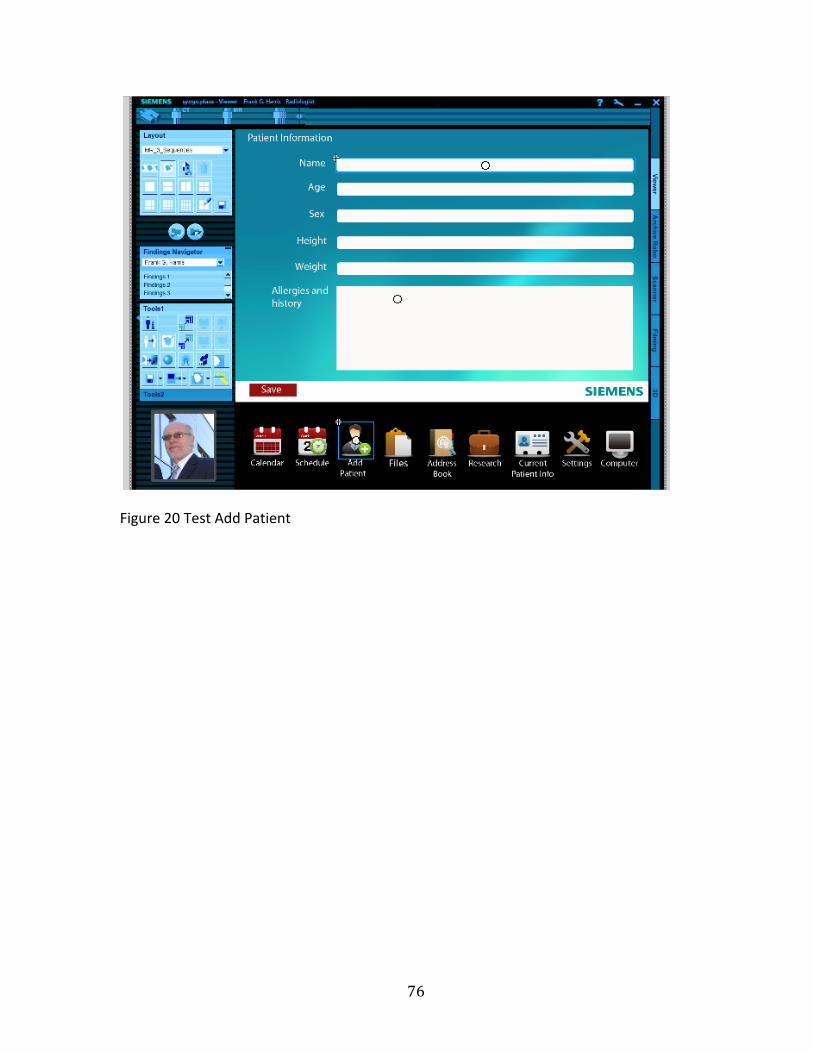
76
Figure 20 Test Add Patient

77
Figure 21 Test Patient Information

78
Figure 22 Test Confirmation
Figure 23 shows what the user would see after clicking on the scan button.
Once that happens a “take image” button will come up. The user will then click that
button. Figure 24 shows the scan on the screen. There is a save button on the
bottom left corner. After saving the image the user would then exit back to the home
screen, shown by Figure 25. If the user is finished scanning the patient, he or she
could close out the screen and this will take the user back to a home screen (shown
in figure 26) where the patient information is.

79
Figure 23 Test Take Image

80
Figure 24 Test Save

81
Figure 25 Test Home Screen With Patient

82
Figure 26 Test Home Screen
3.4. Icons and Ethnography
As part of the development of an initial interface, the study of icons and
ethnography should be a key consideration. However, the researcher is using icons
from the original Siemens design. The researcher has provided examples of the
original icons in the appendix.
The researcher has used these icons, because it is assumed that Siemens had
already completed research in this area. Since this was only an initial interface mock
up the researcher did use icons from different models of Siemens C-‐Arms and try to
create a more cohesive design.
Traditionally, a medical device manufacturer, or the design firm responsible

83
for creating the device, would research the ethnography of different regions where
the device would be used. Based on the findings, the designers could create icons
that were easier to understand in multiple regions.
Table 11 shows how icons might be perceived in different countries. The
table illustrates what a mail icon might look like in six different countries using
regional mailboxes, and gives what is a common solution for this icon, because it is
universally recognized. In medical devices, using icons that are more universally
recognized could help medical devices in their second life cycle.

84
Table 11 Universal Icons

85
3.5. System Architecture Scenarios
After conducting research, the researcher analyzed the results and decided
what would be the best method for moving forward in the research. There were four
different scenarios in which the research could move forward. Also, there were two
considerations to take into account. One consideration was if the user interface
would be a customizable or specialized interface. The second consideration would
be if the interface would be a wireless open adaptable interface or an adaptable
interface.
The option of the first scenario is to relearn the current machines. The
current machines that are in use in developing countries need repairs, user manuals,
and training for locals to fix the machines, and region-‐ specific UI. These are
important problems; however, the current problem offers no incentive for the
manufacturer to fix the issues. These issues could be solved by an independent
organization that was willing to take on some of the current issues.
The second scenario involves keeping the old machines and introducing new
technology to those older devices. The iPad offers so many opportunities to create
custom user interfaces for different applications. The Cocoa or Objective -‐C code is
an open code that any programmer can write for. However, having a device that the
user could potentially download apps onto may be too risky to run a medical device
on.

86
Table 12 Systems Architecture Scenarios The third scenario introduces the thought of having a proprietary device
with an old device. Developing a proprietary tablet that could interact with the older

87
machines wirelessly would allow the software to be more secure. The electrical,
software, and wireless engineers would have to develop a kit to convert the old
machines to communicate with the tablet.
The fourth scenario would involve a new medical device with a proprietary
tablet. This option would require the development of a tablet and a new line of
equipment with wireless capabilities considering the second life.
The tablet could include military-‐grade security. Computer security is directly
proportional to the complexity of the encryption algorithm, the length of its key and
the complexity of the password used. Unfortunately, the security of a password is
directly proportional to the difficulty of remembering it, since the best passwords
mix random upper and lowercase characters with numbers and punctuation.
Since the tablet is a touchscreen and it would be a proprietary system, it could
have a fingerprint scanner, making the password problem become a little less
significant. This would allow only hospital staff the authority to use the tablet.
To develop a device that could have a large impact on the future of medical
devices and also have an incentive for current medical device manufacturers, the
fourth scenario was chosen for further development. This new approach to medical
device design will be applied to a proprietary tablet and a new medical device.

88
3.6. Sketching and Development
Figure 27 Examples of Sketches
The researcher developed sketches as a visual display to create the form of
the C-‐Arm device concept. Figure 27 shows examples of the sketches used in this
study. The practice of sketching will continue through the development process in

89
this study. Using the sketch ideation, the researcher expanded and refined the
concept and built a 3D form.
3.7. Test Computer Model
The researcher developed an initial test CAD model before constructing the
physical sketch model. This test model addressed some of the major issues
commonly found in C-‐Arm devices. Table 13 shows the key improvements that were
addressed.
Table 13 Design Improvements

90
Figure 28 C-‐Arm Overall View
Figure 29 C-‐Arm Interface
Figure 29 shows the new interface and wireless tablet. The tablet will be
used as a visual confirmation tool. The tablet will also allow the user to interact with
the C-‐Arm monitoring system and print images wirelessly to a printer in the lab or

91
office. It will also streamline the work flow and network with the hospital’s server to
load patient information. Figure 30 shows the wireless antenna and the arm-‐locking
mechanism. The antenna will allow the C-‐Arm to send information and images to
the monitoring system. The locking mechanism is a simple one-‐lock system to
unlock and lock the position of the C-‐Arm. Traditional C-‐Arms have to be locked at
multiple points to set the position of the arm.
Figure 30 C-‐Arm Wireless Antenna and Arm Adjustment

92
Figure 31 demonstrates that the user interface is free of any obstructions. In
traditional C-‐Arms, the interface has an obstruction hanging over the center of the
user interface, the back arm of the boom that allowed the C-‐Arm to move forward
and backward hung over the interface. Changing the design of the C-‐Arm’s boom to a
more mechanical arm freed the user interface from any obstructions.
Figure 31 C-‐Arm Mechanical Arm Top View

93
Figure 32 C-‐Arm Side View
3.8. Sketch Model
The researcher developed a sketch model of the C-‐Arm to study the volume
of the device. The researcher felt that the volume was an important part of the
study. Most of the volume in a typical C-‐Arm is composed of electrical components.
Since the researcher is focusing more on the user interface and the overuse of the
device, the research started the design based on the physical size of a Siemens
C-‐Arm.
The development of a medical device requires many people with different
types of expertise. For example, if a corporation were to follow this approach to
designing a medical device, the design would be handed off to different engineers at
different points in the design process. This would allow for the electrical engineers

94
to make the proper updates or the mechanical engineers to make the concept
functional. However, due to the limitations of this project, some aspects of this
approach are going to be assumed that would have taken place, and only the
industrial design aspects will be delivered.
The sketch model will show the researcher the physical volume of the device.
This will allow the researcher to identify if the model’s height is correct for the user
interface. Figure 33 shows the frame of the sketch model. The researcher first built
the frame out of wood. This allowed the researcher to have a sturdy base for the
model.
Figure 33 Wood Frame
Next the researcher applied a foam core skin around the wood frame. This

95
process gave the sketch model’s full volume. Figure 34 shows the application. Figure
35 and 36 show the final sketch model. After the model was complete, the
researcher was then able to find out if the model was thin enough to fit through
common doors, had good weight distribution, and most importantly, if the interface
was at the right height and angle. Because of this model development, the
researcher discovered two key elements to the design. First, the interface needs to
be adjustable, and secondly, the angle of the digital interface needs to be increased.
These design features will be incorporated into the final design concept.
Figure 34 Foam Core Application

96
Figure 35 Final Foam Core Sketch Model

97
Figure 36 Final Model Front Wheels

98
3.9. Development of a User Interface
Based on the findings from the user interface prototype, the researcher
developed the final user interface. The final user interface is similar to the initial
prototype. It continues to incorporate the Siemens imaging interface as a standard
from which to develop. The workspace is a Siemens template, and the majority of
the icons are Siemens icons. Some of the icons were altered to allow the user to
better understand the icons’ functions. In addition, the researcher used some icons
from older devices that better described the function of the icon.
Figure 37 Load Screen
The dashboard is completely new to the interface model, and the researcher
designed these icons to resemble those of the workspace icons. As detailed before,
Figure 37 shows that the new interface also begins with a loading screen to allow

99
the user to know that the machine or device is on and loading the information.
Figure 38 shows the second screen is the language screen that will allow the user to
choose what language the interface will be in. Figure 39 shows that the third screen
is the login. The login will be the same username and password that the hospital
uses on their system.
Figure 38 Language Screen

100
Figure 39 Login Screen
Figure 40 Home Screen
After following the initial steps to set up the machine and log in, the next

101
screen will be the users’ home screen or dashboard, shown in figure 40. From the
Dashboard, the user can access many tabs. These tabs are key functions of the
device, and are C-‐Arm, Workspace, 3-‐D, Filming, and Viewing. At any time, the user
can come back to the Dashboard through its tab.
Figure 41 Load Patient Information
Figure 41 shows where the patient information could be loaded from the
dashboard. Figure 42 and 43 show where the user can check the current patient’s
information, and the screen also gives a visual confirmation of the patient
information.

102
Figure 42 Confirmation of Patient Information
Figure 43 Current Patient Information

103
Figure 44 Documents
Figures 44 to 48 are some of the key features to this interface. This figure
shows how the tablet has stored documents on the tablet’s hard drive. These
documents are templates to change the languages on the user interface. The user
could save the templates to a thumb drive, external hard drive or a computer in the
network. Once the template is saved to thumb drive, the user can take it to a local
printer to have the template printed out. A template can be seen in Figure 54. The
other documents that are stored on the tablet include user guides, troubleshooting
guides, technician guides and operations manual. All of the guides, manuals and
templates would be available in many languages.

104
Figure 45 File Selection
Figure 46 Template Selection Screen
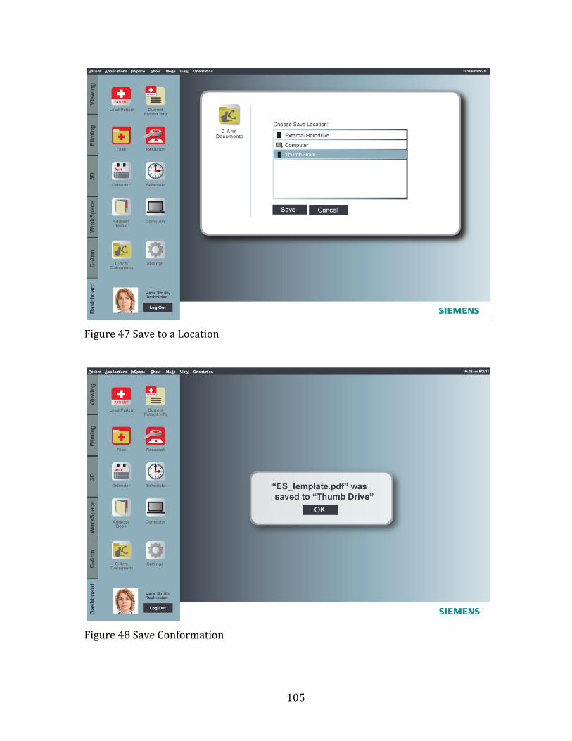
105
Figure 47 Save to a Location
Figure 48 Save Conformation

106
Figure 49 Tablet Screen
Figure 49 shows where the tablet can be used as a monitor for the C-‐Arm in
the workspace. The tablet can also view current monitors being used. Figure 50
shows where the tablet could view one monitor and also save the images from that
monitor. Figure 53 shows where the tablet could be used as a visual confirmation
tool in the C-‐Arm’s main interface. This confirmation will allow the user to see the
changes as they are made to the settings of the device.
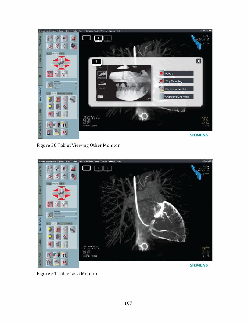
107
Figure 50 Tablet Viewing Other Monitor
Figure 51 Tablet as a Monitor

108
Figure 52 Tablet Image Saving
Figure 53 Interface Confirmation Screen

109
Figure 54 Spanish Template
Table 14 shows a flowchart of the major functions and tabs in the user
interface. This chart demonstrates how the user would navigate to the work tabs.
Each work tab serves a different function to the C-‐Arm as previously shown in
Figures 39 to 52.

110
Table 14 User Interface Flow chart

111
3.10. Systems Design – The Network
Table 15 shows the systems’ network and how each device works with one
another. This system revolves around the tablet and the server. The tablet can
control the C-‐Arm and monitor cart, send information to the server and office
computers, print images from its own screen and from the screens of the monitor
cart, and retrieve/load patient records. The server acts like a hub to all the devices
in the network. The server would be off-‐site and accessed through a VPN
connection. Because of the lack of electrical reliability in developing and second
world countries, the server would need to be off-‐site to protect patient information.

112
Table 15 Systems Network

113
3.11. Final Computer Prototype
The final computer prototype shows key changes that were made to the
device. After reviewing the sketch model and first computer model, the researcher
found areas that needed improvement.
Table 16 Further Improvements

114
In Table 16, the researcher shows that the first improvement was a template
overlay. This template corresponded to the user interface download screen, which is
shown in Figures 55 to 59.
Figure 55 C-‐Arm and Monitor Cart

115
Figure 56 Side View C-‐arm
The second improvement that is shown here is an adjustable interface.
Having an adjustable interface would allow the user to set the device’s interface
height to a viewing level that is comfortable for that specific user.
Figure 57 Raised Interface Detail

116
Figure 58 Exploded Interface Detail
As shown in Figure 58, the user interface features an interchangeable
language template. The template has a 1/8 inch plastic cover that locks over it.

117
Figure 59 Detail of USB and Arm Lock
The third improvement is a charging station for the tablet device and a more
durable lock handle for the C-‐Arm.
Figure 60 Detail of Foot Lock

118
The final addition to the design was quickstep foot locks for the device. The
action of the user stepping on the lock pedals will lock the device’s wheels, and four
floor braces will come down to support the device.
Figure 61 C-‐arm Turned
Figure 62 Monitor Cart Hero

119
The monitor cart is designed to be thinner than a traditional monitor cart
and allows the user to adjust the height as highlighted in Figure 63. The slim design
will allow for easier storage and transportation of the device, while the adjustable
height makes the cart more user-‐friendly.
Figure 63 Monitor Cart Back View
The monitor cart was also designed to support wireless and wired operation
devices such as a keyboard and a mouse. This device would be sold with a wireless
mouse and keyboard. However, considering the second life cycle, the region that the
device is being sent to may not want to replace batteries. With this in mind, the
researcher designed cord ports throughout the cart to allow for wired devices.

120
Figure 64 Monitor Cart Profile
Figure 65 CPU Detail
The researcher is introducing the final part of the device in the monitor cart.
The monitor cart has an interchangeable computer. Traditionally, the computers
have been built into the monitor cart. This would allow for quick repair.

121
3.12. Final Analysis
After completing research, prototypes, and final computer model, the
researcher’s final analysis differs slightly from the anticipated outcome from
Chapter 1. There is a need for a universal or adaptable interface. However, the
foremost problem in medical device design is in the methodology. The methods and
regulations are focused on the technical, mechanical, and production aspect of the
device. It seems as if the human aspect is not as important in the medical device
design process.
In industrial design, there is a human function. This function ensures that
products designers create are useable. By having this function in the revised
approach to medical device design the user interfaces of medical devices should be
more adaptable and usable.
3.13. Limitations of the Study
The limitations of the study were very apparent due to the type of device that
was being used as an example for this study. Some of the key limitations of the study
included time, complexity of the device, testing, and user feedback.
Since the study was completed in two semesters, some research was
assumed. The complexity of the device limited the researcher from building a
working model. The researcher instead focused on building a working user
interface. The user interface and system design of this study is where most of the
changes took place. Because the device is a Class III medical device, which includes

122
devices that can potentially cause the patient harm, user testing or a working model
of the C-‐Arm was not attempted.

123
Chapter 4 Findings
4.1. Findings
The major findings from this study include: the need for a universal interface,
better systems design, more considerations for the interface, better patient filing
system and more security. The need for a universal style of an interface and more
considerations for the interface are apparent, with nearly 70% of medical accidents
caused by misuse of the interface.
The patient filing system is non-‐existent in some countries, and in the U.S.
some places still use paper records with no backup. Recent natural disasters have
proved that system does not work. When a hospital is compromised due to a
disaster, man-‐made or natural, if no backup is in place all records will be lost.
Other findings include the lack of devices being donated due to liability and
manufacturers not supporting old equipment. If a manufacturer would allow a
second party to continue manufacturing parts to support the old devices, this would
enable non-‐profits and resellers to make repairs instead of taking parts off another
device to fix the first one, as described in the research in this project.

124
Chapter 5 Discussion
5.1. Second Life Approach
The final approach to medical device design considering a second life starts
with the research phase. The research includes the problem statement, observation,
user scenarios, material study, market research, interviews, identifying core issues,
environment, ergonomics, technical and human functions, analyzing findings,
electricity, language, need, resources, and device classification.
Phase two is the design phase. The design phase includes sketching, physical
modeling, computer modeling, testing, looking for problems, request designation,
maintenance, operators, and security. The design phase is a time for conception,
ideation, and preparation.
After the concept is approved the development phase can begin. The
development phase is phase three. It includes testing, evaluation, computer
modeling, user feedback, user criteria, development, production and marketing
function, prototype, design advice, pre-‐clinical, early planning, clinical, and IDES.
After the completion of the development phase the device should be ready to begin
manufacturing if all the clinical testing was cleared.
The fourth phase is the deployment phase. The deployment phase takes the
device from manufacturing to the market place. This phase includes presenting,
packaging, marketing, control drawings, documentation transfer, manufacturing,

125
agreements and determinations, and PMA’S / 510(K)s.
The final phase is the revisiting phase. During this phase the device will be
analyzed while it is in the market place. The revisiting phase will include
commercial use, advisory panel, post marketing, control drawings, obsolescence,
recalls, safety alerts, warning letters, and donation process. This phase is new the
approach. Many of the processes are standard medical device process, but this
phase now includes the donation process, which is key to this approach. The revised
or final approach is detailed in Table 17.
Table 17 Medical Device Revised Approach
To compare what has been changed in the design process, Table 4 Industrial
Design Process on page 49 shows the typical industrial design method. In the
research phase six considerations have been added. These considerations include

126
environmental, electrical, language, need, resources, and device classification
research.
In addition the design phase now includes request for designation,
maintenance, operators, and security. The request for designation ensures that
process for the device classification has begun. The addition of maintenance will
include the development of guides and testing that might reduce overall
maintenance. Also the designer would consider the operators and their needs in the
design phase. Security would also be considered to ensure that the security
requirements are met to protect the device and user.
The development and deployment phases have been updated to include
prototyping, design advice, pre-‐clinicals, early planning, clinicals, IDES, agreements
and determinations, and PMA’S/ 510(K)s. These additions are standard medical
device design considerations.

127
Chapter 6 Conclusions
6.1. Future of Medical Devices
Medical devices evolve at a fast rate, and manufacturers are continually
inventing new technology. Future medical devices will be an integral part of one’s
lifestyle. As shown in Image 66, Microsoft is pushing for an integrated healthcare
system. This means that medical device interfaces could be a growing part of one’s
everyday life. Integrated healthcare systems will monitor a person’s entire body. At
any minute, a user could check their cholesterol, pulse, glucose level, and body
temperature. This would happen through applications on a person’s phone. These
statistics would also be available to the user’s personal physicians.
Integrated healthcare would also track eating habits, workouts, and any
medications that the user it taking. If the physician or user has any concerns, a video
conference could be set up immediately to go over solutions to fix the problems. If
integrated healthcare does become part of the general population’s life, medical
device interfaces need to be usable. This study could help designers in creating an
adaptable interface.

128
Figure 66 Future Devices Ergonomidesign (2010)
6.2. Impacting Developing Regions
If the design method detailed in this study were to be followed by large
medical device manufacturers, the developing regions throughout the world could
be impacted positively. This would be due to more developing regions receiving
medical devices if the manufacturers would donate the devices to non-‐profit
medical suppliers after the first use devices. However, currently, most
manufacturers believe that denoting to non-‐profit medical suppliers will reduce
sales.
Many of these regions cannot afford the more expensive medical devices.
This just means that if the region does not have the devices, certain patients will go
untreated.
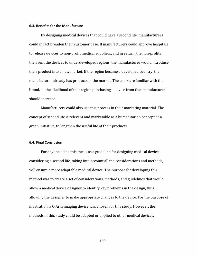
129
6.3. Benefits for the Manufacture
By designing medical devices that could have a second life, manufacturers
could in fact broaden their customer base. If manufacturers could approve hospitals
to release devices to non-‐profit medical suppliers, and in return, the non-‐profits
then sent the devices to underdeveloped regions, the manufacturer would introduce
their product into a new market. If the region became a developed country, the
manufacturer already has products in the market. The users are familiar with the
brand, so the likelihood of that region purchasing a device from that manufacturer
should increase.
Manufacturers could also use this process in their marketing material. The
concept of second life is relevant and marketable as a humanitarian concept or a
green initiative, to lengthen the useful life of their products.
6.4. Final Conclusion
For anyone using this thesis as a guideline for designing medical devices
considering a second life, taking into account all the considerations and methods,
will ensure a more adaptable medical device. The purpose for developing this
method was to create a set of considerations, methods, and guidelines that would
allow a medical device designer to identify key problems in the design, thus
allowing the designer to make appropriate changes to the device. For the purpose of
illustration, a C-‐Arm imaging device was chosen for this study. However, the
methods of this study could be adapted or applied to other medical devices.

130
Much was learned, by the researcher, during the span of this study. The
studied yielded what the researcher might describe as a large gap in medical device
design concerning the human function. Many medical devices in the developed
world are currently facing obsolescence and the path for the majority of these
devices is that of a landfill. The researcher hopes in the future that the medical
device life cycle might be extended to help others.

131
References
Adams, W. R., & Hawkins, J.P. (2007). Health care in Maya Guatemala: confronting
medical pluralism in a developing country. Norman: University of Oklahoma
Press. (pp. 29)
Alexis, S.J. (2008). Caring hands : inspiring stories of volunteer medical missions.
Minneapolis: Fairview Press. (pp. 221)
Arnett, J.J. (2007). International Encyclopedia of Adolescence. London:
Routledge/Taylor & Francis. (pp. 376)
Aykin, N. (E.D.). (2007) Usability and Internationalization, Second International
Conference on Usability and Internationalization, UI-HCII 2007, held as part of
HCI International 2007, Beijing, China, July 22-27, 2007, Proceedings, Part 1.
Berlin New York: Springer (pp. 5, 27, & 367)
Baumann, K., Thomas, B., Laurel, B. (2001) User Interface Design for
Electronic Appliances. London: Taylor & Francis (pp. 292 & 318)
Constantine, L.L., & Lockwood, L.A.D. (1999). Software for Use: A Practical Guide to
the Essential Models and Methods of Usage-Centered Design. (pp. 51)
Device Classification. (2002). Classify Your Medical Device. April 3, 2011, Retrieved
from:http://www.fda.gov/MedicalDevices/DeviceRegulationandGuidance/O
verview/ClassifyYourDevice/default.htm

132
Drain, P., Huffman, S.A., Dirtle, S., & Chan, K.(2009). Caring for the world: a guidebook
to global health opportunities. Toronto: University of Toronto Press. (pp. 46)
Ergonomidesign (2010) Introducing a New Generation of Medical Devices. June 25,
2011. Retrieved from: http://www.ergonomidesign.com/-‐
Default.aspx?ID=1810
Fowler, K.R. (2008) What Every Engineer Ehould Know about Developing Real-Time
Embedded Products. Boca Raton: CRC Press. (pp. 61) Fries, R.C. (2001).
Handbook of Medical Device Design. New York: M. Dekker. (pp. 37 & 320)
Fries, R. (2006). Reliable design of medical devices. Boca Raton: CRC/Taylor &
Francis. (pp. 90 & 148)
Green, W.S., Jordan, P.W. (1999) Human Factors in Product Design: Current Practice
and Future Trends. London Philadelphia, PA: Taylor and Francis (pp. 33)
Hanna, K.E. (2001) Institute of medicine (U.S.). Roundtable on Research and
Development of Drugs, Biologics, and Medical Devices. Innovation and
invention in medical devices: workshop summary. Washington, D.C.: National
Academy Press. (pp. 53)
Henderson, Naomi R. (2009). Managing Moderator Stress: Take a Deep Breath. You
Can Do This!. Marketing Research, Vol. 21 Issue 1. (pp. 28-‐29)Rollins, K.
(2006). The Index of Global Philanthropy. 2006, (pp. 14)
Jacobson, B., Murray, A. (2007). Medical devices: use and safety. Edinburgh New
York: Churchill Livingstone. (pp. 15 & 30)
Kucklick, T.R. (2006). The Medical Device R&D Handbook. Boca Raton: CRC/Taylor &
Francis. (p. 4)

133
Lowgren, J., Stolterman, E., (2005) A Design Perspective on Information Technology.
Cambridge: MIT Press. (pp. 46)
Medical Device Innovation Initiative White Paper (2011) CDRH Innovation Initiative.
May 20, 2011. Retrieved from:
http://www.fda.gov/aboutfda/centersoffices/cdrh/cdrhinnovation/ucm242
067.htm
Medical Product Outsourcing. (2006)The Top 30 Global Medical Device Companies.
March 1, 2011. Retrieved from: http://www.mpo-‐
mag.com/articles/2006/07/top-‐medical-‐device-‐companies-‐report
Pahl, G., Beitz, W., Feldhusen, J., & Grote, K.H. (2003). A Systematic Approach.
Engineering Design. Berlin: Springer. (pp. 104 & 561) 3rd edition
Perez, C. (2008). Caring for them from birth to death : the practice of community-
based Cuban medicine. Lanham, MD: Lexington Books. (pp. 33)
Pendse S, Singh A, Zawada E. (2008) Initiation of Dialysis. In: Handbook of Dialysis.
4th ed. (pp. 14-‐21)
Portable Ventilator Image. April 23, 2011. Retrieved from:
http://www.yshmed.com/en/product2.asp?id=25
Supplies Needed. April 23,2011 Retrieved from: http://www.projectcure.org/give-‐
supplies/supplies-‐needed
Tarnoff, C., & Nowels, L. (2004). Foreign Aid: An Introductory Overview of U.S.
Programs and Policy (Order Code 98-‐916). Foreign Affairs and National
Defence (p. 2)
Teixeira, M.B., Bradley, R. (2003) Design Controls for the Medical Device Industry.

134
New York: Marcel Dekker. (pp. 27)
The World Bank. (2004). A World Bank country study. Poverty in Guatemala.
(pp. 118)
Westwood, J.D., Westwood, S.W., & Haluck, R.S. M.D. (2009). NextMed:
Design For/the Well Being,Medicine Meets Virtual Reality 17.
(pp. 109)
Wiklund, M.E., Wilcox, S.B., & Stephen, S. (2005). Designing Usability into Medical
Products. Boca Raton: CRC Press. (pp. 21)
Wiklund, M.E. (1995) Medical Device and Equipment Design: Usability Engineering
and Ergonomics. (pp. 156)
World Health Organization (2000) GUIDELINES FOR HEALTH CARE EQUIPMENT
DONATIONS. Figure 1 & 2.

135
Appendix
Siemens User Manual
The appendix contains a Siemens C-‐Arm user manual. The user manual was
used a reference tool throughout this study. This manual also corresponds to the
figures 3-‐6 in chapter 1.

136
1

137

138

139

140

141

142

143

144

145

146

147

148

149
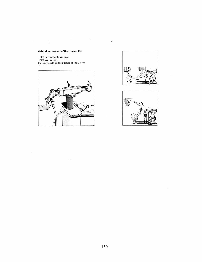
150

151

152

153

154

155

156

157

158

159

160
Copyright © 2022 FDOKUMEN