AN ANALYTICAL MODEL FOR THE PREDICTION OF THE RESISTANCE OF T-STUBS WITH FOUR BOLTS IN A ROW
8
EUROSTEEL 2014, September 10-12, 2014, Naples, Italy AN ANALYTICAL MODEL FOR THE PREDICTION OF THE RESISTANCE OF T-STUBS WITH FOUR BOLTS IN A ROW Aldina Santiago a , Luís Simões da Silva a , Massimo Latour b , Gianvittorio Rizzano b , Stefania Trezza b a University of Coimbra, Dept. of Civil Engineering, Portugal [email protected], [email protected] b University of Salerno, Dept. of Civil Engineering, Italy [email protected], [email protected], [email protected] KEYWORDS: T-stubs, Effective Length, Experimental, Yield line, FEM ABSTRACT The behaviour of the moment resisting steel frames (MRFs) is strongly influenced by the rotational behaviour of joints which can affect both the internal actions arising in beams and columns and the overall deformability of the structure. The fast development of powerful computers and the growing use in professional practice of advanced structural software have allowed designers to accurately account for the non-linear behaviour of structural members and connections. Due to this reason, in order to grasp the MRFs behaviour, it is necessary to have accurate mechanical models able to predict the whole rotational response of steel joints. In particular, the analysis of the connections of a steel structure can be carried out according to the so-called Component Method reported in Eurocode 3 [1]. Such a method is a general approach that can be used to model every type of joint, provided that all the base components are properly identified and modelled. In case of bolted connections, the main joint components, such as the column flange in bending, the end-plate in bending and the web and flange angles in tension are modelled by means of the so-called equivalent T-stub in tension. The T-stub is a sub-assemblage realized by fastening two Tees through the flanges with one or more bolt rows. In technical literature, several works deal with the characterization of the monotonic and cyclic behaviour of T- stubs with two bolts in a row, but with reference to T-stubs with four bolts in two rows, which is a sub-assemblage applicable to many real structural situations, few experimental and modelling works are available and, therefore, more research efforts are still needed. Within such framework, in this paper the attention is focused on the experimental and theoretical analysis of the plastic resistance of T-stubs with four bolts in one row. To this scope, the work mainly focuses on three experimental tests carried out at the University of Coimbra (Fig.1a), on the set up of a finite element model (FEM) in ABAQUS software (Fig.1b) and on the development of an analytical model for predicting the plastic resistance of the T-stub. During the experimental activity at the laboratory of the University of Coimbra, tests were performed on three specimens designed in order to reproduce the typical T-stub failure modes. On the base of these tests a finite element model has been carried out in ABAQUS software. Successively, aiming to carry out a complete model for the prediction of the resistance of T-stubs with four bolts in a row, the analysis of the possible yield line patterns arising in the plate has been necessary. Therefore, by exploiting the developed FEM, several cases with different bolt/plate stiffness ratio and with different values of the T-stub width have been considered (Fig.1c). In this phase, particular attention has been devoted to the type-2 failure mechanism, which is the collapse mechanism most influenced by the presence of the second bolt row. Finally, the approach already suggested in [2,3] has been applied. In particular, by equating the external and internal work, the effective length of the equivalent T-stub in tension has been determined for all the possible cases depending on the failure mechanism and plate geometry. As a conclusion of the work, a general formulation able to provide the strength of a T-stub with four bolts in a row has been developed and
Transcript of AN ANALYTICAL MODEL FOR THE PREDICTION OF THE RESISTANCE OF T-STUBS WITH FOUR BOLTS IN A ROW

EUROSTEEL 2014, September 10-12, 2014, Naples, Italy
AN ANALYTICAL MODEL FOR THE PREDICTION OF THE
RESISTANCE OF T-STUBS WITH FOUR BOLTS IN A ROW
Aldina Santiagoa, Luís Simões da Silva
a, Massimo Latour
b, Gianvittorio Rizzano
b, Stefania Trezza
b
aUniversity of Coimbra, Dept. of Civil Engineering, Portugal
[email protected], [email protected] bUniversity of Salerno, Dept. of Civil Engineering, Italy
[email protected], [email protected], [email protected]
KEYWORDS: T-stubs, Effective Length, Experimental, Yield line, FEM
ABSTRACT
The behaviour of the moment resisting steel frames (MRFs) is strongly influenced by the rotational
behaviour of joints which can affect both the internal actions arising in beams and columns and the
overall deformability of the structure. The fast development of powerful computers and the growing
use in professional practice of advanced structural software have allowed designers to accurately
account for the non-linear behaviour of structural members and connections. Due to this reason, in
order to grasp the MRFs behaviour, it is necessary to have accurate mechanical models able to
predict the whole rotational response of steel joints.
In particular, the analysis of the connections of a steel structure can be carried out according to the
so-called Component Method reported in Eurocode 3 [1]. Such a method is a general approach that
can be used to model every type of joint, provided that all the base components are properly
identified and modelled. In case of bolted connections, the main joint components, such as the
column flange in bending, the end-plate in bending and the web and flange angles in tension are
modelled by means of the so-called equivalent T-stub in tension. The T-stub is a sub-assemblage
realized by fastening two Tees through the flanges with one or more bolt rows. In technical
literature, several works deal with the characterization of the monotonic and cyclic behaviour of T-
stubs with two bolts in a row, but with reference to T-stubs with four bolts in two rows, which is a
sub-assemblage applicable to many real structural situations, few experimental and modelling
works are available and, therefore, more research efforts are still needed.
Within such framework, in this paper the attention is focused on the experimental and theoretical
analysis of the plastic resistance of T-stubs with four bolts in one row. To this scope, the work
mainly focuses on three experimental tests carried out at the University of Coimbra (Fig.1a), on the
set up of a finite element model (FEM) in ABAQUS software (Fig.1b) and on the development of
an analytical model for predicting the plastic resistance of the T-stub. During the experimental
activity at the laboratory of the University of Coimbra, tests were performed on three specimens
designed in order to reproduce the typical T-stub failure modes. On the base of these tests a finite
element model has been carried out in ABAQUS software.
Successively, aiming to carry out a complete model for the prediction of the resistance of T-stubs
with four bolts in a row, the analysis of the possible yield line patterns arising in the plate has been
necessary. Therefore, by exploiting the developed FEM, several cases with different bolt/plate
stiffness ratio and with different values of the T-stub width have been considered (Fig.1c). In this
phase, particular attention has been devoted to the type-2 failure mechanism, which is the collapse
mechanism most influenced by the presence of the second bolt row. Finally, the approach already
suggested in [2,3] has been applied. In particular, by equating the external and internal work, the
effective length of the equivalent T-stub in tension has been determined for all the possible cases
depending on the failure mechanism and plate geometry. As a conclusion of the work, a general
formulation able to provide the strength of a T-stub with four bolts in a row has been developed and

its accuracy has been verified on the results of the parametric analysis carried out in ABAQUS
software.
(a)
(b) (c)
Figure 1. Experimental investigations on T-stubs (a) Finite Element Modelling of T-stubs (b), individuation of yield
lines patterns (c)
CONCLUSIONS
In this work, the results of a theoretical and experimental analysis dealing with the prediction of the
plastic resistance of T-stubs with four bolts in one row is presented. Within the work, by exploiting
a FE model calibrated on the results of three experimental tests, it is evidenced that the failure
mechanism most affected by the second bolt row is the type.2. Furthermore, by means of the FE
model, it is shown that the shape of non-circular yield pattern significantly varies with respect to
the classical theory. Finally, a complete analytical model, based on the definition of new values of
the effective lengths, is proposed demonstrating its accuracy by comparing the analytical
predictions versus the results obtained from a parametric analysis.
ACKNOWLEDGMENT
The authors acknowledge financial support from Ministério da Educação e da Ciência (Fundação
para a Ciência e Tecnologia) under research project PTDC/ECM/110807/2009.
REFERENCES
[1] CEN, 2005a. Eurocode 3: Design of steel structures - Part 1-8: Design of joints. European Committee
for Standardization, CEN, Brussels.
[2] Demonceau, J., Jaspart, J., Muller, C. & Weinand, K., 2010. Application of Eurocode 3 to Steel
Connections with Four Bolts per Horizontal Row. In SDSS', ed. Colloquium on Stability and Ductility
of Steel Structures. Rio de Janeiro, 2010.
[3] Zoetemeijer, P., 1974. A Design Method for the Tension Side of Statically Loaded, Bolted beam-to-
column Connections. Heron, 20, pp.1-59.

EUROSTEEL 2014, September 10-12, 2014, Naples, Italy
AN ANALYTICAL MODEL FOR THE PREDICTION OF THE
RESISTANCE OF T-STUBS WITH FOUR BOLTS IN A ROW
Aldina Santiagoa, Luís Simões da Silva
a, Massimo Latour
b, Gianvittorio Rizzano
b, Stefania Trezza
b
aUniversity of Coimbra, Dept. of Civil Engineering, Portugal
[email protected], [email protected] bUniversity of Salerno, Dept. of Civil Engineering, Italy
[email protected], [email protected], [email protected]
INTRODUCTION
In case of bolted connections, the main components that contribute to the deformability of the joint
are: the column flange in bending, the end-plate in bending and the angles in tension which are
modelled as an equivalent T-stub in tension. In technical literature, several experimental and
theoretical works deal with the characterization of the behavior of T-stubs fastened by means of two
bolts [4,7,8] but, the case of T-stubs with more than two bolts per row is not considered, even
though it is a sub-assemblage that is applied in many practical situations [6]. In this paper, in order
to provide a contribution to improve the model given in EC3, extending it to cases not currently
covered in the code, attention is focused on the experimental and theoretical analysis of T-stubs
with four bolts per row, following three steps: experimental investigation, finite element modelling
and proposal of a mechanical model for the prediction of the T-stub plastic resistance.
1 PREVIOUS STUDIES
Dealing with the behaviour of the T-stub with four bolts in one row some studies have already been
carried out in [3], where the basic formulas to define the resistance of the T-stubs have been
determined. In particular, within the approach proposed by [3], in analogy with the classical T-stub
theory, a simplified beam model that extends the formulations given by EC3 to the case of T-stub
with four bolts in one row has been developed. In particular, based on the assumptions of rigid-
plastic behavior of the steel and of elastic distribution of the forces in the bolts up to failure, the
equations reported in Table 1 have been obtained.
Table 1 – Resistance of T-stubs with four bolts in one row
Failure Mode T-stub with two bolts T-stub with 4 bolts
Mode-1
Mode-2 ∑
∑
(
)
Mode-3 ∑ ∑
The symbols have the same meanings given in EC3, excepting n1 which is the distance between the
two bolts and n2 which is the distance of the external bolt from the free edge. It is possible to note
that the application of the equations obtained by [3] needs the definition of appropriate effective
lengths that will be topic of discussion in the next sections.
2 EXPERIMENTAL ACTIVITY
2.1 Description of the layout
As first step of the research activity, an experimental program has been carried out at the laboratory
on materials and structures of the University of Coimbra. In particular, three T-stubs with four bolts
designed to fail according to different collapse mechanisms have been tested. All the specimens
have been realized starting from steel plates made of S355 steel fastened by means of M12 bolts

made of 8.8 class [2]. In order to favourite the development of the three typical failure modes, the
specimens have been designed according to the following criteria:
Test 1: the T-stub has been designed in order to induce the development of a weak plate-
strong bolt mechanism realized with a plate of 10 mm;
Test 2: the T-stub has been designed in order to develop a mechanism type-2 realized with a
plate of 20 mm;
Test 3: the T-stub has been designed to fail according to a mechanism type-3; bolts are
located very close to the T-stub web in order to induce the bolt failure mechanism (Fig.1). Test 1 Test 2 Test 3
Fig. 1 – Tested Specimens
All the tests have been carried out by means of the rig machine developed at the University of
Coimbra. The machine is composed by the assemblage of a series of steel profiles that are used to
counteract the load applied by an hydraulic cylinder (Maximum load 1000 kN, Stroke 280 mm).
The loads have been applied under displacement control at the constant velocity of 0.02 mm/s in
order to carry out quasi-static tests. During the tests, four LVDTs on both sides of the T-stub are
used to measure the displacements. In particular, the average value of the gap opening and the inner
bolts elongation have been controlled during the tests.
2.2 Experimental results
The first test, according to the adopted design criteria, was characterized by a strong bolt and weak
plate behaviour. From Fig.2a), it can be noted that the plate of Test-1 exhibited a significant plastic
engagement, with a deformed shape characterized by the development of two plastic hinges in
correspondence of the T-stub web and two plastic hinges in correspondence of the bolt lines.
Fig. 2 – Specimens at failure (From the left: Test 1, 2, 3)
In this test, the premature fracture of the bolts was observed before the complete development of the
plastic hinges on the T-stub flange plate. In particular, the failure has first concerned the inner bolts
and, after a partial loss of the T-stubs resistance, also the outer bolts. Specimen 2 had the same
geometrical configuration of the first one, but the flange plate has 20 mm of thickness. In this case
the T-stub exhibited a type-2 collapse mode, characterized by the development of a plastic hinge in
correspondence of the flange-to-web connection followed by the failure of the bolts. Again in this
case, the collapse first arose due to the failure of the inner bolts and, after the partial loss of the
load, followed by the outer bolts.
Finally, in case of Test-3, in agreement with the design procedure, for a value of the load
corresponding approximately to the sum of the resistances of the four M12 bolts in tension, the
failure arose due to the fracture of the bolt shaft. In Fig.3a) the values of the loads recorded by the
t=20 mm t=10 mm t=20 mm

load cell versus the average displacements recorded by the two LVDTs located in the gap opening,
are reported for the three specimens.
3 FINITE ELEMENT MODEL
In order to extend the results of the experimental campaign, a Finite Element Model has been
carried out in Abaqus code. In particular, the FE model has been developed with two scopes. The
first one is to evaluate the yield line patterns arising in the plate, which are necessary to define the
values of the effective lengths to be employed in simplified calculations. The second one is the
extension of the experimental sample by generating a parametric analysis which is crucial to verify
the mechanical model. The FE model is constituted by four parts: the rigid support and its web, the
tested T-stub and the bolts. Bolts and plates materials’ properties have been described by means of
an elastic-plastic isotropic model. The rigid support has been simulated by adopting an infinitely
elastic material with very high value of the stiffness. Concerning the element type, a 8-node linear
brick with reduced integration and instability mesh control has been adopted (C3D8R). The mesh
size has been defined by carrying out a sensitivity analysis in the preliminary phase, by accounting
also for the existing guidelines on the topic[5].
Fig. 3 – a) Experimental results and comparison with the FE model; b) numerical response at failure.
The interaction among the various elements has been defined according to a surface-to-surface
formulation with finite sliding. In the normal direction a “hard contact” has been used, while in the
tangential direction a friction coefficient equal to 0.2 has been defined. In order to reduce the
computational time, half specimen has been modelled accounting for the symmetry. In Fig.3 the
results of the FE analysis are reported both in terms of response at failure and in terms of force-
displacement curve. It is possible to appreciate that the failure mode predicted analytically, is
faithfully reproduced by the model and that the response is well reproduced in terms of stiffness,
resistance and ductility supply of the T-stub.
As aforesaid, preliminarily to the development of the mechanical model, the finite element model
has been used to evaluate the shape of the yield line families, which is a fundamental requirement to
define the values of the effective lengths needed in the simplified calculations. To this scope, in
order to point out the different shapes of the yield line patterns of four-bolts T-stub, several FE
models with different geometry once with two-bolts and once with four-bolts have been generated.
As a result of this analysis the following considerations can be made. In case of mechanism type-1,
the second bolt row is not effective and, therefore, the failure mechanisms have no substantial
differences with respect to classical ones. Conversely, in case of mechanism type-2, while the beam
pattern is still unchanged, the kinematic mechanism in case of non-circular pattern is substantially
different. In fact, in such case, the external bolt row forces the yield lines to pass through the bolts
leading to a shape more similar to the one classically defined in case of Mechanism type-1.
Therefore, from the observation of the FE model results it is clear that in case of 4-bolts T-stubs a
0
20
40
60
80
100
120
140
160
180
0 5 10 15 20 25 30
F [k
N]
d [mm]
Test 1
Experimental
FEM
0
50
100
150
200
250
300
0 2 4 6 8 10 12 14 16 18 20
F [k
N]
d [mm]
Test 2
Experimental
FEM
0
50
100
150
200
250
300
350
400
0 2 4 6 8 10 12
F [k
N]
d [mm]
Test 3
Experimental
FEM
recalibration of the classical model is needed. To this scope, in the next section, a new analytical
formulation defining the effective length is developed.
Mec-1 – Non-Circular Pattern Mec-1 – Non-Circular Pattern
\
Mec-2 – Non-Circular Pattern Mec-2 – Non-Circular Pattern
Fig. 4 – Yield linear patterns from FEM
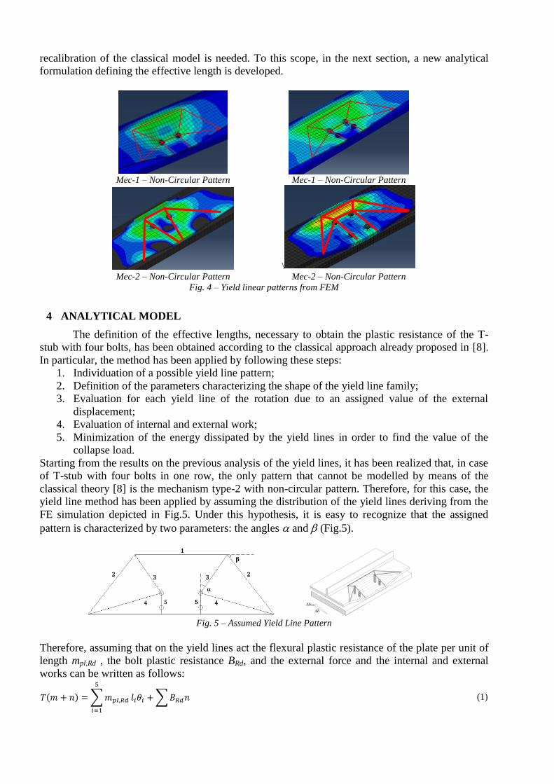
4 ANALYTICAL MODEL
The definition of the effective lengths, necessary to obtain the plastic resistance of the T-
stub with four bolts, has been obtained according to the classical approach already proposed in [8].
In particular, the method has been applied by following these steps:
1. Individuation of a possible yield line pattern;
2. Definition of the parameters characterizing the shape of the yield line family;
3. Evaluation for each yield line of the rotation due to an assigned value of the external
displacement;
4. Evaluation of internal and external work;
5. Minimization of the energy dissipated by the yield lines in order to find the value of the
collapse load.
Starting from the results on the previous analysis of the yield lines, it has been realized that, in case
of T-stub with four bolts in one row, the only pattern that cannot be modelled by means of the
classical theory [8] is the mechanism type-2 with non-circular pattern. Therefore, for this case, the
yield line method has been applied by assuming the distribution of the yield lines deriving from the
FE simulation depicted in Fig.5. Under this hypothesis, it is easy to recognize that the assigned
pattern is characterized by two parameters: the angles and (Fig.5).
Fig. 5 – Assumed Yield Line Pattern
Therefore, assuming that on the yield lines act the flexural plastic resistance of the plate per unit of
length mpl,Rd , the bolt plastic resistance BRd, and the external force and the internal and external
works can be written as follows:
∑
∑ (1)
max

where li is the length of the i-th yield line and i is its rotation. It is evident that in order to define
the value of the effective length it is necessary to find the minimum collapse load T by minimizing
the right hand side of Eq.(1). In particular, as far as the bolts resistance does not depend on
parameters and , it means minimizing the work done by the plastic hinges. Therefore, in order to
obtain the value of the minimum collapse load, the equation (1) has been solved numerically by
developing a user routine in the software Mathematica 5.1. The developed routine provides for an
assigned couple of values of m and n, the values of and that minimize the energy expressed by
Eq. (1) and, therefore, the value of the effective length. To this scope, 10.000 combinations of
values m and n varying in the range from 10 mm to 1000 mm have been generated. From the
results, by means of a multiple regression analysis of the data, the following expression of the
effective width has been obtained with correlation coefficient R2 equal to 0.99:
(2)
Based on the obtained results, the authors’ proposal is to define the resistance of the T-stub with
four bolts in one row by adopting the formulas reported in Table 1 [3] and the values of the
effective lengths given by the classical theory [8], made exception for the case of mechanism type-2
and non-circular pattern, where the effective length should be defined by Eq.2.
5 PARAMETRIC ANALYSIS
In order to check the accuracy of the proposed model for the prediction of the resistance of T-stubs
with four bolts in one row, a parametric analysis has been developed in ABAQUS by employing the
FE model previously described. In particular, the analysis has been carried out by generating a
sample of cases with different geometrical characteristics. Twenty-four models have been defined,
twelve of them with a wide flange (1200 mm width) and the others twelve with a narrow flange
(200 mm). The first group of models has been defined aiming to promote the development of non-
circular patterns, while the second group has been defined aiming to promote the development of
beam patterns. For each group the following combinations of m, n1 and n2 have been defined:
1. m = 40 mm; n1= 80 mm; n2=35 mm
2. m = 60 mm; n1= 60 mm; n2=35 mm
3. m = 40 mm; n1= 60 mm; n2=55 mm
In addition, for each combination of m, n1 and n2, in order to develop collapses belonging to all the
possible failure mechanisms, four values of the thickness have been considered: 5 mm, 10 mm, 15
mm e 20 mm. The steel composing the plates is S355 and the bolts are M12, 8.8 grade.
In order to compare the values obtained with the analytical model defined in previous section and
the results coming from this parametric analysis, it is necessary to define the plastic resistance for
the T-stubs modelled in ABAQUS. To this scope, it is considered that the model presented in EC3
provides a value of the plastic resistance corresponding to the knee that can be determined as a
value 1.5 times greater than the resistance corresponding to the yielding [1].
Therefore, in
Table 2 the geometrical parameters, the collapse mechanisms, the resulting yield line pattern and
the numerical and analytical values are compared. It can be observed that the prediction provided by
the model appears sufficiently accurate with an average value of the Model/FEM ratio equal to
1.078 and a standard deviation equal to 0.19. It is useful to observe that in the cases in which the
mechanism is type-2 and the yield line pattern is non-linear, the adoption of Eq.2. provided by EC3
would lead to a substantial underestimation of the T-stub plastic resistance. On the sample
investigated, the developed model seems to give sufficiently accurate results.
Table 2 – Model vs FEM
B [mm] s [mm] m [mm] n1 [mm] n2 [mm] leff [mm] MEC YLP Ft,rd,MOD [kN] Ft,rd,FEM [kN] Ratio
1200 5 40 80 35 251.2 1 CP 27.87 33.37 0.83
1200 5 60 60 35 358.75 1 NCP 26.53 27.03 0.98
1200 5 40 60 55 251.2 1 CP 27.87 32.51 0.85
1200 10 40 80 35 906.5 2 NCP 91.43 80.27 1.13

1200 10 60 60 35 902.5 2 NCP 85.15 74.06 1.14
1200 10 40 60 55 906.5 2 NCP 95.84 79.47 1.20
1200 15 40 80 35 906.5 3
108.86 88 1.23
1200 15 60 60 35 902.5 3
108.86 88 1.23
1200 15 40 60 55 906.5 3
108.86 94 1.15
1200 20 40 80 35 906.5 3
108.86 101 1.07
1200 20 60 60 35 902.5 3
108.86 102 1.07
1200 20 40 60 55 906.5 3
108.86 114 0.95
200 5 40 80 35 200 1 BP 22.19 29.17 0.76
200 5 60 60 35 200 1 BP 17.35 24.17 0.71
200 5 40 60 55 200 1 BP 22.19 30.74 0.72
200 10 40 80 35 200 1 BP 88.75 74.32 1.19
200 10 60 60 35 200 1 BP 59.17 67.34 0.87
200 10 40 60 55 200 1 BP 88.75 74.38 1.19
200 15 40 80 35 200 3
108.86 83.05 1.31
200 15 60 60 35 200 3
108.86 76.9 1.41
200 15 40 60 55 200 3
108.86 86.67 1.25
200 20 40 80 35 200 3
108.86 90.53 1.20
200 20 60 60 35 200 3
108.86 87.48 1.24
200 20 40 60 55 200 3
108.86 101.13 1.08
Average 1.078
ST.DEV 0.19
6 CONCLUSIONS
In this work, the results of a theoretical and experimental analysis dealing with the prediction of the
plastic resistance of T-stubs with four bolts in one row have been presented. Within the work, by
exploiting a FE model calibrated on the results of three experimental tests, it has been evidenced
that the failure mechanism most affected by the second bolt row is the type.2. Furthermore, by
means of the FE model, the yield line patterns for all the failure mechanisms have been
individuated, showing that the shape of non-circular yield pattern significantly varies with respect
to the classical theory. Finally, a complete analytical model, based on the definition of new values
of the effective lengths, has been proposed demonstrating its accuracy by comparing the analytical
predictions versus the results obtained from a parametric analysis.
ACKNOWLEDGMENT
The authors acknowledge financial support from Ministério da Educação e da Ciência (Fundação
para a Ciência e Tecnologia) under research project PTDC/ECM/110807/2009.
REFERENCES
[1] CEN, 2005a. Eurocode 3: Design of steel structures - Part 1-8: Design of joints. European Committee
for Standardization, CEN, Brussels.
[2] CEN, 2005b. Eurocode 3: Design of steel structures - Part 1-1: General rules and rules for buildings.
European Committee for Standardization, CEN, Brussels.
[3] Demonceau, J., Jaspart, J., Muller, C. & Weinand, K., 2010. Application of Eurocode 3 to Steel
Connections with Four Bolts per Horizontal Row. In SDSS', ed. Colloquium on Stability and Ductility
of Steel Structures. Rio de Janeiro, 2010.
[4] Faella, C., Piluso, V. & Rizzano, G., 2000. Structural Steel Semi-Rigid Connections. Boca Raton: CRC
Press.
[5] Trezza S., 2013. Previsione del Comportamento Ultimo di T-stub con 4 bulloni per fila: Analisi teorico-
sperimentale. Master Thesis, University of Salerno, Tutors: Santiago A., Simões da Silva, Latour M.,
Rizzano G.
[6] Weynand, K.; Oerder, R., 2013. “Typisierte Anschlüsse im Stahlhochbau”, 3rd edition, Stahlbau
Verlags- und Service GmbH, Düsseldorf.
[7] Yee, Y.L. & Melchers, R.E., 1986. Moment-Rotation Curves for Bolted Connections. Journal of
Structural Engineering ASCE, 112, pp.615-35.
[8] Zoetemeijer, P., 1974. A Design Method for the Tension Side of Statically Loaded, Bolted beam-to-
column Connections. Heron, 20, pp.1-59.