An Adjustable Single Degree-of-Freedom System to Guide ...
8
An Adjustable Single Degree-of-Freedom System to Guide Natural Walking Movement for Rehabilitation Brandon Y. Tsuge * Graduate Student Researcher Email: [email protected] J. Michael McCarthy Professor, ASME Fellow Robotics and Automation Laboratory Department of Mechanical Engineering University of California Irvine, California 92697 Email: [email protected] This paper presents a linkage system designed to guide a natural ankle trajectory with the corresponding foot orienta- tion. A six-bar linkage was designed to coordinate the joint angles of an RR chain (R denotes a revolute or hinged joint) that models the leg to achieve the desired ankle trajectory. The design is shown to be adjustable to meet a range of tra- jectories obtained in an individual’s normal gait. Control of the foot position is obtained using a cam-driven parallel chain that has the same input as the six-bar linkage. The re- sult is a one degree of freedom system that guides a natural walking movement of the leg and foot. A solid model of the complete device is presented. 1 Introduction Robotic systems are finding increased use to support treadmill-based rehabilitation for stroke patients and those with spinal cord injuries. These systems attached actuators to a patient’s legs that are programmed to provide a desired leg movement. These systems expand the capability of the one degree-of-freedom Gait Trainer [1], which was designed to move the users foot, to include movement of the knee and hip. Examples are the pneumatically operated gait orthosis, POGO [2], the pneumatically powered gait orthosis, PPGO [3], and the pneumatically actuated robotic system [4]. Also see the review article by Koceska and Koceski [5]. The paper presents the design of a mechanical system that provides support for natural movement of the hip, knee, and ankle with a single actuator. The design of this de- vice applies recent research on an innovative six-bar link- age matched to the dimensions of the user that coordinates * Address all correspondence related to ASME style format and figures to this author. the hip and knee movements to achieve a natural trajec- tory for the ankle by Tsuge et al. [6]. A parallel cam- mechanism driven by the same input controls the angle of the foot through this trajectory. The result is a compact mechan- ical system that provides a repeatable natural leg movement for treadmill rehabilitation. An important feature of the de- sign is that it also provides an adjustment that can vary the ankle trajectory to provide natural variations to the stepping movement. 2 Literature Review Mechanical systems for walking rehabilitation appear as either over-ground systems or treadmill systems. Over- ground systems are exoskeletons that include mechanical braces and actuators under computer control such as the Berkeley Exoskeleton [7,8] and the MindWalker project [9]. More common are such treadmill systems that are designed for use in a dedicated therapy room under the supervision of a physical therapist. For example, the pelvic assist manipu- lator, PAM, [10], includes a body-weight support and manip- ulates the hip of the user on the treadmill. The Active Leg Exoskeleton, ALEX, [11–13] includes body-weight support and independently actuates the hip and knee joints with the ankle supported by a spring-loaded shoe. Other treadmill systems include the driven gait ortho- sis, DGO, which provides a lower limb exoskeleton that is actuated at the knee and the hip with a DC motors. The Ambulation-assisting Robotic Tool for Human Rehabilita- tion, ARTHuR, uses two linear actuators to drive a linkage attached to the angle to manipulate the lower leg on a tread- mill [14]. The LOKOMAT [15], and the Lower Extremity Powered Exoskeleton, LOPES [16], provide actuators that
-
Upload
khangminh22 -
Category
Documents
-
view
7 -
download
0
Transcript of An Adjustable Single Degree-of-Freedom System to Guide ...
An Adjustable Single Degree-of-Freedom Systemto Guide Natural Walking Movement for
Rehabilitation
Brandon Y. Tsuge∗Graduate Student Researcher
Email: [email protected]
J. Michael McCarthyProfessor, ASME Fellow
Robotics and Automation LaboratoryDepartment of Mechanical Engineering
University of CaliforniaIrvine, California 92697
Email: [email protected]
This paper presents a linkage system designed to guide anatural ankle trajectory with the corresponding foot orienta-tion. A six-bar linkage was designed to coordinate the jointangles of an RR chain (R denotes a revolute or hinged joint)that models the leg to achieve the desired ankle trajectory.The design is shown to be adjustable to meet a range of tra-jectories obtained in an individual’s normal gait. Controlof the foot position is obtained using a cam-driven parallelchain that has the same input as the six-bar linkage. The re-sult is a one degree of freedom system that guides a naturalwalking movement of the leg and foot. A solid model of thecomplete device is presented.
1 IntroductionRobotic systems are finding increased use to support
treadmill-based rehabilitation for stroke patients and thosewith spinal cord injuries. These systems attached actuatorsto a patient’s legs that are programmed to provide a desiredleg movement. These systems expand the capability of theone degree-of-freedom Gait Trainer [1], which was designedto move the users foot, to include movement of the knee andhip. Examples are the pneumatically operated gait orthosis,POGO [2], the pneumatically powered gait orthosis, PPGO[3], and the pneumatically actuated robotic system [4]. Alsosee the review article by Koceska and Koceski [5].
The paper presents the design of a mechanical systemthat provides support for natural movement of the hip, knee,and ankle with a single actuator. The design of this de-vice applies recent research on an innovative six-bar link-age matched to the dimensions of the user that coordinates
∗Address all correspondence related to ASME style format and figuresto this author.
the hip and knee movements to achieve a natural trajec-tory for the ankle by Tsuge et al. [6]. A parallel cam-mechanism driven by the same input controls the angle of thefoot through this trajectory. The result is a compact mechan-ical system that provides a repeatable natural leg movementfor treadmill rehabilitation. An important feature of the de-sign is that it also provides an adjustment that can vary theankle trajectory to provide natural variations to the steppingmovement.
2 Literature ReviewMechanical systems for walking rehabilitation appear
as either over-ground systems or treadmill systems. Over-ground systems are exoskeletons that include mechanicalbraces and actuators under computer control such as theBerkeley Exoskeleton [7,8] and the MindWalker project [9].More common are such treadmill systems that are designedfor use in a dedicated therapy room under the supervision ofa physical therapist. For example, the pelvic assist manipu-lator, PAM, [10], includes a body-weight support and manip-ulates the hip of the user on the treadmill. The Active LegExoskeleton, ALEX, [11–13] includes body-weight supportand independently actuates the hip and knee joints with theankle supported by a spring-loaded shoe.
Other treadmill systems include the driven gait ortho-sis, DGO, which provides a lower limb exoskeleton that isactuated at the knee and the hip with a DC motors. TheAmbulation-assisting Robotic Tool for Human Rehabilita-tion, ARTHuR, uses two linear actuators to drive a linkageattached to the angle to manipulate the lower leg on a tread-mill [14]. The LOKOMAT [15], and the Lower ExtremityPowered Exoskeleton, LOPES [16], provide actuators that

therapeutic control the hip and the knee joints. Several sys-tems have been developed for separate actuation of the ankleand foot for treadmill gait rehabilitation by Agrawal et al.[17], Sawicki and Ferris [18], and Kinnaird and Ferris [19].
Our goal is a single degree-of-freedom system that pro-vides natural motion to the hip, knee, angle and foot. Cen-tral to this design is a six-bar linkage that includes an RRchain that matches the upper and lower leg dimensions ofthe user. The ankle trajectory is used to define the movementof this RR chain and the dimensions of the six-bar linkageensure the movement has one degree-of-freedom. Other sys-tems that provide a one degree-of-freedom ankle trajectoryare the Klann six-bar linkage [20], and Jansen eight-bar link-age [21, 22]. There are other single degree-of-freedom, pla-nar linkages that create walking motions developed for bipedrobots, applications [23,24]. However, these linkages do notmatch the natural trajectory of the human ankle and do notcontrol foot orientation.
The synthesis of the six-bar linkage that guides the RRchain to achieve the natural ankle trajectory combines thesynthesis theory of six-bar function generators and optimiza-tion theory [6]. The cam-driven parallel linkage [25] is in-troduced to actuate the foot orientation around the ankle inparallel with the six-bar linkage that controls hip and knee.
Finally, local optimization of the six-bar linkage using agreedy search strategy provides designs for each of a set ofnaturally varying ankle trajectories. The clustering of thesedesigns around a specific set of dimensions yields an adjust-ment that guides the ankle joint through the natural variationof its trajectory. The result is a compact, simple and innova-tive linkage system to support treadmill rehabilitation.
3 Natural Ankle TrajectoriesIn order to design the six-bar linkage that controls the
hip and knee to achieve a natural trajectory for the ankle, webegin by obtaining motion capture data of treadmill walkingby healthy volunteer. The data was collected using the ViconMX three dimensional motion capture system by Nina Rob-son in the Human Interactive Robotics Lab at the CaliforniaState University, Fullerton, Figure 1.
Motion capture data was collected from markers at thehip, knee, ankle, and toe as the user walked on a treadmill.The ankle data consists of 23 trajectories ranging from 199to 210 points, Figure 2. The dimensions of the RR chain thatmodel the upper lower leg were obtained from the hip, kneeand ankle trajectories.
Because the six-bar linkage is to be designed to attachto the hip, the coordinates of the ankle trajectory data pointswere transformed to a coordinate system in the hip. Thisyielded the 23 different trajectories shown in Figure 3, whichare the basis for the design of our gait system.
4 Six-Bar Linkage Mechanism for the Ankle TrajectoryThe synthesis procedure follows that Tsuge et al. [6],
called homotopy directed optimization. This consists of us-ing a combination of homotopy and optimization methods to
Fig. 1: Attached marker locations
100 200 300 400 500 600xHmmL
50
100
150
200
250
yHmmL
Fig. 2: Ankle trajectories obtained from the Vincon MX mo-tion capture system.
-400 -300 -200 -100 100 200xHmmL
-850
-800
-750
-700
-650
yHmmL
Fig. 3: Ankle trajectories transformed to a coordinate systemin the user’s hip.
design a Stephenson III, six bar linkage. Homotopy continu-ation is used to solve the six-bar path synthesis problem for7 precision points. The resulting linkage solutions are thenused as a start population to minimize an objective functionthat utilizes 60 precision points. The notation for the variousjoint parameters, the relative link angles are shown in Figure4. The points A,B,C,D,F,G, and H are the joint coordinatesin the fixed frame and ψ,ρ,φ,µ, and θ are relative angles ofeach of the links relative to a starting linkage position. Inthe context of using this particular linkage topology for thepurpose of an exoskeleton, the point B,F, and P are modeledas the hip, knee, and ankle joint respectively. The synthesisalgorithm requires that a set of ankle points for P be defined.The value of B was set to be at the origin for the simplicity.
The data points for the input P was collected from mo-tion capture data. This data contained coordinates of theankle during several gait cycles. The first set of ankle co-ordinates is shown in Figure 5. These are data points arerelative to the hip joint. A B-spline [26] was used to repre-

ϕρ
μ
ψ
B
CA
G
D
H
P0
F
Pj
θ
Fig. 4: Stephenson III Six-Bar Linkage
-400 -300 -200 -100 100 200
-850
-800
-750
-700
-650
Fig. 5: Ankle Trajectory of a Single Gait Cycle Relative tothe Hip Joint
sent the equation of the curve that goes through these datapoints. From this equation, 7 data points are selected for thehomotopy component of the synthesis procedure, and 60 datapoints were selected for the optimization component. Figure6 shows a plot of these 60 data points and Figure 7 plots the7 points required for the homotopy solution.
4.1 Objective FunctionThe objective function is derived from the loop equa-
tions of the six-bar linkage:
Qk(D−A) =−Uk(H−D)−Tk(P0−H)+(Pk−A),
Qk(D− A) =−Uk(H− D)− Tk(P0− H)+(Pk− A),
Rk(G−C) =−Uk(H−G)−Tk(P0−H)+(Pk−C),
Rk(G−C) =−Uk(H− G)− Tk(P0− H)+(Pk−C),
k = 1, . . . ,NP−1, (1)
-400 -300 -200 -100 100 200
-850
-800
-750
-700
-650
Fig. 6: Set of 60 Precision Points Derived from a B-Splinefor the optimization problem
-400 -300 -200 -100 100 200
-850
-800
-750
-700
-650
Fig. 7: Set of 7 Precision Points Derived from a b-Spline forhomotopy continuation
where (A,C,D,G,H) are the joint parameters and Q,U,T ,and R are the relative rotations of the particular link. Thesevariables are in complex form and their complex conjugatesare denoted by a bar.
The rotations, Qk and Rk were eliminated by multiplyingthe complex conjugate equations.
|D−A|2 = |Uk(H−D)+Tk(P0−H)− (Pk−A)|2,|G−C|2 = |Uk(H−G)+Tk(P0−H)− (Pk−C)|2,k = 1, . . . ,NP−1, (2)
resulting in k sets of two linear equations. The variables Ukand Uk are unknown.
Additional parameters are introduced to solve this sys-tem of equations,
a = ax + iay = H−D
bk = bxk + ibyk = Tk(P0−H)−Pk +A
c = cx + icy = H−G
dk = dxk + idyk = Tk(P0−H)−Pk +C
f = fx + i fy = D−A
g = gx + igy = G−C. (3)
Next, the substitution of (3) into (2) results in
Ukabk +Ukabk = f f −aa−bkbk,
Ukcdk +Ukcdk = gg− cc−dkdk, k = 1, . . . ,NP−1. (4)
Each of these can be solved using Cramer’s rule:
Uk =
∣∣∣∣ f f −aa−bkbk abkgg− cc−dkdk cdk
∣∣∣∣∣∣∣∣abk abkcdk cdk
∣∣∣∣ ,Uk =
∣∣∣∣abk f f −aa−bkbkcdk gg− cc−dkdk
∣∣∣∣∣∣∣∣abk abkcdk cdk
∣∣∣∣ ,
k = 1, . . . ,NP−1. (5)
The normality condition, UkUk = 1, results in the construc-tion of the objective function, that has the design variablevector r = (A,C,D,G,H). This objective function is
F(r) =NP−1
∑i=1
UkUk−1 =NP−1
∑i=1
sin2 µk + cos2 µk−1, (6)
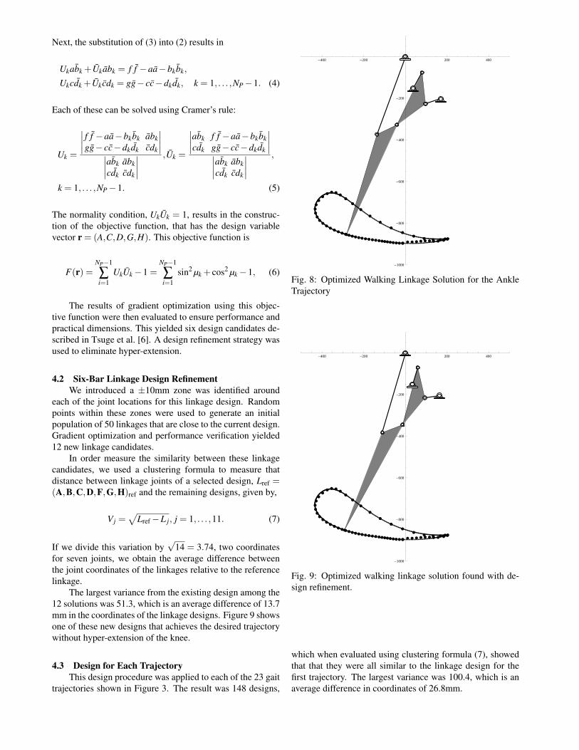
The results of gradient optimization using this objec-tive function were then evaluated to ensure performance andpractical dimensions. This yielded six design candidates de-scribed in Tsuge et al. [6]. A design refinement strategy wasused to eliminate hyper-extension.
4.2 Six-Bar Linkage Design RefinementWe introduced a ±10mm zone was identified around
each of the joint locations for this linkage design. Randompoints within these zones were used to generate an initialpopulation of 50 linkages that are close to the current design.Gradient optimization and performance verification yielded12 new linkage candidates.
In order measure the similarity between these linkagecandidates, we used a clustering formula to measure thatdistance between linkage joints of a selected design, Lref =(A,B,C,D,F,G,H)ref and the remaining designs, given by,
Vj =√
Lref−L j, j = 1, . . . ,11. (7)
If we divide this variation by√
14 = 3.74, two coordinatesfor seven joints, we obtain the average difference betweenthe joint coordinates of the linkages relative to the referencelinkage.
The largest variance from the existing design among the12 solutions was 51.3, which is an average difference of 13.7mm in the coordinates of the linkage designs. Figure 9 showsone of these new designs that achieves the desired trajectorywithout hyper-extension of the knee.
4.3 Design for Each TrajectoryThis design procedure was applied to each of the 23 gait
trajectories shown in Figure 3. The result was 148 designs,
-400 -200 200 400
-1000
-800
-600
-400
-200
Fig. 8: Optimized Walking Linkage Solution for the AnkleTrajectory
-400 -200 200 400
-1000
-800
-600
-400
-200
Fig. 9: Optimized walking linkage solution found with de-sign refinement.
which when evaluated using clustering formula (7), showedthat that they were all similar to the linkage design for thefirst trajectory. The largest variance was 100.4, which is anaverage difference in coordinates of 26.8mm.
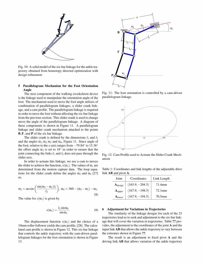
Fig. 10: A solid model of the six-bar linkage for the ankle tra-jectory obtained from homotopy directed optimization withdesign refinement.
5 Parallelogram Mechanism for the Foot OrientationAngleThe next component of the walking exoskeleton device
is the linkage used to manipulate the orientation angle of thefoot. The mechanism used to move the foot angle utilizes ofcombination of parallelogram linkages, a slider crank link-age, and a cam profile. The parallelogram linkage is requiredin order to move the foot without affecting the six-bar linkagefrom the previous section. This slider crank is used to changemove the angle of the parallelogram linkage. A diagram ofthese components is shown in Figure 11. A parallelogramlinkage and slider crank mechanism attached to the pointsB,F, and P of the six bar linkage.
The slider crank is defined by the dimensions l1 and l2and the angles α1,α2,α3 and α4, Figure 11. Since angle ofthe foot, relative to the x-axis ranges from−79.84◦ to 15.36◦
the offset angle α3 is set to 18◦ in order to ensure that thejoint connecting the links l1 and l2 does not pass through theslider axis.
In order to actuate this linkage, we use a cam to movesthe slider to achieve the function, s(α1). The values of α1 aredetermined from the motion capture data. The loop equa-tions for the slider crank define the angles α2 and α4 [27]as,
α2 = arcsin(
sin(α3−α1)l1l2
), α4 = 360− (α3−α1)−α2.
(8)The value for s(α1) is given by
s(α1) =l1 sinα4
sinα2. (9)
The displacement function s(α1) and the choice of a10mm roller follower yields the cam profile, [28]. The calcu-lated cam profile is shown in Figure 12. This six-bar linkagethat controls the ankle trajectory with the cam-driven paral-lelogram linkages for the foot orientation is shown in Figure13.
B
F
Pj
s
α3α2
α1
l1
l2
l1
α4
l1
Fig. 11: The foot orientation is controlled by a cam-drivenparallelogram linkage.
50 100
-50
50
100
Fig. 12: Cam Profile used to Actuate the Slider Crank Mech-anism
Table 1: Coordinates and link lengths of the adjustable drivelink AB and pivot A.
Joint Coordinates Link Length
Adesign (163.9,−204.5) 71.4mm
Aupper (167.9,−198.5) 72.1mm
Alower (167.9,−194.5) 70.5mm
6 Adjustment for Variations in TrajectoriesThe similarity of the linkage designs for each of the 23
trajectories lead us to seek and adjustment to the six-bar link-age that will cover the variation in trajectories. Table ?? pro-vides, the adjustment to the coordinates of the joint A and theinput link AB that allows the ankle trajectory to vary betweenthe extremes shown in Figure ??.
The result is an adjustment to fixed pivot A and thedriving link AB that allows variation of the ankle trajectory
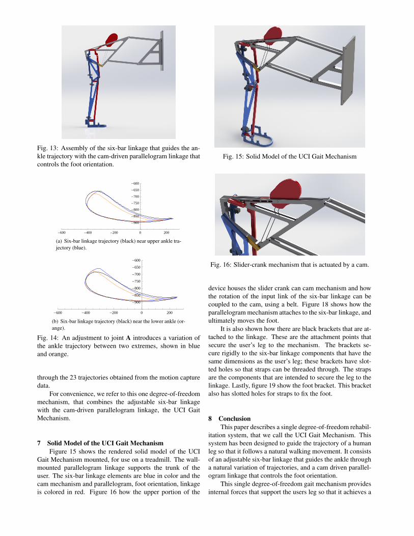
Fig. 13: Assembly of the six-bar linkage that guides the an-kle trajectory with the cam-driven parallelogram linkage thatcontrols the foot orientation.
-600 -400 -200 0 200
-900
-850
-800
-750
-700
-650
-600
(a) Six-bar linkage trajectory (black) near upper ankle tra-jectory (blue).
-600 -400 -200 0 200
-900
-850
-800
-750
-700
-650
-600
(b) Six-bar linkage trajectory (black) near the lower ankle (or-ange).
Fig. 14: An adjustment to joint A introduces a variation ofthe ankle trajectory between two extremes, shown in blueand orange.
through the 23 trajectories obtained from the motion capturedata.
For convenience, we refer to this one degree-of-freedommechanism, that combines the adjustable six-bar linkagewith the cam-driven parallelogram linkage, the UCI GaitMechanism.
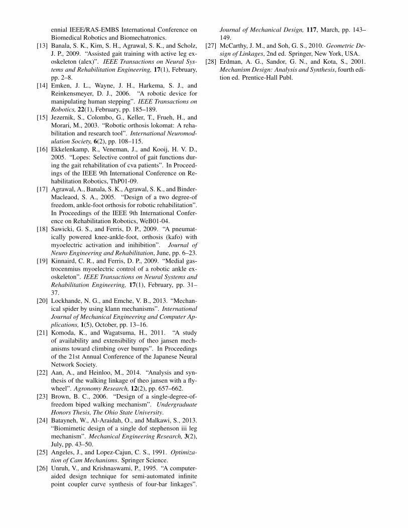
7 Solid Model of the UCI Gait MechanismFigure 15 shows the rendered solid model of the UCI
Gait Mechanism mounted, for use on a treadmill. The wall-mounted parallelogram linkage supports the trunk of theuser. The six-bar linkage elements are blue in color and thecam mechanism and parallelogram, foot orientation, linkageis colored in red. Figure 16 how the upper portion of the
Fig. 15: Solid Model of the UCI Gait Mechanism
Fig. 16: Slider-crank mechanism that is actuated by a cam.
device houses the slider crank can cam mechanism and howthe rotation of the input link of the six-bar linkage can becoupled to the cam, using a belt. Figure 18 shows how theparallelogram mechanism attaches to the six-bar linkage, andultimately moves the foot.
It is also shown how there are black brackets that are at-tached to the linkage. These are the attachment points thatsecure the user’s leg to the mechanism. The brackets se-cure rigidly to the six-bar linkage components that have thesame dimensions as the user’s leg; these brackets have slot-ted holes so that straps can be threaded through. The strapsare the components that are intended to secure the leg to thelinkage. Lastly, figure 19 show the foot bracket. This bracketalso has slotted holes for straps to fix the foot.
8 ConclusionThis paper describes a single degree-of-freedom rehabil-
itation system, that we call the UCI Gait Mechanism. Thissystem has been designed to guide the trajectory of a humanleg so that it follows a natural walking movement. It consistsof an adjustable six-bar linkage that guides the ankle througha natural variation of trajectories, and a cam driven parallel-ogram linkage that controls the foot orientation.
This single degree-of-freedom gait mechanism providesinternal forces that support the users leg so that it achieves a

Fig. 17: The parallelogram mechanism attaches to the six-bar linkage in order to control the foot orientation angle.
Fig. 18: Foot bracket with slotted holes for straps that willsecure the user’s foot in place.
natural walking movement. It can be used to move the user’sleg or have the user’s leg drive a resistance, with or withoutgravity loading on the leg.
A complete solid model of the UCI Gait Mechanism isshown to illustrate its design and how the device would beused.
Acknowledgements
This material is based upon work supported by the Na-tional Science Foundation under Grant No. CMMI 1066082.
References[1] Hesse, S., and Uhlenbrock, D., 2000. “A mechanized
gait trainer for restoration of gait”. Journal of Reha-bilitation Research and Development, 37(6), Novem-ber/December.
[2] Aoyagi, D., Ichinose, W. E., Harkema, S. J., Reinkens-meyer, D. J., and Bobrow, D. J., 2007. “A robotand control algorithm that can synchronously assist innaturalistic motion during body-weight-supported gaittraining following neurologic injury”. IEEE Transac-tions on Neural Systems and Rehabilitation Engineer-ing, 15(3), pp. 387–400.
[3] Zhou, S., and Song, J., 2011. “Design and control ofpneumatically-powered gait orthosis”. In Proceedingsof the 5th International Conference on Bioinformaticsand Biomedical Engineering, IEEE.
[4] Koceska, N., Koceski, S., Zobel, P. B., and Durante,F., 2011. “Gait training using pneumatically actuatedrobot system”. In Advances in Robot Navigation, P. A.Barrera, ed. InTech.
[5] Koceska, N., and Koceski, S., 2013. “Review: Robotdevices for gait rehabilitation”. International Journalof Computer Applications, 62(12), January.
[6] Tsuge, B. Y., Plecnik, M., and McCarthy, J. M., 2015.“Homotopy directed optimization to design a six-barlinkage for a lower limb with a natural ankle trajec-tory”. Submitted to the Journal of Mechanisms andRobotics(JMR-15-1225).
[7] Zoss, A. B., Kazerooni, H., and Chu, A., 2006.“Biomechanical design of the berkeley lower extrem-ity exoskeleton (bleex)”. IEEE/ASME Transactions onMechatronics, 11(2), April, pp. 128–138.
[8] Strickland, E., 2012. “Good-bye wheelchair”. IEEESpectrum, January.
[9] Gancet, J., Ilzkovitz, M., Motard, E., Nevatia, Y.,Letier, P., Weerdt, D. D., Cheron, G., Hoellinger, T.,Seetharaman, K., Petieau, M., Ivaneko, Y., Molinari,M., Pisotta, I., Tamburella, F., Labini, F. S., d’Avella,A., der Kooij, H. V., Wang, L., der Helm, F. V., Wang.,S., Zanow, F., Hauffe, R., and Thorsteinsson, F., 2012.“Mindwalker: Going one step further with assistivelower limbs exoskeleton for sci condition subjects”. InProceedings of the 4th IEEE RAS/EMBS InternationalConference on Biomedical Robotics and Biomecha-tronics.
[10] Aoyagi, D., Ichinose, W. E., Reikensmeyer, D. J., andBobrow, J. E., 2004. “Human step rehabilitation us-ing a robot attached to the pelvis”. In Proceedings ofthe 2004 ASME International Mechanical EngineeringCongress and Exposition, IMECE2004-59472.
[11] Banala, S. K., Agrawal, S. K., and Scholz, J. P., 2007.“Active leg exoskeleton (alex) for gait rehabilitationof motor-impaired patients”. In Proceedings of theIEEE 10th International Conference on RehabilitationRobotics.
[12] Banala, S. K., Kim, S. H., Agrawal, S. K., and Scholz,J. P., 2008. “Assisted gait training with active legexoskeleton(alex)”. In Proceedings of the 2nd Bi-
ennial IEEE/RAS-EMBS International Conference onBiomedical Robotics and Biomechatronics.
[13] Banala, S. K., Kim, S. H., Agrawal, S. K., and Scholz,J. P., 2009. “Assisted gait training with active leg ex-oskeleton (alex)”. IEEE Transactions on Neural Sys-tems and Rehabilitation Engineering, 17(1), February,pp. 2–8.
[14] Emken, J. L., Wayne, J. H., Harkema, S. J., andReinkensmeyer, D. J., 2006. “A robotic device formanipulating human stepping”. IEEE Transactions onRobotics, 22(1), February, pp. 185–189.
[15] Jezernik, S., Colombo, G., Keller, T., Frueh, H., andMorari, M., 2003. “Robotic orthosis lokomat: A reha-bilitation and research tool”. International Neuromod-ulation Society, 6(2), pp. 108–115.
[16] Ekkelenkamp, R., Veneman, J., and Kooij, H. V. D.,2005. “Lopes: Selective control of gait functions dur-ing the gait rehabilitation of cva patients”. In Proceed-ings of the IEEE 9th International Conference on Re-habilitation Robotics, ThP01-09.
[17] Agrawal, A., Banala, S. K., Agrawal, S. K., and Binder-Macleaod, S. A., 2005. “Design of a two degree-offreedom, ankle-foot orthosis for robotic rehabilitation”.In Proceedings of the IEEE 9th International Confer-ence on Rehabilitation Robotics, WeB01-04.
[18] Sawicki, G. S., and Ferris, D. P., 2009. “A pneumat-ically powered knee-ankle-foot, orthosis (kafo) withmyoelectric activation and inihibition”. Journal ofNeuro Engineering and Rehabilitation, June, pp. 6–23.
[19] Kinnaird, C. R., and Ferris, D. P., 2009. “Medial gas-trocenmius myoelectric control of a robotic ankle ex-oskeleton”. IEEE Transactions on Neural Systems andRehabilitation Engineering, 17(1), February, pp. 31–37.
[20] Lockhande, N. G., and Emche, V. B., 2013. “Mechan-ical spider by using klann mechanisms”. InternationalJournal of Mechanical Engineering and Computer Ap-plications, 1(5), October, pp. 13–16.
[21] Komoda, K., and Wagatsuma, H., 2011. “A studyof availability and extensibility of theo jansen mech-anisms toward climbing over bumps”. In Proceedingsof the 21st Annual Conference of the Japanese NeuralNetwork Society.
[22] Aan, A., and Heinloo, M., 2014. “Analysis and syn-thesis of the walking linkage of theo jansen with a fly-wheel”. Agronomy Research, 12(2), pp. 657–662.
[23] Brown, B. C., 2006. “Design of a single-degree-of-freedom biped walking mechanism”. UndergraduateHonors Thesis, The Ohio State University.
[24] Batayneh, W., Al-Araidah, O., and Malkawi, S., 2013.“Biomimetic design of a single dof stephenson iii legmechanism”. Mechanical Engineering Research, 3(2),July, pp. 43–50.
[25] Angeles, J., and Lopez-Cajun, C. S., 1991. Optimiza-tion of Cam Mechanisms. Springer Science.
[26] Unruh, V., and Krishnaswami, P., 1995. “A computer-aided design technique for semi-automated infinitepoint coupler curve synthesis of four-bar linkages”.
Journal of Mechanical Design, 117, March, pp. 143–149.
[27] McCarthy, J. M., and Soh, G. S., 2010. Geometric De-sign of Linkages, 2nd ed. Springer, New York, USA.
[28] Erdman, A. G., Sandor, G. N., and Kota, S., 2001.Mechanism Design: Analysis and Synthesis, fourth edi-tion ed. Prentice-Hall Publ.