Degree of Freedom of Microcontroller based Solar Tracking ...
11
A Real Time Data Monitoring System for Two- Degree of Freedom of Microcontroller based Solar Tracking System M.V.Suparmaniam 1, * , V. Sathis 1 , and A.O. Arshed 1 1 Faculty of Manufacturing Engineering, Universiti Malaysia Pahang, 26600 Pekan, Pahang, Malaysia. Abstract. The dual axis solar tracker was designed for optimum solar cell implementation using dc-dc boost converter which controlled by fuzzy logic controller with the maximum power point tracking (MPPT) method. The objectives of this project are to track and optimize the maximum output power of the solar panel by designing and implementing the fuzzy logic controller using microcontroller as well as to regulate the output voltage of the solar panel using dc-dc boost converter. The photocell panel will detect the existing of sun and the surface plate of photocell panel will move horizontal and vertical axis depending on the value of LDR detected to follow the angular degree of sun in order to get maximum and best result of absorbing energy. The result obtained from the Arduino coding is the variation of duty cycle of PWM signal according to the voltage of solar panel. The final result obtained from dc-dc boost converter showed that the output voltage has been regulated. Data Acquisition System is done by using Arduino voltage sensor and current sensor to collect data for each second with the real time data graph. Overall, the designed system increases the efficiency of the solar panel based on experimental results. 1 Introduction Recently, solar energy has given more and more attention, it is a clean and renewable energy sources. The Photovoltaic (PV) cells are attained to convert solar energy from the sunlight directly to electrical energy. This energy can be utilized in many applications, like lighting, heating and performing different devices [1]. The sun powered cell is containing semiconductor physical which utilizing the photovoltaic impact. At the point when the daylight is opposite to exterior of the PV sun powered board, can acquire higher efficient system; therefore, maximum potential electrical energy can be established [1,2]. Much experimentation has been done to boost the efficiency of the solar cell. Few decades ago, solar cell modules have been created and have been invented by arranging in series to optimise the output voltage. Solar tracking system categorizes as a control system that consists of sensors to detect either the sunlight is upright to the PV panel or not, and a controller that deliver signals to one or more actuator for changing the panel to the maximum * Corresponding author: [email protected] © The Authors, published by EDP Sciences. This is an open access article distributed under the terms of the Creative Commons Attribution License 4.0 (http://creativecommons.org/licenses/by/4.0/). MATEC Web of Conferences 225, 06014 (2018) https://doi.org/10.1051/matecconf/201822506014 UTP-UMP-VIT SES 2018
-
Upload
khangminh22 -
Category
Documents
-
view
4 -
download
0
Transcript of Degree of Freedom of Microcontroller based Solar Tracking ...
A Real Time Data Monitoring System for Two-Degree of Freedom of Microcontroller based Solar Tracking System
M.V.Suparmaniam1, *, V. Sathis1, and A.O. Arshed1
1Faculty of Manufacturing Engineering, Universiti Malaysia Pahang, 26600 Pekan, Pahang, Malaysia.
Abstract. The dual axis solar tracker was designed for optimum solar cell
implementation using dc-dc boost converter which controlled by fuzzy logic
controller with the maximum power point tracking (MPPT) method. The
objectives of this project are to track and optimize the maximum output
power of the solar panel by designing and implementing the fuzzy logic
controller using microcontroller as well as to regulate the output voltage of
the solar panel using dc-dc boost converter. The photocell panel will detect
the existing of sun and the surface plate of photocell panel will move
horizontal and vertical axis depending on the value of LDR detected to
follow the angular degree of sun in order to get maximum and best result of
absorbing energy. The result obtained from the Arduino coding is the
variation of duty cycle of PWM signal according to the voltage of solar
panel. The final result obtained from dc-dc boost converter showed that the
output voltage has been regulated. Data Acquisition System is done by using
Arduino voltage sensor and current sensor to collect data for each second
with the real time data graph. Overall, the designed system increases the
efficiency of the solar panel based on experimental results.
1 Introduction
Recently, solar energy has given more and more attention, it is a clean and renewable energy
sources. The Photovoltaic (PV) cells are attained to convert solar energy from the sunlight
directly to electrical energy. This energy can be utilized in many applications, like lighting,
heating and performing different devices [1]. The sun powered cell is containing
semiconductor physical which utilizing the photovoltaic impact. At the point when the
daylight is opposite to exterior of the PV sun powered board, can acquire higher efficient
system; therefore, maximum potential electrical energy can be established [1,2]. Much
experimentation has been done to boost the efficiency of the solar cell. Few decades ago,
solar cell modules have been created and have been invented by arranging in series to
optimise the output voltage. Solar tracking system categorizes as a control system that
consists of sensors to detect either the sunlight is upright to the PV panel or not, and a
controller that deliver signals to one or more actuator for changing the panel to the maximum
* Corresponding author: [email protected]
© The Authors, published by EDP Sciences. This is an open access article distributed under the terms of the Creative Commons Attribution License 4.0 (http://creativecommons.org/licenses/by/4.0/).
MATEC Web of Conferences 225, 06014 (2018) https://doi.org/10.1051/matecconf/201822506014UTP-UMP-VIT SES 2018
targeted position. Nowadays dual axis solar tracker mechanism gained interest in R&D field
due to the evidence of gain at the efficiency of the PV panel.
In the literature, different designs for solar tracking have been discussed. For the reduction
of tracking time, fuzzy logic control algorithm is implemented with the embedded
microcontroller for improved performance as compared to conventional techniques in power
efficiency and swift maximum power point tracking [2]. The controller aims at maximizing
the solar PV cell's efficiency by forcing sunlight to be incident perpendicularly to the PV
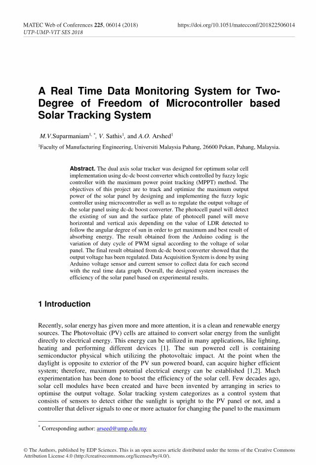
panel at all times. The system consists of PV solar panel that is allowed to move using two
motors, four PV sensors positioned at four different locations, and a fuzzy logic controller
that takes the inputs from the four sensors and calculates the appropriate output speeds for
both motors.
Fig. 1. Solar tracking system.
In [3] the author presented fuzzy control method for maximum power point tracking
(MPPT) of photovoltaic (PV) system under varying irradiation and temperature conditions.
The fuzzy control method has been compared with perturb and observe (P&O) method as
one of the most widely conventional method used in this area because of its simple and easily
implementation. Fuzzy techniques give better and more reliable control and improve energy
conversion efficiency for this application. In [4], the authors developed a small power
photovoltaic control system based on fuzzy control with FPGA technology design and
implementation for MPPT. The system composed of photovoltaic module, buck converter
and the fuzzy logic controller implemented on FPGA for controlling on/off time of MOSFET
switch of a buck converter. Simulation and experimental results show that performance of
the fuzzy controller with FPGA in a maximum power tracking of a photovoltaic array can be
made use of in several photovoltaic products and obtain satisfied result.
In [5,7] authors implemented the fuzzy logic control based solar tracking system using
Arduino Uno. Stepper motor helps in tracking the axis of the sun and keeps the panel in
direction of the sun all day long and a Buck DC-DC Converter has been used for Maximum
Power Point Tracking. The proposed fuzzy logic controller has been implemented and tested
using MATLAB. The above sun tracking power generation system has been tested in real
time using Arduino Uno. The designed system increases the energy generation efficiency of
the solar cells. Developed process to track the sun and attain maximum efficiency using
Arduino uno and LabVIEW for real time monitoring. In hardware development, four light
dependent resistor (LDR) has been used for capturing maximum light source [6]. Two DC
motors have been used to move the solar panel at maximum light source location sensing by
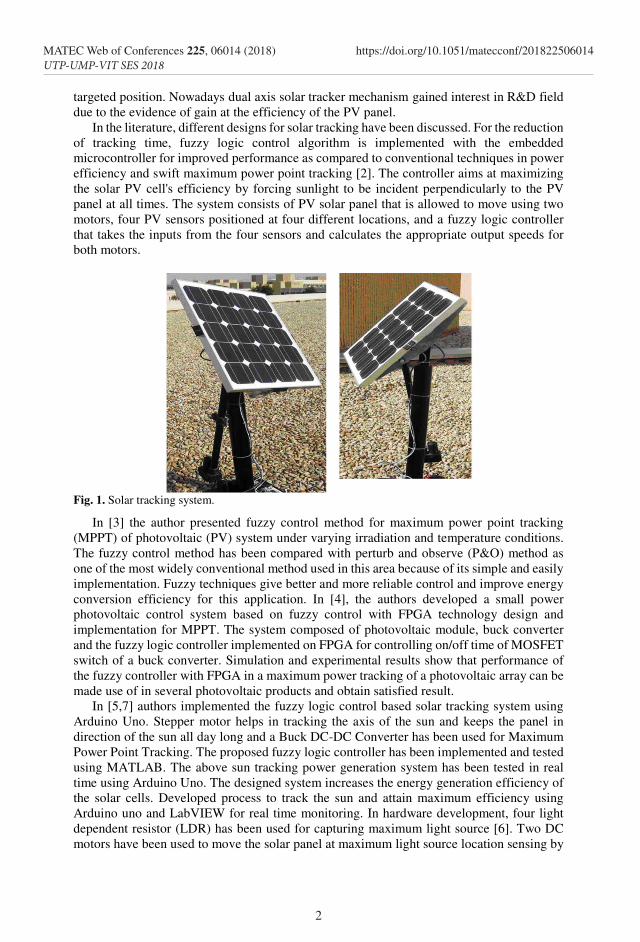
LDR. The GUI is constructed by using LabVIEW. Data collected through the monitoring
system will be analysed to identify the features of the effective solar system.
Fig. 2. Block diagram of system.
In this paper an intelligent fuzzy based tracking controller is introduced. The tracking
system consists of a photovoltaic (PV) panel that can be positioned using two actuators. The
controller depends on the output of the photovoltaic cells that acts as sensors fixed on the
panel. The controller receives inputs from these sensors and performs continuous tracking
throughout the daylight in order to maximize the efficiency of the PV solar panel. A
simulation study is also performed.
2 Design analysis of two axis sun tracking PV module
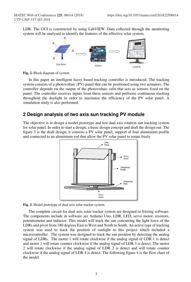
The objective is to design a model prototype and test dual axis rotation sun tracking system
for solar panel. In order to start a design, a basic design concept and draft the design out. The
figure 3 is the draft design; it consists a PV solar panel, support of four aluminium profile
and connected to an aluminium rod that allow the PV solar panel to rotate freely
Fig. 3. Model prototype of dual axis solar tracker system.
The complete circuit for dual axis solar tracker system are designed in fritzing software.
The components include in software are Arduino Uno, LDR, LED, servo motor, resistors,
potentiometer and inductor. This model will track the sun concurring the light force of the
LDRs and pivot from 180 degrees East to West and North to South. An active type of tracking
system was used to track the position of sunlight in this project which included a
microcontroller. The system was designed to track the sun position by detecting the analog
signal of LDRs. The motor 1 will rotate clockwise if the analog signal of LDR 1 is detect
and motor 1 will rotate counter clockwise if the analog signal of LDR 3 is detect. The motor
2 will rotate clockwise if the analog signal of LDR 2 is detect and will rotate counter
clockwise if the analog signal of LDR 4 is detect. The following figure 4 is the flow chart of
the model.
2
MATEC Web of Conferences 225, 06014 (2018) https://doi.org/10.1051/matecconf/201822506014UTP-UMP-VIT SES 2018
targeted position. Nowadays dual axis solar tracker mechanism gained interest in R&D field
due to the evidence of gain at the efficiency of the PV panel.
In the literature, different designs for solar tracking have been discussed. For the reduction
of tracking time, fuzzy logic control algorithm is implemented with the embedded
microcontroller for improved performance as compared to conventional techniques in power
efficiency and swift maximum power point tracking [2]. The controller aims at maximizing
the solar PV cell's efficiency by forcing sunlight to be incident perpendicularly to the PV
panel at all times. The system consists of PV solar panel that is allowed to move using two
motors, four PV sensors positioned at four different locations, and a fuzzy logic controller
that takes the inputs from the four sensors and calculates the appropriate output speeds for
both motors.
Fig. 1. Solar tracking system.
In [3] the author presented fuzzy control method for maximum power point tracking
(MPPT) of photovoltaic (PV) system under varying irradiation and temperature conditions.
The fuzzy control method has been compared with perturb and observe (P&O) method as
one of the most widely conventional method used in this area because of its simple and easily
implementation. Fuzzy techniques give better and more reliable control and improve energy
conversion efficiency for this application. In [4], the authors developed a small power
photovoltaic control system based on fuzzy control with FPGA technology design and
implementation for MPPT. The system composed of photovoltaic module, buck converter
and the fuzzy logic controller implemented on FPGA for controlling on/off time of MOSFET
switch of a buck converter. Simulation and experimental results show that performance of
the fuzzy controller with FPGA in a maximum power tracking of a photovoltaic array can be
made use of in several photovoltaic products and obtain satisfied result.
In [5,7] authors implemented the fuzzy logic control based solar tracking system using
Arduino Uno. Stepper motor helps in tracking the axis of the sun and keeps the panel in
direction of the sun all day long and a Buck DC-DC Converter has been used for Maximum
Power Point Tracking. The proposed fuzzy logic controller has been implemented and tested
using MATLAB. The above sun tracking power generation system has been tested in real
time using Arduino Uno. The designed system increases the energy generation efficiency of
the solar cells. Developed process to track the sun and attain maximum efficiency using
Arduino uno and LabVIEW for real time monitoring. In hardware development, four light
dependent resistor (LDR) has been used for capturing maximum light source [6]. Two DC
motors have been used to move the solar panel at maximum light source location sensing by
LDR. The GUI is constructed by using LabVIEW. Data collected through the monitoring
system will be analysed to identify the features of the effective solar system.
Fig. 2. Block diagram of system.
In this paper an intelligent fuzzy based tracking controller is introduced. The tracking
system consists of a photovoltaic (PV) panel that can be positioned using two actuators. The
controller depends on the output of the photovoltaic cells that acts as sensors fixed on the
panel. The controller receives inputs from these sensors and performs continuous tracking
throughout the daylight in order to maximize the efficiency of the PV solar panel. A
simulation study is also performed.
2 Design analysis of two axis sun tracking PV module
The objective is to design a model prototype and test dual axis rotation sun tracking system
for solar panel. In order to start a design, a basic design concept and draft the design out. The
figure 3 is the draft design; it consists a PV solar panel, support of four aluminium profile
and connected to an aluminium rod that allow the PV solar panel to rotate freely
Fig. 3. Model prototype of dual axis solar tracker system.
The complete circuit for dual axis solar tracker system are designed in fritzing software.
The components include in software are Arduino Uno, LDR, LED, servo motor, resistors,
potentiometer and inductor. This model will track the sun concurring the light force of the
LDRs and pivot from 180 degrees East to West and North to South. An active type of tracking
system was used to track the position of sunlight in this project which included a
microcontroller. The system was designed to track the sun position by detecting the analog
signal of LDRs. The motor 1 will rotate clockwise if the analog signal of LDR 1 is detect
and motor 1 will rotate counter clockwise if the analog signal of LDR 3 is detect. The motor
2 will rotate clockwise if the analog signal of LDR 2 is detect and will rotate counter
clockwise if the analog signal of LDR 4 is detect. The following figure 4 is the flow chart of
the model.
3
MATEC Web of Conferences 225, 06014 (2018) https://doi.org/10.1051/matecconf/201822506014UTP-UMP-VIT SES 2018
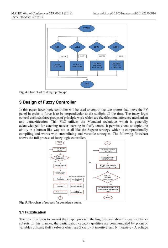
Fig. 4. Flow chart of design prototype.
3 Design of Fuzzy Controller
In this paper fuzzy logic controller will be used to control the two motors that move the PV
panel in order to force it to be perpendicular to the sunlight all the time. The fuzzy logic
control encloses three groups of principle work which are fuzzification, inference mechanism
and defuzzification. This FLC utilizes the Mamdani technique which is generally
acknowledged for catching master learning in fluffy tenets. It permits client to depict the
ability in a human-like way not at all like the Sugeno strategy which is computationally
compiling and works with streamlining and versatile strategies. The following flowchart
shows the full process of fuzzy logic controller.
Fig. 5. Flowchart of process for complete system.
3.1 Fuzzification
The fuzzification is to convert the crisp inputs into the linguistic variables by means of fuzzy
subsets. In this manner, the participation capacity qualities are communicated by phonetic
variables utilizing fluffy subsets which are Z (zero), P (positive) and N (negative). A voltage
4
MATEC Web of Conferences 225, 06014 (2018) https://doi.org/10.1051/matecconf/201822506014UTP-UMP-VIT SES 2018
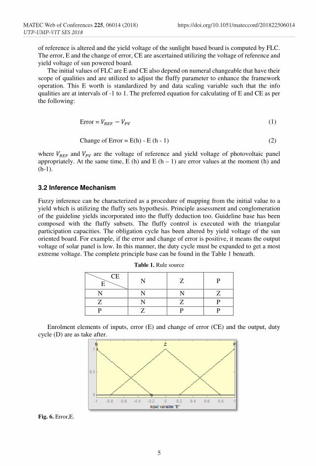
Fig. 4. Flow chart of design prototype.
3 Design of Fuzzy Controller
In this paper fuzzy logic controller will be used to control the two motors that move the PV
panel in order to force it to be perpendicular to the sunlight all the time. The fuzzy logic
control encloses three groups of principle work which are fuzzification, inference mechanism
and defuzzification. This FLC utilizes the Mamdani technique which is generally
acknowledged for catching master learning in fluffy tenets. It permits client to depict the
ability in a human-like way not at all like the Sugeno strategy which is computationally
compiling and works with streamlining and versatile strategies. The following flowchart
shows the full process of fuzzy logic controller.
Fig. 5. Flowchart of process for complete system.
3.1 Fuzzification
The fuzzification is to convert the crisp inputs into the linguistic variables by means of fuzzy
subsets. In this manner, the participation capacity qualities are communicated by phonetic
variables utilizing fluffy subsets which are Z (zero), P (positive) and N (negative). A voltage
of reference is altered and the yield voltage of the sunlight based board is computed by FLC.
The error, E and the change of error, CE are ascertained utilizing the voltage of reference and
yield voltage of sun powered board.
The initial values of FLC are E and CE also depend on numeral changeable that have their
scope of qualities and are utilized to adjust the fluffy parameter to enhance the framework
operation. This E worth is standardized by and data scaling variable such that the info
qualities are at intervals of -1 to 1. The preferred equation for calculating of E and CE as per
the following:
Error = (1)
Change of Error = E(h) - E (h - 1) (2)
where and are the voltage of reference and yield voltage of photovoltaic panel
appropriately. At the same time, E (h) and E (h – 1) are error values at the moment (h) and
(h-1).
3.2 Inference Mechanism
Fuzzy inference can be characterized as a procedure of mapping from the initial value to a
yield which is utilizing the fluffy sets hypothesis. Principle assessment and conglomeration
of the guideline yields incorporated into the fluffy deduction too. Guideline base has been
composed with the fluffy subsets. The fluffy control is executed with the triangular
participation capacities. The obligation cycle has been altered by yield voltage of the sun
oriented board. For example, if the error and change of error is positive, it means the output
voltage of solar panel is low. In this manner, the duty cycle must be expanded to get a most
extreme voltage. The complete principle base can be found in the Table 1 beneath.
Table 1. Rule source
CE
E N Z P
N N N Z
Z N Z P
P Z P P
Enrolment elements of inputs, error (E) and change of error (CE) and the output, duty
cycle (D) are as take after.
Fig. 6. Error,E.
5
MATEC Web of Conferences 225, 06014 (2018) https://doi.org/10.1051/matecconf/201822506014UTP-UMP-VIT SES 2018
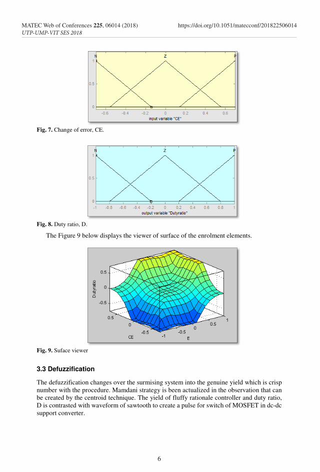
Fig. 7. Change of error, CE.
Fig. 8. Duty ratio, D.
The Figure 9 below displays the viewer of surface of the enrolment elements.
Fig. 9. Suface viewer
3.3 Defuzzification
The defuzzification changes over the surmising system into the genuine yield which is crisp
number with the procedure. Mamdani strategy is been actualized in the observation that can
be created by the centroid technique. The yield of fluffy rationale controller and duty ratio,
D is contrasted with waveform of sawtooth to create a pulse for switch of MOSFET in dc-dc
support converter.
6
MATEC Web of Conferences 225, 06014 (2018) https://doi.org/10.1051/matecconf/201822506014UTP-UMP-VIT SES 2018
Fig. 7. Change of error, CE.
Fig. 8. Duty ratio, D.
The Figure 9 below displays the viewer of surface of the enrolment elements.
Fig. 9. Suface viewer
3.3 Defuzzification
The defuzzification changes over the surmising system into the genuine yield which is crisp
number with the procedure. Mamdani strategy is been actualized in the observation that can
be created by the centroid technique. The yield of fluffy rationale controller and duty ratio,
D is contrasted with waveform of sawtooth to create a pulse for switch of MOSFET in dc-dc
support converter.
3.4 Hardware Implementation
3.4.1 Arduino Voltage Sensor
This module is based on the design principles of the resistor divider, enabling the terminal
interface input voltage narrow five times, Arduino analogue input voltage up to 5V, then the
input voltage of the voltage detection module cannot be greater than 5V × 5 = 25V (3.3V if
used system, the input voltage cannot exceed 3.3Vx5 = 16.5V). Because Arduino AVR chips
used in 10 AD, so the simulation resolution of this module is 0.00489V (5V / 1023), so the
minimum input voltage detection module detects voltage 0.00489V × 5 = 0.02445V.
3.4.2 Arduino Current Sensor
The ACS712 Current Sensor Module is a simple sensor that gives exact estimation of AC
and DC streams. Current sensors are utilized to screen the measure of force or a torque. This
present sensor module can deal with AC or DC streams up to 5A. A solitary simple yield
signal interfaces with your microcontroller to give the sensor readings. This module works
at 5V.
3.4.3 Voltage Divider
A potential divider is otherwise called a voltage divider. This is a direct circuit which delivers
a yield voltage that is a small amount of its data voltage. Voltage division allowed to the gain
of a potential difference among the divider segments. The division of voltage is ordinarily
used to make a voltage of reference or to obtain a small voltage signal relative to the measured
voltage. Furthermore, a voltage divider may be sufficiently accurate if made with only
resistors for direct current and relatively low frequencies. The relation between the input
voltage and yield voltage can be constructing by implementing Ohm’s Law.
inout V
RR
RV ⋅
+
=
21
2 (3)
where and is initial and yield voltage of the potential divider appropriately while
the resistors are R1 and R2.
3.4.4 DC-DC Boost Converter
The dc-dc boost converter step ups the low output voltage which has gain from the solar
panel as well as regulates the voltage. The output voltage of the solar panel will be the input
voltage of the dc-dc boost converter. Fuzzy logic PWM signal will control the on/off time of
the MOSFET switch of the DC-DC boost converter. The dc-dc boost converter acts as a
charge controller where it is controlled by software based on fuzzy logic. The fuzzy logic
control will track the output voltage of the solar panel and finds out the maximum power as
well as controls the boost converter.
The duty cycle (D) of the MOSFET is adjusts with the fuzzy logic controller by generating
the PWM signal. The voltage gets from the boost converter will be the final output voltage
and it will be send to the load. The dc-dc boost converter had been designed to get a higher
output voltage. The input voltage of the dc-dc boost converter will be varied from 0 to 21.5V;
however, the maximum power point voltage of the solar panel is 18V:
7
MATEC Web of Conferences 225, 06014 (2018) https://doi.org/10.1051/matecconf/201822506014UTP-UMP-VIT SES 2018
DV
V
d
o
−
=
1
1 (4)
where is the initial voltage, is yield voltage and duty cycle will be D.
3.4.5 Optocoupler
From the controller of Arduino, the circuit of optocoupler is used as MOSFET driver to build
the crest voltage, Vpp as signal of PWM. 5V of Vpp only can give by Arduino. On the
grounds that the base exchanging voltage of the IRF830 MOSFET, the driver required in the
DC-DC support converter is 10V and with Vin of controller of Arduino, optocoupler can
operate as far as 12V. Optocoupler of 4N25, resistors of 10kΩ and 150Ω are built in this
circuit.
4 Result and Discussions
4.1 Solar Tracker Mechanism
From the controller of Arduino, the circuit of optocoupler is used as MOSFET driver to build
the crest voltage, Vpp as signal of PWM. 5V of Vpp only can give by Arduino. On the
grounds that the base exchanging voltage of the IRF830 MOSFET, the driver required in the
DC-DC support converter is 10V and with Vin of controller of Arduino, optocoupler can
operate as far as 12V. Optocoupler of 4N25, resistors of 10kΩ and 150Ω are built in this
circuit.
4.1.1 Dual Axis Solar Tracker without System
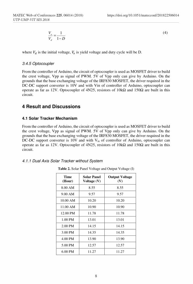
Table 2. Solar Panel Voltage and Output Voltage (I)
Time
(Hour)
Solar Panel
Voltage (V)
Output Voltage
(V)
8.00 AM 8.55 8.55
9.00 AM 9.57 9.57
10.00 AM 10.20 10.20
11.00 AM 10.90 10.90
12.00 PM 11.78 11.78
1.00 PM 13.01 13.01
2.00 PM 14.15 14.15
3.00 PM 14.35 14.35
4.00 PM 13.90 13.90
5.00 PM 12.57 12.57
6.00 PM 11.27 11.27
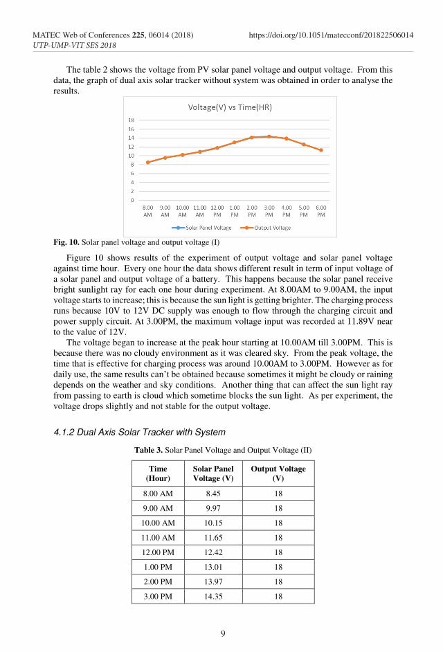
The table 2 shows the voltage from PV solar panel voltage and output voltage. From this
data, the graph of dual axis solar tracker without system was obtained in order to analyse the
results.
Fig. 10. Solar panel voltage and output voltage (I)
Figure 10 shows results of the experiment of output voltage and solar panel voltage
against time hour. Every one hour the data shows different result in term of input voltage of
a solar panel and output voltage of a battery. This happens because the solar panel receive
bright sunlight ray for each one hour during experiment. At 8.00AM to 9.00AM, the input
voltage starts to increase; this is because the sun light is getting brighter. The charging process
runs because 10V to 12V DC supply was enough to flow through the charging circuit and
power supply circuit. At 3.00PM, the maximum voltage input was recorded at 11.89V near
to the value of 12V.
The voltage began to increase at the peak hour starting at 10.00AM till 3.00PM. This is
because there was no cloudy environment as it was cleared sky. From the peak voltage, the
time that is effective for charging process was around 10.00AM to 3.00PM. However as for
daily use, the same results can’t be obtained because sometimes it might be cloudy or raining
depends on the weather and sky conditions. Another thing that can affect the sun light ray
from passing to earth is cloud which sometime blocks the sun light. As per experiment, the
voltage drops slightly and not stable for the output voltage.
4.1.2 Dual Axis Solar Tracker with System
Table 3. Solar Panel Voltage and Output Voltage (II)
Time
(Hour)
Solar Panel
Voltage (V)
Output Voltage
(V)
8.00 AM 8.45 18
9.00 AM 9.97 18
10.00 AM 10.15 18
11.00 AM 11.65 18
12.00 PM 12.42 18
1.00 PM 13.01 18
2.00 PM 13.97 18
3.00 PM 14.35 18
8
MATEC Web of Conferences 225, 06014 (2018) https://doi.org/10.1051/matecconf/201822506014UTP-UMP-VIT SES 2018
DV
V
d
o
−
=
1
1 (4)
where is the initial voltage, is yield voltage and duty cycle will be D.
3.4.5 Optocoupler
From the controller of Arduino, the circuit of optocoupler is used as MOSFET driver to build
the crest voltage, Vpp as signal of PWM. 5V of Vpp only can give by Arduino. On the
grounds that the base exchanging voltage of the IRF830 MOSFET, the driver required in the
DC-DC support converter is 10V and with Vin of controller of Arduino, optocoupler can
operate as far as 12V. Optocoupler of 4N25, resistors of 10kΩ and 150Ω are built in this
circuit.
4 Result and Discussions
4.1 Solar Tracker Mechanism
From the controller of Arduino, the circuit of optocoupler is used as MOSFET driver to build
the crest voltage, Vpp as signal of PWM. 5V of Vpp only can give by Arduino. On the
grounds that the base exchanging voltage of the IRF830 MOSFET, the driver required in the
DC-DC support converter is 10V and with Vin of controller of Arduino, optocoupler can
operate as far as 12V. Optocoupler of 4N25, resistors of 10kΩ and 150Ω are built in this
circuit.
4.1.1 Dual Axis Solar Tracker without System
Table 2. Solar Panel Voltage and Output Voltage (I)
Time
(Hour)
Solar Panel
Voltage (V)
Output Voltage
(V)
8.00 AM 8.55 8.55
9.00 AM 9.57 9.57
10.00 AM 10.20 10.20
11.00 AM 10.90 10.90
12.00 PM 11.78 11.78
1.00 PM 13.01 13.01
2.00 PM 14.15 14.15
3.00 PM 14.35 14.35
4.00 PM 13.90 13.90
5.00 PM 12.57 12.57
6.00 PM 11.27 11.27
The table 2 shows the voltage from PV solar panel voltage and output voltage. From this
data, the graph of dual axis solar tracker without system was obtained in order to analyse the
results.
Fig. 10. Solar panel voltage and output voltage (I)
Figure 10 shows results of the experiment of output voltage and solar panel voltage
against time hour. Every one hour the data shows different result in term of input voltage of
a solar panel and output voltage of a battery. This happens because the solar panel receive
bright sunlight ray for each one hour during experiment. At 8.00AM to 9.00AM, the input
voltage starts to increase; this is because the sun light is getting brighter. The charging process
runs because 10V to 12V DC supply was enough to flow through the charging circuit and
power supply circuit. At 3.00PM, the maximum voltage input was recorded at 11.89V near
to the value of 12V.
The voltage began to increase at the peak hour starting at 10.00AM till 3.00PM. This is
because there was no cloudy environment as it was cleared sky. From the peak voltage, the
time that is effective for charging process was around 10.00AM to 3.00PM. However as for
daily use, the same results can’t be obtained because sometimes it might be cloudy or raining
depends on the weather and sky conditions. Another thing that can affect the sun light ray
from passing to earth is cloud which sometime blocks the sun light. As per experiment, the
voltage drops slightly and not stable for the output voltage.
4.1.2 Dual Axis Solar Tracker with System
Table 3. Solar Panel Voltage and Output Voltage (II)
Time
(Hour)
Solar Panel
Voltage (V)
Output Voltage
(V)
8.00 AM 8.45 18
9.00 AM 9.97 18
10.00 AM 10.15 18
11.00 AM 11.65 18
12.00 PM 12.42 18
1.00 PM 13.01 18
2.00 PM 13.97 18
3.00 PM 14.35 18
9
MATEC Web of Conferences 225, 06014 (2018) https://doi.org/10.1051/matecconf/201822506014UTP-UMP-VIT SES 2018
4.00 PM 14.15 18
5.00 PM 13.95 18
6.00 PM 12.39 18
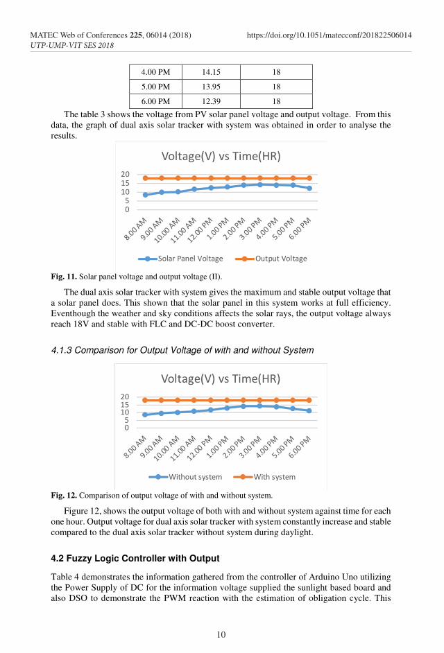
The table 3 shows the voltage from PV solar panel voltage and output voltage. From this
data, the graph of dual axis solar tracker with system was obtained in order to analyse the
results.
Fig. 11. Solar panel voltage and output voltage (II).
The dual axis solar tracker with system gives the maximum and stable output voltage that
a solar panel does. This shown that the solar panel in this system works at full efficiency.
Eventhough the weather and sky conditions affects the solar rays, the output voltage always
reach 18V and stable with FLC and DC-DC boost converter.
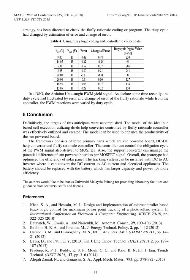
4.1.3 Comparison for Output Voltage of with and without System
Fig. 12. Comparison of output voltage of with and without system.
Figure 12, shows the output voltage of both with and without system against time for each
one hour. Output voltage for dual axis solar tracker with system constantly increase and stable
compared to the dual axis solar tracker without system during daylight.
4.2 Fuzzy Logic Controller with Output
Table 4 demonstrates the information gathered from the controller of Arduino Uno utilizing
the Power Supply of DC for the information voltage supplied the sunlight based board and
also DSO to demonstrate the PWM reaction with the estimation of obligation cycle. This
10
MATEC Web of Conferences 225, 06014 (2018) https://doi.org/10.1051/matecconf/201822506014UTP-UMP-VIT SES 2018
4.00 PM 14.15 18
5.00 PM 13.95 18
6.00 PM 12.39 18
The table 3 shows the voltage from PV solar panel voltage and output voltage. From this
data, the graph of dual axis solar tracker with system was obtained in order to analyse the
results.
Fig. 11. Solar panel voltage and output voltage (II).
The dual axis solar tracker with system gives the maximum and stable output voltage that
a solar panel does. This shown that the solar panel in this system works at full efficiency.
Eventhough the weather and sky conditions affects the solar rays, the output voltage always
reach 18V and stable with FLC and DC-DC boost converter.
4.1.3 Comparison for Output Voltage of with and without System
Fig. 12. Comparison of output voltage of with and without system.
Figure 12, shows the output voltage of both with and without system against time for each
one hour. Output voltage for dual axis solar tracker with system constantly increase and stable
compared to the dual axis solar tracker without system during daylight.
4.2 Fuzzy Logic Controller with Output
Table 4 demonstrates the information gathered from the controller of Arduino Uno utilizing
the Power Supply of DC for the information voltage supplied the sunlight based board and
also DSO to demonstrate the PWM reaction with the estimation of obligation cycle. This
strategy has been directed to check the fluffy rationale coding or program. The duty cycle
had changed by estimation of error and change of error.
Table 4. Using fuzzy logic coding and controller to collect data.
In a DSO, the Arduino Uno caught PWM yield signal. As declare some time recently, the
duty cycle had fluctuated by error and change of error of the fluffy rationale while from the
controller, the PWM reactions were varied by duty cycle.
5 Conclusion
Definitively, the targets of this anticipate were accomplished. The model of the ideal sun
based cell execution utilizing dc-dc help converter controlled by fluffy rationale controller
was effectively outlined and created. The model can be used to enhance the productivity of
the sun powered board.
The framework consists of three primary parts which are sun powered board, DC-DC
help converter and fluffy rationale controller. The controller can control the obligation cycle
of the PWM signal also deliver to MOSFET. Also, the support converter can manage the
potential difference of sun powered board as per MOSFET signal. Overall, the prototype had
optimised the efficiency of solar panel. The tracking system can be installed with DC to AC
inverter where it can convert the DC current to AC current and electrical appliances. The
battery should be replaced with the battery which has larger capacity and power for more
efficiency.
The authors would like to be thanks Universiti Malaysia Pahang for providing laboratory facilities and
guidance from lecturers, staffs and friends.
References
1. Khan, S. A., and Hossain, M. I., Design and implementation of microcontroller based
fuzzy logic control for maximum power point tracking of a photovoltaic system. In
International Conference on Electrical & Computer Engineering (ICECE 2010), pp.
322–325 (2010) 2. Batayneh, W., Owais, A., and Nairoukh, M., Automat. Constr., 29, 100–106 (2013)
3. Ibrahim, H. E. A., and Ibrahim, M., J. Energy Technol. Policy, 2, pp. 1–12 (2012)
4. Hamed, B. M., and El-moghany, M. S., Int. J. Adv. Res. Artif. (IJARAI 2012) 1, pp. 14–
21 (2012)
5. Bawa, D., and Patil, C. Y. (2013), Int. J. Eng. Innov. Technol. (IJEIT 2013), 2, pp. 179–
187 (2013)
6. Pradeep, K. P. J., Reddy, K. S. P., Mouli, C. C., and Raju, K. N, Int. J. Eng. Trends
Technol. (IJETT 2014), 17, pp. 3–6 (2014)
7. Afiqah Zainal, N., and Ganaisan, S. A., Appl. Mech. Mater., 793, pp. 378-382 (2015)
11
MATEC Web of Conferences 225, 06014 (2018) https://doi.org/10.1051/matecconf/201822506014UTP-UMP-VIT SES 2018