Effect of Glass Ceiling on Women's Career Development in Banks ...
Upload
khangminh22Category
view
1download
0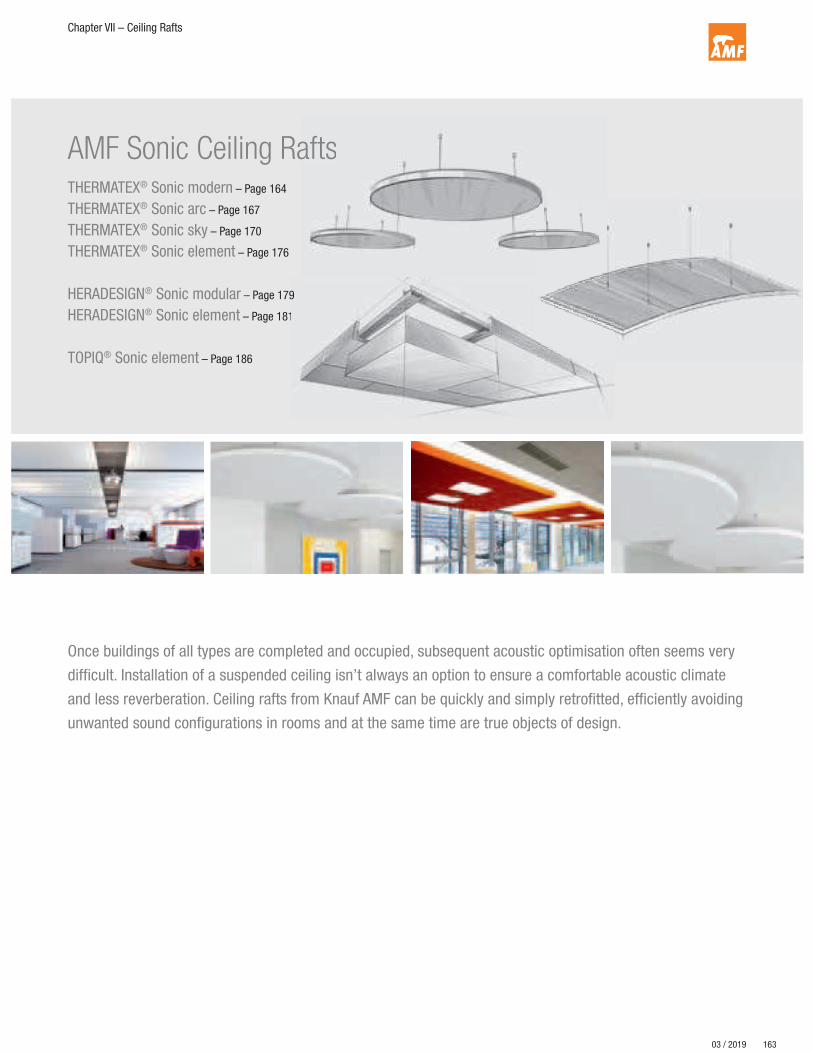
163
Chapter VII – Ceiling Rafts
® kann der Schall im Raum gezielt gedämpft und somit die Raum-
AMF Sonic Ceiling RaftsTHERMATEX® Sonic modern – Page 164
THERMATEX® Sonic arc – Page 167
THERMATEX® Sonic sky – Page 170
THERMATEX® Sonic element – Page 176
HERADESIGN® Sonic modular – Page 179
HERADESIGN® Sonic element – Page 181
TOPIQ® Sonic element – Page 186
afts
Once buildings of all types are completed and occupied, subsequent acoustic optimisation often seems very
difficult. Installation of a suspended ceiling isn’t always an option to ensure a comfortable acoustic climate
and less reverberation. Ceiling rafts from Knauf AMF can be quickly and simply retrofitted, efficiently avoiding
unwanted sound configurations in rooms and at the same time are true objects of design.
9
1
03 / 2019
164
Chapter VII – Ceiling Rafts
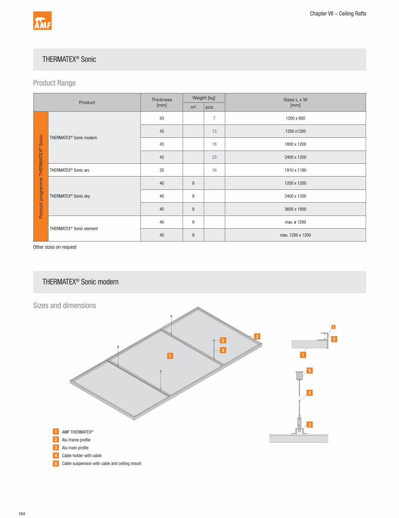
AMF THERMATEX®
Alu-frame profile
Alu main profile
Cable holder with cable
Cable suspension with cable and ceiling mount
Sizes and dimensions
1
11
2
22
3
3
4
4
4
5
5
5
THERMATEX® Sonic
THERMATEX® Sonic modern
Other sizes on request
ProductThickness
[mm]
Weight [kg] Sizes L x W
[mm]m² pcs.
Pro
duct
pro
gra
mm
e T
HE
RM
AT
EX
® S
on
ic THERMATEX® Sonic modern
43 7 1200 x 600
43 13 1200 x1200
43 18 1800 x 1200
43 23 2400 x 1200
THERMATEX® Sonic arc 35 16 1910 x 1180
THERMATEX® Sonic sky
40 8 1200 x 1200
40 8 2400 x 1200
40 8 3600 x 1800
THERMATEX® Sonic element
40 9 max. ø 1200
40 9 max. 1200 x 1200
Product Range

165
Chapter VII – Ceiling Rafts
Section THERMATEX® Sonic modern
The raft is suspended by four cables. The suspension system enables
the raft to be quickly and exactly installed and aligned. Every raft is
delivered with suspension system.
They consist of:
• Cable hanger with cable holder
• Cable (standard length 1.0 m, other cable lengths
and ceiling mounts on request)
• Ceiling mount
• Building material class:
A2-s1,d0 as per EN 13501-1
(or C-s1,d0 depending on printed motif)
• Sound absorption: EN ISO 354
• Humidity resistance: up to 90% relative humidity
• Frame colours: Alu anodised E6-EV1, white similar to RAL 9016,
other colours on request
• Surface: fleece-coated white or motif printed
43
Installation guidelines and advice
B
A
1. 2.
A B
A
M6
M13
The centres in both directions are transferred to the desired fixing positions.Fixing centres for sizes:
A B
1200 x 1200 mm 500 800
1200 x 1800 mm 700 800
1200 x 2400 mm 1000 800
Depending on the soffit material and type of fixing, drilling may be necessary. The included ceiling mounts feature an M6 internal thread for installation to the
ceiling (soffit). Suitable fixings should be chosen for the specific installation and
the type of soffit in consultation with the screw/plug manufacturer.
Possible fixings: M6 bolt or appropriate screw and plug combination
3. 4.

166
Chapter VII – Ceiling Rafts
By releasing the clamping mechanism, the required suspension height can be set
exactly before installation.
To install the rafts, the mounting caps should be completely screwed into the
pre-installed ceiling fixings by two people. The raft should be supported equally
through all four cables, no loose cables are permitted.
The rafts must always be stored on a dry and flat surface and can either be
stacked (max 8 pieces) or stand on the long edge (no stacking permitted).
Mechanical stress (impacts etc.) can cause damage to the product.
During transport and installation of ceiling rafts, the rafts must always be carried
by two people. When removing the packaging and at all times when handling the
rafts, clean white cotton gloves should be worn. Ensure that only the frames of
the ceiling rafts are handled.
X X
7.
9. 10.
Finally, the entire ceiling raft is aligned
8.
X
Thread the cables with the unpressed end through the mounting cap. Subsequently, the cables are threaded through the adjustable, pre-installed cable
holders.
5. 6.
Installation guidelines and advice

167
Chapter VII – Ceiling Rafts
Sizes and dimensions
Section THERMATEX® Sonic arc convex
1910
1910
12
5
12
5
34
91
91
34
AMF THERMATEX®
Frame system 15 x 34 x 7 mm / size 1910 x 1180 mm, radius approx. 5.0 m
Cable holder with cable
Cross brace to fix cable hanger
Section THERMATEX® Sonic arc concave
Delivery
The raft is suspended by four cables. The suspension system enables
the raft to be quickly and exactly installed and aligned. Every raft is
delivered with suspension system.
They consist of:
• Cable hanger with cable holder
• Cable (standard length 1.0 m, other cable lengths
and ceiling mounts on request)
• Ceiling mount
Properties
• Sound absorption: EN ISO 354
• Humidity resistance: up to 90% relative humidity
• Depth: 91 mm
• Frame colours: white similar to RAL 9010,
anodised, all RAL colours on request
• Surface: fleece-coated (black, white, creme, silver,
other surfaces on request)
1
1
2
2
3
3
4
4
THERMATEX® Sonic arc

168
Chapter VII – Ceiling Rafts
Installation guidelines and advice
AB
BA
A
Fixing centres:
A = 900 mm
B = 600 mm
The centres in both directions are transferred to the desired fixing positions.
Depending on the soffit material and type of fixing, drilling may be necessary. The included ceiling mounts feature an M6 internal thread for installation to the
ceiling (soffit). Suitable fixings should be chosen for the specific installation and
the type of soffit in consultation with the screw/plug manufacturer.
Possible fixings:
M6 bolt or appropriate screw and plug combination
Thread the cables with the unpressed end through the mounting cap. Subsequently, the cables are threaded through the adjustable, pre-installed cable
holders.
1. 2.
3.
5.
4.
6.
M6
M13

169
Chapter VII – Ceiling Rafts
H
X
By releasing the clamping mechanism, the required suspension height can be set
exactly before installation.
To install the rafts, the mounting caps should be completely screwed into the
pre-installed ceiling fixings by two people.
Finally, the entire ceiling raft is aligned. The rafts should be supported equally through all four cables, no loose cables are
permitted.
The steps apply to both convex and concave ceiling rafts, regardless of the
version.
Fixing, installation and handling is exactly the same for convex and concave rafts.
The rafts must always be stored on a dry and flat surface and can either be
stacked (max 8 pieces) or stand on the long edge (no stacking permitted).
Mechanical stress (impacts etc.) can cause damage to the product.
During transport and installation of ceiling rafts, the rafts must always be carried
by two people. When removing the packaging and at all times when handling the
rafts, clean white cotton gloves should be worn. Ensure that only the frames of
the ceiling rafts are handled.
X X
7. 8.
9.
11.
10.
12.
Installation guidelines and advice

170
Chapter VII – Ceiling Rafts
11
10
9
8
7
5
6
12
13
143
1 2
5
4
15
Rahmenkonstruktion
mit Eckverbinder
Rahmenkonstruktion
mit flexiblem Eckverbinder
Tiles:
AMF THERMATEX® Acoustic alternative, elements as per System F
Main profile according to span table System F
Frame:
Aluminium L-Profile 40 x 30 mm
Corner connector
Adjustment screws
Splice
Hanger:
Slot nut
Lower cable holder
Cable
Upper cable holder
Ceiling mount
Cross bracing (for lengths over 3.00 m)
Angle bracket 50 x 50 x 1.75 mm
Screws 3.5 mm x 13.5 mm
Dimensions:
Length as per client requirements
Width dependent on tile size, max. 2500 mm
Profile Height [mm] Thickness [mm] Tile size [mm]
PQZ 19/50 50 0.5 300 x 1800
T 24/38 38 0.4 300 x 1500AW
längsseitigSK
stirnseitigGN
längsseitig
SK VT-S 15/24
Properties
• Building material class: A2-s1,d0 as per EN 13501-1
• Sound absorption: EN ISO 354
• Humidity resistance: up to 90% relative humidity
• Frame colours: Alu anodised E6-EV1, white similar to RAL 9016,
other colours on request
• Surface: THERMATEX® Alpha (black, white, creme, silver)
THERMATEX® Alpha HD fleece laminated (white)
• Edges: VT, AW, GN
Sizes and dimensions
Edge configuration (plank tiles)
Edge configuration (square tiles)
1
2
3
4
5
6
7
8
9
10
11
12
13
14
15
THERMATEX® Sonic sky
Profile dependent on selected tile type and tile size
Frame construction
with corner connectors
Frame construction
with corner connectors
AW
long side
SK
GN
long side
SK
short side
VT-S 15/24

171
Chapter VII – Ceiling Rafts
Installation guidelines and advice
A
AX
t
AXø d
1
15
B
A
A
X
A
A
B
Fixing centres:
B = 15 - 16 mm
A ≤ 1500 mm
X ≤ 150 mm (max. distance from perimeter)
H
H
Lower edge of soffit – lower edge of ceiling raft = H + 40 mm
The rafts must be suspended from the soffit by using approved fixings
(plugs, screws, wires, etc.). Each fixing (plug, screw) needs to be mechanically
pretested to a loading of 750N using appropriate testing equipment and
this testing should be documented. Additional loads such as light fittings,
signs, etc. have to be separately supported from the soffit using additional
means. Note that the requirements of EN 13964 section 5.3 (testing of metal
suspension and connecting components) should be observed.
Depending on the soffit material and type of fixing, drilling may be necessary.
The included ceiling mounts feature an M6 internal thread for installation to
the ceiling (soffit). Suitable fixings should be chosen for the specific installation
and the type of soffit in consultation with the screw/plug manufacturer.
Possible fixings: M6 bolt or appropriate screw and plug combination.
Profile holes:
ø d1 = 6,0 mm
t ≥ 12 mm
All suspension screw connections have to be secured with a chemical
screw-lock.
1. 2.
3.
5.
4.
6.
M6
M13

172
Chapter VII – Ceiling Rafts
H
Thread the cables with the unpressed end through the mounting cap. Subsequently, the cables are threaded through the adjustable, preinstalled
cable holders.
By releasing the clamping mechanism, the required suspension height can
be set exactly before installation.
The rafts should be supported equally through all four cables, no loose
cables are permitted.
Corner and splice cross bracing:
- Installation takes place after each element is installed.
- The cross braces are to be fixed across the full raft (same raft width across
the entire length)
- Exact lay out is required for a flawless joint pattern.
7. 8.
9.
11.
10.
12.
X
Installation guidelines and advice

173
Chapter VII – Ceiling Rafts
50 50
15
A
Cross bracing:
A ≤ 2000 mm
For rafts with a complete length of over 3.0 m, screw the reinforcement
profiles to the frame profile at regular intervals ≤ 2000 mm.
The necessary 50 x 50 x 15 x 1.75 mm angle brackets as well as the
3.5 x 13.5 mm screws are included in the delivery.
The cross profiles shown, including fixings, are not included in the standard
delivery.
AA
LQ
LS
2mm 2mm
X
LQ
Cross bracing:
LQ = 15 - 4 mm
A ≤ 2000 mm
Angle of cross bracing:
LS ~ 100 mm
13. 14.
15.
17.
16.
18.
Installation guidelines and advice

174
Chapter VII – Ceiling Rafts
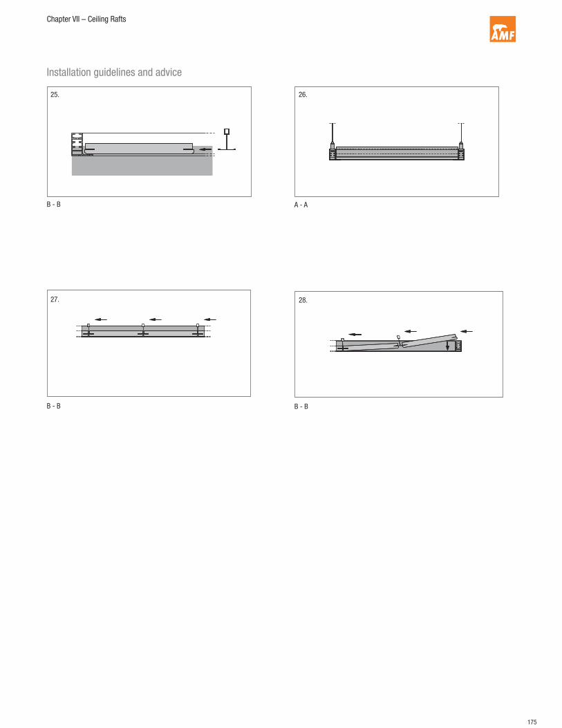
X
HD1 D2
D1 = D2 After installing the suspension (cable hanger to raft and ceiling mount
including cable), the suspension height can be checked and when
necessary corrected. The raft is then fixed on all hangers by two people.
The entire ceiling raft is then aligned. The raft should be supported equally through all four cables, no loose
cables are permitted.
AW
GN
X
The ceiling tiles are inserted. First tile
19. 20.
21.
23.
22.
24.
A
A
B
B
Installation guidelines and advice
175
Chapter VII – Ceiling Rafts
B - B A - A
B - B B - B
25. 26.
27. 28.
Installation guidelines and advice
176
Chapter VII – Ceiling Rafts
D= 1200
600
60
0
R= 424
R= 600
600300
30
0
300
60
0
1200
12
00
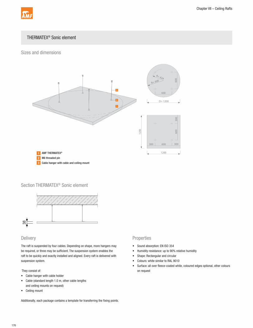
AMF THERMATEX®
M6 threaded pin
Cable hanger with cable and ceiling mount
Delivery
The raft is suspended by four cables. Depending on shape, more hangers may
be required, or three may be sufficient. The suspension system enables the
raft to be quickly and exactly installed and aligned. Every raft is delivered with
suspension system.
They consist of:
• Cable hanger with cable holder
• Cable (standard length 1.0 m, other cable lengths
and ceiling mounts on request)
• Ceiling mount
Additionally, each package contains a template for transferring the fixing points.
Properties
• Sound absorption: EN ISO 354
• Humidity resistance: up to 90% relative humidity
• Shape: Rectangular and circular
• Colours: white similar to RAL 9010
• Surface: all over fleece-coated white, coloured edges optional, other colours
on request
Section THERMATEX® Sonic element
38
Sizes and dimensions
1
2
3
THERMATEX® Sonic element

177
Chapter VII – Ceiling Rafts
Installation guidelines and advice
A
A
A A
4 x
4 x
M6
M13
The centres in both directions are transferred to the desired fixing positions.
The included template can be used for this.
The steps apply to both circular and square/rectangular ceiling rafts, regardless
of the version. The fixing centres for circular and square/rectangular rafts is
A = 600 mm.
Depending on the soffit material and type of fixing, drilling may be necessary. The included ceiling mounts feature an M6 internal thread for installation to the
ceiling (soffit). Suitable fixings should be chosen for the specific installation and
the type of soffit in consultation with the screw/plug manufacturer.
Possible fixings: M6 bolt or appropriate screw and plug combination.
The four pre-installed M6 threaded pins serve as fixing points. The cable hangers included in the delivery should be fully twisted on to these and
the cable threaded through.
A
1. 2.
3.
5.
4.
6.

178
Chapter VII – Ceiling Rafts
X
By releasing the clamping mechanism, the required suspension height can be set
exactly before installation.
After installing the suspension (cable hanger to raft and ceiling mount including
cable), the suspension height can be checked and when necessary corrected.
The raft is then fixed on all hangers by two people.
The entire ceiling raft is then aligned. The cable hangers can be adjusted at any time. By releasing the clamping
mechanism, the required suspension height can be set exactly.
The raft should be supported equally through all four cables, no loose cables are
permitted.
X X
The rafts must always be stored on a dry and flat surface and can either be
stacked (max 8 pieces) or stand on the long edge (no stacking permitted).
Mechanical stress (impacts etc.) can cause damage to the product. During
transport and installation of ceiling rafts, the rafts must always be carried by two
people. When removing the packaging and at all times when handling the rafts,
clean white cotton gloves should be worn. Ensure that only the frames of the
ceiling rafts are handled.
7.
9.
11.
8.
10.
12.
40
H
Installation guidelines and advice

179
Chapter VII – Ceiling Rafts
HERADESIGN® Sonic
ProductThickness
[mm]
Weight
[kg/pcs.]
Edge
configuration
System
component
Size L x W x H
[mm]
Pro
duct
pro
gra
mm
e H
ER
AD
ES
IGN
® S
onic
mod
ula
r
HERADESIGN® superfine /
HERADESIGN® superfine A225
super
fine
5.8
super
fine
A2
8.8
AK-01
1) Corner component 600 x 600 x 125
4.9 7.8 2) Side component 600 600 x 600 x 125
9.8 15.5 3) Side component 1200 1200 x 600 x 125
4.1 6.5 4) Standard 600 600 x 600
8.1 13.0 5) Standard 1200 1200 x 600
HERADESIGN® fine /
HERADESIGN® fine A225 fi
ne
6.3
fine
A2
9.3
AK-01
1) Corner component 600 x 600 x 125
5.4 8.2 2) Side component 600 600 x 600 x 125
10.8 16.2 3) Side component 1200 1200 x 600 x 125
4.5 6.8 4) Standard 600 600 x 600
8.9 13.7 5) Standard 1200 1200 x 600
Edge Configurations
AK 01
Product Range
ProductThickness
[mm]
Weight
[kg/ceiling raft]
Edge
configuration
Size L x W x H
[mm]
HER
AD
ES
IGN
®
Son
ic e
lem
ent
HERADESIGN® superfine 2553.70
AK-012400 x 1200 x 125
27.10 1200 x 1200 x 125
HERADESIGN® fine 2557.90
AK-012400 x 1200 x 125
29.20 1200 x 1200 x 125
HERADESIGN® Sonic modular
Sizes and dimensions
Detail A,
Grid slightly
indented (20 mm)
600-25-20-30 = 535 mm
Detail A Suspension height
Module end 535 mm Module middle 600 mm Module edge 535 mm
Tile size 600 mmTile size 600 mmTile size 600 mm
180
Chapter VII – Ceiling Rafts
• Installation of primary profiles: centres according to System
B 2.1/B 2.2. In the long direction, set one primary profile into each
corner of the upstand of the ceiling raft.
• Distribute main profiles symmetrically in the module, a main profile in
each corner of the upstand.
• A 10 mm gap should be ensured between the inside of the upstand and
the cross profile.
• Screw patterns see chapter B 2.1/B 2.2.
• Begin tile installation from the middle of the raft.
• Push together and align acoustic tiles – plank formats, across the profi-
le direction and fix to the main profiles with HERADESIGN® screws. For
each tile width and centre distance, two screws are required. For indoor
swimming pools and vibrating constructions three screws.
• Note: Observe the necessary corrosion protection requirements.
• Square tiles: Observe the installation direction marked on the reverse of
the tile when installing the tiles.
• Cross joints: four tile corners meet at one point, which means increased
accuracy is required when installing!!
• Screws: HERADESIGN® screws. Corrosion protection must be determined
by the prevailing room conditions. The screw heads must be set flush
with the tile surface and when coloured HERADESIGN® screws are not
used, the screw heads should be painted after installation with the
delivered or equivalent paint.
• Acoustic overlays or films are installed step by step with the installation
of the acoustic tiles. A PE film with a thickness of up to 30 μm does
not affect the sound absorption of the underlying absorber and is
recommended as trickle protection for mineral wool overlays
• Damaged or soiled tiles or tiles with colour deviations may not be
installed. Tiles with edge configurations for T-profile installations can
not be used, as the tile size is smaller than the module.
• Seek professional advice where necessary.
For the installation requirements see DIN 18168 “Lightweight ceiling
linings and suspended ceilings”, as well as EN 13964 “Suspended
ceilings – requirements and test methods”.
Installation guidelines and advice
Sizes and dimensions
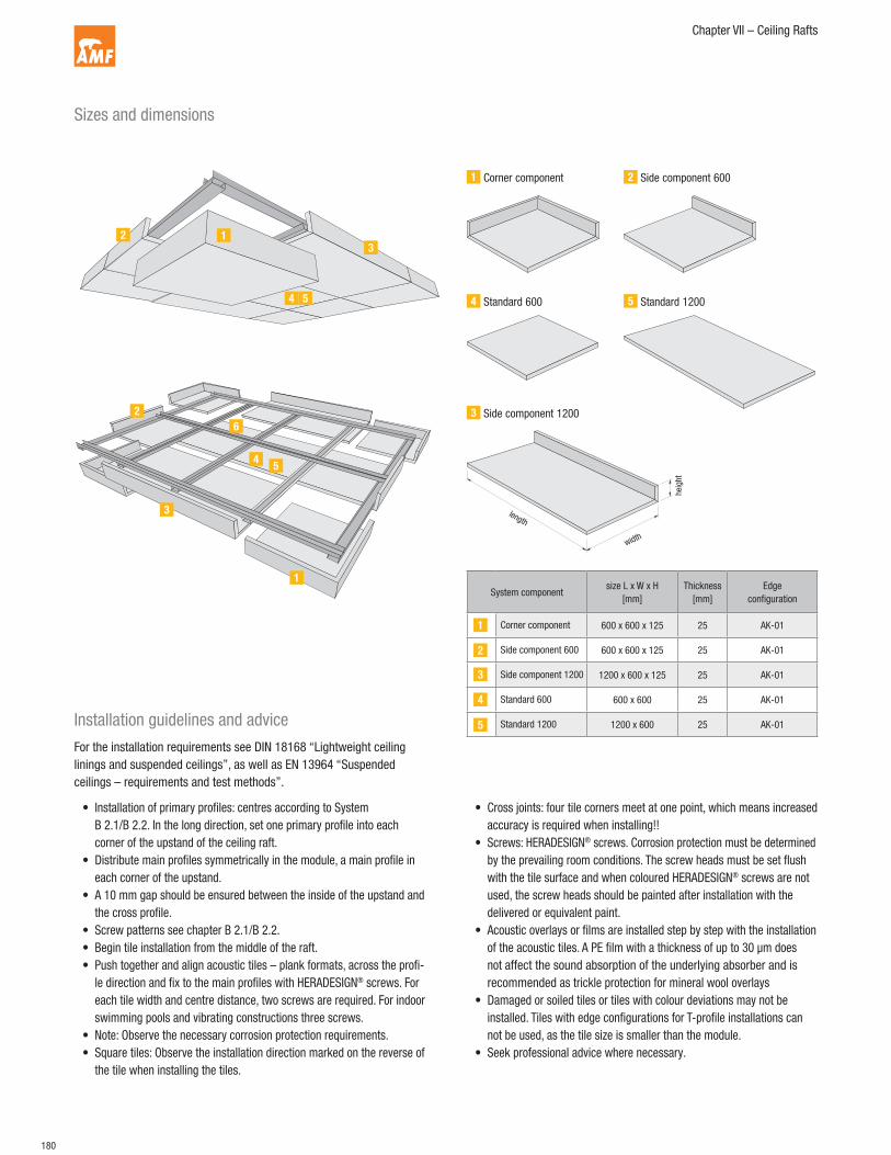
123
4 5
1
2
3
45
6
1 Corner component 2 Side component 600
3 Side component 1200
4 Standard 600 5 Standard 1200
length
width
hei
ght
System componentsize L x W x H
[mm]
Thickness
[mm]
Edge
configuration
Corner component 600 x 600 x 125 25 AK-01
Side component 600 600 x 600 x 125 25 AK-01
Side component 1200 1200 x 600 x 125 25 AK-01
Standard 600 600 x 600 25 AK-01
Standard 1200 1200 x 600 25 AK-01
1
2
3
4
5

181
Chapter VII – Ceiling Rafts
HERADESIGN® Sonic element 1200/2400
Sizes and dimensions
Delivery
Properties
The set delivered consists of:
• Element A with preassembled grid structure and hanger base
• Element B with preassembled grid structure and hanger base
• 3 x connecting elements with the appropriate number of connecting
screws, supplied in a plastic bag.
• 4 x individual hangers (hanger height < 500 mm) in a plastic bag
• Elements A and B from different sets are not compatible and should
only be used as part of the set provided.
• The ceiling raft set is not suitable for use in indoor swimming pools
or spas.
• Surface: The surface layer consists of biologically recommended,
magnesite bonded wood wool acoustic tiles.
• Colour: The standard colours of HERADESIGN® ceiling tiles are white,
similar to RAL 9010 or beige, natural tone 13. Other colours
(RAL, NCS, StoColor) available on request.
1 x element A 1 x element B 1 x drilling template
4 x individual hangers 20 x screws
1 x connection component C
2 x connection components D
Product Size L x W x HWeight
kg/ceiling raft
HERADESIGN® superfine2400 x 1200 x 125 mm
tile thickness 25 mm
53.70
HERADESIGN® fine 57.90

182
Chapter VII – Ceiling Rafts
Installation guidelines and advice
Ensure precise alignment
For the installation requirements see DIN 18168 “Lightweight ceiling linings and suspended ceilings”,
as well as EN 13964 “Suspended ceilings – requirements and test methods”.
Element A
Element A
Element B
Element B
Element A
Element B
Element A
Install connection component C with 6 screws.
Carefully unpack the elements
Put elements together
Install connection components D, each with 5 screws.

183
Chapter VII – Ceiling Rafts
1
32
4 Axis
180°
Install the 4 hangers.Fix connection component D with an additional 2 screws, horizontally.
Remove the drilling template from the packaging. Determine the axis for the ceiling raft. Lay the drilling template on the axis and
mark the holes to be drilled for hangers 1 and 2.
Axis
2
1
Turn the drilling template 180° on the axis and mark the holes to be drilled for
hangers 3 and 4. Install upper hanger parts for hangers 1 to 4.
Install the ceiling raft. Lift the ceiling raft, holding it level and fix the upper
hangers to the lower parts.
184
Chapter VII – Ceiling Rafts
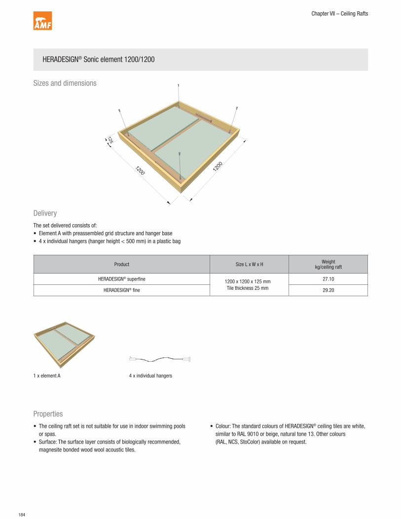
HERADESIGN® Sonic element 1200/1200
Delivery
Properties
The set delivered consists of:
• Element A with preassembled grid structure and hanger base
• 4 x individual hangers (hanger height < 500 mm) in a plastic bag
• The ceiling raft set is not suitable for use in indoor swimming pools
or spas.
• Surface: The surface layer consists of biologically recommended,
magnesite bonded wood wool acoustic tiles.
• Colour: The standard colours of HERADESIGN® ceiling tiles are white,
similar to RAL 9010 or beige, natural tone 13. Other colours
(RAL, NCS, StoColor) available on request.
1 x element A 4 x individual hangers
Product Size L x W x HWeight
kg/ceiling raft
HERADESIGN® superfine1200 x 1200 x 125 mm
Tile thickness 25 mm
27.10
HERADESIGN® fine 29.20
Sizes and dimensions

185
Chapter VII – Ceiling Rafts
Screw the enclosed cable hanger onto the hanger base.Carefully unpack the elements.
Mark the holes on the soffit at the correct centres and drill according to the plugs
being used. Fix the upper hanger parts using suitable screws for the underlying
surface.
Install the ceiling raft. Lift the ceiling raft, holding it level and fix the upper
hangers to the lower parts.
Axis
23
4
1
Installation guidelines and advice
For the installation requirements see DIN 18168 “Lightweight ceiling linings and suspended ceilings”,
as well as EN 13964 “Suspended ceilings – requirements and test methods”.
186
Chapter VII – Ceiling Rafts
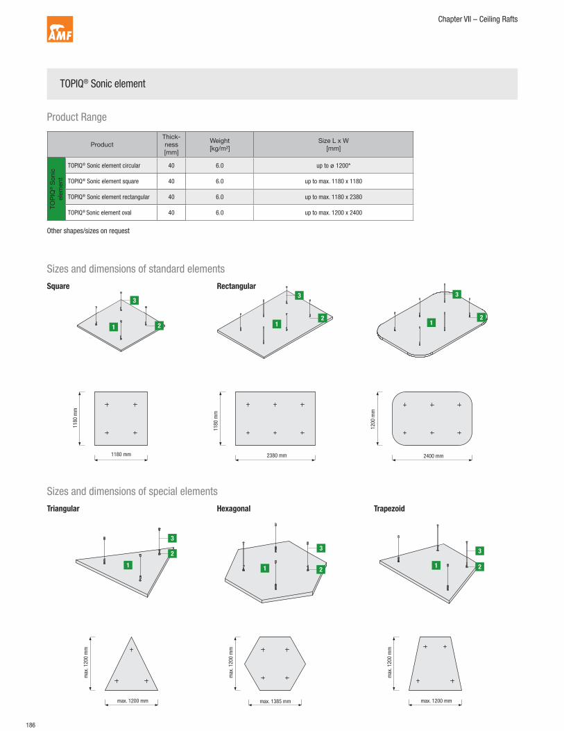
2380 mm
11
80
mm
Square Rectangular
Sizes and dimensions of standard elements
Sizes and dimensions of special elements
TOPIQ® Sonic element
Triangular Hexagonal Trapezoid
1180 mm
11
80
mm
2400 mm
12
00
mm
1
3
2
1
3
2
1
3
21
3
2
1
3
21
3
2
Product Range
Product
Thick-
ness
[mm]
Weight
[kg/m²]
Size L x W
[mm]
TO
PIQ
® S
on
ic
ele
men
t
TOPIQ® Sonic element circular 40 6.0 up to ø 1200*
TOPIQ® Sonic element square 40 6.0 up to max. 1180 x 1180
TOPIQ® Sonic element rectangular 40 6.0 up to max. 1180 x 2380
TOPIQ® Sonic element oval 40 6.0 up to max. 1200 x 2400
Other shapes/sizes on request

187
Chapter VII – Ceiling Rafts
1
3
2
2400 mm
1
3
2
1
3
2
Circular Oval
Technical Properties
Suspension
• Sound absorption: EN ISO 354
• Humidity resistance: up to 95% relative humidity
• Shapes / sizes: Circular up to ø 1200 mm
Square up to max. 1180 x 1180 mm
Rectangular up max. 1180 x 2380 mm
Oval up to max. 1200 x 2400 mm
• Special shapes/sizes: Triangular, hexagonal, trapezoid
Other shapes/sizes on request
• Thickness Approx. 40 mm
• Weight per raft: Approx. 6.0 kg/m² (incl. suspension)
Every ceiling raft is delivered including spiral anchors (fixing to raft). The
rafts are suspended by cables, attached to the spiral anchors with hooks.
AMF TOPIQ® Sonic element
Spiral anchor
Cable suspension with hooks, cable and ceiling mount
1
2
3
1
3
2

188
Chapter VII – Ceiling Rafts
Installation advice
Fixing points for square/rectangular ceiling rafts Fixing points for circular ceiling raftsLength
Wid
thW
idth
Length
Diameter
Diameter
The spiral anchors are twisted in a clockwise direction into the ceiling rafts at the
required fixing points. The exact depth of the spiral anchor in the ceiling raft is
important!
Length
[mm]
Width
[mm]
B
[mm]
2380 1180 6x 300
1780 1180 6x 250
1180 1180 4x 250
900 900 4x 150
Diameter
[mm]
A
[mm]
B
[mm]
C
[mm]
1200 4x 495 350 250
1000 4x 495 350 150
800 3x 346 300 200
Side length
[mm]
A
[mm]
B
[mm]
C
[mm]
1200 3x 680 589 150
1000 3x 480 416 150
800 3x 280 243 150
Fixing points for triangular ceiling rafts Spiral anchor
Side length

189
Chapter VII – Ceiling Rafts
The raft is suspended with the included cables, attached to the spiral anchors
with hooks. By releasing the clamping mechanism, the required suspension
height can be set exactly before installation.
A
A
A A
The steps apply to both circular and square/rectangular ceiling rafts, regardless
of the version. The fixing centres for circular and square/rectangular rafts is
A = 600 mm.
3x / 4x / 6x
The centres in both directions are transferred to the desired fixing positions.
Depending on the soffit material and type of fixing, drilling may be necessary.
Plugs and screws must be suitable for the underlying surface and used in
accordance with the manufacturer’s recommendations.
Every package includes a template to mark the fixing points. The required number
and lay out of spiral anchors should be taken from the table on the previous
page.
The spiral anchors are twisted in on the reverse side at the marked points.
OBSERVE ANCHOR DEPTH!
A
1. 2.
3.
5.
4.
6.
Installation guidelines and advice

190
Chapter VII – Ceiling Rafts
After installing the suspension (cable hanger to raft and ceiling mount including
cable), the suspension height can be checked and when necessary corrected.
The raft is then fixed on all hangers by two people.
The entire ceiling raft is then aligned.
The cable hangers can be adjusted at any time. By releasing the clamping
mechanism, the required suspension height can be set exactly.
The rafts should be supported equally through all four cables, no loose cables are
permitted.
X X
The rafts must always be stored on a dry and flat surface and can either be
stacked (max 8 pieces) or stand on the long edge (no stacking permitted).
Mechanical stress (impacts etc.) can cause damage to the product. During
transport and installation of ceiling rafts, the rafts must always be carried by two
people. When removing the packaging and at all times when handling the rafts,
clean white cotton gloves should be worn. Ensure that only the frames of the
ceiling rafts are handled.
7.H
40
9.
11.
8.
3
X
10.
Installation guidelines and advice
Copyright © 2022 FDOKUMEN