speedwelt 1000 - AMF Reece
71
SPEEDWELT 1000 POCKET WELT MACHINE PARTS AND SERVICE MANUAL PART NUMBER 97. 0032.2.000
-
Upload
khangminh22 -
Category
Documents
-
view
0 -
download
0
Transcript of speedwelt 1000 - AMF Reece

SPEEDWELT 1000
POCKET WELT MACHINE
PARTS AND SERVICE MANUAL
PART NUMBER 97. 0032.2.000


PAGEINTRODUCTION ....................................................................................................... 1-1
SPEEDWELT 1000 VERSIONS ................................................................................. 1-2
SPEEDWELT 1000 SPECIFICATIONS...................................................................... 1-3
CONTROLS................................................................................................................ 1-4
OPERATOR KEYPAD AND DISPLAY SCREEN...................................................... 1-6
PROGRAMMING THE KEYPAD .............................................................................. 1-8
ADJUSTING ROCKER RODS ................................................................................... 1-13
ADJUSTING NEEDLE BAR HEIGHT ........................................................................ 1-14
SEWING ..................................................................................................................... 1-15
PATCH GUIDES.......................................................................................................... 1-16
PATCH FOLDING ...................................................................................................... 1-17
POSITIONING OF PATCH FOLDING BRUSHES.................................................... 1-22
CLAMPING ................................................................................................................ 1-25
PRICK-IN ................................................................................................................... 1-26
CENTER CUTTING.................................................................................................... 1-27
TAB CUTTING ........................................................................................................... 1-30
LOOPERS ................................................................................................................... 1-33
SEWING ..................................................................................................................... 1-37
THREADING .............................................................................................................. 1-38
SEW-OFF ................................................................................................................... 1-39
INSTALLATION AND ADJUSTMENT OF THE SYNCHRONIZER........................ 1-41
PROXIMITY SENSOR SWITCH ............................................................................... 1-42
CONTROL BOX......................................................................................................... 1-43
OPTIONS.................................................................................................................... 1-44
WORK LOCATING AND DRILL HOLE LIGHTS..................................................... 1-47
WELTING MATERIAL ............................................................................................... 1-48
LUBRICATION ........................................................................................................... 1-50
PREVENTIVE MAINTENANCE ............................................................................... 1-51
OPTIONAL ATTACHMENTS ADJUSTMENTS ....................................................... 1-52
WIRING DIAGRAMS
TABLE OF CONTENTS
SPEEDWELT 1000
Released 06/2001U.S.Phone (800)237-3323 Fax (800) 432-4303Outside U.S. Phone (804) 559-5000 Fax )804) 559-5290, www.amfreece.com
SPEEDWELT 1000
1-1Released 06/2001U.S. Phone (800) 367-7332 Fax 559-5210Outside U.S. Phone (804) 559-5000 Fax (804) 559-5210
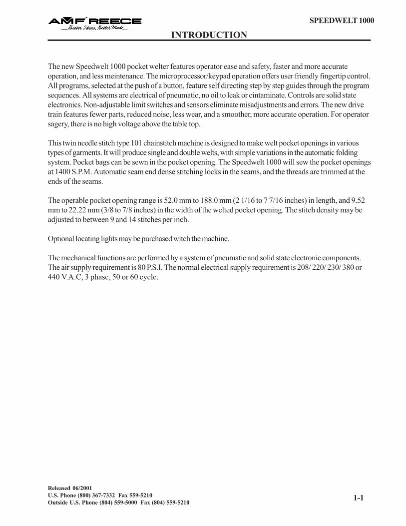
INTRODUCTION
The new Speedwelt 1000 pocket welter features operator ease and safety, faster and more accurateoperation, and less meintenance. The microprocessor/keypad operation offers user friendly fingertip control.All programs, selected at the push of a button, feature self directing step by step guides through the programsequences. All systems are electrical of pneumatic, no oil to leak or cintaminate. Controls are solid stateelectronics. Non-adjustable limit switches and sensors eliminate misadjustments and errors. The new drivetrain features fewer parts, reduced noise, less wear, and a smoother, more accurate operation. For operatorsagery, there is no high voltage above the table top.
This twin needle stitch type 101 chainstitch machine is designed to make welt pocket openings in varioustypes of garments. It will produce single and double welts, with simple variations in the automatic foldingsystem. Pocket bags can be sewn in the pocket opening. The Speedwelt 1000 will sew the pocket openingsat 1400 S.P.M. Automatic seam end dense stitching locks in the seams, and the threads are trimmed at theends of the seams.
The operable pocket opening range is 52.0 mm to 188.0 mm (2 1/16 to 7 7/16 inches) in length, and 9.52mm to 22.22 mm (3/8 to 7/8 inches) in the width of the welted pocket opening. The stitch density may beadjusted to between 9 and 14 stitches per inch.
Optional locating lights may be purchased witch the machine.
The mechanical functions are performed by a system of pneumatic and solid state electronic components.The air supply requirement is 80 P.S.I. The normal electrical supply requirement is 208/ 220/ 230/ 380 or440 V.A.C, 3 phase, 50 or 60 cycle.

1-2
SPEEDWELT 1000
Released 06/2001U.S. Phone (800) 367-7332 Fax 559-5210
Outside U.S. Phone (804) 559-5000 Fax (804) 559-5210
.ONLEDOM NOITPIRCSEDEDIUGHCTAP
EZISFOEPYT
LAIRETAM
012.0.0000.23 tleWelbuoD"8/3 )527.( thgiL
112.0.0000.23 tleWelbuoD"8/3 )166.( muideM/thgiL
212.0.0000.23 tleWelgniS"8/3 )166.( muideM/thgiL
022.0.0000.23 tleWelbuoD"61/7 )096.( yvaeH
122.0.0000.23 tleWelbuoD"61/7 )037.( muideM/thgiL
222.0.0000.23 palrevO/tleWelgniS"61/7 )957.( muideM/thgiL
032.0.0000.23 tleWelbuoD"2/1 )687.( yvaeH
132.0.0000.23 tleWelbuoD"2/1 )058.( muideM/thgiL
232.0.0000.23 tleWelgniS"2/1 )108.( muideM/thgiL
332.0.0000.23 tleWelgniS"2/1 )549.( muideM/thgiL
042.0.0000.23 tleWelbuoD"8/5 )001.1( yvaeH
142.0.0000.23 tleWelbuoD"8/5 )841.1( muideM/thgiL
242.0.0000.23 tleWelgniS"8/5 )032.1( muideM/thgiL
052.0.0000.23 tleWelbuoD"4/3 )053.1( yvaeH
152.0.0000.23 tleWelgniS"4/3 )074.1( muideM/thgiL
252.0.0000.23 palrevO/tleWelgniS"4/3 )001.2( muideM/thgiL
062.0.0000.23 tleWelbuoD"8/7 )556.1( muideM/thgiL
162.0.0000.23 tleWelgniS"8/7 )966.1( muideM/thgiL
SPEEDWELT 1000 MODELS

SPEEDWELT 1000
1-3Released 06/2001U.S. Phone (800) 367-7332 Fax 559-5210Outside U.S. Phone (804) 559-5000 Fax (804) 559-5210
DESCRIPTION Speedwelt 1000 Sewing Machine
SEWING HEAD 2-Needle Chainstitch
STITCH TYPE 101 Single Thread Chainstitch
SEWING SPEED 1.400 Stitch Per Minute
NEEDLE BITE SIZES 3/8�, 7/16�, 1/2�, 5/8�, 3/4�, 7/8�(9.5, 11.1, 12.7, 15.9, 19, 22.2 mm)
POCKET LENGTHS 2 1/16 to 7 7/16� (52 to 188 mm)
STITCH DENSITY Center 9 to 14 spi (1.8 to 2.8 mm)End 18 to 24 spi (0.9 to 1.3 mm)
LENGTH OF END DENSITY STITCHES 2 to 8 mm
WELT STYLES Single, Double, Offset, Overlapping
CENTER KNIFE Scissors Type, Lower Driven
CONTROL SYSTEM Microprocessor
LUBRICATION SYSTEM Manual Oiling Points
ELECTRICAL REQUIREMENTS 220 V, 60 Cycle, 3 Phase380 V, 50 Cycle, 3 Phase
COMPRESSED AIR Pressure 80 psi (5.516 bar)Consumption .25 cmf (7 /m)
NET DIMENSIONS Length 32� 812 mmWidth 28.5� 724 mmHeight 50� 1270 mmWeight 340 lbs. 154 kg
GROSS DIMENSIONS Length 41� 1041 mmWidth 32� 813 mmHeight 53� 1346 mmWeight 500 lbs. 267 kg
SPEEDWELT 1000 SPECIFICATIONS

1-4
SPEEDWELT 1000
Released 06/2001U.S. Phone (800) 367-7332 Fax 559-5210
Outside U.S. Phone (804) 559-5000 Fax (804) 559-5210
POWER SWITCH:
The power switch controls all power to the machine. It is used to power up and power down the machine.In the �OFF� position, there is no power to any component in the SPEEDWELT 1000.
MOTOR SWITCH:
The motor switch controls all power to the motor. In the �OFF� position, the drive motor does not havepower; however, the machine can still have power.
AIR VALVE:
The air valve controls the air supply to the pneumatic system. The system operating pressure is 80 PSI. Thethread pickup arms, tab knives, center knife, clamping, and patch folding are pneumatically operated.
ON SWITCH:
The ON switch turns the microprocessor power on.
EMERGENCY STOP SWITCH:
The emergency stop switch turns the microprocessor and the motor power off.
SEW INTERRUPT SWITCH:
The sew interrupt switch immediately stops the sewing operation and activates the keypad. It serves as areset button when the clamping table is in the front or rear position. IF the table stops in an interim position,the keypad must be used to reset the table position.
THREAD SAFETY SWITCH:
The thread safety switch is used when a thread breakage occurs. This switch, when pressed, prevents themachine from sewing, enabling the operator to re-thread the machine. When the operator is ready tocontinue sewing, the switch, when pressed again, returns the machine to the sewing position before thethread breakage occurred.
KNEE SWITCH:
The knee switch starts the sewing cycle.
CONTROLS

SPEEDWELT 1000
1-5Released 06/2001U.S. Phone (800) 367-7332 Fax 559-5210Outside U.S. Phone (804) 559-5000 Fax (804) 559-5210
TREADLE:
The treadle operates by two different position switches which control the operation of the clamping table,clamps, and brushes. Positions are halfway down (Position Switch # 1), and all the way down (PositionSwitch # 2).
KEYPAD:
The keypad is locked during normal operation to avoid accidental program changes. The SEWINTERRUPT switch stops the operation and activates the keypad for approximately 30 seconds. Striking akey keeps the keypad active until the [ENT] button is pushed, which returns the screen display to the sewprogram selected, and locks the keypad.
THREAD MONITOR SWITCH:
This switch, located under the head cover, will detect a slack or broken thread and will stop the machinefrom sewing and initiate the repair mode.
CONTROLS

1-6
SPEEDWELT 1000
Released 06/2001U.S. Phone (800) 367-7332 Fax 559-5210
Outside U.S. Phone (804) 559-5000 Fax (804) 559-5210
The Keypad / Microprocessor controls all functions of the SPEEDWELT 1000 and displays the activefunction on the screen. There are INPUT / OUTPUT tests which perform diagnostic checks on componentoperations. They isolate problems quickly and simply. The tests read each selected input or output, monitorits operation, and displays the results on the keypad screen.
All power to the SPEEDWELT 1000 is controlled by the POWER switch. The microprocessor power iscontrolled by the ON switch. Both of these switches must be in the �ON� position before the screen willilluminate, displaying the currently selected program. The programs are menu driven and can be easilychanged (see pages 1-9 and 1-10).
The keypad is locked during sewing operations to prevent accidental program changes. The SEWINTERRUPT switch accesses the keypad for about 30 seconds. To keep it active, press one of thefollowing keys.
[RST]; [L]; [KNIFE]; [CTR] or either of the two arrow keys.
To deactivate the keypad, press any of the following keys perscreen instructions:
[ENT]; [HOME]; [CTR] or the SEW INTERRUPT switch
The key functions are as follows:
[RST] -Resets the counter to zero.
[HOME] - At start-up, this key returns the clamp table tothe LOAD position currently selected (frontto back or back to front).
[L] - Selects the loading position, front or back.
[KNIFE] - Turns the TABKNIFE and CENTERKNIFE operation on or off (cut -no cut).
[CTR] - Accesses the Mechanics Diagnostic Programs.
[ENT] - Enters into memory any changes made.
OPERATOR KEYPAD AND DISPLAY SCREEN

SPEEDWELT 1000
1-7Released 06/2001U.S. Phone (800) 367-7332 Fax 559-5210Outside U.S. Phone (804) 559-5000 Fax (804) 559-5210
Operator Keypad and Display Screen
To enter either the Front or Back Loading Programs:
Press the [SEW INTERRUPT] switch.
Press [L].
FRONT LOADINGPress the TREADLE half way down Clamps will go downRelease the TREADLE Clamps will come upPress the TREADLE all the way down Clamps will go down, and the table will go backRelease the TREADLE Brushes will closePress the KNEE SWITCH To continue sewing
or
Press the SEW INTERRUPT SWITCH To cancel, and the brushes will open and clampswill come up
BACK LOADINGPress the TREADLE all the way down Table will go backRelease the TREADLE half way up Clamps will go downPress the TREADLE all the way down Clamps will come upRelease the TREADLE Clamps will go down and the brushes will closePress the TREADLE half way down Brushes will openRelease the TREADLE Brush will closePress the KNIFE SWITCH To continue sewing
or
Press the SEW INTERRUPT SWITCH To cancel, and the brushes will open and clampswill come up
OPERATOR KEYPAD AND DISPLAY SCREEN

1-8
SPEEDWELT 1000
Released 06/2001U.S. Phone (800) 367-7332 Fax 559-5210
Outside U.S. Phone (804) 559-5000 Fax (804) 559-5210
1. Turn the machine on by turning the POWER and MOTOR toggle switches to the ON position.2. Turn on the air valve.3. Push the ON switch.4. The screen will display a message similar to the one below.
This screen (pocket program) briefly describes the active program in the machine. It is possible to have 12different programs. The program being run is locked in memory when the machine is turned off. It will beactive when it is turned on again. To sew a pocket welt, follow the �OPERATOR INSTRUCTIONS�.
T H I N G S T O R E M E M B E R
SEW INTERRUPT: This switch is used to access the program by activating the keypad for about 30seconds. This safety feature prevents accidental changes made through the keypad. This switch can also beused as a �RETURN� to the pocket program screen.
To keep the keypad active, press any one of the following keys:[RST][L][KNIFE][¯][- ][CTR]
To de-activate the keypad, press any of the following per screen instructions:
[ENT][HOME][CTR]SEW INTERRUPT switch
Total lengthof stitching
138 mm [Pocket (1) ] 175
FRONT LOAD
Loadingposition
Currentprogram
Count of sewpockets
PROGRAMMING THE KEYPAD

SPEEDWELT 1000
1-9Released 06/2001U.S. Phone (800) 367-7332 Fax 559-5210Outside U.S. Phone (804) 559-5000 Fax (804) 559-5210
T O S E T T H E S E W I N GP R O G R A M S :
Press the [SEW INTERRUPT] switch.Press the [CTR] key.Press [2] to program.
To program sewing, press [1].To program PATCH LOADER, press [2].
To turn PATCH LOADER on, press [2].
SEMIAUTOMATIC - the operator startssewing after loading and folding.
AUTOMATIC - the foot treadle only isused.
The NEXT [- ] key will advance to anddisplay the next program. The NEXT [¯]key will display the previous program. TheCHANGE [ENT] key allows changes tobe made to the current program, andadvances to the next screen within theprogram.
Once in the program, the LESS [¯] keywill decrease the number, the MORE [- ]key will increase the number. The [ENT]key will confirm any changes made andadvance the program to the next screen.
**For programming instructions foroptions, see the Options section, page1-44.
To enter the sewing mode, press the[CTR] key; to continue in the programmingmode, press the [ENT] key.
TYPICAL - PROGRAMS 2 THROUGH 8
138 mm POCKET (1) 0175
FRONT
I/O TESTS PRESS [1]
PROGRAMM PRESS [2]
PROG. POCKET PRESS [1]
OPTION PRESS [2]
138 mm PROGRAM #1
NEXT [↑][↓] CHANGE [ENT]
138 mm
LESS [↑] MORE [↓] [ENT]
8 mm
LESS [↑] MORE [↓] [ENT]
20
LESS [↑] MORE [↓] [ENT]
10
LESS [↑] MORE [↓] [ENT]
10 mm
LESS [↑] MORE [↓] [ENT]
10 mm
LESS [↑] MORE [↓] [ENT]
SEW POCKET
PROGRAM PRESS [ENT]
147 mm PROGRAM #2
NEXT [↑][↓] CHANGE [ENT]
START C'KNIFE
STOP C'KNIFE
PRESS [CTR]
POCKET LENGTH
END LENGTH
ENDS STITCHING
CENTER STITCHES
PROGRAMMING THE KEYPAD

1-10
SPEEDWELT 1000
Released 06/2001U.S. Phone (800) 367-7332 Fax 559-5210
Outside U.S. Phone (804) 559-5000 Fax (804) 559-5210
PROG. POCKET PRESS [1]
OPTIONS PRESS [2]
WARNING / MACH. WITHOUT
OPTIONS [CTR] WITH [ENT]
AUTO PATCH LOADER [1]
SEQUENCE SEWING [2]
PATCH LOADER ON [1]
OFF [2]
SEMIAUTOMATIC
AUTOMATIC [2]
SEQUENCE OFF [1]
PROG SEQUENCE [2]
TWO POCKETS [2]
THREE POCKETS [3]
1st POCKET [1] [2]
2nd POCKET [1] [2]
1st POCKET [1] [2]
2nd POCKET [1] [2]
3rd POCKET [1] [2]
ENTER POCKET NO.FOR
ENTER POCKET NO.FOR
[1]
ENTER POCKET NO.FOR
ENTER POCKET NO.FOR
ENTER POCKET NO.FOR
PROGRAMMING THE KEYPAD

SPEEDWELT 1000
1-11Released 06/2001U.S. Phone (800) 367-7332 Fax 559-5210Outside U.S. Phone (804) 559-5000 Fax (804) 559-5210
T O C H A N G E A P O C K E TP R O G R A M :
Press [SEW INTERRUPT] switchPress [-] or [ ]̄ to select
T O C H A N G E T H EL O A D I N G P O S I T I O N :
Press [SEW INTERRUPT] switchPress [L] key
T O C H A N G E T H ETA B K N I F E ( C U T - N O C U T ) :
Press [SEW INTERRUPT] switchPress [KNIFE] key* (1) Automatic tab knife center cut (2) No cut center or tab knives (3) Tab cut w/knee switch
E R R O R M E S S A G E
Indicates table is not in the HomepositionPress [HOME]
T O R E S E T T H E C O U N T O FSEWN POCKETS:
Press [SEW INTERRUPT] switchPress [RST]
156 mm POCKET #2 175
FRONT Press [ENT]
DOES TAB KNIFE NEED
CHANGING? Press [ENT]
CANCEL [SEW INTERRUPT]
BLOCKLOAD [ ENT]
TAB, K-CUT [1] NO CUT [2] CANCEL SEW INTERUPT
CUT/KNEE SWITCH [3] CENTER KNIFE OFF [ENT]
ERROR - TABLE NOT HOME
Press [HOME]
CANCEL [SEW INTERRUPT]
Reset Count [ENT]
PROGRAMMING THE KEYPAD

1-12
SPEEDWELT 1000
Released 06/2001U.S. Phone (800) 367-7332 Fax 559-5210
Outside U.S. Phone (804) 559-5000 Fax (804) 559-5210
T O T H R E A D T H E M A C H I N E :
Press the [THREAD SAFETY] switch. Thread themachine. Press the [THREAD SAFETY] switch to return tothe sewing mode.
When a thread breaks, the machine will automatically go intothe [SEW INTERRUPT] mode.
Press the [THREAD SAFETY] switch to return to thesewing mode.
When the material jams:
Remove the material after turning the air valve OFF.
Press [SEW INTERRUPT] to return to the sewing mode.
FINISHED THREADING?
Press [THREAD SAFETY] switch
THREAD BREAK
Press [HOME]
REMOVE PATCH / STITCH
Press / Hold TREADLE
RELOAD PATCH
Release TREADLE
ERROR CORRECTED: To
Continue, Press [ENT]
RETHREAD MACHINE
Press [THREAD SAFETY] switch
JAM - TURN AIR OFF
Press [SEW INTERRUPT]
TURN AIR ON
Press [HOME]
Press [SEW INTERRUPT]
PROGRAMMING THE KEYPAD

SPEEDWELT 1000
1-13Released 06/2001U.S. Phone (800) 367-7332 Fax 559-5210Outside U.S. Phone (804) 559-5000 Fax (804) 559-5210
R O C K E R R O D R E P L A C E M E N T
In most cases, only one of the rocker rods � will actually required replacement. However, replace both ofthe rocker rods. To replace, perform the following steps:
1. Turn the arrow located on eccentric stud � towards the rear of the machine.
2. Remove needle bar �, eccentric stud �, rear stud �, a pin �. Be careful not to lose the small key inthe eccentric stud. Remove the rocker rod assembly �.
3. Remove the four E-rings � from the pins located on the rocker assembly. Remove the pins �.Disassemble the broken rod by loosening locknuts �, removing clevis� � and removing locknuts �. Placeclevis and locknuts on new rod. Re-install eccentric � and rear � studs onto the head. Insert rod � on thehead through the opening located on the left hand side of the machine. Clevis on the new rod should slideover the eccentric � and rear � studs. The length of the rod and the clevis should match the distancebetween the two studs. Repeat for the other rod.
4. Install the new rods onto the front and rear rocker levers using the pins to secure them in place. Re-installE-rings � over the pins �. Remove eccentric and rear studs. Re-install the rocker rod assembly � usingthe studs and pin �.
R O C K E R R O D T E N S I O N
1. The tension is adjusted on the rocker rods � by rotating the eccentric stud �. This is done by removingthe needle holder and pin �.
2. Loosen eccentric stud �. Rotating the stud so the arrow faces the front of the machine increases thetension on the rocker rods; rotating the stud so the arrow faces the rear of the machine decreases thetension. Decrease the tension enough so the needle bar � can move up and down freely. Slowly increasethe tension until there is a slight drag when the needle bar is moved manually up and down. The arrow willbe about at the 1 or 2 o�clock position. Re-tighten stud.
ADJUSTING ROCKER RODS

1-14
SPEEDWELT 1000
Released 06/2001U.S. Phone (800) 367-7332 Fax 559-5210
Outside U.S. Phone (804) 559-5000 Fax (804) 559-5210
1. Move the clamping table to the back load position.
2. Remove the patch guide assembly � by loosening and removing screws �.
3. Move the clamping table to the front load position.
4. Set the gauge squarely on the throat plate �. The bottom of the needle holder should sit on the first stepof the gauge with the needle bar at the bottom, dead center. Adjust the needle bar to this height by looseningthe clamping screw in the gimbal and sliding the needle bar into the proper position. Lock the needle barfirmly into the gimbal by re-tightening the clamping screw.
NOTE: Ensure needles are still in alignment with the throat plate (see page 1-15).
ADJUSTING NEEDLE BAR HEIGHT

SPEEDWELT 1000
1-15Released 06/2001U.S. Phone (800) 367-7332 Fax 559-5210Outside U.S. Phone (804) 559-5000 Fax (804) 559-5210
A D J U S T I N G T H E N E E D L E TO T H R O AT P L AT E
Before starting this adjustment, ensure the clamping table is in the back load position.
1. Select OUTPUT TEST (see page 2-4) from the keypad. Bring the clamps down and remove the patchguide.
2. Lift the machine. Manually operate the needle bar by rotating the knob, located on the centerknife shaft,clockwise. Check for a slight clearance between the needles � and the throat plate � openings. If a slightclearance does not exist, loosen screws � and tap the throat plate to the right or left as necessary. Once theclearance has been obtained, re-tighten screws � and re-install the patch guide.
Note: Ensure the needles are straight.
SEWING

1-16
SPEEDWELT 1000
Released 06/2001U.S. Phone (800) 367-7332 Fax 559-5210
Outside U.S. Phone (804) 559-5000 Fax (804) 559-5210
The patch guide is factory set.
E l i m i n a t i o n o f S i d e P l a y
If play exist between the patch guide arm � and hinge brackets, loosen only one hinge bracket. This is doneby loosening screws �. While pressing brackets together, retighten screws �. As long as one hingebracket remains fixed, the patch guide arm � will remain centralized.
L e v e l i n g o f P a t c h G u i d e
The bottom surface of the patch guide � should rest flatly on the top surface of the throat plate �. If anadjustment is required, loosen locknut � and move allen screw � up or down as necessary. Once theadjustment has been made, re-tighten locknut �.
S e t t i n g t h e Te n s i o n o n t h e P a t c h G u i d e
The patch guide should have a slight drag when it is manually moved up and down. If adjustment is required,loosen locknuts � and move screws � in or out (in tightens the drag; out loosens the drag) as necessary.Once a slight drag is obtained, re-tighten locknuts �. Re-check patch guide for slight drag.
A l i g n m e n t o f P a t c h G u i d e a n d T h r o a t P l a t e
1. The knife slot � of the patch guide must be aligned with the center slot � of the throat plate. To adjust,loosen screws , and move the patch guide to the right or left as necessary. Once the alignment has beenobtained, re-tighten screws .
2. If the alignment can not be obtained by performing step 1 above, loosen screws . Move the patchguide arm � to the right or left as necessary. Re-tighten screws . Repeat step 1 above.
PATCH GUIDES

SPEEDWELT 1000
1-17Released 06/2001U.S. Phone (800) 367-7332 Fax 559-5210Outside U.S. Phone (804) 559-5000 Fax (804) 559-5210
Hor izonta l Adjus tments
The brush blades � must close parallel to the patch guide �, with a clearance on each side of the patchguide equal to the thickness of welting � and backing material. To assure accurate performance, it isessential that the correct adjustments exist between the patch folding arms, slide block �, slide bracket �and clevis �. Refer to pages 1-13 through 1-16 to ensure the proper machine settings are in place beforeperforming the following patch folding adjustments.
PATCH FOLDING

1-18
SPEEDWELT 1000
Released 06/2001U.S. Phone (800) 367-7332 Fax 559-5210
Outside U.S. Phone (804) 559-5000 Fax (804) 559-5210
A d j u s t i n g t h e H e i g h t o f t h e F r o n t E n d B r u s h B l a d e s t o t h e P a t c h G u i d e
Loosen nut �, and turn screw � in or out (in will lower the height; out will raise the height) as necessary.Once the proper height has been obtained, re-tighten nut �.
A d j u s t i n g t h e H e i g h t o f t h e R e a r E n d B r u s h B l a d e s t o t h e P a t c h G u i d e
To raise the height of the brush blade �, tighten screw �, and loosen screw �. To lower the height of thebrush blade �, loosen screw �, and tighten screw �.
NOTE: The height of the rear end brush blades must be 0.79 mm (.03�) higher than the front end brushblades.
PATCH FOLDING

SPEEDWELT 1000
1-19Released 06/2001U.S. Phone (800) 367-7332 Fax 559-5210Outside U.S. Phone (804) 559-5000 Fax (804) 559-5210
S e t t i n g t h e D i s t a n c e b e t w e e n t h e P a t c h G u i d e a n d B r u s h B l a d e s
The following adjustment may vary slightly depending on the thickness of the material being used. Heaviermaterial requires more distance between the patch guide � and the brush blades �; lighter material requiresless distance. If, after performing the following steps, the correct distance has not been obtained, performthe adjustment at the bottom of this page.
To adjust, loosen nut �, and screw piston rod � in or out (in will decrease the distance; out will increasethe distance) as necessary. Once the proper distance is obtained, re-tighten nut �.
NOTE: Patch folding brushes � must not deflect patch guide when welting and backing material is beingfolded. If this occurs, uneven welting or needle breakage may result.
For heavier material, perform the following steps:Loosen screws �, and slide brush arm � in or out as necessary. Once the proper distance has beenobtained, re-tighten screws �.
PATCH FOLDING

1-20
SPEEDWELT 1000
Released 06/2001U.S. Phone (800) 367-7332 Fax 559-5210
Outside U.S. Phone (804) 559-5000 Fax (804) 559-5210
I n s t a l l a t i o n o f B r u s h B l a d e s
The brush arm should be removed in order to replace the brush blades. This is done by removing screws �and the pivot block �. Lift the brush arm up or out. Loosen screws I, located on both ends of the patchfolding brush arm, and remove old brush blade. Install the new brush blade to the full depth of the slot in thepivot. Re-tighten screw I at one end of the arm. Place hex wrench in pivot at the opposite end of the brusharm. Turn the pivot until the brush blade is taut. Once the brush blade is taut, re-tighten screw I. Re-installthe brush arm and the pivot block. Re-install screws H and re-tighten. See page 1-18 for the properadjustment of the brush arm.
NOTE: The brush blades have a long and short side. The long side down is used for sewing light to mediumweight materials. The short side down is used for sewing medium to heavy materials. When installing newbrush blades, ensure that both blades are inserted in the same way, either with both blades with the long sidedown or with both blades having the short side down. There are also several different size blades availablefor the different weight fabrics.
PATCH FOLDING

SPEEDWELT 1000
1-21Released 06/2001U.S. Phone (800) 367-7332 Fax 559-5210Outside U.S. Phone (804) 559-5000 Fax (804) 559-5210
P o s i t i o n i n g o f t h e P a t c h F o l d i n g B r u s h e s
The Speedwelt 1000 is available in several modes. As a result, the adjustments of the patch folding brusheswill vary with each model. The initial steps are as follows:
1. Loosen nut � and move adjusting screw � up or down until the desired dimension is obtained betweenthe slide blocks. Once the desired dimension has been obtained, re-tighten nut.
2. Loosen lower clamp collar � by loosening set screw, located in the lower clamp collar. Move the collarup to within 7.94 mm (.312�) to the top clamp collar �.
3. Pull cylinder rod � down until it touches the adjusting screw.
4. Move the lower clamp collar � down by turning it until it activates the switch �.
5. Turn the clamp collar one more turn.Re-tighten the set screw.
6. Check the brushes for properoperation, and adjust accordingly.
PATCH FOLDING

1-22
SPEEDWELT 1000
Released 06/2001U.S. Phone (800) 367-7332 Fax 559-5210
Outside U.S. Phone (804) 559-5000 Fax (804) 559-5210
MODELS MODELS
3/8� D.W. (.725) 7/16� S.W.O. (.759) 1/2� S.W. (.945) 3/8� D.W. (.661) 1/2� D.W. (.786) 3/8� S.W. (.661) 1/2� D.W. (.856)7/16� D.W. (.690) 1/2� S.W. (.801)7/16� S.W. (.730)
NOTE: The above clearances may vary depending upon the thickness of the material being sewn.
POSITIONING OF PATCH FOLDING BRUSHES

SPEEDWELT 1000
1-23Released 06/2001U.S. Phone (800) 367-7332 Fax 559-5210Outside U.S. Phone (804) 559-5000 Fax (804) 559-5210
MODELS MODELS
5/8� D.W. (1.100) 3/4� D.W. (1.350) 5/8� S.W. (1.230)5/8� D.W. (1.148)
NOTE: The above clearances may vary depending upon the thickness of the material being sewn.
POSITIONING OF PATCH FOLDING BRUSHES

1-24
SPEEDWELT 1000
Released 06/2001U.S. Phone (800) 367-7332 Fax 559-5210
Outside U.S. Phone (804) 559-5000 Fax (804) 559-5210
MODELS MODELS
3/4� S.W. (1.470) 7/8� D.W. (1.669) 3/4� S.W. (2.100) 7/8� D.W. (1.655)
NOTE: The above clearances may vary depending upon the thickness of the material of the being sewn.
POSITIONING OF PATCH FOLDING BRUSHES

SPEEDWELT 1000
1-25Released 06/2001U.S. Phone (800) 367-7332 Fax 559-5210Outside U.S. Phone (804) 559-5000 Fax (804) 559-5210
Adjustment should be made with no material under the clamp foot. Both clamp arms must be adjusted at thesame time.
1. Release all clamping pressure by loosening nuts � and �, and then backing off screw �. Ensure theclamp foot � is in the down position, and turn the air pressure on. Re-tighten nut �.
2. Check to ensure that levers � and level and the center pin � is 1 3/4� above clamp plate �. If thelevers are not level and / or the center of the pin is not 1 3/4� above the clamp plate, adjust by loosening nut�. Using a pair of small pliers, turn piston rod � in or out of clevis � until this levers are level and / or pinis correctly centered. Once the adjustments have been made, re-tighten nut �.
3. Apply clamping pressure by turning screw � inward until it bottoms. Continue to turn 1/2 of a turnfurther. Re-tighten nut �.
4. Ensure that clamp foot � holds the material firmly at all points. If slippage occurs under either side of theclamp foot, increase pressure to that side. This is done by turning screw � slightly inward. Be careful not toturn the screw too tight as to cause the front of the clamp foot to be raised.
CLAMPING

1-26
SPEEDWELT 1000
Released 06/2001U.S. Phone (800) 367-7332 Fax 559-5210
Outside U.S. Phone (804) 559-5000 Fax (804) 559-5210
Stitch density is controlled by the speed at which the clamp travels forward. At the beginning and end ofeach sewing cycle, the clamp table slows briefly to provide closer stitch density which is required at each ofthe pocket. Beginning and end stitch density is 18 to 22 stitches per inch and should consist of 5 or 6 evenlyspaced stitches at the beginning and end of each welt. The clamp table speeds up to provide a center stitchdensity of 9 to 14 stitches per inch (see diagram).
To verify that the stitch pattern conforms to the diagram, perform the following test:
1. Install �pricking� needles prepared from # 950 class needles shortened to 1 9/16� overall and sharpenedto a point.
2. Place a sheet of sturdy paper under the clamp foot and operate the machine through a sewing cycle.
3. Compare that stitching pattern with the diagram above.
4. If the newly created stitching pattern does not match the diagram above, adjustments must be made toend length, end stitching, and center stitches (see Re-programming Instructions on page 1-9).
PRICK-IN

SPEEDWELT 1000
1-27Released 06/2001U.S. Phone (800) 367-7332 Fax 559-5210Outside U.S. Phone (804) 559-5000 Fax (804) 559-5210
R E P L A C E M E N T O F T H E C E N T E R K N I F E
As the knife begins to dull, a ragged center cut will be made. The knife may be sharpened with an oil stone.However, if sharpening the knife does not correct the ragged cut, the knife will need to be replaced. Asupply of sharpened and / or new knives should be kept on hand for ready replacement. To replace a knife,perform the following steps:
Lift the machine. Turn the air pressure OFF by turning the air valve knob � a half turn. Loosen screws �,and raise the knife up and slide it out. Insert the new knife into the knife holder. The bottom of the new knifemust touch the stop screw, located at the bottom of the knife holder. Re-tighten screws �. Turn the airpressure ON.
C E N T E R K N I F E TO T H R O AT P L AT E A D J U S T M E N T
Place the clamp table in the rear position. Open the brush blades. Turn the air pressure OFF. Manually liftthe patch guide, and keep it up using a small screwdriver. Manually push the knife holder � up so that thecenter of the knife passes up through the throat plate. It must pass flush with the cutting edge � of the throatplate (which is the right side of the center slot when facing the machine) and not deflect more than .051 mm(.002�). To adjust, perform the following steps:
Manually push the center knife up through throat plate. Loosen screws � located on the bearing blocks.Move the center knife from side to side as necessary until the knife is able to pass through the throat platewith no gap on the right side of the knife and the throat plate. Re-tighten screws �. At this point, the centerknife should be able to cut a single strand of thread. If the knife does not cut, re-check the adjustment, and/ or replace the knife. Turn the air pressure ON.
CENTER CUTTING

1-28
SPEEDWELT 1000
Released 06/2001U.S. Phone (800) 367-7332 Fax 559-5210
Outside U.S. Phone (804) 559-5000 Fax (804) 559-5210
S E T T I N G T H E H E I G H T O F T H E C E N T E R K N I F E
Place the center knife � in the cutting position, at the bottom of its stroke. The leading edge of the knifepoint should have a clearance of 0.79 mm (.031�) below the top surface of the throat plate �. To adjust,perform the following steps:
Place the clamp table to the rear position. Turn the air pressure OFF. Manually push the center knife holderup into the cutting position. Rotate the knob � located on the knife shaft until the center knife � is at thebottom of its stroke. Loosen the jam screw � located on the clevis �. Turn the piston rod � clockwise orcounterclockwise (turning the rod clockwise will raise the knife; turning the rod counterclockwise will lowerthe knife) as necessary. Once the proper clearance has been obtained, retighten jam screw �.
A D J U S T I N G T H E C E N T E R K N I F E C U T L E N G T H
The center cut � starts approximately 4.76 mm (.187�) after stitching begins, and ends 4.76 mm (.187�)before the stitching stops. Both stitching and the center knife operations are controlled by themicroprocessor and can be changed. To change the settings, see page 1-9.
CENTER CUTTING

SPEEDWELT 1000
1-29Released 06/2001U.S. Phone (800) 367-7332 Fax 559-5210Outside U.S. Phone (804) 559-5000 Fax (804) 559-5210
S E T T I N G T H E T I M I N G O F T H E C E N T E R K N I F E
The needles support the material as the center knife cuts. The cutting occurs as the needles and the centerknife descend. The center knife and the needles should be at their lowest points once the cutting has beencompleted. If the center knife is not at its lowest point after the cutting has occurred, the timing of the centerknife is not correct. To re-set the timing, perform the following steps�
Loosen set screw �. Holding the pulley �, rotate the shaft � clockwise or counterclockwise (rotating theshaft clockwise will allow the knife to cut sooner; rotating the shaft counterclockwise will allow the knife tocut later) as necessary. Once the proper timing has been obtained, re-tighten set screw �.
CENTER CUTTING

1-30
SPEEDWELT 1000
Released 06/2001U.S. Phone (800) 367-7332 Fax 559-5210
Outside U.S. Phone (804) 559-5000 Fax (804) 559-5210
A D J U S T I N G T H E C L A M P I N G M AT S
The inner edge of the clamping mats � must be parallel and equal distance from the side of the throat plate.The mats should just clear the sides of the throat plate �. To adjust, perform the following steps:
Loosen screws �. Slide the clamping mats to the right or left as necessary. Once the proper distance hasbeen obtained, re-tighten screws �.
C E N T E R I N G T H E TA B K N I F E A S S E M B LY
The lower ends of the tab knives should be centrally located between the clamping mats � when the tabknives � are at the top of their stroke. To adjust, perform the following steps:
Loosen screws �. Slide the tab knife bracket to the right or left as necessary. Once the tab knife brackethas been centered, re-tighten screws �.
TAB CUTTING

SPEEDWELT 1000
1-31Released 06/2001U.S. Phone (800) 367-7332 Fax 559-5210Outside U.S. Phone (804) 559-5000 Fax (804) 559-5210
R E P L A C I N G T H E TA B K N I V E S
To replace the tab knives, remove knife holder by removing screw � and removing the tab knife from fingershoe �. Remove nut � and washer �. Remove the old tab knife by sliding it off threading screw �, andthen pulling it down and out. Insert the new knife � by tilting the knife up and into knife pointer � anddown over threaded screw �. Re-install washer � and nut �. Re-install the tab knife into the finger shoe,and re-tighten screw A. Repeat for the other tab knife.
Sew a pocket on a scrap piece of paper to ensure the tab knives are central to the two rows of stitches. Ifthe tab knives are not central, loosen nut � and turn set screws � in or out (in will produce a larger cut;out will produce a smaller cut) as necessary. Once the tab knives have been centralized, re-tighten nut �.
TAB CUTTING

1-32
SPEEDWELT 1000
Released 06/2001U.S. Phone (800) 367-7332 Fax 559-5210
Outside U.S. Phone (804) 559-5000 Fax (804) 559-5210
A D J U S T I N G T H E F R O N T A N D R E A R TA B K N I V E S
The front � and rear � tab knives should be positioned so that the tab cuts are exactly even with the endsof stitching and also equal in distance from the sides of the stitches. The side clearance between the tabknives and the stitching � may be between 0.79 and 1.19 mm (.031� and .047�). Sew a test pattern on apiece of paper to show the location of the knife cuts. The end of the stitching and the tab knives should beequal. If they are not equal, adjust by performing the following steps (in most cases, the front tab knife willnot have to be adjusted; therefore, the adjustment below is from the rear tab knife):
Loosen screw � and slide the rear tab knife holder towards the front or rear of the machine (sliding theholder towards the front of the machine will shorten the cut; sliding it to the rear will extend the cut) asnecessary. Once the correct adjustment has been made, re-tighten screw �.
To sew a pocket 6 3/4� or longer, remove the rear tab knife � from finger shoe � by loosening andremoving screw �. Loosen screw � and remove finger shoe. Flip the finger shoe over and re-install. Re-tighten screw �. Re-insert the rear tab knife, and re-tighten screw �. Adjust the tab knife holderaccordingly.
NOTE: If the front tab knife does require an adjustment perform the steps above; however, sliding theholder towards the front of the machine will extend the cut; sliding it to the rear will shorten the cut.
The above adjustments are standard for most fabrics and materials. However, if the material or fabric is thin,slippery or stretchy, compensating adjustments may be needed. For example, if the material is of a silkynature, the tab cut to end of stitch may need to be further adjusted.
TAB CUTTING

SPEEDWELT 1000
1-33Released 06/2001U.S. Phone (800) 367-7332 Fax 559-5210Outside U.S. Phone (804) 559-5000 Fax (804) 559-5210
The following diagrams illustrate the sequence of looper and needle action for each stitch.
L O O P E R S H A F T A S S E M B LY
The front edge of the looper shaft � to the back of the needle points should measure 2.38 mm (.094�). Thisis a factory setting and must not be changed. The looper shaft � is fixed in position when the bearingblocks � are installed. To check this distance, move the looper holders � to one side and measure usingthe 03.0145.0.000 gauge �. If the measurement is not 2.38 mm (.094�), adjust by the following steps:
Loosen the machine head by loosening the 9 screws, located in the back and on both sides of the head.Slide the machine head forward or backward as necessary. Once the proper measurement has beenobtained, retighten the 9 screws.
When the needles � rise 2.38mm (.094�) from the bottom oftheir stroke, the looper pointsshould enter thread loops � --
As action continues, theloops should slide to theheel of the looper - -
On the down stroke,needle should enterthe thread loop �- -
Just before being caston to the needles.
LOOPERS

1-34
SPEEDWELT 1000
Released 06/2001U.S. Phone (800) 367-7332 Fax 559-5210
Outside U.S. Phone (804) 559-5000 Fax (804) 559-5210
A D J U S T I N G T H E T I M I N G O F T H E L O O P E R S T O T H E N E E D L E B A R
1. Remove patch guide assembly (see page 1-13).
2. Ensure needles are straight.
3. Set the gauge squarely on the throat plate. Position the needle bar at bottom dead center by lifting themachine and rotating the knob clockwise or counterclockwise until the needle bar is at bottom dead center.At this point, the needle holder should rest squarely on the first step of the gauge. To adjust, loosen theclamping screw, and move the needle bar up or down as necessary. Once the needle holder is restingsquarely on the first step of the gauge, re-tighten the clamping screw.
NOTE: When making this adjustment, ensure theneedles are square with the throat plate at all times.
4. When the needles are at bottom dead center, the loopers should be at their maximum rear most position.To adjust, loosen the clamping screw, located on the drive shaft assembly. Center the eccentric stud with asmuch movement forward as backward. Once the eccentric stud has been centered, re-tighten the clampingscrew.
LOOPERS

SPEEDWELT 1000
1-35Released 06/2001U.S. Phone (800) 367-7332 Fax 559-5210Outside U.S. Phone (804) 559-5000 Fax (804) 559-5210
5. Continue turning the knob clockwise until the needle bar rises 2.38 mm (.094�) and the bottom of theneedle holder sits on the second step of the gauge.
6. The centerline of the needle should be in alignment with the center of the clamping screw. The point of thelooper should be on the centerline of the needle, approximately 3.17 mm (.125�) above the needle eye. Toadjust, loosen the clamping screws and move the looper holder to the right or left as necessary. Once thelooper holder is in the proper position, re-tighten the clamping screws.
7. The looper should be as close to the needle as possible without deflecting, with a maximum clearance of0.11 mm (.004�). To adjust, loosen the allen screw and slide the looper to the right or left as necessary.Once the proper clearance has been obtained, re-tighten the allen screw.
LOOPERS

1-36
SPEEDWELT 1000
Released 06/2001U.S. Phone (800) 367-7332 Fax 559-5210
Outside U.S. Phone (804) 559-5000 Fax (804) 559-5210
A D J U S T I N G T H E L O O P E R H E E L T O N E E D L E S E T T I N G
As the needle passes by the heel � of the looper on both the upward and downward strokes, it should passas closely as possible to the heel without deflecting. To adjust, perform the following steps:
Loosen the clamping screw �, located on the drive shaft assembly �. Rotate the eccentric stud �clockwise or counterclockwise (rotating the stud clockwise will move the heel of the looper away from theneedle; counterclockwise will move the heel closer to the needle) as necessary. Once the heel of the looperis in the proper position, re-tighten the clamping screw.
LOOPERS

SPEEDWELT 1000
1-37Released 06/2001U.S. Phone (800) 367-7332 Fax 559-5210Outside U.S. Phone (804) 559-5000 Fax (804) 559-5210
T H R E A D T R I M M I N G
At the end of the sewing cycle, the clamp table moves forward. During this movement, the inside legs of thethread loops come in contact with the trimming knife, cutting the thread.
NOTE: Never sew with a dull knife. This will cause the thread to break close to the last stitch, which couldcause a ravling back of the stitching.
S H A R P E N I N G T H E T R I M M I N G K N I F E
Lift the machine. Loosen screws �, and remove the knife holder � from the looper blocks (it is notnecessary to remove the knives from the holder). Stone the trimming knife � to a sharp edge. It isimperative that the bevel be maintained on the underside of the knife. Once the knife has been sharpened,re-install the knife holder � into the looper blocks, ensuring that the knife points are centered to theloopers. Once they are centered, re-tighten screws �.
SEWING

1-38
SPEEDWELT 1000
Released 06/2001U.S. Phone (800) 367-7332 Fax 559-5210
Outside U.S. Phone (804) 559-5000 Fax (804) 559-5210
T H R E A D I N G T H E M A C H I N E
The thread color should be a basic shade of the garment being sewn. Thread both of the needles from left toright.
A D J U S T I N G T H E T H R E A D TA K E - U P E Y E L E T S
The function of the eyelets � is to provide a looser or tighter stitch, which would be dependent upon thematerial being sewn. To adjust, loosen nut � and move the eyelet forward or backward (moving the eyeletforward would cause the stitch to be looser, moving it backward would cause the stitch to be tighter) asnecessary. Once the proper stitch has been obtained, re-tighten nut �.
A D J U S T I N G T H E S TA RT I N G T H R E A D
Loosen screw � and move actuator � forward or backward (moving the actuator forward will increasethe amount of starting thread; moving the actuator backward will decrease the amount of starting thread) asnecessary. Once the correct amount of starting thread has been obtained, re-tighten screw �.
THREADING

SPEEDWELT 1000
1-39Released 06/2001U.S. Phone (800) 367-7332 Fax 559-5210Outside U.S. Phone (804) 559-5000 Fax (804) 559-5210
A D J U S T I N G T H E T H R E A D L O O P S I Z E
The proper size of the thread loop for the average sewing conditions is just large enough for the looper to fitinto. If the loop is too large, the loop may turn over towards the front, causing the looper to miss it. This iswhat causes skipping. To adjust, perform the following steps:
Loosen set screw �. Raise or lower looper wire � (raising the looper wire will increase the loop size;lowering the loop wire will decrease the loop size) as necessary. Once the proper loop size has beenobtained, re-tighten set screw �.
SEW-OFF

1-40
SPEEDWELT 1000
Released 06/2001U.S. Phone (800) 367-7332 Fax 559-5210
Outside U.S. Phone (804) 559-5000 Fax (804) 559-5210
T H R E A D P I C K U P A R M S
The thread pickup arms � are designed to pass just below and beyond the needles �, grasping the threadtaut before trimming. Select the OUTPUT Test from the keyboard menu (see pages 2-4 through 2-6).Select the thread holder option by pressing the up arrow. Press the [ENTER] key. The thread pickup armswill extend and hold that position. A minimum clearance of 1.59 mm (.063�) is required between eachneedle point � and its pickup arm. To adjust, perform the following steps:
1. Loosen screw �, and move the pickup arms front or back as necessary. Once the proper position hasbeen obtained, re-tighten screw �.
2. Loosen screws �, and move the pickup arms to the right or left as necessary in order to align withneedle thread. Once the proper alignment has been obtained, re-tighten screws �.
3. To obtain distance between the needle and pick-up hook �, loosen screws �, and move the pickuparms up or down as necessary. Once the proper position has been obtained, re-tighten screws �.
To replace the spring located inside the pickup arm, loosen screw �. Turn the retaining plate carefully toensure the spring does not pop out. Remove the old spring, and install the new spring. While holding thespring down, turn the retaining plate until it locks into position, and re-tighten screw �.
SEW-OFF

SPEEDWELT 1000
1-41Released 06/2001U.S. Phone (800) 367-7332 Fax 559-5210Outside U.S. Phone (804) 559-5000 Fax (804) 559-5210
The synchronizer positions the needle bar up when the sewing is finished. To install a synchronizer, performthe following steps:
1. Place the synchronizer onto shaft �. Slide the synchronizer onto retaining bar �. Tighten allen screw �.
2. Plug synchronizer cable � into the control box located under the motor.
3. Attach grounding terminal � to the sewing machine using screw �.
To adjust the synchronizer, perform the following steps:
1. Loosen and remove screw �. Remove cover �. Loosen screw �. Holding the needle bar top deadcenter, rotate disks � so their openings are in alignment with photo eye . Once they are in alignment withthe photoeye, re-tighten screw �, re-install cover, and re-tighten screw �.
2. Release the needle bar, it should stay at top dead center. Sew a pocket welt to ensure the needle bar is inthe up position once the sewing has stopped. If it is not, repeat step 1.
INSTALLATION AND ADJUSTMENT OF THE SYNCHRONIZER

1-42
SPEEDWELT 1000
Released 06/2001U.S. Phone (800) 367-7332 Fax 559-5210
Outside U.S. Phone (804) 559-5000 Fax (804) 559-5210
The proximity sensor switch �, located under the bedplate near the main shaft, tells the machine whetheror not the needle is up at the end of sewing. If the machine does not know the needle is up, it will display anerror message on the keypad. The sensor is activated when the eccentric stud � passes in front of it. Whenthe needle bar is at top dead center, the eccentric stud should be in front of the sensor which would activateit. If the eccentric stud is not in front of the sensor, adjust the synchronizer as described on page 1-40.
PROXIMITY SENSOR SWITCH

SPEEDWELT 1000
1-43Released 06/2001U.S. Phone (800) 367-7332 Fax 559-5210Outside U.S. Phone (804) 559-5000 Fax (804) 559-5210
The control box consists of a potentiometer, and three toggle switches, which normally set the functions ofthe machine (i.e. needle bar position up or down, machine slow start). However, in this case, they have beenfactory set and can not be changed.
CONTROL BOX

1-44
SPEEDWELT 1000
Released 06/2001U.S. Phone (800) 367-7332 Fax 559-5210
Outside U.S. Phone (804) 559-5000 Fax (804) 559-5210
Press [2] to enter to Option section.
Press [ENT].
Press [1] to turn on the patch loader.
Press [2] to return to the sewing screen.
Note: The patch loader can be set foreither semi-automatic or automaticsewing.
Press [1] to return to the sewingprogram.
Press [2] to access sequentialprogramming.
When [1] is pressed, it will blink out andthen come back on. Now press [2].When the program has been set, thescreen will return to the sewing program.
Note: 1 will be the long pocket; 2 mustbe the short pocket.
Program 1 can programmed from 52 mmto 123 mm. Program 2 can be any size in-between.
PROG. POCKET PRESS [1]
OPTIONS PRESS [2]
WARNING / MACH. WITHOUT
OPTIONS [CTR] WITH [ENT]
AUTO PATCH LOADER [1]
SEQUENCE SEWING [2]
PATCH LOADER ON [1] SEMIAUTOMATIC [1]
OFF [2] AUTOMATIC [2]
SEQUENCE OFF [1]
PROG SEQUENCE [2]
TWO POCKETS [2] ENTER POCKET NO.FOR
THREE POCKETS [3] 1st POCKET [1] [2]
ENTER POCKET NO.
[1]
ENTER POCKET NO.
[2]
OPTIONS

SPEEDWELT 1000
1-45Released 06/2001U.S. Phone (800) 367-7332 Fax 559-5210Outside U.S. Phone (804) 559-5000 Fax (804) 559-5210
I n s t a l l i n g t h e S h o r t Tr a v e l K i t
1. Turn off the power to the machine.
2. Change out the parts shown in Illustration A with those included in the kit.
3. Then exchange the positions of the drive link (P/N 32.7145.0.000) and the link (P/N 32.7146.0.000), asshown in Illustration B.
OPTIONS

1-46
SPEEDWELT 1000
Released 06/2001U.S. Phone (800) 367-7332 Fax 559-5210
Outside U.S. Phone (804) 559-5000 Fax (804) 559-5210
4. Remove the existing program chip and replace it with the E-Prom chip from the kit, making sure thenotch in the chip faces to the right.
5. Turn on the power, and then push the Sew Interrupt button.
6. Press the [CTR] key.
7. Press the [1] key, then press the [2] key.
8. Press the [-] key until the �Encoder Count� message appears.
9. Press the [ENT] key (encoder count).
10. Press the [HOME] key (encoder count), then press the [ENT] key again.
11. Press the [1] key to save the count, and then push the Sew Interrupt button.
OPTIONS

SPEEDWELT 1000
1-47Released 06/2001U.S. Phone (800) 367-7332 Fax 559-5210Outside U.S. Phone (804) 559-5000 Fax (804) 559-5210
Lights designed specifically to facilitate work location and increase positioning accuracy are available withthe Speedwelt 1000. These lights project light slots on the garment which accurately fix the location forpositioning work-locating marks such as drilled holes, which can be applied to garment on the cutting table.Other types of locating marks can also be utilized such as darts, seams, slits and chalk marks.
In the production of double-welt sack coat pockets utilizing drilled holes for locating marks, the forwardlantern should be positioned so that when the forward hole is located in the hairline cross-point, it willaccurately establish the starting point on every garment. The rear hole will provide accurate pocketalignment as long as it falls anywhere along the vertical light slots of the rear lantern. The same hole drillingpattern may be used on double welt work for all sizes since the pocket length is controlled by theSpeedWelt 1000 machine.
CAUTION: Avoid drilling holes in the tab areas of the welt. The drilling may shred or reduce a tab area sothat an effective tab can not be formed.
In single-welt work, the rear hole should also be accurately located because it is the starting point onalternate pocket operations.
To focus the light slots, perform the following steps:
1. Loosen screws �, and move the lens carriers up or down asnecessary. Once the light slots are focused, retighten screws �.
2. The bracket angle � may need to be changed if the foldingbrushes obstruct light projection when the clamp foot is raised.This is done by loosening nut � and moving the bracket up ordown as necessary. The bracket may need to be bend slightly.Once the bracket is in the proper position, retighten nut �.
To square light slots with sewing work, perform the followingsteps:
1. Loosen bracket by loosening screws � and rotating the lightsas necessary. Once the lights are square with the sewing work,retighten screws �.
2. The lamp should be centered over the lens in order to centralize lens projection, and to obtain maximumintensity. To adjust, loosen screw � and move the lamp as necessary. Once the lamp is centralized over thelens, retighten screw �.
Note: In some materials, the light slots are clearer as the garment is being moved into position than whenthe garment rests in position. Therefore, while setting the lights, use material where the light slots are clearlyvisible when in the resting position.
WORK LOCATING AND DRILL HOLE LIGHTS

1-48
SPEEDWELT 1000
Released 06/2001U.S. Phone (800) 367-7332 Fax 559-5210
Outside U.S. Phone (804) 559-5000 Fax (804) 559-5210
Welting material consists of welting patch (garment material), backing patch (pellon L-35), and stay material(cotton silesia).
We l t i n g P a t c h ( G a r m e n t M a t e r i a l )
Welting patch length is 1� longer than the actual welt. For the best result, patches for horizontal welts shouldbe cut crosswise to salvage, except where stripes in the material are over 1/4� in width; vertical or diagonalwelt patches should be cut parallel to the salvage.
B a c k i n g P a t c h ( P e l l o n )
Backing patch length is the same as Welting Patch, 1� longer than the welt. For double welting, use patcheswith 1/4� end slits. For single welting and knits, use patches without end slits. Pellon L-35 is recommended.
WELTING MATERIAL

SPEEDWELT 1000
1-49Released 06/2001U.S. Phone (800) 367-7332 Fax 559-5210Outside U.S. Phone (804) 559-5000 Fax (804) 559-5210
Stay material is used for pockets on coats and coat linings. The pocket bag is used in place of the staymaterial in making trouser pockets. Stay material should be cotton silesia with sizing. This material isavailable in rolls of various widths, with perforations every 8�. The perforations aid in allowing the operatorto separate the stay material while the machine is sewing.
Below is a chart which displays the various widths of welting material.
eziS eziS eziS eziS eziS hctaPgnitleW hctaPgnitleW hctaPgnitleW hctaPgnitleW hctaPgnitleW hctaPgnikcaB hctaPgnikcaB hctaPgnikcaB hctaPgnikcaB hctaPgnikcaB lairetaMyatS lairetaMyatS lairetaMyatS lairetaMyatS lairetaMyatS
"61/7 "4/32ot"2/12"2/12
noitacilppAresuorTrof"2"2
"2/1 "3ot"4/32"2/12
noitacilppAresuorTrof"2"2
"8/5 "2/13ot"4/13 "4/13 "3
"4/3tleWgnippalrevO
"4/144ot"4"2/15ot"4/15
"2/13"5
"3ot"2"2/13ot"2
"8/7tleWelgniS
"2/14ot"4/14"4/33
"4"3
"2/13
WELTING MATERIAL

1-50
SPEEDWELT 1000
Released 06/2001U.S. Phone (800) 367-7332 Fax 559-5210
Outside U.S. Phone (804) 559-5000 Fax (804) 559-5210
It is important to oil the machine daily. The table must be in the front loading position in order to reach all oilpoints. The locations of the oil points are indicated with arrow displayed in the diagram below.
LUBRICATION

SPEEDWELT 1000
1-51Released 06/2001U.S. Phone (800) 367-7332 Fax 559-5210Outside U.S. Phone (804) 559-5000 Fax (804) 559-5210
Daily:
- Remove all lint from the looper area at least twice daily.
- Remove lint and dust from the tabletop.
- Lubricate all pivot points with 2-3 drops of sewing machine oil.
- Check the two oil cups (located on the right hand side of the head on the ends of the front and rearshafts), fill as required.
Weekly:
- Check for excessive play in the needle bar, levers, looper shaft, and center knife pivot points. Adjustas required.
Monthly:
- Check to ensure all hardware is tight and secure.
- Visually check for damage to patch caused by scratches or burrs on the patch guides as necessary.
RECOMMENDED PREVENTIVE MAINTENANCE

1-52
SPEEDWELT 1000
Released 06/2001U.S. Phone (800) 367-7332 Fax 559-5210
Outside U.S. Phone (804) 559-5000 Fax (804) 559-5210
A variety of optional attachments are available to make the Speedwelt 1000 even more productive anduser-friendly. These options include an automatic patch loader, two-position cycle sewing and a work ejectsystem.
A u t o m a t i c P a t c h L o a d e r A d j u s t m e n t s
Setting Needle Clearance
When the patch load tray moves into the load position, there should be 1/2� (12.7 mm) clearance from thepoint of the needle to the inside of the patch load tray. To adjust:
1. Loosen the bolt � and the allen screw � on bumper bracket �.
2. Move bumper � backward or forward, as necessary.
3. Re-tighten the allen screw � and the bolt �.
OPTIONAL ATTACHMENTS ADJUSTMENTS

SPEEDWELT 1000
1-53Released 06/2001U.S. Phone (800) 367-7332 Fax 559-5210Outside U.S. Phone (804) 559-5000 Fax (804) 559-5210
C e n t e r i n g t h e P a t c h L o a d Tr a y
When the machine is in the load position, the needles should be centered with the patch load tray. To adjust:
1. Loosen the two adjusting screws on the patch loader arm.
2. Move the arm in or out, as necessary, until the patch load tray is centered.
3. Re-tighten the adjusting screws.
S e t t i n g P a t c h L o a d Tr a y H e i g h t
Clearance between the underside of the patch load tray and the top of the brushes should be approximately1/16� (1.5 mm) to 3/32� (2.3 mm). To adjust:
1. Loosen screw C to raise or lower the loader arm.
2. Adjust carefully to prevent losing previous loader arm and stop adjustments.
OPTIONAL ATTACHMENTS ADJUSTMENTS

1-54
SPEEDWELT 1000
Released 06/2001U.S. Phone (800) 367-7332 Fax 559-5210
Outside U.S. Phone (804) 559-5000 Fax (804) 559-5210
S e t t i n g t h e P a t c h L o a d Tr a y f o r H o m e P o s i t i o n
In the Home position, the patch guide tray should be set so that it is comfortable for the operator to reach.To adjust:
1. Loosen the button head allen screw on bumper bracket C.
2. Move bumper D backward or forward, as necessary.
3. Re-tighten the button head allen screw.
OPTIONAL ATTACHMENTS ADJUSTMENTS

SPEEDWELT 1000
1-55Released 06/2001U.S. Phone (800) 367-7332 Fax 559-5210Outside U.S. Phone (804) 559-5000 Fax (804) 559-5210
A d j u s t i n g L o n g a n d S h o r t P a t c h Tr a y C l a m p s
These clamps hold the welt material in plate during the loading process. The patch tray clamps may need tobe adjusted to maintain the correct amount of holding pressure. To adjust:
1. Loosen screw � and move the short clamp � up or down, as necessary.
2. Re-tighten screw �.
3. Loosen screw � and move the long clamp � up or down, as necessary.
4. Re-tighten screw �.
P a t c h H o l d e r C l e a r a n c e
The patch holder � keeps the welting and backing patches in place as they are being moved into theloading position. For easy inserting of material patches, and to prevent interference with patch folding, thedistance (C) from the patch holder and the front left edge of the tray plate should be slightly morethan the thickness of the material patches.
OPTIONAL ATTACHMENTS ADJUSTMENTS

1-56
SPEEDWELT 1000
Released 06/2001U.S. Phone (800) 367-7332 Fax 559-5210
Outside U.S. Phone (804) 559-5000 Fax (804) 559-5210
A d j u s t i n g P a t c h Tr a y S p e e d
The speed at which the patch load tray travels into the load position and back to its Home position can beadjusted.
To adjust the speed going into the load position:
Use a small screwdriver and turn the recessed speed adjusting screw in the air cylinder (located at thefront of the rotary actuator) in for less speed, or out for more speed.
To adjust the speed for moving the patch load tray into its Home position:
Use a small screwdriver and turn the recessed speed adjusting screw in the air cylinder (located at theback of the rotary actuator) in for less speed, or out for more speed.
OPTIONAL ATTACHMENTS ADJUSTMENTS

SPEEDWELT 1000
1-57Released 06/2001U.S. Phone (800) 367-7332 Fax 559-5210Outside U.S. Phone (804) 559-5000 Fax (804) 559-5210
S e t t i n g t h e I n s i d e E d g e o f t h e P a t c h L o a d Tr a y B a c k B l o c k
While making the adjustments below, be sure to maintain the parallel relationship between the patch guideand the side of the patch load tray. Once adjustments are complete, run the patch loader several times andmake sure there is no binding:
1. Return the clamp table to the back position.
2. Loosen screw � to loosen the stop.
3. Push the knee control and determine the extreme forward movement of the patch load arm. (It is notunusual to have to push the knee control several times to make this determination.)
4. With the patch loader at its most forward point, set the patch load arm so that the sides of the patchtray are parallel with the side of the patch guide.
5. Set the stop so that it lightly touches the patch load arm while it is in the load position. Then make sureno bounce or binding exist when the loader makes contact with the step by manually operating the patchloader several times at this setting.
6. Hold the load arm against the stop and position the inside edge of the patch tray back block 1/2�(2.7 mm) from the needles.
OPTIONAL ATTACHMENTS ADJUSTMENTS

1-58
SPEEDWELT 1000
Released 06/2001U.S. Phone (800) 367-7332 Fax 559-5210
Outside U.S. Phone (804) 559-5000 Fax (804) 559-5210
Tu r n i n g t h e A u t o m a t i c P a t c h L o a d e r O n a n d O ff
To active (or deactivate) the automatic patch loading option:
1. Press the sew interrupt switch.
2. Press [CTR] on the control pad.
3. Press #2.
4. Press #2 again.The LCD screen message should now read:
Without Options Press [CTR] With Options Press [ENT]
5. If the machine is equipped for this option, press [ENT].The LCD message should now read:
Automatic Patch Press [1]Sequence Sew Press [2]
6. Press #1.The LCD message should now read:
Patch Loader On [1]Patch Loader Off [2]
7. To activate the patch loader, press #1. (To deactivate the patch loader, press #2 and then press [ENT]).If the On button is pressed, the LCD message will now give you the option of selecting automatic [2] orsemi-automatic [1] sewing. If the automatic option is selected, the patch tray will load the welt and startthe machine sewing automatically. If the semi-automatic option is selected, the patch tray loads the welt, andthe operator starts the machine sewing using the knee switch.
8. Press #1 for semi-automatic or press #2 for automatic sewing.
9. Press [ENT]
The steps for turning the automatic patch loading option on and off are also explained in the Options Section(see page 1-44).
OPTIONAL ATTACHMENTS ADJUSTMENTS

SPEEDWELT 1000
1-59Released 06/2001U.S. Phone (800) 367-7332 Fax 559-5210Outside U.S. Phone (804) 559-5000 Fax (804) 559-5210
S e t t i n g t h e Ta b K n i v e s f o r Tw o - S t a g e ( S e q u e n t i a l ) S e w i n g
When setting the tab knives for two-stage sewing, the longest pocket length must be set first.
1. To set the long pocket, use the finger screw adjustment on page 1-44.
2. Now use the stop with the alle cap screw to set the short pocket length.
a. Loosen the allen cap screw and move the slide block backward or forward, along the scale, as necessary, to reach the desired length.b. Re-tighten the allen screw.
Note: To turn on (and off) the two-stage sewing option, follow the first four steps outlined inTurning On The Automatic Patch Loader. At step number 5, press #2 to enter the sequencesewing set up. Step number 6 allows you to turn sequence sew On [2] or Off [1]. See the Optionssection (page 1-44) for further explanation.
OPTIONAL ATTACHMENTS ADJUSTMENTS

1-60
SPEEDWELT 1000
Released 06/2001U.S. Phone (800) 367-7332 Fax 559-5210
Outside U.S. Phone (804) 559-5000 Fax (804) 559-5210
A d j u s t i n g t h e Wo r k ( A i r ) E j e c t O p t i o n
The length of the air blast for this option is controlled by a timer which has been factory set. Should yoursewing needs require a shorter or longer air blast, the timer may be adjusted from a minimum of 5 to amaximum of 50 milliseconds. To adjust:
1. Press the sew interrupt switch.
2. Press [CTR].
3. Press Input / Output Test.
4. Advance to the Work Eject option on the LCD screen. The message should say.Work Eject On [1]Work Eject Off [2]
5. Push #1.
6. Push the down arrow for a shorter air blast, the up arrow for a longer air blast.
7. Press [ENT].
OPTIONAL ATTACHMENTS ADJUSTMENTS

2-1
TROUBLESHOOTING
SPEEDWELT 1000
Revised 01/97U.S. Phone (800) 367-7332 Fax 559-5210Outside U.S. Phone (804) 559-5000 Fax (804) 559-5210
P O S S I B L E P R O B L E M
Clamp fails to hold the work
Clamp fails to respond to treadle
Welting and backing patches are notproperly folded
Patch folding brushes fail to respondto treadle control
Welting patch does not travelalong patch guide properly
Tab knives fail to operate
P O S S I B L E C A U S E A N D S O L U T I O N
Check the pads of the clamping mats, and replace if they are worn.
Check the rubber soles of the clamp foot, and replace if they are worn.
Check and re-adjust the clamping pressure if necessary.
Select INPUT TEST on the keypad. Advance to the FOOTSWITCH #1and # 2 program screens, and verify that the switches operate.Replace inoperative switches.
Check the patch guide and patch folding brushes adjustments.
Check the Brushes switch operation. Select INPUT TEST on the keypad.Advance to the BRUSHES screen (by pressing the UP arrow) and verifythat the switch is functioning. Replace switch if necessary.
Check for binding or interference in the patch guide or patch foldingbrushes mechanism. Remove binding or interference.
Re-check patch guide and patch folding brushes adjustment.
Check patch guide adjustments.
Check condition of patch guide. There should be no nicks or scratches.This would prevent the welting patch from sliding off the patch guide.The tail end of the patch guide must be sufficient radius to allow theforming of the welt to travel smoothly on to the patch guide. Removescratches.
When using material that is slippery and dificult to hold (i.e., liningmaterial), small pads of adhesive-backed urethane foam should beplaced on the brush blades. Check that the pads do not extendbeyond the length of the patch guide.
Check the operation of the Tab Knife Switches. Select INPUT TESTon the keypad and advance (using the UP arrow) to the TAB KNIFE UPand TAB KNIFE DOWN screens. Verify that both switches are functioning.Replace and inoperable switch.

2-2
SPEEDWELT 1000
TROUBLESHOOTING
Revised 01/97U.S. Phone (800) 367-7332 Fax 559-5210
Outside U.S. Phone (804) 559-5000 Fax (804) 559-5210
P O S S I B L E P R O B L E M
Ends of welt not square
Corners of welts open
Short tabs
Stitches showing on frontof welt
Incorrect stitching
Thread breakage
P O S S I B L E C A U S E A N D S O L U T I O N
Tab knives are dull or unegually positioned. Replace knives, setting backedges flush with back surfaces of knives.
Rows of stitching uneven at ends. Check that needles are straight andthat there is no skipping of stitches when the sewing starts. Replaceneedles.
Knives are bent or not properly centered. Re-adjust as required.
Tab knives cutting too far. Adjust knives.
Clamp mats set too close, causing material to clog and tear in the corners.Re-adjust as required.
Tab knives cutting too short. Replace knives if dull; otherwise, adjustknives� positions.
Center cut too long. Adjust center knife.
One stitch will be slightly exposed at each corner of the pocket welt, butside stitching should be well concealed. If not, tensions are too looseor clamp mats are set too close together. The thread should be approximatelythe same color as the garment material.
Incorrect needle being used. Check needle and change if necessary.
Needles are not correctly adjusted to the loopers. Adjust if necessary.
Needle tips are blunt. Replace needles.
Needles are not straight. Replace the needles.
Incorrect threding and / or tension is incorrect. Re-thread and / oradjust the thread tension.
Needles are not straight. Replace needles.
Looper has not been correctly installed. Re-install the looper.
Looper is sharp at the point or is worn. Replace the looper.
Needle bar is not aligned properly. Re-align the needle bar.
The needle and looper are not adjusted properly. Re-adjust.
Incorrect clearance between the needle and needle hole slot. Re-adjust theclearance.
Thread handling components are worn or contain burrs. Replace or repairthose components.
The eye of the needle is sharp. Replace the needle.

2-3
TROUBLESHOOTING
SPEEDWELT 1000
Revised 01/97U.S. Phone (800) 367-7332 Fax 559-5210Outside U.S. Phone (804) 559-5000 Fax (804) 559-5210
TO PERFORM MACHINE DIAGNOSTICS
The purpose of the input test is to determine whether the component being tested is receiving a signal. Thecomponents, if working correctly, will cause the keypad display to toggle between ON and OFF. If there is aproblem with the component, the keypad display will not toggle between ON and OFF.
Press the [SEW INTERRUPT] switch.
Press the [CTR] key.
Press [1] to perform input and / or output tests.
Press [1] to perform input tests.
The NEXT [-] key will advance and display the nextscreen of the test. The BACK [̄ ] key will displaythe previous screen of the test.
To test the following components, perform the stepsbelow:
Knee Switch - Press the knee switch in and hold,the keypad should display ON; when the switch isreleased, the keypad should display OFF. If it doesnot, a problem exist in the switch circuitry.
Thread Detect #1 and Thread Detect #2 - Lift thehead cover; located about 3/4 of the way back,micro-switches are located on the right and left handsides of the head (right side micro-switch tests threaddetect #2). Push the micro-switch in and hold; thekeypad should display ON. When the switch isreleased, the keypad should display OFF. If it doesnot, a problem exist in the switch circuitry.
Needle Up - Lower the head cover, lift the machineand rotate the belt located in the rear of the machineon the left hand side. The belt is on a pulley, and asthe belt is being rotated, an arm (located on the shaft of the pulley) passes in front of the needle sensorand activates it. During this time, the keypad displaywill toggle between ON and OFF. If it does not, a problem exists with the sensor.
Table Back and Table Front - Manually move the table back by gripping the brush arm and sliding to the rear ofthe machine. The keypad will display ON; sliding the brush arm forward will move the table forward and the keypadwill display OFF. If it does not, a problem exists in the switch circuitry. The opposite procedure is used for TableFront. The brush arm must be slit forward, which will move the table to the front. The keypad will display ON;sliding the brush arm to the rear of the machine will move the table back, and the keypad will display OFF. If it doesnot, a problem exists in the switch circuitry.
I/O TESTS Press [1]
PROGRAM Press [2]
INPUT TEST Press [1]
OUTPUT TEST Press [2]
KNEE SWITCH SEW (OFF) (ON)
OPTION NEXT [↑] [↑]
THREAD DETECT #1 (ON) (OFF)
BACK [↓] NEXT [↑] [↑]
THREAD DETECT #2 (ON) (OFF)
BACK [↓] NEXT [↑] [↑]
NEEDLE UP (ON) (OFF)
BACK [↓] NEXT [↑] [↑]
TABLE BACK (ON) (ON)
BACK [↓] NEXT [↑] [↑]
TABLE FRONT (ON) (OFF)
BACK [↓] NEXT [↑] [↑]

2-4
SPEEDWELT 1000
TROUBLESHOOTING
Revised 01/97U.S. Phone (800) 367-7332 Fax 559-5210
Outside U.S. Phone (804) 559-5000 Fax (804) 559-5210
Foot switch #1 and Foot Switch #2 - Step on the threadle using the appropriate foot switch position. The keypaddisplay will toggle between ON and OFF. If it does not, a problem exists in the switch circuitry.
Tab Knife Up and Tab Knife Down - Lift the machine. Located in the front of the machine are two micro-switches,one on top of the other. To test the Tab Knife Up: push the top micro-switch in and hold. The keypad will displayON, when released, the keypad will display OFF. To test for the Tab Knife Down: push the bottom micro-switch inand hold. The keypad will display ON. When released, the keypad will display OFF. If it does not, a problem existsin the micro-switch circuitry.
Brushes In- With the machine still lifted,push the micro-switch (located on the aircylinder) in and hold. The keypad willdisplay ON; when released, the keypadwill display OFF. If it does not, a problemexists in the switch circuitry.
Safety Re-Thread - Push the Safety Re-Thread button in and hold. The keypadwill display ON; when released, thekeypad will display OFF. If it does not, aproblem exists with the button switchcircuitry.
To exit, and return to the sewing mode,press [CTR]. To perform output tests,press [2].
The purpose of the output test is todetermine whether the componentbeing tested is functioning properly.The components during this test, ifworking properly, will actuallydemonstrate their functions. If there is aproblem with the component, they willnot demostrate their function.
The [ENT] key will cause the variouspieces of equipment to move, either upor down, in or out.
The NEXT [-] key will advance anddisplay the next screen of the test. TheBACK [̄ ] key will display the previousscreen of the test.
If the machine is not in the proper positionto perform the test, a message will appearindicating what position it must be in. Atthe same time, it will allow the machine tobe positioned correctly by pressing the[ENT] key.
FO O T SW IT CH # 1 (OFF) (O N )
BA CK [↓] NEXT [↑] [↑]
FO O T SW IT CH # 2 (OFF) (O N )
BA CK [↓] NEXT [↑] [↑]
T A BK N IFE UP (OFF) (O N )
BA CK [↓] NEXT [↑] [↑]
T A BK N IFE DO W N (ON ) (O FF)
BA CK [↓] NEXT [↑] [↑]
BRU SH ES IN (OFF) (O N )
BA CK [↓] NEXT [↑] [↑]
PA T CH LO A D H OM E (ON ) (O FF)
BA CK [↓] NEXT [↑] [↑]
PA T CH LO A D M ID (ON ) (O FF)
BA CK [↓] NEXT [↑] [↑]
PA T CH LO A D IN (OFF) (O N )
BA CK [↓] NEXT [↑] [↑]
SA FET Y RE-T H REA D (OFF) (O N )
BA CK [↓] PRESS [CT R] [CT R ]
SEW PO CK ET [CT R]
O U T PU T S PRESS [2]
CLA M PS-UP/DO W N [Ε Ν Τ ]
NEXT [↑]
BRU SH ES-IN /OU T [Ε Ν Τ ]
BA CK [↓] NEXT [↑]
CLA M PS N O T D OW N
PRESS [Ε Ν Τ ]
PatchLoaderMessages -
OutputTests -
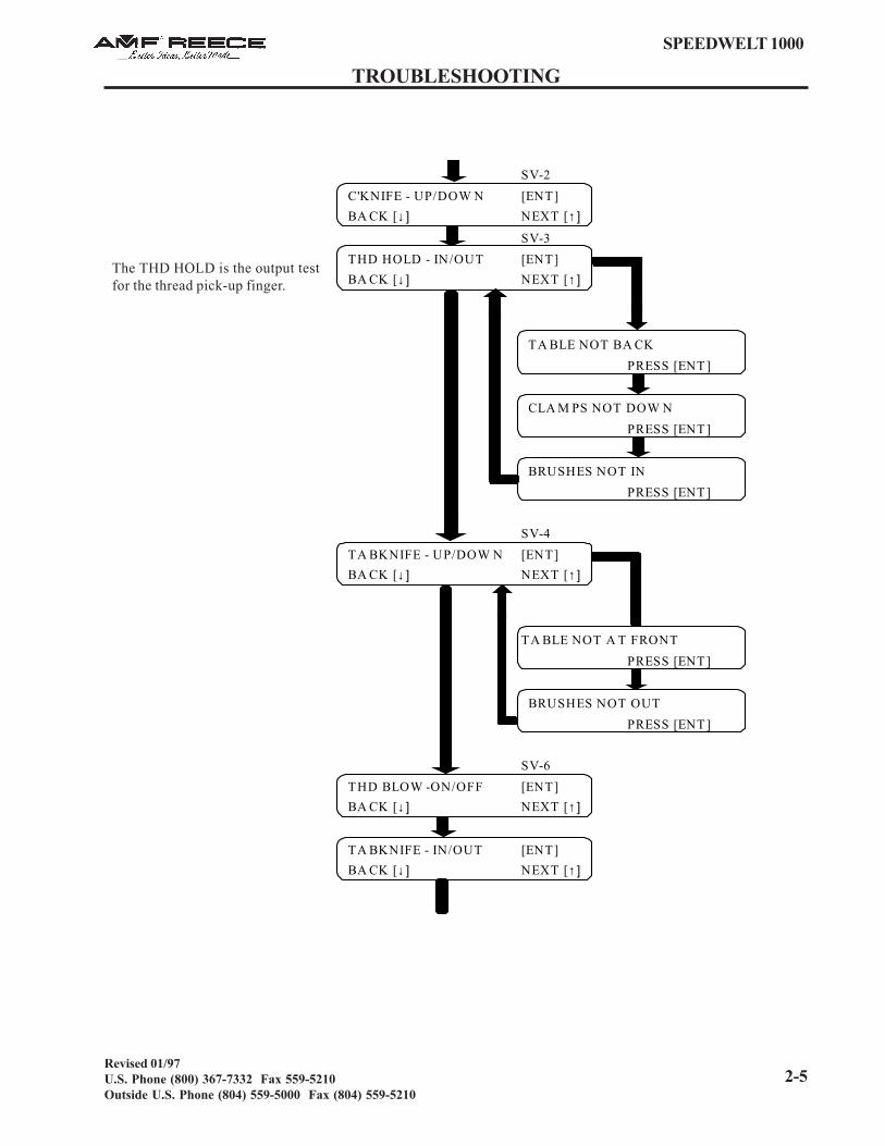
2-5
TROUBLESHOOTING
SPEEDWELT 1000
Revised 01/97U.S. Phone (800) 367-7332 Fax 559-5210Outside U.S. Phone (804) 559-5000 Fax (804) 559-5210
SV-2
C'KNIFE - UP/DOW N [ENT]
BA CK [↓] NEXT [↑]
SV-3
THD HOLD - IN/OUT [ENT]
BA CK [↓] NEXT [↑]
SV-4
TA BKNIFE - UP/DOW N [ENT]
BA CK [↓] NEXT [↑]
SV-6
THD BLOW -ON/OFF [ENT]
BA CK [↓] NEXT [↑]
TA BKNIFE - IN/OUT [ENT]
BA CK [↓] NEXT [↑]
PRESS [ENT ]
PRESS [ENT ]
PRESS [ENT ]
PRESS [ENT ]
BRUSHES NOT IN
TA BLE NOT A T FRONT
PRESS [ENT ]
TA BLE NOT BA CK
CLA M PS NOT DOW N
BRUSHES NOT OUT
The THD HOLD is the output testfor the thread pick-up finger.

2-6
SPEEDWELT 1000
TROUBLESHOOTING
Revised 01/97U.S. Phone (800) 367-7332 Fax 559-5210
Outside U.S. Phone (804) 559-5000 Fax (804) 559-5210
SV - 7 PATCH H/DOWN [ENT] BACK [↓] NEXT [↑]
SV -11 WORK EJECT [ENT] BACK [↓] NEXT [↑]
SV -9 P/CLAMP UP/DOWN [ENT] BACK [↓] NEXT [↑]
SV -10 P/LOAD IN/OUT [ENT] BACK [↓] NEXT [↑]
NEEDLE POSITION [ENT] BACK [↓] NEXT [↑]
NEEDLE POSITION INCORRECT ADJ. SYNCHRO
NEEDLE POSITION CORRECT
CLAMPS NOT DOWNPRESS [ENT]
BRUSHES NOT INPRESS [ENT]
TABLE NOT AT BACKPRESS [ENT]
CLAMPS NOT DOWNPRESS [ENT]
TABLE NOT AT BACKPRESS [ENT]
PRESS [ENT]
PRESS [ENT]
CLAMPS NOT DOWN
BRUSHES NOT IN
[ENT]
PRESS [ENT]

2-7
TROUBLESHOOTING
SPEEDWELT 1000
Revised 01/97U.S. Phone (800) 367-7332 Fax 559-5210Outside U.S. Phone (804) 559-5000 Fax (804) 559-5210
SET EJECT TIME [ENT] BACK [↓] NEXT [↑]
LESS [↓] 020
ENCODER COUNT [HOME] BACK [↓] NEXT [↑]
ENCODER COUNT [HOME] BACK [↓] NEXT [↑]
ENCODER COUNT [ENT] BACK [↓] NEXT [↑]
12390 + / - 40 = 12379 BACK [↓]
FIRST STITCH [ENT] BACK [↓] NEXT [↑]
LONGER [↓] SHORTER [↑] 250
LAST STITCH [ENT] BACK [↓] NEXT [↑]
LONGER [↓] SHORTER [↑] 250
LCD CONTRAST [ENT] BACK [↓] PRESS [CTR]
LIGHTER [↓] DARKER [↑]
SEW POCKET PRESS [CTR] PROGRAM PRESS [2]
SAVE COUNT [1]
PRESS [ENT]
PRESS [ENT]
PRESS [ENT]
MORE [↑] PRESS [ENT]
The ENCODER COUNT is thecount of pulses.
The FIRST STITCH and LASTSTITCH numbers control thestitch length.Example - The higher thenumber entered [ENT], theshorter the stitch
The LCD CONTRASTcontrols the brightness ofthe screen.
To exit, and return to thesewing mode, press [CTR].To enter the programmingfeature, press[2].

2-8
SPEEDWELT 1000
TROUBLESHOOTING
Revised 01/97U.S. Phone (800) 367-7332 Fax 559-5210
Outside U.S. Phone (804) 559-5000 Fax (804) 559-5210
C h a n g i n g t h e N e e d l e B i t e S i ze o n t h e S p e e d We l t 1 0 0 0
Remove the:
a) needle holderb) brush arms (do not lose leveling wedge)c) patch guided) clamp foote) throat platef) trim knife bracketg) tab knife holders
Install, in sequence, the new needle holder (page 1-14) and new throat plate (page 1-14).
Now, center the throat plate to the needle and check the center knife to the knife slot (page 1-26).Adjust the clamp mats to the throat plate (page 1-29). Install the new patch guide (page 1-15).Install the new clamp foot with the right pivot blocks, then center the clamp foot over the mats.
Install brush blades to the brush arms, then install the arms and adjust the patch guide (pages 1-16to 1-24). Adjust the loopers to the needles (pages 1-32 to 4-35). Install the new trim knife to thebracket and re-install the machine (page 1-36). Install the new tab knives and holders (page 1-19 to1-31).
Sew pockets on scrap material and check for correct stitch density, center knife cut, tab knife cut andfor any skipped stitches. Adjust the thread pick-up arms (page 1-39).