All-Electric Spin Control in Interference Single Electron Transistors
9
arXiv:0904.0167v1 [cond-mat.mes-hall] 1 Apr 2009 All-electric-spin control in interference single electron transistors Andrea Donarini, Georg Begemann, and Milena Grifoni Theoretische Physik, Universit¨at Regensburg, 93040 Regensburg, Germany Single particle interference lies at the heart of quantum mechanics. The archetypal double-slit experiment 1 has been repeated with electrons in vacuum 2,3 up to the more massive C 60 molecules 4 . Mesoscopic rings threaded by a magnetic flux provide the solid-state analogous 5,6 . Intra-molecular interference has been recently discussed in molecular junctions 7,8,9,10,11 . Here we propose to exploit interference to achieve all-electrical control of a single electron spin in quantum dots, a highly de- sirable property for spintronics 12,13,14 and spin-qubit applications 15,16,17,18,19 . The device consists of an interference single electron transistor (ISET) 10,11 , where destructive interference between orbitally degenerate electronic states produces current blocking at specific bias voltages. We show that in the presence of parallel polarized ferromagnetic leads the interplay between interference and the exchange coupling on the system generates an effective energy renormalization yielding different blocking biases for majority and minority spins. Hence, by tuning the bias voltage full control over the spin of the trapped electron is achieved. The all-electrical solutions to the challenge of single spin control that have been proposed 15,16,17,18 and realized 19,20 are based either on spin orbit-coupling 15,16,17,18,19 or on tunneling-induced spin splitting in the Kondo regime 20 . Our proposal relies on the current blocking occurring in an ISET due to interference between degenerate states. The conditions for interference blocking are very generic 11 and admit several different realizations. We consider here for clarity a benzene and a triple-dot ISET, Fig. 1. Both are described by the Hamiltonian: H = H sys + H leads + H T , (1) where H sys represents the central system and also contains the energy shift operated by a capacitively coupled gate electrode at the potential V g . The Hamiltonian H sys is in both cases invariant with respect to a discrete set of rotations around the vertical axis passing through the center of the system. This fact allows a classification of its eigenstates in terms of the z component of the angular momentum ℓ and also ensures the existence of degenerate states with different ℓ. Then, a generic eigenstate is represented by the ket |NℓσE〉 where N is the number of electrons on the system, σ is the spin and E the energy of the state. When degenerate states participate to transport they interfere since, like the two paths of the double-slit experiment, they are occupied simultaneously by the travelling electron, but in different superpositions under diverse transport conditions. H lead describes the ferromagnetic leads with equal (for simplicity) parallel polarization P and with a difference eV b between their electrochemical potentials. Finally, H T accounts for the weak tunnelling coupling between the system and the leads, characteristic of SETs, and we consider the tunnelling events restricted to the atoms or to the dots closest to the corresponding lead (Fig. 1). We explicitly consider the Coulomb interaction only in the central part of the device (see the supplementary material 1) due to the strong confinement experienced there by the electrons while, apart from the polarization assumption, we assume a non interacting approximation for the leads. In the weak coupling regime the current essentially consists of sequential tunnelling events at the source and drain lead that increase or decrease by one the number of electrons on the system. The different panels of Figs. 2 and 3 show the current through the benzene and triple dot ISET, respectively, as a function of bias and gate voltage. As in all SETs at low bias so called Coulomb diamonds, where transport is energetically forbidden, occur. Within the diamonds the particle number is fixed as indicated in the figures. Only exceptions are the charge degenerate points FIG. 1: Two examples of interference single electron transistors (ISETs): a benzene molecular junction contacted in the meta configuration (A) and a triple quantum dot artificial molecule (B). The source and drain are parallel polarized ferromagnetic leads.
-
Upload
independent -
Category
Documents
-
view
2 -
download
0
Transcript of All-Electric Spin Control in Interference Single Electron Transistors

arX
iv:0
904.
0167
v1 [
cond
-mat
.mes
-hal
l] 1
Apr
200
9
All-electric-spin control in interference single electron transistors
Andrea Donarini, Georg Begemann, and Milena GrifoniTheoretische Physik, Universitat Regensburg, 93040 Regensburg, Germany
Single particle interference lies at the heart of quantum mechanics. The archetypal double-slitexperiment1 has been repeated with electrons in vacuum2,3 up to the more massive C60 molecules4.Mesoscopic rings threaded by a magnetic flux provide the solid-state analogous5,6. Intra-molecularinterference has been recently discussed in molecular junctions7,8,9,10,11. Here we propose to exploitinterference to achieve all-electrical control of a single electron spin in quantum dots, a highly de-sirable property for spintronics12,13,14 and spin-qubit applications15,16,17,18,19. The device consists ofan interference single electron transistor (ISET)10,11, where destructive interference between orbitallydegenerate electronic states produces current blocking at specific bias voltages. We show that in thepresence of parallel polarized ferromagnetic leads the interplay between interference and the exchangecoupling on the system generates an effective energy renormalization yielding different blocking biasesfor majority and minority spins. Hence, by tuning the bias voltage full control over the spin of thetrapped electron is achieved.
The all-electrical solutions to the challenge of single spin control that have been proposed15,16,17,18 and realized19,20
are based either on spin orbit-coupling15,16,17,18,19 or on tunneling-induced spin splitting in the Kondo regime20. Ourproposal relies on the current blocking occurring in an ISET due to interference between degenerate states. Theconditions for interference blocking are very generic11 and admit several different realizations. We consider here forclarity a benzene and a triple-dot ISET, Fig. 1. Both are described by the Hamiltonian:
H = Hsys +Hleads +HT, (1)
where Hsys represents the central system and also contains the energy shift operated by a capacitively coupled gateelectrode at the potential Vg. The Hamiltonian Hsys is in both cases invariant with respect to a discrete set of rotationsaround the vertical axis passing through the center of the system. This fact allows a classification of its eigenstatesin terms of the z component of the angular momentum ℓ and also ensures the existence of degenerate states withdifferent ℓ. Then, a generic eigenstate is represented by the ket |NℓσE〉 where N is the number of electrons on thesystem, σ is the spin and E the energy of the state. When degenerate states participate to transport they interferesince, like the two paths of the double-slit experiment, they are occupied simultaneously by the travelling electron,but in different superpositions under diverse transport conditions. Hlead describes the ferromagnetic leads with equal(for simplicity) parallel polarization P and with a difference eVb between their electrochemical potentials. Finally, HT
accounts for the weak tunnelling coupling between the system and the leads, characteristic of SETs, and we considerthe tunnelling events restricted to the atoms or to the dots closest to the corresponding lead (Fig. 1). We explicitlyconsider the Coulomb interaction only in the central part of the device (see the supplementary material 1) due tothe strong confinement experienced there by the electrons while, apart from the polarization assumption, we assumea non interacting approximation for the leads.
In the weak coupling regime the current essentially consists of sequential tunnelling events at the source and drainlead that increase or decrease by one the number of electrons on the system. The different panels of Figs. 2 and 3show the current through the benzene and triple dot ISET, respectively, as a function of bias and gate voltage. Asin all SETs at low bias so called Coulomb diamonds, where transport is energetically forbidden, occur. Within thediamonds the particle number is fixed as indicated in the figures. Only exceptions are the charge degenerate points
FIG. 1: Two examples of interference single electron transistors (ISETs): a benzene molecular junction contacted in the metaconfiguration (A) and a triple quantum dot artificial molecule (B). The source and drain are parallel polarized ferromagneticleads.

2
where two diamonds meet. Here the energy difference of two ground states with consecutive particle numbers isequal to the equilibrium chemical potential of the leads. At finite bias the incoming electrons have enough energy toovercome the level spacing and the Coulomb repulsion and the current flows. As a signature of the new states thatenter the bias window, by increasing the voltage the current typically increases steplike.
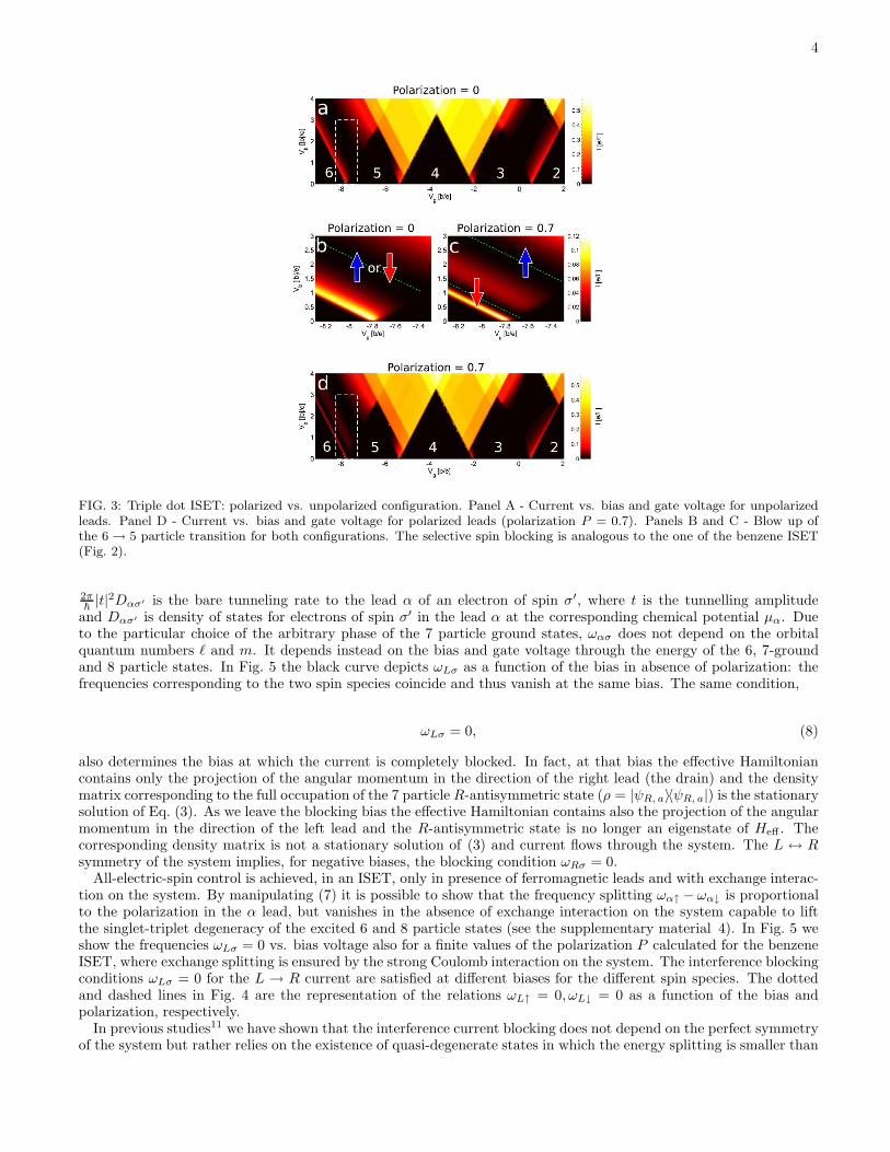
In ISETs an exception to this picture is represented by the interference blockade where the current decreases forincreasing bias generating negative differential conductance (NDC) and eventually vanishes (see green lines in thepanels B and C of Fig. 2 and 3). Panels B in the same figures indicate moreover that, for a given gate voltage and inabsence of polarization in the leads, the current is blocked only at one specific bias voltage. For parallel polarized leads,however, at a given gate voltage, the current is blocked at two specific bias voltages, one for each spin configuration(panels C). As demonstrated below, the blocking of the minority electrons occurs for the smaller bias voltages. Assuch full control of the spin configuration in the ISET can be electrically achieved. The interference blockade and itsspin selectivity is also demonstrated in panels A and B of Fig. 4. Along the dotted (dashed) line a majority (minority)spin electron is trapped into the molecule. The molecular spin state can thus be manipulated simply by adjusting thebias across the ISET. In the following we discuss the physics of the spin-selective interference blocking and presentthe necessary ingredients for its occurrence.
This novel blocking is explained by the presence of an N -particle non-degenerate state and two degenerate N + 1-particle states that simultaneously contribute to transport. It also requires that the ratio between the transitionamplitudes γαi (i = 1, 2, α = L,R) between those N - and N + 1-particle states is different for tunneling at the left(L) and at the right (R) lead11:
γL1
γL26=γR1
γR2. (2)
This condition is fulfilled in both cases presented in Fig. 1 due to the geometrical configuration of the left and rightlead. Due to condition (2), the degenerate states interfere among themselves such to form pairs of blocking andnon-blocking states. The blocking state is only coupled to the source lead (panels C and D of Fig. 4) while thenon-blocking one to both source and drain. An electron that populates the blocking state can neither leave towardsthe drain nor, at high enough bias, return to the source since all energetically available states are there filled. Thenon-blocking state is thus excluded from the dynamics and the current vanishes.
As such we would conclude that the interference blocking is a threshold effect and the current remains blocked untila new excited state participates to the transport. However, as shown in Fig. 2 and 3, the current is blocked only atspecific values of the bias voltage. The explanation of this phenomenon relies on two observations: i) The blockingstate (Fig. 4) must be antisymmetric with respect to the plane perpendicular to the system and passing through itscenter and the atom (quantum dot) closest to the drain; this state is thus also an eigenstate of the projection ofthe angular momentum in the direction of the drain lead21. At positive (negative) bias voltages we call this statethe R(L)-antisymmetric state |ψR(L), a〉. ii) The coupling between the system and the leads not only generates thetunneling dynamics described so far, but also contributes to an internal dynamics of the system that leaves unchangedits particle number. In fact the equation of motion for the reduced density matrix ρ of the system can be cast, tolowest non vanishing order in the coupling to the leads, in the form:
ρ = −i
~[Hsys, ρ] −
i
~[Heff , ρ] + Ltunρ. (3)
The commutator with Hsys in Eq. (3) represents the coherent evolution of the system in absence of the leads. Theoperator Ltun, describes instead the sequential tunnelling processes and is defined in terms of the transition amplitudesγαi between the N and N + 1 particle states like the ones introduced in equation (2). Eventually Heff renormalizesthe coherent dynamics associated to the system Hamiltonian. It reads:
Heff =∑
ασ
ωασLα, (4)
where Lα is the projection of the angular momentum in the direction of the lead α and, for paramagnetic systems,it does not depend on the spin degree of freedom σ. Moreover, ωασ is the frequency renormalization given to thestates of spin σ by their coupling to the α lead. Equation (3) is an example of Bloch-Redfield equation describingthe dynamics of a system coupled to thermal baths. A more detailed version of (3) is presented in the supplementarymaterial 2.
For sake of simplicity we give in the following the explicit form of the transition amplitudes γαi, of the operatorLα and of the associated frequency ωασ only for the benzene ISET and for the ground state transition 6g → 7g thatis characterized by interference blocking. The argumentation is nevertheless very general and can be repeated for allthe systems exhibiting rotational symmetry. The transition amplitudes read:

3
FIG. 2: Benzene ISET: polarized vs. unpolarized configuration. Panel A - Current vs. bias and gate voltage for unpolarizedleads. Panel D - Current vs. bias and gate voltage for polarized leads (polarization P = 0.85). Panels B and C - Blow up of the6 → 7 particle transition for both configurations. The unpolarized case shows a single current blocking line and the trappedelectron has either up or down polarization. The polarized case shows two current blocking lines, corresponding to the differentspin of the trapped electron. The current is given in units of e/Γ where Γ is the bare average rate (supplementary material 4),and the temperature kBT = 0.01b where b is the hopping parameter (supplementary material 1)
γαℓ = 〈6g00|dMσ|7gℓσ〉e−iℓφα , (5)
where |7g ℓ σ〉 are the orbitally degenerate 7 particle ground states, ℓ = ±2 the z projection of the angular momentum
in units of ~ and dMσ destroys an electron of spin σ in a reference carbon atom M placed in the middle between thetwo contact atoms. Moreover, φα is the angle of which we have to rotate the molecule to bring the reference atom Minto the position of the contact atom α. The present choice of the reference atom implies that φL = −φR = π
3 . Inthe Hilbert space generated by the two-fold orbitally degenerate |7g ℓ σ〉 the operator Lα reads:
Lα =~
2
(
1 ei2|ℓ|φα
e−i2|ℓ|φα 1
)
. (6)
For a derivation of (6) see the supplementary material 3 The frequency ωασ is defined in terms of transitionamplitudes to all the states of neighbour particle numbers:
ωασ =1
π
∑
σ′{E}
Γ0ασ′
[
〈7gℓσ|dMσ′ |8{E}〉〈8{E}|d†Mσ′ |7gmσ〉pα(E − E7g)+
〈7gℓσ|d†Mσ′ |6{E}〉〈6{E}|dMσ′ |7gmσ〉pα(E7g
− E)]
,
(7)
where the compact notation |N{E}〉 indicates all possible states with particle number N and energy E, pα(x) =
−Reψ[
12 + iβ
2π(x− µα)
]
where β = 1/kBT , T is the temperature and ψ is the digamma function. Moreover Γ0ασ′ =
4
FIG. 3: Triple dot ISET: polarized vs. unpolarized configuration. Panel A - Current vs. bias and gate voltage for unpolarizedleads. Panel D - Current vs. bias and gate voltage for polarized leads (polarization P = 0.7). Panels B and C - Blow up ofthe 6→ 5 particle transition for both configurations. The selective spin blocking is analogous to the one of the benzene ISET(Fig. 2).
2π~|t|2Dασ′ is the bare tunneling rate to the lead α of an electron of spin σ′, where t is the tunnelling amplitude
and Dασ′ is density of states for electrons of spin σ′ in the lead α at the corresponding chemical potential µα. Dueto the particular choice of the arbitrary phase of the 7 particle ground states, ωασ does not depend on the orbitalquantum numbers ℓ and m. It depends instead on the bias and gate voltage through the energy of the 6, 7-groundand 8 particle states. In Fig. 5 the black curve depicts ωLσ as a function of the bias in absence of polarization: thefrequencies corresponding to the two spin species coincide and thus vanish at the same bias. The same condition,
ωLσ = 0, (8)
also determines the bias at which the current is completely blocked. In fact, at that bias the effective Hamiltoniancontains only the projection of the angular momentum in the direction of the right lead (the drain) and the densitymatrix corresponding to the full occupation of the 7 particle R-antisymmetric state (ρ = |ψR, a〉〈ψR, a|) is the stationarysolution of Eq. (3). As we leave the blocking bias the effective Hamiltonian contains also the projection of the angularmomentum in the direction of the left lead and the R-antisymmetric state is no longer an eigenstate of Heff . Thecorresponding density matrix is not a stationary solution of (3) and current flows through the system. The L ↔ Rsymmetry of the system implies, for negative biases, the blocking condition ωRσ = 0.
All-electric-spin control is achieved, in an ISET, only in presence of ferromagnetic leads and with exchange interac-tion on the system. By manipulating (7) it is possible to show that the frequency splitting ωα↑ − ωα↓ is proportionalto the polarization in the α lead, but vanishes in the absence of exchange interaction on the system capable to liftthe singlet-triplet degeneracy of the excited 6 and 8 particle states (see the supplementary material 4). In Fig. 5 weshow the frequencies ωLσ = 0 vs. bias voltage also for a finite values of the polarization P calculated for the benzeneISET, where exchange splitting is ensured by the strong Coulomb interaction on the system. The interference blockingconditions ωLσ = 0 for the L → R current are satisfied at different biases for the different spin species. The dottedand dashed lines in Fig. 4 are the representation of the relations ωL↑ = 0, ωL↓ = 0 as a function of the bias andpolarization, respectively.
In previous studies11 we have shown that the interference current blocking does not depend on the perfect symmetryof the system but rather relies on the existence of quasi-degenerate states in which the energy splitting is smaller than

5
FIG. 4: Spin control. Panel A - Current through the benzene ISET vs bias and polarization at the 6→ 7 electrons transition.Panel B - Population of the majority spin 7 particle state. The two zero current lines at high bias correspond to the maximumor minimum population of the 7 particle majority spin state and thus identify the spin state of the trapped electron on themolecule. Panels C and D - Schematic representation of the spin selective blocking corresponding to the dashed (C) and dotted(D) lines of the panels A and B.
FIG. 5: Blocking condition. Renormalization frequencies ωLσ of a benzene ISET as function of the bias and for different leadpolarizations. The current blocking condition ωLσ = 0 is fulfilled at different biases for the different spin states.
the tunnelling coupling to the source and drain leads. In the proposed structures the degeneracy is associated withthe rotational symmetry and it has the advantage of a simple geometrical realization of the interference conditions(2). Nevertheless the effect is more general and any other structure exhibiting orbital degeneracy is a good candidatefor an ISET.
We acknowledge financial support by the DFG under the programs SFB689, SPP1243.
1 Young, T., Experiments and calculations relative to physical optics, Phil. Trans. Royal Society of London 94, 12-48 (1804).2 Jonsson, C., Elektroneninterferenzen an mehreren kunstlich hergestellten Feinspalten, Z. Physik 161, 454-474 (1961).

6
3 Merli, P. G., Missiroli, G. F., and Pozzi, G., On the statistical aspect of electron interference phenomena, Am. J. Phys. 44,306-307 (1976).
4 Arndt, M. et al., Wave-particle duality of C60 molecules, Nature 401, 680-682 (1999).5 Yacoby, A., Heiblum, M., Mahalu, D., and Shtrikman, H., Coherence and phase sensitive measurements in a quantum dot,
Phys. Rev. Lett. 74, 4047-4050 (1995).6 Gustavsson, S., Leturcq, R., Studer, M., Ihn, T., and Ensslin, K., Time-Resolved Detection of Single-Electron Interference,
Nano Lett. 8, 2547-2550 (2008).7 Cardamone, D. V., Stafford, C. A., and Mazumdar, S. Controlling quantum transport through a single molecule, Nano Lett.
6, 2422-2426 (2006).8 Ke, S.-H., Yang, W., and Baranger, U., Quantum-interference-controlled molecular electronics, Nano Lett. 8, 3257-3261
(2008).9 Quian, Z., Li, R., Zhao, X., Hou, S., and Sanvito, S., Conceptual molecular quantum phase transistor based on first-principles
quantum transport calculations, Phys. Rev. B 78, 113301.1-4 (2008).10 Begemann, G., Darau, D., Donarini, A., and Grifoni, M., Symmetry fingerprints of a benzene single-electron transistor:
Interplay between Coulomb interaction and orbital symmetry, Phys. Rev. B 77, 201406(R).1-4 (2008); 78, 089901(E).1(2008).
11 Darau, D., Begemann, G., Donarini, A., and Grifoni, M., A benzene interference single-electron transistor, arXiv:0810.2461.12 Wolf, S. A. et al., Spintronics: A spin-based electronic vision for the future, Science 294, 1488-1495 (2001).13 Awschalom, D. D., and Flatte, M. E., Challenges for semiconductor spintronics, Nature Phys. 3 153-159 (2007).14 Ohno, H. et al., Elecric-field control of ferromagnetism, Nature 408, 944-946 (2000).15 Golovach, V. N., Borhani,M., Loss, D., Electric-dipole-induced spin resonance in quantum dots, Phys. Rev. B 74, 165319.1-10
(2006).16 Levitov, L., Rashba, E., Dynamical spin-electric coupling in a quantum dot, Phys. Rev. B 67, 115324.1-5 (2003).17 Debald, S., Emary, C., Spin-orbit-driven coherent oscillations in a few-electron quantum dot, Phys. Rev. Lett. 94, 226803.1-4
(2005).18 Walls, J., Parametric spin excitations in lateral quantum dots, Phys. Rev. B 76, 195307.1-16 (2007).19 Nowack, K. C., Koppens, F. H. L., Nazarov, Yu. V., Vandersypen, L. M. K., Coherent control of a single electron spin with
electric fields, Science 318, 1430-1433 (2007).20 Hauptmann, J. R., Paaske, J., Lindelof, P. E., Electric-field-controlled spin reversal in a quantum dot with ferromagnetic
contacts, Nature Phys. 4, 373-376 (2008).21 The corresponding eigenvalue depends on the symmetry of the atomic (quantum dot) wave function with respect to the
molecular (artificial molecule) plane: ~ or 0 for symmetric or antisymmetric wave fuctions respectively.

7
SUPPLEMENTARY MATERIAL
1. The system Hamiltonian
The Hamiltonian that describes both systems represented in Fig. 1 reads
Hsys = ξ0∑
iσ
d†iσdiσ + b∑
iσ
(
d†iσdi+1σ + d†i+1σdiσ
)
+U∑
i
(
ni↑ −12
) (
ni↓ −12
)
+V∑
i
(ni↑ + ni↓ − 1) (ni+1↑ + ni+1↓ − 1) ,
(9)
where d†iσ creates an electron of spin σ in the pz orbital of carbon i or in the ground state of the quantum dot i and
i = 1, . . . , 6(3) runs over the six carbon atoms (three quantum dots) of the system. Moreover niσ = d†iσdiσ. Theeffect of the gate is included as a renormalization of the on-site energy ξ = ξ0 − eVg (Vg is the gate voltage) andwe conventionally set Vg = 0 at the charge neutrality point. The parameters that we have used are b = 2.5eV, U =9eV, V = 6eV.
2. The generalized master equation
We describe the dynamics of the system with a generalized master equation (GME) for the reduced density matrixρ. This equation is obtained from the Liouville equation for the full density matrix as a perturbation to the lowestnon vanishing order in the coupling to the leads by tracing out the leads degrees of freedom. A generic formulation ofthe GME for a SET in presence of degeneracies or quasi-degeneracies can be found elsewhere e.g.11. We concentratehere on the range of gate and bias voltages at which the dynamics is restricted to transitions involving the |6g00〉 and|7gℓσ〉 many particle states of the benzene ISET.
The seven particle states are spin and orbital degenerate. The general theory of the GME would require a priorito keep thus a full 4x4 density matrix describing the 7 particle subspace. In presence of parallel polarized leads,though, the coherences between different spin degrees of freedom can be neglected since spin is always conservedby the electrons while travelling through the device. The GME can thus be written in terms of the nine variablescollected in the 1x1 matrix ρ6g and the two 2x2 matrices ρ7gσ with σ =↑, ↓. Due to the rotational symmetry of thesystem it is more convenient to refer to another set of variables, namely to describe the dynamics in terms of theoccupation probabilities W6, W7σ and the expectation values of the different projections of the angular momentumfor the system. The new set of variables is:
W6 = ρ6g ,
W7σ = Tr{ρ7gσ},
Lασ = Tr{Lαρ7gσ},
Lzσ = Tr{Lzρ7gσ}.
(10)
The operator Lz is the generator of the set of discrete rotations around the axis perpendicular to the plane of thebenzene molecule that bring the molecule into itself and can be written within the 7 particle Hilbert space spannedby the vectors |7gℓσ〉 as Lz = −~|ℓ|σz, where σz is the third Pauli matrix. The operator Lα generates, in the samespace, the discrete rotations around the axis in the molecular plane and passing through the center and the atomclosest to the contact α. Finally, the dynamics for the variables introduced in Eq. (10) is given by the equations:

8
W6 =2∑
ασ
Γασ
[
−f+α (∆E)W6 + f−
α (∆E)Lασ
]
,
W7σ =2∑
α
Γασ
[
f+α (∆E)W6 − f−
α (∆E)Lασ
]
,
Lασ = − 2Γασf−α (∆E) + 2
{
Γασf+α (∆E) + Γασf
+α (∆E) cos2[|ℓ|(φα − φα)]
}
W6
+ Γασf−α (∆E) sin2[|ℓ|(φα − φα)]W7σ − Γασf
−α (∆E)(Lασ + Lασ) +
sin[2|ℓ|(φα − φα)]
4ωασLzσ,
Lzσ = −∑
α
Γασf−α (∆E)Lzσ − 2 tan[|ℓ|(φL − φR)](ωLσ − ωRσ)(W7σ − LLσ − LRσ)
− 2 cot[|ℓ|(φL − φR)](ωLσ + ωRσ)(LLσ − LRσ),
(11)
where Γασ = Γ0ασ|〈6g00|dασ|7gℓσ〉|
2 is the tunnelling rate at the lead α involving the ground states with 6 and 7particles. Terms describing sequential tunnelling from and to the lead α are proportional to the Fermi functionsf+
α (x) := f(x − µα) and f−α (x) := 1 − f+
α (x), respectively, and ∆E = E6g − E7g + eVg where E6g and E7g are theenergies of the 6 and 7 particle ground states. Finally with α we mean the lead opposite to the lead α. By using theexpression |ℓ| (to be substituted with 2 for the 6 → 7 particle transition) we maintained the generality of the equations.The replacement |ℓ| = 2 → 1 and the appropriate redefinition of ∆E is enough to treat the 6 → 5 transition. Anotherimportant generalization concerns the position of the leads. The para (φL − φR = π) and ortho (φL − φR = π/3)configuration are also treated within the same equations. In particular one can see that all the terms containing therenormalization frequencies drop from the equations in the para configuration and that the equations for the orthoand meta configuration coincide.
3. Matrix form of the operator Lα
The explicit form of Lα is given in Eq. (6). We give here its derivation. It is convenient, for this purpose, tochoose the arbitrary phases of the states |7gℓσ〉 in such a way that the rotation of π around the axis passing througha reference atom M and the center of the molecule transforms |7gℓσ〉 into −|7g − ℓσ〉. In other terms
exp(iπLM
~) = −σx, (12)
where σx is the first Pauli matrix. The relation is in fact an equation for LM and the solution reads:
LM =~
2
(
1 11 1
)
. (13)
Eventually we obtain Lα by rotation of LM in the molecular plane, namely:
Lα = e−i~
φαLzLMei~
φαLz =~
2
(
1 ei2|ℓ|φα
e−i2|ℓ|φα 1
)
, (14)
where φα is the angle of which we have to rotate the molecule to bring the reference atom M into the position of thecontact atom α.

9
4. The spin splitting of the renormalization frequencies
The spin splitting of the renormalization frequencies is obtained from Eq. (7). By introducing the average bare rate
Γ =Γ0
α↑+Γ0
α↓
2 , for simplicity equal in both leads, and using the fact that benzene is paramagnetic we get:
ωα↑−ωα↓ = 2Γ0αPα
1
π
∑
{E}[
〈7gℓ ↑ |dM↑|8{E}〉〈8{E}|d†M↑|7gm ↑〉pα(E − E7g)
+〈7gℓ ↑ |d†M↑|6{E}〉〈6{E}|dM↑|7gm ↑〉pα(E7g− E)
−〈7gℓ ↑ |dM↓|8{E}〉〈8{E}|d†M↓|7gm ↑〉pα(E − E7g)
−〈7gℓ ↑ |d†M↓|6{E}〉〈6{E}|dM↓|7gm ↑〉pα(E7g− E)
]
,
(15)
where one appreciates the linear dependence of the spin splitting on the lead polarization Pα. The first and the thirdterm of the sum would cancel each other if the energy of the singlet and triplet 8 particle states would coincide.An analogous condition, but this time on the 6 particle states, concerns the second and the fourth terms. For thisreason the exchange interaction on the system is a necessary condition to obtain spin splitting of the renormalizationfrequencies and thus the full all-electric spin control.