airbase_3933.pdf - AIVC
144
.,. ,, ,. j [ r I " .. SLUTRAPPORT ISSN 0284-141X 5:- ;t,j,7. f} SCIENCE ROYAL 11» AND ART ) INSTITUTE OF TECHNOLOGY BUILDING SERVICES ENGINEERING Bulletin No. 14 ----- STAT;:Ns RAO FOR BYGGNADSFORSKNING Tagit del \\!'(\_ Dnr Inkom 1989 -10- 1 3 Handlagges a'J A/ ,,0 Besv. Tel. brev. yttr. Arkivering THE BRIS COMPUTER PROGRAM FOR SIMULATING BUILDING THERMAL BEHAVIOUR Physical basis and principles of data handling GOSTA BROWN
-
Upload
khangminh22 -
Category
Documents
-
view
4 -
download
0
Transcript of airbase_3933.pdf - AIVC

,~
.,.
r-~ ,, ,.
j
[
r
I
"
..
SLUTRAPPORT -#3cL~3 ISSN 0284-141X
5:-
;~~k., ;t,j,7. ~ f} SCIENCE ~ ROYAL 11» AND '~ ~"" ART ) INSTITUTE OF ~~~P" TECHNOLOGY
BUILDING SERVICES ENGINEERING
Bulletin No. 14
~ ~}
/c~J>r/_ -----STAT;:Ns RAO FOR BYGGNADSFORSKNING Tagit del \\!'(\_ Dnr ~~//.:7--5 Inkom 1989 -10- 1 3 Handlagges a'J A/ ,,0 Besv. Tel. brev. yttr. Arkivering cY1f?~//.;7-
THE BRIS COMPUTER PROGRAM
FOR SIMULATING BUILDING THERMAL BEHAVIOUR
Physical basis and principles of data handling
GOSTA BROWN

a
t
ISSN 0284-141X
<)
.(l~k . VJ·· -· ~JS:;.t I SCIENCE . ~~. ROYAL
11J AND m INSTITUTE oF - {~ ART @l
=-~~ ==:.~· TECHNOLOGY ,~x~·
BUILDING SERVICES ENGINEERING
Bulletin No. 14
THE BRIS COMPUTER PROGRAM
FOR SIMULATING
BUILDING THERMAL BEHAVIOUR
Physical basis and principles of data handling
Royal Institute of Technology
Department of Building Services Engineering
S-10044 Stockholm, Sweden
1989 BFR - Project No. 890665-3
GOSTA BROWN
~
r

I r .
r
I I
I '
/
CONTENTS
PREFACE
INTRODUCTION
Some characteristics of the program History and usage of the program References
1 CALCULATION OF HEAT AND LIGHT RADIATION IN ROOMS
1
3
7
7 13 18
21
Definitions 21
Conditions 22
Equations for calculating angle factors 22 Example 1 30
Equations for calculating absorption factors 33 Example 2 Absorption factors when surface
reflectivities are equal 36
Example 3 Variation of daylight intensity in a room 41
References 46
2 CALCULATION OF HEATING AND COOLING LOADS 47
Introduction 47
Heat transfer under steady-state temperature conditions 50 Thermal conduction in the interior of a wall
or flooring 50 Heat transfer with respect to facade and room
~ surfaces 51 ' Heat balance for room air 60
Heat balance equations for nonsteady-state temperature conditions 61
Assembly of equations 61 Derivation and explanation of equations 64
Notes on calculation by means of a computer 71
References 74
3 CALCULATION OF HEATING AND COOLING LOADS - AN EXAMPLE 75

•
'
4 PRESENT-DAY STATE OF THE PROGRAM
4.1 Physical basis
4.1.1 Climatic data 4.1.2 Heat transfer through windows 4.1.3 Thermal radiation between room surfaces 4.1.4 Convection heat transfer at room surfaces 4.1.5 Heat sources in a room
4.2 Data handling
4.2.1 General information 4.2.2 Room data 4.2.3 Wall and floor structure data 4.2.4 Air handling control 4.2.5 Use of the concept "quantity sought" 4.2.6 Ventilated floor slab (TermoDeck)
4.2.7 Result output 4.2.7.l Example 4.2.7.2 Frequencies for heating and cooling
powers 4.2.7.3 Plot file
Appendix A: Data forms
Appendix B: A complete printout - an example
Appendix C: Shading coefficients and U-values for windows
87
87
87 89 91 93 94
96
96 101 102 103 105 109
112 (.
112
122 123

I I
....
3
Preface
Up ,to now, a comprehensive description of BRIS, the oldest
and most complete Swedish computer program for simulating
building thermal behaviour, has not been published in
English. In Swedish three articles were issued in 1963 and
1964 in the HVAC-journal VVS . They were also brought to
gether in a reprint in 1964 from the National Swedish
Institute for Building Research (see the reference list at
the end of Introduction). The first article gives a method
of calculating heat and light radiation in rooms, the second
deals with calculating heating and cooling loads, while the
third shows an appl~cation example.
These articles were translated to English in 1965, by
Mr. R.M . E. Diamant, at that time lec~urer in chemical
engineering at the Royal College of Advanced Technology,
Salford. These translations are presented here as Chapters
1, 2 and 3 with only a few corrections.
Including these early articles without alterations of the
text may seem astonishing, after the passing of 25 years .
However, the algorithms used in the program are still the
same, even though the manner of presentation of input and
output data is different, as well as the data handling in
the program. The unit for thermal power is W in the program .
In the Chapters 2 and 3 kcal/h has been kept, presumably·
without any disadvantage for the understanding. Further, for
a reader of today, some remarks in the section 'Notes on
calculation by means of a computer', ' at the end of Chapter
2, may seem superfluous. They are however representative of
the problems at the time of the origin of the program, thus
motivating a preservation.

•
a
4
Since then, the program has been used in a large number of
applications in the fields of research and design. The basis
of input data, such as for climate and heat transfer through
windows etc., has expanded and improved. The computer
technology has developed trernendousl~. All this has
suggested that the way of dealing with the thermodynamics, -as well as the data handling, be given a more detailed
account. This has been done in Chapter 4 .
An example shows an application of the program at the end of
the data handling section. The printout from this example,
including the input data, is given in Appendix B. Appendix A
contains a set of blank data forms, while in Appendix C
shading coefficients and thermal transmission coefficients
of fenestrations are tabulated, for recommended use in the
program.
A reader who is most interested in the use of the BRIS
program and not so much in its physical background may
concentrate his attention to Introduction, Chapter 4 and
the Appendices.
Finally, I would like to express my great gratitude to
Axel Bring, Engelbrekt Istalt and Ed Sowell.
Mr. Axel Bring is the programmer of BRIS. He has also from
the beginning up to now accomplished all program improve
ments and amplifications, including the forms in Appendix A.
He is the author of BRIS prograrnbeskrivning (Bring, 1982)
(User's Manual for BRIS) on which the contents of Chapter 4,
to a great extent, are based. By introducing the code
usaqe of handling the socalled 'quantity sought' in the
program, he has created good conditions for a versatile
system simulation to achieve energy efficient control
strategies.

,,
.,,
5
Dr. Engelbrekt Isfalt has been the most industrious user of
ERIS. His interest in the research field of later years has
been to gain a good thermal indoor climate by taking advan
tage of the heat capacity of building structures, in that
way using a minimum of power input. This is exemplified by
the design of ventilated floor slabs (see Section 4.2.6.).
Professor Edward F. Sowell of the Computer Science
Department at the California State University, Fullerton,
has been visiting professor at the Department of Building
Services Engineering during the last six months. Sowell, who
has been active on several ASHRAE technical committees con
cerned with these matters, has read the manuscript careful
ly, and I feel highly obliged to him for his comments and
criticisms and, also, help in improving the language.
Stockholm, March 1989
Gosta Brown

a
t
....,
7
INTRODUCTION
Some characteristics of the orogram
The ERIS program, developed at the Royal Institute of
Technology, Stockholm, calculates the temperature variations
that occur in a room subject to variable external and in
ternal heat gains. An iterative, finite difference method is
used to solve a system of heat balance equations, taking
into account the effect of heat transfer by radiation be
tween the room surfaces, by convection between the room air
and room surfaces, and by conduction between the different
material layers of the walls and floors. The surface tempe
ratures and the room air temperatures are used to calculate
operative temperatures (below also called effective tempera
tures) and the comfort number, which is a measure of the a
symmetry of the radiation field. The temperatures on the
outside surfaces of walls and floor slabs that enclose a
room are also calculated. This allows conditions in adjacent
rooms, having different heat gains, to be taken into
account.
The implementation, using the iterative method, is briefly
described as follows. All temperatures prevailing at the
beginning of the period being studied, say 24 hours, are
assumed to be known. The period is divided into time steps
of, for instance, one hour or half an hour. The time step
must be short enough so that the variation in temperature~,
radiation intensities etc. during the step may be assumed to
be linear (and so that oscillations in the calculations do
not occur). A calculation, using the system of the heat ba
lance equations, gives the temperatures at the end of one
step from the corresponding figures at the beginning of the
step. Once the temperatures at the end of the first step
have been determined, they are used to calculate the tem
peratures at the end of the next step, with modified values

~
~
8
of coefficients in the equations if necessary. Thus we pro
ceed step by step until we have calculated the temperatures
and other sought variables during the entire calculation
period.
In the heat balance equation for a material layer, the tem
perature change of the layer during a time step is assumed
to be proportional to the average value of the difference
between the temperature gradient at the boundary surfaces of
the layer at the beginning and at the end of the time step.
In other words, implicit midpoint equations are used.
The iterative solution method is very advantageous in con
nection with quantities which are nonlinearly dependent on
the calculated temperatures. This is the case for the ex
change of longwave radiation between the room surfaces,
which in BRIS is determined in accordance with the Stefan~
Boltzmann law, and for the convective heat transfer at the
room surfaces. The stratification at the floor is not like
that at the ceiling. Therefore different expressions are
used in BRIS for the temperature dependence of the con
vective heat transfer coefficients valid at wall, ceiling
and floor.
Iterative calculations promotes a high degree of accuracy.
Versatility is another advantageous property of the pro
gram. Versatility is achieved by use of a variable called
'quantity sought' which can be given different code num
bers. The number says which of four quantities is to be de
termined by the program: room air temperature, supply air.
temperature, supply air flow rate, or heater output. Another
value can be added to the code which implies that limitation
values are applied to the sought quantity.
Climatic data {solar radiation, outdoor temperature) can be
taken from a weather file. For design day calculations, they
can also be calculated by the program. In the calculation of

I
I
9
solar radiation (radiation from sun and sky, and reflected
from the ground), a clear sky is assumed. This is well adap
ted for cases when an accurate estimation of solar radiation
is most urgently needed, i.e. for calculation of cooling
load. Reduction in solar radiation due to absorption in the
atmosphere and a uniformly obstructed horizon can be taken
into account. In design day calculations of heating demand,
the reduction factor can be used to simulate the-effect of
average cloud cover.
Heat loss from external surfaces due to long wave radiation
is taken into account for horizontal surf aces by a constant
whose value d~pends on the cloud cover. For vertical sur-- - - -
faces, this radiation is assumed to be included in the sur-.. .
face heat transfer coefficient.
For the calculation of solar heat gain through a window the
radiation is considered to be divided in two components. One .. .
is transmitted directly through the window without transfor-
mation to heat in panes or shading devices. This shortwave
radiation is assumed to be emitted diffusely from the inside
of the window. The proportions ultimately absorbed at the
different room surfaces, after an infinite number of reflec-
tions, are calculated from the reflectivities of the sur
faces and the room geometry. The other radiation component
is absorbed in the window. Part of this absorbed energy is
transmitted back to the outside of the window and trans
ferred to its environment, while the remainder is emitted to
the room tram the inside of the window. This internal trans
fer occurs in two ways, namely by convection to the room
air, and by long wave radiation to the room surfaces.
The program calculates the solar heat gain hour by hour in
W/m 2 for a window with two panes of ordinary window glass.
In order to get the heat gain through the fenestration in
question, shading coefficients like those shown in Appendix
C have to be given as input data, possibly as time dependent
(
r-
~
"' i
10
data when the shading devices are used during a portion of
the calculation period.
The heat balance equation for the room air states that the
heat, which is introduced convectively from heat sources in
the room and by ventilating air and possibly leakage air
(infiltration), is removed by the exhaust air and by convec
tive heat transfer at the room surfaces.
In BRIS, a 1 heater 1 is a versatile room component. It is
normally assumed to be a radiator, placed on an exterior
wall below a window, and emitting heat to the room air by
convection and to the room surfaces by radiation. It is also
assumed to have negligible thermal inertia when its heat
output is the quantity sought. This standard model of the
heater can be modified. It can, for example, be regarded as
a cooler. It is then assumed to have no radiative thermal
emission and its location in the room is unimportant. Also,
heater without thermal output but with thermal inertia can
simulate heavy furniture or other equipment in the room.
The flow rate and temperature of ventilating air can be pre
scribed or calculated in such a way that room climate re
strictions are enforced. However, it is also possible in
BRIS to include the HVAC system in the simulation. In this
case the supply air flow and temperature as well as heating
or cooling loads applied in the HVAC system will be a result
of the calculations. The variables describing the HVAC
system performance are included in the iterative solution
method. The capability to handle varying recirculation of .
room air or varying heat recovery is of special interest.
Restrictions to system heating and cooling capacities can
also be introduced. When they come into conflict with room
climate restrictions, the system limitations will have pre
cedence, and the resulting room climate will be calculated.
The effects of capacity limitations can thus be studied

•
t
11
directly in a realistic manner. It may be added that the
versatility of the air handling model built in BRIS has made
it possible to simulate a number of ~nnovative systems.
The standard output from a BRIS run includes a heat balance
report, produced for any day or for specified subperiods
during the day. It can also be produced for longer periods.
It is important to observe that the heat ~alance is repor
ted for the room, not for the room air. The room boundary
for this balance report is the wall, ceiling and floor
surfaces in the room, and the inside surface of the windows.
During each calculation step, the heat transterred to or
from the room through the structure surf aces is determined
by calculating the conducted heat through the material layer
next to the surface of each . structure element. The values
are added and specified as 'walls' in the heat balance.
The thermal energy brought to the room through a window is
regarded as the difference between the solar radiation
energy reaching the inside surface of the window and the
energy transmitted from this surface back to the outdoor
air, which is caused by the temperature difference between
the surface and the air. In the heat balance, the solar
radiation and the heat transfer to the outdoor air are spe
c if ied as separate components.
The heat gain and loss contributions shown are therefore
from: solar radiation, window heat transmission, people,
lighting, space heater, 'walls', energy brought to the room
by supply air, and energy brought to the room by infiltra
tion.
Of these items, 'walls' is of special interest. This quanti
ty of heat gives a clear picture of the heat storage effects
of the envelope of the room. During the peak hours, this
r
(
(
(

f
• .
....
12
could be the dominant item in the heat balance, and is often
seen to reduce cooling requirements to half or less of the
heat gains.
'
I
·:.
13
History_and usage of the program
Use of computers in the study of temperature variation in
buildings started early in Sweden. The first example of such
use dates from 1957 when a method was described for computer
calculation of the temperatures in an external wall exposed
to solar radiation, Brown (1957). In the same year another
investigation was presented dealing with design outdoor
temperatures for heating load calculations,
Adamson~ Brown & HovmoLLer (1957). The temperatures
proposed in this work were determined on the basis of com
puter calculated temperature variations in different types
of buildings caused by temperature variation outdoors. In
both these cases, the calculations were made on the Swedish
computer BESK which was installed in 1953.
In a following paper, Brown (1962), is pointed out that
there are three different ways of calculating temperature
variations in buildings: by analytical methods, by elec
trical analogues and by numerical methods. The analogues
were used, for instance, in Denmark and in the Netherlands.
The Division of Heating and Ventilating at the Royal
Institute of Technology in Stockholm always used numerical
methods only, solving difference equation systems with
digital computers.
At the same time as the BRIS program began to be utilized,
there developed a demand for better solar radiation values.
Tables and charts giving irradiation from sun and sky in
Sweden on clear days were compiled, Brown & Isfalt (1969).
The algorithms compiled in connection with this publication
are used in BRIS.
Brown ~ Isfalt (1974) gives a comprehensive description (in
Swedish) concerning solar irradiation and shading devices. A
question of vital importance in the context of solar shading

"
"
14
devices is the transmission of daylight through the window.
The cited report briefly describes methods for daylight
calculations. The BRIS program has been used to study the
distribution of diffuse daylight in a room with one (or
more) window(s) (see Chapter 1). These methods for deter
mination of daylighting levels make it possible, for ex
ample, to establish to what extent artificial lighting must
ae used to meet different illumination requirements, with -attendant increase in the cooling load of the room. These
questions are further described in Isfalt (1971) (in
English) .
At the beginning of the seventies some papers were pub
lished abroad, treating the BRIS program and its use. The
emphasis of these works was on the interaction which takes
place between a building and its climatic installations:
Brown (1971), Brown (1972), Mandorff (1971), .Brown & Isfalt
(1973)~
In Brown (1972), a comparison is shown between the measured
air temperature in a laboratory room exposed to strong solar
radiation during some days through a large window and the
air temperature in that room as simulated by BRIS. The agre
ement was very good.
In Brown & Isfalt (1973) it is demonstrated that low cooling
loads can be achieved by proper use of the heat capacity of
buildings. The cooling requirement in rooms with windows of
the same size and emitting the same solar energy to the room
depends on how the energy is trahsf erred from the inside of
the window. This can be mainly by convection to the room
air, or mainly by radiation to the room surfaces. The coo
ling load will be lower in the latter case due to the ab
sorption of energy at peak hours. It is shown by an example
that the heat storage effect of the external wall in a room
does not have an appreciable influence on room temperature,
since its surface (excluding the window area) is small in

•
t
15
relation to the sum of the surfaces which enclose the room.
The heat capacity of the floors is always large in modern
buildings, 'but they are often provided with floor coverings
or suspended ceilings, which obstruct the surface trans-
mission of heat. Direct contact between ventilation air and
floor slab can however be achieved if the air is conveyed
through ducts in the floor (see Section 4.2.6). Further, it
is shown that if the maximum output of a cooling" instal
lation is too low to maintain the temperature which is set
on the room thermostat, the rise in temperature may never
theless be relatively moderate owing to the heat storage
which occurs in the building structure.
At the National Swedish Institute for Building Research,
S.Mandorff has developed a method in which computer and
manual calculations are combined ~or determination of high
room temperatures as a result of hot outdoor climate
( Mandorff~ 1971). It was shown that on th~ basis of a few
computer calculations (using BRIS), supplemented by simple
manual calculations, it is possible to obtain detailed in
formation on the temperature during 24-hour periods for a
range of different outdoor temperatures. A more condensed
form can be achieved by calculating the cumulative frequency ~.; distribution of the indoor temperature. Allowance must be
made for the frequency distribution of the outdoor tempera- -
ture and the related amount of daily solar radiation, if a
value which reflects actual conditions is to be obtained.
The estimated total of time intervals for which a given
temperature will be exceeded can be used as a 'thermal
performance index' when assessing th.e estimated thermal
indoor climate. It can be used for comparing different
climates resulting from alternative designs of building and
mechanical services. - The method is used by The National
Board of Public Buildings, and also by consultant firms.
During the last decade, the BRIS program has been extended
and improved several times. At the beginning, the program-
(
(
I \
r

'
16
ming language was ALGOL. It was run on TRASK, a Swedish
computer with a small core memory, necessitating compli
cated programming structure. Now, the language is ANSI
Fortran 77. The program is installed on two computers in
Stockholm, namely a PRIME 750 and a Cyber 170/730, available
via Tymnet and Euronet.
As regards the capacity of the program, it can b~ mentioned
that the thermal climate in ten coupled rooms can be treated
simultaneously. Another point of interest is the accuracy
which is inherent in the finite difference method, superior
to the accuracy of other methods which may be faster as to
heat transfer determinations. We have not changed to any new
method, because most of the computer time is spent on the
selection of a 1 desired 1 solution from many possible solu
tions. A long chain of relaxations on temperature restric
tions and limitations in installed conditioning capacity is
then made at each step.
The BRIS program was employed in several contributions to 1 the Fourth International Symposium on the Use of Computers
for Environmental Engineering Related to Buildings' in
Tokyo. Topics covered included the utilization of the
thermal mass of buildings for reducing the size of cooling
and heating systems (Brown & Isfait~ 1983), and the use of
versatile system simulations to find optimum energy saving
strategies and to study tentative new technological
developments (Bring 1 1983). The design of hollow core con~
crete slabs (Andersson et ai. 1 1979) may be said to consi
stute such a new technological development.
The first part of the first mentioned contribution to the ~
symposium gives results from an analytical study on the
thermal response of slabs exposed to temperature changes.
This issue is more thorouqhly treated in Brown (1984).

t
t
. .... ,
17
In the design of a building and its HVAC equipment, a manual
calculation method can be a help at a preliminary stage.
In Brown (1987) a method based on BRIS simulations is pre
sented, intended to show in a swift and clear way how the
indoor temperature and the energy requirements depend on
outdoor climate, air change, heat storage capacity of the
space, and some other parameters.
A trend in architecture is the increasing use of glass.
In Lundquist et al. (1980), glass house projects are
described where the BRIS program has been used. (

I
r
f
--
"
18
References
Adamson, B., Brown, G., and Hovrnoller, E., 1957, Dimensionerande utetemperatur. (Design Outdoor Temperature.) Statens Byggnadsbesparingsutredning. Stockholm.
Andersson, L.O., Bernander, K.G., Isfalt, E. & Rosenfeld, A.H., 1979, Storage of Heat and Coolth in Hollow-Core Concrete Slabs. Swedish Experience and Application to Large, AmericanStyle Buildings, 1979, LBL 8913, EEB - 79 - l,Lawrence Berkeley Laboratories, University of California.
Bring, A., 1982, BRIS Programbeskrivning, Avd. for Installationsteknik, KTH, Stockholm. (Program Manual, Department of Building Services Engineering, Royal Institute of Technology.)
Bring, A., 1983, Versatile System Simulation with the BRIS Program. Proceedings of the Fourth International Symposium on the Use of Computers for Environmental Engineering Related to Buildings. Tokyo.
Brown, G., 1957, Use of Electronic Computers for Solving Unsteady Heat Flow Problems - an Example. National Swedish Committee for Building Research, Stockholm. Also published in: Heating and Air Treatment Engineer, Feb. 1958. - Also in Swedish: Matematikmaskinen som hjalpmedel vid berakning av icke stationara temperaturforlopp - ett exempel, Kylteknisk Tidskrift, 1957, nr.3, p. 159 - 162, Stockholm. -French translation: Utilisation de calculateurs electroniques pour resoudre les problemes de transmission de la chaleur en regime variable, Chauff .- Ventil.- Condition. 33 (1957), No. 10. Paris.
Brown, G., 1962, Nya metoder vid berakning av bygqnaders varme- och kylbehov, VVS 33 (1962) No. 1, p. 5 - 16 (New Methods in Estimating the Heating and Cooling Loads of Buildings.) Also issued as Reprint, No. 5:1962 from National Swedish Institute for Building Research (Swedish) - Finnish translation in: LVT - lehdesta No. 2, 1962.
Brown, G., 1963 a, Metod for datamaskinberakning av varmeoch ljusstralning i rum. (A method of calculating heat and light radiation in rooms by digital computer.)VVS 34, No. 10, p. 357 - 367, Stockholm.
Brown, G., 1963 b, Metod for datamaskinberakning av kyloch varmebehov. (A method of calculatin~ heating and cooling loads by digital computer.) VVS 34, No. 11, p. 401 - 410, Stockholm.

t
I
19
Brown, G., 1964 a, Meted for datamaskinberakning av kyloch varmebehov - ett exernpel. (A method of calculating heating and cooling loads by digital computer - an example.) vvs 35, No. 2, p. 39 - 43, Stockholm.
Brown, G., 1964 b, Metod for datamaskinberakning av varmeoch ljusstralning i rum och av kyl~ och varrnebehov. Nat. Swedish Inst. for Building Res., Reprint 4:1964, Stockholm.
Brown, G., 1971, Simulation by Digital Computer Program of the Temperature Variation in a Room. First gymposiurn on the Use of Computers for Environmental Engineering Related to Buildings, Building Science Series 39~ NBS, Washington, D.C.
Brown, G., 1972, Berechnung nichtstationarer Raumtemperatureir mit Digitalrechner, HLH 23, No. 5, VDI - Verlaq, DUsseldorf.
Brown, G., 1984, Vilka faktorer avgor hur temperaturen i ett rum varierar? Tekniska Meddelanden 1984:3 (vol. 15), Department of Heating and Ventilation, Royal Institute of Technology, Stockholm. (Which Factors are Determining the Temperature Variations in a Room?)
Brown, G., 1987, Manuell bestamning av ternperatur och energibehov i rum, Meddelande nr. ·4, Department of Building Services Engineering, Royal Institute of Technology, Stockholm. (Manual Determination of Temperatures and Energy Requirements in a Room.)
Brown, G. and Isfalt, E., 1969, Instralning fran sol och hinunel i Sverige under klara dagar, Tabeller och diagram. Irradiation from Sun and Sky in Sweden on Clear Days, Tables and Charts. Nat. Swedish Inst. for Building Res., Report 19:1969, Stockholm.
Brown, G. and Isfalt, E., 1973, Proper Use of the Heat Capacity of Buildings to Achieve Low Cooling Loads, Contribution to the CIB W 40 Meeting in Birminsrham, 1973. Also published in B.S.E. (i.e. Building Services Engineer), Ja~ 1976, Vol. 43.
Brown, G. and Isfalt, E., 1974, Solinstralning och solavska:rrmincr (Solar Irradiation and Sun Shadina Devices) . Nat. Swedish Inst~ for Building Res., Report 19:1974, Stockholr (in Swedish with an English summary).
Brown, G. and Isfalt, E., 1983, Use of the Building Structure for Reducing Cooling and Heating Requirements. Proceedings of the Fourth International Symposium on the Use of Computers for Environmental En~ineering Related to Buildings, Tokyo.
Isfalt, E., Punttila, A. and R¢dseth, A., 1977, Investi~ation of three Computer Programs for Calculation of Indoor Climate. A4-Series, No. 9. Department of Heating and Ventilation, Royal Institute of Technology, Stockholm.

I r~
L
L L~·
"""
""'
20
Lundquist, G., et al., 1980, Camera Solaris, National Swedish Council for Building Research, Report T 28:1980 (in Swedish), Stockholm.
Mandorff, s~, 1971, Calculation of the Frequency of High Room Temperatures as a Result of Hot Outdoor Climate. Plenary paper, Vol. 1, of the Fifth International Congress for Heating Ventilating and Air-Conditioning. Polyteknisk Forlag, Copenhagen. - A Swedish issue in VVS No. 4, 1971.

[
r-
1
"'
"·
21
1. CALCUALTION OF HEAT AND LIGHT RADIATION IN ROOMS
Definitions
The absorption
from a surf ace
factor'·. defines the fraction of radiation ~J
A. which is absorbed by a surface A .. In this ~ J
conne~tion not only the fraction of radiation frem A., which ~
radiates directly upon A. and is absorbed there, but also the J
energy of radiation, which reaches A. and is absorbed by it J
after being reflected by all the reflecting surf aces in the
room, is included. Radiation from A . can be in the form of ~
long wave length radiation due to the emissive power of the
surface:
· where
T; )4 E, = ,,c, ( \00 '·
e:. = emissivity ~
C = 10 8 · a, where o =Stefan Boltzmann-s constant, i.e. s
5.67 · 10-8 W/m2K4
T. =the absolute temperature of the surface in K ~ .
It can also be in the form of short and long wave radiation
reflected from the surface A .. ~
The absorption factor ~ij depends upon the absorptivities, the
sizes and forms of all the surfaces in the room, and the posi
tions of all surfaces in relation to each other. If all room
surfaces are black (e: = 1) the fraction of the radiation from
a surf ace A . which is absorbed by a surf ace A . is determined ~ J
only by the size of the two surfaces, by their form and their
positions in relation to each other. In such a case one sub
stitutes angle factor~-. for the absorotion factor ~ ... ~J - ~J

t
•
22
Conditions
The following conditions apply to the use of the method:
a) The surfaces in the room are plane and rectangular,
do not overlap and are either parallel or perpendi
cular to each other.
bl The temperature and the absorptivity of a given sur
face are the same over the whole surface. (A wall,
for example can, however, be divided up into parts
with various temperatures and absorptivities.)
c) All radiation is emitted and reflected diffuse.
d) The room air does not absorb any part of the radia
tion.
Equations for calculating the angle factors
A plane black surface A. has an emissive power ~
Es;= C:: (li)4 100
As the radiation from A . against the entire surroundings ~
is equal to E .A. W, the fraction of radiation which is abs~ ~
sorbed by a surface A. (fig. 1.1.) is equal to: J
,. A I- Ai..,. Aj E si i
according to the definition of the angle factor. In the same
way the fraction of radiation from the surface element dA. ~
which reaches surface element dA. is equal to: J
<f d.1i .... dAj Esi clAj
"'-A· ' . Fig. 1.1. Determination of angle factors for radiation bet-ween two surfaces.
, •'
(

,,
-·
"
23
According to Lambert~s cosine law (see fig. 1.1, where B. ~
and S . are the angles between the normals and the tieline J
between the surface elements), it is possible to express
this fraction of radiation from dA. as: ~
EsidAi f3· cos {3· dA; - COS I· 1 ";":' ,.~
and therefore one obtains:
rr, COS /3· COS R. ..,.. d.Ai ._ dAj = -1 n /l1 dA i ( 1 a)
..
In the same way:
cp cos /3i cos /3· dAJ~ d.Ai=
1 dA· ~ r2 a ( 1 b)
The angle factor for radiation from dA. against A. i.e. ~ J
~dAi + Aj can be obtained by summating all values of
~'A. dA. for radiation from dA. against all surface ele-a ~ + J ~ -
ments of the surface A.: J
ff· s ff cos f3i cos f3 : 'f'JAi~.A;= 'rcf.Ai~dAJ=f ~ 'dA;
A; A; ';':" T
( 2)
It is then possible to obtain ~ 4 . A . by forming the aver.~ + J
age value of ~'A' A. by integrating over the surface A~: a ~ -+ J "'
cp Ai .. Aj =-+ f q; dAi .. Ai dAi ."lj Ai
l ' - -J <p Ai ... Ai - Ai ~ .
• "11
cos /3i cos !3i dA; dAi J - r2 A; ..
( 3)
(4a)

~
t
24
Similarly:
- _1 s rp4i+Ai- A1· 4.
cos f3i cos f3i dAi dA; s 7. ,~ ( 4b) . • ' J Ai
As it is immaterial in which order the integration is carried
out in the two equations, the following equation applies:
Ai (j)Ai + Aj = Aj (j)Aj + Ai
or, if the following writing simplification is employed
(j)Ai + Aj = (j)ij, (j)Aj +Ai = (j)ji:
4 ((. - .f ((; • j Tjj - -'1j 't'jj ( 5)
With the help of equation (5) it is easy to calculate (j) •. J~
after previously determining (j) ••• ~J
An othe r fund a me nta l rule with the calculation of angle fac
tors for surfaces in a room is, that the sum of the angle fac
tors for radiation from a surface against the remaining sur
faces must be equal to 1. If the surfaces are designated 1, 2,
3, .... , n, the sum of the angle factors for radiation from,
for example, surface 2 is equal to:
'f'!.1 + 'f?l + C,."24 ·+ ~:!5 + ... + 'f!n = 1 ( 6)
As it is assumed that surface 2 is plane and therefore does
not receive any radiation from itself, (j)22
= 0.
With the method which .is described here for determining angle
factors by means of a computer, equations are used in the
worked out programme, which only contain terms which can be
calculated by means of equations (7) and (3):
/'" I

1!
L
\.
.I'
' ,,,,
. .-
25
<p. • ...:__ -2-(a y b2 + h2 arctg a ah arctg a
l.J ab n l' b2 + h2 h
b b +by a2 + h2 arctCT - bh arctg-o y a2+h2 h
h2 (a2+b2+h2) n.2] -2 ln (a2 + h2) (62 + h2) ( 7 )
· 1[ b a b Cflij =; _a.rctg h + h arctg a
y a2 -L- h2 b a2 (a! ...L b2 + h2) a'!.
- i arctg y' a2 +Ji,'!.+ 4: bh Ju (a:+ b2) (a2 + h2)
b (a:l+b:i+h2) f? 1 h (a2 +b2 +h2) h2 J - 4 k In (a2 -+- b2) (b2 -+-h2) 1 4: b lu (a2 + h2) (b2 + h2) ( 8)
These equations apply (according to Kollmar-Liese [1]) for
the following two basic cases (see fig. 1.2.):
Case 1 Case 2
h
a a
Fig. 1.2.
1) Two parallel, rectangular surfaces which are similar in
size, where one lies directly above the other (equ. (7)) .
t
t
26
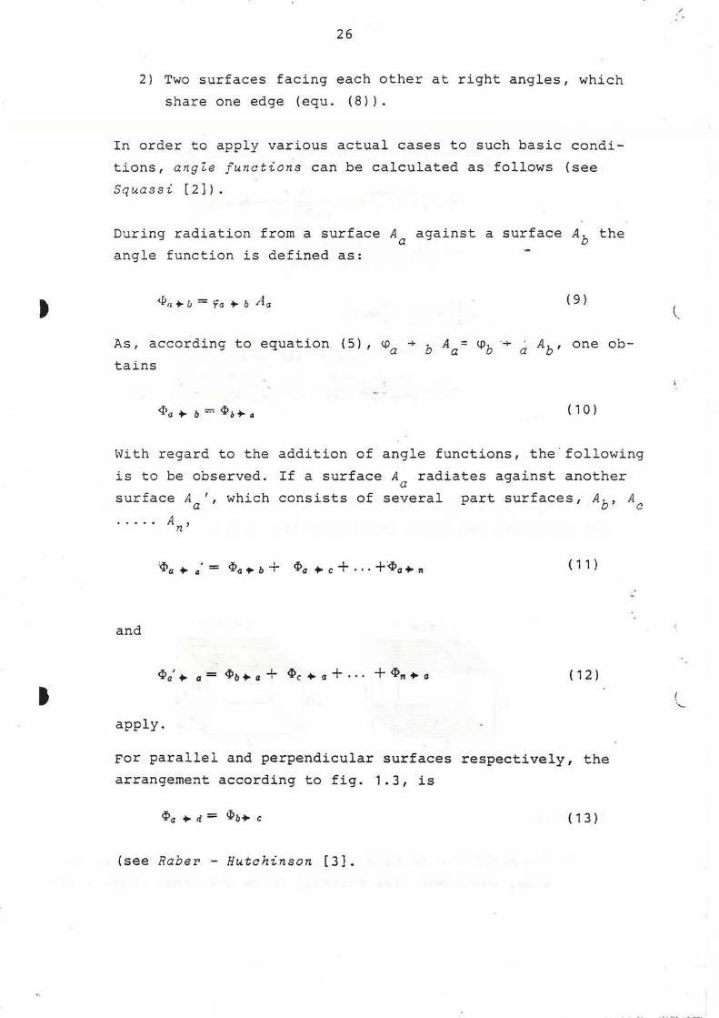
2) Two surfaces facing each other at right angles, which
share one edge (equ. (8) l.
In order to apply various actual cases to such basic condi
tions, angle functions can be calculated as follows (see
Squassi [2]).
During radiation from a surface A against a surface A, the Q D
angle function is defined as:
<I> II ... /J = 'fo ... b iL.l ( 9)
As, according to equation (5), ~a + b Aa= ~b ·+ d Ab' one ob
tains
<I>a+- b=<I>b+-a ( 1 0)
With regard to the addition of angle functions, the . following
is to be observed. If a surface A radiates against another a surface A ', which consists of several part surfaces, Ab, A
a c
and
A . n·
'<I>a ... .. • = <I>~.,. b + <I>a ... c + · · · +:q,a,.. 11
<I>a' ... a = <Pb ... a + <I>c ... a + · · · + <I>n ... a
apply.
( 11 )
( 1 2)
For parallel and perpendicular surfaces respectively, the
arrangement according to fig. 1.3, is
<Pa ... ri = <I>b,.. c ( 1 3)
(see Raber - Hutchinson [3].
"
(_
·.._

•
a
IA 2
I I I
x, I ..r_. 1-\!
IB 2
.r{ X2
IC 2
I I - I {
~ i.r,, I x.]
ID 2
x, I .r, IE
2 I : (
)/ .Y2 X.r
IF 2 I
I
: I I I -l
,r, ~.2 1 X'.r
YJ
Y.z
Y,
(
.(y
I
,(r
)j
~
Yr
YJ
~
Y,
YJ
~
Y,
28
YJ
Yi
Y,
YJ
Y.2
Y1
IG
IH
2A
28
2C
-2
-Yt
2
t ~
Y,
~
}2
Yt
~ ~
~
r-----
(
----
Xi
.r,
I
,r,
I
.r,
I
x,
Y.r
~
>(
..rJ
I JJ I
x.,.
..(. ...r.
.r., x ...
X2 J'J
2
2
2
y.1
JS Y,
X'..<
x ...
..1'4
Fig. 1.5. Parameters required for automatic computation of angle factors.
./ ..
,-
-
"
~
27
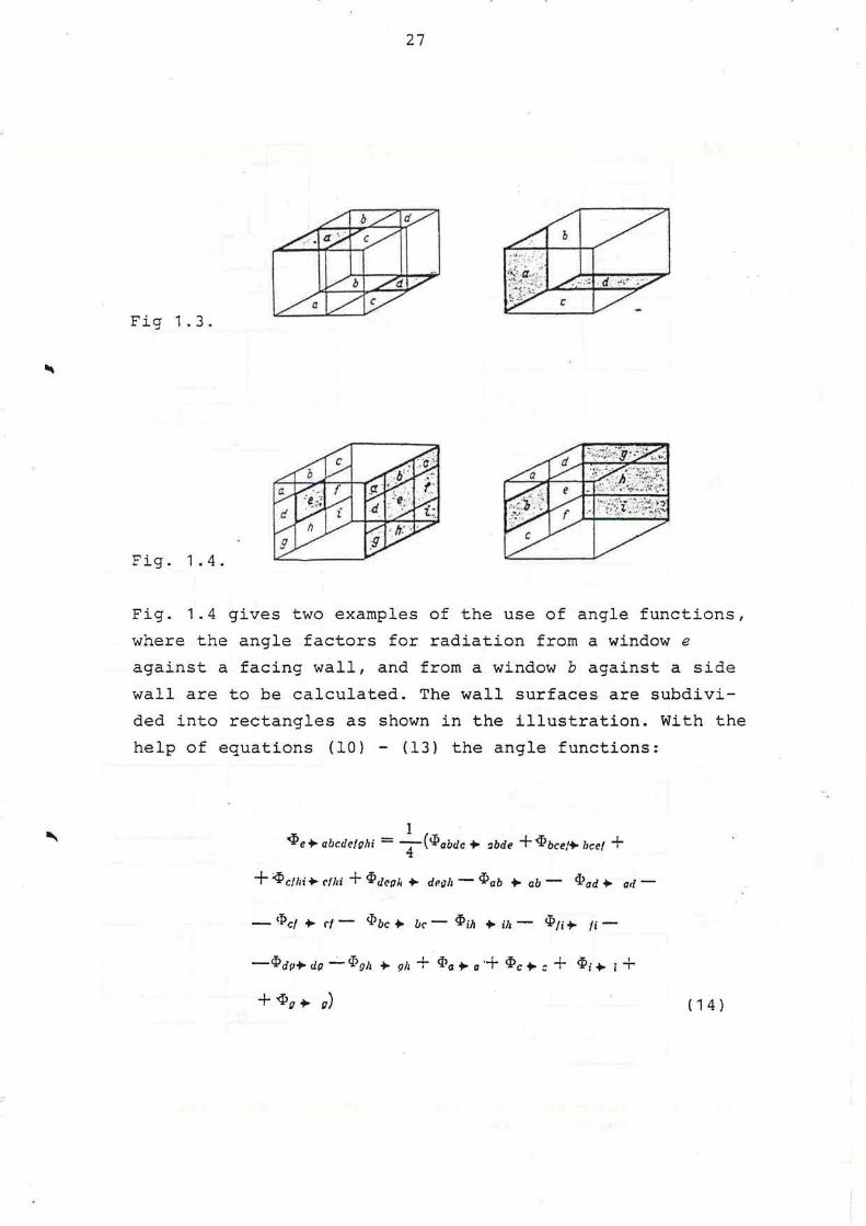
Fig 1.3.
Fig. 1.4.
Fig. 1.4 gives two examples of the use of angle functions,
where the angle factors for radiation from a window e
against a facing wall, and from a window b against a side
wall are to be calculated. The wall surfaces are subdivi
ded into rectangles as shown in the illustration. With the
help of equations (10) - (13) the angle functions:
1 .q>e+- abcdcfuhi = T('Pabdc,.. ~bde +q,bce/+- licef +
+<Pcthi+-r!hi +<I?dcgH. +- dP.~11-<I?ab +-ab- <Pad+- ail-
- <Pct +- rt - <I>bc +- be - q,ih +- i/1 - 'Pn+. fi -
-'Pap+. dg ...;_ <I.>011 +. 911 + q>a +-a+ q,c +-:: + q,i,.. i +
+ '4lg +- u) ( 1 4)

"
"
.....
and
29
<Pb+ rhi = +(<Pabdr+ r,;h + 'Pbccf + hi - <Pae+- oh -
- <P,1+ Iii - <Pa•i + a - '1>cr+- i + <I>d +- :t + iP1 + ;)
are obtained.
( 1 5 )
It can be seen that every term in equations (14) and (15) can
be calculated with the help of equations (7) and (8), after
the angle functions have been exchanged for angle factors
according to equ. ( 9) .
Also other cases which can occur in a room are shown in fig.
1.5, where the two cases in fig. 1.4 correspond to 1A and 2A.
1A to 1H inclusive, show parallel surfaces, the surfaces 1
and 2 being projected in the same plane. In the cases 2A - 2C,
the two surfaces are inclined towards each other at 90°. In
the figure, however, they are turned 90° so that they there
lie in the same plane. The corner, which is formed by the two
planes of surface 1 and surface 2, is given as a straight line.
The programme includes also the calculation of the angle f ac
tor for radiation from a small sphere with surface A. against ~
a rectangle with surface A., with one corner lying over the J
sphere at a distance h from it. For such a fundamental case
that one corner of the rectangle lies directly over the sphere,
the following equation has been derived:
1 ab <:J·· =--arc sin-::=========== ' I] 4 ':7 v h-' + h% (a! + b!) + 0.2 b'l
where a and b are the sides of the rectangle. Here also the
reciprocal theorem equ. (5) and the summation rule equ. (6)
apply .

a
t
,,
30
Example 1
Let us assume that the angle factors for radiation between
all surfaces in a room according to fig. 1.6 are to be de
termined. Let surfaces 1 and 2 be windows (actually against
the inside of the external wall), and 6 and 7 are the glass
part and the timber part of a French window, while 3 is a
radiator.
5
' ;;s 160
1;cs ~s o;
10 (cei-_ ! ~' 1 . ) ; -ing ri' l ,, - ' '
11 (floor) 8
300 I ' 0. , ~ -oo 9 510
Fig. 1 . 6 .
Table 1.1 sununarises how the various angle factors should be
calculated. In the top columns of the table, the designation
of the surface, which is considered as facing the radiation
is given, i.e. the second index number in the designation of
the angle factor.
As regards angle factors for surface 1, it is only ~ 1 + 8
,
~ 1 + 9 , ~ 1 + 10 and~, + 11 which require to be calculated
with the computer. The corresponding columns in the table
give the cases in fig. 1.5 which are applicable.~,+ 1 to
~ 1 + 4 inclusive are 0, as surfaces 1-4 do not receive any
radiation from surface 1.
According to the table~, + 5 = ~2 + 9 - ~1 + 6 - ~, + 7.
The equation can be written ~2 + 9 = ~1 + 5 + ~1 + 6 + ~, + 7·
(
, ..

r r~- -..,
" , _
Table 1.1. Scheme for calculating angle factors for radiation between surfaces in a room according to fig. 1.6.
I 2 J 4 s 6 7 8 !) 10 II
rtr 0 0 0 0 'P::i..-p- 'f,_(I - A A, IA 2A 2A 2A - '1'1-r
__ {j 9' IC So A, 6 -f ( 7-(
rt2 0 0 0 0 'l'r-fl-'1'.i-d - A,,. ~l'. 2A <J',_,o - 'J'.J ·-T A.i 'f>,,. _2 A.i f'r-2 'f't-8 9'1-11
--
cpJ 0 0 0 0 Y'J-.o-~-a--'fJ-T .
28 2A IA 2A 2A 2A .
0 0 0 0 1-'f+-d-'f+-r- A5 Ar .. (r Ai A,o A~·
C/J4 -~_.-,rf'.+-P- A~ <f a--1 A'+ <f',_4 A+ Y'.t-4 A+ ff9_,. :;r fl'10--1 A4 '1'11--1 -Ji-IO-~-K_ 3
C/Js A, Ai A.r A+ 0 0 0 ~ Ap Ad:} Y' ~I ~ ~-s A~ <p).-S As 9"J-S As <f>-1- s A_,. 'f,,_s As- '1'9-I As- IO-J As Y'11-s
--
A1 Y'a-112•J•~ -rp t5 2A 2A A" 'PJ-6 -So6-I -'/'6-1- 0 0 0 2A IA 2A 2A
-- -'f'c_J
28 A.1 'fT-1•2 ..JI 4 -2A IA <pT 28 A, 'PJ-T -'I',_, -<p,._2- 0 0 0 2A 2A
-- - :Tr-.r -- . A, A1 9l!-1121J14 - 9'4 - J) -~ -6" - A A,.
<p 8 ~l~ 'P,_4 ~ti - I :;f~ <pJ --ti - <p4 _, -'l'4 -.2 -- -C/'4 -T A! 'Pd - " ii; <p,_4 0 211 2A r'.t ·- (0
-- :Jh~J'
</J9 A, Ai .41 1>9-6-9'9-1- <fJJ--S16~T - A~ Az A" 0 I 2A A~ '!',_" AD '1'2-9 A{) 'PJ-9 - 9'9_2-IP9-.r -~1-6 -n-r A9 <f11--P A9 'f',_,, A </'4 --9 fjJ9 -- 10
{)
A, 'P A1 ~o-rni_,- ~-9-'P.t'.l-6- A11 Ar A Ai <;o,o :;;- 1-10 rp/() - ( A.u <pJ- lrJ '-9'.u-~-'}}o-J -'f'/Q--T A"' <f'6-KJ A- <fr- IO ~f! r'a-KJ A 'P9-IO 0 IA
I() IO 10
'f II ~ 'P11-1
As . So"'_ .,-9J.,_ ,- 'f,, __ r<f!1 - r ~~ 9' Az 0 A Y', __ II A,.. 'PJ -N A Cfr--H r>KJ-4 9'>() - 0 'ff0-11 II -'fN-:i-93.--.J -~-T A11 '-H II
--i
w f--'

t
I
32
T~is es~ation a?plies, because surface 5 + surface 6 + surface
7 tuyet! :e~ are equal in size to surface 9 and have the same po-
sition i~ relation to surface as surface 9 has in relation to
s~r~ace 2. In addition, there is no need to calculate~, + 6 and ~ 1 ~ 7 by means of the computer as they can be obtained
from ~ 6 ~ 1 and ~ 7 + 1 with the help of equation (5). To cal
culate ~~ + 5 the rule, that the sum of the angle factors for
a surface is equal to 1, has been used.
According to table 1 .1 it is necessary to calculate 31 angle
factors out of the 92 by means of the computer. In a table of
data, wtich is provided for the computer operator, the cases
as in ~ig. 1.5 are quoted and the dimensions of x and y, which
dete rmi ~e the size and position of the surfaces and their po
sitions in relation to each other, are given. With the parallel
surfaces the distances between the surfaces, h, are also to be
given. Only cases 1A, 2A and 2B are dealt with in this example.
All calculated angle factors are given in table 1.2. The
values can be checked by using the rule, that the sum of all
the angle factors of a surface is equal to 1 (e~u. (6)). This
check cannot be used for surface 4, as the rule has already
been used for the calculation of angle factor ~ 4 + 5 .
Table 1 .2. Angle factors for radiation between surfaces in a room according to fig. 1.6.
l 2 3 + 5 6 7 8 9 · 10
<f 1 0 0 0 0 0,124 0,004 0,004 0,!01 0,318 0.263
rpz 0 0 0 0 0,314 0,002 0,002 0,101 0,132 0.253
cpl 0 0 0 0 0,195 0,004 0,004 0,099 0,203 0,142
rr,. 0 0 0 0 0,205 0,003 0,003 0.096 0.210 0,25.;.
q:5 0,013 0,046 0,02i 0,061 0 0 0 0,12+ 0,23i 0.251
rr6 0,011 0,006 0,010 0.014 0 0 0 o,:93 0.2+3 0.21 i
q:, 0,010 0,005 0.009 0.015 0 0 0 0,2H 0.220 0, 125
1Pa 0,020 0.020 0,019 0,039 0, I iO 0,023 0.021 0 0,2 !4 0.23 i
q:·9 0,042 0,01 7 0 .025 0,056 0 ,211 0,013 0.012 0, I-TO 0 0.2+2
'f10 0,031 0,Q3 l 0,016 0,061 0,202 0,010 0,006 0, 139 0,2 ! 8 0
tp\ I 0,022 0,022 0,0+0 0,055 0 . 190 0.010 0.018 0, 139 0.2 18 0."86
t l
0,186
0, 186
0,353
0 ,229
0,2 36
0 ,2')6
0 .3 i l
0 ,23 i
O . ~-f 2
0.256
0
1
'-
\
\
I
r
r-
r-
1
r , .
I
I I l l
I l."
L~ '
)
../
33
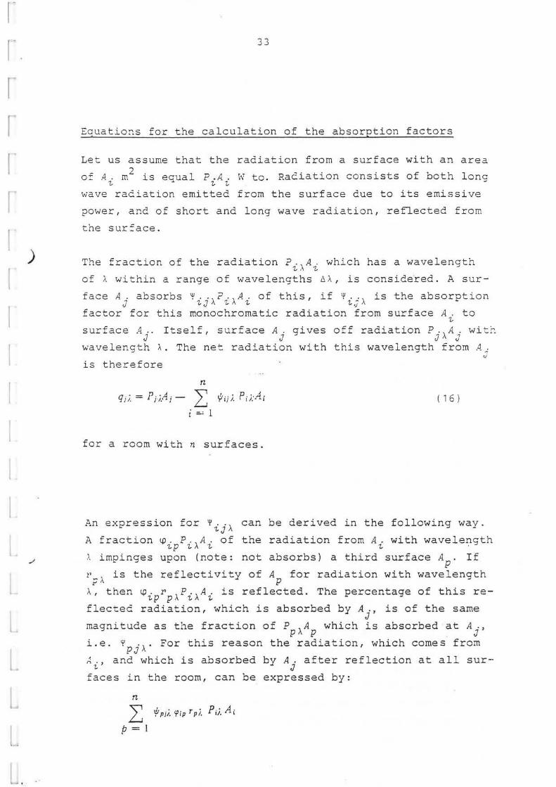
Eauatio~s for the calculation of the absorption factors
Let us assume that the radiation from a surface with an area
of A. m2 is eaual P.A. w to. Raeiation consists of both lone 1., ~ 1., 1., J
wave radiation emitted from the surface due to its emissive
power, and of short and long wave radiation, reflected from
the sur:ace.
The fraction of the radiation P.,A. which has a wavelength 1.,,\ 1.,
of ~ within a range of wavelengths 61.., is considered. A sur-
face A..; absorbs '¥ .. , ? ~·,A . of this, if '¥ • ..; , is the absorption ti 1.-J I\ ~I\ 1., 1.-,J I\
factor for this monochromatic radiation from surface A. to 1.,
surface A .. Itself, surface A. gives .c.c d' t" p ~ · .... ;.., O.:..J.. ra ia ion .,ri. wi'-~-J J J I\ J
wavelength >... The net radiation with this wavelength from A..;
is therefore
n
qji. = Pn.!!.i - L r/JijJ. Pi;:Ai i :.: l
for a room with n surfaces.
'./
( 1 6)
An expression for '¥ij>.. can be derived in the following way.
A fraction~- P.,A. of the radiation from A. with wavelength -ip 1.-1\ 1., 1., .
~ impinges upon (note: not absorbs) a third surface AP. If
21 , is the reflectivity of A for radiation with wavelength
~~ p >.., then~- r ,P.,A. is reflected. The percentage of this re-ip pl\ '/,/\ 1..
fleeted radiation, which is absorbed by A., is of the same J
magnitude as the fraction of P ,A which is absorbed at A., p I\ p J
i.e. 7 ., . For this reason the radiation, which comes from PJ I\
~ ., and which is absorbed by A. after reflection at all sur-1, J
faces in the room, can be expressed by:
n
L './tpii. 'Pip Tpi. Pii. Aj
p=l

t
t
34
The fraction 1,0 • • a . ,\?.,\A . 1-J J '!, '!,
of ?.,\A. is directly absorbed by~~' '!, , '!, c'
if a., J /I.
is the absorption factor of surface A . for radiation J
with wavelength ,\. The total quantity absorbed is 1\1 •• , P., A . , 1-J ·' '!," '!.
and the~efore
n , . = '! ij I. ), 'fip T (Ji. Y Pii. -7- 'fij Gj i. ( 1 7 )
p=
is obtained.
I f it is desired to calcula t e the fraction of radiation ab
sorbed at sur:ace A., originating from A., which has a wave-J '!,
length of ~, in the case of a room with n surfaces, it is
possible to use the equation system (17), which consists o:
n equations with n unknown absorption factors
~'lji., if.'2ji., · · ., ~'iii., i/Jiii., .. ., t/.'nji.
Angle factors <.!J.1
, <.!J.2
, ... , (!) •• , ••• , tp. (note that tp .. = '!- '!- 1-J 1-n ~J
0 while ~ .. i 0) are included in the equations. Also included J J . -
are the reflection factors rl:\' r 2 ,\,
as well as the absorption factor aj,\
face, a.=1-r.). J J
..• ' Y'i,\' Y'j,\' .. .,
(if A. is an opaque J
Y> - n ;, sur..-
~· . ., does not depend upon the transfer of energy which takes '!, J 1,
place between surfaces due to radiation of wavelengths other
than:\, nor is it affected by either convection or conduc
tion heat transfer. It is therefore possible to study short
wave anG longwave radiation in a room separately.
The ref lectivities vary with the wavelength of the radia
tion. The composition of the radiation in a room varies with
the source of radiation. The reflectivities of the surfaces
are therefore not the same for low temperature radiation, i.e.
the radiation which takes place due to the emissive power of
the surfaces, as for radiation from illuminating lamps and
from the sun.
(

.,I
.,,,
35
With low tern?erature radiation the wavelength distribution
varies so slightly, that one can reckon with a certain con
stant reflectivity for a surface which receives such radia
tion. The radiation of the sun has a composition, which
varies with the height of the sun, and is not the same as
the radiation from the sky. In general, the reflectivities
of room surfaces are not known with any greater-degree of
accuracy at any particular wavelength. It is therefore in
most cases justified to assume a constant reflectivity for
a surface, even with shortwave radiation .
The calculation of the absorption factors for room surfaces
is simplified in that the following equations apply for the~
(according to Gebhart [4]):
Gj Ai ~'ij = Gj Ai tflji ( 1 8)
n
" 0 .. = } ' I} ....._J
( 1 9)
i :..--: 1
These equations correspond to equations (5) and (6) which
apply to the angle factors .

t
t
36
Example 2 . Absorptio~ factors when surface
reflectivities are equal.
Calculate the absorption factors for radiation between sur
faces in a room according to fig. 1.7. It is assumed that
all surfaces have the same reflectivity and that this varies
from 0-1. Table 1.3 gives the angle factors for room sur
faces (calculated by means of computer).
Outer wall 6
1 excl window ) ~·anc1ow 1
~
I Ceiling 3
Cross wall 5
l rnside ~14
I . Floor 7
~----219 P4-190_J..l~ .. }-- __ __.:iiO __ _ ._i_JOO.-----,,r
gcross wall !
Ml. 2 I
Fig. 1.7.
Table 1.3. Angle fac~ors for radiation between surfaces in a room according to fig. 1.7.
I I I 2 I 3 I 4 I 5 I 6 I i
(f I 0 0.225 0,263 0,100 0.225 0 O,l 8i
rp 2 0,059 0 0,242 0.1+0 0,236 0.081 0.242
If 3 0,062 0,218 0 0 ,139 0) 18 O.Oii 0,286
rr: ~ 0.0+0 0,214 0,23i 0 0,21 + 0,058 0.23i
<{ 5 0.059 0,236 0.242 0,1+0 0 0,081 o.~42
<{ 6 0 0,20i 0,219 0.097 0 .207 0 0.210
rr 7 0.0H O.~ 18 0.2 86 0.139 0,218 0,095 0
'--

r.
; ~
l. --I
L L L
L
L .. ..
37
For each of the seven room surf aces an equation system was
established, which consists of seven equations which corre
spond with equation (17). For example, for radiation against
the floor it is possible to obtain the absorption factors
from
~· t; = <p t2ri;;~7 + cp13rif;3; + CfHrt/!~7 + cptsrrf;5; + <p1art.{ls; + -7- -.;i;rrf;;; -7- '?t• (1-r)
~· ~7 = 1p2trr./117 + 9~3rrf!37 + 'f2.&.r'i:.i; + y2srt{ls; + tp2nro/e; + ~ co-r0-- ·"'- c~- (1-r)
I ' - ' I I j ' ' - I'
~· ~· = •p3trrf;1; + cp32rr/J2; + cra.i.nft~• + rasrrf;s; + 'f3Brrf;a; + -:- fJ7ri/J;; 7 <pJ; ( 1-r)
~··; = 'f'H,-~'l i + <p.J.2Tijf2; + lft~r~·37 -1- lf.J.5Tlft5i + <p.J.6T~'67 + -:- -?.J.•r1h• + er•• ( L-1·)
{o7 = \.'5LTl;it; + Cf52.T1/127 + 'i53T1/137 + ';S.J.Tif!~; +t;3RTrf;B; + + <f.;;rijf,, + rrs• (1-r)
~~· = \'R trrf; L; + r.rn2ri.{I:; + cpaarya; + rpa4Ti{;4; + cpasrif!s; + -7- cp~;n/r;; + <pa; (1-r)
rfr;; = rp;1n/m + r;;2rif!2; + ir;ari/m + rp;4n/m + rp;srif!3; + + r;;arifs;
The equation systems can be solved easily with a computer
using a standard programme.
Of special interest is the case where there is only long wave
radiation, and where the room surfaces are made from non
metallic materials. Reflection with such surfaces is slight.
In general one can estimate r = 0,07. The absorption factors
calculated by the computer with this reflectivity are given
in table 1.4.
,
t
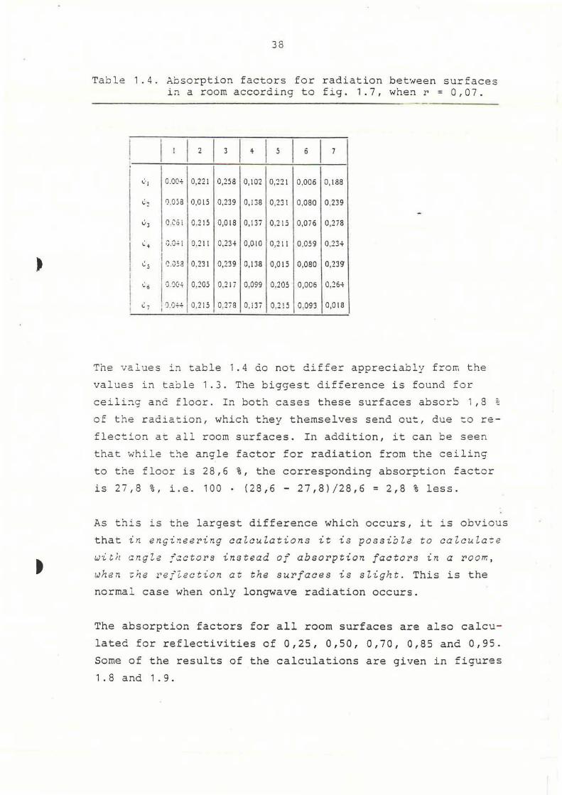
38
Table 1 .4. Absorption factors for radiation between surfaces i~ a room according to fig. 1.7, whe~ r = 0,07.
I
I I I I I I I I t 2 3 4 5 6 7 I
,,:., O.OQ..;. 0,221 0,258 0,102 0,221 0,006 0, 188
~~ 0.058 0,015 0,239 0,138 0,231 0,080 0,239
v3 O.CO i 0.215 0,018 0, 137 0.215 O,Oi6 0,2i8
~+ "'I,..,.
0.211 0,234 0,010 0,211 0,059 0,23+ 'J.'..J~ l
,,: 5 ' '~.0.53 0.231 0,239 0,138 0,015 0,080 0,23<J
! t.'.o I G 'JC:.;. 0.205 0,21 i 0.099 0.205 0,006 0.264
I ~i j -J .G++ 0,215 0,2i8 0, !3i 0,2 15 0 ,093 0,018 !
The values in table 1.4 do not differ appreciably from the
values in table 1.3. The biggest difference is found for
ceili~g anc floor. In both cases these surfaces absor~ 1 , 8 %
of the radiation, which they themselves send ou~, due to re
flection at all room surfaces. In addition, it can be seen
that while t~e angle factor for radiation from the ceiling
to the floor is 28,6 %, the corresponding absorption factor
is 27,8 %, i.e. 100 . (28,6 - 27,8)/28,6 = 2,8 % less.
As this is the largest difference which occurs, it is obvious
that in enqi~eering calculations it is possible to calculate
with angle f~ctors instead of absorption factors in a room ,
when ~he refZection at the surfaces is slight. This is the
normal case when only longwave radiation occurs.
The absorption factors for all room surfaces are also calcu
lated for reflectivities of 0,25, 0,50, 0,70, 0,85 and 0,95.
Some of the results of the calculations are given in figures
1.8 and 1.9.

r~
r· r
~
~
L.
39
~~ I
~I I
0~5 1
o~o
Ops·
0 0 o,s r 110
?ig. 1 .8. Absorption factors for radiation from a surface in a room according to fig. 1.7 back to the same surface with varying reflectivity of the room sur~aces.
?ig. 1 .8 shows what fraction of the radiation from a room
s urface returns to it after reflecting from all room sur-
f aces, with different values of 1•. Naturally, the return
reflections from the largest surfaces, the ceiling and the
floor, are the biggest items. The return reflections from
windows are the least, and it is possible to draw the con
clusion from the values of ~ 11 , that on l y a very small per
c e ntage of the solar and sky radiati o n t hrough the wi ndo ws
is refiected out again.
Fig. 1 .9 shows what quantity of the radiation from the cei
ling surface is absorbed by the different room surfaces,
with different values of r. The values are only slightly
related to r, if one disregards the cases of radiation
against the floor and the radiation back against the ceiling
( '¥ 3 7 and +' 3 3 l ·

t
•
o.:io l
'l1 I I
40
0.2.5 :
o.2o r-~~~~t--~~===--l-=:::--~~~l~~~~---!
0.IS~ ~ '
0 .10 ,
!
0.05 1
! 0
0 Os I r
1,o
?ig . 1 .9. Absorption factors for radiation from ceiling in a room according to fig. 1 .7 against various r oom surfaces, with varying values of the reflectivity of the rbom surfaces.
The curves in fig. 1.9 deviate only slightly from straight
lines. This was also shown to be the case when corresponding
curves were drawn from the other room surfaces. By extrapola
ting the curves it is found that 'ij a pproaches value Aj/EA
when ~ approaches 1 (EA is the total a r ea of the room surfaces).
In a room where all the surfaces have the same reflectivity
one obtains therefore the following approximate equation for
the calculation of the absorption factor for radiation from
surface A. against surface A.: ~ J
A· I ( 1 1·) "'.. -:.. -' r lf/ij = - T 11 I ~A ( 2 0)

I r~
r
r "\
'
41
The largest deviation from a straight line was shown by the
graph for ~ 33 (and ~ 77 ), see fig. 1.8. When r = 0,5, the
error is about 10 % when one applies equation (20).
Example 3. Variation of daylight intensity in a room.
Give the variation of daylight with the distance from a win
dow-wall in a room according to fig. 1.7. The light distri
bution is diffuse and the reflectivities for visible radia
tion are the following for room surfaces 1 to 7 inclusive:
r1 = 0,20, r2 = r4 = rs = r6 = 0,60, r3 = 0,75, r7 = 0,25.
The variation is studied in such a way, that the absorption
factors are calculated for radiation from window surfaces
against horizontal, upwards facing, black surfaces. These
are 1 cm2 in area and placed 80 ems above the floor, (the
height of a writing desk) in points a - l, distributed round
the room according to fig. 1.10.
Window lal( 510 ·----1 l
Window
- ·- ·- ·;:i+-- - b+ . ____ _ c+ _ __ ,,.. . _d+-1 ·--- ~
u JI .1 f gl l ~ I n - · ·+--- - - -+ --- - -~--
_63 . ..}_ ll§__J ____ 12a_i __ 1_28_ .. ~ .5.BJ.s_
Fig. 1.10. Location of surface elements for study of variation of daylight intensity in a room as shown in fig. 1.7.

•
I
42
The angle factors for radiation from the surf ace elements
against room surfaces la, lb, 2, 3, 4, 5, 6 and 7 are first
calculate d b y means of the computer. The angle factors for
radiation from the room surfaces against the surface elements
are t hen calculated with the help of equation (5). The angle
factors at the windows were proviously calculated by equaticn:
<f.'I +. l == Cfl,11 +- la + ify +- li.J
so that it is possible subsequently to treat both windows as
one surface (index indicates one of the surface elements y
a - : ) . The calculation gives the values in table 1.5.
Table 1 .5 Angle factors for radiation between surfaces in a room according to fig. 1.7 and the surface eleme~~s a - l which are positioned in the room accorcing to fig 1.10.
' ! 1 I I I I ' I
! a b c cl e r g I h I ·' I l
, I
r
!
I '{ I ,..., 698 · !C · o ! .82i· !0 '°0,oi0 · I0· 6 0)96 . ] ( · 6 4.810 . 1c·o u3j . : o·o ::u a9 . ;o ·~ IJ .27! . i O- 0io.2.:;5 . : > ol), 200 - : O· 6
<;: 2 J .860 l,103 !,i 03 0,360 2,039 1 " - ' - · J 1-: 1 " - ' - : .:I ' "T' 2.'.139 o,sso 1,; 16
r;: 3 1 1-1 - : - I - 2,'.? 19 2,~1 9
? ,,-.., • :-' - 1 ,'.'!15 1 ' - " _ , .,:i.i 2,o;. j3 1,515 J ,76.!. i ,495
-q: ~ .J.: l -T 0,-T68 l,200 3,301 0,91 i •) ,413 1,001 2,SOi .;. ,862 .; , ~92
Cf ~ G.<3 60 1 , i03 1, 103 0,::160 0,411 O,'.il.5 0,515 •J,411 •),650 ·),3 37
q: 6 2,368 ·J,782 0,3'.l-t 0,160 1 , ~69 O.G45 0.296 0, 14i •) , 112 0, 109
i ; 0 0 0 0 0 0 0 0 0 0 - .. . .
To determine the absorption factor ~ly for radiation from t~e
windows against a surface element y, the following equation
system {according to (17)) is then solved:
I
I
I
'
I

......
'
, ,~ I
43
, , I • , ' • I I ' I + 'ifl.I/ = lfl:!T21./2;J T Cfl313'if3y i 'fl-ti 41.f/4y T . •. i CftiTi'fliy
+'fly (l - ry)
I ' ' I . I + I , I "'" =: ~-·1r1°"1 --""'31"3"''' ~ '"·>•r•w• ---··-r-lif-,y-...-'t' -!I r - 't" JI i r - 'r'.., y • ':"'-"" ~ • .... .11 • • • ' ':"- • ' T '
+ cp2 11 (1 - ry)
i/;3y = cp31r1t/t1.11 + cp32r2i/;2y+rp3-tr-tt/t.i.11 + + 'f31J ( 1 - r 11 )
+ cp3;r;if!1y +
i/;; 11 = lfi1r1r/;1y + cp-;2r2i/;2y + cp-;3r3if;3 11 + ... 1 cp; 11 (1 - ry)
In this case r constitutes the reflectivity of the surface y
element. When r = 0, the absorption factors given in table y
1.6 are obtained. To check the values of the absorption fac-
tors, all absorption factors for radiation from the surface
element against the room surfaces are calculated for each
surface element with the help of equ. (18) and surnrnated. The
sum was 1, which corresponded with equation (19).
Table 1.6. Absorption factors for radiation between surfaces in a room according to fig. 1.7 and surface elements a - Z which are· ~ositioned . in ' the room accor-ding to fig. 1 . 1 0. -
\ a I b I c I d I e I f I g I h I k I I
~I 6,1 ii· I0-6 13,5.i2- JG-6 2,484· !0-6 2,04 i ·I 0-6 6,298-10-6 3,2i4- I0-6 2,384 · 10-6 2,014-10-6 1,914- IC-6 l,8i4· I0-6 1
~2 2,302 2,6i4 2,723 2,487 3,318 3,i81 3,821 3,508 2,2i6 . 2,849
v3 3,388 ·l ,086 ·1',132 3,566 3,066 3,680 3,71 i 3,247 3,112 2.8i2
i:.· 4 1,702 2,115 2,347 4,773 1,671 2,054 2,642 4,298 6,192 6, 114
i:i 5 2,302 2,6i4 2,723 2,487 1,892 2,153 2,192 2,002 2,2i6 1.991
lf,6 3,il3 2,3i0 1,988 I ,i71 2,831 2,233 1,9'38 1,754 l,6ii 1,664
i!t 7 1,737 1,919 1,9il 1,933 1,695 1,393 1,936 1.904 I,892 1.870

I'
'
44
Initially only the absorption factors for radiation against
surface elements a to h inclusive were calculated, but the
calculation was then completed, so that the absorption fac
tors for radiation against surface elements k and i were
also obtained. In this way it was possible to observe,
whether reflection against inner wall 4 should cause an in
crease of the values adjacent to that wall. The values in
table 1.6 show, that this is not the case up to a distance
of 5 cm from the wall.
Absorption factors and angle factors for radiation from the
windows against surface elements a - i are introduced in dia
gram fig. 1.11. With the help of the plotted points in the
diagram, curves were drawn afterwards, which show the varia
tion of the factors with the distance from the window wall.
If the intensity of radiation which is emitted at the inside
surfaces of the windows is I, then it is 10 4 · Iw ·at the T 1 y .
surface element, as '11
1Y is the fraction of radiation from the
window surface, which is absorbed by the black surface ele
ment y of size 1 cm2 and intensity is reckoned per m2 . The
strength of illumination on a surf ace is the flow of light
(radiation flow) which impinges upon 1 m2 . The curves rela
ting to the absorption factors in fig. 1.11 give therefore
the percentage ratio between the intensity of illumination
upon a horizontal surface 80 cm above the floor, and the in
tensity of illumination upon a vertical surface, just inside
the wi~dow, after multiplying by 10 6 . The curves of the angle
factors give the corresponding value in a black room.
This quotient falls from 6 % about 0,7 m from the window, to
just under 2 % at the internal wall, when the walls have the
ref l ectivities mentioned previous l y . I n the case of b l ack
room surfaces, it falls from 4,5 % to 0,2 % or slightly more.
The difference between the values in the light and black room,
respectively, at the same distance from the window is nearly
constant at about 1,75 %, when the distance is more than 1,5 m.
/'

r
r~
·~
~
.. ,
10-~6
5
45
i i l
4 : i ' I
I
\ I I I I ' f actor.S Absorpt,ion
3 I '.\ : "· """" ' , · ·.· ----- =
2 I I I \ \\ i ' 'i.b ' ' - """'"" o-=kl .. t I" I "' factors
I I
'-._~ i !d 9r' --~I -t=r -=
I . I
I ijlO , I ~510 . l 0 . ~~10 0 510
Distance from external walls cm
Fig. 1.11. Absorption and angle factors for radiation from windows in a room as shown in fig. 1.7 to black surface elements of 1 sq.cm area placed hori~ontally face up at a height of 80 cm above floor level along the centre-line of the room (continuous lines) and at a distance of 111 cm from the centre-line (broken lines). The upper curves also show the intensity of the light falling on the elements. This, expressed as a percentage of the intensity of illumination of a surf ace element placed vertically immediately inside the window, amounts in fact to 106 times the absorption factor. The lower curves indicate similarly the intensity of illumination in a black room.

'
,
·.·
46
The curves for the surface elements, which are positioned at
the centre line of the room, lie above the corresponding cur
ves for surface elements which are positioned a third of the
width of the room to the side of the centre line, as long as
the distance from the window wall is more than 0,7 m. The re
lationship is the opposite, if this distance is smaller. The
reason for this is probably the shadow thrown by the frame
between the windows 1a and 1b.
Literature references:
1) Kollmar, A. and Liese, W.: Die Strahlungsheizung.
R. Oldenburg, Munich 1957.
2) Squassi, F.: Die Einstrahlzahlen in Wohnraumen.
Gesundheitsingenie ur 1957, Nr . 5/6, pages 69-72.
3) Raber, B.F. and Hutchinson, F.W.: Panel Heating
and Cooling Analysis. John Wiley and Sons. New
York 1947.
4) Gebhart, B.: Heat Transfer. McGraw-Hill, New York
- Toronto - London 1961.
..-

r
r
I
r
,I
--
... .. ...
47
2 CALCULATION OF HEATING. AND COOLING LOADS
INTRODUCTION
To find the cooling requirements, when the dimensions of an
air conditioning plant are to be determined, it is necessary
to allow for the considerable variation in loading which
takes place during a 24-hourly period. As regards an office
building , for example, not only do the external temperature
vary. Solar radiation may cause large quantities of heat to
enter into the room during working hours, especially through
the windows. The heating effect from lights and from people
inside the offices at any given time, must also be introduced
into the calculations. The building shell (walls and flooring)
is heated, when the air temperature inside the room rises. As
it falls afterwards, the shell gives off heat. The result is
a delay and reduction of the oscillation of the room tempera
ture.
The necessary data for the calculations are set out in tables
2.1 and 2.2. The quantities given in table 2.1 are considered
to vary with the time of the day and should therefore be given
as a function of time. Table 2.2 contains quantities which can,
in general, be considered unaffected by time. The calculations
are made, however, slightly more complicated if one assumes
that, for example a , a or mf in table 2.2 have different y y
given values at different times of the day.
This chapter is intended to give a calculation technique,
which makes it possible to investigate theorectically, how
the various factors in table 2.1 affect the cooling require
ments with different shell and window constructions.
When solving the equations, the values in this table are un
affected variables, when 8 , the temperature of the air in r
the room, is to be determined. There is no reason why one
cannot, however, calculate the cooling effect H instead, when
er is given for different times during the day. It is also
possible to calculate 8 . or G .• i. i.

I
t
l/.
48
The method of calculation can be used for determining both
hea t ing and cooling requirements. Although it is most im
portant to consider temperature variations in a building
when calculating the dimensions of a cooling system, such
variations are also quite valuable to know, when determining
the dimensions of a heating system, for instance if one
wishes to study the use one can make of solar radiation and
of artificial illumination as a source of heat.
Table 2.1. Quantities dependent upon time
Quantity Symbol
Outside air temperature
Equivalent outside air temperature
Solar and sky radiation against a facade
Solar and sky radiation (short wave radiation) transmitted directly through a window
Solar and sky radiation energy absorbed at the inner surface of a window
Solar and sky radiation, transmitted directly through a window other than the one considered
Radiation from a light source spread over a surface (for example a ceiling surface)
Radiation from a point source light supply
Temperature of ventilation air
Ventilation air flow rate
Flow rate of air supplied to the room at outsije air temperature
Heat transferred directly to the room air from heater, lights, human beings etc.
Thermal output of heaters or coolers in the room
a z.
ae
·I
IT
I v
I' T
I, oe
B
a . t.
G . t.
G z.
H a
H
Units
oc
oc
W/m2
W/m2
W/m2
W/m2
W/m2
w
oC
kg/h
kg/h
w
w
.... _
"'--

r-
1
l •
l. l~ . L
"
.....
LI · ' 1 .. 1.,. --
49
Table 2.2. Quantities independent of time
Quantity
Time interval
Thickness of layer
Area
Volume
Thermal diffusivity
Thermal conductivity
Density, ~eight per unit volume
Thermal resistance of air layer
Thermal resistance of window including the external but excluding the int,ernal surface resistance
'
Absorptivity of facade surface for solar and sky radiation
Surface heat transfer coefficient at the outside of an external wall, including the effect of long wave radiation
Angle factor for radiation between two surf aces in a room
Absorption factor for radiation between two surf aces in a room
Emissivity
Symbol
b. t
6:::
A
v
a
>..
p
mi
mf
a y
CL y
~
'I'
e:
Units
h
m
2 m
m3
2 -m /s
W/m0 c
3 kg/m
m2 0 c/W
m2 0 c/W
dimensionless
W/m2 0 c
dimensionless
dimensionless
dimensionless

a
t
so
HEAT TRANSFER UNDER STEADY-STATE TEMPERATURE CONDITIONS
T h e r m a 1 c o n d u c t i o n i n t h e i n t e r i o r
o f a w a 1 1 o r f 1 o o r i n g
Let us assume that the heat flow is one-dimensional and takes
place through a homogeneous material in a direction which is
perpendicular to the wall surface. The material_can be consi
dered as being divided into layers parallel with the wall sur
face according to fig. 2. 1. The temperatures erz_1 , en and. · en +1 are the average temperatures which exist in each specific
layer.
en-1 en en+1
D.X !,,~X
Fig. 2. 1 . Layers n-1 n n + 1
.,. If e
1 > e then the following amount of heat is transferred
n- n• 2 to layer n between layers n - 1 and n, per m of wall surface
and s:
A. ( ) - 6 -6 /.::.X n-1 n
where A is the thermal conductivity of the material. Between
layers n and n + 1 the following quantity of heat is led from
layer n: ,\
/\ ,. /.,,,,J,•''
(6 11 - 0,, + 1)
As the temperatures are constant, layer n is neither heated
nor cooled, and the heat transferred to the layer is always
equal to that which is transferred from it.
"
'
,,,-L~
51
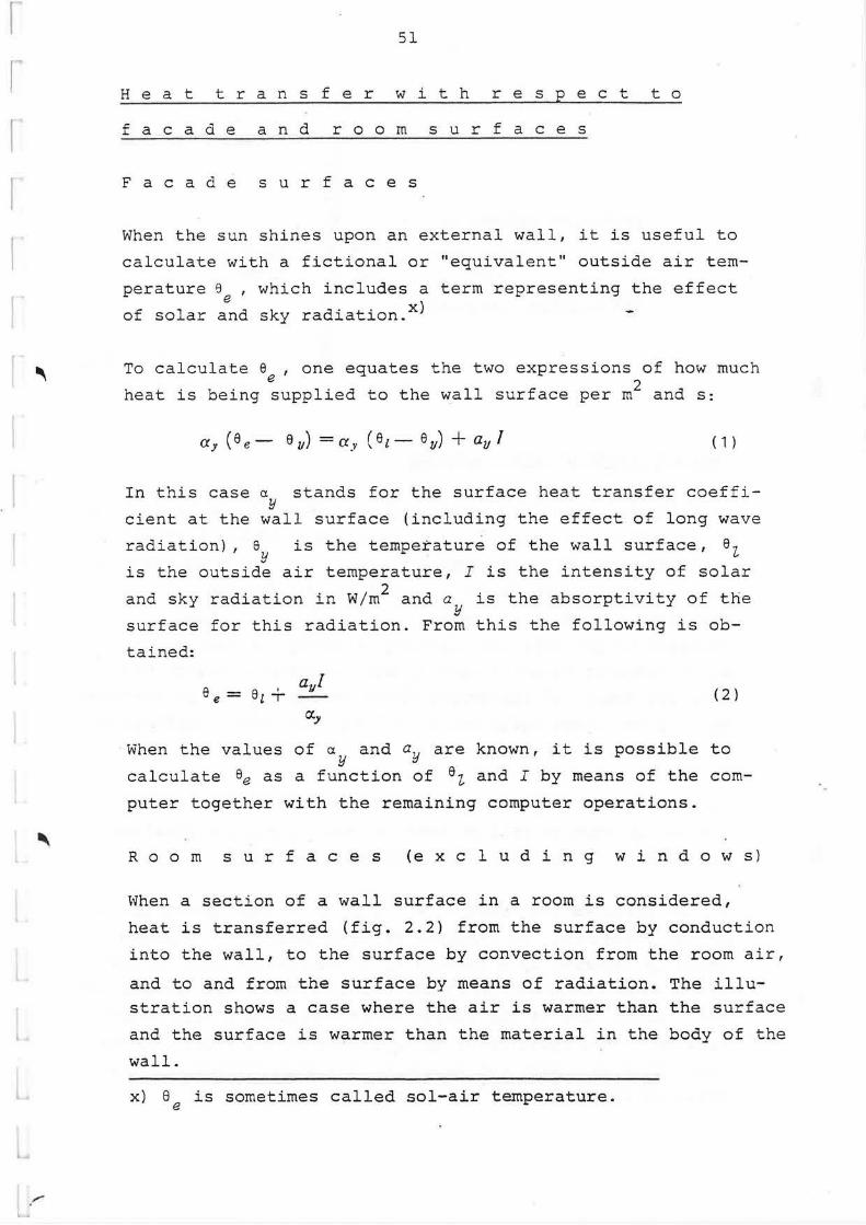
H e a t t r a n s f e r w i t h r e s p e c t t o
f a c a d e a n d r o o m s u r f a c e s
F a c a d e s u r f a c e s
When the sun shines upon an external wall, it is useful to
calculate with a fictional or "equivalent'' outside air tem
perature 9 , which includes a term representing the effect e
of solar and sky radiation.x)
To calculate e , one equates the two expressions of how much e
heat is being supplied to the wall surface per m2 and s:
ay (ee- ev) =a~. (et- e11) + a11 ! ( 1 )
In this case a stands for the surface heat transfer coeff iY
cient at the wall surface (including the effect of long wave
radiation) , e y
is the temperature of the wall surface, e z. is the outside air temperature, I is the intensity of solar
and sky radiation in W/m2 and a is the absorptivity of the y
surface for this radiation. From this the following is ob-
tained:
e e = e ' ayl ll
r:l.y
( 2}
When the values of ay and ay are known, it is possible to
calculate ee as a function of ez. and I by means of the com
puter together with the remaining computer operations.
R o o m s u r f a c e s (e x c 1 u d i n g w i n d o w s)
When a section of a wall surface in a room is considered,
heat is transferred (fig. 2.2} from the surface by conduction
into the wall, to the surface by convection from the room air,
and to and from the surface by means of radiation. The illu
stration shows a case where the air is warmer than the surface
and the surf ace is warmer than the material in the body of the
wall.
x) 8 is sometimes called sol-air temperature. e

t
a
/_:_ .~
52
Impinging radiation
Reflected
Convection
and emitted radiation
Heat radiation at room surfaces
~
/
~
~
~"
~ -Conduction
Fig. 2.2.
In order to solve the complicated mathematical problems whic·h
arise during the calculation of radiation between surfaces in
a closed room, the term "absorption factor" has been introdu
ced. The absorption factor ~ab defines the fraction of radia
tion from a surface A which is absorbed by a surface A, . a o Included is not only the fraction of radiation from A 3 . a which radiates directly upon Ab and is absorbed there, but
also the energy of radiation, which reaches Ab and is absorbed
by it after being reflected by all the reflecting surfaces in
the room.
r . is dependent upon the absorptivities of all the surfaces ao within the room as well as their sizes, shapes and posit~ons
in relation to each other (geometry of room).
If all surfaces are black (£ = 1), so that they absorb all in
cident radiation, the fraction of radiation from a surface Aa
which is absorbed by a surface Ab is determined only by the
size, shape and position of the two surfaces. This must be the
case, as no part of the radiation is reflected by any other
surface in the room, prior to impinging on the receiving sur
face. In such a case one refers to the angle factor ~ab in-
stead of the absorption factor ~ab"
r

r·
r
'--•
J
'
'
.. . .
53
In chapter 1 methods are related for the calculation of ab
sorption factors and angle factors for the cases of radia
tion between plane rectangular surfaces in a room, where the
surfaces do not shield each other, and are either parallel
or perpendicular to each other. Diffuse emission and reflec
tion of all radiation was assumed in these cases. These same
assumptions and methods are incorporated in the program for
calculating heating and cooling loads.
Radiation from a surface can consist of both long wave radia
tion, emitted due to the emissive power of the surface, and
of short and long wave radiation reflected at the surface.
Long wave radiation is emitted from all the surfaces in the
room, walls, floor and ceiling, as well as the.inside surfaces
of windows, radiators, lamps, furniture and human beings
according to equation:
E == E Cs (2-) 4
100 ( 3)
where
~ = the emissive power of the surface in W/m2
E = the emissivity of the surface, dimensionless
C =a • 10 8 , where a= Stefan Boltzmann's constant, i.e. s 5.67 . 10- 8 W/m2 K4
T = the absolute temperature of the surface in K
The inside of a window, (window pane or window drape) or the
surface of a lamp also emits short wave radiation, when it is
light outside or when the lamp is lit, as the case may be.
Long wave radiation:
In an example given in chapter 1 it is shown, that when long
wave radiation between room surfaces is considered, sufficient

,,
t
,,.. .. . , --
54
accuracy is obtained if angle factors are used instead of
absorption factors, i.e. if the reflection of the surfaces
is ignored. Tl1e largest error in the example was found to
be between the ceiling and the floor. In this case it was
found that the angle factor was 2.8 % larger than the ab
sorption factor, if the reflectivity of all surfaces is
r = 0.07. Therefore the prograrr. uses angle factors instead
of absorption factors for long wave radiation.
The net quantity of long wave radiation which a surface A n
receives from a surface A can then be calculated in the u following way.
Let us assume that the surface A sends out a total of P u u w
as long wave radiation. Of this, surf ace A absorbs c.p P w. n un u
Surf ace A gives off P W and A absorbs c.p P W of this. n n u nu n The following relationship applies for angle factors;
'fun Au = 'Pmt An
The net radiation between A and A is therefore; u n
( Pu Pn) P = l!1, Pu - lfnu p n = 'Pnzs An -A - -A un TP.n u n
( 4)
As it is assumed that the reflection between all room sur
faces is equal to zero,
Pu Pn -- = E", -- = Em Ai, An
where E and E , respectively, are calculated according to u n equation (3). If the emissivities of both surfaces = ~, then
equation (4) gives;
P, .. =S.67 •~ ... A. [( 1:~ )'- (~ n If the quantity
fun = (
Tu ).i. ( Tn )°' loO - 100 ( 5)
6r.t-6'n
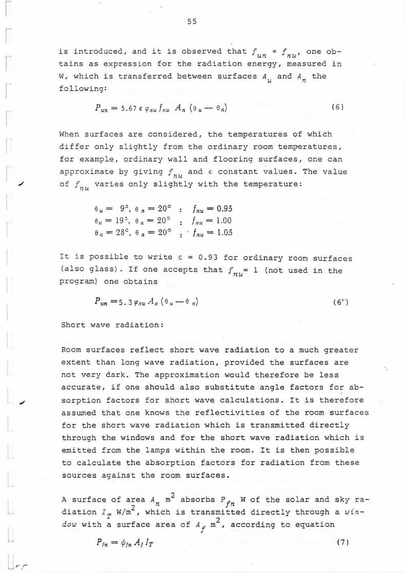
r
r
I
./
~
r · r
55
is introduced, and it is observed that f = f , one ob-un nu tains as expression for the radiation energy, measured in
W, which is transferred between surfaces A and A the u n following:
Pun= s.67 e 'inu f11u An (e u - en) ( 6)
When surfaces are considered, the temperatures of which
differ only slightly from the ordinary room temperatures,
for example, ordinary wall and flooring surfaces, one can
approximate by giving f nu and E constant values. The value
of f varies only slightly with the temperature: nu
6 = go e - sioo u , n - -
e - 19:: 6 - CJQ-=> II - > JI - -
e = 93c 6 = 90" u. - , n -
f nu= 0.95
!1111 = 1.00
· f nu= 1.05
It is possible to write s = 0.93 for ordinary roe~ surfaces
(also glass) . If one accepts that f = 1 (n6t used in the nu
program) one obtains
Pun = 5. 3 'f nu An ( 6 11 - 8 11) ( 6 '')
Short wave radiation:
Room surf aces reflect short wave radiation to a much greater
extent than long wave radiation, provided the surfaces are
not very dark. The approximation would therefore be less
accurate, if one should also substitute angle factors for ab
sorption factors for short wave calculations. It is therefore
assumed that one knows the reflectivities of the room surfaces
for the short wave radiation which is transmitted directly
through the windows and for the short wave radiation which is
emitted from the lamps within the room. It is then possible
to calculate the absorption factors for radiation from these
sources against the room surfaces.
2 A surf ace of area A m absorbs Pf W of the solar and sky ra-n n diation IT W/m2 , which is transmitted directly through a win-
dow with a surface area of Af m2 , according to equation
Prn = ifrnA1Ir ( 7)

I
•
/.- .. ,
56
One obtains different expressions for the fraction of short
wave radiation from illumination sources, which is absorbed
by surf ace A , whether one considers that the lamps are even-n
ly distributed over a larger surface, for example over the
whole ceiling surface, or if they are concentrated in certain
positions .
In the first case one obtains
pbt n = 1i)bt n Abe fbe ' 't '
( 8)
In this case Ibe constitutes the radiation energy in W per
square meter of the surface Abe on which the lamps are posi-
tioned, and ~b the absorption factor for radiation from e,n this surf ace against A . n
If, in the letter case, one has a source of illumination,
which contributes B W of radiation energy in a point for
which the absorption factor for radiation against surf ace A
is equal to ~B , then the radiation absorbed by surf ace A ,n n can be expressed by
PBn=11_1EnB J 'f I
( 9)
n
The total net radiation, measured in w, which is absorbed by
surface An at a certain instant is then, according to equa-~
tions (6) - (9)
P,1 =Arr ~.67 E~'f11u f1111 (eu-811) + <I>n] (.1 0)
where
I <I>11 = A(~ Yin At Ir+ 2: i/Jbe,n Abe he +2: if B,nB)
n
( 1 1 )
e is the temperature of a surface (also window surface) in u
the room from which long wave radiation falls against the sur-
f ace in question A . O is short wave radiation from windows n n
and illumination, measured in W/rn2 , which is absorbed by sur-
face A • The signE indicates that one must add the absorbed n long wave net radiation from all surfaces A in the room, u which are in radiation exchange with A , and the absorbed n
'-
.......

I I
,,,
rtf
i... _ ... ~·~
57
short wave radiation from all windows and sources of illu
mination, respectively.
Convection heat transfer at room surf aces
Heat transfer coefficients between a surface and air, due to
natural convection can be calculated by means of equation
Hu= c(Gr Pr)n
where Nu, Gr and Pr are Nusselt's, Grashof's and Prandtl 's
numbers and c and n are constants. The tem?erature changes
in a room are slight enough to make it possible to consider
the properties of the air to be constant. Than one obtains:
et.k = c (.6e ) 11 L-m ( 1 2)
where
0: -r(
= coefficient of heat transfer by convection, W/m2 0 c
t9 = temperature difference between air and surface, 0 c
L = a characteristic length in m
c, m, n are constants.
Measurements from which the constants can be determined were
carried out by Min et al. 1956 in USA /1/. These were carried
out in a room with floor or ceiling heating. From the results
one obtains the following specific correlations for rooms:
walls: ak = 1.88 680.32 L-0.05 ( 1 3)
warm ceiling, cold floor: ak = 0.20 660.25 L-0.25 ( 1 4)
cold ceiling, warm floor: ak = 2. 4 2 6 e 0. 31 L - 0. 0 8 ( 1 5)
In equation (13) L = the height of the room. In equation (14)
and (15) L = 4 times the area of the ceiling divided by its
perimeter.
The measurements were carried out in a room without air ex
change or other disturbances. In a usual room where these

•.
•
58
occur, the a.k values may be somewhat higher than those given
by equations (13) - (15), especially when temperatur differences
are small and particularly when there is warm ceiling or a
cold floor. In such a case equation (14) gives very small
values, which is to be expected, because the difference bet
ween the temperature of the surface and the air cannot cause
any convection air currents.
The computer carries out a linear interpolation_between
values of a.k given in the following table. The values are cal
culated with the help of equations (13) - (15), where
6. e = [ s -e [ r ( 16)
with respect to windows and wall surfaces,
6,6= Br-8 ( 17a)
with respect to ceiling surfaces, and
6. 8 = 8 - Sr (·1 7b)
for floor surfaces. 8 is the temperature of the air within r
the room, and 6 is the temperature of the surface.
' ~ Ll 0
oC
< 0
0
0.5
2
7
30
a. k 2 o x)
kcal/m h C ·.
Windows, walls Floor, ceiling
- 0.5
0.5 0.5
1.4 1. 6
2. 1 2.4
3 . 1 3.6
4.9 5.7
x) 2 o 1 kcal/m h C = 1.163 W/m2 0 c
T h e i n t e r n a 1 s u r f a c e o f a w i n d o w
Heat gain through a window due to solar and sky radiation per m2
of window surface and hour can be subdivided into two parts, Im 1
and Iv. Here, IT is the radiation which is transmitted
directly to the room. This fraction does not heat the glass

•
t
r ·- ~i J
59
panes (or shading devices). Iv is the fraction of radiant
solar energy, which is first converted into heat within
innermost glass pane (or possibly internal shading device) .
One part of Iv passes to the room by means of long wave
radiation to the room surfaces and by means of convection
to the room air, another transmits back through the window
to its outside.
'r ROOM
'v ---¢f (short wave)
-s.67E!f1pfuffu( sf- euU (long wave)
Fig. 2.3. ~f ( .8f- 8 1) ----1·-- cckf( sf- s r) (convection)
Fig. 2.3 shows the thermal exchange at the internal sur
face of the window. From the inside of the room, the win
dow pane receives short wave radiation from the window~
pane itself, due to reflection at all room surfaces, from
any other windows present, and from artificial lighting.
Corresponding with equation (11), the window in question
absorbs the following quantity of this per rn 2 apart from,
generally, a s~all, transmitted, fraction:
A,. -· I
cpl= ~f (t/;f!AtlT + "i.t/J{rA/lr' +I.if! lu.fAbelbe + +It/; B,f 8)
( 1 8)
~ff designates the absorption factor for radiation IT back
towards A1
. In addition, A} is the surface of an other win
dow in the room, IT is the directly transmitted solar and
sky radiation through this window, and ~ff is the absorption
factor of this radiation against A1.
The long wave radiation from the window pane against a room
surf ace A is equal to u
5.67 e 'P!u ftu ( e, - eu)

f
r
/ ·
60
{Watt per rn 2 window surface}
while the convection heat transfer between the pane and the
room air is equal to
O.kf ( e I - 6 r)
The heat transfer through the window from the innermost glass
pane to the external air is equal to
1 - (er- e·z) ni1
where m: is the thermal resistance of the window including J
the boundary layer resistance on its outside, but excluding
the boundary layer resistance on its inside surface. 8z is
the temperature of the external air.
The heat balance for the internal surface of the window
is then:
Iv + '<JI f = 5 • 6 7 e l: [ ~ f u f /11 ( e / -· ·e u)] + 1
+ akt ( e, - e rJ + - (e t - e t) mr
H e a t b a 1 a n c e f o r r o o m a i r
{ 1 9)
Heat is supplied to the air within the room by means of in
jected. ventilation air {flow rate G. kg/h}, which is heated 'Z-
or cooled to a temperature ei 0 c, and by air leaking in from
the outside (Gl kg/h} at a temperature of 6z 0 c.
The room air also receives heat from lighting, human beings,
etc. and also fram heaters in the room, if present. If one
can neglect the heat storage of these heat sources, and the
heat supply due to radiation from their surfaces, it is possi
ble to introduce their power directly into the heat balance
for the room air. If there are coolers in the room, their
power i$ designated by a minus sign.
Heat is removed with the exhaust air and also by convective
heat transfer at all room surfaces {including windows) if
these are colder than the room air.

I
I
61
The heat balance is then:
0.~4 (Gi s i + Gz e1) + He = 0.24 (Gi + G1) er + + 2.akA (er-. e) (20)
H is the heat transferred directly from the lights, heaters
e~c. to the air. A is the area of a room surface in m2 and 6
is its temperature in °c. Room surfaces also inc~ude the
surfaces of heaters or coolers, if present. Furthermore,
in equ. (20) 0.24 is the specific heat of air in kcal/kg 0 c (1 kcal = 4.19 kJ).
HEAT BALANCE EQUATIONS UNDER NONSTEADY-STATE TEMPERATURE
CONDITIONS
A s s e rn b 1 y o f e q u a t i o n s
To calculate the temperature in the interior of a wall or a
floc1°, the following equation is employed:
Kt Sn-1,1 +Kie n,I + Ka 8n+l,1 = K.,.e n-l + +Kssn+K68n+1
The values of the coefficients are given in table 2.3.
(A)
The te~peratures at facade and room surfaces are calculated
by means of:
-F1 en ±1,1 + F2 en,I - f3 8 ,,,- ~F.i. e.,,, = Fi en ±1 + fs en + Fa e, + "2.f4 e u + F6 (B)
The coefficients are given in table 2.4.
The temperature of the room air can be obtained, in accordance
with equation (20), from:
where
L 1 e ,,1 + L L2 et = L3
Li = 0.24 ( Gi,t + Gr,1) + ~~1: A
Di= -r..ckA
L3 = 0.24 ( Gi,1 a i,1 + G'1,1 e 1,1) + H,,,
(0.24 = the specific heat of air in kcal/kg 0 c)
( c)

Table 2.3 Coefficients in equ. ( A )
-.;off icients Ki I K2 I K3 I K.1
In homage-2 ( /J.X:! + 1) neous mate- -1 -1 1
rial a!J.l
At the ~ 2 '11-I /J.Xn+I /J.Xn-1 boundary . • + surf ace A11-I t::..xn +I 1\11+1 /J.X11-I a11-1/J.t
-1 ,\,._I l::::,. x" + I . .
between two A.,. +r !J.xn-1 /J.X~n+I ,\,,_I /J.X11+I 1\1 + I l::::,. -•11 - 1 materials + +--· +1
an+16.t A11+1 /J.X11-I
At the sur-face of an air layer
!J.x2 n I /J.Xn 1 /J.Xn of which -1 -+-·--+ 1 ---·-- 1 the other a11 6,t' ml An. ml ,\11 surface temperature 1,s en+ 1. *l
---·- ·- - --~ -.a.--l.s....i...-__,ao • -. ., .. ... - ·------• .... . .. *) If the surfaces of the air layer have temperatures o and o 1 n n-
instead of on and en+ 1 ' then the coefficients x1 and K3 change
places with eath other in equation (A), as do K4 and x6 .
I Ka
2 ( /J.X2
a/J,l - I )
,\,1 - I /J.X11+ I " • /J.X-11- I+ . A,.+ I /J.X11- I a,._ 16,t
!J.x~,,+ I ,\n-1 /J.Xn+I + I --· -1
0 n +I 6. ,\,,+I /J.X11- I
!J.x~\1 I !J.x11 ----·--1 a11 6,t ml ,\,,
· ·· ----
~
I Ko
I
I
1 !J.x,. --·--ml ,\ti
CJ\ N

... ~
Table 2.4. Coefficients in equ. ( B )
Coefficient~ Ft I F2 I F3 I Ft I F-.. I Ffj
-" t::.x\ au l !Facade 1 t::.x-11 a,1 0 0 ay 6X11 (Ac -f- 0 ,) --+-·- t::.x,1 + 1 --.'---- t:,,x11-
surface a116l ,\11 {lltf":.l ,\II ,\,,
Facade surf ace 2 S11 C11 p11
') - S11 Cn P11
with thin mt. + 111 t • -l 6.l 0 0 6. t layer out-
+ m1a11 + 1 -m1a,- l m1a, ( 0 e + o,,c) side an air gaQ
~vall, floor t:,.x2 n + U/rn t:,.x,, + 1 + 6.X
2n Clk11
l 6_X11 !Or ceiling ------6.-'<n- I - - -- (~i/1111 A.I (IT+ [ T,1) + surf ace in a,,6t ,\n 6,Xll
a11 t::.t ,\ 11 A II ,\"
Uk11 the roor.i. l -6.x,, 15, 6 7 E -;\- 'f 111J1111 + Y.ifb1,nAbe Ube+ 1111,1) + t:,.x,, A,, I II . . 6.X11 ~ I
-f- 5. 6 7 E-\- ~'P111.l1rn -5. 6 7 E -\-~'f 11u 1111 + ~.if B,n( B + B,)] I II I II
!Heater or '>c1rp1,V1,+ + c11 p1i V 1, 1 2 - W.:11- Ah [H + He + '2:.i/1111 A1 Ur+ IT.') + !Cooler in 0 - 6.t A Clk/1
W.:/1 5.67 E'ft111f/111 6.t A1i ,, troom +s. 6 7 e2..r.p1111h11 -·5. 6 7e'Lcp1wh11 + '5.if b1,hAb,(/b, + lh,,1) + 'Lif; BJ• ( B + Bt)]
trhe inter- Uk/+ I - ( cff! Al [ T,t + I.if !'I A/ I' T,t + nal sur- +s .67 e2..cp1uf111 +
5 • 6 7 E'f /uf/11 A-1 I
itace of a 0 1 (lk/ - I window *) +- + "i.if b1.[AbJb1,I + Iif n.rB,) + lv,1 +;;;a,,, ml I
*) Note that in the case of a window one writes o 1
= o = o = o = 0 in ec.u. (B). -·· · n+ n I' u -
i:
m w
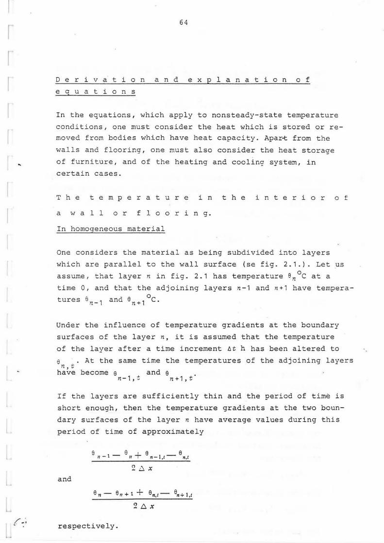
...
{ - ··
I..-....
64
D e r i v a t i o n a n d e x p 1 a n a t i o n o f
e a u a t i o n s
In the equations, which apply to nonsteady-state temperature
conditions, one must consider the heat which is stored or re
moved from bodies which have heat capacity. Apark from the
walls and flooring, one must also consider the heat storage
of furniture, and of the heating and cooling system, in
certain cases.
T h e t e m p e r a t u r e i n t h e i n t e r i o r o f
a w a 1 1 o r f 1 o o r i n g.
In homogeneous material
One considers the material as being subdivided into layers
which are parallel to the wall surface (se fig. 2.1.). Let us
assume, that layer n in fig. 2.1 has temperature en°c at a
time 0, and that the adjoining layers n-1 and n+1 have tempera
tures en_ 1 and en+ 1 °c.
Under the influence of temperature gradients at the boundary
surfaces of the layer n, it is assumed that the temperature
of the layer after a time increment 6t h has been altered to
e . At the same time the temperatures of the adjoining layers n,~
have become e and e n-1,t n+1,t
If the layers are sufficiently thin and the period of time is
short enough, then the temperature gradients at the two boun
dary surfaces of the layer n have average values during this
period of time of approximately
9 11 - 1 - S 11 + e n - 1,1 - S n,I
2DX and
en- 911+1 + en,1- 6n+l,1
2 b. x
respectively.

t
t
65
? The heat balance calculated per m~ of wall surf ace is then
the following for layer n
) ,\ l [ ..L (8 n I - 811 LXCp = f:::,/. --·-- e n-1 - en I
I f:::,x 2
+ 8,;-1,1- 8,,,,-(e11- 8n+1 + Bn,t- 811+1.1)]
where c is the specific heat in J/kg0 c
and o is the density in kg/m3 .
{ 2 1 )
By multiplying the equation by 26x/A6t and shifting the tem
peratures which are to be calculated, i.e. those that apply
at a time 6t, to the left hand side of the equation, the
following is obtained:
- 611-1,1 + 2 + 1 en,,- ·e11+!,t = (
f:::, X~ )
at:,. t .
= e ,, _ 1 + 2 - - I e +e (
/\x:? . )
· af:::,t n n+1 {21a)
where
.\ a= (22)
Cp
(a is the thermal diffusivity).
Equ. (21a) is the same equation as equ. (A) with coefficients
according to table 2.3.
At the boundary layer between two different materials
The two different materials are designated n-1 and n+1. The
thickness, thermal conductivity, specific heat and density of
the layer are
6xn-1, An-1, cn-1 and Pn-1
for the first material, and
b.x .A c and p • n+1, n+1, n+1 n+1
for the other material.

rl
..
I.::-!. /
e n.2
6Xn . 1
66
6n ·1
6Xn.
Sn 8 11 +1 ~n~2
~.,.....-....
Layers n- l nl n+ 1
Material: n -1 n+l
Fig. 2.4.
The temperature of the boundary surface is e . The layer n n 6x + Lx (see fig. 2.4) with thickness n- 1 ~ n+ 1 , is assumed to
have this temperature.
The heat balance for layer n is
(
L.X11-l , 6Xn+1 ) ( e n,t - e n) 2 c n -1 P11- l T 2 C11 + 1 Pn + 1 =
1 [ ,\,f _ 1 ( ' = _6l - . 9 II- 1- 8 11 I 811-l,t -
2 6Xn·-1 811,1)-
An+ t ( ) ] 8 n - 8 II + 1 + 811,I - 6 n - 1,1 6Xn + l
( 2 3)
After rearrangement one obtains equation (A) .
At the surface of an air space
Let us assume that the temperatures of the two boundary sur
faces of the air space are a and e 1
,. see fig. 2.5. Arynro-n n+ - --ximatelv, e ~nd e
1 are also the ternoerature of half the
• n n+ -material layers closest to the air S?ace. The heat balance
for layer n with thickness 6x/2 is then:

•
'
67
6.Xn 1 [ ,\ 71
( en,l - 6 11) -- C71 Pn = 6.l - -- ( 8n- l -C) _.., t,~
- - ""n
1 - 8n + 8n--l,t - 6n,1) - -- ( 8 n - en-:-1 + en,t -
mt
e,, + ,,,) J
After rearranging, one obtains equation (A).
8n.2 e r.-1 en
.6X
....--...----Layers n-1 n
Air layer
e e n-+1 n+2
Fig. 2.5
(24)
If the temperatures of the two boundary surf aces of the air
gap are 8 and e , instead of e and e , the coefficients n n-1 n n+1
will be unchanged. The coefficients K1 and K3 , however, ex-
change positions with each other in equation (A), as do K4 and
K6.
Layers-of dense, highly conductive material can be treated
in a special way. Let us assume that at the surface with
temperature 8 there is a sheet of such a material, asbestos n cement or somethinq similar. One can then consider, that the
temperature in the material does not vary with the distance
from the surface. Under such conditions the left hand side
of the heat balance equation above is changed to:
(_
1,_

.;I
\ ~
'~ ,,, ,.
68
( 8ni-9) ( 6-Xn • n -
2 c,, Pn + Sx Cx Px)
while the right hand side of the equation remains unchanged.
In this case s~ designates the thickness of the sheet, while w
a and p designate the specific heat and density of the mate-x x rial from which the sheet is constructed. The sheet stores
heat, so that the thermal diffusivity is reduced-from
Gn =
to
Gn =
An
Cn P11
An
2 Sx Cn Pn + --ex Px
6Xn
T h e t e m p e r a t u r e s o f f a c a d e a n d
r o o m s u r f a c e s
Facade surf aces
(25)
At the outside of an external wall (see fig. 2.6) a heat ba
lance is established for a material layer closest to the sur
f ace, which has a thickness ~x/2. One obtains:
(en,1 - Sn) b,."<n
2 Cn Pn =
= t;t ·+[ay (a,- en +s,,,-e n,1)-
,\n ( 6 n - Sn :: 1 + 6 n,t - a,± 1,1~ (2 6)
b,.Xn
o. and 6 have the same meaning as given previously. Equation Y e
(Bl is obtained from equation (26) with coefficients according
to table 2.4.
If a facade surface according to fig. 2.6 is covered by a
sheet with a thermal resistance that can be neglected, the
coefficient of thermal diffusivity a can be calculated accor-n ding to equation (25).

t
t
/ .. t . ...
69
ee A ~n -='nt1 · 8nt2 e e en e.n±1 8 n±2 8n::3
·Ct.y ay
Fig. 2.6. Fig. 2. 7 .
I~, as is shown in fig. 2.7,there is a facade where a sheet
with a thermal resistance low enough to be neglected is se
parated from the rest of the wall by an air gap with thermal
resistance m_, one obtains the following heat balance equa-~
tion:
( 8 n,I - e·n) s,, Cn Pn =
=6,,t · ~ [ ay (Se - S·n + 8e,t - 8n,i) -
l (6n-8n:tl + 8n,1-8iz:tl,1)] (27)
mt
Wall, floor and ceiling surfaces in the room
The heat balance for a surface layer with thickness ~x/2 is
the following (see fig. 2.2 and equations (10) and (11)):
..._

•
'
~.,.. .,,. .. .....
70
(ent - Sn)---"cnPn = 6.l ·- ak11 (Sr-en +e"_ f::,,X 1 { . 2 2 .
-6n•t)+S.67e~ [rp,wfnu(eu- 6n+ eu,t- e.n,1)] + . 1 [ + - '5:.ifrnA1Ur +I T,1) + An
+ L~b Ab (Ib + Ib t) e,n e e e,
+ Ii/Js,n (B +Be)] --·
_ _.!:!:.__ (6 n - en± 1 + en,l - en± l,t)} 6X11
( 28)
As before, it is possible to use equ. (25) for the calcula
tion of an in the coefficients F2 and F5 , if the surface is
covered by a sheet which has a thermal resistance small
enough to be neglected.
Heaters and coolers in the room
A heater or cooler always has a heat storage capacity. If
this capacity can be neglected, as well as the radiation heat
transfer from the heating or coo~ing element surfaces, it is
possible to introduce the thermal output of the heater or
cooler into the heat balance for the room air as the suantity
H t in equ. ( C) . c,
If it is impossible to make this approximation, but if one
can assume that the temperature in the heater or cooler is
the same in all its components, eh at a time O and e after . h' t
a time interval 6t, then one obtains a heat balance equa~ion
for the whole apparatus which is as follows (the volume of the
apparatus is assumed as Uh and its surface as Ah):
(Sht - 9 Jt) V11 Cfi Pt1 =Lt. -1-{(H +Ht.)-
' 0 -- a1.;1,A /; ( 9 " - er + e h I - er t ) -
I >
-5.67e.A1i~['f11uftiu (e11- eu+sh1-eu1)] + ' I
+~if 1.hAt Ur+ IT,,)+
+ ~t/lb,,h Abe (he + lb,,1) +
+ I.>f 8.h (B + 8 1)} ( 2 9)

•
t
.,....... ;
71
a and Ht are the thermal output of the heating or cooling
element in ~v.
E~uation (29) also applies for the heat balance of an object
within the room, e.g., furniture or similar. Under these condi
tions H = Ht = 0.
The internal surf ace of a window
It is assumed that the window has no thermal capacity. For
this reason the temperatures can be calculated from the va
lues which apply after the time interval 6t. Equation (19)
can therefore be used directly.
In order to convert this equation into equation (B)' one must
equate the temperatures in equation (B) with 0 at time 0. In
this way one obtains the coefficients given for the inside
of a window in table 2.4.
NOTES ON CALCULATION BY ~£ANS OF C0~2UTERx)
When solving the preceding heat balance equations, one begins
by considering that the temperature is known at every position
of the building where the temperature changes are to be cal_:
culated, at one given initial moment. By solving the equat~9ns
of forms (A), (B) and (C) which are contained in the equation
system, the temperatures after a chosen interval of time 6t
is obtained. These temperatures are then used for determining
the temperatures after a further time interval by employing
the same equation system, but with changed values for the ·
coefficients, if necessary, and so on. The calculations are
carried out step by step, until the variations of the tempe
ratures during the whole period of analysis have been deter
mined.
In general, the temperature conditions are not known at any
given time before the calculations have been carried out.
x) It should be noted that this was written more than 25 years
ago (in Swedish) .

I...#_.,;
72
This, however, is not of any real importance, because after
a few days the initi~l values of th~ temperatures have little
influence upon the calculated values, and therefore the initial
values can be chosen quite freely. If the temperature conditions
in a building are to be studied where the external temperature,
solar radiation etc. vary periodically with a 24-hourly period
(the method of calculation is, however, not limited to such
a case) , the calculations can be stopped after the values
calculated for the last 24-hourly period correspond with those
of the previous 2~-hourly period within the accuracy required.
It is obvious that the calculations must cbntinue longer if
a greater accuracy is required, if the initial values have
been chosen badly, or if the building structure is heavy.
Even if one is only interested in the variation of the room
air temperature, ~t is still necessary to determine the tempe
ratures of the rocm surf aces as well as the temperatures of
the interior of ~alls and floorins. For the calculations of
temperatures in a single room a large number of equations of
form (A) - ( C) is needed, several tens. Moreover, if tempera
tures in many roo:::-~s are to be determined simultaneously,
there may be seve~al hundred equations to be solved. If a
suitable method, say the relaxation method (see for example
Shau /4~ is used ~or the solution of such large equation
systems, the comp~ter costs need not be excessive, provided
that the calculations are carried out with a suitable machine,
and that the program uses the machine to its full capacity.
This meted of calculating room temperatures with regard to
unsteady-state tesperature conditions in a building is,
according to the writer-s opinion, the best to use. There
are naturally also other possibilities, see for example
Ar.dersson /5/ and Brown /6/.
The equations (A) through (C) are of the implicit form. In the
last named paper a nwnerical method of calculations is men
tioned, which is similar to the one described here. By usinq
that method, however, explicit difference equations are used.
For each temperature to be determined, there is an equation
in which the temperature applying after the time interval 6t
is expressed as a function of previous values. For this reason

'
•
73
the new temperatures can be determined without the ~eed to
solve the equations for all the temperatures existing at
the same time sim11lt~neously. This would appear to be an
advantage. The disadvantage of the explicit method is, how
ever, that one must take 6t as a very short period of time
in some cases, so that the calculations will not be subject
to ihstability. When 6t is small, the required comp~ter time
can be large, and the calculation becomes more expensive.
The upper limit of t: while maintaining stability can be cal
culated from the surface heat transfer coefficient, the ther
mal diffusivity and the thickness of th~ layer 6x, ~cir the
various walls and floors, a calculation which can be quite
complex. Although the implicit formulation used is ~ore
stable, it is obvious that one must not use too larqe values
for 6t, if all variations in presupposed temperatures and
other given values are to influence the results in a correct
fashion .

I
I I I , .
r _,,.
_,.
74
R e f e r e n c e s
1. Uin, T.C., Schutrum, L.F., Parmelee, G.V. & Vouris, ~.D . :
Natural convection and radiation in a panel-heated room.
Trans. ASHRAE Vol. 62 (1956), p. 337.
2. Carslaw, H.S. and Jaeqer, J.C.: Conduction of heat in
solids. 2nd ed. Oxford 1959.
3. Cr2nk, J.: The mathematics of diffusion. Oxford 1956.
4. Shaw, F.S.: An introduction to relaxation methods. Dover
Publications Inc. 1953.
5. ~ ndarsson, R.: Some auxiliary methods of solving heat
transfer problems. Meddelande fran Varmestromsgruppen,
Svenska Teknologforeningen, avd. Mekanik, Vol. 4 (1958:2
and 1958:3). In Swedish.
6. 3rown, G.: New methods of estimating heating and cooling
loads of buildings~ VVS 33 (1962) No. 1, p. 5. (Bygg
forskningen, reprint 5: 1962). In Swedish.

t
t
75
3 CALCULATION OF HEATING AND COOLING LOADS- AN EXAMPLE
h sketch, showing the dimensions of the room concerneJ is giver1
in fig. 3.1. Table 3.1 gives the various values for walls and
flooring. The window is a double glazed (coupled frames) type
with Venetian blinds between the panes (inclination of slats
= 45°). The Venetian blinds are lowered at 12:30 p.rn. and drawn
up at 6:30 a.m.
Internal wall c N
w-t-! ;:::1 Ext. wall Ceiling ,...;, Floor I ,. I I Internal I I ~Vin- wall ::::i '
...,, dow .....
i .....:1 N
i I
~ I I lo.a? i l.""\.u, 1. 75 Cl) 1Joor Ni c·
~ 1 I
' ' 2.1
... Win-I '"°! dow ~
l ~ N
I 5.92 3.08 5.62 3.08 ,(
Internal wall a
Fig. 3.1. Dimensions of the boundary surfaces of the room.
The walls and ceiling are drawn in the plane of
the floor.
It is assumed that the room lies on the west side of a buil
ding, whtch is situated at a latitude of 60° north, and that
the calculations are being carried out on a clear day around
the 15th July. It is assumed that the external temperature
anc the radiation from the sun and sky were the same during
the previous 24-hourly periods as during the day in question
(24-hourly periodicity). It is also assumed that the tempera
tures in the rooms lying next to the room which is being
studied, and the ones above and below, vary in the same way as
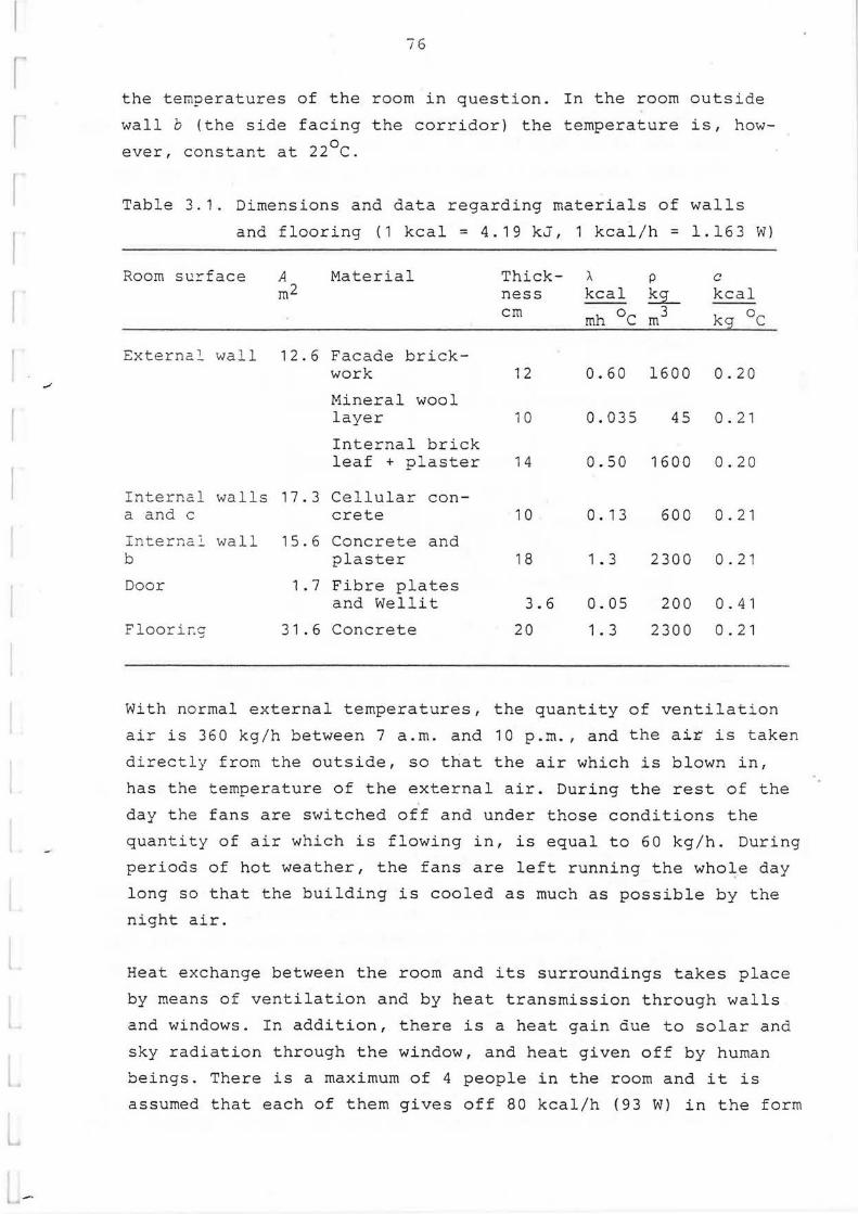
I
I f
l - ·
_,
76
the tern?eratures of the room in question. In the room outside
wall b (the side facing the corridor) the temperature is, howo ever, constant at 22 C.
Table 3.1. Dimensions and data regarding materials of walls
and flooring (1 kcal= 4.19 kJ, 1 kcal/h = 1.163 W)
Room surface A m2
Material
External wall 12.6 Facade brickwork
Mineral wool layer
Internal brick leaf + plaster
Internal walls 17.3 Cellular con-a and c
Internc.2. wall b
Door
Floorir.g
crete
15.6 Concrete and plaster
1.7 Fibre plates and Wellit
31.6 Concrete
Thick- I. p c kcal ness kcal ~
cm mh oc m3 kq 0 c
12
1 0
14
1 0
1 8
3. 6
20
0.60 1600 0 . 20
0.035 45 0.21
0.50 1600 0.20
0. 1 3
1. 3
0.05
1. 3
60 0
2300
200
2300
0. 2 1
0. 21
0. 4 1
0 . 21
With normal external temperatures, the quantity of ventilation
air is 360 kg/h between 7 a.m. and 10 p.m. , and the air is taken
directly from the outside, so that the air which is blown in,
has the temperature of the external air. During the rest of the
day the fans are switched off and under those conditions the
quantity of air which is flowing in, is equal to 60 kg/h. During
periods of hot weather, the fans are left running the who~e day
long so that the building is cooled as much as possible by the
night air.
Heat exchange between the room and its surroundings takes place
by means of ventilation and by heat transmission through walls
and windows. In addition, there is a heat gain due to solar and
sky radiation through the window, and heat given off by human
beings. There is a maximum of 4 people in the room and it is
assumed that each of them gives off 80 kcal/h (93 W) in the form

I
t
77
of sensible heat (latent heat in the fo:rm of moisture from the
skin and water vapour in the air breathed out do not alter
the room temperature). During the day when the room was be
ing studied, no artificial lights were required, and there
were no other sources of heat.
800
600 kcal/h I
I I I lf\, 400
200 I I/ . f I" I •' I I , ,. p I
0 I ..i==:= H=i - -- - , I I l I I I
0 Drawn u blinds
16 24
Hour
Solar and sky rafiation transmitted directly Solar and sky radiation transmitted indirectly
Heat fron human beings
Fig. 3.2. Heat which is being supplied to the room from human
beings and due to solar and sky radiation.
Figure 3.2 shows how the heat given off by human beings is
likely to vary during a 24 hour period. The quantity of solar
and sky radiation, which is transmitted directly through the
window, and the indirectly transmitted radiation of this type,
which is supplied to the room by heating up the inside glass
pane in the window, is also shown here. For windows without
Venetian blinds (i.e. drawn up blinds), the radiation data
were obtained from precalculated tables.
In the case of windows with Venetian blinds, the influence of
these upon the thermal inf low has been calculated according to

78
Ozisik and Shutrum /1/. Their values correspond well with
those which were obtained by the writer when carrying out
his own measurements. The thermal resistance of the window,
including the external surface resistance but excluding the
internal resistance, is taken as 0.29 m2h°C/kcal (0.25 m20c/W)
when the Venetian blinds are drawn up and 0.36 m2h 0 c/kcal 2o (0.31 m C/W) when they are lowered.
It may be of interest to note that when the Venetian blinds
are drawn up, the radiation which is transnitted directly,
is greater than the radiation which is transmitted indirectly,
while the opposite applies when the Venetian blinds are lowe
red.
·c 5Q-,--~-..,.---~,-~--r~-;=~---r~-i
Equivalent out-1 side 1 air remp n I \ I Ao I , Outside air tenperature
30-+--~--'-~~-+-~---++-~--+-~~-11-~-1
20-+-~-'-~__._,~~~-.'-I-~~---~--+---...___,
Te~ . of vent.air Lin case 2.
10-+--~-+~~-+-~---+~~--+-~~--~-i
0 4 8 12 16 20 Hour
24
Fig. 3.3. External air temperature and equivalent outside
air temperature.
When heat transmission through an external wall exposed to the
sun is calculated the equivalent external ternperatur
is obtained by adding the term a Ila to the external air tem-y y
perature (see fig. 3.3). The I value of the solar and sky ra-
diation against the facade is measured in kcal/m2h (W/m2 ), a y is the absorptivity of the wall surface for this radiation and

79
a is the surface heat transfer coefficient (including also y . the effect of long wave radiation). During the whole time
when the facade is exposed to the sun, it is assumed that
a = 14 kcal/rn2h 0 c (16.3 W/m2 0 c) and a = 0.5 . On the side y y facing the corridor, of the wall b and the door, it is assumed
that the coefficient of surface heat transfer, including radia
tion is 6 kcal/m2h 0 c (7.0 W/m2 0 c) for the whole 24 hour period.
As far as radiation between the room surfaces is concerned, it
is presumed that corresponding to the ass~mptions made in chap-
t ter 2, for long wave radiation emitted due to the emissivity of
the surfaces E = 0.93 at all surfaces, while reflection at the
surfaces is zero for all long wave radiation. Solar and sky ra
diation, which is transmitted directly through the windows is,
howe ver, reflected diffuse at all room surfaces. The reflecLivlty
for such radiation is 60 % for wall surfaces, 50 % for door sur
face, 75 % for ceiling, 25 % for floor and 20 % for the inside
of a window. The absorption factors, which can be obtained from
these reflcctivities are given in table 3.2. They have been cal
culated according to the method given in chapter 1.
I
Table 3.2 . Absorption factors~ for radiation from a surface nu A against a surf ace A
n u
Room surf ace n ~ nu
u = w a b c d t ~ . g !
Ext. wall w 0.045 0.118 0~098 0.118 0.012 0.124 0.451 0.034
Int. wall a 0.086 0.060 0.107 0.107 0.012 0.124 0.439 0.065
Int. wall b 0.080 0.119 0.056 0.119 0.007 0.126 0.436 0.057
Int. wall c 0.086 0.107 0.107 0.060 0.012 0.124 0.439 0.065
Door d 0.073 0.100 0.051 0.100 0.007 0.116 0.481 0.072
Ceiling t 0.079 0.109 0.099 0.109 0.013 0.059 0.471 0.061
Floor g 0.096 0.128 0.115 0.128 0.018 0.157 0.292 0.066
Window f 0.046 0.119 0.098 0.119 0.017 0.132 0.434 0.035

/
L
80
A 1 t e r n a t i v e c o n d i t i o n s f o r t h e
c a 1 c u 1 a t i o n s
Six different calculations of the temperature variations du
ring the 24-hour period of 15 July vere made. The con
ditions were varied in the following way:
Case 1 No cooling of the ventilation air takes . olace. Its
flow rate is conatant during the 24-hour period.
Case 2
Case ~
.)
Cooling of ventilation air when required so that
the temperature of the room air does not rise
above 2s0 c. Constant flow rate of ventilation air.
No cooling, ventilation off during the niqht
between 1 0 p. m. and 7 a.m. The leakage air flow
rate is 60 kg/h, while the ventilation air flow
rate is 360 kg/h during the day.
Case :a. The same as case 1 I but the convective heat trans-
fer coefficients at the ceiling and flooring sur-
faces are assumed to have constant values during
the 24-hour period. The average 24-hourly values
which can be calculated in case 1 are used.
Case 1b The same as case 1 but ~k = 2.5 kcal/m2h 0 c (2.9 W/m2 oC)
at ceiling and flooring surfaces for the whole day.
Case 1c The same as case 1 but the instantaneous value of
the equivalent outside air temperature is constant
and equal to the average 24-hourly value of the in
stantaneous values in case 1.
Cases 1a, 1b och 1c were studied to see how certain simplifi
cations of the conditions affect the result of the calcula
tions. A calculation according to the method can, naturally,
be carried out quicker and therefore cheaper, if it is possi
ble to use such simplifications without reducing accuracy too
much.

t
81
28 c
27 -
26 1--~-+---+--..--+-+--+-_._--\---:\-t---~
25
24
23
22
21
2 0 L-...L-.....1-..-.1...-'--'----"--"---'--"--........___.__
0 4 8 12 16 20 24 Hour
Fig. 3.4. Temperature of air in room in cases 1-3.
R e s u 1 t s o f c a l c u l a t i o n s
Diagram fig. 3.4 shows how the temperature of the air in
cases 1, 2 and 3 varies during a 24 hour period.
In case 1 the temperature approaches the maximum value of
26.7°c at 4 p.m. In spite of the fact that, according to
I fig. 3.2 radiation inwards through the window continues to
rise somewhat, the room temperature falls quickly after that
time, evidently because heat given out by the occupants is re
duced rapidly.
r
In case 2, it is seen from the graph in fig. 3.4 that it is
necessary to cool the ventilation air between about 12:45 p.m.
and 6:30 p.m. so that the temperature of the room air should
not rise above 25°c. The temperatures to which the ventilation
air must be cooled, are inserted into the diagram in fig 3.3.
The calculations show, that the maximum cooling effect occurs
at 4 p.m. and is 440 kcal/h (512 W). The entire cooling re
quirement is 1470 kcal (6160 kJ).

,.I
.,,;
,. .. ' '.-· •/
l~
82
In case 3 one misses the cooling of the walls and floor of the
room, caused by the cool night air. During office hours the room
temperature is therefore about 1°c higher than in case 1.
The thermal comfort of human beings depends not only upon
the temperature of the air within the room, but also upon the
temperature of the surfaces of the room, with which the body
is in constant heat exchange due to radiation.
26 ~c
25
24
23
22
---~ 40 ·c
I ·~ I I ' I . 130 i sideJ sur- J \ f ace of wlindow !
0 A 8 12 16 20 Hour
20 24
Fig. 3.5. Temperatures of room surfaces in case 1.
Fig. 3.5 shows how the temperatures of the room surfaces vary

•
a
83
during a 24-hour period in case 1. The window panes and the
blinds are assumed to have no thermal capacity. They absorb
solar radiation, and therefore the temperature of the inner
v:indow surfaces varies strongly. The thermal capacity of the
opaque building materials causes the variations of surface
temperatures to be less than of the room air. In spite of the
fact that the average 24-hourly temperatures of wall and
flooring surfaces are higher than the temperature of the air
within the rooffi (with the exception of the temperature at
the surface of wall b, which is cooled by the cooler air from
the corridor), the surface temperatures are lower during
working hours than the temperature of the air within the room .
The temperature during the day is higher on the surface of the
comparatively light internal walls a and a, than on the surfaces
of the flooring anrl ~he heavier walls. The disadvantage with
light walls is not only that they have less ability to even out
tenperature variations of the air within the room. They also
have a higher surface temperature during the day and therefore
contribute to give a feeling of a higher room temperature.
Fig. 3.6 shows the temperatures at six different times of the
day in the cross-section of the flooring and walls. The exter
nal wall dampens, as can be seen, the strong temperature varia
tions on the outside exceedingly. The variations which occur,
however, on the inside are caused mainly by temperature varia
tions of the air within the room and of other room sur-
faces with which the inside surface of the external wall ex
changes heat by means of radiation. This can be seen from fig.
3.5, where the graph for the external wall has nearly the same
shape as · the graphs for ceiling, floor and wall b.
2 0 2 0 In case 1a, when ak = 1.5 kcal/m C (1.7 W/m C) for the floor
surface and 1.2 kcal/m2
h 0 c (1.4 W/m2 0 c) for the ceiling sur
face during the entire 24 hour period, the temperature of the
air in the room is nearly the same as in case 1 at all times of
the day. The difference is only a few tenths of a degree at
night, while during the day the difference is even smaller. In
the same way the deviations with regard to ceiling and floor
temperatures were quite insignificant.

I I
l 4
'
-
·c
• . Ito
25 r--
2""
23M1t,~
2:£ -I I
• ..t.0 -j\ c
30
17 • .,.
Brick
81
't
25
2""
I I 231'>6<1
t'lall a
22i I anC. c
External walll I I
'Ot m \.( . "'
I Min·eral .I Brick wool
2"' 'c
23
22
' ~ :.!
.L
23
I \J
\ I
\·Tall b
Flooring
x I
\( \ ( ~
-- 'c
Fig. 3.6 Temperatures in
cross-section of
flooring and walls
in case 1 at six
different times of
the day (example:
kl 16 denotes
4p.m.).

85
In case lb the values were, however, so different from those
obtained in case 1 that we must exawine them wore closely:
during the time from 1 p.~. to 5 p.m. the air temperature was 0 found to be about 0.4 C lower, between 1 a.m. and 5 a.m. about
0.4 °c higher than in case 1. The reason for this must be,
that in case lb the floor and ceiling surfaces cool the air
more during the day, and heat them more during the night since
the coefficient of surface heat transfer is greater than in
case 1.
From this can be seen that the value of the coefficient of
• convective heat transfer influences the temperature calcula
tions, but that it can be considered ade~uate to use an aver
age 24-hourly value in order to obtain a sufficiently accurate
result. Of course the average value must be accurately calcula
ted.
In case le it was assumed that the equivalent outside air tem
perature was constant at 27 °c, which is the average 24-hourly
value in case 1. It was found that the temperature of the air
in the room never differed by more than 0.03 °c from the corre
sponding value in case 1. In the case of an external wall, where
the temperature variations are dampened so appreciably as in
this case, and where the heat transfer through the wall is so
small in comparison to that which takes place through the win
dows, it is obviously completely. unnecessary to calculate using
a variable equivalent outside air temperature.
- Cases la, lb and le show how the program can be used to study
the importance of selected modelling assumptions.
_,.., . . ·.
R e f e r e n c e
1. Ozisik~ N. and Schutrum~ L.F.:
Solar· Heat Gains through Slat-Type Between-Glass Shading
Devices. Trans. ASHRAE Vol. 66 (1960), p. 359.

•
87
4 PRESENT-DAY STATE OF THE PROGRAM
4.1 Physical b~sis
4. 1. 1 Climatic data
Outdoor climte is described by outdoor temperature and solar
radiation.
Observed data from a climate file can be used for aperiodic
siinulallons. An optional calendar can be utilized to locate
weekends and public holidays so that different profiles of
time dependent data can be used for these different days.
For a periodic simulation, for a specified day of the year,
the outdoor air temperature can be given by the 24-hour mean
temperature, the amplitude of the temperature variation
during the day, and the hour when the maximum temperature is
reached. The temperature oscillation is then treated as
sinusoidal.
The solar radiation, direct from the sun and diffuse from
the sky, is calculated based on the desired location of the
building, given by latitude and longitude. Latitude is posi-
t tive North of the equator, longitude is positive West of
Greenwich. In addition to that, the time meridian is re
quired to relate the location to the correct time zone.
Rather than using the reference longitude, the time lag
after Greenwich is entered. As an example, Central European
time is normally entered as 23 h. The value should be
corrected for daylight saving time, when relevant.
The reduction of incoming solar radiation due to absorption
in the atmosphere is taken into account by a reduction

r ' : !' (
88
factor entered by the user (maximum value 1.0, for a clear
and dry day). It can also be used to approximate the effects
of average cloud cover in this context.
The radiation from sun and sky is reflected from the ground.
Typical values of the ground surface reflectivity are 0.25
for summer conditions and 0.8 for snow cover.
The BRIS program calculates the solar radiation for an en
tirely unobstructed horizon, or for a horizon hidden to a
specified altitude between 0 and 90 degrees. (Detailed
shading from shading devices or from nearby buildings can at
present only be treated by preparatory runs of separate
shading programs.) Incident radiation values in W/m 2 are
obtained for horizontal building surfaces (roofs) and for
facades with orientations given by their azimuth.
The absorbed fraction of the irradiation at the outer sur
face of an external wall or a roof is determined by the
absorptivity for shortwave radiation, for instance 0.5 for
yellow and light red brick, 0.7 for dark red brick and 0 . 9
for a dark roof cover.
Heat is emitted from building surfaces by longwave radiation
to the sky and by convection to the outdoor air. For the
radiation losses, different cloud cover constants are
assumed which are dependent on cloudiness. They are relevant
for horizontal or somewhat tilting surfaces only . For
vertical surfaces, the radiative heat transfer is assumed to
be included in the surface heat transfer coefficient.

89
4. 1. 2 Heat transfer through windows
According to Chapter 2, the shortwave radiation from sun and
sky can be subdivided into two parts. One, I~, is directly ~
transmitted through the window, possibly after reflections
between the window panes, but not absorbed by them or by the
shading device, if any. The other, Iv~ is absorbed, i.e.
transformed to heat. The temperature rise of the innermost
pane effects the heat balance of the room, and the room
• climate.
•
\)-· . :' . ,
Again, one portion of IV is transferred by longwave radia
tion to surfaces in the room and by convection to the room
air. Another portion of IV is transmitted in the opposite
direction through the window back to its outside.
In BRIS the treatment of heat transfer through a window
exposed to sun will be the following.
Each fenestration combination (number of panes, types of
shading: etc.) has to be described by two shading coeffi
cients £1
and F2
, plus a thermal transmission coefficient U
W/m 20 c, see table in Appendix C. Here F1
denotes total
transmitted solar radiation and f 2 direct transmitted solar
radiation, both relative to total tr.ansmitted radiation for
a window with two panes of ordinary glass, I ~· re;
In the result output from the BRIS computation, I f W/m 2
re and Itot= (IV+ I 1 JAf W are recorded. In addition, values of
the temperature of the internal surface of the window,
e~ °C, and the heat transfer p t J OU
W from this surf ace to
the out-door air, are given (in fact - P t out because the OU
aim is to sum up all heat transferred into the room). It
should be noticed that e1 (calculated from equation (19) in
Chapter 2) is of great importance in connection with the
effective temperature as measured at different points in the
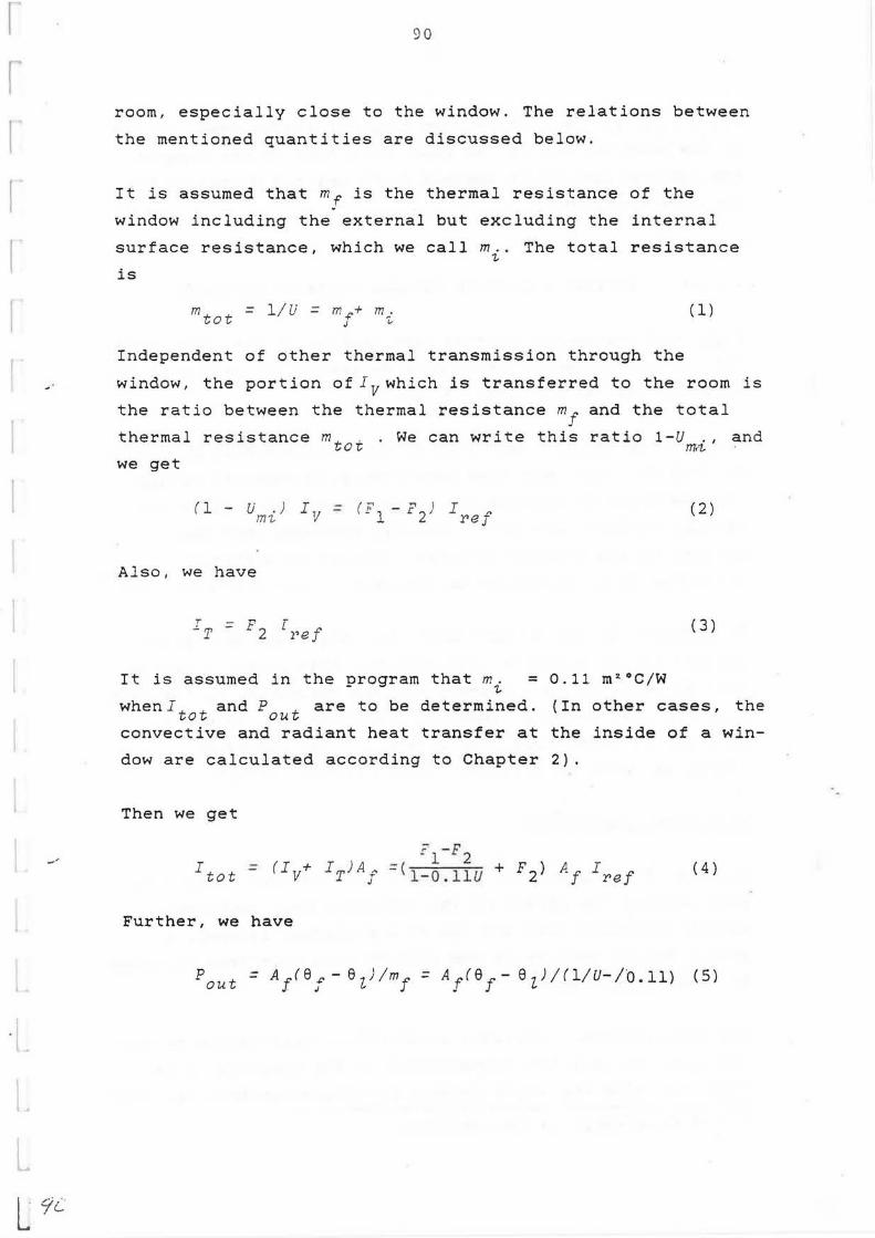
I r~
I I r
· l~ I
L
L
_,
L 7i
90
room, especially close to the window. The relations between
the mentioned quantities are discussed below.
It is assumed that mf is the thermal resistance of the
window including the external but excluding the internal
surface resistance, which we call m .. The total resistance ~
is
mt t = 1/ U = m +' + m ~· ( 1) 0 J "
Independent of other thermal transmission through the
window, the portion of Iv which is transferred to the room is
the ratio between the thermal resistance m+' and the total J
thermal resistance mt . . We can write this ratio 1-U . , and o~ m~
we get
(1 - U . ) IV = (F1
-F2
J I +' m~ reJ
( 2)
Also, we have
T ,,,T ( 3) = F2 [Pef
It is assumed in the orogram that m. = 0.11 m2 °C/W - ~
whenJtot and Pout are to be determined. {In other cases, the
convective and radiant heat transfer at the inside of a win
dow are calculated according to Chapter 2).
Then we get
i l - F2 Itot = (Iv+ IT)Af =(1 - o .11u + F2) Af Iref ( 4)
Further, we have
Pout = A1ref- ezJ!mf = A1 (e 1 - eiJ/(l/u-1·0.11> (5)

I - p tot OU t
91
is the contribution from the window heat transfer
to the heat balance of the room. Note that in the program
the radiant portion is assumed to be emitted diffusely to
the room surfaces.
4. 1. 3 Thermal radiation between surfaces in rooms
Angle and absorption factors (see Chapter 1) for wall, floor
and ceiling surfaces, are always determined in BRIS runs and
• given in the result output if wanted.
•
7 ,...-
Using these factors, examples of determinations of diffusely
emitted daylight show good agreement with measured values.
Best calculation results have been reached when floor and
ceiling surfaces and partition wall surfaces have been
divided in subsurfaces (stripes) ,located at different x '
distances from the window in question (Brown & Isf~lt 1974) '
In passing, it can be mentioned that angle and absorption
factors can be approximately obtained from simple equations
that in addition to the areas and absorptivities of the room
surfaces also contain 'location coefficients'. Values of
such coefficients have been determined for radiation from a
window in rooms of different shapes (Brown 1984)·x) •.
Effective temperature
The aim of the quantity 'effective temperature' is to take
into account the effect of the radiative heat exchange
betwen the human body and the room surfaces, in order to
give a better measure of the comfort in a room than the room
air temperature only.
The BRIS program calculates an effective temperature by con
sidering not only the temperatures of the surfaces in the
room, but also the angle factors for radiation from the room
x) See References in Introduction.

'---•
'
"-
. , ,
92
surfaces to six surfaces of a small hypothetical cube placed
at the point in the room for which the effective temperature
is required . The sides of the cube are parallel to the
surfaces of the room.
Seen from the surfaces of the cube, different parts of the
surfaces of the room appear to be screened, with the result
that the irradiation varies from one surface of the cube to
another .
A comfo~t rating is also determined, defined as the maximum
differe:.ce of effective temperature in different directions
from the calculation point. The comfort factor can be said
to constitute a measure of the asymmetry of the radiation
field, ~ecause it represents the difference between the
tempera:ure of the warmest and the coldest surface on the
cube. A high value, in other words, is an indicator of poor
comfor~.
If the air temperature in an off ice is not cooled during the
working hours of the day, the effective temperature is usu
ally lower than the air temperature (Swedish summer climate
conditions). The graph in fig. 4.1 gives an example showing
the difference between the air and the effective tempera
tures in a point near a window facing the north in a room
that is first assumed to be in a lightweight building
(continuous line), then in a massive building (broken line).
oc 0,6 l
er-eeff l 0,t. ]
0,2 ~
-o t. ; ' ~
.:::..::..:.- .,
12 116 hour _0 : 1~s
-o,6.L· ___ ___ ____.
Fig. 4.1. Difference between room
air temperature and ef
fective temperature.
An example .

,
•
'/ ·' '
93
When BRIS calculates comfort, the variations are restricted
to the six sides of a cube. A sphere would normally give a
slightly higher variations.
BRIS also calculates a frequency distribution for the effec
tive temperature. This can serve as a basis for the calcu
lation of cumulative frequencies over typical climate varia
tions.
The effective temperature is calculated and printed for all
intervals included in the output listin;. The frequency
distribution, however, is normally required just for the
period when the room is occupied. The desired period is
indicated by a reference in form type 3 (see Appendix A).
4 . 1. 4 Convection heat transfer at room surfaces
In BRIS, the convective heat transfer at every room surface,
the inner window surface included, is calculated by using
the formula
= a + b (abs ( e - e)) c ~ p
where ~~ and 9 are the temperatures of room air and surface
respectively. The values a , b and c may be given as con
stants or as time dependent parameters. Normally used values
of a , b and c are those given in Chapter 2.
Usually, the room air is regarded in BRIS as one homogeneous
mass with the same temperature throughout the room. Values
of temperature gradients at ceiling and floor surfaces, con
stant or time dependent, can however be added to the average
room air temperature, thus taking vertical stratification

··1- .. . ~
94
into account. These values are added only for the deter
mination of the convective heat transfer at these surfaces.
4. 1. 5 Heat sources in a room
A nominal heat gain from people is assumed to be valid at
20°C. The heat is thought to decrease linearly with in
creasing room air temperature, reaching a zero value at
40°C. Temperature dependence can be suppressed by giving a
negative input value; the absolute value of the gain will
then be used in the calculations. Note that latent gains are
not treated by the program.
Hea~~n from ligh~§ is normally treated as emitted by a
typical unventilated, fluorescent ceiling light. BRIS will
then distribute the gain evenly over the ceiling, assuming
20 % as visible light, 25 % as long wave radiation and 55 %
as convective heat. Other assumptions may be done in the
input, for instance a portion of thermal energy from lights
may be used to heat return air.
The standard heater used by BRIS is a radiator placed on an
exterior wall below a window. It will be given a size to fit
the available space, and is assumed to have negligible ther
mal inertia. The radiator (only one per room) gives heat to
the room air by convection and to the room surfaces by ra
diation.
The standard heater model can be modified in the following
ways:
A cooler can be represented as a heater with negative
thermal output. It is normally treated as a convective unit,
i.e. a unit with negligible radiation exchange with the room
sur-faces. All heat is then transmitted directly to the room

95
air, and the location of the heater in the room is in
significant.
A quantity 'surface enlargement factor' is used to govern
the convective heat transfer from a heater. Its size is 1
for a convector, 2 for an entirely flat heater. Typical
values are in the range 3 - 4.
The thermal capacity of the heater, in J/°C, although nor
mally negligible, may be given a non zero value . However,
• BRIS will always use zero capacity when heater output is the
quantity sought.
•
·:.,1-~·
The thermal inertia of extra heavy furnit11re or other
equipment in the room can be simulated by the heat capacity
of a heater with a zero thermal output.
The output of a heater can be made dependent on the outdoor
climate by use of an 'outdoor temperature factor' f, to
simulate existing control systems where water supply tempe
rature to the heater is influenced by the outdoor air tem
perature Sz. The output for different air temperatures is
given by a nominal output power multiplied by f.
How f depends on al will be described by BRIS in the
following way.
For two or three values of el the corresponding values
of f are given as input data. For temperatures higher than
the highest or lower than the lowest of these el -values
the f -values do not vary; between the given el -values the
variation of f is linear.

r
·· "
96
4.2 Data handling
4.2.1 General information
Data for the calculations are recorded on printed forms, see
Appendix A. The following types of forms are used:
O General Information
1 Room
2 Wall or Floor/Ceiling
3 Facades plus Room Depende~t Data
4 Profiles of Time Dependent Data
5 Air Handling
6 Ventilated Floor Slab (TermoDeck)
7 Auxiliary Output Control (provisional)
The forms may be used in many different combinations. Data
from the forms are entered into a data file. Any suitable
editor may be used. When old cases have to be revised, new
forms may be completed or the old forms updated, but the
normal practice is to note the changes in an input data
listing and then update the data file directly via the
editor.
User's Manual for BRIS (Bring, 1985) may be referred to
for detailed information about using the forms. However,
97
some survey of the data handling characterizing the program
will be given here.
Data must be expressed in SI-units. The unit of time is
hours instead of seconds and thus the u~it of energy is Wh
rather than Joule (1 Wh = 3600 J). However, specific heat
capacity is measured in J/kg°C.
Flexibility has been a goal during the development of the
BRIS program, to make calculations possible for a wide
J variety of buildings and installations. The different forms
are linked via cross references in the forms themselves, and
the combinations of forms making up a particular case can
vary within wide limits.
I
Different box styles in the forms are used to indicate data
classes. For values that always remain constant during the
calculation, single line boxes are used, and for values that
may vary in time double line boxes are used. In the double
line boxes there could be given a) a constant value or b) a
reference to a table describing the profile of the
variation, as defined in a form of type 4.
All rooms, walls, windows etc. are indentified by numbers.
Each type of element has a separate numbering, from one and
upwards. All individual room surfaces (corresponding to
walls, ceilings, floors, doors, windows and possible lights
and heaters) are numbered separately for each room; every
room has a surface number 1 etc. This numbering is local, in
contrast to the others.
0 L~ •
98
The following Iestrictions apply to element numbers :
Type of element Highest number permitted
room
wall
facade
window
effective temperature
profile of time
dependent data
room surface
10
60
x
x
x
50
16
x The sum of the highest numbers assigned for rooms, walls,
facades, windows, effective temperatures, and profiles must
not exceed 200. The total number of room surfaces in the
data file must not exceed 100.
As seen in Appendix A, the form type 0 for GENERAL
INFORMATION contains data for the building as a whole.
Examples are calculation accuracy, length of simulation,
output control, outdoor climate.
The length of time to be simulated for a periodic cal
culation is specified by the calculation period. The same
period is simulated repeatedly, in general until a recurrent
state has been reached according to a convergence criterion
described below. The typical period length is 24 hours, but
in principle any period length can be used, a few hours or
several days. The simulation can also be aperiodic, i.e.
performed just once for an arbitrary length of time, for
instance a winter or a summer period, or an entire year. A
steady state case can also be run, treated as a periodic
case, with' calculation period put equal to the calculation
step (and print step).

99
Calculation step is the interval between the successive time
coordinates where the program makes complete heat balance
calculations . The choice of intervals is based on con
siderations of accuracy and computer time. Typical intervals
are one hour or half an hour. The shorter value is suitable
when the case contains thin wall layers (around ten milli
meters or less).
Printing step is the interval at which output is produced.
It can be longer than the calculation step : Output may also
i be printed for specified times only.
t
I ••• ,
The difference equations used by BRIS to represent the heat
balance equation are solved for each time step by iteration,
as mentioned in Chapter 2. In each iteration, the variable
values are changed systematically to bring them closer to
the solution. The difference between two successive sets of
variable values are compared with a relaxation tolerance.
When all changes are less than the tolerance, the iteration
is stopped and the calculation proceeds to the next time
step.
Since the different variables in a calculation may be of
very different magnitude, it is reasonable to strive for
some type of relative accuracy. In BRIS, this has been sol
ved by calculating a dimensionless change for each variable,
by the formula
ABS (new value - old value)
20 + ABS (new value)
The value 20 represents a typical magnitude for most cal
culated temperatures. The dimensionless approach will avoid
excessive accuracy demands when loads or air flows take on
large values.

100
In a periodic simulation, the whole calculation period is
iterated. For each new period, the calculation is repeated
at all the time steps in the period. At the end of a period,
each variable value is compared to the value of the same
variable at the end of the previous period. A recurrent
state is deemed to be reached when all the differences
observed fall below the period tolerance. (The value of the
period tolerance is irrelevant in an aperiodic simulation.)
The dimensionless expression described above is used, also
when checking for period convergence. To make period
convergence possible, the period tolerance must obviously be
larger than the relaxation tolerance.
When starting a simulation, all temperature variables are
often given the same initial value. This value should be
chosen close to the mean temperature of the building. The
number of periods required to reach a recurrent state will
depend on how well this value was originally estimated. A
carefully considered start value is especially significant
for heavy constructions with large thermal inertia.
Energy totals can be calculated separately for different
subperiods of each simulated day. Examples of interesting
subperiods are: business hours/after hours, ventilation
on/off, etc. Up to six different subperiods can be chosen.
As shown in form type 0, the output of results from a
simulation run can be controlled by using control codes. A
complete printout is shown in Appendix B and is discussed ~n
4.2.7.
In the remaining part of form type O climatic input data are
to be entered. They are treated in 4.1.1.

101
4.2.2 Room data
Data for rooms are entered in forms type 1 for ROOM. If you
want to study several different and interrelated rooms, e.g.
a corner room and an adjacent room, one form of type 1 is to
be completed for each room.
The wall, ceiling and floor surfaces have fixed numbers:
1 - 6 {as shown in a layout on the back of the form).
• Subsurfaces may be introduced as parts of these main
surfaces to show the locations of windows, wall heaters etc.
Width and length of all surfaces and their reflectivities
are to be noted in this form.
,
In form type 1 the flow rate and temperature of the
infiltration air .are also entered, together with heat gains
from people and lights, the code number of the quantity
sought, and the four quantities that can be sought: room air
temperature, supply air temperature, supply air flow rate
and heater output. Guidance in selecting appropriate code
numbers for quantity sought and for restrictions, if any,
is provided in Section 4.2.5.
All these quantities, including the flow rate of
infiltration air, -i.e. the spontaneous ventilation in the
room, can be regarded constant or time dependent. During fan
operation time the infiltration can sometimes be disregarded
or treated with the forced ventilation.
Heat emitted from people and lights and from heaters in a
room is treated in Section 4.1.5.
The handling of supply air is studied in Section 4.2.4. The
supply air temperature is the temperature of the air
reaching the room, after all processing. See Section 4.2.5
for discussion of quantity sought.

... ·
102
4.2.3 Wall and floor structure data
Each section of a wall or floor slab (below referred to as
wall) is described in a copy of a form type 2 for ENVELOPE
SECTION. The section lists a sequence of homogeneous layers
making up the wall. One of the sides of the wall will always
be a wall surface in the room under consideration; the other
side, the outside, may be a wall surface or a facade. In
this context, facade denotes a surface where radiation and
temperature conditions are known and supplied as input data.
One of two alternative lines of data boxes in the form are
to be entered, depending on whether the outside is a facade
or a wall surface.
The different homogeneous layers (solid materials or air
spaces) of the wall are to be listed in a table in the form.
Layer thickness, thermal conductivity, density and specific
heat capacity of the materials are given here. If standard
materials are used (brick, concrete etc.), they can be
specified by codes. The material properties that are used
in that case are given at the bottom of the form.
Material layers will often have to be divided into thinner
sublayers during the calculation. Too thick sublayers will
mean loss of accuracy; thin layers will increase the
accuracy but will require the time step to be kept short to
avoid oscillations.
A reasonable balance between conflicting needs for accuracy
and short calculation time can be found using time steps of
0.5 or 1 hour. With a time step of 0.5 h, suitable sublayer
thicknesses are 0.04 - 0.05 m for concrete and rock wool,
0.03 - 0.04 for brick, and 0.025 - 0.03 for wood. In thick
walls, sublayers can be made thicker without difficulty.
Suitable sublayer thickness varies with the square root of

I
t
103
the time step. Normal slabs of glass, plasterboard and
particle board are not split into sublayers. Sublayer
thicknesses of the standard materials are chosen by BRIS .
4.2.4 Air handling control
The form type 5 for AIR HANDLING should be used when it is
assumed that the heating and cooling capacity available for
air handling is not unrestricted, i.e. wh~n the prescribed
or calculated supply air temperatures may not be achieved at
all times. Otherwise, the data given in form type 1 are
sufficient for the simulation.
In the simple case when the current room gets air from
another room, only the numbers of the two rooms have to be
introduced in the form 5. Other boxes in the form are meant
for the normal case when the room is supplied by air from an
air supply system.
Temperature rise of the supply air due to fan operation is
specified, and also possible temperature changes in the
supply air duct system, resulting from leakage or bad
insulation.
System code numbers specify which system type is to be
applied: recycling, recovery, recycling and recovery, or
evaporative cooling, when either of these features is used.
In these cases, temperature rise due to fan action on return
air is also entered .
In the alternative of a recycling system, the minimum
proportion fresh air is specified. This proportion may be
held constant, but will often vary during the calculation
period due to occupancy variations. In such a case BRIS will
assure that the fresh air rate will vary from the specified

I
...
,···' .•' ' ... , - '
' -
104
limit and upwards. With this way of operation, satisfying
comfort can be achieved with a minimum of energy demand.
In the case of a recovery system, the maximum temperature
efficiency of the heat exchanger is specified in the form.
The program will assume that the efficiency is variable from
zero up to the limit specified, and best possible comfort
with a minimum of energy demand will be achieved in this
way.
An evaporative cooler is assumed to operate at fixed cooling
efficiency when the cooling is on . When such a cooler is
off, it will act as a heat exchanger in a recovery system.
For this case the dewpoint of the outdoor air must also be
given.
Available power for heating and cooling of supply air is
introduced in form 5. By code numbers, constant or time
dependent, the periods are specified when heating and
cooling may be used, or when a maximum temperature
difference between the room air and the supply air is
required for comfort reasons. This temperature difference is
also given in form type 5. Comfort restrictions on the
supply air can also be introduced as fixed temperature
limits, independent of the room air temperature, in form
type 1. Both the temperature limits and the code for
quantity sought could be used to vary the impact of the
restrictions during the day.
If the aim of the simulation is to estimate the maximum
capacity demand for heating or cooling, a large value that
is certain to be sufficient under worst conditions may be
entered in the form type 5. BRIS calculates then the cooling
or heating capacity if requested, by use of quantity sought.
The power can also be assigned proposed realistic values, in
order to study room climates resulting from intentional
undersizing.

105
It is often desirable, for instance in office buildings, to
use time limits for fan operation, during both heating and
cooling seasons,
During the heating season, the fans can be run at night with
100 % recycling with the motive of redistributing excess
heat stored in sunlit zones during the day. The fan
operation would be discontinued when temperatures in the
warmer zones fall below a certain limit. Another scheme is
t to stop the fans after working hours and start them again
(with heating) if temperatures drop too low . They may be
stopped once again if the temperature then rises above a
limit .
,
/
In hot weather, it is often desirable to use cool night air
for ventilation, until the room air temperature has fallen
sufficiently. When the fans have been stopped, energy
released from the envelope may possibly heat the room air so
that the fans would need to be started again.
Only fixed limits of the room air temperature may be used to
control the fan operation. In hot weather, the switch-on
limit would be higher then the switch-off limit. In the
heating season, both alternatives are possible.
4.2.5 Use of the concept 'quantity sought'
With the aid of quantity sought it is possible to make the
most of a BRIS simulation. The full flexibility of the
program can then be reached. Quantity sought, first
mentioned in Section 4.2.2, is given a detailed, more
exhaustive description in User's Manual, with many examples
referring to realistic cases. The principle of its use will
be shown briefly below.

II
r
I I I
-~
I .,/
/ ·
10 6
The following four variables in the heat balance equation of
the room air have been selected as suitable 'unknown'
quantities in BRIS. Each of them is specified by a code
digit:
Quantity Sought Code
I = Room air temperature 1 1"
.;. i = Supply air temperature 2
c -· = Supply air flow rate 3 "'
~ = Heater output 4 ..
In simpler calculation problems, a single variable is chosen
as the quantity sought. All the others should then be given
predefined values.
If different quantities are sought at different times during
the calculation period, the code digit for quantity sought
valid during the time interval in question must be specified
in a form type 4. For instance, if the heater output is to
be sought during hours 7 - 17 and the air temperature during
all other hours of the day, the code digit will be 4 during
7 - 17 and 1 during 0 - 7 and 17 - 24.
Values must be given to all quantities, also a value to the
quantity that is sought. This latter value is disregarded by
BRIS during the calculation of the quantity sought (unless
it is used as a limit value).
It is not unusual that a limit value is specified for a
quantity whose value varies during the day. During some of
the working hours of a winter day, room air temperature may

107
become higher than a lower comfort limit, owing to heat from
people, light etc.
In an example, say that this lower limit is 22 °C. BRIS will
then determine the heat demand to keep 22°C as long as heat
is needed, i.e . when the calculated heater output is
positive. When no extra heat is required i.e. when the
heater output should become negative to keep 22°C, BRIS will
calculate the air temperature instead of heat demand.
I The limits for the variables may vary during the
•
calculation period. When describing cases with limiting
conditions, quantity sought will be specified on form type 4
by one or more two-digit code numbers. One two-digit number
will be given for each variable involved . The first digit
specifies the variable, as mentioned before . The second
digit specifies the restriction that should be applJed to
the variable:
Function
Minimum value specified
Minimum and maximum value
spec if ied
Maximum value specified
Preferred value specified
Restriction
code
6
8
9
(values may be higher or lower) 0
When more than one quantity is sought, a code chain is
formed, consisting of two or more two-digit code numbers.
BRIS will treat the variables in the order they appear in
the chain.
_,
/.
108
In our example the heater output had a minimum value of 0.
The two-digit code to describe this is 46 . If this condition
fails, BRIS will calculate the room air temperature. For
this quantity we had a lower limit value (of 22°C), and the
code for this condition is 16, and the code chain will be 46
16. In this example, the order of the variables is
irrelevant. The solution will be found also if we enter 16
46 for quantity sought.
If the heater has a limited power, it has a maximum as well
as a minimum output limit. The code number will be 48
instead of 46, and the code chain 48 16 . BRIS will now
calculate the room air temperature if the maximum power of
the heater is too low to keep 22°C in our example.
The code chain could have been written also 48 10 in this
case, i . e.: Calculate the heater output within an interval
and with the room air temperature at a preferred value; if
no solution is found, set the heater output to its nearest
limit and calculate the temperature.
The room air temperature is special among the quantities
sought. When we specify limits for the room air temperature
they are tentative restrictions, desirable to keep for
comfort reasons. Limits for other quantities, on the other
hand, normally correspond to physical restrictions which can
not be exceeded.
The above mentioned difference in kind, between the room a·ir
temperature and the other variables, is reflected in the
calculation strategy in BRIS. If the specified set of
restrictions can not be upheld, BRIS will find a solution by
relaxing the restrictions on the room air temperature.
..

109
4.2.6 Ventilated floor slab (TermoDeck)
Ventilated hollow core concrete floor slabs utilized
according to the TermoDeck patent, can be simulated by BRIS
(see the list of references in Introduction: Andersson et al. (1979)).
In the simplest case, there is a single 'deck' supplied with
air from a separate air handling system. In other cases, one
deck may supply flooring (and possibly ventilation air) to
I more than one room. In such cases, the deck is described as
two or more separate decks. The physical unity of the deck
is modelled by letting exhaust air from one deck become
supply air to another.
~
/ ·' . ,:
The supply air to the hollow core slab may be supplied by
fresh air and return air. Code figures in the form type 6
specifies the proportion of return air (in a recycling case)
and whether the supply air is to be heated or cooled.
The return air is assumed to come from a specified room when
recycling is used. When heating or cooling occurs the
available capacity is supposed to be unlimited.
In case of recycling, heating or cooling of the desired
supply air temperature is derived as a function of outdoor
temperature, via one of three control curves.
BRIS will always try to keep the desired supply temperature
by varying the recycling only, before any heating or cooling
is applied. Heating or cooling will be used when required
and allowed by the system code. The cooling and heating
rates used can be found in the result output.
The control curves are used for different periods of the
day. They are labelled day curve, night curve, and morning

-·
110
cooling curve . The 24 hour calculation period is split into
three corresponding subperiods: day, night, and morning.
The day and night curves are always used during the
corresponding subperiods, whereas the morning subperiod is
intended for optional adjustment, depending on prevailing
conditions . Thus, the night curve continues to be used
during the morning, until an optional switch is made, or the
morning changes to day. The switch can be made, either to
the morning cooling curve, or to the day curve.
The decision to switch over from the night curve is based on
a reading of the exhaust temperature from the deck. This
temperature is compared with a reference temperature, which
in turn is defined as a function of outdoor temperature, via
a fourth control curve. If the deviation of the exhaust
temperature fro~ the reference temperature exceeds a certain
tolerance, a switch in control curve is made. The morning
cooling curve is selected if the exhaust temperature is too
high and the day curve if the exhaust temperature is too
low.
The entire morning ritual can be suppressed by making the
tolerance high. This is normal practice in the heating
season.
Three points are used to describe each curve. The subperiods
will be chosen in such a way that they follow each other in
the intended order: day, night, morning, day,
When more than one TermoDeck is simulated, BRIS will use the
same curves for all decks. The curves need thus only be
specified once, and the curve definition part can be left
blank for the other decks.

-
•
//, . , '
111
The ~ffective heat transfer, taking place between the duct
surfaces and the air ventilating the dticts, will be
described in the form by two parameters: Film coefficient
and Effective .surface.
Recommended values are based on laboratory measurements and
subsequent experience with installed TeromDeck systems. They
can only be obtained from Strangbetong AB, Stockholm.

,,
•
·.l'
112
4.2.7 Result output
4.2.7.1 Exemple
In Appendix B, an example of a complete printout from a BRIS
run is given. It can be seen that the input data (pages B.1
and B.2) are echoed to the output in the same order as they
are filled in on the forms (Appendix A). Headlines are
entered in this input account to facilitate the reading .
From the heading on each result output page (pages B.3-B.9)
it can be seen that the room simulated is an office facing
south with a concrete floor slab. The day considered is a
day in July, and cooling was used, at a maximum rate of 500
w.
Input data entered in accordance with Form type O show that
the steps used were, 0.5 h for the calculation and 1 h for
the printing. The simulation was made for a 24-hour period,
using tolerances of 0.001 for the relaxations and 0.003 for
the period. Climatic data are valid for July 15 and for
Stockholm, with daylight saving time used (time meridian 22
instead of 23 and outdoor temperature maximum at 16 hours).
The horizon was unobstructed.
The first line of data for the room shows the room
dimensions. The 'K' at the beginning of the second line
denotes that the temperature of the infiltration air is the
same as that of the outdoor air. The quantity sought and
gains from people and lights are time dependent, varying
during the day. They are specified via profiles in Form
type 4. We give them numbers 1, 2 and 3 (Tl, T2 and T3),
respectively.
On the third data line, for quantities that may be sought,
the only specified values are the temperature and the flow

113
rate of the supply air. The temperature, 15°C, is a minimum
value, a fact that can be seen from the value of Tl at the
top of page B.2 showing a code number 26 of the quantity
sought for the whole 24-hour period (2 stands for supply air
temperature and 6 for minimum value specified, according to
4.2.5). The flow rate, 180 kg/h, is constant during the
period. The other quantities are indicated by 'N' only,
stating that they are not given any values during the
calculation. The cooling is thought to be .furnished to the
room by the supply air and not by a cooler in the room.
I Otherwise the power rate should have been entered under
'Heater output', with a negative sign.
'
,/, / .·,.'
All properties of wall and floor slab material layers are
described by codes, explained in Form type 2, Appendix A.
On the data line specifying window parameters in conformity
with Form type 3, values on the shading coefficients Fl and
F2 and the transmission coefficient U have been taken from
Appendix C. They are constant, thus valid for the whole 24-
hour period, and in accordance with coefficients of a triple
glazed window with Venetian blinds between external panes.
Effective temperatures for two points in the room have been
requested, one directly in front of the window and 1 m from
it (No. 2), the other in the middle of the room (No. 1).
They are requested during that part of the day when people
are present, and reference is therefore made to profile T2
on Form type 4.
We will now take a look at the data concerning air handling.
They are arranged according to Form type 5 at the bottom of
the input list. We see that the source of the return air is
room No. 1, the return air fan gives an air temperature rise
of l°C, and recycling is used (system code figure is 1). The
code for minimum fresh air is time dependent (T6).

114
On the next line: The difference between the room air tempe
rature and the supply air temperature must not be larger
than 8°C (for comfort reasons), available capacity for
cooling of supply air is 500 W, no heating of the air is
used, and the code for air handling control is time
dependent (T7).
Next line: The control period for the supply air fan
operation is time dependent (T4); fan operation is optional
between 17 and 8. If the fan is running when the fan opera-
~ tion is optional, it will stop when the room air temperature
falls to 21.5°C and start again when the temperature reaches
23.5°C (outside the optional time period the fan will be
running co~tinuously).
I,.
Next line: The supply air temperature will rise 1°C due to
fan operation and 0°C ~ue to leakage or bad insulation in
the duct system.
Among the time dependent data, we have already treated Tl,
the code of quantity sought (which in fact is not time
dependent here because the code number 26 is valid during
the whole calculation period). T2 shows that heat gain from
people is 200 W from 8-11 o'clock, 100 W from 11-13 and 200
W again from 13-17. Here it has been assumed that the gain
from one person is 100 W (at 20°c air temperature). The gain
from lights is 240 W between 8 and 17, according to T3.
The operation of the supply air fan is optional only from .
midnight to 8 o'clock and from 17 to midnight, indicated by
a non-zero value for T4 during that period. From 8-17 the
value is zero, and the fan is always running.
In T5 is shown that an account of energy requirements is
wanted for two sub-periods of the day, one for the time
between 8 and 17 and another for the rest of the day.

115
In T6, it can be seen that a value of 30% is chosen for the
minimum proportion of outdoor air in the supply air, valid
between 8 and 17. No conditions are made for other parts of
the day.
Finally, in T?, a code for air handling control is specified
for the time interval 8-17. The code number, 120, is a sum
of two numbers: 20 and 100. Here 20 means ~hat cooling may
be used, 100 that comfort restriction applies. In this case
D the restriction is that the difference between the room air
temperature and the supply air temperature must not be
larger than 8°C.
•
Output data. The first page, B.3, confirms room dimensions
and climatic data given on page B.1 and B.2, and continues
by showing calculated outdoor air temperatures and values of
radiation on the facade and through an unshaded window with
two panes of ordinary glass. The page ends listing the room
surfaces with their numbers and areas, and numbering corre
sponding walls and windows.
The next page shows the diurnal variation of room air and
supply air temperatures, supply air flow rate and energy
input by supply and infiltration air. Further, gains from
people and ligths are listed, and in the last column the
rate of energy transferred by conduction through the surface
layers of all the walls and the floor slab together. These
gains and the heat transferred through the room sur-f aces
are thermal energy quantities brought to the room (positive
values) or removed from the room (negative values), some
partially by radiation, causing no heating or cooling of the
room air.
On page B.5 the following variables are listed: outdoor
temperature, recirculated ventilation air (%), thermal
energy (W) required for supply air heating or caused by fan

.,
116
operation,thermal energy (W) required for supply air
cooling, effective temperatures (two in this example)
including comfort rating values (defined in 4.1.3).
The two following pages give surface temperatures. Page B.6
shows the temperatures of the six wall and floor slab
surfaces in the room, while B.7 shows the temperature of the
innermost window pane. Additionally on page B.7 the
radiation I and the heat transfer - p . are listed, both tot; out
defined in Section 4.1.2. Their sum is the contribution of
the window heat transfer to the heat balance of the room .
The temperatures of the facade surface and the surf aces
between the different material layers in the walls are
listed on page B.8.
The last printout page, B.9, begins with an account of the
percentage distribution of the effective temperatures during
that period of the day when the room is occupied. Mean
values for this period are also given (mean values for the
entire 24-hour period are given on page B.5).
Page B.9 also shows 'Energy totals' for subperiod 1 (when
the room is not occupied), for subperiod 2 (when the room is
occupied) and for the entire 24-hour period. It can be
observed that values for the entire day can be obtained by
multiplying the corresponding power mean values on pages
• B.4, B.5 and B.7 with the factor 24/1000. The mean room air
temperature for the day is also given on page B.4 with two
decimals.
/
Further, it can be noticed that 'Heater' indicates energy
required for a space heater. 'Air-cool' specifies the
calculated heat removed from supply air, not the electric
energy required to achieve this cooling.
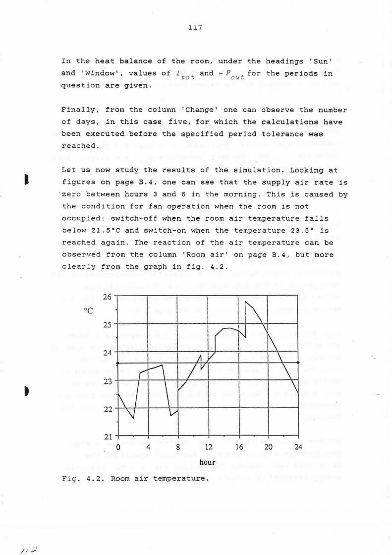
I
t
/ ;' ~/
117
In the heat balance of the room, under the headings 'Sun'
and 'Window', values of 1~ t and - P . +for the periods in ~o o~~
question are given.
Finally, from the column 'Change' one can observe the number
of days, in this case five, for which the calculations have
been executed before the specified period tolerance was
reached.
Let us now study the results of the simulation. Looking at
figures on page B.4, one can see that the supply air rate is
· zero between hours 3 and 6 in the morning. This is caused by
the condition for fan operation when the room is not
occupied: switch-off when the room air temperature falls
below 21.5°C and switch-on when the temperature 23.5° is
reached again. The reaction of the air temperature can be
observed from the column 'Room air' on page B.4, but more
clearly from the graph in fig. 4.2.
26--~---.~~~~~~~~~~--.-~----.
oc 25
24~ --1
23
22
21 0 4 8 12 16 20 24
hour
Fig. 4.2. Room air temperature.

118
The second of the two lines for 8 o'clock in the printed
tables concerns the conditions since the room has been
occupied. The cooling of the supply air begins at eight, see
page B.5. The cooling rate, however, is less than the
maximum value 500 W. More cooling would have caused a lower
supply air temperature than 15°C. This temperature was given
as a minimum in connection with the code number 26 for
quantity sought.
J This limitation is replaced at 10 o'clock by another comfort
restriction that states that the difference between the room
air temperature and the supply air temperature must not be
larger than 8°C. The maximum cooling rate of 500 W is not
used until 15 o'clock, when this temperature difference
restriction no longer applies.
,,,
/•
From page B.5 can be seen that 70% of the ventilation air is
recirculated at 16 and 17 o'clock. At this time of the day
the outdoor air is warmer than the indoor air, and a lower,
and thus more comfortable, indoor temperature will be
achieved by recirculation with the same power input. The
stipulated minimum proportion of 30% of fresh air is
applied, however.
100--~~-.-~~~,..-~~-.--~~~~~---,
% so -1-~~-1--::....,.....~=-1-~~-+-~~--+~~---i
6Q-+-~~---~~-+_.,.---"1--~~---~~-t
40 -1-~~-+~~~+-~~--+~~~..P..r-~--1
20-1-~~-+-~~-+-~~~1--~~-f\-~,,__~
o-t---...~+---.~-+-~....--+~----+..l,_-.-.J....J
23,0 23,5 24,0 24,5 25,0 25,5
~
Fig. 4.3. Percentage distribution of
effective temperature.

t
t
J
119
When the room is occupied, the room air temperature reaches
it$ peak value, 24.85°C, at 15 o'clock, and ~o do the two
effective temperatures, with 25.08 and 25.42°C. The highest
effective temperature is that closest to the hot window pane
(see fig. 4.3). Both are influenced by the temperatures of
all the room surfaces, which are a little warmer on average
than the air temperature, and therefore the effective
temperatures are a little higher than the air temperature.
\V
400-r-~--,.--~~~~--,.-~~......-~--,.--~-.
200
0
-200
-400 0 4 8 12 16 20 24
hour
Fig. 4.4. Heat conducted through surface
layers of walls and floor slabs.
During the night, before 3 o'clock, the room air tempera
ture is falling because of cold outdoor air supplied by the
ventilation. This is counteracted by heat transferred to the
air from the structure surfaces (see fig. 4.4). After the
fan operation has stopped between 2 and 3 in the morning,
the room air temperature rises rapidly, and the quantity of
heat transmitted from the structure will decrease up to 6
o'clock. The fan operation starts again. At that time the
supply air is still cold, the temperature of the room air
falls promptly, and the heat transfer from the structure is
considerable.

,,
120
From 8 to 17 o'clock the heat gain from people and lighting
is large. This is balanced by the cooling of the supply air.
Due to the small difference between the air temperature and
the temperatures of the structure surfaces during this time
interval, the convective heat transfer at these surfaces is
small. Roughly, one can say that the radiation energy from
the sun is entirely balanced, partly by the absorption at
the structure surfaces and partly (to a lesser extent) by
the temperature induced transmission back to the outside of
the window.
In other cases, where no cooling is used, the temperature of
the room air will be higher than the surface temperatures in
the daytime. Then the structure absorbs heat from the air.
Due to the lower temperatures of the structure surfaces the
effective temperature (measured not too close to the window)
will be lower than the air temperature.
The heat balance of the room, for the subperiods 1 and 2 and
for the entire 24-hour period, can be studied in the tabular
statement on page B.9. One can notice that the sums of the
positive items (heat gains) and the negative items (heat
losses) balance each other strictly, as would be expected .
Fig. 4.5 shows how heat gains and losses vary during the
day, and how they are composed of the different components
of heat gain. Gains and losses show some discrepancies,
especially at times of strong load changes.

'\V
I
'\V
t
121
1000.....--~~~~~----,...~~----.,~~~.,--~~....,.-~~-,
Heat gains
soo---------~ '------+-----l
600 -+----+---...1
400 I ! ~
200
Q 1··.-.w.·•".;:;.rw
0 4 8 12 16 20 24
hour
1000
j I Heat losses
800 I I I transm. window
I I I 600
400 I I ~
200
Q ~?{VZU~~W"~
0 4 8 12 16 20 24
hour
Fig. 4.5. Diurnal variation of the heat
balance parameters for the room.

~
,,,
/'.'.'"
122
4.2.7.2. Frequencies for heating and cooling powers
A file can be produced by BRIS to yield frequency tables of
heating and cooling power values. Load from heaters/coolers
in the rooms are included as well as loads from heating/
cooling and fan operation in the air handling. Heat from
lighting is not included. Heating and cooling rates are
shown separately. The file is obtained if a special output
control code is included in the Form type 0 for General in
formation. Values are sampled for each hour during the en
tire calculation period.
Tables are printed for the entire calculation period and for
individual months. The values in the tables specify the num
ber of hours during which different heating or cooling rate
values have been reached or exceeded during the relevant
period.
The heating/cooling rate intervals to be used are selected
by ERIS in such a way that the total number of intervals
does not exceed fifty. The interval size is selected as a
suitable power of ten multiplied by one, two or five.
Days and nights are presented separately and added together.
The separation of days and nights could be useful, e.g. when
reduced power prices apply at certain times. A Form type 7:
Auxiliary output control has to be used, and the two hours
marking the transitions between day and night are to be
entered there.
Reason may exist to include weekends in either days or
nights depending on type of building simulated (off ice/
residential), schedules of power prices, etc. Code 1 en
tered in the form makes weekends group with days, while
code 2 makes weekends group with nights.

1·
,
123
4.2.7.3 Plot file
This is an optional file that contains data intended for
subsequent plotting . It is produced if . a special output
control code is included in the form for General infor
mation.
The format is not adapted to any particular plotter or
plotter program. The user must do any edi·ting required to
suit particular plotting facilities.

r~
r
'
..
BRIS
I Fo•mo~" I
Heading (2 mandatory lines of max 72 chars each)
' )
Calculation Pr int ir.g Calculation 1) Calculation Relaxation step st ep period, h length for tolerance, h h O=aperiodic period ic or relative (1) (1 ) (24) aperiodic (.001)
calculation
4) Output control codes. :Onter ·1 to get operator dialogue.
Hou rs w hen to print. En:;r -1 to get reg ular pr in tout wit h ' pr in ti ng step '.
Cl ima ti c da ta (rema i n i~; ;:;art of form may be omitted)
Day ~.'.cc.::i
Observed cli ma tic da ta 5) or Synthetic climatic d;ita
Na me of climate fil e Latit ude
Rad iation
Facade outsi de ma in s~d ;ice 6) Azimuth Room no . Su rface no .
Calendar (relevant for a~r iod ic calculations onl y )
First Sunday day number
Day numbers for holidays
98 I End marker
Longitude
Horizon (0·90°)
Time meridian
Ground reflectivity (0-1)
Form type 0 for GENERAL INFORM A TIOr;
' '
Period 2) Outtloor air 3) Start value Sub-periods tolerance, temperature for relative oc oc energy (.002)
I I [
Reduction Outdoor temperature factor (0-11 mean oc lamplitudeoc top at, h
1) Calculation length in design day calculation Max number of days
alt 1. Enter O• Iterate until periodic alt 2. Enter .n• Discontinue after n days alt 3. Enter -n• Dialogue after n days.
For aperiodic calculation give total length n• number of days, -n• number of hours
2) Enter K to refer to climatic data in this form
31 Start value alt 1. Enter normal value• Approximate
mean tempereture alt 2. Enter ·1000 • Dialogue, file name
or constant value requested "at run time
4) Standard output codes (add 10 for profiles) O• Energy summary 1 • Energy summary+ room variables 2• Case 1 +boundaries in walls 3• Case 2 +all Wall layers 4• Case 3 +more decimals
5) Example : Stockholm • Latitude 59.3, Long itude -17 .9, Time meridian 23
6) Azimuth examples: South Southeast Southsouthwest
•O • -45 • 22.5
or S or SE or SSW
11

BRIS
Form code Room number Width x Depth y m m
1
Infiltration Quantity Gain from
1 )Temperature sought people
Flow oc ko/h w
t I 1 1 11 r I Quantities that may be sought
x=1 x=2 Room air temperature Supply air temperature
oc 1) Value 1
oc
Value 1 Value 2 Value 2
I 1 1 II 1 1
Reflectivities for ma in surface 1-6
Surface 1 Surface 2 Surface 3 Surface 4 (0.7) 10.6) (0.6) (0.3)
Description of sub-surfaces, parts of main surfaces
Sub-surface Parl of Corner closest to origo ma in surface x y
no no m m
I
98 End marker
Form type 1 fo ~ Roo·
-Height z t/-.:ltiplier Room name (optional) m (1) max 15 chars
' -
Code (xy) for quantiry soL~.1 : x m Variable Variable code
Gain from 2) ?.oom air gradients 1 2 3 4
room temp supply air t 1p supply air f1ow heater output
lights di:,floor
w :c
11 11
X"'3 Supply air fie·.·•
kg/h Value 1 \'alue 2
1 1 11
Surface 5 Surface 6 (0.6) (0.6)
Siz~
z x~:rection
m m
I!
11
dTr.ceiling oc
I
x=4
y • Restriction code
6 8 9 0
Heater output w
Value 1 Value 2
1 1
Y-<firection z-direction m m
2) Leave blank when not relevant
I
Function
Minimurr l;iterval Ma x imum Preferred 'v ~ e
Reflectivi1v
-
-. .
-
-
-
-

I· r I r ·
r ·
-'
@
~
l4
L L Notes:
L L
rx CD Ceiling
y
®
z .. Lx @ " Floor
I
y y y •• •
z~ Lx Lz rx ® z
The layout shows the room surfaces with the main surfaces numbered. All subsurfaces must be rectangular, and may not overlap or cover each other. The position of a sub-5urface is defined relative to the coordinate system local to the surrounding main surface. The coordinates of the corner closest to origo are specified.
®
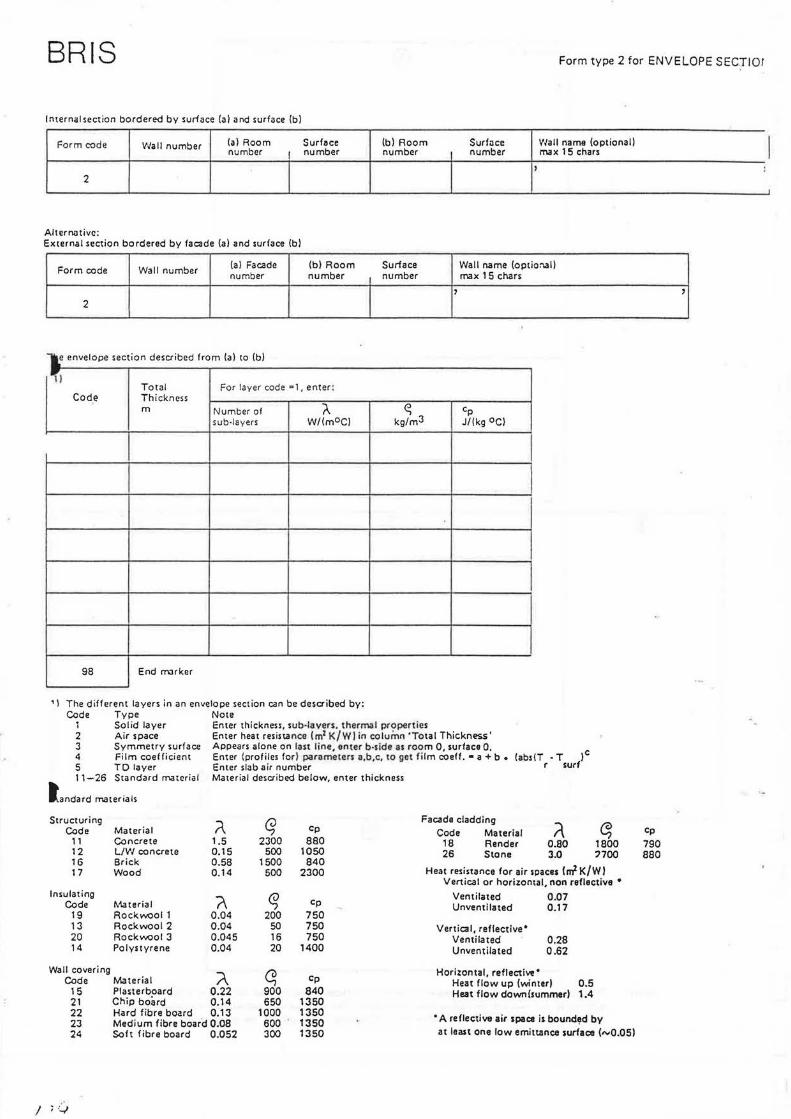
BRIS Form type 2 for ENVELOPE SECTIOr
Internal section bordered by surface (al and surface (b)
Form cod~ Wall number (a) Room Surface (b) Room Surface I Wall name (optional) I number number number number max 15 chars ,, : 2
'
Alterrliltivc: External section bordered by facade (a) and surface (b)
Form code Wall number (al Facade (bl Room Surface Wall name (optio:1all number number number max 15 chars
' ' 2
'ii Total For layer code al, enter:
Code Thickness m Number of t- ~ Cp
sub-layers W/(m°CJ kg/m3 J/(kg 0 c)
I 98 End rmrker
'\ The different layers in an envelope section can be described by: Code Type Note
1 Solid layer Enter thickness, sub·laven. thermal properties 2 Air space Enter heat resistance (m?K/Wlin column 'Total Thickness' 3 Symmetry surface Appears alone on last line, enter b·side as room 0, surface O. 4 Film coefficient Enter (profiles for) parameters a,b,c, to get film coeff. •a+ b. 5 TD layer Enter slab air number
(abs(T • T le r surf
11-26 Standard material Material described below, enter thickness
landard materials
Structuring ~ G Facade cladding
i\ ~ Code Material Cp Code Material Cp 11 Concrete 1.5 2300 880 18 Render 0.80 1800 790 12 L/W concrete 0.15 500 1050 26 Stone 3.0 '700 880 16 Brick 0.58 1500 840
Heat resistance for air spaces !m2 K/W l 17 Wood 0.14 500 2300 Vertical or horizontal, non reflective •
Insulating (\ ~ Ventilated 0.07
Code ~'\aterial Cp Unventilated 0.17 19 Rock~ol 1 0.04 200 750 13 Rockwool 2 0 .04 50 750 Vertical, reflective• 20 Rock~ol 3 0 .045 16 750 Ventilated 0.28 14 Polystyrene 0.04 20 1400 Unventilated 0.62
Wall covering ~ ~ Cp Horizontal, reflective•
Code Material Heat flow up (winter) 0.5 15 Plasterboard 0.22 900 840 Heat flow down(summerl 1.4 21 Chip board 0.14 650 1350 22 Hard fibre board 0.13 1000 1350
•A reflective air space is bound"d by 23 Medium fibre board 0.08 600 1350 24 Soft fibre board 0.052 300 1350 at least one low emittance surface (,,,.0,05)
J ; .. ~

-
••
'~/
BRIS
Facades
Form code
31
31
31
31
Form code
32
Windows
I
Facade number
Room numoer
I
Form cede l Window !surface numoer 1numoer
33 I I 33 I I I
33 I I Lights
Form code Surface numoer
3~ I 34 I
Heater
1) 2l
Form type 3 for FACADES plus ROOM DEPENDENT DAT;.
11 11 Absorptivity Cloud cover Radiation Outdoor
(0-8 for roof, temperature 9 for walls)
a W/m2 oc
I I I I
{Mandatory if data are entered below.)
1,2) 3) 41 1) Total Fl% F2 % Outdoor U-value radiation temperature W/m2
D D DI 11
D D DI 11
D D DI I I
Gain from Lhng wave
Percentage distribution light, w radiation I Visible light To return air
I I
Note 1): see overleaf
1) 3)
Film transmission coefficient W/(m2 OCJ
II 11
l I 11
I I I I
1) Enter K to refer to climatic data in form C ·
5) Parameters for customized film transmission coefficient
a b c
11 11 11 I 11 11 11 I 11 11 11
' I Notes 1) • 5): see overlea ·
Form code Surface Thermal Surface Outdoor temperature factor (nominal output in form Type 1) number ca~acitance enlargement
T1 f1 T2 t2 T3 f3 J/ factor
35
Notes 1) - 3): See overleaf Effective temperature
·effective x y z Profile for time Form code temperature m m m restriction number
36 l I 36 I I 36 I I 36 I. I 98 End marker

l1
a
I .
Notes on form code 33 1) 2) 3)
4)
5)
Enter K to refer to climatic data in form type. 0 2 Total transmitted radiation through two panes of ordinary glass, W/m
Total transmitted radiation through the actual window combination, as fraction of double pane radiation above, %
Direct transmitted radiation through the actual window combination, as fraction of double pane radiation above, %
Customized film coefficient= a+ b .. (abs(Troom - T window)) c Leave blank if not applicable.
Notes on form code 34 1) Typical values for normal fluorescent light
Long wave radiation Visible light To return air Convectively to room air
Notes on form code 35
unventilated 25 20
0 55
ventilated 10 20 70
0
1) An entirely flat radiator has surface enlargement factor =2
For a convective heater, enter: surface number = 0 surface enlargement factor • 1
2) Enter capacitance = 0, when heater output is sought.
3) When outdoor temperature factor is defined H =nominal output• factor
otherwise H = nominal output
Define a curve by two or three points (T , factor) , outdoor

-BRIS
Form code
4
From hour
.,
98
Form code
4
... From hour
98
LJ" ') •,
Profile number
To hour 1) Time step
End marker
Profile number
To hour 1) Time step
End marker
2) Value (s)
2) Value {s)
Form type 4 for PROFILES of Tl:.'.E DEPENDENT DATA
1 J Enter time step for progression of valu:s, or O for interval with constant profile, or S for chain of codes for quantity scught
2) Enter list of values, or constant -.atue, or chain of codes for quantity sought
I I I I

J
t
/
BRIS
Fu: 111 1,;uu~ l Room number
5
Outcoor tempera:ure is specified in form 1ype 0
Recycling, recovery, evaporative cooling
Source of return air (room no.)
Air handling
r·.·1a xi m~ i.1
coolir.g swb temperature
oc
Fun contro l
Fun control period
[ I
I
Temperature rise of return air from fan operation
oc
System code 1 ~Recycling 2= Recovery 3=Recycling +recovery
4•Evaporative cooling
Avoiloble effect~ (WJ
Coo ling I Heating
I
Tcmperuture limits(OC) in room air for
Sw itch-on I Switch-off
I Temperature change
from other change fan operation
I 11 I Air from other room
Room number
98 End marker
Supply air temperature is specified in form type 1
Room air temperature is specified in form type 1
Min fresh air not applicable Min 1resh air
Recovery when of1
Code for air handling control
I
not applicable Max eificiency Mox efficiency
Cooler e1ficiencv
111
I
Form type 5 for AIR HANDLING
not applicable not applicable not applicable
D~w point
11 ·1
-
1 I I ~I I I
~I~. IROOM YI L __ J
-} I I
C> ROOM X

)
""
BRIS Form type 6 for V ENTIU"-TED FLOOR SLAB
Form code Slab air number
6
Air flow Recycle ponion 1) Code for
kg/h % system control
4) 5) 41
Notes 1 l - 91 see table and figure
Temperature rises oc
21 return air 31 supply air
61
1) Code
1 2 3 4
91 System control Fixed recycling Variable recycling Variable recycling + heating Variable recycling+ cooling
Air source Source of Temperature Heat transfer in the ducts.
(slab air number or Oi return air (or 0) at fresh air (or NI Film coefficient Effecti ve surface W/(m2K) m2
I I
The reminder of the form may be left blank.
. 5)
Conuol curves for supply air temperature 7) 8)
Hours of sub-period change Tolerance for morning switch
night-morning morning-day I day-night oc 6)
7)
3)
Curve Point 1 Point 2 Point 3
T outdoor T supply Toutdoor T supply Toutdoor T supply
9) r ._,,___. day <)--i
L ..., ' ,(,, J
night
morning
cooling I 111 I
reference T exhaust 81 T exhaust T exhaust 9) for switch - ~-
98 End marker
4)

_.,. .· ,·
I
l46!U •Z: spua Aep siJelS Aep Aep •l
·pua/M JOJ apo::i a5ue4:> po1Jad-qns JO SJnOH
spoo1 6u1100:> pue 6upea4 10 uo11ema
lOl:f.lNO:> .lndino Al:fV'lllXnV' JO~ L adAl WJO:J ~ .
SI 88

AF'F'E:
0 -OFF I CE SOUTH, C:::Dr1CRETE FLOOR sure -' ,_ll_IL 'l, COOL I NG POl~ER MAX 500 I~ '
:t:
~ B 1
*CALC . ST . PF; I . ST . CALC . PER . LENGTH F:-TOL . P-TOL . OUTDOOR TEt1P . START SUB .5 1 24 0 .001 .003 K 23 T5
* *OUTPUT CONTF:OL CODE 2 *HOURS TO PRINT -1 *CL I t1AT I C DATA < DAVL I GHT SAV I tiG T I t·lE ) 15 07 59.5 -18 22 0.8 20 6 16 *RADIATION *R00t1 SURF . AZ I . HOR . GRND REFL .
1 2 s 0 0.2 98 * ROOt1 1 1 ~: . 6 4 . 5 2 . 7 1 '3 NODULES '
* * I t·iF I LT . ~:oucn PEOPLE L I GHTS K 10 T1 T2 T3
* *ROot1 R I R TEt1P . SUPPL'.? A I R TENP . FLOW N N 15 N 180 N
* * REFLECT I ~J I TV 0.7 0.6 0.6 0 .3 0 .5 0 .6 * * SUB-SURFACES 7 2 0.6 x 0.8 2.4 x 1.2 0.25 r.r, ":'IC•
* * l~ALLS 2 1 1 1 2 ' EXT.WALL' lt• 0. 12 13 0.2 15 0.026 9:3
* 2 2 1 3 1 t:• 'PART I T I ONS' 15 0. 025 2 0. 16 15 0.026 98
* 2 3 1 5 0 0 'INT.~LL' 15 0.026 13 0.025 3 98
* 2 4 1 4 1 1 'FLOOR ' 11 0.2 98
* * FACADE 31 1 0. 8 9 K K 16 *ROOf1 ~!UMBER 32 1 * WINDOW 33 1 7 K 30 9 k 1.9
* *EFF.TEMP 36 1 1.8 2.25 1.4 T2 36 2 L 8 3 . 5 L 2 T2 98
HEATER Ii N

t
•
"' i i i"IE DEPEl'IOENT DATA * QUAt-nlTV SOUGHT CODE -4 1 0 24 s 26 98 * HERT FROt-1 PEOPLE 4 2 (1 8 0 0 8 11 0 200 11 13 13 1013 13 17 0 200 17 24 0 0 98 * HEAT FROt1 L I GHTS 4 3 0 8 0 0 8 17 ~3 240 17 24 0 0 gg
* *FAM COtiTFiOL PEFi I OD 4 4 (1 r:: 1::1 1 :?, 17 0 0 17 24 1::1 1 g:::
* *~:UB-F'ER I ODS FOR El"lERGV 4 5 (1 ::: 13 1 8 17 0 2 17 24 0 1 98
* *11 I t1 ~ OF OUTDOOF: A I R 4 6 0 8 0 0 8 17 0 30 17 24 0 0 90:• ·-· * *CODE FOR A I R HAl1DL I NG CONTROL 4 7 0 8 0 0 8 17 0 120 17 24 0 0 98
* *AIR HANDLING 5 1 1 1 1 T6 ti 8 500 0 T7 T4 23.5 21.5 1 0 98
PAOE 8 .2

I
"
...
1-iRE:ETE BF:iS
OFF ! CE SOUTH I CONCFiETE FLOOR SLAB JUL\' .. COOL I NG F'O~JER MAX 5~10 l~
F:OOl1 D I MEl'IS I OMS
141 DTH 3 . 1:•0 M LEl'lGTH 4 .50 11 HEIGHT 2 .70 M
l·lEATHER ORTA
LATITUDE 59.50 LOl'lGITUDE -18 . 00 T 111E t1ER ID I AN 22.00 DATE 15 . 7 REDUCTION .80
FACTiDE 1
AZ I t1UTH <EAST OF S) . 0 GROUND REFL . < 0- 1 ) .20 HOF: I ZON <DEG ) 0 .
4 . i2
UOLUME
WI t'IOOW 1
.0 .20 0 .
PAGE E:.3 88-09-02 14 :21
43.7 M3
HOUR OUTDOOR RAO I AT I ON ON FACADE OR THRU 2 FWlES OJ /M2 ) 0 17 .0 .0 .0 1 15 . 8 . ~3 .0 ~. 14 .8 . 0 .0 L
3 14.2 .0 .0 4 14.C.::1 .0 . 0 5 14.2 13.Q 9 .3 6 14.8 31.6 21.2 7 15.8 50 . 8 34. 1 8 17.0 99 .7 51 . 1 9 18.4 250.8 124 .4
10 20.0 389 .3 242.7 11 21 .6 496. 1 343.2 12 23.0 563. 1 405.2 13 24.2 582.5 422.9 14 25.2 552.5 395.5 15 25.8 476.0 324 .4 16 2e •. 0 360.7 217 .6 17 ~.C' C•
,t_.._I • '-' 218.7 101 . 6 18 25.2 69 .2 46 .3 19 24.2 45 .9 30.8 20 23.0 27.7 18 .6 21 21.6 10.3 6.9 22 20 . 0 .0 .0 23 18 .4 .0 .0 24 17.0 .0 .0
MEAi'! 20.0 177 .00 116 .57
SRF AREA COP.RESPONDS TO l~R M2
1 16.20 WALL 4 FLOOR 2 6.84 WALL 1 EXT.WALL ') 12. 15 t4RLL 2 PARTITIONS ·-· 4 16.20 WALL 4 FLOOR 5 Q .,,.,
- • (L WALL 3 INT.IJALL 6 12. 15 WALL 2 PARTITIONS 7 2.88 WIND~ 1

•
'
.: ·~ : !:. ·:·:: f::f; i :;: '"r !..:: ~·Jit;E E: . .: :7·:::: -\:il~-((: : ~-
-~= :C~ ~ -:·:7H, CJ!~~RETE FLOOR SLAB ;; rr \: . :· ,-:'. :,_ ; 1·~: ;:. i:,~.:E~: 11A):'. '3i:H~~ ; ~
F:C:::··: :·= ~- ;: :·,C:Di_ilt:::. DF1TE 15. 7
;:;::.;:::~ .:~; ::, -··-::;:_~FPL\' r:;: Ft·--· i=EC;PLE l.';~f i
Q-UEl·iT ; ~·iF IL Tr-I L ~ GHT::; ! ;,-,, i ·~ ~''! ;:....L..·-·
'..: ~ •: I Ci
.·
::.
=
·.·
:.
:::·
": i
! 4
'C'
·~
,--:
~ .;. ....
!';
. .... ..:.. ~ .. ·
.::..;:.
• I ~f _.,. .
- ~i='h;·J
~ .. :;: "_i '- · 1·:.!_i/~
'I
~:: . :; ! 1::;0 . ~Jo
- - :._t ;; ~ :::(~ • t1(1
.:. :
... ~j • r:-
.:.." 5 _ .:.; -:,
- .. - ::. ::
;:~)
1 :::~) . ~~;.:1
. !:'0
fi(l
. 1:11J
-,.-. i;.n·_•
. •::"-' . ~1L~1
!:::•3 ~_:1~:,!
~ :::!:~ ,-~.-:·~ .. _ ... _.
'J ~ ! :::i:1 f;~:1
~: :.:~. ~; .. : : j ~='.(t . ~:1L::~
_ ._. ·=- ~i '::.o . ci~~1 ~ ::~ i.:; ~1L~
... -: , ~;::e . ;.:::ifi
-:!" ':· ; ·; i ::;O . ~:~~i :24 _ :.:. 1 :::1.:1 . o~.:1
24 ::. 1 j:::i;1. 1313
2-·~ .:.s i :::i:~. cu::~
-c: ~ ~=:~:1 0~3
::. 4 .._ (1 ~ :::;:4 . ~:.<~:1 2':- . ~-:: ~ ::· (• .. ~=Hj
~-~ C:.:! 1 :::(1 . (1(1
~ ::,L2~ , ~~10
~ . .: ~ ;;;(i . ~~~~
1 ~='.~~ . ~1(1 - _ ::.:. t:::O . ;:11::1
.:.·.;: . ~:1~ i ~a~i . [1(1
:: . 5:.:~ ~ :::c~ ~=~~=~
2: . i:·~:i ~ 5 ·~: . 7:.
DE.C; 1:: ~·JHfT i-~ATT i·!HTT iiAIT
..; • / y y v I/
1::: . 00 00 -127.54 -15.44 . t3~3 2"7'4. 19
ir; . ?6 t1i.::1 -265. e,4 -17 . ~7 . (1(1 .:::2(1 ~i.:1
i5 . :::(i . 00 .- .. - • . -. t='t-• -.;;. ·::t..::. .. _:·:t -19.o::, . [1(1 .-. ~ .-- -,,-,
..; •. _?.,: •. i •::
. ~=i(i . ~10 · tjL] -15. '.~! 1 ~~(i 179 . !;13
. 0(! . ~:10 .00
. t1t1 . ~x, . ;](!
17···-l',.ll'_I
. ..... ··~ t,.lf,.1 ~=l(i
-26 .24
-25.B9
.-... ~ -~ ·-:·
.... .,. . '"T.O:..
;)~1
. tn)
. ~:~o
(::-:. 9:::
(;;:i. ~~,5
r= ·' _:_ - ='
1f, ~;:: , .00 -250 . 33 - 16 .71 . •3~1 ::· ~~· ~1
1 ;:; ~)~f
15. (i(~ 00 -195 . 57
~73 . 84 -833.89 -13. 7:: -15 7:~:
. (:~:, :: ~ (1 . :::';:t :24~:~ C~!?: 2 i(j. :::•}
,~ 00 170 8~ -399 51 -12 ~2 2~0 00 -~1 ~'.1
15 . 28 16~ 17 -403.28
15 . 90 j60 .97 -403.29 1:. . ::::: -· c -=·; 1 .... 1. I •
~ C' .-.a I ... .' , '='-
::::;; " 1 i -4~}~: . 19
;;:; ! . 44 -403 . 2:::
:::c1 ... ~,4 -4r):~; . 2t· 16 .55 154.52 -403.20
16.'31 151 . 95 -4133 . 25
15.87 15~ . 47-402.17
1 ft 9~;~ 1~:: 5~~1 -?95 4;'
16.67 ~ 54.97 -29~ 64 :::i: .. :::l~t . 0Lj =: ~ - 1
26.2(1 . 130 :~::;:. 11
15 .24 00 .:J..57
i4. ~~~:1 .ee .- .-, .-. 4 - ·:J&.. . .._ I
22.S'S . 0~:~ - ?9 . €10
:::: ~ . 0(t . t}(1 - 129 . 25
-9.4'7 2d0 .08 -171.8~
-6.58 :40.00 -:5~ . sg
-5. 11 24e (11~ -:e;-::i. ;:;9
-2.00 240.00 -259.8~
.70 240.00 -2~:4 . 5~
-.85 240.~0 -~84.57
1.09 240.00 -32? 54
2. 64 24e. c~o -:;::.:·,. ~::;
... se 24(1 . ~:10 -20 1 (19
3.62 240 .00 -102 .31 . (iS . L?(1 - 1L~2. ·;'. i
-.% . (1f1 -70. 74
- ·""'.· C:C"' ..:.. . ·-··-· . (1(1 -2?.10
-.:! . 5•; . 6(i .-. .: -.. -. ,,;_1_1 ..:,. ::'
-7. 19 .L)C1 1~c· J.t=
-9.99 . ;:10 15t: . :::2
19.45 00 -180.05 -12.81 . 1)€1 2 17 . :::·~
i::: . ~::..::
~5 . ::~::
.-... -.. • t..••_.1 ::::::. ,-,.-.f
"='"·' ~ c .~ .-,
- i· .. * . .,. ....
53 .23 -2 18.71 - 10.08
, .. fl:"• . ..........
90 . 0(1
-~·~·:· ..:..i ... : 4~::
?.29

..... ......
t'". '"'-1'. .. •
:t.
•;io·
I I" I ......
l ~:rz q:=,· l
0£. L t-£. L
.-.. =· . .:l·-·
:=::::.
-~ ... , . : •. :'7
.I'
l t. s:::
z:9·sz lt·. l';:
lZ"£Z.
1:>:: · r:::: :::.s·r.z.
i·J... · ·:-~ ,:1,.· ,_.1_.
.-..-.·-- ':t":t .:.,.1:..
i-·c· · 1-·~ .:i.::J .: .• :,.
,-.• -.. 7-::" ::l.':I '··'··
06 .. ::.::
·-1-:r .-.~ •:••".,,, .:.1:...
/,
ii::!O.:i~!1D .:i ~J31J
·~· ::fr.j-d[.J31-J:f3
7C-1" +.7 • .... r ... • r' • ... •
174171 . r.,7"' '-·~· ._ .. _. LL..:~:. 1«; .......... .
00 08"00L 00·
I}~ .
.:o.. ,_, y
~.I. ,,., .... I ,I' ......
.-.. ·:;;.
6Z.
~ l . t:::
l :3 · r.:
~l·r.::
i :.·. ::::::.
to':< .....
-·-· ,.
1;::!0.:f~JIJ:j .:: :.O.:llJ
:j~J-dP3l-3:i3
I '1~J .., ': ,_ .:.:..~ ...i
:•.
l '7
'·.
00· 09·001 00· .)1) . (ii.E, ~:i::: · Ot1; ~::1(; . .:.::~.:. ·-~: ~·-·
51 '8St 08'001 0c· ~(. qi;,t. Cj~:;. (lfl L (1(i
:._:; . i 9::: ~i::: . ~:•;:1 t ~)~;~
li £88 08 001 00
•7·1 .... 7~ ,_. ~ ,.. '-··-·
--.:. 1
.-
/' .
l:)J:i f.J::;~+!C.3H ( ~ /l::.! .. ~·~=~·
8~~llGN~H 818 %J8iJ3~ 80~:~Ll~:~
t·~ !~~(,::; X}:(L.j ~:!3t·~!}: L)~ ~ ~ ~C!C:::i ' /, l•"'p-· :381::; ::iC:C!l.:i 313'~.:1~;.: .:. . :-'..:.:-:::r:. :::: : _:_j.:
.. • -"'.JI"
J
J

~ 2. \.':' ~ .:.~~-~.~~~-.:;::,
; I:; 3l:i~d
:::g. i>Z.
;:.c-,· ... 7 ·-•:i ··:_.
gr.·rz
O•:::. t:: 1)::· tZ
,1
k•:'" ,..7 ._ .. .., • •.t h•:'-"4-.7 ,..I_, ···~
•::::; t._. :3:3. rZ.
,-··:·. ~7 .;:1•.., ,. ·-
t-t• r . .:. ;:.~, · rZ.
17· t>:.:: it r-:::
,-·c-..... 7' .:I•-· ,... ·-·
·:·-::r ···.·
.-·"'"!"' ·:-•.·
r'
.. ·:·. h:"' -·-· . ·-
.-.'"'Y ::J'-·
=·-·
-;. • ..,;i-~· ._. .. ·-
:~I. •: ·•
: .-.-..... l •:· t: ...
.-.-,. :: r.,.
.... ::..•. ..._.
-. ·:·7 -= .. ··-·
~ -· '-·· .. : ·: :_
1:u~11 f ·~ _,,.
.-... ·;·.
. ..
m.n I 3J ::1oi:11.:J 11i:ir·1 i-:i;1;··1 lli:lt·1 11i:ir~ ;{::tns t .::!Hns ~ i:~i-r; !~ .:J~~n::: :::: 3:~n::; :: ~si·,·;
~·1 eo~ >::t!LJ ~:f3t·1ct~ ~=!~ ! : 100::1 I /·. !(·!r· :3t:il::. !::iOO!~ 3l3;~::tt-~•:r.:: '!'1J..fi1}:; 3 :r i ,j;!(:
t

~f.:·~::
~) i. : .: .
·,i
~;1. -.. .: ...
' ~. -.. -~=-
..,. ... .--1 -I -11: .. ... c .. 1 '717f :::z . _., .:l• :. .. _ . . ..... ...... :.. -'--T .. :. ::i::· .. .:.,.. . . ='._ • .
9t." ~ !:' ~i-· -r"":"---- -·-··=· ·-··-··-.!....;. --, .
::·r:. ~ r.-~:::·~: - ._., ·. ,_ . .· ---
. ~. ....... ·-· f •
t't' ' ,-. l_':f-l.ei · .:::.r
·-.
·:
( .. --t'l '~-,, .... ''•
.:_(' ~ ~.· .~ ·-~ ~· ;:> -·-
;l•:. '
.:> (!1:1 !· -
9~ k~-17~~7t : - ;, -
r:,9 ::·:~-00 ~l L -· -
r.::: t1ri-;j1~1 - ~s
. -.. -. ;:::: -;:jo . ':'•:. > I -··-·
/\ /' A
~i::;f.Ji:!:.ii. ;Jiji;;! .i.3H -.._~.:::j ._i
--(. .:. " ,,-. t·1CJ0f.j i r~--- ,:,1~·=·
..... -, : 7. -.
• ·-· !" ~ Z.t~1-6f1-;::;:i ~:.. ::;:i ~(d:i.:i =·. ·:F:1 .::U .. ~·,":>·
-J

LI ·w
Z.l . £Z:
J .... -,-~ .... ,,. .::r•-·
.-... ,-- ·:· ~ .::I -
L: .. ·K ll·~z
6l · v:: 6l.1?Z
,-...... C-7' ;:I,... ·-··-·
..,._., __ "":" ,...,,._. e, .....
: .. •I ', .... ..,. ::.~ 1:.i_.
·:·:.·· . ..,,,_.
.. ~-... 7 ,,, ,_. "' '-"
60't~
Z.6'tZ:
)~·-·-;-._,. • .::11·-·
6l·~z
fZ'tZ. :::r·t.'::::
l;.:::. sz. I..,-·,-.Jo'-· ·:.-·:...
..,,-, .. ~ .... "" •:.(..,
1;1.1 • ·:·7 1 .. •l-1_,1_ •
zo·tz:
•:' ..... c-~ ·-· t ::I·-·
:::~·~::
~z.. t:-Z a·tz:
t9. :~::
sz.· :~::::
l9' l>Z.
---~- .::,.t> .... ~.
L l. ~z
.-.. -.. , .... .., ~·:.. ~'-·
I , .... ,-·"";" • .:I .:II'-·
I 7 -,-.,.. "·-.::11·-
p;::. p;:: f';:: . t>Z
;-.:, . •':'7 .::J•-• ·-··-·
L;:1z. f( IJZ. ::::::
··~··:--.,. L.. ... ·-··-·
·:·.i . ·:·7 1 ... ~ :_ •• _ •
·:·7. 1:"''7 '-··-._ .. _.
.-'·,1::jl]t~8 ;\1::j:Jt.j;j
.• ....... '7 ~..-.... _.
l~'t(.
:~5·r;,:,:
.-. . .-.- ::.,~ ~1--o
I"",.-·~ _,. .::11: ....
.1.-.. :-;-'-.::II ._ ......
,-., • ,-."':'P
~· ·:.··~ £I . ~:::z.
,I ....... •:·~ -•· ·-··-·
·=·.' . •:'·7 '-''-'-··-·
.: .! • ·:· :! '-'-1_.1_.
..,,-.. 1:-·.,. r .;J ,_ .. ,..
1:'1-1 · r:t7 • .... :i ._.._.
,~,~~. 6'.:: ·~i:~. i:,:::
I ,-
7'1-1 -:: I ·-· = ......
I:'••:·• •:r7 ~"-' · ... ··-·
(.9. i::.
.-.~
.: . .: ...
·~1 ! .:.::
l: .._.._ : .....
.-.... =>Y
~'L t·i 6i::.. ~:\ ~
. ' ~-
: ,. •:...·:i .. ·-·
llU:ll; j ,._._. .....
0
1:1~
.. -., =· .. , ...
·,;:, .
....
ii;jmJ:3 111:1r·1 f
i'.!:11]~~8
lll:tM Z. 11!:1~1 3 "Tii:W .. :..:::J;Jt.j;j
Til:lf1 ·',:::.Ji-i:::
lli:it·1
'[:' ~ .::.(:1-60-:::;:. =:· :; 3l:itj.J
r·1 €n:1£ ::i::8~·~ ::3nc1.~ o~~; :oc(1 · ,·\lnr ;3t!!::. ::ioOi.:J 313::Dr.JCC:· ';.;.:..i-1::::: :::.:; i .i:lC·

•;i::;r 8l r. t-9t::'f'f'
7\ ·~· l l z.
717 ... :-. ·-··:.."-'
Ot>0 £,'..1.)" ~3:; ~ l
·--I
.__,,. l-'1~. -66. -(11)
:;.'.0'-~39. s-'-t•. I-5~·-
l 7-''"-i-·1-·. I -50'Z. t1:;. - 'J '2"' •
i.11.:lf.J I HJ3(1 Slll:IM t·10IJl·J I ~1
:::~.::: l0"3
:::~·::: L6 oe· gi I lOO::t-!:!t!:l ll:l3H-~:l ll:l
~1. ~)Z.
dW3l 8000lnO W83W
1;:n;:1 · 9l ·~
.:,
(1\) ;;:n;:1 lt:!3H lH~) 11
1;:u;,
1:hJ. eo· :::t3li:i3H
.-..... I
·-··-· I
i)ti
3ld03d
91 -.:
I~~ • 2 ~)(t .
l ··;t -l ·o;;i :JO: ~:l3d
z.9·;: t-€1 '}-9€! 9 .... 7.
·;·::. ::.-. - •• J :: ·:. ·-f.Jn:::; :::rn.J 11.1
.-.,-,"""l
.:ri I
l :::~ -; ~;:::
:~ · Li:... -t1. ~;,: ,-, ' I,-,. ,-..• -. ..,. •J (.0 -!:I •:.(.
,.=.
.!.
; • i.-. " •• -•• • .
.L..:::1~-·-.:~·il_ ;
-·; ·.~.:.
-::. . ,_
-0 ···:.. .-. .-..... -.:: ·-· ..
0·00~ -0·s3 0·00' -0··~:
~: ::! ~:r:o ~: ~=~ ~:131J
·-· ciW3J. . .:l.d3
M (11::1£ \l:llJ '.~3t10~ C•Lj ! -!OC:::! :' 1'-!!-
8~15 ~001.:l 3l3SJ~GJ ·~i~05 3~;~~0
... J3:_ •. _
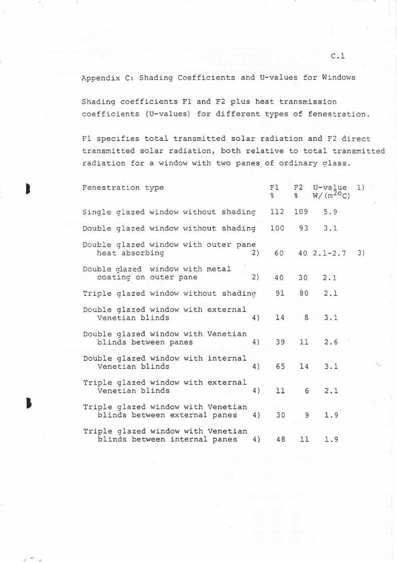
I
I
C.l
Appendix C: Shading Coefficients and U-values for Windows
Shading coefficients Fl and F2 plus heat transmission
coefficients (U-values) for different types of fenestration.
Fl specifies total transmitted solar radiation and F2 direct
transmitted solar radiation, both relative to total transmitted
radiation for a window with two panes. of ordinary crlass.
Fenestration type Fl F2 u-value 1) % % W/ (rn20c)
Single glazed window without shading 112 109 5.9
Double glazed window without shading 100 93 3.1
Double glazed window with outer pane heat absorbing 2) 60 40 2.1-2.7 3)
Double glazed window with metal coating on outer pane 2) 40 30 2. l
Triple glazed window without shadina 91 80 2.1
Double glazed window with external Venetian blinds 4) 14 8 3.1
Double glazed window with Venetian blinds between panes 4) 39 11 2.6
Double glazed window with internal Venetian blinds 4) 65 14 3.1
Triple glazed window with external Venetian blinds 4) 11 6 2.1
Triple glazed window with Venetian blinds between external panes 4) 30 9 1. 9
Triple glazed window with Venetian blinds between internal panes 4) 48 11 1. 9

.-r
C . 2
Fenestration type Fl F2 U-value 1) % % ·w; (rr_2oc)
Double glazed window with drapes between panes, drape quality:
light compact - loose 31-62 17-54 2.3
medium compact - loose 40-62 10-43 2.3
dark compact - loose 46-63 4-33 2 . 3
Double glazed window with internal drapes, drape quality:
light compact - loose 44-71 19-20 2.6
medium compact - loose 59-75 11-48 2. 6
dark compact - loose 70-82 5-37 2.6
1) Valid for glass part, excluding frame, and for sunlit window
2) Variations depending on type and make
3) Lower value applies for gold or copper coating
4) Slat inclination angle 45°