Air Valve Technology and the Advancement of Surge Protection
41
Air Valve Technology and the Advancement of Surge Protection
-
Upload
independent -
Category
Documents
-
view
1 -
download
0
Transcript of Air Valve Technology and the Advancement of Surge Protection

Air Valve Technology and the
Advancement of Surge Protection

Air Valve Technology and the
Advancement of Surge Protection
Index Page No
Author’s Note 1
Air Valve Designs 2
Introducing AirFlo Variable Orifice Air Valve Technology 11
Surge and Waterhammer in Pipelines 16
Surge and Waterhammer and Air Discharge 24
Modelling Air Valves in Surge Analysis Software Programmes 29
Sizing and Positioning of Air Valves 30

Author’s Note The need for adequate, total and efficient pipeline performance has become more critical in recent times. This is due to the growing shortage of experienced maintenance teams, the increased focus on sustainable infrastructure development and the focus on Life Cycle Costing and pipeline efficiencies. Air valves are amongst the most cost effective components on pipelines and play a major part in attaining optimum pipeline performance but if incorrectly selected, sized and positioned, are the root causes of many destructive pipeline phenomena. In 1996, the author wrote a booklet titled “Air Valve Technology Reviewed” which briefly covered a 35 year period of air valve history and the technologies that developed in the quest for a cost effective solution to air release and the surge and waterhammer phenomena. The book highlighted that technology is not stagnant but advances as research improves and as the focus on specific pipeline phenomena increases. This is evident by the number of technical papers and research studies with a specific focus on air release from pipelines and the potential impact of surge and waterhammer that have proliferated since the authoring of this document 16 years ago. Interestingly, as much as air valve research and technology have advanced, so have the older air valve technologies still remained in constant use. This has resulted in a global market that has a spread of air valve technologies with the preference for a specific technology based on historical factors, and market dynamics but not always necessarily based on access to the latest research and pipeline performance criteria. This peculiarity is also reflected in the South African market. It has become an expected norm for air valves to perform four functions namely; pressurised air discharge when the pipeline is operating, large volume discharge during initial filling of the pipeline, large volume air intake when the pipeline drains and automatic surge protection when air is released too rapidly or, under pump trip conditions.
This document covers the evolution of Air Valve Technology since 1995. It discusses every
aspect of air valve design performance specifically the four main functions expected of an air
valve as well as evaluating air valves across their entire operating cycle. A specific emphasises
is placed on the relationship between air valves and the surge and waterhammer phenomena.
Highlighted are important factors surrounding air valve selection and position. This document
also introduces Variable Orifice Air Valve Technology.
The object of this document is to provide the engineer with a comprehensive source of
reference on the advancement of air valves. It is the author’s wish that the information provided
will help towards more effective design and efficient operation of hydraulic pipelines.
Allistair Balutto January 2012
1
Air Valve Designs Though valves are available in a wide range of configurations, air valve technology has advanced in the last 30 years in the South African market into four major designs, currently available on the local market namely: Kinetic Air Valves – these are valves that are specifically designed to discharge air at high velocities and will only close once water enters the valve to shut off the control float. Valves that operate in this fashion create high pressure transients on closure that could result in pipeline bursts. Three Stage (Anti Slam or Anti Shock) Air Valves – these valves generally have a floating orifice that will close at a specific differential pressure to shut off the large orifice and discharge through a smaller port. These valves can prevent air valve slam and pipe bursts but the switching may not happen or happen at too high a differential pressure or, the anti slam orifice may be too large or too small for the appropriate application resulting in either mass oscillation (surge) or waterhammer. Slow Closing (Diaphragm) Air Valves – These valves operate on the principle of equal pressure and differential area and will close slowly allowing all air to be discharged but will spill a pre-determined amount of water before closing. Not only does this design spill water but it can also induce surge pressures when water is discharge due to the differences in density between air and water which has an effect similar to the rapid closing of an isolator valve. Variable Orifice Air Valves – This valve is specifically designed to overcome the shortcomings of Three Stage (Anti Shock/ Anti Slam) Air Valves and Kinetic Air Valves. The valve has a floating Variable Orifice that automatically and infinitely adjusts to prevent surge and waterhammer, regardless of the condition within the pipeline.
Each of these designs is compared below, taking into account, the fundamental performance aspects of a well designed air valve:
Vacuum Protection The most important aspect of air valve sizing is sizing for vacuum conditions. In essence the client pays for mm2 area of protection provided by the air valve. There are three factors that determine the performance of an air valve under vacuum conditions namely: The size of the intake orifice - It is important that the size of the intake orifice and flow paths through the valve equal the nominal size of the valve to ensure the least resistance air intake and consequently the least possible vacuum within a draining pipeline. Not all air valves available on the local market have an intake orifice and flow path through the valve that equals the nominal size of the valve therefore restricting the performance of the valve under vacuum conditions. Shape of the float - The shape of the control float has a major impact on performance of the air valve under vacuum conditions. Valves that have a spherical or dome shaped float exposed to the inlet orifice under vacuum conditions are often subjected to a “Venturi Effect”. This phenomenon creates a low pressure on the surface of the float under air intake conditions that often is lower than the prevailing vacuum conditions in the pipeline. This results in the float being drawn up under vacuum conditions, partially closing the intake orifice and therefore restricting air intake.
2
This phenomenon is often demonstrated in school experiments utilising a ping pong ball and a funnel. The harder air is blown through the funnel, the closer the ping pong ball hover in the throat of the funnel. Mass of the float and flow path towards the float – The shape of the float has a major impact on whether it will be lifted under vacuum conditions as explained above. However, regardless of the design, the mass of the float also has an impact. This is specifically true for non slam or anti shock designs. Practical vacuum testing indicates that when air rushes into the valve under vacuum conditions a low pressure zone is created above the ant slam or anti shock float which can be sufficient to lift the float to partially seal off the large orifice. The float can be heard to rattle under vacuum conditions as the float is repeated lifted and hovers. This is most prevalent in all current Kinetic Air Valve designs. Designs which have the anti slam device as part of a non pressure bearing component prevents this phenomenon from occurring because of how the air flow into the valve is diverted. The AirFlo Variable Orifice design is one such design that allows for full air intake and prevents the lifting of the floats under vacuum conditions. Anti Slam or Anti Shock valves that have the float as part of a pressure bearing component experience rattling of the float as the float is lifted to partially close the large orifice when the differential pressure on intake exceeds more than 5 kPa across it .
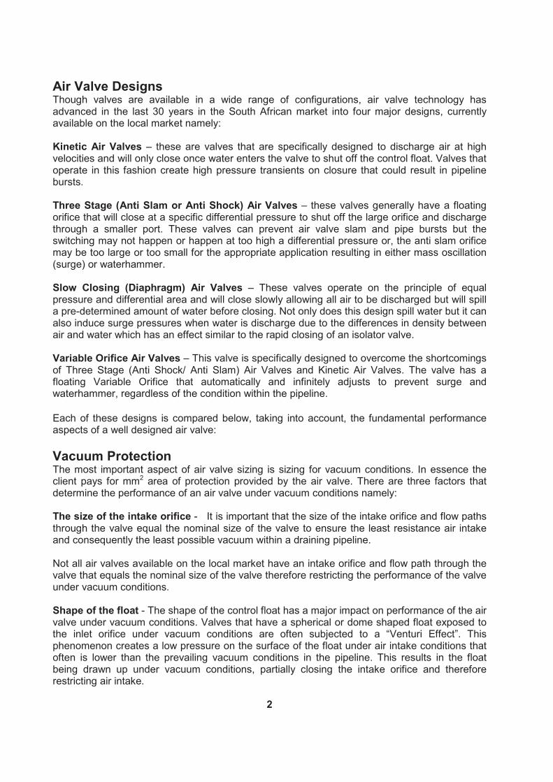
Small Orifice Function The function of a small orifice is governed by the relationship between the sheer weight of the control float and the size of the small orifice. If the control float is relatively too light or the size of the orifice too large then, the orifice will not open under the designed working pressure. Designs with a direct acting small orifice operation, utilising the correct relationship between the mass of the float and the size of the orifice will ensure the opening of the valve consistently at the designed operating pressure.
Fig 1. Direct Acting Small Orifice Function Direct Acting Small Orifice Design. There is an intimate relationship between the mass of the control float and the size of the small orifice. The orifice will not open at the designed working pressure if the orifice is too large or the float too light.
3
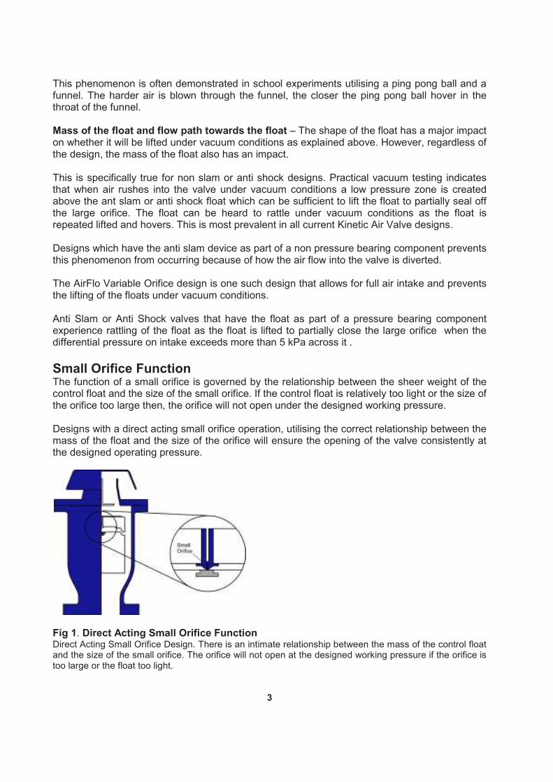
The small orifice function of one design utilises a rubber flap that works on a counter lever
principle. The published discharge figures indicate that the orifice opens up fully under all
operating conditions. However, empirical testing indicates that the critical relationship between
the mass of the small orifice float and the area of the opening to atmosphere is such that the
valve opens a progressively smaller area as the working pressure of the valve increases. The
opening of the small orifice therefore, despite the counter lever action, is only 23%, 12% and
7% of the published figures at 5, 10 and 16 bar operating pressures respectively.
Valves with a small orifice function that utilises lever system are susceptible to the wear of the
lever mechanism at the pivot point with time.
Fig 2. Small Orifice Function with Lever System In this design, the pivot point tends to wear with time
Another aspect of the small orifice function is the position of the small orifice. It is preferred, to
provide a degree of short term transient protection under operating conditions, for the small
orifice to be positioned within a single chamber. This allows for the accumulation of a
predetermined volume of air that is regulated by the small orifice.
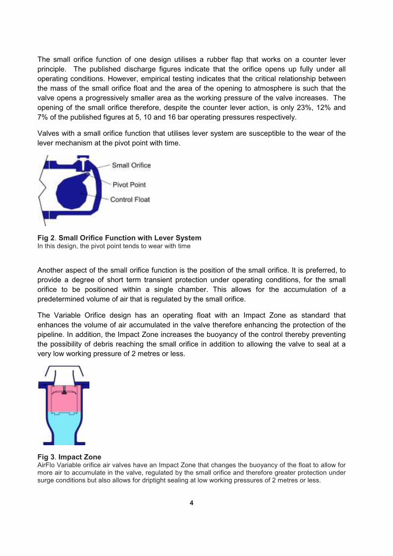
The Variable Orifice design has an operating float with an Impact Zone as standard that
enhances the volume of air accumulated in the valve therefore enhancing the protection of the
pipeline. In addition, the Impact Zone increases the buoyancy of the control thereby preventing
the possibility of debris reaching the small orifice in addition to allowing the valve to seal at a
very low working pressure of 2 metres or less.
Fig 3. Impact Zone AirFlo Variable orifice air valves have an Impact Zone that changes the buoyancy of the float to allow for more air to accumulate in the valve, regulated by the small orifice and therefore greater protection under surge conditions but also allows for driptight sealing at low working pressures of 2 metres or less.
4
Designs utilising a rubber flap, provides the small orifice function externally which may increase
the possibility of tampering but also prevents the accumulation of a sufficient volume of air
within the air valve to provide protection for transients under operating conditions.
Control Floats and Sealing
Hollow Floats - Hollow Float designs may be limited in the working pressure that the valve can
function at as there is a possibility of the floats distorting or imploding under high operating
pressures. Some modern designs utilise a smaller sealing area and a sealing methodology that
does not wedge the float on sealing thereby minimising distortion of the float.
Valves with solid cylindrical floats and a dynamic sealing system can be designed to work at
any working pressure as the floats cannot implode or distort.
Sealing Methodology - The sealing methodology utilised for the control float is critical in
determining the performance of the valves.
Valves that utilise the compression of the seat to effect a seal require high pressures to seal
driptight with some of the designs requirements being as high as 1 bar.
Valves utilising a stainless steel and a bronze or brass backing ring as part of the sealing
arrangement, will create leaks over time as an electrolytic effect is created by the dissimilar
materials.
Designs with a dynamic sealing arrangement will ensure effective sealing is achieved across
the pressure range as the seal adjusts automatically to suit the pressure being exerted on the
floats.
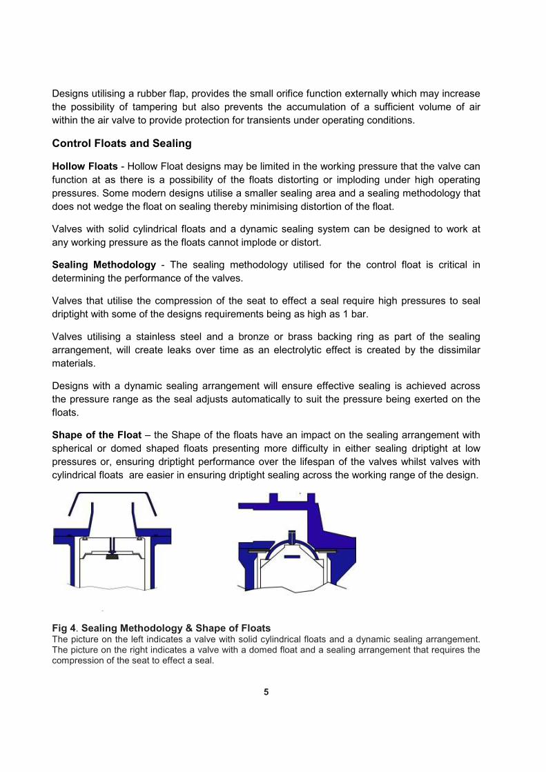
Shape of the Float – the Shape of the floats have an impact on the sealing arrangement with
spherical or domed shaped floats presenting more difficulty in either sealing driptight at low
pressures or, ensuring driptight performance over the lifespan of the valves whilst valves with
cylindrical floats are easier in ensuring driptight sealing across the working range of the design.
Fig 4. Sealing Methodology & Shape of Floats The picture on the left indicates a valve with solid cylindrical floats and a dynamic sealing arrangement. The picture on the right indicates a valve with a domed float and a sealing arrangement that requires the compression of the seat to effect a seal.
5

Surge Protection
Air Valve Slam is a well known and documented phenomenon. Kinetic Air valves are most
susceptible to this phenomenon as the valve is designed to discharge at high velocities and
create slam on closure resulting in high transients and possible pipeline bursts.
3 Stage antis slam valves have been designed to overcome this phenomenon but create
problems of their own namely:
The switching point of the anti shock or anti slam orifice – Anti shock or anti slam valves
have a floating orifice that switches at a predetermined differential pressure across the large
orifice, from a large orifice discharge to a smaller orifice. The switching action is meant to
create back pressure to the advancing liquid column and thereby prevent surge pressures on
closure
Empirical testing indicates that the most optimum switching point for the anti slam float to be 5
kPa or lower. However the design of 3 stage anti slam or anti shock valves are limited by
physical laws such as the operating pressure of the valve and the size of the valve. Valves
larger than DN80 therefore where the anti slam device is a pressure bearing component, have
the tendency to switch at differential pressures higher than 5 kPa therefore inducing potentially
high transients on closure.
It has to be noted that one of the most critical factors is the size of the discharge orifice in
relationship to the main pipeline diameter and the air pressure before all the air has been
released. The higher the ratio between the diameter of the valve and the size of the main
pipeline, the lower the surge pressure within the valve and the pipeline.
Pressure Rise in DN80 Air Valve prior to the switching to the anti slam orifice
Differential Pressure across orifice in kPa Pressure Rise in Valve in Bar Pressure Rise in Pipeline in Bar
1 36.7 9.76
2 51.8 13.7
3 63.3 16.8
4 73.0 19.4
5 81.5 21.6
Fig 5. Potential Surge Pressures Created by anti slam valve prior to switching of anti slam orifice The table above indicate the pressure rise in the valve and pipeline for a DN80 valve, prior to the valve switching to the anti slam orifice. The table also gives the pressure rise in the pipeline, assuming a 300 NB pipeline. For a 400NB pipe with a DN80 valve attached to it and a differential pressure of 5 kPa across the valve, the pressure rise would be 16.3 bar which is a 33% reduction in the pressure magnitude – this indicates the importance of the relationship between the size of the orifice before all air has been released, the differential pressure across the orifice and the size of the main pipeline.
The operation of two anti shock or anti slam valves operating close together may result in the
first air valve discharging air effectively but that there is an insufficient air volume to allow the
second valve to switch to the anti slam mode thereby resulting in the valve slamming shut on
closure and creating transients similar to that of a Kinetic Air Valve.
6
This also happens where valves are slightly oversized as manufacturers often recommend the
design engineer to standardise on the largest air valve indicated in a sizing and positioning
exercise.
The switching of the valve from a large orifice to the anti slam mode results in a transient being
created.
The size of the anti-slam orifice – Depending on the sizing of the pipeline, the anti slam orifice
can be too small or too large. If the diameter of the orifice is too small then, the valve will cause
mass oscillation (surge) within the pipeline as the air valve may release the air too slowly
resulting in the rejoining water columns under pump trip conditions compressing the air to a
point where the air will react like a spring forcing the columns apart thus creating the oscillation.
If the orifice is too large which happens when the valve sizes are standardised during the sizing
and positioning exercise then, the valve will create a transient similar to the performance of a
Kinetic Air Valve upon closure.
Variable Orifice Air Valves were specifically designed to eliminate all these shortcomings. The
valve’s variable orifice adjusts automatically from initial discharge and progressively and
infinitely adjusts the discharge orifice as the differential pressure across it increases. This
eliminates the possibility of a transient as the switching in orifice sizes occurs. Further, the
action of the Variable Orifice always ensures the most optimum orifice size relative to the
pipeline condition thereby preventing a transient on pipeline closure.
The action of the Variable Orifice is such that it will readjust under pump trip conditions. This
ensures that air is released effectively but that the magnitude of the surge is substantially
reduced as well as the amplitude of the wave.
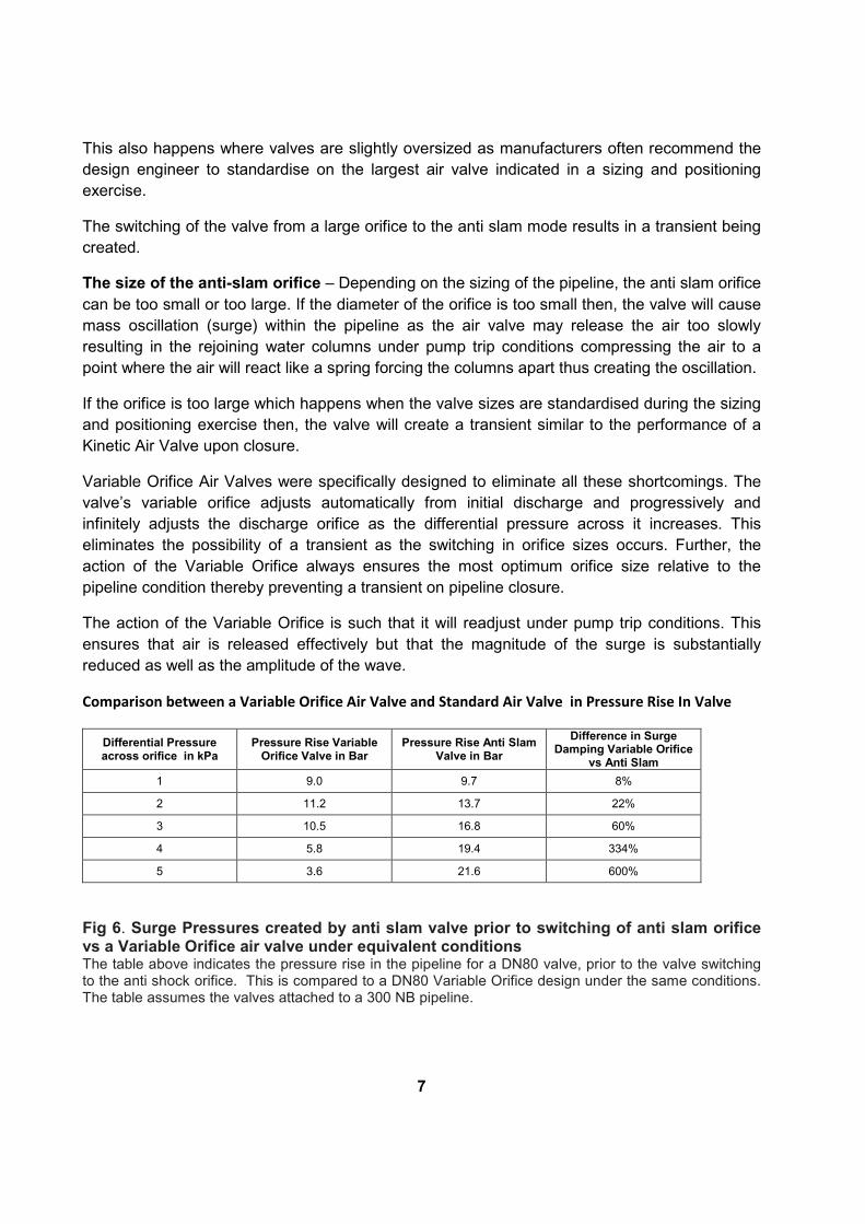
Comparison between a Variable Orifice Air Valve and Standard Air Valve in Pressure Rise In Valve
Differential Pressure across orifice in kPa
Pressure Rise Variable Orifice Valve in Bar
Pressure Rise Anti Slam Valve in Bar
Difference in Surge Damping Variable Orifice
vs Anti Slam
1 9.0 9.7 8%
2 11.2 13.7 22%
3 10.5 16.8 60%
4 5.8 19.4 334%
5 3.6 21.6 600%
Fig 6. Surge Pressures created by anti slam valve prior to switching of anti slam orifice vs a Variable Orifice air valve under equivalent conditions The table above indicates the pressure rise in the pipeline for a DN80 valve, prior to the valve switching to the anti shock orifice. This is compared to a DN80 Variable Orifice design under the same conditions. The table assumes the valves attached to a 300 NB pipeline.
7

Slow closing (Diaphragm) air valves dump a predetermined amount of water on closure. This
action creates a transient on closure due to the difference in densities between water and air
and is similar to the rapid closure of an isolating valve. The magnitude of the pressure transient
is determined by various factors Experimental work indicates that the most important variables
influencing the magnitude of a pressure rise for air released in this manner are; internal
pressure, volume of compressed air pocket, size of opening through which the air escapes and
the elasticity of the system.
The amount of water dumped by this design can be significant. A DN80 valve may dump as
much as 21 litres/second at 34 kPa which will equate to 6208 litres of water if the valve takes 5
minutes to close. Similarly the valve may dump as much as 12511 litres/second at 1 bar in 5
minutes and significantly higher for a large size valve or a valve operating at a higher pressure
or that takes longer to close.
Discharge through Valve in l/sec assuming closure in 5 minutes
Pressure in Bar DN80 DN100 DN150 DN200
0.34 6208 11016 24794 44043
0.69 8858 15747 35431 62970
1.03 12511 22239 50043 88919
1.38 15388 27331 61513 109304
2.07 17716 31495 70882 125960
2.76 19817 35337 79229 140798
3.45 21690 38554 86762 154180
4.14 23413 41621 93651 166407
Fig 7. Potential Water discharged through Slow Closing (Diaphragm) Air Valve The table above indicates the amount of water discharged in l/sec through a slow closing valve assuming closure in 5 minutes.
Valve Design
Valves with a barrel design that are held together between two flanges have the tendency for
the gasket to fail under a specified pressure range. This is specifically true for larger diameter
valves.
The reason for this is as a result of the relationship between the thickness and width of the
gasket, the gasket material, and the diameter vs the wall thickness of the barrel, the nature of
the machining of the edge and the coating thickness of the flanges on sealing faces of the
barrel. The thickness and type as well as the number of tie rods are also a contributing factor.
The pressure that failure of the seal occurs varies. However, it has to be noted that pressure
transients of up to five times the working pressure can be induced in an incorrectly sized air
valve. A DN200 anti slam air valve discharging at 5kPa across the large orifice will induce a
pressure rise of 81.5 bar within the valve. If the differential pressure is 8 kPa then the pressure
rise within the valve will be 102 bar within the valve.
8
Valves with a O-Ring type seal between the two flanges such as the AirFlo design present low
torque and ease of assembly and disassembly and are not subject to failure as highlighted
above.
Summary of Valve Design Based on all the aspects of design highlighted above, it is clear that the following aspects make for a good air valve design: Surge Protection – An air valve as standard must provide a surge protection device that can respond instantaneously to the pipeline condition. Devices with static orifices and distinct switching points such as anti-shock or 3 stage air valves may not be as effective in protecting the pipeline from surge and waterhammer conditions. AirFlo Variable Air Valve Technology is the only technology currently available that can automatically adjust to any condition within the pipeline. Float design – Solid cylindrical floats have proven over time to be the most suitable under all operating conditions as they cannot implode or distort and also discourage the Venturi phenomenon. Dynamic Sealing – Valves with a dynamic seal can seal at low pressures. Valves that require the distortion of the seat in order to effect a seal, require pressure of up to 1 bar to seal driptight under low pressure conditions. Direct Acting Small Orifice Function – Provided that the relationship between the size of the small orifice and the weight of the float has been adhered to positive opening at the designed working pressure will occur for pressurised air discharge. Any other form of small orifice function either requires levers that can wear or, do not open up fully or do not open at all at the designed pressure thereby limiting air discharge. Impact Zone – Valves that utilise solid floats and have an impact zone as standard such as the AirFlo design, ensure low head sealing as well as provide better protection under surge conditions that may when the pipeline is operating. Valve Assembly – valves that are designed with a dynamic O-Ring seal such as AirFlo require low torques to assemble and disassemble. Further, these designs are not subjected to seal failure due to any pressure rise within the valves. Valves that are assembled with tie rods will fail consistently at a given pressure depending on the coating, thickness and width of the sealing gasket and size of the valve. This weakness in design is often sold as a feature but is actually a limitation.
Surge Protection AirFlo provides a multistage, automatic surge protection device that will infinitely adjust to protect the pipeline from surge conditions regardless of the flow conditions within the pipeline. Anti slam or ant shock air valves provides a two stage function with a static orifice that limits the protection of the pipeline in that the switching may occur too late resulting in the valve functioning similar to a Kinetic air valve or the orifice may be too small resulting in mass oscillation within the pipeline.
9
Low Impact Zone AirFlo provides as standard a low impact zone on the control float to ensure low head sealing at 2 metres or less. In addition, the low impact zone ensure a large pocket of air in the valve chamber to protect the pipeline from surge conditions that may occur whilst the pipeline is operating. This feature is absent as a standard feature in most other solid float valve designs
Valve Design AirFlo Variable Orifice air valves are designed to be assembled and disassembled with ease even after years of operation. The seals and seats are easily replaceable O-Rings that require low torque and minimal skill to replace and reassemble. Designs utilising a tie rod system with flat gaskets between the barrel and the flanges requires very high torque especially for the larger valve sizes. In addition, any imperfection on the barrel, change in thickness or width of the gasket, or thickness of coating on the flange surfaces results in the seal failing.
Conclusion This document highlights the important aspects on which the performance and benefits of an air valve design should be analysed. Air Valve technology has advanced since the advent of three stage anti slam technology in 1994 and the next stage of this advancement is in Variable multistage Orifice technology AirFlo has maintained the features and benefits of a single chamber design with solid cylindrical floats and a direct acting small orifice function but has made a major advancement in automatic surge protection of pipelines with its Variable – multistage Orifice design. The AirFlo Variable Orifice design provides the most economical protection of a pipeline system relevant to all functions of an air valve.
10
Introducing AirFlo Variable Orifice Air Valve Technology
It has become an accepted norm for double acting air valves to perform the following functions as standard:
• High Volume low pressure air release during initial filling
• Pressurized air release under pipeline operating conditions
• Large volume air intake under vacuum conditions
• Surge protection under pump trip and rapid filling conditions Air valve technology despite the copious amount of empirical data available and the advancement of supporting testing and design technologies have until recently virtually stagnated since 1994. This is specifically true in the area of surge and waterhammer protection. The Airflo Variable Orifice Air Valve is the latest advancement in air valve design technology and incorporates a variable floating orifice that automatically and infinitely adjusts to the conditions within the pipeline and provides the optimum orifice diameter at any given point during the performance of the pipeline to ensure effective air release whilst preventing waterhammer and substantially reducing mass oscillation. Airflo Variable Orifice Air Valve Technology is as a result of an intensive research and
development programme. It reflects more than 50 years of air valve design evolution, effectively
breaking away from the drawbacks of three stage and anti shock air valve technology.
The research into Airflo has not been limited to only the air valve but has been extended to the
entire pipeline system taking into account Strategic infrastructure Asset Management and Life
Cycle Costing with a special focus on the surge and waterhammer phenomena and the
modelling thereof. Airflo Variable Orifice air valves present the consulting engineer and end
user with a more cost effective and efficient alternative to the building of pipelines and the
management of destructive phenomena such as surge, water hammer and vacuum conditions
in pipelines.
AirFlo is a 100% locally manufactured product that is supported by a depth of technical, design
and manufacturing support. The product provides simple and efficient protection to the pipeline
making it a rapidly growing preferred choice to conventional alternatives.
AirFlo Operation
The AirFlo design focuses on providing four functions in terms of performance. Each function
has been carefully considered to provide the most efficient performance with the least amount
of moving parts whilst providing the longest possible service. The valve performs as follows:
11

Air Discharge
Air enters the valve and flows through the annular space between the floats and the valve body
and discharges from the Large Orifice into atmosphere.
The discharging air immediately impacts the Variable Orifice Shuttle which rises as the air
differential pressure increases across the large orifice.
Air Discharge
In reaction to increased air flow, the Variable Orifice Shuttle rises further forcing air through a
narrower path, resulting in the uniform deceleration of the approaching water due to the
resistance of rising air pressure in the valve.
The magnitude and amplitude of surge and water hammer is reduced more rapidly and more
uniformly with the Variable Orifice principle than conventional anti slam devices.
12

Pressurised Air Release
Liquid enters the valve and the Floats and are buoyed so that the Large Orifice is closed by the
Control Float. The valve will then become internally pressurised. Disentrained air rises through
the liquid and accumulates in the valve . When the volume of air is sufficient to displace the
liquid, the Control Float will no longer be buoyant and will move downwards thereby opening
the Small Orifice and allow accumulated air to be discharged into atmosphere.
Air Intake
Drainage of liquid from the valve causes Floats to move downwards onto the Baffle Plate
assembly, thereby allowing atmospheric air through the valve to rapidly displace draining water
in the pipeline and prevent potentially damaging internal partial vacuum conditions.
13

AirFlo Series ESP Materials of Construction
14
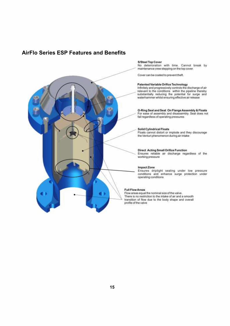
AirFlo Series ESP Features and Benefits
15
Surge and Waterhammer in Pipelines
Pipelines are required to convey liquid reliably, safely and economically whilst functioning over
a broad range of operating regimes.
Any change of flow velocity in a pipeline system creates a change in pressure. The sudden
closure of a valve or the shutdown of a pump causes surge and waterhammer.
Surge and waterhammer events are responsible for equipment failure, pipe rupture, damage to
pipe lining and subsequent internal pipe corrosion. Uncontrolled pump trip leads to column
separation which in turn can result in catastrophic pipe failure due to cavitation and high
pressure rises as the vapour cavities collapse. Vacuum conditions created when columns
separate at peak points can be sufficient to collapse thin walled pipe or, suck in seals which will
result in leaks once the system is re pressurised. In addition, surge and waterhammer events
have an impact on water quality as well as health as these phenomena create such high
intensities of shear that it may cause the detachment of biofilm from the pipe walls as well as
create vacuum conditions low enough to collapse seals resulting in the siphonage of
contaminated groundwater into the pipeline system. As an outcome, depending on the pipeline
system, pipeline failure may either be catastrophic or the pipeline system may be slowly
undermined leading to pipeline fatigue and eventual failure.
Surge and waterhammer phenomena are invetable and have to be properly accounted for in
any pipeline design. However, they are difficult to predict in totality and are highly system
dependant as every piping system is unique and it is impossible to relate one to another and
dispense with the engineering required to assess the need for surge analysis.
There are pipeline operating conditions and pipeline profiles or pipeline equipment where the
likelihood of surge can be predicted with a degree of accuracy allowing the design engineer to
focus on these areas in order to calculate the severity. For instance, surge and waterhammer
are more likely to occur or, will be highest at pump stations, non return valves, air valves and
control valves, at steep peak points and in locations with low static pressures.
Classic surge and waterhammer protection strategy generally employs a series of techniques to
mitigate transients and mass oscillation in pipelines. Techniques include any or a combination
of:
• Installation of high pressure class (stronger) pipe
• Re-routing of the pipeline to alter the profile and thereby limit surge pressures
• Improvement in valve and pump control and operating procedures
• Limiting the velocity in the pipeline
• Increasing the pump inertia
• Design and installation of surge protection devices.
Of all the different available techniques, this document focuses only on the design and
installation of selected pipeline components and surge protection devices with a specific focus
on air valves.
16
Pipeline Components and Surge Protection Devices
There has been a substantial amount of pipeline components and surge protection devices that
have been developed with time that either specifically address the surge or waterhammer
phenomena or, address the phenomena in conjunction with other functions that the device
performs.
The general principle of any surge and waterhammer suppression device is to delay or
minimise the change in flow rate and either absorb or dissipate the energy of the surge in a
variety of ways. Of importance in the effectiveness of the device is to convert the potential of a
rapid transient into a mass oscillation and where possible to minimise the magnitude and
amplitude of the oscillation in order to prevent damage to the system.
The performance and characteristics of traditional surge protection devices such as Surge
Vessels (compressor and bladder types) and One Ways Surge Tanks (Gravity Tanks) have
been well documented in countless publications and text books. Observations of the practical
performance of these devices are as follows:
Surge Vessels
Surge vessels are often located in or as close as possible to the pump station and are used as
the sole protection for long lengths of pipelines. However, these devices in order to be truly
effective need to be utilised in conjunction with air valves and well designed non return valves
and control valves.
Introducing air valves in conjunction with surge vessels as part of the surge protection strategy
better protects the pipeline across its entire length and also reduces the size and therefore the
cost of the surge vessel.
The design of the discharge from and intake of liquid into a surge vessel has a significant effect
on the size, cost and performance of a surge vessel.
Surge vessels are closed systems and absorb the energy of the surge in the entrapped air.
They effectively work by converting the transient into mass oscillation and are therefore highly
reliant on the pipeline friction to bring the pipeline to a steady state. Without the benefit of air
valves to assist in absorbing and dissipating the energy to atmosphere, surge vessels can result
in long term damage to specifically plastic pipelines that have smooth walls and therefore offer
very little resistance to the oscillation in the system.
When a surge vesses is utilised in an application with a number of pumps then, quick acting
non return valves should be selected to be installed subsequent to the pumps. This precaution
is to prevent check valve slam when only one of the pumps trip and the vessel’s response to the
pump trip results in the non return valve being slammed into its seat.
A drawback to surge vessels is failure due to lack of maintenance or, in the case of compressor
type surge vessels, a total loss of power which prevents the compressor being activated.
17

One Way Surge (Gravity) Tanks
A one way surge tank is normally positioned at reductions in an upward slope, or peaks of a
pipeline to prevent severe vacuum pressures from occurring as a result of pump trip.
These devices have the same drawback as surge vessels in that their response under vacuum
conditions is dependent on the outlet design configuration. Further maintenance is a major
consideration as these vessels are fitted with a mechanical end line control valve that is often
susceptible to failure if not properly maintained.
Non Return (Check) Valves
Non Return valves also known as Check valves are commonly installed on the discharge side
of the pump, to prevent drainage of the system and backflow through the pumps upon pump
trip.
Ideally a non return valve should open with the onset of upstream pressure and allow flow through the valve with minimal resistance. The valve should close at the instant of zero flow velocity and remain positively closed during minor pressure surges, and should resist back pressure without leakage.
However, many non return designs only close on flow reversal. Reverse flow and subsequent reverse rotation of pumps can cause damage to pump motors. In addition, reverse flow causes severe surge pressures in the suction side in the case of positive suction head applications. Further, reverse flow causes high transient pressures as the column of water is already in motion and stops abruptly as the non return valve closes. This phenomenon is known as Check Valve Slam and pressures created in this manner are dependent on the valve design used, the initial pumping velocities and the design head of the system but can be substantially high and damaging to the pipeline system.
Each system design is unique, as the factors that may cause Check Valve Slam in one system
may be totally different to those that cause slam for the next. Factors to consider are:
• The inertia of the pump - the lower the angular momentum of the impeller, motor and the liquid within the pump casing, the greater the potential for a check valve to slam.
• The pipeline profile - the higher the proportion of static head vs. dynamic head in a system, the greater the possibility of check valve slam.
• Pipeline diameter - the larger a pipeline diameter, the longer the travel distance and time for a check valve disc to move from open to close, hence the greater the possibility to slam.
• Parallel pumping systems - if one pump shuts off, reversal of flow will be created very rapidly in the common pump header causing the check valve to be slammed shut, inevitably creating a high pressure rise.
• Column separation - the shorter the length of pipe and steeper the incline away from the pump, the more rapid the flow reversal and the higher the transient pressures within the system.
18
System down time and pipeline repairs due to non return valve damage should be considered.
Wear in check valves are greater in designs that are hinged as the action of the disc
continuously “riding” on the flow wears the hinges.
Non Return valves that incorporate springs in their designs, but do not have the benefit of a
positive opening characteristic, are subject to spring cyclic failure as the disc flutters in the
vortex caused by the fluid moving past the discs. Double Door, Poppet and Co-Axial check
valves are especially susceptible to this form of failure.
All valves that do incorporate springs in their design should be selected very carefully to ensure
that the goal of non slam is not compromised by too high a headloss or, that the spring selected
is not too weak to ensure positive and rapid closure thereby creating high transients in the
system as the closing member would be slammed closed by flow reversal in such instances.
Non Return valves have a substantial effect on energy consumption. There is a major difference
in headloss characteristic between manufacturers of similar designs and an even bigger
difference between different design types with comparative variances in headloss of 300% or
more.
Control Valves
Control valves form an essential part of any pipeline network system as the valves are utilised
to automatically control flow, pressure and water levels and, to alleviate surges. Some designs
have inherent higher maintenance requirements than others and the misapplication of these
devices can result in pipeline failure.
Pressure reducing valves should be fitted with speed controls as the rapid reaction of the
valves, especially those utilised in pressure management applications, create transients that
cause system damage.
Surge anticipation valves are effective in countering over pressures, but are incapable of
handling negative pressures. The operation of this device is such that the positive wave reflects
off the reservoir and returns to the device where it is dumped to atmosphere. However, a
damaging negative pressure develops along the length of the pipeline which needs to be
countered by the use of a good air valve design and should not therefore be considered as a
standalone surge protection strategy.
This valve design must be utilised with the utmost caution as it has to work in conjunction with
air valves firstly to minimise the magnitude of the downsurge otherwise either pipe collapse or
seal failure can occur along the length of the pipeline. Secondly, the relationship of the main
pipeline in relationship to the outlet and the velocity of the upsurge needs to be carefully
calculated to ensure that a transient does not occur (due to the density of water vs air) at the
point when water is dumped to atmosphere.
Further, the opening reaction time of a surge anticipation valve is of critical importance in short
pipelines where the upsurge can occur in a very low millisecond time span.
19
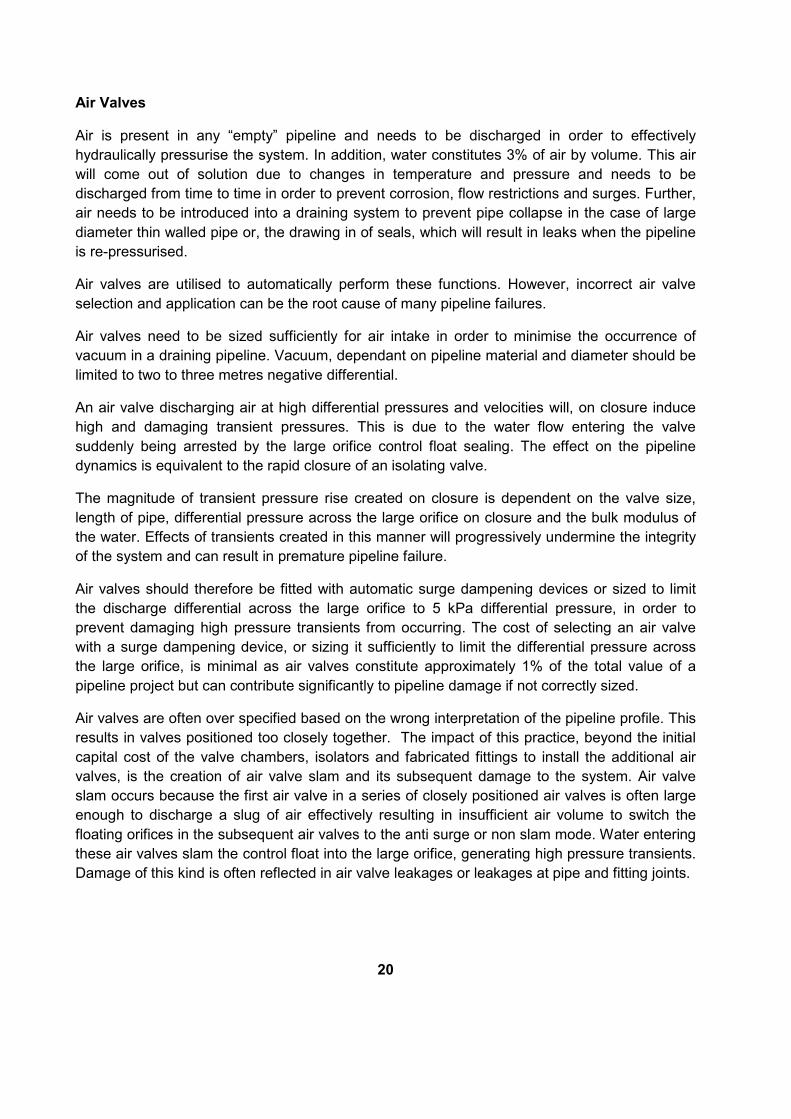
Air Valves
Air is present in any “empty” pipeline and needs to be discharged in order to effectively
hydraulically pressurise the system. In addition, water constitutes 3% of air by volume. This air
will come out of solution due to changes in temperature and pressure and needs to be
discharged from time to time in order to prevent corrosion, flow restrictions and surges. Further,
air needs to be introduced into a draining system to prevent pipe collapse in the case of large
diameter thin walled pipe or, the drawing in of seals, which will result in leaks when the pipeline
is re-pressurised.
Air valves are utilised to automatically perform these functions. However, incorrect air valve
selection and application can be the root cause of many pipeline failures.
Air valves need to be sized sufficiently for air intake in order to minimise the occurrence of
vacuum in a draining pipeline. Vacuum, dependant on pipeline material and diameter should be
limited to two to three metres negative differential.
An air valve discharging air at high differential pressures and velocities will, on closure induce
high and damaging transient pressures. This is due to the water flow entering the valve
suddenly being arrested by the large orifice control float sealing. The effect on the pipeline
dynamics is equivalent to the rapid closure of an isolating valve.
The magnitude of transient pressure rise created on closure is dependent on the valve size,
length of pipe, differential pressure across the large orifice on closure and the bulk modulus of
the water. Effects of transients created in this manner will progressively undermine the integrity
of the system and can result in premature pipeline failure.
Air valves should therefore be fitted with automatic surge dampening devices or sized to limit
the discharge differential across the large orifice to 5 kPa differential pressure, in order to
prevent damaging high pressure transients from occurring. The cost of selecting an air valve
with a surge dampening device, or sizing it sufficiently to limit the differential pressure across
the large orifice, is minimal as air valves constitute approximately 1% of the total value of a
pipeline project but can contribute significantly to pipeline damage if not correctly sized.
Air valves are often over specified based on the wrong interpretation of the pipeline profile. This
results in valves positioned too closely together. The impact of this practice, beyond the initial
capital cost of the valve chambers, isolators and fabricated fittings to install the additional air
valves, is the creation of air valve slam and its subsequent damage to the system. Air valve
slam occurs because the first air valve in a series of closely positioned air valves is often large
enough to discharge a slug of air effectively resulting in insufficient air volume to switch the
floating orifices in the subsequent air valves to the anti surge or non slam mode. Water entering
these air valves slam the control float into the large orifice, generating high pressure transients.
Damage of this kind is often reflected in air valve leakages or leakages at pipe and fitting joints.
20
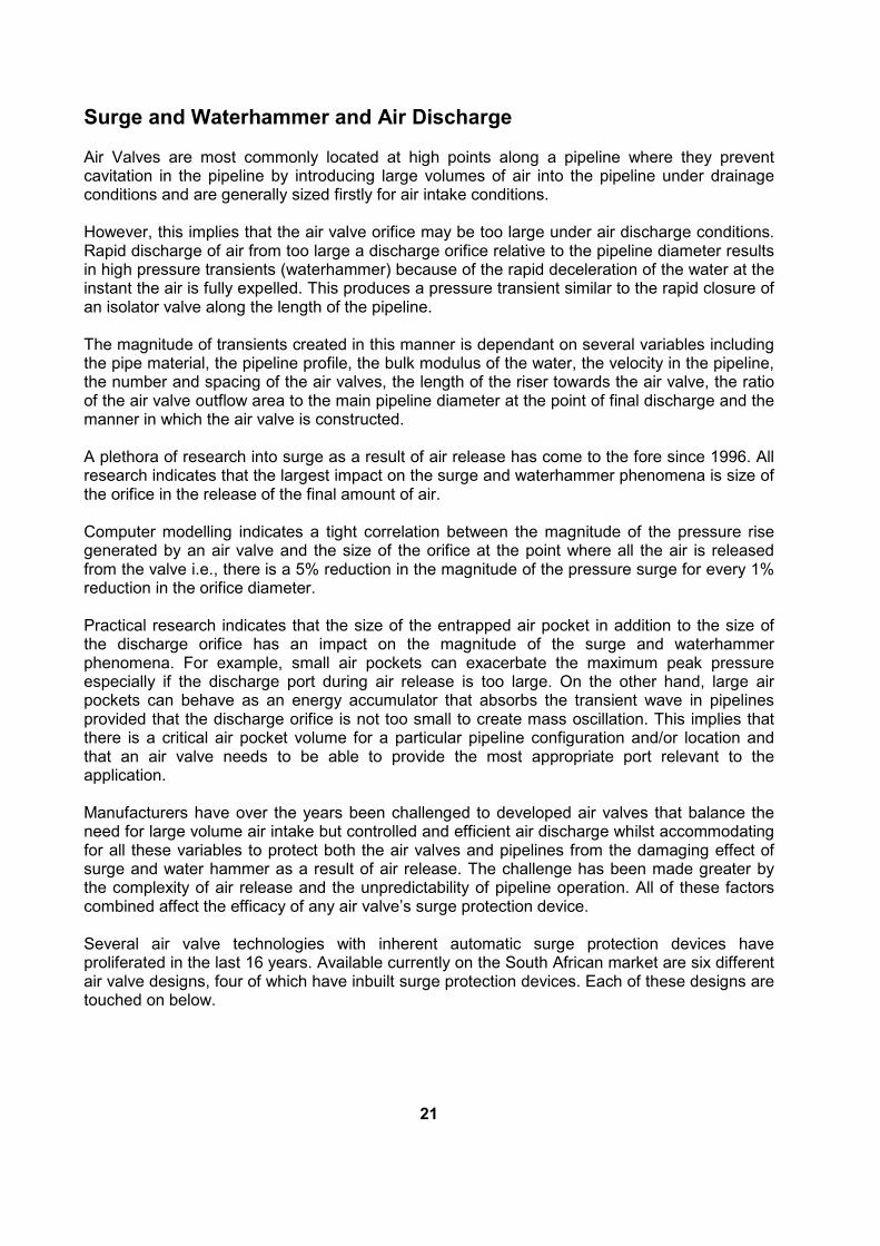
Surge and Waterhammer and Air Discharge Air Valves are most commonly located at high points along a pipeline where they prevent cavitation in the pipeline by introducing large volumes of air into the pipeline under drainage conditions and are generally sized firstly for air intake conditions. However, this implies that the air valve orifice may be too large under air discharge conditions. Rapid discharge of air from too large a discharge orifice relative to the pipeline diameter results in high pressure transients (waterhammer) because of the rapid deceleration of the water at the instant the air is fully expelled. This produces a pressure transient similar to the rapid closure of an isolator valve along the length of the pipeline. The magnitude of transients created in this manner is dependant on several variables including the pipe material, the pipeline profile, the bulk modulus of the water, the velocity in the pipeline, the number and spacing of the air valves, the length of the riser towards the air valve, the ratio of the air valve outflow area to the main pipeline diameter at the point of final discharge and the manner in which the air valve is constructed. A plethora of research into surge as a result of air release has come to the fore since 1996. All research indicates that the largest impact on the surge and waterhammer phenomena is size of the orifice in the release of the final amount of air. Computer modelling indicates a tight correlation between the magnitude of the pressure rise generated by an air valve and the size of the orifice at the point where all the air is released from the valve i.e., there is a 5% reduction in the magnitude of the pressure surge for every 1% reduction in the orifice diameter. Practical research indicates that the size of the entrapped air pocket in addition to the size of the discharge orifice has an impact on the magnitude of the surge and waterhammer phenomena. For example, small air pockets can exacerbate the maximum peak pressure especially if the discharge port during air release is too large. On the other hand, large air pockets can behave as an energy accumulator that absorbs the transient wave in pipelines provided that the discharge orifice is not too small to create mass oscillation. This implies that there is a critical air pocket volume for a particular pipeline configuration and/or location and that an air valve needs to be able to provide the most appropriate port relevant to the application. Manufacturers have over the years been challenged to developed air valves that balance the need for large volume air intake but controlled and efficient air discharge whilst accommodating for all these variables to protect both the air valves and pipelines from the damaging effect of surge and water hammer as a result of air release. The challenge has been made greater by the complexity of air release and the unpredictability of pipeline operation. All of these factors combined affect the efficacy of any air valve’s surge protection device. Several air valve technologies with inherent automatic surge protection devices have proliferated in the last 16 years. Available currently on the South African market are six different air valve designs, four of which have inbuilt surge protection devices. Each of these designs are touched on below.
21
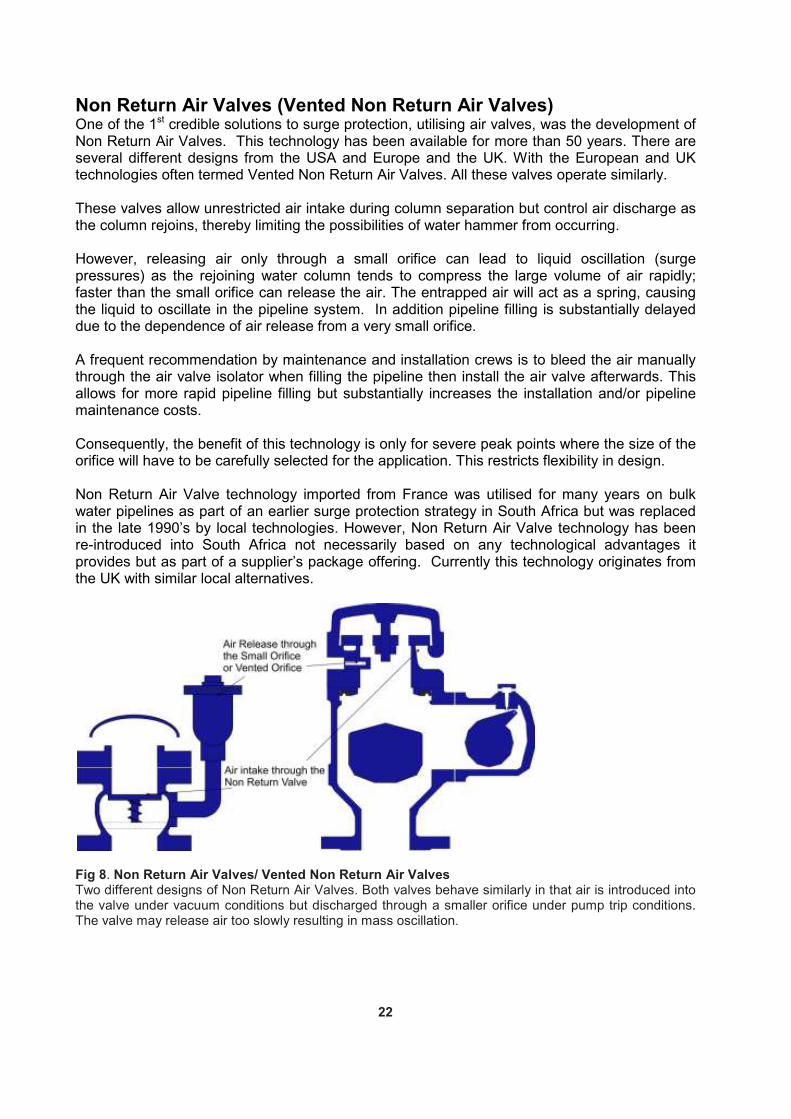
Non Return Air Valves (Vented Non Return Air Valves) One of the 1st credible solutions to surge protection, utilising air valves, was the development of Non Return Air Valves. This technology has been available for more than 50 years. There are several different designs from the USA and Europe and the UK. With the European and UK technologies often termed Vented Non Return Air Valves. All these valves operate similarly. These valves allow unrestricted air intake during column separation but control air discharge as the column rejoins, thereby limiting the possibilities of water hammer from occurring. However, releasing air only through a small orifice can lead to liquid oscillation (surge pressures) as the rejoining water column tends to compress the large volume of air rapidly; faster than the small orifice can release the air. The entrapped air will act as a spring, causing the liquid to oscillate in the pipeline system. In addition pipeline filling is substantially delayed due to the dependence of air release from a very small orifice. A frequent recommendation by maintenance and installation crews is to bleed the air manually through the air valve isolator when filling the pipeline then install the air valve afterwards. This allows for more rapid pipeline filling but substantially increases the installation and/or pipeline maintenance costs. Consequently, the benefit of this technology is only for severe peak points where the size of the orifice will have to be carefully selected for the application. This restricts flexibility in design. Non Return Air Valve technology imported from France was utilised for many years on bulk water pipelines as part of an earlier surge protection strategy in South Africa but was replaced in the late 1990’s by local technologies. However, Non Return Air Valve technology has been re-introduced into South Africa not necessarily based on any technological advantages it provides but as part of a supplier’s package offering. Currently this technology originates from the UK with similar local alternatives.
Fig 8. Non Return Air Valves/ Vented Non Return Air Valves Two different designs of Non Return Air Valves. Both valves behave similarly in that air is introduced into the valve under vacuum conditions but discharged through a smaller orifice under pump trip conditions. The valve may release air too slowly resulting in mass oscillation.
22

Three Stage (Anti Shock or Anti Slam) Air Valves An approach to surge protection utilising air valves first proposed in 1983 is to release a predetermined amount of air from a large orifice and then release a smaller volume of retained air in a controlled manner through a smaller orifice thereby ensuring rapid filling of the pipeline whilst limiting potential surge or water hammer. This proposal was put forward in a seminal technical paper outlining practical cases studies on a large diameter pipeline in Saudi Arabia. The optimum balance between the size of the outlet orifice and the amount of air released before switching to a smaller orifice can result in the reduction of mass oscillation as well as water hammer whilst ensuring effective air release. The device proposed in 1983 whilst effective was extremely cumbersome and expensive as it consisted of five valves and a complex configuration of fittings. Technologies achieving similar results were developed independently in 1980 in the UK and in 1988 in Japan. A cost effective, compact device that imitated some of the results achieved by the practical studies highlighted in the 1983 technical paper first appeared in the South African market in 1994. This technology has become known as three stage air valves as it generally consist of three orifices namely; a large orifice for large volume air discharge or intake, a small orifice for pressurised air discharge and a floating intermediary orifice that will at a specific differential pressure be lifted to seal off the large orifice thereby releasing air through a smaller port which creates a back pressure to slow down the advancing water column, limiting surge and waterhammer when the water enters the air valve. These air valves are also known as anti shock or anti slam air valves. This design concept works effectively if the differential pressure created is high enough to lift the floating orifice to seal off the larger outlet but will create waterhammer if the correct differential pressure is not achieved. Parameters such as the size of the pipeline, the flow velocity within the pipeline and the size of the valve influence the shear mass of the floating orifice which increases the switching point of the orifice. The higher the switching point, the greater the potential for damaging surge and if the switch does not occur then, the valve can create slam (waterhammer) on closure. Additional factors to consider for the design engineer when using this design is the spacing between valves - if two or more valves are too closely spaced together then the possibility exists that the valve adjacent to the flow may switch into the anti slam mode whilst the valve further away may have insufficient air to do so before the water flow reaches it, resulting in it creating waterhammer on closure. Anti slam or anti shock type air valves have static orifice diameters. There is a possibility that the orifice diameter of the anti slam device may be too large resulting in air being released too rapidly, thereby creating waterhammer or too small thereby creating mass oscillation (surge) in the pipeline. The two stage switching and the combination of the amount of air being released initially versus the switching point and the size of the anti slam orifice can create waterhammer in applications such as air valves subsequent to the pump, air valves prior to the non return valve in a borehole application and air valves at the peak points of steep slopes. Because of these limitations, certain manufacturers often specify air valves with a bias mechanism that functions similarly to Non Return Air Valves at critical points along the length of the pipeline.
23

There are currently three manufacturers of anti slam or anti shock air valves in South Africa. Though the design configuration of these valves differs, their surge protection functions are similar.
Fig 9. Three Stage Anti Slam Air Valves Two different designs of Three Stage Air Valves indicating the three orifices which operate at different stages of the valves’ operating cycle. These designs are also known as anti slam or anti shock valves.
Anti Slam Air Valves with Slow Closing Mechanism Among the many American, air valve technologies that have evolved is one that has been around since the late 1950’s which normally has a perforated non return valve disc positioned underneath the air valve. This allows for the air valve to release air but when water enters, it lifts the non return valve disc and water slowly enters the air valve chamber thereby preventing a slam in the valve chamber when the floats are buoyed to close the outlet orifice. This technology has been duplicated in a recent South African air valve design which combines the functions of an anti slam – three stage air valve with a slow closing mechanism. The South African designed valve will draw in air under vacuum conditions and discharge air as the water columns commences to rejoin. Air will pass unrestricted through the valve but will switch to a smaller outlet once a specific differential pressure is reached. In this respect, the design operates on much the same principles as other anti slam devices. The reduction in orifice diameter is achieved in a chamber prior to the control float chamber by the lifting of the regulator floats. When water enters the air valve, the passage of water through the valve will therefore also be throttled. The control float is moved to a closed position by the water which enters the valve at a reduced rate. This aspect of the design is similar to the older American technology. The valve design is such that the regulator floats mass can be increased or decreased to influence the switching point from a large to a smaller discharge orifice. However, the switching point needs to be determined beforehand and only through a surge analysis. This design has, in the manner in which the anti slam feature functions, the same drawback of a static orifice which impacts other anti slam air valve designs. The additional feature in this design is the cushioning benefit provided to the upper float assembly when water enters the valve due to the throttling of the flow prior to the control float.
24
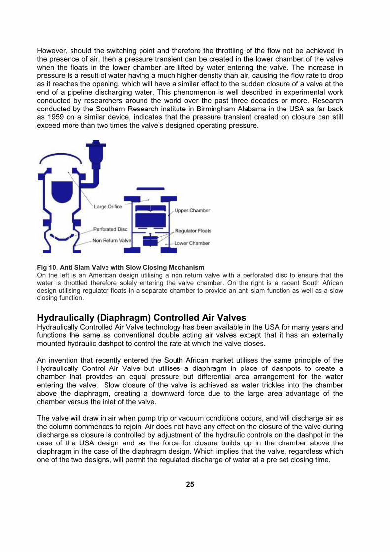
However, should the switching point and therefore the throttling of the flow not be achieved in the presence of air, then a pressure transient can be created in the lower chamber of the valve when the floats in the lower chamber are lifted by water entering the valve. The increase in pressure is a result of water having a much higher density than air, causing the flow rate to drop as it reaches the opening, which will have a similar effect to the sudden closure of a valve at the end of a pipeline discharging water. This phenomenon is well described in experimental work conducted by researchers around the world over the past three decades or more. Research conducted by the Southern Research institute in Birmingham Alabama in the USA as far back as 1959 on a similar device, indicates that the pressure transient created on closure can still exceed more than two times the valve’s designed operating pressure.
Fig 10. Anti Slam Valve with Slow Closing Mechanism On the left is an American design utilising a non return valve with a perforated disc to ensure that the water is throttled therefore solely entering the valve chamber. On the right is a recent South African design utilising regulator floats in a separate chamber to provide an anti slam function as well as a slow closing function. Hydraulically (Diaphragm) Controlled Air Valves Hydraulically Controlled Air Valve technology has been available in the USA for many years and functions the same as conventional double acting air valves except that it has an externally mounted hydraulic dashpot to control the rate at which the valve closes. An invention that recently entered the South African market utilises the same principle of the Hydraulically Control Air Valve but utilises a diaphragm in place of dashpots to create a chamber that provides an equal pressure but differential area arrangement for the water entering the valve. Slow closure of the valve is achieved as water trickles into the chamber above the diaphragm, creating a downward force due to the large area advantage of the chamber versus the inlet of the valve. The valve will draw in air when pump trip or vacuum conditions occurs, and will discharge air as the column commences to rejoin. Air does not have any effect on the closure of the valve during discharge as closure is controlled by adjustment of the hydraulic controls on the dashpot in the case of the USA design and as the force for closure builds up in the chamber above the diaphragm in the case of the diaphragm design. Which implies that the valve, regardless which one of the two designs, will permit the regulated discharge of water at a pre set closing time.
25

The actual spillage of water may induce a pressure surge because water has a much higher density than air, causing the flow rate to drop as it reaches the opening, which will have a similar effect to the sudden closure of a valve at the end of a pipeline discharging water. Experimental work conducted by researchers in a number of countries including Dr. van Vuuren of South Arica indicates that the most important variables influencing the magnitude of a pressure rise for air released in this manner are; internal pressure, volume of compressed air pocket, size of opening through which the air escapes and the elasticity of the system. The amount of water spilled before the valve closes is highly dependant on the time period for the valve to close, the differential pressure across the valve and the size of the valve outlet relative to the main pipeline. It is also important that the valve’s closure time has to be more than two times the pipeline period i.e., two times the time period that a pressure wave will take to move from the air valve and reflect from a reservoir or closed valve back to the air valve. By the very nature of the design, closure will have to be slow. On this basis, a DN150 air valve will dump approximately 83 litres/second of water at 34 kPa differential pressure across the valve outlet. If the valve takes one minute to close then the amount of water dumped is a potential 4959 litres. However, the bigger the valve, the slower the closure would be or ought to be. A typical hydraulically control valve working on a similar principle takes approximately three minutes to close. This implies that the air valve of this size could discharge up to 14870 litres before closure. If this is multiplied across a pipeline with seven DN150 air valves then the spillage rate is a potenial 104090 litres at a specified differential pressure of 34 kPa. The volumes of water discharged will vary according to the factors highlighted above but could be significant for a water stressed country such as South Africa.
Fig 11. Hydraulically Controlled (Diaphragm) Air Valve On the left is an American Hydraulically controlled air valve design utilising a dashpot arrangement to regulate closure. On the right is a Hydraulically controlled diaphragm air valve utilising the principle of equal pressure and differential area in the diaphragm chamber to regulate closure. Both designs dump water before closure. The volume of water dumped is dependant on the closure time of the valve, the size of the valve and the differential pressure across the valve’s outlet
26

Variable Orifice Air Valve Technology Empirical research confirms in over a decade of results conducted by several researchers on a variety of conditions, that the most critical factor that determines the creation of surge and waterhammer on closure of the large orifice of an air valve, or the prevention thereof, is the size of the orifice at that critical point before closure. This is regardless of whether the system on which the air valves are employed is a gravity fed main or pumping system as the surge and waterhammer phenomena occur during initial filling as well as during column separation and the subsequent rejoining of water columns. However, research and extensive computer modeling also indicates that the size of the orifice has to be balanced with the conditions within the pipeline system as too small an orifice may dampen waterhammer but increase mass oscillation (surge) as well as increase filling times for a pipeline whilst too large an orifice will induce waterhammer. The demand for an air valve design with a multi adjustable orifice to address the above has been understood as far back as the early 1980’s but no successful, practical commercially produced air valve was designed until the advent of Variable air valve technology. Variable orifice air valves incorporate a variable floating shuttle that automatically adjusts the discharge outlet of the valve to the conditions within the pipeline and provides the optimum orifice diameter at any given point during the performance of the pipeline to ensure effective air release whilst preventing waterhammer and substantially reducing mass oscillation. Variable orifice air valve technology is a 100% South African developed and patented technology that represents a revolutionary way in the addressing of surge and waterhammer during the release of air. This technology effectively breaks away from the drawbacks and constraints of the surge damping function of other air valve technologies. The most significant advancement is the fact that this design does not have a stationary and standardised orifice and is sensitive to the air outflows of the pipeline. This smooth transition from one differential pressure to the next and the constant adjustment of the orifice size and therefore the backpressure and the slowing down to the advancing water column as the outflow velocities increases is of major benefit to the pipeline designer as it takes away the guess work of whether the orifice is either too small or too large under varying pipeline operating conditions. The action of the Variable orifice is such that it will readjust itself under pump trip and column separation conditions thereby allowing for effective air release whilst reducing the magnitude of the surge as well as reducing the amplitude and time period of the pressure wave. This brings the pipeline to a steady state much more rapidly and smoothly without damage to system. Variable orifice air valve technology is advancement into air valve technology and has moved the performance criteria and the technology for air valves ahead in a significant way in essence setting the bench mark for measuring future advancements in air valve technologies.
27
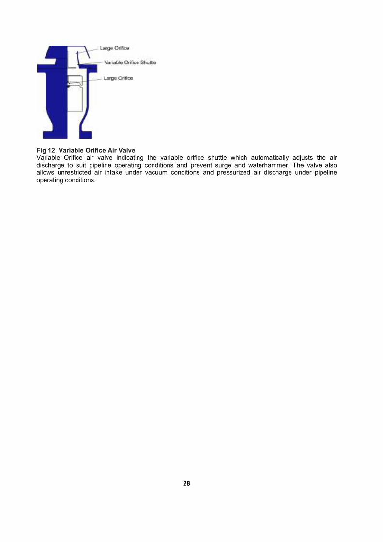
Fig 12. Variable Orifice Air Valve Variable Orifice air valve indicating the variable orifice shuttle which automatically adjusts the air discharge to suit pipeline operating conditions and prevent surge and waterhammer. The valve also allows unrestricted air intake under vacuum conditions and pressurized air discharge under pipeline operating conditions.
28
Modelling Air Valves in Surge Analysis Software Programmes The accuracy of surge analysis has significantly increased as computer capacity and the sharing of research in specific areas have advanced. However, the accuracy of a surge model is highly dependant on the quality of the data, the capability of the software and the understanding by the modeller of these destructive phenomena and the pipeline components utilised to prevent or reduce their impact. The end result of an analysis should be the combination of these factors to deliver a result that is a close approximation of the real world. Every air valve design has a different characteristic in terms of performance and it is important that the selected design is correctly modelled to reflect the reality of the design being utilised. There are several commercially available computer packages that accurately take into account the performance of conventional air valves, Non return air valves and anti slam air valves (3 stage air valves). To model the first two designs have become easier with time as software developers allow for the insertion of the intake orifice and the discharge orifice and the software will then accurately model the valve. However, anti slam (3 stage air valves) are sometimes inaccurately modelled. The reason for this is the assumption that the small orifice also provides part of the surge protection benefit. This assumption is incorrect as the physics of the valve, under surge conditions, only allows for a throttling effect through the anti slam or anti shock orifice. The magnitude of impact through this inaccurate assumption can be significant. A DN80 anti slam valve with a 1.5mm diameter small orifice and an anti slam orifice of 15mm in diameter will result in a 1000% inaccuracy in size and therefore a significant error between utilising the anti shock orifice as a modeller should or utilising the small orifice which is incorrect. This implies that the resultant surge analysis model whilst impressive could be a misrepresentation of what may occur in the pipeline in reality. Variable Orifice Air Valve Technology and Surge and Waterhammer Analysis The Airflo Variable Orifice air valve discharge characteristic is such that the valve maintains a constant air discharge regardless of the differential pressure within a specific differential pressure range. The valve when breaking out of this range, has a predictable discharge orifice size. These characteristics make it easy to model with highly accurate results, utilising conventional commercially available software. Air valve technology as it stands now indicates that even some of the more commercially successful designs are not superior from all points of view and have inherent limitations and that pedigree in age does not necessarily reflect pedigree in performance. The article also indicates that surge damping in air valves is a major challenge and that the governing factor, supported by extensive research is the size of the orifice at the point when the air valve closes. The better the ability, to govern the orifice under all operating conditions, the better the protection the air valve provides. AirFlo Variable Orifice air valve technology provides protection in a wider operating range and therefore may constitute better pipeline protection than any currently available air valve design. Pipeline design and operation has become more complex with time. Conversely, it is important to seek out less complicated and user friendly technologies that will provide years of maintenance free operation. Airflo Variable Orifice air valve technology again is one such technology that provides uncomplicated long term performance.
29
Selection and Positioning of Air Valves
Many guidelines have developed on the positioning and sizing of air valves by various authors
and manufacturers. The author of this document wrote comprehensively on sizing and
positioning in three publications in the mid and late 1990’s. This section of the document
provides the design engineer with a guideline of where to position double acting air valves and
points to consider when selecting an air valve design by covering the latest research since 1996
on air valve design and the sizing and positioning of air valves.
Air Removal and Air Valve Designs
There has been a growing trend, because of the unpredictable nature of air and the complexity
of air valve sizing and positioning to utilise double acting air valves as standard in every air
valve application instead of separating the positioning of the valve according to the function.
Further as the understanding of surge and waterhammer and the impact of air valves on these
phenomena is understood, it has become an expectation that a double acting air valve will as
standard incorporate an automatic surge alleviation function.
Every air valve design has a specific performance characteristic even amongst designs that
look or perform similarly. It cannot therefore be taken for granted that different valve designs of
the same nominal diameter will perform equally. Accurate selection of an air valve can only be
achieved by reference to performance data for a particular design.
An air valve's intake performance, regardless of its design, is limited to 35 kPa differential
across the large orifice. Pipeline materials such as ductile iron pipe can withstand lower
negative pressures than -35 kPa but it is of no benefit to size beyond this point. It is
recommended from practical experience that a differential of 35 kPa be used for fairly rigid
materials such as ductile iron pipe and small diameter steel pipe. A differential pressure of 20
kPa to kPa is recommended for plastic pipes and thin walled, large diameter steel pipes.
In recent years, the prime focus has been on air intake only as the assumption has been that if
an air valve is correctly sized for air intake, it will suffice for air discharge. Research since 1996
has indicated that it is the size of the orifice in relation to the main pipeline that is the final
determining factor on how well an air valve will dampen surge. If there is no reduction to the
diameter of the final outlet under discharge conditions then, the differential pressure across the
air valve should be limited on discharge, to 5 kPa differential across the large orifice. Care
should be taken that even if there is a reduction in discharge outlet in relationship to the nominal
size of the valve, that this should occur at a differential pressure that is lower than 5 kPa and
the reduction is sufficient to prevent damaging water hammer on closure.
Sizing and Locating Air Valves for Air intake
Air valves are first and foremost sized for vacuum conditions which may result from scouring of
the pipeline, pipeline rupture or instantaneous pump stoppage causing column separation.
30
The large orifice diameter of an air valve should not be confused with the nominal inlet size of
the valve. The nominal size of the valve refers to the inlet of the valve connected to the pipeline
but the large orifice refers to the orifice that finally discharges air from the valve or introduces air
into the valve. The dimension of the large orifice and the inlet of the valve are not necessarily
similar in every design. It cannot therefore be taken for granted that every air valve performs the
same.
An air valve should be selected based on the mm2 area of protection it provides under vacuum
conditions, the closest the large orifice is to the nominal size of the valve under air intake
conditions, the higher the performance of the valve and therefore, the better the protection
gained from the valve.
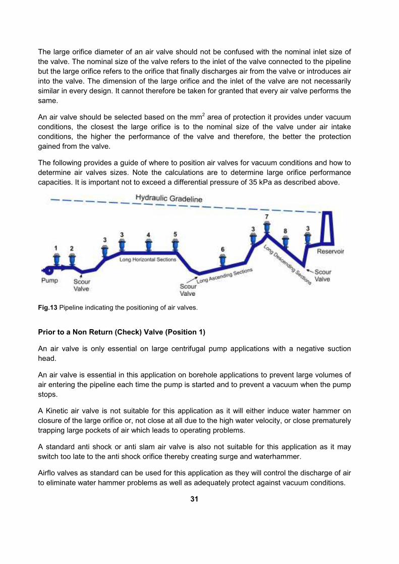
The following provides a guide of where to position air valves for vacuum conditions and how to
determine air valves sizes. Note the calculations are to determine large orifice performance
capacities. It is important not to exceed a differential pressure of 35 kPa as described above.
Fig.13 Pipeline indicating the positioning of air valves.
Prior to a Non Return (Check) Valve (Position 1)
An air valve is only essential on large centrifugal pump applications with a negative suction
head.
An air valve is essential in this application on borehole applications to prevent large volumes of
air entering the pipeline each time the pump is started and to prevent a vacuum when the pump
stops.
A Kinetic air valve is not suitable for this application as it will either induce water hammer on
closure of the large orifice or, not close at all due to the high water velocity, or close prematurely
trapping large pockets of air which leads to operating problems.
A standard anti shock or anti slam air valve is also not suitable for this application as it may
switch too late to the anti shock orifice thereby creating surge and waterhammer.
Airflo valves as standard can be used for this application as they will control the discharge of air
to eliminate water hammer problems as well as adequately protect against vacuum conditions.
31
The air valve selected should be sized on pump discharge velocities.
Pump Discharge - Subsequent to a Non Return (Check) Valve (Position 2)
Assume total pump stoppage.
The air valve size required will be based on an air inflow rate equivalent to the pump flow rate.
Important, when sizing for standard air valves not to exceed 5kPa differential across the large
orifice on filling.
Of utmost importance is that standard anti slam or anti shock air valves positioned at this point,
may switch too late to the anti slam or shock orifice when pump trip occurs, and a separated
column commences to rejoin. This will ultimately result in high surge pressures and pipeline
damage. It is therefore important when utilising these types of air valves to check for the
following:
• Switching point
• Size of the Anti Slam/ Anti Shock orifice
• Thickness of the Anti Slam Float relevant to application to ensure that the strength of the
valve is not compromised in the process
Air vessels are normally positioned at this point to prevent the phenomena of surge and water
hammer. This function can however be performed much more cost effectively and efficiently by
the installation of a TruFlo series Airflo air valve.
Increase in a Downward Slope or Decrease in an Upward Slope (Positions 3 and 5)
From the pipeline under consideration identify all changes in slope. Assume a pipe rupture at the bottom of the most severe slope, or complete pump stoppage. A cavity will form at the point of change in slope that is equal the difference in flow in the two gradients. The rate of air flow into the pipeline should therefore equal the cavity developing rate. It is important to note that the valve selected should not exceed a differential of 35 kPa across
the large orifice (or lower, depending on pipe material).
Restrictions in large orifice diameters and phenomena such as the "Venturi Effect" should be
taken into account when selecting an air valve design.
Long Horizontal Sections (Position 4)
Long horizontal sections should wherever possible be avoided. Ideally a pipeline should have a
minimum slope of 3 to 6 millimetres per metre to facilitate effective air removal as air will tend to
gravitate to the highest point, allowing for removal along the pipeline and at peaks. If long
horizontal sections are unavoidable then air valves should be positioned at 600m intervals for
pipelines up to and including 600mm nominal bore. For pipelines large than 600mm nominal
bore, the valves can be spaced 1 metre for every mm in diameter i.e for a 800mm nominal bore
pipe, the valves will be spaced 800m apart.
32
The sizing of air valves at these positions should be based on the filling rate.
Of utmost importance, is not to exceed a differential of 5 kPa across the large orifice when
sizing, based on filling rates, for Kinetic Air valves.
Long Ascending Sections (position 6)
There will always be a double acting air valve positioned at the top end of every ascending
section. If the length of the ascending section is considerable, additional air valves will be
required, to ensure adequate discharge when filling the pipeline and ample ventilation when it is
being drained. It is recommended that these valves be positioned at intervals of 600m
maximum to ensure both functions are performed effectively. For pipelines large than 600mm
nominal bore, the valves can be spaced 1 metre for every mm in diameter i.e for a 800mm
nominal bore pipe, the valves will be spaced 800m apart.
To size the air valves for these positions, firstly calculate for air intake requirements, based on
rupture, pump stoppage, or scouring velocities.
Before determining the valve size, compare the intake requirements with the filling rate. If the
filling rate is greater than the intake rate, then the valves should be sized according to the filling
rate.
Do not to exceed a differential of 5 kPa across the large orifice when sizing, based on filling
rates, for Kinetic Air valves. A greater differential will lead to water hammer.
High Points below the Hydraulic Gradeline (Position 7)
From the pipeline under consideration, identify the high points which fall below the hydraulic gradeline. Calculate necessary valves independently for each high point. Consider the more severe of the two gradients adjacent to each high point. Determine the maximum rate of flow that can occur in this gradient as a result of pipe rupture at the lowest elevation or, flow due to scouring. Generally valves are sized on scouring velocities or partial rupture to economise on the valve size selected. It is recommended that when sizing for scour conditions to limit the scour area to 12% of the area of the main pipeline. For pipe rupture, the area should depending on the pipeline material be limited to between 10 to 15% of the area of the pipeline. A Chezy’s formulae or similar equation can be used to determine maximum flow rate. The required rate of air intake will be equivalent to that of the liquid drainage rate. It is important to note that the valve selected should not exceed a differential of 35 kPa while drawing in air across the large orifice (or lower, depending on pipe material). Restrictions in large orifice diameters and phenomena such as the "Venturi Effect" should be taken into account when selecting an air valve design.
33
Sometimes a single rupture of a pipeline can result in drainage of both gradients adjacent to an apex point. Unless this is impossible, due to the pipeline characteristics or preventative mechanisms, it is advisable to select the number and size air valves accordingly. An important consideration in a pumping main is the possibility of pump trip and the rejoining of separated water columns, which could lead to damaging surge and water hammer.
Long Descending Sections (Position 8)
The sizing and positioning of double acting air valves for these are exactly the same as for long
ascending sections.
Blank Ends (Not Shown)
This is usually where a pipeline is terminated by a blank flange or a valve. A valve selected for
this positioned should be sized on pipe filling rate, whilst not exceeding 0.05 bar differential
across the large orifice, if Kinetic air valves are considered.
Sizing and Positioning Air Valves for Discharge
Generally, the location of air valves for air intake will suffice for air discharge.
However, the sizes selected (if conventional air valves are considered) may be too large and
therefore discharge air too rapidly and may induce a number of destructive phenomena if
discharging at too high a differential.
It is strongly recommended that the differential across the large orifice of a Kinetic air valve
design does not exceed 5kPa on discharge.
In the light of research subsequent to 1996, it is equally important that when selecting anti slam
or shock air valves that the sizing is such to ensure that the valve provides adequate intake
capabilities but switches to the anti slam or anti shock orifice during air discharge as the valve
will otherwise behave very much like a Kinetic air valve if the switching does not occur.
The use of commercially available sizing software often encourages the use of too many air
valves per pipeline application specifically selecting air valves too close together. Anti slam air
valves that are too large for discharge applications or too closely spaced together may not
switch to the anti slam mode and therefore induce damaging waterhammer conditions similar to
the operation of Kinetic air valves.
AirFlo Variable Orifice Air Valves have been design for the orifice to automatically adjust to the
prevailing pipeline condition. A valve of this design selected for air intake will efficiently and
effectively discharge air, whilst protecting the pipeline from surge, water hammer and vacuum.
34

Small Orifice Air Discharge
Much debate on air valve design has gone around the discharge capacity and capability of the
small orifice. It is the author’s experience from extensive controlled testing and on site
applications of several different air valve designs that effective discharge of pressurised air
depends on the existence of a "Critical Relationship" between the area of the small orifice and
the mass of the control float. This implies that the mass of the float must be greater than the
force created by the working pressure acting on the orifice area. If the float is relatively too light
or the orifice area relatively too great, the float will be held against the orifice, even when not
buoyed, and air discharge will not take place.
Should the correct relationship exist, regardless of design, air will be discharged effectively and
efficiently. The amount of air bled under these conditions is generally relatively small.
There is a school of thought that recommends that a large, small orifice discharge capacity is
desirable. This may have been true for older design air valves that closed prematurely In the
presence of air, thereby capturing large pockets of air in the pipeline and the only means of
bleeding this air was through the small orifice function. However, this argument should no
longer hold for current designs that will discharge large volume low pressure air effectively
during initial filling conditions.
Air valves designs that do not have the correct "Critical Relationship" between the control float
and the discharge nozzle, or that makes use of a lever action for the small orifice function
should be avoided.
35

Recommended Air Valve Chamber Design
A typical Air Valve chamber should have the following considerations:
Valve Chamber
A well designed valve chamber is of importance and should be designed with easy access to
the valve for installation and subsequent maintenance.
Good support is required in the event of the chamber settling. It is recommended that a layer of
stone be placed under the pipe for drainage purposes.
When utilising concrete rings, utilise rings with a 1.5m diameter and with a concrete cast floor
with a minimum of a 800mm opening for the air valve accumulator.
Vents
Two vents should be installed to prevent pressure build up in the valve chamber and facilitate
air circulation and prevent stale air build up in the chamber. Further, the diameter of each vent
should be equal to or greater than the size of the air valve, a mesh with a large aperture should
be placed on the inlet to allow for effective air intake but prevent vermin from entering the valve
chamber.
Isolators
RSV’s are the most suitable isolators for PN16 and PN25 pressure ratings and for air valve
sizes of DN80 and larger. Butterfly valves should be avoided as isolators for air valves because
they present a restriction in flow and may cause turbulence in flow towards the air valve.
Similarly, wedge gate valves should be avoided as isolators for PN40 and higher pressure
ratings. It is recommended in these applications that single offset ball valves be used.
Full bore ball valves are cost effective and highly suitable isolators for DN25 and DN50 air
valves
It is important that an air valve isolator is fully opened during commissioning to prevent
turbulence in flow towards the air valve.
Air Valve
An air valve should always be correctly sized for the application. It is recommended for large
applications to install two smaller air valves per air valve position in place of only one large air
valve. This implies that the pipeline will always be protected to a degree if one of the air valves
fails for whatever reason.
It is sometime requested that an air valve be supplied with bleed cock. In older designs, the
bleed cock was essential to determine if the air valve is working by opening up the bleed cock
periodically to see if air or water is released from it. With the AirFlo Variable Orifice design, the
purpose of the bleed cock serves only as a possible point to measure pressure as the design
ensure effective air release regardless of the application.
36
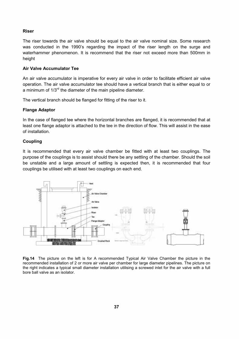
Riser
The riser towards the air valve should be equal to the air valve nominal size. Some research
was conducted in the 1990’s regarding the impact of the riser length on the surge and
waterhammer phenomenon. It is recommend that the riser not exceed more than 500mm in
height
Air Valve Accumulator Tee
An air valve accumulator is imperative for every air valve in order to facilitate efficient air valve
operation. The air valve accumulator tee should have a vertical branch that is either equal to or
a minimum of 1/3rd the diameter of the main pipeline diameter.
The vertical branch should be flanged for fitting of the riser to it.
Flange Adaptor
In the case of flanged tee where the horizontal branches are flanged, it is recommended that at
least one flange adaptor is attached to the tee in the direction of flow. This will assist in the ease
of installation.
Coupling
It is recommended that every air valve chamber be fitted with at least two couplings. The
purpose of the couplings is to assist should there be any settling of the chamber. Should the soil
be unstable and a large amount of settling is expected then, it is recommended that four
couplings be utilised with at least two couplings on each end.
Fig.14 The picture on the left is for A recommended Typical Air Valve Chamber the picture in the recommended installation of 2 or more air valve per chamber for large diameter pipelines. The picture on the right indicates a typical small diameter installation utilising a screwed inlet for the air valve with a full bore ball valve as an isolator.
37

References 1. Adams Hydraulics Brochure and Patents - UK - 1979, 1980 2. Apco, Air and Check Valve Catalogue 3. Balutto, AP - Effects of Air Valve Selection in Pipeline Design– IWISA conference Hong Kong
1995 4. Balutto, AP , Muller , MP - Points to Consider when Sizing and Positioning Air Valves - Published
1995 5. Balutto, AP - Air Valve Technology Reviewed. - Published 1996 6. Balutto, AP - Valves for Air Release and Vacuum Breaking in Pipelines – Pipes and Pipelines -
Published 1998 7. Balutto, AP - The Application of Controlled Air Transfer Technology to Water Pipelines –
Pipelines, Potable & Sanitary Drainage Network Conference - Egypt 1998 8. Balutto, AP - Surge and Water Hammer Prevention –Knowing More about Valves – Published
2000 9. Balutto, AP - Valves and Applications for the Water Industry –Published 2004 10. Balutto, AP - The Application of Life Cycle Costing to New and Existing Pipelines –Published
2005 11. Balutto, AP - Life Cycle Costing Towards a More Holistic Approach –IPUC Conference 2007 12. Balutto, AP - Strategic Infrastructure Asset Management – Water Sustainability Conference –
CSIR 2010 13. Balutto, AP - Air Valve Technology Towards better Surge and Waterhammer Protection ––
Published 2012 14. Cambell A., The Effects of Air Valves on Surge in Pipelines, 4th International Conference on
Pressure Surges, 1983 15. Clarke D.S., Surge Suppression- A Warning, BHRA Conference, University of Manchester, 1985. 16. Effects of Trapped Air During Rapid Filling of Partially Full Pipes - Zhou F, Hicks, Steffler P 17. Lauchlan CS, Escarameia M, May RWP, Burrows R, Gahan C - Air in Pipelines a Literature
Review – Report SR 649 – April 2005 18. Lee, N H - Effect of Pressurization and Expulsion of Entrapped Air in Pipelines - Georgia Institute
of Technology - August 2005 19. Lee TS, Low HT, Ngyun DT - Effects of Air Entrainment on Fluid Transients in Pumping Systems
-– Journal of Fluid Mechanics - July 2007 20. Lingireddy S, Wood DJ, Zloczower N - Pressure Surges in Pipeline Systems Resulting from Air
Releases - - AWWA July 2004 21. van Vuuren SJ, van Dijk M, Steenkamp JN - Quantifying the Influence of Air on the Capacity of
Large Diameter Pipelines and Developing Provisional Guidelines for Effective De-Areation. –– WRC Report No 1177/02/03
22. van Vuuren SJ - The Advantages of Modelling Controlled air Release from Pipelines – 2000 23. van Vuuren SJ - Induced Pressures in Pipelines Resulting from the Fast Release of Air –- May
1989. 24. Vasconcelos JG, Wright SJ Applications and Limitations of Single-Phase Models to the
Description of the Rapid Filling Pipe Problem - Department of Civil and Environmental Engineering - The University of Michigan
25. Zhou F, Hicks, Steffler P - Transient Flow in a Rapidly Filling Horizontal Pipe Containing Trapped Air
38