
Air System Analysis in Engineering Room of the Vessel Ship
6
769 International Journal of Progressive Sciences and Technologies (IJPSAT) ISSN: 2509-0119. © 2020 International Journals of Sciences and High Technologies http://ijpsat.ijsht-journals.org Vol. 23 No. 2 November 2020, pp. 506-511 Corresponding Author: Sutrisno 506 Air System Analysis in Engineering Room of the Vessel Ship Sutrisno, Okol Sri Suharyo Indonesia Naval Technology College, STTAL Surabaya Indonesia Abstract – After post repowering Vessel Ship, in its operation, the engine room temperature conditions change which causes an uncomfortable and dangerous atmosphere for the operation of all equipment in the engine room, especially for the engine controller and other auxiliary control systems, for which a The aim of this study was to determine the amount of heat load caused by heat generated to determine the right blower capacity for the vessel ship engine room, in this study using mathematical calculations based on the theory of air conditioning theory from the calculation of heat load in the vessel ship engine room, calculation of losses in the ducting system and with the presence of friction resistance in the ducting system, as for the results of the research carried out can be concluded that there is a need to replace the blower following the results of the calculation given that the blower is insufficient the air needed Keywords – Air System, Engineering Room. I. INTRODUCTION The increase in temperature in the engine room can affect the performance of equipment and machinery operators. With high temperatures, the air in the engine room expands, causing the oxygen content in the air to thin out. If the oxygen content in the air needed as a mixture of fuel in the combustion process is less, then incomplete combustion will occur. Incomplete combustion causes the power released by the engine to decrease (Susilo et al, 2017). 1.2. Formulation of the problem. This Final Project can formulate several problems as follows: a. The amount of heat load that occurs in the SHIP 354 engine room b. Is the installed capacity of the blower still able to maintain engine room temperature in ideal conditions? 1.3. Research purposes a. What is the amount of heat load that occurs in the engine room using ISO 8861 and calculation of loss in the ship 354 Engine Room ducting system after repowering. b. Is the old air duct system capable of supplying air needs in the engine room. c. Is the installed blower capacity still able to maintain engine room temperature in ideal conditions. II. MATERIALS AND METHODS 2.1 Airflow Calculations. To find out the calculation of airflow in the Machine Room can be known by using calculations on the ISO 8861 method. In it is explained that the outside ambient temperature used is + 35º C. Changes in temperature from the Air Intake leading to the Engine Room to enter the ducting inlet maximum 12.5 ºC. The capacity of the ventilation system that is fulfilled can make the working space comfortable in the engine room, provide adequate combustion air for the main engine, boiler and also prevent sensitive heat apparatus from overheating (Suharjo, 2019). To find out the total amount of air in the engine room below, namely: Q = qc + qh ………(2.1) Q = 1.5 x qc …...... (2.2)
-
Upload
khangminh22 -
Category
Documents
-
view
1 -
download
0
Transcript of Air System Analysis in Engineering Room of the Vessel Ship
769 International Journal of Progressive Sciences and Technologies (IJPSAT) ISSN: 2509-0119. © 2020 International Journals of Sciences and High Technologies http://ijpsat.ijsht-journals.org Vol. 23 No. 2 November 2020, pp. 506-511
Corresponding Author: Sutrisno 506
Air System Analysis in Engineering Room
of the Vessel Ship Sutrisno, Okol Sri Suharyo
Indonesia Naval Technology College, STTAL Surabaya Indonesia
Abstract – After post repowering Vessel Ship, in its operation, the engine room temperature conditions change which causes an uncomfortable and dangerous atmosphere for the operation of all equipment in the engine room, especially for the engine controller and other auxiliary control systems, for which a The aim of this study was to determine the amount of heat load caused by heat generated to determine the right blower capacity for the vessel ship engine room, in this study using mathematical calculations based on the theory of air conditioning theory from the calculation of heat load in the vessel ship engine room, calculation of losses in the ducting system and with the presence of friction resistance in the ducting system, as for the results of the research carried out can be concluded that there is a need to replace the blower following the results of the calculation given that the blower is insufficient the air needed
Keywords – Air System, Engineering Room.
I. INTRODUCTION
The increase in temperature in the engine room can affect the performance of equipment and machinery operators. With high temperatures, the air in the engine room expands, causing the oxygen content in the air to thin out. If the oxygen content in the air needed as a mixture of fuel in the combustion process is less, then incomplete combustion will occur. Incomplete combustion causes the power released by the engine to decrease (Susilo et al, 2017).
1.2. Formulation of the problem.
This Final Project can formulate several problems as follows:
a. The amount of heat load that occurs in the SHIP 354 engine room b. Is the installed capacity of the blower still able to maintain engine room temperature in ideal conditions? 1.3. Research purposes
a. What is the amount of heat load that occurs in the engine room using ISO 8861 and calculation of loss in the ship 354 Engine Room ducting system after repowering.
b. Is the old air duct system capable of supplying air needs in the engine room. c. Is the installed blower capacity still able to maintain engine room temperature in ideal conditions.
II. MATERIALS AND METHODS
2.1 Airflow Calculations.
To find out the calculation of airflow in the Machine Room can be known by using calculations on the ISO 8861 method. In it is explained that the outside ambient temperature used is + 35º C. Changes in temperature from the Air Intake leading to the Engine Room to enter the ducting inlet maximum 12.5 ºC. The capacity of the ventilation system that is fulfilled can make the working space comfortable in the engine room, provide adequate combustion air for the main engine, boiler and also prevent sensitive heat apparatus from overheating (Suharjo, 2019).
To find out the total amount of air in the engine room below, namely:
Q = qc + qh ………(2.1) Q = 1.5 x qc …...... (2.2)
Air System Analysis in Engineering Room of the Vessel Ship
Vol. 23 No. 2 November 2020 ISSN: 2509-0119 507
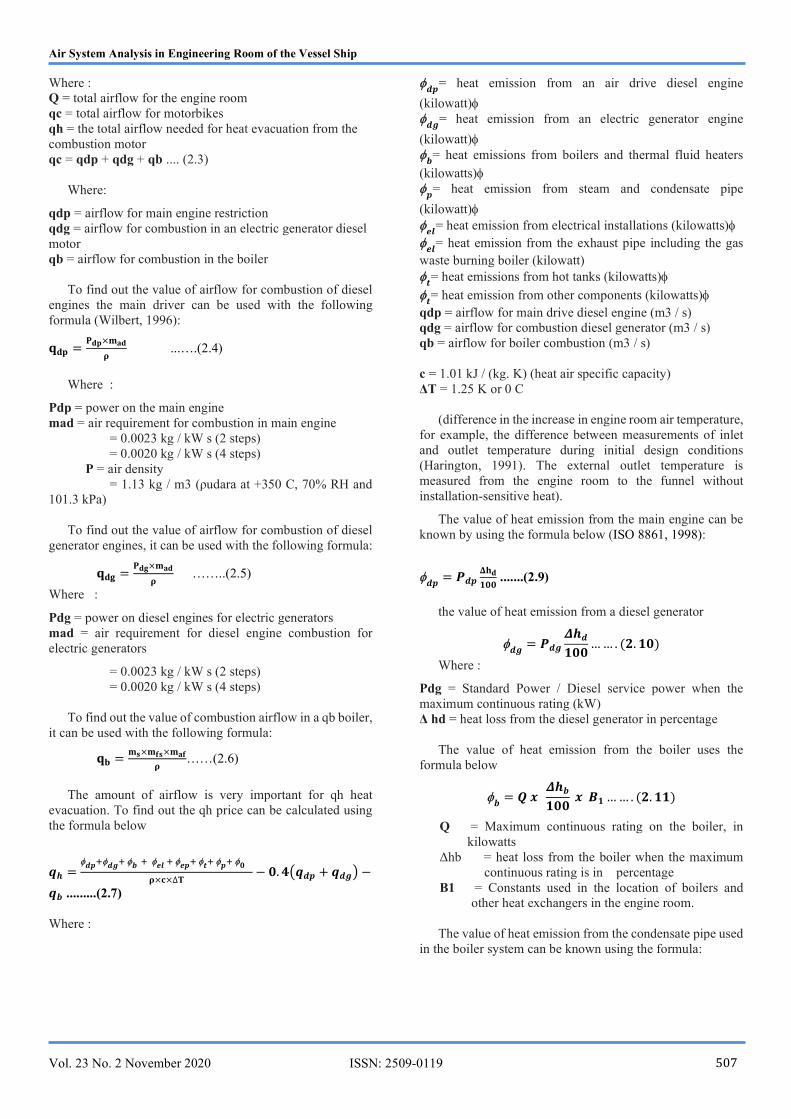
Where : Q = total airflow for the engine room qc = total airflow for motorbikes qh = the total airflow needed for heat evacuation from the combustion motor qc = qdp + qdg + qb .... (2.3)
Where:
qdp = airflow for main engine restriction qdg = airflow for combustion in an electric generator diesel motor qb = airflow for combustion in the boiler
To find out the value of airflow for combustion of diesel engines the main driver can be used with the following formula (Wilbert, 1996):
𝐪𝐝𝐩 =𝐏𝐝𝐩×𝐦𝐚𝐝
𝛒 ...….(2.4)
Where :
Pdp = power on the main engine mad = air requirement for combustion in main engine = 0.0023 kg / kW s (2 steps) = 0.0020 kg / kW s (4 steps) P = air density = 1.13 kg / m3 (ρudara at +350 C, 70% RH and 101.3 kPa)
To find out the value of airflow for combustion of diesel generator engines, it can be used with the following formula:
𝐪𝐝𝐠 =𝐏𝐝𝐠×𝐦𝐚𝐝
𝛒 ……..(2.5)
Where :
Pdg = power on diesel engines for electric generators mad = air requirement for diesel engine combustion for electric generators
= 0.0023 kg / kW s (2 steps) = 0.0020 kg / kW s (4 steps)
To find out the value of combustion airflow in a qb boiler, it can be used with the following formula:
𝐪𝐛 =𝐦𝐬×𝐦𝐟𝐬×𝐦𝐚𝐟
𝛒……(2.6)
The amount of airflow is very important for qh heat
evacuation. To find out the qh price can be calculated using the formula below
𝒒𝒉 =𝒅𝒑 𝒅𝒈 𝒃 𝒆𝒍 𝒆𝒑 𝒕 𝒑 𝟎
𝛒×𝐜×∆𝐓− 𝟎. 𝟒 𝒒𝒅𝒑 + 𝒒𝒅𝒈 −
𝒒𝒃 .........(2.7) Where :
𝒅𝒑
= heat emission from an air drive diesel engine
(kilowatt)
𝒅𝒈= heat emission from an electric generator engine
(kilowatt)
𝒃= heat emissions from boilers and thermal fluid heaters
(kilowatts)
𝒑= heat emission from steam and condensate pipe
(kilowatt)
𝒆𝒍= heat emission from electrical installations (kilowatts)
𝒆𝒍
= heat emission from the exhaust pipe including the gas waste burning boiler (kilowatt)
𝒕= heat emissions from hot tanks (kilowatts)
𝒕= heat emission from other components (kilowatts)
qdp = airflow for main drive diesel engine (m3 / s) qdg = airflow for combustion diesel generator (m3 / s) qb = airflow for boiler combustion (m3 / s) c = 1.01 kJ / (kg. K) (heat air specific capacity) ΔT = 1.25 K or 0 C
(difference in the increase in engine room air temperature, for example, the difference between measurements of inlet and outlet temperature during initial design conditions (Harington, 1991). The external outlet temperature is measured from the engine room to the funnel without installation-sensitive heat).
The value of heat emission from the main engine can be known by using the formula below (ISO 8861, 1998):
𝒅𝒑
= 𝑷𝒅𝒑𝚫𝐡𝐝
𝟏𝟎𝟎 .......(2.9)
the value of heat emission from a diesel generator
𝒅𝒈
= 𝑷𝒅𝒈
𝜟𝒉𝒅
𝟏𝟎𝟎… … . (𝟐. 𝟏𝟎)
Where :
Pdg = Standard Power / Diesel service power when the maximum continuous rating (kW) Δ hd = heat loss from the diesel generator in percentage
The value of heat emission from the boiler uses the formula below
𝒃
= 𝑸 𝒙 𝜟𝒉𝒃
𝟏𝟎𝟎 𝒙 𝑩𝟏 … … . (𝟐. 𝟏𝟏)
Q = Maximum continuous rating on the boiler, in kilowatts
Δhb = heat loss from the boiler when the maximum continuous rating is in percentage
B1 = Constants used in the location of boilers and other heat exchangers in the engine room.
The value of heat emission from the condensate pipe used
in the boiler system can be known using the formula:
Air System Analysis in Engineering Room of the Vessel Ship
Vol. 23 No. 2 November 2020 ISSN: 2509-0119 508
𝒑
= 𝒎𝒔𝒄 𝒙 𝜟𝒉𝒑
𝟏𝟎𝟎… … . (𝟐. 𝟏𝟐)
Where :
msc = Total steam consumption, in kW (1 kW ~ 1.6 kg / h steam)
Δhp = Heat loss from steam and condensate pipe, in the percentage of steam consumption, The value of heat emission from the electric generator can be calculated using the formula:
𝒈
= 𝑷𝒈 𝒙 𝟏 −𝜼
𝟏𝟎𝟎… … . . (𝟐. 𝟏𝟑)
Where : Pg = Power (power) owned by the generator with an air cooling system, in kW (Generators in stand-by position can be ignored)
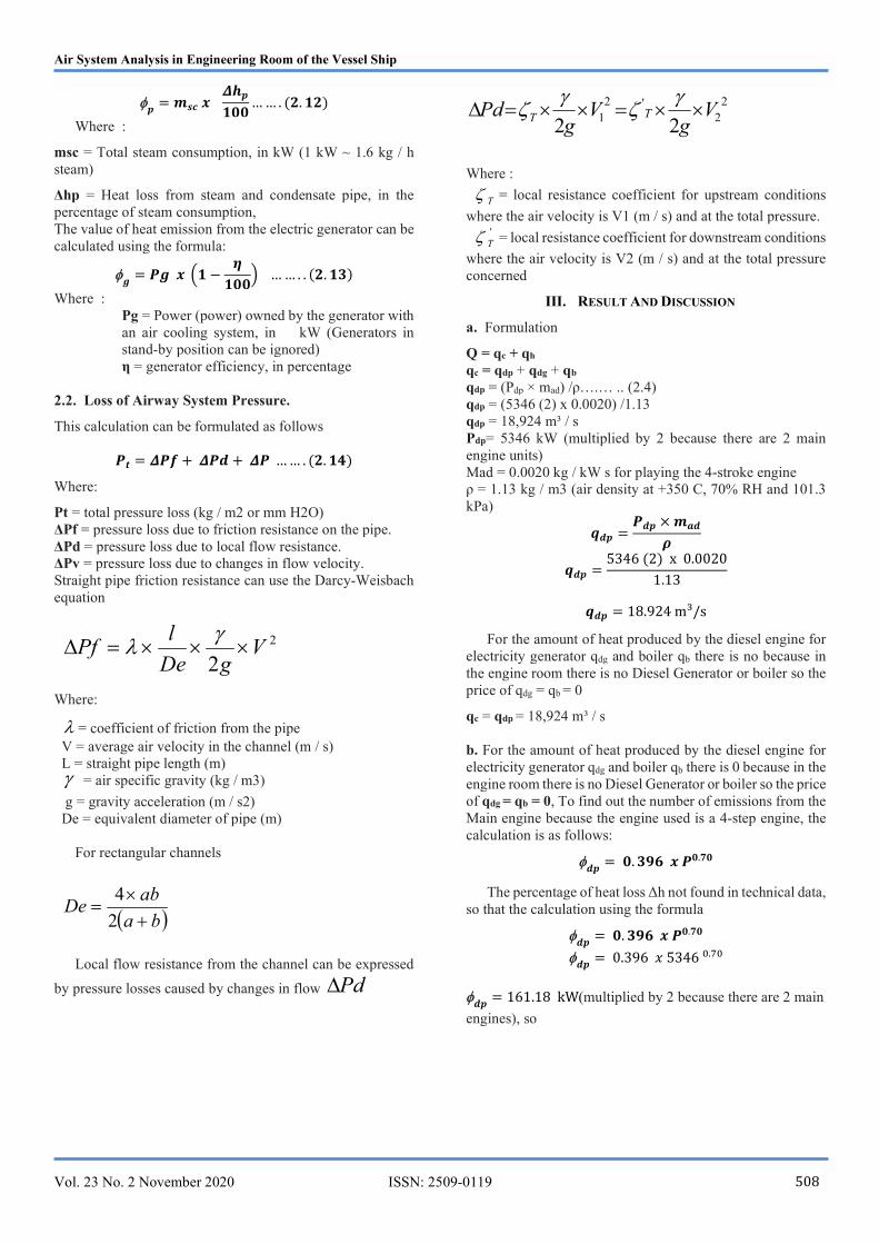
η = generator efficiency, in percentage 2.2. Loss of Airway System Pressure.
This calculation can be formulated as follows
𝑷𝒕 = 𝜟𝑷𝒇 + 𝜟𝑷𝒅 + 𝜟𝑷 … … . (𝟐. 𝟏𝟒)
Where:
Pt = total pressure loss (kg / m2 or mm H2O) ΔPf = pressure loss due to friction resistance on the pipe. ΔPd = pressure loss due to local flow resistance. ΔPv = pressure loss due to changes in flow velocity. Straight pipe friction resistance can use the Darcy-Weisbach equation
Where:
= coefficient of friction from the pipe V = average air velocity in the channel (m / s) L = straight pipe length (m) = air specific gravity (kg / m3)
g = gravity acceleration (m / s2) De = equivalent diameter of pipe (m)
For rectangular channels
Local flow resistance from the channel can be expressed
by pressure losses caused by changes in flow Pd
22
'21 22
Vg
Vg
Pd TT
Where :
T = local resistance coefficient for upstream conditions
where the air velocity is V1 (m / s) and at the total pressure.
'T = local resistance coefficient for downstream conditions
where the air velocity is V2 (m / s) and at the total pressure concerned
III. RESULT AND DISCUSSION
a. Formulation
Q = qc + qh qc = qdp + qdg + qb qdp = (Pdp × mad) /ρ….… .. (2.4) qdp = (5346 (2) x 0.0020) /1.13 qdp = 18,924 m³ / s Pdp= 5346 kW (multiplied by 2 because there are 2 main engine units) Mad = 0.0020 kg / kW s for playing the 4-stroke engine ρ = 1.13 kg / m3 (air density at +350 C, 70% RH and 101.3 kPa)
𝒒𝒅𝒑 =𝑷𝒅𝒑 × 𝒎𝒂𝒅
𝝆
𝒒𝒅𝒑 =5346 (2) x 0.0020
1.13
𝒒𝒅𝒑 = 18.924 m³/s
For the amount of heat produced by the diesel engine for electricity generator qdg and boiler qb there is no because in the engine room there is no Diesel Generator or boiler so the price of qdg = qb = 0
qc = qdp = 18,924 m³ / s b. For the amount of heat produced by the diesel engine for electricity generator qdg and boiler qb there is 0 because in the engine room there is no Diesel Generator or boiler so the price of qdg = qb = 0, To find out the number of emissions from the Main engine because the engine used is a 4-step engine, the calculation is as follows:
𝒅𝒑
= 𝟎. 𝟑𝟗𝟔 𝒙 𝑷𝟎.𝟕𝟎
The percentage of heat loss Δh not found in technical data, so that the calculation using the formula
𝒅𝒑
= 𝟎. 𝟑𝟗𝟔 𝒙 𝑷𝟎.𝟕𝟎
𝒅𝒑
= 0.396 𝑥 5346 .
𝒅𝒑
= 161.18 kW(multiplied by 2 because there are 2 main
engines), so
2
2V
gDe
lPf
ba
abDe
2
4
Air System Analysis in Engineering Room of the Vessel Ship
Vol. 23 No. 2 November 2020 ISSN: 2509-0119 509
𝒅𝒑
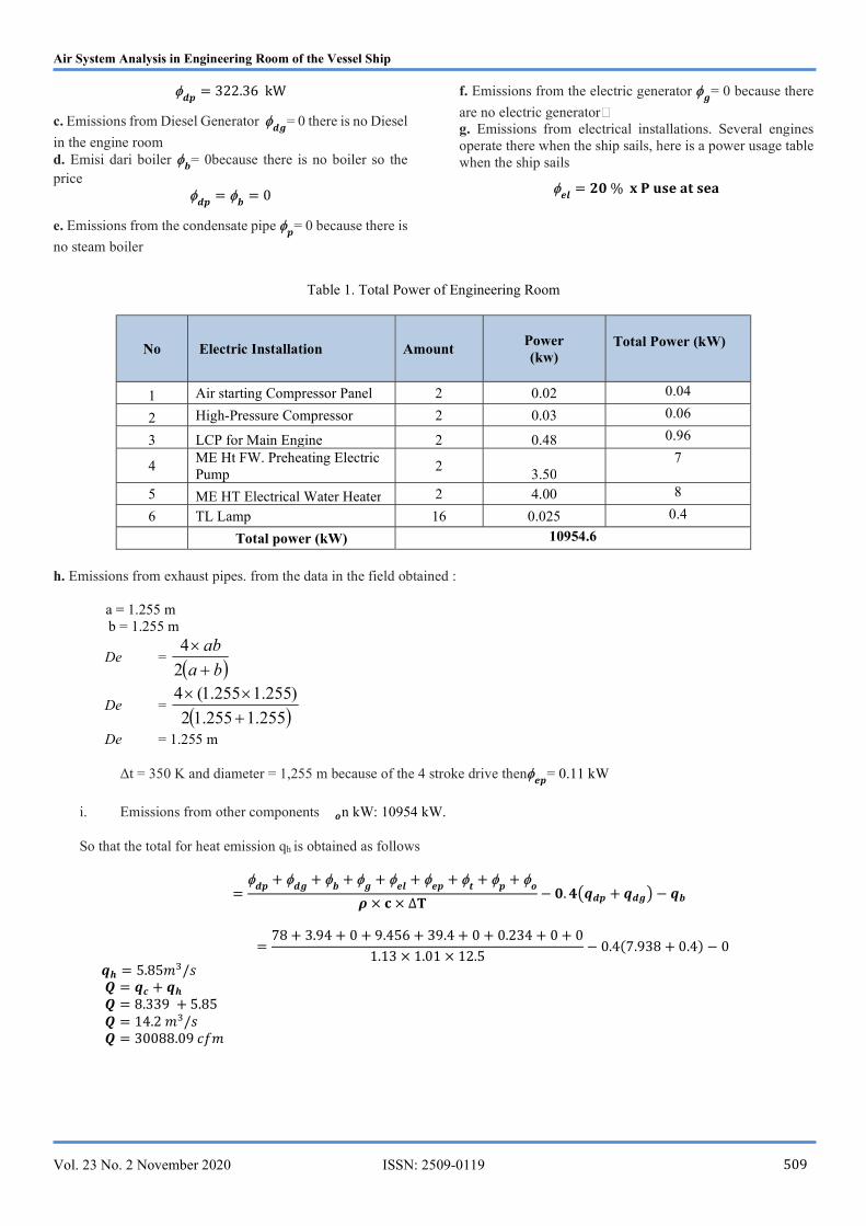
= 322.36 kW
c. Emissions from Diesel Generator 𝒅𝒈
= 0 there is no Diesel
in the engine room d. Emisi dari boiler
𝒃= 0because there is no boiler so the
price
𝒅𝒑=
𝒃= 0
e. Emissions from the condensate pipe 𝒑= 0 because there is
no steam boiler
f. Emissions from the electric generator 𝒈
= 0 because there
are no electric generator g. Emissions from electrical installations. Several engines operate there when the ship sails, here is a power usage table when the ship sails
𝒆𝒍
= 𝟐𝟎 % 𝐱 𝐏 𝐮𝐬𝐞 𝐚𝐭 𝐬𝐞𝐚
Table 1. Total Power of Engineering Room
No Electric Installation Amount Power (kw)
Total Power (kW)
1 Air starting Compressor Panel 2 0.02 0.04
2 High-Pressure Compressor 2 0.03 0.06
3 LCP for Main Engine 2 0.48 0.96
4 ME Ht FW. Preheating Electric Pump
2 3.50
7
5 ME HT Electrical Water Heater 2 4.00 8
6 TL Lamp 16 0.025 0.4
Total power (kW) 10954.6
h. Emissions from exhaust pipes. from the data in the field obtained :
a = 1.255 m b = 1.255 m
De = ba
ab
2
4
De = 255.1255.12
)255.1255.1(4
De = 1.255 m
Δt = 350 K and diameter = 1,255 m because of the 4 stroke drive then𝒆𝒑
= 0.11 kW
i. Emissions from other components 𝒐n kW: 10954 kW.
So that the total for heat emission qh is obtained as follows
=
𝒅𝒑+
𝒅𝒈+
𝒃+
𝒈+
𝒆𝒍+
𝒆𝒑+
𝒕+
𝒑+
𝒐
𝝆 × 𝐜 × ∆𝐓− 𝟎. 𝟒 𝒒𝒅𝒑 + 𝒒𝒅𝒈 − 𝒒𝒃
=78 + 3.94 + 0 + 9.456 + 39.4 + 0 + 0.234 + 0 + 0
1.13 × 1.01 × 12.5− 0.4(7.938 + 0.4) − 0
𝒒𝒉 = 5.85𝑚 /𝑠 𝑸 = 𝒒𝒄 + 𝒒𝒉 𝑸 = 8.339 + 5.85 𝑸 = 14.2 𝑚 /𝑠 𝑸 = 30088.09 𝑐𝑓𝑚
Air System Analysis in Engineering Room of the Vessel Ship
Vol. 23 No. 2 November 2020 ISSN: 2509-0119 510
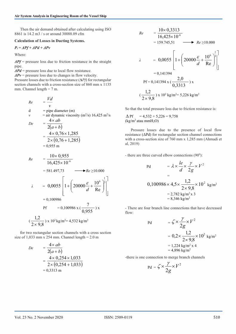
Then the air demand obtained after calculating using ISO
8861 is 14.2 m3 / s or around 30088.09 cfm
Calculation of Losses in Ducting Systems.
Pt = ΔPf + ΔPd + ΔPv
Where:
ΔPf = pressure loss due to friction resistance in the straight pipe. ΔPd = pressure loss due to local flow resistance. ΔPv = pressure loss due to changes in flow velocity. Pressure losses due to friction resistance (ΔPf) for rectangular section channels with a cross-section size of 860 mm x 1135 mm. Channel length = 7 m.
Re = v
Vd
d = pipe diameter (m) v = air dynamic viscosity (m2/s) 16,425 m2/s
De = ba
ab
2
4
= 1,2850,762
1,2850,764
= 0,955 m
Re = 1016,425
0,955106-
= 581.497,73 Re ≥10.000
λ =
3
16
Re
102000010055,0
d
= 0,100986
Pf = 0,100986 x ( 0,955
7) x
(8,92
2,1
) x 102 kg/m2= 4,532 kg/m2
for two rectangular section channels with a cross section size of 1,033 mm x 254 mm. Channel length = 2.0 m
De = ba
ab
2
4
= 033,10,2542
033,10,2544
= 0,3313 m
Re = 1016,425
0,3313106-
= 159.745,51 Re ≥10.000
λ =
3
16
Re
102000010055,0
d
= 0,141394
Pf = 0,141394 x ( 0,3313
0,2) x
(8,92
2,1
) x 102 kg/m2= 5,226 kg/m2
So that the total pressure loss due to friction resistance is:
Pf = 4,532 + 5,226 = 9,758 (kg/m2 atau mmH2O)
Pressure losses due to the presence of local flow resistance (ΔPd) for rectangular section channel connections with a cross-section size of 760 mm x 1,285 mm (Ahmadi et al, 2019)
- there are three curved elbow connections (900):
Pd = 2
2V
gd
le
=
2108,92
2,15,40,100986
kg/m2
= 2,782 kg/m2 x 3 = 8,346 kg/m2
- There are four branch line connections that have decreased flow:
Pd = 2
2V
g
= 210
8,92
2,12,0
kg/m2
= 1,224 kg/m2 x 4 = 4,896 kg/m2
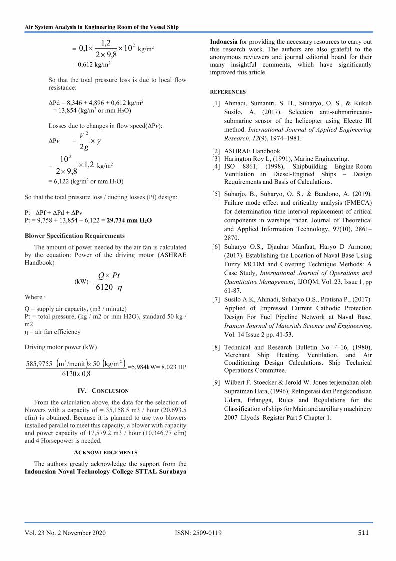
-there is one connection to merge branch channels
Pd = 2
2V
g
Air System Analysis in Engineering Room of the Vessel Ship
Vol. 23 No. 2 November 2020 ISSN: 2509-0119 511
= 210
8,92
2,11,0
kg/m2
= 0,612 kg/m2
So that the total pressure loss is due to local flow resistance: ΔPd = 8,346 + 4,896 + 0,612 kg/m2
= 13,854 (kg/m2 or mm H2O) Losses due to changes in flow speed(ΔPv):
ΔPv = g
V
2
2
= 2,18,92
102
kg/m2
= 6,122 (kg/m2 or mm H2O)
So that the total pressure loss / ducting losses (Pt) design:
Pt= ΔPf + ΔPd + ΔPv Pt = 9,758 + 13,854 + 6,122 = 29,734 mm H2O Blower Specification Requirements
The amount of power needed by the air fan is calculated by the equation: Power of the driving motor (ASHRAE Handbook)
(kW) =6120
PtQ
Where :
Q = supply air capacity, (m3 / minute) Pt = total pressure, (kg / m2 or mm H2O), standard 50 kg / m2 η = air fan efficiency Driving motor power (kW)
8,06120
kg/m 05/menitm 585,9755 23
=5,984kW= 8.023 HP
IV. CONCLUSION
From the calculation above, the data for the selection of blowers with a capacity of = 35,158.5 m3 / hour (20,693.5 cfm) is obtained. Because it is planned to use two blowers installed parallel to meet this capacity, a blower with capacity and power capacity of 17,579.2 m3 / hour (10,346.77 cfm) and 4 Horsepower is needed.
ACKNOWLEDGEMENTS
The authors greatly acknowledge the support from the Indonesian Naval Technology College STTAL Surabaya
Indonesia for providing the necessary resources to carry out this research work. The authors are also grateful to the anonymous reviewers and journal editorial board for their many insightful comments, which have significantly improved this article.
REFERENCES
[1] Ahmadi, Sumantri, S. H., Suharyo, O. S., & Kukuh Susilo, A. (2017). Selection anti-submarineanti-submarine sensor of the helicopter using Electre III method. International Journal of Applied Engineering Research, 12(9), 1974–1981.
[2] ASHRAE Handbook. [3] Harington Roy L, (1991), Marine Engineering. [4] ISO 8861, (1998), Shipbuilding Engine-Room
Ventilation in Diesel-Engined Ships – Design Requirements and Basis of Calculations.
[5] Suharjo, B., Suharyo, O. S., & Bandono, A. (2019). Failure mode effect and criticality analysis (FMECA) for determination time interval replacement of critical components in warships radar. Journal of Theoretical and Applied Information Technology, 97(10), 2861–2870.
[6] Suharyo O.S., Djauhar Manfaat, Haryo D Armono, (2017). Establishing the Location of Naval Base Using Fuzzy MCDM and Covering Technique Methods: A Case Study, International Journal of Operations and Quantitative Management, IJOQM, Vol. 23, Issue 1, pp 61-87.
[7] Susilo A.K, Ahmadi, Suharyo O.S., Pratisna P., (2017). Applied of Impressed Current Cathodic Protection Design For Fuel Pipeline Network at Naval Base, Iranian Journal of Materials Science and Engineering, Vol. 14 Issue 2 pp. 41-53.
[8] Technical and Research Bulletin No. 4-16, (1980), Merchant Ship Heating, Ventilation, and Air Conditioning Design Calculations. Ship Technical Operations Committee.
[9] Wilbert F. Stoecker & Jerold W. Jones terjemahan oleh Supratman Hara, (1996), Refrigerasi dan Pengkondisian Udara, Erlangga, Rules and Regulations for the Classification of ships for Main and auxiliary machinery 2007 Llyods Register Part 5 Chapter 1.