Air Preparation Units - Filters, Regulators, and Lubricators
116
Air Preparation Units Filters, Regulators, and Lubricators
-
Upload
khangminh22 -
Category
Documents
-
view
0 -
download
0
Transcript of Air Preparation Units - Filters, Regulators, and Lubricators

Air Preparation UnitsFilters, Regulators, and Lubricators
Parker Hannifin CorporationFinite Filter OperationOxford, MIwww.parker.com/finitefilter
2
Bulletin 1300-703-08/USA-0914
Parker Hannifin Corporation
CAUTION:Polycarbonate bowls and sight domes, being transparent and tough, are ideal for use with Filters and Lubricators. They are suitable for use in normal industrial environments, but should not be located in areas where they could be subjected to direct sunlight, an impact blow, nor temperatures outside of the rated range. As with most plastics, some chemicals can cause damage. Polycarbonate bowls and sight domes should not be exposed to chlorinated hydro-carbons, ketones, esters and certain alcohols. They should not be used in air systems where compressors are lubricated with fire-resistant fluids such as phosphate ester and di-ester types.
Metal bowls are recommended where ambient and/or media conditions are not compatible with polycarbonate bowls. Metal bowls resist the action of most such solvents, but should not be used where strong acids or bases are present or in salt laden atmospheres. Consult the factory for specific recommendations where these conditions exist.
TO CLEAN POLYCARBONATE COMPONENTS USE MILD SOAP AND WATER ONLY! DO NOT use cleansing agents such as acetone, benzene, carbon tetrachloride, gasoline, toluene, etc., which are damaging to this plastic.
Metal bowl guards are recommended for all applications.
CAUTION:REGULATOR PRESSURE ADJUSTMENT – The working range of knob adjustment is designed to permit outlet pressures within their full range. Pressure adjustment beyond this range is also possible because the knob is not a limiting device. This is a common characteristic of most industrial regulators, and limiting devices may be obtained only by special design.
!
!
Parker Hannifin CorporationFinite Filter OperationOxford, MIwww.parker.com/finitefilter
2
Air Preparation UnitsBulletin 1300-703-08/USA
Parker Hannifin Corporation
CAUTION:Polycarbonate bowls and sight domes, being transparent and tough, are ideal for use with Filters and Lubricators. They are suitable for use in normal industrial environments, but should not be located in areas where they could be subjected to direct sunlight, an impact blow, nor temperatures outside of the rated range. As with most plastics, some chemicals can cause damage. Polycarbonate bowls and sight domes should not be exposed to chlorinated hydro-carbons, ketones, esters and certain alcohols. They should not be used in air systems where compressors are lubricated with fire-resistant fluids such as phosphate ester and di-ester types.
Metal bowls are recommended where ambient and/or media conditions are not compatible with polycarbonate bowls. Metal bowls resist the action of most such solvents, but should not be used where strong acids or bases are present or in salt laden atmospheres. Consult the factory for specific recommendations where these conditions exist.
TO CLEAN POLYCARBONATE COMPONENTS USE MILD SOAP AND WATER ONLY! DO NOT use cleansing agents such as acetone, benzene, carbon tetrachloride, gasoline, toluene, etc., which are damaging to this plastic.
Metal bowl guards are recommended for all applications.
CAUTION:REGULATOR PRESSURE ADJUSTMENT – The working range of knob adjustment is designed to permit outlet pressures within their full range. Pressure adjustment beyond this range is also possible because the knob is not a limiting device. This is a common characteristic of most industrial regulators, and limiting devices may be obtained only by special design.
!
!
We are dedicated to fulfilling your compressed air filtration requirements. We know that every application
requires specific needs and we have the products ready to address them.
If you can’t find a specific compressed air/gas filter, dryer, or accessory in this catalog, call 1-800-521-4357.
Our knowledgeable technical assistance department will be happy to assist you!
Inquires via e-mail are also encouraged. E-mail inquiries to [email protected]. We can provide solutions that will remove contaminants
such as oil, water and particulate from your compressed air and gas lines, saving you time and money!
We are dedicated to fulfilling your compressed air filtration requirements. We know that every application
requires specific needs and we have the products ready to address them.
Inquiries via e-mail are also encouraged. E-mail inquiries to [email protected]. We can provide solutions that will remove contaminants such as oil, water and particulate from your compressed air and
gas lines, saving you time and money!
If you can't find a specific compressed air/gas filter, dryer, or accessory in this catalog, call 1-800-521-4357.Our knowledgeable technical assistance department
will be happy to assist you!

Parker Hannifin CorporationFinite Filter OperationOxford, MIwww.parker.com/finitefilter
33
Table of ContentsTitle Page Number
Product Selection
Drains and Symbol Chart
Air Line Filters
Air Line Coalescing Filters
Air Line Regulators
Filter / Regulator "Piggybacks"
Air Line Lubricators, Micro-Mist
Air Line Lubricators, Mist
Combinations & Accessories
4-5
6-7
8-23
24-37
38-57
58-75
76-83
84-91
Mounting Brackets Kits
Other Products from Parker
Notes
Offer of Sale
14A / 14G
15A / 15G / 15B / 15H
15 Modular Accessories
16G / 16A / 17G / 17A
16H / 16B / 17H / 17B
16 / 17 Modular Accessories
P3N
P3N Accessories
92-93
94-97
98-99
100-101
102-103
104-105
106-109
110
111
112-113
114
115
Bulletin 1300-703-08/USA-0914
Parker Hannifin Corporation

Parker Hannifin CorporationFinite Filter OperationOxford, MIwww.parker.com/finitefilter
4
Basic Unit
Series
Port Size Bowls
Capacity
Elements
(Micron)Page
1/8 1/4 3/8 1/2 3/4 1 1-1/2 Poly MetalMetal SG*
5
F I L T E R S
14F X X X X N/A 1 oz. Standard 10
FF504 X 316 Stainless Steel 1 oz. Standard 14
05F X X X N/A X 2 oz. Standard 16
06F X X X X N/A X 4.4 oz. Standard 18
FF10 X 316 Stainless Steel 4 oz. Standard 20
07F X X X X N/A X 7.2 oz. Standard 22
P3NF X X X N/A N/A X 18 oz. Standard 24
C O A L E S C E R S
Q*S, H*S
X X X X N/A 1 oz.Grade 6 Std., Grade 10 Opt.
26
FF501 X 316 Stainless Steel 1 oz. 0.3 Micron 28
15F X X X X X 2 oz.Grade 6 Std., Grade 10 Opt.
30
11F X X X X X X 4.4 oz.Grade 6 Std., Grade 10 Opt.
32
FF11 X 316 Stainless Steel 4 oz. 0.3 Micron 34
12F X X X X X X 7.2 oz.Grade 6 Std., Grade 10 Opt.
36
Product Selection Chart
Basic Unit
SeriesPort Size Spring
Page1/8 1/4 3/8 1/2 3/4 1 1-1/2 125
R E G U L A T O R S
S T A N D A R D
14R X X Std. 40
FR364 X Std. 42
05R X X Std. 44
06R X X X Std. 46
FR10 X Std. 48
07R X X X Std. 50
P3NR X X X Std. 52
P I L O T
11R X X X - 54
12R X X X - 56
*sight gauge
Bulletin 1300-703-08/USA-0914
Selection Chart Air Preparation Units

Parker Hannifin CorporationFinite Filter OperationOxford, MIwww.parker.com/finitefilter
55
Product Selection Chart
Basic Unit
Series
Port Size Bowls
Capacity
Elements (Micron)
Spring Range
Page
1/8 1/4 3/8 1/2 3/4 1 1-1/2 Poly MetalMetal SG*
5 125
F I L T E R / R E G U L A T O R S
14E X X X X N/A 1 oz. Std. Std. 60
F10E X X X X N/A 1 oz.
Grade 6 Standard; Grade 10 Optional
Std. 62
FB548 X316 Stainless
Steel1 oz.
Grade 6 Standard; Grade 10 Optional
Std. 64
05E X X X X X 2 oz. Std. Std. 6606E X X X X X X 4.4 oz. Std. Std. 68
FB11 X316 Stainless
Steel4 oz. Std. Std. 70
07E X X X X X X 7.2 oz. Std. Std. 72
F12E X X X N/A X N/A 7.2 oz.
Grade 6 Standard; Grade 10 Optional
Std. 74
L U B R I C A T O R S
M I C R O
M I S T
15L X X X N/A X 2 oz.Cannot be filled under
pressure78
16L X X X X N/A X 2.6 oz.Cannot be filled under
pressure80
17L X X X X N/A X 4.9 oz.Cannot be filled under
pressure82
M I S T
04L X X X X N/A 1 oz.Cannot be filled under
pressure86
FL10 X316 Stainless
Steel4 oz. 88
P3NL X X X N/A N/A X 18 oz.Can be filled under
perssure90
C O M B O S
N I P P L E D
14G X X X N/A 1 oz. Two-Unit Std.92
14A X X X N/A 1 oz. Three-Unit Std.
15G X X X N/A X 2 oz. Two-Unit Std.94
15A X X X N/A X 2 oz. Three-Unit Std.
16G X X X X N/A X 2 oz. Two-Unit Std.
10016A X X X X N/A X 2 oz. Three-Unit Std.
17G X X X X N/A X 2 oz. Two-Unit Std.
17A X X X X N/A X 2 oz. Three-Unit Std.
P3N3B X X X N/A N/A X 18 oz. Three-Unit Std. 106
M O D U L A R
15H X X X N/A X 2 oz. Two-Unit Std.96
15B X X X N/A X 2 oz. Three-Unit Std.
16H X X X X N/A X 2 oz. Two-Unit Std.
10216B X X X X N/A X 2 oz. Three-Unit Std.
17H X X X X N/A X 2 oz. Two-Unit Std.
17B X X X X N/A X 2 oz. Three-Unit Std.
P3NCB X X X N/A N/A X 18 oz. Three-Unit Std. 108
*sight gauge
Bulletin 1300-703-08/USA-0914
Selection Chart Air Preparation Units

Parker Hannifin CorporationFinite Filter OperationOxford, MIwww.parker.com/finitefilter
6
(Spitter Drain)
The diaphragm in this drain pulses when there is a pressure differential such as a valve cycling or cylinder stroking downstream. This action flexes the diaphragm and allows the filter to drain the entrapped water.
The float internal to this drain rises with increased liquid level. When the float rises, it opens a seat area allowing the trapped liquids to drain through the bottom. A manual override can be pushed in the bottom of the drain to unseat the float if particulates create a block.
1/8" NPTAccepts1/8 I.D. Tubing
Accepts3/16 I.D. Tubing
Drains
Automatic Pulse Drain Automatic Float Drain
Bulletin 1300-703-08/USA-0914
Drains Air Preparation Units
Parker Hannifin CorporationFinite Filter OperationOxford, MIwww.parker.com/finitefilter
77
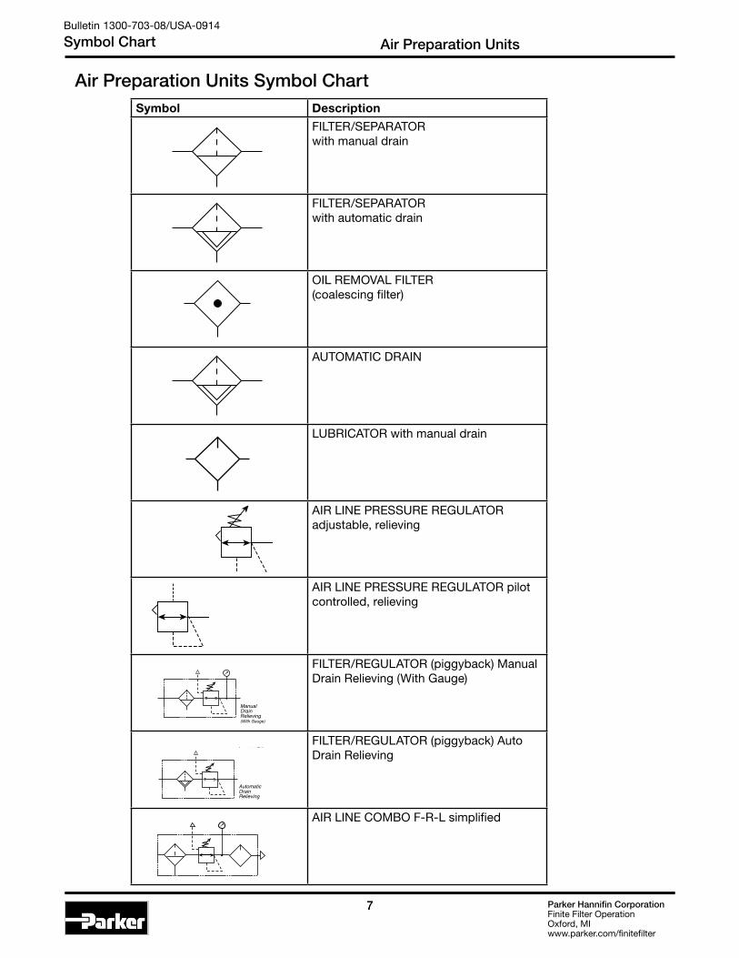
Air Preparation Units Symbol Chart
Bulletin 1300-703-08/USA-0914
Symbol Chart Air Preparation Units
Symbol Description
Parker Hannifin CorporationFinite Filter OperationOxford, MIwww.parker.com/finitefilter
7
Symbol Description
FILTER/SEPARATOR with manual drain
FILTER/SEPARATOR with automatic drain
OIL REMOvAL FILTER
(coalescing filter)
AUTOMATIC DRAIN
LUBRICATOR with manual drain
AIR LINE PRESSURE REGULATOR adjustable, relieving
AIR LINE PRESSURE REGULATOR pilot controlled, relieving
FILTER/REGULATOR (piggyback) Manual Drain Relieving (With Gauge)
FILTER/REGULATOR (piggyback) Auto Drain Relieving
AIR LINE COMBO
F-R-L simplified
Air Preparation Units Symbol Chart
➤
➤
➤
➤
➤
➤
➤
ManualDrainRelieving(With Gauge)
AutomaticDrainRelieving
➤
➤
➤
➤
➤
➤
➤
ManualDrainRelieving(With Gauge)
AutomaticDrainRelieving
FILTER/SEPARATOR with manual drain
Parker Hannifin CorporationFinite Filter OperationOxford, MIwww.parker.com/finitefilter
7
Symbol Description
FILTER/SEPARATOR with manual drain
FILTER/SEPARATOR with automatic drain
OIL REMOvAL FILTER
(coalescing filter)
AUTOMATIC DRAIN
LUBRICATOR with manual drain
AIR LINE PRESSURE REGULATOR adjustable, relieving
AIR LINE PRESSURE REGULATOR pilot controlled, relieving
FILTER/REGULATOR (piggyback) Manual Drain Relieving (With Gauge)
FILTER/REGULATOR (piggyback) Auto Drain Relieving
AIR LINE COMBO
F-R-L simplified
Air Preparation Units Symbol Chart
➤
➤
➤
➤
➤
➤
➤
ManualDrainRelieving(With Gauge)
AutomaticDrainRelieving
➤
➤
➤
➤
➤
➤
➤
ManualDrainRelieving(With Gauge)
AutomaticDrainRelieving
FILTER/SEPARATOR with automatic drain
Parker Hannifin CorporationFinite Filter OperationOxford, MIwww.parker.com/finitefilter
7
Symbol Description
FILTER/SEPARATOR with manual drain
FILTER/SEPARATOR with automatic drain
OIL REMOvAL FILTER
(coalescing filter)
AUTOMATIC DRAIN
LUBRICATOR with manual drain
AIR LINE PRESSURE REGULATOR adjustable, relieving
AIR LINE PRESSURE REGULATOR pilot controlled, relieving
FILTER/REGULATOR (piggyback) Manual Drain Relieving (With Gauge)
FILTER/REGULATOR (piggyback) Auto Drain Relieving
AIR LINE COMBO
F-R-L simplified
Air Preparation Units Symbol Chart
➤
➤
➤
➤
➤
➤
➤
ManualDrainRelieving(With Gauge)
AutomaticDrainRelieving
➤
➤
➤
➤
➤
➤
➤
ManualDrainRelieving(With Gauge)
AutomaticDrainRelieving
OIL REMOVAL FILTER (coalescing filter)
Parker Hannifin CorporationFinite Filter OperationOxford, MIwww.parker.com/finitefilter
7
Symbol Description
FILTER/SEPARATOR with manual drain
FILTER/SEPARATOR with automatic drain
OIL REMOvAL FILTER
(coalescing filter)
AUTOMATIC DRAIN
LUBRICATOR with manual drain
AIR LINE PRESSURE REGULATOR adjustable, relieving
AIR LINE PRESSURE REGULATOR pilot controlled, relieving
FILTER/REGULATOR (piggyback) Manual Drain Relieving (With Gauge)
FILTER/REGULATOR (piggyback) Auto Drain Relieving
AIR LINE COMBO
F-R-L simplified
Air Preparation Units Symbol Chart
➤
➤
➤
➤
➤
➤
➤
ManualDrainRelieving(With Gauge)
AutomaticDrainRelieving
➤
➤
➤
➤
➤
➤
➤
ManualDrainRelieving(With Gauge)
AutomaticDrainRelieving
AUTOMATIC DRAIN
Parker Hannifin CorporationFinite Filter OperationOxford, MIwww.parker.com/finitefilter
7
Symbol Description
FILTER/SEPARATOR with manual drain
FILTER/SEPARATOR with automatic drain
OIL REMOvAL FILTER
(coalescing filter)
AUTOMATIC DRAIN
LUBRICATOR with manual drain
AIR LINE PRESSURE REGULATOR adjustable, relieving
AIR LINE PRESSURE REGULATOR pilot controlled, relieving
FILTER/REGULATOR (piggyback) Manual Drain Relieving (With Gauge)
FILTER/REGULATOR (piggyback) Auto Drain Relieving
AIR LINE COMBO
F-R-L simplified
Air Preparation Units Symbol Chart
➤
➤
➤
➤
➤
➤
➤
ManualDrainRelieving(With Gauge)
AutomaticDrainRelieving
➤
➤
➤
➤
➤
➤
➤
ManualDrainRelieving(With Gauge)
AutomaticDrainRelieving
LUBRICATOR with manual drain
Parker Hannifin CorporationFinite Filter OperationOxford, MIwww.parker.com/finitefilter
7
Symbol Description
FILTER/SEPARATOR with manual drain
FILTER/SEPARATOR with automatic drain
OIL REMOvAL FILTER
(coalescing filter)
AUTOMATIC DRAIN
LUBRICATOR with manual drain
AIR LINE PRESSURE REGULATOR adjustable, relieving
AIR LINE PRESSURE REGULATOR pilot controlled, relieving
FILTER/REGULATOR (piggyback) Manual Drain Relieving (With Gauge)
FILTER/REGULATOR (piggyback) Auto Drain Relieving
AIR LINE COMBO
F-R-L simplified
Air Preparation Units Symbol Chart
➤
➤
➤
➤
➤
➤
➤
ManualDrainRelieving(With Gauge)
AutomaticDrainRelieving
➤
➤
➤
➤
➤
➤
➤
ManualDrainRelieving(With Gauge)
AutomaticDrainRelieving
AIR LINE PRESSURE REGULATOR adjustable, relieving
Parker Hannifin CorporationFinite Filter OperationOxford, MIwww.parker.com/finitefilter
7
Symbol Description
FILTER/SEPARATOR with manual drain
FILTER/SEPARATOR with automatic drain
OIL REMOvAL FILTER
(coalescing filter)
AUTOMATIC DRAIN
LUBRICATOR with manual drain
AIR LINE PRESSURE REGULATOR adjustable, relieving
AIR LINE PRESSURE REGULATOR pilot controlled, relieving
FILTER/REGULATOR (piggyback) Manual Drain Relieving (With Gauge)
FILTER/REGULATOR (piggyback) Auto Drain Relieving
AIR LINE COMBO
F-R-L simplified
Air Preparation Units Symbol Chart
➤
➤
➤
➤
➤
➤
➤
ManualDrainRelieving(With Gauge)
AutomaticDrainRelieving
➤
➤
➤
➤
➤
➤
➤
ManualDrainRelieving(With Gauge)
AutomaticDrainRelieving
AIR LINE PRESSURE REGULATOR pilot controlled, relieving
Parker Hannifin CorporationFinite Filter OperationOxford, MIwww.parker.com/finitefilter
7
Symbol Description
FILTER/SEPARATOR with manual drain
FILTER/SEPARATOR with automatic drain
OIL REMOvAL FILTER
(coalescing filter)
AUTOMATIC DRAIN
LUBRICATOR with manual drain
AIR LINE PRESSURE REGULATOR adjustable, relieving
AIR LINE PRESSURE REGULATOR pilot controlled, relieving
FILTER/REGULATOR (piggyback) Manual Drain Relieving (With Gauge)
FILTER/REGULATOR (piggyback) Auto Drain Relieving
AIR LINE COMBO
F-R-L simplified
Air Preparation Units Symbol Chart
➤
➤
➤
➤
➤
➤
➤
ManualDrainRelieving(With Gauge)
AutomaticDrainRelieving
➤
➤
➤
➤
➤
➤
➤
ManualDrainRelieving(With Gauge)
AutomaticDrainRelieving
FILTER/REGULATOR (piggyback) Manual Drain Relieving (With Gauge)
Parker Hannifin CorporationFinite Filter OperationOxford, MIwww.parker.com/finitefilter
7
Symbol Description
FILTER/SEPARATOR with manual drain
FILTER/SEPARATOR with automatic drain
OIL REMOvAL FILTER
(coalescing filter)
AUTOMATIC DRAIN
LUBRICATOR with manual drain
AIR LINE PRESSURE REGULATOR adjustable, relieving
AIR LINE PRESSURE REGULATOR pilot controlled, relieving
FILTER/REGULATOR (piggyback) Manual Drain Relieving (With Gauge)
FILTER/REGULATOR (piggyback) Auto Drain Relieving
AIR LINE COMBO
F-R-L simplified
Air Preparation Units Symbol Chart
➤
➤
➤
➤
➤
➤
➤
ManualDrainRelieving(With Gauge)
AutomaticDrainRelieving
➤
➤
➤
➤
➤
➤
➤
ManualDrainRelieving(With Gauge)
AutomaticDrainRelieving
FILTER/REGULATOR (piggyback) Auto Drain Relieving
Parker Hannifin CorporationFinite Filter OperationOxford, MIwww.parker.com/finitefilter
7
Symbol Description
FILTER/SEPARATOR with manual drain
FILTER/SEPARATOR with automatic drain
OIL REMOvAL FILTER
(coalescing filter)
AUTOMATIC DRAIN
LUBRICATOR with manual drain
AIR LINE PRESSURE REGULATOR adjustable, relieving
AIR LINE PRESSURE REGULATOR pilot controlled, relieving
FILTER/REGULATOR (piggyback) Manual Drain Relieving (With Gauge)
FILTER/REGULATOR (piggyback) Auto Drain Relieving
AIR LINE COMBO
F-R-L simplified
Air Preparation Units Symbol Chart
➤
➤
➤
➤
➤
➤
➤
ManualDrainRelieving(With Gauge)
AutomaticDrainRelieving
➤
➤
➤
➤
➤
➤
➤
ManualDrainRelieving(With Gauge)
AutomaticDrainRelieving
AIR LINE COMBO F-R-L simplified

Parker Hannifin CorporationFinite Filter OperationOxford, MIwww.parker.com/finitefilter
8
AutomaticDrain
TwistDrain
Air Preparation Units
Bulletin 1300-703-08/USA-0914
Air Line Filters
Filters
• Pipe Sizes 1/8 thru 1½ Inch
• Flows to 310 SCFM
• Pressures to 250 PSIG
Air filters are designed to remove airborne solid contaminants, pipe scale, rust, pipe dope, etc., which may plug small orifices or cause excessive wear and premature failure of pneumatic components.
• Miniature 14F Series, 1/8 and 1/4 Inch
• Miniature FF504 Stainless Series, 1/4 Inch
• Economy 05F Series, 1/4 and 3/8 Inch
• Compact 06F Series, 1/4, 3/8 and 1/2 Inch
• Standard 07F Series, 3/8, 1/2 and 3/4 Inch
• Standard FF10 Stainless Series, 1/2 Inch
• Hi-Flow P3NF Series, 3/4, 1 and 1-1/2 Inch
Filter Selection1. Determine maximum system flow
requirements.
2. Determine maximum allowable pressure drop at rated flow in SCFM.
3. Refer to flow chart and select filter pipe size by choosing curve that offers minimum pressure drop at desired flow in SCFM. For optimum performance, a 2 to 5 PSIG pressure drop should be selected.
Reading Flow Charts to Size Filters
0
1
2
3
4
5
6
7
8
10
9
0 20 40 60 80 100 120 140
Pres
sure
Dro
p - P
SIG
35 PSIG 90 PSIG 150 PSIGPrimary Pressure - PSIG
2.4 bar 6.2 bar 10.3 barPrimary Pressure - bar
0
.1
0 10 20 30 40 50 60
Flow - SCFM
Flow - dm /s
Pres
sure
Dro
p - b
ar
3
n
.2
.3
.4
.5
.6
Flow Characteristics05F22B*
3/8 Inch Ports
Once the required flow is determined for a pneumatic application, the filter can be selected by using the flow chart. To read the filter flow chart, first determine the inlet pressure that will be used. Find the appropriate pressure curve on the graph. Each graph will contain three pressure curves. If the required inlet pressure is not on the graph, interpolate a similar curve for the required pressure. Next, determine the acceptable pressure drop across the filter and locate it on the vertical axis. Find the intersection point of the acceptable pressure drop and the inlet pressure curve. At this point follow a vertical path downward to view the flow in SCFM. If the flow is too low, select a larger port size or body size to give the required flow. If the flow is higher than necessary, select a smaller port size or body size to give the required flow.

Parker Hannifin CorporationFinite Filter OperationOxford, MIwww.parker.com/finitefilter
99
A
D
E
F
G
B
Bowl shownrotated 90°for illustrationpurposes
AB
G
ED
F
Air Preparation UnitsBulletin 1300-703-08/USA-0914
Air Line Filters
14F
A
CBD
FG
E
A
C
BD
FG
E
05F06F / 07F
First Stage Filtration:Air enters at inlet port and flows through deflector plate (A) which causes a swirling action. Liquids and coarse particles are forced to the bowl interior wall (B) by the centrifugal action of the swirling air. They then carry down the bowl wall by the force of gravity. Shroud (C) assures that the proper swirling action occurs and that the air does not pass directly through the filter element (D) until the large particles and liquids are removed. The baffle (E) separates the lower portion of the bowl into a “quiet zone” where the removed liquids and particles collect, unaffected by the swirling air, and are therefore not reentrained into the flowing air.
Second Stage Filtration:After liquids and large particles are removed in the first stage of filtration, the air flows through element (D) where smaller particles are filtered out and retained. The filtered air then passes downstream. Collected liquids and particles in the “quiet zone” should be drained before their level reaches a height where they would be reentrained in the flowing air. This can be accomplished by the twist drain (F) which is actuated by twisting knob (G) counterclockwise.
P3NF
AB
D
FE
F504
AB
C
F
D
F10

Parker Hannifin CorporationFinite Filter OperationOxford, MIwww.parker.com/finitefilter
10
AutomaticDrain
TwistDrain
Features• Excellent water removal efficiency.
• Unique deflector plate that creates swirling of the air stream ensuring maximum water and dirt separation.
• Easily disassembled for servicing without the use of tools.
• 5 micron element standard.
• Interchangable Twist and Automatic Pulse Drains.
• High Flow: 1/8" – 22 SCFM§
1/4" – 24 SCFM§
14F Filters – Miniature
14F Series1/8", 1/4" NPT – Basic 1/8" Body
Bulletin 1300-703-08/USA-0914
Miniature 14F Series
A
B
DE
C
Distance RequiredTo Remove All BowlsRegardless OfDrain Option
F
Bowl Options
Polycarbonate Bowl 1 Twist Drain 5 Automatic Pulse Drain
Metal Bowl 3 Twist Drain 7 Automatic Pulse Drain
14F 1 1 B * —
Elements
B 5 Micron
Port Size
0 1/8 Inch 1 1/4 Inch
‡ For polycarbonate bowl see Caution on page 2.§ SCFM = Standard cubic feet per minute at 90 PSIG inlet and 5 PSIG
pressure drop.
Ordering Information
Port Type
Blank NPT
Engineering Level
* Will be entered at factory
Accepts1/8" Tubing
Automatic Drain
14F Filter Dimensions
A1.69(43)
B1.53(39)
C.39(10)
D3.82(97)
D†
3.87(99)
E4.21(107)
E†
4.26(108)
F1.60(41)
Port Size
NPT
Twist Drain Automatic Pulse Drain
Poly Bowl ‡
1/8" 14F01B* 14F05B*
1/4" 14F11B* 14F15B*
Metal Bowl without Sight Gauge
1/8" 14F03B* 14F07B*
1/4" 14F13B* 14F17B*
Inches (mm)
† With Automatic Pulse Drain.
Parker Hannifin CorporationFinite Filter OperationOxford, MIwww.parker.com/finitefilter
1111
14F SeriesAir Line Filters
Bulletin 1300-703-08/USA-0914
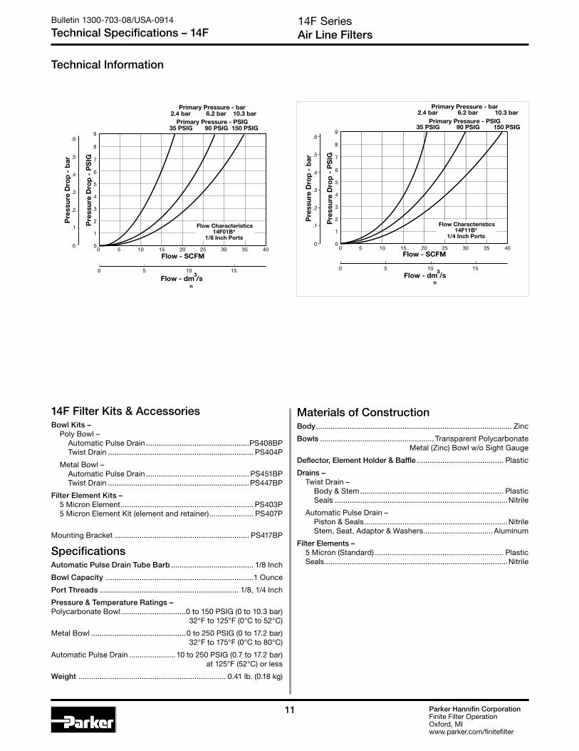
Technical Specifications – 14F
14F Filter Kits & AccessoriesBowl Kits – Poly Bowl – Automatic Pulse Drain .................................................PS408BP Twist Drain ..................................................................... PS404P
Metal Bowl – Automatic Pulse Drain ................................................. PS451BP Twist Drain ...................................................................PS447BP
Filter Element Kits – 5 Micron Element ............................................................... PS403P 5 Micron Element Kit (element and retainer) ..................... PS407P
Mounting Bracket ................................................................ PS417BP
SpecificationsAutomatic Pulse Drain Tube Barb ....................................... 1/8 Inch
Bowl Capacity ......................................................................1 Ounce
Port Threads .................................................................. 1/8, 1/4 Inch
Pressure & Temperature Ratings – Polycarbonate Bowl ...............................0 to 150 PSIG (0 to 10.3 bar) 32°F to 125°F (0°C to 52°C)
Metal Bowl .............................................0 to 250 PSIG (0 to 17.2 bar) 32°F to 175°F (0°C to 80°C)
Automatic Pulse Drain ...................... 10 to 250 PSIG (0.7 to 17.2 bar) at 125°F (52°C) or less
Weight ...................................................................... 0.41 lb. (0.18 kg)
Flow - SCFM
Pre
ssur
e D
rop
- P
SIG
Pre
ssur
e D
rop
- b
ar
35 PSIG 90 PSIG 150 PSIGPrimary Pressure - PSIG
2.4 bar 6.2 bar 10.3 barPrimary Pressure - bar
Flow - dm /s3
n
0 50
1
2
3
4
5
6
7
8
9
10 15 20 25 30 35 40
0 5 10 15
0
.1
.2
.3
.4
.5
.6
Flow Characteristics14F01B*
1/8 Inch Ports
Technical Information
Materials of ConstructionBody ............................................................................................. Zinc
Bowls ...................................................... Transparent Polycarbonate Metal (Zinc) Bowl w/o Sight Gauge
Deflector, Element Holder & Baffle ......................................... Plastic
Drains – Twist Drain – Body & Stem .................................................................... Plastic Seals ..................................................................................Nitrile
Automatic Pulse Drain – Piston & Seals ....................................................................Nitrile Stem, Seat, Adaptor & Washers ................................. Aluminum
Filter Elements – 5 Micron (Standard) ............................................................. Plastic Seals .......................................................................................Nitrile
Flow - SCFM
Pre
ssur
e D
rop
- P
SIG
Pre
ssur
e D
rop
- b
ar
35 PSIG 90 PSIG 150 PSIGPrimary Pressure - PSIG
2.4 bar 6.2 bar 10.3 barPrimary Pressure - bar
Flow - dm /s3
n
0 50
1
2
3
4
5
6
7
8
9
10 15 20 25 30 35 40
0 5 10 15
0
.1
.2
.3
.4
.5
.6
Flow Characteristics14F11B*
1/4 Inch Ports
Parker Hannifin CorporationFinite Filter OperationOxford, MIwww.parker.com/finitefilter
12
Ordering Information
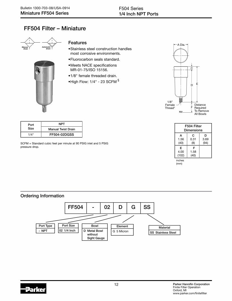
FF504 Filter – Miniature
D
F
C
E
A Dia.
DistanceRequiredTo RemoveAll Bowls
1/8”FemaleThread*
AutomaticDrain
ManualDrain
F504 Series1/4 Inch NPT Ports
Bulletin 1300-703-08/USA-0914
Miniature FF504 Series
F504 Filter Dimensions
A1.56(40)
C0.31(8)
D3.69(94)
E4.00(102)
F1.58(40)
inches (mm)
SCFM = Standard cubic feet per minute at 90 PSIG inlet and 5 PSIG pressure drop.
PortSize
NPT
Manual Twist Drain
1/4" FF504-02DGSS
Features• Stainless steel construction handles most corrosive environments.
• Fluorocarbon seals standard.
• Meets NACE specifications MR-01-75/ISO 15156.
• 1/8" female threaded drain.
• High Flow: 1/4" - 23 SCFM §
Port Type
- NPT
Port Size
02 1/4 Inch
Bowl
D Metal Bowl without Sight Gauge
Element
G 5 Micron Material
SS Stainless Steel
FF504 - 02 D G SS

Parker Hannifin CorporationFinite Filter OperationOxford, MIwww.parker.com/finitefilter
1313
0
1
2
3
4
5
0 5 10 15 20 25
Pre
ssur
e D
rop
- P
SIG
0
0 .5 .75.25 1.0 1.25 1.5
Flow - SCFM
Flow - dm /s
Pre
ssur
e D
rop
- b
ar
3
n
.1
.2
.3
Flow CharacteristicsFF504-02DGSS1/4 Inch Ports
25 PSIG 50 PSIG 75 PSIG 100 PSIGPrimary Pressure - PSIG
1.7 bar 3.4 bar 5.2 bar 6.9 barPrimary Pressure - bar
Technical Information
FF504 SeriesAir Line Filters
Bulletin 1300-703-08/USA-0914
Technical Specifications – FF504
FF504 Filter Kits & AccessoriesFilter Element Kit – Particulate (5 Micron) Element ........................................ EK504VY
Manual Twist Drain – Small (Old) ................................................................SA600Y7-1SS Large (New) ................................................................... SAP05481
Pipe Nipple – 1/4" 316 Stainless Steel ................................................ 616Y28-SS
SpecificationsBowl Capacity .................................................................1.0 Ounces
Filter Rating ......................................................................... 5 Micron
Sump Capacity ..................................................................0.4 Ounce
Port Threads ..........................................................................1/4 Inch
Pressure & Temperature Ratings – Manual Twist Drain ........................... 0 to 300 PSIG (0 to 20.7 bar) 0°F to 180°F (18°C to 82°C) Note: Air must be dry enough to avoid ice formation at temperatures below 32°F (2°C).
Weight ........................................................................0.6 lb. (0.27 kg)
Materials of ConstructionBody .................................................................... 316 Stainless Steel
Bowls .................................................................. 316 Stainless Steel
Deflector .................................................................................. Acetal
Drain ................................................................... 316 Stainless Steel
Element Holder ....................................................................... Acetal
Filter Element ................................................................Polyethylene
Seals ............................................................................ Fluorocarbon

Parker Hannifin CorporationFinite Filter OperationOxford, MIwww.parker.com/finitefilter
14
05F Filters – Economy
Port Size
1 1/4 Inch 2 3/8 Inch
Elements
B 5 MicronPolycarbonate Bowl 2 Metal Bowl Guard/ Twist Drain P Metal Bowl Guard/ Auto Pulse Drain
Metal Bowl 4 Sight Gauge/ Twist Drain T Sight Gauge/ Auto Pulse Drain
Options
Blank No Options
Features• Excellent water removal efficiency.
• Unique deflector plate and shroud creates a swirling of the air stream ensuring maximum water and dirt separation.
• Large filter element surface guarantees low pressure drop and increased element life.
• 5 micron filter element standard.
• Shown with metal bowl guard.
• High Flow: 1/4" – 54 SCFM§ 3/8" – 70 SCFM§
05F 1 2 B * — —
Distance RequiredTo Remove All BowlsRegardless OfDrain Option
D
C
A
B
E
F
Bowl Options
Ordering Information
Inches (mm)
† With Twist or Automatic Pulse Drain
‡ For polycarbonate bowl see Caution on page 2.§ SCFM = Standard cubic feet per minute at 90 PSIG inlet and 5 PSIG
pressure drop.
AutomaticDrain
TwistDrain
Port Type
Blank NPT
05F Filter Dimensions
A2.00(51)
B2.06(52)
C.56(14)
D†
5.35(136)
E†
5.91(150)
F2.25(57)
Port Size
NPT
Twist Drain Automatic Pulse Drain
Poly Bowl‡ / Metal Guard
1/4" 05F12B* 05F1PB*
3/8" 05F22B* 05F2PB*
Metal Bowl / Sight Gauge
1/4" 05F14B* 05F1TB*
3/8" 05F24B* 05F2TB*
Engineering Level
* Will be entered at factory
Accepts1/8" Tubing
Automatic Drain
* 1/4 & 3/8 inch meet ISO 1179-1 Standard.
Bulletin 1300-703-08/USA-0914
05F Filters - Economy
GRAYED OUT ITEMS
ARE OBSOLETE
AS OF JULY 1, 2014

Parker Hannifin CorporationFinite Filter OperationOxford, MIwww.parker.com/finitefilter
15
05F SeriesAir Line Filters
Bulletin 1300-703-08/USA-0914
Technical Specifications – 05F
Technical Information
05F Filter Kits & AccessoriesBowl Guard Kit ...................................................................... PS905P
Bowl Kits – Poly Bowl – Automatic Pulse Drain ................................................... PS995P Twist Drain ..................................................................... PS932P Metal Bowl – Sight Gauge / Automatic Pulse Drain ........................... PS996P Sight Gauge / Twist Drain .............................................. PS935P
DPI Replacement Kit .............................................................PS781P
Drain Kit – Automatic Pulse Drain ................................................... PS998P Twist Drain ........................................................................PS512
Filter Element Kits – 5 Micron Element ............................................................... PS902P
Mounting Bracket Kit ........................................................... PS943P
Sight Gauge Kit .....................................................................PS914P
SpecificationsBowl Capacity .................................................................2.0 Ounces
Sump Capacity ..................................................................0.9 Ounce
Port Threads .................................................................. 1/4, 3/8 Inch
Pressure & Temperature Ratings – Without Differential Pressure Indicator: Polycarbonate Bowl – 0 to 150 PSIG (0 to 10.3 bar) 32°F to 125°F (0°C to 52°C)
Metal Bowl – 0 to 250 PSIG (0 to 17.2 bar) 32°F to 175°F (0°C to 80°C)
With Differential Pressure Indicator: 0 to 150 PSIG (0 to 10.3 bar) 32°F to 125°F (0°C to 52°C) Automatic Pulse Drain – 10 to 150 PSIG (0.7 to 10.3 bar)
Weight ........................................................................1.2 lb. (0.54 kg)
Materials of ConstructionBody ............................................................................................ Zinc
Bowls ..................................................Transparent Polycarbonate or Metal (Zinc) With or Without Sight Gauge
Bowl Guards .............................................................................. Steel
Collar ....................................................................................... Plastic
Deflector, Shroud & Baffle ..................................................... Plastic
Drain ........................................................................................ Plastic
Filter Elements – 5 Micron ............................................................................... Plastic
Seals ..........................................................................................Nitrile
Sight Gauge, DPI ..................................................Polyamide (Nylon)
0
1
2
3
4
5
6
7
8
10
9
0 10 20 30 40 50 60 70 80 90
Pres
sure
Dro
p - P
SIG
35 PSIG 90 PSIG 150 PSIGPrimary Pressure - PSIG
2.4 bar 6.2 bar 10.3 barPrimary Pressure - bar
0
.1
0 5 10 15 20 25 30 35 40
Flow - SCFM
Flow - dm /s
Pres
sure
Dro
p - b
ar
3
n
.2
.3
.4
.5
.6
Flow Characteristics05F12B*
1/4 Inch Ports0
1
2
3
4
5
6
7
8
10
9
0 20 40 60 80 100 120 140
Pres
sure
Dro
p - P
SIG
35 PSIG 90 PSIG 150 PSIGPrimary Pressure - PSIG
2.4 bar 6.2 bar 10.3 barPrimary Pressure - bar
0
.1
0 10 20 30 40 50 60
Flow - SCFM
Flow - dm /s
Pres
sure
Dro
p - b
ar
3
n
.2
.3
.4
.5
.6
Flow Characteristics05F22B*
3/8 Inch Ports
GRAYED OUT ITEMS
ARE OBSOLETE
AS OF JULY 1, 2014

Parker Hannifin CorporationFinite Filter OperationOxford, MIwww.parker.com/finitefilter
16
Features• Excellent water removal efficiency.
• Unique deflector plate and shroud creates a swirling of the air stream ensuring maximum water and dirt separation.
• Large filter element surface guarantees low pressure drop and increased element life.
• Optional automatic float drain available.
• Shown with metal bowl guard.
• High Flow: 1/4" – 53 SCFM§
3/8" – 80 SCFM§
1/2" – 85 SCFM§
06F Filters – Compact
06F Series1/4", 3/8", 1/2" NPT – Basic 3/8" Body
Bulletin 1300-703-08/USA-0914
Compact 06F Series
A
B
DE
C
Distance RequiredTo Remove All BowlsRegardless OfDrain Option
F
‡ For polycarbonate bowl see Caution on page 2.§ SCFM = Standard cubic feet per minute at 90 PSIG inlet and 5 PSIG
pressure drop.
Ordering Information
AutomaticDrain
TwistDrain
Port Size
1 1/4 Inch 2 3/8 Inch 3 1/2 Inch
Elements
B 5 MicronPolycarbonate Bowl 2 Metal Bowl Guard / Twist Drain 6 Metal Bowl Guard / Auto Float Drain
Metal Bowl 4 Sight Gauge / Twist Drain 8 Sight Gauge / Auto Float Drain
Bowl Options
06F 1 2 B * — —
Port Type
Blank NPT
Options
Blank None
06F Filter Dimensions
A2.81(71)
B2.74(70)
C.53(13)
D5.69(145)
D†
5.74(146)
E6.22(158)
E†
6.27(159)
F2.25(57)
Inches (mm)
† With Automatic Float Drain
Port Size
NPT
Twist Drain Automatic Float Drain
Poly Bowl‡ / Metal Guard
1/4" 06F12B* 06F16B*
3/8" 06F22B* 06F26B*
1/2" 06F32B* 06F36B*
Metal Bowl / Sight Gauge
1/4" 06F14B* 06F18B*
3/8" 06F24B* 06F28B*
1/2" 06F34B* 06F38B*
Engineering Level
* Will be entered at factory
* 1/4 & 3/8 inch meet ISO 1179-1 Standard.

Parker Hannifin CorporationFinite Filter OperationOxford, MIwww.parker.com/finitefilter
1717
Bulletin 1300-703-08/USA-0914
Technical Specifications – 06F
35 PSIG 90 PSIG 150 PSIGPrimary Pressure - PSIG
2.4 bar 6.2 bar 10.3 barPrimary Pressure - bar
30Flow - SCFM
00
Pre
ssu
re D
rop
- P
SIG
10 20 40 50 60 70 80
0 5 10 15 20 25 30 35
7
1
2
3
4
5
6
0
Pre
ssu
re D
rop
- b
ar
.1
.2
.3
.4
90 100 110
40 45 50
Flow Characteristics06F22B*
3/8 Inch Ports
Flow - dm /s3
n
Pre
ssu
re D
rop
- P
SIG
0
Pre
ssu
re D
rop
- b
ar
.1
.2
.3
.4
30Flow - SCFM
00
10 20 40 50 60 70 80
0 5 10 15 20 25 30 35
7
1
2
3
4
5
6
90 100 110 120 130
40 45 50 55 60
Flow Characteristics06F32B*
1/2 Inch Ports
Flow - dm /s3
n
35 PSIG 90 PSIG 150 PSIGPrimary Pressure - PSIG
2.4 bar 6.2 bar 10.3 barPrimary Pressure - bar
06F SeriesAir Line Filters
06F Filter Kits & AccessoriesBowl Guard Kit ...................................................................... PS705PBowl Kits – Poly Bowl – Automatic Float Drain .................................................. PS722P Twist Drain ..................................................................... PS732P Metal Bowl – Sight Gauge / Automatic Float Drain ............................ PS723P Sight Gauge / Twist Drain .............................................. PS735PDPI Replacement Kit .............................................................PS781PDrain Kits – Automatic Float Drain ........................................................ PS506P Twist Drain ............................................................................PS512
Filter Element Kits – 5 Micron Element ............................................................... PS702PMounting Bracket Kit .............................................................PS743PSight Gauge Kit ......................................................................PS914P
SpecificationsBowl Capacity .................................................................4.4 OuncesSump Capacity .............................................................. 1.75 OuncesPort Threads ........................................................... 1/4, 3/8, 1/2 Inch
Pressure & Temperature Ratings – Without Differential Pressure Indicator: Polycarbonate Bowl – 0 to 150 PSIG (0 to 10.3 bar) 32°F to 125°F (0°C to 52°C) Metal Bowl – 0 to 250 PSIG (0 to 17.2 bar) 32°F to 175°F (0°C to 80°C) With Differential Pressure Indicator: 0 to 150 PSIG (0 to 10.3 bar) 32°F to 125°F (0°C to 52°C) Automatic Float Drain – 15 to 250 PSIG (1.0 to 17.2 bar) 32°F to 175°F (0°C to 80°C)Weight ........................................................................... 1.4 lb. (0.6 kg)
Materials of ConstructionBody ............................................................................................ ZincBowls .................................................Transparent Polycarbonate or
Metal (Zinc) With or Without Sight GaugeBowl Guards .............................................................................. SteelCollar ....................................................................................... PlasticDeflector, Shroud & Baffle ..................................................... PlasticDrains – Twist Drain – Body & Nut .................................................... Plastic Automatic Float Drain – Housing, Float .............................. Plastic Seals ..................................................................................Nitrile Springs, Push Rod .............................................. Stainless SteelFilter Elements – 5 Micron .......................................................................... Plastic
Seals ..........................................................................................NitrileSight Gauge ...................................................................... Polyamide
Flow - SCFM0
0
Flow Characteristics06F12B*
1/4 Inch Ports
Pre
ssu
re D
rop
- P
SIG
10 20 30 40 50 60 70 80
0 5 10 15 20 25 30 35
7
1
2
3
4
5
6
0
Pre
ssu
re D
rop
- b
ar
.1
.2
.3
.4
35 PSIG 90 PSIG 150 PSIGPrimary Pressure - PSIG
2.4 bar 6.2 bar 10.3 barPrimary Pressure - bar
Flow - dm /s3
n
Technical Information

Parker Hannifin CorporationFinite Filter OperationOxford, MIwww.parker.com/finitefilter
18
Ordering Information
FF10 Series1/2" NPT Ports
Bulletin 1300-703-08/USA-0914
Standard FF10 Series
FF10 Filter – Standard
AutomaticDrain
TwistDrain
D E
C
B Dia.Distance RequiredTo Remove All Bowls Regardless of Drain Option
F
A Dia.
Optional Sight GaugeA1
1/8”FemaleThread*
PortSize
NPT without sight gauge NPT with sight gauge
Manual Twist Drain
Automatic Float Drain
Manual Twist Drain
Automatic Float Drain
1/2" FF10-04DGSS FF10-04DGRSS FF10-04WGSS FF10-04WGRSS
F10 Filter Dimensions
A2.38(60)
A1
2.50(64)
B1.75(44)
C.56(14)
D5.00(127)
E5.56(141)
F2.12(54)
inches (mm)
§ SCFM = Standard cubic feet per minute at 90 PSIG inlet and 5 PSIG pressure drop.
Features• Stainless steel construction handles
most corrosive environments.
• Meets NACE specifications MR-01-75/ISO 15156.
• 1/8" female threaded drain.
• High Flow: 1/2" - 70 SCFM §
FF10 - 04 W G SS
Material
SS Stainless Steel
Options
Blank Manual Twist Drain R Automatic Float Drain
Element
G 5 Micron
Bowl
D Metal Bowl without Sight Gauge W Metal Bowl with Sight Gauge
Port Size
04 1/2 Inch
Port Type
- NPT
Parker Hannifin CorporationFinite Filter OperationOxford, MIwww.parker.com/finitefilter
1919
0
1
2
3
4
5
0 10 20 30 40 50 60 70 80
Pre
ssu
re D
rop
- P
SIG
0
0 5 10 15 20 25 30 35
Flow - SCFM
Flow - dm /s
Pre
ssu
re D
rop
- b
ar
3
n
.1
.2
.3
Flow CharacteristicsFF10-04DGSS1/2 Inch Ports
25 PSIG 50 PSIG 75 PSIG 100 PSIGPrimary Pressure - PSIG
1.7 bar 3.4 bar 5.2 bar 6.9 barPrimary Pressure - bar
FF10 SeriesAir Line Filters
Bulletin 1300-703-08/USA-0914
Technical Specifications – FF10
Technical Information
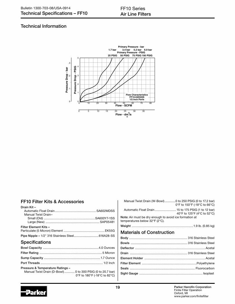
FF10 Filter Kits & AccessoriesDrain Kit – Automatic Float Drain ................................................ SA602MDSS Manual Twist Drain– Small (Old) ............................................................SA600Y7-1SS Large (New) ............................................................... SAP05481
Filter Element Kits – Particulate (5 Micron) Element ................................................ EK55G
Pipe Nipple – 1/2" 316 Stainless Steel.............................616A28-SS
SpecificationsBowl Capacity .................................................................4.0 Ounces
Filter Rating ......................................................................... 5 Micron
Sump Capacity ..................................................................1.7 Ounce
Port Threads ......................................................................... 1/2 Inch
Pressure & Temperature Ratings – Manual Twist Drain (D-Bowl) ............ 0 to 300 PSIG (0 to 20.7 bar) 0°F to 180°F (-18°C to 82°C)
Manual Twist Drain (W-Bowl) ............0 to 250 PSIG (0 to 17.2 bar) 0°F to 150°F (-18°C to 66°C)
Automatic Float Drain ......................... 15 to 175 PSIG (1 to 12 bar) 40°F to 125°F (4°C to 52°C) Note: Air must be dry enough to avoid ice formation at temperatures below 32°F (2°C).
Weight ........................................................................1.9 lb. (0.85 kg)
Materials of ConstructionBody .................................................................... 316 Stainless Steel
Bowls .................................................................. 316 Stainless Steel
Deflector .................................................................................. Acetal
Drain ................................................................... 316 Stainless Steel
Element Holder ....................................................................... Acetal
Filter Element ................................................................Polyethylene
Seals ............................................................................ Fluorocarbon
Sight Gauge .......................................................................... Isoplast

Parker Hannifin CorporationFinite Filter OperationOxford, MIwww.parker.com/finitefilter
20
Inches (mm)
† With Automatic Float Drain
Features• Excellent water removal efficiency.
• Unique deflector plate and shroud creates a swirling of the air stream ensuring maximum water and dirt separation.
• Large filter element surface guarantees low pressure drop and increased element life.
• Optional automatic float drain available.
• Shown with metal bowl guard.
• High Flow: 3/8" – 100 SCFM§ 1/2" – 130 SCFM§ 3/4" – 145 SCFM§
07F Filters – Standard
07F Series3/8", 1/2", 3/4" NPT – Basic 1/2" Body
Bulletin 1300-703-08/USA-0914
Standard 07F Series
A
B
DE
C
Distance RequiredTo Remove All BowlsRegardless OfDrain Option
F
AutomaticDrain
TwistDrain
Port Size
2 3/8 Inch 3 1/2 Inch 4 3/4 Inch
07F 3 2 B * — —
07F Filter Dimensions
A3.24(82)
B3.25(83)
C.70(18)
D6.97(177)
D†
7.00(178)
E7.67(195)
E†
7.70(196)
F2.75(70)
Port Size
NPT
Twist Drain Automatic Float Drain
Poly Bowl‡ / Metal Guard
3/8" 07F22B* 07F26B*1/2" 07F32B* 07F36B*3/4" 07F42B* 07F46B*
Metal Bowl / Sight Gauge
3/8" 07F24B* 07F28B*1/2" 07F34B* 07F38B*3/4" 07F44B* 07F48B*
Elements
B 5 MicronPolycarbonate Bowl 2 Metal Bowl Guard / Twist Drain 6 Metal Bowl Guard / Auto Float Drain
Metal Bowl 4 Sight Gauge / Twist Drain 8 Sight Gauge / Auto Float Drain
Bowl Options Port Type
Blank NPT
Options
Blank None
Engineering Level
* Will be entered at factory
Ordering Information
‡ For polycarbonate bowl see Caution on page 2.§ SCFM = Standard cubic feet per minute at 90 PSIG inlet and 5 PSIG
pressure drop.
* 3/8 & 1/2 inch meet ISO 1179-1 Standard.
GRAYED OUT ITEMS
ARE OBSOLETE
AS OF JULY 1, 2014

Parker Hannifin CorporationFinite Filter OperationOxford, MIwww.parker.com/finitefilter
2121
6000
20 40 80 100 120 140 160
0 10 20 30 40 50 60 70
7
1
2
3
4
5
6
0
.1
.2
.3
.4
180 200 220
80 90 100
Pre
ssur
e D
rop
- P
SIG
Pre
ssur
e D
rop
- b
ar
35 PSIG 90 PSIG 150 PSIGPrimary Pressure - PSIG
2.4 bar 6.2 bar 10.3 barPrimary Pressure - bar
Flow - SCFM
Flow - dm /s3
n
Flow Characteristics07F32A*
1/2 Inch Ports
0
7
1
2
3
4
5
6
0
.1
.2
.3
.4
Pre
ssur
e D
rop
- P
SIG
Pre
ssur
e D
rop
- b
ar
35 PSIG 90 PSIG 150 PSIGPrimary Pressure - PSIG
2.4 bar 6.2 bar 10.3 barPrimary Pressure - bar
Flow - SCFM
Flow - dm /s3
n
600 20 40 80 100 120 140 160
0 10 20 30 40 50 60 70
180 200 220 240 260
80 90 100 110 120
Flow Characteristics07F42A*
3/4 Inch Ports
Pre
ssur
e D
rop
- P
SIG
Pre
ssur
e D
rop
- b
ar35 PSIG 90 PSIG 150 PSIG
Primary Pressure - PSIG2.4 bar 6.2 bar 10.3 bar
Primary Pressure - bar
Flow - SCFM
Flow - dm /s3
n
00
20 40 60 80 100 120 140 160
0 10 20 30 40 50 60 70
7
1
2
3
4
5
6
0
.1
.2
.3
.4
Flow Characteristics07F22A*
3/8 Inch Ports
07F SeriesAir Line Filters
Bulletin 1300-703-08/USA-0914
Technical Specifications – 07F
07F Filter Kits & AccessoriesBowl Guard Kit ..................................................................... PS805PBowl Kits – Poly Bowl – Automatic Float Drain ....................................................PS822P Twist Drain .....................................................................PS832P Metal Bowl – Sight Gauge / Automatic Drain .....................................PS823P Sight Gauge / Twist Drain ..............................................PS835PDPI Replacement Kit ........................................................... PS781PDrain Kits – Automatic Float Drain ........................................................PS506P Twist Drain ........................................................................... PS512
Filter Element Kits – 5 Micron Element ...........................................................PS802P Mounting Bracket Kit ...........................................................PS843PSight Gauge Kit .....................................................................PS914P
SpecificationsBowl Capacity ................................................................. 7.2 OuncesSump Capacity ................................................................2.8 OuncesPort Threads ........................................................... 3/8, 1/2, 3/4 InchPressure & Temperature Ratings – Without Differential Pressure Indicator: Polycarbonate Bowl – 0 to 150 PSIG (0 to 10.3 bar) 32°F to 125°F (0°C to 52°C) Metal Bowl – 0 to 250 PSIG (0 to 17.2 bar) 32°F to 175°F (0°C to 80°C) With Differential Pressure Indicator: 0 to 150 PSIG (0 to 10.3 bar) 32°F to 125°F (0°C to 52°C) Automatic Float Drain – 15 to 250 PSIG (1.0 to 17.2 bar)
Weight ..........................................................................2.2 lb. (1.0 kg)
Materials of ConstructionBody ............................................................................................ ZincBowls ...................................................... Transparent Polycarbonate Metal (Zinc) With or Without Sight GaugeBowl Guards .............................................................................. SteelCollar .........................................................................Plastic or MetalDeflector, Shroud & Baffle ..................................................... PlasticDrains – Twist Drain – Body & Nut ....................................................Plastic Push ‘N’ Drain – Body .................................................................................. Nitrile Stem .................................................................................. Brass Automatic Float Drain – Housing, Float ..................................................................Plastic Seals ................................................................................. Nitrile Springs, Push Rod ..............................................Stainless SteelFilter Elements – 5 Micron (Standard) .............................................................PlasticSeals ......................................................................................... NitrileSight Gauge ...................................................................... Polyamide
Technical Information

Parker Hannifin CorporationFinite Filter OperationOxford, MIwww.parker.com/finitefilter
22
P3NF Series3/4", 1", 1-1/2" NPT – Basic 1" Body
Bulletin 1300-703-08/USA-0914
Hi-Flow P3NF Series
Features• Port blocks (PB) available to provide
1-1/2" port extension to 1" ported bodies.
• Excellent water removal efficiency.
• Metal bowl with sight gauge.
• Large filter element surface guarantees low pressure drop and increased element life.
• Twist Drain as standard, optional automatic float drain.
• High Flow: 3/4" – 270 SCFM§
1" – 300 SCFM§
1-1/2" – 310 SCFM§
P3NF Filters – Hi-Flow
P3N F A 9 8 E S M
Port Type
9 NPT Female
Port Size
6 3/4" (w/o Port Blocks) 8 1" (w/o Port Blocks) P 1-1/2" Port Blocks (w/ 1" Ported Body)
Bowl
S Metal Bowl w/ Sight Gauge
Element
E 5 Micron
Drain
M Twist Drain A Automatic Float Drain
Design Level
B
C
D
AA (PB)
Distance RequiredTo Remove All Bowls Regardless of Drain Option
E
F
P3NF Filter Dimensions
A 3.62 (92)
A (PB)
5.91 (150)
B 3.62 (92)
C 1.38 (35)
D† 9.57 (243)
E†
10.95 (278)
F 4.92 (125)
Ordering Information
# 1" Port Body with 1-1/2" Port Block.§ SCFM = Standard cubic feet per minute at 90 PSIG inlet and 5 PSIG
pressure drop, with 40 micron element.
PortSize
NPT
Twist Drain Automatic Float Drain
Metal Bowl / Sight Gauge
3/4" P3NFA96ESM P3NFA96ESA
1" P3NFA98ESM P3NFA98ESA
1-1/2" # P3NFA9PESM P3NFA9PESA
AutomaticDrain
TwistDrain
Inches (mm)
† With Twist Drain or Automatic Float Drain
* 3/4 & 1 inch meet ISO 1179-1 Standard.
GRAYED OUT ITEMS
ARE OBSOLETE
AS OF JULY 1, 2014

Parker Hannifin CorporationFinite Filter OperationOxford, MIwww.parker.com/finitefilter
2323
P3NF SeriesAir Line Filters
Bulletin 1300-703-08/USA-0914
Technical Specifications – P3NF
# 1" Port Body with 1-1/2" Port Block.
SpecificationsPressure & Temperature Rating – 0 to 250 PSIG (0 to 17 bar) 32°F to 175°F (0°C to 80°C) Automatic Float Drain – 15 to 250 PSIG (1.0 to 17 bar)
Bowl Capacity ...............................................................18.0 Ounces
Sump Capacity ................................................................6.8 Ounces
Weight – 3/4" ........................................................................3.5 lb. (1.6 kg) 1" ...........................................................................3.5 lb. (1.6 kg) 1-1/2" # ................................................................. 4.6 lb. (2.1 kg)
Materials of ConstructionBody ................................................................................... Aluminum
Deflector ................................................................................. Plastic
Drain ........................................................................................ Plastic
Filter Elements – 5 Micron (Standard) ............................................................. Plastic
Seals ................................................................................................... Nitrile
Sight Gauge ..........................................................Polyamide (Nylon)
P3NF Filter Kits & AccessoriesBowl Kits – Metal Bowl – Sight Gauge / Automatic Float Drain ..................P3NKA00BSA Sight Gauge / Twist Drain ................................... P3NKA00BSM
Bowl Latch Kit .......................................................................C11A33
DPI Replacement Kit .............................................................PS781P
Drain Kit – Automatic Float Drain ........................................................ PS506P Twist Drain ............................................................................PS512
Filter Elements – 5 Micron Element ..................................................... P3NKA00ESE
Mounting Bracket Kit ..................................................P3NKA00MW
Sight Gauge Kit ..............................................................P3NKA00PE
0
1
2
3
4
5
6
7
8
10
9
0 50 100 150 200 250 300 350 400 450 500
Pre
ssur
e D
rop
- P
SIG
35 PSIG 90 PSIG 150 PSIGPrimary Pressure - PSIG
2.4 bar 6.2 bar 10.3 barPrimary Pressure - bar
0
.1
0 25 50 75 100 125 150 175 200
Flow - SCFM
Pre
ssur
e D
rop
- b
ar
225
.2
.3
.4
.5
.6
Flow CharacteristicsP3NF
3/4 Inch Ports
Flow - dm /s3
n
0
1
2
3
4
5
6
7
8
10
9
0 200100 300 400 500 600
Pre
ssur
e D
rop
- P
SIG
35 PSIG 90 PSIG 150 PSIGPrimary Pressure - PSIG
2.4 bar 6.2 bar 10.3 barPrimary Pressure - bar
0
.1
0 50 100 150 200 250
Flow - SCFM
Pre
ssur
e D
rop
- b
ar
.2
.3
.4
.5
.6
Flow CharacteristicsP3NF
1 Inch Ports
Flow - dm /s3n
0
1
2
3
4
5
6
7
8
10
9
0 200100 300 400 500 600
Pre
ssur
e D
rop
- P
SIG
35 PSIG 90 PSIG 150 PSIGPrimary Pressure - PSIG
2.4 bar 6.2 bar 10.3 barPrimary Pressure - bar
0
.1
0 50 100 150 200 250
Flow - SCFM
Pre
ssur
e D
rop
- b
ar
.2
.3
.4
.5
.6
Flow CharacteristicsP3NF
1-1/2 Inch Ports
Flow - dm /s3
n
Technical Information
Parker Hannifin CorporationFinite Filter OperationOxford, MIwww.parker.com/finitefilter
24
Air Preparation UnitsBulletin 1300-703-08/USA-0914
Air Line Coalescing Filters
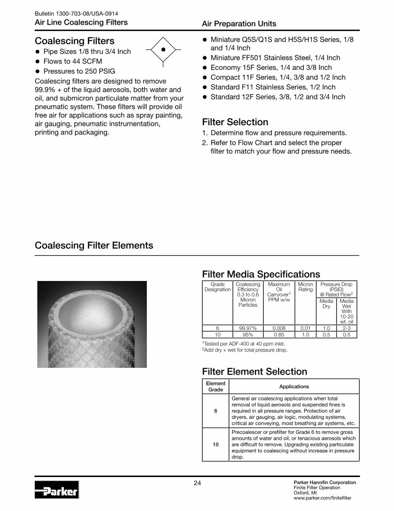
Coalescing Filters• Pipe Sizes 1/8 thru 3/4 Inch
• Flows to 44 SCFM
• Pressures to 250 PSIGCoalescing filters are designed to remove 99.9% + of the liquid aerosols, both water and oil, and submicron particulate matter from your pneumatic system. These filters will provide oil free air for applications such as spray painting, air gauging, pneumatic instrumentation, printing and packaging.
Element Grade
Applications
6
General air coalescing applications when total removal of liquid aerosols and suspended fines is required in all pressure ranges. Protection of air dryers, air gauging, air logic, modulating systems, critical air conveying, most breathing air systems, etc.
10
Precoalescer or prefilter for Grade 6 to remove gross amounts of water and oil, or tenacious aerosols which are difficult to remove. Upgrading existing particulate equipment to coalescing without increase in pressure drop.
Filter Element Selection
• Miniature Q5S/Q1S and H5S/H1S Series, 1/8 and 1/4 Inch
• Miniature FF501 Stainless Steel, 1/4 Inch
• Economy 15F Series, 1/4 and 3/8 Inch
• Compact 11F Series, 1/4, 3/8 and 1/2 Inch
• Standard F11 Stainless Series, 1/2 Inch
• Standard 12F Series, 3/8, 1/2 and 3/4 Inch
Filter Selection1. Determine flow and pressure requirements.2. Refer to Flow Chart and select the proper
filter to match your flow and pressure needs.
1Tested per ADF-400 at 40 ppm inlet. 2Add dry + wet for total pressure drop.
GradeDesignation
Coalescing Efficiency0.3 to 0.6
MicronParticles
MaximumOil
Carryover1PPM w/w
Micron Rating
Pressure Drop (PSID)
@ Rated Flow2
MediaDry
MediaWet With
10-20 wt. oil
6 99.97% 0.008 0.01 1.0 2-310 95% 0.85 1.0 0.5 0.5
Filter Media Specifications
Coalescing Filter Elements
Parker Hannifin CorporationFinite Filter OperationOxford, MIwww.parker.com/finitefilter
24
Air Preparation UnitsBulletin 1300-703-08/USA
Air Line Coalescing Filters
Coalescing Filters
•Pipe Sizes 1/8 thru 3/4 Inch
• Flows to 44 SCFM
• Pressures to 250 PSIGCoalescing filters are designed to remove 99.9% + of the liquid aerosols, both water and oil, and submicron particulate matter from your pneumatic system. These filters will provide oil free air for applications such as spray painting, air gauging, pneumatic instrumentation, printing and packaging.
Element Grade
Applications
6
General air coalescing applications when total removal of liquid aerosols and suspended fines is required in all pressure ranges. Protection of air dryers, air gauging, air logic, modulating systems, critical air conveying, most breathing air systems, etc.
10
Precoalescer or prefilter for Grade 6 to remove gross amounts of water and oil, or tenacious aerosols which are difficult to remove. Upgrading existing particulate equipment to coalescing without increase in pressure drop.
Filter Element Selection
1Tested per ADF-400 at 40 ppm inlet. 2Add dry + wet for total pressure drop.
GradeDesignation
Coalescing Efficiency0.3 to 0.6
MicronParticles
MaximumOil
Carryover1PPM w/w
Micron Rating
Pressure Drop (PSID)
@ Rated Flow2
MediaDry
MediaWet With
10-20 wt. oil
6 99.97% 0.008 0.01 1.0 2-310 95% 0.85 1.0 0.5 0.5
Filter Media Specifications
• Miniature Q5S/Q1S and H5S/H1S Series, 1/8
and 1/4 Inch
• Miniature FF501 Stainless Steel, 1/4 Inch
• Economy 15F Series, 1/4 and 3/8 Inch
• Compact 11F Series, 1/4, 3/8 and 1/2 Inch
• Standard FF11 Stainless Series, 1/2 Inch
• Standard 12F Series, 3/8, 1/2 and 3/4 Inch
Coalescing Filter Elements

Parker Hannifin CorporationFinite Filter OperationOxford, MIwww.parker.com/finitefilter
2525
Air Preparation UnitsBulletin 1300-703-08/USA-0914
Air Line Coalescing Filters
A
BCD
The contaminated air enters the element interior and is forced through a thick membrane of borosilicate glass fibers coated with epoxy (A). Flow then passes through an outer structural support and, at this stage, has removed up to 99.97% + of the sub-micron particles evident in the contaminated air. These tiny droplets coalesce together and are blotted from the filter surface by the drain and release layers of non-woven glass felt and rayon cloth. The drops now begin a gravitational passage to the filter sump (B) where they can be manually or automatically drained.
The clean, filtered air now passes through the outer screen plastic net and out into the pneumatic system. The Air Line Coalescing Filter removes liquid aerosols and sub-micron particulate matter.
Collected liquids and particles in the “quiet zone” should be drained before their level reaches a height where they would be reentrained in the flowing air. This can be accomplished by the manual drain (C) which is actuated by twisting knob (D) counterclockwise. On the 30 Series, unscrew the drain valve (E) slightly until the liquid begins to drain.
A
BCD
A
B
CD
11F / 12F15F
10F
A
D
B
FF501
A
D
B
FF11

Parker Hannifin CorporationFinite Filter OperationOxford, MIwww.parker.com/finitefilter
26
Q 1S - 6HM 06-013
Q5S/Q1S and H5S/H1S Coalescing Filters – Miniature
Q5S, Q1S and H5S/H1S1/8", 1/4" – Basic 1/8" Body
Bulletin 1300-703-08/USA-0914
Miniature Q5S, Q1S and H5S/H1S Series
Standard part numbers shown bold, with Grade 6 Elements (for Grade 10 Elements, replace “6” with “10”). ‡ For polycarbonate bowl see Caution on page 2.§ SCFM = Standard cubic feet per minute at 100 PSIG inlet and 2-3
PSIG pressure drop.
Features• Removes liquid aerosols and sub-micron
particles.
• Liquids gravitate to the bottom of the element and will not re-enter the airstream.
• Oil free air for critical applications, such as air gauging and pneumatic instrumentation and controls.
• Interchangeable twist and automatic pulse drains.
• Grade 6 element, 99.97% DOP efficiency.
• High Flow: Grade 6 Element 1/8" – 7.7 SCFM§
1/4" – 7.7 SCFM§
Grade 10 Element 1/8" – 7.7 SCFM§
1/4" – 7.7 SCFM§ Dimensions
A1.69(43)
B3.82(97)
B*3.87(99)
C0.39(10)
Port Size
NPT
Twist Drain Automatic Drain
Poly Bowl ‡
1/8" Q5S-6HM06-013 AQ5S-6HM06-0131/4" Q1S-6HM06-013 AQ1S-6HM06-013
Metal Bowl
1/8" H5S-6HM06-013 AH5S-6HM06-0131/4" H1S-6HM06-013 AH1S-6HM06-013
Inches (mm)
*Metal Bowl
Bowl Options
Q PolycarbonateH Metal Bowl
Elements
6HM Grade 6 10 HM Grade 10
Drain
A Automatic Drain
Blank Manual Twist Drain
Ordering Information
Port Size
5S 1/8 Inch 1S 1/4 Inch
Port Type
- NPT

Parker Hannifin CorporationFinite Filter OperationOxford, MIwww.parker.com/finitefilter
2727
Q5S, Q1S and H5S/H1SCoalescing Filters (Oil Removal)
Bulletin 1300-703-08/USA-0914
Technical Specifications – Q5S, Q1S and H5S/H1S
Technical Information
Q5S/Q1S and H5S/H1S Coalescing Filter Kits & AccessoriesBowl Kits – Poly Bowl – Automatic Pulse Drain ................................... 40914 Twist Drain ....................................................... 40733 Metal Bowl –Automatic Pulse Drain ................................... 41028 Twist Drain .................................................... 41581Filter Element Kits – Grade 6 (Standard) .............6HM06-013 x 10 Grade 10 (Optional) ..........................................10HM06-013 x 10Mounting Bracket Kit ........................................................PS417BP
SpecificationsAutomatic Pulse Drain Tube Barb .....................................1/8 InchBowl Capacity .................................................................... 1 OunceOperation – Normal Operating Pressure Drop ................................. 2-3 PSIG Maximum Recommended Pressure Drop ..................... 10 PSIG (Element should be replaced) Port Threads ................................................................1/8, 1/4 InchPressure & Temperature Ratings – Polycarbonate Bowl ........................0 to 150 PSIG (0 to 10.3 bar) 32°F to 125°F (0°C to 52°C)
Metal Bowl........................................0 to 250 PSIG (0 to 17.2 bar) 32°F to 175°F (0°C to 80°C)
Automatic Pulse Drain ................10 to 250 PSIG (0.7 to 17.2 bar) at 125°F (52°C) or less
Weight ................................................................... 0.41 lb. (0.18 kg)
Materials of ConstructionBody .................................................................................. AluminumBowls ................................................... Transparent Polycarbonate Metal (Zinc) Drains – Twist Drain – Body & Stem ........................................................Plastic Seals ...................................................................... Nitrile Automatic Pulse Drain – Piston & Seals ....................................................... Nitrile Stem, Seat, Adaptor & Washers ................... AluminumElement Holder ......................................................................PlasticFilter Element ............................. Borosilicate & Microglass fibers Seals ........................................................................................ Nitrile
Q*S, H*S
Grade 6
Q*S, H*S
Grade 10
1Tested per ADF-400 at 40 ppm inlet. 2Add dry + wet for total pressure drop.
GradeDesignation
Coalescing Efficiency0.3 to 0.6
MicronParticles
MaximumOil
Carryover1PPM w/w
Micron Rating
Pressure Drop (PSID)
@ Rated Flow2
MediaDry
MediaWet With
10-20 wt. oil
6 99.97% 0.008 0.01 1.0 2-310 95% 0.85 1.0 0.5 0.5
Filter Media Specifications

Parker Hannifin CorporationFinite Filter OperationOxford, MIwww.parker.com/finitefilter
28
FF501 Series1/4 Inch Ports
Bulletin 1300-703-08/USA-0914
Miniature F501 Series
FF501 Coalescing Filter – Miniature
Ordering Information
D
F
C
E
A Dia.
DistanceRequiredTo RemoveAll Bowls
1/8”FemaleThread*
PortSize
NPT
Manual Twist Drain
1/4" FF501-02DHSS
F501 Coalescing Filter Dimensions
A1.56(40)
C0.31(8)
D3.69(94)
E4.00(102)
F1.58(40)
inches (mm)
Standard part numbers shown bold. For other models refer to ordering information below.
SCFM = Standard cubic feet per minute at 90 PSIG inlet and 5 PSIG pressure drop.
Features• Stainless steel construction handles
most corrosive environments.
• Meets NACE specifications MR-01-75/ISO 15156.
• 1/8" female threaded drain*.
• High Flow: 1/4" - 16 SCFM §
Port Type
- NPT
Port Size
02 1/4 Inch
Bowl
D Metal Bowl without Sight Gauge
Element
H Grade 6
Material
SS Stainless Steel
FF501 - 02 D H SS
Parker Hannifin CorporationFinite Filter OperationOxford, MIwww.parker.com/finitefilter
2929
F501 SeriesCoalescing Filters (Oil Removal)
Bulletin 1300-703-08/USA-0914
Technical Specifications – F501
Technical InformationTechnical Information
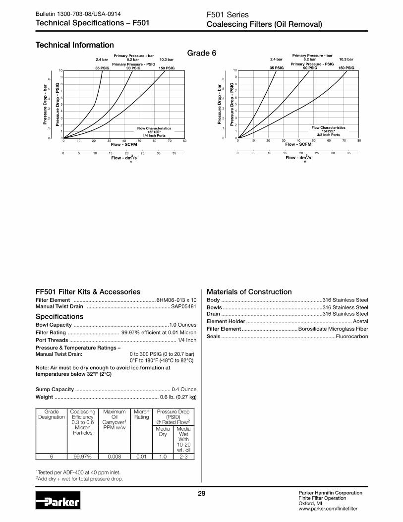
FF501 Filter Kits & AccessoriesFilter Element ........................................................ 6HM06-013 x 10 Manual Twist Drain .........................................................SAP05481
SpecificationsBowl Capacity .................................................................1.0 OuncesFilter Rating ................................... 99.97% efficient at 0.01 MicronPort Threads ......................................................................... 1/4 InchPressure & Temperature Ratings – Manual Twist Drain: 0 to 300 PSIG (0 to 20.7 bar) 0°F to 180°F (-18°C to 82°C)Note: Air must be dry enough to avoid ice formation at temperatures below 32°F (2°C)
Sump Capacity ................................................................. 0.4 OunceWeight ....................................................................... 0.6 lb. (0.27 kg)
Materials of ConstructionBody .....................................................................316 Stainless SteelBowls ....................................................................316 Stainless SteelDrain .....................................................................316 Stainless SteelElement Holder ........................................................................ AcetalFilter Element ...................................... Borosilicate Microglass FiberSeals ..............................................................................Fluorocarbon
0
1
2
3
4
5
6
7
8
10
9
0 10 20 30 40 50 60 70 80
35 PSIG 90 PSIG 150 PSIGPrimary Pressure - PSIG
Flow - SCFM
0 5 10 20 30 35
Flow - dm /s3
n
15 25
Pre
ssur
e D
rop
- P
SIG
2.4 bar 6.2 bar 10.3 barPrimary Pressure - bar
0
.1
Pre
ssur
e D
rop
- b
ar
.2
.3
.4
.5
.6
Flow Characteristics15F12E*
1/4 Inch Ports
Grade 6
0
1
2
3
4
5
6
7
8
10
9
0 10 20 30 40 50 60 70 80
35 PSIG 90 PSIG 150 PSIGPrimary Pressure - PSIG
Flow - SCFM
0 5 10 20 30 35
Flow - dm /s3
n
15 25
Pre
ssur
e D
rop
- P
SIG
2.4 bar 6.2 bar 10.3 barPrimary Pressure - bar
0
.1
Pre
ssur
e D
rop
- b
ar
.2
.3
.4
.5
.6
Flow Characteristics15F22E*
3/8 Inch Ports
1Tested per ADF-400 at 40 ppm inlet. 2Add dry + wet for total pressure drop.
GradeDesignation
Coalescing Efficiency0.3 to 0.6
MicronParticles
MaximumOil
Carryover1PPM w/w
Micron Rating
Pressure Drop (PSID)
@ Rated Flow2
MediaDry
MediaWet With
10-20 wt. oil
6 99.97% 0.008 0.01 1.0 2-3

Parker Hannifin CorporationFinite Filter OperationOxford, MIwww.parker.com/finitefilter
30
Distance Required To Remove All Bowls Regardless Of Drain Option
D
C
E
Electronic DPIC1
ElectronicDPI
F
A
B
G
Features• Removes liquid aerosols and sub-micron
particles.
• Liquids gravitate to the bottom of the element and will not re-enter the airstream.
• Oil free air for critical applications, such as air gauging and pneumatic instrumentation and controls.
• Interchangeable twist and automatic pulse drains.
• Pressure differential indicator standard.
• High Flow: Grade 6 Element Grade 10 Element 1/4" – 30 SCFM § 1/4" – 51 SCFM§
3/8" – 30 SCFM § 3/8" – 66 SCFM§
15F Series1/4", 3/8" NPT – Basic 1/4" Body
Bulletin 1300-703-08/USA-0914
Economy 15F Series
15F Coalescing Filters – Economy
Standard part numbers shown bold, with Grade 6 Elements (for Grade 10 Elements, replace “E” with “H” in the 6th position). For other models refer to ordering information below.‡ For polycarbonate bowl see Caution on page 2.§ SCFM = Standard cubic feet per minute at 90 PSIG inlet and 5 PSIG
pressure drop.
Options
Blank With Differential Pressure Indicator
15F Coalescing Filter Dimensions
A2.00(51)
B2.06(52)
C1.50(38)
C1
1.86(47)
D †
5.35(136)
E †
6.85(174)
F1.77(45)
Inches (mm)† With Twist Drain or Automatic Float Drain
Port Size
1 1/4 Inch 2 3/8 Inch
Elements
E Grade 6 H Grade 10
Polycarbonate Bowl 2 Metal Bowl Guard / Twist Drain P Metal Bowl Guard / Auto Pulse Drain
Metal Bowl 4 Sight Gauge / Twist Drain T Sight Gauge / Auto Pulse Drain
15F 1 2 E * — —
Bowl Options
Ordering Information
Port Type
Blank NPT
Port Size
NPT
Twist Drain Automatic Pulse Drain
Poly Bowl‡ / Metal Guard
1/4" 15F12E* 15F1PE*
3/8" 15F22E* 15F2PE*
Metal Bowl / Sight Gauge
1/4" 15F14E* 15F1TE*
3/8" 15F24E* 15F2TE*
Engineering Level
* Will be entered at factory
Accepts1/8" Tubing
Automatic Drain
* 1/4 & 3/8 inch meet ISO 1179-1 Standard.
GRAYED OUT ITEMS
ARE OBSOLETE
AS OF JULY 1, 2014

Parker Hannifin CorporationFinite Filter OperationOxford, MIwww.parker.com/finitefilter
31
15F SeriesCoalescing Filters (Oil Removal)
Bulletin 1300-703-08/USA-0914
Technical Specifications – 15F
Technical Information
15F Coalescing Filter Kits & AccessoriesBowl Guard Kit .....................................................................PS905PBowl Kits – Poly Bowl – Automatic Pulse Drain .................................PS995P Twist Drain ................................................... PS932P Metal Bowl – Sight Gauge / Automatic Pulse Drain .........PS996P Sight Gauge / Twist Drain ........................... PS935PDPI Replacement Kit .............................................................PS781PDrain Kit – Automatic Pulse Drain ..................................PS998P Twist Drain .......................................................PS512
Filter Element Kits – Grade 6 (Standard) ........................... PS924P Grade 10 (Optional) ...........................PS930P Mounting Bracket Kit ...........................................................PS943PSight Gauge Kit ..................................................................... PS914P
SpecificationsBowl Capacity .................................................................2.0 OuncesSump Capacity ................................................................ 0.9 OuncePort Threads .................................................................. 1/4, 3/8 InchPressure & Temperature Ratings – With Differential Pressure Indicator: 0 to 150 PSIG (0 to 10.3 bar) 32°F to 125°F (0°C to 52°C)Weight ....................................................................... 1.2 lb. (0.54 kg)
Materials of ConstructionBody .............................................................................................ZincBowls ...................................................... Transparent Polycarbonate Metal (Zinc) Without Sight GaugeBowl Guards .............................................................................. SteelCollar ........................................................................................PlasticDrain .........................................................................................PlasticFilter Element – Borosilicate & felt glass fibers 99.97% DOP efficiency Largest Aerosol Particle Passed (Grade 6) ................. 0.01 Micron Largest Solid Particle Passed (Grade 6) ..................... 0.30 MicronSeals .......................................................................................... NitrileSight Gauge, DPI .................................................. Polyamide (Nylon)
0
1
2
3
4
5
6
7
8
10
9
0 10 20 30 40 50 60 70 80
35 PSIG 90 PSIG 150 PSIGPrimary Pressure - PSIG
Flow - SCFM
0 5 10 20 30 35
Flow - dm /s3
n
15 25
Pre
ssur
e D
rop
- P
SIG
2.4 bar 6.2 bar 10.3 barPrimary Pressure - bar
0
.1
Pre
ssur
e D
rop
- b
ar
.2
.3
.4
.5
.6
Flow Characteristics15F12E*
1/4 Inch Ports
Grade 6
Grade 10
0
1
2
3
4
5
6
7
8
10
9
0 10 20 30 40 50 60 70 80
35 PSIG 90 PSIG 150 PSIGPrimary Pressure - PSIG
Flow - SCFM
0 5 10 20 30 35
Flow - dm /s3
n
15 25
Pre
ssur
e D
rop
- P
SIG
2.4 bar 6.2 bar 10.3 barPrimary Pressure - bar
0
.1
Pre
ssur
e D
rop
- b
ar
.2
.3
.4
.5
.6
Flow Characteristics15F22E*
3/8 Inch Ports
0
1
2
3
4
5
6
7
8
10
9
0 10 20 30 40 50 60 70 9080
35 PSIG 90 PSIG 150 PSIGPrimary Pressure - PSIG
Flow - SCFM
Pre
ssur
e D
rop
- P
SIG
2.4 bar 6.2 bar 10.3 barPrimary Pressure - bar
0
.1
Pre
ssur
e D
rop
- b
ar
.2
.3
.4
.5
.6
Flow Characteristics15F12H*
1/4 Inch Ports
0 5 10 15 20 25 30 35 40
Flow - dm /s3
n
0
1
2
3
4
5
6
7
8
10
9
0 20 40 60 80 100 120 140
35 PSIG 90 PSIG 150 PSIGPrimary Pressure - PSIG
Flow - SCFM
Pre
ssur
e D
rop
- P
SIG
2.4 bar 6.2 bar 10.3 barPrimary Pressure - bar
0
.1
Pre
ssur
e D
rop
- b
ar.2
.3
.4
.5
.6
Flow Characteristics15F22H*
3/8 Inch Ports
0 10 20 30 40 50 60
Flow - dm /s3
n
1Tested per ISO 12500-1 at 40 ppm inlet. 2Add dry + wet for total pressure drop.
GradeDesignation
Coalescing Efficiency0.3 to 0.6
MicronParticles
MaximumOil
Carryover1PPM w/w
Micron Rating
Pressure Drop (PSID)
@ Rated Flow2
MediaDry
MediaWet With
10-20 wt. oil
6 99.97% 0.008 0.01 1.0 2-310 95% 0.85 1.0 0.5 0.5
15F Media Specifications
GRAYED OUT ITEMS
ARE OBSOLETE
AS OF JULY 1, 2014

Parker Hannifin CorporationFinite Filter OperationOxford, MIwww.parker.com/finitefilter
32
A
B
D
E
C
F
G
Electronic DPI
C1Electronic
DPI
Distance RequiredTo Remove All BowlsRegardless OfDrain Option
Features• Removes liquid aerosols and sub-micron particles.
• Liquids gravitate to the bottom of the element and will not re-enter the airstream.
• Oil free air for critical applications, such as air gauging and pneumatic instrumentation and controls.
• Interchangeable twist and automatic float drains.
• Pressure differential indicator standard.
• Shown with recommended metal bowl guard.
• High Flow: Grade 6 Element Grade 10 Element 1/4" – 45 SCFM§ 1/4" – 60 SCFM§
3/8" – 48 SCFM§ 3/8" – 72 SCFM§
1/2" – 65 SCFM§ 1/2" – 95 SCFM§
11F Coalescing Filters – Compact
11F Series1/4", 3/8", 1/2" NPT – Basic 3/8" Body
Bulletin 1300-703-08/USA-0914
Compact 11F Series
Standard part numbers shown bold, with Grade 6 Elements (for Grade 10 Elements, replace “E” with “H” in the 6th position). For other models refer to ordering information below.‡ For polycarbonate bowl see Caution on page 2.§ SCFM = Standard cubic feet per minute at 90 PSIG inlet and 5 PSIG
pressure drop.
PortSize
NPT
Twist Drain Automatic Float Drain
Poly Bowl ‡ / Metal Guard
1/4" 11F12E* 11F16E*
3/8" 11F22E* 11F26E*
1/2" 11F32E* 11F36E*Metal Bowl / Sight Gauge
1/4" 11F14E* 11F18E*
3/8" 11F24E* 11F28E*
1/2" 11F34E* 11F38E*
Bowl Options
11F 1 2 E * — —
Options
Blank With Differential Pressure Indicator
11F Coalescing Filter Dimensions
A2.81(71)
B2.74(70)
C1.46(37)
C1
1.81(46)
D
5.69(145)
D †
5.74(146)
E7.15(182)
E †
7.20(183)
F2.25(57)
Inches (mm)
† With Automatic Float Drain
Port Size
1 1/4 Inch 2 3/8 Inch 3 1/2 Inch
Elements
E Grade 6 H Grade 10
Polycarbonate Bowl 2 Metal Bowl Guard / Twist Drain 6 Metal Bowl Guard / Auto Float Drain
Metal Bowl 4 Sight Gauge / Twist Drain 8 Sight Gauge / Auto Float Drain
Port Type
Blank NPT
Engineering Level
* Will be entered at factory
Ordering Information
* 1/4 & 3/8 inch meet ISO 1179-1 Standard.
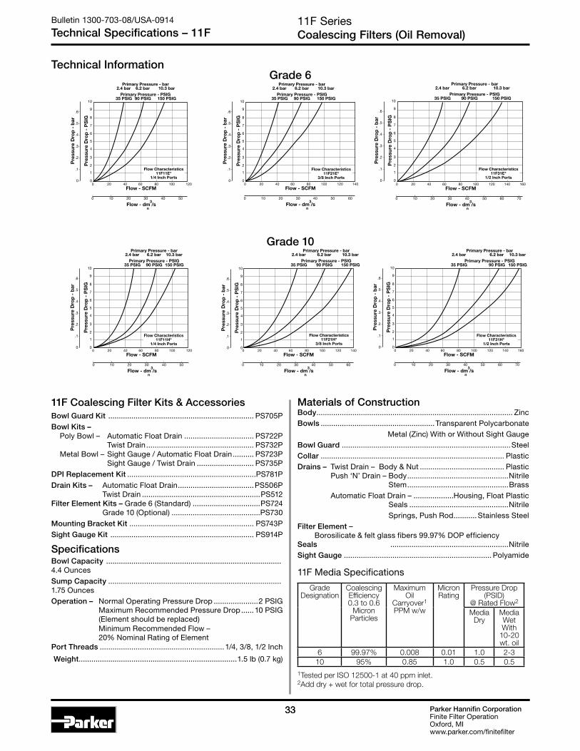
Parker Hannifin CorporationFinite Filter OperationOxford, MIwww.parker.com/finitefilter
3333
11F SeriesCoalescing Filters (Oil Removal)
Bulletin 1300-703-08/USA-0914
Technical Specifications – 11F
Technical Information
11F Coalescing Filter Kits & AccessoriesBowl Guard Kit ..................................................................... PS705PBowl Kits – Poly Bowl – Automatic Float Drain ................................. PS722P Twist Drain ................................................... PS732P Metal Bowl – Sight Gauge / Automatic Float Drain .......... PS723P Sight Gauge / Twist Drain ........................... PS735PDPI Replacement Kit .............................................................PS781PDrain Kits – Automatic Float Drain ....................................PS506P Twist Drain ........................................................PS512 Filter Element Kits – Grade 6 (Standard) ................................PS724 Grade 10 (Optional) ..........................................PS730Mounting Bracket Kit ........................................................... PS743PSight Gauge Kit .................................................................... PS914P
SpecificationsBowl Capacity ................................................................................... 4.4 OuncesSump Capacity .................................................................................. 1.75 OuncesOperation – Normal Operating Pressure Drop .....................2 PSIG Maximum Recommended Pressure Drop ......10 PSIG (Element should be replaced) Minimum Recommended Flow – 20% Nominal Rating of ElementPort Threads ...........................................................1/4, 3/8, 1/2 Inch
Weight ...........................................................................1.5 lb (0.7 kg)
Materials of ConstructionBody ............................................................................................. ZincBowls ......................................................Transparent Polycarbonate Metal (Zinc) With or Without Sight GaugeBowl Guard ................................................................................SteelCollar ....................................................................................... PlasticDrains – Twist Drain – Body & Nut ........................................ Plastic Push ‘N’ Drain – Body ................................................Nitrile Stem ................................................Brass Automatic Float Drain – ...................Housing, Float Plastic Seals ...............................................Nitrile Springs, Push Rod ...........Stainless SteelFilter Element – Borosilicate & felt glass fibers 99.97% DOP efficiency Seals ........................................................NitrileSight Gauge ...................................................................... Polyamide
0 20 8040 100 12060
35 PSIG 90 PSIG 150 PSIGPrimary Pressure - PSIG
2.4 bar 6.2 bar 10.3 barPrimary Pressure - bar
0 10 20
Flow - SCFM
Flow - dm /s3
n
30 40 50
Flow Characteristics11F11E*
1/4 Inch Ports0
1
2
3
4
5
6
7
8
10
9
Pre
ssur
e D
rop
- P
SIG
0
.1
Pre
ssur
e D
rop
- b
ar
.2
.3
.4
.5
.6
0 20 8040 100 12060
35 PSIG 90 PSIG 150 PSIGPrimary Pressure - PSIG
2.4 bar 6.2 bar 10.3 barPrimary Pressure - bar
0 10 20
Flow - SCFM
Flow - dm /s3
n
30 40 50
Flow Characteristics11F11H*
1/4 Inch Ports0
1
2
3
4
5
6
7
8
10
9
Pre
ssur
e D
rop
- P
SIG
0
.1
Pre
ssur
e D
rop
- b
ar
.2
.3
.4
.5
.6
0 20 8040 100 120 14060
35 PSIG 90 PSIG 150 PSIGPrimary Pressure - PSIG
2.4 bar 6.2 bar 10.3 barPrimary Pressure - bar
0 10 20
Flow - SCFM
Flow - dm /s3
n
30 40 50 60
Flow Characteristics11F21E*
3/8 Inch Ports0
1
2
3
4
5
6
7
8
10
9
Pre
ssur
e D
rop
- P
SIG
0
.1
Pre
ssur
e D
rop
- b
ar
.2
.3
.4
.5
.6
0 20 8040 100 120 14060
35 PSIG 90 PSIG 150 PSIGPrimary Pressure - PSIG
2.4 bar 6.2 bar 10.3 barPrimary Pressure - bar
0 10 20
Flow - SCFM
Flow - dm /s3
n
30 40 50 60
Flow Characteristics11F21H*
3/8 Inch Ports0
1
2
3
4
5
6
7
8
10
9
Pre
ssur
e D
rop
- P
SIG
0
.1
Pre
ssur
e D
rop
- b
ar
.2
.3
.4
.5
.6
0 20 8040 100 120 140 16060
35 PSIG 90 PSIG 150 PSIGPrimary Pressure - PSIG
2.4 bar 6.2 bar 10.3 barPrimary Pressure - bar
0 10 20
Flow - SCFM
Flow - dm /s3
n
30 40 50 60 70
Flow Characteristics11F31E*
1/2 Inch Ports0
1
2
3
4
5
6
7
8
10
9
Pre
ssur
e D
rop
- P
SIG
0
.1
Pre
ssur
e D
rop
- b
ar
.2
.3
.4
.5
.6
0 20 8040 100 120 140 16060
35 PSIG 90 PSIG 150 PSIGPrimary Pressure - PSIG
2.4 bar 6.2 bar 10.3 barPrimary Pressure - bar
0 10 20
Flow - SCFM
Flow - dm /s3
n
30 40 50 60 70
Flow Characteristics11F31H*
1/2 Inch Ports0
1
2
3
4
5
6
7
8
10
9
Pre
ssur
e D
rop
- P
SIG
0
.1
Pre
ssur
e D
rop
- b
ar
.2
.3
.4
.5
.6
Grade 6
Grade 10
1Tested per ISO 12500-1 at 40 ppm inlet. 2Add dry + wet for total pressure drop.
GradeDesignation
Coalescing Efficiency0.3 to 0.6
MicronParticles
MaximumOil
Carryover1PPM w/w
Micron Rating
Pressure Drop (PSID)
@ Rated Flow2
MediaDry
MediaWet With
10-20 wt. oil
6 99.97% 0.008 0.01 1.0 2-310 95% 0.85 1.0 0.5 0.5
11F Media Specifications

Parker Hannifin CorporationFinite Filter OperationOxford, MIwww.parker.com/finitefilter
34
Ordering Information
FF11 Series1/2 Inch Ports
Bulletin 1300-703-08/USA-0914
Standard F11 Series
FF11 Coalescing Filter – Standard
D E
C
B Dia.Distance RequiredTo Remove All Bowls Regardless of Drain Option
F
A Dia.
Optional Sight GaugeA1
1/8”FemaleThread*
F11 Coalescing Filter Dimensions
A2.38(60)
A1
2.50(64)
B1.75(44 )
C0.56(14)
D5.00(127)
E5.56(141)
F2.12(54)
inches (mm)
Features• Stainless steel construction handles
most corrosive environments.
• Meets NACE specifications MR-01-75/ISO 15156.
• 1/8" female threaded drain*.
• High Flow: 1/2" - 45 SCFM §
Material
SS Stainless Steel
Element
J Grade 6
Port Size
04 1/2 Inch
Port Type
- NPT G BSPP
F11 - 04 W J SS
PortSize
NPT without sight gauge NPT with sight gauge
Manual Twist Drain
Automatic Float Drain
Manual Twist Drain
Automatic Float Drain
1/2"Metal Bowl With Sight Gauge
F11-04DJSS F11-04DJRSS F11G04WJSS F11G04WJRSS
Options
Blank Manual Twist Drain R Automatic Float Drain
Bowl
D Metal Bowl without Sight Gauge W Metal Bowl with Sight Gauge
Standard part numbers shown bold. For other models refer to ordering information below.
§ SCFM = Standard cubic feet per minute at 90 PSIG inlet and 5 PSIG pressure drop.

Parker Hannifin CorporationFinite Filter OperationOxford, MIwww.parker.com/finitefilter
3535
0
1
2
3
6
7
8
9
10
4
5
0 10 20 30 40 50 60 70 80
Pre
ssur
e D
rop
- P
SIG
0
0 5 10 15 20 25 30 35
Flow - SCFM
Flow - dm /s
Pre
ssur
e D
rop
- b
ar
3
n
.2
.4
.6
Flow CharacteristicsFF11-04DJSS1/2 Inch Ports
35 PSIG 90 PSIG 150 PSIGPrimary Pressure - PSIG
2.4 bar 6.2 bar 10.3 barPrimary Pressure - bar
FF11 SeriesCoalescing Filters (Oil Removal)
Bulletin 1300-703-08/USA-0914
Technical Specifications – FF11
Technical Information
F11 Filter Kits & AccessoriesDrain Kit – Automatic Float Drain ................................................ SA602MDSS Manual Twist Drain– Small (Old) ............................................................SA600Y7-1SS Large (New) ............................................................... SAP05481
Filter Element Kits – Grade 6 .................................................................6HM07-019 x 10
SpecificationsBowl Capacity .................................................................4.0 Ounces
Filter Rating .................................................................... 0.01 Micron
Sump Capacity ..................................................................1.7 Ounce
Port Threads ......................................................................... 1/2 Inch
Pressure & Temperature Ratings – Manual Twist Drain .......................... 0 to 300 PSIG (0 to 20.7 bar) 0°F to 180°F (-18°C to 82°C)
Manual Twist Drain (W) ......................0 to 250 PSIG (0 to 17.2 bar) 0°F to 150°F (-18°C to 66°C)
Automatic Float Drain ..........................0 to 175 PSIG (0 to 12 bar) 40°F to 125°F (4°C to 52°C) Note: Air must be dry enough to avoid ice formation at temperatures below 32°F (2°C).
Weight ........................................................................1.9 lb. (0.85 kg)
Materials of ConstructionBody .................................................................... 316 Stainless Steel
Bowls .................................................................. 316 Stainless Steel
Drain ................................................................... 316 Stainless Steel
Element Holder ....................................................................... Acetal
Filter Element ........................................................Borosilicate Fiber
Seals ............................................................................ Fluorocarbon
Sight Gauge ...........................................................................Isoplast
1Tested per ISO 12500-1 at 40 ppm inlet. 2Add dry + wet for total pressure drop.
GradeDesignation
Coalescing Efficiency0.3 to 0.6
MicronParticles
MaximumOil
Carryover1PPM w/w
Micron Rating
Pressure Drop (PSID)
@ Rated Flow2
MediaDry
MediaWet With
10-20 wt. oil
6 99.97% 0.008 0.01 1.0 2-3
FF11 Media Specifications

Parker Hannifin CorporationFinite Filter OperationOxford, MIwww.parker.com/finitefilter
36
A
B
D
E
C
F
G
Electronic DPIC1
ElectronicDPI
Distance RequiredTo Remove All BowlsRegardless OfDrain Option
Features• Removes liquid aerosols and sub-micron particles.
• Liquids gravitate to the bottom of the element and will not re-enter the airstream.
• Oil free air for critical applications, such as air gauging and pneumatic instrumentation and controls.
• Interchangeable twist and automatic float drains.
• Pressure differential indicator standard.
• Shown with recommended metal bowl guard.
• High Flow: Grade 6 Element Grade 10 Element 3/8" – 73 SCFM§ 3/8" – 98 SCFM§
1/2" – 75 SCFM§ 1/2" – 125 SCFM§
3/4" – 80 SCFM§ 3/4" – 160 SCFM§
12F Coalescing Filters – Standard
12F Series3/8", 1/2", 3/4" NPT – Basic 1/2" Body
Bulletin 1300-703-08/USA-0914
Standard 12F Series
Standard part numbers shown bold, with Grade 6 Elements (for Grade 10 Elements, replace “E” with “H” in the 6th position). For other models refer to ordering information below.‡ For polycarbonate bowl see Caution on page 2.§ SCFM = Standard cubic feet per minute at 90 PSIG inlet and 5 PSIG
pressure drop.
12F 3 2 E * — —
PortSize
NPT
Twist Drain Automatic Float Drain
Poly Bowl ‡ / Metal Guard
3/8" 12F22E* 12F26E*
1/2" 12F32E* 12F36E*
3/4" 12F42E* 12F46E*Metal Bowl / Sight Gauge
3/8" 12F24E* 12F28E*
1/2" 12F34E* 12F38E*
3/4" 12F44E* 12F48E*
12F Coalescing Filter Dimensions
A3.24(82)
B3.25(83)
C1.63(41)
C1
2.00(51)
D
6.97(177)
D †
7.00(178)
E8.60(218)
E †
8.63(219)
F2.75(70)
Inches (mm)
† With Automatic Float Drain
Bowl Options Options
Blank With Differential Pressure Indicator
Port Size
2 3/8 Inch 3 1/2 Inch 4 3/4 Inch
Elements
E Grade 6 H Grade 10
Polycarbonate Bowl 2 Metal Bowl Guard / Twist Drain 6 Metal Bowl Guard / Auto Float Drain
Metal Bowl 4 Sight Gauge / Twist Drain 8 Sight Gauge / Auto Float Drain
Port Type
Blank NPT
Engineering Level
* Will be entered at factory
Ordering Information
* 3/8 & 1/2 inch meet ISO 1179-1 Standard.
For grade specification, please see next page.
GRAYED OUT ITEMS
ARE OBSOLETE
AS OF JULY 1, 2014

Parker Hannifin CorporationFinite Filter OperationOxford, MIwww.parker.com/finitefilter
3737
0 20 8040 100 120 140 160 18060
35 PSIG 90 PSIG 150 PSIGPrimary Pressure - PSIG
2.4 bar 6.2 bar 10.3 barPrimary Pressure - bar
0 10 20
Flow - SCFM
Flow - dm /s3
n
30 40 50 60 70 80
Flow Characteristics12F21E*
3/8 Inch Ports0
1
2
3
4
5
6
7
8
10
9
Pre
ssur
e D
rop
- P
SIG
0
.1
Pre
ssur
e D
rop
- b
ar
.2
.3
.4
.5
.6
12F SeriesCoalescing Filters (Oil Removal)
Bulletin 1300-703-08/USA-0914
Technical Specifications – 12F
Technical Information
Pressure & Temperature Ratings – ......................................................With Differential Pressure Indicator: .......... 0 to 150 PSIG (0 to 10.3 bar) 32°F to 125°F (0°C to 52°C) Automatic Float Drain – 15 to 250 PSIG (1.0 to 17.2 bar)Weight .......................................................................... 2.4 lb. (1.1 kg)
12F Coalescing Filter Kits & AccessoriesBowl Guard Kit ..................................................................... PS805PBowl Kits – Poly Bowl – Automatic Float Drain ....................................PS822P Twist Drain .....................................................PS832P Metal Bowl – Sight Gauge / Automatic Float Drain ............PS823P Sight Gauge / Twist Drain ............................. PS835PDPI Replacement Kit .............................................................PS781PDrain Kits – Automatic Float Drain ................................... PS506P Semi-Auto Drain ............................................ PS511P Twist Drain ....................................................... PS512 Filter Element Kits – Grade 6 (Standard) ................................PS824 Grade 10 (Optional) .........................................PS830Mounting Bracket Kit ........................................................... PS843PSight Gauge Kit .....................................................................PS914P
SpecificationsBowl Capacity .................................................................7.2 OuncesSump Capacity ................................................................2.8 OuncesOperation – Normal Operating Pressure Drop .......................2 PSIG Maximum Recommended Pressure Drop ......10 PSIG (Element should be replaced) Minimum Recommended Flow – 20% Nominal Rating of ElementPort Threads .........................................................3/8, 1/2 & 3/4 Inch
0 20 8040 100 120 140 160 18060
35 PSIG 90 PSIG 150 PSIGPrimary Pressure - PSIG
2.4 bar 6.2 bar 10.3 barPrimary Pressure - bar
0 10 20
Flow - SCFM
Flow - dm /s3
n
30 40 50 60 70 80
Flow Characteristics12F21H*
3/8 Inch Ports0
1
2
3
4
5
6
7
8
10
9
Pre
ssur
e D
rop
- P
SIG
0
.1
Pre
ssur
e D
rop
- b
ar
.2
.3
.4
.5
.6
0
1
2
3
4
5
6
7
8
10
9
0 10050 150 200 250
Pre
ssur
e D
rop
- P
SIG
35 PSIG 90 PSIG 150 PSIGPrimary Pressure - PSIG
2.4 bar 6.2 bar 10.3 barPrimary Pressure - bar
0
.1
0 20
Flow - SCFM
Flow - dm /s
Pre
ssur
e D
rop
- b
ar
3
n
6040 80 100
.2
.3
.4
.5
.6
Flow Characteristics12F31E*
1/2 Inch Ports
0
1
2
3
4
5
6
7
8
10
9
0 10050 150 200 250
Pre
ssur
e D
rop
- P
SIG
35 PSIG 90 PSIG 150 PSIGPrimary Pressure - PSIG
2.4 bar 6.2 bar 10.3 barPrimary Pressure - bar
0
.1
0 20
Flow - SCFM
Flow - dm /s
Pre
ssur
e D
rop
- b
ar
3
n
6040 80 100
.2
.3
.4
.5
.6
Flow Characteristics12F31H*
1/2 Inch Ports
0
1
2
3
4
5
6
7
8
10
9
0 10050 150 200 300250
Pre
ssur
e D
rop
- P
SIG
35 PSIG 90 PSIG 150 PSIGPrimary Pressure - PSIG
2.4 bar 6.2 bar 10.3 barPrimary Pressure - bar
0
.1
0 20
Flow - SCFM
Flow - dm /s
Pre
ssur
e D
rop
- b
ar
3
n
6040 10080 120
.2
.3
.4
.5
.6
Flow Characteristics12F41E*
3/4 Inch Ports
0
1
2
3
4
5
6
7
8
10
9
0 10050 150 200 300250
Pre
ssur
e D
rop
- P
SIG
35 PSIG 90 PSIG 150 PSIGPrimary Pressure - PSIG
2.4 bar 6.2 bar 10.3 barPrimary Pressure - bar
0
.1
0 20
Flow - SCFM
Flow - dm /sP
ress
ure
Dro
p -
bar
3
n
6040 10080 120
.2
.3
.4
.5
.6
Flow Characteristics12F41H*
3/4 Inch Ports
Grade 6
Grade 10
Materials of ConstructionBody ............................................................................................ ZincBowls ......................................................Transparent Polycarbonate Metal (Zinc) With or Without Sight GaugeBowl Guard ................................................................................SteelCollar .........................................................................Plastic or MetalDrains – Twist Drain – Body & Nut ......................................... Plastic Automatic Float Drain – ....................Housing, Float Plastic Seals ...............................................Nitrile Springs, Push Rod ..........Stainless SteelFilter Element – Borosilicate & felt glass fibers 99.97% DOP efficiencySeals ..........................................................................................NitrileSight Gauge ...................................................................... Polyamide
1Tested per ISO 12500-1 at 40 ppm inlet. 2Add dry + wet for total pressure drop.
GradeDesignation
Coalescing Efficiency0.3 to 0.6
MicronParticles
MaximumOil
Carryover1PPM w/w
Micron Rating
Pressure Drop (PSID)
@ Rated Flow2
MediaDry
MediaWet With
10-20 wt. oil
6 99.97% 0.008 0.01 1.0 2-310 95% 0.85 1.0 0.5 0.5
12F Media Specifications

Parker Hannifin CorporationFinite Filter OperationOxford, MIwww.parker.com/finitefilter
38
Air Preparation UnitsBulletin 1300-703-08/USA-0914
Regulators
Regulators• Pipe Sizes 1/8 thru 1½ Inch
• Flows to 300 SCFM
• Pressures to 250 PSIG
Air regulators are designed to provide quick response and accurate pressure regulation for the most demanding industrial applications.
• Miniature 14R Series, 1/8 and 1/4 Inch
• Miniature FR364 Stainless Series, 1/4 Inch
• Economy 05R Series, 1/4 and 3/8 Inch
• Compact 06R Series, 1/4, 3/8 and 1/2 Inch
• Standard FR11 Stainless Series, 1/2 Inch
• Standard 07R Series, 3/8, 1/2 and 3/4 Inch
• Hi-Flow P3NR Series, 3/4, 1 and 1½ Inch
• Pilot Controlled 11R, 12R Series, 1/4 thru 3/4 Inch
Regulator Selection1. Determine maximum system flow
requirements.
2. Determine maximum allowable pressure drop at rated flow in SCFM.
3. Refer to flow chart and select regulator by choosing the curve that offers minimum pressure drop at desired flow in SCFM.
Once the required flow is determined for a pneumatic application the regulator or filter/regulator can be selected by using the flow chart. The chart serves two different purposes. To read the flow, use the right side of the chart. To read the relief characteristics use the left side of the chart. When reading the flow chart, first determine the secondary pressure that will be used. Find the appropriate pressure curve on the graph. Given an acceptable pressure drop for an application, follow the flow curve until it intersects the pressure drop point. This will give the flow at that particular pressure drop.
Reading Flow Charts to Size Regulators
0
15
30
45
60
75
90
105
120
10 0 10 20 30 40 50 60 70 80
Relief and Flow Characteristics05R213A*
05 5 10 15 20 25 30 35
Flow (SCFM)
Flow - dm /s3
n
0
1 Sec
ond
ary
Pre
ssur
e -
PS
IG
Sec
ond
ary
Pre
ssur
e -
bar
2
3
4
5
6
7
8
3/8 Inch PortsPrimary Pressure 100 PSIG (6.9 bar)
! WARNINGProduct rupture can cause serious injury.Do not connect regulator to bottled gas.
Do not exceed maximum primary pressure rating.
CAUTION:REGULATOR PRESSURE ADJUSTMENT – The working range of knob adjustment is designed to permit outlet pressures within their full range. Pressure adjustment beyond this range is also possible because the knob is not a limiting device. This is a common characteristic of most industrial regulators, and limiting devices may be obtained only by special design.
For best performance, regulated pressure should always be set by increasing the pressure up to the desired setting.

Parker Hannifin CorporationFinite Filter OperationOxford, MIwww.parker.com/finitefilter
3939
Air Preparation UnitsBulletin 1300-703-08/USA-0914
Regulators
With the adjusting knob (A) turned fully counterclockwise (no spring load), and pressure supplied to the regulator inlet port, the valve poppet assembly (B) is closed. Turning the adjusting knob clockwise applies a load to control spring (C). This load causes the piston /diaphragm (D) and the valve poppet assembly (B) to move downward allowing flow across the seat area (E) created between the poppet assembly and the seat. Pressure in the downstream line is sensed below the piston / diaphragm (D) and offsets the load of spring (C). As downstream pressure rises, poppet assembly (B) and control piston (C) move upward until the area (E) is closed and the load of the spring (C) and pressure under piston / diaphragm (D) are in balance. A reduced outlet pressure has now been obtained, depending on spring load. Creating a demand downstream, such as opening a valve, results in a reduced pressure under the piston / diaphragm (D). The load of control spring (C) now causes the poppet assembly to move downward opening seat area (E) allowing air to flow to meet the downstream demand. The flow of downstream air is metered by the amount of opening (E).
During low flow requirements, the amount of opening at the seat (E) is small, while at high flows it is large. The downstream pressure signal, which regulates the amount of opening, requires an adjustment over this range, in order to attempt a constant output. This adjustment is the orifice (G), which is sized and located in such a manner as to provide a compensation to the downstream pressure signal transmitted to the piston. This effect is called aspiration and its effect is to maintain downstream pressure nearly constant over a wide range of flow demands.
Should downstream pressure exceed the desired regulated pressure, the excess pressure will cause the piston / diaphragm (D) to move upward against control spring (C), open vent hole (F), and vent the excess pressure to atmosphere through the hole in the bonnet (H). (This occurs in the relieving type regulator only.)
05R, 06R, 07R
P3NR
14R
11R, 12R
D
A
C
E
F
H
GB
C
AH
FG
D
E
B
D
B
E
FH
G
H
A
D
C
B
F
E

Parker Hannifin CorporationFinite Filter OperationOxford, MIwww.parker.com/finitefilter
40
14R Regulator Dimensions
14RA
1.65(42)
B1.56(40)
C2.50(63,5)
D0.38(10)
E2.88(73)
Inches (mm)
14R Regulators – Miniature
14R Series1/8", 1/4" NPT – Basic 1/8" Body
Bulletin 1300-703-08/USA-0914
Miniature 14R Series
A
B
CE
D
14R
1/8" NPTGauge Ports
(2)
Features• Unbalanced poppet standard.
• Solid control piston with lip seal for extended life.
• Non-rising adjusting knob.
• Compact, 2.88 inch (73,2mm) high by 1.65 inch (42mm) wide.
• Easily serviced.
• High Flow: 1/8" – 13 SCFM§
1/4" – 15 SCFM§
Ordering Information
NOTE: 1.218 Dia. (31mm) hole required for panel mounting.
§ SCFM = Standard cubic feet per minute at 100 PSIG inlet, 90 PSIG no flow secondary setting and 10 PSIG pressure drop.
Port Size NPT
Without Gauge
1/8" 14R013F*
1/4" 14R113F*
14R 1 13 F * — — ---
Options
Blank No Options
Preset / Pressure Limited
Blank None
Pressure Range
13 125 PSIG
† Inlet Pressure is 100 PSIG. For other pressures, contact factory.
Port Type Blank NPT
Relief
F Relieving
Port Size
0 1/8 Inch Pipe, 1/8 Inch Gauge Port 1 1/4 Inch Pipe, 1/8 Inch Gauge Port
Engineering Level
*Will be entered at
factory

Parker Hannifin CorporationFinite Filter OperationOxford, MIwww.parker.com/finitefilter
4141
14R SeriesAir Line Regulators
Bulletin 1300-703-08/USA-0914
Technical Specifications – 14R
Technical Information
00
Relief And Flow Characteristics14R013F*
5 10 15 20 25 30 35 40
0
0
20
60
80
40
100
1
2
3
4
5
6
2 4 6 8 10 12 14 16 18
Sec
ond
ary
Pre
ssur
e -
PS
IG
Sec
ond
ary
Pre
ssur
e -
bar
Rated Flow - SCFM
Flow - dm /s3
n
1/8 Inch Ports100 PSIG (6.9 bar) Primary Pressure
0
Relief And Flow Characteristics14R113F*
0
20
60
80
40
100
1
2
3
4
5
6
0 5 10 15 20 25 30 35 40
0 2 4 6 8 10 12 14 16 18
Sec
ond
ary
Pre
ssur
e -
PS
IG
Sec
ond
ary
Pre
ssur
e -
bar
Rated Flow - SCFM
Flow - dm /s3
n
1/4 Inch Ports100 PSIG (6.9 bar) Primary Pressure
14R Regulator Kits & AccessoriesBody Service Kit – Unbalanced ........................................PS424BP
Bonnet Assembly Kit ............................................................ L01369
Gauges – 30 PSIG, 1/8" NPT (0 to 2.1 bar) .................K4515N18030 60 PSIG, 1/8" NPT (0 to 4.1 bar) .................K4515N18060 160 PSIG, 1/8" NPT (0 to 11.0 bar) .............K4515N18160 60 PSIG, 1/4" NPT (0 to 4.1 bar) ................ K4520N14060 160 PSIG, 1/4" NPT (0 to 11.0 bar) .............K4520N14160
Mounting Bracket Kit (Includes Panel Mount Nut) ............ PS417BP
Panel Mount Nuts – Plastic .................................................P78652 Metal ................................................... P01531
Service Kits – Relieving ....................................................... PS426P
Springs – 2-125 PSIG Range (Gold) ....................................... P01173
SpecificationsGauge Ports (2) ..........................................................1/8 or 1/4 Inch (Can be used for Full Flow)Port Threads ...................................................................................... 1/8, 1/4 InchPressure & Temperature Ratings – 0 to 300 PSIG (0 to 20.7 bar)
32°F to 125°F (0°C to 52°C) Low Temperature ............................. -4°F to 125°F (-20°C to 52°C) Secondary Pressure Range–
Standard Pressure .............................. 2 to 125 PSIG (0 to 8.6 bar) Weight – 14R ...............................................................0.3 lb. (0.14 kg)
Materials of ConstructionAdjusting Nut ............................................................................BrassAdjusting Stem & Spring ..........................................................SteelBody ............................................................................................ ZincBonnet, Seat, Piston & Valve Poppet .................................... PlasticSeals ..........................................................................................Nitrile
! WARNINGProduct rupture can cause serious injury.Do not connect regulator to bottled gas.
Do not exceed maximum primary pressure rating.
CAUTION:REGULATOR PRESSURE ADJUSTMENT – The working range of knob adjustment is designed to permit outlet pressures within their full range. Pressure adjustment beyond this range is also possible because the knob is not a limiting device. This is a common characteristic of most industrial regulators, and limiting devices may be obtained only by special design.
For best performance, regulated pressure should always be set by increasing the pressure up to the desired setting.
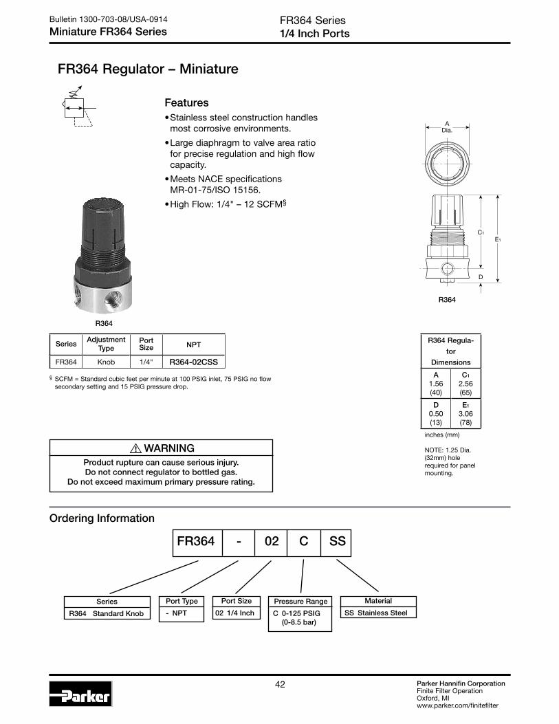
Parker Hannifin CorporationFinite Filter OperationOxford, MIwww.parker.com/finitefilter
42
Ordering Information
Features• Stainless steel construction handles
most corrosive environments.
• Large diaphragm to valve area ratio for precise regulation and high flow capacity.
• Meets NACE specifications MR-01-75/ISO 15156.
• High Flow: 1/4" – 12 SCFM§
FR364 Series1/4 Inch Ports
Bulletin 1300-703-08/USA-0914
Miniature FR364 Series
FR364 Regulator – Miniature
C1
E1
D
ADia.
Material
SS Stainless Steel
Pressure Range
C 0-125 PSIG (0-8.5 bar)
Port Size
02 1/4 Inch
§ SCFM = Standard cubic feet per minute at 100 PSIG inlet, 75 PSIG no flow secondary setting and 15 PSIG pressure drop.
SeriesAdjustment
TypePortSize NPT
FR364 Knob 1/4" R364-02CSS
R364 Regula-
tor
Dimensions
A1.56(40)
C1
2.56(65)
D0.50(13)
E1
3.06(78)
inches (mm)
NOTE: 1.25 Dia. (32mm) hole required for panel mounting.
FR364 - 02 C SS
Port Type
- NPT
Series
R364 Standard Knob
R364
! WARNINGProduct rupture can cause serious injury.Do not connect regulator to bottled gas.
Do not exceed maximum primary pressure rating.
R364

Parker Hannifin CorporationFinite Filter OperationOxford, MIwww.parker.com/finitefilter
4343
0
20
30
50
10
40
60
70
90
80
100
0 2 4 6 8 10 12 14 16 18 20
Pre
ssu
re D
rop
- P
SIG
0
0 .1 .3 .5 .7 .9 1.1 1.3
Flow - SCFM
Flow - dm /s
Pre
ssu
re D
rop
- b
ar
3
n
1
2
3
4
5
6
Flow Characteristics
1/4 Inch Ports100 PSIG (6.9 bar Primary Pressure
FR364 SeriesAir Line Regulators
Bulletin 1300-703-08/USA-0914
Technical Specifications – FR364
Operation
SpecificationsGauge Port .............................................................................1/4 Inch
Operation .................................................. Fluorocarbon Diaphragm
Port Threads ..........................................................................1/4 Inch
Pressure & Temperature Ratings – ...........300 PSIG Max (20.7 bar) 40°F to 150°F (4°C to 66°C)
Weight ........................................................................0.5 lb. (0.23 kg)
Materials of ConstructionAdjustment Mechanism / Springs .................... 316 Stainless Steel
Adjusting Knob (R364) ...............................................Polypropylene
Body .................................................................... 316 Stainless Steel
Bonnet (R364) ......................................................................... Acetal
Bottom Plug ....................................................... 316 Stainless Steel
Poppet ................................................................ 316 Stainless Steel
Seals ............................................................................ Fluorocarbon
FR364 Regulator Kits & AccessoriesR364 Bonnet Kit (Knob Included) ................................CKR364YSS
Gauge – 160 PSIG (0 to 1100 kPa) ..................................... K4515N14160SS
Panel Mount Bracket (Stainless) .....................................161X57-SS
Panel Mount Nut – Stainless .......................................................................R05X51-SS Plastic.............................................................................. R05X51-P
Service Kit – Relieving .....................................................................RKR364YSS
Springs – 0-125 PSIG Range ...............................................SPR-377-1-SS
Technical Information
With the adjusting knob (A) turned fully counter-clockwise (no spring load), and pressure supplied to the regulator inlet port, the valve poppet assembly (B) is closed. Turning the adjusting knob clockwise applies a load to control spring (C). This load causes the diaphragm (D) and the valve poppet assembly (B) to move downward allowing flow across the seat area (E) created between the poppet assembly and the seat. Pressure in the downstream line is sensed below the diaphragm (D) and offsets the load of spring (C). As downstream pressure rises, poppet assembly (B) and diaphragm (D) move upward until the area (E) is closed and the load of the spring (C) and pressure under diaphragm (D) are in balance. A reduced outlet pressure has now been obtained, depending on spring load. Creating a demand downstream, such as opening a valve, results in a reduced pressure under the diaphragm (D). The load of control spring (C) now causes the poppet assembly to move downward opening seat area (E) allowing air to flow to meet the downstream demand. The flow of downstream air is metered by the amount of opening (E).
Should downstream pressure exceed the desired regulated pressure, the excess pressure will cause the diaphragm (D) to move upward against control spring (C), open vent hole (F), and vent the excess pressure to atmosphere through the hole in the bonnet (H). (This occurs in the relieving type regulator only.)
H
F
E
A
D
C
B
FR364
CAUTION:REGULATOR PRESSURE ADJUSTMENT – The working range of knob adjustment is designed to permit outlet pressures within their full range. Pressure adjustment beyond this range is also possible because the knob is not a limiting device. This is a common characteristic of most industrial regulators, and limiting devices may be obtained only by special design.
For best performance, regulated pressure should always be set by increasing the pressure up to the desired setting.

Parker Hannifin CorporationFinite Filter OperationOxford, MIwww.parker.com/finitefilter
44
05R Series1/4", 3/8" NPT – Basic 1/4" Body
Bulletin 1300-703-08/USA-0914
Economy 05R Series
05R Regulators – Economy
Features• Secondary aspiration plus balanced poppet provides
quick response and accurate pressure regulation.
• Rolling diaphragm for extended life.
• Removable non-rising knob for panel mounting and tamper resistance.
• Easily serviced.
• Reverse Flow.
• High Flow: 1/4" – 30 SCFM§
3/8" – 40 SCFM§
NOTE: 1.53 Dia. (39mm) hole required for panel mounting.
§ SCFM = Standard cubic feet per minute at 100 PSIG inlet, 90 PSIG no flow secondary setting and 10 PSIG pressure drop.
A
B
PU
SH TO LOCK
C
D
E
1/4" NPTGauge Ports
(2)
Options
Blank No Options
Preset / Pressure Limited
Blank None
Port Type
Blank NPT
Port Size
1 1/4 Inch 2 3/8 Inch
Pressure Range
Without Gauge 13 125 PSIG
With Gauge** 18 125 PSIG
05R 1 13 A * — — ---
Port Size NPT
Without Gauge
1/4" 05R113A*
3/8" 05R213A*With 160 PSI Gauge
1/4" 05R118A*
3/8" 05R218A*
05R Regulator Dimensions
A2.00(51)
B2.06(52)
C3.16(80)
D1.28(32)
E4.44(113)
Inches (mm)
Ordering Information
** Includes 1-1/2" Dial Face Gauge
Engineering Level
* Will be entered at factory
† Inlet Pressure is 100 PSIG. For other pressures, contact factory.
Relief
A Relieving
* 1/4 & 3/8 inch meet ISO 1179-1 Standard.
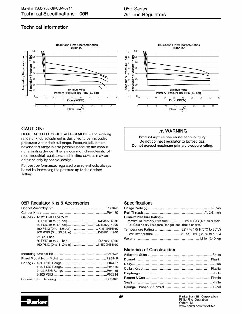
Parker Hannifin CorporationFinite Filter OperationOxford, MIwww.parker.com/finitefilter
4545
05R SeriesAir Line Regulators
Bulletin 1300-703-08/USA-0914
Technical Specifications – 05R
Technical Information
SpecificationsGauge Ports (2) ..................................................................... 1/4 InchPort Threads .................................................................. 1/4, 3/8 InchPrimary Pressure Rating – Maximum Primary Pressure ...................250 PSIG (17.2 bar) Max. For Secondary Pressure Ranges see above charts.Temperature Rating ..............................32°F to 175°F (0°C to 80°C) Low Temperature ............................. -4°F to 125°F (-20°C to 52°C) Weight .......................................................................1.1 lb. (0.49 kg)
Materials of ConstructionAdjusting Stem .........................................................................BrassBonnet ..................................................................................... PlasticBody ............................................................................................. ZincCollar, Knob ............................................................................ PlasticDiaphragm ................................................................................NitrilePoppet & Cap .......................................................................... PlasticSeals ..........................................................................................NitrileSprings – Poppet & Control .......................................................Steel
05R Regulator Kits & AccessoriesBonnet Assembly Kit ........................................................... PS915PControl Knob .........................................................................P04420Gauges – 1-1/2" Dial Face ????
30 PSIG (0 to 2.1 bar) ...................................K4515N14030 60 PSIG (0 to 4.1 bar) ...................................K4515N14060 160 PSIG (0 to 11.0 bar) ............................... K4515N14160 300 PSIG (0 to 20.0 bar) ..............................K4515N14300
2" Dial Face 60 PSIG (0 to 4.1 bar) ................................. K4520N14060 160 PSIG (0 to 11.0 bar) ..............................K4520N14160
Mounting Bracket Kit ...........................................................PS963PPanel Mount Nut – Metal .....................................................PS964PSprings – 1-30 PSIG Range ...................................................P04427 1-60 PSIG Range ...................................................P04426 2-125 PSIG Range .................................................P04425 2-200 PSIG ............................................................P02934Service Kit – Relieving ........................................................PS908P
0
15
30
45
60
75
90
105
120
10 0 10 20 30 40 50 60 70 80
Relief and Flow Characteristics05R113A*
05 5 10 15 20 25 30 35
Flow (SCFM)
Flow - dm /s3
n
0
1 Sec
ond
ary
Pre
ssur
e -
PS
IG
Sec
ond
ary
Pre
ssur
e -
bar
2
3
4
5
6
7
8
1/4 Inch PortsPrimary Pressure 100 PSIG (6.9 bar)
0
15
30
45
60
75
90
105
120
10 0 10 20 30 40 50 60 70 80
Relief and Flow Characteristics05R213A*
05 5 10 15 20 25 30 35
Flow (SCFM)
Flow - dm /s3
n
0
1 Sec
ond
ary
Pre
ssur
e -
PS
IG
Sec
ond
ary
Pre
ssur
e -
bar
2
3
4
5
6
7
8
3/8 Inch PortsPrimary Pressure 100 PSIG (6.9 bar)
! WARNINGProduct rupture can cause serious injury.Do not connect regulator to bottled gas.
Do not exceed maximum primary pressure rating.
CAUTION:REGULATOR PRESSURE ADJUSTMENT – The working range of knob adjustment is designed to permit outlet pressures within their full range. Pressure adjustment beyond this range is also possible because the knob is not a limiting device. This is a common characteristic of most industrial regulators, and limiting devices may be obtained only by special design.
For best performance, regulated pressure should always be set by increasing the pressure up to the desired setting.

Parker Hannifin CorporationFinite Filter OperationOxford, MIwww.parker.com/finitefilter
46
06R Regulators – Compact
06R Series1/4", 3/8", 1/2" NPT – Basic 3/8" Body
Bulletin 1300-703-08/USA-0914
Compact 06R Series
Features• Secondary aspiration plus balanced poppet provides
quick response and accurate pressure regulation.
• Rolling diaphragm for extended life.
• Two high flow 1/4" gauge ports can be used as additional outlets.
• Easily serviced.
• Removable non-rising knob for panel mounting and tamper resistance.
• High Flow: 1/4" – 53 SCFM§ 3/8" – 60 SCFM§ 1/2" – 75 SCFM§
C
E
D
B
A
PU
SH TO LOCK
1/4" NPTGauge Ports
(2)
NOTE: 2.00 Dia. (51mm) hole required for panel mounting.
§ SCFM = Standard cubic feet per minute at 100 PSIG inlet, 90 PSIG no flow secondary setting and 10 PSIG pressure drop.
Options
Blank No Options
Preset / Pressure Limited
Blank None
Port Type
Blank NPT
Port Size
1 1/4 Inch 2 3/8 Inch 3 1/2 Inch
Pressure Range
Without Gauge 13 125 PSIG
Relief
A Relieving
06R 1 13 A * — — ---
! WARNINGProduct rupture can cause serious injury.Do not connect regulator to bottled gas.
Do not exceed maximum primary pressure rating.
Port Size NPT
Without Gauge
1/4" 06R113A*
3/8" 06R213A*
1/2" 06R313A*
Ordering Information
Engineering Level
*Will be entered at
factory
06R Regulator Dimensions
A2.81(71)
B2.74(70)
C4.69(119)
D1.39(35)
E6.08(154)
Inches (mm)
† Inlet Pressure is 100 PSIG. For other pressures, contact factory.
* 1/4 & 3/8 inch meet ISO 1179-1 Standard.

Parker Hannifin CorporationFinite Filter OperationOxford, MIwww.parker.com/finitefilter
4747
06R SeriesAir Line Regulators
Bulletin 1300-703-08/USA-0914
Technical Specifications – 06R
Technical Information
06R Regulator Kits & AccessoriesBonnet Assembly Kit ............................................................PS715P
Control Knob ...................................................................... P04069B
Gauges – 60 PSIG (0 to 4.1 bar) ................................ K4520N14060 160 PSIG (0 to 11.0 bar) ..............................K4520N14160
Mounting Bracket Kit (Includes Panel Mount Nut) .............. PS707P
Panel Mount Nut – Plastic .....................................................P04082 Metal .................................................... P04079B
Service Kit – Relieving (Includes Poppet) ............................ PS708P
Springs – 2-125 PSIG Range ..................................................P04063
Tamperproof Kit .................................................................... PS737P
SpecificationsGauge Ports (2) ..................................................................... 1/4 Inch (Can be used as additional High Flow 1/4 Inch Outlet Ports)Port Threads ...........................................................1/4, 3/8, 1/2 InchPrimary Pressure Rating – Maximum Primary Pressure ............................ 250 PSIG (17.2 bar)Secondary Pressure Range – Standard Pressure .............................. 2 to 125 PSIG (0 to 8.6 bar) Temperature Rating ..............................32°F to 175°F (0°C to 80°C)Weight 1.6 lb. (0.7 kg)
Materials of ConstructionAdjusting Stem ..........................................................................SteelBody ............................................................................................ ZincBonnet, Piston Stem, Valve Poppet & Cap .......................... PlasticCollar, Knob ............................................................................. PlasticDiaphragm ................................................................................NitrileSeals ..........................................................................................NitrileSprings – Poppet ............................................................... Stainless Control ......................................................................Steel
00
Relief And Flow Characteristics06R113A*
Sec
ond
ary
Pre
ssur
e -
PS
IG
10 20 30 40 50
0
0
Sec
ond
ary
Pre
ssur
e -
bar
20
60
80
40
1
2
3
4
5
6
5 25 30
1/4 Inch Ports100 PSIG (6.9 bar) Primary Pressure
10 60 70
5 10 15 20
100
Rated Flow - SCFM
Flow - dm /s3
n
Sec
ond
ary
Pre
ssur
e -
PS
IG
Sec
ond
ary
Pre
ssur
e -
bar
0
1
2
3
4
5
6
00
Relief And Flow Characteristics06R313A*
10 20 30 40 50
0
20
60
80
40
100
5 25 30
10 60 70 80 90
5 10 15 20 35 40
Rated Flow - SCFM
Flow - dm /s3
n
1/2 Inch Ports100 PSIG (6.9 bar) Primary Pressure
Sec
ond
ary
Pre
ssur
e -
PS
IG
Sec
ond
ary
Pre
ssur
e -
bar
0
1
2
3
4
5
6
00
Relief And Flow Characteristics06R213A*
10 20 30 40 50
0
20
60
80
40
100
5 25 30
10 60 70
5 10 15 20
Rated Flow - SCFM
Flow - dm /s3
n
3/8 Inch Ports100 PSIG (6.9 bar) Primary Pressure
CAUTION:REGULATOR PRESSURE ADJUSTMENT – The working range of knob adjustment is designed to permit outlet pressures within their full range. Pressure adjustment beyond this range is also possible because the knob is not a limiting device. This is a common characteristic of most industrial regulators, and limiting devices may be obtained only by special design.
For best performance, regulated pressure should always be set by increasing the pressure up to the desired setting.

Parker Hannifin CorporationFinite Filter OperationOxford, MIwww.parker.com/finitefilter
48
Ordering Information
FR10 Series1/2 Inch Ports
Bulletin 1300-703-08/USA-0914
Standard FR10 Series
FR10 Regulator – Standard
A
B
C
E
D
Features• Stainless steel construction handles
most corrosive environments.
• Large diaphragm to valve area ratio for precise regulation and high flow capacity.
• Meets NACE specifications MR-01-75/ISO 15156.
• Low temperature version available.
• High Flow: 1/2" – 80 SCFM§
PortSize NPT
1/2" FR10-04CSS
Material
SS Stainless Steel
Pressure Range
C 0-125 PSIG (0-8.5 bar)
Port Size
04 1/2 Inch
FR10 - 04 C SS
Port Type
- NPT
§ SCFM = Standard cubic feet per minute at 100 PSIG inlet, 75 PSIG no flow secondary setting and 15 PSIG pressure drop.
R10, R11 Regulator
Dimensions
A2.34(60)
B2.43(62)
C3.59(91)
D1.38(35)
E4.97(126)
inches (mm)NOTE: 1.75 Dia. (44mm) hole required for panel mounting.
Series
R10 Standard Knob
R10
! WARNINGProduct rupture can cause serious injury.Do not connect regulator to bottled gas.
Do not exceed maximum primary pressure rating.
R10

Parker Hannifin CorporationFinite Filter OperationOxford, MIwww.parker.com/finitefilter
4949
0
20
30
50
10
40
60
70
90
80
100
0 10 20 30 40 50 60 70 80 90 100
Pre
ssu
re D
rop
- P
SIG
0
0 5 10 15 20 25 30 35 40 45
Flow - SCFM
Flow - dm /s
Pre
ssu
re D
rop
- b
ar
3
n
1
2
3
4
5
6
Flow Characteristics
1/2 Inch Ports100 PSIG (6.9 bar Primary Pressure
FR10 SeriesAir Line Regulators
Bulletin 1300-703-08/USA-0914
Technical Specifications – FR10
SpecificationsGauge Port .............................................................................1/4 Inch
Operation .................................................. Fluorocarbon Diaphragm
Port Threads ......................................................................... 1/2 Inch
Pressure & Temperature Ratings – ...........300 PSIG Max (20.7 bar)
0°F to 150°F (-18°C to 66°C) Note: Air must be dry enough to avoid ice formation at temperatures below 32°F (2°C).
Weight ...................................................................... 1.79 lb. (0.81 kg)
Materials of ConstructionAdjustment Mechanism / Springs .................... 316 Stainless Steel
Body .................................................................... 316 Stainless Steel
Bonnet / Knob (R10) ............................................................... Acetal
Bottom Plug ....................................................... 316 Stainless Steel
Poppet ................................................................ 316 Stainless Steel
Seals ............................................................................ Fluorocarbon
FR10 Regulator Kits & AccessoriesR10 Bonnet Kit (Knob Included) .................................... CKR10YSS
Gauge – 160 PSIG (0 to 1100 kPa), 2" Face ....................... K4520N14160SS
Panel Mount Bracket (Stainless) .....................................161X57-SS
Panel Mount Nut – Stainless ....................................................................... R10X51-SS Plastic.............................................................................. R10X51-P
Service Kit – Relieving ........................................................................ RKR10YSS
Springs – 0-125 PSIG Range .................................................. SPR-389-1-SS
Operation
D
A
C
B
H
F
E
Technical Information
With the adjusting knob (A) turned fully counter-clockwise (no spring load), and pressure supplied to the regulator inlet port, the valve poppet assembly (B) is closed. Turning the adjusting knob clockwise applies a load to control spring (C). This load causes the diaphragm (D) and the valve poppet assembly (B) to move downward allowing flow across the seat area (E) created between the poppet assembly and the seat. Pressure in the downstream line is sensed below the diaphragm (D) and offsets the load of spring (C). As downstream pressure rises, poppet assembly (B) and diaphragm (D) move upward until the area (E) is closed and the load of the spring (C) and pressure under diaphragm (D) are in balance. A reduced outlet pressure has now been obtained, depending on spring load. Creating a demand downstream, such as opening a valve, results in a reduced pressure under the diaphragm (D). The load of control spring (C) now causes the poppet assembly to move downward opening seat area (E) allowing air to flow to meet the downstream demand. The flow of downstream air is metered by the amount of opening (E).
Should downstream pressure exceed the desired regulated pressure, the excess pressure will cause the diaphragm (D) to move upward against control spring (C), open vent hole (F), and vent the excess pressure to atmosphere through the hole in the bonnet (H). (This occurs in the relieving type regulator only.)
CAUTION:REGULATOR PRESSURE ADJUSTMENT – The working range of knob adjustment is designed to permit outlet pressures within their full range. Pressure adjustment beyond this range is also possible because the knob is not a limiting device. This is a common characteristic of most industrial regulators, and limiting devices may be obtained only by special design.
For best performance, regulated pressure should always be set by increasing the pressure up to the desired setting.

Parker Hannifin CorporationFinite Filter OperationOxford, MIwww.parker.com/finitefilter
50
07R Regulators – Standard
07R Series3/8", 1/2", 3/4" NPT – Basic 1/2" Body
Bulletin 1300-703-08/USA-0914
Standard 07R Series
C
E
D
B
A
PU
SH TO LOCK
1/4" NPTGauge Ports
(2)
Features• Secondary aspiration plus balanced poppet provides
quick response and accurate pressure regulation.
• Rolling diaphragm for extended life.
• Two high flow 1/4" gauge ports can be used as additional outlets.
• Easily serviced.
• Removable non-rising knob for panel mounting and tamper resistance.
• High Flow: 3/8" – 70 SCFM§
1/2" – 90 SCFM§
3/4" – 90 SCFM§
NOTE: 2.00 Dia. (51mm) hole required for panel mounting.
§ SCFM = Standard cubic feet per minute at 100 PSIG inlet, 90 PSIG no flow secondary setting and 10 PSIG pressure drop.
Options
Blank No Options
Preset / Pressure Limited
Blank None† Inlet Pressure is 100
PSIG. For other pressures, contact factory.
Port Type
Blank NPT
Port Size
2 3/8 Inch 3 1/2 Inch 4 3/4 Inch
Pressure Range
Without Gauge 13 125 PSIG
Relief
A Relieving
07R 3 13 A * — — ---
! WARNINGProduct rupture can cause serious injury.Do not connect regulator to bottled gas.
Do not exceed maximum primary pressure rating.
Port Size NPT
Without Gauge
3/8" 07R213A*
1/2" 07R313A*
3/4" 07R413A*
Ordering Information
Engineering Level
*Will be entered at
factory
07R Regulator Dimensions
A3.24(82)
B2.74(70)
C4.79(122)
D1.61(41)
E6.40(163)
Inches (mm)
* 3/8 & 1/2 inch meet ISO 1179-1 Standard.
GRAYED OUT ITEMS
ARE OBSOLETE
AS OF JULY 1, 2014

Parker Hannifin CorporationFinite Filter OperationOxford, MIwww.parker.com/finitefilter
5151
07R SeriesAir Line Regulators
Bulletin 1300-703-08/USA-0914
Technical Specifications – 07R
Technical Information
07R Regulator Kits & AccessoriesBonnet Assembly Kit ............................................................PS715P
Control Knob ...................................................................... P04069B
Gauges – 60 PSIG (0 to 4.1 bar) ................................. K4520N14060 160 PSIG (0 to 11.0 bar) ..............................K4520N14160
Mounting Bracket Kit (Includes Panel Mount Nut) ............... PS807P
Panel Mount Nut – Plastic ....................................................P04082 Metal ................................................... P04079B
Service Kit – Relieving (Includes Poppet) ...........................PS808P
Springs – 2-125 PSIG Range ...........................................P04063
Tamperproof Kit ................................................................... PS737P
SpecificationsGauge Ports (2) ..................................................................... 1/4 Inch (Can be used as additional High Flow 1/4 Inch Outlet Ports)Port Threads ...........................................................3/8, 1/2, 3/4 InchPrimary Pressure Rating – Maximum Primary Pressure ............................ 250 PSIG (17.2 bar)Secondary Pressure Range – Standard Pressure .............................. 2 to 125 PSIG (0 to 8.6 bar) Temperature Rating ..............................32°F to 175°F (0°C to 80°C)Weight 2.5 lb. (1.1 kg)
Materials of ConstructionAdjusting Stem ......................................................................... SteelBody ............................................................................................. ZincBonnet, Piston Stem, Valve Poppet & Cap .......................... PlasticCollar, Knob ............................................................................. PlasticDiaphragm ................................................................................NitrileSeals ..........................................................................................NitrileSprings – Poppet ............................................................... Stainless Control ......................................................................Steel
00
Relief And Flow Characteristics07R213A*
10 30 50 70 900
20
60
80
40
100
1
2
3
4
5
6
10 110 130
0 5 45 555 15 25 35
Sec
ond
ary
Pre
ssur
e -
PS
IG
Sec
ond
ary
Pre
ssur
e -
bar
Rated Flow - SCFM
Flow - dm /s3
n
3/8 Inch Ports100 PSIG (6.9 bar) Primary Pressure
00
Relief And Flow Characteristics07R313A*
10 30 50 70 900
20
60
80
40
100
1
2
3
4
5
6
10 110 130
0 5 45 555 15 25 35
Sec
ond
ary
Pre
ssur
e -
PS
IG
Sec
ond
ary
Pre
ssur
e -
bar
Rated Flow - SCFM
Flow - dm /s3
n
1/2 Inch Ports100 PSIG (6.9 bar) Primary Pressure
00
Relief And Flow Characteristics07R413A*
10 30 50 70 900
20
60
80
40
100
1
2
3
4
5
6
10 110 130 150 170
0 5 45 55 65 755 15 25 35
Sec
ond
ary
Pre
ssur
e -
PS
IG
Sec
ond
ary
Pre
ssur
e -
bar
Rated Flow - SCFM
Flow - dm /s3
n
3/4 Inch Ports100 PSIG (6.9 bar) Primary Pressure
CAUTION:REGULATOR PRESSURE ADJUSTMENT – The working range of knob adjustment is designed to permit outlet pressures within their full range. Pressure adjustment beyond this range is also possible because the knob is not a limiting device. This is a common characteristic of most industrial regulators, and limiting devices may be obtained only by special design.
For best performance, regulated pressure should always be set by increasing the pressure up to the desired setting.

Parker Hannifin CorporationFinite Filter OperationOxford, MIwww.parker.com/finitefilter
52
P3NR Series3/4", 1", 1-1/2" NPT – Basic 1" Body
Bulletin 1300-703-08/USA-0914
Hi-Flow P3NR Series
P3NR Regulators – Hi-Flow
Features• Port blocks (PB) available to provide 1-1/2"
port extension to 1" ported bodies.
• Self relieving feature plus balanced poppet provides quick response and accurate pressure regulation.
• Solid control piston for extended life.
• High Flow: 3/4" – 200 SCFM§ 1" – 300 SCFM§ 1½" – 300 SCFM§
B
CE
D
AA (PB)
PU
SH TO LOCK
1/4" NPTGauge Ports
(2)
P3N R A 9 8 B N N
Pressure Gauge
Without Gauge N 125 PSI (0 to 8 bar)
Adjustment
N Non-Rising Knob
Relief
B Relieving
Port Size
6 3/4" (w/o Port Blocks) 8 1" (w/o Port Blocks) P 1-1/2" Port Blocks (w/ 1" Ported Body)
Port Type
9 NPT Female
Design Level
NOTE: 2.00 Dia. (51mm) hole required for panel mounting.
§ SCFM = Standard cubic feet per minute at 100 PSIG inlet, 90 PSIG no flow secondary setting and 10 PSIG pressure drop.
! WARNINGProduct rupture can cause serious injury.Do not connect regulator to bottled gas.
Do not exceed maximum primary pressure rating.
Port Size NPT
Without Gauge
3/4" P3NRA96BNN
1" P3NRA98BNN
1½ P3NRA9PBNN
Ordering Information
P3NR Regulator Dimensions
A3.62(92)
A(PB)
5.91(150)
B3.62(92)
C6.38(162)
D2.08(53)
E8.46(215)
Inches (mm)
* 3/4 & 1 inch meet ISO 1179-1 Standard.

Parker Hannifin CorporationFinite Filter OperationOxford, MIwww.parker.com/finitefilter
5353
P3NR SeriesAir Line Regulators
Bulletin 1300-703-08/USA-0914
Technical Specifications – P3NR
† 1" Port Body with 1½" Port Block.
Technical Information
P3NR Regulator Kits & AccessoriesControl Knob ................................................................. P3NKA00PNGauges – 60 PSIG (0 to 4.1 bar) ................................. K4520N14060 160 PSIG (0 to 11.0 bar) ..............................K4520N14160
Mounting Bracket Kit* .................................................P3NKA00MW
Service Kit – Relieving ................................................. P3NKA00RR
Springs – 2-125 PSIG Range .............................................C10A1308
SpecificationsGauge Ports (2) ..................................................................... 1/4 Inch (Can be used as additional High Flow 1/4 Inch Outlet Ports)Port Threads ........................................................... 3/4, 1, 1-1/2 Inch
Primary Pressure Rating – Maximum Primary Pressure ............................ 250 PSIG (17.2 bar)Secondary Pressure Range – Standard Pressure .............................. 2 to 125 PSIG (0 to 8.6 bar)Temperature Rating ..............................32°F to 175°F (0°C to 80°C)
0
15
30
45
60
75
120
105
90
0 200100-100 300 400 500 600
0 50-50 100 150 200 250
Flow - SCFM
Pre
ssur
e D
rop
- P
SIG
0
1
Pre
ssur
e D
rop
- b
ar
2
3
4
5
7
6
83/4 Inch Ports
Primary Pressure 100 PSIG (6.9 bar)
Relief And Flow CharacteristicsP3NR
Flow - dm /s3
n
0
15
30
45
60
75
120
105
90
0 200100-100 300 400 500 700600
Pre
ssur
e D
rop
- P
SIG
0
1
0 50-50 100 150 200 250 300
Flow - SCFM
Pre
ssur
e D
rop
- b
ar
2
3
4
5
7
6
8
1 Inch PortsPrimary Pressure 100 PSIG (6.9 bar)
Relief And Flow CharacteristicsP3NR
Flow - dm /s3
n
0
15
30
45
60
75
120
105
90
0 200100-100 300 400 500 700600
Pre
ssur
e D
rop
- P
SIG
0
1
0 50-50 100 150 200 250 300
Flow - SCFM
Pre
ssur
e D
rop
- b
ar
2
3
4
5
7
6
81-1/2 Inch Ports
Primary Pressure 100 PSIG (6.9 bar)
Relief And Flow CharacteristicsP3NR
Flow - dm /s3
n
CAUTION:REGULATOR PRESSURE ADJUSTMENT – The working range of knob adjustment is designed to permit outlet pressures within their full range. Pressure adjustment beyond this range is also possible because the knob is not a limiting device. This is a common characteristic of most industrial regulators, and limiting devices may be obtained only by special design.
For best performance, regulated pressure should always be set by increasing the pressure up to the desired setting.
Weight – 3/4" ................................................................4.2 lb. (1.9 kg) 1" ...................................................................4.2 lb. (1.9 kg) 1½" † .............................................................5.3 lb. (2.4 kg)
Materials of ConstructionAdjusting Stem ..........................................................................SteelBody ....................................................................................AluminumBonnet ...............................................................................AluminumKnob ....................................................................................... PlasticPiston ...................................................................................... PlasticPoppet Assembly .....................................................................BrassSeals ..........................................................................................NitrileSprings – Poppet & Control .....................................................Steel

Parker Hannifin CorporationFinite Filter OperationOxford, MIwww.parker.com/finitefilter
54
11R Pilot Controlled Regulator – Compact
11R Series1/4", 3/8", 1/2" NPT - Basic 3/8" Body
Bulletin 1300-703-08/USA-0914
Compact 11R Series
C E
D
B
1/4" NPT
A
1/4" NPTGauge Ports
(2)
Features• Balanced poppet provides quick response and
accurate pressure regulation.
• Pilot controlled regulators can be mounted “out of reach” with pilot regulator installed in a convenient location.
• Solid control piston for extended life.
• Two full flow 1/4" gauge ports can be used as additional outlets.
• Pilot port 1/4 Inch.
• High Flow: 1/4" – 85 SCFM§
3/8" – 95 SCFM§ 1/2" – 95 SCFM§
11R 2 15 P * —
Port Size
1 1/4 Inch 2 3/8 Inch 3 1/2 Inch
Relief / Gauge Options
Without Gauge 15 Relieving Piston
Port Type
Blank NPT
Adjustment
P Pilot Operated
NOTE: 2.00 Dia. (50,8mm) hole required for panel mounting.
§ SCFM = Standard cubic feet per minute at 100 PSIG inlet, 90 PSIG no flow secondary setting and 10 PSIG pressure drop.
Port Size NPT
Without Gauge
1/4" 11R115P*
3/8" 11R215P*
1/2" 11R315P*
11R Pilot Regulator Dimensions
A2.81(71)
B2.74(70)
C3.05(77)
D1.39(35)
E4.44(113)
Inches (mm)
! WARNINGProduct rupture can cause serious injury.Do not connect regulator to bottled gas.
Do not exceed maximum primary pressure rating.
Ordering Information
Engineering Level
*Will be entered at
factory

Parker Hannifin CorporationFinite Filter OperationOxford, MIwww.parker.com/finitefilter
5555
11R SeriesPilot Controlled Regulators
Bulletin 1300-703-08/USA-0914
Technical Specifications – 11R
Technical Information
11R Pilot Regulator Kits & AccessoriesBody Service Kits – Seat Insert Kit ...................................... PS713P
Gauges – 60 PSIG (0 to 4.1 bar) ................................. K4520N14060 160 PSIG (0 to 11.0 bar) ...............................K4520N14160
Mounting Bracket Kit (Includes Panel Mount Nut) ............... PS707P
Panel Mount Nut – Plastic ....................................................P04082 Metal ................................................... P04079B
Pilot Conversion Kit – Relieving ........................................... PS745P
Service Kits – Relieving ........................................................ PS749P
SpecificationsGauge Ports (2) ......................................................................1/4 Inch (Can be used as additional Full Flow 1/4 Inch Outlet Ports)
Port Threads .......................................................... 1/4, 3/8, 1/2 Inch
Pressure & Temperature Rating – ....... 0 to 250 PSIG (0 to 17.2 bar) 32°F to 175°F (0°C to 80°C)
Weight ........................................................................ 1.3 lb. (0.58 kg.)
Materials of ConstructionBody & Pilot Cap ......................................................................... Zinc
Piston, Valve Poppet, & Collar ............................................... Plastic
Seals ..........................................................................................Nitrile
Springs .......................................................................................Steel
00
Relief And Flow Characteristics11R215P*
20 40 60 80 100
0
0
20
60
80
40
100
1
2
3
4
5
6
10 50 60
20 120 140
10 20 30 40
Sec
ond
ary
Pre
ssur
e -
PS
IG
Sec
ond
ary
Pre
ssur
e -
bar
Rated Flow - SCFM
Flow - dm /s3
n
3/8 Inch Ports100 PSIG (6.9 bar) Primary Pressure
00
Relief And Flow Characteristics11R115P*
20 40 60 80 100
0
0
20
60
80
40
100
1
2
3
4
5
6
10 50 60
20 120 140
10 20 30 40
Sec
ond
ary
Pre
ssur
e -
PS
IG
Sec
ond
ary
Pre
ssur
e -
bar
Rated Flow - SCFM
Flow - dm /s3
n
1/2 Inch Ports100 PSIG (6.9 bar) Primary Pressure
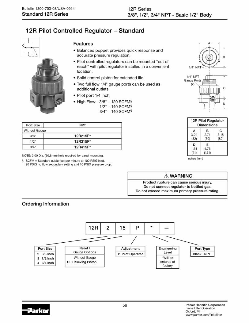
Parker Hannifin CorporationFinite Filter OperationOxford, MIwww.parker.com/finitefilter
56
12R Pilot Controlled Regulator – Standard
12R Series3/8", 1/2", 3/4" NPT - Basic 1/2" Body
Bulletin 1300-703-08/USA-0914
Standard 12R Series
C E
D
B
1/4" NPT
A
1/4" NPTGauge Ports
(2)
Features• Balanced poppet provides quick response and
accurate pressure regulation.
• Pilot controlled regulators can be mounted “out of reach” with pilot regulator installed in a convenient location.
• Solid control piston for extended life.
• Two full flow 1/4" gauge ports can be used as additional outlets.
• Pilot port 1/4 Inch.
• High Flow: 3/8" – 120 SCFM§
1/2" – 140 SCFM§
3/4" – 140 SCFM§
12R 2 15 P * —
NOTE: 2.00 Dia. (50,8mm) hole required for panel mounting.
§ SCFM = Standard cubic feet per minute at 100 PSIG inlet, 90 PSIG no flow secondary setting and 10 PSIG pressure drop.
Port Size NPT
Without Gauge
3/8" 12R215P*
1/2" 12R315P*
3/4" 12R415P*
12R Pilot Regulator Dimensions
A3.24(82)
B2.74(70)
C3.15(80)
D1.61(41)
E4.76(121)
Inches (mm)
! WARNINGProduct rupture can cause serious injury.Do not connect regulator to bottled gas.
Do not exceed maximum primary pressure rating.
Ordering Information
Port Size
2 3/8 Inch 3 1/2 Inch 4 3/4 Inch
Relief / Gauge Options
Without Gauge 15 Relieving Piston
Port Type
Blank NPT
Adjustment
P Pilot Operated
Engineering Level
*Will be entered at
factory

Parker Hannifin CorporationFinite Filter OperationOxford, MIwww.parker.com/finitefilter
5757
Technical Information
12R Pilot Regulator Kits & AccessoriesBody Service Kits – Seat Insert Kit ...................................... PS813P
Gauges – 60 PSIG (0 to 4.1 bar) .................................. K4520N14060 160 PSIG (0 to 11.0 bar) ...............................K4520N14160
Mounting Bracket Kit (Includes Panel Mount Nut) ............... PS807P
Panel Mount Nut – Plastic .....................................................P04082 Metal .................................................... P04079B
Pilot Conversion Kit – Relieving ........................................... PS745P
Service Kits – Relieving .......................................................PS849P
SpecificationsGauge Ports (2) ..................................................................... 1/4 Inch (Can be used as additional Full Flow 1/4 Inch Outlet Ports)
Port Threads ...........................................................3/8, 1/2, 3/4 Inch
Pressure & Temperature Rating – ........0 to 250 PSIG (0 to 17.2 bar) 32°F to 175°F (0°C to 80°C)
Weight ........................................................................2.0 lb. (0.91 kg)
Materials of ConstructionBody & Pilot Cap ......................................................................... Zinc
Piston, Valve Poppet, & Collar ............................................... Plastic
Seals ..........................................................................................Nitrile
Springs .......................................................................................Steel
0
Relief And Flow Characteristics12R315P*
0
20
60
80
40
100
1
2
3
4
5
6
0 20 40 60 80 100 120 140 160
0 10 50 60 7010 20 30 40
20 180
80
200 220
90 100
Sec
ond
ary
Pre
ssur
e -
PS
IG
Sec
ond
ary
Pre
ssur
e -
bar
Rated Flow - SCFM
Flow - dm /s3
n
1/2 Inch Ports100 PSIG (6.9 bar) Primary Pressure
0
Relief And Flow Characteristics12R215P*
0
20
60
80
40
100
1
2
3
4
5
6
0 20 40 60 80 100 120 140 160
0 10 50 60 7010 20 30 40
20 180
80
200
90
Sec
ond
ary
Pre
ssur
e -
PS
IG
Sec
ond
ary
Pre
ssur
e -
bar
Rated Flow - SCFM
Flow - dm /s3
n
3/8 Inch Ports100 PSIG (6.9 bar) Primary Pressure
12R SeriesPilot Controlled Regulators
Bulletin 1300-703-08/USA-0914
Technical Specifications – 12R

Parker Hannifin CorporationFinite Filter OperationOxford, MIwww.parker.com/finitefilter
58
Air Preparation UnitsBulletin 1300-703-08/USA-0914
Filter / Regulators
Filter / Regulators• Pipe Sizes 1/8 thru 3/4 Inch
• Flows to 90 SCFM
• Pressures to 250 PSIG
Integral Filter / Regulators are an excellent choice where accurate pressure regulation and high moisture removal efficiency are required in a space saving package.
• Miniature 14E Series, 1/8 and 1/4 Inch
• Miniature FB548 Stainless Series, 1/4 Inch
• Economy 05E Series, 1/4 and 3/8 Inch
• Compact 06E Series, 1/4, 3/8 and 1/2 Inch
• Standard FB11 Stainless Series, 1/2 Inch
• Standard 07E Series, 3/8, 1/2 and 3/4 Inch
• Standard / Coalescing F12E Series, 3/8, 1/2 and 3/4 Inch
Filter / Regulator Selection1. Determine maximum system flow requirements.
2. Determine maximum allowable pressure drop at rated flow in SCFM.
3. Refer to flow chart and select filter/regulator by choosing the curve that offers minimum pressure drop at desired flow in SCFM.
Once the required flow is determined for a pneumatic application the regulator or filter/regulator can be selected by using the flow chart. The chart serves two different purposes. To read the flow, use the right side of the chart. To read the relief characteristics use the left side of the chart. When reading the flow chart, first determine the secondary pressure that will be used. Find the appropriate pressure curve on the graph. Given an acceptable pressure drop for an application, follow the flow curve until it intersects the pressure drop point. This will give the flow at that particular pressure drop.
Reading Flow Charts to Size Filter / Regulators
Relief And Flow Characteristics05E22A13A*
00
1 15
30
45
60
75
90
105
120
10 0
05 5 10 15 20 25 30 35
10 20 30 40 50 60 70 80Flow - SCFM
Flow - dm /s
Sec
ond
ary
Pre
ssur
e -
PS
IG
Sec
ond
ary
Pre
ssur
e -
bar
3
n
2
3
4
5
6
7
83/8 Inch Ports
Primary Pressure 100 PSIG (6.9 bar)
ä� �
�
�
ä� �
ä� �
�
�
Manual�Drain�Relieving�(With Gauge)��
Automatic�Drain�Relieving
! WARNINGProduct rupture can cause serious injury.Do not connect regulator to bottled gas.
Do not exceed maximum primary pressure rating.
CAUTION:REGULATOR PRESSURE ADJUSTMENT – The working range of knob adjustment is designed to permit outlet pressures within their full range. Pressure adjustment beyond this range is also possible because the knob is not a limiting device. This is a common characteristic of most industrial regulators, and limiting devices may be obtained only by special design.
For best performance, regulated pressure should always be set by increasing the pressure up to the desired setting.

Parker Hannifin CorporationFinite Filter OperationOxford, MIwww.parker.com/finitefilter
5959
Air Preparation UnitsBulletin 1300-703-08/USA-0914
Filter / Regulators
06E / 07E
05E
Turning the knob (A) clockwise applies a load to control spring (B) which forces the piston/diaphragm (C) and valve poppet assembly (D) to move downward allowing filtered air to flow through the seat area (E) created between the poppet assembly and the seat. “First stage filtration” begins when air pressure supplied to the inlet port is directed through deflector plate (F) causing a swirling centrifugal action forcing liquids and coarse particles to the inner bowl wall (G) and down below the lower baffle (H) to the quiet zone. After liquids and large particles are removed in the first stage of filtration “second stage filtration” occurs as air flows through element (J) where smaller particles are filtered out and retained. The air flow now passes through seat area (E) to the outlet port of the unit. Pressure in the downstream line is sensed below the piston/diaphragm (C) and offsets the load of control spring (B). When downstream pressure reaches the set-point, poppet valve assembly (D) and piston/diaphragm (C) move upward closing seat area (E). Should downstream pressure exceed the desired regulated pressure, the excess pressure will cause the piston/ diaphragm (C) to move upward opening vent hole (K) venting the excess pressure to atmosphere through the hole in the bonnet (L). (This occurs in the standard relieving type regulator only.)
L
F
G
D
A
K
C
E
J
B
H
A
B
D
E
JH
F
G
L
CK
K
F
G
D
B
C
E
J
L
Ú
A
H
F12E
14E
K
H
D
B
C
E
J
L
A
G
F

Parker Hannifin CorporationFinite Filter OperationOxford, MIwww.parker.com/finitefilter
60
14E Series1/8", 1/4" NPT – Basic 1/8" Body
Bulletin 1300-703-08/USA-0914
Miniature 14E Series
14E Filter / Regulator – Miniature
14E 1 1 B 13 F * — — ---
Port Size
0 1/8 Inch 1 1/4 Inch
Bowl Options
Polycarbonate Bowl 1 Twist Drain 5 Automatic Drain
Metal Bowl 3 Twist Drain 7 Automatic Drain
Elements
B 5 Micron
Relief
F Relieving
Pressure Range
13 125 PSIG
Port Type
Blank NPT
† Inlet Pressure is 100 PSIG. For other pressures, contact factory.
Preset / Pressure Limited
Blank None
Options
Blank No Options
Features• Excellent water removal efficiency.
• Unbalanced poppet standard.
• Solid control piston for extended life.
• Space saving package offers both filter and regulator features in one integral unit.
• Non-rising adjustment knob.
• Two full flow 1/8" gauge ports.
• High Flow: 1/8" – 16 SCFM§
1/4" – 18 SCFM§
‡ For polycarbonate bowl see Caution on page A2.
§ SCFM = Standard cubic feet per minute at 100 PSIG inlet, 90 PSIG no flow secondary setting and 10 PSIG pressure drop.
NOTE: 1.218 Dia. (31mm) hole required for panel mounting.
PortSize
NPT
Twist Drain Automatic Pulse Drain
Poly Bowl‡
1/8" 14E01B13F* 14E05B13F*
1/4" 14E11B13F* 14E15B13F*
Metal Bowl
1/8" 14E03B13F* 14E07B13F*
1/4" 14E13B13F* 14E17B13F*
Ordering Information
A
B
D
E
C
Distance RequiredTo Remove All BowlsRegardless OfDrain Option
F
1/8" NPTGauge Ports
(2)
Accepts1/8" Tubing
Automatic Drain
14E Filter / Regulator Dimensions
A1.62(41)
B1.58(40)
C2.42(61)
D3.79(96)
D †
3.64(92)
E6.21(158)
E †
6.06(154)
F1.60(41)
Inches (mm)† With Auto Drain
Engineering Level
*Will be entered at
factory

Parker Hannifin CorporationFinite Filter OperationOxford, MIwww.parker.com/finitefilter
6161
14E SeriesFilter / Regulators
Bulletin 1300-703-08/USA-0914
Technical Specifications – 14E
Technical Information
14E Filter / Regulator Kits & AccessoriesBowl Kits – Poly Bowl – Automatic Drain ...........................................PS408BP Twist Drain ..................................................... PS404P
Metal Bowl – Automatic Drain ...........................................PS451BP Twist Drain ...................................................PS447BP
Filter Element Kits – 5 Micron .................................................PS403 40 Micron ...............................................PS401
Gauges – 160 PSIG (0 to 11.0 bar) ............K4515N18160
Mounting Bracket Kit (Includes Panel Mount Nut) ..............PS417BP
Panel Mount Nut ....................................................................P78652
Poppet Kit – Unbalanced .................................................PS424BP
Service Kit – Relieving ........................................................ PS426P
Springs – 2- 125 PSIG Range (Gold) .....................................P01173
SpecificationsAutomatic Pulse Drain Tube Barb ........................................ 1/8 Inch
Bowl Capacity ......................................................................1 Ounce
Gauge Ports (2) (Can be used for Full Flow) .......................... 1/8 Inch
Port Threads ................................................................... 1/8, 1/4 Inch
Pressure & Temperature Ratings – Polycarbonate Bowl
0 to 150 PSIG (0 to 10.3 bar), 32°F to 125°F (0°C to 52°C)
Metal Bowl
0 to 250 PSIG (0 to 17.2 bar), 32°F to 175°F (0°C to 80°C)
Secondary Pressure Ranges – Standard Pressure .......................... 2 to 125 PSIG (0 to 8.6 bar)
Weight .........................................................................0.4 lb. (0.18 kg)
Materials of ConstructionAdjusting Nut ............................................................................. Brass
Adjusting Stem & Spring ........................................................... Steel
Body ............................................................................................. Zinc
Bonnet, Knob, Seat, Piston, Holder & Deflector ....................Plastic
Bowls Available – Transparent ...................................Polycarbonate Metal (Without Sight Gauge) ........................ Zinc
Drains – Manual – Twist Type Body & Stem ..........................................................Plastic Seals .......................................................................Nitrile
Automatic – Pulse Type Piston & Seals .........................................................Nitrile Stem, Seat, Adaptor & Washers ...................... Aluminum
Filter Elements – 5 Micron (Standard) .....................................Plastic
Seals .......................................................................................Nitrile
00
20
60
80
40
100
1
2
3
4
5
6
0 4 8 12 16 20 24 28 32
0 2 4 6 8 10 12 14
Relief And Flow Characteristics14E01B13F*
Sec
ond
ary
Pre
ssur
e -
PS
IG
Sec
ond
ary
Pre
ssur
e -
bar
Rated Flow - SCFM
Flow - dm /s3
n
1/8 Inch Ports100 PSIG (6.9 bar) Primary Pressure
00
4 8 12 16 20 24 28 32
0
0
20
60
80
40
100
1
2
3
4
5
6
2 4 6 8 10 12 14
Relief And Flow Characteristics14E11B13F*
Sec
ond
ary
Pre
ssur
e -
PS
IG
Sec
ond
ary
Pre
ssur
e -
bar
Rated Flow - SCFM
Flow - dm /s3
n
1/4 Inch Ports100 PSIG (6.9 bar) Primary Pressure
! WARNINGProduct rupture can cause serious injury.Do not connect regulator to bottled gas.
Do not exceed maximum primary pressure rating.
CAUTION:REGULATOR PRESSURE ADJUSTMENT – The working range of knob adjustment is designed to permit outlet pressures within their full range. Pressure adjustment beyond this range is also possible because the knob is not a limiting device. This is a common characteristic of most industrial regulators, and limiting devices may be obtained only by special design.
For best performance, regulated pressure should always be set by increasing the pressure up to the desired setting.

Parker Hannifin CorporationFinite Filter OperationOxford, MIwww.parker.com/finitefilter
62
F10E Filter / Regulator - Miniature
Port Size
0 1/8 Inch 1 1/4 Inch
Bowl Options
Polycarbonate Bowl 1 Twist Drain 5 Automatic Drain
Metal Bowl 3 Twist Drain 7 Automatic Drain
Element
E Grade 6 Coalescing Element
H Grade 10 Coalescing Element
Engineering Level
* Will be entered at factory
Pressure Range
13 125 PSIG
Features• Excellent water removal efficiency.
• Unbalanced poppet standard.
• Solid control piston for extended life.
• Space saving package offers both filter and regulator features in one integral unit.
• Non-rising adjustment knob.
• Two full flow 1/8" gauge ports.
• High Flow: 1/8" – 16 SCFM§
1/4" – 18 SCFM§
‡ For polycarbonate bowl see Caution on page A2.
§ SCFM = Standard cubic feet per minute at 100 PSIG inlet, 90 PSIG no flow secondary setting and 10 PSIG pressure drop.
NOTE: 1.218 Dia. (31mm) hole required for panel mounting.
PortSize
NPT
Twist Drain Automatic Pulse Drain
Poly Bowl‡
1/8" F10E0113E* F10E0513E*
1/4" F10E1113E* F10E1513E*
Metal Bowl
1/8" F10E1313E* F10E0713E*
1/4" F10E1313E* F10E1713E*
Ordering Information
F10E Filter / Regulator Dimensions
A1.61(41)
B3.67(93)
B*4.18(106)
Inches (mm)*Metal Bowl
Parker Hannifin CorporationFinite Filter OperationOxford, MIwww.parker.com/finitefilter
62
➤
➤
B
C
➤
➤
A
➤
➤
F10E Series
1/8", 1/4" NPT – Basic 1/8" BodyBulletin 1300-703-08/USA
Miniature F10E Series
F10E Filter / Regulator – Miniature➤
➤
➤
➤
➤
➤
F10E 1 1 13 E *
Port Size
0 1/8 Inch 1 1/4 Inch
Bowl Options
Polycarbonate Bowl 1 Twist Drain 5 Automatic Drain
Metal Bowl 3 Twist Drain 7 Automatic Drain
Element
E Grade 6 Coalescing Element H Grade 10 Coalescing Element
Pressure Range
13 125 PSIG
Features•Excellentwaterremovalefficiency.
•Unbalancedpoppetstandard.
•Solidcontrolpistonforextendedlife.
•Spacesavingpackageoffersbothfilter and regulator features in one integral unit.
•Non-risingadjustmentknob.
•Twofullflow1/8"gaugeports.
•HighFlow: 1/8"–16SCFM§
1/4"–18SCFM§
‡ For polycarbonate bowl see Caution on page 2.
§ SCFM = Standard cubic feet per minute at 100 PSIG inlet, 90 PSIG no flow secondary setting and 10 PSIG pressure drop.
NOTE:1.218 Dia. (31mm) hole required for panel mounting.
PortSize
NPT
Twist Drain Automatic Pulse Drain
Poly Bowl‡
1/8" F10E0113E* F10E0513E*
1/4" F10E1113E* F10E1515E*
Metal Bowl
1/8" F10E1313E* F10E0713E*
1/4" F10E1313E* F10E1713E*
Ordering Information
F10E Filter / Regulator Dimensions
A1.61(41)
B3.67(93)
B*
4.18(106)
C3.14(80)
Inches (mm)*Metal Bowl
➤
➤
➤
➤
➤
➤
Engineering Level
* Will be Entered at Factory
F10E 1 1 13 E *
F10E Series1/8", 1/4" NPT – Basic 1/8" Body
Bulletin 1300-703-08/USA-0914
Miniature F10E Series

Parker Hannifin CorporationFinite Filter OperationOxford, MIwww.parker.com/finitefilter
6363
F10E SeriesFilter / Regulators
Bulletin 1300-703-08/USA-0914
Technical Specifications – F10E
Technical Information
F10E Filter / Regulator Kits & AccessoriesFor spare parts, please call our technical assistance department at 1-800-521-4357.
SpecificationsAutomatic Pulse Drain Tube Barb ........................................ 1/8 Inch
Bowl Capacity ......................................................................1 Ounce
Gauge Ports (2) (Can be used for Full Flow) .......................... 1/8 Inch
Port Threads ................................................................... 1/8, 1/4 Inch
Pressure & Temperature Ratings – Polycarbonate Bowl
0 to 150 PSIG (0 to 10.3 bar), 32°F to 125°F (0°C to 52°C)
Metal Bowl
0 to 250 PSIG (0 to 17.2 bar), 32°F to 175°F (0°C to 80°C)
Secondary Pressure Ranges – Standard Pressure .......................... 2 to 125 PSIG (0 to 8.6 bar)
Weight .........................................................................0.4 lb. (0.18 kg)
Filter Element Kits – Grade 6 (Box of 10) ............................................ 6HR06-013x10
Grade 10 (Box of 10) ........................................ 10HR06-013x10
Materials of ConstructionAdjusting Nut ............................................................................. Brass
Adjusting Stem & Spring ........................................................... Steel
Body ............................................................................................. Zinc
Bonnet, Knob, Seat, Piston, Holder & Deflector ....................Plastic
Bowls Available – Transparent ...................................Polycarbonate Metal (Without Sight Gauge) ........................ Zinc
Drains – Manual – Twist Type Body & Stem ..........................................................Plastic Seals .......................................................................Nitrile
Automatic – Pulse Type Piston & Seals .........................................................Nitrile Stem, Seat, Adaptor & Washers ...................... Aluminum
Filter Elements – 5 Micron (Standard) .....................................Plastic
Seals .......................................................................................Nitrile
! WARNINGProduct rupture can cause serious injury.Do not connect regulator to bottled gas.
Do not exceed maximum primary pressure rating.
CAUTION:REGULATOR PRESSURE ADJUSTMENT – The working range of knob adjustment is designed to permit outlet pressures within their full range. Pressure adjustment beyond this range is also possible because the knob is not a limiting device. This is a common characteristic of most industrial regulators, and limiting devices may be obtained only by special design.
For best performance, regulated pressure should always be set by increasing the pressure up to the desired setting.
Parker Hannifin CorporationFinite Filter OperationOxford, MIwww.parker.com/finitefilter
63
F10E Series
Filter / RegulatorsBulletin 1300-703-08/USA
Technical Specifications – F10E
Technical Information
F10E Filter / Regulator Kits & AccessoriesFor spare parts, please call our technical assistance department at 1-800-521-4357.
SpecificationsAutomatic Pulse Drain Tube Barb ........................................ 1/8 Inch
Bowl Capacity ......................................................................1 Ounce
Gauge Ports (2) (Can be used for Full Flow) .......................... 1/8 Inch
Port Threads ................................................................... 1/8, 1/4 Inch
Pressure & Temperature Ratings –
Polycarbonate Bowl
0 to 150 PSIG (0 to 10.3 bar), 32°F to 125°F (0°C to 52°C)
Metal Bowl
0 to 200 PSIG (0 to 13.8 bar), 32°F to 175°F (0°C to 80°C)
Secondary Pressure Range –
Standard Pressure .......................... 2 to 125 PSIG (0 to 8.6 bar)
Weight .........................................................................0.4 lb. (0.18 kg)
Materials of Construction
Adjusting Nut ............................................................................. Brass
Adjusting Stem & Spring ........................................................... Steel
Body ............................................................................................. Zinc
Bonnet, Knob, Seat, Piston, Holder & Deflector ....................Plastic
Bowls Available – Transparent ...................................Polycarbonate
Metal (Without Sight Gauge) ........................ Zinc
Drains – Manual–TwistType
Body & Stem ..........................................................Plastic
Seals .......................................................................Nitrile
Automatic–PulseType
Piston & Seals .........................................................Nitrile
Stem, Seat, Adaptor & Washers ...................... Aluminum
Filter Elements – Coalescing (Standard) .................................Plastic
Seals .......................................................................................Nitrile
00
20
60
80
40
100
1
2
3
4
5
6
0 4 8 12 16 20 24 28 32
0 2 4 6 8 10 12 14
Relief And Flow CharacteristicsF10E0113E*
Sec
on
dar
y P
ress
ure
- P
SIG
Sec
on
dar
y P
ress
ure
- b
ar
Rated Flow - SCFM
Flow - dm /s3
n
1/8 Inch Ports100 PSIG (6.9 bar) Primary Pressure
00
4 8 12 16 20 24 28 32
0
0
20
60
80
40
100
1
2
3
4
5
6
2 4 6 8 10 12 14
Relief And Flow CharacteristicsF10E1113E*
Sec
on
dar
y P
ress
ure
- P
SIG
Sec
on
dar
y P
ress
ure
- b
ar
Rated Flow - SCFM
Flow - dm /s3
n
1/4 Inch Ports100 PSIG (6.9 bar) Primary Pressure
! WARNINGProduct rupture can cause serious injury.Do not connect regulator to bottled gas.
Do not exceed maximum primary pressure rating.
CAUTION:REGULATOR PRESSURE ADJUSTMENT – The working range of knob adjustment is designed to permit outlet pressures within their full range. Pressure adjustment beyond this range is also possible because the knob is not a limiting device. This is a common characteristic of most industrial regulators, and limiting devices may be obtained only by special design.
For best performance, regulated pressure should always be set by increasing the pressure up to the desired setting.

Parker Hannifin CorporationFinite Filter OperationOxford, MIwww.parker.com/finitefilter
64
Reduced Pressure Range
C 0-125 PSIG (0-8.5 bar)
Ordering Information
Features• Stainless Steel Construction
Handles Most Corrosive Environments
• Large Diaphragm To Valve Area Ratio For Precise Regulation And High Flow Capacity
• 1/8" Female Threaded Drain*
• Meets NACE Specifications MR-01-75/ISO 15156.
• High Flow: 1/4" – 12 SCFM§
* Beginning January 2008
FB548 Series1/4 Inch Ports
Bulletin 1300-703-08/USA-0914
Miniature FB548 Series
FB548 Filter / Regulator – Miniature
D
C1
E1
A Dia.
DistanceRequiredTo RemoveAll Bowls
F
1/8”FemaleThread
PortSize NPT
1/4" FB548-02DGCSS
Port Type
- NPT
Port Size
02 1/4 Inch
Bowl
D Metal Bowl without Sight Gauge
Element
G 5 Micron
Options
Blank Relieving
Material
SS Stainless Steel
FB548 - 02 D G C SS
§ SCFM = Standard cubic feet per minute at 100 PSIG inlet, 75 PSIG no flow secondary setting and 15 PSIG pressure drop.
FB548 Piggyback Dimensions
A1.56(40)
C1
2.17(55)
D3.63(92)
E1
3.06(78)
F1.58(40)
inches (mm)NOTE: 1.25 Dia. (32mm) hole required for panel mounting.
B548
Series
B548 Standard Knob
! WARNINGProduct rupture can cause serious injury.Do not connect regulator to bottled gas.
Do not exceed maximum primary pressure rating.

Parker Hannifin CorporationFinite Filter OperationOxford, MIwww.parker.com/finitefilter
6565
0
20
30
50
10
40
60
70
90
80
100
0 2 4 6 8 10 12 14 16 18 20
Pre
ssur
e D
rop
- P
SIG
0
0 .1 .3 .5 .7 .9 1.1 1.3
Flow - SCFM
Flow - dm /s
Pre
ssur
e D
rop
- b
ar
3
n
1
2
3
4
5
6
Flow Characteristics
1/4 Inch Ports100 PSIG (6.9 bar Primary Pressure
FB548 SeriesFilter / Regulators
Bulletin 1300-703-08/USA-0914
Technical Specifications – FB548
Operation
SpecificationsBowl Capacity .................................................................1.0 Ounces
Filter Rating ......................................................................... 5 Micron
Gauge Port .............................................................................1/4 Inch
Operation .................................................. Fluorocarbon Diaphragm
Port Threads ..........................................................................1/4 Inch
Pressure & Temperature Ratings – ...........300 PSIG Max (20.7 bar) 0°F to 150°F (-18°C to 66°C) Note: Air must be dry enough to avoid ice formation at temperatures below 32°F (2°C).
Sump Capacity ..................................................................0.4 Ounce
Weight ........................................................................0.6 lb. (0.27 kg)
Materials of ConstructionAdjustment Mechanism / Springs .................... 316 Stainless Steel
Body .................................................................... 316 Stainless Steel
Bonnet (B548) ......................................................................... Acetal
Bottom Plug ....................................................... 316 Stainless Steel
Knob (B548) ................................................................Polypropylene
Poppet ................................................................ 316 Stainless Steel
Seals ............................................................................ Fluorocarbon
FB548, Regulator Kits & AccessoriesFB548 Bonnet Kit (Knob Included) ..............................CKR364YSS
Filter Element Kits – Particulate (5 Micron) ....................................................... EK504VY Gauge – 160 PSIG (0 to 1100 kPa), 2" Face ....................... K4515N14160SS
Manual Twist Drain .....................................................SA600Y7-1SS
Panel Mount Bracket (Stainless) .....................................161X57-SS
Panel Mount Nut – Stainless .......................................................................R05X51-SS Plastic.............................................................................. R05X51-P
Service Kit – Relieving ....................................................................... RK549YSS
Springs – 0-125 PSIG Range ...................................................SPR-377-1-SS
Technical Information
L
F
G
D
A
BK
C
E
J
H
Turning the adjusting knob clockwise applies a load tocontrol spring (B) which forces diaphragm (C) and valve poppet assembly (D) to move downward allowing filtered air to flow through the seat area (E) created between the poppet assembly and the seat. “First stage filtration”. Air pressure supplied to the inlet port is directed through deflector plate (F) causing a swirling centrifugal action forcing liquids and coarse particles to the inner bowl wall (G) and down below the lower baffle (H) to the quiet zone. After liquids and large particles are removed in the first stage of filtration “second stage filtration” occurs as air flows through element (J) where smaller particles are filtered out and retained. The air flow now passes through seat area (E) to the outlet port of the unit. Pressure in the downstream line is sensed below the diaphragm (C) and offsets the load of spring (B). When downstream pressure reaches the set-point, poppet valve assembly (D) and diaphragm (C) move upward closing seat area (E). Should downstream pressure exceed the desired regulated pressure, the excess pressure will cause the diaphragm (C) to move upward opening vent hole (K) venting the excess pressure to atmosphere through the hole in the bonnet (L). (This occurs in the standard relieving type filter/regulators only.)
CAUTION:REGULATOR PRESSURE ADJUSTMENT – The working range of knob adjustment is designed to permit outlet pressures within their full range. Pressure adjustment beyond this range is also possible because the knob is not a limiting device. This is a common characteristic of most industrial regulators, and limiting devices may be obtained only by special design.
For best performance, regulated pressure should always be set by increasing the pressure up to the desired setting.

Parker Hannifin CorporationFinite Filter OperationOxford, MIwww.parker.com/finitefilter
66
05E Series1/4", 3/8" NPT – Basic 1/4" Body
Bulletin 1300-703-08/USA-0914
Economy 05E Series
05E Filter / Regulator – Economy
Features• Space saving package offers both filter and
regulator features for optimal performance.
• Excellent water removal efficiency.
• Rolling diaphragm for extended life.
• Removable non-rising knob for tamper resistance.
• Quick response, and accurate pressure regulation regardless of changing flow or inlet pressure.
• 5 micron filter element standard,
• High Flow: 1/4" – 30 SCFM§
3/8" – 40 SCFM§
Distance RequiredTo Remove AllBowls RegardlessOf Drain Option
D
E
C
F
A
B
PU
SH TO LOCK
1/4" NPTGauge Ports
(2)
† Inlet Pressure is 100 PSIG. For other pressures, contact factory.
* Includes 1-1/2" Dial
Bowl OptionsPolycarbonate Bowl
2 Metal Bowl Guard / Twist Drain P Metal Bowl Guard / Auto Pulse Drain Metal Bowl 4 Sight Gauge / Twist Drain T Sight Gauge / Auto Pulse Drain
05E 1 2 B 13 A * — — ---
‡ For polycarbonate bowl see Caution on page 2.
§ SCFM = Standard cubic feet per minute at 100 PSIG inlet, 90 PSIG no flow secondary setting and 10 PSIG pressure drop.
NOTE: 1.53 Dia. (39mm) hole required for panel mounting.
PortSize
NPT
Twist Drain Automatic Pulse Drain
Poly Bowl‡ / Metal Guard
1/4" 05E12B13A* 05E1PB13A*
3/8" 05E22B13A* 05E2PB13A*Metal Bowl / Sight Gauge
1/4" 05E14B13A* 05E1TB13A*
3/8" 05E24B13A* 05E2TB13A*
Ordering Information
05E Filter / Regulator Dimensions
A2.00(51)
B2.06(52)
C3.16(80)
D †
5.35(136)
E †
8.51(216)
F1.77(45)
Inches (mm)† With Twist Drain or Auto
Pulse Drain
Port Size
1 1/4 Inch 2 3/8 Inch
Elements
B 5 Micron
Pressure Range
13 125 PSIG
Port Type
Blank NPT
Options
Blank No Options
Engineering Level
*Will be entered at
factory
Preset / Pressure Limited
Blank None
! WARNINGProduct rupture can cause
serious injury.Do not connect regulator to
bottled gas.Do not exceed maximum primary pressure rating.
Accepts1/8" Tubing
Automatic Drain
Relief
A Relieving
* 1/4 & 3/8 inch meet ISO 1179-1 Standard.
GRAYED OUT ITEMS
ARE OBSOLETE
AS OF JULY 1, 2014

Parker Hannifin CorporationFinite Filter OperationOxford, MIwww.parker.com/finitefilter
67
05E SeriesFilter / Regulators
Bulletin 1300-703-08/USA-0914
Technical Specifications – 05E
SpecificationsBowl Capacity .................................................................2.0 OuncesGauge Port (2) ....................................................................... 1/4 InchSump Capacity ................................................................. 0.9 OuncePort Threads .................................................................. 1/4, 3/8 InchPressure & Temperature Rating – Polycarbonate Bowl – 0 to 150 PSIG (0 to 10.3 bar) 32°F to 125°F (0°C to 52°C) Metal Bowl – 0 to 250 PSIG (0 to 17.2 bar) 32°F to 175°F (0°C to 80°C) Automatic Pulse Drain – 10 to 150 PSIG (0.7 to 10.3 bar)Weight ̀ ........................................................................1.35 lb. (0.6 kg)
Materials of ConstructionAdjusting Stem ..........................................................................SteelBody ............................................................................................ ZincBonnet, Internal Parts ............................................................ PlasticBowl Guard ................................................................................SteelCollar ....................................................................................... PlasticDiaphragm ................................................................................NitrileDrain ........................................................................................ PlasticFilter Element – 5 Micron (Standard) .................................. Plastic
Knob ........................................................................................ PlasticSeals ..........................................................................................NitrileSight Gauge ..........................................................Polyamide (Nylon)Springs – Poppet & Control .......................................................Steel
05E Filter / Regulator Kits & AccessoriesBowl Guard Kit ...................................................................... PS905PBowl Kits – Poly Bowl – Automatic Pulse Drain .................................. PS995P Twist Drain ..................................................... PS932P Metal Bowl – Sight Gauge / Automatic Pulse Drain ........... PS996P Sight Gauge / Twist Drain ............................. PS935P Drain Kit – Automatic Pulse Drain ........................................................ PS998P Twist Drain .........................................................................PS512
Filter Element Kits – 5 Micron ............................................... PS902P 40 Micron .............................................. PS901P
Sight Gauge Kit ..................................................................... PS914PGauges – 1-1/2" Dial Face ???
30 PSIG (0 to 2.1 bar) .................................K4515N14030 60 PSIG (0 to 4.1 bar) .................................K4515N14060 160 PSIG (0 to 11.0 bar) .............................. K4515N14160 300 PSIG (0 to 20.0 bar) .............................K4515N14300
2" Dial Face 60 PSIG (0 to 4.1 bar) ................................ K4520N14060 160 PSIG (0 to 11.0 bar) .............................K4520N14160
Mounting Bracket Kit (Includes Panel Mount Nut) ..............PS963P
Panel Mount Nut – Metal ......................................................PS964P
Spring – 2-125 PSIG Range ................................................P04425
Relieving Service Kit ............................................................PS908P
Bonnet Assembly Kit ........................................................... PS915P
Technical InformationRelief And Flow Characteristics
05E12A13A*
00
1 15
30
45
60
75
90
105
120
10 0
05 5 10 15 20 25 30 35
10 20 30 40 50 60 70 80Flow - SCFM
Flow - dm /s
Sec
ond
ary
Pre
ssur
e -
PS
IG
Sec
ond
ary
Pre
ssur
e -
bar
3
n
2
3
4
5
6
7
81/4 Inch Ports
Primary Pressure 100 PSIG (6.9 bar)
Relief And Flow Characteristics05E22A13A*
00
1 15
30
45
60
75
90
105
120
10 0
05 5 10 15 20 25 30 35
10 20 30 40 50 60 70 80Flow - SCFM
Flow - dm /s
Sec
ond
ary
Pre
ssur
e -
PS
IG
Sec
ond
ary
Pre
ssur
e -
bar
3
n
2
3
4
5
6
7
83/8 Inch Ports
Primary Pressure 100 PSIG (6.9 bar)
CAUTION:REGULATOR PRESSURE ADJUSTMENT – The working range of knob adjustment is designed to permit outlet pressures within their full range. Pressure adjustment beyond this range is also possible because the knob is not a limiting device. This is a common characteristic of most industrial regulators, and limiting devices may be obtained only by special design.
For best performance, regulated pressure should always be set by increasing the pressure up to the desired setting.
GRAYED OUT ITEMS
ARE OBSOLETE
AS OF JULY 1, 2014

Parker Hannifin CorporationFinite Filter OperationOxford, MIwww.parker.com/finitefilter
68
06E Series1/4", 3/8", 1/2" NPT – Basic 3/8" Body
Bulletin 1300-703-08/USA-0914
Compact 06E Series
06E Filter / Regulator – Compact
Features• Space saving package offers both filter and
regulator features for optimal performance.
• Excellent water removal efficiency.
• Rolling diaphragm for extended life.
• Quick response, and accurate pressure regulation regardless of changing flow or inlet pressure.
• Two high flow 1/4" gauge ports can be used as additional outlets.
• Shown with recommended metal bowl guard.
• High Flow: 1/4" – 46 SCFM§
3/8" – 55 SCFM§
1/2" – 61 SCFM§
‡ For polycarbonate bowl see Caution on page 2.
§ SCFM = Standard cubic feet per minute at 100 PSIG inlet, 90 PSIG no flow secondary setting and 10 PSIG pressure drop.
NOTE: 2.00 Dia. (50.8 mm) hole required for panel mounting. Max. panel thickness 1/4".
PU
SH TO LOCK
A
B
D
E
C
Distance RequiredTo Remove All BowlsRegardless OfDrain Option
F
1/4" NPTGauge Ports
(2)
06E 1 2 B 13 A * — — ---Ordering Information
Port Size
1 1/4 Inch 2 3/8 Inch 3 1/2 Inch
Polycarbonate Bowl 2 Metal Bowl Guard / Twist Drain 6 Metal Bowl Guard / Auto Float Drain
Port Type
Blank NPT
Options
Blank No Options
† Inlet Pressure is 100 PSIG. For other pressures, contact factory.
Preset
Blank None
Relief
A Relieving
Elements
B 5 Micron
Pressure Range
13 125 PSIG Metal Bowl
4 Sight Gauge / Twist Drain 8 Sight Gauge / Auto Float Drain
Bowl Options
PortSize
NPT
Twist Drain Automatic Float Drain
Poly Bowl‡ / Metal Guard
1/4" 06E12B13A* 06E16B13A*3/8" 06E22B13A* 06E26B13A*1/2" 06E32B13A* 06E36B13A*
Metal Bowl / Sight Gauge
1/4" 06E14B13A* 06E18B13A*3/8" 06E24B13A* 06E28B13A*1/2" 06E34B13A* 06E38B13A*
06E Filter / Regulator Dimensions
A2.81(71)
B2.74(70)
C4.69(119)
D5.69(145)
D †
5.74(146)
E 10.38(264)
E †
10.43(265)
F2.25(57)
Inches (mm)† With Twist Drain or Auto
Pulse Drain
Engineering Level
*Will be entered at
factory
! WARNINGProduct rupture can cause serious injury.Do not connect regulator to bottled gas.
Do not exceed maximum primary pressure rating.
* 1/4 & 3/8 inch meet ISO 1179-1 Standard.

Parker Hannifin CorporationFinite Filter OperationOxford, MIwww.parker.com/finitefilter
6969
06E SeriesFilter / Regulators
Bulletin 1300-703-08/USA-0914
Technical Specifications – 06E
Technical Information
Pressure & Temperature Ratings – Polycarbonate Bowl – 0 to 150 PSIG (0 to 10.4 bar)
32°F to 125°F (0°C to 52°C) Metal Bowl – 0 to 250 PSIG (0 to 17.2 bar)
32°F to 175°F (0°C to 80°C) Automatic Float Drain – 15 to 250 PSIG (1.0 to 17.2 bar)Secondary Pressure Range –
Standard Pressure ........................................ 2 to 125 PSIG (0 to 8.6 bar)
Sump Capacity ..........................................................................1.75 OuncesWeight .......................................................................................1.6 lb. (0.7 kg)
Materials of ConstructionAdjusting Stem....................................................................................... SteelBody ......................................................................................................... ZincBonnet, Internal Parts ........................................................................ PlasticBowls Available – Transparent .............................................Polycarbonate Metal (With or Without Sight Gauge) ..................... Zinc Bowl Guard ............................................................................................ SteelCollar ................................................................................................... PlasticDiaphragm .............................................................................................NitrileDrains – Manual Twist Drain Standard Body & Nut ........................................................................Plastic Automatic Float Drain Optional (Interchangeable for Field Conversions) Operating Range ........................10 to 250 PSIG (.7 to 17.2 bar) Housing, Float .................................................................. Plastic Seals ..................................................................................Nitrile Springs, Push Rod ..............................................Stainless SteelKnob .................................................................................................. Plastic Filter Elements – 5 Micron (Optional) .............................................. Plastic
Seals ................................................................................NitrileSight Gauge .................................................................................. PolyamideSprings – Poppet .......................................................................... Stainless Control ................................................................................. Steel
06E Filter / Regulator Kits & AccessoriesBonnet Assembly Kit .........................................................................PS715PBowl Guard Kit .................................................................................. PS705PBowl Kits – Poly Bowl – Automatic Float Drain ............................................ PS722P Twist Drain .............................................................. PS732P Metal Bowl – Sight Gauge / Automatic Drain .............................. PS723P Sight Gauge / Twist Drain ...................................... PS735PControl Knob ................................................................................... P04069BDrain Kit – Automatic Float Drain ............................................ PS506P Twist Drain .................................................................PS512
Filter Element Kits – 4 Micron .............................................................PS702 40 Micron ............................................................PS701
Gauges – 60 PSIG (0 to 4.1 bar) ................................... K4520N14060 160 PSIG (0 to 11.0 bar) ................................K4520N14160
Mounting Bracket Kit (Includes Panel Mount Nut) ..........................PS707PPanel Mount Nut ................................................................................P04082
Service Kits – Non-Relieving (Includes Poppet) .............................PS711P Relieving (Includes Poppet) .....................................PS710PSeat Insert Kit ...................................................................................PS713PSpring – 2- 125 PSIG Range ..........................................................P04063
Tamperproof Kit (Key Lock) ...............................................................PS737P
SpecificationsBowl Capacity ..............................................................................4.4 OuncesGauge Ports (2) ................................................................................ 1/4 Inch
(Can be used as Additional Full Flow 1/4" Outlet Ports)Port Threads ....................................................................... 1/4, 3/8, 1/2 Inch
00
10 20 30 40 50
0
20
60
80
40
100
5 25 30
10 60 70 80 90
5 10 15 20 35 40
0
1
2
3
4
5
6
Relief And Flow Characteristics06E32A13A*
Sec
ond
ary
Pre
ssur
e -
PS
IG
Sec
ond
ary
Pre
ssur
e -
bar
Rated Flow - SCFM
Flow - dm /s3
n
1/2 Inch Ports100 PSIG (6.9 bar) Primary Pressure
00
10 20 30 40 50
0
20
60
80
40
100
5 25 30
10 60 70
5 10 15 20
0
1
2
3
4
5
6
Relief And Flow Characteristics06E12A13A*
Sec
ond
ary
Pre
ssur
e -
PS
IG
Sec
ond
ary
Pre
ssur
e -
bar
Rated Flow - SCFM
Flow - dm /s3
n
1/4 Inch Ports100 PSIG (6.9 bar) Primary Pressure
00
10 20 30 40 50
0
20
60
80
40
100
5 25 30
10 60 70
5 10 15 20
0
1
2
3
4
5
6
Relief And Flow Characteristics06E22A13A*
Sec
ond
ary
Pre
ssur
e -
PS
IG
Sec
ond
ary
Pre
ssur
e -
bar
Rated Flow - SCFM
Flow - dm /s3
n
3/8 Inch Ports100 PSIG (6.9 bar) Primary Pressure
CAUTION:REGULATOR PRESSURE ADJUSTMENT – The working range of knob adjustment is designed to permit outlet pressures within their full range. Pressure adjustment beyond this range is also possible because the knob is not a limiting device. This is a common characteristic of most industrial regulators, and limiting devices may be obtained only by special design.
For best performance, regulated pressure should always be set by increasing the pressure up to the desired setting.
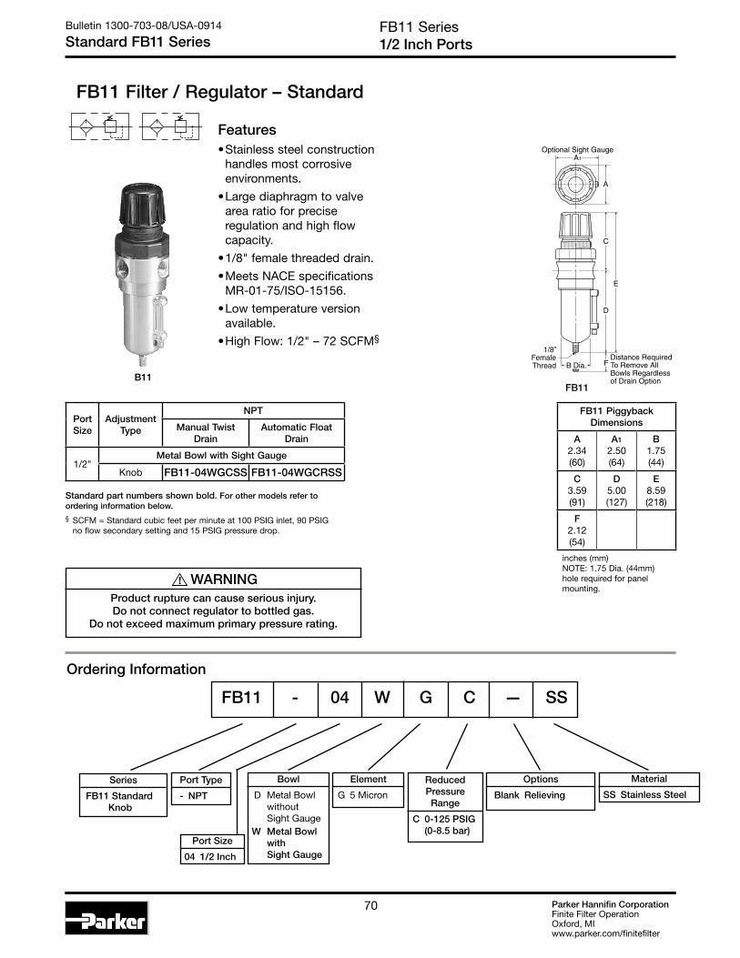
Parker Hannifin CorporationFinite Filter OperationOxford, MIwww.parker.com/finitefilter
70
Series
FB11 Standard Knob
Features• Stainless steel construction
handles most corrosive environments.
• Large diaphragm to valve area ratio for precise regulation and high flow capacity.
• 1/8" female threaded drain.
• Meets NACE specifications MR-01-75/ISO-15156.
• Low temperature version available.
• High Flow: 1/2" – 72 SCFM§
FB11 Series1/2 Inch Ports
Bulletin 1300-703-08/USA-0914
Standard FB11 Series
FB11 Filter / Regulator – Standard
Ordering Information
D
E
C
B Dia.Distance RequiredTo Remove All Bowls Regardless of Drain Option
F
A
Optional Sight GaugeA1
1/8”FemaleThread
Port Type
- NPT
Port Size
04 1/2 Inch
Bowl
D Metal Bowl without Sight Gauge W Metal Bowl with Sight Gauge
Element
G 5 Micron
Reduced Pressure Range
C 0-125 PSIG (0-8.5 bar)
Options
Blank Relieving
Material
SS Stainless Steel
FB11 - 04 W G C — SS
Port Size
Adjustment Type
NPT
Manual Twist Drain
Automatic Float Drain
1/2"Metal Bowl with Sight Gauge
Knob FB11-04WGCSS FB11-04WGCRSS
Standard part numbers shown bold. For other models refer to ordering information below.§ SCFM = Standard cubic feet per minute at 100 PSIG inlet, 90 PSIG
no flow secondary setting and 15 PSIG pressure drop.
FB11 Piggyback Dimensions
A2.34(60)
A1
2.50(64)
B1.75(44)
C3.59(91)
D5.00(127)
E8.59(218)
F2.12(54)
inches (mm)NOTE: 1.75 Dia. (44mm) hole required for panel mounting.
B11FB11
! WARNINGProduct rupture can cause serious injury.Do not connect regulator to bottled gas.
Do not exceed maximum primary pressure rating.
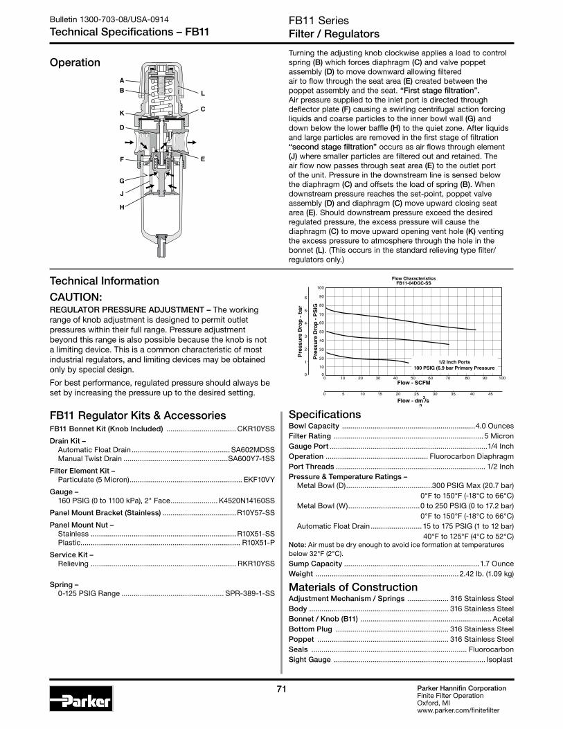
Parker Hannifin CorporationFinite Filter OperationOxford, MIwww.parker.com/finitefilter
7171
F
G
J
B
D
K
A
H
C
L
E
0
20
30
50
10
40
60
70
90
80
100
0 10 20 30 40 50 60 70 80 90 100
Pre
ssu
re D
rop
- P
SIG
0
0 5 10 15 20 25 30 35 40 45
Flow - SCFM
Flow - dm /s
Pre
ssu
re D
rop
- b
ar
3
n
1
2
3
4
5
6
Flow CharacteristicsFB11-04DGC-SS
1/2 Inch Ports100 PSIG (6.9 bar Primary Pressure
FB11 SeriesFilter / Regulators
Bulletin 1300-703-08/USA-0914
Technical Specifications – FB11
SpecificationsBowl Capacity .................................................................4.0 OuncesFilter Rating ......................................................................... 5 MicronGauge Port .............................................................................1/4 InchOperation .................................................. Fluorocarbon DiaphragmPort Threads ......................................................................... 1/2 InchPressure & Temperature Ratings – Metal Bowl (D) ..........................................300 PSIG Max (20.7 bar) 0°F to 150°F (-18°C to 66°C) Metal Bowl (W) ...................................0 to 250 PSIG (0 to 17.2 bar) 0°F to 150°F (-18°C to 66°C) Automatic Float Drain ......................... 15 to 175 PSIG (1 to 12 bar) 40°F to 125°F (4°C to 52°C) Note: Air must be dry enough to avoid ice formation at temperatures below 32°F (2°C).
Sump Capacity ..................................................................1.7 OunceWeight ......................................................................2.42 lb. (1.09 kg)
Materials of ConstructionAdjustment Mechanism / Springs .................... 316 Stainless SteelBody .................................................................... 316 Stainless SteelBonnet / Knob (B11) ................................................................ AcetalBottom Plug ....................................................... 316 Stainless SteelPoppet ................................................................ 316 Stainless SteelSeals ............................................................................ FluorocarbonSight Gauge .......................................................................... Isoplast
FB11 Regulator Kits & AccessoriesFB11 Bonnet Kit (Knob Included) .................................. CKR10YSS
Drain Kit – Automatic Float Drain ................................................ SA602MDSS Manual Twist Drain ...................................................SA600Y7-1SS
Filter Element Kit – Particulate (5 Micron) ....................................................... EKF10VY
Gauge – 160 PSIG (0 to 1100 kPa), 2" Face ....................... K4520N14160SS
Panel Mount Bracket (Stainless) ....................................R10Y57-SS
Panel Mount Nut – Stainless ....................................................................... R10X51-SS Plastic.............................................................................. R10X51-P
Service Kit – Relieving ....................................................................... RKR10YSS
Spring – 0-125 PSIG Range .................................................. SPR-389-1-SS
Operation
Technical Information
Turning the adjusting knob clockwise applies a load to control spring (B) which forces diaphragm (C) and valve poppet assembly (D) to move downward allowing filtered air to flow through the seat area (E) created between the poppet assembly and the seat. “First stage filtration”. Air pressure supplied to the inlet port is directed through deflector plate (F) causing a swirling centrifugal action forcing liquids and coarse particles to the inner bowl wall (G) and down below the lower baffle (H) to the quiet zone. After liquids and large particles are removed in the first stage of filtration “second stage filtration” occurs as air flows through element (J) where smaller particles are filtered out and retained. The air flow now passes through seat area (E) to the outlet port of the unit. Pressure in the downstream line is sensed below the diaphragm (C) and offsets the load of spring (B). When downstream pressure reaches the set-point, poppet valve assembly (D) and diaphragm (C) move upward closing seat area (E). Should downstream pressure exceed the desired regulated pressure, the excess pressure will cause the diaphragm (C) to move upward opening vent hole (K) venting the excess pressure to atmosphere through the hole in the bonnet (L). (This occurs in the standard relieving type filter/regulators only.)
CAUTION:REGULATOR PRESSURE ADJUSTMENT – The working range of knob adjustment is designed to permit outlet pressures within their full range. Pressure adjustment beyond this range is also possible because the knob is not a limiting device. This is a common characteristic of most industrial regulators, and limiting devices may be obtained only by special design.
For best performance, regulated pressure should always be set by increasing the pressure up to the desired setting.

Parker Hannifin CorporationFinite Filter OperationOxford, MIwww.parker.com/finitefilter
72
07E Series3/8", 1/2", 3/4" NPT – Basic 1/2" Body
Bulletin 1300-703-08/USA-0914
Standard 07E Series
07E Filter / Regulator – Standard
Features• Space saving package offers both filter and
regulator features for optimal performance.
• Excellent water removal efficiency.
• Rolling diaphragm for extended life.
• Quick response, and accurate pressure regulation regardless of changing flow or inlet pressure.
• Two high flow 1/4" gauge ports can be used as additional outlets.
• Shown with recommended metal bowl guard.
• High Flow: 3/8" – 70 SCFM§
1/2" – 90 SCFM§ 3/4" – 90 SCFM§
PU
SH TO LOCK
A
B
D
E
C
Distance RequiredTo Remove All BowlsRegardless OfDrain Option
F
1/4" NPTGauge Ports
(2)
07E 3 2 B 13 A * — — ---
‡ For polycarbonate bowl see Caution on page 2.
§ SCFM = Standard cubic feet per minute at 100 PSIG inlet, 90 PSIG no flow secondary setting and 10 PSIG pressure drop.
NOTE: 2.00 Dia. (50.8 mm) hole required for panel mounting. Max. panel thickness 1/4".
PortSize
NPT
Twist Drain Automatic Float Drain
Poly Bowl‡ / Metal Guard
3/8" 07E22B13A* 07E26B13A*1/2" 07E32B13A* 07E36B13A*3/4" 07E42B13A* 07E46B13A*
Metal Bowl / Sight Gauge
3/8" 07E24B13A* 07E28B13A*1/2" 07E34B13A* 07E38B13A*3/4" 07E44B13A* 07E48B13A*
07E Filter / Regulator Dimensions
A3.24(82)
B3.25(83)
C4.79(122)
D6.97(177)
D †
7.00(178)
E 11.76(299)
E †
11.79(299)
F2.75(70)
Inches (mm)† With Auto Float Drain
! WARNINGProduct rupture can cause serious injury.Do not connect regulator to bottled gas.
Do not exceed maximum primary pressure rating.
Port Size
2 3/8 Inch 3 1/2 Inch 4 3/4 Inch
Port Type
Blank NPT
Options
Blank No Options
† Inlet Pressure is 100 PSIG. For other pressures, contact factory.
Preset
Blank None
Relief
A Relieving
Elements
B 5 Micron
Bowl Options Engineering Level
*Will be entered at
factory
Ordering Information
Polycarbonate Bowl 2 Metal Bowl Guard / Twist Drain 6 Metal Bowl Guard / Auto Float Drain
Pressure Range
Without Gauge 13 125 PSIG
§ If 250 PSIG spring range is used, use metal bowl.
Metal Bowl 4 Sight Gauge / Twist Drain 8 Sight Gauge / Auto Float Drain
* 3/8, 1/2 & 3/4 inch meet ISO 1179-1 Standard.
GRAYED OUT ITEMS
ARE OBSOLETE
AS OF JULY 1, 2014

Parker Hannifin CorporationFinite Filter OperationOxford, MIwww.parker.com/finitefilter
7373
Bulletin 1300-703-08/USA-0914
Technical Specifications – 07E
00
10 30 50 70 900
20
60
80
40
100
1
2
3
4
5
6
10 110 130
0 5 45 555 15 25 35
Relief And Flow Characteristics07E32A13A
Sec
ond
ary
Pre
ssur
e -
PS
IG
Sec
ond
ary
Pre
ssur
e -
bar
Rated Flow - SCFM
Flow - dm /s3
n
1/2 Inch Ports100 PSIG (6.9 bar) Primary Pressure
00
10 30 50 70 900
20
60
80
40
100
1
2
3
4
5
6
10 110 130 150 170
0 5 45 55 65 755 15 25 35
Relief And Flow Characteristics07E42A13A
Sec
ond
ary
Pre
ssur
e -
PS
IG
Sec
ond
ary
Pre
ssur
e -
bar
Rated Flow - SCFM
Flow - dm /s3n
3/4 Inch Ports100 PSIG (6.9 bar) Primary Pressure
07E SeriesFilter / Regulators
Technical Information
00
10 30 50 70 900
20
60
80
40
100
1
2
3
4
5
6
10 110 130
0 5 45 555 15 25 35
Relief And Flow Characteristics07E22A13A
Sec
ond
ary
Pre
ssur
e -
PS
IG
Sec
ond
ary
Pre
ssur
e -
bar
Rated Flow - SCFM
Flow - dm /s3
n
3/8 Inch Ports100 PSIG (6.9 bar) Primary Pressure
Pressure & Temperature Ratings – Polycarbonate Bowl – 0 to 150 PSIG (0 to 10.4 bar)
32°F to 125°F (0°C to 52°C) Metal Bowl – 0 to 250 PSIG (0 to 17.2 bar)
32°F to 175°F (0°C to 80°C) Automatic Float Drain – 15 to 250 PSIG (1.0 to 17.2 bar) Secondary Pressure Ranges –
Standard Pressure ........................................ 2 to 125 PSIG (0 to 8.6 bar)
Sump Capacity ............................................................................2.8 OuncesWeight ....................................................................................... 2.5 lb. (1.1 kg)
Materials of ConstructionAdjusting Stem....................................................................................... SteelBody ......................................................................................................... ZincBonnet, Internal Parts ........................................................................ PlasticBowls Available – Transparent .............................................Polycarbonate Metal (With or Without Sight Gauge) ..................... Zinc Bowl Guard ............................................................................................ SteelCollar .....................................................................................Plastic or MetalDiaphragm .............................................................................................NitrileDrains – Manual Twist Drain Standard Body & Nut ........................................................................Plastic
Automatic Float Drain Optional (Interchangeable for Field Conversions) Operating Range ........................10 to 250 PSIG (.7 to 17.2 bar) Housing, Float .................................................................. Plastic Seals ..................................................................................Nitrile Springs, Push Rod ..............................................Stainless SteelKnob .................................................................................................. Plastic Filter Element – 5 Micron (Standard) ............................................. Plastic
Seals ......................................................................................................NitrileSight Gauge .................................................................................. PolyamideSprings – Poppet .......................................................................... Stainless Control ................................................................................. Steel
07E Filter / Regulator Kits & AccessoriesBonnet Assembly Kit .........................................................................PS715PBowl Guard Kit .................................................................................. PS805PBowl Kits – Poly Bowl – Automatic Float Drain ............................................ PS822P Twist Drain .............................................................. PS832P Metal Bowl – Sight Gauge / Automatic Drain .............................. PS823P Sight Gauge / Twist Drain ...................................... PS835PControl Knob P04069BDrain Kits – Automatic Float Drain ............................................ PS506P Twist Drain .................................................................PS512 Filter Element Kits – 5 Micron .............................................................PS802 40 Micron .............................................................PS801
Gauges – 60 PSIG (0 to 4.1 bar) .......................................... K4520N14060 160 PSIG (0 to 11.0 bar) .......................................K4520N14160
Mounting Bracket Kit (Includes Panel Mount Nut) ......................... PS807PPanel Mount Nut ................................................................................P04082
Service Kits – Non-Relieving (Includes Poppet) .............................PS811P Relieving (Includes Poppet) .................................... PS810PSeat Insert Kit .................................................................................. PS813PSprings – 2- 125 PSIG Range ..........................................................P04063
Tamperproof Kit (Key Lock) ...............................................................PS737P
SpecificationsBowl Capacity ..............................................................................7.2 OuncesGauge Ports (2) ................................................................................ 1/4 Inch
(Can be used as Additional Full Flow 1/4" Outlet Ports)Port Threads .......................................................................3/8, 1/2, 3/4 Inch
CAUTION:REGULATOR PRESSURE ADJUSTMENT – The working range of knob adjustment is designed to permit outlet pressures within their full range. Pressure adjustment beyond this range is also possible because the knob is not a limiting device. This is a common characteristic of most industrial regulators, and limiting devices may be obtained only by special design.
For best performance, regulated pressure should always be set by increasing the pressure up to the desired setting.

Parker Hannifin CorporationFinite Filter OperationOxford, MIwww.parker.com/finitefilter
74
PU
SH TO LOCK
A
B
D
E
C
Distance RequiredTo Remove All
Bowls RegardlessOf Drain Option
F
1/4" NPTGauge Ports
(2)
Features• Space saving package offers both coalescer and
regulator features for optimal performance.
• Removes liquid, aerosol and sub-micron particles.
• Rolling diaphragm for extended life.
• Removable non-rising knob for panel mounting and tamper resistance.
• Quick response, and accurate pressure regulation regardless of changing flow or inlet pressure.
• Two high flow 1/4" gauge ports can be used as additional outlets.
• High Flow: Grade 6 Element 3/8" – 35 SCFM§ 1/2" – 40 SCFM§
3/4" – 45 SCFM§
F12E 3 3 C 13 A * — — ---
Bowl Options
Metal Bowl 3 Twist Drain 7 Automatic Float Drain 8 High Flow Twist Drain 9 High Flow Float Drain
Port Size
Without Gauge 13 125 PSIG
Ordering Information
12E Series3/8", 1/2", 3/4" NPT – Basic 1/2" Body
Bulletin 1300-703-08/USA-0914
Standard – Coalescing 12E Series
F12E Filter / Regulator – Coalescing
Standard part numbers shown bold. For other models refer to ordering information below.§ SCFM = Standard cubic feet per minute at 150 PSIG inlet,
90 PSIG no flow secondary setting and 10 PSIG pressure drop.
NOTE: 2.00 Dia. (50.8 mm) hole required for panel mounting.
PortSize
Standard with Coalescer
Standard w/Coalescer and Built-in prefilter
Twist Drain
3/8" F12E23E13A* F12E23Q13A*1/2" F12E33E13A* F12E33Q13A*3/4" F12E43E13A* F12E43Q13A*
Automatic Float Drain
3/8" F12E27E13A* F12E27Q13A*1/2" F12E37E13A* F12E37Q13A*3/4" F12E47E13A* F12E47Q13A*
PortSize
High Flow with Coalescer
High Flow w/Coalescer and Built-in prefilter
Twist Drain
3/8" F12E28C13A* F12E28Q13A*1/2" F12E38C13A* F12E38Q13A*3/4" F12E48C13A* F12E48Q13A*
Automatic Float Drain
3/8" F12E29C13A* F12E29Q13A*1/2" F12E39C13A* F12E39Q13A*3/4" F12E49C13A* F12E49Q13A*
12E Filter / Regulator Dimensions
A3.24(82)
B3.25(83)
C4.79(122)
D8.20(208)
D †
8.17(208)
E 12.99(330)
E †
12.96(329)
F3.29(84)
Inches (mm)† With Twist Drain or Auto Float Drain
! WARNINGProduct rupture can cause serious injury.Do not connect regulator to bottled gas.
Do not exceed maximum primary pressure rating.
Port Size
2 3/8 Inch 3 1/2 Inch 4 1/4 Inch
Port Type
Blank NPT
Options
Blank No Options
† Inlet Pressure is 100 PSIG. For other pressures, contact factory.
Preset
Blank None
Relief
A Relieving
Elements
C Grade 6 Q Grade 6
* 3/8 & 1/2 inch meet ISO 1179-1 Standard.
Engineering Level
*Will be entered at
factory
Note: Q media is a coalescing element with the same configuration as Type C, but with a pleated cellulose prefilter built in.

Parker Hannifin CorporationFinite Filter OperationOxford, MIwww.parker.com/finitefilter
7575
Technical Information
12E SeriesFilter / Regulators
Bulletin 1300-703-08/USA-0914
Technical Specifications – 12E
Secondary Pressure Ranges – Standard Pressure ............................. 2 to 125 PSIG (0 to 8.6 bar)
Sump Capacity ...............................................................2.8 OuncesWeight ........................................................................... 2.5 lb. (1.1 kg)
Materials of ConstructionAdjusting Stem ..........................................................................SteelBody ............................................................................................ ZincBonnet, Internal Parts ........................................................... PlasticBowls Available – Metal (Without Sight Gauge) ........................ Zinc Collar For Bonnet ..................................................................... MetalControl Spring ............................................................................SteelDiaphragm .................................................................................NitrileDrains – Manual Twist Drain Standard Body & Nut ........................................................... Plastic
Automatic Float Drain Optional (Interchangeable for Field Conversions) Operating Range .............10 to 250 PSIG (.7 to 17.2 bar) Housing, Float ...................................................... Plastic Seals .......................................................................Nitrile Springs, Push Rod ..................................Stainless SteelKnob ....................................................................................... Plastic Filter Element – Borosilicate & felt glass fibers 99.97% DOP efficiency Largest Aerosol Particle Passed (Grade 6) ......... 0.75 Microns Largest Solid Particle Passed (Grade 6) ............. 0.30 MicronsSeals ..........................................................................................NitrileSight Gauge....................................................................... PolyamideSprings – Poppet ................................................................. Stainless
F12E Filter / Regulator Kits & AccessoriesBonnet Assembly Kit ............................................................PS715PBowl Kits – Metal Bowl – Automatic Float Drain ................................. PS826P Twist Drain ................................................... PS834P
Control Knob P04069BDrain Kits – Automatic Float Drain .................................PS506P Twist Drain ......................................................PS512
Filter Element –
Gauges – 60 PSIG (0 to 4.1 bar) ................................. K4520N14060 160 PSIG (0 to 11.0 bar) ..............................K4520N14160
Mounting Bracket Kit (Includes Panel Mount Nut) ............. PS807P
Service Kit – Relieving (Includes Poppet) .............................PS886PSprings – 2- 125 PSIG Range ...............................................P04063
Tamperproof Kit (Key Lock) .................................................. PS737P
SpecificationsBowl Capacity .................................................................7.2 OuncesGauge Ports (2) .................................................................... 1/4 Inch
(Can be used as Additional Full Flow 1/4" Outlet Ports)Port Threads ...........................................................3/8, 1/2, 3/4 InchPressure & Temperature Ratings – Metal Bowl – 0 to 250 PSIG (0 to 17.2 bar)
32°F to 175°F (0°C to 80°C)
00
Flow Characteristics12E33E13A*
10 20 30 40 50
0
20
60
80
40
100
5 25 30
10 60 70
5 10 15 20
0
1
2
3
4
5
6
1/2 Inch Ports100 PSIG (6.9 bar)Primary Pressure
Sec
ond
ary
Pre
ssur
e -
PS
IG
Sec
ond
ary
Pre
ssur
e -
bar
Rated Flow - SCFM
Flow - dm /s3
n
CAUTION:REGULATOR PRESSURE ADJUSTMENT – The working range of knob adjustment is designed to permit outlet pressures within their full range. Pressure adjustment beyond this range is also possible because the knob is not a limiting device. This is a common characteristic of most industrial regulators, and limiting devices may be obtained only by special design.
For best performance, regulated pressure should always be set by increasing the pressure up to the desired setting.

Parker Hannifin CorporationFinite Filter OperationOxford, MIwww.parker.com/finitefilter
76
Prep-Air® IIAir Preparation Units
Bulletin 1300-703-08/USA-0914
Micro-Mist Lubricators
Micro-Mist Lubricators• Pipe Sizes 1/4 thru 3/4 Inch
• Flows to 90 SCFM
• Pressures to 250 PSIG
Micro-Mist Air Lubricators are designed to provide optimum and uniform lubrication with fine micro-mist particles of 2 micron or smaller, to pneumatic components even through complex piping arrangements.
• Economy 15L Series, 1/4 and 3/8 Inch
• Compact 16L Series, 1/4, 3/8 and 1/2 Inch
• Standard 17L Series, 3/8, 1/2 and 3/4 Inch
Lubricator Selection1. Determine maximum system flow
requirements.
2. Determine maximum allowable pressure drop at rated flow in SCFM.
3. Refer to flow chart and select lubricator by choosing the curve that offers minimum pressure drop at desired flow in SCFM.
F442 OilQuantity Part Numbers
1 Quart F442001P
1 Gallon F442002P
12 Quart Case F442003P
4 Gallon Case F442005P
Once the required flow is determined for a pneumatic application the lubricator can be selected by using the flow chart. To read the lubricator flow chart, first determine the inlet pressure that will be used. Find the appropriate pressure curve on the graph. Each graph will contain three pressure curves. If the required inlet pressure is not on the graph, interpolate a similar curve for the required pressure. Next, determine the acceptable pressure drop across the lubricator and locate it on the vertical axis. Find the intersection point of the acceptable pressure drop and the inlet pressure curve. At this point follow a vertical path downward to view the flow in SCFM. If the flow is too low, select a larger port size or body size to give the required flow. If the flow is higher than necessary, select a smaller port size or body size to give the required flow.
Reading Flow Charts to Size Micro-Mist Lubricators
0
1
2
3
4
5
6
7
8
9
10
0 10 20 30 5040 60 8070 90 100
Pre
ssur
e D
rop
- P
SIG
0
.1
Flow - SCFM
Flow - dm /s
Pre
ssur
e D
rop
- b
ar
3
n
.2
.3
.4
.5
.6
0 5 10 20 30 35 40 4515 25
35 PSIG 90 PSIG 150 PSIGPrimary Pressure - PSIG
2.4 bar 6.2 bar 10.3 barPrimary Pressure - bar
Flow Characteristics15L11N*
1/4 Inch Ports

Parker Hannifin CorporationFinite Filter OperationOxford, MIwww.parker.com/finitefilter
7777
Prep-Air® IIAir Preparation Units
Bulletin 1300-703-08/USA-0914
Micro-Mist Lubricators
16L / 17L
Air flowing through the unit goes through two paths. At low air flow rates, the majority of the air flows through venturi section (A). The rest of the air slightly deflects and flows by the flapper (B). The velocity of the air flowing through venturi section (A) creates a pressure drop at throat section (C). This lower pressure allows oil to be forced from the reservoir through the pickup tube (D) past the check ball (E), to the dome assembly where the rate of oil flow is controlled by metering screw (F). Rotation of the metering screw (F) in the counterclockwise direction increases the oil flow rate; in the clockwise direction decreases the oil flow rate.
Oil then flows through the clearance between the inner and outer sight domes (G) where drops are formed and drip into the nozzle tube (H). Here it is then broken into fine particles as it expands into the low pressure venturi. From there, the atomized oil flows through the precision orifice (J). This action causes the larger particles of oil to fall back into the reservoir where it can recirculate through the system. The remaining mist of fine particles (5 micron or smaller – about 3% of which passed through the sight dome) is then carried through opening (K) where it joins and mixes with air that bypassed the flapper (B). As air flow rate increases, the flapper (B) deflects, allowing most of the inlet air to bypass the venturi section (A). However, a proportion of the inlet air passes through the venturi, assuring that oil delivery increases linearly with increased air flow rate. This proportioning method is advantageous at low inlet flows because the venturi design remains efficient.
The check ball (E) prevents reverse oil flow down the pickup tube when air flow stops. Thus, oil delivery can resume immediately when air flow restarts. Micro-Mist Lubricators can only be filled when the air supply is shut off.
15L
BA C
J
D
K
E
H
F
G
D
AG
E
áá
F
D
H
D
J K
B C

Parker Hannifin CorporationFinite Filter OperationOxford, MIwww.parker.com/finitefilter
78
D
C
A
B
E
F
Distance RequiredTo Remove PressureFill Adapter
C1
F1
Distance RequiredTo Remove AllBowls RegardlessOf Drain Option
15L Series1/4", 3/8" NPT – Basic 1/4" Body
Bulletin 1300-703-08/USA-0914
Economy 15L Series
15L Micro-Mist Lubricators – Economy
Features• Proportional oil delivery over a wide
range of air flows.
• Generates oil particles of 5 micron or smaller downstream to lubricate systems having complex piping arrangements.
• Precision needle valve assures repeatable oil delivery and provides simple adjustment of delivery rate.
• Ideal for low and high flow applications with changing air flow.
• Transparent sight dome for 360° visibility.
• Removable drip control knob for tamper resistance.
• High Flow: 1/4" – 40 SCFM§ 3/8" – 40 SCFM§
15L 1 2 N * — —
Ordering Information
Standard part numbers shown bold. For other models refer to ordering information below.‡ For polycarbonate bowl and sight dome, see Caution on page 2.§ SCFM = Standard cubic feet per minute at 90 PSIG inlet and 5 PSIG
pressure drop.
PortSize
NPT
Twist Drain No Drain
Poly Bowl ‡ / Metal Guard
1/4" — 15L12N*
3/8" — 15L22N*Metal Bowl / Sight Gauge
1/4" 15L14N* —
3/8" 15L24N* —
Port Type
Blank NPT
Bowl Options
Metal Bowl 4 Sight Gauge / Twist Drain
Fill Options
N No Fill Plug
Port Size
1 1/4 Inch 2 3/8 Inch
Options
Blank No Options
15L Lubricator Dimensions
A2.00(51)
B2.06(52)
C2.26(57)
C1
3.35(85)
D5.12(130)
D†
5.35(136)
E7.38(187)
E†
7.61(193)
F1.77(45)
F†
.39(10)
Inches (mm)† With Twist Drain.
Polycarbonate Bowl 2 Metal Bowl Guard / No Drain
Engineering Level
* Will be entered at factory
* 1/4 & 3/8 inch meet ISO 1179-1 Standard.
GRAYED OUT ITEMS
ARE OBSOLETE
AS OF JULY 1, 2014

Parker Hannifin CorporationFinite Filter OperationOxford, MIwww.parker.com/finitefilter
79
Bulletin 1300-703-08/USA-0914
Technical Specifications – 15L
15L Micro-Mist Lubricator Kits & AccessoriesAdjustment Knob ..................................................................P04121Bowl Guard Kit PS905PBowl Kits – Poly Bowl – No Drain ........................................................ PS946P Metal Bowl – Sight Gauge / Twist Drain ............................. PS929PDrain Kit – Twist Drain ...............................................................PS512Liquid Level Sensor Kit ......................................................... PS797PMounting Bracket Kit ............................................................ PS943POil – 1 Quart .......................................................................F442001P 1 Gal. ..........................................................................F442002P 12 Quart Case ............................................................F442003P 4 Gallon Case ............................................................F442005PPressure Fill Adapter Kit ....................................................... PS916PService Kit ............................................................................. PS948PSight Dome Kit ...................................................................... PS740PSight Gauge Kit ..................................................................... PS914P
SpecificationsBowl Capacity .................................................................2.0 OuncesMinimum Flow for Lubrication .........................2 SCFM at 100 PSIGPort Threads .................................................................. 1/4, 3/8 InchPressure & Temperature Ratings –
Polycarbonate Bowl – 0 to 150 PSIG (0 to 10.3 bar) 32°F to 125°F (0°C to 52°C)
Metal Bowl – 0 to 250 PSIG (0 to 17.2 bar) 32°F to 175°F (0°C to 80°C)
Technical Information
0
1
2
3
4
5
6
7
8
9
10
0 10 20 30 5040 60 8070 90 100
Pre
ssur
e D
rop
- P
SIG
0
.1
Flow - SCFM
Flow - dm /s
Pre
ssur
e D
rop
- b
ar
3
n
.2
.3
.4
.5
.6
0 5 10 20 30 35 40 4515 25
35 PSIG 90 PSIG 150 PSIGPrimary Pressure - PSIG
2.4 bar 6.2 bar 10.3 barPrimary Pressure - bar
Flow Characteristics15L11N*
1/4 Inch Ports0
1
2
3
4
5
6
7
8
9
10
0 20 40 60 10080 120 140
Pre
ssur
e D
rop
- P
SIG
0
.1
Flow - SCFM
Flow - dm /s
Pre
ssur
e D
rop
- b
ar
3
n
.2
.3
.4
.5
.6
0 10 20 40 6030 50
35 PSIG 90 PSIG 150 PSIGPrimary Pressure - PSIG
2.4 bar 6.2 bar 10.3 barPrimary Pressure - bar
Flow Characteristics15L21N*
3/8 Inch Ports
Suggested Lubricant ............................................................F442 OilPetroleum based oil of 100 to 200 SSU viscosity at 100°F and an aniline point greater than 200°F(DO NOT USE OILS WITH ADDITIVES, COMPOUNDED OILS CONTAINING SOLVENTS, GRAPHITE, DETERGENTS, OR SYNTHETIC OILS.)
Weight .......................................................................... 1 lb. (0.45 kg)
Materials of ConstructionBody ............................................................................................ ZincBowls – Transparent ....................................................Polycarbonate Metal (With Sight Gauge) ............................................... Zinc Bowl Guard ................................................................................. SteelCollar ........................................................................................PlasticDrains – Twist – Body & Nut ......................................................PlasticInjector Meter Block & Base Assembly ...................................PlasticSeals ..........................................................................................NitrileSight Dome ..................................................................PolycarbonateSight Gauge ........................................................... Polyamide (Nylon)
15L SeriesAir Line Micro-Mist Lubricators
GRAYED OUT ITEMS
ARE OBSOLETE
AS OF JULY 1, 2014

Parker Hannifin CorporationFinite Filter OperationOxford, MIwww.parker.com/finitefilter
80
16L Series1/4", 3/8", 1/2" NPT – Basic 3/8" Body
Bulletin 1300-703-08/USA-0914
Compact 16L Series
16L Micro-Mist Lubricators – CompactFeatures• Proportional oil delivery over a wide range of air
flows.
• Generates oil particles of 5 micron or smaller downstream to lubricate systems having complex piping arrangements.
• Precision needle valve assures repeatable oil delivery and provides simple adjustment of delivery rate.
• Ideal for low and high flow applications with changing air flow.
• Transparent sight dome for 360° visibility.
• Yellow fill cap identifies Micro-Mist Lubricator.
• High Flow: 1/4" – 40 SCFM § 3/8" – 60 SCFM § 1/2" – 90 SCFM §
A
B
D
C
E
FDistance RequiredTo Remove AllBowls RegardlessOf Drain Option
16L 1 2 B * —
Polycarbonate Bowl 2 Metal Bowl Guard / No Drain
Metal Bowl 4 Sight Gauge / Twist Drain
Bowl Options Options
B With Fill Plug
Standard part numbers shown bold. For other models refer to ordering information below.‡ For polycarbonate bowl and sight dome, see Caution on page 2.§ SCFM = Standard cubic feet per minute at 90 PSIG inlet and 5 PSIG
pressure drop.
PortSize
NPT
Twist Drain No Drain
Poly Bowl ‡ / Metal Guard
1/4" — 16L12B*
3/8" — 16L22B*
1/2" — 16L32B*Metal Bowl / Sight Gauge
1/4" 16L14B* —
3/8" 16L24B* —
1/2" 16L34B* —
16L Lubricator Dimensions
A2.81(71)
B2.74(70)
C2.24(57)
D5.58(142)
D†
5.69(145)
E7.82(199)
E†
7.93(201)
F2.25(57)
Ordering Information
Inches (mm)†With Twist Drain.
Port Type
Blank NPT
Port Size
1 1/4 Inch 2 3/8 Inch 3 1/2 Inch
Engineering Level
* Will be entered at factory
* 1/4 & 3/8 inch meet ISO 1179-1 Standard.

Parker Hannifin CorporationFinite Filter OperationOxford, MIwww.parker.com/finitefilter
8181
0 5 10 15 20 25 30 35 40 45
00
10 20 30 40
7
1
2
3
4
5
6
0
.1
.2
.3
.4
50 60 70 80 90 100
Flow Characteristics16L22B* 3/8 Inch Ports
Pre
ssur
e D
rop
- P
SIG
Pre
ssur
e D
rop
- b
ar
35 PSIG 90 PSIG 150 PSIGPrimary Pressure - PSIG
2.4 bar 6.2 bar 10.3 barPrimary Pressure - bar
Flow - SCFM
Flow - dm /s3
n
00
10 20 30 40 50 60 70
0 5
7
1
2
3
4
5
6
0
.1
.2
.3
.4
10 15 20 25 30
Flow Characteristics16L12B* 1/4 Inch Ports
Pre
ssur
e D
rop
- P
SIG
Pre
ssur
e D
rop
- b
ar35 PSIG 90 PSIG 150 PSIGPrimary Pressure - PSIG2.4 bar 6.2 bar 10.3 barPrimary Pressure - bar
Flow - SCFM
Flow - dm /s3
n
16L SeriesAir Line Micro-Mist Lubricators
Bulletin 1300-703-08/USA-0914
Technical Specifications – 16L
Technical Information
0 5 10 15 20 25 30 35 40 45 50 55 60 7065
00
10 20 30 40
7
1
2
3
4
5
6
0
.1
.2
.3
.4
50 60 70 80 90 100 110 120 130 140 150
Flow Characteristics16L32B* 1/2 Inch Ports
Pre
ssur
e D
rop
- P
SIG
Pre
ssur
e D
rop
- b
ar
35 PSIG 90 PSIG 150 PSIGPrimary Pressure - PSIG
2.4 bar 6.2 bar 10.3 barPrimary Pressure - bar
Flow - SCFM
Flow - dm /s3
n
16L Micro-Mist Lubricator Kits & AccessoriesAdjustment Knob ..................................................................P04121Bowl Guard Kit ...................................................................... PS705PBowl Kits – Poly Bowl – No Drain ........................................................ PS746P Twist Drain .................................................... PS717P Pressure Fill .................................................. PS719P Remote Fill .................................................... PS728P Metal Bowl – Sight Gauge / Twist Drain ............................. PS729P Sight Gauge / Pressure Fill ........................... PS720PDrain Kit – Twist Drain ...............................................................PS512Fill Cap Kit ............................................................................. PS742PLiquid Level Sensor Kit ........................................................ PS797PLubricator Service Kit ........................................................... PS748PMounting Bracket Kit ........................................................... PS743POil – 1 Quart .....................................................................F442001P 1 Gal. ........................................................................F442002P 12 Quart Case ..........................................................F442003P 4 Gallon Case ..........................................................F442005PPressure Fill Adapter Kit ........................................................ PS716PSight Dome / Fill Cap Kit ..................................................... PS739PSight Dome Kit ...................................................................... PS740PNylon Sight Dome Kit ............................................................PS740N
SpecificationsBowl Capacity ................................................................2.60 OuncesMinimum Flow for Lubrication ........................ 1 SCFM At 100 PSIGPort Threads ............................................................1/4, 3/8, 1/2 InchPressure & Temperature Rating –
Polycarbonate Bowl – 0 to 150 PSIG (0 to 10.3 bar) 32°F to 125°F (0°C to 52°C)
Metal Bowl – 0 to 250 PSIG (0 to 17.2 bar) 32°F to 175°F (0°C to 80°C)
Suggested Lubricant ............................................................F442 OilPetroleum based oil of 100 to 200 SSU viscosity at 100°F and an aniline point greater than 200°F(DO NOT USE OILS WITH ADDITIVES, COMPOUNDED OILS CONTAINING SOLVENTS, GRAPHITE, DETERGENTS, OR SYNTHETIC OILS.)
Weight ........................................................................... 1.2 lb. (.5 kg)
Materials of ConstructionBody ............................................................................................ ZincBowls – Transparent ....................................................Polycarbonate Metal (With Sight Gauge) ............................................... Zinc Bowl Guard ................................................................................. SteelCollar ........................................................................................PlasticDrain – Twist – Body & Nut ........................................................PlasticInjector Meter Block & Base Assembly ...................................PlasticSeals ..........................................................................................NitrileSight Dome ..................................................................PolycarbonateSight Gauge ........................................................... Polyamide (Nylon)
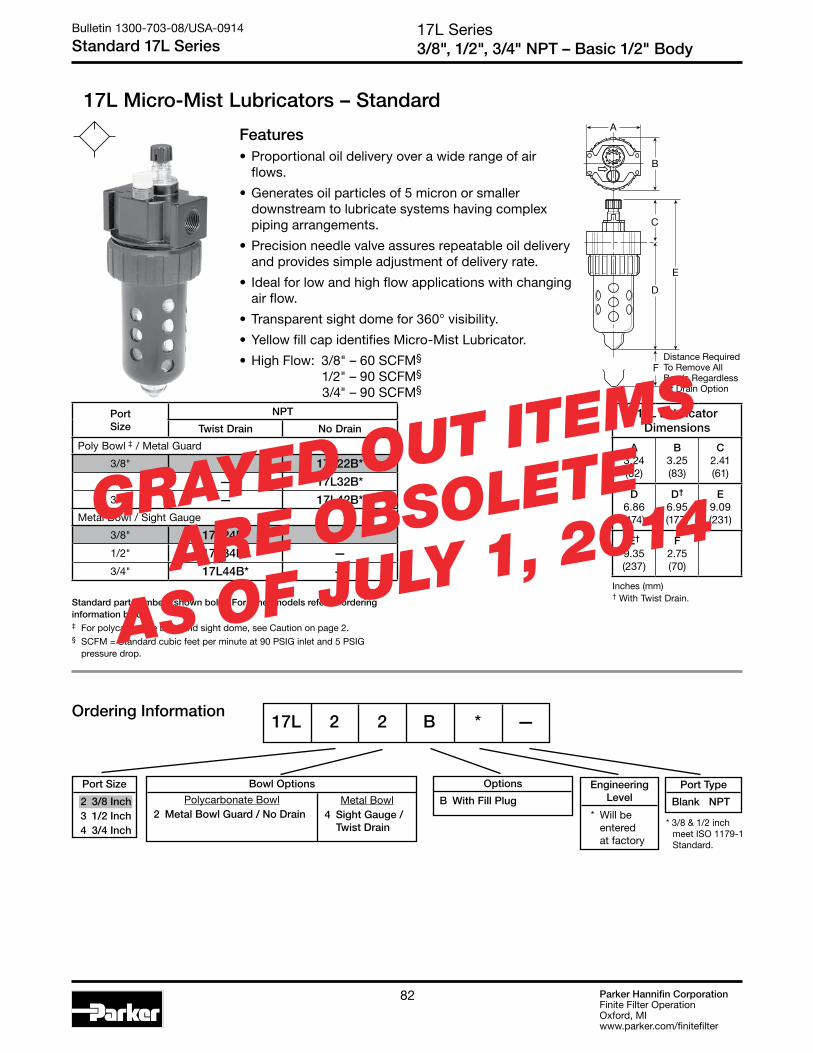
Parker Hannifin CorporationFinite Filter OperationOxford, MIwww.parker.com/finitefilter
82
17L Series3/8", 1/2", 3/4" NPT – Basic 1/2" Body
Bulletin 1300-703-08/USA-0914
Standard 17L Series
17L Micro-Mist Lubricators – Standard
Features• Proportional oil delivery over a wide range of air
flows.
• Generates oil particles of 5 micron or smaller downstream to lubricate systems having complex piping arrangements.
• Precision needle valve assures repeatable oil delivery and provides simple adjustment of delivery rate.
• Ideal for low and high flow applications with changing air flow.
• Transparent sight dome for 360° visibility.
• Yellow fill cap identifies Micro-Mist Lubricator.
• High Flow: 3/8" – 60 SCFM§ 1/2" – 90 SCFM§ 3/4" – 90 SCFM§
A
B
D
C
E
Distance RequiredTo Remove AllBowls RegardlessOf Drain Option
F
17L 2 2 B * —
Standard part numbers shown bold. For other models refer to ordering information below.‡ For polycarbonate bowl and sight dome, see Caution on page 2.§ SCFM = Standard cubic feet per minute at 90 PSIG inlet and 5 PSIG
pressure drop.
PortSize
NPT
Twist Drain No Drain
Poly Bowl ‡ / Metal Guard
3/8" — 17L22B*
1/2" — 17L32B*
3/4" — 17L42B*Metal Bowl / Sight Gauge
3/8" 17L24B* —
1/2" 17L34B* —
3/4" 17L44B* —
17L Lubricator Dimensions
A3.24(82)
B3.25(83)
C2.41(61)
D6.86(174)
D†
6.95(177)
E9.09(231)
E†
9.35(237)
F2.75(70)
Ordering Information
Inches (mm)† With Twist Drain.
Polycarbonate Bowl 2 Metal Bowl Guard / No Drain
Metal Bowl 4 Sight Gauge / Twist Drain
Bowl Options Options
B With Fill Plug
Port Type
Blank NPT
Port Size
2 3/8 Inch 3 1/2 Inch 4 3/4 Inch
Engineering Level
* Will be entered at factory
* 3/8 & 1/2 inch meet ISO 1179-1 Standard.
GRAYED OUT ITEMS
ARE OBSOLETE
AS OF JULY 1, 2014

Parker Hannifin CorporationFinite Filter OperationOxford, MIwww.parker.com/finitefilter
8383
0 5 10 15 20 25 30 35 40 45 50 55 60 7065
00
10 20 30 40
7
1
2
3
4
5
6
0
.1
.2
.3
.4
50 60 70 80 90 100 110 120 130 140 150
Flow Characteristics17L32B* 1/2 Inch Ports
&17L42B* 3/4 Inch Ports
Pre
ssur
e D
rop
- P
SIG
Pre
ssur
e D
rop
- b
ar
35 PSIG 90 PSIG 150 PSIGPrimary Pressure - PSIG
2.4 bar 6.2 bar 10.3 barPrimary Pressure - bar
Flow - SCFM
Flow - dm /s3
n
0 5 10 15 20 25 30 35 40 45
00
10 20 30 40
7
1
2
3
4
5
6
0
.1
.2
.3
.4
50 60 70 80 90 100
Flow Characteristics17L22B* 3/8 Inch Ports
Pre
ssur
e D
rop
- P
SIG
Pre
ssur
e D
rop
- b
ar
35 PSIG 90 PSIG 150 PSIGPrimary Pressure - PSIG
2.4 bar 6.2 bar 10.3 barPrimary Pressure - bar
Flow - SCFM
Flow - dm /s3
n
17L SeriesAir Line Micro-Mist Lubricators
Bulletin 1300-703-08/USA-0914
Technical Specifications – 17L
Technical Information
17L Micro-Mist Lubricator Kits & AccessoriesAdjustment Knob ..................................................................P04121Bowl Guard Kit PS805PBowl Kits – Poly Bowl – No Drain ........................................................ PS846P Twist Drain ..................................................... PS817P Pressure Fill ................................................... PS819P Remote Fill .................................................... PS828P Metal Bowl – Sight Gauge / Twist Drain ............................. PS829P Sight Gauge / Pressure Fill ............................ PS820PDrain Kit – Twist Drain ...............................................................PS512Fill Cap Kit ............................................................................. PS742PLiquid Level Sensor Kit ........................................................ PS797PLubricator Service Kit ........................................................... PS748PMounting Bracket Kit ........................................................... PS843POil – 1 Quart ......................................................................F442001P 1 Gal. .........................................................................F442002P 12 Quart Case ...........................................................F442003P 4 Gallon Case ...........................................................F442005PPressure Fill Adapter Kit ...................................................... PS716PSight Dome / Fill Cap Kit ..................................................... PS739PSight Dome Kit ...................................................................... PS740PNylon Sight Dome Kit ............................................................PS740N
SpecificationsBowl Capacity ..................................................................4.9 OuncesMinimum Flow for Lubrication ........................ 1 SCFM At 100 PSIGPort Threads ............................................................3/8, 1/2, 3/4 InchPressure & Temperature Rating –
Polycarbonate Bowl – 0 to 150 PSIG (0 to 10.3 bar) 32°F to 125°F (0°C to 52°C)
Metal Bowl – 0 to 250 PSIG (0 to 17.2 bar) 32°F to 175°F (0°C to 80°C)
Suggested Lubricant ............................................................F442 OilPetroleum based oil of 100 to 200 SSU viscosity at 100°F and an aniline point greater than 200°F(DO NOT USE OILS WITH ADDITIVES, COMPOUNDED OILS CONTAINING SOLVENTS, GRAPHITE, DETERGENTS, OR SYNTHETIC OILS.)
Weight ........................................................................... 1.9 lb. (.9 kg)
Materials of ConstructionBody ............................................................................................ ZincBowls – Transparent ....................................................Polycarbonate Metal (With Sight Gauge) ............................................... Zinc Bowl Guard ................................................................................. SteelCollar ......................................................................... Plastic or MetalDrain – Twist – Body & Nut ........................................................PlasticInjector Meter Block & Base Assembly ...................................PlasticSeals ..........................................................................................NitrileSight Dome ..................................................................PolycarbonateSight Gauge ........................................................... Polyamide (Nylon)
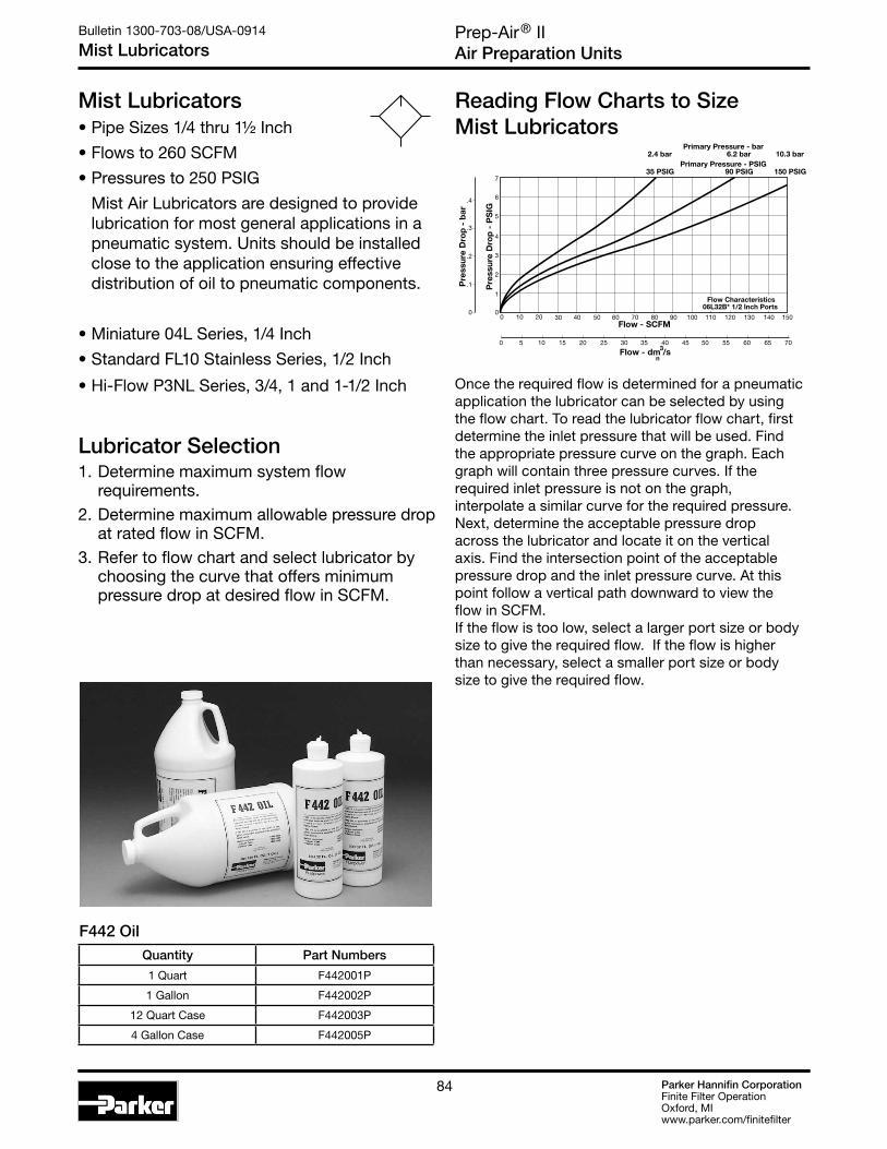
Parker Hannifin CorporationFinite Filter OperationOxford, MIwww.parker.com/finitefilter
84
Prep-Air® IIAir Preparation Units
Bulletin 1300-703-08/USA-0914
Mist Lubricators
Mist Lubricators• Pipe Sizes 1/4 thru 1½ Inch
• Flows to 260 SCFM
• Pressures to 250 PSIG
Mist Air Lubricators are designed to provide lubrication for most general applications in a pneumatic system. Units should be installed close to the application ensuring effective distribution of oil to pneumatic components.
• Miniature 04L Series, 1/4 Inch
• Standard FL10 Stainless Series, 1/2 Inch
• Hi-Flow P3NL Series, 3/4, 1 and 1-1/2 Inch
Lubricator Selection1. Determine maximum system flow
requirements.2. Determine maximum allowable pressure drop
at rated flow in SCFM.3. Refer to flow chart and select lubricator by
choosing the curve that offers minimum pressure drop at desired flow in SCFM.
Once the required flow is determined for a pneumatic application the lubricator can be selected by using the flow chart. To read the lubricator flow chart, first determine the inlet pressure that will be used. Find the appropriate pressure curve on the graph. Each graph will contain three pressure curves. If the required inlet pressure is not on the graph, interpolate a similar curve for the required pressure. Next, determine the acceptable pressure drop across the lubricator and locate it on the vertical axis. Find the intersection point of the acceptable pressure drop and the inlet pressure curve. At this point follow a vertical path downward to view the flow in SCFM. If the flow is too low, select a larger port size or body size to give the required flow. If the flow is higher than necessary, select a smaller port size or body size to give the required flow.
Reading Flow Charts to Size Mist Lubricators
0 5 10 15 20 25 30 35 40 45 50 55 60 7065
00
10 20 30 40
7
1
2
3
4
5
6
0
.1
.2
.3
.4
50 60 70 80 90 100 110 120 130 140 150
Flow Characteristics06L32B* 1/2 Inch Ports
Pre
ssur
e D
rop
- P
SIG
Pre
ssur
e D
rop
- b
ar
35 PSIG 90 PSIG 150 PSIGPrimary Pressure - PSIG
2.4 bar 6.2 bar 10.3 barPrimary Pressure - bar
Flow - SCFM
Flow - dm /s3
n
F442 OilQuantity Part Numbers
1 Quart F442001P
1 Gallon F442002P
12 Quart Case F442003P
4 Gallon Case F442005P

Parker Hannifin CorporationFinite Filter OperationOxford, MIwww.parker.com/finitefilter
8585
Prep-Air® IIAir Preparation Units
Bulletin 1300-703-08/USA-0914
Mist Lubricators
Air flowing through the unit goes through two paths. At low air flow rates, the majority of the air flows through venturi section (A). The rest of the air slightly deflects and flows by the flapper (B), restrictor disc (M) on the 09L. The velocity of the air flowing through venturi section (A) creates a pressure drop at throat section (C). This lower pressure allows oil to be forced from the reservoir through the pickup tube (D) past the check ball (E), to the dome assembly where the rate of oil flow is controlled by metering screw (F). Rotation of the metering screw (F) in the counterclockwise direction increases the oil flow rate; in the clockwise direction decreases the oil flow rate. Oil then flows through the clearance between inner and outer sight domes (G) where drops are formed and drip into the nozzle tube (H). On the 09L, oil flows through the drip tube (F) where drops are formed and drip into the throat section (C). Here it is then broken into fine particles and mixed with the swirling air to be carried to the venturi outlet where it joins the air by passing the flapper (B), (M). As air flow rate increases, the flapper (B), (M) deflects, allowing a greater part of the additional air to bypass the venturi section (A). This assures the oil delivery rate increases linearly with increased air flow rate. The check ball (E) assures that when there is no oil flow the oil in the pickup tube does not return to the reservoir.
The bowl can be filled under pressure due to the action of the check ball (J). When the fill cap is removed, air in the bowl escapes and pressure forces the check ball (J) to nearly seal at (K). When the fill cap is replaced, the small amount of air flow past check ball (J) builds up pressure and together with the spring forces the check ball (J) off seat (K), letting full line pressure into the bowl.
P3NL
F
C
F
B
EK
D
A
G
H
D
J
Bowl shownrotated 90° for illustration purposes
04L
HF
EA
D
D

Parker Hannifin CorporationFinite Filter OperationOxford, MIwww.parker.com/finitefilter
86
Prep-Air® II, 04L Series1/8", 1/4" – Basic 1/8" Body
Bulletin 1300-703-08/USA-0914
Miniature 04L Series
04L Mist Lubricators – Miniature
Features• Proportional oil delivery over a wide range
of air flows.
• Precision needle valve assures repeatable oil delivery and provides simple adjustment of delivery rate.
• Ideal for low and high flow applications with changing air flow.
• Transparent sight dome for 360° visibility.
• High Flow: 1/8" – 20 SCFM§ 1/4" – 20 SCFM§
Ordering Information
D
E
Distance RequiredTo Remove AllBowls RegardlessOf Drain Option
F
C
A
B
04L 1 0 G * —
Body
G Without Tamperproof Cap. No Fill Plug
Polycarbonate Bowl 0 Without Drain
Metal Bowl 3 Twist Drain
Port Size
1 1/4 Inch
Standard part numbers shown bold. For other models refer to ordering information below.‡ For polycarbonate bowl and sight dome, see Caution on page 2.§ SCFM = Standard cubic feet per minute at 90 PSIG inlet and 5 PSIG
pressure drop.
PortSize
NPT
Twist Drain No Drain
Poly Bowl ‡
1/8" — 04L00G*
1/4" — 04L10G*Metal Bowl without Sight Gauge
1/8" 04L03G* —
1/4" 04L13G* —
04L Lubricator Dimensions
A1.73(44)
B1.56(40)
C2.16(55)
D3.64(92)
D†
3.78(96)
E5.80(147)
E†
5.94(151)
F1.60(41)
Inches (mm)† With Twist Drain.
Bowl Options Port Type
Blank NPT
Engineering Level
* Will be entered at factory

Parker Hannifin CorporationFinite Filter OperationOxford, MIwww.parker.com/finitefilter
8787
Prep-Air® II, 04L SeriesAir Line Mist Lubricators
Bulletin 1300-703-08/USA-0914
Technical Specifications – 04L
04L Mist Lubricator Kits & AccessoriesBowl Kits – Poly Bowl – No Drain ....................................................... PS421P Metal Bowl – Twist Drain (No Sight Gauge) .....................PS447BPMounting Bracket Kit ............................................................. PS419Oil – 1 Quart ......................................................................F442001P 1 Gal. .........................................................................F442002P 12 Quart Case ...........................................................F442003P 4 Gallon Case ...........................................................F442005P
SpecificationsBowl Capacity .......................................................................1 OunceMinimum Flow for Lubrication .......................0.5 SCFM at 100 PSIGPort Threads .......................................................................... 1/4 InchPressure & Temperature Ratings –
Polycarbonate Bowl – 0 to 150 PSIG (0 to 10.3 bar) 32°F to 125°F (0°C to 52°C)
Metal Bowl – 0 to 250 PSIG (0 to 17.2 bar) 32°F to 175°F (0°C to 80°C)
Suggested Lubricant – .........................................................F442 Oil Petroleum based oil of 100 to 200 SSU viscosity at
100°F and an aniline point greater than 200°F (DO NOT USE OILS WITH ADDITIVES,
COMPOUNDED OILS CONTAINING SOLVENTS, GRAPHITE, DETERGENTS, OR SYNTHETIC OILS.)
Weight ........................................................................0.4 lb. (0.18 kg)
Materials of ConstructionBody ............................................................................................ Zinc
Bowls – Transparent ...................................................Polycarbonate Metal (Without Sight Gauge) ......................................... Zinc
Drains – Twist – Body & Nut ......................................................Plastic
Seals ..........................................................................................Nitrile
Sight Dome .................................................................Polycarbonate
Technical Information
00
5 10 15 20 30 35 40
0
7
8
9
10
1
2
3
4
5
6
0
.1
.2
.3
.4
5
6
2 4 6 8 10 12 14 16 18 20
25
Flow Characteristics04L00G* 1/8 Inch Ports
Pre
ssur
e D
rop
- P
SIG
Pre
ssur
e D
rop
- b
ar
35 PSIG 90 PSIG 150 PSIGPrimary Pressure - PSIG
2.4 bar 6.2 bar 10.3 barPrimary Pressure - bar
Flow - SCFM
Flow - dm /s3
n
00
5 10 15 20
0
7
9
8
10
1
2
3
4
5
6
0
.1
.2
.3
.4
.5
.6
2 4 6 8 10 12 14 15 16 20
25 30 35 40
Flow Characteristics04L10G* 1/4 Inch Ports
Pre
ssur
e D
rop
- P
SIG
Pre
ssur
e D
rop
- b
ar
35 PSIG 90 PSIG 150 PSIGPrimary Pressure - PSIG
2.4 bar 6.2 bar 10.3 barPrimary Pressure - bar
Flow - SCFM
Flow - dm /s3
n

Parker Hannifin CorporationFinite Filter OperationOxford, MIwww.parker.com/finitefilter
88
FL10 Series1/2 Inch Ports
Bulletin 1300-703-08/USA-0914
Standard FL10 Series
FL10 Lubricator – Standard
DE
C
A Dia.
Optional Sight GaugeA1
B Dia.Distance RequiredTo Remove All Bowls Regardless of Drain Option
F
1/8”FemaleThread
Ordering Information
Port Type
- NPT
Port Size
04 1/2 Inch
Material
SS Stainless Steel
FL10 - 04 W SS
FL10 Lubricator Dimensions
A2.38(60)
A1
2.50(64)
B1.75(44)
C1.81(46)
D5.00(127)
E6.81(173)
F3.50(89)
inches (mm)
Features• Stainless Steel Construction Handles
Most Corrosive Environments
• 1/8" Female Threaded Drain
• Fillable Under Pressure
• Meets NACE Specifications MR-01-75/ISO 15156
• High Flow: 1/2" - 100 SCFM §
Bowl
D Metal Bowl without Sight Gauge W Metal Bowl with Sight Gauge
PortSize
NPT
Metal Bowl Without Sight Gauge
Metal Bowl With Sight Gauge
1/2" FL10-04DSS FL10G04WSS
Standard part numbers shown bold. For other models refer to ordering information below.§ SCFM = Standard cubic feet per minute at 90 PSIG inlet and 5 PSIG
pressure drop.

Parker Hannifin CorporationFinite Filter OperationOxford, MIwww.parker.com/finitefilter
8989
0
1
2
3
4
5
0 10 20 30 40 50 60 70 80 90 100
Pre
ssu
re D
rop
- P
SIG
0
0 5 10 15 20 25 30 35 40 45
Flow - SCFM
Flow - dm /s
Pre
ssu
re D
rop
- b
ar
3
n
.1
.2
.3
Flow CharacteristicsL10-04DSS
1/2 Inch Ports
25 PSIG 50 PSIG 75 PSIG 100 PSIGPrimary Pressure - PSIG
1.7 bar 3.4 bar 5.2 bar 6.9 barPrimary Pressure - bar
FL10 SeriesAir Line Lubricators
Bulletin 1300-703-08/USA-0914
Technical Specifications – FL10
FL10 Filter Kits & AccessoriesDrain Kit – Manual Twist Drain ...................................................SA600Y7-1SS
Pipe Nipple – 1/2" 316 Stainless Steel ................................................616A28-SS
Sight Dome Kit ................................................................... RKL10SS
SpecificationsBowl Capacity .................................................................4.0 Ounces
Port Threads ......................................................................... 1/2 Inch
Pressure & Temperature Ratings – Metal Bowl (D) ..........................................300 PSIG Max (20.7 bar) 0°F to 150°F (-18°C to 66°C) Auto Drain Ratings
Metal Bowl (W) ...................................0 to 250 PSIG (0 to 17.2 bar) 0°F to 150°F (-18°C to 66°C) Note: Air must be dry enough to avoid ice formation at temperatures below 32°F (2°C).
Operation Air flowing through the unit goes through two paths. At low flow rates the majority of the air flows through the Venturi section (A). The rest of the air opens the check valve (C). The velocity of the air flowing through the Venturi section (A) creates a pressure drop. This lower pressure allows the oil to be forced from the reservoir through the pickup tube (B) and travels up to the metering screw (D). The rate of oil delivery is then controlled by adjusting the metering screw (D). Oil flows past the metering screw (D) and forms a drop in the nozzle tube (E). As the oil drops through the dome (F) and back into the Venturi section (A), it is broken up into fine particles. It is then mixed with the air flowing past the check valve (C) and is carried downstream. As the air flow increases the check valve (C) will open more fully. This additional flow will assure that the oil delivery rate will increase linearly with the increase of air flow.
Technical Information
C
A
B
E
D
Weight ........................................................................1.9 lb. (0.85 kg)
Materials of ConstructionBody .................................................................... 316 Stainless Steel
Bowl .................................................................... 316 Stainless Steel
Dip Tube ............................................................. 316 Stainless Steel
Drain ................................................................... 316 Stainless Steel
Fill Plug ............................................................... 316 Stainless Steel
Seals ............................................................................ Fluorocarbon
Sight Dome ...............................................................................Nylon
Sight Gauge ......................................................................... Isoplast

Parker Hannifin CorporationFinite Filter OperationOxford, MIwww.parker.com/finitefilter
90
P3NL Series3/4", 1", & 1½" – Basic 1" Body
Bulletin 1300-703-08/USA-0914
Hi-Flow P3NL Series
P3N L A 9 8 L S N
Drain / Fill Device
N No Drain, Solid Bowl / Fill Plug
Bowl
S Metal Bowl w/ Sight Gauge
Type
Oil Mist L w/ Polycarbonate Sight Dome
Port Size
6 3/4" (w/o Port Blocks) 8 1" (w/o Port Blocks) P 1-1/2" Port Blocks (w/ 1" Ported Body)
Port Type
9 NPT Female
Design Level
P3NL Mist Lubricators – Hi-Flow
Features• Port blocks (PB) available to provide 1½" port
extension to 1" ported bodies.
• Proportional oil delivery over a wide range of air flows.
• Bowl can be filled while air line is under pressure.
• Transparent sight dome for 360° visibility.
• High Flow: 3/4" – 240 SCFM§ 1" – 250 SCFM§ 1½" – 260 SCFM§
B
C
D
AA (PB)
Distance RequiredTo Remove All Bowls
E
F
Ordering Information
Standard part numbers shown bold. For other models refer to ordering information below# 1" Port Body with 1-1/2" Port Block.§ SCFM = Standard cubic feet per minute at 90 PSIG inlet and 5 PSIG
pressure drop.
PortSize
NPT
No Drain
Metal Bowl / Sight Gauge
3/4" P3NLA96LSN
1" P3NLA98LSN
1½" # P3NLA9PLSN
P3NL Lubricator Dimensions
A3.62(92)
APB
5.91(150)
B3.62(92)
C2.81(71)
D9.00(229)
E11.81(300)
F4.92(125)
Inches (mm)
* 3/4 & 1 inch meet ISO 1179-1 Standard.
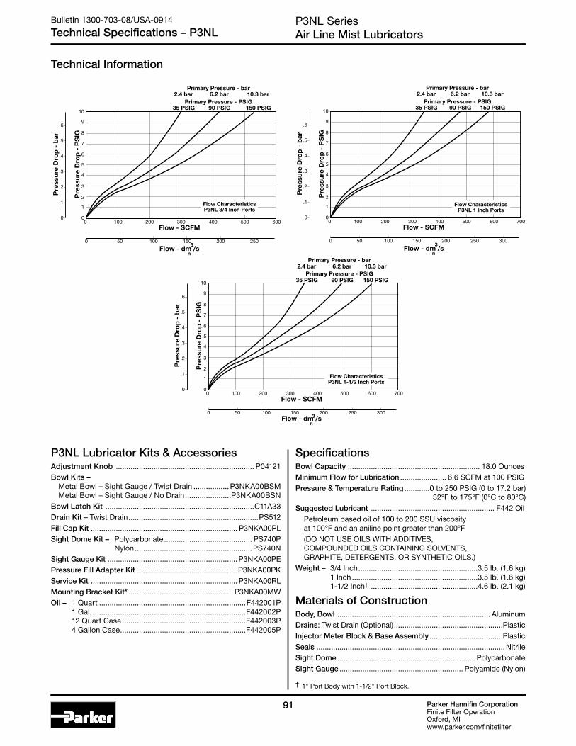
Parker Hannifin CorporationFinite Filter OperationOxford, MIwww.parker.com/finitefilter
9191
P3NL SeriesAir Line Mist Lubricators
Bulletin 1300-703-08/USA-0914
Technical Specifications – P3NL
Technical Information
0
1
2
3
4
5
6
7
8
10
9
0 200100 300 400 500 600
Pre
ssur
e D
rop
- P
SIG
35 PSIG 90 PSIG 150 PSIGPrimary Pressure - PSIG
2.4 bar 6.2 bar 10.3 barPrimary Pressure - bar
0
.1
0 50 100 150 200 250
Flow - SCFM
Pre
ssur
e D
rop
- b
ar
.2
.3
.4
.5
.6
Flow CharacteristicsP3NL 3/4 Inch Ports
Flow - dm /s3
n
0
1
2
3
4
5
6
7
8
10
9
0 200100 300 400 500 700600
Pre
ssur
e D
rop
- P
SIG
35 PSIG 90 PSIG 150 PSIGPrimary Pressure - PSIG
2.4 bar 6.2 bar 10.3 barPrimary Pressure - bar
0
.1
0 50 100 150 200 250 300
Flow - SCFM
Pre
ssur
e D
rop
- b
ar
.2
.3
.4
.5
.6
Flow CharacteristicsP3NL 1 Inch Ports
Flow - dm /s3
n
0
1
2
3
4
5
6
7
8
10
9
0 200100 300 400 500 700600
Pre
ssur
e D
rop
- P
SIG
35 PSIG 90 PSIG 150 PSIGPrimary Pressure - PSIG
2.4 bar 6.2 bar 10.3 barPrimary Pressure - bar
0
.1
0 50 100 150 200 250 300
Flow - SCFM
Pre
ssur
e D
rop
- b
ar
.2
.3
.4
.5
.6
Flow CharacteristicsP3NL 1-1/2 Inch Ports
Flow - dm /s3n
SpecificationsBowl Capacity ............................................................... 18.0 OuncesMinimum Flow for Lubrication ...................... 6.6 SCFM at 100 PSIGPressure & Temperature Rating ............0 to 250 PSIG (0 to 17.2 bar)
32°F to 175°F (0°C to 80°C)Suggested Lubricant ........................................................... F442 Oil
Petroleum based oil of 100 to 200 SSU viscosity at 100°F and an aniline point greater than 200°F(DO NOT USE OILS WITH ADDITIVES, COMPOUNDED OILS CONTAINING SOLVENTS, GRAPHITE, DETERGENTS, OR SYNTHETIC OILS.)
Weight – 3/4 Inch .........................................................3.5 lb. (1.6 kg) 1 Inch ............................................................3.5 lb. (1.6 kg) 1-1/2 Inch† ...................................................4.6 lb. (2.1 kg)
Materials of ConstructionBody, Bowl ......................................................................... AluminumDrains: Twist Drain (Optional) ....................................................PlasticInjector Meter Block & Base Assembly ...................................PlasticSeals ..........................................................................................NitrileSight Dome ..................................................................PolycarbonateSight Gauge ........................................................... Polyamide (Nylon)
† 1" Port Body with 1-1/2" Port Block.
P3NL Lubricator Kits & AccessoriesAdjustment Knob .................................................................. P04121Bowl Kits – Metal Bowl – Sight Gauge / Twist Drain .................P3NKA00BSM Metal Bowl – Sight Gauge / No Drain ......................P3NKA00BSNBowl Latch Kit .......................................................................C11A33Drain Kit – Twist Drain ..............................................................PS512Fill Cap Kit ...................................................................... P3NKA00PLSight Dome Kit – Polycarbonate .......................................... PS740P
Nylon ........................................................PS740NSight Gauge Kit .............................................................. P3NKA00PEPressure Fill Adapter Kit ................................................P3NKA00PKService Kit ...................................................................... P3NKA00RLMounting Bracket Kit* .................................................. P3NKA00MWOil – 1 Quart ......................................................................F442001P 1 Gal. .........................................................................F442002P 12 Quart Case ...........................................................F442003P 4 Gallon Case ............................................................F442005P

Parker Hannifin CorporationFinite Filter OperationOxford, MIwww.parker.com/finitefilter
92
14 Miniature Series 2 & 3-Unit Close Nippled Combinations
Bulletin 1300-703-08/USA-0914
Model Numbers & Dimensions
Close Nippled Combinations – 14 Miniature Series
D FA
B
E
C
A D F
B
E
C
• See individual component pages for details.
Two-Unit Combo
Three-Unit Combo
• Regulator can be mounted with knob in up or down position.
A3.75(95)
B3.79(96)
C2.42(61)
D2.04(52)
E6.21(158)
F0.79(20)
Inches (mm)Note: All dimensions nominal.
Series Port Model Numbers
14G 1/4" 14G11B13F0G*For other models, refer to ordering information on next page.
Series Port Model Numbers
14A 1/4" 14A11B13F0G* For other models, refer to ordering information on next page.
A5.77(147)
B3.82(97)
C2.16(55)
D2.04(52)
E5.98(152)
F0.79(20)
Inches (mm)Note: All dimensions nominal.

Parker Hannifin CorporationFinite Filter OperationOxford, MIwww.parker.com/finitefilter
9393
Bulletin 1300-703-08/USA-0914
Model Number Index14 Miniature Series 2 & 3-Unit Close Nippled Combinations
Ordering Information
14A 1 1 B 13 F 0 G *
Port Size
1 1/4 Inch
Filter Bowl Options
Poly Bowl 1 Twist Drain Metal Bowl 3 Twist Drain
Regulator Pressure
Without Gauge 13 125 PSIG
Lubricator Bowl Options
Poly Bowl 0 No Drain Metal Bowl 3 Twist Drain
Relief
F Relieving
Lubricator Body Options
G No Fill Plug
Filter Element
B 5 Micron
Series
14A 3-Unit 14G 2-Unit
Engineering Level
A
C
DB
EF
F
G
HJ
LM
K Typ.
A
C
BD
EF
F
G
HJ
LM
K Typ.
DimensionsA B C D E F G H J K L M Kit
1.80(46)
2.37(60)
0.90(23)
1.35(34)
1.00(25)
0.50(13)
0.20(5)
1.24(31)
0.56(14)
0.22(6)
0.45(11)
0.62(16)
PS417BP(10F, 14F, P3A, 14R, 14E)
1.80(46)
2.17(55)
0.90(23)
1.35(34)
1.00(25)
0.50(13)
0.20(5)
1.24(31)
0.56(14)
0.22(6)
0.45(11)
0.62(16)
PS419(04L)
Inches (mm)
PS417BP(Includes Panel Mount Nut)
PS419
! WARNINGProduct rupture can cause serious injury.Do not connect regulator to bottled gas.
Do not exceed maximum primary pressure rating.
CAUTION:REGULATOR PRESSURE ADJUSTMENT – The working range of knob adjustment is designed to permit outlet pressures within their full range. Pressure adjustment beyond this range is also possible because the knob is not a limiting device. This is a common characteristic of most industrial regulators, and limiting devices may be obtained only by special design.
For best performance, regulated pressure should always be set by increasing the pressure up to the desired setting. For polycarbonate bowl and sight dome, see Caution on page 2.
Close Nippled Combinations – 14 Miniature Series
*Will be entered at factory

Parker Hannifin CorporationFinite Filter OperationOxford, MIwww.parker.com/finitefilter
94
Two-Unit Combo
Three-Unit Combo
Bulletin 1300-703-08/USA-0914
Model Numbers & Dimensions
• Regulator can be mounted with knob in up or down position.
• See individual component pages for details.
Close Nippled Combinations – 15 Economy Series
B
E
C
A D F
B
E
C
A D F
15 Economy Series 2 & 3-Unit Close Nippled Combinations
A4.49(114)
B5.35(136)
C3.16(80)
D2.05(52)
E8.50(216)
F1.03(26)
Inches (mm)Note: All dimensions nominal.
Series Port Model Numbers
15G1/4" 15G12B13A2N*
3/8" 15G22B13A2N*For other models, refer to ordering information on next page.
A7.00(178)
B5.35(136)
C2.24(57)
D2.05(52)
E7.59(193)
F1.03(26)
Inches (mm)Note: All dimensions nominal.
Series Port Model Numbers
15A1/4" 15A12B13A2N*
3/8" 15A22B13A2N*For other models, refer to ordering information on next page.
GRAYED OUT ITEMS
ARE OBSOLETE
AS OF JULY 1, 2014

Parker Hannifin CorporationFinite Filter OperationOxford, MIwww.parker.com/finitefilter
95
Ordering Information
15A 1 2 B 13 A 2 N *
Regulator Pressure
Without Gauge 13 125 PSIG
Lubricator Bowl Options
Poly Bowl 2 Metal Bowl Guard / No Drain
Metal Bowl / Sight Gauge 4 Twist Drain
15 Economy Series 2 & 3-Unit Close Nippled Combinations
Bulletin 1300-703-08/USA-0914
Model Number Index
Close Nippled Combinations – 05 Economy Series
Kits & Accessories (See individual component sections for other kits and accessories.)
Mounting Bracket Kit ............................................................PS963P (Includes Panel Mount Nut)
Filter Bowl Options
Poly Bowl 2 Metal Bowl Guard / No Drain Metal Bowl 4 Sight Gauge / Twist Drain
Series
15A 3-Unit 15G 2-Unit
Engineering Level
Port Size
1 1/4 Inch 2 3/8 Inch
Relief
A Relieving
Lubricator Body Options
N No Fill Plug
Filter Element
B 5 Micron* Includes 1-1/2"
Dial Face Gauge
§ Metal Bowls Only
! WARNINGProduct rupture can cause serious injury.Do not connect regulator to bottled gas.
Do not exceed maximum primary pressure rating.
CAUTION:REGULATOR PRESSURE ADJUSTMENT – The working range of knob adjustment is designed to permit outlet pressures within their full range. Pressure adjustment beyond this range is also possible because the knob is not a limiting device. This is a common characteristic of most industrial regulators, and limiting devices may be obtained only by special design.
For best performance, regulated pressure should always be set by increasing the pressure up to the desired setting. For polycarbonate bowl and sight dome, see Caution on page 2.
*Will be entered at factory
GRAYED OUT ITEMS
ARE OBSOLETE
AS OF JULY 1, 2014

Parker Hannifin CorporationFinite Filter OperationOxford, MIwww.parker.com/finitefilter
96
15 Economy Series2 & 3-Unit Modular Combinations
Bulletin 1300-703-08/USA-0914
Model Numbers & Dimensions
Modular Combinations – 15 Economy Series• Regulator can be mounted with knob in up or down position.
• See individual component pages for details.
• Gauges, Port Blocks, Manifold Blocks and Ball Valve must be ordered separately.
A4.33(110)
A1
6.38(162)
B5.35(136)
C3.15(80)
D2.05(52)
E8.50(216)
F1.45(37)
G2.60(66)
H1.14(29)
J4.72(120)
Inches (mm)
• All dimensions nominal.
• Mounting brackets not included.
Two-Unit Combo
Three-Unit Combo
B
E
C
A(Without Port Blocks)
J
A1
G
H
D F
.280 x .430(7mm x 11mm)
Slot
B
E
C
A(Without
Port Blocks)
J
A1
G
H
D F
.280 x .430(7mm x 11mm)
Slot
Series Port Model Numbers
15H1/4" 15H12B13A2N*
3/8" 15H22B13A2N*For other models, refer to ordering information on next page.
Series Port Model Numbers
15B1/4" 15B12B13A2N*
3/8" 15B22B13A2N*For other models, refer to ordering information on next page.
A6.70(170)
A1
8.72(222)
B5.35(136)
C2.24(57)
D2.05(52)
E7.59(193)
F1.45(37)
G2.60(66)
H1.14(29)
J2.35(600)
Inches (mm)
• All dimensions nominal.
• Mounting brackets not included.
GRAYED OUT ITEMS
ARE OBSOLETE
AS OF JULY 1, 2014

Parker Hannifin CorporationFinite Filter OperationOxford, MIwww.parker.com/finitefilter
97
Engineering Level
Ordering Information
15B 1 2 B 13 A 2 N * —
Bulletin 1300-703-08/USA-0914
Model Number Index
Body Connector Kit .............................................................. PS954PLockout Valve .................................................................... PS95601PManifold Block .................................................................. PS95701PPressure Switches –
DIN Connectors ...................................................................P01909 Flying Leads ........................................................................P01908
Wall Mounting Kit .................................................................. PS955P
Port Block Kits: 1/8" 1/4" 3/8"
NPT ................... PS95000P.........PS95001P ........ PS95002P
15 Economy Series2 & 3-Unit Modular Combinations
Modular Combinations – 15 Economy Series
Kits & Accessories (See individual component sections for other kits and accessories.)
Modular Options
Blank No Port Blocks
G With Port Blocks
Regulator Pressure
Without Gauge 13 125 PSIG
Lubricator Bowl Options
Poly Bowl 2 Metal Bowl Guard / No DrainMetal Bowl / Sight Gauge
4 Twist Drain
Filter Bowl Options
Poly Bowl 2 Metal Bowl Guard / Twist Drain
Metal Bowl 4 Sight Gauge / Twist Drain
Series
15B 3-Unit 15H 2-Unit
Port Size
1 1/4 Inch 2 3/8 Inch
Lubricator Body Options
N No Fill Plug
Filter Element
B 5 Micron
* Includes 1-1/2" Dial Face Gauge
Relief
A Relieving
! WARNINGProduct rupture can cause serious injury.Do not connect regulator to bottled gas.
Do not exceed maximum primary pressure rating.
CAUTION:REGULATOR PRESSURE ADJUSTMENT – The working range of knob adjustment is designed to permit outlet pressures within their full range. Pressure adjustment beyond this range is also possible because the knob is not a limiting device. This is a common characteristic of most industrial regulators, and limiting devices may be obtained only by special design.
For best performance, regulated pressure should always be set by increasing the pressure up to the desired setting. For polycarbonate bowl and sight dome, see Caution on page 2.
* 1/4 & 3/8 inch meet ISO 1179-1 Standard.
*Will be entered at factory
GRAYED OUT ITEMS
ARE OBSOLETE
AS OF JULY 1, 2014

Parker Hannifin CorporationFinite Filter OperationOxford, MIwww.parker.com/finitefilter
98
15 Economy SeriesModular Assembly & Accessories
Bulletin 1300-703-08/USA-0914
Part Numbers
Modular Accessories – 15 Economy Series
Body Connectors allow you to easily assemble and disassemble Modular Combinations.
Body Connectors are required whenever you assemble two or more pieces together.
Each Kit includes one set.
Port Block Connectors allow you to make threaded port connections to Modular units and are available in various port sizes to match your system requirements.
Each Kit includes all the necessary pieces to make two port connections.
Body ConnectorsPS954P
Port Block Connector Kits 1/8" 1/4" 3/8"
NPT ........PS95000P ........PS95001P ........PS95002P* 1/4 & 3/8 inch meet ISO 1179-1 Standard.
GRAYED OUT ITEMS
ARE OBSOLETE
AS OF JULY 1, 2014

Parker Hannifin CorporationFinite Filter OperationOxford, MIwww.parker.com/finitefilter
99
15 Economy SeriesModular Accessories
Bulletin 1300-703-08/USA-0914
Part Numbers
A Modular Manifold Block can be used between any two Modular units to give additional outlet ports. The 1/4" Manifold Block provides three additional outlets. Any standard pipe plug can be used to close off unused ports.NOTE: Body Connectors are not supplied with Manifold Blocks.
Wall Mounting Kits are available for mounting your Modular Assemblies and can be assembled and used with any standard body connector set.
Since Modular Combinations are always identical in size, you can predrill for wall mounting on your equipment.
Kit includes 1 assembly.
Lockout Valves provide positive shut-off and exhaust capability to isolate Modular units so they can be easily removed from the line and can be locked in a closed position. Center position can be used as a slow start for 06 and 07 series. Accepts #3 padlock. NOTE: Body Connectors are not supplied with Lockout Valves.
Wall Mounting KitsPS955P
Lockout Valve PS95601P
1/4" Port
Modular Manifold BlockPS95701P
1/4" Port
Modular Accessories – 15 Economy Series
.31(8)
3.15(80)
.63(16)
.14 (4)Typ.
.22 (6)Typ..43 (11)
Typ.
.63(16)
2.87(73)
2.28(58)
1.41(36)
.28(7)
.28 (7)Typ.
.85(22)
1.14(29)1.65 (42)
Dia.Thru2 Places
1.93(49)
1.06(27)
.56(14)
.83(21)
2.09(53)
1.65(42)
1.06(27)
1.13(29)
.58(15)
.56(14)
1.38(35)
.83(21)
2.09(52)
1.17(30)
1.65(42)
1/4" NPT
GRAYED OUT ITEMS
ARE OBSOLETE
AS OF JULY 1, 2014

Parker Hannifin CorporationFinite Filter OperationOxford, MIwww.parker.com/finitefilter
100
16 Compact & 17 Standard Series2 & 3-Unit Close Nippled Combinations
Bulletin 1300-703-08/USA-0914
Model Numbers & Dimensions
• See individual component pages for details.
Close Nippled Combinations – 16 Compact & 17 Standard Series
Two-Unit Combo
Three-Unit Combo
06G, 16G Series
A6.13(156)
B5.69(145)
C4.69(119)
D3.18(81)
E10.38(264)
F1.37(35)
07G, 17G Series
A6.99(178)
B6.97(177)
C4.79(122)
D3.44(87)
E11.76(299)
F1.63(41)
Inches (mm)
• All dimensions nominal.
Series PortModel
Numbers
16G
1/4" 16G12A13A2B*
3/8" 16G22A13A2B*
1/2" 16G32A13A2B*
17G
3/8" 17G22A13A2B*
1/2" 17G32A13A2B*
3/4" 17G42A13A2B*For other models, refer to ordering information on next page.
A D F
B
C
E
A
E
C
B
D F
Series PortModel
Numbers
16A
1/4" 16A12A13A2B*
3/8" 16A22A13A2B*
1/2" 16A32A13A2B*
17A
3/8" 17A22A13A2B*
1/2" 17A32A13A2B*
3/4" 17A42A13A2B*For other models, refer to ordering information on next page.
06A, 16A Series
A9.45(240)
B5.69(145)
C2.24(57)
D3.18(81)
E7.93(201)
F1.37(35)
07A, 17A Series
A10.74(2738)
B6.97(177)
C2.41(61)
D3.44(87)
E9.38(238)
F1.63(41)
Inches (mm)
• All dimensions nominal.

Parker Hannifin CorporationFinite Filter OperationOxford, MIwww.parker.com/finitefilter
101101
Bulletin 1300-703-08/USA-0914
Model Number Index
Ordering Information
16A 1 2 A 13 A 1 B *
Close Nippled Combinations – 16 Compact & 17 Standard Series
16 Compact & 17 Standard Series2 & 3-Unit Close Nippled Combinations
Kits & Accessories (See individual component sections for other kits and accessories.)
Mounting Bracket Kit (Includes Panel Mount Nut) 06A, 16A , 06G, 16G ...........................................................PS707P
07A, 17A , 07G, 17G ...........................................................PS807P
Series
Micro-Mist 16A Compact 3-Unit 17A Standard 3-Unit 16G Compact 2-Unit 17G Standard 2-Unit
Filter Bowl Options
Poly Bowl 2 Metal Bowl Guard / Twist Drain
Metal Bowl 4 Sight Gauge / Twist Drain
Regulator Pressure
Without Gauge 13 125 PSIG
Lubricator Bowl Options
Poly Bowl 2 Metal Bowl Guard / No Drain
Metal Bowl / Sight Gauge 4 Twist Drain
Engineering Level
Port Size
1 1/4 Inch* 2 3/8 Inch 3 1/2 Inch 4 3/4 Inch**
Relief
A Relieving
Lubricator Body Options
B With Fill Plug
Filter Element
B 5 Micron
* If 250 PSIG spring range is used, use Metal Bowl.
* Available on 06/16 Series only.
** Available on 07/17 Series only.
! WARNINGProduct rupture can cause serious injury.Do not connect regulator to bottled gas.
Do not exceed maximum primary pressure rating.
CAUTION:REGULATOR PRESSURE ADJUSTMENT – The working range of knob adjustment is designed to permit outlet pressures within their full range. Pressure adjustment beyond this range is also possible because the knob is not a limiting device. This is a common characteristic of most industrial regulators, and limiting devices may be obtained only by special design.
For best performance, regulated pressure should always be set by increasing the pressure up to the desired setting. For polycarbonate bowl and sight dome, see Caution on page 2.
*Will be entered at factory

Parker Hannifin CorporationFinite Filter OperationOxford, MIwww.parker.com/finitefilter
102
16 Compact & 17 Standard Series2 & 3-Unit Modular Combinations
Bulletin 1300-703-08/USA-0914
Model Numbers & Dimensions
• See individual component pages for details.
Modular Combinations – 16 Compact & 17 Standard Series
Two-Unit Combo
Three-Unit Combo
A1
B
C
.280 x .500(7mm x 13mm)
Slot
E G
D F
JA
(Without Port Blocks)
H
B
C
E
A(Without Port Blocks)
J
A1
G
H
D F
.280 x .500(7mm x 13mm)
Slot
06H, 16H SeriesA
6.10(155)
A1
9.04(230)
B5.69(145)
C4.69(119)
D3.18(81)
E10.38(264)
F2.00(51)
G3.58(91)
H1.40(36)
J6.65(169)
07H, 17H SeriesA
7.00(178)
A1
10.28(261)
B6.97(177)
C4.79(122)
D3.44(87)
E11.76(299)
F2.18(55)
G3.58(91)
H1.40(36)
J7.51(191)
Inches (mm)
• All dimensions nominal.
SeriesModel
NumbersPort
Model Numbers
Series
06H
06H12A13A2B* 1/4" 16H12A13A2B*
16H06H22A13A2B* 3/8" 16H22A13A2B*
06H32A13A2B*G 1/2"† 16H32A13A2B*G
07H
07H22A13A2B* 3/8" 17H22A13A2B*
17H07H32A13A2B* 1/2" 17H32A13A2B*
07H42A13A2B* 3/4" 17H42A13A2B*For other models, refer to ordering information on next page.
† 06 / 16 Available with Port Blocks Only.
SeriesModel
NumbersPort
Model Numbers
Series
06B
06B12A13A2B* 1/4" 16B12A13A2B*
16B06B22A13A2B* 3/8" 16B22A13A2B*
06B32A13A2B*G 1/2"† 16B32A13A2B*G
07B
07B22A13A2B* 3/8" 17B22A13A2B*
17B07B32A13A2B* 1/2" 17B32A13A2B*
07B42A13A2B* 3/4" 17B42A13A2B*For other models, refer to ordering information on next page.
† 06 / 16 Available with Port Blocks Only.
06B, 16B SeriesA
9.46(240)
A1
12.39(315)
B5.69(145)
C2.24(57)
D3.18(81)
E7.82(199)
F2.00(51)
G3.58(91)
H1.40(36)
J3.33(85)
07B, 17B SeriesA
10.750(273)
A1
14.03(356)
B6.97(177)
C2.41(61)
D3.44(87)
E9.27(235)
F2.18(55)
G3.58(91)
H1.40(36)
J3.76(95)
Inches (mm)
• All dimensions nominal.

Parker Hannifin CorporationFinite Filter OperationOxford, MIwww.parker.com/finitefilter
103103
16 Compact & 17 Standard Series2 & 3 Unit Modular Combinations
Bulletin 1300-703-08/USA-0914
Model Number Index
Modular Combinations – 16 Compact & 17 Standard Series
Body Connector Kit .............................................................. PS754PLockout Valve ........................................................................ PS756PManifold Block ...................................................................... PS757PPressure Switches –
DIN Connectors ...................................................................P01909 Flying Leads ........................................................................P01908
Wall Mounting Kit .................................................................. PS755P
Port Block Kits: Size NPT
16 Series 1/4" .........PS750P 3/8" .........PS751P 1/2" ......... PS752P*
* Use 1/4 or 3/8 ported bodies.† 1/4, 3/8 & 1/2 inch meet ISO 1179-1 Standard.
17 Series 1/4" .........PS850P 3/8" .........PS851P 1/2" .........PS852P 3/4" .........PS853P
‡ 1/2 inch meets ISO 1179-1 Standard.
Kits & Accessories (See individual component sections for other kits and accessories.)
Series
Micro-Mist 16B Compact 3-Unit 17B Standard 3-Unit 16H Compact 2-Unit 17H Standard 2-Unit
Filter Bowl Options
Poly Bowl 2 Metal Bowl Guard / Twist Drain
Metal Bowl 4 Sight Gauge / Twist Drain
Regulator Pressure
Without Gauge 13 125 PSIG
Lubricator Bowl Options
Poly Bowl 2 Metal Bowl Guard / No Drain Metal Bowl / Sight Gauge 4 Twist Drain
Engineering Level
Port Size
1 1/4 Inch* 2 3/8 Inch 3 1/2 Inch*** 4 3/4 Inch**
Relief
A Relieving
Lubricator Body Options
B With Fill Plug
Filter Element
B 5 Micron
* If 250 PSIG spring range is used, use Metal Bowl.
* Available on 16 Series only.
** Available on 07/17 Series only.
*** 06/16 available with Port Blocks only.
Ordering Information
16B 1 2 B 13 A 2 B * —
Modular Options
Blank No Port Blocks
G With Port Blocks
! WARNINGProduct rupture can cause serious injury.Do not connect regulator to bottled gas.
Do not exceed maximum primary pressure rating.
CAUTION:REGULATOR PRESSURE ADJUSTMENT – The working range of knob adjustment is designed to permit outlet pressures within their full range. Pressure adjustment beyond this range is also possible because the knob is not a limiting device. This is a common characteristic of most industrial regulators, and limiting devices may be obtained only by special design.
For best performance, regulated pressure should always be set by increasing the pressure up to the desired setting. For polycarbonate bowl and sight dome, see Caution on page 2.
*Will be entered at factory

Parker Hannifin CorporationFinite Filter OperationOxford, MIwww.parker.com/finitefilter
104
16 Compact & 07 Standard SeriesModular Assembly & Accessories
Bulletin 1300-703-08/USA-0914
Part Numbers
Modular Accessories – 16 Compact & 17 Standard Series
Body Connectors allow you to easily assemble and disassemble Modular Combinations.
Each Kit includes one set.
Body Connectors are required whenever you assemble two or more pieces together.
Port Block Connectors allow you to make threaded port connections to Modular units and are available in various port sizes to match your system requirements.
Each Kit includes all the necessary pieces to make two port connections.
Body Connectors16 Series ..........PS754P
17 Series ..........PS854P
Port Block Connector KitsSeries Size NPT
16 Series 1/4" ...... PS750 3/8" ..... PS751P 1/2" .... PS752P*
* Use 1/4 or 3/8 ported bodies.
17 Series 1/4" ..... PS850P 3/8" ..... PS851P
1/2" ..... PS852P 3/4" ..... PS853P

Parker Hannifin CorporationFinite Filter OperationOxford, MIwww.parker.com/finitefilter
105105
Bulletin 1300-703-08/USA-0914
Part Numbers
A Modular Manifold Block can be used between any two Modular units to give additional outlet ports. The Manifold Block provides 2 additional outlets in 3/8" and 1/2" sizes. Any standard pipe plug can be used to close off unused ports.NOTE: Body Connectors are not supplied with Manifold Blocks.
Wall Mounting Kits are available for mounting your Modular Assemblies and can be assembled and used with any standard body connector set.
Since Modular Combinations are always identical in size, you can predrill for wall mounting on your equipment.
Kit includes 1 assembly.
Lockout Valves provide positive shut-off and exhaust capability to isolate Modular units so they can be easily removed from the line and can be locked in a closed position. Center position can be used as a slow start. Accepts #3 padlock. NOTE: Body Connectors are not supplied with Lockout Valves.
16 Compact & 17 Standard SeriesModular Accessories
Wall Mounting Kits06 Series & 07 Series ................ PS755P
Lockout Valves
16 Series .......... PS756P ......3/8" Port
17 Series .......... PS856P .....1/2" Port
Modular Manifold Block06 Series ......... PS757P ............ 3/8" Port
07 Series .......... PS857P ........... 1/2" Port
Modular Accessories – 16 Compact & 17 Standard Series
.70(18)
1.40(35)
.350 ±.005
.500 ±.005.375 ±.005
.14 (4)Typ.
.28 (7)Typ.
1.38(35).75
(19)
1.65(42)
4.08(104)
3.58(91)
.50 (13)Typ.
.25 (6)Typ.
1.00(25)
.25(6)
.13(3)
.26 (7)Dia.
3.08(78)
2.67(68)
1.20 (31)SlideTravel
1.34(34)
1.88(48)
2.81(71)
1.40(36)
IN OUT
.31 (2.4) Dia.Lockout
Hole
1.50(38) .75
(19)
.75(19)
2.00(50)
1.00(25)
3/8" PortTop & Bottom
1/2" PortTop & Bottom
2.00(51)
1.00(25)
1.00(25)
2.00(50)
1.00(25)
PS857PPS757P

Parker Hannifin CorporationFinite Filter OperationOxford, MIwww.parker.com/finitefilter
106
P3N Hi-Flow Series2 & 3-Unit Close Nippled Combinations
Bulletin 1300-703-08/USA-0914
Model Numbers & Dimensions
Close Nippled Combinations – P3N Hi-Flow Series• Regulator can be mounted with knob in up or down position.
• See individual component pages for details.
Three-Unit Combo
• 40 Micron Filter Element
• Manual Twist Drain
• Relieving Regulator
• 125 PSI (8.6 bar)
B
C
E
A D F
A11.89(302)
B9.57(243)
C6.38(162)
D3.56(90)
E15.95(405)
F1.81(50)
Inches (mm)• All dimensions nominal. • Mounting brackets not included (change last character in model
number to “B” if required).• Gauges not included (change 12th character to “G” if required).
Series Port Model Numbers
P3N3B
3/4" P3N3B96SGMNNLNA
1" P3N3B98SGMNNLNA
1-1/2"† P3N3B9PSGMNNLNA
Notes: All Combo part numbers are with regulator knob in up position.† 1" Port Body with 1-1/2" Port Block.
For other models, refer to Ordering Information on next page.
GRAYED OUT ITEMS
ARE OBSOLETE
AS OF JULY 1, 2014

Parker Hannifin CorporationFinite Filter OperationOxford, MIwww.parker.com/finitefilter
107
Ordering Information
Bulletin 1300-703-08/USA-0914
Model Number Index
Kits & Accessories (See individual component sections for other kits and accessories.)
Wall Mounting Kit* ........................................................ P3NKA00MW
Port Type
9 NPT Female
Port Size
6 3/4" (w/o Port Blocks) 8 1" (w/o Port Blocks) P 1-1/2" Port Blocks (w/ 1" Ported Body)
Series
Filter Elements
E 5 Micron
Bowl
S Metal Bowl w/ Sight Gauge
Filter Drains
M Twist Drain
P3N 3 A 9 6 S G M N N L N A
Relief
N Relieving
Type
3 Combinations w/ Pipe Nipples
Combination
Metal Bowl B Hi-Flow 3-Unit
Lubricator Type
Oil Mist L w/ Polycarbonate Sight Dome
Regulator Pressure Range & Gauges
Without Gauge N 125 PSI (0 to 8 bar)
Mounting Options
A No Brackets or Kits
Lubricator Drain / Fill Devices
N No Drain, Solid Bowl / Fill Plug
P3N Hi-Flow Series2 & 3-Unit Close Nippled Combinations
Close Nippled Combinations – P3N Hi-Flow Series
! WARNINGProduct rupture can cause serious injury.Do not connect regulator to bottled gas.
Do not exceed maximum primary pressure rating.
CAUTION:REGULATOR PRESSURE ADJUSTMENT – The working range of knob adjustment is designed to permit outlet pressures within their full range. Pressure adjustment beyond this range is also possible because the knob is not a limiting device. This is a common characteristic of most industrial regulators, and limiting devices may be obtained only by special design.
For best performance, regulated pressure should always be set by increasing the pressure up to the desired setting.
GRAYED OUT ITEMS
ARE OBSOLETE
AS OF JULY 1, 2014

Parker Hannifin CorporationFinite Filter OperationOxford, MIwww.parker.com/finitefilter
108
P3N Hi-Flow Series 2 & 3-Unit Modular Combinations
Bulletin 1300-703-08/USA-0914
Model Numbers & Dimensions
Modular Combinations – P3N Hi-Flow Series• Regulator can be mounted with knob in up or down position.
• See individual component pages for details.
Three-Unit Combo
• 40 Micron Filter Element
• Manual Twist Drain
• Relieving Regulator
• 125 PSI (8.6 bar)
D
A1 (Port Blocks)B
C
E
A
B2
(w/ Mtg Brkts)
B1
A3 (w/ Mtg Brkts & Port Blocks)A2
(w/ Mtg Brkts, w/o Port Blocks)
Series Port Model Numbers
P3NCB
3/4" P3NCB96SEMNNLNA
1" P3NCB98SEMNNLNA
1-1/2"† P3NCB9PSEMNNLNANotes: All Combo part numbers are with regulator knob in up position.† 1" Port Body with 1-1/2" Port Block.For other models, refer to Ordering Information on next page.
A10.87(2764)
A1
13.15(334)
A2
13.46(342)
A3
15.75(400)
B3.62(92)
B1
5.20(132)
B2
5.74(146)
C6.38(162)
D9.57(243)
E15.95(405)
Inches (mm)
• All dimensions nominal.
• Mounting brackets not included (change last character in model number to “B” if required).
• Gauges not included (change 12th character to “G” if required).
GRAYED OUT ITEMS
ARE OBSOLETE
AS OF JULY 1, 2014
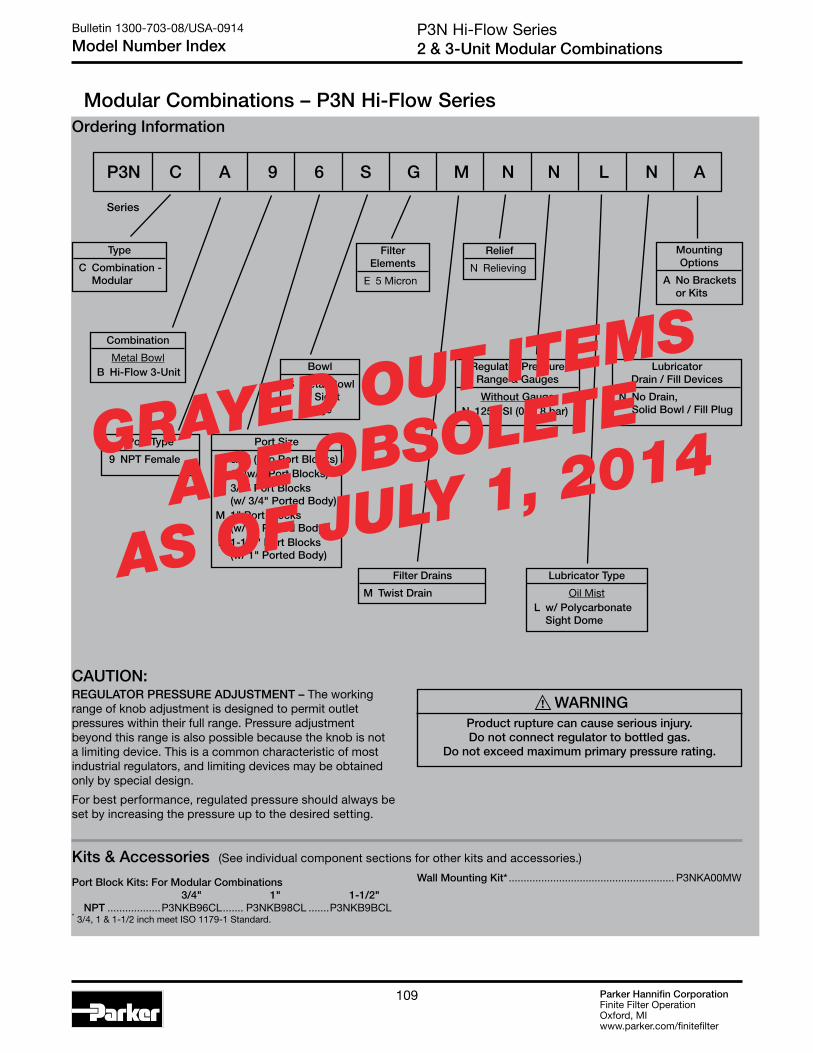
Parker Hannifin CorporationFinite Filter OperationOxford, MIwww.parker.com/finitefilter
109
Ordering Information
P3N Hi-Flow Series 2 & 3-Unit Modular Combinations
Bulletin 1300-703-08/USA-0914
Model Number Index
Series
P3N C A 9 6 S G M N N L N A
Modular Combinations – P3N Hi-Flow Series
Port Type
9 NPT Female
Port Size
6 3/4" (w/o Port Blocks) 8 1" (w/o Port Blocks) H 3/4" Port Blocks (w/ 3/4" Ported Body) M 1" Port Blocks (w/ 1" Ported Body) P 1-1/2" Port Blocks (w/ 1" Ported Body)
Filter Elements
E 5 Micron
Bowl
S Metal Bowl w/ Sight Gauge
Filter Drains
M Twist Drain
Relief
N Relieving
Type
C Combination - Modular
Combination
Metal Bowl B Hi-Flow 3-Unit
Lubricator Type
Oil Mist L w/ Polycarbonate Sight Dome
Regulator Pressure Range & Gauges
Without Gauge N 125 PSI (0 to 8 bar)
Mounting Options
A No Brackets or Kits
Lubricator Drain / Fill Devices
N No Drain, Solid Bowl / Fill Plug
Kits & Accessories (See individual component sections for other kits and accessories.)
Wall Mounting Kit* ........................................................ P3NKA00MWPort Block Kits: For Modular Combinations 3/4" 1" 1-1/2" NPT ..................P3NKB96CL ....... P3NKB98CL .......P3NKB9BCL* 3/4, 1 & 1-1/2 inch meet ISO 1179-1 Standard.
! WARNINGProduct rupture can cause serious injury.Do not connect regulator to bottled gas.
Do not exceed maximum primary pressure rating.
CAUTION:REGULATOR PRESSURE ADJUSTMENT – The working range of knob adjustment is designed to permit outlet pressures within their full range. Pressure adjustment beyond this range is also possible because the knob is not a limiting device. This is a common characteristic of most industrial regulators, and limiting devices may be obtained only by special design.
For best performance, regulated pressure should always be set by increasing the pressure up to the desired setting.
GRAYED OUT ITEMS
ARE OBSOLETE
AS OF JULY 1, 2014

Parker Hannifin CorporationFinite Filter OperationOxford, MIwww.parker.com/finitefilter
110
Port Block Kits 3/4" 1" 1-1/2"
Individual Filters, Individual Regulators and 2-Piece Filter and Regulator Assemblies:
NPT P3NKB96CP .......P3NKB98CP ........P3NKB9BCP
2 and 3 Piece Combinations including a Lubricator (FR/L & FRL), Individual Lubricators, Individual Coalescing Filters and 2-Piece Filter and Coalescer Assemblies:
NPT P3NKB96CL .......P3NKB98CL .........P3NKB9BCL
Port Block Kits allow units to be installed or removed as modular components.
Each Kit includes all the necessary pieces to make two port connections.
Modular Accessories – P3N Hi-Flow Series
P3N High-Flow SeriesModular Assembly & Accessories
Bulletin 1300-703-08/USA-0914
Part Numbers
Mounting BracketsP3NKA00MW
Replacement Body CoversP3NKA00PMEach Kit contains two covers.
All units are shipped with body covers.
OIL
For 1-1/2” BSPP Port Block with E02 fitting application, use Mounting Bracket Kit P3NKA0BMW
For modular combinations, one side has groove and the mating side is flat. Use the o-ring seal provided in the groove. For some modular combinations, both surfaces may have grooves. In those applications, use o-ring in one groove and square seal provided in the other.
* 3/4, 1 & 1-1/2 inch meet ISO 1179-1 Standard.

Parker Hannifin CorporationFinite Filter OperationOxford, MIwww.parker.com/finitefilter
111111
Air Line AccessoriesBulletin 1300-703-08/USA-0914
Mounting Bracket Kits
Mounting Bracket Kits
DimensionsA B C D E F G H J K L M Kit
1.80(46)
2.37(60)
0.90(23)
1.35(34)
1.00(25)
0.50(13)
0.20(5)
1.24(31)
0.56(14)
0.22(6)
0.45(11)
0.62(16)
PS417BP(10F, 14F, P3A, 14R, 14E)
1.80(46)
2.17(55)
0.90(23)
1.35(34)
1.00(25)
0.50(13)
0.20(5)
1.24(31)
0.56(14)
0.22(6)
0.45(11)
0.62(16)
PS419(04L)
0.84(21)
3.25(83)
1.50(38)
0.42(11)
2.00(51)
0.94(24)
0.28(7)
1.44(37)
— — — —PS743P
(06F, 11F, 06L, 16L)
1.00(25)
3.94(100)
1.57(40)
0.50(13)
2.19(56)
1.25(32)
0.28(7)
1.68(43)
— — — —PS843P
(07F, 12F, 07L, 17L)
0.28(7)
2.12(54)
2.00(51)
0.14(4)
1.85(47)
0.63(16)
0.28(7)
1.41 (36)
— — — —PS943P
(05F, 15F, 15L)
0.84(21)
2.59(66)
0.49(12)
1.02(26)
1.85(47)
0.61(15)
0.28(7)
— — — — —PS963P
(05R, 10R, 05E, 27E)
0.84(21)
3.26(83)
0.77(20)
1.46(37)
2.00(51)
0.94(24)
0.28(7)
— — — — —PS707P
(06R, 06E, 11R)
1.00(25)
3.94(100)
0.65(17)
1.68(43)
2.19(56)
1.25(32)
0.28(7)
— — — — —PS807P
(07R, 07E, 12R)
6.22(158)
8.19(208)
2.75(70)
1.97(50)
2.36(60)
1.77(45)
1.30(33)
— — — — —P3NKA00MW
(P3NF, P3NR, P3NE, P3NL)
PS707P & PS807P PS963P (Includes Panel Mount Nut) (Includes Aluminum Panel Mount Nut)
PS419(Includes Panel Mount Nut)
PS743P, PS843P
P3NKA00MW
A
FG
B
C
E
D
F D E
GC
H
B
A
F
D
GC
E
B
A
E
F
G
CH
D
B
A
PS943P
inches (mm)
A
C
DB
EF
F
G
HJ
LM
K Typ.
A
C
BD
EF
F
G
HJ
LM
K Typ.
PS417BP(Includes Panel Mount Nut)
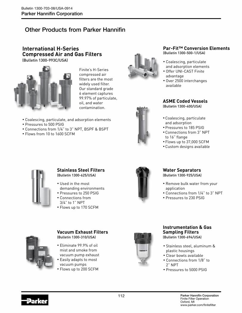
Parker Hannifin CorporationFinite Filter OperationOxford, MIwww.parker.com/finitefilter
112
Other Products from Parker Hannifin
Parker Hannifin CorporationFinite Filter OperationOxford, MIwww.parker.com/finitefilter
112
Other Products from Parker Hannifin
International H-Series Compressed Air and Gas Filters(Bulletin 1300-993C/USA)
Par-Fit™ Conversion Elements(Bulletin 1300-500-1/USA)
• Coalescing, particulate and adsorption elements• Offer UNI-CAST Finite advantage• Over 2500 interchanges available
• Coalescing, particulate and adsorption• Pressures to 185 PSIG• Connections from 3” NPT to 16” flange• Flows up to 37,000 SCFM• Custom designs available
ASME Coded Vessels(Bulletin 1300-400/USA)
• Coalescing, particulate, and adsorption elements • Pressures to 500 PSIG• Connections from 1/4” to 3” NPT, BSPF & BSPT• Flows from 10 to 1600 SCFM
Finite’s H-Series compressed air filters are the most widely used filter. Our standard grade 6 element captures 99.97% of particulate, oil, and water contamination.
Water Separators(Bulletin 1300-925/USA)
• Remove bulk water from your application• Connections from 1/4” to 3” NPT• Pressures to 230 PSIG
• Eliminate 99.9% of oil mist and smoke from vacuum pump exhaust• Easily adapts to most vacuum pumps• Flows up to 200 SCFM
Vacuum Exhaust Filters(Bulletin 1300-310/USA)
• Used in the most demanding environments• Pressures to 250 PSIG• Connections from 3/4” to 1” NPT• Flows up to 170 SCFM
Stainless Steel Filters(Bulletin 1300-625/USA)
Instrumentation & Gas Sampling Filters (Bulletin 1300-694/USA)
• Stainless steel, aluminum & plastic housings• Clear bowls available• Connections from 1/8” to 2” NPT• Pressures to 5000 PSIG
Bulletin 1300-703-08/USA-0914
Parker Hannifin Corporation

Parker Hannifin CorporationFinite Filter OperationOxford, MIwww.parker.com/finitefilter
113113
Other Products from Parker Hannifin
Parker Hannifin CorporationFinite Filter OperationOxford, MIwww.parker.com/finitefilter
113
Other Products from Parker Hannifin
• For point-of-use and OEM applications• Pressure dewpoints down to -40° F• Connections from 1/4” to 1” NPT• Ideal for intermittent flows
• Differential pressure gauges• Float, solenoid, and zero-air-loss drains• Mounting brackets and adapter kits
FDD Desiccant Dryers(Bulletin 1300-850/USA)
Accessories(Bulletin 1300-150/USA)
• Compressed air hollow fiber membrane dryers• Pressure dewpoints down to -40° F• Connections from 1/4” to 1/2” NPT• Flows up to 40 SCFM
Membrane Dryers(Bulletin 1300-800/USA)
• Coalescer/adsorber combination unit• Pressures to 500 PSIG• Connections from 1/4” to 1” NPT• Flows up to 75 SCFM
Dual-Stage BA-Series(Bulletin 1300-905/USA)
• Coalescing, particulate and adsorption• Pressures to 185 PSIG• Connections from 3” NPT to 16” flange• Flows up to 37,000 SCFM• Custom designs available
• CNG, alternative fuel and breathing air filters• Pressures to 5000 PSIG• Ductile iron and nodular cast iron • Coalescing, particulate and adsorption filter elements available
High Pressure Filters,J-Series(Bulletin 1300-997/USA)
• Safely drain condensate under pressure• Pressures to 6000 PSIG• Directly connect to J-Series and SJ-Series• Horizontal or vertical mounting
High Pressure Drains(Bulletin 1300-997/USA)
High Pressure Stainless Steel Filters, SJ-Series(Bulletin 1300-997/USA)
• Compatible with high pressure specialty gases• Pressures to 6000 PSIG• Stainless steel• Variety of filter elements available
• Pressures to 800 PSIG• Connections from 1/2” to 2” NPT, BSPT & BSPF• Use with specialty gases• Variety of filter elements available
Medium Pressure Filters,M-Series(Bulletin 1300-997/USA)
Spheriodal Cast Iron
Parker Hannifin CorporationFinite Filter OperationOxford, MIwww.parker.com/finitefilter
113
Other Products from Parker Hannifin
• For point-of-use and OEM applications• Pressure dewpoints down to -40° F• Connections from 1/4” to 1” NPT• Ideal for intermittent flows
• Differential pressure gauges• Float, solenoid, and zero-air-loss drains• Mounting brackets and adapter kits
FDD Desiccant Dryers(Bulletin 1300-850/USA)
Accessories(Bulletin 1300-150/USA)
• Compressed air hollow fiber membrane dryers• Pressure dewpoints down to -40° F• Connections from 1/4” to 1/2” NPT• Flows up to 40 SCFM
Membrane Dryers(Bulletin 1300-800/USA)
• Coalescer/adsorber combination unit• Pressures to 500 PSIG• Connections from 1/4” to 1” NPT• Flows up to 75 SCFM
Dual-Stage BA-Series(Bulletin 1300-905/USA)
• Coalescing, particulate and adsorption• Pressures to 185 PSIG• Connections from 3” NPT to 16” flange• Flows up to 37,000 SCFM• Custom designs available
• CNG, alternative fuel and breathing air filters• Pressures to 5000 PSIG• Ductile iron and nodular cast iron • Coalescing, particulate and adsorption filter elements available
High Pressure Filters,J-Series(Bulletin 1300-997/USA)
• Safely drain condensate under pressure• Pressures to 6000 PSIG• Directly connect to J-Series and SJ-Series• Horizontal or vertical mounting
High Pressure Drains(Bulletin 1300-997/USA)
High Pressure Stainless Steel Filters, SJ-Series(Bulletin 1300-997/USA)
• Compatible with high pressure specialty gases• Pressures to 6000 PSIG• Stainless steel• Variety of filter elements available
• Pressures to 800 PSIG• Connections from 1/2” to 2” NPT, BSPT & BSPF• Use with specialty gases• Variety of filter elements available
Medium Pressure Filters,M-Series(Bulletin 1300-997/USA)
Bulletin 1300-703-08/USA-0914
Parker Hannifin Corporation
(Bulletin 1300-220/USA)
Parker Hannifin CorporationFinite Filter OperationOxford, MIwww.parker.com/finitefilter
114
Notes
Bulletin 1300-703-08/USA-0914
Parker Hannifin Corporation

Parker Hannifin CorporationFinite Filter OperationOxford, MIwww.parker.com/finitefilter
115115
Offer of Sale
Parker Hannifin CorporationFinite Filter OperationOxford, MIwww.parker.com/finitefilter
115
The items described in this document are hereby offered for sale at prices to be established by Parker Hannifin Corporation, its subsidiaries and its autho-rized distributors. This offer and its acceptance by any customer (“Buyer”) shall be governed by all of the following Terms and Conditions. Buyer’s order for any item described in its document, when communicated to Parker Hannifin Corporation, its subsidiary or an authorized distributor (“Seller”) verbally or in writing, shall constitute acceptance of this offer.
1. Terms and Conditions of Sale: All descriptions, quotations, proposals, of-fers, acknowledgments, acceptances and sales of Seller's products are subject to and shall be governed exclusively by the terms and conditions stated herein. Buyer's acceptance of any offer to sell is limited to these terms and condi-tions. Any terms or conditions in addition to, or inconsistent with those stated herein, proposed by Buyer in any acceptance or an offer by Seller, are hereby objected to. No such additional, different or inconsistent terms and conditions shall become part of the contract between Buyer and Seller unless expressly accepted in writing by Seller. Seller’s acceptance of any offer to purchase by Buyer is expressly conditional upon Buyer’s assent to all the terms and conditions stated herein, including any terms in addition to, or inconsistent with those contained in Buyer’s offer. Acceptance of Seller's products shall in all events constitute such assent.
2. Payment: Payment shall be made by Buyer within 30 days from the date of shipment. Amounts not timely paid shall bear interest at the Maximum rate permitted by law for each month or portion thereof that the Buyer is late making payment. Any claims by Buyer for omissions or shortages in a ship-ment shall be waived unless Seller receives notice thereof within 30 days after Buyer’s receipt of the shipment.
3. Delivery: Unless otherwise provided on the face hereof, delivery shall be made F.O.B. Seller's plant. Regardless of the method of delivery, however, risk of loss shall pass to Buyer upon Seller’s delivery to a carrier. Any delivery dates shown are approximate only and Seller shall have no liability for any delays in delivery.
4. Warranty: Seller warrants that the items sold hereunder shall be free from defects in material or workmanship for a period of 18 months from date of ship-ment to Buyer. THIS WARRANTY COMPRISES THE SOLE AND ENTIRE WARRANTY PERTAINING TO ITEMS PROVIDED HEREUNDER. SELLER MAKES NO OTHER WARRANTY, GUARANTEE, OR REPRESENTATION OF ANY KIND WHATSOEVER. ALL OTHER WARRANTIES, INCLUDING BUT NOT LIMITED TO, MERCHANTABILITY AND FITNESS FOR PURPOSE, WHETHER EXPRESS, IMPLIED, OR ARISING BY OPERATION OF LAW, TRADE USAGE, OR COURSE OF DEALING ARE HEREBY DISCLAIMED.
NOTWITHSTANDING THE FOREGOING, THERE ARE NO WARRANTIES WHATSOEVER ON ITEMS BUILT OR ACQUIRED WHOLLY OR PARTIALLY, TO BUYER’S DESIGNS OR SPECIFICATIONS.
5. Limitation of Remedy: SELLER’S LIABILITY ARISING FROM OR IN ANY WAY CONNECTED WITH THE ITEMS SOLD OR THIS CONTRACT SHALL BE LIMITED EXCLUSIVELY TO REPAIR OR REPLACEMENT OF ITEMS SOLD OR REFUND OF THE PURCHASE PRICE PAID BY BUYER, AT SELLER’S SOLE OPTION. IN NO EVENT SHALL SELLER BE LIABLE FOR ANY INCIDENTAL, CONSEQUENTIAL OR SPECIAL DAMAGES OF ANY KIND OR NATURE WHATSOEVER, INCLUDING BUT NOT LIMITED TO LOST PROFITS ARISING FROM OR IN ANY WAY CONNECTED WITH THIS AGREEMENT OR ITEMS SOLD HEREUNDER, WHETHER ALLEGED TO ARISE FROM BREACH OF CONTRACT, EXPRESS OR IMPLIED WAR-RANTY, OR IN TORT, INCLUDING WITHOUT LIMITATION, NEGLIGENCE, FAILURE TO WARN OR STRICT LIABILITY.
6. Changes, Reschedules and Cancellations: Buyer may request to modify the designs or specifications for the items sold hereunder as well as the quan-tities and delivery dates thereof, or may request to cancel all or part of this order, however, no such requested modification or cancellation shall become part of the contract between Buyer and Seller unless accepted by Seller in a written amendment to this agreement. Acceptance of any such requested modification or cancellation shall be at Seller’s discretion, and shall be upon such terms and conditions as Seller may require.
7. Special Tooling: A tooling charge may be imposed for any special tooling, including without limitation, dies, fixtures, molds and patterns, acquired to manufacture items sold pursuant to this contract. Such special tooling shall be and remain Seller's property notwithstanding payment of any charges by Buy-
Offer of Saleer. In no event will Buyer acquire any interest in apparatus belonging to Seller which is utilized in the manufacture of the items sold hereunder, even if such apparatus has been specially converted or adapted for such manufacture and notwithstanding any charges paid by Buyer. Unless otherwise agreed, Seller shall have the right to alter, discard or otherwise dispose of any special tooling or other property in its sole discretion at any time.
8. Buyer’s Property: Any designs, tools, patterns, materials, drawings, con-fidential information or equipment furnished by Buyer or any other items which become Buyer’s property, may be considered obsolete and may be destroyed by Seller after two (2) consecutive years have elapsed without Buyer placing an order for the items which are manufactured using such property. Seller shall not be responsible for any loss or damage to such property while it is in Seller’s possession or control.
9. Taxes: Unless otherwise indicated on the face hereof, all prices and charges are exclusive of excise, sales, use, property, occupational or like taxes which may be imposed by any taxing authority upon the manufacture, sale or delivery of the items sold hereunder. If any such taxes must be paid by Seller or if Seller is liable for the collection of such tax, the amount thereof shall be in addition to the amounts for the items sold. Buyer agrees to pay all such taxes or to reimburse Seller therefore upon receipt of its invoice. If Buyer claims exemption from any sales, use or other tax imposed by any taxing authority, Buyer shall save Seller harmless from and against any such tax, together with any interest or penalties thereon which may be assessed if the items are held to be taxable.
10. Indemnity For Infringement of Intellectual Property Rights: Seller shall have no liability for infringement of any patents, trademarks, copyrights, trade dress, trade secrets or similar rights except as provided in this Part 10. Seller will defend and indemnify Buyer against allegations of infringement of U.S. patents, U.S. trademarks, copyrights, trade dress and trade secrets (hereinafter ‘Intellectual Property Rights’). Seller will defend at its expense and will pay the cost of any settlement or damages awarded in an action brought against Buyer based on an allegation that an item sold pursuant to this contract infringes the Intellectual Property Rights of a third party. Seller’s obligation to defend and indemnify Buyer is contingent on Buyer notifying Seller within ten (10) days after Buyer becomes aware of such allegations of infringement, and Seller having sole control over the defense of any allega-tions or actions including all negotiations for settlement or compromise. If an item sold hereunder is subject to a claim that it infringes the Intellectual Prop-erty Rights of a third party, Seller may, at its sole expense and option, procure for Buyer the right to continue using said item, replace or modify said item so as to make it noninfringing, or offer to accept return of said item and return the purchase price less a reasonable allowance for depreciation. Notwithstanding the foregoing, Seller shall have no liability for claims of infringement based on information provided by Buyer, or directed to items delivered hereunder for which the designs are specified in whole or part by Buyer, or infringements re-sulting from the modification, combination or use in a system of any item sold hereunder. The foregoing provisions of this Part 10 shall constitute Seller’s sole and exclusive liability and Buyer’s sole and exclusive remedy for infringe-ment of Intellectual Property Rights.
If a claim is based on information provided by Buyer or if the design for an item delivered hereunder is specified in whole or in part by Buyer, Buyer shall defend and indemnify Seller for all costs, expenses or judgments resulting from any claim that such item infringes any patent, trademark, copyright, trade dress, trade secret or any similar right.
11. Force Majeure: Seller does not assume the risk of and shall not be liable for delay or failure to perform any of Seller’s obligations by reason of circum-stances beyond the reasonable control of Seller (hereinafter ‘Events of Force Majeure’). Events of Force Majeure shall include without limitation, accidents, acts of God, strikes or labor disputes, acts, laws, rules or regulations of any government or government agency, fires, floods, delays or failures in delivery of carriers or suppliers, shortages of materials and any other cause beyond Seller’s Control.
12. Entire Agreement/Governing Law: The terms and conditions set forth herein, together with any amendments, modifications and any different terms or conditions expressly accepted by Seller in writing, shall constitute the entire Agreement concerning the items sold, and there are no oral or other representations or agreements which pertain thereto. This Agreement shall be governed in all respects by the law of the State of Ohio. No actions arising out of the sale of the items sold hereunder or this Agreement may be brought by either party more than two (2) years after the cause of action accrues.
Bulletin 1300-703-08/USA-0914
Parker Hannifin Corporation
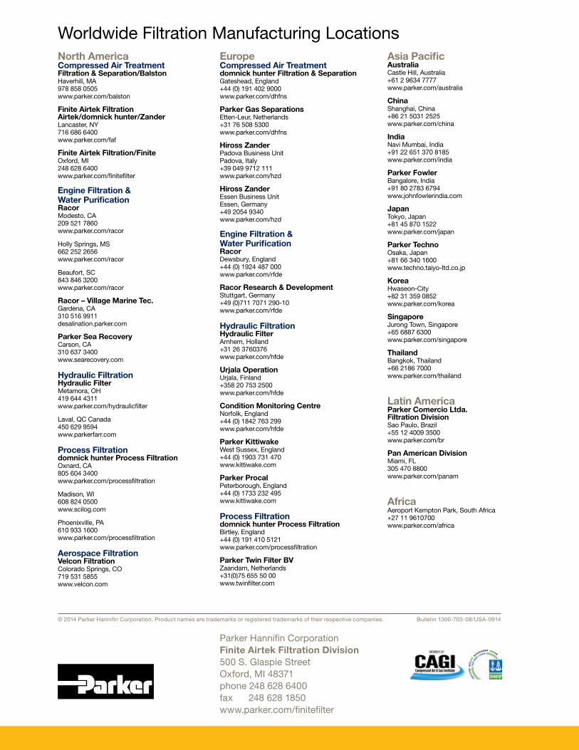
North AmericaCompressed Air TreatmentFiltration & Separation/BalstonHaverhill, MA 978 858 0505 www.parker.com/balston
Finite Airtek Filtration Airtek/domnick hunter/ZanderLancaster, NY 716 686 6400 www.parker.com/faf
Finite Airtek Filtration/FiniteOxford, MI 248 628 6400 www.parker.com/finitefilter
Engine Filtration & Water PurificationRacor Modesto, CA 209 521 7860 www.parker.com/racor
Holly Springs, MS 662 252 2656 www.parker.com/racor
Beaufort, SC 843 846 3200 www.parker.com/racor
Racor – Village Marine Tec.Gardena, CA 310 516 9911 desalination.parker.com
Parker Sea RecoveryCarson, CA 310 637 3400 www.searecovery.com
Hydraulic FiltrationHydraulic FilterMetamora, OH 419 644 4311 www.parker.com/hydraulicfilter
Laval, QC Canada 450 629 9594 www.parkerfarr.com
Process Filtration domnick hunter Process FiltrationOxnard, CA 805 604 3400 www.parker.com/processfiltration
Madison, WI 608 824 0500 www.scilog.com
Phoenixville, PA 610 933 1600 www.parker.com/processfiltration
Aerospace FiltrationVelcon FiltrationColorado Springs, CO 719 531 5855 www.velcon.com
EuropeCompressed Air Treatmentdomnick hunter Filtration & Separation Gateshead, England +44 (0) 191 402 9000 www.parker.com/dhfns
Parker Gas SeparationsEtten-Leur, Netherlands +31 76 508 5300 www.parker.com/dhfns
Hiross Zander Padova Business Unit Padova, Italy +39 049 9712 111 www.parker.com/hzd
Hiross ZanderEssen Business Unit Essen, Germany +49 2054 9340 www.parker.com/hzd
Engine Filtration & Water PurificationRacor Dewsbury, England +44 (0) 1924 487 000 www.parker.com/rfde
Racor Research & DevelopmentStuttgart, Germany +49 (0)711 7071 290-10 www.parker.com/rfde
Hydraulic FiltrationHydraulic Filter Arnhem, Holland +31 26 3760376 www.parker.com/hfde
Urjala Operation Urjala, Finland +358 20 753 2500 www.parker.com/hfde
Condition Monitoring CentreNorfolk, England +44 (0) 1842 763 299 www.parker.com/hfde
Parker KittiwakeWest Sussex, England +44 (0) 1903 731 470 www.kittiwake.com
Parker ProcalPeterborough, England +44 (0) 1733 232 495 www.kittiwake.com
Process Filtration domnick hunter Process FiltrationBirtley, England +44 (0) 191 410 5121 www.parker.com/processfiltration
Parker Twin Filter BVZaandam, Netherlands +31(0)75 655 50 00 www.twinfilter.com
Asia PacificAustralia Castle Hill, Australia +61 2 9634 7777 www.parker.com/australia
China Shanghai, China +86 21 5031 2525 www.parker.com/china
IndiaNavi Mumbai, India +91 22 651 370 8185 www.parker.com/india
Parker FowlerBangalore, India +91 80 2783 6794 www.johnfowlerindia.com
Japan Tokyo, Japan +81 45 870 1522 www.parker.com/japan
Parker TechnoOsaka, Japan +81 66 340 1600 www.techno.taiyo-ltd.co.jp
Korea Hwaseon-City +82 31 359 0852 www.parker.com/korea
SingaporeJurong Town, Singapore +65 6887 6300 www.parker.com/singapore
Thailand Bangkok, Thailand +66 2186 7000 www.parker.com/thailand
Latin AmericaParker Comercio Ltda. Filtration Division Sao Paulo, Brazil +55 12 4009 3500 www.parker.com/br
Pan American Division Miami, FL 305 470 8800 www.parker.com/panam
AfricaAeroport Kempton Park, South Africa +27 11 9610700 www.parker.com/africa
© 2014 Parker Hannifin Corporation. Product names are trademarks or registered trademarks of their respective companies. Bulletin 1300-703-08/USA-0914
Worldwide Filtration Manufacturing Locations
Parker Hannifin CorporationFinite Airtek Filtration Division500 S. Glaspie StreetOxford, MI 48371phone 248 628 6400fax 248 628 1850www.parker.com/finitefilter