AIP Model - National Infrastructure Planning
87
Lake Lothing Third Crossing Design Report Document Reference: 7.5 The Lake Lothing (Lowestoft) Third Crossing Order 201[*] _________________________________________________________________________ _________________________________________________________________________ Document 7.5: Design Report Appendix 3 _________________________________________________________________________ Author: Suffolk County Council
-
Upload
khangminh22 -
Category
Documents
-
view
0 -
download
0
Transcript of AIP Model - National Infrastructure Planning

Lake Lothing Third Crossing Design Report Document Reference: 7.5
The Lake Lothing (Lowestoft)
Third Crossing Order 201[*]
_________________________________________________________________________
_________________________________________________________________________
Document 7.5: Design Report
Appendix 3 _________________________________________________________________________
Author: Suffolk County Council

Lake Lothing Third Crossing Outline AIP for Central Bascule Span
Lake Lothing Third Crossing Outline Approval in Principle for Central Bascule Span
March 12th 2018
Produced for Suffolk County Council Prepared by Sam Smith, KGAL Ltd Marina Walk Offices Whitminster Lane Gloucester GL2 7PR UK T +44 1452 741931 E [email protected]
Notice This document and contents have been prepared in accordance with the scope outlined in the associated sub-consultancy agreement and are intended solely for WSP Ltd / Suffolk County Council’s information and use in relation to the Lake Lothing Third Crossing project. KGAL Ltd assumes no responsibility to any other party in respect of or arising out of or in connection with this document and / or its contents or its usage by any party for any other purpose than that defined above.

Document Ref. C1073G-1_090_P09 - AIP (Bascule Span).docx
Rev P09
March 2018
KGAL Ltd 2018
1
DOCUMENT CONTROL SHEET
Project Title Lake Lothing Third Crossing (LL3X)
Report Title Lake Lothing Third Crossing Approval in Principle for Moving Span
Bridge Ref -
Bridge Code -
Document No.
C1073G-1_090_P09 - AIP (Bascule Span).docx
Status FOR DCO SUBMISSION
Record of Issue
Issue Status Author Date Check Date Authorised DateRev 0 For DCO Sam Smith 12/03/2018 A Robotham 12/03/2018
A Robotham
Distribution
Organisation Contact Copies
WSP Furqan Qamar Electronically
KGAL Ltd Sam Smith, Angela Robotham Electronically
12/03/2018
UKFXQ601
Stamp

Document Ref. C1073G-1_090_P09 - AIP (Bascule Span).docx
Rev 0
March 2018
KGAL Ltd 2018
2

Document Ref. C1073G-1_090_P09 - AIP (Bascule Span).docx
Rev 0
March 2018
KGAL Ltd 2018
3
CONTENTS
Annex A1a – Outline Approval in Principle for the Design of Bridges and Other Highway Structures
where UK National Standards (Eurocodes) are Used .......................................................... 5
1 Highway Details ..................................................................................................................... 5
2 Site Details ............................................................................................................................ 5
3 Proposed Structure ............................................................................................................... 5
4 Design Criteria ..................................................................................................................... 16
5 Structural Analysis............................................................................................................... 19
6 Geotechnical Conditions ..................................................................................................... 23
7 Check .................................................................................................................................. 23
8 Drawings and Documents ................................................................................................... 24
9 The Above is Submitted for Acceptance ............................................................................. 24
10 The Above is Rejected/Agreed Subject to the Amendments and Conditions Shown Below
............................................................................................................................................ 24
Annex A3 – Outline Approval in Principle for M&E Installations in Moveable Bridges and Access
Gantries .............................................................................................................................. 25
1 Highway Details ................................................................................................................... 25
2 Structure Details .................................................................................................................. 25
3 General Description of Mechanical and Electrical Installation (M&E) ................................. 25
4 Operational Design Criteria (as Relevant for the M&E Systems) ....................................... 34
5 Basis of Operation and Control ........................................................................................... 37
6 Plant Room .......................................................................................................................... 43
7 Description of Inspection and Maintenance Arrangements ................................................ 44
8 Check .................................................................................................................................. 46
9 Drawings and Documents ................................................................................................... 46
10 The Above is Submitted for Acceptance ............................................................................. 47
11 The Above is Rejected/Agreed Subject to the Amendments and Conditions Shown Below
............................................................................................................................................ 47
APPENDIX A - Technical Approval Schedule "TAS" ....................................................................... 48
APPENDIX B – Location Plan .......................................................................................................... 65
APPENDIX C – General Arrangement Drawings ............................................................................. 66
APPENDIX D – Associated Drawings .............................................................................................. 68
APPENDIX E – Cost Estimates ....................................................................................................... 69

Document Ref. C1073G-1_090_P09 - AIP (Bascule Span).docx
Rev 0
March 2018
KGAL Ltd 2018
4
Name of Project: Lake Lothing Third Crossing (LL3X)
Name of Structure: Lake Lothing Third Crossing Central Bascule Span
INTRODUCTION
Lake Lothing in Lowestoft, UK, is currently crossed by two road bridges: one carrying the A12 across the passage between the inner and outer harbours and a second carrying the A1117 at the Mutford Locks, Oulton Broad. Both crossings open to allow shipping to access the port causing significant traffic disruption. The proposed crossing is a new road crossing over Lake Lothing, improving connectivity between both sides of the lake as well as relieving congestion in and around the town centre. The proposed bridge will comprise a central bascule river span and approach viaducts to either side.
The main obstacle crossed by the crossing’s central bascule is Lake Lothing.
The bascule bridge has a rolling lift mechanism that is supported on the south approach viaduct. The details of the interdependency between the bascule bridge and the approach viaducts will be covered on the final Approval In Principle document.
This Outline Approval in Principle contains information about the design of the central bascule span only. The approach viaducts are covered by a separate Outline Approval in Principle document.
N.B. This Outline AIP is structured as Annex A1a, followed by Annex A3 of Highways Agency document BD2/12 “Technical Approval of Highway Structures” Volume 1, Section 1, Part 1.
Document Ref. C1073G-1_090_P09 - AIP (Bascule Span).docx
Rev 0
March 2018
KGAL Ltd 2018
5
Annex A1a – Outline Approval in Principle for the Design of Bridges and Other Highway Structures where UK National Standards (Eurocodes) are Used
1 Highway Details
1.1 Type of highway
Over: Single carriageway 2-lane all-purpose road carried by central bascule span. A third lane, whose flow direction may be changed according to traffic conditions, is to be considered.
1.2 Permitted Traffic Speed
Over: Vehicular traffic: 30 mph
Under: Marine traffic: 4 knots (Port speed limit)
1.3 Existing Restrictions
Not Applicable
2 Site Details
2.1 Obstacles Crossed
Lake Lothing
3 Proposed Structure
3.1 Description of Structure and Design Working Life
The proposed Lake Lothing Third Crossing has a central bascule span which is supported by the two water piers of the approach viaducts.
The carriageways and pedestrian / cycleways of the fixed viaducts are continuous over the bascule span, which carries them over the navigation channel below. For details of the carriageway and pedestrian / cycleway widths, see separate AIP for the approach viaducts.

Document Ref. C1073G-1_090_P09 - AIP (Bascule Span).docx
Rev 0
March 2018
KGAL Ltd 2018
6
Figure 1 – General Arrangement of Moving Span Structure
The bascule span structure is a rolling type bascule bridge with counterweights carried in superstructures comprising beams continuous with the span support beams. When the bascule bridge is lowered, its load is shared unequally between the two water piers. When the bascule bridge is raised, its load is transmitted entirely to the South water pier.
The carriageway comprises a 7.3m wide carriageway with a 4.5m wide shared footway on the East side and a 6.0m wide shared footpath and cycleway on the West side. On each side there is a 1.0m wide setback between the parapets and the main box section beams. The total width of the structure between the main beams is 19.8m.
The deck will have a 2.5% transverse fall each side of the centreline of the carriageway plus a longitudinal fall of 1:80 to facilitate the shedding of rainwater. Further provision for the shedding of rainwater is provided by gulleys and channels leading to the highway drainage system.
The bridge will provide a clear channel width of 32m, having unlimited airdraft and protected by fendering.
For details of the mode of operation of the structure, see Annex A3, section 3.1
For further details of the proposed structure refer to drawings in Appendix D.
The bridge shall be designed to have a design working life category 5 (≥120 years) in accordance with NA to BS EN 1990:2002. Expansion joints, waterproofing systems,
SOUTH WATER
PIER
NORTH WATER
PIER

Document Ref. C1073G-1_090_P09 - AIP (Bascule Span).docx
Rev 0
March 2018
KGAL Ltd 2018
7
parapets and safety barriers shall be a design working life category 2 (up to 50 years). Structural Bearings shall be category 5 but with a proposed working life of 50 years in accordance to IAN 124/11. See Annex 3 for the treadplates.
The bascule span will have an associated plant and control room building, located on the South quay. Additionally, a smaller enclosure is to be located on the north quay, to house electrical equipment.
3.2 Structural Type
The superstructure comprises a single, counterweighted, rolling-lift bascule leaf. The deck is an orthotropic steel deck comprising longitudinal bulb flats and transverse beams. Counterweight arms consist of fabricated box girders of width 1.2m which is intended to give access clearance during fabrication for welding. A transverse box section cross-girder has been provided towards the heel of the leaf to allow attachment of the lifting cylinders, and at the nose to increase torsional stiffness of the leaf.
Counterweight will be provided by filling compartments in the counterweight arms with concrete.
3.3 Foundation Type
The bridge is supported on reinforced concrete piers which also carry the approach spans. The South pier supports the flat treadplates and the North pier supports the nose of the bascule span.
3.4 Span Arrangements
The bascule leaf spans 35m between piers (32m between fendering). The opening permits a navigational channel 32m wide with unlimited air draft in the raised position.
The bascule span steel structure will have an unfactored mass of approximately 1010Te, including kentledge and surfacing but excluding M&E equipment (e.g. nose bolts), fasteners and finishes.
The leaf is supported in the lowered position by the treadplates (South pier) and bridge bearings (North pier). In this position, the hydraulic lifting cylinders are unloaded (set to free-float) and do not form a ‘hard point’.
The bascule span rolls back on to the South, rather than North, pier. This provides visibility of the rolling section of the span from the control room located on the South quay.
There is no skew angle in relation to the North and South water piers.
The general arrangement of the structure and typical sections of the bridge are shown on drawings:
1069948-MOU-SGN-LL_C13-DR-CB-0037
1069948-MOU-SGN-LL_C13-DR-CB-0038
1069948-WSP-SGN-LL-C19-DR-CB-0039
1069948-WSP-SGN-LL-C19-DR-CB-0040

Document Ref. C1073G-1_090_P09 - AIP (Bascule Span).docx
Rev 0
March 2018
KGAL Ltd 2018
8
3.5 Articulation Arrangements
The bascule span is raised and lowered by hydraulic cylinders mounted underneath the soffit and acting approximately vertically. Two or more cylinders located centrally (in a lateral sense) at the heel of the deck act to raise and lower the leaf. The span rotates, and simultaneously rolls back and forth, as it is raised and lowered.
The south water pier shall include sole plates and associated support as appropriate, set into the structure of the south water pier. The upper surface of the sole plates shall be horizontal, to accept the flat treadplates.
The North water pier shall include suitable locations for the positioning of two or more bearings to support the nose of the bascule span.
A cut-out in the south approach viaduct permits the cylinders to move with the span as they extend (horizontally, towards the South). The lift angle is approximately 79°. The curved and flat treadplates shall be able to accommodate rotation slightly beyond the raised and lowered positions without detriment.
During raising and lowering, the dead and wind loads are borne entirely on the South pier. The span is held in equilibrium during motion raising and lowering by the treadplates and hydraulic cylinders.
Facilities shall be provided for the locking of the span in the raised position.
Articulation arrangements are shown in the associated drawings (ref: Appendix D)
An energy chain or similar device shall be incorporated, to carry electrical cables to the bascule span. This will provide for highway and pedestrian/cycleway lighting, ‘feature’ lighting as required, and other lighting and electrical devices as required, e.g. nose lock position sensors.
The energy chain shall be set alongside the rolling section of the blades. The ‘rear’ end is anchored to the pier, and the front end anchored to the blade. As the blade is raised, the energy chain is picked up, and set back down when the blade is lowered. The chain must lie exactly on the rolling radius, otherwise it will be stretched or become slack. Provision shall be provided for the protection of the energy chain and the cables within from UV damage, debris, vandalism and so on.
Figure 2 – Energy chain (span-lowered position)

Document Ref. C1073G-1_090_P09 - AIP (Bascule Span).docx
Rev 0
March 2018
KGAL Ltd 2018
9
Figure 3 – Energy chain (mid-lift position)
Figure 4 – Energy chain (span-raised position)
Lighting for the walk/cycleways and main carriageway as per the fixed approaches. Additional ‘beacon’ lighting may be required to mark the tips of the counterweight arms (in the lowered position) and the nose of the deck (in the raised position).
Further architectural illumination may be incorporated as required.
3.6 Classes and Levels
3.6.1 Consequence Class
The Consequence Class for the bascule span is CC3 (‘high’) in accordance with BS EN 1990:2002+A1:2005.
3.6.2 Reliability Class
The Reliability Class is RC3, associated with Consequence Class CC3.
As reliability differentiation is achieved by varying the design supervision and execution inspection levels, KFI shall be taken as 1,0 and Table B3 of BS EN 1990:2002 shall not be used. (Design Manual for Roads and Bridges (DMRB) Volume 1 Section 3, Part 19 (BD 100/16) Table A1, Note 1)

Document Ref. C1073G-1_090_P09 - AIP (Bascule Span).docx
Rev 0
March 2018
KGAL Ltd 2018
10
3.6.3 Inspection Level
The Inspection Level is IL3, in line with the Reliability Class RC3
3.7 Road Restraint Systems Requirements
Containment over the moving span should be a continuation of that on the fixed viaducts, having no points of weakness between the fixed viaducts and the bascule span.
Design of restraint systems shall, where practicable, avoid trapping / crushing-type hazards created by the rotating / moving elements of the bascule span. This is particularly relevant where the waiting public are located near to the treadplates / cantilever arm areas. Parapets to be minimum Class H4a containment. Working width of 1000mm as indicated on drawing 1069948-MOU-SGN-LL_C13-DR-CB-0033. See the Section 3.7 of Approach Span OAIP for further details of risk assessment and parapet selection.
3.8 Proposed arrangements for Future Maintenance and Inspection
3.8.1 Traffic Management
Both marine and road traffic must be considered during maintenance phases. Any period during which the bascule span cannot be lifted would directly impact marine traffic, which may be unable to proceed whilst the span remains in the lowered position. Road traffic would be impacted if the bascule span remains in the raised position, however it would be possible to lower the bridge deck by controlled bleeding of the hydraulic cylinders to allow road traffic to pass.
A temporary partial closure of the bascule span (to road and/or marine traffic) may be required when using an under-bridge unit for inspection of the bascule span soffit (see 3.8.2).
A full closure of the bascule span (to road traffic) will be required when replacing the treadplates (see 3.8.2) or the nose bolts.
Control “wig-wag” signalling lights and vehicular and pedestrian barriers to be provided on both sides of the bridge in the design and where practical located to the sides of the footpaths so as not to adversely obstruct access.
3.8.2 Arrangements for Future Maintenance and Inspection of the Structure. Access Arrangements to Structure.
In the bridge-lowered position, the lift cylinders become unloaded and the dead and live loads are taken by the treadplates and nose bearings. It is plausible, therefore, that maintenance of the lift cylinders and associated hydraulic equipment may be carried out in the span-lowered position, with the bridge open to road traffic. Clearly, however, this may impact the movement of marine traffic.
Arrangements for the insertion of trimming mass into the structure, to allow for future adjustment in the event that the balance of the structure changes, shall be provided. The box section nature of the longitudinal blades lends itself to the insertion of trimming mass at numerous points along their length. Provision should be allowed for this at the detailed design stage. Bolted-on mass is desirable as this can be easily removed and adjusted for position and mass. Trimming mass shall not be bolted on the outside of the structure.

Document Ref. C1073G-1_090_P09 - AIP (Bascule Span).docx
Rev 0
March 2018
KGAL Ltd 2018
11
Maintenance locks to be provided at span-raised position, for e.g. maintenance of the flat and curved treadplates.
The curved and flat treadplates (mounted on the curved box girders and piers respectively) are segmental, rather than being continuous. This permits the replacement of one or more segments from each treadplate with the bascule span in the lowered position, and replacement of the remaining treadplates with the span in the maintenance (raised) position.
Access for inspection of the bascule soffit and to the hydraulic equipment within Pier 4 could be arranged from an under-bridge unit. This can also provide access to a walkway under the soffit of the fixed viaduct, to provide access to the equipment located within the pier: principally the remote hydraulic volumes (indicated in blue, below) the lifting cylinders and associated pipework. Arrangement to be determined by the Contractor at the detailed design stage, taking into account also the access arrangements determined for the fixed viaducts.

Document Ref. C1073G-1_090_P09 - AIP (Bascule Span).docx
Rev 0
March 2018
KGAL Ltd 2018
12
All other mechanical, hydraulic and electrical components within the bridge piers, bascule span, plant / control rooms on the North pier and South quay shall be easily accessible.
The main plant room is to be located at ground level of the control building on the South side of the bridge and facilitate the introduction and removal of large items of plant by fork-lift, or another vehicle, to and from the existing road network. It shall have access doors sufficiently large to permit the movement of such items of plant. A secondary electrical plant room is to be located on the North side quay to accommodate the electrical and communication equipment and installed in a suitable GRP enclosure
On the treadplate ledges of the South water pier, provision for railings and fall arrest points are to be provided.
In case of mains power failures, it shall be possible to bring to site mobile standby generators of suitable power to both the plant room and North quay enclosure, and to be able to connect them to the provided power transfer switches.
Site-specific risk assessments will be required for maintenance and inspection works.

Document Ref. C1073G-1_090_P09 - AIP (Bascule Span).docx
Rev 0
March 2018
KGAL Ltd 2018
13
3.9 Environment and Sustainability
Refer to the Construction Environmental Management Plan (CEMP) for the project.
CEEQUAL is the international evidence-based sustainability assessment, rating and awards scheme for civil engineering, infrastructure, landscaping and works in public spaces. The aim is to attain at least a ‘Very Good’ rating.
Cross-fall is to be provided on the carriageways and pedestrian/cycleways to allow surface water to drain into gullies located adjacent to the kerbs. Channels within the verge allow water to pass through from the carriageway
The amount and position of counterweight material (concrete/steel) will be optimised during installation of the bridge so that the power demanded to raise and lower the bascule leaf will be as low as possible.
3.10 Durability, Materials and finishes
All works generally to be in accordance with the Specifications for Highway Works.
3.10.1 Steel
Structural steelwork for plates to be S355J2G3+N to BS EN 10025.
Thickness up to and including 40 mm thick – Grade S355 J2G3 + N Thickness over 40 mm thick – Grade S355NL All steels shall comply with the relevant BS EN standards, be executed in accordance with BS EN 1090 and be CE marked. Material for the curved and flat treadplates to be specified at the detailed design stage, to give the required wear and contact stress resistances. The unpainted contact surfaces of fixed and rolling tracks will be protected using a proprietary rust prevention system applied at 3 to 6 month intervals. (Corrosion X-HD or similar approved) rather than requiring the treadplates to be fabricated from stainless steel.
3.10.2 Finishes
See OAIP for Fixed Viaducts and Marine Works
3.10.3 Protective Coating Systems
Steelwork shall be protected to a C5M exposure classification in accordance with BS EN ISO12944.
The coating system to be applied to the bridge and related operating equipment shall have a ‘high durability’ with time to first maintenance of more than 15years, 40 years to major maintenance or recoating and 60 years to recoating. The corrosion protection system should be chosen such that with adequate maintenance the structure should have a life of 120 years.
The deck surfaces shall be coated with an anti-skid epoxy based wearing surfaces.
Box sections of the main longitudinal members shall be sealed. Those compartments containing counterweight and/or trimming mass shall be sealed by means of an attached cover plate, to inhibit the free movement of air in and out of the compartments.

Document Ref. C1073G-1_090_P09 - AIP (Bascule Span).docx
Rev 0
March 2018
KGAL Ltd 2018
14
3.11 Risks and Hazards Considered for Design, Execution, Maintenance and Demolition. Consultation with and/or Agreement from Principal Designer
The risks and hazards to both the general public and workforce during the construction, operation, maintenance and demolition of the bridge shall be considered in a CDM design risk assessment and reviewed as the design progresses.
The Principal Designer shall be satisfied that the Designers for this structure are complying with their duties under Managing Health and Safety in Construction – Construction (Design and Management) Regulations 2015 – Guidance on Regulations (L153).
3.12 Estimated Cost of Proposed Structure Together With Other Structural Forms Considered (Including Where Appropriate Other Proprietary Manufactured Structure) and the Reasons for Their Rejection (Including Comparative Whole Life Costs With Dates of Estimates)
Several options were considered for the bascule bridge including a single leaf bascule option, a double leaf bascule option and a single leaf rolling bascule option. The latter has been selected due to comparable cost and greater aesthetic and architectural potential.
See Appendix E for cost estimates of the various bascule options considered.
3.13 Proposed Arrangements for Construction
3.13.1 Construction of Structure
See section 3.4 of Annex A1a in this document for the bridge overall dimensions and mass. How the bridge is erected depends very much on who is doing the fabrication and where it is being fabricated. There is limited scope for bolting on the box section lifting arms due to access, health and safety, and aesthetic considerations so a fully welded structure is envisaged with the arms possibly broken down into units for transportation and site welded. The cross-girder connection to the deck could be bolted, and possibly further subdivision of the deck provided no joints occur in the main carriageway. The bascule span may be brought to site by road or barge. It would likely be in sections, with site completion welding/assembly required. Completion welding would require the identification of a suitable laydown area in the vicinity. The deck could be assembled on one side of the channel and launched over the gap. It may be deemed suitable to add the concrete counterweight to the counterweight arms once the deck has been craned into position over the channel. This will minimise the load to be carried during this positioning operation, and permit the correct amount of concrete to be pumped in to achieve the required preponderance. Each compartment of the counterweight arms should not be completely full of concrete, and will typically be around ~75% full. Attention should therefore be paid to the placement of the concrete such that the fill is not biased towards the inboard or outboard faces, which would introduce undesired loading.
To bring the deck elements in by barge would require e.g. a 200‐class barge; the deck sections having been loaded from a suitable laydown area or directly from a fabricator having suitable load‐out facilities. Use of a barge requires consideration of barge availability, draught and stability. The barge would need to be equipped with suitable temporary works to support the deck elements and possibly suitable sea anchors depending on the passage. The barge would need to be able to pass through the East bridge which, from quay edge to quay edge, is estimated to be approximately 22.5m. The deck elements would then be lifted from the barge by cranes located on the North and South piers, and installed into position.

Document Ref. C1073G-1_090_P09 - AIP (Bascule Span).docx
Rev 0
March 2018
KGAL Ltd 2018
15
3.13.2 Traffic Management
See separate OAIP for fixed viaducts
3.13.3 Service Diversions
See separate OAIP for fixed viaducts
3.13.4 Interface with Existing Structures
See separate OAIP for fixed viaducts

Document Ref. C1073G-1_090_P09 - AIP (Bascule Span).docx
Rev 0
March 2018
KGAL Ltd 2018
16
4 Design Criteria
4.1 Actions
4.1.1 Permanent Actions
All permanent actions to be calculated in accordance with BS EN 1991-1-1 and the National Annex.
Material Density (kN/m3) Reference
Concrete 25 BS EN 1991-1-1:2002 Annex A
Structural Steel 78.5 BS EN 1991-1-1:2002 Annex A
4.1.2 Snow, Wind and Thermal Actions
All snow, wind and thermal actions as per BS EN 1991-1-3, 4 and 5 and the UK National Annexes.
Thermal loading is to be applied in accordance with BS EN 1991-1-5 and the National Annex. Approach 2 will be used for the vertical temperature difference in the bridge.
4.1.3 Actions Relating to Normal Traffic Under AW Regulations and C&U Regulations
Load models LM1 and LM2, braking and fatigue loading shall be as outlined in BS EN 1991-2 and the appropriate National Annex.
4.1.4 Actions Relating to General Order Traffic Under STGO Regulations
Load model LM3. This requirement will be included within the structure maintenance manual.
4.1.5 Footway or Footbridge Variable Actions
The verges shall have footway live loading applied as outlined in BS EN 1991-2 and the appropriate National Annex.
Accidental wheel loads shall be considered in the design of raised verges as outlined in BS EN 1991-2.
4.1.6 Actions Relating to Special Order Traffic, Provision for Exceptional Abnormal Indivisible Loads Including Location of Vehicle Track on the Deck Cross Section.
None.
4.1.7 Accidental Actions
The design will take into account accidental actions as described in BS EN 1991-1-7, the UK NA to BS EN 1991-1-7 (Table NA.1) and Interim Advice Note IAN 124.
The bascule span and associated supporting structures shall be designed to resist a local force due to mast collision of 300kN. It possible that local deformation of the box sections could occur without significant detriment to the overall structural strength. See section 4.6 for departures from standards.

Document Ref. C1073G-1_090_P09 - AIP (Bascule Span).docx
Rev 0
March 2018
KGAL Ltd 2018
17
Collision loading on kerbs and parapets shall be considered (i.e. in accordance with BS EN 1991-2 Cl 4.7.3.2 & 4.7.3.3).
4.1.8 Action During Construction
The design will take into account any adverse actions during execution as outlined in BS EN 1991-1-6 and the appropriate National Annex(es).
The criteria associated with serviceability limit states during execution will be the same as those applicable to the completed structure.
4.1.9 Any Special Action not Covered Above
The design will take into account actions related to maintenance / inspection works such as:
- The load introduced by an underbridge unit sitting on the deck
- The load introduced by the hoisting of hydraulic lift cylinders on a runway beam or similar lifting points underneath the deck
- The load introduced by the bascule span’s deceleration under the conditions of ‘emergency stop’ and failure of the electrical supply. See Annex A3, sections 3.4 and 5.5 for further details of these conditions.
4.1.10 Seismic Loading
An assessment of Consequence Class CC3 structures will be undertaken during the detailed design stage in accordance with PD 6698:2009.
4.1.11 Operational and Survival Conditions
The structure shall be designed for a fault load case involving the loss of support from one hydraulic cylinder and its consequential effect on the torsional loading of the bridge deck and unequal loading of the bridge bearings, including the curved and flat treadplates.
4.2 Heavy or High Load Route Requirements and Arrangements Being Made to Preserve the Route, Including Any Provision for Future Heavier Loads or Future Widening
The route will not be designated as a heavy load route.
4.3 Minimum Headroom Provided
Suffolk County Council requires a 12m clearance below the bascule span above HAT (Highest Astronomical Tide), in the lowered position, and unlimited clearance in the raised position.
4.4 Authorities Consulted and Any Special Conditions Required
Authority Plant/Apparatus Special Conditions
Associated British Ports
None Headroom requirement as detailed in section 4.3.
Suffolk County Council
None Headroom requirement as detailed in section 4.3.

Document Ref. C1073G-1_090_P09 - AIP (Bascule Span).docx
Rev 0
March 2018
KGAL Ltd 2018
18
4.5 Standards and Documents Listed in the Technical Approval Schedule
See attached schedule in Appendix A.
4.6 Proposed Departures Relating to Departures from Standards Given In 4.5
The bascule span might not be able to sustain structurally a shipping collision as per BS EN 1991-1-7: 2006 Annex C Table C.3 and UK NA.
AASHTO Guide Specification and Commentary for Vessel Collision Design of Highway Bridges (the code from which the departure is being sought), states that the collision force on the bridge superstructure from the mast of a 2983ton vessel such as the CFAS Endeavour, based in Lowestoft is calculated to be 300kN (see section 3.11). The loading calculated shall be applied to the bridge superstructure with the bridge in the closed position and during the opening and closing phases where the air draft is still insufficient to prevent a bridge strike.
4.7 Proposed Departures Relating to Methods for Dealing With Aspects Not Covered By Standards In 4.5
The use of Dutch moving bridge standard NEN 6786:2001 NL for the determination of wind loading during the operation of the bridge.
Document Ref. C1073G-1_090_P09 - AIP (Bascule Span).docx
Rev 0
March 2018
KGAL Ltd 2018
19
5 Structural Analysis
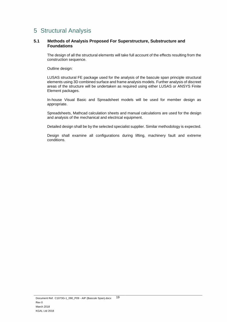
5.1 Methods of Analysis Proposed For Superstructure, Substructure and Foundations
The design of all the structural elements will take full account of the effects resulting from the construction sequence.
Outline design:
LUSAS structural FE package used for the analysis of the bascule span principle structural elements using 3D combined surface and frame analysis models. Further analysis of discreet areas of the structure will be undertaken as required using either LUSAS or ANSYS Finite Element packages.
In-house Visual Basic and Spreadsheet models will be used for member design as appropriate.
Spreadsheets, Mathcad calculation sheets and manual calculations are used for the design and analysis of the mechanical and electrical equipment.
Detailed design shall be by the selected specialist supplier. Similar methodology is expected.
Design shall examine all configurations during lifting, machinery fault and extreme conditions.

Document Ref. C1073G-1_090_P09 - AIP (Bascule Span).docx
Rev 0
March 2018
KGAL Ltd 2018
20
5.2 Idealised Model Proposed for the Structural Design
Figure 5 – Structural Model (shown in lowered position, view on deck upper)

Document Ref. C1073G-1_090_P09 - AIP (Bascule Span).docx
Rev 0
March 2018
KGAL Ltd 2018
21
Figure 6 – Structural Model (shown in raised position, view on soffit)

Document Ref. C1073G-1_090_P09 - AIP (Bascule Span).docx
Rev 0
March 2018
KGAL Ltd 2018
22
5.2.1 Assumptions Proposed for the Calculation of Structural Member Capacities
The capacities of the structural members will be based on gross elastic section properties. No reduction of section due to corrosion shall be considered.
5.3 Proposed Range of Soil Parameters to be Used in the Design of Earth-Retaining Elements
N/A for bascule span

Document Ref. C1073G-1_090_P09 - AIP (Bascule Span).docx
Rev 0
March 2018
KGAL Ltd 2018
23
6 Geotechnical Conditions
6.1 Acceptance of Recommendations of the Geotechnical Design Report to be Used in the Design and Reasons for any Proposed Changes
See OAIP for fixed viaducts. N/A for bascule span; span interfaces with North and South water piers.
6.2 Summary of Design for Highway Structure in the Geotechnical Design Report
See OAIP for fixed viaducts. N/A for bascule span; span interfaces with North and South water piers.
6.3 Differential Settlement to be Allowed for in the Design of the Structure
Sole plates, onto which the flat treadplates are mounted, to be capable of being jacked and shimmed. Contractor’s design enables individual adjustment of the flat treadplates during installation and subsequently. The two rolling tracks are to be founded on a common reinforced concrete founding pile cap to ensure the tracks remain coplanar.
The Contractor shall determine the possible levels of differential settlement within the pile cap and determine the required level of individual adjustment.
6.4 If the Geotechnical Design Report Is Not Yet Available, State When the Results Are Expected and List the Sources of Information Used to Justify the Preliminary Choice of Foundations
See OAIP for fixed viaducts.
7 Check
7.1 Proposed Category and Design Supervision Level
Checking Category: Category 3
Design Supervision Level: DSL3; Extended supervision level (checking performed by an organisation different from that which has prepared the design, in accordance with IAN 124/11)
7.2 If Category 3, Name of Proposed Independent Checker
Category 3 check to be confirmed at detailed design stage.
7.3 Erection Proposals or Temporary Works for Which Types S and P Proposals Will Be Required, Listing Structural Parts of the Permanent Structure Affected With Reasons
The Contractor will be responsible for the temporary works design including the stability of structures in the temporary construction situations. This will include, but is not limited to:
▪ Temporary works associated with installation of the bascule span
▪ Temporary works associated with on-site fabrication and/or assembly


Document Ref. C1073G-1_090_P09 - AIP (Bascule Span).docx
Rev 0
March 2018
KGAL Ltd 2018
25
Annex A3 – Outline Approval in Principle for M&E Installations in Moveable Bridges and Access Gantries
1 Highway Details
1.1 Type of highway
See Annex 1a, Section 1.1
1.2 Permitted Traffic Speed
See Annex 1a, Section 1.2
2 Structure Details
2.1 Brief Description of Structure
See Annex A1a, Section 3.1
2.2 Date of AIP for structure
October 2017
3 General Description of Mechanical and Electrical Installation (M&E)
3.1 Proposed Mode of Operation of Structure
The bascule span is raised and lowered by hydraulic lifting cylinders mounted adjacent to each other, underneath the soffit and acting approximately vertically. Two cylinders are to be mounted centrally (in a lateral sense) at the heel of the deck and act to raise and lower the leaf.
In the closed position the bascule span is simply-supported on elastomeric bearings at the nose end and on the treadplates at the heel. Counterweight mass is contained within the two counterweight arms which form a continuation of the two main longitudinal beams.
As the span is raised, it simultaneously rolls back. This action permits the attainment of unlimited air-draft over the navigation width more readily compared to a trunnion bascule span.

Document Ref. C1073G-1_090_P09 - AIP (Bascule Span).docx
Rev 0
March 2018
KGAL Ltd 2018
26
Figure 7 – Bascule Span in Lowered Position

Document Ref. C1073G-1_090_P09 - AIP (Bascule Span).docx
Rev 0
March 2018
KGAL Ltd 2018
27
Figure 8 – Bascule Span in Raised Position

Document Ref. C1073G-1_090_P09 - AIP (Bascule Span).docx
Rev 0
March 2018
KGAL Ltd 2018
28
Figure 9 – Bascule Span in Intermediate Position
The lifting cylinders initially act in compression as they extend to raise the bascule span. That is to say, the bascule span has a net closure preponderance under all variable (wind and snow) load conditions. During the raising operation and depending on the wind conditions, the span may pass through a point of zero imbalance, as the centre of gravity of the structure passes above the centre of rotation, and become ‘tail-heavy’. In this case, hydraulic restraint will be required for the remainder of the range of motion. By passing through a point of zero imbalance, the additional work and wear of the hydraulic pumps and cylinders during the operating range is reduced, however there may be adverse fatigue effects. Correspondingly, to lower the leaf, the lifting cylinders may initially need to act in tension to begin the lowering operation, then act in compression for the remainder of the lowering operation. A method to manually lower bridge from raised position in the event of power failure shall be established. The Contractor will be required to present the proposed system design and Method Statement for achieving safe operation of the manual lower system. The recovery position should be the lowered position. However, contractual performance demands may state that within a predefined period following a recovery, the bridge shall have the ability to be raised again to allow the passage of marine traffic. The lifting cylinders are to be rear trunnion mounted in brackets supported by the South pier. Spherical bearings are used within the mounting brackets. The lifting cylinders are located in a ‘pit’ within the pier, having walls reaching approximately 5m above HAT to provide against inundation of the pit by high water levels. Notwithstanding, the pit shall be equipped with a drainage arrangement to empty the pit of accumulated water, from e.g. rain and spray.

Document Ref. C1073G-1_090_P09 - AIP (Bascule Span).docx
Rev 0
March 2018
KGAL Ltd 2018
29
The flat treadplates incorporates a series of ‘teeth’ which engage in recesses in the curved treadplates. These serve to ensure correct tracking of the bascule span during the raising and lowering operations. The calculated cycle time under the no-wind conditions is 106secs to raise and 106secs to lower (see section 5.1) with a corresponding power requirement of 200kW. Consideration shall be given to changes in the carriageway joints due to temperature variation. Longitudinal thermal expansion of the bascule span shall be accommodated at the North pier. Adjustable nosing strips between the nose of the bascule span and the North pier shall provide adjustment of the gaps to provide an optimum setting to accommodate the thermal expansion of the leaf. Depending on the design of the fixed viaducts, it may also be necessary to consider the longitudinal thermal expansion of these, which may result in the distance between piers 3 and 4 closing up and impinging of the space available for the bascule span.
It may be necessary under extreme temperature conditions to undertake ‘in-service’ adjustments; i.e. ‘winter’ and ‘summer’ positions of the nosing strips. The anticipated range of longitudinal thermal expansion of the bascule span is anticipated to be around 30mm.
Where NMUs (pedestrians, cyclists, equestrians) are located, gaps shall be covered by treadplates. These shall also be fitted to the carriageway itself, since cyclists and equestrians are permitted to use these, despite there being separate walk/cycleways.
Lateral thermal expansion is accommodated at the North end by sliding of the nose end rocker bearings. The position of the nose bearings will allow for the anticipated longitudinal thermal expansion. At the South end, one set of treadplate teeth and sockets (say the West set) shall have ‘close’ lateral clearance between the teeth and sockets, to locate the bascule span. The other set of teeth and sockets shall have adequate lateral clearance such that lateral thermal expansion does not cause lateral loads on the teeth.

Document Ref. C1073G-1_090_P09 - AIP (Bascule Span).docx
Rev 0
March 2018
KGAL Ltd 2018
30
3.2 Location of Operating and Control Mechanism
In addition to the lifting cylinders described in section 3.1, other M&E equipment is described as follows:
The nose of the bridge rests upon bridge bearings located on the North pier.
Electrically-actuated nose bolts, fed from the North quay electrical enclosure, are located on the North pier. These engage with corresponding receptacles set into the nose of the bascule leaf.
Shock absorbers are also specified on the North pier, to act during lowering of the bascule leaf.
To raise the leaf, the nose bolts are firstly withdrawn and the lift cylinders are then actuated. In the lowered position, a preponderance exists to further prevent bouncing of the deck. The nose bolts are not intended to carry any bridge live or dead load.
Travel-limiting stops and shock absorbers shall be provided on the South approach viaduct to mitigate against the span over-turning, caused by excessive wind loading. The stops shall prevent the upper extents of the counterweight arms travelling beyond their intended range. These shock absorbers and shear locks shall receive and hold the span in the raised position.
The bridge will be controlled, and safety interlocking will be provided by, a Programmable Logic Controller (PLC) system. An associated SCADA system is to be incorporated into the control system to capture, store and transmit operational data only to a designated location such as a main maintenance depot.
Position sensors will monitor the deck position throughout the range of movement and at the limits of travel. The position of the bridge and the sequence of operation will be controlled by the interlocks within the PLC system. Multiple position sensors, based on differing types of technology (to avoid common failure modes) will be provided to allow the control system to identify if a sensor has failed and provide a level of redundancy.
All transducers shall be mounted such that they are ‘vandal-proof’ whilst being accessible to maintenance personnel.
Pedestrian and vehicle barriers will be located across the carriageways and pedestrian/cycleways on both the North and South approach viaducts. These barriers will control traffic and pedestrian access onto the bridge just before and during bridge movements. In addition, wig-wag warning lights and sounders will be provided for vehicle control; warning lights and sounders for pedestrian control. The bridge will be operated by a trained Operator from the control room in the building on the South side of the crossing. The barriers should be located shoreward of the counterweight arms, such that the waiting public are maintained at a safe distance from the moving span.
Given the distance from the plant/control room to the lift cylinders, it may be determined from detailed hydraulic study that remote volumes (one per cylinder) are required in the vicinity of the lift cylinders. These should be located away from the splash zone. A possible location for the remote volumes is within Pier 4, as indicated in the image below:

Document Ref. C1073G-1_090_P09 - AIP (Bascule Span).docx
Rev 0
March 2018
KGAL Ltd 2018
31
Hydraulic lines connecting the plant room to the remote volumes and lifting cylinders (located within Pier 4) may be run within the box section of the fixed viaducts, as indicated in the image below.
Inspection and maintenance of the pipes in this location is feasible. Stainless steel pipes are anticipated in this location, which shall be readily accessible for inspection and maintenance.

Document Ref. C1073G-1_090_P09 - AIP (Bascule Span).docx
Rev P09
March 2018
KGAL Ltd 2018
32
3.3 Electrical Power Supply and Distribution
A 3-phase, 400V power supply of 360kW (450kVA) is calculated for the plant and control room, situated on the South quay. This value is based on the calculated lift cylinder loading and plant/control room power requirements. The installed power shall be confirmed during the detailed design stage. The North pier will have a separate 3 phase 400V, 70kVA power supply to power the distribution panel feeding the wig-wag lights, barriers, nose locking pins, radio, UPS, lights, heaters etc, also. This equipment would fit in an enclosure of 4x3x3m set on the North quay in a location where there is clear line of sight of the radio system to the plant / control room. The bridge control system including the CCTV, radio and the E-Stop circuit should be designed to a Safety Integrity Level and Performance Level determined by the SIL Risk Analysis, ref: BS EN 60204 and BS EN 13849 The plant room and North quay enclosure will house electrical power and distribution panels. The incomer voltage is anticipated to be 400V TPN&E. A separate plant room would be needed to house the distribution network supplier’s distribution equipment such as transformers and low voltage feeders to the bridge South side electrical equipment.
3.4 Stand-by Power Facilities
Main LV incoming power supplies to the South and North locations will each have a power transfer switch, to facilitate the connection of mobile standby generators of suitable power, which would be brought to site in the event of a power outage emergency to maintain vessel navigation. Furthermore, there will be provision to ensure that either a standby diesel engine powered HPU can be connected into the hydraulic system. It shall be possible utilising these standby power facilities to commence a bridge opening cycle within 1 hour of the outage occurring.
Depending on a cost-value analysis, the decision may also be taken to procure diesel generator sets for permanent installation adjacent to the plant room. Suitable floorspace should be provided in the plant room and North quay enclosure respectively, should this be the case. The generator sets should be skid-mounted complete with acoustic enclosures. In the event of a mains power failure during bridge operations, the hydraulic system shall bring the bascule leaf to a controlled stop, and the standby generator sets shall start automatically to enable operations to continue, once the operating system has been reset. The standby generators shall be 400V, 3phase, 50Hz and rated to provide continuously power, at variable load and up to the full site load, and capable of supplying 10% overload for one hour in 12. This shall permit bridge operation at normal, or a reduced, operating speed. The control system shall incorporate a UPS system which will maintain power to the bridge control system, wig-wags and barriers for a sufficient duration to allow connection of a backup power supply, e.g. stand-by generators. This duration should appropriate to the time for stand-by power facilities to be available on-site, as described above.
3.5 Design Working Life, Whole Life and Sustainability Considerations
The bridge will be designed for 8-10 operations (open and close cycle) per day with availability every day of the year. Maximum short-term frequency of two movement cycles per hour. The M&E equipment will be designed for the following life (subject to regular preventative maintenance and inspection):
Fabrications for the mechanical components (including treadplates)
50years
Replaceable mechanical items 25 years.

Document Ref. C1073G-1_090_P09 - AIP (Bascule Span).docx
Rev 0
March 2018
KGAL Ltd 2018
33
Electrical equipment 15years
Hydraulic equipment 50years
Seals, hoses etc 5 years
The mechanical equipment will be designed with the aim of minimising maintenance and adjustment requirements. Lift cylinder mounting bearings will be specified as maintenance-free. Additional lubrication will extend the life of the bearings and aid with corrosion protection. The designs will be optimised to minimise the use of materials, energy (particularly the energy required to raise and lower the bridge) and labour to achieve a minimal disruption or degradation of the natural environment. Counterweight configuration (position and mass) is set to minimise the out-of-balance loads (preponderance) as far as practically possible, to minimise the operational energy requirements. Biodegradable hydraulic oil shall be used.

Document Ref. C1073G-1_090_P09 - AIP (Bascule Span).docx
Rev 0
March 2018
KGAL Ltd 2018
34
4 Operational Design Criteria (as Relevant for the M&E Systems)
4.1 Variable Actions
Refer to Annex A1a for full details.
M&E systems, with the exception of the treadplates, are to be designed for SLS state. The following factors have been applied for determination of loads on the M&E systems:
SLS ULS Combination factor
Deck Dead Load 1.0 n/a
Live Load not in combination with wind load for treadplates design
1.0 1.35
Live Load in combination with wind load for treadplates design
1.0 1.35
Wind Load for treadplates design
1.0 1.7 ᴪ = 0.50 when wind load is not the leading variable
The design of the hydraulic lift cylinders, together with their corresponding support systems, shall incorporate a factor of 1.1 to allow for tolerances in relief valve settings. Buckling factors shall be taken as 3.5 for hydraulic cylinders. Note that the treadplate section that the bascule span rests upon when in the fully lowered position shall be designed to accept the full structural loading.
4.2 Traffic Actions
Refer to the Structural OAIP (Annex A1a) for full details.
4.3 Snow Actions
Snow loading must be considered during the detailed design of the M&E equipment, according to BS EN 1991-1-3 2003 and UK NA (refer particularly to NA 4.1.1 to BS EN 1991-1-3). The Contractor’s design shall take into account stability checks under snow actions.
4.4 Wind Actions
The maximum permitted operating wind speed for the M&E systems shall be taken as 20m/s (ten-minute average wind speed). An anemometer shall be provided linked to the bridge control system to inhibit operation when the ten-minute average wind speed exceeds this value. Rate of extension of the lifting cylinders will slow under increasing wind / gust conditions and recover as gusts dissipates. With reference to document C1073G-085 (Performance Specification) section 9.1, the Contractor designs the bascule span and associated equipment for the maximum credible windspeed assuming the bridge is immobile and in an elevated position for a period of two months.

Document Ref. C1073G-1_090_P09 - AIP (Bascule Span).docx
Rev 0
March 2018
KGAL Ltd 2018
35
The design wind speed for the bascule span in the lowered position shall take into account the maximum credible windspeed during the expected lifespan of the structure. The shape factor for the bridge is to be taken as 1.3. Density of air to be taken as the International Standard Atmosphere (ISA) value of 1.225kg/m3. For further information on the application of wind actions see Dutch Moving Bridge Code NEN 6786:2001 NL.
4.5 Thermal Actions
Refer to the Structural OAIP (Annex A1a) for full details.
4.6 Any Special Actions not Listed Above
The treadplates shall be designed to absorb the ship impact reactions resulting from ship impact loading stated in the Structural AIP when in the lowered position. In the lowered position, the nose bolts may be required to accept the loads caused by misalignment of the span with the nose abutment. There may be shear force which the nose bolts should resist. In the raised position, the nose locks are withdrawn and do not act. Due consideration shall be given to the design, material and process selection with regard to fatigue. Fatigue can be caused by, for example: live load application, variable (wind) loads and by any load reversals during the range of motion due to the span passing through an ‘over-centre’ condition and the lifting cylinder loads changing from compressive to tensile, and vice-versa. Permissible stresses in the bascule structure and associated equipment will be reduced when fatigue is considered.
The M&E systems shall be designed to accommodate failure of one hydraulic lift cylinder, such that the bascule span can be lowered without damage to the structure and associated M&E equipment, albeit possibly at a reduced speed. Particular attention is drawn to the requirement for lightning conduction, given the size of this structure, according to the relevant standard below. The bascule span will require strike plates at both the nose and the tips of the counterweight arms, given the changing orientation of the structure. A designated connection is required between the bascule span and a designated and testable earth connection, e.g. via braided conductor. It is not sufficient to rely on the contact between the treadplates to provide this connection.
4.7 List of Relevant Safety Consultation Documents
4.7.1 Additional Relevant Standards and Publications
Mechanical Systems
• BS 2573 Rules for the design of Cranes, Parts 1 (structures) and 2 (mechanisms).
Parts of BS2573 which have not been specifically covered by BS13001 may be used
(i.e. revert to BS2573 by exception).
Based on the number of openings per year (3650) and the operating time
(210seconds full cycle), the Class of Utilisation of the mechanisms will be T7 (service
life less than 25000hours, greater than 12000hours). The majority of load on the drive
system will be due to permanent load, hence the State of Loading (BS 2573-2, Table
2) will be L4 (mechanisms regularly subjected to their maximum loads). Using T7 and
L4 for the drive system gives a Group Classification of M8.
• BS EN 13001-1:2015: Cranes. General design. General principles and requirements
• The Machinery Directive 2006/42/EC and referenced standards.

Document Ref. C1073G-1_090_P09 - AIP (Bascule Span).docx
Rev 0
March 2018
KGAL Ltd 2018
36
• NEN 6786:2001 NL – Design of Movable Bridges (Dutch).
• AASHTO LRFD Movable Highway Bridge Design Specifications 2nd Edition 2007.
(Use as design guidance for treadplates).
Electrical Systems
• The Machinery Directive 2006/42/EC and referenced standards including the
requirements for preparing a CE mark for the equipment.
• Low Voltage Directive (Electrical Equipment Safety Regulations)
• Electromagnetic Compatibility (EMC) Regulation
• Council directive 92/57/EEC (Construction Design & Management Regulations)
• In accordance with BS7671 Requirements for Electrical Installations, IEEE
• Wiring Regulations (Edition current at time of machine being first put to use)
• The Waste Electrical and Electronic Equipment (WEEE) Directive
• BS EN 62305-1 :2006, Protection against Lightning, General Principles
• BS 7430:1998, Code of Practice for Earthing
• R&TTE 1999/5/CE -Industrial remote controls, radio equipment and communication
terminals.
• BS7958 Standard setting out recommendations on the management and operation of
CCTV systems
• BS8418 Standard on the design, installation, commissioning, maintenance, operation
and remote monitoring of detector-activated CCTV
Control System
• In accordance with best and current practice and tested in accordance with a Failure
Mode and Effects Analysis (FMEA) and Hazard and Operability Study (HAZOP).
Hydraulic Systems
• BS EN ISO 4413:2010 – Hydraulic Fluid Power - General Rules and Safety
Requirements for Systems and their Components.
4.8 Proposed Departures from Standards Given in 4.7 and 4.7.1
None
4.9 Proposed Departures from Standards not Covered by 4.7 and 4.7.1
None

Document Ref. C1073G-1_090_P09 - AIP (Bascule Span).docx
Rev 0
March 2018
KGAL Ltd 2018
37
5 Basis of Operation and Control
5.1 Normal Operating Conditions
Including the time taken to clear pedestrians and cyclists off the bridge, to operate the wig-wags and barriers, and for marine traffic to pass, the bridge close/open/close operation will have a total cycle time of between 382 and 712seconds depending on traffic clearing and vessel passage times. The bridge will be controlled via the control room on the South quay.
Phase Duration (sec) Cumulative Time (sec)
Vessel requests bridge opening 0 0
Alarm/wigwag light signals start 20 20
Barriers drop and traffic stops 10 30
Bridge Clears of traffic (pedestrian) 60-80 90-110
Bridge lifts open 106 196-216
Vessel passes through 70-380 266-596
Bridge lowers 106 372-702
Lights/alarm stops, barriers lift 10 382-712
Traffic resumes 0 382-712
N.B. If there is snow on the bascule span, it is conceivable that this becomes deposited onto to South fixed viaduct as the span is raised. Traffic and NMU (Non-Motorised Units) barriers shall therefore be placed to the South of this location, to avoid snow being deposited onto waiting traffic and NMUs. This is in-keeping with the requirement to place the barriers to the South of the tips of the counterweight arms, to mitigate the crushing hazard posed by the counterweight arms as the bridge is raised or lowered. Deposited snow may need to be cleared from the fixed approach before the barriers are raised.
5.1.1 Bridge Operating Sequence
The system shall be designed so that a single operator, assisted by a touch screen HMI and CCTV, can raise and lower the bridge from controls located at a control desk in the control room. It is the Designer’s responsibility to ensure it is possible to view all hazard areas from the control room, as required by the Machinery Directive. Visual coverage to be supplemented with CCTV to obtain a complete picture, including monitoring of the marine channel for traffic/obstructions. CCTV shall be supplemented by localised ‘enabling’ lighting as required. The power and control system shall be located in the plant and control rooms of the control tower, located on the South quay. The control room shall have a clear view to the bridge deck. It is unlikely that it will be possible to have a clear view of both sets of treadplates, given that they are located a distance below the carriageway, hence CCTV shall be used to achieve full coverage in these areas. The CCTV system satisfies the requirements for safe use of machinery and the need for an operator to view all potential areas of hazard. See document C1073G-085, section 16.19. It is therefore likely that CCTV will also be required to assist the operator to view the North pier and nose of the bascule span, as well as the marine traffic. It is important to ensure that the treadplates are free from debris before operating the bridge. A debris shield can be incorporated to assist with keeping the treadplates clear of debris, as indicated in the image below. However, this does not protect the whole length of the treadplates and it may be necessary for personnel to access the treadplates platform to clear the treadplates. The Contractor shall develop a design which assists in preventing the accumulation or placement of debris on the rolling tracks. Operating and monitoring procedures shall be developed to check the condition of the tracks before opening the bridge.

Document Ref. C1073G-1_090_P09 - AIP (Bascule Span).docx
Rev 0
March 2018
KGAL Ltd 2018
38
The following sequences are based on bridge control from the South side operator control desk:
- The operator inserts of a key in the ‘control desk power’ keyswitch and energises the control system. - The operator logs into the HMI and checks system availability to check all required devices are not in fault and available ready to run. Sequence will not move forward from this point if the available check fails. Illumination on the control desk shall indicate that all wig-wags and sounders are healthy. - Wind speed and direction are also checked. If wind speed is above the limit at which the bridge can open safely, the bridge stays closed. If the wind speed it within acceptable limits, the PLC allows the operator to continue with bridge operations.
- The operator starts the Hydraulic Power Units (HPU) by pressing the appropriate illuminated buttons on the control desk. Buttons shall flash while HPUs are running up and be fully lit when the HPUs are running unloaded. A fault light Illuminates if a fault has occurred and this will also be registered on the HMI alarms screen.
- The operator checks for normal traffic flow visually and through CCTV and, when appropriate, presses and holds the ‘Start wig-wags and sounders’ pushbutton. The wig-wags and sounders activate. Additional ‘red-man’ indicators shall illuminate to indicate to Non-Motorised Units (pedestrians, cyclists, equestrians,…) that they should stop and wait in the waiting area. - When the road traffic has stopped on both sides of the bridge, the operator presses the ‘Close entry traffic barriers’ illuminated pushbutton to lower the entry traffic barriers. This may happen before or after all NMUs have left the span, depending on NMU and vehicular traffic densities. Traffic already on the bridge continues to leave the span. - When clear of NMU traffic, the operator presses and holds the ‘Close pedestrian barriers’ illuminated pushbutton to lower the pedestrian barriers. - When clear of vehicular traffic, the operator presses and holds the ‘Close exit traffic barriers’ illuminated pushbutton. Traffic barriers are interlocked so that the entry barriers are not lowered at the same time as the exit barriers.

Document Ref. C1073G-1_090_P09 - AIP (Bascule Span).docx
Rev 0
March 2018
KGAL Ltd 2018
39
- When the NMU and vehicle barriers are confirmed as lowered, the sounders are silenced but the wig-wag lights continue to flash for the duration of the bridge operation. The bridge is ready to be raised.
- On the HMI screen the operator presses the ‘Raise bridge’ button and the following sequence is carried out automatically:
- The nose bolts are withdrawn.
- The bascule span raises to the ‘raised’ position. When the bascule span
approaches the ‘raised’ position, the span is slowed to a creep speed.
- Once in the raised position, the shear locks engage with the counterweight arms
to maintain the bascule span in the raised position.
- The HPU pumps are unloaded and run on for a period time to cool the oil and
then stop.
- The operator changes the navigation lights from red to green so that vessels may pass
through.
- When all vessels have passed, and the channel is clear, the operator changes the navigation lights from to green to red to prevent additional vessels navigating through. - At the HMI, the operator presses the ‘Lower bridge‘ button and the following sequence is carried out automatically:
- The HPU is restarted and the pumps run unloaded.
- The shear locks disengage and when confirmed retracted, the bridge begins to
lower.
- When the ‘nearly lowered’ position is detected, the lowering is reduced to creep
speed until the bascule span has reached the fully lowered position.
- The nose bolts are driven to lock the bascule span.
- The operator presses the ‘release all barriers’ button.
- The sounders are activated, to alert NMUs and vehicle drivers that the barriers are
about to be raised. After a delay (e.g. five seconds; adjustable during commissioning) all
traffic and pedestrian barriers/gates are simultaneously raised.
- When all barriers are confirmed as open, the wig-wags, red-man signs and sounders
are extinguished, allowing all traffic to resume.
- The operator switches the HPU to ‘off’.
- The operator switches the control power switch to ‘off’. The system is deactivated
except for the HPU re-circulating pumps which continue to operate for a predetermined
period to clean and cool the oil.
- The operator shall also have the ability to issue direct loudspeaker instructions to the public via microphone, as well as the ability to replay pre-recorded audio messages.
At each of the above stages, the HMI visual representation of the bascule span shall update to reflect each change of status. At any time, the operator can stop the bridge motion by pressing the HMI ‘stop’ button which does not stop the HPU but interrupts the bridge sequence. The operator can then continue with bridge operation to raise or lower the bridge.

Document Ref. C1073G-1_090_P09 - AIP (Bascule Span).docx
Rev 0
March 2018
KGAL Ltd 2018
40
If an ‘emergency stop’ pushbutton is pressed, all systems (including the HPU) are stopped and the navigation lights change from green to red. The ‘stop’ status is registered in the HMI. If the traffic and pedestrian barriers are lowered, they remain in that position. To continue with bridge operations the operator must release the emergency stop, reset the system and restart the HPU. It is feasible that multiple vessels may pass through the raised bridge in succession, in one or both directions (E-W and W-E). This being the case, the Operator shall have the ability to control the flow of marine traffic (via marine control lights visible to vessels) in both directions, as well as control of the bridge movement. This is in keeping with the Machinery Directive requirement of a single point of control for the installation, rather than passing the control of vessels to a third, possibly off-site, party. The Operator shall be in communication with the Port Authority, and any other relevant parties.
5.2 Authorities Consulted
• Suffolk County Council
• Associated British Ports - Lowestoft
5.3 State Any Special Requirements Imposed During Liaison with Such Authorities.
• TBD
5.4 Describe communications systems involved
• Communication during bridge operation
• Voice contact via mobile telephone/ hand held radio telephone
• VHF radio to marine craft
• Public Address system with pedestrians and CCTV.
5.5 Design Requirements for Emergency Works Testing and Site Operating Condition
The bridge control system shall consist of a redundant PLC, with digital and analogue I/O modules, HMI and UPS. A category 4 emergency stop circuit will be employed as part of the design. This will in turn remove power from the main hydraulic pump motors by de-energising the Hydraulic Power Unit (HPU) motor contactors and bringing the bridge to a controlled stop. Contactor monitoring will be employed to ensure contactor weld checking and failure.
The emergency stop is compliant with ISO 13 850/EN418, red mushroom head, press-to-stop, detented, twist-to-release type, complete with round yellow legend plate. When the switch is released, the control system must be manually reset before any further operations can continue, providing any other emergency stops are not operating.
Emergency stop pushbutton stations shall be provided in the plant and control rooms at the following locations, as well as other locations as required by an Essential Health and Safety Risk Assessment / HAZOP: • Each main control panel • On the operator control desk • Near or on the HPUs • Hydraulic cylinders pit • Near the nose bolts • Near the shear locks
Operation of an emergency stop button shall bring the bascule leaf to a controlled stop. Emergency stop stations are connected in series and the circuits are maintained so that they remain active when control power is turned off at the main control panel. This shall ensure that if, during routine inspections, there is hydraulic oil leakage the activation of an Emergency stop pushbutton shall inhibit bridge movement.

Document Ref. C1073G-1_090_P09 - AIP (Bascule Span).docx
Rev 0
March 2018
KGAL Ltd 2018
41
Releasing an emergency stop does not enable any equipment or plant operation until the operator resets the system and re-selects the operating mode. Remote wireless emergency stop shall be compliant to the latest IEC 61508, secure data transmission standards Intake and exhaust louvres, as well as exhaust pipes for any generator sets shall be specified. The pit containing the hydraulic lifting cylinders is likely to be classified as a confined space.
5.6 Fail Safe Operation Safety Systems, Failure Mode and Effect Analysis (FMEA)
A full FMEA will be required to be performed as a stand-alone task; this is to be performed by the Contractor with input from the design team. The analysis will assess the general risks to the reliable operation of the bridge against probability of occurrence and result of failure. It will also consider the safety implications of failure and the required performance levels of equipment, redundancy and back-up systems. The Contractor adopts an appropriate SIL level to meet the reliability targets, and designs the systems to meet these targets. It is not intended that statistical analysis will be carried out on items of the assessment that do not have safety implications.
5.7 Arrangements for Commissioning and Handover to Maintaining Authority Including Relevant Documentation and Operator’s Manuals
5.7.1 Commissioning and Testing
• Fully test and adjust all parts of the system • Demonstrate that the control system functions properly using all the different modes of
operation, including all abnormal and fault conditions. • Demonstrate the correct movement and speed of all parts of the system. • Verify the correct position of all limit and proximity switches, adjusting as necessary. • Verify and adjust if necessary the setting of all pressure relief valves. • Demonstrate that the entire system and all ancillary items operate fully in accordance with
the requirements of the Specification. • Provide a test schedule, which will test or verify all parts of the control logic and the
emergency systems. • Demonstrate functionality of the UPS System • Carry out any further tests required by the Engineer. • Operate the bridge under the instruction of the Engineer as required.
5.7.2 Acceptance Testing
• Acceptance tests will be carried out once the commissioning and testing is fully completed. The acceptance test will comprise of the demonstration of the entire system to “The Engineer” and “The Employer” in one session.
• The reliability of the system will be tested by carrying out a minimum of ten full operations of the bridge. Each full operation will employ each of the described bridge operations namely, fully automatic, fully manual and emergency operations. Demonstrate bridge operations under power outage conditions. An emergency stop will be demonstrated by tripping the safety circuit.
5.7.3 Post Commissioning and Handover
Mechanical:
• Ensure that all greasing points have been charged sufficiently to view the grease issuing.

Document Ref. C1073G-1_090_P09 - AIP (Bascule Span).docx
Rev 0
March 2018
KGAL Ltd 2018
42
• Ensure that the hydraulic power packs are filled with oil to the correct level.
• Check all fixings for tightness.
Electrical:
• Ensure that all systems, displays, lights and illuminated pushbuttons are operational.
• Ensure all system is safe and left in ‘automatic’ mode.
5.7.4 Operations and Maintenance (O&M) manuals
The O&M manual will include full details of the methods of inspection of the structure with relation to its effect on shipping and traffic management. The proposed documentation will comply with British Standards and comprise:
• Fully detailed instructions for the operation and maintenance of the whole scheme and plant, together with all necessary detailed drawings and spare parts schedules.
• Descriptions of the plant • Copies of any manufactures literature will be included • Original certificates, data sheets, manufacturer’s manuals etc. • Safety precautions • Safe systems of work • Pre-start-up check lists • A description of all controls (manual, automatic and emergency) to include the sequence of
operation within the whole control system • A description of all controls, manual, automatic and emergency. To include the sequence
of operation within the whole control system • Isolation procedures • Fault-finding instructions • Routine check procedure
NOTE: A risk assessment and method statement must be included in this section for any maintenance operations that contains any risk or is outside of being normal day to day maintenance.
Document Ref. C1073G-1_090_P09 - AIP (Bascule Span).docx
Rev 0
March 2018
KGAL Ltd 2018
43
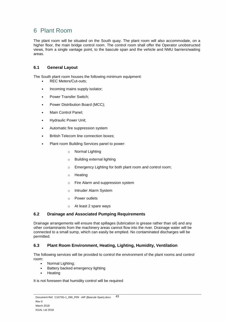
6 Plant Room
The plant room will be situated on the South quay. The plant room will also accommodate, on a higher floor, the main bridge control room. The control room shall offer the Operator unobstructed views, from a single vantage point, to the bascule span and the vehicle and NMU barriers/waiting areas.
6.1 General Layout
The South plant room houses the following minimum equipment: • REC Meters/Cut-outs;
• Incoming mains supply isolator;
• Power Transfer Switch;
• Power Distribution Board (MCC);
• Main Control Panel;
• Hydraulic Power Unit;
• Automatic fire suppression system
• British Telecom line connection boxes;
• Plant room Building Services panel to power:
o Normal Lighting
o Building external lighting
o Emergency Lighting for both plant room and control room;
o Heating
o Fire Alarm and suppression system
o Intruder Alarm System
o Power outlets
o At least 2 spare ways
6.2 Drainage and Associated Pumping Requirements
Drainage arrangements will ensure that spillages (lubrication is grease rather than oil) and any other contaminants from the machinery areas cannot flow into the river. Drainage water will be connected to a small sump, which can easily be emptied. No contaminated discharges will be permitted.
6.3 Plant Room Environment, Heating, Lighting, Humidity, Ventilation
The following services will be provided to control the environment of the plant rooms and control room:
• Normal Lighting;
• Battery backed emergency lighting
• Heating
It is not foreseen that humidity control will be required

Document Ref. C1073G-1_090_P09 - AIP (Bascule Span).docx
Rev 0
March 2018
KGAL Ltd 2018
44
6.4 Mechanical and Electrical Equipment
The plant room will house the following equipment: • Main electrical panels.
• Hydraulic Power Packs
• Oil storage area (bunded)
• Building services distribution panel
• Lifting equipment for replacement of heavy plant
• Ventilation
• Work bench
• Louvres for the provision of ventilation to the plant room equipment
• A lifting runway beam will be provided to aid handling of heavy items of plant from their
designated position to the outside entrance plant room access door.
• A workbench and a secure storage area for spares
• Intruder alarm control panel
• Bunded area for the storage of hydraulic oils.
6.5 Security, Intruder and Fire Alarm Systems
• Fire Alarm and Suppression System with connections for onward wiring/annunciations to remote station.
• Intruder Alarm System with connections for onward wiring/annunciations to remote station. • CCTV System
6.6 Proposed Firefighting Measures
The control room will be equipped with all necessary fire extinguishers to suit the different types of fire identified during the fire hazard risk assessment.
7 Description of Inspection and Maintenance Arrangements
7.1 Proposals for Inspection and Maintenance of Bridge Structure
See structural AIP Annex A1a for more details
7.2 Proposals for Inspection and Maintenance of M&E Installation
Access to the lift cylinders for removal / re-installation would be carried out in the span-lowered position. This would avoid needing to ‘dog’ (mechanically lock) the span in the raised position for a protracted length of time and crane the cylinders in/out from the North water pier. A runway beam and/or lifting points to be provisioned on the underside of the bascule span. A barge-mounted crane and/or suitable lifting equipment to be used to carried out the removal-re-installation of the cylinders. It is suggested to perform an inspection of all equipment at least monthly; certainly annually. This is to include the hydraulic equipment located within the South pier, i.e. the remote volumes (valve stations), lifting cylinders and associated pipework. It is likely that equipment inspections will take place more frequently after first commissioning, perhaps daily and then weekly, for a period of around a month. Suitable lifting points will be provided, attached to the underside of the moving span permit the removal and replacement of key items of M&E equipment (e.g. hydraulic motors and gearboxes). Access to the hydraulic and electrical plant rooms will be from ground level through double doors.

Document Ref. C1073G-1_090_P09 - AIP (Bascule Span).docx
Rev 0
March 2018
KGAL Ltd 2018
45
7.3 Proposed Documentation
• Full set of ‘As Built’ drawings for both the Electrical and Mechanical Equipment • 2 sets of Operation and Maintenance Manuals • CE Technical File • Records of Factory and Site Acceptance Testing • Commissioning procedures • Bridge crew training materials
7.4 Proposals for Plant Monitoring, Data Collection and Management
Human Machine Interface: The HMI/SCADA screens will be a panel PC component mounted in the operator control desk front. The HMI will include but not limited to:
• The HMI Flat Panel 15" LCD monitor and include but not limited to:
o Bright TFT LCD screen display protected by a scratch-resistant, anti-reflective
mineral glass
o Connectivity to the PLC.
o Connectivity to a laptop computer for downloading historical data
o All software and licences
• The HMI/SCADA default screen is to be programmed to display the current status of the
Hydraulic Power Packs and other site equipment. Each section of the control system is to
be displayed on individual screens. The system also logs the most recent alarms which can
be acknowledged using this page. By logging-in using a username and password code,
operators can access the data such as:
o Site wide general arrangement of equipment showing
o Show alarm history.
o All data shown on the control panel graphic operator terminals
o All PLC inputs and outputs
o Override functions for safety lock out systems
o Operational run hours for all motors
o Read outs for all sensors and transducers
o Data logger to log fault code history, warnings, alarms, operating data etc with
enough capacity to store data up to 30 days after which the older data is
overwritten.
o Other variables and screens can be set up as required.
The data can be transferred from the HMI to a laptop via an inbuilt USB port. The system will include a facility for viewing the HMI screens and data at a remote station through the use of PC Anywhere (or similar) software whereby a remote operator can dial in and log in the HMI/SCADA to view system status and other screens. No parameter changes will be possible from the remote location.

Document Ref. C1073G-1_090_P09 - AIP (Bascule Span).docx
Rev 0
March 2018
KGAL Ltd 2018
46
8 Check
8.1 Category III Check to be In Accordance With BD02/12
8.2 Name of Proposed Independent Checker
To be confirmed
9 Drawings and Documents
9.1 List of Drawings and Documents Accompanying the Submission
The complete list of drawing accompanying the overall AIP will be found in the Structural AIP section.
9.2 List of Drawings and Documents Accompanying Annex 3
None
9.3 List of Documents Relating to Inspection, Maintenance and Safe Operation
The Operation and Maintenance manual are to be issued on completion of the project.


Document Ref. C1073G-1_090_P09 - AIP (Bascule Span).docx
Rev 0
March 2018
KGAL Ltd 2018
48
APPENDIX A - Technical Approval Schedule "TAS"
Schedule of Design Documents Relating to Highway Bridges and Structures using National Standards (Eurocodes)
Specifications Specific to Movable Bridges
Used Document & Publication Date Title
✓ AASHTO Standard Specifications for Movable Highway Bridges 1988
Standard Specifications for Movable Highway Bridges
✓ NEN 6786:2001 NL Dutch Moving Bridge Code
Specification Specific to Vessel Allision
Used Document & Publication Date Title
✓ AASHTO, February 1991 Guide Specification and Commentary for Vessel Collision Design of Highway Bridges. Volume 1: Final Report
British Standards
Non-conflicting with Eurocodes.
Used Document & Publication Date Title
BS 4449:2005 +A2:2009 Steel for the reinforcement of concrete etc.
BS 4483:2005 Steel fabric for the reinforcement of concrete.
BS 5896:2012 High tensile steel wire and strand for the pre-stressing of concrete. Specification
BS 5930:2015 Code of practice for ground investigations
BS 6031:2009 Code of practice for earthworks
BS 6744:2001+A2:2009 Stainless steel bars for the reinforcement of and use in concrete. Requirements and test methods
BS 6779-4:1999 Highway parapets for bridges and other structures. . Specification for parapets of reinforced and unreinforced masonry construction
✓ BS 7818:1995 Specification for pedestrian restraint systems in metal
BS 8006-1:2010 Code of practice for strengthened/reinforced soils and other fills
BS 8500-1:2015 Concrete - Complimentary British standard to BS EN 206-1. Method of specifying and guidance for the specifier
BS 8500-2:2015 Concrete – Complementary British Standard to BS EN 206. Specification for constituent materials and concrete.
BS 8666:2005+A1:2008 Scheduling, dimensioning, bending and cutting of steel reinforcement for concrete - Specification
✓ BS EN 14388: 2002 Road traffic noise reducing devices - Specification

Document Ref. C1073G-1_090_P09 - AIP (Bascule Span).docx
Rev 0
March 2018
KGAL Ltd 2018
49
Eurocodes and Associated UK National Annexes
All national annexes will be used with the list of documents below. Users to confirm latest Amendments and Corrigenda.
Used Eurocode Part Title Publication
Date
UK National Annex
Publication Date
Eurocode 0 Basis of Structural Design
✓ BS EN 1990 +A1:2005
Eurocode 0: Basis of structural design 27-Jul-02 15-Dec-04
Eurocode 1 Actions on Structures
✓ BS EN 1991-1-1 Actions on structures – Part 1-1: General actions – Densities, self-weight and imposed loads
29-Jul-02 30-Dec-05
✓ BS EN 1991-1-3 Actions on structures – Part 1-3: General actions – Snow loads
24-Jul-03 23-Dec-05
✓ BS EN 1991-1-4 +A1:2010
Actions on structures – Part 1-4: General actions – Wind actions
25-Apr-05 30-Sep-08
✓ BS EN 1991-1-5 Actions on structures – Part 1-5: General actions – Thermal actions
04-Mar-04 30-Apr-07
✓ BS EN 1991-1-6 Actions on structures – Part 1-6: General actions – Actions during execution
15-Dec-05 30-May-08
✓ BS EN 1991-1-7 Actions on structures – Part 1-7: General actions – Accidental actions
29-Sep-06 31-Dec 08
✓ BS EN 1991-2 Actions on structures – Part 2: Traffic loads on bridges
31-Oct-03 30-May-08
Eurocode 2 Design of Concrete Structures
BS EN 1992-1-1 +A1:2014
Design of concrete structures – Part 1-1: General – Common rules for building and civil engineering structures
23-Dec-04 08-Dec-05
BS EN 1992-2 Design of concrete structures – Part 2: Bridges 02-Dec-05 31-Dec-07
Eurocode 3 Design of Steel Structures
✓ BS EN 1993-1-1 Design of steel structures – Part 1-1: General rules and rules for buildings
18-May-05 31-Dec-08
✓ BS EN 1993-1-3 Design of steel structures. General rules. Supplementary rules for cold-formed members and sheeting
30-Nov-06 28-Feb-09
✓ BS EN 1993-1-4 Design of steel structures – Part 1-4: General Supplementary rules for stainless steel
30-Nov-06 28-Feb-09
BS EN 1993-1-5 Design of steel structures – Part 1-5: General – Strength and stability of planar plated structures without transverse loading
30-Nov-06 30-May-08
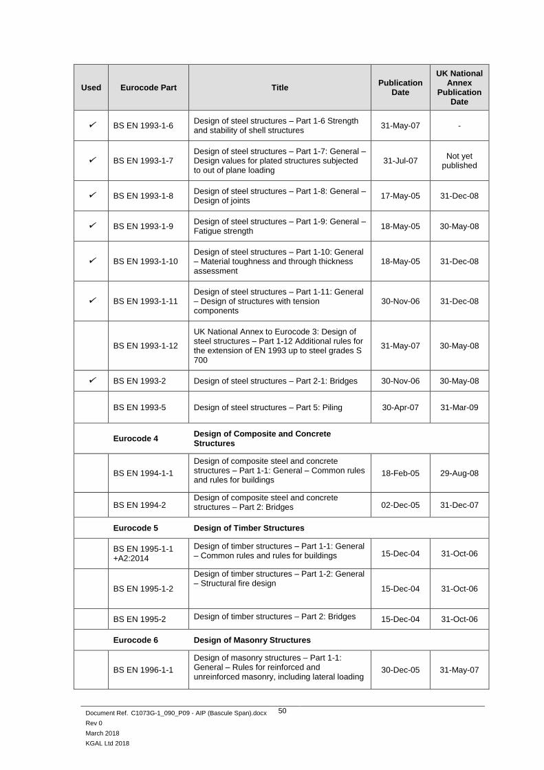
Document Ref. C1073G-1_090_P09 - AIP (Bascule Span).docx
Rev 0
March 2018
KGAL Ltd 2018
50
Used Eurocode Part Title Publication
Date
UK National Annex
Publication Date
✓ BS EN 1993-1-6 Design of steel structures – Part 1-6 Strength and stability of shell structures
31-May-07 -
✓ BS EN 1993-1-7 Design of steel structures – Part 1-7: General – Design values for plated structures subjected to out of plane loading
31-Jul-07 Not yet
published
✓ BS EN 1993-1-8 Design of steel structures – Part 1-8: General – Design of joints
17-May-05 31-Dec-08
✓ BS EN 1993-1-9 Design of steel structures – Part 1-9: General – Fatigue strength
18-May-05 30-May-08
✓ BS EN 1993-1-10 Design of steel structures – Part 1-10: General – Material toughness and through thickness assessment
18-May-05 31-Dec-08
✓ BS EN 1993-1-11 Design of steel structures – Part 1-11: General – Design of structures with tension components
30-Nov-06 31-Dec-08
BS EN 1993-1-12
UK National Annex to Eurocode 3: Design of steel structures – Part 1-12 Additional rules for the extension of EN 1993 up to steel grades S 700
31-May-07 30-May-08
✓ BS EN 1993-2 Design of steel structures – Part 2-1: Bridges 30-Nov-06 30-May-08
BS EN 1993-5 Design of steel structures – Part 5: Piling 30-Apr-07 31-Mar-09
Eurocode 4 Design of Composite and Concrete Structures
BS EN 1994-1-1
Design of composite steel and concrete structures – Part 1-1: General – Common rules and rules for buildings
18-Feb-05 29-Aug-08
BS EN 1994-2 Design of composite steel and concrete structures – Part 2: Bridges 02-Dec-05 31-Dec-07
Eurocode 5 Design of Timber Structures
BS EN 1995-1-1 +A2:2014
Design of timber structures – Part 1-1: General – Common rules and rules for buildings 15-Dec-04 31-Oct-06
BS EN 1995-1-2
Design of timber structures – Part 1-2: General – Structural fire design
15-Dec-04 31-Oct-06
BS EN 1995-2 Design of timber structures – Part 2: Bridges 15-Dec-04 31-Oct-06
Eurocode 6 Design of Masonry Structures
BS EN 1996-1-1
Design of masonry structures – Part 1-1: General – Rules for reinforced and unreinforced masonry, including lateral loading
30-Dec-05 31-May-07

Document Ref. C1073G-1_090_P09 - AIP (Bascule Span).docx
Rev 0
March 2018
KGAL Ltd 2018
51
Used Eurocode Part Title Publication
Date
UK National Annex
Publication Date
BS EN 1996-1-2 Design of masonry structures – Part 1-2: General – Structural fire design 30-Jun-05 31-May-07
BS EN 1996-2 Design of masonry structures – Part 2: Selection and execution of masonry 15-Feb-06 31-May-07
BS EN 1996-3
Design of masonry structures – Part 3: Simplified calculation methods for masonry structures
15-Feb-06 31-May-07
Eurocode 7 Geotechnical design
BS EN 1997-1 +A1:2013
Geotechnical design – Part 1: General rules 22-Dec-04 30-Nov-07
BS EN 1997-2 Geotechnical design – Part 2: Ground investigation and testing 30-Apr-07 31 Mar 09
Eurocode 8 Design of Structures for Earthquake Resistance
BS EN 1998-1 +A1:2013
Design of structures for earthquake resistance – Part 1: General rules seismic actions and rules for buildings
08-Apr-05 29-Aug-08
✓ BS EN 1998-2 +A2:2011
Design of structures for earthquake resistance – Part 2: Bridges 20-Dec-05 30-June-09
BS EN 1998-5
Design of structures for earthquake resistance – Part 5: Foundations, retaining structures and geotechnical aspects
08-Apr-05 29-Aug-08
Eurocode 9 Design of Aluminium Structures
BS EN 1999-1-1 +A2:2013
Design of aluminium structures – Part 1-1: General – Common rules 31-Aug-07 31-Dec-08
BS EN 1999-1-2 Design of aluminium structures – Part 1-2: General – Structural fire design 30-Apr-07 31-Mar-09
BS EN 1999-1-3
+A1:2011
Design of aluminium structures – Part 1-3: Additional rules for structures susceptible to fatigue
31-Aug-07 31-Dec-08
BS EN 1999-1-4 Design of aluminium structures – Part 1-4: Supplementary rules for trapezoidal sheeting 30-Apr-07 31-Mar-09
BS EN 1999-1-5 Design of aluminium structures – Part 1-5: Supplementary rules for shell structures 30-Apr-07 31-Mar-09

Document Ref. C1073G-1_090_P09 - AIP (Bascule Span).docx
Rev 0
March 2018
KGAL Ltd 2018
52
BSI Published Documents
Used Document Reference
Title Date of Issue
✓ PD 6688-1-1
Background paper to the UK National Annex to BS EN 1991-1-1
[Actions on structures – General Actions – Densities, self-weight and imposed loads]
May 2011
PD 6688-1-4 Background paper to the UK National Annex to BS EN 1991-1-4
[Actions on structures – General Actions – Wind actions] 2015
✓
PD 6688-1-7
+A1:2014
Recommendations for the design of structures to BS EN 1991-1-7
[Actions on structures – General Actions – Accidental actions] 2009
✓ PD 6688-2 Recommendations for the design of structures to BS EN 1991-2
[Actions on structures – General Actions – Traffic loads on bridges] Mar 2011
PD 6687-1 Background paper to the UK National Annex to BS EN 1992-1 & 3
[Design of concrete structures] Dec 2010
PD 6687-2 Recommendations for the design of structures to BS EN 1992-2
[Design of concrete structures - Bridges] 2008
PD 6694-1
Recommendations for the design of structures subject to traffic loading to BS EN 1997-1
[Geotechnical Design – General rules]
May 2011
✓ PD 6695-1-9 Recommendations for the design of structures to BS EN 1993-1-9
[Design of steel structures – General – Fatigue Strength] 2008
✓ PD 6695-1-10
Recommendations for the design of structures to BS EN 1993-1-10
[Design of steel structures – General – Material toughness and through thickness assessment]
2009
✓
PD 6695-2 + A1:2012 Incorporating Corrigendum No.1
Recommendations for the design of bridges to BS EN 1993
[Design of steel structures] 2008
✓
PD 6696-2
+A1:2012
Background paper to BS EN 1994-2 and the UK National Annex to BS EN 1994-2
[Design of composite steel and concrete structures – Bridges]
2007
✓ PD 6698
Recommendations for the design of structures for earthquake resistance to BS EN 1998
[Design of structures for earthquake resistance]
2009
✓ PD 6703 Structural bearings – Guidance on the use of structural bearings 2009
✓ PD 6705-2
+A1:2013 Recommendations for the execution of steel bridges to BS EN 1090-2 Dec 2010

Document Ref. C1073G-1_090_P09 - AIP (Bascule Span).docx
Rev 0
March 2018
KGAL Ltd 2018
53
Execution Standards
Used Document Ref
Title Date
✓ BS EN 1090-1 +A1:2011
Execution of steel structures and aluminium structures. Requirements for conformity assessment of structural components
2009
✓ BS EN 1090-2 +A1:2011
Execution of steel structures and aluminium structures. Technical requirements for steel structures
2008
BS EN 1090-3
Execution of steel structures and aluminium structures. Technical requirements for aluminium structures
2008
BS EN 13670 Execution of concrete structures 2009
Product Standards
Used Document Ref
Title Date
✓ BS EN 1337 Structural Bearings, Parts 1 - 11. Various
✓ BS EN 10080 Steel for the reinforcement of concrete. Weldable reinforcing steel 2005
✓ BS EN 10025 Hot rolled products of structural steels, Pt 1 to 6, example see below: 2004
✓ BS EN 10025-5
Hot rolled products of structural steels. . Technical delivery conditions for structural steels with improved atmospheric corrosion resistance (weathering steels)
2004
BS EN 206-1 Corrigenda Nos. 1 and 2 and Amendments Nos. 1, 2 and 3.
Concrete. Specification, performance, production and conformity 2013
BS 5896 High tensile steel wire and strand for the prestressing of concrete - Specification.
2012
prEN 10138-3 DPC Prestressing steels Part 3: Strand - under development use BS 5896.
✓ BS EN 1317-1-2010
Road Restraints Systems – Part 1, Terminology and general criteria for test methods
2010
✓ BS EN 1317-2-2010
Road Restraints Systems – Part 2, Performance classes, impact test acceptance criteria and test methods for safety barriers
2010
BS EN 1317-3-2010
Road Restraints Systems – Part 3, Performance classes, impact test acceptance criteria and test methods for crash cushions
2010
✓ DD ENV 1317-4-2002
Road Restraints Systems – Part 4, Performance classes, impact test acceptance criteria and test methods for terminals and transitions of safety barriers
2002
BS EN 13369
Common rules for precast concrete products 2013
BS EN 15050 Bridge elements 2007
BS EN 14844 +A2:2011
Box culverts 2006
BS EN 15258 Retaining wall elements 2008
BS EN 12843 Masts and poles 2004
BS EN 12794 Foundation piles 2005
The Manual of Contract Documents for Highway Works (MCDHW)

Document Ref. C1073G-1_090_P09 - AIP (Bascule Span).docx
Rev 0
March 2018
KGAL Ltd 2018
54
Used Title Date of Issue
✓ Volume 1: Specification for Highway Works Feb 2016
✓ Volume 2: Notes for Guidance on the Specification for Highway Works Feb 2016
✓ Volume 3: Highway Construction Details Nov 2005
The Design Manual for Roads and Bridges (DMRB)
The following have been reproduced from the current alpha-numeric index in the DMRB, Volume 0, Section 1, Part 1, dated Sept 2015.
This must be read in conjunction with DEM 134/11, Annex C. . Annex C includes guidance in lieu of BA 36, BA 42, BA 57, BA 59, BA 84, BD 20, BD 57 and BD 70. .
Reference to be made to superscript notes for conditions of use where applicable. .
Used Document Reference
Title Date of Issue Decimal Ref.
Design Manual for Roads and Bridges (DMRB)
✓ GD 01/15 Introduction to the Design Manual for Roads and Bridges
Aug 2015 0.1.2
✓ GD 02/08 Quality Management Systems for Highway Design May 2008 0.2.1
GD 04/12 Standard for Safety Risk Assessment on The Strategic Road Network
Nov 2012 0.2.3
GD 5/16 Asbestos Management in Trunk Road Assets. 0.2.4
Bridges and Structures, Advice Notes (BA Series)
BA 09/81
The Use of BS 5400: Part 10: 1980 Code of Practice for Fatigue
Amendment No.1
Dec 1981
Nov 1983 1.3
BA 16/97
The Assessment of Highway Bridges and Structures. Amendment No. 1
Amendment No. 2
May 1997
Nov 1997
Nov 2001
3.4.4
BA 19/85 The Use of BS 5400; Part 3; 1982 Jan 1985 1.3
BA 26/94 Expansion Joints for Use in Highway Bridge Decks Nov 1994 2.3.7
BA 28/92 Evaluation of Maintenance Costs in Comparing Alternative Designs for Highway Structures
Aug 1992 1.2.2
BA 30/94 Strengthening of Concrete Highway Structures Using Externally Bonded Plates
Feb 1994 3.3.1
BA 35/90 Inspection and Repair of Concrete Highway Structures Jun 1990 3b
BA 36/90 The Use of Permanent Formwork Feb 1991 2.3.7
BA 37/92 Priority Ranking of Existing Parapets Oct 1992 2.3.2
BA 38/93 Assessment of the Fatigue Life of Corroded or Damaged Reinforcing Bars
Oct 1990 3.4.5
BA 39/93 Assessment of Reinforced Concrete Half-joints Apr 1993 3.4.6
BA 40/93 Tack Welding of Reinforcing Bars Apr 1993 1.3.4
✓ BA 41/98 The Design and Appearance of Bridges Feb 1998 1.3.11
BA 42/96 The Design of Integral Bridges [Incorporating Amendment No.1 dated May 2003]
Nov 1996 1.3.12

Document Ref. C1073G-1_090_P09 - AIP (Bascule Span).docx
Rev 0
March 2018
KGAL Ltd 2018
55
Used Document Reference
Title Date of Issue Decimal Ref.
BA 44/96 Assessment of Concrete Highway Bridge and Structures
Nov 1996 3.4.15
BA 47/99 1 Waterproofing and Surfacing of Concrete Bridge Decks Aug 1999 2.3.5
BA 51/95 The Assessment of Concrete Structures Affected by Steel Corrosion Feb 1995 3.4.13
BA 52/94 The Assessment of Concrete Highway Structures Affected by Alkali Silica Reaction
Nov 1994 3.4.10
BA 53/94 Bracing Systems and The Use of U-Frames in Steel Highway Bridges
Dec 1994 1.3.13
BA 54/94 Load Testing for Bridge Assessment Apr 1994 3.4.8
BA 55/06 The Assessment of Bridge Substructures and Foundations, Retaining Walls and Buried Structures
May 2006 3.4.9
BA 57/01 Design for Durability Aug 2001 1.3.8
BA 58/94 Design of Bridges and Concrete Structures with External Unbonded Prestressing
Nov 1994 1.3.10
BA 59/94 Design of Bridges for Hydraulic Action May 1994 1.3.6
BA 67/96 Enclosure of Bridges Aug 1996 2.2.8
BA 72/03 Maintenance of Road Tunnels May 2003 3.2.3
BA 82/00 Formation of Continuity Joints in Bridge Decks Nov 2000 2.3.7
BA 83/02 Cathodic Protection for Use in Reinforced Concrete Highway Structures
Feb 2002 3.3.3
BA 85/04 Coatings For Concrete Highway Structures & Ancillary Structures
May 2004 2.4.3
BA 86/06 Advice Notes on the Non-Destructive Testing of Highway Structures
Aug 2006 3.1.7
BA 87/04 Management of Corrugated Steel Buried Structures Correction No.1 Correction No.2
Aug 2004 Feb 2006 Nov 2009
3.3.4
BA 88/04 Management of Buried Concrete Box Structures Aug 2004 3.3.5
BA 92/07 The Use of Recycled Concrete Aggregates in Structural Concrete
May 2007 2.3.9
BA 93/09 Structural Assessment of Bridges with Deck Hinges Feb 2009 3.1.5
Bridges and Structures, Standards (BD Series)
✓ BD 02/12 Technical Approval of Highway Structures May 2012 1.1.1
BD 07/01 Weathering Steel for Highway Structures Nov 2001 2.3.8
BD 09/81 Implementation of BS 5400: Part 10: 1980. Code of Practice for Fatigue
Dec 1981 1.3
BD 10/97 Design of Highway Structures in Areas of Mining Subsidence
May 1997 1.3.14
BD 12/01 Design of Corrugated Steel Buried Structures with Spans Greater than 0.9 Metres and up to 8.0 Metres
Nov 2001 2.2.6
✓ BD 13/06 Design of Steel Bridges. Use of BS 5400 -3: 2000 May 2006 1.3.14
✓ BD 15/92 General Principles for The Design and Construction of Bridges: Use of BS 5400: Part 1: 1988
Dec 1992 1.3.2
BD 16/82 Design of Composite Bridges. Use of BS 5400: Part 5: 1979 Amendment No.1
Nov 1982
Dec 1987 1.3
✓ BD 20/92 Bridge Bearings. Use of BS 5400: Part 9: 1983 Oct 1992 2.3.1

Document Ref. C1073G-1_090_P09 - AIP (Bascule Span).docx
Rev 0
March 2018
KGAL Ltd 2018
56
Used Document Reference
Title Date of Issue Decimal Ref.
BD 21/01 The Assessment of Highway Bridges and Structures May 2001 3.4.3
BD 24/92 Design of Concrete Bridges. Use of BS 5400 part 4: 1990
Nov 1992 1.3.1
BD 27/86 Materials for the Repair of Concrete Highway Structures Nov 1986 3.3
BD 29/17 Design Criteria for Footbridges May 2017 2.2.8
BD 30/87 Backfilled Retaining Walls and Bridge Abutments Aug 1987 2.1
BD 31/01 The Design of Buried Concrete Box and Portal Frame Structures
Nov 2001 2.2.12
✓ BD 33/94 Expansion Joints for Use in Highway Bridge Decks Nov 1994 2.3.6
✓ BD 35/14 Quality Assurance Schemes for Paints and Similar Protective Coatings
Aug 2014 2.4.1
BD 36/92 Evaluation of Maintenance Costs in Comparing Alternative Designs for Highway Structures
Aug 1992 1.2.1
BD 37/01 Loads for Highway Bridges Aug 2001 1.3.14
BD 43/03 The Impregnation of reinforced and Prestressed Concrete Highway Structures using Hydrophobic Pore-Lining Impregnants Note HA moratorium, ref TAA
Feb 2003 2.4.2
BD 44/15 The Assessment of Concrete Highway Bridges and Structures
Aug 2015 3.4.14
BD 45/93 Identification Marking of Highway Structures Aug 1993 3.1.1
BD 47/99 Waterproofing and Surfacing for Concrete Bridge Decks Aug 1999 2.3.4
BD 48/93
The Assessment and Strengthening of Highway Bridge Supports
Jun 1993 3.4.7
BD 49/01 Design Rules for Aerodynamic Effects on Bridges May 2001 1.3.3
✓ BD 51/14 Portal and Cantilever Signs/Signal Gantries May 2014 2.2.4
BD 53/95 Inspection and Records for Road Tunnels Jul 1995 3.1.6
BD 54/15 Management of Post-tensioned Concrete Bridges Feb 2015 3.2.5
BD 56/10 The Assessment of Steel Highway Bridges and Structures
Jun 2010 3.4.11
BD 57/01 Design for Durability Aug 2001 1.3.7
BD 58/94 The design of Concrete Highway Bridges and Structures with External and Unbonded Prestressing
Nov 1994 1.3.9
BD 60/04 Design of Highway Bridges for Vehicle Collision Loads May 2004 1.3.5
BD 61/10 The Assessment of Composite Highway Bridges and Structures
Jun 2010 3.4.16
✓ BD 62/07 As Built, Operational and Maintenance Records for Highway Structures
Feb 2007 3.2.1
BD 63/07 Inspection of Highway Structures Feb 2007 3.1.4
BD 65/14 Design Criteria for Collision Protector Beams Dec 2014 2.2.5
BD 67/96 Enclosures of Bridges Aug 1996 2.2.7
BD 70/03
Strengthened/Reinforced Soils and Other Fills for Retaining Walls and Bridge Abutments Use of BS 8006; 1995, incorporating Amendment No.1 (Issue 2 March 1999)
May 2003 2.1.5
BD 78/99 Design of Road Tunnels Aug 1999 2.2.9
BD 79/13 The Management of Sub-standard Highway Structures Feb 2013 3.4.18

Document Ref. C1073G-1_090_P09 - AIP (Bascule Span).docx
Rev 0
March 2018
KGAL Ltd 2018
57
Used Document Reference
Title Date of Issue Decimal Ref.
BD 81/02 Use of Compressive Membrane Action in Bridge Decks May 2002 3.4.20
BD 82/00 Design of Buried Rigid Pipes Aug 2000 2.2.10
BD 84/02 Strengthening of Concrete Bridge Supports Vehicle Impact Using Fibre Reinforced Polymers
Aug 2002
1.3.16
BD 85/08 Strengthening Highway Structures Using Externally Bonded Fibre Reinforced Polymer
Nov 2008
1.3.18
BD 86/11 The Assessment of Highway Bridges and Structures For The Effects of Special Types General Order (STGO) and Special Order (SO) Vehicles
Nov 2011 3.4.19
BD 87/05 Maintenance Painting of Steelwork May 2005 3.2.2
BD 89/03 The Conservation of Highway Structures Nov 2003 3.2.4
BD 90/05 Design of FRP Bridges and Highway Structures May 2005 1.3.17
BD 91/04 Unreinforced Masonry Arch Bridges Nov 2004 2.2.14
BD 94/07 Design of Minor Structures Feb 2007 2.2.1
BD 95/07 Treatment of Existing Structures on Highway Widening Schemes
Aug 2007 1.2.3
BD 97/12 Assessment of Scour and Other Hydraulic Actions at Highways Bridges
May 2012 3.4.21
BD 101/11 Structural Review and Assessment of Highway Structures
Nov 2011 3.4.22
Bridges and Structures, Technical memoranda (BE Series)
BE 13 Fatigue Risk in Bailey Bridges Apr 1968 3.4
BE 23 Shear Key Decks
Amendment No.1 to Annex
Nov 1970
Jun 1971
1.3
BE 05/75 Rules for The Design and Use of Freyssinet Concrete Hinges in Highway Structures
Mar 1975 1.3
BE 07/04 Departmental Standard (Interim) Motorway Sign/Signal Gantries
Aug 2004 2.2
Traffic Engineering and Control, Standards (TD and TA Series)
TA 11/09 Traffic Surveys by Roadside Interview Nov 2009 5.1.4
TA 12/07 Traffic Signals on High Speed roads May 2007 8.1.1
TA 15/07 Pedestrian Facilities at Traffic Signal Installations May 2007 8.1.1
✓ TA 16/07 General Principles of Control by Traffic Signals May 2007 8.1.1
TA 22/81 Vehicle Speed Measurement on All-Purpose Roads Nov 1981 5.1
TA 23/81 Junctions and Accesses Determination of Size of Roundabouts and Major/Minor Junctions
Dec 1981 6.2
TA 30/82 Choice Between Options for Use in The Assessment of New Rural Roads
Jul 1982 5.1
TA 46/97 Traffic Flows Ranges for Use in The Assessment of New Rural Roads
Feb 1997 5.1.3
TA 49/07 Appraisal of New and replacement Lighting on The Strategic Motorway and All Purpose Trunk Road Network
Aug 2007 8.3

Document Ref. C1073G-1_090_P09 - AIP (Bascule Span).docx
Rev 0
March 2018
KGAL Ltd 2018
58
Used Document Reference
Title Date of Issue Decimal Ref.
TA 56/87 Hazardous cattle Crossings: Use of Flashing Amber Lamps
Nov 1987 8.2
TA 57/87 Roadside Features
[Chapters 2 and 3 are superseded by TD 69/07]
Jan 1989 6.3
TA 60/90 The Use of variable Message Signs on All-Purpose and Motorway Trunk Roads
Aug 1990 8.2
TA 64/94 Narrow Lanes and Tidal Flow Operations at Roadworks on Motorways and Dual carriageway Trunk Roads with Full Width Hard Shoulders
Apr 1994 8.4.3
TA 66/95 Police Observation Platforms on Motorways Jan 1995 6.3.2
TA 68/96 The Assessment and Design of Pedestrian Crossings Nov 1996 8.5.1
*TA 70/97 Motorways. Introduction Feb 1997 9.2.1
*TA 71/97 Motorways. Overview Feb 1997 9.3.1
*TA 72/97 National Motorways Communications Systems (NMCS) Feb 1997 9.4.1
*TA 73/16 Emergency roadside telephone Aug 2016 9.2.1
*TA 74/05 Motorway Signalling Nov 2005 9.4.3
*TA 76/97 Motorway Control Offices Feb 1997 9.4.5
TA 78/97 Design of Road Markings at Roundabouts Nov 1997 6.2.3
TA 79/99 Traffic Capacity of Urban Roads
Amendment No. 1
Feb 1999
May 1999
5.1.3
TA 80/99 Surface Drainage of Wide Carriageways Feb 1999 4.2.2
TA 81/99 Coloured Surfacing in Road Layout (Excluding Traffic Calming)
Feb 1999 6.3.4
TA 82/99 The Installation of Traffic Signals and Associated Equipment
May 1999 8.1.1
TA 83/05 Guide to The Use of Variable Message Signs for Strategic Traffic Management on Trunk Roads and Trunk Road Motorways
Nov 2005 9.4.6
✓ TA 84/06
Code of Practice for Traffic Control and Information for Systems for All-Purpose Roads
[Incorporates Correction dated Feb 2007]
May 2006 8.1.2
TA 85/01 Guidance of Minor Improvements to Existing Roads Nov 2001 6.1.3
TA 86/03 Layout of Large Signal Controlled Junctions Feb 2003 6.2.8
TA 87/04 Trunk Road Traffic Calming Feb 2004 6.3.5
✓ TA 90/05 The Geometric Design of Pedestrian, Cycle and Equestrian Routes
Feb 2005 6.3.5
TA 91/05 Provision for Non-Motorised Users Feb 2005 5.2.4
TA 92/03 Crossover and Changeover Design Nov 2003 8.4.6
TA 98/08 The Layout of Toll Plazas Feb 2008 6.3.6
TD 07/07 Statutory Approval of Traffic Control Equipment May 2007 8.1.1
✓ TD 09/93 Road Geometry and Highway link design
Amendment No.1
Jun 1993
Feb 2002
6.1.1
TD 11/82 Use of Certain Departmental Standards in The Design and Assessment of Trunk Road Schemes
Jul 1982 5.1

Document Ref. C1073G-1_090_P09 - AIP (Bascule Span).docx
Rev 0
March 2018
KGAL Ltd 2018
59
Used Document Reference
Title Date of Issue Decimal Ref.
TD 16/07 Geometric Design of Roundabouts Aug 2007 6.2.3
TD 17/85 Criteria for The Provision of Closed Circuit Television on Motorways
May 1985 9.3
TD 18/85 Criteria for The Use of Gantries for Traffic Signs and Matrix Traffic Signals on Trunk Roads and Trunk Road Motorways
Jul 1985 9.1
✓ TD 19/061 Requirement for Road Restraint Systems
Correction No. 1
Aug 2006
Feb 2008
2.2.8
TD 22/06 Layout of Grade Separated Junctions Feb 2006 6.2.1
TD 23/99 Trunk Roads and Trunk Road Motorways Inspection and Maintenance of Road Lighting
Nov 1999 8.3
TD 24/97 All-Purpose Trunk Roads Inspection and Maintenance of Traffic Signals and Associated Equipment
Aug 1997 8.1
TD 25/01 Inspection and Maintenance of Traffic Signs on Motorway and All-Purpose Truck Roads
Feb 2001 8.2.2
TD 26/071 Inspection and Maintenance of Road Markings and Road Studs on Motorway and All-Purpose Truck Roads
May 2007 8.2.2
TD 27/05 Cross sections and Headroom Feb 2005 6.1.2
TD 33/05 The Use of Variable Message Signs on All-Purpose and Motorway Trunk Roads
Nov 2005 8.2.2
TD 34/07 Design of Road Lighting for The Strategic Motorway and All Purpose Trunk Road Network
Aug 2007 8.3
TD 35/06 All Purpose Trunk Roads MOVA System of Traffic Control at Signals
May 2006 8.1.1
TD 36/93 Subways for Pedestrians and Pedal Cyclists, Layout and Dimensions
Jul 1993 6.3.1
TD 37/93 Scheme Assessment Reporting Aug 1993 5.1.2
TD 39/94 The Design of Major Interchanges Apr 1994 6.2.4
TD 40/94 The Layout of Compact Grade Separated Junctions Jul 1994 6.2.5
TD 41/95 Vehicular Access to All Purpose Trunk Roads Mar 1995 6.2.7
TD 42/95 Geometric Design of Major/Minor Priority Junctions Jan 1995 6.2.6
TD 45/94 Motorway Incident Detection and Automatic Signalling (MIDAS)
Dec 1994 9.1.2
TD 46/05 Motorway Signalling Nov 2005 9.1.1
TD 49/07 Requirements for Lorry Mounted Crash Cushions Nov 2007 8.4.7
TD 50/04 The Geometric Layout of Signal-Controlled Junctions and Signalised Roundabouts
Nov 2004 6.2.3
TD 51/03 Segregated Left Turn Lanes and Subsidiary Deflection islands at Roundabouts
Nov 2003 6.3.5
TD 52/04 Traffic Signs to Tourist Attractions and facilities in England: Tourist Signing – Trunk Roads
Feb 2004 8.2.4
TD 53/05 Traffic Signs to Retail Destinations and Exhibition Centres in England and Wales – Trunk Roads
Feb 2005 8.2.6
TD 54/07 Design of Mini Roundabouts Aug 2007 6.2.2
TD 69/07 The Location and layout of Lay-Bys and Rest Areas Nov 2007 6.3.3
TD 70/08 Design of Wide Single 2+1 Roads Aug 2008 6.1.4

Document Ref. C1073G-1_090_P09 - AIP (Bascule Span).docx
Rev 0
March 2018
KGAL Ltd 2018
60
Used Document Reference
Title Date of Issue Decimal Ref.
TD 72/17 Transmission Infrastructure Feb 2017 9.3.1
TD 89/08 Use of Passively Safe Signposts, Lighting Columns & Traffic Signal Posts to BS EN 12767
May 2008 8.2.2
Notes: Refer to Annex C of IAN 124 for additional guidance/ requirements. Check current position with IAN 97/07 Assessment and Upgrading of Existing Parapets and TD 19/06 Requirement for Road Restraint Systems.
Advice Notes – Highways (HA Series)
HA 13/81 The Planting of Trees and Shrubs Feb 1981 5.2
HA 37/97 Hydraulic Design of Road Edge Surface Water Channels
Aug 1997 4.2
HA 39/98 Edge of Pavement Details Aug 1998 4.2.1
HA 40/01 Determination of Pipe and Bedding Combinations for Drainage Works
Nov 2001 4.2.5
HA 41/90 A Permeameter for Drainage Layers Apr 1990 4.2
HA 44/91 Design and Preparation of Contract Documents
Amendment No. 1
Jun 1991
Apr 1995
4.1.1
HA 55/92 New Roads Landform and Alignment Dec 1992 10.1.1
HA 56/92 New Roads Planting, Vegetation and Soils Dec 1992 10.1.2
HA 57/92 New Roads Integration with Rural Landscapes Dec 1992 10.1.3
HA 58/92 New Roads The Road Corridor
Amendment No. 1
Dec 1992
Feb 1997
10.1.4
HA 59/92 Mitigating Against Effects on Badgers Feb 1997 10.4.2
HA 60/92 New Roads Heritage Dec 1992 10.1.5
HA 63/92 Improving Existing Roads Improvement Techniques Dec 1992 10.2.2
HA 65/94 Design Guide for Environmental Barriers Jul 1994 10.5.1
HA 66/95 Environmental Barriers – Technical Requirements Sep 1995 10.5.2
HA 67/93 The Wildflower Handbook Jun 1993 10.3.1
HA 70/94 Construction of Highway Earthworks Dec 1994 4.1.5
HA 74/07 Treatment of Fill and Capping Materials using Either Lime or Cement or Both
May 2007 4.1.6
HA 75/01 Trunk Roads and Archaeological Mitigation Feb 2001 10.6.1
HA 78/96 Design of Outfalls for Surface Water Channels Jan 1996 4.2.2
HA 79/97 Edge of Pavement Details for Porous Asphalt Surface Cones
Feb 1997 4.2.4
HA 80/99 Nature Conservation Advice in Relation to Bats May 1999 10.4.3
HA 81/99 Nature Conservation Advice in Relation to Otters May 1999 10.4.4
HA 83/99 Safety Aspects of Road Edge Drainage Features Nov 1999 4.2.4
HA 84/01 Nature Conservation and Biodiversity (supersedes the section in HA 59/92 (Nature Conservation). Mitigating Against Effects on Badgers is extant in 10.4.2)
Feb 2001 10.4.1
Advice Notes – Highways (HA Series)
HA 85/01 Road Improvement within Limited Land Take Feb 2001 10.2.1
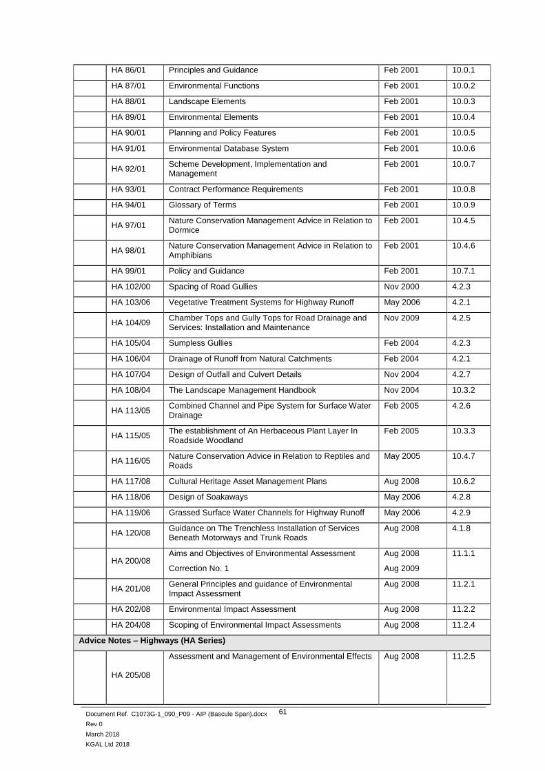
Document Ref. C1073G-1_090_P09 - AIP (Bascule Span).docx
Rev 0
March 2018
KGAL Ltd 2018
61
HA 86/01 Principles and Guidance Feb 2001 10.0.1
HA 87/01 Environmental Functions Feb 2001 10.0.2
HA 88/01 Landscape Elements Feb 2001 10.0.3
HA 89/01 Environmental Elements Feb 2001 10.0.4
HA 90/01 Planning and Policy Features Feb 2001 10.0.5
HA 91/01 Environmental Database System Feb 2001 10.0.6
HA 92/01 Scheme Development, Implementation and Management
Feb 2001 10.0.7
HA 93/01 Contract Performance Requirements Feb 2001 10.0.8
HA 94/01 Glossary of Terms Feb 2001 10.0.9
HA 97/01 Nature Conservation Management Advice in Relation to Dormice
Feb 2001 10.4.5
HA 98/01 Nature Conservation Management Advice in Relation to Amphibians
Feb 2001 10.4.6
HA 99/01 Policy and Guidance Feb 2001 10.7.1
HA 102/00 Spacing of Road Gullies Nov 2000 4.2.3
HA 103/06 Vegetative Treatment Systems for Highway Runoff May 2006 4.2.1
HA 104/09 Chamber Tops and Gully Tops for Road Drainage and Services: Installation and Maintenance
Nov 2009 4.2.5
HA 105/04 Sumpless Gullies Feb 2004 4.2.3
HA 106/04 Drainage of Runoff from Natural Catchments Feb 2004 4.2.1
HA 107/04 Design of Outfall and Culvert Details Nov 2004 4.2.7
HA 108/04 The Landscape Management Handbook Nov 2004 10.3.2
HA 113/05 Combined Channel and Pipe System for Surface Water Drainage
Feb 2005 4.2.6
HA 115/05 The establishment of An Herbaceous Plant Layer In Roadside Woodland
Feb 2005 10.3.3
HA 116/05 Nature Conservation Advice in Relation to Reptiles and Roads
May 2005 10.4.7
HA 117/08 Cultural Heritage Asset Management Plans Aug 2008 10.6.2
HA 118/06 Design of Soakaways May 2006 4.2.8
HA 119/06 Grassed Surface Water Channels for Highway Runoff May 2006 4.2.9
HA 120/08 Guidance on The Trenchless Installation of Services Beneath Motorways and Trunk Roads
Aug 2008 4.1.8
HA 200/08 Aims and Objectives of Environmental Assessment
Correction No. 1
Aug 2008
Aug 2009
11.1.1
HA 201/08 General Principles and guidance of Environmental Impact Assessment
Aug 2008 11.2.1
HA 202/08 Environmental Impact Assessment Aug 2008 11.2.2
HA 204/08 Scoping of Environmental Impact Assessments Aug 2008 11.2.4
Advice Notes – Highways (HA Series)
HA 205/08
Assessment and Management of Environmental Effects
Aug 2008 11.2.5

Document Ref. C1073G-1_090_P09 - AIP (Bascule Span).docx
Rev 0
March 2018
KGAL Ltd 2018
62
HA 207/07
Air Quality
May 2007 11.3.1
HA 208/07 Cultural Heritage
Aug 2007 11.3.2
HA 217/08 Alternative Filter Media and Stabilisation Techniques for Combined Surface and Sub-Surface Drains
Aug 2008 4.2.4
HA 218/08 Glossary of Terms Used in The Design Manual for Roads and Bridges Volume 11 Sections 1 and 2
Aug 2008 11.2.7
HA 219/09 Determination of Pipe Roughness and Assessment of Sediment Deposition to Aid Pipeline Design
Nov 2009 4.2.4
Highways, Standards (HD Series)
HD 19/15 Road Safety Audit Mar 2015 5.2.2
HD 20/05 Detector Loops for Motorways Nov 2005 9.3.1
HD 22/08 Managing Geotechnical Risk Aug 2008 4.1.2
HD 23/99 General Information Feb 1999 7.1.1
HD 24/06 Traffic Assessment
Correction No. 1
Feb 2006
Nov 2006
7.2.1
HD 26/06 Pavement Design Feb 2006 7.2.3
HD 27/15 Pavement Construction Methods Sep 2015 7.2.4
HD 28/15 Skidding Resistance July 2015 7.3.1
HD 29/08 Data for Pavement Assessment May 2008 7.3.2
HD 30/08 Maintenance Assessment Procedure May 2008 7.3.3
HD 31/94
Maintenance of Bituminous Roads
Amendment No. 1
Amendment No. 2
Jan 1994
Mar 1995
Feb 1998
7.4.1
HD 32/94 Maintenance of Concrete Roads Jan 1994 7.4.2
HD 33/16 Surface and Sub-Surface Drainage Systems for Highways
May 26 4.2.3
HD 35/04 Conservation and The Use of Secondary and recycled Materials
Nov 2004 7.1.2
HD 36/06 Surfacing Materials for New and Maintenance Construction
Nov 2006 7.5.1
HD 37/99 Bituminous Surfacing Materials and Techniques
Amendment No. 1
Feb 1999
May 1999
7.5.2
HD 38/97 Concrete Surfacing and Materials
Amendment No. 1
Aug 1997
Feb 1999
7.5.3
HD 39/01 Footway Design May 2001 7.2.5
HD 41/15 Maintenance of Highway Geotechnical Assets July 2015 4.1.3
Highways, Standards (HD Series)
HD 43/04 Drainage Data Management System for Highways Nov 2004 4.2.4
HD 44/09 Assessment of Implications (of Highways and/or Roads Projects) on European Sites (Including Appropriate Assessment)
Feb 2009 11.4.1

Document Ref. C1073G-1_090_P09 - AIP (Bascule Span).docx
Rev 0
March 2018
KGAL Ltd 2018
63
HD 45/09 Road Drainage and The Water Environment Nov 2009 11.3.10
HD 47/08 Screening of Projects for Environmental Impact Assessment
Aug 2008 11.2.3
HD 48/08 Reporting of Environmental Impact Assessment Aug 2008 11.2.6
HD 49/16 Highway Drainage Design Principal requirements May 2016 4.2.1
HD 50/16 The certification of Drainage Design May 2016 4.2.1
HD 213/11 Noise and Vibration
Revision 1
Feb 2011
Nov 2011
11.3.7

Document Ref. C1073G-1_090_P09 - AIP (Bascule Span).docx
Rev 0
March 2018
KGAL Ltd 2018
64
Roads Service Policy, Interim Advice and Miscellaneous
Used Document
Ref Title Date
IAN 41/02 European cement standards Jan 02
IAN 48/03 Measures to minimise the risk of sulphate attack (including thaumasite) – New construction and structures under construction
Jan 03
IAN 49/13 Use of warning signs for new asphalt road surfaces Feb 13
✓ IAN 69/05 Designing for maintenance Dec 05
IAN 70/06 Implementation of new reinforcement standards (BS4449:2005, BS4482:2005, BS4483:2005 and BS8666:2005)
Jan 06
IAN 95/07 Revised guidance regarding the use of BS8500:2006 for the design and construction of structures using concrete
May 07
✓ IAN 96/07r1 Guidance on implementing results of research on bridge deck waterproofing
Aug 07
IAN 105/08 Implementation of construction (design and management) 2007 and the withdrawal of SD 10 and SD 11
Jan 08
IAN 117/08 r2
Certification of combined kerb and drainage products Jun 10
✓ IAN 124/11 Use of Eurocodes for the design of highway structures Jul 11
IAN 131/11 Deflection of permanent formwork May 11
IAN 154/12 Revision of clause 903, clause 921 and clause 942 Sep 12
CIRIA C543 Bridge Detailing Guide
CIRIA C660 Early Thermal Cracking
CIRIA C686 Safe access for maintenance and repair
✓ CIRIA R155 Bridges - design for improved durability

Document Ref. C1073G-1_090_P09 - AIP (Bascule Span).docx
Rev 0
March 2018
KGAL Ltd 2018
65
APPENDIX B – Location Plan
Figure 7 – Aerial view of Lowestoft
Figure 8 – Aerial view of Lake Lothing showing proposed crossing alignment

Document Ref. C1073G-1_090_P09 - AIP (Bascule Span).docx
Rev 0
March 2018
KGAL Ltd 2018
66
APPENDIX C – General Arrangement Drawings
The following images are taken from drawings 1069948-WSP-SGN-LL-C19-DR-CB-0039 and 1069948-WSP-SGN-LL-C19-DR-CB-0040:
Figure 9 – Central Bascule Span – Structure Elevation
Figure 10 – Central Bascule Span - Structure Plan

Document Ref. C1073G-1_090_P09 - AIP (Bascule Span).docx
Rev 0
March 2018
KGAL Ltd 2018
67
Figure 11 – Central Bascule Span - Structure Sections

Document Ref. C1073G-1_090_P09 - AIP (Bascule Span).docx
Rev 0
March 2018
KGAL Ltd 2018
68
APPENDIX D – Associated Drawings
1069948-MOU-SGN-LL_C13-DR-CB-0034/35/36 M&E General Arrangement
1069948-MOU-SGN-LL_C13-DR-CB-0037 Bascule Outline Form (elevation)
1069948-MOU-SGN-LL_C13-DR-CB-0038 Bascule Outline Form (plan)
1069948-WSP-SGN-LL-C19-DR-CB-0039 Bascule Outline Structure
1069948-WSP-SGN-LL-C19-DR-CB-0040 Bascule Outline Structure

Mapping reproduced by permission of Ordnance Survey on
behalf of HMSO.
© Crown copyright and database rights 2017. All rights
reserved.
Ordnance Survey licence number 100023395
Contains OS data © Crown copyright and database rights
2017.
LEGEND
NOTES
DESCRIPTION
REVISION DRAWN CHECKED APPROVED DATE
PROJECT TITLE
DRAWING TITLE
DRAWING STATUS
DRAWN
SCALE @ A1 SIZE
DRAWING NUMBER
CHECKED APPROVED AUTHORISED SUITABILITY
DATE REVISION
Project Originator Volume
Location Type Role Number
M & E GENERAL ARRANGEMENT
1 of 3
AS SHOWN
1069948-MOU-SGN-LL_C13-DR-CB-0034
P1
SMB SS ASR
FOR INFORMATION
S3
14/10/2017
1. ALL DIMENSIONS ARE IN MILLIMETERS UNLESS NOTED
OTHERWISE.
2. FIXED APPROACH PROFILES SHOWN INDICATIVE ONLY. TO BE
DEVELOPED BY CIVIL CONTRACTOR.
3. DETAILS VIEWS ARE REPRESENTATIVE ONLY.
HEALTH, SAFETY &
ENVIRONMENTAL INFORMATION
IN ADDITION TO THE HAZARDS AND RISKS NORMALLY
ASSOCIATED WITH THE TYPE OF WORK DETAILED ON THIS
DRAWING, PLEASE NOTE THE FOLLOWING SIGNIFICANT
RISKS TO HEALTH & SAFETY:-
IMPORTANT
THE SIGNIFICANT RISKS ASSOCIATED
WITH THE PROJECT ARE NOTED BELOW
IT IS ASSUMED THAT ALL WORKS SHALL BE UNDERTAKEN BY A
COMPETENT CONTRACTOR WORKING WHERE APPROPRIATE TO
AN APPROVED SAFE SYSTEM OF WORK
REF: THIS DRAWING MUST READ IN CONJUNCTION WITH RISK
ASSESSMENTS, ASSEMBLY PROCEDURES & METHOD
STATEMENTS CREATED SPECIFICALLY FOR THE PROJECT.
CONSIDER THE RISKS ASSOCIATED WITH THE USE OF
TEMPORARY WORKS. APPOINT A COORDINATOR &
PROVIDE CALCULATIONS WHERE REQUIRED. REFER TO
BS5975 WHEN MANAGING TEMPORARY WORKS.
ACCESS TO THE CYLINDER PIT & INTERNAL BRIDGE DECK
AREAS ARE CONSIDERED CONFINED SPACES. ADHERE TO
CONFINED SPACES REGULATIONS 1997,APPROVED CODE
OF PRACTICE & HSE REGULATIONS AND GUIDANCE.

Mapping reproduced by permission of Ordnance Survey on
behalf of HMSO.
© Crown copyright and database rights 2017. All rights
reserved.
Ordnance Survey licence number 100023395
Contains OS data © Crown copyright and database rights
2017.
LEGEND
NOTES
DESCRIPTION
REVISION DRAWN CHECKED APPROVED DATE
PROJECT TITLE
DRAWING TITLE
DRAWING STATUS
DRAWN
SCALE @ A1 SIZE
DRAWING NUMBER
CHECKED APPROVED AUTHORISED SUITABILITY
DATE REVISION
Project Originator Volume
Location Type Role Number
M & E GENERAL ARRANGEMENT
2 of 3
AS SHOWN
1069948-MOU-SGN-LL_C13-DR-CB-0035
P1
SMB SS ASR
FOR INFORMATION
S3
14/10/2017
1. ALL DIMENSIONS ARE IN MILLIMETERS UNLESS NOTED
OTHERWISE.
2. FIXED APPROACH PROFILES SHOWN INDICATIVE ONLY. TO BE
DEVELOPED BY CIVIL CONTRACTOR.
3. DETAILS VIEWS ARE REPRESENTATIVE ONLY.
HEALTH, SAFETY &
ENVIRONMENTAL INFORMATION
IN ADDITION TO THE HAZARDS AND RISKS NORMALLY
ASSOCIATED WITH THE TYPE OF WORK DETAILED ON THIS
DRAWING, PLEASE NOTE THE FOLLOWING SIGNIFICANT
RISKS TO HEALTH & SAFETY:-
IMPORTANT
THE SIGNIFICANT RISKS ASSOCIATED
WITH THE PROJECT ARE NOTED BELOW
IT IS ASSUMED THAT ALL WORKS SHALL BE UNDERTAKEN BY A
COMPETENT CONTRACTOR WORKING WHERE APPROPRIATE TO
AN APPROVED SAFE SYSTEM OF WORK
REF: THIS DRAWING MUST READ IN CONJUNCTION WITH RISK
ASSESSMENTS, ASSEMBLY PROCEDURES & METHOD
STATEMENTS CREATED SPECIFICALLY FOR THE PROJECT.
CONSIDER THE RISKS ASSOCIATED WITH THE USE OF
TEMPORARY WORKS. APPOINT A COORDINATOR &
PROVIDE CALCULATIONS WHERE REQUIRED. REFER TO
BS5975 WHEN MANAGING TEMPORARY WORKS.
ACCESS TO THE CYLINDER PIT & INTERNAL BRIDGE DECK
AREAS ARE CONSIDERED CONFINED SPACES. ADHERE TO
CONFINED SPACES REGULATIONS 1997,APPROVED CODE
OF PRACTICE & HSE REGULATIONS AND GUIDANCE.

Mapping reproduced by permission of Ordnance Survey on
behalf of HMSO.
© Crown copyright and database rights 2017. All rights
reserved.
Ordnance Survey licence number 100023395
Contains OS data © Crown copyright and database rights
2017.
LEGEND
NOTES
DESCRIPTION
REVISION DRAWN CHECKED APPROVED DATE
PROJECT TITLE
DRAWING TITLE
DRAWING STATUS
DRAWN
SCALE @ A1 SIZE
DRAWING NUMBER
CHECKED APPROVED AUTHORISED SUITABILITY
DATE REVISION
Project Originator Volume
Location Type Role Number
M & E GENERAL ARRANGEMENT
3 of 3
AS SHOWN
1069948-MOU-SGN-LL_C13-DR-CB-0036
P1
SMB SS ASR
FOR INFORMATION
S3
14/10/2017
1. ALL DIMENSIONS ARE IN MILLIMETERS UNLESS NOTED
OTHERWISE.
2. FIXED APPROACH PROFILES SHOWN INDICATIVE ONLY. TO BE
DEVELOPED BY CIVIL CONTRACTOR.
3. DETAILS VIEWS ARE REPRESENTATIVE ONLY.
HEALTH, SAFETY &
ENVIRONMENTAL INFORMATION
IN ADDITION TO THE HAZARDS AND RISKS NORMALLY
ASSOCIATED WITH THE TYPE OF WORK DETAILED ON THIS
DRAWING, PLEASE NOTE THE FOLLOWING SIGNIFICANT
RISKS TO HEALTH & SAFETY:-
IMPORTANT
THE SIGNIFICANT RISKS ASSOCIATED
WITH THE PROJECT ARE NOTED BELOW
IT IS ASSUMED THAT ALL WORKS SHALL BE UNDERTAKEN BY A
COMPETENT CONTRACTOR WORKING WHERE APPROPRIATE TO
AN APPROVED SAFE SYSTEM OF WORK
REF: THIS DRAWING MUST READ IN CONJUNCTION WITH RISK
ASSESSMENTS, ASSEMBLY PROCEDURES & METHOD
STATEMENTS CREATED SPECIFICALLY FOR THE PROJECT.
CONSIDER THE RISKS ASSOCIATED WITH THE USE OF
TEMPORARY WORKS. APPOINT A COORDINATOR &
PROVIDE CALCULATIONS WHERE REQUIRED. REFER TO
BS5975 WHEN MANAGING TEMPORARY WORKS.
ACCESS TO THE CYLINDER PIT & INTERNAL BRIDGE DECK
AREAS ARE CONSIDERED CONFINED SPACES. ADHERE TO
CONFINED SPACES REGULATIONS 1997,APPROVED CODE
OF PRACTICE & HSE REGULATIONS AND GUIDANCE.

Mapping reproduced by permission of Ordnance Survey on
behalf of HMSO.
© Crown copyright and database rights 2017. All rights
reserved.
Ordnance Survey licence number 100023395
Contains OS data © Crown copyright and database rights
2017.
LEGEND
NOTES
DESCRIPTION
REVISION DRAWN CHECKED APPROVED DATE
PROJECT TITLE
DRAWING TITLE
DRAWING STATUS
DRAWN
SCALE @ A1 SIZE
DRAWING NUMBER
CHECKED APPROVED AUTHORISED SUITABILITY
DATE REVISION
Project Originator Volume
Location Type Role Number
BASCULE OUTLINE FORM
AS SHOWN
1069948-MOU-SGN-LL_C13-DR-CB-0037
P3
DAR SS ASR
FOR INFORMATION
S3
14/10/2017
1. ALL DIMENSIONS ARE IN MILLIMETERS UNLESS NOTED
OTHERWISE.
2. PIER SHAPE IS INDICATIVE AND IN DEVELOPMENT PROCESS.
3. READ IN CONJUNCTION WITH DRAWINGS:
1069948-MOU-SGN-LL_C13-DR-CB-0033 SITE PLAN SHT 2
1069948-MOU-SGN-LL_C13-DR-CB-0034 M&E DETAILS SHT 1
1069948-MOU-SGN-LL_C13-DR-CB-0035 M&E DETAILS SHT 2
EAST ELEVATION
SCALE 1:250
HEALTH, SAFETY &
ENVIRONMENTAL INFORMATION
IN ADDITION TO THE HAZARDS AND RISKS NORMALLY
ASSOCIATED WITH THE TYPE OF WORK DETAILED ON THIS
DRAWING, PLEASE NOTE THE FOLLOWING SIGNIFICANT
RISKS TO HEALTH & SAFETY:-
IMPORTANT
THE SIGNIFICANT RISKS ASSOCIATED
WITH THE PROJECT ARE NOTED BELOW
IT IS ASSUMED THAT ALL WORKS SHALL BE UNDERTAKEN BY A
COMPETENT CONTRACTOR WORKING WHERE APPROPRIATE TO
AN APPROVED SAFE SYSTEM OF WORK
REF: THIS DRAWING MUST READ IN CONJUNCTION WITH RISK
ASSESSMENTS, ASSEMBLY PROCEDURES & METHOD
STATEMENTS CREATED SPECIFICALLY FOR THE PROJECT.
CONSIDER THE RISKS ASSOCIATED WITH THE USE OF
TEMPORARY WORKS. APPOINT A COORDINATOR &
PROVIDE CALCULATIONS WHERE REQUIRED. REFER TO
BS5975 WHEN MANAGING TEMPORARY WORKS.
ACCESS TO THE CYLINDER PIT & INTERNAL BRIDGE DECK
AREAS ARE CONSIDERED CONFINED SPACES. ADHERE TO
CONFINED SPACES REGULATIONS 1997,APPROVED CODE
OF PRACTICE & HSE REGULATIONS AND GUIDANCE.
CHANGE TO FORM OF COUNTERWEIGHT ARM
P2 DAR SS ASR 20/11/2017
H4a PARAPET ADDED TO MOVING SPAN
P3 DAR SS ASR 10/01/2018

Mapping reproduced by permission of Ordnance Survey on
behalf of HMSO.
© Crown copyright and database rights 2017. All rights
reserved.
Ordnance Survey licence number 100023395
Contains OS data © Crown copyright and database rights
2017.
LEGEND
NOTES
DESCRIPTION
REVISION DRAWN CHECKED APPROVED DATE
PROJECT TITLE
DRAWING TITLE
DRAWING STATUS
DRAWN
SCALE @ A1 SIZE
DRAWING NUMBER
CHECKED APPROVED AUTHORISED SUITABILITY
DATE REVISION
Project Originator Volume
Location Type Role Number
BASCULE OUTLINE FORM
AS SHOWN
1069948-MOU-SGN-LL_C13-DR-CB-0038
P1
DAR SS ASR
FOR INFORMATION
S3
20/10/2017
HEALTH, SAFETY &
ENVIRONMENTAL INFORMATION
IN ADDITION TO THE HAZARDS AND RISKS NORMALLY
ASSOCIATED WITH THE TYPE OF WORK DETAILED ON THIS
DRAWING, PLEASE NOTE THE FOLLOWING SIGNIFICANT
RISKS TO HEALTH & SAFETY:-
IMPORTANT
THE SIGNIFICANT RISKS ASSOCIATED
WITH THE PROJECT ARE NOTED BELOW
IT IS ASSUMED THAT ALL WORKS SHALL BE UNDERTAKEN BY A
COMPETENT CONTRACTOR WORKING WHERE APPROPRIATE TO
AN APPROVED SAFE SYSTEM OF WORK
REF: THIS DRAWING MUST READ IN CONJUNCTION WITH RISK
ASSESSMENTS, ASSEMBLY PROCEDURES & METHOD
STATEMENTS CREATED SPECIFICALLY FOR THE PROJECT.
CONSIDER THE RISKS ASSOCIATED WITH THE USE OF
TEMPORARY WORKS. APPOINT A COORDINATOR &
PROVIDE CALCULATIONS WHERE REQUIRED. REFER TO
BS5975 WHEN MANAGING TEMPORARY WORKS.
ACCESS TO THE CYLINDER PIT & INTERNAL BRIDGE DECK
AREAS ARE CONSIDERED CONFINED SPACES. ADHERE TO
CONFINED SPACES REGULATIONS 1997,APPROVED CODE
OF PRACTICE & HSE REGULATIONS AND GUIDANCE.
Mapping reproduced by permission of Ordnance Survey on
behalf of HMSO.
© Crown copyright and database rights 2017. All rights
reserved.
Ordnance Survey licence number 100023395
Contains OS data © Crown copyright and database rights
2017.
LEGEND
NOTES
DESCRIPTION
REVISION DRAWN CHECKED APPROVED DATE
PROJECT TITLE
DRAWING TITLE
DRAWING STATUS
DRAWN
SCALE @ A1 SIZE
DRAWING NUMBER
CHECKED APPROVED AUTHORISED SUITABILITY
DATE REVISION
Project Originator Volume
Location Type Role Number
1. ALL DIMENSIONS ARE IN MILLIMETERS UNLESS NOTED
OTHERWISE.
2. PIER SHAPE IS INDICATIVE AND IN DEVELOPMENT PROCESS.
3. READ IN CONJUNCTION WITH DRAWINGS:
1069948-MOU-SGN-LL_C13-DR-CB-0033 SITE PLAN SHT 2
1069948-MOU-SGN-LL_C13-DR-CB-0034 M&E DETAILS SHT 1
1069948-MOU-SGN-LL_C13-DR-CB-0035 M&E DETAILS SHT 2
1069948-MOU-SGN-LL_C13-DR-CB-0037 BASCULE OUTLINE FORM
HEALTH, SAFETY &
ENVIRONMENTAL INFORMATION
IN ADDITION TO THE HAZARDS AND RISKS NORMALLY
ASSOCIATED WITH THE TYPE OF WORK DETAILED ON THIS
DRAWING, PLEASE NOTE THE FOLLOWING SIGNIFICANT
RISKS TO HEALTH & SAFETY:-
IMPORTANT
THE SIGNIFICANT RISKS ASSOCIATED
WITH THE PROJECT ARE NOTED BELOW
IT IS ASSUMED THAT ALL WORKS SHALL BE UNDERTAKEN BY A
COMPETENT CONTRACTOR WORKING WHERE APPROPRIATE TO
AN APPROVED SAFE SYSTEM OF WORK
REF: THIS DRAWING MUST READ IN CONJUNCTION WITH RISK
ASSESSMENTS, ASSEMBLY PROCEDURES & METHOD
STATEMENTS CREATED SPECIFICALLY FOR THE PROJECT.
CONSIDER THE RISKS ASSOCIATED WITH THE USE OF
TEMPORARY WORKS. APPOINT A COORDINATOR &
PROVIDE CALCULATIONS WHERE REQUIRED. REFER TO
BS5975 WHEN MANAGING TEMPORARY WORKS.
ACCESS TO THE CYLINDER PIT & INTERNAL BRIDGE DECK
AREAS ARE CONSIDERED CONFINED SPACES. ADHERE TO
CONFINED SPACES REGULATIONS 1997,APPROVED CODE
OF PRACTICE & HSE REGULATIONS AND GUIDANCE.

Mapping reproduced by permission of Ordnance Survey on
behalf of HMSO.
© Crown copyright and database rights 2017. All rights
reserved.
Ordnance Survey licence number 100023395
Contains OS data © Crown copyright and database rights
2017.
LEGEND
NOTES
DESCRIPTION
REVISION DRAWN CHECKED APPROVED DATE
PROJECT TITLE
DRAWING TITLE
DRAWING STATUS
DRAWN
SCALE @ A1 SIZE
DRAWING NUMBER
CHECKED APPROVED AUTHORISED SUITABILITY
DATE REVISION
Project Originator Volume
Location Type Role Number
GENERAL ARRANGEMENT
BASCULE OUTLINE STRUCTURE
(SHEET 1 OF 2)
AS SHOWN
1069948-WSP-SGN-LL-C19-DR-CB-0039
P3
DR SS ASR
FOR INFORMATION
--
03/01/2018
1. Estimated mass = 630t
HEALTH, SAFETY &
ENVIRONMENTAL INFORMATION
IN ADDITION TO THE HAZARDS AND RISKS NORMALLY
ASSOCIATED WITH THE TYPE OF WORK DETAILED ON THIS
DRAWING, PLEASE NOTE THE FOLLOWING SIGNIFICANT
RISKS TO HEALTH & SAFETY:-
IMPORTANT
THE SIGNIFICANT RISKS ASSOCIATED
WITH THE PROJECT ARE NOTED BELOW
IT IS ASSUMED THAT ALL WORKS SHALL BE UNDERTAKEN BY A
COMPETENT CONTRACTOR WORKING WHERE APPROPRIATE TO
AN APPROVED SAFE SYSTEM OF WORK
REF: THIS DRAWING MUST READ IN CONJUNCTION WITH RISK
ASSESSMENTS, ASSEMBLY PROCEDURES & METHOD
STATEMENTS CREATED SPECIFICALLY FOR THE PROJECT.
CONSIDER THE RISKS ASSOCIATED WITH THE USE OF
TEMPORARY WORKS. APPOINT A COORDINATOR &
PROVIDE CALCULATIONS WHERE REQUIRED. REFER TO
BS5975 WHEN MANAGING TEMPORARY WORKS.
ACCESS TO THE CYLINDER PIT & INTERNAL BRIDGE DECK
AREAS ARE CONSIDERED CONFINED SPACES. ADHERE TO
CONFINED SPACES REGULATIONS 1997,APPROVED CODE
OF PRACTICE & HSE REGULATIONS AND GUIDANCE.

Mapping reproduced by permission of Ordnance Survey on
behalf of HMSO.
© Crown copyright and database rights 2017. All rights
reserved.
Ordnance Survey licence number 100023395
Contains OS data © Crown copyright and database rights
2017.
LEGEND
NOTES
DESCRIPTION
REVISION DRAWN CHECKED APPROVED DATE
PROJECT TITLE
DRAWING TITLE
DRAWING STATUS
DRAWN
SCALE @ A1 SIZE
DRAWING NUMBER
CHECKED APPROVED AUTHORISED SUITABILITY
DATE REVISION
Project Originator Volume
Location Type Role Number
GENERAL ARRANGEMENT
BASCULE OUTLINE STRUCTURE
(SHEET 2 OF 2)
AS SHOWN
1069948-WSP-SGN-LL-C19-DR-CB-0040
P3
DR SS ASR
FOR INFORMATION
--
02/01/2018
HEALTH, SAFETY &
ENVIRONMENTAL INFORMATION
IN ADDITION TO THE HAZARDS AND RISKS NORMALLY
ASSOCIATED WITH THE TYPE OF WORK DETAILED ON THIS
DRAWING, PLEASE NOTE THE FOLLOWING SIGNIFICANT
RISKS TO HEALTH & SAFETY:-
IMPORTANT
THE SIGNIFICANT RISKS ASSOCIATED
WITH THE PROJECT ARE NOTED BELOW
IT IS ASSUMED THAT ALL WORKS SHALL BE UNDERTAKEN BY A
COMPETENT CONTRACTOR WORKING WHERE APPROPRIATE TO
AN APPROVED SAFE SYSTEM OF WORK
REF: THIS DRAWING MUST READ IN CONJUNCTION WITH RISK
ASSESSMENTS, ASSEMBLY PROCEDURES & METHOD
STATEMENTS CREATED SPECIFICALLY FOR THE PROJECT.
CONSIDER THE RISKS ASSOCIATED WITH THE USE OF
TEMPORARY WORKS. APPOINT A COORDINATOR &
PROVIDE CALCULATIONS WHERE REQUIRED. REFER TO
BS5975 WHEN MANAGING TEMPORARY WORKS.
ACCESS TO THE CYLINDER PIT & INTERNAL BRIDGE DECK
AREAS ARE CONSIDERED CONFINED SPACES. ADHERE TO
CONFINED SPACES REGULATIONS 1997,APPROVED CODE
OF PRACTICE & HSE REGULATIONS AND GUIDANCE.
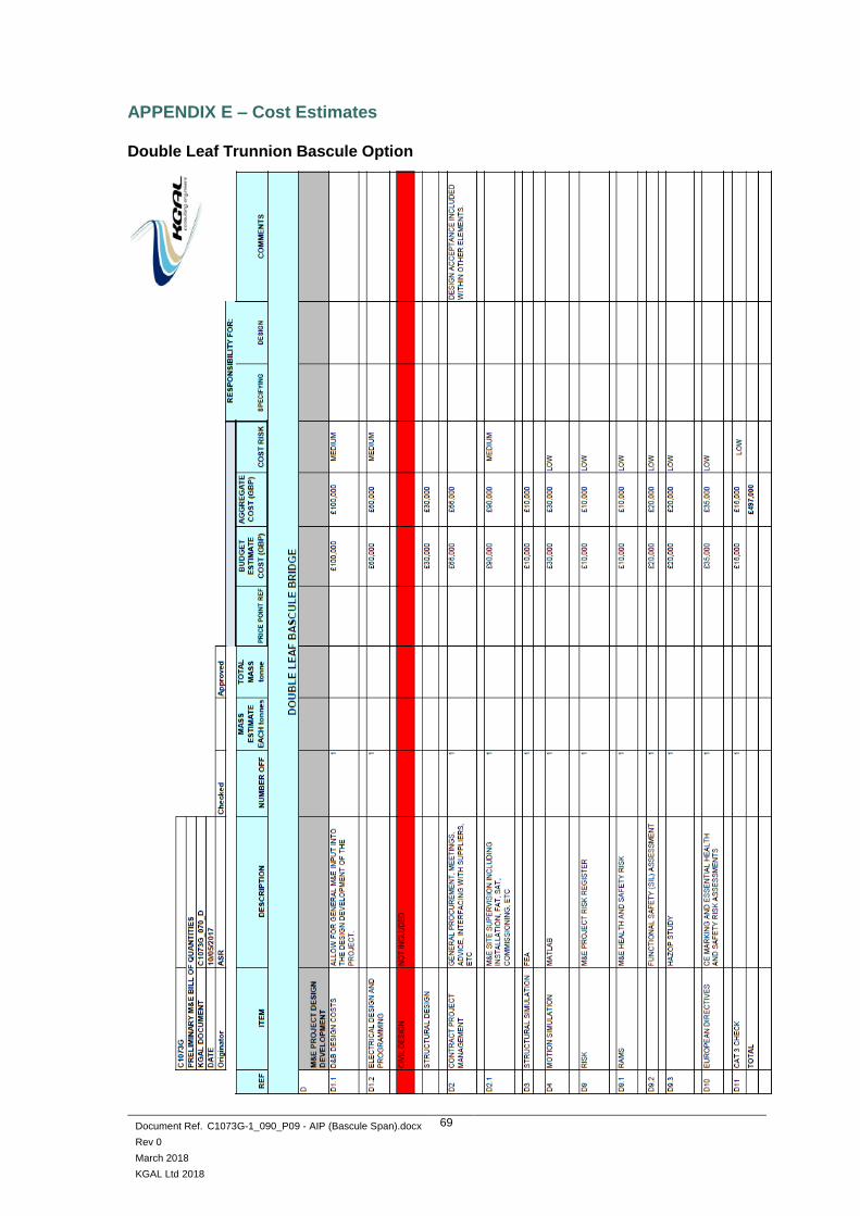
Document Ref. C1073G-1_090_P09 - AIP (Bascule Span).docx
Rev 0
March 2018
KGAL Ltd 2018
69
APPENDIX E – Cost Estimates
Double Leaf Trunnion Bascule Option

Document Ref. C1073G-1_090_P09 - AIP (Bascule Span).docx
Rev 0
March 2018
KGAL Ltd 2018
70

Document Ref. C1073G-1_090_P09 - AIP (Bascule Span).docx
Rev 0
March 2018
KGAL Ltd 2018
71
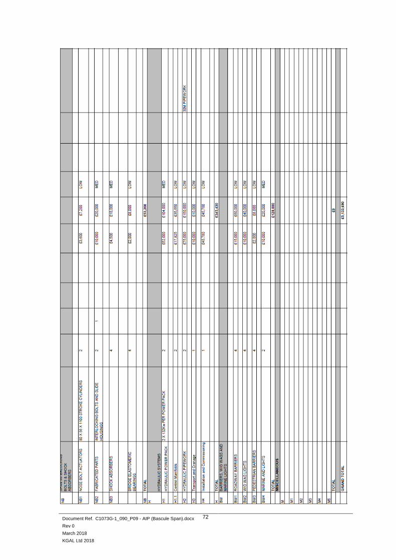
Document Ref. C1073G-1_090_P09 - AIP (Bascule Span).docx
Rev 0
March 2018
KGAL Ltd 2018
72

Document Ref. C1073G-1_090_P09 - AIP (Bascule Span).docx
Rev 0
March 2018
KGAL Ltd 2018
73
Single Leaf Trunnion Bascule Option

Document Ref. C1073G-1_090_P09 - AIP (Bascule Span).docx
Rev 0
March 2018
KGAL Ltd 2018
74

Document Ref. C1073G-1_090_P09 - AIP (Bascule Span).docx
Rev 0
March 2018
KGAL Ltd 2018
75

Document Ref. C1073G-1_090_P09 - AIP (Bascule Span).docx
Rev 0
March 2018
KGAL Ltd 2018
76
Single Leaf Rolling Lift Option

Document Ref. C1073G-1_090_P09 - AIP (Bascule Span).docx
Rev 0
March 2018
KGAL Ltd 2018
77

Document Ref. C1073G-1_090_P09 - AIP (Bascule Span).docx
Rev 0
March 2018
KGAL Ltd 2018
78