AFFORDABLE ROOM SERVICE ROBOT NAVIGATION USING IR ...
24
AFFORDABLE ROOM SERVICE ROBOT NAVIGATION USING IR TECHNIQUE AZREEY BIN AZLAN RAJA (55569) Bachelor of Computer Science with Honors (Network Computing) 2020
-
Upload
khangminh22 -
Category
Documents
-
view
4 -
download
0
Transcript of AFFORDABLE ROOM SERVICE ROBOT NAVIGATION USING IR ...

AFFORDABLE ROOM SERVICE ROBOT NAVIGATION USING IR TECHNIQUE
AZREEY BIN AZLAN RAJA
(55569)
Bachelor of Computer Science with Honors
(Network Computing)
2020

AFFORDABLE ROOM SERVICE ROBOT NAVIGATION USING IR TECHNIQUE
AZREEY BIN AZLAN RAJA
This project is submitted in partial fulfillment of the
requirements for the degree of
Bachelor of Computer Science and Information Technology
Faculty Computer Science and Information Technology
UNIVERSITI MALAYSIA SARAWAK
2020

I
FORM B
12/8/2020

II
ACKNOWLEDGEMENT
In the name of Allah, the most beneficent and merciful, it is my radiant sentiment to place on
record of my best regards to my dearest supervisor and Final Year Project coordinator, Prof. Dr.
Wang Yin Chai took time out to hear, supervise and guide me in completing my Final Year
Project despite his hectic schedule and giving useful tips and tricks for Final Year Project
completion. Secondly, with utmost gratitude, I would like to address my thanks to my cherished
examiner, Dr. Kartinah Binti Zen, who had given me constructive feedbacks and remarks on
my Final Year Project. I choose this moment to acknowledge their contribution to gratefully.
Aside from that, I would like to express my heartiest gratitude to my parents and family who
had supported me, encouraged me, and never give up on me despite my long years of studies. I
wish to express my deepest thanks to Muneerah Binti Hussin in giving necessary advice and
guidance to make my life easier Also, my sincere appreciation and uttermost sense of gratitude
to my friends, Nur Nadiah Johan Nazri, Adam Tony, and all September Intake 2016/2017 batch
members who had helped me and stayed with me in going through the ups and downs of my
bachelor degree journey. Finally, I would like to address special thanks to all of the respondents
for their unflagging cooperation and prompt responses. It is a delight for me to acknowledge
and work with all of you.

1
TABLE OF CONTENTS
FORM B ................................................................................................................................ i
ACKNOWLEDGEMENT .....................................................................................................ii
TABLE OF CONTENTS....................................................................................................... 1
LIST OF FIGURES ............................................................................................................... 5
LIST OF TABLES ................................................................................................................ 7
ABSTRACT .......................................................................................................................... 8
ABSTRAK ............................................................................................................................ 9
CHAPTER 1: INTRODUCTION ........................................................................................ 10
1.1 Project title ............................................................................................................. 10
1.2 Introduction/Background ........................................................................................ 10
1.3 Problem Statement ................................................................................................. 11
1.4 Objectives .............................................................................................................. 11
1.5 Procedures/Methodologies...................................................................................... 12
1.5.1 Analysis and quick design phase .................................................................... 12
1.5.2 Prototype cycle phase ..................................................................................... 12
1.5.3 Testing phase ................................................................................................. 13
1.5.4 Implementation phase ..................................................................................... 13
1.6 Scope ..................................................................................................................... 13
1.7 Significant of project .............................................................................................. 14
1.8 Project Schedule ..................................................................................................... 14
2
1.9 Expected Outcome ................................................................................................. 15
1.10 Conclusion ............................................................................................................. 15
CHAPTER 2: LITERATURE REVIEW .............................................................................. 16
2.1 Introduction ............................................................................................................ 16
2.2 Review on existing system/application ................................................................... 16
2.2.1 Waiter Robot-Solution to Restaurant Automation ........................................... 17
2.2.2 Remote Controlled Waiter Robot for Restaurant Automation ......................... 19
2.2.3 Smart Food Serving Robot in Restaurant ........................................................ 21
2.2.4 Simple Ordering Waiter Line Follower Robot using Arduino ............................... 22
2.3 Comparison of existing system/application and the proposed system/app ............... 23
2.4 Tools and Technology in the development of the Proposed Application ................. 24
2.4.1 Laptop ............................................................................................................ 24
2.4.2 Robot ............................................................................................................. 24
2.4.3 Arduino .......................................................................................................... 26
2.4.4 Arduino IDE................................................................................................... 28
2.4.5 IR Sensors ...................................................................................................... 28
2.5 Summary ................................................................................................................ 30
CHAPTER 3: REQUIREMENT ANALYSIS AND DESIGN.............................................. 31
3.1 Introduction ............................................................................................................ 31
3.2 System Design and General Architecture ................................................................ 31
3.3 System Development Methodology ........................................................................ 32
3
3.3.1 Analysis and Quick Design............................................................................. 33
3.3.2 Prototype Cycle .............................................................................................. 33
3.3.3 Develop .......................................................................................................... 33
3.3.4 Demonstrate ................................................................................................... 34
3.3.5 Refine ............................................................................................................ 34
3.3.6 Testing ........................................................................................................... 34
3.3.7 Implementation .............................................................................................. 35
3.4 Requirement System Analysis and Design .............................................................. 35
3.4.1 Identify the user ............................................................................................. 35
3.4.2 Identify Requirements .................................................................................... 36
3.5 Block Diagram of Proposed system ........................................................................ 40
3.6 System Flowchart for IR sensor .............................................................................. 41
3.7 System Framework ................................................................................................. 42
3.8 Summary ................................................................................................................ 42
CHAPTER 4: IMPLEMENTATION AND TESTING ......................................................... 43
4.1 Introduction ............................................................................................................ 43
4.2 System Implementation .......................................................................................... 44
4.2.1 Arduino Uno .................................................................................................. 44
4.2.2 IR Sensor ....................................................................................................... 45
4.2.3 Motor Driver .................................................................................................. 46
4.2.4 Relay with remote control .............................................................................. 47
4
4.2.5 LiPo Battery 12V ........................................................................................... 48
4.3 Prototype Development .......................................................................................... 49
4.4 Prototype Modelling ............................................................................................... 53
4.5 Prototype Program .................................................................................................. 53
4.5.1 Hardware Programming ................................................................................. 53
4.6 Prototype Testing ................................................................................................... 59
4.6.1 Component testing.......................................................................................... 60
4.5.2 Full Circuit Testing .............................................................................................. 63
4.7 Summary ................................................................................................................ 65
CHAPTER 5: CONCLUSION AND FUTURE WORKS ..................................................... 66
5.1 Introduction ............................................................................................................ 66
5.2 Objective Achievement .......................................................................................... 66
5.3 Limitations ............................................................................................................. 68
5.4 Future Work ........................................................................................................... 69
5.5 Summary ................................................................................................................ 69
References ........................................................................................................................... 70
5
LIST OF FIGURES
Figure 1. 1 Rapid Application Development (RAD) Diagram ............................................... 12
Figure 1. 2 Gantt charts of FYP ............................................................................................ 15
Figure 2. 1 Shows Waiter Robot-solution to Restaurant Automation ..................................... 18
Figure 2. 2 Remote Controlled Waiter Robot for Restaurant Automation .............................. 20
Figure 2. 3 Shows Model demo of Smart Food Serving Robot in Restaurant......................... 21
Figure 2. 4 Shows Simple Ordering Waiter Line Follower Robot using Arduino .................. 22
Figure 3. 1 System design of the proposed system ................................................................ 31
Figure 3. 2 Rapid Application Development Phases .............................................................. 32
Figure 3. 3 Arduino Uno ....................................................................................................... 36
Figure 3. 4 IR sensor ............................................................................................................ 37
Figure 3. 5 DC Motor ........................................................................................................... 37
Figure 3. 6 RF Module (Transmitter with receiver) ............................................................... 38
Figure 3. 7 Motor Driver ...................................................................................................... 39
Figure 3. 8 Arduino IDE Software ........................................................................................ 39
Figure 3. 9 Block diagram of proposed system...................................................................... 40
Figure 3. 10 The flowchart for IR sensor .............................................................................. 41

6
Figure 4. 1 Arduino Uno ....................................................................................................... 44
Figure 4. 2 IR Sensor ............................................................................................................ 45
Figure 4. 3 Motor Driver....................................................................................................... 46
Figure 4. 4 Relay with remote control ................................................................................... 47
Figure 4. 5 LiPo Battery 12V ................................................................................................ 48
Figure 4. 6 Prototype set-up .................................................................................................. 49
Figure 4. 7 The connection between microcontroller and motor drive ................................... 50
Figure 4. 8 IR Sensor that connected to the microcontroller .................................................. 51
Figure 4. 9 The Relay connected with LiPo battery ............................................................... 51
Figure 4. 10 Track with black and white line ........................................................................ 52
Figure 4. 11 Complete testing of the project.......................................................................... 52
Figure 4. 12 Complete testing of the prototype...................................................................... 59
Figure 4. 13 Arduino IDE ..................................................................................................... 60
Figure 4. 14 Arduino microcontroller testing ........................................................................ 61
Figure 4. 15 IR Sensor testing ............................................................................................... 61
Figure 4. 16 Motor drive testing ........................................................................................... 62

7
LIST OF TABLES
Table 1 Comparison of the existing systems ......................................................................... 23
Table 2 Hardware requirement and specification .................................................................. 36
Table 3 Table of Software requirement and its specifications ................................................ 39
Table 4 A Test case for the Arduino ..................................................................................... 63
Table 5 A Test case for the IR sensor and Motor driver ........................................................ 63
Table 6 The objective and achievement of the prototype system ........................................... 67
8
ABSTRACT
The room service robot navigation is a mobile machine that can detect and follow the
line drawn on the floor. Generally, the path is predefined and can be either visible like a black
line on a white surface with a high contrasting color or it can be invisible like a magnetic field.
Therefore, this robot should sense the line with its Infrared Ray (IR) sensors installed under the
robot. After that, the data is transmitted to the processor by specific transition buses. Hence,
the processor is going to decide the proper commands and then it sends them to the driver and
thus the path will be followed by the line follower robot.

9
ABSTRAK
Navigasi robot perkhidmatan bilik ialah mesin mudah alih yang dapat mengesan dan
mengikuti garis yang dilukis di atas lantai. Secara amnya, jalan itu telah dipratentukan dan
boleh kelihatan seperti garis hitam di atas permukaan putih dengan warna kontras yang tinggi
atau ia tidak kelihatan seperti medan magnet. Oleh itu, robot ini harus mengesan garis tersebut
dengan sensor sinar Inframerah yang dipasang di bawah robot. Selepas itu, data dihantar ke
prosessor khusus oleh bas peralihan. Oleh itu, prosessor akan menentukan arah yang betul dan
kemudian menghantarnya kepada pemandu dan jalan itu akan diikuti oleh robot pengikut baris.

10
CHAPTER 1: INTRODUCTION
1.1 Project title
Affordable Room Service Robot Navigation using IR Technique
1.2 Introduction/Background
A robot is a machine that resembles a living creature in being capable of moving
independently and performing complex actions. It is typically designed to reduce the
appropriate amount of human work. Usually, it is designed to reduce the risk factor for human
work and increase the comfort of any worker. In developed countries, robotics has made great
strides. High performance, high precision, lower labor costs, and the ability to work in
hazardous locations put robotics in an advantageous position over many other technologies of
this kind. In an era where robotics and automation are developing so fast, this project intends
to combine both the aforementioned fields to develop and automated serving system for a hotel.
In my project, I will invent a hotel room service robot navigation using the IR technique. IR is
an infrared sensor is an electronic device that emits some aspects of the environment to be
sensed. An IR sensor can monitor an object's heat and sense movement. Some types of detectors
only measure infrared radiation instead of emitting it as a passive IR sensor. This is our target
to use robots for greater efficiency and saving human time and efforts. A line tracer has been
presented which will trace a white line on a black surface or vice-versa. The line will be placed
in front of the hotel rooms so that the robot can follow the line from a door to a door. Then, the
robot will bring the item that has ordered by the customer such as toiletries, and food to their
doors. The special features of this proposed system are when the waiter press the customer room
number by remote control, the robot will bring the item that has been ordered and stop at the
11
room that has been press by the waiter. Then, the robot will stop at the starting point and wait
for the next order item.
1.3 Problem Statement
Nowadays, many small-to-medium enterprises (SME) such as in hotel fields, cannot afford
the usage of the waiter robot to replace human work. Currently, many waiter robots are very
expensive and complicated to use. Since it required a specialist to service and do the
maintenance part for the service. Thus, there is a need to build a robot which able to replace the
waiter in the hotel. The robot can replace human work such as bringing the customer’s needs.
For example, it ables to carry parcels, food, or even the customer toiletries. This proposed
project uses robots with IR sensors for greater efficiency and saving human time and effort. It
will able to identify and design the requirement of navigation technique for room service robots
using affordable solutions. Then, it can identify the product function and features of the room
service robot.
1.4 Objectives
To identify and design the requirement of navigation technique for room service
robots using affordable solutions.
To identify the product function and features of the room service robot.
To design and propose a framework for the implementation of room service robots.
To develop a robot prototype with IR sensors.
12
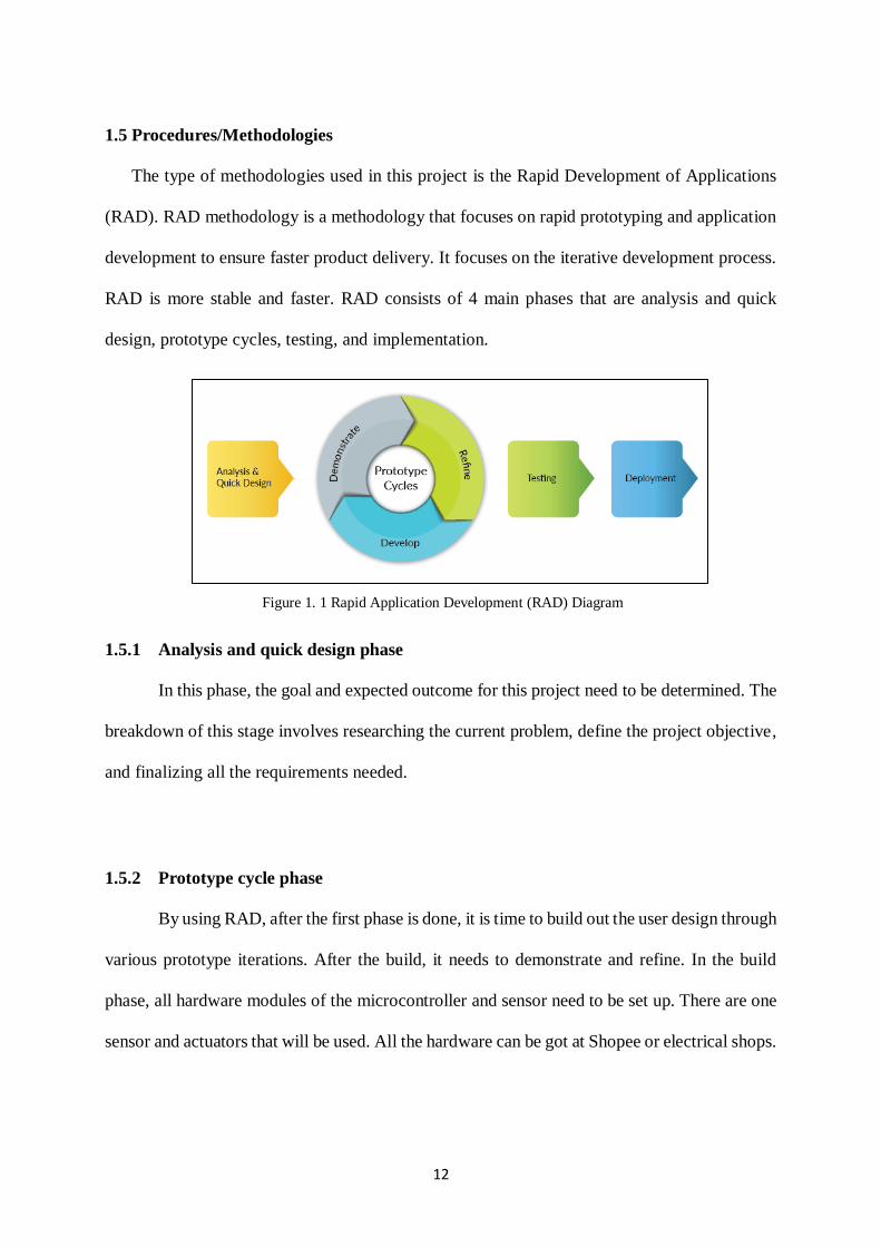
1.5 Procedures/Methodologies
The type of methodologies used in this project is the Rapid Development of Applications
(RAD). RAD methodology is a methodology that focuses on rapid prototyping and application
development to ensure faster product delivery. It focuses on the iterative development process.
RAD is more stable and faster. RAD consists of 4 main phases that are analysis and quick
design, prototype cycles, testing, and implementation.
1.5.1 Analysis and quick design phase
In this phase, the goal and expected outcome for this project need to be determined. The
breakdown of this stage involves researching the current problem, define the project objective,
and finalizing all the requirements needed.
1.5.2 Prototype cycle phase
By using RAD, after the first phase is done, it is time to build out the user design through
various prototype iterations. After the build, it needs to demonstrate and refine. In the build
phase, all hardware modules of the microcontroller and sensor need to be set up. There are one
sensor and actuators that will be used. All the hardware can be got at Shopee or electrical shops.
Figure 1. 1 Rapid Application Development (RAD) Diagram

13
1.5.3 Testing phase
For this phase, the prototypes from the prototype cycle phases are converted into a
working model. Then, it will be tested based on-line the following robot. Testing also involving
testing all the individual units either the software or hardware to make sure it is functioning
well. Also, more details about the testing phases will be described in Chapter 4.
1.5.4 Implementation phase
This is the implementation phase where the finished model will be done. It also needs
to be testing to ensure all the requirement is being achieved. In this final phase, the final
prototype will be finished to be used in the hotel.
1.6 Scope
Affordable room service robot navigation using the IR technique is a simulation of a robot
in the hotel. It would be used for the hotel’s employees. A room will be set up with the track of
the hotel room, to test the robot before it implements in the hotel. A black line will be used as
a path of the robot to move according to the track. Therefore, a set of IR sensors is used to sense
the path of the track which is the black line, and capture the data and sent it to the
microcontroller which is Arduino Uno. The proposed project is designed is a car robot that acts
as a waiter in the hotel. It can bring the need of the customer such as toiletries and send to their
room.
14
1.7 Significant of project
This project offers some insights which can help the hotel employee to ease their works so
that they can focus on other work. The advantages of this project are they will be used for
sending things from one place to another. Next, there is no need for human operators. The robot
can perform repetitive tasks by following the path on its own by using the IR sensors. It also
can be used for domestic purposes. Lastly, it is used in the hotel to carry parcels, food, or
toiletries.
1.8 Project Schedule
The project schedule is used as a guideline and reminder to develop this Room Service
Robot Navigation using IR Technique. Gantt chart has been used to represent the project
schedule with the help of Microsoft Excel to ensure the time of completion of the project
punctually. The Gantt chart is developed based on important dates and tasks according to Final
Year Project 1 and Final Year Project. All the important dates and tasks are illustrated in the
Gantt chart as shown in Figure 1.2.

15
1.9 Expected Outcome
Upon project completion, a Room Service Robot Navigation using IR Technique will be
developed which has the features of an IR sensor that can send the item for hotel customers.
Next, it will help the hotel not to expend more money to hire a worker. Other than that, the
robot will follow the path using IR sensors. Then, the robot will capable of taking various
degrees of turns.
1.10 Conclusion
This project will be using RAD methodology for the development of the IoT project. It will
help the waiter in the hotel to deliver the needs of the customers so that they can focus on other
works. This line following robot based on IoTs is acting as a waiter robot that fulfills the
customer’s needs such as toiletries, food, and more.
Figure 1. 2 Gantt charts of FYP

16
CHAPTER 2: LITERATURE REVIEW
2.1 Introduction
In reviewing the literature, existing systems with similar functions and processes to the
proposed system will be discussed in more detail. A comprehensive analysis will be carried out
to inspect the strengths, weaknesses, and features of those systems. Four existing systems
chosen for this literature review are Waiter Robot-Solution to Restaurant Automation, Remote
Controlled Waiter Robot for Restaurant Automation, Smart Food Serving Robot in Restaurant,
and lastly, Simple Ordering Waiter Line Follower Robot using Arduino. All the system
reviewed is related to the line following robot that uses the IR sensor. Based on the analysis, a
comparison between the existing application and the proposed application will be made. This
is to adapt to the strengths and to avoid the weaknesses of the existing systems to improve the
proposed application. Apart from that, this chapter also discusses the tools and technology used
in the development of the proposed application which can help to find suitable tools and
technology in the process to develop this proposed application.
2.2 Review on existing system/application
The criteria of the waiter line following robot are it can follow the track using the IR
sensors, Arduino, remote control, wheels, and other hardware. My project criteria are the robot
can follow the line on its track and can make a degree of turns while using the remote control.
17
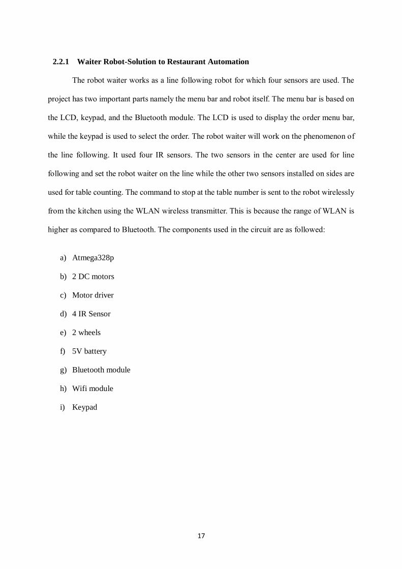
2.2.1 Waiter Robot-Solution to Restaurant Automation
The robot waiter works as a line following robot for which four sensors are used. The
project has two important parts namely the menu bar and robot itself. The menu bar is based on
the LCD, keypad, and the Bluetooth module. The LCD is used to display the order menu bar,
while the keypad is used to select the order. The robot waiter will work on the phenomenon of
the line following. It used four IR sensors. The two sensors in the center are used for line
following and set the robot waiter on the line while the other two sensors installed on sides are
used for table counting. The command to stop at the table number is sent to the robot wirelessly
from the kitchen using the WLAN wireless transmitter. This is because the range of WLAN is
higher as compared to Bluetooth. The components used in the circuit are as followed:
a) Atmega328p
b) 2 DC motors
c) Motor driver
d) 4 IR Sensor
e) 2 wheels
f) 5V battery
g) Bluetooth module
h) Wifi module
i) Keypad
18
Figure 2.1 below shows how is the implementation of the Waiter Robot-solution to the
Restaurant Automation.
Figure 2. 1 Shows Waiter Robot-solution to Restaurant Automation

19
2.2.2 Remote Controlled Waiter Robot for Restaurant Automation
This proposed work is based on wireless communication with the help of the TSOP
1738 module (Infrared Receiver Module). This proposed work includes AVR ROBOT, TSOP
IR receiver, Remote, buzzer, RC-5 Decoder. TSOP sensor is designed to receive the coded
infrared pulses from the transmitter and directs the function of the device. Here Coded Infrared
pulses are the commands from the operator then internally these commands are served as
various activities of Robot. Here we are using Robots for mankind's operations in big
restaurants as a waiter or as an employee. This Robot can able to do functions like taking orders
from each table, passing to the operator, and sweep out and make clean an area after the table
is empty. The robot waiter works as a line following robot for which sensors are used. The
components used in the circuit are as followed:
a) Arduino Uno
b) Keypad
c) Infrared sensors
d) Tsop 1738
e) LCD
f) Motor Driver
g) Bluetooth module

20
Figure 2.2 below shows how is the implementation of the Remote Controlled solution
for Restaurant Automation.
Figure 2. 2 Remote Controlled Waiter Robot for Restaurant Automation