AESO SOL Methodology for the Operations Horizon
23
-
Upload
khangminh22 -
Category
Documents
-
view
4 -
download
0
Transcript of AESO SOL Methodology for the Operations Horizon


Foreword
The AESO is responsible for reliability coordination functions within the province of Alberta, which includes the entire Alberta Interconnected Electric System (AIES). ARS FAC-011-AB requires that the Reliability Coordinator have a documented methodology for use in developing system operating limits (SOLs) within its Reliability Coordinator area. This document provides the details of the AESO’s SOL methodology for the Operations Horizon. The AESO performs operational planning analysis and assessments over a 4 year horizon, from the rolling 12-month period starting at real-time (now) up to the end of year 4, including the following sub-horizons: seasonal, outage planning, next-day, same-day, and Real-time. The AESO SOL methodology for the Operations Horizon is applicable across the entire operations planning horizon.

Page 3 Effective Date: September 1, 2015
Contents Foreword ........................................................................................................................................................... 2
A. Purpose ..................................................................................................................................................... 4
B. Applicability............................................................................................................................................... 4
C. Effective Date ........................................................................................................................................... 4
D. Minimum Acceptable System Performance ........................................................................................ 4
E. Process for Selecting Applicable Contingencies ................................................................................ 6
F. Determining SOLs ................................................................................................................................... 8
G. Determining SOLs that Qualify as IROLs..........................................................................................11
H. IROL TV in the AESO Area ..................................................................................................................13
I. Current List of IROLs in AESO Area ..................................................................................................13
J. System Study Models ...........................................................................................................................14
K. AESO Communication of SOLs and IROLs ......................................................................................15
Appendix ‘1’: Descriptions ............................................................................................................................17
Appendix 2: Acceptable Thermal Performance Examples ...........................................................................19
Revision History ............................................................................................................................................23

Page 4 Effective Date: September 1, 2015
Definitions and Descriptions of Terms The capitalized terms used in this SOL Methodology are to have meanings set forth in the Alberta Electric System Operator (AESO) Consolidated Glossary and Appendix I.
A. Purpose This document is the AESO System Operating Limit (SOL) Methodology for the Operations Horizon. The document establishes the methodology to be used in the AESO area for determining SOLs and Interconnection Reliability Operating Limits (IROL) for use in the Operations Horizon pursuant to Alberta Reliability Standards (ARS) FAC-011-AB and ARS FAC-014-AB.
The use of this SOL Methodology in the operations planning horizon will ensure the reliable operation of the Bulk Electric System (BES) in the AESO area. It is not the intent of this SOL methodology to limit in any way the nature and range of studies and analyses the AESO may take in ensuring acceptable system performance throughout the Operations Horizon.
The ultimate task of the AESO is to assess and evaluate projected system conditions as Real-Time approaches with the objective of ensuring acceptable system performance in Real-Time. Establishing operating limits such as SOLs and IROLs, scheduling limits; and ensuring plans, processes, and procedures are developed to prevent and to mitigate instances of exceeding SOLs and IROLs are a few of the means by which acceptable system performance can be achieved.
B. Applicability This SOL methodology is to apply to the AESO area for developing SOLs and IROLs used in the Operations Horizon where the study scope commenced on the effective date of this methodology.
C. Effective Date The effective date for this revision of this AESO SOL methodology is September 01, 2015.
D. Minimum Acceptable System Performance SOLs in the AESO area are established such that operating within these boundaries provides Bulk Electric System (BES) acceptable pre- and post-contingency performance consistent with this documented methodology. [Ref: ARS FAC-011-2 R2].
In the AESO area, the BES is expected to be operated such that acceptable system performance is being achieved in both the pre- and post-contingency states. The AESO may rely on Real-Time tools or rely on prior studies provided that the prior studies demonstrate acceptable performance for the current or expected system conditions.

Page 5 Effective Date: September 1, 2015
It is not the intent of this SOL methodology to require more stringent BES performance than that stipulated in the prevailing AESO transmission planning (TPL) Reliability Standards and WECC TPL Criteria and Practices, or to expect the BES to perform in any way better than it was designed.
SOLs (including SOLs that qualify as IROLs) are to be established to ensure acceptable BES performance throughout the Operations Horizon (including the Real-time sub-horizon). If any of the acceptable pre- or post-contingency system performance criteria stipulated in this methodology is not being met, an SOL is being exceeded.
Acceptable Pre-Contingency Performance: Acceptable pre-contingency system performance is characterized as follows [Ref: FAC-011-2 R2.1]:
1. The BES is to demonstrate transient, dynamic and voltage stability. 2. All Facilities are to be within their continuous Facility Ratings. Refer to illustration in Appendix II. 3. All Facilities are to be within their pre-contingency voltage limits. 4. All Facilities are to be within their stability limits.
Acceptable Post-Contingency Performance for Single Contingencies: Acceptable post- contingency system performance is characterized as follows [Ref: FAC-011-2 R2.2]:
1. The BES is to demonstrate transient, dynamic and voltage stability. 2. All Facilities are to be within their applicable Emergency Ratings or Temporary Emergency
Ratings, as provided by the appropriate facility owner. (Refer to illustration in Appendix 1). 3. All Facilities are to be within their post-contingency voltage limits. 4. All Facilities are to be within their stability limits. 5. Cascading or uncontrolled separation is not to occur.
Acceptable System Response for Single Contingencies: In determining the system’s response to a single contingency, the following actions are acceptable [Ref: FAC-011-2 R2.3]:
1. Planned or controlled interruption of electric supply to radial customers or some local network customers connected to or supplied by the Faulted Facility or by the affected area [Ref: FAC-011-2 R2.3.1].
2. Interruption of other network customers [Ref: FAC-011-2 R2.3.2]: i. Only if the system has already been adjusted, or is being adjusted, following at least one
prior outage, or ii. If the Real-time operating conditions are more adverse than anticipated in the corresponding
studies.
3. System reconfiguration through manual or automatic control or protection actions [Ref: FAC-011-2 R2.3.3]. SOLs must allow for adequate time for manual reconfiguration actions.
Acceptable Post Contingency Performance for Credible Multiple Contingencies: Acceptable post-contingency system performance is characterized as follows:
1. In the seasonal sub-horizon and the balance of the Operations Horizon including the seasonal sub horizon, acceptable system performance is characterized by:
i. The BES is to demonstrate transient, dynamic and voltage stability. ii. All Facilities are to be within their applicable Emergency Facility Ratings, or Temporary
Emergency Ratings, as provided by the appropriate facility owner (unless this level of BES

Page 6 Effective Date: September 1, 2015
performance is more stringent than Reliability Standard requirements applicable to the Planning Horizon).
iii. All Facilities are to be within their post-contingency voltage limits (unless this level of BES performance is more stringent than Reliability Standard requirements applicable to the Planning Horizon).
iv. All Facilities are to be within their stability limits. v. Cascading or uncontrolled separation is not to occur.
2. Due to equipment outages, topology changes and other conditions for which the system was not designed, it may not always be possible to meet the same level of acceptable system performance in shorter term sub-horizons (i.e., Outage Planning, Next-Day, Same-Day, Real-time) as in the seasonal sub- horizon. When studies indicate that prevailing impacting outages do not allow for the same level of system performance as described in item Acceptable Post Contingency Performance for Multiple Contingencies section (a) (ii) and (iii) above, the AESO is to establish adequate plans, processes, and procedures to contain and mitigate Credible Multiple Contingencies impacts.
The BES is to demonstrate acceptable pre- and post-contingency system performance throughout the Operations Horizon for the following Contingencies at a minimum:
• Single Contingencies internal to the AESO Area. • Credible Multiple Contingencies internal to the AESO Area. • Any Single Contingencies and Credible Multiple Contingencies external to the AESO area that is
known to or may impact the AESO area. • Any applicable Regionally Critical Multiple Contingencies as determined by the AESO.
Conditions that expose the system to unacceptable BES performance cannot be allowed to continue indefinitely. As such, when the system is experiencing unacceptable pre- or post-contingency performance, the system must be adjusted as soon as practical to be prepared for the next contingency.
When system studies conducted throughout the Operations Horizon (including Real-time Assessments) indicate that any of the acceptable post-contingency system performance criteria are not being met, the AESO is to take pre-contingency actions to achieve acceptable performance. These actions may include, at a minimum, the following [FAC-011-2 R2.4]:
• Commit and re-dispatch generation. • Make adjustments to the uses of the transmission system (e.g., schedule
curtailments/adjustments). • Make changes to system topology.
It should be noted that there are no firm transfers via interties to the AESO area.
E. Process for Selecting Applicable Contingencies
This section describes the AESO process for selecting applicable Contingencies for use in the Operations Horizon, and determining which of the Multiple Contingencies provided to the AESO in accordance with FAC-014-AB-2 R4 are applicable for use in the Operations Horizon given the actual or expected system conditions. The process addresses the need to modify SOLs, the subset of SOLs that qualify as IROLs, and the associated list of Multiple Contingencies. [FAC-011-2 R3.2 and R.3.3].

Page 7 Effective Date: September 1, 2015
Applicable Single Contingencies for use in the Operations Horizon
The system is to demonstrate acceptable BES performance throughout the Operations Horizon following the Single Contingencies identified below. 1
• Single-line-to-ground (SLG) or 3-Phase Fault (whichever is more severe), with Normal Clearing, on
any Faulted generator, line, transformer, or shunt device. • Loss of any generator, line, transformer, or shunt device without a Fault. • Single pole block, with Normal Clearing, in a monopolar or bipolar high voltage direct current
system.
Applicable Multiple Contingencies for Use in the Operations Horizon
The AESO is responsible for identifying Multiple Contingencies (MC) within its area. The inability to prevent or mitigate adverse impacts of a Multiple Contingency is not considered an acceptable reason for changing credibility of the Multiple Contingencies at any time in the Operations Horizon.
This SOL methodology does not require that all Multiple Contingencies that were studied over the entire 4-year Operations Horizon be studied in all sub-horizons within the Operations Horizon. Some of these MCs may not be deemed credible for use in the seasonal sub-horizon (which is defined as a period less than 12 months but greater than 6 months) due to differences in system topology and/or load or generation levels compared to longer sub-horizons within the Operations Horizon.
In determining the credibility of Multiple Contingencies in its area, the AESO (Ops Planning) will apply engineering judgment and system operating experience, consult with its AESO Long Term Planning department, transmission operator, transmission owners, generator owners, and utilize the following references:
• List of MCs studied by the Long Term Planning department in the Planning Horizon. • Category C of ‘Appendix 1 of the Transmission System Standards – Normal and Emergency
Conditions’ in Alberta Reliability Standard TPL-003-AB-0. • WECC System Performance Regional Business Practice TPL-001-WECC-RBP-2 (for common
corridor, margins, and mean time between failures).
The AESO shall assess whether any of the MCs that have been determined by the AESO Long Term Planning department to result in stability limits (provided per FAC-014-2 R6) are Credible and thus applicable for use in the seasonal sub-horizon. The AESO shall modify applicable SOLs (including SOLs that qualify as IROLs) based on the revised list of Credible MCs.
Applicable Multiple Contingencies for Use in the Outage Planning, Next-day, Same-day and Real-time Sub-horizons
While the Methodology introduces levels of flexibility that allow the AESO to revise the list of Credible MCs, the AESO recognizes that the impact of an MC may go beyond the AESO’s area. Therefore, as much as practicable, when the AESO revises the list of Credible MCs and if the AESO determines there is a potential impact on a neighboring Balancing Authority or Reliability Coordinator (RC), the AESO will allow time for adequate coordination of studies with neighboring Balancing Authorities or RCs that may be necessary to verify acceptable BES performance and establish or revise SOLs/IROLs.
1 The AESO must identify and develop a list of the subset of multiple contingencies, if any, from reliability standard TPL-003-AB which result in stability limits in its planning horizon

Page 8 Effective Date: September 1, 2015
The AESO shall determine which MCs in its area are Credible and applicable for use in the seasonal sub-horizon shall remain Credible and applicable for use in the Outage Planning, Next-Day, Same-Day, and Real-Time sub-horizons until the rationale for the MC credibility is changed and documented.
If the AESO expects that an MC may become Credible in the shorter sub-horizons due to, for example, an upcoming storm season, the AESO will communicate such information in a timely manner. As much as practicable, the AESO will develop pre-established outage limits (SOLs/IROLs) that can be applied should that particular MC become Credible.
If the AESO determines that the list of Credible Multiple Contingencies must be changed, the AESO is to communicate the changes are per Alberta Reliability Standard (ARS) FAC-014-AB.
Regionally Critical Multiple Contingencies
AESO is to consider any Regionally Critical Multiple Contingencies that are provided by the Peak RC or other RC’s within WECC. Information provided to the AESO should include at a minimum the following:
• Rationale used to determine Multiple Contingencies regional criticality. • Study requirements and expectations. • Acceptable performance criteria for each Regionally Critical Multiple Contingency.
Other Multiple Contingency Considerations
Items below apply to those Multiple Contingencies that have already been deemed Credible by the AESO. While these requirements are applicable for the entirety of the Operations Horizon, they are not intended to require that these analyses be performed in any specific sub-horizon.
When performing studies, it is acceptable to analyze only those Credible Contingencies that would produce the more severe system results or impacts. The selection of these Contingencies is based on prior or current studies. The rationale for the Contingencies selected is to be available as supporting evidence.
Where common tower circuits (i.e., any two adjacent BES circuits on a single tower) are deemed Credible Multiple Contingencies, the analysis is to include simultaneous loss of the two circuits. For stability studies, SLG faults with normal clearing are to be analyzed. For contingencies that AESO Planning deemed credible, three phase fault with normal clearing to be analyzed.
Where two Adjacent Transmission Circuits that are both greater than or equal to 240 kV share a common right-of-way for a total of 5 Kilometers or more and are deemed Credible Multiple Contingencies (excluding – but not limited to – substation entrances, pinch points, and river crossings); the analysis is to include simultaneous loss of the two adjacent circuits. For stability studies, SLG faults with normal clearing are to be analyzed.
Where stuck/failed breaker Multiple Contingencies are deemed Credible, the analysis is to include SLG Fault with normal breaker failure clearing.
Where bipolar DC line Contingencies are deemed Credible, simultaneous permanent loss of both poles of a direct current bipolar Facility are to be analyzed.
F. Determining SOLs AESO is expected to assess projected system conditions as necessary as Real-time approaches in order to establish SOLs (including SOLs that qualify as IROLs), plans, processes, and procedures to meet pre- and

Page 9 Effective Date: September 1, 2015
post- contingency acceptable system performance in Real-time operations.
SOLs in the AESO operating area are established such that operating within these boundaries provides BES acceptable pre- and post-contingency performance consistent with this documented methodology. [Ref: FAC-011-2 R2].
General
AESO is to establish SOLs for AESO area consistent with provisions of this SOL methodology. [Ref: FAC-014-AB, R2].
AESO is to establish seasonal SOLs (including SOLs that qualify as IROLs) and develop plans, processes, and procedures that support operation within the established SOLs. All post-contingency mitigation plans should reflect the time necessary to take mitigating actions, including control actions, to return the system to a secure state.
AESO is to establish SOLs, including IROLs, consistent with this SOL Methodology. The AESO will ensure that:
• Facilities in the AESO Energy Management System (EMS) model contain Facility Ratings, Emergency Ratings, and Temporary Emergency Ratings as provided by generation owners and transmission owners.
• The AESO EMS model contains voltage limits. • This list is not intended to include all BES Single Contingencies – only those that result in the loss
of multiple Facilities, e.g., based on system configuration. • Stability limits have been established consistent with this SOL methodology, and the AESO system
operators and engineers have awareness of these limits. • When performing Operational Planning Horizon Analyses and Real-time Assessments, the AESO is
to follow this SOL Methodology to determine when SOLs qualify as IROLs. • The AESO is to review SOLs that have been determined to qualify as IROLs and make a final
determination whether an identified SOL should be declared an actual IROL. • The AESO’s EMS Real-time Contingency Analysis (RTCA) and Real-time Voltage Stability
(RTVSA) applications provide indication of whether acceptable thermal and voltage system performance would be achieved in the post-contingency state for actual system conditions.
Unless more restrictive limitations are present, SOLs are to be equal to the applicable Facility Ratings, voltage limits, voltage stability limits, transient stability limits, and WECC Path Ratings. The most limiting of these will determine the SOL used in Real-time operations. A generator producing more than its nameplate rating is not an indicator of SOL exceedance.
The AESO is to use anticipated transmission system configuration, generation dispatch, and load levels when establishing SOLs (including SOLs that qualify as IROLs) [Ref: FAC-011-2 R3.6]. At a minimum, AESO is to establish SOLs based on studies or analyses of reasonably expected maximum stressed BES conditions for the sub-horizon under study.
The AESO will determine when it is appropriate to use SOLs established in previous studies, or whether expected system conditions warrant performing new studies to:
• Ensure acceptable BES performance. • Establish or update SOLs (including SOLs that qualify as IROLs). • Develop plans, processes, and procedures necessary to ensure acceptable BES performance.

Page 10 Effective Date: September 1, 2015
For any transient or voltage stability SOL that – while not qualifying as an IROL – has been identified by the AESO as impacting more than one Intertie, the AESO and The Interconnected Transmission Operator(s) are to develop and document agreed upon coordinated plans, processes, and procedures to mitigate SOL exceedances within a predefined time duration. If the AESO and interconnected transmission operator(s) cannot agree on pre-defined time duration, then a default 30-minute time duration is to be used.
Transient Stability Limits
The AESO is to establish SOLs to prevent unit/intra-area instability, inter-area instability, or tripping of critical BES Facilities due to out-of-step conditions with the exception of controlled separation schemes on the interties between Alberta and Montana (Path 83), and Alberta and BC (Path 1).
AESO is to establish SOLs to prevent insufficiently damped system response. These SOLs are to be identified based on undamped and sustained system oscillations. Oscillations that do not show positive damping within a 30-second2 time frame are to be deemed undamped.
To facilitate monitoring, AESO is to communicate established transient stability limited SOLs as pre-contingent MW flow limits on Transmission Paths/Interfaces consisting of single or multiple transmission elements.
AESO is to communicate transient stability limits and associated documentation per this methodology.
Voltage Limits
The AESO is to establish acceptable pre- and post-contingency voltage limits3 for its area and communicate these per FAC-014-2-AB. Operating outside established voltage limits will constitute SOL exceedance. (This requirement is to apply to all BES Facilities and any sub-100 kV Facilities that the AESO deems critical for BES reliability).
Steady State (Post Transient) Voltage Stability Limits
The process for establishing voltage stability limited SOLs in the AESO area focuses on two aspects:
• Identifying the voltage stability limit (i.e., the maximum pre- contingency power transfer or load level for which a post-contingency solution can be reached) and applying minimum margins to determine the corresponding voltage stability-limited SOL.
• Ensuring that voltage stability is demonstrated for each established Transmission Path/Interface or area load SOL.
The AESO is to stress Transmission Paths/Interfaces or load areas to the reasonably expected maximum transfer conditions or area load levels to determine whether steady state voltage stability limits exist4. If this voltage stability limit does not qualify as an IROL, the following minimum margins are to be applied to establish corresponding SOLs expressed in megawatts:
• The Transmission Path/Interface SOL will be equal to or less than the maximum pre-contingency
power transfer for which a post-contingency solution can be reached less a minimum 5 percent margin for Single Contingencies or a minimum 2.5 percent margin for Multiple Contingencies.
2 This stipulation is not intended to require that transient stability simulations be run out to 30-seconds all the time in order to ensure the system is stable and positively damped. Shorter runs are permissible. 3 The AESO have flexibility to modify these limits as necessary based on actual or expected conditions. 4 The AESO may select to use analysis methods such as the P-V or V-Q analysis.

Page 11 Effective Date: September 1, 2015
• The area load level SOL will be equal to or less than the maximum pre- contingency area load for which a post-contingency solution can be reached, less a minimum of 5 percent margin for Single Contingencies or a minimum 2.5 percent margin for Multiple Contingencies.
The AESO is to perform studies to ensure that SOLs for Transmission Paths/Interfaces or load areas demonstrate voltage stability with margins as described below:
• For Transmission Paths/Interfaces, voltage stability is required with the pre- contingency path/interface flow modeled at a minimum of 105 percent of the path/interface SOL (pre-contingency system conditions) for Single Contingencies. For Multiple Contingencies, post-transient voltage stability is required with the pre-contingency transfer path/interface flow modeled at a minimum of 102.5 percent of the path/interface SOL.
• For load areas, voltage stability is required for the area modeled at a minimum of 105 percent of the reference load level SOL (pre-contingency system conditions) for SCs. For Multiple Contingencies, post-transient voltage stability is required with the area modeled at a minimum of 102.5 percent of the reference load level.
The AESO is to communicate any identified steady state voltage stability limits and associated documentation, or any reactive margin requirements per ARS FAC-014-AB.
Thermal Limits
AESO is to communicate changes to BES and any critical sub-100 kV Facility Ratings as per current processes until FAC-008 is in effect.
Facility Ratings, Emergency Ratings, and Temporary Emergency Ratings used in the Operations Horizon are provided to the AESO by the transmission facility owners in Alberta. When transmission facility owners provide Emergency Ratings and Temporary Emergency Ratings to the AESO, these must be accompanied by corresponding time durations.
G. Determining SOLs that Qualify as IROLs When an IROL is exceeded, the Interconnection has entered into an insecure state, i.e., the most limiting Credible or Regionally Critical Contingency could result in instability, uncontrolled separation, or Cascading outages which adversely impact the reliability of the BES.
In the AESO area, SOLs that qualify as IROLs will be established consistent with the following.
General
The AESO is to identify the subset of SOLs that qualify as IROLs consistent with this SOL Methodology. When the AESO identifies an SOL that qualifies as an IROL, the AESO is to communicate the results of its analysis as per FAC-014-AB.
SOLs qualify as IROLs when impact containment cannot be demonstrated as described in the ‘Impact Containment and IROL Load Impact’ section below or when studies indicate that instability, cascading, or uncontrolled separation may occur resulting in uncontrolled interruption of load equal to or greater than 1,000 MW.
For each identified IROL, the AESO, in conjunction with the impacted interconnected transmission operator,

Page 12 Effective Date: September 1, 2015
are to develop plans, processes, and procedures that identify actions that are to be taken (up to and including load shedding) to prevent violating the IROL and to mitigate the magnitude and duration of exceeding that IROL such that the IROL is relieved within the IROL’s Tv.
Impact Containment and IROL Load Impact
When studies in the Operations Horizon indicate pre- or post-contingency instances of instability, uncontrolled separation, or cascading, a potential IROL condition is present. The presence of an SOL that qualifies as an IROL will be determined based on (a) whether impact containment is demonstrated and (b) the level of load impact. The AESO is to consider impact containment to be adequately demonstrated when all the following are accomplished:
• Impacted area is predefined by studies. • Cascading is restrained from sequentially spreading beyond the impacted area. • Coordinated plans, processes, and procedures to ensure adequate containment within the
impacted area have been developed and documented.
The AESO is to identify SOLs that qualify as IROLs when studies indicate that instability, cascading outages, or uncontrolled separation may occur resulting in uncontrolled interruption of load equal to or greater than 1000 MW. This threshold represents an upper bound for load loss regardless of demonstrated containment, but excludes load loss due to intended RAS actions. The 1000 MW threshold is intended to restrict the applicability of IROLs to large-area impacts rather than small-load areas. This requirement is not intended to prevent the AESO from declaring IROLs for unanticipated operating conditions or to preserve the integrity of the Interconnection.
Determining Transient Stability Limited IROLs in the Peak RC Area
This section addresses transient stability limited IROLs based on dynamic time domain simulations. It is not intended to address small signal stability.
The AESO is to identify Transmission Path/Interface SOLs that qualify as IROLs to prevent intra-area or inter-area instability or uncontrolled tripping of BES Facilities due to out-of-step conditions.5
Where transient simulations show loss of synchronism due to disturbances external to the AESO area, the AESO is to coordinate with the Peak RC to make a determination as to whether an IROL exists.
Determining Steady State (Post-Transient) Voltage Stability Limited IROLs
The maximum pre-contingency megawatt power transfer or area load for which a post-contingency solution can be achieved for the limiting (critical) Contingency qualifies as an IROL unless impact containment can be demonstrated as described in the ‘Impact Containment and IROL Load Impact’ section above and the level of uncontrolled load interruption is less than 1000 MW. Applicable operating margins are to be addressed in the related IROL plans, processes, and procedures. See the illustration below.
5 When a group of machines in one area separate from a group of machines in another area their respective relative rotor angles and
frequencies tend to become increasingly out of phase as the simulation progresses. Machines in one area will tend to speed up while machines in the other area tend to slow down. Line flow plots show large magnitude high frequency oscillations. Large magnitude oscillations will also be apparent in the bus voltage magnitude plots. Transmission lines may trip due to protection relays triggering on abnormal values of monitored parameters. this is the rest of note 6 from page 16.

Page 13 Effective Date: September 1, 2015
Figure 1: An IROL Example based on P-V Analysis:
Determining Thermally Limited IROLs
Cascading potentially occurs when studies indicate that a Contingency results in severe loading on a Facility, triggering a chain reaction of Facility disconnections by relay action, equipment failure, or forced immediate manual disconnection of the Facility (for example, due to public safety concerns).
The AESO is to identify the subset of SOLs that qualify as thermally limited IROLs when studies indicate post-contingency overloading and subsequent loss of BES Facility(ies) resulting in Cascading outages beyond an area pre-determined by studies 6. The process outlined below is to be followed:
• Run Contingency analysis and identify all Credible Contingencies that result in post- contingency loading in excess of the lower of:
i. Facility trip settings. ii. 125 percent of the highest Facility Rating.
• For each flagged Credible Contingency, open both the contingent element(s) that cause(s) the post contingency loading and all consequent Facilities that overload in excess of (a) (i) or (ii) above. Rerun Contingency analysis.
• Repeat step (b) for any newly overloaded Facility(ies) in excess of (a) (i) or (ii) above. Continue with this process until Cascading stops within a predefined area or the solution diverges.
• Evaluate results to identify thermally limited SOLs that qualify as IROLs.
H. IROL TV in the AESO Area The IROL Tv in the AESO area is to be less than or equal to 30 minutes [FAC-011-2 R3.7]. The default IROL Tv value is 30 minutes. However, shorter duration IROL Tv values may be established based on relay/protection settings and other considerations.
I. Current List of IROLs in AESO Area The AESO is to maintain a current list of predefined IROLs in its area. Currently AESO do not have any predefined IROLs in its area. 6 This condition indicates inadequate impact containment.

Page 14 Effective Date: September 1, 2015
J. System Study Models Types of Study Models
The study model used for establishing SOLs must include the entire AESO area and appropriate representation of WECC. [Ref: FAC-011-2 R3.1].
The AESO uses a network model in EMS for real-time operations. AESO Operation Planning and Operation Coordination uses Pss/e for system studies, and for determining the subset of thermal and steady state voltage BES Facility SOLs that qualify as IROLs. The AESO EMS utilizes a network model of the entire Alberta Interconnected Electric System (AIES) BES for all transmission elements greater than 25 kV, and an appropriate representation of the external WECC system by a reduced model. Loads served over radial lines are typically lumped at the delivery bus. AESO EMS network model consists of transmission lines, transformers, circuit breakers and switches, reactive devices, generation units, step-up transformers, loads, HVDC links, and other electrical components relevant to the security analysis of the ATS.
The AESO does normally use the WECC operating base case; the Alberta-only study models are more commonly used to determine limits internal to Alberta. The Alberta-only study models rely on the same information that is being used to create the WECC operating base case, however, the Alberta-only models represent the AIES to a greater level of detail than the WECC operating base case, and the rest of the Western Interconnection is represented by an equivalent. For WECC Path related studies, a WECC operating base case with a full Alberta model is normally used.
Specific Model Requirements
Anticipated topology, generation dispatch, and load levels are utilized by the AESO [Ref: FAC-011-2 R3.6].
Contingency lists are established as appropriate based on their use [Ref: FAC-011-2 R3.2]:
• The contingency list used by the AESO contingency analysis application for Real-time and next-day analysis includes select credible multiple Facility contingencies, non-radial BES transmission lines and transformers, and generators. Transmission line contingencies are defined for applicable non-radial line segments that make up the circuit between two or more fault relaying breakers located at two or more switching stations. Similarly, contingencies for transformers are defined by their corresponding fault relaying breakers.
• The AESO will study all single facility contingencies and credible multiple-facility contingencies that are known to impact the portion of the system or Transmission Path being studied.
The approved WECC operating base cases are used as the starting power system conditions for establishing seasonal SOLs (including SOLs that qualify as IROLs) for use in the Operations Horizon.

Page 15 Effective Date: September 1, 2015
Remedial Action Schemes (RAS)
The AESO makes extensive use of Remedial Action Schemes (RAS) that includes controlled separation schemes. These RAS are designed to ensure that grid reliability is maintained following a contingency or system disturbance by administering automatic corrective actions. These corrective actions are intended to preserve system voltages and machine/system stability and to prevent unacceptable Facility loading and prolonged undervoltage conditions.
These RAS schemes are to be incorporated into the AESO EMS and applicable off-line studies where feasible [Ref: FAC-011-2 R3.5].
The AESO is to include RAS in the off-line and on-line study models where feasible.
SOL Methodology Document Distribution
The AESO will publish the SOL methodology on its website (www.aeso.ca) and provide printed or electronic copies of this methodology to interested parties upon request. Printed copies are considered to be uncontrolled.
Reviewing, Responding to and Archiving Technical Comments
Technical comments on this SOL Methodology may be submitted via email to [email protected].
K. AESO Communication of SOLs and IROLs The AESO is to provide its SOLs and IROLs to those entities listed below: [FAC-014-AB R5].
• Adjacent Reliability Coordinators • Transmission Operators within the AESO Area that has a reliability-related need. • Adjacent Planning Authorities • Those entities that have a reliability-related need for those limits and have provided a written request
that includes a schedule for delivery of those limits. This communication is to take place when SOLs are established or revised. [ARS FAC-014-2 R5] SOLs communicated from the AESO is to include the following information:
a) Applicable limits (such as MVA, MW, MVar, Amperes, Frequency or Volts) i. Facility Ratings shall include the magnitude (in MVA or Amps) and the corresponding
duration in hours/minutes. b) The type of limitation represented by the SOL. For example:
i. Thermal Limit / Facility Rating ii. Voltage Limit (steady state) iii. Voltage Stability iv. Transient Stability
c) Limiting Contingency(ies), limiting conditions, and monitored Element(s) associated with the SOL. d) Pertinent prior outage information such as Facility or unit outages. e) Any applicable transient or voltage stability SOL mitigation time durations per the TOP procedures. f) Anticipated time duration of the SOL’s applicability (for example, a certain season, a period of
weeks/days, a specific set of hours, time duration related to a certain Facility outage, or other measure as appropriate).

Page 16 Effective Date: September 1, 2015
The AESO is to provide the following supporting information for each IROL: [FAC-014-AB R5.1]
• Identification and status information of the associated Facility (or group of Facilities) that is critical to the derivation of the IROL .
• The value of the IROL and its associated Tv . • The associated Contingency(ies) . • The type of limitation represented by the IROL (e.g., voltage collapse, transient stability)

Page 17 Effective Date: September 1, 2015
Appendix ‘1’: Descriptions
Adjacent Transmission Circuits: Two transmission circuits with separation between their center lines less than 250 feet at the point of separation with no Bulk Electric System circuit between them. Transmission circuits that cross, but are otherwise separated by 250 feet or more between their centerlines, are not Adjacent Transmission Circuits.
Credible: Plausible (i.e., believable) with a sufficiently high degree of likelihood of occurrence.
Emergency Rating: The rating as defined by the transmission facility owner that specifies the level of electrical loading or output, usually expressed in megawatts (MW) or MVar or other appropriate units, that a system, facility, or element can support, produce, or withstand for a finite period of time. The rating assumes acceptable loss of equipment life or other physical or safety limitations for the equipment involved.
Fault: An event occurring on an electric system such as a short circuit, a broken wire, or an intermittent connection.
Facility: A set of electrical equipment that operates as a single Bulk Electric System Element (e.g., a line, a generator, a shunt compensator, transformer, etc.).
Facility Rating: The maximum or minimum continuous voltage, current, frequency, or real or reactive power flow through a facility that does not violate the applicable equipment rating of any equipment comprising the facility. The Facility Rating is defined by the transmission facility owner.
IROL Tv: The maximum time that an Interconnection Reliability Operating Limit can be violated before the risk to the interconnection becomes greater than acceptable. The Interconnection Reliability Operating Limit’s Tv must be less than or equal to 30 minutes.
Multiple Contingency: The simultaneous failure of multiple system Facilities that are either physically or electrically linked in response to a single initiating event or common mode failure, e.g., common transmission tower failure, common right-of way or breaker failure.
Planning Horizon: The planning horizon covers the period starting from 5 years from the current year to at least 20 years from the current year.
Operations Horizon: The operations horizon covers the next 4 year period, from the rolling 12-month period starting at Real-Time (now) up to the end of year 4, including the following sub-horizons: seasonal, outage planning, next-day, same-day, and Real-Time. The typical Operations Horizon and sub- horizons can be illustrated as shown in Figure 1 below.

Page 18 Effective Date: September 1, 2015
Figure 1: Operations Horizon Continuum
Real-time: Present time as opposed to future time.
Real-time Assessment: An examination of existing and expected system conditions, conducted by collecting and reviewing immediately available data.
Regionally Critical Multiple Contingency: A Multiple Contingency that is determined by a RC to have Interconnection-wide impact (including but not limited to Cascading, voltage collapse, and instability) and special circumstances that, considered together, supersede the determination of credibility by a transmission operator. The special circumstances include historical performances and practices, system disturbances, system analysis, etc.
Reliability Coordinator: The entity that is the highest level of authority who is responsible for the reliable operation of the Bulk Electric System, has the wide area view of the Bulk Electric System, and has the operating tools, processes and procedures, including the authority to prevent or mitigate emergency operating situations in both next-day analysis and real-time operations. The Reliability Coordinator has the purview that is broad enough to enable the calculation of Interconnection Reliability Operating Limits, which may be based on the operating parameters of transmission systems beyond any Transmission Operator’s vision.
Single Contingency: The failure of any single Element or Facility that impacts one or more Facilities as determined by prevailing zones of protection.
Temporary Emergency Rating: An Emergency Rating that is to be applied on a temporary basis as defined by the transmission facility owner.
Transmission Path/Interface: Any defined grouping of BES Facilities that are treated as a monitored power system element. Transmission Paths may include for example, paths internal to the AESO area and paths defined by the list of “major WECC transfer paths” referenced in AESO Reliability Standard TOP-007-WECC-1.
Real-Time
Same Day
Next Day
A rolling 45-day period starting after next-day
Seasonal 12 months up to 4 years
The system changes as Real-Time approaches

Page 19 Effective Date: September 1, 2015
Appendix 2: Acceptable Thermal Performance Examples
1. Transmission Line Facility Rating/Thermal Example A sample Facility has the following set of Facility Ratings or thermal limits and corresponding time durations as provided by the Transmission Owner consistent with their Facility Rating Methodology.
2. Transformer Rating/Thermal example Ellerslie 500/240 KV
(Emergency rating)
Facility rating
0.5 hour rating
Facility rating

Page 20 Effective Date: September 1, 2015
3. Pre- and Post- Contingency State
4. Pre-Contingency State (i.e., actual Real-time operations) for Transformers
(0.5 hours)
Landing here in response to single contingency is acceptable provided that, if the contingency were to occur in real time operations, flow can be reduced to below 1620 MVA within 0.5 hours
(0.5 hour rating)

Page 21 Effective Date: September 1, 2015
5. Pre-Contingency State (i.e., actual Real-time operations)
6. Post-Contingency State (i.e., where the system is expected to land in response to a Single Contingency)
Page 22 Effective Date: September 1, 2015
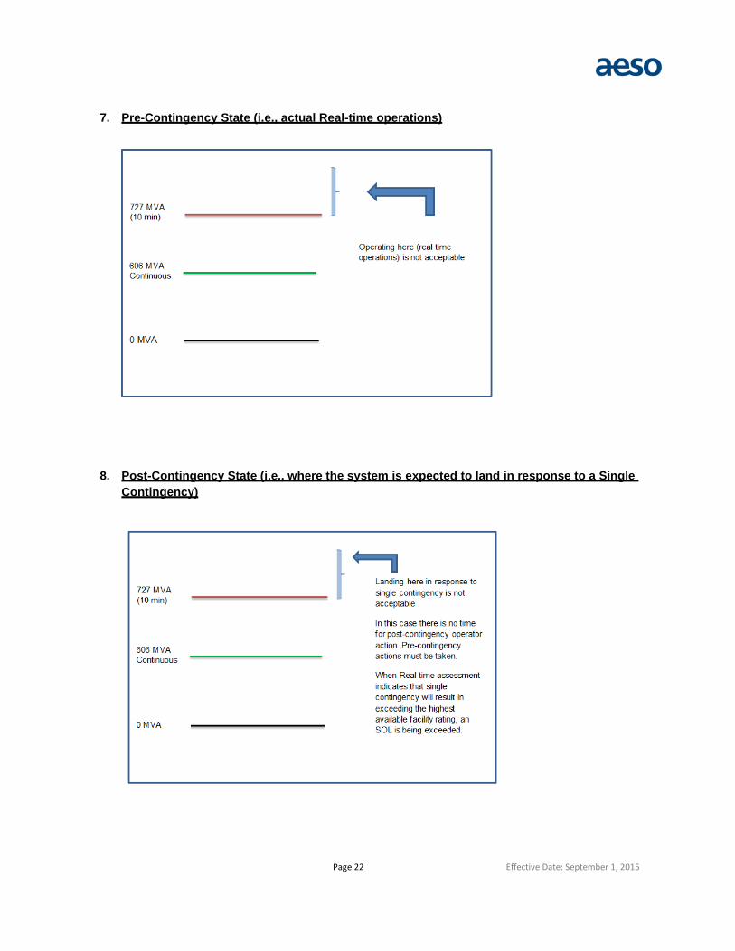
7. Pre-Contingency State (i.e., actual Real-time operations)
8. Post-Contingency State (i.e., where the system is expected to land in response to a Single Contingency)

Page 23 Effective Date: September 1, 2015
Revision History
Version Effective Date
1 October 1, 2012
AESO SOL Methodology for the Operations Horizon to be consistent with Peak RC Methodology “System Operating Limits Methodology for the Operations Horizon Version 6.1”
1.1 January 1, 2014
. Updated to include IROLs
2 March 3, 2014
Effective March 3, 2014. AESO SOL Methodology for the Operations Horizon updated to be consistent with Peak RC Methodology “System Operating Limits Methodology for the Operations Horizon Revision 7.0”
2.1 January 5, 2015
Updated to be consistent with multiple contingency definitions
3.0 September 01, 2015
Revised to be consistent with ARS FAC-011 and FAC- 014