AEC-Q100-012 Short-Circuit Reliability Test Results for Smart ...
14
1 SLVA709A – June 2015 – Revised May 2019 Submit Documentation Feedback Copyright © 2015–2019, Texas Instruments Incorporated AEC-Q100-012 Short-Circuit Reliability Test Results for Smart Power Switches (1) All trademarks are the property of their respective owners. (1) Application Report SLVA709A – June 2015 – Revised May 2019 AEC-Q100-012 Short-Circuit Reliability Test Results for Smart Power Switches ABSTRACT Smart power switches are widely used as short-circuit protection devices in automotive systems. Therefore, the robustness of the device under repetitive short-circuit stress is crucial to providing protection for the entire system. In order to guarantee protection, the AEC Q100-012 provides a industry standard qualification certificate which specifies the reliability of this type of device. This application report describes the AEC Q100-012 specification and provides the test method and results for TI's Smart Power Switch devices. Contents 1 AEC Q100-012 Introduction ................................................................................................ 2 1.1 Introduction .......................................................................................................... 2 1.2 Equivalent Test Circuit ............................................................................................. 2 1.3 Test Conditions ..................................................................................................... 2 1.4 Passing Conditions ................................................................................................. 3 2 Types of Short Circuit ....................................................................................................... 3 2.1 Cold Repetitive Short Circuit—Short Pulse...................................................................... 4 2.2 Cold Repetitive Short Circuit—Long Pulse ...................................................................... 5 2.3 Hot Repetitive Short Circuit ....................................................................................... 6 3 Short-Circuit Test Setup .................................................................................................... 7 3.1 Test Setup Introduction ............................................................................................ 7 3.2 Test Set Up .......................................................................................................... 7 3.3 Failure Check ...................................................................................................... 10 4 Results and Conclusion ................................................................................................... 10 5 References .................................................................................................................. 12 List of Figures 1 Smart HSS Short-Circuit Model ............................................................................................ 2 2 Timing Diagram of Cold Repetitive Short Circuit—Short Pulse ....................................................... 5 3 Timing Diagram of Cold Repetitive Short Circuit—Long Pulse ........................................................ 6 4 Timing Diagram of Hot Repetitive Short Circuit ......................................................................... 6 5 System Block Diagram ...................................................................................................... 7 6 Instruments ................................................................................................................... 8 7 Layout of Driver Board ...................................................................................................... 8 8 Layout of Oven Board ....................................................................................................... 9 9 User Interface ................................................................................................................ 9 List of Tables 1 Output Impedance ........................................................................................................... 3 2 Grade Level Table ........................................................................................................... 3 3 Test Requirements Summary .............................................................................................. 4 4 High Side Switch Test Results ........................................................................................... 10
-
Upload
khangminh22 -
Category
Documents
-
view
0 -
download
0
Transcript of AEC-Q100-012 Short-Circuit Reliability Test Results for Smart ...

1SLVA709A–June 2015–Revised May 2019Submit Documentation Feedback
Copyright © 2015–2019, Texas Instruments Incorporated
AEC-Q100-012 Short-Circuit Reliability Test Results for Smart PowerSwitches
(1) All trademarks are the property of their respective owners.
(1)
Application ReportSLVA709A–June 2015–Revised May 2019
AEC-Q100-012 Short-Circuit Reliability Test Results forSmart Power Switches
ABSTRACTSmart power switches are widely used as short-circuit protection devices in automotive systems.Therefore, the robustness of the device under repetitive short-circuit stress is crucial to providingprotection for the entire system. In order to guarantee protection, the AEC Q100-012 provides a industrystandard qualification certificate which specifies the reliability of this type of device.
This application report describes the AEC Q100-012 specification and provides the test method andresults for TI's Smart Power Switch devices.
Contents1 AEC Q100-012 Introduction ................................................................................................ 2
1.1 Introduction .......................................................................................................... 21.2 Equivalent Test Circuit ............................................................................................. 21.3 Test Conditions ..................................................................................................... 21.4 Passing Conditions ................................................................................................. 3
2 Types of Short Circuit ....................................................................................................... 32.1 Cold Repetitive Short Circuit—Short Pulse...................................................................... 42.2 Cold Repetitive Short Circuit—Long Pulse ...................................................................... 52.3 Hot Repetitive Short Circuit ....................................................................................... 6
3 Short-Circuit Test Setup .................................................................................................... 73.1 Test Setup Introduction ............................................................................................ 73.2 Test Set Up .......................................................................................................... 73.3 Failure Check ...................................................................................................... 10
4 Results and Conclusion ................................................................................................... 105 References .................................................................................................................. 12
List of Figures
1 Smart HSS Short-Circuit Model............................................................................................ 22 Timing Diagram of Cold Repetitive Short Circuit—Short Pulse ....................................................... 53 Timing Diagram of Cold Repetitive Short Circuit—Long Pulse ........................................................ 64 Timing Diagram of Hot Repetitive Short Circuit ......................................................................... 65 System Block Diagram...................................................................................................... 76 Instruments ................................................................................................................... 87 Layout of Driver Board ...................................................................................................... 88 Layout of Oven Board....................................................................................................... 99 User Interface ................................................................................................................ 9
List of Tables
1 Output Impedance ........................................................................................................... 32 Grade Level Table ........................................................................................................... 33 Test Requirements Summary .............................................................................................. 44 High Side Switch Test Results ........................................................................................... 10

Control System ON/OFF
VBB
GND
OUT
Rsupply
10 m
Lsupply
5 µH Lshort
Rshort
+±
14 VIdealDC-voltage
source
AEC Q100-012 Introduction www.ti.com
2 SLVA709A–June 2015–Revised May 2019Submit Documentation Feedback
Copyright © 2015–2019, Texas Instruments Incorporated
AEC-Q100-012 Short-Circuit Reliability Test Results for Smart PowerSwitches
5 TPS1H100-Q1 Test Result Summary ................................................................................... 106 TPS2H160-Q1 Test Result Summary ................................................................................... 107 TPS4H160-Q1 Test Result Summary ................................................................................... 118 TPS1H200-Q1 Test Result Summary ................................................................................... 119 TPS1H000-Q1 Test Result Summary ................................................................................... 1110 TPS2H000-Q1 Test Result Summary ................................................................................... 1111 TPS4H000-Q1 Test Result Summary ................................................................................... 11
1 AEC Q100-012 Introduction
1.1 IntroductionThe Automotive Electronics Council (AEC) provides the AEC Q100-012 documentation which specifiesstandards for short-circuit reliability testing. The main purpose of this test is to determine the reliability ofsmart-power switches when operating in a continuous short-circuit condition. The AEC Q100-012specification includes an equivalent test circuit, detailed test conditions, different reliability gradedefinitions, and other information.
1.2 Equivalent Test CircuitFigure 1 shows the basic equivalent test circuit for a smart high-side switch (HSS). The HSS is the deviceunder test (DUT) that performs the repetitive short-circuit tests while the Rsupply and Lsupply are the inputimpedance from the voltage source side (VBB), and the Rshort and Lshort are the output impedance from themodule board and the cables. These input and output impedances simulate input and output cables orinterconnects that impact the performance under short-circuit events.
Figure 1. Smart HSS Short-Circuit Model
1.3 Test Conditions
1.3.1 Supply VoltageThe supply is modeled by an ideal voltage source, VBAT, which generally is set at 14 V ± 2%.
1.3.2 Input ImpedanceA total resistance of Rsupply = 10 mΩ ± 20% and an inductance of Lsupply = 5 μH ± 20% are specified tosimulate the cable and interconnects from the automotive battery to the HSS.
www.ti.com AEC Q100-012 Introduction
3SLVA709A–June 2015–Revised May 2019Submit Documentation Feedback
Copyright © 2015–2019, Texas Instruments Incorporated
AEC-Q100-012 Short-Circuit Reliability Test Results for Smart PowerSwitches
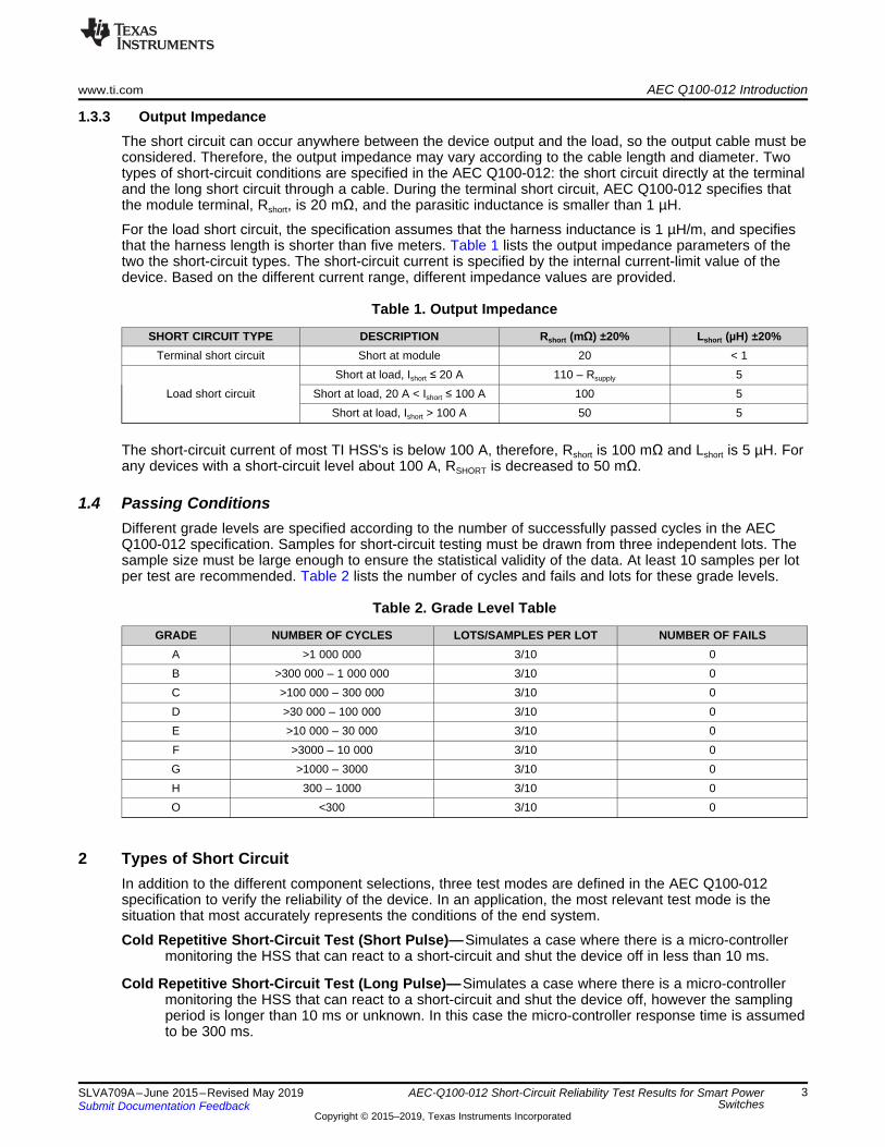
1.3.3 Output ImpedanceThe short circuit can occur anywhere between the device output and the load, so the output cable must beconsidered. Therefore, the output impedance may vary according to the cable length and diameter. Twotypes of short-circuit conditions are specified in the AEC Q100-012: the short circuit directly at the terminaland the long short circuit through a cable. During the terminal short circuit, AEC Q100-012 specifies thatthe module terminal, Rshort, is 20 mΩ, and the parasitic inductance is smaller than 1 µH.
For the load short circuit, the specification assumes that the harness inductance is 1 µH/m, and specifiesthat the harness length is shorter than five meters. Table 1 lists the output impedance parameters of thetwo the short-circuit types. The short-circuit current is specified by the internal current-limit value of thedevice. Based on the different current range, different impedance values are provided.
Table 1. Output Impedance
SHORT CIRCUIT TYPE DESCRIPTION Rshort (mΩ) ±20% Lshort (µH) ±20%Terminal short circuit Short at module 20 < 1
Load short circuitShort at load, Ishort ≤ 20 A 110 – Rsupply 5
Short at load, 20 A < Ishort ≤ 100 A 100 5Short at load, Ishort > 100 A 50 5
The short-circuit current of most TI HSS's is below 100 A, therefore, Rshort is 100 mΩ and Lshort is 5 µH. Forany devices with a short-circuit level about 100 A, RSHORT is decreased to 50 mΩ.
1.4 Passing ConditionsDifferent grade levels are specified according to the number of successfully passed cycles in the AECQ100-012 specification. Samples for short-circuit testing must be drawn from three independent lots. Thesample size must be large enough to ensure the statistical validity of the data. At least 10 samples per lotper test are recommended. Table 2 lists the number of cycles and fails and lots for these grade levels.
Table 2. Grade Level Table
GRADE NUMBER OF CYCLES LOTS/SAMPLES PER LOT NUMBER OF FAILSA >1 000 000 3/10 0B >300 000 – 1 000 000 3/10 0C >100 000 – 300 000 3/10 0D >30 000 – 100 000 3/10 0E >10 000 – 30 000 3/10 0F >3000 – 10 000 3/10 0G >1000 – 3000 3/10 0H 300 – 1000 3/10 0O <300 3/10 0
2 Types of Short CircuitIn addition to the different component selections, three test modes are defined in the AEC Q100-012specification to verify the reliability of the device. In an application, the most relevant test mode is thesituation that most accurately represents the conditions of the end system.
Cold Repetitive Short-Circuit Test (Short Pulse)—Simulates a case where there is a micro-controllermonitoring the HSS that can react to a short-circuit and shut the device off in less than 10 ms.
Cold Repetitive Short-Circuit Test (Long Pulse)—Simulates a case where there is a micro-controllermonitoring the HSS that can react to a short-circuit and shut the device off, however the samplingperiod is longer than 10 ms or unknown. In this case the micro-controller response time is assumedto be 300 ms.

Types of Short Circuit www.ti.com
4 SLVA709A–June 2015–Revised May 2019Submit Documentation Feedback
Copyright © 2015–2019, Texas Instruments Incorporated
AEC-Q100-012 Short-Circuit Reliability Test Results for Smart PowerSwitches
Hot Repetitive Short-Circuit Test—Simulates a case where there is no micro-controller monitoring theHSS, so the HSS indefinitely stays enabled into the short-circuit.
Table 3 lists the detailed ambient temperature, pulse duration, and cycle numbers.
Table 3. Test Requirements Summary
TEST ITEMS TEST CONDITION RECCOMENDED TEST CYCLES
Cold repetitive short-circuittest
Short pulse –40°C, 10-ms pulse, cool down 1 MillionLong pulse –40°C, 300-ms pulse, cool down 1 Million
Hot repetitive short-circuit test 25°C, keeping short 1 Million
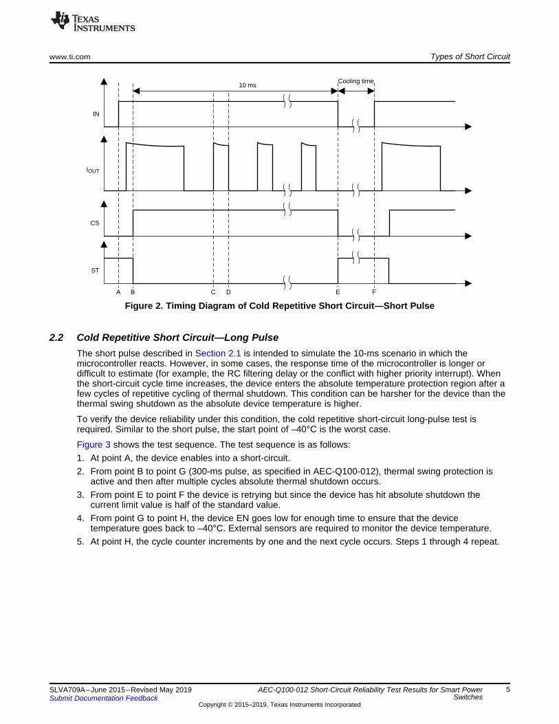
2.1 Cold Repetitive Short Circuit—Short PulseThe cold repetitive short-circuit test is intended to simulate an event where the device is monitored by anMCU that can react to a short-circuit event within 10 ms. For TI's smart high-side switches, a short-circuitfault can be reported on the current sense pin (CS) or the status output pin (ST). In general, themicrocontroller turns off the channels when it receives this fault indication, however the microcontrollersampling period introduces some delay. During this 10 ms delay, the device passes in and out of thermalswing shutdown until the microcontroller recognizes the fault. After the fault is recognized, themicrocontroller shuts the device off and the device remains off while it cools down. This short-circuitpattern is considered one cycle of repetitive short-circuit.
Due to the relatively short 10 ms pulse, during the thermal cycling, the device always shuts down due tothe thermal swing detection, and the temperature never hits the absolute thermal temperature shutdown.Given the high power dissipated in a short-circuit event, the stress of the rapid temperature variation mustbe considered, especially for the repetitive stress under extremely low temperature.
Figure 2 shows the test sequence. The test sequence is as follows:1. At point A, the device enables into a short circuit.2. From point B to point E (10-ms, as specified in AEC-Q100-012), the device remains enabled while the
internal thermal swing protection works to minimize the temperature variation.3. At point C the device has cooled down and turns back on until point D when it turns off again due to
thermal cycling.4. From point E to point F, the device EN goes low for enough time to ensure the device temperature
goes back to –40°C. External sensors are required to monitor the device temperature.5. At point F, the cycle counter increments by 1 and the next cycle occurs. Steps 1 through 4 repeat.
ST
CS
IOUT
IN
10 msCooling time
E FC DA B
www.ti.com Types of Short Circuit
5SLVA709A–June 2015–Revised May 2019Submit Documentation Feedback
Copyright © 2015–2019, Texas Instruments Incorporated
AEC-Q100-012 Short-Circuit Reliability Test Results for Smart PowerSwitches
Figure 2. Timing Diagram of Cold Repetitive Short Circuit—Short Pulse
2.2 Cold Repetitive Short Circuit—Long PulseThe short pulse described in Section 2.1 is intended to simulate the 10-ms scenario in which themicrocontroller reacts. However, in some cases, the response time of the microcontroller is longer ordifficult to estimate (for example, the RC filtering delay or the conflict with higher priority interrupt). Whenthe short-circuit cycle time increases, the device enters the absolute temperature protection region after afew cycles of repetitive cycling of thermal shutdown. This condition can be harsher for the device than thethermal swing shutdown as the absolute device temperature is higher.
To verify the device reliability under this condition, the cold repetitive short-circuit long-pulse test isrequired. Similar to the short pulse, the start point of –40°C is the worst case.
Figure 3 shows the test sequence. The test sequence is as follows:1. At point A, the device enables into a short-circuit.2. From point B to point G (300-ms pulse, as specified in AEC-Q100-012), thermal swing protection is
active and then after multiple cycles absolute thermal shutdown occurs.3. From point E to point F the device is retrying but since the device has hit absolute shutdown the
current limit value is half of the standard value.4. From point G to point H, the device EN goes low for enough time to ensure that the device
temperature goes back to –40°C. External sensors are required to monitor the device temperature.5. At point H, the cycle counter increments by one and the next cycle occurs. Steps 1 through 4 repeat.

IOUT
IN
E FC DA B
ST
CS
IOUT
IN
300 ms
Cooling
time
E FC DA B G H
Types of Short Circuit www.ti.com
6 SLVA709A–June 2015–Revised May 2019Submit Documentation Feedback
Copyright © 2015–2019, Texas Instruments Incorporated
AEC-Q100-012 Short-Circuit Reliability Test Results for Smart PowerSwitches
Figure 3. Timing Diagram of Cold Repetitive Short Circuit—Long Pulse
2.3 Hot Repetitive Short CircuitThe cold repetitive short-circuit scenarios are the target for fault cases in applications that are monitoredby a microcontroller, however some applications do not have any micro-controller monitoring the HSS sonothing shuts down the EN pin after a short circuit event is recognized. The enable signal remains activeduring a hot repetitive short-circuit. In this case, the hot repetitive short-circuit test is required. After theshort-circuit occurs, the device quickly enters absolute thermal shutdown cycling then remains indefinitelyin repetitive thermal cycling mode. A cool-down period for the device is not required. The test begins atroom temperature since the temperature variation occurs only at the first cycle and therefore the device isat hot for the entirety of the test.
Figure 4 shows the test sequence. The test sequence is as follows:1. At point A, the device enables into a short-circuit.2. From point B to point F, thermal swing protection is active first then thermal shutdown occurs.3. The short-circuit condition continues indefinitely.
Figure 4. Timing Diagram of Hot Repetitive Short Circuit

Lshort
PC Host System
PXISystem
PXI6509
PXI6224
Monitor device
Fuse
Power Supply (GPIB)
PWR_IN_Sx
SC_EN_Sx
PWR_CS_Sx
IN_Sx
Smart High-Side
Driver
Rshort
www.ti.com Short-Circuit Test Setup
7SLVA709A–June 2015–Revised May 2019Submit Documentation Feedback
Copyright © 2015–2019, Texas Instruments Incorporated
AEC-Q100-012 Short-Circuit Reliability Test Results for Smart PowerSwitches
3 Short-Circuit Test Setup
3.1 Test Setup IntroductionThe AEC-Q100-012 standard requires at least 30 devices originating from three separate silicon lots for asufficient sample size. System control relies on a central PC host which is linked to a PXI bus system withPXI-6509 and PXI-6224 cards. The PXI-6509 and PXI-6224 cards generate the control signals andprocess the feedback signals of the test. All DUTs are processed individually and independently. ThePWR_IN_Sx signal enables the current-monitor device. The SC_EN_Sx signal turns on the short-circuitresistor, Rshort. The PWR_CS_Sx signal is the short-circuit current feedback signal. The IN_Sx signalenables the HSS and triggers the short circuit.
Some power sequences are required to ensure that the test functions correctly. Follow these powersequences:1. Power on the monitor device with the PWR_IN_Sx signal.2. Turn on the N-MOS Rshort with the SC_EN_Sx signal.3. Turn on the IN_Sx signal to force the device into short-circuit mode.4. Read back the PWR_CS_Sx signal and process it with a software algorithm.
Figure 5. System Block Diagram
3.2 Test Set UpThe three main sections of the test control system are the power and driver boards, the oven and the ovenboard, and the PC host system.

Short-Circuit Test Setup www.ti.com
8 SLVA709A–June 2015–Revised May 2019Submit Documentation Feedback
Copyright © 2015–2019, Texas Instruments Incorporated
AEC-Q100-012 Short-Circuit Reliability Test Results for Smart PowerSwitches
Figure 6. Instruments
Figure 7 shows the layout of one cell on the driver board and includes the monitor device and theconnectors with the oven boards.
Figure 7. Layout of Driver Board
Figure 8 shows the layout of the oven board. The DUTs are placed on this board, which consists of 20individual cells. This oven board is placed inside the oven for different temperature tests.

www.ti.com Short-Circuit Test Setup
9SLVA709A–June 2015–Revised May 2019Submit Documentation Feedback
Copyright © 2015–2019, Texas Instruments Incorporated
AEC-Q100-012 Short-Circuit Reliability Test Results for Smart PowerSwitches
Figure 8. Layout of Oven Board
Figure 9 shows the graphical user interface (GUI) in the PC host system and how different test modes andconditions can be configured easily by the end user. The DUT status, test cycles, and waveforms can bemonitored from this interface.
Figure 9. User Interface

Short-Circuit Test Setup www.ti.com
10 SLVA709A–June 2015–Revised May 2019Submit Documentation Feedback
Copyright © 2015–2019, Texas Instruments Incorporated
AEC-Q100-012 Short-Circuit Reliability Test Results for Smart Power Switches
3.3 Failure CheckTwo types of failure checks are conducted for each device: the real-time monitor and the pre-test data andpost-test data check.
3.3.1 Real-Time MonitorAny DUT failures, including open loads or device internal shorts, can by caught by real-time monitoring. Ifeither failure mechanism is detected, the number of cycles undergone by the DUT is recorded as a devicefailure. The two failures are defined as:
Short-circuit failure — If the PWR_CS_Sx signal reaches the maximum set value, the short-circuit failureof the DUT is detected. The controller shuts down the corresponding site and records the numberof cycles that have been performed on that site.
Open-load failure — If the PWR_CS_Sx signal reaches zero for the set time, it is recognized as anopen-load failure DUT. The controller shuts down the corresponding site and records the number ofcycles that have been performed on that site.
3.3.2 The Pre-Test and Post-Test Data CheckPre-test and post-test data are only checked for each device on the automatic test equipment (ATE). Anyvalue outside of the device specification listed in the data sheet is regarded as a test failure.
4 Results and ConclusionTI HSS devices are all tested based on the described test conditions and setup. The testing resultsdetermine a device grade as defined in the Section 1.4 section which is shown in Table 4.
Table 4. High Side Switch Test Results
DEVICE NAME RON CHANNEL COUNT GRADETPS1H100-Q1 100 mΩ 1 ATPS2H160-Q1 160 mΩ 2 ATPS4H160-Q1 160 mΩ 4 BTPS1H200-Q1 200 mΩ 1 ATPS1H000-Q1 1000 mΩ 1 ATPS2H000-Q1 1000 mΩ 2 ATPS4H000-Q1 1000 mΩ 4 A
The tables below give the specific test results and conditions for each device.
Table 5. TPS1H100-Q1 Test Result Summary
TESTPROCEDURE
LOTS/SAMPLESPER LOT
INITIALTEMPERATURE CYCLES FAILED UNITS POST TEST
Cold RepetitiveShort Pulse 3/10 –40 1 000 000 0 Pass
Cold RepetitiveLong Pulse 3/10 –40 1 000 000 0 Pass
Hot Repetitive Pulse 3/10 25 1 000 000 0 Pass
Table 6. TPS2H160-Q1 Test Result Summary
TESTPROCEDURE
LOTS/SAMPLESPER LOT
INITIALTEMPERATURE CYCLES FAILED UNITS POST TEST
Cold RepetitiveShort Pulse 3/10 –40 1 000 000 0 Pass

www.ti.com Results and Conclusion
11SLVA709A–June 2015–Revised May 2019Submit Documentation Feedback
Copyright © 2015–2019, Texas Instruments Incorporated
AEC-Q100-012 Short-Circuit Reliability Test Results for Smart Power Switches
Table 6. TPS2H160-Q1 Test Result Summary (continued)TEST
PROCEDURELOTS/SAMPLES
PER LOTINITIAL
TEMPERATURE CYCLES FAILED UNITS POST TEST
Cold RepetitiveLong Pulse 3/10 –40 1 000 000 0 Pass
Hot Repetitive Pulse 3/10 25 1 000 000 0 Pass
Table 7. TPS4H160-Q1 Test Result Summary
TESTPROCEDURE
LOTS/SAMPLESPER LOT
INITIALTEMPERATURE CYCLES FAILED UNITS POST TEST
Cold RepetitiveShort Pulse 3/10 –40 1 000 000 0 Pass
Cold RepetitiveLong Pulse 3/10 –40 300 000 0 Pass
Hot Repetitive Pulse 3/10 25 1 000 000 0 Pass
Table 8. TPS1H200-Q1 Test Result Summary
TESTPROCEDURE
LOTS/SAMPLESPER LOT
INITIALTEMPERATURE CYCLES FAILED UNITS POST TEST
Cold RepetitiveShort Pulse 3/10 –40 1 000 000 0 Pass
Cold RepetitiveLong Pulse 3/10 –40 1 000 000 0 Pass
Hot Repetitive Pulse 3/10 25 1 000 000 0 Pass
Table 9. TPS1H000-Q1 Test Result Summary
TESTPROCEDURE
LOTS/SAMPLESPER LOT
INITIALTEMPERATURE CYCLES FAILED UNITS POST TEST
Cold RepetitiveShort Pulse 3/10 –40 1 000 000 0 Pass
Cold RepetitiveLong Pulse 3/10 –40 1 000 000 0 Pass
Hot Repetitive Pulse 3/10 25 1 000 000 0 Pass
Table 10. TPS2H000-Q1 Test Result Summary
TESTPROCEDURE
LOTS/SAMPLESPER LOT
INITIALTEMPERATURE CYCLES FAILED UNITS POST TEST
Cold RepetitiveShort Pulse 3/10 –40 1 000 000 0 Pass
Cold RepetitiveLong Pulse 3/10 –40 1 000 000 0 Pass
Hot Repetitive Pulse 3/10 25 1 000 000 0 Pass
Table 11. TPS4H000-Q1 Test Result Summary
TESTPROCEDURE
LOTS/SAMPLESPER LOT
INITIALTEMPERATURE CYCLES FAILED UNITS POST TEST
Cold RepetitiveShort Pulse 3/10 –40 1 000 000 0 Pass
Cold RepetitiveLong Pulse 3/10 –40 1 000 000 0 Pass
Hot Repetitive Pulse 3/10 25 1 000 000 0 Pass
References www.ti.com
12 SLVA709A–June 2015–Revised May 2019Submit Documentation Feedback
Copyright © 2015–2019, Texas Instruments Incorporated
AEC-Q100-012 Short-Circuit Reliability Test Results for Smart PowerSwitches
The results of the AEC Q100-12 testing show that nearly all of the TI HSS devices fulfill 1 million repetitiveshort-circuits without a failure regardless of test qualification. Therefore, the devices are primarily qualifiedas Grade A, the highest short-circuit reliability certificate in the industry.
5 References• AEC - Q100-012 - REVSHORT CIRCUIT RELIABILITY CHARACTERIZATION OF SMART POWER
DEVICES FOR 12V SYSTEMS (Automotive Electronics Council, 2006)• TPS1H100-Q1 40-V, 100-mΩ Single-Channel Smart High-Side Power Switch Data Sheet

www.ti.com Revision History
13SLVA709A–June 2015–Revised May 2019Submit Documentation Feedback
Copyright © 2015–2019, Texas Instruments Incorporated
Revision History
Revision HistoryNOTE: Page numbers for previous revisions may differ from page numbers in the current version.
Changes from Original (June 2015) to A Revision ......................................................................................................... Page
• Changed title from Short-Circuit Reliability Test for Smart Power Switch AEC-Q100-012 Test of TPS1H100-Q1 to AEC-Q100-012 Short Circuit Reliability Test Results for Smart Power Switches. ...................................................... 1
• Updated abstract. ......................................................................................................................... 1• Updated wording in Introduction......................................................................................................... 2• Updated wording in Equivalent Test Circuit section. ................................................................................. 2• Moved Test Conditions, Supply voltage, Input Impedance, Output Impedance, and Passing Conditions sections to section
1. ............................................................................................................................................ 2• Added Types of Short Circuit section to section 2. ................................................................................... 3• Added Cold Repetitive Short Circuit—Short Pulse, Cold Repetitive Short Circuit—Long Pulse, and Hot Repetitive Short
Circuit sections to section 2. ............................................................................................................. 4• Added Test Setup Introduction, Test Setup, Failure Check, Real-time Monitor, and The Pre-Test and Post-Test Data
Check sections to section 3. ............................................................................................................. 7• Added Results and Conclusion as section 4. ........................................................................................ 10• Added table 8-15. ........................................................................................................................ 10
IMPORTANT NOTICE AND DISCLAIMER
TI PROVIDES TECHNICAL AND RELIABILITY DATA (INCLUDING DATASHEETS), DESIGN RESOURCES (INCLUDING REFERENCEDESIGNS), APPLICATION OR OTHER DESIGN ADVICE, WEB TOOLS, SAFETY INFORMATION, AND OTHER RESOURCES “AS IS”AND WITH ALL FAULTS, AND DISCLAIMS ALL WARRANTIES, EXPRESS AND IMPLIED, INCLUDING WITHOUT LIMITATION ANYIMPLIED WARRANTIES OF MERCHANTABILITY, FITNESS FOR A PARTICULAR PURPOSE OR NON-INFRINGEMENT OF THIRDPARTY INTELLECTUAL PROPERTY RIGHTS.These resources are intended for skilled developers designing with TI products. You are solely responsible for (1) selecting the appropriateTI products for your application, (2) designing, validating and testing your application, and (3) ensuring your application meets applicablestandards, and any other safety, security, or other requirements. These resources are subject to change without notice. TI grants youpermission to use these resources only for development of an application that uses the TI products described in the resource. Otherreproduction and display of these resources is prohibited. No license is granted to any other TI intellectual property right or to any thirdparty intellectual property right. TI disclaims responsibility for, and you will fully indemnify TI and its representatives against, any claims,damages, costs, losses, and liabilities arising out of your use of these resources.TI’s products are provided subject to TI’s Terms of Sale (www.ti.com/legal/termsofsale.html) or other applicable terms available either onti.com or provided in conjunction with such TI products. TI’s provision of these resources does not expand or otherwise alter TI’s applicablewarranties or warranty disclaimers for TI products.
Mailing Address: Texas Instruments, Post Office Box 655303, Dallas, Texas 75265Copyright © 2019, Texas Instruments Incorporated